Profile Handling Systems - Chapter 8 8-1 P P r r o o f f i i l l e e H H a a n n d d l l i i n n g g S S y y s s t t e e m m s s This chapter sponsored by Granco Clark www.GrancoClark.com Equipment for handling extruded profiles after the press is as varied as the ingenuity and creativity of the human mind can produce. As a result it is impossible to describe in detail every type of equipment; however, the general maintenance principles that apply to the most common types of handling systems are presented. This chapter covers equipment items 7 through 15 in the illustration below (plus profile stackers).

Welcome message from author
This document is posted to help you gain knowledge. Please leave a comment to let me know what you think about it! Share it to your friends and learn new things together.
Transcript
Profile Handling Systems - Chapter 8
8-1
PPrrooffiillee HHaannddlliinngg SSyysstteemmss This chapter sponsored by Granco Clark
www.GrancoClark.com
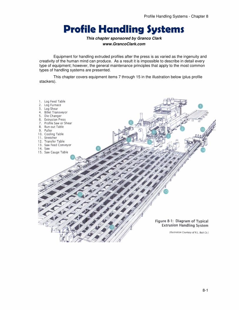
Equipment for handling extruded profiles after the press is as varied as the ingenuity and creativity of the human mind can produce. As a result it is impossible to describe in detail every type of equipment; however, the general maintenance principles that apply to the most common types of handling systems are presented.
This chapter covers equipment items 7 through 15 in the illustration below (plus profile stackers).

Profile Handling Systems - Chapter 8
8-2
Sponsor's advertisement --- more information: www.grancoclark.com
Profile Handling Systems - Chapter 8
8-3
High-Temperature Textile Materials for Extrusion Handling1
Textile materials offer useful properties for extrusion handling, mainly the elimination of damage caused by lift-over and walking beams, graphite marking, and cooling spots. “Soft” handling systems are also cleaner and quieter. Most new plants now use lead-out and run-out rollers, as well as transfer and cooling belts made from high-temperature textiles.
The technology of fiber products available for handling systems continues to evolve
2. A few general
principles are summarized here:
In general, there are two types of industrial textiles:
• Woven textiles are made from fibers that are spun into yarn and then woven together in a loom.
• Non-woven textiles or felts are made by compressing fibers together and punching with barbed needles to increase density.
Desired characteristics for handling system textiles are:
1. Temperature resistance in excess of 930oF
(500oC)
2. High resistance to wear
3. Good thermal conductivity
4. Reasonable tensile strength
5. Minimum elongation
6. Fiber hardness less than that of aluminum (at temperature)
7. Low coefficient of friction
8. No primary health risks
9. Reasonable availability and cost
While there are many available choices of fibers for lower temperatures, the choices diminish rapidly above 660
oF (350
oC). The requirement for good wear
resistance further restricts the choices; as a rule, the higher the temperature resistance the lower the wear resistance. Fibers resistant to high temperatures tend to be brittle, with lower tensile strength and higher hardness than desired. However, good thermal conductivity helps the materials conduct heat away from the point of contact and thus improve life.
1 Much of this section is condensed from the following paper: Douglas, M., “High Temperature
Textile Products for Aluminum Extrusion Handling Systems,” Proceedings of 6th International Aluminum Extrusion Technology Seminar, Vol. II, (1996), p. 287-292.
2 Gaube, Doris, “Technical Textiles for Handling Systems: Introducing High Tech While Avoiding
Basic Mistakes,” Proceedings of 6th International Aluminum Extrusion Technology Seminar, (2004).
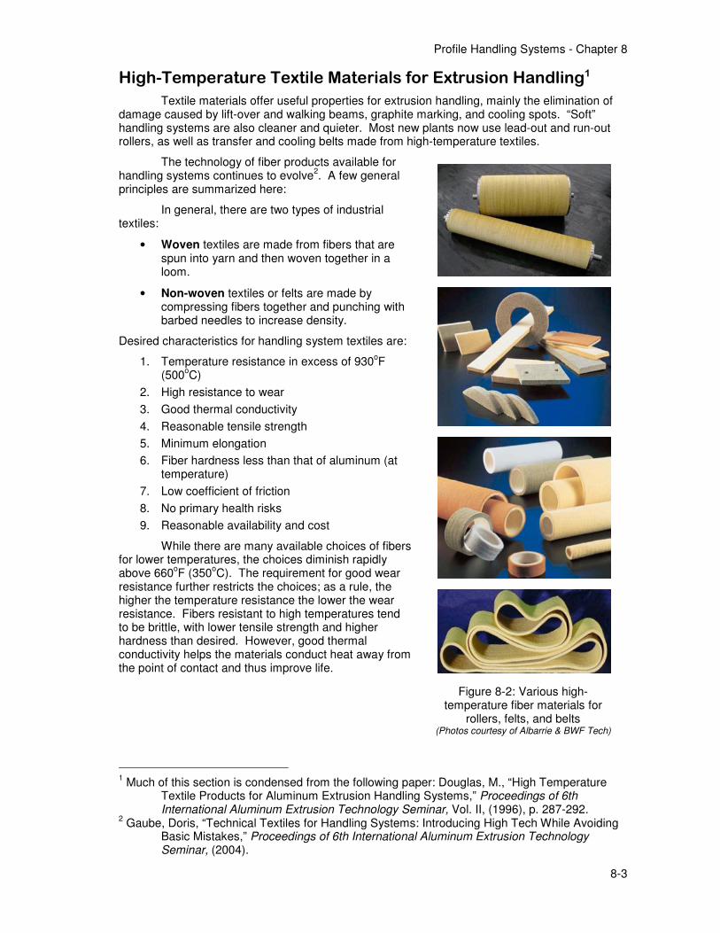
Figure 8-2: Various high-temperature fiber materials for
rollers, felts, and belts (Photos courtesy of Albarrie & BWF Tech)
Profile Handling Systems - Chapter 8
8-4
Rollers. The lead-out directly in front of the press presents the highest temperatures any of the fiber products will see in the handling system, before the profiles have been cooled significantly. Large profiles present the greatest problems due to higher heat conduction and radiation to the fibers. There has been some success in this area by using water cooling on or through the rollers, and by impregnating the rollers with graphite or special resins.
The designs of roller systems in use today vary widely. Some use felts, others woven covers. Some use a solid drum-type roller for the inside, others a hollow extruded framework. Some are one-piece sleeves, others 3-piece so the sections may be replaced cheaply when needed.
Belts. Belts may be made of the same high-temperature yarns used for rollers and may be woven or felt materials. Most belt failures are due to over-temperature and misalignment. As with rollers, most problems occur in the belts closest to the press, which handle the profiles before sufficient cooling has occurred.
Belt sizes in extrusion plants range from 60mm wide x 5mm thick (2.36” x 0.19”) up to 200mm x 10mm (8.0” x 0.39”); most common widths are 80mm (3.15”) and 100mm (3.93”).
Joints are a key issue, as concern for profile damage rules out most mechanical fasteners as well as straight-across splices. “Chevron” shaped splices are the current standard, to increase joint strength while avoiding profiles hanging on the joint; the sewing yarns must also withstand the high temperatures. Seamless belts are also in use in some plants.
Slat and Beam Covers. Many extruders have successfully replaced graphite with high-temperature felt pads on walking beams, lift-overs, and even slat conveyors, at least for lighter-weight profiles. Friction forces may become important, so modifications to the material to reduce the friction coefficient are usually necessary.
High-temperature fiber pads have not been successful on the initial part of the lead-out table due to the temperatures. Water cooling is some help but may lead to marking of the profiles.
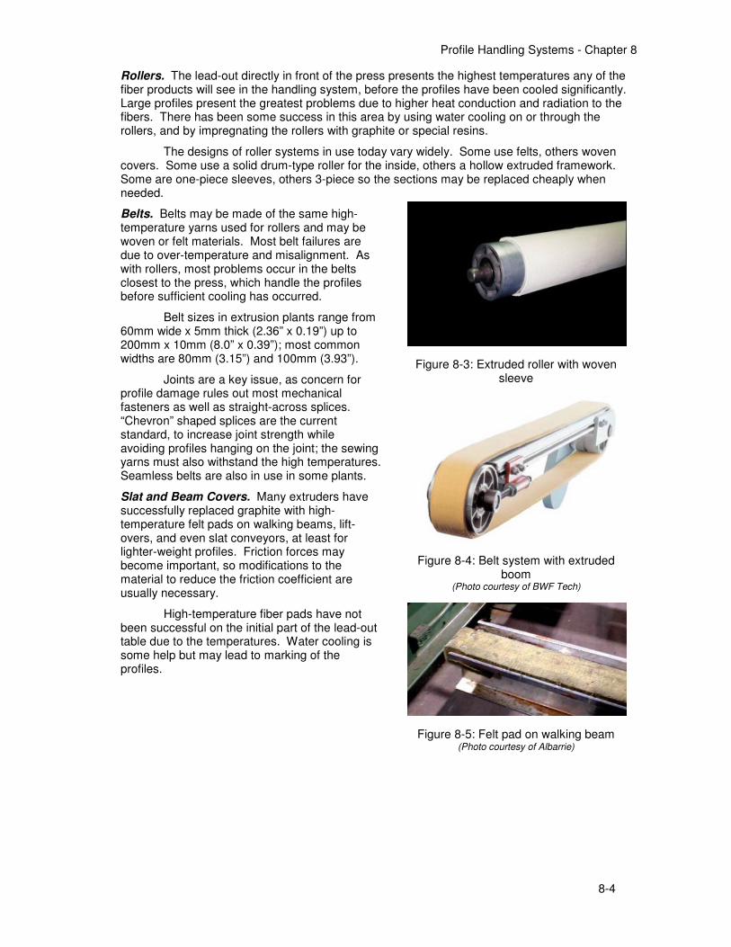
Figure 8-3: Extruded roller with woven sleeve
Figure 8-4: Belt system with extruded boom
(Photo courtesy of BWF Tech)
Figure 8-5: Felt pad on walking beam (Photo courtesy of Albarrie)
Profile Handling Systems - Chapter 8
8-5
Lead-out Tables
Various types of stationary lead-out tables are used to connect the press discharge either to the water quench or handling system. Typical construction incorporates a welded steel framework with a top surface usually made of flat graphite (solid surface or cross-bar slats), or rollers (surfaced in high-temp fibers such as Kevlar, graphite, steel, or other high-temperature material).
The lead-out table may incorporate a frame or system of slots to enable placement of graphite divider bars to maintain separation of profiles in multi-strand extrusion. Because the ideal support height of the table varies in relation to the press centerline, according to the height of the profiles, tables are often designed to raise or lower accordingly; the table may be hinged about a distant point or raised uniformly, usually powered from the press auxiliary hydraulic circuit or by a hand operated lifting device.
Length of the lead-out varies depending on whether there is a water quench or mini-slat, the type of puller if any, and the distance to the start of the cooling system. When a flying-cut saw or puller-saw system is used, lead-out length must be increased considerably (minimum 50 ft or 16 m) to allow completion of the cutting cycle before the profile weld mark reaches the start of the cooling table. Also, when working with a flying-cut profile saw, newer tables have sections that drop down individually as the saw passes, so that it is not necessary to lift the profiles up off the table for sawing. This action prevents bending and marking of the profiles.
Routine maintenance of the lead-out area should be minimal, involving primarily the replacement of graphite bars or roller contact surfaces. Inspect the table daily, looking for broken graphite, excessively worn areas, or sharp projections which could snag or damage the profiles. Replace broken graphite or file smooth as needed. Due to the heat gained from the profiles, many extruders successfully extend the life of these components by means of water cooling; for example, trickling water over the graphite, or designing the rollers to rotate through a water bath.
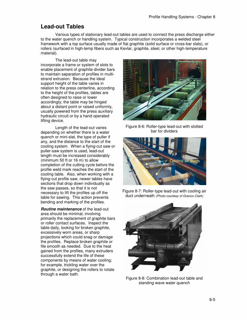
Figure 8-6: Roller-type lead-out with slotted bar for dividers
Figure 8-7: Roller-type lead-out with cooling air duct underneath (Photo courtesy of Granco Clark)
Figure 8-8: Combination lead-out table and standing wave water quench
Cooling air ducts
Profile Handling Systems - Chapter 8
8-6
Run-Out Conveyors
The slat conveyors that have traditionally been used to guide and convey profiles away from the press after extrusion are being replaced with roller tables. The growing use of pullers, combined with their improved reliability, has made the conveying function of the run-out conveyor less important, so that many presses are now equipped with roller-type conveyors, either idle or powered. High-temperature roller materials have been improved; and, when combined with better profile cooling, give good life without the marking problems associated with graphite. Still, slat conveyors remain in regular use in many extrusion handling systems.
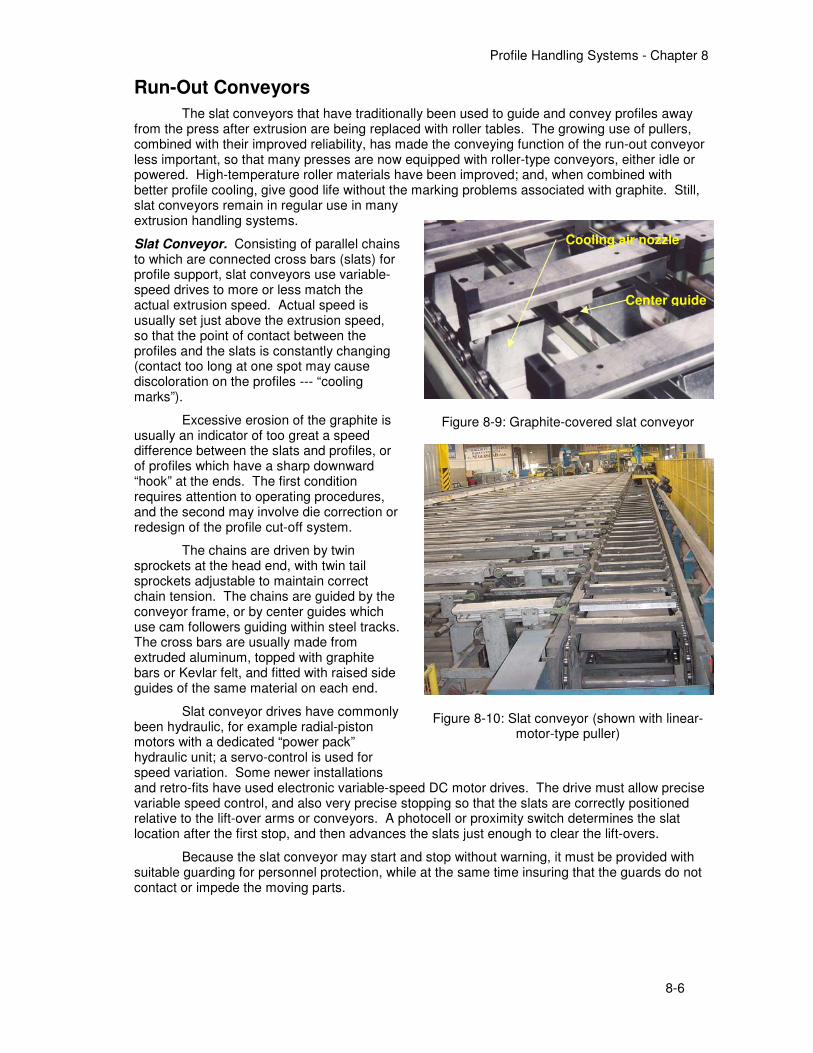
Slat Conveyor. Consisting of parallel chains to which are connected cross bars (slats) for profile support, slat conveyors use variable-speed drives to more or less match the actual extrusion speed. Actual speed is usually set just above the extrusion speed, so that the point of contact between the profiles and the slats is constantly changing (contact too long at one spot may cause discoloration on the profiles --- “cooling marks”).
Excessive erosion of the graphite is usually an indicator of too great a speed difference between the slats and profiles, or of profiles which have a sharp downward “hook” at the ends. The first condition requires attention to operating procedures, and the second may involve die correction or redesign of the profile cut-off system.
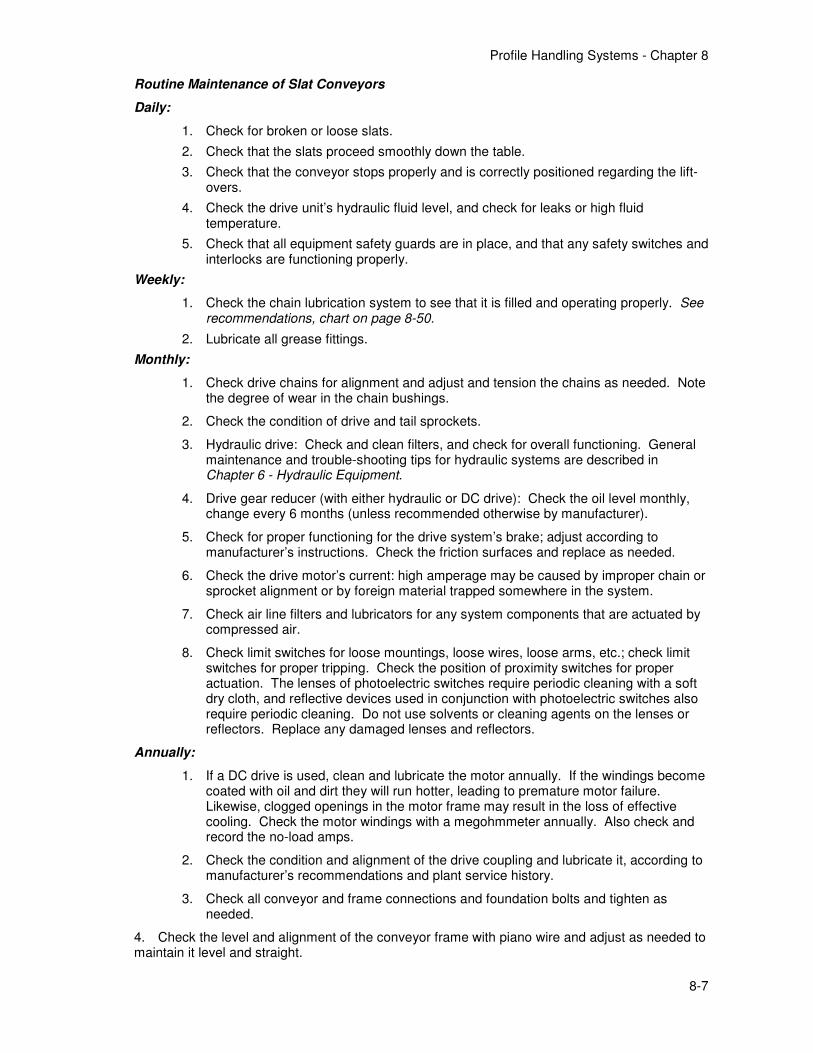
The chains are driven by twin sprockets at the head end, with twin tail sprockets adjustable to maintain correct chain tension. The chains are guided by the conveyor frame, or by center guides which use cam followers guiding within steel tracks. The cross bars are usually made from extruded aluminum, topped with graphite bars or Kevlar felt, and fitted with raised side guides of the same material on each end.
Slat conveyor drives have commonly been hydraulic, for example radial-piston motors with a dedicated “power pack” hydraulic unit; a servo-control is used for speed variation. Some newer installations and retro-fits have used electronic variable-speed DC motor drives. The drive must allow precise variable speed control, and also very precise stopping so that the slats are correctly positioned relative to the lift-over arms or conveyors. A photocell or proximity switch determines the slat location after the first stop, and then advances the slats just enough to clear the lift-overs.
Because the slat conveyor may start and stop without warning, it must be provided with suitable guarding for personnel protection, while at the same time insuring that the guards do not contact or impede the moving parts.
Figure 8-9: Graphite-covered slat conveyor
Figure 8-10: Slat conveyor (shown with linear-motor-type puller)
Center guide
Cooling air nozzle
Profile Handling Systems - Chapter 8
8-7
Routine Maintenance of Slat Conveyors
Daily:
1. Check for broken or loose slats.
2. Check that the slats proceed smoothly down the table.
3. Check that the conveyor stops properly and is correctly positioned regarding the lift-overs.
4. Check the drive unit’s hydraulic fluid level, and check for leaks or high fluid temperature.
5. Check that all equipment safety guards are in place, and that any safety switches and interlocks are functioning properly.
Weekly:
1. Check the chain lubrication system to see that it is filled and operating properly. See recommendations, chart on page 8-50.
2. Lubricate all grease fittings.
Monthly:
1. Check drive chains for alignment and adjust and tension the chains as needed. Note the degree of wear in the chain bushings.
2. Check the condition of drive and tail sprockets.
3. Hydraulic drive: Check and clean filters, and check for overall functioning. General maintenance and trouble-shooting tips for hydraulic systems are described in Chapter 6 - Hydraulic Equipment.
4. Drive gear reducer (with either hydraulic or DC drive): Check the oil level monthly, change every 6 months (unless recommended otherwise by manufacturer).
5. Check for proper functioning for the drive system’s brake; adjust according to manufacturer’s instructions. Check the friction surfaces and replace as needed.
6. Check the drive motor’s current: high amperage may be caused by improper chain or sprocket alignment or by foreign material trapped somewhere in the system.
7. Check air line filters and lubricators for any system components that are actuated by compressed air.
8. Check limit switches for loose mountings, loose wires, loose arms, etc.; check limit switches for proper tripping. Check the position of proximity switches for proper actuation. The lenses of photoelectric switches require periodic cleaning with a soft dry cloth, and reflective devices used in conjunction with photoelectric switches also require periodic cleaning. Do not use solvents or cleaning agents on the lenses or reflectors. Replace any damaged lenses and reflectors.
Annually:
1. If a DC drive is used, clean and lubricate the motor annually. If the windings become coated with oil and dirt they will run hotter, leading to premature motor failure. Likewise, clogged openings in the motor frame may result in the loss of effective cooling. Check the motor windings with a megohmmeter annually. Also check and record the no-load amps.
2. Check the condition and alignment of the drive coupling and lubricate it, according to manufacturer’s recommendations and plant service history.
3. Check all conveyor and frame connections and foundation bolts and tighten as needed.
4. Check the level and alignment of the conveyor frame with piano wire and adjust as needed to maintain it level and straight.
Profile Handling Systems - Chapter 8
8-8
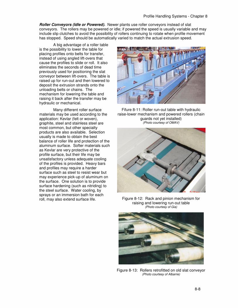
Roller Conveyors (Idle or Powered). Newer plants use roller conveyors instead of slat conveyors. The rollers may be powered or idle; if powered the speed is usually variable and may include slip clutches to avoid the possibility of rollers continuing to rotate when profile movement has stopped. Speed should be automatically varied to match the actual extrusion speed.
A big advantage of a roller table is the possibility to lower the table for placing profiles onto belts for transfer, instead of using angled lift-overs that cause the profiles to slide or roll. It also eliminates the seconds of dead time previously used for positioning the slat conveyor between lift-overs. The table is raised up for run-out and then lowered to deposit the extrusion strands onto the unloading belts or chains. The mechanism for lowering the table and raising it back after the transfer may be hydraulic or mechanical.
Many different roller surface materials may be used according to the application: Kevlar (felt or woven), graphite, steel and stainless steel are most common, but other specialty products are also available. Selection usually is made to obtain the best balance of roller life and protection of the aluminum surface. Softer materials such as Kevlar are very protective of the profile surface, but their life may be unsatisfactory unless adequate cooling of the profiles is provided. Heavy bars and profiles may require a harder surface such as steel to resist wear but may experience pick-up of aluminum on the surface. One solution is to provide surface hardening (such as nitriding) to the steel surface. Water cooling, by sprays or an immersion bath for each roll, may also extend surface life.
Fifure 8-11: Roller run-out table with hydraulic raise-lower mechanism and powered rollers (chain
guards not yet installed) (Photo courtesy of OMAV)
Figure 8-12: Rack and pinion mechanism for raising and lowering run-out table
(Photo courtesy of Gia)
Figure 8-13: Rollers retrofitted on old slat conveyor (Photo courtesy of Albarrie)

Profile Handling Systems - Chapter 8
8-9
Routine Maintenance of Roller-type Run-Out Conveyors
Daily:
1. Check the condition of rollers; repair or replace damaged or badly grooved rollers. If rollers are water-cooled, check that cooling is working properly.
2. Confirm that all idle rollers turn freely; check that roller drives are functioning properly.
3. Check the raise/lower function for correct, smooth operation.
4. Check that all equipment safety guards are in place, and that any safety switches and interlocks are functioning properly.
Weekly:
1. Lubricate all grease fittings. See recommendations, chart on page 8-50.
2. If rollers are chain driven, check the chain lubrication system to see that it is filled and operating properly.
Monthly:
1. Service the variable-speed drive equipment, same as for slat conveyor drives (above).
2. Hydraulic drive for raising/lowering the table: Check and clean filters, and check for overall functioning. General maintenance and trouble-shooting tips for hydraulic systems are described in Chapter 5 - Hydraulic Equipment.
3. Electric motor/gear reducer for raising/lowering the table: Check the oil level monthly, change every 6 months (unless recommended otherwise by manufacturer).
4. Check the drive motor’s current: high amperage may be caused by improper chain or sprocket alignment or by foreign material trapped somewhere in the system.
Annually:
1. If a DC drive is used, clean and lubricate the motor annually. If the windings become coated with oil and dirt they will run hotter, leading to premature motor failure. Likewise, clogged openings in the motor frame may result in the loss of effective cooling. Check the motor windings with a megohmmeter annually. Also check and record the no-load amps.
2. Check the condition and alignment of the drive coupling and lubricate it, according to manufacturer’s recommendations and plant service history.
3. Check all conveyor and frame connections and foundation bolts and tighten as needed.
4. Check the level and alignment of the conveyor frame with piano wire and adjust as needed to maintain it level and straight.
Profile Handling Systems - Chapter 8
8-10
Water Quench Systems
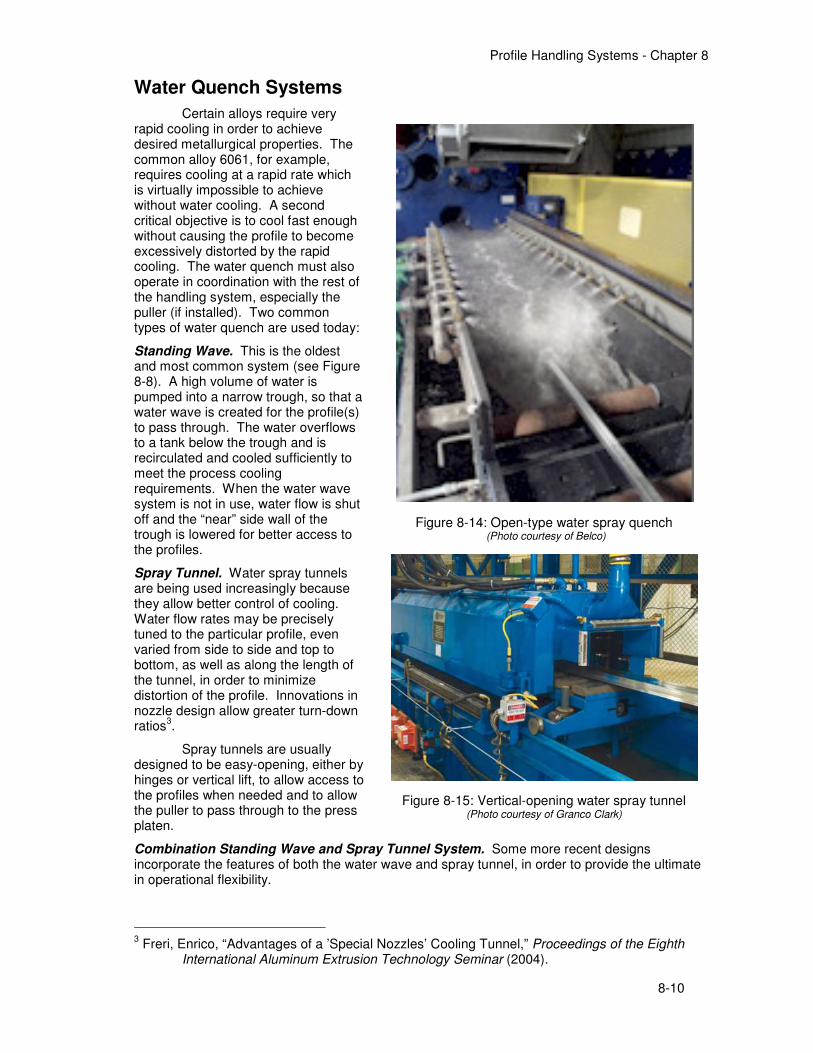
Certain alloys require very rapid cooling in order to achieve desired metallurgical properties. The common alloy 6061, for example, requires cooling at a rapid rate which is virtually impossible to achieve without water cooling. A second critical objective is to cool fast enough without causing the profile to become excessively distorted by the rapid cooling. The water quench must also operate in coordination with the rest of the handling system, especially the puller (if installed). Two common types of water quench are used today:
Standing Wave. This is the oldest and most common system (see Figure 8-8). A high volume of water is pumped into a narrow trough, so that a water wave is created for the profile(s) to pass through. The water overflows to a tank below the trough and is recirculated and cooled sufficiently to meet the process cooling requirements. When the water wave system is not in use, water flow is shut off and the “near” side wall of the trough is lowered for better access to the profiles.
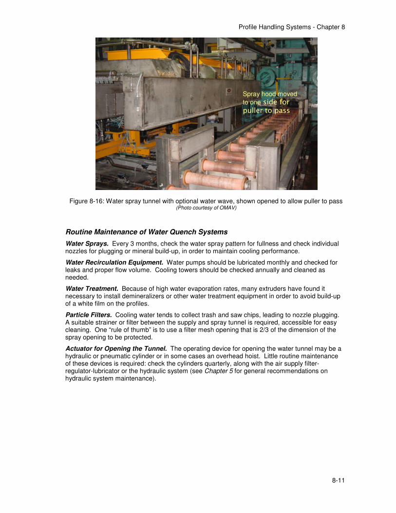
Spray Tunnel. Water spray tunnels are being used increasingly because they allow better control of cooling. Water flow rates may be precisely tuned to the particular profile, even varied from side to side and top to bottom, as well as along the length of the tunnel, in order to minimize distortion of the profile. Innovations in nozzle design allow greater turn-down ratios
3.
Spray tunnels are usually designed to be easy-opening, either by hinges or vertical lift, to allow access to the profiles when needed and to allow the puller to pass through to the press platen.
Combination Standing Wave and Spray Tunnel System. Some more recent designs incorporate the features of both the water wave and spray tunnel, in order to provide the ultimate in operational flexibility.
3 Freri, Enrico, “Advantages of a ’Special Nozzles’ Cooling Tunnel,” Proceedings of the Eighth
International Aluminum Extrusion Technology Seminar (2004).
Figure 8-14: Open-type water spray quench (Photo courtesy of Belco)
Figure 8-15: Vertical-opening water spray tunnel (Photo courtesy of Granco Clark)
Profile Handling Systems - Chapter 8
8-11
Routine Maintenance of Water Quench Systems
Water Sprays. Every 3 months, check the water spray pattern for fullness and check individual nozzles for plugging or mineral build-up, in order to maintain cooling performance.
Water Recirculation Equipment. Water pumps should be lubricated monthly and checked for leaks and proper flow volume. Cooling towers should be checked annually and cleaned as needed.
Water Treatment. Because of high water evaporation rates, many extruders have found it necessary to install demineralizers or other water treatment equipment in order to avoid build-up of a white film on the profiles.
Particle Filters. Cooling water tends to collect trash and saw chips, leading to nozzle plugging. A suitable strainer or filter between the supply and spray tunnel is required, accessible for easy cleaning. One “rule of thumb” is to use a filter mesh opening that is 2/3 of the dimension of the spray opening to be protected.
Actuator for Opening the Tunnel. The operating device for opening the water tunnel may be a hydraulic or pneumatic cylinder or in some cases an overhead hoist. Little routine maintenance of these devices is required: check the cylinders quarterly, along with the air supply filter-regulator-lubricator or the hydraulic system (see Chapter 5 for general recommendations on hydraulic system maintenance).
Figure 8-16: Water spray tunnel with optional water wave, shown opened to allow puller to pass (Photo courtesy of OMAV)
Spray hood moved
to one side for puller to pass
Profile Handling Systems - Chapter 8
8-12
Air Quench Systems
Nearly all extrusion press lines use forced air cooling for the profiles, solely or in combination with water quenching. Besides quenching for the sake of metallurgical properties, forced air cooling reduces the profiles to temperatures suitable for safe handling and less heat damage to handling equipment. The designs in use for forced air cooling include:
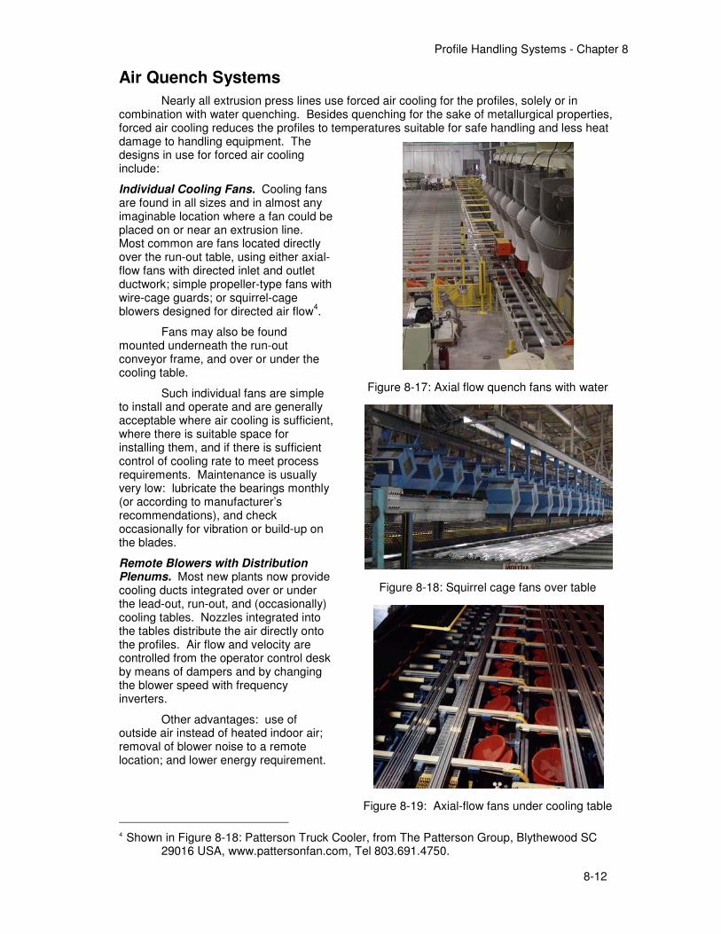
Individual Cooling Fans. Cooling fans are found in all sizes and in almost any imaginable location where a fan could be placed on or near an extrusion line. Most common are fans located directly over the run-out table, using either axial-flow fans with directed inlet and outlet ductwork; simple propeller-type fans with wire-cage guards; or squirrel-cage blowers designed for directed air flow
4.
Fans may also be found mounted underneath the run-out conveyor frame, and over or under the cooling table.
Such individual fans are simple to install and operate and are generally acceptable where air cooling is sufficient, where there is suitable space for installing them, and if there is sufficient control of cooling rate to meet process requirements. Maintenance is usually very low: lubricate the bearings monthly (or according to manufacturer’s recommendations), and check occasionally for vibration or build-up on the blades.
Remote Blowers with Distribution Plenums. Most new plants now provide cooling ducts integrated over or under the lead-out, run-out, and (occasionally) cooling tables. Nozzles integrated into the tables distribute the air directly onto the profiles. Air flow and velocity are controlled from the operator control desk by means of dampers and by changing the blower speed with frequency inverters.
Other advantages: use of outside air instead of heated indoor air; removal of blower noise to a remote location; and lower energy requirement.
4 Shown in Figure 8-18: Patterson Truck Cooler, from The Patterson Group, Blythewood SC
29016 USA, www.pattersonfan.com, Tel 803.691.4750.
Figure 8-17: Axial flow quench fans with water
Figure 8-18: Squirrel cage fans over table
Figure 8-19: Axial-flow fans under cooling table (Photo courtest of Granco Clark)
Profile Handling Systems - Chapter 8
8-13
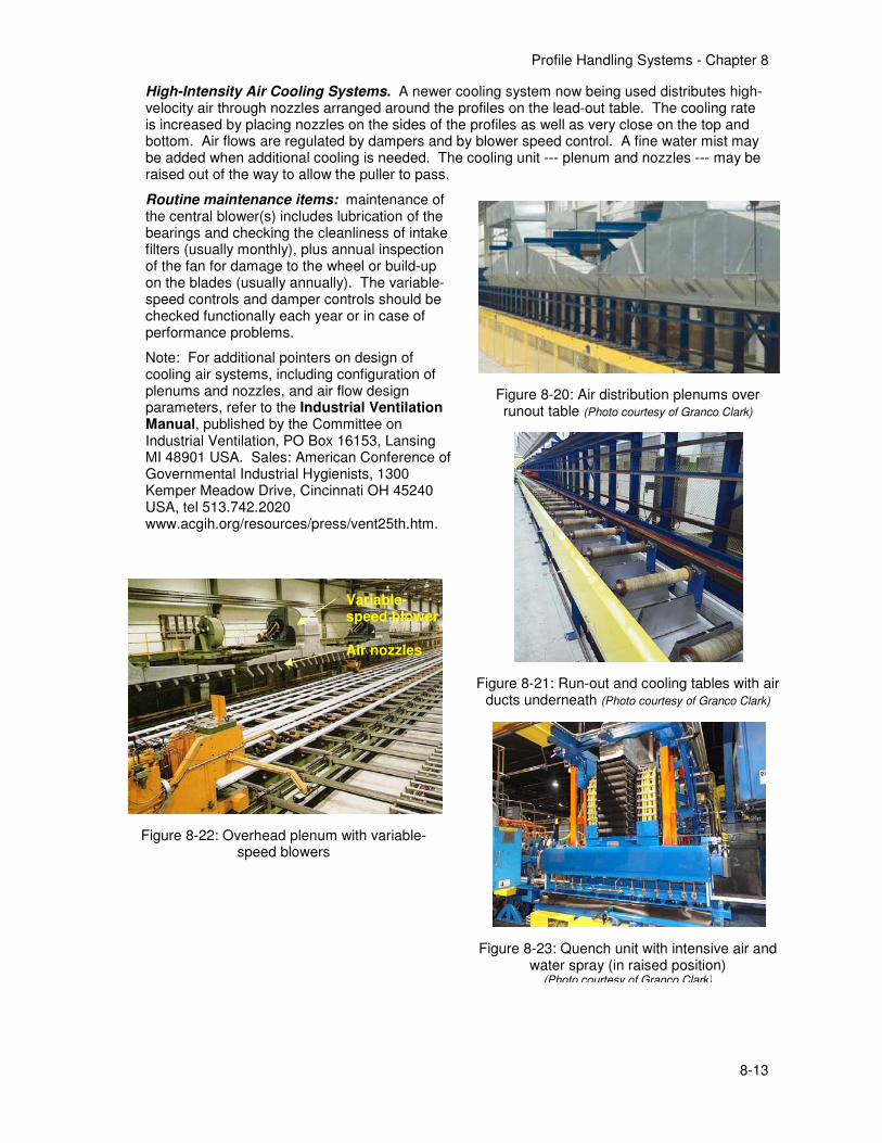
High-Intensity Air Cooling Systems. A newer cooling system now being used distributes high-velocity air through nozzles arranged around the profiles on the lead-out table. The cooling rate is increased by placing nozzles on the sides of the profiles as well as very close on the top and bottom. Air flows are regulated by dampers and by blower speed control. A fine water mist may be added when additional cooling is needed. The cooling unit --- plenum and nozzles --- may be raised out of the way to allow the puller to pass.
Routine maintenance items: maintenance of the central blower(s) includes lubrication of the bearings and checking the cleanliness of intake filters (usually monthly), plus annual inspection of the fan for damage to the wheel or build-up on the blades (usually annually). The variable-speed controls and damper controls should be checked functionally each year or in case of performance problems.
Note: For additional pointers on design of cooling air systems, including configuration of plenums and nozzles, and air flow design parameters, refer to the Industrial Ventilation Manual, published by the Committee on Industrial Ventilation, PO Box 16153, Lansing MI 48901 USA. Sales: American Conference of Governmental Industrial Hygienists, 1300 Kemper Meadow Drive, Cincinnati OH 45240 USA, tel 513.742.2020 www.acgih.org/resources/press/vent25th.htm.
Figure 8-20: Air distribution plenums over runout table (Photo courtesy of Granco Clark)
Figure 8-21: Run-out and cooling tables with air ducts underneath (Photo courtesy of Granco Clark)
Figure 8-23: Quench unit with intensive air and water spray (in raised position)
(Photo courtesy of Granco Clark)
Figure 8-22: Overhead plenum with variable-speed blowers
Variable-speed blower
Air nozzles
Profile Handling Systems - Chapter 8
8-14
Saws and Shears for Hot Profile Cut-Off
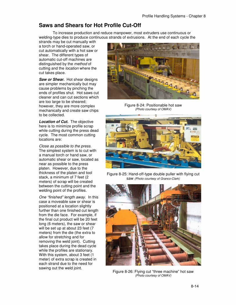
To increase production and reduce manpower, most extruders use continuous or welding-type dies to produce continuous strands of extrusions. At the end of each cycle the strands may be cut manually with a torch or hand-operated saw, or cut automatically with a hot saw or shear. The different types of automatic cut-off machines are distinguished by the method of cutting and the location where the cut takes place.
Saw or Shear. Hot shear designs are simpler mechanically but may cause problems by pinching the ends of profiles shut. Hot saws cut cleaner and can cut sections which are too large to be sheared; however, they are more complex mechanically and create saw chips to be collected.
Location of Cut. The objective here is to minimize profile scrap while cutting during the press dead cycle. The most common cutting locations are:
Close as possible to the press. The simplest system is to cut with a manual torch or hand saw, or automatic shear or saw, located as near as possible to the press platen. However, due to the thickness of the platen and tool stack, a minimum of 7 feet (2 meters) of scrap will be created between the cutting point and the welding point of the profiles.
One “finished” length away. In this case a moveable saw or shear is positioned at a location slightly further than one finished cut length from the die face. For example, if the final cut product will be 20 feet long (6 meters), the saw or shear will be set up at about 23 feet (7 meters) from the die (the extra to allow for stretching and for removing the weld joint). Cutting takes place during the dead cycle while the profiles are stationary. With this system, about 3 feet (1 meter) of extra scrap is created in each strand due to the need for sawing out the weld joint.
Figure 8-24: Positionable hot saw (Photo courtesy of OMAV)
Figure 8-25: Hand-off-type double puller with flying cut saw (Photo courtesy of Granco-Clark)
Figure 8-26: Flying cut “three machine” hot saw (Photo courtesy of OMAV)
Profile Handling Systems - Chapter 8
8-15
“Double length” line layout. If a lead-out table is provided with length equal to the total strand length, the strands may be cut on the weld mark during the dead cycle with the minimum possible scrap. For a description of this system see Chapter C – Modernizing Older Presses.
Cut “on-the-fly”. A “flying” saw may be used to cut on the weld mark, during the extrusion cycle, without interrupting or lengthening the production cycle, also yielding the minimum possible scrap. There are several designs now offered:
• Mounted on the first puller of a hand-off type double puller (the original type of flying cut)
• A separate sawing machine, working with twin, alternating pullers (non-hand-off)
• Saws mounted on both pullers of a twin-type double puller (non-hand-off)
In each type of flying cut the saw must accelerate quickly and precisely match the profile speed to avoid delay or damage to the profiles.
Hot Saws
Hot saws pose the same maintenance concerns whether their location is fixed, moveable, or mounted directly on the extrusion puller:
Maintenance accessibility: hot saws are only available for maintenance when the press is down, and a saw breakdown usually shuts the press down. Therefore, good preventive maintenance and reliability are important.
Blade lubrication: sawing hot aluminum will often adversely affect blade life, so the best blade lubrication system possible should be used. CanMist-type lubricants
5 may be used on moveable
and puller-mounted saws by adding a supply of compressed air to operate the applicator. On puller-mounted saws a mini air compressor may be used, or a traveling air reservoir with a docking and refill system.
Chip collection: a vacuum system, either traveling or connected to the moveable saw by means of an appropriate duct-connecting device, may be used where chip collection is important for process considerations. Chip collection is discussed in more detail under Finish Saws below, page 8-36.
Routine Maintenance of Hot Saws
Daily:
1. Check the sharpness of the blade. The best indicator will be the cut ends of profiles: excessive deformation indicates a dull blade or poor lubrication. Check for metal build-up on the blade.
2. Clean the sawing area of chips and other debris which damage profiles or may interfere with operation.
3. Check for proper functioning of saw positioning and/or clamping devices, according to the type of saw in use.
4. Check for proper functioning of the blade actuation system (usually hydraulic).
5. Check for leaks of hydraulic fluid or compressed air.
6. Check the level of blade lubricant in the reservoir and check the function of the lubricant applicator; a piece of cardboard or brown paper held in front of each nozzle will quickly show the rate and pattern of lubrication.
5 Sawing Coolants/Lubricants. Aluminum sawing, whether hot sawing at the press, or cold
sawing of profiles or billets, may be significantly improved by means of advanced coolant-lubricant products. The surface-wetting and heat removal properties of these fluids allow a significant reduction in the quantity of lubricant needed, so there is less fluid left on the product being sawed. Blade life is dramatically improved, and the quality of cut is much better. A special low-volume applicator is required due to the small quantity used. Typical supplier: Amcol Corporation, Hazel Park, Michigan USA (Tel 248-414-5700, fax 248-414-7489), www.amcolcorp.com.
Profile Handling Systems - Chapter 8
8-16
7. Check that all equipment safety guards are in place, and that any safety switches and interlocks are functioning properly.
Weekly:
1. Lubricate all grease fittings. See recommendations, chart on page 8-50.
Monthly:
1. Service the hydraulic system: clean the tank; check and clean the hydraulic filter; clean and check for fluid leaks.
2. Clean the saw and saw table thoroughly.
3. Change the cloth chip collector bags, where installed; old bags may be restored by washing in warm water with laundry detergent, or dry cleaning, to remove accumulated oils.
4. Check the blade drive motor’s amperage.
5. Check air line filters and lubricators for any system components actuated by compressed air.
6. Check limit switches for loose mountings, loose wires, loose arms, etc.; check limit switches for proper tripping. Check the position of proximity switches for proper actuation. The lenses of photoelectric switches require periodic cleaning with a soft dry cloth, and reflective devices used In conjunction with photoelectric switches also require periodic cleaning. Do not use solvents or cleaning agents on the lenses or reflectors. Replace any damaged lenses and reflectors.
Annually:
1. Check the leveling and alignment of the saw and lead-out table with piano wire and machinist’s level, to insure straightness and accuracy.
2. Clean and lubricate the motors annually. If the windings become coated with oil and dirt they will run hotter, leading to premature motor failure. Likewise, clogged openings in the motor frame may result in the loss of effective cooling. Check the motor windings with a megohmmeter annually. Also check and record the no-load amps.
3. Check the condition and alignment of the blade arbor, according to manufacturer’s recommendations and plant service history.
4. Check all saw and frame connectors and foundation bolts and tighten as needed.
5. Check all hydraulic and pneumatic cylinders for leaks or damaged packing, and repair or replace as needed.
Hot Profile Shears
Hot profile shears, whether fixed or moveable, tend to be mechanically simple. Blade actuation is normally hydraulic, so in the case of a positionable shear the hydraulic system must also travel, often mounted on a “mini-slat” conveyor. With automatic operation of the positioner and shear, safety is a critical issue; the hot shear must be fitted with suitable guards, and also a “light curtain” safety switch to prevent operation when human presence is detected.
Routine Maintenance of Hot Shears
Daily:
1. Observe the proper functioning of the shear and positioning system.
2. Look at the condition of the shear blade and at the profiles for a trouble-free quality of cut.
3. Check that all equipment safety guards are in place, and that any safety switches and interlocks are functioning properly.
Profile Handling Systems - Chapter 8
8-17
Weekly:
1. Lubricate all grease fittings. See recommendations, chart on page 8-50.
Monthly:
1. Service the hydraulic system: clean the tank; check and clean the hydraulic filter; clean and check for fluid leaks.
2. Check the positioning drive and other mechanical components, and lubricate as recommended by the manufacturer.
3. Check power feeders to the shear system for loose or defective connections or faults in the flexible connectors.
Annually:
1. Check hydraulic cylinder(s) for leaks or damaged packing, and repair or replace as needed.
2. Due to shock and impact loads, check all frame connectors and foundation bolts and tighten as needed.
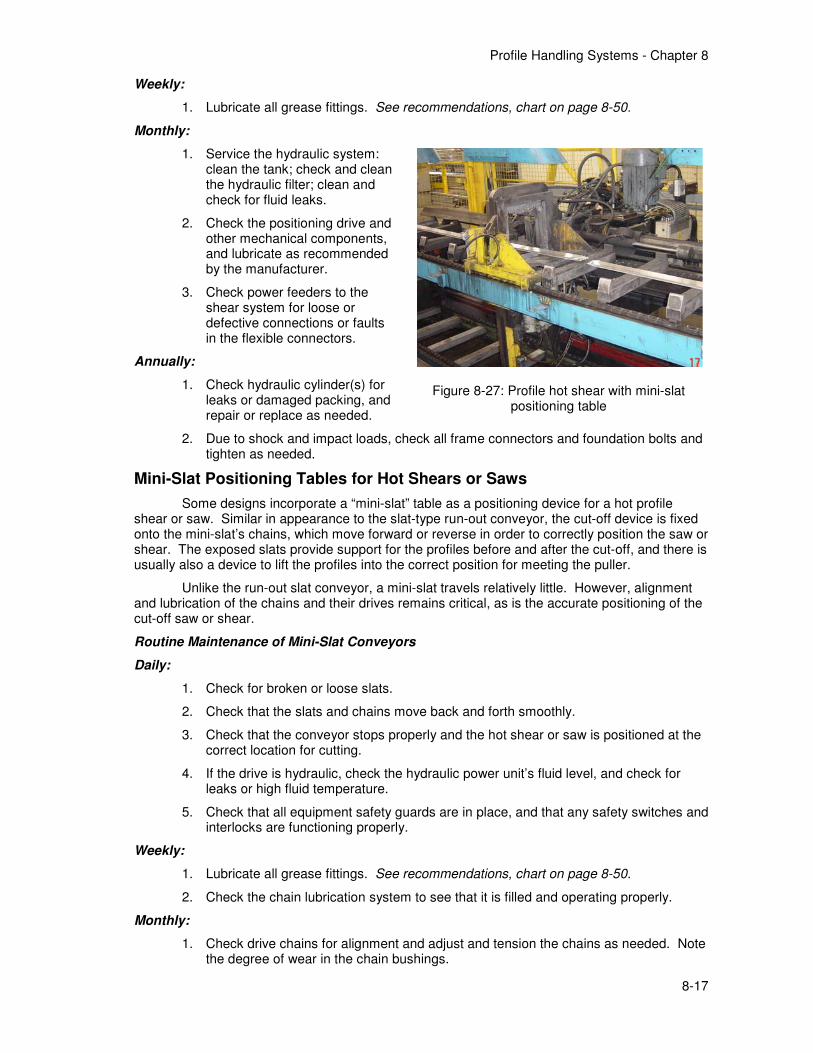
Mini-Slat Positioning Tables for Hot Shears or Saws
Some designs incorporate a “mini-slat” table as a positioning device for a hot profile shear or saw. Similar in appearance to the slat-type run-out conveyor, the cut-off device is fixed onto the mini-slat’s chains, which move forward or reverse in order to correctly position the saw or shear. The exposed slats provide support for the profiles before and after the cut-off, and there is usually also a device to lift the profiles into the correct position for meeting the puller.
Unlike the run-out slat conveyor, a mini-slat travels relatively little. However, alignment and lubrication of the chains and their drives remains critical, as is the accurate positioning of the cut-off saw or shear.
Routine Maintenance of Mini-Slat Conveyors
Daily:
1. Check for broken or loose slats.
2. Check that the slats and chains move back and forth smoothly.
3. Check that the conveyor stops properly and the hot shear or saw is positioned at the correct location for cutting.
4. If the drive is hydraulic, check the hydraulic power unit’s fluid level, and check for leaks or high fluid temperature.
5. Check that all equipment safety guards are in place, and that any safety switches and interlocks are functioning properly.
Weekly:
1. Lubricate all grease fittings. See recommendations, chart on page 8-50.
2. Check the chain lubrication system to see that it is filled and operating properly.
Monthly:
1. Check drive chains for alignment and adjust and tension the chains as needed. Note the degree of wear in the chain bushings.
Figure 8-27: Profile hot shear with mini-slat
positioning table
Profile Handling Systems - Chapter 8
8-18
2. Check the condition of drive and tail sprockets.
3. Hydraulic power unit: Check and clean filters, and check for overall functioning. General maintenance and trouble-shooting tips for hydraulic systems are described in Chapter 5 - Hydraulic Equipment.
4. Drive gear reducer (with either hydraulic or electric drive): Check the oil level monthly, change every 6 months (unless recommended otherwise by manufacturer).
5. Check for proper functioning for the drive system’s brake, if used; adjust according to manufacturer’s instructions. Check the friction surfaces and replace as needed.
6. Check the drive motor’s amperage: high amperage may be caused by improper chain or sprocket alignment or by foreign material trapped somewhere in the system.
7. Check air line filters and lubricators if any system components are actuated by compressed air.
8. Check limit switches for loose mountings, loose wires, loose arms, etc.; check limit switches for proper tripping. Check the position of proximity switches for proper actuation. The lenses of photoelectric switches require periodic cleaning with a soft dry cloth, and reflective devices used In conjunction with photoelectric switches also require periodic cleaning. Do not use solvents or cleaning agents on the lenses or reflectors. Replace any damaged lenses and reflectors.
Annually:
1. Clean and lubricate the electric motor(s) annually. If the windings become coated with oil and dirt they will run hotter, leading to premature motor failure. Likewise, clogged openings in the motor frame may result in the loss of effective cooling. Check the motor windings with a megohmmeter annually. Also check and record the no-load amps.
2. Check all conveyor and frame connections and foundation bolts and tighten as needed.
3. Check the level and alignment of the conveyor frame and adjust as needed to maintain it level and straight.
Profile Handling Systems - Chapter 8
8-19
Pullers
Extrusion pullers come in all sizes, shapes, and types --- so many different designs in fact that it is impossible to cover them all in a single text on extrusion press system maintenance. Fortunately, most pullers are of relatively recent supply, and the original manufacturers are still available for parts, service, and service advice. Here the subject is reviewed in a general manner, with the hope that some useful suggestions will be found by anyone involved in plant maintenance.
Function of the Puller and Design Objectives
The extrusion puller should accomplish four important functions:
1. Take and guide the profiles down the run-out table every cycle without operator involvement.
2. Notify the press to stop extruding when the exact economic length has been reached.
3. Provide just enough pulling force to make all holes of multi-hole dies run-out to the same length.
4. Position the profiles accurately enough for the next handling step to be performed automatically.
In providing these functions, the puller must be:
• reliable --- up-time equal to or better than the rest of the press system
• fast --- able to complete its tasks and return within the press dead cycle, and
• smooth --- operating without damage to profile quality.
Puller Safety
Because pullers operate automatically and often very fast, they must be provided with suitable guards and other personnel protective devices, such as light curtains or other switches to detect when a person is present and shut the puller down to prevent injury. In most cases it is possible to limit access to the dangerous zones by installing fences and gates, which should be fitted with switches that stop the puller when a person enters. In the press operator’s work area, light curtains may be used to protect against a worker or visitor stepping in front of a fast moving puller. (Note that pullers are extremely fast yet quiet, and it is very easy for an unsuspecting person to step into harm’s way without realizing the danger.)
Puller Types
Different puller types may be distinguished by several design features; the merits of each are the subject of ongoing debate among their users and suppliers:
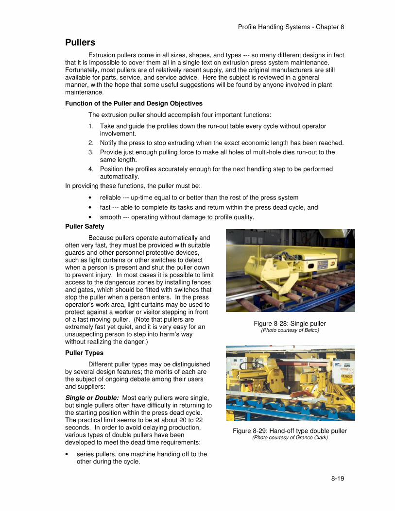
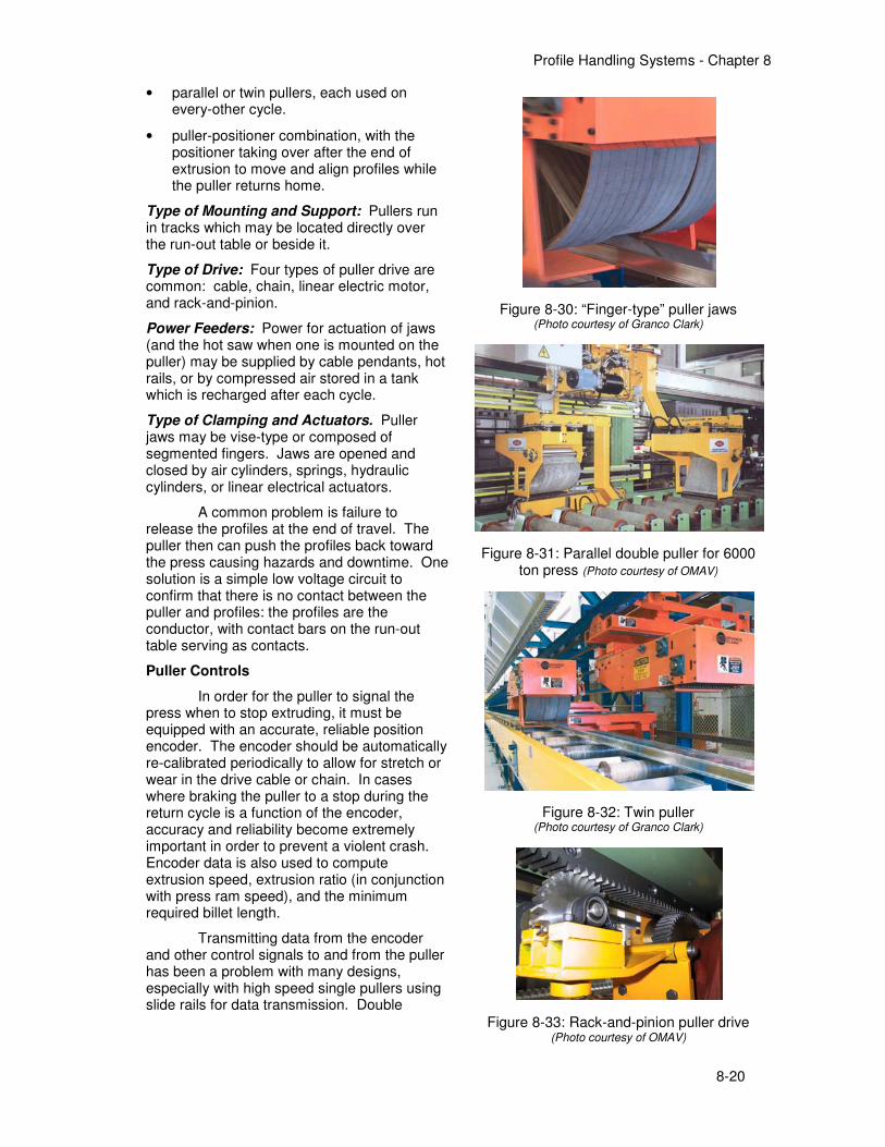
Single or Double: Most early pullers were single, but single pullers often have difficulty in returning to the starting position within the press dead cycle. The practical limit seems to be at about 20 to 22 seconds. In order to avoid delaying production, various types of double pullers have been developed to meet the dead time requirements:
• series pullers, one machine handing off to the other during the cycle.
Figure 8-28: Single puller (Photo courtesy of Belco)
Figure 8-29: Hand-off type double puller (Photo courtesy of Granco Clark)
Profile Handling Systems - Chapter 8
8-20
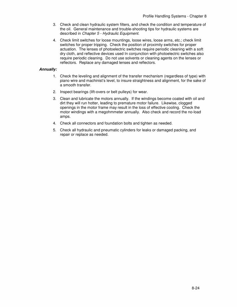
• parallel or twin pullers, each used on every-other cycle.
• puller-positioner combination, with the positioner taking over after the end of extrusion to move and align profiles while the puller returns home.
Type of Mounting and Support: Pullers run in tracks which may be located directly over the run-out table or beside it.
Type of Drive: Four types of puller drive are common: cable, chain, linear electric motor, and rack-and-pinion.
Power Feeders: Power for actuation of jaws (and the hot saw when one is mounted on the puller) may be supplied by cable pendants, hot rails, or by compressed air stored in a tank which is recharged after each cycle.
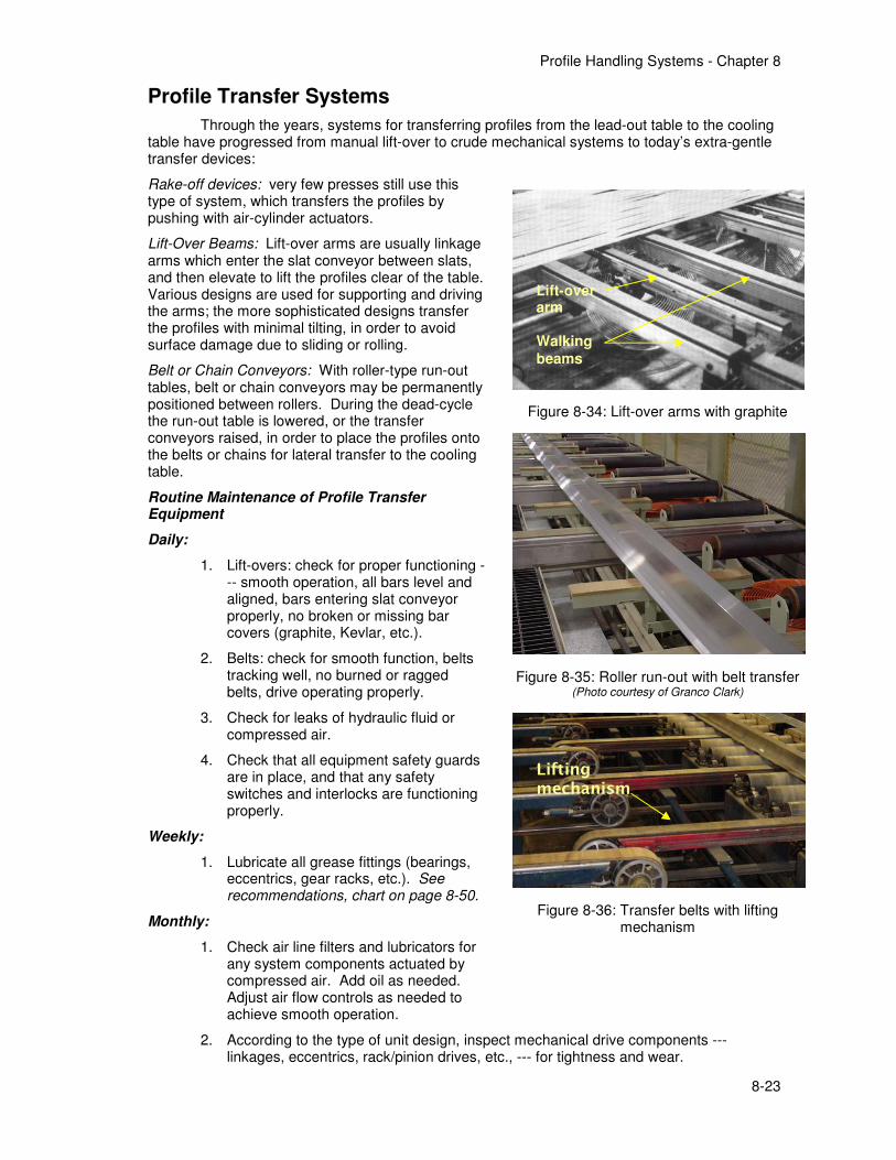
Type of Clamping and Actuators. Puller jaws may be vise-type or composed of segmented fingers. Jaws are opened and closed by air cylinders, springs, hydraulic cylinders, or linear electrical actuators.
A common problem is failure to release the profiles at the end of travel. The puller then can push the profiles back toward the press causing hazards and downtime. One solution is a simple low voltage circuit to confirm that there is no contact between the puller and profiles: the profiles are the conductor, with contact bars on the run-out table serving as contacts.
Puller Controls
In order for the puller to signal the press when to stop extruding, it must be equipped with an accurate, reliable position encoder. The encoder should be automatically re-calibrated periodically to allow for stretch or wear in the drive cable or chain. In cases where braking the puller to a stop during the return cycle is a function of the encoder, accuracy and reliability become extremely important in order to prevent a violent crash. Encoder data is also used to compute extrusion speed, extrusion ratio (in conjunction with press ram speed), and the minimum required billet length.
Transmitting data from the encoder and other control signals to and from the puller has been a problem with many designs, especially with high speed single pullers using slide rails for data transmission. Double
Figure 8-30: “Finger-type” puller jaws (Photo courtesy of Granco Clark)
Figure 8-31: Parallel double puller for 6000 ton press (Photo courtesy of OMAV)
Figure 8-32: Twin puller (Photo courtesy of Granco Clark)
Figure 8-33: Rack-and-pinion puller drive (Photo courtesy of OMAV)

Profile Handling Systems - Chapter 8
8-21
pullers can operate slower and can use flex cable or, more recently, photocell data transfer.
The puller must also provide a controlled tension applied to the profiles, which is usually controllable by the operator or Supervisory Computer. It is usually desirable to have the lowest possible pulling force, consistent with the inertia of the puller body and the force necessary to keep it in smooth motion.
Routine Maintenance of Extrusion Pullers
Daily:
1. Observe operation of the puller for several cycles, to see that it functions correctly and smoothly and starts and stops without undue impact. Note any problems.
2. Check that the puller travels in a level plane, that the speed and tension are being correctly controlled, and that the puller position is being indicated correctly.
3. Check that the carriage stops at the proper positions for profile pick-up and discharge.
4. If the drive has hydraulic components, check the hydraulic power unit’s fluid level, and check for leaks or high fluid temperature.
5. For pneumatic components check the air supply for leaks and correct pressure.
6. Check that all equipment safety guards are in place, and that any safety switches and interlocks are functioning properly.
Weekly:
1. Lubricate all grease fittings. See recommendations, chart on page 8-50.
2. Check the chain lubrication system (if installed) to see that it is filled and operating properly.
Monthly:
1. Check drive chains or cables for alignment and adjust the tension as needed.
2. Check the condition of drive and tail sprockets and/or cable pulleys.
3. Inspect drive chains; check the degree of wear in the chain bushings.
4. Inspect drive cable(s) for wear, broken wires, or work hardening. Cables should be replaced every 6 months.
5. Inspect the position encoder and also its drive coupling (or other method of attachment).
6. Check for proper functioning of the drive system’s brake, if used; adjust according to the manufacturer’s instructions. Check the friction surfaces and replace as needed.
7. Inspect support and/or guide wheels and bearings, for wear and roundness. Check that they rotate freely.
8. Inspect the puller guide rails for wear or damage, and visually check for straightness and alignment.
9. Hydraulic system(s) for actuators: Check and clean filters, and check for overall functioning. General maintenance and trouble-shooting tips for hydraulic systems are described in Chapter 6 - Hydraulic Equipment.
10. Drive gear reducer: Check the oil level monthly, change every 6 months (unless recommended otherwise by manufacturer).
11. Check V-belt drives for belt condition and correct tension.
12. Check the drive motor’s current: high amperage may be caused by improper track alignment or problems with the drive chain/cable or carriage wheels/bearings.

Profile Handling Systems - Chapter 8
8-22
13. Check air line filters and lubricators for all system components actuated by compressed air.
14. For linear motor pullers, check the condition of tracks and hot rails; check and adjust the gap for linear motors.
15. Check linear actuators (if used for the clamps); check for galling or sticking, and replace if in doubt.
16. Inspect segmented jaw teeth for wear, breakage, or metal build-up.
17. Check shock absorbers to see that they are in proper condition to stop the puller when needed.
18. Check all limit switches for loose mountings, loose wires, loose arms, etc.; check limit switches for proper tripping. Check the position of proximity switches for proper actuation. The lenses of photoelectric switches require periodic cleaning with a soft dry cloth, and reflective devices used In conjunction with photoelectric switches also require periodic cleaning. Do not use solvents or cleaning agents on the lenses or reflectors. Replace any damaged lenses and reflectors.
Annually:
1. Clean and lubricate the electric motor(s) annually. If the windings become coated with oil and dirt they will run hotter, leading to premature motor failure. Likewise, clogged openings in the motor frame may result in the loss of effective cooling. Check the motor windings with a megohmmeter annually. Also check and record the no-load amps.
2. Check the level and alignment of the puller track(s) from end to end with piano wire and machinist’s level, and adjust as needed to maintain it level and straight.
3. Check all conveyor and frame connections and foundation bolts and tighten as needed.
4. Check all hydraulic and pneumatic cylinders for leaks or damaged packing, and repair or replace as needed.
5. Approximately annually, based on actual plant experience, pendant cables and/or hot rails for electric feed should be replaced in order to insure puller reliability.
Profile Handling Systems - Chapter 8
8-23
Profile Transfer Systems
Through the years, systems for transferring profiles from the lead-out table to the cooling table have progressed from manual lift-over to crude mechanical systems to today’s extra-gentle transfer devices:
Rake-off devices: very few presses still use this type of system, which transfers the profiles by pushing with air-cylinder actuators.
Lift-Over Beams: Lift-over arms are usually linkage arms which enter the slat conveyor between slats, and then elevate to lift the profiles clear of the table. Various designs are used for supporting and driving the arms; the more sophisticated designs transfer the profiles with minimal tilting, in order to avoid surface damage due to sliding or rolling.
Belt or Chain Conveyors: With roller-type run-out tables, belt or chain conveyors may be permanently positioned between rollers. During the dead-cycle the run-out table is lowered, or the transfer conveyors raised, in order to place the profiles onto the belts or chains for lateral transfer to the cooling table.
Routine Maintenance of Profile Transfer Equipment
Daily:
1. Lift-overs: check for proper functioning --- smooth operation, all bars level and aligned, bars entering slat conveyor properly, no broken or missing bar covers (graphite, Kevlar, etc.).
2. Belts: check for smooth function, belts tracking well, no burned or ragged belts, drive operating properly.
3. Check for leaks of hydraulic fluid or compressed air.
4. Check that all equipment safety guards are in place, and that any safety switches and interlocks are functioning properly.
Weekly:
1. Lubricate all grease fittings (bearings, eccentrics, gear racks, etc.). See recommendations, chart on page 8-50.
Monthly:
1. Check air line filters and lubricators for any system components actuated by compressed air. Add oil as needed. Adjust air flow controls as needed to achieve smooth operation.
2. According to the type of unit design, inspect mechanical drive components --- linkages, eccentrics, rack/pinion drives, etc., --- for tightness and wear.
Figure 8-34: Lift-over arms with graphite
Figure 8-35: Roller run-out with belt transfer (Photo courtesy of Granco Clark)
Figure 8-36: Transfer belts with lifting mechanism
Lift-over arm Walking
beams
Lifting mechanism
Profile Handling Systems - Chapter 8
8-24
3. Check and clean hydraulic system filters, and check the condition and temperature of the oil. General maintenance and trouble-shooting tips for hydraulic systems are described in Chapter 5 - Hydraulic Equipment.
4. Check limit switches for loose mountings, loose wires, loose arms, etc.; check limit switches for proper tripping. Check the position of proximity switches for proper actuation. The lenses of photoelectric switches require periodic cleaning with a soft dry cloth, and reflective devices used In conjunction with photoelectric switches also require periodic cleaning. Do not use solvents or cleaning agents on the lenses or reflectors. Replace any damaged lenses and reflectors.
Annually:
1. Check the leveling and alignment of the transfer mechanism (regardless of type) with piano wire and machinist’s level, to insure straightness and alignment, for the sake of a smooth transfer.
2. Inspect bearings (lift-overs or belt pulleys) for wear.
3. Clean and lubricate the motors annually. If the windings become coated with oil and dirt they will run hotter, leading to premature motor failure. Likewise, clogged openings in the motor frame may result in the loss of effective cooling. Check the motor windings with a megohmmeter annually. Also check and record the no-load amps.
4. Check all connectors and foundation bolts and tighten as needed.
5. Check all hydraulic and pneumatic cylinders for leaks or damaged packing, and repair or replace as needed.
Profile Handling Systems - Chapter 8
8-25
Maintaining Belt Systems
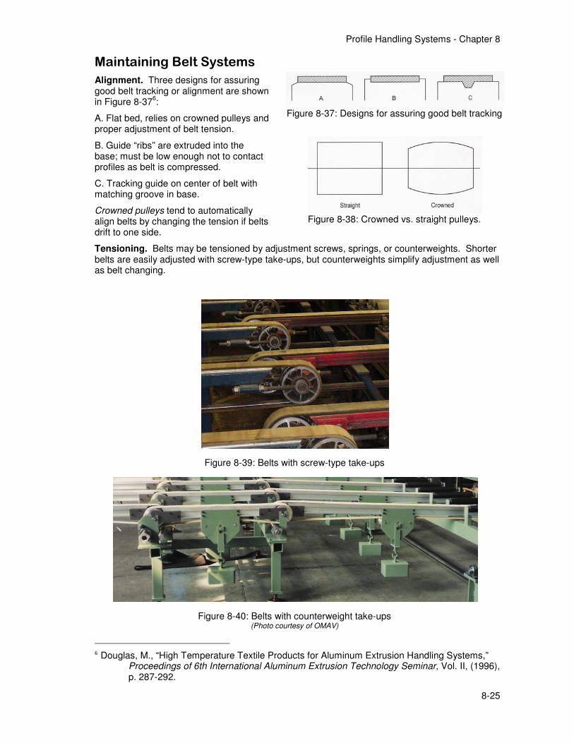
Alignment. Three designs for assuring good belt tracking or alignment are shown in Figure 8-37
6:
A. Flat bed, relies on crowned pulleys and proper adjustment of belt tension.
B. Guide “ribs” are extruded into the base; must be low enough not to contact profiles as belt is compressed.
C. Tracking guide on center of belt with matching groove in base.
Crowned pulleys tend to automatically align belts by changing the tension if belts drift to one side.
Tensioning. Belts may be tensioned by adjustment screws, springs, or counterweights. Shorter belts are easily adjusted with screw-type take-ups, but counterweights simplify adjustment as well as belt changing.
6 Douglas, M., “High Temperature Textile Products for Aluminum Extrusion Handling Systems,”
Proceedings of 6th International Aluminum Extrusion Technology Seminar, Vol. II, (1996), p. 287-292.
Figure 8-37: Designs for assuring good belt tracking
Figure 8-38: Crowned vs. straight pulleys.
Figure 8-39: Belts with screw-type take-ups
Figure 8-40: Belts with counterweight take-ups (Photo courtesy of OMAV)
Profile Handling Systems - Chapter 8
8-26
Cooling Tables
Besides providing a space for cooling and accumulating the profiles between extrusion and stretching, the cooling table may also be used to form stretcher batches and to remove some deformation which occurs due to cooling. Cooling tables are usually one of the following types, or combinations:
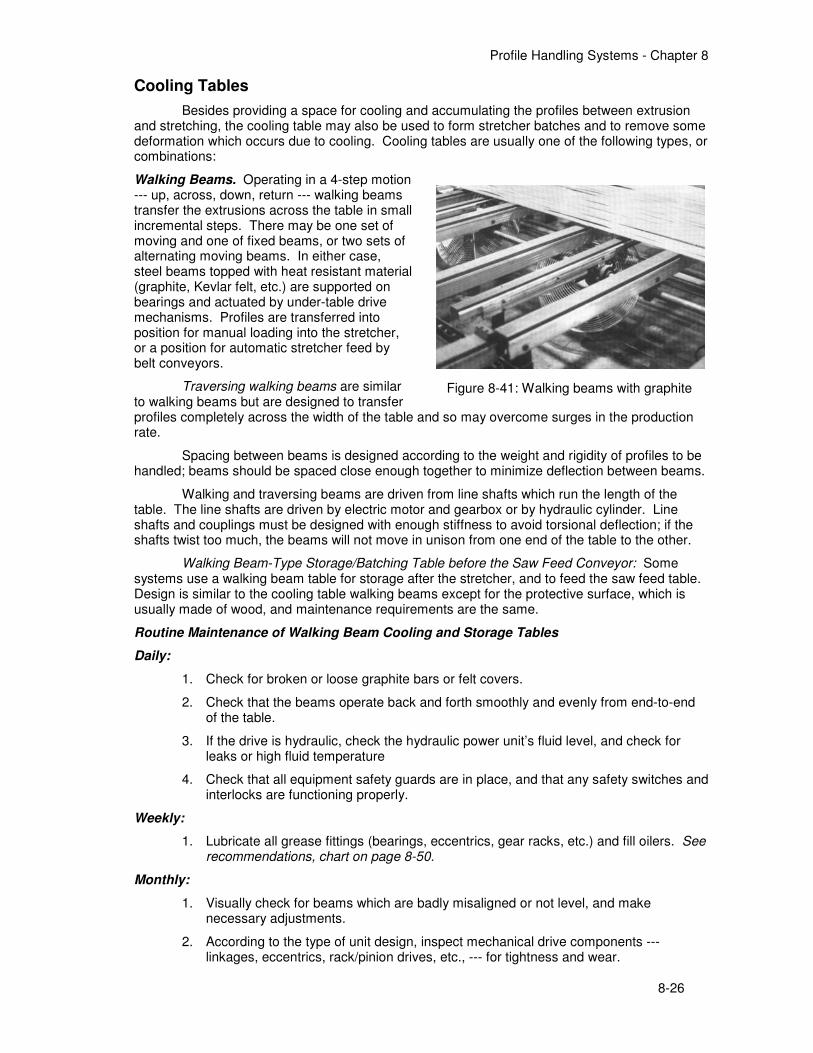
Walking Beams. Operating in a 4-step motion --- up, across, down, return --- walking beams transfer the extrusions across the table in small incremental steps. There may be one set of moving and one of fixed beams, or two sets of alternating moving beams. In either case, steel beams topped with heat resistant material (graphite, Kevlar felt, etc.) are supported on bearings and actuated by under-table drive mechanisms. Profiles are transferred into position for manual loading into the stretcher, or a position for automatic stretcher feed by belt conveyors.
Traversing walking beams are similar to walking beams but are designed to transfer profiles completely across the width of the table and so may overcome surges in the production rate.
Spacing between beams is designed according to the weight and rigidity of profiles to be handled; beams should be spaced close enough together to minimize deflection between beams.
Walking and traversing beams are driven from line shafts which run the length of the table. The line shafts are driven by electric motor and gearbox or by hydraulic cylinder. Line shafts and couplings must be designed with enough stiffness to avoid torsional deflection; if the shafts twist too much, the beams will not move in unison from one end of the table to the other.
Walking Beam-Type Storage/Batching Table before the Saw Feed Conveyor: Some systems use a walking beam table for storage after the stretcher, and to feed the saw feed table. Design is similar to the cooling table walking beams except for the protective surface, which is usually made of wood, and maintenance requirements are the same.
Routine Maintenance of Walking Beam Cooling and Storage Tables
Daily:
1. Check for broken or loose graphite bars or felt covers.
2. Check that the beams operate back and forth smoothly and evenly from end-to-end of the table.
3. If the drive is hydraulic, check the hydraulic power unit’s fluid level, and check for leaks or high fluid temperature
4. Check that all equipment safety guards are in place, and that any safety switches and interlocks are functioning properly.
Weekly:
1. Lubricate all grease fittings (bearings, eccentrics, gear racks, etc.) and fill oilers. See recommendations, chart on page 8-50.
Monthly:
1. Visually check for beams which are badly misaligned or not level, and make necessary adjustments.
2. According to the type of unit design, inspect mechanical drive components --- linkages, eccentrics, rack/pinion drives, etc., --- for tightness and wear.
Figure 8-41: Walking beams with graphite

Profile Handling Systems - Chapter 8
8-27
3. Check line shafts for alignment and loose couplings. Note the condition and/or wear of line shaft bearings.
4. Check hydraulic drive unit (where installed), clean filters, and check for overall functioning. General maintenance and trouble-shooting tips for hydraulic systems are described in Chapter 6 - Hydraulic Equipment.
5. Drive gear reducer (with electric drive): Check the oil level monthly, change every 6 months (unless recommended otherwise by manufacturer).
6. Check drive chains (where installed) for alignment, and adjust and tension the chains as needed. Note the degree of wear in the chain. Check the condition of drive and tail sprockets.
7. Check limit switches for loose mountings, loose wires, loose arms, etc.; check limit switches for proper tripping.
Annually:
1. Check the level and alignment of the table frame and adjust as needed to maintain it level and straight.
2. Check all frame connectors and foundation bolts and tighten as needed.
3. Clean and lubricate the electric motor(s) annually. If the windings become coated with oil and dirt they will run hotter, leading to premature motor failure. Likewise, clogged openings in the motor frame may result in the loss of effective cooling. Check the motor windings with a megohmmeter annually. Also check and record the no-load amps.
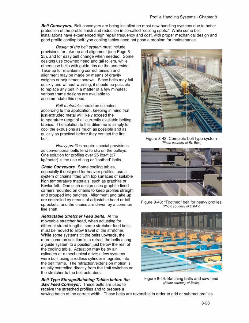
Belt Conveyors. Belt conveyors are being installed on most new handling systems due to better protection of the profile finish and reduction in soinstallations have experienced high repair frequency and cost, with proper mechanical design and good profile cooling belt-type cooling tables need not pose a problem for maintenance.
Design of the belt systemprovisions for take-up and alignment25), and for easy belt change when needed. Some designs use crowned head and tail rollers, while others use belts with guide ribs on the underside. Take-up for maintaining correct tension and alignment may be made by means of gravity weights or adjustment screws. Since belts may fail quickly and without warning, it should be possible to replace any belt in a matter of a few minutes; various frame designs are available to accommodate this need.
Belt materials should be selected according to the application, keeping in mind that just-extruded metal will likely exceed the temperature range of all currently available belting fabrics. The solution to this dilemma is simply to cool the extrusions as much as possible and as quickly as practical before they contact the first belt.
Heavy profiles require special provisions as conventional belts tend to slip on the pulleys. One solution for profiles over 25 lbs/ft (37 kg/meter) is the use of cog or “toothed” belts.
Chain Conveyors. Some cooling tabespecially if designed for heavier profiles, use a system of chains fitted with top surfaces of suitable high temperature materials, such as graphite or Kevlar felt. One such design uses graphitecarriers mounted on chains to keep profiles straand grouped into batches. Alignment and takeare controlled by means of adjustable head or tail sprockets, and the chains are driven by a common line shaft.
Retractable Stretcher Feed Belts.moveable stretcher head, when adjusting for different strand lengths, some stretcher feed belts must be moved to allow travel of the stretcher. While some systems tilt the belts upwards, the more common solution is to retract the belts along a guide system to a position just below the rest of the cooling table. Actuation may be by air cylinders or a mechanical drive; a few systems were built using a rodless cylinder integrated into the belt frame. The retraction/extension motion is usually controlled directly from the stretcher to the belt actuators.
Belt-Type Storage/Batching Tables before the Saw Feed Conveyor. These belts are used to receive the stretched profiles and to prepare a sawing batch of the correct width. These belts are reversible in order to add or subtract profil
Profile Handling Systems
Belt conveyors are being installed on most new handling systems due to better protection of the profile finish and reduction in so-called “cooling spots.” While some belt installations have experienced high repair frequency and cost, with proper mechanical design and
type cooling tables need not pose a problem for maintenance.
Design of the belt system must include up and alignment (see Page 8-
, and for easy belt change when needed. Some designs use crowned head and tail rollers, while others use belts with guide ribs on the underside.
up for maintaining correct tension and alignment may be made by means of gravity
or adjustment screws. Since belts may fail quickly and without warning, it should be possible to replace any belt in a matter of a few minutes; various frame designs are available to
should be selected the application, keeping in mind that
extruded metal will likely exceed the temperature range of all currently available belting fabrics. The solution to this dilemma is simply to cool the extrusions as much as possible and as
ore they contact the first
require special provisions as conventional belts tend to slip on the pulleys. One solution for profiles over 25 lbs/ft (37 kg/meter) is the use of cog or “toothed” belts.
Some cooling tables, especially if designed for heavier profiles, use a system of chains fitted with top surfaces of suitable high temperature materials, such as graphite or Kevlar felt. One such design uses graphite-lined carriers mounted on chains to keep profiles straight and grouped into batches. Alignment and take-up are controlled by means of adjustable head or tail sprockets, and the chains are driven by a common
Retractable Stretcher Feed Belts. At the moveable stretcher head, when adjusting for
erent strand lengths, some stretcher feed belts must be moved to allow travel of the stretcher. While some systems tilt the belts upwards, the more common solution is to retract the belts along a guide system to a position just below the rest of
ng table. Actuation may be by air cylinders or a mechanical drive; a few systems were built using a rodless cylinder integrated into the belt frame. The retraction/extension motion is usually controlled directly from the limit switches on
o the belt actuators.
Type Storage/Batching Tables before the These belts are used to
receive the stretched profiles and to prepare a sawing batch of the correct width. These belts are reversible in order to add or subtract profil
Figure 8-42: Complete belt(Photo courtesy of RL Best)
Figure 8-43: “Toothed” belt for heavy profiles(Photo courtesy of OMAV)
Figure 8-44: Batching balts and saw feed(Photo courtesy of Belco)
Profile Handling Systems - Chapter 8
8-28
Belt conveyors are being installed on most new handling systems due to better spots.” While some belt
installations have experienced high repair frequency and cost, with proper mechanical design and type cooling tables need not pose a problem for maintenance.
sawing batch of the correct width. These belts are reversible in order to add or subtract profiles
42: Complete belt-type system hoto courtesy of RL Best)
43: “Toothed” belt for heavy profiles (Photo courtesy of OMAV)
44: Batching balts and saw feed (Photo courtesy of Belco)

Profile Handling Systems - Chapter 8
8-29
until a photocell determines that the correct batch has been formed. The belts should accommodate enough saw batches to minimize production delays. Because of lower temperatures at this end of the system, rubber belts may usually be used.
Routine Maintenance of Belt and Chain Conveyors
Daily:
1. Check for burned, torn, or ragged belts, or damaged felt or graphite on the chain.
2. Check that the belts or chains move smoothly and track straight.
3. Check that belt tensions are adjusted and auto-tensioning devices or counterweights are able to move freely.
Weekly:
1. Lubricate all grease fittings (bearings, pulleys, etc.) and fill oilers. See recommendations, chart on page 8-50.
Monthly:
1. Check drive chains (where installed) for alignment and adjust and tension the chains as needed. Note the degree of wear of the chains. Check the condition of drive and tail sprockets.
2. Drive gear reducer: Check the oil level monthly, change every 6 months (unless recommended otherwise by manufacturer).
3. Check air line filters and lubricators for actuator cylinders and any other system components which are actuated by compressed air.
4. Check limit switches for loose mountings, loose wires, loose arms, etc.; check limit switches for proper tripping. Check the position of proximity switches for proper actuation. The lenses of photoelectric switches require periodic cleaning with a soft dry cloth, and reflective devices used In conjunction with photoelectric switches also require periodic cleaning. Do not use solvents or cleaning agents on the lenses or reflectors. Replace any damaged lenses and reflectors.
Annually:
1. Clean and lubricate the electric motor(s) annually. If the windings become coated with oil and dirt they will run hotter, leading to premature motor failure. Likewise, clogged openings in the motor frame may result in the loss of effective cooling. Check the motor windings with a megohmmeter annually. Also check and record the no-load amps.
2. Check all conveyor and frame connections and foundation bolts and tighten as needed.
3. Check the level and alignment of the conveyor frames and adjust as needed to maintain them level and straight.
Profile Handling Systems - Chapter 8
8-30
Stretchers
Profiles are stretched for the purpose of straightening --- removing the twists and deformations which occur during the extrusion cycle --- and to remove residual stresses. Stretchers are usually sized to provide stretching force for the largest profile produced, based on the cross sectional area multiplied by the yield stress of the alloy. (See the tables: Stretcher Capacity Calculation (Metric and English units) in the Useful Tables section.)
The amount of stretch may be controlled in several ways: by sight (the operator’s judgment); by force; by length of stretch; or by the percentage of total strand length. Some machines use a laser device to measure actual distance between head and tailstock, then use an encoder device on the stretch cylinder to calculate and control the percentage of stretch.
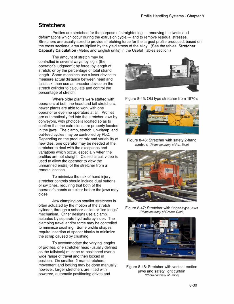
Where older plants were staffed with operators at both the head and tail stretchers, newer plants are able to work with one operator or even no operators at all. Profiles are automatically fed into the stretcher jaws by conveyors, with photocells located so as to confirm that the extrusions are properly located in the jaws. The clamp, stretch, un-clamp, and out-feed cycles may be controlled by PLC. Depending on the product mix and variability of new dies, one operator may be needed at the stretcher to deal with the exceptions and variations which occur, especially when the profiles are not straight. Closed circuit video is used to allow the operator to view the unmanned end(s) of the stretcher from a remote location.
To minimize the risk of hand injury, stretcher controls should include dual buttons or switches, requiring that both of the operator’s hands are clear before the jaws may close.
Jaw clamping on smaller stretchers is often actuated by the motion of the stretch cylinder, through a scissor-action or “ice tongs” mechanism. Other designs use a clamp actuated by separate hydraulic cylinder. The clamping travel and/or force may be controlled to minimize crushing. Some profile shapes require insertion of spacer blocks to minimize the scrap caused by crushing.
To accommodate the varying lengths of profiles, one stretcher head (usually defined as the tailstock) must be re-positioned over a wide range of travel and then locked in position. On smaller, 2-man stretchers, movement and locking may be done manually; however, larger stretchers are fitted with powered, automatic positioning drives and
Figure 8-45: Old type stretcher from 1970’s
Figure 8-46: Stretcher with safety 2-hand controls (Photo courtesy of R.L. Best)
Figure 8-47: Stretcher with finger-type jaws (Photo courtesy of Granco Clark)
Figure 8-48: Stretcher with vertical-motion jaws and safety light curtain
(Photo courtesy of Belco)
Profile Handling Systems - Chapter 8
8-31
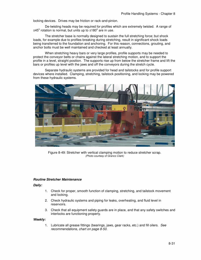
locking devices. Drives may be friction or rack-and-pinion.
De-twisting heads may be required for profiles which are extremely twisted. A range of ±45
o rotation is normal, but units up to ±180
o are in use.
The stretcher base is normally designed to sustain the full stretching force; but shock loads, for example due to profiles breaking during stretching, result in significant shock loads being transferred to the foundation and anchoring. For this reason, connections, grouting, and anchor bolts must be well maintained and checked at least annually.
When stretching heavy bars or very large profiles, profile supports may be needed to protect the conveyor belts or chains against the lateral stretching motion, and to support the profile in a level, straight position. The supports rise up from below the stretcher frame and lift the bars or profiles up level with the jaws and off the conveyors during the stretch cycle.
Separate hydraulic systems are provided for head and tailstocks and for profile support devices where installed. Clamping, stretching, tailstock positioning, and locking may be powered from these hydraulic systems.
Routine Stretcher Maintenance
Daily:
1. Check for proper, smooth function of clamping, stretching, and tailstock movement and locking.
2. Check hydraulic systems and piping for leaks, overheating, and fluid level in reservoirs.
3. Check that all equipment safety guards are in place, and that any safety switches and interlocks are functioning properly.
Weekly:
1. Lubricate all grease fittings (bearings, jaws, gear racks, etc.) and fill oilers. See recommendations, chart on page 8-50.
Figure 8-49: Stretcher with vertical clamping motion to reduce stretcher scrap. (Photo courtesy of Granco Clark)

Profile Handling Systems - Chapter 8
8-32
Monthly:
1. Inspect the jaws for wear or damage.
2. If the tailstock is driven by friction, clean the drive wheel and contact surface; check that the drive wheels are sufficiently grooved to provide dependable movement and check the wheels for roundness. Check the wheel bearings.
3. Check rack-and-pinion drive mechanism where installed.
4. Check that the head and tailstock locking mechanisms (hooks, pins, etc.) lock smoothly and securely; look for signs of over-stressing or deformation.
5. Check and clean hydraulic filters, and check for overall hydraulic systems functioning. General maintenance and trouble-shooting tips for hydraulic systems are described in Chapter 5 - Hydraulic Equipment.
6. Check all hydraulic cylinders for leaks, scratched or damaged rods, or damaged packing, and repair or replace as needed. Use a stone to remove deep scratches or gouges from the rods in order to prevent packing damage. Extend the main cylinders fully and check for excess deflection as a sign of wear to the cylinder bushings.
7. Check limit switches for loose mountings, loose wires, loose arms, etc.; check limit switches for proper tripping. Check the position of proximity switches for proper actuation. The lenses of photoelectric switches require periodic cleaning with a soft dry cloth, and reflective devices used In conjunction with photoelectric switches also require periodic cleaning. Do not use solvents or cleaning agents on the lenses or reflectors. Replace any damaged lenses and reflectors.
Annually:
1. Tighten all connector bolts and foundation anchor bolts.
2. Check grouting of the stretcher frame.
Profile Handling Systems - Chapter 8
8-33
Saw Feed Conveyors
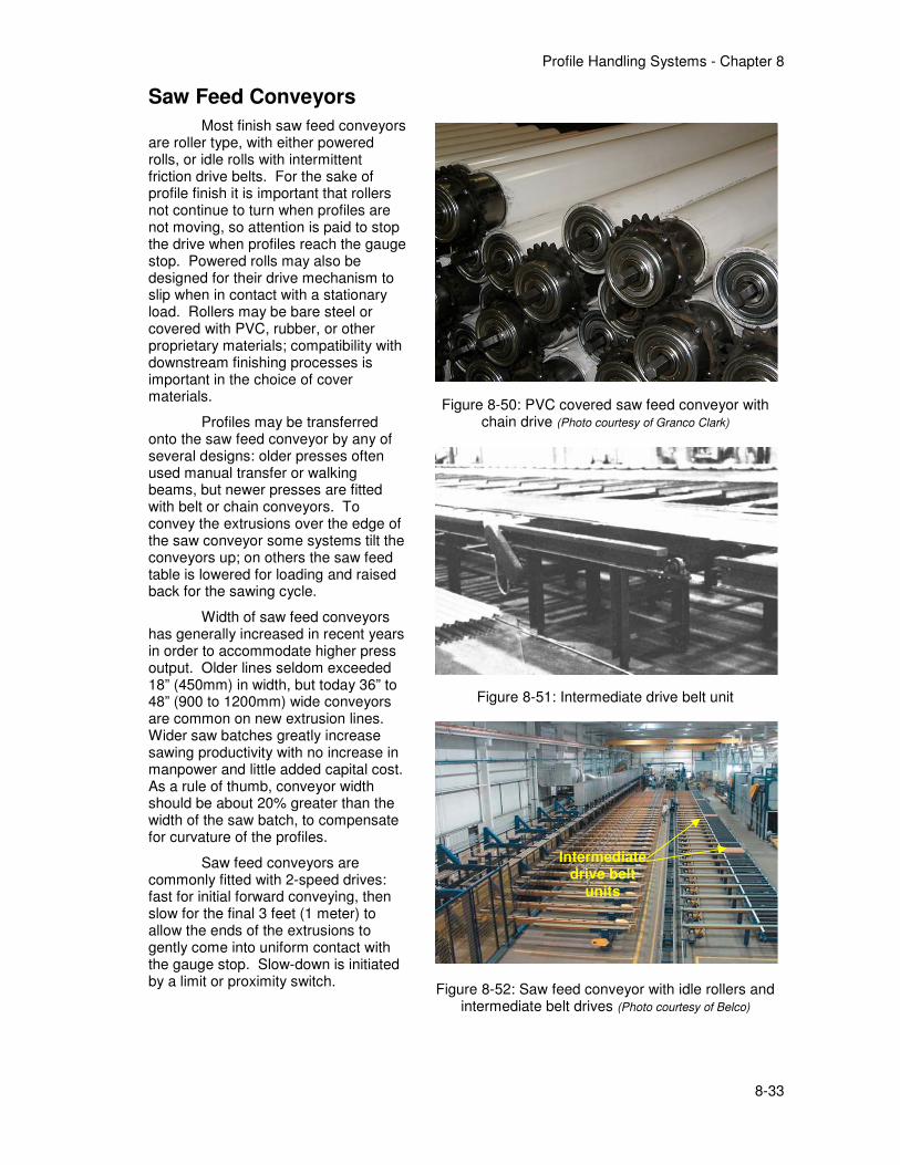
Most finish saw feed conveyors are roller type, with either powered rolls, or idle rolls with intermittent friction drive belts. For the sake of profile finish it is important that rollers not continue to turn when profiles are not moving, so attention is paid to stop the drive when profiles reach the gauge stop. Powered rolls may also be designed for their drive mechanism to slip when in contact with a stationary load. Rollers may be bare steel or covered with PVC, rubber, or other proprietary materials; compatibility with downstream finishing processes is important in the choice of cover materials.
Profiles may be transferred onto the saw feed conveyor by any of several designs: older presses often used manual transfer or walking beams, but newer presses are fitted with belt or chain conveyors. To convey the extrusions over the edge of the saw conveyor some systems tilt the conveyors up; on others the saw feed table is lowered for loading and raised back for the sawing cycle.
Width of saw feed conveyors has generally increased in recent years in order to accommodate higher press output. Older lines seldom exceeded 18” (450mm) in width, but today 36” to 48” (900 to 1200mm) wide conveyors are common on new extrusion lines. Wider saw batches greatly increase sawing productivity with no increase in manpower and little added capital cost. As a rule of thumb, conveyor width should be about 20% greater than the width of the saw batch, to compensate for curvature of the profiles.
Saw feed conveyors are commonly fitted with 2-speed drives: fast for initial forward conveying, then slow for the final 3 feet (1 meter) to allow the ends of the extrusions to gently come into uniform contact with the gauge stop. Slow-down is initiated by a limit or proximity switch.
Figure 8-50: PVC covered saw feed conveyor with chain drive (Photo courtesy of Granco Clark)
Figure 8-51: Intermediate drive belt unit
Figure 8-52: Saw feed conveyor with idle rollers and intermediate belt drives (Photo courtesy of Belco)
Intermediate drive belt
units
Profile Handling Systems - Chapter 8
8-34
Routine Maintenance of Saw Feed Conveyors:
Daily:
1. Check that all conveyor rollers turn freely.
2. Check the drive belts or roller drives to see that all sections are working properly and profiles are fed smoothly.
3. Check the raise/lower action to see that all is working smoothly.
4. Check the hydraulic fluid level in the raise/lower system (if installed), and check for leaks or high fluid temperature.
5. Check that all equipment safety guards are in place, and that any safety switches and interlocks are functioning properly.
Weekly:
1. Lubricate all grease fittings (bearings, etc.) and fill oilers. See recommendations, chart on page 8-50.
2. Check chain lubrication systems (if installed) to see that they are filled and operating properly.
Monthly:
1. Replace any damaged or worn roller covers.
2. Chain-driven live roller conveyors: check drive chains for alignment and adjust and re-tension the chains as needed. Note the degree of wear in the chain.
3. Drive belt sections should be checked for wear or damage to the belts and for correct tension and tracking. Check drive chains for alignment and adjust and re-tension the chains as needed.
4. Gear reducers for belt or roller drives and/or table lift: Check the oil level monthly, change every 6 months (unless recommended otherwise by manufacturer).
5. Check air line filters and lubricators for any system components actuated by compressed air. Add oil as needed.
Annually:
1. Check that the saw feed conveyor table is level with the saw table and length gauge table.
2. Hydraulic drive for table lift (if installed): Check and clean filters, and check for overall functioning. General maintenance and trouble-shooting tips for hydraulic systems are described in Chapter 5 - Hydraulic Equipment.
3. Check limit switches for loose mountings, loose wires, loose arms, etc.; check limit switches for proper tripping. Check the position of proximity switches for proper actuation. The lenses of photoelectric switches require periodic cleaning with a soft dry cloth, and reflective devices used In conjunction with photoelectric switches also require periodic cleaning. Do not use solvents or cleaning agents on the lenses or reflectors. Replace any damaged lenses and reflectors.
4. Clean and lubricate drive and table lift motors annually. If the windings become coated with oil and dirt they will run hotter, leading to premature motor failure. Likewise, clogged openings in the motor frame may result in the loss of effective cooling. Check the motor windings with a megohmmeter annually. Also check and record the no-load amps.
5. Check all conveyor and frame connections and foundation bolts and tighten as needed.
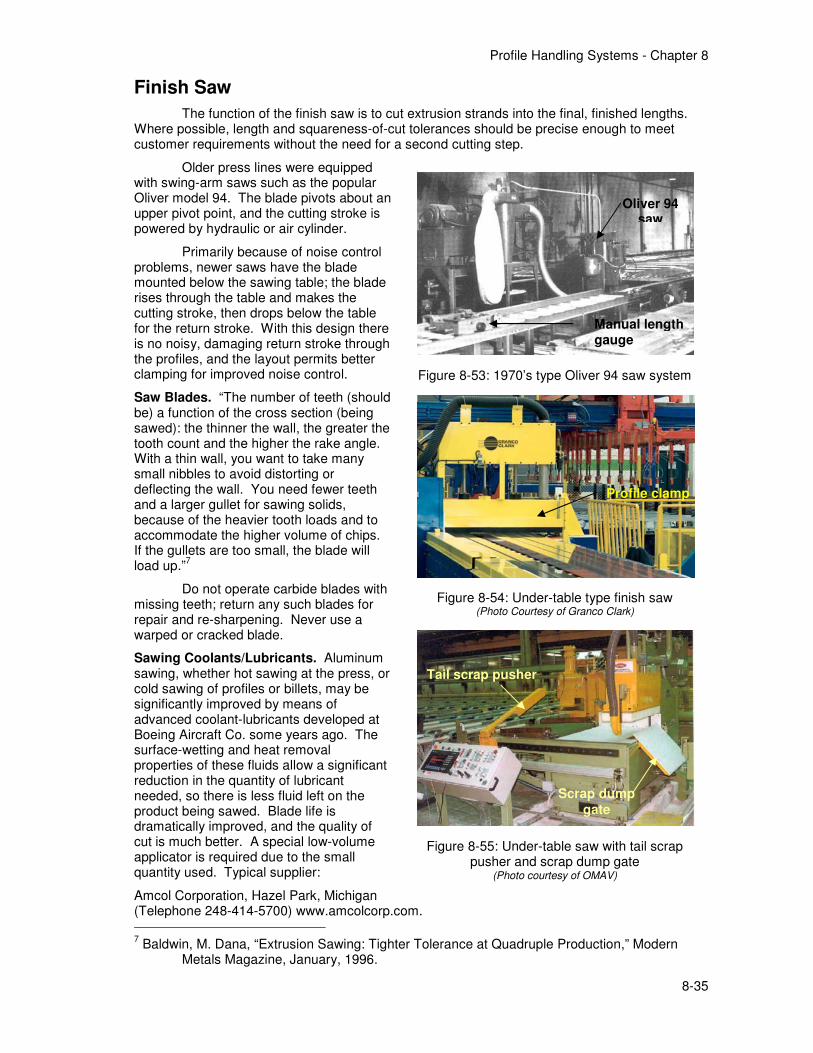
Profile Handling Systems - Chapter 8
8-35
Finish Saw
The function of the finish saw is to cut extrusion strands into the final, finished lengths. Where possible, length and squareness-of-cut tolerances should be precise enough to meet customer requirements without the need for a second cutting step.
Older press lines were equipped with swing-arm saws such as the popular Oliver model 94. The blade pivots about an upper pivot point, and the cutting stroke is powered by hydraulic or air cylinder.
Primarily because of noise control problems, newer saws have the blade mounted below the sawing table; the blade rises through the table and makes the cutting stroke, then drops below the table for the return stroke. With this design there is no noisy, damaging return stroke through the profiles, and the layout permits better clamping for improved noise control.
Saw Blades. “The number of teeth (should be) a function of the cross section (being sawed): the thinner the wall, the greater the tooth count and the higher the rake angle. With a thin wall, you want to take many small nibbles to avoid distorting or deflecting the wall. You need fewer teeth and a larger gullet for sawing solids, because of the heavier tooth loads and to accommodate the higher volume of chips. If the gullets are too small, the blade will load up.”
7
Do not operate carbide blades with missing teeth; return any such blades for repair and re-sharpening. Never use a warped or cracked blade.
Sawing Coolants/Lubricants. Aluminum sawing, whether hot sawing at the press, or cold sawing of profiles or billets, may be significantly improved by means of advanced coolant-lubricants developed at Boeing Aircraft Co. some years ago. The surface-wetting and heat removal properties of these fluids allow a significant reduction in the quantity of lubricant needed, so there is less fluid left on the product being sawed. Blade life is dramatically improved, and the quality of cut is much better. A special low-volume applicator is required due to the small quantity used. Typical supplier:
Amcol Corporation, Hazel Park, Michigan (Telephone 248-414-5700) www.amcolcorp.com.
7 Baldwin, M. Dana, “Extrusion Sawing: Tighter Tolerance at Quadruple Production,” Modern
Metals Magazine, January, 1996.
Figure 8-53: 1970’s type Oliver 94 saw system
Figure 8-54: Under-table type finish saw (Photo Courtesy of Granco Clark)
Figure 8-55: Under-table saw with tail scrap pusher and scrap dump gate
(Photo courtesy of OMAV)
Oliver 94 saw
Manual length gauge
Tail scrap pusher
Scrap dump
gate
Profile clamp
Profile Handling Systems - Chapter 8
8-36
For recommendations on installation and maintenance of low-volume saw coolant applicators see page 8-38.
Saw Noise Control. Sawing of aluminum profiles has long posed a risk of employee exposure to unacceptable noise levels. Noise is generated by the contact of blade and profile, and also by reverberation of the profiles, which may be quite difficult to control due to the length of profiles available to generate sound.
In order to develop ways to reduce this noise at the source, industry trade associations have sponsored research into saw noise abatement.
8,9 In general, this research has led to better
blade designs and developing of profile clamping systems which will minimize the generation of noise.
Saw Chip Collection. Effective collection of saw chips requires a well-designed, well-maintained capture hood, connecting ducts, suction blower, and collector. For best results, the capture hood should be designed so that chips fly directly into the hood from the blade as a result of their natural velocity; the air capture velocity then adds to the effect. The required air flow is determined to provide the required capture velocity, and ductwork is sized to maintain the necessary conveying velocity for the chips. The velocity should be high enough to pick up or re-entrain particles which fall out when the system is down or malfunctioning. Typical velocities for capture and conveying: 4000 to 5000 ft/min (1200 to 1500 meter/min).
For additional pointers on design of chip collectors, including configuration of hoods and air flow parameters, refer to the Industrial Ventilation Manual, published by the Committee on Industrial Ventilation, PO Box 16153, Lansing MI 48901 USA. Sales: American Conference of Governmental Industrial Hygienists, 1300 Kemper Meadow Drive, Cincinnati OH 45240 USA, tel 513.742.2020, www.acgih.org/resources/press/vent25th.htm.
For cyclone-type collectors, be sure that the discharge duct fits snugly on the chip drum, and that the drum is emptied when it becomes about 2/3 full. Periodically shaking the filter bags and/or shutting off the air flow for a few minutes will often restore the air flow volume.
Routine Maintenance of Finish Saws
Daily:
1. Check the sharpness of the blade. The best indicator will be the cut ends of profiles: excessive deformation indicates a dull blade or poor lubrication.
2. Clean the saw table of chips and other debris which damage profiles or may interfere with alignment.
3. Listen for excess noise caused by the blade’s rear edge passing through profiles, which is a sign that blade alignment is incorrect.
4. Check for proper functioning of clamps, in order to minimize noise and also to hold profiles securely against the table and back fence for cutting accuracy.
5. Check condition of the clamp pads for damage or embedded saw chips; clean or replace.
6. Check for proper functioning of the blade actuator system (usually hydraulic).
7. Check for leaks of hydraulic fluid or compressed air.
8. Check the level of blade lubricant in the reservoir and check the function of the lubricant applicator; a piece of cardboard or brown paper held in front of each nozzle will quickly show the rate and pattern of lubrication.
8 Proceedings of the Workshop on the Control of Metal Sawing Noise in the Aluminum Industry,
June, 1976. The Aluminum Association, Washington DC. 9 1984 Saw Noise Report and 1987 Saw Noise Report. Aluminum Extruders Council, Chicago IL,
USA.
Profile Handling Systems - Chapter 8
8-37
9. Check that all equipment safety guards are in place, and that any safety switches and interlocks are functioning properly.
Weekly:
1. Lubricate all grease fittings (bearings, etc.) and fill oilers. See recommendations, chart on page 8-50.
Monthly:
1. Service the hydraulic system: clean the tank; check and clean the hydraulic filter; clean and check for fluid leaks.
2. Clean the saw and saw table thoroughly.
3. Check the alignment of the saw blade with the back stop or guide fence.
4. Change the cloth chip collector bags; old bags may be restored by washing in warm water with laundry detergent, or dry cleaning, to remove accumulated oils.
5. Check the drive motor’s current.
6. Check air line filters and lubricators for any system components actuated by compressed air. Add oil as needed.
7. Check limit switches for loose mountings, loose wires, loose arms, etc.; check limit switches for proper tripping. Check the position of proximity switches for proper actuation. The lenses of photoelectric switches require periodic cleaning with a soft dry cloth, and reflective devices used In conjunction with photoelectric switches also require periodic cleaning. Do not use solvents or cleaning agents on the lenses or reflectors. Replace any damaged lenses and reflectors.
Annually:
1. Check the leveling and alignment of the saw, saw table, back fence, saw feed table, and length gauge table, with piano wire and machinist’s level, to insure squareness and accuracy of cuts.
2. Clean and lubricate the motors annually. If the windings become coated with oil and dirt they will run hotter, leading to premature motor failure. Likewise, clogged openings in the motor frame may result in the loss of effective cooling. Check the motor windings with a megohmmeter annually. Also check and record the no-load amps.
3. Check the condition and alignment of the blade arbor, according to manufacturer’s recommendations and plant service history.
4. Check all conveyor and frame connections and foundation bolts and tighten as needed.
5. Check all hydraulic and pneumatic cylinders for leaks or damaged packing, and repair or replace as needed.
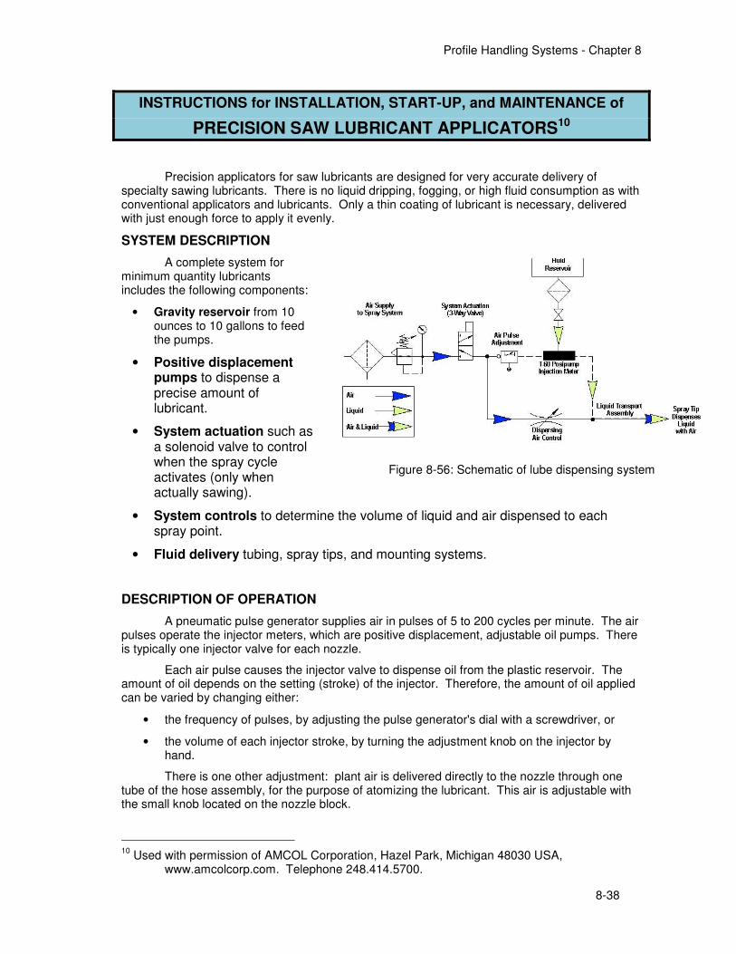
Profile Handling Systems - Chapter 8
8-38
INSTRUCTIONS for INSTALLATION, START-UP, and MAINTENANCE of
PRECISION SAW LUBRICANT APPLICATORS10
Precision applicators for saw lubricants are designed for very accurate delivery of specialty sawing lubricants. There is no liquid dripping, fogging, or high fluid consumption as with conventional applicators and lubricants. Only a thin coating of lubricant is necessary, delivered with just enough force to apply it evenly.
SYSTEM DESCRIPTION
A complete system for minimum quantity lubricants includes the following components:
• Gravity reservoir from 10 ounces to 10 gallons to feed the pumps.
• Positive displacement pumps to dispense a precise amount of lubricant.
• System actuation such as a solenoid valve to control when the spray cycle activates (only when actually sawing).
• System controls to determine the volume of liquid and air dispensed to each spray point.
• Fluid delivery tubing, spray tips, and mounting systems.
DESCRIPTION OF OPERATION
A pneumatic pulse generator supplies air in pulses of 5 to 200 cycles per minute. The air pulses operate the injector meters, which are positive displacement, adjustable oil pumps. There is typically one injector valve for each nozzle.
Each air pulse causes the injector valve to dispense oil from the plastic reservoir. The amount of oil depends on the setting (stroke) of the injector. Therefore, the amount of oil applied can be varied by changing either:
• the frequency of pulses, by adjusting the pulse generator's dial with a screwdriver, or
• the volume of each injector stroke, by turning the adjustment knob on the injector by hand.
There is one other adjustment: plant air is delivered directly to the nozzle through one tube of the hose assembly, for the purpose of atomizing the lubricant. This air is adjustable with the small knob located on the nozzle block.
10
Used with permission of AMCOL Corporation, Hazel Park, Michigan 48030 USA, www.amcolcorp.com. Telephone 248.414.5700.
Figure 8-56: Schematic of lube dispensing system
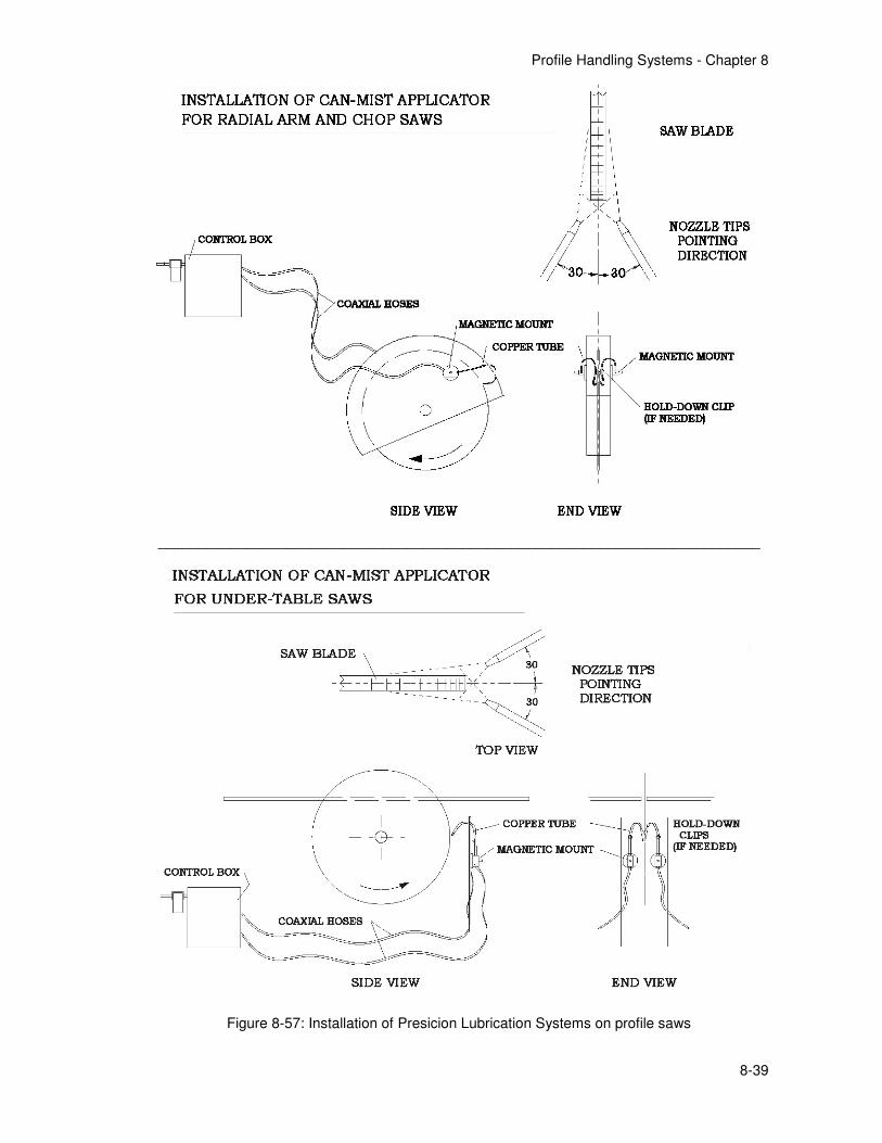
Profile Handling Systems - Chapter 8
8-39
___________________________________________________________________________
Figure 8-57: Installation of Presicion Lubrication Systems on profile saws
Profile Handling Systems - Chapter 8
8-40
INSTALLATION
1. Install the unit in a location convenient to the saw, allowing access to refill the reservoir.
2. Connect plant air supply to the air inlet connection of the air filter. Air should be 60 to 90 psi (5 Bar), clean and free of water. You may add a solenoid valve to the air supply line if you want the applicator to turn off automatically when the saw is turned off.
3. Mount the nozzles on the saw, located for access to the blade. The nozzles should travel with the blade. Use the magnetic mounts supplied, or attach the nozzles directly to the saw's guard or frame. The copper nozzles can be bent by hand so that they point at the blade with the proper angle. The sketches on page 8-38 show some typical mounting arrangements.
Note: different-length nozzles may be purchased to suit any application.
4. Nozzles should apply the spray to the "gullet" of the blade before it contacts the material being sawed. CanMist products do not release from the blade due to centrifugal forces and are not removed by blade guides or drive wheels. Therefore, the fluid may be
applied in any position relative to the cutting point --- even 180o or more away.
5. Place the nozzles so that they will not be clogged by chips from the cut.
START-UP AND ADJUSTMENT
1. Fill the reservoir with coolant/lubricant and replace the cap.
Note: some lubricants may attack the Buna-N seals and O-rings, or the polycarbonate reservoir, and the warranty will be voided. Use only the recommended fluids, which must be compatible with aluminum, brass, PVC, and rubber.
2. The applicator is normally filled with fluid and tested at the factory before shipping, and priming should not be necessary. However, the system can be primed by purging air from the stack as follows:
• remove the air plug from the bottom block of the stack
• adjust each injector the maximum setting
• cycle the system repeatedly --- 50 cycles per foot of tubing.
3. For initial settings:
Pulse Generator* Injector Valves** ------------------------ ------------------------- HEAVY DUTY 3/4 to 7/8 1
MEDIUM DUTY 1 to 1-1/4 3
LIGHT DUTY 1-1/2 5
* Adjustable from 0 to 4. To increase the number of pulses, turn this dial to a lower number setting. Do not operate the generator for long periods below 0.25 on the timer setting.
** To decrease the flow, turn the knob counter-clockwise. (The flow may be turned completely off by turning all the way in either direction.)
4. Air flow control (on the nozzle block at the saw) is adjusted to the lowest possible flow rate that allows for proper fluid dispensing at the spray tip.
5. You may check the delivery by moving the nozzle a safe distance away from the saw blade and then holding a piece of paper about 3 inches in front of the nozzle for 5 seconds. You will observe a pattern about 2 inches in diameter. If the pattern is completely wet, adjust the injector valve for lower volume per stroke (counter-clockwise). Adjust it as needed until the pattern is light dots with a little space between them.
Profile Handling Systems - Chapter 8
8-41
TROUBLESHOOTING
Problem Potential Cause and Cure
Fluid volume inappropriate • Injectors misadjusted; adjust individual injectors
• Air pulse generator misadjusted; adjust
Inconsistent spray volume to one nozzle • Spray tip is clogged; remove, clean, replace
• Spray tip is not properly attached; attach
• Spray tip is damaged; replace
• Liquid or air hose is severed or incorrectly attached; reconnect or replace
Inconsistent spray volume to all nozzles • Fluid level low; refill reservoir
• Strainer clogged; clean or replace
• Air pulse generator operating inconsistently; repair or replace
Mist or fog • Manifold dispensing air pressure set too high; adjust
• Individual nozzle flow too high; adjust
Liquid from back of injector • Injector contact seals leaking; clean injector and replace o-ring
No or low dispersing air • Manifold dispensing air pressure set too low; adjust
• Air hose is kinked; repair or replace
• Spray tip is clogged; clean or replace
• Spray tip is damaged; replace
Air in liquid line • Fluid line not properly attached to pump; repair or replace
• Injector seal failing; rebuild or replace
Liquid drains from spray tip • Injector check valve failing; rebuild or replace
• Liquid line is discontinuous; reconnect or repair
PREVENTIVE MAINTENANCE (Minimum)
Daily:
1. Fill reservoir
2. Check the system and settings
Quarterly:
1. Empty, clean and refill reservoir and strainer
Annually:
1. Rebuild or replace injector pumps
2. Rebuild or replace pneumatic pulse generator
3. Replace liquid and air hose assemblies
DO'S AND DON'TS
• DO keep the air breather plug open at all times.
• DO keep the air filter reasonably clean.
• DO regularly check the unit settings and fluid usage to insure that it is in correct operating order.
• DON'T let the reservoir run completely empty --- it may require re-priming.
• DON'T operate the pulse generator at either "Zero" or "maximum speed" because it may bind up.
• DON'T use fluids that are not compatible with this system, for example: amines, phosphate esters, solvents, oils, etc. Use only CanMist products to be sure.
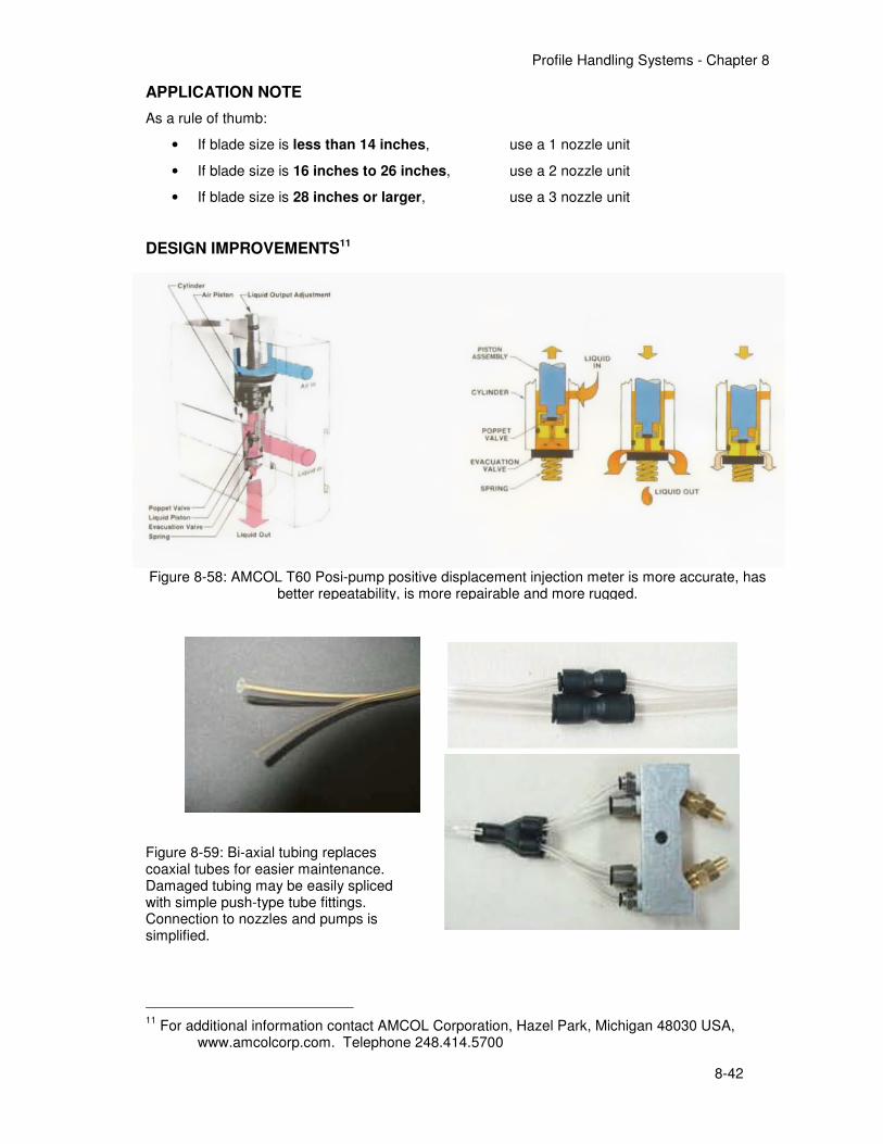
Profile Handling Systems - Chapter 8
8-42
APPLICATION NOTE
As a rule of thumb:
• If blade size is less than 14 inches, use a 1 nozzle unit
• If blade size is 16 inches to 26 inches, use a 2 nozzle unit
• If blade size is 28 inches or larger, use a 3 nozzle unit
DESIGN IMPROVEMENTS11
Figure 8-59: Bi-axial tubing replaces coaxial tubes for easier maintenance. Damaged tubing may be easily spliced with simple push-type tube fittings. Connection to nozzles and pumps is simplified.
11
For additional information contact AMCOL Corporation, Hazel Park, Michigan 48030 USA, www.amcolcorp.com. Telephone 248.414.5700
Figure 8-58: AMCOL T60 Posi-pump positive displacement injection meter is more accurate, has
better repeatability, is more repairable and more rugged.
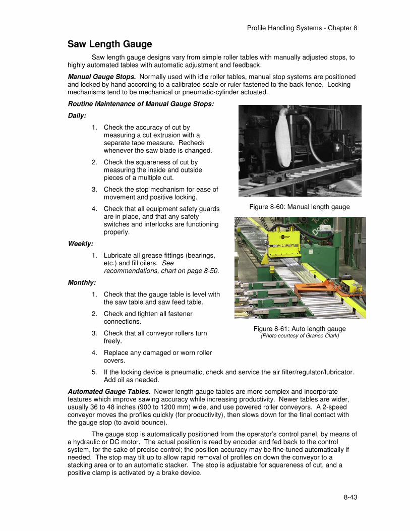
Profile Handling Systems - Chapter 8
8-43
Saw Length Gauge
Saw length gauge designs vary from simple roller tables with manually adjusted stops, to highly automated tables with automatic adjustment and feedback.
Manual Gauge Stops. Normally used with idle roller tables, manual stop systems are positioned and locked by hand according to a calibrated scale or ruler fastened to the back fence. Locking mechanisms tend to be mechanical or pneumatic-cylinder actuated.
Routine Maintenance of Manual Gauge Stops:
Daily:
1. Check the accuracy of cut by measuring a cut extrusion with a separate tape measure. Recheck whenever the saw blade is changed.
2. Check the squareness of cut by measuring the inside and outside pieces of a multiple cut.
3. Check the stop mechanism for ease of movement and positive locking.
4. Check that all equipment safety guards are in place, and that any safety switches and interlocks are functioning properly.
Weekly:
1. Lubricate all grease fittings (bearings, etc.) and fill oilers. See recommendations, chart on page 8-50.
Monthly:
1. Check that the gauge table is level with the saw table and saw feed table.
2. Check and tighten all fastener connections.
3. Check that all conveyor rollers turn freely.
4. Replace any damaged or worn roller covers.
5. If the locking device is pneumatic, check and service the air filter/regulator/lubricator. Add oil as needed.
Automated Gauge Tables. Newer length gauge tables are more complex and incorporate features which improve sawing accuracy while increasing productivity. Newer tables are wider, usually 36 to 48 inches (900 to 1200 mm) wide, and use powered roller conveyors. A 2-speed conveyor moves the profiles quickly (for productivity), then slows down for the final contact with the gauge stop (to avoid bounce).
The gauge stop is automatically positioned from the operator’s control panel, by means of a hydraulic or DC motor. The actual position is read by encoder and fed back to the control system, for the sake of precise control; the position accuracy may be fine-tuned automatically if needed. The stop may tilt up to allow rapid removal of profiles on down the conveyor to a stacking area or to an automatic stacker. The stop is adjustable for squareness of cut, and a positive clamp is activated by a brake device.
Figure 8-60: Manual length gauge
Figure 8-61: Auto length gauge (Photo courtesy of Granco Clark)
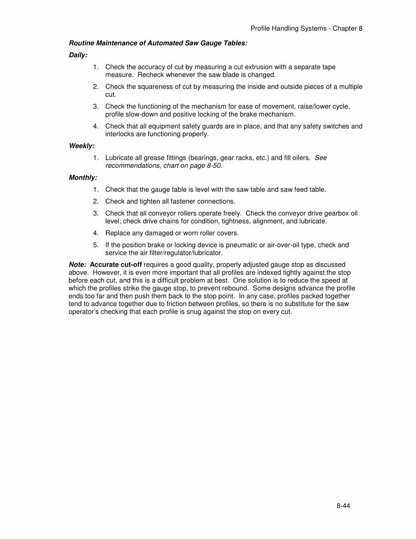
Profile Handling Systems - Chapter 8
8-44
Routine Maintenance of Automated Saw Gauge Tables:
Daily:
1. Check the accuracy of cut by measuring a cut extrusion with a separate tape measure. Recheck whenever the saw blade is changed.
2. Check the squareness of cut by measuring the inside and outside pieces of a multiple cut.
3. Check the functioning of the mechanism for ease of movement, raise/lower cycle, profile slow-down and positive locking of the brake mechanism.
4. Check that all equipment safety guards are in place, and that any safety switches and interlocks are functioning properly.
Weekly:
1. Lubricate all grease fittings (bearings, gear racks, etc.) and fill oilers. See recommendations, chart on page 8-50.
Monthly:
1. Check that the gauge table is level with the saw table and saw feed table.
2. Check and tighten all fastener connections.
3. Check that all conveyor rollers operate freely. Check the conveyor drive gearbox oil level; check drive chains for condition, tightness, alignment, and lubricate.
4. Replace any damaged or worn roller covers.
5. If the position brake or locking device is pneumatic or air-over-oil type, check and service the air filter/regulator/lubricator.
Note: Accurate cut-off requires a good quality, properly adjusted gauge stop as discussed above. However, it is even more important that all profiles are indexed tightly against the stop before each cut, and this is a difficult problem at best. One solution is to reduce the speed at which the profiles strike the gauge stop, to prevent rebound. Some designs advance the profile ends too far and then push them back to the stop point. In any case, profiles packed together tend to advance together due to friction between profiles, so there is no substitute for the saw operator’s checking that each profile is snug against the stop on every cut.
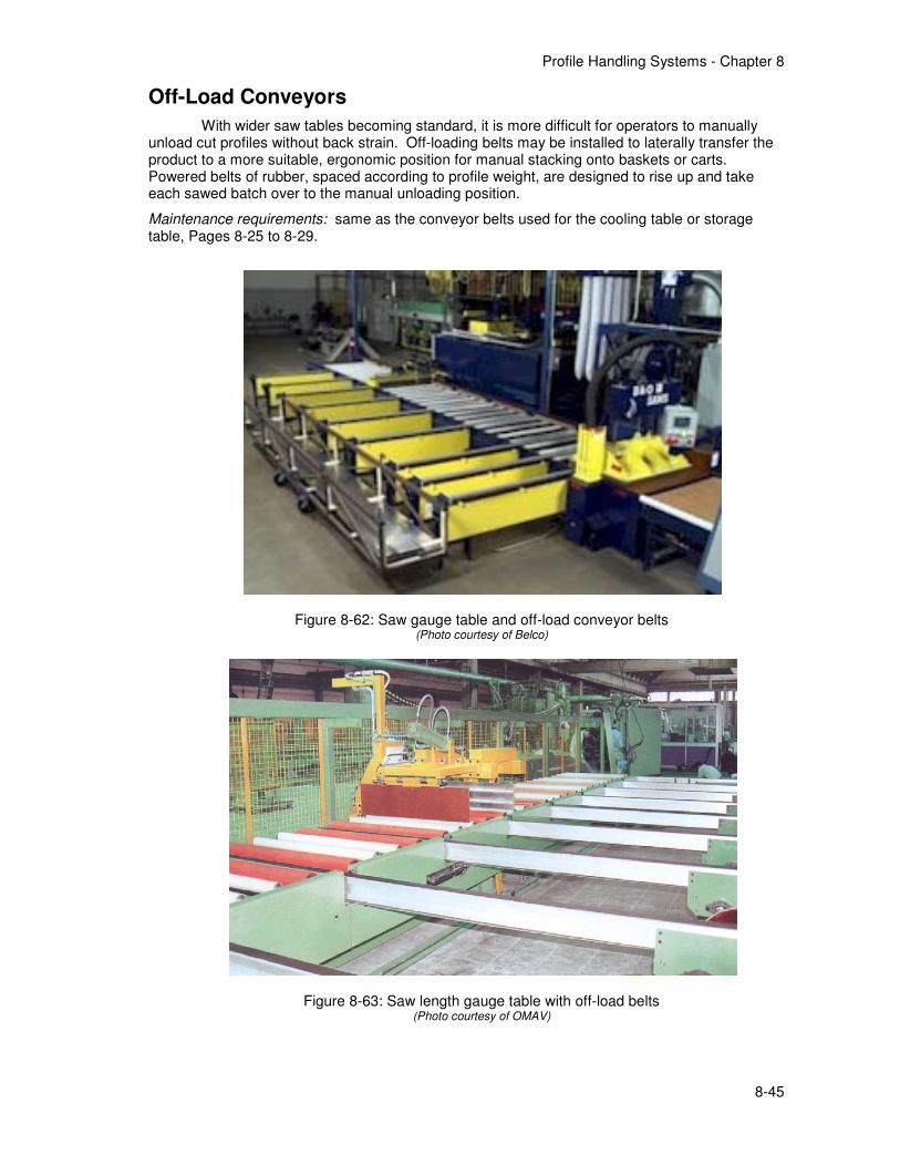
Profile Handling Systems - Chapter 8
8-45
Off-Load Conveyors
With wider saw tables becoming standard, it is more difficult for operators to manually unload cut profiles without back strain. Off-loading belts may be installed to laterally transfer the product to a more suitable, ergonomic position for manual stacking onto baskets or carts. Powered belts of rubber, spaced according to profile weight, are designed to rise up and take each sawed batch over to the manual unloading position.
Maintenance requirements: same as the conveyor belts used for the cooling table or storage table, Pages 8-25 to 8-29.
Figure 8-62: Saw gauge table and off-load conveyor belts (Photo courtesy of Belco)
Figure 8-63: Saw length gauge table with off-load belts (Photo courtesy of OMAV)
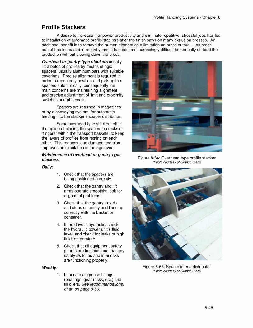
Profile Handling Systems - Chapter 8
8-46
Profile Stackers
A desire to increase manpower productivity and eliminate repetitive, stressful jobs has led to installation of automatic profile stackers after the finish saws on many extrusion presses. An additional benefit is to remove the human element as a limitation on press output --- as press output has increased in recent years, it has become increasingly difficult to manually off-load the production without slowing down the press.
Overhead or gantry-type stackers usually lift a batch of profiles by means of rigid spacers, usually aluminum bars with suitable coverings. Precise alignment is required in order to repeatedly position and pick up the spacers automatically; consequently the main concerns are maintaining alignment and precise adjustment of limit and proximity switches and photocells.
Spacers are returned in magazines or by a conveying system, for automatic feeding into the stacker’s spacer distributor.
Some overhead-type stackers offer the option of placing the spacers on racks or “fingers” within the transport baskets, to keep the layers of profiles from resting on each other. This reduces load damage and also improves air circulation in the age oven.
Maintenance of overhead or gantry-type stackers
Daily:
1. Check that the spacers are being positioned correctly.
2. Check that the gantry and lift arms operate smoothly; look for alignment problems.
3. Check that the gantry travels and stops smoothly and lines up correctly with the basket or container.
4. If the drive is hydraulic, check the hydraulic power unit’s fluid level, and check for leaks or high fluid temperature.
5. Check that all equipment safety guards are in place, and that any safety switches and interlocks are functioning properly.
Weekly:
1. Lubricate all grease fittings (bearings, gear racks, etc.) and fill oilers. See recommendations, chart on page 8-50.
Figure 8-64: Overhead-type profile stacker (Photo courtesy of Granco Clark)
Figure 8-65: Spacer infeed distributor (Photo courtesy of Granco Clark)
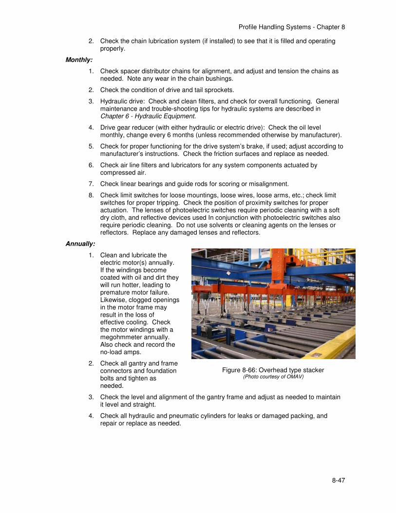
Profile Handling Systems - Chapter 8
8-47
2. Check the chain lubrication system (if installed) to see that it is filled and operating properly.
Monthly:
1. Check spacer distributor chains for alignment, and adjust and tension the chains as needed. Note any wear in the chain bushings.
2. Check the condition of drive and tail sprockets.
3. Hydraulic drive: Check and clean filters, and check for overall functioning. General maintenance and trouble-shooting tips for hydraulic systems are described in Chapter 6 - Hydraulic Equipment.
4. Drive gear reducer (with either hydraulic or electric drive): Check the oil level monthly, change every 6 months (unless recommended otherwise by manufacturer).
5. Check for proper functioning for the drive system’s brake, if used; adjust according to manufacturer’s instructions. Check the friction surfaces and replace as needed.
6. Check air line filters and lubricators for any system components actuated by compressed air.
7. Check linear bearings and guide rods for scoring or misalignment.
8. Check limit switches for loose mountings, loose wires, loose arms, etc.; check limit switches for proper tripping. Check the position of proximity switches for proper actuation. The lenses of photoelectric switches require periodic cleaning with a soft dry cloth, and reflective devices used In conjunction with photoelectric switches also require periodic cleaning. Do not use solvents or cleaning agents on the lenses or reflectors. Replace any damaged lenses and reflectors.
Annually:
1. Clean and lubricate the electric motor(s) annually. If the windings become coated with oil and dirt they will run hotter, leading to premature motor failure. Likewise, clogged openings in the motor frame may result in the loss of effective cooling. Check the motor windings with a megohmmeter annually. Also check and record the no-load amps.
2. Check all gantry and frame connectors and foundation bolts and tighten as needed.
3. Check the level and alignment of the gantry frame and adjust as needed to maintain it level and straight.
4. Check all hydraulic and pneumatic cylinders for leaks or damaged packing, and repair or replace as needed.
Figure 8-66: Overhead type stacker (Photo courtesy of OMAV)
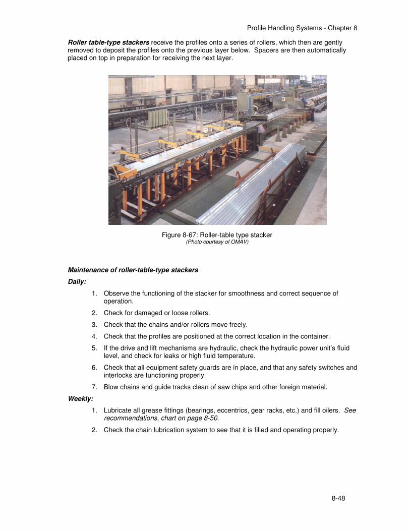
Profile Handling Systems - Chapter 8
8-48
Roller table-type stackers receive the profiles onto a series of rollers, which then are gently removed to deposit the profiles onto the previous layer below. Spacers are then automatically placed on top in preparation for receiving the next layer.
Maintenance of roller-table-type stackers
Daily:
1. Observe the functioning of the stacker for smoothness and correct sequence of operation.
2. Check for damaged or loose rollers.
3. Check that the chains and/or rollers move freely.
4. Check that the profiles are positioned at the correct location in the container.
5. If the drive and lift mechanisms are hydraulic, check the hydraulic power unit’s fluid level, and check for leaks or high fluid temperature.
6. Check that all equipment safety guards are in place, and that any safety switches and interlocks are functioning properly.
7. Blow chains and guide tracks clean of saw chips and other foreign material.
Weekly:
1. Lubricate all grease fittings (bearings, eccentrics, gear racks, etc.) and fill oilers. See recommendations, chart on page 8-50.
2. Check the chain lubrication system to see that it is filled and operating properly.
Figure 8-67: Roller-table type stacker (Photo courtesy of OMAV)

Profile Handling Systems - Chapter 8
8-49
Monthly:
1. Check drive chains for alignment and adjust and tension the chains as needed. Check for wear in the chain bushings.
2. Check the condition of drive and tail sprockets.
3. Hydraulic unit: Check and clean filters, and check for overall functioning. General maintenance and trouble-shooting tips for hydraulic systems are described in Chapter 5 - Hydraulic Equipment.
4. Check air line filters and lubricators if any system components are actuated by compressed air. Add oil as needed.
5. Check limit switches for loose mountings, loose wires, loose arms, etc.; check limit switches for proper tripping. Check the position of proximity switches for proper actuation. The lenses of photoelectric switches require periodic cleaning with a soft dry cloth, and reflective devices used In conjunction with photoelectric switches also require periodic cleaning. Do not use solvents or cleaning agents on the lenses or reflectors. Replace any damaged lenses and reflectors.
Annually:
1. Clean and lubricate the electric motor(s) annually. If the windings become coated with oil and dirt they will run hotter, leading to premature motor failure. Likewise, clogged openings in the motor frame may result in the loss of effective cooling. Check the motor windings with a megohmmeter annually. Also check and record the no-load amps.
2. Check all conveyor and frame connections and foundation bolts and tighten as needed.
3. Check the level and alignment of the conveyor frame and adjust as needed to maintain it level and straight.
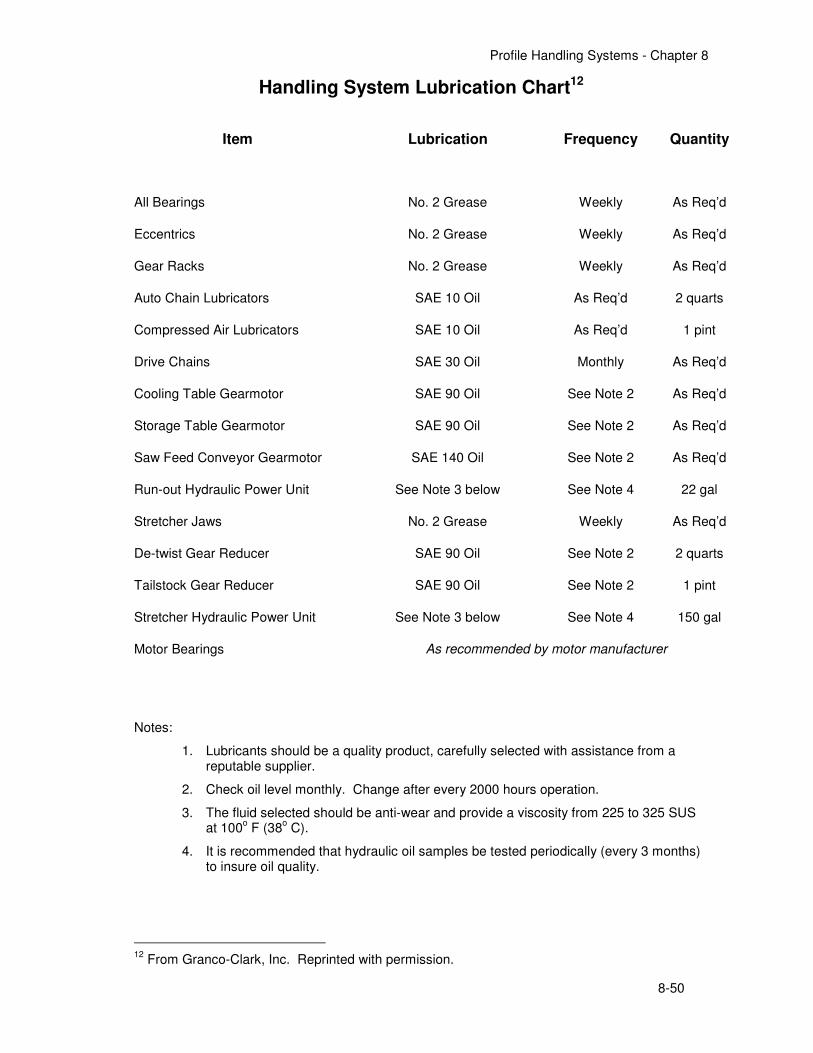
Profile Handling Systems - Chapter 8
8-50
Handling System Lubrication Chart12
Item Lubrication Frequency Quantity
All Bearings No. 2 Grease Weekly As Req’d
Eccentrics No. 2 Grease Weekly As Req’d
Gear Racks No. 2 Grease Weekly As Req’d
Auto Chain Lubricators SAE 10 Oil As Req’d 2 quarts
Compressed Air Lubricators SAE 10 Oil As Req’d 1 pint
Drive Chains SAE 30 Oil Monthly As Req’d
Cooling Table Gearmotor SAE 90 Oil See Note 2 As Req’d
Storage Table Gearmotor SAE 90 Oil See Note 2 As Req’d
Saw Feed Conveyor Gearmotor SAE 140 Oil See Note 2 As Req’d
Run-out Hydraulic Power Unit See Note 3 below See Note 4 22 gal
Stretcher Jaws No. 2 Grease Weekly As Req’d
De-twist Gear Reducer SAE 90 Oil See Note 2 2 quarts
Tailstock Gear Reducer SAE 90 Oil See Note 2 1 pint
Stretcher Hydraulic Power Unit See Note 3 below See Note 4 150 gal
Motor Bearings As recommended by motor manufacturer
Notes:
1. Lubricants should be a quality product, carefully selected with assistance from a reputable supplier.
2. Check oil level monthly. Change after every 2000 hours operation.
3. The fluid selected should be anti-wear and provide a viscosity from 225 to 325 SUS at 100
o F (38
o C).
4. It is recommended that hydraulic oil samples be tested periodically (every 3 months) to insure oil quality.
12
From Granco-Clark, Inc. Reprinted with permission.
Related Documents

![Festo Handling and Positioning Profile · Descripción FHPP Controlador del motor del tipo CMM... Festo Handling and Positioning Profile Descripción 555 697 es 1006a [749 177] Festo](https://static.cupdf.com/doc/110x72/5c61a86009d3f2f2128b6b83/festo-handling-and-positioning-profile-descripcion-fhpp-controlador-del-motor.jpg)