© Carrier Corporation 2014 Form 42-10PD Carrier’s 42C,D,S,V Series fan coil units offer: • Design flexibility, occupying minimum space • Easy, low-cost installation • Permanent split capacitor or electronically commutated motors deliver peak operating efficiency • High performance, low cost • Greater zone comfort control Features/Benefits Carrier’s extensive range of superior fan-coil units combine design flexibility with easy, low-cost installation. Versatility With Carrier’s 42 Series fan coils, you can select from 4 horizontal, 6 vertical, 5 ducted or 5 stacked models; furred-in or cabinet style, slant top or low silhou- ette, in 150 through 2000 cfm capaci- ties. Coils are available with up to 5 rows (depending on model), to satisfy a variety of application requirements. The units are ideal for installation in motels, apartments, and other multi-room build- ings. Many optional control packages are available to facilitate the following modes of operation: 2-pipe heating and cooling, 2-pipe heating and cooling with auxiliary electric heat, 2-pipe cool- ing with total electric heat, and 4-pipe heating and cooling. The control pack- age offering includes 24-v or line volt- age thermostats and BACnet* commu- nicating controls. Casings and frame are fabricated from tough, heavy gage galvanized steel. Cus- tom decorative colors allow the unit to blend with any interior design. 42C,D,S,V Series Fan Coil Air Conditioners 60 Hz 150 to 2000 cfm Product Data 42CA HORIZONTAL 42DA DUCTED 42VB VERTICAL 42SH STACK

Welcome message from author
This document is posted to help you gain knowledge. Please leave a comment to let me know what you think about it! Share it to your friends and learn new things together.
Transcript
© Carrier Corporation 2014 Form 42-10PD
Carrier’s 42C,D,S,V Series fan coil units offer:• Design flexibility, occupying minimum
space• Easy, low-cost installation• Permanent split capacitor or
electronically commutated motors deliver peak operating efficiency
• High performance, low cost• Greater zone comfort control
Features/BenefitsCarrier’s extensive range of superior fan-coil units combine design flexibility with easy, low-cost installation.VersatilityWith Carrier’s 42 Series fan coils, you can select from 4 horizontal, 6 vertical, 5 ducted or 5 stacked models; furred-in or cabinet style, slant top or low silhou-ette, in 150 through 2000 cfm capaci-ties. Coils are available with up to 5 rows (depending on model), to satisfy a variety of application requirements. The units are ideal for installation in motels, apartments, and other multi-room build-ings. Many optional control packages are available to facilitate the following modes of operation: 2-pipe heating and cooling, 2-pipe heating and cooling with auxiliary electric heat, 2-pipe cool-ing with total electric heat, and 4-pipe heating and cooling. The control pack-age offering includes 24-v or line volt-age thermostats and BACnet* commu-nicating controls.
Casings and frame are fabricated from tough, heavy gage galvanized steel. Cus-tom decorative colors allow the unit to blend with any interior design.
42C,D,S,V SeriesFan Coil
Air Conditioners60 Hz
150 to 2000 cfm
ProductData
42CA HORIZONTAL
42DA DUCTED
42VB VERTICAL42SH STACK
2
Low-cost installation and operationEach unit is designed to occupy aminimum space. No complex system controls are required for Carrier fan coil units. Piping, drain, and wiring connections are readily accessible and mounting holes and slots are pre-drilled to save installation time and field labor expense.
42 Series quality reduces service and maintenance expensesAll coils are factory leak tested at 300 psig air pressure with coil
submerged in water. Condensate drain pans are available in stainless steel or heavy gage galvanized steel construc-tions, along with optional condensate overflow switches complying to the lat-est building codes. A variety of insula-tion types are available for energy sav-ings, sound absorption and indoor air quality (IAQ) preservation.
Efficient operationBlower wheels are centrifugal-type, forward curved, double width, and dou-ble inlet sized for maximum efficiency.
Quiet, dependableperformanceAll units are built to operate unobtru-sively with quiet motors and fans. In ad-dition, 1/2-in. thick sound-absorbing, insulation is used to line the cabinet.
42C Series horizontal, 42VSeries vertical unitsCarrier room fan coil units operate at exceptionally low sound levels. A generous amount of insulation absorbsoperating sound and rugged, rigid construction ensures vibration free op-eration at all fan speeds.
Economical, three-speed fans deliver just the right amount of conditioned air for your comfort needs at any load, and each unit can be shut off when not in use. Optional electronically commu-tated motors deliver peak operating ef-ficiency. By choosing Carrier units, you can match your application with a wide range of custom-designed options and accessories, including electric heat. Filters are cleanable or throwaway type.
Carrier room fan-coil units provide unsurpassed year-round comfort.
Features/Benefits (cont)
Table of contentsPage
Features/Benefits . . . . . . . . . . . . . . . . . . . . . . . . . . . . . . . . . . . . . . . . . . 1-7Options . . . . . . . . . . . . . . . . . . . . . . . . . . . . . . . . . . . . . . . . . . . . . . . 8-13Controls . . . . . . . . . . . . . . . . . . . . . . . . . . . . . . . . . . . . . . . . . . . . . . 14-17Selection Procedure . . . . . . . . . . . . . . . . . . . . . . . . . . . . . . . . . . . . . . . . . 18Application Data . . . . . . . . . . . . . . . . . . . . . . . . . . . . . . . . . . . . . . . . 18-3542C Model Number Nomenclature . . . . . . . . . . . . . . . . . . . . . . . . . . . . . . . . 36 AHRI Capacity Ratings . . . . . . . . . . . . . . . . . . . . . . . . . . . . . . . . . . . 37 Physical Data . . . . . . . . . . . . . . . . . . . . . . . . . . . . . . . . . . . . . . . . . . . 38 Base Unit Dimensions . . . . . . . . . . . . . . . . . . . . . . . . . . . . . . . . . . 39-54
Accessory Dimensions . . . . . . . . . . . . . . . . . . . . . . . . . . . . . . . . . . 55,56 Performance Data . . . . . . . . . . . . . . . . . . . . . . . . . . . . . . . . . . . . . 57-63 Electrical Data . . . . . . . . . . . . . . . . . . . . . . . . . . . . . . . . . . . . . . . 64,6542V Model Number Nomenclature . . . . . . . . . . . . . . . . . . . . . . . . . . . . . . . . 66 AHRI Capacity Ratings . . . . . . . . . . . . . . . . . . . . . . . . . . . . . . . . . . . 67 Physical Data . . . . . . . . . . . . . . . . . . . . . . . . . . . . . . . . . . . . . . . . . . . 68 Base Unit Dimensions . . . . . . . . . . . . . . . . . . . . . . . . . . . . . . . . . . 69-79
Accessory Dimensions . . . . . . . . . . . . . . . . . . . . . . . . . . . . . . . . . . 80-82 Performance Data . . . . . . . . . . . . . . . . . . . . . . . . . . . . . . . . . . . . . . . . 83 Electrical Data . . . . . . . . . . . . . . . . . . . . . . . . . . . . . . . . . . . . . . . 84-8642D Model Number Nomenclature . . . . . . . . . . . . . . . . . . . . . . . . . . . . . . . . 87 AHRI Capacity Ratings . . . . . . . . . . . . . . . . . . . . . . . . . . . . . . . . . . . 87 Physical Data . . . . . . . . . . . . . . . . . . . . . . . . . . . . . . . . . . . . . . . . . . . 88 Base Unit Dimensions . . . . . . . . . . . . . . . . . . . . . . . . . . . . . . . . . . 89-93 Accessory Dimensions . . . . . . . . . . . . . . . . . . . . . . . . . . . . . . . . . . 94,95 Performance Data . . . . . . . . . . . . . . . . . . . . . . . . . . . . . . . . . . . . . 96-99 Electrical Data . . . . . . . . . . . . . . . . . . . . . . . . . . . . . . . . . . . . . 100-10242S Model Number Nomenclature . . . . . . . . . . . . . . . . . . . . . . . . . . . . . . . 103 AHRI Capacity Ratings . . . . . . . . . . . . . . . . . . . . . . . . . . . . . . . . . . . 104 Physical Data . . . . . . . . . . . . . . . . . . . . . . . . . . . . . . . . . . . . . . . . . . 104 Base Unit Dimensions . . . . . . . . . . . . . . . . . . . . . . . . . . . . . . . . 105-112
Accessory Dimensions . . . . . . . . . . . . . . . . . . . . . . . . . . . . . . . . 113-117 Performance Data . . . . . . . . . . . . . . . . . . . . . . . . . . . . . . . . . . . 118-125 Electrical Data . . . . . . . . . . . . . . . . . . . . . . . . . . . . . . . . . . . . . . 126,127Guide Specifications . . . . . . . . . . . . . . . . . . . . . . . . . . . . . . . . . . . . 128-137Index . . . . . . . . . . . . . . . . . . . . . . . . . . . . . . . . . . . . . . . . . . . . . . . . . . . 138

3
42D ducted unitsA drip lip (removable drain pan exten-sion) is available for field installation on ceiling models 42DA,DC,DE and DF. The drip lip is recommended for all ceiling models when a valve package is installed.
Motor/blower assembly can be easi-ly removed from the unit for ease of service. Removing this assembly pro-vides clear access to the entering air face of the coil, making coil cleaning a relatively simple matter. Removable panels make access to components and connections easy.
42S stacked unitsEach Carrier stack unit comes factory equipped with insulated supply, return, and drain risers. The design of the 42S units allows them to be set one on top of the other in a vertical column rising floor to floor up the building. Each ris-er has a 3-in. belled section at the top, so the riser piping can be connected by only one sweat connection per riser. Field-installed couplings or internal pipe connections are not needed.
Each stack unit is constructed of 18-gage galvanized steel and factory pre-wired with all control, motor, and optional electric heat wiring conve-niently terminating in a single, accessible junction box. Each stack unit requires only one field power connection.
Field-mounted accessories, such as the 3-speed switch/thermostat pack-age for furred-in units, are equipped with a pre-wired quick disconnect plug for easy installation.
The riser size for the stack units can be specified to match building require-ments so that cutting, sorting, and han-dling of the risers is not necessary. All units arrive tagged as specified by the customer for efficient delivery to the correct building location.
Units can be loaded onto delivery trucks so that they can be off-loaded in the proper installation sequence.
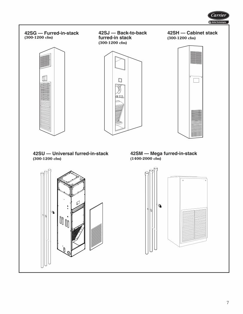
The 42SG furred-in-stack is a single unit, designed for concealed applications in corners or along room walls. The return-air grille is removable to allow access for servicing major components.
The 42SG is also available in master/slave unit pairs, shipped indi-vidually and installed and piped togeth-er in the field. The master unit includes risers with stub out for field piping con-nections to the slave unit which has no risers of its own.
The 42SJ back-to-back furred-in stack is designed for installation in the separation wall between 2 rooms. The unit consists of 2 units piped to a set of common risers. Each unit has its own valves and controls. The return-air
grille is removable to allow access for servicing major components.
The 42SH cabinet stack unit is de-signed for applications where con-cealed installations are not possible or practical. This model features a double-deflection supply-air grille and an inte-gral return-air grille access panel. Con-trols are normally mounted on the unit but may also be remote wall mounted.
The 42SU universal furred-in stack is designed for easy field configuration utilizing laser cut knockouts. Riser, drain, supply, and outside-air knock-outs have been strategically located on the unit for field configuration. Prior to unit installation, all risers are shipped separately from the units for pre-instal-lation and testing purposes.
The 42SM mega furred-in stack unit is designed for applications requiring units with increased capacity. The 42SM is designed to deliver 1400 to 2000 CFM at 0.5 in. ESP (external static pressure). Although usually in-stalled in a small mechanical closet, the unit also features an optional decora-tive return air panel to allow for a clas-sic high-rise type application. The unit’s high static capability will easily handle high-efficiency air filters and decorative supply grilles, while the modular design provides quiet operation.
* Sponsored by ASHRAE (American Society of Heating, Refrigerating, and Air-Conditioning Engineers).

4
Features/Benefits (cont)
42CAFurred-in ceiling model with low silhouette.(200-1200 cfm)
42CEFurred-in ceiling model with factory-installedplenum.(200-1200 cfm)
42CGCabinet model for under-ceiling mount withbottom or rear stamped louver return air grille.(200-1200 cfm)
42CKCabinet model with telescoping flip-down paneland stamped louver bottom return or ductcollar rear return.(200-1200 cfm)

5
42VAFurred-in model for under-the-windowapplications with top or front discharge.(200-1200 cfm)
42VFCabinet model with slant top andtop or front discharge.(200-1200 cfm)
42VCFurred-in lowboy model for concealed under-the-window applications.(200-600 cfm)
42VECabinet lowboy model with stamped louver dis-charge grille and 2 control access doors.(200-600 cfm)
42VGFurred-in wall model. Available with a 10-in.valve compartment extension.(150 and 300 cfm)
42VBCabinet model with top orfront discharge.(200-1200 cfm)

6
Features/Benefits (cont)
42DAFurred-in model for installation in theceiling or over the closet.(600-2000 cfm)
42DDVertical model with galvanized casing.Commonly for closet installation.(600-2000 cfm)
42DECeiling model with galvanized casing.(600-2000 cfm)
42DFExposed-ceiling cabinet model with inte-gral double-deflection discharge grille anda bar-type return-air grille.(600-2000 cfm)
42DCFurred-in ceiling model with factory-installedinsulated plenum.(600-2000 cfm)
42-68d
7
42SG — Furred-in-stack(300-1200 cfm)
42SJ — Back-to-backfurred-in stack (300-1200 cfm)
42SH — Cabinet stack(300-1200 cfm)
42SU — Universal furred-in-stack(300-1200 cfm)
a42-4148
42SM — Mega furred-in-stack(1400-2000 cfm)
42-100d
a42-4260

8
AVAILABLE OPTIONS
LEGEND *All options are factory-installed unless noted as shipped loose.†Standard grille is steel; option is available as steel or aluminum.**Registered trademark of Johns Manville.
OPTIONS OR STANDARD FEATURES*UNIT SERIES — 42
Ceiling — Horizontal Vertical Floor Ducted — Horizontal Stack — VerticalCA CE CG CK VA VB VF VC VE VG DA DC DE DF DD SG SH SJ SU SM
AIR VENT Automatic Air Vent X X X X X X X X X X X X X X X X X X X Manual Air Vent Std Std Std Std Std Std Std Std Std Std Std Std Std Std Std Std Std Std Std StdCABINET CHANGES Front Panel, 18 Gage Std Std Std Std Std Std Std Std Std Std Std Std Std Std Std Std Std Std Std Std Extended Cabinet Height X X Valve Compartment Extension, 10 in. XCOILS 2-Row (Cooling Only) X X X X Std Std Std 3-Row (2-Row Cooling, 1-Row Heating) X X 3-Row (Cooling/Heating Only) Std Std Std Std Std Std Std X X X X X X X Std Std Std Std X 4-Row (3-Row Cooling, 1-Row Heating) X X X X X X X X X X X X X X X X X 4-Row (Cooling/Heating Only) X X X X X X X Std Std Std Std Std X X X X Std 5-Row (Cooling/Heating Only) X 5-Row (4-Row Cooling, 1-Row Heating) X X X X X X X X X X X X X X X X X 5-Row (3-Row Cooling, 2-Row Heating) X X X X X X X X X X X X X X X X X 6-Row (4-Row Cooling, 2-Row Heating) X X X X X 6-Row (Cooling/Heating Only) X X X X X 7-Row (6-Row Cooling, 1-Row Heating) X X X X 8-Row (6-Row Cooling, 2-Row Heating) X X X X 10 FPI Std Std Std Std Std Std Std Std Std Std Std Std 12 FPI Std Std Std 14 FPI Std Std Std Std Std Stainless Steel Coil Wrapper X X X X X X X X X X X X X X X X X XDAMPERS 25% Motorized Damper ETO ETO ETO ETO 5 x 7 Manual Sliding Damper X X X 4 in. Opening Assembly with Sliding Damper X X X
6 in. Opening with Manual Sliding Damper X
Outside-Air Knockouts Std Outdoor-Air Connection ETO ETO ETO X X ETO ETO ETO ETODECORATIVE COLORS See Carrier Paint Selector Guide ETO ETO ETO ETO ETO ETO ETO ETODISCHARGE GRILLES Stamped Discharge Std Std Std Std Std Std Double Deflection, Factory-Installed† X X X X X Std Double Deflection, Shipped Loose† X Std Std Std X XDRAIN PANS Standard Drain Pan, Closed-Cell Foam on Inside Std Std Std Std Std Std Std Std Std Std Std Std Std Std Std Std Std Std
Extended Drain Pan X X X X Stainless Steel Standard Drain Pan X X X X X X X X X X X X X X X X X X X Std Stainless Steel Extended Drain Pan X X X X Tell-Tale Only X X X X X X X X Drip Lip Only X X X X X X X X Tell-Tell and Drip Lip X X X X X X X XDUCT COLLAR Discharge Std Std Std Std Std Std Std Std Std Std Std Std Discharge Knockouts StdELECTRIC HEATERS Nichrome Wire Strip Heater X X X X X X X X X X X X X X X X X Sheath Type Heater X X
EC — Electronically CommutatedETO — Engineered to OrderPSC — Permanent Split CapacitorStd — Standard
X — Available as Options
Options
9
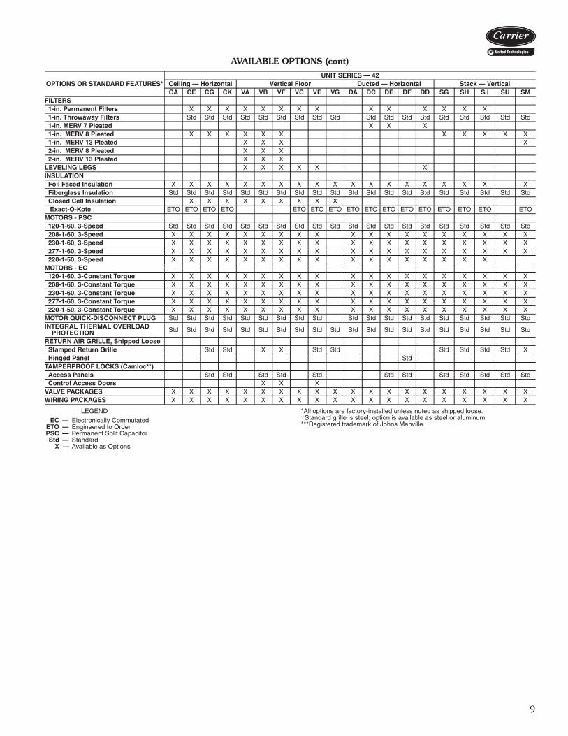
AVAILABLE OPTIONS (cont)
LEGEND *All options are factory-installed unless noted as shipped loose.†Standard grille is steel; option is available as steel or aluminum.***Registered trademark of Johns Manville.
OPTIONS OR STANDARD FEATURES*UNIT SERIES — 42
Ceiling — Horizontal Vertical Floor Ducted — Horizontal Stack — VerticalCA CE CG CK VA VB VF VC VE VG DA DC DE DF DD SG SH SJ SU SM
FILTERS 1-in. Permanent Filters X X X X X X X X X X X X X X 1-in. Throwaway Filters Std Std Std Std Std Std Std Std Std Std Std Std Std Std Std Std Std Std 1-in. MERV 7 Pleated X X X 1-in. MERV 8 Pleated X X X X X X X X X X X 1-in. MERV 13 Pleated X X X X 2-in. MERV 8 Pleated X X X 2-in. MERV 13 Pleated X X XLEVELING LEGS X X X X X XINSULATION Foil Faced Insulation X X X X X X X X X X X X X X X X X X X Fiberglass Insulation Std Std Std Std Std Std Std Std Std Std Std Std Std Std Std Std Std Std Std Std Closed Cell Insulation X X X X X X X X X Exact-O-Kote ETO ETO ETO ETO ETO ETO ETO ETO ETO ETO ETO ETO ETO ETO ETO ETOMOTORS - PSC 120-1-60, 3-Speed Std Std Std Std Std Std Std Std Std Std Std Std Std Std Std Std Std Std Std Std 208-1-60, 3-Speed X X X X X X X X X X X X X X X X X X X 230-1-60, 3-Speed X X X X X X X X X X X X X X X X X X X 277-1-60, 3-Speed X X X X X X X X X X X X X X X X X X X 220-1-50, 3-Speed X X X X X X X X X X X X X X X X XMOTORS - EC 120-1-60, 3-Constant Torque X X X X X X X X X X X X X X X X X X X 208-1-60, 3-Constant Torque X X X X X X X X X X X X X X X X X X X 230-1-60, 3-Constant Torque X X X X X X X X X X X X X X X X X X X 277-1-60, 3-Constant Torque X X X X X X X X X X X X X X X X X X X 220-1-50, 3-Constant Torque X X X X X X X X X X X X X X X X X X XMOTOR QUICK-DISCONNECT PLUG Std Std Std Std Std Std Std Std Std Std Std Std Std Std Std Std Std Std StdINTEGRAL THERMAL OVERLOAD PROTECTION Std Std Std Std Std Std Std Std Std Std Std Std Std Std Std Std Std Std Std Std
RETURN AIR GRILLE, Shipped Loose Stamped Return Grille Std Std X X Std Std Std Std Std Std X Hinged Panel StdTAMPERPROOF LOCKS (Camloc**) Access Panels Std Std Std Std Std Std Std Std Std Std Std Std Control Access Doors X X XVALVE PACKAGES X X X X X X X X X X X X X X X X X X X XWIRING PACKAGES X X X X X X X X X X X X X X X X X X X X
EC — Electronically CommutatedETO — Engineered to OrderPSC — Permanent Split CapacitorStd — Standard
X — Available as Options

10
Factory-installed optionsCoils — Choice of a 2-pipe or 4-pipe system with the fol-lowing chilled/hot water coil configurations:
LEGEND
*Needs quote control.
Seismic Compliance Options — Several models havebeen tested and approved for installations requiring IBC orOSHPD seismic certification. See the following tables forapproved models and options.Condensate overflow switch — This switch shuts downthe unit when the water level in the drain pan reaches anunsafe level. Building code changes in many locales nowrequire this type of device.Decorative colors — A wide variety of colors (Cham-pagne Beige, Toffee Brown, Ermine Grey, and PolarWhite) are available to match any interior décor. Select adesired color from a paint chip chart, Catalog number842-011, or provide paint chip for matching. Standardcolor is now Arctic White; the other colors require a specialquote. Optional or custom colors will only be quoted by thefactory if the volume is significant enough to use the mini-mum quantity of paint required by the painting vendor.Therefore, the optional or custom color will not be avail-able on small quantities of units. As an alternative, units
can be coated with primer by the factory to allow for fieldpainting. Decorative colors may be applied to:• Cabinet of 42VB, VF, VE, VG• Cabinet of 42CG• Panels of 42SH• Bottom panels of 42CK• Cabinet of 42DFElectric heaters — Coils are of high grade single-phase,nichrome resistance wire, insulated by ceramic insulators inplated steel brackets. Heater sizes available are shown inthe application data section for the respective units. Notavailable on 42VG units.Filters — Each unit (except the 42CA, DA units) includesa non-woven synthetic throwaway filter sized for low veloc-ity and maximum efficiency. The standard option will filterboth return and outside air. For optional filters, please referto available option table on pages 8 and 9.Fusing — Incoming power fusing, as well as blower motorand control sub-fusing for units that use electric heat. Theblower motor and control sub-fusing (single power sourcewiring) is required when single source power with electricheat is specified.Manual air vents — Each standard coil includes a man-ual air vent to allow venting at the coil if necessary forquick, complete air elimination.Motors — Three-speed PSC (permanent split capacitor)motors are offered as standard, providing the ability toadjust airflow to meet varying load conditions. High-staticPSC motors are available as an option for applicationsrequiring higher external static capability. ECM (electroni-cally commutated) motors are optional on all units except42VG. ECM motors offer programmable features, lowsound, and increased energy efficiency. Refer to the appli-cation data section for more information on ECM controlmethods.Outside-air opening/damper — Damper is adjustablefrom 0 to 25% and provides ventilation air to unit.(Manual/motorized damper available on 42SG, SH, SJ,SM units.)Service switches — Concealed service switches areavailable for use by maintenance and service personnel toshut off the power while working on the unit. Single power source connection — Factory-installedjunction box allows use of single power source for motorand heater when they are of the same voltage. Stamped toe space return-air grille — The return-airgrille is available as a factory-installed option for 42VB and42VF units.Tamperproof Camloc fasteners (Allen head) —Camloc fasteners are installed on the access panels and areavailable for all cabinet model units.Thermostat control packages — We offer a variety ofcontrol devices to meet the most basic to the mostdemanding operating logic. All of our control schemes uti-lize 3-speed fan control to modulate cooling output, maxi-mize the percentage of latent heat removal, and to furtherreduce the sound level when maximum cooling and
COIL CONFIGURATIONUNIT
42C 42D 42S 42V2-Row Coil • ETO ETO —
3-Row Coil• • •
42VA,VB, VC,VE,VF
only
4-Row Coil • • • 42VA,VB, VF only
5-Row Coil — — 42SM only —
6-Row Coil — • — —8-Row Coil* — ETO — —Opposite End Coil Connections
3/1 • • • 42VA,VB, VF only
3/2 • • • 42VA,VB, VF only
4/1 • • • 42VA,VB, VF only
4/2 — • — —
6/1 — 42DA,DC, DE,DF only — —
6/2 — 42DA,DC, DE,DF only — —
Same End Coil Connections
2/1 — — — 42VC,VE only
3/1 • • • 42VA,VB, VF only
3/2 • • • 42VA,VB, VF only
4/1 • • • 42VA,VB, VF only
4/2 — • — —
6/1 — 42DA,DC, DE,DF only — —
6/2 — 42DA,DC, DE,DF only — —
Cu/Cu Coil Special Option* ETO ETO ETO ETO
• Available — Not AvailableETO Engineer to Order
Options (cont)

11
heating performance is not required. The standard ther-mostat control option is line voltage except on 42SU and42SM, which include a low voltage control package asstandard. Unit-mounted line voltage and 24-v thermostats
are available on the 42V Series units. For thermostat con-trol package options refer to pages 13-16.
42C SEISMIC COMPLIANCE OPTION COMPATIBILITY CHART
OPTION DESCRIPTIONUNIT
42CA 42CE 42CG 42CK
2-Pipe Hydronic Coil Configurations
2-Row Coil I I I/O I/O3-Row Coil I I I/O I/O4-Row or 5-Row Coil I I I/O I/O
4-Pipe Hydronic Coil Configuration
2/1 or 2/2 Split Coil I I I/O I/O3/1, 3/2, or 4/1 Split Coil I I I/O I/O
Electric Heat All electric heat options I I I/O I/OService Switches All service switch options I I I/O I/O
Coil OptionsStainless steel coil wrapper I I I/O I/OCoil air vents (manual or automatic) I I I/O I/OCoil drains I I I/O I/O
PSC Motors 115V, 208V, 230V, 277V, Single Phase, 60 Hz I I I/O I/O
Control PackagesAll control package options EXCEPT Fan Coil Open and CCN Controllers (Digit 16 cannot be W or Z)
I I I/O I/O
Individual Valves and Valve Packages
All valve options EXCEPT modulating valves and valve packages containing modulating valves I I I/O I/O
Filters1-inch throwaway or permanent washable NA I I/O I/O1-inch pleated MERV 8 NA I I/O I/O
Drain Pan
Standard drain pan I I I/O I/OStainless steel drain pan I I I/O I/OTell-Tale I I I/O I/ODrip Lip I I I/O I/OExtended main drain pan (galvanized or stain-less steel) I I I/O I/O
Condensate overflow switch (option 26-A) I I I/O I/O
Cabinet InsulationStandard Tuf-Skin fiberglass insulation I I I/O I/OFoil-faced fiberglass insulation I I I/O I/O
LEGENDI — International Building Code (IBC) ComplianceO — Office of Statewide Health Planning and Development (OSHPD) Pre-Approved (OSP-0229-10)
NOTES:1. Seismic compliance option includes factory-supplied, field-
installed isolation hanger and seismic restraints required for agiven unit.
2. Direct expansion (DX) coils and steam coils are not compatiblewith seismic compliance option.
3. Electonically commutated motors (ECM) are not compatible withseismic compliance option.

12
Field-installed accessoriesAutomatic air vents — Automatic air vents have fiberwashers which allow air in the pipes to pass through, auto-matically bleeding the system, and eliminating the need tomanually remove air from the system. When wet, washersswell and seal the system.Drip lips (removable drain extension) — Drip lips arefrequently used when valves are added after unit installa-tion and space limitations will not permit use of anextended drain pan. The drip lip is placed on the end ofthe drain pan and is pitched toward the pan to ensureproper drainage. The drip lip gives positive control of con-densate from valves and controls. Panels, frames, and grilles — Panels, frames, andgrilles on the 42S Series units can be chosen in a wide vari-ety of combinations to suit room decorating requirementsand allow access to the unit for maintenance. Dischargegrilles are double deflection type, aluminum finish or
painted. Return-air access panels containing return-airgrilles are available in five different types as illustrated onpages 114 and 115.
PANELS, FRAMES AND GRILLES
42D SEISMIC COMPLIANCE OPTION COMPATIBILITY CHART
OPTION DESCRIPTIONUNIT
42DA 42DC 42DE 42DF 42DD
2-Pipe Hydronic Coil Configurations
3-Row Coil I I I/O I/O I/O4-Row or 5-Row Coil I I I/O I/O I/O6-Row Coil I I I/O I/O I/O7-Row or 8-Row Coil I I I/O I/O N/A
4-Pipe Hydronic Coil Configuration
3/1, 3/2 or 4/1 Split Coil I I I/O I/O I/O4/2 Split Coil I I I/O I/O I/O6/1 or 6/2 Split Coil I I I/O I/O N/A
Electric Heat All electric heat options I I I/O I/O I/OService Switches All service switch options I I I/O I/O I/O
Coil OptionsStainless steel coil wrapper I I I/O I/O I/OCoil air vents (manual or automatic) I I I/O I/O I/OCoil drains I I I/O I/O I/O
PSC Motors 115V, 208V, 230V, 277V, Single Phase, 60 Hz I I I/O I/O I/O
Control PackagesAll control package options EXCEPT Fan Coil Open and CCN Controllers (Digit 16 cannot be W or Z)
I I I/O I/O I/O
Individual Valves and Valve Packages
All valve options EXCEPT modulating valves and valve packages containing modulating valves
I I I/O I/O I/O
Filters1-inch throwaway or permanent washable NA I I/O I/O I/O1-inch pleated MERV 8 NA I I/O I/O I/O
Drain Pan
Standard drain pan I I I/O I/O I/OStainless steel drain pan I I I/O I/O I/OTell-Tale I I I/O I/O I/ODrip Lip I I I/O I/O I/OExtended main drain pan (galvanized or stain-less steel) I I I/O I/O I/O
Condensate overflow switch (option 26-A) I I I/O I/O I/O
Cabinet InsulationStandard Tuf-Skin fiberglass insulation I I I/O I/O I/OFoil-faced fiberglass insulation I I I/O I/O I/O
LEGENDI — International Building Code (IBC) ComplianceO — Office of Statewide Health Planning and Development (OSHPD) Pre-Approved (OSP-0229-10)
NOTES:1. For Horizontal Units (42DA, DC, DE, DF) - Seismic compliance
option includes factory-supplied, field-installed isolation hangerand seismic restraints required for a given unit.
2. For Vertical Unit (42DD) - Seismic compliance option offers hardmounting or isolated mounting. For hard mounting, expansionanchors with all brackets is factory supplied, field installed. Forisolated mounting, required isolation mounting system is factoryprovided, field installed.
3. Direct expansion (DX) coils and steam coils are not compatiblewith seismic compliance option.
4. Electronically commutated motors (ECM) are not compatible withseismic compliance option.
PANELNO. DESCRIPTION
1Standard, 18-gage galvanized steel. Coated with baked-on Arctic White enamel finish. Attached to unit with 1/4 turnfasteners.
218-gage galvanized steel. Coated with baked-on Arctic White enamel finish. Includes access door for concealed unit-mounted controls.
3Bar-type extruded aluminum with frame matching double deflection supply grille. Fastens to wall and unit with 11/2 in. long screws.
4and
5
18-gage galvanized steel. Coated with baked-on Arctic White enamel finish. Frame mounted on sheetrock with screws. Panel mounted in frame with 1/4 turn fasteners.
All Each panel provides access to all internal components.
Options (cont)

13
Return-air grilles — Stamped-type return-air grilles arestandard on 42CG,CK,VE,VG,SG,SH,SJ,SU units andoptional on 42VB,VF,SM units. Anodized aluminumhinged bar-type grilles are installed on 42DF units.Risers — The 42S Series units can accommodate 3/4-in.(supply and return) and 1-in. (drain) to 21/2-in. riser sizes in2-pipe systems. For other applications, such as reversereturn risers or 4-pipe systems, it may be necessary toaccommodate the additional risers.
Condensate drains are available in sizes down to 1-in. forgreater cost economy. Riser size-reducers are factory-in-stalled on 42SG, SJ, and SH. For risers over 119-in. long,extension pieces can be furnished for field installation.NOTE: Risers for the 42SU,SM units are shipped sepa-rately for field installation and testing before the unit isinstalled.Riser expansion — The 42S Series units are built toaccommodate modest expansion of the external riser. Thisonly allows for expansion between the unit and theriser. This allowance for movement within the unit isnot intended to replace necessary riser expansion compen-sation devices that the consulting engineer may deemadvisable for the external riser system. External riserexpansion/contraction compensation and anchoring arethe responsibility of the consulting engineer and the install-ing contractor.Risers material and insulation — The 42S Series unitsupply, return, and drain risers can be furnished in type Mor L copper. All factory-furnished risers are insulated withflexible closed foam insulation in 1/2-in. or 3/4-in. thick-ness.Discharge grilles — Two types of double deflection dis-charge grilles are available for 42CG, VB, VF, VE units; anintegral steel grille painted to match the unit or a separateunpainted anodized aluminum grille. Optional discharge airgrilles for 42S Series units are suitable for sidewall applica-tion, and available in clear anodized aluminum or Arctic
White finish. The aluminum discharge grilles are suitablefor air dry field painting. The discharge grille frame andblades are 6063 extruded aluminum alloy with 200-R1satin anodized finish. The frame has a typical wall thick-ness of 0.050-in. and is separated from the blades withinjection-molded nylon bushings. This method of assemblyminimizes corrosion and vibration. The frame mountingholes are dimpled, allowing for a counter-sunk fastenerhead appearance. All blades are airfoil in design, individu-ally adjustable and spaced 3/4-in. on center. At the outeredge of the frame is a specifically engineered channelwhich retains an extruded flexible vinyl bulb gasket thatproduces a positive air seal at the mounting surface, mini-mizing smudging. An optional opposed blade damper isscrewdriver operated through the face of the unit and hasthe same extruded aluminum construction and injection-molded nylon bushings. The unit achieves an effective areaof 80% with the blades set at a 0 degree pattern, thus elim-inating high velocity and pressure drop at the grille face.Wider deflection with reduced throw may be achieved atthe 22 and 45 degree blade settings with slightly increasedsound levels. Tell-tale drain pan — A secondary drain connection islocated above the primary drain to act as a “tell-tale” in theevent that the primary drain becomes obstructed. They canbe applied to either the main drain pan or an extendedmain drain pan. This option is only available on the 42Cand 42DA, DC, DE, DF units.Thermostats control packages — The standard ther-mostat control option is line voltage except for 42SU and42SM units. Wall-mounted line voltage and 24-v thermo-stats are available on the 42 Series fan coil units. For ther-mostat control packages options refer to pages 14-16.Trim strips — Strips are available for use with partiallyrecessed vertical 42VA units and 42S series units only.
DRIP LIP(Horizontal Unit)
“TELL-TALE” DRAIN PAN(Horizontal Unit)
a42-258 a42-259
14
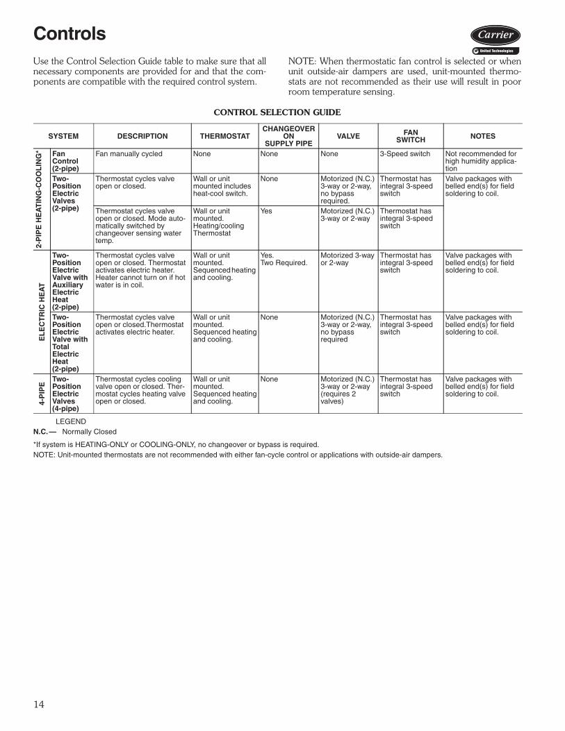
Use the Control Selection Guide table to make sure that allnecessary components are provided for and that the com-ponents are compatible with the required control system.
NOTE: When thermostatic fan control is selected or whenunit outside-air dampers are used, unit-mounted thermo-stats are not recommended as their use will result in poorroom temperature sensing.
CONTROL SELECTION GUIDE
LEGEND
*If system is HEATING-ONLY or COOLING-ONLY, no changeover or bypass is required.NOTE: Unit-mounted thermostats are not recommended with either fan-cycle control or applications with outside-air dampers.
SYSTEM DESCRIPTION THERMOSTATCHANGEOVER
ONSUPPLY PIPE
VALVE FANSWITCH NOTES
2-P
IPE
HE
AT
ING
-CO
OL
ING
* Fan Control(2-pipe)
Fan manually cycled None None None 3-Speed switch Not recommended for high humidity applica-tion
Two-PositionElectricValves(2-pipe)
Thermostat cycles valveopen or closed.
Wall or unit mounted includes heat-cool switch.
None Motorized (N.C.)3-way or 2-way,no bypass required.
Thermostat has integral 3-speed switch
Valve packages with belled end(s) for field soldering to coil.
Thermostat cycles valveopen or closed. Mode auto-matically switched by changeover sensing water temp.
Wall or unit mounted.Heating/coolingThermostat
Yes Motorized (N.C.)3-way or 2-way
Thermostat has integral 3-speed switch
EL
EC
TR
IC H
EA
T
Two-PositionElectricValve withAuxiliaryElectricHeat(2-pipe)
Thermostat cycles valveopen or closed. Thermostatactivates electric heater.Heater cannot turn on if hot water is in coil.
Wall or unit mounted. Sequenced heating and cooling.
Yes.Two Required.
Motorized 3-way or 2-way
Thermostat has integral 3-speed switch
Valve packages with belled end(s) for field soldering to coil.
Two-PositionElectricValve withTotalElectricHeat(2-pipe)
Thermostat cycles valveopen or closed.Thermostat activates electric heater.
Wall or unit mounted.Sequenced heatingand cooling.
None Motorized (N.C.)3-way or 2-way,no bypass required
Thermostat has integral 3-speed switch
Valve packages with belled end(s) for field soldering to coil.
4-P
IPE
Two-PositionElectricValves(4-pipe)
Thermostat cycles cooling valve open or closed. Ther-mostat cycles heating valve open or closed.
Wall or unit mounted.Sequenced heatingand cooling.
None Motorized (N.C.)3-way or 2-way(requires 2 valves)
Thermostat has integral 3-speed switch
Valve packages with belled end(s) for field soldering to coil.
N.C.— Normally Closed
Controls

15
Remote-mounted controls
Wall mounted 3-speed switch — This switch has 4positions: OFF, HIGH, MEDIUM, and LOW. Switch hasauxiliary contact that is energized when switch is in HIGH,MEDIUM or LOW position.Some of the options common with the 3-speed switch are:1. Unit-mounted switch on furred-in vertical model. (Avail-
able as special order on horizontal models.)2. Switch without OFF position.3. Key-operated switch.
Optional remote-mounted thermostat or unit-mounted 24-v thermostat
24-v Debonair thermostat — Features large Thermo-glow™ display, Neverlost™ memory, ExactFit lockingcover, Smart Fan™ dynamic fan speed control, 4-pipe,2-pipe automatic changeover applications with adjustabledead band. Programmable and non-programmable modelsavailable.
Optional remote-mounted line-voltage thermostat
Line voltage T155 thermostat — Features 50 to 90 Ftemperature range, manual 3-speed fan control, mount is astandard 2 x 4 in. box, 4-pipe, 2-pipe and autochangeoverapplications. Available in vertical or horizontal styles.
Unit-mounted controlsLine voltage controls by others — Unit supplied withwiring for valve cycle operation, including changeover sen-sors (as required) for use with field-installed line voltagethermostats.24-v controls by others — Unit supplied with factory-installed 24-v transformer, 3-speed relay board, and aqua-stat (as required) for use with field-installed low voltagecontrols.
Unit-mounted 3-speed switch — Switch has OFF,HIGH, MED and LOW positions. Switch is also equippedwith auxiliary connection energized when switch is inHIGH, MED or LOW position.
3-SPEED SWITCH
COOL
HEAT
AUTO
R
24-V DEBONAIR® THERMOSTAT
LINE VOLTAGE T155 THERMOSTAT
OFF
HI MED
LO
3-SPEED SWITCH
16
Controls (cont)
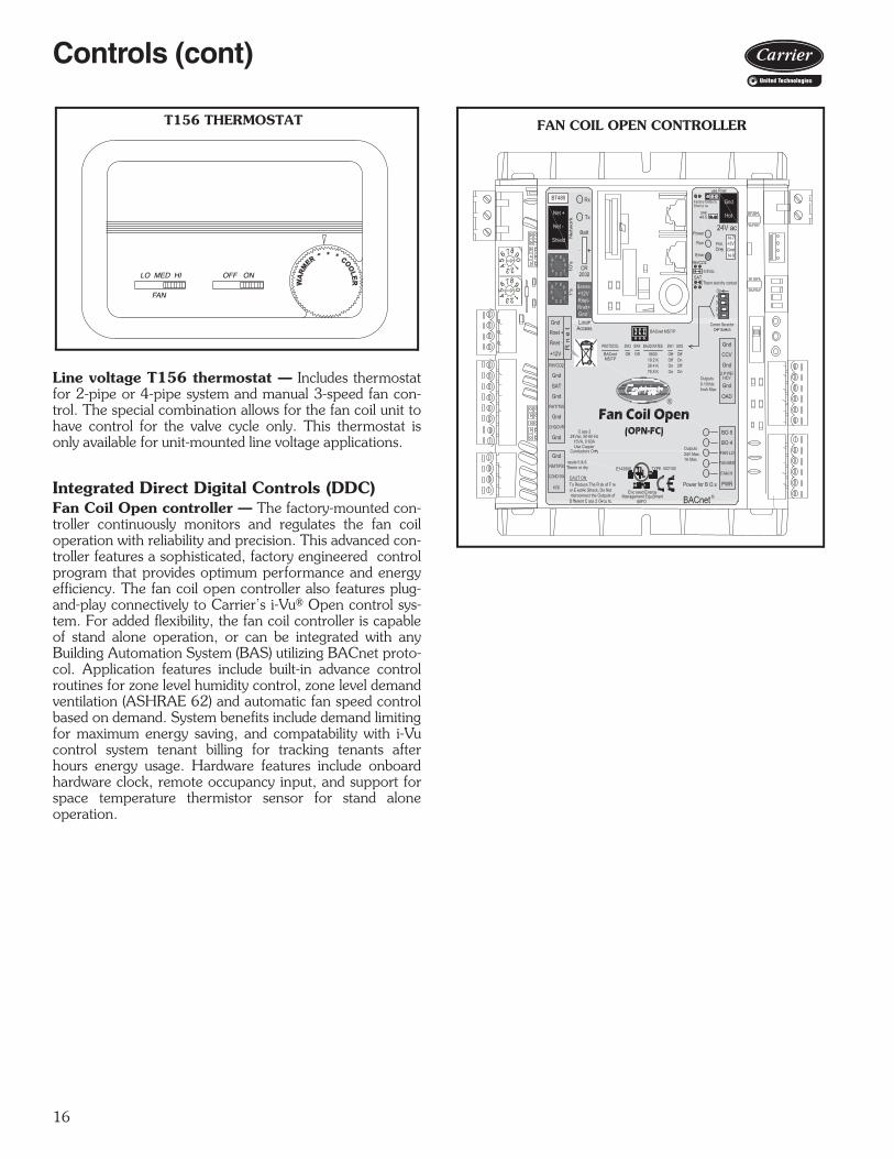
Line voltage T156 thermostat — Includes thermostatfor 2-pipe or 4-pipe system and manual 3-speed fan con-trol. The special combination allows for the fan coil unit tohave control for the valve cycle only. This thermostat isonly available for unit-mounted line voltage applications.
Integrated Direct Digital Controls (DDC)Fan Coil Open controller — The factory-mounted con-troller continuously monitors and regulates the fan coiloperation with reliability and precision. This advanced con-troller features a sophisticated, factory engineered controlprogram that provides optimum performance and energyefficiency. The fan coil open controller also features plug-and-play connectively to Carrier’s i-Vu® Open control sys-tem. For added flexibility, the fan coil controller is capableof stand alone operation, or can be integrated with anyBuilding Automation System (BAS) utilizing BACnet proto-col. Application features include built-in advance controlroutines for zone level humidity control, zone level demandventilation (ASHRAE 62) and automatic fan speed controlbased on demand. System benefits include demand limitingfor maximum energy saving, and compatability with i-Vucontrol system tenant billing for tracking tenants afterhours energy usage. Hardware features include onboardhardware clock, remote occupancy input, and support forspace temperature thermistor sensor for stand aloneoperation.
FAN
LO MED HI OFF ON
T156 THERMOSTAT
a42-4192
FAN COIL OPEN (OPN-FC)
876
54 321
09
876
54 321
09
FAN COIL OPEN CONTROLLER
17
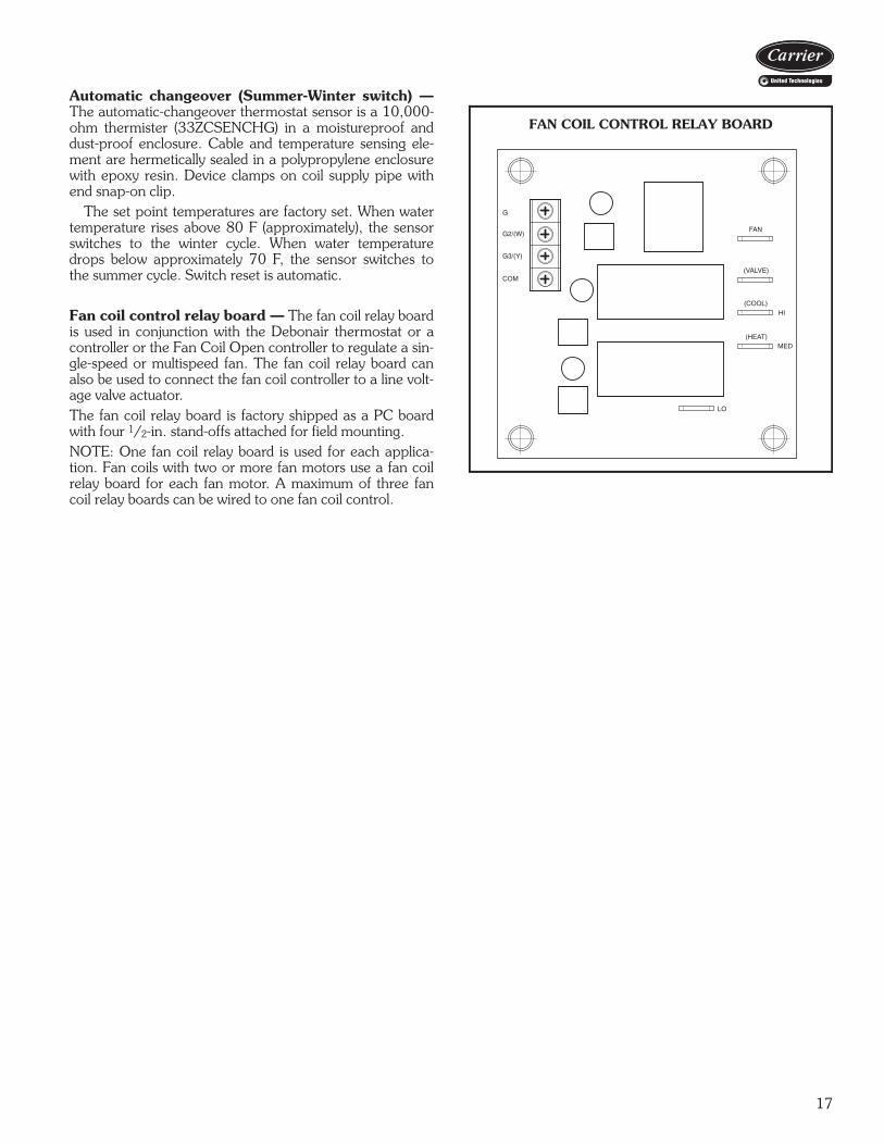
Automatic changeover (Summer-Winter switch) —The automatic-changeover thermostat sensor is a 10,000-ohm thermister (33ZCSENCHG) in a moistureproof anddust-proof enclosure. Cable and temperature sensing ele-ment are hermetically sealed in a polypropylene enclosurewith epoxy resin. Device clamps on coil supply pipe withend snap-on clip.
The set point temperatures are factory set. When watertemperature rises above 80 F (approximately), the sensorswitches to the winter cycle. When water temperaturedrops below approximately 70 F, the sensor switches tothe summer cycle. Switch reset is automatic.
Fan coil control relay board — The fan coil relay boardis used in conjunction with the Debonair thermostat or acontroller or the Fan Coil Open controller to regulate a sin-gle-speed or multispeed fan. The fan coil relay board canalso be used to connect the fan coil controller to a line volt-age valve actuator. The fan coil relay board is factory shipped as a PC boardwith four 1/2-in. stand-offs attached for field mounting.NOTE: One fan coil relay board is used for each applica-tion. Fan coils with two or more fan motors use a fan coilrelay board for each fan motor. A maximum of three fancoil relay boards can be wired to one fan coil control.
G
G2/(W)
G3/(Y)
COM
FAN
(VALVE)
(COOL)HI
(HEAT)MED
LO
FAN COIL CONTROL RELAY BOARD
a42-4186
18
Refer to the Carrier Electronic Selection Program for infor-mation to determine unit sizing for your needs.
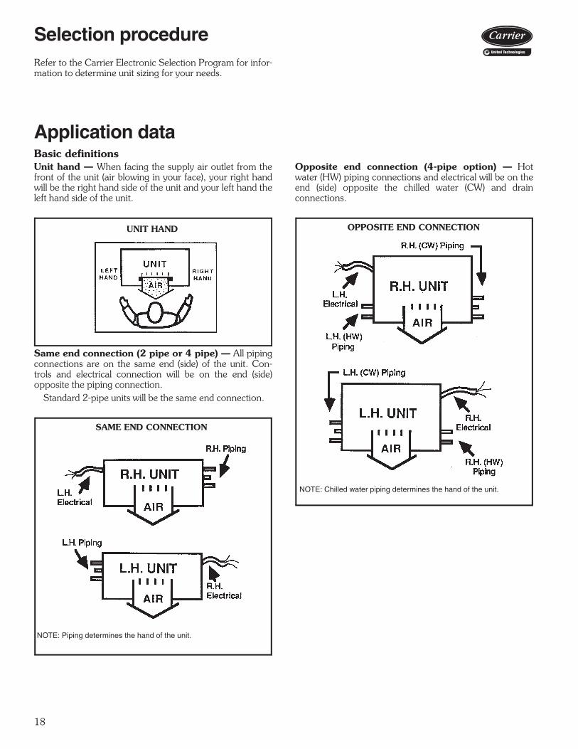
Application dataBasic definitionsUnit hand — When facing the supply air outlet from thefront of the unit (air blowing in your face), your right handwill be the right hand side of the unit and your left hand theleft hand side of the unit.
Same end connection (2 pipe or 4 pipe) — All pipingconnections are on the same end (side) of the unit. Con-trols and electrical connection will be on the end (side)opposite the piping connection.
Standard 2-pipe units will be the same end connection.
Opposite end connection (4-pipe option) — Hotwater (HW) piping connections and electrical will be on theend (side) opposite the chilled water (CW) and drainconnections.
UNIT HAND
SAME END CONNECTION
NOTE: Piping determines the hand of the unit.
OPPOSITE END CONNECTION
NOTE: Chilled water piping determines the hand of the unit.
Selection procedure
19
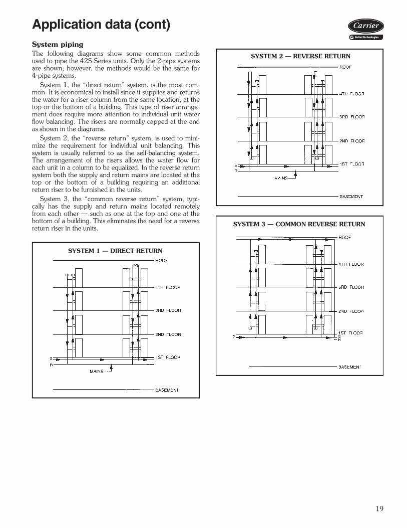
System pipingThe following diagrams show some common methodsused to pipe the 42S Series units. Only the 2-pipe systemsare shown; however, the methods would be the same for4-pipe systems.
System 1, the “direct return” system, is the most com-mon. It is economical to install since it supplies and returnsthe water for a riser column from the same location, at thetop or the bottom of a building. This type of riser arrange-ment does require more attention to individual unit waterflow balancing. The risers are normally capped at the endas shown in the diagrams.
System 2, the “reverse return” system, is used to mini-mize the requirement for individual unit balancing. Thissystem is usually referred to as the self-balancing system.The arrangement of the risers allows the water flow foreach unit in a column to be equalized. In the reverse returnsystem both the supply and return mains are located at thetop or the bottom of a building requiring an additionalreturn riser to be furnished in the units.
System 3, the “common reverse return” system, typi-cally has the supply and return mains located remotelyfrom each other — such as one at the top and one at thebottom of a building. This eliminates the need for a reversereturn riser in the units.
SYSTEM 1 — DIRECT RETURN
SYSTEM 2 — REVERSE RETURN
SYSTEM 3 — COMMON REVERSE RETURN
Application data (cont)

20
Risers (42S units)Riser diameter is an important consideration in the designof stack series systems. Standard units can accommodate3/4-in. to 21/2-in. riser sizes in 2-pipe systems. For otherapplications, such as reverse return risers or 4-pipe sys-tems, it may be necessary to accommodate the additionalrisers.
Riser size is based on the water flow needed for a giventier of units. Unit risers are sized according to the diameterand length requirements as specified by the customer. Todetermine riser size, water velocity should be limited to 5 to8 ft per second. Thus, if 10 units are to be stacked verti-cally with each unit requiring 3 gpm, the maximum flow inthe risers is 30 gpm. Through 11/4 in. risers, this is a veloc-ity of 7.5 ft per second. The maximum flow rate of30 gpm occurs only at the supply and return points. As thewater moves upward, the flow in the supply riser is reduced
by 3 gpm per floor, so that after 3 floors, the total flow is21 gpm and riser size can be reduced to one inch. See theMain Riser Pressure Drops chart on page 125.
Condensate drains are available in sizes down to 1 in. forgreater first cost economy.
Riser size-reducers are factory installed and caps are pro-vided at customer request except for 42SU units.
For risers of over 119 in. length, extension pieces canbe furnished for field installation.
Typical arrangementsTypical arrangement applications for each model type areshown on page 21. The fan coil units feature almost anunlimited number of arrangements to meet the needs ofnew construction, renovation, or reconstruction. Consultthe factory for the arrangement (standard or special) tomeet your particular need.
MAXIMUM RISER DIAMETER DIAGRAM
LEGEND
NOTES:1. The F dimension is determined by the following formula: X + A + B + C + D + E + X = F
(where X = 7/16 in.)2. The largest diameter riser in each tier must be able to fit in the smallest size cabinet and
not exceed the F dimension.3. For unit sizes 14-20, contact application engineering.
UNIT SIZE F DIMENSION03,04 17 in.06,08 20 in.10,12 24 in.
CR — Cold Water ReturnCS — Cold Water SupplyDR — DrainHR — Hot Water ReturnHS — Hot Water Supply
a42-3986
Application data (cont)

21
TYPICAL ARRANGEMENT APPLICATIONS
a42-3987

22
42SU
Room ARoom B
Room ARoom B
42SU
Room ARoom B
42SU
Room ARoom B
42SU
Exterior Wall
LEGEND
Field Sheetrock
Separation or Utility Chase
Universal Stack Unit
Hoses for Field Installation
Partition (or Separation) Wall
Supply Air
Return Air
The Supply, Return, and Drain risers (2-pipe or4-pipe applications) can be oriented on any ofthree sides of the unit.
42SUCabinet
Return Air
HR
CRD
HS
CSHR
CRD
HS
CS
HR CRDHS CS
HR = Hot Water ReturnHS = Hot Water SupplyD = DrainCR = ColdWater ReturnCS = ColdWater Supply
D CRHS CSHR
R = ReturnD = DrainS = Supply
R D S
2-pipe 4-pipe
42SU ARRANGEMENT OPTIONS
One of the unique traits of the Universal Stack (42SU) is the variety of possible unit arrangements. Thebest unit design configuration can be selected by choosing from numerous unit arrangement optionsthat utilize knockout designs while conserving floor space and reducing installation costs.Below are just a few pictorials of the many arrangement possibilities of the 42SU fan coil system.NOTE: Risers ship separately. Units are field connected to risers using factory furnished flex hoses.
a42-4261
a42-4261
Application data (cont)

23
Equipment installedin closet with ducted and direct discharge
42SM
Furred in with ducted discharge
42SM
Exterior Wall
LEGEND
Field Sheetrock
Separation or Utility Chase
Mega Stack Unit
Partition (or Separation) Wall
Supply Air
Return Air
Field Installed Risers
42SM UNIT CONFIGURATION OPTIONS
Mega Stack units (42SM) are designed to be installed either in a small mechanical closet or furred in withdrywall adhered directly to the cabinet. One of the unique traits of the 42SM unit is its optional dischargeplenum. The discharge plenum is a factory-installed option that adds 22-in. to the unit height and pro-vides multiple air duct or supply-air grille connections.The designer is afforded the luxury of specifying a single unit, which can duct to multiple spaces, directdischarge to a single space, or provide a combination of the two. If necessary, the plenum can be addedor removed in the field to accommodate design changes.Below are a few of the many arrangement possibilities of the 42SM fan coil system.
a42-4262
NOTE: Risers ship separately. Units should be field connected using factory furnished flex hoses.
a42-4262

24
PIPING COMPONENTS
LEGEND
*Check all system component pressure ratings (coils, values, pumps,etc.) with manufacturer and any applicable local or national pipingcodes prior to specifying system pressure rating.
SYMBOL/SKETCH DESCRIPTIONCV FACTOR RATING* STEAM
USE1/2 3/4 PSI FMANUAL AIR VENT: Threaded brass needle valve with screwdriver slot for adjustment.Application — Body brazed into high point of heating and cooling coils for bleeding air from coil. Standard item on all hydronic coils (not used on steam or DX coils). Should not be used in lieu of main system air vents.
N/A N/A 400 100 NO
AUTOMATIC AIR VENT: Nickel plated brass valve, fiber-disc type, with positive shut-off ball-check and quick vent feature via knurled vent screw.Application — Optional replacement for man-ual air vent. Automatically passes minute quantities of air through the fiber discs which expand upon contact with water, completely sealing the valve. As air accumulates, the fiber discs dry and shrink, repeating the cycle. Not recommended for removing large quantities of air encountered during initial start-up or subse-quent draining and refilling. Should not be used in lieu of main system air vents.
N/A N/A 125 240 NO
SWAGE: Copper tube end expanded to accept a copper tube of the same size for factory or field brazing.Application — Used where possible for all tub-ing joints for best joint integrity.
N/A N/A 300 200 YES
UNION: Combination wrought copper/cast brass union assembly, solder by solder.Application — Used for quick connect (and dis-connect) of valve package components to min-imize field labor and facilitate servicing of unit.
N/A N/A 300 200 YES
INSERTION TEST PORT: Brass body valvefor acceptance of test probe (up to 1/8 in.diameter).Application — Installed on one (or both) sides of the coil to allow for temperature or pressure sensing. Used for close tolerance water bal-ancing and service analysis.
N/A N/A 250 250 NO
PRESSURE TEST PORT: Brass body 1/4 ser-vice access fitting with removable depressor type core.Application — Installed on both sides of the coil to allow for pressure sensing. Attach pres-sure gages to facilitate close tolerance water balancing.
N/A N/A 400 210 NO
CIRCUIT SETTER: Variable water flow balanc-ing valve with manual adjustment knob, pointer, percent-open scale, memory stop and integral pressure read-out ports.Application — Used for close tolerance water flow balancing. Positive shut-off ball valve fea-ture allows usage as combination balancing and shut-off valve.
2.12 3.9 300 250 NO
Cv — Coefficient of VelocityDX — Direct ExpansionETO— Engineering to Order
Application data (cont)
25
PIPING COMPONENTS (cont)
LEGEND
*Check all system component pressure ratings (coils, values, pumps,etc.) with manufacturer and any applicable local or national pipingcodes prior to specifying system pressure rating.
SYMBOL/SKETCH DESCRIPTIONCV FACTOR RATING* STEAM
USE1/2 3/4 PSI F
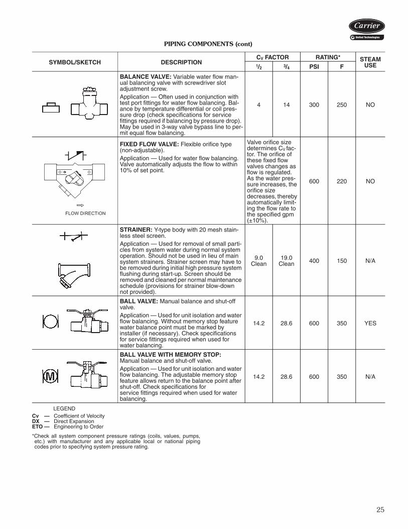
BALANCE VALVE: Variable water flow man-ual balancing valve with screwdriver slot adjustment screw.Application — Often used in conjunction with test port fittings for water flow balancing. Bal-ance by temperature differential or coil pres-sure drop (check specifications for service fittings required if balancing by pressure drop). May be used in 3-way valve bypass line to per-mit equal flow balancing.
4 14 300 250 NO
FIXED FLOW VALVE: Flexible orifice type (non-adjustable).Application — Used for water flow balancing. Valve automatically adjusts the flow to within 10% of set point.
Valve orifice size determines CV fac-tor. The orifice of these fixed flow valves changes as flow is regulated. As the water pres-sure increases, the orifice size decreases, thereby automatically limit-ing the flow rate to the specified gpm (±10%).
600 220 NO
STRAINER: Y-type body with 20 mesh stain-less steel screen.Application — Used for removal of small parti-cles from system water during normal system operation. Should not be used in lieu of main system strainers. Strainer screen may have to be removed during initial high pressure system flushing during start-up. Screen should be removed and cleaned per normal maintenance schedule (provisions for strainer blow-down not provided).
9.0Clean
19.0Clean 400 150 N/A
BALL VALVE: Manual balance and shut-off valve.Application — Used for unit isolation and water flow balancing. Without memory stop feature water balance point must be marked by installer (if necessary). Check specifications for service fittings required when used for water balancing.
14.2 28.6 600 350 YES
BALL VALVE WITH MEMORY STOP:Manual balance and shut-off valve.Application — Used for unit isolation and water flow balancing. The adjustable memory stop feature allows return to the balance point after shut-off. Check specifications forservice fittings required when used for water balancing.
14.2 28.6 600 350 N/A
Cv — Coefficient of VelocityDX — Direct ExpansionETO — Engineering to Order
a42-4282

26
PIPING COMPONENTS (cont)
LEGEND
*Check all system component pressure ratings (coils, values, pumps,etc.) with manufacturer and any applicable local or national pipingcodes prior to specifying system pressure rating.
SYMBOL/SKETCH DESCRIPTIONCV FACTOR RATING* STEAM
USE1/2 3/4 PSI F
2-WAY MOTORIZED VALVE (25 PSI close off differential pressure): Electric 2-position flow control valve (open/closed). Normally closed body with manual override lever. Installed in supply line to unit.Application — All standard control and valve packages are based upon normally closed valves (valve electrically powered open and closed by spring return when electric power removed). Manual override lever allows valve to be placed in the open position for second-ary (unit) flushing, constant water flow prior to start-up, etc. Manual override is automatically disengaged when valve is electrically acti-vated. Consult factory for normally open valve applications.
3.5 3.5 300 200
YES15PSI
MAX.
2-WAY MOTORIZED VALVE (150 PSI close off differential pressure): Electric 2-position flow control valve (open/closed). Normally closed body with manual override lever. Installed in supply line to unit.Application — All standard control and valve packages are based upon normally closed valves (valve electrically powered open and closed by spring return when electric power removed). Manual override lever allows valve to be placed in the open position for second-ary (unit) flushing, constant water flow prior to start-up, etc. Manual override is automatically disengaged when valve is electrically acti-vated. Consult factory for normally open valve applications.
4.9 10.3 300 240 NO
3-WAY MOTORIZED VALVE (25 PSI close off differential pressure): Electric2-position flow control valve (closed to coil/open to bypass or open to coil/closed to bypass). Normally closed with manual over-ride lever. Installed in supply line to unit.Application — Same comments as 2-way motorized valve except with manual override lever engaged the valve is open to both ports and water flow will take the path of least resis-tance through the valve package (not neces-sarily 100% through the coil).
4.0 4.0 300 200 N/A
3-WAY MOTORIZED VALVE (150 PSI close off differential pressure): Electric2-position flow control valve (closed to coil/open to bypass or open to coil/closed to bypass). Normally closed with manual over-ride lever. Installed in supply line to unit.Application — Same comments as 2-way motorized valve except with manual override lever engaged the valve is open to both ports and water flow will take the path of least resis-tance through the valve package (not neces-sarily 100% through the coil).
4.9 4.9 300 240 N/A
Cv — Coefficient of VelocityDX — Direct ExpansionETO — Engineering to Order
Application data (cont)

27
PIPING COMPONENTS (cont)
LEGEND *Check all system component pressure ratings (coils, values, pumps,etc.) with manufacturer and any applicable local or national piping codes prior to specifying system pressure rating.
SYMBOL/SKETCH DESCRIPTIONCV FACTOR RATING* STEAM
USE1/2 3/4 PSI F
MODULATING VALVE (Optional)(Non-Spring Return, Floating Point Actua-tor): Modulating valves are designed to con-trol the flow in the circuit by making incremental adjustments to the flow path within the valve. Application — To control fluid flow in fan coil units.On the 42DD,SG,SJ,SH commercial fan coil models, the factory provided modulating valve has application restrictions. In these models, the valve packages are located in the air-stream, downstream of the coil. Due to the ambient temperature limitations of the modu-lating valves, the valves can only be used in the units listed above with 2-pipe cooling only systems.
4.0 300 200 N/A
MODULATING VALVE (Optional)(Non-Spring Return, Proportional Type Actuator): Modulating valves are designed to control the flow in the circuit by making incre-mental adjustments to the flow path within the valve. Application — To control fluid flow in fan coil units.On the 42DD,SG,SJ,SH commercial fan coil models, the factory provided modulating valve has application restrictions. In these models, the valve packages are located in the air-stream, downstream of the coil. Due to the ambient temperature limitations of the modu-lating valves, the valves can only be used in the units listed above with 2-pipe cooling only systems.
4.0 300 200 N/A
MODULATING VALVE (Requires ETO)(Spring Return): Modulating valves are designed to control the flow in the circuit by making incremental adjustments to the flow path within the valve.Application — Same comments as non-spring return except when powered, the actuator moves to the desired position, at the same time tensing the spring return system. When power is removed for more than two minutes the spring returns the actuator to the normal position.
4.0 300 200 N/A
AQUASTAT: Water temperature sensing elec-trical switch. (Line Voltage Controls)Application — Clips directly on nominalsize 1/2 in. or 3/4 in. copper tubing for water temperature sensing. Must be correctly located for proper control operation.
CHANGEOVER SENSOR: Water tempera-ture sensor thermistor. Application — Sensor shall clamp on the out-side diameter of the pipe. Sensor plate shall bend to allow its radius to be adjusted to fit the pipe. Sensor shall be secured to the pipe with mounting clamp. Insulate the mounting loca-tion of sensor on the pipe.
Cv — Coefficient of VelocityDX — Direct ExpansionETO — Engineering to Order
28
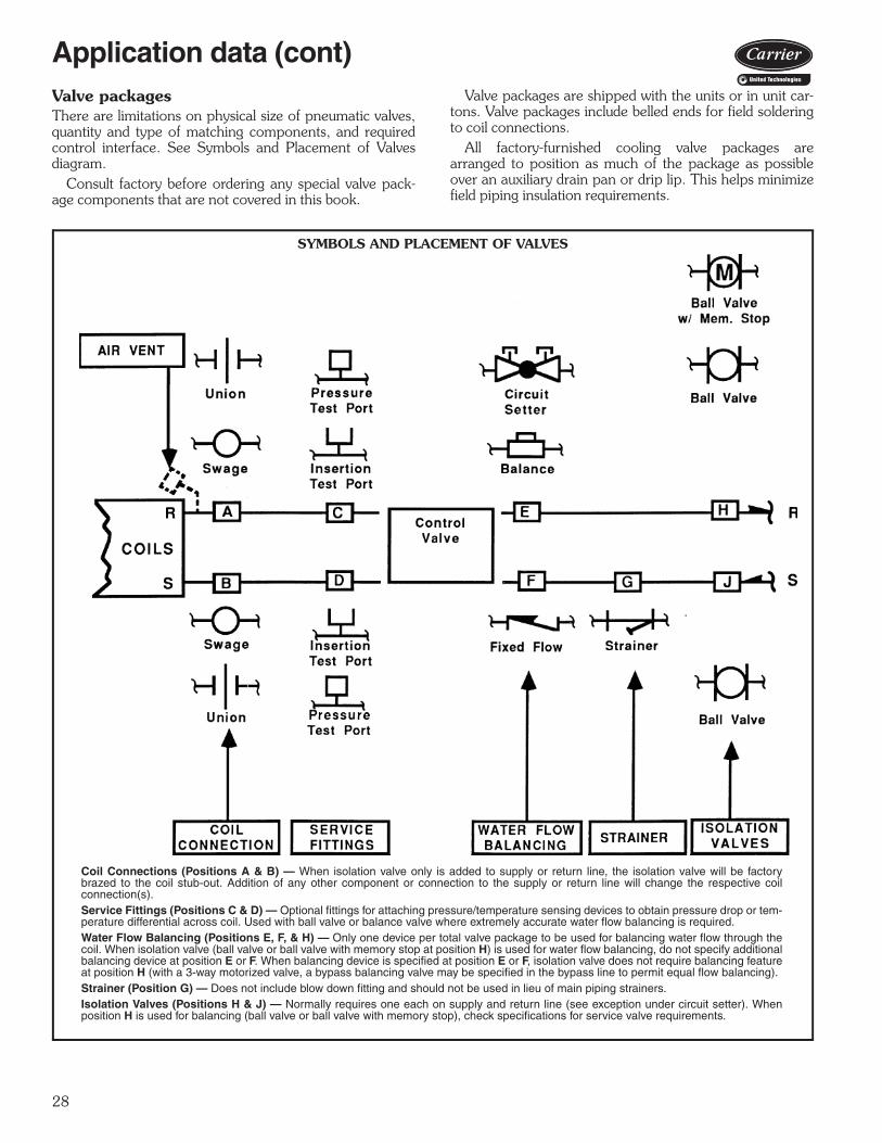
Valve packagesThere are limitations on physical size of pneumatic valves,quantity and type of matching components, and requiredcontrol interface. See Symbols and Placement of Valvesdiagram.
Consult factory before ordering any special valve pack-age components that are not covered in this book.
Valve packages are shipped with the units or in unit car-tons. Valve packages include belled ends for field solderingto coil connections.
All factory-furnished cooling valve packages arearranged to position as much of the package as possibleover an auxiliary drain pan or drip lip. This helps minimizefield piping insulation requirements.
a42-213tf
SYMBOLS AND PLACEMENT OF VALVES
Coil Connections (Positions A & B) — When isolation valve only is added to supply or return line, the isolation valve will be factorybrazed to the coil stub-out. Addition of any other component or connection to the supply or return line will change the respective coilconnection(s).Service Fittings (Positions C & D) — Optional fittings for attaching pressure/temperature sensing devices to obtain pressure drop or tem-perature differential across coil. Used with ball valve or balance valve where extremely accurate water flow balancing is required.Water Flow Balancing (Positions E, F, & H) — Only one device per total valve package to be used for balancing water flow through thecoil. When isolation valve (ball valve or ball valve with memory stop at position H) is used for water flow balancing, do not specify additionalbalancing device at position E or F. When balancing device is specified at position E or F, isolation valve does not require balancing featureat position H (with a 3-way motorized valve, a bypass balancing valve may be specified in the bypass line to permit equal flow balancing).Strainer (Position G) — Does not include blow down fitting and should not be used in lieu of main piping strainers.Isolation Valves (Positions H & J) — Normally requires one each on supply and return line (see exception under circuit setter). Whenposition H is used for balancing (ball valve or ball valve with memory stop), check specifications for service valve requirements.
a42-4222
Application data (cont)

29
*When aquastat is used for automatic changeover, bypass is required asindicated by dashed line.
NOTES:1. Packages factory furnished and field installed (except 42S units).2. Valves are 5/8-in. ODS unless otherwise specified.3. If an automatic flow control valve is added, it will be located on supply line between shutoff valve and coil (or motorized control valve, if supplied).4. Packages 17-A,C,D,E,F,J,K,L, and P are listed on current price pages.5. Modulating control valve is installed in return line (not shown).
a42-3988
VALVE PACKAGE ARRANGEMENTS
LEGEND
Ball Valve
Ball Valve with Memory Stop
Circuit Setter
Motorized 2-Way Valve
Motorized 3-Way Valve
M
M
M

30
A42-4263
PLENUM
COIL
DRAIN PAN 24"
VALVEPACKAGE
AREA
HEIGHT OF COIL
18"
42CEA, DCA (SEE NOTES 1, 2)
CABINET
9-1/2"
12-1/4"
14-3/8"(SEE
NOTE 4)
VALVEPACKAGE
AREA
VALVEPACKAGE
AREACABINET
42VCA (SEE NOTES 3, 4)
42VAA (SEE NOTE 3)
25"
9-1/2"
9-1/4"
VALVE PACKAGE SPACING RECOMMENDATIONS
NOTES:1. Valve package dimensions on ceiling mod-
els are based on a 4-pipe unit with (1) 3-waycontrol valve, (1) ball valve, and (1) circuitsetter.
2. Coil height dimensions on 42CEA and42DCA are provided in the physical datasection of the product data.
3. Valve package dimensions on floor units arebased on the valve package space providedon the exposed floor models.
4. Height of the 42VCA is 16 3/8 in. dependingon coil and electric heat selection.
Application data (cont)
31
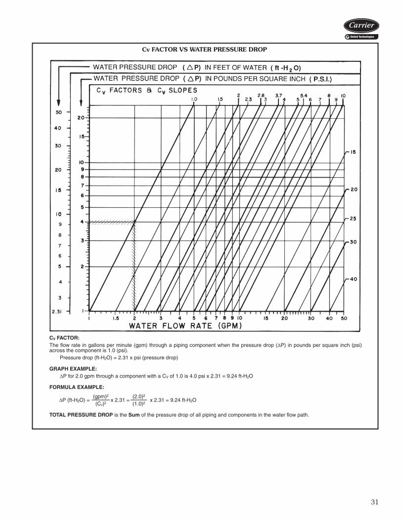
CV FACTOR:The flow rate in gallons per minute (gpm) through a piping component when the pressure drop ( P) in pounds per square inch (psi)across the component is 1.0 (psi).
Pressure drop (ft-H2O) = 2.31 x psi (pressure drop)
GRAPH EXAMPLE:P for 2.0 gpm through a component with a CV of 1.0 is 4.0 psi x 2.31 = 9.24 ft-H2O
FORMULA EXAMPLE:
TOTAL PRESSURE DROP is the Sum of the pressure drop of all piping and components in the water flow path.
P (ft-H2O) =(gpm)2
x 2.31 =(2.0)2
x 2.31 = 9.24 ft-H2O(Cv)2 (1.0)2
Cv FACTOR VS WATER PRESSURE DROP
32
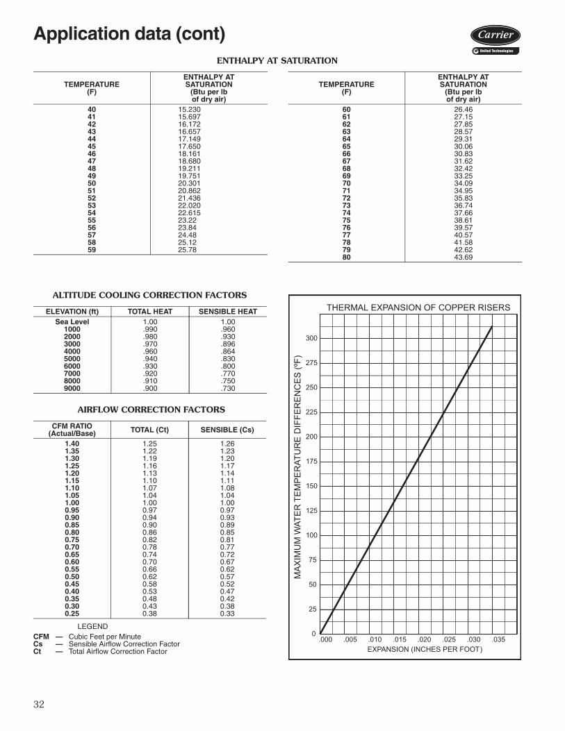
ENTHALPY AT SATURATION
ALTITUDE COOLING CORRECTION FACTORS
AIRFLOW CORRECTION FACTORS
LEGEND
TEMPERATURE(F)
ENTHALPY ATSATURATION
(Btu per lbof dry air)
TEMPERATURE(F)
ENTHALPY ATSATURATION
(Btu per lbof dry air)
40 15.230 60 26.4641 15.697 61 27.1542 16.172 62 27.8543 16.657 63 28.5744 17.149 64 29.3145 17.650 65 30.0646 18.161 66 30.8347 18.680 67 31.6248 19.211 68 32.4249 19.751 69 33.2550 20.301 70 34.0951 20.862 71 34.9552 21.436 72 35.8353 22.020 73 36.7454 22.615 74 37.6655 23.22 75 38.6156 23.84 76 39.5757 24.48 77 40.5758 25.12 78 41.5859 25.78 79 42.62
80 43.69
ELEVATION (ft) TOTAL HEAT SENSIBLE HEATSea Level 1.00 1.00
1000 .990 .9602000 .980 .9303000 .970 .8964000 .960 .8645000 .940 .8306000 .930 .8007000 .920 .7708000 .910 .7509000 .900 .730
CFM RATIO(Actual/Base) TOTAL (Ct) SENSIBLE (Cs)
1.40 1.25 1.261.35 1.22 1.231.30 1.19 1.201.25 1.16 1.171.20 1.13 1.141.15 1.10 1.111.10 1.07 1.081.05 1.04 1.041.00 1.00 1.000.95 0.97 0.970.90 0.94 0.930.85 0.90 0.890.80 0.86 0.850.75 0.82 0.810.70 0.78 0.770.65 0.74 0.720.60 0.70 0.670.55 0.66 0.620.50 0.62 0.570.45 0.58 0.520.40 0.53 0.470.35 0.48 0.420.30 0.43 0.380.25 0.38 0.33
CFM — Cubic Feet per MinuteCs — Sensible Airflow Correction FactorCt — Total Airflow Correction Factor
.000 .005 .030.025.020.015.010 .035
THERMAL EXPANSION OF COPPER RISERS
EXPANSION (INCHES PER FOOT)
300
275
250
225
200
175
125
100
75
50
25
0
150
MAX
IMU
M W
ATE
R T
EM
PE
RAT
UR
E D
IFFE
RE
NC
ES
(ºF)
Application data (cont)

33
Electric heatElectric heaters are available for installation on Carrier fancoil units in the following applications.Total electric heat — This system provides completeheating during the heating season; no boiler is required.Heating and cooling are now available on an individualbasis throughout the year with a 2-pipe system.
Chilled water is used for cooling and the electric heater isused for heating. Individual room controls can be suppliedfor either manual or automatic changeover.Auxiliary electric heat — This system is used for heat-ing between seasons or during the cooling season whenchilled water is being circulated. Individual room controlsare supplied to provide electric heat only when chilledwater is being circulated through the system. Water flowthrough the unit is shut off when the heater is turned on.
During the winter heating season, heating is provided byhot water circulated through the system. A changeoverdevice locks out the electric heat when the hot water iscirculated.
Heater constructionStrip heaters are used with Model 42C ceiling units,Model 42D ducted units, Model 42S stack units and Model42V (except 42VC and VE).
These heaters consist of coils of the highest grade resis-tance wire, insulated by ceramic insulators on plated steelbrackets. High limit thermal cutouts protect the unit in theevent of airflow loss.
All heaters except those used in 42S stack units are posi-tioned on the incoming (preheat) side of the unit coil. On42S stack units, the strip heater is located in the fan dis-charge on the leaving side of the coil.Sheath heaters are used with Model 42VC and 42VEvertical units. There heaters consist of the highest graderesistance wire, centered in a 1/2 in. diameter copperplated steel sheath. The wire is insulated from the sheathby magnesium oxide powder packed around it. To increasethe heater surface exposed to air, a 1 1/4 in. OD fin of cop-per plated steel is wound around the sheath in a spiral thatmakes 5 turns per linear inch. Sheath and fin are perma-nently bounded together by copper brazing. The heatersare positioned on the leaving (rehead) side of the unit coil.
Heater electrical data1. Load voltage may be 120, 208, 240 or 277 volts. For
unit size and kW limitations, refer to the specific unitcatalogs.
2. All heaters are single stage and single phase except for42SM, which offers 2-stage electric heaters.
3. Unless a single power-source option is selected, theelectric heat units require 2 separate power sources.With the single power-source option, only one line cir-cuit need be brought into the unit. Fuse protection isadded to the motor/control circuit to protect thesecomponents. This is separate from the field-furnishedtotal unit overcurrent protection.
MODEL 42C CEILING UNITWITH ELECTRIC STRIP HEATER

34
HEATER ELECTRICAL DATA42C SERIES
42V SERIES
NOTE: All heaters are single-stage and single-phase. Contact yourCarrier representative for heater availability for 220-1-50 units.
42D SERIES
NOTE: All heaters are single-stage and single-phase.
42S SERIES
NOTES:1. Contact your Carrier representative for heater availability on 42SU
unit quick ship program.2. 12 kW heater only available with 277V heater voltage.
HEATERVOLTAGE kW CAPACITY
(Btuh)UNIT SIZE
02 03 04 06 08 10 12
120
0.5 1,708 * *1.0 3,415 * * * * *1.5 5,123 * * * * *2.0 6,830 * * * * * * *3.0 10,245 * * * * * *
208
0.5 1,708 * *1.0 3,415 * * * * *1.5 5,123 * * * * *2.0 6,830 * * * * * * *3.0 10,245 * * * * * *4.0 13,660 * * * *5.0 17,075 * * * *6.0 20,490 * * * *8.0 27,320 * *
240,277
0.5 1,708 * *1.0 3,415 * * *1.5 5,123 * * *2.0 6,830 * * * * * * *3.0 10,245 * * * * * *4.0 13,660 * * * *5.0 17,075 * * * *6.0 20,490 * * * *8.0 27,320 * *
10.0 34,150 *
HEATERVOLTAGE kW CAPACITY
(Btuh)UNIT SIZE
02 03 04 06 08 10 12
120
1.0 3,415 * * * *1.5 5,123 * * *2.0 6,830 * * *3.0 10,245 * * * *
208,240
1.0 3,415 * * * *1.5 5,123 * * *2.0 6,830 * * *3.0 10,245 * * * *4.0 13,660 * * *
277
1.0 3,415 * * * *1.5 5,123 * * *2.0 6,830 * * *3.0 10,245 * * * *4.0 13,660 * * *5.0 17,075 * *6.0 20,490 *
HEATERVOLTAGE kW CAPACITY
(Btuh)UNIT SIZE
06 08 10 12 14 16 18 20
1202.0 6,830 * * *3.0 10,245 * * *
208,240,277
2.0 6,830 * * *3.0 10,245 * * *4.0 13,660 * * * * * * * *5.0 17,075 * * * * * * *6.0 20,490 * * * * * * *7.0 23,905 * * * * * *8.0 27,320 * * * * *9.0 30,735 * * * * *
10.0 34,150 * * * *12.0 40,980 * * *14.0 47,810 *
HEATERVOLTAGE kW
UNIT SIZE03 04 06 08 10 12 14 16 20
120
1.0 * * * * * *1.5 * * * * * *2.0 * * * * * *3.0 * * * * * *
208
1.0 * * * * * *1.5 * * * * * *2.0 * * * * * *3.0 * * * * * *4.0 * * * * * * * *5.0 * * * *6.0 * * * * * * *8.0 * * * * * *
240
1.0 * * * * * *1.5 * * * * * *2.0 * * * * * *3.0 * * * * * *4.0 * * * * * * * *5.0 * * * *6.0 * * * * * * *8.0 * * * * * *
10.0 * * * * *
277
1.0 * * * * * *1.5 * * * * * *2.0 * * * * * *3.0 * * * * * *4.0 * * * * * * * *5.0 * * * *6.0 * * * * * * *8.0 * * * * * *
10.0 * * * * *12.0 * * *
Application data (cont)

35
ECM motor control methodsThere are three main control methods to control the speedof electronically commutated motor (ECM) for desirable air-flow for a given application.3-discrete speed input, potentiometer field speedadjustment — This method uses the ECM with potenti-ometer field adjustment. The relay board will have threemain circuits for HI, MEDIUM, and LOW speed. Each ofthese speeds can be adjusted by potentiometer to any valuein the motor’s operating range. This will allow the custom-ization of air flow on each speed of the fan coil unit to bet-ter suit any requirements.
4-discrete speed input, potentiometer field speedadjustment, solid state (only with 24-v controls byother option) — This is the same as 3-discrete speed in-put but with additional fourth speed. All 4 speeds can beadjusted by potentiometer to any value in the motor’soperating range.Control method no. 3 — ECM variable speed (onlywith 24-v controls by other option) — This methodrequires 0 to 10-v signal for fan speed. It has no predeter-mined fan speeds and will ramp the motor fan speed ac-cording to the controller used on the fan coil unit. All ECMmotor packages use a constant torque operating mode. AnETO request is required for pricing and availability of con-stant airflow operation.
L2
LOW
MED
HIG
H
VR1
VR2
VR3
K1
K2
K3
LOW
MED
HIG
HC
OM
C1
C2
C3
CR1
Com
Flo4Flo3Flo2Flo1FloComNeutral24Vac
EVO/ECM
Status
Flo3Flo2Flo1 Flo4Flo0
45pd-51 +5V
3-DISCRETE SPEED INPUT
4-DISCRETE SPEED INPUT

36
Design Series (A or B*)
Motor Options1 – 120-v High-Static Permanent Split Capacitor (HSPSC)2 – 208/1/60 HSPSC3 – 230/1/60 HSPSC4 – 277/1/60 HSPSCA – 120-v Electonically Commutated Motor (ECM) with Control Option 1B – 120-v ECM with Control Option 2C – 120-v Permanent Split Capacitor (PSC) (Standard)D – 208/1/60 PSCE – 230/1/60 PSCF – 277/1/60 PSCG – 120-v ECM with Control Option 3H – 208-v ECM with Control Option 1J – 208-v ECM with Control Option 2K – 208-v ECM with Control Option 3L – 230-v ECM with Control Option 1M – 230-v ECM with Control Option 2N – 230-v ECM with Control Option 3P – 277-v ECM with Control Option 1Q – 277-v ECM with Control Option 3R – 277-v ECM with Control Option 2V – 220/1/50 PSC†
* Model 42CG only.† Contact Application Engineering for data on the 50 Hz motor.
Control Option 1 – 3-Discrete Potentiometer Field Speed AdjustmentControl Option 2 – Variable Flow 0-10 VDC or 4-20 mAControl Option 3 – 4-Discrete Potentiometer Field Speed Adjustment
a42-4374
Model number nomenclature4
2C
Ser
ies
Uni
ts

37
The 42C Series fan coil units are certified in compliancewith the Air-Conditioning, Heating and Refrigeration Insti-tute (AHRI) Industry Standard 440 for room fan coil units.Approved standard ratings are tabulated below.
AHRI APPROVED STANDARD RATINGS*
LEGEND
*Ratings based on motor at high fan speed, standard air and dry coil oper-ation, 10° F water temperature rise; entering-air temperature 67 F wb;80 F db; entering water temperature 45 F.
†Motor type permanent split capacitor operating at 115-1-60 voltage.
UNIT UNITSIZE
COILROWS
NOMINALCFM GPM
COOLING CAPACITYPOWER
INPUT (WATTS)†TotalMBtuh
SensibleMBtuh
42CA,CE,CG,CK
02
3
200 1.2 6.0 4.4 8703 300 1.8 9.0 6.3 8504 400 2.5 12.1 8.8 16506 600 3.6 17.3 13.0 22508 800 4.6 22.6 16.2 23510 1000 5.5 27.5 21.0 30512 1200 6.6 32.8 25.0 43502
4
200 1.4 6.9 4.3 8703 300 2.1 9.8 6.5 8504 400 2.8 13.8 9.8 14506 600 4.0 19.6 14.3 22008 800 5.1 25.5 18.8 23510 1000 6.2 31.0 22.0 30012 1200 7.5 37.2 27.7 425
GPM — Gallons per minuteMBtuh — Capacity (Btuh in thousands)
AHRI capacity ratings4
2C
Series U
nits

38
*Calculate operating weight of unit: shipping weight + coil waterweight x number of coil rows.
†Filter size if located in return-air plenum.
UNIT SIZE 42C 02 03 04 06 08 10 12NOMINAL AIRFLOW (cfm) 200 300 400 600 800 1000 1200SHIPPING WEIGHT (lb)* 42CA 36 39 49 59 64 95 107 42CE 55 60 70 82 95 135 154 42CG 98 118 126 168 176 215 245 42CK 115 120 135 150 155 227 241COIL WATER WEIGHT(Approx lb per row of coil) 42CA, CE, CG, CK 0.7 0.8 1.0 1.4 1.7 2.3 2.7COILS FPI 10 fins/inch Coil Face Area (sq ft) 0.8 1.1 1.4 1.9 2.3 3.2 3.7MOTOR (qty) 42C Series 1 1 1 1 1 2 2BLOWER (qty) 42CA, CE, CG, CK 1 1 2 2 2 4 4FILTERS Nominal Size (in.) (1-in. thick) 42CA NA NA NA NA NA NA NA 42CE† 10 x 18 10 x 22 10 x 28 10 x 33 10 x 40 10 x 54 10 x 62 42CG Bottom Return 10 x 231/2 10 x 28 10 x 321/2 10 x 37 10 x 41 10 x 541/2 10 x 63 Rear Return 8 x 231/2 8 x 28 8 x 321/2 8 x 37 8 x 41 8 x 541/2 8 x 63 42CK Bottom Return 10 x 28 10 x 28 10 x 33 10 x 45 10 x 45 10 x 62 10 x 62 Rear Return 7 x 21 7 x 21 7 x 27 7 x 38 7 x 38 7 x 52 7 x 52 Qty 1 1 1 1 1 1 1SUPPLY DUCT COLLAR 1-in.PIPING CONNECTIONS (Sweat) (in.) Coil Outlet and Inlet 5/8 OD Drain Connection 7/8 OD Tell-Tale Drain 5/8 OD
Physical data4
2C
Ser
ies
Uni
ts

39
1
2
3
1(25)
3(76)
B
A
2-1/4(64)
1-1/8(29)
6(152)
1-1/2(38) D’
A’
5
4
EMTG. HOLES
H6
3/4(19)
3/4(19)
115
16(406)
SUPPLYAIRFG
7/8(22)
7
10 89
17-1/2(445)
8-3/8(213)
1(25)
42CA FURRED-IN HORIZONTAL UNIT
LEGEND1 — Junction Box (remote mount)2 — Flexible Metal Conduit3 — Drain Conn, 7/8-in. OD4 — Tell-Tale Drain Conn, 5/8-in. OD (optional)5 — Drip Lip (optional)6 — Hanger Slots (4), Rubber Grommet
has 3/8-in. Diameter Hole7 — Supply Duct Collar, 1-in.8 — Air Vent, 1/8-in. MPT9 — Return Conn, 5/8-in. OD10 — Supply Conn, 5/8-in. OD11 — Drain Pan
*Unit weights are based on dry coils and minimum rows. Weights exclude packaging, valves, and other components.
UNITSIZE
NOMAIRFLOW
(Cfm)
DIMENSIONS (in.) QTY/UNIT FACEAREA(sq ft)
UNIT WEIGHT*
(lb)A A’ B D’ E F G H Blower Motor
02 200 211/4 311/4 16 13 181/4 61/4 83/4 193/4 1 1 0.83 3603 300 251/4 361/4 20 14 221/4 61/4 83/4 233/4 1 1 1.08 3904 400 311/4 431/4 26 15 281/4 61/4 83/4 293/4 2 1 1.35 4906 600 361/4 431/4 31 10 331/4 71/2 10 343/4 2 1 1.88 5908 800 431/4 571/4 38 17 401/4 71/2 10 413/4 2 1 2.31 6410 1000 571/4 651/4 52 11 541/4 71/2 10 553/4 4 2 3.16 9512 1200 651/4 751/4 60 13 621/4 71/2 10 633/4 4 2 3.65 107
NOTES:1. Right hand unit shown; left hand unit opposite. Coil connection loca-
tions are ±5/8-inches.2. Unit sizes 02 and 03 have one motor, one blower; sizes 04 through
08 have one motor, 2 blowers; sizes 10 and 12 have 2 motors,4 blowers.
3. Standard 3-row coil shown.4. Overall unit dimension increases by 4 in. with optional electric heat.5. Not shown: 3-speed fan switch; wall plate, closed cell foam on main
drain pan.6. Units have galvanized finish.7. See 42CA-203-1 for optional coil connections.8. Dimensions shown in inches (mm).
a42-4099.eps
Base unit dimensions4
2C
Series U
nits

40
42CA FURRED-IN HORIZONTAL UNIT WITH ELECTRIC HEAT
LEGEND1 — Junction Box (remote mount)2 — Flexible Metal Conduit3 — Strip Heater High Limit4 — Electric Strip Heater Element5 — Tell-Tale Drain Conn, 5/8-in. OD (optional)6 — Drain Conn, 7/8-in. OD7 — Drip Lip (optional)8 — Supply Duct Collar, 1-in.9 — Air Vent, 1/8-in. MPT10 — Return Conn, 5/8-in. OD11 — Supply Conn, 5/8-in. OD12 — Hanger Slots (4), Rubber Grommet
has 3/8-in. Diameter Hole13 — Drain Pan
NOTES:1. Right hand unit shown; left hand unit opposite. Coil connection loca-
tions are ±5/8-inches.2. Unit sizes 02 and 03 have one motor, one blower; sizes 04 through
08 have one motor, 2 blowers; sizes 10 and 12 have 2 motors,4 blowers.
3. Standard 3-row coil shown.4. Overall unit dimension increases by 4 in. with optional electric heat.5. Not shown: 3-speed fan switch; wall plate, closed cell foam on main
drain pan.6. Units have galvanized finish.7. See 42CA-203-1 for optional coil connections.8. Dimensions shown in inches (mm).
*Unit weights are based on dry coils and minimum rows. Weights exclude packaging, valves, and other components.
UNITSIZE
NOMAIRFLOW
(Cfm)
DIMENSIONS (in.) QTY/UNIT FACEAREA(sq ft)
UNIT WEIGHT*
(lb)A A’ B D’ E F G H Blower Motor
02 200 211/4 311/4 16 13 181/4 61/4 83/4 193/4 1 1 0.83 3803 300 251/4 361/4 20 14 221/4 61/4 83/4 233/4 1 1 1.08 4104 400 311/4 431/4 26 15 281/4 61/4 83/4 293/4 2 1 1.35 5106 600 361/4 431/4 31 10 331/4 71/2 10 343/4 2 1 1.88 6108 800 431/4 571/4 38 17 401/4 71/2 10 413/4 2 1 2.31 6610 1000 571/4 651/4 52 11 541/4 71/2 10 553/4 4 2 3.16 9712 1200 651/4 751/4 60 13 621/4 71/2 10 633/4 4 2 3.65 109
a42-4100.eps
13
Base unit dimensions (cont)4
2C
Ser
ies
Uni
ts
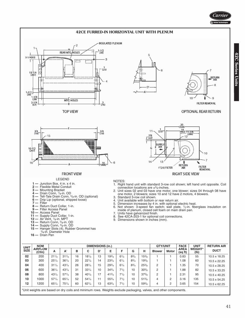
41
16
42CE FURRED-IN HORIZONTAL UNIT WITH PLENUM
NOTES:1. Right hand unit with standard 3-row coil shown; left hand unit opposite. Coil
connection locations are ±5/8-inches.2. Unit sizes 02 and 03 have one motor, one blower; sizes 04 through 08 have
one motor, 2 blowers; sizes 10 and 12 have 2 motors, 4 blowers.3. Standard 3-row coil shown.4. Unit available with bottom or rear return air.5. Dimension increases by 4 in. with optional electric heat.6. Not shown: 3-speed fan switch; wall plate, 1/2-in. fiberglass insulation on
inside of plenum, closed cell foam on main drain pan.7. Units have galvanized finish.8. See 42CA-203-1 for optional coil connections.9. Dimensions shown in inches (mm).
LEGEND1 — Junction Box, 4 in. x 4 in.2 — Flexible Metal Conduit3 — Mounting Bracket4 — Drain Conn, 7/8-in. OD5 — Tell-Tale Drain Conn, 5/8-in. OD (optional)6 — Drip Lip (optional, shipped loose)7 — Filter8 — Return Duct Collar, 1-in.9 — Filter Access Panel
10 — Access Panel11 — Supply Duct Collar, 1-in.12 — Air Vent, 1/8-in. MPT13 — Return Conn, 5/8-in. OD14 — Supply Conn, 5/8-in. OD15 — Hanger Slots (4), Rubber Grommet has
3/8-in. Diameter Hole16 — Drain Pan
*Unit weights are based on dry coils and minimum rows. Weights exclude packaging, valves, and other components.
UNITSIZE
NOMAIRFLOW
(Cfm)
DIMENSIONS (in.) QTY/UNIT FACEAREA(sq ft)
UNIT WEIGHT*
(lb)
RETURN AIR
A A’ B C D’ E F G H Blower Motor DUCT
02 200 211/4 311/4 16 181/4 13 193/4 61/4 83/4 153/8 1 1 0.83 55 10.5 x 18.2503 300 251/4 361/4 20 221/4 14 233/4 61/4 83/4 193/8 1 1 1.08 60 10.5 x 22.2504 400 311/4 431/4 26 281/4 15 293/4 61/4 83/4 253/8 2 1 1.35 70 10.5 x 28.2506 600 361/4 431/4 31 331/4 10 343/4 71/2 10 303/8 2 1 1.88 82 10.5 x 33.2508 800 431/4 571/4 38 401/4 17 413/4 71/2 10 373/8 2 1 2.31 95 10.5 x 40.2510 1000 571/4 651/4 52 541/4 11 553/4 71/2 10 513/8 4 2 3.16 135 10.5 x 54.2512 1200 651/4 751/4 60 621/4 13 633/4 71/2 10 593/8 4 2 3.65 154 10.5 x 62.25
a42-4101
42
C S
eries Units
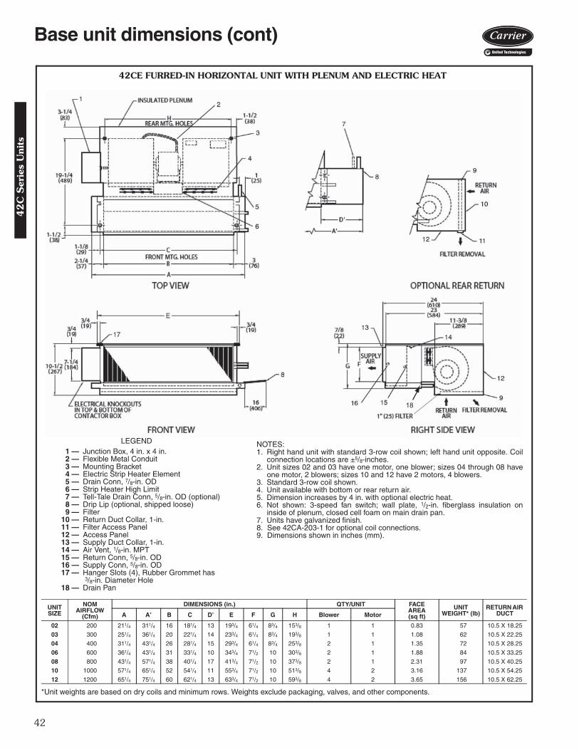
42
18
42CE FURRED-IN HORIZONTAL UNIT WITH PLENUM AND ELECTRIC HEAT
NOTES:1. Right hand unit with standard 3-row coil shown; left hand unit opposite. Coil
connection locations are ±5/8-inches.2. Unit sizes 02 and 03 have one motor, one blower; sizes 04 through 08 have
one motor, 2 blowers; sizes 10 and 12 have 2 motors, 4 blowers.3. Standard 3-row coil shown.4. Unit available with bottom or rear return air.5. Dimension increases by 4 in. with optional electric heat.6. Not shown: 3-speed fan switch; wall plate, 1/2-in. fiberglass insulation on
inside of plenum, closed cell foam on main drain pan.7. Units have galvanized finish.8. See 42CA-203-1 for optional coil connections.9. Dimensions shown in inches (mm).
LEGEND1 — Junction Box, 4 in. x 4 in.2 — Flexible Metal Conduit3 — Mounting Bracket4 — Electric Strip Heater Element5 — Drain Conn, 7/8-in. OD6 — Strip Heater High Limit7 — Tell-Tale Drain Conn, 5/8-in. OD (optional)8 — Drip Lip (optional, shipped loose)9 — Filter
10 — Return Duct Collar, 1-in.11 — Filter Access Panel12 — Access Panel13 — Supply Duct Collar, 1-in.14 — Air Vent, 1/8-in. MPT15 — Return Conn, 5/8-in. OD16 — Supply Conn, 5/8-in. OD17 — Hanger Slots (4), Rubber Grommet has
3/8-in. Diameter Hole18 — Drain Pan
*Unit weights are based on dry coils and minimum rows. Weights exclude packaging, valves, and other components.
UNITSIZE
NOMAIRFLOW
(Cfm)
DIMENSIONS (in.) QTY/UNIT FACEAREA(sq ft)
UNITWEIGHT* (lb)
RETURN AIR DUCTA A’ B C D’ E F G H Blower Motor
02 200 211/4 311/4 16 181/4 13 193/4 61/4 83/4 153/8 1 1 0.83 57 10.5 X 18.25
03 300 251/4 361/4 20 221/4 14 233/4 61/4 83/4 193/8 1 1 1.08 62 10.5 X 22.25
04 400 311/4 431/4 26 281/4 15 293/4 61/4 83/4 253/8 2 1 1.35 72 10.5 X 28.25
06 600 361/4 431/4 31 331/4 10 343/4 71/2 10 303/8 2 1 1.88 84 10.5 X 33.25
08 800 431/4 571/4 38 401/4 17 413/4 71/2 10 373/8 2 1 2.31 97 10.5 X 40.25
10 1000 571/4 651/4 52 541/4 11 553/4 71/2 10 513/8 4 2 3.16 137 10.5 X 54.25
12 1200 651/4 751/4 60 621/4 13 633/4 71/2 10 593/8 4 2 3.65 156 10.5 X 62.25
A42-4102
Base unit dimensions (cont)4
2C
Ser
ies
Uni
ts
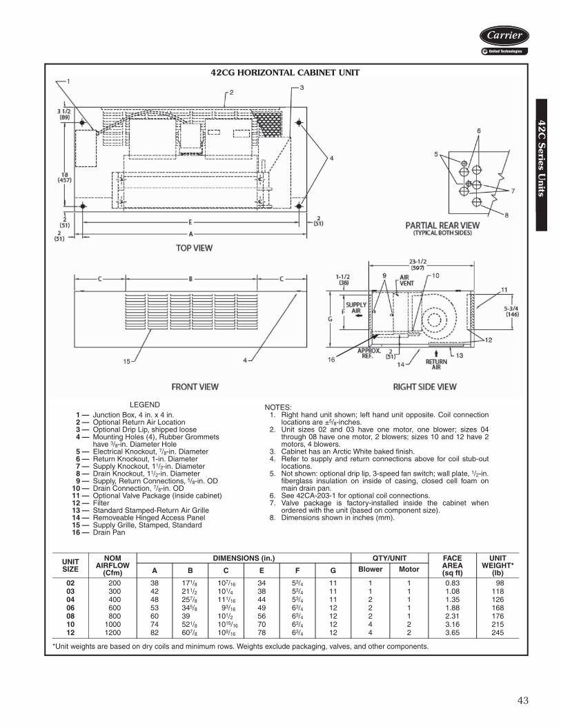
43
16
42CG HORIZONTAL CABINET UNIT
LEGEND1 — Junction Box, 4 in. x 4 in.2 — Optional Return Air Location3 — Optional Drip Lip, shipped loose4 — Mounting Holes (4), Rubber Grommets
have 3/8-in. Diameter Hole5 — Electrical Knockout, 7/8-in. Diameter6 — Return Knockout, 1-in. Diameter7 — Supply Knockout, 11/2-in. Diameter8 — Drain Knockout, 11/2-in. Diameter9 — Supply, Return Connections, 5/8-in. OD
10 — Drain Connection, 7/8-in. OD11 — Optional Valve Package (inside cabinet)12 — Filter13 — Standard Stamped-Return Air Grille14 — Removeable Hinged Access Panel15 — Supply Grille, Stamped, Standard16 — Drain Pan
*Unit weights are based on dry coils and minimum rows. Weights exclude packaging, valves, and other components.
UNITSIZE
NOMAIRFLOW
(Cfm)
DIMENSIONS (in.) QTY/UNIT FACEAREA(sq ft)
UNIT WEIGHT*
(lb)A B C E F G Blower Motor
02 200 38 171/8 107/16 34 53/4 11 1 1 0.83 9803 300 42 211/2 101/4 38 53/4 11 1 1 1.08 11804 400 48 257/8 111/16 44 53/4 11 2 1 1.35 12606 600 53 345/8 93/16 49 63/4 12 2 1 1.88 16808 800 60 39 101/2 56 63/4 12 2 1 2.31 17610 1000 74 521/8 1015/16 70 63/4 12 4 2 3.16 21512 1200 82 607/8 109/16 78 63/4 12 4 2 3.65 245
NOTES:1. Right hand unit shown; left hand unit opposite. Coil connection
locations are ±5/8-inches.2. Unit sizes 02 and 03 have one motor, one blower; sizes 04
through 08 have one motor, 2 blowers; sizes 10 and 12 have 2motors, 4 blowers.
3. Cabinet has an Arctic White baked finish.4. Refer to supply and return connections above for coil stub-out
locations.5. Not shown: optional drip lip, 3-speed fan switch; wall plate, 1/2-in.
fiberglass insulation on inside of casing, closed cell foam onmain drain pan.
6. See 42CA-203-1 for optional coil connections.7. Valve package is factory-installed inside the cabinet when
ordered with the unit (based on component size).8. Dimensions shown in inches (mm).
A42-4105
42
C S
eries Units

44
17
42CG HORIZONTAL CABINET WITH ELECTRIC HEAT
LEGEND1 — Junction Box, 4 in. x 4 in.2 — Optional Stamped Rear Return Grille3 — Optional Drip Lip, shipped loose4 — Electric Strip Heater Element5 — Mounting Holes (4), Rubber Grommets
have 3/8-in. Diameter Hole6 — Electrical Knockout, 7/8-in. Diameter7 — Return Knockout, 1-in. Diameter8 — Supply Knockout, 11/2-in. Diameter9 — Drain Knockout, 11/2-in. Diameter
10 — Drain Connection, 7/8-in. OD11 — Optional Valve Package (inside cabinet)12 — Filter13 — Standard Stamped-Return Air Grille14 — Removeable Hinged Access Panel15 — Supply, Return Connections, 5/8-in. OD16 — Supply Grille, Stamped, Standard17 — Drain Pan
NOTES:1. Right hand unit shown; left hand unit opposite. Coil connection
locations are ±5/8-inches.2. Unit sizes 02 and 03 have one motor, one blower; sizes 04
through 08 have one motor, 2 blowers; sizes 10 and 12 have 2motors, 4 blowers.
3. Cabinet has an Arctic White baked finish.4. Refer to supply and return connections above for coil stub-out
locations.5. Not shown: optional drip lip, 3-speed fan switch; wall plate, 1/2-in.
fiberglass insulation on inside of casing, closed cell foam onmain drain pan.
6. See 42CA-203-1 for optional coil connections.7. Valve package is factory-installed inside the cabinet when
ordered with the unit (based on component size).8. Dimensions shown in inches (mm).
*Unit weights are based on dry coils and minimum rows. Weights exclude packaging, valves, and other components.
UNITSIZE
NOMAIRFLOW
(Cfm)
DIMENSIONS (in.) QTY/UNIT FACEAREA(sq ft)
UNIT WEIGHT*
(lb)A B C E F G Blower Motor
02 200 38 171/8 107/16 34 53/4 11 1 1 0.83 9803 300 42 211/2 101/4 38 53/4 11 1 1 1.08 11804 400 48 257/8 111/16 44 53/4 11 2 1 1.35 12606 600 53 345/8 93/16 49 63/4 12 2 1 1.88 16808 800 60 39 101/2 56 63/4 12 2 1 2.31 17610 1000 74 521/8 1015/16 70 63/4 12 4 2 3.16 21512 1200 82 607/8 109/16 78 63/4 12 4 2 3.65 245
A42-4106
Base unit dimensions (cont)4
2C
Ser
ies
Uni
ts

45
DOUBLE DEFLECTIONSUPPLY AIR GRILLE
C B C
RESILIENT MOUNTINGGROMMETS WITH 3/8" (10)DIA HOLE (TYP. OF 4)
Ø7/8" (22) KNOCKOUT(TYP. OF 2)
Ø1-1/2" KNOCKOUT(TYPE. OF 5)
PARTIAL REAR VIEW(TYPICAL BOTH SIDES)
2(51)
CHILLED/HOT WATERSUPPLY & RETURN
CONNECTIONSTOP VIEW
CONTACTOR BOX (J-BOX ONUNITS WITH NO CONTROLS)
3-1/2(89)
2(51)
2(51)
EA
18(457)
1" RETURNDUCT COLLAR &1" (25) FILTER
OPTIONAL “L” SHAPEDDRIP LIP, SHIPPED LOOSE
FRONT VIEW
REMOVABLE HINGEDRA/ACCESS PANEL
23-1/2(597) 1" RETURN
DUCT COLLAR&
1" (25) FILTER
6(152)
RETURNAIR
1-1/2(38)
GFSUPPLY
AIR
AIR VENT7/8" (22) O.D.
CONDENSATEDRAIN CONNECTION
RIGHT SIDE VIEW
2(51)
APPROX.REF.
42CG HORIZONTAL CABINET WITH DOUBLE DEFLECTOR SUPPLY AIR GRILLE AND DUCT REAR RETURN
NOTES:1. Right hand unit shown; left hand unit opposite. 2. Internal factory valve package and drains may not align with
cabinet knockouts.3. All dimensions ± 1/4-in.4. Cabinet is Arctic White polyester powder coat paint.
UNITSIZE
NOMAIRFLOW
(Cfm)
DIMENSIONS (in.) DUCTED REAR RETURN SIZE
(in.)
FILTER SIZE (in.)
QTY/UNIT
A B C E F G Blower Motor
02 200 38 171/8 107/16 34 53/4 11 6 x 211/2 8 x 231/2 1 103 300 42 211/2 101/4 38 53/4 11 6 x 253/4 8 x 28 1 104 400 48 257/8 111/16 44 53/4 11 6 x 301/4 8 x 321/2 2 106 600 53 345/8 93/16 49 63/4 12 6 x 341/2 8 x 37 2 108 800 60 39 101/2 56 63/4 12 6 x 39 8 x 41 2 110 1000 74 521/8 1015/16 70 63/4 12 6 x 52 8 x 541/2 4 212 1200 82 607/8 109/16 78 63/4 12 6 x 603/4 8 x 63 4 2
a42-4317
42
C S
eries Units

46
DOUBLE DEFLECTIONSUPPLY AIR GRILLE
C B C
RESILIENT MOUNTINGGROMMETS WITH 3/8" (10)DIA HOLE (TYP. OF 4)
Ø7/8" (22) KNOCKOUT(TYP. OF 2)
Ø1-1/2" KNOCKOUT(TYPE. OF 5)
PARTIAL REAR VIEW(TYPICAL BOTH SIDES)
2(51)
CHILLED/HOT WATERSUPPLY & RETURN
CONNECTIONSTOP VIEW
CONTACTOR BOX (J-BOX ONUNITS WITH NO CONTROLS)
3-1/2(89)
2(51)
2(51)
EA
18(457)
1" RETURNDUCT COLLAR &1" (25) FILTER
OPTIONAL “L” SHAPEDDRIP LIP, SHIPPED LOOSE
FRONT VIEW
REMOVABLE HINGEDRA/ACCESS PANEL
23-1/2(597)
1" RETURNDUCT COLLAR
&1" (25) FILTER
6(152)
RETURNAIR
1-1/2(38)
GFSUPPLY
AIR
AIR VENT7/8" (22) O.D.
CONDENSATEDRAIN CONNECTION
RIGHT SIDE VIEW
2(51)
APPROX.REF.
OPTIONALELECTRIC STRIPHEATER ELEMENT
42CG HORIZONTAL CABINET WITH DOUBLE DEFLECTOR SUPPLY AIR GRILLE, DUCT REAR RETURN AND HEATER
A42-4315
NOTES:1. Right hand unit shown; left hand unit opposite. 2. Internal factory valve package and drains may not align with
cabinet knockouts.3. All dimensions ± 1/4-in.4. Cabinet is Arctic White polyester powder coat paint.
UNITSIZE
NOMAIRFLOW
(Cfm)
DIMENSIONS (in.) DUCTED REAR RETURN SIZE
(in.)
FILTER SIZE (in.)
QTY/UNIT
A B C E F G Blower Motor
02 200 38 171/8 107/16 34 53/4 11 6 x 211/2 8 x 231/2 1 103 300 42 211/2 101/4 38 53/4 11 6 x 253/4 8 x 28 1 104 400 48 257/8 111/16 44 53/4 11 6 x 301/4 8 x 321/2 2 106 600 53 345/8 93/16 49 63/4 12 6 x 341/2 8 x 37 2 108 800 60 39 101/2 56 63/4 12 6 x 39 8 x 41 2 110 1000 74 521/8 1015/16 70 63/4 12 6 x 52 8 x 541/2 4 212 1200 82 607/8 109/16 78 63/4 12 6 x 603/4 8 x 63 4 2
Base unit dimensions (cont)4
2C
Ser
ies
Uni
ts

47
STANDARD STAMPEDSUPPLY AIR GRILLE
C B C
RESILIENT MOUNTINGGROMMETS WITH 3/8" (10)DIA HOLE (TYP. OF 4)
Ø7/8" (22) KNOCKOUT(TYP. OF 2)
Ø1-1/2" KNOCKOUT(TYPE. OF 5)
PARTIAL REAR VIEW(TYPICAL BOTH SIDES)
2(51)
CHILLED/HOT WATERSUPPLY & RETURN
CONNECTIONSTOP VIEW
CONTACTOR BOX (J-BOX ONUNITS WITH NO CONTROLS)
3-1/2(89)
2(51)
2(51)
EA
18(457)
1" RETURNDUCT COLLAR &1" (25) FILTER
OPTIONAL “L” SHAPEDDRIP LIP, SHIPPED LOOSE
FRONT VIEW
REMOVABLE HINGEDRA/ACCESS PANEL
23-1/2(597) 1" RETURN
DUCT COLLAR&
1" (25) FILTER
6(152)RETURN
AIR
1-1/2(38)
GF
SUPPLYAIR
AIR VENT7/8" (22) O.D.
CONDENSATEDRAIN CONNECTION
RIGHT SIDE VIEW
2(51)
APPROX.REF.
42CG HORIZONTAL CABINET WITH STAMPED SUPPLY AIR GRILLE AND DUCT REAR RETURN
a42-4318
NOTES:1. Right hand unit shown; left hand unit opposite. 2. Internal factory valve package and drains may not align with
cabinet knockouts.3. All dimensions ± 1/4-in.4. Cabinet is Arctic White polyester powder coat paint.
UNITSIZE
NOMAIRFLOW
(Cfm)
DIMENSIONS (in.) DUCTED REAR RETURN SIZE
(in.)
FILTER SIZE (in.)
QTY/UNIT
A B C E F G Blower Motor
02 200 38 171/8 107/16 34 53/4 11 6 x 211/2 8 x 231/2 1 103 300 42 211/2 101/4 38 53/4 11 6 x 253/4 8 x 28 1 104 400 48 257/8 111/16 44 53/4 11 6 x 301/4 8 x 321/2 2 106 600 53 345/8 93/16 49 63/4 12 6 x 341/2 8 x 37 2 108 800 60 39 101/2 56 63/4 12 6 x 39 8 x 41 2 110 1000 74 521/8 1015/16 70 63/4 12 6 x 52 8 x 541/2 4 212 1200 82 607/8 109/16 78 63/4 12 6 x 603/4 8 x 63 4 2
42
C S
eries Units
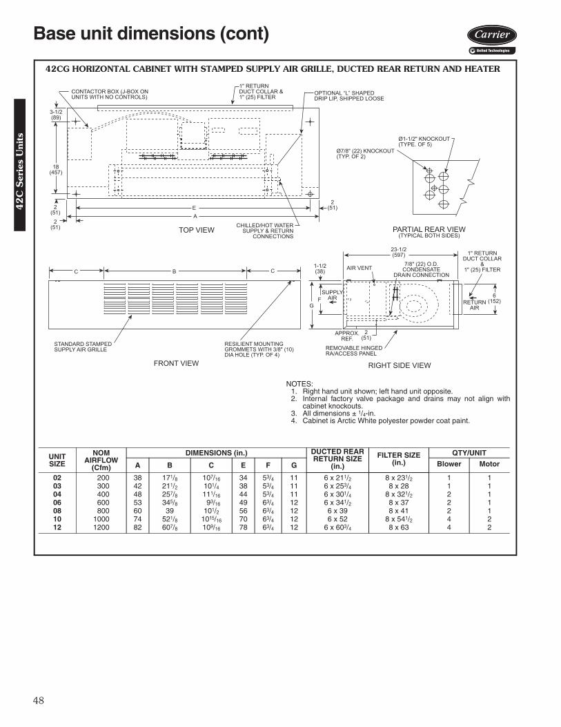
48
STANDARD STAMPEDSUPPLY AIR GRILLE
C B C
RESILIENT MOUNTINGGROMMETS WITH 3/8" (10)DIA HOLE (TYP. OF 4)
Ø7/8" (22) KNOCKOUT(TYP. OF 2)
Ø1-1/2" KNOCKOUT(TYPE. OF 5)
PARTIAL REAR VIEW(TYPICAL BOTH SIDES)
2(51)
CHILLED/HOT WATERSUPPLY & RETURN
CONNECTIONSTOP VIEW
CONTACTOR BOX (J-BOX ONUNITS WITH NO CONTROLS)
3-1/2(89)
2(51)
2(51)
EA
18(457)
1" RETURNDUCT COLLAR &1" (25) FILTER
OPTIONAL “L” SHAPEDDRIP LIP, SHIPPED LOOSE
FRONT VIEW
REMOVABLE HINGEDRA/ACCESS PANEL
23-1/2(597) 1" RETURN
DUCT COLLAR&
1" (25) FILTER
6(152)RETURN
AIR
1-1/2(38)
GF
SUPPLYAIR
AIR VENT7/8" (22) O.D.
CONDENSATEDRAIN CONNECTION
RIGHT SIDE VIEW
2(51)
APPROX.REF.
42CG HORIZONTAL CABINET WITH STAMPED SUPPLY AIR GRILLE, DUCTED REAR RETURN AND HEATER
a42-4316
NOTES:1. Right hand unit shown; left hand unit opposite. 2. Internal factory valve package and drains may not align with
cabinet knockouts.3. All dimensions ± 1/4-in.4. Cabinet is Arctic White polyester powder coat paint.
UNITSIZE
NOMAIRFLOW
(Cfm)
DIMENSIONS (in.) DUCTED REAR RETURN SIZE
(in.)
FILTER SIZE (in.)
QTY/UNIT
A B C E F G Blower Motor
02 200 38 171/8 107/16 34 53/4 11 6 x 211/2 8 x 231/2 1 103 300 42 211/2 101/4 38 53/4 11 6 x 253/4 8 x 28 1 104 400 48 257/8 111/16 44 53/4 11 6 x 301/4 8 x 321/2 2 106 600 53 345/8 93/16 49 63/4 12 6 x 341/2 8 x 37 2 108 800 60 39 101/2 56 63/4 12 6 x 39 8 x 41 2 110 1000 74 521/8 1015/16 70 63/4 12 6 x 52 8 x 541/2 4 212 1200 82 607/8 109/16 78 63/4 12 6 x 603/4 8 x 63 4 2
Base unit dimensions (cont)4
2C
Ser
ies
Uni
ts

49
42CK HORIZONTAL CABINET UNIT WITH TELESCOPIC ACCESS PANEL,FRONT SUPPLY, AND BOTTOM RETURN
*Unit weights are based on dry coils and minimum rows. Weights exclude packaging, valves, and other components.
UNITSIZE
NOMAIRFLOW
(Cfm)
DIMENSIONS (in.) QTY/UNIT BOTTOM RETURN
FILTER SIZE (in.)
UNIT WEIGHT* (lb)A B C D E F Blower Motor
02 200 35 16 123/4 37 32 6 1 1 10 x 21 11503 300 35 20 83/4 37 32 6 1 1 10 x 21 12004 400 41 26 83/4 43 38 6 2 1 10 x 27 13506 600 53 31 153/4 55 50 7 2 1 10 x 38 15008 800 53 38 83/4 55 50 7 2 1 10 x 38 15510 1000 75 52 163/4 77 72 7 4 2 10 x 52 22712 1200 75 60 83/4 77 72 7 4 2 10 x 52 241
NOTES:1. Right hand unit shown; left hand unit opposite.2. Internal factory valve package and drains may not align with cabinet
knockouts.3. Dimensions shown in inches (mm). All dimensions are ±1/4 inches.4. Bottom panel is Arctic White polyester powder coat paint.
DRAIN PAN
A42-4149 42
C S
eries Units

50
12
11
10
913
42CK HORIZONTAL CABINET UNIT WITH TELESCOPIC ACCESS PANEL,FRONT SUPPLY, BOTTOM RETURN, AND HEATER
NOTES:1. Right hand unit shown; left hand unit opposite.2. Internal factory valve package and drains may not align with
cabinet knockouts.3. Dimensions shown in inches (mm). All dimensions are
±1/4 inches.4. Bottom panel is Arctic White polyester powder coat paint.
*Unit weights are based on dry coils and minimum rows. Weights exclude packaging, valves, and other components.
UNITSIZE
NOMAIRFLOW
(Cfm)
DIMENSIONS (in.) QTY/UNIT BOTTOM RETURN
FILTER SIZE (in.)
UNIT WEIGHT* (lb)A B C D E F Blower Motor
02 200 35 16 123/4 37 32 6 1 1 10 x 21 11703 300 35 20 83/4 37 32 6 1 1 10 x 21 12204 400 41 26 83/4 43 38 6 2 1 10 x 27 13706 600 53 31 153/4 55 50 7 2 1 10 x 38 15208 800 53 38 83/4 55 50 7 2 1 10 x 38 15710 1000 75 52 163/4 77 72 7 4 2 10 x 52 22912 1200 75 60 83/4 77 72 7 4 2 10 x 52 243
a42-4150
LEGEND1 — Contactor Box2 — Strip Heater High Limit 3 — Electric Strip Heater Element4 — Optimal L-shape Drip Lip, shipped loose5 — Chilled/Hot Water Supply and Return Connection6 — Resilient Mounting Grommets with 3/8-in. Diameter Hole
(typically 4)7 — Electrical Knockout, 7/8-in. Diameter 8 — Drain Knockout, 11/2-in. Diameter 9 — Stamped Return Air Grille and 1-in. Filter
10 — Condensate Drain Connection, 7/8-in. OD11 — Hinged Bottom Return Air Panel12 — Supply Duct Collar, 1-in. OD13 — Drain Pan
Base unit dimensions (cont)4
2C
Ser
ies
Uni
ts

51
42CK HORIZONTAL CABINET UNIT WITH TELESCOPIC ACCESS PANEL,FRONT SUPPLY, AND REAR RETURN
*Unit weights are based on dry coils and minimum rows. Weights exclude packaging, valves, and other components.
UNITSIZE
NOMAIRFLOW
(Cfm)
DIMENSIONS (in.) QTY/UNIT REAR RETURN FILTER SIZE (in.)
UNIT WEIGHT* (lb)A B C D E F Blower Motor
02 200 35 16 123/4 37 32 6 1 1 7 x 21 11503 300 35 20 83/4 37 32 6 1 1 7 x 21 12004 400 41 26 83/4 43 38 6 2 1 7 x 27 13506 600 53 31 153/4 55 50 7 2 1 7 x 38 15008 800 53 38 83/4 55 50 7 2 1 7 x 38 15510 1000 75 52 163/4 77 72 7 4 2 7 x 52 22712 1200 75 60 83/4 77 72 7 4 2 7 x 52 241
a42-4151
NOTES:1. Right hand unit shown; left hand unit opposite.2. Internal factory valve package and drains may not align with
cabinet knockouts.3. Dimensions shown in inches (mm). All dimensions are
±1/4 inches.4. Bottom panel is Arctic White polyester powder coat paint.
LEGEND1 — Junction Box2 — 1-in. Ducted Rear Return and 1-in. Filter 3 — Optimal L-shape Drip Lip, shipped loose4 — Chilled/Hot Water Supply and Return Connection5 — Resilient Mounting Grommets with 3/8-in. Diameter Hole
(typically 4)6 — Electrical Knockout, 7/8-in. Diameter7 — Drain Knockout, 11/2-in. Diameter8 — 1-in. Ducted Rear Return and 1-in. Filter9 — Condensate Drain Connection, 7/8-in. OD
10 — Hinged Bottom Return Air Panel11 — Supply Duct Collar, 1-in. OD12 — Drain Pan
8
9
10
11
76
5
4
3
21
12
42
C S
eries Units
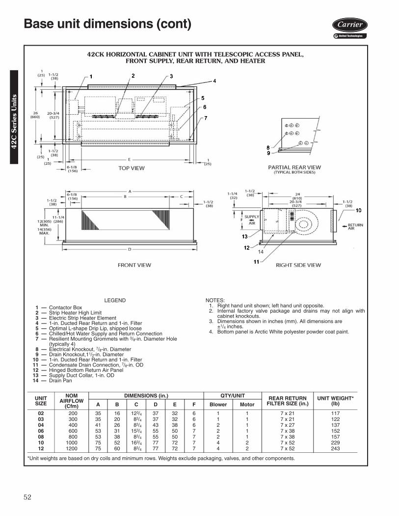
52
42CK HORIZONTAL CABINET UNIT WITH TELESCOPIC ACCESS PANEL,FRONT SUPPLY, REAR RETURN, AND HEATER
NOTES:1. Right hand unit shown; left hand unit opposite.2. Internal factory valve package and drains may not align with
cabinet knockouts.3. Dimensions shown in inches (mm). All dimensions are
±1/4 inches.4. Bottom panel is Arctic White polyester powder coat paint.
*Unit weights are based on dry coils and minimum rows. Weights exclude packaging, valves, and other components.
UNITSIZE
NOMAIRFLOW
(Cfm)
DIMENSIONS (in.) QTY/UNIT REAR RETURN FILTER SIZE (in.)
UNIT WEIGHT* (lb)A B C D E F Blower Motor
02 200 35 16 123/4 37 32 6 1 1 7 x 21 11703 300 35 20 83/4 37 32 6 1 1 7 x 21 12204 400 41 26 83/4 43 38 6 2 1 7 x 27 13706 600 53 31 153/4 55 50 7 2 1 7 x 38 15208 800 53 38 83/4 55 50 7 2 1 7 x 38 15710 1000 75 52 163/4 77 72 7 4 2 7 x 52 22912 1200 75 60 83/4 77 72 7 4 2 7 x 52 243
a42-4152
LEGEND1 — Contactor Box2 — Strip Heater High Limit3 — Electric Strip Heater Element4 — 1-in. Ducted Rear Return and 1-in. Filter 5 — Optimal L-shape Drip Lip, shipped loose6 — Chilled/Hot Water Supply and Return Connection7 — Resilient Mounting Grommets with 3/8-in. Diameter Hole
(typically 4)8 — Electrical Knockout, 7/8-in. Diameter9 — Drain Knockout,11/2-in. Diameter
10 — 1-in. Ducted Rear Return and 1-in. Filter11 — Condensate Drain Connection, 7/8-in. OD12 — Hinged Bottom Return Air Panel13 — Supply Duct Collar, 1-in. OD14 — Drain Pan
14
Base unit dimensions (cont)4
2C
Ser
ies
Uni
ts

53
16
42CK HORIZONTAL CABINET UNIT WITH TELESCOPIC ACCESS PANEL, BOTTOM SUPPLY, BOTTOM RETURN*
LEGEND1 — Junction Box, 4 in. x 4 in.2 — Optional Drip Lip, shipped loose3 — Mounting Holes (4), Rubber Grommets
have 3/8-in. Diameter Hole4 — Piping Knockout, 11/2-in. Diameter5 — Electrical Knockout, 7/8-in. Diameter6 — Drain Knockout, 11/2-in. Diameter7 — Supply Duct Collar8 — Return Connection, 5/8-in. OD.9 — Optional Rear Return. Consult factory for
collar dimensions.10 — Drain, 7/8-in. OD.11 — Stamped Bottom Return Air Grille12 — Filter13 — Stamped Air Supply Grille14 — Hinged Bottom Access Panel15 — Supply Connection, 5/8-in. OD.16 — Drain Pan
†Unit weights are based on dry coils and minimum rows. Weights exclude packaging, valves, and other components.
UNITSIZE
NOMAIRFLOW
(Cfm)
DIMENSIONS (in.) QTY/UNIT FACE AREA(sq ft)
UNIT WEIGHT†
(lb)A D E Blower Motor
02 200 35 37 32 1 1 0.83 11503 300 35 37 32 1 1 1.08 12004 400 41 43 38 2 1 1.35 13506 600 53 55 50 2 1 1.88 15008 800 53 55 50 2 1 2.31 15510 1000 75 77 72 4 2 3.16 22712 1200 75 77 72 4 2 3.65 241
* ETO — Engineered to Order.NOTES:
1. Right hand unit shown; left hand unit opposite. Coil connectionlocations are ±5/8-inches.
2. Unit sizes 02 and 03 have one motor, one blower; sizes 04through 08 have one motor, 2 blowers; sizes 10 and 12 have 2motors, 4 blowers.
3. Bottom access panel has an Arctic White baked finish.4. Refer to supply and return connections above for coil stub-out
locations.5. Not shown: optional drip lip, 3-speed fan switch; wall plate, 1/2-in.
fiberglass insulation on inside of casing, closed cell foam onmain drain pan.
6. See 42CA-203-1 for optional coil connections.7. Valve package is factory-installed inside the cabinet when
ordered with the unit (based on component size).8. Bottom return or bottom supply is an ETO (engineering to order)
request.9. Dimensions shown in inches (mm). A42-4107
42
C S
eries Units

54
18
42CK HORIZONTAL CABINET WITH TELESCOPIC ACCESS PANEL BOTTOM SUPPLY, BOTTOM RETURN, AND ELECTRIC HEAT*
LEGEND1 — Junction Box, 4 in. x 4 in.2 — Strip Heater High Limit3 — Electric Strip Heater Element4 — Optional Drip Lip, shipped loose5 — Mounting Holes (4), Rubber Grommets
have 3/8-in. Diameter Hole6 — Piping Knockout, 11/2-in. Diameter7 — Electrical Knockout, 7/8-in. Diameter8 — Drain Knockout, 11/2-in. Diameter9 — Supply Duct Collar
10 — Optional Rear Return. Consult factory for collar dimensions.
11 — Drain, 7/8-in. OD.12 — Stamped Bottom Return Air Grille13 — Filter14 — Stamped Air Supply Grille15 — Hinged Bottom Access Panel16 — Supply Connection, 5/8-in. OD.17 — Return Connection, 5/8-in. OD.18 — Drain Pan
* ETO — Engineered to Order.NOTES:
1. Right hand unit shown; left hand unit opposite. Coil connectionlocations are ±5/8-inches.
2. Unit sizes 02 and 03 have one motor, one blower; sizes 04through 08 have one motor, 2 blowers; sizes 10 and 12 have 2motors, 4 blowers.
3. Bottom access panel has an Arctic White baked finish.4. Refer to supply and return connections above for coil stub-out
locations.5. Not shown: optional drip lip, 3-speed fan switch; wall plate, 1/2-in.
fiberglass insulation on inside of casing, closed cell foam onmain drain pan.
6. See 42CA-203-1 for optional coil connections.7. Valve package is factory-installed inside the cabinet when
ordered with the unit (based on component size).8. Bottom return or bottom supply is an ETO (engineering to order)
request.9. Dimensions shown in inches (mm).
†Unit weights are based on dry coils and minimum rows. Weights exclude packaging, valves, and other components.
UNIT SIZE NOM AIRFLOW(Cfm)
DIMENSIONS (in.) QTY/UNIT FACE AREA(sq ft)
UNIT WEIGHT†(lb)A D E Blower Motor
02 200 35 37 32 1 1 0.83 11703 300 35 37 32 1 1 1.08 12204 400 41 43 38 2 1 1.35 13706 600 53 55 50 2 1 1.88 15208 800 53 55 50 2 1 2.31 15710 1000 75 77 72 4 2 3.16 22912 1200 75 77 72 4 2 3.65 243
A42-4108
Base unit dimensions (cont)4
2C
Ser
ies
Uni
ts

55
42C
OPTIO
NA
L C
OIL
CO
NN
EC
TIO
N L
OC
ATIO
N S
IZES 0
2–1
2
NO
TE
S:
1.R
ight
han
d un
it sh
own;
left
hand
uni
t opp
osite
.2.
All
dim
ensi
ons
are
in in
ches
±1 /
4 in
ch.
3.D
imen
sion
s do
not
app
ly to
uni
ts w
ith fa
ctor
y va
lve
pack
ages
.4.
All
conn
ectio
n si
zes
5 /8
inO
D.
5.S
plit
coil
conn
ectio
ns
show
n ar
e fo
r 4-
pipe
co
mbi
natio
ns;
chill
ed/h
ot w
ater
coi
ls o
nly,
with
hot
wat
er c
oil
in s
tand
ard
rehe
at p
ositi
on.
CO
IL C
ON
NE
CT
ION
DIM
EN
SIO
NS
R I G H T H A N D
UN
ITS
IZE
3-R
OW
CO
IL4-
RO
W C
OIL
3 A
ND
1 S
PL
IT C
OIL
AB
CD
EF
GH
JK
LM
NP
Q02
43/ 4
25/ 8
41/ 4
41/ 4
35/ 8
41/ 4
55/ 1
621
/ 16
55/ 1
631
/ 841
/ 455
/ 811
/ 821
/ 16
41/ 4
0343
/ 425
/ 841
/ 441
/ 435
/ 841
/ 455
/ 16
21/ 1
655
/ 16
31/ 8
41/ 4
55/ 8
11/ 8
21/ 1
641
/ 404
43/ 4
25/ 8
41/ 4
41/ 4
35/ 8
41/ 4
55/ 1
621
/ 16
55/ 1
631
/ 841
/ 455
/ 811
/ 821
/ 16
41/ 4
0643
/ 425
/ 835
/ 847
/ 851
/ 247
/ 855
/ 16
21/ 1
655
/ 16
31/ 8
47/ 8
67/ 8
23/ 8
21/ 1
647
/ 808
43/ 4
25/ 8
35/ 8
47/ 8
35/ 8
41/ 4
55/ 1
621
/ 16
55/ 1
631
/ 847
/ 867
/ 823
/ 821
/ 16
47/ 8
1043
/ 425
/ 847
/ 835
/ 841
/ 447
/ 855
/ 16
21/ 1
655
/ 16
31/ 8
51/ 2
67/ 8
23/ 8
21/ 1
641
/ 412
43/ 4
25/ 8
47/ 8
35/ 8
41/ 4
47/ 8
55/ 1
621
/ 16
55/ 1
631
/ 851
/ 267
/ 823
/ 821
/ 16
41/ 4
R I G H T H A N D
UN
ITS
IZE
3 A
ND
2 S
PL
IT C
OIL
R I G H T H A N D
UN
ITS
IZE
4 A
ND
1 S
PL
IT C
OIL
JK
LM
NP
QJ
KL
MN
PQ
0265
/ 16
41/ 8
41/ 4
55/ 8
13/ 4
211 /
1641
/ 402
53/ 1
625
/ 841
/ 455
/ 811
/ 819
/ 16
41/ 4
0365
/ 16
41/ 8
41/ 4
55/ 8
13/ 4
211 /
1641
/ 403
55/ 1
625
/ 841
/ 455
/ 811
/ 819
/ 16
41/ 4
0465
/ 16
41/ 8
41/ 4
55/ 8
13/ 4
211 /
1641
/ 404
55/ 1
625
/ 841
/ 455
/ 811
/ 819
/ 16
41/ 4
0665
/ 16
41/ 8
47/ 8
67/ 8
321
1 /16
47/ 8
0655
/ 16
25/ 8
47/ 8
67/ 8
23/ 8
19/ 1
647
/ 808
65/ 1
641
/ 847
/ 867
/ 83
211 /
1647
/ 808
55/ 1
625
/ 847
/ 867
/ 823
/ 819
/ 16
47/ 8
1065
/ 16
41/ 8
51/ 2
67/ 8
321
1 /16
41/ 4
1055
/ 16
25/ 8
51/ 2
67/ 8
23/ 8
19/ 1
641
/ 412
65/ 1
641
/ 851
/ 267
/ 83
211 /
1647
/ 812
55/ 1
625
/ 851
/ 267
/ 823
/ 819
/ 16
41/ 4
L E F T H A N D
UN
ITS
IZE
3-R
OW
CO
IL4-
RO
W C
OIL
3 A
ND
1 S
PL
IT C
OIL
AB
CD
EF
GH
JK
LM
NP
Q02
43/ 4
25/ 8
41/ 4
41/ 4
41/ 4
35/ 8
55/ 1
621
/ 16
55/ 1
631
/ 835
/ 85
1 /2
21/ 1
635
/ 803
43/ 4
25/ 8
41/ 4
41/ 4
41/ 4
35/ 8
55/ 1
621
/ 16
55/ 1
631
/ 835
/ 85
1 /2
21/ 1
635
/ 804
43/ 4
25/ 8
41/ 4
41/ 4
41/ 4
35/ 8
55/ 1
621
/ 16
55/ 1
631
/ 835
/ 85
1 /2
21/ 1
635
/ 806
43/ 4
25/ 8
47/ 8
35/ 8
47/ 8
51/ 2
55/ 1
621
/ 16
55/ 1
631
/ 841
/ 463
/ 41 /
221
/ 16
41/ 4
0843
/ 425
/ 847
/ 835
/ 841
/ 435
/ 855
/ 16
21/ 1
655
/ 16
31/ 8
41/ 4
63/ 4
1 /2
21/ 1
641
/ 410
43/ 4
25/ 8
35/ 8
47/ 8
47/ 8
41/ 2
55/ 1
621
/ 16
55/ 1
631
/ 835
/ 863
/ 41 /
221
/ 16
47/ 8
1243
/ 425
/ 835
/ 847
/ 847
/ 841
/ 255
/ 16
21/ 1
655
/ 16
31/ 8
35/ 8
63/ 4
1 /2
21/ 1
647
/ 8
L E F T H A N D
UN
ITS
IZE
3 A
ND
2 S
PL
IT C
OIL
JK
LM
NP
Q02
65/ 1
641
/ 835
/ 85
11/ 8
211 /
1635
/ 803
65/ 1
641
/ 835
/ 85
11/ 8
211 /
1635
/ 804
65/ 1
641
/ 835
/ 85
11/ 8
211 /
1635
/ 806
65/ 1
641
/ 841
/ 463
/ 411
/ 821
1 /16
41/ 4
0865
/ 16
41/ 8
41/ 4
63/ 4
11/ 8
211 /
1641
/ 410
65/ 1
641
/ 835
/ 863
/ 411
/ 821
1 /16
47/ 8
1265
/ 16
41/ 8
35/ 8
63/ 4
11/ 8
211 /
1647
/ 8
L E F T H A N D
UN
ITS
IZE
4 A
ND
1 S
PL
IT C
OIL
JK
LM
NP
Q02
53/ 1
625
/ 835
/ 85
1 /2
19/ 1
635
/ 803
55/ 1
625
/ 835
/ 85
1 /2
19/ 1
635
/ 804
55/ 1
625
/ 835
/ 85
1 /2
19/ 1
635
/ 806
55/ 1
625
/ 841
/ 463
/ 41 /
219
/ 16
41/ 4
0855
/ 16
25/ 8
41/ 4
63/ 4
1 /2
19/ 1
641
/ 410
55/ 1
625
/ 835
/ 863
/ 41 /
219
/ 16
47/ 8
1255
/ 16
25/ 8
35/ 8
63/ 4
1 /2
19/ 1
647
/ 8
Accessory dimensions4
2C
Series U
nits
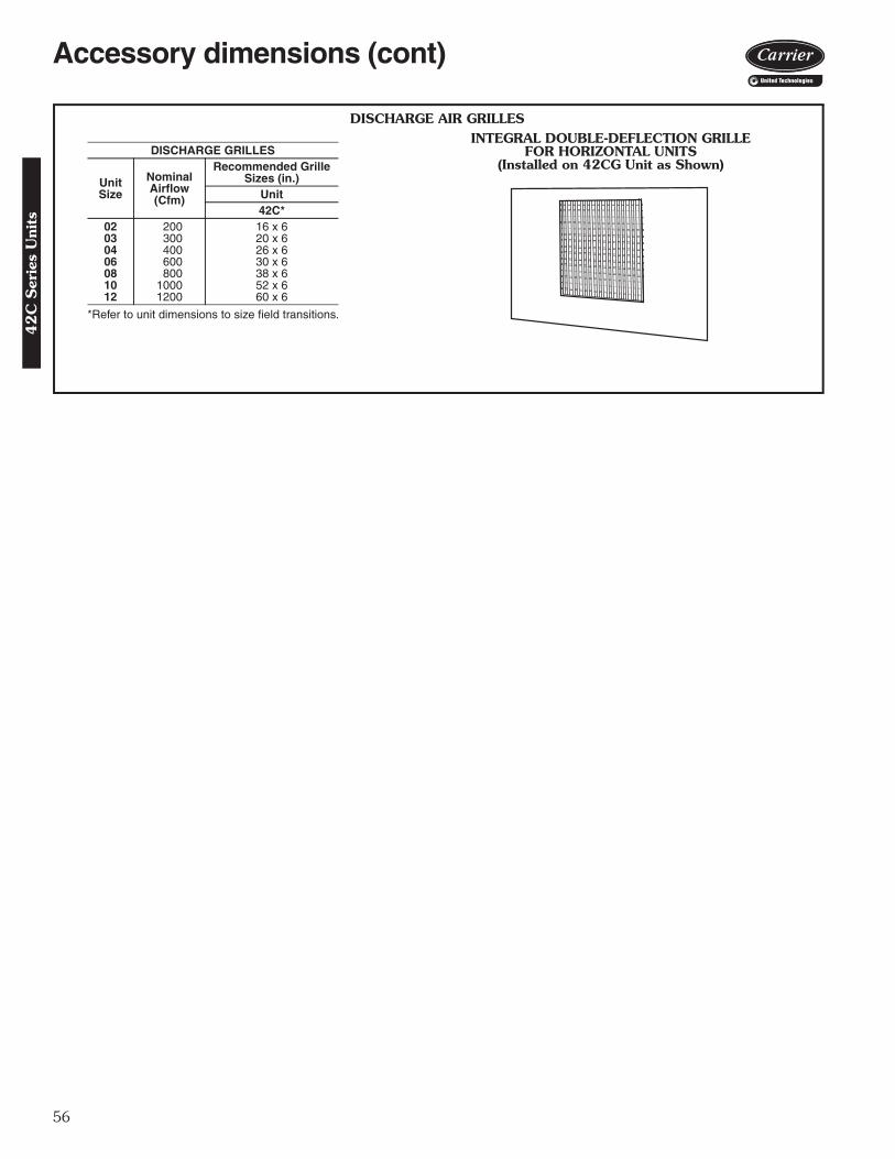
56
DISCHARGE AIR GRILLES
*Refer to unit dimensions to size field transitions.
DISCHARGE GRILLES
UnitSize
NominalAirflow(Cfm)
Recommended Grille Sizes (in.)
Unit42C*
02 200 16 x 603 300 20 x 604 400 26 x 606 600 30 x 608 800 38 x 610 1000 52 x 612 1200 60 x 6
INTEGRAL DOUBLE-DEFLECTION GRILLEFOR HORIZONTAL UNITS
(Installed on 42CG Unit as Shown)
A42-4117
Accessory dimensions (cont)4
2C
Ser
ies
Uni
ts
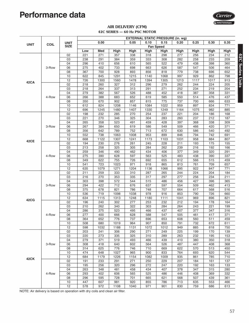
57
AIR DELIVERY (CFM)42C SERIES — 60 Hz PSC MOTOR
NOTE: Air delivery is based on operation with dry coils and clean air filter.
UNIT COIL UNIT SIZE
EXTERNAL STATIC PRESSURE (in. wg)0.00 0.05 0.10 0.15 0.20 0.25 0.30 0.35
Fan SpeedLow Med High High High High High High High High
42CA
3-Row
02 221 271 357 338 318 298 277 256 234 21203 238 291 384 359 333 308 282 258 233 20904 296 410 656 610 565 522 479 438 398 36006 275 402 733 698 663 626 587 547 506 46408 367 700 928 893 856 818 779 738 696 65210 622 845 1291 1215 1140 1068 997 929 862 79812 726 1300 1560 1478 1394 1305 1213 1117 1017 913
4-Row
02 218 260 327 312 296 279 262 244 224 20503 218 264 337 313 291 271 252 234 219 20404 279 382 567 526 488 452 418 387 358 33106 266 388 683 652 619 585 550 514 476 43708 350 670 902 857 815 775 737 700 666 63310 612 824 1208 1146 1084 1022 959 897 834 77112 696 1245 1480 1407 1330 1249 1164 1075 982 885
42CE
3-Row
02 198 232 285 270 254 237 221 204 186 16803 221 270 346 325 304 283 260 237 212 18704 265 358 523 491 459 428 397 368 338 30906 267 384 650 619 586 549 509 466 420 37108 356 642 789 752 713 672 630 586 540 49210 552 738 1063 1008 953 899 846 794 742 69112 668 1122 1307 1241 1173 1103 1031 958 884 807
4-Row
02 194 230 276 261 245 228 211 193 175 15503 213 258 325 305 284 262 239 216 192 16604 259 346 490 462 434 406 377 349 320 29106 275 390 628 597 563 525 483 438 390 33708 349 622 755 726 692 655 612 566 515 45910 541 723 1023 971 918 865 813 761 709 65712 635 1079 1271 1204 1136 1066 995 922 847 771
42CG
3-Row
02 211 259 333 310 287 265 244 224 204 18403 216 270 353 335 317 297 277 256 234 21104 303 398 572 544 515 486 456 427 396 36506 294 422 712 676 637 597 554 509 462 41308 375 678 821 786 748 707 664 617 568 51610 536 719 1098 1038 978 916 853 790 726 66012 634 1115 1313 1248 1180 1111 1041 969 896 821
4-Row
02 196 240 302 277 253 232 212 194 178 16403 210 262 340 322 303 284 264 243 221 19904 286 375 523 495 466 437 407 377 347 31606 277 400 666 628 588 547 505 461 417 37108 364 652 776 737 696 653 608 560 511 45910 508 680 1019 964 907 850 791 732 672 61112 598 1032 1188 1131 1072 1012 949 885 818 750
42CK
3-Row
02 203 241 306 290 271 249 225 199 170 13903 220 273 335 325 310 289 263 232 195 15304 279 371 519 493 466 439 410 380 350 31806 308 418 640 602 564 526 487 447 408 36808 314 625 776 746 710 669 622 570 513 45010 474 648 1027 965 900 833 764 693 620 54412 684 1179 1226 1154 1082 1009 935 861 785 710
4-Row
02 191 233 291 271 250 229 207 184 161 13703 195 256 320 296 272 247 220 192 163 13304 263 348 481 458 434 407 378 347 315 28006 293 402 606 565 525 486 446 408 369 33208 296 595 728 701 665 621 568 507 439 36110 447 607 981 920 855 786 713 635 553 46612 578 972 1108 1040 971 901 830 759 686 613
Performance data4
2C
Series U
nits

58
AIR DELIVERY FAN CURVES42CE SERIES — 02 UNIT SIZE
42CE SERIES — 03 UNIT SIZE
SCFMECM Operating Range:PSC Motor Fan Curve: 3-Row- 5-Row
4-Row
0
0.05
0.10
0.15
0.20
0.25
0.30
0.35
0.40
0.45
0.50
0 50 100 150 200 250 300 350
ESP
(in. w
g)
Low
Med
High
0 50 100 150 200 250 300 350 400 450SCFM
ECM Operating Range:PSC Motor Fan Curve: 3-Row- 5-Row
4-Row
0
0.05
0.10
0.15
0.20
0.25
0.30
0.35
0.40
0.45
0.50
ESP
(in. w
g)
Low
Med
High
LEGENDECM — Electronically Commutated MotorESP — External Static PressurePSC — Permanent Split CapacitorSCFM — Square Cubic Feet per Minute
Performance data (cont)4
2C
Ser
ies
Uni
ts

59
AIR DELIVERY FAN CURVES (cont)42CE SERIES — 04 UNIT SIZE
42CE SERIES — 06 UNIT SIZE
0
0.05
0.10
0.15
0.20
0.25
0.30
0.35
0.40
0.45
0.50
100 150 200 250 300 350 400 450 500 550 600 650
ESP
(in. w
g)
SCFMECM Operating Range:
Low
Med
High
PSC Motor Fan Curve: 3-Row- 5-Row4-Row
SCFMPSC Motor Fan Curve: 3-Row 5-Row
4-Row
0
0.05
0.10
0.15
0.20
0.25
0.30
0.35
0.40
0.45
0.50
100 150 200 250 300 350 400 450 500 550 600 650 700 750
ESP
(in.w
g)
ECM Operating Range:
Low
Med
High
LEGENDECM — Electronically Commutated MotorESP — External Static PressurePSC — Permanent Split CapacitorSCFM — Square Cubic Feet per Minute
42
C S
eries Units

60
AIR DELIVERY FAN CURVES (cont)42CE SERIES — 08 UNIT SIZE
42CE SERIES — 10 UNIT SIZE
SCFMECM Operating Range:PSC Motor Fan Curve: 3-Row- 5-Row
4-Row
0
0.05
0.10
0.15
0.20
0.25
0.30
0.35
0.40
0.45
0.50
200 250 300 350 400 450 500 550 600 650 700 750 800 850
ESP
(in. w
g)
Low
Med
High
-
SCFMECM Operating Range:PSC Motor Fan Curve: 3-Row- 5-Row
4-Row
0
0.05
0.10
0.15
0.20
0.25
0.30
0.35
0.40
0.45
0.50
350 400 450 500 550 600 650 700 750 800 850 900 950 1000 1050 1100 1150 1200 1250
ESP
(in. w
g)
Low
Med
High
LEGENDECM — Electronically Commutated MotorESP — External Static PressurePSC — Permanent Split CapacitorSCFM — Square Cubic Feet per Minute
Performance data (cont)4
2C
Ser
ies
Uni
ts
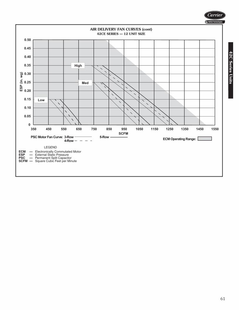
61
AIR DELIVERY FAN CURVES (cont)42CE SERIES — 12 UNIT SIZE
SCFMECM Operating Range:PSC Motor Fan Curve: 3-Row- 5-Row
4-Row
0
0.05
0.10
0.15
0.20
0.25
0.30
0.35
0.40
0.45
0.50
350 450 550 650 750 850 950 1050 1150 1250 1350 1450 1550
ESP
(in. w
g)
Low
Med
High
-
LEGENDECM — Electronically Commutated MotorESP — External Static PressurePSC — Permanent Split CapacitorSCFM — Square Cubic Feet per Minute
42
C S
eries Units

62
SOUND POWER DATA42CA HORIZONTAL FURRED-IN CEILING UNIT
NOTES:1. Unit Test Configuration: Open Return / Front Supply, 3 Row, 10
FPI (fins per inch) Coil, 0.0 in. ESP at High Speed, 115 VAC PSC(permanent split capacitor) Motor.
2. Casing Radiated Testing per AHRI (Air-Conditioning, Heating andRefrigeration Institute) 260-2012: 4.2.2.3 Casing radiated with freeinlet, Sound Rating of Ducted Air Moving and Conditioning Equip-ment.
3. Ducted Discharge Testing per AHRI 260-2012: 4.2.2.1 Ducted dis-charge, Sound Rating of Ducted Air Moving and ConditioningEquipment.
4. Sound power data is expressed decibels, dB RE: 1 x 10-12W(picowatts).
UNIT RATING FANSPEED CFM
SOUND POWER LEVEL, Lw (dB one reference pico watt) - HzA-wgt (dBA)125 Hz 250 Hz 500 Hz 1000 Hz 2000 Hz 4000 Hz 8000 Hz
02
CASING RADIATED
H 280 58 56 57 56 52 48 43 60
M 200 52 50 51 49 44 38 37 53
L 165 48 45 45 43 37 33 37 47
DUCTED DISCHARGE
H 280 56 53 52 48 45 38 38 54
M 200 51 47 46 41 37 32 36 47
L 165 48 43 41 35 31 30 36 43
03
CASING RADIATED
H 300 58 55 58 57 54 49 44 61
M 210 52 47 49 47 42 37 37 51
L 165 50 43 43 41 36 32 36 46
DUCTED DIS-CHARGE
H 300 55 52 53 50 47 40 38 55
M 210 50 46 47 42 38 32 35 48
L 165 48 42 41 36 32 30 35 43
04
CASING RADIATED
H 625 64 62 63 62 60 56 52 67
M 415 58 53 54 52 47 42 39 56
L 315 53 46 47 44 38 33 37 48
DUCTED DISCHARGE
H 625 67 57 59 57 52 46 43 61
M 415 62 48 49 45 40 33 36 51
L 315 57 43 42 37 31 30 36 45
06
CASING RADIATED
H 750 67 63 63 62 59 55 52 66
M 460 59 51 52 49 45 40 38 54
L 350 54 44 43 41 36 32 36 46
DUCTED DISCHARGE
H 750 67 63 63 62 59 55 52 66
M 460 59 51 52 49 45 40 38 54
L 350 54 44 43 41 36 32 36 46
08
CASING RADIATED
H 875 65 66 67 66 63 60 57 71
M 720 62 61 62 61 57 54 50 65
L 425 53 48 49 46 41 36 36 51
DUCTED DISCHARGE
H 875 73 62 63 62 57 54 51 66
M 720 72 59 59 57 52 48 45 62
L 425 63 45 46 41 35 32 35 50
10
CASING RADIATED
H 1220 67 67 67 67 63 60 56 71
M 840 62 57 59 56 51 47 42 60
L 645 58 51 52 48 42 37 36 53
DUCTED DISCHARGE
H 1220 68 62 64 62 56 52 49 66
M 840 65 54 55 51 44 39 37 56
L 645 62 47 48 43 36 31 34 50
12
CASING RADIATED
H 1525 68 68 69 69 65 62 59 73
M 1330 65 65 66 65 61 57 54 69
L 820 56 53 55 51 46 41 38 56
DUCTED DISCHARGE
H 1525 68 64 66 64 59 56 52 68
M 1330 65 61 63 60 55 51 48 65
L 820 56 49 52 46 40 35 35 52
Performance data (cont)4
2C
Ser
ies
Uni
ts
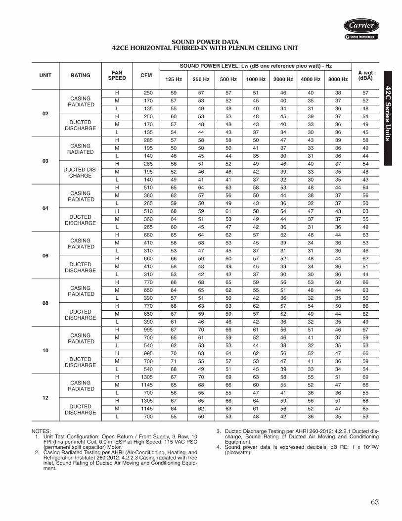
63
SOUND POWER DATA42CE HORIZONTAL FURRED-IN WITH PLENUM CEILING UNIT
NOTES:1. Unit Test Configuration: Open Return / Front Supply, 3 Row, 10
FPI (fins per inch) Coil, 0.0 in. ESP at High Speed, 115 VAC PSC(permanent split capacitor) Motor.
2. Casing Radiated Testing per AHRI (Air-Conditioning, Heating, andRefrigeration Institute) 260-2012: 4.2.2.3 Casing radiated with freeinlet, Sound Rating of Ducted Air Moving and Conditioning Equip-ment.
3. Ducted Discharge Testing per AHRI 260-2012: 4.2.2.1 Ducted dis-charge, Sound Rating of Ducted Air Moving and ConditioningEquipment.
4. Sound power data is expressed decibels, dB RE: 1 x 10-12W(picowatts).
UNIT RATING FANSPEED CFM
SOUND POWER LEVEL, Lw (dB one reference pico watt) - HzA-wgt (dBA)125 Hz 250 Hz 500 Hz 1000 Hz 2000 Hz 4000 Hz 8000 Hz
02
CASING RADIATED
H 250 59 57 57 51 46 40 38 57
M 170 57 53 52 45 40 35 37 52
L 135 55 49 48 40 34 31 36 48
DUCTED DISCHARGE
H 250 60 53 53 48 45 39 37 54
M 170 57 48 48 43 40 33 36 49
L 135 54 44 43 37 34 30 36 45
03
CASING RADIATED
H 285 57 58 58 50 47 43 39 58
M 195 50 50 50 41 37 33 36 49
L 140 46 45 44 35 30 31 36 44
DUCTED DIS-CHARGE
H 285 56 51 52 49 46 40 37 54
M 195 52 46 46 42 39 33 35 48
L 140 49 41 41 37 32 30 35 43
04
CASING RADIATED
H 510 65 64 63 58 53 48 44 64
M 360 62 57 56 50 44 38 37 56
L 265 59 50 49 43 36 32 37 50
DUCTED DISCHARGE
H 510 68 59 61 58 54 47 43 63
M 360 64 51 53 49 44 37 37 55
L 265 60 45 47 42 36 31 36 49
06
CASING RADIATED
H 660 65 64 62 57 52 48 44 63
M 410 58 53 53 45 39 34 36 53
L 310 53 47 45 37 31 31 36 46
DUCTED DISCHARGE
H 660 66 59 60 57 52 48 44 62
M 410 58 48 49 45 39 34 36 51
L 310 53 42 42 37 30 30 36 44
08
CASING RADIATED
H 770 66 68 65 59 56 53 50 66
M 650 64 65 62 55 51 48 44 63
L 390 57 51 50 42 36 32 35 50
DUCTED DISCHARGE
H 770 68 63 63 62 57 54 50 66
M 650 67 59 59 57 52 49 44 62
L 390 61 46 46 42 36 32 35 49
10
CASING RADIATED
H 995 67 70 66 61 56 51 46 67
M 700 65 61 59 52 46 41 37 59
L 540 62 53 53 44 38 32 35 53
DUCTED DISCHARGE
H 995 70 63 64 62 56 52 47 66
M 700 71 55 57 53 47 41 36 59
L 540 68 49 51 45 39 33 34 54
12
CASING RADIATED
H 1305 67 70 69 63 58 55 51 69
M 1145 65 68 66 60 55 52 47 66
L 700 56 55 55 47 41 36 36 55
DUCTED DISCHARGE
H 1305 67 65 66 64 59 56 51 68
M 1145 64 62 63 61 56 52 47 65
L 700 55 50 53 48 42 36 35 53
42
C S
eries Units

64
ELECTRIC HEATER DATA
LEGENDFLA — Full Load AmpsNOTE: All heaters are single-stage and single-phase.
42CA,CE,CG AND CK PSC MOTOR DATA
*Total motor amps and watts shown for units with 2 motors.NOTES:
1. Motor nameplate amps may vary.2. Fan coil units comply with ETL, Canadian Standards Association
(CSA), and ETL of Canada standards.
42C HIGH-STATIC PSC MOTOR DATA
NOTES: 1. High-static PSC motors are available on 42CA,CE,CK for 60 Hz voltages
with a special quote.
2. Motor amps and watts based on 115V motors.
HEATERVOLTAGE
HEATER kW
0.5 1.0 1.5 2.0 3.0 4.0 5.0 6.0 8.0 10.0
FLA
120 4.2 8.3 12.5 16.7 25.0 — — — — —208 2.4 4.8 7.2 9.6 14.4 19.2 24.0 28.8 38.5 —240 2.1 4.2 6.3 8.3 12.5 16.7 20.8 25.0 33.3 41.7277 1.8 3.6 5.4 7.2 10.8 14.4 18.05 21.7 28.9 36.1
V-Ph-Hz FANSPEED
UNIT SIZE02 03 04 06
Nominal Hp Watts Amps Nominal
Hp Watts Amps Nominal Hp Watts Amps Nominal
Hp Watts Amps
115-1-60H
1/30
78 0.531/30
89 0.831/12
144 1.401/12
151 1.40M 58 0.31 62 0.50 91 0.70 86 0.72L 44 0.27 47 0.34 68 0.45 60 0.45
208-1-60H
1/30
98 0.481/30
99 0.481/12
120 0.691/12
132 0.69M 75 0.29 75 0.29 88 0.43 92 0.47L 49 0.15 49 0.15 54 0.22 55 0.24
230-1-60H
1/30
114 0.481/30
112 0.481/12
137 0.691/12
150 0.69M 87 0.31 86 0.32 104 0.45 111 0.52L 57 0.15 57 0.15 62 0.24 65 0.28
277-1-60H
1/30
104 0.351/30
112 0.351/12
143 0.691/12
155 0.69M 86 0.26 91 0.26 107 0.43 112 0.43L 55 0.16 57 0.16 65 0.25 67 0.35
V-Ph-Hz FANSPEED
UNIT SIZE08 10* 12*
Nominal Hp Watts Amps Nominal
Hp Watts Amps NominalHp Watts Amps
115-1-60H
1/6
223 2.501/12 (2)
286 2.801/6 (2)
399 5.00M 166 1.50 184 1.40 307 2.80L 83 1.20 134 0.90 166 1.20
208-1-60H
1/6
189 1.301/12 (2)
245 1.381/6 (2)
325 2.60M 109 0.69 182 0.94 208 1.33L 60 0.47 109 0.46 120 0.94
230-1-60H
1/6
206 1.301/12 (2)
281 1.381/6 (2)
356 2.60M 128 0.70 210 1.00 241 1.34L 72 0.50 130 0.50 143 1.00
277-1-60H
1/6
245 0.911/12 (2)
288 1.381/6 (2)
426 1.82M 152 0.62 219 0.80 293 1.20L 120 0.35 132 0.25 234 0.66
SIZE NOMINAL HP AMPS WATTS42C*02 1/12 1.4 5942C*03 1/12 1.4 10042C*04 1/6 2.5 19542C*06 1/6 2.5 19542C*08 1/5 3.6 27742C*10 1/6 5.0 36042C*12 1/5 7.2 513
Electrical data4
2C
Ser
ies
Uni
ts

65
42C ECM MOTOR DATA
SIZE NOMINAL HPAMPS
120V 208V 230V 277V
42C*02 1/7
2.4
1.4 1.3 1.242C*03 1/7
42C*04 1/6
1.6 1.5 1.042C*06 1/6
42C*08 1/6
42C*10 1/6 (2)3.2 3.0 2.0
42C*12 1/6 (2)
42
C S
eries Units

66
Design Series (A or C*)
Motor Options1 – 120-v High-Static Permanent Split Capacitor (HSPSC)2 – 208/1/60 HSPSC3 – 230/1/60 HSPSC4 – 277/1/60 HSPSCA – 120-v Electonically Commutated Motor (ECM) with Control Option 1B – 120-v ECM with Control Option 2C – 120-v Permanent Split Capacitor (PSC) (Standard)D – 208/1/60 PSCE – 230/1/60 PSCF – 277/1/60 PSCG – 120-v ECM with Control Option 3H – 208-v ECM with Control Option 1J – 208-v ECM with Control Option 2K – 208-v ECM with Control Option 3L – 230-v ECM with Control Option 1M – 230-v ECM with Control Option 2N – 230-v ECM with Control Option 3P – 277-v ECM with Control Option 1Q – 277-v ECM with Control Option 3R – 277-v ECM with Control Option 2V – 220/1/50 PSC†
* Model 42VA, VB, and VF.† Contact Application Engineering for data on the 50 Hz motor.
VA
Control Option 1 – 3-Discrete Potentiometer Field Speed AdjustmentControl Option 2 – Variable Flow 0-10 VDC or 4-20 mAControl Option 3 – 4-Discrete Potentiometer Field Speed Adjustment
Model number nomenclature4
2V
Ser
ies
Uni
ts

67
The 42V Series fan coil units are certified in compliancewith the Air-Conditioning, Heating and Refrigeration Insti-tute (AHRI) Industry Standard 440 for room fan coil units.Approved standard ratings are tabulated below:
AHRI APPROVED STANDARD RATINGS*
LEGEND
*Ratings based on motor at high fan speed, standard air and dry coil oper-ation, 10° F water temperature rise; entering-air temperature 67 F wb;80 F db; entering water temperature 45 F.
†Motor type permanent split capacitor operating at 115-1-60 voltage.**Shaded pole motor.
UNIT UNITSIZE
COILROWS
NOMINALCFM GPM
COOLING CAPACITYPOWER
INPUT (WATTS)†TotalMBtuh
SensibleMBtuh
42VA,VB,VF
02
3
200 1.0 6.9 4.7 8003 300 1.5 8.1 5.9 11004 400 2.4 11.6 8.8 13506 600 3.0 18.7 13.4 19008 800 4.0 20.8 14.4 20010 1000 4.8 31.7 21.1 27512 1200 5.3 34.1 23.9 35502
4
200 — — — —03 300 2.0 9.2 6.5 11004 400 2.7 12.7 9.1 13506 600 3.8 20.6 14.2 19008 800 4.2 21.7 14.3 20010 1000 5.9 30.7 19.9 27512 1200 7.8 38.9 25.6 350
42VG 01 2 150 0.6 2.1 1.6 135**03 300 1.5 5.2 4.7 270**
42VC,VE
02
2
200 1.2 5.1 3.6 6803 300 2.0 8.6 6.7 13504 400 2.6 12.3 8.3 15006 600 3.6 18.3 13.2 26002
3
200 1.3 5.5 3.8 6803 300 2.4 10.9 7.1 13004 400 3.0 13.4 8.8 14506 600 4.1 21.1 14.6 250
GPM — Gallons per minuteMBtuh — Capacity (Btuh in thousands)
AHRI capacity ratings42V
Series U
nits

68
*Calculate operating weight of unit: shipping weight + coil waterweight x number of coil rows.
†Available in sizes 02-06.
UNIT SIZE 42V 01 02 03 04 06 08 10 12NOMINAL AIRFLOW (cfm) 150 200 300 400 600 800 1000 1200SHIPPING WEIGHT (lb)* 42VA — 42 47 57 77 79 108 127 42VB — 63 68 82 99 101 133 154 42VC — 50 60 72 110 — — — 42VE — 72 100 108 154 — — — 42VF — 64 69 83 100 102 135 156 42VG 40 — 74 — — — — —COIL WATER WEIGHT (Approx lb per row of coil) 42VA, VB, VC†, VF — 0.7 0.8 1.0 1.4 1.7 2.3 2.7 42VE — 0.9 1.2 1.6 2.3 — — — 42VG 0.4 — 1.0 — — — — —COILS FPI (42VA, VB, VF) 12 fins/inch FPI (42VC, VE, VG) 10 fins/inch Coil Face Area (sq ft) 0.8 0.8 1.1 1.4 1.9 2.3 3.2 3.7MOTOR (qty) 42VA, VB, VF — 1 1 1 1 1 2 2 42VC, VE — 1 1 1 2 — — — 42VG 1 — 2 — — — — —BLOWER (qty) 42VA, VB, VF — 1 1 2 2 2 4 4 42VC, VE — 2 2 2 4 — — — 42VG 1 — 2 — — — — —FILTERSNominal Size (in.) (1-in. thick) 42VA, VB, VF — 73/4 x 213/4 73/4 x 213/4 73/4 x 313/4 73/4 x 413/4 73/4 x 433/4 73/4 x 573/4 73/4 x 653/4 42VC, VE — 7 x 213/4 7 x 263/4 7 x 343/4 7 x 483/4 — — — 42VG 10 x 141/2 — 10 x 28 — — — — — Qty 1 1 1 1 1 1 1 1SUPPLY DUCT COLLAR 1-in.PIPING CONNECTIONS (Sweat) (in.) Coil Outlet and Inlet 5/8 OD Drain Connection 3/4 MPT
Physical data4
2V
Ser
ies
Uni
ts

69
42VA FURRED-IN VERTICAL UNIT
TOP VIEW
SUPPLY AIR OPENING
ACCESS PANELREMOVABLE FRONT
DUCT COLLAR1" (25) SUPPLY
3/4" (19) MPT CONNECTIONDRAIN PAN WITHPLASTIC AUXILIARY 7X7
RETURN AIR OPENING
SUPPLYAIR
2(51)
5(127)
2-1/4(57)
A
6-1/2(165)
B
9-1/4(235)
4(102)
11-3/4(298)
25(635)
3-3/4(95) *
3-3/4(95) *D
MOUNTING HOLES RIGHT SIDE VIEW
AIRRETURN
2-7/8(73)
C
5-1/2(140)STD.
OPTIONAL CONTROL
BOX SHOWN(STD IS
2X4 J-BOX)
2(51)
DRAIN TROUGH
SUPPLY & WATERRETURNCONNECTIONS
AIR VENT
9 1/4(235)
1(25)
8-1/4(210)
1" (25) FILTER
14-1/2(368)
16-1/8(410)
1/2" (13)MOUNTING
HOLES(TYP OF 4)
4(102)
1/2(2X)(13)
4-1/2(114)
(DIMENSION FROM INSIDE CASE LEG)
(DIMENSION FROM MOUNTING HOLE)
2-1/2(64)
FRONT VIEW
NOTES:1. All dimensions are ± 1/4-in. (6).2. Standard 3-row coil shown.3. Right hand unit shown, left hand unit is opposite.4. Dimensions shown in inches (mm).
UNITSIZE
DIMENSIONS (in.) QTY/UNIT UNIT WEIGHT* (lb)A B C D Blower Motor
02 24 3/16 22 23 16 1 1 4203 24 3/16 22 23 18 1 1 4704 34 3/16 32 33 26 2 1 5706 44 3/16 42 43 36 2 1 7708 46 3/16 44 45 38 2 1 7910 60 3/16 58 59 52 4 2 10812 68 3/16 66 67 60 4 2 127
*Unit weights are based on dry coils and minimum rows. Weights exclude packaging, valves, and other components.
Base unit dimensions4
2V
Series U
nits

70
FRONT VIEW
TOP VIEW
SUPPLY AIR OPENING
ACCESS PANELREMOVABLE FRONT
DUCT COLLAR1" (25) SUPPLY
PLASTIC AUXILIARY 7X7 DRAIN PAN WITH 3/4" (19) MPT CONNECTION
RETURN AIR OPENING
SUPPLYAIR
2(51)
5(127)
2-1/4(57)
A
6-1/2(165)
B
9-1/4(235)
4(102)
11-3/4(298)
25(635)
3-3/4(95) *
3-3/4(95) *D
MOUNTING HOLES
RIGHT SIDE VIEW
AIRRETURN
2-7/8(73)
C
5-1/2(140)STD.
OPTIONAL CONTROL BOX SHOWN (STD IS 2X4 J-BOX)
2(51)
DRAIN TROUGH
SUPPLY & RETURNWATER CONNECTIONS
AIR VENT
9 1/4(235)
1(25)
8-1/4(210)
1" (25) FILTER
14-1/2(368)
16-1/8(410)
1/2" (13)MOUNTING
HOLES(TYP OF 4)
4(102)
1/2(2X)(13)
4-1/2(114)
(DIMENSION FROM INSIDE CASE LEG)
(DIMENSION FROM MOUNTING HOLE)
STRIP HEATERHIGH LIMIT
ELECTRIC STRIPHEATER ELEMENT
2-1/2(64)
42VA FURRED-IN VERTICAL UNIT WITH ELECTRIC HEATER
*Unit weights are based on dry coils and minimum rows. Weights exclude packaging, valves, and other components.
UNITSIZE
DIMENSIONS (in.) QTY/UNIT UNIT WEIGHT* (lb)A B C D Blower Motor
02 24 3/16 22 23 16 1 1 4203 24 3/16 22 23 18 1 1 4704 34 3/16 32 33 26 2 1 5706 44 3/16 42 43 36 2 1 7708 46 3/16 44 45 38 2 1 7910 60 3/16 58 59 52 4 2 10812 68 3/16 66 67 60 4 2 127
NOTES:1. All dimensions are ± 1/4-in. (6).2. Standard 3-row coil shown.3. Right hand unit shown, left hand unit is opposite.4. Dimensions shown in inches (mm).
Base unit dimensions (cont)4
2V
Ser
ies
Uni
ts

71
11-3/4(298)
4(102)
9-1/4(235)
2-7/8(73)
RETURNAIR
AIRSUPPLY
RETURN AIR OPENING
REMOVABLE FRONTACCESS PANEL
TOP VIEW
FRONT VIEW RIGHT SIDE VIEW
1-3/4(45)
5-3/4 (146)
1-1/2(38)
PLASTIC AUXILIARY7X7 DRAIN PAN WITH 3/4" (19) MPT CONNECTION
9(229)
9(229)
9-1/2(241)
9-1/2(241)
OPTIONAL1/4 TURN PANELFASTENER TYP.
1/2" (13) MTG. HOLES
(TYP. OF 4)
3-3/4(95)
5(127)
5(127)
3-3/4(95)
STANDARD STAMPEDSUPPLY GRILLE
CONTROL ACCESSDOOR STD. (2)
MOUNTING HOLES
A
B
C
E ED
25(635)
(OPTIONS AVAILABLE)
2(51)
DRAIN TROUGH
SUPPLY & RETURNWATER CONNECTIONS
9(229)
3/4(19)
8-1/4(210)
1" (25) FILTER 14-1/2
(368)
16-1/8(410)
AIR VENT
4-1/2(114)
CONTROL BOX SHOWN(STD BOX IS 2X4)
4(102)
(DIMENSION FROM MOUNTING HOLE)
(DIMENSION FROM INSIDE CASE LEG)
2-1/2(64)
42VB VERTICAL CABINET UNIT
A42-4110
NOTES:1. All dimensions are ± 1/4-in. (6).2. Standard 3-row coil shown.3. Right hand unit shown, left hand unit is opposite.4. Dimensions shown in inches (mm).
*Unit weights are based on dry coils and minimum rows. Weights exclude packaging, valves, and other components.
UNITSIZE
DIMENSIONS (in.) QTY/UNIT UNIT WEIGHT* (lb)A B C D E Blower Motor
02 41 22 23 17 1/4 3 1/8 1 1 6303 41 22 23 17 1/4 3 1/8 1 1 6804 51 32 33 26 3 3/4 2 1 8206 61 42 43 39 2 1/4 2 1 9908 63 44 45 39 3 1/4 2 1 10110 77 58 59 52 1/8 3 5/8 4 2 13312 85 66 67 61 3 1/4 4 2 154
42
V S
eries Units
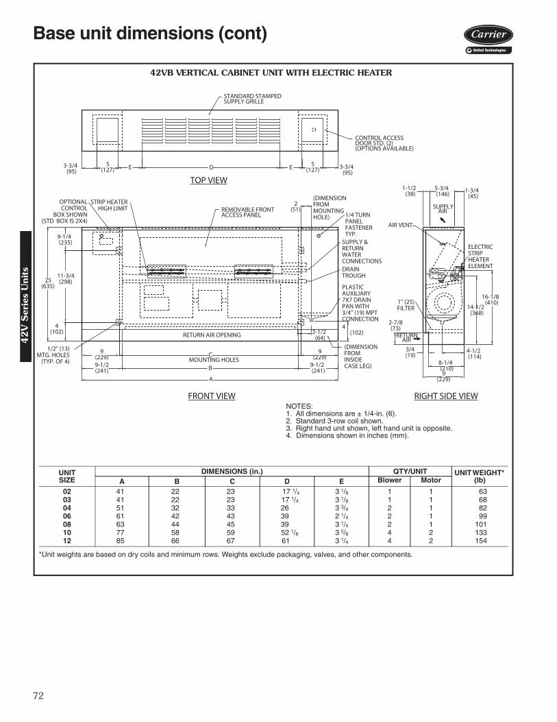
72
11-3/4(298)
4(102)
9-1/4(235)
2-7/8(73)
RETURNAIR
AIRSUPPLY
RETURN AIR OPENING
REMOVABLE FRONTACCESS PANEL
TOP VIEW
FRONT VIEW RIGHT SIDE VIEW
1-3/4(45)
5-3/4 (146)
1-1/2(38)
PLASTIC AUXILIARY 7X7 DRAIN PAN WITH3/4" (19) MPT CONNECTION
9(229)
9(229)
9-1/2(241)
9-1/2(241)
OPTIONALCONTROL
BOX SHOWN(STD BOX IS 2X4)
1/4 TURN PANELFASTENERTYP.
1/2" (13) MTG. HOLES
(TYP. OF 4)
3-3/4(95)
5(127)
5(127)
3-3/4(95)
STANDARD STAMPEDSUPPLY GRILLE
CONTROL ACCESSDOOR STD. (2)
MOUNTING HOLES
A
B
C
E ED
25(635)
(OPTIONS AVAILABLE)
2(51)
DRAIN TROUGH
SUPPLY & RETURNWATER CONNECTIONS
9(229)
3/4(19)
8-1/4(210)
1" (25) FILTER 14-1/2
(368)
16-1/8(410)
AIR VENT
4-1/2(114)
4(102)
(DIMENSION FROM MOUNTING HOLE)
(DIMENSIONFROM INSIDE CASE LEG)
STRIP HEATERHIGH LIMIT
ELECTRIC STRIPHEATER ELEMENT
2-1/2(64)
42VB VERTICAL CABINET UNIT WITH ELECTRIC HEATER
NOTES:1. All dimensions are ± 1/4-in. (6).2. Standard 3-row coil shown.3. Right hand unit shown, left hand unit is opposite.4. Dimensions shown in inches (mm).
*Unit weights are based on dry coils and minimum rows. Weights exclude packaging, valves, and other components.
UNITSIZE
DIMENSIONS (in.) QTY/UNIT UNIT WEIGHT* (lb)A B C D E Blower Motor
02 41 22 23 17 1/4 3 1/8 1 1 6303 41 22 23 17 1/4 3 1/8 1 1 6804 51 32 33 26 3 3/4 2 1 8206 61 42 43 39 2 1/4 2 1 9908 63 44 45 39 3 1/4 2 1 10110 77 58 59 52 1/8 3 5/8 4 2 13312 85 66 67 61 3 1/4 4 2 154
Base unit dimensions (cont)4
2V
Ser
ies
Uni
ts

73
13(330)
AIR VENT
AIRSUPPLY
RETURN AIR OPENING
REMOVABLE FRONTACCESS PANEL
TOP VIEW
FRONT VIEW
1-3/4(45)
5-3/4(146)1-1/2
(38)OPTIONALCONTROL BOX SHOWN(STD BOX IS 2X4) 1/4 TURN PANEL
FASTENER TYP.
STANDARD STAMPEDSUPPLY GRILLE
CONTROL ACCESSDOOR STD. (2)
B 9-1/2(241)
C 9(229)
MOUNTING HOLES9-1/2(241)
9(229)
4(102)
11-3/4 (298)
1/2" (13) MTG. HOLES
(TYP. OF 4)
A
3-3/4(95)
5(127) E D E 5
(127)3-3/4
(95)
RIGHT SIDE VIEW
2-7/8(73)
AIRRETURN
1" (25)FILTER
28-3/4(730)
(OPTIONS AVAILABLE)
PLASTIC AUXILIARY 7X7 DRAIN PAN WITH3/4" (19) MPT CONNECTION
DRAIN TROUGH
SUPPLY & RETURNWATER CONNECTIONS
9(229)
3/4(19)
8-1/4(210)
14-1/2(368)
16-1/8(410)
(102)4
4-1/2(114)
(DIMENSION FROM MOUNTING HOLE)
2-1/2(64)
2(51)
(DIMENSIONFROM INSIDECASE LEG)
42VF VERTICAL CABINET UNIT WITH SLANT TOP
A42-4111NOTES:1. All dimensions are ± 1/4-in. (6).2. Standard 3-row coil shown.3. Right hand unit shown, left hand unit is opposite.4. Dimensions shown in inches (mm).
*Unit weights are based on dry coils and minimum rows. Weights exclude packaging, valves, and other components.
UNITSIZE
DIMENSIONS (in.) QTY/UNIT UNIT WEIGHT* (lb)A B C D E Blower Motor
02 41 22 23 17 1/4 3 1/8 1 1 6403 41 22 23 17 1/4 3 1/8 1 1 6904 51 32 33 26 3 3/4 2 1 8306 61 42 43 39 2 1/4 2 1 10008 63 44 45 39 3 1/4 2 1 10210 77 58 59 52 1/8 3 5/8 4 2 13512 85 66 67 61 3 1/4 4 2 156
42
V S
eries Units

74
Base unit dimensions (cont)
13(330)
AIR VENT
AIRSUPPLY
RETURN AIR OPENING
REMOVABLE FRONTACCESS PANEL
TOP VIEW
FRONT VIEW
1-3/4(45)
5-3/4(146)1-1/2
(38)
1/4 TURN PANELFASTENER TYP.
STANDARD STAMPEDSUPPLY GRILLE
CONTROL ACCESSDOOR STD. (2)
B 9-1/2(241)
C 9(229)MOUNTING HOLES
9-1/2(241)
9(229)
4(102)
11-3/4 (298)
1/2" (13) MTG. HOLES
(TYP. OF 4)
A
3-3/4(95)
5(127) E D E 5
(127)3-3/4
(95)
RIGHT SIDE VIEW
2-7/8(73)
AIRRETURN
1" (25) FILTER
28-3/4(730)
(OPTIONS AVAILABLE)
PLASTIC AUXILIARY 7X7 DRAIN PAN WITH3/4" (19) MPT CONNECTION
DRAIN TROUGH
SUPPLY & RETURNWATER CONNECTIONS
9(229)
3/4(19)
8-1/4(210)
14-1/2(368)
16-1/8(410)
(102)4
4-1/2(114)
(DIMENSION FROM MOUNTING HOLE)
2-1/2(64)
2(51)
(DIMENSIONFROM INSIDECASE LEG)
OPTIONALCONTROL
BOX SHOWN(STD BOX
IS 2X4)
STRIP HEATERHIGH LIMIT
ELECTRIC STRIPHEATER ELEMENT
42VF VERTICAL CABINET UNIT WITH SLANT TOP AND ELECTRIC HEATER
NOTES:1. All dimensions are ± 1/4-in. (6).2. Standard 3-row coil shown.3. Right hand unit shown, left hand unit is opposite.4. Dimensions shown in inches (mm).
*Unit weights are based on dry coils and minimum rows. Weights exclude packaging, valves, and other components.
UNITSIZE
DIMENSIONS (in.) QTY/UNIT UNIT WEIGHT* (lb)A B C D E Blower Motor
02 41 22 23 17 1/4 3 1/8 1 1 6403 41 22 23 17 1/4 3 1/8 1 1 6904 51 32 33 26 3 3/4 2 1 8306 61 42 43 39 2 1/4 2 1 10008 63 44 45 39 3 1/4 2 1 10210 77 58 59 52 1/8 3 5/8 4 2 13512 85 66 67 61 3 1/4 4 2 156
42
V S
erie
s U
nits
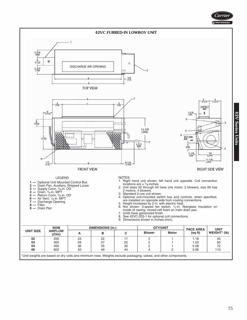
75
14-3/8(368)
9
LEGEND1 — Optional Unit Mounted Control Box2 — Drain Pan, Auxiliary, Shipped Loose3 — Supply Conn, 5/8-in. OD4 — Drain, 3/4-in. MPT5 — Return Conn, 5/8-in. OD6 — Air Vent, 1/8-in. MPT7 — Discharge Opening8 — Filter9 — Drain Pan
*Unit weights are based on dry coils and minimum rows. Weights exclude packaging, valves, and other components.
UNIT SIZENOM
AIRFLOW(Cfm)
DIMENSIONS (in.) QTY/UNIT FACE AREA(sq ft)
UNIT WEIGHT* (lb)A B C Blower Motor
02 200 23 22 17 2 1 1.18 5003 300 28 27 22 2 1 1.53 6004 400 36 35 30 2 1 2.08 7206 600 50 49 44 4 2 3.06 110
NOTES:1. Right hand unit shown; left hand unit opposite. Coil connection
locations are ± 5/8-inches.2. Unit sizes 02 through 04 have one motor, 2 blowers; size 06 has
2 motors, 4 blowers.3. Standard 2-row coil shown.4. Optional unit-mounted switch box and controls, when specified,
are installed on opposite side from cooling connections.5. Height increases by 2 in. with electric heat.6. Not shown: 3-speed fan switch, 1/2-in. fiberglass insulation on
inside of casing, closed cell foam on main drain pan.7. Units have galvanized finish.8. See 42VC-203-1 for optional coil connections.9. Dimensions shown in inches (mm). A42-4112
42VC FURRED-IN LOWBOY UNIT
42
V S
eries Units

76
10
42VC FURRED-IN LOWBOY UNIT WITH ELECTRIC HEAT
LEGEND1 — Unit-Mounted Control Box (Optional)2 — Drain Pan, Auxiliary, Shipped Loose3 — Air Vent, 1/8-in. MPT4 — Supply Conn, 5/8-in. OD5 — Drain, 3/4-in. MPT6 — Return Conn, 5/8-in. OD7 — Filter8 — Electical Sheath Heater Element9 — Discharge Opening
10 — Drain Pan
*Unit weights are based on dry coils and minimum rows. Weights exclude packaging, valves, and other components.
UNIT SIZENOM
AIRFLOW(Cfm)
DIMENSIONS (in.) QTY/UNIT FACE AREA(sq ft)
UNIT WEIGHT* (lb)A B C Blower Motor
02 200 23 22 17 2 1 1.18 5003 300 28 27 22 2 1 1.53 6004 400 36 35 30 2 1 2.08 7206 600 50 49 44 4 2 3.06 110
NOTES:1. Right hand unit shown; left hand unit opposite. Coil connection
locations are ± 5/8-inches.2. Unit sizes 02 through 04 have one motor, 2 blowers; size 06 has
2 motors, 4 blowers.3. Standard 2-row coil shown.4. Optional unit-mounted switch box and controls, when specified,
are installed on opposite side from cooling connections.5. Height increases by 2 in. with electric heat.6. Not shown: 3-speed fan switch, 1/2-in. fiberglass insulation on
inside of casing, closed cell foam on main drain pan.7. Units have galvanized finish.8. See 42VC-203-1 for optional coil connections.9. Dimensions shown in inches (mm). A42-4113
Base unit dimensions (cont)4
2V
Ser
ies
Uni
ts
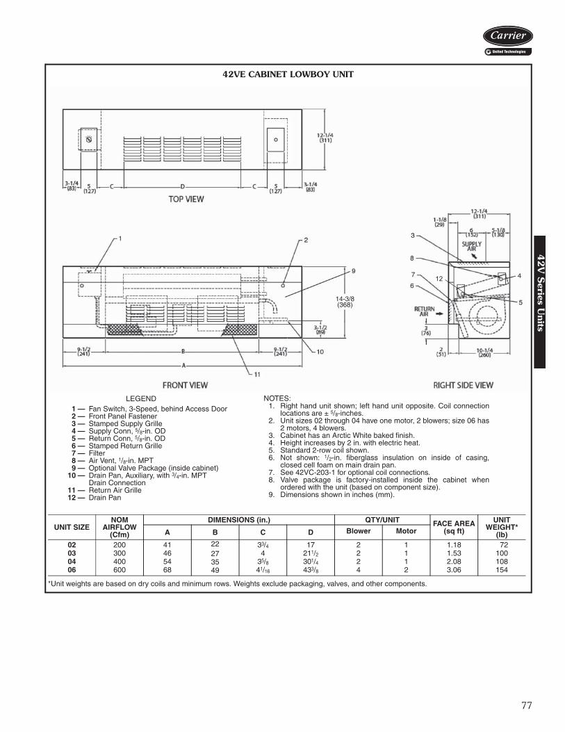
77
14-3/8(368)
12
*Unit weights are based on dry coils and minimum rows. Weights exclude packaging, valves, and other components.
UNIT SIZENOM
AIRFLOW(Cfm)
DIMENSIONS (in.) QTY/UNIT FACE AREA(sq ft)
UNIT WEIGHT*
(lb)A B C D Blower Motor
02 200 41 22 33/4 17 2 1 1.18 7203 300 46 27 4 211/2 2 1 1.53 10004 400 54 35 35/8 301/4 2 1 2.08 10806 600 68 49 41/16 433/8 4 2 3.06 154
LEGEND1 — Fan Switch, 3-Speed, behind Access Door2 — Front Panel Fastener3 — Stamped Supply Grille4 — Supply Conn, 5/8-in. OD5 — Return Conn, 5/8-in. OD6 — Stamped Return Grille7 — Filter8 — Air Vent, 1/8-in. MPT9 — Optional Valve Package (inside cabinet)
10 — Drain Pan, Auxiliary, with 3/4-in. MPTDrain Connection
11 — Return Air Grille12 — Drain Pan
NOTES:1. Right hand unit shown; left hand unit opposite. Coil connection
locations are ± 5/8-inches.2. Unit sizes 02 through 04 have one motor, 2 blowers; size 06 has
2 motors, 4 blowers.3. Cabinet has an Arctic White baked finish.4. Height increases by 2 in. with electric heat.5. Standard 2-row coil shown.6. Not shown: 1/2-in. fiberglass insulation on inside of casing,
closed cell foam on main drain pan.7. See 42VC-203-1 for optional coil connections.8. Valve package is factory-installed inside the cabinet when
ordered with the unit (based on component size).9. Dimensions shown in inches (mm). A42-4114
42VE CABINET LOWBOY UNIT
42
V S
eries Units

78
13
42VE CABINET LOWBOY UNIT WITH ELECTRIC HEAT
*Unit weights are based on dry coils and minimum rows. Weights exclude packaging, valves, and other components.
UNIT SIZENOM
AIRFLOW(Cfm)
DIMENSIONS (in.) QTY/UNIT FACE AREA(sq ft)
UNIT WEIGHT*
(lb)A B C D Blower Motor
02 200 41 22 33/4 17 2 1 1.18 7203 300 46 27 4 211/2 2 1 1.53 10004 400 54 35 35/8 301/4 2 1 2.08 10806 600 68 49 41/16 433/8 4 2 3.06 154
LEGEND1 — Fan Switch, 3-Speed, behind Access Door2 — Electrical Sheath Heater Element3 — Stamped Supply Grille4 — Supply Conn, 5/8-in. OD5 — Return Conn, 5/8-in. OD6 — Stamped Return Grille7 — Filter8 — Air Vent, 1/8-in. MPT9 — Front Panel Fastener
10 — Optional Valve Package (inside cabinet)11 — Drain Pan, Auxiliary, with 3/4-in. MPT
Drain Connection12 — Return Air Grille13 — Drain Pan
NOTES:1. Right hand unit shown; left hand unit opposite. Coil connection
locations are ± 5/8-inches.2. Unit sizes 02 through 04 have one motor, 2 blowers; size 06 has
2 motors, 4 blowers.3. Cabinet has an Arctic White baked finish.4. Height increases by 2 in. with electric heat.5. Standard 2-row coil shown.6. Not shown: 1/2-in. fiberglass insulation on inside of casing,
closed cell foam on main drain pan.7. See 42VC-203-1 for optional coil connections.8. Valve package is factory-installed inside the cabinet when
ordered with the unit (based on component size).9. Dimensions shown in inches (mm).
A42-4115
Base unit dimensions (cont)4
2V
Ser
ies
Uni
ts

79
12
42VG FURRED-IN WALL UNIT
LEGEND1 — Supply Conn, 5/8-in. OD2 — Air Vent, 1/8-in. MPT3 — Filter4 — Return Air Grille, Stamped5 — Stamped Supply Grille6 — Return Conn, 5/8-in. OD7 — Removable Front Panel8 — Drain Conn, 7/8-in. OD9 — Auxilary Drain Pan
10 — Valve Compartment - (Optional)11 — Junction Box12 — Drain Pan
NOTES:1. Right hand unit shown; left hand unit opposite. Coil connection
locations are ± 5/8-inches.2. Front panel has an Arctic White baked finish.3. Standard 2-row coil shown.4. Unit size 01 has one motor, one blower; size 03 has 2 motors,
2 blowers.5. Unit has 1/2-in. flanges for mounting to wall surface.6. Front panel hooks at top of unit, swing down and snap in at bottom
against a spring clip.7. Not shown: 3-speed fan switch, wall plate, 1/2-in. fiberglass insula-
tion on inside of casing, closed cell foam on main drain pan.8. Dimensions shown in inches (mm).
*Unit weights are based on dry coils and minimum rows. Weights exclude packaging, valves, and other components.
UNIT SIZENOM
AIRFLOW(Cfm)
DIMENSIONS (in.) QTY/UNIT UNIT WEIGHT*
(lb)A B C D E Blower Motor
01 150 253/4 153/4 14 11/2 123/4 1 1 4003 300 393/4 293/4 28 115/16 257/8 2 2 74
a42-4116
42V
Series U
nits

80
AIR VENT
RIGHT SIDE VIEW
FGHJ
AIR VENT
14-1/2
16-1/8
FGHJ
LEFT SIDE VIEW
14-1/2
16-1/8
42VA,VB,VF OPTIONAL COIL CONNECTION LOCATION SIZES 02–12
a42-4390
COIL CONNECTION DIMENSIONS (in.)
RIGHT
HAND
UNITSIZE
LEFT SIDE DIMENSIONS 1-ROW HEAT WITH 3-ROW COOL
1-ROW HEAT WITH 4-ROW COOL
2-ROW HEAT WITH 3-ROW COOL
QUANTITY/UNIT3-ROW COIL 4-ROW COILH
SUPPLYF
RETURNH
SUPPLYF
RETURNG
SUPPLYJ
RETURNG
SUPPLYJ
RETURNG
SUPPLYJ
RETURN BLOWER MOTOR
02 4 1/2 4 1/2 4 1/2 5 6 1/4 5 1/2 7 1/2 5 3/4 6 6 1/4 1 103 4 3/4 6 5 1/4 4 1/4 7 6 1/4 5 1/2 7 1/4 7 1/4 6 3/4 1 104 4 1/8 5 1/2 5 3/4 5 1/4 7 1/2 7 1/4 7 1/4 6 1/2 7 1/4 5 3/4 2 106 5 1/4 5 6 1/4 6 7 6 3/8 7 1/4 7 1/4 7 1/8 7 1/4 2 108 5 1/4 5 6 1/4 6 7 6 3/8 7 1/4 7 1/4 7 1/8 7 1/4 4 110 5 3/4 5 1/4 5 3/4 5 1/4 7 1/4 7 1/2 7 3/8 7 1/2 7 1/4 7 1/2 4 212 4 3/4 4 1/2 5 3/4 5 1/4 6 1/2 6 1/2 7 1/4 7 1/2 7 1/4 7 1/2 4 2
LEFT
HAND
UNITSIZE
LEFT SIDE DIMENSIONS 1-ROW HEAT WITH 3-ROW COOL
1-ROW HEAT WITH 4-ROW COOL
2-ROW HEAT WITH 3-ROW COOL
QUANTITY/UNIT3-ROW COIL 4-ROW COILH
SUPPLYF
RETURNH
SUPPLYF
RETURNG
SUPPLYJ
RETURNG
SUPPLYJ
RETURNG
SUPPLYJ
RETURN BLOWER MOTOR
02 4 1/2 4 1/2 4 1/2 4 7/8 7 3/4 5 3/4 5 1/2 6 3/4 5 3/4 5 3/4 1 103 5 1/2 4 1/4 6 1/4 4 3/4 6 6 1/4 7 7 1/2 7 1/2 6 3/4 1 104 4 3/4 4 1/2 5 3/4 5 1/4 7 6 1/2 6 6 3/4 7 5 3/4 2 106 4 3/8 4 1/4 5 1/2 5 1/8 6 6 1/4 7 7 1/8 6 1/4 7 1/4 2 108 4 3/8 4 1/4 5 1/2 5 1/8 6 6 1/4 7 7 1/8 6 1/4 7 1/4 2 110 5 3/4 5 1/2 5 3/4 5 1/2 7 1/4 7 1/2 7 1/2 7 1/2 7 1/4 7 1/2 4 212 6 1/4 5 1/4 5 1/2 5 1/4 6 1/4 6 1/2 7 1/4 7 1/4 7 7 1/4 4 2
Accessory dimensions4
2V
Ser
ies
Uni
ts
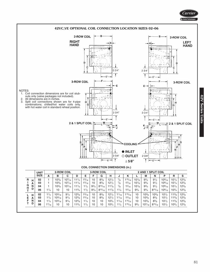
81
42VC,VE OPTIONAL COIL CONNECTION LOCATION SIZES 02–06
NOTES:1. Coil connection dimensions are for coil stub-
outs only (valve packages not included).2. All dimensions are in inches.3. Split coil connections shown are for 4-pipe
combinations; chilled/hot water coils only,with hot water coil in standard reheat position.
COIL CONNECTION DIMENSIONS (in.)
UNITSIZE
2-ROW COIL 3-ROW COIL 2 AND 1 SPLIT COILA B C D E F G H J K L M N P R S
RIGHT
HAND
02 1 103/8 107/16 111/4 15/16 10 83/8 121/2 7/8 115/16 101/8 93/4 91/2 109/16 101/4 123/803 1 103/8 107/16 111/4 15/16 10 83/8 121/2 7/8 15/16 101/8 93/4 91/2 109/16 101/4 123/804 1 103/8 107/16 111/4 11/2 93/4 815/16 117/8 7/8 15/16 101/8 93/4 91/2 109/16 101/4 123/806 11/4 10 10 113/4 11/2 93/4 815/16 117/8 11/4 15/16 93/4 93/4 815/16 109/16 103/4 123/8
LEFT
HAND
02 11/4 103/16 91/4 123/8 15/16 10 83/8 121/2 11/16 115/16 10 103/8 103/8 101/2 113/8 123/803 11/4 103/16 91/4 123/8 15/16 10 83/8 121/2 11/16 15/16 10 103/8 83/8 101/2 113/8 123/804 11/4 103/16 91/4 123/8 11/4 10 10 103/4 11/16 115/16 10 103/8 83/8 101/2 113/8 123/806 17/16 10 10 113/4 11/4 10 10 103/4 11/4 115/16 93/4 107/16 815/16 101/2 103/4 123/8
42
V S
eries Units

82
DISCHARGE AIR GRILLES
*Refer to unit dimensions to size field transitions.
DISCHARGE GRILLES
UnitSize
NominalAirflow(Cfm)
Recommended Grille Sizes (in.)
Unit42VA 42VB,VF 42VC* 42VE
02 200 16 x 5 16 x 6 16 x 5 16 x 603 300 18 x 5 16 x 6 22 x 5 22 x 604 400 26 x 5 26 x 6 30 x 5 30 x 606 600 36 x 5 36 x 6 44 x 5 44 x 608 800 38 x 5 38 x 6 — —10 1000 52 x 5 52 x 6 — —12 1200 60 x 5 60 x 6 — —
INTEGRAL DOUBLE-DEFLECTION GRILLEFOR VERTICAL UNITS
ANODIZED ALUMINUM DOUBLE-DEFLECTIONGRILLE (With Frame)
A42-4118
Accessory dimensions (cont)42V
Ser
ies
Uni
ts

83
AIR DELIVERY (CFM)42V SERIES — 60 Hz PSC MOTOR
NOTE: Air delivery is based on operation with PSC motors, dry coils and clean air filter.
SOUND POWER DATA42VA, VB, AND VF VERTICAL FLOOR FAN COIL UNITS
NOTES:1. Testing in compliance with AHRI (Air-Conditioning, Heating, and
Refrigeration Institute) 350, Sound Performance Rating of Non-Ducted Indoor Air-Conditioning Equipment.
2. Sound power data is based on an exposed cabinet model with115/1/60 PSC motor, 3 row coil, standard 1-in. throwaway filter andstandard louvered discharge.
3. Sound power data is expressed decibels, dB RE: 1 x 10-12W(picowatts).
UNIT SIZE COILCFM AT 0.0 ESP FOR FAN SPEED HIGH SPEED CFM AT ESP INDICATED
LOW MED HIGH 0.05 0.1 0.15 0.2
42VA,VB,VF
02 3-Row 147 208 244 222 201 180 159
033-Row 224 262 317 300 283 266 2484-Row 213 256 310 292 274 255 236
043-Row 279 350 487 461 434 407 3794-Row 266 344 463 439 414 389 363
063-Row 383 553 629 598 568 539 5114-Row 373 536 611 582 554 527 501
083-Row 377 603 689 645 600 555 5104-Row 364 579 664 620 575 530 484
103-Row 590 723 971 923 874 823 7724-Row 557 690 896 885 811 762 711
123-Row 738 1029 1166 1119 1070 1020 9684-Row 718 974 1094 1052 1009 963 915
42VC,VE
022-Row 125 170 250 225 190 150 1203-Row 115 155 230 210 180 145 115
032-Row 195 285 370 345 305 275 2353-Row 185 265 345 315 285 255 230
042-Row 240 350 480 440 400 360 3203-Row 230 335 460 420 385 345 310
062-Row 395 575 750 700 660 660 5603-Row 355 510 670 625 580 540 495
UNITSIZE
FANSPEED
SOUND POWER LEVEL, Lw (dB one reference picowatt)63 Hz 125 Hz 250 Hz 500 Hz 1000 Hz 2000 Hz 4000 Hz 8000 Hz
02H 58.2 55.6 60.1 51.9 46.3 41.8 36,0 35.2M 58.4 53.5 57.4 47.9 41.4 37.6 31.2 34.5L 58.2 48.4 45.6 40.4 33.4 28.1 28.9 34.4
03H 58.9 62.4 63.0 58.2 55.2 48.1 43.9 38.6M 58.9 58.6 58.3 54.3 49.1 42.4 37.0 35.5L 58.3 55.6 54.8 50.9 43.8 36.7 31.9 34.8
04H 59.0 62.4 67.5 59.6 56.2 51.0 46.3 40.6M 58.2 56.2 62.5 53.3 48.9 43.2 36.9 35.2L 57.7 53.9 52.0 47.1 44.1 34.9 30.8 34.4
06H 57.4 66.2 69.0 61.7 58.9 52.3 48.2 42.2M 60.0 65.3 67.1 59.8 56.3 49.7 44.8 38.9L 58.1 58.8 53.9 49.6 43.9 36.3 31.4 34.8
08H 61.5 65.6 68.8 63.1 60.3 54.0 50.9 45.7M 60.4 65.5 70.8 61.4 58.3 51.7 47.8 42.7L 57.7 63.3 60.3 53.5 46.6 40.6 34.4 34.8
10H 61.8 63.9 67.2 63.7 60.2 53.7 48.5 41.7M 59.3 58.4 61.5 57.9 51.6 45.2 38.4 35.0L 61.6 54.4 55.9 52.0 44.8 38.4 31.6 34.2
12H 60.9 67.5 72.3 65.8 62.2 56.1 51.9 46.8M 59.6 67.7 72.3 64.0 60.2 53.8 49.4 43.9L 57.9 64.7 62.7 55.6 49.5 42.6 36.7 33.6
Performance data4
2V
Series U
nits

84
ELECTRIC HEATER DATA
LEGENDFLA — Full Load AmpsNOTE: All heaters are single-stage and single-phase.
42VA,VB, AND VF PSC MOTOR DATA
*Total motor amps and watts shown for units with 2 motors.NOTES:
1. Motor nameplate amps may vary.2. Fan coil units comply with ETL, Canadian Standards Association (CSA), and
ETL of Canada standards.
HEATERVOLTAGE
HEATER kW1.0 1.5 2.0 3.0 4.0 5.0 6.0
FLA120 8.3 12.5 16.7 25.0 — — —208 4.8 7.2 9.6 14.4 19.2 — —240 4.2 6.3 8.3 12.5 16.7 — —277 3.6 5.4 7.2 10.8 14.4 18.05 21.7
V-Ph-Hz FANSPEED
FANSPEED(RPM)
UNIT SIZE02 03 04 06
Nominal Hp Watts Amps Nominal Hp Watts Amps Nominal Hp Watts Amps Nominal Hp Watts Amps
115-1-60H 1200
1/40
60 0.391/30
80 0.691/12
125 1.201/6
180 1.94M 980 50 0.35 60 0.51 85 0.73 140 1.30L 790 45 0.28 50 0.42 60 0.56 85 0.76
208-1-60H 1200
1/40
70 0.261/30
95 0.451/12
115 0.541/6
145 0.74M 980 65 0.24 70 0.35 85 0.41 100 0.51L 790 60 0.22 50 0.24 55 0.26 60 0.31
230-1-60H 1200
1/40
75 0.281/30
110 0.471/12
130 0.561/6
160 0.72M 980 70 0.26 85 0.36 100 0.43 115 0.51L 790 65 0.24 60 0.25 60 0.28 70 0.33
277-1-60H 1200
1/40
70 0.161/30
105 0.521/12
130 0.571/6
185 0.68M 980 60 0.13 85 0.37 105 0.41 135 0.49L 790 55 0.10 55 0.21 65 0.24 110 0.41
V-Ph-Hz FANSPEED
FANSPEED
UNIT SIZE08 10* 12*
Nominal Hp Watts Amps Nominal Hp Watts Amps Nominal Hp Watts Amps
115-1-60H 1200
1/6
195 1.921/12 (2)
260 2.541/6 (2)
335 3.75M 980 150 1.35 175 1.54 255 2.43L 790 80 0.72 135 1.18 160 1.47
208-1-60H 1200
1/6
155 0.791/12 (2)
225 1.061/6 (2)
270 1.36M 980 100 0.52 175 0.81 190 0.97L 790 55 0.30 110 0.51 120 0.62
230-1-60H 1200
1/6
170 0.801/12 (2)
260 1.101/6 (2)
295 1.37M 980 115 0.54 200 0.84 210 0.97L 790 65 0.33 130 0.54 140 0.66H 1200
1/6
195 0.741/12 (2)
275 1.14 295 1.37277-1-60 M 980 135 0.53 215 0.80 1/6 (2) 250 0.91
L 790 110 0.43 140 0.47 215 0.79
Electrical data4
2V
Ser
ies
Uni
ts
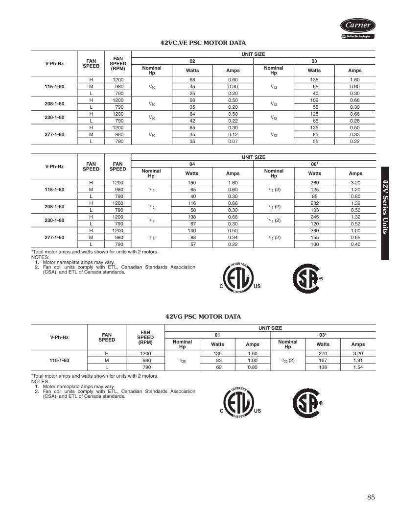
85
42VC,VE PSC MOTOR DATA
*Total motor amps and watts shown for units with 2 motors.NOTES:
1. Motor nameplate amps may vary.2. Fan coil units comply with ETL, Canadian Standards Association
(CSA), and ETL of Canada standards.
42VG PSC MOTOR DATA
*Total motor amps and watts shown for units with 2 motors.NOTES:
1. Motor nameplate amps may vary.2. Fan coil units comply with ETL, Canadian Standards Association
(CSA), and ETL of Canada standards.
V-Ph-Hz FANSPEED
FANSPEED(RPM)
UNIT SIZE02 03
NominalHp Watts Amps Nominal
Hp Watts Amps
115-1-60H 1200
1/20
68 0.601/12
135 1.60M 980 45 0.30 65 0.60L 790 25 0.20 40 0.30
208-1-60H 1200
1/2056 0.50
1/12109 0.66
L 790 35 0.20 55 0.30
230-1-60H 1200
1/2064 0.50
1/12128 0.66
L 790 42 0.22 65 0.28
277-1-60H 1200
1/20
85 0.301/12
135 0.50M 980 45 0.12 85 0.33L 790 35 0.07 55 0.22
V-Ph-Hz FANSPEED
FANSPEED
UNIT SIZE04 06*
NominalHp Watts Amps Nominal
Hp Watts Amps
115-1-60H 1200
1/12
150 1.601/12 (2)
260 3.20M 980 65 0.60 125 1.20L 790 40 0.30 85 0.80
208-1-60H 1200
1/12116 0.66
1/12 (2)232 1.32
L 790 58 0.30 103 0.50
230-1-60H 1200
1/12138 0.66
1/12 (2)245 1.32
L 790 67 0.30 120 0.52
277-1-60H 1200
1/12
140 0.501/12 (2)
260 1.00M 980 88 0.34 155 0.65L 790 57 0.22 100 0.40
V-Ph-Hz FANSPEED
FANSPEED(RPM)
UNIT SIZE01 03*
NominalHp Watts Amps Nominal
Hp Watts Amps
115-1-60H 1200
1/20
135 1.601/20 (2)
270 3.20M 980 83 1.00 167 1.91L 790 69 0.80 138 1.54
42
V S
eries Units

86
42VA, VB, VC, VE, VF ECM MOTOR DATA
SIZE NOMINAL HPAMPS
120V 208V 230V 277V
42V*02 1/7
2.4
1.4 1.3 1.242V*03 1/7
42V*04 1/6
1.6 1.5 1.042V*06 1/6
42V*08 1/6
42V*10 1/6 (2)3.2 3.0 2.0
42V*12 1/6 (2)
Electrical data (cont)4
2V
Ser
ies
Uni
ts

87
AHRI capacity ratingsThe 42D Series fan coil units are certified in compliancewith the Air-Conditioning, Heating and Refrigeration Insti-tute (AHRI) Industry Standard 440 for room fan coil units.Approved standard ratings are tabulated below:
AHRI APPROVED STANDARD RATINGS*
*Ratings based on motor at high fan speed, standard air and dry coiloperation, 10°F water temperature rise; entering-air temperatures of80 F db, 67 F wb; entering-water temperature 45 F.
†With standard 4-row coil.
**Motor type, permanent split capacitor, operating at 115-1-60 voltage.
B
ww
w
A – 120V Electronically Commutated Motor (ECM) with Control Option 1B – 120V ECM with Control Option 2C – 120V PSC-STDD – 208/1/60 PSCE – 230/1/60 PSCF – 277/1/60 PSCG – 120V ECM with Control Option 3H – 208V ECM with Control Option 1J – 208V ECM with Control Option 2K – 208V ECM with Control Option 3L – 230V ECM with Control Option 1M – 230V ECM with Control Option 2N – 230V ECM with Control Option 3P – 277V ECM with Control Option 1Q – 277V ECM with Control Option 3R – 277V ECM with Control Option 2V – 220/1/50 PSC*Control Option 1 – 3-Discrete Potentiometer Field Speed AdjustmentControl Option 2 – Variable Flow 0-10 VDC or 4-20 mAControl Option 3 – 4-Discrete Potentiometer Field Speed Adjustment
* Contact Application Engineering for data on the 50 Hz motor.
a42-3995
LEGENDPSC — Permanent Split Capacitor
* Contact Application Engineering for Data on the 50Hz motor.
UNITTYPE UNIT SIZE† NOMINAL
CFM GPMCOOLING CAPACITY
POWERINPUT (WATTS)**Total
Heat BtuhSensible
Heat Btuh
42DF
06 600 3.7 18,100 13,700 22508 800 5.0 23,400 17,600 27510 1000 6.9 33,300 24,000 40012 1200 8.7 41,800 30,200 45014 1400 10.0 48,900 34,000 470
Model number nomenclature 4
2D
Series U
nits
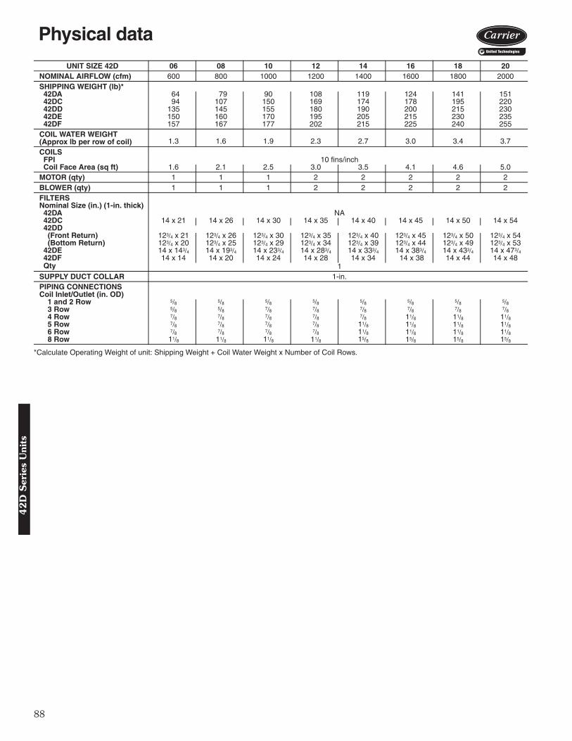
88
*Calculate Operating Weight of unit: Shipping Weight + Coil Water Weight x Number of Coil Rows.
UNIT SIZE 42D 06 08 10 12 14 16 18 20NOMINAL AIRFLOW (cfm) 600 800 1000 1200 1400 1600 1800 2000SHIPPING WEIGHT (lb)* 42DA 64 79 90 108 119 124 141 151 42DC 94 107 150 169 174 178 195 220 42DD 135 145 155 180 190 200 215 230 42DE 150 160 170 195 205 215 230 235 42DF 157 167 177 202 215 225 240 255COIL WATER WEIGHT(Approx lb per row of coil) 1.3 1.6 1.9 2.3 2.7 3.0 3.4 3.7
COILS FPI 10 fins/inch Coil Face Area (sq ft) 1.6 2.1 2.5 3.0 3.5 4.1 4.6 5.0MOTOR (qty) 1 1 1 2 2 2 2 2BLOWER (qty) 1 1 1 2 2 2 2 2FILTERSNominal Size (in.) (1-in. thick) 42DA NA 42DC 14 x 21 14 x 26 14 x 30 14 x 35 14 x 40 14 x 45 14 x 50 14 x 54 42DD
(Front Return) 123/4 x 21 123/4 x 26 123/4 x 30 123/4 x 35 123/4 x 40 123/4 x 45 123/4 x 50 123/4 x 54(Bottom Return) 123/4 x 20 123/4 x 25 123/4 x 29 123/4 x 34 123/4 x 39 123/4 x 44 123/4 x 49 123/4 x 53
42DE 14 x 143/4 14 x 193/4 14 x 233/4 14 x 283/4 14 x 333/4 14 x 383/4 14 x 433/4 14 x 473/4 42DF 14 x 14 14 x 20 14 x 24 14 x 28 14 x 34 14 x 38 14 x 44 14 x 48 Qty 1SUPPLY DUCT COLLAR 1-in.PIPING CONNECTIONSCoil Inlet/Outlet (in. OD) 1 and 2 Row 5/8 5/8 5/8 5/8 5/8 5/8 5/8 5/8 3 Row 5/8 5/8 7/8 7/8 7/8 7/8 7/8 7/8 4 Row 7/8 7/8 7/8 7/8 7/8 11/8 11/8 11/8 5 Row 7/8 7/8 7/8 7/8 11/8 11/8 11/8 11/8 6 Row 7/8 7/8 7/8 7/8 11/8 11/8 11/8 11/8 8 Row 11/8 11/8 11/8 11/8 15/8 15/8 15/8 15/8
Physical data 4
2D
Ser
ies
Uni
ts

89
12
42DA FURRED-IN CEILING UNIT WITH ELECTRIC HEAT
*Unit weights are based on dry coils and minimum rows. Weights exclude packaging, valves, and othercomponents.NOTES:1. Right hand unit shown; left hand unit opposite. Coil connection locations are ± 5/8 inches.2. Sizes 06, 08 and 10 have one motor, one blower; sizes 12 through 20 have 2 motors, 2 blowers.3. Standard 4-row coil shown. Other coil option dimensional data available on request.4. See 42DA-203-1 for optional coil connections.5. Fan switch, wall plate not shown.6. Galvanized finish provided as standard.7. Dimensions are in inches (mm).
UNIT SIZE
NOMAIRFLOW
(Cfm)
DIMENSIONS (in. ± 1/8) QTY/UNIT UNIT WEIGHT*
(lb)A A’ B D’ E H Blower Motor
06 600 23 32 14 131/2 17 181/2 1 1 6408 800 28 37 19 131/2 22 231/2 1 1 7910 1000 32 42 23 141/2 26 271/2 1 1 9012 1200 37 47 28 141/2 31 321/2 2 2 10814 1400 42 52 33 141/2 36 371/2 2 2 11916 1600 47 56 38 131/2 41 421/2 2 2 12418 1800 52 62 43 141/2 46 471/2 2 2 14120 2000 56 66 47 141/2 50 511/2 2 2 151
LEGEND1 — Motor Junction Box2 — Motor-Blower Assembly3 — Electric Strip Heater Element (optional)4 — Auxiliary Drip Lip (Optional, Shipped Loose)5 — Tell-Tale Drain (optional)6 — Drain Connection, 7/8-in. OD7 — Air Vent, 1/8-in. MPT8 — Supply Connection9 — Supply Duct Collar, 1 inch
10 — Return Connection11 — Mounting Holes (four, 3/4-in. diameter) have
Rubber Grommets with 3/8-in. holes.12 — Drain Pan
a42-4120
Base unit dimensions4
2D
Series U
nits
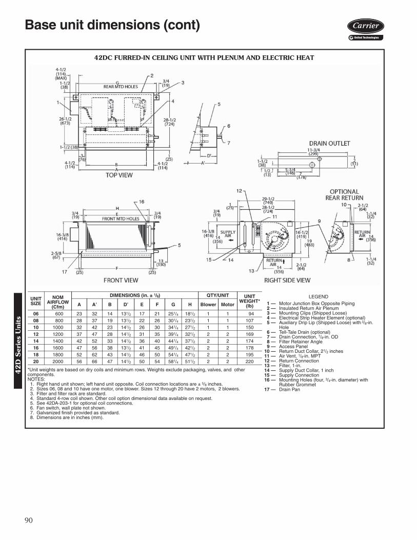
90
17
42DC FURRED-IN CEILING UNIT WITH PLENUM AND ELECTRIC HEAT
LEGEND1 — Motor Junction Box Opposite Piping2 — Insulated Return Air Plenum3 — Mounting Clips (Shipped Loose)4 — Electrical Strip Heater Element (optional)5 — Auxiliary Drip Lip (Shipped Loose) with 3/8-in.
Hole6 — Tell-Tale Drain (optional)7 — Drain Connection, 7/8-in. OD8 — Filter Retainer Angle9 — Access Panel
10 — Return Duct Collar, 21/2 inches11 — Air Vent, 1/8-in. MPT12 — Return Connection13 — Filter, 1-in.14 — Supply Duct Collar, 1 inch15 — Supply Connection16 — Mounting Holes (four, 3/4-in. diameter) with
Rubber Grommet17 — Drain Pan
A42-4121
*Unit weights are based on dry coils and minimum rows. Weights exclude packaging, valves, and other components.NOTES:1. Right hand unit shown; left hand unit opposite. Coil connection locations are ± 5/8 inches.2. Sizes 06, 08 and 10 have one motor, one blower. Sizes 12 through 20 have 2 motors, 2 blowers.3. Filter and filter rack are standard.4. Standard 4-row coil shown. Other coil option dimensional data available on request.5. See 42DA-203-1 for optional coil connections.6. Fan switch, wall plate not shown.7. Galvanized finish provided as standard.8. Dimensions are in inches (mm).
UNITSIZE
NOMAIRFLOW
(Cfm)
DIMENSIONS (in. ± 1/8) QTY/UNIT UNIT WEIGHT*
(lb)A A’ B D’ E F G H Blower Motor
06 600 23 32 14 131/2 17 21 251/4 181/2 1 1 9408 800 28 37 19 131/2 22 26 301/4 231/2 1 1 10710 1000 32 42 23 141/2 26 30 341/4 271/2 1 1 15012 1200 37 47 28 141/2 31 35 391/4 321/2 2 2 16914 1400 42 52 33 141/2 36 40 441/4 371/2 2 2 17416 1600 47 56 38 131/2 41 45 491/4 421/2 2 2 17818 1800 52 62 43 141/2 46 50 541/4 471/2 2 2 19520 2000 56 66 47 141/2 50 54 581/4 511/2 2 2 220
Base unit dimensions (cont)4
2D
Ser
ies
Uni
ts
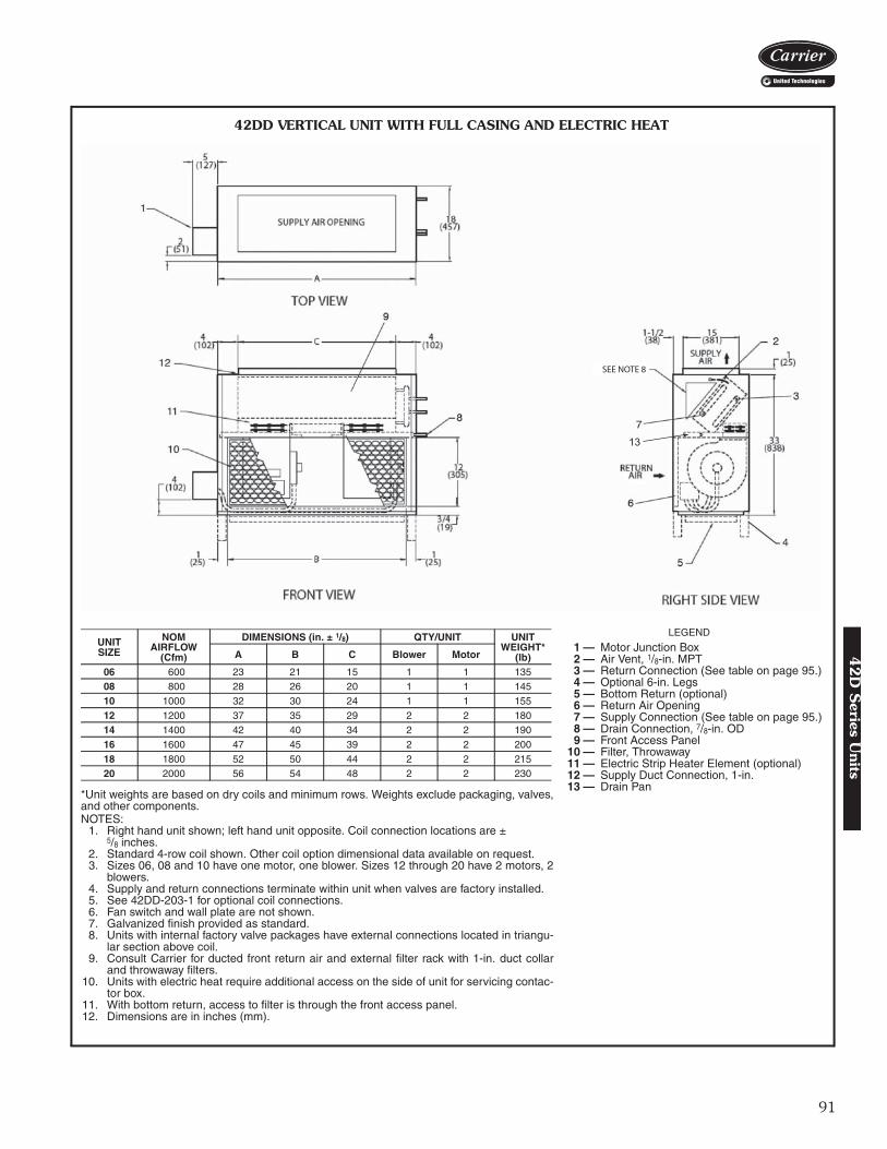
91
SEE NOTE 8
13
*Unit weights are based on dry coils and minimum rows. Weights exclude packaging, valves,and other components.NOTES:
1. Right hand unit shown; left hand unit opposite. Coil connection locations are ± 5/8 inches.
2. Standard 4-row coil shown. Other coil option dimensional data available on request.3. Sizes 06, 08 and 10 have one motor, one blower. Sizes 12 through 20 have 2 motors, 2
blowers.4. Supply and return connections terminate within unit when valves are factory installed.5. See 42DD-203-1 for optional coil connections.6. Fan switch and wall plate are not shown.7. Galvanized finish provided as standard.8. Units with internal factory valve packages have external connections located in triangu-
lar section above coil.9. Consult Carrier for ducted front return air and external filter rack with 1-in. duct collar
and throwaway filters.10. Units with electric heat require additional access on the side of unit for servicing contac-
tor box.11. With bottom return, access to filter is through the front access panel.12. Dimensions are in inches (mm).
UNITSIZE
NOMAIRFLOW
(Cfm)
DIMENSIONS (in. ± 1/8) QTY/UNIT UNIT WEIGHT*
(lb)A B C Blower Motor
06 600 23 21 15 1 1 13508 800 28 26 20 1 1 14510 1000 32 30 24 1 1 15512 1200 37 35 29 2 2 18014 1400 42 40 34 2 2 19016 1600 47 45 39 2 2 20018 1800 52 50 44 2 2 21520 2000 56 54 48 2 2 230
LEGEND
1 — Motor Junction Box2 — Air Vent, 1/8-in. MPT3 — Return Connection (See table on page 95.)4 — Optional 6-in. Legs5 — Bottom Return (optional)6 — Return Air Opening7 — Supply Connection (See table on page 95.)8 — Drain Connection, 7/8-in. OD9 — Front Access Panel
10 — Filter, Throwaway11 — Electric Strip Heater Element (optional)12 — Supply Duct Connection, 1-in.13 — Drain Pan
A42-4122
42DD VERTICAL UNIT WITH FULL CASING AND ELECTRIC HEAT
42
D S
eries Units

92
42DE CEILING UNIT WITH FULL CASING AND ELECTRIC HEAT
*Unit weights are based on dry coils and minimum rows. Weights exclude pack-aging, valves, and other components.NOTES:
1. Right hand unit shown; left hand unit opposite.2. Coil stub-out location data available on request.3. Unit fabricated of galvanized steel.4. Internal parts fabricated of galvanized steel.5. Sizes 06, 08 and 10 have one motor, one blower. Sizes 12 through 20 have
2 motors, 2 blowers.6. Units must have drain line pitched and trapped externally.7. See 42DA-203-1 for optional coil connections.8. Fan switch, wall plate not shown.9. Galvanized finished provided as standard.
10. Dimensions are in inches (mm).
UNIT SIZE
NOM AIRFLOW
(Cfm)
DIMENSIONS (in. ± 1/8) QTY/UNIT UNIT WEIGHT*
(lb)A B C D Blower Motor
06 600 31 15 15 26 1 1 15008 800 36 20 20 31 1 1 16010 1000 40 24 24 35 1 1 17012 1200 45 29 29 40 2 2 19514 1400 50 34 34 45 2 2 20516 1600 55 39 39 50 2 2 21518 1800 60 44 44 55 2 2 23020 2000 64 48 48 59 2 2 235
LEGEND1 — Motor Junction Box2 — Unit Mounting Channel (2), 14-gage; 4 Mounting
Slots, 1/2-in. x 2-in.3 — Auxiliary Drip Lip (optional, shipped loose)4 — Side Access Panels5 — Electrical Strip Heater Element (optional)6 — Supply Air Duct Connection, 1 in.7 — Manual Air Vent8 — Filter, Throwaway, 1-in.9 — Return Air Duct Connection, 21/2 in.
10 — Drain, 7/8-in. OD11 — Bottom Access Panel12 — Drain Pan13 — Coil Inlet (see table on page 94), Copper Sweat Con-
nection14 — Coil Outlet (see table on page 94), Copper Sweat
Connection
A42-4123
Base unit dimensions (cont)4
2D
Ser
ies
Uni
ts

93
*Unit weights are based on dry coils and minimum rows. Weights exclude packaging,valves, and other components.NOTES:1. Right hand unit shown; left hand unit opposite.2. Coil stub-out connection data available on request.3. Units fabricated of galvanized steel with an Arctic White baked finish.4. Internal parts fabricated of galvanized steel.5. Sizes 06, 08 and 10 have one motor, one blower. Sizes 12 through 20 have 2 motors,
2 blowers.6. Units must have drain line pitched and trapped externally.7. Stamped supply and return grilles are not available.8. Bottom return air is not available.9. See 42DA-203-1 for optional coil connections.
10. Fan switch and wall plate are not shown.11. Dimensions are in inches (mm).
UNIT SIZE
NOM AIRFLOW
(Cfm)
DIMENSIONS (in. ± 1/8) QTY/UNIT UNIT WEIGHT*
(lb)A B C D E Blower Motor
06 600 31 131/2 14 26 81/2 1 1 15008 800 36 181/2 20 31 8 1 1 16010 1000 40 221/2 24 35 8 1 1 17012 1200 45 271/2 28 40 81/2 2 2 19514 1400 50 321/2 34 45 8 2 2 20516 1600 55 371/2 38 50 81/2 2 2 21518 1800 60 421/2 44 55 8 2 2 23020 2000 64 461/2 48 59 8 2 2 235
LEGEND1 — Junction Box2 — Return Air Grille, Hinged, Bar Type, with Fil-
ter Frame (Anodized Aluminum Only)3 — Unit Mounting Channel (2), 14-gage; 4
Mounting Slots, 1/2 in. x 2-in.4 — Auxiliary Drip Lip5 — Electric Strip Heater Element (optional)6 — Coil Inlet (See table on page 94), Copper
Sweat Connection7 — Coil Outlet (See table on page 94), Copper
Sweat Connection8 — Manual Air Vent9 — Filter, Throwaway10 — Bottom Access Panel11 — Drain, 7/8-in. OD12 — Drain Pan Insulated with Styrofoam13 — Side Access Panel (2)14 — Discharge Air Grille (Double Deflection)
A42-4124
42DF EXPOSED CEILING UNIT WITH DISCHARGE AND RETURN GRILLE AND ELECTRIC HEAT
42
D S
eries Units

94
42D
A,D
C,D
E A
ND
DF
OPTIO
NA
L C
OIL
CO
NN
EC
TIO
N L
OC
ATIO
N S
IZES 0
6–2
0
a42-3996
NO
TE
S:
1.R
efer
to p
ages
92
and
93 fo
r co
il in
let a
nd o
utle
t kno
ckou
t loc
atio
ns o
n D
E a
nd D
F u
nits
.2.
Coo
ling
coil
is fi
rst i
n th
e ai
rstr
eam
.3.
Spl
it co
il co
nnec
tions
sho
wn
are
for
4-pi
pe c
ombi
natio
n ch
illed
wat
er/h
ot w
ater
coi
ls o
nly,
UN
IT C
FM
CO
IL C
ON
NE
CT
ION
DIM
EN
SIO
NS
(in
.)3-
Ro
w4-
Row
6-R
owA
CF
GA
CF
GA
CF
GR
igh
t H
and
600-
800
1000
-200
037
/ 837
/ 86 6
75/ 1
691
3 /16
75/ 1
691
3 /16
213 /
1661
/ 16
413 /
1610
7 /16
13/ 4
71/ 8
413 /
1610
7 /16
Lef
t H
and
600-
800
1000
-200
037
/ 837
/ 86 6
715 /
1657
/ 16
75/ 1
610
7 /16
213 /
1661
/ 16
57/ 1
691
3 /16
13/ 4
71/ 8
57/ 1
613
/ 16
UN
IT C
FM
CO
IL C
ON
NE
CT
ION
DIM
EN
SIO
NS
(in
.)3
and
1 S
plit
Co
il3
and
2 S
plit
Co
ilA
BC
DE
FG
AB
CD
EF
GR
igh
t H
and
600-
800
1000
-200
021
3 /16
213 /
16
37/ 8
37/ 8
61/ 1
661
/ 16
11/ 1
611
/ 16
75/ 1
641
3 /16
75/ 1
691
3 /16
139 /
1613
9 /16
21/ 4
21/ 4
37/ 8
37/ 8
61/ 1
661
/ 16
3 /4
3 /4
75/ 1
641
3 /16
75/ 1
691
3 /16
131 /
413
1 /4
Lef
t H
and
600-
800
1000
-200
021
3 /16
213 /
16
37/ 8
37/ 8
61/ 1
661
/ 16
7 /16
7 /16
715 /
1657
/ 16
715 /
1610
7 /16
1215
/ 16
1215
/ 16
21/ 4
21/ 4
37/ 8
37/ 8
61/ 1
661
/ 16
3 /4
3 /4
715 /
1657
/ 16
715 /
1610
7 /16
131 /
413
1 /4
UN
IT C
FM
CO
IL C
ON
NE
CT
ION
DIM
EN
SIO
NS
(in
.)4
and
1 S
plit
Co
il4
and
2 S
plit
Co
ilA
BC
DE
FG
AB
CD
EF
GR
igh
t H
and
600-
2000
3 /4
213 /
1661
/ 16
7 /16
413 /
1610
7 /16
1215
/ 16
21/ 4
37/ 8
71/ 8
3 /4
413 /
1610
7 /16
131 /
4
Lef
t H
and
600-
2000
3 /4
213 /
1661
/ 16
11/ 1
657
/ 16
913 /
1613
9 /16
21/ 4
37/ 8
71/ 8
3 /4
57/ 1
691
3 /16
131 /
4
UN
IT C
FM
CO
IL C
ON
NE
CT
ION
DIM
EN
SIO
NS
(in
.)6
and
1 S
plit
Co
ilA
BC
DE
FG
Rig
ht
Han
d60
0-80
010
00-2
000
13/ 4
27/ 8
81/ 4
3 /8
43/ 4
103 /
813
1 /4
Lef
t H
and
600-
800
1000
-200
013
/ 427
/ 881
/ 43 /
843
/ 410
3 /8
131 /
4
NO
TE
: D
oes
not
appl
y to
con
nect
ion
size
whe
n op
tiona
l va
lve
pack
ages
are
use
d.
CO
IL C
ON
NE
CT
ION
S S
IZE
S (
OD
CO
PP
ER
SW
EA
T)
(in
.)cf
m1-
2 R
ow3
Ro
w4
Ro
w5
Ro
w6
Row
8 R
ow60
05 /
85 /
87 /
87 /
87 /
811
/ 880
05 /
85 /
87 /
87 /
87 /
811
/ 810
005 /
87 /
87 /
87 /
87 /
811
/ 812
005 /
87 /
87 /
87 /
87 /
811
/ 814
005 /
87 /
87 /
811
/ 811
/ 815
/ 816
005 /
87 /
811
/ 811
/ 811
/ 815
/ 818
005 /
87 /
811
/ 811
/ 811
/ 815
/ 820
005 /
87 /
811
/ 811
/ 811
/ 815
/ 8
Accessory dimensions4
2D
Ser
ies
Uni
ts
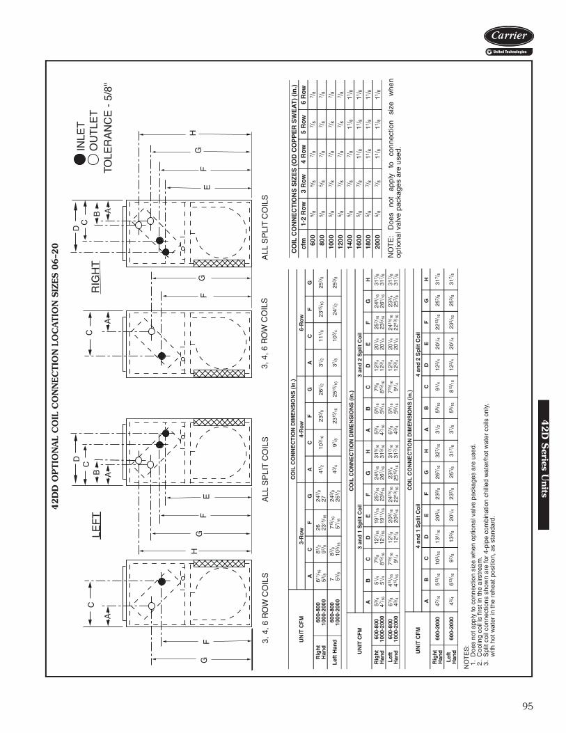
95
42D
D O
PTIO
NA
L C
OIL
CO
NN
EC
TIO
N L
OC
ATIO
N S
IZES 0
6–2
0
a42-3997
NO
TE
S:
1.D
oes
not a
pply
to c
onne
ctio
n si
ze w
hen
optio
nal v
alve
pac
kage
s ar
e us
ed.
2.C
oolin
g co
il is
firs
t in
the
airs
trea
m.
3.S
plit
coil
conn
ectio
ns s
how
n ar
e fo
r 4-
pipe
com
bina
tion
chill
ed w
ater
/hot
wat
er c
oils
onl
y,w
ith h
ot w
ater
in th
e re
heat
pos
ition
, as
stan
dard
.
UN
IT C
FM
CO
IL C
ON
NE
CT
ION
DIM
EN
SIO
NS
(in
.)
3-R
ow
4-R
ow6-
Ro
w
AC
FG
AC
FG
AC
FG
Rig
ht
Han
d60
0-80
010
00-2
000
611 /
1653
/ 881
/ 297
/ 826 23
15/ 1
6
247 /
827
41/ 2
103 /
1623
3 /8
261 /
231
/ 211
1 /8
2315
/ 16
257 /
8
Lef
t H
and
600-
800
1000
-200
07 53
/ 887
/ 810
3 /16
715 /
1657
/ 16
243 /
826
1 /2
43/ 4
97/ 8
2315
/ 16
2515
/ 16
37/ 8
103 /
424
1 /2
253 /
8
UN
IT C
FM
CO
IL C
ON
NE
CT
ION
DIM
EN
SIO
NS
(in
.)
3 an
d 1
Sp
lit C
oil
3 an
d 2
Sp
lit C
oil
AB
CD
EF
GH
AB
CD
EF
GH
Rig
ht
Han
d60
0-80
010
00-2
000
53/ 4
47/ 1
6
51/ 4
51/ 4
75/ 8
815 /
16
127 /
1612
7 /16
1911
/ 16
1911
/ 16
257 /
1623
5 /16
245 /
1626
7 /16
315 /
1631
5 /16
53/ 4
47/ 1
6
59/ 1
659
/ 16
75/ 8
815 /
16
123 /
412
3 /4
201 /
420
1 /4
257 /
1623
5 /16
245 /
1626
1 /16
317 /
831
7 /8
Lef
t H
and
600-
800
1000
-200
061
/ 843
/ 441
5 /16
415 /
16
715 /
1691
/ 412
1 /8
121 /
8
203 /
1620
3 /16
2415
/ 16
2213
/ 16
233 /
425
15/ 1
6
317 /
1631
7 /16
61/ 8
43/ 4
59/ 1
659
/ 16
715 /
1691
/ 412
3 /4
123 /
4
201 /
420
1 /4
2415
/ 16
2213
/ 16
233 /
425
7 /8
317 /
831
7 /8
UN
IT C
FM
CO
IL C
ON
NE
CT
ION
DIM
EN
SIO
NS
(in
.)
4 an
d 1
Sp
lit C
oil
4 an
d 2
Sp
lit C
oil
AB
CD
EF
GH
AB
CD
EF
GH
Rig
ht
Han
d60
0-20
0047
/ 16
513 /
1610
3 /16
131 /
1620
3 /4
233 /
826
7 /16
327 /
1631
/ 259
/ 16
91/ 4
123 /
420
1 /4
2213
/ 16
257 /
831
7 /8
Lef
t H
and
600-
2000
43/ 4
613 /
1697
/ 813
3 /8
201 /
423
7 /8
257 /
831
7 /8
37/ 8
59/ 1
681
5 /16
123 /
420
1 /4
235 /
1625
3 /8
317 /
8
NO
TE
: D
oes
not
appl
y to
co
nnec
tion
size
w
hen
optio
nal v
alve
pac
kage
s ar
e us
ed.
CO
IL C
ON
NE
CT
ION
S S
IZE
S (
OD
CO
PP
ER
SW
EA
T)
(in
.)cf
m1-
2 R
ow3
Ro
w4
Ro
w5
Row
6 R
ow60
05 /
85 /
87 /
87 /
87 /
8
800
5 /8
5 /8
7 /8
7 /8
7 /8
1000
5 /8
7 /8
7 /8
7 /8
7 /8
1200
5 /8
7 /8
7 /8
7 /8
7 /8
1400
5 /8
7 /8
7 /8
11/ 8
11/ 8
1600
5 /8
7 /8
11/ 8
11/ 8
11/ 8
1800
5 /8
7 /8
11/ 8
11/ 8
11/ 8
2000
5 /8
7 /8
11/ 8
11/ 8
11/ 8
42
D S
eries Units
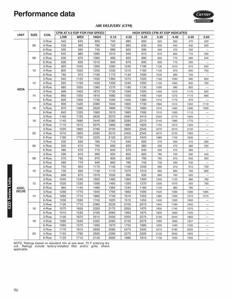
96
AIR DELIVERY (CFM)
NOTE: Ratings based on standard cfm at sea level, 70 F entering drycoil. Ratings include factory-installed filter and/or grille, whereapplicable.
UNIT SIZE COILCFM AT 0.0 ESP FOR FAN SPEED HIGH SPEED CFM AT ESP INDICATED
LOW MED HIGH 0.10 0.20 0.25 0.30 0.40 0.50 0.60
42DA
063-Row 545 645 800 740 680 650 620 560 470 330
4-Row 530 360 780 720 660 630 600 540 430 260
6-Row 505 595 740 680 620 590 560 470 330 —
083-Row 645 885 1080 1010 940 910 870 800 710 590
4-Row 630 870 1060 990 920 890 850 770 680 540
6-Row 600 830 1010 940 870 840 800 710 590 —
103-Row 825 1045 1280 1260 1240 1190 1130 1010 910 640
4-Row 805 1020 1250 1230 1210 1160 1100 970 840 700
6-Row 765 975 1190 1170 1140 1090 1030 890 720 —
123-Row 945 1125 1450 1360 1270 1220 1180 1090 990 850
4-Row 925 1100 1420 1330 1240 1200 1150 1060 950 790
6-Row 885 1055 1360 1270 1180 1130 1090 990 850 —
143-Row 890 1405 1875 1730 1590 1520 1450 1310 1170 920
4-Row 860 1355 1810 1680 1550 1490 1420 1270 1110 890
6-Row 820 1300 1730 1590 1450 1380 1310 1170 970 —
163-Row 900 1420 2080 1940 1800 1730 1660 1510 1350 1110
4-Row 875 1385 2030 1890 1750 1680 1610 1460 1280 1000
6-Row 845 1335 1960 1810 1660 1590 1510 1350 1110 —
183-Row 1160 1720 2630 2570 2485 2415 2340 2170 1945 —
4-Row 1145 1685 2445 2380 2285 2215 2145 1985 1770 —
6-Row 1115 1615 2075 1990 1885 1820 1755 1615 1425 —
203-Row 1225 1860 2780 2700 2605 2545 2470 2310 2120 —
4-Row 1210 1825 2595 2510 2405 2345 2275 2125 1950 —
6-Row 1180 1755 2225 2120 2010 1945 1885 1755 1600 —
42DC, DD,DE
063-Row 535 630 780 710 640 600 570 500 410 280
4-Row 520 610 760 690 620 580 550 470 380 230
6-Row 485 570 710 640 570 540 500 410 280 —
083-Row 590 810 990 920 850 820 780 700 590 430
4-Row 575 795 970 900 830 790 760 670 550 350
6-Row 560 770 940 860 780 740 700 590 430 —
103-Row 755 955 1170 1140 1100 1040 990 910 810 700
4-Row 735 930 1140 1110 1070 1010 960 860 760 660
6-Row 690 875 1070 1030 990 930 880 760 620 —
123-Row 1040 1240 1600 1480 1360 1300 1240 1120 980 780
4-Row 1035 1235 1590 1460 1330 1270 1200 1070 920 700
6-Row 965 1145 1480 1360 1240 1180 1120 980 780 —
143-Row 1290 1770 1940 1795 1660 1595 1525 1390 1280 1085
4-Row 1260 1710 1880 1740 1610 1550 1485 1350 1210 1015
6-Row 1200 1590 1745 1625 1510 1455 1400 1265 1065 —
163-Row 1105 1710 2380 2230 2100 2015 1945 1785 1640 —
4-Row 1075 1650 2320 2175 2050 1970 1905 1745 1570 —
6-Row 1015 1530 2180 2060 1950 1875 1820 1660 1425 —
183-Row 1105 1675 2515 2450 2355 2275 2185 2045 1850 —
4-Row 1090 1640 2355 2260 2155 2075 1990 1860 1657 —
6-Row 1060 1570 1990 1870 1755 1680 1600 1490 1330 —
203-Row 1170 1815 2690 2580 2475 2405 2315 2185 2025 —
4-Row 1155 1780 2505 2390 2275 2205 2120 2000 1855 —
6-Row 1125 1710 2140 2000 1880 1810 1730 1630 1505 —
Performance data4
2D
Ser
ies
Uni
ts

97
AIR DELIVERY (CFM) (cont)
NOTE: Ratings based on standard cfm at sea level, 70 F entering drycoil. Ratings include factory-installed filter and/or grille, whereapplicable.
UNIT SIZE COILCFM AT 0.0 ESP FOR FAN SPEED HIGH SPEED CFM AT ESP INDICATED
LOW MED HIGH 0.10 0.20 0.25 0.30 0.40 0.50 0.60
42DF
063-Row 465 545 680 — — — — — — —
4-Row 460 540 670 — — — — — — —
6-Row 445 520 650 — — — — — — —
083-Row 490 670 820 — — — — — — —
4-Row 480 665 810 — — — — — — —
6-Row 465 640 780 — — — — — — —
103-Row 660 835 1020 — — — — — — —
4-Row 645 820 1000 — — — — — — —
6-Row 620 785 960 — — — — — — —
123-Row 810 960 1240 — — — — — — —
4-Row 795 945 1220 — — — — — — —
6-Row 775 925 1190 — — — — — — —
143-Row 700 1105 1470 — — — — — — —
4-Row 680 1090 1450 — — — — — — —
6-Row 665 1050 1400 — — — — — — —
163-Row 685 1085 1590 — — — — — — —
4-Row 680 1070 1570 — — — — — — —
6-Row 650 1030 1510 — — — — — — —
183-Row 1155 1505 1800 — — — — — — —
4-Row 1140 1485 1780 — — — — — — —
6-Row 1090 1420 1700 — — — — — — —
203-Row 1280 1675 2030 — — — — — — —
4-Row 1260 1650 2000 — — — — — — —
6-Row 1225 1600 1940 — — — — — — —
42
D S
eries Units
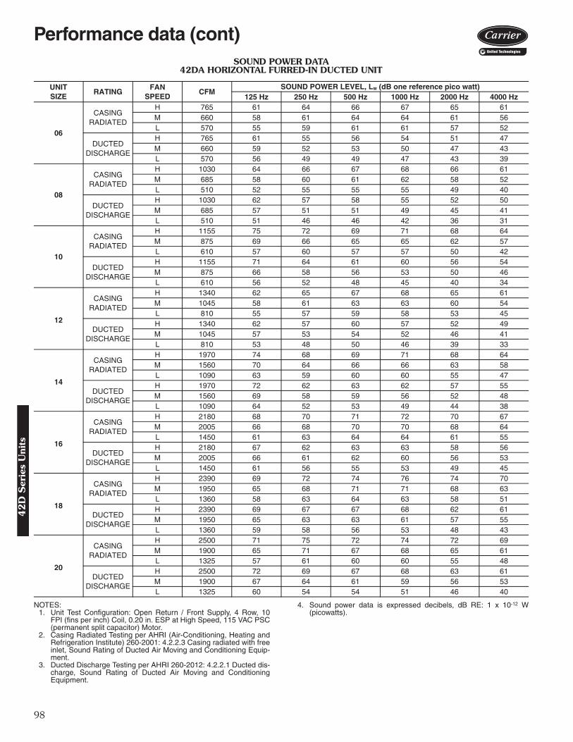
98
SOUND POWER DATA42DA HORIZONTAL FURRED-IN DUCTED UNIT
NOTES:1. Unit Test Configuration: Open Return / Front Supply, 4 Row, 10
FPI (fins per inch) Coil, 0.20 in. ESP at High Speed, 115 VAC PSC(permanent split capacitor) Motor.
2. Casing Radiated Testing per AHRI (Air-Conditioning, Heating andRefrigeration Institute) 260-2001: 4.2.2.3 Casing radiated with freeinlet, Sound Rating of Ducted Air Moving and Conditioning Equip-ment.
3. Ducted Discharge Testing per AHRI 260-2012: 4.2.2.1 Ducted dis-charge, Sound Rating of Ducted Air Moving and ConditioningEquipment.
4. Sound power data is expressed decibels, dB RE: 1 x 10-12 W(picowatts).
UNITSIZE
RATINGFAN
SPEEDCFM
SOUND POWER LEVEL, Lw (dB one reference pico watt)125 Hz 250 Hz 500 Hz 1000 Hz 2000 Hz 4000 Hz
06
CASINGRADIATED
H 765 61 64 66 67 65 61M 660 58 61 64 64 61 56L 570 55 59 61 61 57 52
DUCTEDDISCHARGE
H 765 61 55 56 54 51 47M 660 59 52 53 50 47 43L 570 56 49 49 47 43 39
08
CASINGRADIATED
H 1030 64 66 67 68 66 61M 685 58 60 61 62 58 52L 510 52 55 55 55 49 40
DUCTEDDISCHARGE
H 1030 62 57 58 55 52 50M 685 57 51 51 49 45 41L 510 51 46 46 42 36 31
10
CASINGRADIATED
H 1155 75 72 69 71 68 64M 875 69 66 65 65 62 57L 610 57 60 57 57 50 42
DUCTEDDISCHARGE
H 1155 71 64 61 60 56 54M 875 66 58 56 53 50 46L 610 56 52 48 45 40 34
12
CASINGRADIATED
H 1340 62 65 67 68 65 61M 1045 58 61 63 63 60 54L 810 55 57 59 58 53 45
DUCTEDDISCHARGE
H 1340 62 57 60 57 52 49M 1045 57 53 54 52 46 41L 810 53 48 50 46 39 33
14
CASINGRADIATED
H 1970 74 68 69 71 68 64M 1560 70 64 66 66 63 58L 1090 63 59 60 60 55 47
DUCTEDDISCHARGE
H 1970 72 62 63 62 57 55M 1560 69 58 59 56 52 48L 1090 64 52 53 49 44 38
16
CASINGRADIATED
H 2180 68 70 71 72 70 67M 2005 66 68 70 70 68 64L 1450 61 63 64 64 61 55
DUCTEDDISCHARGE
H 2180 67 62 63 63 58 56M 2005 66 61 62 60 56 53L 1450 61 56 55 53 49 45
18
CASINGRADIATED
H 2390 69 72 74 76 74 70M 1950 65 68 71 71 68 63L 1360 58 63 64 63 58 51
DUCTEDDISCHARGE
H 2390 69 67 67 68 62 61M 1950 65 63 63 61 57 55L 1360 59 58 56 53 48 43
20
CASINGRADIATED
H 2500 71 75 72 74 72 69M 1900 65 71 67 68 65 61L 1325 57 61 60 60 55 48
DUCTEDDISCHARGE
H 2500 72 69 67 68 63 61M 1900 67 64 61 59 56 53L 1325 60 54 54 51 46 40
Performance data (cont)4
2D
Ser
ies
Uni
ts
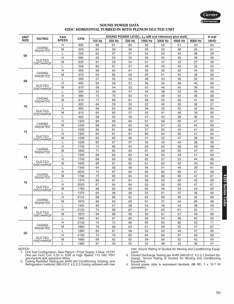
99
SOUND POWER DATA42DC HORIZONTAL FURRED-IN WITH PLENUM DUCTED UNIT
NOTES:1. Unit Test Configuration: Rear Return / Front Supply, 4 Row, 10 FPI
(fins per inch) Coil, 0.20 in. ESP at High Speed, 115 VAC PSC(permanent split capacitor) Motor.
2. Casing Radiated Testing per AHRI (Air-Conditioning, Heating, andRefrigeration Institute) 260-2012: 4.2.2.3 Casing radiated with free
inlet, Sound Rating of Ducted Air Moving and Conditioning Equip-ment.
3. Ducted Discharge Testing per AHRI 260-2012: 4.2.2.1 Ducted dis-charge, Sound Rating of Ducted Air Moving and ConditioningEquipment.
4. Sound power data is expressed decibels, dB RE: 1 x 10-12 W(picowatts).
UNITSIZE RATING FAN
SPEED CFMSOUND POWER LEVEL, Lw (dB one reference pico watt) A-wgt
(dbA)125 Hz 250 Hz 500 Hz 1000 Hz 2000 Hz 4000 Hz 8000 Hz
06
CASINGRADIATED
H 695 66 61 60 58 56 51 43 63M 625 64 59 59 56 53 48 40 61L 555 62 57 57 54 50 45 38 59
DUCTEDDISCHARGE
H 695 63 55 55 56 50 46 39 59M 625 61 53 54 51 47 43 37 56L 555 60 51 51 49 45 40 35 54
08
CASINGRADIATED
H 905 68 64 61 59 56 52 44 65M 670 64 60 58 55 51 45 38 60L 500 57 55 53 48 43 36 35 54
DUCTEDDISCHARGE
H 905 64 59 57 56 52 49 40 60M 670 59 54 53 50 46 42 36 55L 500 53 48 47 44 38 33 35 49
10
CASINGRADIATED
H 995 75 70 64 61 58 54 46 68M 810 71 66 61 58 55 50 41 64L 620 64 59 55 52 46 39 36 57
DUCTEDDISCHARGE
H 995 69 64 60 58 55 52 42 64M 810 65 60 57 55 51 48 39 60L 620 58 52 50 47 43 38 36 52
12
CASINGRADIATED
H 1325 69 65 63 61 59 55 47 67M 1200 68 63 62 59 57 52 44 65L 1050 66 61 60 57 55 49 41 62
DUCTEDDISCHARGE
H 1325 64 61 61 60 54 50 41 64M 1200 63 60 60 57 52 47 39 62L 1050 62 57 57 55 49 44 38 59
14
CASINGRADIATED
H 1700 72 66 64 62 60 56 49 68M 1650 71 65 63 61 59 55 47 67L 1340 68 62 60 58 55 49 41 63
DUCTEDDISCHARGE
H 1700 68 63 63 62 57 53 44 66M 1650 66 61 62 61 55 52 43 65L 1340 64 58 58 56 51 46 39 61
16
CASINGRADIATED
H 2025 72 67 65 65 62 59 51 69M 1780 70 65 64 63 60 56 47 67L 1375 66 61 61 58 55 49 40 63
DUCTEDDISCHARGE
H 2025 67 64 64 63 58 56 47 67M 1780 66 62 62 62 56 53 44 65L 1375 62 58 58 55 51 47 38 60
18
CASINGRADIATED
H 2125 68 66 65 65 60 59 50 69M 1870 66 63 63 61 57 54 46 66L 1405 60 57 58 54 49 45 38 59
DUCTEDDISCHARGE
H 2125 72 69 67 67 64 61 54 71M 1870 69 66 65 63 61 57 49 68L 1405 63 61 60 58 54 48 40 62
20
CASINGRADIATED
H 2150 74 74 66 65 63 60 53 71M 1880 70 68 63 61 59 55 47 67L 1385 62 61 58 54 50 44 37 60
DUCTEDDISCHARGE
H 2150 72 70 65 64 60 57 49 69M 1880 69 62 62 59 56 52 43 64L 1385 61 55 55 52 48 42 36 57
42
D S
eries Units

100
42D ELECTRIC HEATER DATA
LEGENDFLA — Full Load AmpsNOTES:
1. All heaters are single-stage and single-phase.2. In all units using over 48 amps, the heating elements are sub-
divided and protected. Additional cost is incurred because ofadded components.
3. A separate power source is required for motor and heaters exceptwhen motors and heaters of same voltage are ordered in conjunc-tion with a single power source wiring option. This option, whichmeets NEC (National Electric Code) requirements, consists of afactory-furnished and installed junction box and fuse for 6.25 amp(max) fan and control circuit connection to a single power source.Power supply circuit to unit must be field furnished and installed inaccordance with applicable codes.
42DA PSC MOTOR DATA
*Total motor amps and watts shown for units with 2 motors (size 12 through 20).NOTES:
1. Motor nameplate amps may vary.2. Fan coil units comply with ETL, Canadian Standards Association
(CSA), and ETL of Canada standards.
HEATERVOLTAGE
HEATER kW2.0 3.0 4.0 5.0 6.0 7.0 8.0 9.0 10.0 12.0 14.0
FLA120 16.7 25.0 — — — — — — — — —208 9.6 14.4 19.2 24.0 28.8 33.7 38.5 43.3 48.1 57.7 67.3240 8.3 12.5 16.7 20.8 25.0 29.2 33.3 37.5 41.7 50.0 58.3277 7.2 10.8 14.4 18.0 21.7 25.3 28.9 32.5 36.1 43.3 50.5
V-Ph-Hz FANSPEED
FANSPEED(RPM)
UNIT SIZE
06 08 10 12*
Nominal Hp Watts Amps Nominal
Hp Watts Amps Nominal Hp Watts Amps Nominal
Hp Watts Amps
115-1-60H 1200
1/8280 2.70
1/5330 3.10
1/4470 5.60
1/8 (2)550 5.30
M 980 200 2.00 225 2.25 360 3.70 305 2.92L 790 140 1.50 135 1.44 240 2.60 205 1.93
208/230-1-60H 1200
1/10
240 1.101/5
420 1.801/4
430 2.001/5 (2)
450 2.10M 980 175 0.74 280 1.26 260 1.20 325 1.45L 790 110 0.50 155 0.73 165 0.80 215 1.00
277-1-60H 1200
1/5275 1.15
1/5275 1.21
1/4425 1.62
1/5 (2)550 2.40
M 980 175 0.69 175 0.69 260 1.04 355 1.38L 790 90 0.33 90 0.34 155 0.65 175 0.67
V-Ph-Hz FANSPEED
FANSPEED(RPM)
UNIT SIZE
14* 16* 18* 20*
Nominal Hp Watts Amps Nominal
Hp Watts Amps Nominal Hp Watts Amps Nominal
Hp Watts Amps
115-1-60H 1200
1/5 (2)650 6.40
1/4 (2)900 8.80
1/4 (2)1180 11.80
1/4 (2)1180 11.80
M 980 440 4.60 705 6.90 770 8.30 770 8.30L 790 280 3.00 430 4.20 460 5.30 460 5.30
208/230-1-60H 1200
1/5 (2)465 2.10
1/5 (2)740 3.60
1/4 (2)925 4.10
1/4 (2)925 4.10
M 980 325 1.45 360 1.80 5.45 2.48 545 2.48L 790 220 1.00 220 1.20 330 1.60 330 1.60
277-1-60H 1200
1/4 (2)735 2.70
1/4 (2)940 3.60
1/4 (2)980 3.72
1/4 (2)980 3.72
M 980 510 1.90 560 2.20 550 2.20 550 2.20L 790 330 1.30 335 1.40 320 1.40 320 1.40
Electrical data4
2D
Ser
ies
Uni
ts
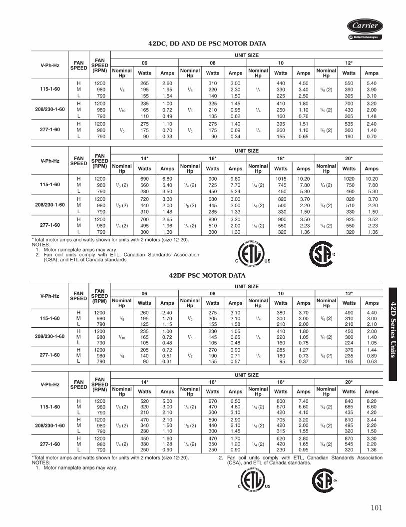
101
42DC, DD AND DE PSC MOTOR DATA
*Total motor amps and watts shown for units with 2 motors (size 12-20).NOTES:
1. Motor nameplate amps may vary.2. Fan coil units comply with ETL, Canadian Standards Association
(CSA), and ETL of Canada standards.
42DF PSC MOTOR DATA
*Total motor amps and watts shown for units with 2 motors (size 12-20).NOTES:
1. Motor nameplate amps may vary.
2. Fan coil units comply with ETL, Canadian Standards Association(CSA), and ETL of Canada standards.
V-Ph-Hz FANSPEED
FANSPEED(RPM)
UNIT SIZE
06 08 10 12*
Nominal Hp Watts Amps Nominal
Hp Watts Amps Nominal Hp Watts Amps Nominal
Hp Watts Amps
115-1-60H 1200
1/8265 2.60
1/5310 3.00
1/4440 4.50
1/8 (2)550 5.40
M 980 195 1.95 220 2.30 330 3.40 390 3.90L 790 155 1.54 140 1.50 225 2.50 305 3.10
208/230-1-60H 1200
1/10
235 1.001/5
325 1.451/4
410 1.801/5 (2)
700 3.20M 980 165 0.72 210 0.95 250 1.10 430 2.00L 790 110 0.49 135 0.62 160 0.76 305 1.48
277-1-60H 1200
1/5275 1.10
1/5275 1.40
1/4395 1.51
1/5 (2)535 2.40
M 980 175 0.70 175 0.69 260 1.10 360 1.40L 790 90 0.33 90 0.34 155 0.65 190 0.70
V-Ph-Hz FANSPEED
FANSPEED(RPM)
UNIT SIZE
14* 16* 18* 20*
Nominal Hp Watts Amps Nominal
Hp Watts Amps Nominal Hp Watts Amps Nominal
Hp Watts Amps
115-1-60H 1200
1/5 (2)690 6.80
1/4 (2)900 9.80
1/4 (2)1015 10.20
1/4 (2)1020 10.20
M 980 560 5.40 725 7.70 745 7.80 750 7.80L 790 280 3.50 450 5.24 450 5.30 460 5.30
208/230-1-60H 1200
1/5 (2)720 3.30
1/5 (2)680 3.00
1/4 (2)820 3.70
1/4 (2)820 3.70
M 980 440 2.00 445 2.00 500 2.20 510 2.20L 790 310 1.48 285 1.33 330 1.50 330 1.50
277-1-60H 1200
1/4 (2)700 2.65
1/4 (2)830 3.20
1/4 (2)900 3.50
1/4 (2)925 3.52
M 980 495 1.96 510 2.00 550 2.23 550 2.23L 790 300 1.30 300 1.30 320 1.36 320 1.36
V-Ph-Hz FANSPEED
FANSPEED(RPM)
UNIT SIZE06 08 10 12*
Nominal Hp Watts Amps Nominal
Hp Watts Amps Nominal Hp Watts Amps Nominal
Hp Watts Amps
115-1-60H 1200
1/8260 2.40
1/5275 3.10
1/4380 3.70
1/8 (2)490 4.40
M 980 195 1.70 205 2.10 300 3.00 310 3.00L 790 125 1.15 155 1.58 210 2.00 210 2.10
208/230-1-60H 1200
1/10
235 1.001/5
230 1.051/4
410 1.801/5 (2)
450 2.00M 980 165 0.72 145 0.65 220 1.05 300 1.40L 790 105 0.48 105 0.48 160 0.75 224 1.05
277-1-60H 1200
1/5205 0.72
1/5270 0.90
1/4285 1.27
1/5 (2)370 1.44
M 980 140 0.51 190 0.71 180 0.73 235 0.89L 790 90 0.31 155 0.57 95 0.37 165 0.63
V-Ph-Hz FANSPEED
FANSPEED(RPM)
UNIT SIZE14* 16* 18* 20*
Nominal Hp Watts Amps Nominal
Hp Watts Amps Nominal Hp Watts Amps Nominal
Hp Watts Amps
115-1-60H 1200
1/5 (2)520 5.00
1/4 (2)670 6.50
1/4 (2)800 7.40
1/4 (2)840 8.20
M 980 320 3.00 470 4.80 670 6.60 685 6.60L 790 210 2.10 300 3.10 420 4.10 435 4.20
208/230-1-60H 1200
1/5 (2)470 2.10
1/5 (2)590 2.90
1/4 (2)705 3.20
1/4 (2)810 3.44
M 980 340 1.50 440 2.10 420 2.00 495 2.20L 790 230 1.10 300 1.45 315 1.55 320 1.50
277-1-60H 1200
1/4 (2)450 1.60
1/4 (2)470 1.70
1/4 (2)620 2.80
1/4 (2)870 3.30
M 980 330 1.28 350 1.20 420 1.65 545 2.20L 790 250 0.90 250 0.90 230 0.95 320 1.36
42
D S
eries Units

102
42D ECM MOTOR DATA
SIZE NOMINAL HPAMPS
120V 208V 230V 277V
42D*06 1/2
8.4 4 4 3.342D*08 1/2
42D*10 1/2
42D*12 1/2 (2)
16.8 8 8 6.6
42D*14 1/2 (2)
42D*16 1/2 (2)
42D*18 1/2 (2)
42D*20 1/2 (2)
Electrical data (cont)4
2D
Ser
ies
Uni
ts
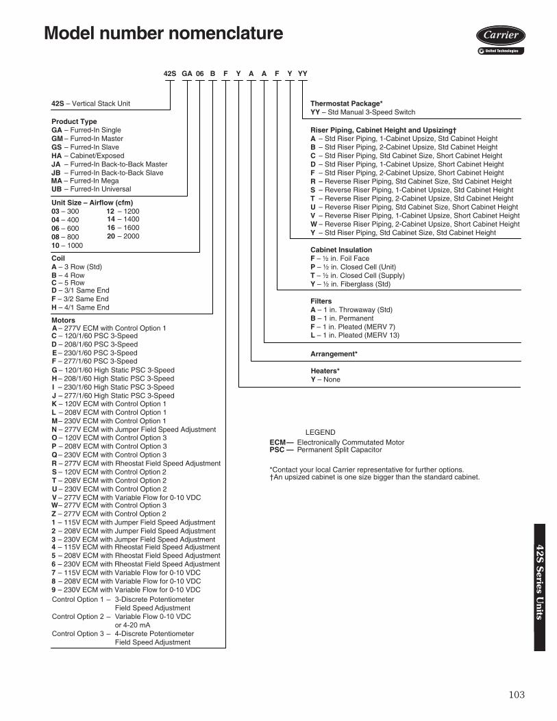
103
42S – Vertical Stack Unit
Product TypeGAGMGSHAJAJB
UB
Unit Size – Airflow (cfm)03 – 30004 – 40006 – 60008 – 80010 – 1000
12 – 1200
CoilA – 3 Row (Std)B – 4 Row
D – 3/1 Same EndF – 3/2 Same EndH – 4/1 Same End
Motors
C – 120/1/60 PSC 3-SpeedD – 208/1/60 PSC 3-SpeedE – 230/1/60 PSC 3-SpeedF – 277/1/60 PSC 3-Speed
Heaters*Y – None
Arrangement*
FiltersA – 1 in. Throwaway (Std)B – 1 in. Permanent F – 1 in. Pleated (MERV 7)
Cabinet InsulationF – ½ in. Foil FaceP – ½ in. Closed Cell (Unit)T – ½ in. Closed Cell (Supply)Y – ½ in. Fiberglass (Std)
– Std Riser Piping, 1-Cabinet Upsize, Std Cabinet Height– Std Riser Piping, 2-Cabinet Upsize, Std Cabinet Height– Std Riser Piping, Std Cabinet Size, Short Cabinet Height– Std Riser Piping, 1-Cabinet Upsize, Short Cabinet Height– Std Riser Piping, 2-Cabinet Upsize, Short Cabinet Height– Reverse Riser Piping, Std Cabinet Size, Std Cabinet Height– Reverse Riser Piping, 1-Cabinet Upsize, Std Cabinet Height– Reverse Riser Piping, 2-Cabinet Upsize, Std Cabinet Height– Reverse Riser Piping, Std Cabinet Size, Short Cabinet Height– Reverse Riser Piping, 1-Cabinet Upsize, Short Cabinet Height– Reverse Riser Piping, 2-Cabinet Upsize, Short Cabinet Height– Std Riser Piping, Std Cabinet Size, Std Cabinet Height
Thermostat Package*YY – Std Manual 3-Speed Switch
42S GA 06 B F Y A A F Y YY
Riser Piping, Cabinet Height and Upsizing†ABCDFRSTUVWY
– Furred-In Single– Furred-In Master– Furred-In Slave– Cabinet/Exposed– Furred-In Back-to-Back Master– Furred-In Back-to-Back Slave
– Furred-In UniversalMA – Furred-In Mega
14 – 140016 – 160020 – 2000
C – 5 Row
G – 120/1/60 High Static PSC 3-SpeedH – 208/1/60 High Static PSC 3-SpeedI – 230/1/60 High Static PSC 3-SpeedJ – 277/1/60 High Static PSC 3-SpeedK – 120V ECM with Control Option 1L – 208V ECM with Control Option 1M– 230V ECM with Control Option 1N – 277V ECM with Jumper Field Speed AdjustmentO – 120V ECM with Control Option 3P – 208V ECM with Control Option 3Q – 230V ECM with Control Option 3R – 277V ECM with Rheostat Field Speed AdjustmentS – 120V ECM with Control Option 2T – 208V ECM with Control Option 2U – 230V ECM with Control Option 2V – 277V ECM with Variable Flow for 0-10 VDC
L – 1 in. Pleated (MERV 13)
W– 277V ECM with Control Option 3Z – 277V ECM with Control Option 21 – 115V ECM with Jumper Field Speed Adjustment2 – 208V ECM with Jumper Field Speed Adjustment3 – 230V ECM with Jumper Field Speed Adjustment4 – 115V ECM with Rheostat Field Speed Adjustment5 – 208V ECM with Rheostat Field Speed Adjustment6 – 230V ECM with Rheostat Field Speed Adjustment7 – 115V ECM with Variable Flow for 0-10 VDC8 – 208V ECM with Variable Flow for 0-10 VDC9 – 230V ECM with Variable Flow for 0-10 VDC
A – 277V ECM with Control Option 1
Control Option 1 – 3-Discrete Potentiometer Field Speed AdjustmentControl Option 2 – Variable Flow 0-10 VDC or 4-20 mAControl Option 3 – 4-Discrete Potentiometer Field Speed Adjustment
LEGEND
*Contact your local Carrier representative for further options.†An upsized cabinet is one size bigger than the standard cabinet.
ECM— Electronically Commutated MotorPSC — Permanent Split Capacitor
a42-4392
Model number nomenclature4
2S
Series U
nits

104
The 42S Series fan coil units are certified in compliancewith the Air-Conditioning, Heating and Refrigeration Insti-tute (AHRI) Industry Standard 440 for room fan coil units.Approved standard ratings are tabulated below:
AHRI APPROVED STANDARD RATINGS — STANDARD CAPACITY COIL
*Table values are listed for each half of 42SJ units and master/slave.†Motor type, permanent split capacitor, operating at 115-1-60 voltage.**Size 14 only available with 42SM unit.
NOTES: 1. Ratings based on motor at high fan speed, standard air and dry
coil operation, 10° F water temperature rise; entering-air tempera-tures of 80 F db, 67 F wb; entering-water temperature 45 F.
2. Nominal airflow for Mega Stack unit sizes 16 and 20 fall outsidethe performance range covered by standard AHRI 440 for roomfan coils.
Physical data
*Calculate Operating Weight of Unit: Shipping Weight + Coil Water Weight x Number of Coil Rows.†42SJ units require two filters.
UNITTYPE* UNIT SIZE COIL NOMINAL
CFM GPMCOOLING CAPACITY POWER INPUT
(Watts)†Total Heat Btuh Sensible Heat Btuh
42S
033-Row 300 2.7 11,500 7,000 854-Row 300 3.2 12,200 7,300 85
043-Row 400 2.8 13,600 9,000 1154-Row 400 3.5 15,600 9,600 115
063-Row 600 4.1 21,900 14,000 1354-Row 600 5.1 26,000 15,300 135
083-Row 800 4.4 27,500 17,800 2504-Row 800 5.6 31,400 19,500 250
103-Row 1000 6.3 37,700 24,500 3254-Row 1000 7.5 42,200 25,600 325
123-Row 1200 6.7 43,100 28,400 4404-Row 1200 8.0 46,500 30,500 440
14**3-Row 1400 7.7 38,300 27,900 6704-Row 1400 9.0 45,200 32,400 630
UNIT SIZE 42S 03 04 06 08 10 12 14 16 20NOMINAL AIRFLOW (cfm) 300 400 600 800 1000 1200 1400 1600 2000SHIPPING WEIGHT (lb)* 42SGA,SGM,SU 180 225 240 260 280 305 — — — 42SH 202 247 262 286 311 336 — — — 42SJ 360 450 480 520 560 610 — — — 42SGS 162 203 216 234 252 275 — — — 42SM — — — — — — 390 390 390COIL WATER WEIGHT (Approx lb per row of coil) 1.79 2.63 3.45 4.09 4.09 4.39
COILS FPI 14 fins/inchBLOWER (qty) 42SGA,SH,SU,SGM,SGS,SM 1 1 1 1 1 1 1 1 1 42SJ 2 2 2 2 2 2 — — —FILTERS
Nominal Size (in.) (1-in. thick) 121/2 x 241/4 161/4 x 263/4 201/2 x 291/4 241/2 x 291/2261/2 x 291/2
Qty 1†PIPING CONNECTIONS Inlet (in. OD) 1/2, unless larger size valve package is selected
AHRI capacity ratings42S
Ser
ies
Uni
ts

105
42SGA FURRED-IN STACK UNIT WITHOUT RISER CHASE
NOTES:1. Units are fabricated of galvanized steel with a 16-gage galvanized fan deck.2. All risers are insulated with (1/2-in. or 3/4-in. thick) closed cell insulation.3. Thermostat shipped loose for field installation when ordered with the unit.4. Risers are factory piped to coil with valve package as specified.5. Blower, motor, coil, valves, and filter are accessible through the return air opening.6. Unit and control box are insulated.7. Riser length = [(floor to floor) +2 in.], maximum riser length = 119 inches.8. Maximum riser size is 21/2-in. diameter. If larger size is required, please consult the factory.9. Expansion loops in hot water heating circuits as required.
10. Dimensions are in inches. Dimensions in () are in millimeters.11. Drawing is pictorial (see unit arrangements for actual supply and return air orientation).12. A 9-in. x 21/4-in. slot is provided in the inside back panel for coil connection penetration to permit expan-
sion and contraction of riser. Care must be taken to position the riser so that coil connection is at center ofslot.
UNIT MODEL
SINGLE SUPPLY DOUBLE SUPPLY TOP SUPPLY DIMENSIONS -
INCHES FILTER SIZEA B SIZE A B SIZE C D SIZE E G H I
42SGA03 14 8 14 X 8 14 6 14 X 6 14 10 14 x 10 17 11/2 11/2 14 121/2 X 24¹/4 X 1
42SGA04 14 12 14 X12 14 6 14 X 6 14 10 14 x 10 17 11/2 11/2 14 121/2 X 24¹/4 X 1
42SGA06 18 10 18 X10 18 6 18 X 6 16 12 16 x 12 20 1 2 18 16¹/4 X 263/4 X 1
42SGA08 18 12 18 X 12 18 6 18 X 6 16 12 16 x 12 20 1 2 18 16¹/4 X 263/4 X 1
42SGA10 — — — 22 8 22 X 8 18 16 18 x 16 24 1 3 22 201/2 X 29¹/4 X 1
42SGA12 — — — 22 8 22 X 8 18 16 18 x 16 24 1 3 22 201/2 X 29¹/4 X 1
ITEM DESCRIPTION QTY1 Electrical Knockouts 12 3-in. Expanded Section of Riser 3/53 Strip Heater (Optional) 14 Limit Switch (Optional) 15 1/2-in. Isolation Ball Valve 2/4
6 Flexible Drain Tube/P-Trap 17 Coil 1/2-in. OD Copper Tube 1
8 Filter, Throwaway, 1-in. 19 Return Air Opening 1
10 Air Vent, Manual 111 Molex Connector for Field-Installed Tstat 112 Control Box 1
13 Knockout (For Optional Remote Mounting)/Side 2
14 Riser, Supply and Return (Copper) 2/415 Riser, Drain (Copper) 116 Drain Pan 117 Acoustical Bypass Panel 118 Blower 119 Motor, 3-Speed, PSC, with Quick Connect 120 Access Panel (Control Box) 121 Control Opening (Surface Mount Tstat) 122 Duct Collar, 1/2-in. Extension 1/2/3
23 Supply Air Opening(s) 1/2/3
24 Top Supply Duct Collar 1-in. Extension (Optional) 1
LEGENDCR — Cold Water ReturnCS — Cold Water SupplyD — DrainHR — Hot Water ReturnHS — Hot Water SupplyR — ReturnS — Supply
a42-4187
Base unit dimensions4
2S
Series U
nits

106
*Drawing provided for reference only. Dimensions may vary with options ordered.NOTES:1. Units are fabricated of 18-gage galvanized steel with a 16-gage galvanized fan deck.2. All risers are insulated with (1/2-in. or 3/4-in. thick) closed cell insulation.3. Risers are piped to coil with valve package as specified.4. Blower, motor, coil, valves, and filter are accessible through the return air opening.5. Unit and control box are insulated.6. Maximum riser size is 21/2-in. diameter. If larger sizes are required, please consult the
factory.7. Riser length = [(floor to floor) +2 in.], maximum riser length = 119 inches.8. Expansion loops in hot water heating circuits as required.9. Drawing is pictorial (see unit arrangements for actual supply and return air orientation).
10. Unit is available in front return only.11. Dimensions are in inches. Dimensions is () are in milimeters.12. A 9-in. x 21/4-in. slot is provided in the inside back panel for coil connection penetration to permit expan-
sion and contraction of risers. Care must be taken to position the risers so that coil connection is at cen-ter of slot.
42SHA CABINET STACK UNIT
ITEM DESCRIPTION QTY1 Full Riser Chase 1
2 Electrical Knockouts 13 3-in. Expansion Section of Riser 3/54 Strip Heater (Optional) 15 Limit Switch (Optional) 16 1/2-in. Isolation Ball Valve 2/4
7 Flexible Drain Tube/P-Trap 18 Drain Pan 19 Coil 1/2-in. OD Copper Tube 1
10 Filter, Throwaway, 1-in. 111 Air Vent, Manual 112 Control Box 113 Cabinet Camloc Fastener 214 3-Speed Switch (Optional) 1
15 Electrical Access Panel 116 Riser, Supply and Return (Copper) 2/417 Riser, Drain (Copper) 118 Return Air Panel 119 Motor, 3-Speed, PSC with Quick Connect 120 Blower 121 Thermostat (Optional) 122 Hinged Control Access Door 123 Double Deflection Steel Core Grille Assembly 1
UNIT MODEL
SINGLE SUPPLY DOUBLE SUPPLY DIMENSIONS - INCHESFILTER SIZE
A B SIZE A B SIZE C D E F G
42SHA03 14 8 14 X 8 14 6 14 X 6 17 223/8 21/2 22¹/8 14¾ 121/2 X 24¹/4 X 1
42SHA04 14 12 14 X12 14 8 14 X 8 17 223/8 21/2 22¹/8 14¾ 121/2 X 24¹/4 X 1
42SHA06 14 12 14 X12 14 8 14X 8 20 253/8 21/2 265/8 17¾ 16¹/4 X 263/4 X 1
42SHA08 14 16 14 X 16 14 10 14 X 10 20 253/8 21/2 265/8 17¾ 16¹/4 X 263/4 X 1
42SHA10 18 16 18 X 16 14 12 14 X 12 24 293/8 21/2 31¹/8 17¾ 201/2 X 29¹/4 X 1
42SHA12 18 16 18 X 16 14 12 14X 12 24 293/8 2¹/² 31¹/8 17¾ 20¹/² X 29¼ X 1
a42-4188
LEGENDCR — Cold Water ReturnCS — Cold Water SupplyD — DrainHR — Hot Water ReturnHS — Hot Water SupplyR — ReturnS — Supply
Base unit dimensions (cont)42S
Ser
ies
Uni
ts

107
NOTES:1. Units are fabricated of galvanized steel with a 16-gage galvanized fan deck.2. All risers are insulated with (1/2-in. or 3/4-in. thick) closed cell insulation.3. Thermostat shipped loose for field installation when ordered with the unit.4. Risers are piped to coil with valve package as specified.5. Blower, motor, coil, valves, and filter are accessible through the return air opening.6. Unit and control box are insulated.7. Riser length = [(floor to floor) +2 in.], maximum riser length = 119 inches.8. Maximum riser size is 21/2-in. diameter. If larger size is required, please consult the factory.9. Expansion loops in hot water heating circuits as required.
10. Drawing is pictorial (see unit arrangements for actual supply and return air orientation).11. Dimensions are in inches. Dimensions in () are in millimeters.12. A 9-in. x 21/4-in. slot is provided in the inside back panel for coil connection penetration to permit expansion
and contraction of riser. Care must be taken to position the riser so that coil connection is at center of slot.
42SJA/42SJB FURRED-IN STACK BACK TO BACK UNIT
UNIT MODEL
SINGLE SUPPLY DOUBLE SUPPLY TOP SUPPLY DIMENSIONS - INCHESFILTER SIZE
A B SIZE A B SIZE C D SIZE E G H I J
42SJA03 14 8 14 X 8 14 6 14 X 6 14 10 14 x 10 17 11/2² 11/2² 14 39 5/8 121/2 X 24¹/4 X 1
42SJA04 14 12 14 X12 14 6 14 X 6 14 10 14 x 10 17 11/2² 11/2 14 39 5/8 121/2 X 24¹/4 X 1
42SJA06 18 10 18 X10 18 6 18 X 6 16 12 16 x 12 20 1 2 18 45 5/8 16¹/4 X 263/4 X 1
42SJA08 18 12 18 X 12 18 6 18 X 6 16 12 16 x 12 20 1 2 18 45 5/8 16¹/4 X 263/4 X 1
42SJA10 — — — 22 8 22 X 8 18 16 18 x 16 24 1 3 22 53 5/8 201/2 X 29¹/4 X 1
42SJA12 — — — 22 8 22 X 8 18 16 18 x 16 24 1 3 22 53 5/8 201/2 X 29¹/4 X 1
ITEM DESCRIPTION QTY1 Electrical Knockouts 6
2 Gypsum Board 5/8” Type X 1
3 3-in. Expanded Section of Riser 3/54 Strip Heater (Optional) 25 Limit Switch (Optional) 26 1/2-in. Isolation Ball Valve 2/47 Thermafiber Insulation —
8 Flexible Drain Tube/P-Trap 2
9 Coil 1/2-in. OD Copper Tube 2
10 Filter, Throwaway, 1-in. 211 Return Air Opening 212 Air Vent, Manual 2
13 Knockout (For Optional Remote Mounting)/Side 2
14 Molex Connector for Field-Installed Tstat 215 Control Box 216 Riser, Drain (Copper) 117 Riser, Supply and Return (Copper) 2/4
18 Drain Pan 219 Acoustical Bypass Panel 220 Blower 221 Motor, 3-Speed, PSC, with Quick Connect 222 Access Panel (Control Box) 2
23 Control Opening (Surface Mount Tstat) 2
24 Duct Collar, 1/2-in. Extension (Typical) 1/2/3
25 Supply Air Opening(s) 1/2/3
26 Top Supply Duct Collar, 1-in. Extension (Optional) 1
LEGEND
CR — Cold Water ReturnCS — Cold Water SupplyD — DrainHR — Hot Water ReturnHS — Hot Water SupplyR — ReturnS — Supply
a42-4189
42
S S
eries Units

108
NOTES:1. Units are fabricated of galvanized steel with a 16-gage galvanized fan deck.2. All risers are insulated with (1/2-in. or 3/4-in. thick) closed cell insulation.3. Thermostat shipped loose for field installation when ordered with the unit.4. Risers are piped to coil with valve package as specified.5. Blower, motor, coil, valves, and filter are accessible through the return air opening.6. Unit and control box are insulated.7. Riser length = [(floor to floor) +2 in.], maximum riser length = 119 inches.8. Maximum riser size is 21/2-in. diameter. If larger size is required, please consult the factory.9. Expansion loops in hot water heating circuits as required.
10. Drawing is pictorial (see unit arrangements for actual supply and return air orientation).11. Dimensions are in inches. Dimensions in () are in millimeters.12. A 9-in. x 21/4-in. slot is provided in the inside back panel for coil connection penetration to permit
expansion and contraction of riser. Care must be taken to position the riser so that coil connection is at center of slot.
42SGM FURRED-IN STACK MASTER UNIT
UNIT MODEL
SINGLE SUPPLY DOUBLE SUPPLY TOP SUPPLY DIMENSIONS - INCHESFILTER SIZE
A B SIZE A B SIZE C D SIZE E G H I
42SGM03 14 8 14 X 8 14 6 14 X 6 14 10 14 x 10 17 11/2² 11/2² 14 121/2 X 24¹/4 X 1
42SGM04 14 12 14 X12 14 6 14 X 6 14 10 14 x 10 17 11/2² 11/2 14 121/2 X 24¹/4 X 1
42SGM06 18 10 18 X10 18 6 18 X 6 16 12 16 x 12 20 1 2 18 16¹/4 X 263/4 X 1
42SGM08 18 12 18 X 12 18 6 18 X 6 16 12 16 x 12 20 1 2 18 16¹/4 X 263/4 X 1
42SGM10 — — — 22 8 22 X 8 18 16 18 x 16 24 1 3 22 201/2 X 29¹/4 X 1
42SGM12 — — — 22 8 22 X 8 18 16 18 x 16 24 1 3 22 201/2 X 29¹/4 X 1
ITEM DESCRIPTION QTY1 Electrical Knockouts 1
2 3-in. Expanded Section of Riser 3/53 Strip Heater (Optional) 14 Limit Switch (Optional) 15 1/2-in. Isolation Ball Valve 2/46 Flexible Drain Tube/P-Trap 17 Coil 1/2-in. OD Copper Tube 1
8 Filter, Throwaway, 1-in. 19 Return Air Opening 1
10 Air Vent, Manual 111 Molex Connector for Field-Installed Tstat 112 Control Box 1
13 Knockout (For Optional Remote Mounting)/Side 2
14 Riser, Supply and Return (Copper) 2/415 Riser, Drain (Copper) 116 Drain Pan 117 Acoustical Bypass Panel 1
18 Blower 119 Motor, 3-Speed, PSC, with Quick Connect 120 Access Panel (Control Box) 121 Control Opening (Surface Mount Tstat) 122 Duct Collar, 1/2-in. Extension (Typical) 1/2/3
23 Supply Air Opening(s) 1/2/3
24 Top Supply Duct Collar, 1-in. Extension (Optional) 1
A42-4127
LEGEND
CR — Cold Water ReturnCS — Cold Water SupplyD — DrainHR — Hot Water ReturnHS — Hot Water SupplyR — ReturnS — Supply
Base unit dimensions (cont)42S
Ser
ies
Uni
ts

109
a42-4191
LEGEND
CR — Cold Water ReturnCS — Cold Water SupplyD — DrainHR — Hot Water ReturnHS — Hot Water SupplyR — ReturnS — Supply
NOTES:1. Units are fabricated of galvanized steel with a 16-gage galvanized fan deck.2. Coil with valves as specified.3. Thermostats shipped loose for field connection when ordered with unit.4. Blower, motor, coil, valves, and filter are accessible through the return air opening.5. Unit and control box are insulated.6. Expansion loops in hot water heating circuits as required.7. All dimensions are in inches. Dimensions in () are in millimeters.8. Drawing is pictorial (see unit arrangements for actual supply and return air orientation)9. A 9-in. x 21/4-in. slot is provided in the inside back panel for coil connection penetration to permit expansion
and contraction of risers. Care must be taken to position the risers so that coil connection is at center of slot.
42SGS FURRED-IN SLAVE UNIT
UNIT MODEL
SINGLE SUPPLY DOUBLE SUPPLY TOP SUPPLY DIMENSIONS - INCHESFILTER SIZE
A B SIZE A B SIZE C D SIZE E G H I
42SGS03 14 8 14 X 8 14 6 14 X 6 14 10 14 x 10 17 11/2² 11/2² 14 121/2 X 24¹/4 X 1
42SGS04 14 12 14 X12 14 6 14 X 6 14 10 14 x 10 17 11/2² 11/2 14 121/2 X 24¹/4 X 1
42SGS06 18 10 18 X10 18 6 18 X 6 16 12 16 x 12 20 1 2 18 16¹/4 X 263/4 X 1
42SGS08 18 12 18 X 12 18 6 18 X 6 16 12 16 x 12 20 1 2 18 16¹/4 X 263/4 X 1
42SGS10 — — — 22 8 22 X 8 18 16 18 x 16 24 1 3 22 201/2 X 29¹/4 X 1
42SGS12 — — — 22 8 22 X 8 18 16 18 x 16 24 1 3 22 201/2 X 29¹/4 X 1
ITEM DESCRIPTION QTY1 Electrical Knockouts 1
2 Strip Heater (Optional) 13 Limit Switch (Optional) 14 1/2-in. Isolation Ball Valve 2/45 Coil Stub Outs 2/46 Shipping Brace 2/47 Flexible Drain Tube/P-Trap 18 Coil 1/2-in. OD Copper Tube 1
9 Filter, Throwaway, 1-in. 110 Return Air Opening 111 Air Vent, Manual 1
12 Knockout (For Optional Remote Mounting)/Side 2
13 Molex Connector for Field-Installed Tstat 114 Control Box 115 Drain Pan 116 Acoustical Bypass Panel 117 Blower 118 Motor, 3-Speed, PSC, with Quick Connect 119 Access Panel (Control Box) 120 Control Opening (Surface Mount Tstat) 121 Duct Collar, 1/2-in. Extension (Typical) 1/2/3
22 Supply Air Opening(s) 1/2/3
23 Top Supply Duct Collar 1-in. Extension (Optional) 1
42
S S
eries Units
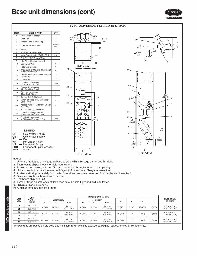
110
8(203)
51(1295)
IE
19
8
14
23 15
22
10
11
9
3
5
2
E
63(1600)
21
12
13
17
7
6
16
A
B
F
39(991)
5(127)
1-1/4(32)
4(102)
88(2235)
HR
HS
CR
CS
D
1-1/4(32)
H C H
HR CR CSHS D
3-5/8(92)
3-5/8(92)
3(76)3
(76)
4
1-1/4(32)
20
18
1
TOP VIEW
FRONT VIEW SIDE VIEW
42SU UNIVERSAL FURRED-IN STACK
*Unit weights are based on dry coils and minimum rows. Weights exclude packaging, valves, and other components.
UNITSIZE
UNIT WEIGHT*
lb (kg)
DIMENSIONS, in. (mm)FILTER SIZE
in. (mm)Side Supply Top SupplyE F H I
A B Size C D Size
03 180 (82)14 (356) 12 (305) 14 x 12
(356 x 305) 14 (356) 10 (254) 14 x 10(356 x 254) 17 (432) 3 (76) 11/2 (38) 14 (356) 121/2 x 241/4 x 1
(318 x 616 x 25)04 225 (102)
06 240 (109)18 (457) 12 (305) 18 x 12
(457 x 305) 16 (406) 12 (305) 16 x 12(406 x 305) 20 (508) 1 (25) 2 (51) 18 (457) 161/4 x 263/4 x 1
(413 x 679 x 25)08 260 (118)
10 280 (127)22 (559) 16 (406) 22 x 16
(559 x 406) 18 (457) 16 (406) 18 x 16(457 x 406) 24 (610) 1 (25) 3 (76) 22 (559) 201/2 x 291/4 x 1
(521 x 743 x 25)12 305 (138)
NOTES:1. Units are fabricated of 18-gage galvanized steel with a 16-gage galvanized fan deck.2. Thermostats shipped loose for field connection.3. Blower, motor, valves, coil, and filter are accessible through the return air opening.4. Unit and control box are insulated with 1/2-in. (13 mm) coated fiberglass insulation.5. All risers will ship separately from units. Riser dimensions are measured from centerline of knockout.6. Drain knockouts on three sides of cabinet.7. Flex hoses ship with unit.8. Thread fittings on both ends of flex hoses must be field tightened and leak tested.9. Return air panel not shown.10.All dimensions are in inches (mm).
LEGENDCR — Cold Water ReturnCS — Cold Water SupplyD — DrainHR — Hot Water ReturnHS — Hot Water SupplyPSC — Permanent Split CapacitorSWT — Sweat
ITEM DESCRIPTION QTY
1 Float Switch (Optional) 1
2 Drain Pan 1
3 Flexible Drain Tube/P-Trap 1
4 Drain Knockout (3 Sides) 1 each side
5 Blower 1
6 Riser Knockouts (3 Sides) 2/4
7 1/2 in. Flare Adaptor (SWT x 37.5) 2/4
8 Coil, 1/2 in. OD Copper Tube 1
9 1 in. Filter (Factory Installed) 1
10 Manual Air Vent 1
11 Return Air Opening 1
12 Knockout (For Optional Thermostat Remote Mounting) 3
13 Molex Connector for Field-Installed Thermostat 1
14 Control Box 1
15 Duct Collar Extension(1/2 in. Side, 1 in. Top) 1/2/3
16 Outside Air Knockout(On Each Side Panel) 1
17 Electrical Knockouts(Near Each Side) 1
18 Service Switch (Optional) 1
19 Motor, 3-Speed, PSC, with Quick Connect Std 1
20 Access Panel for Motor and Blower Assembly 1
21 Access Panel (Control Box) 1
22 Control Opening Knockout(Surface Mount Thermostat) 1
23 Supply Air Knockouts(4 Sides and Top, Stitch Cut) 1/2/3
a42-4268
Base unit dimensions (cont)42S
Ser
ies
Uni
ts

111
6
5
8(203)
51(1295)
IE
21
10
16
25 17
24
12
13
11
3
7
2
E
63(1600)
2314
15
19
9
8
18
A
B
F
39(991)
5(127)
1-1/4(32)
4(102)
88(2235)
HR
HS
CR
CS
D
1-1/4(32)
H C H
HR CR CSHS D
3-5/8(92)
3-5/8(92)
3(76)3
(76)
4
1-1/4(32)
1
22
20
TOP VIEW
FRONT VIEWSIDE VIEW
42SU UNIVERSAL FURRED-IN STACK WITH HEATER
*Unit weights are based on dry coils and minimum rows. Weights exclude packaging, valves, and other components.
UNITSIZE
UNIT WEIGHT*
lb (kg)
DIMENSIONS, in. (mm)FILTER SIZE
in. (mm)Side Supply Top SupplyE F H I
A B Size C D Size03 182 (83)
14 (356) 12 (305) 14 x 12(356 x 305) 14 (356) 10 (254) 14 x 10
(356 x 254) 17 (432) 3 (76) 11/2 (38) 14 (356) 121/2 x 241/4 x 1(318 x 616 x 25)04 227 (103)
06 242 (110)18 (457) 12 (305) 18 x 12
(457 x 305) 16 (406) 12 (305) 16 x 12(406 x 305) 20 (508) 1 (25) 2 (51) 18 (457) 161/4 x 263/4 x 1
(413 x 679 x 25)08 262 (119)
10 282 (128)22 (559) 16 (406) 22 x 16
(559 x 406) 18 (457) 16 (406) 18 x 16(457 x 406) 24 (610) 1 (25) 3 (76) 22 (559) 201/2 x 291/4 x 1
(521 x 743 x 25)12 307 (139)
NOTES:1. Units are fabricated of 18-gage galvanized steel with a 16-gage galvanized fan deck.2. Thermostats shipped loose for field connection.3. Blower, motor, valves, coil, and filter are accessible through the return air opening.4. Unit and control box are insulated with 1/2-in. (13 mm) coated fiberglass insulation.5. All risers will ship separately from units. Riser dimensions are measured from centerline of knockout.6. Drain knockouts on three sides of cabinet.7. Flex hoses ship with unit.8. Thread fittings on both ends of flex hoses must be field tightened and leak tested.9. Return air panel not shown.
10. All dimensions are in inches (mm).
LEGENDCR — Cold Water ReturnCS — Cold Water SupplyD — DrainHR — Hot Water ReturnHS — Hot Water SupplyPSC — Permanent Split CapacitorSWT — Sweat
ITEM DESCRIPTION QTY1 Float Switch (Optional) 12 Drain Pan 13 Flexible Drain Tube/P-Trap 1
4 Drain Knockout (3 Sides) 1 each side
5 Limit Switch (Factory Installed) 16 Strip Heater 17 Blower 18 Riser Knockouts (3 Sides) 2/49 1/2 in. Flare Adaptor (SWT x 37.5) 2/410 Coil, 1/2 in. OD Copper Tube 111 1 in. Filter (Factory Installed) 112 Manual Air Vent 113 Return Air Opening 1
14 Knockout (For OptionalThermostat Remote Mounting) 3
15 Molex Connector forField-Installed Thermostat 1
16 Control Box 1
17 Duct Collar Extension(1/2 in. Side, 1 in. Top) 1/2/3
18 Outside Air Knockout(On Each Side Panel) 1
19 Electrical Knockouts(Near Each Side) 1
20 Service Switch (Optional) 1
21 Motor, 3-Speed, PSC,with Quick Connect Std 1
22 Access Panel for Motor and Blower Assembly 1
23 Access Panel (Control Box) 1
24 Control Opening Knockout(Surface Mount Thermostat) 1
25 Supply Air Knockouts(4 Sides and Top, Stitch Cut) 1/2/3
a42-4271 42
S S
eries Units

112
30(762)
28(711)
SWT X 37.5 FLAREADAPTER
ACOUSTICALSERVICEACCESS PANEL
FLEXIBLE DRAIN
TUBE/P-TRAP
FILTER
RISERKNOCKOUTS
(OPTIONAL)RETURN AIR
PANEL
DRAIN PAN
SUPPLY AIROPENING
CONTROL BOX
COIL
MOTOR/BLOWER,3 SPEED, PSC, HIGH STATIC
24(610)
5(127)
66*(1676)
59(1499)
39(991)
SUPPLY TOP DUCT
COLLAR, 1"(25)
(OPTIONAL)INTERLOCKINGDISCONNECT
SWITCH
ELECTRICALKNOCKOUTS
5(127)
3(76)
3(76)
DHS CR1-1/4(32)
3(76)
11(280)
24(610)
3(76)
3(76)
3-5/8(92)3-5/8
(92) DHS CSCRHR1-1/4(32)
3(76)
11(280)
24(610)
SUPPLY PLENUM(OPTIONAL)
22(559)
4 22(559)4 (102) 4 (102)
4-3/4 (121)
16(406)
4-3/4 (121)
16(406)
1 (25) 22(559) 1 (25)
4-PIPE 2-PIPE
42SM MEGA FURRED-IN STACK
NOTES:1. Units measurements on drawings are shown in inches (millimeters).2. Units are fabricated of galvanized steel with a 16 gage galvanized fan deck.3. Blower, motor, valves, coil, and filter are accessible through the return air opening.4. Unit and control box are insulated with 1/2-in. (13 mm) coated fiberglass insulation.5. Maximum riser size is 2 1/2-in. (64 mm) diameter. If larger sizes are required, please consult the factory.6. This drawing is pictorial. (See unit arrangements for actual supply and return air orientation.)7. Riser length = [floor to floor + 2-in. (51 mm)]. Maximum riser length is 119-in. (3023 mm).8. Unit shipping weight is approximately 390 lb (176 kg).
LEGENDCR — Cold Water ReturnCS — Cold Water SupplyD — DrainHR — Hot Water ReturnHS — Hot Water SupplyPSC — Permanent Split CapacitorSWT — Sweat
a42-4269
Base unit dimensions (cont)42S
Ser
ies
Uni
ts

113
TOP
FRONT RIGHT
22(559)
24(610)
24(610)
24(610)
3 (76) 3 (76)
1-1/4 (32)
11(279)
1-1/4 (32)
30(762)
16(406)
22(559)
4(102)
1(25)
22(559)
1(25)
1-1/4 (32)
16(406)
4(102)
42SM OPTIONAL SUPPLY PLENUM
NOTES:1. Plenum box adds 22-in. (559 mm) to unit height, adds 26 lb (11.8 kg) to unit weight, and is factory
installed.2. 1/4-in. closed cell insulation is standard for the plenum box.3. Side supply is 22-in. (559 mm) x 16-in. (406 mm) on all four sides.4. Top supply is 24-in. (610 mm) x 11-in. (279 mm) which matches unit top ducted discharge.5. All dimensions are in inches (mm).
a42-4270a42-4270
Accessory dimensions4
2S
Series U
nits

114
GRILLE LOCATIONS
UNIT FIG. GRILLE ARRANGEMENTS
42SG ASupply Up to 3 grilles located on any of
3 sides shown.
Return One grille located on any of 3 sides shown.
42SH BSupply Up to 3 grilles located on any of
3 sides shown.Return One grille located opposite risers.
42SJ CSupply Up to 3 grilles located on any of
3 sides shown (per section).
Return One grille located on any of 3 sides shown (per section).
42SU DSupply Up to 3 openings from any 5 knock-
outs available.Return One grille location.
PANEL NO. 1 PANEL NO. 2 WITH CONTROL DOOR
SHORT FRAME — SURFACE MOUNTED GRILLE(for use with surface or wall mounted thermostat applications)
LONG FRAME — SURFACE MOUNTED GRILLE(for use with unit mounted thermostat applications)
PANEL NO. 3
SHORT FRAME — SURFACE MOUNTED GRILLE(for use with surface or wall mounted thermostat applications)
a42-4156
Accessory dimensions (cont)42S
Ser
ies
Uni
ts

115
PANEL NO. 4
SHORT FRAME — SURFACE MOUNTED GRILLE(for use with surface or wall mounted thermostat applications)
PANEL NO. 5 WITH CONTROL DOOR
LONG FRAME — SURFACE MOUNTED GRILLE(for use with unit mounted thermostat applications)
LONG FRAME — SURFACE MOUNTED GRILLE(for use with wall mounted thermostat applications)
PANEL NO. 2 WITHOUT CONTROL DOOR
42
S S
eries Units

116
PANEL NO. 2 WITHOUT DOOR
61.1
A
PANEL NO. 1 FOR 42SU
52.5
A
PANEL NO. 1 FOR 42SM
60.5
A
RETURN-AIR WALL PANELS FOR FURRED-IN UNITS — PANELS WITH NO FRAME
PANEL DIMENSIONS (in.)
NOTE: Dimensions in inches.
PANEL NO. UNIT UNIT SIZE A
142SG,SJ,
SU
03, 04 15.506, 08 19.510, 12 23.5
42SM 14,16,20 29.5
2 42SG,SJ03, 04 15.506, 08 19.510, 12 23.5
3 42SG,SJ03, 04 15.206, 08 19.210, 12 23.2
PANEL NO. 1
55.5
A
a42-4167
PANEL NO. 2
61.1
A
a42-4169PANEL NO. 3
55.3
A
A42-4173
A42-4272
A42-4274
A42-4275
Accessory dimensions (cont)42S
Ser
ies
Uni
ts
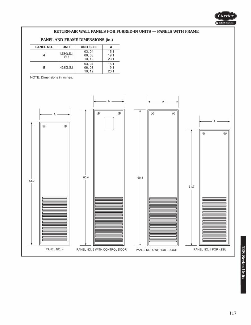
117
PANEL NO. 5 WITH CONTROL DOOR
60.4
A
PANEL NO. 4
54.7
A
PANEL NO. 4 FOR 42SU
51.7
A
RETURN-AIR WALL PANELS FOR FURRED-IN UNITS — PANELS WITH FRAME
PANEL AND FRAME DIMENSIONS (in.)
NOTE: Dimensions in inches.
PANEL NO. UNIT UNIT SIZE A
4 42SG,SJ, SU
03, 04 15.106, 08 19.110, 12 23.1
5 42SG,SJ03, 04 15.106, 08 19.110, 12 23.1
A42-4168 A42-4276A42-4277
PANEL NO. 5 WITHOUT DOOR
60.4
A
A42-4273
42
S S
eries Units

118
AIR DELIVERY
SCFMECM Operating Range:PSC Motor Fan Curve: 3-Row 5-Row4-Row
0
0.05
0.10
0.15
0.20
0.25
0.30
0.35
0.40
0.45
0.50
0 50 100 150 200 250 300 350
ESP
(in. w
g)
Low Med High
400 450 500
SCFMECM Operating Range:PSC Motor Fan Curve: 3-Row 5-Row4-Row
0
0.05
0.10
0.15
0.20
0.25
0.30
0.35
0.40
0.45
0.50
0 100 200 300
ESP
(in. w
g)
400 500
Low Med High
600
42S SERIES — UNIT SIZE 03
42S SERIES — UNIT SIZE 04
a42-4359
LEGENDECM — Electronically Commutated MotorESP — External Static PressurePSC — Permanent Split CapacitorSCFM — Square Cubic Feet Per Minute
a42-4360
Performance data42S
Ser
ies
Uni
ts

119
AIR DELIVERY (cont)
0
0.05
0.10
0.15
0.20
0.25
0.30
0.35
0.40
0.45
0.50
ESP
(in. w
g)
SCFMECM Operating Range:PSC Motor Fan Curve: 3-Row 5-Row4-Row
0 100 200 300 400 500 600 700 800 900
Low Med High
Low Med High0
0.05
0.10
0.15
0.20
0.25
0.30
0.35
0.40
0.45
0.50
ESP
(in. w
g)
SCFMECM Operating Range:PSC Motor Fan Curve: 3-Row 5-Row4-Row
0 100 200 300 400 500 600 700 800 900 1000 1100
42S SERIES — UNIT SIZE 06
42S SERIES — UNIT SIZE 08
a42-4361
LEGENDECM — Electronically Commutated MotorESP — External Static PressurePSC — Permanent Split CapacitorSCFM — Square Cubic Feet Per Minute
a42-4362
42
S S
eries Units
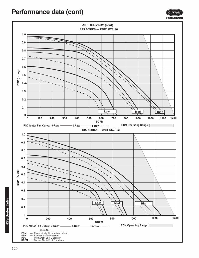
120
AIR DELIVERY (cont)
0
0.1
0.2
0.3
0.4
0.5
0.6
0.7
0.8
0.9
1.0
ESP
(in. w
g)
SCFMECM Operating Range:PSC Motor Fan Curve: 3-Row 5-Row4-Row
0 100 200 300 400 500 600 700 800 900 1000 1100 1200
Low Med High
0
0.1
0.2
0.3
0.4
0.5
0.6
0.7
0.8
0.9
1.0
ESP
(in. w
g)
SCFMECM Operating Range:PSC Motor Fan Curve: 3-Row 5-Row4-Row
0 200 400 600 800 1000 1200 1400
Low Med High
42S SERIES — UNIT SIZE 10
42S SERIES — UNIT SIZE 12
a42-4363
a42-4364
LEGENDECM — Electronically Commutated MotorESP — External Static PressurePSC — Permanent Split CapacitorSCFM — Square Cubic Feet Per Minute
Performance data (cont)42S
Ser
ies
Uni
ts
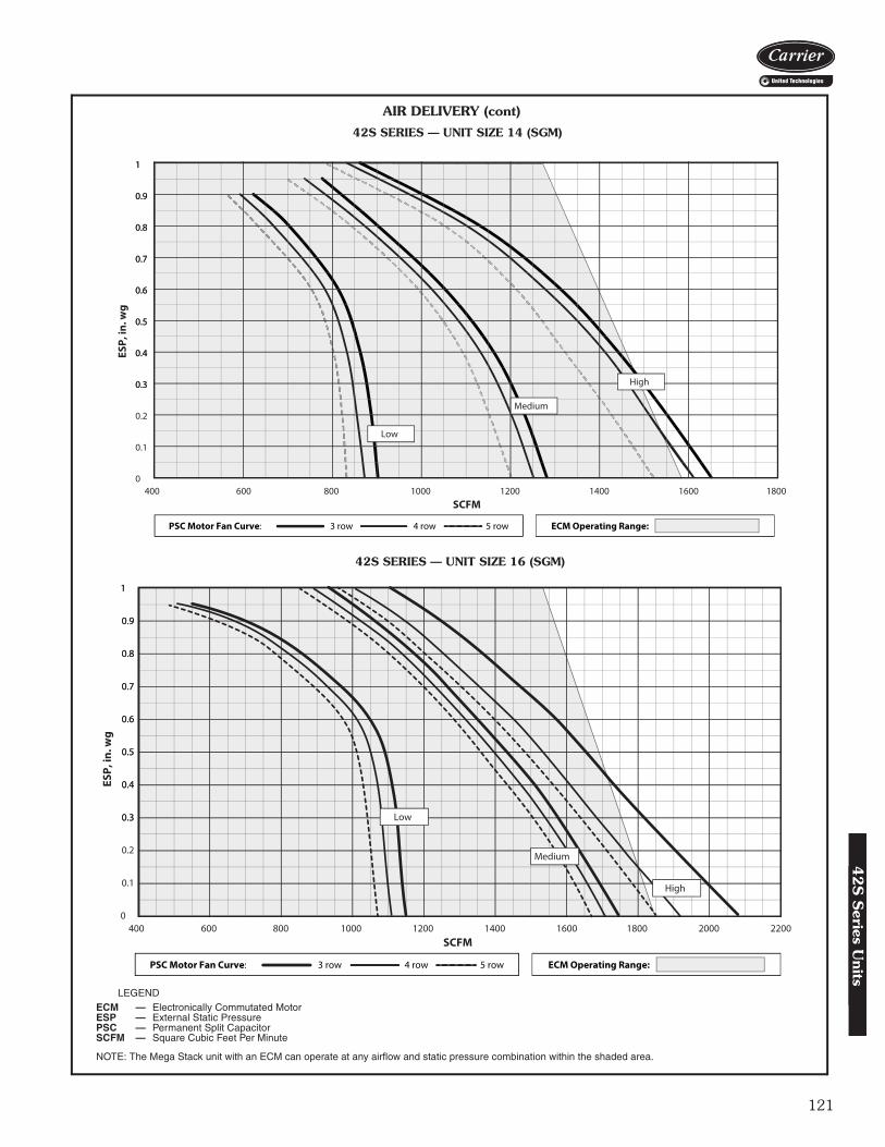
121
AIR DELIVERY (cont)
PSC Motor Fan Curve: 3 row 4 row 5 row ECM Operating Range:
0.3
0.4
0.5
0.6
0.7
0.8
0.9
1
0
0.1
0.2
0.3
0.4
0.5
0.6
0.7
0.8
0.9
1
400 600 800 1000 1200 1400 1600 1800 2000 2200
ESP,
in. w
g
SCFM
Low
Medium
High
42S SERIES — UNIT SIZE 14 (SGM)
42S SERIES — UNIT SIZE 16 (SGM)
a42-4279
LEGEND
NOTE: The Mega Stack unit with an ECM can operate at any airflow and static pressure combination within the shaded area.
ECM — Electronically Commutated MotorESP — External Static PressurePSC — Permanent Split CapacitorSCFM — Square Cubic Feet Per Minute
0.3
0.4
0.5
0.6
0.7
0.8
0.9
1
0
0.1
0.2
0.3
0.4
0.5
0.6
0.7
0.8
0.9
1
400 600 800 1000 1200 1400 1600 1800
ESP,
in. w
g
SCFM
PSC Motor Fan Curve: 3 row 4 row 5 row ECM Operating Range:
Low
Medium
High
42
S S
eries Units

122
AIR DELIVERY (cont)
42S SERIES — UNIT SIZE 20 (SGM)
a42-4280LEGEND
NOTE: The Mega Stack unit with an ECM can operate at any airflow and static pressure combination within the shaded area.
For high-static PSC and ECM fan performance data, refer to Carrier Electronic Selection Program.
ECM — Electronically Commutated MotorESP — External Static PressurePSC — Permanent Split CapacitorSCFM — Square Cubic Feet Per Minute
0.3
0.4
0.5
0.6
0.7
0.8
0.9
1
0
0.1
0.2
0.3
0.4
0.5
0.6
0.7
0.8
0.9
1
600 800 1000 1200 1400 1600 1800 2000 2200 2400
ESP,
in. w
g
SCFM
Low
Medium
High
PSC Motor Fan Curve: 3 row 4 row 5 row ECM Operating Range:
Performance data (cont)42S
Ser
ies
Uni
ts

123
SOUND POWER DATA42SG FURRED-IN STACK FAN COIL UNIT (CASING RADIATED SOUND PER AHRI 350)
NOTES:1. Unit Test Configuration: Front Return / Front Supply, 4 Row, 14 FPI
(fins per inch) Coil, 0.0 in. ESP at High Speed, 115 VAC PSC (per-manent split capacitor) Motor, #1 Return Air Panel, DD AluminumGrille.
2. Casing Radiated Testing per AHRI (Air-Conditioning, Heating, andRefrigeration Institute) 350-2008: 4.2.2.3 Casing radiated with freeinlet, Sound Rating of Ducted Air Moving and Conditioning Equip-ment.
3. Sound power data is expressed decibels, dB RE: 1 x 10-12 W(picowatts).
UNITSIZE
RATINGFAN
SPEEDCFM
SOUND POWER LEVEL, L. (dB one reference pico watt) A-wgt
(dBA)125 Hz 250 Hz 500 Hz 1000 Hz 2000 Hz 4000 Hz 8000 Hz
03
CASING RADIATED with #1 Style Return Air Panel and
Double Deflection Aluminum Grille
H 360 63 53 50 42 34 33 38 51M 310 59 50 47 38 30 32 38 48
L 280 56 47 45 35 27 32 38 46
04
CASING RADIATED with #1 Style Return Air Panel and
Double Deflection Aluminum Grille
H 460 62 56 53 47 39 36 38 54M 385 59 52 50 44 35 33 38 51
L 290 56 49 47 40 30 32 38 47
06
CASING RADIATED with #1 Style Return Air Panel and
Double Deflection Aluminum Grille
H 580 69 58 53 46 41 38 37 56M 500 65 54 50 43 37 35 36 53
L 400 59 48 46 37 30 31 36 47
08
CASING RADIATED with #1 Style Return Air Panel and
Double Deflection Aluminum Grille
H 810 72 62 59 53 49 45 40 61M 580 65 56 53 47 41 37 36 54
L 430 60 49 47 39 32 31 36 48
10
CASING RADIATED with #1 Style Return Air Panel and
Double Deflection Aluminum Grille
H 1045 71 66 63 59 56 53 43 65M 930 69 63 60 55 53 49 40 62
L 670 62 56 53 46 42 37 37 54
12
CASING RADIATED with #1 Style Return Air Panel and
Double DeflectionAluminum Grille
H 1145 71 68 63 60 56 53 43 66M 950 68 63 61 55 52 48 39 62
L 805 65 59 58 52 48 43 37 59
42
S S
eries Units
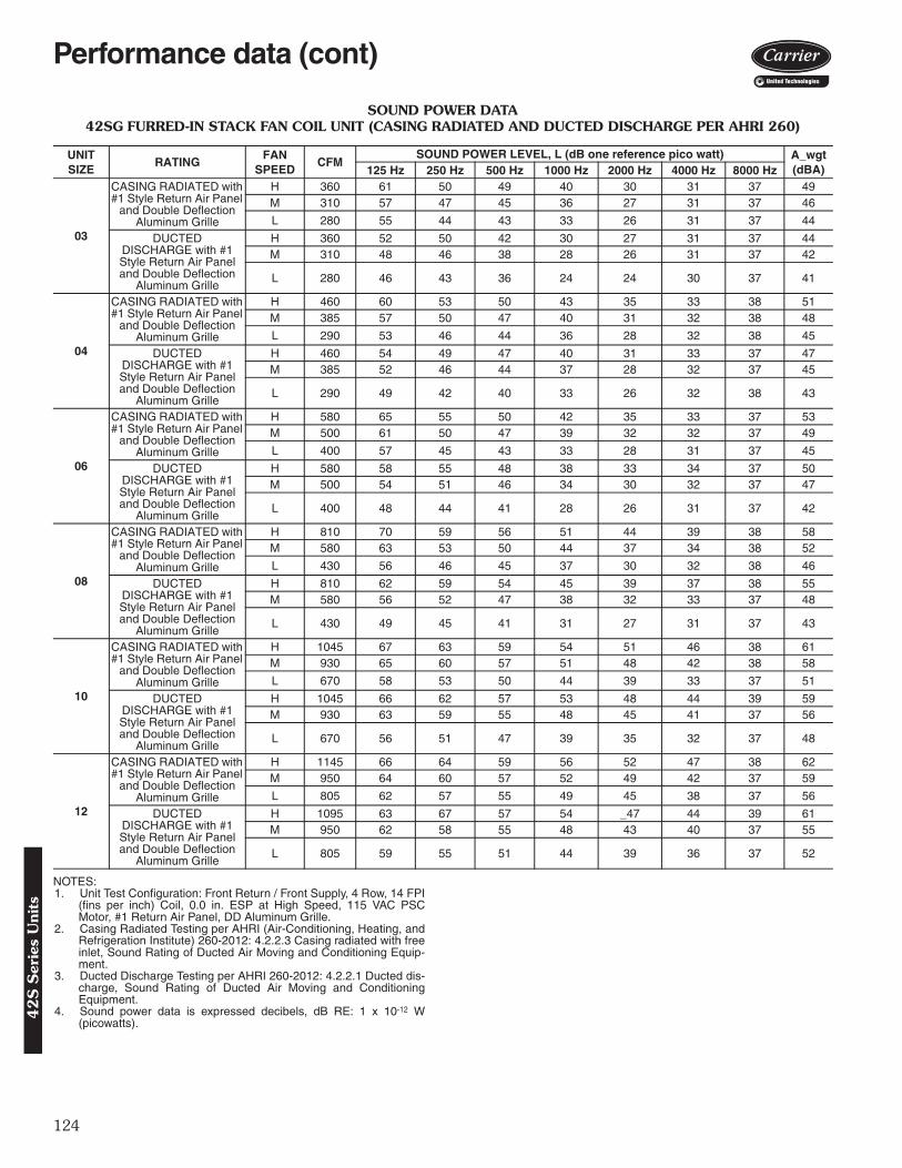
124
SOUND POWER DATA42SG FURRED-IN STACK FAN COIL UNIT (CASING RADIATED AND DUCTED DISCHARGE PER AHRI 260)
NOTES:1. Unit Test Configuration: Front Return / Front Supply, 4 Row, 14 FPI
(fins per inch) Coil, 0.0 in. ESP at High Speed, 115 VAC PSCMotor, #1 Return Air Panel, DD Aluminum Grille.
2. Casing Radiated Testing per AHRI (Air-Conditioning, Heating, andRefrigeration Institute) 260-2012: 4.2.2.3 Casing radiated with freeinlet, Sound Rating of Ducted Air Moving and Conditioning Equip-ment.
3. Ducted Discharge Testing per AHRI 260-2012: 4.2.2.1 Ducted dis-charge, Sound Rating of Ducted Air Moving and ConditioningEquipment.
4. Sound power data is expressed decibels, dB RE: 1 x 10-12 W(picowatts).
UNITSIZE
RATINGFAN
SPEEDCFM
SOUND POWER LEVEL, L (dB one reference pico watt) A_wgt(dBA)125 Hz 250 Hz 500 Hz 1000 Hz 2000 Hz 4000 Hz 8000 Hz
03
CASING RADIATED with #1 Style Return Air Panel
and Double Deflection Aluminum Grille
H 360 61 50 49 40 30 31 37 49M 310 57 47 45 36 27 31 37 46
L 280 55 44 43 33 26 31 37 44
DUCTED DISCHARGE with #1 Style Return Air Panel and Double Deflection
Aluminum Grille
H 360 52 50 42 30 27 31 37 44M 310 48 46 38 28 26 31 37 42
L 280 46 43 36 24 24 30 37 41
04
CASING RADIATED with #1 Style Return Air Panel
and Double Deflection Aluminum Grille
H 460 60 53 50 43 35 33 38 51M 385 57 50 47 40 31 32 38 48
L 290 53 46 44 36 28 32 38 45
DUCTED DISCHARGE with #1 Style Return Air Panel and Double Deflection
Aluminum Grille
H 460 54 49 47 40 31 33 37 47M 385 52 46 44 37 28 32 37 45
L 290 49 42 40 33 26 32 38 43
06
CASING RADIATED with #1 Style Return Air Panel
and Double Deflection Aluminum Grille
H 580 65 55 50 42 35 33 37 53M 500 61 50 47 39 32 32 37 49
L 400 57 45 43 33 28 31 37 45
DUCTED DISCHARGE with #1 Style Return Air Panel and Double Deflection
Aluminum Grille
H 580 58 55 48 38 33 34 37 50M 500 54 51 46 34 30 32 37 47
L 400 48 44 41 28 26 31 37 42
08
CASING RADIATED with #1 Style Return Air Panel
and Double Deflection Aluminum Grille
H 810 70 59 56 51 44 39 38 58M 580 63 53 50 44 37 34 38 52
L 430 56 46 45 37 30 32 38 46
DUCTED DISCHARGE with #1 Style Return Air Panel and Double Deflection
Aluminum Grille
H 810 62 59 54 45 39 37 38 55M 580 56 52 47 38 32 33 37 48
L 430 49 45 41 31 27 31 37 43
10
CASING RADIATED with #1 Style Return Air Panel
and Double Deflection Aluminum Grille
H 1045 67 63 59 54 51 46 38 61M 930 65 60 57 51 48 42 38 58
L 670 58 53 50 44 39 33 37 51
DUCTED DISCHARGE with #1 Style Return Air Panel and Double Deflection
Aluminum Grille
H 1045 66 62 57 53 48 44 39 59M 930 63 59 55 48 45 41 37 56
L 670 56 51 47 39 35 32 37 48
12
CASING RADIATED with #1 Style Return Air Panel
and Double Deflection Aluminum Grille
H 1145 66 64 59 56 52 47 38 62M 950 64 60 57 52 49 42 37 59
L 805 62 57 55 49 45 38 37 56
DUCTED DISCHARGE with #1 Style Return Air Panel and Double Deflection
Aluminum Grille
H 1095 63 67 57 54 _47 44 39 61M 950 62 58 55 48 43 40 37 55
L 805 59 55 51 44 39 36 37 52
Performance data (cont)42S
Ser
ies
Uni
ts
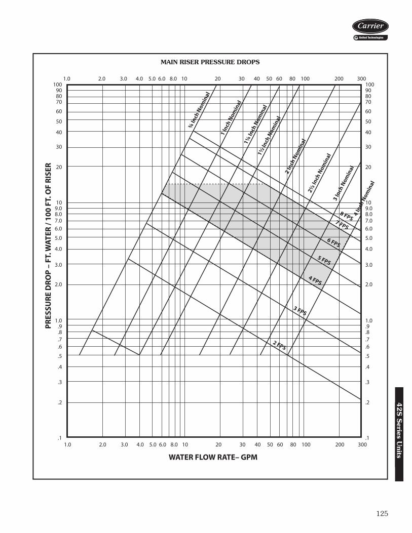
125
PRES
SURE
DRO
P –
FT. W
ATER
/ 10
0 FT
. OF
RISE
R
WATER FLOW RATE– GPM
100 90 80 70
60
50
40
30
20
10 9.0 8.0 7.0 6.0
5.0
4.0
3.0
2.0
1.0 .9 .8 .7 .6
.5
.4
.3
.2
.1
100 90 80 70
60
50
40
30
20
10 9.0 8.0 7.0 6.0
5.0
4.0
3.0
2.0
1.0 .9 .8 .7 .6
.5
.4
.3
.2
.1 1.0 2.0 3.0 4.0 5.0 6.0 8.0 10 20 30 40 50 60 80 100 200 300
1.0 2.0 3.0 4.0 5.0 6.0 8.0 10 20 30 40 50 60 80 100 200 300
1½ In
ch N
omin
al
6 FPS
5 FPS
4 FPS
3 FPS
2 FPS
8 FPS7 FPS
¾ In
ch N
omin
al
1 In
ch N
omin
al
1¼ In
ch N
omin
al
2½ In
ch N
omin
al
2 In
ch N
omin
al
3 In
ch N
omin
al
4 In
ch N
omin
al
MAIN RISER PRESSURE DROPS
a42-4225
42
S S
eries Units
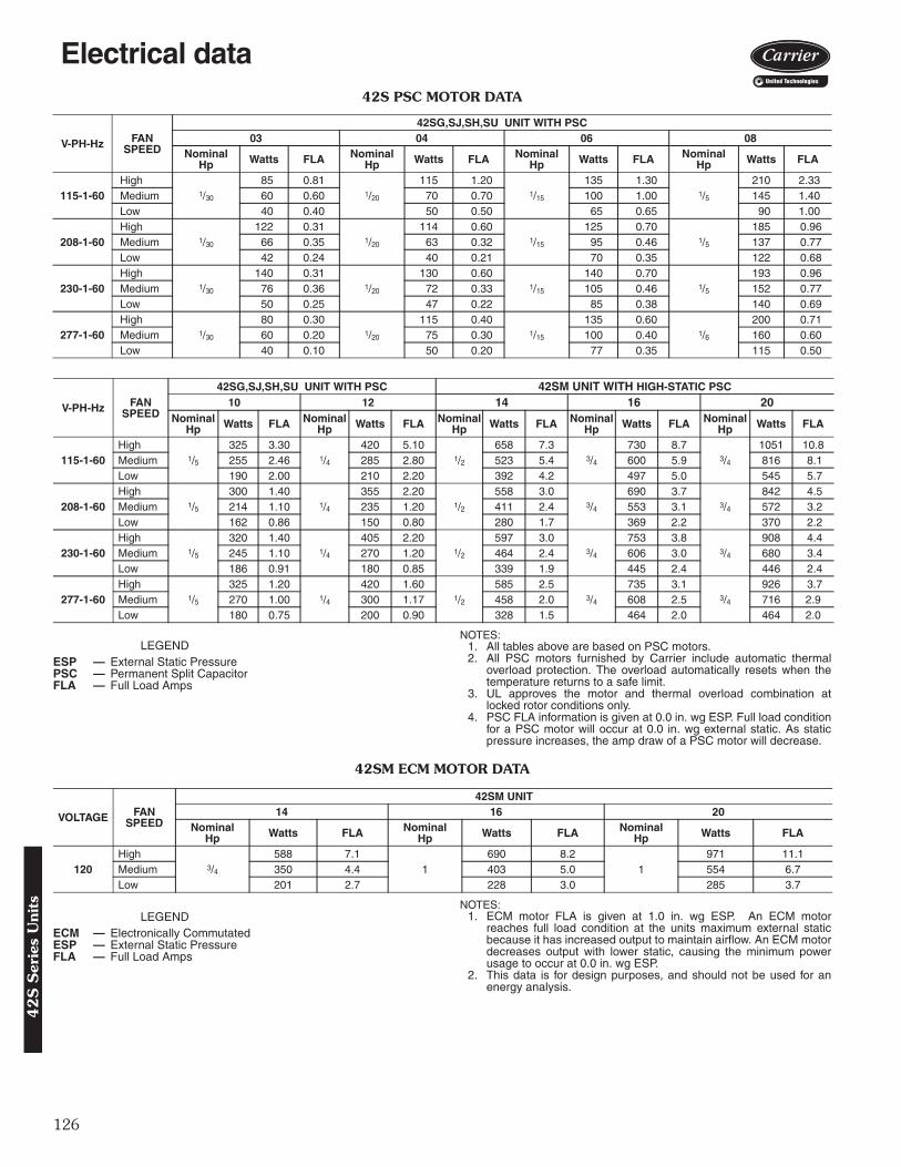
126
42S PSC MOTOR DATA
LEGENDNOTES:
1. All tables above are based on PSC motors.2. All PSC motors furnished by Carrier include automatic thermal
overload protection. The overload automatically resets when thetemperature returns to a safe limit.
3. UL approves the motor and thermal overload combination atlocked rotor conditions only.
4. PSC FLA information is given at 0.0 in. wg ESP. Full load conditionfor a PSC motor will occur at 0.0 in. wg external static. As staticpressure increases, the amp draw of a PSC motor will decrease.
42SM ECM MOTOR DATA
LEGENDNOTES:
1. ECM motor FLA is given at 1.0 in. wg ESP. An ECM motorreaches full load condition at the units maximum external staticbecause it has increased output to maintain airflow. An ECM motordecreases output with lower static, causing the minimum powerusage to occur at 0.0 in. wg ESP.
2. This data is for design purposes, and should not be used for anenergy analysis.
V-PH-Hz FAN SPEED
42SG,SJ,SH,SU UNIT WITH PSC 03 04 06 08
NominalHp Watts FLA Nominal
Hp Watts FLA NominalHp Watts FLA Nominal
Hp Watts FLA
115-1-60High
1/30
85 0.811/20
115 1.201/15
135 1.301/5
210 2.33Medium 60 0.60 70 0.70 100 1.00 145 1.40Low 40 0.40 50 0.50 65 0.65 90 1.00
208-1-60High
1/30
122 0.311/20
114 0.601/15
125 0.701/5
185 0.96Medium 66 0.35 63 0.32 95 0.46 137 0.77Low 42 0.24 40 0.21 70 0.35 122 0.68
230-1-60High
1/30
140 0.311/20
130 0.601/15
140 0.701/5
193 0.96Medium 76 0.36 72 0.33 105 0.46 152 0.77Low 50 0.25 47 0.22 85 0.38 140 0.69
277-1-60High
1/30
80 0.301/20
115 0.401/15
135 0.601/6
200 0.71Medium 60 0.20 75 0.30 100 0.40 160 0.60Low 40 0.10 50 0.20 77 0.35 115 0.50
V-PH-Hz FAN SPEED
42SG,SJ,SH,SU UNIT WITH PSC 42SM UNIT WITH HIGH-STATIC PSC10 12 14 16 20
NominalHp Watts FLA Nominal
Hp Watts FLA NominalHp Watts FLA Nominal
Hp Watts FLA NominalHp Watts FLA
115-1-60High
1/5
325 3.301/4
420 5.101/2
658 7.33/4
730 8.73/4
1051 10.8Medium 255 2.46 285 2.80 523 5.4 600 5.9 816 8.1Low 190 2.00 210 2.20 392 4.2 497 5.0 545 5.7
208-1-60High
1/5
300 1.401/4
355 2.201/2
558 3.03/4
690 3.73/4
842 4.5Medium 214 1.10 235 1.20 411 2.4 553 3.1 572 3.2Low 162 0.86 150 0.80 280 1.7 369 2.2 370 2.2
230-1-60High
1/5
320 1.401/4
405 2.201/2
597 3.03/4
753 3.83/4
908 4.4Medium 245 1.10 270 1.20 464 2.4 606 3.0 680 3.4Low 186 0.91 180 0.85 339 1.9 445 2.4 446 2.4
277-1-60High
1/5
325 1.201/4
420 1.601/2
585 2.53/4
735 3.13/4
926 3.7Medium 270 1.00 300 1.17 458 2.0 608 2.5 716 2.9Low 180 0.75 200 0.90 328 1.5 464 2.0 464 2.0
ESP — External Static PressurePSC — Permanent Split CapacitorFLA — Full Load Amps
VOLTAGE FAN SPEED
42SM UNIT14 16 20
NominalHp Watts FLA Nominal
Hp Watts FLA NominalHp Watts FLA
120High
3/4
588 7.11
690 8.21
971 11.1Medium 350 4.4 403 5.0 554 6.7Low 201 2.7 228 3.0 285 3.7
ECM — Electronically CommutatedESP — External Static PressureFLA — Full Load Amps
Electrical data42S
Ser
ies
Uni
ts

127
42SG, SH, SJ, SU ECM MOTOR DATA
42S ELECTRIC HEATER DATA
LEGENDFLA — Full Load AmpsNOTES:
1. All heaters are single stage and single-phase. Two-stage heatersmay be available with a special request.
2. In all units using over 48 amps, the heating elements are subdi-vided and protected. Additional cost is incurred because of addedcomponents. Each circuit of the electric heater coil has an auto-matic reset thermal cutout with back-up high limit control and oper-ating contactor.
3. Electric heater and motor voltage must be the same and need tobe ordered in conjunction with a single power source wiring option.This option, which meets NEC (National Electric Code) require-ments, consists of a factory-furnished and installed junction boxand fuse for 6.25 amp (max) fan and control circuit connection to asingle power source. All units with electric heat must include afused service switch. Power supply circuit to unit must be field fur-nished and installed in accordance with applicable codes.
4. Fan coil units comply with ETL, Canadian Standards Association(CSA), and ETL of Canada standards.
SIZE NOMINAL HPAMPS
120V 208V 230V 277V
42S*03 1/6
2.4 1.6 1.5 1.042S*04 1/6
42S*06 1/6
42S*08 1/2
8.4 4 4 3.342S*10 1/2
42S*12 1/2
HEATERVOLTAGE
HEATER kW1.0 1.5 2.0 3.0 4.0 5.0 6.0 8.0 10.0 12.0
FLA120 8.3 12.5 16.7 25.0 — — — — — —208 4.8 7.2 9.6 14.4 19.2 24.0 28.8 38.5 — —240 4.2 6.2 8.3 12.5 16.7 20.8 25.0 33.3 45.5 —277 3.6 5.4 7.2 10.8 14.4 18.0 21.7 28.9 36.1 43.3
42
S S
eries Units

128
Fan Coil Unit — Horizontal ModelsHVAC Guide Specifications — 42CSize Range: 200 to 1200 Nominal CfmCarrier Model Numbers:
42CA (Furred-in)42CE (Furred-in with Plenum)42CG (Cabinet)42CK (Furred-in, Telescoping Panel)
Part 1 — General1.01 SYSTEM DESCRIPTION
Horizontal, 2-pipe or 4-pipe (or electric heat), roomfan coil unit with furred-in, above ceiling cabinetfor ducting, or with cabinet for exposed ceilinginstallations.
1.02 QUALITY ASSURANCEUnits shall be tested and certified in accordance withAHRI (Air-Conditioning, Heating, and RefrigerationInstitute) standard 440, latest edition. All units shallhave C-ETL-US listing signifying the units have beenexamined by ETL and are in compliance with boththe US and Canadian applicable standards. Eachcoil shall be factory tested for leakage at 300 psig airpressure with coil submerged in water. Insulationand adhesive shall meet NFPA (National Fire Protec-tion Association) 90A requirements for flame spreadand smoke generation. All equipment wiring shallcomply with NEC (National Electrical Code) require-ments.
1.03 DELIVERY, STORAGE AND HANDLINGEach unit shall be individually packaged from pointof manufacture. Unit shall be handled and stored inaccordance with the manufacturer’s instructions.
Part 2 — Products2.01 EQUIPMENT
A. General:Factory-assembled, horizontal, blow-thru type fancoil for furred-in, exposed ceiling or ducted installa-tions. Unit shall be complete with water coil(s),fan(s), motor(s), drain pan, and all required wiring,piping, controls and special features. Standard insu-lation shall be dual density fiberglass insulation.
B. Furred-in Base Unit (42CA):1. Casing is 18-gage galvanized steel, lined on the
inside with 1/2-in. thick fiberglass insulation,with a 1 in. long collar for supply duct connec-tion. NO filter installed in base unit.
2. The drain pan shall be constructed of galva-nized steel extending the entire length andwidth of the coil(s) and shall be pitched fordrainage. The inside surface of the drain panshall be coated with closed-cell fire-retardantfoam insulation. An extension drain pan shallbe provided for installation under factory-provided water valves at the job site.
C. Furred-in Units with Plenum (42CE):Base unit with factory-installed plenum section and1-in. fiberglass throwaway filter as shown on equip-ment drawings. The plenum shall be bottom or rearair return, shall enclose the fan/motor assemblies,and shall be lined with 1/2-in. fiberglass insulation.Unit shall have a removable panel to provide accessto fan/motor assemblies and unit identification label.
D. Cabinet Units (42CG):Base unit with stamped discharge grille, removablebottom access panel with stamped return-air grille,filter rack and 1-in. fiberglass throwaway filter. Thepanel shall be fastened with slotted head, positive-locking quarter-turn fasteners. The cabinet shall becoated with an Arctic White baked finish.
E. Ceiling, Furred-in with 2-in. Telescoping CeilingPanel (42CK):Base unit with full galvanized upper casing, adjust-able height, hinged return-air ceiling panel, and1-in. fiberglass throwaway filter. Panel shall becoated with an Arctic White baked finish.
F. Fans:Direct-driven, double-width fan wheels with forward-curved blades shall be statically and dynamicallybalanced. Scrolls shall be constructed of galvanizedsteel. Fan wheels shall be constructed of galvanizedsteel.
G. Coils:Standard base unit shall be equipped with a 3-row or4-row coil for installation in a 2-pipe system.Additional coil depth and circuiting shall be providedfor installation in a 4-pipe system as described in theSpecial Features section. All coils shall have 1/2-in.copper tubes and aluminum fins (10 fins per inch)spacing. Coil fins are mechanical bonded to tubejoints. The copper tubes comply with the ASTM(American Society for Testing and Materials) B-75.The fin thickness is 0.0045-in. and tube thickness is0.016 inch. All coils are tested with air under waterand are suitable for design working pressures of 250psig at 220 F. Burst tested at 300 psig.
H. Controls and Safeties:The fan motor(s) shall be equipped with integralautomatic temperature reset for motor protection.
I. Operating Characteristics:1. A one-coil unit installed in a 2-pipe system shall
be capable of providing heating or cooling asdetermined by the operating mode of the cen-tral water supply system.
2. A double-circuit coil unit installed in a 4-pipesystem shall be capable of providing sequencedheating and cooling.
Guide specifications — 42C series

129
J. Electrical Requirements:Standard unit shall operate on 120 v, single-phase,60 Hz electric power. All internal wiring shall be inflexible conduit.
K. Motor(s):Fan motors shall be 3-speed, 120 v, single-phase,60 Hz, permanent split capacitor type, with sleevetype bearings and oversized oil reservoirs to ensurelubrication. Motor shall have thermal overload pro-tection with automatic reset and be connected withquick connect electrical plug.
L. Special Features:Certain standard features are not applicable whenthe features designated by * are specified. See yourlocal Carrier Sales Offices for amendingspecifications.
* 1. Unit coil(s) shall be equipped with automatic airvents.
* 2. For installation in a 4-pipe chilled water ordirect expansion (DX R-410A) system, unitshall be equipped with a 3-row cooling/one-row heating split-circuit coil, a 3-row cooling/2-row heating split-circuit coil, or a 4-row cool-ing/one-row heating split-circuit coil asrequired. Coil connections to be as shown onthe equipment drawings.
* 3. For installation on a 2-pipe chilled water ordirect expansion (DX R-410A) system, unitsshall be equipped with a 2-row, 3-row, or4-row, cooling/heating coil.
* 4. Fan motor shall be permanent split-capacitortype, 208, 220, 240, or 277-v, single-phase,50 or 60 Hz as specified on the equipmentschedule.
* 5. Unit shall be equipped with electric strip heatersmounted on the entering air side of the watercoil. Heaters shall include high limit cutout withauto reset and contactor. Capacity and voltageshall be as shown on the equipment schedule.When fan motor and electric heater are selectedat the same voltage and connected to a singlepower source, a junction box and fuse shall befactory furnished and installed to protect themotor and control circuit.
* 6. Filter track and cleanable filter shall be installedin the plenum.
* 7. Drain pan shall include a second drain connec-tion located above the main drain connection toact as an indicator that the main drain isplugged.
* 8. Discharge-air grille with double deflection, alu-minum construction with aluminum frame shallbe factory installed as shown on the equipment
schedule. Aluminum grilles shall have a naturalanodized finish (42CG only).
* 9. Double-deflection discharge-air grille with steelconstruction shall be factory installed as shownon equipment schedule. Grille shall be paintedto match cabinet (42CG only).
10. Manual stop, balancing, combination balanceand stop, ball type, and flow control valves shallbe factory furnished and installed as indicatedon the equipment drawings.
11. Motorized 2-way and 3-way valves shall be fac-tory wired and assembled with tubes terminat-ing in belled ends or unions for field attachmentto the coil. Valves shall be packaged within unitto prevent shipping damage.
12. Heating and/or cooling wall thermostat shall befactory furnished for field installation.
13. Automatic changeover device(s) shall be factorywired for field installation on the supply piping.
14. Sequenced heating and cooling wall thermostatshall be factory furnished for field installation.
15. Tamper-proof fasteners (Allen head) shall beinstalled on the access panel on cabinet models.
16. Unit shall operate on 208, 220, 240, or 277-v,single-phase, 50 or 60 Hz electrical power asspecified on the equipment schedule. All wiringshall be in flexible metal conduit.
17. Cabinet of 42CG unit or bottom panels of42CK unit shall be painted with the color speci-fied on the equipment schedule.
18. A stainless steel drain pan shall be available forfactory installation.
19. Factory-installed insulation options shall includefoil faced fiberglass or closed cell insulation.
20. Control Options:a. 3-speed, 4-position manual fan switch on a
wall plate for field-mounting.b. Factory-installed 24-v transformer and relay
board for use, with 24-v controls by others.c. Carrier’s Debonair® 24-v digital display pro-
grammable or non-programmable thermo-stat, including factory-installed 24-vtransformer, relay board, and changeoversensors, as required. Provides automatic fanspeed control based on demand.
d. Factory-Installed Carrier Fan Coil OpenController: BACnet based communicatingcontroller with pre-programmed controlalgorithms; including factory-installed 24-vtransformer, relay board, supply air sensor,return air sensor and changeover sensor (asrequired). Provides automatic fan speed con-trol based on demand.

130
Fan Coil Unit — Ducted ModelsHVAC Guide Specifications — 42DSize Range: 600 to 2000 Nominal CfmCarrier Model Numbers:
42DA (Ceiling Furred-in)42DC (Ceiling Furred-in with Plenum)42DD (Vertical with Galvanized Casing)42DE (Ceiling with Galvanized Casing)42DF (Ceiling Exposed Cabinet)
Part 1 — General1.01 SYSTEM DESCRIPTION
Horizontal, 2-pipe or 4-pipe or electric heat fan coilunit for ducted installations; horizontal furred-in orexposed ceiling model, ceiling cabinet, or verticalmodel with galvanized casing for closet or utilityroom installation.
1.02 QUALITY ASSURANCEUnits shall be ETL approved, except for 42DF. Allunits shall be CSA (Canadian Standards Association)approved, including 42DF. Each coil shall be factorytested for leakage at 300 psig air pressure with coilsubmerged in water. Insulation and adhesive shallmeet NFPA (National Fire Protection Association)90A requirements for flame spread and smoke gen-eration. All equipment wiring shall comply with NEC(National Electrical Code) requirements. The 42DFmodel shall be tested and certified in accordancewith AHRI Standard 440, latest edition.
1.03 DELIVERY, STORAGE AND HANDLINGUnit shall be handled and stored in accordance withthe manufacturer’s instructions.
Part 2 — Products2.01 EQUIPMENT
A. General:Factory assembled, horizontal or vertical blow-thruducted fan coil unit. Unit shall be complete withwater coil(s), fan(s), motor(s), drain pan, andall required wiring, piping, controls and specialfeatures. Standard insulation shall be dual densityfiberglass insulation.
B. Horizontal, Furred-in Base Unit (42DA):1. Outside panels shall be galvanized steel, lined
on the inside with 1/2-in. thick fiberglass insula-tion and a 1 in. long collar for supply ductconnection.
2. The drain pan shall be constructed of 18-gagegalvanized steel extending the entire length andwidth of coil(s) and pitched for drainage. Theinside surface of the drain pan shall be coatedwith closed-cell, fire retardant foam. An exten-sion drain pan shall be provided for installationat the jobsite under the factory-furnished elec-tric water valves.
C. Horizontal Base Unit with Plenum for ConcealedInstallation (42DC): Unit shall have a factory-installed, 18-gage galva-nized steel plenum section and 1-in. throwaway fil-ter. The plenum shall be either bottom or rearreturn, lined with 1/2-in. thick fiberglass insulationand include a removable panel to provide access tothe fan/motor assembly.
D. Horizontal, Enclosed Unit for Concealed Installation(42DE):Unit shall be constructed of galvanized steel withremovable panels for access to internal compo-nents. Units have 1/2-in. fiberglass insulation, filtertrack with 1-in. throwaway filter, 1-in. supply collar,and 21/2-in. return-air collar on rear of unit for ductconnection.
E. Horizontal Cabinet Unit for Exposed Installation(42DF):Unit shall be constructed of steel with arctic whitere-coatable baked enamel finish. Cabinet shall belined with 1/2-in. fiberglass insulation and haveremovable bottom access panel. Unit shall includehinged bar type return-air grille on rear of unit with1-in. throwaway filter and integral double deflectionsupply-air grille.
F. Vertical, Enclosed Unit for Closet Installation(42DD):Unit shall be constructed of galvanized steel with1/2-in. fiberglass insulation. Unit shall include frontreturn-air opening with 1-in. throwaway filter and1-in. supply-air duct collar.
G. Fans:Direct-driven, double-width fan wheels shall haveforward-curved blades, and be statically and dynami-cally balanced, with scrolls and fans constructed ofgalvanized steel.
H. Coils:Standard base unit shall be equipped with a 4-rowcoil for installation in a 2-pipe system. Additionalcoil depth and circuiting shall be provided for instal-lation in a 4-pipe system as described in the SpecialFeatures section. All coils shall have 1/2-in. coppertubes and aluminum fins (10 fins per inch) spacing;Coil fins are mechanical bonded to tube joints. Thecopper tubes comply with the ASTM (AmericanSociety for Testing and Materials) B-75. The finthickness is 0.0045-in. and tube thickness is 0.016-inch. All coils are tested with air under water and aresuitable for design working pressures of 250 psig at220 F. Burst tested at 300 psig.
I. Controls and Safeties:The fan motor(s) shall be equipped with integral,automatic reset thermal overload motor protection.
Guide specifications — 42D series

131
J. Operating Characteristics:A single-circuit coil unit installed in a 2-pipe systemshall be capable of providing heating or cooling asdetermined by the operating mode of the centralwater supply system. A double circuit coil unitinstalled in a 4-pipe system shall be capable of pro-viding sequenced heating and cooling.
K. Electrical Requirements:Standard unit shall operate on 115-v, single-phase,60-Hz electric power, and all exposed wiring shall bein a flexible conduit.
L. Motor(s):Fan motors shall be 3-speed permanent split capaci-tor type, 115 volts, with sleeve type bearings andoversized oil reservoirs. Motor shall have thermaloverload protection with automatic reset and beconnected with quick connect electrical plug.
M. Special Features:Certain standard features are not applicable whenthe features designated by * are specified. Seeyour local Carrier Sales Office for amendingspecifications.
* 1. Unit coil(s) shall be equipped with automatic airvents.
* 2. Unit shall be equipped with a 3-row, 4-row or6-row cooling coil for installation in a 2-pipechilled water system or direct expansion(DX R-410A) system.
* 3. For installation in a 4-pipe chilled water systemor direct expansion (DX R-410A) system, unitshall be equipped with either a 3-row cooling/1-row heating split circuit, or 3/2 split circuit or4/1 split circuit, or a 4/2 split circuit or a 6/1split circuit (except 42DD) as required.
* 4. Fan motor(s) shall be permanent split capacitortype, 208, 230, or 277 volts for low-staticapplications (42DF) or 208, 230 or 277 voltsfor high-static applications (42DA, DC, DD,and DE). 220-volt fan motor shall be availablefor 50 Hz applications.
* 5. Electric Heat:a. Unit shall be equipped with electric resis-
tance strip heaters mounted on the enteringair side of the water coil.
b. Heaters shall include automatic reset highlimit cutout, contactor, factory-furnishedjunction box and fuse to protect the motor.
c. Heaters shall be single-stage, single-phase,120, 208, 220, 240 or 277 volts, for 50 Hzor 60 Hz applications. Capacity shall be asshown on the equipment schedule.
d. Control circuit for single power source con-nection is available and must be used whenmotors and heaters are of the same voltage.
* 6. Filter track and cleanable filter shall be installedin the plenum (42DC, DD, and DE only).
7. Drain pan shall include a second drain connec-tion located above the main drain connection toact as an indicator that the main drain isplugged.
8. Removable drain pan extension (drip lip) shallbe available for field installation under electricwater valves.
9. Six-in. diameter outside air opening with ductcollar shall be provided to duct outside ventila-tion air to unit, with or without manual outdoorair damper. (Special quote needed.)
10. Balancing and combination balance and stop(ball) and flow control valves shall be factory fur-nished and installed as indicated on the equip-ment drawings.
11. Motorized 2-way and 3-way valves shall bewired to the unit. In order to prevent shippingdamage, they shall be factory assembled in thevalve package. The valve packages shall termi-nate with belled ends or unions for field attach-ment to the coil.
12. Heating and/or cooling thermostat (SPDT)shall be factory furnished for field installation(2-pipe system).
13. Automatic changeover device(s) shall be factorywired for field installation on supply piping(2-pipe system).
14. Sequenced heating and cooling wall thermostatshall be factory furnished for field installation(4-pipe system)
15. Cabinet of 42DF unit shall be painted with thecolor specified on the equipment schedule.
16. A stainless steel drain pan shall be available forfactory installation.
17. Factory-installed insulation options shall includefoil faced fiberglass or closed cell insulation.
18. Control Options:a. 3-speed, 4-position manual fan switch on a
wall plate for field-mounting.b. Factory-installed 24-v transformer and relay
board for use, with 24-v controls by others.c. Carrier’s Debonair® 24-v digital display pro-
grammable or non-programmable thermo-stat, including factory-installed 24-vtransformer, relay board, and changeoversensors, as required. Provides automatic fanspeed control based on demand.
d. Factory-Installed Carrier Fan Coil OpenController: BACnet based communicatingcontroller with pre-programmed controlalgorithms; including factory-installed 24-vtransformer, relay board, supply air sensor,return air sensor and changeover sensor (asrequired). Provides automatic fan speed con-trol based on demand.
132
Fan Coil Unit — Vertical Stack ModelsHVAC Guide Specifications — 42SSize Range: 300 to 2000 Nominal CfmCarrier Model Numbers:
42SG (Furred-in, 300 to 1200 Cfm)42SH (Cabinet, 300 to 1200 Cfm)42SJ (Furred-in, Back-to-Back, 300 to 1200 Cfm)42SM (Mega, Furred-in, 1400 to 2000 Cfm)42SU (Universal, Furred-in, 300 to 1200 Cfm)
Part 1 — General1.01 SYSTEM DESCRIPTION
Stack fan coil units, 2-pipe, 4-pipe or 2-pipe withelectric heat for furred-in or exposed cabinets thatare floor mounted in multi-story buildings.
1.02 QUALITY ASSURANCEUnits shall be tested and certified in accordance withAHRI (Air-Conditioning, Heating, and RefrigerationInstitute) standard 440, latest edition. All units shallhave C-ETL-US listing signifying the units have beenexamined by ETL and are in compliance with boththe US and Canadian applicable standards. Eachcoil shall be factory tested for leakage at 300 psig airpressure with coil submerged in water. Insulationand adhesive shall meet NFPA (National Fire Pre-vention Association) 90A requirements for flamespread and smoke generation.
1.03 DELIVERY, STORAGE AND HANDLINGUnit shall be handled and stored in accordance withthe manufacturer’s instructions.
Part 2 — Products2.01 EQUIPMENT
A. General:Factory assembled, stack fan coil units. Units arecomplete with water coil(s), fan(s), motor(s), drainpan, and all required wiring, piping, controls, andspecial features. Standard insulation shall be dualdensity fiberglass insulation.
B. Cabinet Stack Unit (42SH):Outside panels are made of 18-gage galvanized steelcoated with baked-on enamel finish and are fabri-cated with no exposed fasteners. The interior sur-faces shall be lined with 1/2-in. thick fiberglassinsulation. The standard cabinet unit has factory-installed double deflection discharge grille(s) andstamped supply grille. Controls are factory wiredand mounted in small access panel at front of unit.
C. Furred-In Stack Unit (42SG):The unit shall be constructed of 18-gage galvanizedsteel frame and 18-gage galvanized steel back panel.The fan coil is for furred-in installation. These unitsare designed to have the wallboard applied directlyto the unit surface and all openings have standard1/2-in. thick fiberglass insulation. Units have doubledeflection aluminum discharge grille(s) and painted,stamped (standard) or bar-type aluminum (optional)return-air grille panel. Removable return-air grille
provides access to all internal piping and wiring.Controls are provided with a quick disconnect plugfor field-mounting on front of unit.
D. Back-To-Back Furred-In Stack Units (42SJ):The open unit shall be constructed of 18-gage galva-nized steel frame and 18-gage galvanized steel backpanel. These units are similar to the 42SG but areactually two completely separate units contained inone cabinet that share a common set of risers.These units are designed to have the wallboarddirectly applied to the unit surface and openingshave standard 1/2-in. drywall flanges. The interiorsurfaces shall be lined with 1/2-in. thick fiberglassinsulation. Units have double deflection aluminumsupply grille(s) and painted, stamped (standard) orbar-type aluminum (optional) return-air grille panel.Removable return-air grille provides access to allinternal piping and wiring. Controls are providedwith a quick disconnect plug for field-mounting onfront of unit.
E. Universal Furred-In Stack Units (42SU):Units shall be constructed of heavy-gage galvanizedsteel frame and back panel. Interior surfaces shall belined with standard fiberglass insulation. Units shallbe designed to have wallboard applied directly to theunit surface. All units shall include a return air block-off panel. Units shall have an optional double deflec-tion aluminum discharge grille(s) or an optional arc-tic white painted double deflection discharge grille(s).Unit shall have an arctic white painted stamped steelreturn air access panel. Removable return air/accesspanel shall provide access to all internal compo-nents. Controls shall be provided with a quick-con-nect plug for field-mounting of thermostat on thefront of unit. Units shall have stainless steel hosekits.
F. Mega Furred-In Stack Units (42SM):Units shall be constructed of heavy-gage galvanizedsteel frame and back panel. Interior surfaces shallbe lined with standard fiberglass insulation.Optional anti-microbial fiberglass, foil faced orclosed cell insulation is available. Units shall bedesigned to have wallboard applied directly to theunit surface. Controls shall be factory wired andaccessible from the front of the unit. Return air/access opening shall provide access to all internalcomponents. All valve package piping to the coil(s)shall be factory installed.
G. Drain Pan:Drain pan shall be formed of 18-gage steel and shallbe coated inside with fire-retardant closed-cell foaminsulation. Water never touches the metal pan, elim-inating the possibility of corrosion. On 42SG, SH,and SJ units the drain is factory piped to the drainriser that has a removable “P-trap” allowing easycleaning. On 42SU and 42SM units, the drain panshall be field piped to the drain riser with a remov-able/cleanable “P-trap.” On 42SM units, the
Guide specifications — 42S series

133
standard drain pan is stainless steel, externallycoated with a 2-part closed cell foam insulation.
H. Filter:A filter track complete with 1-in. non-woven syn-thetic throwaway filter shall be installed in the unit.Optional filters are available.
I. Fan:1. Centrifugal fan shall be directly driven by an
electric motor.2. Fan wheel shall be double-width type with
forward-curved blades and shall be statically anddynamically balanced.
3. Fan wheel and scroll shall be constructed of gal-vanized steel.
4. Fans shall be easily removable.J. Coil:
1. Standard base unit shall be equipped with a3-row coil for installation in a 2-pipe system.Additional coil depth and circuiting shall be pro-vided for installation in a 4-pipe system asdescribed in the Special Features section.
2. All coils shall have 1/2-in. copper tubes andaluminum fins with 14 fins per inch spacing;coil fins are mechanically bonded to coppertubes. The copper tubes comply with theASTM (American Society for Testing and Mate-rials) B-75. The fin thickness is 0.0045-in. andtube thickness is 0.016 inches. All coils aretested with air at 300 psig under water.
3. Coil shall be equipped with a manual air ventand shall be piped to supply and returnrisers with valves as specified on the equipmentdrawings. For 42SU and 42SM units, coil is notpiped to risers, which shall be shipped sepa-rately.
4. Piping between hot water coil and risers shallinclude loops to compensate for maximum riserexpansion and contraction of 11/2-in. on42SG, 42SH, and 42SJ units. On 42SU and42SM units, a flexible hose is included.
K. Flexible Hose for 42SU and 42SM Fan Coil:1. Construction:
a. Hose shall have an external component con-structed of stainless steel 304L wire braidwith an internal core tube of EPDM rubber.
b. Hoses shall have 37.5 degree female swivelcrimp on fittings on either end for attach-ment to brass 1/2-in. male adapters.
c. Hoses shall be assembled with a patentedprocess which bonds the tube to the outerbraid, minimizing the possibility of the hoseassembly kinking during installation.
d. All hoses shall be equipped with perma-nently installed (crimped) end fittings to elim-inate the possibility of bands or clampsloosening and creating leaks.
e. Plated steel hose swivel fittings and brassadapters shall reduce the possibility of over-torquing.
2. Regulations:a. Hoses shall meet UL-94 VO rating listed as
Underwriters Laboratories Yellow Card num-ber QMFZ2.E80017.
b. The 1/2-in. hoses shall be rated for a maxi-mum working pressure of 400 psig andburst pressure of 1600 psig.
c. Temperature range for hose assemblies shallbe –40 to 200 F.
d. Hoses shall be field connected.e. Torque specifications for hose connections
shall be 350 in.-lb +10/-0 in.-lb to preventleaks.
L. Risers:1. Standard factory-furnished and installed risers
shall be up to 119 in. long with 3-in. belledends at the top for floor to floor dimensions upto 117 in. For floor to floor dimensions greaterthan 117 in., 104 in. risers will be providedwith riser extensions up to 24 in. long.
2. Supply and return risers shall be 3/4-in. to2 1/2-in. diameter.
3. Risers shall be Type M or L copper insulatedwith 1/2-in. or 3/4-in. thick closed cell insulation.
4. Optional riser chase on 42SGA for applicationof wall board directly to the chase.
M. Valves:The factory furnished or installed risers shall haveball valves except on the drain riser.
N. Controls and Safeties:1. Controls:
Unit shall come with no controls unless controlpackage is selected.
2. Safeties:Unit fan motor shall be equipped with thermaloverload protection with automatic reset.
O. Operating Characteristics:1. A unit with a conventional coil, installed in a
2-pipe system, shall be capable of providingheating or cooling as determined by the operat-ing mode of the central water supply system.
2. A unit with a row-split coil, installed in a 4-pipesystem, shall be capable of providing sequencedheating and cooling.
P. Electrical Requirements:Standard unit shall operate on 115-v, single-phase,60 Hz electrical power supply. All externallyexposed wiring shall be in flexible conduit.
Q. Motor:1. Standard fan motor shall be 3-speed, 115-v,
single-phase, 60 Hz, permanent split capacitortype, factory mounted on the blower housing.

134
2. Bearings shall be permanently lubricated sleevetype.
3. Motor shall be equipped with quick connectelectrical plug.
4. Motor shall have thermal overload protectionwith automatic reset.
R. Special Features:Certain standard features are not applicable whenthe features designated by * are specified.
* 1. Unit coil shall be equipped with automatic airvents.
* 2. Unit shall be equipped with a 3-row, 4-row, or5-row (42SM) coil for installation in a 2-pipesystem.
* 3. For installation in a 4-pipe system, unit shall beequipped with:a. A 3/1, 3/2 or 4/1 row-split coil, as shown
on equipment drawings for cooling andheating.
b. Two each supply and return risers and onedrain riser.
c. Two ball valves, 2 circuit setters and two 2-way motorized valves.
d. Motorized control valves shall be rated at300 psi with 150 psi close-off pressure dif-ferential, and rated to operate with fluid tem-peratures from 40 to 180 F. Normallyclosed valves shall be powered open withspring driven closure.
* 4. Unit shall be equipped with 3-way motorizedvalves.
5. Fixed flow valve(s) shall be factory installed asshown on the equipment drawings.
* 6. Motor shall be 3-speed, single-phase, 60 Hzpermanent split capacitor type for 208, 230 or277 volts or 50 Hz permanent split capacitortype for 220 volts.
7. Motor shall be ECM (electronically commutatedmotor) motor for single-phase, 60 Hz, 115,208, 230, or 277 V.
* 8. Double-deflection aluminum finish supplygrille(s) shall be finished for field installation.
9. Double-deflection aluminum finish supplygrille(s) with opposed blade damper shall be fur-nished for field installation on two or more dis-charge units.
10. Ceiling skirts for exposed stack units shall beprovided for field trim and installation.
11. A fresh-air opening shall be provided as shownon the equipment drawings.
*12. One-in. thick cleanable filters, pleated MERV 8filters, or pleated MERV 13 filters shall beinstalled in the filter track.
13. Unit shall be equipped with nichrome wire elec-tric strip heaters for total or auxiliary electricheat as specified on the equipment schedule.a. Heaters shall be protected by an automatic
reset safety cutout switch and a fusible link.b. Heater capacity shall be as specified on the
equipment schedule.c. Heaters shall be single phase, 60 Hz for
120, 208, 240 or 277 volts as specified onthe equipment schedule.
d. Electric heaters shall include thermal over-load protection with fusible link back-up.
e. Units with electric heat shall also includeblower motor and control sub-fusing.
14. Fused or unfused service switch shall be pro-vided. Switch shall be suitable for single phase,60 Hz service for 115, 208, 240 or 277 voltsas specified on the equipment schedule.
15. Panels of 42SH unit shall be painted with thecolor specified on the equipment schedule.
16. Return air panels shall be supplied as shown onthe equipment drawings.
17. Tamper-proof fastners (Allen head) shall beinstalled on the access panels on cabinetmodels.
18. A stainless steel drain pan shall be available forfactory installation.
19. Factory-installed insulation options shall includefoil faced fiberglass or closed cell insulation(42SG,SH,SJ,SM only).
20. Control Options:a. Factory installed 24-v transformer and relay
board for use, with 24-v controls by others.b. Carrier’s Debonair® 24-v digital display pro-
grammable or non-programmable thermo-stat, including factory-installed 24-vtransformer, relay board, and changeoversensors, as required. Provides automatic fanspeed control based on demand.
c. Factory-Installed Carrier Fan Coil OpenController: BACnet based communicatingcontroller with pre-programmed controlalgorithms; including factory-installed 24-vtransformer, relay board, supply air sensor,return air sensor, and changeover sensor (asrequired). Provides automatic fan speed con-trol based on demand.
Guide specifications — 42S series (cont)
135
Fan Coil Unit — Vertical ModelsHVAC Guide Specifications — 42VSize Range: 200 to 1200 Nominal CfmCarrier Model Numbers:
42VA (Furred-in)42VB (Cabinet)42VC (Furred-in, Lowboy, 200 to 600 cfm)42VE (Cabinet, Lowboy, 200 to 600 cfm)42VF (Cabinet, Slant Top)42VG (Furred-in, Wall, 150 and 300 cfm)
Part 1 — General1.01 SYSTEM DESCRIPTION
Vertical, 2-pipe or 4-pipe, or electric heat, room fancoil unit for furred-in, or cabinet floor mountedinstallation. (42VC and VE are low profile units.)
1.02 QUALITY ASSURANCEUnit shall be tested and certified in accordance withAHRI (Air-Conditioning, Heating, and RefrigerationInstitute) Standard 440, latest edition, and base unitETL certified. All units shall have C-ETL-US listingsignifying the units have been examined by ETL andare in compliance with both the US and Canadianapplicable standards. (Units with special featuresmay not have ETL certification.) Each coil shall befactory tested for leakage at 300 psig air pressurewith coil submerged in water. Insulation and adhe-sive shall meet NFPA (National Fire Protection Asso-ciation) 90A requirements for flame spread andsmoke generation.
1.03 DELIVERY, STORAGE AND HANDLINGEach unit shall be individually packaged from pointof manufacture. Unit shall be handled and stored inaccordance with the manufacturer’s instructions.
Part 2 — Products2.01 EQUIPMENT
A. General:Factory-assembled, vertical, blow-thru type floor-mounted fan coil for furred-in or exposed installa-tions. Unit shall be complete with water coil, fan(s),motor(s), drain pan, and all required wiring, piping,controls and special features. Standard insulationshall be dual density fiberglass insulation.
B. Base Unit (42VA, VC):1. Outside panels are made of 18-gage galvanized
steel. Lined on the inside with 1/2-in. thick fiber-glass insulation, with a 1 in. long collar for topsupply duct connection. Units shall be suppliedwith a 1-in. fiberglass throwaway filter.
2. The drain pan shall be constructed of 18-gagegalvanized steel extending the entire length andwidth of the coil(s) and pitched for drainage.The inside surface of the drain pan shall becoated with closed cell fire retardant foam insu-lation. An extension drain pan shall be providedfor installation under the water valves at the job-site.
C. Cabinet Models (42VB, VE, VF):1. Cabinet models shall be coated with an Arctic
White baked finish, and include a 1-in. fiber-glass throwaway filter.
2. Cabinet models shall be free standing with 2access doors. A stamped supply-air grille shallbe included in the top of the cabinet. (Overallcabinet height shall not exceed 141/2-in. on lowprofile 42VE unit.)
3. The 42VF top panel shall slope down fromback to front at an angle of 25 degrees. Stan-dard stamped grille shall provide a dischargeinto the room at a nominal 67 degrees from thevertical.
D. Furred-In Model (42VG):1. Cabinet shall be fabricated of 18-gage galva-
nized steel with 1/2-in. thick fiberglass insula-tion. Cabinet shall be coated with baked enamelfinish. Removable front panel shall provide ser-vice access and shall include die-formed supplyand return-air grilles.
2. Combination condensate pan and fan deckshall be insulated with closed-cell fire-retardantfoam.
E. Fans:Direct-driven, double-width fan wheels shall haveforward-curved blades and shall be statically anddynamically balanced. Scrolls and fan wheels shallbe constructed of galvanized steel.
F. Coils:Standard base unit shall be equipped with a 3-row(42VA, VB, VF units) or 2-row coil (42VC, VE, VGunits) for installation in a 2-pipe system. Additionalcoil depth and circuiting shall be provided for instal-lation in a 4-pipe system as described in the SpecialFeatures section. All coils shall have 1/2-in. coppertubes and aluminum fins (12 fins per inch for42VA,VB,VF and 10 fins per inch for 42VC,VF,VG)spacing; Coil fins are mechanical bonded to tubejoints. The copper tubes comply with the ASTM B-75. The fin thickness is 0.0045 in. and tube thick-ness is 0.016 in. All coils are tested with air underwater and are suitable for design working pressuresof 250 psig at 220 F. Burst tested at 350 psig.
G. Controls and Safeties:Internal wiring from motor and valves shall be inflexible metal conduit, terminating in the junctionbox.
H. Operating Characteristics:1. A one-coil unit installed in a 2-pipe system shall
be capable of providing heating and cooling asdetermined by the operating mode of the cen-tral water supply system.
2. A double-circuit coil unit installed with a 4-pipesystem shall be capable of providing sequencedheating and cooling.
Guide specifications — 42V series
136
I. Electrical Requirements:Standard unit shall operate on 120 v, single-phase,60 Hz electric power. All internal wiring shall be inflexible conduit.
J. Motor(s):Fan motor(s) shall be 3-speed, 120 v, single-phase,60 Hz, permanent split capacitor type with sleevetype bearings and oversized oil reservoirs to ensurelubrication. Motors shall have integral automatictemperature reset for motor protection.
K. Special Features:Certain standard features are not applicable whenthe features designated by * are specified. Seeyour local Carrier Sales Office for amendingspecifications.
* 1. Unit coil(s) shall be equipped with automatic airvents.
* 2. For installation in a 2-pipe system, unit shall beequipped with a 3-row or 4-row cooling/heat-ing coil (42VA,VB,VF units) or a 3-row cool-ing/heating coil (42VC,VE).
* 3. For installation in a 4-pipe system, 42VA,VB,VF units shall be equipped with a 3-rowcooling/one-row heating split-circuit coil, a3-row cooling/2-row heating split-circuit coil ora 4-row cooling/one-row heating split-circuitcoil as required. The 42VC,VE units shall beequipped with a 2-row cooling/one-row heat-ing split-circuit coil.
* 4. Fan motor shall be permanent split-capacitortype, 208, 220, 240, or 277-v, single-phase,50 or 60 Hz as specified on the equipmentschedule.
* 5. Unit shall be equipped with electric resistancesheath type heaters mounted on the leaving airside of the water coil. Heaters shall include highlimit cutout with auto reset and contactor.Capacity and voltage shall be as shown on theequipment schedule. When fan motor and elec-tric heater are selected at the same voltage andconnected to a single power source, a junctionbox and fuse shall be factory furnished andinstalled to protect the motor and control cir-cuit. Unit height on 42VC and VE shall beincreased by 2 in. to accommodate heaters.
* 6. Cleanable filter shall be factory installed in thefilter track.
* 7. Leveling legs shall be factory installed on theunit and permit a maximum adjustment of3/4 inch.
8. Switch box complete with switch shall be fac-tory installed on the unit.
9. Discharge-air grille with double deflectionaluminum construction as shown on theequipment schedule shall be furnished for fieldinstallation (42VA,VC units).
10. Discharge-air grille with double deflection steelor aluminum construction shall be shippedinstalled in the unit (42VB,VF,VE units). Steelgrilles shall be painted to match cabinet. Alumi-num grilles shall be a natural anodized finish.
11. Reverse-stamped grille (42VB,VF units) shallprovide a discharge into the room at a nominal23 degrees from vertical.
12. Stamped type aluminum return-air grille with fil-ter holder shall be furnished for field installa-tion. (Not available for 42VG unit.)
13. Manual stop, balancing, combination balanceand stop (ball type), and flow control valves shallbe factory furnished and installed as indicatedon the equipment drawings.
14. Motorized 2-way an d 3-way valves shall be fac-tory assembled and wired to unit with tubes ter-minating in belled ends or unions for fieldattachment to the coil. Valves shall be packagedwithin the unit to prevent shipping damage.
15. Heating and/or cooling wall thermostat shall befactory furnished for field installation.
16. Heating and/or cooling thermostat shall be fac-tory wired and installed.
17. Automatic changeover device(s) shall be factorywired for field installation on the supply piping.
18. Sequenced heating and cooling wall thermostatshall be factory furnished for field installation.
19. Sequenced heating and cooling thermostat shallbe factory wired and installed.
*20. Tamper-proof fasteners (Allen head) shall beinstalled on front panel and access doors oncabinet models.
*21. Cabinet shall be painted with the color specifiedon the equipment schedule.
*22. Factory-installed outside-air damper shall bemanually adjustable through the return airopening or shall be arranged for remote manualadjustment, complete with linkage and electricmotor to open damper when fan is on. Or, unitshall have a 3/16-in. shaft extending outside theunit for installation of a field-supplied damper(42VA,VB,VF).
23. Unit shall operate on 208, 220, 240, or 277-v,single-phase, 50 or 60 Hz electrical power asspecified on the equipment schedule. All wiringshall be in flexible conduit.
24. A stainless steel drain pan shall be available forfactory installation.
25. Factory-installed insulation options shall includefoil faced fiberglass or closed cell insulation.
Guide specifications — 42V series (cont)

137
26. Control Options:a. Furred-in units shall be furnished with a 3-
speed, 4-position manual fan switch on awall plate for field-mounting. Cabinet unitsshall be furnished with a factory-installed, 3-speed, 4-position manual fan switch.
b. Factory-installed 24-v transformer and relayboard for use, with 24-v controls by others.
c. Carrier’s Debonair® 24-v digital display pro-grammable or non-programmable thermo-stat, including factory-installed 24-v
transformer, relay board, and changeoversensors, as required. Provides automatic fanspeed control based on demand.
d. Factory-Installed Carrier Fan Coil OpenController: BACnet based communicatingcontroller with pre-programmed controlalgorithms; including factory-installed 24-vtransformer, relay board, supply air sensor,return air sensor and changeover sensor (asrequired). Provides automatic fan speed con-trol based on demand.
138
42CA section 36-6542CE section 36-6542CG section 36-6542CK section 36-6542DA section 87-10242DC section 87-10242DD section 87-10242DE section 87-10242DF section 87-10242SG section 103-12742SH section 103-12742SJ section 103-12742SM section 103-12742SU section 103-12742VA section 66-8642VB section 66-8642VC section 66-8642VE section 66-8642VF section 66-8642VG section 66-86Air delivery 42C 57-61 42D 96,97 42S 118-122 42V 83Application data 18-35AHRI rating data 42C 37 42D 87 42S 104 42V 67Arrangements, 42S 20-22Automatic changeover 17Capacities 42C 37 42D 87 42S 104 42V 67Certifications and listings 37, 67, 87, 104Coil connections 28, 55, 80, 81, 94, 95Controls 14-17 Selection guide 14 Remote-mounted 15 Unit-mounted 15,16Cv factor 31Dimensions Accessories 42C 55,56 42D 94,95 42S 113-117 42V 80-82 Base unit 42C 39-54 42D 89-93 42S 105-112 42V 69-79Discharge air grilles 56,82Electric heaters 14,33,34,64,84,100,127Electrical data 42C 64, 65 42D 100-102 42S 126, 127 42V 84-86Features/Benefits 1-7 Filters 42C 38 42D 88 42S 104 42V 68
Guide specifications 42C 128, 129 42D 130, 131 42S 132-134 42V 135-137Isolation valves 28Model number nomenclature 42C 36 42D 87 42S 103 42V 66Motor data 42C 64, 65 42D 100-102 42S 126, 127 42V 84-86Options 8-13Panel combinations 12, 114-117Performance data 42C 57-63 42D 96-99 42S 118-125 42V 83Physical data 42C 38 42D 88 42S 104 42V 68Piping 19, 24-27Risers 13, 20, 125Selection procedure 18Service fittings 28Shipping weights 42C 38 42D 88 42S 104 42V 68Seismic compliance compatibility 42C 11 42D 12Strainer 25, 28Thermostat 10, 13-16Valve package arrangements 29Water flow balancing Components 28
Index


Manufacturer reserves the right to discontinue, or change at any time, specifications or designs without notice and without incurring obligations.Pg 140 Catalog No. 04-52420016-01 Printed in U.S.A. Form 42-10PD
Replaces: 42-9PD
Carrier Corporation • Syracuse, New York 13221 9-14
Related Documents