Philips Dynalite 6/691 Gardeners Road Mascot NSW 2020 Australia P: +61 (0)2 8338 9000 F: +61 (0)2 8338 9999 E: [email protected] W: www.philips.com/dynalite Fan Coil Unit Controller Networked heating, ventilation and air conditioning control User Guide Version 1.0

Welcome message from author
This document is posted to help you gain knowledge. Please leave a comment to let me know what you think about it! Share it to your friends and learn new things together.
Transcript
Philips Dynalite 6/691 Gardeners Road Mascot NSW 2020 Australia P: +61 (0)2 8338 9000 F: +61 (0)2 8338 9999 E: [email protected] W: www.philips.com/dynalite
Fan Coil Unit Controller Networked heating, ventilation and air conditioning control
User Guide Version 1.0
Fan Coil Unit Controller (FCUC)
Philips Fan Coil Unit Controller User Guide 2
Background
Philips Dynalite is a highly specialized company whose principal occupation is to provide ‘cutting edge’ solutions for lighting control. Our achievements have been recognized worldwide and Philips Dynalite is generally the system of choice for projects involving integration with third-party vendor’s equipment and for large-scale applications.
Philips Dynalite’s philosophy is to provide the best solution possible for each and every project. This is the key to our success. Our considerable investment in Research & Development ensures that we remain at the forefront of our industry. Our position as a world leader in lighting management systems for the future is sustained through our total commitment to innovation.
We are represented around the world by distributors and dealers who are handpicked for their ability to provide the highest possible level of service.
From a stock exchange in Shanghai, to a luxury resort in Dubai, a smart home in Sao Paulo to limestone caves in New Zealand, Philips Dynalite’s innovative solutions deliver intelligent light.
Ongoing research and development has enabled Philips Dynalite to create secure automated systems that control tens of thousands of individual light fittings in high-rise office buildings from any location anywhere in the world. Our networks are engineered to deliver instant notification of power or system failure, and report via a LAN, internet, or through an SMS gateway to a mobile phone. This provides the assurance necessary in applications where continuous operation is vital, such as road tunnels, computer servers or cold storage units.
Philips Dynalite’s modular product design philosophy also improves system flexibility. Through this approach, specific application requirements can be accommodated with greatly reduced lead times. As an industry leader Philips Dynalite is committed to creating superior lighting control and energy management systems, setting new benchmarks in performance and efficiency.
In receiving the International Association of Lighting Designers award for Most Innovative Product, the Philips Dynalite control system has been independently recognized as ‘A user friendly and sensible modular approach, which takes it from sophisticated domestic settings to large architectural spaces’.
Fan Coil Unit Controller (FCUC)
Philips Fan Coil Unit Controller User Guide 3
Contents
1 Fan Coil Unit Controller (FCUC) ............................................................................................. 7 1.1 Introduction ..............................................................................................................................................................7 1.2 Features ......................................................................................................................................................................7 1.3 Connections ..............................................................................................................................................................8 1.4 Plant Structure....................................................................................................................................................... 10 1.5 Commissioning ...................................................................................................................................................... 11
2 FCUC Initial Configuration ....................................................................................................... 12 2.1 Load Device ........................................................................................................................................................... 12 2.2 Run the FCUC Configuration Wizard ............................................................................................................. 13 2.3 Control Scheme .................................................................................................................................................... 14 2.4 Controller............................................................................................................................................................... 14 2.5 Hardware Interfaces ............................................................................................................................................ 14 2.6 Switch Input Functions ........................................................................................................................................ 14
3 Configure Plant............................................................................................................................ 16 3.1 Plant configuration tab ......................................................................................................................................... 16 3.2 Logical Address ..................................................................................................................................................... 16 3.3 Valves ....................................................................................................................................................................... 18 3.4 Fans .......................................................................................................................................................................... 20 3.5 Aux Output ............................................................................................................................................................ 21 3.6 Fault Signals ............................................................................................................................................................ 22 3.7 Runtime Parameters ............................................................................................................................................ 23
4 Configure Temperature Control ............................................................................................ 24 4.1 Temperature Control Tab ................................................................................................................................. 24 4.2 PID Control Scheme ............................................................................................................................................ 25
4.2.1 Modes ..................................................................................................................................................................... 25 4.2.2 General Settings ................................................................................................................................................... 25 4.2.3 Cooling Parameters ............................................................................................................................................ 26 4.2.4 Heating Parameters ............................................................................................................................................. 26
4.3 Tuning Wizard ....................................................................................................................................................... 27 4.4 FCUC Graph Settings .......................................................................................................................................... 32 4.5 Staged Control Scheme ....................................................................................................................................... 32
4.5.1 Modes ..................................................................................................................................................................... 33 4.5.2 General Settings ................................................................................................................................................... 33 4.5.3 Stage Counts ......................................................................................................................................................... 34 4.5.4 Stages Table .......................................................................................................................................................... 34
4.6 FCUC Diagnostics ................................................................................................................................................ 35
5 Configure Switches ..................................................................................................................... 37
5.1 Switch Configuration Tab ................................................................................................................................... 37 5.1.1 General .................................................................................................................................................................. 37 5.1.2 Logical Addresses ................................................................................................................................................ 37
Fan Coil Unit Controller (FCUC)
Philips Fan Coil Unit Controller User Guide 4
5.1.3 Advanced ............................................................................................................................................................... 37 5.1.4 Function ................................................................................................................................................................. 38 5.1.5 Airflow sensor ...................................................................................................................................................... 38 5.1.6 Custom .................................................................................................................................................................. 38 5.1.7 Dirty air filter ....................................................................................................................................................... 39 5.1.8 Drip tray overflow .............................................................................................................................................. 39 5.1.9 Energy Holdoff ..................................................................................................................................................... 39 5.1.10 Fire trip ........................................................................................................................................................... 39 5.1.11 Hot water on cold valve ............................................................................................................................. 40 5.1.12 Preset .............................................................................................................................................................. 40 5.1.13 No function .................................................................................................................................................... 40
6 DyNet Interface .......................................................................................................................... 41 6.1 FCUC User Preferences ..................................................................................................................................... 41 6.2 Fault states.............................................................................................................................................................. 42 6.3 Task Port Interface ............................................................................................................................................... 42
7 Field Descriptions ....................................................................................................................... 43 7.1 Plant Configuration .............................................................................................................................................. 43 7.2 Temperature Control .......................................................................................................................................... 46
7.2.1 PID control ........................................................................................................................................................... 46 7.2.2 Staged control ...................................................................................................................................................... 47
Fan Coil Unit Controller (FCUC)
Philips Fan Coil Unit Controller User Guide 5
About this guide
Guide Overview This guide is designed to assist in the configuration of the DDFCUC010 and DDFCUC010 fan coil unit controllers.
A working knowledge of EnvisionProject and Dynalite commissioning processes is required to effectively use this document. For more information on EnvisionProject and commissioning processes, consult the EnvisionProject User Guide.
Parameters in this controller require information that must be sourced from third party manufacturer’s device details and specifications. HVAC knowledge is required
Disclaimer These instructions have been prepared by Philips Dynalite and provide information on Philips Dynalite products for use by registered owners. Some information may become superseded through changes to the law and as a result of evolving technology and industry practices.
Any reference to non- Philips Dynalite products or web links does not constitute an endorsement of those products or services
Copyright © 2011 Dynalite manufactured by WMGD Pty Ltd (ABN 33 097 246 921). All rights reserved. Not to be reproduced without permission. Dynalite, Dimtek, DLight, DyNet and associated logos are the registered trademarks of WMGD Pty Ltd.

Fan Coil Unit Controller (FCUC)
Philips Fan Coil Unit Controller User Guide 7
Product Overview
1 Fan Coil Unit Controller (FCUC)
1.1 Introduction The DDFCUC010 and DDFCUC024 Fan Coil Unit Controllers are designed to control heating, ventilation and air conditioning (HVAC) systems.
Conceptually the FCUC consists of two controllers, one for heating and one for cooling. Outputs are provided for controlling heating liquid valves and cooling liquid valves as well as relays for driving fan motors and a high capacity relay for electrical heaters.
An input is provided for a resistive type temperature sensor and the device can also use data from a networked temperature sensor such as the Philips Dynalite DTS900. Programmable dry contact inputs are provided for peripherals such as smoke detectors, motion detectors, window open/close sensors, drip tray overflows, dirty air filters and airflow detectors.
1.2 Features
• Can be networked with other equipment via the onboard RS485 DyNet port
• Powerful Internal PLC - Custom scripts can be written to provide process control based or conditional logic
• Temperature Sensor Input - 20K NTC (Negative Temperature Coefficient). Networked temperature sensors also supported.
• Dry Contact Inputs - three programmable inputs for devices including; window sensor, motion detector, smoke detector, drip tray and air filter
• Many Control Options―Control of this device can be via a combination of methods, eg. serial control port (DyNet), relay contacts, push button wall stations, infrared receivers and time clocks
• Simple Installation―DIN rail mount facilitates installation. All connection terminals are accessible without disassembly
Fan Coil Unit Controller (FCUC)
Philips Fan Coil Unit Controller User Guide 8
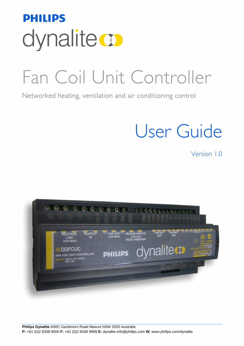
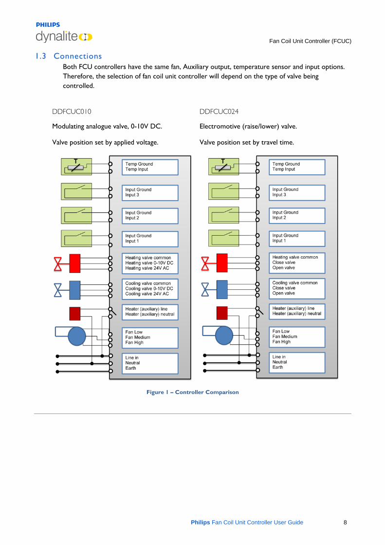
1.3 Connections Both FCU controllers have the same fan, Auxiliary output, temperature sensor and input options. Therefore, the selection of fan coil unit controller will depend on the type of valve being controlled.
DDFCUC010
Modulating analogue valve, 0-10V DC.
Valve position set by applied voltage.
DDFCUC024
Electromotive (raise/lower) valve.
Valve position set by travel time.
Figure 1 – Controller Comparison
Fan Coil Unit Controller (FCUC)
Philips Fan Coil Unit Controller User Guide 9
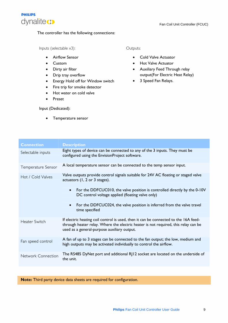
The controller has the following connections:
Inputs (selectable x3):
• Airflow Sensor • Custom • Dirty air filter • Drip tray overflow • Energy Hold off for Window switch • Fire trip for smoke detector • Hot water on cold valve • Preset
Input (Dedicated):
• Temperature sensor
Outputs:
• Cold Valve Actuator • Hot Valve Actuator • Auxiliary Feed Through relay
output(For Electric Heat Relay) • 3 Speed Fan Relays.
Connection Description
Selectable inputs Eight types of device can be connected to any of the 3 inputs. They must be configured using the EnvisionProject software.
Temperature Sensor A local temperature sensor can be connected to the temp sensor input.
Hot / Cold Valves Valve outputs provide control signals suitable for 24V AC floating or staged valve actuators (1, 2 or 3 stages).
• For the DDFCUC010, the valve position is controlled directly by the 0-10V DC control voltage applied (floating valve only)
• For the DDFCUC024, the valve position is inferred from the valve travel
time specified
Heater Switch If electric heating coil control is used, then it can be connected to the 16A feed-through heater relay. Where the electric heater is not required, this relay can be used as a general-purpose auxiliary output.
Fan speed control A fan of up to 3 stages can be connected to the fan output; the low, medium and high outputs may be activated individually to control the airflow.
Network Connection The RS485 DyNet port and additional RJ12 socket are located on the underside of the unit.
Note: Third party device data sheets are required for configuration.
Fan Coil Unit Controller (FCUC)
Philips Fan Coil Unit Controller User Guide 10
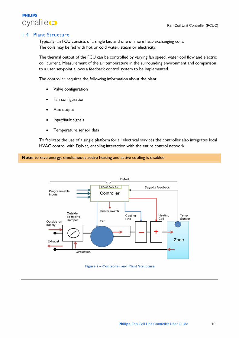
1.4 Plant Structure Typically, an FCU consists of a single fan, and one or more heat-exchanging coils. The coils may be fed with hot or cold water, steam or electricity.
The thermal output of the FCU can be controlled by varying fan speed, water coil flow and electric coil current. Measurement of the air temperature in the surrounding environment and comparison to a user set-point allows a feedback control system to be implemented.
The controller requires the following information about the plant
• Valve configuration
• Fan configuration
• Aux output
• Input/fault signals
• Temperature sensor data
To facilitate the use of a single platform for all electrical services the controller also integrates local HVAC control with DyNet, enabling interaction with the entire control network
Note: to save energy, simultaneous active heating and active cooling is disabled.
Figure 2 – Controller and Plant Structure
Fan Coil Unit Controller (FCUC)
Philips Fan Coil Unit Controller User Guide 11
1.5 Commissioning To complete the process of commissioning you will need to consider the following factors:
• Area climate specifications
• Environmental and usage factors
• Selection of areas to be controlled
• Number and location of controller units required (typically one per area)
• Plant hardware interface, capacity and limitations
• Lag times between control signal and effect
• Lower energy solutions
• Control scheme to be used
o PID control or
o Staged control
• Type of user interface
Note: you will need to refer to third party equipment specifications for performance parameter figures.
Mode
AirCon On/Off
Fan
Temp+ Temp-
21°CFan High
P8
P6
P5
P4
P3
P2
P1
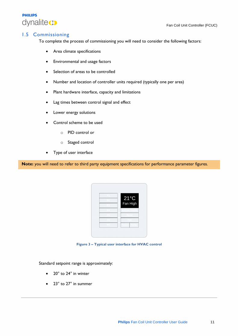
Figure 3 – Typical user interface for HVAC control
Standard setpoint range is approximately:
• 20° to 24° in winter
• 23° to 27° in summer
FCUC Initial Configuration
Philips Fan Coil Unit Controller User Guide 12
Envision
2 FCUC Initial Configuration
This topic covers configuration of the DDFCUC010 and DDFCUC024 Fan Coil Unit Controller using EnvisionProject. To end up with a fully configured controller perform the following tasks:
1. Load the device
2. Run the Configuration Wizard, FCUC Diagnostics and PID Tuning Wizard, if required
3. Configure Plant
4. Configure Temperature Control
5. Configure Switches
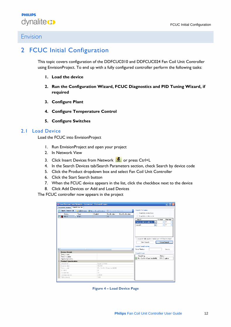
2.1 Load Device Load the FCUC into EnvisionProject
1. Run EnvisionProject and open your project 2. In Network View
3. Click Insert Devices from Network or press Ctrl+L 4. In the Search Devices tab/Search Parameters section, check Search by device code 5. Click the Product dropdown box and select Fan Coil Unit Controller 6. Click the Start Search button 7. When the FCUC device appears in the list, click the checkbox next to the device 8. Click Add Devices or Add and Load Devices
The FCUC controller now appears in the project
Figure 4 – Load Device Page
FCUC Initial Configuration
Philips Fan Coil Unit Controller User Guide 13
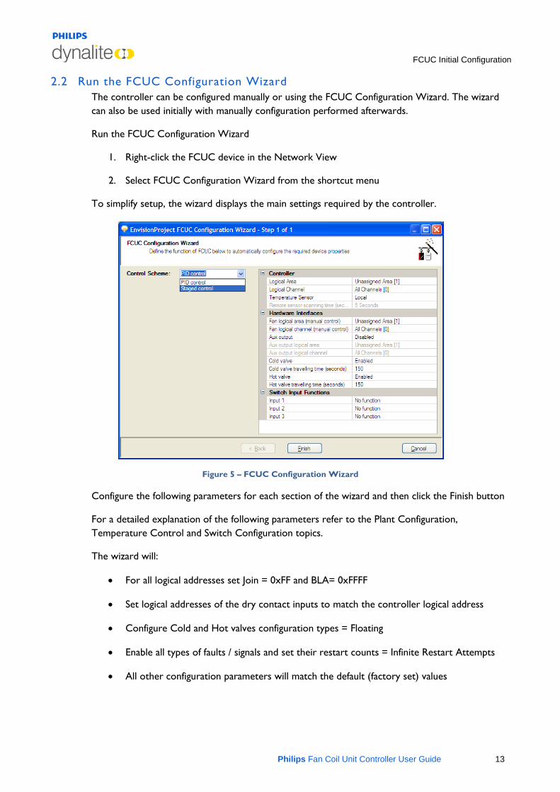
2.2 Run the FCUC Configuration Wizard The controller can be configured manually or using the FCUC Configuration Wizard. The wizard can also be used initially with manually configuration performed afterwards.
Run the FCUC Configuration Wizard
1. Right-click the FCUC device in the Network View
2. Select FCUC Configuration Wizard from the shortcut menu
To simplify setup, the wizard displays the main settings required by the controller.
Figure 5 – FCUC Configuration Wizard
Configure the following parameters for each section of the wizard and then click the Finish button
For a detailed explanation of the following parameters refer to the Plant Configuration, Temperature Control and Switch Configuration topics.
The wizard will:
• For all logical addresses set Join = 0xFF and BLA= 0xFFFF
• Set logical addresses of the dry contact inputs to match the controller logical address
• Configure Cold and Hot valves configuration types = Floating
• Enable all types of faults / signals and set their restart counts = Infinite Restart Attempts
• All other configuration parameters will match the default (factory set) values
FCUC Initial Configuration
Philips Fan Coil Unit Controller User Guide 14
2.3 Control Scheme Select the required scheme:
Control Scheme PID control/Staged control
2.4 Controller Define the controller parameters:
Controller logical area Assigned logical Area for plant control
Controller logical channel Assigned logical channel for plant control
Temperature Sensor Local/Remote (directly connected to the controller or connected via the DyNet network).
Remote sensor scanning time (seconds) Polling period for remote sensor(eg DTS9900). The default is 5.
2.5 Hardware Interfaces Define the hardware interfaces:
Fan logical area (manual control) Assigned logical Area for manual fan control
Fan logical channel (manual control) Assigned logical channel for manual fan control
Aux output Disabled/Manual/Heating/Cooling. If manual then specify Aux Output Logical Address
Aux output logical area (Aux output is set to Manual) Assigned logical Area for auxiliary output
Aux output logical channel (Aux output is set to Manual) Assigned logical channel auxiliary output
Cold valve Enabled/Disabled
Cold valve travelling time (seconds) Hot valve Enabled/Disabled
Hot valve travelling time (seconds) Enter parameter from plant manufacturers’ data sheet
2.6 Switch Input Functions Define the Switch Input Functions:
FCUC Initial Configuration
Philips Fan Coil Unit Controller User Guide 15
Input 1, 2 or 3 Airflow sensor/Dirty air filter/Drip tray overflow/Energy holdoff/Fire trip/Hot water on cold valve/Preset/No function

Configure Plant
Philips Fan Coil Unit Controller User Guide 16
3 Configure Plant
3.1 Plant configuration tab The Plant Configuration Tab contains settings for the Logical address, Temperature sensor, Valves, Fan, Aux output, faults/signals and runtime parameters.
The following buttons are available on the Plant Configuration toolbar.
• Displayed fields can be sorted in one of two ways by using the following buttons:
Categorized
Alphabetically
• Initially only the basic fields are shown. To reveal all fields
click the button. Most standard setups will not require the use of advanced parameters.
• The controller remembers the current settings for the setpoint, fan, aux output and Mode.
Click the button and then press F12 (Save to Device) to reset the currently operating values back to the default.
• To create a new setpoint temperature, enter a temperature in degrees Celsius in the box
on the toolbar and click the button. This is the desired temperature given to the FCUC to maintain. The setpoint can be overridden by DyNet logical opcode 0x48 until next message or reset.
The following fields are available on the Plant Configuration page.
Note: Standard Fields are shown in bold italics. Advanced fields are shown in standard italics.
3.2 Logical Address Controller logical area Set the area in which temperature control is to be used.
Controller logical channel Set the channels to be affected. Use the channel number or use All Channels (0).
Controller join Assign any join rows that are applicable using the join byte.
Controller BLA Enable/Disable Base Link Area.
Temperature Sensor
Configure Plant
Philips Fan Coil Unit Controller User Guide 17
Use local sensor True for a sensor directly connected to the DDFCUC010 and False when using a DTS900 on the network (the FCU controller can send logical DyNet messages to retrieve the temperature of the area from devices like DTS900).
Type of local sensor Type of local sensor. This option is to inform the device that, on-board temperature sensing circuitry is being used to retrieve the temperature of the area. Only NTC (Negative Temperature Coefficient) is supported at the moment
Remote sensor scanning time (Seconds) Polling period for DTS9900
Use initial setpoint on startup Use the initial setpoint temperature (°C) on plant start up
Initial setpoint (°C) Initial setpoint temperature (°C). This parameter defines the (starting) temperature set point for device whenever device resets. This set point is in effect until set point is changed by DyNet message. The parameter supports temperature in 0.01°C resolution. The range is -127.99°C to +127.99°C. The default is 22.00°C.
Measured temperature offset (°C) 0.1 degree increments to offset the temperature value of the sensor. The value defined for this parameter shall be added to the measured temperature before it is used by the FCUC. The valid range is -12.7°C to +12.7°C. The default is 0.0°C
Local sensor Enable / Disable direct sensor
Local sensor logarithmic True for Logarithmic and False for Linear
Local sensor logarithmic constant Value for logarithmic configuration, details available from sensor manufacturer
Local sensor logarithmic resistance Value for logarithmic configuration, details available from sensor manufacturer
Local sensor pullup resistor Value for local pull up resistor fitted on board, To change value; remove cover, use Jumper selection 1k or 22k (22k default)
Configure Plant
Philips Fan Coil Unit Controller User Guide 18
3.3 Valves Cold valve Enable/Disable cold valve. This option enables cooling control in FCU controller using a cold water system which is controlled by an electronically operated valve. The default is enabled
Cold valve configuration type Type of cold valve, choose from floating, 1 stage, 2 stage and 3 stage
• floating valve:
o This is the only option for the DDFCO010
o For the DDFCO024 this option is used to drive a valve which is controlled by two separate signals, either to open or close the valve. Specify the travel time to control the valve position and specify the ON & OFF Delay to prevent valve wear and tear.
• 1 stage valve: This option is used where a cooling system is controlled by only two states – ON and OFF. The non-zero value will activate both output signals, while the zero value will deactivate both output signals. User enters the On & Off time delay.
• 2 stage valve: This option is used if the cooling system has two ON stages. The zero value deactivates both output signals, 1-50% activate only one of output signal (i.e. valve open) and 51-100% activates both output signals. User enters On & Off time delay.
• 3 stage valve: This option will be used if the cooling system has three ON stages. The zero value deactivates both output signals, 1-33% activates only one of output signals (i.e. valve open), 34-66% activates only another output signal (i.e. valve close) and 67-100% activates both output signals. User enters the On & Off time delay.
Cold valve active high state True or false for staged valves only, used to set the default starting position for the valve
Allow hot water on cold valve True or False to allow heating and cooling using one valve
Cold valve travelling time (seconds) Time taken to go from fully closed to fully open. Valid time range is 1-600 seconds with 150 seconds as default. This time is used by FCUC to precisely control the valve position. The value for the parameter can be found in the valve datasheet.
Cold valve minimum on time (seconds) Minimum time the valve must be on before turning back off to prevent valve damage. The valid value range is 0-1200 seconds with 0 seconds used as default
Cold valve minimum off time (seconds) Minimum time the valve must be off before turning back on to prevent valve damage. The valid value range is 0-1200 seconds with 0 seconds used as default.
Configure Plant
Philips Fan Coil Unit Controller User Guide 19
Cold valve scheduled overrun period (hours) Default set to 24hrs, used to reset the valve to home position Range is 0-168 hours.
Hot valve Enable/Disable hot valve. This option enables heating control in FCU controller using a hot water system which is controlled by an electronically operated valve. The default is enabled
Hot valve configuration type Type of hot valve, choose from floating, 1 stage, 2 stage and 3 stage
• floating valve:
o This is the only option for the DDFCO010
o For the DDFCO024 this option is used to drive a valve which is controlled by two separate signals, either to open or close the valve. Specify the travel time to control the valve position and specify the ON & OFF Delay to prevent valve wear and tear.
• 1 stage valve: This option is used where a heating system is controlled by only two states – ON and OFF. The non-zero value will activate both output signals, while the zero value will deactivate both output signals. User enters the On & Off time delay.
• 2 stage valve: This option is used if heating system has two ON stages. The zero value deactivates both output signals, 1-50% will activate only one of output signals (i.e. valve open) and 51-100% will activate both output signals. User enters the On & Off time delay.
• 3 stage valve: This option is used if heating system has three ON stages. The zero value will deactivate both output signals, 1-33% will activate only one of output signals (i.e. valve open), 34-66% will activate only another output signal (i.e. valve close) and 67-100% will activate both output signals. User enters the On & Off time delay.
Hot valve active high state True or false for staged valves only, used to set the default starting position for the valve
Hot valve travelling time (seconds) Time taken to go from fully closed to fully open. Valid time range is 1-600 seconds with 150 seconds as default. This time is used by FCUC to precisely control the valve position. The value for the parameter can be found in the valve datasheet.
Hot valve minimum on time (seconds) Minimum time the valve must be on before turning back off to prevent valve damage. The valid value range is 0-1200 seconds with 0 seconds used as default
Hot valve minimum off time (seconds) Minimum time the valve must be off before turning back on to prevent valve damage. The valid value range is 0-1200 seconds with 0 seconds used as default.
Hot valve scheduled overrun period (hours) Default set to 24hrs, used to reset the valve to home position. Range is 0-168 hours.
Configure Plant
Philips Fan Coil Unit Controller User Guide 20
Valve min control efforts (%) Minimum % change in position required before the valve will be activated Prevents excessive valve wear
3.4 Fans Fan Enable/Disable. This option enables the fan control by FCUC. The default is enabled.
Fan logical area Assigned logical Area for fan control. Only used in manual mode
Fan logical channel Assigned logical channel for fan control. Only used in manual mode
Fan join Fan control join byte. Only used in manual mode
Fan BLA Enable/Disable Base Link Area for fan control. Only used in manual mode
Fan active high state True will close the relay when driver and False will open the relay when driven
Fan configuration type Fan type, select from 1 speed, 2 speed and 3 speed. Default option is 3 speeds.
1 speed fan: This option is used where fan only has ON and OFF control. The non-zero value will activate the Fan-L output signal, while zero value will deactivate the Fan-L output signal. Fan-M and Fan-H always remain deactivated.
2 speed fan: This option is used where fan has two ON states and OFF control. The value of 1-50% activates the Fan-L output signal, while values from 51-100% activates Fan-M output signal. Only one output signal is activated at any given time, while Fan-H will always remain deactivated.
3 speed fan: This option is used where fan has three ON states and OFF control. Values of 1-33% activate the Fan-L output signal, values from 34-66% activate the Fan-M output signal, while values from 67-100% activate the Fan-H output signal. Only one output signal can be activated at any given time.
Fan minimum on time (seconds) Minimum time the fan must be on before turning back off to prevent fan damage. The valid value range is 0-2400 seconds with 0 seconds used as default.
Fan minimum off time (seconds) Minimum time the fan must be off before turning back on to prevent fan damage. The valid value range is 0-2400 seconds with 0 seconds used as default.
Configure Plant
Philips Fan Coil Unit Controller User Guide 21
Fan runup time (seconds) Used to build up required air pressure in ducts, the airflow switch won’t work till the overrun time expires. During the run up time, both valves remain off. The valid value range is 0-1200 seconds with 0 seconds used as default.
Fan overrun time (seconds) The length of time the fan will run on after valve is closed. This period defines the extended period of time for which the fan will run once plant is shutdown, i.e. plant shut down request is received and both valves are in the fully closed position. Upon completion of the overrun time, the fan enters into an off delay period. This period will not apply in trip conditions. The valid value range is 0-1200 seconds with 0 seconds used as default.
3.5 Aux Output Aux output Enable/Disable Aux output
Aux output logical area Assigned logical Area for Aux output. Only used in manual mode
Aux output logical channel Assigned logical Channel for Aux output. Only used in manual mode
Aux output join Aux output join byte. Only used in manual mode
Aux output BLA Enable/Disable Base Link Area for Aux output. Only used in manual mode
Aux output active high state True will close the relay when driven and False will open the relay when driven
Aux output min on time (seconds) Minimum time the Aux output to remain on before turning back off to prevent damage. The valid value range is 0-7200 seconds with 0 seconds used as default
Aux output min off time (seconds) Minimum time the Aux output to remain off before turning back on to prevent damage. The valid value range is 0-7200 seconds with 0 seconds used as default.
Aux Output control Aux output control type. Choose from Manual, Temperature Controller Heating and Temperature Controller Cooling. Manual (by DyNet) is the default.
Note: If Aux Output control is set to Temperature Controller Heating/Cooling with PID control in effect, then the auxiliary output relay shall be used for heating/cooling purposes and not the hot/cold water valves.
Configure Plant
Philips Fan Coil Unit Controller User Guide 22
3.6 Fault Signals Fire trip Enable/Disable fire trip. This input is designed to integrate smoke detector devices to FCU. If enabled, plant (i.e. FCU control operation) will be tripped when the input is active.
Fire trip auto restart count Number of restarts allowed within one hour. This allows the plant to re-start automatically whenever fire trip condition is restored to normal
Fire trip fan off True/False. When smoke is detected, the fan speed is set to off if true or runs at high speed if false.
Energy holdoff Enable/Disable holdoff. This input is designed to integrate (room) window sensor to FCU controller. If enabled, plant (i.e. FCU control operation) will be tripped when input is active, i.e. window open.
Energy holdoff auto restart count Number of restarts allowed within one hour. This allows the plant to re-start automatically whenever window is closed.
Energy holdoff fan off True/False. When window open is detected, the fan speed is set to off if true or the fan runs at high speed if false
Air flow fault Enable/Disable air flow fault. This input is designed to integrate air flow sensing, i.e. fan failure to the FCU. If enabled, plant (i.e. FCU control operation) will be tripped when the input is active. This fault is not active during fan runup time.
Air flow fault auto restart count Number of restarts allowed within one hour
Air flow fault fan off True/False, Fan speed to full
Sensor fault Enable/Disable sensor fault. Refers to temperature sensor
Sensor fault auto restart count Number of restarts allowed within one hour. Refers to temperature sensor
Sensor fault fan off True/False, Refers to temperature sensor. True is fan speed to off. False is fan speed to full.
Drip tray Enable/Disable drip tray
Drip tray auto restart count Number of restarts allowed within one hour
Configure Plant
Philips Fan Coil Unit Controller User Guide 23
Drip tray fan off True/False, Fan speed to full
Dirty filter Enable/Disable dirty filter
Dirty filler auto restart count Number of restarts allowed within one hour
Dirty filter fan off True/False, Fan speed to full
Note: By default all fault signals are enabled and auto restart is enabled. Auto restart count allows the user to configure, how many reset attempts can be made before the plant is permanently shut down. The possible values are None, One, Two and Infinite. The default option is Infinite restart attempts. Once plant permanently shuts down, then user needs to reset the fault state (to normal) by sending DyNet message (physical DyNet message opcode - 0x5B) once fault is restored and plant needs to start again.
3.7 Runtime Parameters
These parameters are read-only. They can be cleared by clicking the button and then pressing F12 (Save to Device).
Last known valid preset Last known preset used
Last known manual fan speed Last known fan speed used
Last known aux output level Last known aux output level used
Last known temperature setpoint (°C) Last known temperature used
Configure Temperature Control
Philips Fan Coil Unit Controller User Guide 24
4 Configure Temperature Control
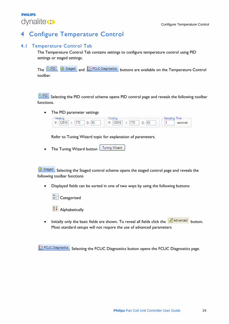
4.1 Temperature Control Tab The Temperature Control Tab contains settings to configure temperature control using PID settings or staged settings.
The , and buttons are available on the Temperature Control toolbar.
Selecting the PID control scheme opens PID control page and reveals the following toolbar functions.
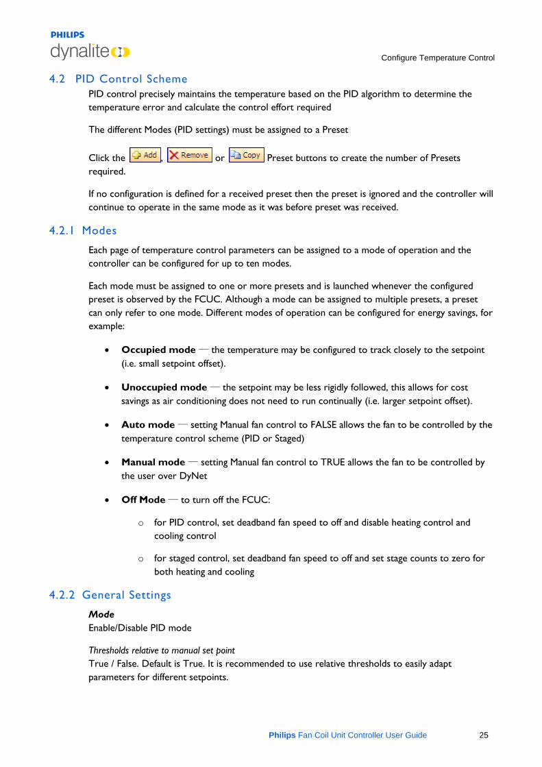
• The PID parameter settings
Refer to Tuning Wizard topic for explanation of parameters.
• The Tuning Wizard button
Selecting the Staged control scheme opens the staged control page and reveals the following toolbar functions
• Displayed fields can be sorted in one of two ways by using the following buttons:
Categorised
Alphabetically
• Initially only the basic fields are shown. To reveal all fields click the button. Most standard setups will not require the use of advanced parameters
Selecting the FCUC Diagnostics button opens the FCUC Diagnostics page.
Configure Temperature Control
Philips Fan Coil Unit Controller User Guide 25
4.2 PID Control Scheme PID control precisely maintains the temperature based on the PID algorithm to determine the temperature error and calculate the control effort required
The different Modes (PID settings) must be assigned to a Preset
Click the , or Preset buttons to create the number of Presets required.
If no configuration is defined for a received preset then the preset is ignored and the controller will continue to operate in the same mode as it was before preset was received.
4.2.1 Modes
Each page of temperature control parameters can be assigned to a mode of operation and the controller can be configured for up to ten modes.
Each mode must be assigned to one or more presets and is launched whenever the configured preset is observed by the FCUC. Although a mode can be assigned to multiple presets, a preset can only refer to one mode. Different modes of operation can be configured for energy savings, for example:
• Occupied mode ― the temperature may be configured to track closely to the setpoint (i.e. small setpoint offset).
• Unoccupied mode ― the setpoint may be less rigidly followed, this allows for cost savings as air conditioning does not need to run continually (i.e. larger setpoint offset).
• Auto mode ― setting Manual fan control to FALSE allows the fan to be controlled by the temperature control scheme (PID or Staged)
• Manual mode ― setting Manual fan control to TRUE allows the fan to be controlled by the user over DyNet
• Off Mode ― to turn off the FCUC:
o for PID control, set deadband fan speed to off and disable heating control and cooling control
o for staged control, set deadband fan speed to off and set stage counts to zero for both heating and cooling
4.2.2 General Settings
Mode Enable/Disable PID mode
Thresholds relative to manual set point True / False. Default is True. It is recommended to use relative thresholds to easily adapt parameters for different setpoints.
Configure Temperature Control
Philips Fan Coil Unit Controller User Guide 26
Manual fan control True / False. False is the default value. Setting the manual fan control to true will disable PID control of the fan and fan will be controlled directly over DyNet.
Heating/Cooling switch over delay (seconds) Time in seconds to delay switching between heating and cooling modes. If setpoint change switches over then this delay is not applied. The default is 1800 seconds and range is 0-65534 seconds.
Dead band fan speed This field defines the fan speed when neither heating nor cooling is in operation. This typically happens when the measured temperature is between the (effective) heating & cooling set point. Refer to Cooling/Heating offset for effective dead band. The fan shall also run on dead band speed, whenever system is inside the heating/cooling switch over delay period. The possible fan speeds are High, Mid, Low or Off
4.2.3 Cooling Parameters
Cooling control Enable/Disable
Cooling setpoint offset (°C) Offset to temperature cooling setpoint. This parameter accepts value in units of 0.1 °C with the range of 0.0 to 10.0 °C. The default is 0.5 °C.
Cooling temperature error to run fan at low speed (°C) Temperature differential to use low fan speed setting
Cooling temperature error to run at mid speed (°C) Temperature differential to use med fan speed setting
Cooling temperature error to run at high speed (°C) Temperature differential to use high fan speed setting
4.2.4 Heating Parameters
Heating control Enable/Disable
Heating setpoint offset (°C) Offset to temperature heating setpoint. This parameter accepts value in units of 0.1 °C with the range of 0.0 to 10.0 °C. The default is 0.5 °C.
Heating temperature error to run at low speed (°C) Temperature differential to use low fan speed setting
Heating temperature error to run at mid speed (°C) Temperature differential to use med fan speed setting
Heating temperature error to run at high speed (°C) Temperature differential to use high fan speed setting
Configure Temperature Control
Philips Fan Coil Unit Controller User Guide 27
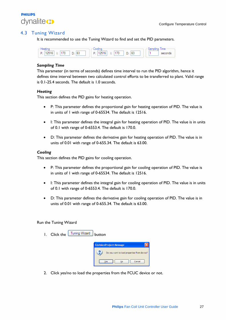
4.3 Tuning Wizard It is recommended to use the Tuning Wizard to find and set the PID parameters.
Sampling Time This parameter (in terms of seconds) defines time interval to run the PID algorithm, hence it defines time interval between two calculated control efforts to be transferred to plant. Valid range is 0.1-25.4 seconds. The default is 1.0 seconds.
Heating This section defines the PID gains for heating operation.
• P: This parameter defines the proportional gain for heating operation of PID. The value is in units of 1 with range of 0-65534. The default is 12516.
• I: This parameter defines the integral gain for heating operation of PID. The value is in units of 0.1 with range of 0-6553.4. The default is 170.0.
• D: This parameter defines the derivative gain for heating operation of PID. The value is in units of 0.01 with range of 0-655.34. The default is 63.00.
Cooling This section defines the PID gains for cooling operation.
• P: This parameter defines the proportional gain for cooling operation of PID. The value is in units of 1 with range of 0-65534. The default is 12516.
• I: This parameter defines the integral gain for cooling operation of PID. The value is in units of 0.1 with range of 0-6553.4. The default is 170.0.
• D: This parameter defines the derivative gain for cooling operation of PID. The value is in units of 0.01 with range of 0-655.34. The default is 63.00.
Run the Tuning Wizard
1. Click the button
2. Click yes/no to load the properties from the FCUC device or not.
Configure Temperature Control
Philips Fan Coil Unit Controller User Guide 28
When the wizard starts-up it can optionally load the temperature control settings from the device. Otherwise it will take the existing configuration from the EnvisionProject job.
The tuning of each function should be performed under real operating conditions for example, tuning for the heating function may not be appropriate during summer or tuning for cooling in winter will not simulate real operating conditions.
Tuning the controller consists of setting some initial parameters and using these parameters over a period of time to collect the measured room temperature and observe the performance of the controller.
Tuning heating and cooling cannot be performed at the same time. Active heating and cooling is not permitted by the controller.
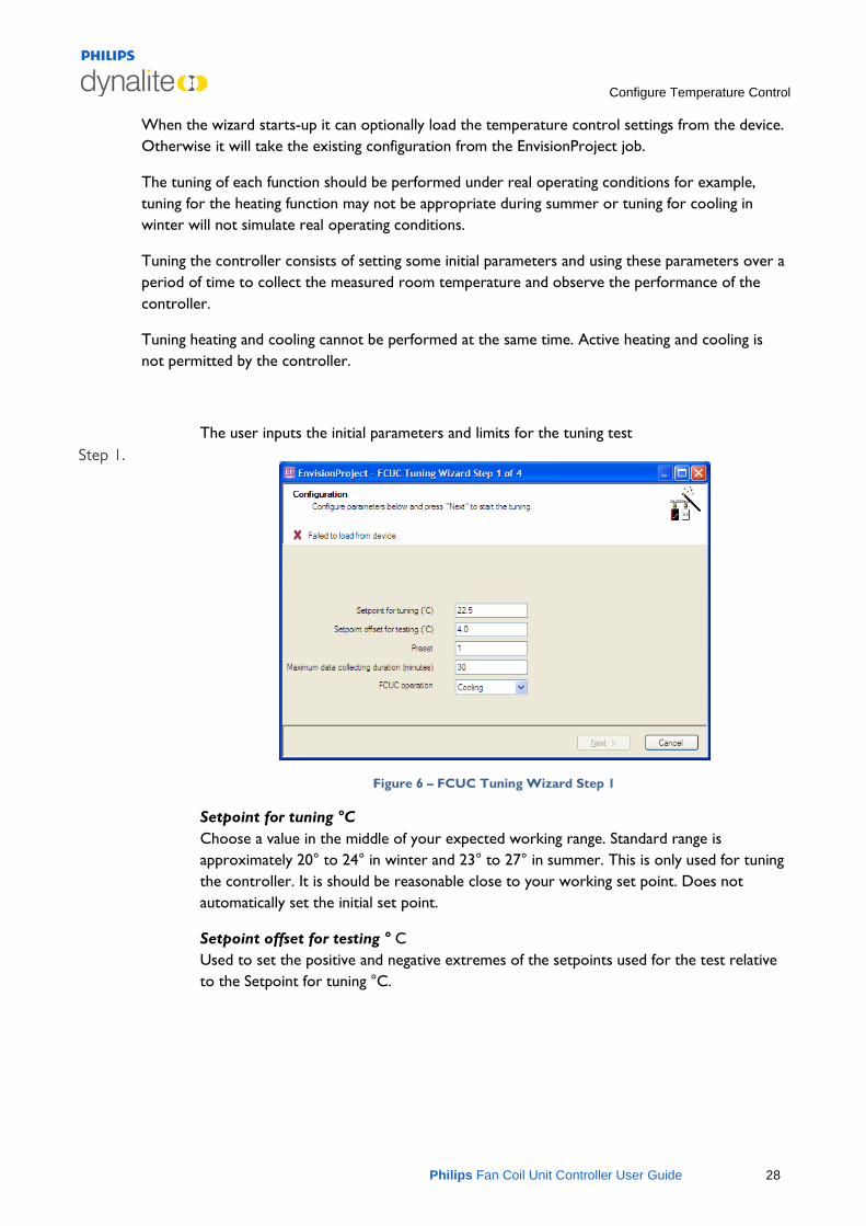
Step 1. The user inputs the initial parameters and limits for the tuning test
Figure 6 – FCUC Tuning Wizard Step 1
Setpoint for tuning °C Choose a value in the middle of your expected working range. Standard range is approximately 20° to 24° in winter and 23° to 27° in summer. This is only used for tuning the controller. It is should be reasonable close to your working set point. Does not automatically set the initial set point.
Setpoint offset for testing ° C Used to set the positive and negative extremes of the setpoints used for the test relative to the Setpoint for tuning °C.
Configure Temperature Control
Philips Fan Coil Unit Controller User Guide 29
Preset This is the preset used during the tuning test. PID parameters found during the tuning are applicable in all operating modes however, the function selected for tuning (heating or cooling) should match mode assigned to the preset.
Operation of controller is preset based and the controller must be in preset at any given time. This preset is used during the tuning
Maximum data collecting duration (minutes) This is when the wizard will stop collecting data. The tuning wizard looks for 3 full periods of oscillation around the setpoint for a successful test. Normally the test is completed once the test criteria are met. Otherwise the test will fail at the time limit set.
FCUC operation Used to set the appropriate function (heating or cooling). The controller can only tune for heating and cooling independently.
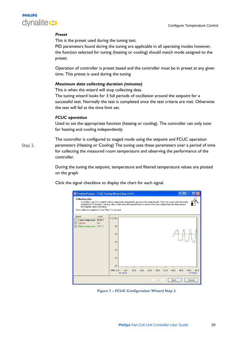
Step 2. The controller is configured to staged mode using the setpoint and FCUC operation parameters (Heating or Cooling) The tuning uses these parameters over a period of time for collecting the measured room temperature and observing the performance of the controller.
During the tuning the setpoint, temperature and filtered temperature values are plotted on the graph
Click the signal checkbox to display the chart for each signal.
Figure 7 – FCUC Configuration Wizard Step 2
Configure Temperature Control
Philips Fan Coil Unit Controller User Guide 30
Press the Start button to begin data collection
Press the skip button to go to the next step. You can skip data collection if you already have some approximate values for PID. It will save time if you have used another tuning tool or have commissioned similar areas before.
Once the data collection is started the wizard configures FCUC to single stage mode with no hysteresis and hot or cold valves and fan set to 100 %. Then the wizard starts collecting data required to evaluate PID coefficients. This includes polling the temperature, the setpoint and status of the FCUC.
If the value of setpoint changes or the function changes between cooling and heating then the tuning wizard will stop and display an error message.
When enough data is collected then the "Next" button becomes enabled. The "Start" button remains disabled while the data is being collected.
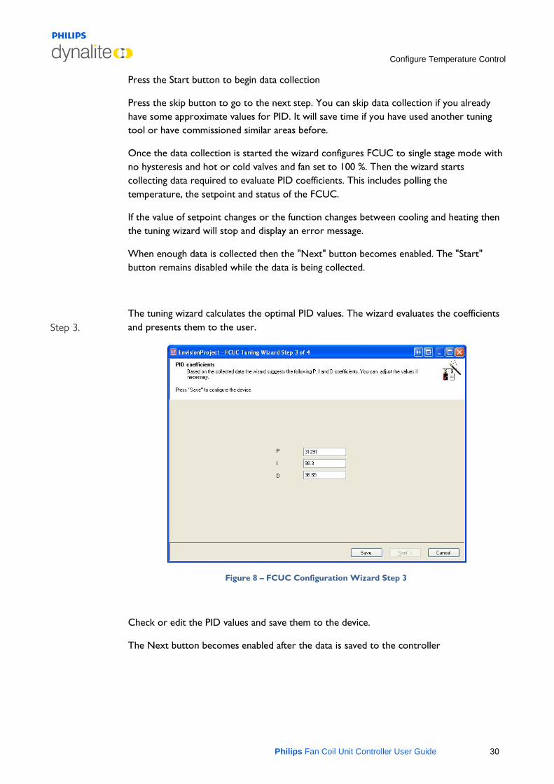
Step 3. The tuning wizard calculates the optimal PID values. The wizard evaluates the coefficients and presents them to the user.
Figure 8 – FCUC Configuration Wizard Step 3
Check or edit the PID values and save them to the device.
The Next button becomes enabled after the data is saved to the controller
Configure Temperature Control
Philips Fan Coil Unit Controller User Guide 31
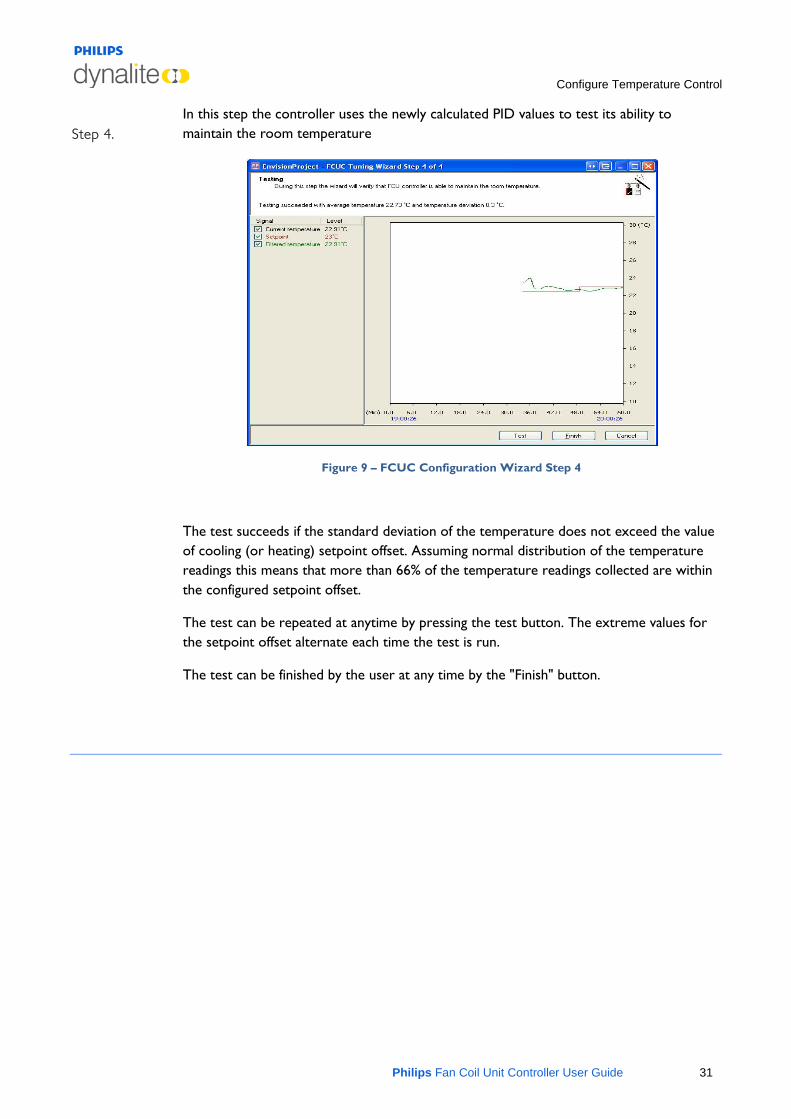
Step 4. In this step the controller uses the newly calculated PID values to test its ability to maintain the room temperature
Figure 9 – FCUC Configuration Wizard Step 4
The test succeeds if the standard deviation of the temperature does not exceed the value of cooling (or heating) setpoint offset. Assuming normal distribution of the temperature readings this means that more than 66% of the temperature readings collected are within the configured setpoint offset.
The test can be repeated at anytime by pressing the test button. The extreme values for the setpoint offset alternate each time the test is run.
The test can be finished by the user at any time by the "Finish" button.
Configure Temperature Control
Philips Fan Coil Unit Controller User Guide 32
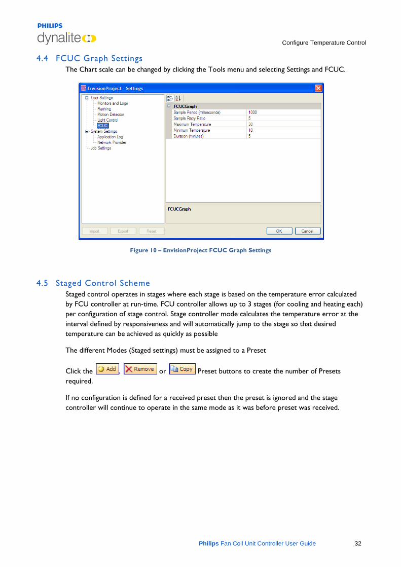
4.4 FCUC Graph Settings The Chart scale can be changed by clicking the Tools menu and selecting Settings and FCUC.
Figure 10 – EnvisionProject FCUC Graph Settings
4.5 Staged Control Scheme Staged control operates in stages where each stage is based on the temperature error calculated by FCU controller at run-time. FCU controller allows up to 3 stages (for cooling and heating each) per configuration of stage control. Stage controller mode calculates the temperature error at the interval defined by responsiveness and will automatically jump to the stage so that desired temperature can be achieved as quickly as possible
The different Modes (Staged settings) must be assigned to a Preset
Click the , or Preset buttons to create the number of Presets required.
If no configuration is defined for a received preset then the preset is ignored and the stage controller will continue to operate in the same mode as it was before preset was received.
Configure Temperature Control
Philips Fan Coil Unit Controller User Guide 33
4.5.1 Modes
Each page of temperature control parameters can be assigned to a mode of operation and the controller can be configured for up to ten modes. Each mode must be assigned to one or more presets and is launched whenever the configured preset is observed by FCUC. Although a mode can be assigned to multiple presets, a preset can only refer to one mode.
Different modes of operation can be configured for energy savings, for example:
• Occupied mode ― the temperature may be configured to track closely to the setpoint (i.e. small setpoint offset).
• Unoccupied mode ― the setpoint may be less rigidly followed, this allows for cost savings as air conditioning does not need to run continually (i.e. larger setpoint offset).
• Auto mode ― setting Manual fan control to FALSE allows the fan to be controlled by the temperature control scheme (PID or Staged)
• Manual mode ― setting Manual fan control to TRUE allows the fan to be controlled by the user over DyNet
• Off Mode ― to turn off the FCUC:
o for PID control, set deadband fan speed to off and disable heating control and cooling control
o for staged control, set deadband fan speed to off and set stage counts to zero for both heating and cooling
4.5.2 General Settings
Mode Enable/Disable
Thresholds relative to manual set point True / False
Manual fan control True / False
Responsiveness (seconds) Default or time setting. This parameter defines the time delay to re-evaluate the stage. Valid range is 1-30 seconds with default of 5 seconds
Cooling stage hysteresis (°C) The intention of heating hysteresis is to avoid oscillation between two heating stages whenever the heating stage boundary is approached. The hysteresis applies in both directions. For example, if the heating stage changes from 2nd to 3rd at 15 °C, then by adding 0.5 hysteresis the heating effort for stage-3 starts when temperature falls below 14.5°C then moves to stage-2 when the temperature rises to 15.5°C. The value is in units of 0.25°C with range of 0.0-3.5°C. The default is 0.25°C
Configure Temperature Control
Philips Fan Coil Unit Controller User Guide 34
Heating stage hysteresis (°C) The intention of cooling hysteresis is to avoid oscillation between two cooling stages whenever the cooling stage boundary is approached. The hysteresis applies in both directions. For example, if the cooling stage changes from 2nd to 3rd at 25°C then by adding 0.5 hysteresis the cooling effort for stage-3 starts when the temperature exceeds 25.5 °C then moves to stage-2 when the temperature drops to 24.5°C. The value is in units of 0.25 °C with range of 0.0-3.5 °C. The default is 0.25 °C.
4.5.3 Stage Counts
Cooling stage count Number of stages available for configuration (0-3). Zero disables cooling
Heating stage count Number of stages available for configuration (0-3). Zero disables heating
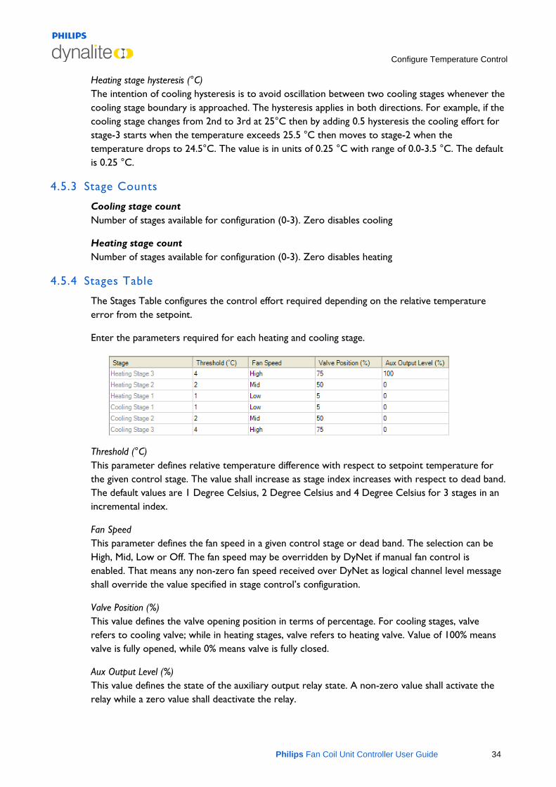
4.5.4 Stages Table
The Stages Table configures the control effort required depending on the relative temperature error from the setpoint.
Enter the parameters required for each heating and cooling stage.
Threshold (°C) This parameter defines relative temperature difference with respect to setpoint temperature for the given control stage. The value shall increase as stage index increases with respect to dead band. The default values are 1 Degree Celsius, 2 Degree Celsius and 4 Degree Celsius for 3 stages in an incremental index.
Fan Speed This parameter defines the fan speed in a given control stage or dead band. The selection can be High, Mid, Low or Off. The fan speed may be overridden by DyNet if manual fan control is enabled. That means any non-zero fan speed received over DyNet as logical channel level message shall override the value specified in stage control’s configuration.
Valve Position (%) This value defines the valve opening position in terms of percentage. For cooling stages, valve refers to cooling valve; while in heating stages, valve refers to heating valve. Value of 100% means valve is fully opened, while 0% means valve is fully closed.
Aux Output Level (%) This value defines the state of the auxiliary output relay state. A non-zero value shall activate the relay while a zero value shall deactivate the relay.
Configure Temperature Control
Philips Fan Coil Unit Controller User Guide 35
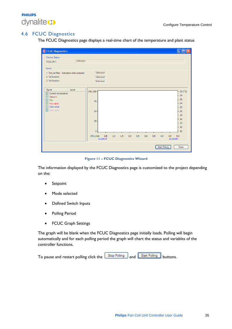
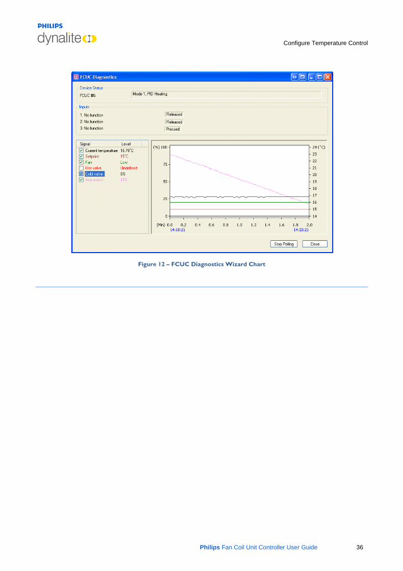
4.6 FCUC Diagnostics The FCUC Diagnostics page displays a real-time chart of the temperature and plant status
Figure 11 – FCUC Diagnostics Wizard
The information displayed by the FCUC Diagnostics page is customized to the project depending on the:
• Setpoint
• Mode selected
• Defined Switch Inputs
• Polling Period
• FCUC Graph Settings
The graph will be blank when the FCUC Diagnostics page initially loads. Polling will begin automatically and for each polling period the graph will chart the status and variables of the controller functions.
To pause and restart polling click the and buttons.
Configure Temperature Control
Philips Fan Coil Unit Controller User Guide 36
Figure 12 – FCUC Diagnostics Wizard Chart
Configure Switches
Philips Fan Coil Unit Controller User Guide 37
5 Configure Switches
5.1 Switch Configuration Tab The Switches tab contains settings to configure the input switches for the controller.
The following buttons are available on the Switch Configuration toolbar.
• Displayed fields can be sorted in one of two ways by using the following buttons:
Categorized
Alphabetically
• Initially only the basic fields are shown. To reveal all fields
click the button. Most standard setups will not require the use of advanced parameters.
5.1.1 General
Switches Enable/Disable. Affects all switches
5.1.2 Logical Addresses
logical Area Set the area where the switch will be used.
logical Channel Set the channels to be affected. Use the channel number or use All Channels (0).
Controller join Assign any join rows that are applicable using the join byte.
Controller BLA Enable/Disable Base Link Area.
5.1.3 Advanced
Channel Enable/Disable
Enabled when panel disabled True/False. Function is still available in panic mode
Trigger at startup True/False. Switch action is force triggered at startup. Defined action will be executed based on switch state (ie pressed or released) when device is reset.
Configure Switches
Philips Fan Coil Unit Controller User Guide 38
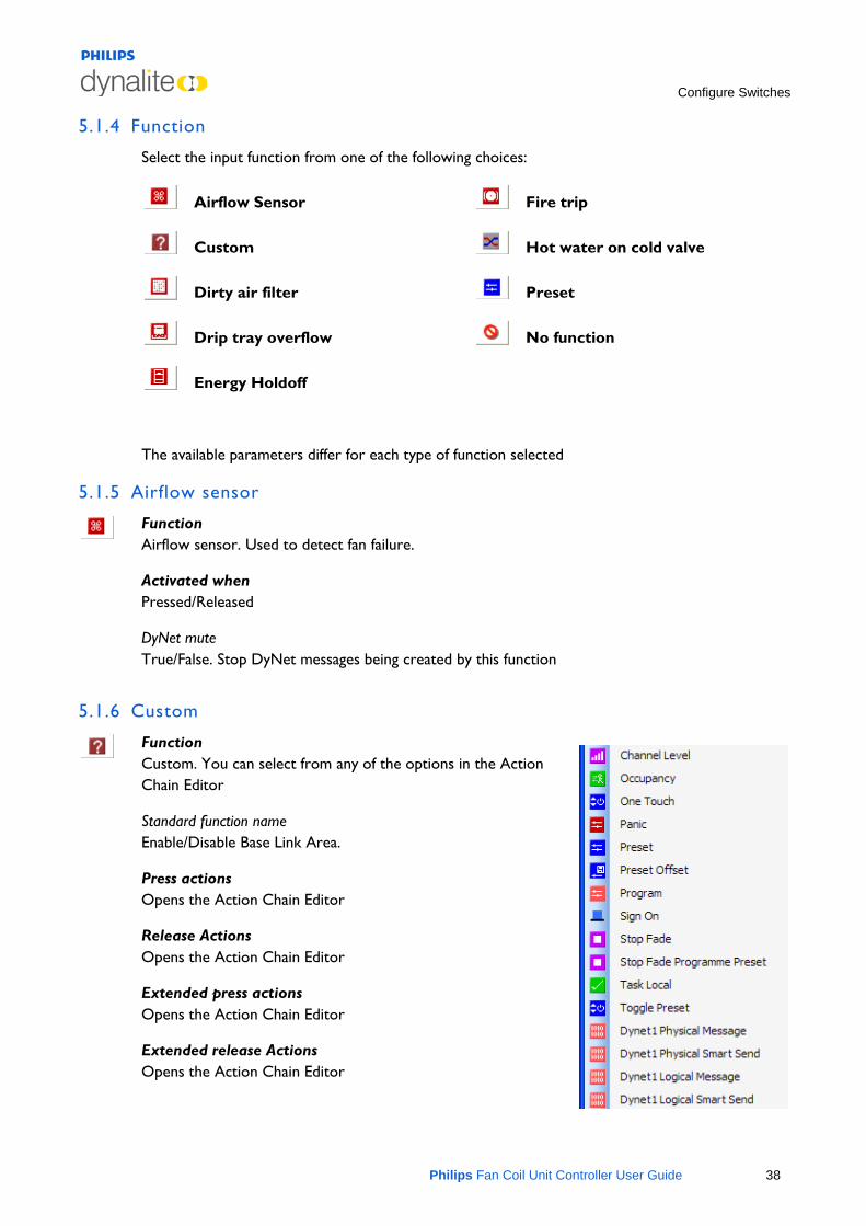
5.1.4 Function
Select the input function from one of the following choices:
Airflow Sensor
Custom
Dirty air filter
Drip tray overflow
Energy Holdoff
Fire trip
Hot water on cold valve
Preset
No function
The available parameters differ for each type of function selected
5.1.5 Airflow sensor
Function Airflow sensor. Used to detect fan failure.
Activated when Pressed/Released
DyNet mute True/False. Stop DyNet messages being created by this function
5.1.6 Custom
Function Custom. You can select from any of the options in the Action Chain Editor
Standard function name Enable/Disable Base Link Area.
Press actions Opens the Action Chain Editor
Release Actions Opens the Action Chain Editor
Extended press actions Opens the Action Chain Editor
Extended release Actions Opens the Action Chain Editor
Configure Switches
Philips Fan Coil Unit Controller User Guide 39
5.1.7 Dirty air filter
5.1.8 Drip tray overflow
5.1.9 Energy Holdoff
5.1.10 Fire trip
Function Dirty air filter. Used to indicate air filter is dirty and requires cleaning.
Activated when Pressed/Released
DyNet mute True/False. Stop DyNet messages being created by this function.
Function Drip tray overflow. The drip tray is full with water and needs draining.
Activated when Pressed/Released
DyNet mute True/False. Stop DyNet messages being created by this function.
Function Energy Holdoff. Also known as window switch. Used to turn off the plant when window is open to conserve energy.
Activated when Pressed/Released
DyNet mute True/False. Stop DyNet messages being created by this function
Function Fire trip. Used to detect smoke.
Activated when Pressed/Released
DyNet mute True/False. Stop DyNet messages being created by this function.
Configure Switches
Philips Fan Coil Unit Controller User Guide 40
5.1.11 Hot water on cold valve
5.1.12 Preset
5.1.13 No function
Function Hot water on cold valve. Used to specify that hot water is available on the cold water valve.
Activated when Pressed/Released
DyNet mute True/False. Stop DyNet messages being created by this function.
Function Preset. Used to recall a preset function over DyNet.
Preset Pressed/Released
Fade (rounded to 10 ms) 00:00:00:010 (hh:mm:ss:fff)
DyNet mute True/False. Stop DyNet messages being created by this function.
Function No function. Switch is not used
Activated when Pressed/Released
DyNet mute Enable/Disable Base Link Area.
DyNet Interface
Philips Fan Coil Unit Controller User Guide 41
6 DyNet Interface
This section lists DyNet messages added for FCUC which are not readily accessible from EnvisionProject using the GUI. It also lists some of the other DyNet messages intended for use in typical HVAC situations.
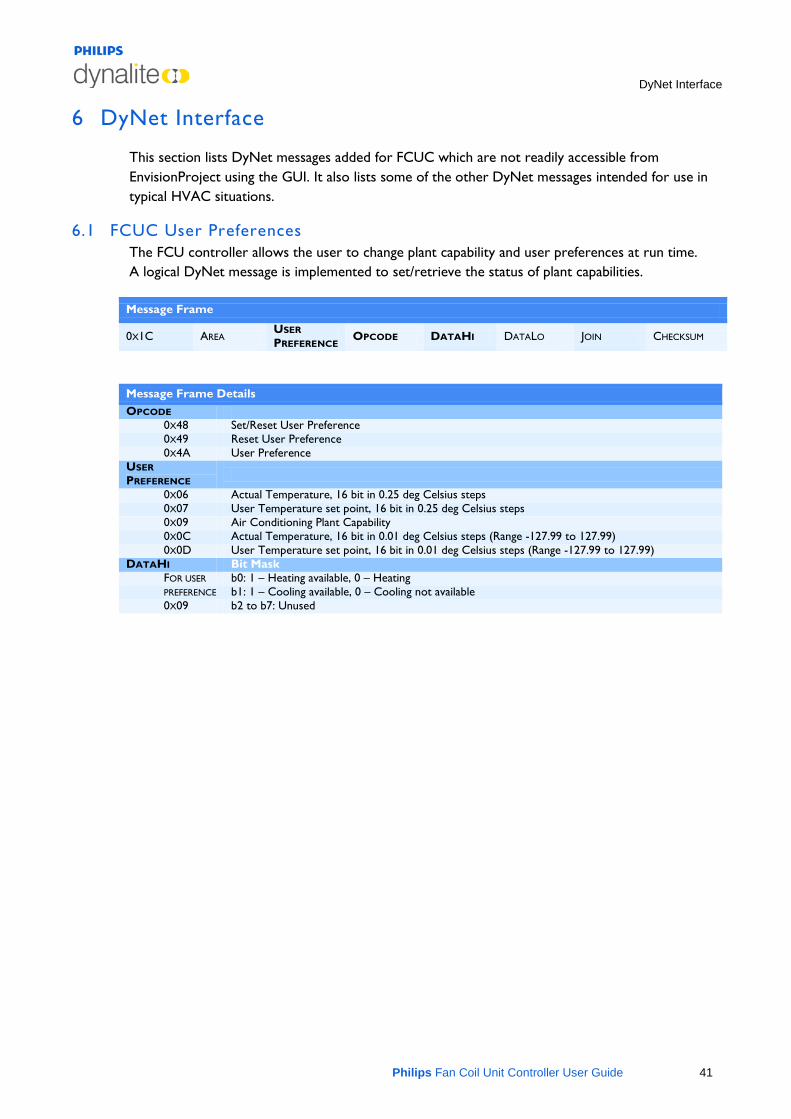
6.1 FCUC User Preferences The FCU controller allows the user to change plant capability and user preferences at run time. A logical DyNet message is implemented to set/retrieve the status of plant capabilities.
Message Frame
0X1C AREA USER PREFERENCE OPCODE DATAHI DATALO JOIN CHECKSUM
Message Frame Details OPCODE
0X48 Set/Reset User Preference 0X49 Reset User Preference 0X4A User Preference
USER PREFERENCE
0X06 Actual Temperature, 16 bit in 0.25 deg Celsius steps 0X07 User Temperature set point, 16 bit in 0.25 deg Celsius steps 0X09 Air Conditioning Plant Capability 0X0C Actual Temperature, 16 bit in 0.01 deg Celsius steps (Range -127.99 to 127.99) 0X0D User Temperature set point, 16 bit in 0.01 deg Celsius steps (Range -127.99 to 127.99)
DATAHI Bit Mask FOR USER b0: 1 – Heating available, 0 – Heating PREFERENCE b1: 1 – Cooling available, 0 – Cooling not available 0X09 b2 to b7: Unused
DyNet Interface
Philips Fan Coil Unit Controller User Guide 42
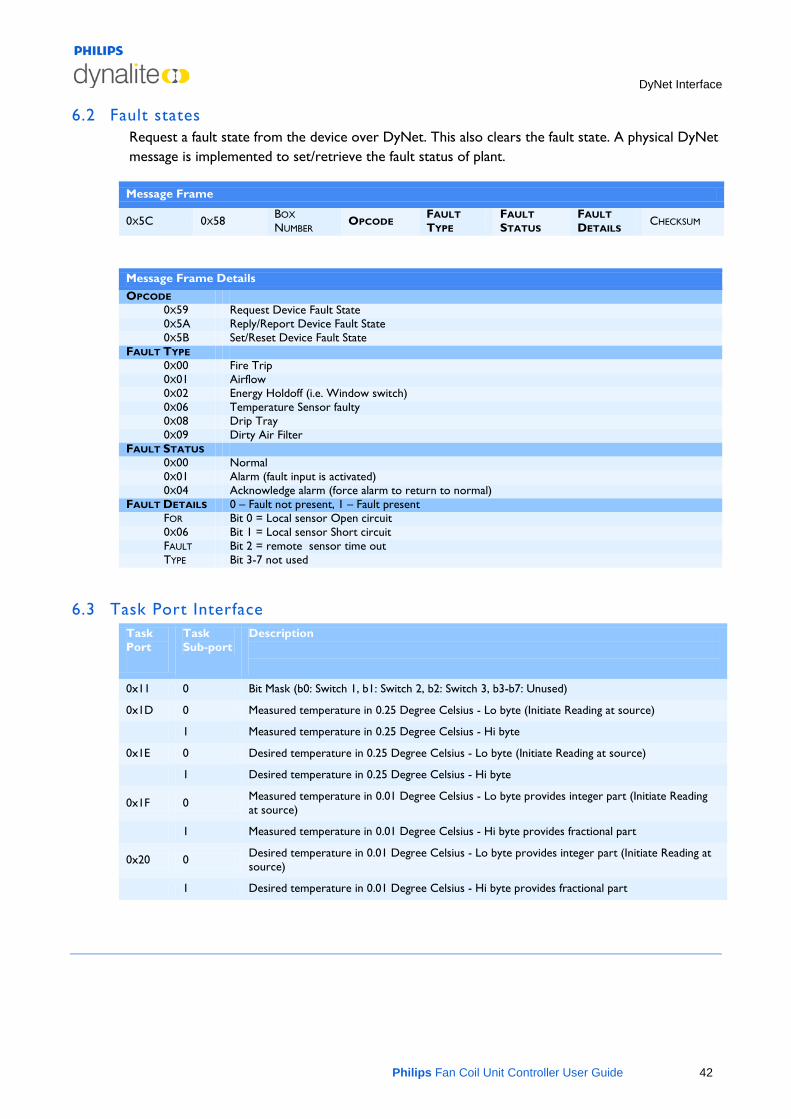
6.2 Fault states Request a fault state from the device over DyNet. This also clears the fault state. A physical DyNet message is implemented to set/retrieve the fault status of plant.
Message Frame
0X5C 0X58 BOX
NUMBER OPCODE FAULT TYPE
FAULT STATUS
FAULT DETAILS CHECKSUM
Message Frame Details OPCODE
0X59 Request Device Fault State 0X5A Reply/Report Device Fault State 0X5B Set/Reset Device Fault State
FAULT TYPE 0X00 Fire Trip 0X01 Airflow 0X02 Energy Holdoff (i.e. Window switch) 0X06 Temperature Sensor faulty 0X08 Drip Tray 0X09 Dirty Air Filter
FAULT STATUS 0X00 Normal 0X01 Alarm (fault input is activated) 0X04 Acknowledge alarm (force alarm to return to normal)
FAULT DETAILS 0 – Fault not present, 1 – Fault present FOR Bit 0 = Local sensor Open circuit 0X06 Bit 1 = Local sensor Short circuit FAULT Bit 2 = remote sensor time out TYPE Bit 3-7 not used
6.3 Task Port Interface Task Port
Task Sub-port
Description
0x11 0 Bit Mask (b0: Switch 1, b1: Switch 2, b2: Switch 3, b3-b7: Unused)
0x1D 0 Measured temperature in 0.25 Degree Celsius - Lo byte (Initiate Reading at source)
1 Measured temperature in 0.25 Degree Celsius - Hi byte
0x1E 0 Desired temperature in 0.25 Degree Celsius - Lo byte (Initiate Reading at source)
1 Desired temperature in 0.25 Degree Celsius - Hi byte
0x1F 0 Measured temperature in 0.01 Degree Celsius - Lo byte provides integer part (Initiate Reading at source)
1 Measured temperature in 0.01 Degree Celsius - Hi byte provides fractional part
0x20 0 Desired temperature in 0.01 Degree Celsius - Lo byte provides integer part (Initiate Reading at source)
1 Desired temperature in 0.01 Degree Celsius - Hi byte provides fractional part
Field Descriptions
Philips Fan Coil Unit Controller User Guide 43
7 Field Descriptions
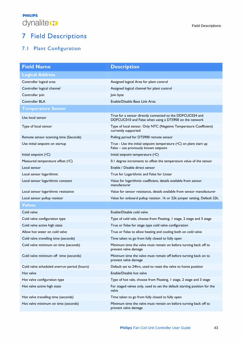
7.1 Plant Configuration
Field Name Description Logical Address Controller logical area Assigned logical Area for plant control
Controller logical channel Assigned logical channel for plant control
Controller join Join byte
Controller BLA Enable/Disable Base Link Area
Temperature Sensor
Use local sensor True for a sensor directly connected to the DDFCUC024 and DDFCUC010 and False when using a DTS900 on the network
Type of local sensor Type of local sensor. Only NTC (Negative Temperature Coefficient) currently supported
Remote sensor scanning time (Seconds) Polling period for DTS900 remote sensor
Use initial setpoint on startup True - Use the initial setpoint temperature (oC) on plant start up False – use previously known setpoint
Initial setpoint (oC) Initial setpoint temperature (oC)
Measured temperature offset (oC) 0.1 degree increments to offset the temperature value of the sensor
Local sensor Enable / Disable direct sensor
Local sensor logarithmic True for Logarithmic and False for Linear
Local sensor logarithmic constant Value for logarithmic coefficient, details available from sensor manufacturer
Local sensor logarithmic resistance Value for sensor resistance, details available from sensor manufacturer
Local sensor pullup resistor Value for onboard pullup resistor. 1k or 22k jumper setting. Default 22k.
Valves
Cold valve Enable/Disable cold valve
Cold valve configuration type Type of cold vale, choose from Floating, 1 stage, 2 stage and 3 stage
Cold valve active high state True or False for stage type cold valve configuration
Allow hot water on cold valve True or False to allow heating and cooling both on cold valve
Cold valve travelling time (seconds) Time taken to go from fully closed to fully open
Cold valve minimum on time (seconds) Minimum time the valve must remain on before turning back off to prevent valve damage
Cold valve minimum off time (seconds) Minimum time the valve must remain off before turning back on to prevent valve damage
Cold valve scheduled overrun period (hours) Default set to 24hrs, used to reset the valve to home position
Hot valve Enable/Disable hot valve
Hot valve configuration type Type of hot vale, choose from Floating, 1 stage, 2 stage and 3 stage
Hot valve active high state For staged valves only, used to set the default starting position for the valve
Hot valve travelling time (seconds) Time taken to go from fully closed to fully open
Hot valve minimum on time (seconds) Minimum time the valve must remain on before turning back off to prevent valve damage
Field Descriptions
Philips Fan Coil Unit Controller User Guide 44
Hot valve minimum off time (seconds) Minimum time the valve must remain off before turning back on to prevent valve damage
Hot valve scheduled overrun period (hours) Default set to 24hrs, used to reset the valve to home position
Valve min control efforts (%) Minimum % change in control effort required before the valve will be activated. Prevents excessive valve wear
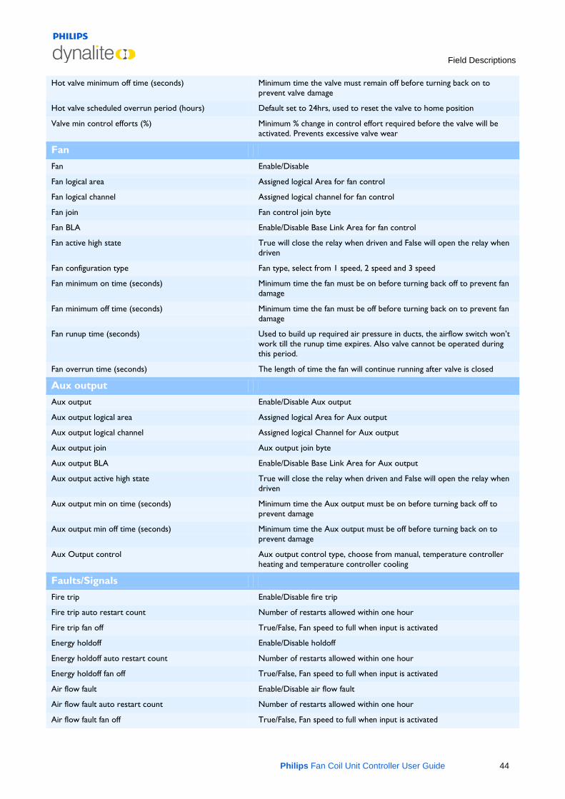
Fan
Fan Enable/Disable
Fan logical area Assigned logical Area for fan control
Fan logical channel Assigned logical channel for fan control
Fan join Fan control join byte
Fan BLA Enable/Disable Base Link Area for fan control
Fan active high state True will close the relay when driven and False will open the relay when driven
Fan configuration type Fan type, select from 1 speed, 2 speed and 3 speed
Fan minimum on time (seconds) Minimum time the fan must be on before turning back off to prevent fan damage
Fan minimum off time (seconds) Minimum time the fan must be off before turning back on to prevent fan damage
Fan runup time (seconds) Used to build up required air pressure in ducts, the airflow switch won’t work till the runup time expires. Also valve cannot be operated during this period.
Fan overrun time (seconds) The length of time the fan will continue running after valve is closed
Aux output
Aux output Enable/Disable Aux output
Aux output logical area Assigned logical Area for Aux output
Aux output logical channel Assigned logical Channel for Aux output
Aux output join Aux output join byte
Aux output BLA Enable/Disable Base Link Area for Aux output
Aux output active high state True will close the relay when driven and False will open the relay when driven
Aux output min on time (seconds) Minimum time the Aux output must be on before turning back off to prevent damage
Aux output min off time (seconds) Minimum time the Aux output must be off before turning back on to prevent damage
Aux Output control Aux output control type, choose from manual, temperature controller heating and temperature controller cooling
Faults/Signals
Fire trip Enable/Disable fire trip
Fire trip auto restart count Number of restarts allowed within one hour
Fire trip fan off True/False, Fan speed to full when input is activated
Energy holdoff Enable/Disable holdoff
Energy holdoff auto restart count Number of restarts allowed within one hour
Energy holdoff fan off True/False, Fan speed to full when input is activated
Air flow fault Enable/Disable air flow fault
Air flow fault auto restart count Number of restarts allowed within one hour
Air flow fault fan off True/False, Fan speed to full when input is activated
Field Descriptions
Philips Fan Coil Unit Controller User Guide 45
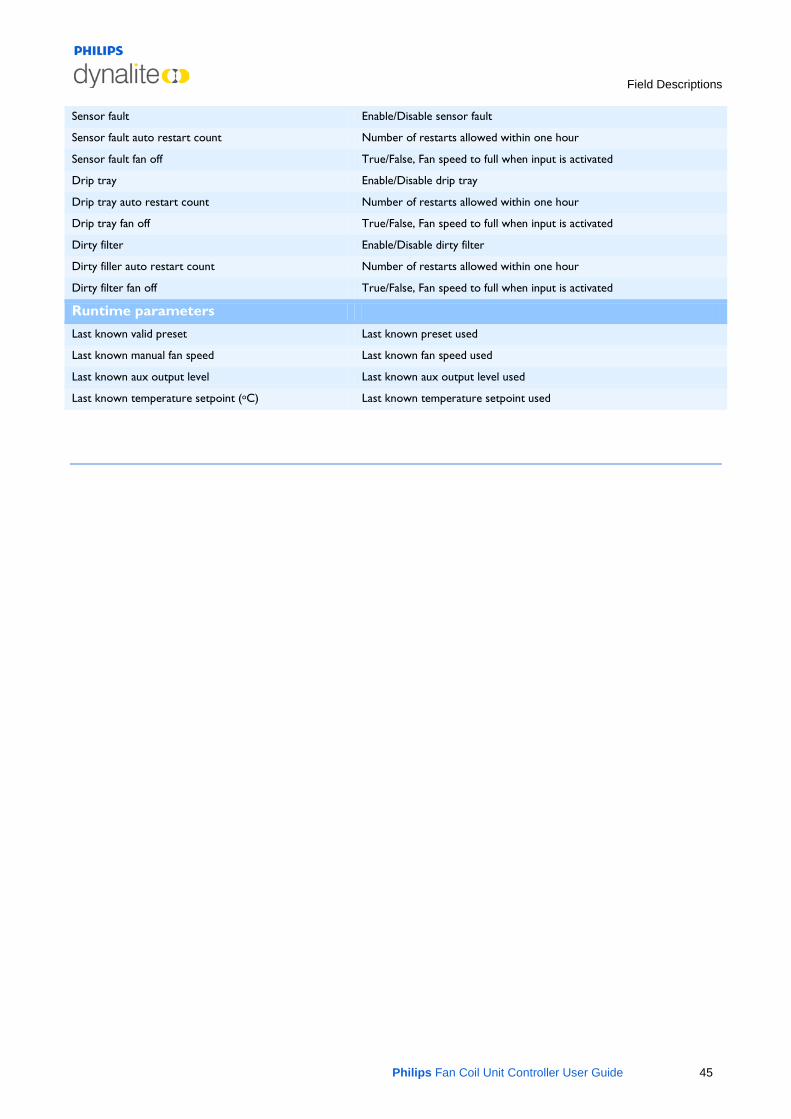
Sensor fault Enable/Disable sensor fault
Sensor fault auto restart count Number of restarts allowed within one hour
Sensor fault fan off True/False, Fan speed to full when input is activated
Drip tray Enable/Disable drip tray
Drip tray auto restart count Number of restarts allowed within one hour
Drip tray fan off True/False, Fan speed to full when input is activated
Dirty filter Enable/Disable dirty filter
Dirty filler auto restart count Number of restarts allowed within one hour
Dirty filter fan off True/False, Fan speed to full when input is activated
Runtime parameters
Last known valid preset Last known preset used
Last known manual fan speed Last known fan speed used
Last known aux output level Last known aux output level used
Last known temperature setpoint (oC) Last known temperature setpoint used
Field Descriptions
Philips Fan Coil Unit Controller User Guide 46
7.2 Temperature Control
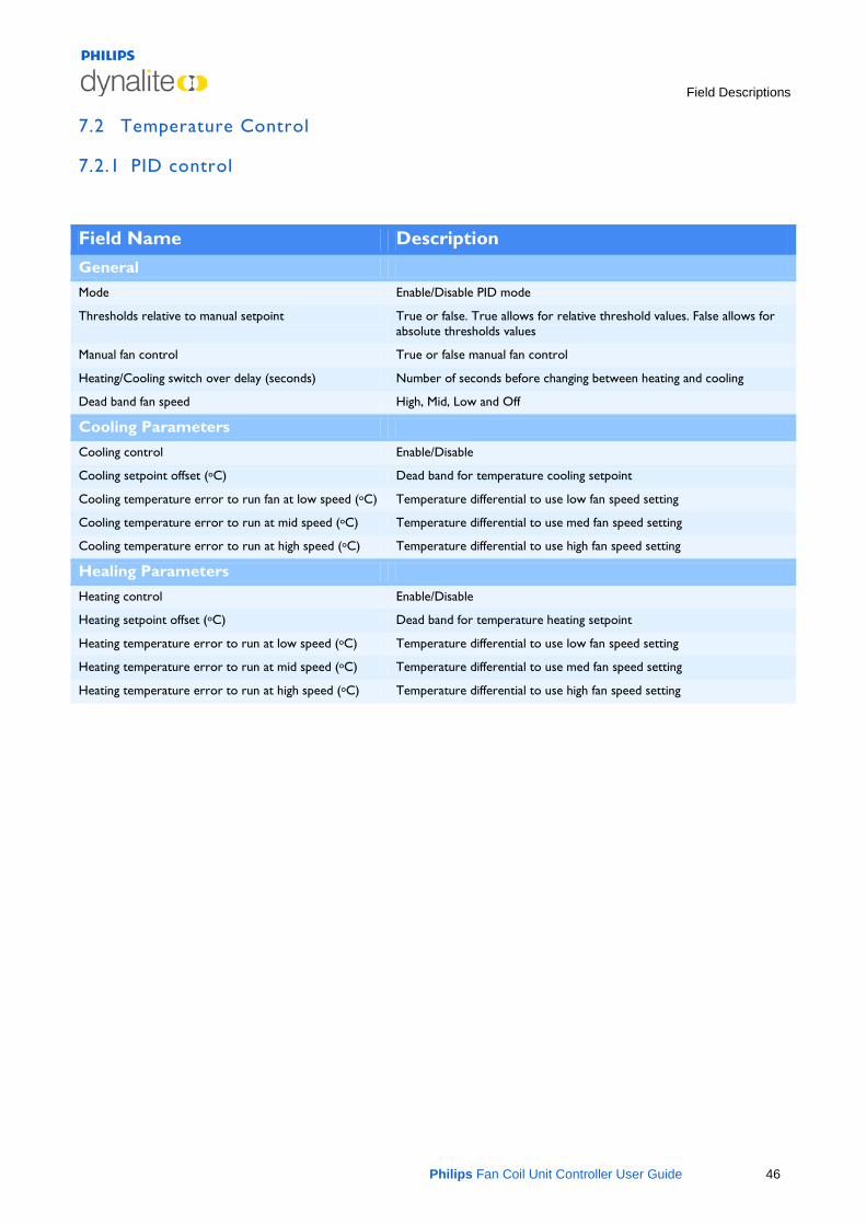
7.2.1 PID control
Field Name Description General Mode Enable/Disable PID mode
Thresholds relative to manual setpoint True or false. True allows for relative threshold values. False allows for absolute thresholds values
Manual fan control True or false manual fan control
Heating/Cooling switch over delay (seconds) Number of seconds before changing between heating and cooling
Dead band fan speed High, Mid, Low and Off
Cooling Parameters
Cooling control Enable/Disable
Cooling setpoint offset (oC) Dead band for temperature cooling setpoint
Cooling temperature error to run fan at low speed (oC) Temperature differential to use low fan speed setting
Cooling temperature error to run at mid speed (oC) Temperature differential to use med fan speed setting
Cooling temperature error to run at high speed (oC) Temperature differential to use high fan speed setting
Healing Parameters
Heating control Enable/Disable
Heating setpoint offset (oC) Dead band for temperature heating setpoint
Heating temperature error to run at low speed (oC) Temperature differential to use low fan speed setting
Heating temperature error to run at mid speed (oC) Temperature differential to use med fan speed setting
Heating temperature error to run at high speed (oC) Temperature differential to use high fan speed setting
Field Descriptions
Philips Fan Coil Unit Controller User Guide 47
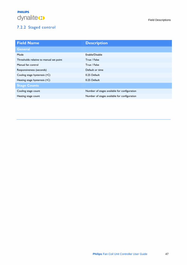
7.2.2 Staged control
Field Name Description General Mode Enable/Disable
Thresholds relative to manual set point True / False
Manual fan control True / False
Responsiveness (seconds) Default or time
Cooling stage hysteresis (oC) 0.25 Default
Heating stage hysteresis (oC) 0.25 Default
Stage Counts
Cooling stage count Number of stages available for configuration
Heating stage count Number of stages available for configuration

Related Documents