Permanent-magnet synchronous motors Contents Product description 12/2 Overview of technical data 12/4 Motor selection data Series PE.. for Super Premium Efficiency IE4 1) 12/5 Series P…, high-power motors 12/7 Terminal boxes Identical to terminal boxes of standard motors see Chapter 2 Bearings Identical to bearings of standard motors, see Chapter 2 Dimensions Identical to dimensions of standard motors see Chapter 2 and assignment tables 12/9 1) IE5 upon request (see VEMeKAT for latest status) 12

Welcome message from author
This document is posted to help you gain knowledge. Please leave a comment to let me know what you think about it! Share it to your friends and learn new things together.
Transcript

Permanent-magnet synchronous motors
Contents
Product description 12/2Overview of technical data 12/4
Motor selection data Series PE.. for Super Premium Efficiency IE41) 12/5Series P…, high-power motors 12/7
Terminal boxesIdentical to terminal boxes of standard motorssee Chapter 2
BearingsIdentical to bearings of standard motors,see Chapter 2
DimensionsIdentical to dimensions of standard motors see Chapter 2 and assignment tables 12/9
1) IE5 upon request (see VEMeKAT for latest status)
12

Low
vol
tage
ele
ctric
al m
achi
nes
12/2
Product descriptionPermanent-magnet synchronous motors can be used wherever machines are to be driven with variable speed. As is the case for synchronous motors with separate excitation, a permanent-magnet synchronous motor also cannot be started directly on the mains. Permanent-magnet synchro-nous motors are intended solely for converter-fed operation. They represent a variant of standard motors, but are not to be considered replacements for servo drives.
As a permanent-magnet synchronous motor with field- orient ed control displays similar characteristics to a DC machine, they were originally used almost exclusively for demanding variable-speed drive systems, as the elimination of brushes served to reduce maintenance costs.
Nowadays, they are in increasingly widespread use in appli-cations where maximum efficiency is the prime concern. The especially high efficiency in both full and partial load opera-tion permits the realisation of economical drive solutions for working machines of all kinds.
Permanent-magnet synchronous motors meet the requi-rements of efficiency classifications IE3 and IE4 without additional expense for materials. The double savings effect of high efficiency in operation (reduced energy consumption) alongside reduced material input for manufacture (for the P21 series compared to an asynchronous motor with equivalent output) qualifies a drive with permanent-magnet synchronous motor as a sustainable investment in the future.
Special notes regarding the calculation of a variable-speed drive system with permanent magnet synchronous motor
Permanent-magnet synchronous motors are excited by way of permanent magnets, i.e. the strength of the exciting field is determined when the machine is calculated and remains constant. There is thus no possibility for operation with field weakening in the classic manner known from asynchronous machines. Over the whole speed setting range (assumption: Rated speed = Maximum speed), the induced voltage is proportional to the speed.If a correspondingly suitable converter is used, a limited field weakening range can be realised by modifying one compo-nent of the current.
The converter-fed operation of a permanent-magnet synchro-nous motor means that the standard assignment of a rated speed to a motor pole number and rated frequency (usually 50 Hz or 60 Hz) is no longer necessary. Optimum adapta-tion of the motor to the working machine or technological process, and similarly to the output voltage of the converter, is unproblematic.A rated speed of 3000 rpm, for example, is realised with a 4-pole permanent-magnet synchronous motor with a 100 Hz winding. The product range does not include 2-pole perma-nent-magnet synchronous motors. On the other hand, lower rated speeds (e.g. 1200 or 900 rpm) can be realised with lower rated frequencies. Permanent-magnet synchronous motors can deliver very high overload torques, provided they
have been calculated accordingly and the converter is able to supply the necessary peak currents for the required duration.
As an option, permanent-magnet synchronous motors can also be supplied with position encoders. This enables precise determination of the speed of the magnet wheel and its posi-tion in the stator. In conjunction with field-oriented control, it is then possible to realise drives for applications which place very high demands on torque constancy and the accuracy of speed synchronisation, for example.
In case of high mass moments of inertia and fast speed changes, it may be necessary to use a brake resistor to protect the converter.
The motors can also be ordered as drive units with frequency converter. This brings the following benefits for the customer:
– Pre-parameterised unit– Radio interference suppression to EN 55011, class A1,
for shielded cable lengths up to 150 m – Radio interference suppression to EN 55011, class B1,
for shielded cable lengths up to 50 m – Integrated brake chopper– Mains input voltage 380 ...500 V ± 10%, 50/60 Hz
Design versions
Series Shaft height Materials of housing, end shields and feet
Foot mounting
P.1R 63 bis 132 T
Grey cast iron
BoltedPE2R 80 K4 BoltedPE2R 71, 80 G4 CastP.1R 132 bis 280 BoltedP2.R 315, 355 CastP20R 56 bis 80 CastP20R 90 bis 250 BoltedP20R 280 bis 315 Cast
Low
vol
tage
ele
ctric
al m
achi
nes
12
12/3
Fig. 1: Principle design of a PM motor
Outwardly, a permanent-magnet motor does not differ from an equivalent asynchronous motor. The design is based on that of the robust and reliable VEM standard motors in grey cast iron housing. The stator corresponds to the basic series K2.R, and the squirrel cage of an asynchronous
motor provides the basis for the magnet wheel (rotor). The squirrel-cage rotor body is turned after die-casting, neody-mium iron boron magnets are glued around the body and the whole assembly is then bandaged (see photo below).
Fig. 2: PM rotor with magnets in place Fig. 3: PM rotor complete with bandage

Low
vol
tage
ele
ctric
al m
achi
nes
12/4
Product group Magnetic rotor, IEC/ENRated output1) IE4-PE.R 63 bis 315, 0.12 to 250 kW
P..R 63 bis 315, 0.12 bis 315 kWSizes 63 to 315Housing material Grey cast iron Rated torque 0.8 Nm to 2000 NmEfficiency classification1)/ efficiency determination
IEC DTS 60034-30-2 TS:2016 /IEC/TS 60034-2-3 Ed. 1.0: 2013
Method of connection Single-speed motors are designed for star connection as standard.Stator winding insulation Thermal class 155
to IEC/EN 60034-1Degree of protection IP 55
to IEC/EN 60034-5Type of cooling IC 411, IC 416, IC 410, IC 418
IC 71W (IC 31W) upon requestto EC/EN 60034-6
Coolant temperature/ installation altitude
Standard -20 °C to +40 °C, Altitude 1000 m above sea level
Rated voltage Standard voltages to EN 60038 50 Hz: 230 V, 400 V, 500 V, 690 V60 Hz: 275 V, 460 V, 480 V, 600 V
Duty Types S1, continuous duty, Short-time duty S2, 10/30/60 min Duty Type S3/S6, 25/40/60 % c.d.f., S9
Types of construction IM B3, IM B35, IM B5, IM B14, IM B34 and derived Types to IEC/EN 60034-7
Paint finish Normal finish “Moderate”, colour RAL 7031, blue-grey Special finish “Worldwide”, colour RAL 7031, blue-grey
Vibration severity grade Grade “A” as standard for machines with no special vibration requirements
Shaft ends to DIN 748 (IEC 60072), balanced with half-keyLimit speeds Please refer to the section of “Limit speeds“ in catalogue section
“Motors for converter-fed operation”, Chapter 4.Bearing design Please refer to the tables of “Bearing design data“ in catalogue
section „Standand motors“, Chapter 2.Motor mass Please refer to the technical selection lists.Terminal boxes Please refer to the section “Terminal boxes” in catalogue
section „Standand motors“, Chapter 2.Documentation An operating and maintenance manual, a terminal plan and a safety
data sheet are supplied with each motor.Tolerances Please refer to the section “Tolerances” in catalogue section
“Introduction“, Chapter 1.Options Please refer to the section “Overview of modifications” in catalogue
section “Introduction“, Chapter 1.
1) IE5 upon request (see VEMeKAT for latest status)
Overview of technical data The most important technical data are summarised in the following table. Further information can be taken from the catalogue section “Technical explanations”, chapter 1.
Low
vol
tage
ele
ctric
al m
achi
nes
12
12/5
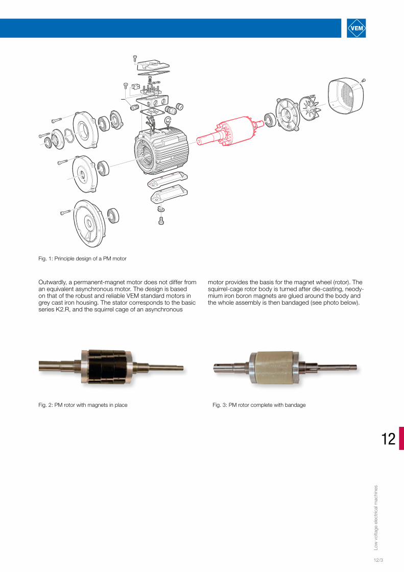
Permanent-magnet synchronous motors for converter-fed operation“Super Premium Efficiency IE4”1) according to IEC DTS 60034-30-2 TS 2016
with surface cooling, Type of cooling IC 411Thermal class 155[F/B], degree of protection IP 55
Motor selection data Converter input voltage 400 V, 50 HzSp
eed
Freq
uenc
y
Rate
d ou
tput
Torq
ue
Max
. tor
que
(2
min
)
Volta
ge
Effic
ienc
y
Pow
er fa
ctor
Rate
d cu
rren
t
Phas
e re
sist
ance
at
20
°C
No-lo
ad v
olta
ge a
t 10
00 rp
m
Mag
netis
ing
indu
ctan
ce
Leak
age
in
duct
ance
Mag
netis
ing
reac
tanc
e
Leak
age
reac
tanc
e
Mot
or m
omen
t of
iner
tia
Mot
or m
ass
100% R1 20 UP0 20 L1H L1σ X1H X1σ J m
rpm Hz [kW] [Nm] [Nm] [V] [%] [-] [A] [Ω] [V/1000 rpm] [mH] [mH] [Ω] [Ω] kgm² kgSynchronous speed 3000 rpm – 4-pole version, rated frequency 100 Hz
IE4-PE1R 63 K4 IE4-PE0R 56 K4 3000 100 0.12 0.40 2.50 330 80 0.99 0.3 32 100 60 28 37.7 17.59 0.00019 4.8IE4-PE1R 63 K4 IE4-PE0R 56 K4 3000 100 0.18 0.60 2.50 335 80 0.99 0.35 32 100 60 28 37.7 17.59 0.00019 4.8IE4-PE1R 63 G4 IE4-PE0R 56 G4 3000 100 0.25 0.80 3.50 320 81.5 0.99 0.5 18 105 42 18 26.39 11.31 0.00024 5.2IE4-PE1R 71 K4 IE4-PE0R 63 K4 3000 100 0.37 1.20 4.00 320 83.2 0.99 0.81 13.5 100 37 15 23.25 9.42 0.00040 6.8IE4-PE1R 71 G4 IE4-PE0R 63 G4 3000 100 0.55 1.80 7.00 330 81.5 0.99 1.23 8.7 105 30 10 18.85 6.28 0.00050 7.8IE4-PE1R 80 K4 IE4-PE0R 71 K4 3000 100 0.75 2.40 10.00 335 84.2 0.99 1.55 4.6 110 25 8 15.71 5.03 0.00087 10.6IE4-PE1R 80 G4 IE4-PE0R 71 G4 3000 100 1.1 3.50 14.00 330 86.4 0.99 2.25 2.8 105 18 5 11.31 3.14 0.00107 11.7IE4-PE1R 90 S4 IE4-PE0R 80 K4 3000 100 1.5 4.80 19.00 310 86.8 0.99 3.25 1.7 105 9.5 2.5 5.97 1.57 0.00207 15.5IE4-PE1R 90 L4 IE4-PE0R 80 G4 3000 100 2.2 7.00 28.00 280 88.1 0.99 5.20 0.8 90 5 1 3.14 0.63 0.00260 18.0IE4-PE1R 100 L4 IE4-PE0R 90 L4 3000 100 3.0 9.50 45.00 320 92.7 0.99 5.90 0.6 100 4.7 1.3 2.95 0.82 0.00400 23.5IE4-PE1R 112 MY4 IE4-PE0R 100 S4 3000 100 4.0 12.70 50.00 330 91.2 0.99 7.75 0.4 110 3.2 0.8 2.01 0.50 0.00725 31.0IE4-PE1R 132 SY4T IE4-PE0R 100 L4 3000 100 5.5 17.50 85.00 310 92.3 1.00 11.10 0.25 110 2 0.5 1.26 0.31 0.009 39IE4-PE1R 132 S4T IE4-PE0R 100 LX4 3000 100 7.5 23.90 100.00 305 92.8 1.00 15.30 0.2 105 1.2 0.3 0.75 0.19 0.011 47IE4-PE1R 132 M4 IE4-PE0R 132 S4 3000 100 11.0 35.00 44.00 344 92.6 1.00 20.0 0.1170 121 2.280 0.960 1.432 0.603 0.022 72IE4-PE1R 132 M4 IE4-PE0R 132 S4 3000 100 15.0 48.00 60.00 347 93.4 1.00 26.7 0.1170 121 2.280 0.960 1.432 0.603 0.022 72IE4-PE1R 160 M4 IE4-PE0R 132 M4 3000 100 18.5 59.00 74.00 350 93.8 1.00 32.6 0.0690 116 1.660 0.630 1.042 0.396 0.031 92IE4-PE1R 160 L4 IE4-PE0R 160 S4 3000 100 18.5 59.00 74.00 372 93.9 0.99 31.0 0.0480 121 1.576 0.526 0.990 0.330 0.062 121IE4-PE1R 180 M4 IE4-PE0R 160 M4 3000 100 22.0 70.00 88.00 346 94.0 1.00 39.0 0.0410 123 1.350 0.460 0.848 0.289 0.079 135IE4-PE1R 180 M4 IE4-PE0R 160 M4 3000 100 30.0 96.00 120.00 347 94.5 0.99 53.5 0.0410 123 1.350 0.460 0.848 0.289 0.079 135IE4-PE1R 180 L4 IE4-PE0R 180 S4 3000 100 30.0 96.00 119.00 362 94.7 0.98 52.0 0.0270 116 1.150 0.360 0.722 0.226 0.116 170IE4-PE1R 200 L4 IE4-PE0R 180 M4 3000 100 37.0 118.00 147.00 365 95 0.98 63.0 0.0180 118 0.901 0.257 0.566 0.161 0.150 200IE4-PE1R 225 S4 IE4-PE0R 200 M4 3000 100 45.0 143.00 179.00 365 95.1 0.98 76.5 0.0110 118 0.725 0.198 0.455 0.124 0.251 270IE4-PE1R 225 M4 IE4-PE0R 200 L4 3000 100 55.0 175.00 218.00 355 95.4 0.98 96.0 0.0091 115 0.587 0.153 0.369 0.096 0.288 300IE4-PE1R 250 M4 IE4-PE0R 225 M4 3000 100 75.0 239.00 298.00 369 95.7 0.97 127.0 0.0073 118 0.543 0.144 0.341 0.090 0.457 375IE4-PE1R 250 M4 IE4-PE0R 225 M4 3000 100 90.0 287.00 358.00 374 96 0.96 151.0 0.0073 118 0.543 0.145 0.341 0.091 0.457 375IE4-PE1R 280 S4 IE4-PE0R 250 S4 3000 100 110.0 350.00 438.00 363 96.1 0.96 190.0 0.0045 115 0.420 0.111 0.264 0.070 0.864 520IE4-PE1R 280 S4 IE4-PE0R 250 S4 3000 100 132.0 420.00 525.00 370 96.4 0.94 228.0 0.0045 115 0.420 0.111 0.264 0.070 0.864 520IE4-PE1R 280 M4 IE4-PE0R 250 M4 3000 100 160.0 509.00 637.00 380 96.5 0.94 269.0 0.0037 118 0.373 0.085 0.234 0.053 1.011 580IE4-PE1R 315 MX4 IE4-PE0R 315 S4 3000 100 200.0 637.00 796.00 360 96.9 0.98 339.0 0.0019 117 0.152 0.038 0.095 0.024 1.556 980IE4-PE1R 315 MY4 IE4-PE0R 315 M4 3000 100 250.0 796.00 995.00 380 97.1 0.97 406.0 0.0018 123 0.161 0.036 0.101 0.023 2.499 1170
1) IE5 upon request (see VEMeKAT for latest status)
Motor selection data

Low
vol
tage
ele
ctric
al m
achi
nes
Motor selection data
12/6
Motor selection data Converter input voltage 400 V, 50 HzSp
eed
Freq
uenc
y
Rate
d ou
tput
Torq
ue
Max
. tor
que
(2
min
)
Volta
ge
Effic
ienc
y
Pow
er fa
ctor
Rate
d cu
rren
t
Phas
e re
sist
ance
at
20
°C
No-lo
ad v
olta
ge a
t 10
00 rp
m
Mag
netis
ing
indu
ctan
ce
Leak
age
in
duct
ance
Mag
netis
ing
reac
tanc
e
Leak
age
reac
tanc
e
Mot
or m
omen
t of
iner
tia
Mot
or m
ass
100% R1 20 UP0 20 L1H L1σ X1H X1σ J m
rpm Hz [kW] [Nm] [Nm] [V] [%] [-] [A] [Ω] [V/1000 rpm] [mH] [mH] [Ω] [Ω] kgm² kgSynchronous speed 1500 rpm – 4-pole version, rated frequency 50 Hz
IE4-PE1R 63 K4 IE4-PE0R 56 K4 1500 50 0.12 0.8 2.5 310 76.0 0.98 0.3 95 170 160 80 50.3 25.13 0.00019 4.8IE4-PE1R 63 G4 IE4-PE0R 56 G4 1500 50 0.18 1.1 3.5 310 80.5 0.98 0.41 57 180 130 60 40.8 18.85 0.00024 5.2IE4-PE2R 71 K4 IE4-PE0R 71 K4 1500 50 0.25 1.6 10 290 84.4 1.00 0.65 14.5 190 76 24 23.9 7.54 0.00087 9.9IE4-PE2R 71 G4 IE4-PE0R 71 G4 1500 50 0.37 2.4 14 290 90.7 0.99 0.82 9.5 195 61 19 19.2 5.97 0.00107 11.0IE4-PE2R 80 K4 IE4-PE0R 71 G4 1500 50 0.55 3.5 14 300 87.6 0.99 1.22 9.5 195 61 19 19.2 5.97 0.00107 11.7IE4-PE2R 80 G4 IE4-PE0R 80 K4 1500 50 0.75 4.8 19 305 87.5 0.99 1.60 6 195 36 9 11.3 2.83 0.00207 14.5IE4-PE2R 90 S4 IE4-PE0R 80 G4 1500 50 1.1 7 28 300 91.5 0.99 2.35 3.4 190 24.5 5.5 7.7 1.73 0.00260 18.0IE4-PE1R 90 L4 IE4-PE0R 80 G4 1500 50 1.5 9.5 28 305 88.3 0.99 3.25 3.4 190 24.5 5.5 7.7 1.73 0.00260 18.0IE4-PE1R 100 L4 IE4-PE0R 90 L4 1500 50 2.2 14 45 315 90.5 0.99 4.5 2.1 195 15.5 4.5 4.9 1.41 0.00400 23.5IE4-PE1R 100 LX4 IE4-PE0R 100 S4 1500 50 3.0 19.1 50 335 91.6 0.99 5.7 1.5 215 16.0 4.0 5.0 1.26 0.00725 30.0IE4-PE1R 112 M4 IE4-PE0R 100 L4 1500 50 4.0 25.5 70 320 92.3 0.99 7.9 0.9 205 10.5 2.5 3.3 0.79 0.009 37.0IE4-PE1R 112 MX4 IE4-PE0R 100 LX4 1500 50 5.5 35 100 325 93.1 0.99 10.6 0.65 210 8.2 1.8 2.6 0.57 0.011 45.0IE4-PE1R 132 M4 IE4-PE0R 132 S4 1500 50 7.5 48.00 60.00 362 93.5 0.99 13.0 0.4290 232 8.379 3.486 2.631 1.095 0.022 70IE4-PE1R 160 M4 IE4-PE0R 132 M4 1500 50 11.0 70.00 88.00 362 94.1 0.99 19.0 0.2510 235 5.847 2.227 1.836 0.699 0.031 92IE4-PE1R 160 L4 IE4-PE0R 160 S4 1500 50 15.0 96.00 119.00 357 94.3 0.98 26.5 0.1250 229 3.717 1.306 1.167 0.410 0.068 120IE4-PE1R 180 M4 IE4-PE0R 160 M4 1500 50 18.5 118.00 147.00 364 94.8 0.98 32.0 0.1340 233 5.101 1.613 1.602 0.506 0.073 136IE4-PE1R 180 L4 IE4-PE0R 180 S4 1500 50 22.0 140.00 175.00 354 95 0.98 39.0 0.0720 226 2.840 0.937 0.892 0.294 0.126 170IE4-PE1R 200 L4 IE4-PE0R 180 M4 1500 50 30.0 191.00 239.00 360 95.3 0.98 52.0 0.0510 230 2.210 0.675 0.694 0.212 0.162 220IE4-PE1R 225 S4 IE4-PE0R 200 M4 1500 50 37.0 236.00 294.00 355 95.5 0.97 65.0 0.0290 228 1.800 0.531 0.565 0.167 0.269 270IE4-PE1R 225 M4 IE4-PE0R 200 L4 1500 50 45.0 287.00 358.00 363 95.7 0.98 77.0 0.0240 233 1.603 0.450 0.503 0.141 0.308 300IE4-PE1R 250 M4 IE4-PE0R 225 M4 1500 50 55.0 350.00 438.00 355 95.8 0.97 96.0 0.0170 228 1.231 0.347 0.387 0.109 0.492 375IE4-PE1R 250 M4 IE4-PE0R 225 M4 1500 50 75.0 478.00 597.00 366 96.1 0.98 126.0 0.0170 237 1.319 0.369 0.414 0.116 0.492 375IE4-PE1R 280 S4 IE4-PE0R 250 S4 1500 50 90.0 573.00 716.00 369 96.3 0.98 150.0 0.0120 239 1.176 0.283 0.369 0.089 0.911 520IE4-PE1R 280 M4 IE4-PE0R 250 M4 1500 50 110.0 700.00 875.00 359 96.4 0.96 191.0 0.0088 229 0.897 0.207 0.282 0.065 1.065 580IE4-PE1R 280 M4 IE4-PE0R 250 M4 1500 50 132.0 840.00 1050.00 373 96.5 0.98 216.0 0.0099 243 0.848 0.250 0.266 0.079 1.089 580IE4-PE1R 315 S4 IE4-PE0R 280 S4 1500 50 160.0 1019.001273.00 356 96.8 0.95 283.0 0.0060 224 0.727 0.155 0.228 0.049 1.750 740IE4-PE1R 315 MX4 IE4-PE0R 315 S4 1500 50 200.0 1273.001592.00 366 96.9 0.98 333.0 0.0044 239 0.484 0.114 0.152 0.036 2.350 1000IE4-PE1R 315 MY4 IE4-PE0R 315 M4 1500 50 250.0 1592.001990.00 372 97 0.96 418.0 0.0035 236 0.389 0.078 0.122 0.024 4.224 1200
Synchronous speed 1000 rpm – 6-pole version, rated frequency 50 Hz
IE4-PE1R 132 MX6 IE4-PE0R 132 S6 1000 50 5.5 53.00 66.00 362 91.5 0.99 10.0 0.5350 348 6.624 3.072 2.080 0.965 0.040 70IE4-PE1R 160 M6 IE4-PE0R 132 M6 1000 50 7.5 72.00 90.00 364 91.7 0.99 13.0 0.3580 351 5.160 2.300 1.620 0.722 0.052 86IE4-PE1R 160 L6 IE4-PE0R 160 S6 1000 50 11.0 105.00 131.00 361 92.5 0.98 19.5 0.2390 345 4.549 1.729 1.428 0.543 0.104 114IE4-PE1R 180 L6 IE4-PE0R 160 M6 1000 50 15.0 143.00 179.00 360 93.1 0.98 26.5 0.1590 345 3.385 1.217 1.063 0.382 0.135 136IE4-PE1R 180 L6 IE4-PE0R 160 M6 1000 50 18.5 177.00 221.00 358 93.6 0.99 32.5 0.1545 347 3.403 1.217 1.069 0.382 0.135 136IE4-PE1R 200 L6 IE4-PE0R 180 S6 1000 50 22.0 210.00 263.00 359 93.9 0.99 38.0 0.1140 355 3.332 1.136 1.046 0.357 0.219 175IE4-PE1R 200 LX6 IE4-PE0R 180 M6 1000 50 30.0 287.00 358.00 359 94.3 0.98 52.5 0.0790 343 2.538 0.835 0.797 0.262 0.270 200IE4-PE1R 225 M6 IE4-PE0R 200 M6 1000 50 37.0 353.00 442.00 362 94.6 0.981 64.0 0.0495 350 1.899 0.610 0.596 0.192 0.437 265IE4-PE1R 250 M6 IE4-PE0R 225 M6 1000 50 45.0 430.00 537.00 360 94.9 0.98 78.0 0.0375 349 1.604 0.529 0.504 0.166 0.711 360IE4-PE1R 280 S6 IE4-PE0R 250 S6 1000 50 55.0 525.00 657.00 360 95.3 0.95 98.0 0.0335 334 1.656 0.538 0.520 0.169 1.142 465IE4-PE1R 280 M6 IE4-PE0R 250 M6 1000 50 75.0 716.00 895.00 367 95.5 0.97 128.0 0.0260 348 1.414 0.436 0.444 0.137 1.423 520IE4-PE1R 315 S6 IE4-PE0R 280 S6 1000 50 90.0 860.00 1074.00 358 95.8 0.95 160.0 0.0163 334 1.123 0.348 0.353 0.109 2.275 690IE4-PE1R 315 M6 IE4-PE0R 280 M6 1000 50 110.0 1050.001313.00 360 96 0.96 192.0 0.0120 341 0.908 0.266 0.285 0.084 2.875 800IE4-PE1R 315 MX6 IE4-PE0R 315 S6 1000 50 132.0 1261.001576.00 371 96.2 0.97 221.0 0.0116 356 0.910 0.262 0.286 0.082 3.110 890IE4-PE1R 315 MY6 IE4-PE0R 315 M6 1000 50 160.0 1528.001910.00 368 96.3 0.97 269.0 0.0076 353 0.717 0.181 0.225 0.057 5.285 1050IE4-PE1R 315 L6 IE4-PE0R 315 L6 1000 50 200.0 1273.001592.00 365 96.4 0.96 342.0 0.0063 347 0.612 0.151 0.192 0.047 5.940 1250IE4-PE1R 315 LX6 IE4-PE0R 315 LX6 1000 50 250.0 1592.001990.00 362 96.5 0.95 435.0 0.0043 340 0.451 0.106 0.142 0.033 7.644 1460
Permanent-magnet synchronous motors for converter-fed operation“Super Premium Efficiency IE4”1) according to IEC DTS 60034-30-2 TS 2016
with surface cooling, Type of cooling IC 411Thermal class 155[F/B], degree of protection IP 55
Low
vol
tage
ele
ctric
al m
achi
nes
12
12/7
Motor selection data Converter input voltage 400 V, 50 Hz
Spee
d
Freq
uenc
y
Rate
d ou
tput
Torq
ue
Max
. tor
que
(2
min
)
Volta
ge
Effic
ienc
y
Pow
er fa
ctor
Rate
d cu
rren
t
Phas
e re
sist
ance
at
20
°C
No-lo
ad v
olta
ge a
t 10
00 rp
m
Mag
netis
ing
indu
ctan
ce
Leak
age
in
duct
ance
Mag
netis
ing
reac
tanc
e
Leak
age
reac
tanc
e
Mot
or m
omen
t of
iner
tia
Mot
or m
ass
100% R1 20 UP0 20 L1H L1σ X1H X1σ J m
rpm Hz [kW] [Nm] [Nm] [V] [%] [-] [A] [Ω] [V/1000 rpm] [mH] [mH] [Ω] [Ω] kgm² kgSynchronous speed 3000 rpm – 4-pole version, rated frequency 100 Hz
P21R 63 K4 P20R 56 K4 3000 100 0.37 1.2 2.5 330 77.5 0.98 0.80 26 95 50 20 31.4 12.6 0.00019 4.8P21R 63 G4 P20R 56 G4 3000 100 0.55 1.8 3.5 334 78 0.98 1.20 17 100 35 15 22.0 9.4 0.00024 5.2P21R 71 K4 P20R 63 K4 3000 100 0.75 2.4 4 330 77.0 0.98 1.74 11.5 100 30 13 18.8 8.2 0.00040 6.8P21R 71 G4 P20R 63 G4 3000 100 1.10 3.5 7 320 78.0 0.98 2.50 7.5 93 25 10 15.7 6.3 0.00050 7.8P21R 80 K4 P20R 71 K4 3000 100 1.50 4.8 10 320 81.0 0.98 3.20 4.5 100 21 6 13.2 3.8 0.00087 10.6P21R 80 G4 P20R 71 G4 3000 100 2.2 7.0 14 310 90.0 0.96 4.70 2.4 100 15 5 9.4 3.1 0.00107 11.7P21R 90 S4 P20R 80 K4 3000 100 3.0 9.5 19 325 86.3 0.98 6.30 1.7 105 9.5 2.5 6.0 1.6 0.00207 15.5P21R 90 L4 P20R 80 G4 3000 100 4.0 12.7 28 290 87.4 0.98 9.30 0.8 90 5 1 3.1 0.6 0.00260 18.0P21R 100 L4 P20R 90 L4 3000 100 5.5 17.5 45 320 92.9 0.98 10.90 0.6 100 4.7 1.3 3.0 0.8 0.00400 23.5P21R 112 MY4 P20R 100 S4 3000 100 7.5 23.9 50 330 93.3 0.99 14.20 0.4 110 3.2 0.8 2.0 0.5 0.00725 31.0P21R 132 M4 P20R 132 S4 3000 100 15 48 60.0 357 90.3 0.99 27.1 0.1 117 1.682 0.738 1.056 0.463 0.024 72P21R 160 M4 P20R 132 M4 3000 100 18.5 59.0 74.0 366 90.9 0.99 32.4 0.059 120 1.207 0.485 0.758 0.305 0.033 92P21R 160 L4 P20R 160 S4 3000 100 22 70.0 88.0 362 91.3 0.99 38.8 0.037 119 1.187 0.398 0.745 0.25 0.065 120P21R 180 M4 P20R 160 M4 3000 100 30 96.0 120.0 358 92 0.99 53.0 0.032 117 1.003 0.327 0.63 0.205 0.076 135P21R 180 L4 P20R 180 S4 3000 100 37 118.0 148.0 367 92.5 0.99 64.0 0.021 121 0.811 0.267 0.509 0.168 0.126 170P21R 200 L4 P20R 180 M4 3000 100 45 143.0 179.0 359 92.9 0.99 79.0 0.0138 118 0.577 0.176 0.362 0.111 0.162 200P21R 225 S4 P20R 200 M4 3000 100 55 175.0 219.0 358 93.2 1 95.0 0.00865 119 0.536 0.153 0.337 0.096 0.264 270P21R 225 M4 P20R 200 L4 3000 100 75 239.0 299.0 362 93.8 0.99 129.0 0.0073 119 0.457 0.125 0.287 0.0785 0.303 300P21R 250 M4 P20R 225 M4 3000 100 90 287.0 359.0 363 94.1 1 152.0 0.0053 121 0.378 0.104 0.237 0.0653 0.485 375P21R 280 S4 P20R 250 S4 3000 100 110 350.0 438.0 371 94.3 1 182.0 0.0035 124 0.317 0.076 0.199 0.0477 0.911 520P21R 280 M4 P20R 250 M4 3000 100 132 420.0 525.0 373 94.6 1 216.0 0.0029 126 0.269 0.063 0.169 0.0396 1.065 580P21R 315 S4 P20R 280 S4 3000 100 160 509.0 636.0 371 94.8 1 263.0 0.00623 124 0.672 0.14 0.422 0.0879 1.75 740P21R 315 M4 P20R 280 M4 3000 100 200 637.0 796.0 365 95 1 333.0 0.0046 121 0.546 0.108 0.343 0.0678 1.75 840
Synchronous speed 1500 rpm – 4-pole version, rated frequency 50 Hz
P21R 63 K4 P20R 56 K4 1500 50 0.18 1.1 2.5 340 73.0 0.98 0.45 95 170 160 80 50.3 25.1 0.00019 4.8P21R 63 G4 P20R 56 G4 1500 50 0.25 1.6 3.5 330 77.5 0.98 0.57 57 180 130 60 40.8 18.9 0.00024 5.2P21R 71 K4 P20R 63 K4 1500 50 0.3 1.9 4.0 315 66.5 0.98 0.75 44 165 110 50 34.6 15.7 0.0004 6.8P21R 71 G4 P20R 63 G4 1500 50 0.5 3.2 7.0 340 75.0 0.98 1.40 27 175 85 35 26.7 11.0 0.00050 7.8P21R 80 K4 P20R 71 K4 1500 50 0.75 4.8 10.0 325 80.6 0.99 1.75 14.5 190 76 24 23.9 7.5 0.00087 10.6P21R 80 G4 P20R 71 G4 1500 50 1.1 7.0 14.0 330 82.7 0.99 2.35 9.5 195 61 19 19.2 6.0 0.00107 11.7P21R 90 S4 P20R 80 K4 1500 50 1.5 9.5 19.0 330 81.1 0.98 3.30 6 195 36 9 11.3 2.8 0.00207 15.5P21R 90 L4 P20R 80 G4 1500 50 2.2 14.0 28.0 320 85.3 0.97 4.80 3.4 190 24.5 5.5 7.7 1.7 0.00260 18.0P21R 100 L4 P20R 90 L4 1500 50 3 325.0 45.0 325 87.7 0.98 6.20 2.1 195 15.5 4.5 4.9 1.4 0.00400 23.5P21R 100 LX4 P20R 100 S4 1500 50 4 25.5 50.0 320 89.1 0.97 8.35 1.4 200 16.0 4.0 5.0 1.3 0.00725 30.0P21R 112 M4 P20R 100 L4 1500 50 5.5 35.0 85.0 325 91.5 0.98 10.90 0.9 205 10.5 2.5 3.3 0.8 0.009 37.0P21R 132 S4T P20R 100 LX4 1500 50 7.5 47.7 100.0 330 91.7 0.98 14.60 0.65 210 8.2 1.8 2.6 0.6 0.011 47.0P21R 132 M4 P20R 132 S4 1500 50 11 70.0 88.0 361 89.8 0.99 19.8 0.359 230 6.59 2.85 2.069 0.895 0.024 70P21R 160 M4 P20R 132 M4 1500 50 15 96.0 120 364 90.6 0.99 26.5 0.204 236 4.63 1.85 1.454 0.581 0.033 92P21R 160 L4 P20R 160 S4 1500 50 18.5 118 148 363 91.2 0.99 32.6 0.125 236 3.90 1.37 1.225 0.43 0.068 120P21R 180 M4 P20R 160 M4 1500 50 22 140 175 363 91.6 0.99 38.6 0.096 236 3.27 0.99 1.027 0.311 0.079 136P21R 180 L4 P20R 180 S4 1500 50 30 191 239 362 92.3 0.98 53.0 0.0742 233 2.98 0.969 0.934 0.304 0.126 170P21R 200 L4 P20R 180 M4 1500 50 37 236 295 363 92.7 0.99 64.0 0.05 236 2.35 0.704 0.736 0.221 0.162 200P21R 225 S4 P20R 200 M4 1500 50 45 287 359 361 93.1 0.99 78.0 0.029 239 1.94 0.558 0.61 0.175 0.269 270P21R 225 M4 P20R 200 L4 1500 50 55 350 438 356 93.5 0.99 96.0 0.024 234 1.63 0.45 0.513 0.141 0.308 300P21R 250 M4 P20R 225 M4 1500 50 75 478 598 363 94 0.99 128.0 0.0173 238 1.33 0.37 0.416 0.116 0.492 380P21R 280 S4 P20R 250 S4 1500 50 90 573 716 359 94.2 0.99 155.0 0.0106 237 1.00 0.242 0.315 0.076 0.935 535P21R 280 M4 P20R 250 M4 1500 50 110 700 875 360 94.5 0.99 189.0 0.00825 238 0.82 0.189 0.257 0.0593 1.089 600P21R 315 S4 P20R 280 S4 1500 50 132 840 1050 362 94.7 0.99 225.0 0.00628 241 0.72 0.155 0.226 0.0487 1.79 740P21R 315 M4 P20R 280 M4 1500 50 160 1019 1274 363 94.9 0.99 271.0 0.00509 239 0.59 0.1223 0.186 0.0384 2.071 840P21R 315 MX4 P20R 315 S4 1500 50 200 1273 1591 361 95.1 0.99 340.0 0.00384 238 0.42 0.0994 0.131 0.0312 2.406 1000P21R 315 MY4 P20R 315 M4 1500 50 250 1592 1990 361 95.1 0.99 425.0 0.00359 237 0.39 0.0776 0.122 0.0244 4.224 1200P21R 315 L4 P20R 315 L4 1500 50 315 2006 2508 619 95.1 0.99 312.0 0.00763 409 0.91 0.171 0.284 0.0537 5.273 1450
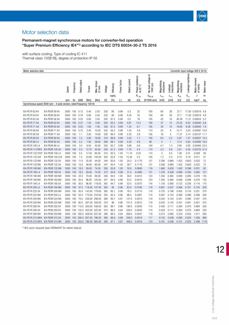
Permanent-magnet synchronous motors for converter-fed operationSeries P2.R, high-power motors
Increased output, with surface cooling, Type of cooling IC 411Thermal class 155[F/B], degree of protection IP 55

Low
vol
tage
ele
ctric
al m
achi
nes
Motor selection data
12/8
Motor selection data Converter input voltage 400 V, 50 Hz
Spee
d
Freq
uenc
y
Rate
d ou
tput
Torq
ue
Max
. tor
que
(2
min
)
Volta
ge
Effic
ienc
y
Pow
er fa
ctor
Rate
d cu
rren
t
Phas
e re
sist
ance
at
20
°C
No-lo
ad v
olta
ge a
t 10
00 rp
m
Mag
netis
ing
indu
ctan
ce
Leak
age
in
duct
ance
Mag
netis
ing
reac
tanc
e
Leak
age
reac
tanc
e
Mot
or m
omen
t of
iner
tia
Mot
or m
ass
100% R1 20 UP0 20 L1H L1σ X1H X1σ J m
rpm Hz [kW] [Nm] [Nm] [V] [%] [-] [A] [Ω] [V/1000 rpm] [mH] [mH] [Ω] [Ω] kgm² kgSynchronous speed 1000 rpm – 6-pole version, rated frequency 50 Hz
P21R 132 M6 P20R 112 MX6 1000 50 5.5 53 66 353 86.5 1 10.4 0.991 344 7.75 4.02 2.434 1.262 0.021 53P21R 132 MX6 P20R 132 S6 1000 50 7.5 72 90 362 88.5 0.99 13.7 0.501 348 6.64 3.072 2.084 0.965 0.04 70P21R 160 M6 P20R 132 M6 1000 50 11 105 131 359 90.2 0.99 19.8 0.348 342 4.69 2.177 1.472 0.684 0.052 86P21R 160 L6 P20R 160 S6 1000 50 15 143 179 360 91 1 26.4 0.252 356 4.76 1.796 1.494 0.564 0.103 114P21R 180 L6 P20R 160 M6 1000 50 18.5 177 221 360 91.5 0.99 32.8 0.168 347 3.40 1.217 1.067 0.382 0.135 136P21R 200 L6 P20R 180 S6 1000 50 22 210 263 354 92 1 39.0 0.103 347 3.00 1.026 0.942 0.322 0.223 175P21R 200 LX6 P20R 180 M6 1000 50 30 287 359 359 92.7 0.99 53.0 0.077 351 2.33 0.784 0.733 0.246 0.27 200P21R 225 M6 P20R 200 M6 1000 50 37 353 441 361 93.1 0.99 64.0 0.054 352 1.92 0.61 0.602 0.192 0.437 265P21R 250 M6 P20R 225 M6 1000 50 45 430 538 360 93.5 0.99 78.0 0.038 351 1.45 0.49 0.455 0.154 0.721 360P21R 280 S6 P20R 250 S6 1000 50 55 525 656 362 93.9 1 93.0 0.026 360 1.25 0.412 0.394 0.129 1.198 465P21R 280 M6 P20R 250 M6 1000 50 75 716 895 362 94.1 0.99 128.0 0.0204 357 0.95 0.297 0.297 0.0933 1.492 520P21R 315 S6 P20R 280 S6 1000 50 90 860 1075 359 94.3 0.99 155.0 0.014 353 0.99 0.29 0.311 0.0911 2.367 690P21R 315 M6 P20R 280 M6 1000 50 110 1051 1314 363 94.9 0.99 186.0 0.0119 362 0.81 0.23 0.255 0.0722 2.981 800P21R 315 MX6 P20R 315 S6 1000 50 132 1261 1576 358 95.2 0.98 228.0 0.0086 350 0.70 0.192 0.22 0.0603 3.226 880P21R 315 MY6 P20R 315 M6 1000 50 160 1528 1910 362 95.4 0.98 273.0 0.00759 358 0.69 0.181 0.216 0.0568 5.334 1050P21R 315 L6 P20R 315 L6 1000 50 200 1910 2388 361 95.6 0.97 345.0 0.0058 347 0.55 0.137 0.173 0.043 5.995 1250P21R 315 LX6 P20R 315 LX6 1000 50 250 2388 2985 363 95.6 0.99 420.0 0.0043 359 0.45 0.106 0.142 0.0333 7.714 1450
Synchronous speed 750 rpm – 8-pole version, rated frequency 50 Hz
P21R 160 M8 P20R 132 S8 750 50 5.5 70 88 358 84.6 0.99 10.6 0.747 452 5.30 4.223 1.665 1.326 0.042 70P21R 160 MX8 P20R 132 M8 750 50 7.5 96 120 361 86.5 0.99 14.0 0.515 459 4.15 3.231 1.302 1.015 0.054 86P21R 160 L8 P20R 160 S8 750 50 11 140 175 362 87.5 0.99 20.3 0.326 459 4.77 2.11 1.499 0.663 0.106 114P21R 180 L8 P20R 160 M8 750 50 15 191 239 358 88.7 0.99 27.5 0.381 446 3.07 2.68 0.964 0.842 0.138 136P21R 200 L8 P20R 180 S8 750 50 18.5 236 295 175P21R 200 LX8 P20R 180 M8 750 50 22 280 350 200P21R 225 M8 P20R 200 M8 750 50 30 382 478 360 90.5 0.98 54.0 0.0815 459 1.83 0.897 0.576 0.282 0.439 265P21R 250 M8 P20R 225 M8 750 50 37 471 589 0.439 360
Permanent-magnet synchronous motors for converter-fed operationSeries P2.R, high-power motors
Increased output, with surface cooling, Type of cooling IC 411Thermal class 155[F/B], degree of protection IP 55

Low
vol
tage
ele
ctric
al m
achi
nes
12
12/9
Assignment tableType Type Type J m
PE.R K21R K20R kgm² kgSynchronous speed 3000 rpm – 4-pole version, rated frequency 100 Hz
IE4-PE1R 63 K4 IE4-PE0R 56 K4 K21R 63 K2 K20R 56 K2 0.00019 4.8IE4-PE1R 63 K4 IE4-PE0R 56 K4 K21R 63 K2 K20R 56 K2 0.00019 4.8IE4-PE1R 63 G4 IE4-PE0R 56 G4 K21R 63 G2 K20R 56 G2 0.00024 5.2IE4-PE1R 71 K4 IE4-PE0R 63 K4 K21R 71 K2 K20R 63 K2 0.00040 6.8IE4-PE1R 71 G4 IE4-PE0R 63 G4 K21R 71 G2 K20R 63 G2 0.00050 7.8IE4-PE1R 80 K4 IE4-PE0R 71 K4 K21R 80 K2 K20R 71 K2 0.00087 10.6IE4-PE1R 80 G4 IE4-PE0R 71 G4 K21R 80 G2 K20R 71 G2 0.00107 11.7IE4-PE1R 90 S4 IE4-PE0R 80 K4 K21R 90 S2 K20R 80 K2 0.00207 15.5IE4-PE1R 90 L4 IE4-PE0R 80 G4 K21R 90 L2 K20R 80 G2 0.00260 18.0IE4-PE1R 100 L4 IE4-PE0R 90 L4 K21R 100 L2 K20R 90 L2 0.00400 23.5IE4-PE1R 112 MY4 IE4-PE0R 100 S4 K21R 112 M2 K20R 100 S2 0.00725 31.0IE4-PE1R 132 SY4T IE4-PE0R 100 L4 K21R 132 ST K20R 100 L2 0.0090 39.0IE4-PE1R 132 S4T IE4-PE0R 100 LX4 K21R 132 SX2T K20R 100 LX2 0.0110 47.0IE4-PE1R 132 M4 IE4-PE0R 132 S4 K21R 132 M4 K20R 132 S4 0.022 72IE4-PE1R 132 M4 IE4-PE0R 132 S4 K21R 132 M4 K20R 132 S4 0.022 72IE4-PE1R 160 M4 IE4-PE0R 132 M4 K21R 160 M4 K20R 132 M4 0.031 92IE4-PE1R 160 L4 IE4-PE0R 160 S4 K21R 160 L4 K20R 160 S4 0.062 121IE4-PE1R 180 M4 IE4-PE0R 160 M4 K21R 180 M4 K20R 160 M4 0.079 135IE4-PE1R 180 M4 IE4-PE0R 160 M4 K21R 180 M4 K20R 160 M4 0.079 135IE4-PE1R 180 L4 IE4-PE0R 180 S4 K21R 180 L4 K20R 180 S4 0.116 170IE4-PE1R 200 L4 IE4-PE0R 180 M4 K21R 200 L4 K20R 180 M4 0.150 200IE4-PE1R 225 S4 IE4-PE0R 200 M4 K21R 225 S4 K20R 200 M4 0.251 270IE4-PE1R 225 M4 IE4-PE0R 200 L4 K21R 225 M4 K20R 200 L4 0.288 300IE4-PE1R 250 M4 IE4-PE0R 225 M4 K21R 250 M4 K20R 225 M4 0.457 375IE4-PE1R 250 M4 IE4-PE0R 225 M4 K21R 250 M4 K20R 225 M4 0.457 375IE4-PE1R 280 S4 IE4-PE0R 250 S4 K21R 280 S4 K20R 250 S4 0.864 520IE4-PE1R 280 S4 IE4-PE0R 250 S4 K21R 280 S4 K20R 250 S4 0.864 520IE4-PE1R 280 M4 IE4-PE0R 250 M4 K21R 280 M4 K20R 250 M4 1.011 580IE4-PE1R 315 MX4 IE4-PE0R 315 S4 K21R 315 MX4 K20R 315 S4 1.556 980IE4-PE1R 315 MY4 IE4-PE0R 315 M4 K21R 315 MY4 K20R 315 M4 2.50 1170
Synchronous speed 1500 rpm – 4-pole version, rated frequency 50 Hz
IE4-PE1R 63 K4 IE4-PE0R 56 K4 K21R 63 K4 K20R 56 K4 0.00019 4.8IE4-PE1R 63 G4 IE4-PE0R 56 G4 K21R 63 G4 K20R 56 G4 0.00024 5.2IE4-PE2R 71 K4 - - IE2-W21R 71 K4 0.00087 9.9IE4-PE2R 71 G4 - - IE2-W21R 71 G4 0.00107 11.0IE4-PE2R 80 K4 - K21R 80 G4 - 0.00107 11.7IE4-PE2R 80 G4 - - IE2-W21R 80 K4 0.00207 14.5IE4-PE2R 90 S4 - - IE2-WE2R 90 S4 0.00260 18.0IE4-PE1R 90 L4 IE4-PE0R 80 G4 K21R 90 L4 K20R 80 G4 0.00260 18.0IE4-PE1R 100 L4 IE4-PE0R 90 L4 K21R 100 L4 K20R 90 L4 0.00400 23.5IE4-PE1R 100 LX4 IE4-PE0R 100 S4 K21R 100 LX4 K20R 100 S4 0.00725 30IE4-PE1R 112 M4 IE4-PE0R 100 L4 K21R 112 M4 K20R 100 L4 0.0090 37IE4-PE1R 132 S4T IE4-PE0R 100 LX4 K21R 132 S4T K20R 100 LX4 0.0110 47IE4-PE1R 132 M4 IE4-PE0R 132 S4 K21R 132 M4 K20R 132 S4 0.02 70IE4-PE1R 160 M4 IE4-PE0R 132 M4 K21R 160 M4 K20R 132 M4 0.03 92IE4-PE1R 160 L4 IE4-PE0R 160 S4 K21R 160 L4 K20R 160 S4 0.07 120IE4-PE1R 180 M4 IE4-PE0R 160 M4 K21R 180 M4 K20R 160 M4 0.07 136IE4-PE1R 180 L4 IE4-PE0R 180 S4 K21R 180 L4 K20R 180 S4 0.13 170IE4-PE1R 200 L4 IE4-PE0R 180 M4 K21R 200 L4 K20R 180 M4 0.16 220IE4-PE1R 225 S4 IE4-PE0R 200 M4 K21R 225 S4 K20R 200 M4 0.27 270IE4-PE1R 225 M4 IE4-PE0R 200 L4 K21R 225 M4 K20R 200 L4 0.31 300IE4-PE1R 250 M4 IE4-PE0R 225 M4 K21R 250 M4 K20R 225 M4 0.49 375IE4-PE1R 250 M4 IE4-PE0R 225 M4 K21R 250 M4 K20R 225 M4 0.49 375IE4-PE1R 280 S4 IE4-PE0R 250 S4 K21R 280 S4 K20R 250 S4 0.91 520IE4-PE1R 280 M4 IE4-PE0R 250 M4 K21R 280 M4 K20R 250 M4 1.07 580IE4-PE1R 280 M4 IE4-PE0R 250 M4 K21R 280 M4 K20R 250 M4 1.09 580IE4-PE1R 315 S4 IE4-PE0R 280 S4 K21R 315 S4 K20R 280 S4 1.75 740IE4-PE1R 315 MX4 IE4-PE0R 315 S4 K21R 315 MX4 K20R 315 S4 2.35 1000IE4-PE1R 315 MY4 IE4-PE0R 315 M4 K21R 315 MY4 K20R 315 M4 4.22 1200
Terminal boxes, bearings and dimensionsThe permanent-magnet synchronous motors IE4-PE.R are identical to the series K21R/WE.R. For further information regarding the terminal boxes, bearings and dimensions, please refer to Chapter 2.

Low
vol
tage
ele
ctric
al m
achi
nes
12/10
Terminal boxes, bearings and dimensions
Assignment tableType Type Type J m
PE.R K21R K20R kgm² kgSynchronous speed 1000 rpm – 6-pole version, rated frequency 50 Hz
IE4-PE1R 132 MX6 IE4-PE0R 132 S6 K21R 132 MX6 K20R 132 S6 0.040 70IE4-PE1R 160 M6 IE4-PE0R 132 M6 K21R 160 M6 K20R 132 M6 0.052 86IE4-PE1R 160 L6 IE4-PE0R 160 S6 K21R 160 L6 K20R 160 S6 0.104 114IE4-PE1R 180 L6 IE4-PE0R 160 M6 K21R 180 L6 K20R 160 M6 0.135 136IE4-PE1R 180 L6 IE4-PE0R 160 M6 K21R 180 L6 K20R 160 M6 0.135 136IE4-PE1R 200 L6 IE4-PE0R 180 S6 K21R 200 L6 K20R 180 S6 0.219 175IE4-PE1R 200 LX6 IE4-PE0R 180 M6 K21R 200 LX6 K20R 180 M6 0.270 200IE4-PE1R 225 M6 IE4-PE0R 200 M6 K21R 225 M6 K20R 200 M6 0.437 265IE4-PE1R 250 M6 IE4-PE0R 225 M6 K21R 250 M6 K20R 225 M6 0.711 360IE4-PE1R 280 S6 IE4-PE0R 250 S6 K21R 280 S6 K20R 250 S6 1.142 465IE4-PE1R 280 M6 IE4-PE0R 250 M6 K21R 280 M6 K20R 250 M6 1.423 520IE4-PE1R 315 S6 IE4-PE0R 280 S6 K21R 315 S6 K20R 280 S6 2.275 690IE4-PE1R 315 M6 IE4-PE0R 280 M6 K21R 315 M6 K20R 280 M6 2.875 800IE4-PE1R 315 MX6 IE4-PE0R 315 S6 K21R 315 MX6 K20R 315 S6 3.110 890IE4-PE1R 315 MY6 IE4-PE0R 315 M6 K21R 315 MY6 K20R 315 M6 5.285 1050IE4-PE1R 315 L6 IE4-PE0R 315 L6 K21R 315 L6 K20R 315 L6 5.940 1250IE4-PE1R 315 LX6 IE4-PE0R 315 LX6 K21R 315 LX6 K20R 315 LX6 7.644 1460
The permanent-magnet synchronous motors P21R are identical to the series K21R. For further information regarding the terminal boxes, bearings and dimensions, please refer to Chapter 2.

Low
vol
tage
ele
ctric
al m
achi
nes
12
12/11
Assignment tableType Type J m
P21R K21R kgm² kgSynchronous speed 3000 rpm – 4-pole version, rated frequency 100 Hz
P21R 63 K4 P20R 56 K4 K21R 63 K2 K20R 56 K2 0.00019 4.8P21R 63 G4 P20R 56 G4 K21R 63 G2 K20R 56 G2 0.00024 5.2P21R 71 K4 P20R 63 K4 K21R 71 K2 K20R 63 K2 0.00040 6.8P21R 71 G4 P20R 63 G4 K21R 71 G2 K20R 63 G2 0.00050 7.8P21R 80 K4 P20R 71 K4 K21R 80 K2 K20R 71 K2 0.00087 10.6P21R 80 G4 P20R 71 G4 K21R 80 G2 K20R 71 G2 0.00107 11.7P21R 90 S4 P20R 80 K4 K21R 90 S2 K20R 80 K2 0.00207 15.5P21R 90 L4 P20R 80 G4 K21R 90 L2 K20R 80 G2 0.00260 18.0P21R 100 L4 P20R 90 L4 K21R 100 L2 K20R 90 L2 0.00400 23.5P21R 112 MY4 P20R 100 S4 K21R 112 M2 K20R 100 S2 0.00725 31.0P21R 132 M4 P20R 132 S4 K21R 132 M4 K20R 132 S4 0.024 72P21R 160 M4 P20R 132 M4 K21R 160 M4 K20R 132 M4 0.033 92P21R 160 L4 P20R 160 S4 K21R 160 L4 K20R 160 S4 0.065 120P21R 180 M4 P20R 160 M4 K21R 180 M4 K20R 160 M4 0.076 135P21R 180 L4 P20R 180 S4 K21R 180 L4 K20R 180 S4 0.126 170P21R 200 L4 P20R 180 M4 K21R 200 L4 K20R 180 M4 0.162 200P21R 225 S4 P20R 200 M4 K21R 225 S4 K20R 200 M4 0.264 270P21R 225 M4 P20R 200 L4 K21R 225 M4 K20R 200 L4 0.303 300P21R 250 M4 P20R 225 M4 K21R 250 M4 K20R 225 M4 0.485 375P21R 280 S4 P20R 250 S4 K21R 280 S4 K20R 250 S4 0.911 520P21R 280 M4 P20R 250 M4 K21R 280 M4 K20R 250 M4 1.065 580P21R 315 S4 P20R 280 S4 K21R 315 S4 K20R 280 S4 1.75 740P21R 315 M4 P20R 280 M4 K21R 315 M4 K20R 280 M4 1.75 840
Synchronous speed 1500 rpm – 4-pole version, rated frequency 50 Hz
P21R 63 K4 P20R 56 K4 K21R 63 K4 K20R 56 K4 0.00019 4.8P21R 63 G4 P20R 56 G4 K21R 63 G4 K20R 56 G4 0.00024 5.2P21R 71 K4 P20R 63 K4 K21R 71 K4 K20R 63 K4 0.00040 6.8P21R 71 G4 P20R 63 G4 K21R 71 G4 K20R 63 G4 0.00050 7.8P21R 80 K4 P20R 71 K4 K21R 80 K4 K20R 71 K4 0.00087 10.6P21R 80 G4 P20R 71 G4 K21R 80 G4 K20R 71 G4 0.00107 11.7P21R 90 S4 P20R 80 K4 K21R 90 S4 K20R 80 K4 0.00207 15.5P21R 90 L4 P20R 80 G4 K21R 90 L4 K20R 80 G4 0.00260 18.0P21R 100 L4 P20R 90 L4 K21R 100 L4 K20R 90 L4 0.00400 23.5P21R 100 LX4 P20R 100 S4 K21R 100 LX4 K20R 100 S4 0.00725 30.0P21R 112 M4 P20R 100 L4 K21R 112 M4 K20R 100 L4 0.0090 37.0P21R 132 S4T P20R 100 LX4 K21R 132 S4T K20R 100 LX4 0.0110 47.0P21R 132 M4 P20R 132 S4 K21R 132 M4 K20R 132 S4 0.02 70P21R 160 M4 P20R 132 M4 K21R 160 M4 K20R 132 M4 0.03 92P21R 160 L4 P20R 160 S4 K21R 160 L4 K20R 160 S4 0.07 120P21R 180 M4 P20R 160 M4 K21R 180 M4 K20R 160 M4 0.08 136P21R 180 L4 P20R 180 S4 K21R 180 L4 K20R 180 S4 0.13 170P21R 200 L4 P20R 180 M4 K21R 200 L4 K20R 180 M4 0.16 200P21R 225 S4 P20R 200 M4 K21R 225 S4 K20R 200 M4 0.27 270P21R 225 M4 P20R 200 L4 K21R 225 M4 K20R 200 L4 0.31 300P21R 250 M4 P20R 225 M4 K21R 250 M4 K20R 225 M4 0.49 380P21R 280 S4 P20R 250 S4 K21R 280 S4 K20R 250 S4 0.94 535P21R 280 M4 P20R 250 M4 K21R 280 M4 K20R 250 M4 1.09 600P21R 315 S4 P20R 280S 4 K21R 315 S4 K20R 280S 4 1.79 740P21R 315 S4 P20R 280M 4 K21R 315 S4 K20R 280M 4 2.07 840P21R 315 MX4 P20R 315 S4 K21R 315 MX4 K20R 315 S4 2.41 1000P21R 315 MY4 P20R 315 M4 K21R 315 MY4 K20R 315 M4 4.22 1200P21R 315 L4 P20R 315 L4 K21R 315 L4 K20R 315 L4 5.27 1450
The permanent-magnet synchronous motors P21R are identical to the series K21R. For further information regarding the terminal boxes, bearings and dimensions, please refer to Chapter 2.

Low
vol
tage
ele
ctric
al m
achi
nes
12/12
Terminal boxes, bearings and dimensions
Assignment tableType Type J m
P21R K21R kgm² kgSynchronous speed 1000 rpm – 6-pole version, rated frequency 50 Hz
P21R 132 MX6 P20R 132 S6 K21R 132 MX6 K20R 132 S6 0.040 70P21R 160 M6 P20R 132 M6 K21R 160 M6 K20R 132 M6 0.052 86P21R 160 L6 P20R 160 S6 K21R 160 L6 K20R 160 S6 0.103 114P21R 180 L6 P20R 160 M6 K21R 180 L6 K20R 160 M6 0.135 136P21R 200 L6 P20R 180 S6 K21R 200 L6 K20R 180 S6 0.223 175P21R 200 LX6 P20R 180 M6 K21R 200 LX6 K20R 180 M6 0.270 200P21R 225 M6 P20R 200 M6 K21R 225 M6 K20R 200 M6 0.437 265P21R 250 M6 P20R 225 M6 K21R 250 M6 K20R 225 M6 0.721 360P21R 280 S6 P20R 250 S6 K21R 280 S6 K20R 250 S6 1.198 465P21R 280 M6 P20R 250 M6 K21R 280 M6 K20R 250 M6 1.492 520P21R 315 S6 P20R 280 S6 K21R 315 S6 K20R 280 S6 2.367 690P21R 315 M6 P20R 280 M6 K21R 315 M6 K20R 280 M6 2.981 800P21R 315 MX6 P20R 315 S6 K21R 315 MX6 K20R 315 S6 3.226 880P21R 315 MY6 P20R 315 M6 K21R 315 MY6 K20R 315 M6 5.334 1050P21R 315 L6 P20R 315 L6 K21R 315 L6 K20R 315 L6 5.995 1250P21R 315 LX6 P20R 315 LX6 K21R 315 LX6 K20R 315 LX6 7.714 1450
Synchronous speed 750 rpm – 8-pole version, rated frequency 50 Hz
P21R 160 M8 P20R 132 S8 K21R 160 M8 K20R 132 S8 0.042 70P21R 160 MX8 P20R 132 M8 K21R 160 MX8 K20R 132 M8 0.054 86P21R 160 L8 P20R 160 S8 K21R 160 L8 K20R 160 S8 0.106 114P21R 180 L8 P20R 160 M8 K21R 180 L8 K20R 160 M8 0.138 136P21R 200 L8 P20R 180 S8 K21R 200 L8 K20R 180 S8 175P21R 200 LX8 P20R 180 M8 K21R 200 LX8 K20R 180 M8 200P21R 225 M8 P20R 200 M8 K21R 225 M8 K20R 200 M8 0.439 265P21R 250 M8 P20R 225 M8 K21R 250 M8 K20R 225 M8 0.439 360
The permanent-magnet synchronous motors P21R are identical to the series K21R.For further information regarding the terminal boxes, bearings and dimensions, please refer to Chapter 2.

Low
vol
tage
ele
ctric
al m
achi
nes
12
12/13

VMUK_NS02-112-EN-2/17 Printed in Germany. Subject to change.
For detailed information please visit our website.
www.vem-group.com
VEM Holding GmbH
Pirnaer Landstraße 176 01257 Dresden Germany
Sales
Low voltage department
Tel. +49 3943 68-3127 Fax +49 3943 68-2440 E-mail: [email protected]
High voltage department
Tel. +49 351 208-3237 Fax +49 351 208-1108 E-mail: [email protected]
Drive systems department
Tel. +49 351 208-1180 Fax +49 351 208-1185 E-mail: [email protected]
VEM Service
Tel. +49 351 208-3237 Fax +49 351 208-1108 E-mail: [email protected]
© 2017 Juniks Marketing GmbH
Related Documents