Vol-3 Issue-4 2017 IJARIIE-ISSN (O)-2395-4396 6140 www.ijariie.com 2024 Design and Analysis of Permanent Magnet Synchronous Generator for Wind Energy Conversion System using Ansoft-Maxwell D.Karthigha 1 , Aadhyasha Patel 2 , 1 Assistant Professor, EEE, Prince Shri Venkateshwara Padmavathy Engineering College, TamilNadu, India 2 Assistant Professor, EEE, Prince Shri Venkateshwara Padmavathy Engineering College, TamilNadu, India ABSTRACT Now-a-days Permanent magnet synchronous generator plays a major role in the Wind energy conversion system. This project deals with the design of 1.5 kW, 500 rpm, 230V,50Hz multi pole permanent magnet synchronous generator for direct drive wind energy conversion system using the software Ansoft Maxwell. This design is based on considering the parameters such as diameter of core, core length, machine type, material type, number of poles, number of armature conductors and slot etc., The RMxprt construction obtained from the above parameters are exported to Maxwell 3D design to perform the Magnetostatic analysis which involves validation of design, analysis setup, boundaries and excitation. Keywords : Magnetostatic Analysis, Cogging torque, Pole, Armature conductors, Air gap flux density. 1. INTRODUCTION Permanent magnet generators can be divided into two groups: geared machines and direct-driven machines. Currently, the tendency to eliminate the gearbox from the permanent magnet generator structure is increasing because the gearbox brings additional weight and costs, demands regular maintenance, generates noise and incurs losses. However, many problems may occur while constructing a new direct-driven permanent magnet generator design [2][3]. The energy converters using permanent magnets include a variety of configurations, and such terms as motor, generator, alternator, stepper motor, linear motor, actuator, transducer, control motor, tachometer, brushless dc motor and many others are used to describe them[5]. The stator of the machine (motor) is identical to the stator of a multiphase AC machine. However, the new component is the rotor, which in contrast to conventional rotors relies on permanent magnets as the source of excitation rather than an electric current in windings[5][6]. The optimum rotor configuration, rotor electromagnetic and mechanical design, as well as the stator electromagnetic design must be matched to achieve a higher efficient machine of the desired load characteristics, high power factor, and high efficiency and performance [7]. The advantages of PM machines over electrically excited machines are Higher efficiency and energy yield, No additional power supply for the magnet field excitation, Improvement in the thermal characteristics of the

Welcome message from author
This document is posted to help you gain knowledge. Please leave a comment to let me know what you think about it! Share it to your friends and learn new things together.
Transcript
Vol-3 Issue-4 2017 IJARIIE-ISSN (O)-2395-4396
6140 www.ijariie.com 2024
Design and Analysis of Permanent Magnet
Synchronous Generator for Wind Energy
Conversion System using Ansoft-Maxwell
D.Karthigha
1, Aadhyasha Patel
2,
1 Assistant Professor, EEE, Prince Shri Venkateshwara Padmavathy Engineering College,
TamilNadu, India 2 Assistant Professor, EEE, Prince Shri Venkateshwara Padmavathy Engineering College,
TamilNadu, India
ABSTRACT Now-a-days Permanent magnet synchronous generator plays a major role in the Wind energy conversion system.
This project deals with the design of 1.5 kW, 500 rpm, 230V,50Hz multi pole permanent magnet synchronous
generator for direct drive wind energy conversion system using the software Ansoft Maxwell. This design is based
on considering the parameters such as diameter of core, core length, machine type, material type, number of poles,
number of armature conductors and slot etc., The RMxprt construction obtained from the above parameters are
exported to Maxwell 3D design to perform the Magnetostatic analysis which involves validation of design, analysis
setup, boundaries and excitation.
Keywords : Magnetostatic Analysis, Cogging torque, Pole, Armature conductors, Air gap flux density.
1. INTRODUCTION
Permanent magnet generators can be divided into two groups: geared machines and direct-driven machines.
Currently, the tendency to eliminate the gearbox from the permanent magnet generator structure is increasing
because the gearbox brings additional weight and costs, demands regular maintenance, generates noise and incurs
losses. However, many problems may occur while constructing a new direct-driven permanent magnet generator
design [2][3].
The energy converters using permanent magnets include a variety of configurations, and such terms as
motor, generator, alternator, stepper motor, linear motor, actuator, transducer, control motor, tachometer, brushless
dc motor and many others are used to describe them[5]. The stator of the machine (motor) is identical to the stator of
a multiphase AC machine. However, the new component is the rotor, which in contrast to conventional rotors relies
on permanent magnets as the source of excitation rather than an electric current in windings[5][6]. The optimum
rotor configuration, rotor electromagnetic and mechanical design, as well as the stator electromagnetic design must
be matched to achieve a higher efficient machine of the desired load characteristics, high power factor, and high
efficiency and performance [7].
The advantages of PM machines over electrically excited machines are Higher efficiency and energy yield,
No additional power supply for the magnet field excitation, Improvement in the thermal characteristics of the
Vol-3 Issue-4 2017 IJARIIE-ISSN (O)-2395-4396
6140 www.ijariie.com 2025
machine due to absence of the field losses, Higher reliability due to the absence of mechanical components as slip
rings, Lighter and therefore higher power to weight ratio.
The attractiveness of PM generators is further enhanced by the availability of high-energy PM materials
such as neodymium-iron boron. The advantages of permanent magnets in PMSG are they do not require an
additional DC supply for the excitation circuit and they avoid the use of slip rings, hence it is simpler and
maintenance free.
2. WIND ENERGY CONVERSION SYSTEM MODEL
The basic diagram of the wind energy conversion system to be analyzed on this paper is illustrated in Fig.
1. The system is composed by a wind rotor which transforms the kinetic energy from the wind with wind speed in
mechanical torque in the shaft. The shaft drives directly the PMSG, which generates power with variable-frequency
and alternate current. A rectifier bridge with a bulky capacitor Clink is responsible for AC-DC conversion to form
the DC link.
The Static compensators connected on main bus between generator and bridge rectifier. It consists of a six-
switch, three-phase voltage source inverter (VSI), a CDC capacitor on the DC side of the inverter, and a LF to
suppress high-frequency currents originated by the switching of the VSI. A bank of capacitors C is used for filter
high-frequency voltage occasioned by the inverter.
2. PMSG CONSTRUCTION BY ANSOFT MAXWELL
2.1 Ansoft Maxwell and RMxprt
Ansoft Maxwell is the premier electromagnetic field simulation software for engineers tasked with designing
and analyzing 3-D and 2-D electromagnetic and electromechanical devices such as motors, actuators, transformers,
sensors and coils. Maxwell includes 3-D/2-D Magnetic Transient, AC electromagnetic, Magnetostatic, Electrostatic
analysis.
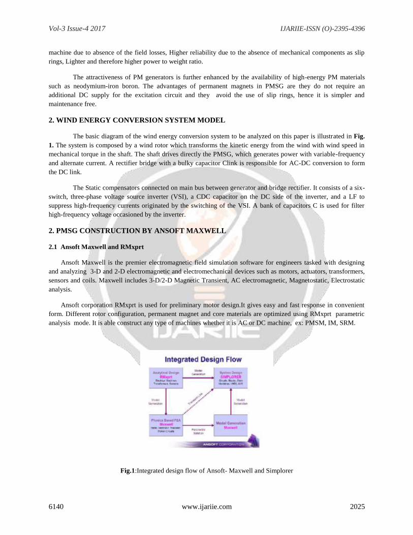
Ansoft corporation RMxprt is used for preliminary motor design.It gives easy and fast response in convenient
form. Different rotor configuration, permanent magnet and core materials are optimized using RMxprt parametric
analysis mode. It is able construct any type of machines whether it is AC or DC machine, ex: PMSM, IM, SRM.
Fig.1:Integrated design flow of Ansoft- Maxwell and Simplorer

Vol-3 Issue-4 2017 IJARIIE-ISSN (O)-2395-4396
6140 www.ijariie.com 2026
Fig.2:Design flow of Ansoft – Maxwell
2.2 Steps for design
The steps involved in designing PMSG by Ansoft-Maxwell are
(i)The machine type is chosen in the Rmxprt construction .
(ii)The obtained parameters of PMSG such as inner and outer diameter of stator and rotor, no of poles, no
of slots , pole arc and pole pitch, width and height of the pole body and pole shoe, no of parallel branches etc are
applied .
(iii)Then the number of coils, length of the coil, resistance of the field coil , and magnet parameters such as
remenence, magnetic coercivity, relative permeability of the magnet, magnetic reluctance, are also applied in the
rotor configurations.
(iv)Then the constructed design, parameters are validated and are analysed for the machine construction,
parameters set up to give Rmxprt construction of PMSG.
(v)Then this Rmxprt construction is exported to Maxwell 3D design to obtain a 3D model of PMSG
which is undergone a Magnetostatic analysis which is a finite element technique.
(vi)This validate the various excitation, boundary condition and optimetrics to produce the results.
3. DESIGN OF PMSG
To design a 1.5kW Permanent magnet synchronous generator with a speed N=500rpm, efficiency =0.95,
Frequency =50Hz, voltage= 230V...
3.1 Design of Stator
The output equation of synchronous machines is Output KVA is
Q=CoD2Lns (1)
where Co is the output coefficient given by
Co=11Bav ac Kw10-3
(2)
D- diameter of Stator (m), L- length of core(m)
Product D²L =Q/Co.ns m³
Vol-3 Issue-4 2017 IJARIIE-ISSN (O)-2395-4396
6140 www.ijariie.com 2027
Synchronous speed ns=2f/p (rps) (3)
Peripheral speed o armature
Va=π D N “m/s” (4)
For a round pole face L =ΨT
=ΨπD/p. (5)
The poles are attached to the pole body. The ratio of pole arc to pole pitch Ψ is assumed as 0.67 for the
round poles in which length of the pole is equal to width of the pole shoe [2].
When all the turns are connected in series then Turns/phase is given by, Turns/phase
Tph=Eph/4.44fØKw (6)
The number of coils is more than the required minimum number of coils. Hence best choice for number of
coils is 462.
Number of turns per coil =Z/2c.
The slot opening should be as small as possible in order to reduce flux pulsation losses. With increase in
depth of the slot the eddy current loss in conductors increases, specific permeance of slot increases, reactance
voltage increases and its becomes difficult to fabricate the laminations with narrow width at the roots of teeth.
Factors considered before finalizing the slot dimensions are Flux density in tooth, Flux pulsations, Eddy
current loss in conductors and the reactance voltage.
Total number of armature conductors =slots x conductor per slot.
Total armature conductors= 6Tph
Number of slots Ss= 3pq (7)
where p-no of poles
q- slots/pole/phase. (2 to 4)
The slot width (Ws) =πD /2Ns.(m) (8)
Slot pitch ys= πD/Ss (9)
(< 25mm for small machines)
3.2 Design of Pole body and Pole shoe
A larger value of air gap results in lesser noise, better cooling, reduced pole face losses, reduced circulating
currents and less distortion of field form. Also larger air-gap results in higher mmf which reduces armature reaction.
The mmf required for the flux across the air gap is approximately 80% of the no load field mmf [2], then
Mmf required for air gap,
Atg =800,00BgKgLg (10)
Vol-3 Issue-4 2017 IJARIIE-ISSN (O)-2395-4396
6140 www.ijariie.com 2028
Where Kg =1.15 =gap contraction factor
Lg is length of the air gap
Bg is the flux density in the air gap.
Armature mmf per pole ATa =ac.τ /2
Magnet Reluctance (Rm);
Rm =Hc x Nm /Br πDL (I/Hm) (11)
where Hc is the Magnet co-ercevity
Nm is the Number of poles
Br is the Magnet remanence
Magnet thickness Tm is
Tm = (Gap flux factor (Pc) + air gap reluctance(Rg)) / magnet reluctance (Rm) (12)
Slot fill factor =Total slot copper area (Ac) / total slot area(Aw). (13)
The reluctance of the magnetic material can be estimated using the following equation, Reluctance, S
=length/area x1/permeability =l /Aμ.
Permeability of magnetic material(μ) =μr.μo
μr =Relative permeability
μo =4π x10ˉ7 H/m =Absolute permeability of free space.
NdFeB SH materials has temperature 150°c (or) 302 °F, Br =11.2 and Hc =10.7
Relative permeability of magnet μr =Br / (Hc) x μo.
Air gap reluctance Rg =Nm.g /πDLμo.(I/H) (14)
Where Nm=Number of poles
g=Air-gap thickness
D=Diameter
L=Length:
μo=Permeability of air =1.256 x10ˉ³ x10ˉ³.H/m.
Flux per pole=(Bav*πDL)/p (Wb/m) (15)
Flux in the pole body, φp=Cl x φ. (16)
Leakage co-efficient Cl =1.12 to 1.25.

Vol-3 Issue-4 2017 IJARIIE-ISSN (O)-2395-4396
6140 www.ijariie.com 2029
Area of the body, Ap =φp /Bp (m2)
(17)
Bp - Flux density in the pole body.
Length of pole, Lp =L – (0.001 to 0.015) m.
Net iron length of pole Lpi =0.9Lp (m)
Width of the pole, bp =Ap /Lpi (18)
Height of pole body, hp =hf+ Thickness of insulation and clearance.
Height of pole shoe Hs=2dd , (19)
dd - diameter of damper winding
dd = Ad/Nd
=area of damper bar per pole/ number of bar per pole.
Short circuit ratio is defined as the ratio of field current for OC to the field current for the SC current.
Short Circuit Ratio = Field current for OC volt / Field current for SC current
SCR =OFo /OFs,
where OFo =per unit field current required to develop
rated voltage on open circuit.
OFs =per unit field current required to develop
rated current on short circuit.
3.3 Design rules upon slots and combinations
The number of poles has to full fill three absolute requirements [2]
1. First of all the pole number must be an even number.
2. Further the number of pole pairs, Pp, in sections, of the machine cannot be a multiple of the phase number, since
this would lead to unbalanced windings.
3. The final requirement is that the number of poles cannot be equal to the number of slots. Since this would lead to
an undesired cogging torque.
3.4 Design Specification
Chosen specific magnetic loading= 0.5Wb/m2, specific magnetic loading = 35000A/m and Winding
factor=0.955. By using the above calculations mentioned above and taking the assumptions above, the dimensions
obtained are,
3.5 Stator Design
Outer Diameter of stator= 240mm
Vol-3 Issue-4 2017 IJARIIE-ISSN (O)-2395-4396
6140 www.ijariie.com 2030
Inner diameter of stator=170mm
Core length= 0.90m.
Pole pitch =0.189m
Pole arc b=0.1273 m.
Peripheral speed of armature Va =25.30 m/s.
Number of slots =30
Slot width=1.9mm
Number of conductors= 720.
Conductor per slot =2
3.6 Rotor Design
Outer Diameter of rotor=170mm
Inner diameter of rotor=140mm
Armature winding terminal voltage= 230V
Number of parallel path = 2.
Current per parallel path Iz =1.71Amp.
Conductor per pole= 120.
Flux per pole Φ =0.05 WB/m2
Slots per pole arc =4.5578Sa.
Minimum number of coils, Cmin =460.
Net iron length Li=137mm
Air gap length=1mm
Armature current Ia =3.41A.
Remanence Br =11.2 and
Coercivity =10.7
Relative permeability of magnet μr =833.38 x 10³.
Armature mmf per pole ATa =257.25 A
Magnet reluctance Rm = 4.92 x10²
Air gap reluctance (Rg)=1.289.g x106
Vol-3 Issue-4 2017 IJARIIE-ISSN (O)-2395-4396
6140 www.ijariie.com 2031
Length of coil =2.818m.
Resistance of field coil Rc =164.38Ω
Coil current Ic =1.472 A
Slot fill factor = 4.0597 x10⁻⁶
Conductor current density Ja = 2.9A/mm².
Line current IL = Power/(V*efficiency)=3.588A.
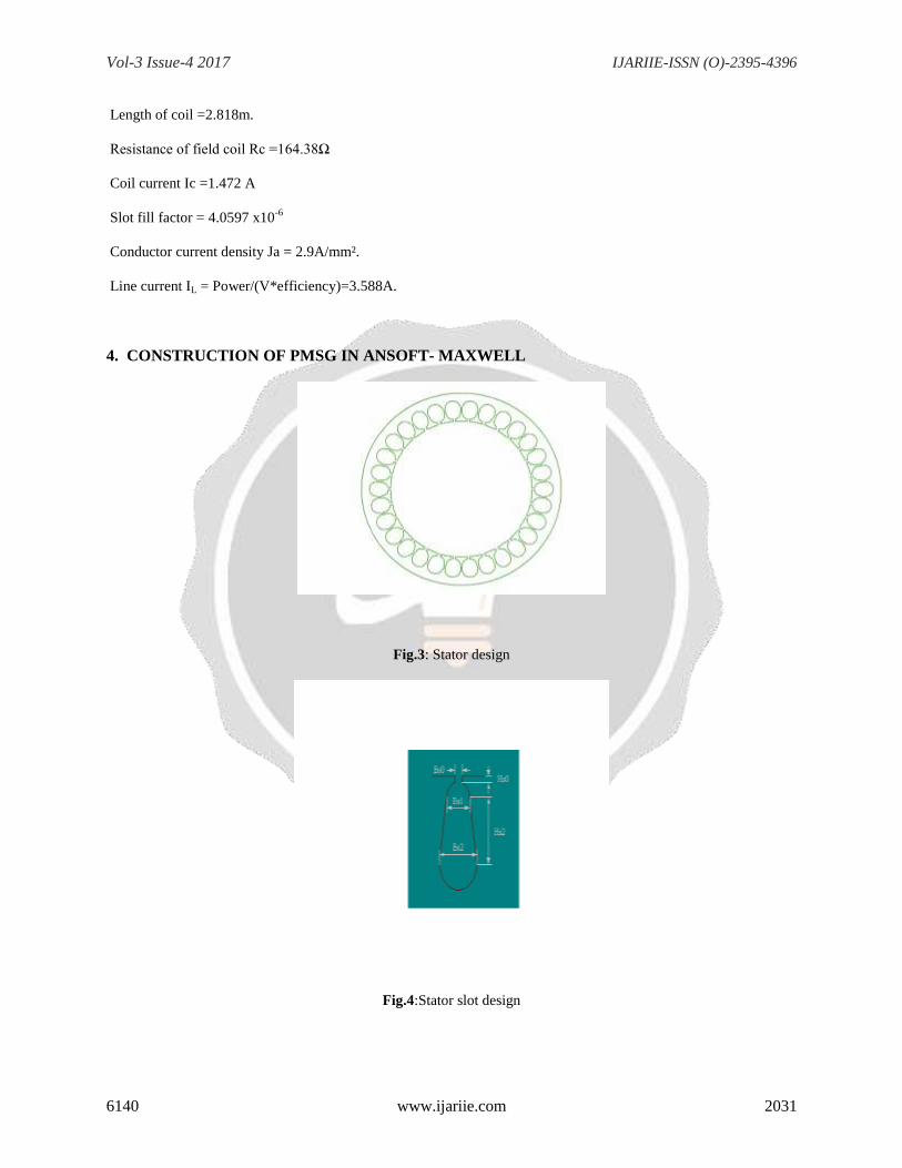
4. CONSTRUCTION OF PMSG IN ANSOFT- MAXWELL
Fig.3: Stator design
Fig.4:Stator slot design

Vol-3 Issue-4 2017 IJARIIE-ISSN (O)-2395-4396
6140 www.ijariie.com 2032
Fig.5: Windings of Stator
Fig.6: Rotor design
Fig.7: Entire Ansoft-RMxprt Construction

Vol-3 Issue-4 2017 IJARIIE-ISSN (O)-2395-4396
6140 www.ijariie.com 2033
Fig.8: Ansoft RMxprt Construction of PMSG Export to Ansoft- Maxwell 3D Design
4.1 Magnetostatic Analysis
Fig.9: Sectioning of Stator and Rotor for Magnetostatic Analysis
The steps for Magnetostatic analysis involves,
Vol-3 Issue-4 2017 IJARIIE-ISSN (O)-2395-4396
6140 www.ijariie.com 2034
(i)The RMxprt construction of permanent magnet synchronous generator is exported to Maxwell 3D
design.
(ii)Then this 3D model of PMSG is validated and analysed for the throughout Maxwell construction
obtained from RMxprt , boundary condition,and various excitation operations.
(iii)For the magnetostatic analysis we have to section the stator and rotor core in 3D model into number of
sections.
(iv)This produces the sections of the 3D model and this section is taken for the magnetostatic analysis.
(v)Select one of the sections and delete other sections. For that section an excitation current is applied.
5. SIMULATION AND RESULTS
Mathematical analysis of Low speed permanent magnet generator simulated by Ansoft Maxwell and
RMxprt software. And simulation result are no-load induced winding voltage at line and phase , cogging torque is
the torque due to the interaction between the permanent magnets of the rotor and the stator slots , air gap flux
density distribution , Power factor, their armature currents are shown.
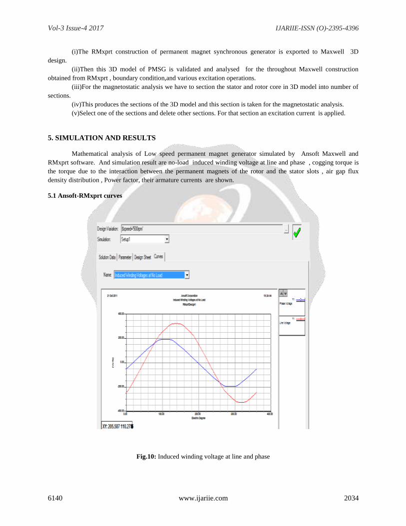
5.1 Ansoft-RMxprt curves
Fig.10: Induced winding voltage at line and phase
Vol-3 Issue-4 2017 IJARIIE-ISSN (O)-2395-4396
6140 www.ijariie.com 2035
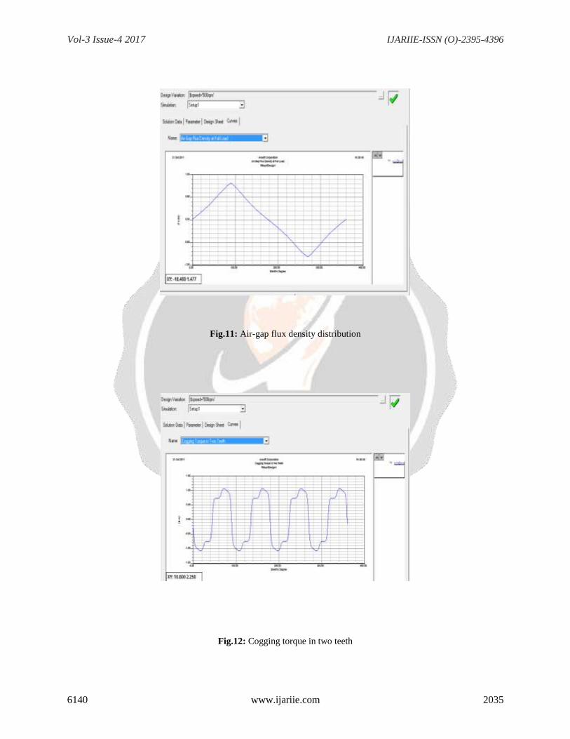
Fig.11: Air-gap flux density distribution
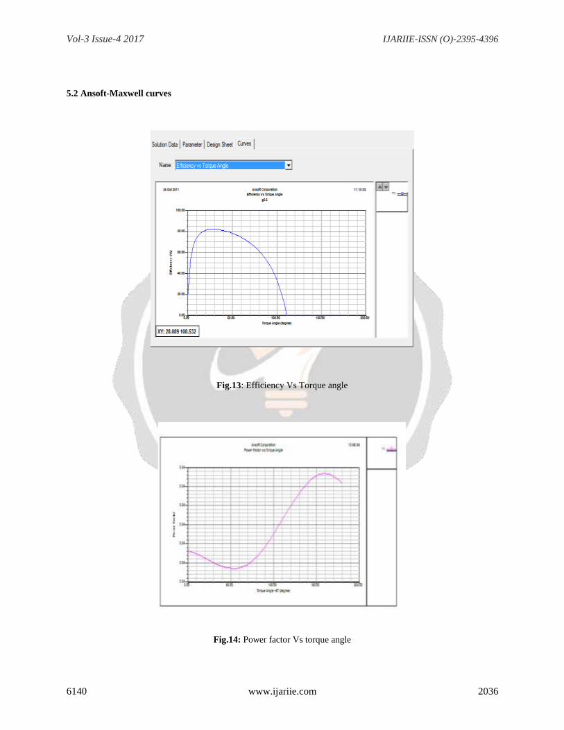
Fig.12: Cogging torque in two teeth
Vol-3 Issue-4 2017 IJARIIE-ISSN (O)-2395-4396
6140 www.ijariie.com 2036
5.2 Ansoft-Maxwell curves
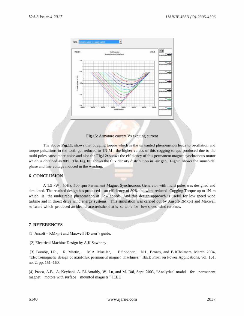
Fig.13: Efficiency Vs Torque angle
Fig.14: Power factor Vs torque angle
Vol-3 Issue-4 2017 IJARIIE-ISSN (O)-2395-4396
6140 www.ijariie.com 2037
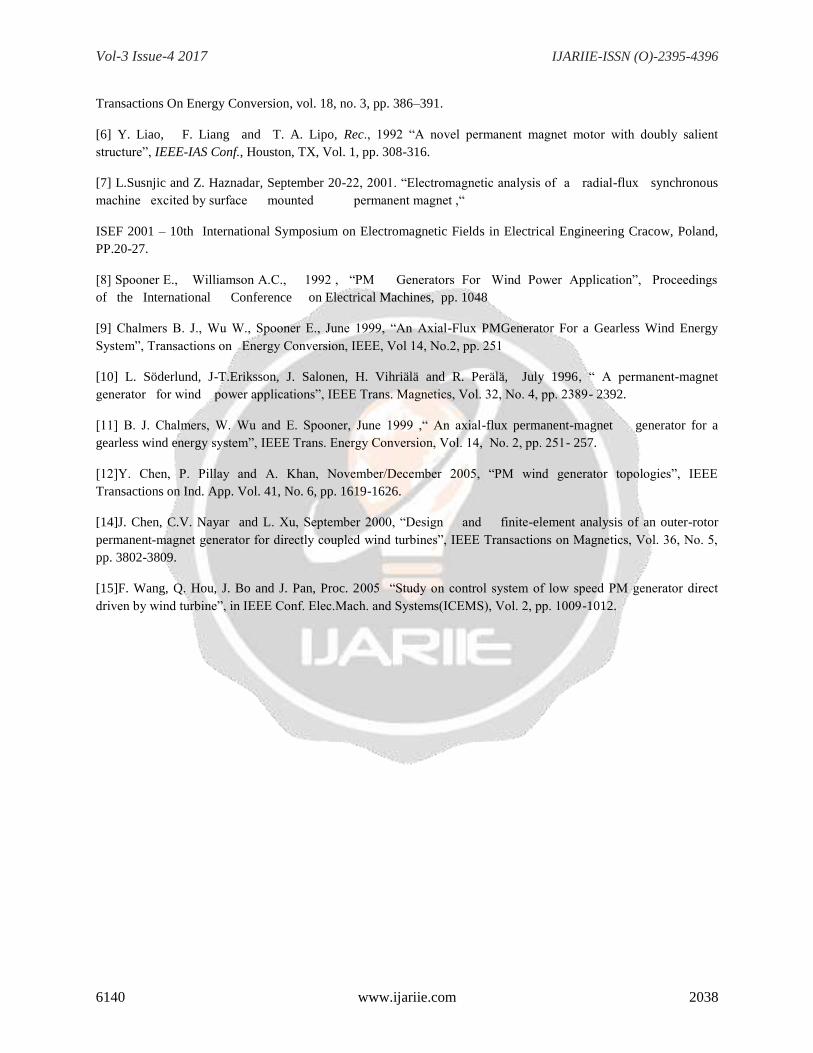
Fig.15: Armature current Vs exciting current
The above Fig.11: shows that cogging torque which is the unwanted phenomenon leads to oscillation and
torque pulsations in the teeth get reduced to 1N-M , the higher values of this cogging torque produced due to the
multi poles cause more noise and also the Fig.12: shows the efficiency of this permanent magnet synchronous motor
which is obtained as 80%. The Fig.10: shows the flux density distribution in air gap, Fig.9: shows the sinusoidal
phase and line voltage induced in the winding.
6 CONCLUSION
A 1.5 kW , 50Hz, 500 rpm Permanent Magnet Synchronous Generator with multi poles was designed and
simulated. The resulted design has produced an efficiency of 80% and with reduced Cogging Torque up to 1N-m
which is the undesirable phenomenon at low speeds. And this design approach is useful for low speed wind
turbine and in direct drive wind energy systems. This simulation was carried out by Ansoft-RMxprt and Maxwell
software which produced an ideal characteristics that is suitable for low speed wind turbines.
7 REFERENCES
[1] Ansoft – RMxprt and Maxwell 3D user’s guide.
[2] Electrical Machine Design by A.K.Sawhney
[3] Bumby, J.R., R. Martin, M.A. Mueller, E.Spooner, N.L. Brown, and B.JChalmers, March 2004,
“Electromagnetic design of axial-flux permanent magnet machines,” IEEE Proc. on Power Applications, vol. 151,
no. 2, pp. 151–160.
[4] Proca, A.B., A. Keyhani, A. El-Antably, W. Lu, and M. Dai, Sept. 2003, “Analytical model for permanent
magnet motors with surface mounted magnets,” IEEE
Vol-3 Issue-4 2017 IJARIIE-ISSN (O)-2395-4396
6140 www.ijariie.com 2038
Transactions On Energy Conversion, vol. 18, no. 3, pp. 386–391.
[6] Y. Liao, F. Liang and T. A. Lipo, Rec., 1992 “A novel permanent magnet motor with doubly salient
structure”, IEEE-IAS Conf., Houston, TX, Vol. 1, pp. 308-316.
[7] L.Susnjic and Z. Haznadar, September 20-22, 2001. “Electromagnetic analysis of a radial-flux synchronous
machine excited by surface mounted permanent magnet ,“
ISEF 2001 – 10th International Symposium on Electromagnetic Fields in Electrical Engineering Cracow, Poland,
PP.20-27.
[8] Spooner E., Williamson A.C., 1992 , “PM Generators For Wind Power Application”, Proceedings
of the International Conference on Electrical Machines, pp. 1048
[9] Chalmers B. J., Wu W., Spooner E., June 1999, “An Axial-Flux PMGenerator For a Gearless Wind Energy
System”, Transactions on Energy Conversion, IEEE, Vol 14, No.2, pp. 251
[10] L. Söderlund, J-T.Eriksson, J. Salonen, H. Vihriälä and R. Perälä, July 1996, “ A permanent-magnet
generator for wind power applications”, IEEE Trans. Magnetics, Vol. 32, No. 4, pp. 2389- 2392.
[11] B. J. Chalmers, W. Wu and E. Spooner, June 1999 ,“ An axial-flux permanent-magnet generator for a
gearless wind energy system”, IEEE Trans. Energy Conversion, Vol. 14, No. 2, pp. 251- 257.
[12]Y. Chen, P. Pillay and A. Khan, November/December 2005, “PM wind generator topologies”, IEEE
Transactions on Ind. App. Vol. 41, No. 6, pp. 1619-1626.
[14]J. Chen, C.V. Nayar and L. Xu, September 2000, “Design and finite-element analysis of an outer-rotor
permanent-magnet generator for directly coupled wind turbines”, IEEE Transactions on Magnetics, Vol. 36, No. 5,
pp. 3802-3809.
[15]F. Wang, Q. Hou, J. Bo and J. Pan, Proc. 2005 “Study on control system of low speed PM generator direct
driven by wind turbine”, in IEEE Conf. Elec.Mach. and Systems(ICEMS), Vol. 2, pp. 1009-1012.
Related Documents