Citation: Shill, S.K.; Garcez, E.O.; Al-Ameri, R.; Subhani, M. Performance of Two-Way Concrete Slabs Reinforced with Basalt and Carbon FRP Rebars. J. Compos. Sci. 2022, 6, 74. https://doi.org/ 10.3390/jcs6030074 Academic Editor: Francesco Tornabene Received: 3 February 2022 Accepted: 28 February 2022 Published: 1 March 2022 Publisher’s Note: MDPI stays neutral with regard to jurisdictional claims in published maps and institutional affil- iations. Copyright: © 2022 by the authors. Licensee MDPI, Basel, Switzerland. This article is an open access article distributed under the terms and conditions of the Creative Commons Attribution (CC BY) license (https:// creativecommons.org/licenses/by/ 4.0/). Article Performance of Two-Way Concrete Slabs Reinforced with Basalt and Carbon FRP Rebars Sukanta Kumer Shill , Estela O. Garcez, Riyadh Al-Ameri and Mahbube Subhani * School of Engineering, Deakin University, Waurn Ponds, Geelong, VIC 3216, Australia; [email protected] (S.K.S.); [email protected] (E.O.G.); [email protected] (R.A.-A.) * Correspondence: [email protected] Abstract: Fibre-reinforced polymer (FRP) rebars are being increasingly used to reinforce concrete structures that require long-term resistance to a corrosive environment. This study presents structural performance of large scale two-way concrete slabs reinforced with FRP rebars, and their performances were compared against conventional steel reinforced concrete. Both carbon FRP (CFRP) and basalt FRP (BFRP) were considered as steel replacement. Experimental results showed that the CFRP- and BFRP-RC slabs had approximately 7% and 4% higher cracking moment capacities than the steel-RC slab, respectively. The BFRP-RC slabs experienced a gradual decrease in the load capacity beyond the peak load, whereas the CFRP-RC slabs underwent a sharp decrease in load capacity, similar to the steel-RC slab. The BFRP-RC slabs demonstrated 1.72 times higher ductility than CFRP-RC slabs. The steel-RC slab was found to be safe against punching shear but failed due to flexural bending moment. The FRP-RC slabs were adequately safe against bending moment but failed due to punching shear. At failure load, the steel rebars were found to be yielded; however, the FRP rebars were not ruptured. FRP-RC slabs experienced a higher number of cracks and higher deflection compared to the steel-RC slab. However, FRP-RC slabs exhibited elastic recovery while unloading. Elastic recovery was not observed in the steel-RC slab. Additionally, the analytical load carrying capacity was validated against experimental values to investigate the efficacy of the current available standards (ACI 318-14 and ACI 440.1R-15) to predict the capacity of a two-way slab reinforced with CFRP or BFRP. The experimental load capacity of the CFRP-RC slabs was found to be approximately 1.20 times higher than the theoretical ultimate load capacity. However, the experimental load capacity of the BFRP-RC slabs was 6% lower than their theoretical ultimate load capacity. Keywords: fibre-reinforced polymer (FRP); basalt FRP rebar; carbon FRP rebar; two-way slab; load–deflection behaviour; punching shear; ductility of RC slab 1. Introduction Concrete slabs require reinforcement whether they are used as suspended structural members (e.g., floors of a building, bridge deck, or culvert structure) or ground bearing slabs. For suspended floor slabs, the reinforcement design depends on the superimposed load intensity, materials properties, and span length of the slab. Concrete slabs directly placed on the ground also require at least a minimum amount of reinforcement to protect them from shrinkage and temperatures effects. Worldwide, this reinforcing of concrete slabs is conventionally done using mild steel rebars. A number of outdoor concrete infrastructures, such as marine structures, protective structures in coastal area, airfield rigid pavements, parking areas, bridge decks, railway sleepers, and sewer infrastructures are often subjected to various aggressive environmental exposures, such as de-icing salts, high humidity, elevated temperatures, chloride ions, hydrogen sulphide gas, and other chemicals [1–5]. Exposure to those harsh conditions significantly reduces the alkalinity of the protective layer of concrete to reinforcing steel that results in substantial damage to the steel rebars. As conventional steel rebars are highly J. Compos. Sci. 2022, 6, 74. https://doi.org/10.3390/jcs6030074 https://www.mdpi.com/journal/jcs

Welcome message from author
This document is posted to help you gain knowledge. Please leave a comment to let me know what you think about it! Share it to your friends and learn new things together.
Transcript
�����������������
Citation: Shill, S.K.; Garcez, E.O.;
Al-Ameri, R.; Subhani, M.
Performance of Two-Way Concrete
Slabs Reinforced with Basalt and
Carbon FRP Rebars. J. Compos. Sci.
2022, 6, 74. https://doi.org/
10.3390/jcs6030074
Academic Editor: Francesco
Tornabene
Received: 3 February 2022
Accepted: 28 February 2022
Published: 1 March 2022
Publisher’s Note: MDPI stays neutral
with regard to jurisdictional claims in
published maps and institutional affil-
iations.
Copyright: © 2022 by the authors.
Licensee MDPI, Basel, Switzerland.
This article is an open access article
distributed under the terms and
conditions of the Creative Commons
Attribution (CC BY) license (https://
creativecommons.org/licenses/by/
4.0/).
Article
Performance of Two-Way Concrete Slabs Reinforced with Basaltand Carbon FRP RebarsSukanta Kumer Shill , Estela O. Garcez, Riyadh Al-Ameri and Mahbube Subhani *
School of Engineering, Deakin University, Waurn Ponds, Geelong, VIC 3216, Australia;[email protected] (S.K.S.); [email protected] (E.O.G.); [email protected] (R.A.-A.)* Correspondence: [email protected]
Abstract: Fibre-reinforced polymer (FRP) rebars are being increasingly used to reinforce concretestructures that require long-term resistance to a corrosive environment. This study presents structuralperformance of large scale two-way concrete slabs reinforced with FRP rebars, and their performanceswere compared against conventional steel reinforced concrete. Both carbon FRP (CFRP) and basaltFRP (BFRP) were considered as steel replacement. Experimental results showed that the CFRP- andBFRP-RC slabs had approximately 7% and 4% higher cracking moment capacities than the steel-RCslab, respectively. The BFRP-RC slabs experienced a gradual decrease in the load capacity beyond thepeak load, whereas the CFRP-RC slabs underwent a sharp decrease in load capacity, similar to thesteel-RC slab. The BFRP-RC slabs demonstrated 1.72 times higher ductility than CFRP-RC slabs. Thesteel-RC slab was found to be safe against punching shear but failed due to flexural bending moment.The FRP-RC slabs were adequately safe against bending moment but failed due to punching shear.At failure load, the steel rebars were found to be yielded; however, the FRP rebars were not ruptured.FRP-RC slabs experienced a higher number of cracks and higher deflection compared to the steel-RCslab. However, FRP-RC slabs exhibited elastic recovery while unloading. Elastic recovery was notobserved in the steel-RC slab. Additionally, the analytical load carrying capacity was validatedagainst experimental values to investigate the efficacy of the current available standards (ACI 318-14and ACI 440.1R-15) to predict the capacity of a two-way slab reinforced with CFRP or BFRP. Theexperimental load capacity of the CFRP-RC slabs was found to be approximately 1.20 times higherthan the theoretical ultimate load capacity. However, the experimental load capacity of the BFRP-RCslabs was 6% lower than their theoretical ultimate load capacity.
Keywords: fibre-reinforced polymer (FRP); basalt FRP rebar; carbon FRP rebar; two-way slab;load–deflection behaviour; punching shear; ductility of RC slab
1. Introduction
Concrete slabs require reinforcement whether they are used as suspended structuralmembers (e.g., floors of a building, bridge deck, or culvert structure) or ground bearingslabs. For suspended floor slabs, the reinforcement design depends on the superimposedload intensity, materials properties, and span length of the slab. Concrete slabs directlyplaced on the ground also require at least a minimum amount of reinforcement to protectthem from shrinkage and temperatures effects. Worldwide, this reinforcing of concreteslabs is conventionally done using mild steel rebars.
A number of outdoor concrete infrastructures, such as marine structures, protectivestructures in coastal area, airfield rigid pavements, parking areas, bridge decks, railwaysleepers, and sewer infrastructures are often subjected to various aggressive environmentalexposures, such as de-icing salts, high humidity, elevated temperatures, chloride ions,hydrogen sulphide gas, and other chemicals [1–5]. Exposure to those harsh conditionssignificantly reduces the alkalinity of the protective layer of concrete to reinforcing steelthat results in substantial damage to the steel rebars. As conventional steel rebars are highly
J. Compos. Sci. 2022, 6, 74. https://doi.org/10.3390/jcs6030074 https://www.mdpi.com/journal/jcs
J. Compos. Sci. 2022, 6, 74 2 of 19
prone to oxidation when exposed to moisture and air, they easily become oxidised andproduce iron oxides (rust).
Rust usually occupies a higher volume than steel and exerts multidirectional stresseson the surrounding concrete. Consequently, failure in bonds between concrete and steelrebars occurs, and numerous cracks develop [1]. Corrosion of steel rebars eventually leadsto the degradation of concrete, reduces the life expectancy of the structures considerably,and demands expensive strengthening/retrofitting works [6,7]. Therefore, the long-termdurability of concrete structures subjected to severe conditions is a crucial concern in theconstruction industry worldwide.
To resolve the issue, various protective measures, e.g., increasing concrete cover,coating steel rebars with epoxy, and improving the permeability of concrete, have beentaken into consideration. Nevertheless, not a single method has been fully successful toeliminate the corrosion risk of conventional steel reinforcement [7]. Innovation of fibre-reinforced polymer (FRP) rebars led the construction industry a step ahead to find thesolution to the problem at a lower cost. Recently, numerous studies reported that FRPrebars were found to be one of the promising alternatives to conventional steel rebars toreinforce concrete structures because of their excellent corrosion resistance, tensile strength,and lightweight [1,7–17].
FRP bars are usually manufactured from various high tensile strength fibres, such asglass, carbon, basalt, and aramid fibres, which are impregnated using different polymericresins, fillers, and curing agents. FRP rebars are non-corrosive, almost non-conductive, andpossess higher tensile strength [2,8–11]. However, they exhibit a linearly elastic stress–strainrelationship (no yield point) with a lower modulus of elasticity compared to conventionalsteel rebar [16,18–20].
Apart from the benefits of corrosion resistance, FRP-RC structures are lighter in weightthan steel-reinforced structures. As a result, the fabrication and installation processes ofprecast concrete elements are easier. In recent years, FRP rebars have become targeted dueto the enormous potential of replacing conventional steel reinforcement in multi-storeybuildings, industrial structures, water treatment plants, and other structures. For example,FRP rebars were used in real-life concrete structures around the world where durabilityand magnetic permeability were the controlling parameters [13,20–22].
Past studies reported that CFRP rebars are effective and appropriate as reinforcementsfor structural concrete [7,23]. According to Bilotta et al. [24], CFRP-RC slabs perform betterthan steel-reinforced slabs even when subjected to fire. CFRP was found to be lighter(usually 20% of the mass of conventional steel) and possesses a higher strength-to-weightratio and tensile strength [25]. In contrast, compared to steel reinforced slabs, CFRP-RCslabs usually require additional shear rebars to improve the punching resistance [26].
A few recent studies investigated the performance of BFRP-RC structures underdifferent loading and environmental conditions [27,28]. Basalt fibre is a relatively newbuilding material, which is composed of minerals such as pyroxene, plagioclase, andolivine [25]. It is environmentally friendly and can be a suitable alternative to glass fibrein the construction industry, as it has better physical and mechanical properties [25,29,30].Moreover, BFRP rebar has been recognized for its higher elongation at fracture and betterchemical resistance, especially in alkaline environments [31–33]. Additionally, BFRP rebarspossess a wide range of thermal and UV light resistance, have superior electro-magneticproperties, and are less costly compared to CFRP [30].
The flexural design of FRP-RC members is comparable to that of the concrete structuresreinforced with steel rebars [1,34,35]. However, due to the lower modulus of elasticity ofFRP rebars, concrete structures reinforced with FRP rebars usually possess lower shearstrength and flexural stiffness. As stated, FRP-RC members experience wider and deepercracks under the same loads when compared with typical RC structures [1,35]. Concretestructures reinforced with FRP exhibit relatively higher deflections and may experiencebrittle/sudden failure [19,20].
J. Compos. Sci. 2022, 6, 74 3 of 19
As reported, the structural performance of FRP-RC structures under service conditionsare promising [7]. To limit the cracks and deflection of FRP-RC structures, the designis generally governed by the serviceable state limit [1]. In order to avoid catastrophicfailures, most of the design codes recommend an over-reinforced flexural design for FRP-RC members [1,36]. Although the design guidelines of FRP-RC members are currentlyavailable [1], the limitations of use and design recommendations are still evolving asresearch progresses.
The present study is motivated by the promising properties of BFRP rebars, whichhave the potential to substitute steel rebars in corrosive environments. To date, the literaturerelated to the performance of BFRP reinforced two-way concrete slabs is still scarce. Thus,this paper deals with the load–deflection behaviour of large scale two-way concrete slabsreinforced with BFRP and CFRP rebars. It elucidates the ultimate load capacity, modes offailure, flexural stiffness, cracking moment, ultimate bending moment, punching shear ca-pacity, serviceable moment, and strain distribution along the FRP rebars. The experimentalload–deflection capacities of the FRP-RC slabs are compared with the theoretical capacitiesproposed by ACI 440.1R-15 [1]. The findings of this extensive experimental investigationwill help practitioners and engineers to design and construct CFRP- and BFRP-RC slabs.
2. Experimental Program
A total of seven simply supported two-way concrete slabs reinforced with CFRP, BFRP,and steel rebar was fabricated and tested to failure. Among the seven concrete slabs, threewere reinforced with CFRP, three were reinforced with BFRP, and one was reinforced withtypical steel rebar as a control specimen.
2.1. Material Properties
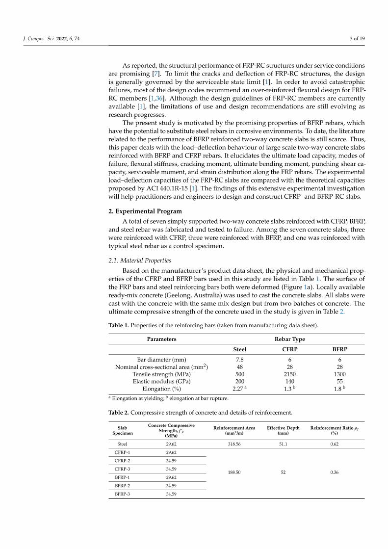
Based on the manufacturer’s product data sheet, the physical and mechanical prop-erties of the CFRP and BFRP bars used in this study are listed in Table 1. The surface ofthe FRP bars and steel reinforcing bars both were deformed (Figure 1a). Locally availableready-mix concrete (Geelong, Australia) was used to cast the concrete slabs. All slabs werecast with the concrete with the same mix design but from two batches of concrete. Theultimate compressive strength of the concrete used in the study is given in Table 2.
Table 1. Properties of the reinforcing bars (taken from manufacturing data sheet).
Parameters Rebar Type
Steel CFRP BFRP
Bar diameter (mm) 7.8 6 6Nominal cross-sectional area (mm2) 48 28 28
Tensile strength (MPa) 500 2150 1300Elastic modulus (GPa) 200 140 55
Elongation (%) 2.27 a 1.3 b 1.8 b
a Elongation at yielding; b elongation at bar rupture.
Table 2. Compressive strength of concrete and details of reinforcement.
SlabSpecimen
Concrete CompressiveStrength, f’c
(MPa)
Reinforcement Area(mm2/m)
Effective Depth(mm)
Reinforcement Ratio ρf(%)
Steel 29.62 318.56 51.1 0.62
CFRP-1 29.62
188.50 52 0.36
CFRP-2 34.59
CFRP-3 34.59
BFRP-1 29.62
BFRP-2 34.59
BFRP-3 34.59
J. Compos. Sci. 2022, 6, 74 4 of 19
J. Compos. Sci. 2022, 6, x FOR PEER REVIEW 3 of 19
Concrete structures reinforced with FRP exhibit relatively higher deflections and may ex-perience brittle/sudden failure [19,20].
As reported, the structural performance of FRP-RC structures under service condi-tions are promising [7]. To limit the cracks and deflection of FRP-RC structures, the design is generally governed by the serviceable state limit [1]. In order to avoid catastrophic fail-ures, most of the design codes recommend an over-reinforced flexural design for FRP-RC members [1,36]. Although the design guidelines of FRP-RC members are currently avail-able [1], the limitations of use and design recommendations are still evolving as research progresses.
The present study is motivated by the promising properties of BFRP rebars, which have the potential to substitute steel rebars in corrosive environments. To date, the litera-ture related to the performance of BFRP reinforced two-way concrete slabs is still scarce. Thus, this paper deals with the load–deflection behaviour of large scale two-way concrete slabs reinforced with BFRP and CFRP rebars. It elucidates the ultimate load capacity, modes of failure, flexural stiffness, cracking moment, ultimate bending moment, punch-ing shear capacity, serviceable moment, and strain distribution along the FRP rebars. The experimental load–deflection capacities of the FRP-RC slabs are compared with the theo-retical capacities proposed by ACI 440.1R-15 [1]. The findings of this extensive experi-mental investigation will help practitioners and engineers to design and construct CFRP- and BFRP-RC slabs.
2. Experimental Program A total of seven simply supported two-way concrete slabs reinforced with CFRP,
BFRP, and steel rebar was fabricated and tested to failure. Among the seven concrete slabs, three were reinforced with CFRP, three were reinforced with BFRP, and one was rein-forced with typical steel rebar as a control specimen.
2.1. Material Properties Based on the manufacturer’s product data sheet, the physical and mechanical prop-
erties of the CFRP and BFRP bars used in this study are listed in Table 1. The surface of the FRP bars and steel reinforcing bars both were deformed (Figure 1a). Locally available ready-mix concrete (Geelong, Australia) was used to cast the concrete slabs. All slabs were cast with the concrete with the same mix design but from two batches of concrete. The ultimate compressive strength of the concrete used in the study is given in Table 2.
Table 1. Properties of the reinforcing bars (taken from manufacturing data sheet).
Parameters Rebar Type Steel CFRP BFRP
Bar diameter (mm) 7.8 6 6 Nominal cross-sectional area (mm2) 48 28 28
Tensile strength (MPa) 500 2150 1300 Elastic modulus (GPa) 200 140 55
Elongation (%) 2.27 a 1.3 b 1.8 b a Elongation at yielding; b elongation at bar rupture.
(a)
J. Compos. Sci. 2022, 6, x FOR PEER REVIEW 4 of 19
(b)
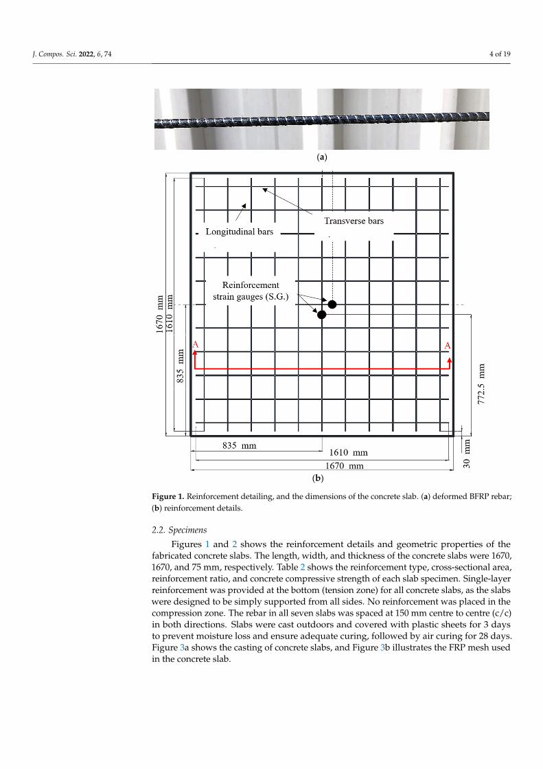
Figure 1. Reinforcement detailing, and the dimensions of the concrete slab. (a) deformed BFRP re-bar; (b) reinforcement details.
Table 2. Compressive strength of concrete and details of reinforcement.
Slab Specimen
Concrete Compressive Strength, f’c
(MPa)
Reinforcement Area (mm2/m)
Effective Depth (mm)
Reinforcement Ratio, 𝝆𝒇 (%)
Steel 29.62 318.56 51.1 0.62 CFRP-1 29.62
188.50 52 0.36
CFRP-2 34.59 CFRP-3 34.59 BFRP-1 29.62 BFRP-2 34.59 BFRP-3 34.59
2.2. Specimens Figures 1 and 2 shows the reinforcement details and geometric properties of the fab-
ricated concrete slabs. The length, width, and thickness of the concrete slabs were 1670, 1670, and 75 mm, respectively. Table 2 shows the reinforcement type, cross-sectional area, reinforcement ratio, and concrete compressive strength of each slab specimen. Single-layer reinforcement was provided at the bottom (tension zone) for all concrete slabs, as the slabs were designed to be simply supported from all sides. No reinforcement was placed in the compression zone. The rebar in all seven slabs was spaced at 150 mm centre to centre (c/c) in both directions. Slabs were cast outdoors and covered with plastic sheets for 3 days to prevent moisture loss and ensure adequate curing, followed by air curing for
Figure 1. Reinforcement detailing, and the dimensions of the concrete slab. (a) deformed BFRP rebar;(b) reinforcement details.
2.2. Specimens
Figures 1 and 2 shows the reinforcement details and geometric properties of thefabricated concrete slabs. The length, width, and thickness of the concrete slabs were 1670,1670, and 75 mm, respectively. Table 2 shows the reinforcement type, cross-sectional area,reinforcement ratio, and concrete compressive strength of each slab specimen. Single-layerreinforcement was provided at the bottom (tension zone) for all concrete slabs, as the slabswere designed to be simply supported from all sides. No reinforcement was placed in thecompression zone. The rebar in all seven slabs was spaced at 150 mm centre to centre (c/c)in both directions. Slabs were cast outdoors and covered with plastic sheets for 3 daysto prevent moisture loss and ensure adequate curing, followed by air curing for 28 days.Figure 3a shows the casting of concrete slabs, and Figure 3b illustrates the FRP mesh usedin the concrete slab.
J. Compos. Sci. 2022, 6, 74 5 of 19
J. Compos. Sci. 2022, 6, x FOR PEER REVIEW 5 of 19
28 days. Figure 3a shows the casting of concrete slabs, and Figure 3b illustrates the FRP mesh used in the concrete slab.
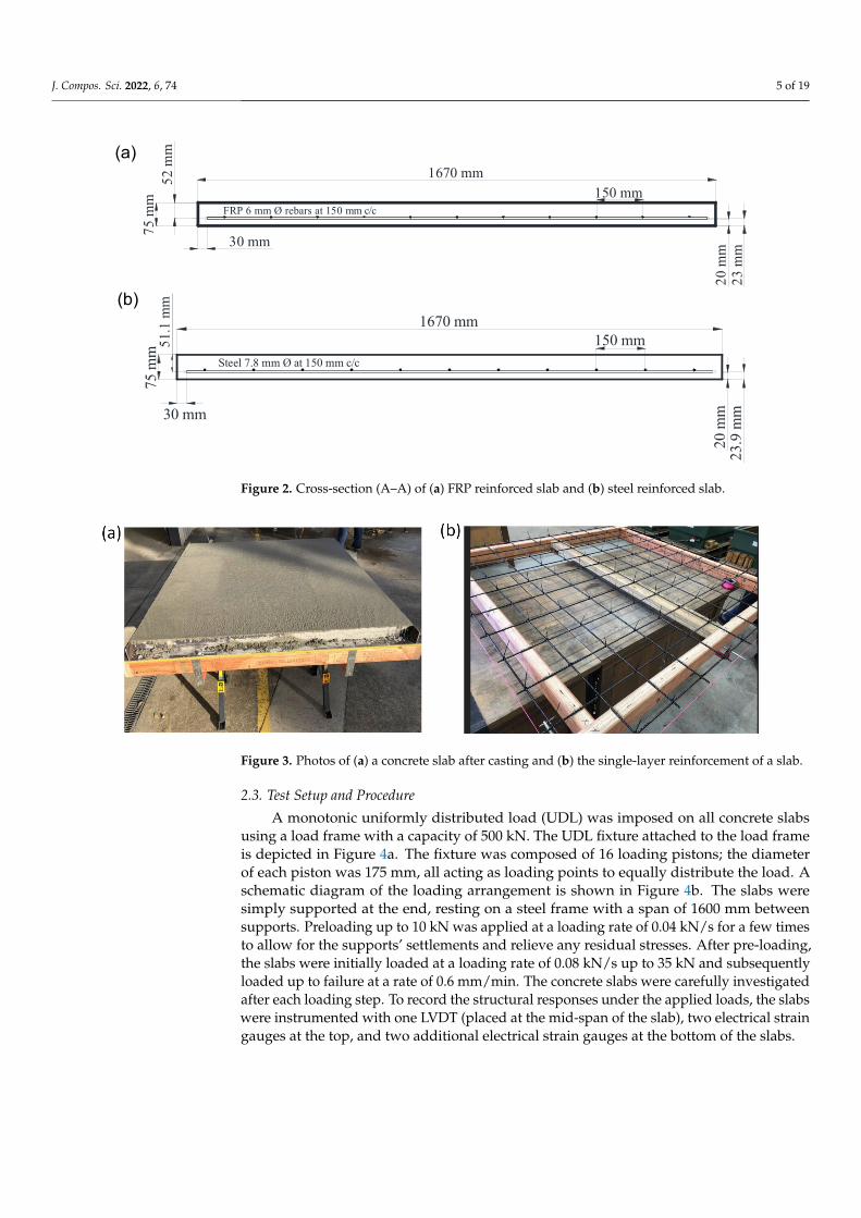
Figure 2. Cross-section (A–A) of (a) FRP reinforced slab and (b) steel reinforced slab.
Figure 3. Photos of (a) a concrete slab after casting and (b) the single-layer reinforcement of a slab.
2.3. Test Setup and Procedure A monotonic uniformly distributed load (UDL) was imposed on all concrete slabs
using a load frame with a capacity of 500 kN. The UDL fixture attached to the load frame is depicted in Figure 4a. The fixture was composed of 16 loading pistons; the diameter of each piston was 175 mm, all acting as loading points to equally distribute the load. A schematic diagram of the loading arrangement is shown in Figure 4b. The slabs were simply supported at the end, resting on a steel frame with a span of 1600 mm between supports. Preloading up to 10 kN was applied at a loading rate of 0.04 kN/s for a few times to allow for the supports’ settlements and relieve any residual stresses. After pre-loading, the slabs were initially loaded at a loading rate of 0.08 kN/s up to 35 kN and subsequently loaded up to failure at a rate of 0.6 mm/min. The concrete slabs were carefully investigated after each loading step. To record the structural responses under the applied loads, the slabs were instrumented with one LVDT (placed at the mid-span of the slab), two electri-cal strain gauges at the top, and two additional electrical strain gauges at the bottom of the slabs.
23 m
m
1670 mm52 m
m
30 mm
75 m
m
20 m
m
FRP 6 mm Ø rebars at 150 mm c/c150 mm
(a)
23.9
mm30 mm
1670 mm
51.1
mm
20 m
m
75 m
m
150 mmSteel 7.8 mm Ø at 150 mm c/c
(b)
Figure 2. Cross-section (A–A) of (a) FRP reinforced slab and (b) steel reinforced slab.
J. Compos. Sci. 2022, 6, x FOR PEER REVIEW 5 of 19
28 days. Figure 3a shows the casting of concrete slabs, and Figure 3b illustrates the FRP mesh used in the concrete slab.
Figure 2. Cross-section (A–A) of (a) FRP reinforced slab and (b) steel reinforced slab.
Figure 3. Photos of (a) a concrete slab after casting and (b) the single-layer reinforcement of a slab.
2.3. Test Setup and Procedure A monotonic uniformly distributed load (UDL) was imposed on all concrete slabs
using a load frame with a capacity of 500 kN. The UDL fixture attached to the load frame is depicted in Figure 4a. The fixture was composed of 16 loading pistons; the diameter of each piston was 175 mm, all acting as loading points to equally distribute the load. A schematic diagram of the loading arrangement is shown in Figure 4b. The slabs were simply supported at the end, resting on a steel frame with a span of 1600 mm between supports. Preloading up to 10 kN was applied at a loading rate of 0.04 kN/s for a few times to allow for the supports’ settlements and relieve any residual stresses. After pre-loading, the slabs were initially loaded at a loading rate of 0.08 kN/s up to 35 kN and subsequently loaded up to failure at a rate of 0.6 mm/min. The concrete slabs were carefully investigated after each loading step. To record the structural responses under the applied loads, the slabs were instrumented with one LVDT (placed at the mid-span of the slab), two electri-cal strain gauges at the top, and two additional electrical strain gauges at the bottom of the slabs.
23 m
m
1670 mm52 m
m
30 mm
75 m
m
20 m
m
FRP 6 mm Ø rebars at 150 mm c/c150 mm
(a)
23.9
mm30 mm
1670 mm
51.1
mm
20 m
m
75 m
m
150 mmSteel 7.8 mm Ø at 150 mm c/c
(b)
Figure 3. Photos of (a) a concrete slab after casting and (b) the single-layer reinforcement of a slab.
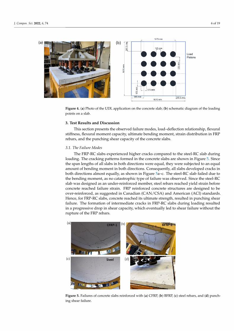
2.3. Test Setup and Procedure
A monotonic uniformly distributed load (UDL) was imposed on all concrete slabsusing a load frame with a capacity of 500 kN. The UDL fixture attached to the load frameis depicted in Figure 4a. The fixture was composed of 16 loading pistons; the diameterof each piston was 175 mm, all acting as loading points to equally distribute the load. Aschematic diagram of the loading arrangement is shown in Figure 4b. The slabs weresimply supported at the end, resting on a steel frame with a span of 1600 mm betweensupports. Preloading up to 10 kN was applied at a loading rate of 0.04 kN/s for a few timesto allow for the supports’ settlements and relieve any residual stresses. After pre-loading,the slabs were initially loaded at a loading rate of 0.08 kN/s up to 35 kN and subsequentlyloaded up to failure at a rate of 0.6 mm/min. The concrete slabs were carefully investigatedafter each loading step. To record the structural responses under the applied loads, the slabswere instrumented with one LVDT (placed at the mid-span of the slab), two electrical straingauges at the top, and two additional electrical strain gauges at the bottom of the slabs.
J. Compos. Sci. 2022, 6, 74 6 of 19J. Compos. Sci. 2022, 6, x FOR PEER REVIEW 6 of 19
Figure 4. (a) Photo of the UDL application on the concrete slab; (b) schematic diagram of the loading points on a slab.
3. Test Results and Discussion This section presents the observed failure modes, load–deflection relationship, flex-
ural stiffness, flexural moment capacity, ultimate bending moment, strain distribution in FRP rebars, and the punching shear capacity of the concrete slabs.
3.1. The Failure Modes The FRP-RC slabs experienced higher cracks compared to the steel-RC slab during
loading. The cracking patterns formed in the concrete slabs are shown in Figure 5. Since the span lengths of all slabs in both directions were equal, they were subjected to an equal amount of bending moment in both directions. Consequently, all slabs developed cracks in both directions almost equally, as shown in Figure 5a–c. The steel-RC slab failed due to the bending moment, as no catastrophic type of failure was observed. Since the steel-RC slab was designed as an under-reinforced member, steel rebars reached yield strain before concrete reached failure strain. FRP reinforced concrete structures are designed to be over-reinforced, as suggested in Canadian (CAN/CSA) and American (ACI) standards. Hence, for FRP-RC slabs, concrete reached its ultimate strength, resulted in punching shear fail-ure. The formation of intermediate cracks in FRP-RC slabs during loading resulted in a progressive drop in shear capacity, which eventually led to shear failure without the rup-ture of the FRP rebars.
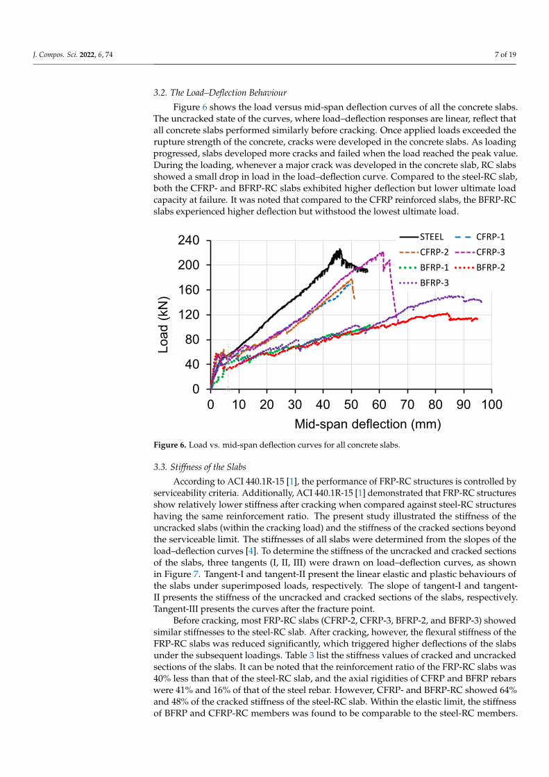
Figure 5. Failures of concrete slabs reinforced with (a) CFRP, (b) BFRP, (c) steel rebars, and (d) punching shear failure.
Figure 4. (a) Photo of the UDL application on the concrete slab; (b) schematic diagram of the loadingpoints on a slab.
3. Test Results and Discussion
This section presents the observed failure modes, load–deflection relationship, flexuralstiffness, flexural moment capacity, ultimate bending moment, strain distribution in FRPrebars, and the punching shear capacity of the concrete slabs.
3.1. The Failure Modes
The FRP-RC slabs experienced higher cracks compared to the steel-RC slab duringloading. The cracking patterns formed in the concrete slabs are shown in Figure 5. Sincethe span lengths of all slabs in both directions were equal, they were subjected to an equalamount of bending moment in both directions. Consequently, all slabs developed cracks inboth directions almost equally, as shown in Figure 5a–c. The steel-RC slab failed due tothe bending moment, as no catastrophic type of failure was observed. Since the steel-RCslab was designed as an under-reinforced member, steel rebars reached yield strain beforeconcrete reached failure strain. FRP reinforced concrete structures are designed to beover-reinforced, as suggested in Canadian (CAN/CSA) and American (ACI) standards.Hence, for FRP-RC slabs, concrete reached its ultimate strength, resulted in punching shearfailure. The formation of intermediate cracks in FRP-RC slabs during loading resultedin a progressive drop in shear capacity, which eventually led to shear failure without therupture of the FRP rebars.
J. Compos. Sci. 2022, 6, x FOR PEER REVIEW 6 of 19
Figure 4. (a) Photo of the UDL application on the concrete slab; (b) schematic diagram of the loading points on a slab.
3. Test Results and Discussion This section presents the observed failure modes, load–deflection relationship, flex-
ural stiffness, flexural moment capacity, ultimate bending moment, strain distribution in FRP rebars, and the punching shear capacity of the concrete slabs.
3.1. The Failure Modes The FRP-RC slabs experienced higher cracks compared to the steel-RC slab during
loading. The cracking patterns formed in the concrete slabs are shown in Figure 5. Since the span lengths of all slabs in both directions were equal, they were subjected to an equal amount of bending moment in both directions. Consequently, all slabs developed cracks in both directions almost equally, as shown in Figure 5a–c. The steel-RC slab failed due to the bending moment, as no catastrophic type of failure was observed. Since the steel-RC slab was designed as an under-reinforced member, steel rebars reached yield strain before concrete reached failure strain. FRP reinforced concrete structures are designed to be over-reinforced, as suggested in Canadian (CAN/CSA) and American (ACI) standards. Hence, for FRP-RC slabs, concrete reached its ultimate strength, resulted in punching shear fail-ure. The formation of intermediate cracks in FRP-RC slabs during loading resulted in a progressive drop in shear capacity, which eventually led to shear failure without the rup-ture of the FRP rebars.
Figure 5. Failures of concrete slabs reinforced with (a) CFRP, (b) BFRP, (c) steel rebars, and (d) punching shear failure. Figure 5. Failures of concrete slabs reinforced with (a) CFRP, (b) BFRP, (c) steel rebars, and (d) punch-ing shear failure.
J. Compos. Sci. 2022, 6, 74 7 of 19
3.2. The Load–Deflection Behaviour
Figure 6 shows the load versus mid-span deflection curves of all the concrete slabs.The uncracked state of the curves, where load–deflection responses are linear, reflect thatall concrete slabs performed similarly before cracking. Once applied loads exceeded therupture strength of the concrete, cracks were developed in the concrete slabs. As loadingprogressed, slabs developed more cracks and failed when the load reached the peak value.During the loading, whenever a major crack was developed in the concrete slab, RC slabsshowed a small drop in load in the load–deflection curve. Compared to the steel-RC slab,both the CFRP- and BFRP-RC slabs exhibited higher deflection but lower ultimate loadcapacity at failure. It was noted that compared to the CFRP reinforced slabs, the BFRP-RCslabs experienced higher deflection but withstood the lowest ultimate load.
J. Compos. Sci. 2022, 6, x FOR PEER REVIEW 7 of 19
3.2. The Load–Deflection Behaviour Figure 6 shows the load versus mid-span deflection curves of all the concrete slabs.
The uncracked state of the curves, where load–deflection responses are linear, reflect that all concrete slabs performed similarly before cracking. Once applied loads exceeded the rupture strength of the concrete, cracks were developed in the concrete slabs. As loading progressed, slabs developed more cracks and failed when the load reached the peak value. During the loading, whenever a major crack was developed in the concrete slab, RC slabs showed a small drop in load in the load–deflection curve. Compared to the steel-RC slab, both the CFRP- and BFRP-RC slabs exhibited higher deflection but lower ultimate load capacity at failure. It was noted that compared to the CFRP reinforced slabs, the BFRP-RC slabs experienced higher deflection but withstood the lowest ultimate load.
Figure 6. Load vs. mid-span deflection curves for all concrete slabs.
3.3. Stiffness of the Slabs According to ACI 440.1R-15 [1], the performance of FRP-RC structures is controlled
by serviceability criteria. Additionally, ACI 440.1R-15 [1] demonstrated that FRP-RC structures show relatively lower stiffness after cracking when compared against steel-RC structures having the same reinforcement ratio. The present study illustrated the stiffness of the uncracked slabs (within the cracking load) and the stiffness of the cracked sections beyond the serviceable limit. The stiffnesses of all slabs were determined from the slopes of the load–deflection curves [4]. To determine the stiffness of the uncracked and cracked sections of the slabs, three tangents (I, II, III) were drawn on load–deflection curves, as shown in Figure 7. Tangent-I and tangent-II present the linear elastic and plastic behav-iours of the slabs under superimposed loads, respectively. The slope of tangent-I and tan-gent-II presents the stiffness of the uncracked and cracked sections of the slabs, respec-tively. Tangent-III presents the curves after the fracture point.
0
40
80
120
160
200
240
0 10 20 30 40 50 60 70 80 90 100
Load
(kN
)
Mid-span deflection (mm)
STEEL CFRP-1CFRP-2 CFRP-3BFRP-1 BFRP-2BFRP-3
Figure 6. Load vs. mid-span deflection curves for all concrete slabs.
3.3. Stiffness of the Slabs
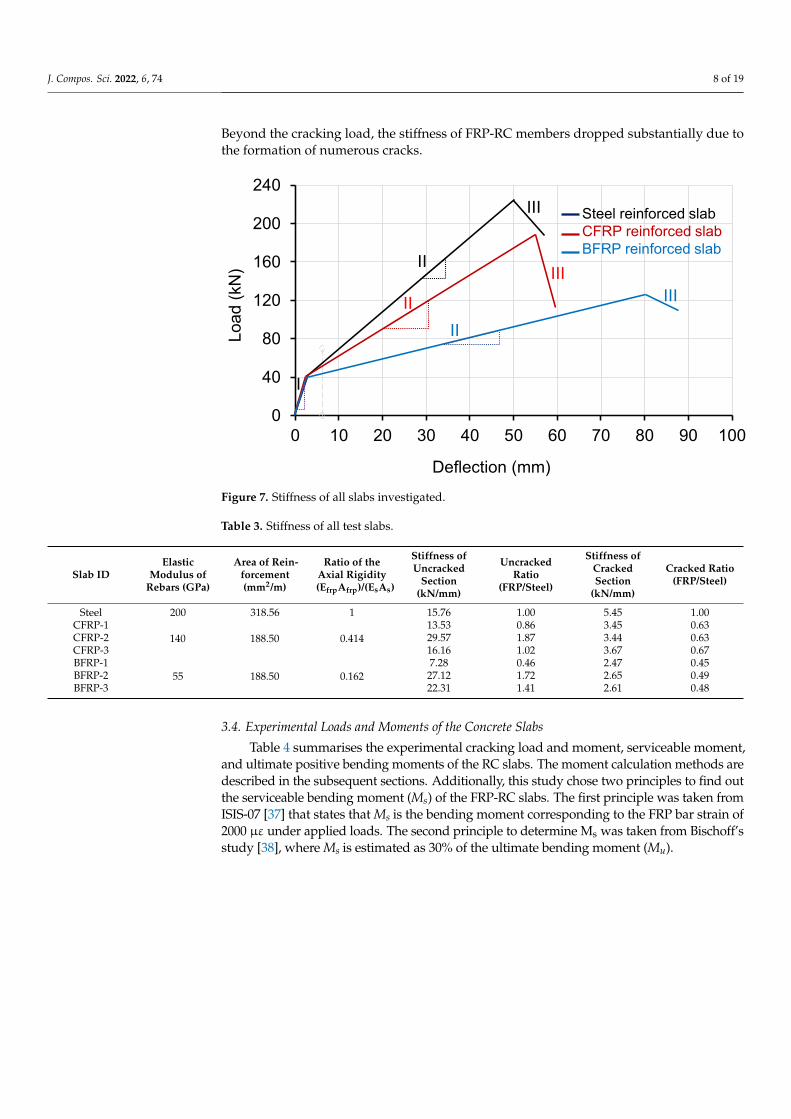
According to ACI 440.1R-15 [1], the performance of FRP-RC structures is controlled byserviceability criteria. Additionally, ACI 440.1R-15 [1] demonstrated that FRP-RC structuresshow relatively lower stiffness after cracking when compared against steel-RC structureshaving the same reinforcement ratio. The present study illustrated the stiffness of theuncracked slabs (within the cracking load) and the stiffness of the cracked sections beyondthe serviceable limit. The stiffnesses of all slabs were determined from the slopes of theload–deflection curves [4]. To determine the stiffness of the uncracked and cracked sectionsof the slabs, three tangents (I, II, III) were drawn on load–deflection curves, as shownin Figure 7. Tangent-I and tangent-II present the linear elastic and plastic behaviours ofthe slabs under superimposed loads, respectively. The slope of tangent-I and tangent-II presents the stiffness of the uncracked and cracked sections of the slabs, respectively.Tangent-III presents the curves after the fracture point.
Before cracking, most FRP-RC slabs (CFRP-2, CFRP-3, BFRP-2, and BFRP-3) showedsimilar stiffnesses to the steel-RC slab. After cracking, however, the flexural stiffness of theFRP-RC slabs was reduced significantly, which triggered higher deflections of the slabsunder the subsequent loadings. Table 3 list the stiffness values of cracked and uncrackedsections of the slabs. It can be noted that the reinforcement ratio of the FRP-RC slabs was40% less than that of the steel-RC slab, and the axial rigidities of CFRP and BFRP rebarswere 41% and 16% of that of the steel rebar. However, CFRP- and BFRP-RC showed 64%and 48% of the cracked stiffness of the steel-RC slab. Within the elastic limit, the stiffnessof BFRP and CFRP-RC members was found to be comparable to the steel-RC members.
J. Compos. Sci. 2022, 6, 74 8 of 19
Beyond the cracking load, the stiffness of FRP-RC members dropped substantially due tothe formation of numerous cracks.
J. Compos. Sci. 2022, 6, x FOR PEER REVIEW 8 of 19
Figure 7. Stiffness of all slabs investigated.
Before cracking, most FRP-RC slabs (CFRP-2, CFRP-3, BFRP-2, and BFRP-3) showed similar stiffnesses to the steel-RC slab. After cracking, however, the flexural stiffness of the FRP-RC slabs was reduced significantly, which triggered higher deflections of the slabs under the subsequent loadings. Table 3 list the stiffness values of cracked and uncracked sections of the slabs. It can be noted that the reinforcement ratio of the FRP-RC slabs was 40% less than that of the steel-RC slab, and the axial rigidities of CFRP and BFRP rebars were 41% and 16% of that of the steel rebar. However, CFRP- and BFRP-RC showed 64% and 48% of the cracked stiffness of the steel-RC slab. Within the elastic limit, the stiff-ness of BFRP and CFRP-RC members was found to be comparable to the steel-RC mem-bers. Beyond the cracking load, the stiffness of FRP-RC members dropped substantially due to the formation of numerous cracks.
Table 3. Stiffness of all test slabs.
Slab ID Elastic Mod-ulus of Re-bars (GPa)
Area of Re-inforce-
ment (mm2/m)
Ratio of the Axial Rigidity (EfrpAfrp)/(EsAs)
Stiffness of Uncracked
Section (kN/mm)
Uncracked Ra-tio
(FRP/Steel)
Stiffness of Cracked Sec-
tion (kN/mm)
Cracked Ratio (FRP/Steel)
Steel 200 318.56 1 15.76 1.00 5.45 1.00 CFRP-1
140 188.50 0.414 13.53 0.86 3.45 0.63
CFRP-2 29.57 1.87 3.44 0.63 CFRP-3 16.16 1.02 3.67 0.67 BFRP-1
55 188.50 0.162 7.28 0.46 2.47 0.45
BFRP-2 27.12 1.72 2.65 0.49 BFRP-3 22.31 1.41 2.61 0.48
3.4. Experimental Loads and Moments of the Concrete Slabs Table 4 summarises the experimental cracking load and moment, serviceable mo-
ment, and ultimate positive bending moments of the RC slabs. The moment calculation methods are described in the subsequent sections. Additionally, this study chose two prin-ciples to find out the serviceable bending moment (Ms) of the FRP-RC slabs. The first prin-ciple was taken from ISIS-07 [37] that states that Ms is the bending moment corresponding to the FRP bar strain of 2000 µε under applied loads. The second principle to determine
0
40
80
120
160
200
240
0 10 20 30 40 50 60 70 80 90 100
II
IIII
I
Steel reinforced slabCFRP reinforced slabBFRP reinforced slab
Load
(kN
)
Deflection (mm)
III
IIIIII
Figure 7. Stiffness of all slabs investigated.
Table 3. Stiffness of all test slabs.
Slab IDElastic
Modulus ofRebars (GPa)
Area of Rein-forcement(mm2/m)
Ratio of theAxial Rigidity(EfrpAfrp)/(EsAs)
Stiffness ofUncracked
Section(kN/mm)
UncrackedRatio
(FRP/Steel)
Stiffness ofCrackedSection
(kN/mm)
Cracked Ratio(FRP/Steel)
Steel 200 318.56 1 15.76 1.00 5.45 1.00CFRP-1
140 188.50 0.41413.53 0.86 3.45 0.63
CFRP-2 29.57 1.87 3.44 0.63CFRP-3 16.16 1.02 3.67 0.67BFRP-1
55 188.50 0.1627.28 0.46 2.47 0.45
BFRP-2 27.12 1.72 2.65 0.49BFRP-3 22.31 1.41 2.61 0.48
3.4. Experimental Loads and Moments of the Concrete Slabs
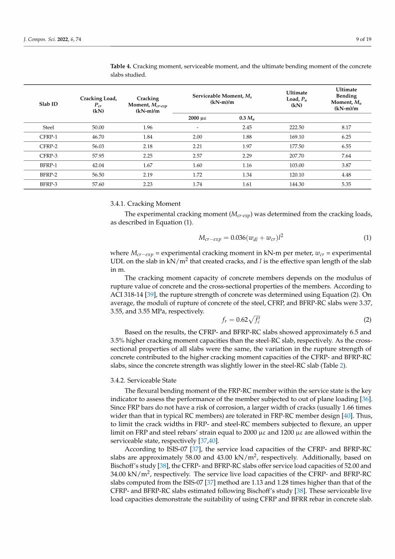
Table 4 summarises the experimental cracking load and moment, serviceable moment,and ultimate positive bending moments of the RC slabs. The moment calculation methods aredescribed in the subsequent sections. Additionally, this study chose two principles to find outthe serviceable bending moment (Ms) of the FRP-RC slabs. The first principle was taken fromISIS-07 [37] that states that Ms is the bending moment corresponding to the FRP bar strain of2000 µε under applied loads. The second principle to determine Ms was taken from Bischoff’sstudy [38], where Ms is estimated as 30% of the ultimate bending moment (Mu).
J. Compos. Sci. 2022, 6, 74 9 of 19
Table 4. Cracking moment, serviceable moment, and the ultimate bending moment of the concreteslabs studied.
Slab IDCracking Load,
Pcr(kN)
CrackingMoment, Mcr-exp
(kN-m)/m
Serviceable Moment, Ms(kN-m)/m
UltimateLoad, Pu
(kN)
UltimateBending
Moment, Mu(kN-m)/m
2000 µε 0.3 Mu
Steel 50.00 1.96 - 2.45 222.50 8.17
CFRP-1 46.70 1.84 2.00 1.88 169.10 6.25
CFRP-2 56.03 2.18 2.21 1.97 177.50 6.55
CFRP-3 57.95 2.25 2.57 2.29 207.70 7.64
BFRP-1 42.04 1.67 1.60 1.16 103.00 3.87
BFRP-2 56.50 2.19 1.72 1.34 120.10 4.48
BFRP-3 57.60 2.23 1.74 1.61 144.30 5.35
3.4.1. Cracking Moment
The experimental cracking moment (Mcr-exp) was determined from the cracking loads,as described in Equation (1).
Mcr−exp = 0.036(wdl + wcr)l2 (1)
where Mcr−exp = experimental cracking moment in kN-m per meter, wcr = experimentalUDL on the slab in kN/m2 that created cracks, and l is the effective span length of the slabin m.
The cracking moment capacity of concrete members depends on the modulus ofrupture value of concrete and the cross-sectional properties of the members. According toACI 318-14 [39], the rupture strength of concrete was determined using Equation (2). Onaverage, the moduli of rupture of concrete of the steel, CFRP, and BFRP-RC slabs were 3.37,3.55, and 3.55 MPa, respectively.
fr = 0.62√
f ′c (2)
Based on the results, the CFRP- and BFRP-RC slabs showed approximately 6.5 and3.5% higher cracking moment capacities than the steel-RC slab, respectively. As the cross-sectional properties of all slabs were the same, the variation in the rupture strength ofconcrete contributed to the higher cracking moment capacities of the CFRP- and BFRP-RCslabs, since the concrete strength was slightly lower in the steel-RC slab (Table 2).
3.4.2. Serviceable State
The flexural bending moment of the FRP-RC member within the service state is the keyindicator to assess the performance of the member subjected to out of plane loading [36].Since FRP bars do not have a risk of corrosion, a larger width of cracks (usually 1.66 timeswider than that in typical RC members) are tolerated in FRP-RC member design [40]. Thus,to limit the crack widths in FRP- and steel-RC members subjected to flexure, an upperlimit on FRP and steel rebars’ strain equal to 2000 µε and 1200 µε are allowed within theserviceable state, respectively [37,40].
According to ISIS-07 [37], the service load capacities of the CFRP- and BFRP-RCslabs are approximately 58.00 and 43.00 kN/m2, respectively. Additionally, based onBischoff’s study [38], the CFRP- and BFRP-RC slabs offer service load capacities of 52.00 and34.00 kN/m2, respectively. The service live load capacities of the CFRP- and BFRP-RCslabs computed from the ISIS-07 [37] method are 1.13 and 1.28 times higher than that of theCFRP- and BFRP-RC slabs estimated following Bischoff’s study [38]. These serviceable liveload capacities demonstrate the suitability of using CFRP and BFRR rebar in concrete slab.
J. Compos. Sci. 2022, 6, 74 10 of 19
3.4.3. Ultimate Moment
To determine the ultimate positive bending moment capacity of a simply supportedtwo-way concrete slab, the coefficient method of ACI 318-14 [39] was followed. Theultimate positive bending moment (Mu) in kN-m per unit meter was determined followingEquation (3).
Mu = 0.036(wdl + wll)l2 (3)
where wdl is the self-weight of the slab, and wll is the experimental ultimate UDL appliedon the slab in kN/m2.
Results showed that the CFRP- and BFRP-RC slabs possessed approximately 17 and45% lower ultimate moment capacities compared to the steel-RC slab, respectively. Fur-thermore, the ultimate moment capacity of the steel-RC slab was 4.17 times higher thanits cracking moment capacity, whereas on average, the ultimate moment capacities of theCFRP- and BFRP-RC slabs was 3.25 and 2.25 times higher than their cracking momentcapacities. The reason for that is due to the development of numerous wide cracks in theFRP-RC slabs beyond the cracking load. As the FRP bar has a lower modulus of elasticitycompared to steel, the FRP-RC slabs underwent significantly higher deflections under thesame load. Consequently, numerous cracks were developed beyond the serviceable limit,and cracking continually increased until the failure. Progressive cracking significantlyreduced the flexural capacity of the FRP-RC slabs, as the propagation of cracks into thecompressive zone led to the reduction in the effective depth of the slabs. Thus, the FRP-RCslabs showed lower ultimate moment capacity compared to the steel-reinforced slab. Fur-thermore, the BFRP-RC slabs had around 34% lower ultimate moment capacity than theCFRP-RC slabs, as BFRP bars used in the study had approximately 60% lower modulus ofelasticity than that of the CFRP bars.
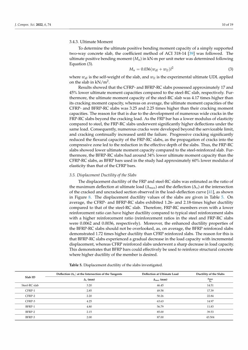
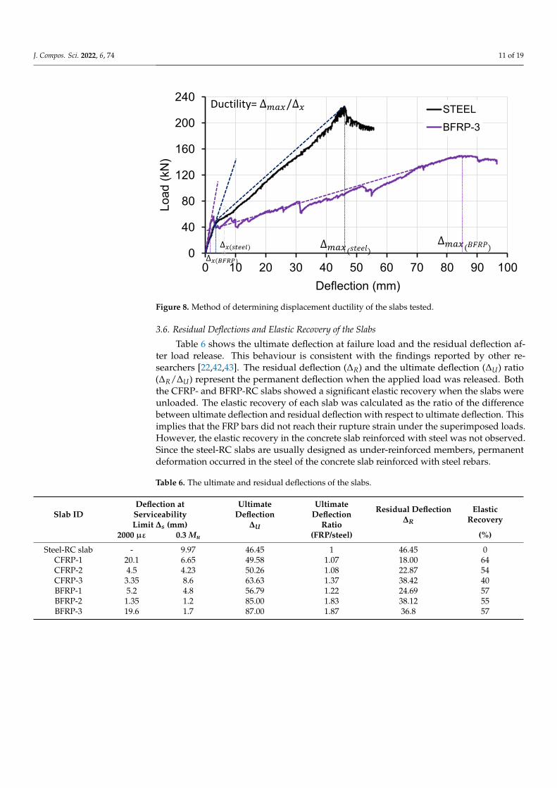
3.5. Displacement Ductility of the Slabs
The displacement ductility of the FRP and steel-RC slabs was estimated as the ratio ofthe maximum deflection at ultimate load (∆max) and the deflection (∆x) at the intersectionof the cracked and uncracked section observed in the load–deflection curve [41], as shownin Figure 8. The displacement ductility values of the slabs are given in Table 5. Onaverage, the CFRP- and BFRP-RC slabs exhibited 1.26- and 2.18-times higher ductilitycompared to that of the steel-RC slab. Therefore, FRP-RC members even with a lowerreinforcement ratio can have higher ductility compared to typical steel reinforcement slabswith a higher reinforcement ratio (reinforcement ratios in the steel and FRP-RC slabswere 0.0062 and 0.0036, respectively). Moreover, the enhanced ductility properties ofthe BFRP-RC slabs should not be overlooked, as, on average, the BFRP reinforced slabsdemonstrated 1.72 times higher ductility than CFRP reinforced slabs. The reason for this isthat BFRP-RC slabs experienced a gradual decrease in the load capacity with incrementaldisplacement, whereas CFRP reinforced slabs underwent a sharp decrease in load capacity.This demonstrates that BFRP bars could effectively be used to reinforce structural concretewhere higher ductility of the member is desired.
Table 5. Displacement ductility of the slabs investigated.
Slab IDDeflection (∆x) at the Intersection of the Tangents Deflection at Ultimate Load Ductility of the Slabs
∆x (mm) ∆max (mm) ∆max∆x
Steel-RC slab 3.20 46.45 14.51
CFRP-1 2.85 49.58 17.39
CFRP-2 2.20 50.26 22.84
CFRP-3 4.25 63.63 14.97
BFRP-1 4.80 56.79 11.83
BFRP-2 2.15 85.00 39.53
BFRP-3 2.00 87.00 43.504
J. Compos. Sci. 2022, 6, 74 11 of 19J. Compos. Sci. 2022, 6, x FOR PEER REVIEW 11 of 19
Figure 8. Method of determining displacement ductility of the slabs tested.
Table 5. Displacement ductility of the slabs investigated.
Slab ID Deflection (∆𝒙) at the Intersection of the Tangents Deflection at Ultimate Load Ductility of the Slabs ∆𝒙 (mm) ∆𝒎𝒂𝒙 (mm)
∆𝒎𝒂𝒙∆𝒙
Steel-RC slab 3.20 46.45 14.51 CFRP-1 2.85 49.58 17.39 CFRP-2 2.20 50.26 22.84 CFRP-3 4.25 63.63 14.97 BFRP-1 4.80 56.79 11.83 BFRP-2 2.15 85.00 39.53 BFRP-3 2.00 87.00 43.504
3.6. Residual Deflections and Elastic Recovery of the Slabs Table 6 shows the ultimate deflection at failure load and the residual deflection after
load release. This behaviour is consistent with the findings reported by other researchers [22,42,43]. The residual deflection (∆ ) and the ultimate deflection (∆ ) ratio (∆ ∆⁄ ) rep-resent the permanent deflection when the applied load was released. Both the CFRP- and BFRP-RC slabs showed a significant elastic recovery when the slabs were unloaded. The elastic recovery of each slab was calculated as the ratio of the difference between ultimate deflection and residual deflection with respect to ultimate deflection. This implies that the FRP bars did not reach their rupture strain under the superimposed loads. However, the elastic recovery in the concrete slab reinforced with steel was not observed. Since the steel-RC slabs are usually designed as under-reinforced members, permanent deformation oc-curred in the steel of the concrete slab reinforced with steel rebars.
Table 6. The ultimate and residual deflections of the slabs.
Slab ID Deflection at Serviceability Limit ∆𝒔 (mm)
Ultimate De-flection ∆𝑼
Ultimate De-flection
Ratio
Residual De-flection ∆𝑹
Elastic Recovery
2000 µε 0.3 Mu (FRP/steel) (%) Steel-RC slab - 9.97 46.45 1 46.45 0
CFRP-1 20.1 6.65 49.58 1.07 18.00 64 CFRP-2 4.5 4.23 50.26 1.08 22.87 54 CFRP-3 3.35 8.6 63.63 1.37 38.42 40
0
40
80
120
160
200
240
0 10 20 30 40 50 60 70 80 90 100
Load
(kN
)
Deflection (mm)
STEELBFRP-3
)
Ductility=
Figure 8. Method of determining displacement ductility of the slabs tested.
3.6. Residual Deflections and Elastic Recovery of the Slabs
Table 6 shows the ultimate deflection at failure load and the residual deflection af-ter load release. This behaviour is consistent with the findings reported by other re-searchers [22,42,43]. The residual deflection (∆R) and the ultimate deflection (∆U) ratio(∆R/∆U) represent the permanent deflection when the applied load was released. Boththe CFRP- and BFRP-RC slabs showed a significant elastic recovery when the slabs wereunloaded. The elastic recovery of each slab was calculated as the ratio of the differencebetween ultimate deflection and residual deflection with respect to ultimate deflection. Thisimplies that the FRP bars did not reach their rupture strain under the superimposed loads.However, the elastic recovery in the concrete slab reinforced with steel was not observed.Since the steel-RC slabs are usually designed as under-reinforced members, permanentdeformation occurred in the steel of the concrete slab reinforced with steel rebars.
Table 6. The ultimate and residual deflections of the slabs.
Slab IDDeflection atServiceabilityLimit ∆s (mm)
UltimateDeflection
∆U
UltimateDeflection
Ratio
Residual Deflection∆R
ElasticRecovery
2000 µε 0.3 Mu (FRP/steel) (%)
Steel-RC slab - 9.97 46.45 1 46.45 0CFRP-1 20.1 6.65 49.58 1.07 18.00 64CFRP-2 4.5 4.23 50.26 1.08 22.87 54CFRP-3 3.35 8.6 63.63 1.37 38.42 40BFRP-1 5.2 4.8 56.79 1.22 24.69 57BFRP-2 1.35 1.2 85.00 1.83 38.12 55BFRP-3 19.6 1.7 87.00 1.87 36.8 57
J. Compos. Sci. 2022, 6, 74 12 of 19
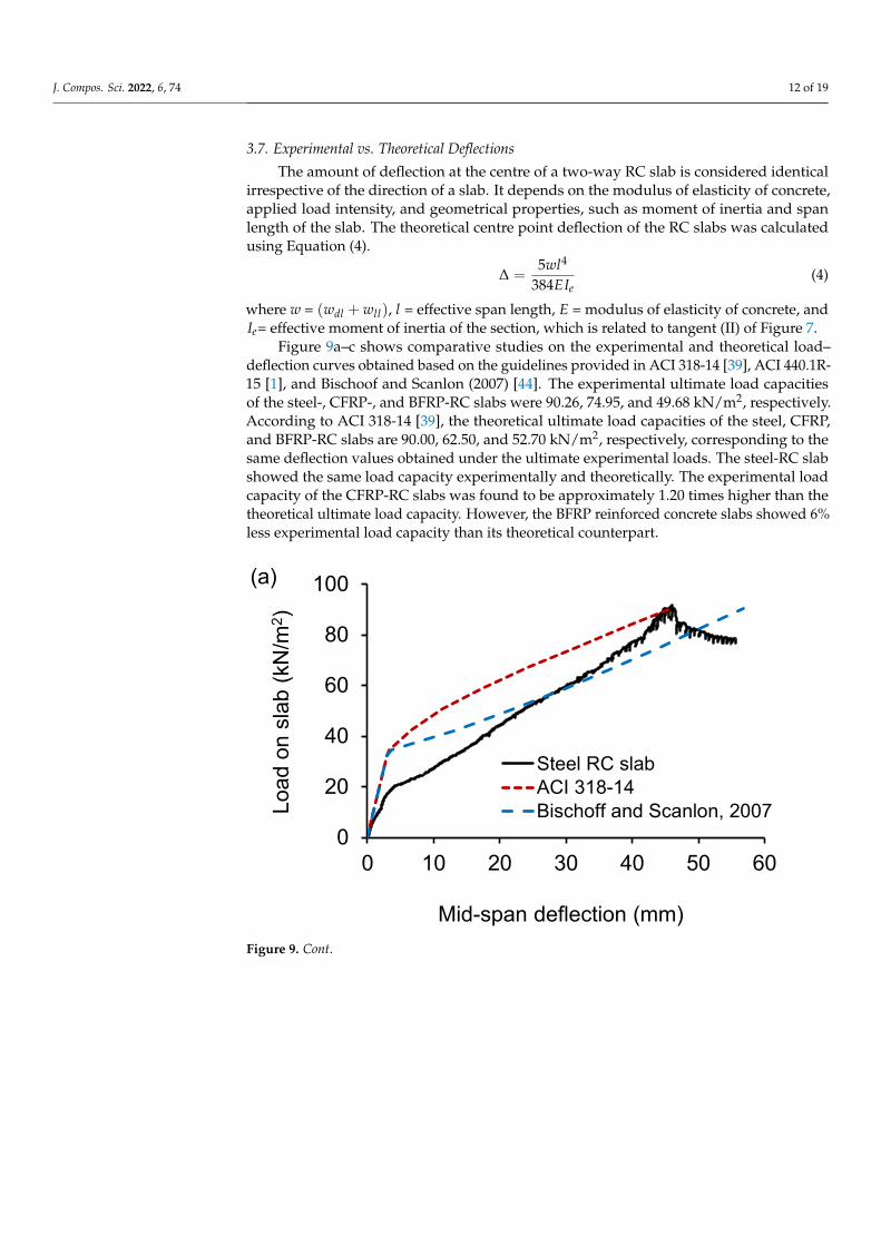
3.7. Experimental vs. Theoretical Deflections
The amount of deflection at the centre of a two-way RC slab is considered identicalirrespective of the direction of a slab. It depends on the modulus of elasticity of concrete,applied load intensity, and geometrical properties, such as moment of inertia and spanlength of the slab. The theoretical centre point deflection of the RC slabs was calculatedusing Equation (4).
∆ =5wl4
384EIe(4)
where w = (wdl + wll), l = effective span length, E = modulus of elasticity of concrete, andIe= effective moment of inertia of the section, which is related to tangent (II) of Figure 7.
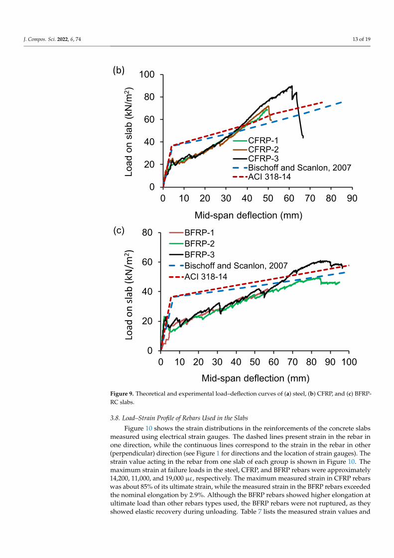
Figure 9a–c shows comparative studies on the experimental and theoretical load–deflection curves obtained based on the guidelines provided in ACI 318-14 [39], ACI 440.1R-15 [1], and Bischoof and Scanlon (2007) [44]. The experimental ultimate load capacitiesof the steel-, CFRP-, and BFRP-RC slabs were 90.26, 74.95, and 49.68 kN/m2, respectively.According to ACI 318-14 [39], the theoretical ultimate load capacities of the steel, CFRP,and BFRP-RC slabs are 90.00, 62.50, and 52.70 kN/m2, respectively, corresponding to thesame deflection values obtained under the ultimate experimental loads. The steel-RC slabshowed the same load capacity experimentally and theoretically. The experimental loadcapacity of the CFRP-RC slabs was found to be approximately 1.20 times higher than thetheoretical ultimate load capacity. However, the BFRP reinforced concrete slabs showed 6%less experimental load capacity than its theoretical counterpart.
J. Compos. Sci. 2022, 6, x FOR PEER REVIEW 12 of 19
BFRP-1 5.2 4.8 56.79 1.22 24.69 57 BFRP-2 1.35 1.2 85.00 1.83 38.12 55 BFRP-3 19.6 1.7 87.00 1.87 36.8 57
3.7. Experimental vs. Theoretical Deflections The amount of deflection at the centre of a two-way RC slab is considered identical
irrespective of the direction of a slab. It depends on the modulus of elasticity of concrete, applied load intensity, and geometrical properties, such as moment of inertia and span length of the slab. The theoretical centre point deflection of the RC slabs was calculated using Equation (4). ∆ = 5𝑤𝑙384𝐸𝐼 (4)
where w = 𝑤 + 𝑤 ), 𝑙 = effective span length, 𝐸 = modulus of elasticity of concrete, and 𝐼 = effective moment of inertia of the section, which is related to tangent (II) of Figure 7.
Figure 9a–c shows comparative studies on the experimental and theoretical load–deflection curves obtained based on the guidelines provided in ACI 318-14 [39], ACI 440.1R-15 [1], and Bischoof and Scanlon (2007) [44]. The experimental ultimate load ca-pacities of the steel-, CFRP-, and BFRP-RC slabs were 90.26, 74.95, and 49.68 kN/m2, re-spectively. According to ACI 318-14 [39], the theoretical ultimate load capacities of the steel, CFRP, and BFRP-RC slabs are 90.00, 62.50, and 52.70 kN/m2, respectively, corre-sponding to the same deflection values obtained under the ultimate experimental loads. The steel-RC slab showed the same load capacity experimentally and theoretically. The experimental load capacity of the CFRP-RC slabs was found to be approximately 1.20 times higher than the theoretical ultimate load capacity. However, the BFRP reinforced concrete slabs showed 6% less experimental load capacity than its theoretical counterpart.
0
20
40
60
80
100
0 10 20 30 40 50 60
Load
on
slab
(kN
/m2 )
Mid-span deflection (mm)
Steel RC slabACI 318-14Bischoff and Scanlon, 2007
(a)
Figure 9. Cont.
J. Compos. Sci. 2022, 6, 74 13 of 19J. Compos. Sci. 2022, 6, x FOR PEER REVIEW 13 of 19
Figure 9. Theoretical and experimental load–deflection curves of (a) steel, (b) CFRP, and (c) BFRP-RC slabs.
3.8. Load–Strain Profile of Rebars Used in the Slabs Figure 10 shows the strain distributions in the reinforcements of the concrete slabs
measured using electrical strain gauges. The dashed lines present strain in the rebar in one direction, while the continuous lines correspond to the strain in the rebar in other (perpendicular) direction (see Figure 1 for directions and the location of strain gauges). The strain value acting in the rebar from one slab of each group is shown in Figure 10. The maximum strain at failure loads in the steel, CFRP, and BFRP rebars were approximately 14,200, 11,000, and 19,000 µε, respectively. The maximum measured strain in CFRP rebars was about 85% of its ultimate strain, while the measured strain in the BFRP rebars ex-ceeded the nominal elongation by 2.9%. Although the BFRP rebars showed higher elon-gation at ultimate load than other rebars types used, the BFRP rebars were not ruptured, as they showed elastic recovery during unloading. Table 7 lists the measured strain values and developed stresses in FRP rebars at failure loads. Additionally, the ultimate strain of concrete for each slab computed using ACI 440.1R-15 [1] is presented. The developed stress in all FRP rebars at ultimate load remained well below the rupture strength. This implies that FRP rebars did not rupture when the slabs failed due to loads. As punching shear of concrete triggers the failure of FRP-RC slabs, this study recommends high strength concrete to be used in concrete structures reinforced with FRP rebars to achieve high resistance against punching shear force.
0
20
40
60
80
100
0 10 20 30 40 50 60 70 80 90
Load
on
slab
(kN
/m2 )
Mid-span deflection (mm)
CFRP-1CFRP-2CFRP-3Bischoff and Scanlon, 2007ACI 318-14
(b)
0
20
40
60
80
0 10 20 30 40 50 60 70 80 90 100
Load
on
slab
(kN/
m2 )
Mid-span deflection (mm)
BFRP-1BFRP-2BFRP-3Bischoff and Scanlon, 2007ACI 318-14
(c)
Figure 9. Theoretical and experimental load–deflection curves of (a) steel, (b) CFRP, and (c) BFRP-RC slabs.
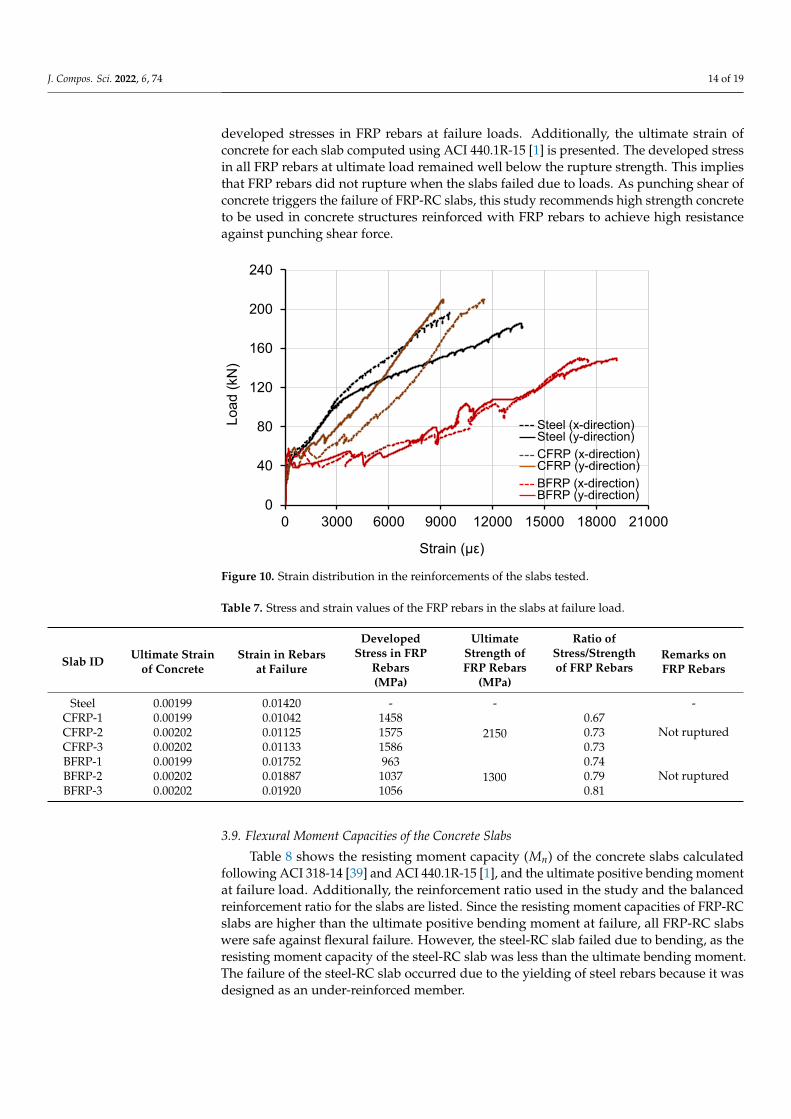
3.8. Load–Strain Profile of Rebars Used in the Slabs
Figure 10 shows the strain distributions in the reinforcements of the concrete slabsmeasured using electrical strain gauges. The dashed lines present strain in the rebar inone direction, while the continuous lines correspond to the strain in the rebar in other(perpendicular) direction (see Figure 1 for directions and the location of strain gauges). Thestrain value acting in the rebar from one slab of each group is shown in Figure 10. Themaximum strain at failure loads in the steel, CFRP, and BFRP rebars were approximately14,200, 11,000, and 19,000 µε, respectively. The maximum measured strain in CFRP rebarswas about 85% of its ultimate strain, while the measured strain in the BFRP rebars exceededthe nominal elongation by 2.9%. Although the BFRP rebars showed higher elongation atultimate load than other rebars types used, the BFRP rebars were not ruptured, as theyshowed elastic recovery during unloading. Table 7 lists the measured strain values and
J. Compos. Sci. 2022, 6, 74 14 of 19
developed stresses in FRP rebars at failure loads. Additionally, the ultimate strain ofconcrete for each slab computed using ACI 440.1R-15 [1] is presented. The developed stressin all FRP rebars at ultimate load remained well below the rupture strength. This impliesthat FRP rebars did not rupture when the slabs failed due to loads. As punching shear ofconcrete triggers the failure of FRP-RC slabs, this study recommends high strength concreteto be used in concrete structures reinforced with FRP rebars to achieve high resistanceagainst punching shear force.
J. Compos. Sci. 2022, 6, x FOR PEER REVIEW 14 of 19
Figure 10. Strain distribution in the reinforcements of the slabs tested.
Table 7. Stress and strain values of the FRP rebars in the slabs at failure load.
Slab ID Ultimate
Strain of Con-crete
Strain in Rebars at Failure
Developed Stress in FRP
Rebars
Ultimate Strength of FRP
Rebars
Ratio of Stress/Strength of
FRP Rebars Remarks on FRP Rebars
(MPa) (MPa) Steel 0.00199 0.01420 - - -
CFRP-1 0.00199 0.01042 1458 2150
0.67 Not ruptured CFRP-2 0.00202 0.01125 1575 0.73
CFRP-3 0.00202 0.01133 1586 0.73 BFRP-1 0.00199 0.01752 963
1300 0.74
Not ruptured BFRP-2 0.00202 0.01887 1037 0.79 BFRP-3 0.00202 0.01920 1056 0.81
3.9. Flexural Moment Capacities of the Concrete Slabs Table 8 shows the resisting moment capacity (𝑀 ) of the concrete slabs calculated
following ACI 318-14 [39] and ACI 440.1R-15 [1], and the ultimate positive bending mo-ment at failure load. Additionally, the reinforcement ratio used in the study and the bal-anced reinforcement ratio for the slabs are listed. Since the resisting moment capacities of FRP-RC slabs are higher than the ultimate positive bending moment at failure, all FRP-RC slabs were safe against flexural failure. However, the steel-RC slab failed due to bend-ing, as the resisting moment capacity of the steel-RC slab was less than the ultimate bend-ing moment. The failure of the steel-RC slab occurred due to the yielding of steel rebars because it was designed as an under-reinforced member.
Table 8. Ultimate resisting moment and bending moment of the slabs.
Slab ID Reinforcement
Ratio
Balanced Rein-forcement
Ratio
Resisting Mo-ment, Mn
Resisting Load, Pn
Ultimate Bending Mo-
ment, Mu
𝑴𝒏𝑴𝒖 Ra-
tio Remarks
(kN-m/m) (kN) (kNm/M)
Steel 0.00623 0.02269 7.61 206.95 8.17 0.93 Failed by steel yielding
CFRP-1 0.00362 0.00241 10.04 274.45 6.25 1.61
0
40
80
120
160
200
240
0 3000 6000 9000 12000 15000 18000 21000
Load
(kN
)
Strain (με)
Steel (x-direction)Steel (y-direction)CFRP (x-direction)CFRP (y-direction)BFRP (x-direction)BFRP (y-direction)
Figure 10. Strain distribution in the reinforcements of the slabs tested.
Table 7. Stress and strain values of the FRP rebars in the slabs at failure load.
Slab ID Ultimate Strainof Concrete
Strain in Rebarsat Failure
DevelopedStress in FRP
Rebars
UltimateStrength ofFRP Rebars
Ratio ofStress/Strengthof FRP Rebars
Remarks onFRP Rebars
(MPa) (MPa)
Steel 0.00199 0.01420 - - -CFRP-1 0.00199 0.01042 1458
21500.67
Not rupturedCFRP-2 0.00202 0.01125 1575 0.73CFRP-3 0.00202 0.01133 1586 0.73BFRP-1 0.00199 0.01752 963
13000.74
Not rupturedBFRP-2 0.00202 0.01887 1037 0.79BFRP-3 0.00202 0.01920 1056 0.81
3.9. Flexural Moment Capacities of the Concrete Slabs
Table 8 shows the resisting moment capacity (Mn) of the concrete slabs calculatedfollowing ACI 318-14 [39] and ACI 440.1R-15 [1], and the ultimate positive bending momentat failure load. Additionally, the reinforcement ratio used in the study and the balancedreinforcement ratio for the slabs are listed. Since the resisting moment capacities of FRP-RCslabs are higher than the ultimate positive bending moment at failure, all FRP-RC slabswere safe against flexural failure. However, the steel-RC slab failed due to bending, as theresisting moment capacity of the steel-RC slab was less than the ultimate bending moment.The failure of the steel-RC slab occurred due to the yielding of steel rebars because it wasdesigned as an under-reinforced member.
J. Compos. Sci. 2022, 6, 74 15 of 19
Table 8. Ultimate resisting moment and bending moment of the slabs.
Slab ID ReinforcementRatio
BalancedReinforcement
Ratio
ResistingMoment, Mn
ResistingLoad, Pn
UltimateBending
Moment, Mu
MnMu
Ratio Remarks
(kN-m/m) (kN) (kNm/M)
Steel 0.00623 0.02269 7.61 206.95 8.17 0.93 Failed by steelyielding
CFRP-10.00362
0.00241 10.04 274.45 6.25 1.61 Safe againstbending momentCFRP-2 0.00248 11.06 302.78 6.55 1.69
CFRP-3 0.00248 11.06 302.78 7.64 1.45BFRP-1
0.003620.00240 6.77 183.61 3.87 1.75 Safe against
bending momentBFRP-2 0.00239 7.41 201.39 4.48 1.65BFRP-3 0.00239 7.41 201.39 5.35 1.39
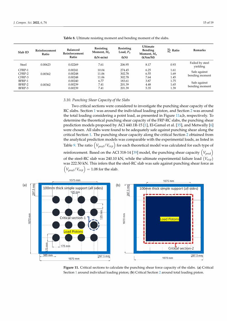
3.10. Punching Shear Capacity of the Slabs
Two critical sections were considered to investigate the punching shear capacity of theRC slabs. Section 1 was around the individual loading piston, and Section 2 was aroundthe total loading considering a point load, as presented in Figure 11a,b, respectively. Todetermine the theoretical punching shear capacity of the FRP-RC slabs, the punching shearprediction models proposed by ACI 440.1R-15 [1], El-Gamal et al. [35], and Metwally [6]were chosen. All slabs were found to be adequately safe against punching shear along thecritical Section 1. The punching shear capacity along the critical Section 2 obtained fromthe analytical prediction models was comparable with the experimental loads, as listed inTable 9. The ratio
(Vpred/Vexp
)for each theoretical model was calculated for each type of
reinforcement. Based on the ACI 318-14 [39] model, the punching shear capacity(
Vpred
)of the steel-RC slab was 240.10 kN, while the ultimate experimental failure load
(Vexp
)was 222.50 kN. This infers that the steel-RC slab was safe against punching shear force as(
Vpred/Vexp
)= 1.08 for the slab.
J. Compos. Sci. 2022, 6, x FOR PEER REVIEW 15 of 19
CFRP-2 0.00248 11.06 302.78 6.55 1.69 Safe against bend-ing moment CFRP-3 0.00248 11.06 302.78 7.64 1.45
BFRP-1 0.00362
0.00240 6.77 183.61 3.87 1.75 Safe against bend-ing moment BFRP-2 0.00239 7.41 201.39 4.48 1.65
BFRP-3 0.00239 7.41 201.39 5.35 1.39
3.10. Punching Shear Capacity of the Slabs Two critical sections were considered to investigate the punching shear capacity of
the RC slabs. Section 1 was around the individual loading piston, and Section 2 was around the total loading considering a point load, as presented in Figure 11a,b, respec-tively. To determine the theoretical punching shear capacity of the FRP-RC slabs, the punching shear prediction models proposed by ACI 440.1R-15 [1], El-Gamal et al. [35], and Metwally [6] were chosen. All slabs were found to be adequately safe against punch-ing shear along the critical Section 1. The punching shear capacity along the critical Section 2 obtained from the analytical prediction models was comparable with the experimental loads, as listed in Table 9. The ratio 𝑉 𝑉⁄ for each theoretical model was calculated for each type of reinforcement. Based on the ACI 318-14 [39] model, the punching shear capacity 𝑉 of the steel-RC slab was 240.10 kN, while the ultimate experimental fail-ure load 𝑉 was 222.50 kN. This infers that the steel-RC slab was safe against punch-ing shear force as 𝑉 𝑉⁄ = 1.08 for the slab.
Figure 11. Critical sections to calculate the punching shear force capacity of the slabs. (a) Critical Section 1 around individual loading piston; (b) Critical Section 2 around total loading piston.
Table 9. Experimental and theoretical punching shear capacity of the CFRP- and BFRP-RC slabs based on different analytical models.
Slabs 𝑽𝒆𝒙𝒑 (kN) ACI 440.1R-15 [1] El-Gamal et al. [35] Metwally [6] 𝑽𝒑𝒓𝒆𝒅 (kN) 𝑽𝒑𝒓𝒆𝒅 𝑽𝒆𝒙𝒑⁄ 𝑽𝒑𝒓𝒆𝒅 (kN) 𝑽𝒑𝒓𝒆𝒅 𝑽𝒆𝒙𝒑⁄ 𝑽𝒑𝒓𝒆𝒅 (kN) 𝑽𝒑𝒓𝒆𝒅 𝑽𝒆𝒙𝒑⁄
CFRP-1 169.10 177.1 1.05 181.5 1.07 202.4 1.20 CFRP-2 177.49 184.9 1.04 196.5 1.11 219.1 1.23 CFRP-3 207.74 184.9 0.89 196.5 0.95 219.1 1.05 BFRP-1 102.96 115.0 1.12 132.9 1.29 148.2 1.44 BFRP-2 120.05 119.9 1.00 143.9 1.20 160.5 1.34 BFRP-3 144.34 119.9 0.83 143.9 1.00 160.5 1.11
Figure 11. Critical sections to calculate the punching shear force capacity of the slabs. (a) CriticalSection 1 around individual loading piston; (b) Critical Section 2 around total loading piston.
J. Compos. Sci. 2022, 6, 74 16 of 19
Table 9. Experimental and theoretical punching shear capacity of the CFRP- and BFRP-RC slabsbased on different analytical models.
Slabs Vexp (kN)ACI 440.1R-15 [1] El-Gamal et al. [35] Metwally [6]
Vpred (kN) Vpred/Vexp Vpred (kN) Vpred/Vexp Vpred (kN) Vpred/Vexp
CFRP-1 169.10 177.1 1.05 181.5 1.07 202.4 1.20CFRP-2 177.49 184.9 1.04 196.5 1.11 219.1 1.23CFRP-3 207.74 184.9 0.89 196.5 0.95 219.1 1.05BFRP-1 102.96 115.0 1.12 132.9 1.29 148.2 1.44BFRP-2 120.05 119.9 1.00 143.9 1.20 160.5 1.34BFRP-3 144.34 119.9 0.83 143.9 1.00 160.5 1.11
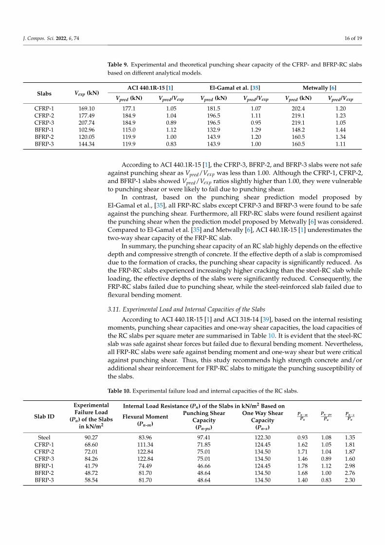
According to ACI 440.1R-15 [1], the CFRP-3, BFRP-2, and BFRP-3 slabs were not safeagainst punching shear as Vpred/Vexp was less than 1.00. Although the CFRP-1, CFRP-2,and BFRP-1 slabs showed Vpred/Vexp ratios slightly higher than 1.00, they were vulnerableto punching shear or were likely to fail due to punching shear.
In contrast, based on the punching shear prediction model proposed byEl-Gamal et al., [35], all FRP-RC slabs except CFRP-3 and BFRP-3 were found to be safeagainst the punching shear. Furthermore, all FRP-RC slabs were found resilient againstthe punching shear when the prediction model proposed by Metwally [6] was considered.Compared to El-Gamal et al. [35] and Metwally [6], ACI 440.1R-15 [1] underestimates thetwo-way shear capacity of the FRP-RC slab.
In summary, the punching shear capacity of an RC slab highly depends on the effectivedepth and compressive strength of concrete. If the effective depth of a slab is compromiseddue to the formation of cracks, the punching shear capacity is significantly reduced. Asthe FRP-RC slabs experienced increasingly higher cracking than the steel-RC slab whileloading, the effective depths of the slabs were significantly reduced. Consequently, theFRP-RC slabs failed due to punching shear, while the steel-reinforced slab failed due toflexural bending moment.
3.11. Experimental Load and Internal Capacities of the Slabs
According to ACI 440.1R-15 [1] and ACI 318-14 [39], based on the internal resistingmoments, punching shear capacities and one-way shear capacities, the load capacities ofthe RC slabs per square meter are summarised in Table 10. It is evident that the steel-RCslab was safe against shear forces but failed due to flexural bending moment. Nevertheless,all FRP-RC slabs were safe against bending moment and one-way shear but were criticalagainst punching shear. Thus, this study recommends high strength concrete and/oradditional shear reinforcement for FRP-RC slabs to mitigate the punching susceptibility ofthe slabs.
Table 10. Experimental failure load and internal capacities of the RC slabs.
Slab ID
ExperimentalFailure Load
(Pu) of the Slabsin kN/m2
Internal Load Resistance (Pn) of the Slabs in kN/m2 Based onPn−m
Pu
Pn−psPu
Pn−sPu
Flexural Moment(Pn-m)
Punching ShearCapacity
(Pn-ps)
One Way ShearCapacity
(Pn-s)
Steel 90.27 83.96 97.41 122.30 0.93 1.08 1.35CFRP-1 68.60 111.34 71.85 124.45 1.62 1.05 1.81CFRP-2 72.01 122.84 75.01 134.50 1.71 1.04 1.87CFRP-3 84.26 122.84 75.01 134.50 1.46 0.89 1.60BFRP-1 41.79 74.49 46.66 124.45 1.78 1.12 2.98BFRP-2 48.72 81.70 48.64 134.50 1.68 1.00 2.76BFRP-3 58.54 81.70 48.64 134.50 1.40 0.83 2.30
J. Compos. Sci. 2022, 6, 74 17 of 19
4. Summary and Conclusions
This study demonstrates structural performance of two-way concrete slabs reinforcedwith CFRP, BFRP, and conventional steel rebars. The load versus mid-span deflectionbehaviour, cracked and uncracked stiffness, serviceability, flexural moment capacity, andpunching and one-way shear capacity of the RC slabs were investigated and considered asindicators of structural performance. Based on the experimental and analytical investiga-tion, the following essential conclusion can be drawn:
• Compared to the typical steel-RC slab, both the CFRP- and BFRP-RC slabs expe-rienced significantly higher deflection and cracking while loading. However, theperformance of the FRP-RC slabs was comparable to that of the steel-RC slab withinthe serviceability limit.
• Although the axial rigidity of CFRP and BFRP rebars are 41% and 16% of that ofsteel rebar, the CFRP- and BFRP-RC slabs exhibited 64% and 48% the stiffness of thesteel-RC slab after cracking.
• Both the CFRP- and BFRP-RC slabs showed significant elastic recovery during unload-ing, which was not the case in the steel-RC slab. This indicates that the FRP rebars didnot reach their rupture strain, as CFRP and BFRP rebars reached 71% and 78% of theirrupture strength at failure, respectively.
• Beyond the peak load, the BFRP-RC slabs experienced a gradual decrease in the loadcapacity with incremental displacement, whereas the CFRP-RC slabs underwent asharp decrease in load capacity, similar to the steel-RC slab. Consequently, the CFRP-and BFRP-RC slabs exhibited 1.26- and 2.18-times higher displacement-ductility thanthat of the steel-RC slab. The BFRP-RC slabs demonstrated 1.72-times higher ductilitythan CFRP-RC slabs because the percentage of elongation of BFRP rebars was higherthan that of CFRP rebars.
• The steel-RC slab failed due to flexural tension, and the FRP-RC slabs failed due topunching shear. As the FRP-RC slabs experienced significantly higher cracks, the shearcapacity of the slabs dropped gradually with the increase of loading. These cracksresulted in reducing the effective depth of the section. Thus, the FRP-RC slabs faileddue to punching shear without any rupture of the FRP rebars.
• Since the design of the FRP-RC flexural member is governed by serviceability criteria,and the performance of CFRP- and BFRP-RC slabs is comparable with that of thesteel-RC slab, CFRP- and BFRP both are suitable to reinforce concrete slabs.
Although FRP rebars are more expensive than steel rebars, they can be an alternativeto typical steel rebars to reinforce concrete slabs where corrosion resistance is a concern.Therefore, the benefit of using FRP rebars in concrete is to improve durability. This studydemonstrated that CFRP and BFRP rebars both can be an alternative to steel rebars as theirperformance within the serviceability limit is satisfactory and comparable to steel rebars.Additionally, BFRP is cheaper than CFRP rebar and has a competitive price. Hence, BFRPbars can be a choice to reinforce structural concrete where durability and/or higher strength-to-weight ratio is desired. However, additional shear reinforcement and/or higher strengthconcrete is recommended to improve the punching shear capacity of the BFRP-RC slabs.
Author Contributions: Conceptualization, M.S. and E.O.G.; methodology, M.S. and E.O.G.; software,M.S. and S.K.S.; validation, S.K.S., M.S. and E.O.G.; formal analysis, S.K.S.; investigation, S.K.S. andM.S.; resources, M.S., E.O.G. and R.A.-A.; data curation, E.O.G.; writing—original draft preparation,S.K.S.; writing—review and editing, M.S. and R.A.-A.; visualization, S.K.S.; supervision, M.S.; projectadministration, E.O.G.; funding acquisition, M.S., E.O.G. and R.A.-A. All authors have read andagreed to the published version of the manuscript.
Funding: This project was funded by internal research grant of School of Engineering at Deakin University.
Institutional Review Board Statement: Not applicable.
Informed Consent Statement: Not applicable.
J. Compos. Sci. 2022, 6, 74 18 of 19
Conflicts of Interest: The authors declare no conflict of interest.
References1. ACI PRC-440.1-15; Guide for the Design and Construction of Structural Concrete Reinforced with Fiber-Reinforced Polymer Bars.
American Concrete Institute: Farmington Hills, MI, USA, 2015.2. Wang, X.; Zhang, X.; Ding, L.; Tang, J.; Wu, Z. Punching shear behavior of two-way coral-reef-sand concrete slab reinforced with
BFRP composites. Constr. Build. Mater. 2020, 231, 117113. [CrossRef]3. Shill, S.K.; Al-Deen, S.; Ashraf, M.; Hossain, M.M. Residual properties of conventional concrete repetitively exposed to high
thermal shocks and hydrocarbon fluids. Constr. Build. Mater. 2020, 252, 119072. [CrossRef]4. Mirza, O.; Shill, S.K.; Johnston, J. Performance of Precast Prestressed Steel-Concrete Composite Panels Under Static Loadings to
Replace the Timber Transoms for Railway Bridge. Structures 2019, 19, 30–40. [CrossRef]5. Shill, S.K.; Al-Deen, S.; Ashraf, M.; Elahi, M.A.; Subhani, M.; Hutchison, W. A comparative study on the performance of
cementitious composites resilient to airfield conditions. Constr. Build. Mater. 2021, 282, 122709. [CrossRef]6. Metwally, I.M. Prediction of punching shear capacities of two-way concrete slabs reinforced with FRP bars. HBRC J. 2013, 9,
125–133. [CrossRef]7. Aljazaeri, Z.; Alghazali, H.H.; Myers, J.J. Effectiveness of Using Carbon Fiber Grid Systems in Reinforced Two-Way Concrete Slab
System. ACI Struct. J. 2020, 117, 81–89. [CrossRef]8. El-Gamal, S.; El-Salakawy, E.; Benmokrane, B. Behavior of Concrete Bridge Deck Slabs Reinforced with Fiber-Reinforced Polymer
Bars Under Concentrated Loads. ACI Struct. J. 2005, 102, 727. [CrossRef]9. Yost, J.R.; Goodspeed, C.H.; Schmeckpeper, E.R. Flexural Performance of Concrete Beams Reinforced with FRP Grids. J. Compos.
Constr. 2001, 5, 18–25. [CrossRef]10. Mahroug, M.; Ashour, A.; Lam, D. Tests of continuous concrete slabs reinforced with carbon fibre reinforced polymer bars.
Compos. Part B Eng. 2014, 66, 348–357. [CrossRef]11. Banthia, N.; Al-Asaly, M.; Ma, S. Behavior of Concrete Slabs Reinforced with Fiber-Reinforced Plastic Grid. J. Mater. Civ. Eng.
1995, 7, 252–257. [CrossRef]12. Cai, J.; Pan, J.; Zhou, X. Flexural behavior of basalt FRP reinforced ECC and concrete beams. Constr. Build. Mater. 2017, 142,
423–430. [CrossRef]13. Fang, H.; Xu, X.; Liu, W.; Qi, Y.; Bai, Y.; Zhang, B.; Hui, D. Flexural behavior of composite concrete slabs reinforced by FRP grid
facesheets. Compos. Part B Eng. 2016, 92, 46–62. [CrossRef]14. Zhang, B.; Masmoudi, R.; Benmokrane, B. Behaviour of one-way concrete slabs reinforced with CFRP grid reinforcements. Constr.
Build. Mater. 2004, 18, 625–635. [CrossRef]15. Rahman, A.H.; Kingsley, C.Y.; Kobayashi, K. Service and Ultimate Load Behavior of Bridge Deck Reinforced with Carbon FRP
Grid. J. Compos. Constr. 2000, 4, 16–23. [CrossRef]16. Michaluk, C.R.; Rizkalla, S.H.; Tadros, G.; Benmokrane, B. Flexural behavior of one-way concrete slabs reinforced by fiber
reinforced plastic reinforcements. ACI Struct. J. 1998, 95, 353–365.17. Erfan, A.M.; Elnaby, R.M.A.; Badr, A.A.; El-Sayed, T.A. Flexural behavior of HSC one way slabs reinforced with basalt FRP bars.
Case Stud. Constr. Mater. 2021, 14, e00513. [CrossRef]18. Mahroug, M.E.M. Behaviour of Continuous Concrete Slabs Reinforced with FRP Bars. Experimental and Computational
Investigations on the Use of Basalt and Carbon Fibre Reinforced Polymer Bars in Continuous Concrete Slabs. Ph.D. Thesis,University of Bradford, Bradford, UK, 2014.
19. El-Salakawy, E.; Benmokrane, B. Serviceability of concrete bridge deck slabs reinforced with FRP composite bars. ACI Struct. J.2004, 101, 727–736.
20. Taerwe, L. Non-Metallic (FRP) Reinforcement for Concrete Structures: Proceedings of the Second International RILEM Symposium; CRCPress: Boca Raton, FL, USA, 2014.
21. Zhang, Q. Behaviour of Two-Way Slabs Reinforced with Cfrp Bars. Ph.D. Thesis, Memorial University of Newfoundland,St. John’s, NL, Canada, 2006.
22. Rashid, M.I. Concrete Slabs Reinforced with GFRP Bars; Memorial University of Newfoundland: St. John’s, NL, Canada, 2004.23. Karayannis, C.G.; Kosmidou, P.-M.K.; Chalioris, C.E. Reinforced Concrete Beams with Carbon-Fiber-Reinforced Polymer Bars—
Experimental Study. Fibers 2018, 6, 99. [CrossRef]24. Bilotta, A.; Compagnone, A.; Esposito, L.; Nigro, E. Structural behaviour of FRP reinforced concrete slabs in fire. Eng. Struct.
2020, 221, 111058. [CrossRef]25. Amran, Y.H.M.; Alyousef, R.; Rashid, R.S.M.; Alabduljabbar, H.; Hung, C.-C. Properties and applications of FRP in strengthening
RC structures: A review. Structures 2018, 16, 208–238. [CrossRef]26. Huang, Z.; Zhao, Y.; Zhang, J.; Wu, Y. Punching shear behaviour of concrete slabs reinforced with CFRP grids. Structures 2020, 26,
617–625. [CrossRef]27. Yu, X.; Zhou, B.; Hu, F.; Zhang, Y.; Xu, X.; Fan, C.; Zhang, W.; Jiang, H.; Liu, P. Experimental investigation of basalt fiber-reinforced
polymer (BFRP) bar reinforced concrete slabs under contact explosions. Int. J. Impact Eng. 2020, 144, 103632. [CrossRef]28. Hassan, M.; Benmokrane, B.; ElSafty, A.; Fam, A. Bond durability of basalt-fiber-reinforced-polymer (BFRP) bars embedded in
concrete in aggressive environments. Compos. Part B Eng. 2016, 106, 262–272. [CrossRef]
J. Compos. Sci. 2022, 6, 74 19 of 19
29. Adhikari, S. Mechanical Properties and Flexural Applications of Basalt Fiber Reinforced Polymer (BFRP) Bars. Ph.D. Thesis,University of Akron, Akron, OH, USA, 2009.
30. Sun, X.; Gao, C.; Wang, H. Bond performance between BFRP bars and 3D printed concrete. Constr. Build. Mater. 2021, 269, 121325.[CrossRef]
31. Balea, L.; Dusserre, G.; Bernhart, G. Mechanical behaviour of plain-knit reinforced injected composites: Effect of inlay yarns andfibre type. Compos. Part B Eng. 2014, 56, 20–29. [CrossRef]
32. Deák, T.; Czigány, T. Chemical composition and mechanical properties of basalt and glass fibers: A comparison. Text. Res. J. 2009,79, 645–651. [CrossRef]
33. Attia, K.; Alnahhal, W.; Elrefai, A.; Rihan, Y. Flexural behavior of basalt fiber-reinforced concrete slab strips reinforced with BFRPand GFRP bars. Compos. Struct. 2019, 211, 1–12. [CrossRef]
34. Nanni, A. Flexural Behavior and Design of RC Members Using FRP Reinforcement. J. Struct. Eng. 1993, 119, 3344–3359. [CrossRef]35. El-Gamal, S.; El-Salakawy, E.; Benmokrane, B. A new punching shear equation for two-way concrete slabs reinforced with FRP
bars. ACI Spec. Publ. 2005, 230, 877–894.36. Goonewardena, J.; Ghabraie, K.; Subhani, M. Flexural Performance of FRP-Reinforced Geopolymer Concrete Beam. J. Compos. Sci.
2020, 4, 187. [CrossRef]37. Provis, J.L.; Rose, V.; Bernal, S.A.; van Deventer, J.S.J. High-Resolution Nanoprobe X-ray Fluorescence Characterization of
Heterogeneous Calcium and Heavy Metal Distributions in Alkali-Activated Fly Ash. Langmuir 2009, 25, 11897–11904. [CrossRef][PubMed]
38. Bischoff, P.; Gross, S.; Ospina, C. The story behind proposed changes to ACI 440 deflection requirements for FRP-reinforcedconcrete. Spec. Publ. 2009, 264, 53–76.
39. ACI CODE-318-14: Building Code Requirements for Structural Concrete and Commentary; American Concrete Institute: FarmingtonHills, MI, USA, 2014.
40. Bischoff, P.H. Reevaluation of Deflection Prediction for Concrete Beams Reinforced with Steel and Fiber Reinforced Polymer Bars.J. Struct. Eng. 2005, 131, 752–767. [CrossRef]
41. Rakhshanimehr, M.; Esfahani, M.R.; Kianoush, M.R.; Mohammadzadeh, B.A.; Mousavi, S.R. Flexural ductility of reinforcedconcrete beams with lap-spliced bars. Can. J. Civ. Eng. 2014, 41, 594–604. [CrossRef]
42. Benmokrane, B.; Chaallal, O.; Masmoudi, R. Glass fibre reinforced plastic (GFRP) rebars for concrete structures. Constr. Build.Mater. 1995, 9, 353–364. [CrossRef]
43. Ospina, C.E.; Alexander, S.D.B.; Cheng, J.J.R. Punching of Two-Way Concrete Slabs with Fiber-Reinforced Polymer ReinforcingBars or Grids. Struct. J. 2003, 100, 589–598.
44. Bischoff, P.H.; Scanlon, A. Effective Moment of Inertia for Calculating Deflections of Concrete Members Containing SteelReinforcement and Fiber-Reinforced Polymer Reinforcement. ACI Struct. J. 2007, 104, 68. [CrossRef]
Related Documents