Reinforced Concrete Slabs – Analysis and Design An electronic textbook for basic concrete courses Author 1 Author 2 (Arial Bold, 16 pkt.) BsC Thesis (Arial Bold, 16pkt.) Department of Civil Engineering 20xx (Arial Regular, 16 pkt.) Per Goltermann Department of Civil Engineering 2013 Indsæt billede

Welcome message from author
This document is posted to help you gain knowledge. Please leave a comment to let me know what you think about it! Share it to your friends and learn new things together.
Transcript
Reinforced Concrete Slabs – Analysis and Design
An electronic textbook for basic concrete courses
Author 1 Author 2 (Arial Bold, 16 pkt.)
BsC Thesis (Arial Bold, 16pkt.)
Department of Civil Engineering20xx (Arial Regular, 16 pkt.)
Per Goltermann
Department of Civil Engineering
2013
Indsæt billede
Reinforced Concrete Slabs. Design and Analysis
List of Content
Scope ................................................................................................................................................. 1-3
Symbols and definitions .................................................................................................................... 1-6
1. Introduction ............................................................................................................................... 1-1
1.1. Limitations to the single span slabs .................................................................................... 1-2
1.2. Double span slabs and their advantages ............................................................................. 1-3
1.3. What we need to be able to do ........................................................................................... 1-5
1.4. The rest of the book ............................................................................................................ 1-6
1.5. Reading instructions for this book...................................................................................... 1-6
2. Classic plate theory ................................................................................................................... 2-1
2.1. The classic plate theory ...................................................................................................... 2-2
2.2. Reactions ............................................................................................................................ 2-4
2.3. Boundary conditions........................................................................................................... 2-5
2.4. Resume for a rectangular plate ........................................................................................... 2-6
2.5. Plate deformations .............................................................................................................. 2-7
2.6. How to deal with a concrete slab........................................................................................ 2-8
2.7. Additional reading material ................................................................................................ 2-9
3. Serviceability Limit State, deflections ...................................................................................... 3-1
3.1. Bending stiffness of the reinforced concrete slab .............................................................. 3-2
3.2. Short term and long term loading ....................................................................................... 3-3
3.3. Bending stiffness estimation .............................................................................................. 3-4
3.4. Rectangular slab with simple supports, solved by perturbation method ............................ 3-5
3.5. Slabs with more complicated geometry, solved by FEM ................................................... 3-8
3.6. Additional examples and problems .................................................................................... 3-9
3.7. Additional reading material .............................................................................................. 3-10
4. Ultimate Limit State. Lower-limit solution with a guessed solution ........................................ 4-1
4.1. The guessed solution for a rectangular slab with 4 sides supported .................................. 4-3
4.2. Other guessed solutions ...................................................................................................... 4-4
4.3. Practical limitations ............................................................................................................ 4-5
4.4. Additional reading material ................................................................................................ 4-5
5. Ultimate Limit State. The Strip Method ................................................................................... 5-1
5.1. The strip method ................................................................................................................. 5-2
5.2. Comparison to the classic plate theory ............................................................................... 5-4
5.3. Additional examples and problems .................................................................................... 5-5
5.4. Additional reading material ................................................................................................ 5-6
Reinforced Concrete Slabs. Design and Analysis
6. Ultimate Limit State. The Yield Line Method .......................................................................... 6-1
6.1. The virtual work principle and the upper limit method...................................................... 6-1
6.2. Upper limit method for a simple beam ............................................................................... 6-2
6.2.1. The external work ....................................................................................................... 6-4 6.2.2. The internal work ........................................................................................................ 6-4 6.2.3. The loadcarrying capacity ........................................................................................... 6-5
6.3. Additional examples and problems .................................................................................... 6-5
6.4. Additional reading material ................................................................................................ 6-5
6.5. Upper limit solution – yield line method – in slabs ........................................................... 6-6
6.5.1. Failure mechanisms during testing ............................................................................. 6-6 6.5.2. Testing of slab 1 .......................................................................................................... 6-6
6.5.3. Testing of slab 2 .......................................................................................................... 6-7
6.5.4. Failure mechanisms observed in the tests ................................................................... 6-8 6.6. Possible failure mechanisms for our models ...................................................................... 6-9
6.7. The external work ............................................................................................................. 6-10
6.8. The internal work ............................................................................................................. 6-10
6.9. The load-carrying capacity ............................................................................................... 6-11
6.10. Rotations of a section and internal work ...................................................................... 6-12
6.11. Broken yield lines and internal work ............................................................................ 6-13
6.12. Additional examples and problems .............................................................................. 6-14
6.13. Additional reading materials ......................................................................................... 6-16
7. Dictionary (English – Danish) .................................................................................................. 7-1
Examples
Example 3.1. Serviceability Limit State. Deflections.
Rectangular plate with simple supports and uniform loading.
Example 3.2. Serviceability Limit State. Deflections.
Rectangular plate with hole and three sides supported.
Example 5.1. C-shaped plate with some simply supported sides and some free sides.
Example 5.2. Strip Method Design.
Rectangular plate with a hole and three sides supported.
Example 6.1. Yield Line Method.
Two point loading of a beam – plastic hinge.
Example 6.2. Yield Line Method.
Continuous beam with cantilever part.
Example 6.3. Yield Line Method.
Rectangular plate with uniform load.
Example 6.4. Yield Line Method.
Quadratic plate with “uniform” load.
Example 6.5. Yield Line Method.
Distinguish between possible and impossible mechanisms.

Reinforced Concrete Slabs. Design and Analysis
Scope
Dear reader
The purpose of this textbook is to introduce the basic understanding, the analysis and the design of
reinforced concrete plates.
The book has been written with an engineering approach in mind: We will start by identifying the
problems to be solved and then develop a method to solve these. We will also check that this leads
to methods, which are valid according to the basic mechanical rules.
This inductive approach differs from the traditional deductive approach, but we will reach the same
understanding, even if we often start with a simple problem, a simple test or a video of the testing
and use this as a basis for the development.
I have uses this approach in my teaching of basic concrete structures at the Technical University of
Denmark for few years and have found it easier for the students to understand - and often a lot
more interesting for the students, as the relevance of other topics, assumptions and simplifications
becomes much clearer.
I have produced this book as an electronic textbook for a number of reasons
1. The use of e.g. a video in a printed textbook is not possible, where the electronic form
enables the book to be placed on a homepage with links to videos and pictures placed on
YouTube, Picassa or other free and public sites.
2. The examples, exercises, solutions and in the end also the full classroom material will be
made available for free download from the homepage in the latest versions, as eg. exercises
are constantly updated, based on the feedback from students and assistant teachers.
3. The textbook can have a logical, linear part and at the same time have additional examples,
videos, small tests and additional examples, which can be used for those of you, who prefer
one or several additional examples.
4. The book can be updated whenever necessary, just as with additional examples and
explanations can be added.
5. It is possible to distribute the book free of costs and thus also free of charge – as any of you
can download it to you PC or print it.

Reinforced Concrete Slabs. Design and Analysis
The relevant material consists of this book, the examples, but also of supporting files and videos.
It need to be said, that at the book and the examples will be in English from the beginning,
however, the exercises and the solutions and the rest will be in Danish at the moment, but these
may be translated later.
You may try a translation machine on the Internet as eg. Google, which may provide a fair
translation from Danish to English and enable you to understand the exercises and solutions – but
the lecture videos will naturally require some understanding of Danish (sorry about that, but
regulations requires these lectures to be in Danish as they deal with basic concrete structures).
The available material in English will thus be
This textbook, organized in six main chapters (1)
Relevant examples (1)
plus additional material in Danish
Pdf copies of overheads for each chapter (1)
Videos of each of the presentations of these chapters (2)
Electronic examples as dynamic pdf-files for each chapter (1)
Videos of the lecture, organised as one lecture per chapter (2)
Exercises (1)
Solutions to exercises (1)
The materials are available at
(1): The course homepage www.concretestructures.byg.dtu.dk
(2): The course account at Youtube, user: ConStruct2800Lyngby

Reinforced Concrete Slabs. Design and Analysis
What you need to know before you work with the plates: You must be able to analyse and design
reinforced concrete beams, before you study the reinforced concrete plates and this means of course
also that you must be able to estimate bending moments, shear forces and reactions.
You do not need to be familiar with plate theory or finite element methods, however, such
knowledge will help you understand the models for the concrete plates and also enable you to go
beyond the examples in the book. Additional knowledge of virtual work, lower limit and upper limit
solutions will also be a help for your understanding, but are not vital.
I hope that you will find the book and the setup helpful for your
understanding of reinforced concrete plates, their function, behaviour and
design – and that you in due time will find the reinforced concrete as
fascinating and useful as I do.
Enjoy
Per Goltermann
Professor
DTU-Byg.
…. and I would also like to thank all the other concrete fans at the university and in the industry,
who have helped me with samples, photographs, videos – and perhaps those of my students, who
kept asking until I actually came up with a simple and logical explanation, which they could
understand easily. I have now tested the approaches on almost 1000 students from B.Sc. Civil
Engineering, B.Eng. Building Engineering and B.Eng. Architectural Engineering - so I hope the
book will have a fair chance of working with other students as well.
Reinforced Concrete Slabs. Design and Analysis
Symbols and definitions
As tensile reinforcement area;
b width of a beam;
c index for concrete;
D plate bending stiffness;
d effective height;
Ec modulus of elasticity of the concrete
Ec,long long term modulus of elasticity for the concrete;
Ec,short short term modulus of elasticity for the concrete;
Es modulus of elasticity of reinforcement steel;
g dead load;
L span length, length of yield line;
i degree of restraint;
Lx, Ly lengths of the rectangular slab in the x and y directions;
M bending moment;
m bending moment per width;
mi restraining moment per width along edge i;
mn bending moment per width in the n direction
mu bending moment capacity for positive bending;
m’u bending moment capacity for negative bending;
mx, my bending moment per width in the x and y directions;
mxy torsion moment per width;
mxo,myo,mxyo maximal values of mx, my and mxy in a simply supported rectangular plate;
p distributed load;
px,py load transferred in the x and y directions;
pi(-)
lower limit solutions load carrying capacity for strip i;
q live load;
R concentrated reaction;
Rij concentrated reaction at the junction of edge I and edge j;
r reaction per length;
s index for steel;
t thickness of the slab, coordinate along a line;
u deflection;
v shear force per width;
V shear force;
vn shear force per width in the n direction;
vx,vy shear force per width in the x and y directions;
We,Wi external and internal work in failure mechanism for upper limit solution;
x,y coordinates and indexes for the x and y directions;
ratio between modulus of elasticity of steel and concrete;
, b elastic parameters for estimation of elastic cross-sectional properties;
the creep factor;
reinforcement degree.

Reinforced Concrete Slabs. Design and Analysis Page 1-1
1. Introduction
The best place to begin is to compare the beams and slabs (plate), which span in one direction only:
There is no difference in the estimations of those two structural elements – but it will be different if
we let the slabs span in two directions.
Figure 1.1. A few structures with single span prefabricated plates or slabs.
The design in practice is normally different as
The function of a beam is normally to carry a load and this means that the widths of beams
tend to be as small as possible, usually determined by the wish to place the tensile
reinforcement at the bottom of the cross-section.
The slab must be able to carry the load as well, but it will often be a lot wider, as the plates
are normally used to fill a certain area, as eg. a separation of two floors in a building or to
act as walls in building, exposed to wind loads.
This means that beams will normally have a high reinforcement degree in the range of 0,2-0,4,
whereas slabs normally have lower degrees in the range of 0,05-0,1.
There are, however, limitations to the design of the single span slabs, which may be overcome by
design and use of double span plates and use of plate theory.
Reinforced Concrete Slabs. Design and Analysis Page 1-2
1.1. Limitations to the single span slabs
The use of prefabricated slabs or plates spanning in one direction, is very popular in the
constructions business, but has a serious limitation in their span width. This is best realised in the
case of a slab with load q and eigenweight g and a span L and bending stiffness EI, where the
maximal shear force V, bending moment M and deflection u are estimated as
2
4
1( )
2
1( )
8
5 ( )
384
V g q L
M g q L
g qu L
EI
(1.1)
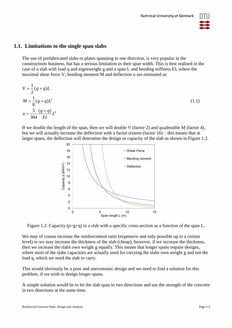
If we double the length of the span, then we will double V (factor 2) and quadrouble M (factor 4),
but we will actually increase the deflection with a factor sixteen (factor 16) – this means that at
larger spans, the deflection will determine the design or capacity of the slab as shown in Figure 1.2.
Figure 1.2. Capacity (p=g+q) in a slab with a specific cross-section as a function of the span L.
We may of course increase the reinforcement ratio (expensive and only possible up to a certain
level) or we may increase the thickness of the slab (cheap), however, if we increase the thickness,
then we increase the slabs own weight g equally. This means that longer spans require designs,
where most of the slabs capacities are actually used for carrying the slabs own weight g and not the
load q, which we need the slab to carry.
This would obviously be a poor and uneconomic design and we need to find a solution for this
problem, if we wish to design longer spans.
A simple solution would be to let the slab span in two directions and use the strength of the concrete
in two directions at the same time.
Reinforced Concrete Slabs. Design and Analysis Page 1-3
1.2. Double span slabs and their advantages
The simplest idea is really to place reinforcement in both directions and let the slab span in the two
directions, so we can utilize the concrete in the compression zone in the two different directions, as
this would allow us to carry the load in two different directions at the same time using the same
concrete eigenweight and this would lead to a lower deflection, lower bending moments and lower
shear forces.
9 m
9 m
9 m
9 m
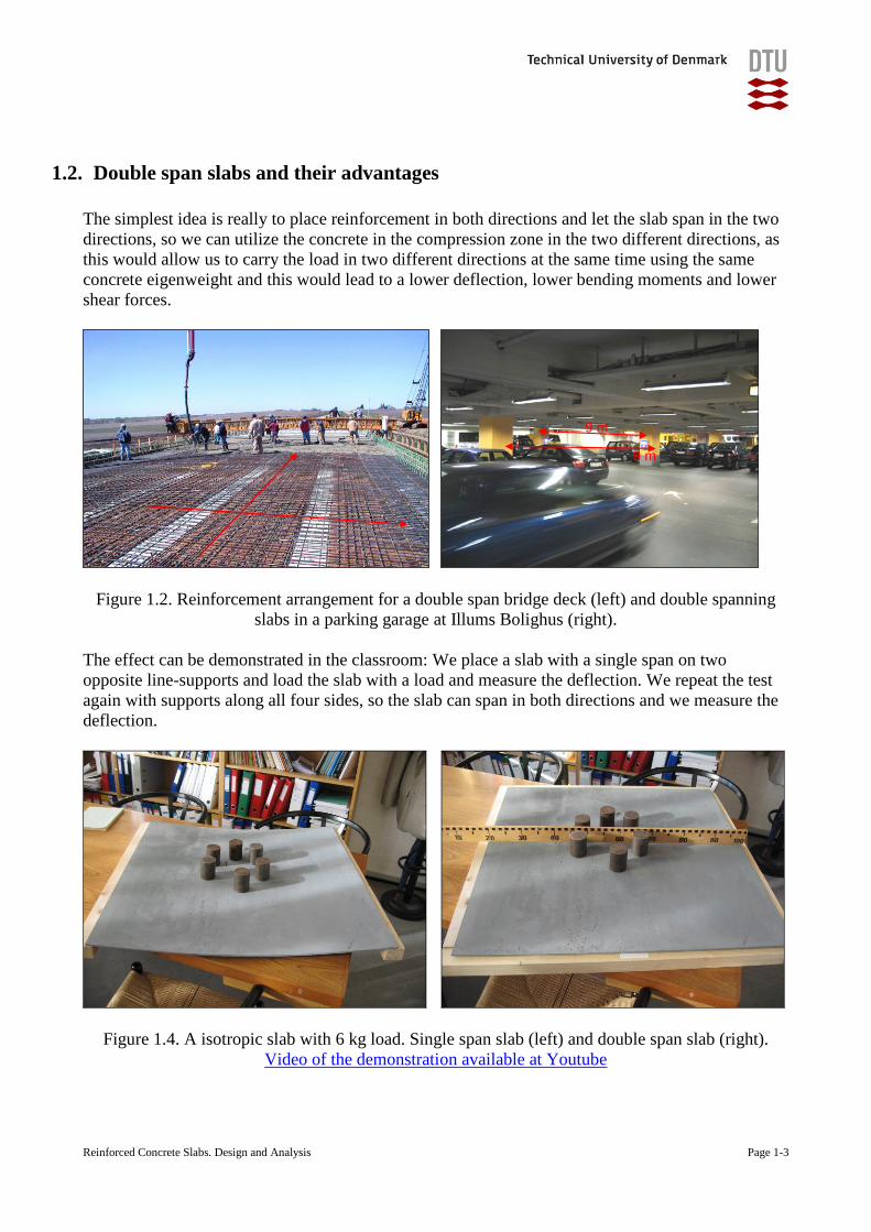
Figure 1.2. Reinforcement arrangement for a double span bridge deck (left) and double spanning
slabs in a parking garage at Illums Bolighus (right).
The effect can be demonstrated in the classroom: We place a slab with a single span on two
opposite line-supports and load the slab with a load and measure the deflection. We repeat the test
again with supports along all four sides, so the slab can span in both directions and we measure the
deflection.
Figure 1.4. A isotropic slab with 6 kg load. Single span slab (left) and double span slab (right).
Video of the demonstration available at Youtube
Reinforced Concrete Slabs. Design and Analysis Page 1-4
The current slab was a plexiglass slab of 5 x 800 x 800 mm, loaded with 6 kg and we measured a
maximal deflection at single span of 31 mm and at double span a deflection of only 10 mm.
We notice that the simple idea of describing the double spanning quadratic and isotropic slab as
beam bending in the two directions would lead to predicted deflection of 50 % of single span slab.
The deflection has, however, decreased to 10 mm / 31 mm = 32 %, which is much lower and much
better – and we would like to benefit from this phenomenae.
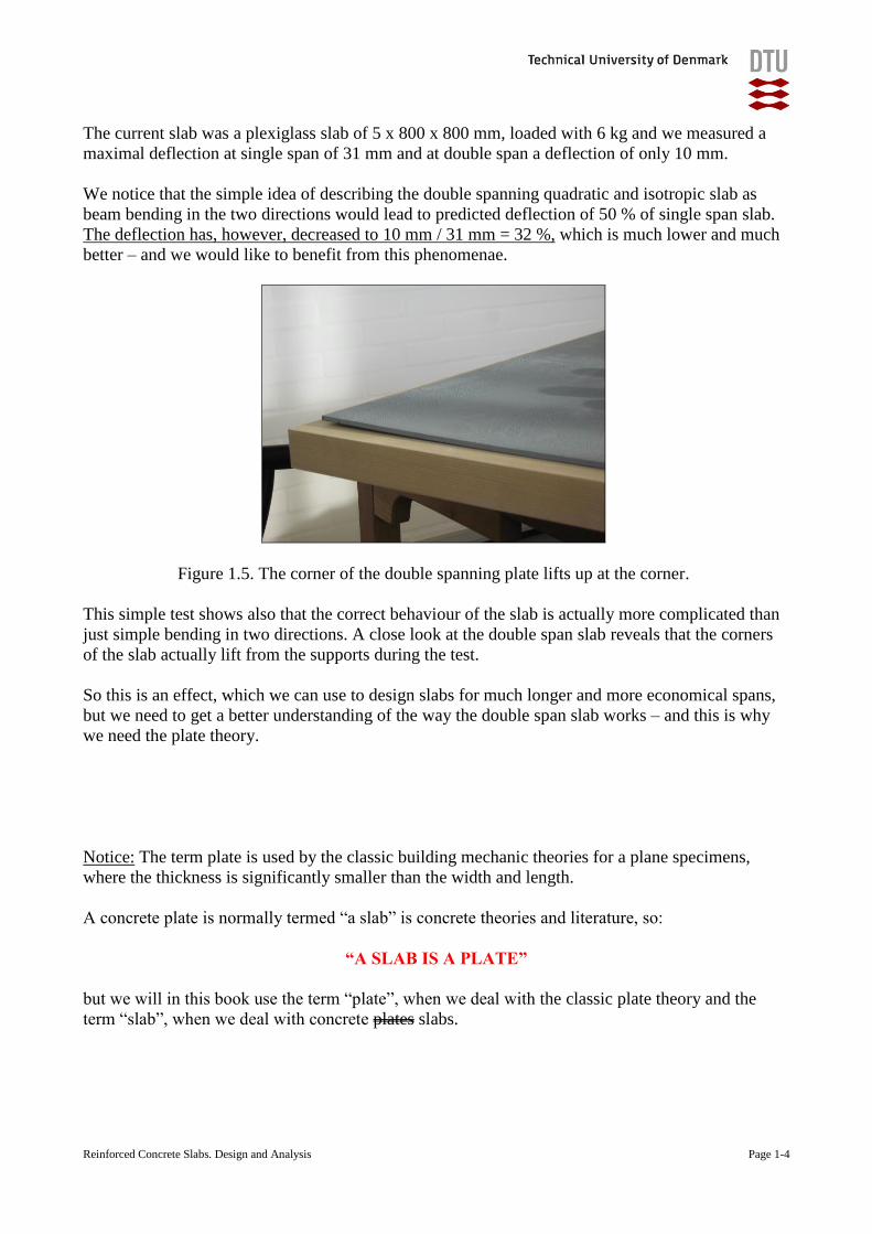
Figure 1.5. The corner of the double spanning plate lifts up at the corner.
This simple test shows also that the correct behaviour of the slab is actually more complicated than
just simple bending in two directions. A close look at the double span slab reveals that the corners
of the slab actually lift from the supports during the test.
So this is an effect, which we can use to design slabs for much longer and more economical spans,
but we need to get a better understanding of the way the double span slab works – and this is why
we need the plate theory.
Notice: The term plate is used by the classic building mechanic theories for a plane specimens,
where the thickness is significantly smaller than the width and length.
A concrete plate is normally termed “a slab” is concrete theories and literature, so:
“A SLAB IS A PLATE”
but we will in this book use the term “plate”, when we deal with the classic plate theory and the
term “slab”, when we deal with concrete plates slabs.
Reinforced Concrete Slabs. Design and Analysis Page 1-5
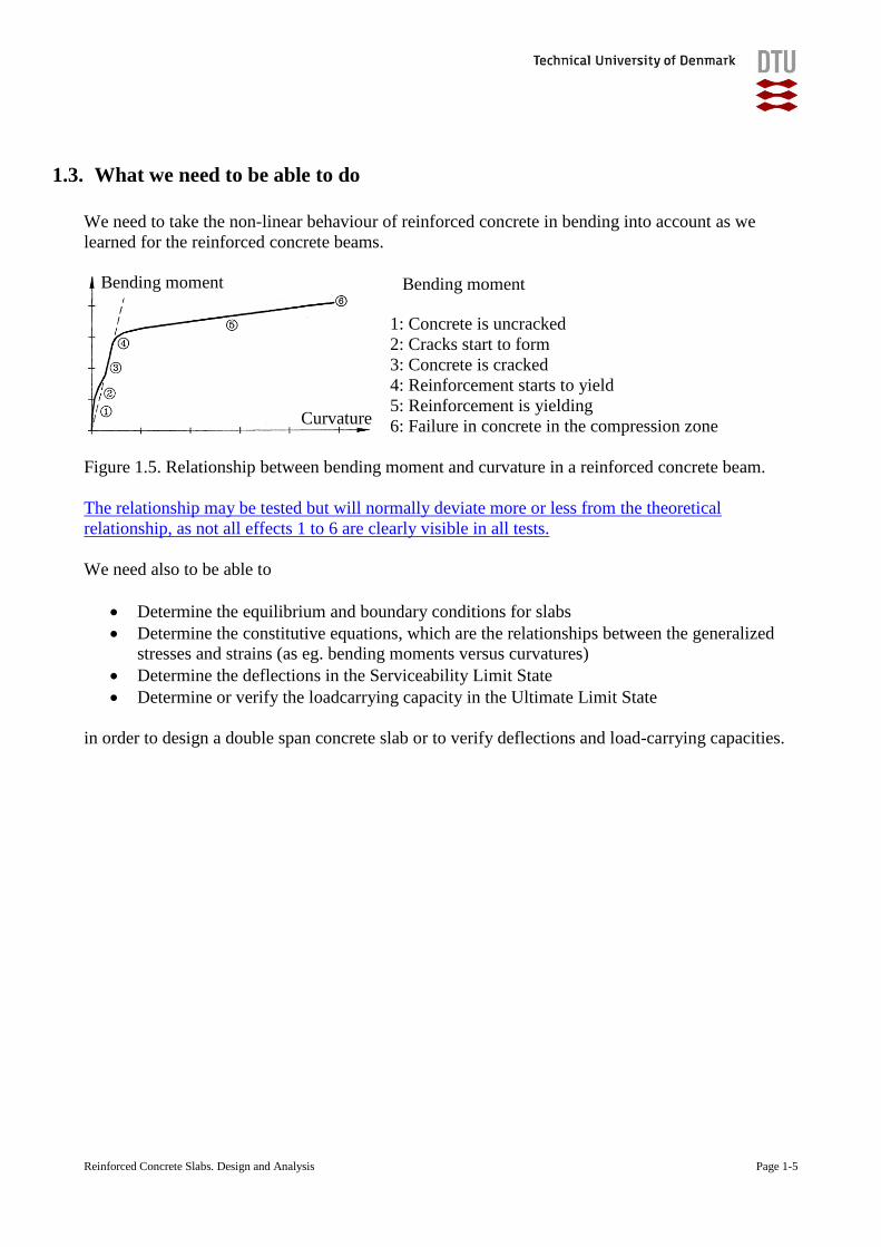
1.3. What we need to be able to do
We need to take the non-linear behaviour of reinforced concrete in bending into account as we
learned for the reinforced concrete beams.
1: Concrete is uncracked
2: Cracks start to form
3: Concrete is cracked
4: Reinforcement starts to yield
5: Reinforcement is yielding
6: Failure in concrete in the compression zone
Figure 1.5. Relationship between bending moment and curvature in a reinforced concrete beam.
The relationship may be tested but will normally deviate more or less from the theoretical
relationship, as not all effects 1 to 6 are clearly visible in all tests.
We need also to be able to
Determine the equilibrium and boundary conditions for slabs
Determine the constitutive equations, which are the relationships between the generalized
stresses and strains (as eg. bending moments versus curvatures)
Determine the deflections in the Serviceability Limit State
Determine or verify the loadcarrying capacity in the Ultimate Limit State
in order to design a double span concrete slab or to verify deflections and load-carrying capacities.
Bending moment
Curvature
Bending moment
Reinforced Concrete Slabs. Design and Analysis Page 1-6
1.4. The rest of the book
The following topics will be dealt with in the chapters in the rest of the book
2. Classic slab theory (very brief)
3. Deflections in the uncracked and cracked states
4. Lower limit solutions with a guessed solution
5. Lower limit solutions with the strip method
6. Upper limit solutions with the yield line method
Each of these main chapters will be in their own chapter.
The chapter 2 on classic plate theory is very brief as many universities offers courses in plate theory
and it is therefore mainly to list the formulas and relationships required for the chapter 3.
The chapter 3 deals with deformations in the serviceability limit state and utilize the plate theory.
The chapters 4 and 5 can be read independently of chapter 2 and 3, although the lower limit
solutions must fulfil the equilibrium and boundary conditions, listed in chapter 2.
The chapter 6 can be read independently of the other chapters, although it is often interesting to
compare the capacities derived by the methods in chapter 6 and 5.
1.5. Reading instructions for this book
The electronic text book use simple rules and logic combined with cases from tested specimens,
examples and exercises and be organised in:
1. a linear part, which will be the student must understand, as it is the core of the method and
which suitable for printing as one file and
2. key examples, which are very important for the understanding of the basic principles and
assumptions and
3. a non-linear part, which includes additional and optional examples, exercises, videos,
presentation of test cases, references to additional reading material, simple tests etc. This
part is more dynamic, as additional cases, examples and exercises are added when required,
since the number of examples needed for fully understanding the method and the
possibilities will depend on the individual student and on the individual aspect.
The book has a brief English-Danish dictionary enclosed as the textbook is intended for use at
Technical University of Denmark in Copenhagen, Denmark – where the lectures will normally be in
Danish. (Teachers in other languages may likewise decide to add their own technical dictionary for
their students).
Reinforced Concrete Slabs. Design and Analysis Page 2-1
2. Classic plate theory
We noticed in our simple test that the double spanning plate had some interesting advantages
compared to the single spanning plate, but that it also had a more complex behaviour.
We will in this chapter (very briefly) outline the classic plate theory with equilibrium, boundary
conditions and the generalised stress-strain relationships, so we can carry out the estimations later
or set up simplified models and analysis.
The classic plate theory is based on the assumptions that
The plate has a constant thickness
The plate is thin, compared to its length and width
The plate is exposed to pure bending
The plane cross-sections remain plane and perpendicular to the centre plane
The deflections are small compared to the thickness
which we will assume are also valid for normal concrete plates or slabs and we will use these
assumptions to derive the plate theory in the following.
A more throughout introduction to plate theory can be found in the textbook from any university
course covering plate theory and we will therefore keep the explanations as brief as possible and
instead focus on the concrete slabs.
Reinforced Concrete Slabs. Design and Analysis Page 2-2
2.1. The classic plate theory
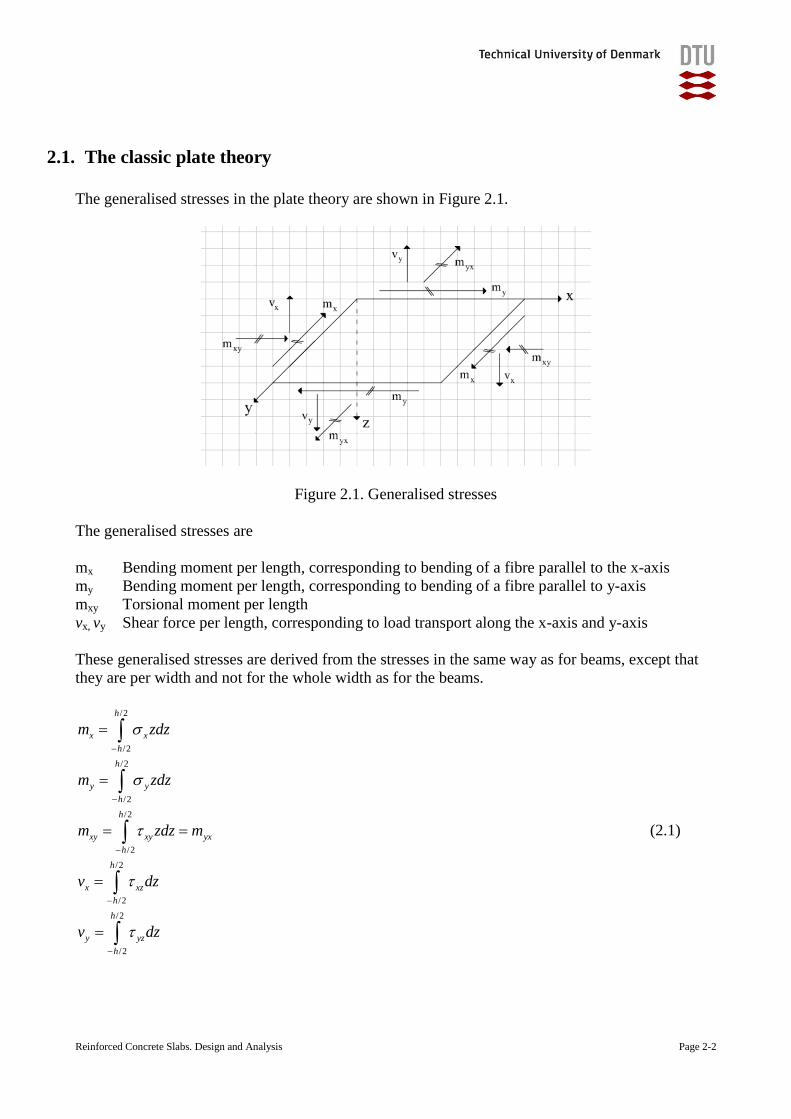
The generalised stresses in the plate theory are shown in Figure 2.1.
Figure 2.1. Generalised stresses
The generalised stresses are
mx Bending moment per length, corresponding to bending of a fibre parallel to the x-axis
my Bending moment per length, corresponding to bending of a fibre parallel to y-axis
mxy Torsional moment per length
vx, vy Shear force per length, corresponding to load transport along the x-axis and y-axis
These generalised stresses are derived from the stresses in the same way as for beams, except that
they are per width and not for the whole width as for the beams.
/2
/2
/2
/2
/2
/2
/2
/2
/2
/2
h
x x
h
h
y y
h
h
xy xy yx
h
h
x xz
h
h
y yz
h
m zdz
m zdz
m zdz m
v dz
v dz
(2.1)
Reinforced Concrete Slabs. Design and Analysis Page 2-3
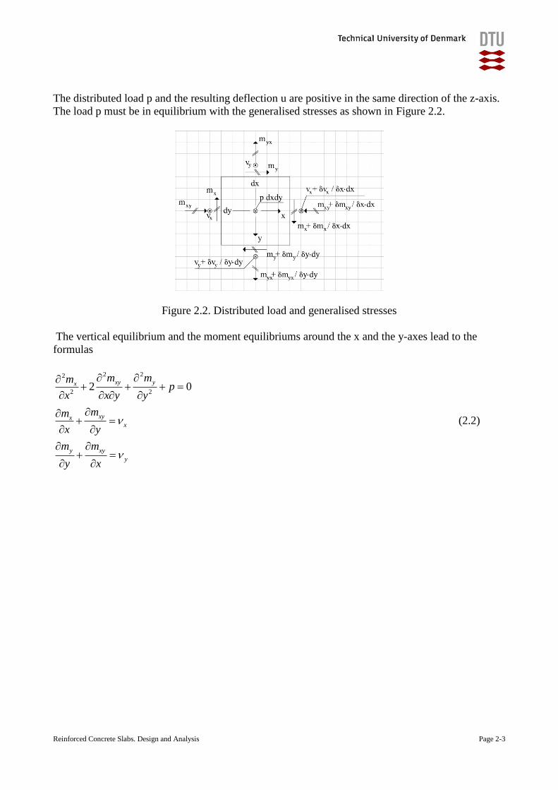
The distributed load p and the resulting deflection u are positive in the same direction of the z-axis.
The load p must be in equilibrium with the generalised stresses as shown in Figure 2.2.
Figure 2.2. Distributed load and generalised stresses
The vertical equilibrium and the moment equilibriums around the x and the y-axes lead to the
formulas
2 22
2 22 0
xy yx
xyxx
y xy
y
m mmp
x x y y
mm
x y
m m
y x
(2.2)
Reinforced Concrete Slabs. Design and Analysis Page 2-4
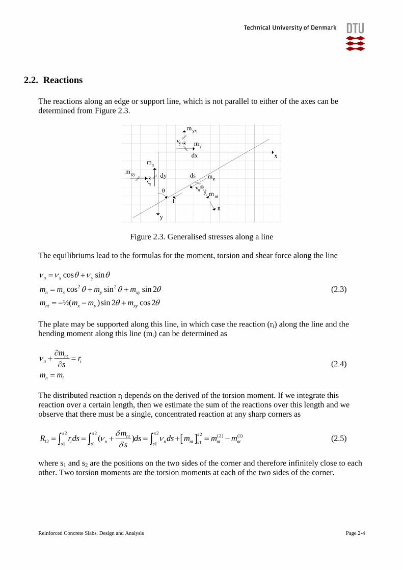
2.2. Reactions
The reactions along an edge or support line, which is not parallel to either of the axes can be
determined from Figure 2.3.
Figure 2.3. Generalised stresses along a line
The equilibriums lead to the formulas for the moment, torsion and shear force along the line
2 2
cos sin
cos sin sin 2
½( )sin 2 cos 2
n x y
n x y xy
nt x y xy
m m m m
m m m m
(2.3)
The plate may be supported along this line, in which case the reaction (ri) along the line and the
bending moment along this line (mi) can be determined as
ntn i
n i
mr
s
m m
(2.4)
The distributed reaction ri depends on the derived of the torsion moment. If we integrate this
reaction over a certain length, then we estimate the sum of the reactions over this length and we
observe that there must be a single, concentrated reaction at any sharp corners as
2 2 2 2 (2) (1)
12 11 1 1( )
s s s snti n n nt nt ntss s s
mR rds ds ds m m m
s
(2.5)
where s1 and s2 are the positions on the two sides of the corner and therefore infinitely close to each
other. Two torsion moments are the torsion moments at each of the two sides of the corner.
Reinforced Concrete Slabs. Design and Analysis Page 2-5
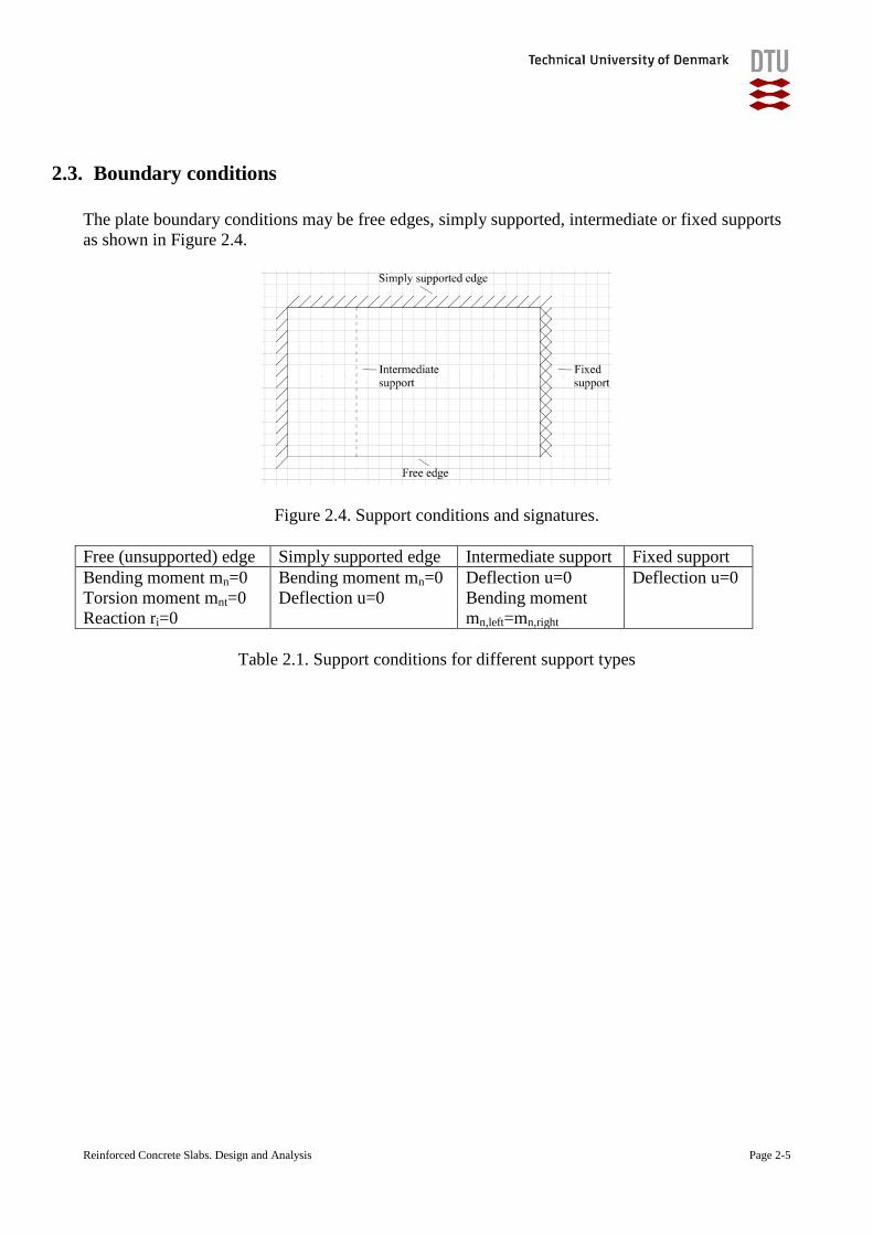
2.3. Boundary conditions
The plate boundary conditions may be free edges, simply supported, intermediate or fixed supports
as shown in Figure 2.4.
Figure 2.4. Support conditions and signatures.
Free (unsupported) edge Simply supported edge Intermediate support Fixed support
Bending moment mn=0
Torsion moment mnt=0
Reaction ri=0
Bending moment mn=0
Deflection u=0
Deflection u=0
Bending moment
mn,left=mn,right
Deflection u=0
Table 2.1. Support conditions for different support types
Reinforced Concrete Slabs. Design and Analysis Page 2-6
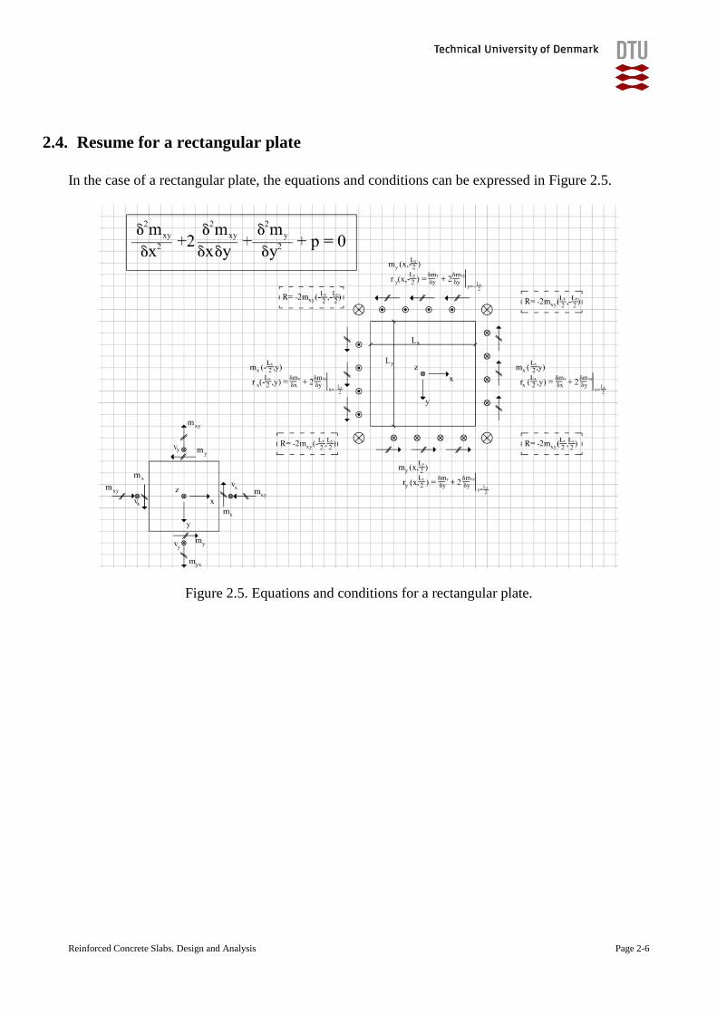
2.4. Resume for a rectangular plate
In the case of a rectangular plate, the equations and conditions can be expressed in Figure 2.5.
Figure 2.5. Equations and conditions for a rectangular plate.
Reinforced Concrete Slabs. Design and Analysis Page 2-7
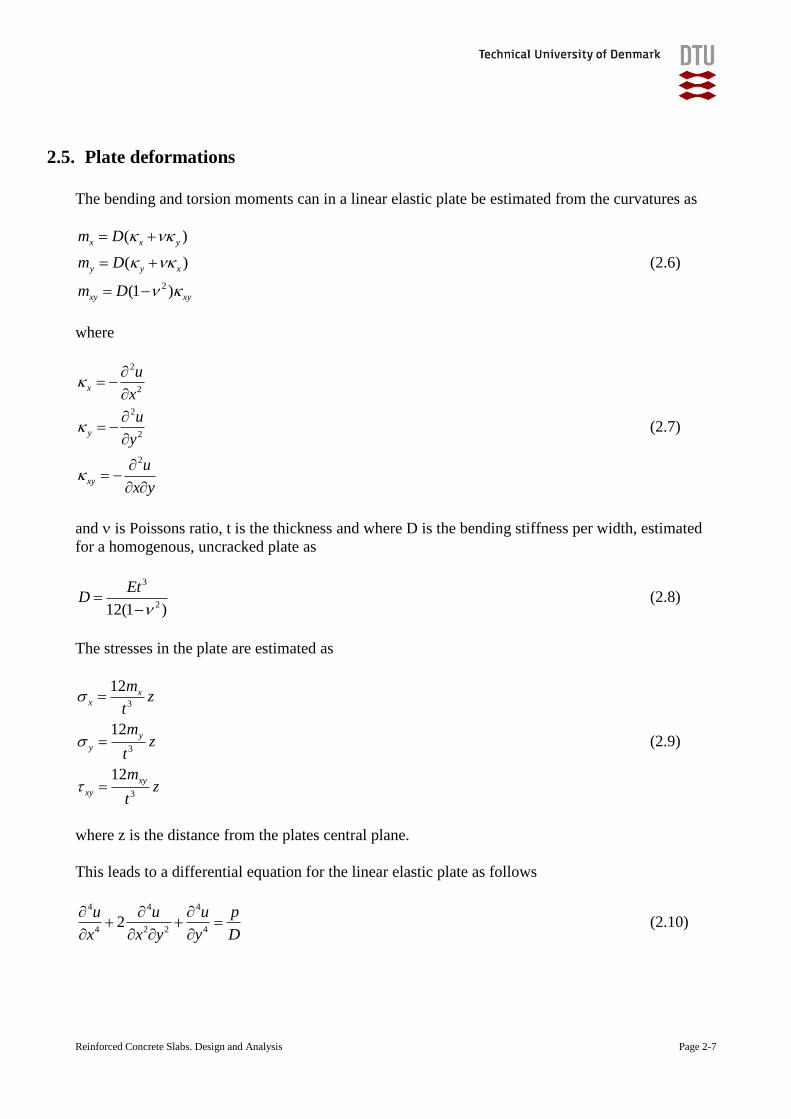
2.5. Plate deformations
The bending and torsion moments can in a linear elastic plate be estimated from the curvatures as
2
( )
( )
(1 )
x x y
y y x
xy xy
m D
m D
m D
(2.6)
where
2
2
2
2
2
x
y
xy
u
x
u
y
u
x y
(2.7)
and is Poissons ratio, t is the thickness and where D is the bending stiffness per width, estimated
for a homogenous, uncracked plate as
3
212(1 )
EtD
(2.8)
The stresses in the plate are estimated as
3
3
3
12
12
12
xx
y
y
xy
xy
mz
t
mz
t
mz
t
(2.9)
where z is the distance from the plates central plane.
This leads to a differential equation for the linear elastic plate as follows
4 4 4
4 2 2 42
u u u p
x x y y D
(2.10)
Reinforced Concrete Slabs. Design and Analysis Page 2-8
2.6. How to deal with a concrete slab
The current formulas deal with the static equilibrium, which must be fulfilled by all slabs, but may
be difficult to fulfil with simple models and calculations for more complex slabs. It deals also with
the aspects of deformations, which may be a problem due to the non-linear relationships in steel,
concrete and in the reinforced and cracked concrete cross-section.
Uncracked: At low loads, the slab will be uncracked and we may use the classic plate theory. When
the tensile stresses exceed the tensile strength, the slab will start to form cracks, however, these
cracks will normally only be visible and affect the deformations, when the tensile stresses exceed
the tensile strength significantly.
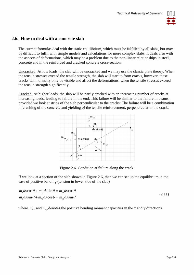
Cracked: At higher loads, the slab will be partly cracked with an increasing number of cracks at
increasing loads, leading to failure in the end. This failure will be similar to the failure in beams,
provided we look at strips of the slab perpendicular to the cracks: The failure will be a combination
of crushing of the concrete and yielding of the tensile reinforcement, perpendicular to the crack.
Figure 2.6. Condition at failure along the crack.
If we look at a section of the slab shown in Figure 2.6, then we can set up the equilibrium in the
case of positive bending (tension in lower side of the slab)
cos sin cos
sin cos sin
x xy ux
y xy uy
m ds m ds m ds
m ds m ds m ds
(2.11)
where and ux uym m denotes the positive bending moment capacities in the x and y directions.
Reinforced Concrete Slabs. Design and Analysis Page 2-9
This leads to the failure or yield condition in a positive failure or yield line
2( )( ) 0ux x uy y xym m m m m (2.12)
A similar expression can be found for failure with a negative bending or negative yield line, where ' ' and ux uym m denotes the negative bending moment capacities in the x and y directions
' ' 2( )( ) 0ux x uy y xym m m m m (2.13)
2.7. Additional reading material
2.1. Timoshenko, S.P and Woinowsky-Krieger, S.: ”Theory of plates and shells”, McGraw-
Hill International Editions.
This is an old classic and well known book, which presents a number of solutions for
elastic plates, which may be helpful for some of the simplest cases.
2.2. Any textbook from a plate theory course can be recommended for further knowledge and
understanding of plate theory.
2.3. Any Finite Element Method program with plate elements will allow calculations of a
large range of linear elastic, isotropic plates as a modern alternative to Timoshenko’s
book.

Reinforced Concrete Slabs. Design and Analysis Page 3-1
3. Serviceability Limit State, deflections
One of the reasons, why we are looking into the behaviour of slabs with double spans is that we
know that the double span may decrease the deflections significantly. In our simple test of the
quadratic, isotropic plate, we managed to reduce the deflection with a factor of almost 3 ! – we do,
however, need to be able to estimate the deflections without having to test them every time.
The last chapter presented the plate theory briefly, including the relationship between the
generalised stresses (bending and torsion moments) and the generalised strains (bending and torsion
curvatures) and related these to the stresses and strains in the material.
We will in this chapter determine the deflections in a very simple elastic plate and in a plate with a
slightly more complex geometry. We will also have a close look at the stiffness (D or EI) used in
the estimation of the deflections.
Reinforced Concrete Slabs. Design and Analysis Page 3-2
3.1. Bending stiffness of the reinforced concrete slab
We did carry out a small test with a linear elastic plexiglass plate in the classroom, where we saw
the effects of the double span. We know, however, that reinforced concrete cross-sections tend to
crack in the tensile zone and that this results in a quite nonlinear relationship between the bending
moment and the curvature in a beam.
We should therefore start our investigations by checking the load-deflection relationship of a
reinforced concrete slab, as e.g. a quadratic slab supported along all four sides and exposed to a
distributed load as shown in Figure 3.1 below.
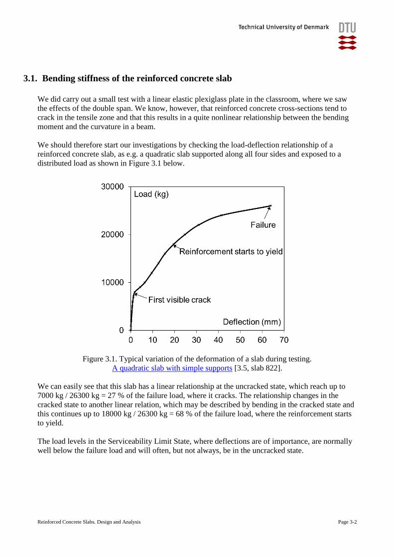
Figure 3.1. Typical variation of the deformation of a slab during testing.
A quadratic slab with simple supports [3.5, slab 822].
We can easily see that this slab has a linear relationship at the uncracked state, which reach up to
7000 kg / 26300 kg = 27 % of the failure load, where it cracks. The relationship changes in the
cracked state to another linear relation, which may be described by bending in the cracked state and
this continues up to 18000 kg / 26300 kg = 68 % of the failure load, where the reinforcement starts
to yield.
The load levels in the Serviceability Limit State, where deflections are of importance, are normally
well below the failure load and will often, but not always, be in the uncracked state.
Reinforced Concrete Slabs. Design and Analysis Page 3-3
3.2. Short term and long term loading
We need also to realise that there is a difference between the level of the loads, which only acts for
a short period (minutes, hours or days) and the level of the loads, which acts for a longer time
(years).
The deflections for the short term loads must be estimated with short-term modulus of elasticity,
whereas the deflections for the long term loads must be estimated with the long term modulus of
elasticity, so
short term deflections are estimated for the high, short term value of the load using the
concretes normal modulus of elasticity (Ec,short=Ecm), but
long term deflections are estimated for the lower long term value of the load using long-term
values of the modulus of elasticity (Ec,long=Ecm/(1+creep factor), which on the safe side can
be taken as Ec,long=Ec,short/4)
Reinforced Concrete Slabs. Design and Analysis Page 3-4
3.3. Bending stiffness estimation
In design for practical structures, the engineer will often assume that the slabs are uncracked and
use D as bending stiffness as
3
212(1 )
cE tD
(3.1)
this will normally provide a fair estimate of the deflections at modest loads as seen from Figure 3.1,
although the slab is usually more or less cracked even in the serviceability state. However, if the
engineer wishes to be absolutely sure to obtain a conservative estimate, then it will be assumed that
the cross-section is cracked, only the tensile reinforcement is taken into account and D will be
replaced by EI/width, where EI is estimated for the cracked cross-section for short-term or long
term loads as
3 2 21( / 2) ( )
12
where the height of the compressionzone x is found from
( / 2) ( ) 0
and where is defined as
=E /
c t
t s
t s
s c
EI E I
I x x x A d x
S x x A d x x
E
(3.2)
The above expressions can be derived for a beam with a cross-section in pure bending with no
compressive reinforcement, where
As is the amount of tensile reinforcement per width b
d is the effective height of the reinforcement
Es is the modulus of elasticity of the reinforcement
Ec is the modulus of elasticity of the concrete (short term or long term, depending of the load
duration)
Reinforced Concrete Slabs. Design and Analysis Page 3-5
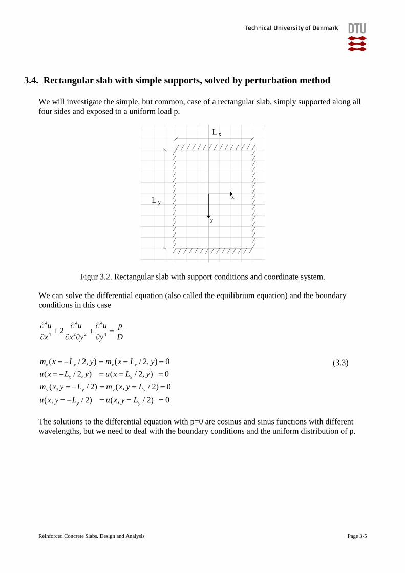
3.4. Rectangular slab with simple supports, solved by perturbation method
We will investigate the simple, but common, case of a rectangular slab, simply supported along all
four sides and exposed to a uniform load p.
Figur 3.2. Rectangular slab with support conditions and coordinate system.
We can solve the differential equation (also called the equilibrium equation) and the boundary
conditions in this case
4 4 4
4 2 2 42
( / 2, ) ( / 2, ) 0
( / 2, ) ( / 2, ) 0
( , / 2) ( , / 2) 0
( , / 2) ( , / 2) 0
x x x x
x x
y y y y
y y
u u u p
x x y y D
m x L y m x L y
u x L y u x L y
m x y L m x y L
u x y L u x y L
(3.3)
The solutions to the differential equation with p=0 are cosinus and sinus functions with different
wavelengths, but we need to deal with the boundary conditions and the uniform distribution of p.
Reinforced Concrete Slabs. Design and Analysis Page 3-6
We may therefore use a perturbation method to describe the deformation u, and as we notice that
the loading and the boundary conditions are double symmetric, then we will limit our solutions to
the double symmetric deformations functions of u
cos cos 1,3,5,... and 1,3,5,...x y
m x n yu n m
L L
(3.4)
which all fulfil the boundary conditions and also fulfil the differential equation for a distributed load
of
2 44 2
( , ) 2 cos cosx x y y x y
m m n n m x n yp x y
L L L L L L
(3.5)
We may use a combination of these solutions to derive a solution for an uniform p-load as follows
262 21 1
2 2
cos cos16
where 1,3,5,... 1,3,5,...x y
m n
x y
m x n y
L Lpu m n
D m nmn
L L
(3.6)
This method for solving the equations and boundary conditions were much used in the older days
(when I was a student in the last millenium), where computers were few and slow or did not exist
and where engineering therefore had to develop this kind of solution, where a number of the
contributions had to be taken in order to reach a fairly accurate result. The current solution is
derived by Navier and is presented in the classic handbook [3.1], where Timoshenko and
Woinowsky-Krieger have presented a number of this type of solutions.
Reinforced Concrete Slabs. Design and Analysis Page 3-7
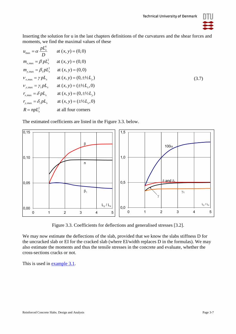
Inserting the solution for u in the last chapters definitions of the curvatures and the shear forces and
moments, we find the maximal values of these 4
max
2
,max
2
,max 1
,max
,max 1
,max
,max 1
2
at ( , ) (0,0)
at ( , ) (0,0)
at ( , ) (0,0)
at ( , ) (0, ½ )
at ( , ) ( ½ ,0)
at ( , ) (0, ½ )
at ( , ) ( ½ ,0)
at all f
x
x x
y x
x x y
y x x
x x y
y x x
x
pLu x y
D
m pL x y
m pL x y
pL x y L
pL x y L
r pL x y L
r pL x y L
R npL
our corners
(3.7)
The estimated coefficients are listed in the Figure 3.3. below.
Figure 3.3. Coefficients for deflections and generalised stresses [3.2].
We may now estimate the deflections of the slab, provided that we know the slabs stiffness D for
the uncracked slab or EI for the cracked slab (where EI/width replaces D in the formulas). We may
also estimate the moments and thus the tensile stresses in the concrete and evaluate, whether the
cross-sections cracks or not.
This is used in example 3.1.
Reinforced Concrete Slabs. Design and Analysis Page 3-8
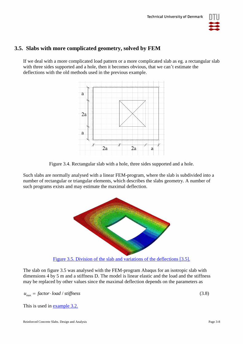
3.5. Slabs with more complicated geometry, solved by FEM
If we deal with a more complicated load pattern or a more complicated slab as eg. a rectangular slab
with three sides supported and a hole, then it becomes obvious, that we can’t estimate the
deflections with the old methods used in the previous example.
Figure 3.4. Rectangular slab with a hole, three sides supported and a hole.
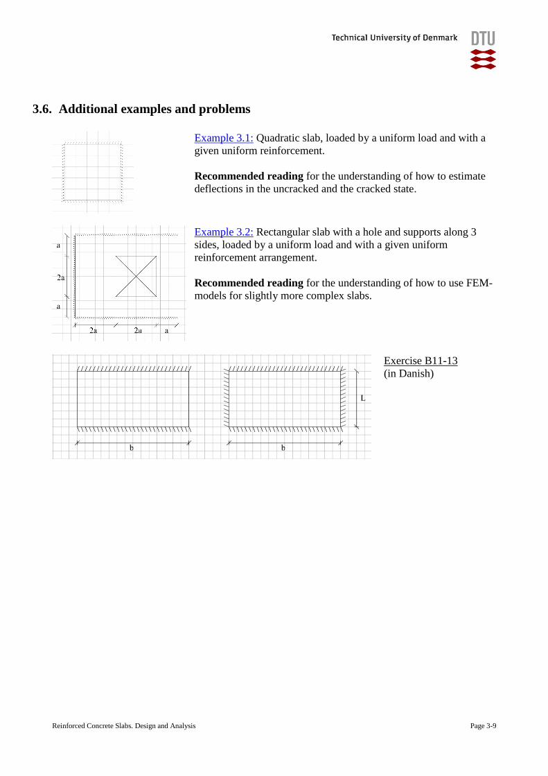
Such slabs are normally analysed with a linear FEM-program, where the slab is subdivided into a
number of rectangular or triangular elements, which describes the slabs geometry. A number of
such programs exists and may estimate the maximal deflection.
Figure 3.5. Division of the slab and variations of the deflections [3.5].
The slab on figure 3.5 was analysed with the FEM-program Abaqus for an isotropic slab with
dimensions 4 by 5 m and a stiffness D. The model is linear elastic and the load and the stiffness
may be replaced by other values since the maximal deflection depends on the parameters as
max /u factor load stiffness (3.8)
This is used in example 3.2.
Reinforced Concrete Slabs. Design and Analysis Page 3-9
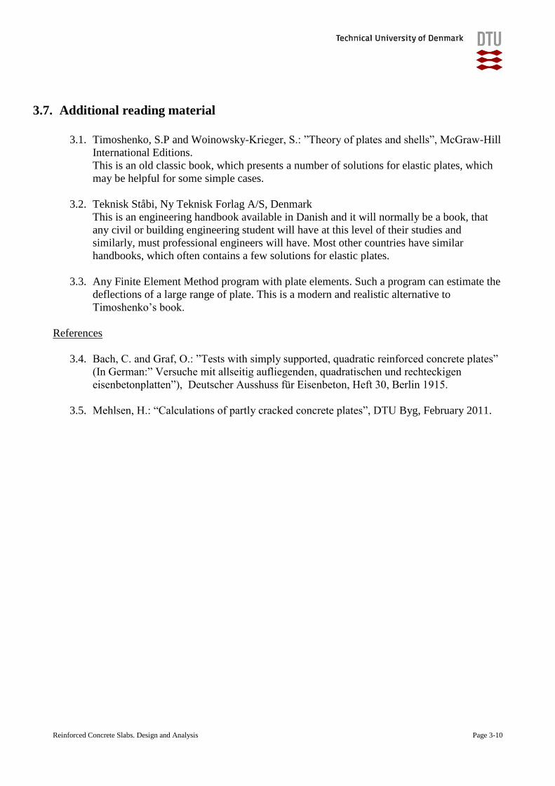
3.6. Additional examples and problems
Example 3.1: Quadratic slab, loaded by a uniform load and with a
given uniform reinforcement.
Recommended reading for the understanding of how to estimate
deflections in the uncracked and the cracked state.
Example 3.2: Rectangular slab with a hole and supports along 3
sides, loaded by a uniform load and with a given uniform
reinforcement arrangement.
Recommended reading for the understanding of how to use FEM-
models for slightly more complex slabs.
Exercise B11-13
(in Danish)
Reinforced Concrete Slabs. Design and Analysis Page 3-10
3.7. Additional reading material
3.1. Timoshenko, S.P and Woinowsky-Krieger, S.: ”Theory of plates and shells”, McGraw-Hill
International Editions.
This is an old classic book, which presents a number of solutions for elastic plates, which
may be helpful for some simple cases.
3.2. Teknisk Ståbi, Ny Teknisk Forlag A/S, Denmark
This is an engineering handbook available in Danish and it will normally be a book, that
any civil or building engineering student will have at this level of their studies and
similarly, must professional engineers will have. Most other countries have similar
handbooks, which often contains a few solutions for elastic plates.
3.3. Any Finite Element Method program with plate elements. Such a program can estimate the
deflections of a large range of plate. This is a modern and realistic alternative to
Timoshenko’s book.
References
3.4. Bach, C. and Graf, O.: ”Tests with simply supported, quadratic reinforced concrete plates”
(In German:” Versuche mit allseitig aufliegenden, quadratischen und rechteckigen
eisenbetonplatten”), Deutscher Ausshuss für Eisenbeton, Heft 30, Berlin 1915.
3.5. Mehlsen, H.: “Calculations of partly cracked concrete plates”, DTU Byg, February 2011.
Reinforced Concrete Slabs. Design and Analysis Page 4-1
4. Ultimate Limit State. Lower-limit solution with a guessed solution
The plate theory describes the differential equation and the boundary conditions, which must be
fulfilled in order to fulfil the equilibrium and the constitutive conditions. This will require complex
models for more complex geometries or load conditions, but it is possible to establish simple,
analytical solutions for simple geometries and load distributions.
This may be achieved by a lower limit solution: A lower limit solution is a solution, which fulfils
the condition of equilibrium and also fulfils the boundary conditions. This means that the solution is
one of the many possible ways of transporting the loads to the supports through the plate and at the
same time have equilibrium between the loads, the forces and the reactions in every point of the
plate. A lower limit solution may not be the optimal solution and other solutions may verify a
higher load-carrying capacity, but it will be on the safe side.
The reinforced concrete slab shall then later be checked, so it can be verified that the slab has a
sufficient load-carrying capacity to carry the cross-sectional forces, predicted by the lower-limit
solution.
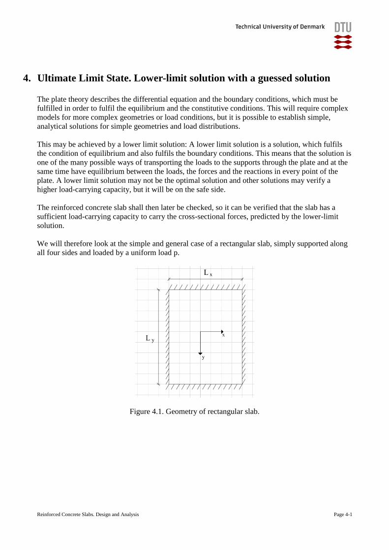
We will therefore look at the simple and general case of a rectangular slab, simply supported along
all four sides and loaded by a uniform load p.
Figure 4.1. Geometry of rectangular slab.
Reinforced Concrete Slabs. Design and Analysis Page 4-2
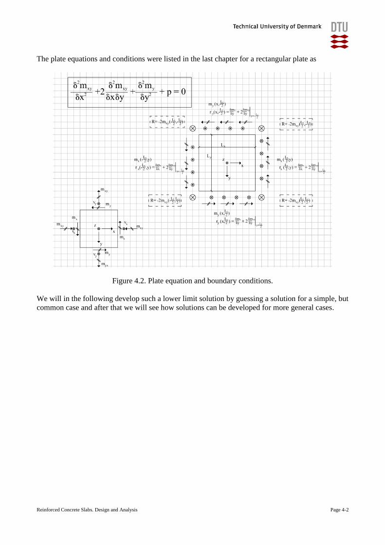
The plate equations and conditions were listed in the last chapter for a rectangular plate as
Figure 4.2. Plate equation and boundary conditions.
We will in the following develop such a lower limit solution by guessing a solution for a simple, but
common case and after that we will see how solutions can be developed for more general cases.
Reinforced Concrete Slabs. Design and Analysis Page 4-3
4.1. The guessed solution for a rectangular slab with 4 sides supported
In the case of a rectangular slab with supports on all four sides, loaded by a uniform load p it would
be a good guess to assume that mx and my have parabolic variations (mx=a+bx+cx2, my=d+ey+fy
2)
as this would lead to constant values of the derived in the equilibrium equation.
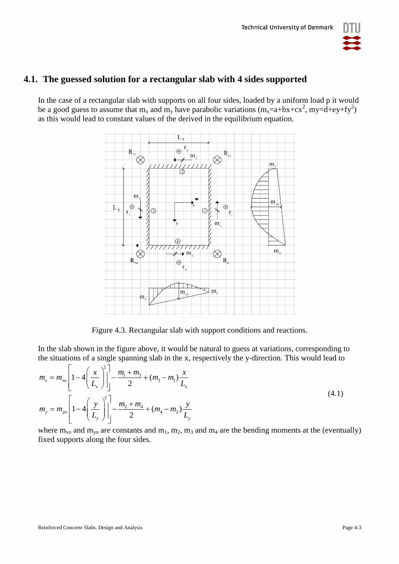
Figure 4.3. Rectangular slab with support conditions and reactions.
In the slab shown in the figure above, it would be natural to guess at variations, corresponding to
the situations of a single spanning slab in the x, respectively the y-direction. This would lead to 2
1 33 1
2
2 44 2
1 4 ( )2
1 4 ( )2
x xo
x x
y yo
y y
m mx xm m m m
L L
m my ym m m m
L L
(4.1)
where mxo and myo are constants and m1, m2, m3 and m4 are the bending moments at the (eventually)
fixed supports along the four sides.
Reinforced Concrete Slabs. Design and Analysis Page 4-4
The variation of the torsional moment can be guessed as well (mxy=g+hx+iy+jxy) and found to be
xy xyo
x y
xym m
l l (4.2)
It can be shown that setting
( )xyo xo yom m m (4.3)
leads to the highest lower limit solution, that is the highest p-value for given mxo and myo.
Inserting (4.1) to (4.3) in the plates differential equation (2.1) leads to
1 4 1 4 ½y x
xo yo x y
x y
L Lm m pL L
L L
(4.4)
This solution leads to the reactions
1 31 2
2 42 2
3 13 2
4 24 2
42
42
42
42
x xyo
y x
y y
xo
x y
x xyo
y x
y y
xo
x y
pL L m mr m
L L
pL L m mr m
L L
pL L m mr m
L L
pL L m mr m
L L
(4.5)
12 23 34 41 ½( )xo yoR R R R m m
4.2. Other guessed solutions
It will of course be possible to develop other, guessed solutions for this and other problems and
other load types, but it is only in few cases, that it will be possible to develop analytical lower-limit
solutions.
A new and modern possibility is, however, to use a Finite Element Method (FEM) program to
determine a solution, as such programs will determine solutions which fulfils the conditions (see
example 3.2).
Using a FEM program will normally provide valid lower limit solutions, since the program’s
solutions fulfil both the equilibrium and the boundary conditions with a sufficient accuracy. The
program’s use of a simple stress-strain relationship will, however, of make the programs solutions
extra conservative and a resulting in a higher consumption of resources (concrete and especially
require more reinforcement).
Reinforced Concrete Slabs. Design and Analysis Page 4-5
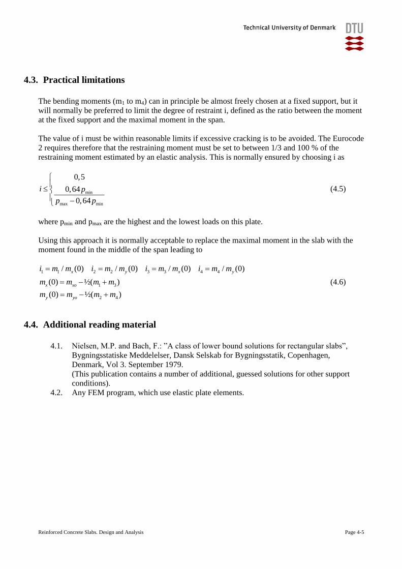
4.3. Practical limitations
The bending moments (m1 to m4) can in principle be almost freely chosen at a fixed support, but it
will normally be preferred to limit the degree of restraint i, defined as the ratio between the moment
at the fixed support and the maximal moment in the span.
The value of i must be within reasonable limits if excessive cracking is to be avoided. The Eurocode
2 requires therefore that the restraining moment must be set to between 1/3 and 100 % of the
restraining moment estimated by an elastic analysis. This is normally ensured by choosing i as
min
max min
0,5
0,64
0,64
i p
p p
(4.5)
where pmin and pmax are the highest and the lowest loads on this plate.
Using this approach it is normally acceptable to replace the maximal moment in the slab with the
moment found in the middle of the span leading to
1 1 2 2 3 3 4 4
1 3
2 4
/ (0) / (0) / (0) / (0)
(0) ½( )
(0) ½( )
x y x y
x xo
y yo
i m m i m m i m m i m m
m m m m
m m m m
(4.6)
4.4. Additional reading material
4.1. Nielsen, M.P. and Bach, F.: ”A class of lower bound solutions for rectangular slabs”,
Bygningsstatiske Meddelelser, Dansk Selskab for Bygningsstatik, Copenhagen,
Denmark, Vol 3. September 1979.
(This publication contains a number of additional, guessed solutions for other support
conditions).
4.2. Any FEM program, which use elastic plate elements.
Reinforced Concrete Slabs. Design and Analysis Page 5-1
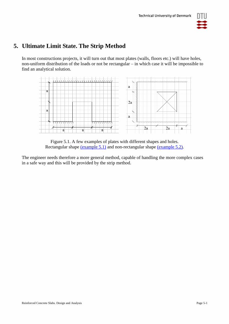
5. Ultimate Limit State. The Strip Method
In most constructions projects, it will turn out that most plates (walls, floors etc.) will have holes,
non-uniform distribution of the loads or not be rectangular – in which case it will be impossible to
find an analytical solution.
Figure 5.1. A few examples of plates with different shapes and holes.
Rectangular shape (example 5.1) and non-rectangular shape (example 5.2).
The engineer needs therefore a more general method, capable of handling the more complex cases
in a safe way and this will be provided by the strip method.
Reinforced Concrete Slabs. Design and Analysis Page 5-2
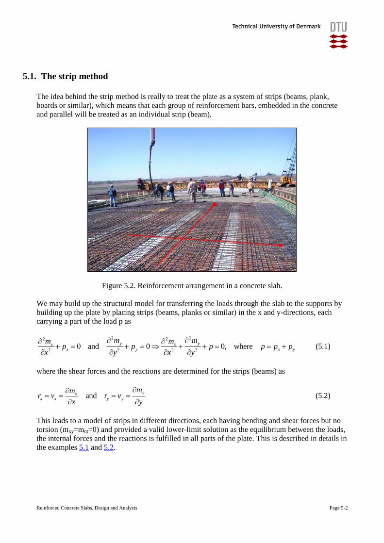
5.1. The strip method
The idea behind the strip method is really to treat the plate as a system of strips (beams, plank,
boards or similar), which means that each group of reinforcement bars, embedded in the concrete
and parallel will be treated as an individual strip (beam).
Figure 5.2. Reinforcement arrangement in a concrete slab.
We may build up the structural model for transferring the loads through the slab to the supports by
building up the plate by placing strips (beams, planks or similar) in the x and y-directions, each
carrying a part of the load p as
2 22 2
2 2 2 20 and 0 0, where
y yx xx y x y
m mm mp p p p p p
x y x y
(5.1)
where the shear forces and the reactions are determined for the strips (beams) as
andyx
x x y y
mmr v r v
x y
(5.2)
This leads to a model of strips in different directions, each having bending and shear forces but no
torsion (mxy=mnt=0) and provided a valid lower-limit solution as the equilibrium between the loads,
the internal forces and the reactions is fulfilled in all parts of the plate. This is described in details in
the examples 5.1 and 5.2.
Reinforced Concrete Slabs. Design and Analysis Page 5-3
In each strip the maximal and minimal moments (mi,min and mi,max) are determined at the lower limit
of the loadcarrying capacity is determined as the maximal value of p=pi(-)
, where the moments stay
within
'
,min ,maxiu i i ium m m m (5.3)
where m’iu and miu are the bending moment capacity of strip i in negative bending (tension in the
top of the plate) and in positive bending (tension in the bottom of the plate).
The lower limit solution for the capacity of the plate p(-)
is determined as the lowest of the capacities
for the strips
( ) ( ) ( )
1 2min( , ,...)p p p (5.4)
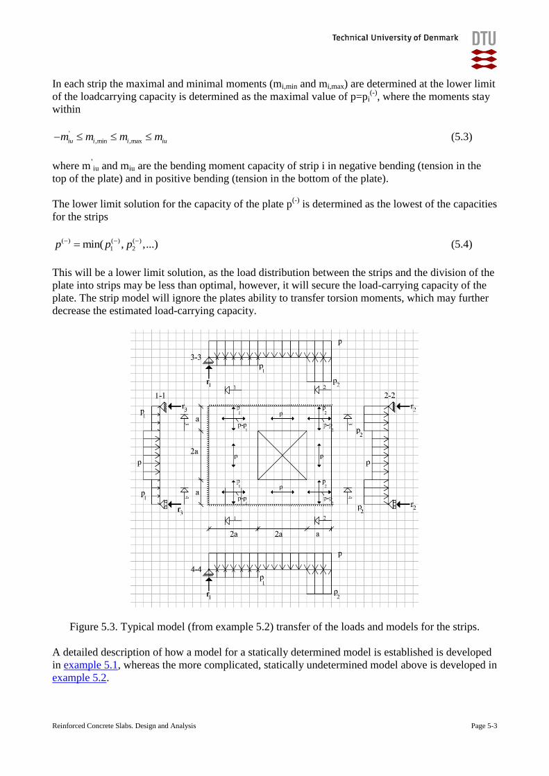
This will be a lower limit solution, as the load distribution between the strips and the division of the
plate into strips may be less than optimal, however, it will secure the load-carrying capacity of the
plate. The strip model will ignore the plates ability to transfer torsion moments, which may further
decrease the estimated load-carrying capacity.
Figure 5.3. Typical model (from example 5.2) transfer of the loads and models for the strips.
A detailed description of how a model for a statically determined model is established is developed
in example 5.1, whereas the more complicated, statically undetermined model above is developed in
example 5.2.
Reinforced Concrete Slabs. Design and Analysis Page 5-4
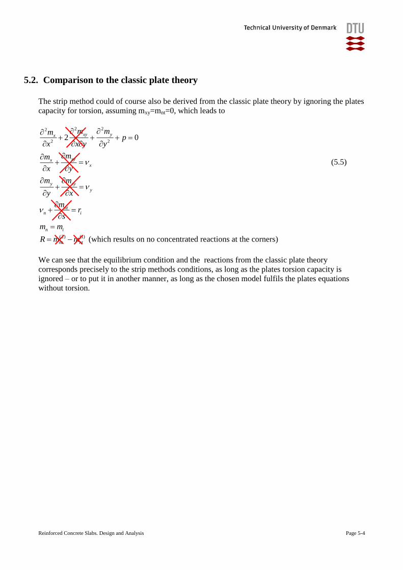
5.2. Comparison to the classic plate theory
The strip method could of course also be derived from the classic plate theory by ignoring the plates
capacity for torsion, assuming mxy=mnt=0, which leads to
2 22
2 22 0
xy yx
xyxx
y xy
y
m mmp
x x y y
mm
x y
m m
y x
(5.5)
ntn i
n i
mr
s
m m
(2) (1)
nt ntR m m (which results on no concentrated reactions at the corners)
We can see that the equilibrium condition and the reactions from the classic plate theory
corresponds precisely to the strip methods conditions, as long as the plates torsion capacity is
ignored – or to put it in another manner, as long as the chosen model fulfils the plates equations
without torsion.
Reinforced Concrete Slabs. Design and Analysis Page 5-5
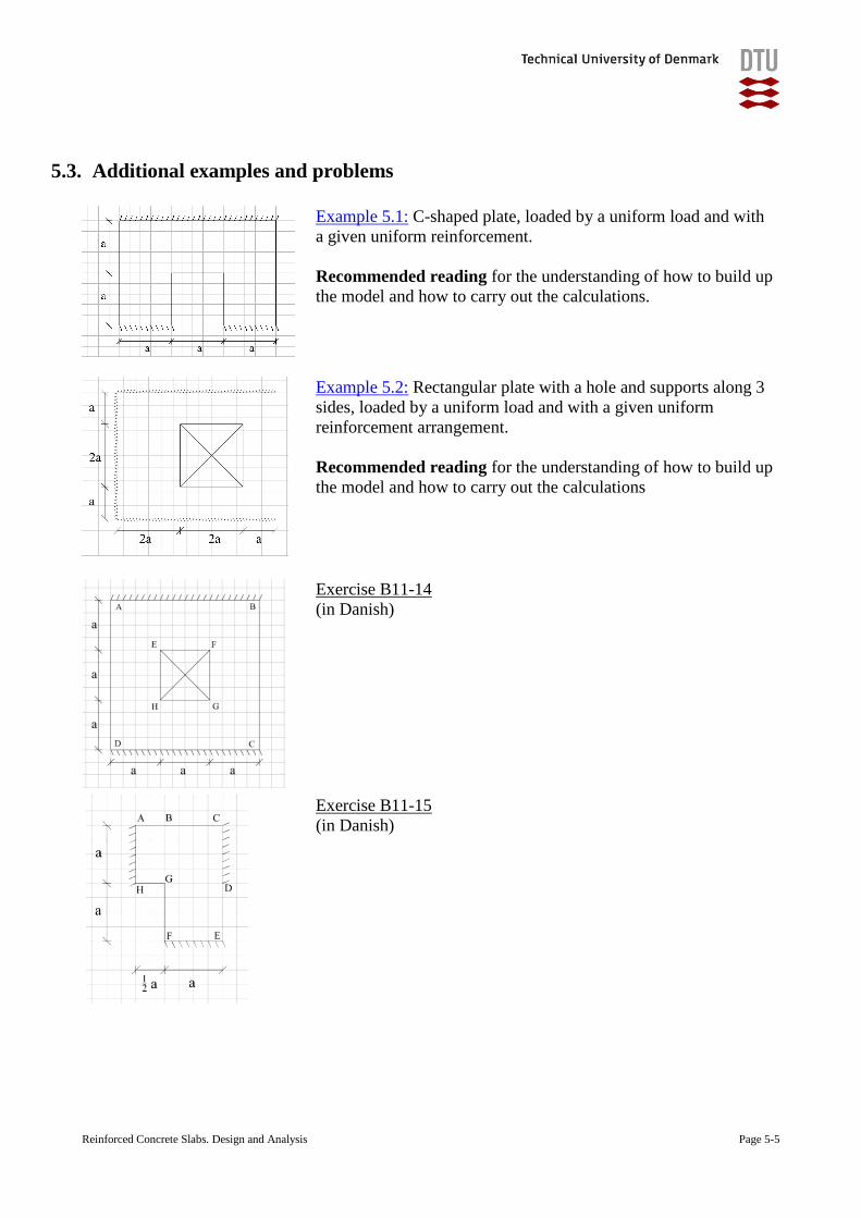
5.3. Additional examples and problems
Example 5.1: C-shaped plate, loaded by a uniform load and with
a given uniform reinforcement.
Recommended reading for the understanding of how to build up
the model and how to carry out the calculations.
Example 5.2: Rectangular plate with a hole and supports along 3
sides, loaded by a uniform load and with a given uniform
reinforcement arrangement.
Recommended reading for the understanding of how to build up
the model and how to carry out the calculations
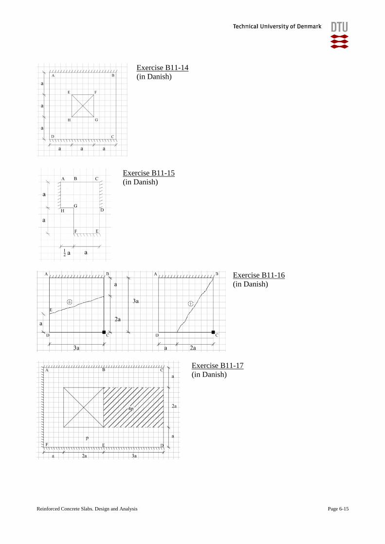
Exercise B11-14
(in Danish)
Exercise B11-15
(in Danish)
Reinforced Concrete Slabs. Design and Analysis Page 5-6
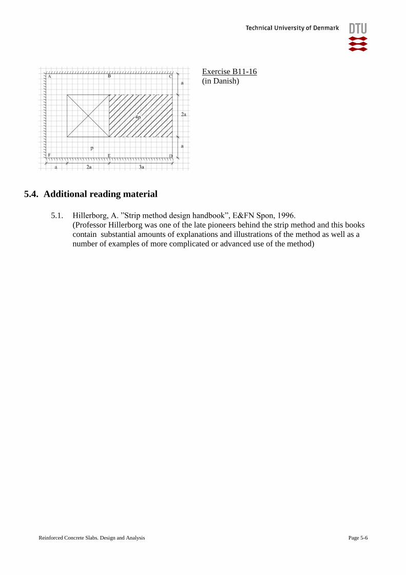
Exercise B11-16
(in Danish)
5.4. Additional reading material
5.1. Hillerborg, A. ”Strip method design handbook”, E&FN Spon, 1996.
(Professor Hillerborg was one of the late pioneers behind the strip method and this books
contain substantial amounts of explanations and illustrations of the method as well as a
number of examples of more complicated or advanced use of the method)
Reinforced Concrete Slabs. Design and Analysis Page 6-1
6. Ultimate Limit State. The Yield Line Method
The load-carrying capacities of reinforced concrete slabs may be verified by many lower-limit
solutions, as e.g. the guessed solutions, the Finite Element Method estimations, the strip method or
many others.
The experience is, however, that the lower limit methods, suitable for simple estimations by hand
tend to involve quite a lot of calculation for slabs with even just slightly complex geometries or load
distributions.
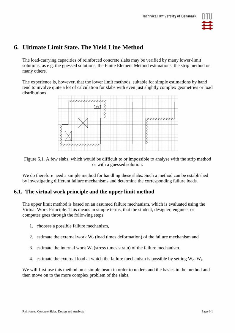
Figure 6.1. A few slabs, which would be difficult to or impossible to analyse with the strip method
or with a guessed solution.
We do therefore need a simple method for handling these slabs. Such a method can be established
by investigating different failure mechanisms and determine the corresponding failure loads.
6.1. The virtual work principle and the upper limit method
The upper limit method is based on an assumed failure mechanism, which is evaluated using the
Virtual Work Principle. This means in simple terms, that the student, designer, engineer or
computer goes through the following steps
1. chooses a possible failure mechanism,
2. estimate the external work We (load times deformation) of the failure mechanism and
3. estimate the internal work Wi (stress times strain) of the failure mechanism.
4. estimate the external load at which the failure mechanism is possible by setting We=Wi.
We will first use this method on a simple beam in order to understand the basics in the method and
then move on to the more complex problem of the slabs.
Reinforced Concrete Slabs. Design and Analysis Page 6-2
6.2. Upper limit method for a simple beam
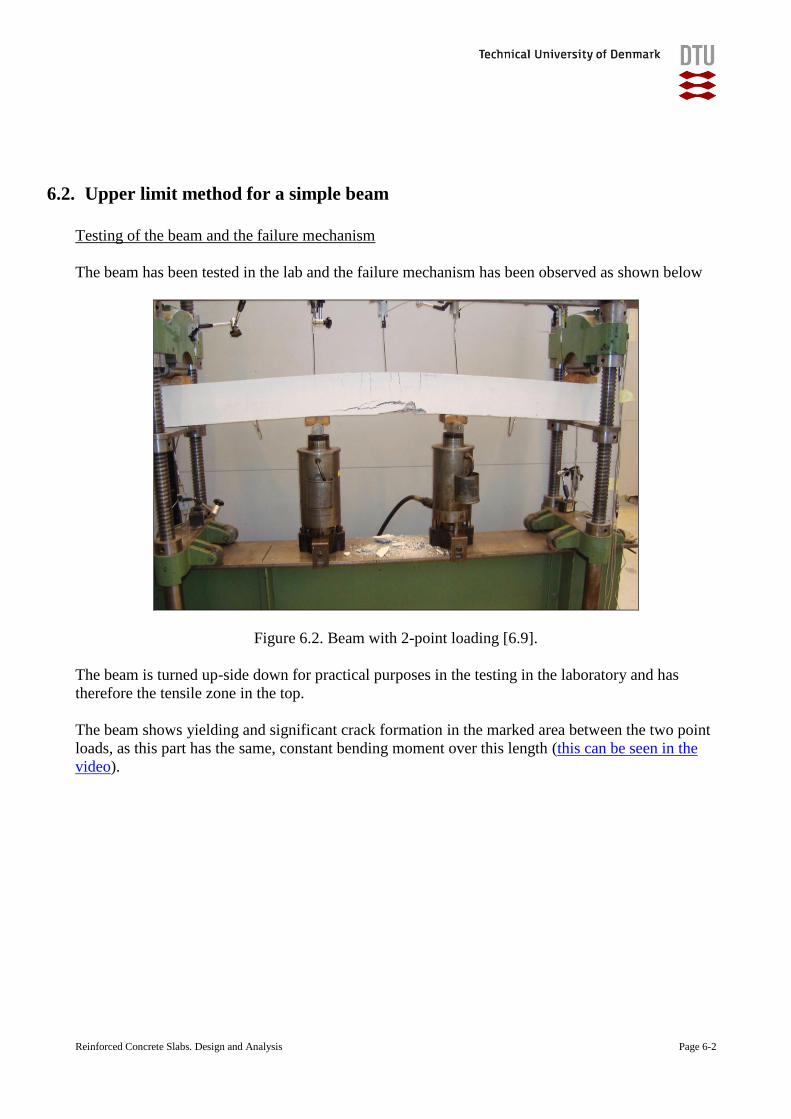
Testing of the beam and the failure mechanism
The beam has been tested in the lab and the failure mechanism has been observed as shown below
Figure 6.2. Beam with 2-point loading [6.9].
The beam is turned up-side down for practical purposes in the testing in the laboratory and has
therefore the tensile zone in the top.
The beam shows yielding and significant crack formation in the marked area between the two point
loads, as this part has the same, constant bending moment over this length (this can be seen in the
video).
Reinforced Concrete Slabs. Design and Analysis Page 6-3
Static model and failure mechanism
The load-carrying capacity of a beam is normally estimated with simple formulas as explained in
any basic course in concrete structures and should not require use of the virtual work method, but is
still very suitable as an introduction.
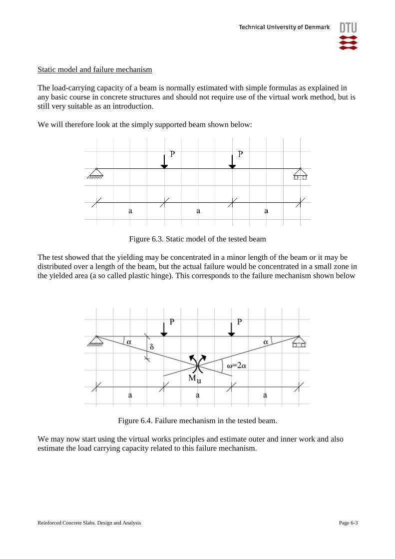
We will therefore look at the simply supported beam shown below:
Figure 6.3. Static model of the tested beam
The test showed that the yielding may be concentrated in a minor length of the beam or it may be
distributed over a length of the beam, but the actual failure would be concentrated in a small zone in
the yielded area (a so called plastic hinge). This corresponds to the failure mechanism shown below
Figure 6.4. Failure mechanism in the tested beam.
We may now start using the virtual works principles and estimate outer and inner work and also
estimate the load carrying capacity related to this failure mechanism.
Reinforced Concrete Slabs. Design and Analysis Page 6-4
6.2.1. The external work
The external work is easily estimated as the sum of the external loads multiplied with the
incremental deformations of the beam in the failure in the load positions
( ) ( )e i iW p s s ds P (6.1)
where
Pi is a concentrated load in point i
p(s) is a distributed line load at coordinate s
i is the incremental displacement of the mechanism in position i
is the incremental displacement of the mechanism at coordinate s
6.2.2. The internal work
The internal work is the sum of the bending moments and the incremental curvatures in the
beam, which occurs at the instant, where the failure occurs. This means that
( ) ( )iW M s s ds (6.2)
The part of the beam failed (reinforcement yielded and the concrete was crushed) in more or less
concentrated area in the zone between the two loads, which means that the extra, incremental
curvature occurs in this zone only and is zero in all other parts of the beam. This means that the
inner work in the beam with a positive yielding moment is calculated as the plastic work in the zone
( ) ( ) ( )i u u uW M s s ds M s ds M a M (6.3)
where
( )s ds (6.4)
and similarly in a beam with a negative yielding moment
'
i uW M (6.5)
where
Mu is the positive yielding moment
Mu’ is the negative yielding moment
is the bend in the plastic hinge of the beam.
Reinforced Concrete Slabs. Design and Analysis Page 6-5
6.2.3. The loadcarrying capacity
This is found by setting the internal work Wi equal to the external work We, leading to an upper
limit value of load-carrying capacity.
This is described in details in example 6.1.
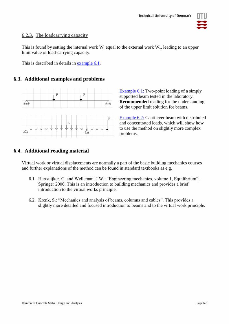
6.3. Additional examples and problems
Example 6.1: Two-point loading of a simply
supported beam tested in the laboratory.
Recommended reading for the understanding
of the upper limit solution for beams.
Example 6.2: Cantilever beam with distributed
and concentrated loads, which will show how
to use the method on slightly more complex
problems.
6.4. Additional reading material
Virtual work or virtual displacements are normally a part of the basic building mechanics courses
and further explanations of the method can be found in standard textbooks as e.g.
6.1. Hartsuijker, C. and Welleman, J.W.: “Engineering mechanics, volume 1, Equilibrium”,
Springer 2006. This is an introduction to building mechanics and provides a brief
introduction to the virtual works principle.
6.2. Krenk, S.: “Mechanics and analysis of beams, columns and cables”. This provides a
slightly more detailed and focused introduction to beams and to the virtual work principle.
Reinforced Concrete Slabs. Design and Analysis Page 6-6
6.5. Upper limit solution – yield line method – in slabs
The upper limit solution in a slab is derived using the same approach as for a beam:
1. we identify and select a kinematically permissible failure mechanism (yield line pattern),
2. we calculate the external and internal work during the failure and
3. we calculate the upper limit load from the requirement of We=Wi.
6.5.1. Failure mechanisms during testing
We will look at the behaviour of a slab during testing and see how it develops cracks and in the end
how it fails. We will for this purpose look at the failure mechanisms of two simple slabs:
Slab 1: A simple rectangular slab of fibre reinforced concrete tested at DTU
Slab 2: A simple quadratic slab of reinforced concrete, tested in Stuttgart
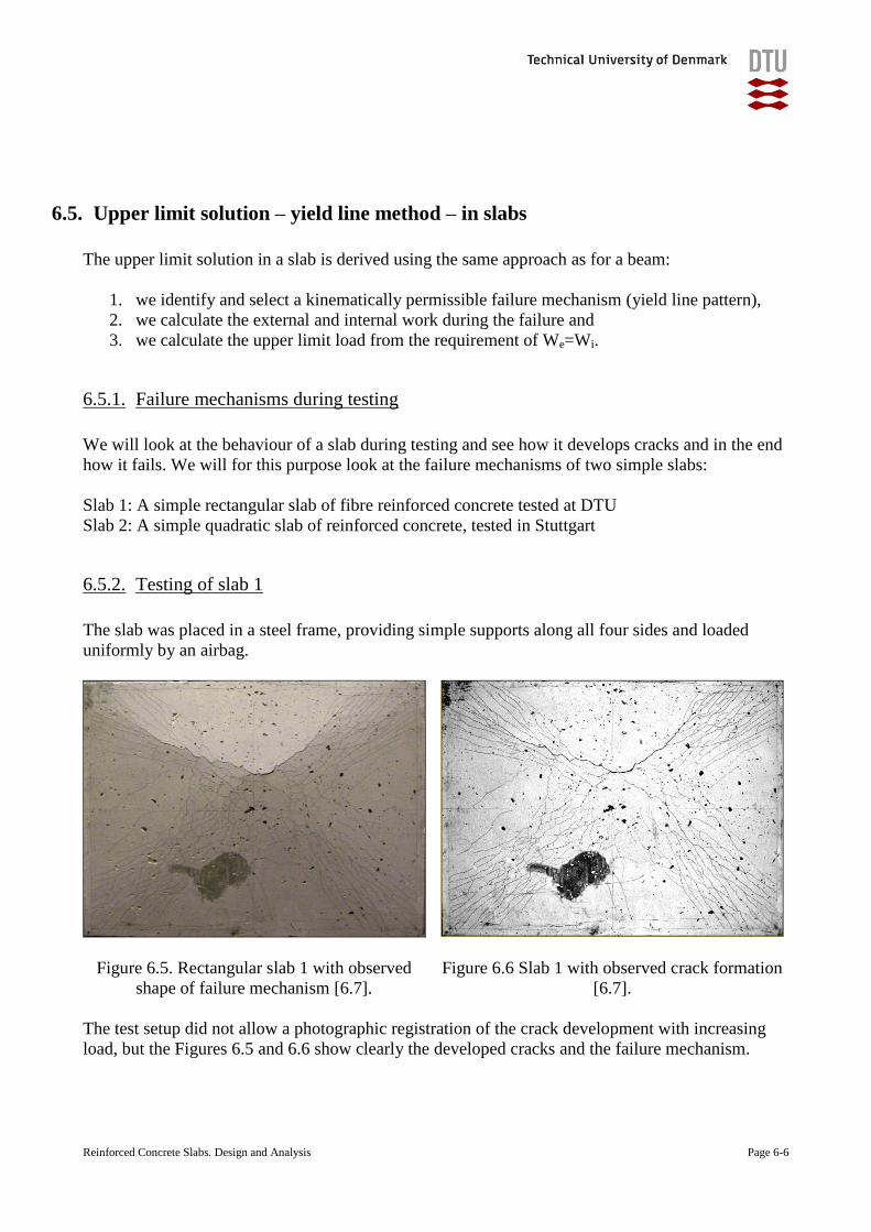
6.5.2. Testing of slab 1
The slab was placed in a steel frame, providing simple supports along all four sides and loaded
uniformly by an airbag.
Figure 6.5. Rectangular slab 1 with observed
shape of failure mechanism [6.7].
Figure 6.6 Slab 1 with observed crack formation
[6.7].
The test setup did not allow a photographic registration of the crack development with increasing
load, but the Figures 6.5 and 6.6 show clearly the developed cracks and the failure mechanism.
Reinforced Concrete Slabs. Design and Analysis Page 6-7
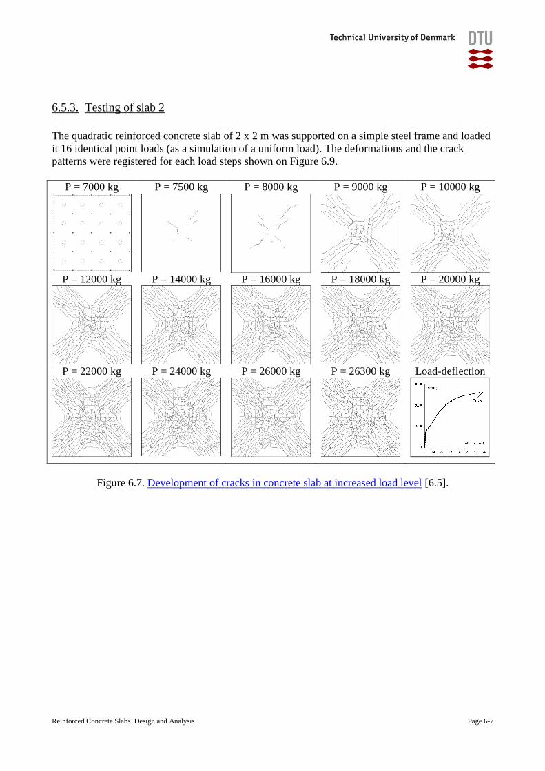
6.5.3. Testing of slab 2
The quadratic reinforced concrete slab of 2 x 2 m was supported on a simple steel frame and loaded
it 16 identical point loads (as a simulation of a uniform load). The deformations and the crack
patterns were registered for each load steps shown on Figure 6.9.
P = 7000 kg P = 7500 kg P = 8000 kg P = 9000 kg P = 10000 kg
P = 12000 kg P = 14000 kg P = 16000 kg P = 18000 kg P = 20000 kg
P = 22000 kg P = 24000 kg P = 26000 kg P = 26300 kg Load-deflection
Figure 6.7. Development of cracks in concrete slab at increased load level [6.5].
Reinforced Concrete Slabs. Design and Analysis Page 6-8
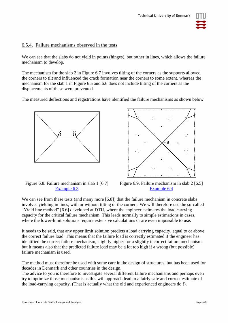
6.5.4. Failure mechanisms observed in the tests
We can see that the slabs do not yield in points (hinges), but rather in lines, which allows the failure
mechanism to develop.
The mechanism for the slab 2 in Figure 6.7 involves tilting of the corners as the supports allowed
the corners to tilt and influenced the crack formation near the corners to some extent, whereas the
mechanism for the slab 1 in Figure 6.5 and 6.6 does not include tilting of the corners as the
displacements of these were prevented.
The measured deflections and registrations have identified the failure mechanisms as shown below
Figure 6.8. Failure mechanism in slab 1 [6.7]
Example 6.3
Figure 6.9. Failure mechanism in slab 2 [6.5]
Example 6.4
We can see from these tests (and many more [6.8]) that the failure mechanism in concrete slabs
involves yielding in lines, with or without tilting of the corners. We will therefore use the so-called
“Yield line method” [6.6] developed at DTU, where the engineer estimates the load carrying
capacity for the critical failure mechanism. This leads normally to simple estimations in cases,
where the lower-limit solutions require extensive calculations or are even impossible to use.
It needs to be said, that any upper limit solution predicts a load carrying capacity, equal to or above
the correct failure load. This means that the failure load is correctly estimated if the engineer has
identified the correct failure mechanism, slightly higher for a slightly incorrect failure mechanism,
but it means also that the predicted failure load may be a lot too high if a wrong (but possible)
failure mechanism is used.
The method must therefore be used with some care in the design of structures, but has been used for
decades in Denmark and other countries in the design.
The advice to you is therefore to investigate several different failure mechanisms and perhaps even
try to optimize those mechanisms as this will approach lead to a fairly safe and correct estimate of
the load-carrying capacity. (That is actually what the old and experienced engineers do !).
Reinforced Concrete Slabs. Design and Analysis Page 6-9
6.6. Possible failure mechanisms for our models
We have seen from the tested slab, that it is very easy to determine the failure mechanism after a
test have been carried out – but we would also like to be able to predict the failure mechanism
without actually testing a slab in order to be able to predict the load-carrying capacity. This is to a
large extent dependent of engineering judgement – often combined with the analysis of several
different failure mechanisms.
We noticed that the displacements of the beam and the slab during the failure essentially consisted
of
1. sections, which moved and rotated without any additional curvature and
2. plastic hinges or straight yield lines, which did curve and bend.
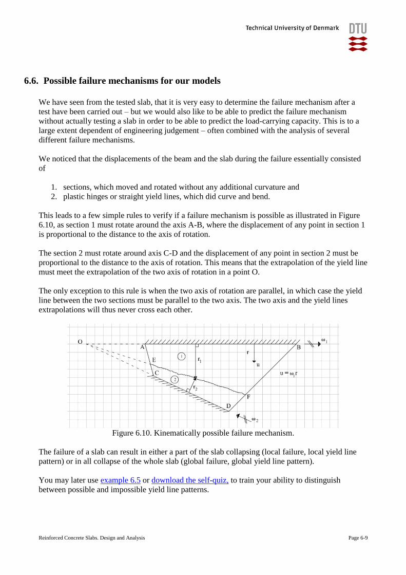
This leads to a few simple rules to verify if a failure mechanism is possible as illustrated in Figure
6.10, as section 1 must rotate around the axis A-B, where the displacement of any point in section 1
is proportional to the distance to the axis of rotation.
The section 2 must rotate around axis C-D and the displacement of any point in section 2 must be
proportional to the distance to the axis of rotation. This means that the extrapolation of the yield line
must meet the extrapolation of the two axis of rotation in a point O.
The only exception to this rule is when the two axis of rotation are parallel, in which case the yield
line between the two sections must be parallel to the two axis. The two axis and the yield lines
extrapolations will thus never cross each other.
Figure 6.10. Kinematically possible failure mechanism.
The failure of a slab can result in either a part of the slab collapsing (local failure, local yield line
pattern) or in all collapse of the whole slab (global failure, global yield line pattern).
You may later use example 6.5 or download the self-quiz, to train your ability to distinguish
between possible and impossible yield line patterns.
Reinforced Concrete Slabs. Design and Analysis Page 6-10
6.7. The external work
This is estimated (as for the beam) as the sum of the loads multiplied with the incremental
deformations of the beam in the points, where the loads are applied
( , ) ( , )e i iW p x y x y dx dy P (6.6)
6.8. The internal work
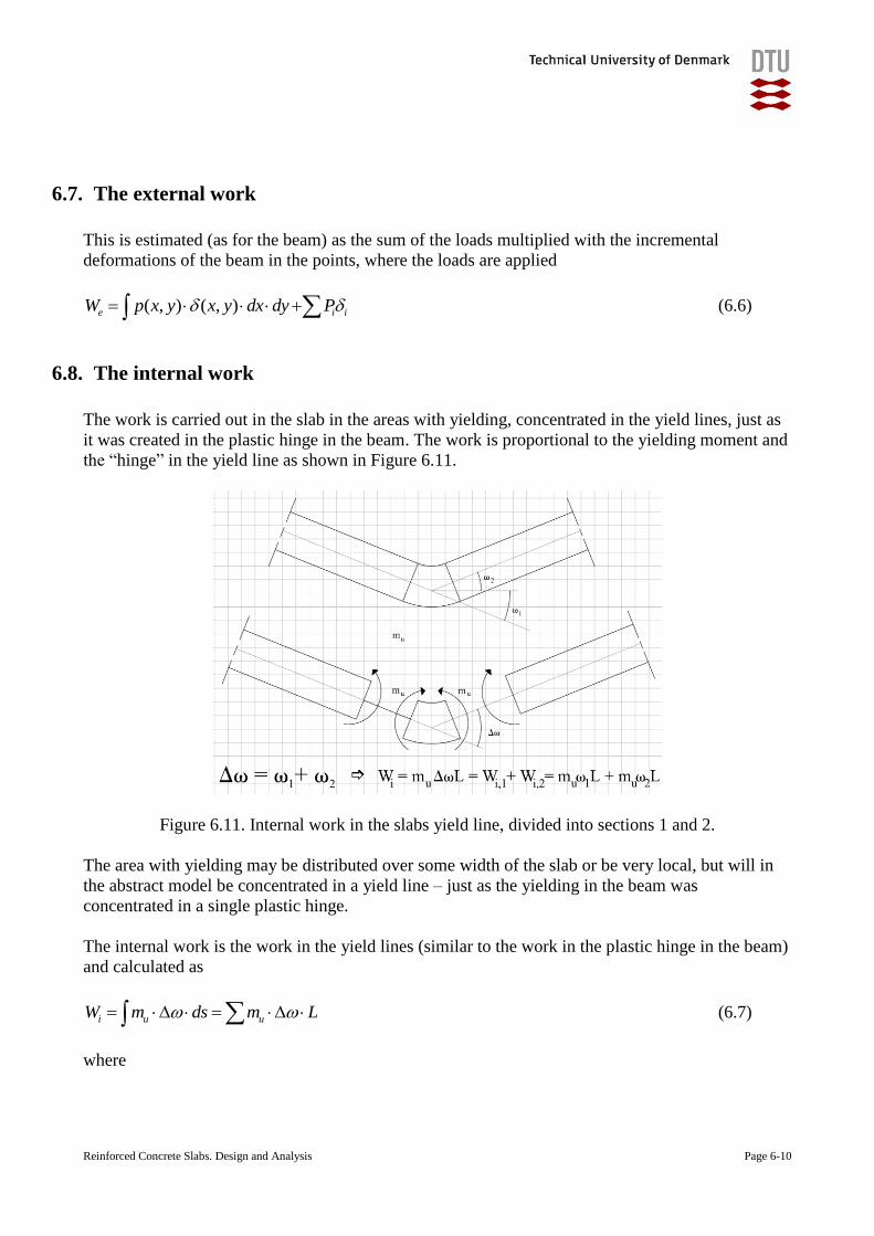
The work is carried out in the slab in the areas with yielding, concentrated in the yield lines, just as
it was created in the plastic hinge in the beam. The work is proportional to the yielding moment and
the “hinge” in the yield line as shown in Figure 6.11.
Figure 6.11. Internal work in the slabs yield line, divided into sections 1 and 2.
The area with yielding may be distributed over some width of the slab or be very local, but will in
the abstract model be concentrated in a yield line – just as the yielding in the beam was
concentrated in a single plastic hinge.
The internal work is the work in the yield lines (similar to the work in the plastic hinge in the beam)
and calculated as
i u uW m ds m L (6.7)
where

Reinforced Concrete Slabs. Design and Analysis Page 6-11
mu is the yielding moment per length for bending perpendicular to the yield line
Δ is the bend in the yielding line
L is the length of the yield line
The problem with the estimation of the internal work in the yield lines is normally that there is a
contribution from each of the yield lines and that the reinforcement directions may not be parallel or
perpendicular to the yield line, so the estimation of the internal works in the yield lines may be quite
extensive.
We would therefore like to simplify the estimations by separating the internal work in a yield line
into the contributions from each side of the yield line. This is estimated as the work carried out by
the individual sections of the slab between the yield lines as
in u in u in
i in u in
W m ds m L
W W m L
(6.8)
6.9. The load-carrying capacity
This is now estimated (as for the beam) from
o iW W
(6.9)
Reinforced Concrete Slabs. Design and Analysis Page 6-12
6.10. Rotations of a section and internal work
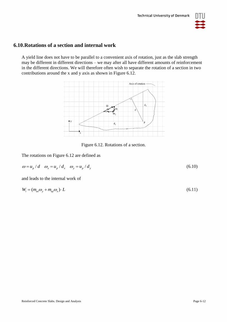
A yield line does not have to be parallel to a convenient axis of rotation, just as the slab strength
may be different in different directions – we may after all have different amounts of reinforcement
in the different directions. We will therefore often wish to separate the rotation of a section in two
contributions around the x and y axis as shown in Figure 6.12.
Figure 6.12. Rotations of a section.
The rotations on Figure 6.12 are defined as
/ / /p x p x y p yu d u d u d (6.10)
and leads to the internal work of
( )i ux y uy xW m m L (6.11)
Reinforced Concrete Slabs. Design and Analysis Page 6-13
6.11. Broken yield lines and internal work
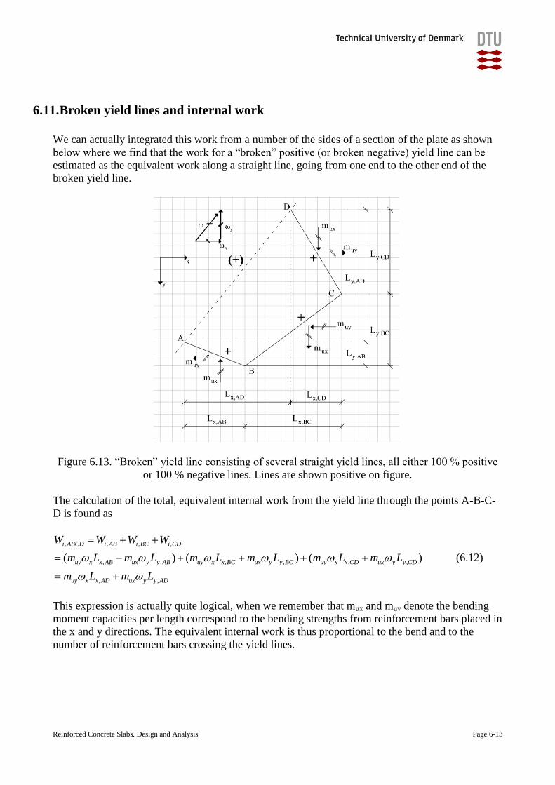
We can actually integrated this work from a number of the sides of a section of the plate as shown
below where we find that the work for a “broken” positive (or broken negative) yield line can be
estimated as the equivalent work along a straight line, going from one end to the other end of the
broken yield line.
Figure 6.13. “Broken” yield line consisting of several straight yield lines, all either 100 % positive
or 100 % negative lines. Lines are shown positive on figure.
The calculation of the total, equivalent internal work from the yield line through the points A-B-C-
D is found as
, , , ,
, , , , , ,
, ,
( ) ( ) ( )
i ABCD i AB i BC i CD
uy x x AB ux y y AB uy x x BC ux y y BC uy x x CD ux y y CD
uy x x AD ux y y AD
W W W W
m L m L m L m L m L m L
m L m L
(6.12)
This expression is actually quite logical, when we remember that mux and muy denote the bending
moment capacities per length correspond to the bending strengths from reinforcement bars placed in
the x and y directions. The equivalent internal work is thus proportional to the bend and to the
number of reinforcement bars crossing the yield lines.
Reinforced Concrete Slabs. Design and Analysis Page 6-14
6.12. Additional examples and problems
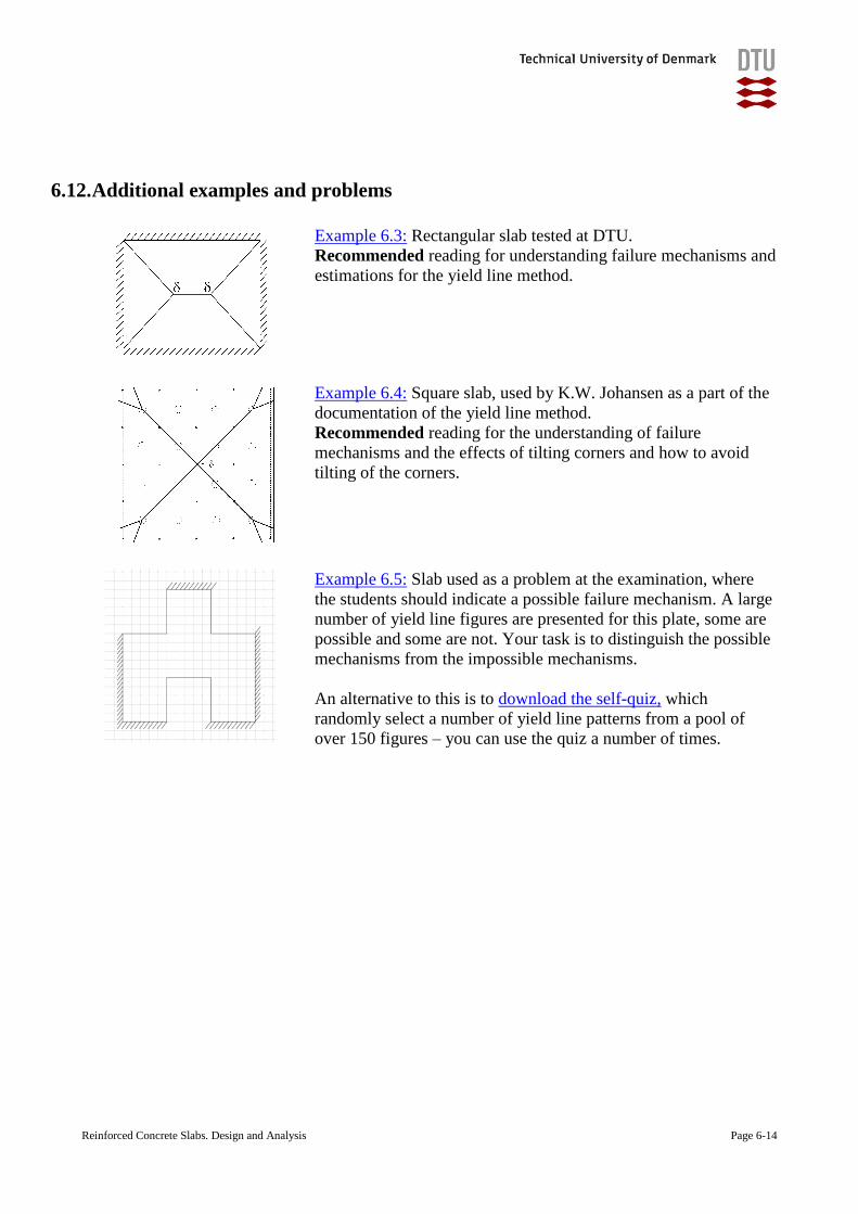
Example 6.3: Rectangular slab tested at DTU.
Recommended reading for understanding failure mechanisms and
estimations for the yield line method.
Example 6.4: Square slab, used by K.W. Johansen as a part of the
documentation of the yield line method.
Recommended reading for the understanding of failure
mechanisms and the effects of tilting corners and how to avoid
tilting of the corners.
Example 6.5: Slab used as a problem at the examination, where
the students should indicate a possible failure mechanism. A large
number of yield line figures are presented for this plate, some are
possible and some are not. Your task is to distinguish the possible
mechanisms from the impossible mechanisms.
An alternative to this is to download the self-quiz, which
randomly select a number of yield line patterns from a pool of
over 150 figures – you can use the quiz a number of times.
Reinforced Concrete Slabs. Design and Analysis Page 6-15
Exercise B11-14
(in Danish)
Exercise B11-15
(in Danish)
Exercise B11-16
(in Danish)
Exercise B11-17
(in Danish)
Reinforced Concrete Slabs. Design and Analysis Page 6-16
6.13. Additional reading materials
6.3.Johansen, K. W.: “Pladeformler”, Polyteknisk Forlag, Copenhagen, 1968, 14 pages (“Yield
line formulae for slabs”, Translated by Cement and Concrete Association, London, 1972.
Ref 12.044).
This publication contains a large number of examples, where the upper limit solution is
presented, but where the actual deriving of the formulas is not presented.
6.4.Kennedy, Gerard and Goodshild, Charles: ”Practical yield line design”, British Cement
Association, 2003, http://www.concretecentre.com/PDF/PYLD240603a.pdf, 171 pages.
This is a good and extensive introduction to a practical use of the yield line method.
References
6.5.Bach, C. and Graf, O.: “Versuche allseitig aufliegenden, quadratischen und rechteckigen
eisenbetonplatten”, Deutscher Ausschuss für Eisenbeton, heft 30, 1915.
6.6.Johansen, K. W.: ”Brudlinieteorier”, Jul. Gjellerups Forlag, Copenhagen, 1943, 191 pages.
(Yield Line theory, Translated by Cement and Concrete Association, London, 1962, 182
pages).
6.7.Knudsen, K. I.: “Slabs in fibrereinforced concrete, Use of yield line method (In Danish:
Plader i fiberarmeret beton. Brug af brudlinieteori)”, Danmarks Teknisk Universitet, 2008.
6.8.Park, R. and Gamble, W. L. :”Reinforced concrete slabs”, 2ed, Wiley, 2000.
6.9.Khailani, Z.Y.; Pey, S. And Thyssen. A.A. :”Laboratoriepraktik 11761, Betonbjælke,
testning og videofremstilling”, Byg-DTU, December 2008, Lyngby, Denmark.

Reinforced Concrete Slabs. Design and Analysis Page 7-1
7. Dictionary (English – Danish)
Kinematically permissible failure mechanism: Kinematisk tilladelig brudfigur
Degree of restraint: Indspændingsgrad
External work: Ydre arbejde
Failure mechanism: Brudmekanisme
Global failure : Global brudfigur, total brudfigur, total kollaps
Internal work: Indre arbejde
Local failure: Lokal brud, lokal brudfigur
Lower limit solution: Nedreværdiløsning
Plastic hinge: Flydeled
Restraining moment: Indspændingsmoment
Static conditions of equilibrium: Statiske ligevægtsbetingelser
Static equilibrium : Statisk ligevægt
Statically permissible solution: Statisk tilladelig løsning
Strip method: Strimmelmetoden
Third point positions: Trediedelspunkterne
Tilts: Vippere
Virtual works principle: Virtuelt arbejdes princip
Yield line: Flydelinie
Additional terms and words will be added, whenever a fair need is identified – and I assume, that
my students will help me with this point.
Reinforced Concrete Slabs. Design and Analysis Page 8-1
8. Examples
The following examples are integrated in this document to facilitate printing and to make sure you
have all the relevant information:
Example 3.1. Serviceability Limit State. Deflections. Rectangular plate with simple
supports and uniform loading.
Example 3.2. Serviceability Limit State. Deflections. Rectangular plate with hole and three
sides supported.
Example 5.1. C-shaped plate with some simply supported sides and some free sides.
Example 5.2. Strip Method Design. Rectangular plate with a hole and three sides supported.
Example 6.1. Yield Line Method. Two point loading of a beam – plastic hinge.
Example 6.2. Yield Line Method. Continuous beam with cantilever part.
Example 6.3. Yield Line Method. Rectangular plate with uniform load.
Example 6.4. Yield Line Method. Quadratic plate with “uniform” load.
Example 6.5. Yield Line Method. Distinguish between possible and impossible
mechanisms.
The full texts of the examples are enclosed in the following.
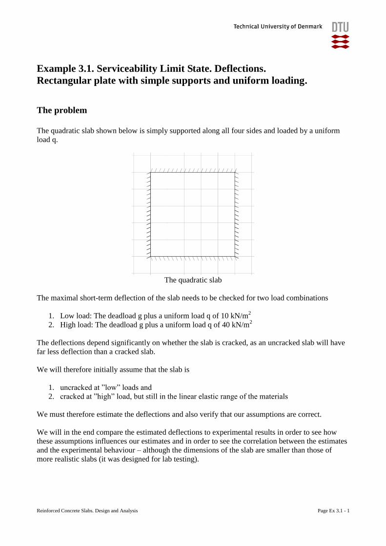
Reinforced Concrete Slabs. Design and Analysis Page Ex 3.1 - 1
Example 3.1. Serviceability Limit State. Deflections.
Rectangular plate with simple supports and uniform loading.
The problem
The quadratic slab shown below is simply supported along all four sides and loaded by a uniform
load q.
The quadratic slab
The maximal short-term deflection of the slab needs to be checked for two load combinations
1. Low load: The deadload g plus a uniform load q of 10 kN/m2
2. High load: The deadload g plus a uniform load q of 40 kN/m2
The deflections depend significantly on whether the slab is cracked, as an uncracked slab will have
far less deflection than a cracked slab.
We will therefore initially assume that the slab is
1. uncracked at ”low” loads and
2. cracked at ”high” load, but still in the linear elastic range of the materials
We must therefore estimate the deflections and also verify that our assumptions are correct.
We will in the end compare the estimated deflections to experimental results in order to see how
these assumptions influences our estimates and in order to see the correlation between the estimates
and the experimental behaviour – although the dimensions of the slab are smaller than those of
more realistic slabs (it was designed for lab testing).
Reinforced Concrete Slabs. Design and Analysis Page Ex 3.1 - 2
Geometry and material parameters
The reinforced concrete slab has a span length L = 2 m and is h = 81 mm thick and is reinforced
with steel bars Ø7 mm per 100 mm in each direction, with an effective height d = 66mm.
The material properties are
25
20
400
440
cm
ck
yk
uk
f MPa
f MPa
f MPa
f MPa
The modulus of elasticity are estimated as
0,3 0,3
2522000 22000 27085
10 10
cmcm
fE MPa
The slabs will normally form visible cracks when the tensile stresses exceed the tensile strength
after which the slabs will have a decreased stiffness. The tensile strength fctm is estimated as
2/3 2/30,3 0,3 20 2,21ctm ckf f MPa
Reinforced Concrete Slabs. Design and Analysis Page Ex 3.1 - 3
Case 1: Low load
The slabs own weight g is estimated from its density incl. reinforcement of 24 kN/m2, leading to
224 0,081 1,94 /g kN m
We will assume that the load is so low that the slab is still uncracked. In this situation the plate
stiffness is estimated as
3 3
6 2
2 2
27085 811249,5 10 /
12(1 ) 12(1 0,2 )
cmE hD Nmm mm
The deflection may now be determined from Figure 3.3b as
4 4 3 4
max 6
( ) (10 1,94) 10 20000,0047 0,8
1249,5 10
pL g q Lu mm
D D
We will, however, need to check whether the assumption of an uncracked slab is correct and we do
that be estimating the maximal tensile stress as
2 3 2
max 1,max 2 2 2
( ) 0,0486 (10 1,94) 10 20006 6 6 2,12 2,21
81t ctm
m g q LMPa f MPa
h h
We can see that this is below the tensile strength and the slab may therefore correctly be estimated
as uncracked. The slab would probably crack at a load of app.
23,36(10 1,94) 1,94 16,98 /
2,12q kN m
Loads above this level would lead to a rapid decrease of the stiffness.
Reinforced Concrete Slabs. Design and Analysis Page Ex 3.1 - 4
Case 2: High load
The high load (40+1,94=41,94kN/m2) is well above the load at which the cracks occur
(16,98kN/m2) and we must therefore assume a cracked cross-section for which we estimate
5
2
3 2 2
3 2 2 2
6 4
/ 2 10 / 27085 7,38
( / 2) ( ) 1000 ( / 2) 7,38 10 (7 / 2) (66 ) 0 16,88
1( / 2) ( )
12
11000 16,88 1000 16,88 (16,88 / 2) 7,38 10 (7 / 2) (66 16,88)
12
8,742 10 /
s cm
t s
t s
E E
S b x x A d x x x x x mm
I bx bx x A d x
mm
3 2
53 6 2
8,742 10 /
2 108,742 10 236,77 10 /
7,38
sc t t
m mm mm
EEI E I I Nmm mm
We use this stiffness in the expression for the deflection, where we replace the uncracked D with
our cracked EI and find
4 4 3 4
max 6
( ) (40 1,94) 10 20000,0047 13,32
236,77 10
pL q g Lu mm
EI EI
We have, however, based our estimations on the assumption, that the materials are still in the linear
area and we will therefore need to estimate the maximal tensile stress in the reinforcement and the
maximal compressive stress in the concrete. This requires first the maximal bending moment
estimated as
2 3 2 3
max 1( ) 0,0486 (40 1,94) 10 2000 8,154 10 /m g q L Nmm mm
and then the stresses estimated as 3
max,max 3
3
,max 3
8,154 1016,88 15,745 20
8,742 10
8,154 10( ) 7,38 (66 16,88) 345 400
18,742 10
c ck
t
maxs yk
t
mx MPa f MPa
I
md x MPa f MPa
I
This shows us that the stresses in the concrete and in the steel are well below their maximal possible
values. It also indicates that the reinforcement would start to yield at a load of
2400(40 1,94) 1,94 46,7 /
345q kN m
Loads above this level are possible (as 440 400uk ykf MPa f MPa ), but will lead to large
deflections (as the reinforcements strain will grow rapidly due to the yielding).
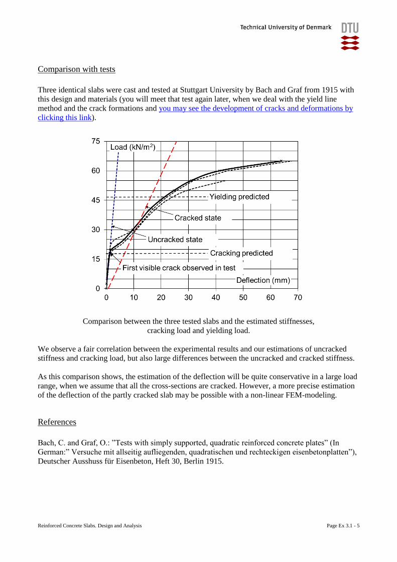
Reinforced Concrete Slabs. Design and Analysis Page Ex 3.1 - 5
Comparison with tests
Three identical slabs were cast and tested at Stuttgart University by Bach and Graf from 1915 with
this design and materials (you will meet that test again later, when we deal with the yield line
method and the crack formations and you may see the development of cracks and deformations by
clicking this link).
Comparison between the three tested slabs and the estimated stiffnesses,
cracking load and yielding load.
We observe a fair correlation between the experimental results and our estimations of uncracked
stiffness and cracking load, but also large differences between the uncracked and cracked stiffness.
As this comparison shows, the estimation of the deflection will be quite conservative in a large load
range, when we assume that all the cross-sections are cracked. However, a more precise estimation
of the deflection of the partly cracked slab may be possible with a non-linear FEM-modeling.
References
Bach, C. and Graf, O.: ”Tests with simply supported, quadratic reinforced concrete plates” (In
German:” Versuche mit allseitig aufliegenden, quadratischen und rechteckigen eisenbetonplatten”),
Deutscher Ausshuss für Eisenbeton, Heft 30, Berlin 1915.
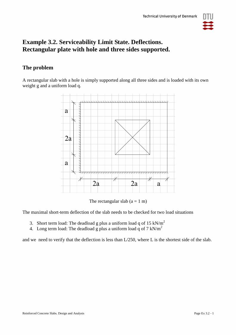
Reinforced Concrete Slabs. Design and Analysis Page Ex 3.2 - 1
Example 3.2. Serviceability Limit State. Deflections.
Rectangular plate with hole and three sides supported.
The problem
A rectangular slab with a hole is simply supported along all three sides and is loaded with its own
weight g and a uniform load q.
The rectangular slab (a = 1 m)
The maximal short-term deflection of the slab needs to be checked for two load situations
3. Short term load: The deadload g plus a uniform load q of 15 kN/m2
4. Long term load: The deadload g plus a uniform load q of 7 kN/m2
and we need to verify that the deflection is less than L/250, where L is the shortest side of the slab.
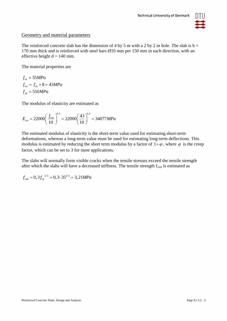
Reinforced Concrete Slabs. Design and Analysis Page Ex 3.2 - 2
Geometry and material parameters
The reinforced concrete slab has the dimension of 4 by 5 m with a 2 by 2 m hole. The slab is h =
170 mm thick and is reinforced with steel bars Ø10 mm per 150 mm in each direction, with an
effective height d = 140 mm.
The material properties are
35
8 43
550
ck
cm ck
yk
f MPa
f f MPa
f MPa
The modulus of elasticity are estimated as
0,3 0,3
4322000 22000 34077
10 10
cmcm
fE MPa
The estimated modulus of elasticity is the short-term value used for estimating short-term
deformations, whereas a long-term value must be used for estimating long-term deflections. This
modulus is estimated by reducing the short term modulus by a factor of 1 , where is the creep
factor, which can be set to 3 for most applications.
The slabs will normally form visible cracks when the tensile stresses exceed the tensile strength
after which the slabs will have a decreased stiffness. The tensile strength fctm is estimated as
2/3 2/30,3 0,3 35 3,21ctm ckf f MPa
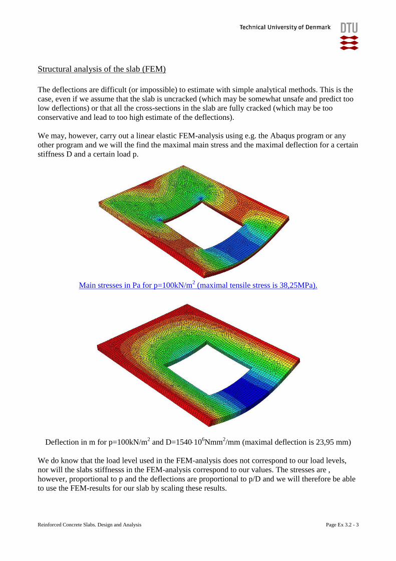
Reinforced Concrete Slabs. Design and Analysis Page Ex 3.2 - 3
Structural analysis of the slab (FEM)
The deflections are difficult (or impossible) to estimate with simple analytical methods. This is the
case, even if we assume that the slab is uncracked (which may be somewhat unsafe and predict too
low deflections) or that all the cross-sections in the slab are fully cracked (which may be too
conservative and lead to too high estimate of the deflections).
We may, however, carry out a linear elastic FEM-analysis using e.g. the Abaqus program or any
other program and we will the find the maximal main stress and the maximal deflection for a certain
stiffness D and a certain load p.
Main stresses in Pa for p=100kN/m
2 (maximal tensile stress is 38,25MPa).
Deflection in m for p=100kN/m2 and D=154010
6Nmm
2/mm (maximal deflection is 23,95 mm)
We do know that the load level used in the FEM-analysis does not correspond to our load levels,
nor will the slabs stiffnesss in the FEM-analysis correspond to our values. The stresses are ,
however, proportional to p and the deflections are proportional to p/D and we will therefore be able
to use the FEM-results for our slab by scaling these results.
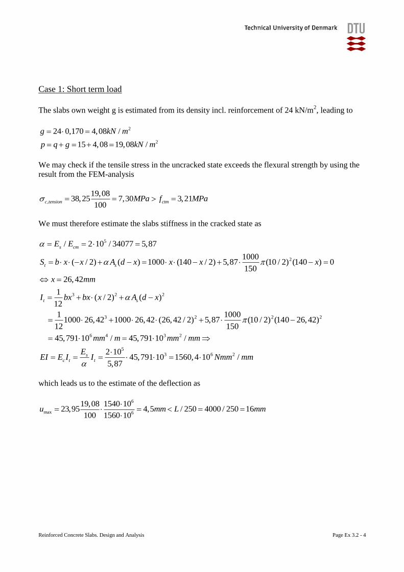
Reinforced Concrete Slabs. Design and Analysis Page Ex 3.2 - 4
Case 1: Short term load
The slabs own weight g is estimated from its density incl. reinforcement of 24 kN/m2, leading to
We may check if the tensile stress in the uncracked state exceeds the flexural strength by using the
result from the FEM-analysis
,
19,0838,25 7,30 3,21
100c tension ctmMPa f MPa
We must therefore estimate the slabs stiffness in the cracked state as
5
2
3 2 2
3 2 2
/ 2 10 / 34077 5,87
1000( / 2) ( ) 1000 (140 / 2) 5,87 (10 / 2) (140 ) 0
150
26,42
1( / 2) ( )
12
1 10001000 26,42 1000 26,42 (26,42 / 2) 5,87 (10 / 2) (140 26,4
12 150
s cm
t s
t s
E E
S b x x A d x x x x
x mm
I bx bx x A d x
2
6 4 3 2
53 6 2
2)
45,791 10 / 45,791 10 /
2 1045,791 10 1560,4 10 /
5,87
sc t t
mm m mm mm
EEI E I I Nmm mm
which leads us to the estimate of the deflection as
6
max 6
19,08 1540 1023,95 4,5 / 250 4000 / 250 16
100 1560 10u mm L mm
2
2
24 0,170 4,08 /
15 4,08 19,08 /
g kN m
p q g kN m
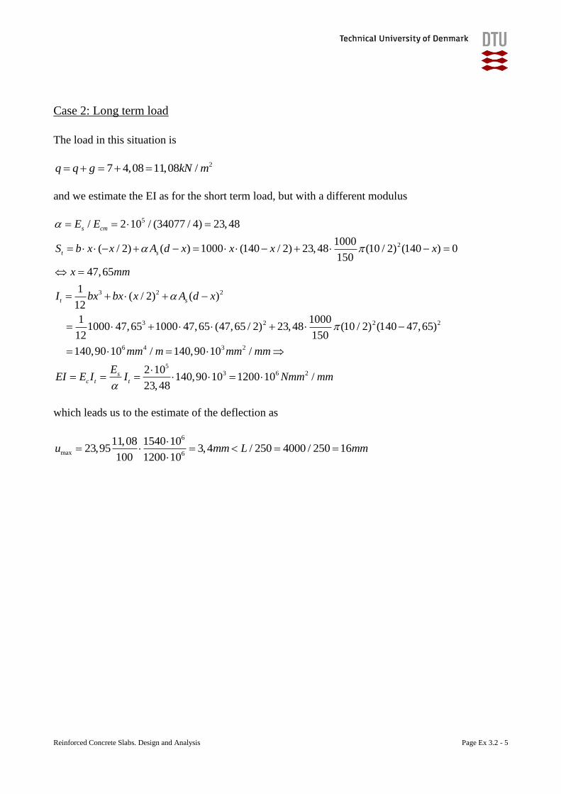
Reinforced Concrete Slabs. Design and Analysis Page Ex 3.2 - 5
Case 2: Long term load
The load in this situation is
27 4,08 11,08 /q q g kN m
and we estimate the EI as for the short term load, but with a different modulus
5
2
3 2 2
3 2 2
/ 2 10 / (34077 / 4) 23,48
1000( / 2) ( ) 1000 (140 / 2) 23,48 (10 / 2) (140 ) 0
150
47,65
1( / 2) ( )
12
1 10001000 47,65 1000 47,65 (47,65 / 2) 23,48 (10 / 2) (1
12 150
s cm
t s
t s
E E
S b x x A d x x x x
x mm
I bx bx x A d x
2
6 4 3 2
53 6 2
40 47,65)
140,90 10 / 140,90 10 /
2 10140,90 10 1200 10 /
23,48
sc t t
mm m mm mm
EEI E I I Nmm mm
which leads us to the estimate of the deflection as
6
max 6
11,08 1540 1023,95 3,4 / 250 4000 / 250 16
100 1200 10u mm L mm
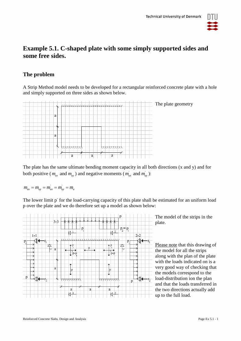
Reinforced Concrete Slabs. Design and Analysis Page Ex 5.1 - 1
Example 5.1. C-shaped plate with some simply supported sides and
some free sides.
The problem
A Strip Method model needs to be developed for a rectangular reinforced concrete plate with a hole
and simply supported on three sides as shown below.
The plate geometry
The plate has the same ultimate bending moment capacity in all both directions (x and y) and for
both positive ( and ux uym m ) and negative moments ( ' ' and ux uym m ):
' '
ux uy ux uy um m m m m
The lower limit p- for the load-carrying capacity of this plate shall be estimated for an uniform load
p over the plate and we do therefore set up a model as shown below:
The model of the strips in the
plate.
Please note that this drawing of
the model for all the strips
along with the plan of the plate
with the loads indicated on is a
very good way of checking that
the models correspond to the
load-distribution ion the plan
and that the loads transferred in
the two directions actually add
up to the full load.
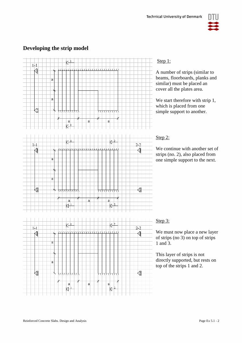
Reinforced Concrete Slabs. Design and Analysis Page Ex 5.1 - 2
Developing the strip model
Step 1:
A number of strips (similar to
beams, floorboards, planks and
similar) must be placed an
cover all the plates area.
We start therefore with strip 1,
which is placed from one
simple support to another.
Step 2:
We continue with another set of
strips (no. 2), also placed from
one simple support to the next.
Step 3:
We must now place a new layer
of strips (no 3) on top of strips
1 and 3.
This layer of strips is not
directly supported, but rests on
top of the strips 1 and 2.
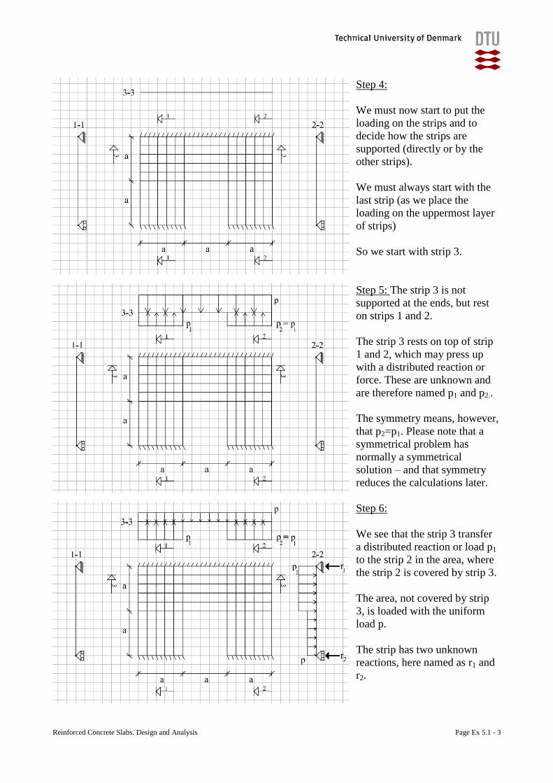
Reinforced Concrete Slabs. Design and Analysis Page Ex 5.1 - 3
Step 4:
We must now start to put the
loading on the strips and to
decide how the strips are
supported (directly or by the
other strips).
We must always start with the
last strip (as we place the
loading on the uppermost layer
of strips)
So we start with strip 3.
Step 5: The strip 3 is not
supported at the ends, but rest
on strips 1 and 2.
The strip 3 rests on top of strip
1 and 2, which may press up
with a distributed reaction or
force. These are unknown and
are therefore named p1 and p2..
The symmetry means, however,
that p2=p1. Please note that a
symmetrical problem has
normally a symmetrical
solution – and that symmetry
reduces the calculations later.
Step 6:
We see that the strip 3 transfer
a distributed reaction or load p1
to the strip 2 in the area, where
the strip 2 is covered by strip 3.
The area, not covered by strip
3, is loaded with the uniform
load p.
The strip has two unknown
reactions, here named as r1 and
r2.
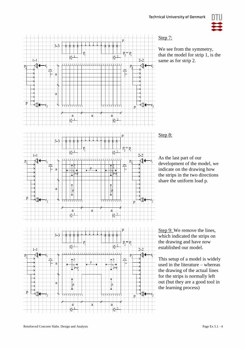
Reinforced Concrete Slabs. Design and Analysis Page Ex 5.1 - 4
Step 7:
We see from the symmetry,
that the model for strip 1, is the
same as for strip 2.
Step 8:
As the last part of our
development of the model, we
indicate on the drawing how
the strips in the two directions
share the uniform load p.
Step 9: We remove the lines,
which indicated the strips on
the drawing and have now
established our model.
This setup of a model is widely
used in the literature – whereas
the drawing of the actual lines
for the strips is normally left
out (but they are a good tool in
the learning process)
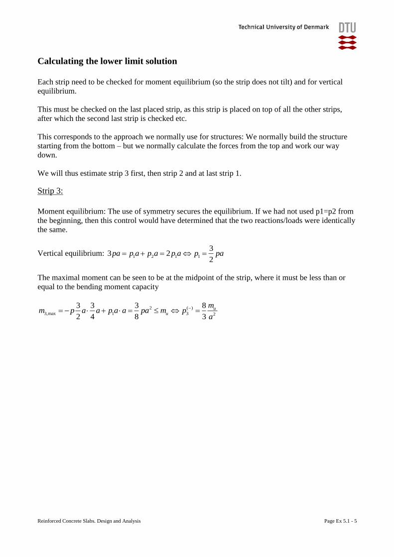
Reinforced Concrete Slabs. Design and Analysis Page Ex 5.1 - 5
Calculating the lower limit solution
Each strip need to be checked for moment equilibrium (so the strip does not tilt) and for vertical
equilibrium.
This must be checked on the last placed strip, as this strip is placed on top of all the other strips,
after which the second last strip is checked etc.
This corresponds to the approach we normally use for structures: We normally build the structure
starting from the bottom – but we normally calculate the forces from the top and work our way
down.
We will thus estimate strip 3 first, then strip 2 and at last strip 1.
Strip 3:
Moment equilibrium: The use of symmetry secures the equilibrium. If we had not used p1=p2 from
the beginning, then this control would have determined that the two reactions/loads were identically
the same.
Vertical equilibrium: 1 2 1 1
33 2
2pa p a p a p a p pa
The maximal moment can be seen to be at the midpoint of the strip, where it must be less than or
equal to the bending moment capacity
2 ( )
3,max 1 3 2
3 3 3 8
2 4 8 3
uu
mm p a a p a a pa m p
a
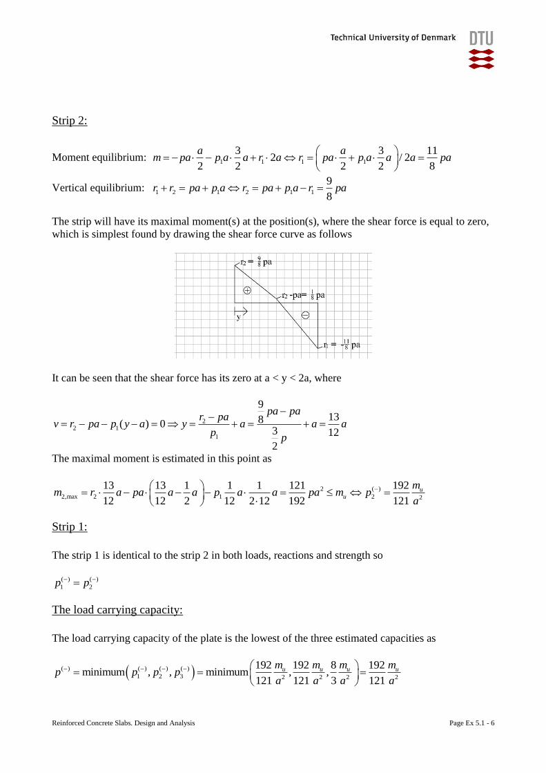
Reinforced Concrete Slabs. Design and Analysis Page Ex 5.1 - 6
Strip 2:
Moment equilibrium: 1 1 1 1
3 3 112 / 2
2 2 2 2 8
a am pa p a a r a r pa p a a a pa
Vertical equilibrium: 1 2 1 2 1 1
9
8r r pa p a r pa p a r pa
The strip will have its maximal moment(s) at the position(s), where the shear force is equal to zero,
which is simplest found by drawing the shear force curve as follows
It can be seen that the shear force has its zero at a < y < 2a, where
22 1
1
9
138( ) 03 12
2
pa par pa
v r pa p y a y a a ap
p
The maximal moment is estimated in this point as
2 ( )
2,max 2 1 2 2
13 13 1 1 1 121 192
12 12 2 12 2 12 192 121
uu
mm r a pa a a p a a pa m p
a
Strip 1:
The strip 1 is identical to the strip 2 in both loads, reactions and strength so
( ) ( )
1 2p p
The load carrying capacity:
The load carrying capacity of the plate is the lowest of the three estimated capacities as
( ) ( ) ( ) ( )
1 2 3 2 2 2 2
192 192 8 192minimum , , minimum , ,
121 121 3 121
u u u um m m mp p p p
a a a a
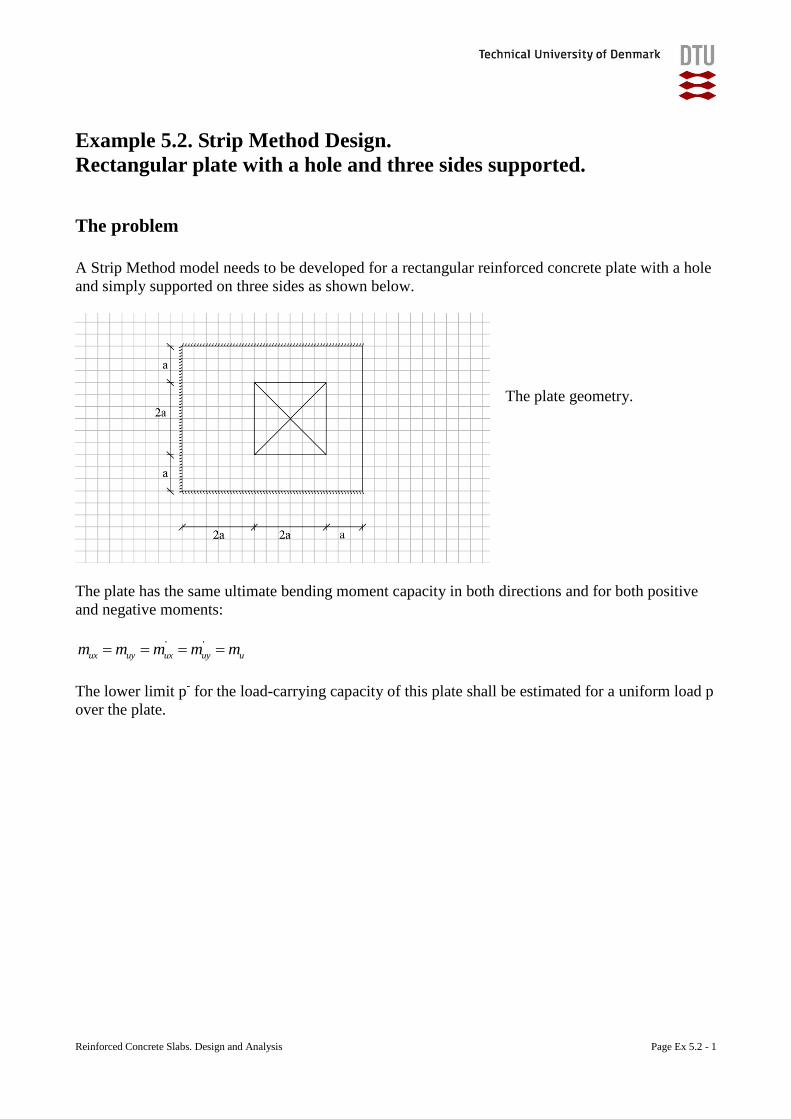
Reinforced Concrete Slabs. Design and Analysis Page Ex 5.2 - 1
Example 5.2. Strip Method Design.
Rectangular plate with a hole and three sides supported.
The problem
A Strip Method model needs to be developed for a rectangular reinforced concrete plate with a hole
and simply supported on three sides as shown below.
The plate geometry.
The plate has the same ultimate bending moment capacity in both directions and for both positive
and negative moments:
' '
ux uy ux uy um m m m m
The lower limit p- for the load-carrying capacity of this plate shall be estimated for a uniform load p
over the plate.
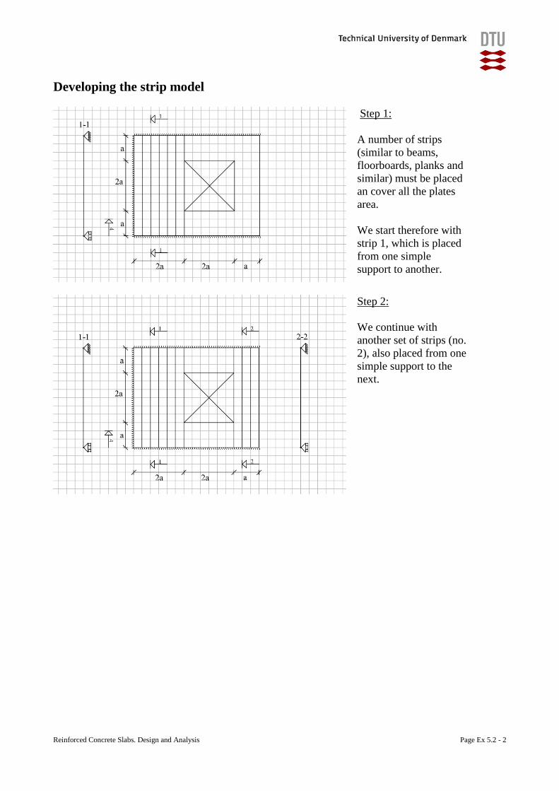
Reinforced Concrete Slabs. Design and Analysis Page Ex 5.2 - 2
Developing the strip model
Step 1:
A number of strips
(similar to beams,
floorboards, planks and
similar) must be placed
an cover all the plates
area.
We start therefore with
strip 1, which is placed
from one simple
support to another.
Step 2:
We continue with
another set of strips (no.
2), also placed from one
simple support to the
next.
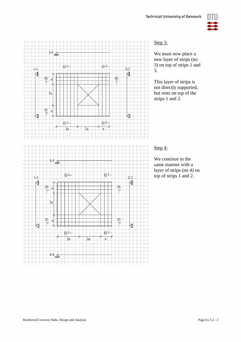
Reinforced Concrete Slabs. Design and Analysis Page Ex 5.2 - 3
Step 3:
We must now place a
new layer of strips (no
3) on top of strips 1 and
3.
This layer of strips is
not directly supported,
but rests on top of the
strips 1 and 2.
Step 4:
We continue in the
same manner with a
layer of strips (no 4) on
top of strips 1 and 2.
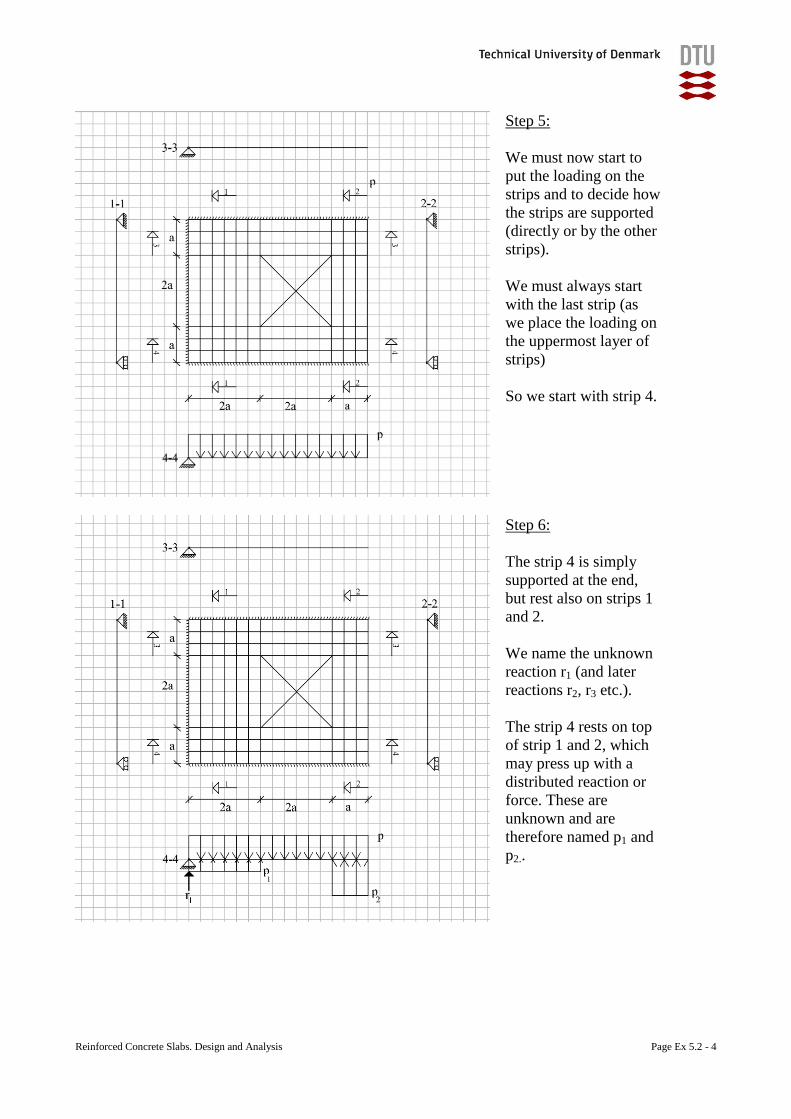
Reinforced Concrete Slabs. Design and Analysis Page Ex 5.2 - 4
Step 5:
We must now start to
put the loading on the
strips and to decide how
the strips are supported
(directly or by the other
strips).
We must always start
with the last strip (as
we place the loading on
the uppermost layer of
strips)
So we start with strip 4.
Step 6:
The strip 4 is simply
supported at the end,
but rest also on strips 1
and 2.
We name the unknown
reaction r1 (and later
reactions r2, r3 etc.).
The strip 4 rests on top
of strip 1 and 2, which
may press up with a
distributed reaction or
force. These are
unknown and are
therefore named p1 and
p2..
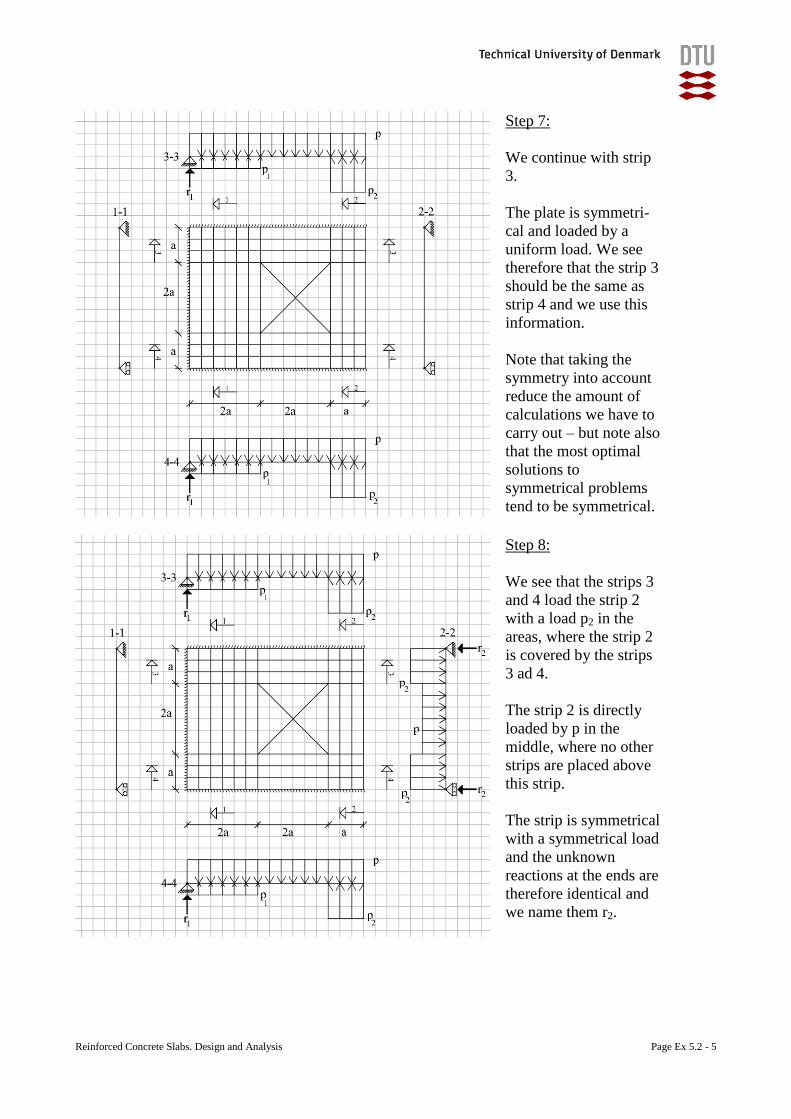
Reinforced Concrete Slabs. Design and Analysis Page Ex 5.2 - 5
Step 7:
We continue with strip
3.
The plate is symmetri-
cal and loaded by a
uniform load. We see
therefore that the strip 3
should be the same as
strip 4 and we use this
information.
Note that taking the
symmetry into account
reduce the amount of
calculations we have to
carry out – but note also
that the most optimal
solutions to
symmetrical problems
tend to be symmetrical.
Step 8:
We see that the strips 3
and 4 load the strip 2
with a load p2 in the
areas, where the strip 2
is covered by the strips
3 ad 4.
The strip 2 is directly
loaded by p in the
middle, where no other
strips are placed above
this strip.
The strip is symmetrical
with a symmetrical load
and the unknown
reactions at the ends are
therefore identical and
we name them r2.
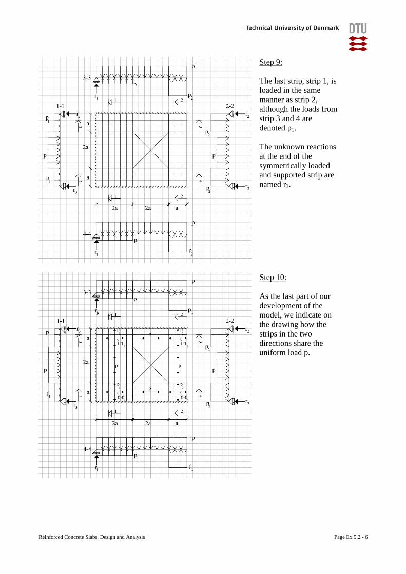
Reinforced Concrete Slabs. Design and Analysis Page Ex 5.2 - 6
Step 9:
The last strip, strip 1, is
loaded in the same
manner as strip 2,
although the loads from
strip 3 and 4 are
denoted p1.
The unknown reactions
at the end of the
symmetrically loaded
and supported strip are
named r3.
Step 10:
As the last part of our
development of the
model, we indicate on
the drawing how the
strips in the two
directions share the
uniform load p.
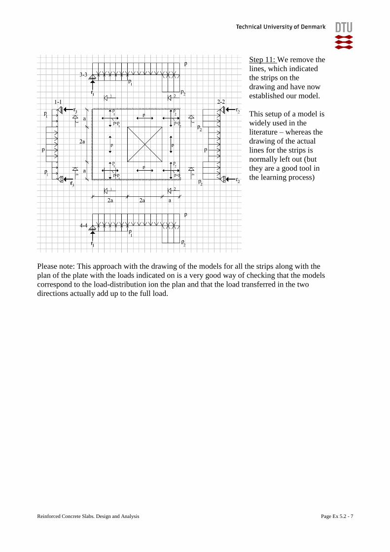
Reinforced Concrete Slabs. Design and Analysis Page Ex 5.2 - 7
Step 11: We remove the
lines, which indicated
the strips on the
drawing and have now
established our model.
This setup of a model is
widely used in the
literature – whereas the
drawing of the actual
lines for the strips is
normally left out (but
they are a good tool in
the learning process)
Please note: This approach with the drawing of the models for all the strips along with the
plan of the plate with the loads indicated on is a very good way of checking that the models
correspond to the load-distribution ion the plan and that the load transferred in the two
directions actually add up to the full load.
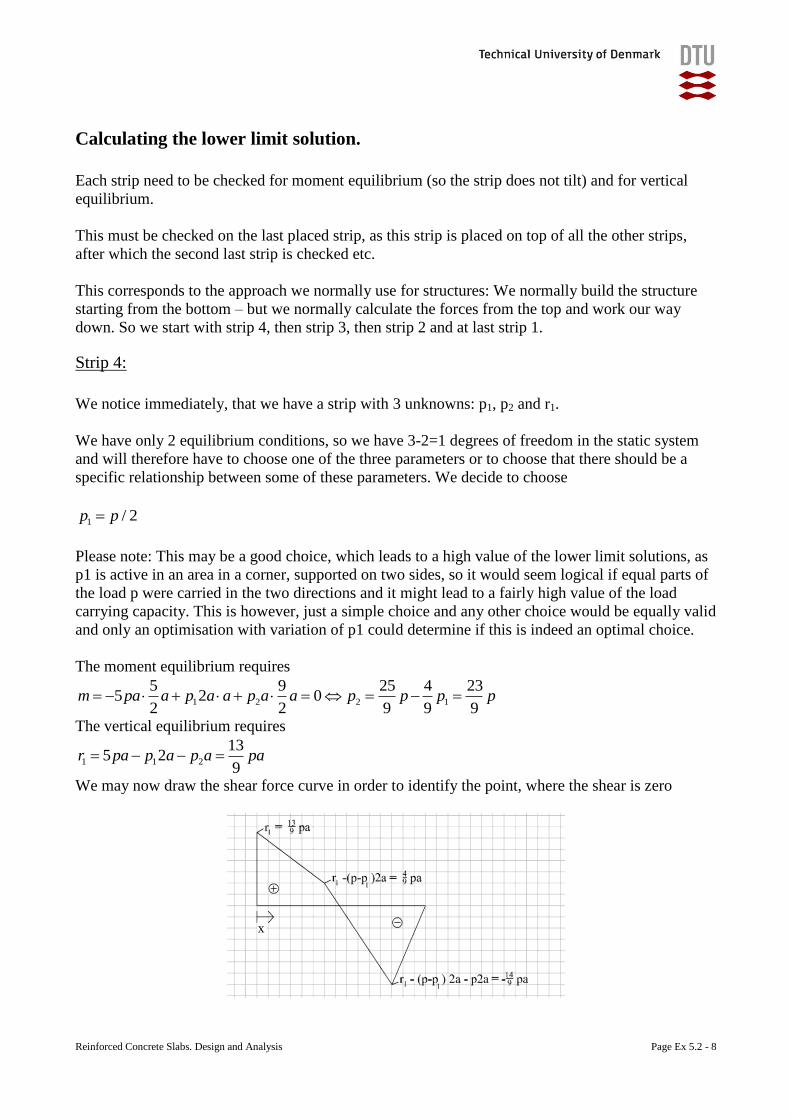
Reinforced Concrete Slabs. Design and Analysis Page Ex 5.2 - 8
Calculating the lower limit solution.
Each strip need to be checked for moment equilibrium (so the strip does not tilt) and for vertical
equilibrium.
This must be checked on the last placed strip, as this strip is placed on top of all the other strips,
after which the second last strip is checked etc.
This corresponds to the approach we normally use for structures: We normally build the structure
starting from the bottom – but we normally calculate the forces from the top and work our way
down. So we start with strip 4, then strip 3, then strip 2 and at last strip 1.
Strip 4:
We notice immediately, that we have a strip with 3 unknowns: p1, p2 and r1.
We have only 2 equilibrium conditions, so we have 3-2=1 degrees of freedom in the static system
and will therefore have to choose one of the three parameters or to choose that there should be a
specific relationship between some of these parameters. We decide to choose
1 / 2p p
Please note: This may be a good choice, which leads to a high value of the lower limit solutions, as
p1 is active in an area in a corner, supported on two sides, so it would seem logical if equal parts of
the load p were carried in the two directions and it might lead to a fairly high value of the load
carrying capacity. This is however, just a simple choice and any other choice would be equally valid
and only an optimisation with variation of p1 could determine if this is indeed an optimal choice.
The moment equilibrium requires
1 2 2 1
5 9 25 4 235 2 0
2 2 9 9 9m pa a p a a p a a p p p p
The vertical equilibrium requires
1 1 2
135 2
9r pa p a p a pa
We may now draw the shear force curve in order to identify the point, where the shear is zero
x
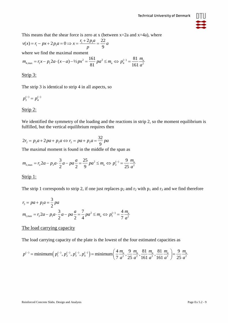
Reinforced Concrete Slabs. Design and Analysis Page Ex 5.2 - 9
This means that the shear force is zero at x (between x=2a and x=4a), where
1 11 1
2 22( ) 2 0
9
r p av x r px p a x a
p
where we find the maximal moment
2 2 ( )
4,max 1 1 4 2
161 812 ( ) ½
81 161
uu
mm r x p a x a px pa m p
a
Strip 3:
The strip 3 is identical to strip 4 in all aspects, so
( ) ( )
3 4p p
Strip 2:
We identified the symmetry of the loading and the reactions in strip 2, so the moment equilibrium is
fulfilled, but the vertical equilibrium requires then
2 2 2 2 2
322 2
9r p a pa p a r pa p a pa
The maximal moment is found in the middle of the span as
2 ( )
2,max 2 2 2 2
3 25 92
2 2 9 25
uu
mam r a p a a pa pa m p
a
Strip 1:
The strip 1 corresponds to strip 2, if one just replaces p2 and r2 with p1 and r3 and we find therefore
3 1
3
2r pa p a pa
2 ( )
1,max 3 1 1 2
3 7 42
2 2 4 7
uu
mam r a p a a pa pa m p
a
The load carrying capacity
The load carrying capacity of the plate is the lowest of the four estimated capacities as
( ) ( ) ( ) ( ) ( )
1 2 3 4 2 2 2 2 2
4 9 81 81 9minimum , , , minimum , , ,
7 25 161 161 25
u u u u um m m m mp p p p p
a a a a a
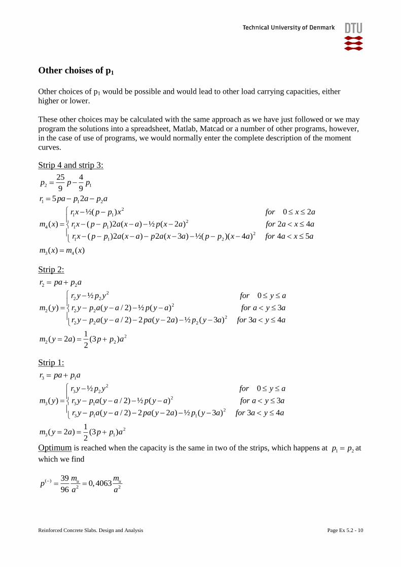
Reinforced Concrete Slabs. Design and Analysis Page Ex 5.2 - 10
Other choises of p1
Other choices of p1 would be possible and would lead to other load carrying capacities, either
higher or lower.
These other choices may be calculated with the same approach as we have just followed or we may
program the solutions into a spreadsheet, Matlab, Matcad or a number of other programs, however,
in the case of use of programs, we would normally enter the complete description of the moment
curves.
Strip 4 and strip 3:
2 1
25 4
9 9p p p
1 1 25 2r pa p a p a
2
1 1
2
4 1 1
2
1 1 2
3 4
½( ) 0 2
( ) ( )2 ( ) ½ ( 2 ) 2 4
( )2 ( ) 2 ( 3 ) ½( )( 4 ) 4 5
( ) ( )
r x p p x for x a
m x r x p p a x a p x a for a x a
r x p p a x a p a x a p p x a for a x a
m x m x
Strip 2:
2 2r pa p a
2
2 2
2
2 2 2
2
2 2 2
2
2 2
½ 0
( ) ( / 2) ½ ( ) 3
( / 2) 2 ( 2 ) ½ ( 3 ) 3 4
1( 2 ) (3 )
2
r y p y for y a
m y r y p a y a p y a for a y a
r y p a y a pa y a p y a for a y a
m y a p p a
Strip 1:
3 1r pa p a
2
3 2
2
3 3 1
2
3 1 1
2
3 1
½ 0
( ) ( / 2) ½ ( ) 3
( / 2) 2 ( 2 ) ½ ( 3 ) 3 4
1( 2 ) (3 )
2
r y p y for y a
m y r y p a y a p y a for a y a
r y p a y a pa y a p y a for a y a
m y a p p a
Optimum is reached when the capacity is the same in two of the strips, which happens at 1 2p p at
which we find
( )
2 2
390,4063
96
u um mp
a a
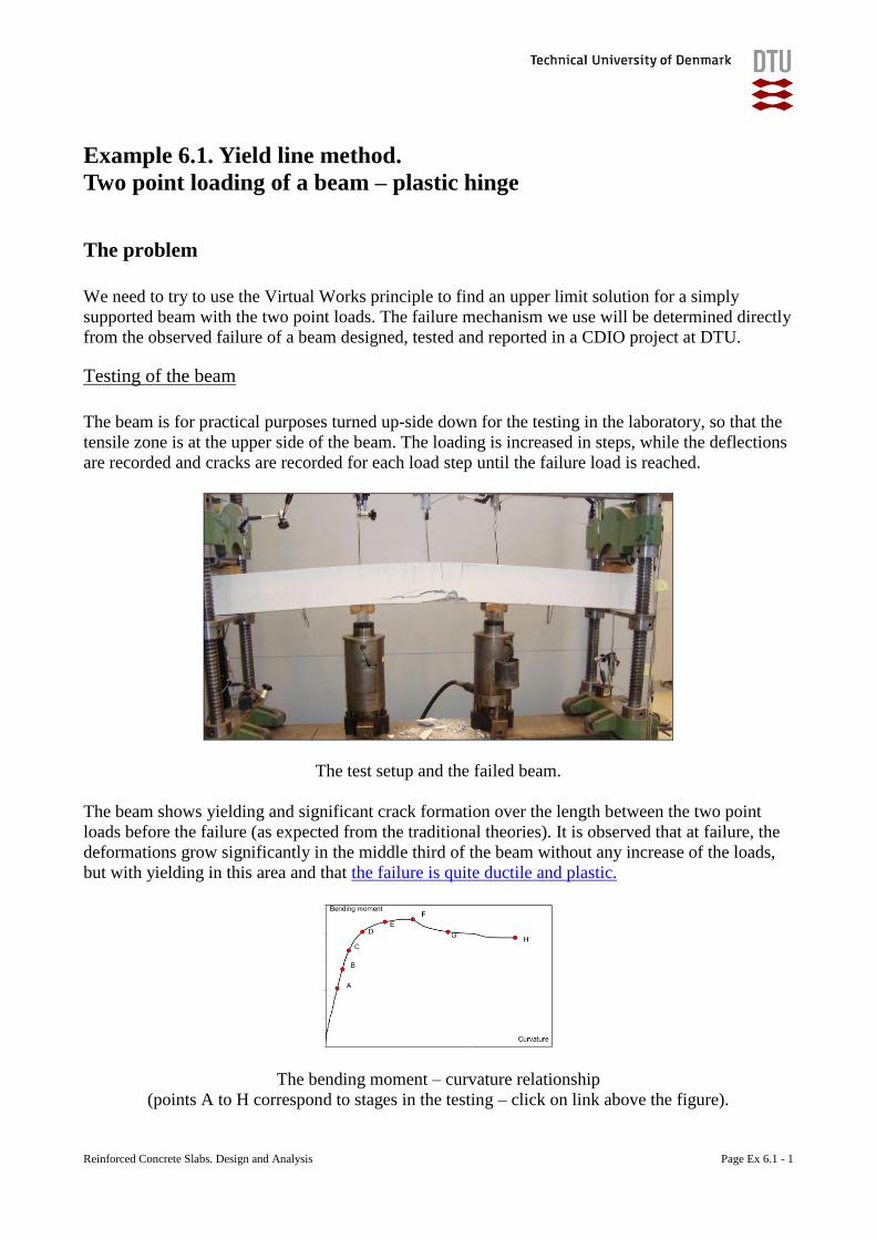
Reinforced Concrete Slabs. Design and Analysis Page Ex 6.1 - 1
Example 6.1. Yield line method.
Two point loading of a beam – plastic hinge
The problem
We need to try to use the Virtual Works principle to find an upper limit solution for a simply
supported beam with the two point loads. The failure mechanism we use will be determined directly
from the observed failure of a beam designed, tested and reported in a CDIO project at DTU.
Testing of the beam
The beam is for practical purposes turned up-side down for the testing in the laboratory, so that the
tensile zone is at the upper side of the beam. The loading is increased in steps, while the deflections
are recorded and cracks are recorded for each load step until the failure load is reached.
The test setup and the failed beam.
The beam shows yielding and significant crack formation over the length between the two point
loads before the failure (as expected from the traditional theories). It is observed that at failure, the
deformations grow significantly in the middle third of the beam without any increase of the loads,
but with yielding in this area and that the failure is quite ductile and plastic.
The bending moment – curvature relationship
(points A to H correspond to stages in the testing – click on link above the figure).
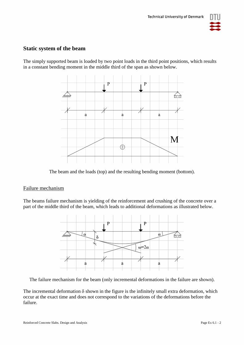
Reinforced Concrete Slabs. Design and Analysis Page Ex 6.1 - 2
Static system of the beam
The simply supported beam is loaded by two point loads in the third point positions, which results
in a constant bending moment in the middle third of the span as shown below.
The beam and the loads (top) and the resulting bending moment (bottom).
Failure mechanism
The beams failure mechanism is yielding of the reinforcement and crushing of the concrete over a
part of the middle third of the beam, which leads to additional deformations as illustrated below.
The failure mechanism for the beam (only incremental deformations in the failure are shown).
The incremental deformation shown in the figure is the infinitely small extra deformation, which
occur at the exact time and does not correspond to the variations of the deformations before the
failure.
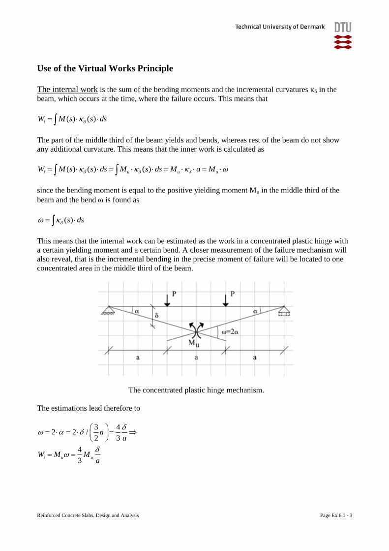
Reinforced Concrete Slabs. Design and Analysis Page Ex 6.1 - 3
Use of the Virtual Works Principle
The internal work is the sum of the bending moments and the incremental curvatures in the
beam, which occurs at the time, where the failure occurs. This means that
( ) ( )iW M s s ds
The part of the middle third of the beam yields and bends, whereas rest of the beam do not show
any additional curvature. This means that the inner work is calculated as
( ) ( ) ( )i u u uW M s s ds M s ds M a M
since the bending moment is equal to the positive yielding moment Mu in the middle third of the
beam and the bend is found as
( )s ds
This means that the internal work can be estimated as the work in a concentrated plastic hinge with
a certain yielding moment and a certain bend. A closer measurement of the failure mechanism will
also reveal, that is the incremental bending in the precise moment of failure will be located to one
concentrated area in the middle third of the beam.
The concentrated plastic hinge mechanism.
The estimations lead therefore to
3 42 2 /
2 3
4
3i u u
aa
W M Ma
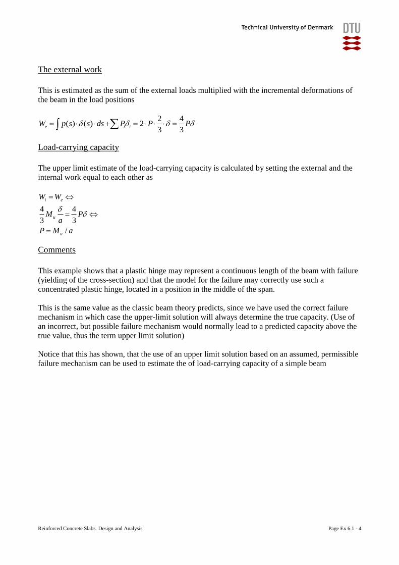
Reinforced Concrete Slabs. Design and Analysis Page Ex 6.1 - 4
The external work
This is estimated as the sum of the external loads multiplied with the incremental deformations of
the beam in the load positions
2 4( ) ( ) 2
3 3e i iW p s s ds P P P
Load-carrying capacity
The upper limit estimate of the load-carrying capacity is calculated by setting the external and the
internal work equal to each other as
4 4
3 3
/
i e
u
u
W W
M Pa
P M a
Comments
This example shows that a plastic hinge may represent a continuous length of the beam with failure
(yielding of the cross-section) and that the model for the failure may correctly use such a
concentrated plastic hinge, located in a position in the middle of the span.
This is the same value as the classic beam theory predicts, since we have used the correct failure
mechanism in which case the upper-limit solution will always determine the true capacity. (Use of
an incorrect, but possible failure mechanism would normally lead to a predicted capacity above the
true value, thus the term upper limit solution)
Notice that this has shown, that the use of an upper limit solution based on an assumed, permissible
failure mechanism can be used to estimate the of load-carrying capacity of a simple beam
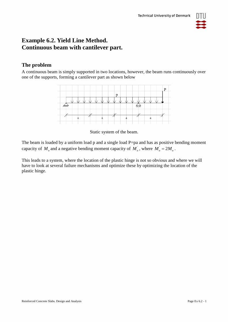
Reinforced Concrete Slabs. Design and Analysis Page Ex 6.2 - 1
Example 6.2. Yield Line Method.
Continuous beam with cantilever part.
The problem
A continuous beam is simply supported in two locations, however, the beam runs continuously over
one of the supports, forming a cantilever part as shown below
Static system of the beam.
The beam is loaded by a uniform load p and a single load P=pa and has as positive bending moment
capacity of uM and a negative bending moment capacity of '
uM , where ' 2u uM M .
This leads to a system, where the location of the plastic hinge is not so obvious and where we will
have to look at several failure mechanisms and optimize these by optimizing the location of the
plastic hinge.
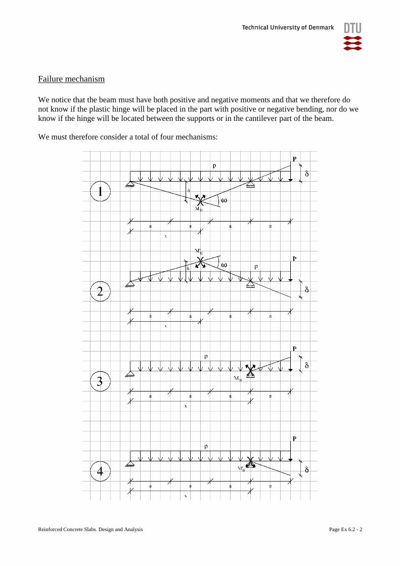
Reinforced Concrete Slabs. Design and Analysis Page Ex 6.2 - 2
Failure mechanism
We notice that the beam must have both positive and negative moments and that we therefore do
not know if the plastic hinge will be placed in the part with positive or negative bending, nor do we
know if the hinge will be located between the supports or in the cantilever part of the beam.
We must therefore consider a total of four mechanisms:
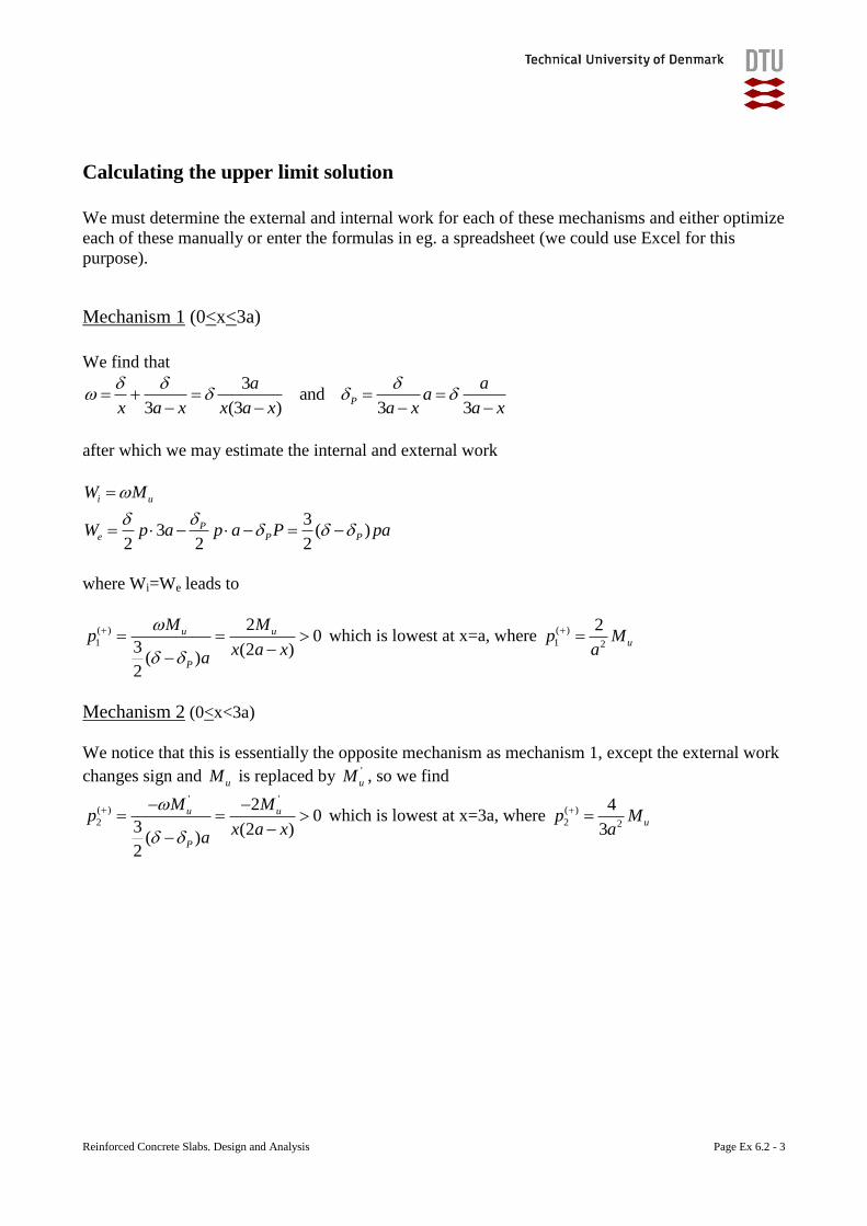
Reinforced Concrete Slabs. Design and Analysis Page Ex 6.2 - 3
Calculating the upper limit solution
We must determine the external and internal work for each of these mechanisms and either optimize
each of these manually or enter the formulas in eg. a spreadsheet (we could use Excel for this
purpose).
Mechanism 1 (0<x<3a)
We find that
3and
3 (3 ) 3 3P
a aa
x a x x a x a x a x
after which we may estimate the internal and external work
33 ( )
2 2 2
i u
Pe P P
W M
W p a p a P pa
where Wi=We leads to
( )
1
20
3 (2 )( )
2
u u
P
M Mp
x a xa
which is lowest at x=a, where ( )
1 2
2up M
a
Mechanism 2 (0<x<3a)
We notice that this is essentially the opposite mechanism as mechanism 1, except the external work
changes sign and uM is replaced by '
uM , so we find
' '( )
2
20
3 (2 )( )
2
u u
P
M Mp
x a xa
which is lowest at x=3a, where ( )
2 2
4
3up M
a
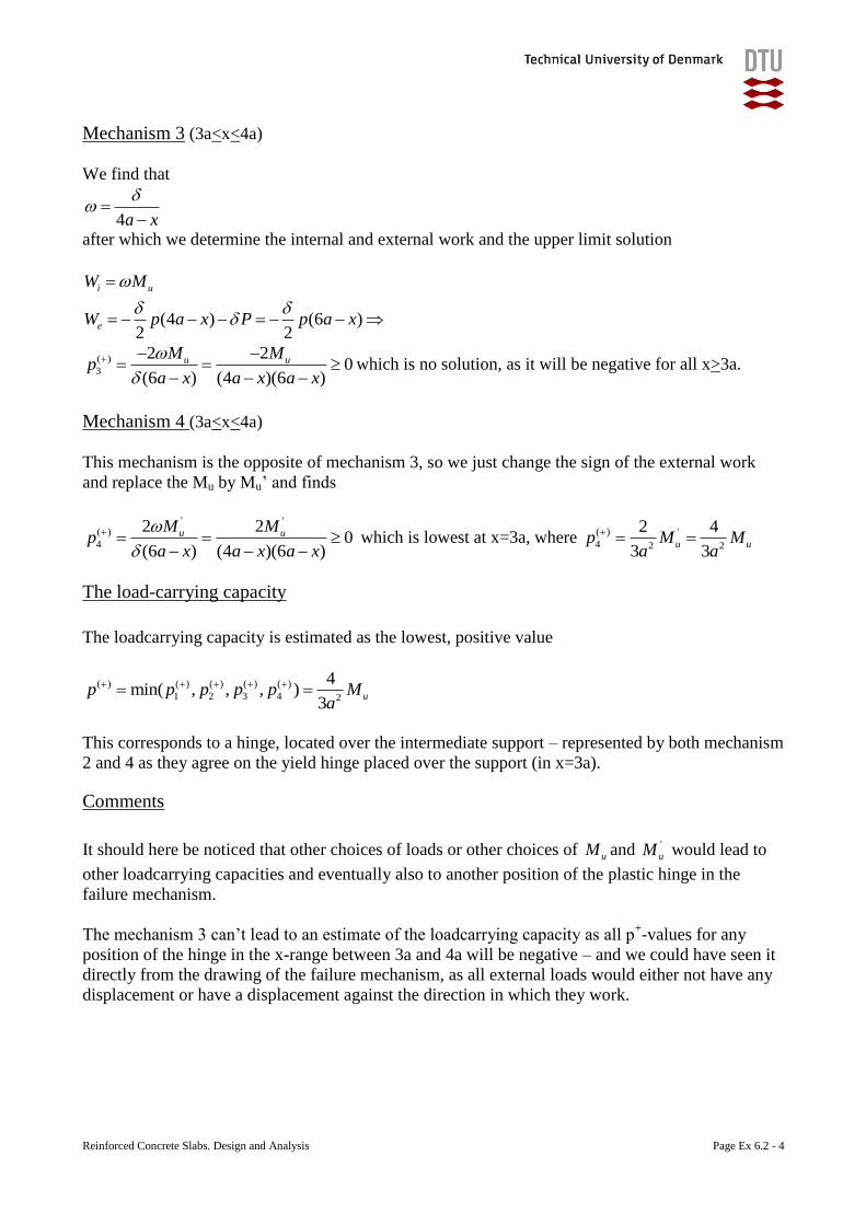
Reinforced Concrete Slabs. Design and Analysis Page Ex 6.2 - 4
Mechanism 3 (3a<x<4a)
We find that
4a x
after which we determine the internal and external work and the upper limit solution
(4 ) (6 )2 2
i u
e
W M
W p a x P p a x
( )
3
2 20
(6 ) (4 )(6 )
u uM Mp
a x a x a x
which is no solution, as it will be negative for all x>3a.
Mechanism 4 (3a<x<4a)
This mechanism is the opposite of mechanism 3, so we just change the sign of the external work
and replace the Mu by Mu’ and finds
' '
( )
4
2 20
(6 ) (4 )(6 )
u uM Mp
a x a x a x
which is lowest at x=3a, where ( ) '
4 2 2
2 4
3 3u up M M
a a
The load-carrying capacity
The loadcarrying capacity is estimated as the lowest, positive value
( ) ( ) ( ) ( ) ( )
1 2 3 4 2
4min( , , , )
3up p p p p M
a
This corresponds to a hinge, located over the intermediate support – represented by both mechanism
2 and 4 as they agree on the yield hinge placed over the support (in x=3a).
Comments
It should here be noticed that other choices of loads or other choices of uM and '
uM would lead to
other loadcarrying capacities and eventually also to another position of the plastic hinge in the
failure mechanism.
The mechanism 3 can’t lead to an estimate of the loadcarrying capacity as all p+-values for any
position of the hinge in the x-range between 3a and 4a will be negative – and we could have seen it
directly from the drawing of the failure mechanism, as all external loads would either not have any
displacement or have a displacement against the direction in which they work.
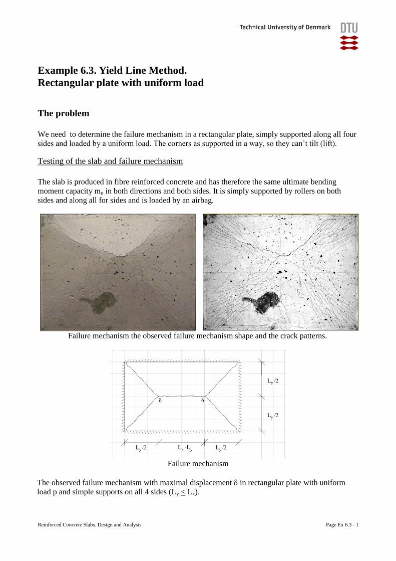
Reinforced Concrete Slabs. Design and Analysis Page Ex 6.3 - 1
Example 6.3. Yield Line Method.
Rectangular plate with uniform load
The problem
We need to determine the failure mechanism in a rectangular plate, simply supported along all four
sides and loaded by a uniform load. The corners as supported in a way, so they can’t tilt (lift).
Testing of the slab and failure mechanism
The slab is produced in fibre reinforced concrete and has therefore the same ultimate bending
moment capacity mu in both directions and both sides. It is simply supported by rollers on both
sides and along all for sides and is loaded by an airbag.
Failure mechanism the observed failure mechanism shape and the crack patterns.
Failure mechanism
The observed failure mechanism with maximal displacement in rectangular plate with uniform
load p and simple supports on all 4 sides (Ly < Lx).
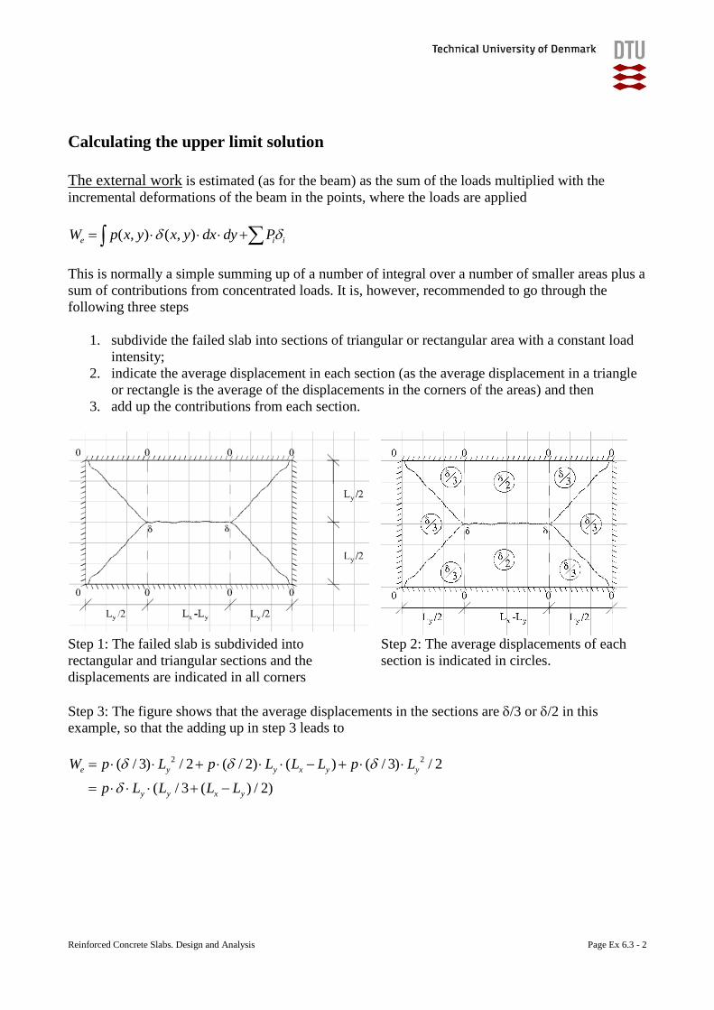
Reinforced Concrete Slabs. Design and Analysis Page Ex 6.3 - 2
Calculating the upper limit solution
The external work is estimated (as for the beam) as the sum of the loads multiplied with the
incremental deformations of the beam in the points, where the loads are applied
( , ) ( , )e i iW p x y x y dx dy P
This is normally a simple summing up of a number of integral over a number of smaller areas plus a
sum of contributions from concentrated loads. It is, however, recommended to go through the
following three steps
1. subdivide the failed slab into sections of triangular or rectangular area with a constant load
intensity;
2. indicate the average displacement in each section (as the average displacement in a triangle
or rectangle is the average of the displacements in the corners of the areas) and then
3. add up the contributions from each section.
Step 1: The failed slab is subdivided into
rectangular and triangular sections and the
displacements are indicated in all corners
Step 2: The average displacements of each
section is indicated in circles.
Step 3: The figure shows that the average displacements in the sections are /3 or /2 in this
example, so that the adding up in step 3 leads to
2 2( / 3) / 2 ( / 2) ( ) ( / 3) / 2
( / 3 ( ) / 2)
e y y x y y
y y x y
W p L p L L L p L
p L L L L
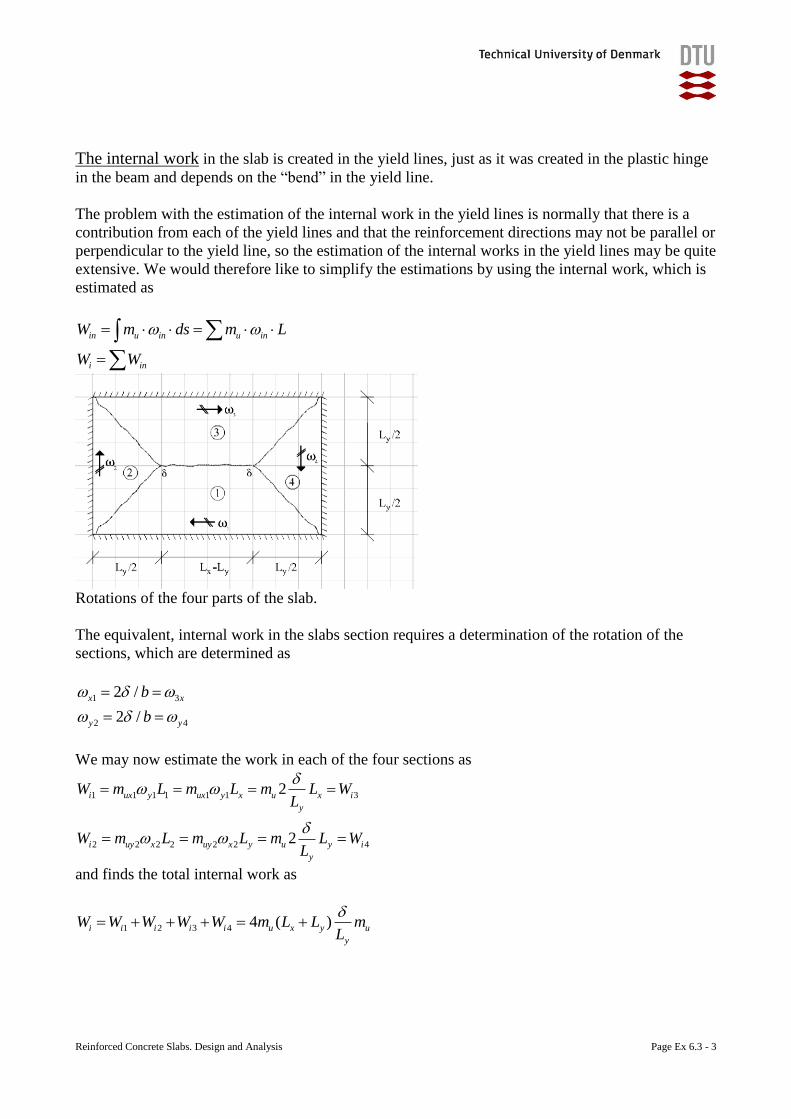
Reinforced Concrete Slabs. Design and Analysis Page Ex 6.3 - 3
The internal work in the slab is created in the yield lines, just as it was created in the plastic hinge
in the beam and depends on the “bend” in the yield line.
The problem with the estimation of the internal work in the yield lines is normally that there is a
contribution from each of the yield lines and that the reinforcement directions may not be parallel or
perpendicular to the yield line, so the estimation of the internal works in the yield lines may be quite
extensive. We would therefore like to simplify the estimations by using the internal work, which is
estimated as
in u in u in
i in
W m ds m L
W W
Rotations of the four parts of the slab.
The equivalent, internal work in the slabs section requires a determination of the rotation of the
sections, which are determined as
1 3
2 4
2 /
2 /
x x
y y
b
b
We may now estimate the work in each of the four sections as
1 1 1 1 1 1 3
2 2 2 2 2 2 4
2
2
i ux y ux y x u x i
y
i uy x uy x y u y i
y
W m L m L m L WL
W m L m L m L WL
and finds the total internal work as
1 2 3 4 4 ( )i i i i i u x y u
y
W W W W W m L L mL

Reinforced Concrete Slabs. Design and Analysis Page Ex 6.3 - 4
The loadcarrying capacity is now estimated from
e iW W
which in our example leads to
2
24( )
(3 )
y x
u
y x y
L Lp m
L L L

Reinforced Concrete Slabs. Design and Analysis Page Ex 6.4 - 1
Example 6.4. Yield Line Method.
Quadratic plate with “uniform” load.
The problem
The case will show the development of cracks in the slab and the development of yielding lines in
the slab at the higher load levels. The quadratic slab is actually one of the tests, used by K.W.
Johansen as documentation for his yield line theory.
Static system of the slab
The slab was intended to be simply supported and loaded by a number of loads, simulating a
distributed, uniform load. The slab was therefore placed directly on top of a steel frame, which
prevents the slabs sides from moving down, but did not prevent the sides or corners from moving
upwards in contrast to our normal, ideal simple support.
We will therefore start by seeing the development of the failure mechanism as reported from the
testing, but we will analyse three different cases
1. Simply supported sides with no tilting of the corners (easy);
2. Simply supported sides, which allows tilting of the corners (difficult – but KWJ’s example);
3. Simply supported sides, with an estimation of the corners forces required to prevent tilting.
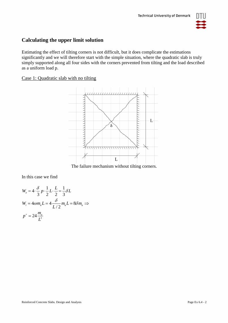
Reinforced Concrete Slabs. Design and Analysis Page Ex 6.4 - 2
Calculating the upper limit solution
Estimating the effect of tilting corners is not difficult, but it does complicate the estimations
significantly and we will therefore start with the simple situation, where the quadratic slab is truly
simply supported along all four sides with the corners prevented from tilting and the load described
as a uniform load p.
Case 1: Quadratic slab with no tilting
The failure mechanism without tilting corners.
In this case we find
2
1 14
3 2 2 3
4 4 8/ 2
24
e
i u u u
u
LW p L L
W m L m L mL
mp
L
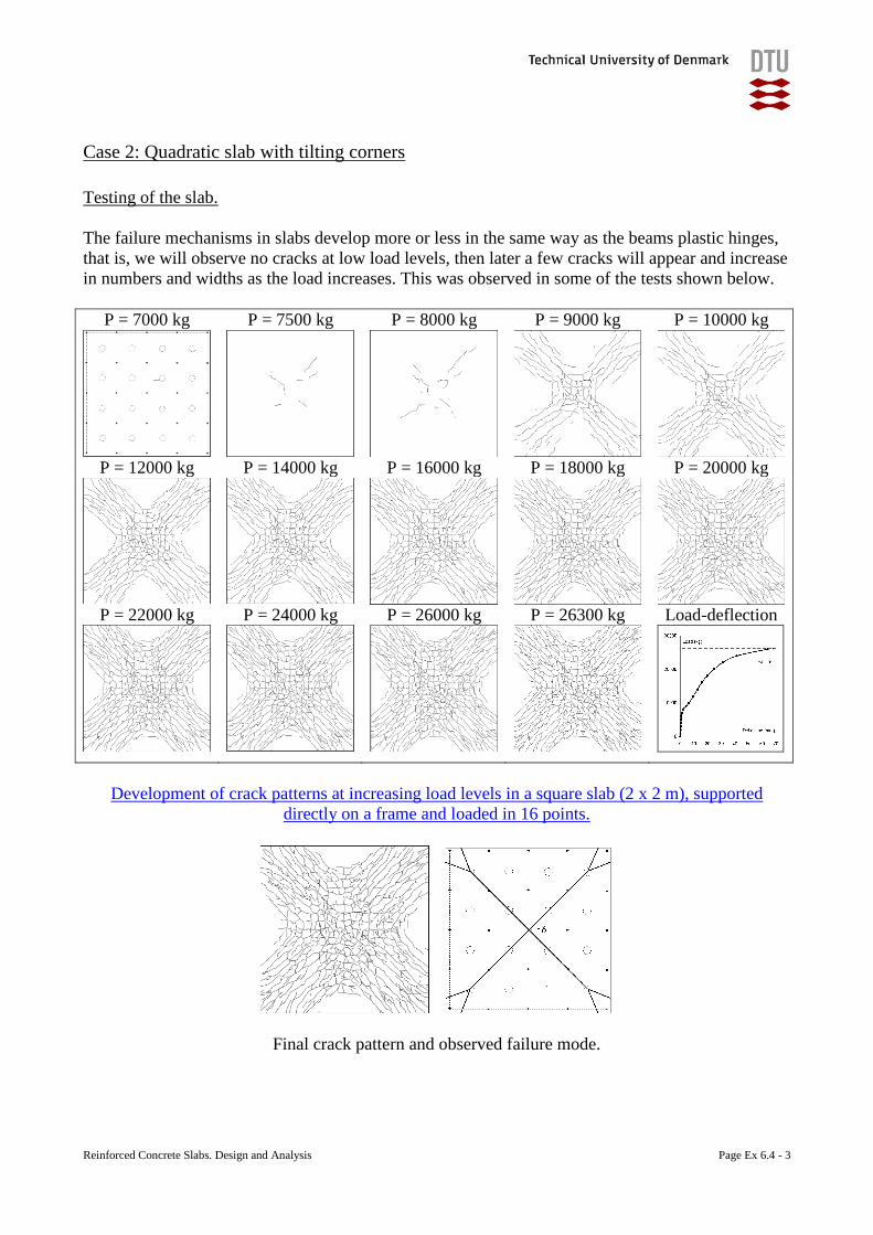
Reinforced Concrete Slabs. Design and Analysis Page Ex 6.4 - 3
Case 2: Quadratic slab with tilting corners
Testing of the slab.
The failure mechanisms in slabs develop more or less in the same way as the beams plastic hinges,
that is, we will observe no cracks at low load levels, then later a few cracks will appear and increase
in numbers and widths as the load increases. This was observed in some of the tests shown below.
P = 7000 kg P = 7500 kg P = 8000 kg P = 9000 kg P = 10000 kg
P = 12000 kg P = 14000 kg P = 16000 kg P = 18000 kg P = 20000 kg
P = 22000 kg P = 24000 kg P = 26000 kg P = 26300 kg Load-deflection
Development of crack patterns at increasing load levels in a square slab (2 x 2 m), supported
directly on a frame and loaded in 16 points.
Final crack pattern and observed failure mode.
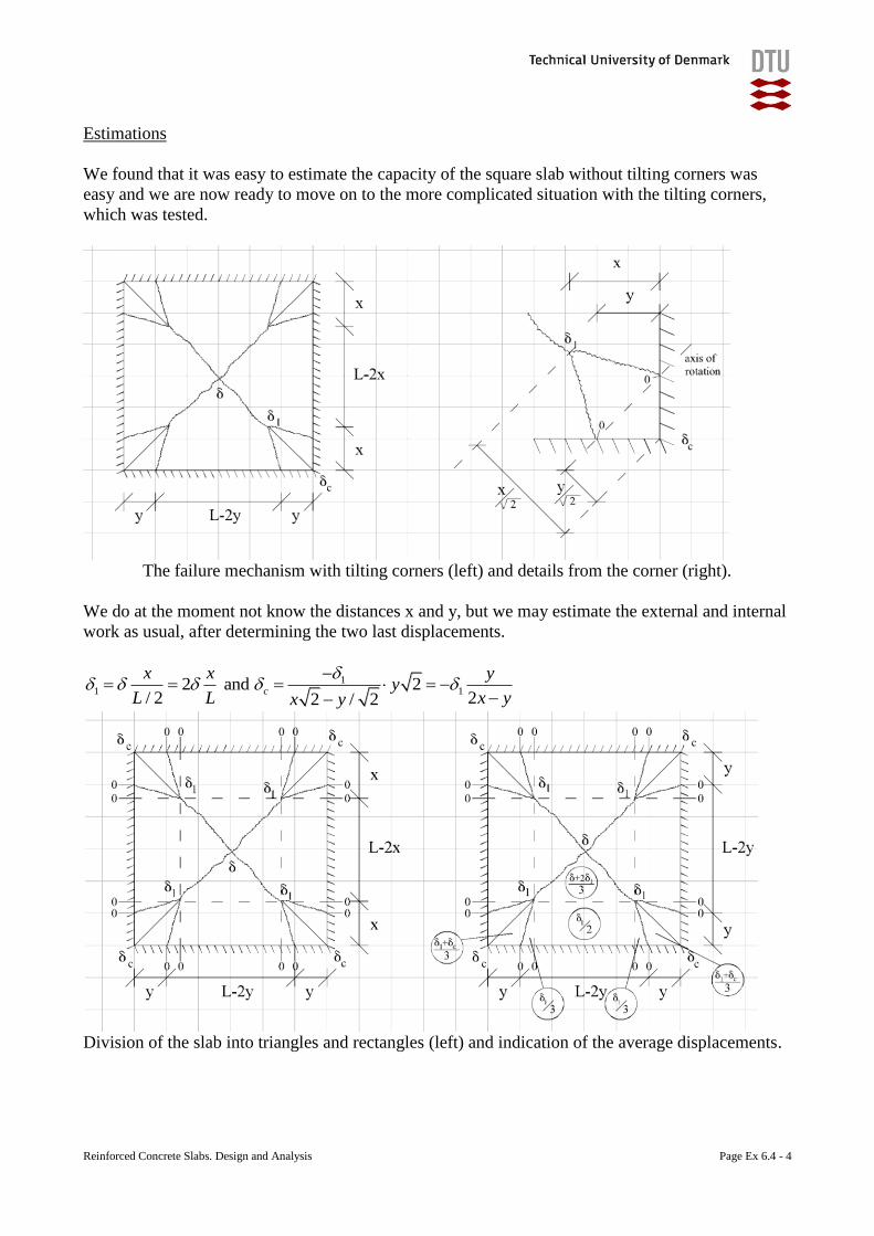
Reinforced Concrete Slabs. Design and Analysis Page Ex 6.4 - 4
Estimations
We found that it was easy to estimate the capacity of the square slab without tilting corners was
easy and we are now ready to move on to the more complicated situation with the tilting corners,
which was tested.
The failure mechanism with tilting corners (left) and details from the corner (right).
We do at the moment not know the distances x and y, but we may estimate the external and internal
work as usual, after determining the two last displacements.
11 12 and 2
/ 2 22 / 2c
x x yy
L L x yx y
Division of the slab into triangles and rectangles (left) and indication of the average displacements.
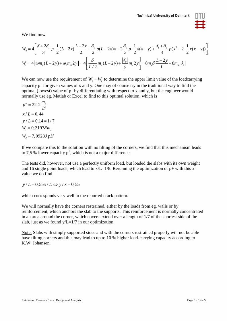
Reinforced Concrete Slabs. Design and Analysis Page Ex 6.4 - 5
We find now
211 1 12 1 2 1 14 ( 2 ) ( 2 ) 2 ( ) ( 2 ( ))
3 2 2 2 3 2 3 2
24 ( 2 ) 2 4 ( 2 ) 2 8 8
/ 2
ce
c
i u c u u u u u c
L xW p L x p L x x p x x y p x x x y
L yW m L y m y m L y m y m m
L y L
We can now use the requirement of e iW W to determine the upper limit value of the loadcarrying
capacity p+ for given values of x and y. One may of course try in the traditional way to find the
optimal (lowest) value of p+ by differentiating with respect to x and y, but the engineer would
normally use eg. Matlab or Excel to find to this optimal solution, which is
2
2
22,2
/ 0,44
/ 0,14 1/ 7
0,3197
7,0928
u
u
i
e
mp
L
x L
y L
W m
W pL
If we compare this to the solution with no tilting of the corners, we find that this mechanism leads
to 7,5 % lower capacity p+, which is not a major difference.
The tests did, however, not use a perfectly uniform load, but loaded the slabs with its own weight
and 16 single point loads, which lead to x/L=1/8. Rerunning the optimization of p+ with this x-
value we do find
/ 0,55 / / 0,55y L x L y x
which corresponds very well to the reported crack pattern.
We will normally have the corners restrained, either by the loads from eg. walls or by
reinforcement, which anchors the slab to the supports. This reinforcement is normally concentrated
in an area around the corner, which covers extend over a length of 1/7 of the shortest side of the
slab, just as we found y/L=1/7 in our optimization.
Note: Slabs with simply supported sides and with the corners restrained properly will not be able
have tilting corners and this may lead to up to 10 % higher load-carrying capacity according to
K.W. Johansen.
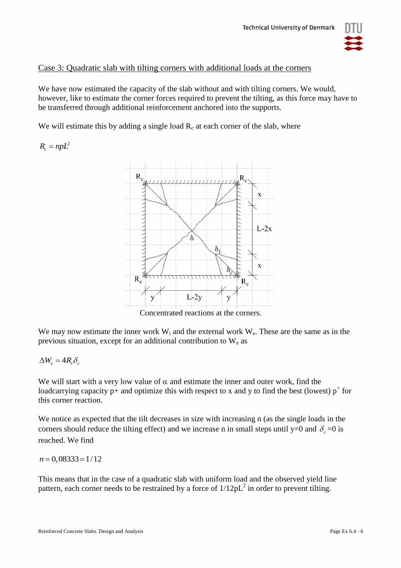
Reinforced Concrete Slabs. Design and Analysis Page Ex 6.4 - 6
Case 3: Quadratic slab with tilting corners with additional loads at the corners
We have now estimated the capacity of the slab without and with tilting corners. We would,
however, like to estimate the corner forces required to prevent the tilting, as this force may have to
be transferred through additional reinforcement anchored into the supports.
We will estimate this by adding a single load Rc at each corner of the slab, where
2
cR npL
Concentrated reactions at the corners.
We may now estimate the inner work Wi and the external work We. These are the same as in the
previous situation, except for an additional contribution to We as
4e c cW R
We will start with a very low value of and estimate the inner and outer work, find the
loadcarrying capacity p+ and optimize this with respect to x and y to find the best (lowest) p+ for
this corner reaction.
We notice as expected that the tilt decreases in size with increasing n (as the single loads in the
corners should reduce the tilting effect) and we increase n in small steps until y=0 and c =0 is
reached. We find
0,08333 1/12n
This means that in the case of a quadratic slab with uniform load and the observed yield line
pattern, each corner needs to be restrained by a force of 1/12pL2 in order to prevent tilting.

Reinforced Concrete Slabs. Design and Analysis Page Ex 6.4 - 7
References
Bach, C. and Graf, O.: “Versuche allseitig aufliegenden, quadratischen und rechteckigen
eisenbetonplatten”, Deutscher Ausschuss für Eisenbeton, heft 30, 1915.
Johansen, K. W.: ”Brudlinieteorier”, Jul. Gjellerups Forlag, Copenhagen, 1943, 191 pages. (Yield
Line theory, Translated by Cement and Concrete Association, London, 1962, 182 pages).
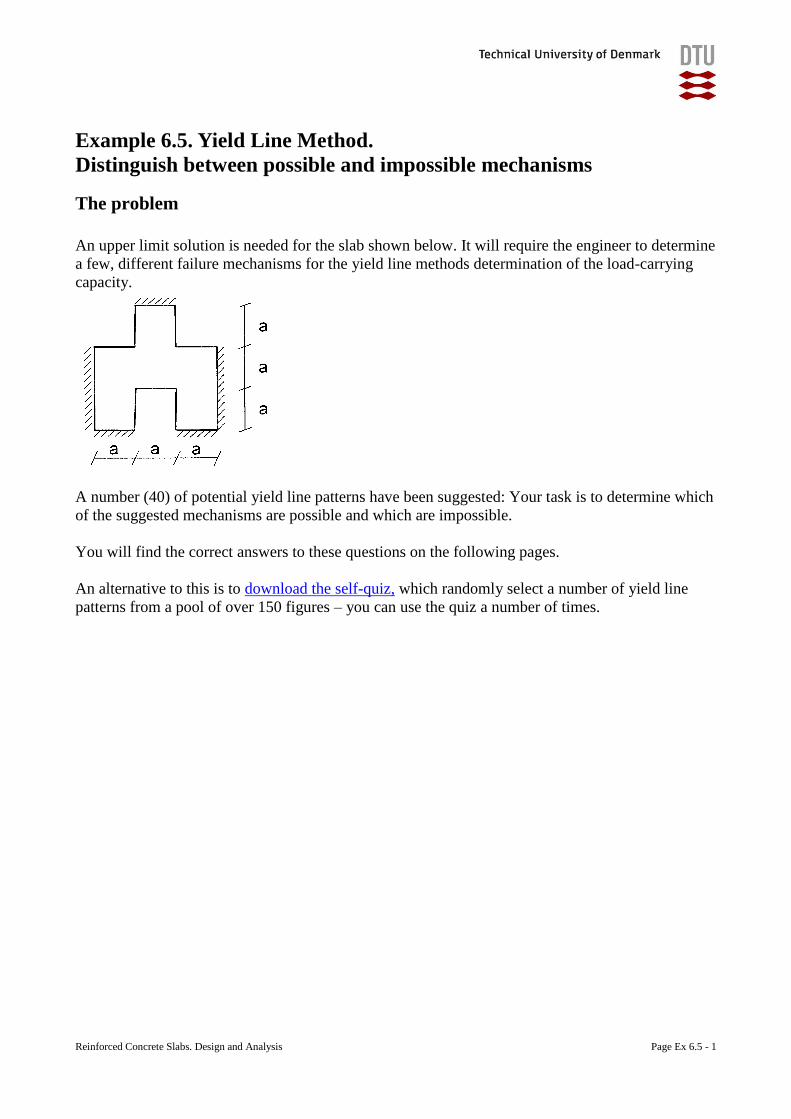
Reinforced Concrete Slabs. Design and Analysis Page Ex 6.5 - 1
Example 6.5. Yield Line Method.
Distinguish between possible and impossible mechanisms
The problem
An upper limit solution is needed for the slab shown below. It will require the engineer to determine
a few, different failure mechanisms for the yield line methods determination of the load-carrying
capacity.
A number (40) of potential yield line patterns have been suggested: Your task is to determine which
of the suggested mechanisms are possible and which are impossible.
You will find the correct answers to these questions on the following pages.
An alternative to this is to download the self-quiz, which randomly select a number of yield line
patterns from a pool of over 150 figures – you can use the quiz a number of times.
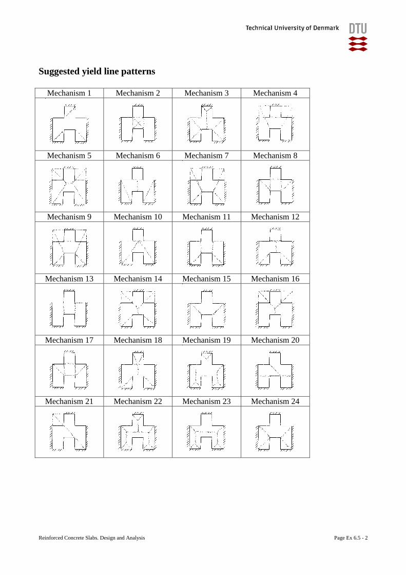
Reinforced Concrete Slabs. Design and Analysis Page Ex 6.5 - 2
Suggested yield line patterns
Mechanism 1 Mechanism 2 Mechanism 3 Mechanism 4
Mechanism 5 Mechanism 6 Mechanism 7 Mechanism 8
Mechanism 9 Mechanism 10 Mechanism 11 Mechanism 12
Mechanism 13 Mechanism 14 Mechanism 15 Mechanism 16
Mechanism 17 Mechanism 18 Mechanism 19 Mechanism 20
Mechanism 21 Mechanism 22 Mechanism 23 Mechanism 24
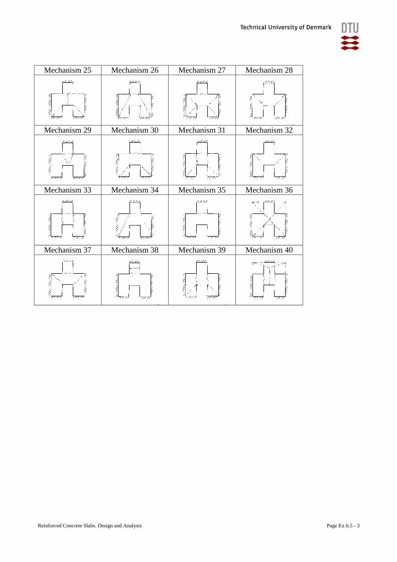
Reinforced Concrete Slabs. Design and Analysis Page Ex 6.5 - 3
Mechanism 25 Mechanism 26 Mechanism 27 Mechanism 28
Mechanism 29 Mechanism 30 Mechanism 31 Mechanism 32
Mechanism 33 Mechanism 34 Mechanism 35 Mechanism 36
Mechanism 37 Mechanism 38 Mechanism 39 Mechanism 40
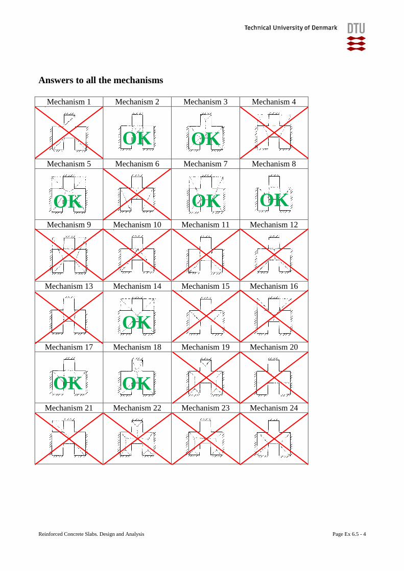
Reinforced Concrete Slabs. Design and Analysis Page Ex 6.5 - 4
Answers to all the mechanisms
Mechanism 1 Mechanism 2 Mechanism 3 Mechanism 4
Mechanism 5 Mechanism 6 Mechanism 7 Mechanism 8
Mechanism 9 Mechanism 10 Mechanism 11 Mechanism 12
Mechanism 13 Mechanism 14 Mechanism 15 Mechanism 16
Mechanism 17 Mechanism 18 Mechanism 19 Mechanism 20
Mechanism 21 Mechanism 22 Mechanism 23 Mechanism 24
OK OK
OK OK OK
OK OK
OK
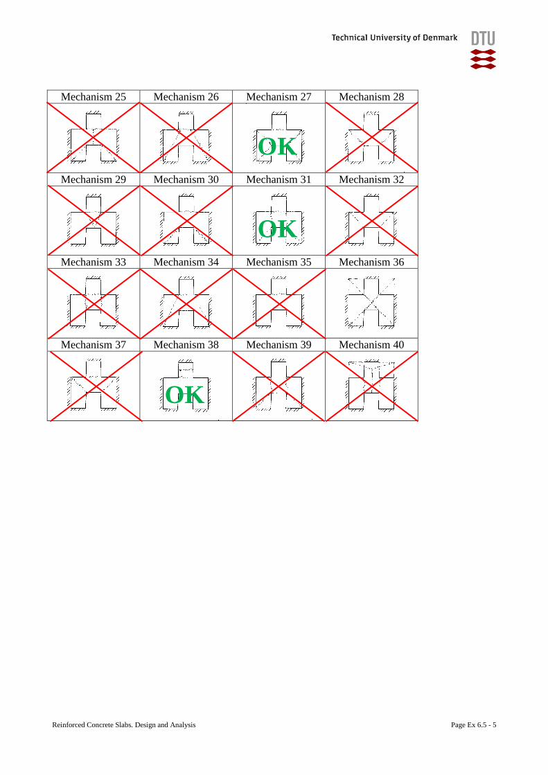
Reinforced Concrete Slabs. Design and Analysis Page Ex 6.5 - 5
Mechanism 25 Mechanism 26 Mechanism 27 Mechanism 28
Mechanism 29 Mechanism 30 Mechanism 31 Mechanism 32
Mechanism 33 Mechanism 34 Mechanism 35 Mechanism 36
Mechanism 37 Mechanism 38 Mechanism 39 Mechanism 40
OK
OK
OK

DTU Civil Engineering
Department of Civil Engineering
Technical University of Denmark
Brovej, Building 118
DK 2800 Kgs. Lyngby
Telephone +45 45 25 17 00
www.byg.dtu.dk
Related Documents