Mercury iPS Issue 01 / January 2012 / Original Instructions www.oxford-instruments.com Oxford Instruments NanoScience Handbook ©2012. Oxford Instruments Nanotechnology Tools Limited. All rights reserved.

Welcome message from author
This document is posted to help you gain knowledge. Please leave a comment to let me know what you think about it! Share it to your friends and learn new things together.
Transcript

Mercury iPS
Issue 01 / January 2012 / Original Instructions
Oxford Instruments NanoScience
Handbook
www.oxford-instruments.com
©2012. Oxford Instruments Nanotechnology Tools Limited. All rights reserved.

Handbook
Mercury iPS
This page is intentionally blank.
Page 2January 2012 / 59-UMC0072 / Issue 01 Original Instructions

Handbook
Mercury iPS
PREFACE
PREFACEWelcome to the Operator’s Handbook for the Oxford Instruments NanoScience Mercury iPS magnet power supply unit. The Mercury Mercury iPS is designed to drive a superconducting magnet in laboratory applications.
This Operator’s Handbook provides all the information necessary for the safe and proper installation and operation of the Mercury iPS.
Use of this manualThis manual provides operating and service information for the Oxford Instruments NanoScience Mercury iPS.
Chapter 1 to Chapter 2 provide essential information that must be read and understood before operating the Mercury iPS for the first time.
Customer supportOxford Instruments NanoScience has global customer support facilities that provide a coordinated response to customer’s queries. All queries are recorded on our support database and are dealt with as quickly as possible. If we are not able to answer the query immediately, we will contact you promptly.
Before contacting a customer support facility, please ensure that you have referred to the appropriate section of this manual.
Please direct all queries through your nearest support facility (see below) and have the following details available:
You can contact us at the telephone numbers and email addresses listed on the last page of this handbook.
System type Mercury iPS
Serial number
Contact information Your name, the name of your company, and how we can contact you.
Details of your query The nature of your problem, part numbers of spares required, etc.
January 2012 / 59-UMC0072 / Issue 01Page 3Original Instructions

Handbook
Mercury iPS
PREFACE
Health and safety informationThe Mercury iPS contains hazardous areas. Before working with the Mercury iPS, all personnel must read and become thoroughly familiar with the information given in Chapter 1. In particular, users must read, understand and strictly observe all:
Warning notices
Caution notices
Safety labels and markings on the equipment
For ease of reference and rapid response in an emergency, this handbook must be safely kept in close proximity to the Mercury iPS.
Intended usersUsers of the iPS must have received adequate training on its safe and effective use before attempting to work with the equipment. Please contact Oxford Instruments NanoScience for information on training requirements and training courses that are available.
Training requirements vary from country to country. Users must ensure that training is given in accordance with all applicable local laws and regulations.
If any user of the equipment has not been directly trained by Oxford Instruments NanoScience, ensure that they understand the safety issues associated with the equipment, and that they consult relevant personnel for guidance when operating the equipment.
Statement of intended use of the Mercury iPSThe iPS has been designed for powering superconducting magnets in laboratory applications. The equipment has been designed to operate within the process parameter limits that are outlined in this manual.
The iPS is intended to be installed, used and operated only for the purpose for which the iPS was designed, and only in accordance with the instructions given in this manual and other accompanying documents. Nothing stated in this manual reduces the responsibilities of users to exercise sound judgement and best practice.
It is the user's responsibility to ensure the system is operated in a safe manner. Consideration must be made for all aspects of the system's life-cycle, including, handling, installation, normal operation, maintenance, dismantling, decontamination and disposal. It is the user's responsibility to complete suitable risk assessments, to determine the magnitude of hazards.
The installation, use and operation of the iPS are subject to laws in the jurisdictions in which the equipment is installed and in use. Users must install, use and operate the equipment only in such ways that do not conflict with said applicable laws and regulations.
If the equipment is not installed, used, maintained, refurbished, modified and upgraded as specified by the manufacturer, then the protection it provides could be impaired. Any resultant non-compliance, damage, or personal injury would be the fault of the owner or user.
Use of the equipment for purposes other than those intended and expressly stated by Oxford Instruments NanoScience, as well as incorrect use or operation of the equipment, may relieve Oxford Instruments NanoScience or its agent of the responsibility for any resultant non-compliance, damage or injury. The system must only be used with all external panels fitted.
January 2012 / 59-UMC0072 / Issue 01 Page 4 Original Instructions
Handbook
Mercury iPS
PREFACE
Typographical conventionsFor clarity and ease of explanation, the following typographical conventions are used in this manual:
Modes of operation are expressed in upper case, italic letters. Thus:
AUTO, MANUAL, SERVICE.
On-screen objects in the graphical user interface (GUI) are expressed in bold letters. Thus:
manual button, Position panel, Forward field.
The names of on-screen windows and panels in the GUI are expressed with upper-case initial letters. Thus:
AMU Service Util panel.
The names of physical controls are expressed in bold letters enclosed in arrow symbols. Thus:
<Alt> key on the personal computer (PC) keyboard, <ON> button.
Keys to be pressed in sequence are expressed thus:
<Crtl> <S>.
Keys to be pressed simultaneously are expressed thus:
<Crtl> + <S>.
Directory paths are expressed thus:
C:\name\name\name.
DisclaimersOxford Instruments NanoScience assumes no liability for use of this document if any unauthorised changes to the content or format have been made.
Oxford Instruments NanoScience’s policy is one of continued improvement. The Company reserves the right to alter without notice the specification, design or conditions of supply of any of its products or services. Although every effort has been made to ensure that the information in this manual is accurate and up to date, errors may occur. Oxford Instruments NanoScience shall have no liability arising from the use of or reliance by any party on the contents of this manual and, to the fullest extent permitted by law, excludes all liability for loss or damages howsoever caused.
This manual is provided without warranty of any kind, either implied or expressed, including, but not limited to, the implied warranties of merchantability and fitness for a particular purpose.
Copyright noticeYou may make hard copies of this manual for your organisation´s internal use in connection with the system with which it was supplied, provided that the integrity of the manual is maintained and this copyright notice is reproduced. Other than as permitted above, you may not reproduce or transmit any part of this document, electronically or mechanically, without the prior written permission of Oxford Instruments NanoScience.
January 2012 / 59-UMC0072 / Issue 01Page 5Original Instructions

Handbook
Mercury iPS
PREFACE
AcknowledgementsAll tradenames and trademarks that appear in this manual are hereby acknowledged.
Acronyms, abbreviations and special termsA glossary of acronyms, abbreviations and special terms is given at the end of this manual.
Revision historyThis is issue 01 of the Mercury iPS Handbook, as shown in the footer at the bottom of each page.
The changes made to this document and a summary of previous issues are listed in the table below.
Always use the latest issue of the manual.
Revision Affected page(s) Summary of changes
01 All pages. First edition of the Mercury iPS Handbook.
January 2012 / 59-UMC0072 / Issue 01 Page 6 Original Instructions

Handbook
Mercury iPS
PREFACE
Certification and compliance statementsThe Mercury iPS magnet power supply complies with the following standards and certifications:
EN61010.1: Safety requirements for electrical equipment for measurement, control and laboratory use.
EN61326: Electrical equipment for measurement, control and laboratory use: EMC requirements.
CE
UL
CSA
China Restriction of Hazardous Substances
Signed:
Jim Hutchins
Managing Director
Oxford Instruments NanoScience Limited
January 2012 / 59-UMC0072 / Issue 01Page 7Original Instructions

Handbook
Mercury iPS
PREFACE
This page is intentionally blank.
Page 8January 2012 / 59-UMC0072 / Issue 01 Original Instructions

Handbook
Mercury iPS
PREFACE.............................................................................................................................................. 3
Use of this manual ............................................................................................................................... 3Customer support................................................................................................................................ 3Health and safety information ............................................................................................................ 4Intended users ..................................................................................................................................... 4Statement of intended use of the Mercury iPS ................................................................................. 4Typographical conventions ................................................................................................................ 5Disclaimers........................................................................................................................................... 5Copyright notice .................................................................................................................................. 5Acknowledgements ............................................................................................................................. 6Acronyms, abbreviations and special terms..................................................................................... 6Revision history ................................................................................................................................... 6Certification and compliance statements.......................................................................................... 7
1 HEALTH AND SAFETY ..................................................................................................... 17
1.1 Warnings ........................................................................................................................... 171.1.1 Protective ground ........................................................................................................... 171.1.2 High voltage hazard ....................................................................................................... 171.1.3 Maintenance and adjustment ......................................................................................... 181.1.4 Restrictions on use ........................................................................................................ 181.2 Cautions ............................................................................................................................ 191.2.1 Electrostatic caution ....................................................................................................... 191.2.2 Cooling caution .............................................................................................................. 191.3 Solid waste ........................................................................................................................ 19
2 GETTING STARTED .......................................................................................................... 21
2.1 Checking the electrical supply ........................................................................................ 212.2 Mounting the equipment .................................................................................................. 212.3 Connecting electrical power ............................................................................................ 222.3.1 Connecting the magnet - single unit .............................................................................. 222.3.2 Connecting the magnet - multiple units .......................................................................... 232.3.2.1 Connecting three units to a vector-rotate arrangement.............................................. 232.3.2.2 Connecting multiple units in series or parallel ........................................................... 252.3.3 Connecting the temperature sensor (if required) ........................................................... 262.3.4 Connecting the data interfaces ...................................................................................... 272.3.4.1 Connecting the ethernet interface (if required)........................................................... 272.3.4.2 Connecting the RS232 serial interface (if required) ................................................... 272.3.4.3 Connecting ISOBUS (if required) ............................................................................... 272.3.4.4 Connecting the GPIB (if required) .............................................................................. 272.3.5 Connecting the auxiliary port (if required) ...................................................................... 272.3.6 Connecting the level-meter (if required) ......................................................................... 272.4 Powering up the unit for the first time ............................................................................ 282.4.1 Setting the date and time ............................................................................................... 282.4.2 General settings ............................................................................................................. 282.4.3 Updating firmware .......................................................................................................... 282.5 Configuring the Mercury iPS ........................................................................................... 292.5.1 Configuring the magnet output ....................................................................................... 292.5.1.1 Configuring the master unit ........................................................................................ 292.5.1.2 Configuring rate limits for the magnet ........................................................................ 302.5.2 Configuring temperature sensors (if fitted) ..................................................................... 302.5.3 Configuring the temperature sensor inputs .................................................................... 312.5.3.1 Configuring the sensor details.................................................................................... 31
January 2012 / 59-UMC0072 / Issue 01Page 9Original Instructions

Handbook
Mercury iPS
2.5.3.2 Using a generic calibration-file ................................................................................... 322.6 Testing the inputs and outputs ....................................................................................... 332.6.1 Testing the temperature sensor inputs (if applicable) .................................................... 332.6.2 Testing the magnet supply output .................................................................................. 332.6.3 Testing the persistent heater (if required) ...................................................................... 342.7 Configuring remote interfaces ......................................................................................... 342.8 Engineering mode ............................................................................................................. 352.8.1 Entering engineering mode. ........................................................................................... 352.8.2 Exiting engineering mode ............................................................................................... 35
3 OVERVIEW OF THE IPS .................................................................................................... 37
3.1 Superconducting magnets ............................................................................................... 373.1.1 Magnet types .................................................................................................................. 373.1.2 Persistent-switch ............................................................................................................ 373.1.3 Quench ........................................................................................................................... 373.2 Magnet power supply unit ................................................................................................ 383.3 System description ........................................................................................................... 393.3.1 Magnet power supply ..................................................................................................... 393.3.2 Switch-heater output ...................................................................................................... 393.3.2.1 Quench detection........................................................................................................ 393.3.3 Temperature sensor input .............................................................................................. 393.3.4 Remote interfaces .......................................................................................................... 393.3.5 Display and touch-screen ............................................................................................... 393.3.6 Electrical power supply ................................................................................................... 40
4 USER INTERFACE ............................................................................................................ 41
4.1 Front panel controls ......................................................................................................... 414.2 Front panel meters ............................................................................................................ 424.3 LCD and GUI ...................................................................................................................... 424.3.1 Using the touch screen ................................................................................................... 424.3.1.1 Initiating actions.......................................................................................................... 424.3.1.2 Drop-down menus ...................................................................................................... 424.3.1.3 Scrolling...................................................................................................................... 434.3.1.4 Soft keypads............................................................................................................... 434.3.1.5 Using arrows to adjust numeric values ....................................................................... 454.3.1.6 Button labels .............................................................................................................. 464.3.2 Common screen features ............................................................................................... 464.3.2.1 Home and Apply buttons ............................................................................................ 464.3.3 Home page ..................................................................................................................... 474.3.3.1 Home page - solenoid mode....................................................................................... 474.3.3.2 Home page - vector rotate mode................................................................................ 484.3.3.3 Magnet control areas for vector rotate magnets ........................................................ 504.3.4 Additional home pages ................................................................................................... 514.3.5 Set Point/Set Rate page ................................................................................................. 524.3.6 Ramp Rate Limits Editor page ....................................................................................... 534.3.7 Plot Configuration page .................................................................................................. 544.3.8 Plot page ........................................................................................................................ 554.3.9 Master/Slave Configuration page ................................................................................... 554.3.9.1 The master/slave configuration table.......................................................................... 564.3.10 Engineering Configuration pages ................................................................................... 574.3.11 General Settings tab ....................................................................................................... 584.3.11.1 Display Settings tab.................................................................................................... 59
January 2012 / 59-UMC0072 / Issue 01 Page 10 Original Instructions

Handbook
Mercury iPS
4.3.11.2 Card Settings tab ....................................................................................................... 604.3.11.3 RS232 Settings tab ................................................................................................... 614.3.11.4 Ethernet Settings tab ................................................................................................. 624.3.11.5 ISOBus Settings tab ................................................................................................... 634.3.11.6 GPIB Settings tab....................................................................................................... 634.3.11.7 Clock Settings tab ...................................................................................................... 644.3.11.8 Cal Update settings tab ............................................................................................. 654.3.11.9 F/W Update settings tab ............................................................................................ 664.3.11.10 EngMode tab ............................................................................................................. 674.3.11.11 Factory Settings tab .................................................................................................. 684.3.12 Alarm Logs page ............................................................................................................ 694.3.12.1 Channel summary panel ........................................................................................... 704.3.13 Channel Display Configuration page ............................................................................. 714.3.14 Sensor details pages ..................................................................................................... 724.3.14.1 Temperature Sensor Details page ............................................................................. 724.3.15 Generic Sensor Adjustment page .................................................................................. 734.3.15.1 Level Meter Sensor Details page ............................................................................... 744.3.16 Save File pages ............................................................................................................. 764.3.17 Load File pages ............................................................................................................. 77
5 FUNCTIONAL DESCRIPTION ........................................................................................... 79
5.1 Master and slave units ..................................................................................................... 795.2 Master unit description .................................................................................................... 795.2.1 Main components - master ............................................................................................ 795.2.1.1 User interface - master............................................................................................... 805.2.2 Motherboard ................................................................................................................... 805.2.3 Magnet power supply operation - master ....................................................................... 805.2.3.1 Ramp rate limits ......................................................................................................... 805.2.3.2 Magnet operation with a persistent-switch ................................................................ 815.2.3.3 Quench detection - master ........................................................................................ 825.2.3.4 Auto rundown - master ............................................................................................... 825.2.4 Mercury iPS connections - master ................................................................................. 835.2.4.1 Electrical power connection........................................................................................ 835.2.4.2 Magnet connections ................................................................................................... 835.2.4.3 Persistent-switch heater output .................................................................................. 835.2.4.4 Temperature sensor input ......................................................................................... 845.2.5 Communications interfaces - master ............................................................................. 855.2.5.1 Serial RS232 interface ............................................................................................... 855.2.5.2 Oxford Instruments NanoScience ISOBUS................................................................ 865.2.5.3 USB interface ............................................................................................................. 865.2.5.4 Ethernet interface ....................................................................................................... 865.2.5.5 SPI bus ...................................................................................................................... 875.2.6 Daughter boards - master .............................................................................................. 875.2.6.1 Expansion slots - master ........................................................................................... 885.2.6.2 Positioning daughter boards....................................................................................... 885.3 Slave unit description ...................................................................................................... 885.3.1 Output modes ................................................................................................................ 895.3.2 Control system - slave ................................................................................................... 895.3.3 User interface - slave ..................................................................................................... 895.3.4 Mercury iPS connections - slave .................................................................................... 895.3.4.1 Electrical power connection........................................................................................ 895.3.4.2 Magnet connections ................................................................................................... 89
January 2012 / 59-UMC0072 / Issue 01Page 11Original Instructions

Handbook
Mercury iPS
5.3.4.3 Switch heater output ................................................................................................... 895.3.4.4 Communication interfaces - slave............................................................................... 895.3.5 Daughter boards - slave ................................................................................................. 895.4 Controlling the Mercury iPS through a remote interface .............................................. 895.5 Overview of temperature measurement ......................................................................... 905.5.1 Types of temperature sensor ......................................................................................... 905.5.1.1 Thermocouples .......................................................................................................... 925.5.1.2 Resistance and diode sensors.................................................................................... 925.5.2 Calibration for different sensors ..................................................................................... 925.6 Circuit description of the magnet power-supply ........................................................... 93
6 BASIC OPERATING INSTRUCTIONS .............................................................................. 95
6.1 Configuring the LCD ......................................................................................................... 956.2 Magnet current operations ............................................................................................... 956.2.1 Changing the current through the magnet ...................................................................... 956.2.2 Using persistent mode (if required) ................................................................................ 956.2.2.1 Establishing a persistent current in the magnet.......................................................... 956.2.2.2 Changing the persistent current in the magnet........................................................... 966.2.2.3 Changing the persistent current in the magnet to zero .............................................. 976.2.3 Recovering from a quench ............................................................................................. 976.3 Using the plot function ..................................................................................................... 986.3.1 Configuring a plot ........................................................................................................... 986.3.2 To remove a trace from the plot ..................................................................................... 996.3.3 Adjusting the plot scaling ................................................................................................ 996.3.4 To exit the plot .............................................................................................................. 1006.4 Configuring external interfaces ..................................................................................... 1006.4.1 Configuring the ethernet interface (if required) ............................................................. 1006.4.2 Configuring the RS232 serial interface (if required) ..................................................... 1016.4.3 Configuring the GPIB (if required) ................................................................................ 1016.4.4 Configuring the USB interface (if required) .................................................................. 1016.4.5 Enabling remote control of the Mercury iPS ................................................................. 1016.4.6 Enabling local control of the Mercury iPS ..................................................................... 1026.5 Re-configuring temperature sensors ............................................................................ 1026.5.1 To clear a panel configuration ...................................................................................... 1026.5.2 Re-configuring a sensor ............................................................................................... 1026.6 Updating the firmware .................................................................................................... 1026.6.1 Updating the application ............................................................................................... 1026.6.2 Updating the firmware on a board ................................................................................ 1036.7 Saving and restoring configurations ............................................................................ 1046.7.1 Saving a configuration .................................................................................................. 1046.7.2 Restoring a configuration ............................................................................................. 104
7 REMOTE OPERATION .................................................................................................... 105
7.1 Notes on instrument addresses .................................................................................... 1057.2 Communication protocols for RS232 and GPIB .......................................................... 1057.2.1 Commands and responses .......................................................................................... 1067.2.2 Numeric parameters ..................................................................................................... 1067.3 Control via ISOBUS ........................................................................................................ 1067.4 GPIB interface ................................................................................................................. 1077.4.1 Switching between RS232 and GPIB operation ........................................................... 1077.4.2 Sending commands via the GPIB ................................................................................ 1077.4.3 Accepting responses via the GPIB. .............................................................................. 108
January 2012 / 59-UMC0072 / Issue 01 Page 12 Original Instructions

Handbook
Mercury iPS
7.4.4 The status byte and use of a serial poll ....................................................................... 1087.4.4.1 RQS bit..................................................................................................................... 1087.4.4.2 BAV bit ..................................................................................................................... 1087.4.4.3 MAV bit..................................................................................................................... 1087.4.4.4 Status byte update rate ............................................................................................ 1097.4.5 Use of the service request line ..................................................................................... 1097.4.6 Use of the device clear function ................................................................................... 1097.4.7 Use of the interface clear function ............................................................................... 1097.4.8 Non-implemented features of the GPIB ....................................................................... 1097.4.9 Compatibility with IEEE-488.2 ...................................................................................... 1097.4.10 Writing a reliable GPIB control program ...................................................................... 1107.4.10.1 Timeouts................................................................................................................... 110
8 PREVENTIVE MAINTENANCE ....................................................................................... 111
8.1 Six-monthly maintenance .............................................................................................. 1118.1.1 Cleaning the touch-screen ........................................................................................... 1118.1.2 Calibrating the temperature-sensor boards ................................................................. 1118.1.3 Unscheduled maintenance .......................................................................................... 111
9 TROUBLESHOOTING ..................................................................................................... 113
9.1 Fault-finding features of the iPS ................................................................................... 1139.1.1 Alarm-logs .................................................................................................................... 1139.2 Troubleshooting information ......................................................................................... 113
10 COMMAND REFERENCE GUIDE ................................................................................... 115
10.1 Nomenclature used in this section ............................................................................... 11510.2 SCPI and legacy command sets .................................................................................... 11510.3 SCPI command messages ............................................................................................. 11510.3.1 SCPI protocol conventions ........................................................................................... 11510.3.2 Reading the overall instrument configuration ............................................................... 11610.3.3 Basic SCPI command structure ................................................................................... 11610.3.4 Verbs ............................................................................................................................ 11610.3.5 Nouns ........................................................................................................................... 11710.3.5.1 System commands .................................................................................................. 11810.3.5.2 Addressing a magnet controller................................................................................ 11910.3.5.3 Addressing a temperature sensor ........................................................................... 12110.3.5.4 Addressing a level meter sensor ............................................................................. 12310.3.5.5 Addressing an auxiliary I/O daughter board ............................................................. 12410.3.6 Invalid responses ......................................................................................................... 12510.4 Legacy command messages ......................................................................................... 12510.4.1 Legacy monitor commands .......................................................................................... 12510.4.1.1 Cn command - Set Control....................................................................................... 12510.4.1.2 Rn command - Read Parameter ............................................................................. 12610.4.1.3 V command - Read Version ..................................................................................... 12610.4.1.4 X command - Examine Status.................................................................................. 12710.4.2 Legacy control commands ........................................................................................... 12910.4.2.1 An command - Set Activity ....................................................................................... 12910.4.2.2 Fn command - Set Front Panel to Display Parameter ............................................. 13010.4.2.3 Hn command - Set Switch Heater ............................................................................ 13110.4.2.4 In command - Set Target Current............................................................................. 13110.4.2.5 Jn command - Set Target Field ................................................................................ 13110.4.2.6 Pn command - Set Polarity ...................................................................................... 132
January 2012 / 59-UMC0072 / Issue 01Page 13Original Instructions
Handbook
Mercury iPS
10.4.2.7 Sn command - Set Current Sweep Rate .................................................................. 13210.4.2.8 Set Field Sweep Rate............................................................................................... 13210.4.3 Legacy system commands ........................................................................................... 13210.4.3.1 ! command - Set ISOBUS Address........................................................................... 132
11 TECHNICAL SPECIFICATIONS ...................................................................................... 133
11.1 Master unit ....................................................................................................................... 13311.1.1 Physical specification - master ..................................................................................... 13311.1.2 Electrical power supply - master .................................................................................. 13311.1.3 Magnet and persistent-switch heater output - master .................................................. 13311.1.4 Temperature sensor inputs - master ............................................................................ 13411.1.5 PC interfaces - master .................................................................................................. 13511.1.6 Electrical isolation - master .......................................................................................... 13511.1.7 Environmental specifications - master .......................................................................... 13511.2 Optional slave units ........................................................................................................ 13611.2.1 Physical specification - slave ........................................................................................ 13611.2.2 Electrical power supply - slave ..................................................................................... 13611.2.3 Magnet and persistent-switch heater output - slave ..................................................... 13611.2.4 PC interfaces - slave .................................................................................................... 13711.2.5 Electrical isolation - slave ............................................................................................. 13711.2.6 Environmental specifications - slave ............................................................................ 137
12 TEMPERATURE SENSOR DAUGHTER BOARD ........................................................... 139
12.1 Overview of the temperature sensor board .................................................................. 13912.2 Installing a temperature sensor board .......................................................................... 13912.2.1 Fitting the board ........................................................................................................... 13912.2.2 Connecting the sensor ................................................................................................. 14012.2.3 Configuring the temperature sensor board ................................................................... 14012.3 Description of the temperature measurement circuit ................................................. 14112.3.1 Description of voltage measurement mode .................................................................. 14112.3.2 Description of constant current measurement mode .................................................... 14212.3.3 Description of constant voltage measurement mode ................................................... 14412.3.4 Calibrating the temperature measurement circuit ........................................................ 145
13 LEVEL-METER DAUGHTER BOARD ............................................................................. 147
13.1 Description of the level-meter board ............................................................................ 14713.1.1 Principles of operation .................................................................................................. 14713.1.1.1 Operation of the board with a helium-level probe..................................................... 14713.1.1.2 Operation of the board with a nitrogen-level probe .................................................. 14813.1.1.3 Explanation why different methods are used for the two liquids............................... 14813.1.1.4 Refill control .............................................................................................................. 14813.2 Installing the level-meter board ..................................................................................... 14813.2.1 Fitting the board ........................................................................................................... 14813.2.2 Connecting the sensor ................................................................................................. 14913.3 Configuring the level-meter board ................................................................................ 15013.3.1 Configuring a liquid-helium sensor ............................................................................... 15013.3.2 Configuring a liquid-nitrogen sensor ............................................................................. 15113.4 Specification of the level-meter board .......................................................................... 152
14 GPIB DAUGHTER BOARD .............................................................................................. 153
14.1 Description of the GPIB daughter board ...................................................................... 15314.2 Installing a GPIB board .................................................................................................. 153
January 2012 / 59-UMC0072 / Issue 01 Page 14 Original Instructions
Handbook
Mercury iPS
14.2.1 Fitting the board ........................................................................................................... 15314.2.2 Connecting to the GPIB board ..................................................................................... 154
15 AUXILIARY I/O DAUGHTER BOARD ............................................................................. 155
15.1 Description of the auxiliary I/O board ........................................................................... 15515.1.1 Auxiliary I/O board functions ........................................................................................ 15515.2 Installing an auxiliary I/O board .................................................................................... 15615.2.1 Fitting the board ........................................................................................................... 15615.2.2 Connecting to the auxiliary I/O board ........................................................................... 15715.2.3 Configuring an input on the auxiliary I/O board ............................................................ 15715.2.4 Configuring an output on the auxiliary I/O board ......................................................... 158
GLOSSARY....................................................................................................................................... 159
Acronyms and abbreviations.......................................................................................................... 160
January 2012 / 59-UMC0072 / Issue 01Page 15Original Instructions

Handbook
Mercury iPS
This page is intentionally blank.
Page 16January 2012 / 59-UMC0072 / Issue 01 Original Instructions

Handbook
Mercury iPS
HEALTH AND SAFETY
1 HEALTH AND SAFETYThis chapter describes all health and safety considerations relating to the Oxford Instruments NanoScience Mercury iPS magnet power supply.
The following safety precautions must be observed during the operation, service and repair of this instrument.
1.1 WarningsBefore you attempt to install or operate this equipment for the first time, please make sure that you are aware of the precautions that you must take to ensure your own safety.
1.1.1 Protective groundThe equipment must be connected to an electrical ground. The ground wire (green/yellow) in the equipment power cable must be connected to the electrical ground system of the installation.
Only use extension cords that have a protective ground conductor.
Do not disconnect the protective ground connection inside or outside the equipment.
Do not connect external electrical circuits to the equipment if its protective ground is disconnected.
There is a ground pillar on the rear panel, identified by a symbol. Connect the
grounds of any external equipment to this pillar.
1.1.2 High voltage hazard
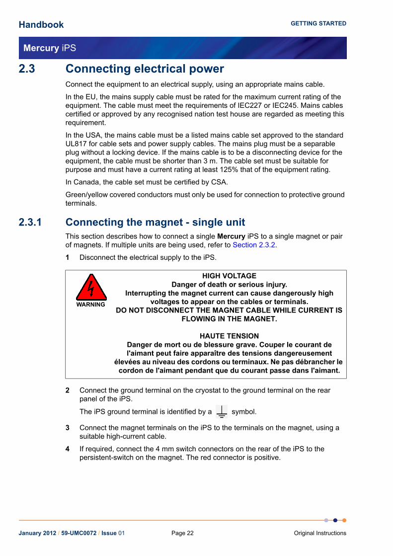
Disconnecting the magnet terminals while current is flowing in the magnet can induce dangerously high voltages. Before disconnecting the magnet, reduce the magnet current to zero, switch off the external AC electrical supply to the Mercury iPS, and disconnect and remove the external supply cable.
WARNING
HIGH VOLTAGEDanger of death or serious injury.
Interrupting the magnet current can cause dangerously high voltages to appear on the cables or terminals.
Do not disconnect the magnet cable while current is flowing in the magnet.
HAUTE TENSIONDanger de mort ou de blessure grave. Couper le courant de l'aimant peut faire apparaître des tensions dangereusement
élevées au niveau des cordons ou terminaux. Ne pas débrancher le cordon de l'aimant pendant que du courant passe dans l'aimant.
January 2012 / 59-UMC0072 / Issue 01Page 17Original Instructions

Handbook
Mercury iPS
HEALTH AND SAFETY
This equipment contains high voltages. Isolate this equipment before removing any covers. To isolate this equipment, switch off the external AC electrical supply, and disconnect and remove the external supply cable.
The AC electrical supply is considered to be the disconnect device for the equipment. Do not restrict access to the AC electrical supply at any time. The AC electrical supply cable must remain accessible for disconnection of the equipment.
1.1.3 Maintenance and adjustmentOnly qualified and authorised persons must service or repair this equipment.
Under no circumstances must the user adjust or repair this equipment while the electrical power supply is connected.
Ensure that the equipment is disconnected from the AC electrical power supply before the covers are removed or fuses are removed or fitted. It is NOT sufficient to switch off the <1 0> switch on the rear panel or the <On/Off> button on the front panel.
The equipment contains capacitors that may remain charged after AC electrical power is removed. Discharge all capacitors before starting work.
1.1.4 Restrictions on useThe equipment is not suitable for use in explosive, flammable or hazardous environments.
The equipment does not provide protection against the ingress of water. The equipment must be positioned so that it will not be exposed to water ingress.
WARNING
HIGH VOLTAGEDanger of death or serious injury.
Switch off the external AC electrical supply and disconnect and remove the external supply cable, before maintaining this
equipment or removing any covers.
HAUTE TENSIONDanger de mort ou de blessure grave. Sectionner l'alimentation
électrique C.A. externe puis déconnecter et retirer le cordon d'alimentation externe avant d'effectuer toute maintenance de cet
équipement ou d'en retirer les capots.
January 2012 / 59-UMC0072 / Issue 01 Page 18 Original Instructions

Handbook
Mercury iPS
HEALTH AND SAFETY
1.2 Cautions
1.2.1 Electrostatic caution
This equipment contains electrostatic sensitive devices (ESSD). Use ESSD protective procedures in accordance with BS CECC00015 Part 1 and American National Standard EIA-541-1998 when installing or maintaining this product.
1.2.2 Cooling cautionInternal components in this equipment are air-cooled. Ensure that the side and rear ventilation spaces are not obstructed.
If the iPS is mounted in a rack, ensure that the rear of the rack is open. Site the rack at least 30 cm from a wall or other obstruction, to ensure adequate airflow around the unit.
1.3 Solid wasteThe lithium battery on the motherboard will become solid waste if it has to be replaced. Dispose of this item according to local and national regulations.
Caution
ELECTROSTATIC SENSITIVE EQUIPMENTThis equipment contains electrostatic sensitive devices (ESSD). Use
approved ESSD procedures when installing or maintaining this product.
ÉQUIPEMENT SENSIBLE AUX DÉCHARGES ÉLECTROSTATIQUECet équipement contient des dispositifs qui sont sensibles aux
décharges électrostatiques (ESSD). Utiliser des procédures ESSD homologuées lors de l'installation ou de la maintenance de ce produit.
Caution
EQUIPMENT VENTILATIONIf the Mercury unit is to be rack mounted, to ensure an adequate airflow around the unit it is important that the back of the rack is open and the
rack is not placed less than 30 cm from a back wall.
Lorsque le Mercury est monté en rack, s'assurer que le rack est ouvert à l'arrière et se trouve au minimum à 30 cm du mur afin de garantir une
circulation d'air suffisante.
January 2012 / 59-UMC0072 / Issue 01Page 19Original Instructions

Handbook
Mercury iPS
HEALTH AND SAFETY
This page is intentionally blank.
Page 20January 2012 / 59-UMC0072 / Issue 01 Original Instructions
Handbook
Mercury iPS
GETTING STARTED
2 GETTING STARTEDEnsure that you have read and understood the information in Chapter 1 before installing or operating this equipment.
2.1 Checking the electrical supply
The iPS automatically configures itself to match the supplied electrical power, if the voltage and frequency are within the specified ranges (see Section 11.1.2). No user intervention is required.
2.2 Mounting the equipmentThe equipment is housed inside a 19 inch, 2U enclosure. The enclosure can be placed on a bench or a table, or fitted within a suitable rack enclosure. Ensure there is sufficient access at the rear for the electrical connections.
If Master and Slave units are to be connected together, it is recommended that the Slave units are mounted directly below the Master in a rack. This arrangement allows standard link bars to be used to connect the outputs of the units in parallel.
If the iPS is mounted in a rack, ensure that the rear of the rack is open. Site the rack at least 30 cm from a wall or other obstruction, to ensure adequate airflow around the unit.
Caution
CHECK THE SUPPLY VOLTAGECheck that the voltage supplied to the equipment is within the specified
range. Operating the equipment with an incorrect voltage may cause permanent damage.
CONTRÔLER LA TENSION D'ALIMENTATIONContrôler que la tension fournie à l'équipement est comprise dans les limites spécifiées. Exploiter l'équipement avec une tension incorrecte
peut l'endommager de manière permanente.
Caution
EQUIPMENT VENTILATIONIf the Mercury unit is to be rack mounted, to ensure an adequate airflow around the unit it is important that the back of the rack is open and the
rack is not placed less than 30 cm from a back wall.
Lorsque le Mercury est monté en rack, s'assurer que le rack est ouvert à l'arrière et se trouve au minimum à 30 cm du mur afin de garantir une
circulation d'air suffisante.
January 2012 / 59-UMC0072 / Issue 01Page 21Original Instructions
Handbook
Mercury iPS
GETTING STARTED
2.3 Connecting electrical powerConnect the equipment to an electrical supply, using an appropriate mains cable.
In the EU, the mains supply cable must be rated for the maximum current rating of the equipment. The cable must meet the requirements of IEC227 or IEC245. Mains cables certified or approved by any recognised nation test house are regarded as meeting this requirement.
In the USA, the mains cable must be a listed mains cable set approved to the standard UL817 for cable sets and power supply cables. The mains plug must be a separable plug without a locking device. If the mains cable is to be a disconnecting device for the equipment, the cable must be shorter than 3 m. The cable set must be suitable for purpose and must have a current rating at least 125% that of the equipment rating.
In Canada, the cable set must be certified by CSA.
Green/yellow covered conductors must only be used for connection to protective ground terminals.
2.3.1 Connecting the magnet - single unitThis section describes how to connect a single Mercury iPS to a single magnet or pair of magnets. If multiple units are being used, refer to Section 2.3.2.
1 Disconnect the electrical supply to the iPS.
2 Connect the ground terminal on the cryostat to the ground terminal on the rear panel of the iPS.
The iPS ground terminal is identified by a symbol.
3 Connect the magnet terminals on the iPS to the terminals on the magnet, using a suitable high-current cable.
4 If required, connect the 4 mm switch connectors on the rear of the iPS to the persistent-switch on the magnet. The red connector is positive.
WARNING
HIGH VOLTAGEDanger of death or serious injury.
Interrupting the magnet current can cause dangerously high voltages to appear on the cables or terminals.
DO NOT DISCONNECT THE MAGNET CABLE WHILE CURRENT IS FLOWING IN THE MAGNET.
HAUTE TENSIONDanger de mort ou de blessure grave. Couper le courant de l'aimant peut faire apparaître des tensions dangereusement
élevées au niveau des cordons ou terminaux. Ne pas débrancher le cordon de l'aimant pendant que du courant passe dans l'aimant.
January 2012 / 59-UMC0072 / Issue 01 Page 22 Original Instructions

Handbook
Mercury iPS
GETTING STARTED
2.3.2 Connecting the magnet - multiple unitsThere are many possible arrangements for connecting multiple units together. it is not possible to describe every possible arrangement. The two basic configurations are:
One Master and two slaves driving a vector-rotate arrangement (see Section 2.3.2.1).
One Master and multiple Slaves connected in series or parallel (see Section 2.3.2.2).
2.3.2.1 Connecting three units to a vector-rotate arrangementRefer to Figure 2-1 for a diagram of the necessary connections.
1 Disconnect the electrical supply to each of the iPS units.
2 Connect the ground terminal on the rear panel of each iPS to the ground terminal on the cryostat.
The iPS ground terminal is identified by a symbol.
3 Connect the magnet terminals on the Master unit to the terminals on the X-axis magnet coil, using a suitable high-current cable.
4 Connect the magnet terminals on the first Slave unit to the terminals on the Y-axis magnet coil, using a suitable high-current cable.
5 Connect the magnet terminals on the second Slave unit to the terminals on the Z-axis magnet coil, using a suitable high-current cable.
6 Connect the Master and Slave SPI bus connections, using two SPI bus cables (see Section 5.2.5.5).
WARNING
HIGH VOLTAGEDanger of death or serious injury.
Interrupting the magnet current can cause dangerously high voltages to appear on the cables or terminals.
DO NOT DISCONNECT THE MAGNET CABLE WHILE CURRENT IS FLOWING IN THE MAGNET.
HAUTE TENSIONDanger de mort ou de blessure grave. Couper le courant de l'aimant peut faire apparaître des tensions dangereusement
élevées au niveau des cordons ou terminaux. Ne pas débrancher le cordon de l'aimant pendant que du courant passe dans l'aimant.
January 2012 / 59-UMC0072 / Issue 01Page 23Original Instructions

Handbook
Mercury iPS
GETTING STARTED
7 If required, connect the switch-heater terminals on the rear of each iPS to the persistent-switch on the relevant magnet.
Figure 2-1 Vector-rotate connections
January 2012 / 59-UMC0072 / Issue 01 Page 24 Original Instructions

Handbook
Mercury iPS
GETTING STARTED
2.3.2.2 Connecting multiple units in series or parallel1 Disconnect the electrical supply to each of the iPS units.
2 Connect the ground terminal on the rear panel of each iPS to the ground terminal on the cryostat.
The iPS ground terminal is identified by a symbol.
3 Connect the magnet terminals on the Master and Slave units in series or parallel, as required. It is possible to combine series and parallel connections, but each parallel arm must have the same number of units in it. Slave units are supplied with link bars, which can be used to make parallel connections between units.
4 Connect the terminals on the magnet to achieve the required configuration.
5 Connect the Master and Slave SPI bus connections, using the provided SPI bus cables (see Section 5.2.5.5).
6 If required, connect the switch-heater terminals on the rear of the Master unit to the persistent-switch on the magnet.
WARNING
HIGH VOLTAGEDanger of death or serious injury.
Interrupting the magnet current can cause dangerously high voltages to appear on the cables or terminals.
DO NOT DISCONNECT THE MAGNET CABLE WHILE CURRENT IS FLOWING IN THE MAGNET.
HAUTE TENSIONDanger de mort ou de blessure grave. Couper le courant de l'aimant peut faire apparaître des tensions dangereusement
élevées au niveau des cordons ou terminaux. Ne pas débrancher le cordon de l'aimant pendant que du courant passe dans l'aimant.
January 2012 / 59-UMC0072 / Issue 01Page 25Original Instructions

Handbook
Mercury iPS
GETTING STARTED
Figure 2-2 shows an example of six units connected in two parallel arms of three units each.
Figure 2-2 Example combination serial and parallel configuration
2.3.3 Connecting the temperature sensor (if required)1 If required, connect the temperature sensor as described in Section 5.2.4.4.
January 2012 / 59-UMC0072 / Issue 01 Page 26 Original Instructions

Handbook
Mercury iPS
GETTING STARTED
2.3.4 Connecting the data interfacesIf it is required to connect the iPS to a computer, refer to the relevant section below.
2.3.4.1 Connecting the ethernet interface (if required)1 Connect the ethernet interface to the computer, using a standard ethernet cable.
2.3.4.2 Connecting the RS232 serial interface (if required)1 Connect the RS232 interface on the Master unit to the computer, using a suitable
cable (see Section 5.2.5.1).
2.3.4.3 Connecting ISOBUS (if required)1 Connect the iPS to one of the Slave connectors on the ISOBUS cable.
2 Connect the computer to the Master connector on the ISOBUS cable.
2.3.4.4 Connecting the GPIB (if required)
1 Turn off electrical power to the iPS.
2 Turn off electrical power to all instruments and controllers that are connected to the GPIB.
3 Connect the Master unit to the bus using a standard GPIB cable.
2.3.5 Connecting the auxiliary port (if required)1 Referring to Section 15.2.2, connect any required inputs or outputs to the port on
the auxiliary I/O daughter-board.
2.3.6 Connecting the level-meter (if required)1 Referring to Section 13.2.2, connect a level-sensor to the relevant port on the
level meter daughter-board.
Caution
CABLE DISCONNECTIONDo not connect or disconnect GPIB cables while the computer, or any of the instruments, are powered up. Equipment damage can result if this
precaution is not observed.
DÉBRANCHEMENT DU CORDON Ne pas brancher ou débrancher des cordons de bus d'interface général pendant que l'ordinateur, ou n'importe lequel des instruments, est sous
tension. Ne pas respecter cette précaution risque d'endommager l'équipement.
January 2012 / 59-UMC0072 / Issue 01Page 27Original Instructions

Handbook
Mercury iPS
GETTING STARTED
2.4 Powering up the unit for the first time
2.4.1 Setting the date and time1 Switch the <1 0> switch on the rear panel of the unit so that the 1 is depressed.
2 Press the <On/Off> button on the front of the unit. The button illuminates blue.
3 Wait until the Home page appears (see Figure 2-3).
Figure 2-3 Home page
4 Tap Settings on the Home page. The General Settings page is displayed (see Section 4.3.11).
5 Scroll the tabs until the Clock tab is displayed.
6 Tap Clock. The Clock Settings tab is displayed (see Section 4.3.11.7).
7 Check the date and time that are displayed.
8 To change the date or time:
a) Select the parameter to be changed (e.g. Hour).
b) Enter a positive or negative offset value and tap Apply to save the change.
c) Repeat steps a to b until the displayed time is correct.
Example: The currently set time is 11:31. The correct time is 9:27. Enter an offset of minus two hours and four minutes to set the clock correctly.
2.4.2 General settingsRefer to Section 4.3.11 for general settings.
2.4.3 Updating firmwareRefer to Section 6.6 for information on updating the firmware.
January 2012 / 59-UMC0072 / Issue 01 Page 28 Original Instructions

Handbook
Mercury iPS
GETTING STARTED
2.5 Configuring the Mercury iPS
2.5.1 Configuring the magnet outputYou can only configure the magnet from engineering mode.
2.5.1.1 Configuring the master unit1 Enter engineering mode (see Section 2.8.1).
2 Tap Config. The Master/Slave Configuration page opens (see Section 4.3.9).
3 Tap Magnet Type and select the required magnet type from a drop-down menu. The options are Solenoid, Split Pair and Vector Rotate.
4 If slave units are connected to the master unit, check that the Slaves detected: field displays the correct number of slave units. If the displayed number is incorrect, remove electrical power from all units and investigate the cause (see Chapter 9).
5 Tap the Config cell in the Z-axis row of the config table. Select either Serial, Parallel or Matrix configuration for this axis. If no slaves are connected, this field is ignored.
6 Tap the Limit (A) cell for the Z-axis row. Enter a current limit for this magnet coil.
NOTE: If several PSUs are connected in series or parallel, enter the current limit for the magnet coil, not the limit for an individual power supply.
7 Tap the Limit (V) cell for the Z-axis row. Enter a maximum permitted voltage for this magnet coil. Voltages greater than this value are treated as transients. Transients longer than Trans (mS) will trigger the quench detection circuit. Enter 0 to disable quench detection.
NOTE: If several PSUs are connected in series or parallel, enter the voltage limit for the magnet coil, not the limit for an individual power supply.
8 Tap the I to H (A/T) field and enter the scaling factor for this magnet coil. This value is used to translate current values (Amps) to magnetic field values (Tesla) on the GUI. Changing this value affects the displayed values but does not change the output of the power supply.
9 Tap the Ind (H) field and enter the inductance of the magnet coil in Henry. This value is specific to the magnet.
10 Tap the Trans (mS) field and enter a maximum permitted transient time for this coil in mS. Voltage transients that are longer than this time will trigger the quench detection circuit. Enter 0 to disable transient detection.
11 Tap the Switch field and select the power supply that is connected to the persistent switch. Select None if no persistent switch is to be used.
12 Tap the Sw Cur (mA) field and enter the required current (in mA) for the persistent-switch. If Switch is set to None, this value is ignored.
13 Tap the Mode field and select either Unipolar or Bipolar operation for this coil.
January 2012 / 59-UMC0072 / Issue 01Page 29Original Instructions

Handbook
Mercury iPS
GETTING STARTED
14 Tap the Safety field and select the sensor or digital input that is to be used to disable this magnet if an unsafe condition exists. Select None if no input is to be used.
NOTE: If a digital input is selected in the Safety field, a low input signal activates the safety procedure and shuts down the magnet.
15 Tap the Limit (K) field and enter the maximum safe temperature for this magnet. This value is ignored unless a temperature sensor input is selected in the Safety field.
16 Tap the Limit (L) field and enter the minimum safe cryogen level for this magnet as a percentage. This value is ignored unless a level sensor input is selected in the Safety field.
17 If Magnet Type is set to Vector Rotate, repeat steps 5 to 16 for the Y-axis and X-axis rows.
18 Tap Home to return to the Home page.
19 If no more configurations are to be performed, exit engineering mode (see Section 2.8.2).
2.5.1.2 Configuring rate limits for the magnet1 Enter engineering mode (see Section 2.8.1).
2 Tap the magnet summary area on the Home page.
3 Tap Rate Limits.
4 Tap the first Type cell in the table and enter the type of rate limit to be set. See Section 5.2.3.1 for an explanation of rate limit types.
5 Tap the first From(A) cell in the table and enter the lowest current to be defined.
6 Tap the first To(A) cell in the table and enter the upper current for this range.
7 Tap the first Rate Limit cell in the table and enter a rate limit for this current range.
8 Repeat steps 4 to 7 until limits have been entered for the entire operating current range of the magnet, and for all rate limit types that are to be defined.
9 Tap Home to return to the Home page.
10 If no more configurations are to be performed, exit engineering mode (see Section 2.8.2).
2.5.2 Configuring temperature sensors (if fitted)1 If the unit has already been configured for your application, continue from Section
2.6.
2 If the unit has not been configured for your application, continue from Section 2.5.3.
January 2012 / 59-UMC0072 / Issue 01 Page 30 Original Instructions
Handbook
Mercury iPS
GETTING STARTED
2.5.3 Configuring the temperature sensor inputs1 Tap the > button on the Home page to display the additional Home pages (see
Section 4.3.4). This page shows six panels and four buttons. If the unit is unconfigured, all six panels will display 0.0000. Additional panels can be displayed by scrolling right.
2 Tap once on an unconfigured panel. The Channel Display Configuration page is displayed (see Section 4.3.13).
3 Choose a sensor input from the drop-down menu in the Devices field.
The sensor names are initially of the form BoardBN.DTSN.
Where:
Board= MB for Mother Board or DB for Daughter Board.
BN= Board Number.
DT= T for Temperature sensor, H for Heater, L for Level Meter, or G for Gas-flow Controller.
SN= Signal Number.
4 Tap Signals and select Temperature.
5 Tap Assign to save the changes and to return to the Home page.
6 If required, configure the other panels on the Home page in a similar fashion.
2.5.3.1 Configuring the sensor details1 Tap a configured panel on the Home page. The Temperature Sensor Details page is
displayed.
2 Tap the Sensor Type field and select a sensor type from the drop-down menu.
3 Tap the Calibration field and select a calibration file from the drop-down menu. If you select the Generic calibration file, you can adjust the calibration to suit a particular sensor (see Section 2.5.3.2).
4 Tap the Excitation field and select an excitation mode from the drop-down menu.
5 Tap the Magnitude field and enter an excitation value:current in μA for Diode or PTC sensorsvoltage in mV for NTC sensors.
6 If required, tap the field containing the name of the sensor and enter a new name. (e.g. Change DB3.T1 to Zone 1 Temperature.).
7 Tap Home. The Home page is displayed. If the sensor has been configured correctly, the selected panel will display a sensor reading.
January 2012 / 59-UMC0072 / Issue 01Page 31Original Instructions

Handbook
Mercury iPS
GETTING STARTED
2.5.3.2 Using a generic calibration-file
Overview of generic calibration file use
Some generic calibration-files are supplied for common sensors having reasonably predictable forms of resistance as a function of temperature, for example sensors that conform to an ITS-90 standard. However the response of an individual sensor may deviate slightly from the standard curve. If two known temperatures are available it is possible to make small adjustments to the scale and offset of the standard curve to match a particular sensor. The process can be used with either PTC and NTC sensors.
The adjustment is applied to the measured parameter, so for a resistance sensor the adjustment is applied to the measured resistance.
For best results the scaling adjustment should be applied at the high-parameter end and the offset at the low-parameter end. So for a NTC resistance sensor, apply the scaling at the known low-temperature point (ideally near the high-resistance end of the range). If a scale adjustment of more than a few percent is required to correct the temperature reading, investigate the measurement set-up to check there is not some other error present.
Once the scaling adjustment has been made, change to the low-resistance end of the range and make the offset adjustment (for an NTC resistance sensor, this is a high-temperature point). Again this should be a small adjustment. As these adjustments are not independent, re-check the high-resistance point after the offset has been adjusted. A few iterations of these adjustments may be required to achieve the desired accuracy.
Procedure for using a generic calibration file
You need a method of maintaining the temperature sensor at two known temperatures (T1 and T2) to perform this calibration. This procedure calibrates the sensor for temperatures between these two known values.
For this procedure, T1 produces a lower sensor-resistance than T2:
For a PTC sensor, T1<T2.
For an NTC sensor, T1>T2.
1 Tap a configured panel on the Home page. The Temperature Sensor Details page is displayed.
2 Tap the Calibration field and select Generic from the drop-down menu.
3 Tap Cal Adj.
4 Place the sensor in a location with temperature T1.
5 Adjust the Offset value to produce the required Scaled Parameter value.
6 Place the sensor in a location with temperature T2.
7 Adjust the Scale value to produce the required Scaled Parameter value.
8 Repeat steps 4 to 7 until a calibration of the required accuracy has been obtained.
9 Tap Save to apply the new calibration.
January 2012 / 59-UMC0072 / Issue 01 Page 32 Original Instructions

Handbook
Mercury iPS
GETTING STARTED
2.6 Testing the inputs and outputsIf any of the following tests fails, refer to Chapter 9 for troubleshooting information.
1 Switch on the master unit and all slave units.
2.6.1 Testing the temperature sensor inputs (if applicable)1 Tap the > button on the Home page.
2 Check that the temperature displayed on each of the connected temperature sensors is correct.
2.6.2 Testing the magnet supply output1 If a persistent heater is connected, check that the Heater button on the Home page
displays the message Heater Off.
2 Tap Hold on the Home page to open the clamp-relay.
3 Tap the summary area on the Home page (see Figure 2-4).
Figure 2-4 Mercury iPS summary area
4 Enter a small setpoint value in the Set Point field. The Set Point/Set Rate page opens.
5 Enter a suitable ramp rate in the Set Rate field.
6 Tap Home to return to the Home page.
7 If a persistent heater is connected, tap the Heater button on the Home page so that it displays the message Heater On.
8 Tap To Set.
9 Check that the value displayed in the Current field ramps up to the programmed value.
10 Check that the value displayed in the Magnet field is equal to the value displayed in the Current field.
11 Check that the current displayed on the front-panel meter is correct.
12 Check that the current displayed on the front-panel meter of each slave unit is correct.
13 Tap To Zero and check that the displayed current ramps down to zero.
January 2012 / 59-UMC0072 / Issue 01Page 33Original Instructions
Handbook
Mercury iPS
GETTING STARTED
14 Gradually increase the setpoint of the magnet until the maximum rated current is reached.
15 Tap To Zero and wait until the displayed current is zero.
2.6.3 Testing the persistent heater (if required)1 Check that the Heater button on the Home page displays the message Heater Off.
2 Tap Hold on the Home page to open the clamp-relay.
3 Tap the summary area on the Home page (see Figure 2-4).
4 Enter a small setpoint value in the Set Point field (e.g. 1 to 2 Amps).
5 Enter a suitable ramp rate in the Set Rate field.
6 Tap Home to return to the Home page.
7 Tap the Heater button on the Home page until it displays the message Heater On.
8 Tap To Set.
9 Check that the value displayed in the Current field ramps up to the programmed value.
10 Check that the value displayed in the Magnet field is equal to the value displayed in the Current field.
11 Check that the current displayed on the front-panel meter is correct.
12 Check that the current displayed on the front-panel meter of each slave unit is correct.
13 Tap Hold.
14 Tap the Heater button on the Home page until it displays the message Heater Off.
15 Check that the value displayed in the Current field is unchanged.
16 Check that the value displayed in the Magnet field is unchanged.
17 Tap To Zero and check that the value displayed in the Current field ramps down to zero.
18 Check that the value displayed in the Magnet field is unchanged.
19 Tap To Set.
20 Check that the value displayed in the Current field ramps up to the programmed value.
21 Tap the Heater button on the Home page until it displays the message Heater On.
22 Tap To Zero and check that the values displayed in the Current field and the Magnet field both ramp down to zero.
2.7 Configuring remote interfacesIf it is required to control the Mercury iPS from a remote computer, refer to Section 6.4.
January 2012 / 59-UMC0072 / Issue 01 Page 34 Original Instructions

Handbook
Mercury iPS
GETTING STARTED
2.8 Engineering mode
2.8.1 Entering engineering mode.1 Tap Settings on the Home page.
2 Scroll right until the EngMode tab is visible.
3 Tap EngMode. The EngMode page opens.
4 Enter the engineering password in the Password field.
5 Tap Enter. If the correct password was entered, the message Correct! appears.
2.8.2 Exiting engineering mode1 Tap Settings on the Home page.
2 Scroll right until the EngMode tab is visible.
3 Tap EngMode. The EngMode page opens.
4 Tap LogOff. The message Correct! disappears.
January 2012 / 59-UMC0072 / Issue 01Page 35Original Instructions

Handbook
Mercury iPS
GETTING STARTED
This page is intentionally blank.
Page 36January 2012 / 59-UMC0072 / Issue 01 Original Instructions

Handbook
Mercury iPS
OVERVIEW OF THE iPS
3 OVERVIEW OF THE IPS
3.1 Superconducting magnetsA superconducting material has zero resistance when its temperature is below the critical temperature for that material. If the temperature is raised above the critical temperature, the superconductor becomes resistive, causing power-dissipation if an electrical current is flowing.
Electrical current must be established slowly in the coil of a superconducting magnet, as transients can cause part of the magnet to become resistive. When the required current is established, the terminals of the magnet can be shorted together by a superconducting persistent-switch. The current will then circulate round the magnet coils for a long period (usually many months) without any external energy source.
3.1.1 Magnet typesThere are many possible magnet configurations. These include:
Solenoid ModeThe output drives a single electrical circuit consisting of a single coil.
Split PairThe output drives a single electrical circuit consisting of a pair of coils in series.
Vector-Rotate ModeThree units drive three separate electrical circuits, each consisting of a single coil or pair of coils, to produce a vector field.
3.1.2 Persistent-switchSome magnets include a persistent-switch, which is a non-inductive coil of superconductor with an integral heater. The persistent-switch is connected across the magnet terminals. When the heater is energised, the persistent-switch heats up. The switch ceases to be superconducting, causing the switch to open. When the correct magnet current is established, the heater can be de-energised, causing the persistent-switch to cool down. The switch becomes superconducting again, shorting out the magnet terminals. The current then circulates round the magnet until the switch is opened again.
3.1.3 QuenchIf part of the magnet coil becomes resistive for any reason, electrical current in the magnet produces rapid heating in the resistive section. This causes further parts of the coil to heat up and become resistive. This chain reaction can cause the entire magnet to become resistive in a short period. This effect is called a quench. In some circumstances a quench can damage the magnet or associated equipment.
A quench can be produced if the rate of change of current in the magnet is too great. Most superconducting systems include a means of dissipating the energy that is stored in the magnet if a quench is detected.
January 2012 / 59-UMC0072 / Issue 01Page 37Original Instructions

Handbook
Mercury iPS
OVERVIEW OF THE iPS
3.2 Magnet power supply unitThe Mercury iPS is a high-precision, highly stable power supply designed for driving a superconducting magnet in laboratory applications. The supply is capable of sourcing and sinking current and it also accurately controls the slew of the current. The power supply includes a high-power load-resistor to dissipate stored energy from the magnet.
The contacts of an internal clamp relay are connected across the magnet output terminals. The clamp relay contacts open to allow current to flow in the external circuit. The contacts close if a fault (such as a power failure) occurs.
The Mercury iPS is a microprocessor based instrument and is controlled by an operating program (firmware) contained in flash memory. The firmware version number is indicated by a two-part number (e.g. 1.01). The first digit of this number indicates the major version of the firmware, and the second two digits indicate minor revisions.
The basic unit includes a bipolar magnet output. Additional slave units can be connected to increase the output power capability. Slave units can be connected in series or in parallel with the master unit, or can be connected to separate magnet-coils, for example in a vector-rotate arrangement.
The unit accommodates up to eight optional daughter-boards to allow additional features to be added.
The Mercury iPS includes a single persistent-switch output (see Section 3.3.2). This output is used to drive an optional persistent-switch in the magnet.
The unit also includes a temperature sensor input that can accept a wide variety of temperature sensors. The unit can detect short-circuit inputs, open-circuit inputs, and inputs that are shorted to ground.
Additional temperature sensor inputs can be added (to a total of 9 inputs).
An optional board can be added to monitor and control the level of cryogen in a reservoir.
The Mercury iPS contains non-volatile memory, and it retains its configuration when electrical power is removed.
January 2012 / 59-UMC0072 / Issue 01 Page 38 Original Instructions
Handbook
Mercury iPS
OVERVIEW OF THE iPS
3.3 System description
3.3.1 Magnet power supplyThe magnet power output can supply up to 60 A at 10 V.
When commanded by the user, the magnet current ramps up or down to a setpoint value that the user enters. The ramp rate is also defined by the user.
3.3.2 Switch-heater outputThe iPS includes an output to drive an optional persistent-switch heater. This output can supply up to 120 mA at up to 12 V (see Section 5.2.4.3 for more details).
3.3.2.1 Quench detectionThe iPS can be configured to detect the start of a quench. If a quench is detected, the persistent-switch automatically opens, diverting the magnet current through high-power resistors inside the power supply. This dissipates stored energy from the magnet.
3.3.3 Temperature sensor inputThe iPS temperature-sensor input can interface with a wide variety of temperature sensors. A high accuracy measurement circuit amplifies, scales and filters the voltage produced by the sensor. This conditioned voltage is then passed to a 24-bit analogue to digital converter (ADC).
Some sensors (e.g. resistance sensors) require excitation. For positive temperature coefficient sensors, this is generated by a high-stability current source. For negative temperature coefficient sensors, this is provided by a true voltage-source.
The basic iPS can monitor one temperature sensor. Additional sensors can be monitored by adding daughter boards.
3.3.4 Remote interfacesThe iPS contains several interfaces that can be connected to a remote PC:
RS232 interface.
Universal serial bus (USB) interface.
Ethernet interface.
Optional general purpose interface bus (GPIB) (IEEE-488) interface.
The remote PC can send data to the iPS and read data from the iPS. Only one interface can be active at a time.
3.3.5 Display and touch-screenThe iPS contains a 4.3inch full-colour liquid crystal display (LCD) with a touch-screen. The touch screen is the main input device to the Mercury iPS.
The unit contains an ambient-light sensor and can be configured to automatically change the display brightness to match ambient light conditions.
A slave unit does not have an LCD.
January 2012 / 59-UMC0072 / Issue 01Page 39Original Instructions

Handbook
Mercury iPS
OVERVIEW OF THE iPS
3.3.6 Electrical power supplyThe iPS automatically configures itself to match the supplied electrical power, as long as the voltage and frequency are within the specified ranges. No user intervention is required.
The iPS powers all sensors and stepper motors that are connected to it.
January 2012 / 59-UMC0072 / Issue 01 Page 40 Original Instructions

Handbook
Mercury iPS
USER INTERFACE
4 USER INTERFACEThe iPS is controlled from the front panel (see Figure 4-1).
Figure 4-1 Front panel of master unit
There is also a power switch on the rear panel (see Figure 4-2).
Figure 4-2 Part of the rear panel of the master unit
4.1 Front panel controlsThe <On/Off> button on the front panel switches the unit into STANDBY mode. When the switch is OFF, electrical power is still supplied to the switch-mode power-supply inside the unit. The button illuminates blue when the unit is powered up.
The switch marked <1 0> on the rear panel switches electrical power on and off.
January 2012 / 59-UMC0072 / Issue 01Page 41Original Instructions
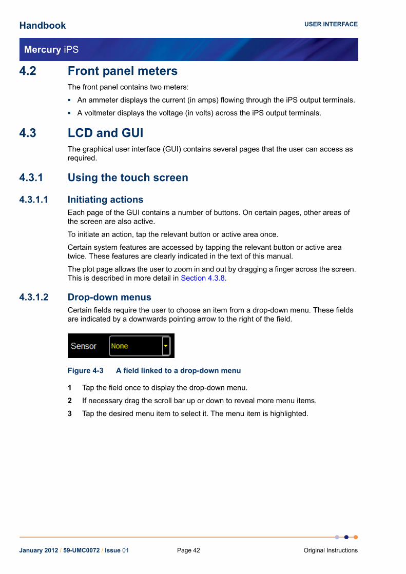
Handbook
Mercury iPS
USER INTERFACE
4.2 Front panel metersThe front panel contains two meters:
An ammeter displays the current (in amps) flowing through the iPS output terminals.
A voltmeter displays the voltage (in volts) across the iPS output terminals.
4.3 LCD and GUIThe graphical user interface (GUI) contains several pages that the user can access as required.
4.3.1 Using the touch screen
4.3.1.1 Initiating actionsEach page of the GUI contains a number of buttons. On certain pages, other areas of the screen are also active.
To initiate an action, tap the relevant button or active area once.
Certain system features are accessed by tapping the relevant button or active area twice. These features are clearly indicated in the text of this manual.
The plot page allows the user to zoom in and out by dragging a finger across the screen. This is described in more detail in Section 4.3.8.
4.3.1.2 Drop-down menusCertain fields require the user to choose an item from a drop-down menu. These fields are indicated by a downwards pointing arrow to the right of the field.
Figure 4-3 A field linked to a drop-down menu
1 Tap the field once to display the drop-down menu.
2 If necessary drag the scroll bar up or down to reveal more menu items.
3 Tap the desired menu item to select it. The menu item is highlighted.
January 2012 / 59-UMC0072 / Issue 01 Page 42 Original Instructions

Handbook
Mercury iPS
USER INTERFACE
4 Tap OK to select the item, or Cancel to exit without selecting the item.
Figure 4-4 A drop-down menu
4.3.1.3 ScrollingOn some pages there is not enough space to display all the keys associated with the page. This is indicated by buttons labelled either > or <.
Tap the < button to scroll to the left. Tap the > button to scroll to the right.
Figure 4-5 Scroll buttons
4.3.1.4 Soft keypadsCertain fields in the GUI require the user to enter alpha-numeric characters. Tap the field to display a keypad.
There are two types of keypad that may be displayed. If a field requires numeric data only, a numeric keypad is displayed (see Figure 4-6).
Figure 4-6 Numeric keypad
January 2012 / 59-UMC0072 / Issue 01Page 43Original Instructions
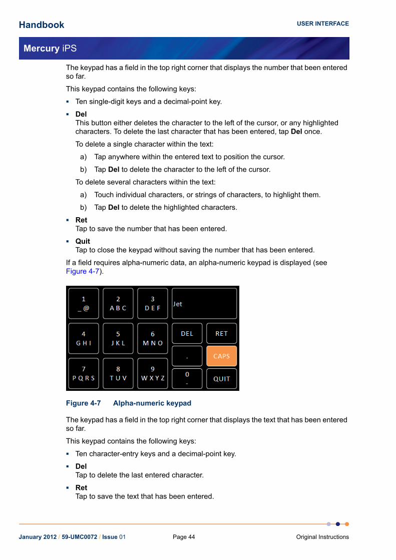
Handbook
Mercury iPS
USER INTERFACE
The keypad has a field in the top right corner that displays the number that been entered so far.
This keypad contains the following keys:
Ten single-digit keys and a decimal-point key.
DelThis button either deletes the character to the left of the cursor, or any highlighted characters. To delete the last character that has been entered, tap Del once.
To delete a single character within the text:
a) Tap anywhere within the entered text to position the cursor.
b) Tap Del to delete the character to the left of the cursor.
To delete several characters within the text:
a) Touch individual characters, or strings of characters, to highlight them.
b) Tap Del to delete the highlighted characters.
RetTap to save the number that has been entered.
QuitTap to close the keypad without saving the number that has been entered.
If a field requires alpha-numeric data, an alpha-numeric keypad is displayed (see Figure 4-7).
Figure 4-7 Alpha-numeric keypad
The keypad has a field in the top right corner that displays the text that has been entered so far.
This keypad contains the following keys:
Ten character-entry keys and a decimal-point key.
DelTap to delete the last entered character.
RetTap to save the text that has been entered.
January 2012 / 59-UMC0072 / Issue 01 Page 44 Original Instructions

Handbook
Mercury iPS
USER INTERFACE
CAPSTap to enter capital letters. The characters on the keypad change to match the selection.
QuitTap to exit the keypad without saving the number that has been entered.
Each character-entry key represents several characters.
a) Tap a key once to enter the digit displayed on the key.
b) Tap a key twice to enter the first character displayed on the key.
c) Tap a key three, four, or five times to enter subsequent characters displayed on the key.
For example:
a) To enter the digit 2, tap the 2 key once.
b) To enter the letter B, tap the 2 key three times.
c) To enter the letter Z, tap the 9 key five times.
4.3.1.5 Using arrows to adjust numeric valuesSome numeric fields use up and down arrows to adjust their value.
Figure 4-8 A numeric field with up and down arrows
Tap once to decrease the displayed value.
Numeric displayTap once to enter a new value using a numeric keypad.
Tap once to increase the displayed value.
January 2012 / 59-UMC0072 / Issue 01Page 45Original Instructions
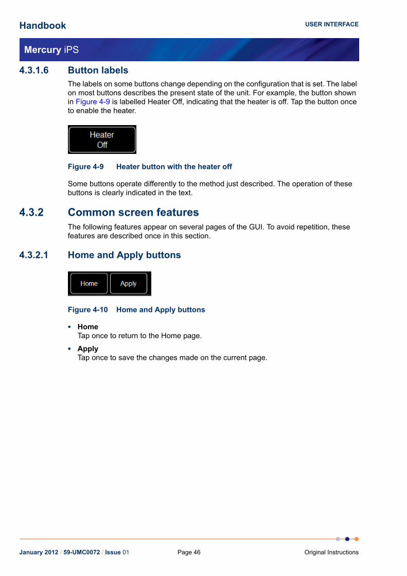
Handbook
Mercury iPS
USER INTERFACE
4.3.1.6 Button labelsThe labels on some buttons change depending on the configuration that is set. The label on most buttons describes the present state of the unit. For example, the button shown in Figure 4-9 is labelled Heater Off, indicating that the heater is off. Tap the button once to enable the heater.
Figure 4-9 Heater button with the heater off
Some buttons operate differently to the method just described. The operation of these buttons is clearly indicated in the text.
4.3.2 Common screen featuresThe following features appear on several pages of the GUI. To avoid repetition, these features are described once in this section.
4.3.2.1 Home and Apply buttons
Figure 4-10 Home and Apply buttons
HomeTap once to return to the Home page.
ApplyTap once to save the changes made on the current page.
January 2012 / 59-UMC0072 / Issue 01 Page 46 Original Instructions

Handbook
Mercury iPS
USER INTERFACE
4.3.3 Home pageWhen the equipment is powered on, the Home page is displayed. The Home page is different depending if the unit is set to solenoid mode (see Section 4.3.3.1) or vector-rotate mode (see Section 4.3.3.2).
4.3.3.1 Home page - solenoid modeIf the iPS is set to solenoid mode, the Home page shown in Figure 4-11 is displayed.
Figure 4-11 GUI home page for solenoid mode
The home page contains the following features:
A summary area that displays summary information for the magnet. Tap Current (A) to display the Set Point / Set Rate page (see Section 4.3.5).
Current is the measured current flowing out of the positive terminal of the Mercury iPS.
Magnet is the current that is flowing through the magnet coils. This value is identical to Current when the persistent-switch is open. When the persistent-switch closes, this value stops updating. If the output of the iPS is changed with the persistent-switch closed, Current changes but Magnet does not.
Voltage is the measured voltage across the magnet terminals.
Interface connect/disconnect buttonThe button displays one of the following letters:
E if the ethernet interface is selected.
I if the Isobus interface is selected.
U if the USB interface is selected.
G if the GPIB interface is selected.
L if local control is selected.
The button is orange if the selected interface is connected.The button is black if the selected interface is not connected.Tap the button once to connect or disconnect the interface.
January 2012 / 59-UMC0072 / Issue 01Page 47Original Instructions
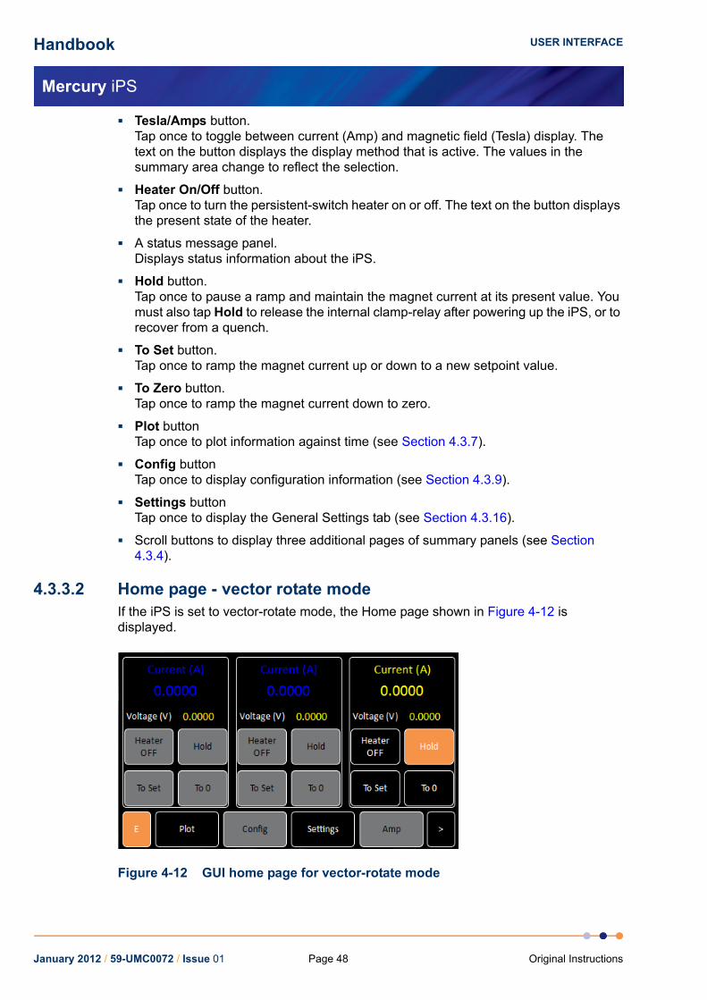
Handbook
Mercury iPS
USER INTERFACE
Tesla/Amps button.Tap once to toggle between current (Amp) and magnetic field (Tesla) display. The text on the button displays the display method that is active. The values in the summary area change to reflect the selection.
Heater On/Off button.Tap once to turn the persistent-switch heater on or off. The text on the button displays the present state of the heater.
A status message panel.Displays status information about the iPS.
Hold button.Tap once to pause a ramp and maintain the magnet current at its present value. You must also tap Hold to release the internal clamp-relay after powering up the iPS, or to recover from a quench.
To Set button.Tap once to ramp the magnet current up or down to a new setpoint value.
To Zero button.Tap once to ramp the magnet current down to zero.
Plot buttonTap once to plot information against time (see Section 4.3.7).
Config buttonTap once to display configuration information (see Section 4.3.9).
Settings buttonTap once to display the General Settings tab (see Section 4.3.16).
Scroll buttons to display three additional pages of summary panels (see Section 4.3.4).
4.3.3.2 Home page - vector rotate modeIf the iPS is set to vector-rotate mode, the Home page shown in Figure 4-12 is displayed.
Figure 4-12 GUI home page for vector-rotate mode
January 2012 / 59-UMC0072 / Issue 01 Page 48 Original Instructions

Handbook
Mercury iPS
USER INTERFACE
The home page contains the following features:
Three control areas that display summary information for each magnet axis (see Section 4.3.3.3).
Interface connect/disconnect buttonThe button displays one of the following letters:
E if the ethernet interface is selected.
I if the Isobus interface is selected.
U if the USB interface is selected.
G if the GPIB interface is selected.
L if local control is selected.
The button is orange if the selected interface is connected.The button is black if the selected interface is not connected.Tap the button once to connect or disconnect the interface.
Plot buttonTap once to plot information against time (see Section 4.3.7).
Config buttonTap once to display configuration information (see Section 4.3.9).
Settings buttonTap once to display the General Settings tab (see Section 4.3.16).
T/A button.Tap once to toggle between current (A) and magnetic field (T) display. The text on the button displays the display method that is active. The values in the summary area change to reflect the selection.
Scroll buttons to display three additional pages of summary panels(see Section 4.3.4).
January 2012 / 59-UMC0072 / Issue 01Page 49Original Instructions

Handbook
Mercury iPS
USER INTERFACE
4.3.3.3 Magnet control areas for vector rotate magnets
Figure 4-13 Magnet control area for vector-rotate magnets
Each magnet control area contains the following fields and controls:
A summary area that displays the magnet current (or magnetic field) and voltage for one axis. Tap once to display the Set Point / Set Rate page (see Section 4.3.5).
Heater On/Off button.Tap once to turn the persistent-switch heater on or off. The text on the button displays the present state of the heater.
Hold button.Tap once to pause a ramp and maintain the magnet current at its present value. You must also tap Hold to release the internal clamp-relay after powering up the Mercury iPS, or to recover from a quench.
To Set button.Tap once to ramp the magnet current up or down to a new setpoint value.
To 0 button.Tap once to ramp the magnet current down to zero.
January 2012 / 59-UMC0072 / Issue 01 Page 50 Original Instructions

Handbook
Mercury iPS
USER INTERFACE
4.3.4 Additional home pagesThree additional Home pages are displayed when the scroll key is tapped.
Figure 4-14 GUI additional home page
Each additional home page contains the following features:
Six channel-summary panels that displays summary information for each channel that is enabled (see Section 4.3.12.1).
Plot buttonTap once to plot information against time (see Section 4.3.7).
Control buttonNot used.
Settings buttonTap once to display the General Settings tab (see Section 4.3.16).
Heater buttonNot used.
Scroll buttons to display the other home pages.
January 2012 / 59-UMC0072 / Issue 01Page 51Original Instructions
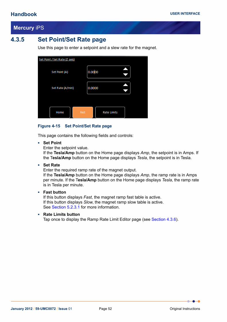
Handbook
Mercury iPS
USER INTERFACE
4.3.5 Set Point/Set Rate pageUse this page to enter a setpoint and a slew rate for the magnet.
Figure 4-15 Set Point/Set Rate page
This page contains the following fields and controls:
Set PointEnter the setpoint value.If the Tesla/Amp button on the Home page displays Amp, the setpoint is in Amps. If the Tesla/Amp button on the Home page displays Tesla, the setpoint is in Tesla.
Set RateEnter the required ramp rate of the magnet output.If the Tesla/Amp button on the Home page displays Amp, the ramp rate is in Amps per minute. If the Tesla/Amp button on the Home page displays Tesla, the ramp rate is in Tesla per minute.
Fast buttonIf this button displays Fast, the magnet ramp fast table is active.If this button displays Slow, the magnet ramp slow table is active.See Section 5.2.3.1 for more information.
Rate Limits buttonTap once to display the Ramp Rate Limit Editor page (see Section 4.3.6).
January 2012 / 59-UMC0072 / Issue 01 Page 52 Original Instructions

Handbook
Mercury iPS
USER INTERFACE
4.3.6 Ramp Rate Limits Editor pageThis page can only be accessed in engineering mode (see Section 4.3.10).
Enter a ramp rate limit table on this page. See Section 5.2.3.1 for information on ramp rate limits.
Figure 4-16 Ramp Rates Limits Editor page
The page displays a ramp-rates-limit table. If the table is empty, only the first row is displayed (see Figure 4-16). If the table contains data, one or more rows of values are displayed.
The table contains the following columns:
TypeSelect the rate limit type from the drop-down list (see section Section 5.2.3.1).
From (A)Enter the lower current (in Amps) of the range for which a rate limit is to be defined.
To (A)Enter the upper current (in Amps) of the range for which a rate limit is to be defined.
Rate Limit (A/min)Enter the rate limit (in Amps per minute) for this range.
January 2012 / 59-UMC0072 / Issue 01Page 53Original Instructions

Handbook
Mercury iPS
USER INTERFACE
4.3.7 Plot Configuration pageThe Plot Configuration page allows the user to select one or more signals to be plotted against time.
To access the page:
1 If no plots have been configured, tap the Plot button on the Home page.
2 If a plot is displayed, tap the plot area once. The Plot Configuration page appears as an overlay on the Plot page.
Figure 4-17 Plot Configuration page
The page contains the following fields and controls:
DeviceSelect a device from a drop-down menu.
SignalSelect a signal to display from a drop-down menu.
CloseTap once to close the Plot Configuration page without saving any changes that have been made.
SaveTap once to add the selected trace to the plot.
DeleteTap once to remove the selected trace from the plot.
January 2012 / 59-UMC0072 / Issue 01 Page 54 Original Instructions

Handbook
Mercury iPS
USER INTERFACE
4.3.8 Plot page
Figure 4-18 Typical Signal Monitor Plot page
The Plot page can display up to six different values plotted against time.
If a plot has been configured, the trace updates in real time.
4.3.9 Master/Slave Configuration pageThis page can only be accessed in engineering mode (see Section 4.3.11.10).
This page allows the user to configure slave units to be controlled from a master unit.
Figure 4-19 Master/Slave Configuration page
The page contains the following fields and controls:
Slaves detected fieldDisplays the number of slave units that have been detected on the serial peripheral interface (SPI) bus.
Magnet TypeSelect a magnet type from the drop-down menu.
Master/Slave configuration table (see Section 4.3.9.1).
January 2012 / 59-UMC0072 / Issue 01Page 55Original Instructions

Handbook
Mercury iPS
USER INTERFACE
Eng Config buttonTap once to display the Engineering Configuration page (see Section 4.3.11.10).
Save buttonTap once to save the master/slave configuration.
Load buttonTap once to load a new master/slave configuration from a file.
4.3.9.1 The master/slave configuration tableThe master/slave configuration table contains a row for each axis group (Z-axis, Y-axis and X-axis). The table contains the following columns:
ConfigSelect either Series, Parallel or Matrix configuration for the power supplies in this axis group.
Limit (A)Enter a current limit for this magnet coil in amps.
NOTE: If several PSUs are connected in series or parallel, enter the current limit for the magnet coil, not the limit for an individual power supply.
Limit (V)Enter a voltage limit for this magnet coil.
NOTE: If several PSUs are connected in series or parallel, enter the voltage limit for the magnet coil, not the limit for an individual power supply.
I to H (A/T)Enter the ratio between coil current and magnetic field for this magnet (e.g. an I to H value of 0.5 means that 1 amp of current produces 2 Tesla of field).
Ind (H)Enter the inductance of the magnet in Henry.
Trans (ms)Enter a time in mSec. If the measured voltage across the magnet terminals exceeds the value entered in the Limit (V) field for longer than this time period, the quench procedure is activated. Enter zero time to disable quench detection.
SwitchSelect the power supply in this group that is connected to the switch heater on the magnet for this axis. Enter None if there is no switch heater on this axis.
Sw Cur (mA)Enter the required persistent-switch current for this magnet in mA.
ModeEnter Unipolar for unipolar operation of this magnet (positive current only).Enter Bipolar for bipolar operation (positive and negative current).
January 2012 / 59-UMC0072 / Issue 01 Page 56 Original Instructions

Handbook
Mercury iPS
USER INTERFACE
SafetySelect a sensor that is to be used to start an auto rundown if an unsafe condition exists. See Section 5.2.3.4 for a description of auto rundown.
a) Select a temperature sensor if a high temperature is to be used to detect an unsafe condition.
b) Select a level sensor if a low level of cryogen is to be used to detect an unsafe condition.
c) Select an input on the auxiliary I/O board if a digital input is to be used to detect an unsafe condition.
NOTE: An unsafe condition may damage the hardware. An unsafe condition does not normally present a hazard to personnel.
Limit (K)Enter the maximum safe temperature for this magnet. If the temperature sensor selected in the Safety field measures a temperature above this value, it flags an unsafe condition.
Limit (L)Enter the minimum safe cryogen level for this magnet. If the level sensor selected in the Safety field measures a level below this value, it flags an unsafe condition.
4.3.10 Engineering Configuration pagesThese pages can only be accessed in engineering mode (see Section 4.3.11.10).
There is one page for each magnet axis. Use the horizontal scroll controls to access other magnet groups.
Use this page to configure the power supplies in each magnet axis group.
Figure 4-20 Engineering Configuration page (for a parallel connection)
If the power supplies in this group are connected in parallel, the table contains a single row. If the power supplies in this group are connected in series, the table contains a single column. If the power supplies in this group are connected in a combination of series and parallel connections (matrix), the table contains several rows and columns.
January 2012 / 59-UMC0072 / Issue 01Page 57Original Instructions

Handbook
Mercury iPS
USER INTERFACE
To add a power supply to this group, tap a blank cell and select a power supply from the drop-down menu.
To remove a power supply from this group, tap the cell containing the name of the power supply and select None from the drop-down menu.
4.3.11 General Settings tab
Figure 4-21 General Settings tab
The page contains the following fields and controls:
Home Screen Revert OptionIf Home Screen Revert mode is set On, the interface reverts to the Home page after one minute, if no user activity is detected. If this field is set Off, the present page is displayed until the user navigates to another page.
Remote AccessSelect Local from the drop-down menu to allow the user to control the iPS from the GUI. Select an interface from the drop-down menu to enable remote control via the selected interface.
SCPI/Legacy fieldThis field is only displayed if an interface is selected in Remote Access.Select SCPI to use a command set based on Signal Orientated Measurement Commands.Select Legacy to use a command set that is compatible with legacy instruments.
The page contains the following buttons:
AlarmTap once to access the Alarm Logs page (see Section 4.3.12).
January 2012 / 59-UMC0072 / Issue 01 Page 58 Original Instructions

Handbook
Mercury iPS
USER INTERFACE
4.3.11.1 Display Settings tab
The page contains the following fields and controls:
Auto Dim OptionWhen User is displayed, the auto-dim feature is turned off. When Sensor is displayed, the auto-dim feature is active (see Section 5.2.1.1).
Timeout value (sec)Set the time that must elapse (in seconds) before the display brightness changes. This field is only displayed if Auto Dim Option is set to Sensor.
Auto Dim (%)Enter a percentage brightness value for the display when it is automatically dimmed. Auto Dim (%) must be less than, or equal to, Brightness (%).
Brightness (%)Select a percentage value from the drop-down menu to alter the brightness of the display.
The page contains the following buttons:
AlarmTap once to access the Alarm Logs page (see Section 4.3.12).
January 2012 / 59-UMC0072 / Issue 01Page 59Original Instructions

Handbook
Mercury iPS
USER INTERFACE
4.3.11.2 Card Settings tab
Each row of this table corresponds to an expansion slot in the iPS. The table lists which boards are fitted in which slot. The columns show:
Row numberThe number of the slot.
IDThe ID of the board fitted in this slot.
TypeThe type of board fitted in this slot.
NameThe name of the board fitted in this slot.
Serial NumberThe serial number of the board fitted in this slot.
Board RevThe revision number of the board.
Firmware RevThe firmware version loaded onto the board.
The page contains the following buttons:
AlarmTap once to access the Alarm Logs page (see Section 4.3.12).
January 2012 / 59-UMC0072 / Issue 01 Page 60 Original Instructions

Handbook
Mercury iPS
USER INTERFACE
4.3.11.3 RS232 Settings tab
The page contains the following fields and controls:
BaudSelect a baud rate for the RS232 interface from the drop-down menu.
DataSelect the number of data bits for the RS232 interface from the drop-down menu.
ParitySelect a parity scheme for the RS232 interface from the drop-down menu.
StopSelect the number of stop bits for the RS232 interface from the drop-down menu.
Flow ControlSelect a flow-control scheme for the RS232 interface from the drop-down menu.
The page contains the following buttons:
AlarmTap once to access the Alarm Logs page (see Section 4.3.12).
January 2012 / 59-UMC0072 / Issue 01Page 61Original Instructions

Handbook
Mercury iPS
USER INTERFACE
4.3.11.4 Ethernet Settings tab
The page contains the following fields and controls:
IP AddressIf dynamic host configuration protocol (DHCP) is set Off, enter the ip address that has been assigned to the iPS ethernet connection.
SubnetIf DHCP is set Off, enter the subnet mask that is to be used for the iPS ethernet connection.
GatewayIf DHCP is set Off, enter the gateway address that is to be used for the iPS ethernet connection.
DHCPSelect if DHCP is to be used or not. If DHCP is set to On, the iPS is automatically assigned an ip address, subnet mask, and gateway from the network. If DHCP is set to Off, the values entered in the IP Address, Subnet and Gateway fields are used.
MAC AddressThe MAC address of the iPS is displayed. This value is assigned at the factory and cannot be edited.
The page contains the following buttons:
AlarmTap once to access the Alarm Logs page (see Section 4.3.12).
January 2012 / 59-UMC0072 / Issue 01 Page 62 Original Instructions

Handbook
Mercury iPS
USER INTERFACE
4.3.11.5 ISOBus Settings tab
The page contains the following fields and controls:
ISOBus AddressSelect an ISOBUS address for this instrument from the drop-down menu.
The page contains the following buttons:
AlarmTap once to access the Alarm Logs page (see Section 4.3.12).
4.3.11.6 GPIB Settings tab
The page contains the following fields and controls:
GPIB AddressSelect a GPIB address for this instrument from the drop-down menu.
The page contains the following buttons:
AlarmTap once to access the Alarm Logs page (see Section 4.3.12).
January 2012 / 59-UMC0072 / Issue 01Page 63Original Instructions

Handbook
Mercury iPS
USER INTERFACE
4.3.11.7 Clock Settings tab
The page contains the following fields and controls:
Date timeDisplays the date and time that are currently set in the iPS.
ParameterSelect a date or time parameter to be changed (e.g. Hour).
Value (offset)Enter a positive or negative offset value for the chosen parameter. The chosen offset value is added to the Date time field. The displayed date automatically changes if the offset value moves the time past 24 hours. (e.g. If the present time is shown as 15:21:17, an offset of +2 hours will change the time to 17:21:17. An offset of +9 hours, advances the date by one day and the time to 00:21:17.).
The page contains the following buttons:
AlarmTap once to access the Alarm Logs page (see Section 4.3.12).
January 2012 / 59-UMC0072 / Issue 01 Page 64 Original Instructions
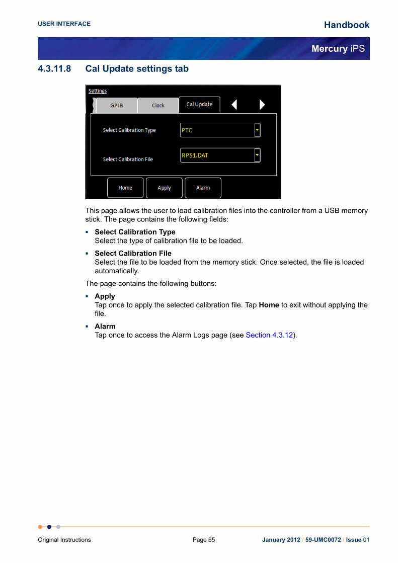
Handbook
Mercury iPS
USER INTERFACE
4.3.11.8 Cal Update settings tab
This page allows the user to load calibration files into the controller from a USB memory stick. The page contains the following fields:
Select Calibration TypeSelect the type of calibration file to be loaded.
Select Calibration FileSelect the file to be loaded from the memory stick. Once selected, the file is loaded automatically.
The page contains the following buttons:
ApplyTap once to apply the selected calibration file. Tap Home to exit without applying the file.
AlarmTap once to access the Alarm Logs page (see Section 4.3.12).
January 2012 / 59-UMC0072 / Issue 01Page 65Original Instructions

Handbook
Mercury iPS
USER INTERFACE
4.3.11.9 F/W Update settings tab
The page allows the user to update the iPS application or the firmware on a daughter board. The new firmware must be located on a USB memory stick. The system automatically disconnects any output signals while the firmware is being updated.
The page contains the following fields and controls:
Firmware DeviceSelect the name of a board from a drop-down list to update the firmware on that board.Select APPLICATION to update the application that is running on the iPS.
Firmware FileSelect the file on the memory stick to load onto the daughter board.
The page contains the following buttons:
AlarmTap once to access the Alarm Logs page (see Section 4.3.12).
January 2012 / 59-UMC0072 / Issue 01 Page 66 Original Instructions
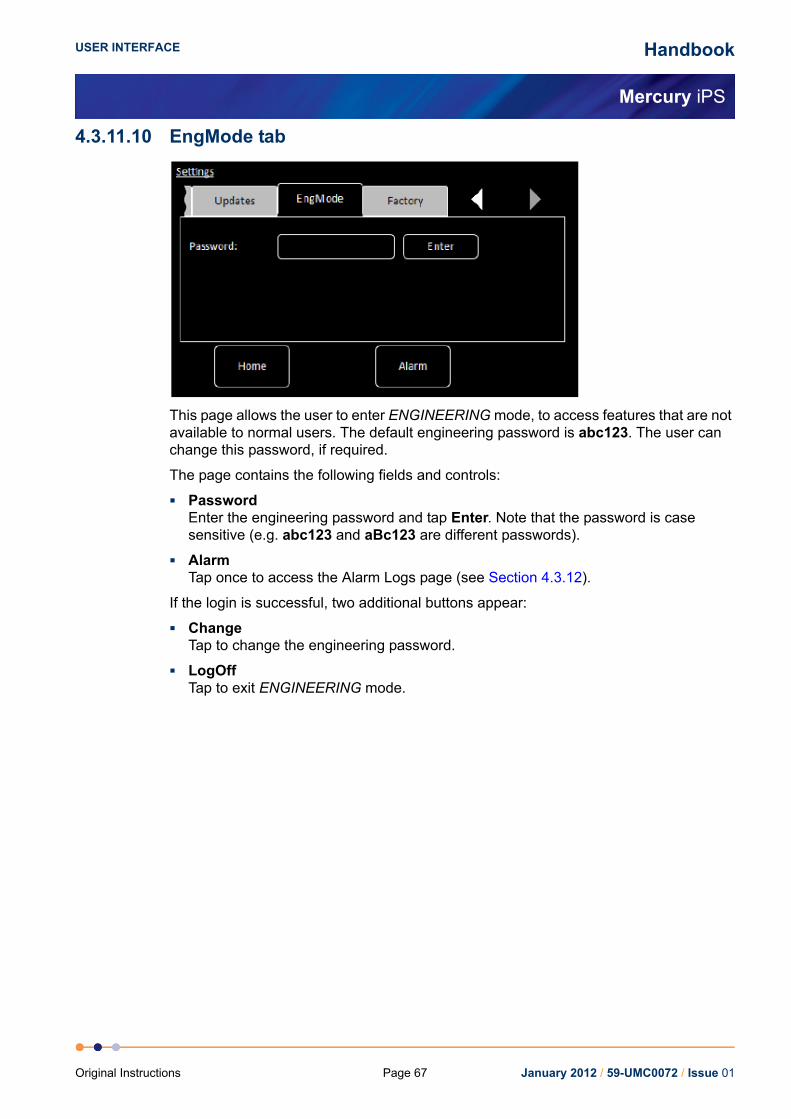
Handbook
Mercury iPS
USER INTERFACE
4.3.11.10 EngMode tab
This page allows the user to enter ENGINEERING mode, to access features that are not available to normal users. The default engineering password is abc123. The user can change this password, if required.
The page contains the following fields and controls:
PasswordEnter the engineering password and tap Enter. Note that the password is case sensitive (e.g. abc123 and aBc123 are different passwords).
AlarmTap once to access the Alarm Logs page (see Section 4.3.12).
If the login is successful, two additional buttons appear:
ChangeTap to change the engineering password.
LogOffTap to exit ENGINEERING mode.
January 2012 / 59-UMC0072 / Issue 01Page 67Original Instructions

Handbook
Mercury iPS
USER INTERFACE
4.3.11.11 Factory Settings tab
This page allows the user to save the configuration of the Mercury iTC as a file. The user can then load a previously saved configuration.
NOTE: The system configuration contains information that the user has entered via the GUI (such as names of sensors, paired signals, calibration etc.). It does not include the firmware versions.
The page contains the following fields and controls:
Save configurationTo save the present system configuration, enter a filename in the Enter Name field and tap Save Configuration.
Drop-down menuSelect a saved file to load or delete. Loading a file changes the unit’s configuration to the saved configuration. Note that the original factory configuration is called FACTORY_OI.
The page contains the following buttons:
AlarmTap once to access the Alarm Logs page (see Section 4.3.12).
RevertTap once to load the selected configuration file and reboot the Mercury iPS.
DeleteTap once to delete the selected firmware file from the list of available files.
January 2012 / 59-UMC0072 / Issue 01 Page 68 Original Instructions

Handbook
Mercury iPS
USER INTERFACE
4.3.12 Alarm Logs pageThis page displays a table of alarms that have been generated on the system.
Figure 4-22 Alarm Logs page
The table contains an entry when an alarm is first raised, and another entry when the alarm is restored.
The table has the following columns:
Date/TimeThe date and time when the alarm was raised.
Device UIDThe identifier of the device that raised the alarm.
AlarmA brief description of the alarm (e.g. Short-circuit).
January 2012 / 59-UMC0072 / Issue 01Page 69Original Instructions

Handbook
Mercury iPS
USER INTERFACE
4.3.12.1 Channel summary panelFigure 4-23 shows a typical channel summary panel on the Home page.
Figure 4-23 Channel summary panel
The channel-summary panel displays the following information:
Channel identifier or nickname
The main display value for the channel (e.g. measured temperature)
If the summary panel has not been configured:
the panel displays the name None and the value 0.0000.
1 Tap the panel once to display the Channel Display Configuration Page (see Figure 4-24).
If the panel has been configured:
the summary panel displays a sensor name and a sensor value.
2 Tap the panel once to display the Sensor Details page (see Section 4.3.14).
3 Tap the panel twice to display the Channel Display Configuration Page (see Figure 4-24).
January 2012 / 59-UMC0072 / Issue 01 Page 70 Original Instructions

Handbook
Mercury iPS
USER INTERFACE
4.3.13 Channel Display Configuration pageThis page allows the user to configure inputs and outputs associated with a panel on the Home page. Figure 4-24 shows the page when the panel is unconfigured.
Figure 4-24 Channel Display Configuration page
The page contains the following fields and controls:
DevicesSelect a sensor for this panel from a drop-down menu. Select None to clear the configuration for this panel.
SignalsSelect a sensor parameter to display from a drop-down menu.
Pair buttonNot used.
Assign buttonTap once to save any changes made.
January 2012 / 59-UMC0072 / Issue 01Page 71Original Instructions

Handbook
Mercury iPS
USER INTERFACE
4.3.14 Sensor details pagesThere are several alternative sensor details pages. The page that displays depends on which Channel Summary panel was selected.
4.3.14.1 Temperature Sensor Details pageThis page displays detailed information about the selected temperature sensor.
Figure 4-25 Temperature Sensor Details page
The page contains the following fields and controls:
Sensor name
Sensor ReadingsThe values shown are:I(μA) - the sensor excitation current in μA.P(μW) - the power dissipated in the sensor in μW.R(Ω) - the resistance of the sensor in Ohms.S(Ω/K) - the sensitivity of the sensor in Ohms per Kelvin.T(K) - the temperature measured by the sensor in Kelvin.V (mV) - the sensor output voltage in mV.
Sensor TypeSelect a sensor type from a drop-down menu. Available types are:Thermocouple - a thermocouple.PTC - positive temperature coefficient sensor.NTC - negative temperature coefficient sensor.Diode - a diode sensor.Refer to Section 5.5 for a detailed explanation of sensor types.
CalibrationSelect a calibration file from a drop-down menu. The list of files changes depending on which sensor type is selected.
InterpolationSelect an interpolation method for calculating the calibration curve from the calibration table (see Section 5.5.2).
ExcitationSelect an excitation mode from a drop-down menu (see Section 5.5.1.2).
January 2012 / 59-UMC0072 / Issue 01 Page 72 Original Instructions

Handbook
Mercury iPS
USER INTERFACE
Excitation MagnitudeTap once to display a numeric keypad.If Sensor Type is set to PTC, enter an excitation current in μA.If Sensor Type is set to Diode, enter an excitation current in μA.If Sensor Type is set to NTC, enter an excitation voltage in mV.If Sensor Type is set to Thermocouple, this value is ignored.
Cal Adj buttonThis button is only active if the Calibration field is set to Generic. Tap once to access the Generic Sensor Adjustment page (see Section 4.3.15). This allows the user to adjust the scale and offset of a generic calibration curve to suit a particular sensor.
Calibrate buttonTap once to calibrate this measurement circuit. This routine takes approximately one minute. An error message is generated if the calibration fails for any reason.
4.3.15 Generic Sensor Adjustment pageThis page allows the user to adjust the calibration curve of a generic sensor. See Section 2.5.3.2 for a detailed explanation of this process.
Figure 4-26 Generic Sensor Adjustment page
The page contains the following fields and controls:
Measured ParameterDisplays the measured sensor value (i.e. resistance or voltage).
Scaled ParameterDisplays the measured parameter value after the selected Scale and Offset have been applied. If Scale= 1 and Offset= 0, Measured Parameter and Scaled Parameter are identical.
ScaleAdjust to change the slope of the calibration curve.
OffsetAdjust to change the offset of the calibration curve.
SaveTap to save the new Scale and Offset values.
January 2012 / 59-UMC0072 / Issue 01Page 73Original Instructions
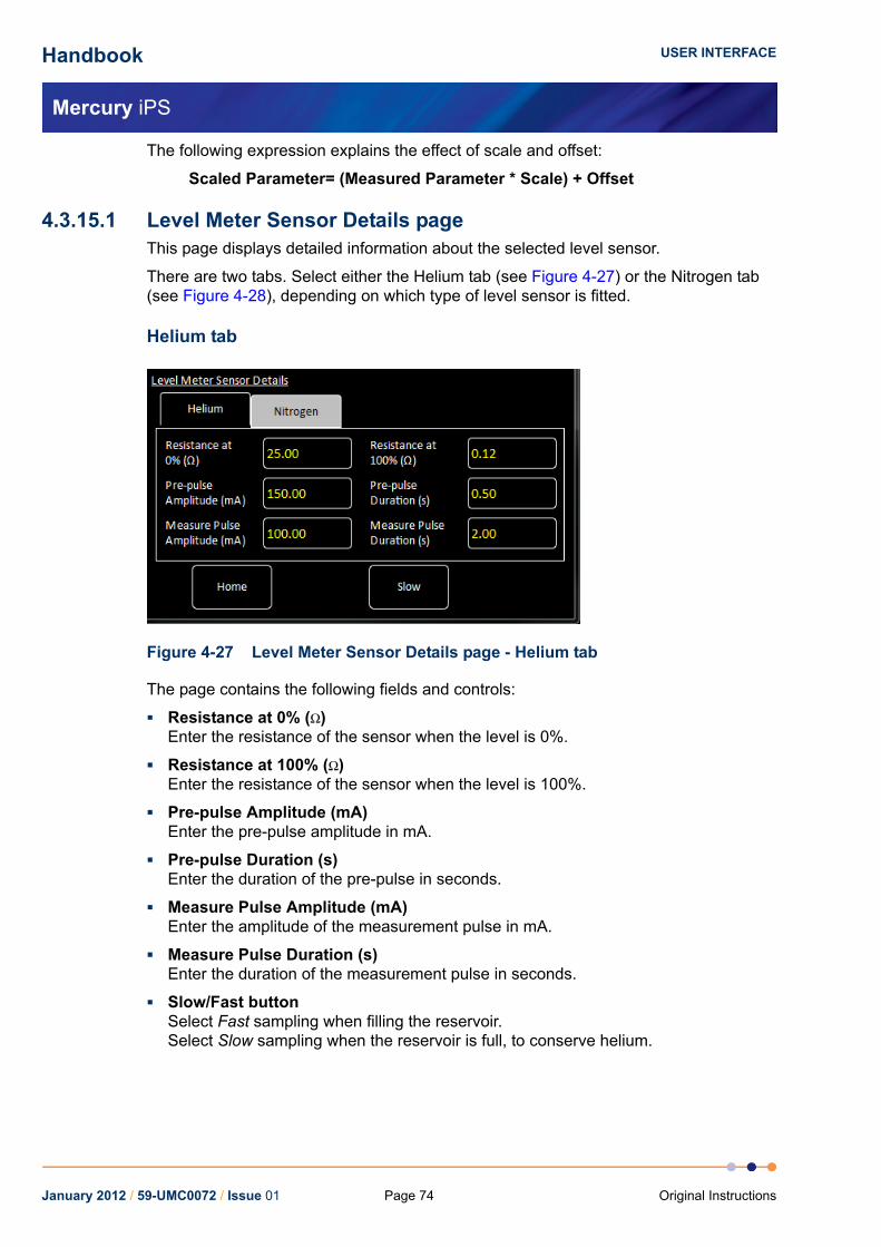
Handbook
Mercury iPS
USER INTERFACE
The following expression explains the effect of scale and offset:
Scaled Parameter= (Measured Parameter * Scale) + Offset
4.3.15.1 Level Meter Sensor Details pageThis page displays detailed information about the selected level sensor.
There are two tabs. Select either the Helium tab (see Figure 4-27) or the Nitrogen tab (see Figure 4-28), depending on which type of level sensor is fitted.
Helium tab
Figure 4-27 Level Meter Sensor Details page - Helium tab
The page contains the following fields and controls:
Resistance at 0% (Ω)Enter the resistance of the sensor when the level is 0%.
Resistance at 100% (Ω)Enter the resistance of the sensor when the level is 100%.
Pre-pulse Amplitude (mA)Enter the pre-pulse amplitude in mA.
Pre-pulse Duration (s)Enter the duration of the pre-pulse in seconds.
Measure Pulse Amplitude (mA)Enter the amplitude of the measurement pulse in mA.
Measure Pulse Duration (s)Enter the duration of the measurement pulse in seconds.
Slow/Fast buttonSelect Fast sampling when filling the reservoir.Select Slow sampling when the reservoir is full, to conserve helium.
January 2012 / 59-UMC0072 / Issue 01 Page 74 Original Instructions
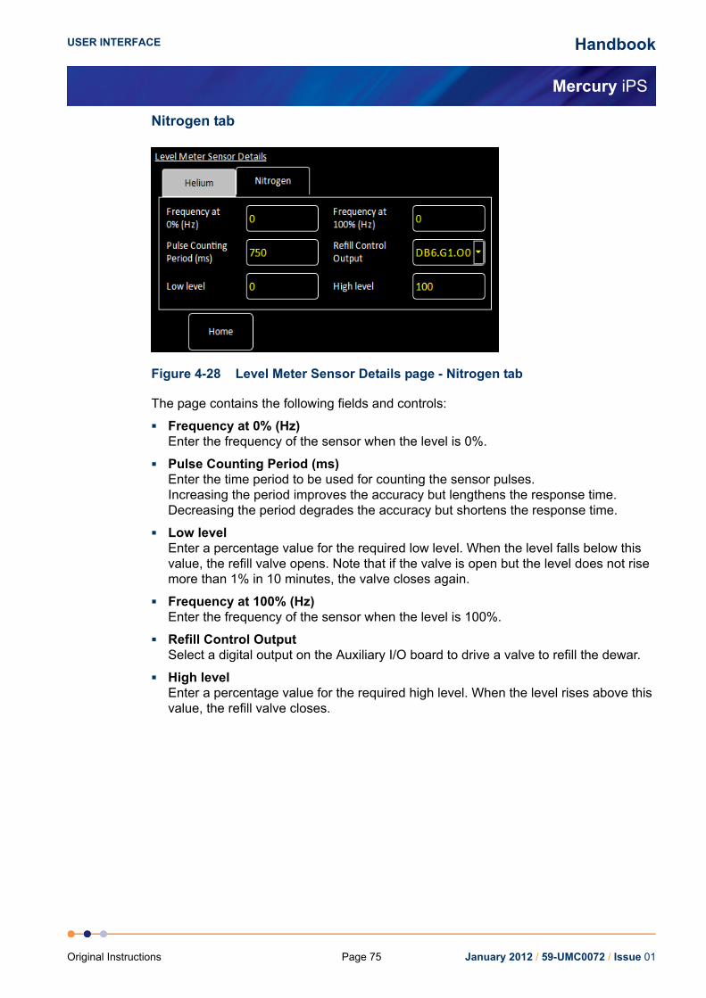
Handbook
Mercury iPS
USER INTERFACE
Nitrogen tab
Figure 4-28 Level Meter Sensor Details page - Nitrogen tab
The page contains the following fields and controls:
Frequency at 0% (Hz)Enter the frequency of the sensor when the level is 0%.
Pulse Counting Period (ms)Enter the time period to be used for counting the sensor pulses.Increasing the period improves the accuracy but lengthens the response time.Decreasing the period degrades the accuracy but shortens the response time.
Low levelEnter a percentage value for the required low level. When the level falls below this value, the refill valve opens. Note that if the valve is open but the level does not rise more than 1% in 10 minutes, the valve closes again.
Frequency at 100% (Hz)Enter the frequency of the sensor when the level is 100%.
Refill Control OutputSelect a digital output on the Auxiliary I/O board to drive a valve to refill the dewar.
High levelEnter a percentage value for the required high level. When the level rises above this value, the refill valve closes.
January 2012 / 59-UMC0072 / Issue 01Page 75Original Instructions
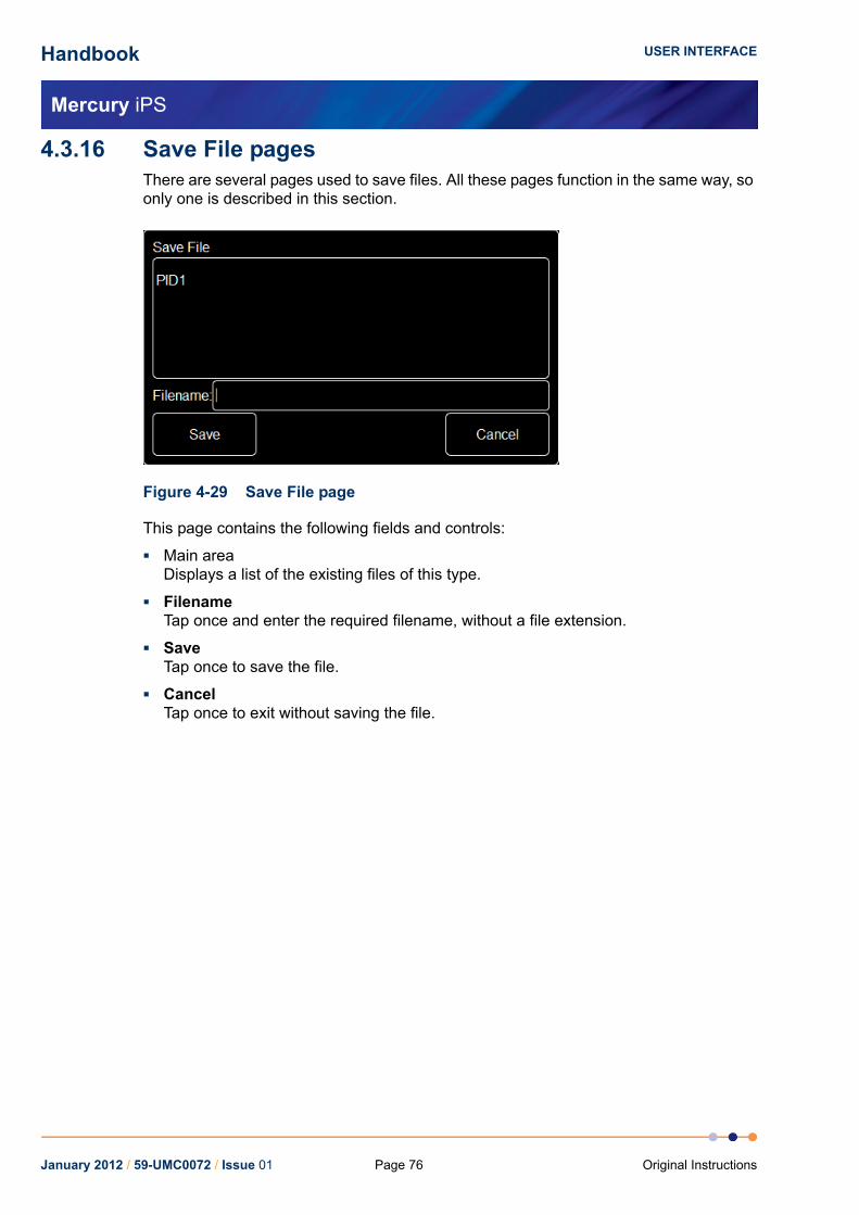
Handbook
Mercury iPS
USER INTERFACE
4.3.16 Save File pagesThere are several pages used to save files. All these pages function in the same way, so only one is described in this section.
Figure 4-29 Save File page
This page contains the following fields and controls:
Main areaDisplays a list of the existing files of this type.
FilenameTap once and enter the required filename, without a file extension.
SaveTap once to save the file.
CancelTap once to exit without saving the file.
January 2012 / 59-UMC0072 / Issue 01 Page 76 Original Instructions
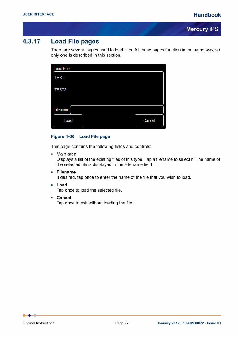
Handbook
Mercury iPS
USER INTERFACE
4.3.17 Load File pagesThere are several pages used to load files. All these pages function in the same way, so only one is described in this section.
Figure 4-30 Load File page
This page contains the following fields and controls:
Main areaDisplays a list of the existing files of this type. Tap a filename to select it. The name of the selected file is displayed in the Filename field
FilenameIf desired, tap once to enter the name of the file that you wish to load.
LoadTap once to load the selected file.
CancelTap once to exit without loading the file.
January 2012 / 59-UMC0072 / Issue 01Page 77Original Instructions

Handbook
Mercury iPS
USER INTERFACE
This page is intentionally blank.
Page 78January 2012 / 59-UMC0072 / Issue 01 Original Instructions
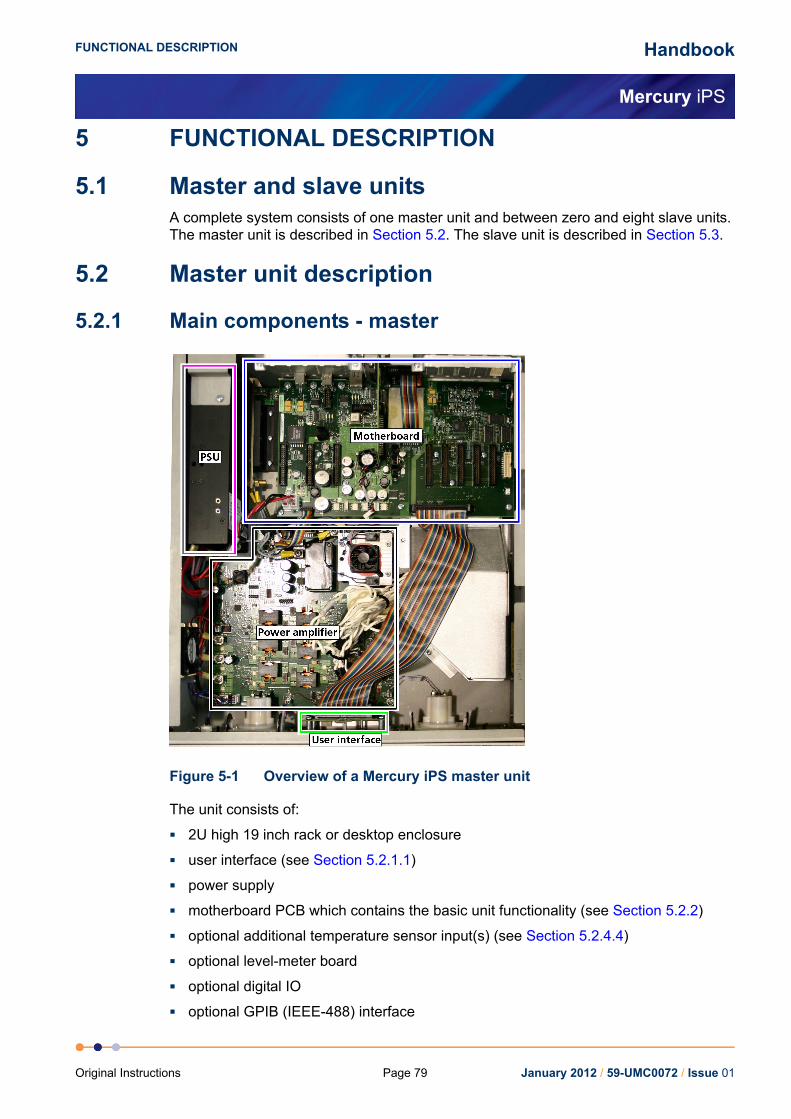
Handbook
Mercury iPS
FUNCTIONAL DESCRIPTION
5 FUNCTIONAL DESCRIPTION
5.1 Master and slave unitsA complete system consists of one master unit and between zero and eight slave units. The master unit is described in Section 5.2. The slave unit is described in Section 5.3.
5.2 Master unit description
5.2.1 Main components - master
Figure 5-1 Overview of a Mercury iPS master unit
The unit consists of:
2U high 19 inch rack or desktop enclosure
user interface (see Section 5.2.1.1)
power supply
motherboard PCB which contains the basic unit functionality (see Section 5.2.2)
optional additional temperature sensor input(s) (see Section 5.2.4.4)
optional level-meter board
optional digital IO
optional GPIB (IEEE-488) interface
January 2012 / 59-UMC0072 / Issue 01Page 79Original Instructions

Handbook
Mercury iPS
FUNCTIONAL DESCRIPTION
5.2.1.1 User interface - masterThe user interface consists of a 420 x RGB x 272 pixel LCD-TFT display and touch-screen. A opto-sensor is fitted above the display to detect ambient light levels. The Mercury iPS can be configured to vary the display brightness to match the ambient light level (auto-dim feature).
The front-panel also contains an analogue ammeter and a voltmeter.
5.2.2 MotherboardThe motherboard contains the processors that control the iPS. The operating program and control applications are stored on a flash drive. The motherboard also provides a single temperature-sensor input.
There are eight expansion slots, each of which can accept an optional daughter board (see Section 5.2.6).
5.2.3 Magnet power supply operation - masterThe magnet power supply is a bipolar current source, designed to drive an inductive load. It contains a clamp-relay that shorts out the magnet output terminals when the unit is shut-down.
5.2.3.1 Ramp rate limitsThe Mercury iPS limits the rate-of-change of current in the magnet to prevent quenches. The values are programmed into a rate-limit table. Each row of the table contains a rate-limit for a particular rate-limit type over a specified range of currents.
There are four possible rate-limit types.:
MRFa (Magnet Ramp Fast)This type is used for normal operation.
MRSl (Magnet Ramp Slow)This type is used to re-train the magnet after a thermal cycle or after a quench has been detected.
LRMZ (Lead Ramping Magnet at Zero)This type is used when the magnet terminals are shorted out and the current is zero. In this state, only the magnet-leads are in circuit.
LRMF (Lead Ramping Magnet at Field)This type is used when the magnet terminals are shorted out and the current through the magnet is at its programmed value. In this state, only the magnet-leads are in circuit.
If the programmed magnet conditions produce a ramp that exceeds the rate-limit, the power-supply output ramps at the limit value. An error message is also logged on the GUI.
January 2012 / 59-UMC0072 / Issue 01 Page 80 Original Instructions

Handbook
Mercury iPS
FUNCTIONAL DESCRIPTION
5.2.3.2 Magnet operation with a persistent-switchWhen current is being established in the magnet, the iPS slowly ramps its output current at a controlled rate. The persistent-switch output is energised, so that the persistent-switch is high-resistance (see Figure 5-2).
Figure 5-2 Establishing current in the magnet
When the required current is flowing in the magnet, the persistent-switch output is de-energised, so that the persistent-switch becomes superconducting. This shorts out the magnet terminals, and a persistent current circulates around the magnet coils (see Figure 5-3).
Figure 5-3 Persistent current
The current output from the iPS also circulates through the persistent-switch. The iPS output could be disabled in this state without affecting the current in the magnet.
If the electrical power supply to the iPS fails, the persistent-switch output turns off, causing the switch to cool down. The persistent-switch then short-circuits the output terminals so that the current in the magnet is maintained. If the electrical power is restored, the persistent-switch output remains off until the user demands a change in the magnet current.
January 2012 / 59-UMC0072 / Issue 01Page 81Original Instructions

Handbook
Mercury iPS
FUNCTIONAL DESCRIPTION
5.2.3.3 Quench detection - masterThe iPS continually monitors the voltage produced across the magnet terminals. If the voltage exceeds a programmed value for a programmed time, a quench is flagged. The iPS then ramps the magnet current down to zero at a controlled rate. The iPS also switches the current through high-power resistors inside the unit, which dissipate stored energy from the magnet.
5.2.3.4 Auto rundown - masterIf the Mercury iPS detects a condition that may be unsafe for the equipment, it performs an auto rundown sequence to protect the equipment. The sequence is:
1 The iPS ramps its output to match the magnet current.
2 The iPS switches on the persistent heater and waits until the switch has opened.
3 The iPS ramps its output down to zero.
4 The iPS switches off the persistent heater.
An auto rundown can be triggered by any of the following:
A temperature higher or lower than a specified range.
A low level of cryogen.
A low level on a specified digital input.
January 2012 / 59-UMC0072 / Issue 01 Page 82 Original Instructions

Handbook
Mercury iPS
FUNCTIONAL DESCRIPTION
5.2.4 Mercury iPS connections - masterFigure 5-1 shows the connections on the right side of the rear panel.
Table 5-1 MPSU rear panel (right side)
5.2.4.1 Electrical power connectionThe rear panel contains an IEC C14 connector for the main electrical supply to the unit.
5.2.4.2 Magnet connectionsThe main magnet terminals are busbar bolts on the rear panel of the Mercury iPS. Output polarity is defined as positive when current flows out of the MAGNET +VE busbar and returns to the MAGNET -VE busbar.
5.2.4.3 Persistent-switch heater outputThe persistent-switch heater output is via two 4 mm banana sockets on the rear panel of the iPS. The red socket is the positive connection.
January 2012 / 59-UMC0072 / Issue 01Page 83Original Instructions

Handbook
Mercury iPS
FUNCTIONAL DESCRIPTION
5.2.4.4 Temperature sensor inputThe temperature sensor input is via 9-way D-connector on the rear panel of the iPS. Pin assignations are listed in Table 5-2.
The basic iPS includes a single input channel for one temperature sensor. An additional 8 sensor inputs can be added (total 9 inputs).
The unit can accept the following sensor types:
Negative temperature coefficient (NTC) resistance
Positive temperature coefficient (PTC) resistance
Thermocouple
Silicon diode
Each input can be read at a maximum rate of 10 Hz. The unit can detect short-circuit inputs, open-circuit inputs, and inputs that are shorted to ground.
The iPS contains a internal temperature sensor that is used to compensate for fluctuations in ambient temperature.
See Section 5.5 for an overview of the temperature measurement methods that are available on the Mercury iPS.
Connections to the sensor vary depending on the type of sensor in use (see Table 5-3).
Table 5-2 Channel pin connections
Pin Number
Connection
1 Sensor input high
2 Sensor input GND.
3 Sensor input low
4 Current source +ve
5 Current source -ve
6 Not used
7 Not used
8 Not used
9 Chassis ground.
Table 5-3 Sensor connections
Connection Thermocouple Metal Resistor Ge/Carbon Resistor
Si/Ga As Diode
Input High V+ V+ V- V-
Input Low V- V- V+ V+
Current +ve n/c I+ I+ I+
Current -ve n/c I- I- I-
January 2012 / 59-UMC0072 / Issue 01 Page 84 Original Instructions

Handbook
Mercury iPS
FUNCTIONAL DESCRIPTION
Connecting thermocouples
Thermocouples must be connected using the correct wire type to ensure measurement accuracy.
5.2.5 Communications interfaces - masterThe unit has the following interfaces:
Serial RS232 + ISOBUS (see Section 5.2.5.1)
Serial2 USB (see Section 5.2.5.3)
GPIB (IEEE-488) (optional) (see Chapter 14)
Ethernet 10/100 IEE802.3 (see Section 5.2.5.4)
SPI bus output for controlling slave units (see Section 5.2.5.5)
5.2.5.1 Serial RS232 interfaceThe RS232 interface is connected via a 25-way D-socket on the rear panel. The iPS is configured as Data Circuit-terminating Equipment (DCE), with the standard pin-assignations listed in Table 5-4.
Most computer RS232 interfaces are configured as Data Terminal Equipment (DTE). If the computer has a 25-way D-plug, the cable must be connected pin-to pin (i.e. Pin 1 to Pin 1, Pin 2 to Pin 2 etc.). If the computer has a 9-way D-plug, a standard RS232 9-way to 25-way cable is required.
The iPS does not require signals to be present on the RTS or DTR (pin 20) lines. The RTS signal is fed back to the computer as CTS. The iPS sends logic high levels (+5 V) to the computer on DSR and DCD.
Table 5-4 RS232 connections on the Mercury iPS
Pin Signal Name Notes
1 FG Linked to chassis ground inside the iPS.
2 TD Data from the computer to the iPS.
3 RD Data from the iPS to the computer.
4 RTS Linked to Pin 5 inside the iPS.
5 CTS Linked to Pin 4 inside the iPS.
6 DSR Linked to +5 V when the iPS is powered.
7 SG Linked to digital ground inside the iPS.
8 DCD Linked to +5 V when the iPS is powered.
9 to 25 Open circuit.
January 2012 / 59-UMC0072 / Issue 01Page 85Original Instructions

Handbook
Mercury iPS
FUNCTIONAL DESCRIPTION
Voltage levels for the transmitted and received data are listed in Table 5-5.
5.2.5.2 Oxford Instruments NanoScience ISOBUSISOBUS allows a single RS232 port on a computer to control a number of instruments independently. This arrangement requires an ISOBUS cable, which carries a single ISOBUS Master connector (25-way D-socket) and up to eight ISOBUS Slave connectors (25-way D-plug). Each slave connector incorporates full optical isolation, so that each slave is isolated from the master and from every other slave.
NOTE: An ISOBUS slave is any RS232 device that is controlled by the master ISOBUS device. It is not the same as an Mercury iPS slave, which is a particular version of the iPS that is controlled by an iPS master device, using the SPI bus (see Section 5.2.5.5).
The ISOBUS slave connectors draw electrical power from the individual instruments, via the DCD signal. The master connector draws electrical power from either the DTR or RTS signals from the computer.
A special command protocol is required to use ISOBUS (see Section 7.3).
5.2.5.3 USB interfaceThe USB port allows one-to-one communication with a computer. USB 2.0 full-speed (12 MBits per second) version is supported.
5.2.5.4 Ethernet interfaceThe ethernet interface is connected via an RJ45 connector on the rear panel. The iPS can be configured to use a fixed ip address, or to use DHCP.
Table 5-5 RS232 voltage levels
Signal Allowed Voltage Level
Tx data high >+5.5 V
Tx data low <-5.5 V
Rx data high threshold <+2.6 V
Rx data low threshold >+1.4 V
Max Rx input voltage ±30 V
January 2012 / 59-UMC0072 / Issue 01 Page 86 Original Instructions

Handbook
Mercury iPS
FUNCTIONAL DESCRIPTION
5.2.5.5 SPI busThe SPI bus is connected via RS485 connectors on the rear panel. The bus allows iPS Master and Slave units to communicate. A Master unit has a single male RS485 connector on the rear panel. A slave unit has a male connector and a female connector on the rear panel. The SPI bus is connected in a daisy-chain fashion from one unit to the next (see Figure 5-4). The order in which the slave units are connected together is not important.
Figure 5-4 Example SPI bus connections between Master and Slave units
Once the Master iPS is configured with the connection arrangement, control of the slave units is transparent to the user.
5.2.6 Daughter boards - masterThe iPS master unit can accept up to 8 daughter boards. These can consist of combinations of the following board types:
Temperature sensorA board containing a single temperature sensor interface. A maximum of eight of these boards can be fitted (see Chapter 12).
Level meterA board containing a single level meter, which is used to monitor the amount of gas or liquid in the system. Only one of these boards can be fitted (see Chapter 13).
Auxiliary I/O boardA board containing a number of I/O lines. Only one of these boards can be fitted (see Chapter 15).
GPIBA board which provides an external GPIB interface for connection to another device (e.g. a PC). Only one of these boards can be fitted (see Chapter 14).
The iPS automatically identifies every daughter board that is fitted.
January 2012 / 59-UMC0072 / Issue 01Page 87Original Instructions
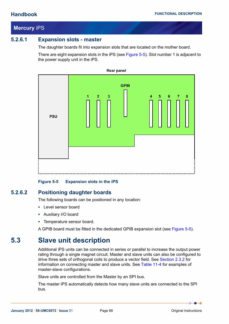
Handbook
Mercury iPS
FUNCTIONAL DESCRIPTION
5.2.6.1 Expansion slots - masterThe daughter boards fit into expansion slots that are located on the mother board.
There are eight expansion slots in the iPS (see Figure 5-5). Slot number 1 is adjacent to the power supply unit in the iPS.
Figure 5-5 Expansion slots in the iPS
5.2.6.2 Positioning daughter boardsThe following boards can be positioned in any location:
Level sensor board
Auxiliary I/O board
Temperature sensor board.
A GPIB board must be fitted in the dedicated GPIB expansion slot (see Figure 5-5).
5.3 Slave unit descriptionAdditional iPS units can be connected in series or parallel to increase the output power rating through a single magnet circuit. Master and slave units can also be configured to drive three sets of orthogonal coils to produce a vector field. See Section 2.3.2 for information on connecting master and slave units. See Table 11-4 for examples of master-slave configurations.
Slave units are controlled from the Master by an SPI bus.
The master iPS automatically detects how many slave units are connected to the SPI bus.
January 2012 / 59-UMC0072 / Issue 01 Page 88 Original Instructions

Handbook
Mercury iPS
FUNCTIONAL DESCRIPTION
5.3.1 Output modesThe Master and Slave units can be configured in either solenoid, split-pair or vector-rotate mode, to suit the magnet.
5.3.2 Control system - slaveA slave unit is controlled from the master unit.
5.3.3 User interface - slaveThe front-panel contains an analogue ammeter and a voltmeter. A slave unit has no LCD.
5.3.4 Mercury iPS connections - slave
5.3.4.1 Electrical power connectionThe back panel contains an IEC C14 connector for the main electrical supply to the unit.
5.3.4.2 Magnet connectionsThe main magnet terminals are busbar bolts on the rear panel of the iPS. Output polarity is defined as positive when current flows out of the MAGNET +VE busbar and returns to the MAGNET -VE busbar.
5.3.4.3 Switch heater outputThe switch-heater output is via two 4 mm banana sockets on the rear panel of the iPS. The red socket is the positive connection.
5.3.4.4 Communication interfaces - slaveThe unit has the following communication interface.
SPI bus output for control by a master unit.
5.3.5 Daughter boards - slaveNo daughter boards can be fitted to a slave unit.
5.4 Controlling the Mercury iPS through a remote interfaceThe Mercury iPS can be controlled by a remote PC via one of the possible control interfaces.
If one or more Slaves is connected to a Master unit, it is only necessary to connect the computer to the Master unit.
January 2012 / 59-UMC0072 / Issue 01Page 89Original Instructions
Handbook
Mercury iPS
FUNCTIONAL DESCRIPTION
5.5 Overview of temperature measurementThe iPS uses a highly accurate measurement circuit to measure the voltage produced by a sensor.
5.5.1 Types of temperature sensorThe iPS can use several types of temperature sensor:
ThermocouplesA thermocouple comprises two junctions of dissimilar metals held at different temperatures. This acts as a voltage source, based on the Seebeck effect, the output voltage of which increases with increasing temperature difference. The iPS contains cold-junction compensation, so a reference junction is not required.
Metallic resistance thermometersThe resistance of metallic resistors increases with increasing temperature due to the increase of scattering events of the conduction electrons. Over much of the temperature range the relationship is approximately linear until, at low temperatures, impurity scattering becomes significant and the sensor sensitivity flattens off. The iPS passes a constant current through the sensor and measures the voltage produced, using a 4-wire measurement. Resolution to 1 mK is possible at low temperatures, if a suitable resistor and energisation current are used.
Semiconductor resistance thermometersThe resistance of semiconductor resistors decreases with increasing temperature. The relationship is non-linear. The iPS uses a 4-wire connection, applying a constant voltage across the resistor. The iPS then measures the current, which is used to calculate the temperature. The current through the resistor increases with temperature and its relationship to the temperature is more linear than the resistance of the resistor. Using a constant voltage ensures that power dissipation in the resistor decreases as the temperature decreases. Resolution to 0.1mK is possible at low temperatures.
Semiconductor diodesThese devices produce a voltage that decreases as the temperature increases. The iPS passes a constant current through the diode and measures the voltage produced. Resolution to 1mK is possible at low temperatures.
The iPS includes calibration curves for the following sensor types.
Table 5-6 Sensor range data
Code Sensor Range
Lin1 Linear range 0-1677.7
Null1 Centre zero -838.9 to +838.9
Con 1 Conductance 0 to 20
TG 5 AuFe 0.03/Chr 2 to 500K
TG 5 AuFe 0.03/Chr 2 to 500K
TG 5 AuFe 0.03/Chr 2 to 500K
TG_57 AuFe 0.07/Chr 2 to 500K
January 2012 / 59-UMC0072 / Issue 01 Page 90 Original Instructions

Handbook
Mercury iPS
FUNCTIONAL DESCRIPTION
TG_57 AuFe 0.07/Chr 2 to 500K
TG_57 AuFe 0.07/Chr 2 to 500K
CN 3 Cernox resistor 1.5 to 300K
TT 5 Copper/Const 20 to 500K
TT 5 Copper/Const 20 to 500K
TT 4 Copper/Const -250 to 400°C
TT 4 Copper/Const -250 to 400°C
TK 10 Chromel/Alumel 0 to 1000°C
TK 10 Chromel/Alumel 0 to 1000°C
TK 13 Chromel/Alumel -200 to 1370°C
TK 13 Chromel/Alumel -200 to 1370°C
CR 11 Ruthenium oxide 0.25 to 10K
RF 522 RhFe resistor 1.5 to 500K
RP 1 Platinum resistor -200 to +100°C
RP 53 Platinum resistor 20 to 500K
RP 514 Platinum resistor 50 to 500K
RL 3 CLTS 2 to 300K
DS 32 Silicon diode (OI) 2 to 300K
DS 31 Silicon diode (LS) 2 to 300K
CC 35 C-glass CR500 2 to 300K
CA 21 100R Allen Bradley 4 to 250K
CA 22 270R Allen Bradley 4 to 250K
CS 01 470R Speer 0.25 to 9.999K
1. The Lin and Null ranges are general purpose ranges that may be configured for any required span and zero. Both ranges provide a linear relationship between input and display. The Lin range is unipolar while the Null range is bipolar.
2. The ITC includes two curves for 27 Ohm Rhodium/Iron sensors. Curve A is used for sensors having a resistance of 2 Ohms or greater at 4.2K. Curve B is used for sensors having a resistance of less than 2 Ohms at 4.2K. Using the appropriate curve should produce linearisation errors of less than 1% over the full temperature range. For a more accurate fit to a specific sensor, order a custom calibration.
3. This is for a pure platinum element.4. This is for a platinum element that is ballasted to BS1904/
DIN43760. This element is more readily available than a pure platinum element, but its performance is unspecified below 73K (the data between 50K and 70K is based on BS1904:964 rather than BS1904:1984).
Table 5-6 Sensor range data
Code Sensor Range
January 2012 / 59-UMC0072 / Issue 01Page 91Original Instructions

Handbook
Mercury iPS
FUNCTIONAL DESCRIPTION
5.5.1.1 ThermocouplesThe MPSU measures the voltage produced by the thermocouple and converts it to a corresponding temperature. A 2-wire connection is used for thermocouples.
5.5.1.2 Resistance and diode sensorsResistance and diode sensors require an excitation current. A 4-wire connection is used for these sensors.
When the circuit is configured to measure PTC sensors, such as PT100 platinum resistance thermometers, the excitation current is generated by a high-stability current source.
When the circuit is configured to measure NTC sensors, such as CERNOX ceramic oxi-nitride or RuO2 ruthenium oxide resistance thermometers, the excitation is generated by a true voltage source.
The magnitude of the excitation current can be programmed to suit the application. Three types of excitation are available:
UnipolarThe excitation current is always positive.
BipolarThe excitation changes polarity between each successive measurement. The displayed sensor value is an average of the results from the last two measurements. Thus every measurement is an average of values measured with positive and negative excitation currents.
Soft edgeThis is similar to bipolar excitation, except the current ramps between the positive and negative values. The current is maintained at a stable value between the ramps to allow a measurement to be taken. Soft-edge excitation might be used to reduce electrical interference produced by fast-changing currents.
5.5.2 Calibration for different sensorsThe iPS uses calibration tables to store calibration data for different sensor types. The user can also create a new calibration file for a specific sensor. Calibration tables can be saved as files.
A calibration file contains a number of discrete data pairs, each mapping a sensor reading onto a temperature value. Interpolation is used to provide calibration at intermediate values.
The iPS calculates setpoint limits and sensor limits from the chosen calibration file.
January 2012 / 59-UMC0072 / Issue 01 Page 92 Original Instructions

Handbook
Mercury iPS
FUNCTIONAL DESCRIPTION
5.6 Circuit description of the magnet power-supply Figure 5-6 is a block diagram of the Mercury iPS.
Figure 5-6 Block diagram of the Mercury iPS
January 2012 / 59-UMC0072 / Issue 01Page 93Original Instructions

Handbook
Mercury iPS
FUNCTIONAL DESCRIPTION
The slave processor sends a current demand signal to a 20-bit digital to analogue converter (DAC). The DAC output voltage drives the demand input on the error amplifier. The output of the error amplifier drives a pulse-width modulation (PWM) controller, which in turn feeds a set of bipolar class D amplifiers.
The magnet output current flows from the class D amplifiers through a precision sense resistor. The voltage across this resistor is buffered and fed into the feedback input of the error amplifier. This voltage is also measured by a 24-bit ADC and passed back to the slave processor.
The magnet output voltage is filtered and passed to another 24-bit ADC, which returns the measured voltage to the slave processor.
January 2012 / 59-UMC0072 / Issue 01 Page 94 Original Instructions
Handbook
Mercury iPS
BASIC OPERATING INSTRUCTIONS
6 BASIC OPERATING INSTRUCTIONS
6.1 Configuring the LCD1 Tap Settings on the Home page. The Settings tabs are displayed.
2 Select the Display tab.
3 Tap the Auto Dim Option field to turn the auto-dim feature on or off.See Section 5.2.1.1 for a description of auto-dim.
4 Adjust the Brightness (%) and AutoDim (%) fields as required.
5 Tap Apply to save the changes.
6 Tap Home to return to the Home page.
6.2 Magnet current operations
6.2.1 Changing the current through the magnet1 Tap the Tesla/Amps button on the Home page until it displays the required setting.
2 Tap the summary area on the Home page to display the Set Point / Set Rate page (see Section 4.3.5).
3 Tap Set Point and enter the required magnet setpoint (in Amps or Tesla).
4 Tap Set Rate and enter the required ramp rate (in Amps per minute or Tesla per minute).
5 Tap Home to return to the Home page.
6 If a persistent heater is used, tap the Heater button on the Home page until it displays the message Heater On.
7 Tap To Set to ramp the magnet current to the setpoint that has just been entered.
8 Wait until the displayed magnet current is equal to the setpoint.
9 If required, tap Hold to maintain the magnet current at its present value.
10 If it is required to turn off the magnet, tap To Zero to ramp the magnet current to zero.
6.2.2 Using persistent mode (if required)
6.2.2.1 Establishing a persistent current in the magnet1 Check that the Heater button on the Home page displays the message Heater Off.
2 Tap the summary area on the Home page (see Figure 3).
3 Enter the required setpoint value in the Set Point field.
4 Enter a suitable ramp rate in the Set Rate field.
5 Tap Home to return to the Home page.
6 Tap the Heater button on the Home page until it displays the message Heater On.
January 2012 / 59-UMC0072 / Issue 01Page 95Original Instructions

Handbook
Mercury iPS
BASIC OPERATING INSTRUCTIONS
7 Tap To Set.
8 Check that the value displayed in the Current field ramps up to the programmed value.
9 Tap Hold.
10 Tap the Heater button on the Home page until it displays the message Heater Off.
11 Tap To Zero and check that the value displayed in the Current field ramps down to zero.
12 Check that the value displayed in the Magnet field is unchanged.
6.2.2.2 Changing the persistent current in the magnet1 Check that the Heater button on the Home page displays the message Heater Off.
2 Note the value displayed in the Magnet field.
3 Tap the summary area on the Home page (see Figure 3).
4 Enter the current displayed in the Magnet field in the Set Point field.
5 Enter a suitable ramp rate in the Set Rate field.
6 Tap Home to return to the Home page.
7 Tap To Set.
8 Check that the value displayed in the Current field ramps up to the programmed value.
9 Tap the Heater button on the Home page until it displays the message Heater On.
10 Tap the summary area on the Home page (see Figure 3).
11 Enter a new current value in the Set Point field.
12 Enter a suitable ramp rate in the Set Rate field.
13 Tap Home to return to the Home page.
14 Tap To Set.
15 Check that the value displayed in the Current field ramps up or down to the programmed value.
16 Tap Hold.
17 Tap the Heater button on the Home page until it displays the message Heater Off.
18 Tap To Zero and check that the value displayed in the Current field ramps down to zero.
19 Check that the value displayed in the Magnet field is unchanged.
January 2012 / 59-UMC0072 / Issue 01 Page 96 Original Instructions

Handbook
Mercury iPS
BASIC OPERATING INSTRUCTIONS
6.2.2.3 Changing the persistent current in the magnet to zero1 Check that the Heater button on the Home page displays the message Heater Off.
2 Note the value displayed in the Magnet field.
3 Tap the summary area on the Home page (see Figure 3).
4 Enter the current displayed in the Magnet field in the Set Point field.
5 Enter a suitable ramp rate in the Set Rate field.
6 Tap Home to return to the Home page.
7 Tap To Set.
8 Check that the value displayed in the Current field ramps up to the programmed value.
9 Tap the Heater button on the Home page until it displays the message Heater On.
10 Tap To Zero.
11 Check that the values displayed in the Current and Magnet fields ramp down to zero.
6.2.3 Recovering from a quenchIf a quench has occurred, perform the following steps to recover the system:
1 If a persistent heater is connected, check that the Heater button on the Home page displays the message Heater Off.
2 Tap Hold on the Home page to open the clamp-relay.
3 Tap the summary area on the Home page. The Set Point / Set Rate page opens.
4 Enter a small setpoint value in the Set Point field.
5 Enter a suitable ramp rate in the Set Rate field.
6 Tap Home to return to the Home page.
7 Tap the Heater button on the Home page until it displays the message Heater On.
8 Tap To Set.
9 Check that the value displayed in the Current field ramps up to the programmed value.
10 Check that the value displayed in the Magnet field is equal to the value displayed in the Current field.
11 Check that the current displayed on the front-panel meter is correct.
12 Check that the current displayed on the front-panel meter of each slave unit is correct.
13 Gradually increase the setpoint of the magnet until the maximum rated current is reached.
14 Tap To Zero and wait until the displayed current is zero.
January 2012 / 59-UMC0072 / Issue 01Page 97Original Instructions

Handbook
Mercury iPS
BASIC OPERATING INSTRUCTIONS
6.3 Using the plot function
6.3.1 Configuring a plot1 Tap Plot on the Home page. The Plot Configuration page is displayed.
2 Tap Device and select the first device to be used.
3 Tap Signal and select the first signal to be plotted.
4 Tap Save to plot the first signal.
5 To add traces to the plot, double-tap anywhere on the plot area and repeat steps 2 to 4.
6 By default, the Plot page displays a scale on the Y-axis only (see Figure 6-1). To remove the X axis scale, tap once on the bottom of the X axis (see Figure 6-2).
Figure 6-1 Signal Monitor Plot page with Y axis scale only
January 2012 / 59-UMC0072 / Issue 01 Page 98 Original Instructions

Handbook
Mercury iPS
BASIC OPERATING INSTRUCTIONS
Figure 6-2 Signal Monitor Plot page with X and Y axis scales
6.3.2 To remove a trace from the plot1 Tap Plot on the Home page. The Plot page is displayed.
2 Double-tap anywhere on the page. The Plot Configuration page is displayed.
3 Tap Device and select the required device.
4 Tap Signal and select the trace that is to be removed from the plot.
5 Tap Delete. The selected trace is removed from the plot.
6.3.3 Adjusting the plot scalingTo adjust the scaling of a plot:
1 Place a finger on the region of interest of the plot. The re-scaled plot will be centred around this position.
2 Drag the finger to zoom in and out around the area of interest:
a) Drag the finger to the right to expand the X-axis (zoom in).
b) Drag the finger to the left to contract the X-axis (zoom out).
c) Drag the finger up to expand the Y-axis (zoom in).
d) Drag the finger down to contract the Y-axis (zoom out).
These motions can be combined. For example, dragging the finger towards the bottom right corner expands the X-axis and contracts the Y-axis.
3 Double click on a scale to return to the default scaling for that axis.
January 2012 / 59-UMC0072 / Issue 01Page 99Original Instructions

Handbook
Mercury iPS
BASIC OPERATING INSTRUCTIONS
Figure 6-3 illustrates how to adjust the scaling of a plot.
Figure 6-3 Scaling a plot
6.3.4 To exit the plot1 Tap anywhere on the page. The Plot Configuration page is displayed.
2 Tap Home to return to the Home page.
6.4 Configuring external interfacesOnly one external interface can be used at a time. refer to the relevant section for information on configuring an external interface.
6.4.1 Configuring the ethernet interface (if required)1 Obtain the required ethernet settings from the network administrator.
2 Tap Settings on the Home page.
3 Scroll to the Ethernet tab.
4 Tap DHCP and select either On or Off.
5 If DHCP is set On, the unit obtains its ip address from the network. No further configuration is required.
6 If DHCP is set Off, enter an IP Address for the unit.
7 If DHCP is set Off, enter a Subnet mask for the unit.
8 If DHCP is set Off, enter a Gateway value for the unit.
9 Tap Apply to save the changes.
10 To enable the interface, see Section 6.4.5.
January 2012 / 59-UMC0072 / Issue 01 Page 100 Original Instructions

Handbook
Mercury iPS
BASIC OPERATING INSTRUCTIONS
6.4.2 Configuring the RS232 serial interface (if required)1 Tap Settings on the Home page.
2 Scroll to the RS232 tab.
3 Enter the required Baud rate.
NOTE: If replacing a legacy unit, set the baud rate to 9600.
4 Set the required number of Data bits.
5 Set the required Parity scheme.
6 Set the required number of Stop bits.
7 Set the required Flow Control scheme.
8 Tap Apply to save the changes.
9 If ISOBUS is to be used, scroll to the ISOBus tab.
10 Set the ISOBUS address to a value between 1 and 8.
11 Tap Apply to save the changes.
12 To enable the interface, see Section 6.4.5.
6.4.3 Configuring the GPIB (if required)1 Tap Settings on the Home page.
2 Scroll to the GPIB tab.
3 Enter a GPIB Address value between 0 and 31.
NOTE: Every unit connected to the GPIB must have a different GPIB address.
4 Tap Apply.
5 To enable the interface, see Section 6.4.5.
6.4.4 Configuring the USB interface (if required)No configuration is required for the USB interface.
To enable the interface, see Section 6.4.5.
6.4.5 Enabling remote control of the Mercury iPS1 Tap Settings on the Home page.
2 Tap the Remote Access field and select an interface from the drop-down menu.
3 Tap Apply to enable the selected interface.
January 2012 / 59-UMC0072 / Issue 01Page 101Original Instructions

Handbook
Mercury iPS
BASIC OPERATING INSTRUCTIONS
6.4.6 Enabling local control of the Mercury iPS1 Tap Settings on the Home page.
2 Tap the Remote Access field and select Local from the drop-down menu.
1 Tap Apply to enable local control of the iPS.
6.5 Re-configuring temperature sensors
6.5.1 To clear a panel configuration1 Double-tap the panel on the Home page that is to be cleared.
2 Tap the Devices field and select None from the drop-down menu.
3 Tap Assign.
4 The panel on the Home page should now display the name None.
6.5.2 Re-configuring a sensor1 Tap a configured panel on the Home page.
2 Edit the sensor details on the Sensor Details Screen page.
3 Tap Home to return to the Home page.
6.6 Updating the firmwareThe user can either update the firmware for a particular card, or the application for the whole system.
6.6.1 Updating the application1 Tap Settings on the Home page.
2 Select the F/W Update tab.
3 Tap the Firmware Device field and select APPLICATION from the drop-down menu.
4 Tap the Firmware File field and select a firmware file from the drop-down list.
5 Tap Apply. The iPS installs the new firmware and starts up in TRIAL mode.
NOTE: Do not power-off the iPS in TRIAL mode
6 Run some standard operations to test that the iPS is working as expected.
January 2012 / 59-UMC0072 / Issue 01 Page 102 Original Instructions

Handbook
Mercury iPS
BASIC OPERATING INSTRUCTIONS
7 If the new firmware is acceptable:
a) Tap Settings on the Home page.
b) Select the F/W Update tab.
c) Tap Save Changes to accept the new firmware version (see Figure 6-4).
Figure 6-4 F/W Update tab in TRIAL mode
8 If the new firmware is not acceptable for some reason:
a) Tap Settings on the Home page.
b) Select the F/W Update tab.
c) Tap Revert Changes to revert to the old firmware version.
6.6.2 Updating the firmware on a board
NOTE: The system automatically disconnects any output signals while the firmware is being updated. It also re-connects the outputs once the update is completed.
1 Tap Settings on the Home page.
2 Select the F/W Update tab.
3 Tap the Firmware Device field and select the required device from the drop-down menu.
4 Tap the Firmware File field and select a firmware file from the drop-down list.
5 Tap Apply. The iPS installs the new firmware.
6 Run some standard operations to test that the iPS is working as expected.
January 2012 / 59-UMC0072 / Issue 01Page 103Original Instructions

Handbook
Mercury iPS
BASIC OPERATING INSTRUCTIONS
6.7 Saving and restoring configurations
6.7.1 Saving a configuration1 Tap Settings on the Home page.
2 Select the Factory tab.
3 Enter a name for the present configuration in the Enter Name field.
4 Tap Save Configuration.
6.7.2 Restoring a configuration1 Tap Settings on the Home page.
2 Select the Factory tab.
3 Select a saved configuration from the drop-down box. Note that the original factory configuration is called FACTORY_OI.
4 Tap Revert. The system loads the selected configuration and reboots the Mercury iPS.
January 2012 / 59-UMC0072 / Issue 01 Page 104 Original Instructions

Handbook
Mercury iPS
REMOTE OPERATION
7 REMOTE OPERATIONThe iPS can be remotely operated via any of the following interfaces:
RS232 or ISOBUS
GPIB (IEEE-488)
Ethernet
USB
This allows a computer to interrogate the instrument and, if required, to take control of it.
7.1 Notes on instrument addressesAn iPS can have a GPIB address and an ISOBUS address. These addresses are distinct and can be different.
The ISOBUS address can be changed via ISOBUS (see Section 7.3).
The GPIB address is set from the GPIB Settings page on the unit (see Section 4.3.11.6).
The USB interface is a one-to-one connection, and no addresses are required.
7.2 Communication protocols for RS232 and GPIBThe same command protocols are used for the RS232 and the GPIB interfaces.
All commands consist of a string of printing American Standard Code for Information Interchange (ASCII) characters, terminated by a Carriage Return character. A Line Feed may optionally be sent after the Carriage Return, but the iPS ignores it.
Unless a command starts with a $ (dollar) character, all commands evoke a response from the iPS. The response consists of a string of one or more printing ASCII characters, terminated by a Carriage Return character. This may optionally be followed by a Line Feed character.
If the first character of the command is $, the command is obeyed but no response is sent.
Any response is normally sent immediately after the command is received. The following scenarios may delay the response:
If a GUI button is tapped when the command is received, the response may be delayed until the button is released.
If the RS232 interface is in use, the response is automatically sent as soon as the interface is available.
If the GPIB is used, the response is sent when the instrument is next addressed to talk.
January 2012 / 59-UMC0072 / Issue 01Page 105Original Instructions
Handbook
Mercury iPS
REMOTE OPERATION
7.2.1 Commands and responsesCommands sent to the iPS consist of a single letter, optionally followed by a numeric parameter, terminated by a Carriage Return. All common operation commands are based on upper-case letters. Lower case letters are used for some specialised commands.
The response sent by the iPS varies depending on the command. Usually the response consists of the command letter received, followed by the value of any data requested. If a command instructs the iPS to perform an action rather than to send data, the response is just the command letter.
If a command is not recognised, has an illegal parameter, or cannot be obeyed for any reason, an error response is sent. This consists of a ? (question mark), followed by all or part of the command string that produced the error. To simplify error handling in the computer, the ? is always the first character returned.
The most common reason for a command error is attempting to execute a command while the iPS is in LOCAL mode. The X command can be used to determine the current status of the iPS to prevent this type of error.
7.2.2 Numeric parametersAll numeric parameters are treated as signed decimal numbers, and are sent as a string of decimal digits with a decimal point in the appropriate place.
7.3 Control via ISOBUSTo allow separate instruments on the bus to be distinguished, each instrument is allocated a unique address in the range 0 to 9.
When more than one instrument is connected to ISOBUS, all commands must start with a special ISOBUS control character. If the control character is omitted, all instruments connected to ISOBUS will reply together.
NOTE: Omitting the control character will result in lost data, but will not cause hardware damage.
The command following the control character (and any required parameter) follows the form described in Section 7.2.
The response of the instrument depends on the initial control character:
@n (At)addresses the command to instrument number n, where n is a digit in the range 0 to 9. The instrument obeys the command and returns its usual response. All other instruments ignore the command and send no reply.
$ (Dollar)instructs all instruments to send no reply. This character is normally sent before a command that is sent to all instruments simultaneously. This prevents the instruments from echoing the command together, which would cause a conflict.
January 2012 / 59-UMC0072 / Issue 01 Page 106 Original Instructions

Handbook
Mercury iPS
REMOTE OPERATION
& (Ampersand)instructs an instrument to ignore any following ISOBUS control characters. This character is not used by the iPS. The command allows instruments that include @, $, & or ! characters in their command set to be used on ISOBUS.
!n (Exclamation)instructs the instrument that, from now on, its ISOBUS address is n. This command must not be used if more than one instrument is connected to ISOBUS, as it will set all connected instruments to the same address. This command does not affect the instrument`s GPIB address.
NOTE: Use the $ command with caution, as it suppresses all responses, including the ? error response. Thus the computer cannot determine if a command has been received.
NOTE: If a command is to be addressed to a specific instrument, but no reply is required, it is permissible to use $ and @n together. The $ must always come first.
NOTE: The ! command is only obeyed if a U command followed by a non-zero password is sent first. This is to avoid accidentally changing an instrument address.
7.4 GPIB interfaceAn instrument can be controlled by GPIB or RS232, but not both simultaneously.
7.4.1 Switching between RS232 and GPIB operationIf the iPS is using RS232 and GPIB has not been deliberately disabled, the instrument can be switched to GPIB operation at any time by asserting the GPIB IN-USE state. This occurs automatically when a GPIB controller asserts the Remote Enable (REN) line and addresses the interface to either talk or listen at the selected GPIB address.
Once the instrument is in the GPIB IN-USE state, it remains in that state until electrical power is removed or the instrument is reset.
7.4.2 Sending commands via the GPIBCommands sent via the GPIB follow the same syntax as commands on the RS232 interface. Commands must be terminated by a Carriage Return. A Line Feed may be sent, if desired, but the iPS ignores it.
The iPS always accepts GPIB commands unless it is in TEST mode.
If a command produces a response message, the controller must read the response before sending a further command.
January 2012 / 59-UMC0072 / Issue 01Page 107Original Instructions

Handbook
Mercury iPS
REMOTE OPERATION
7.4.3 Accepting responses via the GPIB.Messages issued by the iPS on the GPIB consist by default of an ASCII character string, terminated by a Carriage Return. The instrument can be configured to send an additional Line Feed, if required, by sending a initial Q2 command after power-up. The Q2 message itself produces no response, but all subsequent responses are terminated by the Carriage Return/Line Feed pair.
The interface never asserts the EOI line at the end of a message. Instead it allows either Carriage Return or Line Feed to be used as the End-of-String (EOS) character.
7.4.4 The status byte and use of a serial pollThe GPIB controller must be able to determine when the iPS has data to be read. If the iPS is configured to talk, but no data is available, the controller will wait indefinitely unless a timeout period has been defined.
The program running on the GPIB controller can be written so that it only waits for a response when the last command sent is expected to produce data. However this is method is unreliable if some unexpected event occurs.
A better method is for the GPIB controller to read a status byte from the iPS by conducting a serial poll. The iPS always returns a status byte when a serial poll is conducted.
Three bits in the status byte are significant:
Bit 6 (value 64 decimal)RQS (requesting service)
Bit 4 (value 16 decimal)MAV (message available)
Bit 1 (value 2 decimal)BAV (byte available)
7.4.4.1 RQS bitThe position of the RQS bit is specified in the IEEE-488.1 and IEEE-488.2 standards. The RQS bit indicates that the iPS has requested service by asserting the GPIB SRQ line TRUE.
The RQS bit is reset when the GPIB controller reads the status byte, which allows the interface to clear the SRQ line. If the GPIB controller reads the status byte again, the RQS bit will be zero, even if the service request has not been actioned. The program running on the GPIB controller must remember that the iPS has requested service. The RQS bit is only set again if the iPS requests service again.
7.4.4.2 BAV bitThe BAV bit is set as soon as at least one byte of data is available to be read. The BAV bit always reflects the status of the iPS at the time that the status byte was read.
7.4.4.3 MAV bitThe MAV bit is set when a complete message (including the <CR> or <LF> character) is available to be read. The MAV bit always reflects the status of the iPS at the time that the status byte was read.
January 2012 / 59-UMC0072 / Issue 01 Page 108 Original Instructions
Handbook
Mercury iPS
REMOTE OPERATION
7.4.4.4 Status byte update rateThe iPS updates the status byte every millisecond. If the status byte is read within 1 mS of reading data from the interface, the BAV and MAV bits may still be set. If these bits are found to be set immediately after reading data, the GPIB controller should read the status byte again to confirm if data is still remaining.
7.4.5 Use of the service request lineThe iPS issues a service request (by pulling the SRQ line) when a complete message is available to be read. The MAV bit will be set at the same time. The exception is when the iPS is already configured to talk. Since the GPIB controller is already reading data from the iPS, a service request is not required.
The GPIB controller can be programmed to monitor the SRQ line and to only read data from the iPS when the SRQ line is asserted. This is more efficient that reading the status byte at regular intervals.
7.4.6 Use of the device clear functionWhen the iPS receives a GPIB Device Clear message, it empties all communication buffers. It does not reset any of the magnet control functions. Device Clear can thus be safely used to empty the communication buffers of any unread messages.
Device Clear can be sent by either the GPIB DCL message (which clears all connected devices), or by the GPIB SDC message (which only clears the addressed device).
If an ISOBUS Gateway is in use, Device Clear only clears the buffers in the master instrument. If data is currently being transmitted from a slave instrument to the master instrument, the message will be read into the buffer after it has been cleared.
7.4.7 Use of the interface clear functionWhen the iPS receives a single-line Interface Clear (IFC) message, it clears the GPIB interface functions as specified by IEEE-488.1. The command does not clear any pending data in the buffers. The command does not affect any magnet control functions.
7.4.8 Non-implemented features of the GPIBThe GPIB Remote Enable (REN) line is only used to alert the iPS to the presence of an active controller. It is not used for switching between Local and Remote modes. Use the C command to switch between local and remote modes. This is simpler than the REN command and is also compatible with RS232 operation.
The GPIB Local Lockout and Go To Local commands have no effect on the iPS. Use the C command to perform these actions.
The iPS does not respond to a parallel poll request. Because the GPIB interface uses open-collector data-buffers, the iPS can co-exist on a GPIB that has other instruments that do have a parallel poll capability.
7.4.9 Compatibility with IEEE-488.2The Mercury iPS magnet power supply supports IEEE-488.2.
January 2012 / 59-UMC0072 / Issue 01Page 109Original Instructions
Handbook
Mercury iPS
REMOTE OPERATION
7.4.10 Writing a reliable GPIB control programThe GPIB interface in the iPS has been designed to be very reliable. However the GPIB control program must assume that data can be occasionally corrupted. The following sections describe features that must be built into the control program to ensure maximum reliability.
7.4.10.1 TimeoutsAll commands that attempt to write or read data to an instrument must have a Timeout facility built in. This ensures that the bus only waits a specified time period for a response from an instrument.
When a timeout occurs, the controller must conduct a serial poll to attempt to discover what has caused the timeout. If the serial poll also generates a timeout, the controller must reset the interface using the Interface Clear (IFC) line. If a serial poll still fails, the controller must assume that the iPS has lost power, has been disconnected, or has failed in some way. The program must then alert the operator that a fault has occurred and, if possible, continue operating the remaining instruments on the GPIB.
January 2012 / 59-UMC0072 / Issue 01 Page 110 Original Instructions

Handbook
Mercury iPS
PREVENTIVE MAINTENANCE
8 PREVENTIVE MAINTENANCEThe iPS requires minimal maintenance. It is recommended that the following maintenance tasks are performed every six months.
8.1 Six-monthly maintenance1 Clean the touch-screen (see Section 8.1.1).
2 Calibrate the temperature-sensor boards (see Section 8.1.2).
8.1.1 Cleaning the touch-screenRequired items:
A soft, microfibre cloth.
The touch-screen is a sensitive item that is easily scratched. Only use recommended cleaning products to clean the screen.
1 Switch off the instrument.
2 Wipe the touch-screen with a soft microfibre cloth to remove dust or any marks. Do not use solvents or abrasive cleaning products.
8.1.2 Calibrating the temperature-sensor boardsThis procedure calibrates the electronics on each temperature-sensor board that is fitted to the MPSU. It does not calibrate the external temperature sensors.
1 Scroll from the Home page to display the Additional Home pages.
2 Locate the summary panel for the first temperature-sensor board to be calibrated.
3 Tap the panel once to display the Sensor Details page
4 Tap Calibrate.
5 Wait until the internal calibration routine has completed. This takes approximately one minute.
6 Repeat steps 2 to 5 for every temperature-sensor board that is configured.
8.1.3 Unscheduled maintenanceThe lithium-ion coin-cell on the motherboard may have to be replaced. Only use a suitably approved lithium coin-cell with built-in protection (e.g. Panasonic 3V BR2032). Only trained personnel must replace this item.
January 2012 / 59-UMC0072 / Issue 01Page 111Original Instructions

Handbook
Mercury iPS
PREVENTIVE MAINTENANCE
This page is intentionally blank.
Page 112January 2012 / 59-UMC0072 / Issue 01 Original Instructions

Handbook
Mercury iPS
TROUBLESHOOTING
9 TROUBLESHOOTING
9.1 Fault-finding features of the iPS
9.1.1 Alarm-logsThe alarm-logs list alarms that have been raised, and the time that each alarm occurred. This is a useful tool if a fault occurs. For example the alarm-logs record if a particular temperature sensor is open-circuit or short-circuit.
To access the alarm-logs:
1 Tap Settings on the Home page.
2 Tap Alarm on the General Settings tab.
3 Scroll through the list to display more alarms.
9.2 Troubleshooting informationTable 9-1 contains troubleshooting information for the iPS.
Table 9-1 iPS troubleshooting information
Symptom Possible Cause Action
The Slaves Detected field displays the wrong number of slave units.
One or more slave units is not powered.
Check that the blue power indicator on each slave unit is illuminated.
Bad SPI bus connection to one or more slave units.
Check the SPI bus connection to each slave unit.
No magnet current is displayed on the GUI when the Run to Setpoint button is pressed.
Bad magnet connection. Check the connections to the magnet.
The temperature of the magnet is too high.
Check the magnet temperature.
A zero ramp rate has been programmed.
Check the Set Rate field is set to a positive value.
A quench has been detected. Check the status message on the Home page.
The current output of the MPSU changes, but the magnetic field of the magnet does not change.
The persistent-switch heater is off. Check the connection to the persistent-switch.
Check the Switch field on the Master/Slave Configuration page is set to True.
Check the persistent-switch current that is programmed on the Master/Slave Configuration page.
January 2012 / 59-UMC0072 / Issue 01Page 113Original Instructions
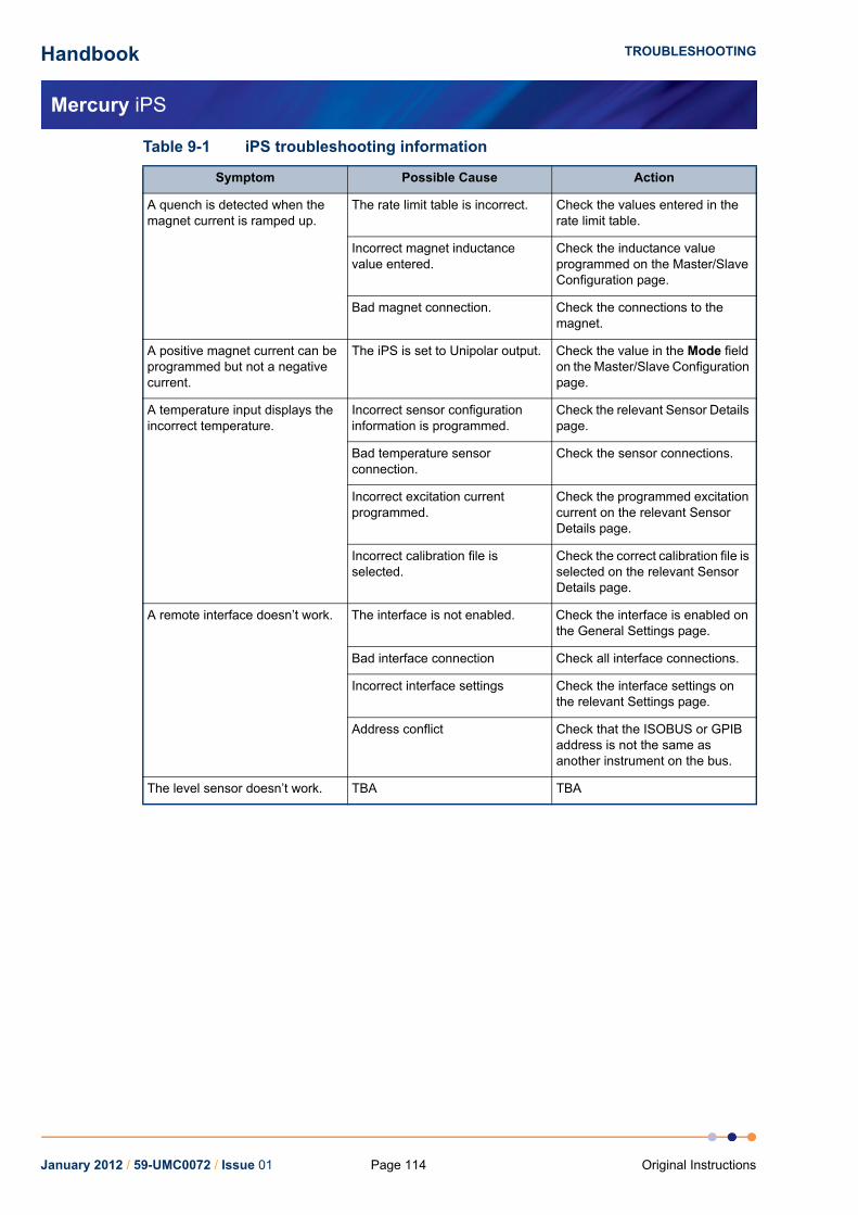
Handbook
Mercury iPS
TROUBLESHOOTING
A quench is detected when the magnet current is ramped up.
The rate limit table is incorrect. Check the values entered in the rate limit table.
Incorrect magnet inductance value entered.
Check the inductance value programmed on the Master/Slave Configuration page.
Bad magnet connection. Check the connections to the magnet.
A positive magnet current can be programmed but not a negative current.
The iPS is set to Unipolar output. Check the value in the Mode field on the Master/Slave Configuration page.
A temperature input displays the incorrect temperature.
Incorrect sensor configuration information is programmed.
Check the relevant Sensor Details page.
Bad temperature sensor connection.
Check the sensor connections.
Incorrect excitation current programmed.
Check the programmed excitation current on the relevant Sensor Details page.
Incorrect calibration file is selected.
Check the correct calibration file is selected on the relevant Sensor Details page.
A remote interface doesn’t work. The interface is not enabled. Check the interface is enabled on the General Settings page.
Bad interface connection Check all interface connections.
Incorrect interface settings Check the interface settings on the relevant Settings page.
Address conflict Check that the ISOBUS or GPIB address is not the same as another instrument on the bus.
The level sensor doesn’t work. TBA TBA
Table 9-1 iPS troubleshooting information
Symptom Possible Cause Action
January 2012 / 59-UMC0072 / Issue 01 Page 114 Original Instructions
Handbook
Mercury iPS
COMMAND REFERENCE GUIDE
10 COMMAND REFERENCE GUIDE
10.1 Nomenclature used in this sectionThe following conventions are used in this document when listing SCPI commands:
Capital letters designate a keyword that must be entered literally (e.g. SET).
Capital letters in angle brackets designate a parameter that must be substituted by the required value (e.g. <UID> might represent DB2, MB1 etc.).
Several words in square brackets, separated by vertical lines, indicate alternative values that a parameter can take (e.g. [LIN | SPL | LAGR]).
10.2 SCPI and legacy command setsThe iPS supports two separate sets of remote commands:
SCPIThese commands are based on the SCPI command set, although the iPS may not be fully compliant with SCPI.
Legacy commandsThese commands were used in previous temperature controller models (e.g. ITC503).
The user configures the iPS to use one set or the other.
It is recommended that new applications use the SCPI command set, as these commands provide greater functionality. The legacy command set is provided so that the iPS is compatible with any existing remote applications that have been written to drive older OINS equipment.
10.3 SCPI command messagesThis section specifies the command message format for communication using the SCPI (Signal Orientated Measurement Commands) derived protocol. Although the messaging protocol is based on SCPI, it is not SCPI compliant.
10.3.1 SCPI protocol conventionsThe commands are case-sensitive.
Keywords are a maximum of four characters long. Keywords longer than four characters generate an invalid command response.
Keywords are separated by a colon : (ASCII 0x3Ah).
The maximum line length is 1024 bytes (characters), including line terminators.
All command lines are terminated by the new line character \n (ASCII 0x0Ah)
January 2012 / 59-UMC0072 / Issue 01Page 115Original Instructions
Handbook
Mercury iPS
COMMAND REFERENCE GUIDE
10.3.2 Reading the overall instrument configurationSend the command:
*IDN?
The format of the reply is:
IDN:OXFORD INSTRUMENTS:MERCURY dd:ss:ff
Where:
dd is the basic instrument type (either iPS, iTC or Cryojet)
ss is the serial number of the main board
ff is the firmware version of the instrument
10.3.3 Basic SCPI command structureThe basic command structure is:
<VERB>:<NOUN>:<NOUN>
All commands generate an <INVALID> response if the command cannot be interpreted (see Section 10.3.5.5).
10.3.4 VerbsThe interface controller can only issue two verbs:
READ - A query command reading information on the specified noun.
SET - Updates information for the specified noun. An attempt to set a read-only noun returns an invalid response.
The iPS replies to both these verbs with a STAT (status) verb:
If responding to a READ verb, the STAT verb is followed by the requested data.
If responding to a SET verb, the STAT verb is followed by the value set.
January 2012 / 59-UMC0072 / Issue 01 Page 116 Original Instructions

Handbook
Mercury iPS
COMMAND REFERENCE GUIDE
10.3.5 NounsElements within the iPS are addressed by a hierarchical structure:
A Board contains a number of Devices.
A Device contains a number of Signals.
The structure of NOUNS reflects this:
Where <UID> is a unique identifier that is allocated to each board, based on its SPI location.
A SYS:CAT command must be executed to retrieve the device UIDs.
The general format of UIDs is:
DB#- for daughter boards, where # is the slot id.
MB# - for the motherboard.
A SIG is returned as a value, followed by the scale.
Scale is of the form:
n# - nano
u# - micro
m# - milli
# - none
k# - kilo
M# - mega
where # is replaced by the relevant SI units, for example:
A - Amps
V - Volts
W - Watts
DEV:<UID>:<TYPE>:SIG:<TYPE>
DEV:<UID>:<TYPE> [TEMP | HTR | LVL | GAS]
SIG:<TYPE> [VOLT | CURR | POWR | RES | TEMP]
January 2012 / 59-UMC0072 / Issue 01Page 117Original Instructions

Handbook
Mercury iPS
COMMAND REFERENCE GUIDE
10.3.5.1 System commandsSystem commands are used for system-level settings.
To enter engineering mode, send the following command:
SET:SYS:MODE:ENG:PASS:******
To exit engineering mode, send the following command:
SET:SYS:MODE:NORM
To change the system password, you must be in engineering mode. Then you can send an issue password command:
SET:SYS:MODE:ENG:PASS:******
SET:SYS:PASS:newpassword
SET:SYS:MODE:NORM
(where ****** is the existing password and newpassword is the new password).
SYS system designator N/A
TIME time in the 24 hour clock Read/Set hh:mm:ss
DATE date Read/Set yyyy:mm:dd
MAN manufacturing designator N/A
HVER hardware version Read only version number
FVER firmware version (GUI/APP) Read only version number
SERL unit serial number Read only alphanumeric
MODE mode of operation [NORM | ENG] Read/Set enumerated value
PASS engineering mode password Set alphanumeric. Required to enter ENG mode.
FLSH amount of free space in flash memory Read free space in kByte
DISP display designator N/A
DIMA auto dim on/off Read/Set OFF, ON
DIMT auto dim time Read/Set seconds
BRIG brightness Read/Set 10.0 to 100.0%
RST reset the system Set N/A
CAT catalogue Read
January 2012 / 59-UMC0072 / Issue 01 Page 118 Original Instructions

Handbook
Mercury iPS
COMMAND REFERENCE GUIDE
Example of a system command
Send the following command to determine the unit configuration:
READ:SYS:CAT?
A system with no daughter boards would return the following:
STAT:DEV:MB0 :TEMP:DEV:MB1 :HTR
This message indicates the motherboard has one temperature sensor in id0 and one heater in id1.
A system with one set of daughter boards might return the following:
STAT:DEV:MB0 :TEMP:DEV:DB1 :TEMP:DEV:MB1 :HTR:DEV:DB2:HTR:DEV:DB3 :AUX:DEV:DB4 :LVL
This message indicates that there are two temperature sensors, two heaters, one auxiliary I/O board, and one level sensor.
10.3.5.2 Addressing a magnet controllerTo address a magnet controller, use the following structure:
DEV:GRPX:PSU
DEV:GRPY:PSU
DEV:GRPZ:PSU
The configuration settings for a magnet controller are:
PSU Power supply designator N/A
MAN Manufacturing designator N/A
HVER Hardware version Read only version number
FVER Firmware version Read only version number
SERL Serial number Read only alphanumeric
NICK Nickname Read/set alphanumeric
BIPL Bipolar output Read/set (EM)
OFF, ON
OCNF Output configuration [PARA | SERS] Read/set (EM)
enumerated set
CLIM Current limit (A) Read/set (EM)
float value(0.0 to 360.00)
ATOB Current to field factor (A/T) Read/set (EM)
float value(1.00 to 30.00)
IND Magnet inductance (H) Read/set (EM)
float value(1.00 to 500.00)
SWPR Switch present Read/set (EM)
OFF, ON
SHTC Switch heater current (mA) Read/set (mA)
float value(0.0 to 125.00)
January 2012 / 59-UMC0072 / Issue 01Page 119Original Instructions

Handbook
Mercury iPS
COMMAND REFERENCE GUIDE
NOTE: EM in the above table= Engineering Mode. These parameters can only be set in engineering mode.
The signals for a magnet controller are:
VLIM Software voltage limit (V) Read/set (EM)
float value(0.00 to 12.49)
VTRN Ignore voltage transient Read/set (EM)
OFF, ON
VTRT Ignore voltage transient time (s) Read/set (EM)
float value(0.00 to 120.00)
VOLT Most recent voltage reading Read only float value
CURR Most recent current reading Read only float value
RCUR Most recent current rate reading Read only float value
FLD Most recent field reading Read only float value
RFLD Most recent field rate reading Read only float value
PCUR Most recent persistent current reading
Read only float value
PFLD Most recent persistent field reading Read only float value
CSET Most recent target current reading / current to set
Read/set float value(-CLIM to CLIM)
FSET Most recent target field reading / field to set
Read/set float value(-CLIM/ATOB toCLIM/ATOB)
RCST Most recent target current rate reading / current rate to set
Read/set float value(0.00 to 1200.00)
RFST Most recent target field rate reading / field rate to set
Read/set float value(0.00 to 50.00)
NOTE: Ramp rates are limited by the rate limit table.
SWHT Switch heater status/set[ON | OFF] (if CURR= PCUR)
Read/set enumerated set
SWHN Set [ON | OFF] without checking if CURR= PCUR.
Set enumerated set
ACTN PSU action status/set[HOLD | RTOS | RTOZ | CLMP]
enumerated set
NOTE: RTOS= Ramp to set, RTOZ= Ramp to zero, CLMP= clamp output if CURR=0.
January 2012 / 59-UMC0072 / Issue 01 Page 120 Original Instructions

Handbook
Mercury iPS
COMMAND REFERENCE GUIDE
10.3.5.3 Addressing a temperature sensorTo address a temperature sensor, use the following structure:
DEV:<UID>:TEMP
Where <UID> is a unique identifier that is allocated to each board, based on its SPI location.
The configuration settings for a temperature sensor are:
TEMP Temperature sensor designator N/A
MAN Manufacturing designator N/A
HVER Hardware version Read only version number
FVER Firmware version Read only version number
SERL Serial number Read only alphanumeric
NICK Nickname Read/set alphanumeric
TYPE [PTC | NTC | DDE | TCE] Read/set Enumerated set
EXCT Excitation designator N/A
TYPE Excitation type [UNIP | BIP | SOFT] Read/set Enumerated set
MAG Excitation magnitude Read/set Float value followed by a scale
CAL Calibration designator N/A
FILE Calibration file name Read/set Filename
INT Interpolation type [LIN | SPL | LAGR] Read/set Enumerated set
SCAL Scaling factor Read/set Float value [0.5 to 1.5]
OFFS Offset value Read/set Float value [-100.0 to 100.0]
HOTL Hot limit Read only Float value
COLD Cold limit Read only Float value
January 2012 / 59-UMC0072 / Issue 01Page 121Original Instructions

Handbook
Mercury iPS
COMMAND REFERENCE GUIDE
The signals for a temperature sensor are:
NOTE: The signals that are available depend on the type of sensor being addressed. If a signal is unavailable, the message INVALID is returned.
Example of configuring a temperature sensor
The following command configures a temperature sensor:
SET:DEV:MB0 :TEMP:TYPE:PTC:EXCT:TYPE:UNIP:MAG:10uA:CALB:RP5:DAT
If this command is successfully completed, the following message is returned:
STAT:SET:DEV:MB0 :TEMP:TYPE:PTC:EXCT:TYPE:UNIP:MAG:10uA:CALB:RP5:DAT
If the excitation type is not supported, the following message is returned:
STAT:SET:DEV:MB0 :TEMP:TYPE:PTC:EXCT:TYPE:INVALID:MAG:INVALID:CALB:RP5:DAT
NOTE: All the new settings that are valid are set. All the new settings that are invalid are not changed.
Example of reading a temperature sensor
The following command reads the sensor voltage:
READ:DEV:MB0 :SIG:VOLT?
The sensor returns the following message:
STAT:DEV:MB0 :SIG:VOLT:12.345:mV
VOLT Most recent voltage reading Read only Float value
CURR Most recent current reading Read only Float value
POWR Most recent power reading Read only Float value
RES Most recent resistance reading Read only Float value
TEMP Most recent temperature reading Read only Float value
SLOP Temperature sensitivity Read only Float value
January 2012 / 59-UMC0072 / Issue 01 Page 122 Original Instructions
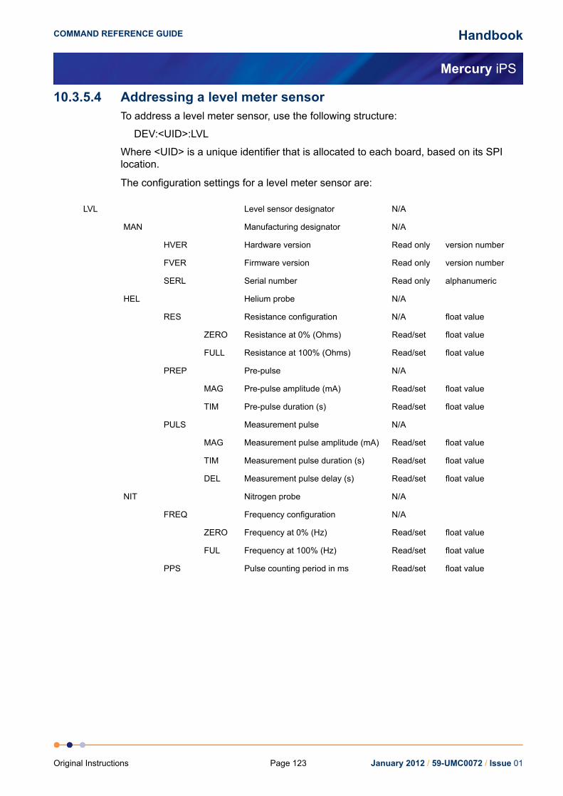
Handbook
Mercury iPS
COMMAND REFERENCE GUIDE
10.3.5.4 Addressing a level meter sensorTo address a level meter sensor, use the following structure:
DEV:<UID>:LVL
Where <UID> is a unique identifier that is allocated to each board, based on its SPI location.
The configuration settings for a level meter sensor are:
LVL Level sensor designator N/A
MAN Manufacturing designator N/A
HVER Hardware version Read only version number
FVER Firmware version Read only version number
SERL Serial number Read only alphanumeric
HEL Helium probe N/A
RES Resistance configuration N/A float value
ZERO Resistance at 0% (Ohms) Read/set float value
FULL Resistance at 100% (Ohms) Read/set float value
PREP Pre-pulse N/A
MAG Pre-pulse amplitude (mA) Read/set float value
TIM Pre-pulse duration (s) Read/set float value
PULS Measurement pulse N/A
MAG Measurement pulse amplitude (mA) Read/set float value
TIM Measurement pulse duration (s) Read/set float value
DEL Measurement pulse delay (s) Read/set float value
NIT Nitrogen probe N/A
FREQ Frequency configuration N/A
ZERO Frequency at 0% (Hz) Read/set float value
FUL Frequency at 100% (Hz) Read/set float value
PPS Pulse counting period in ms Read/set float value
January 2012 / 59-UMC0072 / Issue 01Page 123Original Instructions

Handbook
Mercury iPS
COMMAND REFERENCE GUIDE
The signals for a level meter sensor are:
10.3.5.5 Addressing an auxiliary I/O daughter boardTo address an auxiliary board, use the following structure:
DEV:<UID>:AUX
Where <UID> is a unique identifier that is allocated to each board, based on its SPI location.
The configuration settings for an auxiliary board are:
The signals for an auxiliary board are:
HEL Helium probe N/A
RES Probe measured resistance (Ohms) Read only float value
LEV Probe calculated level (%) Read only float value
NIT Nitrogen probe N/A
COUN Probe measured counter value Read only unsigned integer
FREQ Probe calculated frequency value (Hz)
Read only float value
LEV Probe calculated level (%) Read only float value
AUX Auxiliary board designator N/A
MAN Manufacturing designator N/A
HVER Hardware version Read only version number
FVER Firmware version Read only version number
SERL Serial number Read only alphanumeric
GMIN Minimum gas flow setting Read/set float value(0.0 to 20.0)
GFSF Gas flow scaling factor Read/set float value(0.0 to 99.0)
TES Temperature error sensitivity Read/set float value(0.0 to 20.0)
TVES Temperature voltage error sensitivity Read/set float value(0.0 to 20.0)
GEAR Valve gearing Read/set unsigned integer(0 to 7)
SPD Stepper speed Read/set unsigned integer(0=slow, 1= fast)
STEP Present position of the stepper motor Read only unsigned integer(0.0 to Max Steps)
OPEN Percentage open Read/set float value(0.0 to 100.0)
January 2012 / 59-UMC0072 / Issue 01 Page 124 Original Instructions
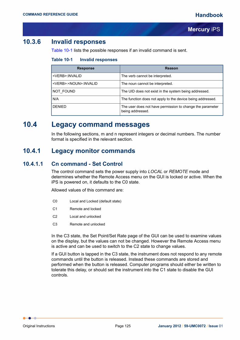
Handbook
Mercury iPS
COMMAND REFERENCE GUIDE
10.3.6 Invalid responsesTable 10-1 lists the possible responses if an invalid command is sent.
10.4 Legacy command messagesIn the following sections, m and n represent integers or decimal numbers. The number format is specified in the relevant section.
10.4.1 Legacy monitor commands
10.4.1.1 Cn command - Set ControlThe control command sets the power supply into LOCAL or REMOTE mode and determines whether the Remote Access menu on the GUI is locked or active. When the iPS is powered on, it defaults to the C0 state.
Allowed values of this command are:
In the C3 state, the Set Point/Set Rate page of the GUI can be used to examine values on the display, but the values can not be changed. However the Remote Access menu is active and can be used to switch to the C2 state to change values.
If a GUI button is tapped in the C3 state, the instrument does not respond to any remote commands until the button is released. Instead these commands are stored and performed when the button is released. Computer programs should either be written to tolerate this delay, or should set the instrument into the C1 state to disable the GUI controls.
Table 10-1 Invalid responses
Response Reason
<VERB>:INVALID The verb cannot be interpreted.
<VERB>:<NOUN>:INVALID The noun cannot be interpreted.
NOT_FOUND The UID does not exist in the system being addressed.
N/A The function does not apply to the device being addressed.
DENIED The user does not have permission to change the parameter being addressed.
C0 Local and Locked (default state)
C1 Remote and locked
C2 Local and unlocked
C3 Remote and unlocked
January 2012 / 59-UMC0072 / Issue 01Page 125Original Instructions

Handbook
Mercury iPS
COMMAND REFERENCE GUIDE
10.4.1.2 Rn command - Read ParameterThe READ command allows the computer to interrogate a number of variables. The returned value is always a decimal number.
Possible values for the command are listed below:
NOTE: Variables marked with a "*" are used for service diagnostics only.
10.4.1.3 V command - Read VersionThe VERSION command requires no parameters. It returns a message indicating the instrument type and firmware version number.
R0 Demand current (output current) amp
R1 Measured power supply voltage volt
R2 Measured magnet current amp
R3 Unused
R4 * Demand current (duplicate of R0) amp
R5 Setpoint (target current) amp
R6 Current sweep rate amp/minute
R7 Demand field (output field) tesla
R8 Setpoint (target field) tesla
R9 Field sweep rate tesla/minute
R10 * DAC zero offset amp
R11 * Channel 1 frequency/4
R12 * Channel 2 frequency/4
R13 * Channel 3 frequency/4
R14 * Demand current (duplicate of R0) amp
R15 Software voltage limit volt
R16 Persistent magnet current tesla
R17 Trip current amp
R18 Persistent magnet field tesla
R19 Trip field tesla
R20 Switch heater current milliamp
R21 Safe current limit, most negative amp
R22 Safe current limit, most positive amp
R23 Lead resistance milliohm
R24 Magnet inductance henry
January 2012 / 59-UMC0072 / Issue 01 Page 126 Original Instructions

Handbook
Mercury iPS
COMMAND REFERENCE GUIDE
10.4.1.4 X command - Examine StatusThe EXAMINE command allows the computer to read the present power supply STATUS. The command requires no parameters and returns a message string with a fixed length of 15 characters.
The returned string is of the form:
XmnAnCnHnMmnPmn
Where:
Xmn System Status
m=0 Normal
m=1 Quenched
m=2 Overheated
m=4 Warming up
m=8 Fault
n=0 Normal
n=1 On the positive voltage limit
n=2 On the negative voltage limit
n=4 Outside the negative current limit
n=8 Outside the positive current limit
An Activity
n=0 Hold
n=1 To setpoint
n=2 To zero
n=4 Clamped
Cn Local/Remote Status
n=0 Local and locked
n=1 Remote and locked
n=2 Local and unlocked
n=3 Remote and unlocked
n=4 Auto rundown
n=5 Auto rundown
n=6 Auto rundown
n=7 Auto rundown
January 2012 / 59-UMC0072 / Issue 01Page 127Original Instructions

Handbook
Mercury iPS
COMMAND REFERENCE GUIDE
The active states SWEEPING and SWEEP LIMITING indicate the mode in which the output current is changing.
A changing output in IMMEDIATE mode (e.g. magnet persistent) is flagged by SWEEP LIMITING only.
In SWEEP mode (e.g. changing the magnet current), only SWEEPING will be indicated. However if the attempted sweep rate exceeds the sweep rate limit, SWEEP LIMITING will also be indicated.
Hn Switch Heater
n=0 Off magnet at zero (switch closed)
n=1 On (switch open)
n=2 Off magnet at field (switch closed)
n=5 Heater fault (heater is on but the current is low)
n=8 No switch fitted
Mmn Mode
Display Magnet Sweep
m=0 amps Fast
m=1 tesla Fast
m=4 amps Slow
m=5 tesla Slow
n=0 At rest (output constant)
n=1 Sweeping (output changing)
n=2 Sweep limiting (output changing)
n=3 Sweeping and sweep limiting (output changing)
January 2012 / 59-UMC0072 / Issue 01 Page 128 Original Instructions

Handbook
Mercury iPS
COMMAND REFERENCE GUIDE
For iPS power supplies, the polarity flags are superseded by signed numbers for currents and fields. The polarity flags are included here for compatibility with the earlier PS120-10. The user should ignore these flags.
10.4.2 Legacy control commands
10.4.2.1 An command - Set ActivityThe ACTIVATE command corresponds to the use of the Hold, To Set and To Zero buttons on the GUI. A fourth state, CLAMP, can also be selected. CLAMP corresponding to the state the iPS is in when it powers up.
Allowed values for this command are:
When the power supply is in its clamped state, A1 and A2 are not recognised.
Pmn Polarity
Desired Magnet Commanded
m=0 Positive Positive Positive
m=1 Positive Positive Negative
m=2 Positive Negative Positive
m=3 Positive Negative Negative
m=4 Negative Positive Positive
m=5 Negative Positive Negative
m=6 Negative Negative Positive
m=7 Negative Negative Negative
n=1 Negative contactor closed Verification flags
n=2 Positive contactor closed Verification flags
n=3 Both contactors open Verification flags
n=4 Both contactors closed Verification flags
A0 Hold
A1 To setpoint
A2 To zero
A4 Clamp (clamps the output of the power supply.
January 2012 / 59-UMC0072 / Issue 01Page 129Original Instructions

Handbook
Mercury iPS
COMMAND REFERENCE GUIDE
10.4.2.2 Fn command - Set Front Panel to Display ParameterThe FRONT PANEL DISPLAY command sets the display to show one of the internal parameters rather than the normal demanded current or field.
Possible values of the command are:
Normal display operation may be restored by any of the following methods:
Sending an F0 command (for current display)
Sending an F7 command (for field display)
Pressing the Amp/Tesla button on the GUI twice.
The Fn command is used during test and fault diagnosis.
F0 Demand current (output current) amp
F1 Measured power supply voltage volt
F2 Measured magnet current amp
F3 Unused
F4 * Demand current (duplicate of F0) amp
F5 Setpoint (target current) amp
F6 Current sweep rate amp/minute
F7 Demand field (output field) tesla
F8 Setpoint (target field) tesla
F9 Field sweep rate tesla/minute
F10 * DAC zero offset amp
R11 * Channel 1 frequency/4
F12 * Channel 2 frequency/4
F13 * Channel 3 frequency/4
F14 * Demand current (duplicate of F0) amp
F15 Software voltage limit volt
F16 Persistent magnet current tesla
F17 Trip current amp
F18 Persistent magnet field tesla
F19 Trip field tesla
F20 Switch heater current milliamp
F21 Safe current limit, most negative amp
F22 Safe current limit, most positive amp
F23 Lead resistance milliohm
F24 Magnet inductance henry
January 2012 / 59-UMC0072 / Issue 01 Page 130 Original Instructions

Handbook
Mercury iPS
COMMAND REFERENCE GUIDE
10.4.2.3 Hn command - Set Switch HeaterThe HEATER command activates the switch heater, if fitted.
Possible values for the command are:
The H1 command only opens the switch if the recorded magnet current is equal to the present power supply output current. The magnitude and polarity of the current are both considered.+0 and -0 amps are considered to be equal values.
Note that the H2 command opens the switch without checking if the recorded magnet current is equal to the present power supply output current.
Please note the following points:
1 After issuing a command, wait for several seconds for the switch to respond.
2 Changing the state of the switch heater automatically sets SWEEP or IMMEDIATE mode:
a) IMMEDIATE mode is selected only if a superconducting switch is fitted and is closed.
b) Otherwise the control of the power supply is always in SWEEP mode.Note that in IMMEDIATE mode, changes occur at a limiting rate, not as an instantaneous step. For example it might take 30 seconds for the output to change from zero to full current.In SWEEP mode, changes occur at a rate specified by the S or T command, unless the demanded rate exceeds the rate limit.
10.4.2.4 In command - Set Target CurrentThe I command sets the setpoint (target) current that the iPS will sweep to.
The parameter n is the required current sent as a decimal number. The resolution of the set current is 0.001 amp.
10.4.2.5 Jn command - Set Target FieldThe J command sets the setpoint (target) field that the iPS will sweep to.
The parameter n is the required field sent as a decimal number. The resolution of the set field is 0.0001 tesla.
H0 Heater off close switch
H1 Heater on if PSU Current = Magnet Current open switch
H2 Heater on, with no checks open switch
Caution
CAUTIONSending an H2 command opens the persistent switch, even if the
magnet current is not equal to the power supply current. Using this command incorrectly can cause equipment damage.
January 2012 / 59-UMC0072 / Issue 01Page 131Original Instructions
Handbook
Mercury iPS
COMMAND REFERENCE GUIDE
10.4.2.6 Pn command - Set PolarityThe POLARITY command is not necessary for operation of the iPS, but is included here for compatibility with the earlier PS120-10 power supply.
The POLARITY command sets the desired polarity of the output current. If the activity is set to SET POINT and the polarity is to be changed, the power supply sweeps to zero, changes the polarity of the magnet, and then sweeps up to the set point current. Possible values for the command are:
10.4.2.7 Sn command - Set Current Sweep RateThe SWEEP RATE command sets the sweep rate (amps/minute) that will be used when the iPS is in SWEEP mode. The parameter n is the required sweep rate sent as a decimal number.
The selected sweep rate only applies when the power supply is operated in SWEEP mode (for example, when the persistent switch is open). It is not necessary for the PSU to be in SWEEP mode when the S command is issued.
10.4.2.8 Set Field Sweep RateThe SWEEP RATE command sets the sweep rate (tesla/minute) that will be used when the iPS is in SWEEP mode. The parameter n is the required sweep rate sent as a decimal number. The resolution is 0.001 tesla/minute.
The selected sweep rate only applies when the power supply is operated in SWEEP mode (for example, when the persistent switch is open). It is not necessary for the PSU to be in sweep mode when the T command is issued.
10.4.3 Legacy system commands
10.4.3.1 ! command - Set ISOBUS AddressSee Section 7.3.
P0 No action
P1 Set positive current
P2 Set negative current
P4 Swap polarity of the current
January 2012 / 59-UMC0072 / Issue 01 Page 132 Original Instructions

Handbook
Mercury iPS
TECHNICAL SPECIFICATIONS
11 TECHNICAL SPECIFICATIONSThis chapter lists the technical specifications of the Mercury iPS.
11.1 Master unit
11.1.1 Physical specification - master
11.1.2 Electrical power supply - master
11.1.3 Magnet and persistent-switch heater output - master
Table 11-1 Physical specifications
Item Specification
Width 426 mm
Depth 480 mm
Height 131 mm
Weight TBA kg
Table 11-2 Specifications of the electrical power supply - master
Item Specification
Mains supply voltage 100 VAC to 240 VAC
Mains supply frequency 47 Hz to 63 Hz
Maximum supply power 800 W
Maximum mains voltage fluctuation ±10% of nominal voltage
Category II transient overvoltages can typically be present on the mains supply.
Table 11-3 Specifications of the magnet output - master
Item Specification
Current output -60 A to +60 A
Voltage output -10 V to +10 V
Maximum output power 600 W
Output polarity Bipolar
Load inductance 0 H to 1000 H
Load resistance 0.001 ohms to open circuit
Output current resolution 0.1 mA
Output current stability ±3 mA per °C after 20 minutes warm-up
January 2012 / 59-UMC0072 / Issue 01Page 133Original Instructions

Handbook
Mercury iPS
TECHNICAL SPECIFICATIONS
11.1.4 Temperature sensor inputs - master
The unit can accommodate thermocouple sensors with cold-junction compensation (CJC).
The unit can accommodate silicon-diode sensors (constant current supply).
The unit detects short-circuit inputs, open-circuit inputs, and inputs that are shorted to ground.
The unit can store calibration files for sensors and can automatically set range-limits from the calibration file.
The user does not need to set the zero or the span for calibrated sensors.
Table 11-4 Examples of master and slave configurations
Configuration Maximum Current Output
Maximum Voltage Output
1 Master and 1 Slave in series. 60 A 20 V
1 Master and 1 Slave in parallel 120 A 10 V
4 parallel branches, each having two units in series
240 A 20 V
Table 11-5 Specifications of the persistent-switch heater output - master
Item Specification
Maximum output current 120 mA
Maximum output voltage 12 V
Persistent-switch heater resistance 0 ohms to 100 ohms
Table 11-6 Specifications of temperature sensor inputs
Item Specification
Basic unit - single sensor input Upgradeable to 9 sensor inputs
NTC resistance range 5 Ohms to 200 kOhms
Constant voltage Typically <10 mV
PTC resistance range 5 Ohms to 3 kOhms
Constant current 0.1 to 1000 μA
Sensors to be connected with four wires (pins 1, 3, 4 & 5) of 9-way D-connector on iPS.Pin 2 is sense shield.
Sensor ADC resolution 24 bit
Resistance-sensor excitation modes Unipolar or bipolar
Sensor sampling rate Typically 1 Hz. Maximum 10 Hz.
January 2012 / 59-UMC0072 / Issue 01 Page 134 Original Instructions

Handbook
Mercury iPS
TECHNICAL SPECIFICATIONS
11.1.5 PC interfaces - master
11.1.6 Electrical isolation - master
The mains-supply to chassis conforms to EN61010 and UL/CSA standard.
The mains-supply is double-insulated from all other terminals.
11.1.7 Environmental specifications - master
Table 11-7 PC interface specifications - master
Item Specification
Serial interface RS232 + ISOBUS
Serial interface 2 USB
GPIB IEEE-488 (optional)
Ethernet 10/100 IEE802.3
SPI bus Output port to control slave units
Table 11-8 Electrical isolation specifications
Item Specification
Sensor terminals to chassis >50 VDC
Communications 0 V to chassis >50 VDC
Communications to sensor >50 VDC
Table 11-9 Environmental specifications
Item Specification
Recommended ambient temperature 20°C to 30°C
Ambient temperature (with reduced performance)
0° to 35°C
Shipping and storage temperature -30°C to 85°C
Atmospheric pressure 800 hPA to 1060 hPA (2000 m to sea-level)
Maximum relative humidity 75% non-condensing
Pollution degree 2
January 2012 / 59-UMC0072 / Issue 01Page 135Original Instructions

Handbook
Mercury iPS
TECHNICAL SPECIFICATIONS
11.2 Optional slave units
11.2.1 Physical specification - slave
11.2.2 Electrical power supply - slave
11.2.3 Magnet and persistent-switch heater output - slave
Table 11-10 Physical specifications
Item Specification
Width 426 mm
Depth 480 mm
Height 131 mm
Weight TBA kg
Table 11-11 Specifications of the electrical power supply - slave
Item Specification
Mains supply voltage 100 VAC to 240 VAC
Mains supply frequency 47 Hz to 63 Hz
Maximum supply power 800 W
Maximum mains voltage fluctuation ±10% of nominal voltage
Category II transient overvoltages can typically be present on the mains supply.
Table 11-12 Specifications of the magnet output - slave
Item Specification
Current output -60 A to +60 A
Voltage output -10 V to +10 V
Maximum output power 600 W
Output polarity Bipolar
Load inductance 0 H to 1000 H
Load resistance 0.001 ohms to open circuit
Output current resolution 0.1 mA
Output current stability ±3 mA per °C after 20 minutes warm-up
January 2012 / 59-UMC0072 / Issue 01 Page 136 Original Instructions

Handbook
Mercury iPS
TECHNICAL SPECIFICATIONS
11.2.4 PC interfaces - slave
11.2.5 Electrical isolation - slave
The mains-supply to chassis conforms to EN61010 and UL/CSA standard.
The mains-supply is double-insulated from all other terminals.
11.2.6 Environmental specifications - slave
Table 11-13 Specifications of the switch-heater output - slave
Item Specification
Maximum output current 120 mA
Maximum output voltage 12 V
Persistent-switch heater resistance 0 ohms to 100 ohms
Table 11-14 PC interface specifications - slave
Item Specification
SPI bus Input port for control
SPI bus Output port for control
Table 11-15 Electrical isolation specifications
Item Specification
Sensor terminals to chassis >50 VDC
Communications 0 V to chassis >50 VDC
Communications to sensor >50 VDC
Table 11-16 Environmental specifications
Item Specification
Recommended ambient temperature 20°C to 30°C
Ambient temperature (with reduced performance)
0° to 35°C
Shipping and storage temperature -30°C to 85°C
Atmospheric pressure 800 hPA to 1060 hPA (2000 m to sea-level)
Maximum relative humidity 75% non-condensing
Pollution degree 2
January 2012 / 59-UMC0072 / Issue 01Page 137Original Instructions

Handbook
Mercury iPS
TECHNICAL SPECIFICATIONS
This page is intentionally blank.
Page 138January 2012 / 59-UMC0072 / Issue 01 Original Instructions

Handbook
Mercury iPS
TEMPERATURE SENSOR daughter BOARD
12 TEMPERATURE SENSOR DAUGHTER BOARDThis chapter describes the single temperature sensor board.
12.1 Overview of the temperature sensor boardThe unit can accept the following sensor types:
NTC resistance
PTC resistance
Thermocouple
Silicon diode
Each input can be read at a maximum rate of 10 Hz. The unit can detect short-circuit inputs, open-circuit inputs, and inputs that are shorted to ground.
The iPS contains a temperature sensor that is used to compensate for fluctuations in ambient temperature.
12.2 Installing a temperature sensor board
12.2.1 Fitting the boardA temperature sensor board can be fitted in any expansion slot.
1 Turn off electrical power to the iPS.
2 Remove the electrical power connector from the back of the unit.
3 Remove the screws that secure the lid of the iPS. There are 6 screws on either side panel of the MPSU and 3 screws on the rear panel.
4 Lift off the lid.
5 Remove the two screws that secure the board-clamp. Remove the board clamp.
Figure 12-1 Board-clamp
January 2012 / 59-UMC0072 / Issue 01Page 139Original Instructions

Handbook
Mercury iPS
TEMPERATURE SENSOR daughter BOARD
6 Remove the screw that secures the blanking panel in the location where the board is to be fitted. Keep the screw.
Figure 12-2 Daughter-board blanking-panel
7 Using appropriate ESSD precautions, fit the temperature board in the allocated expansion slot.
8 Secure the board using the screw that was removed in step 6.
9 Refit the board-clamp, using the two screws that were removed earlier.
10 Fit the lid back onto the unit, using the screws that were removed earlier.
12.2.2 Connecting the sensorA single-sensor board has a single 9-way D-connector.
12.2.3 Configuring the temperature sensor boardSee Section 2.5.2 for details.
January 2012 / 59-UMC0072 / Issue 01 Page 140 Original Instructions
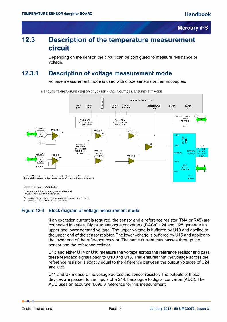
Handbook
Mercury iPS
TEMPERATURE SENSOR daughter BOARD
12.3 Description of the temperature measurement circuitDepending on the sensor, the circuit can be configured to measure resistance or voltage.
12.3.1 Description of voltage measurement modeVoltage measurement mode is used with diode sensors or thermocouples.
Figure 12-3 Block diagram of voltage measurement mode
If an excitation current is required, the sensor and a reference resistor (R44 or R45) are connected in series. Digital to analogue converters (DACs) U24 and U25 generate an upper and lower demand voltage. The upper voltage is buffered by U10 and applied to the upper end of the sensor resistor. The lower voltage is buffered by U15 and applied to the lower end of the reference resistor. The same current thus passes through the sensor and the reference resistor.
U13 and either U14 or U16 measure the voltage across the reference resistor and pass these feedback signals back to U10 and U15. This ensures that the voltage across the reference resistor is exactly equal to the difference between the output voltages of U24 and U25.
U11 and U7 measure the voltage across the sensor resistor. The outputs of these devices are passed to the inputs of a 24-bit analogue to digital converter (ADC). The ADC uses an accurate 4.096 V reference for this measurement.
January 2012 / 59-UMC0072 / Issue 01Page 141Original Instructions

Handbook
Mercury iPS
TEMPERATURE SENSOR daughter BOARD
The reference resistors are 2 kΩ and 80 kΩ. Depending on the excitation current, the resistor and gain factor are chosen so that the ADC input voltage is in the optimum range.
The sensor voltage is:
Vsensor= Vref x ADCnorm/ADCgain
Where:
ADCnorm is the ADC reading normalised to the range 0 to ±1 V.
ADCgain is the gain setting of the ADC.
The temperature of the sensor to heater connection is measured for thermocouple correction.
If an excitation current is not required (i.e. for a thermocouple sensor), U10 and U15 are switched off.
12.3.2 Description of constant current measurement modeConstant current measurement mode is used with sensors that have a positive temperature coefficient.
Figure 12-4 Block diagram of constant current measurement mode
The sensor and a reference resistor (either R44 or R45) are connected in series. Digital to analogue converters U24 and U25 generate an upper and lower demand voltage. This voltage is equal to the required current multiplied by the value of the selected reference resistor.
January 2012 / 59-UMC0072 / Issue 01 Page 142 Original Instructions

Handbook
Mercury iPS
TEMPERATURE SENSOR daughter BOARD
The upper voltage is buffered by U10 and applied to the upper end of the sensor resistor. The lower voltage is buffered by U15 and applied to the lower end of the reference resistor. The same current thus passes through the sensor and the reference resistor.
U13 and either U14 or U16 measure the voltage across the reference resistor and pass these feedback signals back to U10 and U15. This ensures that the voltage across the reference resistor is exactly equal to the difference between the output voltages of U24 and U25.
The outputs of U13 and either U14 or U16 are also scaled by a reference gain multiplier, whose gain is selected to give an output in the range 1 V to 2.5 V. This voltage is then passed to the reference voltage inputs of the ADC (U12). This circuit configuration produces a ratiometric measurement technique.
The resistance of the sensor is:
Rsensor= Rref x |ADCnorm| x RefGain/ADCgain
Where:
Rref is the reference resistance (either 2 kΩ or 80 kΩ).
ADCnorm is the ADC reading, normalised to the range 0 to ±1 V.
RefGain is the interpolated gain from the calibration tables.
ADCgain is the gain setting of the ADC.
The measurement accuracy of this circuit does not depend on the accuracy of the excitation current or the reference voltage. The accuracy primarily depends on the accuracy of the reference resistor plus any errors introduced by operational amplifiers.
January 2012 / 59-UMC0072 / Issue 01Page 143Original Instructions

Handbook
Mercury iPS
TEMPERATURE SENSOR daughter BOARD
12.3.3 Description of constant voltage measurement modeConstant voltage measurement mode is used with sensors that have a negative temperature coefficient.
Figure 12-5 Block diagram of constant voltage measurement mode
The sensor and a reference resistor (either R44 or R45) are connected in series. Digital to analogue converters U24 and U25 generate an upper and lower demand voltage. The upper voltage is buffered by U10 and applied to the upper end of the sensor resistor. The lower voltage is buffered by U15 and applied to the lower end of the reference resistor. The same current thus passes through the sensor and the reference resistor.
U7 and U11 measure the voltage across the sensor and drive the inputs of ADC U12. The outputs of U7 and U11 are also fed back to U10 and U15. This ensures that the voltage across the sensor is exactly equal to the demand voltage generated by U24 and U25.
January 2012 / 59-UMC0072 / Issue 01 Page 144 Original Instructions

Handbook
Mercury iPS
TEMPERATURE SENSOR daughter BOARD
U13 and either U14 or U16 measure the voltage across the reference resistor. This differential voltage is scaled by a reference gain multiplier, whose gain is selected to give an output in the range 1 V to 2.5 V. This voltage is then passed to the reference voltage inputs of the ADC (U12). This circuit configuration produces a ratiometric measurement technique. The resistance of the sensor is:
Rsensor= Rref x |ADCnorm| x RefGain/ADCgain
Where:
Rref is the reference resistance (either 2 kΩ or 80 kΩ).
ADCnorm is the ADC reading, normalised to the range 0 to ±1 V.
RefGain is the interpolated gain from the calibration tables.
ADCgain is the gain setting of the ADC.
The measurement accuracy of this circuit does not depend on the accuracy of the excitation or reference voltages. The accuracy primarily depends on the accuracy of the reference resistor plus any errors introduced by operational amplifiers.
12.3.4 Calibrating the temperature measurement circuitFigure 12-6 shows a block diagram of the temperature measurement circuit in calibration mode.
Figure 12-6 Temperature measurement circuit calibration
The calibration is performed using a ratiometric circuit configuration. In calibration mode, DACs U24 and U25 supply a differential calibration voltage to the input of ADC U12. This same differential voltage is scaled by a reference gain multiplier circuit, and supplied to the reference voltage inputs of U12.
The ADC input has a programmable gain amplifier (PGA) with five gain settings (1, 8, 16, 64 and 128). An autocalibration is performed for each range.
January 2012 / 59-UMC0072 / Issue 01Page 145Original Instructions

Handbook
Mercury iPS
TEMPERATURE SENSOR daughter BOARD
The reference gain multiplier is also programmable with eight gains (1, 2, 4, 8, 16, 32, 64 and 128). Each gain is calibrated at low and high reference voltages (1.2 V and 2.4 V). The exact gain that is used for calculating sensor resistance is a linear interpolation between these two values.
It is only necessary to perform this calibration using a positive excitation voltage. The ADC is operated in chop mode, which eliminates any offsets in the ADC.
Calibration is performed using the highest possible ADC accuracy setting, which is also the slowest acquisition time. The results are stored in flash memory for use during a measurement whenever a range is changed. Calibration is not performed every time a range is changed, as this would cause unacceptable measurement delays.
January 2012 / 59-UMC0072 / Issue 01 Page 146 Original Instructions

Handbook
Mercury iPS
LEVEL-METER DAUGHTER BOARD
13 LEVEL-METER DAUGHTER BOARDThis chapter describes the level-meter daughter board.
13.1 Description of the level-meter boardThe level-meter board monitors the level of cryogen in a reservoir. The board can be used with liquid helium and liquid nitrogen systems. The level-meter raises an error if the cryogen level falls below a safe level.
The level-meter board uses a superconducting-wire probe to measure the depth of liquid helium, or a capacitance probe to detect the level of liquid nitrogen.
There are two 9-way D connectors on the board; one for a nitrogen sensor and one for a helium sensor.
13.1.1 Principles of operation
13.1.1.1 Operation of the board with a helium-level probeThe probe is a length of superconducting wire extending from the bottom to the top of the helium reservoir. The probe is normally mounted vertically, although other geometries are possible.
The section of wire below the liquid surface is cooled more efficiently that the section in the gas above the liquid. The level-meter controls the current through the wire such that the temperature of the section in the gas is above the critical temperature (and is thus resistive), while the section in the liquid is below the critical temperature (and thus superconducting). The length of the resistive section of the wire thus depends on the level of liquid in the reservoir.
To minimise heating of the sample, the current in the wire is turned off after a measurement has been made. Because there is zero current through the probe, the whole length of wire becomes superconducting between measurements. When the next measurement is made, it is necessary to introduce heat into the section of wire in the gas to make it resistive. A small heater-resistor is mounted in thermal contact with the top of the wire to heat a small section of wire. If the current in the wire is sufficient, the resistive section propagates down the wire until it extends to the surface of the liquid.
When the measurement has been made, the current in the wire is turned off again. The measurement is performed at intervals between a few second to a few hours, depending on the expected rate of change of the liquid level. Do not perform measurements too often, as each measurement boils off a small quantity of helium. A fast sampling rate is available for use when the reservoir is being filled.
The maximum probe-length depends on the resistivity of the probe wire:
For probes up to 1.4 m in length, a wire resistivity of 166 Ohms/meter is used, with a current of 130 mA.
For probes up to 2 m in length, a wire of resistivity of 61.2 Ohms/meter is used, with a current of 250 mA.
January 2012 / 59-UMC0072 / Issue 01Page 147Original Instructions

Handbook
Mercury iPS
LEVEL-METER DAUGHTER BOARD
13.1.1.2 Operation of the board with a nitrogen-level probeThe nitrogen-probe consists of two concentric steel-tubes. The tubes act as the plates of a capacitor, while the annular space between them acts as a dielectric. Liquid-nitrogen has a relative permittivity of 1.45, so the capacitance of the section of probe under the liquid surface increases by approximately 45%.
The probe-head includes an oscillator whose frequency depends on the capacitance of the probe. Thus the oscillator frequency also depends on the level of liquid.
The probe-head requires no adjustment. the working range of the oscillator (5 kHz to 65 kHz) accommodates probes up to 2 metres long.
13.1.1.3 Explanation why different methods are used for the two liquidsLiquid helium has a relative permittivity of only 1.055, which is similar to the relative permittivity of helium gas at 4.2 K. The capacitance probe is thus not sensitive to the liquid level when used with liquid helium.
It is possible to make a liquid-nitrogen probe using a wire made of a high-temperature superconductor. However this probe would be much less robust than a capacitive probe.
13.1.1.4 Refill controlThe level meter board can control a valve to refill the unpressurised dewar from a pressurised dewar. The valve must be driven from an unused output of the auxiliary I/O board (see Section 15.2.2).
13.2 Installing the level-meter board
13.2.1 Fitting the boardThe level-meter board can be fitted in any expansion slot. Only one level meter board can be fitted in a Mercury iPS, because of power consumption limitations.
1 Turn off electrical power to the iPS.
2 Remove the electrical power connector from the back of the unit.
3 Remove the screws that secure the lid of the iPS. There are 6 screws on either side panel of the iPS and 3 screws on the rear panel.
4 Lift off the lid.
5 Remove the two screws that secure the board-clamp. Remove the board clamp.
Figure 13-1 Board-clamp
January 2012 / 59-UMC0072 / Issue 01 Page 148 Original Instructions

Handbook
Mercury iPS
LEVEL-METER DAUGHTER BOARD
6 Remove the screw that secures the blanking panel in the location where the board is to be fitted. Keep the screw.
Figure 13-2 Daughter-board blanking-panel
7 Using appropriate ESSD precautions, fit the level-meter board in the allocated expansion slot.
8 Secure the board using the screw that was removed in step 6.
9 Refit the board-clamp, using the two screws that were removed earlier.
10 Fit the lid back onto the unit, using the screws that were removed earlier.
13.2.2 Connecting the sensorConnect the sensor to the appropriate 9-way D-connector on the rear panel of the board. The pin connections are listed in Table 13-1.
Table 13-1 Level-meter sensor pin connections
Pin Signal Name Helium Probe Nitrogen Probe
1 VHIGH V sense (Top) n/c
2 VLOW V sense (Bottom) n/c
3 (Unused)
4 FREQ IN Link to 5 OUTPUT FREQ (0 to 12 V)
5 FREQ OUT Link to 4 n/c
6 IHIGH I (Top) n/c
7 ILOW I (Bottom) 0 V
8 +12 V n/c +12V (20 mA maximum)
9 CHASSIS GND Screen Screen
January 2012 / 59-UMC0072 / Issue 01Page 149Original Instructions

Handbook
Mercury iPS
LEVEL-METER DAUGHTER BOARD
13.3 Configuring the level-meter boardIf you are using the level-meter with liquid helium, see Section 13.3.1.
If you are using the level-meter with liquid nitrogen, see Section 13.3.2.
13.3.1 Configuring a liquid-helium sensor1 Tap an unconfigured panel on the Home page. The Channel Display Configuration
page is displayed.
2 Tap on the Devices field and select a level meter input.
3 Tap on the Signals field and select Resistance.
4 Tap Assign to save the changes.
5 Tap Home.
6 With the helium sensor at room temperature, record the sensor resistance value that is displayed on the Home page.
7 Fully immerse the sensor part of the probe in liquid helium.
8 Record the sensor resistance value that is displayed on the Home page. This value should be close to zero.
9 Tap the configured level-meter panel on the Home page. The Level Meter Sensor Details page is displayed.
10 Select the Helium tab.
Figure 13-3 Level Meter Sensor Details page - Helium tab
11 Enter the resistance measured in step 6 in the Resistance at 0% (Ω) field.
12 Enter the resistance measured in step 8 in the Resistance at 100% (Ω) field.
13 Enter a value between 0 and 160 mA in the Measurement Pulse Amplitude (mA) field.
14 Enter a value in seconds in the Measurement Pulse Duration (s) field.
15 Tap the Fast/Slow button until it displays Slow.
January 2012 / 59-UMC0072 / Issue 01 Page 150 Original Instructions

Handbook
Mercury iPS
LEVEL-METER DAUGHTER BOARD
NOTE: Select Fast sampling when filling the reservoir. Return the sampling rate to Slow when the reservoir is full, to conserve helium.
16 If a pre-pulse is required, enter a value between 0 and 160 mA in the Pre-pulse Amplitude (mA) field.
17 If a pre-pulse is required, enter a value in seconds in the Pre-pulse Duration (s) field.
18 Tap Home to return to the Home page.
19 If required, access the Channel Display Configuration page and change the displayed value from Resistance to He Level.
13.3.2 Configuring a liquid-nitrogen sensor1 Tap an unconfigured panel on the Home page. The Channel Display Configuration
page is displayed.
2 Tap on the Devices field and select a level meter input.
3 Tap on the Signals field and select Pulse.
4 Tap Assign to save the changes.
5 Tap Home.
6 With the nitrogen sensor at room temperature, record the sensor frequency that is displayed on the Home page.
7 Fully immerse the sensor part of the probe in liquid nitrogen.
8 Record the sensor frequency that is displayed on the Home page.
9 Tap the configured level-meter panel on the Home page. The Level Meter Sensor Details page is displayed.
10 Select the Nitrogen tab.
Figure 13-4 Level Meter Sensor Details page - Nitrogen tab
11 Enter the frequency measured in step 6 in the Frequency at 0% (Hz) field.
January 2012 / 59-UMC0072 / Issue 01Page 151Original Instructions

Handbook
Mercury iPS
LEVEL-METER DAUGHTER BOARD
12 Enter the frequency measured in step 8 in the Frequency at 100% (Hz) field.
13 If required, change the value displayed in the Pulse Counting Period (ms) field.
14 If required, select a digital output in the Refill Control Output field. This output should connect to the refill valve on the liquid nitrogen system.
15 If using a refill valve, enter a value in the Low Level field. The selected refill output is activated when the liquid nitrogen level falls below the Low Level value.
16 If using a refill valve, enter a value in the High Level field. The selected refill output is activated when the liquid nitrogen level rises above the High Level value.
17 Tap Home to return to the Home page.
18 If required, access the Channel Display Configuration page and change the displayed value from Pulse to N2 Level.
13.4 Specification of the level-meter board
Table 13-2 Environmental specifications of the level meter
Parameter Specification
Recommended ambient temperature 20°C to 30°C
Ambient temperature (with reduced performance) 0°C to 50°C
Altitude Up to 2000 m
Vibration Fixed laboratory installation
Table 13-3 Specification of the helium probe
Parameter Specification
Excitation current settings 20 mA to 280 mA in 20 mA steps
Excitation current accuracy ±5%
Excitation voltage 40 V maximum
Probe resistance 0 Ω to 300 Ω
Probe resistance measurement accuracy ±0.2%
Probe resistance measurement stability ±0.1%
Probe resistance ADC measurement resolution Better than 0.005%
Probe connections isolation to chassis >50 VDC
Table 13-4 Specification of the nitrogen probe
Parameter Specification
Probe source voltage 12 VDC
Probe source oscillator frequency range 5 kHz to 65 kHz
Probe sensing resolution (level) 0.1%
Probe sensing accuracy (level) 0.5%
January 2012 / 59-UMC0072 / Issue 01 Page 152 Original Instructions

Handbook
Mercury iPS
GPIB DAUGHTER BOARD
14 GPIB DAUGHTER BOARD
14.1 Description of the GPIB daughter boardGPIB is a parallel interface that allows a single computer to control a number of instruments independently. The GPIB interface on the iPS conforms to the standard IEEE-488.1. The GPIB must be connected using a standard GPIB cable.
The GPIB interface fully complies with IEE-488.1-1987 as a talker/listener, able to generate service requests and to respond to serial poll and device clear commands. The interface does not support parallel polling and has no trigger function. Open-collector drivers are used on the bus lines, so the instrument does not prevent parallel polling of other devices connected to the bus.
The complete GPIB capability of the instrument is specified by the Capability Identification Codes:
SH1 AH1 T6 L4 SR1 RL0 PP0 DC1 DT0 C0 E1
14.2 Installing a GPIB board
14.2.1 Fitting the boardA GPIB board can only be fitted in the dedicated GPIB expansion slot.
1 Turn off electrical power to the iPS.
2 Remove the electrical power connector from the back of the unit.
3 Remove the screws that secure the lid of the iPS. There are 6 screws on either side panel of the iPS and 3 screws on the rear panel.
4 Lift off the lid.
Caution
CABLE DISCONNECTIONDo not connect or disconnect GPIB cables while the computer, or any of the instruments, are powered up. Equipment damage can result if this
precaution is not observed.
DÉBRANCHEMENT DU CORDON Ne pas brancher ou débrancher des cordons de bus d'interface général pendant que l'ordinateur, ou n'importe lequel des instruments, est sous
tension. Ne pas respecter cette précaution risque d'endommager l'équipement.
January 2012 / 59-UMC0072 / Issue 01Page 153Original Instructions

Handbook
Mercury iPS
GPIB DAUGHTER BOARD
5 Remove the two screws that secure the blanking panel in the location where the board is to be fitted. Keep the screws.
Figure 14-1 GPIB board
6 Using appropriate ESSD precautions, fit the GPIB board in the GPIB expansion slot.
7 Secure the board using the screws that were removed in step 5.
8 Fit the lid back onto the unit, using the screws that were removed earlier.
14.2.2 Connecting to the GPIB boardThe GPIB board has a single GPIB connector.
Connect the board to another GPIB device on the bus, using a standard GPIB cable.
January 2012 / 59-UMC0072 / Issue 01 Page 154 Original Instructions

Handbook
Mercury iPS
AUXILIARY I/O DAUGHTER BOARD
15 AUXILIARY I/O DAUGHTER BOARDThe auxiliary I/O board can be fitted in any expansion slot in the iPS.
15.1 Description of the auxiliary I/O board
15.1.1 Auxiliary I/O board functionsThe optional auxiliary board performs the following functions:
It provides digital inputs that can be used for various functions.
It provides digital outputs that can be used for various functions (e.g. control of a refill valve).
The auxiliary port connections are made via a 15-way D-socket on the rear panel.
The outputs are open-collector transistors, and each can sink up to 500 mA from a maximum supply voltage of +25 VDC. If the load is inductive, it is recommended that a diode is connected across the load to absorb the stored energy.
Low-power loads can be driven directly from pin 15, which is connected to the unregulated 11 V line via a diode and a fuse. Pin 15 can source a maximum current of 500 mA.
The input lines on the auxiliary port can either be driven by TTL levels, or by contact closures switching to +5 VDC. A 100 kOhm pull-down resistor (to 0 V) is fitted to each input.
If a temperature-switch is fitted, it must be connected so that an over-temperature condition pulls the input above +2.5 VDC. The internal 100 kOhm resistor may be shunted by an external resistor, if required to match the input to a sensor characteristic.
January 2012 / 59-UMC0072 / Issue 01Page 155Original Instructions

Handbook
Mercury iPS
AUXILIARY I/O DAUGHTER BOARD
15.2 Installing an auxiliary I/O board
15.2.1 Fitting the boardAn auxiliary I/O board can be fitted in any expansion slot.
1 Turn off electrical power to the iPS.
2 Remove the electrical power connector from the back of the unit.
3 Remove the screws that secure the lid of the iPS. There are 6 screws on either side panel of the iPS and 3 screws on the rear panel.
4 Lift off the lid.
5 Remove the two screws that secure the board-clamp. Remove the board clamp.
Figure 15-1 Board-clamp
6 Remove the screw that secures the blanking panel in the location where the board is to be fitted. Keep the screw.
Figure 15-2 Daughter-board blanking-panel
7 Using appropriate ESSD precautions, fit the auxiliary I/O board in the allocated expansion slot.
8 Secure the board using the screw that was removed in step 6.
9 Refit the board-clamp, using the two screws that were removed earlier.
10 Fit the lid back onto the unit, using the screws that were removed earlier.
January 2012 / 59-UMC0072 / Issue 01 Page 156 Original Instructions
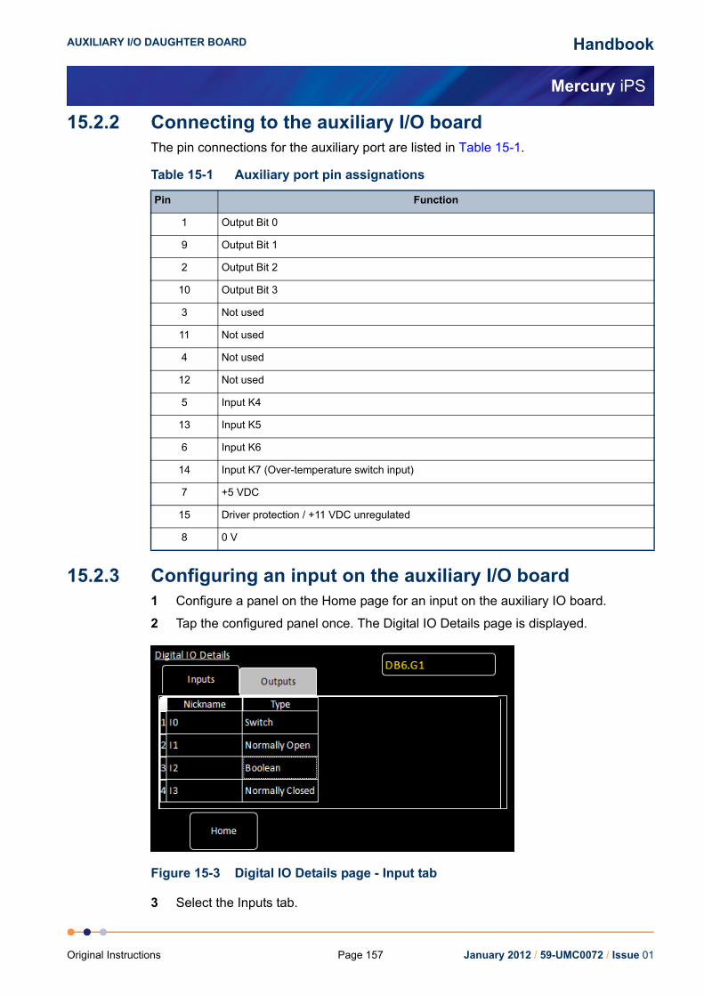
Handbook
Mercury iPS
AUXILIARY I/O DAUGHTER BOARD
15.2.2 Connecting to the auxiliary I/O boardThe pin connections for the auxiliary port are listed in Table 15-1.
15.2.3 Configuring an input on the auxiliary I/O board1 Configure a panel on the Home page for an input on the auxiliary IO board.
2 Tap the configured panel once. The Digital IO Details page is displayed.
Figure 15-3 Digital IO Details page - Input tab
3 Select the Inputs tab.
Table 15-1 Auxiliary port pin assignations
Pin Function
1 Output Bit 0
9 Output Bit 1
2 Output Bit 2
10 Output Bit 3
3 Not used
11 Not used
4 Not used
12 Not used
5 Input K4
13 Input K5
6 Input K6
14 Input K7 (Over-temperature switch input)
7 +5 VDC
15 Driver protection / +11 VDC unregulated
8 0 V
January 2012 / 59-UMC0072 / Issue 01Page 157Original Instructions

Handbook
Mercury iPS
AUXILIARY I/O DAUGHTER BOARD
4 Enter a nickname for the input that is to be used.
5 Select a Type for the input. The input type that you select changes the displayed status of the input on the Home page.The options are:SWITCH - The Home page displays ON when the input is high and OFF when the input is low.NORMALLY OPEN - The Home page displays CLOSED when the input is high and OPEN when the input is low.NORMALLY OPEN - The Home page displays OPEN when the input is high and CLOSED when the input is low.BOOLEAN - The Home page displays TRUE when the input is high and FALSE when the input is low.
15.2.4 Configuring an output on the auxiliary I/O board1 Configure a panel on the Home page for an output on the auxiliary IO board.
2 Tap the configured panel once. The Digital IO Details page is displayed.
Figure 15-4 Digital IO Details page - Output tab
3 Select the Outputs tab.
4 Enter a nickname for the output that is to be used.
5 Select a Type for the output. The output type that you select changes the displayed status of the output on the Home page.The options are:SWITCH - The Home page displays ON when the output is on and OFF when the output is off.NORMALLY OPEN - The Home page displays CLOSED when the output is on and OPEN when the output is off.NORMALLY OPEN - The Home page displays OPEN when the output is on and CLOSED when the output is off.BOOLEAN - The Home page displays TRUE when the output is on and FALSE when the output is off.
January 2012 / 59-UMC0072 / Issue 01 Page 158 Original Instructions

Handbook
Mercury iPS
GLOSSARY
GLOSSARYThis glossary explains the acronyms, abbreviations and special terms used in this Instructions for Use Manual. The entries are presented in alphanumeric order.
January 2012 / 59-UMC0072 / Issue 01Page 159Original Instructions
Handbook
Mercury iPS
GLOSSARY
Acronyms and abbreviationsADC Analogue to Digital ConverterASCII American Standard Code for Information InterchangeCJC Cold Junction CompensationDAC Digital to Analogue ConverterDCE Data Circuit-terminating EquipmentDHCP Dynamic Host Configuration ProtocolDTE Data Terminal EquipmentEPROM Electrically Programmable Read-Only MemoryESSD Electrostatic Sensitive DevicesEOS End of StringGPIB General Purpose Interface Bus (IEEE-488)GUI Graphical User InterfaceI/O Input/outputLCD Liquid Crystal DisplayLED Light Emitting DiodeN/A Not ApplicableNTC Negative Temperature CoefficientPC Personal ComputerPCB Printed Circuit BoardPGA Programmable Gain AmplifierPSU Power Supply UnitPTC Positive Temperature CoefficientPWM Pulse Width ModulationRT Room TemperatureSCPI Signal Orientated Measurement Commands (a command protocol)SPI Serial Peripheral InterfaceTBA To be AdvisedUID Unique IdentifierUSB Universal Serial BusVTI Variable Temperature Insert
January 2012 / 59-UMC0072 / Issue 01 Page 160 Original Instructions

Handbook
Mercury iPS
This page is intentionally blank.
Page 161 January 2012 / 59-UMC0072 / Issue 01Original Instructions

w
UOTOTTFEEW
PORNSTFEW
COODTTFFEE
ROTOTTFEEW
T
Handbook
ww.oxford-instruments.com
nited Kingdomxford Instruments NanoScienceubney Woods, Abingdon,xon, OX13 5QXel: +44(0)1865 393200 (sales)el: +44(0)1865 393311 (support)ax: +44(0)1865 393333 (sales and support)mail: [email protected] (sales)mail: [email protected] (support)eb: www.oxford-instruments.com
EuropeOxford Instruments NanoScienceTubney Woods, Abingdon,Oxon, OX13 5QXTel: +44(0)1865 393200 (sales)Tel: +44(0)1865 393311 (support)Fax: +44(0)1865 393333 (sales and support)Email: [email protected] (sales)Email: [email protected] (support)Web: www.oxford-instruments.com
eople’s Republic of Chinaxford Instruments Chinaoom 14F, No. 1 Plaza No. 800,anjing East Road,hanghai 200001el: +86 21 6132 9688ax: +86 21 6360 8535mail: [email protected]: www.oichina.cn
Americas300 Baker Avenue, Suite 150Concord, MA 01742Phone: +1 978 369 9933 (sales)Toll Free: +1 800 447 4717Fax: +1 978-369 8287 (sales and support)Email: [email protected] (sales)Email: [email protected] (support)
entral Europexford Instruments GmbHtto-von-Guericke Ring 10,-65205 Wiesbadenel: +49 6122 937 171 (sales)el: +44(0)1865 393311 (support)ax: +49 6122 937 175 (sales)ax: +44(0)1865 393333 (support)mail: [email protected] (sales)mail: [email protected] (support)
JapanOxford Instruments K.K.Haseman Building2-11-6 TomiokaKotokuTokyo 1350047Tel: +81 3 5245 3871Fax: +81 3-5245 4466Email: [email protected] (sales)Email: [email protected] (support)Web: www.oxinst.co.jp
est of the Worldxford Instruments NanoScienceubney Woods, Abingdon,xon, OX13 5QXel: +44(0)1865 393200 (sales)el: +44(0)1865 393311 (support)ax: +44(0)1865 393333 (sales and support)mail: [email protected] (sales)mail: [email protected] (support)eb: www.oxford-instruments.com
echnical support
Mercury iPS
Related Documents