PCUB-110 User Guide Precision Control Unit PCUB-110 for the ALC-601 in Revolution XD and WD systems andor.com © Andor Technology 2015 Version 2.2 revised 19 Mar 2015

Welcome message from author
This document is posted to help you gain knowledge. Please leave a comment to let me know what you think about it! Share it to your friends and learn new things together.
Transcript

PCUB-110
User GuidePrecision Control Unit PCUB-110for the ALC-601 in Revolution XD
and WD systems andor.com © Andor Technology 2015
Version 2.2 revised 19 Mar 2015
PCUB-110
2Version 2.2 rev 19 Mar 2015
TABLE OF CONTENTS
SECTION 1: INTRODUCTION ............................................................................................................... 8
1.1 ABOUT THE PCUB-110 ........................................................................................................... 8
1.2 INTENDED USE ........................................................................................................................ 8
1.3 TECHNICAL SUPPORT ............................................................................................................ 9
1.4 DISCLAIMER ......................................................................................................................... 10
1.5 COPYRIGHT AND PROTECTIVE NOTICES ........................................................................... 10
1.6 TRADEMARKS AND PATENT INFORMATION ....................................................................... 10
SECTION 2: PRODUCT OVERVIEW ................................................................................................... 11
2.1 ANDOR IQ SOFTWARE .......................................................................................................... 11
2.2 THE PCUB-110 PRECISION CONTROL UNIT ....................................................................... 12
2.3 PCI DAC CARD....................................................................................................................... 13
SECTION 3: SPECIFICATIONS ........................................................................................................... 14
3.1 POWER SUPPLY .................................................................................................................... 14
3.2 OPERATING CONDITIONS .................................................................................................... 14
3.3 INTERFACE SPECIFICATIONS .............................................................................................. 15
3.3.1 Front Panel Interface ................................................................................................ 15
3.3.1.1 Digital I/O Ports (TTL Triggers) ................................................................ 16
3.3.1.2 AOTF Control ........................................................................................... 17
3.3.1.3 Analogue Piezo Control ........................................................................... 18
3.3.2 Rear Panel Interface ................................................................................................. 19
3.3.2.1 Active Blanking Control ........................................................................... 19
3.3.2.2 DAC Card Connector ............................................................................... 20
3.4 MECHANICAL SPECIFICATIONS .......................................................................................... 20
3.5 TRANSPORT & STORAGE SPECIFICATIONS ....................................................................... 20
PCUB-110
3Version 2.2 rev 19 Mar 2015
SECTION 4: INSTALLATION ............................................................................................................... 21
4.1 INSTALLATION OF THE PCU UNIT ........................................................................................ 21
4.1.1 Location and Mounting ............................................................................................. 21
4.1.2 Ventilation .................................................................................................................. 21
4.1.3 Assembly ................................................................................................................... 21
4.1.4 Power Connection and Protective Earthing ............................................................ 21
4.2 INSTALLING THE DAC CARD ................................................................................................ 22
4.2.1 DIP Switch Settings .................................................................................................. 22
4.2.2 Installing the PCI Card .............................................................................................. 23
4.3 INSTALLATION OF CABLING ................................................................................................. 25
4.3.1 Power Cabling ........................................................................................................... 25
4.3.2 DAC Card Cabling ..................................................................................................... 25
4.3.3 ALC AOTF Cabling .................................................................................................... 26
4.3.4 Active Blanking Cabling............................................................................................ 26
4.3.5 MPU Cabling ............................................................................................................. 27
4.3.6 FRAPPA Cabling ....................................................................................................... 28
4.3.7 Analogue Piezo Cabling ........................................................................................... 28
4.4 INSTALLING THE SOFTWARE ............................................................................................... 28
SECTION 5: OPERATION ................................................................................................................... 29
5.1 EMERGENCY DISCONNECTION ......................................................................................... 29
5.2 INSTRUCTIONS FOR USE ..................................................................................................... 29
5.2.1 Operating Controls.................................................................................................... 29
SECTION 6: MAINTENANCE .............................................................................................................. 31
6.1 CLEANING AND DECONTAMINATION .................................................................................. 31
6.2 REGULAR CHECKS ............................................................................................................... 31
6.3 ANNUAL ELECTRICAL SAFETY CHECKS ........................................................................... 31
6.4 FUSE REPLACEMENT ........................................................................................................... 31

PCUB-110
4Version 2.2 rev 19 Mar 2015
APPENDIX A: GLOSSARY .................................................................................................................. 32
APPENDIX B: OTHER INFORMATION ............................................................................................... 33
PCUB-110
5Version 2.2 rev 19 Mar 2015
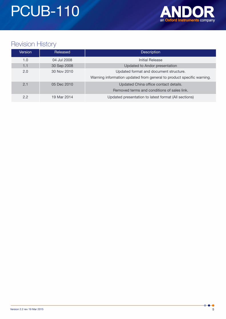
Revision HistoryVersion Released Description
1.0 04 Jul 2008 Initial Release
1.1 30 Sep 2008 Updated to Andor presentation
2.0 30 Nov 2010 Updated format and document structure.
Warning information updated from general to product specific warning.
2.1 05 Dec 2010 Updated China office contact details.
Removed terms and conditions of sales link.
2.2 19 Mar 2014 Updated presentation to latest format (All sections)

PCUB-110
6Version 2.2 rev 19 Mar 2015
Safety and Warning Information
PLEASE READ THIS INFORMATION FIRST
1. If the equipment is used in a manner not specified by Andor, the protection provided by the equipment may be impaired.
2. The RF and Therm connectors on the front panel must be connected before power-on.
3. See Section 5.1, “Emergency Disconnection”.
4. There are no user-serviceable parts inside the product and the enclosure must not be opened. Only authorised service personnel may service this equipment.
5. This product is powered by the mains and includes mains components. If you open the enclosure, you expose yourself to electric shock hazards.
6. Protective earth is an integral part of the protection against electric shock in this product. Do not tamper with any of the earthing measures, e.g. the earth bonding point on the rear panel.
7. Only the correctly specified mains power supply and fuse must be used.
8. A number of screws on the device may have been marked with red paint to prevent tampering. If you adjust these screws your warranty will be void.
9. The product contains components that are extremely sensitive to static electricity and radiated electromagnetic fields, and therefore should not be used, or stored, close to EMI/RFI generators, electrostatic field generators, electromagnetic or radioactive devices, or other similar sources of high energy fields. The types of equipment that can cause problems are plasma sources, arc welders, radio frequency generators, x-ray instruments, and pulsed discharge optical sources.
10. Operation of the system close to intense pulsed sources (lasers, xenon strobes, arc lamps, and the like) may compromise performance, if shielding is inadequate.
11. Please note that this product is not designed to provide protection from ionising radiation. Any customer using this product in such an application should provide their own protection.
12. Your product is a precision scientific instrument containing fragile components. Always handle it with care.
13. Do not wet or spill liquids on the product. Do not store or place liquids on the Cabinet worktop. If spillage occurs on the product, switch off power immediately, and wipe off with dry, lint-free cloth. If any ingress has occurred or is suspected, unplug mains cable, do not use, and contact Andor service.
14. The product is only to be used as part of a Revolution XD or WD Microscope System. Users must be authorised and trained personnel only; otherwise this may result in personal injury, and/ or equipment damage and impaired system performance.
15. See Section 6.1, “Cleaning and Decontamination”.
16. See Section 4.1.2, “Ventilation”.
17. See the “Manual Handling” section below.
18. To ensure correct and safe operation of this product, please read this manual before use. Keep this user guide in a safe place for future reference.
PCUB-110
7Version 2.2 rev 19 Mar 2015
General Safety SymbolSThe following are explanations of the safety symbols found on this product:
Caution, risk of electric shock.
Caution, risk of danger.
Caution, consult technical manual before servicing.
manual HandlinG Due to the delicate nature of some of the components within, care must be exercised when handling this product.
Proper manual handling techniques are important when installing the Revolution XD or WD system to ensure that the integrity of the product is safeguarded and individuals involved are not exposed to unnecessary manual handling risks, such as:
• Lifting a load which is too heavy
• Poor posture or technique during lifting
• Dropping a load
• Lifting objects with sharp edges
The PCU is suitable for 1-person installation into an Andor Cabinet.

PCUB-110
8Version 2.2 rev 19 Mar 2015
INTRODUCTION
SECTION 1: INTRODUCTIONThank you for purchasing an Andor Precision Control Unit (PCU).
This manual is aimed at covering the installation, operation and maintenance of the PCUB-110, which is the control unit for Andor Revolution XD and WD systems.
Before you start to use the product, read this manual thoroughly and follow the instructions given. After reading this manual, please keep it in a safe place for future quick reference.
The contents of this manual are subject to change without notice. Although every effort has been made to ensure the accuracy of this manual, errors and/ or inconsistencies may remain. If you note any points that are unclear please contact your representative.
This product forms part of the Revolution XD or WD system, and so to use any other equipment with this product, read the other manuals too. Some of the equipment described in this manual may not be included in the set you have purchased.
Figure 1: The PCUB-110 Precision Control Unit
1.1 about tHe PCub-110
Andor’s PCU provides synchronisation for all Revolution components, ensuring the iXon, CSU-X or CSU-W, ALC, MPU, FRAPPA and Piezo stages remain in precise temporal alignment. This minimises specimen exposure times and allows the highest frame rates to be achieved while ensuring precision components are stabilised for high quality imaging.
The PCU also provides an interface for system expansion enabling Revolution to be synchronised with other equipment.
1.2 intended uSe
This product is intended to be used as part of a Revolution XD or WD microscopy system and should only be used indoors.

PCUB-110
9Version 2.2 rev 19 Mar 2015
INTRODUCTION
1.3 teCHniCal SuPPort
If you have any questions regarding the use of this equipment, please contact the representative* from whom your system was purchased, or:
Europe USAAndor Technology
7 Millennium Way
Springvale Business Park
Belfast
BT12 7AL
Northern Ireland
Tel. +44 (0) 28 9023 7126
Fax. +44 (0) 28 9031 0792
www.andor.com/contact_us/support_request
Andor Technology
425 Sullivan Avenue
Suite # 3
South Windsor
CT 06074
USA
Tel. +1 (860) 290-9211
Fax. +1 (860) 290-9566
www.andor.com/contact_us/support_request
Asia-Pacific ChinaAndor Technology (Japan)
4F NE Sarugakucho Building
2-7-6 Sarugaku-Cho
Chiyoda-Ku
Tokyo 101-0064
Japan
Tel. +81-3-3518 6488
Fax. +81-3-3518 6489
www.andor.com/contact_us/support_request
Andor Technology
Room 1213, Building B
Luo Ke Time Square
No. 103 Huizhongli
Chaoyang District
Beijing,100101 P.R.
China
Tel: +86 (0)10 51294977
Fax. +86(0)10-6445-5401
www.andor.com/contact_us/support_request
* The latest contact details for your local representative can be found on our website.
PCUB-110
10Version 2.2 rev 19 Mar 2015
INTRODUCTION
1.4 diSClaimer
THE INFORMATION CONTAINED HEREIN IS PROVIDED “AS IS” WITHOUT WARRANTY, CONDITION OR REPRESENTATION OF ANY KIND, EITHER EXPRESS, IMPLIED, STATUTORY OR OTHERWISE, INCLUDING BUT NOT LIMITED TO, ANY WARRANTY OF MERCHANTABILITY, NON-INFRINGEMENT OR FITNESS FOR A PARTICULAR PURPOSE.
IN NO EVENT SHALL ANDOR BE LIABLE FOR ANY LOSS OR DAMAGE, WHETHER DIRECT, INDIRECT, SPECIAL, INCIDENTAL, CONSEQUENTIAL OR OTHERWISE HOWSOEVER CAUSED WHETHER ARISING IN CONTRACT TORT OR OTHERWISE, ARISING OUT OF OR IN CONNECTION WITH THE USE OF THE INFORMATION PROVIDED HEREIN.
1.5 CoPyriGHt and ProteCtive notiCeS
The copyright in this document and the associated drawings are the property of Andor Technology and all rights are reserved. This document and the associated drawings are issued on condition that they are not copied, reprinted or reproduced, nor their contents disclosed.
The publication of information in this documentation does not imply freedom from any patent or proprietary right of Andor Technology or any third party.
1.6 trademarkS and Patent information
Andor and the Andor logo are trademarks of Andor Technology. Andor Technology is an Oxford Instruments company. All other marks are property of their owners. Borealis includes technology covered by the following patents: US Patent No. 8,275,226, EP Patent No. 2196839, US Patent No. 8,670,178 and CA Patent No. 2779146.
Changes are periodically made to the product and these will be incorporated into new editions of the manual. New versions of all Andor manuals will be made available through MyAndor http://my.andor.com/login.aspx. If you do not have an account please register at http://my.andor.com/Register.aspx.
PCUB-110
11Version 2.2 rev 19 Mar 2015
PRODUCT OVERVIEW
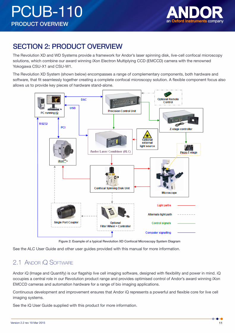
SECTION 2: PRODUCT OVERVIEWThe Revolution XD and WD Systems provide a framework for Andor’s laser spinning disk, live-cell confocal microscopy solutions, which combine our award winning iXon Electron Multiplying CCD (EMCCD) camera with the renowned Yokogawa CSU-X1 and CSU-W1.
The Revolution XD System (shown below) encompasses a range of complementary components, both hardware and software, that fit seamlessly together creating a complete confocal microscopy solution. A flexible component focus also allows us to provide key pieces of hardware stand-alone.
Figure 2: Example of a typical Revolution XD Confocal Microscopy System Diagram
See the ALC User Guide and other user guides provided with this manual for more information.
2.1 andor iQ Software
Andor iQ (Image and Quantify) is our flagship live cell imaging software, designed with flexibility and power in mind. iQ occupies a central role in our Revolution product range and provides optimised control of Andor’s award winning iXon EMCCD cameras and automation hardware for a range of bio imaging applications.
Continuous development and improvement ensures that Andor iQ represents a powerful and flexible core for live cell imaging systems.
See the iQ User Guide supplied with this product for more information.

PCUB-110
12Version 2.2 rev 19 Mar 2015
PRODUCT OVERVIEW
2.2 tHe PCub-110 PreCiSion Control unit
The PCUB-110 is the main control unit of the Revolution XD Microscopy System.
Figure 3: PCUB-110 Precision Control Unit
The PCUB-110 has the following functions:
• Control of the AOTF (Acousto-Optical Tuneable Filter) in the ALC, including active blanking, which allows laser light though the AOTF only when the camera is in Live mode, or acquiring an image.
• Provision to control an external analogue Piezo stage.
• 8 digital inputs and 8 digital outputs that are used to trigger the lasers in the ALC, to control the MPU, or for other user-defined purposes.
PCUB-110
13Version 2.2 rev 19 Mar 2015
PRODUCT OVERVIEW
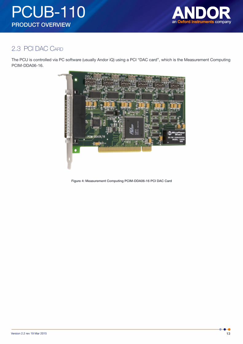
2.3 PCi daC Card
The PCU is controlled via PC software (usually Andor iQ) using a PCI “DAC card”, which is the Measurement Computing PCIM-DDA06-16.
Figure 4: Measurement Computing PCIM-DDA06-16 PCI DAC Card
PCUB-110
14Version 2.2 rev 19 Mar 2015
SPECIFICATIONS
SECTION 3: SPECIFICATIONS
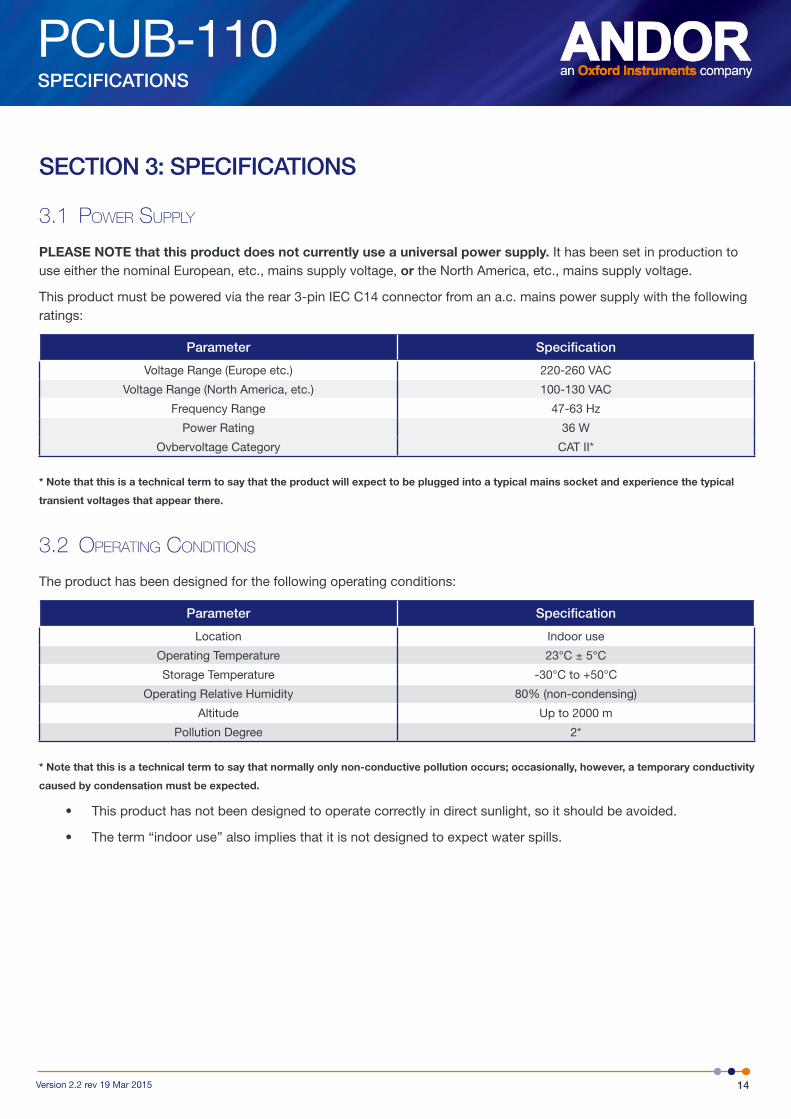
3.1 Power SuPPly
PLEASE NOTE that this product does not currently use a universal power supply. It has been set in production to use either the nominal European, etc., mains supply voltage, or the North America, etc., mains supply voltage.
This product must be powered via the rear 3-pin IEC C14 connector from an a.c. mains power supply with the following ratings:
Parameter Specification
Voltage Range (Europe etc.) 220-260 VAC
Voltage Range (North America, etc.) 100-130 VAC
Frequency Range 47-63 Hz
Power Rating 36 W
Ovbervoltage Category CAT II*
* Note that this is a technical term to say that the product will expect to be plugged into a typical mains socket and experience the typical
transient voltages that appear there.
3.2 oPeratinG ConditionS
The product has been designed for the following operating conditions:
Parameter Specification
Location Indoor use
Operating Temperature 23°C ± 5°C
Storage Temperature -30°C to +50°C
Operating Relative Humidity 80% (non-condensing)
Altitude Up to 2000 m
Pollution Degree 2*
* Note that this is a technical term to say that normally only non-conductive pollution occurs; occasionally, however, a temporary conductivity
caused by condensation must be expected.
• This product has not been designed to operate correctly in direct sunlight, so it should be avoided.
• The term “indoor use” also implies that it is not designed to expect water spills.
PCUB-110
15Version 2.2 rev 19 Mar 2015
SPECIFICATIONS
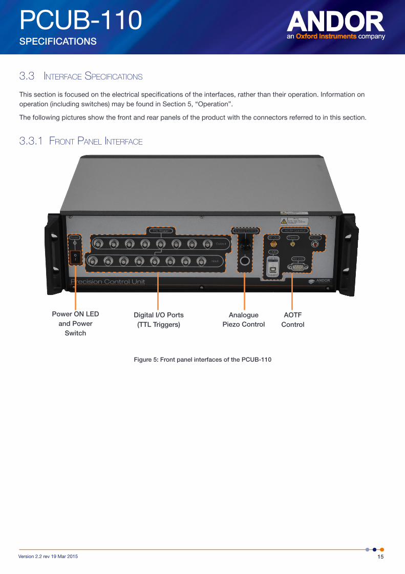
3.3 interfaCe SPeCifiCationS
This section is focused on the electrical specifications of the interfaces, rather than their operation. Information on operation (including switches) may be found in Section 5, “Operation”.
The following pictures show the front and rear panels of the product with the connectors referred to in this section.
3.3.1 front Panel interfaCe
Figure 5: Front panel interfaces of the PCUB-110
Power ON LED and Power
Switch
Digital I/O Ports (TTL Triggers)
AnaloguePiezo Control
AOTF Control
PCUB-110
16Version 2.2 rev 19 Mar 2015
SPECIFICATIONS
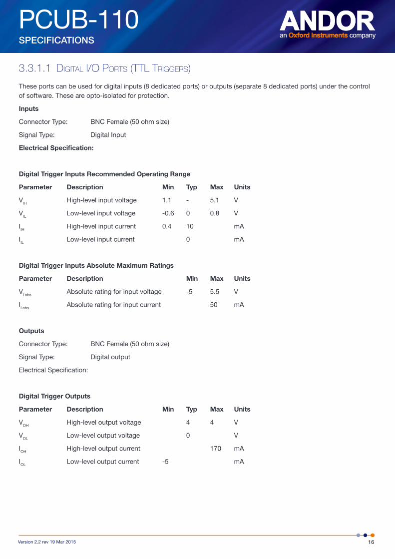
3.3.1.1 diGital i/o PortS (ttl triGGerS)
These ports can be used for digital inputs (8 dedicated ports) or outputs (separate 8 dedicated ports) under the control of software. These are opto-isolated for protection.
Inputs
Connector Type: BNC Female (50 ohm size)
Signal Type: Digital Input
Electrical Specification:
Digital Trigger Inputs Recommended Operating Range
Parameter Description Min Typ Max Units
VIH High-level input voltage 1.1 - 5.1 V
VIL Low-level input voltage -0.6 0 0.8 V
IIH High-level input current 0.4 10 mA
IIL Low-level input current 0 mA
Digital Trigger Inputs Absolute Maximum Ratings
Parameter Description Min Max Units
VI abs Absolute rating for input voltage -5 5.5 V
II abs Absolute rating for input current 50 mA
Outputs
Connector Type: BNC Female (50 ohm size)
Signal Type: Digital output
Electrical Specification:
Digital Trigger Outputs
Parameter Description Min Typ Max Units
VOH High-level output voltage 4 4 V
VOL Low-level output voltage 0 V
IOH High-level output current 170 mA
IOL Low-level output current -5 mA
PCUB-110
17Version 2.2 rev 19 Mar 2015
SPECIFICATIONS
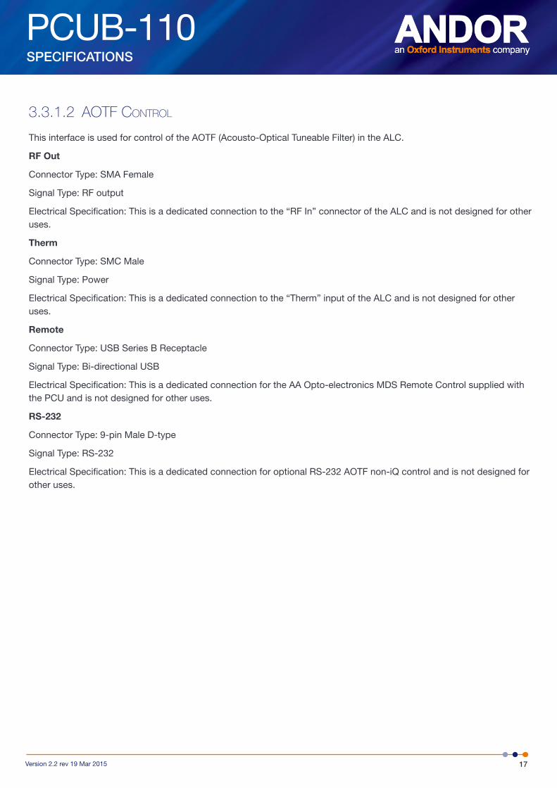
3.3.1.2 aotf Control
This interface is used for control of the AOTF (Acousto-Optical Tuneable Filter) in the ALC.
RF Out
Connector Type: SMA Female
Signal Type: RF output
Electrical Specification: This is a dedicated connection to the “RF In” connector of the ALC and is not designed for other uses.
Therm
Connector Type: SMC Male
Signal Type: Power
Electrical Specification: This is a dedicated connection to the “Therm” input of the ALC and is not designed for other uses.
Remote
Connector Type: USB Series B Receptacle
Signal Type: Bi-directional USB
Electrical Specification: This is a dedicated connection for the AA Opto-electronics MDS Remote Control supplied with the PCU and is not designed for other uses.
RS-232
Connector Type: 9-pin Male D-type
Signal Type: RS-232
Electrical Specification: This is a dedicated connection for optional RS-232 AOTF non-iQ control and is not designed for other uses.
PCUB-110
18Version 2.2 rev 19 Mar 2015
SPECIFICATIONS
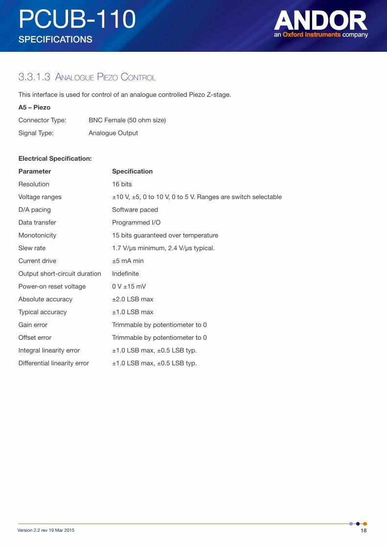
3.3.1.3 analoGue Piezo Control
This interface is used for control of an analogue controlled Piezo Z-stage.
A5 – Piezo
Connector Type: BNC Female (50 ohm size)
Signal Type: Analogue Output
Electrical Specification:
Parameter Specification
Resolution 16 bits
Voltage ranges ±10 V, ±5, 0 to 10 V, 0 to 5 V. Ranges are switch selectable
D/A pacing Software paced
Data transfer Programmed I/O
Monotonicity 15 bits guaranteed over temperature
Slew rate 1.7 V/μs minimum, 2.4 V/μs typical.
Current drive ±5 mA min
Output short-circuit duration Indefinite
Power-on reset voltage 0 V ±15 mV
Absolute accuracy ±2.0 LSB max
Typical accuracy ±1.0 LSB max
Gain error Trimmable by potentiometer to 0
Offset error Trimmable by potentiometer to 0
Integral linearity error ±1.0 LSB max, ±0.5 LSB typ.
Differential linearity error ±1.0 LSB max, ±0.5 LSB typ.
PCUB-110
19Version 2.2 rev 19 Mar 2015
SPECIFICATIONS
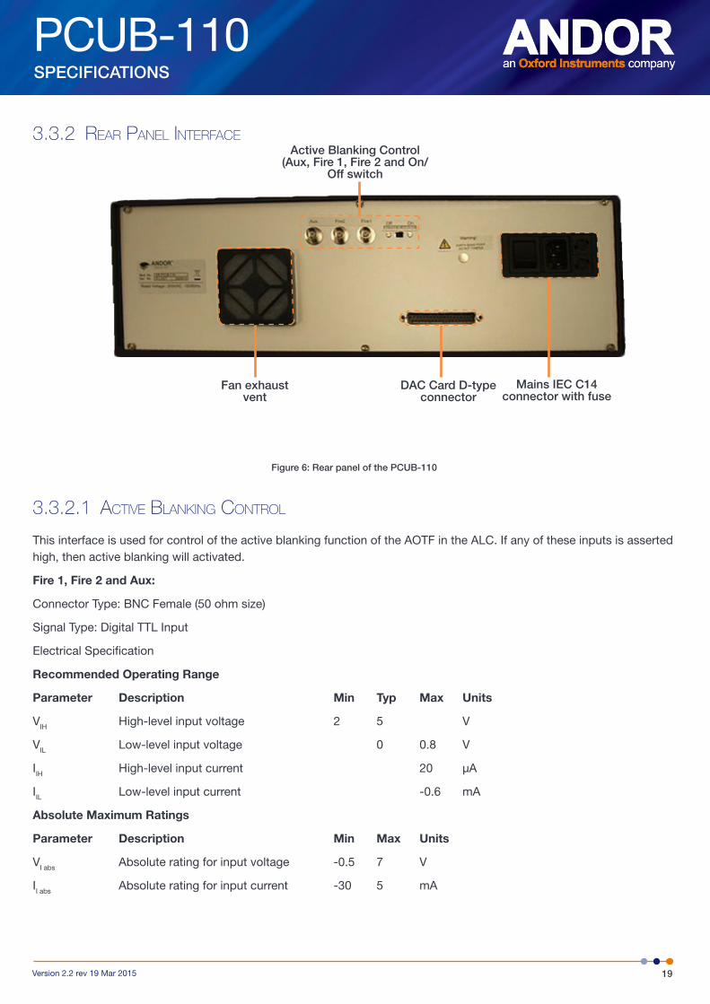
3.3.2 rear Panel interfaCe
Figure 6: Rear panel of the PCUB-110
3.3.2.1 aCtive blankinG Control
This interface is used for control of the active blanking function of the AOTF in the ALC. If any of these inputs is asserted high, then active blanking will activated.
Fire 1, Fire 2 and Aux:
Connector Type: BNC Female (50 ohm size)
Signal Type: Digital TTL Input
Electrical Specification
Recommended Operating Range
Parameter Description Min Typ Max Units
VIH High-level input voltage 2 5 V
VIL Low-level input voltage 0 0.8 V
IIH High-level input current 20 µA
IIL Low-level input current -0.6 mA
Absolute Maximum Ratings
Parameter Description Min Max Units
VI abs Absolute rating for input voltage -0.5 7 V
II abs Absolute rating for input current -30 5 mA
Fan exhaust vent
DAC Card D-type connector
Mains IEC C14 connector with fuse
Active Blanking Control (Aux, Fire 1, Fire 2 and On/
Off switch
PCUB-110
20Version 2.2 rev 19 Mar 2015
SPECIFICATIONS
3.3.2.2 daC Card ConneCtor
This is a dedicated connection to the Measurement Computing PCIM-DDA06-16 PCI DAC card and is not designed for other uses.
Parameter Specification
PCI Standard PCI 2.1
PCI Supply Voltage 5V
PCI Supply Current 965 mA typical, 1206 mA maximum
PCI Bus Width 32-bit
PCI Bus Speed 33 MHz
Form Factor Half-length card (de facto standard)
Dimensions 174.4 mm (L) x 100.6 mm (W) x 11.65 mm (H)
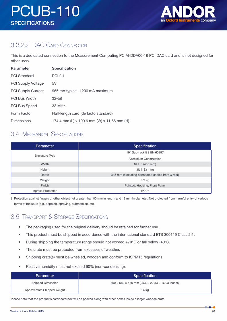
3.4 meCHaniCal SPeCifiCationS
Parameter Specification
Enclosure Type19” Sub-rack BS EN 60297
Aluminium Construction
Width 84 HP (465 mm)
Height 3U (133 mm)
Depth 315 mm (excluding connected cables front & rear)
Weight 8.9 kg
Finish Painted: Housing, Front Panel
Ingress Protection IP20†
† Protection against fingers or other object not greater than 80 mm in length and 12 mm in diameter. Not protected from harmful entry of various
forms of moisture (e.g. dripping, spraying, submersion, etc.)
3.5 tranSPort & StoraGe SPeCifiCationS
• The packaging used for the original delivery should be retained for further use.
• This product must be shipped in accordance with the international standard ETS 300119 Class 2.1.
• During shipping the temperature range should not exceed +70°C or fall below -40°C.
• The crate must be protected from excesses of weather.
• Shipping crate(s) must be wheeled, wooden and conform to ISPM15 regulations.
• Relative humidity must not exceed 90% (non-condensing).
Parameter Specification
Shipped Dimension 650 × 580 × 430 mm (25.6 × 22.83 × 16.93 inches)
Approximate Shipped Weight 14 kg
Please note that the product’s cardboard box will be packed along with other boxes inside a larger wooden crate.

PCUB-110
21Version 2.2 rev 19 Mar 2015
INSTALLATION
SECTION 4: INSTALLATIONThis product will usually be supplied as part of a system, and will be installed by Andor Installation Technician or a trained Andor Systems distributor. The following is only provided to augment this.
4.1 inStallation of tHe PCu unit
4.1.1 loCation and mountinG
• Temperature and humidity must meet the specifications shown in Section 3.2, “Operating Conditions”.
• Operation vibrations should be reduced as much as possible.
• Usually the product will be installed in a cabinet. However, if this is not the case, then ensure that the product is placed on a surface suitable for the weight and size of the product (see Section 3.4, “Mechanical Specifications”), and conforming to the other requirements in this document, e.g. ventilation.
• If a cabinet is used, it should not be placed tightly against a wall.
• Power cabling and control cables should be routed to prevent accidents, damage and accidental unplugging.
4.1.2 ventilation
• The product has fan exhaust vents on the rear panel, with an intake on the bottom panel.
• To prevent equipment failure, ensure that there are no obstructions at the inlet or exhaust vents.
• The PCU should have a 1U air gap below when installed in a rack, or ensure it stands on its supplied feet if desk-mounted.
• Clearance to the rear should be 150 mm
4.1.3 aSSembly
The PCU box itself requires no assembly. Cables connections are covered in Section 4.3, “Installation of Cabling”.
4.1.4 Power ConneCtion and ProteCtive eartHinG
• See Section 5.1, “Emergency Disconnection”.
• The RF and Therm connectors on the front panel must be connected before power-on.
• Before connection, check that the mains power socket used can provide the power specified in Section 3.1, “Power Supply”.
• Always switch off power before connecting/ disconnecting cables from the product.
• A mains power cable is provided with this product, but ensure that it satisfies local regulations for safety.
• Mains power is connected via the 3-pin IEC C14 connector on the rear panel of the product.
• An integral part of protection against electric shock in the case of a fault is the protective earth provided via the earth conductors in the mains cable. It is therefore vital that the earth system of the building, and in particular the socket, is constructed properly to provide suitable protection when needed.
• Do not pull cables by the sheath. Use the connector body.
PCUB-110
22Version 2.2 rev 19 Mar 2015
INSTALLATION
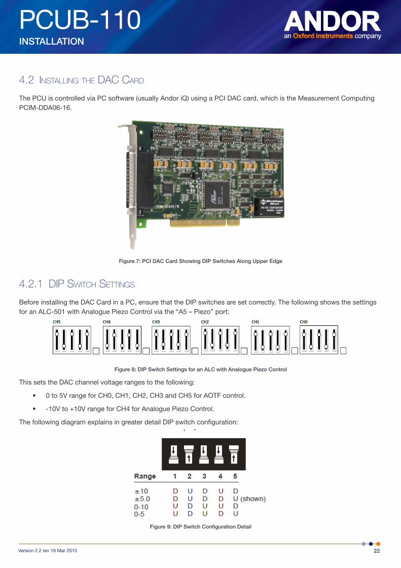
4.2 inStallinG tHe daC Card
The PCU is controlled via PC software (usually Andor iQ) using a PCI DAC card, which is the Measurement Computing PCIM-DDA06-16.
Figure 7: PCI DAC Card Showing DIP Switches Along Upper Edge
4.2.1 diP SwitCH SettinGS
Before installing the DAC Card in a PC, ensure that the DIP switches are set correctly. The following shows the settings for an ALC-501 with Analogue Piezo Control via the “A5 – Piezo” port:
Figure 8: DIP Switch Settings for an ALC with Analogue Piezo Control
This sets the DAC channel voltage ranges to the following:
• 0 to 5V range for CH0, CH1, CH2, CH3 and CH5 for AOTF control.
• -10V to +10V range for CH4 for Analogue Piezo Control.
The following diagram explains in greater detail DIP switch configuration:
Figure 9: DIP Switch Configuration Detail
PCUB-110
23Version 2.2 rev 19 Mar 2015
INSTALLATION
4.2.2 inStallinG tHe PCi Card
The PCI DAC Card is installed in the same manner as you would fit most other add-in cards such as graphics cards.
PLEASE NOTE: Consult the manual supplied with your computer to ensure correct installation of the controller card for your particular model as models change frequently.
We recommend you perform the installation in a similar manner to the following:
1. Power down the computer and any accessories.
2. Unplug the computer and any accessories from the mains sockets.
3. Whilst observing appropriate static control procedures, unplug all cables from the rear of the computer.
4. Unscrew any cover-mounting screws on the computer and set them aside safely.
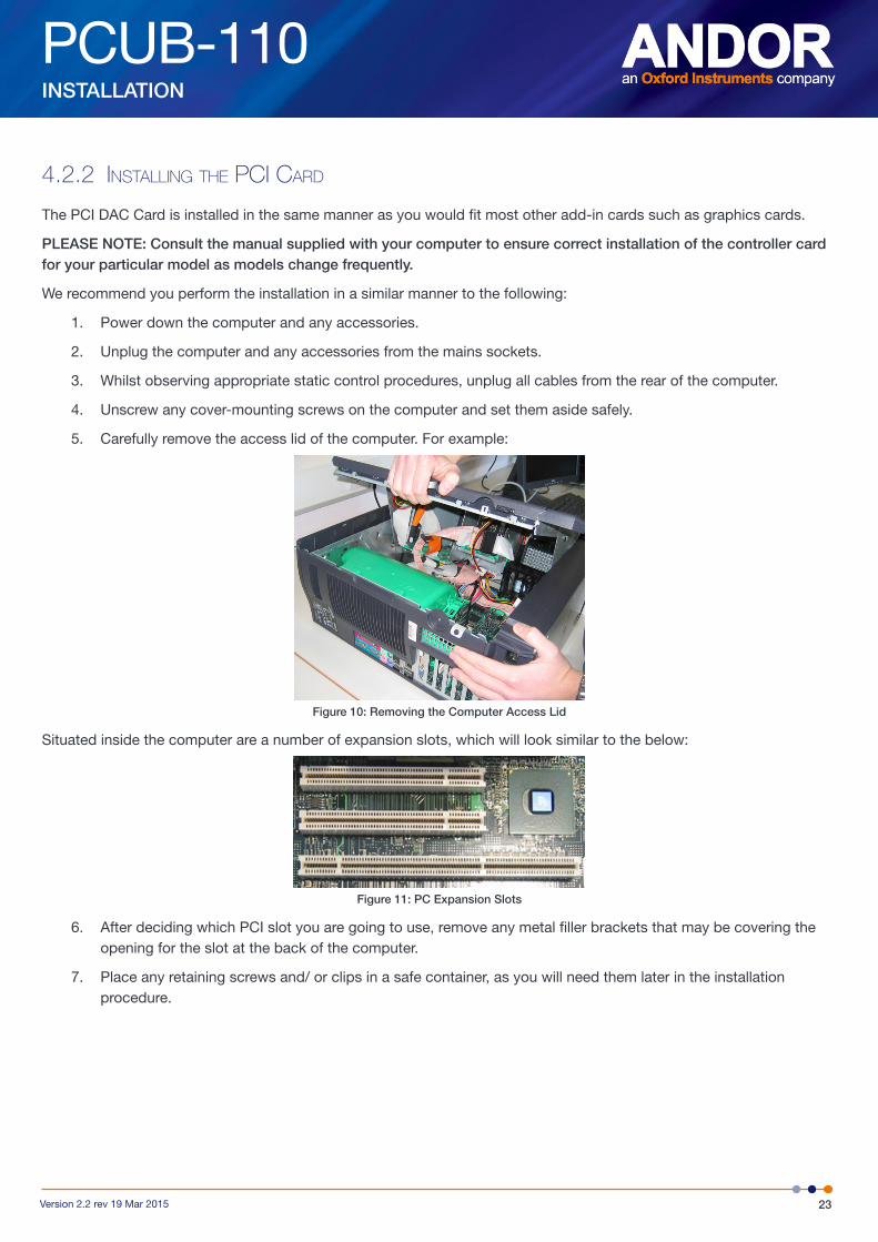
5. Carefully remove the access lid of the computer. For example:
Figure 10: Removing the Computer Access Lid
Situated inside the computer are a number of expansion slots, which will look similar to the below:
Figure 11: PC Expansion Slots
6. After deciding which PCI slot you are going to use, remove any metal filler brackets that may be covering the opening for the slot at the back of the computer.
7. Place any retaining screws and/ or clips in a safe container, as you will need them later in the installation procedure.
PCUB-110
24Version 2.2 rev 19 Mar 2015
INSTALLATION
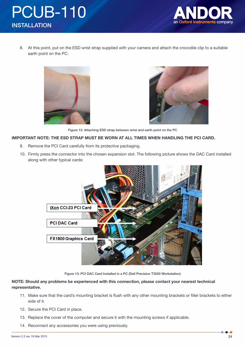
8. At this point, put on the ESD wrist strap supplied with your camera and attach the crocodile clip to a suitable earth point on the PC:
Figure 12: Attaching ESD strap between wrist and earth point on the PC
IMPORTANT NOTE: THE ESD STRAP MUST BE WORN AT ALL TIMES WHEN HANDLING THE PCI CARD.
9. Remove the PCI Card carefully from its protective packaging.
10. Firmly press the connector into the chosen expansion slot. The following picture shows the DAC Card installed along with other typical cards:
Figure 13: PCI DAC Card Installed in a PC (Dell Precision T3500 Workstation)
NOTE: Should any problems be experienced with this connection, please contact your nearest technical representative.
11. Make sure that the card’s mounting bracket is flush with any other mounting brackets or filler brackets to either side of it.
12. Secure the PCI Card in place.
13. Replace the cover of the computer and secure it with the mounting screws if applicable.
14. Reconnect any accessories you were using previously.
PCUB-110
25Version 2.2 rev 19 Mar 2015
INSTALLATION
4.3 inStallation of CablinG
4.3.1 Power CablinG
See Section 4.1.4 Power Connection and protective Earthing.
4.3.2 daC Card CablinG
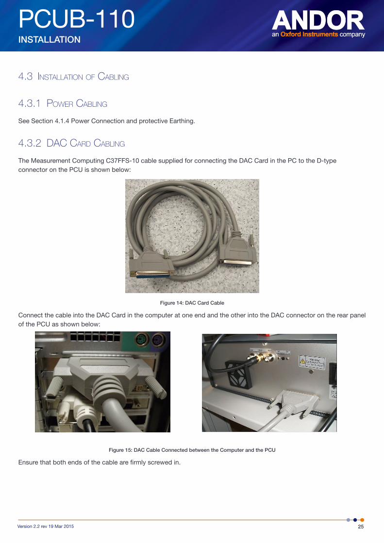
The Measurement Computing C37FFS-10 cable supplied for connecting the DAC Card in the PC to the D-type connector on the PCU is shown below:
Figure 14: DAC Card Cable
Connect the cable into the DAC Card in the computer at one end and the other into the DAC connector on the rear panel of the PCU as shown below:
Figure 15: DAC Cable Connected between the Computer and the PCU
Ensure that both ends of the cable are firmly screwed in.
PCUB-110
26Version 2.2 rev 19 Mar 2015
INSTALLATION
4.3.3 alC aotf CablinG
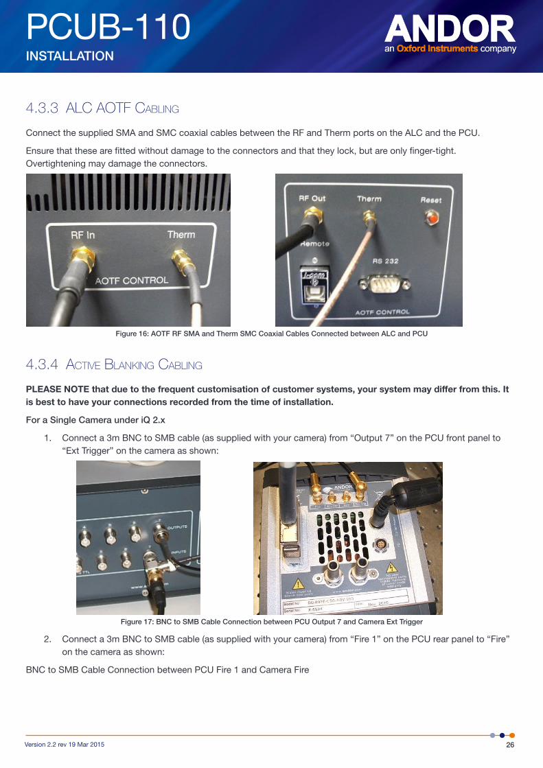
Connect the supplied SMA and SMC coaxial cables between the RF and Therm ports on the ALC and the PCU.
Ensure that these are fitted without damage to the connectors and that they lock, but are only finger-tight. Overtightening may damage the connectors.
Figure 16: AOTF RF SMA and Therm SMC Coaxial Cables Connected between ALC and PCU
4.3.4 aCtive blankinG CablinG
PLEASE NOTE that due to the frequent customisation of customer systems, your system may differ from this. It is best to have your connections recorded from the time of installation.
For a Single Camera under iQ 2.x
1. Connect a 3m BNC to SMB cable (as supplied with your camera) from “Output 7” on the PCU front panel to “Ext Trigger” on the camera as shown:
Figure 17: BNC to SMB Cable Connection between PCU Output 7 and Camera Ext Trigger
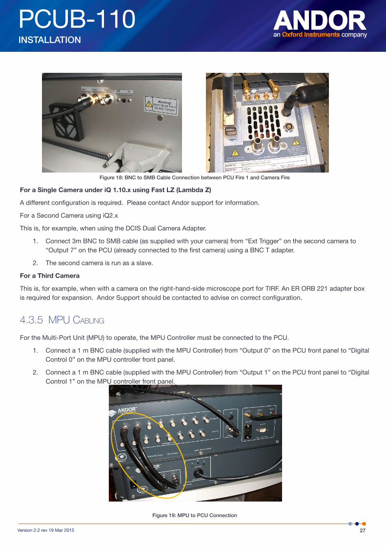
2. Connect a 3m BNC to SMB cable (as supplied with your camera) from “Fire 1” on the PCU rear panel to “Fire” on the camera as shown:
BNC to SMB Cable Connection between PCU Fire 1 and Camera Fire
PCUB-110
27Version 2.2 rev 19 Mar 2015
INSTALLATION
Figure 18: BNC to SMB Cable Connection between PCU Fire 1 and Camera Fire
For a Single Camera under iQ 1.10.x using Fast LZ (Lambda Z)
A different configuration is required. Please contact Andor support for information.
For a Second Camera using iQ2.x
This is, for example, when using the DCIS Dual Camera Adapter.
1. Connect 3m BNC to SMB cable (as supplied with your camera) from “Ext Trigger” on the second camera to “Output 7” on the PCU (already connected to the first camera) using a BNC T adapter.
2. The second camera is run as a slave.
For a Third Camera
This is, for example, when with a camera on the right-hand-side microscope port for TIRF. An ER ORB 221 adapter box is required for expansion. Andor Support should be contacted to advise on correct configuration.
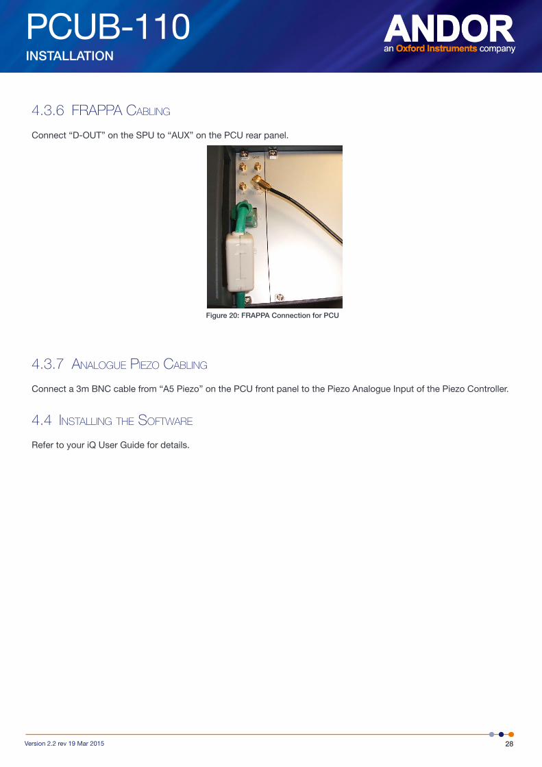
4.3.5 mPu CablinG
For the Multi-Port Unit (MPU) to operate, the MPU Controller must be connected to the PCU.
1. Connect a 1 m BNC cable (supplied with the MPU Controller) from “Output 0” on the PCU front panel to “Digital Control 0” on the MPU controller front panel.
2. Connect a 1 m BNC cable (supplied with the MPU Controller) from “Output 1” on the PCU front panel to “Digital Control 1” on the MPU controller front panel.
Figure 19: MPU to PCU Connection
PCUB-110
28Version 2.2 rev 19 Mar 2015
INSTALLATION
4.3.6 fraPPa CablinG
Connect “D-OUT” on the SPU to “AUX” on the PCU rear panel.
Figure 20: FRAPPA Connection for PCU
4.3.7 analoGue Piezo CablinG
Connect a 3m BNC cable from “A5 Piezo” on the PCU front panel to the Piezo Analogue Input of the Piezo Controller.
4.4 inStallinG tHe Software
Refer to your iQ User Guide for details.
PCUB-110
29Version 2.2 rev 19 Mar 2015
OPERATION
SECTION 5: OPERATIONIf the equipment is used in a manner not specified by Andor, the protection provided by the equipment may be impaired.
5.1 emerGenCy diSConneCtion
In case of emergency, the disconnecting device is the mains lead.
This will either be the mains lead connected to the product, or in the case of a cabinet-based system the mains lead to the cabinet.
SWITCH OFF THE MAINS SOCKET AND REMOVE THE MAINS LEAD FROM THE PRODUCT.
5.2 inStruCtionS for uSe
The main operation of this product is as part of the wider Revolution XD system and this is covered in the iQ User Guide and by the training given by your Andor Installation Technician or trained Andor Systems distributor.
The following are some hardware-related points about operation.
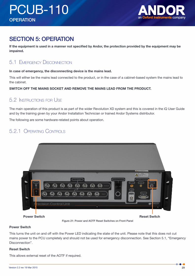
5.2.1 oPeratinG ControlS
Figure 21: Power and AOTF Reset Switches on Front Panel
Power Switch
This turns the unit on and off with the Power LED indicating the state of the unit. Please note that this does not cut mains power to the PCU completely and should not be used for emergency disconnection. See Section 5.1, “Emergency Disconnection”.
Reset Switch
This allows external reset of the AOTF if required.
Power Switch Reset Switch
PCUB-110
30Version 2.2 rev 19 Mar 2015
OPERATION
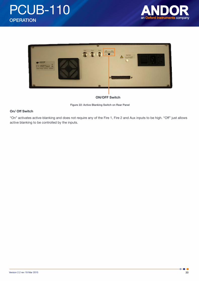
Figure 22: Active Blanking Switch on Rear Panel
On/ Off Switch
“On” activates active-blanking and does not require any of the Fire 1, Fire 2 and Aux inputs to be high. “Off” just allows active blanking to be controlled by the inputs.
ON/OFF Switch

PCUB-110
31Version 2.2 rev 19 Mar 2015
MAINTENANCE
SECTION 6: MAINTENANCEPLEASE NOTE the following:
• If the equipment is used in a manner not specified by Andor, the protection provided by the equipment may be impaired.
• In case of emergency, the disconnecting device is the mains lead. This will either be the mains lead connected to the product, or in the case of a cabinet-based system the mains lead to the cabinet.
6.1 CleaninG and deContamination
To clean the product, only use a damp lint-free cloth. Do not wet the connectors. Do not use solvents, cleaning agents, or aerosols.
6.2 reGular CHeCkS
The state of the product should be checked regularly, esp. the integrity of the enclosure and the mains cable.
Do not use equipment that is damaged.
6.3 annual eleCtriCal Safety CHeCkS
It is advisable to check the integrity of the insulation and protective earth of the product on an annual basis, e.g. U.K. PAT testing.
Do not use equipment that is damaged.
6.4 fuSe rePlaCement
The characteristics of the fuse used in this product are as follows:
Rated Current: 2 A
Rated Voltage: 250 V a.c.
Size: 5 × 20 mm
Type: Time delay, low breaking capacity
The rated voltage could be lowered in North America and countries who use a similar mains supply to 125 V a.c.
The actual fuse used in this product is a Cooper Bussmann S506-2-R or S506-2A.

PCUB-110
32Version 2.2 rev 19 Mar 2015
GLOSSARY
APPENDIX A: GLOSSARYADC Analogue-to-Digital Converter: Converts an analogue voltage to a digital signal.
ALC Andor Laser Combiner: The unit at the heart of the Revolution XD that combines laser light from several internal sources and controls their emission into the microscopy system.
AOTF Acousto-Optical Tuneable Filter
DAC Digital-to-Analogue Converter: Converts a digital signal to an analogue voltage.
ESD Electrostatic Discharge
EMC Electromagnetic Compatibility
EU European Union
FRAPPA Fluorescence Recovery After Photo-bleach (FRAP) and Photo Activation (PA): Imaging protocols in which a computer-steered laser beam is used to photo-bleach or photo-activate a user-defined region in the specimen.
IO Input/ Output: Generic input and output electrical signal connections.
iQ The PC software used to control the Revolution system.
LED Light Emitting Diode
MPU Multi-Port Unit: An optional addition to the ALC that uses fast galvanometer switching to switch the ALC laser light between multiple ports (usually CSU-X1, FRAPPA and TIRF)..
PCI Peripheral Component Interconnect: A computer local bus standard for attaching hardware devices in a computer that can take either the form of integrated circuits fitted onto the motherboard itself, or expansion cards that fits into slots.
PCU Precision Control Unit: A Revolution XD unit that provides part of the control of the system including ALC AOTF control, MPU control, TTL input interface to PC, TTL output interface from PC and analogue piezo stage control.
MPU Multi-Port Unit: A special head using galvanometers to direct the laser light from an ALC through to multiple ports, together with its control box.
SMA Sub-Miniature version A: Coaxial RF connectors with a screw type coupling mechanism, and available in 50 Ω impedance only.
SMB Sub-Miniature version B: Coaxial RF connectors with a screw type coupling mechanism, smaller than an SMA connector, and available in 50 Ω and 75 Ω impedances.
SMC Sub-Miniature version C: Coaxial RF connectors with a screw type coupling mechanism, smaller than both SMA and SMB connectors, and available in 50 Ω and 75 Ω impedances.
TIRF Total Internal Reflection Fluorescence: The electromagnetic field of the Totally- Internally Reflected light extends into the sample beyond the interface by 100-200 nm into the medium of lower refractive index, so that only a very thin section of the specimen undergoes fluorescence excitation.
USB Universal Serial Bus: A serial bus standard to connect devices to a host computer.

PCUB-110
33Version 2.2 rev 19 Mar 2015
OTHER INFORMATION
APPENDIX B: OTHER INFORMATIONTerms and CondiTions of sale and WarranTy informaTion
The terms and conditions of sale, including warranty conditions, will have been made available during the ordering process. The current version may be viewed at: http://www.andor.com/pdfs/literature/Andor_Standard_Warranty.pdf
WasTe eleCTroniC and eleCTriCal equipmenT regulaTions 2006 (Weee)
The company’s statement on the disposal of WEEE can be found in the Terms and Conditions
Related Documents