Journal of Asian Electric Vehicles, Volume 12, Number 1, June 2014 1679 Overview of Wireless Charging Technologies for Electric Vehicles Chun Qiu 1 , K. T. Chau 2 , Tze Wood Ching 3 , and Chunhua Liu 4 1 Department of Electrical and Electronic Engineering, The University of Hong Kong, [email protected] 2 Department of Electrical and Electronic Engineering, The University of Hong Kong, [email protected] 3 Department of Electromechanical Engineering, University of Macau, [email protected] 4 Department of Electrical and Electronic Engineering, The University of Hong Kong, [email protected] Abstract This paper gives an overview of current wireless charging technologies on electric vehicles (EVs) charging. In general, the near-field technologies are preferred over far-field ones. Inductive power transfer and strongly cou- pled magnetic resonance technologies are chosen for detailed review. Furthermore, special issues related to EV applications are also discussed, namely efficient power supply, misalignment tolerance, multiple pick-up control, simultaneous power and data transmission and shielding methods. Keywords electric vehicle, wireless charging, wireless power transfer, inductive power transfer, coupled magnetic resonance 1. INTRODUCTION The commercial market of electric vehicles (EVs) has begun to grow. The existing conductive charg- ing method requires high power charging devices or charging stations to recharge the vehicle within a short time [Liu et al., 2013]. Incompatible plugs receptacles also cause additional inconvenience between different EV models. As for the wireless charging technologies, different EV models can share their charging infra- structure if the same wireless power transfer (WPT) technology is adopted. In longer term, dynamic road charging technology will enable users to charge the EV battery while driving, as shown in Figure 1. This brings about much reduced battery size, extended driving range and reduced vehicle price, and further stimulates the EV market. Far-filed and near-field are the two main categories for WPT technologies. The far-field technologies use microwave radiation or laser as energy carrier. They are capable to transfer high power over long distances. But a direct line-of-sight transmission path and com- plicated tracking strategies are required [Shinohara, 2013]. Moreover, the EMC requirements are more stringent as the frequency of operation increases. So the anten- nas should be large enough to satisfy the power den- sity limits, which is impractical for EV WPT applica- tions. For these reasons, far-field WPT technologies are by far mostly used in space and military applica- tions, such as solar power satellite [Jaffe and McSpad- den, 2013]. For the near-filed WPT technologies, both electric- field and magnetic-field are used for energy transmis- sion. By using electric-field, energy transmission is unaffected by metal barriers, and also causes lower EMI than the magnetic-field counterpart. However, the permittivity of air is intrinsically small, which results inadequate coupling capacitance [Liu, 2011]. Special dielectric materials can help to enhance cou- pling. However, it is still quite sensitive to the air gap length and displacement of coupling plates [Theodor- idis, 2012]. The near-field magnetic-field based WPT technologies have made many achievements in both short-range and mid-range applications [Suzuki et al., 2011; Liu et al., 2014]. Early short-range EV applica- tion employs pairs of ferrite cores to achieve strong coupling. The charging power can transfer tens of kil- owatts, but the air gap is limited to several centimeters and the vehicle movement is highly restricted [Covic and Boys, 2013]. Later researches use resonance to extend the air gap length and modified core/winding arrangements to accommodate large lateral misalign- ment. The air gap can reach tens of centimeters, which is governed by the dimensions of transmitting coil Fig. 1 Move-and-charge EV system

Welcome message from author
This document is posted to help you gain knowledge. Please leave a comment to let me know what you think about it! Share it to your friends and learn new things together.
Transcript
Journal of Asian Electric Vehicles, Volume 12, Number 1, June 2014
1679
Overview of Wireless Charging Technologies for Electric Vehicles
Chun Qiu 1, K. T. Chau 2, Tze Wood Ching 3, and Chunhua Liu 4
1 Department of Electrical and Electronic Engineering, The University of Hong Kong, [email protected] Department of Electrical and Electronic Engineering, The University of Hong Kong, [email protected]
3 Department of Electromechanical Engineering, University of Macau, [email protected] Department of Electrical and Electronic Engineering, The University of Hong Kong, [email protected]
AbstractThis paper gives an overview of current wireless charging technologies on electric vehicles (EVs) charging. In general, the near-field technologies are preferred over far-field ones. Inductive power transfer and strongly cou-pled magnetic resonance technologies are chosen for detailed review. Furthermore, special issues related to EV applications are also discussed, namely efficient power supply, misalignment tolerance, multiple pick-up control, simultaneous power and data transmission and shielding methods.
Keywordselectric vehicle, wireless charging, wireless power transfer, inductive power transfer, coupled magnetic resonance
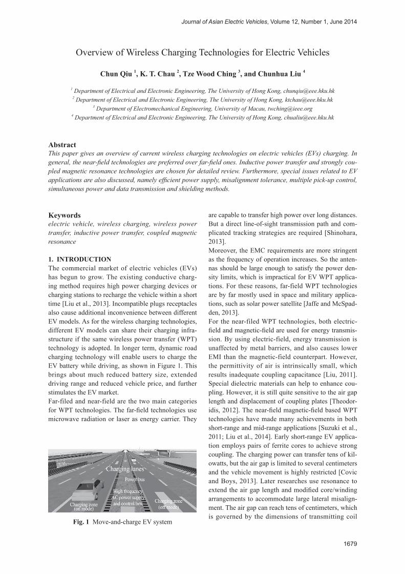
1. INTRODUCTIONThe commercial market of electric vehicles (EVs) has begun to grow. The existing conductive charg-ing method requires high power charging devices or charging stations to recharge the vehicle within a short time [Liu et al., 2013]. Incompatible plugs receptacles also cause additional inconvenience between different EV models. As for the wireless charging technologies, different EV models can share their charging infra-structure if the same wireless power transfer (WPT) technology is adopted. In longer term, dynamic road charging technology will enable users to charge the EV battery while driving, as shown in Figure 1. This brings about much reduced battery size, extended driving range and reduced vehicle price, and further stimulates the EV market.Far-filed and near-field are the two main categories for WPT technologies. The far-field technologies use microwave radiation or laser as energy carrier. They
are capable to transfer high power over long distances. But a direct line-of-sight transmission path and com-plicated tracking strategies are required [Shinohara, 2013].Moreover, the EMC requirements are more stringent as the frequency of operation increases. So the anten-nas should be large enough to satisfy the power den-sity limits, which is impractical for EV WPT applica-tions. For these reasons, far-field WPT technologies are by far mostly used in space and military applica-tions, such as solar power satellite [Jaffe and McSpad-den, 2013].For the near-filed WPT technologies, both electric-field and magnetic-field are used for energy transmis-sion. By using electric-field, energy transmission is unaffected by metal barriers, and also causes lower EMI than the magnetic-field counterpart. However, the permittivity of air is intrinsically small, which results inadequate coupling capacitance [Liu, 2011]. Special dielectric materials can help to enhance cou-pling. However, it is still quite sensitive to the air gap length and displacement of coupling plates [Theodor-idis, 2012]. The near-field magnetic-field based WPT technologies have made many achievements in both short-range and mid-range applications [Suzuki et al., 2011; Liu et al., 2014]. Early short-range EV applica-tion employs pairs of ferrite cores to achieve strong coupling. The charging power can transfer tens of kil-owatts, but the air gap is limited to several centimeters and the vehicle movement is highly restricted [Covic and Boys, 2013]. Later researches use resonance to extend the air gap length and modified core/winding arrangements to accommodate large lateral misalign-ment. The air gap can reach tens of centimeters, which is governed by the dimensions of transmitting coil
Fig. 1 Move-and-charge EV system

C. Qiu et al.: Overview of Wireless Charging Technologies for Electric Vehicles
1680
[Wang et al., 2005]. Mid-range applications by elimi-nating the ferrite cores extend transmitting distance to the order of the coil diameter or even several times of the coil size. By using magnetic resonance and multi-coil configuration, the resistance of the coils is further reduced and the transmitting distance is extended to several meters with a power level up to hundreds of watts [Kurs et al., 2007].This paper mainly focuses on the magnetic-field based near-field short-range and mid-range WPT technolo-gies, which are most promising for EV wireless charg-ing applications. The inductive power transfer (IPT) and strongly coupled magnetic resonance are intro-duced with a summary on their state-of-the-art appli-cations. Key issues and technologies for EV wireless charging are specially chosen and discussed, namely power converter design, mis-alignment tolerance, adaptive control strategies, and EMI issues.
2. WIRELESS POWER TRANSFER2.1 Inductive power transferThe typical arrangement of IPT system is shown in Figure 2. An inverter converts the DC power into high frequency AC current or voltage. The operat-ing frequency varies from tens of kilohertz to several megahertz. The key element is a pair of magnetically coupled coils. In order to enhance the mutual induct-ance, ferrite cores are used in one or both sides of the coils. Litz wires are frequently used to lower the parasitic resistance and therefore high Q-factor. The litz coil consists of many individually insulated thin conductor stands wounded in a particular patterns to reduce both the skin and proximity effects. However, for frequency higher than 1 MHz, (e.g. 13.56 MHz) litz wires are less effective and rarely used. Copper conductor or hollow copper tube could be alternative solutions [Karalis et al., 2008].Compensation capacitances are added on both primary and secondary sides, either in series or in parallel. The purpose of compensation networks is to maximize the load power and meanwhile minimize the reac-tive power of the primary inverter. The series-series topology is theoretically optimal because the value
of primary compensation capacitor is independent from mutual inductance and the load conditions [Ko and Jiang, 2013]. For the series-parallel topology, the value of primary compensation capacitor is independ-ent with mutual inductance but varies with load. The parallel compensation is more suitable when current source characteristic at the secondary end is required or a large primary current is preferred. Fixed or adjust-able passive capacitors are usually used in most ap-plications. Active capacitance control is also theoreti-cally achievable using switch-mode power converters, which offer much more freedom of operation.The simplified equivalent circuit of series-series com-pensated IPT system is shown in Figure 3. M denotes the mutual inductance between primary and secondary coils. Model elements include self-inductance of cou-pled coils L1 and L2, lumped compensation capacitors C1 and C2, parasitic AC resistance of coils and capaci-tors R1 and R2, the internal resistance of AC voltage supply RS, and the load RL, which is assumpted purely resistive to simplify the analysis. The operation at resonant frequency ω0 can be described by (1) to (6),
VS = (RS + R1) I1 – jω0MI2 (1)
VL = jω0MI1 – R2I2 (2)
ω02M2V1
2RLPL =
[(RS + R1) (RL + R2) + ω02M2]2
(3)
ω02M2RL
η =(RS + R1) (RL + R2)2 + ω0
2M2 (RL + R2) (4)
Fig. 2 Typical IPT EV charging system
Fig. 3 Schematic of series compensated inductive power transfer system
Journal of Asian Electric Vehicles, Volume 12, Number 1, June 2014
1681
ω02M2
RL, max power = R2 + R1
(5)
ω02M2R2
RL, max efficiency = R22 +
R1
(6)
In equations (3) and (4), the transferred power and efficiency are functions of load and mutual induct-ances. For EV application, the load is defined by the battery’s depth-of-discharge and the charging speed, and the mutual inductance is directly related to the relative position between on-board pickup coil and fixed transmitting coil. The first problem is both the load and mutual inductance are ever changing because EVs cannot be always perfectly parked or they are moving during power transfer. Another problem is that for a certain conditions, the load power and efficiency cannot achieve maximum point at the same time, as shown by equations (5) and (6). Therefore, the chal-lenge for IPT wireless charging is the implementation of suitable control strategies, such as load matching and variable frequency control to regulate the load power while maintaining high transmission efficiency.
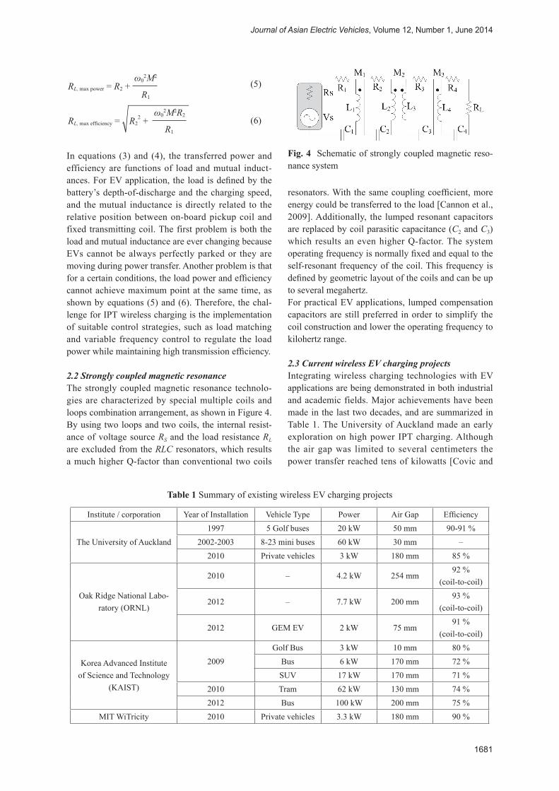
2.2 Strongly coupled magnetic resonanceThe strongly coupled magnetic resonance technolo-gies are characterized by special multiple coils and loops combination arrangement, as shown in Figure 4. By using two loops and two coils, the internal resist-ance of voltage source RS and the load resistance RL
are excluded from the RLC resonators, which results a much higher Q-factor than conventional two coils
resonators. With the same coupling coefficient, more energy could be transferred to the load [Cannon et al., 2009]. Additionally, the lumped resonant capacitors are replaced by coil parasitic capacitance (C2 and C3) which results an even higher Q-factor. The system operating frequency is normally fixed and equal to the self-resonant frequency of the coil. This frequency is defined by geometric layout of the coils and can be up to several megahertz.For practical EV applications, lumped compensation capacitors are still preferred in order to simplify the coil construction and lower the operating frequency to kilohertz range.
2.3 Current wireless EV charging projectsIntegrating wireless charging technologies with EV applications are being demonstrated in both industrial and academic fields. Major achievements have been made in the last two decades, and are summarized in Table 1. The University of Auckland made an early exploration on high power IPT charging. Although the air gap was limited to several centimeters the power transfer reached tens of kilowatts [Covic and
Institute / corporation Year of Installation Vehicle Type Power Air Gap Efficiency
The University of Auckland1997 5 Golf buses 20 kW 50 mm 90-91 %
2002-2003 8-23 mini buses 60 kW 30 mm –2010 Private vehicles 3 kW 180 mm 85 %
Oak Ridge National Labo-ratory (ORNL)
2010 – 4.2 kW 254 mm92 %
(coil-to-coil)
2012 – 7.7 kW 200 mm93 %
(coil-to-coil)
2012 GEM EV 2 kW 75 mm91 %
(coil-to-coil)
Korea Advanced Institute of Science and Technology
(KAIST)
2009Golf Bus 3 kW 10 mm 80 %
Bus 6 kW 170 mm 72 %SUV 17 kW 170 mm 71 %
2010 Tram 62 kW 130 mm 74 %2012 Bus 100 kW 200 mm 75 %
MIT WiTricity 2010 Private vehicles 3.3 kW 180 mm 90 %
Table 1 Summary of existing wireless EV charging projects
Fig. 4 Schematic of strongly coupled magnetic reso-nance system
C. Qiu et al.: Overview of Wireless Charging Technologies for Electric Vehicles
1682
Boys, 2010]. Their recent research has been aiming at extending vertical distance and adapting horizontal offsets, such as the single-sided flux magnetic cou-pler (DD-DDQ) system [Budhia et al., 2013]. ORNL focused on the high efficiency lumped coil design and successfully implemented it into a 72 V lead-acid battery powered EV [Miller, 2012]. KAIST has made great achievement on dynamic wireless charg-ing in the last few years, which is called on-line elec-tric vehicles (OLEV) [Jung et al., 2013]. The OLEV project was launched in 2009. In the same year, three generations of prototypes were reported with power ranges from 3 to 17 kW [Lee et al., 2010]. The first demonstration, a 2.2 km tram loop, was installed in 2010. This 62 kW wireless powered tram equipped with a battery module of 40 % smaller than normal battery-powered trams. In 2012, an OLEV bus system was demonstrated which was capable to transfer 100 kW (5 sets of 20 kW pick-up coils) through a 20cm air gap with average efficiency of 75 %. [Jim et al., 2013]. KAIST is ready to apply its OLEV technology on a high-speed high-power railway (over 300 km/h, 180 kW) at the end of 2013 [Ahn et al., 2013]. MIT (WiTricity) employed the strongly coupled magnetic resonance technology and implemented a commercially available 3.3 kW charging kit for market EV models.
3. EFFICIENT POWER CONVERTERFor the IPT applications operating under 1 MHz, LCL resonant converter is widely adopted [Wang et al., 2004], as shown in Figure 5. The inductance L0 can be a lumped inductor or the secondary winding of high frequency isolation transformer. The LCL resonant converter has the following merits. Firstly, the con-stant voltage from H-bridge results constant current in the primary coil which is independent of load con-ditions. And this current can be easily controlled by adjusting the duty cycle of the bridge. Secondly, the H-bridge only support the real power dissipated by the load and parasitic resistances, while high resonant cur-rent in the primary coil is supported by compensation capacitor C1 [Kissin et al., 2009].Different types of RF amplifiers are used for operating frequency over megahertz range. Class E amplifier has the simplest one-switch architecture and offers high output power. Class D is an alternative solution. With
half-bridge or full-bridge topologies, the VA rating of power switches can be lower than Class E amplifier. However, the efficiency of the Class D amplifier is related to the reflected loaded Q. So there may be a notable drop when the transmission distance increases [Garnica et al., 2013].
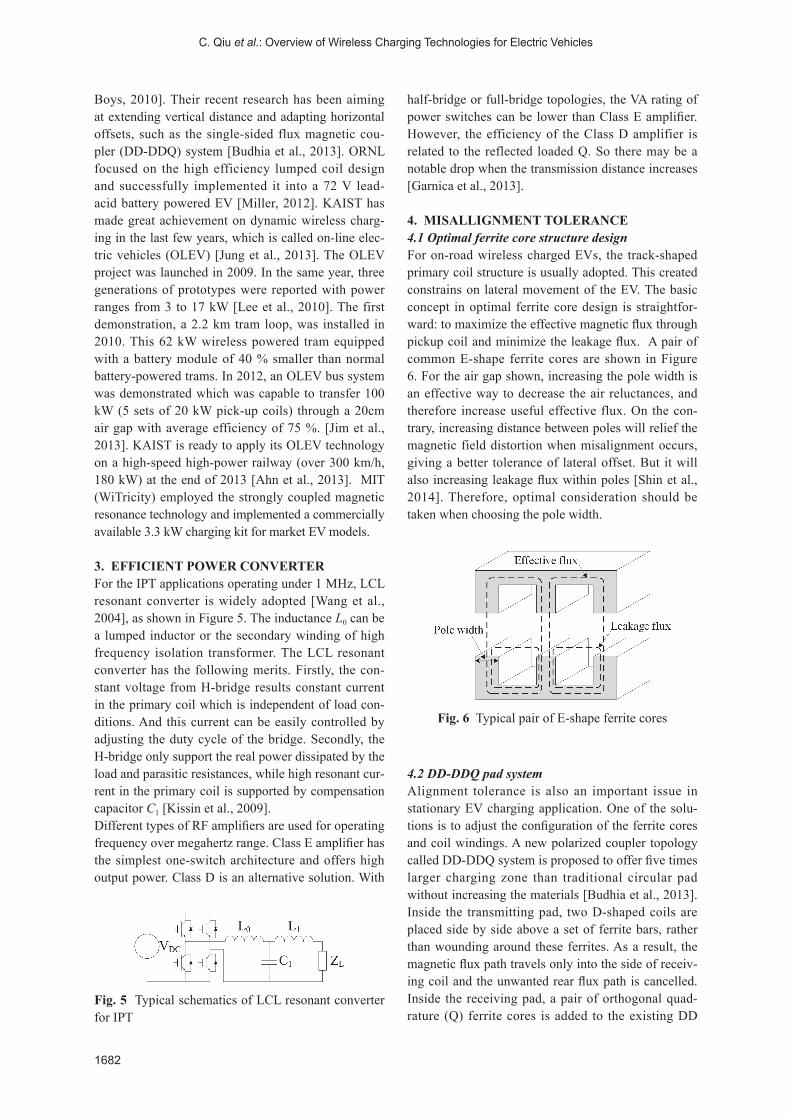
4. MISALLIGNMENT TOLERANCE4.1 Optimal ferrite core structure designFor on-road wireless charged EVs, the track-shaped primary coil structure is usually adopted. This created constrains on lateral movement of the EV. The basic concept in optimal ferrite core design is straightfor-ward: to maximize the effective magnetic flux through pickup coil and minimize the leakage flux. A pair of common E-shape ferrite cores are shown in Figure 6. For the air gap shown, increasing the pole width is an effective way to decrease the air reluctances, and therefore increase useful effective flux. On the con-trary, increasing distance between poles will relief the magnetic field distortion when misalignment occurs, giving a better tolerance of lateral offset. But it will also increasing leakage flux within poles [Shin et al., 2014]. Therefore, optimal consideration should be taken when choosing the pole width.
4.2 DD-DDQ pad systemAlignment tolerance is also an important issue in stationary EV charging application. One of the solu-tions is to adjust the configuration of the ferrite cores and coil windings. A new polarized coupler topology called DD-DDQ system is proposed to offer five times larger charging zone than traditional circular pad without increasing the materials [Budhia et al., 2013]. Inside the transmitting pad, two D-shaped coils are placed side by side above a set of ferrite bars, rather than wounding around these ferrites. As a result, the magnetic flux path travels only into the side of receiv-ing coil and the unwanted rear flux path is cancelled. Inside the receiving pad, a pair of orthogonal quad-rature (Q) ferrite cores is added to the existing DD
Fig. 5 Typical schematics of LCL resonant converter for IPT
Fig. 6 Typical pair of E-shape ferrite cores

Journal of Asian Electric Vehicles, Volume 12, Number 1, June 2014
1683
structure, enabling capture of magnetic flux from both horizontal and vertical directions.
4.3 Range adaption control of strongly coupled mag-netic resonanceFor the strongly coupled magnetic resonance, the transmission efficiency drops quickly when distance or orientation between coupled resonators deviates from its normal position. For wireless EVs charging, the relative position between resonators could hardly be stable. So, adaptive control is essential [Sample et al., 2011].The highest possible efficiency is occurred when source/load impedance matches with coil impedances. The impedance adjusting can be realized by real-time tuning the operating frequency, or by keeping a fixed operating frequency but using impedance match-ing networks between coils and source, and between coils and load. Either frequency tuning or impedance matching is effective in the over-coupled regime. Oth-erwise, the mutual inductance is too weak to support high efficient transmission [Sample et al., 2013].
5. MULTIPLE PICK-UP CONTROLFor on-road wireless EV charging, there is a situation when more than one vehicle connects onto the same power transmitter. Each secondary coil has magnetic coupling with the primary coil but demands for in-dependent power control. The system will become unstable when too many light loaded secondary pick-ups are connected. Therefore, decoupling control is proposed to solve this problem and meanwhile offers a possible way to regulate secondary power [Covic and Boys, 2013].
The key concept of decoupling control is to short-circuit the light loaded pick-ups. This is equivalent to removing unwanted pick-ups from primary transmitter and adding a small amount of reactive power in the primary supply. For a parallel compensated topology, a boost converter is added before the load, and simi-larly, a buck converter is added for the series compen-sated topology, as shown in Figure 7 [Keeling et al., 2010].However, this method assumes that all pick-ups are operating at the tuned frequency and the mutual in-ductance between every primary and secondary coil keeps constant. This might be a reasonable assumption for monorail system. But for other configuration (e.g. lumped pad system), more effective method should be explored since mutual inductance changes with pad positions.
6. CONCURRENT DATA TRANSMISSIONNormally, when primary side control is adopted, the information of secondary side conditions should be sent back to the primary side, using wireless commu-nication. However this will increase the overall sys-tem cost. Recent studies reveals that concurrent data transmission with power will offer better solutions.Figure 8 shows the basic principle of capacitive ampli-tude modulation. The modulation capacitors Cm1 and
(a)
(b)
Fig. 7 Decoupling regulator. (a) parallel compensated secondary, (b) series compensated secondary
Fig. 8 Capacitive amplitude modulation. (a) schemat-ics, (b) amplitude modulation
(a)
(b)

C. Qiu et al.: Overview of Wireless Charging Technologies for Electric Vehicles
1684
Cm2 are periodically added to the load, changing the network impedance characteristics. This change will result in the change of primary voltage. The change of primary voltage is then demodulated and converted to corresponding data. The format of the data package can be found in wireless power transfer standard Qi [Johns, 2011].
7. EMI SHIELDING AND SAFETY ISSUESThe alternating current through the coupled coils generate unwanted electromagnetic fields. As the un-wanted EMI brings up safety issues, the International Commission on Non-Ionizing Radiation Protection (ICNIRP) suggests that the acceptable human expo-sure to electromagnetic field should be less than 6.25 µT at frequency 0.8-150 kHz [ICNIRP, 1998].Coreless hollow winding coils have better misalign-ment tolerant performance but with severe EMI into the space [Qiu et al., 2014]. By using ferrite material as flux guide, the unwanted leakage flux is contained, resulting less EMI. Using metallic plate as shielding between human and coils is a common method to con-trol the EMI level inside an EV. It is worth noting that directly placing metal object near coils will decrease the self and mutual inductances, thus hinder the power transfer [Geselowitz et al., 1992]. When ferrite materi-als are placed between the coil and metallic shielding, this effect can be minimized.Using reactive conducting coils to create reverse EMI is proved to be anther effective counter-measure [Kim et al., 2013]. In a 5 x 20 kW wireless charging prototype, ten parallel compensated reactive coils are placed alongside with the receiving coils. Each reso-nating coil is parallel compensated with controlled capacitor array. The EMI levels measured at strategic points are feed to the controller. By choosing a suit-able resonating capacitance, the EMI can be mini-mized.
CONCLUSIONIn this paper, various WPT technologies are intro-duced and compared in the perspective of EV wireless charging applications. The principles of inductive power transfer and strongly coupled magnetic reso-nance are discussed, focusing on maximum power transfer and maximum efficiency. A summary has been made on current wireless EV charging achieve-ments. Other core issues in EV wireless charging are specially chosen and discussed. Latest solutions for every issue is being discussed.
AcknowledgementsThis work was supported by a grant (Project No. 201109176034) from HKU Small Project Funding,
Hong Kong Special Administrative Region, China.
ReferencesAhn, S., N. P. Suh, and D. H. Cho, Charging up the
road, IEEE Spectrum, Vol. 50, No. 4, 48-54, 2013.Budhia, M., J. T. Boys, G. A. Covic, and C. Huang,
Development of a single-sided flux magnetic cou-pler for electric vehicle IPT charging systems, IEEE Transactions on Industrial Electronics, Vol. 60, No. 1, 318-328, 2013.
Cannon, B. L., J. F. Hoburg, D. D. Stancil, and S. C. Goldstein, Magnetic resonant coupling as a poten-tial means for wireless power transfer to multiple small receivers, IEEE Transactions on Power Elec-tronics, Vol. 24, No. 7, 2009.
Covic, G. A., and J. T. Boys, Inductive power transfer (IPT) powering our future, Power Electron. Re-search Group, Univ. Auckland, New Zealand, Tech. Rep., 2010. [Online]. Available: http://ceme.ece.illinois.eduiseminars/CEME910Covic.pdf.
Covic, G. A., and J. T. Boys, Inductive power trans-fer, Proceeding of the IEEE, Vol. 101, 1276-1289, 2013.
Garnica, J., R. A. Chinga, and J. Lin, Wireless power transmission from far field to near field, Proceeding of the IEEE, Vol. 101, 1321-1331, 2013.
Geselowitz, D. B., Q. Hoang, and R. P. Gaumond, The effect of metal on a transcutaneous energy trans-mission system, IEEE Transactions on Biomedical Engineering, Vol. 39, No. 9, 928-934, 1992.
ICNIRP Guidelines, Guidelines for limiting exposure to time-varying electric, magnetic, and electromag-netic fields (up to 300GHz), Health Physics, Vol. 74, No. 4, 494-522, 1998.
Jaffe, P., and J. McSpadden, Energy conversion and transmission modules for space solar power, Pro-ceeding of the IEEE, Vol. 101, 1424-1437, 2013.
Johns, B., An introduction to the Wireless Power Consortium standard and TI’s compliant solutions, Analog Application Journal, 10-12, 2011.
Karalis, A., J. D. Joannopoulos, and M. Soljacic, Ef-ficient wireless non-radiative mid-range energy transfer, Annals of Physics, Vol. 323, No. 1, 34-48, 2008.
Keeling, N. A., G. A. Covic, and J. T. Boys, A unity power factor IPT pick-up for high power applica-tions, IEEE Transactions on Industrial Electronics, Vol. 57, No. 2, 744-751, 2010.
Kim, J., J. Kim, S. Kong, H. Kim, I. S. Suh, N. P. Suh, D. H. Cho, J. Kim, and S. Ahn, Coil design and shielding methods for a magnetic resonant wireless power transfer system, Proceeding of the IEEE, Vol. 101, 1332-1342, 2013.
Kissin, M. L. G., C. Y. Huang, G. A. Covic, and J. T.

Journal of Asian Electric Vehicles, Volume 12, Number 1, June 2014
1685
Boys, Detection of the tuned point of a fixed-fre-quency LCL resonant power supply, IEEE Transac-tions on Power Electronics, Vol. 24, No. 4, 2009.
Ko, Y. D., and Y. J. Jang, The optimal system design of the online electric vehicle utilizing wireless power transmission technology, IEEE Transactions on Intelligent Transportation Systems, Vol. 14, No. 3, 1255-1265, 2013.
Kurs, A., A. Karalis, R. Moffatt, J. D. Joannopoulos, P. Fisher, and M. Soljacic, Wireless power transfer via strongly coupled magnetic resonances, Science, Vol. 317, No. 5834, 83-86, 2007.
Lee, S., J. Huh, C. Park, N. S. Choi, G. H. Cho, and C. T. Rim, On-line electric vehicle using inductive power transfer system, in IEEE Energy Conver-sion Congress and Exposition ECCE, Atlanta, GA, 2010, 1598-1601.
Liu, C., Fundamental study on capacitively coupled contactless power transfer technology, Ph.D. dis-sertation, Department of Electrical and Computer Engineering, The University of Auckland, 2011.
Liu, C., K. T. Chau, C. Qiu, and F. Lin, Investigation of energy harvesting for magnetic sensor arrays on Mars by wireless power transmission, Journal of Applied Physics, Vol. 115, 17E702: 1-3, 2014.
Liu, C., K. T. Chau, D. Wu, and S. Gao, Opportunities and challenges of vehicle-to-home, vehicle-to-ve-hicle and vehicle-to-grid technologies, Proceeding of the IEEE, Invited Paper, Vol. 101, No. 11, 2409-2427, 2013.
Miller, J. M., Wireless plug-in electric vehicle (PEV) charging, Oak Ridge National Laboratory, Techni-cal Report, 2012. [Online]. Available: http://www1.eere.energy.gov/vehiclesandfuels/pdfs/merit_review_2012/veh_sys_sim/vss061_miller_2012_o.pdf.
Qiu, C., K. T. Chau, C. Liu, W. Li, and F. Lin, Quan-titative comparison of dynamic flux distribution of magnetic couplers for roadway electric vehicle wireless charging system, Journal of Applied Phys-ics, Vol. 115, 17A334, 2014.
Sample, A. P., B. H. Waters, S. T. Wisdom, and J. R. Smith, Enabling seamless wireless power delivery in dynamic environments, Proceeding of the IEEE, Vol. 101, 1343-1358, 2013.
Sample, A. P., D. A. Meyer, and J. R. Smith, Analy-sis, experimental results, and range adaptation of magnetically coupled resonators for wireless power transfer, IEEE Transactions on Industrial Electron-ics, Vol. 58, No. 2, 544-554, 2011.
Shin, J., S. Shin, Y. Kim, S. Ahn, S. Lee, G. Jung, S. Joen, and D. Cho, Design and implementation of shaped magnetic-resonance-based wireless power transfer system for roadway-powered moving
electric vehicles, IEEE Transactions on Industrial Electronics, Vol. 61, No. 3, 1179-1192, 2014.
Shinohara, N., Beam control technologies with a high-efficiency phased array for microwave power trans-mission in Japan, Proceeding of the IEEE, Vol. 101, 1448-1463, 2013.
Suzuki, S., M. Ishihara, and Y. Kobayashi, The im-provement of the noninvasive power-supply system using magnetic coupling for medical implants, IEEE Transactions on Magnetics, Vol. 47, No. 10, 2811-2814, 2011.
Theodoridis, M. P., Effective capacitive power trans-fer, IEEE Transactions on Power Electronics, Vol. 27, No. 12, 4906-4913, 2012.
Wang, C. S., O. H. Stielau, and G. A. Covic, Design considerations for a contactless electric vehicle bat-tery charger, IEEE Transactions on Industrial Elec-tronics, Vol. 52, No. 5, 1308-1314, 2005.
Wang, C. S., G. A. Covic, and O. S. Stielau, Investi-gating an LCL load resonant inverter for inductive power transfer applications, IEEE Transactions on Power Electronics, Vol. 19, No. 4, 2004.
Zhang, Z., K. T. Chau, C. Liu, C. Qiu, and F. Lin, An efficient wireless power transfer system with secu-rity considerations for electric vehicle applications, Journal of Applied Physics, Vol. 115, 17A328: 1-3, 2014.
(Received May 24, 2014; accepted June 4, 2014)
Related Documents


![Design and Comparison Wireless Power Transfer … — Magnetically ... phones [4]-[7], and mobile laptop charging [8], [9]. ... Design and Comparison Wireless Power Transfer Base on](https://static.cupdf.com/doc/110x72/5ab660ff7f8b9a6e1c8d9cc7/design-and-comparison-wireless-power-transfer-magnetically-phones-4-7.jpg)