Light Weight Wireless Power Transfer for EV Charging “Link efficiency led design” Paul D. Mitcheson Department of Electrical and Electronic Engineering, Imperial College London, U.K. 1 Underpinning Research

Welcome message from author
This document is posted to help you gain knowledge. Please leave a comment to let me know what you think about it! Share it to your friends and learn new things together.
Transcript
Light Weight Wireless Power
Transfer for EV Charging“Link efficiency led design”
Paul D. Mitcheson
Department of Electrical and Electronic Engineering, Imperial College London, U.K.
1
Underpinning Research
Existing Systems
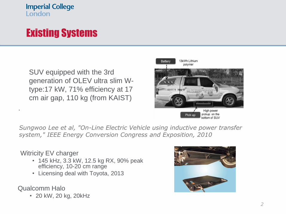
SUV equipped with the 3rd
generation of OLEV ultra slim W-
type:17 kW, 71% efficiency at 17
cm air gap, 110 kg (from KAIST)
.
2
Sungwoo Lee et al, "On-Line Electric Vehicle using inductive power transfer system," IEEE Energy Conversion Congress and Exposition, 2010
Witricity EV charger• 145 kHz, 3.3 kW, 12.5 kg RX, 90% peak
efficiency, 10-20 cm range
• Licensing deal with Toyota, 2013
Qualcomm Halo• 20 kW, 20 kg, 20kHz
IPT - A Poorly Coupled Transformer
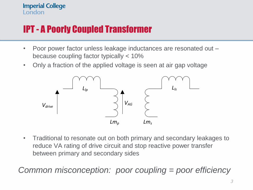
• Poor power factor unless leakage inductances are resonated out –
because coupling factor typically < 10%
• Only a fraction of the applied voltage is seen at air gap voltage
• Traditional to resonate out on both primary and secondary leakages to
reduce VA rating of drive circuit and stop reactive power transfer
between primary and secondary sides
3
Llp
Lmp Lms
Lls
VdriveVAG
Common misconception: poor coupling = poor efficiency

Efficiency
Efficiency given by:
Need to maximise k2Q1Q2
k2Q1Q2 > 10 for η > 50%
k2Q1Q2 > 350 for η > 90%
221
2
21
2
11
=
QQk
QQk
kQ1 Q2
Couplingfactor
distancex
r1 r2
Secondary resonance
Optimal load
The traditional approach is to increase k, reducing leakage inductance and
improving link efficiency…. But….

Motivation
• Coils with ferrite cores are heavy – and ferrite is costly and brittle
• Their directed magnetic flux leads to restricted freedom of movement
• Air-core coils, with their wide flux coverage, are more suitable for many
IPT applications
• Lightweight for EVs
• Dynamic charging of moving vehicles
• With coils acting as weakly coupled transformer, link efficiency
deteriorates rapidly with distance
• Driving high Q coils with weak coupling presents an interesting set of
challenges for the power electronics.
5
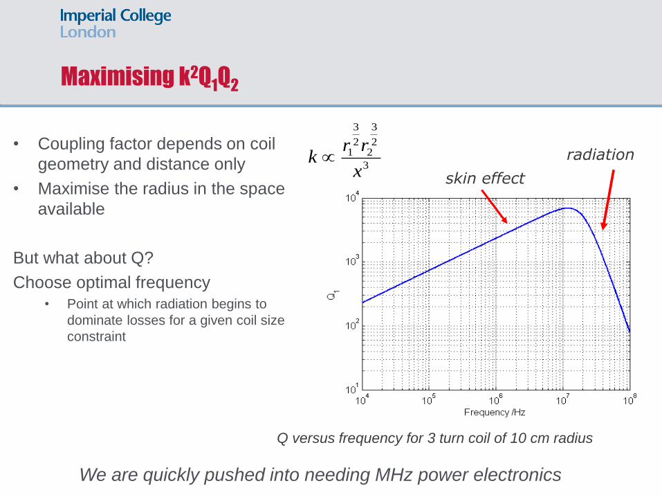
Maximising k2Q1Q2
• Coupling factor depends on coil
geometry and distance only
• Maximise the radius in the space
available
But what about Q?
Choose optimal frequency
• Point at which radiation begins to
dominate losses for a given coil size
constraint
3
2
3
22
3
1
x
rrk
Q
3
1
Q
skin effect
radiation
Q versus frequency for 3 turn coil of 10 cm radius
We are quickly pushed into needing MHz power electronics
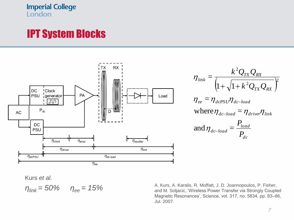
IPT System Blocks
dc
loadloaddc
linkdriverloaddc
loaddcdcPSUee
RXTX
RXTXlink
P
P
QQk
QQk
=and
=where
=
11
=2
2
2
Kurs et al.
ηlink = 50% ηee = 15%A. Kurs, A. Karalis, R. Moffatt, J. D. Joannopoulos, P. Fisher,
and M. Soljacic, ‘Wireless Power Transfer via Strongly Coupled
Magnetic Resonances’, Science, vol. 317, no. 5834, pp. 83–86,
Jul. 2007.
7
Inverters
• Conventional hard-switching not suitable in MHz region
• Device switching times become comparable to driving signal period
• Can be inefficient at higher frequencies
• Soft switching inverters (eg ZVS Class-D and Class-E) employ zero-
voltage switching to minimise power dissipation
• Class-D inverters: popular with low-power systems adhering to Qi or
A4WP standards
• Lower normalised output power compared to Class-E
• Require floating gate drive
• But can operate over larger load range with ZVS if the switching frequency is
below resonant frequency of output load network.
8
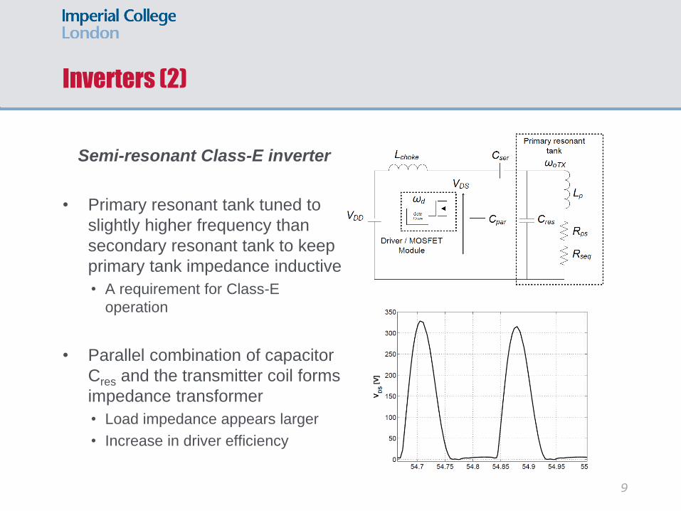
Inverters (2)
Semi-resonant Class-E inverter
• Primary resonant tank tuned to
slightly higher frequency than
secondary resonant tank to keep
primary tank impedance inductive
• A requirement for Class-E
operation
• Parallel combination of capacitor
Cres and the transmitter coil forms
impedance transformer
• Load impedance appears larger
• Increase in driver efficiency
9

High Frequency Semi-resonant Class-E Driver
10
78% dc-load efficiency, 100 W, 6 MHz, IXYS Si module
Increasing the Power – 3 kW target
11
3 kW System desirable for mains EV charging
• Wide bandgap devices exhibit significant improvements:
• Greater power handling capability through higher blocking voltages (SiC) and lower on-state resistance (SiC, GaN)
• Low gate charge requirements (GaN) and fast switching speeds (GaN)
• Resonant gate drive allows low power driving of SiC device at MHz frequencies despite twice the Vgs.
• Improved inverter design to reduce voltage stress: Class-EF2
• Power combining e.g. push-pull architecture

SiC MOSFET
First experimental integration of Cree SiC MOSFETs in higher power 6
MHz Class E driver inverter achieved 700 W of power to the load
(1.2kV device, with RDSON = 0.16 Ohms)
The IXYS gate drive consumed more than twice that required to switch
the original Si MOSFET, due mainly to the larger Vgs required.

Resonant gate drive with class E
Class E primary IPT driver design:
● Cree C2M00800120D 1200 V SiC MOSFET
(Ciss = 259pF, RG = 11.4 Ohms, RDSon = 280 Ohms)
Resonant gate drive design:
● New TI LMG5200 half bridge driver GaN modules integrated in one package as switches (~600mW
power consumption for 2 modules at 6MHz)
● Body diode not good enough so use Vishay Schottky MSS1P3L
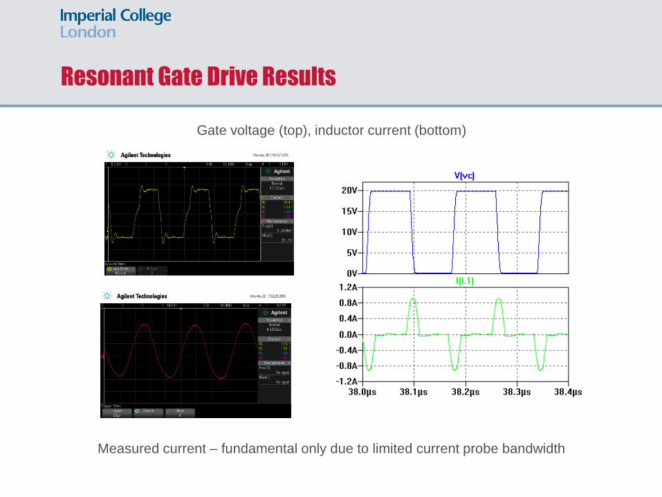
Resonant Gate Drive Results
Gate voltage (top), inductor current (bottom)
Measured current – fundamental only due to limited current probe bandwidth
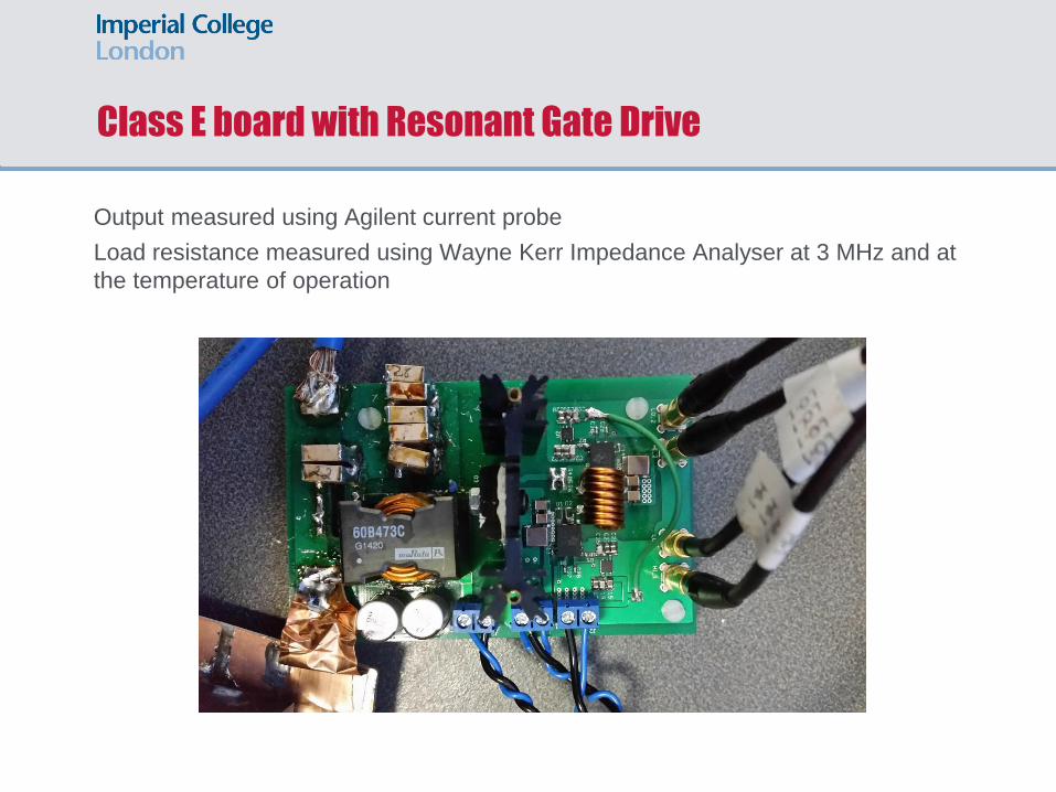
Class E board with Resonant Gate Drive
Output measured using Agilent current probe
Load resistance measured using Wayne Kerr Impedance Analyser at 3 MHz and at
the temperature of operation

Measured Class E Efficiency
Total efficiency of new SiC class E including resonant gate drive losses is ~94%,
~12 % better than original Si version with off-the shelf gate drive
Measured Efficiency versus input power
Original This work
Efficiency ~82% ~94%
Gate drive ~6 W < 2 W
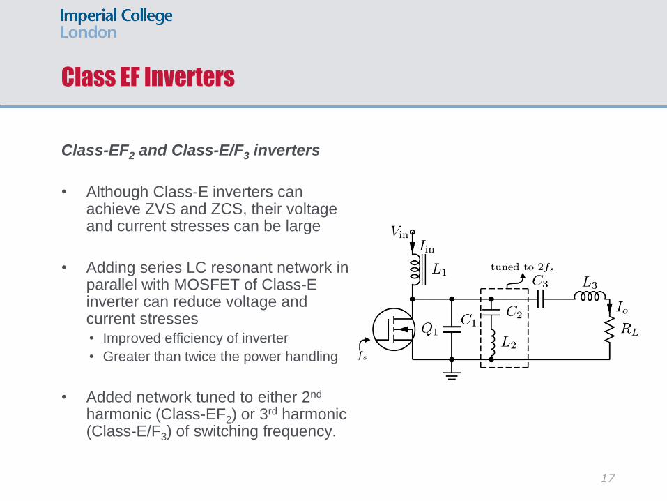
Class EF Inverters
Class-EF2 and Class-E/F3 inverters
• Although Class-E inverters can achieve ZVS and ZCS, their voltage and current stresses can be large
• Adding series LC resonant network in parallel with MOSFET of Class-E inverter can reduce voltage and current stresses
• Improved efficiency of inverter
• Greater than twice the power handling
• Added network tuned to either 2nd
harmonic (Class-EF2) or 3rd harmonic (Class-E/F3) of switching frequency.
17
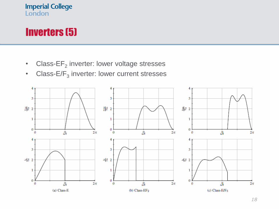
Inverters (5)
• Class-EF2 inverter: lower voltage stresses
• Class-E/F3 inverter: lower current stresses
18
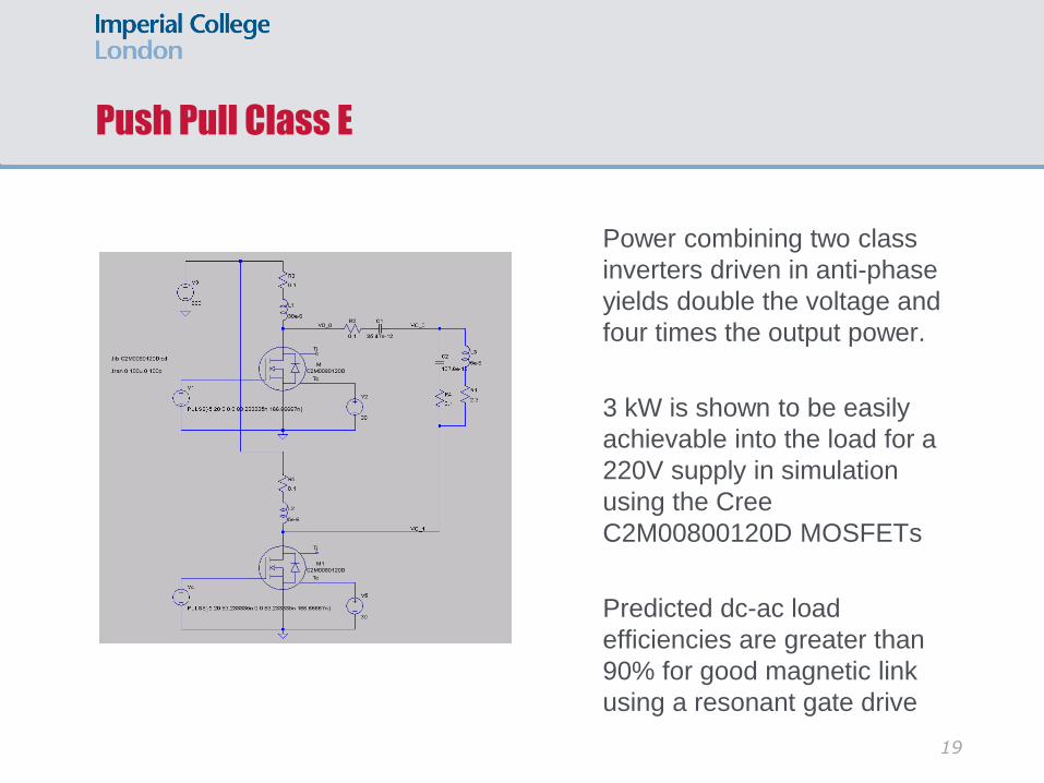
Push Pull Class E
Power combining two class
inverters driven in anti-phase
yields double the voltage and
four times the output power.
3 kW is shown to be easily
achievable into the load for a
220V supply in simulation
using the Cree
C2M00800120D MOSFETs
Predicted dc-ac load
efficiencies are greater than
90% for good magnetic link
using a resonant gate drive
19

Rectifiers – also soft switched
Voltage-driven low dv/dt Class-E rectifier
• Inductor Lr in series with parallel connection of capacitor Cr and diode Dr performs half-wave rectification
• Lr in resonance with Cr at system operating frequency
• Any uncancelled leakage inductance from secondary coil can be absorbed into Lr, and diode’s junction capacitance can be absorbed into Cr
20
𝑅𝑑𝑐 = 2𝑀2𝑅𝑖𝑛
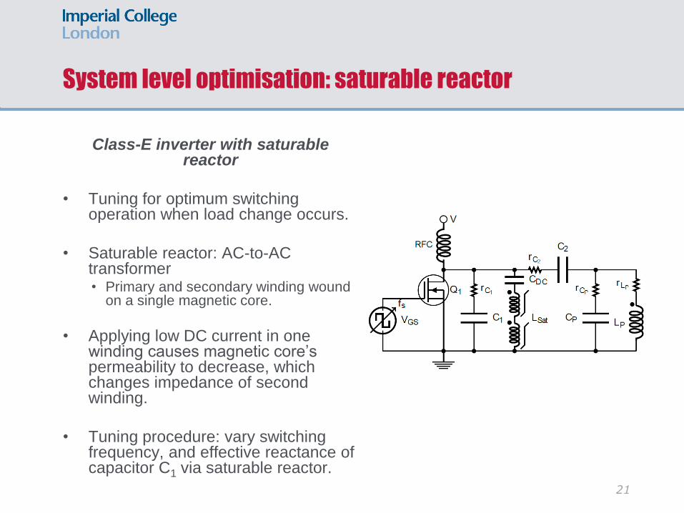
System level optimisation: saturable reactor
Class-E inverter with saturablereactor
• Tuning for optimum switching operation when load change occurs.
• Saturable reactor: AC-to-AC transformer• Primary and secondary winding wound
on a single magnetic core.
• Applying low DC current in one winding causes magnetic core’s permeability to decrease, which changes impedance of second winding.
• Tuning procedure: vary switching frequency, and effective reactance of capacitor C1 via saturable reactor.
21
Electromagnetic Field Limits and Regulations
• Limits on EM field levels protecting humans from adverse effects of
exposure.
• Thermal and non-thermal effects
• EU Directive (2013/35/EU) – exposure of workers
• Adopted on 26 June 2013, to be transposed into UK law by 1 July 2016
• Based on ICNIRP 1998 and 2010
• Exclusion zones
• Design for minimal magnetic field
• Increase link efficiency and overall efficiency
22
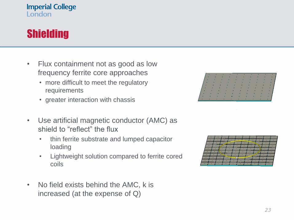
Shielding
• Flux containment not as good as low
frequency ferrite core approaches
• more difficult to meet the regulatory
requirements
• greater interaction with chassis
• Use artificial magnetic conductor (AMC) as
shield to “reflect” the flux
• thin ferrite substrate and lumped capacitor
loading
• Lightweight solution compared to ferrite cored
coils
• No field exists behind the AMC, k is
increased (at the expense of Q)
23
Conclusion
• Well on the way to achieving a complete lightweight 3 kW IPT system
suitable as an initial EV charging prototype
• Maximising the link efficiency for air core coils serves as the design
starting point
• The system architecture, circuit blocks and components have been
chosen to maximise the end-to-end efficiency
• AMCs are considered as a lightweight approach to shielding to meet
health and safety regulations and minimise interaction with the chassis
• If driven properly, ferrite-less coils can achieve high efficiency at low
cost and weight
24
References
• Modeling and Analysis of Class EF and Class E/F Inverters With
Series-Tuned Resonant Networks, S Aldhaher, DC Yates, PD
Mitcheson, Power Electronics, IEEE Transactions on 31 (5), 3415-
3430
• Link efficiency-led design of mid-range inductive power transfer
systems, CH Kwan, G Kkelis, S Aldhaher, J Lawson, DC Yates, PCK
Luk, Emerging Technologies: Wireless Power (WoW), 2015 IEEE
PELS Workshop on, 1-7
• Maximizing DC-to-load efficiency for inductive power transfer, M
Pinuela, DC Yates, S Lucyszyn, PD Mitcheson, Power Electronics,
IEEE Transactions on 28 (5), 2437-2447
25
Acknowledgements
• EPSRC Uk-China Interface and Network Infrastructure to Support EV
Participation in Smart Grids
• EDF (student CASE awards)
• EPSRC Power Electronics Centre Components Theme
• David Yates, Sam Aldhaher, James Lawson, George Kkelis, Chris
Kwan
26
Related Documents


![fgw.henan.gov.cnfgw.henan.gov.cn/filecenter/res_base/rjcms/... · GB/T GB,'T 2978] 50052 GB 50965-2014 AC charging spot charging spot EV charging station EV power—supply system](https://static.cupdf.com/doc/110x72/6012a0d474313f339b176015/fgwhenangovcnfgwhenangovcnfilecenterresbaserjcms-gbt-gbt-2978.jpg)

