Optimising Fibre Installation Inside the Multiple Dwelling Unit A White Paper by the Deployment & Operations Committee Contributors: Dieter Verdegem, CommScope Marc Van Heck, CommScope Stefaan Fagot, CommScope Mike Knott, Corning Juan Colina, Corning Jiri Vyslouzil, Duraline Paul Ekpenyong, m2fx

Welcome message from author
This document is posted to help you gain knowledge. Please leave a comment to let me know what you think about it! Share it to your friends and learn new things together.
Transcript

Optimising Fibre Installation Inside the Multiple Dwelling Unit A White Paper by the Deployment & Operations Committee
Contributors:
Dieter Verdegem, CommScope
Marc Van Heck, CommScope
Stefaan Fagot, CommScope
Mike Knott, Corning
Juan Colina, Corning
Jiri Vyslouzil, Duraline
Paul Ekpenyong, m2fx

2
Version Date Author(s)
White paper MDU_FTTH
Council Europe_v1
25th April 2016 Contributors: Dieter Verdegem, CommScope;
Marc Van Heck, CommScope; Stefaan Fagot,
CommScope; Mike Knott, Corning; Juan
Colina, Corning; Jiri Vyslouzil, Duraline; Paul
Ekpenyong, m2fx
White paper MDU_FTTH
Council Europe_v2
18 July 2016 Edited by Pauline Rigby
3
Contents
Introduction .......................................................................................................................................... 4
Chapter 1: Definition of Total Cost of Ownership................................................................................ 5
Chapter 2: Factors That Influence TCO .............................................................................................. 6
A. Size of the MDU ........................................................................................................................ 6
B. Spliced versus connectorized installations............................................................................... 8
Chapter 3: Solutions for Optimised Fibre Deployments in MDUs..................................................... 10
a). Connectorized products ...................................................................................................... 10
(i) Pre-connectorized drop and riser cables................................................................................ 10
(ii) Floor box with reel for easy storage of cable slack ............................................................ 11
(iii) Ferrulized drop cable .......................................................................................................... 12
b). Microducts inside the MDU ................................................................................................. 13
c). Small diameter drop cables ................................................................................................ 14
d). Riser cable with reinforced retractable fibre ....................................................................... 15
e). Adhesive fibre systems ....................................................................................................... 15
f). Indexing on vertical cable ....................................................................................................... 16
g). Cascaded splitters............................................................................................................... 17
h). Field-installable connectors ................................................................................................ 18
Chapter 4: Conclusion ....................................................................................................................... 19
Figure references ............................................................................................................................... 20

4
Introduction
The ever-growing demand for high-speed, high-bandwidth services continues to be a major driver
for fibre to the home (FTTH) deployment in Europe. Broadband is increasingly regarded as the
fourth utility. There can be no doubt that, with the increasing usage of streaming entertainment
services and teleworking, this utility is now considered essential by many of Europe’s citizens.
New research shows that people increasingly base their choice of a place to live on the availability
of high-speed broadband. Given that more than 50% of Europe’s population lives in multiple
dwelling units (MDUs), with even greater concentrations of up to 70% in cities, the deployment of
fibre in the MDU environment is absolutely critical for many service providers. Not only do MDUs
represent a substantial portion of the subscriber base, the fact that these subscribers live in a
concentrated geographical area makes them an attractive target for FTTH roll-out.
Since the population density in MDUs is high, it generally costs less to deploy FTTH in this
environment compared to individual residences (although the cost still depends on the specific
circumstances). As the population density doubles from 4000 people/km² to 8000 people/km², the
cost of civil engineering and cable installation increases by just 30%, according to analysis by
telecoms consultancy firm iDATE.
That said, MDUs exist in all shapes and sizes, from skyscrapers with hundreds of living units to
apartment blocks with just a few units. Old buildings often have congested utility shafts with very
little space left for cables and enclosures, whereas new apartments can be designed with fibre
network deployments in mind at the outset. Moreover, local regulations often require different
approaches. Hence, there are almost as many possible FTTH architectures as there are MDUs.
Clearly, there is no “one size fits all” solution.
For every situation, a service provider will need to find an appropriate and optimized approach that
makes it possible to deliver reliable services and control the overall network costs. One option is to
attach fibre cables to the outside of the building. For the purposes of this report, however, we will
concentrate on deployment of fibre cables inside the MDU.
This white paper describes the different cost drivers of a fibre roll-out in an MDU environment, and
discuss how these factors can be optimized to minimize the total cost of ownership (TCO). We also
provide an overview of products that help drive down the TCO, helping service providers to find
economical and practical solutions for fibre installation in an MDU.

5
Chapter 1: Definition of Total Cost of Ownership
The total cost of ownership (TCO) is the purchase price of an asset plus the costs of operation.
When deploying FTTH in an MDU, the three main elements that constitute the TCO are:
installation cost
material costs
maintenance costs
Installation and material costs are typically incurred on day one, during the installation.
Maintenance costs, however, occur at a later stage and are often recurring costs.
If we take a closer look at these cost drivers, we see they consist of several elements:
installation cost
o pre-engineering phase
o installation tools
o installation time
o skilled labour versus non-skilled labour
o number of truck rolls
o van stock
material cost
o cost of active infrastructure (electronic equipment, mainly at the central office)
o cost of passive infrastructure (including ducts, cable and other passive elements for
fibre management)
maintenance cost
o product reliability
o quality of installation (have products been properly installed)
o testing capabilities on day one (at installation)
o demarcation between homes passed and homes connected
o need for future upgrades
Where an operator can improve the control or reduce the cost of one or more of these elements,
they can also reduce the total cost of the fibre roll-out.
It is also crucial to understand that many of the above cost drivers show inter-dependencies: for
example, additional investment in easy-to-install passive network elements may lead to shorter
installation times and higher quality of installation, hence reducing the maintenance costs.
Having a clear overview of all the cost drivers and making smart decisions that take all elements
into account will be paramount to optimizing the total cost of ownership.

6
Chapter 2: Factors That Influence TCO
In this chapter we will describe two parameters that heavily influence TCO:
Size of the MDU
Spliced versus connectorized architectures
We use a simple model to show how these parameters affect the TCO of an MDU FTTH roll-out.
A. Size of the MDU
The most important factor determining TCO in the MDU is the size of the buildings to be cabled.
There is no precise definition, but in general small buildings cover up to 12 customers, whereas
medium and large buildings have up to 72 or more customers, respectively. To minimise TCO, the
operator must select the most appropriate architecture for the size of the building.
Figure 1 shows some of the main architectures used worldwide.
Figure 1: Small, medium and high-rise MDU cabled by a direct drop, multi-riser or single riser solution
A. Direct drop: For small MDUs, direct drop architectures are applied where customer
connections are made using individual cables between the end user and a fibre distribution
box sitting either in the basement or on the lower part of the façade.
B. Multi-riser: In larger buildings, a direct drop approach is often not economical, because of
space constraints and the time required to install multiple drop cables. Instead, multiple
central riser segments can be used to serve a defined area on each floor around a floor
termination box. The main advantage is the space savings achieved in the riser.
C. Single riser: If space inside the MDU is really constrained, a useful alternative is to install
a single riser cable inside a single duct that branches out to individual drop cables at the
floor level. The aim is to lessen the visual impact of cabling in these deployments by using
adequate vertical areas, for example on the façade or through existing risers.

7
To determine the best approach, we recommend modelling the main cost elements of the installation, and then using the results of the model to compare several alternative scenarios. Below is the output of such a model.
Scenario 1: Mid-span access with floor box on each floor; HC defined as drop and outlet
Scenario 2: Direct drop to each apartment
Scenario 3: Pre-connectorized riser cable
Time to install
Material cost
Labour cost
Graph 1: Relative cost and time to deploy FTTH in a small MDU
Graph 2: Relative cost and time to deploy FTTH in a medium-size MDU
Graph 3: Relative cost and time to deploy FTTH in a large MDU
0%
20%
40%
60%
80%
100%
120%
Rel
ativ
e to
tal
cost
an
d t
ime
Medium-size MDU (40 units)
Scenario 1 Scenario 2 Scenario 3
0%
20%
40%
60%
80%
100%
120%
140%
Rel
ativ
e to
tal
cost
an
d&
tim
e
Large MDU (120 units)
Scenario 2Scenario 1 Scenario 3
0%
20%
40%
60%
80%
100%
120%
Rel
ativ
e to
tal
cost
an
d t
ime
Small MDU (8 living units)
Scenario 1 Scenario 2 Scenario 3
8
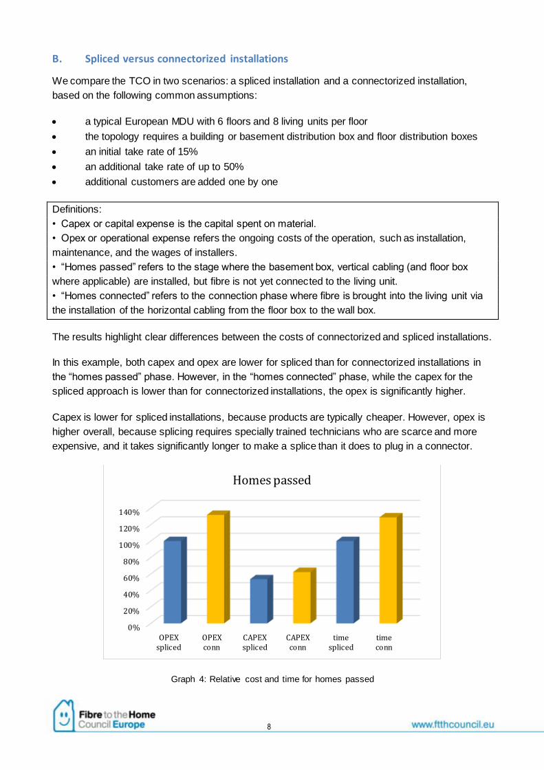
B. Spliced versus connectorized installations
We compare the TCO in two scenarios: a spliced installation and a connectorized installation,
based on the following common assumptions:
a typical European MDU with 6 floors and 8 living units per floor
the topology requires a building or basement distribution box and floor distribution boxes
an initial take rate of 15%
an additional take rate of up to 50%
additional customers are added one by one
Definitions:
• Capex or capital expense is the capital spent on material.
• Opex or operational expense refers the ongoing costs of the operation, such as installation,
maintenance, and the wages of installers.
• “Homes passed” refers to the stage where the basement box, vertical cabling (and floor box
where applicable) are installed, but fibre is not yet connected to the living unit.
• “Homes connected” refers to the connection phase where fibre is brought into the living unit via
the installation of the horizontal cabling from the floor box to the wall box.
The results highlight clear differences between the costs of connectorized and spliced installations.
In this example, both capex and opex are lower for spliced than for connectorized installations in
the “homes passed” phase. However, in the “homes connected” phase, while the capex for the
spliced approach is lower than for connectorized installations, the opex is significantly higher.
Capex is lower for spliced installations, because products are typically cheaper. However, opex is
higher overall, because splicing requires specially trained technicians who are scarce and more
expensive, and it takes significantly longer to make a splice than it does to plug in a connector.
Graph 4: Relative cost and time for homes passed
0%
20%
40%
60%
80%
100%
120%
140%
OPEXspliced
OPEXconn
CAPEXspliced
CAPEXconn
timespliced
timeconn
Homes passed
9
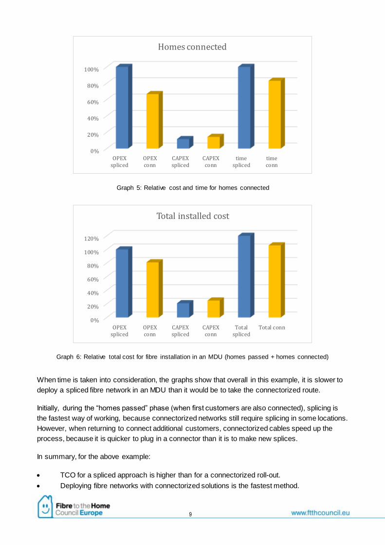
Graph 5: Relative cost and time for homes connected
Graph 6: Relative total cost for fibre installation in an MDU (homes passed + homes connected)
When time is taken into consideration, the graphs show that overall in this example, it is slower to
deploy a spliced fibre network in an MDU than it would be to take the connectorized route.
Initially, during the “homes passed” phase (when first customers are also connected), splicing is
the fastest way of working, because connectorized networks still require splicing in some locations.
However, when returning to connect additional customers, connectorized cables speed up the
process, because it is quicker to plug in a connector than it is to make new splices.
In summary, for the above example:
TCO for a spliced approach is higher than for a connectorized roll-out.
Deploying fibre networks with connectorized solutions is the fastest method.
0%
20%
40%
60%
80%
100%
OPEXspliced
OPEXconn
CAPEXspliced
CAPEXconn
timespliced
timeconn
Homes connected
0%
20%
40%
60%
80%
100%
120%
OPEXspliced
OPEXconn
CAPEXspliced
CAPEXconn
Totalspliced
Total conn
Total installed cost
10
Chapter 3: Solutions for Optimised Fibre Deployments in MDUs
In this chapter, we provide an overview of practical solutions that can help reduce TCO in MDU
environments. For each solution we will provide an indication of how they help improve the cost
drivers and consequently lower the TCO.
a). Connectorized products
Compared to any form of copper cable, fibre is inherently more difficult to join, because the fibre
cores have to be aligned to sub-micron accuracy during the splice process (whether by a fusion or
mechanical method), and the uncoated glass at the joint must be protected. A high concentration
of fibre jointing is needed in MDU deployments, which drives the installation costs upwards.
Although fusion and mechanical splicing have been available since the early days of fibre
deployment, the process still requires a high degree of skill and capital equipment. As a result, pre-
connectorized cables, which have been developed specifically for installation inside MDUs, can
reduce TCO by reducing the need for skilled labour in the field and moving it into dedicated
factories under quality controlled conditions.
Generally speaking, the more pre-configuration that can be built in to the assemblies in the factory,
the greater the opportunity for cost reduction – assuming, of course, that the ease of installation
and flexibility in the field remain guaranteed.
A few common examples of connectorized solutions are described below.
(i) Pre-connectorized drop and riser cables
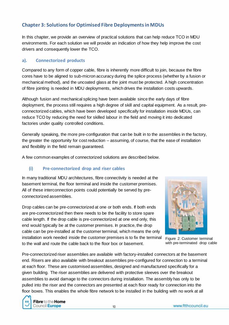
In many traditional MDU architectures, fibre connectivity is needed at the
basement terminal, the floor terminal and inside the customer premises.
All of these interconnection points could potentially be served by pre-
connectorized assemblies.
Drop cables can be pre-connectorized at one or both ends. If both ends
are pre-connectorized then there needs to be the facility to store spare
cable length. If the drop cable is pre-connectorized at one end only, this
end would typically be at the customer premises. In practice, the drop
cable can be pre-installed at the customer terminal, which means the only
installation work needed inside the customer premises is to fix the terminal
to the wall and route the cable back to the floor box or basement.
Pre-connectorized riser assemblies are available with factory-installed connectors at the basement
end. Risers are also available with breakout assemblies pre-configured for connection to a terminal
at each floor. These are customised assemblies, designed and manufactured specifically for a
given building. The riser assemblies are delivered with protective sleeves over the breakout
assemblies to avoid damage to the connectors during installation. The assembly has only to be
pulled into the riser and the connectors are presented at each floor ready for connection into the
floor boxes. This enables the whole fibre network to be installed in the building with no work at all
Figure 2: Customer terminal with pre-terminated drop cable
11
at the fibre level except that of connecting the fibre from the outside world into the splitter input in
the basement box.
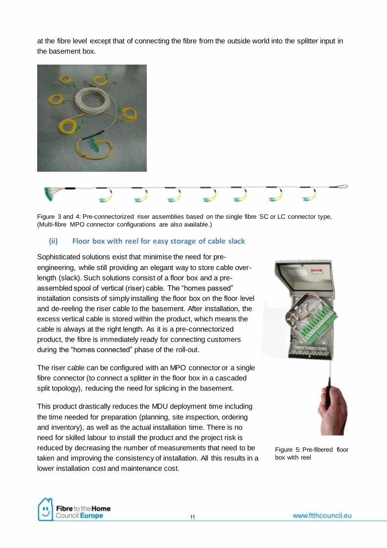
Figure 3 and 4: Pre-connectorized riser assemblies based on the single fibre SC or LC connector type,
(Multi-fibre MPO connector configurations are also available.)
(ii) Floor box with reel for easy storage of cable slack
Sophisticated solutions exist that minimise the need for pre-
engineering, while still providing an elegant way to store cable over-
length (slack). Such solutions consist of a floor box and a pre-
assembled spool of vertical (riser) cable. The “homes passed”
installation consists of simply installing the floor box on the floor level
and de-reeling the riser cable to the basement. After installation, the
excess vertical cable is stored within the product, which means the
cable is always at the right length. As it is a pre-connectorized
product, the fibre is immediately ready for connecting customers
during the “homes connected” phase of the roll-out.
The riser cable can be configured with an MPO connector or a single
fibre connector (to connect a splitter in the floor box in a cascaded
split topology), reducing the need for splicing in the basement.
This product drastically reduces the MDU deployment time including
the time needed for preparation (planning, site inspection, ordering
and inventory), as well as the actual installation time. There is no
need for skilled labour to install the product and the project risk is
reduced by decreasing the number of measurements that need to be
taken and improving the consistency of installation. All this results in a
lower installation cost and maintenance cost.
Figure 5: Pre-fibered floor
box with reel

12
Figure 6: Multi-fibre dual-ended MPO connectorized riser on a collapsible reel
(iii) Ferrulized drop cable
Ferrulized drop cables are pre-connectorized cables with a slimline profile, which allow the outer
connector housing to be “clicked on” after the cable has been pulled or pushed through the duct.
This results in faster and more efficient installation.
Figure 7: Ferrulized drop cable
The ferrulized drop cables can be pushed from the subscriber’s apartment to either a floor box or a
basement distribution box, depending on the size of the MDU. Another approach is to employ a
pullable cable whereby the pre-installed pull cord in the microduct is used to pull the cable through
the microduct. Both simplex and duplex cables of both types are now on the market.
When microducts are already in place – which is increasingly the case for new buildings – then it is
straightforward to deploy a pre-connectorized pushable cable from the apartment to the floor box
or distribution box. Alternatively, the drop cable can be pulled through the microduct infrastructure.
This is also a cost-efficient option because it requires no extra equipment.
Figure 8: Microducts from living units to floor box and basement box.

13
Which of these options is available will depend on the configuration of the MDU. For a small MDU,
the microducts can run directly to the distribution box and the pre-connectorized cable will be
pushed or pulled into place. This is what we would call a “home run” configuration – see Figure 8.
The cable does not need to be pre-connectorized on both ends. In the case of pulled cables
usually only one end is connectorized while the other is spliced or terminated with a field connector
depending on its location in the network. This reduces the need for on-site pre-audit visits.
Where the cables are already connectorized on both ends, the person making the connection does
not need to have any special skills and the process will be quick. Less time per install means that
the labour element of the cost, which is usually significant, is greatly reduced. Of course the pre-
connectorized cable is more expensive (particularly if crews already have fusion splicers at their
disposal) but it guarantees factory quality. Accurate surveys can help to minimise the storage of
slack fibre. It is also possible that with pre-connectorized cables the consumer end can be
integrated into the wall plate that comes embedded in the reel holding the cable. Furthermore, new
connections can be easily added as and when customers sign up for services over fibre.
The same considerations apply when the MDU is larger, but in this case the ferrulized cable is
pushed or pulled to the floor box/cabinet, depending on the type of cable being used.
In brownfield installations, it may be possible to use existing ducts, for instance the ducts that carry
coaxial cables, which in Europe are the corrugated type of conduit with typical dimensions 20mm
outer diameter (OD) and 14mm inner diameter (ID) or 16mm/10mm (OD/ID). There is usually
enough room in these ducts to accommodate fibre cables, given their relatively small size.
As we have already noted, the ferrulized cable drop requires less time and less skilled labour to
install and does not require specialised and expensive installation tools. Another natural benefit of
this approach is that more customer connections per day can be achieved. The combination of
these benefits will lead to reduced installation costs.
Maintenance costs are also lower with this type of product. For example, an existing cable can be
easily removed and replaced without specialist skills or tools.
b). Microducts inside the MDU
Microduct networks provide the most future-proof solution because they allow easier technology
upgrades during the lifetime of the microduct simply by pulling in new cables. Another benefit is
that it spreads the investment cost over time and avoids the unnecessary cost of dark fibre.
Microduct networks can be built into both greenfield (new build) and brownfield (existing)
environments. The greenfield installation of infrastructure represents the ideal situation and it
increases property value. The capex is in this case spread among developer, telecom operator and
owner. It also saves any future construction cost at the same time.
Microducts can also be installed in existing buildings, of course, which is more cost-effective where
the utility shafts allow hassle-free installation.

14
Typical microduct topologies include:
a) Floor cabinets – connections to living
units are centralised in floor cabinets.
b) Basement central distribution frame –
individual riser micro-ducts connect
directly to individual flats.
Both topologies are typically based on
microduct sizes of 5/3.5mm or 4/3mm, which
are made of HDPE with LSHF additives.
Either individual single microducts or bundles
can be used for the vertical riser part of the
installation. The latter centralized topology
brings an advantage of minimising the
number of fibre splicing points.
c) Central riser microduct – using one
central microduct 16/12 or 20/16mm as a
riser duct
A “window” in the central riser is cut at each
floor and, on customer request for
connection, the drop fibre cable is installed or
pushed in from the window down to the
basement under its own weight.
c). Small diameter drop cables
Small diameter cables less than one millimetre across with high tensile strength are ideal for
horizontal applications in the “homes passed” phase of the roll-out, when they are used to connect
the wall outlet inside the living unit with the floor box, which is typically located in the utility shaft.
The routing path can be complicated and the installation methods can include on-wall installation,
in-wall installations (typically through ducts) or a combination of both. Pulling the horizontal cable,
especially in brownfield situations, can be very time consuming. Small diameter cables with a high
tensile strength allow a faster and secure pulling of the cable through congested ducts or pipes,
resulting in a faster customer connection and lower installation costs.
Figure 9: Floor cabinets
Figure 10: Basement central distribution frame
Figure 11: Central riser micro-duct

15
Figure 12: Small diameter horizontal drop cable
d). Riser cable with reinforced retractable fibre
Breakout riser cables typically contain 12 to 96 fibres in reinforced fibre elements, which give
significant tensile strength to the fibre elements, thus avoiding the need to embed strength
members in the jacket of the cable. The cables have a small diameter and are highly flexible.
Fibres of a substantial length can be retracted at floor level by making a simple window cut,
eliminating the need for a second window cut on a higher floor.
These cables allow fast and reliable installation in congested shafts, and a fast and easy
connection to the horizontal drop cables. Also, the need for site surveys is reduced as the cable
can be pulled through almost all ducts. All this reduces the total installation cost during the “homes
passed” phase of the roll-out.
Figure 13: Breakout riser cables with reinforced retractable fibre
e). Adhesive fibre systems
Reduced bend radius technology allows installers to create tight bends in the fibre with low risk of
attenuation loss. This has enabled suppliers to develop new adhesive-based fibre systems that
provide fast, flexible and nearly invisible installation of fibre cables inside a building. For example,
installers can quickly and easily “glue” fibre around baseboards, windows and trim work.
16
With heat-activated microcables a lightweight, portable handheld tool activates the adhesive in the
fibre, allowing the fibre to bond continuously to the surface area as it is applied. The heat-activated
microcable can be compatible with field installable connectors or can be fusion spliced in the
network. Other products are available on the market, such as miniature fibre elements that are
fixed to the wall with air-cured sealants.
These products offer installers a fast, consistent method for installing fibre throughout a building
with low visibility. The portable system can be used for any indoor installation, minimising the
installer’s equipment costs. This also offers an aesthetically appealing “on-the-wall” alternative to
in-duct systems when shafts are congested.
Figure 14: Fibre with adhesive coating Figure 15: Handheld tool
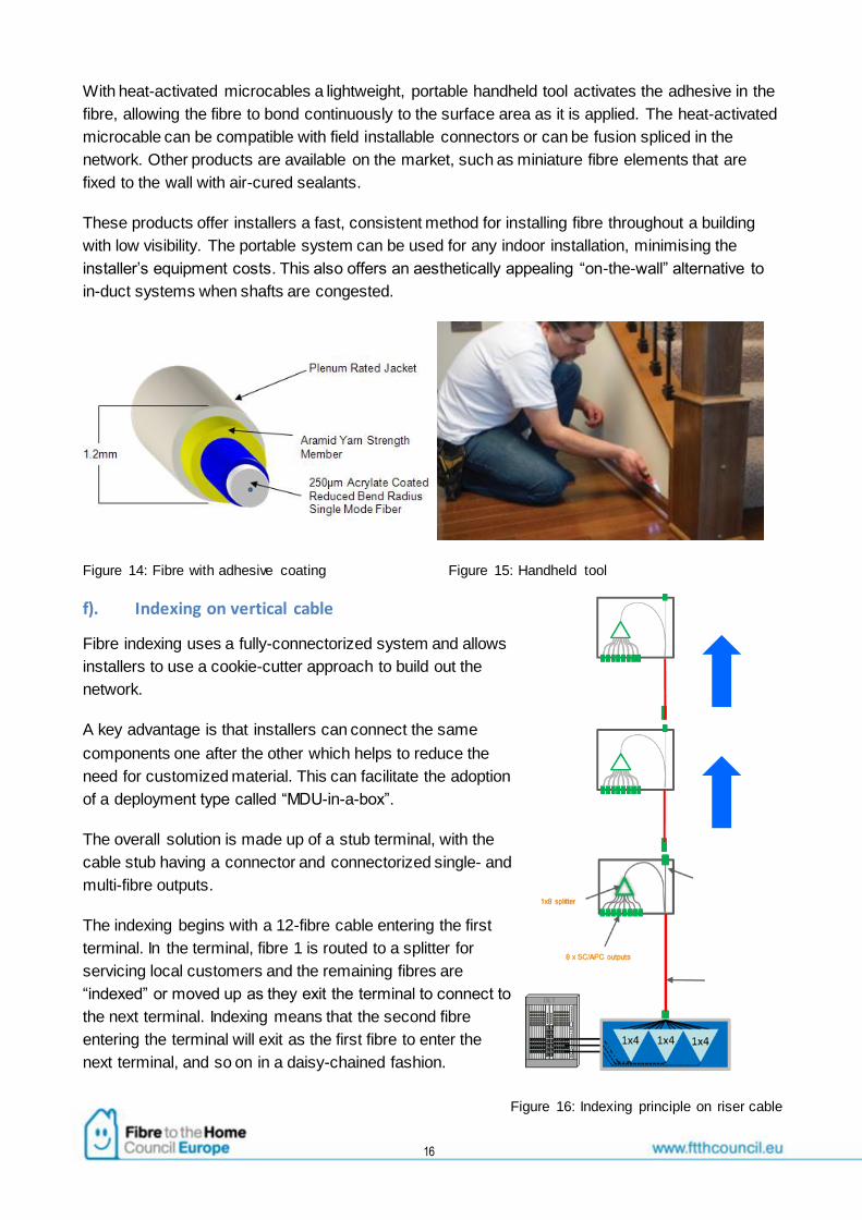
f). Indexing on vertical cable
Fibre indexing uses a fully-connectorized system and allows
installers to use a cookie-cutter approach to build out the
network.
A key advantage is that installers can connect the same
components one after the other which helps to reduce the
need for customized material. This can facilitate the adoption
of a deployment type called “MDU-in-a-box”.
The overall solution is made up of a stub terminal, with the
cable stub having a connector and connectorized single- and
multi-fibre outputs.
The indexing begins with a 12-fibre cable entering the first
terminal. In the terminal, fibre 1 is routed to a splitter for
servicing local customers and the remaining fibres are
“indexed” or moved up as they exit the terminal to connect to
the next terminal. Indexing means that the second fibre
entering the terminal will exit as the first fibre to enter the
next terminal, and so on in a daisy-chained fashion.
Figure 16: Indexing principle on riser cable

17
g). Cascaded splitters
Especially in large MDUs where high take rates are anticipated, a cascaded split scenario is very
interesting. In such a scenario, the splitters are distributed throughout the MDU rather than being
located at the basement boxes.
The first splitter can be located in the entrance facility with multiple fibres going out to the separate
floors where a splitter is installed to serve the floor. Alternatively, the first splitter can be placed on
one of the served floors. If the building has 8 units per floor, a total of 4 floors can be handled on
32-split ratio system with a 4-way splitter feeding 8 way splitters on each floor. Likewise, one could
use a first splitter of 8 ways to serve 4 floors. Or a 16-way first splitter would serve 4 floors. The
best option depends on the building and how cabling would be installed.
This scenario is most suited to high-rise MDUs where the number of floors is more than 12 and/or
the number of customers per floor is higher than 8.
Figure 17: Cascaded split in medium to large MDUs
This method of deployment has some important trade-offs that need to be carefully considered.
One benefit of this technology is that it will simplify fault location on high-rise MDUs and in turn
enable quicker remediation. Another key advantage is that it simplifies the requirements in the
basement where the basement box is deployed. It also requires a lot less space in the vertical
conduit than for other solutions. Overall, these advantages will really streamline the planning
stages of deploying fibre in medium or large MDUs. The flip side of this deployment methodology
is that using splitters within the floor box could increase the amount of hardware that needs to be
deployed at floor level.

18
h). Field-installable connectors
Field-installable connectors provide a balance between factory pre-configuration and flexibility of
installation in the field. They can be used at all points in the MDU infrastructure and are available in
a wide range of connector formats and cable compatibility options.
Recent technology advances have led to field-installable connectors with higher optical
performance, which makes them suitable for certain FTTH applications. Although some degree of
fibre-handling skill is needed, this method requires less expensive equipment compared to fusion
splicing, so it can provide a good middle-ground in the quest to reduce TCO.
Field-installable connectors generally take the form of a standard connector body with a pre-
prepared and polished ferrule with a fibre stub inside. A mechanical splice is included within the
body of the connector. The installation process involves preparing the field fibre, inserting it into the
rear of the connector, activating the mechanical splice and, finally, mechanically locking the fibre
and cable to the connector body, normally with a crimp mechanism.
Figure 18: Cutaway of a field installable connector
A range of installation tools is available,
normally proprietary to each manufacturer’s
connector type. These tools aid in the
installation process, and some can provide an
indicative result for the performance of the
assembled connector.
Figure 19: Field installable connector installation tool

19
Finally, “splice-on” connectors are also available. With these connectors, the ferrule contains a
factory-installed stub fibre, which is fusion spliced onto the field fibre using a fusion splice machine.
There is normally a special adaptor to hold the connector in the machine during the splicing
process. The fusion splice is protected by a small heatshrink sleeve. Finally, the plastic connector
body parts are clipped into place onto the ferrule assembly covering the heatshrink sleeve.
Figure 20: Spice-on connector
Chapter 4: Conclusion
A service provider wishing to optimize his total cost of ownership when rolling out fibre to the home
(FTTH) inside a multiple dwelling unit (MDU) needs to have a good understanding of the different
cost elements that drive installation, material and maintenance costs, and to understand the
interdependencies between those cost drivers.
This white paper should help in that regard, by providing a summary of techniques and product
types typically used in FTTH roll-outs inside MDUs. Which of the solutions presented is most
suited for a specific deployment will depend on specific parameters, such as size and type of the
MDU, availability and cost of skilled resources, and time to install the fibre network.

20
Figure references
Corning: 1, 2, 3, 4, 5, 17, 18, 19, 20
CommScope: 6, 12, 13, 14, 15, 16
Duraline: 9, 10, 11
M2fx: 7, 8
Related Documents