Optical System Design – S15 MTF Joseph A. Shaw – Montana State University Optical Transfer Function (OTF) Modulation Transfer Function (MTF) The Optical Transfer Function (OTF) is a complex-valued function describing the response of an imaging system as a function of spatial frequency. Modulation Transfer Function (MTF) = magnitude of the complex OTF Phase Transfer Function (PTF) = phase of the complex OTF 1 , = , , Incoherent imaging systems are linear in irradiance Coherent imaging systems are linear in field amplitude

Welcome message from author
This document is posted to help you gain knowledge. Please leave a comment to let me know what you think about it! Share it to your friends and learn new things together.
Transcript
Optical System Design – S15 MTF
Joseph A. Shaw – Montana State University
Optical Transfer Function (OTF)
Modulation Transfer Function (MTF)
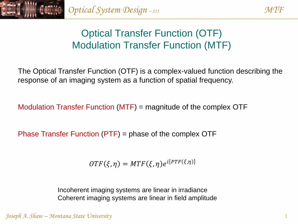
The Optical Transfer Function (OTF) is a complex-valued function describing the
response of an imaging system as a function of spatial frequency.
Modulation Transfer Function (MTF) = magnitude of the complex OTF
Phase Transfer Function (PTF) = phase of the complex OTF
1
𝑂𝑇𝐹 𝜉, 𝜂 = 𝑀𝑇𝐹 𝜉, 𝜂 𝑒𝑖 𝑃𝑇𝐹 𝜉,𝜂
Incoherent imaging systems are linear in irradiance
Coherent imaging systems are linear in field amplitude
Optical System Design – S15 MTF
Joseph A. Shaw – Montana State University
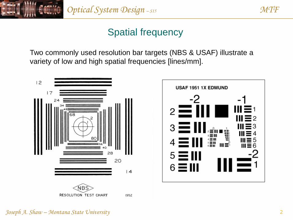
Spatial frequency
Two commonly used resolution bar targets (NBS & USAF) illustrate a
variety of low and high spatial frequencies [lines/mm].
2
Optical System Design – S15 MTF
Joseph A. Shaw – Montana State University
Modulation
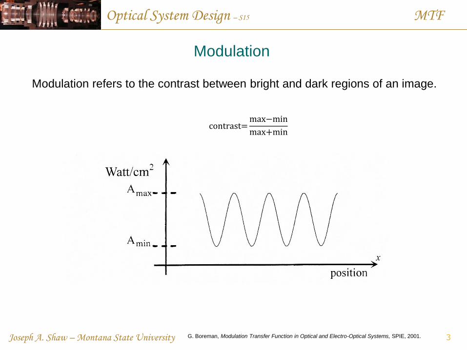
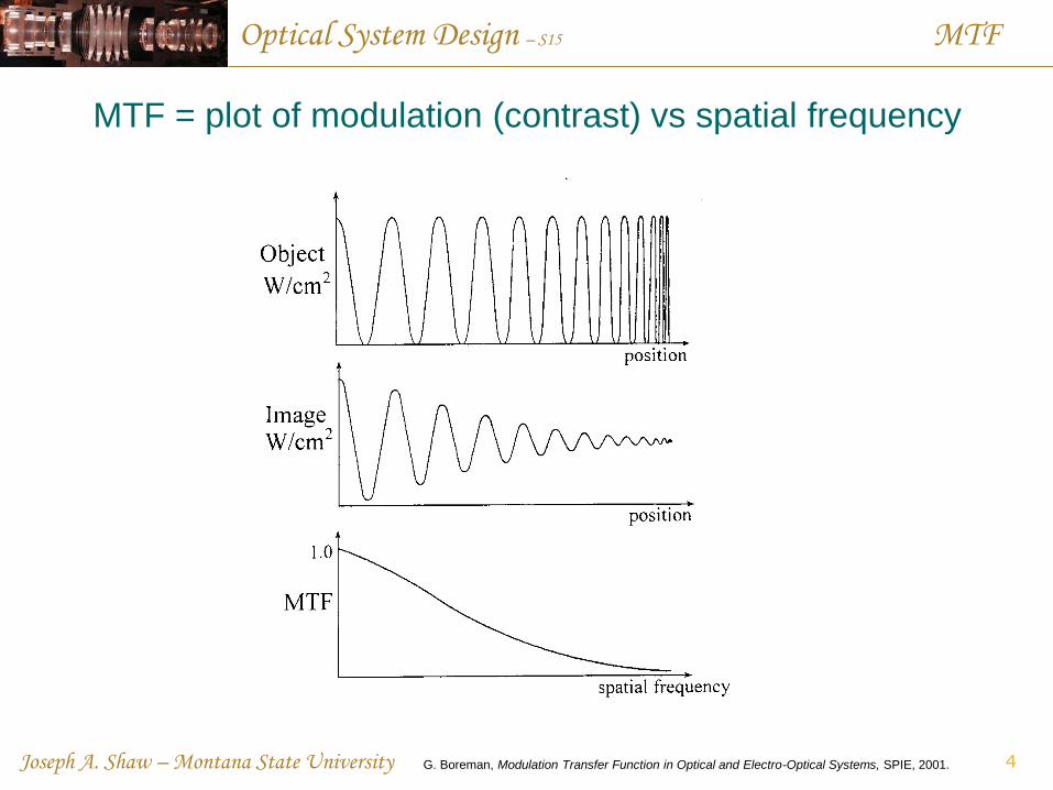
Modulation refers to the contrast between bright and dark regions of an image.
3
contrast=max−min
max+min
G. Boreman, Modulation Transfer Function in Optical and Electro-Optical Systems, SPIE, 2001.
Optical System Design – S15 MTF
Joseph A. Shaw – Montana State University
MTF = plot of modulation (contrast) vs spatial frequency
4 G. Boreman, Modulation Transfer Function in Optical and Electro-Optical Systems, SPIE, 2001.
Optical System Design – S15 MTF
Joseph A. Shaw – Montana State University
Linear Time-Invariant (LTI) systems
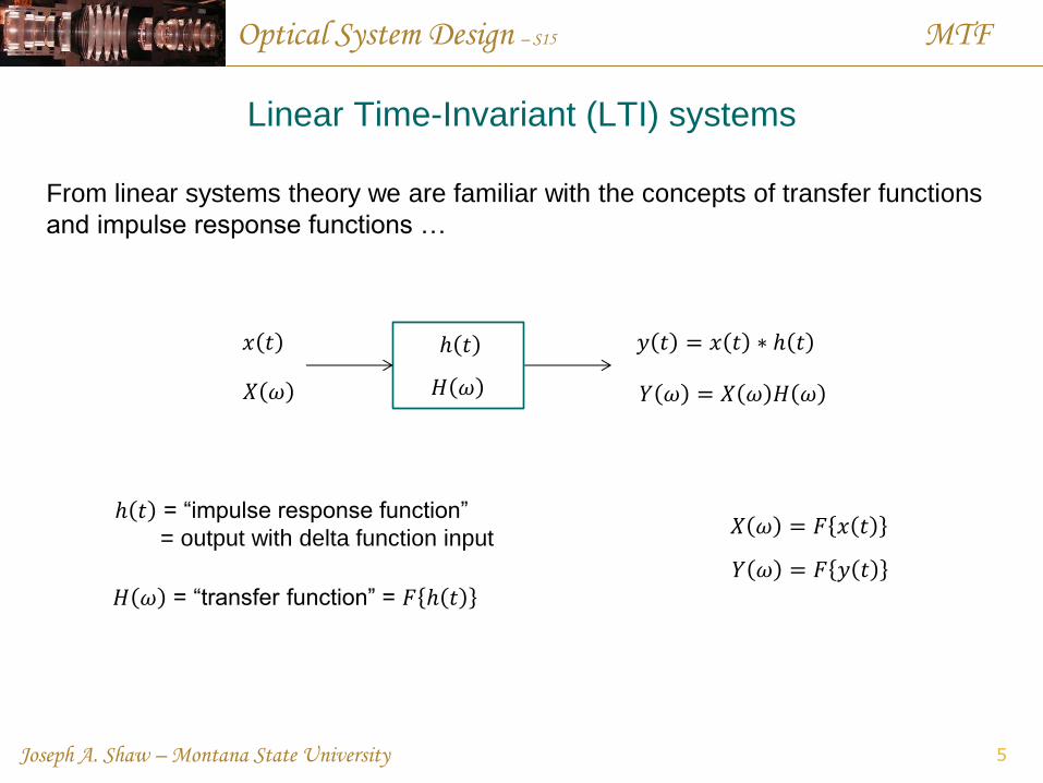
From linear systems theory we are familiar with the concepts of transfer functions
and impulse response functions …
5
𝑥 𝑡 𝑦 𝑡 = 𝑥 𝑡 ∗ ℎ 𝑡 ℎ 𝑡
𝑌 𝜔 = 𝑋 𝜔 𝐻 𝜔 𝐻 𝜔 𝑋 𝜔
𝑋 𝜔 = 𝐹 𝑥 𝑡
𝑌 𝜔 = 𝐹 𝑦 𝑡
ℎ 𝑡 = “impulse response function”
= output with delta function input
𝐻 𝜔 = “transfer function” = 𝐹 ℎ 𝑡
Optical System Design – S15 MTF
Joseph A. Shaw – Montana State University
Linear Shift-Invariant (LSI) systems
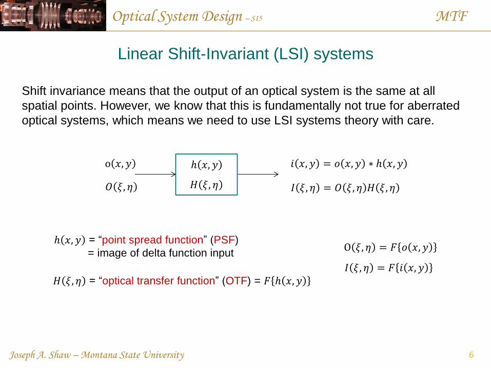
Shift invariance means that the output of an optical system is the same at all
spatial points. However, we know that this is fundamentally not true for aberrated
optical systems, which means we need to use LSI systems theory with care.
6
o 𝑥, 𝑦 𝑖 𝑥, 𝑦 = 𝑜 𝑥, 𝑦 ∗ ℎ 𝑥, 𝑦 ℎ 𝑥, 𝑦
𝐼 𝜉, 𝜂 = 𝑂 𝜉, 𝜂 𝐻 𝜉, 𝜂 𝐻 𝜉, 𝜂 𝑂 𝜉, 𝜂
O 𝜉, 𝜂 = 𝐹 𝑜 𝑥, 𝑦
𝐼 𝜉, 𝜂 = 𝐹 𝑖 𝑥, 𝑦
ℎ 𝑥, 𝑦 = “point spread function” (PSF)
= image of delta function input
𝐻 𝜉, 𝜂 = “optical transfer function” (OTF) = 𝐹 ℎ 𝑥, 𝑦
Optical System Design – S15 MTF
Joseph A. Shaw – Montana State University
PSF of ideal optical imaging systems
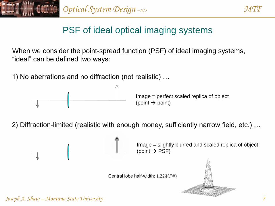
When we consider the point-spread function (PSF) of ideal imaging systems,
“ideal” can be defined two ways:
7
1) No aberrations and no diffraction (not realistic) …
2) Diffraction-limited (realistic with enough money, sufficiently narrow field, etc.) …
Image = perfect scaled replica of object
(point point)
Image = slightly blurred and scaled replica of object
(point PSF)
Central lobe half-width: 1.22𝜆 𝐹#
Optical System Design – S15 MTF
Joseph A. Shaw – Montana State University
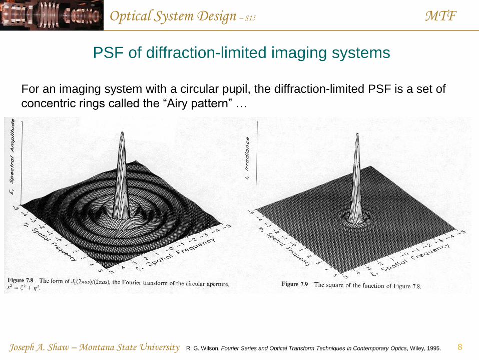
PSF of diffraction-limited imaging systems
For an imaging system with a circular pupil, the diffraction-limited PSF is a set of
concentric rings called the “Airy pattern” …
8 R. G. Wilson, Fourier Series and Optical Transform Techniques in Contemporary Optics, Wiley, 1995.
Optical System Design – S15 MTF
Joseph A. Shaw – Montana State University
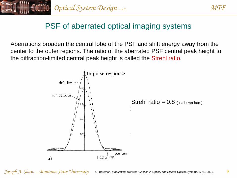
PSF of aberrated optical imaging systems
Aberrations broaden the central lobe of the PSF and shift energy away from the
center to the outer regions. The ratio of the aberrated PSF central peak height to
the diffraction-limited central peak height is called the Strehl ratio.
G. Boreman, Modulation Transfer Function in Optical and Electro-Optical Systems, SPIE, 2001. 9
Strehl ratio = 0.8 (as shown here)
Optical System Design – S15 MTF
Joseph A. Shaw – Montana State University
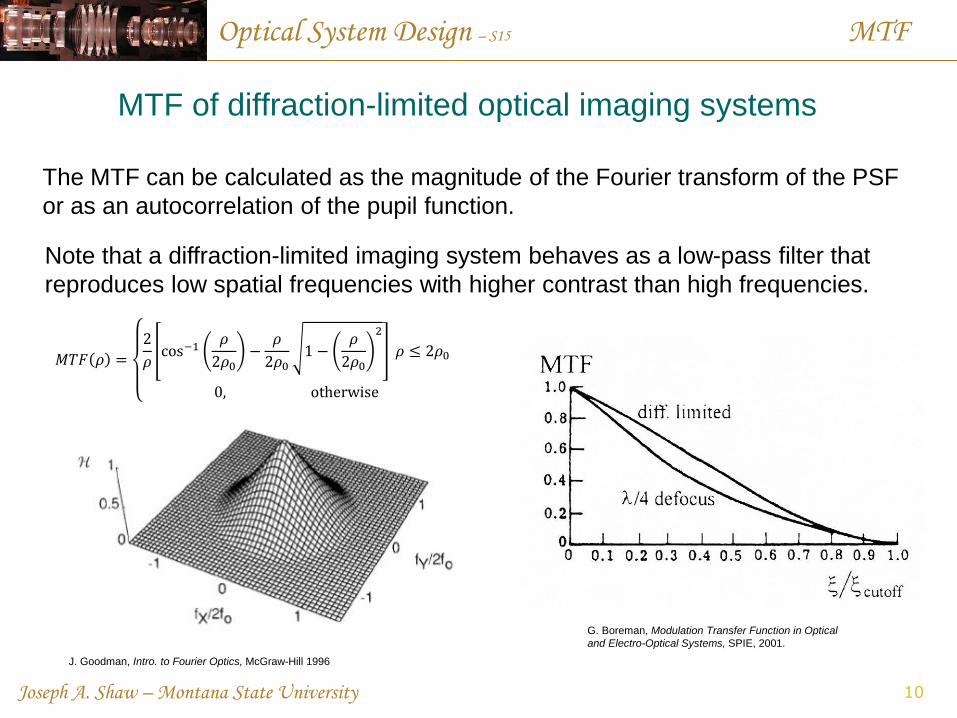
MTF of diffraction-limited optical imaging systems
The MTF can be calculated as the magnitude of the Fourier transform of the PSF
or as an autocorrelation of the pupil function.
G. Boreman, Modulation Transfer Function in Optical
and Electro-Optical Systems, SPIE, 2001.
10
𝑀𝑇𝐹 𝜌 =
2
𝜌cos−1
𝜌
2𝜌0−
𝜌
2𝜌01 −
𝜌
2𝜌0
2
𝜌 ≤ 2𝜌0
0, otherwise
J. Goodman, Intro. to Fourier Optics, McGraw-Hill 1996
Note that a diffraction-limited imaging system behaves as a low-pass filter that
reproduces low spatial frequencies with higher contrast than high frequencies.
Optical System Design – S15 MTF
Joseph A. Shaw – Montana State University
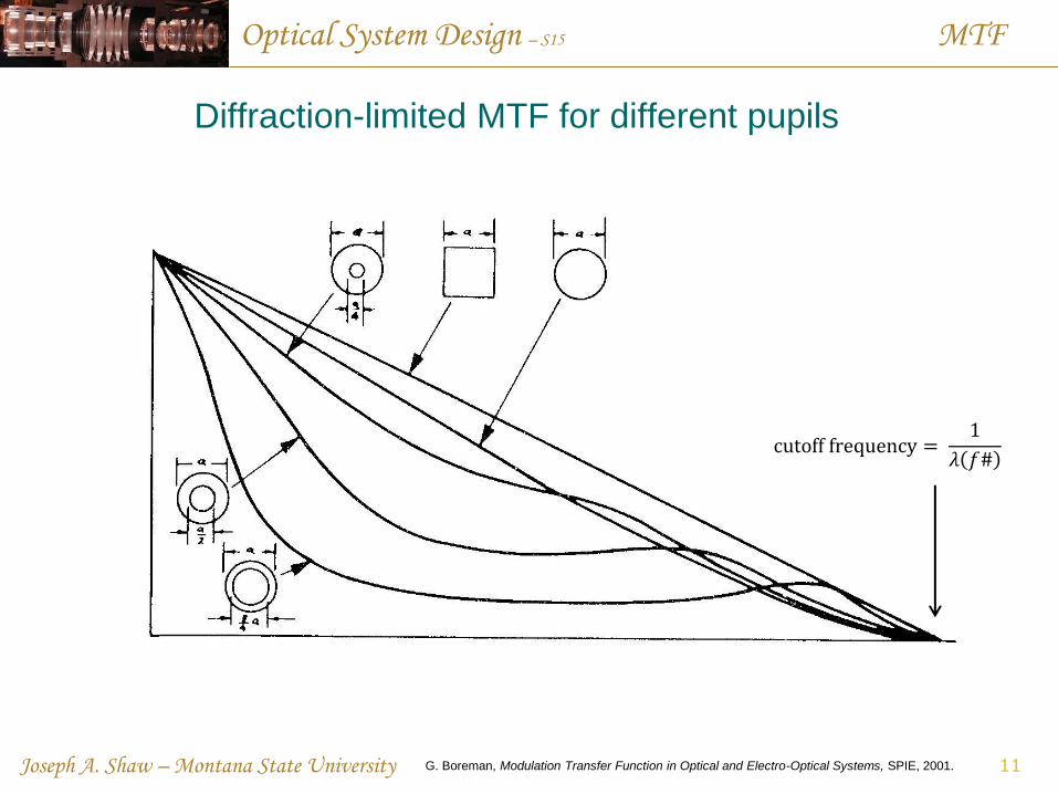
Diffraction-limited MTF for different pupils
G. Boreman, Modulation Transfer Function in Optical and Electro-Optical Systems, SPIE, 2001. 11
cutoff frequency = 1
𝜆 𝑓#
Optical System Design – S15 MTF
Joseph A. Shaw – Montana State University
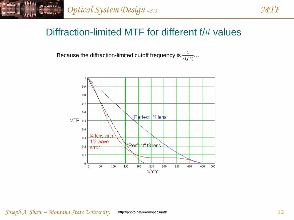
Diffraction-limited MTF for different f/# values
http://photo.net/learn/optics/mtf/ 12
Because the diffraction-limited cutoff frequency is 1
𝜆 𝑓#…
Optical System Design – S15 MTF
Joseph A. Shaw – Montana State University
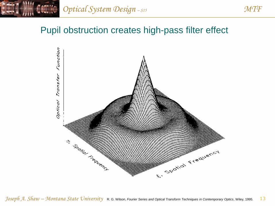
Pupil obstruction creates high-pass filter effect
13 R. G. Wilson, Fourier Series and Optical Transform Techniques in Contemporary Optics, Wiley, 1995.
Optical System Design – S15 MTF
Joseph A. Shaw – Montana State University
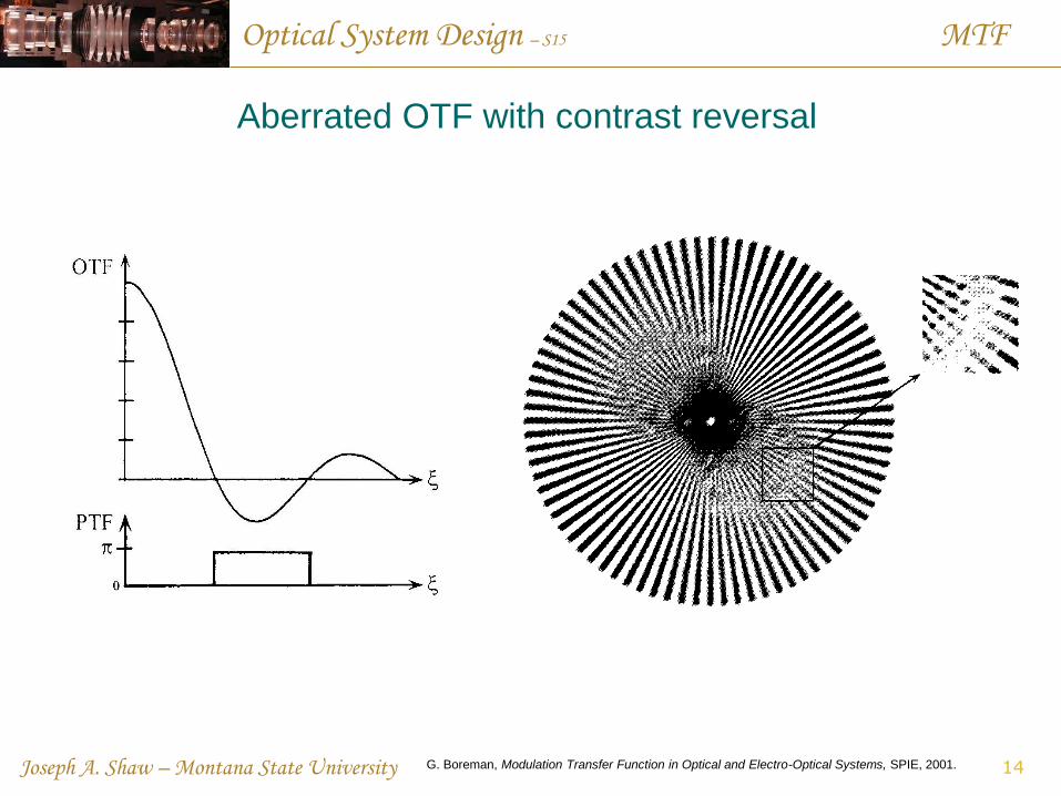
Aberrated OTF with contrast reversal
G. Boreman, Modulation Transfer Function in Optical and Electro-Optical Systems, SPIE, 2001. 14
Optical System Design – S15 MTF
Joseph A. Shaw – Montana State University
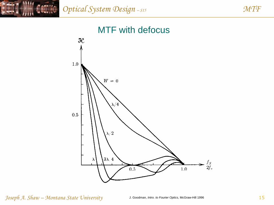
MTF with defocus
15 J. Goodman, Intro. to Fourier Optics, McGraw-Hill 1996
Optical System Design – S15 MTF
Joseph A. Shaw – Montana State University
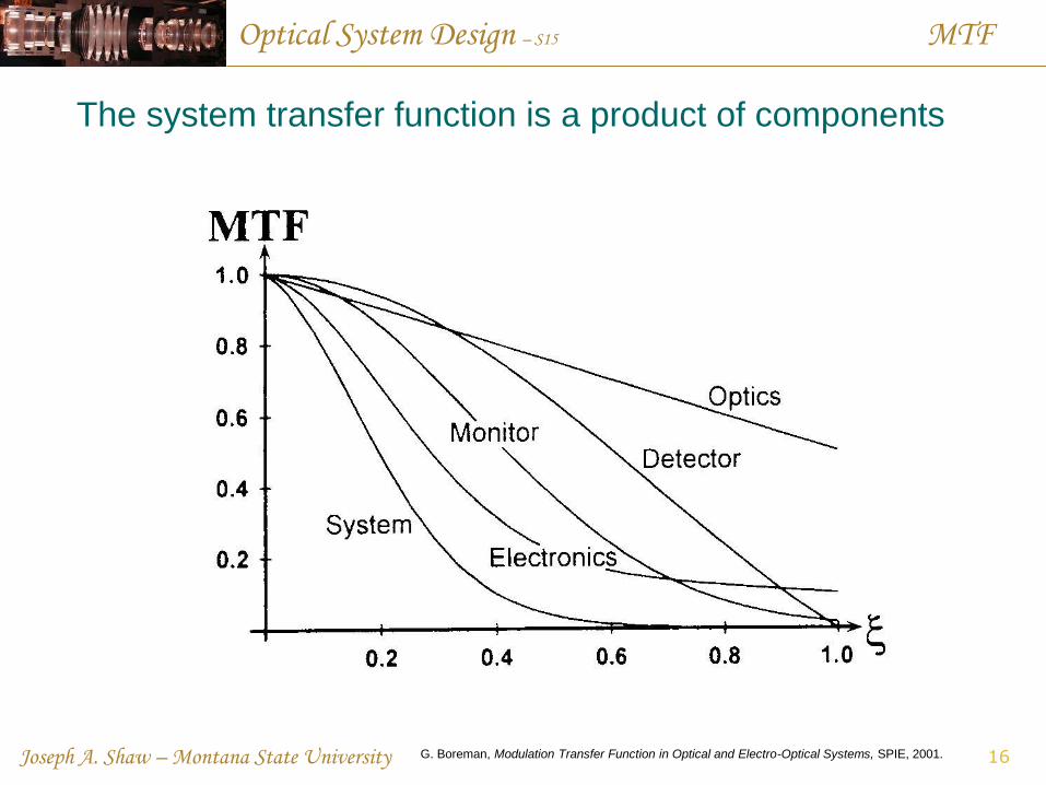
The system transfer function is a product of components
16 G. Boreman, Modulation Transfer Function in Optical and Electro-Optical Systems, SPIE, 2001.
Optical System Design – S15 MTF
Joseph A. Shaw – Montana State University
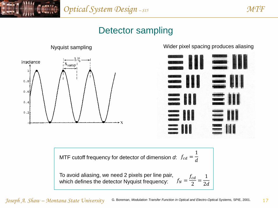
Detector sampling
17 G. Boreman, Modulation Transfer Function in Optical and Electro-Optical Systems, SPIE, 2001.
Nyquist sampling Wider pixel spacing produces aliasing
𝑓𝑐𝑑 =1
𝑑 MTF cutoff frequency for detector of dimension d:
To avoid aliasing, we need 2 pixels per line pair,
which defines the detector Nyquist frequency: 𝑓𝑁 =𝑓𝑐𝑑
2=
1
2𝑑
Optical System Design – S15 MTF
Joseph A. Shaw – Montana State University
MTF in Zemax
18
Geometric MTF … Geometric optics approximation calculated from ray data
(useful for heavily aberrated systems with OPD ≥ 10𝜆)
FFT MTF … Diffraction-based MTF calculated from FFT of pupil
Huygens MTF … Complex sum of Huygens wavelet PSFs …
(useful for tilted image planes, but much slower than FFT)
Related Documents