IDEALARC ® AC/DC 250 Operator’s Manual Save for future reference Date Purchased Code: (ex: 10859) Serial: (ex: U1060512345) IM402-B | Issue Date 7-Aug © Lincoln Global, Inc. All Rights Reserved. For use with machines having Code Numbers: 9491; 9512; 9513; 9514; 9548; 9645; 9646; 9670; 9712; 9713; 9738; 9755; 9992; 9993; 9994; 9995; 9996; 9997; 9998; 11094; 11100; 11101; 11102; 11103; 11104 Register your machine: www.lincolnelectric.com/register Authorized Service and Distributor Locator: www.lincolnelectric.com/locator

Welcome message from author
This document is posted to help you gain knowledge. Please leave a comment to let me know what you think about it! Share it to your friends and learn new things together.
Transcript

IDEALARC ® AC/DC 250
Operator’s Manual
Save for future reference
Date Purchased
Code: (ex: 10859)
Serial: (ex: U1060512345)
IM402-B | Issue D ate 7-Aug
© Lincoln Global, Inc. All Rights Reserved.
For use with machines having Code Numbers:
9491; 9512; 9513; 9514; 9548; 9645; 9646; 9670; 9712; 9713; 9738; 9755; 9992; 9993; 9994; 9995; 9996; 9997; 9998; 11094; 11100; 11101; 11102; 11103; 11104
Register your machine: www.lincolnelectric.com/register
Authorized Service and Distributor Locator: www.lincolnelectric.com/locator

FOR ENGINEpowered equipment.
1.a. Turn the engine off before troubleshooting and maintenancework unless the maintenance work requires it to be running.
____________________________________________________1.b. Operate engines in open, well-ventilated
areas or vent the engine exhaust fumesoutdoors.
____________________________________________________1.c. Do not add the fuel near an open flame
welding arc or when the engine is running.Stop the engine and allow it to cool beforerefueling to prevent spilled fuel from vaporiz-ing on contact with hot engine parts andigniting. Do not spill fuel when filling tank. Iffuel is spilled, wipe it up and do not startengine until fumes have been eliminated.
____________________________________________________1.d. Keep all equipment safety guards, covers and devices in
position and in good repair.Keep hands, hair, clothing andtools away from V-belts, gears, fans and all other movingparts when starting, operating or repairing equipment.
____________________________________________________
1.e. In some cases it may be necessary to remove safetyguards to perform required maintenance. Removeguards only when necessary and replace them when themaintenance requiring their removal is complete.Always use the greatest care when working near movingparts.
___________________________________________________1.f. Do not put your hands near the engine fan.
Do not attempt to override the governor oridler by pushing on the throttle control rodswhile the engine is running.
___________________________________________________1.g. To prevent accidentally starting gasoline engines while
turning the engine or welding generator during maintenancework, disconnect the spark plug wires, distributor cap ormagneto wire as appropriate.
iSAFETYi
ARC WELDING CAN BE HAZARDOUS. PROTECT YOURSELF AND OTHERS FROM POSSIBLE SERIOUS INJURY OR DEATH.KEEP CHILDREN AWAY. PACEMAKER WEARERS SHOULD CONSULT WITH THEIR DOCTOR BEFORE OPERATING.
Read and understand the following safety highlights. For additional safety information, it is strongly recommended that youpurchase a copy of “Safety in Welding & Cutting - ANSI Standard Z49.1” from the American Welding Society, P.O. Box351040, Miami, Florida 33135 or CSA Standard W117.2-1974. A Free copy of “Arc Welding Safety” booklet E205 is availablefrom the Lincoln Electric Company, 22801 St. Clair Avenue, Cleveland, Ohio 44117-1199.
BE SURE THAT ALL INSTALLATION, OPERATION, MAINTENANCE AND REPAIR PROCEDURES AREPERFORMED ONLY BY QUALIFIED INDIVIDUALS.
WARNING
Mar ʻ95
ELECTRIC ANDMAGNETIC FIELDSmay be dangerous
2.a. Electric current flowing through any conductor causeslocalized Electric and Magnetic Fields (EMF). Weldingcurrent creates EMF fields around welding cables andwelding machines
2.b. EMF fields may interfere with some pacemakers, andwelders having a pacemaker should consult their physicianbefore welding.
2.c. Exposure to EMF fields in welding may have other healtheffects which are now not known.
2.d. All welders should use the following procedures in order tominimize exposure to EMF fields from the welding circuit:
2.d.1. Route the electrode and work cables together - Securethem with tape when possible.
2.d.2. Never coil the electrode lead around your body.
2.d.3. Do not place your body between the electrode andwork cables. If the electrode cable is on your rightside, the work cable should also be on your right side.
2.d.4. Connect the work cable to the workpiece as close aspossible to the area being welded.
2.d.5. Do not work next to welding power source.
1.h. To avoid scalding, do not remove theradiator pressure cap when the engine ishot.
CALIFORNIA PROPOSITION 65 WARNINGS
Diesel engine exhaust and some of its constituentsare known to the State of California to cause can-cer, birth defects, and other reproductive harm.
The engine exhaust from this product containschemicals known to the State of California to causecancer, birth defects, or other reproductive harm.
The Above For Diesel Engines The Above For Gasoline Engines

iiSAFETYii
ARC RAYS can burn.4.a. Use a shield with the proper filter and cover
plates to protect your eyes from sparks andthe rays of the arc when welding or observingopen arc welding. Headshield and filter lensshould conform to ANSI Z87. I standards.
4.b. Use suitable clothing made from durable flame-resistantmaterial to protect your skin and that of your helpers fromthe arc rays.
4.c. Protect other nearby personnel with suitable, non-flammablescreening and/or warn them not to watch the arc nor exposethemselves to the arc rays or to hot spatter or metal.
ELECTRIC SHOCK cankill.3.a. The electrode and work (or ground) circuits
are electrically “hot” when the welder is on.Do not touch these “hot” parts with your bareskin or wet clothing. Wear dry, hole-free
gloves to insulate hands.
3.b. Insulate yourself from work and ground using dry insulation.Make certain the insulation is large enough to cover your fullarea of physical contact with work and ground.
In addition to the normal safety precautions, if weldingmust be performed under electrically hazardousconditions (in damp locations or while wearing wetclothing; on metal structures such as floors, gratings orscaffolds; when in cramped positions such as sitting,kneeling or lying, if there is a high risk of unavoidable oraccidental contact with the workpiece or ground) usethe following equipment:
• Semiautomatic DC Constant Voltage (Wire) Welder.• DC Manual (Stick) Welder.• AC Welder with Reduced Voltage Control.
3.c. In semiautomatic or automatic wire welding, the electrode,electrode reel, welding head, nozzle or semiautomaticwelding gun are also electrically “hot”.
3.d. Always be sure the work cable makes a good electricalconnection with the metal being welded. The connectionshould be as close as possible to the area being welded.
3.e. Ground the work or metal to be welded to a good electrical(earth) ground.
3.f. Maintain the electrode holder, work clamp, welding cable andwelding machine in good, safe operating condition. Replacedamaged insulation.
3.g. Never dip the electrode in water for cooling.
3.h. Never simultaneously touch electrically “hot” parts ofelectrode holders connected to two welders because voltagebetween the two can be the total of the open circuit voltageof both welders.
3.i. When working above floor level, use a safety belt to protectyourself from a fall should you get a shock.
3.j. Also see Items 6.c. and 8.
FUMES AND GASEScan be dangerous.5.a. Welding may produce fumes and gases
hazardous to health. Avoid breathing thesefumes and gases. When welding, keepyour head out of the fume. Use enoughventilation and/or exhaust at the arc to keep
fumes and gases away from the breathing zone. Whenwelding with electrodes which require specialventilation such as stainless or hard facing (seeinstructions on container or MSDS) or on lead orcadmium plated steel and other metals or coatingswhich produce highly toxic fumes, keep exposure aslow as possible and below Threshold Limit Values (TLV)using local exhaust or mechanical ventilation. Inconfined spaces or in some circumstances, outdoors, arespirator may be required. Additional precautions arealso required when welding on galvanized steel.
5. b. The operation of welding fume control equipment is affectedby various factors including proper use and positioning ofthe equipment, maintenance of the equipment and the spe-cific welding procedure and application involved. Workerexposure level should be checked upon installation andperiodically thereafter to be certain it is within applicableOSHA PEL and ACGIH TLV limits.
5.c. Do not weld in locations near chlorinated hydrocarbon vaporscoming from degreasing, cleaning or spraying operations.The heat and rays of the arc can react with solvent vapors toform phosgene, a highly toxic gas, and other irritating prod-ucts.
5.d. Shielding gases used for arc welding can displace air andcause injury or death. Always use enough ventilation,especially in confined areas, to insure breathing air is safe.
5.e. Read and understand the manufacturerʼs instructions for thisequipment and the consumables to be used, including thematerial safety data sheet (MSDS) and follow youremployerʼs safety practices. MSDS forms are available fromyour welding distributor or from the manufacturer.
5.f. Also see item 1.b.
AUG 06

iiiSAFETYiii
FOR ELECTRICALLYpowered equipment.
8.a. Turn off input power using the disconnectswitch at the fuse box before working onthe equipment.
8.b. Install equipment in accordance with the U.S. NationalElectrical Code, all local codes and the manufacturerʼsrecommendations.
8.c. Ground the equipment in accordance with the U.S. NationalElectrical Code and the manufacturerʼs recommendations.
CYLINDER may explodeif damaged.7.a. Use only compressed gas cylinders
containing the correct shielding gas for theprocess used and properly operatingregulators designed for the gas and
pressure used. All hoses, fittings, etc. should be suitable forthe application and maintained in good condition.
7.b. Always keep cylinders in an upright position securelychained to an undercarriage or fixed support.
7.c. Cylinders should be located:• Away from areas where they may be struck or subjected tophysical damage.
• A safe distance from arc welding or cutting operations andany other source of heat, sparks, or flame.
7.d. Never allow the electrode, electrode holder or any otherelectrically “hot” parts to touch a cylinder.
7.e. Keep your head and face away from the cylinder valve outletwhen opening the cylinder valve.
7.f. Valve protection caps should always be in place and handtight except when the cylinder is in use or connected foruse.
7.g. Read and follow the instructions on compressed gascylinders, associated equipment, and CGA publication P-l,“Precautions for Safe Handling of Compressed Gases inCylinders,” available from the Compressed Gas Association1235 Jefferson Davis Highway, Arlington, VA 22202.
Jan, 07
WELDING and CUTTINGSPARKS can
cause fire or explosion.6.a. Remove fire hazards from the welding area.
If this is not possible, cover them to preventthe welding sparks from starting a fire.
Remember that welding sparks and hotmaterials from welding can easily go through small cracksand openings to adjacent areas. Avoid welding nearhydraulic lines. Have a fire extinguisher readily available.
6.b. Where compressed gases are to be used at the job site,special precautions should be used to prevent hazardoussituations. Refer to “Safety in Welding and Cutting” (ANSIStandard Z49.1) and the operating information for theequipment being used.
6.c. When not welding, make certain no part of the electrodecircuit is touching the work or ground. Accidental contactcan cause overheating and create a fire hazard.
6.d. Do not heat, cut or weld tanks, drums or containers until theproper steps have been taken to insure that such procedureswill not cause flammable or toxic vapors from substancesinside. They can cause an explosion even though they havebeen “cleaned”. For information, purchase “RecommendedSafe Practices for the Preparation for Welding and Cutting ofContainers and Piping That Have Held HazardousSubstances”, AWS F4.1 from the American Welding Society(see address above).
6.e. Vent hollow castings or containers before heating, cutting orwelding. They may explode.
6.f. Sparks and spatter are thrown from the welding arc. Wear oilfree protective garments such as leather gloves, heavy shirt,cuffless trousers, high shoes and a cap over your hair. Wearear plugs when welding out of position or in confined places.Always wear safety glasses with side shields when in awelding area.
6.g. Connect the work cable to the work as close to the weldingarea as practical. Work cables connected to the buildingframework or other locations away from the welding areaincrease the possibility of the welding current passingthrough lifting chains, crane cables or other alternate cir-cuits. This can create fire hazards or overheat lifting chainsor cables until they fail.
6.h. Also see item 1.c.
6.I. Read and follow NFPA 51B “ Standard for Fire PreventionDuring Welding, Cutting and Other Hot Work”, availablefrom NFPA, 1 Batterymarch Park,PO box 9101, Quincy, Ma022690-9101.
6.j. Do not use a welding power source for pipe thawing.

ivSAFETYiv
PRÉCAUTIONS DE SÛRETÉPour votre propre protection lire et observer toutes les instructionset les précautions de sûreté specifiques qui parraissent dans cemanuel aussi bien que les précautions de sûreté générales suiv-antes:
Sûreté Pour Soudage A LʼArc1. Protegez-vous contre la secousse électrique:
a. Les circuits à lʼélectrode et à la piéce sont sous tensionquand la machine à souder est en marche. Eviter toujourstout contact entre les parties sous tension et la peau nueou les vétements mouillés. Porter des gants secs et sanstrous pour isoler les mains.
b. Faire trés attention de bien sʼisoler de la masse quand onsoude dans des endroits humides, ou sur un planchermetallique ou des grilles metalliques, principalement dansles positions assis ou couché pour lesquelles une grandepartie du corps peut être en contact avec la masse.
c. Maintenir le porte-électrode, la pince de masse, le câblede soudage et la machine à souder en bon et sûr étatdefonctionnement.
d.Ne jamais plonger le porte-électrode dans lʼeau pour lerefroidir.
e. Ne jamais toucher simultanément les parties sous tensiondes porte-électrodes connectés à deux machines à souderparce que la tension entre les deux pinces peut être letotal de la tension à vide des deux machines.
f. Si on utilise la machine à souder comme une source decourant pour soudage semi-automatique, ces precautionspour le porte-électrode sʼapplicuent aussi au pistolet desoudage.
2. Dans le cas de travail au dessus du niveau du sol, se protégercontre les chutes dans le cas ou on recoit un choc. Ne jamaisenrouler le câble-électrode autour de nʼimporte quelle partiedu corps.
3. Un coup dʼarc peut être plus sévère quʼun coup de soliel,donc:
a. Utiliser un bon masque avec un verre filtrant appropriéainsi quʼun verre blanc afin de se protéger les yeux du ray-onnement de lʼarc et des projections quand on soude ouquand on regarde lʼarc.
b. Porter des vêtements convenables afin de protéger lapeau de soudeur et des aides contre le rayonnement delʻarc.
c. Protéger lʼautre personnel travaillant à proximité ausoudage à lʼaide dʼécrans appropriés et non-inflammables.
4. Des gouttes de laitier en fusion sont émises de lʼarc desoudage. Se protéger avec des vêtements de protection libresde lʼhuile, tels que les gants en cuir, chemise épaisse, pan-talons sans revers, et chaussures montantes.
5. Toujours porter des lunettes de sécurité dans la zone desoudage. Utiliser des lunettes avec écrans lateraux dans leszones où lʼon pique le laitier.
6. Eloigner les matériaux inflammables ou les recouvrir afin deprévenir tout risque dʼincendie dû aux étincelles.
7. Quand on ne soude pas, poser la pince à une endroit isolé dela masse. Un court-circuit accidental peut provoquer unéchauffement et un risque dʼincendie.
8. Sʼassurer que la masse est connectée le plus prés possiblede la zone de travail quʼil est pratique de le faire. Si on placela masse sur la charpente de la construction ou dʼautresendroits éloignés de la zone de travail, on augmente le risquede voir passer le courant de soudage par les chaines de lev-age, câbles de grue, ou autres circuits. Cela peut provoquerdes risques dʼincendie ou dʼechauffement des chaines et descâbles jusquʼà ce quʼils se rompent.
9. Assurer une ventilation suffisante dans la zone de soudage.Ceci est particuliérement important pour le soudage de tôlesgalvanisées plombées, ou cadmiées ou tout autre métal quiproduit des fumeés toxiques.
10. Ne pas souder en présence de vapeurs de chlore provenantdʼopérations de dégraissage, nettoyage ou pistolage. Lachaleur ou les rayons de lʼarc peuvent réagir avec les vapeursdu solvant pour produire du phosgéne (gas fortement toxique)ou autres produits irritants.
11. Pour obtenir de plus amples renseignements sur la sûreté,voir le code “Code for safety in welding and cutting” CSAStandard W 117.2-1974.
PRÉCAUTIONS DE SÛRETÉ POURLES MACHINES À SOUDER ÀTRANSFORMATEUR ET ÀREDRESSEUR
1. Relier à la terre le chassis du poste conformement au code delʼélectricité et aux recommendations du fabricant. Le dispositifde montage ou la piece à souder doit être branché à unebonne mise à la terre.
2. Autant que possible, Iʼinstallation et lʼentretien du poste seronteffectués par un électricien qualifié.
3. Avant de faires des travaux à lʼinterieur de poste, la debranch-er à lʼinterrupteur à la boite de fusibles.
4. Garder tous les couvercles et dispositifs de sûreté à leurplace.
Mar. ʻ93

– 6 –
vv
Thank You for selecting a QUALITY product by Lincoln Electric. We want youto take pride in operating this Lincoln Electric Company product••• as much pride as we have in bringing this product to you!
Read this Operators Manual completely before attempting to use this equipment. Save this manual and keep ithandy for quick reference. Pay particular attention to the safety instructions we have provided for your protection.The level of seriousness to be applied to each is explained below:
WARNINGThis statement appears where the information must be followed exactly to avoid serious personal injury or loss of life.
This statement appears where the information must be followed to avoid minor personal injury or damage to this equipment.
CAUTION
Please Examine Carton and Equipment For Damage ImmediatelyWhen this equipment is shipped, title passes to the purchaser upon receipt by the carrier. Consequently, Claimsfor material damaged in shipment must be made by the purchaser against the transportation company at thetime the shipment is received.
Please record your equipment identification information below for future reference. This information can befound on your machine nameplate.
Product _________________________________________________________________________________
Model Number ___________________________________________________________________________
Code Number or Date Code_________________________________________________________________
Serial Number____________________________________________________________________________
Date Purchased___________________________________________________________________________
Where Purchased_________________________________________________________________________
Whenever you request replacement parts or information on this equipment, always supply the information youhave recorded above. The code number is especially important when identifying the correct replacement parts.
On-Line Product Registration- Register your machine with Lincoln Electric either via fax or over the Internet.
• For faxing: Complete the form on the back of the warranty statement included in the literature packetaccompanying this machine and fax the form per the instructions printed on it.
• For On-Line Registration: Go to our WEB SITE at www.lincolnelectric.com. Choose “Quick Links” and then“Product Registration”. Please complete the form and submit your registration.
CUSTOMER ASSISTANCE POLICYThe business of The Lincoln Electric Company is manufacturing and selling high quality welding equipment, consumables, and cutting equip-ment. Our challenge is to meet the needs of our customers and to exceed their expectations. On occasion, purchasers may ask LincolnElectric for advice or information about their use of our products. We respond to our customers based on the best information in our posses-sion at that time. Lincoln Electric is not in a position to warrant or guarantee such advice, and assumes no liability, with respect to such infor-mation or advice. We expressly disclaim any warranty of any kind, including any warranty of fitness for any customerʼs particular purpose,with respect to such information or advice. As a matter of practical consideration, we also cannot assume any responsibility for updating orcorrecting any such information or advice once it has been given, nor does the provision of information or advice create, expand or alter anywarranty with respect to the sale of our products.
Lincoln Electric is a responsive manufacturer, but the selection and use of specific products sold by Lincoln Electric is solely within the controlof, and remains the sole responsibility of the customer. Many variables beyond the control of Lincoln Electric affect the results obtained inapplying these types of fabrication methods and service requirements.
Subject to Change – This information is accurate to the best of our knowledge at the time of printing. Please refer to www.lincolnelectric.comfor any updated information.

– 7 –
TABLE OF CONTENTS
Page
GENERAL DESCRIPTION ..................................................................................................8
RECOMMENDED PROCESSES & EQUIPMENT...............................................................8AC and DC Constant Current Welding .............................................................................8TIG Welding ......................................................................................................................8
DESIGN FEATURES ...........................................................................................................8
OPTIONS/ACCESSORIES & COMPATIBLE LINCOLN EQUIPMENT ..............................8Power Factor Capacitors ...........................................................................................8Undercarriage ............................................................................................................8Hi-Freq .......................................................................................................................8Standard Accessory Set ............................................................................................8
TECHNICAL SPECIFICATIONS .........................................................................................9
INSTALLATION ...............................................................................................................10-11Safety Precautions...........................................................................................................10Machine Installation .........................................................................................................10
Location ....................................................................................................................10Input Connections.....................................................................................................10Stacking....................................................................................................................11
Installation of Field Installed Options ...............................................................................11Output Cable Size and Connection..................................................................................11
OPERATION.......................................................................................................................12Safety Precautions...........................................................................................................12
Duty Cycle ................................................................................................................12Control Operation .....................................................................................................12
MAINTENANCE .................................................................................................................13Safety Precautions...........................................................................................................13General Maintenance.......................................................................................................13
TROUBLESHOOTING .....................................................................................................13-15Rectifier Troubleshooting .................................................................................................13Troubleshooting Procedures .........................................................................................14-15
WIRING DIAGRAMS .......................................................................................................16-17
PARTS LIST ...............................................................................................................P200 Series

– 8 –
GENERAL DESCRIPTION
The Idealarc® 250 is a single phase constant currentarc welding power source available in an AC/DCmodel only. Designed for stick welding, it may also beused for TIG welding when used with the K799 Hi-Freq unit.
RECOMMENDED PROCESSES ANDEQUIPMENT
AC and DC Constant Current Welding
TIG Welding
The K799 can be used with this machine to providehigh frequency stabilization and a gas valve for TIGwelding. It operates on 115V 50/60 Hz power. Awater valve (for water cooled TIG torches) is availableas an option.
When TIG welding, AC or DC may be used but whenAC TIG welding, the duty cycle must be decreased byone-half.
DESIGN FEATURES
• Power On/Off switch.
• Polarity switch selects AC, DC+ or DC- .
• Continuous current control dials with exact weldingcurrent needed for each job. Settings are preciseand free from creep.
• Spring loaded knob on the continuous currentcontrol crank pulls out for easy adjustment andsnaps back out of the way when released.
• Meets NEMA Class II specifications.
• Recessed front panel protects controls.
• Large safety margins and protective circuits protectrectifiers from transient voltages and high currents.
• Submersion dipping of assembled transformer andchoke in special sealing/insulating material givesextra protection against moisture and corrosiveatmosphere.
• Stackability - Machines can be stacked up to threehigh.
• Outstanding Arc Stability - Transformer design andbuilt-in stabilizer provide pop-out-resistant weldingwith all electrodes, including those which normallyrequire an industrial type AC welder.
• Reconnect panel is provided to permit changingfrom one input voltage to another without reconnect-ing transformer leads.
OPTIONS / ACCESSORIESAND COMPATIBLE LINCOLNEQUIPMENT
Factory Installed Options/Accessories
• Power Factor Capacitors(Reduce input amps by 30% at rated load.)
Field Installed Options
• Power Factor Capacitors(Reduce input amps by 30% at rated load.)
• Undercarriage (K866)Consists of a handle, axle, wheels, front bracket andmounting hardware. Overall width 24.56 inches(624 mm).
• Hi Freq Kit (K799)Converts Idealarc 250 into a TIG welder.Request Bulletin E385 for full details.
• Standard Accessory Kit (K710)Includes electrode holder, work clamp, electrode,work cables, and headshield with lens andcoverplate
AC 35-300 Amps 60 Hz 35-250 Amps 50 HzDC 40-250 Amps 50/60 Hz
Duty Cycle 60 Hz 50 Hz100%-140 Amps 100%-140 Amps
50%-200 Amps 60%-180 Amps30%-250 Amps 30%-250 Amps20%-300 Amps
– 9 –
TECHNICAL SPECIFICATIONS: IDEALARC AC/DC 250
Model AC/DC 250 AC/DC 250
Type K1053 K1054AC Input Frequency 60 50Output Rating NEMA CLASS II (60) IEC 974
AC DC AC DCAmperes 300 250 250 250Volts 32 30 30 30Duty Cycle 20 30 30 30
Current Range 35-300 40-250 35-250 40-250Max. O.C.V. 72 70 72 70Input PowerStandard Voltages 208/230/460 220/380/440
230/460/575 380/415/500
Rated Input Current(230V 60Hz, 220V 50Hz)With Condensers 68 68Without Condensers 86 86
Idle Input Current (230V)With Condensers 23 23Without Condensers 6.2 6.2
Power Factor (200 Amp Load)With Condensers 83.3 83.3Without Condensers 69.0 69.0
INPUT - OUTPUT RATINGS
HEIGHT WIDTH DEPTH WEIGHT
27.00 in. 19.00 in. 21.50 in. 350 lbs.159 kg
686 mm 483 mm 546 mm
PHYSICAL DIMENSIONS
– 10 –
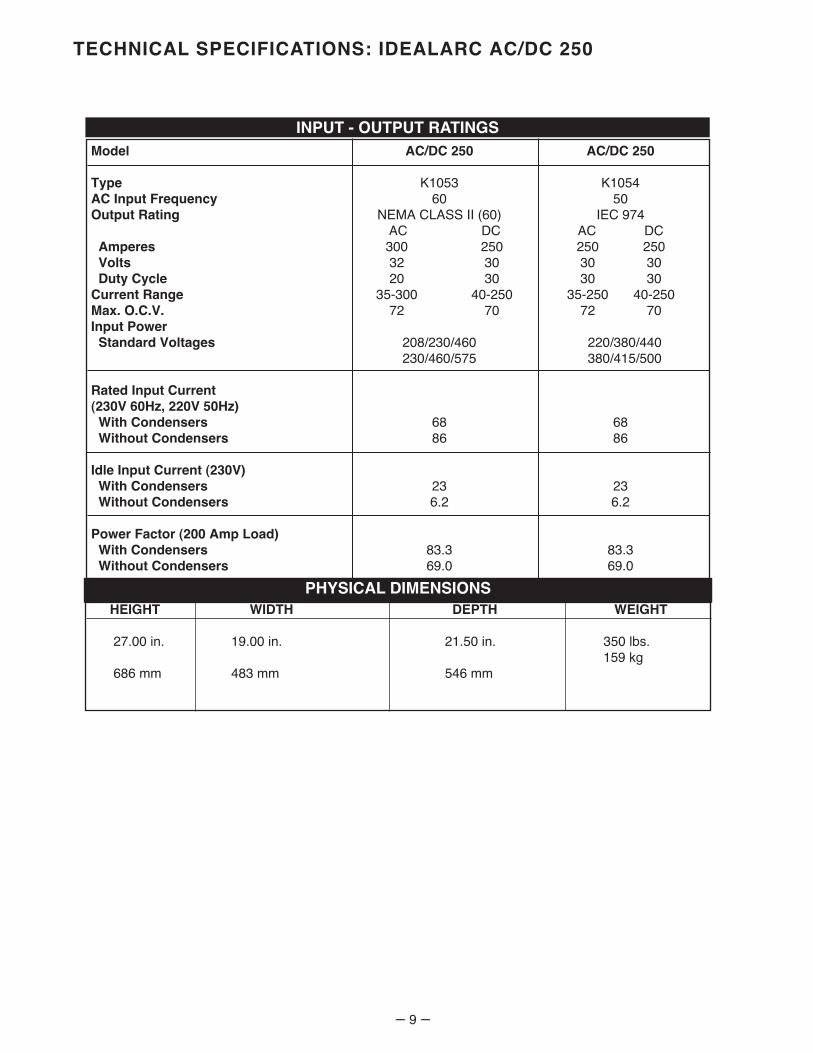
INSTALLATIONSafety Precautions
• Connect the Idealarc 250 grounding terminal locatedunder the reconnect panel (marked ) to a goodelectrical ground per the U.S. National ElectricalCode and any applicable local codes.
• Turn the power switch on the Idealarc 250 “OFF”before connecting or disconnecting output cables orother equipment.
• Only qualified personnel should perform this installa-tion.
Undercarriages: If the optional K866 undercarriageis to be installed, it should be done before connectingthe welder to power lines. Instructions are includedwith the undercarriage.
ELECTRIC SHOCK can kill.• Do not touch electrically live parts or
electrode with skin or wet clothing.• Insulate yourself from work and
ground.• Always wear dry insulating gloves.
------------------------------------------------------------------------FUMES AND GASES can be dangerous.• Keep your head out of fumes.• Use ventilation or exhaust to remove
fumes from breathing zone.
------------------------------------------------------------------------WELDING SPARKS can cause fire or
explosion.• Keep flammable material away.• Do not weld on closed containers.
------------------------------------------------------------------------ARC RAYS can burn eyes and skin.• Wear eye, ear and body protection.
------------------------------------------------------------
See additional warning information at thefront of this operatorʼs manual.
-----------------------------------------------------------
WARNING
Location
The machine should be located in a clean, dry placewhere there is free circulation of clean air such that airmovement in the back and along the sides will not berestricted. Dirt and dust that can be drawn into themachine should be kept to a minimum. Failure toobserve the precautions can result in excessiveoperating temperatures and nuisance shutdown of themachine.
Input Connections
Be sure the voltage, phase and frequency of the inputpower is as specified on the welder rating plate locat-ed on the rear panel of the machine. Either a singlephase or one phase of a three phase line can beused.
Have a qualified electrician install the machine per thefollowing instructions:
Remove the left side panel (viewed from the front).Route the input power lines through the hole in therear panel and center baffle. Lug the input leads witha ring terminal for a 1/4” (6mm) screw. Connectlugged leads to L1 and L2 of the reconnect panel perthe wiring diagram pasted to m inside of the sidepanel. Input connection must conform to the U.S.National Electrical Code and all local codes.
Models designed for two or three input voltages areshipped connected for the highest voltage.Reconnect instructions are on the diagram pasted tothe inside of the side panel. Consult rating plate onthe rear panel for machine input voltage rating.
The welder frame must be grounded. A stud markedwith the symbol located under the reconnectpanel is provided for this purpose. See the U.S.National Electrical Code for details on proper ground-ing methods.
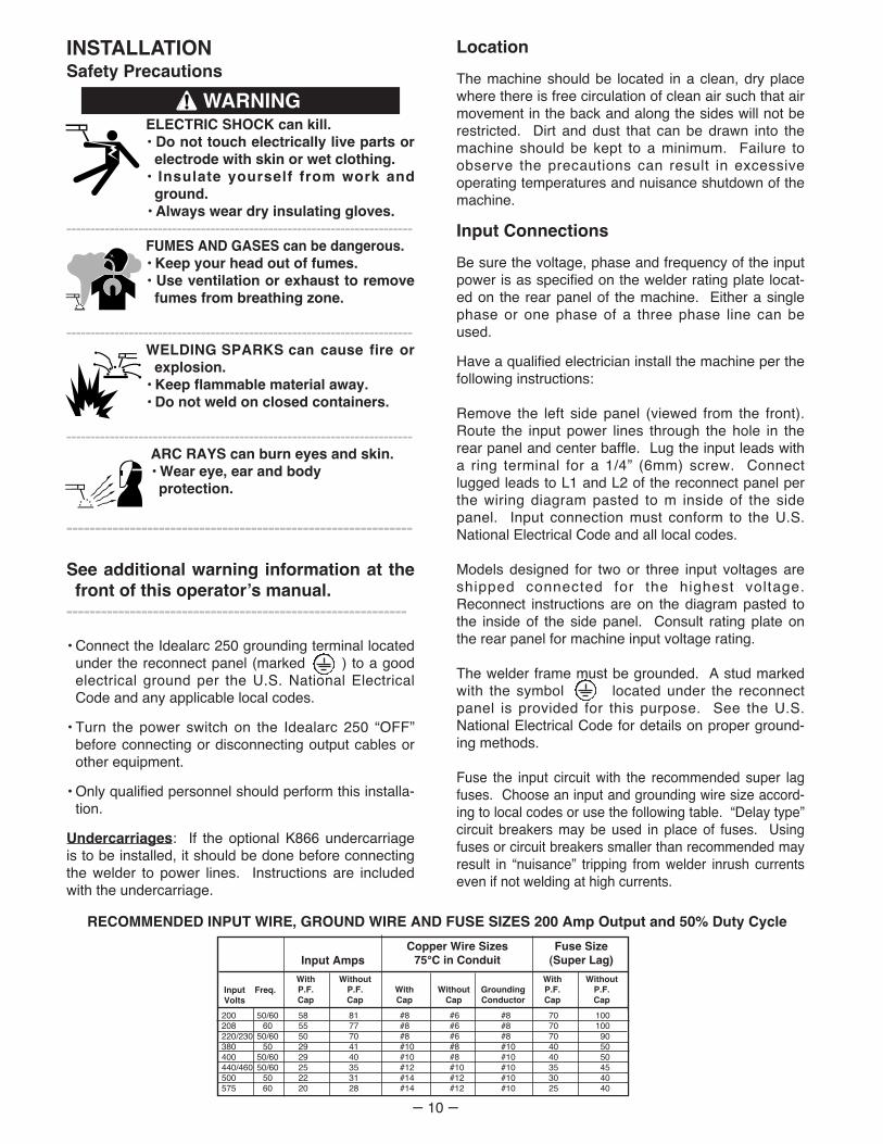
Fuse the input circuit with the recommended super lagfuses. Choose an input and grounding wire size accord-ing to local codes or use the following table. “Delay type”circuit breakers may be used in place of fuses. Usingfuses or circuit breakers smaller than recommended mayresult in “nuisance” tripping from welder inrush currentseven if not welding at high currents.
200 50/60 58 81 #8 #6 #8 70 100208 60 55 77 #8 #6 #8 70 100220/230 50/60 50 70 #8 #6 #8 70 90380 50 29 41 #10 #8 #10 40 50400 50/60 29 40 #10 #8 #10 40 50440/460 50/60 25 35 #12 #10 #10 35 45500 50 22 31 #14 #12 #10 30 40575 60 20 28 #14 #12 #10 25 40
InputVolts
Freq.WithP.F.Cap
WithoutP.F.Cap
WithCap
WithoutCap
GroundingConductor
WithP.F.Cap
WithoutP.F.Cap
Input AmpsCopper Wire Sizes
75°C in ConduitFuse Size
(Super Lag)
RECOMMENDED INPUT WIRE, GROUND WIRE AND FUSE SIZES 200 Amp Output and 50% Duty Cycle

– 11 –
STACKING
A. Make sure the first or bottom unit is setting on alevel, well supported surface.
B. The units must be stacked with their front flush,making sure the two holes in the base rails ofthe unit being stacked on top are over the twoholes located on the top front corners of the unitbeing stacked on. Fasten the units togetherwith 5/16 (8 mm) bolts, nuts and lockwashersthrough these holes.
C. Remote fastening bolts before lifting unit offstacks.
Installation of Field Installed Options
For installation of compatible field installed options,see Field Installed Options section, and refer to theinstructions included with those options.
Output Cable Size and Connection
The output leads are connected to the output termi-nals marked “WORK” and “ELECTRODE”. They arelocated at the lower right and lower left corners of thefront panel. The 60 Hz Idealarc 250 provides 1/2”studs for weld cable connections. The 50 Hz Idealarc250 provides European weld cable connector recepta-cles. Minimum cable sizes recommended are listed inthe table below.
CABLE SIZES FOR COMBINED LENGTHS OFCOPPER ELECTRODE AND WORK CABLES
0-100 Ft.
100-150 Ft.
150-200 Ft.
200-250 Ft.
200 Amps50% Duty Cycle
3 (30mm2)
2 (35mm2)
1 (45mm2)
1/0 (55mm2)
250 Amps30% Duty Cycle
3 (30mm2)
2 (35mm2)
1 (45mm2)
1/0 (55mm2)
FALLING EQUIPMENT can causeinjury.• Do not lift this machine using lift bale if
it is equipped with a heavy accessorysuch as undercarriage or gas cylinder.
• Lift only with equipment of adequate lifting capacity.• Be sure machine is stable when lifting.• Do not stack more than three high.• Do not stack on top of any other type machine.---------------------------------------------------------------------
WARNING
ELECTRIC SHOCK can kill.• Turn the power switch of thewelding power source “OFF”before connecting or disconnect-
ing output cables.------------------------------------------------------------
WARNING

OPERATIONSafety Precautions
Be sure the Idealarc 250 is properly installed, and thatall accessories are properly hooked up beforeattempting operation.
DUTY CYCLE
This machine is rated at a 30% duty cycle at 250amps or 50% duty cycle at 200 amp output. Dutycycle is based on a 10 minute period. Therefore,the welder can be loaded at 200 amperes for 5minutes out of each 10 minute period. Higher dutycycles can be used at lower currents; see ratingplate information.
– 12 –
CONTROL OPERATION
A. Current Control Handle
Rotating the hand wheel raises and lowers theoutput current allowing the operator to dial thedesired current. Clockwise rotation reducesthe current while counter-clockwise rotationincreases the current. Turning the currentcontrol handle also drives the output pointer atthe bottom of the nameplate which indicatesthe stick welding current at NEMA arc volts.
B. Polarity Switch
Turn the arc polarity switch in the upper righthand corner of the case front to AC, DC(-) orDC(+) as required for the particular application.DO NOT CHANGE POLARITY SWITCHWHILE WELDING. Doing this can seriouslydamage the switch.
C. TIG Welding
The Idealarc 250 with the optional Hi-Freq is aninexpensive equipment combination for part-time production or repair TIG welding of alu-minum, magnesium, thin stainless steel andmany space-age metals. The Idealarc 250 canbe used for normal stick electrode welding withthe Hi-Freq attached.
Reduce the Idealarc 250 duty cycle by 50%when AC TIG welding, i.e., the welder should beoperated for only two and one half minutes outof every ten at rated current of 200 amperes.
The Hi-Freq includes high frequency generator,gas valve and needed controls. It operates on115V, 50/60 Hz AC power.
NOTE: The Hi-Freq unit includes an R.F.bypass capacitor kit for power source protec-tion. Installation instructions are in the kit.(When using the Idealarc 250 with any otherhigh frequency equipment, an R.F. bypasscapacitor must be installed. Order Kit T12246.)To provide protection, the welder groundingstud or frame must be connected to ground(see instructions on grounding in MachineInstallation section). Also follow the groundinginstructions given in the Hi-Freq Instructionmanual.
ELECTRIC SHOCK can kill.• Do not touch electrically live parts or
electrode with skin or wet clothing.• Insulate yourself from work and
ground.• Always wear dry insulating gloves.
------------------------------------------------------------------------FUMES AND GASES can be dangerous.• Keep your head out of fumes.• Use ventilation or exhaust to remove
fumes from breathing zone.
------------------------------------------------------------------------WELDING SPARKS can cause fire or
explosion.• Keep flammable material away.• Do not weld on closed containers.
------------------------------------------------------------------------ARC RAYS can burn eyes and skin.• Wear eye, ear and body protection.
------------------------------------------------------------
See additional warning information at thefront of this operatorʼs manual.
-----------------------------------------------------------
WARNING
CAUTION

MAINTENANCESafety Precautions
General Maintenance
1. The fan motor has sealed ball bearings whichrequires no service.
2. In dusty locations dirt may clog the air channelscausing the welder to run hot. Under theseconditions carefully blow out the welder at regularintervals.
3. Keep the electrode and work cable connectiontight.
4. Every twelve months or at the first indication of abinding current pointer, turn the input power offand remove the left case side. Wipe the pointerguide bar clean and lubricate with graphitegrease.
5. When cleaning the current pointer, clean thereactor quadrant teeth, drive gear and pinion.Lubricate with graphite grease.
– 13 –
TROUBLESHOOTINGSafety Precautions
Rectifier Troubleshooting
1. Turn the input power off.
2. Disconnect all input and output leads from therectifier bridge.
3. Connect an ohmmeter between the DC positive(red) terminal and one of the AC (yellow) termi-nals. Note the ohmmeter reading using the 10 to100 scale.
4. Reverse the ohmmeter leads. Note the readings.
5. The reading taken in steps 3 and 4 should bedifferent. If the readings are the same andnear zero, the rectifier has shorted. IF thereadings are the same and near full scale, therectifier has failed open.
6. Repeat steps 3, 4 and 5 between the DC posi-tive (red) terminal and each of the AC (yellow)terminals.
7. Repeat steps 3, 4 and 5 between the DC nega-tive (black) terminal and each of the AC (yel-low) terminals.
NOTE: Since it is unlikely that all rectifiers of afull wave bridge would fail simultaneously,check the test method and the ohmmeter if thechecking indicates that all rectifiers have failed.
ELECTRIC SHOCK can kill.• Have a qualified individual install and
service this equipment.• Turn the input power off at the fuse
box before working on equipment.• Do not touch electrically hot parts.---------------------------------------------------------------------
WARNINGELECTRIC SHOCK can kill.• Have a qualified individual install and
service this equipment.• Turn the input power off at the fuse
box before working on equipment.• Do not touch electrically hot parts.---------------------------------------------------------------------
WARNING

– 14 –
TROUBLE
A. Welder will not weld.
B. Welder welds, but soon stopswelding (DC only).
CAUSE
1. Line switch not turned “On”.Supply line fuse blown.
2. Power circuit dead.
3. Broken power lead.
4. Wrong voltage.
5. Electrode or work lead loose orbroken.
6. Open transformer circuit.
7. Polarity switch not centered.
1. Proper ventilation hindered.
2. Welder loaded beyond rating.
3. Fan motor inoperative.
4. Poor internal connections.
5. Excessive dust accumulation inwelder.
6. Bi-metallic thermostat dirty.
WHAT TO DO
1. Place line switch in “On” posi-tion. Replace. (Look for reasonfor blown fuse first).
2. Check supply line voltage.
3. Repair.
4. Check voltage against ratingplate. Check reconnect paneljumper.
5. Tighten and repair connections.
6. Send to repair shop to have coilsreplaced.
7. Center switch handle on DC(+),DC(-), or AC.
1. Make sure all case openings arefree for proper circulation of air.
2. Operate at normal current andduty cycle consistent with rating.
3. Check leads and motor bear-ings. Fan motor can be testedon 115V line; with welder on,voltage across fan motor shouldbe approximately 115V.
4. Check for loose or hot connec-tions and tighten.
5. Blow out welder with low pres-sure.
6. Carefully clean in naptha.
TROUBLESHOOTING

– 15 –
TROUBLE
C. Variable or sluggish welding.
D. Welder wonʼt shut off.
E. Polarity switch wonʼt turn.
CAUSE
1. Poor work or electrode terminalconnection.
2. Current too low.
3. Low line voltage.
4. Welding leads too small.
5. Old and badly frayed weldingcables.
1. Line switch has failedmechanically.
1. Contacts rough and pitted fromimproper switching under load.
WHAT TO DO
1. Check and clean all connections.
2. Check recommended currentsfor rod type and size.
3. Check with power company.
4. See Output Cable section.
5. Replace.
1. Replace switch.
1. Replace switch.
TROUBLESHOOTING (CONTINUED)

– 16 –
NO
TE
: T
his
dia
gra
m is
fo
r re
fere
nce
onl
y.
It m
ay n
ot
be
accu
rate
fo
r al
l mac
hine
s co
vere
d b
y th
is m
anua
l. T
he s
pec
ific
dia
gra
m f
or
a p
artic
ular
co
de
is p
aste
d in
sid
eth
e m
achi
ne o
n o
ne o
f th
e en
clo
sure
pan
els.
If
the
dia
gra
m is
ille
gib
le, w
rite
to
the
Ser
vice
Dep
artm
ent
for
a re
pla
cem
ent.
Giv
e th
e eq
uip
men
t co
de
num
ber
..
H1
L1 L2
TO G
RO
UN
D P
ER
NA
TIO
NA
LE
LEC
TRIC
AL
CO
DE
INP
UT
LEA
DS
RE
CO
NN
EC
TP
AN
EL
OP
TIO
NA
L P
OW
ER
FAC
TOR
CA
PA
CIT
OR
S
MO
TOR
X1
X2
X3 X
4
FAN
MTR
LIN
ES
WIT
CH
RE
CTI
FIE
RO
VE
RLO
AD
THE
RM
OS
TAT
PO
WE
RR
EC
TIFI
ER
SU
PP
RE
SS
OR
CIR
CU
IT
AR
C P
OLA
RIT
Y S
WIT
CH
(LO
OK
ING
FR
OM
IN
SID
E M
AC
HIN
E)
WO
RK
ELE
CTR
OD
E
STA
BIL
IZE
RC
IRC
UI
T
CH
OK
E
AC
1
AC
2
(+)
(-)
EL
EC
TR
ICA
L S
YM
BO
LS
PE
R E
15
37
.
P.F
. C
AP
LE
AD
-H
IGH
P.F
. C
AP
LE
AD
-M
ED
INP
UT
VO
LTS
INP
UT
VO
LTS
RE
CO
NN
EC
T P
AN
EL
LEA
D P
OS
ITIO
N
CO
NN
EC
TIO
NS
MU
ST
BE
TIG
HT
EN
ED
SE
CU
RE
LY
.
H5
H5
SE
E T
AB
LE
BE
LOW
FO
R
CO
RR
EC
T
CO
NN
EC
TIO
N
208/
230/
460
H5
H5
DO
NO
T TO
UC
H E
LEC
TRIC
ALL
Y "
HO
T" P
AR
TS S
UC
H A
S O
UTP
UT
TER
MIN
ALS
DO
NO
T O
PE
RA
TE W
ITH
CO
VE
RS
RE
MO
VE
D.
ON
LY Q
UA
LIFI
ED
PE
RS
ON
NE
L S
HO
ULD
IN
STA
LL O
R S
ER
VIC
E T
HIS
EQ
UIP
ME
NT.
GR
OU
ND
ING
SC
RE
W (
)
MU
ST
BE
CO
NN
EC
TED
TO
A G
OO
D E
AR
TH G
RO
UN
D
HIG
H V
OLT
AG
Eca
n ki
ll
O
R I
NTE
RN
AL
WIN
DIN
GS
.
TUR
N T
HE
IN
PU
T P
OW
ER
TO
TH
E W
ELD
ER
OFF
US
ING
TH
E D
ISC
ON
NE
CT
SW
ITC
HA
T TH
E F
US
E B
OX
BE
FOR
E I
NS
TALL
ING
OR
SE
RV
ICIN
G T
HIS
MA
CH
INE
.
TH
RO
UG
H T
HE
IN
PU
T C
AB
LE P
ER
NA
TIO
NA
L E
LEC
TRIC
AL
CO
DE
.
HIG
H
ME
D
LOW
208
2 30
230
460
460
575
LOW
ME
D
HIG
H
MA
CH
INE
S A
RE
SH
IPP
ED
FR
OM
FA
CT
OR
Y C
ON
NE
CT
ED
FO
R H
IGH
ES
T I
NP
UT
VO
LT
AG
E.
LOW
H2
ME
D H
3
HIG
H H
4
INP
UT
VO
LTS
H5
LOW
ME
D
HIG
H
230/
460/
575
200
400
P.F
. C
AP
LE
AD
-H
IGH
200/
400
(50/
60 H
Z)60
HZ
6 0 H
Z
S193
43
WIR
ING
DIA
GR
AM
- 25
0 A
MP
IDEA
LAR
C 6
0 H
Z &
50
/ 60
HZ
8-2-
90

– 17 –
NO
TE
: T
his
dia
gra
m is
fo
r re
fere
nce
onl
y.
It m
ay n
ot
be
accu
rate
fo
r al
l mac
hine
s co
vere
d b
y th
is m
anua
l. T
he s
pec
ific
dia
gra
m f
or
a p
artic
ular
co
de
is p
aste
d in
sid
eth
e m
achi
ne o
n o
ne o
f th
e en
clo
sure
pan
els.
If
the
dia
gra
m is
ille
gib
le, w
rite
to
the
Ser
vice
Dep
artm
ent
for
a re
pla
cem
ent.
Giv
e th
e eq
uip
men
t co
de
num
ber
..
H1
L1
L2
TO
GR
OU
ND
PE
R N
AT
ION
AL
EL
EC
TR
ICA
L C
OD
E
INP
UT
LE
AD
SR
EC
ON
NE
CT
PA
NE
L
OP
TIO
NA
L P
OW
ER
FA
CT
OR
CA
PA
CIT
OR
S MO
TO
R
X1
X2
X3 X
4
FA
N
MT
R
LIN
E
SW
ITC
H
RE
CT
IFIE
R
OV
ER
LO
AD
TH
ER
MO
ST
AT
PO
WE
R
RE
CT
IFIE
R
SU
PP
RE
SS
OR
CIR
CU
IT
AR
C P
OL
AR
ITY
SW
ITC
H(L
OO
KIN
G F
RO
M I
NS
IDE
MA
CH
INE
)
WO
RK
EL
EC
TR
OD
E
ST
AB
ILIZ
ER
CIR
CU
IT
CH
OK
E
AC
1A
C2
(+)(-)
V
1000
5W
150
/10
0WL
OW
ME
D
HIG
H
SE
E T
AB
LE
BE
LO
W F
OR
CO
RR
EC
T
CO
NN
EC
TIO
N
EL
EC
TR
ICA
L S
YM
BO
LS
PE
R E
15
37
.
P.F
. C
AP
LE
AD
-H
IGH
P.F
. C
AP
LE
AD
-M
ED
INP
UT
VO
LT
SIN
PU
T V
OL
TS
22
0/3
80
/44
03
80
/50
0
RE
CO
NN
EC
T P
AN
EL
LE
AD
PO
SIT
ION
CO
NN
EC
TIO
NS
MU
ST
BE
TIG
HT
EN
ED
SE
CU
RE
LY
.
H5
H5
H5
H5
DO
NO
T T
OU
CH
EL
EC
TR
ICA
LL
Y "
HO
T"
PA
RT
S S
UC
H A
S O
UT
PU
T T
ER
MIN
AL
S
DO
NO
T O
PE
RA
TE
WIT
H C
OV
ER
S R
EM
OV
ED
.
ON
LY
QU
AL
IFIE
D P
ER
SO
NN
EL
SH
OU
LD
IN
ST
AL
L O
R S
ER
VIC
E T
HIS
EQ
UIP
ME
NT
.H
IGH
VO
LT
AG
Eca
n k
ill
OR
IN
TE
RN
AL
WIN
DIN
GS
.
TU
RN
TH
E I
NP
UT
PO
WE
R T
O T
HE
WE
LD
ER
OF
F U
SIN
G T
HE
DIS
CO
NN
EC
T S
WIT
CH
AT
TH
E F
US
E B
OX
BE
FO
RE
IN
ST
AL
LIN
G O
R S
ER
VIC
ING
TH
IS M
AC
HIN
E.
TH
RO
UG
H T
HE
IN
PU
T C
AB
LE
PE
R N
AT
ION
AL
EL
EC
TR
ICA
L C
OD
E.
22
0
44
0
5
00
38
0
HIG
H
ME
D
LO
W
HIG
H
MA
CH
INE
S A
RE
SH
IPP
ED
FR
OM
FA
CT
OR
Y C
ON
NE
CT
ED
FO
R H
IGH
ES
T I
NP
UT
VO
LT
AG
E.
H2
H3 H4
GR
OU
ND
ING
SC
RE
W M
US
T B
E C
ON
NE
CT
ED
TO
A G
OO
D E
AR
TH
GR
OU
ND
38
0
L
OW
41
5M
ED
N.A
. B
OL
TE
D C
ON
NE
CT
ION
ON
MA
CH
INE
S
WIT
H C
OP
PE
R C
OIL
S.
N.A
.
S19
441
WIR
ING
DIA
GR
AM
- 2
50 A
MP
IDE
AL
AR
C 5
0 H
Z
8-2-
90

NOTES

WARNING
AVISO DEPRECAUCION
ATTENTION
WARNUNG
ATENÇÃO
Spanish
French
German
Portuguese
Japanese
Chinese
Korean
Arabic
READ AND UNDERSTAND THE MANUFACTURER’S INSTRUCTION FOR THIS EQUIPMENT AND THE CONSUMABLES TO BEUSED AND FOLLOW YOUR EMPLOYER’S SAFETY PRACTICES.
SE RECOMIENDA LEER Y ENTENDER LAS INSTRUCCIONES DEL FABRICANTE PARA EL USO DE ESTE EQUIPO Y LOSCONSUMIBLES QUE VA A UTILIZAR, SIGA LAS MEDIDAS DE SEGURIDAD DE SU SUPERVISOR.
LISEZ ET COMPRENEZ LES INSTRUCTIONS DU FABRICANT EN CE QUI REGARDE CET EQUIPMENT ET LES PRODUITS AETRE EMPLOYES ET SUIVEZ LES PROCEDURES DE SECURITE DE VOTRE EMPLOYEUR.
LESEN SIE UND BEFOLGEN SIE DIE BETRIEBSANLEITUNG DER ANLAGE UND DEN ELEKTRODENEINSATZ DES HER-STELLERS. DIE UNFALLVERHÜTUNGSVORSCHRIFTEN DES ARBEITGEBERS SIND EBENFALLS ZU BEACHTEN.
● Do not touch electrically live parts orelectrode with skin or wet clothing.
● Insulate yourself from work andground.
● No toque las partes o los electrodosbajo carga con la piel o ropa moja-da.
● Aislese del trabajo y de la tierra.
● Ne laissez ni la peau ni des vête-ments mouillés entrer en contactavec des pièces sous tension.
● Isolez-vous du travail et de la terre.
● Berühren Sie keine stromführendenTeile oder Elektroden mit IhremKörper oder feuchter Kleidung!
● Isolieren Sie sich von denElektroden und dem Erdboden!
● Não toque partes elétricas e elec-trodos com a pele ou roupa molha-da.
● Isole-se da peça e terra.
● Keep flammable materials away.
● Mantenga el material combustiblefuera del área de trabajo.
● Gardez à l’écart de tout matérielinflammable.
● Entfernen Sie brennbarres Material!
● Mantenha inflamáveis bem guarda-dos.
● Wear eye, ear and body protection.
● Protéjase los ojos, los oídos y elcuerpo.
● Protégez vos yeux, vos oreilles etvotre corps.
● Tragen Sie Augen-, Ohren- und Kör-perschutz!
● Use proteção para a vista, ouvido ecorpo.

WARNING
AVISO DEPRECAUCION
ATTENTION
WARNUNG
ATENÇÃO
Spanish
French
German
Portuguese
Japanese
Chinese
Korean
Arabic
LEIA E COMPREENDA AS INSTRUÇÕES DO FABRICANTE PARA ESTE EQUIPAMENTO E AS PARTES DE USO, E SIGA ASPRÁTICAS DE SEGURANÇA DO EMPREGADOR.
● Keep your head out of fumes.● Use ventilation or exhaust to
remove fumes from breathing zone.
● Los humos fuera de la zona de res-piración.
● Mantenga la cabeza fuera de loshumos. Utilice ventilación oaspiración para gases.
● Gardez la tête à l’écart des fumées.● Utilisez un ventilateur ou un aspira-
teur pour ôter les fumées des zonesde travail.
● Vermeiden Sie das Einatmen vonSchweibrauch!
● Sorgen Sie für gute Be- undEntlüftung des Arbeitsplatzes!
● Mantenha seu rosto da fumaça.● Use ventilação e exhaustão para
remover fumo da zona respiratória.
● Turn power off before servicing.
● Desconectar el cable de ali-mentación de poder de la máquinaantes de iniciar cualquier servicio.
● Débranchez le courant avant l’entre-tien.
● Strom vor Wartungsarbeitenabschalten! (Netzstrom völlig öff-nen; Maschine anhalten!)
● Não opere com as tampas removidas.● Desligue a corrente antes de fazer
serviço.● Não toque as partes elétricas nuas.
● Do not operate with panel open orguards off.
● No operar con panel abierto oguardas quitadas.
● N’opérez pas avec les panneauxouverts ou avec les dispositifs deprotection enlevés.
● Anlage nie ohne Schutzgehäuseoder Innenschutzverkleidung inBetrieb setzen!
● Mantenha-se afastado das partesmoventes.
● Não opere com os paineis abertosou guardas removidas.

• Sales and Service through Subsidiaries and Distributors Worldwide •
Cleveland, Ohio 44117-1199 U.S.A. TEL: 216.481.8100 FAX: 216.486.1751 WEB SITE: www.lincolnelectric.com
• World's Leader in Welding and Cutting Products •
Related Documents