IDEALARC DC-600 World’s Leader in Welding and Cutting Products Premier Manufacturer of Industrial Motors SERVICE MANUAL Sales and Service through Subsidiaries and Distributors Worldwide 22801 St. Clair Ave. Cleveland, Ohio 44117-1199 U.S.A. Tel (216) 481-8100 For use with machines having Code Numbers: 9773MSP 9774 9776M 9778M 9779M 9780M 9793MSP 9910M SVM108-A August, 1998 Safety Depends on You Lincoln arc welding and cutting equipment is designed and built with safety in mind. However, your overall safety can be increased by proper installation ... and thoughtful operation on your part. DO NOT INSTALL, OPERATE OR REPAIR THIS EQUIPMENT WITHOUT READING THIS MANUAL AND THE SAFETY PRECAUTIONS CONTAINED THROUGHOUT. And, most importantly, think before you act and be careful. 1 2 3 4 5 6 7 8 9 10 ® RETURN TO MAIN INDEX Return to Master TOC Return to Master TOC Return to Master TOC Return to Master TOC View Safety Info View Safety Info View Safety Info View Safety Info

Lincoln Idealarc DC-600
Oct 25, 2015
Manual de operacion y mantenimiento Lincoln IdealARC DC 600
Welcome message from author
This document is posted to help you gain knowledge. Please leave a comment to let me know what you think about it! Share it to your friends and learn new things together.
Transcript
IDEALARC DC-600
World’s Leader in Welding and Cutting Products Premier Manufacturer of Industrial Motors
SERVICE MANUAL
Sales and Service through Subsidiaries and Distributors Worldwide22801 St. Clair Ave. Cleveland, Ohio 44117-1199 U.S.A. Tel (216) 481-8100
For use with machines having Code Numbers: 9773MSP97749776M9778M9779M9780M9793MSP9910M
SVM108-AAugust, 1998
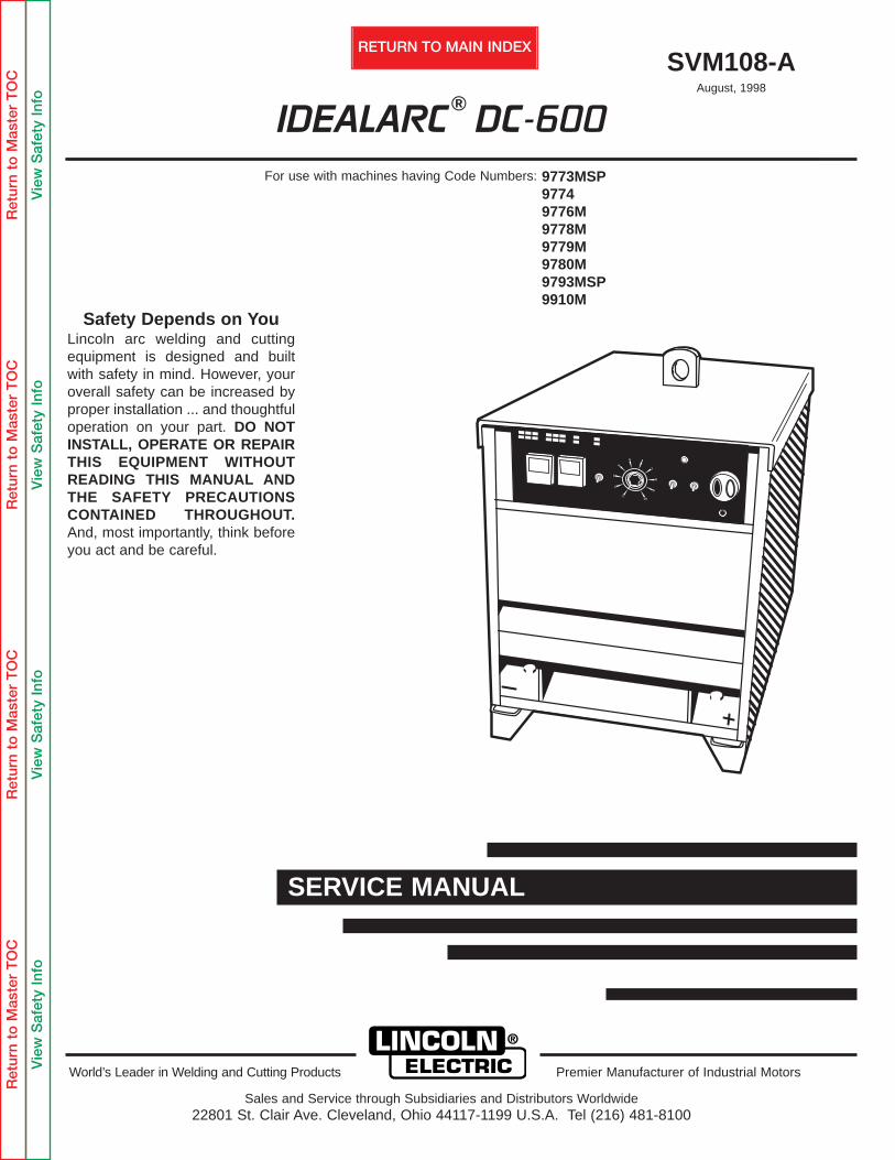
Safety Depends on YouLincoln arc welding and cuttingequipment is designed and builtwith safety in mind. However, youroverall safety can be increased byproper installation ... and thoughtfuloperation on your part. DO NOTINSTALL, OPERATE OR REPAIRTHIS EQUIPMENT WITHOUTREADING THIS MANUAL ANDTHE SAFETY PRECAUTIONSCONTAINED THROUGHOUT.And, most importantly, think beforeyou act and be careful.
1
2
3
4
5 6
7
8
9
10
®
RETURN TO MAIN INDEX
Ret
urn
to M
aste
r T
OC
Ret
urn
to M
aste
r T
OC
Ret
urn
to M
aste
r T
OC
Ret
urn
to M
aste
r T
OC
Vie
w S
afet
y In
foV
iew
Saf
ety
Info
Vie
w S
afet
y In
foV
iew
Saf
ety
Info
Ret
urn
to M
aste
r T
OC
Ret
urn
to M
aste
r T
OC
Ret
urn
to M
aste
r T
OC
Ret
urn
to M
aste
r T
OC
FUMES AND GASEScan be dangerous.3.a. Welding or cutting may produce fumes and
gases hazardous to health. Avoid breathing these fumes and gases.When welding, or cutting keep your head out of the fume.Use enough ventilation and/or exhaust at thearc to keep fumes and gases away from thebreathing zone. When welding or cut-
ting with electrodes which require special ventilation such asstainless or hard facing (see instructions on container orMSDS) or on lead or cadmium plated steel and other metalsor coatings which produce highly toxic fumes, keep exposureas low as possible and below Threshold Limit Values (TLV)using local exhaust or mechanical ventilation. In confinedspaces or in some circumstances, outdoors, a respirator maybe required. Additional precautions are also required whenwelding on galvanized steel.
3.b. Do not weld or cut in locations near chlorinated hydrocarbon vapors coming from degreasing, cleaning or spraying operations. The heat and rays of the arc can react with solvent vapors to form phosgene, a highly toxic gas, and other irritating products.
3.c. Shielding gases used for arc welding or cutting can displace air and cause injury or death. Always use enough ventilation,especially in confined areas, to insure breathing air is safe.
3.d. Read and understand the manufacturer’s instructions for thisequipment and the consumables to be used, including thematerial safety data sheet (MSDS) and follow youremployer’s safety practices. MSDS forms are available fromyour welding distributor or from the manufacturer.
3.e. Also see item 7b.
ELECTRIC SHOCKcan kill.1.a. The electrode and work (or ground) circuits
are electrically “hot” when the welder or cutteris on. Do not touch these “hot” parts with your bare skin or wet clothing. Wear dry, hole-freegloves to insulate hands.
1.b. Insulate yourself from work and ground using dry insulation.Make certain the insulation is large enough to cover your fullarea of physical contact with work and ground.
In addition to the normal safety precautions, if welding orcutting must be performed under electrically hazardous conditions (in damp locations or while wearing wet clothing; on metal structures such as floors, gratings or scaffolds; when in cramped positions such as sitting, kneeling or lying, if there is a high risk of unavoidable or accidental contact with the workpieceor ground) use the following equipment:
• Semiautomatic DC Constant Voltage (Wire) Welder.• DC Manual (Stick) Welder.• AC Welder with Reduced Voltage Control.
1.c. In semiautomatic or automatic wire welding, the electrode,electrode reel, welding head, nozzle or semiautomaticwelding gun are also electrically “hot”.
1.d. Always be sure the work cable makes a good electricalconnection with the metal being welded. The connectionshould be as close as possible to the area being welded.
1.e. Ground the work or metal to be welded to a good electrical(earth) ground.
1.f. Maintain the electrode holder, work clamp, welding or cuttingcable and welding or cutting machine in good, safe operating condition. Replace damaged insulation.
1.g. Never dip the electrode in water for cooling.
1.h. Never simultaneously touch electrically “hot” parts ofelectrode holders connected to two welders because voltagebetween the two can be the total of the open circuit voltageof both welders.
1.i. When working above floor level, use a safety belt to protectyourself from a fall should you get a shock.
1.j. Also see Items 4.c. and 6.
PROTECT YOURSELF AND OTHERS FROM POSSIBLE SERIOUS INJURY OR DEATH. KEEP CHILDRENAWAY. PACEMAKER WEARERS SHOULD CONSULT WITH THEIR DOCTOR BEFORE OPERATING.
Read and understand the following safety highlights. For additional safety information, it is strongly recommended that you pur-chase a copy of “Safety in Welding & Cutting - ANSI Standard Z49.1” from the American Welding Society, P.O. Box 351040,Miami, Florida 33135 or CSA Standard W117.2-1974. A Free copy of “Arc Welding Safety” booklet E205 is available from theLincoln Electric Company, 22801 St. Clair Avenue, Cleveland, Ohio 44117-1199.
BE SURE THAT ALL INSTALLATION, OPERATION, MAINTENANCE AND REPAIR PROCEDURES ARE PER-FORMED ONLY BY QUALIFIED INDIVIDUALS.
ARC RAYS can burn.2.a. Use a shield with the proper filter and cover
plates to protect your eyes from sparks andthe rays of the arc when welding or cutting orobserving open arc welding or cutting. Headshield and filter lens should conform to ANSI Z87. I standards.
2.b. Use suitable clothing made from durable flame-resistantmaterial to protect your skin and that of your helpers fromthe arc rays.
2.c. Protect other nearby personnel with suitable, non-flammablescreening and/or warn them not to watch the arc nor exposethemselves to the arc rays or to hot spatter or metal.
WELDING can be hazardous.
SAFETY
IDEALARC DC-600
i
WARNING
Ret
urn
to M
aste
r T
OC
Ret
urn
to M
aste
r T
OC
Ret
urn
to M
aste
r T
OC
Ret
urn
to M
aste
r T
OC
FOR ELECTRICALLYpowered equipment.
6.a.Turn off input power using the disconnectswitch at the fuse box before working onthe equipment.
6.b. Install equipment in accordance with the U.S. NationalElectrical Code, all local codes and the manufacturer’srecommendations.
6.c. Ground the equipment in accordance with the U.S. NationalElectrical Code and the manufacturer’s recommendations.
CYLINDER may explodeif damaged.
5.a. Use only compressed gas cylinders contain-ing the correct shielding gas for the processused and properly operating regulatorsdesigned for the gas and pressure used. Allhoses, fittings, etc. should be suitable for theapplication and maintained in good condi-tion.
5.b. Always keep cylinders in an upright position securelychained to an undercarriage or fixed support.
5.c. Cylinders should be located:• Away from areas where they may be struck or subjected tophysical damage.
• A safe distance from arc welding or cutting operations andany other source of heat, sparks, or flame.
5.d. Never allow the electrode, electrode holder or any otherelectrically “hot” parts to touch a cylinder.
5.e. Keep your head and face away from the cylinder valve outletwhen opening the cylinder valve.
5.f. Valve protection caps should always be in place and handtight except when the cylinder is in use or connected foruse.
5.g. Read and follow the instructions on compressed gascylinders, associated equipment, and CGA publication P-l,“Precautions for Safe Handling of Compressed Gases inCylinders,” available from the Compressed Gas Association1235 Jefferson Davis Highway, Arlington, VA 22202.
WELDING OR CUTTINGSPARKS can cause fire orexplosion.4.a. Remove fire hazards from the welding or cut-ting area. If this is not possible, cover them toprevent the welding or cutting sparks from start-
ing a fire. Remember that welding or cutting sparks and hotmaterials from welding or cutting can easily go through smallcracks and openings to adjacent areas. Avoid welding or cut-ting near hydraulic lines. Have a fire extinguisher readilyavailable.
4.b. Where compressed gases are to be used at the job site,special precautions should be used to prevent hazardoussituations. Refer to “Safety in Welding and Cutting” (ANSIStandard Z49.1) and the operating information for theequipment being used.
4.c. When not welding or cutting, make certain no part of theelectrode circuit is touching the work or ground. Accidentalcontact can cause overheating and create a fire hazard.
4.d. Do not heat, cut or weld tanks, drums or containers until theproper steps have been taken to insure that such procedureswill not cause flammable or toxic vapors from substancesinside. They can cause an explosion even though they havebeen “cleaned”. For information, purchase “RecommendedSafe Practices for the Preparation for Welding and Cutting ofContainers and Piping That Have Held HazardousSubstances”, AWS F4.1 from the American Welding Society(see address above).
4.e. Vent hollow castings or containers before heating, cutting orwelding. They may explode.
4.f. Sparks and spatter are thrown from the welding and cutting arc. Wear oil free protective garments such as leather gloves,heavy shirt, cuffless trousers, high shoes and a cap overyour hair. Wear ear plugs when welding or cutting out of posi-tion or in confined places. Always wear safety glasses withside shields when in a welding or cutting area.
4.g. Connect the work cable to the work as close to the welding or cutting area as practical. Work cables connected to thebuilding framework or other locations away from the weldingarea increase the possibility of the welding or cutting currentpassing through lifting chains, crane cables or other alternatecircuits. This can create fire hazards or overheat liftingchains or cables until they fail.
4.h. Also see item 7c.
IDEALARC DC-600
SAFETY ii
Ret
urn
to M
aste
r T
OC
Ret
urn
to M
aste
r T
OC
Ret
urn
to M
aste
r T
OC
Ret
urn
to M
aste
r T
OC FOR ENGINE
powered equipment.7.a. Turn the engine off before troubleshooting and maintenance
work unless the maintenance work requires it to be running.____________________________________________________
7.b. Operate engines in open, well-ventilatedareas or vent the engine exhaust fumesoutdoors.
____________________________________________________
7.c. Do not add the fuel near an open flamewelding or cutting arc or when the engine is running. Stop the engine and allow it to cool before refueling to prevent spilled fuel fromvaporizing on contact with hot engine partsand igniting. Do not spill fuel when fillingtank. If fuel is spilled, wipe it up and do notstart engine until fumes have beeneliminated.
____________________________________________________
7.d. Keep all equipment safety guards, coversand devices in position and in good repair.Keep hands, hair, clothing and tools awayfrom V-belts, gears, fans and all othermoving parts when starting, operating orrepairing equipment.
____________________________________________________
7.e. In some cases it may be necessary to remove safetyguards to perform required maintenance. Removeguards only when necessary and replace them when themaintenance requiring their removal is complete.Always use the greatest care when working near movingparts.
7.f. Do not put your hands near the engine fan. Do notattempt to override the governor or idler by pushing onthe throttle control rods while the engine is running.
7.g. To prevent accidentally starting gasoline engines whileturning the engine or welding generator during maintenancework, disconnect the spark plug wires, distributor cap ormagneto wire as appropriate.
___________________________________________________
ELECTRIC AND MAGNETICFIELDSmay be dangerous
8.a. Electric current flowing through any conductor causes localized Electric and Magnetic Fields (EMF). Welding or cutting current creates EMF fields around welding or cutting cables and welding machines
8.b. EMF fields may interfere with some pacemakers, andwelders or cutters having a pacemaker should consult their physician before welding or cutting.
8.c. Exposure to EMF fields in welding or cutting may have otherhealth effects which are now not known.
8d. All welders or cutters should use the following procedures inorder to minimize exposure to EMF fields from the welding or cutting circuit:
8.d.1. Route the electrode and work cables together - Securethem with tape when possible.
8.d.2. Never coil the electrode lead around your body.
8.d.3. Do not place your body between the electrode andwork cables. If the electrode cable is on your right side, the work cable should also be on your right side.
8.d.4. Connect the work cable to the workpiece as close aspossible to the area being welded.
8.d.5. Do not work next to welding or cutting power source.
7.h. To avoid scalding, do not remove theradiator pressure cap when the engine ishot.
SAFETY iii
IDEALARC DC-600
Ret
urn
to M
aste
r T
OC
Ret
urn
to M
aste
r T
OC
Ret
urn
to M
aste
r T
OC
Ret
urn
to M
aste
r T
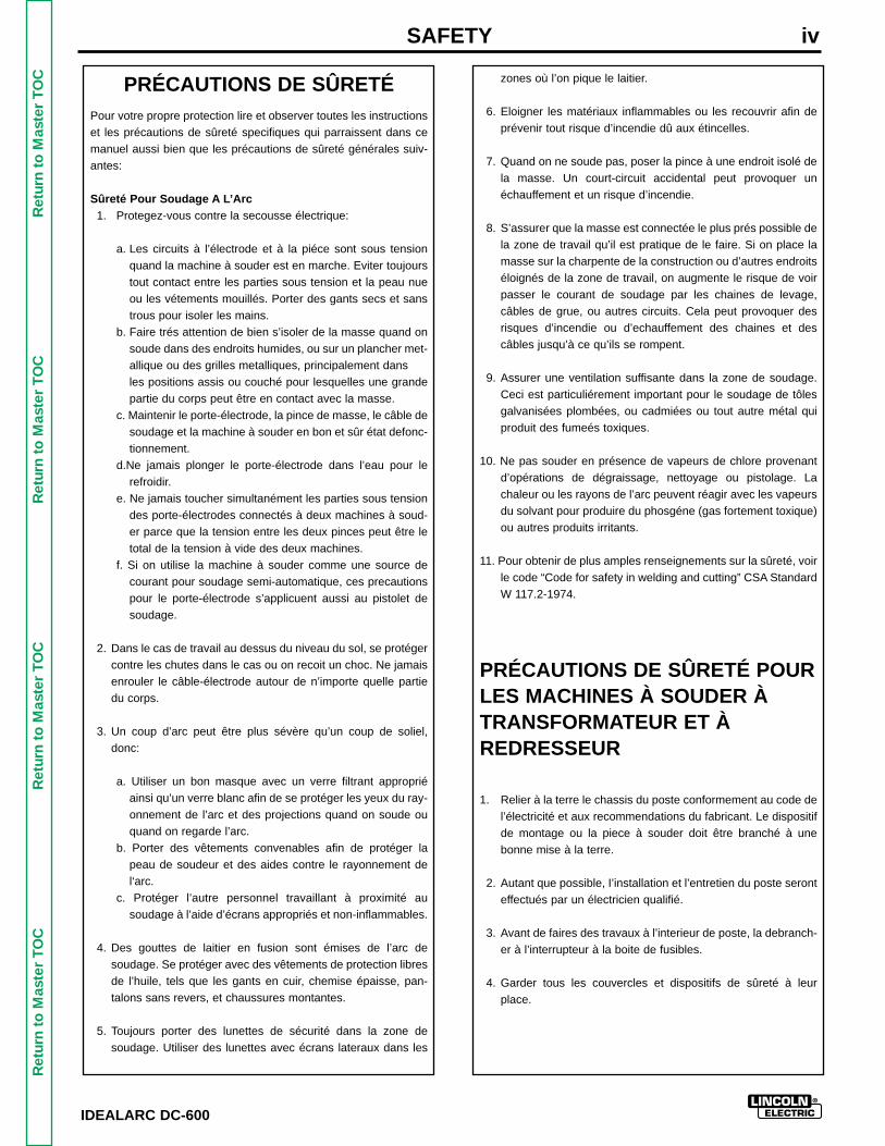
OC PRÉCAUTIONS DE SÛRETÉ
Pour votre propre protection lire et observer toutes les instructionset les précautions de sûreté specifiques qui parraissent dans cemanuel aussi bien que les précautions de sûreté générales suiv-antes:
Sûreté Pour Soudage A L’Arc1. Protegez-vous contre la secousse électrique:
a. Les circuits à l’électrode et à la piéce sont sous tensionquand la machine à souder est en marche. Eviter toujourstout contact entre les parties sous tension et la peau nueou les vétements mouillés. Porter des gants secs et sanstrous pour isoler les mains.
b. Faire trés attention de bien s’isoler de la masse quand onsoude dans des endroits humides, ou sur un plancher met-allique ou des grilles metalliques, principalement dans les positions assis ou couché pour lesquelles une grandepartie du corps peut être en contact avec la masse.
c. Maintenir le porte-électrode, la pince de masse, le câble desoudage et la machine à souder en bon et sûr état defonc-tionnement.
d.Ne jamais plonger le porte-électrode dans l’eau pour lerefroidir.
e. Ne jamais toucher simultanément les parties sous tensiondes porte-électrodes connectés à deux machines à soud-er parce que la tension entre les deux pinces peut être letotal de la tension à vide des deux machines.
f. Si on utilise la machine à souder comme une source decourant pour soudage semi-automatique, ces precautionspour le porte-électrode s’applicuent aussi au pistolet desoudage.
2. Dans le cas de travail au dessus du niveau du sol, se protégercontre les chutes dans le cas ou on recoit un choc. Ne jamaisenrouler le câble-électrode autour de n’importe quelle partiedu corps.
3. Un coup d’arc peut être plus sévère qu’un coup de soliel,donc:
a. Utiliser un bon masque avec un verre filtrant appropriéainsi qu’un verre blanc afin de se protéger les yeux du ray-onnement de l’arc et des projections quand on soude ouquand on regarde l’arc.
b. Porter des vêtements convenables afin de protéger lapeau de soudeur et des aides contre le rayonnement del‘arc.
c. Protéger l’autre personnel travaillant à proximité ausoudage à l’aide d’écrans appropriés et non-inflammables.
4. Des gouttes de laitier en fusion sont émises de l’arc desoudage. Se protéger avec des vêtements de protection libresde l’huile, tels que les gants en cuir, chemise épaisse, pan-talons sans revers, et chaussures montantes.
5. Toujours porter des lunettes de sécurité dans la zone desoudage. Utiliser des lunettes avec écrans lateraux dans les
zones où l’on pique le laitier.
6. Eloigner les matériaux inflammables ou les recouvrir afin deprévenir tout risque d’incendie dû aux étincelles.
7. Quand on ne soude pas, poser la pince à une endroit isolé dela masse. Un court-circuit accidental peut provoquer unéchauffement et un risque d’incendie.
8. S’assurer que la masse est connectée le plus prés possible dela zone de travail qu’il est pratique de le faire. Si on place lamasse sur la charpente de la construction ou d’autres endroitséloignés de la zone de travail, on augmente le risque de voirpasser le courant de soudage par les chaines de levage,câbles de grue, ou autres circuits. Cela peut provoquer desrisques d’incendie ou d’echauffement des chaines et descâbles jusqu’à ce qu’ils se rompent.
9. Assurer une ventilation suffisante dans la zone de soudage.Ceci est particuliérement important pour le soudage de tôlesgalvanisées plombées, ou cadmiées ou tout autre métal quiproduit des fumeés toxiques.
10. Ne pas souder en présence de vapeurs de chlore provenantd’opérations de dégraissage, nettoyage ou pistolage. Lachaleur ou les rayons de l’arc peuvent réagir avec les vapeursdu solvant pour produire du phosgéne (gas fortement toxique)ou autres produits irritants.
11. Pour obtenir de plus amples renseignements sur la sûreté, voirle code “Code for safety in welding and cutting” CSA StandardW 117.2-1974.
PRÉCAUTIONS DE SÛRETÉ POURLES MACHINES À SOUDER ÀTRANSFORMATEUR ET ÀREDRESSEUR
1. Relier à la terre le chassis du poste conformement au code del’électricité et aux recommendations du fabricant. Le dispositifde montage ou la piece à souder doit être branché à unebonne mise à la terre.
2. Autant que possible, I’installation et l’entretien du poste seronteffectués par un électricien qualifié.
3. Avant de faires des travaux à l’interieur de poste, la debranch-er à l’interrupteur à la boite de fusibles.
4. Garder tous les couvercles et dispositifs de sûreté à leurplace.
SAFETY iv
IDEALARC DC-600
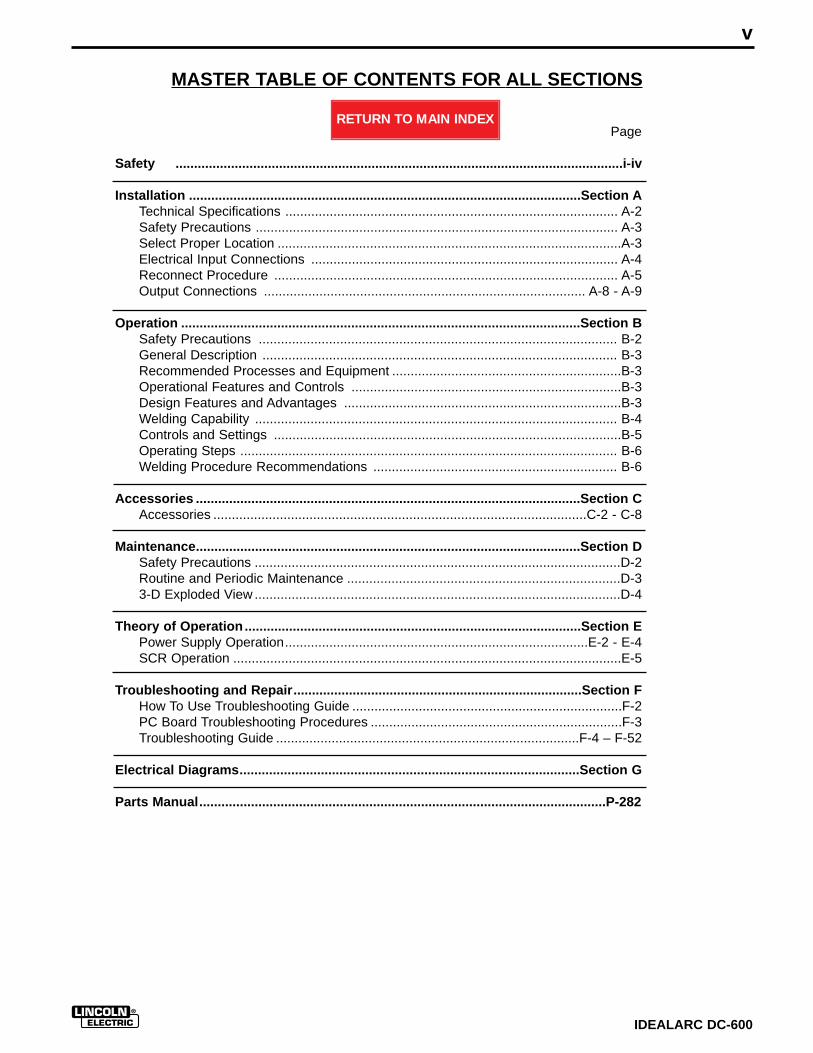
MASTER TABLE OF CONTENTS FOR ALL SECTIONS
Page
Safety .........................................................................................................................i-iv
Installation ..........................................................................................................Section ATechnical Specifications .......................................................................................... A-2Safety Precautions .................................................................................................. A-3Select Proper Location .............................................................................................A-3Electrical Input Connections ................................................................................... A-4Reconnect Procedure ............................................................................................. A-5Output Connections ....................................................................................... A-8 - A-9
Operation ............................................................................................................Section BSafety Precautions ................................................................................................. B-2General Description ................................................................................................ B-3Recommended Processes and Equipment ..............................................................B-3Operational Features and Controls .........................................................................B-3Design Features and Advantages ...........................................................................B-3Welding Capability .................................................................................................. B-4Controls and Settings ..............................................................................................B-5Operating Steps ...................................................................................................... B-6Welding Procedure Recommendations .................................................................. B-6
Accessories ........................................................................................................Section CAccessories .....................................................................................................C-2 - C-8
Maintenance........................................................................................................Section DSafety Precautions ...................................................................................................D-2Routine and Periodic Maintenance ..........................................................................D-33-D Exploded View ...................................................................................................D-4
Theory of Operation ...........................................................................................Section EPower Supply Operation..................................................................................E-2 - E-4SCR Operation .........................................................................................................E-5
Troubleshooting and Repair..............................................................................Section FHow To Use Troubleshooting Guide .........................................................................F-2PC Board Troubleshooting Procedures ....................................................................F-3Troubleshooting Guide ..................................................................................F-4 – F-52
Electrical Diagrams............................................................................................Section G
Parts Manual..............................................................................................................P-282
v
IDEALARC DC-600
RETURN TO MAIN INDEX
SECTION A-1
IDEALARC DC-600
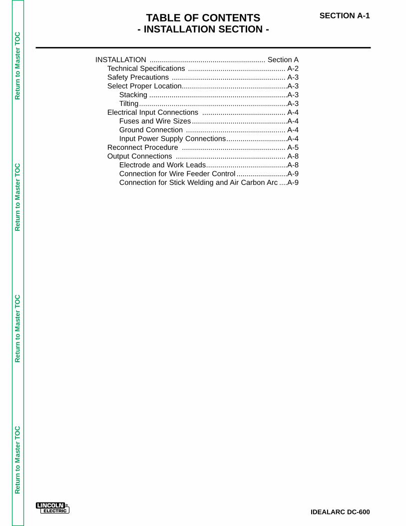
TABLE OF CONTENTS- INSTALLATION SECTION -
INSTALLATION ......................................................... Section ATechnical Specifications ................................................ A-2Safety Precautions ........................................................ A-3Select Proper Location....................................................A-3
Stacking ....................................................................A-3Tilting.........................................................................A-3
Electrical Input Connections ......................................... A-4Fuses and Wire Sizes ...............................................A-4Ground Connection ................................................. A-4Input Power Supply Connections..............................A-4
Reconnect Procedure ................................................... A-5Output Connections ...................................................... A-8
Electrode and Work Leads........................................A-8Connection for Wire Feeder Control .........................A-9Connection for Stick Welding and Air Carbon Arc ....A-9
Ret
urn
to M
aste
r T
OC
Ret
urn
to M
aste
r T
OC
Ret
urn
to M
aste
r T
OC
Ret
urn
to M
aste
r T
OC
Ret
urn
to S
ectio
n T
OC
Ret
urn
to S
ectio
n T
OC
Ret
urn
to S
ectio
n T
OC
Ret
urn
to S
ectio
n T
OC
Ret
urn
to M
aste
r T
OC
Ret
urn
to M
aste
r T
OC
Ret
urn
to M
aste
r T
OC
Ret
urn
to M
aste
r T
OC
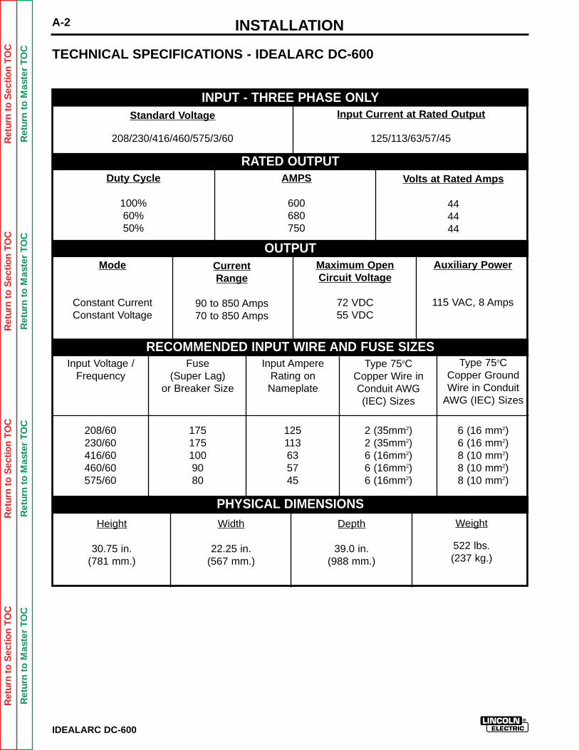
INSTALLATIONA-2
Weight
522 lbs.(237 kg.)
INPUT - THREE PHASE ONLY
RATED OUTPUT
OUTPUT
RECOMMENDED INPUT WIRE AND FUSE SIZES
PHYSICAL DIMENSIONS
Standard Voltage
Duty Cycle
100%60%50%
Mode
Constant CurrentConstant Voltage
Auxiliary Power
115 VAC, 8 Amps
CurrentRange
90 to 850 Amps70 to 850 Amps
Input Voltage /Frequency
Fuse(Super Lag)
or Breaker Size
Input AmpereRating onNameplate
2 (35mm2)2 (35mm2)6 (16mm2)6 (16mm2)6 (16mm2)
6 (16 mm2)6 (16 mm2)8 (10 mm2)8 (10 mm2)8 (10 mm2)
208/60230/60416/60460/60575/60
1751751009080
125113635745
Type 75oCCopper Wire inConduit AWG(IEC) Sizes
Type 75oCCopper GroundWire in Conduit
AWG (IEC) Sizes
Depth
39.0 in.(988 mm.)
Width
22.25 in.(567 mm.)
Height
30.75 in.(781 mm.)
Maximum OpenCircuit Voltage
72 VDC55 VDC
AMPS
600680750
Volts at Rated Amps
444444
Input Current at Rated Output
208/230/416/460/575/3/60 125/113/63/57/45
TECHNICAL SPECIFICATIONS - IDEALARC DC-600
IDEALARC DC-600
Ret
urn
to S
ectio
n T
OC
Ret
urn
to S
ectio
n T
OC
Ret
urn
to S
ectio
n T
OC
Ret
urn
to S
ectio
n T
OC
Ret
urn
to M
aste
r T
OC
Ret
urn
to M
aste
r T
OC
Ret
urn
to M
aste
r T
OC
Ret
urn
to M
aste
r T
OC
INSTALLATION A-3
Read entire Installation Section before installingthe IDEALARC DC-600.
SAFETY PRECAUTIONS
ELECTRIC SHOCK CAN KILL.
• Only qualified personnel should installthis machine.
• Turn the input power OFF at the disconnect switch or fuse box beforeworking on the equipment.
• Do not touch electrically hot parts.
• Always connect the IDEALARC DC-600 grounding terminal to a good electrical earth ground.
• Set the IDEALARC DC-600 Power ON/OFF PUSH BUTTON toOFF position when connecting power cord to input power.
__________________
SELECT PROPER LOCATION
Place the IDEALARC DC-600 where clean air canfreely circulate in through the front intake and outthrough the rear louvers. Dirt, dust, or any foreignmaterial that can be drawn into the machine should bekept at a minimum. Not following these precautionscan result in the nuisance shutdown of the machinebecause of excessive operating temperatures.
STACKING
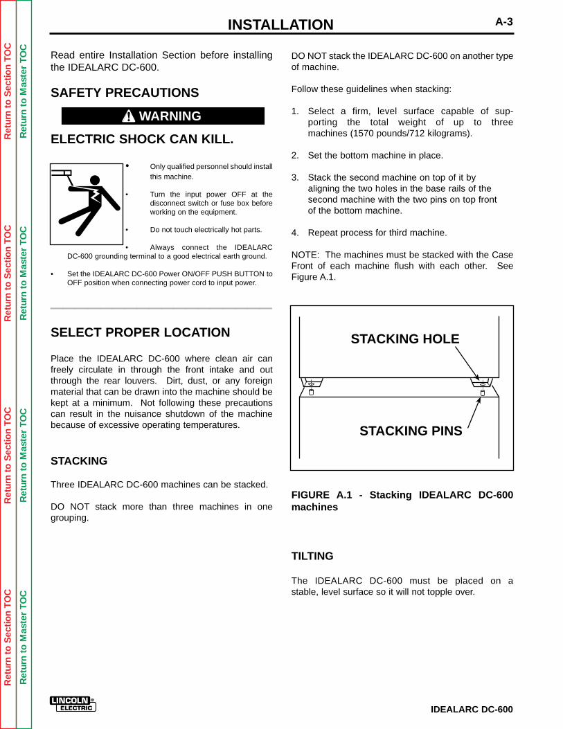
Three IDEALARC DC-600 machines can be stacked.
DO NOT stack more than three machines in onegrouping.
DO NOT stack the IDEALARC DC-600 on another typeof machine.
Follow these guidelines when stacking:
1. Select a firm, level surface capable of sup-porting the total weight of up to three machines (1570 pounds/712 kilograms).
2. Set the bottom machine in place.
3. Stack the second machine on top of it by aligning the two holes in the base rails of the second machine with the two pins on top front of the bottom machine.
4. Repeat process for third machine.
NOTE: The machines must be stacked with the CaseFront of each machine flush with each other. SeeFigure A.1.
FIGURE A.1 - Stacking IDEALARC DC-600machines
TILTING
The IDEALARC DC-600 must be placed on a stable, level surface so it will not topple over.
STACKING HOLE
STACKING PINS
IDEALARC DC-600
WARNING
Ret
urn
to S
ectio
n T
OC
Ret
urn
to S
ectio
n T
OC
Ret
urn
to S
ectio
n T
OC
Ret
urn
to S
ectio
n T
OC
Ret
urn
to M
aste
r T
OC
Ret
urn
to M
aste
r T
OC
Ret
urn
to M
aste
r T
OC
Ret
urn
to M
aste
r T
OC
INSTALLATIONA-4
IDEALARC DC-600
ELECTRICAL INPUT CONNECTIONS
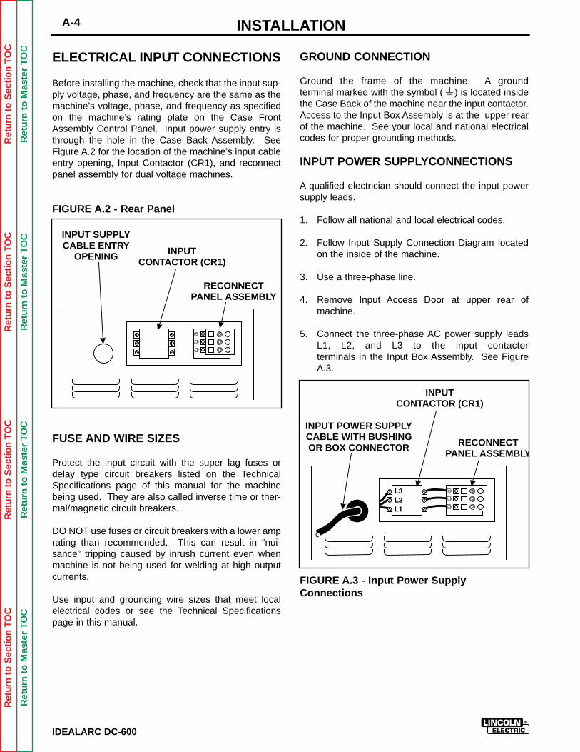
Before installing the machine, check that the input sup-ply voltage, phase, and frequency are the same as themachine’s voltage, phase, and frequency as specifiedon the machine’s rating plate on the Case FrontAssembly Control Panel. Input power supply entry isthrough the hole in the Case Back Assembly. SeeFigure A.2 for the location of the machine’s input cableentry opening, Input Contactor (CR1), and reconnectpanel assembly for dual voltage machines.
FIGURE A.2 - Rear Panel
FUSE AND WIRE SIZES
Protect the input circuit with the super lag fuses ordelay type circuit breakers listed on the TechnicalSpecifications page of this manual for the machinebeing used. They are also called inverse time or ther-mal/magnetic circuit breakers.
DO NOT use fuses or circuit breakers with a lower amprating than recommended. This can result in “nui-sance” tripping caused by inrush current even whenmachine is not being used for welding at high outputcurrents.
Use input and grounding wire sizes that meet localelectrical codes or see the Technical Specificationspage in this manual.
GROUND CONNECTION
Ground the frame of the machine. A ground terminal marked with the symbol ( ) is located insidethe Case Back of the machine near the input contactor.Access to the Input Box Assembly is at the upper rearof the machine. See your local and national electricalcodes for proper grounding methods.
INPUT POWER SUPPLYCONNECTIONS
A qualified electrician should connect the input powersupply leads.
1. Follow all national and local electrical codes.
2. Follow Input Supply Connection Diagram locatedon the inside of the machine.
3. Use a three-phase line.
4. Remove Input Access Door at upper rear ofmachine.
5. Connect the three-phase AC power supply leadsL1, L2, and L3 to the input contactorterminals in the Input Box Assembly. See FigureA.3.
FIGURE A.3 - Input Power SupplyConnections
INPUT SUPPLYCABLE ENTRY
OPENING INPUTCONTACTOR (CR1)
RECONNECTPANEL ASSEMBLY
INPUT POWER SUPPLYCABLE WITH BUSHINGOR BOX CONNECTOR
INPUTCONTACTOR (CR1)
RECONNECTPANEL ASSEMBLY
INSTALLATION A-5
IDEALARC DC-600
Ret
urn
to S
ectio
n T
OC
Ret
urn
to S
ectio
n T
OC
Ret
urn
to S
ectio
n T
OC
Ret
urn
to S
ectio
n T
OC
Ret
urn
to M
aste
r T
OC
Ret
urn
to M
aste
r T
OC
Ret
urn
to M
aste
r T
OC
Ret
urn
to M
aste
r T
OC
RECONNECT PROCEDURE
Multiple voltage machines are shipped connected tothe highest input voltage listed on the machine’s ratingplate. Before installing the machine, check that theReconnect Panel in the Input Box Assembly is con-nected for the proper voltage.
Failure to follow these instructions can cause immedi-ate failure of components within the machine.
__________________
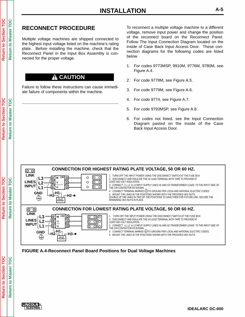
To reconnect a multiple voltage machine to a differentvoltage, remove input power and change the positionof the reconnect board on the Reconnect Panel.Follow The Input Connection Diagram located on theinside of Case Back Input Access Door. These con-nection diagrams for the following codes are listedbelow.
1. For codes 9773MSP, 9910M, 9776M, 9780M, seeFigure A.4.
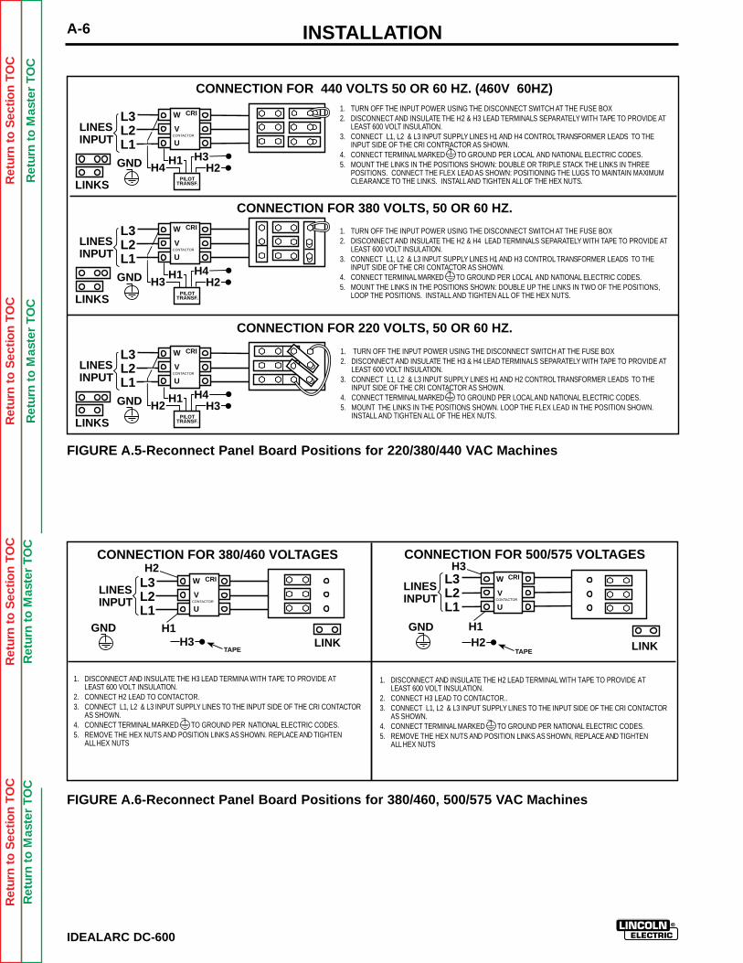
2. For code 9778M, see Figure A.5.
3. For code 9779M, see Figure A.6.
4. For code 9774, see Figure A.7.
5. For code 9793MSP, see Figure A.8.
6. For codes not listed, see the Input ConnectionDiagram pasted on the inside of the Case Back Input Access Door.
L3 L2 L1
LINK
LINES INPUT
GND H2H1
H3
L3 L2 L1
LINK
LINES INPUT
H3H1
H2GND
W
V
U
W
V
U
CONTACTOR
CRI
CRI
CONNECTION FOR HIGHEST RATING PLATE VOLTAGE, 50 OR 60 HZ.
CONNECTION FOR LOWEST RATING PLATE VOLTAGE, 50 OR 60 HZ.
CTOR
1. TURN OFF THE INPUT POWER USING THE DISCONNECT SWITCH AT THE FUSE BOX 2. DISCONNECT AND INSULATE THE H2 LEAD TERMINAL WITH TAPE TO PROVIDE AT LEAST 600 VOLT INSULATION. 3. CONNECT L1, L2 & L3 INPUT SUPPLY LINES H1 AND H3 TRANSFORMER LEADS TO THE INPUT SIDE OF THE CRI CONTACTOR AS SHOWN. 4. CONNECT TERMINAL MARKED TO GROUND PER LOCAL AND NATIONAL ELECTRIC CODES. 5. MOUNT THE LINKS IN THE POSITIONS SHOWN WITH THE PROVIDED HEX NUTS, DOUBLE UP THE LINKS IN TWO OF THE POSITIONS TO SAVE THEM FOR FUTURE USE. SECURE THE REMAINING HEX NUTS IN PLACE.
1. TURN OFF THE INPUT POWER USING THE DISCONNECT SWITCH AT THE FUSE BOX 2. DISCONNECT AND INSULATE THE H3 LEAD TERMINAL WITH TAPE TO PROVIDE AT LEAST 600 VOLT INSULATION. 3. CONNECT L1, L2 & L3 INPUT SUPPLY LINES H1 AND H2 TRANSFORMER LEADS TO THE INPUT SIDE OF THE CRI CONTACTOR AS SHOWN. 4. CONNECT TERMINAL MARKED TO GROUND PER LOCAL AND NATIONAL ELECTRIC CODES. 5. MOUNT THE LINKS IN THE POSITIONS SHOWN WITH THE PROVIDED HEX NUTS.
PILOT TRANSF.
PILOT TRANSF.
FIGURE A.4-Reconnect Panel Board Positions for Dual Voltage Machines
CAUTION
Ret
urn
to S
ectio
n T
OC
Ret
urn
to S
ectio
n T
OC
Ret
urn
to S
ectio
n T
OC
Ret
urn
to S
ectio
n T
OC
Ret
urn
to M
aste
r T
OC
Ret
urn
to M
aste
r T
OC
Ret
urn
to M
aste
r T
OC
Ret
urn
to M
aste
r T
OC
INSTALLATIONA-6
IDEALARC DC-600
CONNECTION FOR 380 VOLTS, 50 OR 60 HZ.
CONNECTION FOR 440 VOLTS 50 OR 60 HZ. (460V 60HZ)1. TURN OFF THE INPUT POWER USING THE DISCONNECT SWITCH AT THE FUSE BOX2. DISCONNECT AND INSULATE THE H2 & H3 LEAD TERMINALS SEPARATELY WITH TAPE TO PROVIDE AT
LEAST 600 VOLT INSULATION.3. CONNECT L1, L2 & L3 INPUT SUPPLY LINES H1 AND H4 CONTROL TRANSFORMER LEADS TO THE
INPUT SIDE OF THE CRI CONTRACTOR AS SHOWN.4. CONNECT TERMINAL MARKED TO GROUND PER LOCAL AND NATIONAL ELECTRIC CODES.5. MOUNT THE LINKS IN THE POSITIONS SHOWN: DOUBLE OR TRIPLE STACK THE LINKS IN THREE
POSITIONS. CONNECT THE FLEX LEAD AS SHOWN: POSITIONING THE LUGS TO MAINTAIN MAXIMUMCLEARANCE TO THE LINKS. INSTALL AND TIGHTEN ALL OF THE HEX NUTS.
1. TURN OFF THE INPUT POWER USING THE DISCONNECT SWITCH AT THE FUSE BOX2. DISCONNECT AND INSULATE THE H2 & H4 LEAD TERMINALS SEPARATELY WITH TAPE TO PROVIDE AT
LEAST 600 VOLT INSULATION.3. CONNECT L1, L2 & L3 INPUT SUPPLY LINES H1 AND H3 CONTROL TRANSFORMER LEADS TO THE
INPUT SIDE OF THE CRI CONTACTOR AS SHOWN.4. CONNECT TERMINAL MARKED TO GROUND PER LOCAL AND NATIONAL ELECTRIC CODES.5. MOUNT THE LINKS IN THE POSITIONS SHOWN: DOUBLE UP THE LINKS IN TWO OF THE POSITIONS,
LOOP THE POSITIONS. INSTALL AND TIGHTEN ALL OF THE HEX NUTS.
L3L2L1
LINKS
LINESINPUT
H4H1
H2GND
W
V
UCONTACTOR
CRI
H3
L3L2L1
LINKS
LINESINPUT
H3H1
H2GND
W
V
UCONTACTOR
CRI
H4
L3L2L1
LINKS
LINESINPUT
H2H1
H3GND
W
V
UCONTACTOR
CRI
H4
1. TURN OFF THE INPUT POWER USING THE DISCONNECT SWITCH AT THE FUSE BOX2. DISCONNECT AND INSULATE THE H3 & H4 LEAD TERMINALS SEPARATELY WITH TAPE TO PROVIDE AT
LEAST 600 VOLT INSULATION.3. CONNECT L1, L2 & L3 INPUT SUPPLY LINES H1 AND H2 CONTROL TRANSFORMER LEADS TO THE
INPUT SIDE OF THE CRI CONTACTOR AS SHOWN.4. CONNECT TERMINAL MARKED TO GROUND PER LOCAL AND NATIONAL ELECTRIC CODES.5. MOUNT THE LINKS IN THE POSITIONS SHOWN. LOOP THE FLEX LEAD IN THE POSITION SHOWN.
INSTALL AND TIGHTEN ALL OF THE HEX NUTS.
CONNECTION FOR 220 VOLTS, 50 OR 60 HZ.
PILOTTRANSF.
PILOTTRANSF.
PILOTTRANSF.
FIGURE A.5-Reconnect Panel Board Positions for 220/380/440 VAC Machines
FIGURE A.6-Reconnect Panel Board Positions for 380/460, 500/575 VAC Machines
CONNECTION FOR 380/460 VOLTAGES
1. DISCONNECT AND INSULATE THE H2 LEAD TERMINAL WITH TAPE TO PROVIDE ATLEAST 600 VOLT INSULATION.
2. CONNECT H3 LEAD TO CONTACTOR..3. CONNECT L1, L2 & L3 INPUT SUPPLY LINES TO THE INPUT SIDE OF THE CRI CONTACTOR
AS SHOWN.4. CONNECT TERMINAL MARKED TO GROUND PER NATIONAL ELECTRIC CODES.5. REMOVE THE HEX NUTS AND POSITION LINKS AS SHOWN, REPLACE AND TIGHTEN
ALL HEX NUTS
L3L2L1
LINK
LINESINPUT
H2
H3GND
W
V
UCONTACTOR
CRI L3L2L1
LINK
LINESINPUT
GNDH2
W
V
U
CRI
CONTACTOR
H1
TAPE
CONNECTION FOR 500/575 VOLTAGESH3
H1
1. DISCONNECT AND INSULATE THE H3 LEAD TERMINA WITH TAPE TO PROVIDE ATLEAST 600 VOLT INSULATION.
2. CONNECT H2 LEAD TO CONTACTOR.3. CONNECT L1, L2 & L3 INPUT SUPPLY LINES TO THE INPUT SIDE OF THE CRI CONTACTOR
AS SHOWN.4. CONNECT TERMINAL MARKED TO GROUND PER NATIONAL ELECTRIC CODES.5. REMOVE THE HEX NUTS AND POSITION LINKS AS SHOWN. REPLACE AND TIGHTEN
ALL HEX NUTS
TAPE
INSTALLATION A-7
IDEALARC DC-600
Ret
urn
to S
ectio
n T
OC
Ret
urn
to S
ectio
n T
OC
Ret
urn
to S
ectio
n T
OC
Ret
urn
to S
ectio
n T
OC
Ret
urn
to M
aste
r T
OC
Ret
urn
to M
aste
r T
OC
Ret
urn
to M
aste
r T
OC
Ret
urn
to M
aste
r T
OC
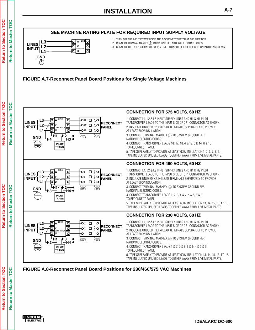
FIGURE A.7-Reconnect Panel Board Positions for Single Voltage Machines
L3L2L1
LINESINPUT
GND
SEE MACHINE RATING PLATE FOR REQUIRED INPUT SUPPLY VOLTAGE1. TURN OFF THE INPUT POWER USING THE DISCONNECT SWITCH AT THE FUSE BOX2. CONNECT TERMINAL MARKED TO GROUND PER NATIONAL ELECTRIC CODES.3. CONNECT THE L1, L2, & L3 INPUT SUPPLY LINES TO INPUT SIDE OF THE CRI CONTACTOR AS SHOWN.
W
V
UCONTACTOR
CRI
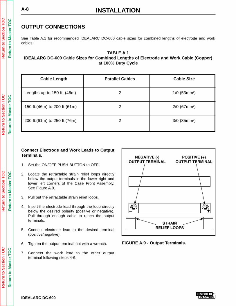
FIGURE A.8-Reconnect Panel Board Positions for 230/460/575 VAC Machines
Ret
urn
to S
ectio
n T
OC
Ret
urn
to S
ectio
n T
OC
Ret
urn
to S
ectio
n T
OC
Ret
urn
to S
ectio
n T
OC
Ret
urn
to M
aste
r T
OC
Ret
urn
to M
aste
r T
OC
Ret
urn
to M
aste
r T
OC
Ret
urn
to M
aste
r T
OC
INSTALLATION
IDEALARC DC-600
A-8
OUTPUT CONNECTIONS
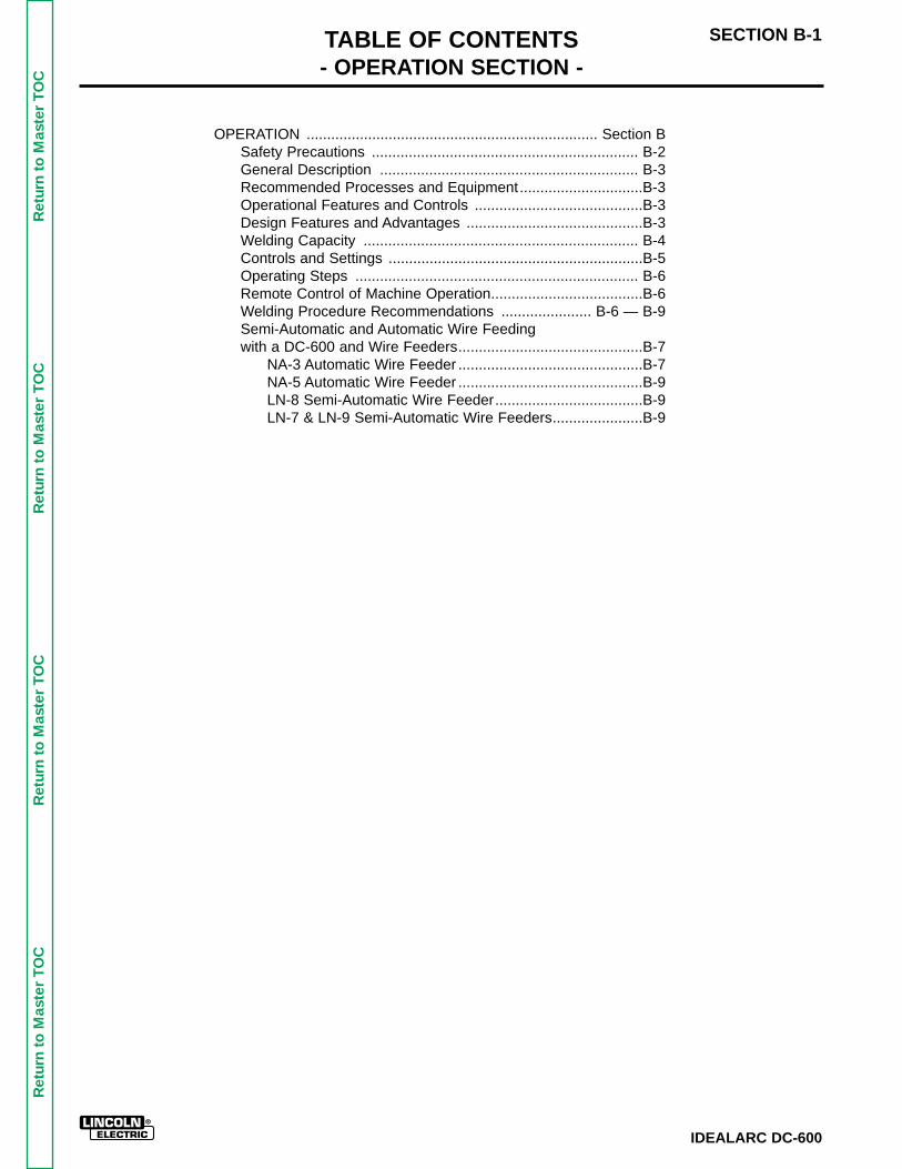
See Table A.1 for recommended IDEALARC DC-600 cable sizes for combined lengths of electrode and workcables.
TABLE A.1IDEALARC DC-600 Cable Sizes for Combined Lengths of Electrode and Work Cable (Copper)
at 100% Duty Cycle
Cable SizeParallel CablesCable Length
1/0 (53mm2)2
2
2
Lengths up to 150 ft. (46m)
2/0 (67mm2)150 ft.(46m) to 200 ft (61m)
3/0 (85mm2)200 ft.(61m) to 250 ft.(76m)
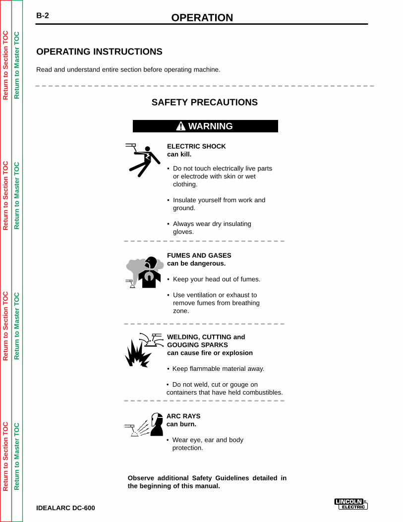
Connect Electrode and Work Leads to OutputTerminals.
1. Set the ON/OFF PUSH BUTTON to OFF.
2. Locate the retractable strain relief loops directlybelow the output terminals in the lower right andlower left corners of the Case Front Assembly.See Figure A.9.
3. Pull out the retractable strain relief loops.
4. Insert the electrode lead through the loop directlybelow the desired polarity (positive or negative).Pull through enough cable to reach the output terminals.
5. Connect electrode lead to the desired terminal(positive/negative).
6. Tighten the output terminal nut with a wrench.
7. Connect the work lead to the other output terminal following steps 4-6.
FIGURE A.9 - Output Terminals.

INSTALLATION A-9
IDEALARC DC-600
Ret
urn
to S
ectio
n T
OC
Ret
urn
to S
ectio
n T
OC
Ret
urn
to S
ectio
n T
OC
Ret
urn
to S
ectio
n T
OC
Ret
urn
to M
aste
r T
OC
Ret
urn
to M
aste
r T
OC
Ret
urn
to M
aste
r T
OC
Ret
urn
to M
aste
r T
OC
1. Set ON/OFF PUSH BUTTON to OFF.
2. Locate and open the hinged access door on theFront Case Assembly.
3. If necessary, disconnect all wire feeder controlcable connections from the DC-600 terminal strip.
4. Remove the leads from the unit by pulling themthrough and out of the strain relief loops.
5. Connect a jumper wire from terminal #2 to terminal#4 on the terminal strip.
6. Set the Welding Mode Switch to the VV position forboth stick welding and air/carbon arc cutting.
NOTE: To use the IDEALARC DC-600 for both stickwelding / air/carbon arc cutting, AND semi-automatic /automatic welding, the optional Multi-Process Switch(K804) must be used. See the ACCESSORIESSection of this manual for instructions on installing andusing the Multi-Process Switch. When the Multi-Process Switch is not used, all control, work, and elec-trode leads from semi-automatic or automatic wirefeeders must be disconnected from the IDEALARCDC-600 before connecting the machine for stick weld-ing or air/carbon arc cutting.
Connection For Semi-Automatic or AutomaticWire Feeder Control
NOTE: See the ACCESSORIES Section of this manu-al for specific instructions on connecting the followingsemi-automatic and automatic wire feeders:
• LN-7• LN-8• LN-9
• NA-3• NA-5
• LT-7• LT-56
Connection for Stick Welding and Air/CarbonArc Cutting Operation
THE OUTPUT TERMINALS ARE ENERGIZED AT ALLTIMES WHEN THE IDEALARC DC-600 IS CON-NECTED FOR STICK WELDING AND AIR/CARBONARC CUTTING.
__________________
}Semi-Automatic Wire Feeders
}Automatic Wire Feeders
}Tractors
WARNING
OPERATION ....................................................................... Section BSafety Precautions ................................................................. B-2General Description ............................................................... B-3Recommended Processes and Equipment..............................B-3Operational Features and Controls .........................................B-3Design Features and Advantages ...........................................B-3Welding Capacity ................................................................... B-4Controls and Settings ..............................................................B-5Operating Steps ..................................................................... B-6Remote Control of Machine Operation.....................................B-6Welding Procedure Recommendations ...................... B-6 — B-9Semi-Automatic and Automatic Wire Feeding with a DC-600 and Wire Feeders.............................................B-7
NA-3 Automatic Wire Feeder .............................................B-7NA-5 Automatic Wire Feeder .............................................B-9LN-8 Semi-Automatic Wire Feeder....................................B-9LN-7 & LN-9 Semi-Automatic Wire Feeders......................B-9
TABLE OF CONTENTS- OPERATION SECTION -
SECTION B-1
IDEALARC DC-600
Ret
urn
to M
aste
r T
OC
Ret
urn
to M
aste
r T
OC
Ret
urn
to M
aste
r T
OC
Ret
urn
to M
aste
r T
OC
OPERATIONB-2
IDEALARC DC-600
Ret
urn
to S
ectio
n T
OC
Ret
urn
to S
ectio
n T
OC
Ret
urn
to S
ectio
n T
OC
Ret
urn
to S
ectio
n T
OC
Ret
urn
to M
aste
r T
OC
Ret
urn
to M
aste
r T
OC
Ret
urn
to M
aste
r T
OC
Ret
urn
to M
aste
r T
OC
ELECTRIC SHOCKcan kill.
• Do not touch electrically live partsor electrode with skin or wetclothing.
• Insulate yourself from work andground.
• Always wear dry insulating gloves.
FUMES AND GASEScan be dangerous.
• Keep your head out of fumes.
• Use ventilation or exhaust toremove fumes from breathingzone.
WELDING, CUTTING and GOUGING SPARKScan cause fire or explosion
• Keep flammable material away.
• Do not weld, cut or gouge oncontainers that have held combustibles.
ARC RAYScan burn.
• Wear eye, ear and bodyprotection.
OPERATING INSTRUCTIONS
Read and understand entire section before operating machine.
SAFETY PRECAUTIONS
Observe additional Safety Guidelines detailed inthe beginning of this manual.
WARNING
OPERATION B-3
IDEALARC DC-600
Ret
urn
to S
ectio
n T
OC
Ret
urn
to S
ectio
n T
OC
Ret
urn
to S
ectio
n T
OC
Ret
urn
to S
ectio
n T
OC
Ret
urn
to M
aste
r T
OC
Ret
urn
to M
aste
r T
OC
Ret
urn
to M
aste
r T
OC
Ret
urn
to M
aste
r T
OC
GENERAL DESCRIPTION
The IDEALARC DC-600 is an SCR controlled threephase welding and cutting power source. It uses a sin-gle range potentiometer to control:
• Submerged Arc Semi-Automatic or AutomaticWelding
• Open Arc Semi-Automatic or Automatic Welding• Stick Welding (Standard on All Machines)• Air/Carbon Arc Cutting (Carbon Rod Sizes up to
3/8” Diameter)
The IDEALARC DC-600 has a three-position WeldingMode Switch to enable the user to operate in one ofthree modes:
• Constant Voltage (CV) Innershield• Constant Voltage (CV) Submerged Arc• Variable Voltage (VV - Constant Current)
Submerged Arc
The IDEALARC DC-600 can be easily connected towire feeding equipment, including:
• Semi-automatic wire feeders LN-7, LN-8, and LN-9
• Automatic wire feeders NA-3 and NA-5• Tractors LT-56 and LT-7
The optional Multi-Process Switch allows the user toswitch between semi-automatic or automatic weldingand stick welding or air/carbon arc cutting without dis-connecting the wire feeder equipment control, elec-trode, and work leads.
RECOMMENDED PROCESSES ANDEQUIPMENT
The IDEALARC DC-600 is recommended for the fol-lowing welding or cutting processes within its outputcapacity of 70 amps to 850 amps in the ConstantVoltage mode and 90 amps to 850 amps in theVariable Voltage (Constant Current) mode:
• Submerged Arc Semi-Automatic or AutomaticWelding
• Open Arc Semi-Automatic or Automatic Welding• Stick Welding (Standard on All Machines)• Air/Carbon Arc Cutting (Carbon Rod Sizes up to
3/8” Diameter)
OPERATIONAL FEATURES ANDCONTROLS
The IDEALARC DC-600 comes with the following standard controls:
• ON/OFF PUSH BUTTON• OUTPUT CONTROL POTENTIOMETER• OUTPUT CONTROL SWITCH (Remote or
Machine Control)• WELDING MODE SWITCH• CONTROL CIRCUIT POLARITY SWITCH• POWER SOURCE PILOT LIGHT• DC AMMETER (OPTIONAL)• DC VOLTMETER (OPTIONAL)
DESIGN FEATURES AND ADVANTAGES
The following list of design features will help youunderstand the machine’s total capabilities and howyou can take advantage of them to get maximum useof your machine.
• Excellent arc characteristics for optimum constantvoltage submerged arc and Innershield weldingperformance.
• A control circuit designed to provide good startingfor a large variety of processes and procedures.
• Output Control Potentiometer that provides easysingle range continuous control.
• Output Control Switch that provides simple switch-ing from local to remote control.
• Red neon pilot light to confirm that the InputContactor is energized.
OPERATIONB-4
IDEALARC DC-600
Ret
urn
to S
ectio
n T
OC
Ret
urn
to S
ectio
n T
OC
Ret
urn
to S
ectio
n T
OC
Ret
urn
to S
ectio
n T
OC
Ret
urn
to M
aste
r T
OC
Ret
urn
to M
aste
r T
OC
Ret
urn
to M
aste
r T
OC
Ret
urn
to M
aste
r T
OC
Duty Cycle
50%(Based on 10 min.)
750
680
600
44
44
44
50/60
50/60
50/60
60%(Based on 10 min.)
100%
Amps Volts Hertz
• Auxiliary power source to provide 115-volt ACpower (1000 VA) to wire feeding equipment.
• Multi-functional terminal strip for easy connectionof wire feeding control cables and switchingbetween CV Innershield and CV Submerged Arcwelding when using the Dual Process or DualProcedure Kits.
• Recessed output terminals to avoid any person orobject from accidentally coming into contact withthe output terminals and labeled positive and neg-ative for easy identification.
• Thermostatically protected power source.• Electronic protection circuit to protect power
source against overloads.• Input line voltage compensation to provide an
essentially constant output.• SCR electronically controlled welder output pro-
vides extra long life, especially for highly repetitivewelding applications.
• Three circuit solid state control system providesmaximum performance and circuit protection.
• Low profile case provides maximum use of space.• Convenient access to all controls.• Output lead strain relief loops to prevent terminal
and cable damage.• Easily removed case side, even when stacked.• Outdoor operation because enclosure is designed
with air intake louvers that keep dripping waterfrom entering the unit. Transformer, SCR bridge,and choke have special corrosion resistant paintfor added protection.
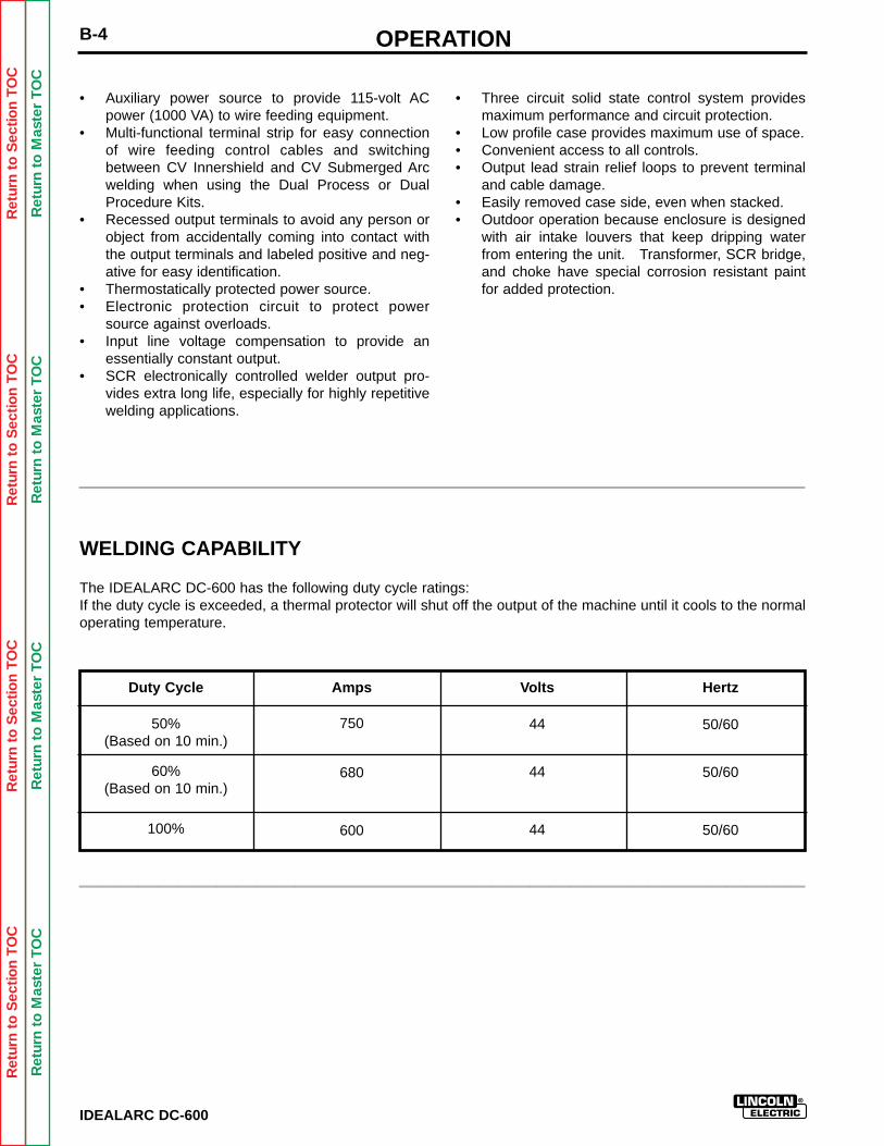
WELDING CAPABILITY
The IDEALARC DC-600 has the following duty cycle ratings:If the duty cycle is exceeded, a thermal protector will shut off the output of the machine until it cools to the normaloperating temperature.
_____________________________________
_____________________________________
OPERATION B-5
IDEALARC DC-600
Ret
urn
to S
ectio
n T
OC
Ret
urn
to S
ectio
n T
OC
Ret
urn
to S
ectio
n T
OC
Ret
urn
to S
ectio
n T
OC
Ret
urn
to M
aste
r T
OC
Ret
urn
to M
aste
r T
OC
Ret
urn
to M
aste
r T
OC
Ret
urn
to M
aste
r T
OC CONTROLS AND SETTINGS
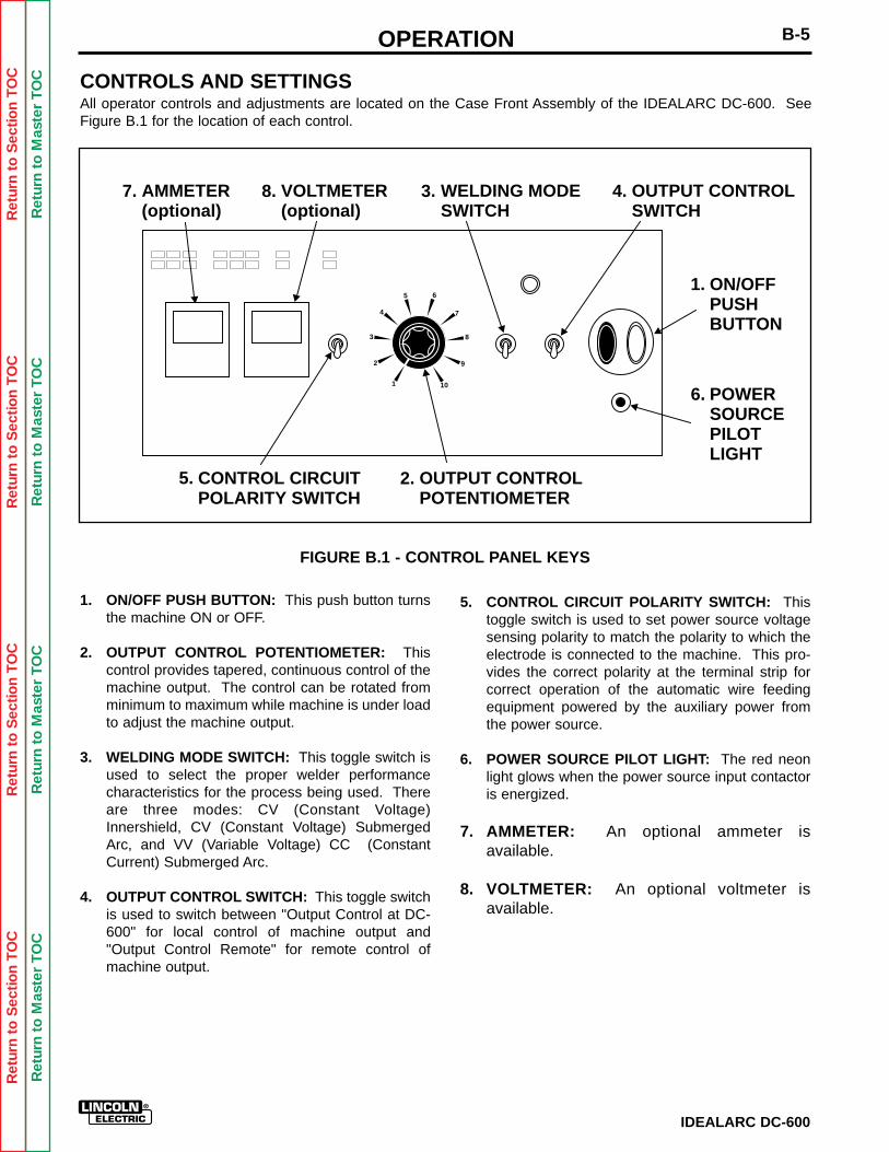
All operator controls and adjustments are located on the Case Front Assembly of the IDEALARC DC-600. SeeFigure B.1 for the location of each control.
FIGURE B.1 - CONTROL PANEL KEYS
1. ON/OFF PUSH BUTTON: This push button turnsthe machine ON or OFF.
2. OUTPUT CONTROL POTENTIOMETER: Thiscontrol provides tapered, continuous control of themachine output. The control can be rotated fromminimum to maximum while machine is under loadto adjust the machine output.
3. WELDING MODE SWITCH: This toggle switch isused to select the proper welder performancecharacteristics for the process being used. Thereare three modes: CV (Constant Voltage)Innershield, CV (Constant Voltage) SubmergedArc, and VV (Variable Voltage) CC (ConstantCurrent) Submerged Arc.
4. OUTPUT CONTROL SWITCH: This toggle switchis used to switch between "Output Control at DC-600" for local control of machine output and"Output Control Remote" for remote control ofmachine output.
5. CONTROL CIRCUIT POLARITY SWITCH: Thistoggle switch is used to set power source voltagesensing polarity to match the polarity to which theelectrode is connected to the machine. This pro-vides the correct polarity at the terminal strip forcorrect operation of the automatic wire feedingequipment powered by the auxiliary power fromthe power source.
6. POWER SOURCE PILOT LIGHT: The red neonlight glows when the power source input contactoris energized.
7. AMMETER: An optional ammeter is available.
8. VOLTMETER: An optional voltmeter is available.
1
2
3
4
5 6
7
8
9
10
ON/OFFPUSHBUTTON
1.
6.
2.5.
3. 4.7.
OUTPUT CONTROLPOTENTIOMETER
WELDING MODESWITCH
POWERSOURCEPILOTLIGHT
OUTPUT CONTROLSWITCH
AMMETER(optional)
8. VOLTMETER(optional)
CONTROL CIRCUITPOLARITY SWITCH
OPERATIONB-6
IDEALARC DC-600
Ret
urn
to S
ectio
n T
OC
Ret
urn
to S
ectio
n T
OC
Ret
urn
to S
ectio
n T
OC
Ret
urn
to S
ectio
n T
OC
Ret
urn
to M
aste
r T
OC
Ret
urn
to M
aste
r T
OC
Ret
urn
to M
aste
r T
OC
Ret
urn
to M
aste
r T
OC
OPERATING STEPS
The following procedures are for using the IDEAL-ARC DC-600 in the local control mode of operation.For remote control of the machine, see the RemoteControl of Machine Operation section.
Before operating the machine, make sure you have allmaterials needed to complete the job. Be sure you arefamiliar with and have taken all possible safety pre-cautions before starting work. It is important that youfollow these operating steps each time you use themachine.
1. Turn on the main AC power supply to the machine.
2. Set the CONTROL CIRCUIT POLARITY SWITCHto the appropriate position.- Set toggle to "Electrode Negative" position if theelectrode is connected to the negative (-) outputterminal.- Set toggle to "Electrode Positive" position if theelectrode is connected to the positive (+) outputterminal.
3. Set the WELDING MODE SWITCH to weldingprocess being used.- CV Innershield- CV Submerged Arc- VV (CC)
4. Push the ON/OFF PUSH BUTTON to the ON posi-tion- The red neon light glows.- The fan starts.
5. Set Output Control Potentiometer to desired volt-age or current.
6. Make the weld (NOTE: Terminal #2 and #4 mustbe connected together to energize the machine output).
REMOTE CONTROL OF MACHINEOPERATION
The toggle switch on the control panel labeled “OutputControl at DC-600” — “Output Control Remote” givesthe operator the option of controlling the machine out-put from a remote location. If in the Remote position awire feeder with remote control capabilities or a remotecontrol device such as a K775 must be connected toterminals 75, 76, and 77. Refer to Accessories Sectionfor wire feeder remote information.
WELDING PROCEDURE RECOMMENDATIONS
Select Welding Mode Switch position based on type ofwelding to be done.
1. Innershield Welding/Other Open Arc Processes:Use the CV Innershield mode.
2. Submerged Arc Welding: Use the CV SubmergedArc mode. If performing high speed welding,switch between the CV Submerged Arc and the CVInnershield mode and use the mode that producesthe best welding results.
3. Air/Carbon Arc Cutting / Stick Welding / HighCurrent, Large Puddle Submerged Arc Welding:Use the VV (CC) mode. When the IDEALARC DC-600 is used for Air/Carbon Arc cutting, the OUT-PUT CONTROL POTENTIOMETER should be setto "9" initially. Based on the size of the carbonbeing used or the process, turn the potentiometerto a lower setting as required by the process. Youcan use carbon rods up to 3/8" in diameter at cur-rents as high as 750 amps with excellent arc con-trol. The welder protection circuit protects themachine from extremely high short circuiting pulses.
Ret
urn
to S
ectio
n T
OC
Ret
urn
to S
ectio
n T
OC
Ret
urn
to S
ectio
n T
OC
Ret
urn
to S
ectio
n T
OC
Ret
urn
to M
aste
r T
OC
Ret
urn
to M
aste
r T
OC
Ret
urn
to M
aste
r T
OC
Ret
urn
to M
aste
r T
OC
OPERATION B-7
IDEALARC DC-600
SEMI-AUTOMATIC ANDAUTOMATIC WIRE FEEDING WITHA IDEALARC DC-600 AND WIREFEEDERS
When using the IDEALARC DC-600 with semi-auto-matic or automatic wire feeding equipment and forstick welding or air/carbon arc cutting, it is recom-mended that the optional MULTI-PROCESS SWITCHbe used. This switch permits you to easily change thepolarity of the connected wire feeding equipment orswitch to stick welding or air/carbon arc cutting.
NA-3 AUTOMATIC WIRE FEEDER
1. Set the DC-600 Output Control Switch to Remote.NOTE: Later model NA-3 automatic wire feedersare capable of cold starts when the NA-3 Modeswitch is in the CV or VV(CC) mode position.Some earlier models are capable of cold startingonly in the VV(CC) mode position. Cold startingenables you to inch the wire down to the work,automatically stop, and automatically energize theflux hopper valve.
2. Set the DC-600 welding mode switch for thedesired process: CV Submerged Arc, CVInnershield mode or VV(CC) mode.
3. Set the NA-3 mode Switch Position to either CV orVV(CC) to match the DC-600 mode selected instep 2.
4. Refer to the NA-3 operators manual for instruc-tions on how to use the NA-3 in conjunction withthe DC-600.
5. Follow the following guidelines for good arc strikingdetailed below for each welding mode.
GOOD ARC STRIKING GUIDELINES FOR THE NA-3WITH THE IDEALARC DC-600 IN THE CVINNERSHIELD, CV SUBMERGED ARC OR VV(CC)WELDING MODES.
Following are some basic arc striking techniques thatapply to all wire feed processes. Using these proce-dures should provide trouble-free starting. These pro-cedures apply to single, solid wires and Innershieldwires.
1. Cut the electrode to a sharp point.
2. Set the NA-3 Open Circuit Voltage Control to thesame dial setting as the Arc Voltage Control. If thisis a new welding procedure, a good starting pointis to set the Open Circuit Voltage Control to # 6.
NOTE: The open circuit voltage of the IDEALARC DC-600 varies from approximately 16volts to 56 volts in the CV Innershield or CVSubmerged Arc modes. The open circuit voltage isconstant in the VV(CC) mode.
3. Run a test weld. Set proper current, voltage, andtravel speed.
a. For the best starting performance, the NA-3 Open Circuit Voltage Control and VoltageControl setting should be the same. Set theInch Speed Control for the slowest inch speedpossible.
b. To adjust the Open Circuit Voltage Control toget the best starting performance, makerepeated starts observing the NA-3 voltmeter.
When the voltmeter pointer swings smoothly up tothe desired arc voltage, without undershooting orovershooting the desired arc voltage, the OpenCircuit Voltage Control is set properly.
If the voltmeter pointer overshoots the desired volt-age and then returns back to the desired voltage,the Open Circuit Voltage Control is set too high.This can result in a bad start where the wire tendsto "Blast off."
If the voltmeter pointer hesitates before coming upto the desired voltage, the Open Circuit VoltageControl is set too low. This can cause the elec-trode to stub.
4. Start and make the weld.
a. Cold starts. For cold starts, be sure the workpiece is clean and the electrode makes posi-tive contact with the work piece.
b. Hot "On the Fly" starts. For hot starts, travelshould begin before the wire contacts the workpiece.
OPERATIONB-8
IDEALARC DC-600
Ret
urn
to S
ectio
n T
OC
Ret
urn
to S
ectio
n T
OC
Ret
urn
to S
ectio
n T
OC
Ret
urn
to S
ectio
n T
OC
Ret
urn
to M
aste
r T
OC
Ret
urn
to M
aste
r T
OC
Ret
urn
to M
aste
r T
OC
Ret
urn
to M
aste
r T
OC
ARC STRIKING WITH IDEALARC DC-600 AND THENA-3 START BOARD
When electrical strikeouts exceed 1 3/4” (44.4mm) anNA-3 Start Board may be required to improve arc strik-ing.
When the NA-3 Start Board is used to improve arcstriking, use the following procedures:
1. Set start time at 0.
2. Set NA-3 start current and start voltage at mid-range.
3. Set the NA-3 output current and voltage to theproper settings for the welding procedure to beused.
4. Turn the Start Board Timer to maximum.
5. Set Start Board current and voltage control.
a. Set the Start Board current control to 1 1/2 dialnumbers below that set on the NA-3 currentcontrol.
b. Set the Start Board voltage control equal withthe NA-3 voltage control setting.
NOTE: These Start Board current and voltage set-tings result in a start up current that is lower thanthe NA-3 current setting and approximately equalwith the NA-3 voltage setting for the desired weld-ing procedure.
6. Establish the correct arc striking procedure withthe NA-3 Start Board timer set at maximum.
a. For the best starting performance, the NA-3Open Circuit Voltage Control and VoltageControl setting should be the same. Set theInch Speed Control for the slowest inch speedpossible.
b. To adjust the Open Circuit Voltage Control toget the best starting performance, makerepeated starts observing the NA-3 voltmeter.
When the voltmeter pointer swings smoothly up tothe desired arc voltage, without undershooting orovershooting the desired arc voltage, the OpenCircuit Voltage Control is set properly.
If the voltmeter pointer overshoots the desired volt-age and then returns back to the desired voltage,the Open Circuit Voltage Control is set too high.This can result in a bad start where the wire tendsto "Blast off."
If the voltmeter pointer hesitates before coming upto the desired voltage, the Open Circuit VoltageControl is set too low. This can cause the elec-trode to stub.
c. Set NA-3 Start Board current and voltage asclose to the welding procedure current andvoltage as possible.
NOTE: The Start Board current and voltageshould be as close as possible to the welding pro-cedure current and voltage, while still getting satis-factory starts.
d. Set the start time to as low a time as possiblewhile still getting satisfactory starts.
7. Start and make the weld.
OPERATION B-9
IDEALARC DC-600
Ret
urn
to S
ectio
n T
OC
Ret
urn
to S
ectio
n T
OC
Ret
urn
to S
ectio
n T
OC
Ret
urn
to S
ectio
n T
OC
Ret
urn
to M
aste
r T
OC
Ret
urn
to M
aste
r T
OC
Ret
urn
to M
aste
r T
OC
Ret
urn
to M
aste
r T
OC
IDEALARC DC-600 POWER SOURCESETTING WHEN CONNECTED TO NA-5WIRE FEEDER
When using the IDEALARC DC-600 with the NA-5 wirefeeder, set the controls on the IDEALARC DC-600 asfollows for the best performance:
1. Turn OFF main AC input power supply to the IDE-ALARC DC-600.
2. Connect the electrode cables to terminal polarity tobe used.
3. Set the CONTROL CIRCUIT POLARITY SWITCHto the same polarity as the electrode cable con-nection.
4. Set the OUTPUT CONTROL SWITCH toREMOTE.
5. Set the IDEALARC DC-600 WELDING MODESWITCH to the position that matches the weldingprocess being used.
a. For submerged arc welding, set WELDINGMODE SWITCH TO CV SUBMERGED ARCposition.
b. For all open arc welding processes set WELD-ING MODE SWITCH TO CV INNERSHIELDposition.
LN-8 SEMI-AUTOMATIC WIRE FEEDER
To use the LN-8 Semi-Automatic Wire Feeder with IDEALARC DC-600
1. Set the IDEALARC DC-600 WELDING MODESWITCH to either CV Innershield mode or CVSubmerged Arc mode depending on the weldingprocess being used.
2. Set the IDEALARC DC-600 OUTPUTCONTROL SWITCH to the REMOTE position.
3. Set the LN-8 Welding Mode Switch to the CV posi-tion. The LN-8 Welding Mode Switch is located onthe variable voltage (CC) board.
4. Refer to the LN-8 Operator’s Manual for instruc-tions on how to use the LN-8.
LN-7 AND LN-9 SEMI-AUTOMATIC WIREFEEDERS OR OTHER CONSTANT WIREFEEDERS
To use the LN-7, LN-9, or other constant wire feedspeed semi-automatic wire feeders with IDEALARCDC-600
1. Set the IDEALARC DC-600 WELDING MODESWITCH to either CV Innershield mode or CVSubmerged Arc mode depending on the weldingprocess being used.
NOTE: These semi-automatic wire feeders cannotbe used in the VV(CC) mode.
2. Set the IDEALARC DC-600 OUTPUTCONTROL SWITCH.
a. LN-7: Use either an optional K775 RemoteControl Box Assembly or set the IDEALARC DC-600 OUTPUT CONTROLSWITCH in the Local position.
b. LN-9: Refer to the LN-9 Operator’s Manual forinstructions of how to use the LN-9.
ACCESSORIES .................................................................. Section CAccessories.....................................................................C-2Multi-Process Switch ......................................................C-2Undercarriage .................................................................C-4Meters .............................................................................C-4Connections for Wire Feeder Control .............................C-5
NA-3..........................................................................C-5NA-5..........................................................................C-6LN-8 or LN-9 .............................................................C-7LN-7 ..........................................................................C-8
IDEALARC DC-600
Section C-1TABLE OF CONTENTS- ACCESSORIES SECTION -
Ret
urn
to M
aste
r T
OC
Ret
urn
to M
aste
r T
OC
Ret
urn
to M
aste
r T
OC
Ret
urn
to M
aste
r T
OC
ACCESSORIESC-2
IDEALARC DC-600
Ret
urn
to S
ectio
n T
OC
Ret
urn
to S
ectio
n T
OC
Ret
urn
to S
ectio
n T
OC
Ret
urn
to S
ectio
n T
OC
Ret
urn
to M
aste
r T
OC
Ret
urn
to M
aste
r T
OC
Ret
urn
to M
aste
r T
OC
Ret
urn
to M
aste
r T
OC
OPTIONS/ACCESSORIES
• Multi-Process Switch (K804)• Remote Control Box Assembly (K775)• Undercarriages (K817, K817R, K842)
Semi-Automatic and Automatic Wire Feeders• LN-7• LN-8• LN-9
• NA-3• NA-5
MULTI-PROCESS SWITCH
The MULTI-PROCESS SWITCH gives you the abilityto:• Switch between "stick welding or air/carbon arc
cutting" and using a semi-automatic or automaticwire feeder.
• Change the polarity of a semi-automatic or auto-matic wire feeder without changing any electricalcable connections.
See Figure C.1
FIGURE C.1 - MULTI-PROCESS SWITCH
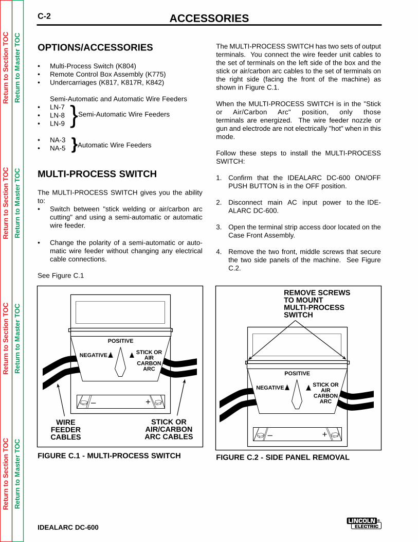
The MULTI-PROCESS SWITCH has two sets of outputterminals. You connect the wire feeder unit cables tothe set of terminals on the left side of the box and thestick or air/carbon arc cables to the set of terminals onthe right side (facing the front of the machine) asshown in Figure C.1.
When the MULTI-PROCESS SWITCH is in the "Stickor Air/Carbon Arc" position, only those terminals are energized. The wire feeder nozzle orgun and electrode are not electrically "hot" when in thismode.
Follow these steps to install the MULTI-PROCESSSWITCH:
1. Confirm that the IDEALARC DC-600 ON/OFFPUSH BUTTON is in the OFF position.
2. Disconnect main AC input power to the IDE-ALARC DC-600.
3. Open the terminal strip access door located on theCase Front Assembly.
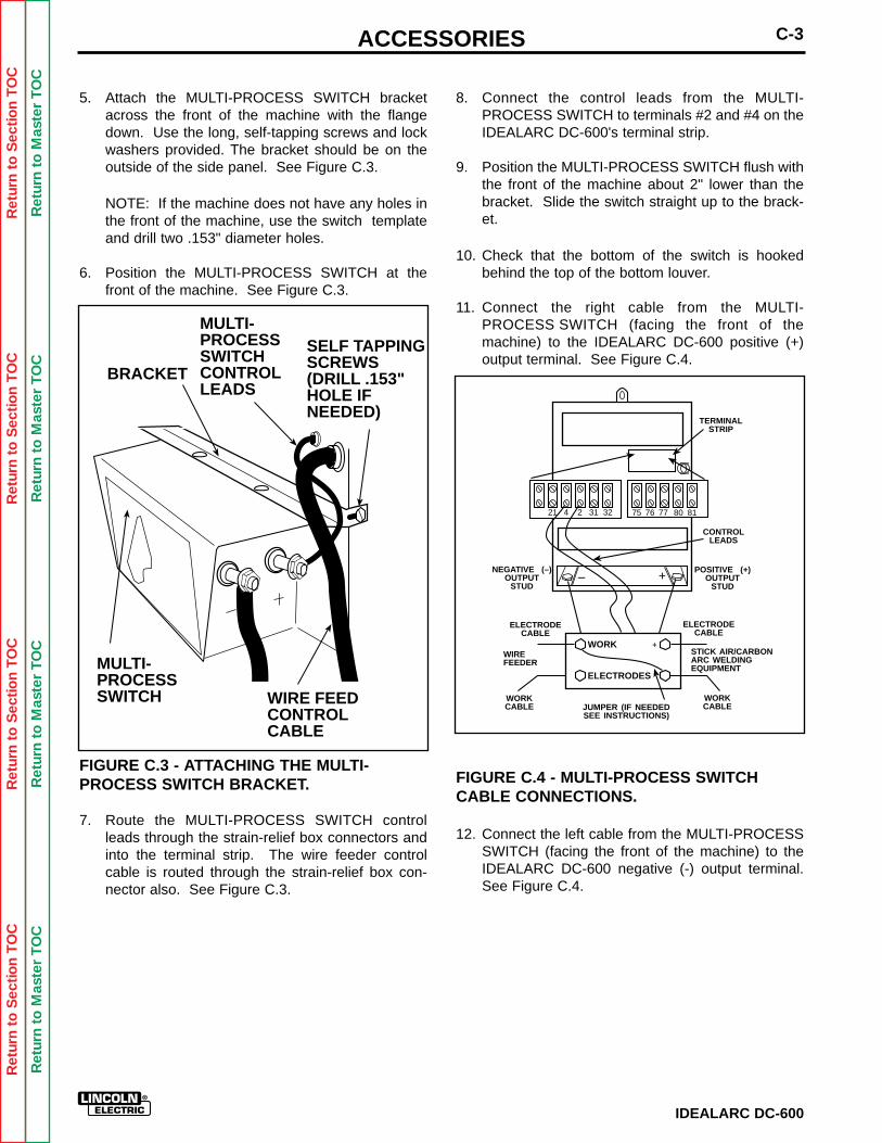
4. Remove the two front, middle screws that securethe two side panels of the machine. See FigureC.2.
FIGURE C.2 - SIDE PANEL REMOVAL
}Semi-Automatic Wire Feeders
}Automatic Wire Feeders
– +
WIREFEEDERCABLES
STICK ORAIR/CARBONARC CABLES
NEGATIVE
POSITIVE
STICK ORAIR
CARBONARC
– +
REMOVE SCREWSTO MOUNTMULTI-PROCESSSWITCH
NEGATIVE
POSITIVE
STICK ORAIR
CARBONARC
ACCESSORIES C-3
IDEALARC DC-600
Ret
urn
to S
ectio
n T
OC
Ret
urn
to S
ectio
n T
OC
Ret
urn
to S
ectio
n T
OC
Ret
urn
to S
ectio
n T
OC
Ret
urn
to M
aste
r T
OC
Ret
urn
to M
aste
r T
OC
Ret
urn
to M
aste
r T
OC
Ret
urn
to M
aste
r T
OC
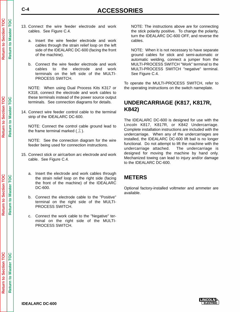
5. Attach the MULTI-PROCESS SWITCH bracketacross the front of the machine with the flangedown. Use the long, self-tapping screws and lockwashers provided. The bracket should be on theoutside of the side panel. See Figure C.3.
NOTE: If the machine does not have any holes inthe front of the machine, use the switch templateand drill two .153" diameter holes.
6. Position the MULTI-PROCESS SWITCH at thefront of the machine. See Figure C.3.
FIGURE C.3 - ATTACHING THE MULTI-PROCESS SWITCH BRACKET.
7. Route the MULTI-PROCESS SWITCH controlleads through the strain-relief box connectors andinto the terminal strip. The wire feeder controlcable is routed through the strain-relief box con-nector also. See Figure C.3.
8. Connect the control leads from the MULTI-PROCESS SWITCH to terminals #2 and #4 on theIDEALARC DC-600's terminal strip.
9. Position the MULTI-PROCESS SWITCH flush withthe front of the machine about 2" lower than thebracket. Slide the switch straight up to the brack-et.
10. Check that the bottom of the switch is hookedbehind the top of the bottom louver.
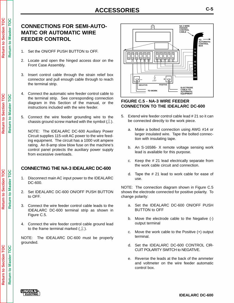
11. Connect the right cable from the MULTI-PROCESS SWITCH (facing the front of themachine) to the IDEALARC DC-600 positive (+)output terminal. See Figure C.4.
FIGURE C.4 - MULTI-PROCESS SWITCHCABLE CONNECTIONS.
12. Connect the left cable from the MULTI-PROCESSSWITCH (facing the front of the machine) to theIDEALARC DC-600 negative (-) output terminal.See Figure C.4.
MULTI-PROCESSSWITCH
BRACKET
WIRE FEEDCONTROLCABLE
MULTI-PROCESSSWITCHCONTROLLEADS
SELF TAPPINGSCREWS(DRILL .153"HOLE IFNEEDED)
WORKCABLE
WORK
ELECTRODES
21 4 2 31 32 75 76 77 80 81
TERMINALSTRIP
POSITIVE (+)OUTPUT
STUD– +
NEGATIVE (–)OUTPUT
STUD
ELECTRODECABLE
WORKCABLE
ELECTRODECABLE
JUMPER (IF NEEDEDSEE INSTRUCTIONS)
+
CONTROLLEADS
STICK AIR/CARBONARC WELDINGEQUIPMENT
WIREFEEDER
ACCESSORIESC-4
IDEALARC DC-600
Ret
urn
to S
ectio
n T
OC
Ret
urn
to S
ectio
n T
OC
Ret
urn
to S
ectio
n T
OC
Ret
urn
to S
ectio
n T
OC
Ret
urn
to M
aste
r T
OC
Ret
urn
to M
aste
r T
OC
Ret
urn
to M
aste
r T
OC
Ret
urn
to M
aste
r T
OC
13. Connect the wire feeder electrode and workcables. See Figure C.4.
a. Insert the wire feeder electrode and workcables through the strain relief loop on the leftside of the IDEALARC DC-600 (facing the frontof the machine).
b. Connect the wire feeder electrode and workcables to the electrode and work terminals on the left side of the MULTI-PROCESS SWITCH.
NOTE: When using Dual Process Kits K317 orK318, connect the electrode and work cables tothese terminals instead of the power source outputterminals. See connection diagrams for details.
14. Connect wire feeder control cable to the terminalstrip of the IDEALARC DC-600.
NOTE: Connect the control cable ground lead tothe frame terminal marked ( ).
NOTE: See the connection diagram for the wirefeeder being used for connection instructions.
15. Connect stick or air/carbon arc electrode and workcable. See Figure C.4.
a. Insert the electrode and work cables throughthe strain relief loop on the right side (facingthe front of the machine) of the IDEALARCDC-600.
b. Connect the electrode cable to the "Positive"terminal on the right side of the MULTI-PROCESS SWITCH.
c. Connect the work cable to the "Negative" ter-minal on the right side of the MULTI-PROCESS SWITCH.
NOTE: The instructions above are for connectingthe stick polarity positive. To change the polarity,turn the IDEALARC DC-600 OFF, and reverse thecables.
NOTE: When it is not necessary to have separateground cables for stick and semi-automatic orautomatic welding, connect a jumper from theMULTI-PROCESS SWITCH "Work" terminal to theMULTI-PROCESS SWITCH "negative" terminal.See Figure C.4.
To operate the MULTI-PROCESS SWITCH, refer tothe operating instructions on the switch nameplate.
UNDERCARRIAGE (K817, K817R,K842)
The IDEALARC DC-600 is designed for use with theLincoln K817, K817R, or K842 Undercarriage.Complete installation instructions are included with theundercarriage. When any of the undercarriages areinstalled, the IDEALARC DC-600 lift bail is no longerfunctional. Do not attempt to lift the machine with theundercarriage attached. The undercarriage isdesigned for moving the machine by hand only.Mechanized towing can lead to injury and/or damageto the IDEALARC DC-600.
METERS
Optional factory-installed voltmeter and ammeter areavailable.
ACCESSORIES C-5
IDEALARC DC-600
Ret
urn
to S
ectio
n T
OC
Ret
urn
to S
ectio
n T
OC
Ret
urn
to S
ectio
n T
OC
Ret
urn
to S
ectio
n T
OC
Ret
urn
to M
aste
r T
OC
Ret
urn
to M
aste
r T
OC
Ret
urn
to M
aste
r T
OC
Ret
urn
to M
aste
r T
OC
CONNECTIONS FOR SEMI-AUTO-MATIC OR AUTOMATIC WIREFEEDER CONTROL
1. Set the ON/OFF PUSH BUTTON to OFF.
2. Locate and open the hinged access door on theFront Case Assembly.
3. Insert control cable through the strain relief boxconnector and pull enough cable through to reachthe terminal strip.
4. Connect the automatic wire feeder control cable tothe terminal strip. See corresponding connectiondiagram in this Section of the manual, or theinstructions included with the wire feeder.
5. Connect the wire feeder grounding wire to thechassis ground screw marked with the symbol ( ).
NOTE: The IDEALARC DC-600 Auxiliary PowerCircuit supplies 115-volt AC power to the wire feed-ing equipment. The circuit has a 1000 volt ampererating. An 8-amp slow blow fuse on the machine’scontrol panel protects the auxiliary power supplyfrom excessive overloads.
CONNECTING THE NA-3 IDEALARC DC-600
1. Disconnect main AC input power to the IDEALARCDC-600.
2. Set IDEALARC DC-600 ON/OFF PUSH BUTTONto OFF.
3. Connect the wire feeder control cable leads to theIDEALARC DC-600 terminal strip as shown inFigure C.5.
4. Connect the wire feeder control cable ground leadto the frame terminal marked ( ).
NOTE: The IDEALARC DC-600 must be properlygrounded.
FIGURE C.5 - NA-3 WIRE FEEDERCONNECTION TO THE IDEALARC DC-600
5. Extend wire feeder control cable lead # 21 so it canbe connected directly to the work piece.
a. Make a bolted connection using AWG #14 orlarger insulated wire. Tape the bolted connec-tion with insulating tape.
b. An S-16586- X remote voltage sensing worklead is available for this purpose.
c. Keep the # 21 lead electrically separate fromthe work cable circuit and connection.
d. Tape the # 21 lead to work cable for ease ofuse.
NOTE: The connection diagram shown in Figure C.5shows the electrode connected for positive polarity. Tochange polarity:
a. Set the IDEALARC DC-600 ON/OFF PUSHBUTTON to OFF
b. Move the electrode cable to the Negative (-)output terminal
c. Move the work cable to the Positive (+) outputterminal.
d. Set the IDEALARC DC-600 CONTROL CIR-CUIT POLARITY SWITCH to NEGATIVE.
e. Reverse the leads at the back of the ammeterand voltmeter on the wire feeder automaticcontrol box.
21 4 2 31 32 75 76 77 80 81
– +NEGATIVE
TO WORK
ELECTRODECABLE TOAUTOMATICEQUIPMENT
NA 3 WIREFEEDERCONTROLCABLE
77
76
75
32
31
2
4
21
POSITIVE
TOAUTOMATICCONTROLBOX
GND
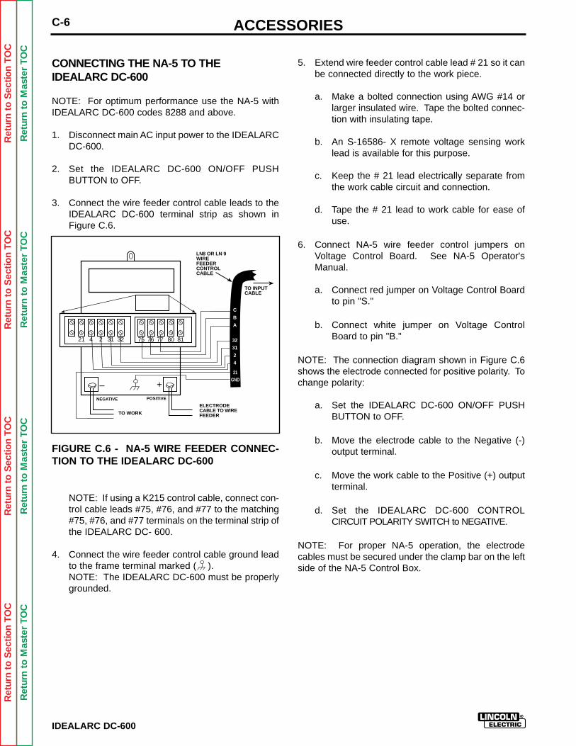
ACCESSORIESC-6
IDEALARC DC-600
Ret
urn
to S
ectio
n T
OC
Ret
urn
to S
ectio
n T
OC
Ret
urn
to S
ectio
n T
OC
Ret
urn
to S
ectio
n T
OC
Ret
urn
to M
aste
r T
OC
Ret
urn
to M
aste
r T
OC
Ret
urn
to M
aste
r T
OC
Ret
urn
to M
aste
r T
OC
CONNECTING THE NA-5 TO THE IDEALARC DC-600
NOTE: For optimum performance use the NA-5 withIDEALARC DC-600 codes 8288 and above.
1. Disconnect main AC input power to the IDEALARCDC-600.
2. Set the IDEALARC DC-600 ON/OFF PUSHBUTTON to OFF.
3. Connect the wire feeder control cable leads to theIDEALARC DC-600 terminal strip as shown inFigure C.6.
FIGURE C.6 - NA-5 WIRE FEEDER CONNEC-TION TO THE IDEALARC DC-600
NOTE: If using a K215 control cable, connect con-trol cable leads #75, #76, and #77 to the matching#75, #76, and #77 terminals on the terminal strip ofthe IDEALARC DC- 600.
4. Connect the wire feeder control cable ground leadto the frame terminal marked ( ).NOTE: The IDEALARC DC-600 must be properlygrounded.
5. Extend wire feeder control cable lead # 21 so it canbe connected directly to the work piece.
a. Make a bolted connection using AWG #14 orlarger insulated wire. Tape the bolted connec-tion with insulating tape.
b. An S-16586- X remote voltage sensing worklead is available for this purpose.
c. Keep the # 21 lead electrically separate fromthe work cable circuit and connection.
d. Tape the # 21 lead to work cable for ease ofuse.
6. Connect NA-5 wire feeder control jumpers onVoltage Control Board. See NA-5 Operator'sManual.
a. Connect red jumper on Voltage Control Boardto pin "S."
b. Connect white jumper on Voltage ControlBoard to pin "B."
NOTE: The connection diagram shown in Figure C.6shows the electrode connected for positive polarity. Tochange polarity:
a. Set the IDEALARC DC-600 ON/OFF PUSHBUTTON to OFF.
b. Move the electrode cable to the Negative (-)output terminal.
c. Move the work cable to the Positive (+) outputterminal.
d. Set the IDEALARC DC-600 CONTROLCIRCUIT POLARITY SWITCH to NEGATIVE.
NOTE: For proper NA-5 operation, the electrodecables must be secured under the clamp bar on the leftside of the NA-5 Control Box.
21 4 2 31 32 75 76 77 80 81
– +NEGATIVE
TO WORK
ELECTRODECABLE TO WIREFEEDER
LN8 OR LN 9WIREFEEDERCONTROLCABLE
C
B
A
32
31
2
4
POSITIVE
TO INPUTCABLE
21GND
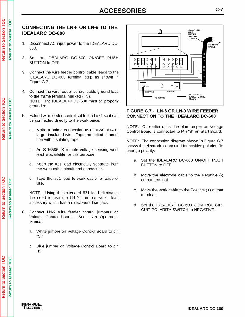
ACCESSORIES C-7
IDEALARC DC-600
Ret
urn
to S
ectio
n T
OC
Ret
urn
to S
ectio
n T
OC
Ret
urn
to S
ectio
n T
OC
Ret
urn
to S
ectio
n T
OC
Ret
urn
to M
aste
r T
OC
Ret
urn
to M
aste
r T
OC
Ret
urn
to M
aste
r T
OC
Ret
urn
to M
aste
r T
OC
CONNECTING THE LN-8 OR LN-9 TO THEIDEALARC DC-600
1. Disconnect AC input power to the IDEALARC DC-600.
2. Set the IDEALARC DC-600 ON/OFF PUSHBUTTON to OFF.
3. Connect the wire feeder control cable leads to theIDEALARC DC-600 terminal strip as shown inFigure C.7.
4. Connect the wire feeder control cable ground leadto the frame terminal marked ( ).NOTE: The IDEALARC DC-600 must be properlygrounded.
5. Extend wire feeder control cable lead #21 so it canbe connected directly to the work piece.
a. Make a bolted connection using AWG #14 orlarger insulated wire. Tape the bolted connec-tion with insulating tape.
b. An S-16586- X remote voltage sensing worklead is available for this purpose.
c. Keep the #21 lead electrically separate fromthe work cable circuit and connection.
d. Tape the #21 lead to work cable for ease ofuse.
NOTE: Using the extended #21 lead eliminatesthe need to use the LN-9's remote work leadaccessory which has a direct work lead jack.
6. Connect LN-9 wire feeder control jumpers onVoltage Control board. See LN-9 Operator'sManual.
a. White jumper on Voltage Control Board to pin"S."
b. Blue jumper on Voltage Control Board to pin"B."
FIGURE C.7 - LN-8 OR LN-9 WIRE FEEDERCONNECTION TO THE IDEALARC DC-600
NOTE: On earlier units, the blue jumper on VoltageControl Board is connected to Pin "B" on Start Board.
NOTE: The connection diagram shown in Figure C.7shows the electrode connected for positive polarity. Tochange polarity:
a. Set the IDEALARC DC-600 ON/OFF PUSHBUTTON to OFF
b. Move the electrode cable to the Negative (-)output terminal
c. Move the work cable to the Positive (+) outputterminal.
d. Set the IDEALARC DC-600 CONTROL CIR-CUIT POLARITY SWITCH to NEGATIVE.
21 4 2 31 32 75 76 77 80 81
– +NEGATIVE
TO WORK
ELECTRODECABLE TO WIREFEEDER
LN8 OR LN 9WIREFEEDERCONTROLCABLE
C
B
A
32
31
2
4
POSITIVE
TO INPUTCABLE
21GND
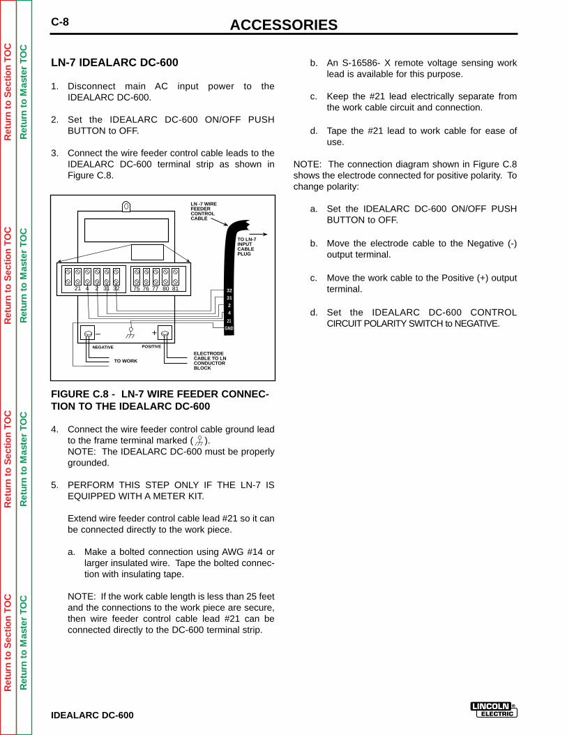
ACCESSORIESC-8
IDEALARC DC-600
Ret
urn
to S
ectio
n T
OC
Ret
urn
to S
ectio
n T
OC
Ret
urn
to S
ectio
n T
OC
Ret
urn
to S
ectio
n T
OC
Ret
urn
to M
aste
r T
OC
Ret
urn
to M
aste
r T
OC
Ret
urn
to M
aste
r T
OC
Ret
urn
to M
aste
r T
OC
LN-7 IDEALARC DC-600
1. Disconnect main AC input power to the IDEALARC DC-600.
2. Set the IDEALARC DC-600 ON/OFF PUSHBUTTON to OFF.
3. Connect the wire feeder control cable leads to theIDEALARC DC-600 terminal strip as shown inFigure C.8.
FIGURE C.8 - LN-7 WIRE FEEDER CONNEC-TION TO THE IDEALARC DC-600
4. Connect the wire feeder control cable ground leadto the frame terminal marked ( ).NOTE: The IDEALARC DC-600 must be properlygrounded.
5. PERFORM THIS STEP ONLY IF THE LN-7 ISEQUIPPED WITH A METER KIT.
Extend wire feeder control cable lead #21 so it canbe connected directly to the work piece.
a. Make a bolted connection using AWG #14 orlarger insulated wire. Tape the bolted connec-tion with insulating tape.
NOTE: If the work cable length is less than 25 feetand the connections to the work piece are secure,then wire feeder control cable lead #21 can beconnected directly to the DC-600 terminal strip.
b. An S-16586- X remote voltage sensing worklead is available for this purpose.
c. Keep the #21 lead electrically separate fromthe work cable circuit and connection.
d. Tape the #21 lead to work cable for ease ofuse.
NOTE: The connection diagram shown in Figure C.8shows the electrode connected for positive polarity. Tochange polarity:
a. Set the IDEALARC DC-600 ON/OFF PUSHBUTTON to OFF.
b. Move the electrode cable to the Negative (-)output terminal.
c. Move the work cable to the Positive (+) outputterminal.
d. Set the IDEALARC DC-600 CONTROLCIRCUIT POLARITY SWITCH to NEGATIVE.
21 4 2 31 32 75 76 77 80 81
– +NEGATIVE
TO WORK
ELECTRODECABLE TO LNCONDUCTORBLOCK
LN -7 WIREFEEDERCONTROLCABLE
77
76
75
32
31
2
4
POSITIVE
TO LN-7INPUTCABLEPLUG
21GND
TABLE OF CONTENTS- MAINTENANCE SECTION -
Section D-1
IDEALARC DC-600
MAINTENANCE .................................................................. Section DSafety Precautions ...................................................................D-2Routine and Periodic Maintenance ..........................................D-33-D Exploded View...................................................................D-4
Ret
urn
to M
aste
r T
OC
Ret
urn
to M
aste
r T
OC
Ret
urn
to M
aste
r T
OC
Ret
urn
to M
aste
r T
OC
Ret
urn
to S
ectio
n T
OC
Ret
urn
to S
ectio
n T
OC
Ret
urn
to S
ectio
n T
OC
Ret
urn
to S
ectio
n T
OC
Ret
urn
to M
aste
r T
OC
Ret
urn
to M
aste
r T
OC
Ret
urn
to M
aste
r T
OC
Ret
urn
to M
aste
r T
OC
IDEALARC DC-600
D-2 MAINTENANCE
MAINTENANCE
SAFETY PRECAUTIONS
ELECTRIC SHOCKCAN KILL.
Only qualified personnel shouldperform this maintenance.
Turn the input power OFF at thedisconnect switch or fuse boxbefore working on this equipment.
Do not touch electrically hot parts.
__________________
WARNING
Ret
urn
to S
ectio
n T
OC
Ret
urn
to S
ectio
n T
OC
Ret
urn
to S
ectio
n T
OC
Ret
urn
to S
ectio
n T
OC
Ret
urn
to M
aste
r T
OC
Ret
urn
to M
aste
r T
OC
Ret
urn
to M
aste
r T
OC
Ret
urn
to M
aste
r T
OC
IDEALARC DC-600
D-3MAINTENANCE
ROUTINE AND PERIODIC MAINTENANCE
1. Disconnect input AC power supply lines to themachine before performing periodic maintenance,tightening, cleaning, or replacing parts. SeeFigure D.1
Perform the following daily:
1. Check that no combustible materials are in thewelding or cutting area or around the machine.
2. Remove any debris, dust, dirt, or materials thatcould block the air flow to the machine for cooling.
3. Inspect the electrode cables for any slits or punctures in the cable jacket, or any condition thatwould affect the proper operation of the machine.
Perform Periodically:
Clean the inside of the machine with low pressure airstream. Clean the following parts. Refer to Figure D.1.
• Main transformer and choke.
• Electrode and work cable connections.
• SCR rectifier bridge and heat sink fins.
• Control board.
• Firing board.
• Fan Assembly.NOTE: The fan motor has sealed bearings whichrequire no maintenance.
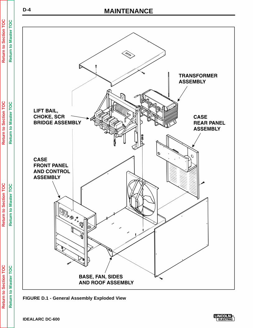
Ret
urn
to S
ectio
n T
OC
Ret
urn
to S
ectio
n T
OC
Ret
urn
to S
ectio
n T
OC
Ret
urn
to S
ectio
n T
OC
Ret
urn
to M
aste
r T
OC
Ret
urn
to M
aste
r T
OC
Ret
urn
to M
aste
r T
OC
Ret
urn
to M
aste
r T
OC
IDEALARC DC-600
D-4 MAINTENANCE
FIGURE D.1 - General Assembly Exploded View
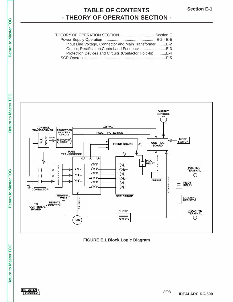
TABLE OF CONTENTS- THEORY OF OPERATION SECTION -
Section E-1
IDEALARC DC-600
THEORY OF OPERATION SECTION ................................ Section EPower Supply Operation ..................................................E-2 - E-5
Input Line Voltage, Connector and Main Transformer .........E-2Output, Rectification,Control and Feedback ........................E-3Protection Devices and Circuits (Contactor Hold-In) ...........E-4
SCR Operation ..........................................................................E-5
TERMINALSTRIP
CONTACTOR
TOCONTROL
BOARD
REMOTECONTROL
MAINTRANSFORMER
CONTROLTRANSFORMER
115 VAC
115 VAC
FAULT PROTECTIONPROTECTION
DEVICES &CIRCUTS
CONTACTORHOLD-IN( )
FIRING BOARD CONTROLBOARD
PILOTRELAY
FEEDBACK
FEEDBACK
OUTPUTCONTROL
MODESWITCH
POSITIVETERMINAL
NEGATIVETERMINAL
LATCHINGRESISTOR
PILOTRELAY
CHOKE
115VAC
FAN
RECONNECT
SCR BRIDGE
SHUNT
FIGURE E.1 Block Logic Diagram
Ret
urn
to M
aste
r T
OC
Ret
urn
to M
aste
r T
OC
Ret
urn
to M
aste
r T
OC
Ret
urn
to M
aste
r T
OC
8/98
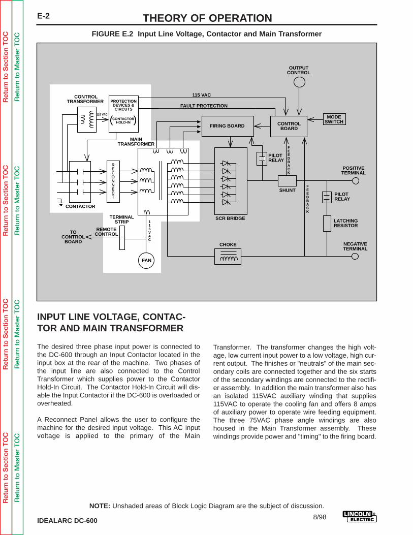
Ret
urn
to S
ectio
n T
OC
Ret
urn
to S
ectio
n T
OC
Ret
urn
to S
ectio
n T
OC
Ret
urn
to S
ectio
n T
OC
Ret
urn
to M
aste
r T
OC
Ret
urn
to M
aste
r T
OC
Ret
urn
to M
aste
r T
OC
Ret
urn
to M
aste
r T
OC
IDEALARC DC-600
E-2 THEORY OF OPERATION
INPUT LINE VOLTAGE, CONTAC-TOR AND MAIN TRANSFORMER
The desired three phase input power is connected tothe DC-600 through an Input Contactor located in theinput box at the rear of the machine. Two phases ofthe input line are also connected to the ControlTransformer which supplies power to the ContactorHold-In Circuit. The Contactor Hold-In Circuit will dis-able the Input Contactor if the DC-600 is overloaded oroverheated.
A Reconnect Panel allows the user to configure themachine for the desired input voltage. This AC inputvoltage is applied to the primary of the Main
Transformer. The transformer changes the high volt-age, low current input power to a low voltage, high cur-rent output. The finishes or "neutrals" of the main sec-ondary coils are connected together and the six startsof the secondary windings are connected to the rectifi-er assembly. In addition the main transformer also hasan isolated 115VAC auxiliary winding that supplies115VAC to operate the cooling fan and offers 8 ampsof auxiliary power to operate wire feeding equipment.The three 75VAC phase angle windings are alsohoused in the Main Transformer assembly. Thesewindings provide power and "timing" to the firing board.
TERMINALSTRIP
CONTACTOR
TOCONTROL
BOARD
REMOTECONTROL
MAINTRANSFORMER
CONTROLTRANSFORMER
115 VAC
115 VAC
FAULT PROTECTIONPROTECTION
DEVICES &CIRCUTS
CONTACTORHOLD-IN( )
FIRING BOARD CONTROLBOARD
PILOTRELAY
FEEDBACK
FEEDBACK
OUTPUTCONTROL
MODESWITCH
POSITIVETERMINAL
NEGATIVETERMINAL
LATCHINGRESISTOR
PILOTRELAY
CHOKE
115VAC
FAN
RECONNECT
SCR BRIDGE
SHUNT
FIGURE E.2 Input Line Voltage, Contactor and Main Transformer
NOTE: Unshaded areas of Block Logic Diagram are the subject of discussion.
8/98
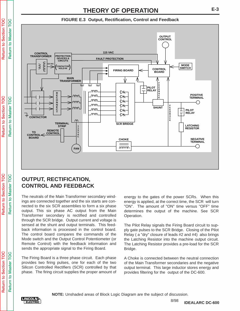
Ret
urn
to S
ectio
n T
OC
Ret
urn
to S
ectio
n T
OC
Ret
urn
to S
ectio
n T
OC
Ret
urn
to S
ectio
n T
OC
Ret
urn
to M
aste
r T
OC
Ret
urn
to M
aste
r T
OC
Ret
urn
to M
aste
r T
OC
Ret
urn
to M
aste
r T
OC
IDEALARC DC-600
E-3THEORY OF OPERATIONFIGURE E.3 Output, Rectification, Control and Feedback
OUTPUT, RECTIFICATION, CONTROL AND FEEDBACK
The neutrals of the Main Transformer secondary wind-ings are connected together and the six starts are con-nected to the six SCR assemblies to form a six phaseoutput. This six phase AC output from the MainTransformer secondary is rectified and controlledthrough the SCR bridge. Output current and voltage issensed at the shunt and output terminals. This feed-back information is processed in the control board.The control board compares the commands of theMode switch and the Output Control Potentiometer (orRemote Control) with the feedback information andsends the appropriate signal to the Firing Board.
The Firing Board is a three phase circuit. Each phaseprovides two firing pulses, one for each of the twoSilicon Controlled Rectifiers (SCR) controlled by thatphase. The firing circuit supplies the proper amount of
energy to the gates of the power SCRs. When thisenergy is applied, at the correct time, the SCR will turn"ON". The amount of "ON" time versus "OFF" timedetermines the output of the machine. See SCROperation.
The Pilot Relay signals the Firing Board circuit to sup-ply gate pulses to the SCR Bridge. Closing of the PilotRelay ( a "dry" closure of leads #2 and #4) also bringsthe Latching Resistor into the machine output circuit.The Latching Resistor provides a pre-load for the SCRBridge.
A Choke is connected between the neutral connectionof the Main Transformer secondaries and the negativeoutput terminal. This large inductor stores energy andprovides filtering for the output of the DC-600.
TERMINALSTRIP
CONTACTOR
TOCONTROL
BOARD
REMOTECONTROL
MAINTRANSFORMER
CONTROLTRANSFORMER
115 VAC
115 VAC
FAULT PROTECTIONPROTECTION
DEVICES &CIRCUTS
CONTACTORHOLD-IN( )
FIRING BOARD CONTROLBOARD
PILOTRELAY
FEEDBACK
FEEDBACK
OUTPUTCONTROL
MODESWITCH
POSITIVETERMINAL
NEGATIVETERMINAL
LATCHINGRESISTOR
PILOTRELAY
CHOKE
115VAC
FAN
RECONNECT
SCR BRIDGE
SHUNT
NOTE: Unshaded areas of Block Logic Diagram are the subject of discussion.
8/98
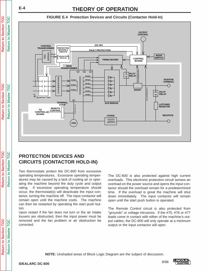
Ret
urn
to S
ectio
n T
OC
Ret
urn
to S
ectio
n T
OC
Ret
urn
to S
ectio
n T
OC
Ret
urn
to S
ectio
n T
OC
Ret
urn
to M
aste
r T
OC
Ret
urn
to M
aste
r T
OC
Ret
urn
to M
aste
r T
OC
Ret
urn
to M
aste
r T
OC
IDEALARC DC-600
E-4 THEORY OF OPERATIONFIGURE E.4 Protection Devices and Circuits (Contactor Hold-In)
PROTECTION DEVICES AND CIRCUITS (CONTACTOR HOLD-IN)
Two thermostats protect the DC-600 from excessiveoperating temperatures. Excessive operating temper-atures may be caused by a lack of cooling air or oper-ating the machine beyond the duty cycle and outputrating. If excessive operating temperature shouldoccur, the thermostat(s) will deactivate the input con-tactor, turning the machine off. The input contactor willremain open until the machine cools. The machinecan then be restarted by operating the start push but-ton.Upon restart if the fan does not turn or the air intakelouvers are obstructed, then the input power must beremoved and the fan problem or air obstruction be corrected.
The DC-600 is also protected against high currentoverloads. This electronic protection circuit senses anoverload on the power source and opens the input con-tactor should the overload remain for a predeterminedtime. If the overload is great the machine will shutdown immediately. The input contactor will remainopen until the start push button is operated.
The Remote Control circuit is also protected from"grounds" or voltage intrusions. If the #75, #76 or #77leads come in contact with either of the machine's out-put cables, the DC-600 will only operate at a minimumoutput or the input contactor will open.
TERMINALSTRIP
CONTACTOR
TOCONTROL
BOARD
REMOTECONTROL
MAINTRANSFORMER
CONTROLTRANSFORMER
115 VAC
115 VAC
FAULT PROTECTIONPROTECTION
DEVICES &CIRCUTS
CONTACTORHOLD-IN( )
FIRING BOARD
PILOTRELAY
FEEDBACK
FEEDBACK
OUTPUTCONTROL
MODESWITCH
POSITIVETERMINAL
NEGATIVE
LATCHINGRESISTOR
PILOTRELAY
CHOKE
115VAC
FAN
RECONNECT
CONTROLBOARD
SCR BRIDGE
SHUNT
NOTE: Unshaded areas of Block Logic Diagram are the subject of discussion.
8/98
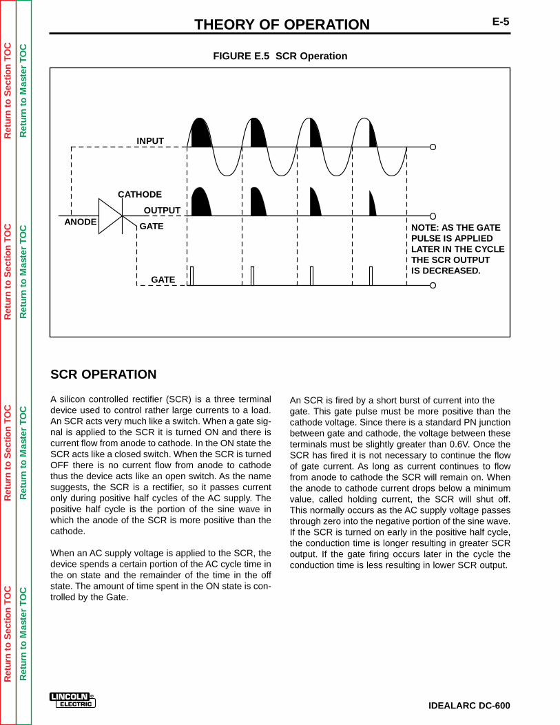
Ret
urn
to S
ectio
n T
OC
Ret
urn
to S
ectio
n T
OC
Ret
urn
to S
ectio
n T
OC
Ret
urn
to S
ectio
n T
OC
Ret
urn
to M
aste
r T
OC
Ret
urn
to M
aste
r T
OC
Ret
urn
to M
aste
r T
OC
Ret
urn
to M
aste
r T
OC
IDEALARC DC-600
E-5THEORY OF OPERATION
FIGURE E.5 SCR Operation
SCR OPERATION
A silicon controlled rectifier (SCR) is a three terminaldevice used to control rather large currents to a load.An SCR acts very much like a switch. When a gate sig-nal is applied to the SCR it is turned ON and there iscurrent flow from anode to cathode. In the ON state theSCR acts like a closed switch. When the SCR is turnedOFF there is no current flow from anode to cathodethus the device acts like an open switch. As the namesuggests, the SCR is a rectifier, so it passes currentonly during positive half cycles of the AC supply. Thepositive half cycle is the portion of the sine wave inwhich the anode of the SCR is more positive than thecathode.
When an AC supply voltage is applied to the SCR, thedevice spends a certain portion of the AC cycle time inthe on state and the remainder of the time in the offstate. The amount of time spent in the ON state is con-trolled by the Gate.
An SCR is fired by a short burst of current into thegate. This gate pulse must be more positive than thecathode voltage. Since there is a standard PN junctionbetween gate and cathode, the voltage between theseterminals must be slightly greater than 0.6V. Once theSCR has fired it is not necessary to continue the flowof gate current. As long as current continues to flowfrom anode to cathode the SCR will remain on. Whenthe anode to cathode current drops below a minimumvalue, called holding current, the SCR will shut off.This normally occurs as the AC supply voltage passesthrough zero into the negative portion of the sine wave.If the SCR is turned on early in the positive half cycle,the conduction time is longer resulting in greater SCRoutput. If the gate firing occurs later in the cycle theconduction time is less resulting in lower SCR output.
INPUT
OUTPUT
GATE
GATEANODE
CATHODE
NOTE: AS THE GATEPULSE IS APPLIEDLATER IN THE CYCLETHE SCR OUTPUTIS DECREASED.
TABLE OF CONTENTS- TROUBLESHOOTING & REPAIR SECTION -
SECTION F-1
IDEALARC DC-600
Troubleshooting & Repair Section................................................................Section FSafety Precautions.................................................................................................F-2How to Use Troubleshooting Guide.......................................................................F-2PC Board Troubleshooting Procedures .................................................................F-3Troubleshooting Guide................................................................................F-4 - F-12Test Procedures
Control Transformer Voltage Test .......................................................F-13 - F-14Main Transformer Voltage Test ...........................................................F-16 - F-20Firing Board Test.................................................................................F-21 - F-27Control Board Test ..............................................................................F-28 - F-32Static SCR Test...................................................................................F-33 - F-36Active SCR Test ..................................................................................F-37 - F-40
Oscilloscope WaveformsNormal Open Circuit Voltage Waveform Constant Current Mode.................F-41Normal Maximum Open Circuit Voltage Waveform
Constant Voltage Innershield Mode.......................................................F-42Normal Minimum Open Circuit Voltage Waveform
Constant Voltage Innershield Mode.......................................................F-43Typical Output Voltage Waveform Machine Loaded
Constant Voltage Innershield Mode.......................................................F-44Typical SCR Gate Voltage Waveform @ Maximum Output Setting .....................
Constant Voltage Innershield Mode.......................................................F-45Abnormal Open Circuit Voltage Waveform
Constant Voltage Innershield Mode.......................................................F-46Replacement Procedures
Input Contactor Cleaning and or Replacement ..................................F-47 - F-48SCR Output Bridge Removal.........................................................................F-49
Removal of Individual SCR Heat Sinks ......................................F-50 - F-53Removal of Lift Bail Assembly ............................................................F-54 - F-56Removal of Transformer from Lift Bail Assembly ...............................F-57 - F-59Transformer Disassembly and Coil Replacement .........................................F-60
Retest After Repair ..................................................................................F-61 - F-62
Ret
urn
to M
aste
r T
OC
Ret
urn
to M
aste
r T
OC
Ret
urn
to M
aste
r T
OC
Ret
urn
to M
aste
r T
OC

Ret
urn
to S
ectio
n T
OC
Ret
urn
to S
ectio
n T
OC
Ret
urn
to S
ectio
n T
OC
Ret
urn
to S
ectio
n T
OC
Ret
urn
to M
aste
r T
OC
Ret
urn
to M
aste
r T
OC
Ret
urn
to M
aste
r T
OC
Ret
urn
to M
aste
r T
OC
IDEALARC DC-600
F-2 TROUBLESHOOTING & REPAIR
HOW TO USE TROUBLESHOOTING GUIDE
Service and Repair should only be performed by Lincoln Electric Factory Trained Personnel.Unauthorized repairs performed on this equipment may result in danger to the technician andmachine operator and will invalidate your factory warranty. For your safety and to avoidElectrical Shock, please observe all safety notes and precautions detailed throughout thismanual.
______________________________Step 3. PERFORM COMPONENT TESTS.The last column labeled “RecommendedCourse of Action” lists the most likely com-ponents that may have failed in yourmachine. It also specifies the appropriatetest procedure to verify that the subject com-ponent is either good or bad. If there are anumber of possible components, check thecomponents in the order listed to eliminateone possibility at a time until you locate thecause of your problem.
All of the referenced test proceduresreferred to in the Troubleshooting Guide aredescribed in detail at the end of this chapter.Refer to the Troubleshooting and RepairTable of Contents to locate each specificTest Procedure. All of the specified testpoints, components, terminal strips, etc. canbe found on the referenced electrical wiringdiagrams and schematics. Refer to theElectrical Diagrams Section Table ofContents to locate the appropriate diagram.
If for any reason you do not understand the test procedures or are unable to perform thetests/repairs safely, contact the Lincoln Electric Service Department for technical trou-bleshooting assistance before you proceed call 216-383-2531 or 1-800-833-9353.
______________________________
This Troubleshooting Guide is provided tohelp you locate and repair possible machinemalfunctions. Simply follow the three-stepprocedure listed below.
Step 1. LOCATE PROBLEM (SYMPTOM).Look under the column labeled “PROBLEM(SYMPTOMS)”. This column describes pos-sible symptoms that the machine may exhib-it. Find the listing that best describes thesymptom that the machine is exhibiting.Symptoms are grouped into several maincategories: output problems and weldingproblems.
Step 2. PERFORM EXTERNAL TESTS.The second column labeled “POSSIBLEAREAS OF MISADJUSTMENT(S)” lists theobvious external possibilities that may con-tribute to the machine symptom. Performthese tests/checks in the order listed. Ingeneral, these tests can be conducted with-out removing the case wrap-around cover.
CAUTION
Ret
urn
to S
ectio
n T
OC
Ret
urn
to S
ectio
n T
OC
Ret
urn
to S
ectio
n T
OC
Ret
urn
to S
ectio
n T
OC
Ret
urn
to M
aste
r T
OC
Ret
urn
to M
aste
r T
OC
Ret
urn
to M
aste
r T
OC
Ret
urn
to M
aste
r T
OC
CAUTION: Sometimes machine failuresappear to be due to PC board failures. Theseproblems can sometimes be traced to poorelectrical connections. To avoid problems whentroubleshooting and replacing PC boards,please use the following procedure:
1. Determine to the best of your technical abili-ty that the PC board is the most likely com-ponent causing the failure symptom.
2. Check for loose connections at the PC boardto assure that the PC board is properly con-nected.
3. If the problem persists, replace the suspectPC board using standard practices to avoidstatic electrical damage and electrical shock.Read the warning inside the static resistantbag and perform the following procedures:
P.C. Board can be dam-aged by static electricity.
- Remove your body’s sta-tic charge before openingthe static-shielding bag.Wear an anti-static wriststrap. For safety, use a 1Meg ohm resistive cordconnected to a groundedpart of the equipmentframe.
- If you don’t have a wriststrap, touch an unpainted,grounded, part of the
equipment frame. Keep touching the frame toprevent static build-up. Be sure not to touch anyelectrically live parts at the same time.
- Tools which come in contact with the P.C.Board must be either conductive, anti-static orstatic-dissipative.
IDEALARC DC-600
F-3TROUBLESHOOTING & REPAIR
ELECTRIC SHOCK cankill.Have an electrician install andservice this equipment. Turn theinput power OFF at the fuse boxbefore working on equipment. Donot touch electrically hot parts.
- Remove the P.C. Board from the static-shield-ing bag and place it directly into the equipment.Don’t set the P.C. Board on or near paper, plas-tic or cloth which could have a static charge. Ifthe P.C. Board can’t be installed immediately,put it back in the static-shielding bag.
- If the P.C. Board uses protective shortingjumpers, don’t remove them until installation iscomplete.
- If you return a P.C. Board to The LincolnElectric Company for credit, it must be in thestatic-shielding bag. This will prevent furtherdamage and allow proper failure analysis.
4. Test the machine to determine if the failuresymptom has been corrected by the replacement PC board.
NOTE: It is desirable to have a spare (knowngood) PC board available for PC board trou-bleshooting.
NOTE: Allow the machine to heat up so that allelectrical components can reach their operatingtemperature.
5. Remove the replacement PC board and sub-stitute it with the original PC board to recreate the original problem.
a. If the original problem does not reappearby substituting the original board, then the PC board was not the problem.Continue to look for bad connections inthe control wiring harness, junctionblocks, and terminal strips.
b. If the original problem is recreated by thesubstitution of the original board, then the PC board was the problem. Reinstallthe replacement PC board and test themachine.
6. Always indicate that this procedure was followed when warranty reports are to besubmitted.
NOTE: Following this procedure and writing onthe warranty report, “INSTALLED ANDSWITCHED PC BOARDS TO VERIFY PROB-LEM,” will help avoid denial of legitimate PCboard warranty claims.
PC BOARD TROUBLESHOOTING PROCEDURES
ATTENTIONStatic-SensitiveDevicesHandle only atStatic-SafeWorkstations
Reusable ContainerDo Not Destroy
WARNING
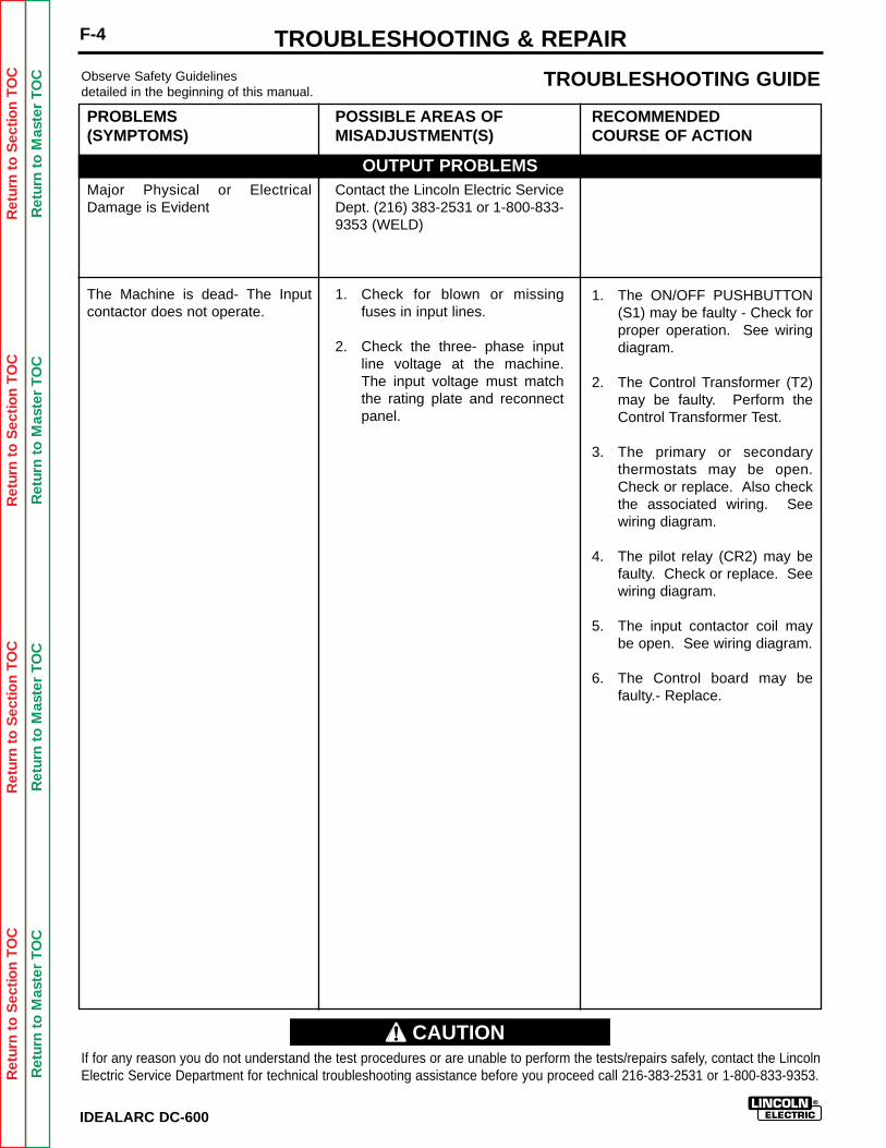
Ret
urn
to S
ectio
n T
OC
Ret
urn
to S
ectio
n T
OC
Ret
urn
to S
ectio
n T
OC
Ret
urn
to S
ectio
n T
OC
Ret
urn
to M
aste
r T
OC
Ret
urn
to M
aste
r T
OC
Ret
urn
to M
aste
r T
OC
Ret
urn
to M
aste
r T
OC
IDEALARC DC-600
F-4 TROUBLESHOOTING & REPAIRObserve Safety Guidelinesdetailed in the beginning of this manual.
TROUBLESHOOTING GUIDE
PROBLEMS(SYMPTOMS)
Major Physical or ElectricalDamage is Evident
The Machine is dead- The Inputcontactor does not operate.
POSSIBLE AREAS OFMISADJUSTMENT(S)
Contact the Lincoln Electric ServiceDept. (216) 383-2531 or 1-800-833-9353 (WELD)
1. Check for blown or missingfuses in input lines.
2. Check the three- phase inputline voltage at the machine.The input voltage must matchthe rating plate and reconnectpanel.
RECOMMENDEDCOURSE OF ACTION
1. The ON/OFF PUSHBUTTON(S1) may be faulty - Check forproper operation. See wiringdiagram.
2. The Control Transformer (T2)may be faulty. Perform theControl Transformer Test.
3. The primary or secondarythermostats may be open.Check or replace. Also checkthe associated wiring. Seewiring diagram.
4. The pilot relay (CR2) may befaulty. Check or replace. Seewiring diagram.
5. The input contactor coil maybe open. See wiring diagram.
6. The Control board may befaulty.- Replace.
If for any reason you do not understand the test procedures or are unable to perform the tests/repairs safely, contact the LincolnElectric Service Department for technical troubleshooting assistance before you proceed call 216-383-2531 or 1-800-833-9353.
OUTPUT PROBLEMS
CAUTION
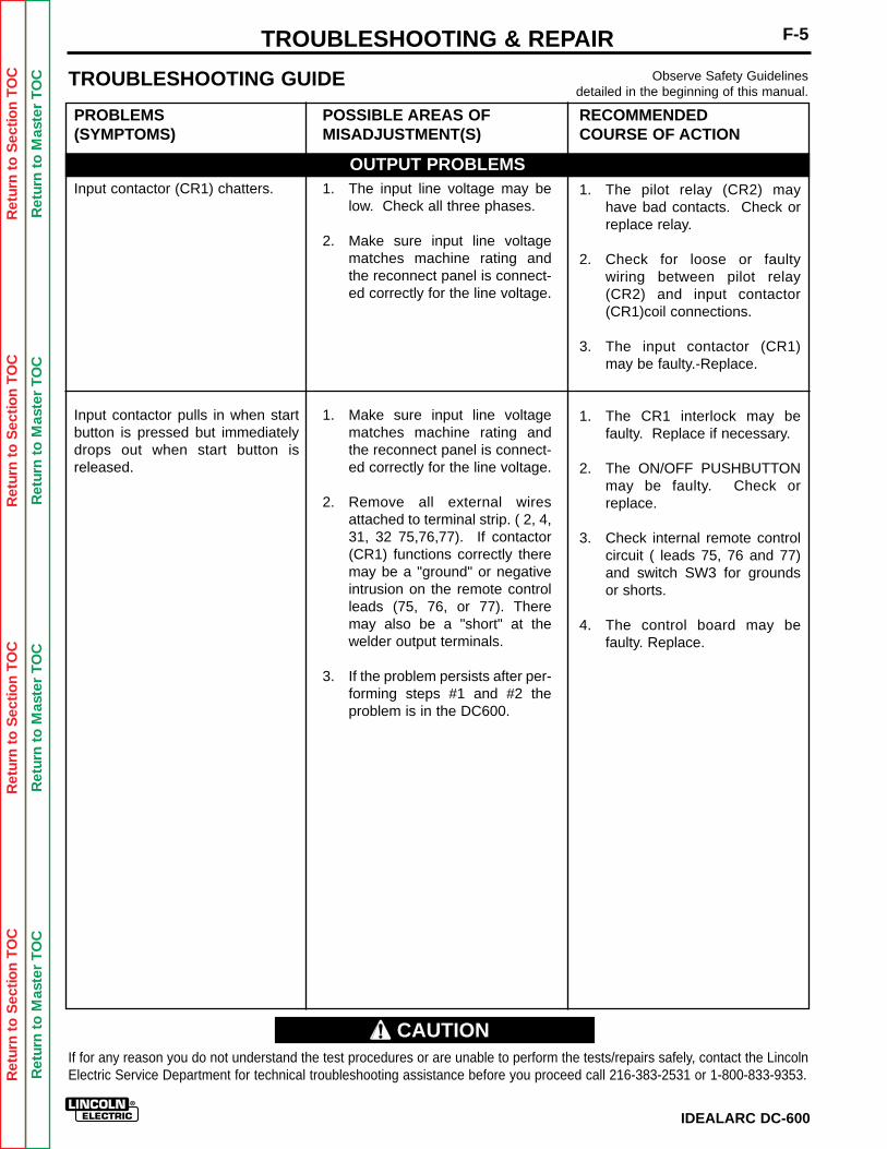
Ret
urn
to S
ectio
n T
OC
Ret
urn
to S
ectio
n T
OC
Ret
urn
to S
ectio
n T
OC
Ret
urn
to S
ectio
n T
OC
Ret
urn
to M
aste
r T
OC
Ret
urn
to M
aste
r T
OC
Ret
urn
to M
aste
r T
OC
Ret
urn
to M
aste
r T
OC
IDEALARC DC-600
F-5TROUBLESHOOTING & REPAIRObserve Safety Guidelines
detailed in the beginning of this manual.TROUBLESHOOTING GUIDE
PROBLEMS(SYMPTOMS)
Input contactor (CR1) chatters.
Input contactor pulls in when startbutton is pressed but immediatelydrops out when start button isreleased.
POSSIBLE AREAS OFMISADJUSTMENT(S)
1. The input line voltage may below. Check all three phases.
2. Make sure input line voltagematches machine rating andthe reconnect panel is connect-ed correctly for the line voltage.
1. Make sure input line voltagematches machine rating andthe reconnect panel is connect-ed correctly for the line voltage.
2. Remove all external wiresattached to terminal strip. ( 2, 4,31, 32 75,76,77). If contactor(CR1) functions correctly theremay be a "ground" or negativeintrusion on the remote controlleads (75, 76, or 77). Theremay also be a "short" at thewelder output terminals.
3. If the problem persists after per-forming steps #1 and #2 theproblem is in the DC600.
RECOMMENDEDCOURSE OF ACTION
1. The pilot relay (CR2) mayhave bad contacts. Check orreplace relay.
2. Check for loose or faultywiring between pilot relay(CR2) and input contactor(CR1)coil connections.
3. The input contactor (CR1)may be faulty.-Replace.
1. The CR1 interlock may befaulty. Replace if necessary.
2. The ON/OFF PUSHBUTTONmay be faulty. Check orreplace.
3. Check internal remote controlcircuit ( leads 75, 76 and 77)and switch SW3 for groundsor shorts.
4. The control board may befaulty. Replace.
If for any reason you do not understand the test procedures or are unable to perform the tests/repairs safely, contact the LincolnElectric Service Department for technical troubleshooting assistance before you proceed call 216-383-2531 or 1-800-833-9353.
OUTPUT PROBLEMS
CAUTION
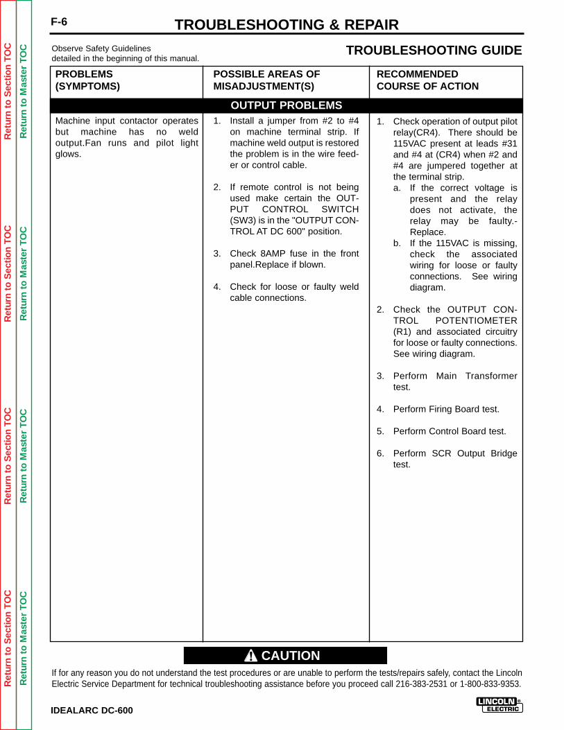
Ret
urn
to S
ectio
n T
OC
Ret
urn
to S
ectio
n T
OC
Ret
urn
to S
ectio
n T
OC
Ret
urn
to S
ectio
n T
OC
Ret
urn
to M
aste
r T
OC
Ret
urn
to M
aste
r T
OC
Ret
urn
to M
aste
r T
OC
Ret
urn
to M
aste
r T
OC
IDEALARC DC-600
F-6 TROUBLESHOOTING & REPAIRObserve Safety Guidelinesdetailed in the beginning of this manual.
TROUBLESHOOTING GUIDE
PROBLEMS(SYMPTOMS)
Machine input contactor operatesbut machine has no weldoutput.Fan runs and pilot lightglows.
POSSIBLE AREAS OFMISADJUSTMENT(S)
1. Install a jumper from #2 to #4on machine terminal strip. Ifmachine weld output is restoredthe problem is in the wire feed-er or control cable.
2. If remote control is not beingused make certain the OUT-PUT CONTROL SWITCH(SW3) is in the "OUTPUT CON-TROL AT DC 600" position.
3. Check 8AMP fuse in the frontpanel.Replace if blown.
4. Check for loose or faulty weldcable connections.
RECOMMENDEDCOURSE OF ACTION
1. Check operation of output pilotrelay(CR4). There should be115VAC present at leads #31and #4 at (CR4) when #2 and#4 are jumpered together atthe terminal strip.a. If the correct voltage is
present and the relaydoes not activate, therelay may be faulty.-Replace.
b. If the 115VAC is missing,check the associatedwiring for loose or faultyconnections. See wiringdiagram.
2. Check the OUTPUT CON-TROL POTENTIOMETER(R1) and associated circuitryfor loose or faulty connections.See wiring diagram.
3. Perform Main Transformertest.
4. Perform Firing Board test.
5. Perform Control Board test.
6. Perform SCR Output Bridgetest.
If for any reason you do not understand the test procedures or are unable to perform the tests/repairs safely, contact the LincolnElectric Service Department for technical troubleshooting assistance before you proceed call 216-383-2531 or 1-800-833-9353.
OUTPUT PROBLEMS
CAUTION
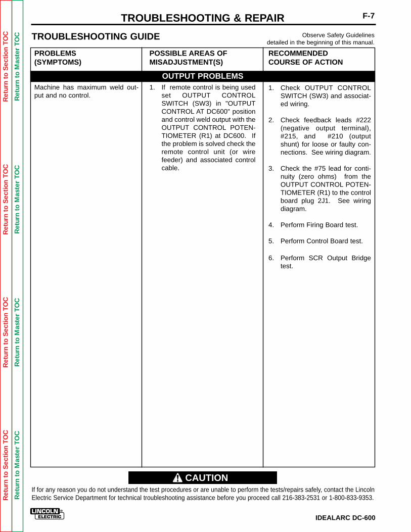
Ret
urn
to S
ectio
n T
OC
Ret
urn
to S
ectio
n T
OC
Ret
urn
to S
ectio
n T
OC
Ret
urn
to S
ectio
n T
OC
Ret
urn
to M
aste
r T
OC
Ret
urn
to M
aste
r T
OC
Ret
urn
to M
aste
r T
OC
Ret
urn
to M
aste
r T
OC
IDEALARC DC-600
F-7TROUBLESHOOTING & REPAIRObserve Safety Guidelines
detailed in the beginning of this manual.TROUBLESHOOTING GUIDE
PROBLEMS(SYMPTOMS)
Machine has maximum weld out-put and no control.
POSSIBLE AREAS OFMISADJUSTMENT(S)
1. If remote control is being usedset OUTPUT CONTROLSWITCH (SW3) in "OUTPUTCONTROL AT DC600" positionand control weld output with theOUTPUT CONTROL POTEN-TIOMETER (R1) at DC600. Ifthe problem is solved check theremote control unit (or wirefeeder) and associated controlcable.
RECOMMENDEDCOURSE OF ACTION
1. Check OUTPUT CONTROLSWITCH (SW3) and associat-ed wiring.
2. Check feedback leads #222(negative output terminal),#215, and #210 (outputshunt) for loose or faulty con-nections. See wiring diagram.
3. Check the #75 lead for conti-nuity (zero ohms) from theOUTPUT CONTROL POTEN-TIOMETER (R1) to the controlboard plug 2J1. See wiringdiagram.
4. Perform Firing Board test.
5. Perform Control Board test.
6. Perform SCR Output Bridgetest.
If for any reason you do not understand the test procedures or are unable to perform the tests/repairs safely, contact the LincolnElectric Service Department for technical troubleshooting assistance before you proceed call 216-383-2531 or 1-800-833-9353.
OUTPUT PROBLEMS
CAUTION
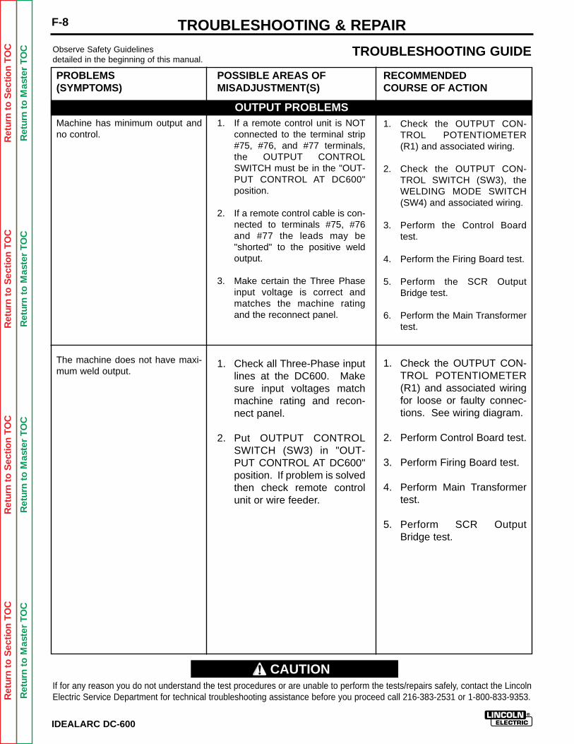
Ret
urn
to S
ectio
n T
OC
Ret
urn
to S
ectio
n T
OC
Ret
urn
to S
ectio
n T
OC
Ret
urn
to S
ectio
n T
OC
Ret
urn
to M
aste
r T
OC
Ret
urn
to M
aste
r T
OC
Ret
urn
to M
aste
r T
OC
Ret
urn
to M
aste
r T
OC
IDEALARC DC-600
F-8 TROUBLESHOOTING & REPAIRObserve Safety Guidelinesdetailed in the beginning of this manual.
TROUBLESHOOTING GUIDE
PROBLEMS(SYMPTOMS)
Machine has minimum output andno control.
The machine does not have maxi-mum weld output.
POSSIBLE AREAS OFMISADJUSTMENT(S)
1. If a remote control unit is NOTconnected to the terminal strip#75, #76, and #77 terminals,the OUTPUT CONTROLSWITCH must be in the "OUT-PUT CONTROL AT DC600"position.
2. If a remote control cable is con-nected to terminals #75, #76and #77 the leads may be"shorted" to the positive weldoutput.
3. Make certain the Three Phaseinput voltage is correct andmatches the machine ratingand the reconnect panel.
1. Check all Three-Phase inputlines at the DC600. Makesure input voltages matchmachine rating and recon-nect panel.
2. Put OUTPUT CONTROLSWITCH (SW3) in "OUT-PUT CONTROL AT DC600"position. If problem is solvedthen check remote controlunit or wire feeder.
RECOMMENDEDCOURSE OF ACTION
1. Check the OUTPUT CON-TROL POTENTIOMETER(R1) and associated wiring.
2. Check the OUTPUT CON-TROL SWITCH (SW3), theWELDING MODE SWITCH(SW4) and associated wiring.
3. Perform the Control Boardtest.
4. Perform the Firing Board test.
5. Perform the SCR OutputBridge test.
6. Perform the Main Transformertest.
1. Check the OUTPUT CON-TROL POTENTIOMETER(R1) and associated wiringfor loose or faulty connec-tions. See wiring diagram.
2. Perform Control Board test.
3. Perform Firing Board test.
4. Perform Main Transformertest.
5. Perform SCR OutputBridge test.
If for any reason you do not understand the test procedures or are unable to perform the tests/repairs safely, contact the LincolnElectric Service Department for technical troubleshooting assistance before you proceed call 216-383-2531 or 1-800-833-9353.
OUTPUT PROBLEMS
CAUTION
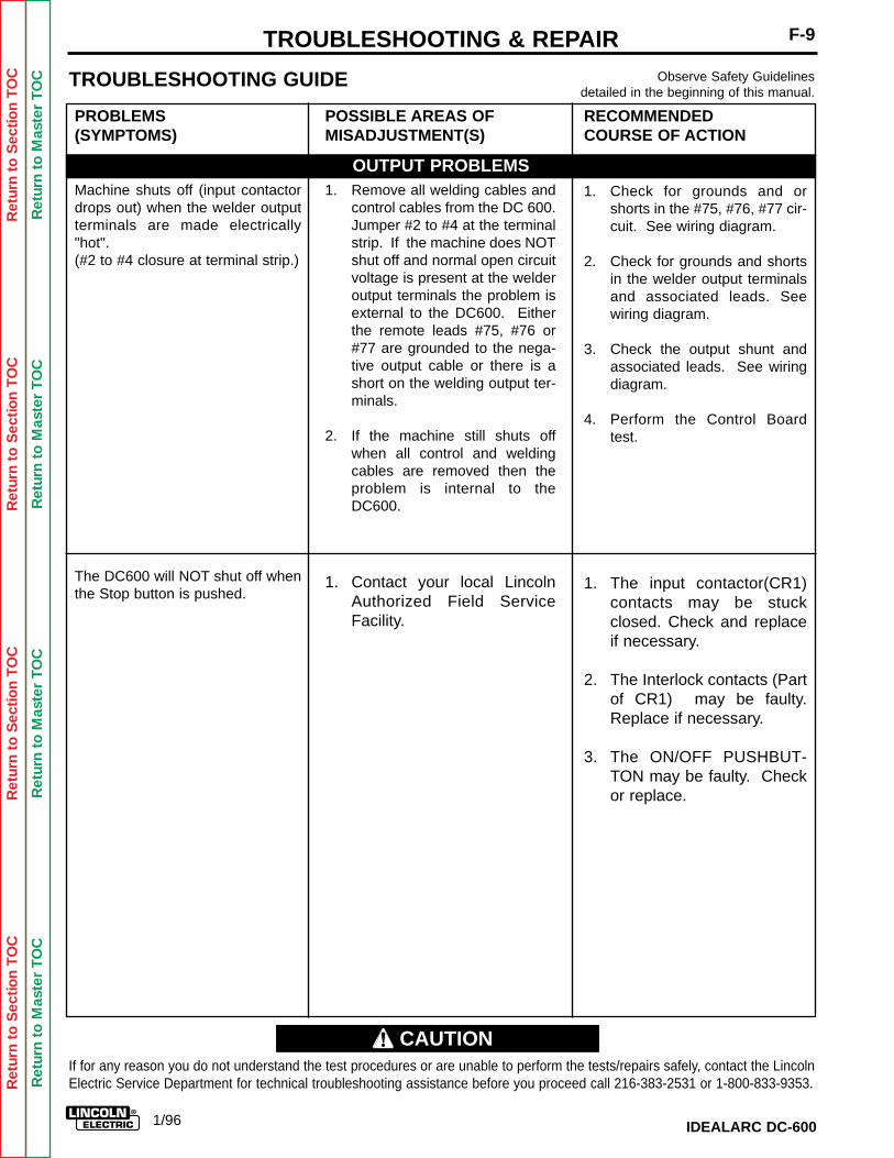
Ret
urn
to S
ectio
n T
OC
Ret
urn
to S
ectio
n T
OC
Ret
urn
to S
ectio
n T
OC
Ret
urn
to S
ectio
n T
OC
Ret
urn
to M
aste
r T
OC
Ret
urn
to M
aste
r T
OC
Ret
urn
to M
aste
r T
OC
Ret
urn
to M
aste
r T
OC
IDEALARC DC-600
F-9TROUBLESHOOTING & REPAIRObserve Safety Guidelines
detailed in the beginning of this manual.TROUBLESHOOTING GUIDE
PROBLEMS(SYMPTOMS)
Machine shuts off (input contactordrops out) when the welder outputterminals are made electrically"hot".(#2 to #4 closure at terminal strip.)
The DC600 will NOT shut off whenthe Stop button is pushed.
POSSIBLE AREAS OFMISADJUSTMENT(S)
1. Remove all welding cables andcontrol cables from the DC 600.Jumper #2 to #4 at the terminalstrip. If the machine does NOTshut off and normal open circuitvoltage is present at the welderoutput terminals the problem isexternal to the DC600. Eitherthe remote leads #75, #76 or#77 are grounded to the nega-tive output cable or there is ashort on the welding output ter-minals.
2. If the machine still shuts offwhen all control and weldingcables are removed then theproblem is internal to theDC600.
1. Contact your local LincolnAuthorized Field ServiceFacility.
RECOMMENDEDCOURSE OF ACTION
1. Check for grounds and orshorts in the #75, #76, #77 cir-cuit. See wiring diagram.
2. Check for grounds and shortsin the welder output terminalsand associated leads. Seewiring diagram.
3. Check the output shunt andassociated leads. See wiringdiagram.
4. Perform the Control Boardtest.
1. The input contactor(CR1)contacts may be stuckclosed. Check and replaceif necessary.
2. The Interlock contacts (Partof CR1) may be faulty.Replace if necessary.
3. The ON/OFF PUSHBUT-TON may be faulty. Checkor replace.
If for any reason you do not understand the test procedures or are unable to perform the tests/repairs safely, contact the LincolnElectric Service Department for technical troubleshooting assistance before you proceed call 216-383-2531 or 1-800-833-9353.
OUTPUT PROBLEMS
CAUTION
1/96
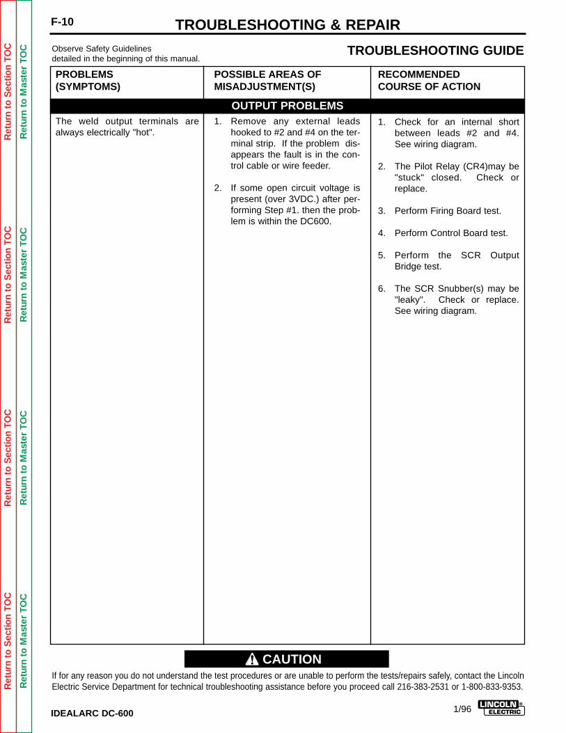
Ret
urn
to S
ectio
n T
OC
Ret
urn
to S
ectio
n T
OC
Ret
urn
to S
ectio
n T
OC
Ret
urn
to S
ectio
n T
OC
Ret
urn
to M
aste
r T
OC
Ret
urn
to M
aste
r T
OC
Ret
urn
to M
aste
r T
OC
Ret
urn
to M
aste
r T
OC
IDEALARC DC-600
F-10 TROUBLESHOOTING & REPAIRObserve Safety Guidelinesdetailed in the beginning of this manual.
TROUBLESHOOTING GUIDE
PROBLEMS(SYMPTOMS)
The weld output terminals arealways electrically "hot".
POSSIBLE AREAS OFMISADJUSTMENT(S)
1. Remove any external leadshooked to #2 and #4 on the ter-minal strip. If the problem dis-appears the fault is in the con-trol cable or wire feeder.
2. If some open circuit voltage ispresent (over 3VDC.) after per-forming Step #1. then the prob-lem is within the DC600.
RECOMMENDEDCOURSE OF ACTION
1. Check for an internal shortbetween leads #2 and #4.See wiring diagram.
2. The Pilot Relay (CR4)may be"stuck" closed. Check orreplace.
3. Perform Firing Board test.
4. Perform Control Board test.
5. Perform the SCR OutputBridge test.
6. The SCR Snubber(s) may be"leaky". Check or replace.See wiring diagram.
If for any reason you do not understand the test procedures or are unable to perform the tests/repairs safely, contact the LincolnElectric Service Department for technical troubleshooting assistance before you proceed call 216-383-2531 or 1-800-833-9353.
OUTPUT PROBLEMS
CAUTION
1/96
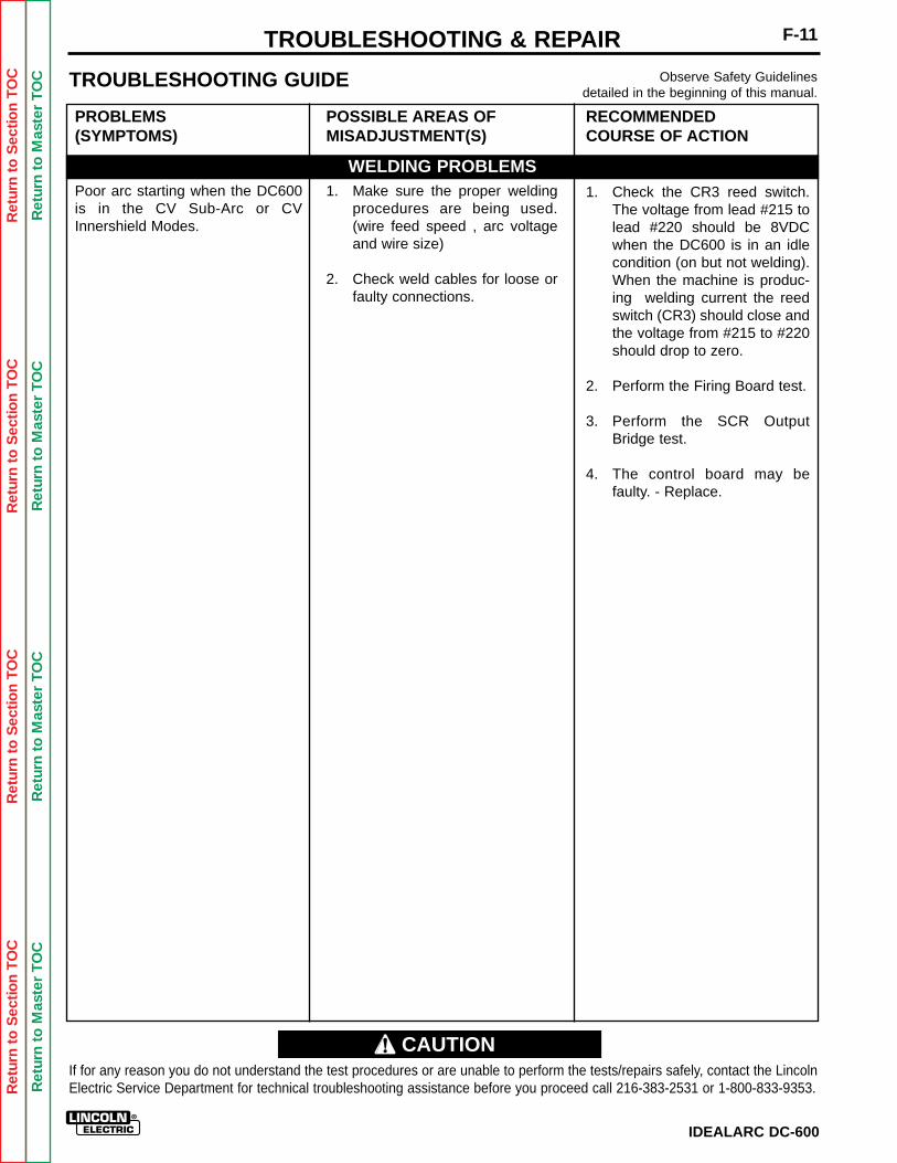
Ret
urn
to S
ectio
n T
OC
Ret
urn
to S
ectio
n T
OC
Ret
urn
to S
ectio
n T
OC
Ret
urn
to S
ectio
n T
OC
Ret
urn
to M
aste
r T
OC
Ret
urn
to M
aste
r T
OC
Ret
urn
to M
aste
r T
OC
Ret
urn
to M
aste
r T
OC
IDEALARC DC-600
F-11TROUBLESHOOTING & REPAIRObserve Safety Guidelines
detailed in the beginning of this manual.TROUBLESHOOTING GUIDE
PROBLEMS(SYMPTOMS)
Poor arc starting when the DC600is in the CV Sub-Arc or CVInnershield Modes.
POSSIBLE AREAS OFMISADJUSTMENT(S)
1. Make sure the proper weldingprocedures are being used.(wire feed speed , arc voltageand wire size)
2. Check weld cables for loose orfaulty connections.
RECOMMENDEDCOURSE OF ACTION
1. Check the CR3 reed switch.The voltage from lead #215 tolead #220 should be 8VDCwhen the DC600 is in an idlecondition (on but not welding).When the machine is produc-ing welding current the reedswitch (CR3) should close andthe voltage from #215 to #220should drop to zero.
2. Perform the Firing Board test.
3. Perform the SCR OutputBridge test.
4. The control board may befaulty. - Replace.
If for any reason you do not understand the test procedures or are unable to perform the tests/repairs safely, contact the LincolnElectric Service Department for technical troubleshooting assistance before you proceed call 216-383-2531 or 1-800-833-9353.
WELDING PROBLEMS
CAUTION
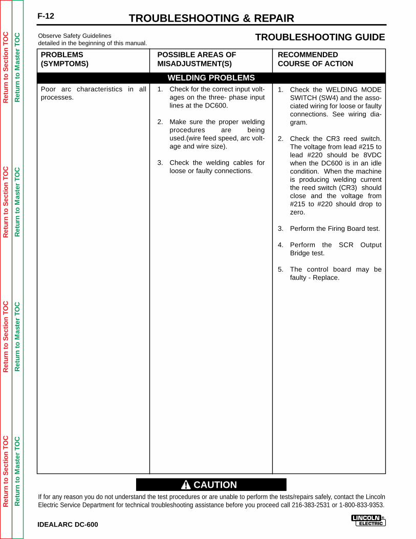
Ret
urn
to S
ectio
n T
OC
Ret
urn
to S
ectio
n T
OC
Ret
urn
to S
ectio
n T
OC
Ret
urn
to S
ectio
n T
OC
Ret
urn
to M
aste
r T
OC
Ret
urn
to M
aste
r T
OC
Ret
urn
to M
aste
r T
OC
Ret
urn
to M
aste
r T
OC
IDEALARC DC-600
F-12 TROUBLESHOOTING & REPAIRObserve Safety Guidelinesdetailed in the beginning of this manual.
TROUBLESHOOTING GUIDE
PROBLEMS(SYMPTOMS)
Poor arc characteristics in allprocesses.
POSSIBLE AREAS OFMISADJUSTMENT(S)
1. Check for the correct input volt-ages on the three- phase inputlines at the DC600.
2. Make sure the proper weldingprocedures are beingused.(wire feed speed, arc volt-age and wire size).
3. Check the welding cables forloose or faulty connections.
RECOMMENDEDCOURSE OF ACTION
1. Check the WELDING MODESWITCH (SW4) and the asso-ciated wiring for loose or faultyconnections. See wiring dia-gram.
2. Check the CR3 reed switch.The voltage from lead #215 tolead #220 should be 8VDCwhen the DC600 is in an idlecondition. When the machineis producing welding currentthe reed switch (CR3) shouldclose and the voltage from#215 to #220 should drop tozero.
3. Perform the Firing Board test.
4. Perform the SCR OutputBridge test.
5. The control board may befaulty - Replace.
If for any reason you do not understand the test procedures or are unable to perform the tests/repairs safely, contact the LincolnElectric Service Department for technical troubleshooting assistance before you proceed call 216-383-2531 or 1-800-833-9353.
WELDING PROBLEMS
CAUTION
Ret
urn
to S
ectio
n T
OC
Ret
urn
to S
ectio
n T
OC
Ret
urn
to S
ectio
n T
OC
Ret
urn
to S
ectio
n T
OC
Ret
urn
to M
aste
r T
OC
Ret
urn
to M
aste
r T
OC
Ret
urn
to M
aste
r T
OC
Ret
urn
to M
aste
r T
OC
IDEALARC DC-600
F-13TROUBLESHOOTING & REPAIR
CONTROL TRANSFORMER (T2) VOLTAGE TEST
Service and repair should be performed only by Lincoln Electric factory trained personnel.Unauthorized repairs performed on this equipment could result in danger to the technicianor the machine operator and will invalidate your factory warranty. For your safety and toavoid electrical shock, please observe all safety notes and precautions detailed throughoutthis manual.
If for any reason you do not understand the test procedures or are unable to perform thetests/repairs safely, contact the Lincoln Electric service department for technical trou-bleshooting assistance before you proceed. Call (216) 383-2531 or (800) 833-9353(WELD).
______________________________
TEST DESCRIPTION
This test will determine if the correct voltage is beinga. applied to the primary of the control transformer.b. induced on the secondary winding of the control transformer.
MATERIALS NEEDED
Volt/Ohm Meter (Multimeter)IDEALARC DC-600 wiring diagrams (See Electrical Diagram Section of Manual).
WARNING
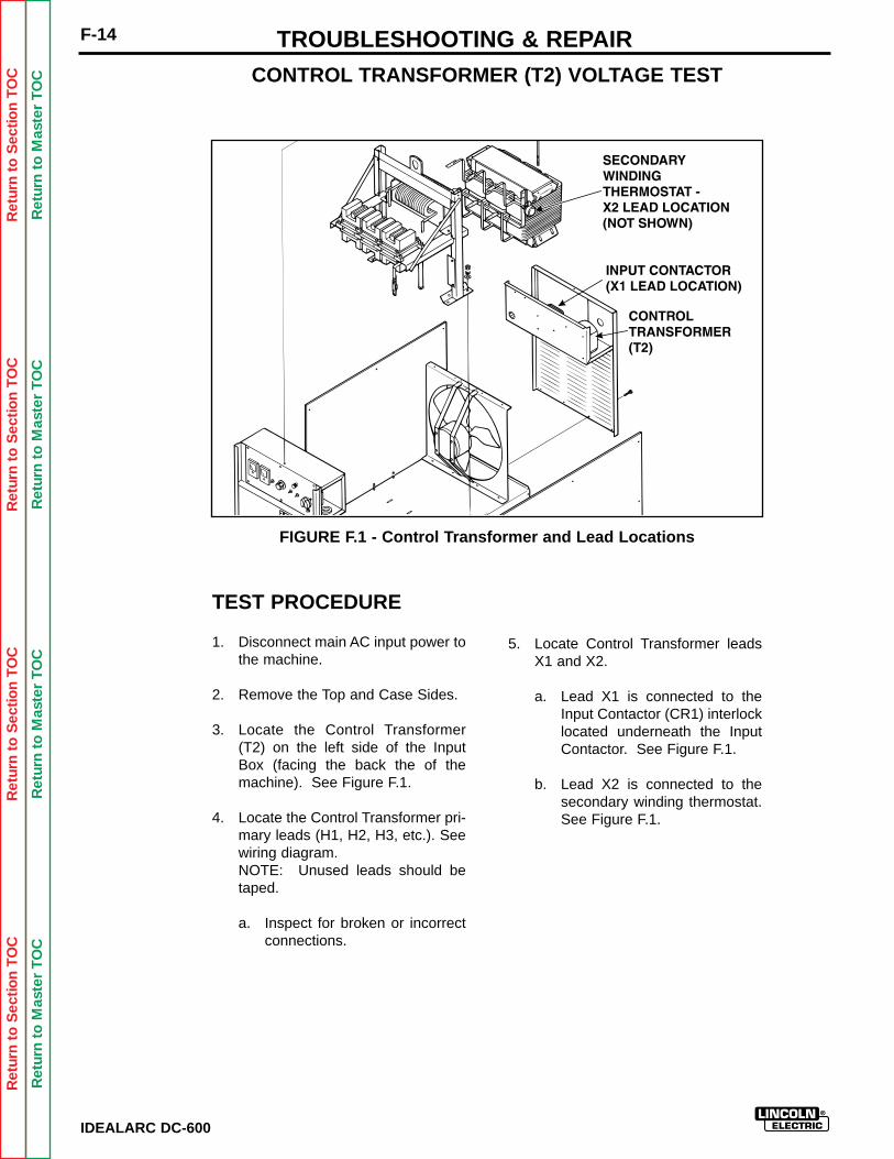
Ret
urn
to S
ectio
n T
OC
Ret
urn
to S
ectio
n T
OC
Ret
urn
to S
ectio
n T
OC
Ret
urn
to S
ectio
n T
OC
Ret
urn
to M
aste
r T
OC
Ret
urn
to M
aste
r T
OC
Ret
urn
to M
aste
r T
OC
Ret
urn
to M
aste
r T
OC
F-14
IDEALARC DC-600
TROUBLESHOOTING & REPAIR
FIGURE F.1 - Control Transformer and Lead Locations
TEST PROCEDURE
1. Disconnect main AC input power tothe machine.
2. Remove the Top and Case Sides.
3. Locate the Control Transformer(T2) on the left side of the InputBox (facing the back the of themachine). See Figure F.1.
4. Locate the Control Transformer pri-mary leads (H1, H2, H3, etc.). Seewiring diagram.NOTE: Unused leads should betaped.
a. Inspect for broken or incorrectconnections.
5. Locate Control Transformer leadsX1 and X2.
a. Lead X1 is connected to theInput Contactor (CR1) interlocklocated underneath the InputContactor. See Figure F.1.
b. Lead X2 is connected to thesecondary winding thermostat.See Figure F.1.
CONTROL TRANSFORMER (T2) VOLTAGE TEST
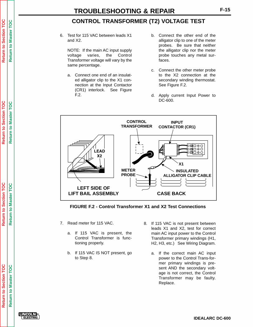
Ret
urn
to S
ectio
n T
OC
Ret
urn
to S
ectio
n T
OC
Ret
urn
to S
ectio
n T
OC
Ret
urn
to S
ectio
n T
OC
Ret
urn
to M
aste
r T
OC
Ret
urn
to M
aste
r T
OC
Ret
urn
to M
aste
r T
OC
Ret
urn
to M
aste
r T
OC
6. Test for 115 VAC between leads X1and X2.
NOTE: If the main AC input supplyvoltage varies, the ControlTransformer voltage will vary by thesame percentage.
a. Connect one end of an insulat-ed alligator clip to the X1 con-nection at the Input Contactor(CR1) interlock. See FigureF.2.
IDEALARC DC-600
F-15TROUBLESHOOTING & REPAIRCONTROL TRANSFORMER (T2) VOLTAGE TEST
CONTROLTRANSFORMER
INPUTCONTACTOR (CR1)
INSULATEDALLIGATOR CLIP CABLE
X1
METERPROBE
LEFT SIDE OFLIFT BAIL ASSEMBLY CASE BACK
b. Connect the other end of thealligator clip to one of the meterprobes. Be sure that neitherthe alligator clip nor the meterprobe touches any metal sur-faces.
c. Connect the other meter probeto the X2 connection at thesecondary winding thermostat.See Figure F.2.
d. Apply current Input Power toDC-600.
FIGURE F.2 - Control Transformer X1 and X2 Test Connections
7. Read meter for 115 VAC.
a. If 115 VAC is present, theControl Transformer is func-tioning properly.
b. If 115 VAC IS NOT present, goto Step 8.
8. If 115 VAC is not present betweenleads X1 and X2, test for correctmain AC input power to the ControlTransformer primary windings (H1,H2, H3, etc.) See Wiring Diagram.
a. If the correct main AC inputpower to the Control Trans-for-mer primary windings is pre-sent AND the secondary volt-age is not correct, the ControlTransformer may be faulty.Replace.

Ret
urn
to S
ectio
n T
OC
Ret
urn
to S
ectio
n T
OC
Ret
urn
to S
ectio
n T
OC
Ret
urn
to S
ectio
n T
OC
Ret
urn
to M
aste
r T
OC
Ret
urn
to M
aste
r T
OC
Ret
urn
to M
aste
r T
OC
Ret
urn
to M
aste
r T
OC
IDEALARC DC-600
F-16
MAIN TRANSFORMER (T1) VOLTAGE TEST
Service and repair should be performed only by Lincoln Electric factory trained personnel.Unauthorized repairs performed on this equipment could result in danger to the technicianor the machine operator and will invalidate your factory warranty. For your safety and toavoid electrical shock, please observe all safety notes and precautions detailed throughoutthis manual.
If for any reason you do not understand the test procedures or are unable to perform thetests/repairs safely, contact the Lincoln Electric service department for technical trou-bleshooting assistance before you proceed. Call (216) 383-2531 or (800) 833-9353(WELD).
______________________________
TEST DESCRIPTION
This test will determine if the correct voltages are beinga. applied to the primary windings of the Main Transformer (T1).b. induced on the secondary winding, auxiliary windings, and phase angle
windings.
MATERIALS NEEDED
Volt/Ohm Meter (Multimeter)IDEALARC DC-600 wiring diagram (See Electrical Diagram Section of Manual).
TROUBLESHOOTING & REPAIR
WARNING
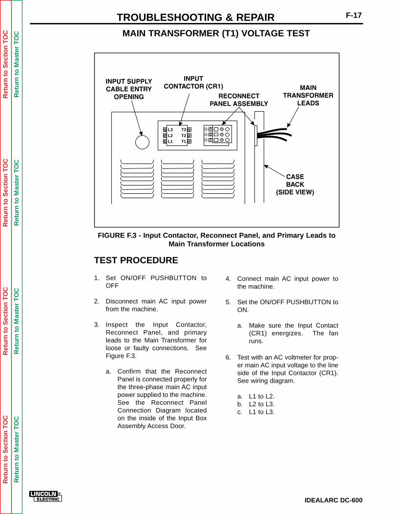
Ret
urn
to S
ectio
n T
OC
Ret
urn
to S
ectio
n T
OC
Ret
urn
to S
ectio
n T
OC
Ret
urn
to S
ectio
n T
OC
Ret
urn
to M
aste
r T
OC
Ret
urn
to M
aste
r T
OC
Ret
urn
to M
aste
r T
OC
Ret
urn
to M
aste
r T
OC
IDEALARC DC-600
F-17TROUBLESHOOTING & REPAIR
TEST PROCEDURE
1. Set ON/OFF PUSHBUTTON toOFF
2. Disconnect main AC input powerfrom the machine.
3. Inspect the Input Contactor,Reconnect Panel, and primaryleads to the Main Transformer forloose or faulty connections. SeeFigure F.3.
a. Confirm that the ReconnectPanel is connected properly forthe three-phase main AC inputpower supplied to the machine.See the Reconnect PanelConnection Diagram locatedon the inside of the Input BoxAssembly Access Door.
4. Connect main AC input power tothe machine.
5. Set the ON/OFF PUSHBUTTON toON.
a. Make sure the Input Contact(CR1) energizes. The fanruns.
6. Test with an AC voltmeter for prop-er main AC input voltage to the lineside of the Input Contactor (CR1).See wiring diagram.
a. L1 to L2.b. L2 to L3.c. L1 to L3.
MAIN TRANSFORMER (T1) VOLTAGE TEST
L3L2L1
T3T2T1
FIGURE F.3 - Input Contactor, Reconnect Panel, and Primary Leads toMain Transformer Locations
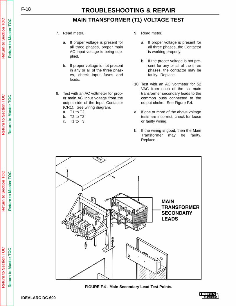
Ret
urn
to S
ectio
n T
OC
Ret
urn
to S
ectio
n T
OC
Ret
urn
to S
ectio
n T
OC
Ret
urn
to S
ectio
n T
OC
Ret
urn
to M
aste
r T
OC
Ret
urn
to M
aste
r T
OC
Ret
urn
to M
aste
r T
OC
Ret
urn
to M
aste
r T
OC
IDEALARC DC-600
F-18 TROUBLESHOOTING & REPAIR
7. Read meter.
a. If proper voltage is present forall three phases, proper mainAC input voltage is being sup-plied.
b. If proper voltage is not presentin any or all of the three phas-es, check input fuses andleads.
8. Test with an AC voltmeter for prop-er main AC input voltage from theoutput side of the Input Contactor(CR1). See wiring diagram.a. T1 to T2.b. T2 to T3.c. T1 to T3.
9. Read meter.
a. If proper voltage is present forall three phases, the Contactoris working properly.
b. If the proper voltage is not pre-sent for any or all of the threephases, the contactor may befaulty. Replace.
10. Test with an AC voltmeter for 52VAC from each of the six maintransformer secondary leads to thecommon buss connected to theoutput choke. See Figure F.4.
a. If one or more of the above voltagetests are incorrect, check for looseor faulty wiring.
b. If the wiring is good, then the MainTransformer may be faulty.Replace.
MAIN TRANSFORMER (T1) VOLTAGE TEST
FIGURE F.4 - Main Secondary Lead Test Points.
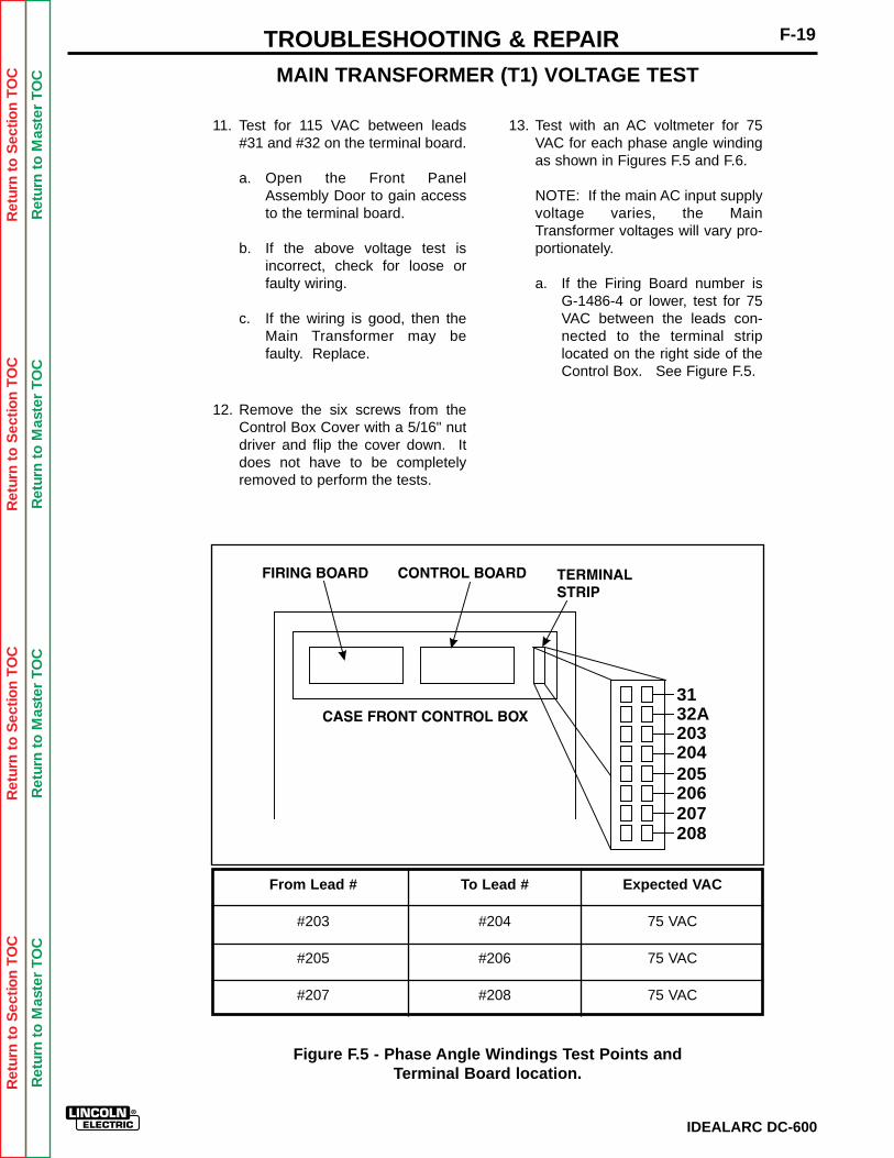
Ret
urn
to S
ectio
n T
OC
Ret
urn
to S
ectio
n T
OC
Ret
urn
to S
ectio
n T
OC
Ret
urn
to S
ectio
n T
OC
Ret
urn
to M
aste
r T
OC
Ret
urn
to M
aste
r T
OC
Ret
urn
to M
aste
r T
OC
Ret
urn
to M
aste
r T
OC
IDEALARC DC-600
F-19TROUBLESHOOTING & REPAIR
11. Test for 115 VAC between leads#31 and #32 on the terminal board.
a. Open the Front PanelAssembly Door to gain accessto the terminal board.
b. If the above voltage test isincorrect, check for loose orfaulty wiring.
c. If the wiring is good, then theMain Transformer may befaulty. Replace.
12. Remove the six screws from theControl Box Cover with a 5/16" nutdriver and flip the cover down. Itdoes not have to be completelyremoved to perform the tests.
13. Test with an AC voltmeter for 75VAC for each phase angle windingas shown in Figures F.5 and F.6.
NOTE: If the main AC input supplyvoltage varies, the MainTransformer voltages will vary pro-portionately.
a. If the Firing Board number isG-1486-4 or lower, test for 75VAC between the leads con-nected to the terminal striplocated on the right side of theControl Box. See Figure F.5.
MAIN TRANSFORMER (T1) VOLTAGE TEST
From Lead # To Lead # Expected VAC
#203 #204 75 VAC
#205 #206 75 VAC
#207 #208 75 VAC
Figure F.5 - Phase Angle Windings Test Points andTerminal Board location.
3132A203204205206207208
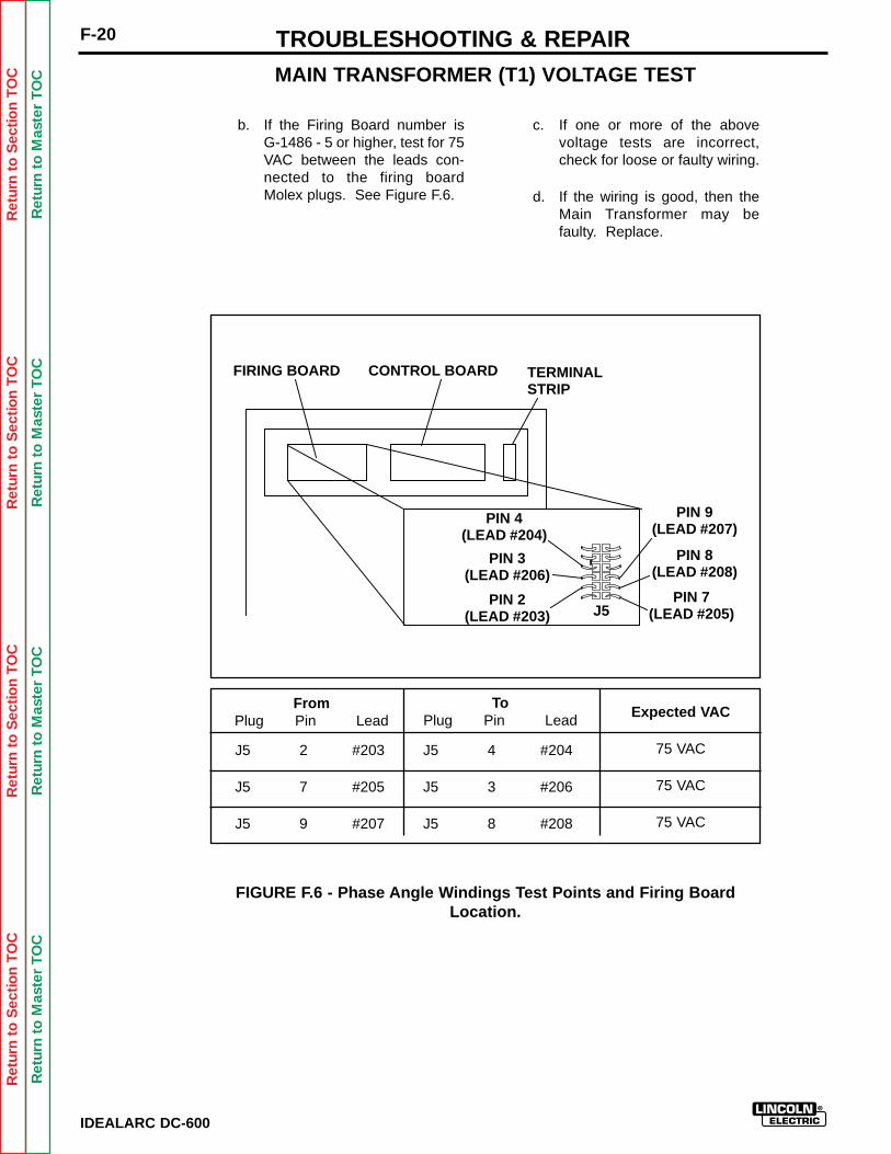
Ret
urn
to S
ectio
n T
OC
Ret
urn
to S
ectio
n T
OC
Ret
urn
to S
ectio
n T
OC
Ret
urn
to S
ectio
n T
OC
Ret
urn
to M
aste
r T
OC
Ret
urn
to M
aste
r T
OC
Ret
urn
to M
aste
r T
OC
Ret
urn
to M
aste
r T
OC
IDEALARC DC-600
F-20 TROUBLESHOOTING & REPAIR
b. If the Firing Board number isG-1486 - 5 or higher, test for 75VAC between the leads con-nected to the firing boardMolex plugs. See Figure F.6.
c. If one or more of the abovevoltage tests are incorrect,check for loose or faulty wiring.
d. If the wiring is good, then theMain Transformer may befaulty. Replace.
MAIN TRANSFORMER (T1) VOLTAGE TEST
FromPlug Pin Lead
ToPlug Pin Lead Expected VAC
J5 2 #203 J5 4 #204 75 VAC
J5 7 #205 J5 3 #206 75 VAC
J5 9 #207 J5 8 #208 75 VAC
FIGURE F.6 - Phase Angle Windings Test Points and Firing BoardLocation.
FIRING BOARD CONTROL BOARD TERMINALSTRIP
J5
PIN 8(LEAD #208)
PIN 9(LEAD #207)
PIN 4(LEAD #204)
PIN 7(LEAD #205)
PIN 2(LEAD #203)
PIN 3(LEAD #206)

Ret
urn
to S
ectio
n T
OC
Ret
urn
to S
ectio
n T
OC
Ret
urn
to S
ectio
n T
OC
Ret
urn
to S
ectio
n T
OC
Ret
urn
to M
aste
r T
OC
Ret
urn
to M
aste
r T
OC
Ret
urn
to M
aste
r T
OC
Ret
urn
to M
aste
r T
OC
FIRING BOARD TEST
Service and repair should be performed only by Lincoln Electric factory trained personnel.Unauthorized repairs performed on this equipment could result in danger to the technicianor the machine operator and will invalidate your factory warranty. For your safety and toavoid electrical shock, please observe all safety notes and precautions detailed throughoutthis manual.
If for any reason you do not understand the test procedures or are unable to perform thetests/repairs safely, contact the Lincoln Electric service department for technical trou-bleshooting assistance before you proceed. Call (216) 383-2531 or (800) 833-9353(WELD).
______________________________
TEST DESCRIPTION
This test determines whether or not the Firing Board is receiving the correct voltages andgate signals. The LEDs (Light Emitting Diodes) will help you determine if the Firing Boardis generating gate signals to the main SCRs.
MATERIALS NEEDED
Volt/Ohm Meter (Multimeter)IDEALARC DC-600 wiring diagram and Firing Board schematic drawing (See ElectricalDrawing Section of Manual).
F-21TROUBLESHOOTING & REPAIR
IDEALARC DC-600
WARNING
Ret
urn
to S
ectio
n T
OC
Ret
urn
to S
ectio
n T
OC
Ret
urn
to S
ectio
n T
OC
Ret
urn
to S
ectio
n T
OC
Ret
urn
to M
aste
r T
OC
Ret
urn
to M
aste
r T
OC
Ret
urn
to M
aste
r T
OC
Ret
urn
to M
aste
r T
OC
TEST PROCEDURE FORNORMAL FIRING BOARDOPERATION
1. Disconnect main AC input power tothe IDEALARC DC-600.
2. Locate the Firing Board on the leftside of Control Box facing themachine.
3. Perform a visual inspection of theFiring Board to see if there are anyloose or faulty connections.
4. Connect the correct main AC inputpower to the machine.
5. Set the ON/OFF PUSHBUTTON toON.
6. Locate LEDs 7, 8, and 9 on theFiring Board. See Figure F.7.Each LED should be ON and beequally bright. Use Table F.1 tocheck the operation of each LED.
FIRING BOARD TEST
F-22 TROUBLESHOOTING & REPAIR
IDEALARC DC-600
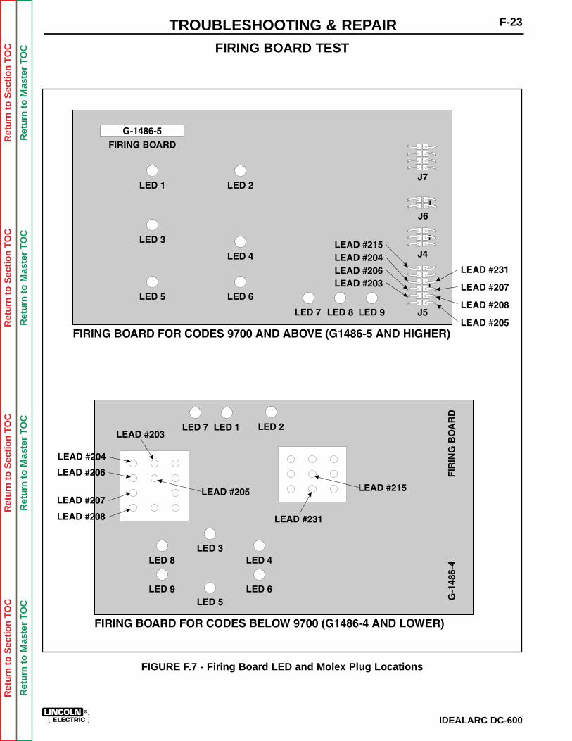
FIRING BOARD TEST
FIGURE F.7 - Firing Board LED and Molex Plug Locations
F-23TROUBLESHOOTING & REPAIR
IDEALARC DC-600
Ret
urn
to S
ectio
n T
OC
Ret
urn
to S
ectio
n T
OC
Ret
urn
to S
ectio
n T
OC
Ret
urn
to S
ectio
n T
OC
Ret
urn
to M
aste
r T
OC
Ret
urn
to M
aste
r T
OC
Ret
urn
to M
aste
r T
OC
Ret
urn
to M
aste
r T
OC
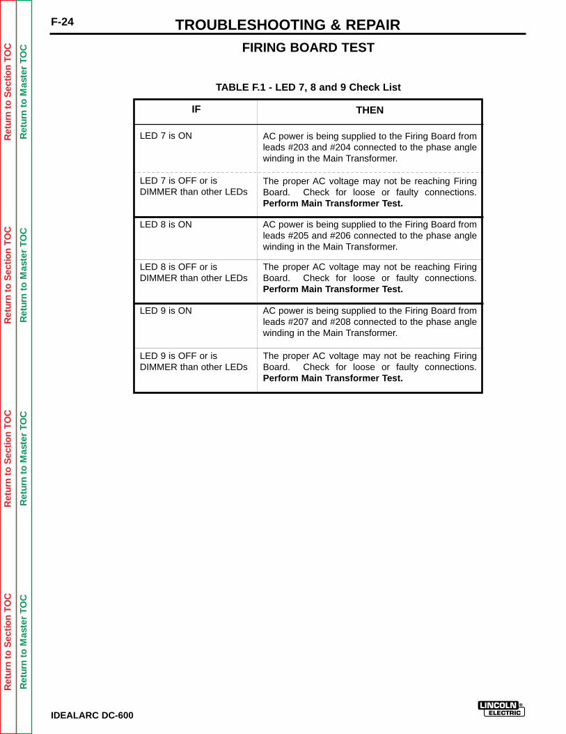
FIRING BOARD TEST
IDEALARC DC-600
F-24 TROUBLESHOOTING & REPAIR
TABLE F.1 - LED 7, 8 and 9 Check List
IF
LED 7 is ON
THEN
AC power is being supplied to the Firing Board fromleads #203 and #204 connected to the phase anglewinding in the Main Transformer.
LED 7 is OFF or is DIMMER than other LEDs
The proper AC voltage may not be reaching FiringBoard. Check for loose or faulty connections.Perform Main Transformer Test.
LED 8 is ON AC power is being supplied to the Firing Board fromleads #205 and #206 connected to the phase anglewinding in the Main Transformer.
LED 8 is OFF or is DIMMER than other LEDs
The proper AC voltage may not be reaching FiringBoard. Check for loose or faulty connections.Perform Main Transformer Test.
LED 9 is ON AC power is being supplied to the Firing Board fromleads #207 and #208 connected to the phase anglewinding in the Main Transformer.
LED 9 is OFF or is DIMMER than other LEDs
The proper AC voltage may not be reaching FiringBoard. Check for loose or faulty connections.Perform Main Transformer Test.
Ret
urn
to S
ectio
n T
OC
Ret
urn
to S
ectio
n T
OC
Ret
urn
to S
ectio
n T
OC
Ret
urn
to S
ectio
n T
OC
Ret
urn
to M
aste
r T
OC
Ret
urn
to M
aste
r T
OC
Ret
urn
to M
aste
r T
OC
Ret
urn
to M
aste
r T
OC
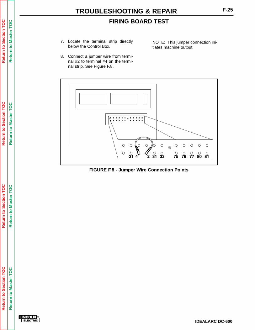
Ret
urn
to S
ectio
n T
OC
Ret
urn
to S
ectio
n T
OC
Ret
urn
to S
ectio
n T
OC
Ret
urn
to S
ectio
n T
OC
Ret
urn
to M
aste
r T
OC
Ret
urn
to M
aste
r T
OC
Ret
urn
to M
aste
r T
OC
Ret
urn
to M
aste
r T
OC
7. Locate the terminal strip directlybelow the Control Box.
8. Connect a jumper wire from termi-nal #2 to terminal #4 on the termi-nal strip. See Figure F.8.
FIGURE F.8 - Jumper Wire Connection Points
FIRING BOARD TEST
NOTE: This jumper connection ini-tiates machine output.
F-25TROUBLESHOOTING & REPAIR
IDEALARC DC-600
Ret
urn
to S
ectio
n T
OC
Ret
urn
to S
ectio
n T
OC
Ret
urn
to S
ectio
n T
OC
Ret
urn
to S
ectio
n T
OC
Ret
urn
to M
aste
r T
OC
Ret
urn
to M
aste
r T
OC
Ret
urn
to M
aste
r T
OC
Ret
urn
to M
aste
r T
OC
IDEALARC DC-600
F-26 TROUBLESHOOTING & REPAIR
9. Locate LEDs 1 to 6. Each LEDshould glow with equal brightness.NOTE: LEDs 1 to 6 indicate thatthe gate firing signals are beinggenerated to send to each of theSCRs.
10. Set the OUTPUT CONTROLSWITCH (SW3) in the "OutputControl at DC-600" position.
11. Set the WELDING CONTROLSWITCH in either of the "CV" posi-tions.
12. Rotate the OUTPUT CONTROLPOTENTIOMETER. As the pot isturned clockwise, the LEDs glowbrighter. As the pot is turnedcounter-clockwise, the LEDs dim.
a. If the LEDs glow and change inbrightness equally as the pot isturned and the problem contin-ues, then the SCR Bridge maybe faulty. Perform SCR Bridgetest.
b. If any or all of LEDs 1-6 do notglow or do not change inbrightness equally as the pot isturned, go to Step 13.
13. Test for 10 VDC to 13 VDCbetween leads #231 and #215 onthe Firing Board in CV mode.
a. Locate on the Firing Board theMolex Plug with leads #231and #215 connected to it. SeeFigure F.7.
b. Set the ON/OFF PUSH BUTTON to OFF.
c. Remove the Molex Plug fromthe board.
d. Insert the meter probes into theappropriate Plug lead cavities.
NOTE: OBSERVE POLARITY.DC VOLTAGES BEING TESTED.
e. Connect the Molex Plug intothe Firing Board.
f. Set the WELDING MODESWITCH in either of the "CV"positions.
g. Set the ON/OFF PUSHBUT-TON to ON.
h. Rotate the OUTPUT CON-TROL POTENTIOMETERclockwise and counter-clock-wise. The DC voltage betweenleads #231 and #215 shouldvary from 10 VDC to 13 VDCas the pot is turned from mini-mum to maximum.
i. If the voltage does NOT vary,then the Control Board may befaulty. Replace.
FIRING BOARD TEST
Ret
urn
to S
ectio
n T
OC
Ret
urn
to S
ectio
n T
OC
Ret
urn
to S
ectio
n T
OC
Ret
urn
to S
ectio
n T
OC
Ret
urn
to M
aste
r T
OC
Ret
urn
to M
aste
r T
OC
Ret
urn
to M
aste
r T
OC
Ret
urn
to M
aste
r T
OC
TROUBLESHOOTING & REPAIR
IDEALARC DC-600
F-27
14. Test for approximately 5.8 VDCbetween leads #231 and # 215 onthe Firing Board in VV (CC) mode.
a. Keep the meter probes insert-ed into the Plug lead cavitiesfor leads #231 and #215.
b. Keep the jumper connected atterminals #2 and #4 at the ter-minal strip.
c. Set the WELDING MODESWITCH (SW4) to the VV (CC)position.
d. Rotate the OUTPUT CON-TROL POTENTIOMETERclockwise and counter-clock-wise. The DC voltage betweenleads #231 and #215 should beconstant at approximately 5.8VDC. This voltage should notvary when the pot is turned.
e. Remove probes inserted intothe Molex Plug lead cavities oflead #231 and #215.
15. Test Output Pilot Control Relay(CR4) for proper operation byremoving and replacing repeatedlythe jumper wire from terminal # 2.This should cause the relay con-tacts to open and close. The con-tacts can be seen closing andopening through the clear plasticrelay case or can be heard openingand closing.
a. If the Output Control Relay(CR4) does not close whenenergized, check for loose orfaulty wiring.
16. Remove the jumper from terminals#2 and #4 on the terminal strip.
17. Replace the Firing Board if theabove voltage and control relaytests were passed. It may befaulty.
FIRING BOARD TEST

Ret
urn
to S
ectio
n T
OC
Ret
urn
to S
ectio
n T
OC
Ret
urn
to S
ectio
n T
OC
Ret
urn
to S
ectio
n T
OC
Ret
urn
to M
aste
r T
OC
Ret
urn
to M
aste
r T
OC
Ret
urn
to M
aste
r T
OC
Ret
urn
to M
aste
r T
OC
IDEALARC DC-600
F-28 TROUBLESHOOTING & REPAIR
CONTROL BOARD TEST
Service and repair should be performed only by Lincoln Electric factory trained personnel.Unauthorized repairs performed on this equipment could result in danger to the technicianor the machine operator and will invalidate your factory warranty. For your safety and toavoid electrical shock, please observe all safety notes and precautions detailed throughoutthis manual.
If for any reason you do not understand the test procedures or are unable to perform thetests/repairs safely, contact the Lincoln Electric service department for technical trou-bleshooting assistance before you proceed. Call (216) 383-2531 or (800) 833-9353(WELD).
______________________________
TEST DESCRIPTION
This test will determine if the Control Board is receiving the correct voltages and feedbacksignals.
MATERIALS NEEDED
Analog Volt/Ohm Meter (Multimeter)IDEALARC DC-600 wiring diagrams (See Electrical Diagrams Section of this Manual).
WARNING
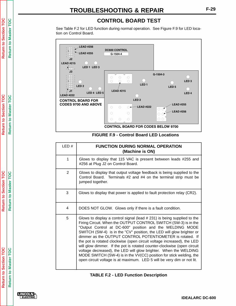
Ret
urn
to S
ectio
n T
OC
Ret
urn
to S
ectio
n T
OC
Ret
urn
to S
ectio
n T
OC
Ret
urn
to S
ectio
n T
OC
Ret
urn
to M
aste
r T
OC
Ret
urn
to M
aste
r T
OC
Ret
urn
to M
aste
r T
OC
Ret
urn
to M
aste
r T
OC
See Table F.2 for LED function during normal operation. See Figure F.9 for LED loca-tion on Control Board.
FIGURE F.9 - Control Board LED Locations
IDEALARC DC-600
F-29TROUBLESHOOTING & REPAIR
CONTROL BOARD TEST
Glows to display that 115 VAC is present between leads #255 and#256 at Plug J2 on Control Board.
1
Glows to display that output voltage feedback is being supplied to theControl Board. Terminals #2 and #4 on the terminal strip must bejumped together.
2
Glows to display that power is applied to fault protection relay (CR2).3
DOES NOT GLOW. Glows only if there is a fault condition.4
Glows to display a control signal (lead # 231) is being supplied to theFiring Circuit. When the OUTPUT CONTROL SWITCH (SW-3) is in the"Output Control at DC-600" position and the WELDING MODESWITCH (SW-4) is in the "CV" position, the LED will glow brighter ordimmer as the OUTPUT CONTROL POTENTIOMETER is rotated. Ifthe pot is rotated clockwise (open circuit voltage increased), the LEDwill glow dimmer. If the pot is rotated counter-clockwise (open circuitvoltage decreased), the LED will glow brighter. When the WELDINGMODE SWITCH (SW-4) is in the VV(CC) position for stick welding, theopen circuit voltage is at maximum. LED 5 will be very dim or not lit.
5
FUNCTION DURING NORMAL OPERATION(Machine is ON)
LED #
TABLE F.2 - LED Function Description
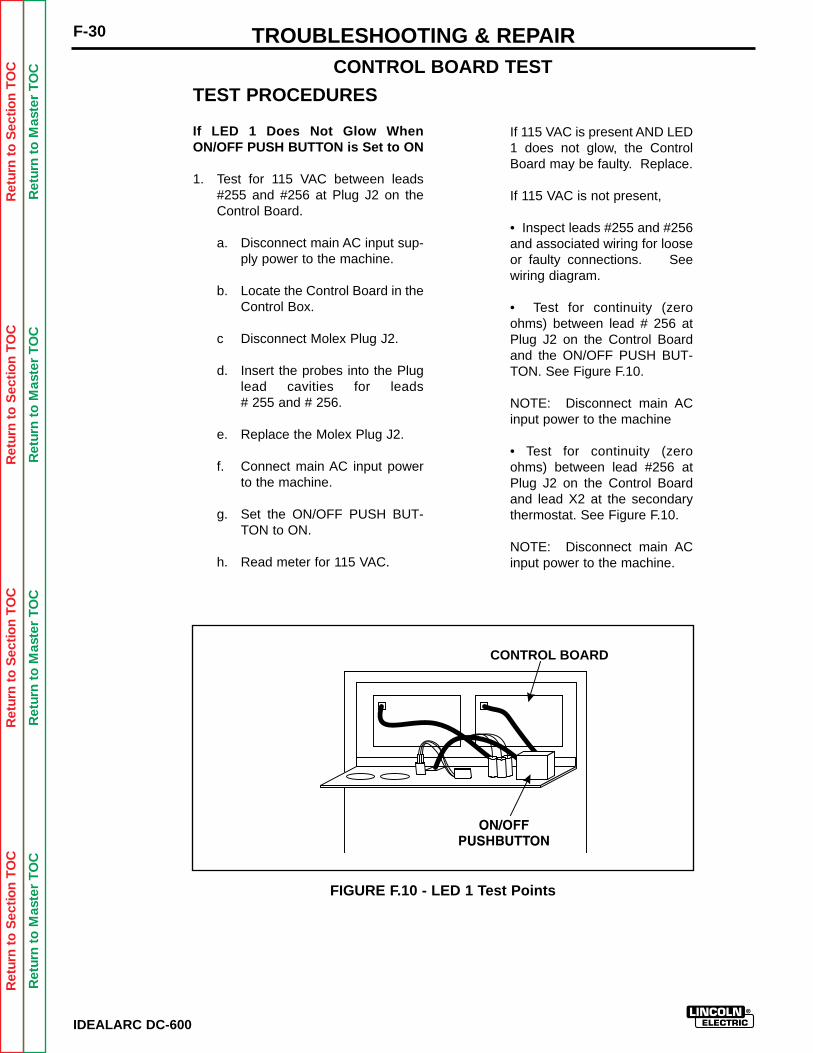
Ret
urn
to S
ectio
n T
OC
Ret
urn
to S
ectio
n T
OC
Ret
urn
to S
ectio
n T
OC
Ret
urn
to S
ectio
n T
OC
Ret
urn
to M
aste
r T
OC
Ret
urn
to M
aste
r T
OC
Ret
urn
to M
aste
r T
OC
Ret
urn
to M
aste
r T
OC
IDEALARC DC-600
F-30 TROUBLESHOOTING & REPAIR
TEST PROCEDURES
If LED 1 Does Not Glow WhenON/OFF PUSH BUTTON is Set to ON
1. Test for 115 VAC between leads#255 and #256 at Plug J2 on theControl Board.
a. Disconnect main AC input sup-ply power to the machine.
b. Locate the Control Board in theControl Box.
c Disconnect Molex Plug J2.
d. Insert the probes into the Pluglead cavities for leads # 255 and # 256.
e. Replace the Molex Plug J2.
f. Connect main AC input powerto the machine.
g. Set the ON/OFF PUSH BUT-TON to ON.
h. Read meter for 115 VAC.
If 115 VAC is present AND LED1 does not glow, the ControlBoard may be faulty. Replace.
If 115 VAC is not present,
• Inspect leads #255 and #256and associated wiring for looseor faulty connections. Seewiring diagram.
• Test for continuity (zeroohms) between lead # 256 atPlug J2 on the Control Boardand the ON/OFF PUSH BUT-TON. See Figure F.10.
NOTE: Disconnect main ACinput power to the machine
• Test for continuity (zeroohms) between lead #256 atPlug J2 on the Control Boardand lead X2 at the secondarythermostat. See Figure F.10.
NOTE: Disconnect main ACinput power to the machine.
FIGURE F.10 - LED 1 Test Points
CONTROL BOARD
CONTROL BOARD TEST
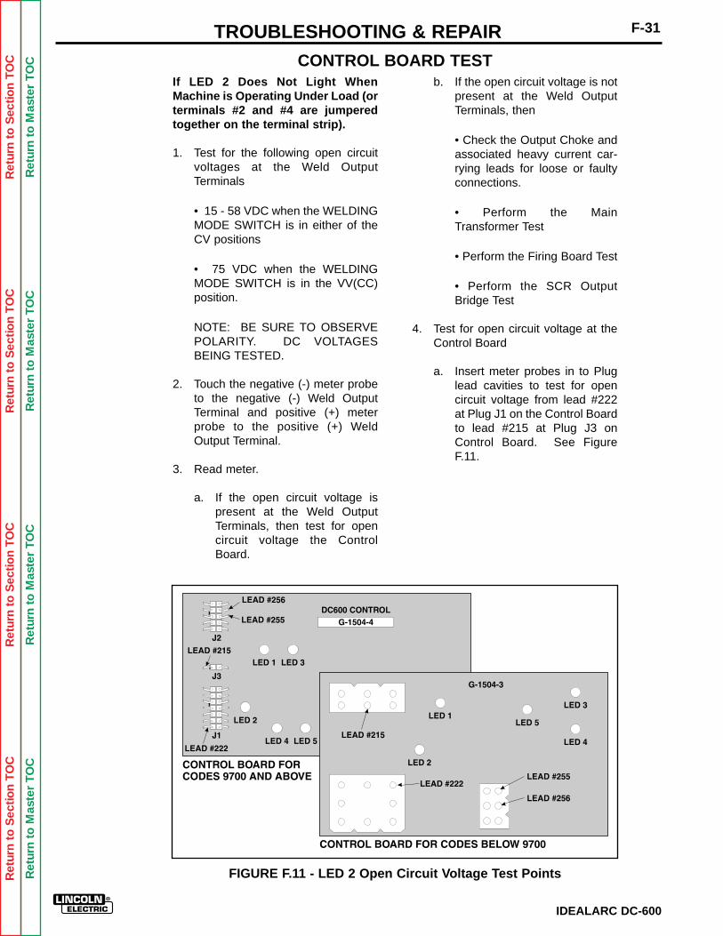
Ret
urn
to S
ectio
n T
OC
Ret
urn
to S
ectio
n T
OC
Ret
urn
to S
ectio
n T
OC
Ret
urn
to S
ectio
n T
OC
Ret
urn
to M
aste
r T
OC
Ret
urn
to M
aste
r T
OC
Ret
urn
to M
aste
r T
OC
Ret
urn
to M
aste
r T
OC
IDEALARC DC-600
F-31TROUBLESHOOTING & REPAIR
If LED 2 Does Not Light WhenMachine is Operating Under Load (orterminals #2 and #4 are jumperedtogether on the terminal strip).
1. Test for the following open circuitvoltages at the Weld OutputTerminals
• 15 - 58 VDC when the WELDINGMODE SWITCH is in either of theCV positions
• 75 VDC when the WELDINGMODE SWITCH is in the VV(CC)position.
NOTE: BE SURE TO OBSERVEPOLARITY. DC VOLTAGESBEING TESTED.
2. Touch the negative (-) meter probeto the negative (-) Weld OutputTerminal and positive (+) meterprobe to the positive (+) WeldOutput Terminal.
3. Read meter.
a. If the open circuit voltage ispresent at the Weld OutputTerminals, then test for opencircuit voltage the ControlBoard.
b. If the open circuit voltage is notpresent at the Weld OutputTerminals, then
• Check the Output Choke andassociated heavy current car-rying leads for loose or faultyconnections.
• Perform the MainTransformer Test
• Perform the Firing Board Test
• Perform the SCR OutputBridge Test
4. Test for open circuit voltage at theControl Board
a. Insert meter probes in to Pluglead cavities to test for opencircuit voltage from lead #222at Plug J1 on the Control Boardto lead #215 at Plug J3 onControl Board. See FigureF.11.
FIGURE F.11 - LED 2 Open Circuit Voltage Test Points
CONTROL BOARD TEST
Ret
urn
to S
ectio
n T
OC
Ret
urn
to S
ectio
n T
OC
Ret
urn
to S
ectio
n T
OC
Ret
urn
to S
ectio
n T
OC
Ret
urn
to M
aste
r T
OC
Ret
urn
to M
aste
r T
OC
Ret
urn
to M
aste
r T
OC
Ret
urn
to M
aste
r T
OC
IDEALARC DC-600
F-32 TROUBLESHOOTING & REPAIR
If LED 3 Does Not Glow But LED 1Does Glow When ON PUSH BUTTON Is Pushed
NOTE: When this condition occurs, theFault Protection Relay (CR2) is notreceiving the 24 VDC supply voltage.Therefore, the Input Contactor (CR1)cannot close. Perform the following:
1. Set and hold in the ON position theON/OFF PUSH BUTTON.
a. If LED 4 glows or flickers,
• Check the Weld OutputTerminals and associatedwiring for a "short" condition.See wiring diagram.
• Check the Remote ControlCircuit (leads #75, #76, #77).They may be shorted to thenegative welding voltage. Seewiring diagram.
b. If the above procedures do notuncover the problem, theControl Board may be faulty.Replace.
If LED 5 Does Not Glow and Vary inBrightness Under the FollowingConditions
Machine is operating under load (or ter-minals #2 and #4 are jumpered togeth-er on the terminal strip).
The OUTPUT CONTROL POTEN-TIOMETER is rotated.
The WELD MODE SWITCH is in eitherCV position.
The OUTPUT CONTROL SWITCH is inthe "Output Control at DC-600" posi-tion.
1. Check the OUTPUT CONTROLPOTENTIOMETER and associatedwiring for loose or faulty connec-tions.
a. If all the above conditions aremet, the Control Board may befaulty. Replace.
CONTROL BOARD TEST
b. If the open circuit voltage is notpresent at the Control Board,then check leads #222 and#215 for loose or faulty wiringconnections. See wiring dia-gram.
5. Test for continuity (zero ohms)between the negative output termi-nal and lead #222 at Plug J1 on theControl Board.
a. If more than zero ohms is mea-sured, the lead may be faulty.
6. Test for continuity (zero ohms)between the positive output termi-nal and lead #215 at Plug J3 on theControl Board.
a. If more than zero ohms is mea-sured, the lead may be faulty.
NOTE: If previous tests do not revealthe problem then the Control Boardmay be faulty. Replace.

Ret
urn
to S
ectio
n T
OC
Ret
urn
to S
ectio
n T
OC
Ret
urn
to S
ectio
n T
OC
Ret
urn
to S
ectio
n T
OC
Ret
urn
to M
aste
r T
OC
Ret
urn
to M
aste
r T
OC
Ret
urn
to M
aste
r T
OC
Ret
urn
to M
aste
r T
OC
F-33
IDEALARC DC-600
TROUBLESHOOTING & REPAIR
STATIC SCR TEST
Service and repair should be performed only by Lincoln Electric factory trained personnel.Unauthorized repairs performed on this equipment could result in danger to the technicianor the machine operator and will invalidate your factory warranty. For your safety and toavoid electrical shock, please observe all safety notes and precautions detailed throughoutthis manual.
If for any reason you do not understand the test procedures or are unable to perform thetests/repairs safely, contact the Lincoln Electric service department for technical trou-bleshooting assistance before you proceed. Call (216) 383-2531 or (800) 833-9353(WELD).
______________________________
TEST DESCRIPTION
The Static SCR Test is used to quickly determine if an SCR is shorted or "leaky." See theWaveform Section in this manual for normal and abnormal SCR waveforms.
MATERIALS NEEDED
Analog Ohmmeter (Multimeter)IDEALARC DC-600 wiring diagrams (See Electrical Diagrams Section of this Manual).
WARNING
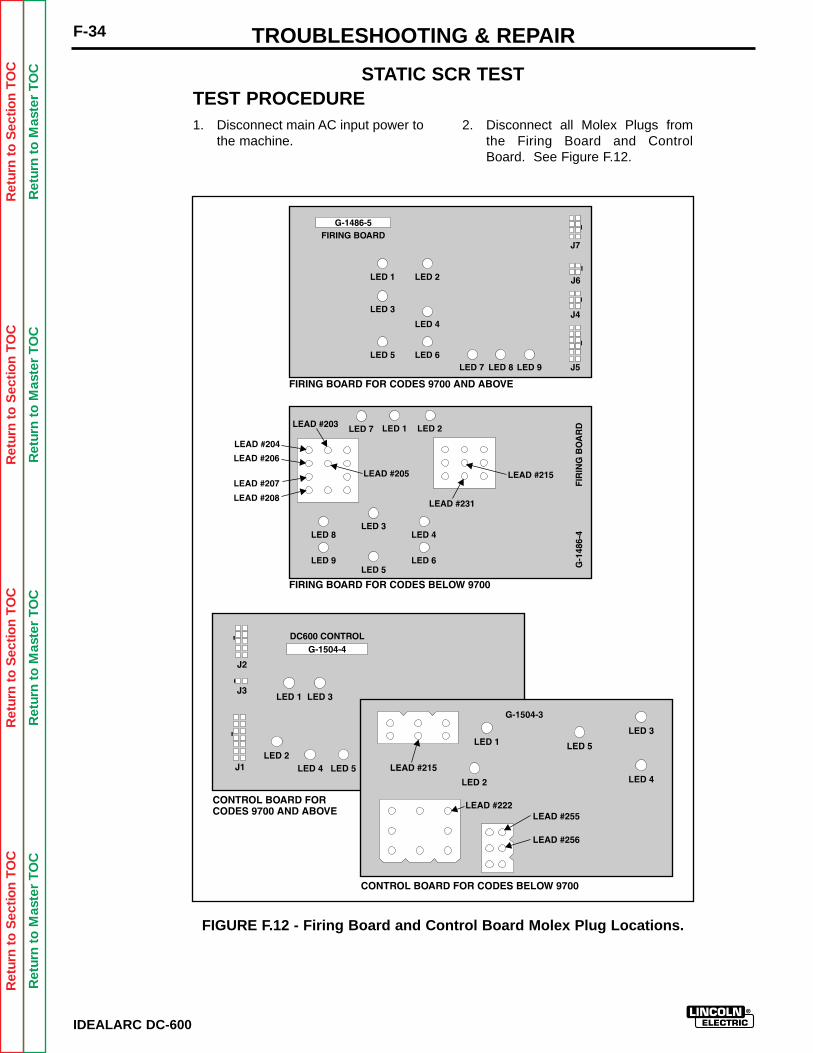
Ret
urn
to S
ectio
n T
OC
Ret
urn
to S
ectio
n T
OC
Ret
urn
to S
ectio
n T
OC
Ret
urn
to S
ectio
n T
OC
Ret
urn
to M
aste
r T
OC
Ret
urn
to M
aste
r T
OC
Ret
urn
to M
aste
r T
OC
Ret
urn
to M
aste
r T
OC
IDEALARC DC-600
F-34 TROUBLESHOOTING & REPAIR
1. Disconnect main AC input power tothe machine.
2. Disconnect all Molex Plugs fromthe Firing Board and ControlBoard. See Figure F.12.
STATIC SCR TEST
FIGURE F.12 - Firing Board and Control Board Molex Plug Locations.
TEST PROCEDURE
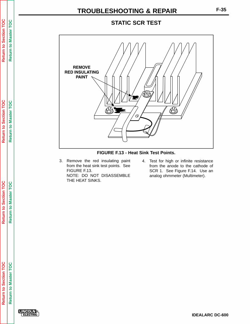
Ret
urn
to S
ectio
n T
OC
Ret
urn
to S
ectio
n T
OC
Ret
urn
to S
ectio
n T
OC
Ret
urn
to S
ectio
n T
OC
Ret
urn
to M
aste
r T
OC
Ret
urn
to M
aste
r T
OC
Ret
urn
to M
aste
r T
OC
Ret
urn
to M
aste
r T
OC
3. Remove the red insulating paintfrom the heat sink test points. SeeFIGURE F.13.NOTE: DO NOT DISASSEMBLETHE HEAT SINKS.
4. Test for high or infinite resistancefrom the anode to the cathode ofSCR 1. See Figure F.14. Use ananalog ohmmeter (Multimeter).
FIGURE F.13 - Heat Sink Test Points.
F-35TROUBLESHOOTING & REPAIR
STATIC SCR TEST
IDEALARC DC-600
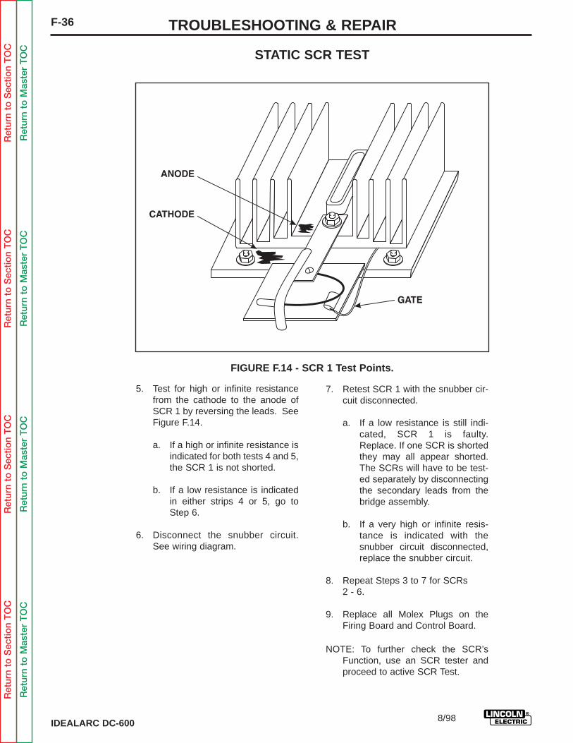
Ret
urn
to S
ectio
n T
OC
Ret
urn
to S
ectio
n T
OC
Ret
urn
to S
ectio
n T
OC
Ret
urn
to S
ectio
n T
OC
Ret
urn
to M
aste
r T
OC
Ret
urn
to M
aste
r T
OC
Ret
urn
to M
aste
r T
OC
Ret
urn
to M
aste
r T
OC
IDEALARC DC-600
F-36 TROUBLESHOOTING & REPAIR
STATIC SCR TEST
5. Test for high or infinite resistancefrom the cathode to the anode ofSCR 1 by reversing the leads. SeeFigure F.14.
a. If a high or infinite resistance isindicated for both tests 4 and 5,the SCR 1 is not shorted.
b. If a low resistance is indicatedin either strips 4 or 5, go toStep 6.
6. Disconnect the snubber circuit.See wiring diagram.
7. Retest SCR 1 with the snubber cir-cuit disconnected.
a. If a low resistance is still indi-cated, SCR 1 is faulty.Replace. If one SCR is shortedthey may all appear shorted.The SCRs will have to be test-ed separately by disconnectingthe secondary leads from thebridge assembly.
b. If a very high or infinite resis-tance is indicated with thesnubber circuit disconnected,replace the snubber circuit.
8. Repeat Steps 3 to 7 for SCRs2 - 6.
9. Replace all Molex Plugs on theFiring Board and Control Board.
NOTE: To further check the SCR’sFunction, use an SCR tester andproceed to active SCR Test.
FIGURE F.14 - SCR 1 Test Points.
8/98

Ret
urn
to S
ectio
n T
OC
Ret
urn
to S
ectio
n T
OC
Ret
urn
to S
ectio
n T
OC
Ret
urn
to S
ectio
n T
OC
Ret
urn
to M
aste
r T
OC
Ret
urn
to M
aste
r T
OC
Ret
urn
to M
aste
r T
OC
Ret
urn
to M
aste
r T
OC
IDEALARC DC-600
F-37TROUBLESHOOTING & REPAIR
ACTIVE SCR TEST
Service and repair should be performed only by Lincoln Electric factory trained personnel.Unauthorized repairs performed on this equipment could result in danger to the technicianor the machine operator and will invalidate your factory warranty. For your safety and toavoid electrical shock, please observe all safety notes and precautions detailed throughoutthis manual.
If for any reason you do not understand the test procedures or are unable to perform thetests/repairs safely, contact the Lincoln Electric service department for technical trou-bleshooting assistance before you proceed. Call (216) 383-2531 or (800) 833-9353(WELD).
______________________________
TEST DESCRIPTION
The Active SCR Test will determine if the device is able to be gated ON and conduct currentfrom anode to cathode.
MATERIALS NEEDED
An SCR Tester as specified in this procedure.IDEALARC DC-600 wiring diagrams (See Electrical Diagrams Section of this Manual).
WARNING
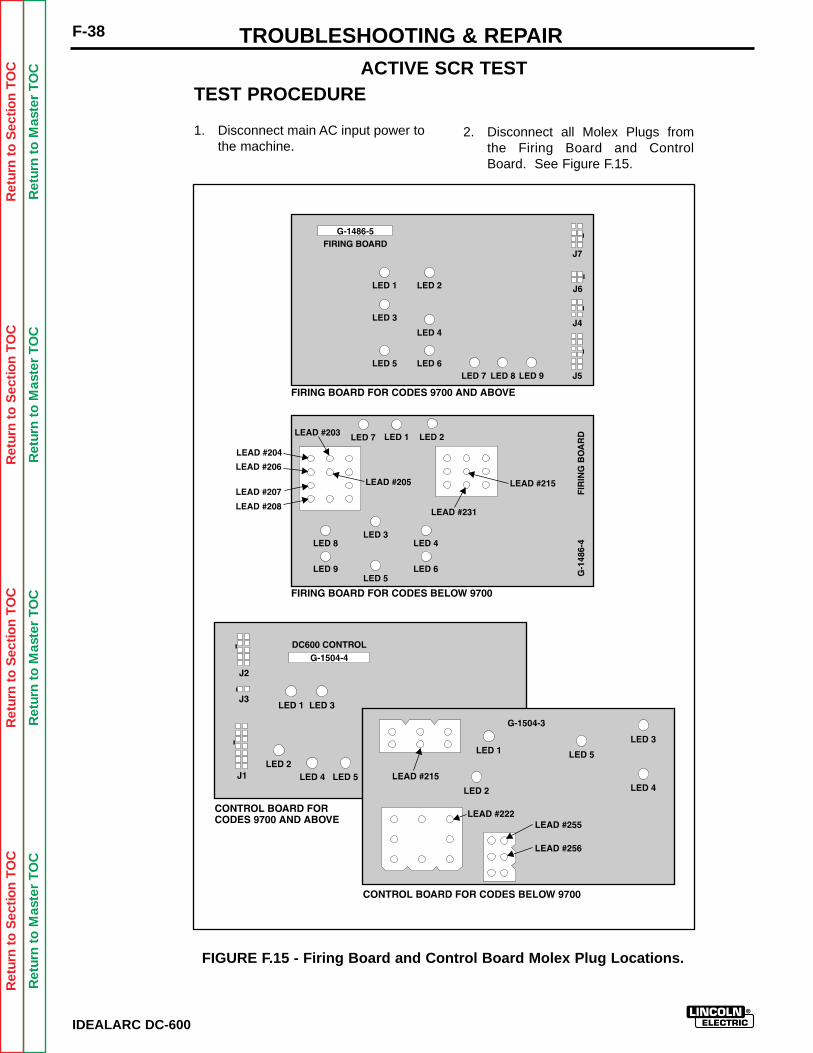
Ret
urn
to S
ectio
n T
OC
Ret
urn
to S
ectio
n T
OC
Ret
urn
to S
ectio
n T
OC
Ret
urn
to S
ectio
n T
OC
Ret
urn
to M
aste
r T
OC
Ret
urn
to M
aste
r T
OC
Ret
urn
to M
aste
r T
OC
Ret
urn
to M
aste
r T
OC
IDEALARC DC-600
F-38 TROUBLESHOOTING & REPAIR
TEST PROCEDURE
1. Disconnect main AC input power tothe machine.
2. Disconnect all Molex Plugs fromthe Firing Board and ControlBoard. See Figure F.15.
ACTIVE SCR TEST
FIGURE F.15 - Firing Board and Control Board Molex Plug Locations.
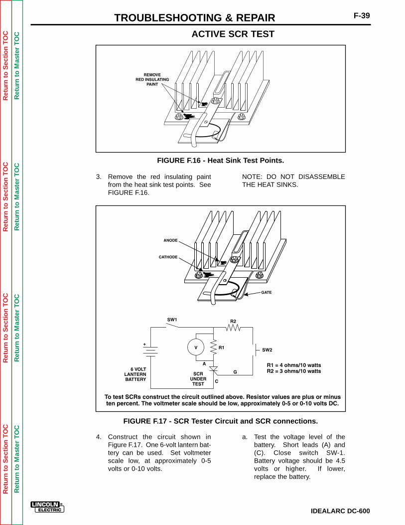
Ret
urn
to S
ectio
n T
OC
Ret
urn
to S
ectio
n T
OC
Ret
urn
to S
ectio
n T
OC
Ret
urn
to S
ectio
n T
OC
Ret
urn
to M
aste
r T
OC
Ret
urn
to M
aste
r T
OC
Ret
urn
to M
aste
r T
OC
Ret
urn
to M
aste
r T
OC
FIGURE F.16 - Heat Sink Test Points.
3. Remove the red insulating paintfrom the heat sink test points. SeeFIGURE F.16.
4. Construct the circuit shown inFigure F.17. One 6-volt lantern bat-tery can be used. Set voltmeterscale low, at approximately 0-5volts or 0-10 volts.
IDEALARC DC-600
F-39TROUBLESHOOTING & REPAIR
a. Test the voltage level of thebattery. Short leads (A) and(C). Close switch SW-1.Battery voltage should be 4.5volts or higher. If lower,replace the battery.
FIGURE F.17 - SCR Tester Circuit and SCR connections.
NOTE: DO NOT DISASSEMBLETHE HEAT SINKS.
ACTIVE SCR TEST
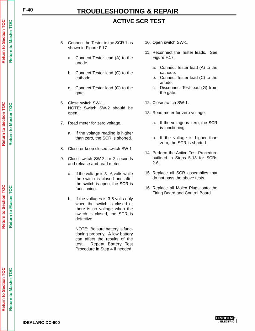
Ret
urn
to S
ectio
n T
OC
Ret
urn
to S
ectio
n T
OC
Ret
urn
to S
ectio
n T
OC
Ret
urn
to S
ectio
n T
OC
Ret
urn
to M
aste
r T
OC
Ret
urn
to M
aste
r T
OC
Ret
urn
to M
aste
r T
OC
Ret
urn
to M
aste
r T
OC
IDEALARC DC-600
F-40 TROUBLESHOOTING & REPAIR
5. Connect the Tester to the SCR 1 asshown in Figure F.17.
a. Connect Tester lead (A) to theanode.
b. Connect Tester lead (C) to thecathode.
c. Connect Tester lead (G) to thegate.
6. Close switch SW-1. NOTE: Switch SW-2 should beopen.
7. Read meter for zero voltage.
a. If the voltage reading is higherthan zero, the SCR is shorted.
8. Close or keep closed switch SW-1
9. Close switch SW-2 for 2 secondsand release and read meter.
a. If the voltage is 3 - 6 volts whilethe switch is closed and afterthe switch is open, the SCR isfunctioning.
b. If the voltages is 3-6 volts onlywhen the switch is closed orthere is no voltage when theswitch is closed, the SCR isdefective.
NOTE: Be sure battery is func-tioning properly. A low batterycan affect the results of thetest. Repeat Battery TestProcedure in Step 4 if needed.
10. Open switch SW-1.
11. Reconnect the Tester leads. SeeFigure F.17.
a. Connect Tester lead (A) to thecathode.
b. Connect Tester lead (C) to theanode.
c. Disconnect Test lead (G) fromthe gate.
12. Close switch SW-1.
13. Read meter for zero voltage.
a. If the voltage is zero, the SCRis functioning.
b. If the voltage is higher thanzero, the SCR is shorted.
14. Perform the Active Test Procedureoutlined in Steps 5-13 for SCRs 2-6.
15. Replace all SCR assemblies thatdo not pass the above tests.
16. Replace all Molex Plugs onto theFiring Board and Control Board.
ACTIVE SCR TEST
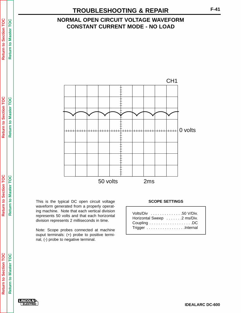
Ret
urn
to S
ectio
n T
OC
Ret
urn
to S
ectio
n T
OC
Ret
urn
to S
ectio
n T
OC
Ret
urn
to S
ectio
n T
OC
Ret
urn
to M
aste
r T
OC
Ret
urn
to M
aste
r T
OC
Ret
urn
to M
aste
r T
OC
Ret
urn
to M
aste
r T
OC
F-41TROUBLESHOOTING & REPAIR
IDEALARC DC-600
SCOPE SETTINGS
NORMAL OPEN CIRCUIT VOLTAGE WAVEFORMCONSTANT CURRENT MODE - NO LOAD
This is the typical DC open circuit voltagewaveform generated from a properly operat-ing machine. Note that each vertical divisionrepresents 50 volts and that each horizontaldivision represents 2 milliseconds in time.
Note: Scope probes connected at machineouput terminals: (+) probe to positive termi-nal, (-) probe to negative terminal.
Volts/Div . . . . . . . . . . . . . .50 V/Div.Horizontal Sweep . . . . . . .2 ms/Div.Coupling . . . . . . . . . . . . . . . . . . .DCTrigger . . . . . . . . . . . . . . . . .Internal
0 volts
50 volts 2ms
CH1

Ret
urn
to S
ectio
n T
OC
Ret
urn
to S
ectio
n T
OC
Ret
urn
to S
ectio
n T
OC
Ret
urn
to S
ectio
n T
OC
Ret
urn
to M
aste
r T
OC
Ret
urn
to M
aste
r T
OC
Ret
urn
to M
aste
r T
OC
Ret
urn
to M
aste
r T
OC
IDEALARC DC-600
F-42 TROUBLESHOOTING & REPAIR
SCOPE SETTINGS
NORMAL OPEN CIRCUIT VOLTAGE WAVEFORMCONSTANT VOLTAGE INNERSHIELD
MAXIMUM OUTPUT SETTING - NO LOAD
This is the typical DC open circuit voltagewaveform generated from a properly operat-ing machine. Note that each vertical divisionrepresents 50 volts and that each horizontaldivision represents 2 milliseconds in time.
Note: Scope probes connected at machineouput terminals: (+) probe to positive termi-nal, (-) probe to negative terminal.
Volts/Div . . . . . . . . . . . . . .50 V/Div.Horizontal Sweep . . . . . . .2 ms/Div.Coupling . . . . . . . . . . . . . . . . . . .DCTrigger . . . . . . . . . . . . . . . . .Internal
0 volts
50 volts 2ms
CH1
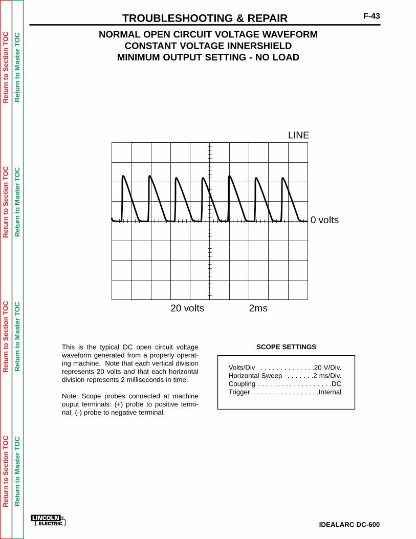
Ret
urn
to S
ectio
n T
OC
Ret
urn
to S
ectio
n T
OC
Ret
urn
to S
ectio
n T
OC
Ret
urn
to S
ectio
n T
OC
Ret
urn
to M
aste
r T
OC
Ret
urn
to M
aste
r T
OC
Ret
urn
to M
aste
r T
OC
Ret
urn
to M
aste
r T
OC
IDEALARC DC-600
F-43TROUBLESHOOTING & REPAIR
SCOPE SETTINGS
NORMAL OPEN CIRCUIT VOLTAGE WAVEFORMCONSTANT VOLTAGE INNERSHIELD
MINIMUM OUTPUT SETTING - NO LOAD
This is the typical DC open circuit voltagewaveform generated from a properly operat-ing machine. Note that each vertical divisionrepresents 20 volts and that each horizontaldivision represents 2 milliseconds in time.
Note: Scope probes connected at machineouput terminals: (+) probe to positive termi-nal, (-) probe to negative terminal.
Volts/Div . . . . . . . . . . . . . .20 V/Div.Horizontal Sweep . . . . . . .2 ms/Div.Coupling . . . . . . . . . . . . . . . . . . .DCTrigger . . . . . . . . . . . . . . . . .Internal
0 volts
20 volts 2ms
LINE
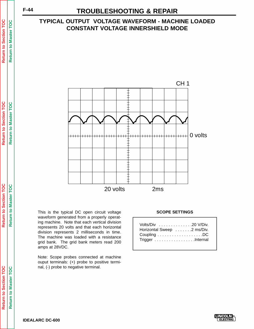
Ret
urn
to S
ectio
n T
OC
Ret
urn
to S
ectio
n T
OC
Ret
urn
to S
ectio
n T
OC
Ret
urn
to S
ectio
n T
OC
Ret
urn
to M
aste
r T
OC
Ret
urn
to M
aste
r T
OC
Ret
urn
to M
aste
r T
OC
Ret
urn
to M
aste
r T
OC
IDEALARC DC-600
F-44 TROUBLESHOOTING & REPAIR
SCOPE SETTINGS
TYPICAL OUTPUT VOLTAGE WAVEFORM - MACHINE LOADEDCONSTANT VOLTAGE INNERSHIELD MODE
This is the typical DC open circuit voltagewaveform generated from a properly operat-ing machine. Note that each vertical divisionrepresents 20 volts and that each horizontaldivision represents 2 milliseconds in time.The machine was loaded with a resistancegrid bank. The grid bank meters read 200amps at 28VDC.
Note: Scope probes connected at machineouput terminals: (+) probe to positive termi-nal, (-) probe to negative terminal.
Volts/Div . . . . . . . . . . . . . .20 V/Div.Horizontal Sweep . . . . . . .2 ms/Div.Coupling . . . . . . . . . . . . . . . . . . .DCTrigger . . . . . . . . . . . . . . . . .Internal
0 volts
20 volts 2ms
CH 1

Ret
urn
to S
ectio
n T
OC
Ret
urn
to S
ectio
n T
OC
Ret
urn
to S
ectio
n T
OC
Ret
urn
to S
ectio
n T
OC
Ret
urn
to M
aste
r T
OC
Ret
urn
to M
aste
r T
OC
Ret
urn
to M
aste
r T
OC
Ret
urn
to M
aste
r T
OC
IDEALARC DC-600
F-45TROUBLESHOOTING & REPAIR
SCOPE SETTINGS
TYPICAL SCR GATE VOLTAGE WAVEFORMCONSTANT VOLTAGE INNERSHIELD
MAXIMUM OUTPUT SETTING - NO LOAD
This is the typical SCR gate pulse voltagewaveform. The machine was in an open cir-cuit condition (no load) and operating proper-ly. Note that each vertical division represents2 volts and that each horizontal division rep-resents 5 milliseconds in time.
Note: Scope probes connected at SCR gateand cathode: (+) probe to gate, (-) probe to cathode.
Volts/Div . . . . . . . . . . . . . . .2 V/Div.Horizontal Sweep . . . . . . .5 ms/Div.Coupling . . . . . . . . . . . . . . . . . . .DCTrigger . . . . . . . . . . . . . . . . .Internal
0 volts
2 volts 5ms
CH1
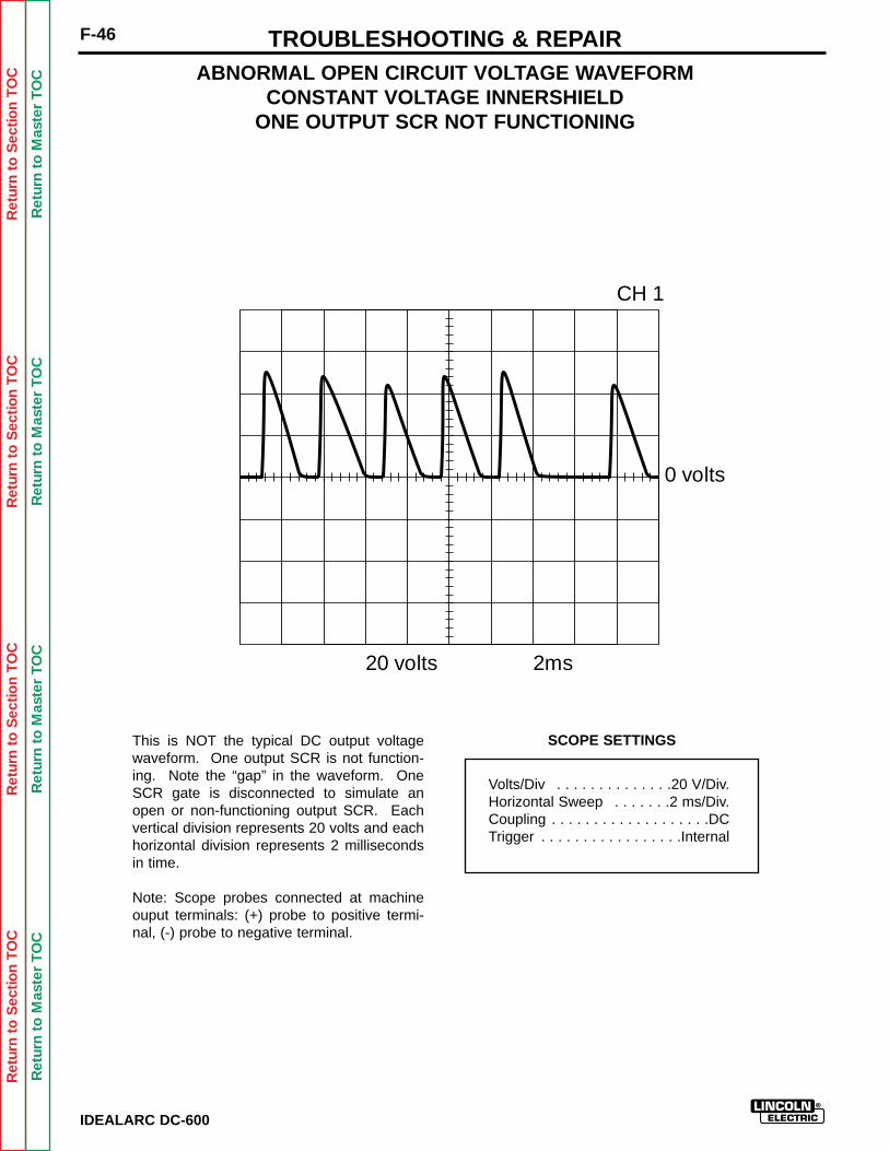
Ret
urn
to S
ectio
n T
OC
Ret
urn
to S
ectio
n T
OC
Ret
urn
to S
ectio
n T
OC
Ret
urn
to S
ectio
n T
OC
Ret
urn
to M
aste
r T
OC
Ret
urn
to M
aste
r T
OC
Ret
urn
to M
aste
r T
OC
Ret
urn
to M
aste
r T
OC
IDEALARC DC-600
F-46 TROUBLESHOOTING & REPAIR
SCOPE SETTINGS
ABNORMAL OPEN CIRCUIT VOLTAGE WAVEFORMCONSTANT VOLTAGE INNERSHIELD
ONE OUTPUT SCR NOT FUNCTIONING
This is NOT the typical DC output voltagewaveform. One output SCR is not function-ing. Note the “gap” in the waveform. OneSCR gate is disconnected to simulate anopen or non-functioning output SCR. Eachvertical division represents 20 volts and eachhorizontal division represents 2 millisecondsin time.
Note: Scope probes connected at machineouput terminals: (+) probe to positive termi-nal, (-) probe to negative terminal.
Volts/Div . . . . . . . . . . . . . .20 V/Div.Horizontal Sweep . . . . . . .2 ms/Div.Coupling . . . . . . . . . . . . . . . . . . .DCTrigger . . . . . . . . . . . . . . . . .Internal
0 volts
20 volts 2ms
CH 1

Ret
urn
to S
ectio
n T
OC
Ret
urn
to S
ectio
n T
OC
Ret
urn
to S
ectio
n T
OC
Ret
urn
to S
ectio
n T
OC
Ret
urn
to M
aste
r T
OC
Ret
urn
to M
aste
r T
OC
Ret
urn
to M
aste
r T
OC
Ret
urn
to M
aste
r T
OC
IDEALARC DC-600
F-47TROUBLESHOOTING & REPAIR
INPUT CONTACTOR (CR1) CLEANING/REPLACEMENT
Service and repair should be performed only by Lincoln Electric factory trained personnel.Unauthorized repairs performed on this equipment could result in danger to the technicianor the machine operator and will invalidate your factory warranty. For your safety and toavoid electrical shock, please observe all safety notes and precautions detailed throughoutthis manual.
If for any reason you do not understand the test procedures or are unable to perform thetests/repairs safely, contact the Lincoln Electric service department for technical trou-bleshooting assistance before you proceed. Call (216) 383-2531 or (800) 833-9353(WELD).
______________________________
MATERIALS NEEDED
Phillips head screwdriver5/16" socket wrenchFlat head screw driverLow pressure air source
WARNING
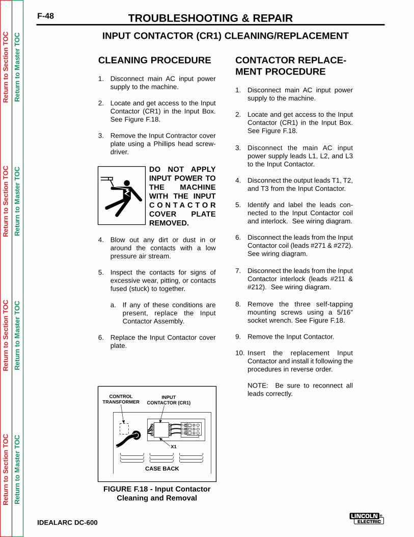
Ret
urn
to S
ectio
n T
OC
Ret
urn
to S
ectio
n T
OC
Ret
urn
to S
ectio
n T
OC
Ret
urn
to S
ectio
n T
OC
Ret
urn
to M
aste
r T
OC
Ret
urn
to M
aste
r T
OC
Ret
urn
to M
aste
r T
OC
Ret
urn
to M
aste
r T
OC
IDEALARC DC-600
F-48 TROUBLESHOOTING & REPAIR
CLEANING PROCEDURE
1. Disconnect main AC input powersupply to the machine.
2. Locate and get access to the InputContactor (CR1) in the Input Box.See Figure F.18.
3. Remove the Input Contractor coverplate using a Phillips head screw-driver.
DO NOT APPLYINPUT POWER TOTHE MACHINEWITH THE INPUTC O N T A C T O RCOVER PLATEREMOVED.
4. Blow out any dirt or dust in oraround the contacts with a lowpressure air stream.
5. Inspect the contacts for signs ofexcessive wear, pitting, or contactsfused (stuck) to together.
a. If any of these conditions arepresent, replace the InputContactor Assembly.
6. Replace the Input Contactor coverplate.
CONTACTOR REPLACE-MENT PROCEDURE
1. Disconnect main AC input powersupply to the machine.
2. Locate and get access to the InputContactor (CR1) in the Input Box.See Figure F.18.
3. Disconnect the main AC inputpower supply leads L1, L2, and L3to the Input Contactor.
4. Disconnect the output leads T1, T2,and T3 from the Input Contactor.
5. Identify and label the leads con-nected to the Input Contactor coiland interlock. See wiring diagram.
6. Disconnect the leads from the InputContactor coil (leads #271 & #272).See wiring diagram.
7. Disconnect the leads from the InputContactor interlock (leads #211 Ô). See wiring diagram.
8. Remove the three self-tappingmounting screws using a 5/16"socket wrench. See Figure F.18.
9. Remove the Input Contactor.
10. Insert the replacement InputContactor and install it following theprocedures in reverse order.
NOTE: Be sure to reconnect allleads correctly.
INPUT CONTACTOR (CR1) CLEANING/REPLACEMENT
FIGURE F.18 - Input ContactorCleaning and Removal
CONTROLTRANSFORMER
INPUTCONTACTOR (CR1)
X1
CASE BACK
Ret
urn
to S
ectio
n T
OC
Ret
urn
to S
ectio
n T
OC
Ret
urn
to S
ectio
n T
OC
Ret
urn
to S
ectio
n T
OC
Ret
urn
to M
aste
r T
OC
Ret
urn
to M
aste
r T
OC
Ret
urn
to M
aste
r T
OC
Ret
urn
to M
aste
r T
OC
IDEALARC DC-600
F-49TROUBLESHOOTING & REPAIR
SCR / SCR OUTPUT BRIDGE REMOVAL
Service and repair should be performed only by Lincoln Electric factory trained personnel.Unauthorized repairs performed on this equipment could result in danger to the technicianor the machine operator and will invalidate your factory warranty. For your safety and toavoid electrical shock, please observe all safety notes and precautions detailed throughoutthis manual.
If for any reason you do not understand the test procedures or are unable to perform thetests/repairs safely, contact the Lincoln Electric service department for technical trou-bleshooting assistance before you proceed. Call (216) 383-2531 or (800) 833-9353(WELD).
______________________________
MATERIALS NEEDED
9/16" socket wrench1/2" socket wrench1/2" open end wrench
WARNING
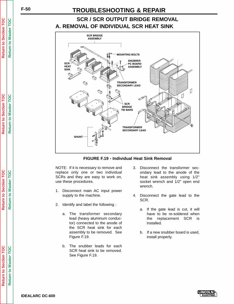
Ret
urn
to S
ectio
n T
OC
Ret
urn
to S
ectio
n T
OC
Ret
urn
to S
ectio
n T
OC
Ret
urn
to S
ectio
n T
OC
Ret
urn
to M
aste
r T
OC
Ret
urn
to M
aste
r T
OC
Ret
urn
to M
aste
r T
OC
Ret
urn
to M
aste
r T
OC
IDEALARC DC-600
F-50 TROUBLESHOOTING & REPAIR
NOTE: If it is necessary to remove andreplace only one or two individualSCRs and they are easy to work on,use these procedures.
1. Disconnect main AC input powersupply to the machine.
2. Identify and label the following :
a. The transformer secondarylead (heavy aluminum conduc-tor) connected to the anode ofthe SCR heat sink for eachassembly to be removed. SeeFigure F.19.
b. The snubber leads for eachSCR heat sink to be removed.See Figure F.19.
SCR / SCR OUTPUT BRIDGE REMOVAL
FIGURE F.19 - Individual Heat Sink Removal
A. REMOVAL OF INDIVIDUAL SCR HEAT SINK
3. Disconnect the transformer sec-ondary lead to the anode of theheat sink assembly using 1/2"socket wrench and 1/2" open endwrench.
4. Disconnect the gate lead to theSCR.
a. If the gate lead is cut, it willhave to be re-soldered whenthe replacement SCR isinstalled.
b. If a new snubber board is used,install properly.
Ret
urn
to S
ectio
n T
OC
Ret
urn
to S
ectio
n T
OC
Ret
urn
to S
ectio
n T
OC
Ret
urn
to S
ectio
n T
OC
Ret
urn
to M
aste
r T
OC
Ret
urn
to M
aste
r T
OC
Ret
urn
to M
aste
r T
OC
Ret
urn
to M
aste
r T
OC
IDEALARC DC-600
TROUBLESHOOTING & REPAIR
5. Remove the four thru bolts andassociated nuts and washers hold.ing the SCR heat sink to the bridgetie bars.
a. The main mounting bolts thatmount the SCR bridge assem-bly to the frame rail may haveto be loosened to slide theSCR Heat Sink out from underthe buss jumper strap.
b. When all four thru-bolts areremoved, the SCR Heat Sinkdirectly above or below will bedetached also. Support theSCR Heat Sink above orbelow. To hold the Heat Sink inplace temporarily, insert one ofthe thru-bolts and replace thenut hand tight.
F-51
6. Install the replacement SCR HeatSink in reverse order of removal.
a. Apply a thin layer of LincolnE1868 (Dow Corning 340) heatsink compound to all boltedelectrical connections on thealuminum heat sinks.
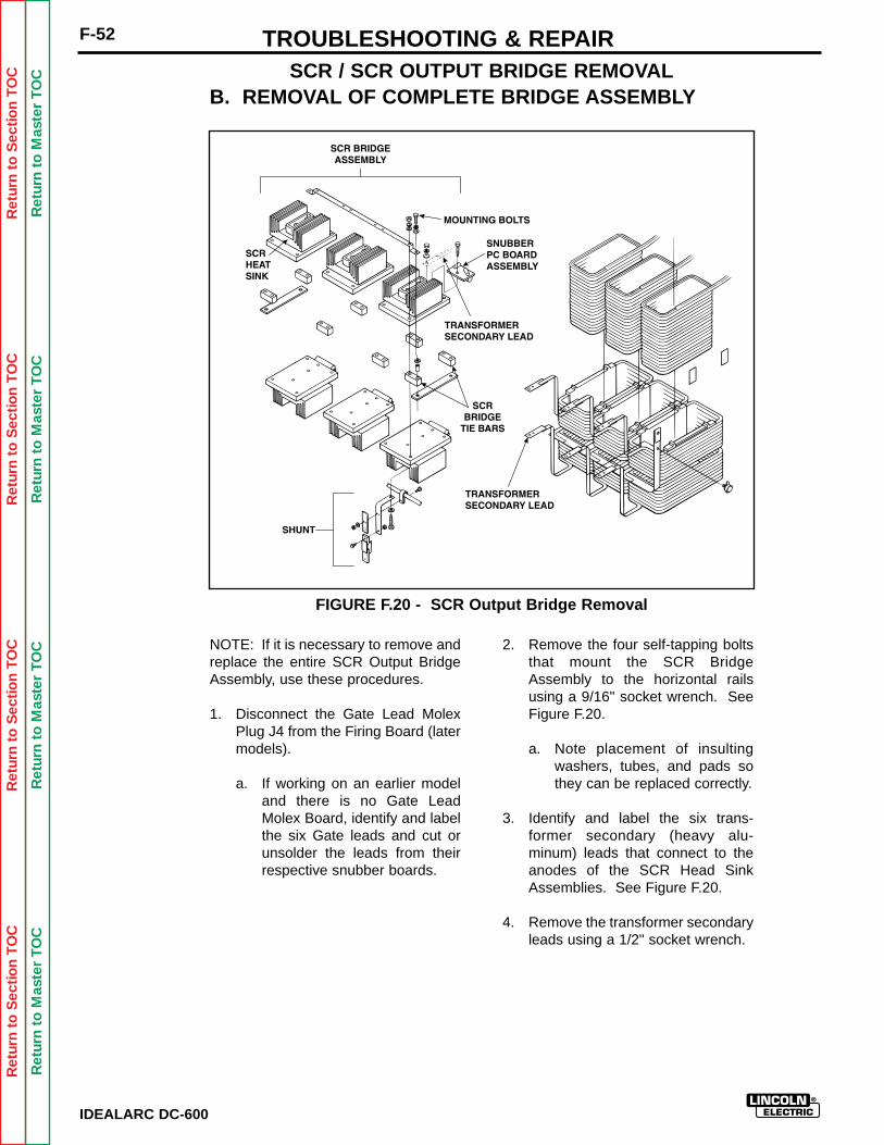
Ret
urn
to S
ectio
n T
OC
Ret
urn
to S
ectio
n T
OC
Ret
urn
to S
ectio
n T
OC
Ret
urn
to S
ectio
n T
OC
Ret
urn
to M
aste
r T
OC
Ret
urn
to M
aste
r T
OC
Ret
urn
to M
aste
r T
OC
Ret
urn
to M
aste
r T
OC
IDEALARC DC-600
F-52 TROUBLESHOOTING & REPAIRSCR / SCR OUTPUT BRIDGE REMOVAL
NOTE: If it is necessary to remove andreplace the entire SCR Output BridgeAssembly, use these procedures.
1. Disconnect the Gate Lead MolexPlug J4 from the Firing Board (latermodels).
a. If working on an earlier modeland there is no Gate LeadMolex Board, identify and labelthe six Gate leads and cut orunsolder the leads from theirrespective snubber boards.
2. Remove the four self-tapping boltsthat mount the SCR BridgeAssembly to the horizontal railsusing a 9/16" socket wrench. SeeFigure F.20.
a. Note placement of insultingwashers, tubes, and pads sothey can be replaced correctly.
3. Identify and label the six trans-former secondary (heavy alu-minum) leads that connect to theanodes of the SCR Head SinkAssemblies. See Figure F.20.
4. Remove the transformer secondaryleads using a 1/2" socket wrench.
FIGURE F.20 - SCR Output Bridge Removal
B. REMOVAL OF COMPLETE BRIDGE ASSEMBLY
Ret
urn
to S
ectio
n T
OC
Ret
urn
to S
ectio
n T
OC
Ret
urn
to S
ectio
n T
OC
Ret
urn
to S
ectio
n T
OC
Ret
urn
to M
aste
r T
OC
Ret
urn
to M
aste
r T
OC
Ret
urn
to M
aste
r T
OC
Ret
urn
to M
aste
r T
OC
IDEALARC DC-600
F-53TROUBLESHOOTING & REPAIR
SCR / SCR OUTPUT BRIDGE REMOVAL
8. Lift the SCR Bridge Assemblystraight up and out of the machinebeing sure that no leads becometangled or hooked on the othermachine parts.
a. Be sure to locate the SCRBridge Assembly on a stablework surface capable of hold-ing the weight of the assembly.
9. Remove individual SCR Heat Sinksfollowing the procedure describedin A above.
10. Replace all insulating materials,including the insulators on theframe rail and all insulating tubes,when installing the SCR OutputBridge Assembly.
11. The Output Bridge assemblyshould be electrically isolated fromground. Check with an analog ohmmeter. Minimum resistance is500,000 ohms to ground.
5. Remove the bolt that connects theShunt Assembly (heavy copper)lead to the SCR Bridge Assembly.The Shunt Assembly connects thepositive Weld Output Terminal tothe SCR Bridge Assembly.
6. Remove the small snubber leadfrom the left hand (facing the frontof the machine) rear heat sinkmounting bolt using a 1/2" socketwrench.
7. Clear all leads from any obstruc-tions.

Ret
urn
to S
ectio
n T
OC
Ret
urn
to S
ectio
n T
OC
Ret
urn
to S
ectio
n T
OC
Ret
urn
to S
ectio
n T
OC
Ret
urn
to M
aste
r T
OC
Ret
urn
to M
aste
r T
OC
Ret
urn
to M
aste
r T
OC
Ret
urn
to M
aste
r T
OC
IDEALARC DC-600
F-54 TROUBLESHOOTING & REPAIR
LIFT BAIL REMOVAL (INCLUDING MAIN TRANSFORMER,CHOKE, AND OUTPUT BRIDGE ASSEMBLY)
Service and repair should be performed only by Lincoln Electric factory trained personnel.Unauthorized repairs performed on this equipment could result in danger to the technicianor the machine operator and will invalidate your factory warranty. For your safety and toavoid electrical shock, please observe all safety notes and precautions detailed throughoutthis manual.
If for any reason you do not understand the test procedures or are unable to perform thetests/repairs safely, contact the Lincoln Electric service department for technical trou-bleshooting assistance before you proceed. Call (216) 383-2531 or (800) 833-9353(WELD).
______________________________
WARNING
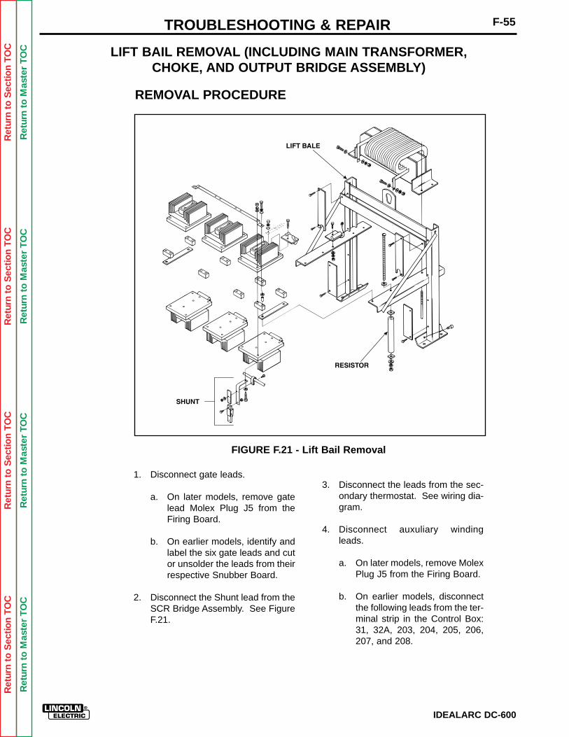
Ret
urn
to S
ectio
n T
OC
Ret
urn
to S
ectio
n T
OC
Ret
urn
to S
ectio
n T
OC
Ret
urn
to S
ectio
n T
OC
Ret
urn
to M
aste
r T
OC
Ret
urn
to M
aste
r T
OC
Ret
urn
to M
aste
r T
OC
Ret
urn
to M
aste
r T
OC
F-55TROUBLESHOOTING & REPAIR
IDEALARC DC-600
1. Disconnect gate leads.
a. On later models, remove gatelead Molex Plug J5 from theFiring Board.
b. On earlier models, identify andlabel the six gate leads and cutor unsolder the leads from theirrespective Snubber Board.
2. Disconnect the Shunt lead from theSCR Bridge Assembly. See FigureF.21.
3. Disconnect the leads from the sec-ondary thermostat. See wiring dia-gram.
4. Disconnect auxuliary windingleads.
a. On later models, remove MolexPlug J5 from the Firing Board.
b. On earlier models, disconnectthe following leads from the ter-minal strip in the Control Box:31, 32A, 203, 204, 205, 206,207, and 208.
LIFT BAIL REMOVAL (INCLUDING MAIN TRANSFORMER,CHOKE, AND OUTPUT BRIDGE ASSEMBLY)
FIGURE F.21 - Lift Bail Removal
REMOVAL PROCEDURE
Ret
urn
to S
ectio
n T
OC
Ret
urn
to S
ectio
n T
OC
Ret
urn
to S
ectio
n T
OC
Ret
urn
to S
ectio
n T
OC
Ret
urn
to M
aste
r T
OC
Ret
urn
to M
aste
r T
OC
Ret
urn
to M
aste
r T
OC
Ret
urn
to M
aste
r T
OC
IDEALARC DC-600
F-56 TROUBLESHOOTING & REPAIR
5. Disconnect leads #215 and #216from Relay CR4 and lead #231from the splice connector.
6. Disconnect leads #211 and #212from the ON/OFF PUSH BUTTON.
7. Disconnect lead #256 from thePILOT LIGHT.
8. Disconnect lead #271 from relayCR2 located in the Control Box.
9. Remove resistor R2 from the hori-zontal rail. See Figure F.21.
10. Cut and remove all cable ties andunbundle all wires.
11. Label and cut fan motor leads.
12. Separate leads #271, #211, and X2from the harness.
13. Disconnect lead #272 from InputContactor (CR1) coil.
14. Disconnect the heavy copper leadfrom the negative Weld OutputTerminal.
15. Identify, label, and disconnect theMain Transformer leads from theReconnect Panel and the threeleads that go to the InputContactor.
16. Remove the four mounting nutsthat hold the Lift Bail Assembly tothe Base.
17. Lift the Bail Assembly carefullystraight up and out of the machineusing a hoist. Be sure all leads arefree to move with the assembly.
LIFT BAIL REMOVAL (INCLUDING MAIN TRANSFORMER,CHOKE, AND OUTPUT BRIDGE ASSEMBLY)

Ret
urn
to S
ectio
n T
OC
Ret
urn
to S
ectio
n T
OC
Ret
urn
to S
ectio
n T
OC
Ret
urn
to S
ectio
n T
OC
Ret
urn
to M
aste
r T
OC
Ret
urn
to M
aste
r T
OC
Ret
urn
to M
aste
r T
OC
Ret
urn
to M
aste
r T
OC
F-57TROUBLESHOOTING & REPAIR
IDEALARC DC-600
TRANSFORMER REMOVAL FROM LIFT BAIL ASSEMBLY
Service and repair should be performed only by Lincoln Electric factory trained personnel.Unauthorized repairs performed on this equipment could result in danger to the technicianor the machine operator and will invalidate your factory warranty. For your safety and toavoid electrical shock, please observe all safety notes and precautions detailed throughoutthis manual.
If for any reason you do not understand the test procedures or are unable to perform thetests/repairs safely, contact the Lincoln Electric service department for technical trou-bleshooting assistance before you proceed. Call (216) 383-2531 or (800) 833-9353(WELD).
______________________________
MATERIALS NEEDED
9/16" socket wrench9/16" open end wrench1/2" socket wrench1/2" open end wrench3/8" socket wrench
WARNING
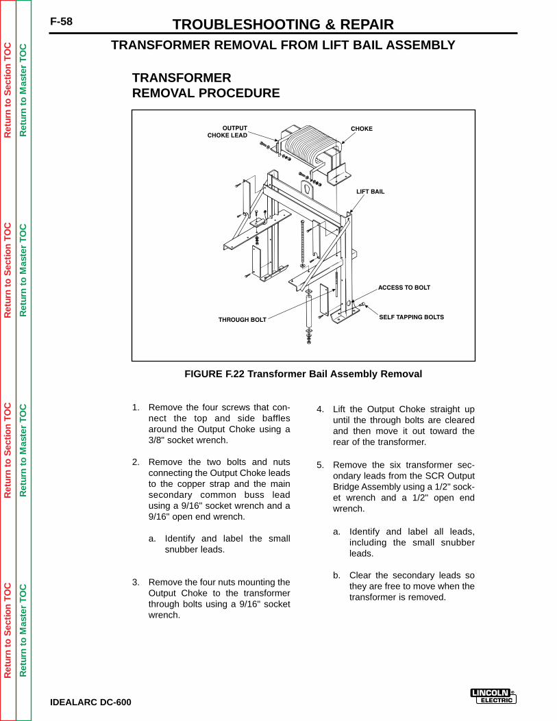
Ret
urn
to S
ectio
n T
OC
Ret
urn
to S
ectio
n T
OC
Ret
urn
to S
ectio
n T
OC
Ret
urn
to S
ectio
n T
OC
Ret
urn
to M
aste
r T
OC
Ret
urn
to M
aste
r T
OC
Ret
urn
to M
aste
r T
OC
Ret
urn
to M
aste
r T
OC
F-58 TROUBLESHOOTING & REPAIR
IDEALARC DC-600
TRANSFORMERREMOVAL PROCEDURE
1. Remove the four screws that con-nect the top and side bafflesaround the Output Choke using a3/8" socket wrench.
2. Remove the two bolts and nutsconnecting the Output Choke leadsto the copper strap and the mainsecondary common buss leadusing a 9/16" socket wrench and a9/16" open end wrench.
a. Identify and label the smallsnubber leads.
3. Remove the four nuts mounting theOutput Choke to the transformerthrough bolts using a 9/16" socketwrench.
TRANSFORMER REMOVAL FROM LIFT BAIL ASSEMBLY
FIGURE F.22 Transformer Bail Assembly Removal
4. Lift the Output Choke straight upuntil the through bolts are clearedand then move it out toward therear of the transformer.
5. Remove the six transformer sec-ondary leads from the SCR OutputBridge Assembly using a 1/2" sock-et wrench and a 1/2" open endwrench.
a. Identify and label all leads,including the small snubberleads.
b. Clear the secondary leads sothey are free to move when thetransformer is removed.
Ret
urn
to S
ectio
n T
OC
Ret
urn
to S
ectio
n T
OC
Ret
urn
to S
ectio
n T
OC
Ret
urn
to S
ectio
n T
OC
Ret
urn
to M
aste
r T
OC
Ret
urn
to M
aste
r T
OC
Ret
urn
to M
aste
r T
OC
Ret
urn
to M
aste
r T
OC
F-59TROUBLESHOOTING & REPAIR
IDEALARC DC-600
6. Remove the four self-tapping boltsthat hold the Lift Bail to the trans-former base using a 9/16" socketwrench. See Figure F.22.
NOTE: There is one bolt on eachside of the transformer that must beremoved by inserting the wrenchthrough the hole in Lift Bail.
7. Remove the Lift Bail and OutputBridge Assembly from the trans-former by lifting the Lift Bail upslightly and sliding the Lift Bailtowards the SCR Bridge.
TRANSFORMER DISASSEMBLY
1. Identify and label all leads to thetransformer.
2. Cut or unsolder all leads.
a. Cut the secondary leads.These must be re-TIG weldedto the new transformer coils.
3. Remove the four nuts from thethrough bolts that hold the trans-former together.
4. Attach a hoist to the top of the EIron and lift from assembly.
TRANSFORMER REMOVAL FROM LIFT BAIL ASSEMBLY
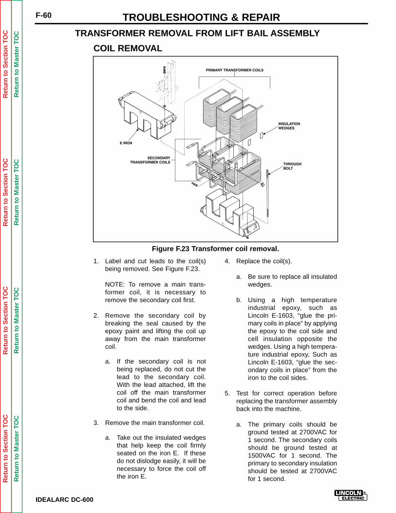
1. Label and cut leads to the coil(s)being removed. See Figure F.23.
NOTE: To remove a main trans-former coil, it is necessary toremove the secondary coil first.
2. Remove the secondary coil bybreaking the seal caused by theepoxy paint and lifting the coil upaway from the main transformercoil.
a. If the secondary coil is notbeing replaced, do not cut thelead to the secondary coil.With the lead attached, lift thecoil off the main transformercoil and bend the coil and leadto the side.
3. Remove the main transformer coil.
a. Take out the insulated wedgesthat help keep the coil firmlyseated on the iron E. If thesedo not dislodge easily, it will benecessary to force the coil offthe iron E.
4. Replace the coil(s).
a. Be sure to replace all insulatedwedges.
b. Using a high temperatureindustrial epoxy, such asLincoln E-1603, “glue the pri-mary coils in place” by applyingthe epoxy to the coil side andcell insulation opposite thewedges. Using a high tempera-ture industrial epoxy, Such asLincoln E-1603, “glue the sec-ondary coils in place” from theiron to the coil sides.
5. Test for correct operation beforereplacing the transformer assemblyback into the machine.
a. The primary coils should beground tested at 2700VAC for1 second. The secondary coilsshould be ground tested at1500VAC for 1 second. Theprimary to secondary insulationshould be tested at 2700VACfor 1 second.
TRANSFORMER REMOVAL FROM LIFT BAIL ASSEMBLY
IDEALARC DC-600
F-60 TROUBLESHOOTING & REPAIR
Figure F.23 Transformer coil removal.
COIL REMOVAL
Ret
urn
to S
ectio
n T
OC
Ret
urn
to S
ectio
n T
OC
Ret
urn
to S
ectio
n T
OC
Ret
urn
to S
ectio
n T
OC
Ret
urn
to M
aste
r T
OC
Ret
urn
to M
aste
r T
OC
Ret
urn
to M
aste
r T
OC
Ret
urn
to M
aste
r T
OC
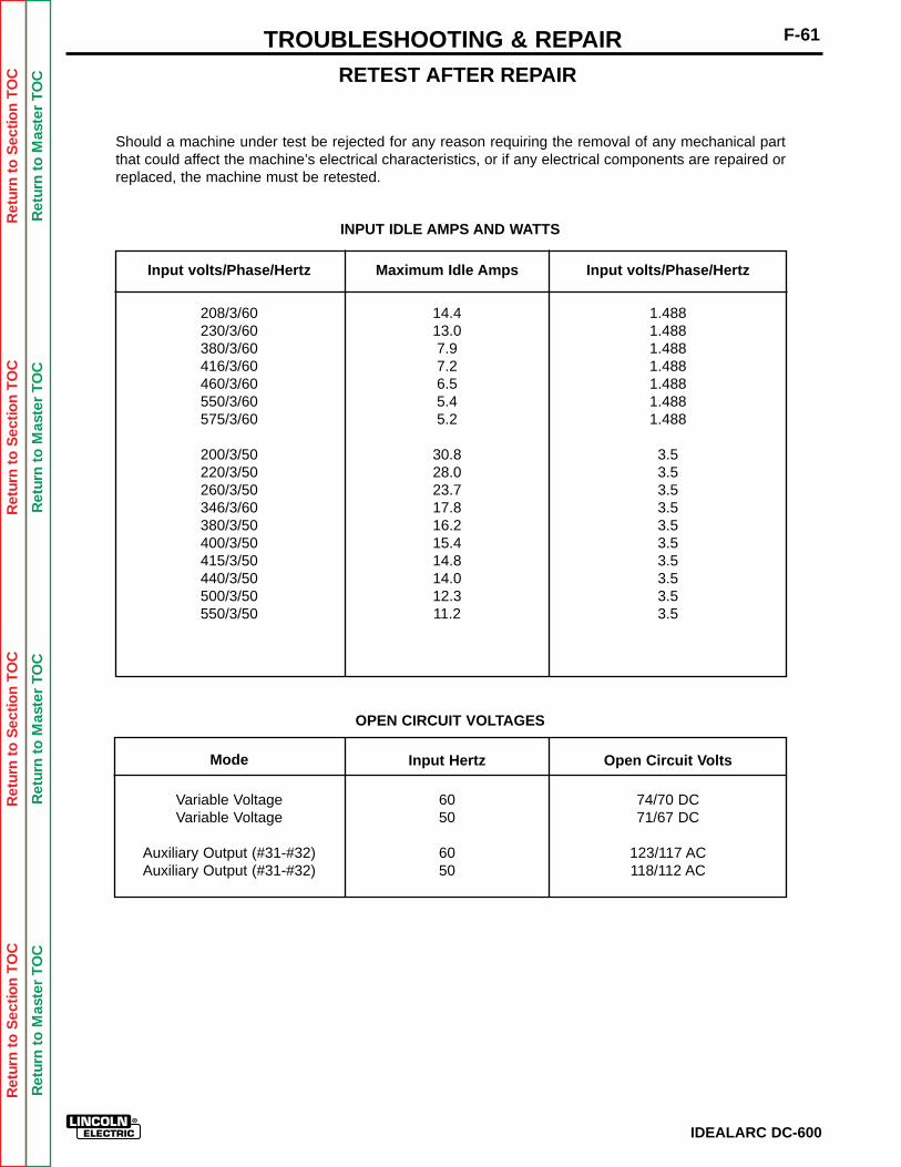
IDEALARC DC-600
F-61TROUBLESHOOTING & REPAIRRETEST AFTER REPAIR
Should a machine under test be rejected for any reason requiring the removal of any mechanical partthat could affect the machine’s electrical characteristics, or if any electrical components are repaired orreplaced, the machine must be retested.
INPUT IDLE AMPS AND WATTS
OPEN CIRCUIT VOLTAGES
208/3/60230/3/60380/3/60416/3/60460/3/60550/3/60575/3/60
200/3/50220/3/50260/3/50346/3/60380/3/50400/3/50415/3/50440/3/50500/3/50550/3/50
14.413.07.97.26.55.45.2
30.828.023.717.816.215.414.814.012.311.2
1.4881.4881.4881.4881.4881.4881.488
3.53.53.53.53.53.53.53.53.53.5
Input volts/Phase/Hertz Input volts/Phase/HertzMaximum Idle Amps
Open Circuit VoltsInput Hertz
74/70 DC71/67 DC
123/117 AC118/112 AC
6050
6050
Variable VoltageVariable Voltage
Auxiliary Output (#31-#32)Auxiliary Output (#31-#32)
Mode
Ret
urn
to S
ectio
n T
OC
Ret
urn
to S
ectio
n T
OC
Ret
urn
to S
ectio
n T
OC
Ret
urn
to S
ectio
n T
OC
Ret
urn
to M
aste
r T
OC
Ret
urn
to M
aste
r T
OC
Ret
urn
to M
aste
r T
OC
Ret
urn
to M
aste
r T
OC
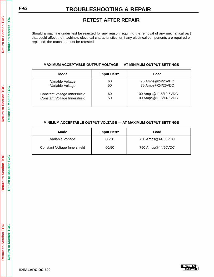
Should a machine under test be rejected for any reason requiring the removal of any mechanical partthat could affect the machine’s electrical characteristics, or if any electrical components are repaired orreplaced, the machine must be retested.
MAXIMUM ACCEPTABLE OUTPUT VOLTAGE — AT MINIMUM OUTPUT SETTINGS
MINIMUM ACCEPTABLE OUTPUT VOLTAGE — AT MAXIMUM OUTPUT SETTINGS
Mode
Variable VoltageVariable Voltage
Constant Voltage InnershieldConstant Voltage Innershield
Input Hertz
6050
6050
Load
75 Amps@24/26VDC75 Amps@24/26VDC
100 [email protected]/12.5VDC100 [email protected]/14.5VDC
Mode
Variable Voltage
Constant Voltage Innershield
Input Hertz
60/50
60/50
Load
750 Amps@44/50VDC
750 Amps@44/50VDC
RETEST AFTER REPAIR
F-62 TROUBLESHOOTING & REPAIR
IDEALARC DC-600
Ret
urn
to S
ectio
n T
OC
Ret
urn
to S
ectio
n T
OC
Ret
urn
to S
ectio
n T
OC
Ret
urn
to S
ectio
n T
OC
Ret
urn
to M
aste
r T
OC
Ret
urn
to M
aste
r T
OC
Ret
urn
to M
aste
r T
OC
Ret
urn
to M
aste
r T
OC
Ret
urn
to M
aste
r T
OC
Ret
urn
to M
aste
r T
OC
Ret
urn
to M
aste
r T
OC
Ret
urn
to M
aste
r T
OC
TABLE OF CONTENTS- ELECTRICAL DIAGRAMS -
Section G
IDEALARC DC600
ELECTRICAL DIAGRAMS SECTION ...................... Section G
Control Board Layout.......................................................G-1(G1504-4 and above)
Firing Board Layout .........................................................G-3(G1486-5 and above)Wiring Diagram ...........................................................G-5(Codes 9773,9776,9778,9779,9780,9910)
Wiring Diagram ................................................................G-6(Code 9774)
Operating Schematic .......................................................G-7Control Board Schematic.................................................G-8
(G1504-4 and above)Firing Board Schematic ...................................................G-9
(G1486-5 and above)
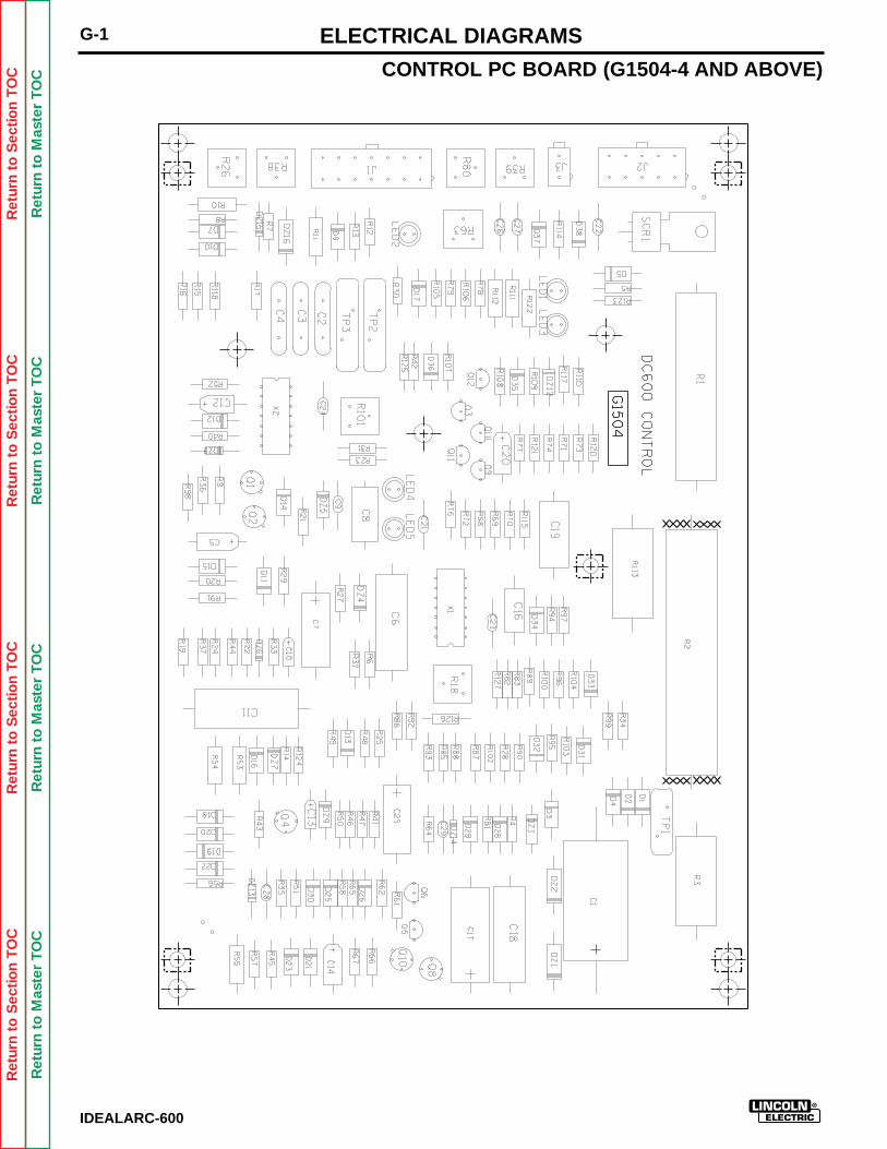
Ret
urn
to S
ectio
n T
OC
Ret
urn
to S
ectio
n T
OC
Ret
urn
to S
ectio
n T
OC
Ret
urn
to S
ectio
n T
OC
Ret
urn
to M
aste
r T
OC
Ret
urn
to M
aste
r T
OC
Ret
urn
to M
aste
r T
OC
Ret
urn
to M
aste
r T
OC
IDEALARC-600
G-1 ELECTRICAL DIAGRAMS
CONTROL PC BOARD (G1504-4 AND ABOVE)
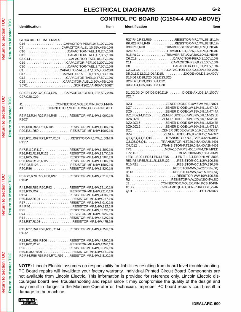
Ret
urn
to S
ectio
n T
OC
Ret
urn
to S
ectio
n T
OC
Ret
urn
to S
ectio
n T
OC
Ret
urn
to S
ectio
n T
OC
Ret
urn
to M
aste
r T
OC
Ret
urn
to M
aste
r T
OC
Ret
urn
to M
aste
r T
OC
Ret
urn
to M
aste
r T
OC
R37,R40,R83,R89 . . . . . . . . . . . .RESISTOR-MF,1/4W,68.1K,1%R6,R23,R48,R49 . . . . . . . . . . . . .RESISTOR-MF,1/4W,82.5K,1%R39,R63,R80 . . . . . . . . . .TRIMMER-ST,1/2W,50K,10%,LINEARR26,R38 . . . . . . . . . . . . . . .TRIMMER-ST,1/2W,1K,10%,LINEARR18,R101 . . . . . . . . . . . . .TRIMMER-ST,1/2W,20K,10%,LINEARC6,C18 . . . . . . . . . . . . . . . . . . .CAPACITOR-PEF,0.1,100V,10%C11 . . . . . . . . . . . . . . . . . . . . .CAPACITOR-PEF,0.22,100V,10%C8 . . . . . . . . . . . . . . . . . . . . . . .CAPACITOR-PEF,.01,200V,10%C2,C3,C4 . . . . . . . . . . . . . .CAPACITOR-CD,.02,600V,+80/-20%D5,D11,D12,D13,D14,D15, . . . . . . . . . .DIODE-AXLDS,1A,400VD16,D17,D18,D20,D22,D23,D25D26,D28,D29,D30,D31,D32D33,D34,D35,D36,D37,D38
D1,D2,D3,D4,D7,D9,D10,D19 . . . . . . .DIODE-AXLDS,1A,1000VD21 *
DZ3 . . . . . . . . . . . . . . . . . .ZENER DIODE-0.4W,6.2V,5%,1N821DZ7 . . . . . . . . . . . . . . . . . .ZENER DIODE-1W,12V,5%,1N4742ADZ5 . . . . . . . . . . . . . . . . . .ZENER DIODE-1W,15V,5%,1N4744ADZ13,DZ14,DZ15 . . . . . .ZENER DIODE-0.5W,3.0V,5%,1N5225BDZ6,DZ8 . . . . . . . . . . . .ZENER DIODE-0.5W,8.2V,5%,1N5237BDZ2,DZ16 . . . . . . . . . . . . .ZENER DIODE-5W,10V,5%,1N5347BDZ9,DZ12 . . . . . . . . . . . . .ZENER DIODE-1W,30V,5%,1N4751ADZ1 . . . . . . . . . . . . . . . .ZENER DIODE-5W,16.0/16.5V,1N5353*DZ4 . . . . . . . . . . . . . . . . .ZENER DIODE-1W,9.9/10.4V,1N4740*Q1,Q2,Q4,Q8,Q10 . . . . . . .TRANSISTOR-NJF,T206,40V,2N4857Q3,Q5,Q6,Q11 . . . . . . .TRANSISTOR-N,T226,0.5A,40V,2N4401Q9,Q12 . . . . . . . . . . . . .TRANSISTOR-P,T226,0.5A,40V,2N4403TP1 . . . . . . . . . . . . . . . . . .MOV-150VRMS,45J,14MM,CRIMPEDTP2,TP3 . . . . . . . . . . . . . . . . . . . . .MOV-320VRMS,160J,20MMLED1,LED2,LED3,LED4,LED5 . . .LED-T-1 3/4,RED,HLMP-3003R53,R54,R55,R111,R112,R122 . . . .RESISTOR-CC,1/2W,100,5%R10,R11 . . . . . . . . . . . . . . . . . . . . .RESISTOR-CC,1/2W,330,5%R3 . . . . . . . . . . . . . . . . . . . . . . .RESISTOR-WW,5W,270,5%,SQR113 . . . . . . . . . . . . . . . . . . . . .RESISTOR-WW,5W,150,5%,SQR1 . . . . . . . . . . . . . . . . . . . . . . . . .RESISTOR-WW,10W,100,5%R2 . . . . . . . . . . . . . . . . . . . . . .RESISTOR-WW,20W,200,5%,SQJ2 . . . . . . . . . . . . . . . . .CONNECTOR,MOLEX,MINI,PCB,10-PINX1,X2 . . . . . . . . . . . . .IC-OP-AMP,QUAD,GEN-PURPOSE,224NQU1 . . . . . . . . . . . . . . . . . . . . . . . . . . . . . . . . . . . .PUT-2N6027
G1504 BILL OF MATERIALSC16 . . . . . . . . . . . . . . . . . . . .CAPACITOR-PEMF,.047,100V,10%C7 . . . . . . . . . . . . . . . . . . . .CAPACITOR-ALEL,10,25V,+75/-10%C10 . . . . . . . . . . . . . . . . . . . . . . .CAPACITOR-TAEL,1.8,20V,10%C12 . . . . . . . . . . . . . . . . . . . . . . .CAPACITOR-TAEL,4.7,35V,10%C5,C14 . . . . . . . . . . . . . . . . . . . . .CAPACITOR-TAEL,18,15V,10%C19 . . . . . . . . . . . . . . . . . . . . . .CAPACITOR-PEF,.022,200V,10%C20 . . . . . . . . . . . . . . . . . . . . . . .CAPACITOR-TAEL,2.7,50V,10%C1 . . . . . . . . . . . . . . . . . . .CAPACITOR-ALEL,47,160V,+50/-20%C17 . . . . . . . . . . . . . . . . . . .CAPACITOR-ALEL,6,150V,+50/-10%C13 . . . . . . . . . . . . . . . . . . . . . .CAPACITOR-TAEL,0.47,50V,10%C25 . . . . . . . . . . . . . . . . . . . .CAPACITOR-ALEL,2,50V,+75/-10%SCR1 . . . . . . . . . . . . . . . . . . . . . . . . .SCR-T202,4A,400V,C106D*
C9,C21,C22,C23,C24,C26, . . .CAPACITOR-CEMO,.022,50V,20%C27,C28,C29
J1 . . . . . . . . . . . . . . . . .CONNECTOR,MOLEX,MINI,PCB,14-PINJ3 . . . . . . . . . . . . .CONNECTOR,MOLEX,MINI,PCB,2-PIN,GOLD
R7,R22,R24,R29,R44,R45 . . . . . .RESISTOR-MF,1/4W,1.00K,1%R102*
R19,R58,R65,R81,R105 . . . . . . . .RESISTOR-MF,1/4W,10.0K,1%R20,R21,R50 . . . . . . . . . . . . . . . . .RESISTOR-MF,1/4W,100K,1%
R25,R51,R67,R73,R77,R107 . . . . .RESISTOR-MF,1/4W,1.00M,%R121*
R47,R110,R117 . . . . . . . . . . . . . . .RESISTOR-MF,1/4W,1.30K,1%R16,R42,R118,R125 . . . . . . . . . . .RESISTOR-MF,1/4W,13.7K,1%R31,R85,R99 . . . . . . . . . . . . . . . .RESISTOR-MF,1/4W,1.50K,1%R36,R94,R126,R127 . . . . . . . . . . .RESISTOR-MF,1/4W,15.0K,1%R5,R98,R123 . . . . . . . . . . . . . . . . .RESISTOR-MF,1/4W,150K,1%R70,R86 . . . . . . . . . . . . . . . . . . . .RESISTOR-MF,1/4W,1.82K,1%
R8,R72,R78,R79,R88,R97 . . . . . .RESISTOR-MF,1/4W,2.21K,1%R103*
R43,R68,R82,R90,R92 . . . . . . . . .RESISTOR-MF,1/4W,22.1K,1%R33,R35,R52 . . . . . . . . . . . . . . . . .RESISTOR-MF,1/4W,221K,1%R124 . . . . . . . . . . . . . . . . . . . . . . .RESISTOR-MF,1/4W,24.3K,1%R30,R32,R104 . . . . . . . . . . . . . . . . .RESISTOR-MF,1/4W,267,1%R17 . . . . . . . . . . . . . . . . . . . . . . . .RESISTOR-MF,1/4W,3.01K,1%R4,R46 . . . . . . . . . . . . . . . . . . . . . . .RESISTOR-MF,1/4W,332,1%R95 . . . . . . . . . . . . . . . . . . . . . . . .RESISTOR-MF,1/4W,33.2K,1%R74 . . . . . . . . . . . . . . . . . . . . . . . .RESISTOR-MF,1/4W,392K,1%R14 . . . . . . . . . . . . . . . . . . . . . . . .RESISTOR-MF,1/4W,44.2K,1%R28,R87,R108 . . . . . . . . . . . . . . . . .RESISTOR-MF,1/4W,475,1%
R15,R27,R41,R76,R91,R114 . . . . .RESISTOR-MF,1/4W,4.75K,1%R115*
R12,R61,R93,R106 . . . . . . . . . . . .RESISTOR-MF,1/4W,47.5K,1%R13,R62,R120 . . . . . . . . . . . . . . . .RESISTOR-MF,1/4W,475K,1%R66 . . . . . . . . . . . . . . . . . . . . . . . .RESISTOR-MF,1/4W,56.2K,1%R69,R100,R109 . . . . . . . . . . . . . . . .RESISTOR-MF,1/4W,681,1%R9,R34,R56,R57,R64,R71,R96 . . .RESISTOR-MF,1/4W,6.81K,1%
IDEALARC-600
G-2ELECTRICAL DIAGRAMS
Identification Item Identification Item
CONTROL PC BOARD (G1504-4 AND ABOVE)
NOTE: Lincoln Electric assumes no responsibility for liablilities resulting from board level troubleshooting.PC Board repairs will invalidate your factory warranty. Individual Printed Circuit Board Components arenot available from Lincoln Electric. This information is provided for reference only. Lincoln Electric dis-courages board level troubleshooting and repair since it may compromise the quality of the design andmay result in danger to the Machine Operator or Technician. Improper PC board repairs could result indamage to the machine.
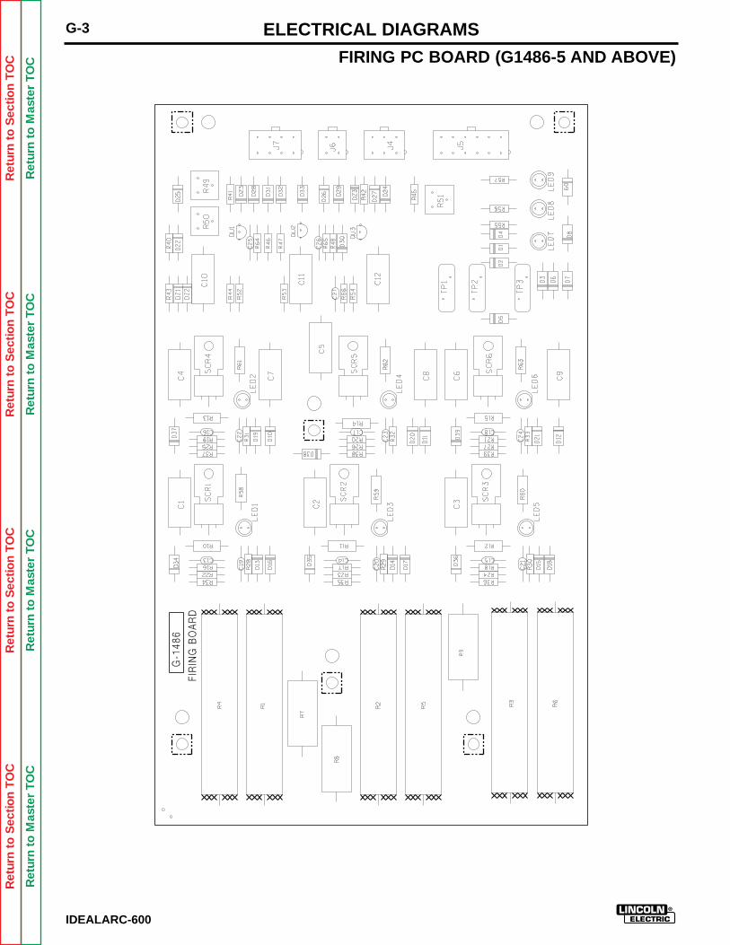
Ret
urn
to S
ectio
n T
OC
Ret
urn
to S
ectio
n T
OC
Ret
urn
to S
ectio
n T
OC
Ret
urn
to S
ectio
n T
OC
Ret
urn
to M
aste
r T
OC
Ret
urn
to M
aste
r T
OC
Ret
urn
to M
aste
r T
OC
Ret
urn
to M
aste
r T
OC
IDEALARC-600
ELECTRICAL DIAGRAMS
FIRING PC BOARD (G1486-5 AND ABOVE)
FIR
ING
BO
AR
D
G-1
486
G-3
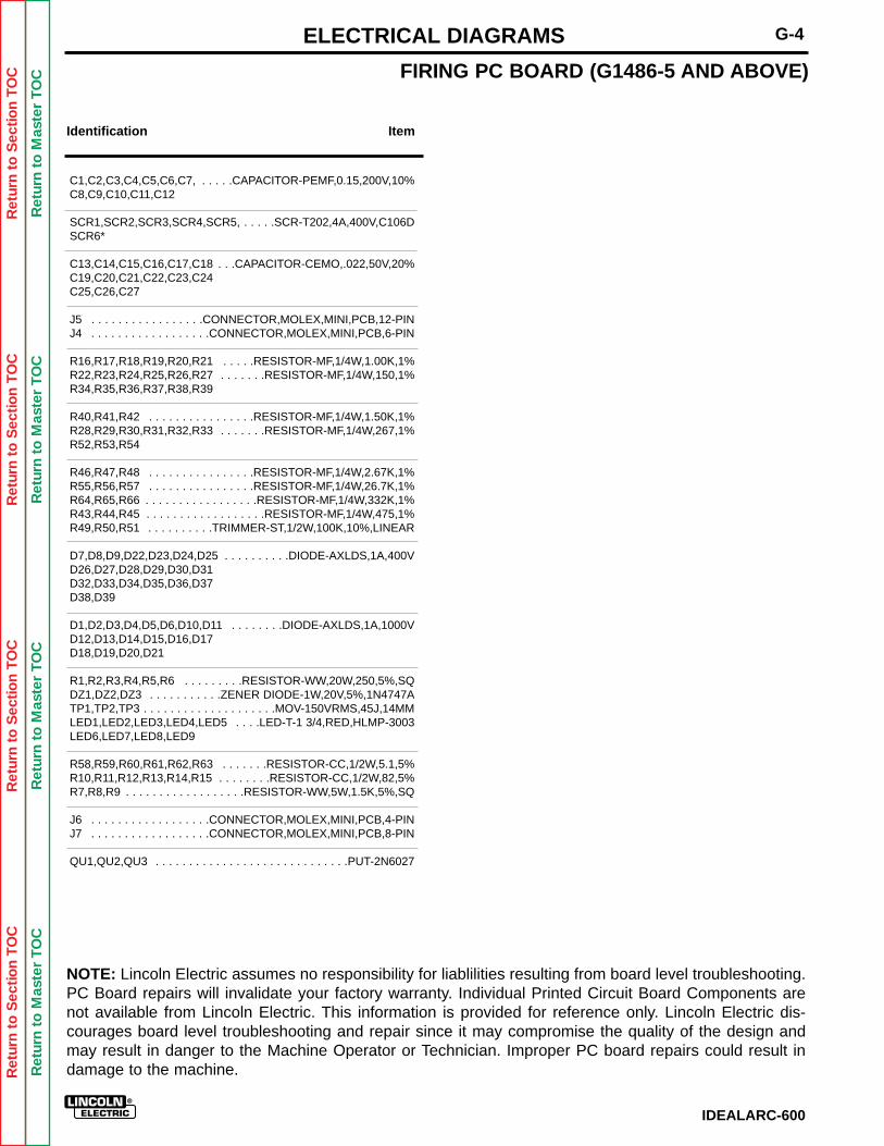
Ret
urn
to S
ectio
n T
OC
Ret
urn
to S
ectio
n T
OC
Ret
urn
to S
ectio
n T
OC
Ret
urn
to S
ectio
n T
OC
Ret
urn
to M
aste
r T
OC
Ret
urn
to M
aste
r T
OC
Ret
urn
to M
aste
r T
OC
Ret
urn
to M
aste
r T
OC
IDEALARC-600
G-4ELECTRICAL DIAGRAMS
FIRING PC BOARD (G1486-5 AND ABOVE)
Identification Item
C1,C2,C3,C4,C5,C6,C7, . . . . .CAPACITOR-PEMF,0.15,200V,10%C8,C9,C10,C11,C12
SCR1,SCR2,SCR3,SCR4,SCR5, . . . . .SCR-T202,4A,400V,C106DSCR6*
C13,C14,C15,C16,C17,C18 . . .CAPACITOR-CEMO,.022,50V,20%C19,C20,C21,C22,C23,C24C25,C26,C27
J5 . . . . . . . . . . . . . . . . .CONNECTOR,MOLEX,MINI,PCB,12-PINJ4 . . . . . . . . . . . . . . . . . .CONNECTOR,MOLEX,MINI,PCB,6-PIN
R16,R17,R18,R19,R20,R21 . . . . .RESISTOR-MF,1/4W,1.00K,1%R22,R23,R24,R25,R26,R27 . . . . . . .RESISTOR-MF,1/4W,150,1%R34,R35,R36,R37,R38,R39
R40,R41,R42 . . . . . . . . . . . . . . . .RESISTOR-MF,1/4W,1.50K,1%R28,R29,R30,R31,R32,R33 . . . . . . .RESISTOR-MF,1/4W,267,1%R52,R53,R54
R46,R47,R48 . . . . . . . . . . . . . . . .RESISTOR-MF,1/4W,2.67K,1%R55,R56,R57 . . . . . . . . . . . . . . . .RESISTOR-MF,1/4W,26.7K,1%R64,R65,R66 . . . . . . . . . . . . . . . . .RESISTOR-MF,1/4W,332K,1%R43,R44,R45 . . . . . . . . . . . . . . . . . .RESISTOR-MF,1/4W,475,1%R49,R50,R51 . . . . . . . . . .TRIMMER-ST,1/2W,100K,10%,LINEAR
D7,D8,D9,D22,D23,D24,D25 . . . . . . . . . .DIODE-AXLDS,1A,400VD26,D27,D28,D29,D30,D31D32,D33,D34,D35,D36,D37D38,D39
D1,D2,D3,D4,D5,D6,D10,D11 . . . . . . . .DIODE-AXLDS,1A,1000VD12,D13,D14,D15,D16,D17D18,D19,D20,D21
R1,R2,R3,R4,R5,R6 . . . . . . . . .RESISTOR-WW,20W,250,5%,SQDZ1,DZ2,DZ3 . . . . . . . . . . .ZENER DIODE-1W,20V,5%,1N4747ATP1,TP2,TP3 . . . . . . . . . . . . . . . . . . . .MOV-150VRMS,45J,14MMLED1,LED2,LED3,LED4,LED5 . . . .LED-T-1 3/4,RED,HLMP-3003LED6,LED7,LED8,LED9
R58,R59,R60,R61,R62,R63 . . . . . . .RESISTOR-CC,1/2W,5.1,5%R10,R11,R12,R13,R14,R15 . . . . . . . .RESISTOR-CC,1/2W,82,5%R7,R8,R9 . . . . . . . . . . . . . . . . . .RESISTOR-WW,5W,1.5K,5%,SQ
J6 . . . . . . . . . . . . . . . . . .CONNECTOR,MOLEX,MINI,PCB,4-PINJ7 . . . . . . . . . . . . . . . . . .CONNECTOR,MOLEX,MINI,PCB,8-PIN
QU1,QU2,QU3 . . . . . . . . . . . . . . . . . . . . . . . . . . . . .PUT-2N6027
NOTE: Lincoln Electric assumes no responsibility for liablilities resulting from board level troubleshooting.PC Board repairs will invalidate your factory warranty. Individual Printed Circuit Board Components arenot available from Lincoln Electric. This information is provided for reference only. Lincoln Electric dis-courages board level troubleshooting and repair since it may compromise the quality of the design andmay result in danger to the Machine Operator or Technician. Improper PC board repairs could result indamage to the machine.

Ret
urn
to S
ectio
n T
OC
Ret
urn
to S
ectio
n T
OC
Ret
urn
to S
ectio
n T
OC
Ret
urn
to S
ectio
n T
OC
Ret
urn
to M
aste
r T
OC
Ret
urn
to M
aste
r T
OC
Ret
urn
to M
aste
r T
OC
Ret
urn
to M
aste
r T
OC
IDEALARC-600
NOTES
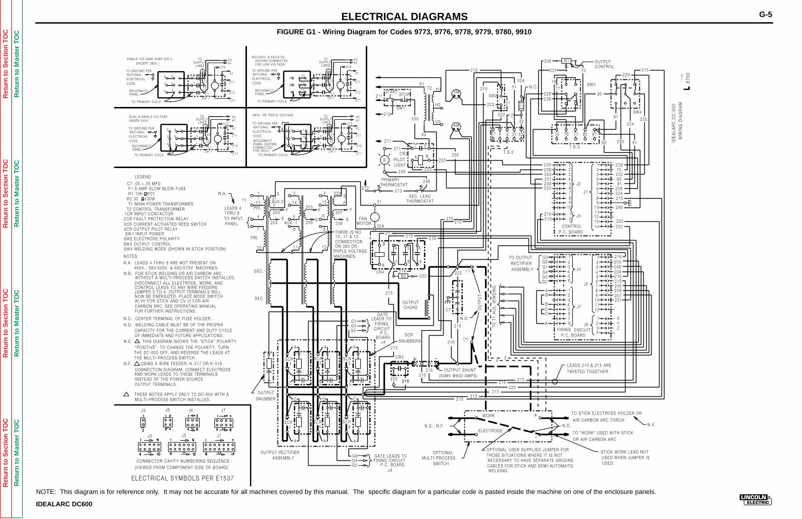
G-5ELECTRICAL DIAGRAMS
TO GROUND PERNAT IONAL
H3H1
X1
211
212
TOSUPPLY
L INES
L3
L2
L1
271
272
3
2
1
6
5
4
9
8
7
TO PR IMARY COILS
CODEELECTR ICAL
211
212SW1
STARTSTOP
255
X1
X2
T2 H1
H2
H3
VM
AM
+
+
-
-
210
210
SW2
222
222
21
2
31
32A
32
21 4 2 31 32
T .S .2
N .C .
226238
236 R1
237 75
80
OUTPUTCONTROL
229215
232224
81
77
76
7675 77 80 81
T .S .380 280 81
229
215
210
81
215 220
280
112 23 34 4
556 6789
12
80
226224
23275
222
235256255231238233
J1
J2
J3
CONTROLP.C . BOARD
20311
2 23 34 45 56 6
789
J4
J5
F IR ING CIRCUITP .C . BOARD
TO T
1 A
UX
. W
IND
ING
24
210215
220215
215215
+
-
WORK
ELECTRODE
LEADS 210 & 215 ARE
TWISTED TOGETHER
TO ST ICK ELECTRODE HOLDER OR
A IR-CARBON ARC TORCH
TO "WORK" USED WITH ST ICK
OR A IR-CARBON ARC
ST ICK WORK LEAD NOTUSED WHEN JUMPER ISUSED.
OPT IONAL USER SUPPL IED JUMPER FORTHOSE S ITUAT IONS WHERE IT IS NOT
CABLES FOR ST ICK AND SEMI -AUTOMAT ICWELD ING.
N .D . N .E .N .D . , N .F .
OPT IONAL MULT I -PROCESS
SWITCH
210
210
210215
OUTPUT SHUNT(50MV @800 AMPS}
220 215215
OUTPUTCHOKE C7
222
OU
TPU
T
N .D .
(+ )
( - )
215210
222R2214
A
B
7
4
8
5
9
6
31 215216
32A
31
FANMOTOR
215
272273
SEC. LEADTHERMOSTAT
256PR IMARYTHERMOSTAT
256
P ILOTL IGHT
233
235255B
57
A
271
271
R
S
S
F
F
32A
207
208
3
15
6
9
12
S
F205
206
2
14
5
8
11
AUX. 1S
F203
204
F
31S
AUX.2
11
PR I .
4
7
PR I .
10
SEC.
SEC.
T1
THERE IS NO10 , 11 & 12CONNECT IONON 380 OR
TR IPLE VOLTAGEMACHINES.
4
LEADS 4THRU 9TO INPUTPANEL
SCR
SCR
SCR SCR
SCR SCR
1
2
3
4
5
6
OUTPUTSNUBBER
G6G4G2 P.C . BOARD
OUTPUT RECT IF IERASSEMBLY
GATELEADS TO
C IRCUIT F IR ING
BOARDP.C . SCR
LEGEND
C7 .05 + .05 MFDF1 8 AMP SLOW BLOW FUSER1 10K POT
T1 MA IN POWER TRANSFORMERR2 30 , 100W
T2 CONTROL TRANSFORMER
2CR FAULT PROTECT ION RELAY1CR INPUT CONTACTOR
4CR OUTPUT P ILOT RELAY3CR CURRENT ACT IVATED REED SWITCH
SW1 INPUT POWERSW2 ELECTRODE POLAR ITYSW3 OUTPUT CONTROLSW4 WELD ING MODE (SHOWN IN ST ICK POS IT ION )
NOTES:
N .B . FOR ST ICK WELD ING OR A IR CARBON ARCWITHOUT A MULT I -PROCESS SWITCH INSTALLED,D ISCONNECT ALL ELECTRODE, WORK, ANDCONTROL LEADS TO ANY WIRE FEEDERS.JUMPER 2 TO 4 . OUTPUT TERMINALS WILLNOW BE ENERGIZED. PLACE MODE SWITCHIN VV FOR ST ICK AND CV ( I ) FOR A IRCARBON ARC. SEE OPERAT ING MANUALFOR FURTHER INSTRUCT IONS.
N .C . CENTER TERMINAL OF FUSE HOLDER.
N .D . WELD ING CABLE MUST BE OF THE PROPERCAPACITY FOR THE CURRENT AND DUTY CYCLEOF IMMEDIATE AND FUTURE APPL ICAT IONS.
"POS IT IVE" . TO CHANGE THE POLAR ITY , TURNTHE DC-600 OFF , AND REVERSE THE LEADS ATTHE MULT I -PROCESS SWITCH.
CONNECT ION D IAGRAM, CONNECT ELECTRODEAND WORK LEADS TO THESE TERMINALSINSTEAD OF THE POWER SOURCEOUTPUT TERMINALS.
THESE NOTES APPLY ONLY TO DC-600 WITH AMULT I -PROCESS SWITCH INSTALLED.
SNUBBERS
+ -
G1G3G5
F1
N.E . TH IS D IAGRAM SHOWS THE "ST ICK" POLAR ITY
N.F . US ING A WIRE FEEDER, K-317 OR K-318
215
GATE LEADS TO F IR ING C IRCUIT NECESSARY TO HAVE SEPARATE GROUND
AA A
A A A
C C C
CCC
N.A . LEADS 4 THRU 9 ARE NOT PRESENT ON
CR 1
S INGLE VOLTAGE OVER 300 V .(EXCEPT 380V . )
RECONNECTPANEL
TO GROUND PERNAT IONAL
H1
X1
211
212
TOSUPPLY
L INES
L3
L2
L1
271
272
3
2
1
9
8
7
TO PR IMARY COILS
CODEELECTR ICAL
CR 1
RECONNECT
H2
TO GROUND PERNAT IONAL
H1
X1
211
212
TOSUPPLY
L INES
L3
L2
L1
271
272
TO PR IMARY COILS
CODEELECTR ICAL
CR 1
RECONNECTPANEL
H2380/500V . & 460 /575V .
FOR LOW VOLTAGE)(SHOWN CONNECTED
15
14
13
3
2
1
TO GROUND PERNAT IONAL
H1
X1
211
212
TOSUPPLY
L INES
L3
L2
L1
271
272
3
2
1
6
5
4
9
8
7
TO PR IMARY COILS
CODEELECTR ICAL
CR 1
RECONNECTPANEL
DUAL & S INGLE VOLTAGEUNDER 300V .
H2 380V . OR TR IPLE VOLTAGE
6
5
4
11
10
12PANEL (SHOWNCONNECTEDFOR 380V . )
N .A .
13
460V . , 380 /500V . & 460 /575V . MACHINES.
CR3
CR4
CR2
SW3
SW4
1-1
7-92
B
ID
EA
LAR
C D
C-6
00
W
IRIN
G D
IAG
RA
M
8750
L
J4
J4
10
789
1011121314
J7
12345678
101112
1234
J6
AB
B'CC'
A '
G3G6G1G4G5G2
216
206204215215205208207231
XYZ
RECT IF IER ASSEMBLY
TO OUTPUT
ELECTR ICAL SYMBOLS PER E1537
J3
J1
J7
CONNECTOR CAV ITY NUMBERING SEQUENCE
(V IEWED FROM COMPONENT S IDE OF BOARD)
J6 J4
J2 J5
IDEALARC DC600
FIGURE G1 - Wiring Diagram for Codes 9773, 9776, 9778, 9779, 9780, 9910
NOTE: This diagram is for reference only. It may not be accurate for all machines covered by this manual. The specific diagram for a particular code is pasted inside the machine on one of the enclosure panels.
Ret
urn
to S
ectio
n T
OC
Ret
urn
to S
ectio
n T
OC
Ret
urn
to S
ectio
n T
OC
Ret
urn
to S
ectio
n T
OC
Ret
urn
to M
aste
r T
OC
Ret
urn
to M
aste
r T
OC
Ret
urn
to M
aste
r T
OC
Ret
urn
to M
aste
r T
OC
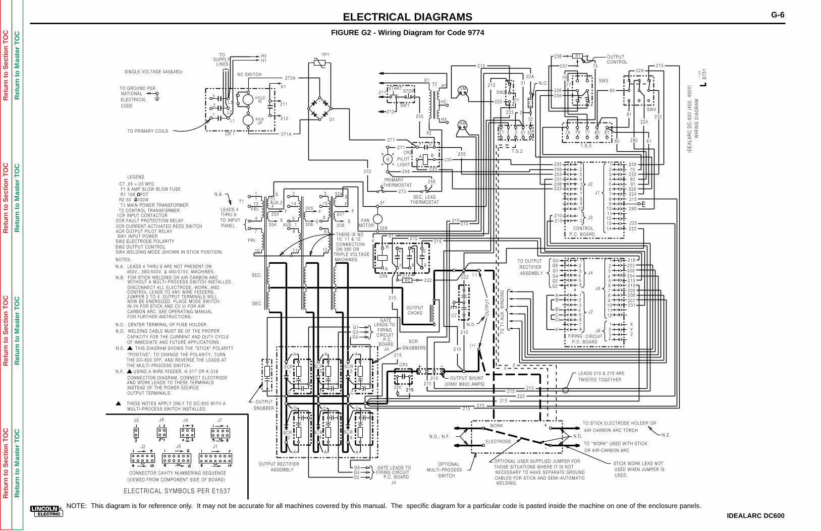
Ret
urn
to S
ectio
n T
OC
Ret
urn
to S
ectio
n T
OC
Ret
urn
to S
ectio
n T
OC
Ret
urn
to S
ectio
n T
OC
Ret
urn
to M
aste
r T
OC
Ret
urn
to M
aste
r T
OC
Ret
urn
to M
aste
r T
OC
Ret
urn
to M
aste
r T
OC
G-6ELECTRICAL DIAGRAMS
211
212SW1
STARTSTOP
255
X1
X2
T2 H1
H2
H3
VM
AM
+
+
-
-
210
210
SW2
222
222
21
2
31
32A
32
21 4 2 31 32
T .S .2
N .C .
226238
236 R1
237 75
80
OUTPUTCONTROL
229215
232224
81
77
76
7675 77 80 81
T .S .380 280 81
229
215
210
81
215 220
280
112 23 34 4
556 6789
12
80
226224
23275
222
235256255231238233
J1
J2
J3
CONTROLP.C . BOARD
20311
2 23 34 45 56 6
789
J4
J5
F IR ING CIRCUITP .C . BOARD
TO T
1 A
UX
. W
IND
ING
24
210215
220215
215215
+
-
WORK
ELECTRODE
LEADS 210 & 215 ARE
TWISTED TOGETHER
TO ST ICK ELECTRODE HOLDER OR
A IR-CARBON ARC TORCH
TO "WORK" USED WITH ST ICK
OR A IR-CARBON ARC
ST ICK WORK LEAD NOTUSED WHEN JUMPER ISUSED.
OPT IONAL USER SUPPL IED JUMPER FORTHOSE S ITUAT IONS WHERE IT IS NOT
CABLES FOR ST ICK AND SEMI -AUTOMAT ICWELD ING.
N .D . N .E .N .D . , N .F .
OPT IONAL MULT I -PROCESS
SWITCH
210
210
210215
OUTPUT SHUNT(50MV @800 AMPS}
220 215215
OUTPUTCHOKE C7
222
OU
TPU
T
N .D .
(+ )
( - )
215210
222R2214
A
B
7
4
8
5
9
6
31 215216
32A
31
FANMOTOR
215
272
273SEC. LEAD
THERMOSTAT
256PR IMARYTHERMOSTAT
256
P ILOTL IGHT
233
235255B
57
A
271
271
R
S
S
F
F
32A
207
208
3
15
6
9
12
S
F205
206
2
14
5
8
11
AUX. 1S
F203
204
F
31S
AUX.2
11
PR I .
4
7
PR I .
10
SEC.
SEC.
T1
THERE IS NO10 , 11 & 12CONNECT IONON 380 OR
TR IPLE VOLTAGEMACHINES.
4
LEADS 4THRU 9TO INPUTPANEL
SCR
SCR
SCR SCR
SCR SCR
1
2
3
4
5
6
OUTPUTSNUBBER
G6G4G2 P.C . BOARD
OUTPUT RECT IF IERASSEMBLY
GATELEADS TO
C IRCUIT F IR ING
BOARDP.C . SCR
LEGEND
C7 .05 + .05 MFDF1 8 AMP SLOW BLOW FUSER1 10K POT
T1 MA IN POWER TRANSFORMERR2 30 , 100W
T2 CONTROL TRANSFORMER
2CR FAULT PROTECT ION RELAY1CR INPUT CONTACTOR
4CR OUTPUT P ILOT RELAY3CR CURRENT ACT IVATED REED SWITCH
SW1 INPUT POWERSW2 ELECTRODE POLAR ITYSW3 OUTPUT CONTROLSW4 WELD ING MODE (SHOWN IN ST ICK POS IT ION )
NOTES:
N .B . FOR ST ICK WELD ING OR A IR CARBON ARCWITHOUT A MULT I -PROCESS SWITCH INSTALLED,D ISCONNECT ALL ELECTRODE, WORK, ANDCONTROL LEADS TO ANY WIRE FEEDERS.JUMPER 2 TO 4 . OUTPUT TERMINALS WILLNOW BE ENERGIZED. PLACE MODE SWITCHIN VV FOR ST ICK AND CV ( I ) FOR A IRCARBON ARC. SEE OPERAT ING MANUALFOR FURTHER INSTRUCT IONS.
N .C . CENTER TERMINAL OF FUSE HOLDER.
N .D . WELD ING CABLE MUST BE OF THE PROPERCAPACITY FOR THE CURRENT AND DUTY CYCLEOF IMMEDIATE AND FUTURE APPL ICAT IONS.
"POS IT IVE" . TO CHANGE THE POLAR ITY , TURNTHE DC-600 OFF , AND REVERSE THE LEADS ATTHE MULT I -PROCESS SWITCH.
CONNECT ION D IAGRAM, CONNECT ELECTRODEAND WORK LEADS TO THESE TERMINALSINSTEAD OF THE POWER SOURCEOUTPUT TERMINALS.
THESE NOTES APPLY ONLY TO DC-600 WITH AMULT I -PROCESS SWITCH INSTALLED.
SNUBBERS
+ -
G1G3G5
F1
N.E . TH IS D IAGRAM SHOWS THE "ST ICK" POLAR ITY
N.F . US ING A WIRE FEEDER, K-317 OR K-318
215
GATE LEADS TO F IR ING C IRCUIT NECESSARY TO HAVE SEPARATE GROUND
AA A
A A A
C C C
CCC
N.A . LEADS 4 THRU 9 ARE NOT PRESENT ON
N.A .
13
460V . , 380 /500V . & 460 /575V . MACHINES.
CR3
CR4
CR2
SW3
SW4
1-1
7-92
B
W
IRIN
G D
IAG
RA
M
8751
L
J4
J4
10
789
1011121314
J7
12345678
101112
1234
J6
AB
B'CC'
A '
G3G6G1G4G5G2
216
206204215215205208207231
XYZ
RECT IF IER ASSEMBLY
TO OUTPUT
ELECTR ICAL SYMBOLS PER E1537
J3
J1
J7
CONNECTOR CAV ITY NUMBERING SEQUENCE
(V IEWED FROM COMPONENT S IDE OF BOARD)
J6 J4
J2 J5
TO GROUND PERNAT IONAL
H3H1
X1
211
212
TOSUPPLY
L INES
L3
L2
L1
3
2
1
TO PR IMARY COILS
CODEELECTR ICAL
CR 1
_
+
NC SWITCH
HOLD
271A
272A
IN
P ICKUP
S INGLE VOLTAGE 440&460v
D1
I
DE
ALA
RC
DC
-600
(40
0, 4
60V
)
TP1
IDEALARC DC600
FIGURE G2 - Wiring Diagram for Code 9774
NOTE: This diagram is for reference only. It may not be accurate for all machines covered by this manual. The specific diagram for a particular code is pasted inside the machine on one of the enclosure panels.
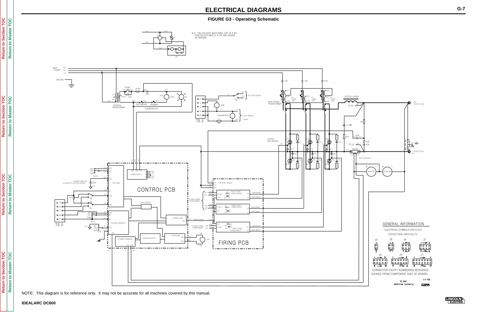
Ret
urn
to S
ectio
n T
OC
Ret
urn
to S
ectio
n T
OC
Ret
urn
to S
ectio
n T
OC
Ret
urn
to S
ectio
n T
OC
Ret
urn
to M
aste
r T
OC
Ret
urn
to M
aste
r T
OC
Ret
urn
to M
aste
r T
OC
Ret
urn
to M
aste
r T
OC
ELECTRICAL DIAGRAMS G-7
TS 2
21
4
2
31
32
75
76
77
80
81
TS 3
R1
S4-A
S4-B
S4-C
VV
VV
VV
CV I
CV I
CV I
CVS
CVS
CVS
S3
2CR
1CR
L1
L2
L3
1CR 1CR
1CR
STARTSTOP
R1CR
2CR
SECONDARY PR IMARY
SHUNT215
215 210210
226
238
75
229
80
81
280
224
232
3CR
220
215
215
CURRENT REED SW.CLOSED WITH OUTPUT CURRENT
235
236
236
235
210 215
222
222
231
204
203
206
205
208
207
G1
G2
G3
G4
G5
G6
215
215
216
X
Y
Z
AA'
C
BB'
C '
75 VAC
75 VAC
75 VAC
SET PO INT
POWER SUPPLY
VOLTAGE FEEDBACK
CURRENT FEEDBACK
FAULT DETECT.
SHUTDOWN
CONTROL AMP
OVERLOAD DETECT.
+32V+16V
-10V-6 .2V
4CR
FAN MOTOR
F1
8A
31
32A
S2
222
210
216 214
R2
4CR
4CR
4CRC7
215256 255
OUTPUT CHOKE
TO S2222
210TO S2
32A
207
208206
205
31
203
204
1J5
5J5
6J5
4J5
2J5
3J5
7J5
10J5
2J6
1J7
8J7
1J6
2J7
5J7
8J5
9J5
3J6
6J7
5J7
CONTROL PCB
4J2
1J2
6J2
2J31J314J1
9J1
3J1
5J1
4J1
1J1
5J2
6J1
2J1
13J1
7J1
10J1
2J2
3J2
8J1
5 0mV @ 800Amps
F IR ING PCB
"-" OUTPUT STUD
"+" OUTPUT STUD
120VAC
120VAC
F IR ING C IRCUIT
F IR ING C IRCUIT
F IR ING C IRCUIT
231
231
231
F IR ING BD. ENABLE
SCR1 & SCR2
SCR3 & SCR4
SCR5 & SCR6
GATE DR IVE
GATE DR IVE
GATE DR IVE
GATE DR IVE
GATE DR IVE
GATE DR IVE
F IR ING S IGNAL
GENERAL INFORMAT ION
INPUT POWER
J3
J1
J7
CONNECTOR CAV ITY NUMBERING SEQUENCE
(V IEWED FROM COMPONENT S IDE OF BOARD)
J6 J4
J2 J5
TO MAIN POWER TRANSFORMER
TO MA IN POWER TRANSFORMER
21TO OUTPUT STUDS
TO AUX. W IND ING
GROUND
255 271
272273256
H3
H2
212211
THERMOSTATS
CONTROLTRANSFORMER
N.A .
R14
R11
R15
R16
R12 R13
G1
G2 G4 G6
G3 G5
C17
C20
C18 C19
C21 C22
SCR1
SCR2
SCR3 SCR5
SCR4 SCR6
C11
C14
C12 C13
C15 C16
C10
R10
TO F IR ING PCB
TO F IR ING PCB
TO F IR ING PCB
OUTPUTSCR BR IDGE
MAIN POWERTRANSFORMER
AMMETER VOLTMETER
+ - - +
.051000
271
272
+ -
271A
272A
CR1
D1TP I
N .A . ON 440/460V MACHINES, CR1 IS A DC CONTACTOR AND D1 & TP I ARE ADDED AS SHOWN.
H1
1400
CAPACITORS= MFD/VOLTS
ELECTR ICAL SYMBOLS PER E1537 .
1
47
10
2 3
5 68 9
11 12
IDEALARC DC600
FIGURE G3 - Operating Schematic
NOTE: This diagram is for reference only. It may not be accurate for all machines covered by this manual.
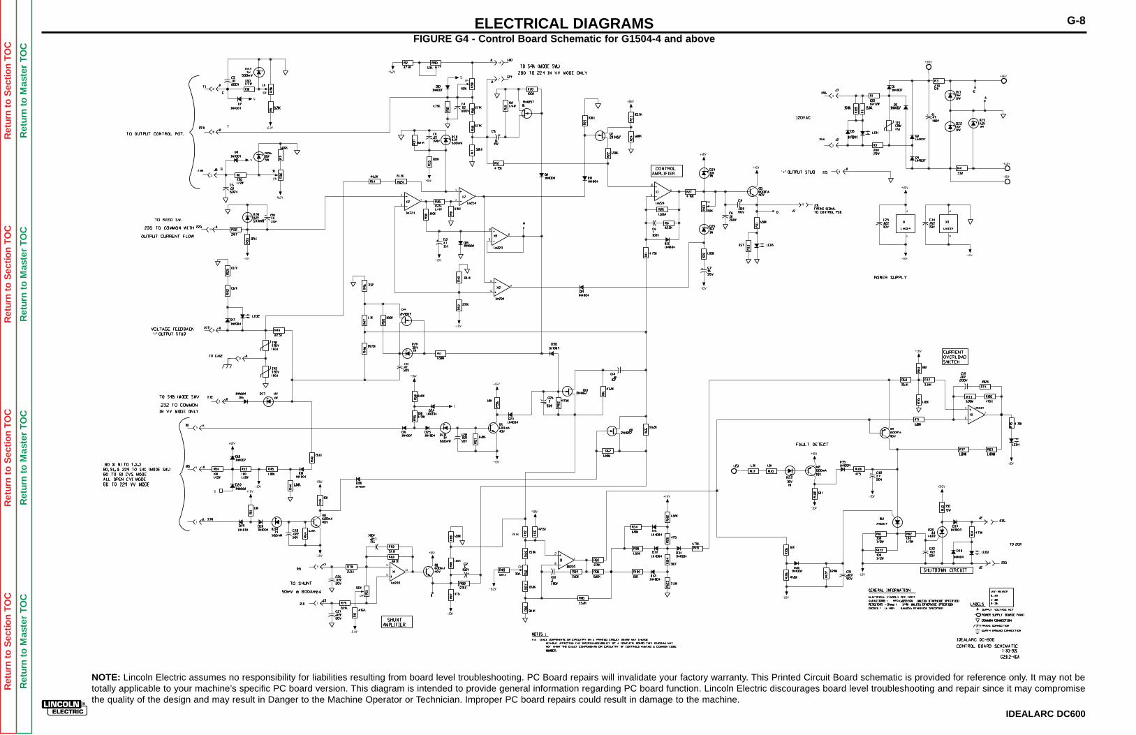
Ret
urn
to S
ectio
n T
OC
Ret
urn
to S
ectio
n T
OC
Ret
urn
to S
ectio
n T
OC
Ret
urn
to S
ectio
n T
OC
Ret
urn
to M
aste
r T
OC
Ret
urn
to M
aste
r T
OC
Ret
urn
to M
aste
r T
OC
Ret
urn
to M
aste
r T
OC
ELECTRICAL DIAGRAMS G-8
IDEALARC DC600
FIGURE G4 - Control Board Schematic for G1504-4 and above
NOTE: Lincoln Electric assumes no responsibility for liabilities resulting from board level troubleshooting. PC Board repairs will invalidate your factory warranty. This Printed Circuit Board schematic is provided for reference only. It may not betotally applicable to your machine’s specific PC board version. This diagram is intended to provide general information regarding PC board function. Lincoln Electric discourages board level troubleshooting and repair since it may compromisethe quality of the design and may result in Danger to the Machine Operator or Technician. Improper PC board repairs could result in damage to the machine.
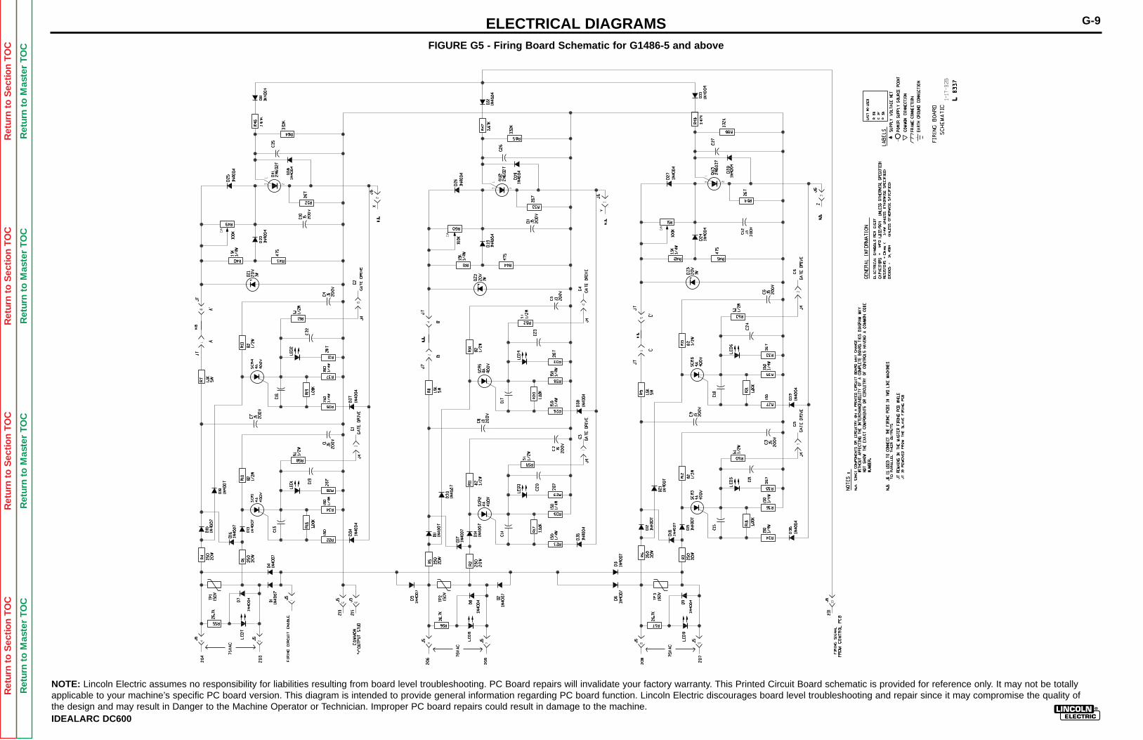
Ret
urn
to S
ectio
n T
OC
Ret
urn
to S
ectio
n T
OC
Ret
urn
to S
ectio
n T
OC
Ret
urn
to S
ectio
n T
OC
Ret
urn
to M
aste
r T
OC
Ret
urn
to M
aste
r T
OC
Ret
urn
to M
aste
r T
OC
Ret
urn
to M
aste
r T
OC
ELECTRICAL DIAGRAMS G-9
IDEALARC DC600
FIGURE G5 - Firing Board Schematic for G1486-5 and above
NOTE: Lincoln Electric assumes no responsibility for liabilities resulting from board level troubleshooting. PC Board repairs will invalidate your factory warranty. This Printed Circuit Board schematic is provided for reference only. It may not be totallyapplicable to your machine’s specific PC board version. This diagram is intended to provide general information regarding PC board function. Lincoln Electric discourages board level troubleshooting and repair since it may compromise the quality ofthe design and may result in Danger to the Machine Operator or Technician. Improper PC board repairs could result in damage to the machine.
Related Documents