BeoVision 5 – 42 EU Plasma Display Panel Update Type 890x SN: 16391203 or higher Service Center repair guide English, German, French, Italian, Spanish, Danish, Dutch ABO-CENTER v/HENRIKSENS ELEKTRONIK

Welcome message from author
This document is posted to help you gain knowledge. Please leave a comment to let me know what you think about it! Share it to your friends and learn new things together.
Transcript
BeoVision 5 – 42 EU Plasma Display Panel UpdateType 890xSN: 16391203 or higher
Service Center repair guideEnglish, German, French, Italian, Spanish, Danish, Dutch
ABO-CENTER v/HENRIKSENS ELEKTRONIK
Contents
1.1 English
2.1 German
3.1 French
4.1 Italian
5.1 Spanish
6.1 Danish
7.1 Dutch
8.1 Illustrations
8.1 Plasma Display Panel in service position
8.4 Remounting Plasma Display Panel
8.5 Remove contrast screen and plasma frame
8.6 Replacement of modules
9.1 Survey of modules
ABO-CENTER v/HENRIKSENS ELEKTRONIK
1.1
1.3 Servicing
1.4 Fault fl ow chart
1.10 Placement of measuring points
1.12 Local Screen Failure and OSD menu
1.13 Self-check
1.14 Pixel test
1.15 Replacement of modules
1.16 Test, adjustment and confi guration after repair
1.18 Final check after repair
8.1 Illustrations
Contents, English
ABO-CENTER v/HENRIKSENS ELEKTRONIK

1.2
ABO-CENTER v/HENRIKSENS ELEKTRONIK
1.3
Plasma Display Panel (PDP)
ServicingThe PDP may only be serviced by qualifi ed technical personal.
If it is not possible to determine the location of the fault or replacing spare part does not clear the fault, please contact your national Service Center for technical support.
HandlingThe PDP must always be placed vertical to avoid damaging it self.There is a major risk on damaging the PDP if it is placed in a horizontal position.Whenever possible place the PDP in the servicestand.
Use only the micro fi bre cloth, part no. 3375706 to clean the PDP.Do not use any kind of cleaning detergents on the PDP.
Burn-in Burn-in on the PDP might occur when displaying a non-moving picture for more than app. 30 minutes.
WarningStatic Electricity may destroy the product.
Use of ESD-matA static-protective fi eld service kit, including ESD-mat, must always be used when the product is disassembled and there is direct access to eg. modules or internal wiring.Follow the instructions in the guide.
The ESD-mat must never be connected to the product when mains is applied.
Trouble shooting
Actions before dismantling the PDPCheck the PDP for burn-in and pixel errors!This check is very important when the PDP must be transported to a workshop.Please refer to Pixel test, page 1.14.
Before dismantling the PDP - disconnect the mains supply and wait minimum 1 minute for the electolytic capasitors to discharge.
Connect ESD-mat.
Plasma Display Panel, English
ABO-CENTER v/HENRIKSENS ELEKTRONIK
1.4
PLASMA DISPLAY PANEL
(PDP)
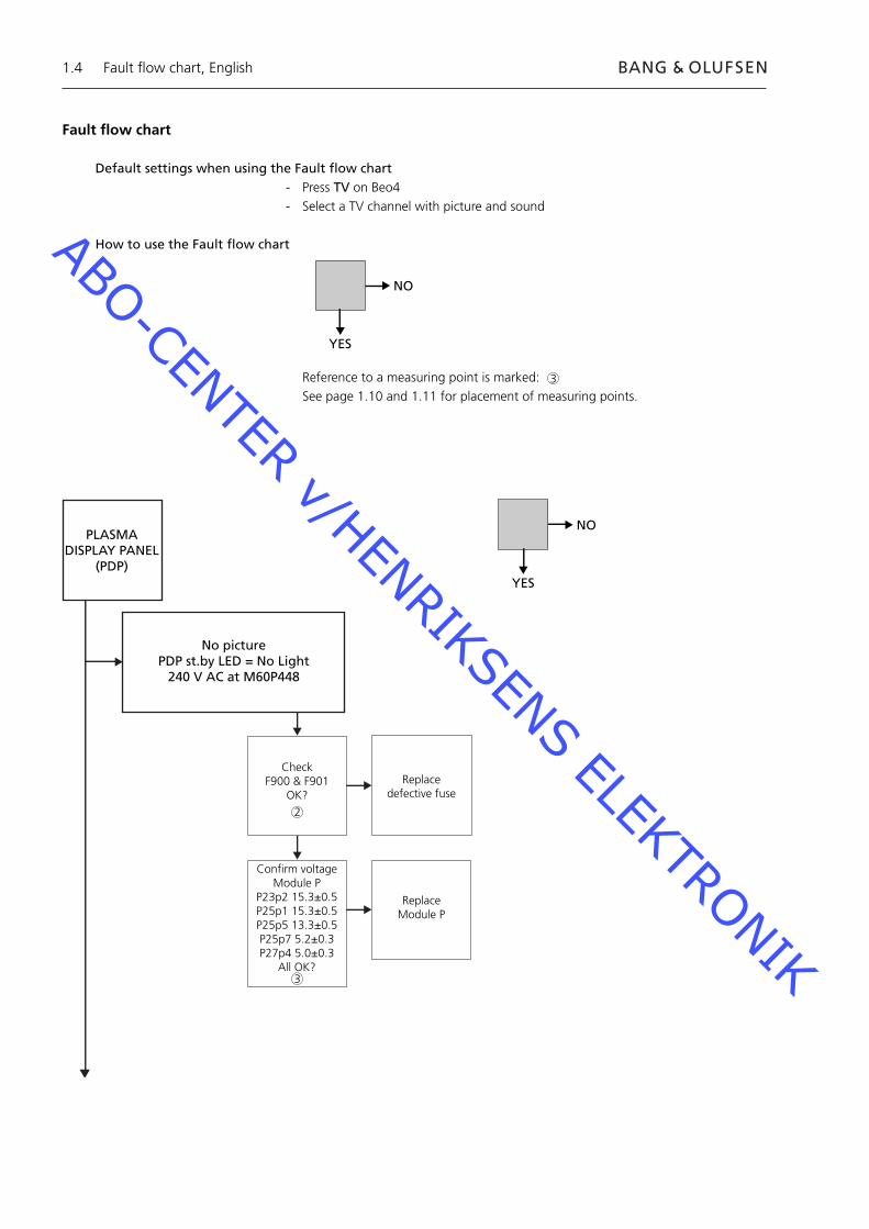
No picturePDP st.by LED = No Light
240 V AC at M60P448
Check F900 & F901
OK?Replace
defective fuse
Confirm voltage Module P
P23p2 15.3±0.5P25p1 15.3±0.5P25p5 13.3±0.5P25p7 5.2±0.3P27p4 5.0±0.3
All OK?
Replace Module P
NO
YES
Fault fl ow chart, English
Fault fl ow chart
Default settings when using the Fault fl ow chart- Press TV on Beo4- Select a TV channel with picture and sound
How to use the Fault fl ow chart
Reference to a measuring point is marked: See page 1.10 and 1.11 for placement of measuring points.
NO
YES
2
3
3
ABO-CENTER v/HENRIKSENS ELEKTRONIK
1.5
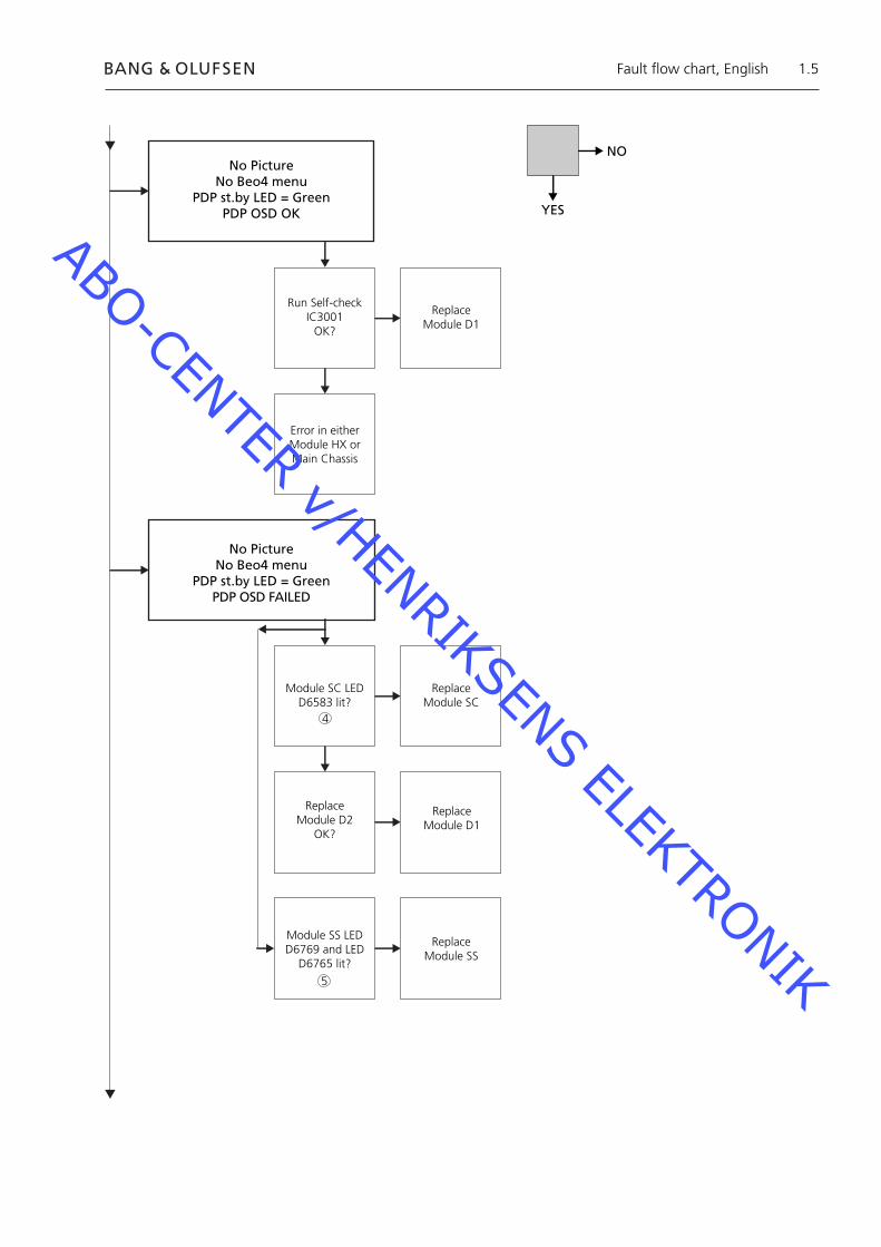
No PictureNo Beo4 menu
PDP st.by LED = GreenPDP OSD OK
Run Self-check IC3001
OK?
Replace Module D1
Error in either Module HX or Main Chassis
No PictureNo Beo4 menu
PDP st.by LED = GreenPDP OSD FAILED
Module SC LED D6583 lit?
Replace Module SC
Replace Module D2
OK?
Replace Module D1
Module SS LED D6769 and LED
D6765 lit?
Replace Module SS
NO
YES
Fault fl ow chart, English
5
4
ABO-CENTER v/HENRIKSENS ELEKTRONIK
1.6
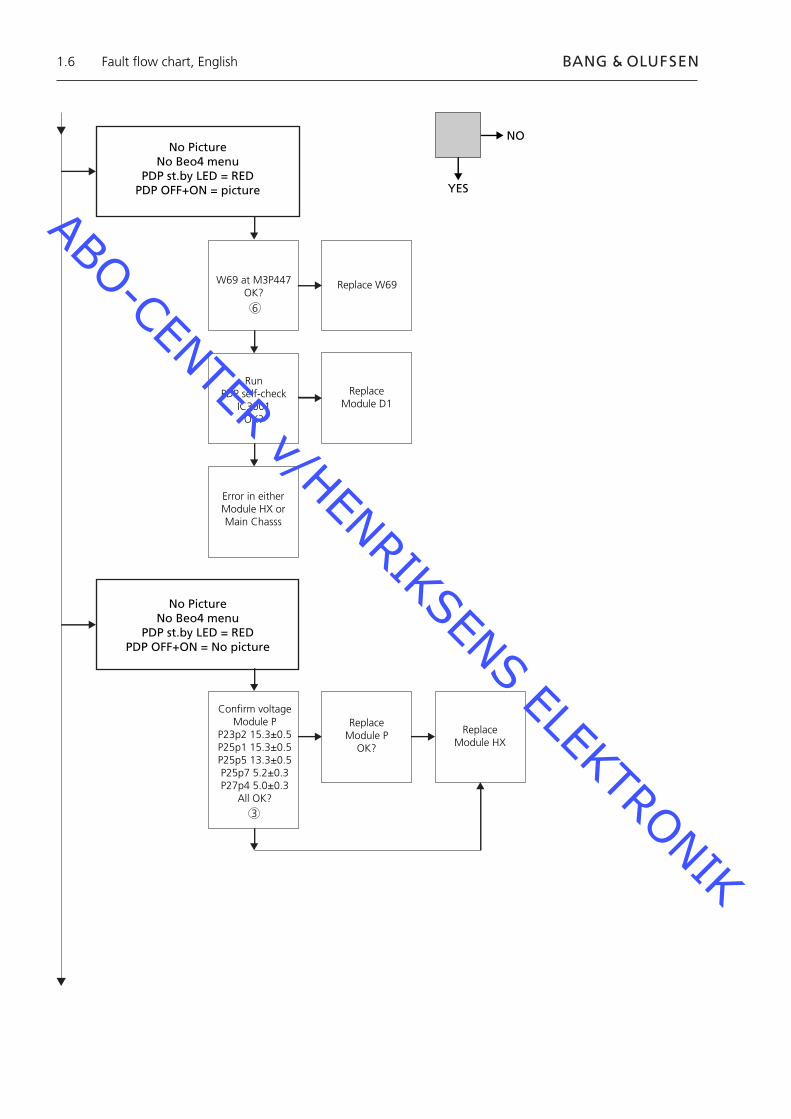
No PictureNo Beo4 menu
PDP st.by LED = REDPDP OFF+ON = picture
W69 at M3P447OK?
Replace W69
Run PDP self-check
IC3001OK?
Replace Module D1
Error in either Module HX or Main Chasss
No PictureNo Beo4 menu
PDP st.by LED = REDPDP OFF+ON = No picture
Confirm voltage Module P
P23p2 15.3±0.5P25p1 15.3±0.5P25p5 13.3±0.5P25p7 5.2±0.3P27p4 5.0±0.3
All OK?
Replace Module P
OK?
Replace Module HX
NO
YES
Fault fl ow chart, English
6
3
ABO-CENTER v/HENRIKSENS ELEKTRONIK
1.7
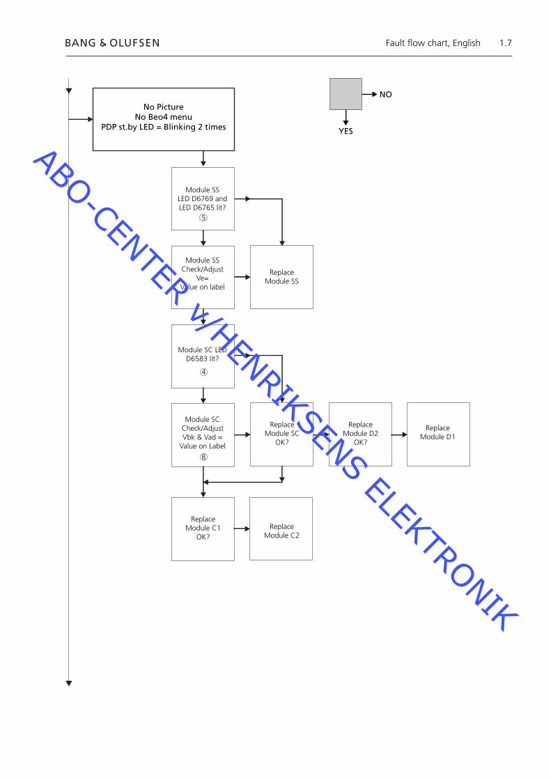
No Picture No Beo4 menu
PDP st.by LED = Blinking 2 times
Module SSLED D6769 and LED D6765 lit?
Module SSCheck/Adjust
Ve=Value on label
Replace Module SS
Module SC LED D6583 lit?
Module SCCheck/AdjustVbk & Vad =
Value on Label
Replace Module SC
OK?
Replace Module D2
OK?
Replace Module D1
Replace Module C1
OK?Replace
Module C2
NO
YES
Fault fl ow chart, English
8
4
5
ABO-CENTER v/HENRIKSENS ELEKTRONIK
1.8
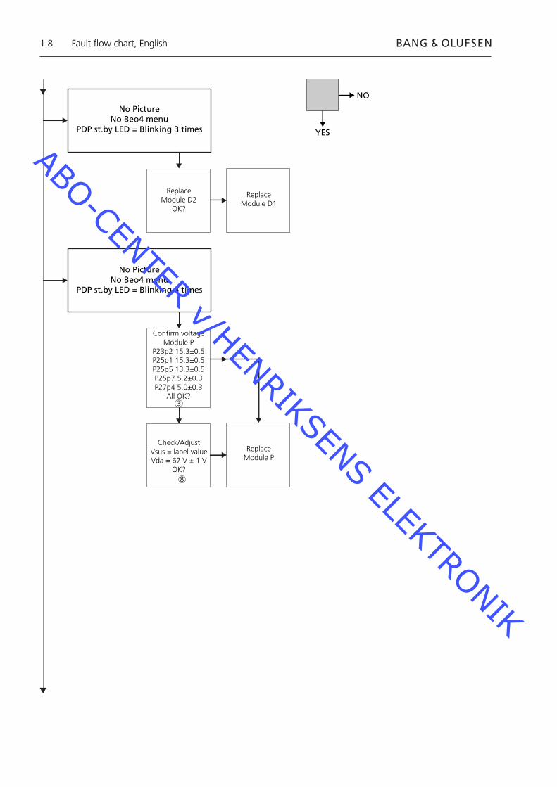
No PictureNo Beo4 menu
PDP st.by LED = Blinking 3 times
Replace Module D2
OK?
No PictureNo Beo4 menu
PDP st.by LED = Blinking 4 times
Confirm voltage Module P
P23p2 15.3±0.5P25p1 15.3±0.5P25p5 13.3±0.5P25p7 5.2±0.3P27p4 5.0±0.3
All OK?
Check/AdjustVsus = label valueVda = 67 V ± 1 V
OK?
Replace Module P
Replace Module D1
NO
YES
Fault fl ow chart, English
3
8
ABO-CENTER v/HENRIKSENS ELEKTRONIK
1.9
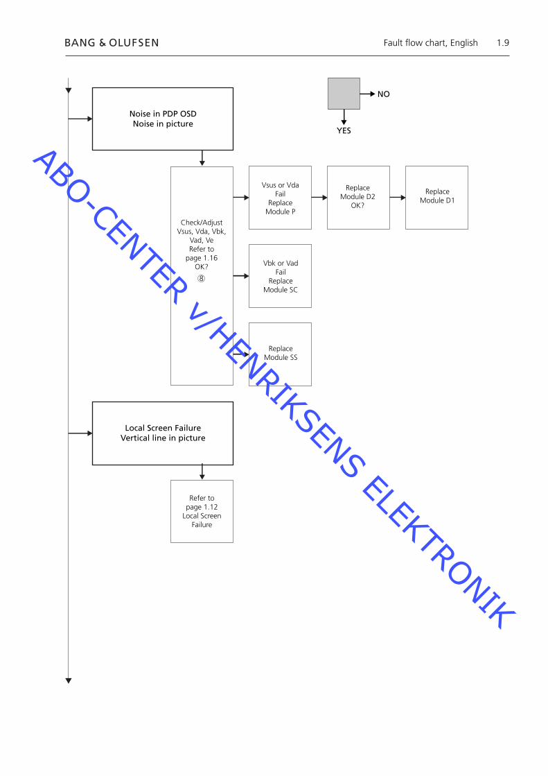
Noise in PDP OSDNoise in picture
Check/AdjustVsus, Vda, Vbk,
Vad, VeRefer to
page 1.16OK?
Vsus or VdaFail
Replace Module P
Replace Module D2
OK?
Replace Module D1
Vbk or VadFail
ReplaceModule SC
Replace Module SS
Local Screen FailureVertical line in picture
Refer to page 1.12
Local Screen Failure
NO
YES
Fault fl ow chart, English
8
ABO-CENTER v/HENRIKSENS ELEKTRONIK
1.10
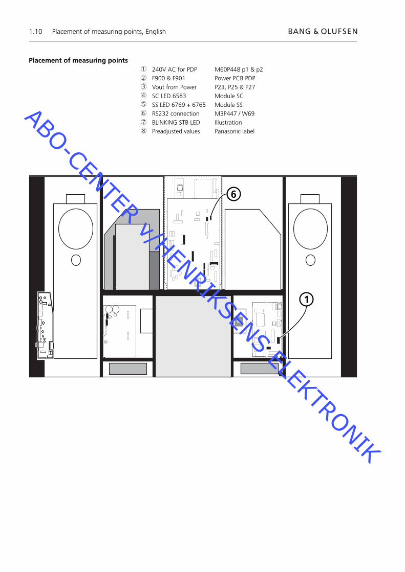
Placement of measuring points 240V AC for PDP M60P448 p1 & p2 F900 & F901 Power PCB PDP Vout from Power P23, P25 & P27 SC LED 6583 Module SC SS LED 6769 + 6765 Module SS RS232 connection M3P447 / W69 BLINKING STB LED Illustration Preadjusted values Panasonic label
1
6
1
2
3
4
5
6
7
8
Placement of measuring points, English
ABO-CENTER v/HENRIKSENS ELEKTRONIK

1.11
Blinking times Blink timing Contents & Check point
Twice
Three
Four
Once3 sec
No light
Light
SC, SS, C board
D board
P board (Check P7, P8protection circuits)
38
2
4 5
Placement of measuring points, English
7
1
ABO-CENTER v/HENRIKSENS ELEKTRONIK

1.12
Local Screen FailureThe Plasma Display Panel may have a local area failure on the screen.The illustration below shows a possible connection between failure and module.
SU or D2 module
C2 or D2 module C1 or D2 module
SD or D2 module
OSD menu on the Plasma Display Panel1. Remove self-adhesive tape
2. Press PICTURE, SOUND or SET UP on NN Remote Control.
SOUND
+
+_VOL
R
SET UP
PICTURE
Local Screen Failure and OSD menu, English
ABO-CENTER v/HENRIKSENS ELEKTRONIK

1.13
ID IIC1 IIC2 IIC3
D1 D2
H
Z
IC9355
IC9357
IC9007
IC9200
IC3001
IC3004
IC2401
IC9900
IC9602
IC9652
IC3501
IC3699
IC3804
IC4502
OK H21
OK H51
OK H52
OK H53
OK H53
OK H54
OK H58
OK H55
OK H55
OK H57
OK H56
OK H59
OK H60
- - -
BStandby
+
+_VOL
R
LED
Plasma Display Panel (PDP) self-check
The self-check checks the status of the circuits connected to the IIC bus- Please refer to illustrations for: - Placement of black self-adhesive tape on the PDP. - Placement of buttons on NN Remote Control.- Remove front frame and front cloth. See illustrations, page 8.1.- Remove the black self-adhesive tape on the Plasma Display Panel. See ➢1.- Switch on the product.- Enter Self-check mode. Press button "B" on the Plasma Display Panel and at the same time button
OFF TIMER on the remote control. See ➢1 and ➢2. The display will show “:-”, while the self-check is performed.- Result of self-check. See ➢3. “OK” No fault “- -” Fault in or missing circuit- Exit Self-check mode. Press “Standby” on NN Remote Control and thereafter press Standby on Beo4.- Mount the black self-adhesive tape on the Plasma Display Panel.- Mount the front cloth and front frame.
➢1 ➢2 ➢3
OFF TIMER
Plasma Dispay Panel self-check, English
ABO-CENTER v/HENRIKSENS ELEKTRONIK
1.14
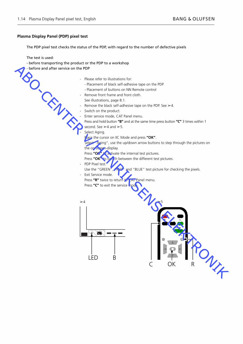
Plasma Display Panel (PDP) pixel test
The PDP pixel test checks the status of the PDP, with regard to the number of defective pixels
The test is used:- before transporting the product or the PDP to a workshop- before and after service on the PDP
- Please refer to illustrations for: - Placement of black self-adhesive tape on the PDP - Placement of buttons on NN Remote control- Remove front frame and front cloth. See illustrations, page 8.1.- Remove the black self-adhesive tape on the PDP. See ➢4.- Switch on the product.- Enter service mode, CAT Panel menu. Press and hold button “B” and at the same time press button “C” 3 times within 1
second. See ➢4 and ➢5.- Select Aging. Place the cursor on IIC Mode and press “OK”. Select “Aging”, use the up/down arrow buttons to step through the pictures on
the on-screen-display. Press “OK” to activate the internal test pictures. Press “OK” to switch between the different test pictures.- PDP Pixel test. Use the “GREEN”, “RED” and “BLUE” test picture for checking the pixels.- Exit Service mode. Press “R” twice to return to CAT Panel menu. Press “C” to exit the service mode.
BLED
➢4 ➢5
Plasma Display Panel pixel test, English
C
+
+_VOL
R
ROK
ABO-CENTER v/HENRIKSENS ELEKTRONIK
1.15
Replacement of modulesReplacement of modulesReplacement of contrast screen
Actions before dismantling the PDPBefore dismantling the PDP - disconnect the mains supply and wait minimum 1 minute for the electolytic capasitors to discharge.
Connect ESD-mat.
After replacing module(s) in the PDP follow the test and adjustment procedure as described in “Test and adjustment after replacement of module(s)” on page 1.16.
NOTEInternal cables in the PDP.Please show precaution when disconnecting cables from sockets.
Replacement of modulesFollow the instructions described on page:
8.2 PDP in service position 8.3 for selected PCB
Replacement of contrast screenUse white gloves to avoid smudging the contrast screen.
Use only the micro fi bre cloth, part no. 3375706 to clean the PDP.Do not use any kind of cleaning detergents on the PDP.
Follow the instructions described on page: 8.2 PDP in service position 8.1 Remove contrast screen and plasma frame
Replacement of modules, English
ABO-CENTER v/HENRIKSENS ELEKTRONIK
1.16
Test, adjustment and confi guration after repairConfi gure PDP for B&O menuTest and adjustment after replacement of module(s)”
WARNINGBurn-in on the PDP might occur when displaying a non-moving picture for more than app. 30 minutes.
Test and adjustmentTest and adjustment after replacement of module(s)” must be executed after any repair on the PDP.
Confi gure PDP for B&O menuThe D1/D2 module must be confi gured to work with Bang & Olufsen features.
1. Please refer to illustration for:- placement of buttons on Plasma panel and NN remote control.- CAT Panel menu & CD mode.
2. Remove the front cloth, see page 8.1.
3. Remove the black self-adhesive tape.
4. Switch BV5 on.
5. Switch Plasma panel on. Press the button marked “A”. The Plasma led lights green.
6. Enter Service mode. Press and hold the button “B” and at the same time press button “C” 3 times
within 1 seconds.
7. Access to CD Mode in the CAT Panel menu. Use the arrow buttons to select CD Mode. Press the button “D” for 5 seconds.
8. CD menu
9. Check Memory Address and Data in Memory data change.Use the arrow buttons to fi nd the required memory address in Memory data change.First address code is set using the left/right arrow buttons.Second address code is set using the up/down arrow buttons.
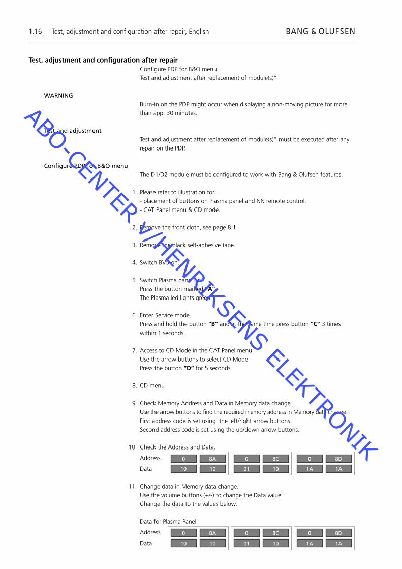
10. Check the Address and Data.
Address
Data
11. Change data in Memory data change.Use the volume buttons (+/-) to change the Data value.Change the data to the values below.
Data for Plasma Panel
Address
Data
Test, adjustment and confi guration after repair, English
0
10
8A
10
0
01
8C
10
0
1A
8D
1A
0
10
8A
10
0
01
8C
10
0
1A
8D
1A
ABO-CENTER v/HENRIKSENS ELEKTRONIK

1.17
12. Exit Service mode.Leave CD mode press the button “R” and the CAT Panel menu appears again.Leave CAT Panel menu press the button “C”.
13. Mount the black self-adhesive tape, front cloth and front frame.
Test, adjustment and confi guration after repair, English
BC
+
+_VOL
R
LEDR
ADOK
CAT Panel sys. 8.1
IIC Mode
CD Mode
SD Mode
ID Mode
CD
MiCom Software version
Memory data version
Memory data change Address
Data
1.43 OK
14.08 16.34
A0 8A
10 10
Addresses to changeData to change
ABO-CENTER v/HENRIKSENS ELEKTRONIK
1.18
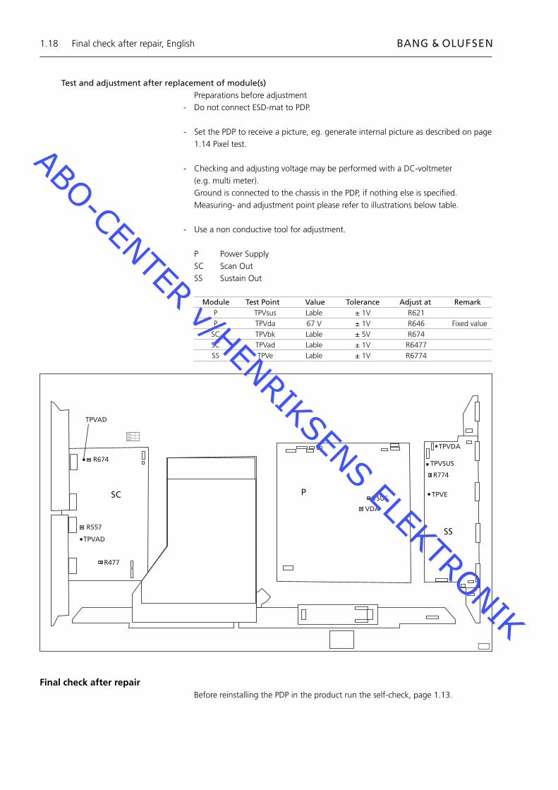
Test and adjustment after replacement of module(s)Preparations before adjustment
- Do not connect ESD-mat to PDP.
- Set the PDP to receive a picture, eg. generate internal picture as described on page 1.14 Pixel test.
- Checking and adjusting voltage may be performed with a DC-voltmeter (e.g. multi meter).
Ground is connected to the chassis in the PDP, if nothing else is specifi ed. Measuring- and adjustment point please refer to illustrations below table.
- Use a non conductive tool for adjustment.
P Power SupplySC Scan OutSS Sustain Out
R674
R557
R477
TPVAD
VSUS
VDA
TPVDA
TPVSUS
TPVE
R774
SC P
SS
XVC
VCX
CXV
TPVAD
Module Test Point Value Tolerance Adjust at Remark P TPVsus Lable ± 1V R621 P TPVda 67 V ± 1V R646 Fixed value SC TPVbk Lable ± 5V R674 SC TPVad Lable ± 1V R6477 SS TPVe Lable ± 1V R6774
Final check after repairBefore reinstalling the PDP in the product run the self-check, page 1.13.
Final check after repair, English
ABO-CENTER v/HENRIKSENS ELEKTRONIK
2.1Inhalt, Deutsch
2.3 Service
2.4 Fehlersuchdiagramm
2.10 Lage der Messpunkte
2.12 Lokaler Bildschirmfehler und OSD-Menü
2.13 PDP – Selbsttest
2.14 PDP – Pixel test
2.15 Austausch von Modulen
2.16 Test, Einstellung und Konfi guration nach der Reparatur
2.18 Abschlussprüfung nach der Reparatur
8.1 Abbildungen
ABO-CENTER v/HENRIKSENS ELEKTRONIK

ABO-CENTER v/HENRIKSENS ELEKTRONIK

2.3
Plasma-Displaypanel (PDP)
ServiceDas PDP darf nur von qualifi zierten Technikern gewartet werden.
Wenn sich der Fehler nicht lokalisieren bzw. er sich durch den Austausch von Ersatzteilen nicht beseitigen lässt, fragen Sie bitte Ihr nationales Servicecenter nach technischer Unterstützung.
HandhabungDas PDP muss zur Vermeidung von Beschädigungen stets vertikal platziert werden.In horizontaler Position besteht hohe Gefahr einer PDP-Beschädigung.Wenn möglich, stellen Sie das PDP in den Serviceständer.
Benutzen Sie zur PDP-Reinigung nur das Mikrofasertuch, Bestellnr. 3375706.Reinigen Sie das PDP nie mit irgendwelchen Reinigungsmitteln.
EinbrennenAuf dem PDP können Nachbilder einbrennen, wenn ein Standbild für länger als ca. 30 Minuten angezeigt wird.
AchtungStatische Elektrizität kann das Gerät beschädigen.
ESD-MatteWenn das Gerät zerlegt wird und hierbei direkter Zugang zu beispielsweise Modulen bzw. der internen Verdrahtung gegeben ist, muss stets ein Vor-Ort-Servicekit einschließlich ESD-Matte zum Schutz vor statischer Elektrizität benutzt werden.Befolgen Sie die Hinweise in der Anleitung.
Die ESD-Matte darf nie an ein unter Netzspannung stehendes Gerät angeschlossen werden.
Fehlersuche
Maßnahmen vor Ausbau des PDPPDP auf eingebrannte Nachbilder und Pixelfehler prüfen!Diese Prüfung ist sehr wichtig, wenn das PDP in eine Werkstatt gebracht werden muss.Siehe Pixeltest auf Seite 2.14.
Vor dem PDP-Ausbau - Netzanschluss trennen und mindestens eine Minute auf Elkoentladung warten.
ESD-Matte anschließen.
Plasma-Displaypanel, Deutsch
ABO-CENTER v/HENRIKSENS ELEKTRONIK

2.4
PLASMA-DISPLAYPANEL
(PDP)
Kein BildPDP St.by-LED = leuchtet nicht
240 V AC an M60P448
F900 & F901prüfenOK?
DefekteSicherung
austauschen
Spannungsprüfung Modul P
P23p2 15,3±0,5P25p1 15,3±0,5P25p5 13,3±0,5P25p7 5,2±0,3P27p4 5,0±0,3
Alle OK?
Modul Paustauschen
Nein
Ja
Fehlersuchdiagramm, Deutsch
Fehlersuchdiagramm
Voreinstellungen für die Benutzung des Fehlersuchdiagramms- TV auf Beo4 drücken- Ein TV-Programm mit Bild und Ton wählen
Benutzung des Fehlersuchdiagramms
Angabe eines Messpunkts: Zur Lage der Messpunkte siehe Seiten 2.10 und 2.11.
Nein
Ja
2
3
3
ABO-CENTER v/HENRIKSENS ELEKTRONIK

2.5
Kein BildKein Beo4-Menü
PDP St.by-LED = GrünPDP-OSD OK
Selbsttest durchführen
IC3001OK?
Modul D1austauschen
Fehler in Modul HX oder
im Hauptchassis
Kein BildKein Beo4-Menü
PDP St.by-LED = GrünKein PDP-OSD
Modul SCLeuchtet LED
D6583?Modul SC
austauschen
Modul D2austauschen
OK?
Modul D1austauschen
Modul SSLeuchten LED
D6769 und LED D6765?
Modul SSaustauschen
Nein
Ja
Fehlersuchdiagramm, Deutsch
5
4
ABO-CENTER v/HENRIKSENS ELEKTRONIK

2.6
Kein BildKein Beo4-Menü
PDP St.by-LED = ROTPDP AUS+EIN = Bild
W69 an M3P447OK?
W69 austauschen
PDP-Selbsttestdurchführen
IC3001OK?
Modul D1austauschen
Fehler in Modul HX oder
im Hauptchassis
Kein BildKein Beo4-Menü
PDP St.by-LED = ROTPDP AUS+EIN = Kein Bild
Spannungsprüfung Modul P
P23p2 15,3±0,5P25p1 15,3±0,5P25p5 13,3±0,5P25p7 5,2±0,3P27p4 5,0±0,3
Alle OK?
Modul Paustauschen
OK?
Modul HXaustauschen
Nein
Ja
Fehlersuchdiagramm, Deutsch
6
3
ABO-CENTER v/HENRIKSENS ELEKTRONIK
2.7
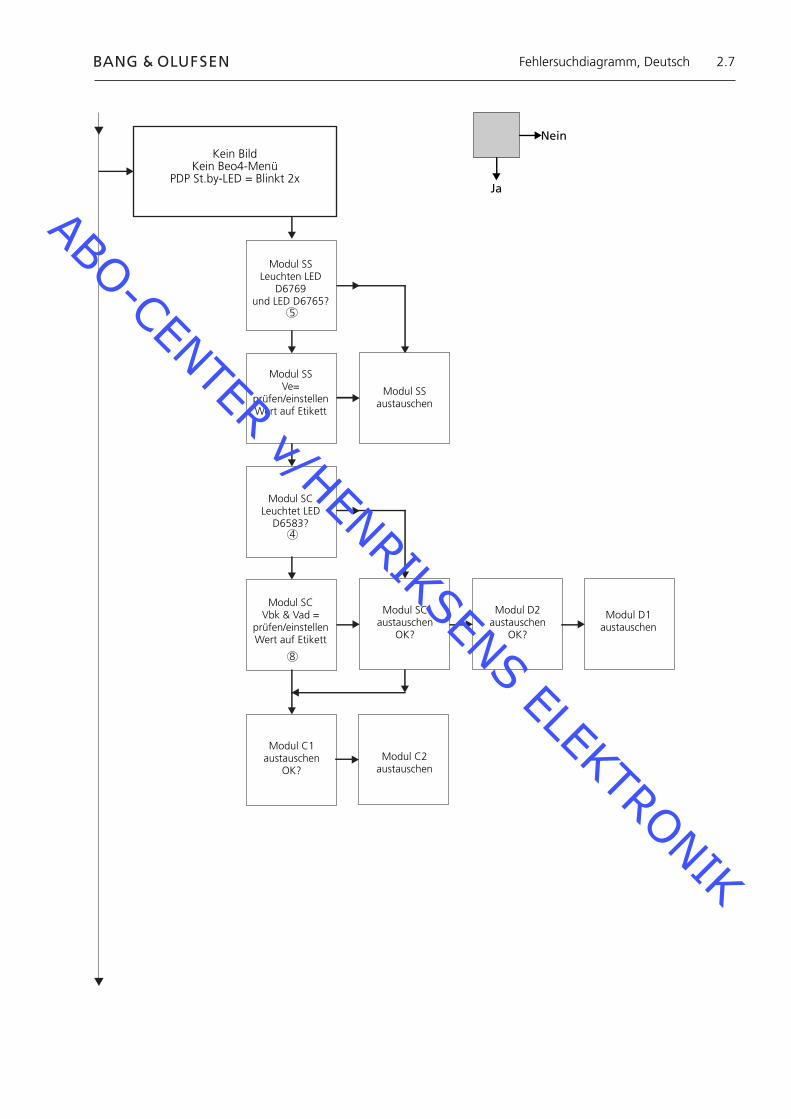
Kein BildKein Beo4-Menü
PDP St.by-LED = Blinkt 2x
Modul SSLeuchten LED
D6769und LED D6765?
Modul SSVe=
prüfen/einstellenWert auf Etikett
Modul SSaustauschen
Modul SCLeuchtet LED
D6583?
Modul SCVbk & Vad =
prüfen/einstellenWert auf Etikett
Modul SCaustauschen
OK?
Modul D2austauschen
OK?
Modul D1austauschen
Modul C1austauschen
OK?Modul C2
austauschen
Nein
Ja
Fehlersuchdiagramm, Deutsch
8
4
5
ABO-CENTER v/HENRIKSENS ELEKTRONIK

2.8
Kein BildKein Beo4-Menü
PDP St.by-LED = Blinkt 3x
Modul D2austauschen
OK?
Kein BildKein Beo4-Menü
PDP St.by-LED = Blinkt 4x
Spannungsprüfung Modul P
P23p2 15,3±0,5P25p1 15,3±0,5P25p5 13,3±0,5P25p7 5,2±0,3P27p4 5,0±0,3
Alle OK?
Vsus = Wert auf Etikett
prüfen/einstellenVda = 67 V ± 1 V
OK?
Modul Paustauschen
Modul D1austauschen
Nein
Ja
Fehlersuchdiagramm, Deutsch
3
8
ABO-CENTER v/HENRIKSENS ELEKTRONIK

2.9
Störung in PDP-OSDBildstörung
Vsus, Vda, Vbk, Vad, Ve
prüfen/einstellenSiehe
Seite 2.18OK?
Vsus bzw. Vdafalsch
Modul Paustauschen
Modul D2austauschen
OK?
Modul D1austauschen
Vbk bzw. Vadfalsch
Modul SCaustauschen
Modul SSaustauschen
Lokaler BildschirmfehlerVertikale Linie im Bild
Siehe Seite 2.12
LokalerBildschirmfehler
Nein
Ja
Fehlersuchdiagramm, Deutsch
8
ABO-CENTER v/HENRIKSENS ELEKTRONIK
2.10
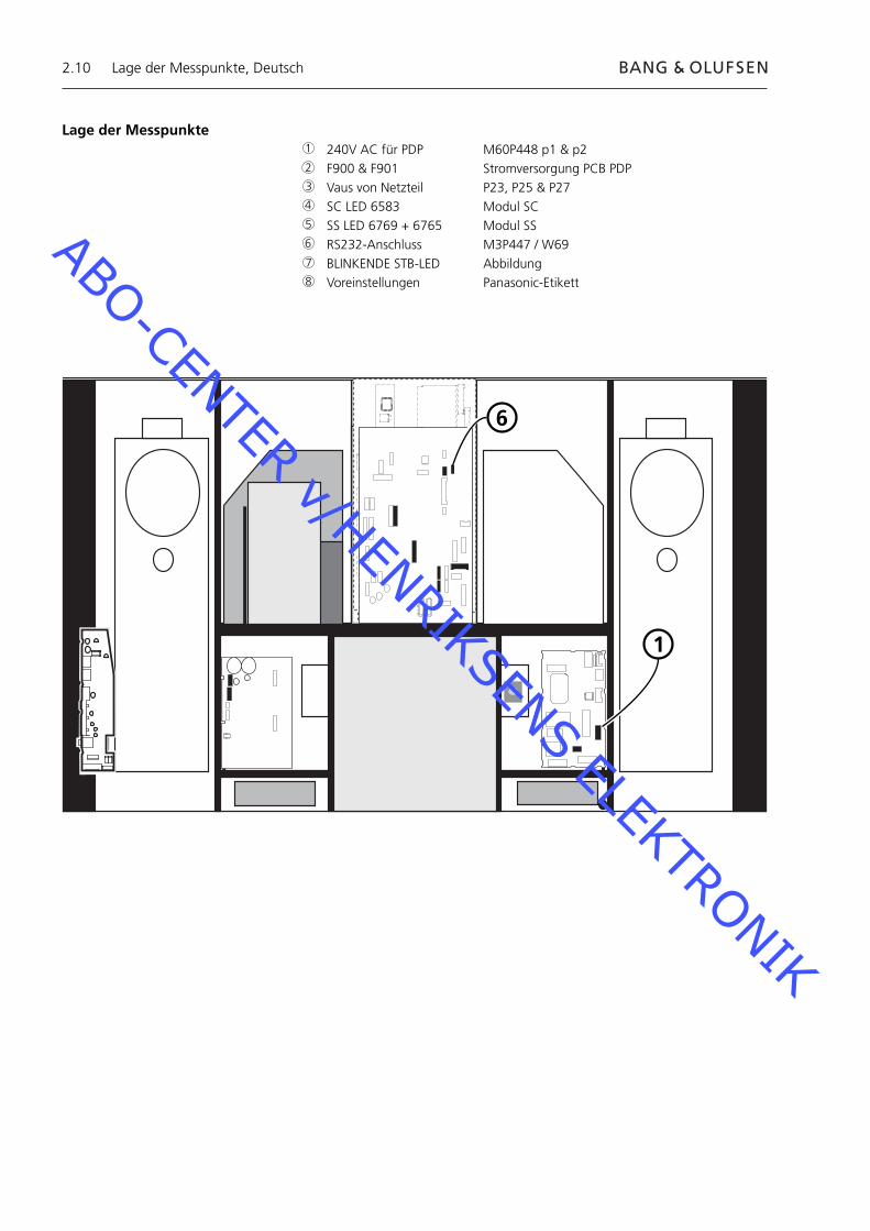
Lage der Messpunkte 240V AC für PDP M60P448 p1 & p2 F900 & F901 Stromversorgung PCB PDP Vaus von Netzteil P23, P25 & P27 SC LED 6583 Modul SC SS LED 6769 + 6765 Modul SS RS232-Anschluss M3P447 / W69 BLINKENDE STB-LED Abbildung Voreinstellungen Panasonic-Etikett
1
6
1
2
3
4
5
6
7
8
Lage der Messpunkte, Deutsch
ABO-CENTER v/HENRIKSENS ELEKTRONIK

2.11
Blinking times Blink timing Contents & Check point
Twice
Three
Four
Once3 sec
No light
Light
SC, SS, C board
D board
P board (Check P7, P8protection circuits)
38
2
4 5
Lage der Messpunkte, Deutsch
7
1
ABO-CENTER v/HENRIKSENS ELEKTRONIK

2.12
Lokaler BildschirmfehlerDas PDP kann einen lokalen Bildschirmfehler aufweisen.Die nachstehende Abbildung zeigt einen möglichen Zusammenhang zwischen Fehler und Modul.
Modul SU bzw. D2
Modul C2 bzw. D2 Modul C1 bzw. D2
Modul SD bzw. D2
OSD-Menü auf dem PDP1. Klebeband entfernen2. PICTURE, SOUND oder SETUP auf NN-Fernbedienung drücken.
SOUND
+
+_VOL
R
SETUP
PICTURE
Lokaler Bildschirmfehler und OSD-Menü, Deutsch
ABO-CENTER v/HENRIKSENS ELEKTRONIK

2.13
ID IIC1 IIC2 IIC3
D1 D2
H
Z
IC9355
IC9357
IC9007
IC9200
IC3001
IC3004
IC2401
IC9900
IC9602
IC9652
IC3501
IC3699
IC3804
IC4502
OK H21
OK H51
OK H52
OK H53
OK H53
OK H54
OK H58
OK H55
OK H55
OK H57
OK H56
OK H59
OK H60
- - -
BStandby
+
+_VOL
R
LED
PDP-Selbsttest
Der Selbsttest prüft den Status der am IIC-Bus angeschlossenen Schaltungen- Siehe bitte Abbildungen zu: - Lage des schwarzen Klebebands auf dem PDP. - Lage der Tasten auf der NN-Fernbedienung.- Frontrahmen und Textilfront abnehmen. Siehe Abbildungen, Seite 8.1.- Schwarzes Klebeband auf dem PDP entfernen. Siehe ➢1.- Gerät einschalten.- Selbsttest aktivieren. Taste “B“ auf dem PDP und gleichzeitig Taste “OFF TIMER“ auf der
Fernbedienung drücken. Siehe ➢1 und ➢2. Das Display zeigt während des Selbsttests „:-“ an.- Ergebnis des Selbsttests. Siehe ➢3. „OK“ Kein Fehler „- -“ Schaltung defekt bzw. fehlend- Selbsttest verlassen. “Standby“ auf NN-Fernbedienung und dann “Standby“ auf der Beo4 drücken.- Schwarzes Klebeband auf dem PDP anbringen.- Frontrahmen und Textilfront montieren.
➢1 ➢2 ➢3
OFF TIMER
PDP-Selbsttest, Deutsch
ABO-CENTER v/HENRIKSENS ELEKTRONIK

2.14
PDP-Pixeltest
Der PDP-Pixeltest prüft das PDP auf die Anzahl defekter Bildpunkte
Der Test wird durchgeführt:- vor dem Transport des Geräts bzw. des PDP in eine Werkstatt- vor und nach dem Service am PDP
- Siehe bitte Abbildungen zu: - Lage des schwarzen Klebebands auf dem PDP. - Lage der Tasten auf der NN-Fernbedienung.- Frontrahmen und Textilfront abnehmen. Siehe Abbildungen auf Seite 8.1.- Schwarzes Klebeband auf dem PDP entfernen. Siehe ➢4.- Gerät einschalten.- Servicemodus aktivieren, CAT-Panelmenü. Taste “B“ gedrückt halten und gleichzeitig Taste “C“ dreimal innerhalb einer Sekunde
drücken. Siehe ➢4 und ➢5.- Aging wählen. Cursor auf IIC Mode setzen und “OK“ drücken. „Aging“ wählen, mit den Auf/Ab-Pfeiltasten die Bilder im OSD durchgehen. Mit “OK“ die internen Testbilder aktivieren. Mit “OK“ zwischen den verschiedenen Testbildern umschalten.- PDP-Pixeltest. Testbilder „GRÜN“, „ROT“ und „BLAU“ für den Pixeltest benutzen.- Servicemodus verlassen. Zweimal “R“ drücken, um zum CAT-Panelmenü zurückzukehren. “C“ zum Verlassen des Servicemodus drücken.
BLED
➢4 ➢5
PDP-Pixeltest, Deutsch
C
+
+_VOL
R
ROK
ABO-CENTER v/HENRIKSENS ELEKTRONIK
2.15
Austausch von ModulenAustausch von ModulenAustausch der Kontrastfi lterscheibe
Maßnahmen vor Ausbau des PDPVor dem PDP-Ausbau - Netzanschluss trennen und mindestens eine Minute auf Elkoentladung warten.
ESD-Matte anschließen.
Nach dem Modultausch am PDP die auf Seite 2.18 beschriebenen „Tests und Einstellungen nach dem Modultausch“ durchführen.
HINWEISInterne Kabel im PDP.Kabel an Steckverbindern vorsichtig trennen.
Austausch von ModulenDie Hinweise auf diesen Seiten befolgen:
8.2 PDP in Serviceposition 8.3 für gewählte PCB
Austausch der Kontrastfi lterscheibeWeiße Handschuhe benutzen, um keine Spuren auf der Kontrastscheibe zu hinterlassen.
Benutzen Sie zur PDP-Reinigung nur das Mikrofasertuch, Bestellnr. 3375706.Reinigen Sie das PDP nie mit irgendwelchen Reinigungsmitteln.
Die Hinweise auf diesen Seiten befolgen: 8.2 PDP in Serviceposition 8.1 Kontrastfi lterscheibe und Plasmarahmen ausbauen
Austausch von Modulen, Deutsch
ABO-CENTER v/HENRIKSENS ELEKTRONIK
2.16
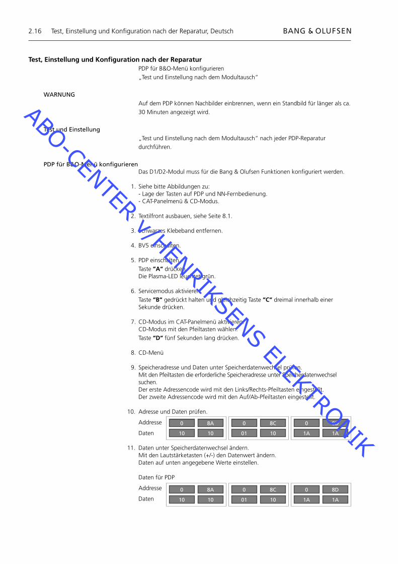
Test, Einstellung und Konfi guration nach der ReparaturPDP für B&O-Menü konfi gurieren„Test und Einstellung nach dem Modultausch“
WARNUNGAuf dem PDP können Nachbilder einbrennen, wenn ein Standbild für länger als ca. 30 Minuten angezeigt wird.
Test und Einstellung„Test und Einstellung nach dem Modultausch“ nach jeder PDP-Reparatur durchführen.
PDP für B&O-Menü konfi gurierenDas D1/D2-Modul muss für die Bang & Olufsen Funktionen konfi guriert werden.
1. Siehe bitte Abbildungen zu:- Lage der Tasten auf PDP und NN-Fernbedienung.- CAT-Panelmenü & CD-Modus.
2. Textilfront ausbauen, siehe Seite 8.1.
3. Schwarzes Klebeband entfernen.
4. BV5 einschalten.
5. PDP einschalten. Taste “A“ drücken. Die Plasma-LED leuchtet grün.
6. Servicemodus aktivieren. Taste “B“ gedrückt halten und gleichzeitig Taste “C“ dreimal innerhalb einer
Sekunde drücken.
7. CD-Modus im CAT-Panelmenü aktivieren. CD-Modus mit den Pfeiltasten wählen. Taste “D“ fünf Sekunden lang drücken.
8. CD-Menü
9. Speicheradresse und Daten unter Speicherdatenwechsel prüfen.Mit den Pfeiltasten die erforderliche Speicheradresse unter Speicherdatenwechsel suchen.Der erste Adressencode wird mit den Links/Rechts-Pfeiltasten eingestellt.Der zweite Adressencode wird mit den Auf/Ab-Pfeiltasten eingestellt.
10. Adresse und Daten prüfen.
Addresse
Daten
11. Daten unter Speicherdatenwechsel ändern.Mit den Lautstärketasten (+/-) den Datenwert ändern.Daten auf unten angegebene Werte einstellen.
Daten für PDP
Addresse
Daten
Test, Einstellung und Konfi guration nach der Reparatur, Deutsch
0
10
8A
10
0
01
8C
10
0
1A
8D
1A
0
10
8A
10
0
01
8C
10
0
1A
8D
1A
ABO-CENTER v/HENRIKSENS ELEKTRONIK

2.17
12. Servicemodus verlassen.Zum Verlassen des CD-Modus und erneuten Anzeigen des CAT-Panelmenüs die Taste “R“ drücken.CAT-Panelmenü mit Taste “C“ verlassen.
13. Schwarzes Klebeband, Frontrahmen und Textilfront anbringen.
Test, Einstellung und Konfi guration nach der Reparatur, Deutsch
BC
+
+_VOL
R
LEDR
ADOK
CAT Panel sys. 8.1
IIC Mode
CD Mode
SD Mode
ID Mode
CD
MiCom Software version
Memory data version
Memory data change Address
Data
1.43 OK
14.08 16.34
A0 8A
10 10
Zu änderndeAdressenZu änderndeDaten
ABO-CENTER v/HENRIKSENS ELEKTRONIK
2.18
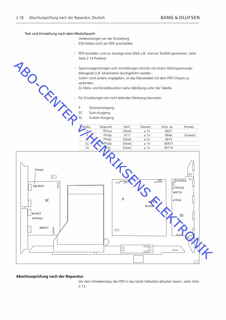
Test und Einstellung nach dem ModultauschVorbereitungen vor der Einstellung
- ESD-Matte nicht am PDP anschließen.
- PDP einstellen und zur Anzeige eines Bilds z.B. internes Testbild generieren, siehe Seite 2.14 Pixeltest.
- Spannungsprüfungen und -einstellungen können mit einem Gleichspannungs-Messgerät (z.B. Multimeter) durchgeführt werden.
Sofern nicht anders angegeben, ist das Massekabel mit dem PDP-Chassis zu verbinden.
Zu Mess- und Einstellpunkten siehe Abbildung unter der Tabelle.
- Für Einstellungen ein nicht leitendes Werkzeug benutzen.
P StromversorgungSC Scan-AusgangSS Sustain-Ausgang
R674
R557
R477
TPVAD
VSUS
VDA
TPVDA
TPVSUS
TPVE
R774
SC P
SS
XVC
VCX
CXV
TPVAD
Modul Testpunkt Wert Toleranz Einst. an Hinweis P TPVsus Etikett ± 1V R621 P TPVda 67 V ± 1V R646 Festwert SC TPVbk Etikett ± 5V R674 SC TPVad Etikett ± 1V R6477 SS TPVe Etikett ± 1V R6774
Abschlussprüfung nach der ReparaturVor dem Wiedereinbau des PDP in das Gerät Selbsttest ablaufen lassen, siehe Seite 2.13.
Abschlussprüfung nach der Reparatur, Deutsch
ABO-CENTER v/HENRIKSENS ELEKTRONIK
3.1
3.3 Entretien
3.4 Diagramme de dépannage
3.10 Emplacement des points de mesure
3.12 Défaillance locale écran et menu OSD
3.13 Autotest écran plasma
3.14 Test des pixel de l’écran plasma
3.15 Remplacement de modules
3.16 Test, réglage et confi guration après réparation
3.18 Vérifi kation défi tive après réparation
8.1 llustrations
Sommaire, Français
ABO-CENTER v/HENRIKSENS ELEKTRONIK

ABO-CENTER v/HENRIKSENS ELEKTRONIK
3.3
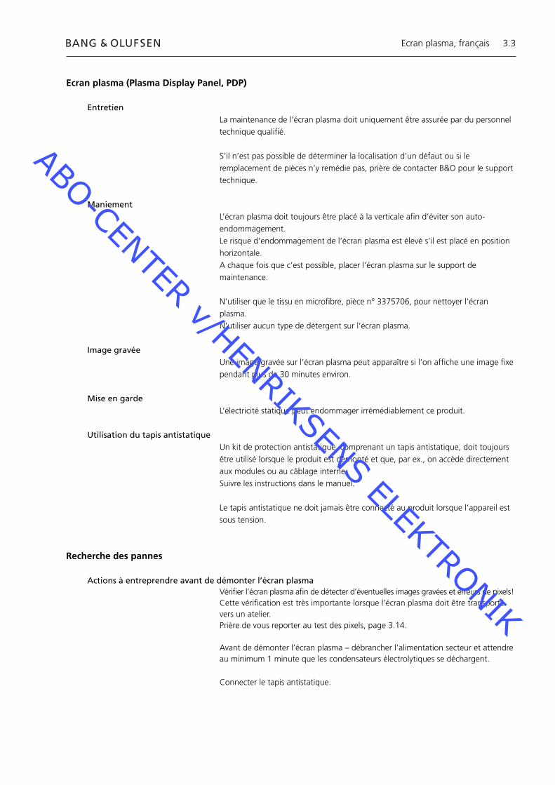
Ecran plasma (Plasma Display Panel, PDP)
EntretienLa maintenance de l’écran plasma doit uniquement être assurée par du personnel technique qualifi é.
S’il n’est pas possible de déterminer la localisation d’un défaut ou si le remplacement de pièces n’y remédie pas, prière de contacter B&O pour le support technique.
ManiementL’écran plasma doit toujours être placé à la verticale afi n d’éviter son auto-endommagement.Le risque d’endommagement de l’écran plasma est élevé s’il est placé en position horizontale.A chaque fois que c’est possible, placer l’écran plasma sur le support de maintenance.
N’utiliser que le tissu en microfi bre, pièce n° 3375706, pour nettoyer l’écran plasma.N’utiliser aucun type de détergent sur l’écran plasma.
Image gravéeUne image gravée sur l’écran plasma peut apparaître si l’on affi che une image fi xe pendant plus de 30 minutes environ.
Mise en gardeL’électricité statique peut endommager irrémédiablement ce produit.
Utilisation du tapis antistatique Un kit de protection antistatique, comprenant un tapis antistatique, doit toujours être utilisé lorsque le produit est démonté et que, par ex., on accède directement aux modules ou au câblage interne.Suivre les instructions dans le manuel.
Le tapis antistatique ne doit jamais être connecté au produit lorsque l’appareil est sous tension.
Recherche des pannes
Actions à entreprendre avant de démonter l’écran plasma Vérifi er l’écran plasma afi n de détecter d’éventuelles images gravées et erreurs de pixels!Cette vérifi cation est très importante lorsque l’écran plasma doit être transporté vers un atelier.Prière de vous reporter au test des pixels, page 3.14.
Avant de démonter l’écran plasma – débrancher l’alimentation secteur et attendre au minimum 1 minute que les condensateurs électrolytiques se déchargent.
Connecter le tapis antistatique.
Ecran plasma, français
ABO-CENTER v/HENRIKSENS ELEKTRONIK
3.4
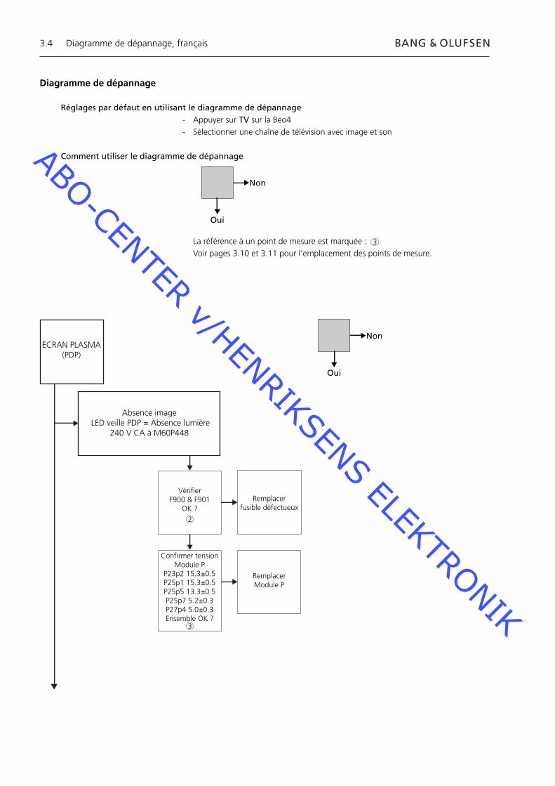
ECRAN PLASMA(PDP)
Absence image LED veille PDP = Absence lumière
240 V CA à M60P448
Vérifier F900 & F901
OK ?Remplacer
fusible défectueux
Confirmer tension Module P
P23p2 15.3±0.5P25p1 15.3±0.5P25p5 13.3±0.5P25p7 5.2±0.3P27p4 5.0±0.3Ensemble OK ?
Remplacer Module P
Non
Oui
Diagramme de dépannage, français
Diagramme de dépannage
Réglages par défaut en utilisant le diagramme de dépannage - Appuyer sur TV sur la Beo4- Sélectionner une chaîne de télévision avec image et son
Comment utiliser le diagramme de dépannage
La référence à un point de mesure est marquée : Voir pages 3.10 et 3.11 pour l’emplacement des points de mesure.
Non
Oui
2
3
3
ABO-CENTER v/HENRIKSENS ELEKTRONIK

3.5
Absence imageAbsence menu Beo4LED veille PDP = Verte
OSD PDP OK
Exécuter autotest IC3001OK ?
Remplacer Module D1
Erreur soit dans Module HX soit
dans châssis principal
Absence imageAbsence menu Beo4 LED veille PDP = Verte
ECHEC OSD PDP
LED D6583 du Module SC allumée ?
Remplacer Module SC
Remplacer Module D2
OK ?
Remplacer Module D1
LED D6769 et LED D6765 du Module
SS allumées ?
Remplacer Module SS
Non
Oui
Diagramme de dépannage, français
5
4
ABO-CENTER v/HENRIKSENS ELEKTRONIK
3.6
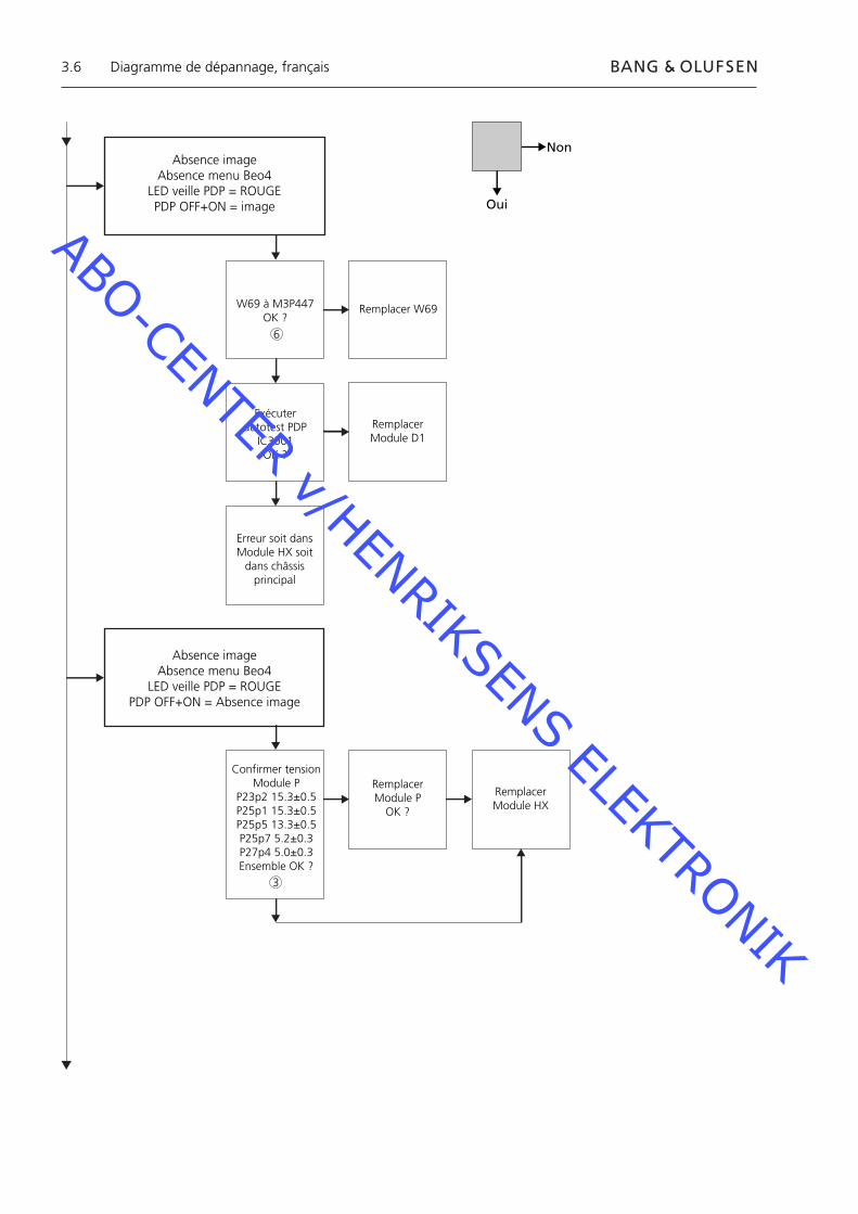
Absence imageAbsence menu Beo4
LED veille PDP = ROUGEPDP OFF+ON = image
W69 à M3P447OK ?
Remplacer W69
Exécuter autotest PDP
IC3001OK ?
Remplacer Module D1
Erreur soit dans Module HX soit
dans châssis principal
Absence imageAbsence menu Beo4
LED veille PDP = ROUGEPDP OFF+ON = Absence image
Confirmer tension Module P
P23p2 15.3±0.5P25p1 15.3±0.5P25p5 13.3±0.5P25p7 5.2±0.3P27p4 5.0±0.3Ensemble OK ?
Remplacer Module P
OK ?
Remplacer Module HX
Non
Oui
Diagramme de dépannage, français
6
3
ABO-CENTER v/HENRIKSENS ELEKTRONIK
3.7
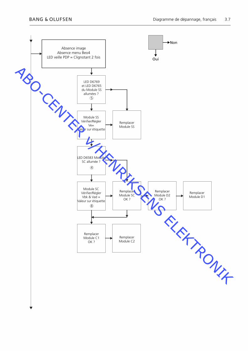
Absence image Absence menu Beo4
LED veille PDP = Clignotant 2 fois
LED D6769 et LED D6765 du Module SS
allumées ?
Module SSVérifier/Régler
Ve=Valeur sur étiquette
Remplacer Module SS
LED D6583 Module SC allumée ?
Module SCVérifier/RéglerVbk & Vad =
Valeur sur étiquette
Remplacer Module SC
OK ?
Remplacer Module D2
OK ?
Remplacer Module D1
Remplacer Module C1
OK ?Remplacer Module C2
Non
Oui
Diagramme de dépannage, français
8
4
5
ABO-CENTER v/HENRIKSENS ELEKTRONIK

3.8
Absence imageAbsence menu Beo4
LED veille PDP = Clignotant 3 fois
Remplacer Module D2
OK ?
Absence imageAbsence menu Beo4
LED veille PDP = Clignotant 4 fois
Confirmer tension Module P
P23p2 15.3±0.5P25p1 15.3±0.5P25p5 13.3±0.5P25p7 5.2±0.3P27p4 5.0±0.3Ensemble OK ?
Vérifier/RéglerVsus = valeur sur
étiquetteVda = 67 V ± 1 V
OK ?
Remplacer Module P
Remplacer Module D1
Non
Oui
Diagramme de dépannage, français
3
8
ABO-CENTER v/HENRIKSENS ELEKTRONIK

3.9
Bruit dans OSD PDP Bruit dans l’image
Vérifier/RéglerVsus, Vda, Vbk,
Vad, VeSe reporter page 3.18
OK ?
Vsus ou VdaEchec
Remplacer Module P
RemplacerModule D2
OK ?
Remplacer Module D1
Vbk ou VadEchec
RemplacerModule SC
Remplacer Module SS
Défaillance locale écranLigne verticale dans l’image
Se reporter page 3.12
Défaillance locale écran
Non
Oui
Diagramme de dépannage, français
8
ABO-CENTER v/HENRIKSENS ELEKTRONIK
3.10
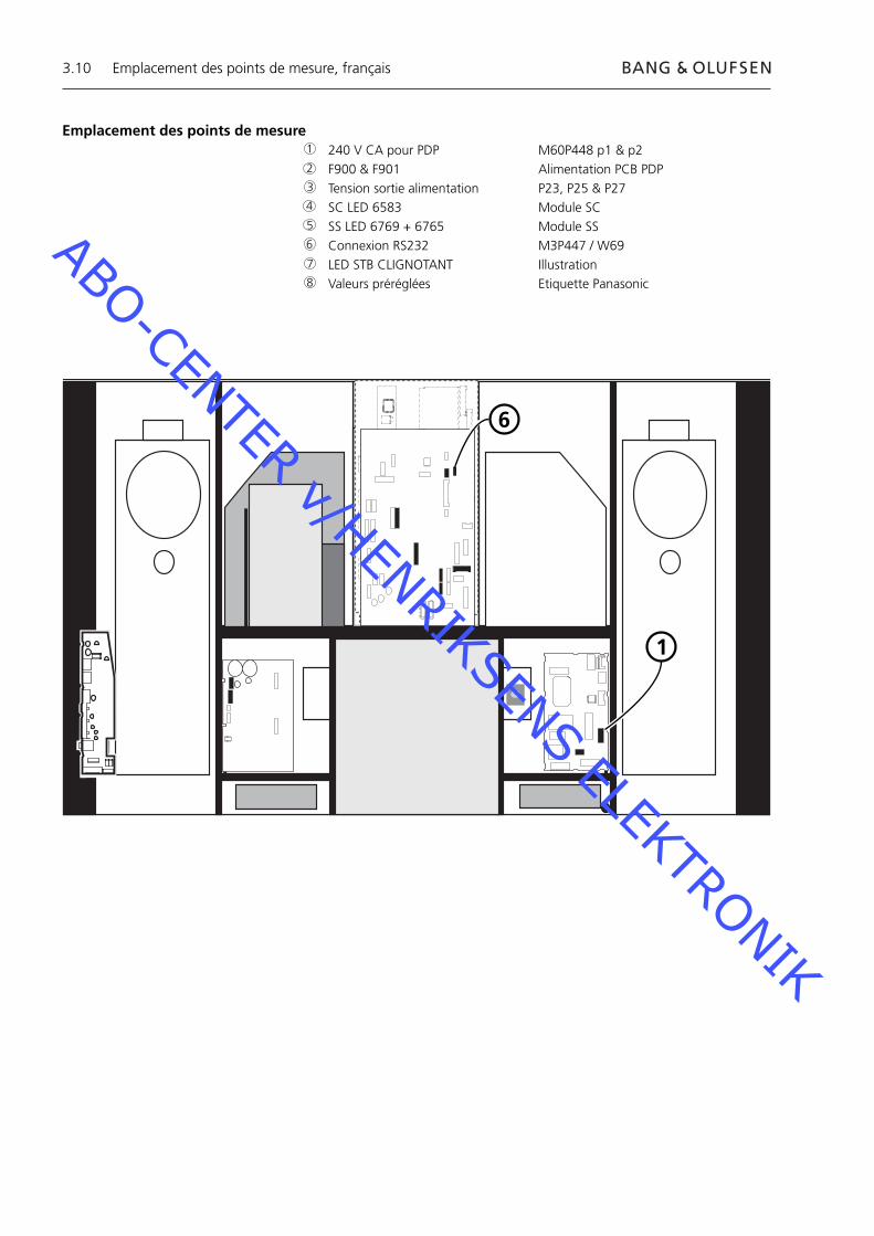
Emplacement des points de mesure 240 V CA pour PDP M60P448 p1 & p2 F900 & F901 Alimentation PCB PDP Tension sortie alimentation P23, P25 & P27 SC LED 6583 Module SC SS LED 6769 + 6765 Module SS Connexion RS232 M3P447 / W69 LED STB CLIGNOTANT Illustration Valeurs préréglées Etiquette Panasonic
1
6
1
2
3
4
5
6
7
8
Emplacement des points de mesure, français
ABO-CENTER v/HENRIKSENS ELEKTRONIK

3.11
Blinking times Blink timing Contents & Check point
Twice
Three
Four
Once3 sec
No light
Light
SC, SS, C board
D board
P board (Check P7, P8protection circuits)
38
2
4 5
Emplacement des points de mesure, français
7
1
ABO-CENTER v/HENRIKSENS ELEKTRONIK

3.12
Défaillance locale écranL’affi chage plasma peut présenter une défaillance sur une zone localisée de l’écran.L’illustration ci-dessous montre une corrélation possible entre la défaillance et le module.
Module SU ou D2
Module C2 ou D2 Module C1 ou D2
Module SD ou D2
Menu OSD à l’écran plasma 1. Retirer la bande autocollante 2. Appuyer sur PICTURE, SOUND ou SET UP sur la télécommande NN.
SOUND
+
+_VOL
R
SET UP
PICTURE
Défaillance locale écran et menu OSD, français
ABO-CENTER v/HENRIKSENS ELEKTRONIK

3.13
ID IIC1 IIC2 IIC3
D1 D2
H
Z
IC9355
IC9357
IC9007
IC9200
IC3001
IC3004
IC2401
IC9900
IC9602
IC9652
IC3501
IC3699
IC3804
IC4502
OK H21
OK H51
OK H52
OK H53
OK H53
OK H54
OK H58
OK H55
OK H55
OK H57
OK H56
OK H59
OK H60
- - -
BVeille
+
+_VOL
R
LED
Autotest écran plasma (PDP)
L’autotest vérifi e l’état des circuits connectés au bus IIC- Prière de vous reporter aux illustrations pour : - l’emplacement de la bande autocollante noire sur l’écran plasma. - l’emplacement des touches sur la télécommande NN.- Retirer le cadre avant et la face avant en tissu Voir les illustrations, page 8.1.- Retirer la bande autocollante noire de l’écran plasma. Voir ➢1.- Mettre l’appareil sous tension.- Entrer en mode autotest. Appuyer simultanément sur la touche "B" de l’écran plasma et la touche
"OFF TIMER" de la télécommande. Voir ➢1 et ➢2. Maintenant l’affi cheur indique ":-" pendant l’exécution de l’autotest.- Résultat de l’autotest. Voir ➢3. "OK" Aucun défaut "- -" Circuit défaillant ou absent- Quitter le mode autotest. Appuyer sur "Standby" sur la télécommande NN puis appuyer sur "Standby" sur
la Beo4.- Remettre la bande autocollante noire sur l’écran plasma.- Remettre la face avant en tissu et le cadre avant.
➢1 ➢2 ➢3
OFF TIMER
Autotest écran plasma, français
ABO-CENTER v/HENRIKSENS ELEKTRONIK
3.14
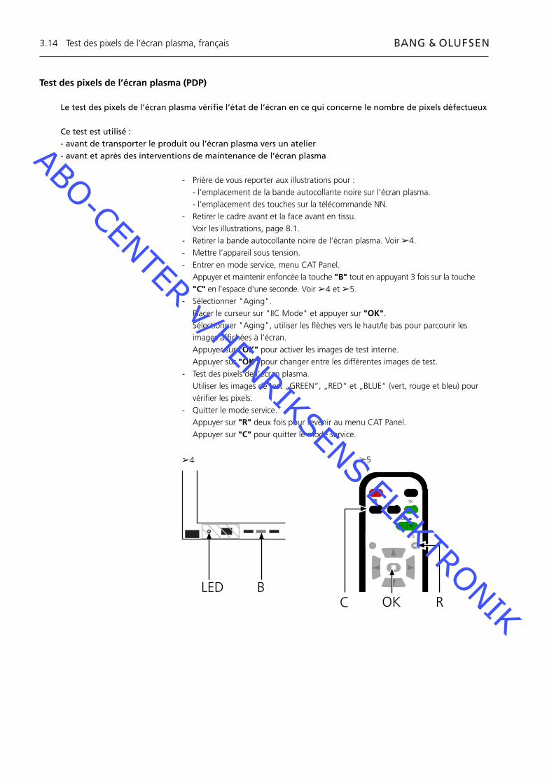
Test des pixels de l’écran plasma (PDP)
Le test des pixels de l’écran plasma vérifi e l’état de l’écran en ce qui concerne le nombre de pixels défectueux
Ce test est utilisé :- avant de transporter le produit ou l’écran plasma vers un atelier - avant et après des interventions de maintenance de l’écran plasma
- Prière de vous reporter aux illustrations pour : - l’emplacement de la bande autocollante noire sur l’écran plasma. - l’emplacement des touches sur la télécommande NN.- Retirer le cadre avant et la face avant en tissu. Voir les illustrations, page 8.1.- Retirer la bande autocollante noire de l’écran plasma. Voir ➢4.- Mettre l’appareil sous tension.- Entrer en mode service, menu CAT Panel. Appuyer et maintenir enfoncée la touche "B" tout en appuyant 3 fois sur la touche
"C" en l’espace d’une seconde. Voir ➢4 et ➢5.- Sélectionner "Aging". Placer le curseur sur "IIC Mode" et appuyer sur "OK". Sélectionner "Aging", utiliser les fl èches vers le haut/le bas pour parcourir les
images affi chées à l’écran. Appuyer sur "OK" pour activer les images de test interne. Appuyer sur "OK" pour changer entre les différentes images de test.- Test des pixels de l’écran plasma. Utiliser les images de test „GREEN“, „RED“ et „BLUE“ (vert, rouge et bleu) pour
vérifi er les pixels.- Quitter le mode service. Appuyer sur "R" deux fois pour revenir au menu CAT Panel. Appuyer sur "C" pour quitter le mode service.
BLED
➢4 ➢5
Test des pixels de l’écran plasma, français
C
+
+_VOL
R
ROK
ABO-CENTER v/HENRIKSENS ELEKTRONIK
3.15
Remplacement de modulesRemplacement de modulesRemplacement de l’écran de contraste
Actions à entreprendre avant de démonter l’écran plasmaAvant de démonter l’écran plasma – débrancher l’alimentation secteur et attendre au minimum 1 minute que les condensateurs électrolytiques se déchargent.
Connecter le tapis antistatique.
Après remplacement de module(s) dans l’écran plasma, suivre la procédure de test et de réglage décrite dans «Test et réglage après remplacement de module(s)», page 3.18.
REMARQUE !Câbles internes de l’écran plasma.Soyez prudent en débranchant les câbles des prises.
Remplacement de modulesSuivre les instructions décrites, page :
8.2 écran plasma en position de maintenance 8.3 pour le PCB sélectionné
Remplacement de l’écran de contrastePorter des gants blancs afi n d’éviter de salir l’écran de contraste.
N’utiliser que le tissu en microfi bre, pièce n° 3375706, pour nettoyer l’écran plasma.N’utiliser aucun type de détergent sur l’écran plasma.
Suivre les instructions décrites, page : 8.2 écran plasma en position de maintenance 8.1 Retirer l’écran de contraste et le cadre plasma
Remplacement de modules, français
ABO-CENTER v/HENRIKSENS ELEKTRONIK
3.16
Test, réglage et confi guration après réparationConfi gurer l’écran plasma pour le menu B&O«Test et réglage après remplacement de module(s)»
AVERTISSEMENT :Des images gravées sur l’écran plasma peuvent apparaître si l’on affi che une image fi xe pendant plus de 30 minutes environ.
Test et réglageIl convient d’effectuer »Test et réglage après remplacement de module(s)« après toute réparation de l’écran plasma.
Confi gurer l’écran plasma pour le menu B&OLe module D1/D2 doit être confi guré pour fonctionner avec les caractéristiques Bang & Olufsen.
1. Prière de vous reporter aux illustrations pour :- l’emplacement des touches sur l’écran plasma et la télécommande NN.- le menu CAT Panel & le mode CD.
2. Retirer la face avant en tissu, voir page 8.1.
3. Retirer la bande autocollante noire.
4. Allumer le BV5.
5. Mettre l’écran plasma sous tension. Appuyer sur la touche marquée "A". La LED plasma verte s’allume.
6. Entrer en mode service. Appuyer et maintenir enfoncée la touche B tout en appuyant 3 fois sur la touche "C"
en l’espace d’une seconde.
7. Accéder au mode CD dans le menu CAT Panel. Utiliser les touches fl échées pour sélectionner le mode CD. Appuyer sur la touche "D" pendant 5 secondes.
8. Menu CD
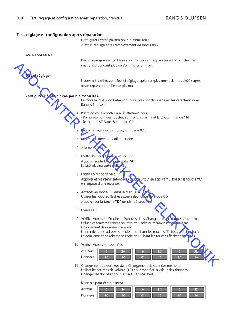
9. Vérifi er Adresse mémoire et Données dans Changement de données mémoire.Utiliser les touches fl échées pour trouver l’adresse mémoire nécessaire dans Changement de données mémoire.Le premier code adresse se règle en utilisant les touches fl échées gauche/droite.Le deuxième code adresse se règle en utilisant les touches fl échées haut/bas.
10. Vérifi er Adresse et Données.
Adresse
Données
11. Changement de données dans Changement de données mémoire.Utiliser les touches de volume (+/-) pour modifi er la valeur des données.Changer les données pour les valeurs ci-dessous.
Données pour écran plasma
Adresse
Données
Test, réglage et confi guration après réparation, français
0
10
8A
10
0
01
8C
10
0
1A
8D
1A
0
10
8A
10
0
01
8C
10
0
1A
8D
1A
ABO-CENTER v/HENRIKSENS ELEKTRONIK

3.17
12. Quitter le mode service.Quitter le mode CD, appuyer sur la touche "R" après quoi le menu CAT Panel réapparaît.Quitter le menu CAT Panel, appuyer sur la touche "C".
13. Remettre la bande autocollante noire, la face avant en tissu et le cadre avant.
Test, réglage et confi guration après réparation, français
BC
+
+_VOL
R
LEDR
ADOK
CAT Panel sys. 8.1
IIC Mode
CD Mode
SD Mode
ID Mode
CD
MiCom Software version
Memory data version
Memory data change Address
Data
1.43 OK
14.08 16.34
A0 8A
10 10
Adresses à modifier
Données à modifi er
ABO-CENTER v/HENRIKSENS ELEKTRONIK
3.18
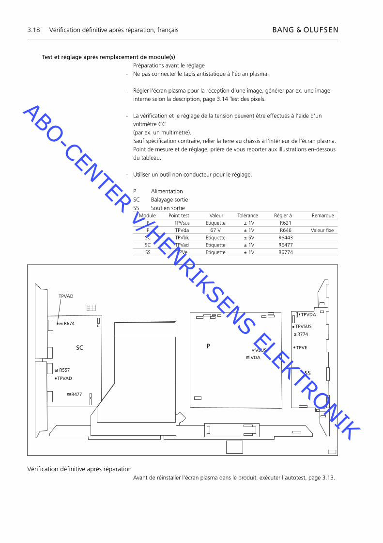
Test et réglage après remplacement de module(s)Préparations avant le réglage
- Ne pas connecter le tapis antistatique à l’écran plasma.
- Régler l’écran plasma pour la réception d’une image, générer par ex. une image interne selon la description, page 3.14 Test des pixels.
- La vérifi cation et le réglage de la tension peuvent être effectués à l’aide d’un voltmètre CC (par ex. un multimètre).
Sauf spécifi cation contraire, relier la terre au châssis à l’intérieur de l’écran plasma. Point de mesure et de réglage, prière de vous reporter aux illustrations en-dessous
du tableau.
- Utiliser un outil non conducteur pour le réglage.
P AlimentationSC Balayage sortieSS Soutien sortie
R674
R557
R477
TPVAD
VSUS
VDA
TPVDA
TPVSUS
TPVE
R774
SC P
SS
XVC
VCX
CXV
TPVAD
Module Point test Valeur Tolérance Régler à Remarque P TPVsus Etiquette ± 1V R621 P TPVda 67 V ± 1V R646 Valeur fi xe SC TPVbk Etiquette ± 5V R6443 SC TPVad Etiquette ± 1V R6477 SS TPVe Etiquette ± 1V R6774
Vérifi cation défi nitive après réparationAvant de réinstaller l’écran plasma dans le produit, exécuter l’autotest, page 3.13.
Vérifi cation défi nitive après réparation, français
ABO-CENTER v/HENRIKSENS ELEKTRONIK
4.1
4.3 Assistenza
4.4 Diagramma di fl usso degli errori
4.10 Disposizione dei punti di misurazione
4.12 Guasto schermo locale e menu a video (OSD)
4.13 Test automatico del pannello
4.14 Test dei pixel del pannello del displat al plasma
4.15 Sostituzione dei modulif modules
4.16 Prova, regolazione e confi gurazione dopo la riparazione
4.18 Verifi ca fi nale dopo la riparazione
8.1 Illustrazioni
Sommario, Italiano
ABO-CENTER v/HENRIKSENS ELEKTRONIK

4.2
ABO-CENTER v/HENRIKSENS ELEKTRONIK
4.3
Pannello del display al plasma (PDP)
AssistenzaGli interventi di assistenza tecnica sul PDP possono essere eseguiti esclusivamente dal personale tecnico qualifi cato.
Se non è possibile determinare la posizione del guasto oppure se sostituendo la parte non si elimina il guasto, è preferibile rivolgersi al centro di servizio nazionale di assistenza tecnica.
ManipolazioneIl PDP deve sempre essere collocato in posizione verticale per evitare eventuali danni.Se il PDP è collocato in posizione orizzontale ci sono maggiori rischi di danneggiarlo.Quando possibile mettere il PDP sull’apposito supporto per l’intervento di assistenza tecnica.
Utilizzare esclusivamente un panno in microfi bre, parte n. 3375706, per pulire il PDP.Non utilizzare nessun detergente di pulizia sul PDP.
Burn-inL’effetto ombra dovuto al burn-in nel PDP si potrebbe verifi care quando un’immagine immobile resta visualizzata per un intervallo maggiore di ca. 30 minuti.
AvvertenzaL’elettricità statica può recare danni irreparabili al prodotto!
Uso del tappetino anti ESDÈ necessario utilizzare sempre un kit da campo per gli interventi di manutenzione con protezione antistatica, compreso il tappetino anti ESD, quando si smonta l’apparecchio e quando c’è un accesso diretto ai moduli e ai cavi interni.Seguire le istruzioni del manuale d’uso.
Il tappetino anti ESD non deve mai essere collegato all’apparecchio quando è inserita l’alimentazione di rete.
Risoluzione dei problemi
Azioni da eseguire prima dello smontaggio del PDPControllare il PDP per rilevare eventuali errori di burn-in e dei pixel!Questo controllo è molto importante quando il PDP deve essere trasportato in offi cina.Fare riferimento al test dei pixel, pagina 4.14.
Prima di smontare il PDP scollegare l’alimentazione di rete ed attendere almeno 1 minuto affi nché i condensatori elettrolitici si scarichino.
Collegare il tappetino anti ESD.
Pannello del display al plasma, Italiano
ABO-CENTER v/HENRIKSENS ELEKTRONIK
4.4
PANNELLO DEL DISPLAY AL
PLASMA (PDP)
Nessuna immaginePDP st.by LED = Nessuna luce
240 V CA in M60P448
Controllare F900 & F901
OK?Sostituire
i fusibili difettosi
Confermare la tensione del modulo P
P23p2 15,3±0,5P25p1 15,3±0,5P25p5 13,3±0,5P25p7 5,2±0,3P27p4 5,0±0,3
Tutto OK?
Sostituire il Modulo P
NO
Sì
Diagramma di fl usso degli errori, Italiano
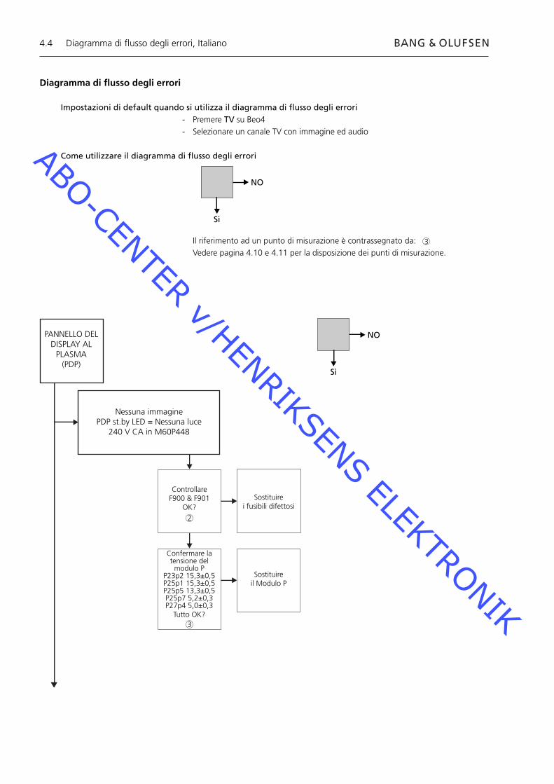
Diagramma di fl usso degli errori
Impostazioni di default quando si utilizza il diagramma di fl usso degli errori- Premere TV su Beo4- Selezionare un canale TV con immagine ed audio
Come utilizzare il diagramma di fl usso degli errori
Il riferimento ad un punto di misurazione è contrassegnato da: Vedere pagina 4.10 e 4.11 per la disposizione dei punti di misurazione.
NO
Sì
2
3
3
ABO-CENTER v/HENRIKSENS ELEKTRONIK
4.5
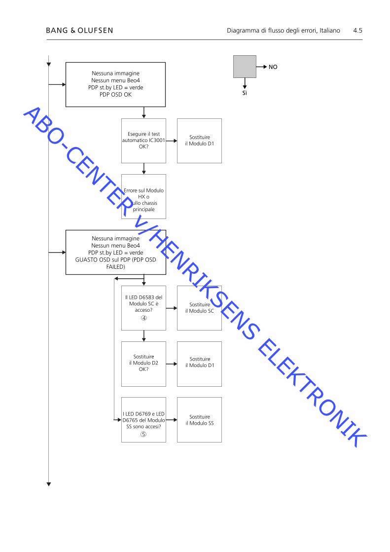
Nessuna immagineNessun menu Beo4
PDP st.by LED = verdePDP OSD OK
Eseguire il test automatico IC3001
OK?
Sostituire il Modulo D1
Errore sul Modulo HX o
sullo chassis principale
Nessuna immagineNessun menu Beo4
PDP st.by LED = verdeGUASTO OSD sul PDP (PDP OSD
FAILED)
Il LED D6583 del Modulo SC è
acceso?Sostituire
il Modulo SC
Sostituire il Modulo D2
OK?
Sostituire il Modulo D1
I LED D6769 e LED D6765 del Modulo
SS sono accesi?
Sostituire il Modulo SS
NO
Sì
Diagramma di fl usso degli errori, Italiano
5
4
ABO-CENTER v/HENRIKSENS ELEKTRONIK

4.6
Nessuna immagineNessun menu Beo4
PDP st.by LED = rossoPDP OFF+ON = immagine
W69 in M3P447OK?
Sostituire W69
Eseguire il test automatico del PDP IC3001
OK?
Sostituire il Modulo D1
Errore Modulo HX o sullo chassis principale
Nessuna immagineNessun menu Beo4
PDP st.by LED = rossoPDP OFF+ON = nessuna immagine
Confermare la tensione del modulo P
P23p2 15,3±0,5P25p1 15,3±0,5P25p5 13,3±0,5P25p7 5,2±0,3P27p4 5,0±0,3
Tutto OK?
Sostituire ilModulo P
OK?
Sostituire il Modulo HX
NO
Sì
Diagramma di fl usso degli errori, Italiano
6
3
ABO-CENTER v/HENRIKSENS ELEKTRONIK
4.7
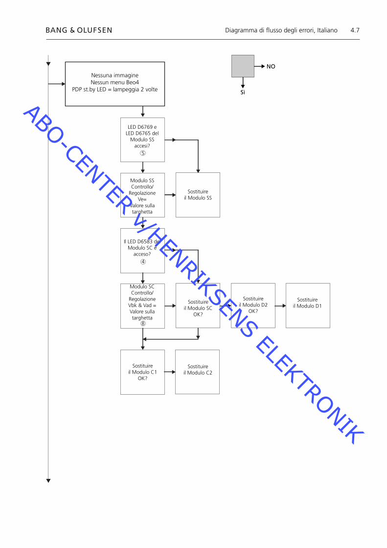
Nessuna immagine Nessun menu Beo4
PDP st.by LED = lampeggia 2 volte
LED D6769 e LED D6765 del
Modulo SSaccesi?
Modulo SSControllo/
RegolazioneVe=
Valore sulla targhetta
Sostituire il Modulo SS
Il LED D6583 del Modulo SC è
acceso?
Modulo SCControllo/
RegolazioneVbk & Vad =Valore sulla targhetta
Sostituire il Modulo SC
OK?
Sostituire il Modulo D2
OK?
Sostituire il Modulo D1
Sostituire il Modulo C1
OK?
Sostituire il Modulo C2
NO
Sì
Diagramma di fl usso degli errori, Italiano
8
4
5
ABO-CENTER v/HENRIKSENS ELEKTRONIK
4.8
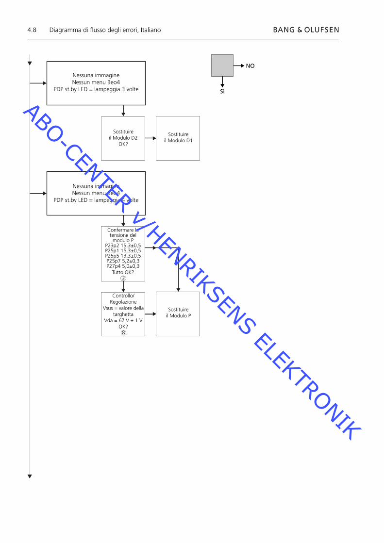
Nessuna immagine Nessun menu Beo4
PDP st.by LED = lampeggia 3 volte
Sostituire il Modulo D2
OK?
Nessuna immagine Nessun menu Beo4
PDP st.by LED = lampeggia 4 volte
Confermare la tensione del modulo P
P23p2 15,3±0,5P25p1 15,3±0,5P25p5 13,3±0,5P25p7 5,2±0,3P27p4 5,0±0,3
Tutto OK?
Controllo/Regolazione
Vsus = valore della targhetta
Vda = 67 V ± 1 VOK?
Sostituire il Modulo P
Sostituire il Modulo D1
NO
Sì
Diagramma di fl usso degli errori, Italiano
3
8
ABO-CENTER v/HENRIKSENS ELEKTRONIK
4.9
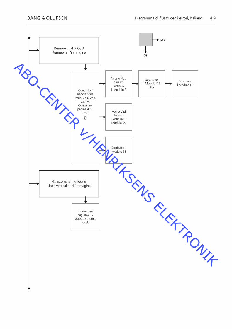
Rumore in PDP OSDRumore nell’immagine
Controllo /Regolazione
Vsus, Vda, Vbk, Vad, Ve
Consultare pagina 4.18
OK?
Vsus o VdaGuasto
Sostituire il Modulo P
Sostituire il Modulo D2
OK?
Sostituire il Modulo D1
Vbk o VadGuasto
Sostituire ilModulo SC
Sostituire il Modulo SS
Guasto schermo locale Linea verticale nell’immagine
Consultare pagina 4.12
Guasto schermo locale
NO
Sì
Diagramma di fl usso degli errori, Italiano
8
ABO-CENTER v/HENRIKSENS ELEKTRONIK

4.10
Disposizione dei punti di misurazione 240V CA per PDP M60P448 p1 & p2 F900 & F901 Alimentazione PCB PDP Vout da alimentazione P23, P25 & P27 SC LED 6583 Modulo SC SS LED 6769 + 6765 Modulo SS Connettore RS232 M3P447 / W69 LED STB LAMPEGGIANTE Illustrazione Valori preimpostati Targhetta d’identifi cazione Panasonic
1
6
1
2
3
4
5
6
7
8
Disposizione dei punti di misurazione, Italiano
ABO-CENTER v/HENRIKSENS ELEKTRONIK

4.11
Blinking times Blink timing Contents & Check point
Twice
Three
Four
Once3 sec
No light
Light
SC, SS, C board
D board
P board (Check P7, P8protection circuits)
38
2
4 5
Disposizione dei punti di misurazione, Italiano
7
1
ABO-CENTER v/HENRIKSENS ELEKTRONIK

4.12
Guasto schermo localeIl pannello del display al plasma può presentare un guasto di area locale sullo schermo.L’illustrazione seguente mostra un collegamento possibile tra il guasto e il modulo.
Modulo SU o D2
Modulo C2 o D2 Modulo C1 o D2
Modulo SD o D2
Menu a video (OSD) sul Pannello del Display al Plasma1. Rimuovere il nastro adesivo2. Premere PICTURE, SOUND o SET UP sul telecomando NN del display al plasma.
SOUND
+
+_VOL
R
SET UP
PICTURE
Guasto schermo locale e menu a video (OSD), Italiano
ABO-CENTER v/HENRIKSENS ELEKTRONIK
4.13
ID IIC1 IIC2 IIC3
D1 D2
H
Z
IC9355
IC9357
IC9007
IC9200
IC3001
IC3004
IC2401
IC9900
IC9602
IC9652
IC3501
IC3699
IC3804
IC4502
OK H21
OK H51
OK H52
OK H53
OK H53
OK H54
OK H58
OK H55
OK H55
OK H57
OK H56
OK H59
OK H60
- - -
BStandby
+
+_VOL
R
LED
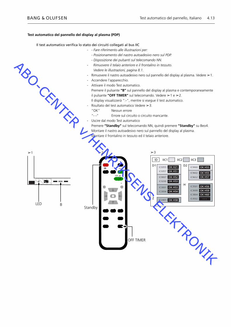
Test automatico del pannello del display al plasma (PDP)
Il test automatico verifi ca lo stato dei circuiti collegati al bus IIC- - Fare riferimento alle illustrazioni per: - Posizionamento del nastro autoadesivo nero sul PDP. - Disposizione dei pulsanti sul telecomando NN.- Rimuovere il telaio anteriore e il frontalino in tessuto. Vedere le illustrazioni, pagina 8.1.- Rimuovere il nastro autoadesivo nero sul pannello del display al plasma. Vedere ➢1.- Accendere l’apparecchio.- Attivare il modo Test automatico. Premere il pulsante “B” sul pannello del display al plasma e contemporaneamente
il pulsante "OFF TIMER" sul telecomando. Vedere ➢1 e ➢2. Il display visualizzerà “:-”, mentre si esegue il test automatico.- Risultato del test automatico Vedere ➢3. “OK” Nessun errore “- -” Errore sul circuito o circuito mancante.- Uscire dal modo Test automatico Premere “Standby” sul telecomando NN, quindi premere "Standby" su Beo4.- Montare il nastro autoadesivo nero sul pannello del display al plasma.- Montare il frontalino in tessuto ed il telaio anteriore.
➢1 ➢2 ➢3
OFF TIMER
Test automatico del pannello, Italiano
ABO-CENTER v/HENRIKSENS ELEKTRONIK
4.14
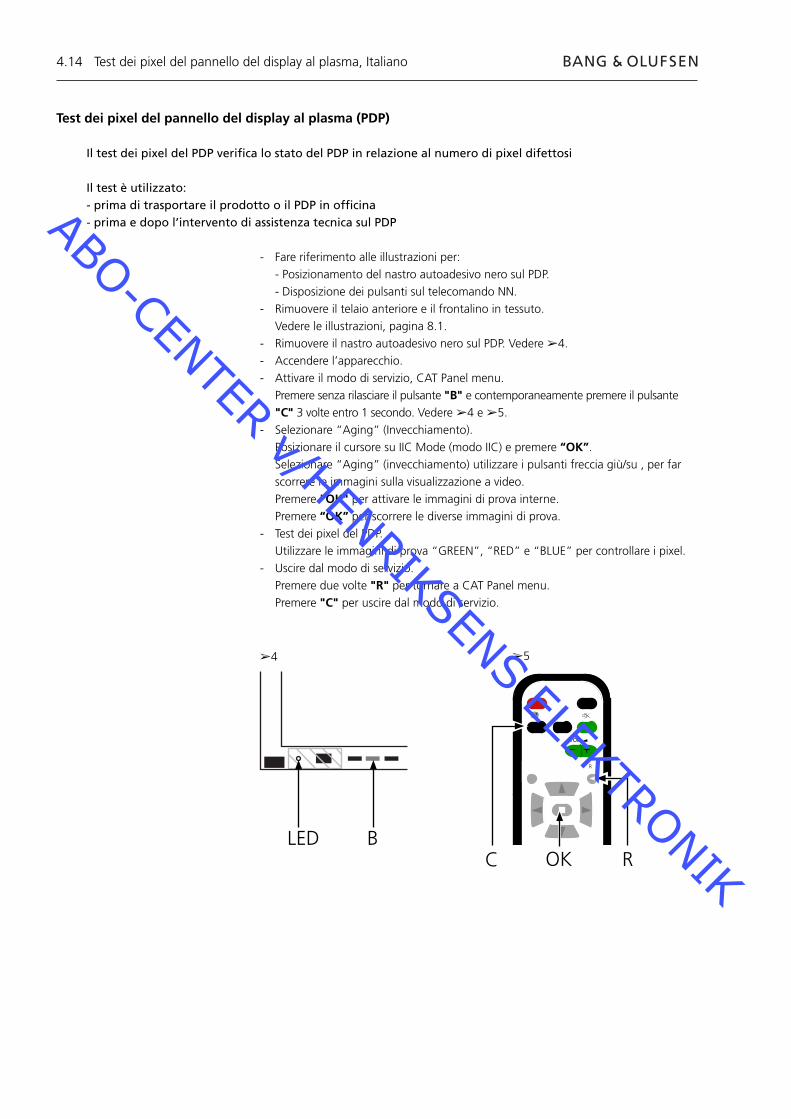
Test dei pixel del pannello del display al plasma (PDP)
Il test dei pixel del PDP verifi ca lo stato del PDP in relazione al numero di pixel difettosi
Il test è utilizzato:- prima di trasportare il prodotto o il PDP in offi cina- prima e dopo l’intervento di assistenza tecnica sul PDP
- Fare riferimento alle illustrazioni per: - Posizionamento del nastro autoadesivo nero sul PDP. - Disposizione dei pulsanti sul telecomando NN.- Rimuovere il telaio anteriore e il frontalino in tessuto. Vedere le illustrazioni, pagina 8.1.- Rimuovere il nastro autoadesivo nero sul PDP. Vedere ➢4.- Accendere l’apparecchio.- Attivare il modo di servizio, CAT Panel menu. Premere senza rilasciare il pulsante "B" e contemporaneamente premere il pulsante
"C" 3 volte entro 1 secondo. Vedere ➢4 e ➢5.- Selezionare “Aging” (Invecchiamento). Posizionare il cursore su IIC Mode (modo IIC) e premere “OK”. Selezionare “Aging” (invecchiamento) utilizzare i pulsanti freccia giù/su , per far
scorrere le immagini sulla visualizzazione a video. Premere "OK" per attivare le immagini di prova interne. Premere “OK” per scorrere le diverse immagini di prova.- Test dei pixel del PDP. Utilizzare le immagini di prova “GREEN”, “RED” e “BLUE” per controllare i pixel.- Uscire dal modo di servizio. Premere due volte "R" per tornare a CAT Panel menu. Premere "C" per uscire dal modo di servizio.
BLED
➢4 ➢5
Test dei pixel del pannello del display al plasma, Italiano
C
+
+_VOL
R
ROK
ABO-CENTER v/HENRIKSENS ELEKTRONIK
4.15
Sostituzione dei moduliSostituzione dei moduliSostituzione dello schermo di contrasto
Azioni da eseguire prima dello smontaggio del PDPPrima di smontare il PDP scollegare l’alimentazione di rete ed attendere almeno 1 minuto affi nché i condensatori elettrolitici si scarichino.
Collegare il tappetino anti ESD.
Dopo aver sostituito il/i modulo/i nel PDP seguire il procedimento di prova e di regolazione descritto nella sezione “Prova e regolazione dopo la sostituzione di moduli” a pagina 4.18.
NOTACavi interni del PDP.Prestare molta attenzione quando si scollegano i cavi dalle prese.
Sostituzione dei moduliSeguire le istruzioni descritte a pagina:
8.2 PDP in posizione di servizio 8.3 per la PCB selezionata
Sostituzione dello schermo di contrastoServirsi di guanti bianchi per evitare di sporcare lo schermo di contrasto.
Utilizzare esclusivamente un panno in microfi bre, parte n. 3375706, per pulire il PDP.Non utilizzare nessun detergente di pulizia sul PDP.
Seguire le istruzioni descritte a pagina: 8.2 PDP in posizione di servizio 8.1 Rimozione dello schermo di contrasto e del telaio del display al
plasma
Sostituzione dei moduli, Italiano
ABO-CENTER v/HENRIKSENS ELEKTRONIK
4.16
Prova, regolazione e confi gurazione dopo la riparazioneConfi gurare il PDP per il menu B&O Prova e regolazione dopo la sostituzione di moduli
AVVERTENZAL’effetto ombra dovuto al burn-in nel PDP si potrebbe verifi care quando un’immagine immobile resta visualizzata per un intervallo maggiore di ca. 30 minuti.
Prova e regolazioneLa procedura di “Prova e regolazione dopo la sostituzione di moduli” deve essere eseguita dopo ogni riparazione del PDP.
Confi gurazione del PDP per il menu B&OIl modulo D1/D2 deve essere confi gurato per funzionare con le caratteristiche Bang & Olufsen.
1. Fare riferimento all’illustrazione per:- Disposizione dei pulsanti sul pannello del display al plasma e sul telecomando NN.- CAT panel menu e modo CD.
2. Rimuovere il frontalino in tessuto, vedere pagina 8.1.
3. Rimuovere il nastro autoadesivo nero.
4. Accendere BV5.
5. Accendere il pannello del display al plasma. Premere il pulsante contrassegnato da "A". Il Led del plasma diventa verde.
6. Attivare il modo di servizio. Premere senza rilasciare il pulsante B e contemporaneamente premere il pulsante
"C" 3 volte entro 1 secondo.
7. Accedere al modo CD nel CAT Panel menu. Utilizzare i pulsanti direzionali per selezionare CD Mode (modo CD). Premere il pulsante "D" per 5 secondi.
8. Menu CD
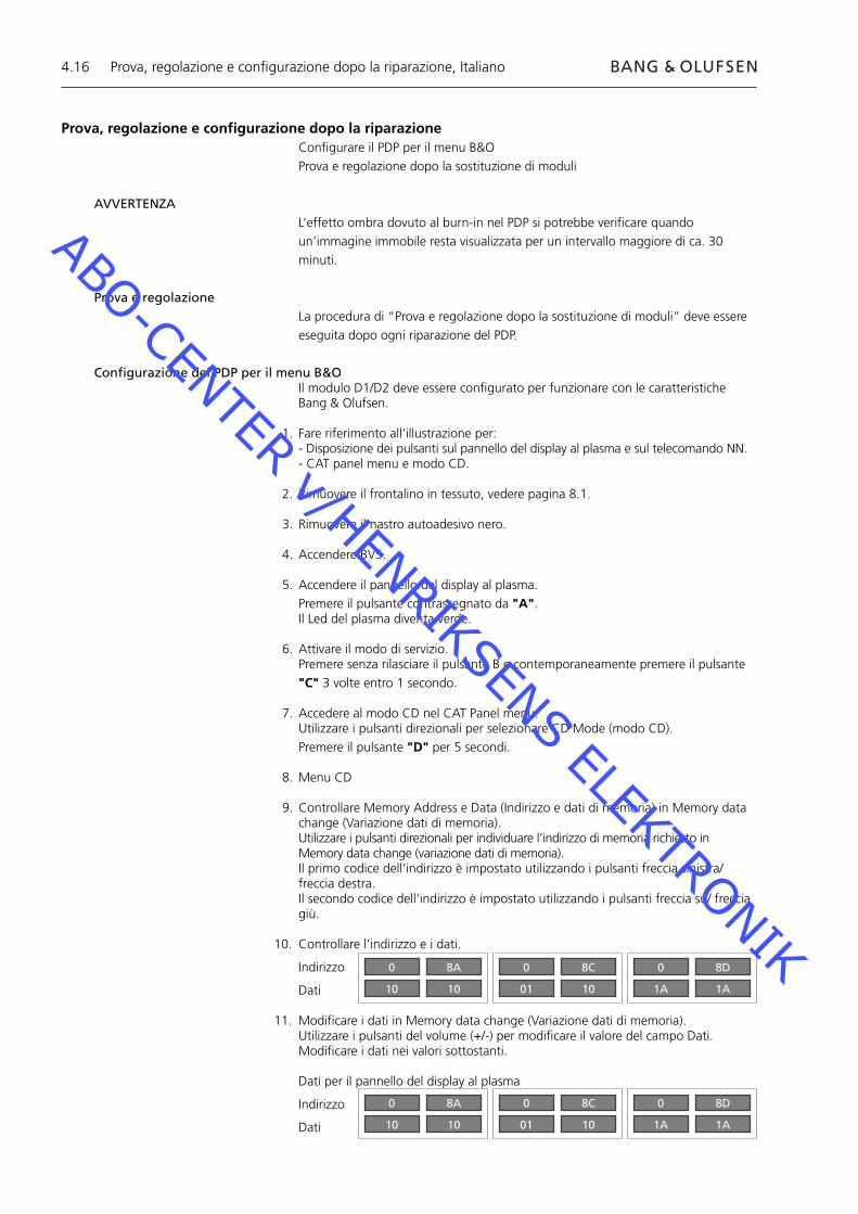
9. Controllare Memory Address e Data (Indirizzo e dati di memoria) in Memory data change (Variazione dati di memoria).Utilizzare i pulsanti direzionali per individuare l’indirizzo di memoria richiesto in Memory data change (variazione dati di memoria).Il primo codice dell’indirizzo è impostato utilizzando i pulsanti freccia sinistra/ freccia destra.Il secondo codice dell’indirizzo è impostato utilizzando i pulsanti freccia su/ freccia giù.
10. Controllare l’indirizzo e i dati.
Indirizzo
Dati
11. Modifi care i dati in Memory data change (Variazione dati di memoria).Utilizzare i pulsanti del volume (+/-) per modifi care il valore del campo Dati.Modifi care i dati nei valori sottostanti.
Dati per il pannello del display al plasma
Indirizzo
Dati
Prova, regolazione e confi gurazione dopo la riparazione, Italiano
0
10
8A
10
0
01
8C
10
0
1A
8D
1A
0
10
8A
10
0
01
8C
10
0
1A
8D
1A
ABO-CENTER v/HENRIKSENS ELEKTRONIK

4.17
12. Uscire dal modo di servizio.Uscire dal modo CD premendo "R" e ricomparirà CAT Panel menu.Uscire da CAT Panel menu premendo il pulsante "C".
13. Montare il nastro autoadesivo nero, il frontalino in tessuto ed il telaio anteriore.
Prova, regolazione e confi gurazione dopo la riparazione, Italiano
BC
+
+_VOL
R
LEDR
ADOK
CAT Panel sys. 8.1
IIC Mode
CD Mode
SD Mode
ID Mode
CD
MiCom Software version
Memory data version
Memory data change Address
Data
1.43 OK
14.08 16.34
A0 8A
10 10
Indirizzi da modificareDati da modifi care
ABO-CENTER v/HENRIKSENS ELEKTRONIK
4.18
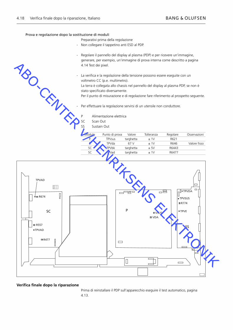
Prova e regolazione dopo la sostituzione di moduliPreparativi prima della regolazione
- Non collegare il tappetino anti ESD al PDP.
- Regolare il pannello del display al plasma (PDP) e per ricevere un’immagine, generare, per esempio, un’immagine di prova interna come descritto a pagina 4.14 Test dei pixel.
- La verifi ca e la regolazione della tensione possono essere eseguite con un voltmetro CC (p.e. multimetro).
La terra è collegata allo chassis nel pannello del display al plasma PDP, se non è stato specifi cato diversamente.
Per il punto di misurazione e di regolazione fare riferimento al prospetto seguente.
- Per effettuare la regolazione servirsi di un utensile non conduttore.
P Alimentazione elettricaSC Scan OutSS Sustain Out
R674
R557
R477
TPVAD
VSUS
VDA
TPVDA
TPVSUS
TPVE
R774
SC P
SS
XVC
VCX
CXV
TPVAD
Modulo Punto di prova Valore Tolleranza Regolare Osservazioni P. TPVsus targhetta ± 1V R621 P. TPVda 67 V ± 1V R646 Valore fi sso SC TPVbk targhetta ± 5V R6443 SC TPVad targhetta ± 1V R6477
Verifi ca fi nale dopo la riparazionePrima di reinstallare il PDP sull’apparecchio eseguire il test automatico, pagina 4.13.
Verifi ca fi nale dopo la riparazione, Italiano
ABO-CENTER v/HENRIKSENS ELEKTRONIK
5.1
5.3 Servicio técnico
5.4 Diagrama de fl ujo de errores
5.10 Situación de los puntes de medida
5.12 Fallo local de la pantalla y menú OSD
5.13 Autocomprobación del panel de visualización de plasma
5.14 Prueba de pixeles del panel de visualización de plasma
5.15 Sustitución de los módulos
5.16 Prueba, ajuste y confi guración después de la reparación
5.18 Comprobación fi nal después de la reparación
8.1 Illustraciones
Contenido, Español
ABO-CENTER v/HENRIKSENS ELEKTRONIK
5.2
ABO-CENTER v/HENRIKSENS ELEKTRONIK
5.3
Panel de visualización de plasma (PDP)
Servicio técnicoEl mantenimiento y reparación del panel de visualización de plasma sólo puede ser realizado por personal cualifi cado.
Si no es posible determinar la ubicación del fallo, o si al sustituir las piezas de recambio éste no se corrige, contacte con su Centro de Mantenimiento nacional para obtener asistencia técnica.
ManipulaciónEl panel de visualización de plasma debe colocarse siempre en posición vertical para evitar que se dañe.Si se ubica en posición horizontal hay más posibilidades de que sufra algún desperfecto.Siempre que sea posible coloque el PDP en el soporte destinado al efecto.
Utilice solamente el paño de microfi bras, nº de referencia 3375706, para limpiar el PDP.No utilice detergentes de ningún tipo para limpiar el PDP.
Imagen retenidaPodría producirse una imagen retenida en el PDP si se visualiza una imagen sin movimiento durante más de 30 minutos aproximadamente.
AdvertenciaLa electricidad estática puede destruir el producto.
Uso de la alfombrilla de protección antiestáticaAl desmontar el producto y acceder, por ejemplo, a los módulos o al cableado interno, siempre debe utilizarse el kit de servicio de campo con protección estática, que incluye la alfombrilla de protección antiestática.Siga las instrucciones de la guía.
Nunca debe conectarse la alfombrilla de protección antiestática al producto si éste está conectado a la red eléctrica.
Resolución de problemas
Acciones previas al desmontaje del PDP¡Compruebe si el PDP presenta errores de píxel e imagen retenida!Esta comprobación es muy importante si hay que llevar el PDP a un taller de reparación.Consulte la Prueba de píxeles en la página 5.14.
Antes de desmontar el PDP - Desconecte la alimentación de corriente y espere 1 minuto como mínimo para que se descarguen los condensadores electrolíticos.
Conecte la alfombrilla de protección antiestática.
Panel de visualización de plasma, Español
ABO-CENTER v/HENRIKSENS ELEKTRONIK

5.4
PANEL DE VISUALIZACIÓN
DE PLASMA (PDP)
No hay imagenLED st.by del PDP = Apagado
240 V CA en M60P448
Compruebe F900 y F901¿Correcto?
Sustituya el fusible defectuoso
Confirme las tensiones en el
módulo PP23p2 15,3 ± 0,5P25p1 15,3 ± 0,5P25p5 13,3 ± 0,5P25p7 5,2 ± 0,3P27p4 5,0 ± 0,3¿Todas correctas?
Sustituya el módulo P
NO
Sí
Diagrama de fl ujo de errores, Español
Diagrama de fl ujo de errores
Confi guración predeterminada cuando se utiliza el diagrama de fl ujo de errores- Pulse TV en Beo4- Seleccione un canal de TV con imagen y sonido
Cómo usar el diagrama de fl ujo de errores
La referencia a un punto de medida se indica del modo siguiente: Consulte la página 5.10 y 5.11 para conocer la situación de los puntos de medida.
NO
Sí
2
3
3
ABO-CENTER v/HENRIKSENS ELEKTRONIK
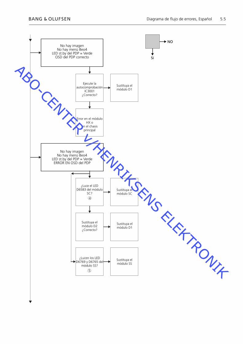
5.5
No hay imagenNo hay menú Beo4
LED st.by del PDP = VerdeOSD del PDP correcto
Ejecute la autocomprobación
IC3001¿Correcto?
Sustituya el módulo D1
Error en el módulo HX o
en el chasis principal
No hay imagenNo hay menú Beo4
LED st.by del PDP = VerdeERROR EN OSD del PDP
¿Luce el LED D6583 del módulo
SC?Sustituya el módulo SC
Sustituya el módulo D2¿Correcto?
Sustituya el módulo D1
¿Lucen los LED D6769 y D6765 del
módulo SS?
Sustituya el módulo SS
NO
Sí
Diagrama de fl ujo de errores, Español
5
4
ABO-CENTER v/HENRIKSENS ELEKTRONIK
5.6
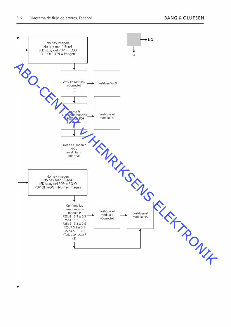
No hay imagenNo hay menú Beo4
LED st.by del PDP = ROJOPDP OFF+ON = imagen
W69 en M3P447¿Correcto?
Sustituya W69
Ejecute la autocomprobación
IC3001 del PDP¿Correcto?
Sustituya el módulo D1
Error en el módulo HX o
en el chasis principal
No hay imagenNo hay menú Beo4
LED st.by del PDP = ROJOPDP OFF+ON = No hay imagen
Confirme las tensiones en el
módulo PP23p2 15,3 ± 0,5P25p1 15,3 ± 0,5P25p5 13,3 ± 0,5P25p7 5,2 ± 0,3P27p4 5,0 ± 0,3¿Todas correctas?
Sustituya el módulo P
¿Correcto?
Sustituya el módulo HX
NO
Sí
Diagrama de fl ujo de errores, Español
6
3
ABO-CENTER v/HENRIKSENS ELEKTRONIK
5.7
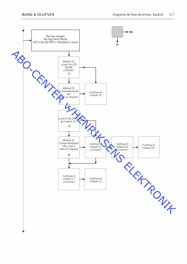
No hay imagen No hay menú Beo4
LED st.by del PDP = Parpadea 2 veces
Módulo SS¿Lucen los LED
D6769y D6765?
Módulo SSCompruebe/ajuste
Ve=Valor en etiqueta
Sustituya el módulo SS
¿Luce el LED D6583 del módulo SC?
Módulo SCCompruebe/ajuste
Vbk y Vad =Valor en etiqueta
Sustituya el módulo SC¿Correcto?
Sustituya el módulo D2¿Correcto?
Sustituya el módulo D1
Sustituya el módulo C1 ¿Correcto?
Sustituya el módulo C2
NO
Sí
Diagrama de fl ujo de errores, Español
8
4
5
ABO-CENTER v/HENRIKSENS ELEKTRONIK

5.8
No hay imagenNo hay menú Beo4
LED st.by del PDP = Parpadea 3 veces
Sustituya el módulo D2¿Correcto?
No hay imagenNo hay menú Beo4
LED st.by del PDP = Parpadea 4 veces
Confirme las tensiones en el
módulo PP23p2 15,3 ± 0,5P25p1 15,3 ± 0,5P25p5 13,3 ± 0,5P25p7 5,2 ± 0,3P27p4 5,0 ± 0,3¿Todas correctas?
Compruebe/ajusteVsus = valor en
etiquetaVda = 67 V ± 1 V
¿Correcto?
Sustituya el módulo P
Sustituya el módulo D1
NO
Sí
Diagrama de fl ujo de errores, Español
3
8
ABO-CENTER v/HENRIKSENS ELEKTRONIK
5.9
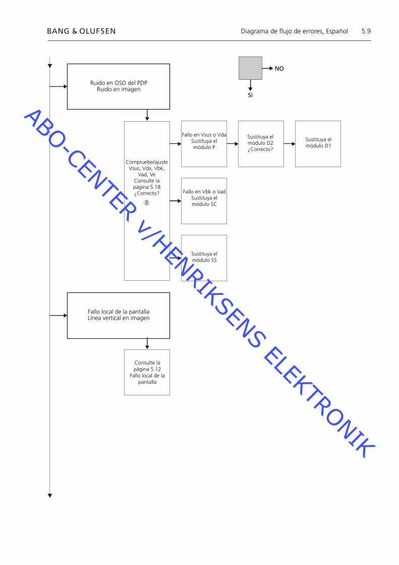
Ruido en OSD del PDPRuido en imagen
Compruebe/ajusteVsus, Vda, Vbk,
Vad, VeConsulte la página 5.18¿Correcto?
Fallo en Vsus o VdaSustituya el módulo P
Sustituya el módulo D2¿Correcto?
Sustituya el módulo D1
Fallo en Vbk o VadSustituya elmódulo SC
Sustituya elmódulo SS
Fallo local de la pantallaLínea vertical en imagen
Consulte lapágina 5.12
Fallo local de la pantalla
NO
Sí
Diagrama de fl ujo de errores, Español
8
ABO-CENTER v/HENRIKSENS ELEKTRONIK

5.10
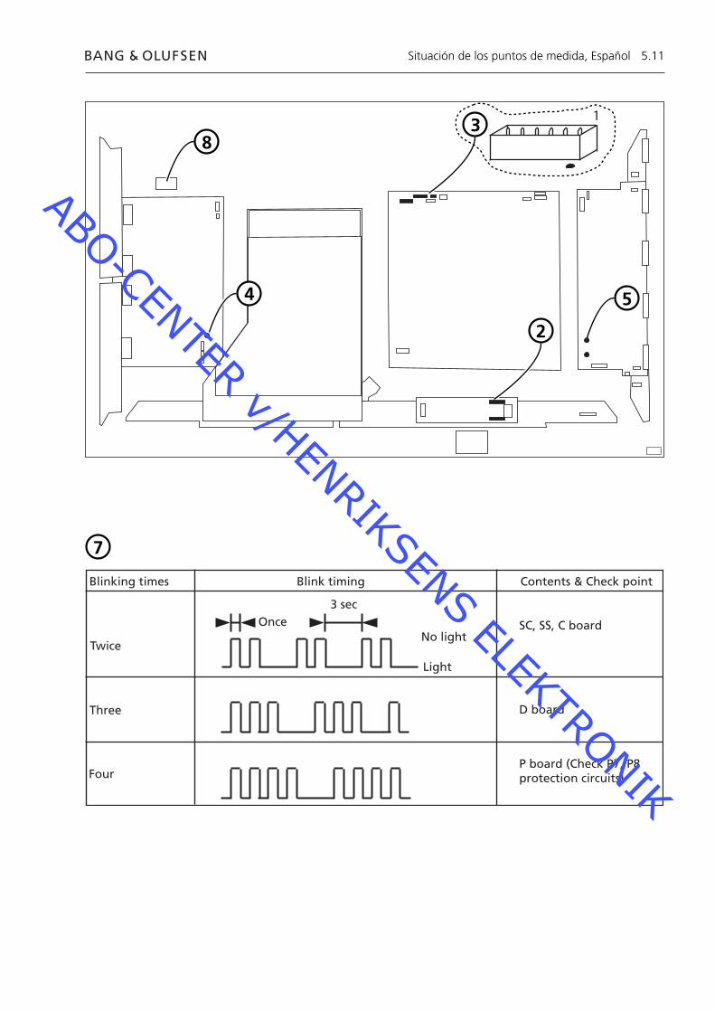
Situación de los puntos de medida 240V CA para el PDP M60P448 p1 & p2 F900 & F901 Tarjeta de alimentación del PDP Tensión de salida (Vout) de la fuente de alimentación P23, P25 & P27 LED SC 6583 Módulo SC LED SS 6769 + 6765 Módulo SS Conexión RS232 M3P447 / W69 LED STB PARPADEANTE Ilustración Valores predefi nidos Etiqueta Panasonic
1
6
1
2
3
4
5
6
7
8
Situación de los puntos de medida, Español
ABO-CENTER v/HENRIKSENS ELEKTRONIK
5.11
Blinking times Blink timing Contents & Check point
Twice
Three
Four
Once3 sec
No light
Light
SC, SS, C board
D board
P board (Check P7, P8protection circuits)
38
2
4 5
Situación de los puntos de medida, Español
7
1
ABO-CENTER v/HENRIKSENS ELEKTRONIK

5.12
Fallo local de la pantallaEl panel de visualización de plasma puede tener un fallo en una zona determinada de la pantalla.La ilustración más abajo muestra una posible conexión entre el fallo y el módulo.
Módulo SU o D2
Módulo C2 o D2 Módulo C1 o D2
Módulo SD o D2
Menú OSD del panel de visualización de plasma1. Retire la cinta autoadhesiva2. Pulse PICTURE (Imagen), SOUND (Sonido) o SET UP (Confi guración) en el terminal a distancia sin nombre.
SOUND
+
+_VOL
R
SET UP
PICTURE
Fallo local de la pantalla y menú OSD, Español
ABO-CENTER v/HENRIKSENS ELEKTRONIK
5.13
ID IIC1 IIC2 IIC3
D1 D2
H
Z
IC9355
IC9357
IC9007
IC9200
IC3001
IC3004
IC2401
IC9900
IC9602
IC9652
IC3501
IC3699
IC3804
IC4502
OK H21
OK H51
OK H52
OK H53
OK H53
OK H54
OK H58
OK H55
OK H55
OK H57
OK H56
OK H59
OK H60
- - -
BStandby
+
+_VOL
R
LED
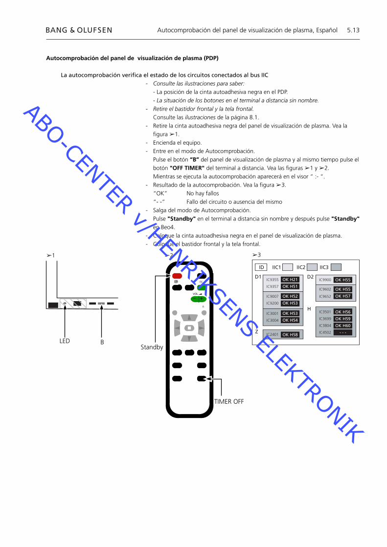
Autocomprobación del panel de visualización de plasma (PDP)
La autocomprobación verifi ca el estado de los circuitos conectados al bus IIC- Consulte las ilustraciones para saber: - La posición de la cinta autoadhesiva negra en el PDP. - La situación de los botones en el terminal a distancia sin nombre.- Retire el bastidor frontal y la tela frontal. Consulte las ilustraciones de la página 8.1.- Retire la cinta autoadhesiva negra del panel de visualización de plasma. Vea la
fi gura ➢1.- Encienda el equipo.- Entre en el modo de Autocomprobación. Pulse el botón “B” del panel de visualización de plasma y al mismo tiempo pulse el
botón "OFF TIMER" del terminal a distancia. Vea las fi guras ➢1 y ➢2. Mientras se ejecuta la autocomprobación aparecerá en el visor “ :- “.- Resultado de la autocomprobación. Vea la fi gura ➢3. “OK” No hay fallos “- -” Fallo del circuito o ausencia del mismo- Salga del modo de Autocomprobación. Pulse "Standby" en el terminal a distancia sin nombre y después pulse "Standby"
en Beo4.- Coloque la cinta autoadhesiva negra en el panel de visualización de plasma.- Coloque el bastidor frontal y la tela frontal.
➢1 ➢2 ➢3
TIMER OFF
Autocomprobación del panel de visualización de plasma, Español
ABO-CENTER v/HENRIKSENS ELEKTRONIK
5.14
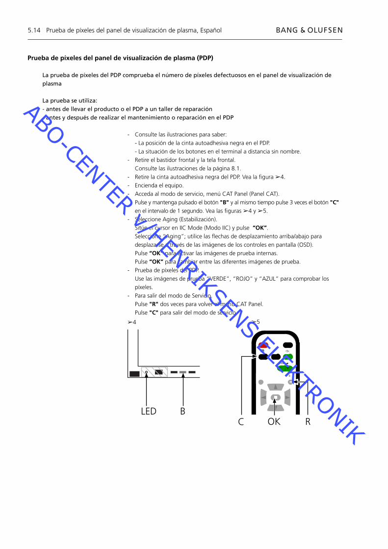
Prueba de píxeles del panel de visualización de plasma (PDP)
La prueba de píxeles del PDP comprueba el número de píxeles defectuosos en el panel de visualización de plasma
La prueba se utiliza:- antes de llevar el producto o el PDP a un taller de reparación- antes y después de realizar el mantenimiento o reparación en el PDP
- Consulte las ilustraciones para saber: - La posición de la cinta autoadhesiva negra en el PDP. - La situación de los botones en el terminal a distancia sin nombre.- Retire el bastidor frontal y la tela frontal. Consulte las ilustraciones de la página 8.1.- Retire la cinta autoadhesiva negra del PDP. Vea la fi gura ➢4.- Encienda el equipo.- Acceda al modo de servicio, menú CAT Panel (Panel CAT). Pulse y mantenga pulsado el botón "B" y al mismo tiempo pulse 3 veces el botón "C"
en el intervalo de 1 segundo. Vea las fi guras ➢4 y ➢5.- Seleccione Aging (Estabilización). Sitúe el cursor en IIC Mode (Modo IIC) y pulse “OK”. Seleccione “Aging”; utilice las fl echas de desplazamiento arriba/abajo para
desplazarse a través de las imágenes de los controles en pantalla (OSD). Pulse “OK” para activar las imágenes de prueba internas. Pulse “OK” para cambiar entre las diferentes imágenes de prueba.- Prueba de píxeles del PDP. Use las imágenes de prueba “VERDE”, “ROJO” y “AZUL” para comprobar los
píxeles.- Para salir del modo de Servicio. Pulse "R" dos veces para volver al menú CAT Panel. Pulse "C" para salir del modo de servicio.
BLED
➢4 ➢5
Prueba de píxeles del panel de visualización de plasma, Español
C
+
+_VOL
R
ROK
ABO-CENTER v/HENRIKSENS ELEKTRONIK
5.15
Sustitución de los módulosSustitución de los módulosSustitución de la pantalla de contraste
Acciones previas al desmontaje del PDPAntes de desmontar el PDP - Desconecte la alimentación de corriente y espere 1 minuto como mínimo para que se descarguen los condensadores electrolíticos.
Conecte la alfombrilla de protección antiestática.
Después de sustituir el módulo o módulos del PDP, siga el procedimiento de prueba y ajuste que se describe en “Prueba y ajuste después de sustituir los módulos” en la página 5.18.
NOTACables internos del PDP.Actúe con precaución cuando desconecte los cables de los conectores.
Sustitución de los módulosSiga las instrucciones descritas en la página:
8.2 Panel de visualización de plasma en posición de mantenimiento o reparación
8.3 para la tarjeta de circuito impreso seleccionada
Sustitución de la pantalla de contrasteUtilice unos guantes blancos para no ensuciar la pantalla de contraste.
Utilice solamente el paño de microfi bras, nº de referencia 3375706, para limpiar el PDP.No utilice detergentes de ningún tipo para limpiar el PDP.
Siga las instrucciones descritas en la página: 8.2 Panel de visualización de plasma en posición de mantenimiento o
reparación 8.1 Retirada de la pantalla de contraste y del marco del panel de plasma
Sustitución de los módulos, Español
ABO-CENTER v/HENRIKSENS ELEKTRONIK

5.16
Prueba, ajuste y confi guración después de la reparaciónConfi guración del PDP para el menú B&OPrueba y ajuste después de sustituir los módulos
ADVERTENCIAPodría producirse una imagen retenida en el PDP si se visualiza una imagen sin movimiento durante más de 30 minutos aproximadamente.
Prueba y ajusteLa “Prueba y ajuste después de sustituir los módulos” tiene que realizarse después de cualquier reparación en el panel de visualización de plasma.
Confi guración del PDP para el menú B&OEl módulo D1/D2 debe confi gurarse para que funcione con las prestaciones de Bang & Olufsen.
1. Consulte la ilustración para conocer:- la situación de los botones en el panel de plasma y en el terminal a distancia sin nombre.- El menú CAT Panel y el modo CD.
2. Retire la tela frontal, vea la fi gura 8.1.
3. Retire la cinta autoadhesiva negra.
4. Encienda BV5.
5. Encienda el panel de plasma. Pulse el botón identifi cado con "A". El LED del panel de plasma se enciende en verde.
6. Acceda al modo de Servicio. Pulse y mantenga pulsado el botón "B" y al mismo tiempo pulse 3 veces el botón
"C" en el intervalo de 1 segundo.
7. Acceda a CD Mode en el menú CAT Panel. Utilice las fl echas de desplazamiento para seleccionar CD Mode. Pulse el botón D durante 5 segundos.
8. Menú CD
9. Compruebe los datos y la dirección de memoria en Memory data change (Cambio de datos de la memoria).Use las teclas de desplazamiento para buscar la dirección de memoria precisa en Memory data change.El primer código de dirección se confi gura mediante las fl echas de desplazamiento a izquierda/derecha.El segundo código de dirección se confi gura mediante las fl echas de desplazamiento arriba/abajo.
10. Compruebe la dirección y los datos.
Dirección
Datos
11. Cambie los datos en Memory data change.Utilice los botones de volumen (+/-) para cambiar el valor Datos.Cambie los datos a los valores siguientes.
Datos para el panel de plasma
Dirección
Datos
Prueba, ajuste y confi guración después de la reparación, Español
0
10
8A
10
0
01
8C
10
0
1A
8D
1A
0
10
8A
10
0
01
8C
10
0
1A
8D
1A
ABO-CENTER v/HENRIKSENS ELEKTRONIK
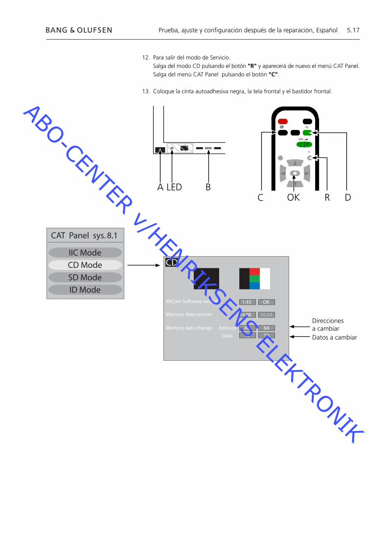
5.17
12. Para salir del modo de Servicio.Salga del modo CD pulsando el botón "R" y aparecerá de nuevo el menú CAT Panel.Salga del menú CAT Panel pulsando el botón "C".
13. Coloque la cinta autoadhesiva negra, la tela frontal y el bastidor frontal.
Prueba, ajuste y confi guración después de la reparación, Español
BC
+
+_VOL
R
LEDR
ADOK
CAT Panel sys. 8.1
IIC Mode
CD Mode
SD Mode
ID Mode
CD
MiCom Software version
Memory data version
Memory data change Address
Data
1.43 OK
14.08 16.34
A0 8A
10 10
Direcciones a cambiarDatos a cambiar
ABO-CENTER v/HENRIKSENS ELEKTRONIK
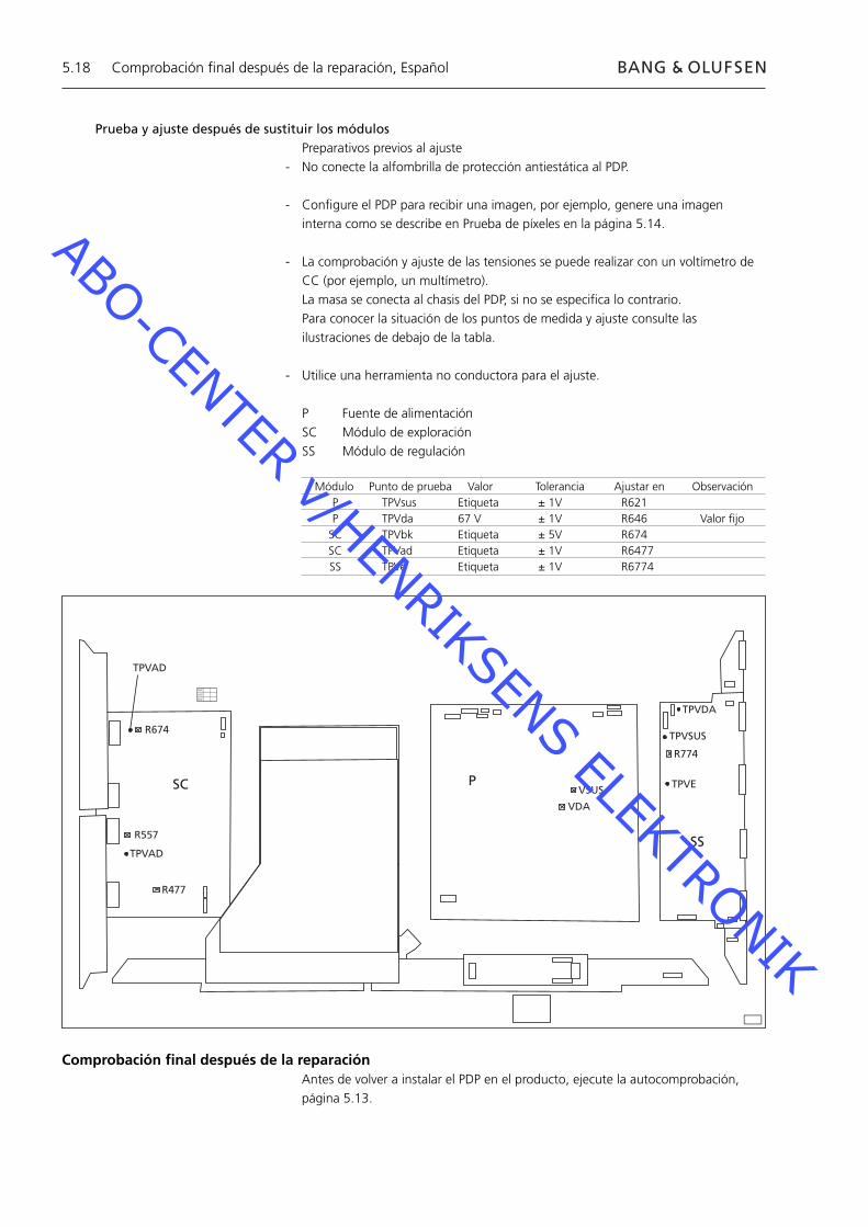
5.18
Prueba y ajuste después de sustituir los módulosPreparativos previos al ajuste
- No conecte la alfombrilla de protección antiestática al PDP.
- Confi gure el PDP para recibir una imagen, por ejemplo, genere una imagen interna como se describe en Prueba de píxeles en la página 5.14.
- La comprobación y ajuste de las tensiones se puede realizar con un voltímetro de CC (por ejemplo, un multímetro).
La masa se conecta al chasis del PDP, si no se especifi ca lo contrario. Para conocer la situación de los puntos de medida y ajuste consulte las
ilustraciones de debajo de la tabla.
- Utilice una herramienta no conductora para el ajuste.
P Fuente de alimentaciónSC Módulo de exploraciónSS Módulo de regulación
R674
R557
R477
TPVAD
VSUS
VDA
TPVDA
TPVSUS
TPVE
R774
SC P
SS
XVC
VCX
CXV
TPVAD
Módulo Punto de prueba Valor Tolerancia Ajustar en Observación P TPVsus Etiqueta ± 1V R621 P TPVda 67 V ± 1V R646 Valor fi jo SC TPVbk Etiqueta ± 5V R674 SC TPVad Etiqueta ± 1V R6477 SS TPVe Etiqueta ± 1V R6774
Comprobación fi nal después de la reparaciónAntes de volver a instalar el PDP en el producto, ejecute la autocomprobación, página 5.13.
Comprobación fi nal después de la reparación, Español
ABO-CENTER v/HENRIKSENS ELEKTRONIK
6.1
6.3 Servicering
6.4 Fejltræ
6.10 Placering af målepunkter
6.12 Lokal skærmfejl og menuen OSD
6.13 Plasma Display Panel – self-check
6.14 Plasma Display Panel – pixel test
6.15 Udskiftning af enheder
6.16 Test, justering og konfi guration efter reparation
6.18 Afsluttende kontrol efter reparation
8.1 Illustrationer
Indhold, dansk
ABO-CENTER v/HENRIKSENS ELEKTRONIK

6.2
ABO-CENTER v/HENRIKSENS ELEKTRONIK
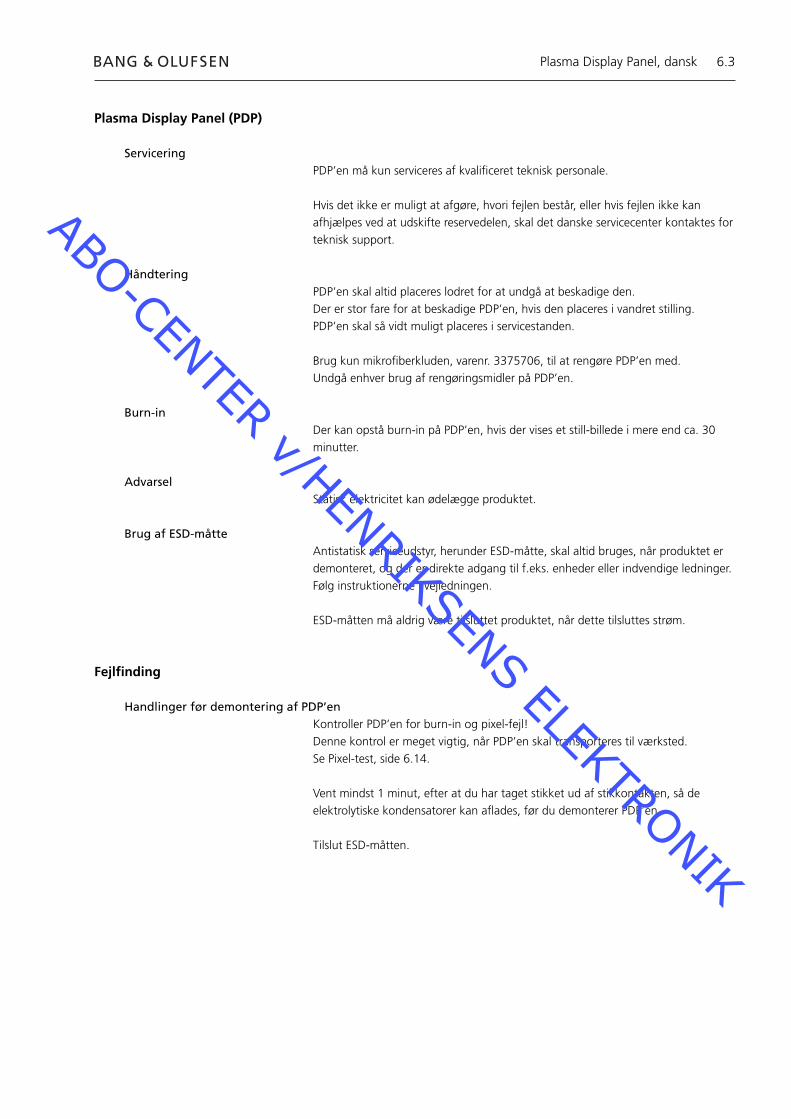
6.3
Plasma Display Panel (PDP)
ServiceringPDP’en må kun serviceres af kvalifi ceret teknisk personale.
Hvis det ikke er muligt at afgøre, hvori fejlen består, eller hvis fejlen ikke kan afhjælpes ved at udskifte reservedelen, skal det danske servicecenter kontaktes for teknisk support.
HåndteringPDP’en skal altid placeres lodret for at undgå at beskadige den.Der er stor fare for at beskadige PDP’en, hvis den placeres i vandret stilling.PDP’en skal så vidt muligt placeres i servicestanden.
Brug kun mikrofi berkluden, varenr. 3375706, til at rengøre PDP’en med.Undgå enhver brug af rengøringsmidler på PDP’en.
Burn-in Der kan opstå burn-in på PDP’en, hvis der vises et still-billede i mere end ca. 30 minutter.
AdvarselStatisk elektricitet kan ødelægge produktet.
Brug af ESD-måtteAntistatisk serviceudstyr, herunder ESD-måtte, skal altid bruges, når produktet er demonteret, og der er direkte adgang til f.eks. enheder eller indvendige ledninger.Følg instruktionerne i vejledningen.
ESD-måtten må aldrig være tilsluttet produktet, når dette tilsluttes strøm.
Fejlfi nding
Handlinger før demontering af PDP’enKontroller PDP’en for burn-in og pixel-fejl!Denne kontrol er meget vigtig, når PDP’en skal transporteres til værksted.Se Pixel-test, side 6.14.
Vent mindst 1 minut, efter at du har taget stikket ud af stikkontakten, så de elektrolytiske kondensatorer kan afl ades, før du demonterer PDP’en.
Tilslut ESD-måtten.
Plasma Display Panel, dansk
ABO-CENTER v/HENRIKSENS ELEKTRONIK

6.4
PLASMA DISPLAY PANEL
(PDP)
Intet billedePDP st.by LED = Intet lys240 V AC ved M60P448
KontrollerF900 & F901
OK?Udskift
defekt sikring
Bekræft spænding enhed P
P23p2 15.3±0.5P25p1 15.3±0.5P25p5 13.3±0.5P25p7 5.2±0.3P27p4 5.0±0.3
Alle OK?
Udskift Enhed P
Nej
Ja
Fejltræ, dansk
Fejltræ
Standardinstillinger ved brug af fejltræ- Tryk på TV på Beo4- Vælg en tv-kanal med billede og lyd
Sådan bruges fejltræet
Henvisning til et målepunkt er markeret med: Se side 6.10 og 6.11 vedrørende placering af målepunkter.
Nej
Ja
2
3
3
ABO-CENTER v/HENRIKSENS ELEKTRONIK

6.5
Intet billedeIngen Beo4 menu
PDP st.by LED = GrønPDP OSD OK
Kør self-check IC3001
OK?
Udskift Enhed D1
Fejl i enten enhed HX eller
hovedchassis
Intet billedeIngen Beo4 menu
PDP st.by LED = GrønPDP OSD MISLYKKEDES
Lyser modul SC LED D6583?
Udskift Enhed SC
UdskiftEnhed D2
OK?
Udskift Enhed D1
Lyser SS LED D6769 og LED D6765?
Udskift Enhed SS
Nej
Ja
Fejltræ, dansk
5
4
ABO-CENTER v/HENRIKSENS ELEKTRONIK
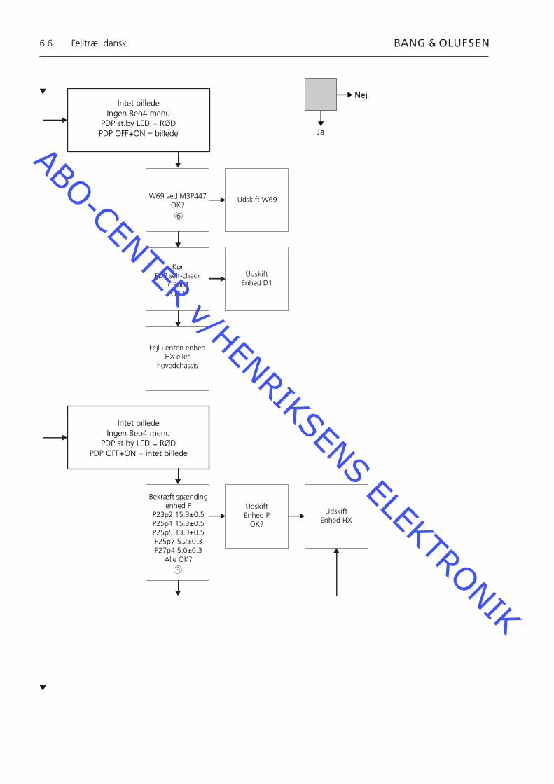
6.6
Intet billedeIngen Beo4 menu
PDP st.by LED = RØDPDP OFF+ON = billede
W69 ved M3P447OK?
Udskift W69
Kør PDP self-check
IC3001OK?
Udskift Enhed D1
Fejl i enten enhed HX eller
hovedchassis
Intet billedeIngen Beo4 menu
PDP st.by LED = RØDPDP OFF+ON = intet billede
Bekræft spænding enhed P
P23p2 15.3±0.5P25p1 15.3±0.5P25p5 13.3±0.5P25p7 5.2±0.3P27p4 5.0±0.3
Alle OK?
UdskiftEnhed P
OK?
Udskift Enhed HX
Nej
Ja
Fejltræ, dansk
6
3
ABO-CENTER v/HENRIKSENS ELEKTRONIK

6.7
Intet billedeIngen Beo4 menu
PDP st.by LED= Blinker 2 gange
Lyser enhed SSdiode D6769 ogdiode D6765?
Enhed SSKontroller/juster
Ve=Værdi på label
Udskift Enhed SS
Lyser modul SC LED D6583?
Enhed SCKontroller/juster
Vbk & Vad =Værdi på label
UdskiftEnhed SC
OK?
UdskiftEnhed D2
OK?
Udskift Enhed D1
UdskiftEnhed C1
OK?Udskift
Enhed C2
Nej
Ja
Fejltræ, dansk
8
4
5
ABO-CENTER v/HENRIKSENS ELEKTRONIK
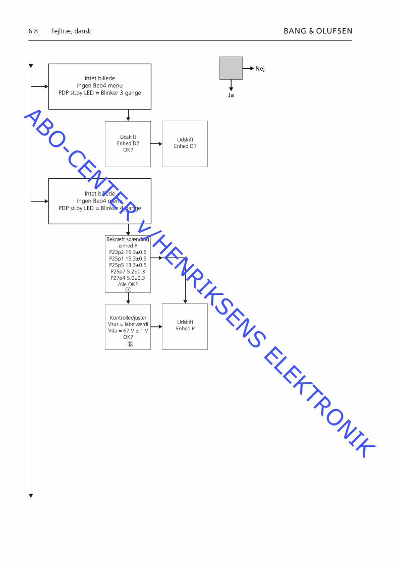
6.8
Intet billedeIngen Beo4 menu
PDP st.by LED = Blinker 3 gange
UdskiftEnhed D2
OK?
Intet billedeIngen Beo4 menu
PDP st.by LED = Blinker 4 gange
Bekræft spænding enhed P
P23p2 15.3±0.5P25p1 15.3±0.5P25p5 13.3±0.5P25p7 5.2±0.3P27p4 5.0±0.3
Alle OK?
Kontroller/justerVsus = labelværdiVda = 67 V ± 1 V
OK?
Udskift Enhed P
Udskift Enhed D1
Nej
Ja
Fejltræ, dansk
3
8
ABO-CENTER v/HENRIKSENS ELEKTRONIK
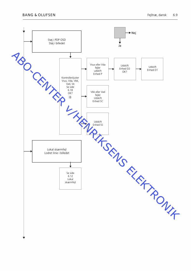
6.9
Støj i PDP OSDStøj i billedet
Kontroller/justerVsus, Vda, Vbk,
Vad, VeSe side6.18OK?
Vsus eller Vdafejler
udskiftEnhed P
UdskiftEnhed D2
OK?
Udskift Enhed D1
Vbk eller Vadfejler
UdskiftEnhed SC
Udskift Enhed SS
Lokal skærmfejlLodret linie i billedet
Se side 6.12Lokal
skærmfejl
Nej
Ja
Fejltræ, dansk
8
ABO-CENTER v/HENRIKSENS ELEKTRONIK

6.10
Placering af målepunkter 240 V AC for PDP M60P448 p1 & p2 F900 & F901 Power PCB PDP Vout fra Power P23, P25 & P27 SC LED 6583 Enhed SC SS LED 6769 + 6765 Enhed SS RS232-forbindelse M3P447 / W69 BLINKENDE STB LED Illustration Forudindstillede værdier Panasonic label
1
6
1
2
3
4
5
6
7
8
Placering af målepunkter, dansk
ABO-CENTER v/HENRIKSENS ELEKTRONIK

6.11
Blinking times Blink timing Contents & Check point
Twice
Three
Four
Once3 sec
No light
Light
SC, SS, C board
D board
P board (Check P7, P8protection circuits)
38
2
4 5
Placering af målepunkter, dansk
7
1
ABO-CENTER v/HENRIKSENS ELEKTRONIK

6.12
Lokal skærmfejlPDP’en kan have en fejl i et lokalt område på skærmen.Illustrationen nedenfor viser en mulig sammenhæng mellem fejl og enhed.
SU eller D2 enhed
C2 eller D2 enhed C1 eller D2 enhed
SD eller D2 enhed
Menuen OSD på Plasma Display Panel1. Fjern den selvklæbende tape2. Tryk på PICTURE, SOUND eller SET UP på NN fjernbetjeningen.
SOUND
+
+_VOL
R
SET UP
PICTURE
Lokal skærmfejl og menuen OSD, dansk
ABO-CENTER v/HENRIKSENS ELEKTRONIK
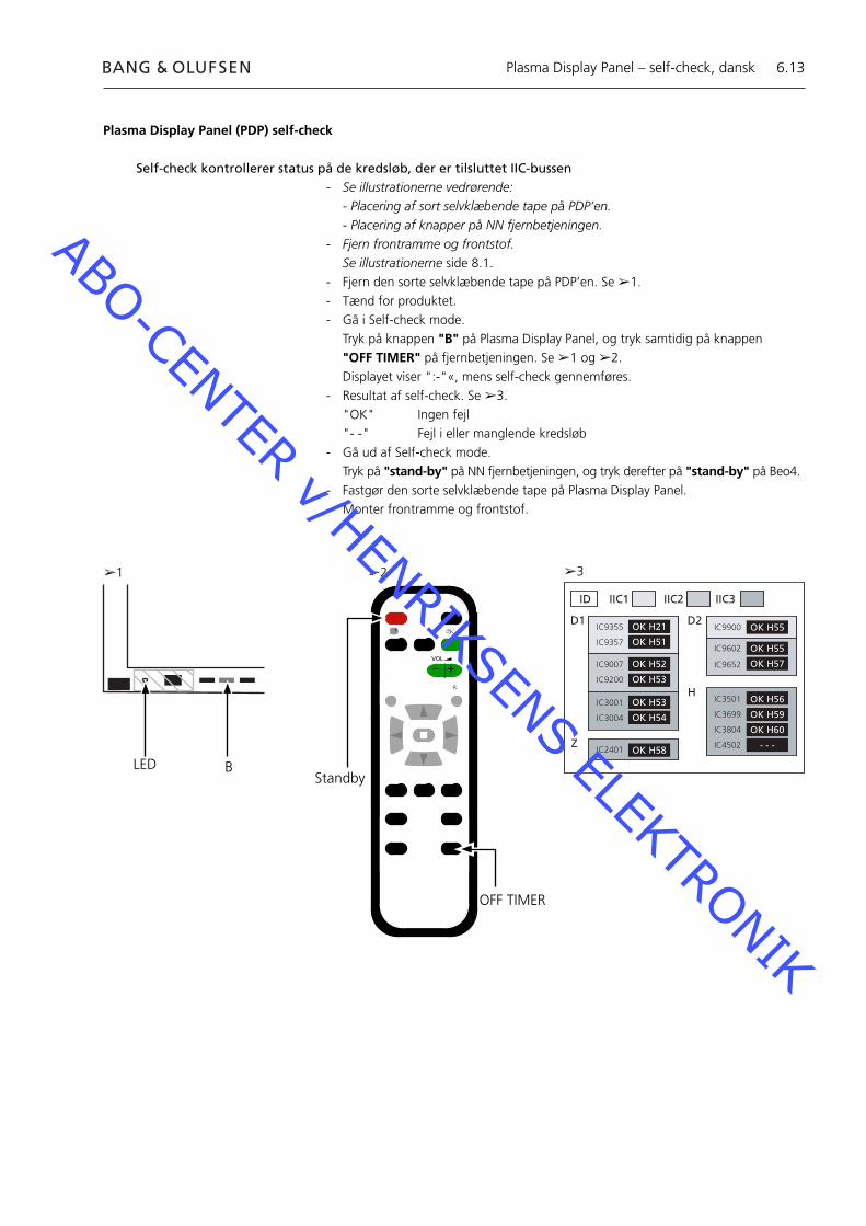
6.13
ID IIC1 IIC2 IIC3
D1 D2
H
Z
IC9355
IC9357
IC9007
IC9200
IC3001
IC3004
IC2401
IC9900
IC9602
IC9652
IC3501
IC3699
IC3804
IC4502
OK H21
OK H51
OK H52
OK H53
OK H53
OK H54
OK H58
OK H55
OK H55
OK H57
OK H56
OK H59
OK H60
- - -
BStandby
+
+_VOL
R
LED
Plasma Display Panel (PDP) self-check
Self-check kontrollerer status på de kredsløb, der er tilsluttet IIC-bussen- Se illustrationerne vedrørende: - Placering af sort selvklæbende tape på PDP’en. - Placering af knapper på NN fjernbetjeningen.- Fjern frontramme og frontstof. Se illustrationerne side 8.1.- Fjern den sorte selvklæbende tape på PDP’en. Se ➢1.- Tænd for produktet.- Gå i Self-check mode. Tryk på knappen "B" på Plasma Display Panel, og tryk samtidig på knappen
"OFF TIMER" på fjernbetjeningen. Se ➢1 og ➢2. Displayet viser ":-"«, mens self-check gennemføres.- Resultat af self-check. Se ➢3. "OK" Ingen fejl "- -" Fejl i eller manglende kredsløb- Gå ud af Self-check mode. Tryk på "stand-by" på NN fjernbetjeningen, og tryk derefter på "stand-by" på Beo4.- Fastgør den sorte selvklæbende tape på Plasma Display Panel.- Monter frontramme og frontstof.
➢1 ➢2 ➢3
OFF TIMER
Plasma Display Panel – self-check, dansk
ABO-CENTER v/HENRIKSENS ELEKTRONIK
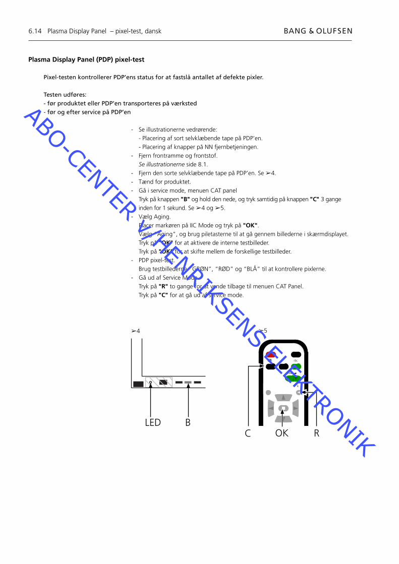
6.14
Plasma Display Panel (PDP) pixel-test
Pixel-testen kontrollerer PDP’ens status for at fastslå antallet af defekte pixler.
Testen udføres:- før produktet eller PDP’en transporteres på værksted- før og efter service på PDP’en
- Se illustrationerne vedrørende: - Placering af sort selvklæbende tape på PDP’en. - Placering af knapper på NN fjernbetjeningen.- Fjern frontramme og frontstof. Se illustrationerne side 8.1.- Fjern den sorte selvklæbende tape på PDP’en. Se ➢4.- Tænd for produktet.- Gå i service mode, menuen CAT panel Tryk på knappen "B" og hold den nede, og tryk samtidig på knappen "C" 3 gange
inden for 1 sekund. Se ➢4 og ➢5.- Vælg Aging. Placer markøren på IIC Mode og tryk på "OK". Vælg "Aging", og brug piletasterne til at gå gennem billederne i skærmdisplayet. Tryk på "OK" for at aktivere de interne testbilleder. Tryk på "OK" for at skifte mellem de forskellige testbilleder.- PDP pixel-test. Brug testbillederne “GRØN”, “RØD” og “BLÅ” til at kontrollere pixlerne.- Gå ud af Service Mode. Tryk på "R" to gange for at vende tilbage til menuen CAT Panel. Tryk på "C" for at gå ud af service mode.
BLED
➢4 ➢5
Plasma Display Panel – pixel-test, dansk
C
+
+_VOL
R
ROK
ABO-CENTER v/HENRIKSENS ELEKTRONIK
6.15
Udskiftning af enhederUdskiftning af enhederUdskiftning af kontrastskærm
Handlinger før demontering af PDP’enVent mindst 1 minut, efter at du har taget stikket ud af stikkontakten, så de elektrolytiske kondensatorer kan afl ades, før du demonterer PDP’en.
Tilslut ESD-måtten.
Når du har udskiftet enhed(er) i PDP’en, skal du gennemgå testen og justeringsproceduren som beskrevet i afsnittet »Test og justering efter udskiftning af enhed(er)« på side 6.18.
BEMÆRKIndvendige ledninger i PDP’en.Vær forsigtig, når du kobler ledningerne fra stikkene.
Udskiftning af enhederFølg instruktionerne på side:
8.2 PDP i serviceposition 8.3 for udvalgte PCB’er
Udskiftning af kontrastskærmBrug hvide handsker for at undgå at snavse kontrastskærmen til.
Brug kun mikrofi berkluden, varenr. 3375706, til at rengøre PDP’en med.Undgå enhver brug af rengøringsmidler på PDP’en.
Følg instruktionerne på side: 8.2 PDP i serviceposition 8.1 Fjern kontrastskærm og plasmaramme
Udskiftning af enheder, dansk
ABO-CENTER v/HENRIKSENS ELEKTRONIK
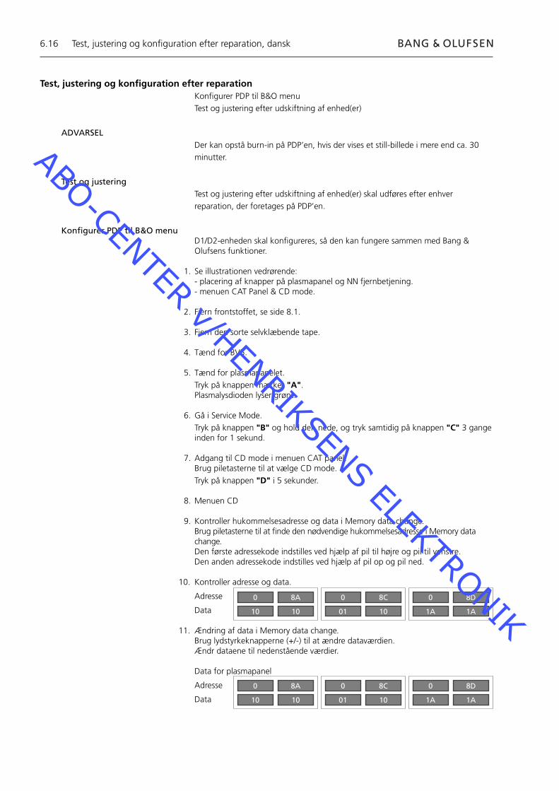
6.16
Test, justering og konfi guration efter reparationKonfi gurer PDP til B&O menuTest og justering efter udskiftning af enhed(er)
ADVARSELDer kan opstå burn-in på PDP’en, hvis der vises et still-billede i mere end ca. 30 minutter.
Test og justeringTest og justering efter udskiftning af enhed(er) skal udføres efter enhver reparation, der foretages på PDP’en.
Konfi gurer PDP til B&O menuD1/D2-enheden skal konfi gureres, så den kan fungere sammen med Bang & Olufsens funktioner.
1. Se illustrationen vedrørende:- placering af knapper på plasmapanel og NN fjernbetjening.- menuen CAT Panel & CD mode.
2. Fjern frontstoffet, se side 8.1.
3. Fjern den sorte selvklæbende tape.
4. Tænd for BV5.
5. Tænd for plasmapanelet. Tryk på knappen mærket "A". Plasmalysdioden lyser grønt.
6. Gå i Service Mode. Tryk på knappen "B" og hold den nede, og tryk samtidig på knappen "C" 3 gange
inden for 1 sekund.
7. Adgang til CD mode i menuen CAT panel. Brug piletasterne til at vælge CD mode. Tryk på knappen "D" i 5 sekunder.
8. Menuen CD
9. Kontroller hukommelsesadresse og data i Memory data change. Brug piletasterne til at fi nde den nødvendige hukommelsesadresse i Memory data change.Den første adressekode indstilles ved hjælp af pil til højre og pil til venstre.Den anden adressekode indstilles ved hjælp af pil op og pil ned.
10. Kontroller adresse og data.
Adresse
Data
11. Ændring af data i Memory data change.Brug lydstyrkeknapperne (+/-) til at ændre dataværdien.Ændr dataene til nedenstående værdier.
Data for plasmapanel
Adresse
Data
Test, justering og konfi guration efter reparation, dansk
0
10
8A
10
0
01
8C
10
0
1A
8D
1A
0
10
8A
10
0
01
8C
10
0
1A
8D
1A
ABO-CENTER v/HENRIKSENS ELEKTRONIK
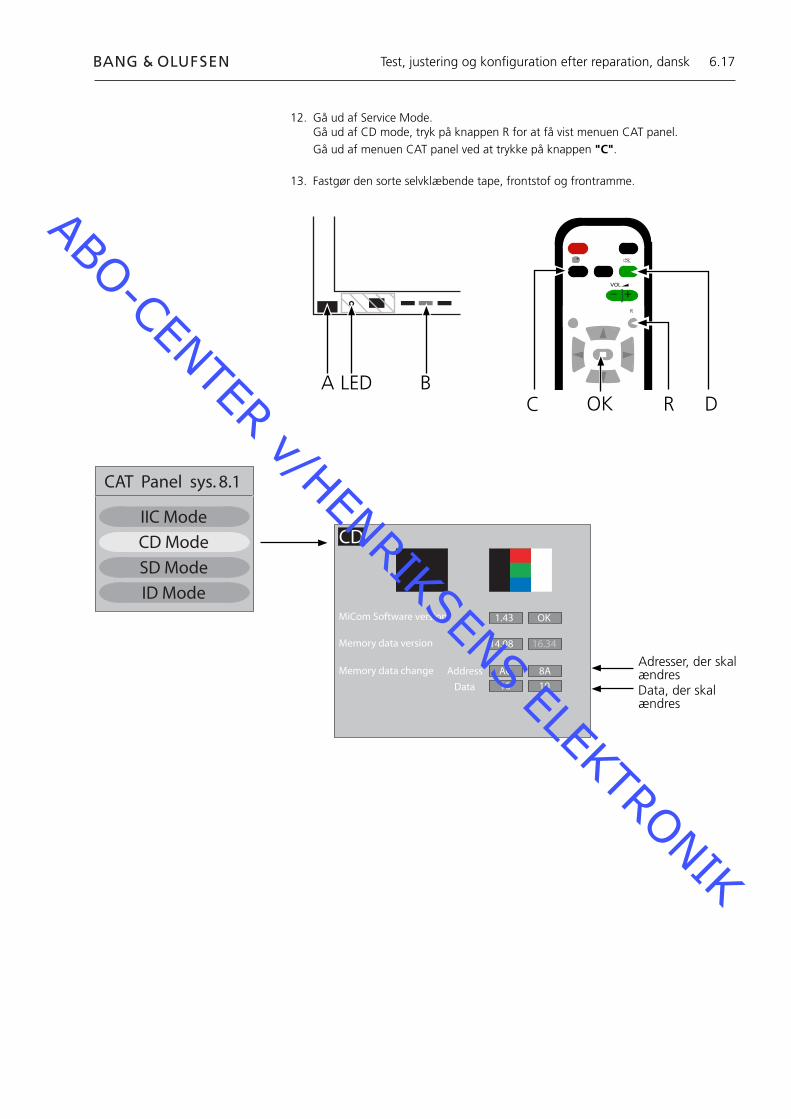
6.17
12. Gå ud af Service Mode.Gå ud af CD mode, tryk på knappen R for at få vist menuen CAT panel.Gå ud af menuen CAT panel ved at trykke på knappen "C".
13. Fastgør den sorte selvklæbende tape, frontstof og frontramme.
Test, justering og konfi guration efter reparation, dansk
BC
+
+_VOL
R
LEDR
ADOK
CAT Panel sys. 8.1
IIC Mode
CD Mode
SD Mode
ID Mode
CD
MiCom Software version
Memory data version
Memory data change Address
Data
1.43 OK
14.08 16.34
A0 8A
10 10
Adresser, der skal ændresData, der skal ændres
ABO-CENTER v/HENRIKSENS ELEKTRONIK
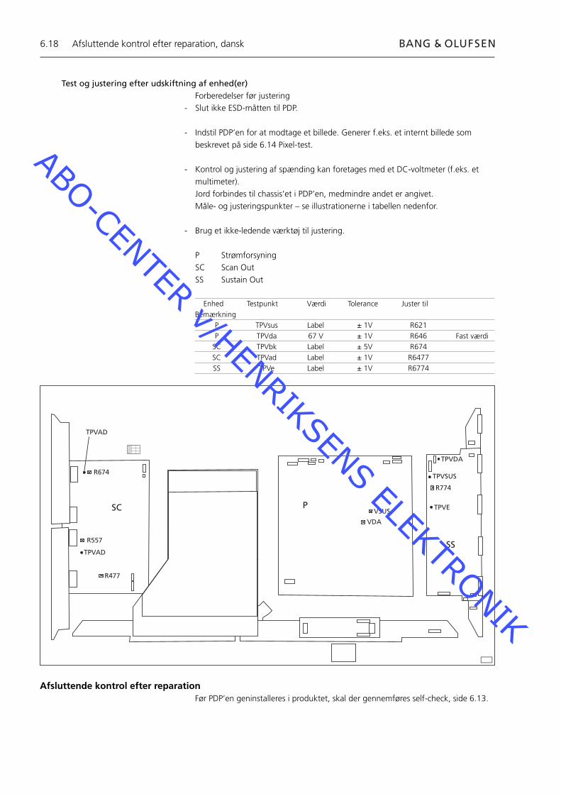
6.18
Test og justering efter udskiftning af enhed(er)Forberedelser før justering
- Slut ikke ESD-måtten til PDP.
- Indstil PDP’en for at modtage et billede. Generer f.eks. et internt billede som beskrevet på side 6.14 Pixel-test.
- Kontrol og justering af spænding kan foretages med et DC-voltmeter (f.eks. et multimeter).
Jord forbindes til chassis’et i PDP’en, medmindre andet er angivet. Måle- og justeringspunkter – se illustrationerne i tabellen nedenfor.
- Brug et ikke-ledende værktøj til justering.
P StrømforsyningSC Scan OutSS Sustain Out
R674
R557
R477
TPVAD
VSUS
VDA
TPVDA
TPVSUS
TPVE
R774
SC P
SS
XVC
VCX
CXV
TPVAD
Enhed Testpunkt Værdi Tolerance Juster til Bemærkning P TPVsus Label ± 1V R621 P TPVda 67 V ± 1V R646 Fast værdi SC TPVbk Label ± 5V R674 SC TPVad Label ± 1V R6477 SS TPVe Label ± 1V R6774
Afsluttende kontrol efter reparationFør PDP’en geninstalleres i produktet, skal der gennemføres self-check, side 6.13.
Afsluttende kontrol efter reparation, dansk
ABO-CENTER v/HENRIKSENS ELEKTRONIK
7.1
7.3 Servicehandelingen uitvoeren
7.4 Foutzoekschema
7.10 Plaats van meetpunkten
7.12 Lokale schermfout en menu OSD
7.13 Zelftest van het plasmascherm
7.14 Pixeltest voor plasmascherm
7.15 Modules vervangen
7.16 Testen, afstellen en confi gureren na reparatie
7.18 Laatste controle na reparatie
8.1 Afbeeldingen
Inhoudsopgave, Nederlands
ABO-CENTER v/HENRIKSENS ELEKTRONIK

7.2
ABO-CENTER v/HENRIKSENS ELEKTRONIK
7.3
Plasmascherm, (PDP)
Servicehandelingen uitvoerenHet plasmascherm mag alleen worden geopend door deskundig technisch personeel.
Als u de fout niet kunt opsporen, of als het probleem na vervanging van het onderdeel niet verholpen is, neem dan contact op met het nationale Service Center voor technische ondersteuning.
Neerzetten en reinigenHet plasmascherm moet altijd verticaal worden neergezet om beschadiging te voorkomen.Er bestaat grote kans op beschadiging als het plasmascherm horizontaal wordt neergezet.Zet het plasmascherm zoveel mogelijk in de servicestand.
Gebruik alleen de micro-vezeldoek, onderdeelnummer 3375706, om het plasmascherm te reinigen.Gebruik bij het schoonmaken van het plasmascherm geen reinigingsmiddelen.
InbrandenEr bestaat risico op inbranden als een stilstaand beeld langer dan ongeveer 30 minuten op het plasmascherm wordt weergegeven.
WaarschuwingStatische elektriciteit kan het product ernstig beschadigen.
Antistatische mat gebruikenGebruik bij het demonteren van het product, wanneer u in direct contact staat met bijvoorbeeld de modules of interne bekabeling, altijd een antistatische mat met polsband.Volg de aanwijzingen in de handleiding.
De antistatische mat mag nooit worden gebruikt wanneer het product op het elektriciteitsnet is aangesloten.
Problemen oplossen
Voordat u het plasmascherm demonteertControleer het plasmascherm op inbranden en pixelfouten!Deze controle is zeer belangrijk wanneer het plasmascherm voor reparatie naar een werkplaats moet worden vervoerd.Zie pagina 7.14 voor het uitvoeren van een pixeltest.
Haal, voordat u het plasmascherm demonteert, de stekker van het plasmascherm uit het stopcontact en wacht minimaal 1 minuut totdat de elektrostatische componenten zijn ontladen.
Sluit de antistatische mat aan.
Plasmascherm, Nederlands
ABO-CENTER v/HENRIKSENS ELEKTRONIK

7.4
Plasmascherm(PDP)
Geen beeldPDP st.by LED = Brandt niet
240 V AC bij M60P448
ControleerF900 & F901
OK?Vervang
defecte zekering
Bevestig voltage Module P
P23p2 15,3±0,5P25p1 15,3±0,5P25p5 13,3±0,5P25p7 5,2±0,3P27p4 5,0±0,3
Alles OK?
VervangModule P
Nee
Ja
Foutzoekschema, Nederlands
Foutzoekschema
Standaardinstellingen bij gebruik van het foutzoekschema- Druk op de Beo4 op TV- Kies een tv-zender met beeld en geluid
Het foutzoekschema gebruiken
De meetpunten waarnaar wordt verwezen, zijn gemarkeerd: Zie pagina 7.10 en 7.11 voor meer informatie over de plaats van meetpunten.
Nee
Ja
2
3
3
ABO-CENTER v/HENRIKSENS ELEKTRONIK

7.5
Geen beeldGeen Beo4-menu
PDP st.by LED = GroenPDP OSD OK
Zelftest IC3001uitvoeren
OK?
VervangModule D1
Fout in Module HX of
hoofdchassis
Geen beeldGeen Beo4-menu
PDP st.by LED = GroenPDP OSD MISLUKT
Module SC LED D6583 brandt?
VervangModule SC
Vervang Module D2
OK?
VervangModule D1
Module SS LED D6769 en LED
D6765 branden?
VervangModule SS
Nee
Ja
Foutzoekschema, Nederlands
5
4
ABO-CENTER v/HENRIKSENS ELEKTRONIK
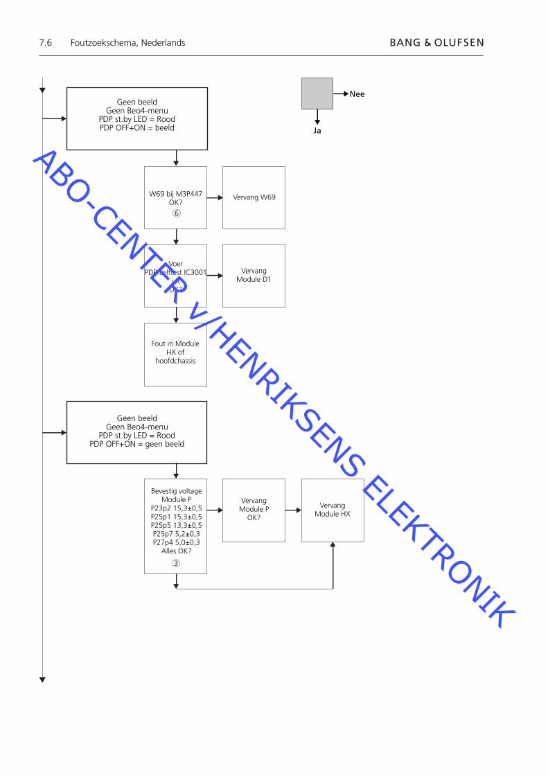
7.6
Geen beeldGeen Beo4-menu
PDP st.by LED = RoodPDP OFF+ON = beeld
W69 bij M3P447OK?
Vervang W69
Voer PDP-zelftest IC3001
uitOK?
VervangModule D1
Fout in Module HX of
hoofdchassis
Geen beeldGeen Beo4-menu
PDP st.by LED = RoodPDP OFF+ON = geen beeld
Bevestig voltage Module P
P23p2 15,3±0,5P25p1 15,3±0,5P25p5 13,3±0,5P25p7 5,2±0,3P27p4 5,0±0,3
Alles OK?
Vervang Module P
OK?
VervangModule HX
Nee
Ja
Foutzoekschema, Nederlands
6
3
ABO-CENTER v/HENRIKSENS ELEKTRONIK
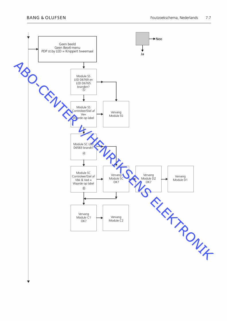
7.7
Geen beeldGeen Beo4-menu
PDP st.by LED = Knippert tweemaal
Module SSLED D6769 en
LED D6765 branden?
Module SSControleer/Stel af
Ve=Waarde op label
VervangModule SS
Module SC LED D6583 brandt?
Module SCControleer/Stel af
Vbk & Vad =Waarde op label
Vervang Module SC
OK?
Vervang Module D2
OK?
VervangModule D1
Vervang Module C1
OK?Vervang
Module C2
Nee
Ja
Foutzoekschema, Nederlands
8
4
5
ABO-CENTER v/HENRIKSENS ELEKTRONIK
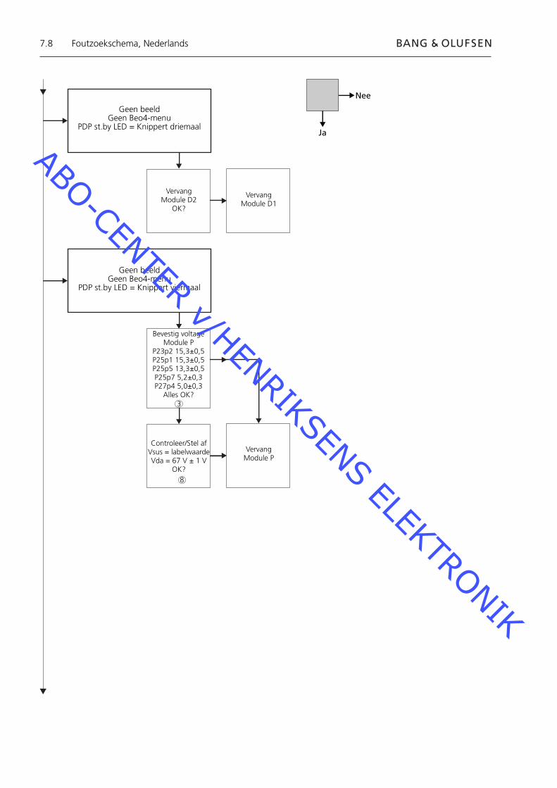
7.8
Geen beeldGeen Beo4-menu
PDP st.by LED = Knippert driemaal
Vervang Module D2
OK?
Geen beeldGeen Beo4-menu
PDP st.by LED = Knippert viermaal
Bevestig voltage Module P
P23p2 15,3±0,5P25p1 15,3±0,5P25p5 13,3±0,5P25p7 5,2±0,3P27p4 5,0±0,3
Alles OK?
Controleer/Stel afVsus = labelwaardeVda = 67 V ± 1 V
OK?
VervangModule P
VervangModule D1
Nee
Ja
Foutzoekschema, Nederlands
3
8
ABO-CENTER v/HENRIKSENS ELEKTRONIK

7.9
Ruis in PDP OSDBeeldruis
Controleer/Stel afVsus, Vda, Vbk,
Vad, VeRaadpleeg
pagina 7.18OK?
Vsus of VdaFout
Vervang Module P
Vervang Module D2
OK?
VervangModule D1
Vbk of VadFout
VervangModule SC
Vervang Module SS
Lokale schermfoutVerticale lijn in beeld
Raadpleegpagina 7.12:
Lokale schermfout
Nee
Ja
Foutzoekschema, Nederlands
8
ABO-CENTER v/HENRIKSENS ELEKTRONIK

7.10
Plaats van meetpunten 240V AC voor PDP M60P448 p1 & p2 F900 & F901 Spanning printplaat PCB van PDP Vout van spanning P23, P25 & P27 SC-LED 6583 SC-module SS-LED 6769 + 6765 SS-module RS232-aansluiting M3P447 / W69 KNIPPERENDE STB-LED Afbeelding Vooraf ingestelde waarden Panasonic-label
1
6
1
2
3
4
5
6
7
8
Plaats van meetpunten, Nederlands
ABO-CENTER v/HENRIKSENS ELEKTRONIK

7.11
Blinking times Blink timing Contents & Check point
Twice
Three
Four
Once3 sec
No light
Light
SC, SS, C board
D board
P board (Check P7, P8protection circuits)
38
2
4 5
Plaats van meetpunten, Nederlands
7
1
ABO-CENTER v/HENRIKSENS ELEKTRONIK
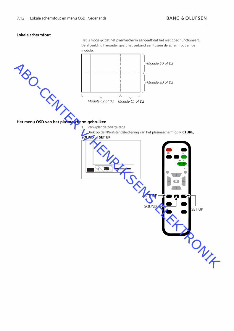
7.12
Lokale schermfoutHet is mogelijk dat het plasmascherm aangeeft dat het niet goed functioneert.De afbeelding hieronder geeft het verband aan tussen de schermfout en de module.
Module SU of D2
Module C2 of D2 Module C1 of D2
Module SD of D2
Het menu OSD van het plasmascherm gebruiken1. Verwijder de zwarte tape2. Druk op de NN-afstandsbediening van het plasmascherm op PICTURE, SOUND of SET UP
SOUND
+
+_VOL
R
SET UP
PICTURE
Lokale schermfout en menu OSD, Nederlands
ABO-CENTER v/HENRIKSENS ELEKTRONIK

7.13
ID IIC1 IIC2 IIC3
D1 D2
H
Z
IC9355
IC9357
IC9007
IC9200
IC3001
IC3004
IC2401
IC9900
IC9602
IC9652
IC3501
IC3699
IC3804
IC4502
OK H21
OK H51
OK H52
OK H53
OK H53
OK H54
OK H58
OK H55
OK H55
OK H57
OK H56
OK H59
OK H60
- - -
BStandby
+
+_VOL
R
LED
Zelftest van het plasmascherm (PDP)
Met de zelftest kunt u de status controleren van de circuits die op de IIC-bus zijn aangesloten- Op de afbeeldingen ziet u waar u: - De zwarte tape op het plasmascherm kunt vinden. - De knoppen op NN-afstandsbediening kunt vinden.- Verwijder de voorste ombouw en het luidsprekerfront. Zie de afbeeldingen op pagina 8.1.- Verwijder de zwarte tape van het plasmascherm. Zie ➢1.- Zet het product aan.- Activeer de zelftestmodus. Druk op het plasmascherm op "B" en tegelijkertijd op de afstandsbediening op
"OFF TIMER". Zie ➢1 en ➢2. Op het scherm wordt ":- " weergegeven tijdens het uitvoeren van de zelftest.- Resultaat van de zelftest. Zie ➢3. "OK" Geen fout “- -” Fout in of ontbrekend circuit- Verlaat de zelftestmodus. Druk eerst op de NN-afstandsbediening op "Standby" en druk vervolgens op de
Beo4 op "Standby".- Plak de zwarte tape op het plasmascherm.- Bevestig het luidsprekerfront en de voorste ombouw.
➢1 ➢2 ➢3
OFF TIMER
Zelftest van het plasmascherm, Nederlands
ABO-CENTER v/HENRIKSENS ELEKTRONIK
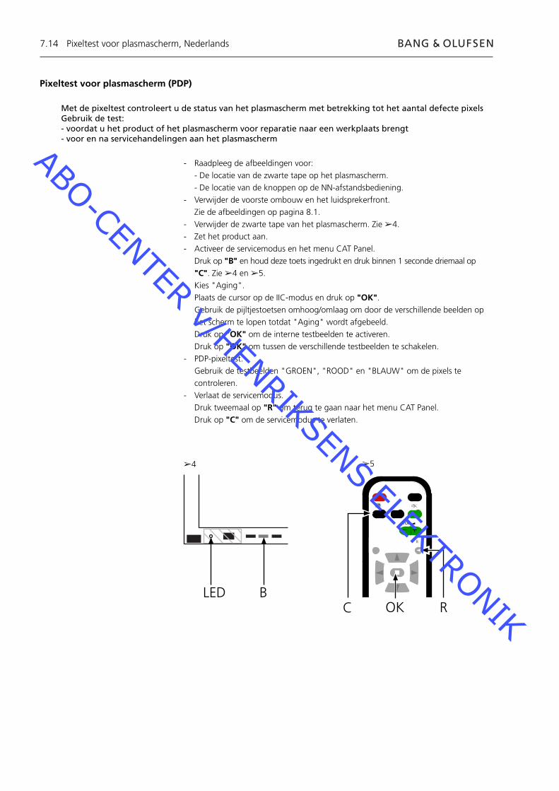
7.14
Pixeltest voor plasmascherm (PDP)
Met de pixeltest controleert u de status van het plasmascherm met betrekking tot het aantal defecte pixelsGebruik de test:- voordat u het product of het plasmascherm voor reparatie naar een werkplaats brengt- voor en na servicehandelingen aan het plasmascherm
- Raadpleeg de afbeeldingen voor: - De locatie van de zwarte tape op het plasmascherm. - De locatie van de knoppen op de NN-afstandsbediening.- Verwijder de voorste ombouw en het luidsprekerfront. Zie de afbeeldingen op pagina 8.1.- Verwijder de zwarte tape van het plasmascherm. Zie ➢4.- Zet het product aan.- Activeer de servicemodus en het menu CAT Panel. Druk op "B" en houd deze toets ingedrukt en druk binnen 1 seconde driemaal op
"C". Zie ➢4 en ➢5.- Kies "Aging". Plaats de cursor op de IIC-modus en druk op "OK". Gebruik de pijltjestoetsen omhoog/omlaag om door de verschillende beelden op
het scherm te lopen totdat "Aging" wordt afgebeeld. Druk op "OK" om de interne testbeelden te activeren. Druk op "OK" om tussen de verschillende testbeelden te schakelen.- PDP-pixeltest. Gebruik de testbeelden "GROEN", "ROOD" en "BLAUW" om de pixels te
controleren.- Verlaat de servicemodus. Druk tweemaal op "R" om terug te gaan naar het menu CAT Panel. Druk op "C" om de servicemodus te verlaten.
BLED
➢4 ➢5
Pixeltest voor plasmascherm, Nederlands
C
+
+_VOL
R
ROK
ABO-CENTER v/HENRIKSENS ELEKTRONIK
7.15
Modules vervangenModules vervangenHet contrastscherm vervangen
Voordat u het plasmascherm demonteertHaal, voordat u het plasmascherm demonteert, de stekker van het plasmascherm uit het stopcontact en wacht minimaal 1 minuut totdat de elektrostatische componenten zijn ontladen.
Sluit de antistatische mat aan.
Volg, nadat u een of meer modules in het plasmascherm hebt vervangen, de test- en afstellingsprocedure zoals beschreven in „Testen en afstellen na vervanging van module(s)“ (zie pagina 7.18).
OPMERKINGInterne kabels in het plasmascherm.Wees voorzichtig met het lostrekken van de kabels.
Modules vervangenVolg de aanwijzingen op pagina:
8.2 PDP in servicepositie 8.3 voor geselecteerde PCB
Het contrastscherm vervangenGebruik witte handschoenen om te voorkomen dat het contrastscherm vuil wordt.
Gebruik alleen de micro-vezeldoek, onderdeelnummer 3375706, om het plasmascherm te reinigen.Gebruik bij het schoonmaken van het plasmascherm geen reinigingsmiddelen.
Volg de aanwijzingen op pagina: 8.2 PDP in servicepositie 8.1 Het contrastscherm en de plasmaombouw verwijderen
Modules vervangen, Nederlands
ABO-CENTER v/HENRIKSENS ELEKTRONIK
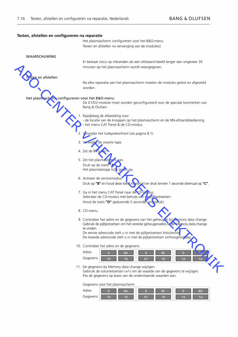
7.16
Testen, afstellen en confi gureren na reparatieHet plasmascherm confi gureren voor het B&O-menuTesten en afstellen na vervanging van de module(s)
WAARSCHUWINGEr bestaat risico op inbranden als een stilstaand beeld langer dan ongeveer 30 minuten op het plasmascherm wordt weergegeven.
Testen en afstellenNa elke reparatie aan het plasmascherm moeten de modules getest en afgesteld worden.
Het plasmascherm confi gureren voor het B&O-menuDe D1/D2-module moet worden geconfi gureerd voor de speciale kenmerken van Bang & Olufsen.
1. Raadpleeg de afbeelding voor:- de locatie van de knoppen op het plasmascherm en de NN-afstandsbediening.- het menu CAT Panel & de CD-modus.
2. Verwijder het luidsprekerfront (zie pagina 8.1).
3. Verwijder de zwarte tape.
4. Zet de BV5 aan.
5. Zet het plasmascherm aan. Druk op de toets "A". Het plasmalampje licht groen op.
6. Activeer de servicemodus. Druk op "B" en houd deze toets ingedrukt en druk binnen 1 seconde driemaal op "C".
7. Ga in het menu CAT Panel naar de CD-modus. Selecteer de CD-modus met behulp van de pijltjestoetsen. Houd de toets "D" gedurende 5 seconden ingedrukt.
8. CD-menu
9. Controleer het adres en de gegevens van het geheugen bij Memory data change.Gebruik de pijltjestoetsen om het vereiste geheugenadres in de Memory data change te vinden.De eerste adrescode stelt u in met de pijltjestoetsen links/rechts.De tweede adrescode stelt u in met de pijltjestoetsen omhoog/omlaag.
10. Controleer het adres en de gegevens.
Adres
Gegevens
11. De gegevens bij Memory data change wijzigen.Gebruik de volumetoetsen (+/-) om de waarde van de gegevens te wijzigen.Pas de gegevens op basis van de onderstaande waarden aan.
Gegevens voor het plasmascherm
Adres
Gegevens
Testen, afstellen en confi gureren na reparatie, Nederlands
0
10
8A
10
0
01
8C
10
0
1A
8D
1A
0
10
8A
10
0
01
8C
10
0
1A
8D
1A
ABO-CENTER v/HENRIKSENS ELEKTRONIK

7.17
12. Verlaat de servicemodus.Met de toets "R" verlaat u de CD-modus en gaat u terug naar het menu CAT Panel.Druk op de toets "C" om het menu CAT Panel te verlaten.
13. Bevestig de zwarte tape, het luidsprekerfront en de voorste ombouw.
Testen, afstellen en confi gureren na reparatie, Nederlands
BC
+
+_VOL
R
LEDR
ADOK
CAT Panel sys. 8.1
IIC Mode
CD Mode
SD Mode
ID Mode
CD
MiCom Software version
Memory data version
Memory data change Address
Data
1.43 OK
14.08 16.34
A0 8A
10 10
Te wijzigenadressenTe wijzigen gegevens
ABO-CENTER v/HENRIKSENS ELEKTRONIK
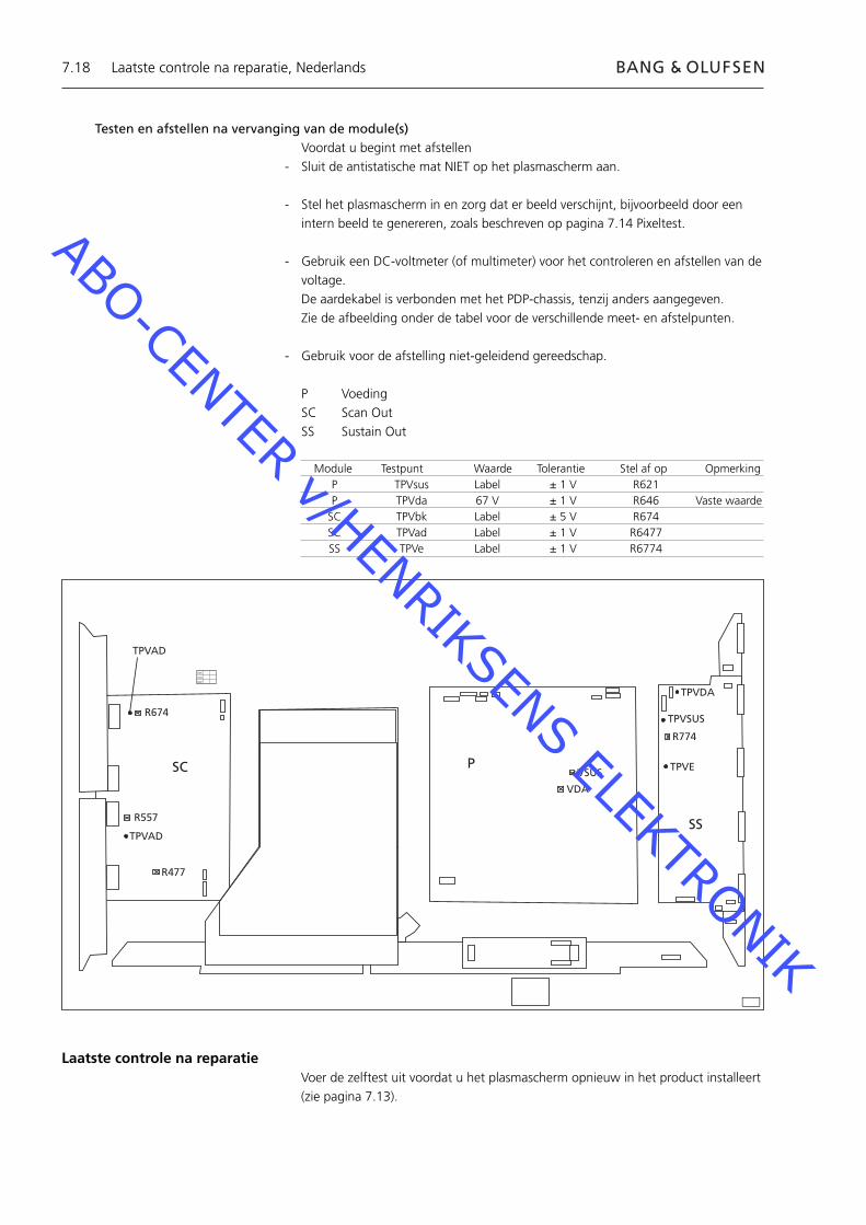
7.18
Testen en afstellen na vervanging van de module(s)Voordat u begint met afstellen
- Sluit de antistatische mat NIET op het plasmascherm aan.
- Stel het plasmascherm in en zorg dat er beeld verschijnt, bijvoorbeeld door een intern beeld te genereren, zoals beschreven op pagina 7.14 Pixeltest.
- Gebruik een DC-voltmeter (of multimeter) voor het controleren en afstellen van de voltage.
De aardekabel is verbonden met het PDP-chassis, tenzij anders aangegeven. Zie de afbeelding onder de tabel voor de verschillende meet- en afstelpunten.
- Gebruik voor de afstelling niet-geleidend gereedschap.
P VoedingSC Scan OutSS Sustain Out
R674
R557
R477
TPVAD
VSUS
VDA
TPVDA
TPVSUS
TPVE
R774
SC P
SS
XVC
VCX
CXV
TPVAD
Module Testpunt Waarde Tolerantie Stel af op Opmerking P TPVsus Label ± 1 V R621 P TPVda 67 V ± 1 V R646 Vaste waarde SC TPVbk Label ± 5 V R674 SC TPVad Label ± 1 V R6477 SS TPVe Label ± 1 V R6774
Laatste controle na reparatieVoer de zelftest uit voordat u het plasmascherm opnieuw in het product installeert (zie pagina 7.13).
Laatste controle na reparatie, Nederlands
ABO-CENTER v/HENRIKSENS ELEKTRONIK
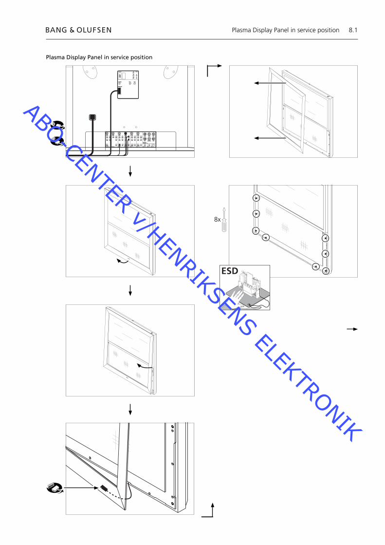
8.1
Plasma Display Panel in service position
8x
FRONT CENTRE FRONT
REAR SUBWOOFER REAR
SPEAKERS
CATVSTBSATV AUXDVDV TAPEREC OUT PROJ DATA
S-VIDEO
VIDEO RIGHT
COAX LEFT
CTRL CTRL CTRLCTRLCTRLCTRLCTRL
VIDEO RIGHT
COAX LEFT
VIDEO RIGHT
COAX LEFT
VIDEO RIGHT
COAX LEFT
VIDEO RIGHT
LEFT
VIDEO RIGHT
COAX LEFT
S-VIDEOS-VIDEOS-VIDEOS-VIDEOS-VIDEO
OPTICAL OPTICAL OPTICAL OPTICAL OPTICAL
PROJ. OUT
IR RECEIVER
MASTER LINK
RF IN A RF IN B
Y/G DTV IN
Pr/R H
Pb/B V
ESD
Plasma Display Panel in service position
ABO-CENTER v/HENRIKSENS ELEKTRONIK
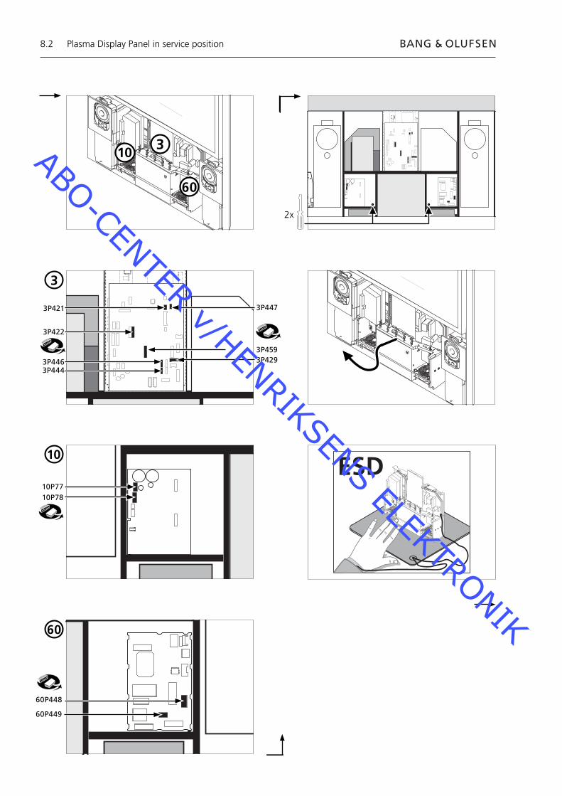
8.2
3P421
3P422
3P446 3P429
3P447
10P7710P78
60P448
60P449
2x
ESD
3P444
3
60
3
10
60
10
3P459
Plasma Display Panel in service position
ABO-CENTER v/HENRIKSENS ELEKTRONIK
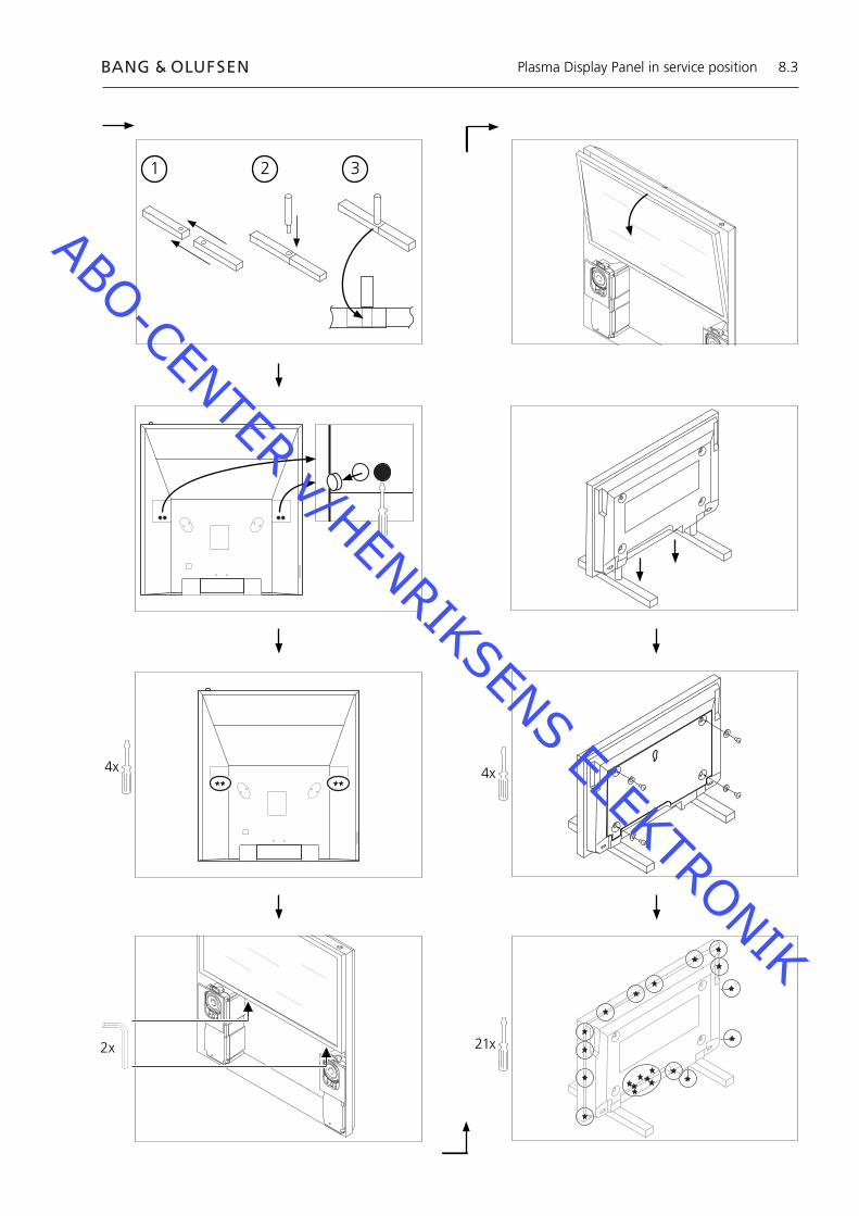
8.3
2x 21x
4x
1 2 3
4x
Plasma Display Panel in service position
ABO-CENTER v/HENRIKSENS ELEKTRONIK

8.4
2x
4x
Service position, page 8.1
Remove Main chassis
70mm
Remounting Plasma Display Panel
Remounting Plasma Display Panel
ABO-CENTER v/HENRIKSENS ELEKTRONIK
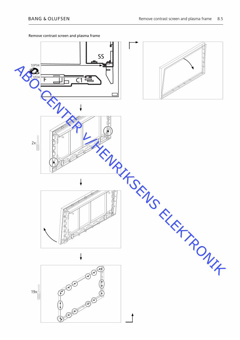
8.5
C1
SS
F
SSP34
C1P24
2x
19x
Remove contrast screen and plasma frame
Remove contrast screen and plasma frame
ABO-CENTER v/HENRIKSENS ELEKTRONIK
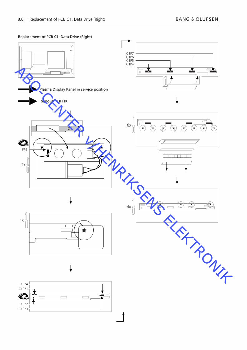
8.6
C1
Replacement of PCB C1, Data Drive (Right)
Plasma Display Panel in service position
Remove PCB HX
2x
FP9
C1P24
C1P21
C1P22
C1P23
1x
C1P7C1P6C1P5C1P4
8x
4x
C1
Replacement of PCB C1, Data Drive (Right)
ABO-CENTER v/HENRIKSENS ELEKTRONIK
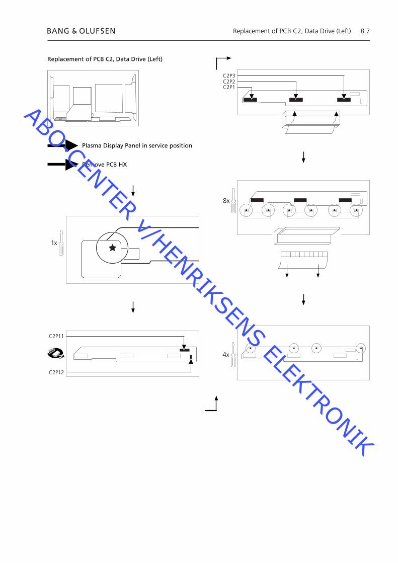
8.7
C2
Replacement of PCB C2, Data Drive (Left)
Plasma Display Panel in service position
Remove PCB HX
C2P11
C2P12
1x
C2P3C2P2C2P1
8x
4x
Replacement of PCB C2, Data Drive (Left)
ABO-CENTER v/HENRIKSENS ELEKTRONIK
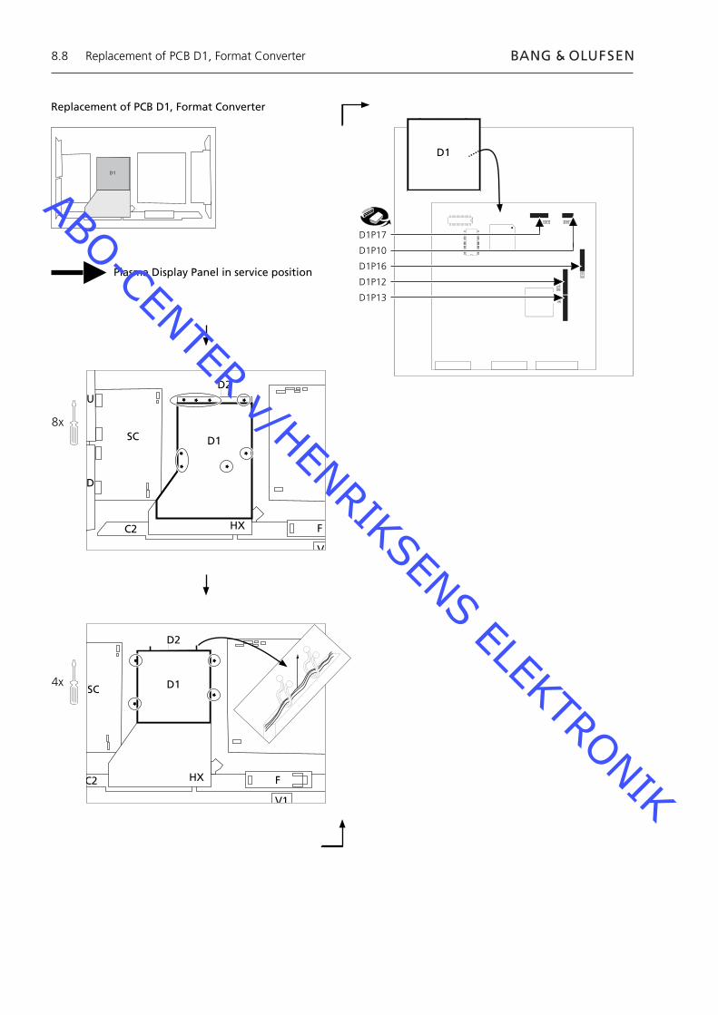
8.8
Replacement of PCB D1, Format Converter
8x
U
D
SC
C2
D2
D1
HX F
V
SC
C2
D2
D1D
HX F
V1
Plasma Display Panel in service position
D17 D10
D16
D12
D13
4x
D1P17
D1P10
D1P16
D1P12
D1P13
D1
D1
Replacement of PCB D1, Format Converter
ABO-CENTER v/HENRIKSENS ELEKTRONIK
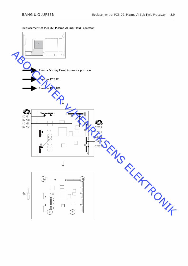
8.9
Replacement of PCB D2, Plasma AI Sub-FIeld Processor
Plasma Display Panel in service position
Remove PCB D1
Remove PCB HX
4x
D21
D20
D23
D22
D26
D29
D24
D25
D27
D32
D31
D2P21D2P20D2P23D2P22 D2P29
D2P31
D2P32
D2P25
D2P27
D21
D20
D23
D22
D26
D29
D24
D25
D27
D32
D31
D2
Replacement of PCB D2, Plasma AI Sub-Field Processor
ABO-CENTER v/HENRIKSENS ELEKTRONIK
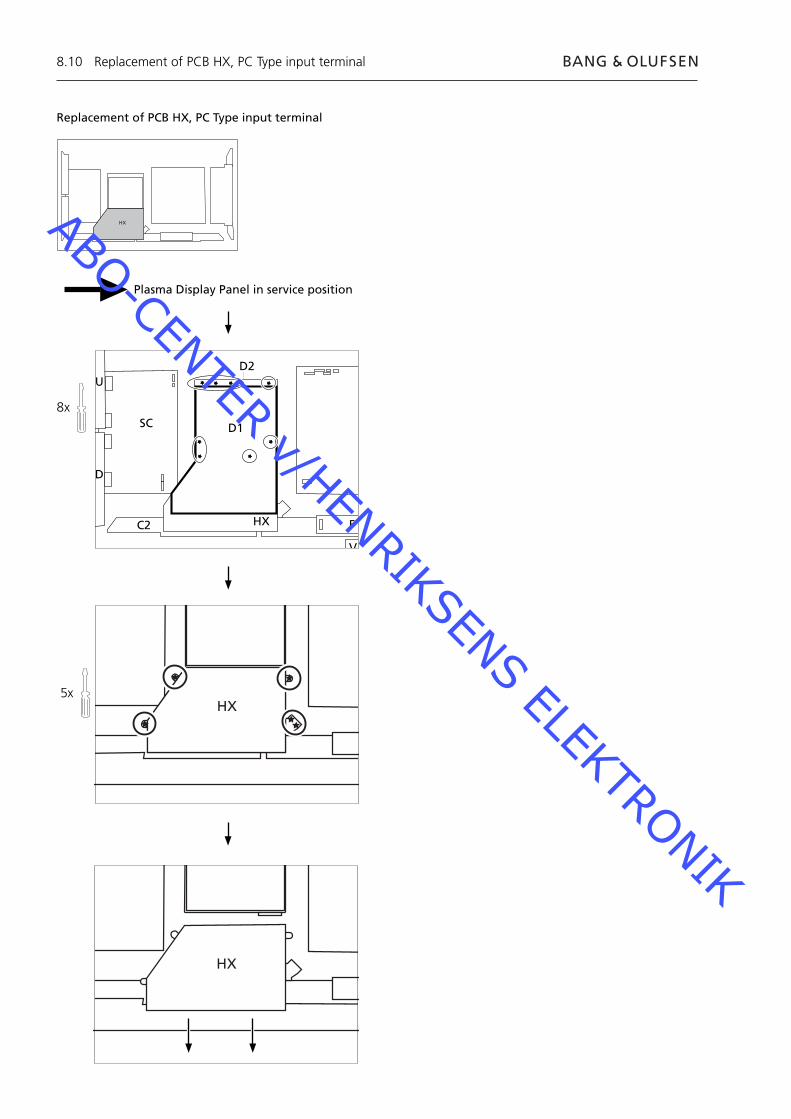
8.10
Replacement of PCB HX, PC Type input terminal
8x
U
D
SC
C2
D2
D1
HX F
V
Plasma Display Panel in service position
HX
5xHX
HX
Replacement of PCB HX, PC Type input terminal
ABO-CENTER v/HENRIKSENS ELEKTRONIK
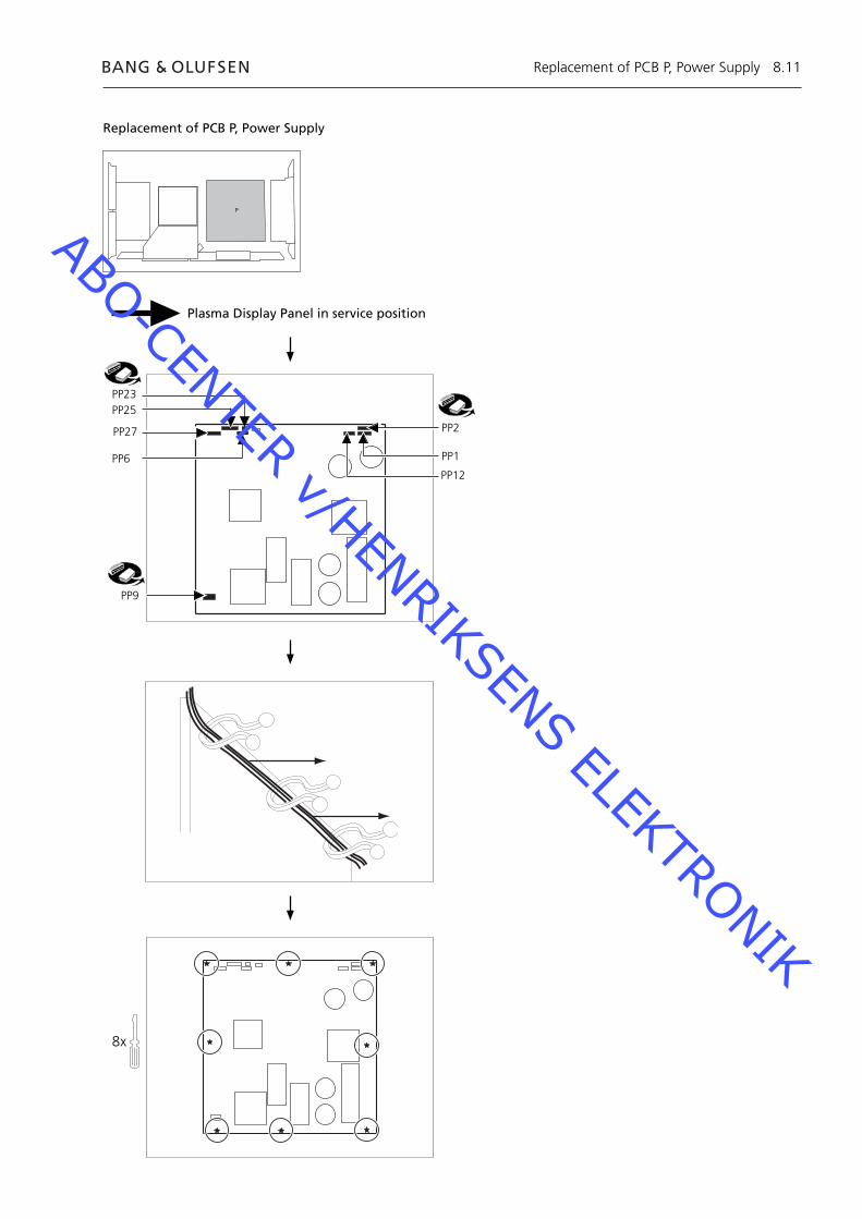
8.11
Replacement of PCB P, Power Supply
Plasma Display Panel in service position
P
PP23PP25
PP9
PP27
PP6 PP1
PP12
PP2
8x
Replacement of PCB P, Power Supply
ABO-CENTER v/HENRIKSENS ELEKTRONIK
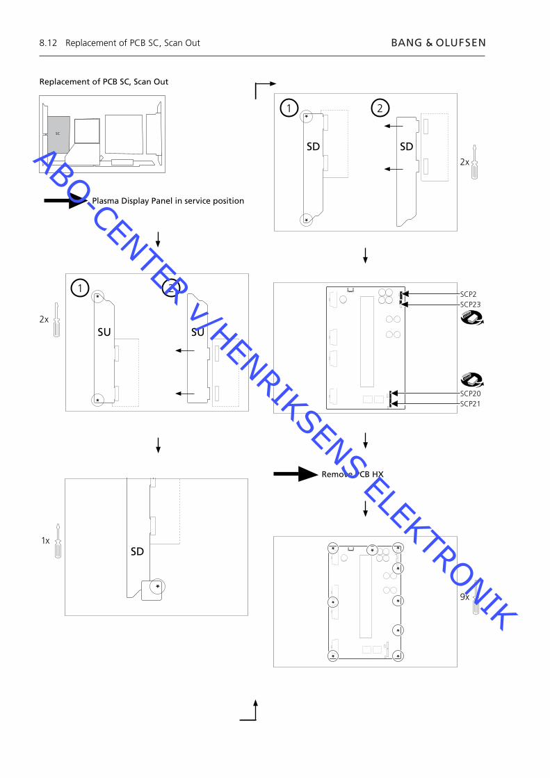
8.12
Replacement of PCB SC, Scan Out
Plasma Display Panel in service position
SC
1 2
2x
SU SU
1 2
1x
2x
SD SD
SCP2SCP23
SCP20SCP21
Remove PCB HX
9x
SD
Replacement of PCB SC, Scan Out
ABO-CENTER v/HENRIKSENS ELEKTRONIK
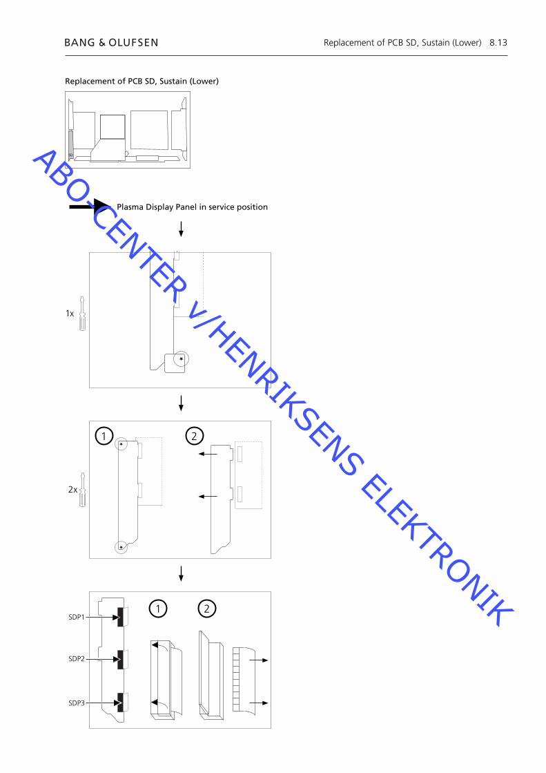
8.13
Replacement of PCB SD, Sustain (Lower)
Plasma Display Panel in service position
1 2
SDP1
SDP2
SDP3
1 2
2x
SD
1x
Replacement of PCB SD, Sustain (Lower)
ABO-CENTER v/HENRIKSENS ELEKTRONIK
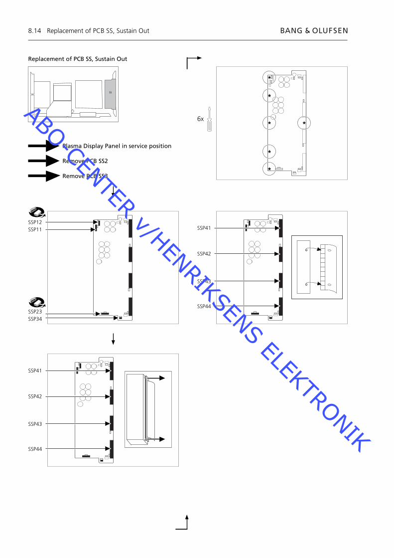
8.14
Replacement of PCB SS, Sustain Out
Plasma Display Panel in service position
Remove PCB SS2
Remove PCB SS3
SSP12SSP11
SSP23SSP34
6x
SS
SSP41
SSP42
SSP43
SSP44
SSP41
SSP42
SSP43
SSP44
Replacement of PCB SS, Sustain Out
ABO-CENTER v/HENRIKSENS ELEKTRONIK
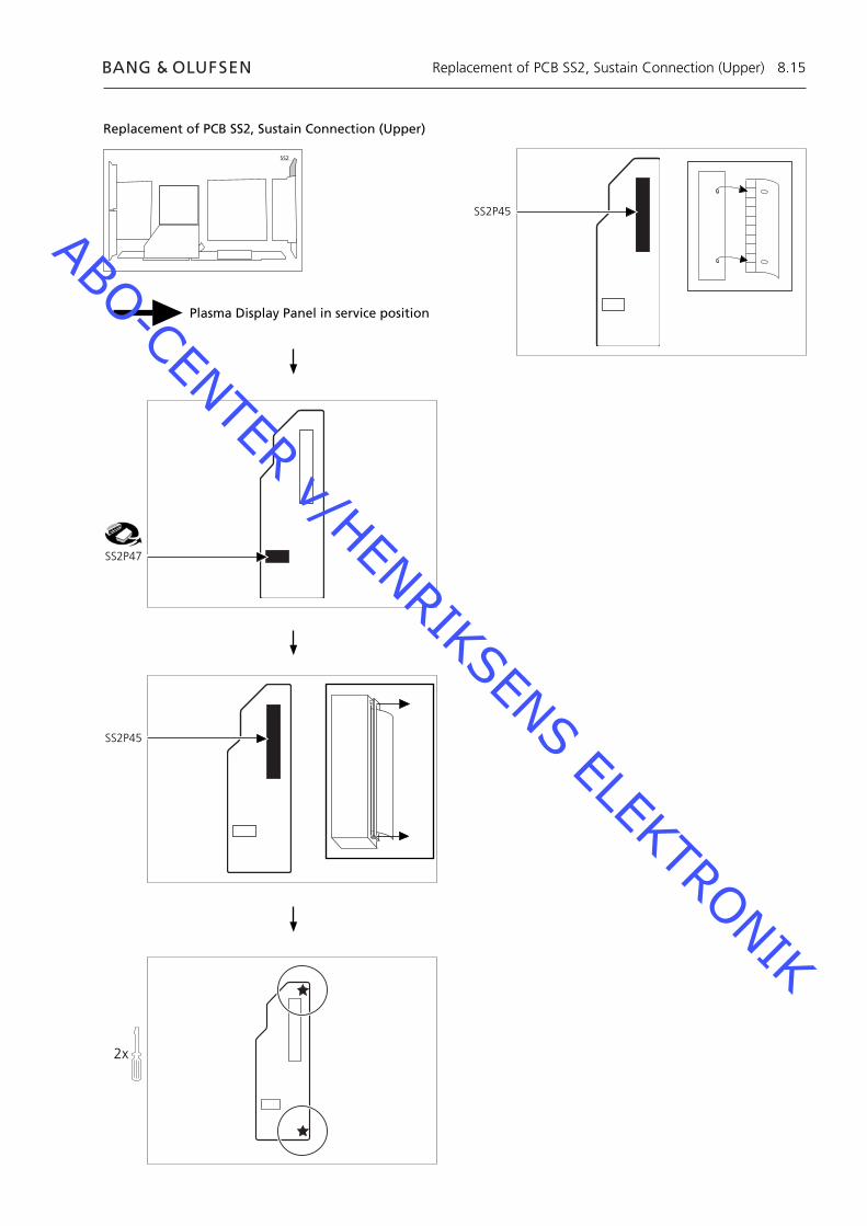
8.15
Replacement of PCB SS2, Sustain Connection (Upper)
Plasma Display Panel in service position
SS2
SS2P47
SS2P45
2x
SS2P45
Replacement of PCB SS2, Sustain Connection (Upper)
ABO-CENTER v/HENRIKSENS ELEKTRONIK
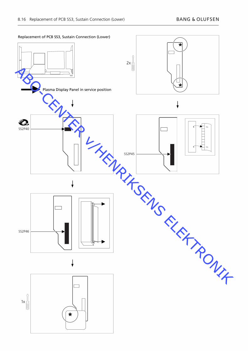
8.16
Replacement of PCB SS3, Sustain Connection (Lower)
Plasma Display Panel in service position
SS3
SS2P40
SS2P46
2x
SS2P45
1x
Replacement of PCB SS3, Sustain Connection (Lower)
ABO-CENTER v/HENRIKSENS ELEKTRONIK
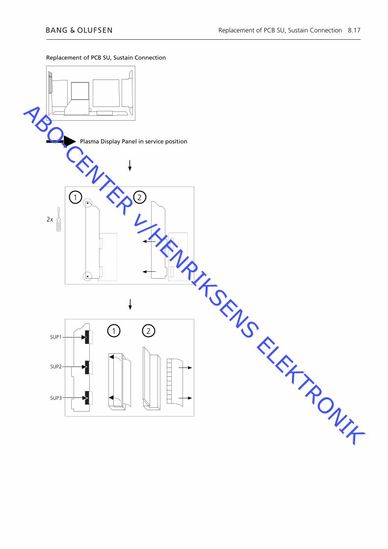
8.17
Replacement of PCB SU, Sustain Connection
Plasma Display Panel in service position
1 2
SUP1
SUP2
SUP3
1 2
2x
SU
Replacement of PCB SU, Sustain Connection
ABO-CENTER v/HENRIKSENS ELEKTRONIK
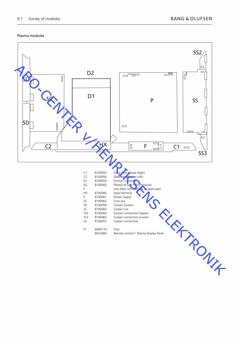
Survey of modules9.1
Plasma modules
C1 8100055 Data drive (Lower Right)C2 8100056 Data drive (Lower Left)D1 8100059 Format ConverterD2 8100060 Plasma AI Sub-Field ProcessorF Line fi lter, not available as spare partHX 8100066 Input terminalP 8100061 Power SupplySC 8100062 Scan outSD 8100058 Sustain (Lower)SS 8100063 Sustain outSS2 8100064 Sustain connection (Upper)SS3 8100065 Sustain connection (Lower)SU 8100057 Sustain connection
F1 6600174 Fuse 8053460 Remote control f. Plasma Display Panel
SU
SD
SC
C2
P
HX F C1
SS
SS3
SS2
D2
D1
ABO-CENTER v/HENRIKSENS ELEKTRONIK
ABO-CENTER v/HENRIKSENS ELEKTRONIK
Bang & OlufsenDK-7600 StruerDenmark
Phone +45 96 84 11 22*Fax +45 97 85 39 11
08-03 / 3543388
ABO-CENTER v/HENRIKSENS ELEKTRONIK
Related Documents


![Pioneer 5g Pdp Plasma Tv Training Manual [ET]](https://static.cupdf.com/doc/110x72/54ff9c444a79598f128b49a9/pioneer-5g-pdp-plasma-tv-training-manual-et.jpg)