Belgacom Mobile Page 1 of 8 1999 Feb - 02 NEN Access Features Martin Hocking Gerdy Seynaeve NEN Access Features NOK_HO_PC_course 1999 Feb 11 Course document (V 4.1) Nokia handover, power control and channel allocation Summary The goal of this document is to describe some of the Nokia system features concerning handover, power control and channel allocation

Nokiaho&Pc
Dec 28, 2015
Handover , Powercontrol
Welcome message from author
This document is posted to help you gain knowledge. Please leave a comment to let me know what you think about it! Share it to your friends and learn new things together.
Transcript
Belgacom Mobile Page 1 of 8 1999 Feb - 02 NEN Access Features Martin Hocking
Gerdy Seynaeve
NEN Access Features NOK_HO_PC_course
1999 Feb 11
Course document (V 4.1)
Nokia handover, power control
and channel allocation
Summary
The goal of this document is to describe some of the Nokia system features concerning handover, power control and channel allocation
Belgacom Mobile Page 2 of 8 1999 Feb - 02 NEN Access Features Martin Hocking
Gerdy Seynaeve
Contents
PART I Introduction
PART II The Mobile
1. Measurements made by the mobile 7
1.1. quality 7
1.2. Level 7
1.3. Dtx 7
1.4. Radio link supervision. 8
2. Handovers and BSIC Decoding 8
2.1. BSIC = Base Station Identity Code 8
2.2. System information messages 8
2.3. Dual BA list 9
2.4. BSIC decoding 9
PART III BTS functionality
1. Measurement reporting by the BTS 14
2. Idle interference measurement 16
2.1. Measuring uplink idle interference when the TCH is idle 16
2.2. Measuring uplink idle interference when the TCH is active 16
3. Timing advance 16
4. MS Speed measurement 17
5. BTS pre-processing 17
6. Radio link supervision 17
PART IV BSC functionality
1. Averaging of measurements 19
1.1. Averaging serving cell measurements 19
1.1.1. General 19
1.1.2. Fast averaging 19
1.1.3. Quality averaging 20
1.1.4. Level averaging without power control 20
1.1.5. Level averaging with power control 20
1.2. Averaging of neighbour cell levels 21
1.3. MS Speed averaging 22
1.4. Variable window size 23
Belgacom Mobile Page 3 of 8 1999 Feb - 02 NEN Access Features Martin Hocking
Gerdy Seynaeve
1.5. DTx usage 23
1.6. Missing measurements 25
1.7. Threshold comparison - N & P voting 26
2. The Power Control Algorithm 27
2.1. General 27
2.2. Uplink power control 28
2.2.1. Ms power increase due to level 29
2.2.2. Ms power increase due to quality 32
2.2.3. Ms power decrease due to level 34
2.2.4. Ms power decrease due to quality 34
2.3. Downlink power control 39
2.3.1. BTS power increase due to level 40
2.3.2. BTS power increase due to quality 40
2.3.3. BTS power decrease due to level 42
2.3.4. BTS power decrease due to quality 42
2.4. Power control performance indicators 44
3. The handover algorithm 44
3.1. HO types 44
3.1.1. Intracell - intra BSC - inter BSC 44
3.1.2. non-synchronised vs. synchronised 46
3.1.3. Different HO reasons 46
3.2. Overview 47
3.3. Handovers for normal radio conditions 48
3.3.1. General 48
3.3.2. Power budget handover 48
3.3.3. Level handover 51
3.3.4. Quality handover 52
3.3.5. Interference handover 52
3.4. Traffic reason handovers 54
3.4.1. Umbrella handover 54
3.4.2. MS speed handover : measured / in relation to cell size 55
3.4.3. Relation between Umbrella and MS speed handover 57
3.4.4. Traffic handover 58
3.4.5. Directed retry 58
3.4.6. Enhancements on the directed retry procedure
with BSS SW rel S7 60
Belgacom Mobile Page 4 of 8 1999 Feb - 02 NEN Access Features Martin Hocking
Gerdy Seynaeve
3.5. Other HO reasons 61
3.5.1. Rapid field drop 61
3.5.2. Enhanced rapid field drop (HO due to
turn around corner MS) BSS release S7 61
3.5.3. MS distance 61
3.5.4. Administration request to empty cell 62
3.6. HO prevention timers 63
3.6.1. Time interval between successive handover attempts 63
3.6.2. Guard period after HO failure 63
3.6.3. Guard time before handback 64
3.7. Handover priority 65
3.7.1. Handover type selection 65
3.7.2. HO priority based on load 67
3.7.3. Example for a power budget handover 67
3.7.4. Reordering of priorities due to C/I
based handover candidate evaluation 68
3.8. Handover reselection 71
3.9. Handover queuing 77
3.10. Handover performance indicators 80
3.11. Optimisation of MS power in HO 87
3.11.1. Intercell handovers within the same BSC 87
3.11.2. Intracell handovers 87
3.12. HO optimisation 89
3.12.1. 90
3.12.2. PBGT HO margins 90
3.12.3. Level handovers 93
3.12.4. Small HO lists 93
3.12.5. Finding missing neighbours 94
3.12.6. Drive arounds and statistics 94
3.12.7. Special Handovers 94
3.13. HO timing 95
3.13.1. Source cell 97
3.13.2. Target cell 97
4. Interworking between HO and PC 99
5. The channel allocation algorithm 100
5.1. Interference band calculation 100
Belgacom Mobile Page 5 of 8 1999 Feb - 02 NEN Access Features Martin Hocking
Gerdy Seynaeve
5.1.1. Interference band selection based on Ms Power 100
5.1.2. Interference band recommendation 101
5.2. Interference channel selection procedures 106
5.2.1. Channel selection when BSC
interference requirement is present 106
5.2.2. Channel selection when MSC
interference requirement is present 106
5.2.3. Channel selection when no interference
requirement is present 106
5.3. TCH selection 107
5.3.1. Basic channel search 107
5.3.2. Channel search in a busy cell 107
5.3.3. Packing of TCHs 109
5.3.4. TRX prioritisation in TCH allocation 110
5.3.5. TCH allocation in intracell handover (non super reuse) 110
5.3.6. TCH allocation in intracell handover, regular to super reuse 110
APPENDIX - Default parameter settings
1. Radio link supervision 112
2. BTS pre-processing 112
3. Idle interference 112
4. HO related parameters 113
5. PC related parameters 116
6. Other parameters 118
Belgacom Mobile Page 6 of 8 1999 Feb - 02 NEN Access Features Martin Hocking
Gerdy Seynaeve
PART 1 : Introduction____________________________
The goal of this document is to describe some of the Nokia system features concerning handover, power control and channel allocation algorithms with all their related subjects. It is correct to our best knowledge for the BSS S7 release, but may differ from the actual working due to interpretation of the Nokia functional description manuals which are not clear on all subjects. This is a training only document. The document contains a number of features that are described in detail. Before these features can be used, there has to be a First Office Application and guidelines have to be developed by the NEN department in co-operation with the regional department. All the related parameters can therefore not be altered before the above step is finished.
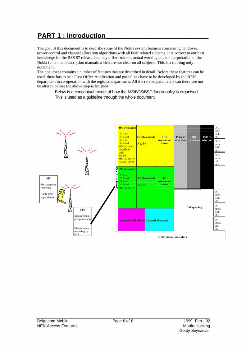
Below is a conceptual model of how the MS/BTS/BSC functionality is organised. This is used as a guideline through the whole document.
HO averaging
UL LevUL QualDL LevDL QualMS DistanceNeighbourcellsSpeedMS/BS powerUL/DL interf
HO thresholds
Nx, Px
HOprevention
timers
Priorityof actions
HOpriorities
Cell re-selection
O/GinterBSCHO
BTS
Measurementpre-processing
Measurementreporting byBTS
MS
Measurementreporting
Radio linksupervision
PC averaging
UL LevUL QualDL LevDL QualMS/BS power
PC thresholds
Nx, Px
PCprevention
timers
Optimised MS Power Channel allocation
Call queuing
O/GintraBSCHO
O/GintracellHO
I/C intracellHO
I/C intraBSCHO
I/CinterBSCHO
Performance indicators
Belgacom Mobile Page 7 of 8 1999 Feb - 02 NEN Access Features Martin Hocking
Gerdy Seynaeve
PART 2 : The mobile_____________________________
1. Measurements made by the mobile
1.1. quality
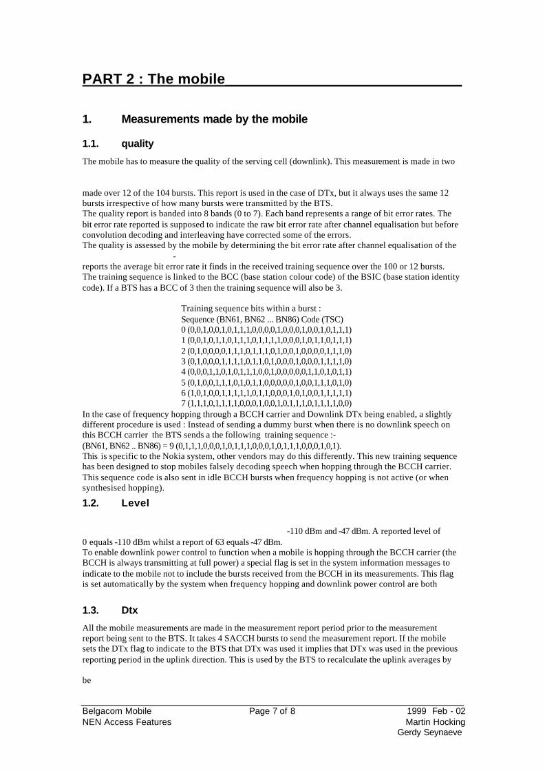
The mobile has to measure the quality of the serving cell (downlink). This measurement is made in two
made over 12 of the 104 bursts. This report is used in the case of DTx, but it always uses the same 12 bursts irrespective of how many bursts were transmitted by the BTS. The quality report is banded into 8 bands (0 to 7). Each band represents a range of bit error rates. The bit error rate reported is supposed to indicate the raw bit error rate after channel equalisation but before convolution decoding and interleaving have corrected some of the errors. The quality is assessed by the mobile by determining the bit error rate after channel equalisation of the
-reports the average bit error rate it finds in the received training sequence over the 100 or 12 bursts. The training sequence is linked to the BCC (base station colour code) of the BSIC (base station identity code). If a BTS has a BCC of 3 then the training sequence will also be 3.
Training sequence bits within a burst : Sequence (BN61, BN62 ... BN86) Code (TSC) 0 (0,0,1,0,0,1,0,1,1,1,0,0,0,0,1,0,0,0,1,0,0,1,0,1,1,1) 1 (0,0,1,0,1,1,0,1,1,1,0,1,1,1,1,0,0,0,1,0,1,1,0,1,1,1) 2 (0,1,0,0,0,0,1,1,1,0,1,1,1,0,1,0,0,1,0,0,0,0,1,1,1,0) 3 (0,1,0,0,0,1,1,1,1,0,1,1,0,1,0,0,0,1,0,0,0,1,1,1,1,0) 4 (0,0,0,1,1,0,1,0,1,1,1,0,0,1,0,0,0,0,0,1,1,0,1,0,1,1) 5 (0,1,0,0,1,1,1,0,1,0,1,1,0,0,0,0,0,1,0,0,1,1,1,0,1,0) 6 (1,0,1,0,0,1,1,1,1,1,0,1,1,0,0,0,1,0,1,0,0,1,1,1,1,1) 7 (1,1,1,0,1,1,1,1,0,0,0,1,0,0,1,0,1,1,1,0,1,1,1,1,0,0)
In the case of frequency hopping through a BCCH carrier and Downlink DTx being enabled, a slightly different procedure is used : Instead of sending a dummy burst when there is no downlink speech on this BCCH carrier the BTS sends a the following training sequence :- (BN61, BN62 .. BN86) = 9 (0,1,1,1,0,0,0,1,0,1,1,1,0,0,0,1,0,1,1,1,0,0,0,1,0,1). This is specific to the Nokia system, other vendors may do this differently. This new training sequence has been designed to stop mobiles falsely decoding speech when hopping through the BCCH carrier. This sequence code is also sent in idle BCCH bursts when frequency hopping is not active (or when synthesised hopping).
1.2. Level
-110 dBm and -47 dBm. A reported level of 0 equals -110 dBm whilst a report of 63 equals -47 dBm. To enable downlink power control to function when a mobile is hopping through the BCCH carrier (the BCCH is always transmitting at full power) a special flag is set in the system information messages to indicate to the mobile not to include the bursts received from the BCCH in its measurements. This flag is set automatically by the system when frequency hopping and downlink power control are both
1.3. Dtx
All the mobile measurements are made in the measurement report period prior to the measurement report being sent to the BTS. It takes 4 SACCH bursts to send the measurement report. If the mobile sets the DTx flag to indicate to the BTS that DTx was used it implies that DTx was used in the previous reporting period in the uplink direction. This is used by the BTS to recalculate the uplink averages by
be
Belgacom Mobile Page 8 of 8 1999 Feb - 02 NEN Access Features Martin Hocking
Gerdy Seynaeve
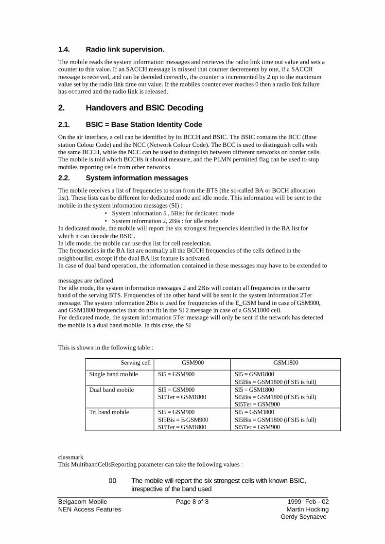
1.4. Radio link supervision.
The mobile reads the system information messages and retrieves the radio link time out value and sets a counter to this value. If an SACCH message is missed that counter decrements by one, if a SACCH message is received, and can be decoded correctly, the counter is incremented by 2 up to the maximum value set by the radio link time out value. If the mobiles counter ever reaches 0 then a radio link failure has occurred and the radio link is released.
2. Handovers and BSIC Decoding
2.1. BSIC = Base Station Identity Code
On the air interface, a cell can be identified by its BCCH and BSIC. The BSIC contains the BCC (Base station Colour Code) and the NCC (Network Colour Code). The BCC is used to distinguish cells with the same BCCH, while the NCC can be used to distinguish between different networks on border cells. The mobile is told which BCCHs it should measure, and the PLMN permitted flag can be used to stop mobiles reporting cells from other networks.
2.2. System information messages
The mobile receives a list of frequencies to scan from the BTS (the so-called BA or BCCH allocation list). These lists can be different for dedicated mode and idle mode. This information will be sent to the mobile in the system information messages (SI) :
• System information 5 , 5Bis: for dedicated mode • System information 2, 2Bis : for idle mode
In dedicated mode, the mobile will report the six strongest frequencies identified in the BA list for which it can decode the BSIC. In idle mode, the mobile can use this list for cell reselection. The frequencies in the BA list are normally all the BCCH frequencies of the cells defined in the neighbourlist, except if the dual BA list feature is activated. In case of dual band operation, the information contained in these messages may have to be extended to
messages are defined. For idle mode, the system information messages 2 and 2Bis will contain all frequencies in the same band of the serving BTS. Frequencies of the other band will be sent in the system information 2Ter message. The system information 2Bis is used for frequencies of the E_GSM band in case of GSM900, and GSM1800 frequencies that do not fit in the SI 2 message in case of a GSM1800 cell. For dedicated mode, the system information 5Ter message will only be sent if the network has detected the mobile is a dual band mobile. In this case, the SI
This is shown in the following table :
Serving cell GSM900 GSM1800
Single band mo bile SI5 = GSM900 SI5 = GSM1800 SI5Bis = GSM1800 (if SI5 is full)
Dual band mobile SI5 = GSM900 SI5Ter = GSM1800
SI5 = GSM1800 SI5Bis = GSM1800 (if SI5 is full) SI5Ter = GSM900
Tri band mobile SI5 = GSM900 SI5Bis = E-GSM900 SI5Ter = GSM1800
SI5 = GSM1800 SI5Bis = GSM1800 (if SI5 is full) SI5Ter = GSM900
classmark This MultibandCellsReporting parameter can take the following values :
00 The mobile will report the six strongest cells with known BSIC, irrespective of the band used
Belgacom Mobile Page 9 of 9 1999 Feb - 02 NEN Access Features Martin Hocking
Gerdy Seynaeve
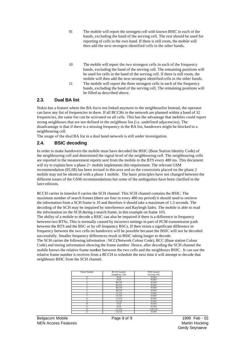
01 The mobile will report the strongest cell with known BSIC in each of the bands, excluding the band of the serving cell. The rest should be used for reporting of cells in the own band. If there is still room, the mobile will then add the next strongest identified cells in the other bands.
10 The mobile will report the two strongest cells in each of the frequency bands, excluding the band of the serving cell. The remaining positions will be used for cells in the band of the serving cell. If there is still room, the mobile will then add the next strongest identified cells in the other bands.
11 The mobile will report the three strongest cells in each of the frequency bands, excluding the band of the serving cell. The remaining positions will be filled as described above.
2.3. Dual BA list
Nokia has a feature where the BA list is not linked anymore to the neighbourlist Instead, the operator can have any list of frequencies in there. If all BCCHs in the network are planned within a band of 32 frequencies, the same list can be activated on all cells. This has the advantage that mobiles could report strong neighbours that are not defined in the neighbour list (i.e. undefined adjacencies). The disadvantage is that if there is a missing frequency in the BA list, handovers might be blocked to a neighbouring cell. The usage of the dual BA list in a dual band network is still under investigation.
2.4. BSIC decoding
In order to make handovers the mobile must have decoded the BSIC (Base Station Identity Code) of the neighbouring cell and determined the signal level of the neighbouring cell. The neighbouring cells are reported in the measurement reports sent from the mobile to the BTS every 480 ms. This document will try to explain how a phase 2+ mobile implements this requirement. The relevant GSM recommendation (05.08) has been revised in this area and so the constraints placed on the phase 2 mobile may not be identical with a phase 1 mobile. The basic principles have not changed between the different issues of the GSM recommendations but some of the ambiguities have been clarified in the later editions.
BCCH carrier in timeslot 0 carries the SCH channel. This SCH channel contains the BSIC. The maximum number of search frames (there are four in every 480 ms period) it should need to retrieve the information from a SCH frame is 10 and therefore it should take a maximum of 1.5 seconds. The decoding of the SCH may be impaired by interference and Rayleigh fades. The mobile is able to read the information on the SCH during a search frame, in this example on frame 103. The ability of a mobile to decode a BSIC can also be impaired if there is a difference in frequency between two BTSs. This is normally caused by incorrect settings in part of PCM transmission path between the BTS and the BSC or by off frequency BSCs. If their exists a significant difference in frequency between the two cells no handovers will be possible because the BSIC will not be decoded successfully. Smaller frequency differences result in BSIC taking longer to decode. The SCH carries the following information : NCC(Network Colour Code), BCC (Base station Colour Code) and timing information showing the frame number. Hence, after decoding the SCH channel the mobile knows the relative frame number between the two cells and the neighbours BSIC. It can use the relative frame number it receives from a BCCH to schedule the next time it will attempt to decode that neighbours BSIC from the SCH channel.
Frame Number BCCH channel (neighbour cell)
TCH channel (serving cell)
0 FCH TCH/F 1 SCH TCH/F 2 BCCH TCH/F 3 BCCH TCH/F 4 BCCH TCH/F 5 BCCH TCH/F 6 CCCH TCH/F 7 CCCH TCH/F 8 CCCH TCH/F 9 CCCH TCH/F
10 FCH TCH/F 11 SCH TCH/F 12 CCCH SACCH 13 CCCH TCH/F
Belgacom Mobile Page 10 of 10 1999 Feb - 02 NEN Access Features Martin Hocking
Gerdy Seynaeve
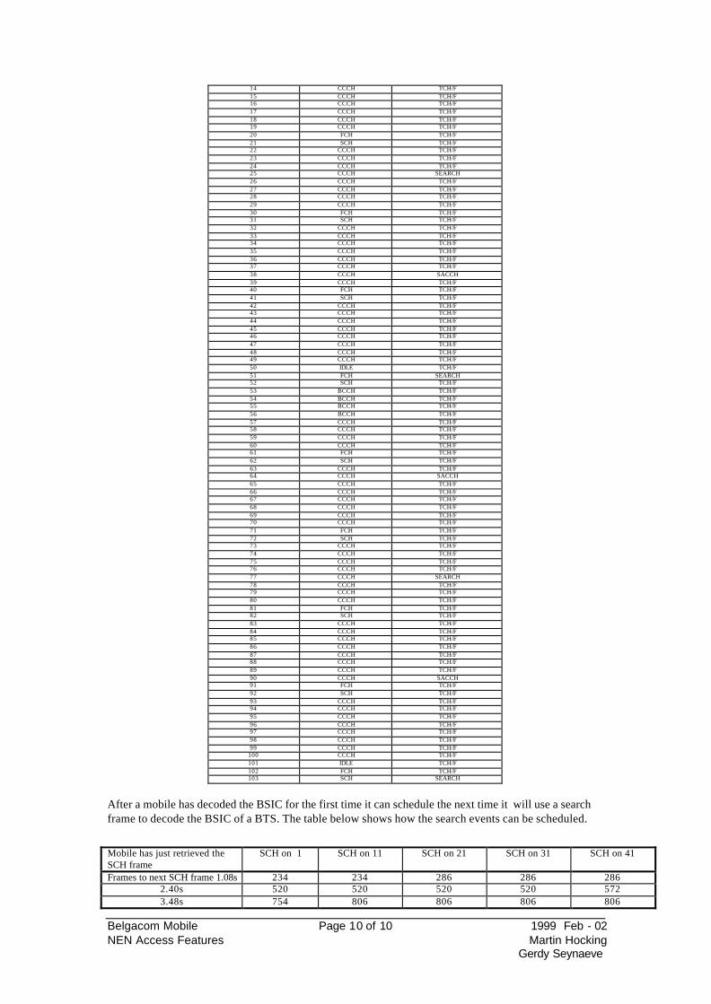
14 CCCH TCH/F 15 CCCH TCH/F 16 CCCH TCH/F 17 CCCH TCH/F 18 CCCH TCH/F 19 CCCH TCH/F 20 FCH TCH/F 21 SCH TCH/F 22 CCCH TCH/F 23 CCCH TCH/F 24 CCCH TCH/F 25 CCCH SEARCH 26 CCCH TCH/F 27 CCCH TCH/F 28 CCCH TCH/F 29 CCCH TCH/F 30 FCH TCH/F 31 SCH TCH/F 32 CCCH TCH/F 33 CCCH TCH/F 34 CCCH TCH/F 35 CCCH TCH/F 36 CCCH TCH/F 37 CCCH TCH/F 38 CCCH SACCH 39 CCCH TCH/F 40 FCH TCH/F 41 SCH TCH/F 42 CCCH TCH/F 43 CCCH TCH/F 44 CCCH TCH/F 45 CCCH TCH/F 46 CCCH TCH/F 47 CCCH TCH/F 48 CCCH TCH/F 49 CCCH TCH/F 50 IDLE TCH/F 51 FCH SEARCH 52 SCH TCH/F 53 BCCH TCH/F 54 BCCH TCH/F 55 BCCH TCH/F 56 BCCH TCH/F 57 CCCH TCH/F 58 CCCH TCH/F 59 CCCH TCH/F 60 CCCH TCH/F 61 FCH TCH/F 62 SCH TCH/F 63 CCCH TCH/F 64 CCCH SACCH 65 CCCH TCH/F 66 CCCH TCH/F 67 CCCH TCH/F 68 CCCH TCH/F 69 CCCH TCH/F 70 CCCH TCH/F 71 FCH TCH/F 72 SCH TCH/F 73 CCCH TCH/F 74 CCCH TCH/F 75 CCCH TCH/F 76 CCCH TCH/F 77 CCCH SEARCH 78 CCCH TCH/F 79 CCCH TCH/F 80 CCCH TCH/F 81 FCH TCH/F 82 SCH TCH/F 83 CCCH TCH/F 84 CCCH TCH/F 85 CCCH TCH/F 86 CCCH TCH/F 87 CCCH TCH/F 88 CCCH TCH/F 89 CCCH TCH/F 90 CCCH SACCH 91 FCH TCH/F 92 SCH TCH/F 93 CCCH TCH/F 94 CCCH TCH/F 95 CCCH TCH/F 96 CCCH TCH/F 97 CCCH TCH/F 98 CCCH TCH/F 99 CCCH TCH/F
100 CCCH TCH/F 101 IDLE TCH/F 102 FCH TCH/F 103 SCH SEARCH
After a mobile has decoded the BSIC for the first time it can schedule the next time it will use a search frame to decode the BSIC of a BTS. The table below shows how the search events can be scheduled. Mobile has just retrieved the SCH frame
SCH on 1 SCH on 11 SCH on 21 SCH on 31 SCH on 41
Frames to next SCH frame 1.08s 234 234 286 286 286 2.40s 520 520 520 520 572 3.48s 754 806 806 806 806
Belgacom Mobile Page 11 of 11 1999 Feb - 02 NEN Access Features Martin Hocking
Gerdy Seynaeve
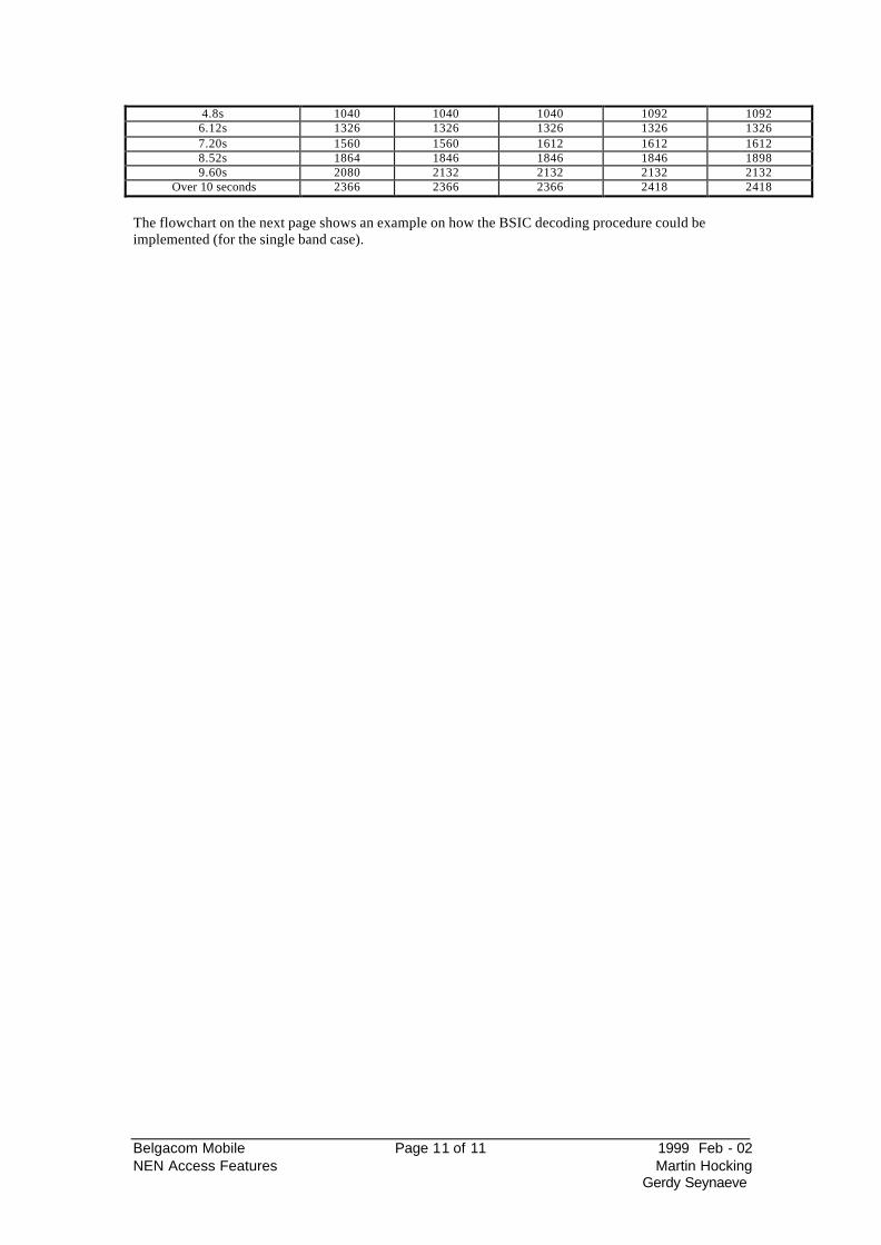
4.8s 1040 1040 1040 1092 1092 6.12s 1326 1326 1326 1326 1326 7.20s 1560 1560 1612 1612 1612 8.52s 1864 1846 1846 1846 1898 9.60s 2080 2132 2132 2132 2132
Over 10 seconds 2366 2366 2366 2418 2418
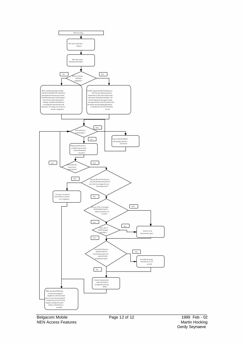
The flowchart on the next page shows an example on how the BSIC decoding procedure could be implemented (for the single band case).
Belgacom Mobile Page 12 of 12 1999 Feb - 02 NEN Access Features Martin Hocking
Gerdy Seynaeve
BSIC decoding
MS arrives on the new
Channel.
MS arrived fromimmediate
assignment ?
MS reads systeminformation message 5
MS re- calculates the relative timimgof all the decoded BCCH's frequencies
that appeared in the previous systeminfomation message 5 and also appear
in this TCH's system information 5message. Using this information to
re-schedule the retrival of the SCHinformation. No change neccessary for
channel assignment
The MS compares the BCCH frequenicesthat it has decoded using system
information 2 (idle ) and compares thiswith system information message 5. All
BCCH frequencies that appear in bothmessages and have been decoded (SCH)
the mobile uses this timimg informationto schedule the next SCH decoding
period.
Is the mobile on
a search frame ?
Measure the RX level of
an ARFCN given in thesystem information
message 5.
Is this frame the
start of a newreport period ?
Has any BCCH which has notbeen decoded been measured as
one of the six strongest for tworeporting periods ?
Is any BCCH that wasreported in the last
measurement report notreported in this
measurement report.
Has any of the six strongestBCCH failed to have its
BSIC decoded for 10seconds ?
Construct measurementreport showing six
strongest BCCH's andBSIC's
Have any ofBCCH changed
their BSIC ?
Save BSIC & timinginformation for 10
seconds
Remove from
measurement report
Make sure that all BSICs that
are still in the strongest 6neighbours will be decoded
before 10 seconds has elapsed.Using the known SCH Frame
timing to schedule the searchframes as effectibvely as
possiable
Use upto 5 seconds ofsearch frames to decode
new neighbour.
NO
Tune to a BCCH ARFCN
and attempt to decode aSCH frame
YES
YES
YES
YES
YES
YES
YES
NO
NO
NO
NO
NO
NO
Belgacom Mobile Page 13 of 13 1999 Feb - 02 NEN Access Features Martin Hocking
Gerdy Seynaeve
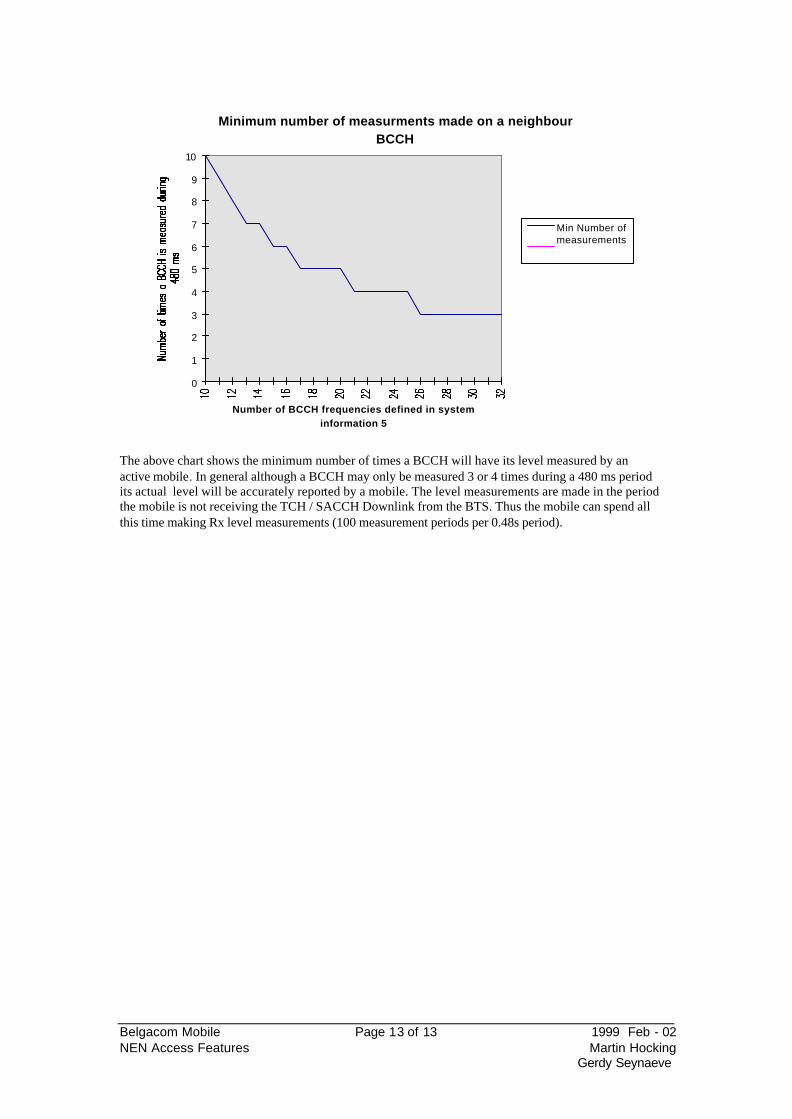
Minimum number of measurments made on a neighbour BCCH
0
1
2
3
4
5
6
7
8
9
10
Number of BCCH frequencies defined in system information 5
Min Number ofmeasurements
The above chart shows the minimum number of times a BCCH will have its level measured by an active mobile . In general although a BCCH may only be measured 3 or 4 times during a 480 ms period its actual level will be accurately reported by a mobile. The level measurements are made in the period the mobile is not receiving the TCH / SACCH Downlink from the BTS. Thus the mobile can spend all this time making Rx level measurements (100 measurement periods per 0.48s period).
Belgacom Mobile Page 14 of 14 1999 Feb - 02 NEN Access Features Martin Hocking
Gerdy Seynaeve
PART 3 : BTS functionality_______________________
1. Measurement reporting by the BTS
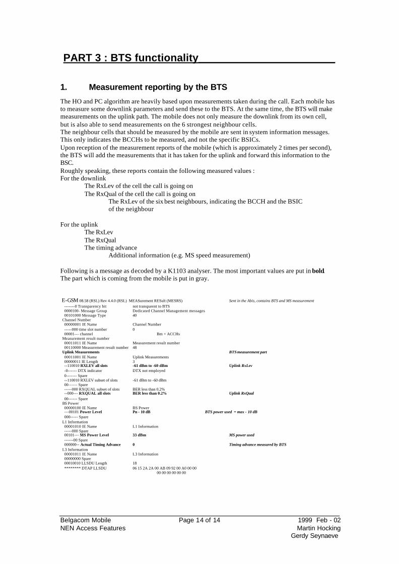
The HO and PC algorithm are heavily based upon measurements taken during the call. Each mobile has to measure some downlink parameters and send these to the BTS. At the same time, the BTS will make measurements on the uplink path. The mobile does not only measure the downlink from its own cell, but is also able to send measurements on the 6 strongest neighbour cells. The neighbour cells that should be measured by the mobile are sent in system information messages. This only indicates the BCCHs to be measured, and not the specific BSICs. Upon reception of the measurement reports of the mobile (which is approximately 2 times per second), the BTS will add the measurements that it has taken for the uplink and forward this information to the BSC. Roughly speaking, these reports contain the following measured values : For the downlink The RxLev of the cell the call is going on The RxQual of the cell the call is going on
The RxLev of the six best neighbours, indicating the BCCH and the BSIC of the neighbour
For the uplink The RxLev The RxQual The timing advance
Additional information (e.g. MS speed measurement) Following is a message as decoded by a K1103 analyser. The most important values are put in bold. The part which is coming from the mobile is put in gray. E-GSM 08.58 (RSL) Rev 4.4.0 (RSL) MEASurement RESult (MESRS) Sent in the Abis, contains BTS and MS measurement -------0 Transparency bit not transparent to BTS 0000100- Message Group Dedicated Channel Management messages 00101000 Message Type 40 Channel Number 00000001 IE Name Channel Number -----000 time slot number 0 00001--- channel Bm + ACCHs Measurement result number 00011011 IE Name Measurement result number 00110000 Measurement result number 48 Uplink Measurements BTS measurement part 00011001 IE Name Uplink Measurements 00000011 IE Length 3 --110010 RXLEV all slots -61 dBm to -60 dBm Uplink RxLev -0------ DTX indicator DTX not employed 0------- Spare --110010 RXLEV subset of slots -61 dBm to -60 dBm 00------ Spare -----000 RXQUAL subset of slots BER less than 0.2% --000--- RXQUAL all slots BER less than 0.2% Uplink RxQual 00------ Spare BS Power 00000100 IE Name BS Power ---00101 Power Level Pn - 10 dB BTS power used = max - 10 dB 000----- Spare L1 Information 00001010 IE Name L1 Information -----000 Spare 00101--- MS Power Level 33 dBm MS power used ------00 Spare 000000-- Actual Timing Advance 0 Timing advance measured by BTS L3 Information 00001011 IE Name L3 Information 00000000 Spare 00010010 LLSDU Length 18 ******** DTAP LLSDU 06 15 2A 2A 00 AB 09 92 00 A0 00 00
00 00 00 00 00 00
Belgacom Mobile Page 15 of 15 1999 Feb - 02 NEN Access Features Martin Hocking
Gerdy Seynaeve
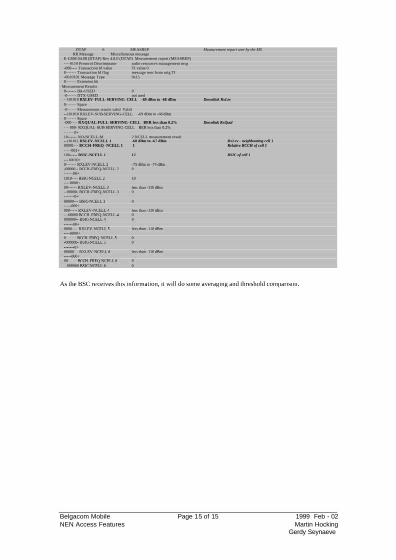
As the BSC receives this information, it will do some averaging and threshold comparison.
DTAP 6 MEASREP Measurement report sent by the MS RR Message Miscellaneous message E-GSM 04.08 (DTAP) Rev 4.8.0 (DTAP) Measurement report (MEASREP) ----0110 Protocol Discriminator radio resources management msg -000---- Transaction Id value TI value 0 0------- Transaction Id flag message sent from orig TI -0010101 Message Type 0x15 0------- Extension bit Measurement Results 0------- BA-USED 0 -0------ DTX-USED not used --101010 RXLEV-FULL-SERVING-CELL -69 dBm to -68 dBm Downlink RxLev 0------- Spare -0------ Measurement results valid Valid --101010 RXLEV-SUB-SERVING-CELL -69 dBm to -68 dBm 0------- Spare -000---- RXQUAL-FULL-SERVING-CELL BER less than 0.2% Downlink RxQual ----000- RXQUAL-SUB-SERVING-CELL BER less than 0.2% -------0+ 10------ NO-NCELL-M 2 NCELL measurement result --101011 RXLEV-NCELL 1 -68 dBm to -67 dBm RxLev - neighbouring cell 1 00001--- BCCH-FREQ -NCELL 1 1 Relative BCCH of cell 1 -----001+ 100----- BSIC-NCELL 1 12 BSIC of cell 1 ---10010+ 0------- RXLEV-NCELL 2 -75 dBm to -74 dBm -00000-- BCCH-FREQ-NCELL 2 0 ------00+ 1010---- BSIC-NCELL 2 10 ----0000+ 00------ RXLEV-NCELL 3 less than -110 dBm --00000- BCCH-FREQ-NCELL 3 0 -------0+ 00000--- BSIC-NCELL 3 0 -----000+ 000----- RXLEV-NCELL 4 less than -110 dBm ---00000 BCCH-FREQ-NCELL 4 0 000000-- BSIC-NCELL 4 0 ------00+ 0000---- RXLEV-NCELL 5 less than -110 dBm ----0000+ 0------- BCCH-FREQ-NCELL 5 0 -000000- BSIC-NCELL 5 0 -------0+ 00000--- RXLEV-NCELL 6 less than -110 dBm -----000+ 00------ BCCH-FREQ-NCELL 6 0 --000000 BSIC-NCELL 6 0
Belgacom Mobile Page 16 of 16 1999 Feb - 02 NEN Access Features Martin Hocking
Gerdy Seynaeve
2. Idle interference measurement
Nokia uses uplink idle interference in the allocation of TCH resources. Nokia has two methods for measuring uplink idle interference the first being when the TCH is idle and the second being when the timeslot is active
2.1. Measuring uplink idle interference when the TCH is idle
The BTS sends out a resource indication message to the BSC at regular intervals as defined by the parameter AveragingPeriod. Each resource TCH / SDCCH is individually identified and has its average ambient noise level reported during that reporting period. If a TCH was synthesised frequency hopping the uplink idle interference report would show the average level of interference on the uplink over all the hopping frequencies. The ambient noise level is grouped into 5 boundaries. These boundaries are defined by the parameters BO0, BO1, BO2, BO3, BO4 and B05. The interference is reported in bands, Band 0 is reported if the measured level lies between BO0 and BO1 (the lowest level of interference), and band 4 (the highest level of interference) if the level lies between BO4 and BO5. The level is calculated by making level measurements on all of the uplink frames that are associated with that resource over the Averaging Period. E.G. if the averaging period was 10 SACCH frames the average would be calculated from 104 * 10 frames (=1040). Hence the resource must be idle for the whole reporting period for the measurement to be valid and correct.
2.2. Measuring uplink idle interference when the TCH is active
When a mobile is active on a TCH during the search frames (4 in every SACCH period) the mobile does not transmit. The BTS knows when the mobile is not transmitting and during this period it makes a measurement of the uplink level. Because the BTS knows that the mobile is not transmitting the signal level reported must be due to uplink interference. The boundaries and the averaging period remain the same for both methods of measuring uplink interference. Note the above method will not work when two half rate channels are active sharing the same timeslot, because when one mobile is searching for a SCH channel the other half rate mobile is transmitting on its SACCH. By using the two methods a value for the average uplink interference is available 1 SACCH period after the TCH was released. Thus resources can be matched better to the next mobile.
3. Timing advance
This is measured by the BTS. The further the mobile is away from the BTS the more the signal is delayed. Therefore the BTS sends a message to the mobile to start its transmission earlier (timing advance) to combat this delay. 1 timing advance is equal to a distance of about 550m
Belgacom Mobile Page 17 of 17 1999 Feb - 02 NEN Access Features Martin Hocking
Gerdy Seynaeve
4. MS Speed measurement
The BTS estimates the MS speed by using the crossing rate algorithm. The algorithm is based on comparison between the signal levels obtained from each burst and their averaged value over one SACCH multiframe (104 bursts). The algorithm counts the rate at which the signal level crosses the averages signal level. The crossing rate is relative to the mobile speed. As Rayleigh fades are at the maximum every half wavelength, a deep fade can be expected every 15 cm. This is not possible anymore when using frequency hopping, except for the BCCH carrier in case of synthesised frequency hopping. There are a lot of conditions where MS speed can not be measured (see later in this document).
5. BTS pre-processing
The BTS will normally receive measurement reports from each mobile which is in communication. The BTS will add to that the part it has measured itself (i.e. the uplink part). This information is sent on the LAPD links in the Abis interface. Since the capacity of the LAPD links is limited, whenever the LAPD is in overload, measurements will be discarded at random. One of the solutions for this is to increase the speed of the LAPD links (32 kbit/s, 64 kbit/s instead of 16 kbit/s). Another approach is that the BTS takes over some processing from the BSC and does the averaging calculation itself. This has some important implications :
• The measurement reports contain averaged values • The measurement reports come each 2, 3 or 4 SACCH periods (depending on the
parameters defined). Since the values are already averaged, and because they are coming less frequently, the parameter settings have to take this into account. This will especially effect Nx, Px and Windowsize values. Do not use BTS averaging, it will need a complete redesign of all parameter settings.
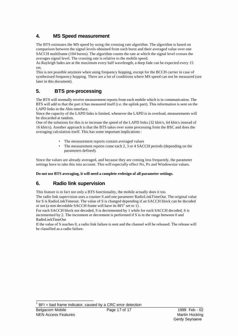
6. Radio link supervision
This feature is in fact not only a BTS functionality, the mobile actually does it too. The radio link supervision uses a counter S and one parameter RadioLinkTimeOut. The original value for S is RadioLinkTimeout. The value of S is changed depending if an SACCH block can be decoded or not (a non decodable SACCH frame will have its BFI1 set to 1) . For each SACCH block not decoded, S is decremented by 1 while for each SACCH decoded, S is incremented by 2. The increment or decrement is performed if S is in the range between 0 and RadioLinkTimeOut If the value of S reaches 0, a radio link failure is sent and the channel will be released. The release will be classified as a radio failure.
1 BFI = bad frame indicator, caused by a CRC error detection
Belgacom Mobile Page 18 of 18 1999 Feb - 02 NEN Access Features Martin Hocking
Gerdy Seynaeve
Counter S
Time
RadioLinkTimeout
Radio link failure
SACCH block decoded : +2
SACCH block not decoded : -1
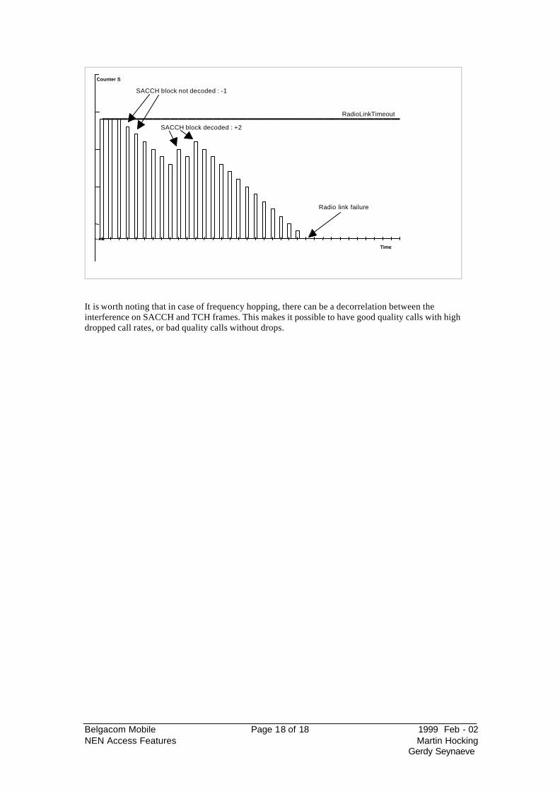
It is worth noting that in case of frequency hopping, there can be a decorrelation between the interference on SACCH and TCH frames. This makes it possible to have good quality calls with high dropped call rates, or bad quality calls without drops.
Belgacom Mobile Page 19 of 19 1999 Feb - 02 NEN Access Features Martin Hocking
Gerdy Seynaeve
PART 4 : BSC functionality_______________________
7. Averaging of measurements
7.1. Averaging serving cell measurements
7.1.1. General Before any decisions are taken, the received measurements are averaged. This averaging is always controlled by an averaging window (using the sliding averaging technique), and by weighting factors.
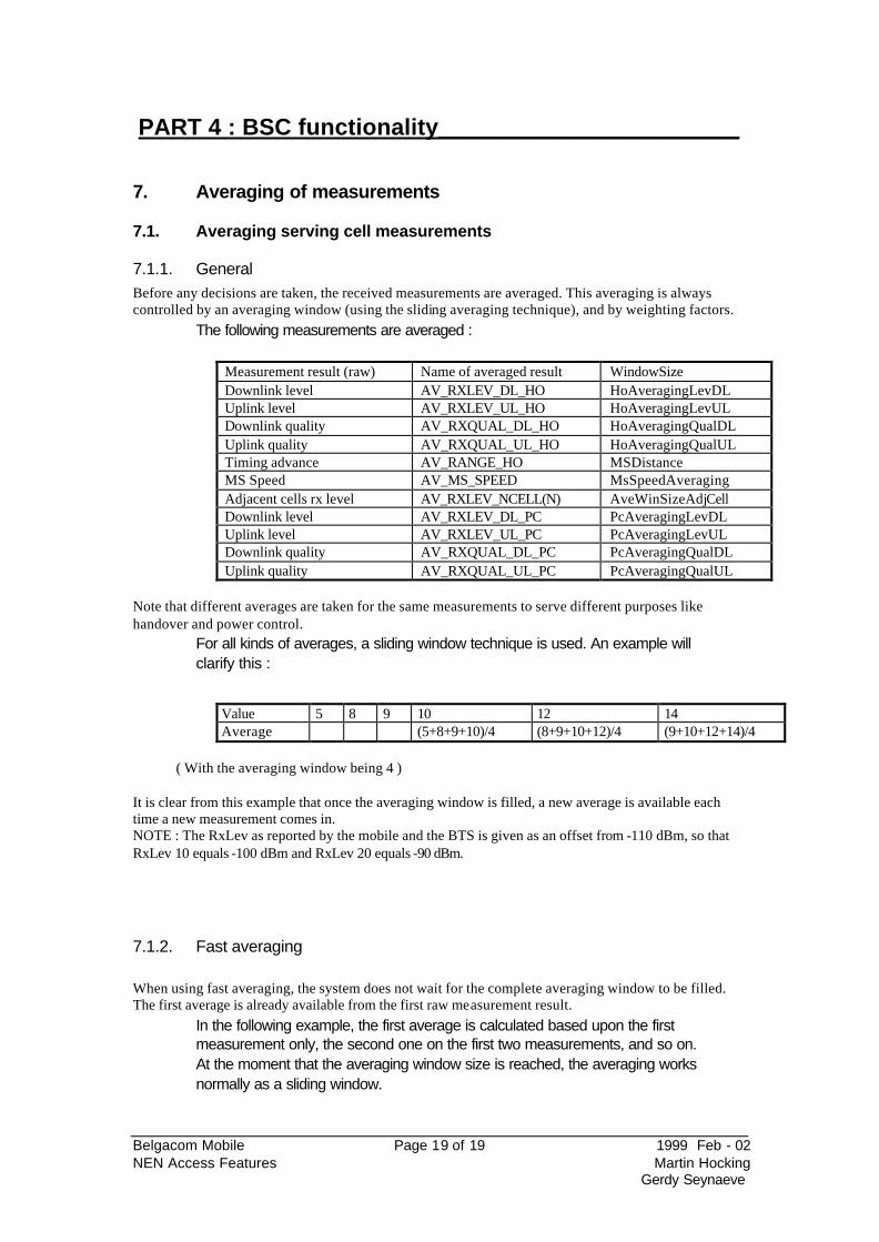
The following measurements are averaged :
Measurement result (raw) Name of averaged result WindowSize Downlink level AV_RXLEV_DL_HO HoAveragingLevDL Uplink level AV_RXLEV_UL_HO HoAveragingLevUL Downlink quality AV_RXQUAL_DL_HO HoAveragingQualDL Uplink quality AV_RXQUAL_UL_HO HoAveragingQualUL Timing advance AV_RANGE_HO MSDistance MS Speed AV_MS_SPEED MsSpeedAveraging Adjacent cells rx level AV_RXLEV_NCELL(N) AveWinSizeAdjCell Downlink level AV_RXLEV_DL_PC PcAveragingLevDL Uplink level AV_RXLEV_UL_PC PcAveragingLevUL Downlink quality AV_RXQUAL_DL_PC PcAveragingQualDL Uplink quality AV_RXQUAL_UL_PC PcAveragingQualUL
Note that different averages are taken for the same measurements to serve different purposes like handover and power control.
For all kinds of averages, a sliding window technique is used. An example will clarify this :
Value 5 8 9 10 12 14 Average (5+8+9+10)/4 (8+9+10+12)/4 (9+10+12+14)/4
( With the averaging window being 4 )
It is clear from this example that once the averaging window is filled, a new average is available each time a new measurement comes in. NOTE : The RxLev as reported by the mobile and the BTS is given as an offset from -110 dBm, so that RxLev 10 equals -100 dBm and RxLev 20 equals -90 dBm.
7.1.2. Fast averaging When using fast averaging, the system does not wait for the complete averaging window to be filled. The first average is already available from the first raw measurement result.
In the following example, the first average is calculated based upon the first measurement only, the second one on the first two measurements, and so on. At the moment that the averaging window size is reached, the averaging works normally as a sliding window.
Belgacom Mobile Page 20 of 20 1999 Feb - 02 NEN Access Features Martin Hocking
Gerdy Seynaeve
RxLev reported by MS
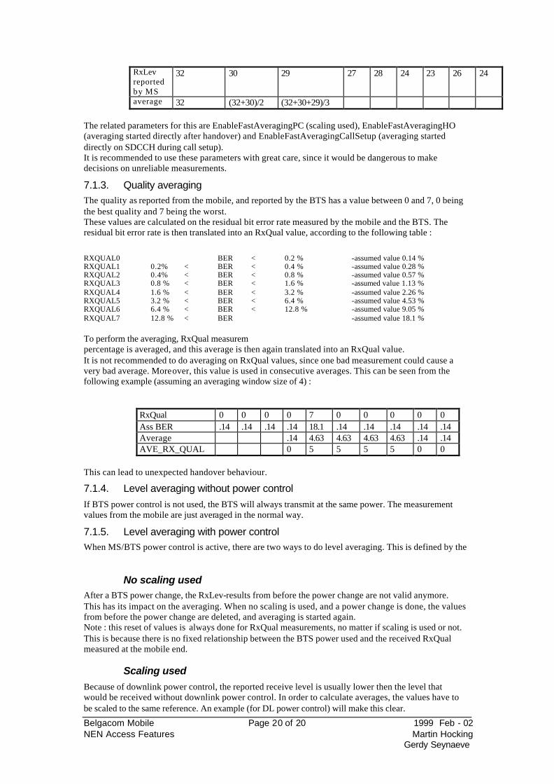
32 30 29 27 28 24 23 26 24
average 32 (32+30)/2 (32+30+29)/3 The related parameters for this are EnableFastAveragingPC (scaling used), EnableFastAveragingHO (averaging started directly after handover) and EnableFastAveragingCallSetup (averaging started directly on SDCCH during call setup). It is recommended to use these parameters with great care, since it would be dangerous to make decisions on unreliable measurements.
7.1.3. Quality averaging The quality as reported from the mobile, and reported by the BTS has a value between 0 and 7, 0 being the best quality and 7 being the worst. These values are calculated on the residual bit error rate measured by the mobile and the BTS. The residual bit error rate is then translated into an RxQual value, according to the following table :
RXQUAL0 BER < 0.2 % -assumed value 0.14 % RXQUAL1 0.2% < BER < 0.4 % -assumed value 0.28 % RXQUAL2 0.4% < BER < 0.8 % -assumed value 0.57 % RXQUAL3 0.8 % < BER < 1.6 % -assumed value 1.13 % RXQUAL4 1.6 % < BER < 3.2 % -assumed value 2.26 % RXQUAL5 3.2 % < BER < 6.4 % -assumed value 4.53 % RXQUAL6 6.4 % < BER < 12.8 % -assumed value 9.05 % RXQUAL7 12.8 % < BER -assumed value 18.1 % To perform the averaging, RxQual measurempercentage is averaged, and this average is then again translated into an RxQual value. It is not recommended to do averaging on RxQual values, since one bad measurement could cause a very bad average. Moreover, this value is used in consecutive averages. This can be seen from the following example (assuming an averaging window size of 4) :
RxQual 0 0 0 0 7 0 0 0 0 0 Ass BER .14 .14 .14 .14 18.1 .14 .14 .14 .14 .14 Average .14 4.63 4.63 4.63 4.63 .14 .14 AVE_RX_QUAL 0 5 5 5 5 0 0
This can lead to unexpected handover behaviour.
7.1.4. Level averaging without power control If BTS power control is not used, the BTS will always transmit at the same power. The measurement values from the mobile are just averaged in the normal way.
7.1.5. Level averaging with power control When MS/BTS power control is active, there are two ways to do level averaging. This is defined by the
No scaling used After a BTS power change, the RxLev-results from before the power change are not valid anymore. This has its impact on the averaging. When no scaling is used, and a power change is done, the values from before the power change are deleted, and averaging is started again. Note : this reset of values is always done for RxQual measurements, no matter if scaling is used or not. This is because there is no fixed relationship between the BTS power used and the received RxQual measured at the mobile end.
Scaling used
Because of downlink power control, the reported receive level is usually lower then the level that would be received without downlink power control. In order to calculate averages, the values have to be scaled to the same reference. An example (for DL power control) will make this clear.
Belgacom Mobile Page 21 of 21 1999 Feb - 02 NEN Access Features Martin Hocking
Gerdy Seynaeve
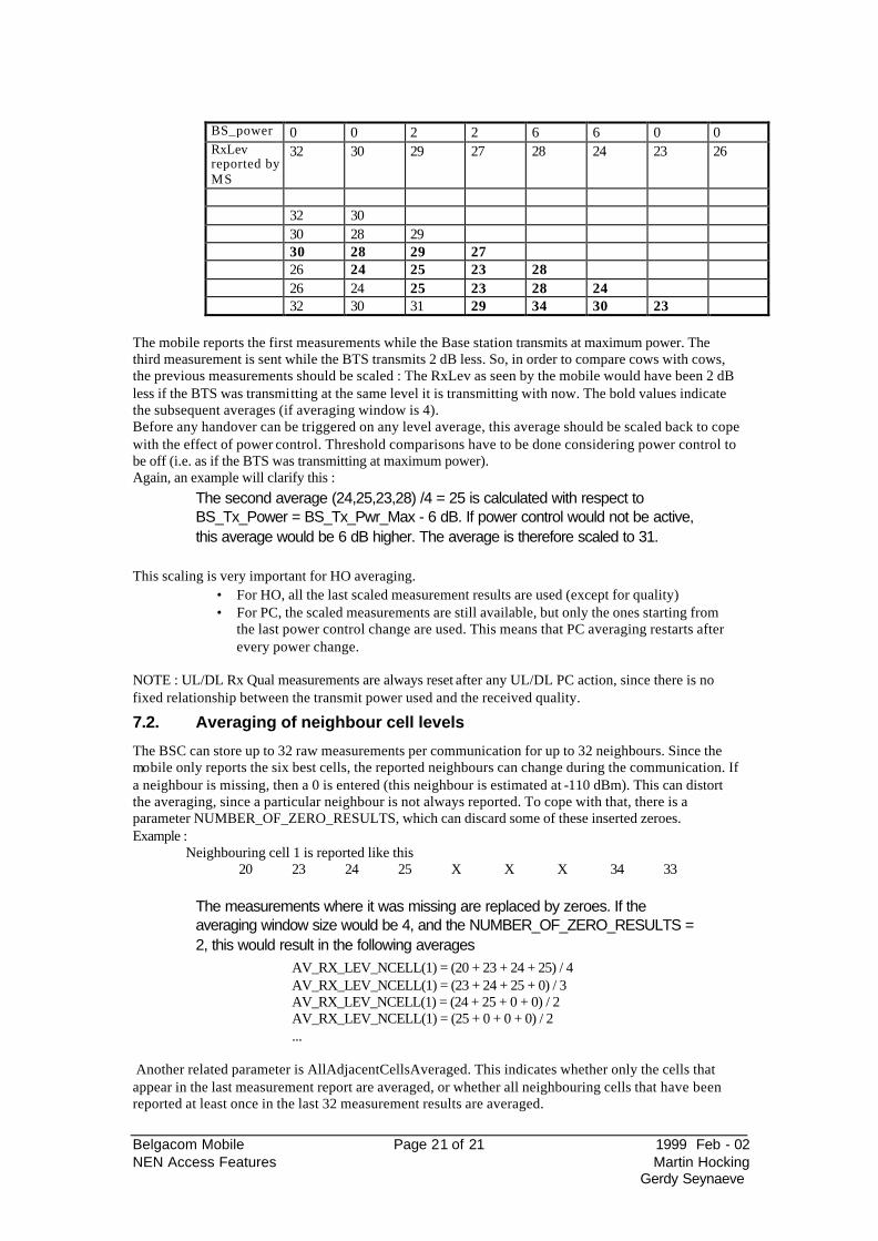
BS_power 0 0 2 2 6 6 0 0 RxLev reported by MS
32 30 29 27 28 24 23 26
32 30 30 28 29 30 28 29 27 26 24 25 23 28 26 24 25 23 28 24 32 30 31 29 34 30 23
The mobile reports the first measurements while the Base station transmits at maximum power. The third measurement is sent while the BTS transmits 2 dB less. So, in order to compare cows with cows, the previous measurements should be scaled : The RxLev as seen by the mobile would have been 2 dB less if the BTS was transmitting at the same level it is transmitting with now. The bold values indicate the subsequent averages (if averaging window is 4). Before any handover can be triggered on any level average, this average should be scaled back to cope with the effect of power control. Threshold comparisons have to be done considering power control to be off (i.e. as if the BTS was transmitting at maximum power). Again, an example will clarify this :
The second average (24,25,23,28) /4 = 25 is calculated with respect to BS_Tx_Power = BS_Tx_Pwr_Max - 6 dB. If power control would not be active, this average would be 6 dB higher. The average is therefore scaled to 31.
This scaling is very important for HO averaging.
• For HO, all the last scaled measurement results are used (except for quality) • For PC, the scaled measurements are still available, but only the ones starting from
the last power control change are used. This means that PC averaging restarts after every power change.
NOTE : UL/DL Rx Qual measurements are always reset after any UL/DL PC action, since there is no fixed relationship between the transmit power used and the received quality.
7.2. Averaging of neighbour cell levels
The BSC can store up to 32 raw measurements per communication for up to 32 neighbours. Since the mobile only reports the six best cells, the reported neighbours can change during the communication. If a neighbour is missing, then a 0 is entered (this neighbour is estimated at -110 dBm). This can distort the averaging, since a particular neighbour is not always reported. To cope with that, there is a parameter NUMBER_OF_ZERO_RESULTS, which can discard some of these inserted zeroes. Example : Neighbouring cell 1 is reported like this 20 23 24 25 X X X 34 33
The measurements where it was missing are replaced by zeroes. If the averaging window size would be 4, and the NUMBER_OF_ZERO_RESULTS = 2, this would result in the following averages
AV_RX_LEV_NCELL(1) = (20 + 23 + 24 + 25) / 4 AV_RX_LEV_NCELL(1) = (23 + 24 + 25 + 0) / 3 AV_RX_LEV_NCELL(1) = (24 + 25 + 0 + 0) / 2 AV_RX_LEV_NCELL(1) = (25 + 0 + 0 + 0) / 2 ...
Another related parameter is AllAdjacentCellsAveraged. This indicates whether only the cells that appear in the last measurement report are averaged, or whether all neighbouring cells that have been reported at least once in the last 32 measurement results are averaged.
Belgacom Mobile Page 22 of 22 1999 Feb - 02 NEN Access Features Martin Hocking
Gerdy Seynaeve
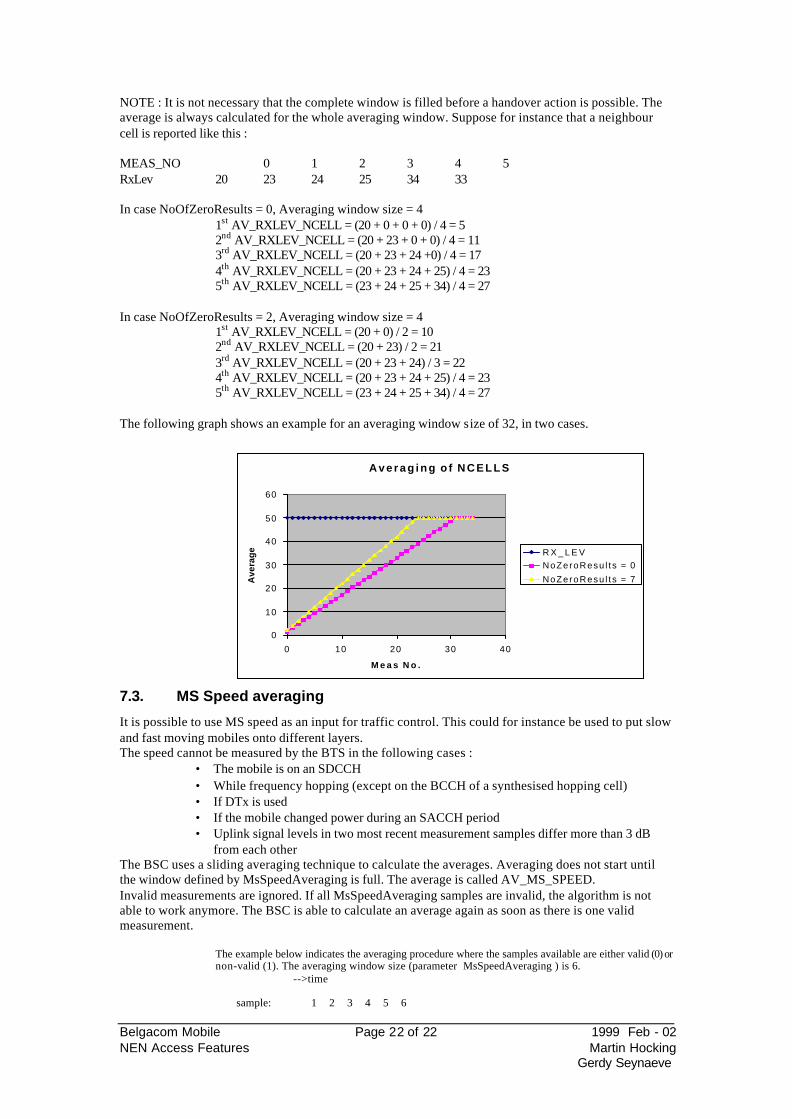
NOTE : It is not necessary that the complete window is filled before a handover action is possible. The average is always calculated for the whole averaging window. Suppose for instance that a neighbour cell is reported like this : MEAS_NO 0 1 2 3 4 5 RxLev 20 23 24 25 34 33 In case NoOfZeroResults = 0, Averaging window size = 4 1st AV_RXLEV_NCELL = (20 + 0 + 0 + 0) / 4 = 5 2nd AV_RXLEV_NCELL = (20 + 23 + 0 + 0) / 4 = 11 3rd AV_RXLEV_NCELL = (20 + 23 + 24 +0) / 4 = 17 4th AV_RXLEV_NCELL = (20 + 23 + 24 + 25) / 4 = 23 5th AV_RXLEV_NCELL = (23 + 24 + 25 + 34) / 4 = 27 In case NoOfZeroResults = 2, Averaging window size = 4 1st AV_RXLEV_NCELL = (20 + 0) / 2 = 10 2nd AV_RXLEV_NCELL = (20 + 23) / 2 = 21 3rd AV_RXLEV_NCELL = (20 + 23 + 24) / 3 = 22 4th AV_RXLEV_NCELL = (20 + 23 + 24 + 25) / 4 = 23 5th AV_RXLEV_NCELL = (23 + 24 + 25 + 34) / 4 = 27 The following graph shows an example for an averaging window size of 32, in two cases.
7.3. MS Speed averaging
It is possible to use MS speed as an input for traffic control. This could for instance be used to put slow and fast moving mobiles onto different layers. The speed cannot be measured by the BTS in the following cases :
• The mobile is on an SDCCH • While frequency hopping (except on the BCCH of a synthesised hopping cell) • If DTx is used • If the mobile changed power during an SACCH period • Uplink signal levels in two most recent measurement samples differ more than 3 dB
from each other The BSC uses a sliding averaging technique to calculate the averages. Averaging does not start until the window defined by MsSpeedAveraging is full. The average is called AV_MS_SPEED. Invalid measurements are ignored. If all MsSpeedAveraging samples are invalid, the algorithm is not able to work anymore. The BSC is able to calculate an average again as soon as there is one valid measurement.
The example below indicates the averaging procedure where the samples available are either valid (0) or non-valid (1). The averaging window size (parameter MsSpeedAveraging ) is 6. -->time sample: 1 2 3 4 5 6
A v e r a g i n g o f N C E L L S
0
10
20
30
40
50
60
0 10 20 30 40
M e a s N o .
Ave
rag
e R X _ L E VNoZeroResu l t s = 0
NoZeroResu l t s = 7
Belgacom Mobile Page 23 of 23 1999 Feb - 02 NEN Access Features Martin Hocking
Gerdy Seynaeve
valid/ non-valid: 0 1 0 0 0 1 MS speed: 43 - 65 58 34 - 43 + 65 + 58 + 34 AV_MS_SPEED = ------------------------ = 50 4
7.4. Variable window size
Based upon the measured speed of the mobile station, the window size for calculating averages for handover can be modified. This can be used to allow faster averaging for high speed mobiles. If a mobile is considered as a fast moving mobile, the following parameters will be changed :
• HOAveragingLevDLWindowSize • HoAveragingLevULWindowSize • AveragingWindowSizeAdjCell • NumberOfZeroResults
The windowsizes are altered by by a factor defined by the MsSpeedDetectionState parameter (1..100%). This would mean that a windowsize of 10 would be reduced to 8 when MsSpeedDetectionState = 8.
If a mobile is considered as a slow moving mobile, the normal averages are used. If the MsSpeedDetectionState has value 0, the information is only used for multilayer handover functionality.
7.5. DTx usage
General description
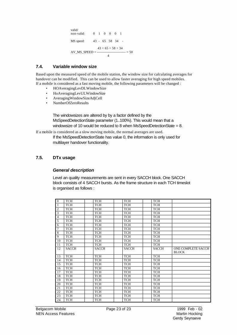
Level an quality measurements are sent in every SACCH block. One SACCH block consists of 4 SACCH bursts. As the frame structure in each TCH timeslot is organised as follows :
0 TCH TCH TCH TCH 1 TCH TCH TCH TCH 2 TCH TCH TCH TCH 3 TCH TCH TCH TCH 4 TCH TCH TCH TCH 5 TCH TCH TCH TCH 6 TCH TCH TCH TCH 7 TCH TCH TCH TCH 8 TCH TCH TCH TCH 9 TCH TCH TCH TCH 10 TCH TCH TCH TCH 11 TCH TCH TCH TCH 12 SACCH SACCH SACCH SACCH ONE COMPLETE SACCH
BLOCK 13 TCH TCH TCH TCH 14 TCH TCH TCH TCH 15 TCH TCH TCH TCH 16 TCH TCH TCH TCH 17 TCH TCH TCH TCH 18 TCH TCH TCH TCH 19 TCH TCH TCH TCH 20 TCH TCH TCH TCH 21 TCH TCH TCH TCH 22 TCH TCH TCH TCH 23 TCH TCH TCH TCH 24 TCH TCH TCH TCH
Belgacom Mobile Page 24 of 24 1999 Feb - 02 NEN Access Features Martin Hocking
Gerdy Seynaeve
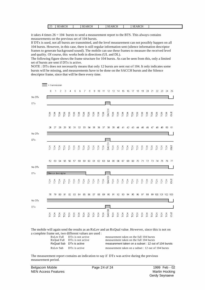
25 SEARCH SEARCH SEARCH SEARCH
it takes 4 times 26 = 104 bursts to send a measurement report to the BTS. This always contains measurements on the previous set of 104 bursts. If DTx is used, not all bursts are transmitted, and the level measurement can not possibly happen on all 104 bursts. However, in this case, there is still regular information sent (silence information descriptor frames to generate background sound). The mobile can use these frames to measure the received level and quality. Of course, this works both in directions (UL and DL). The following figure shows the frame structure for 104 bursts. As can be seen from this, only a limited set of bursts are sent if DTx is active. NOTE : DTx does not necessarily means that only 12 bursts are sent out of 104. It only indicates some bursts will be missing, and measurements have to be done on the SACCH bursts and the Silence descriptor frame, since that will be there every time.
The mobile will again send the results as an RxLev and an RxQual value. However, since this is not on a complete frame set, two different values are used :
RxLev Full DTx is not active measurement taken on the full 104 bursts RxQual Full DTx is not active measurement taken on the full 104 bursts RxQual Sub DTx is active measurement taken on a subset : 12 out of 104 bursts
RxLev Sub DTx is active measurement taken on a subset : 12 out of 104 bursts The measurement report contains an indication to say if DTx was active during the previous measurement period.
Belgacom Mobile Page 25 of 25 1999 Feb - 02 NEN Access Features Martin Hocking
Gerdy Seynaeve
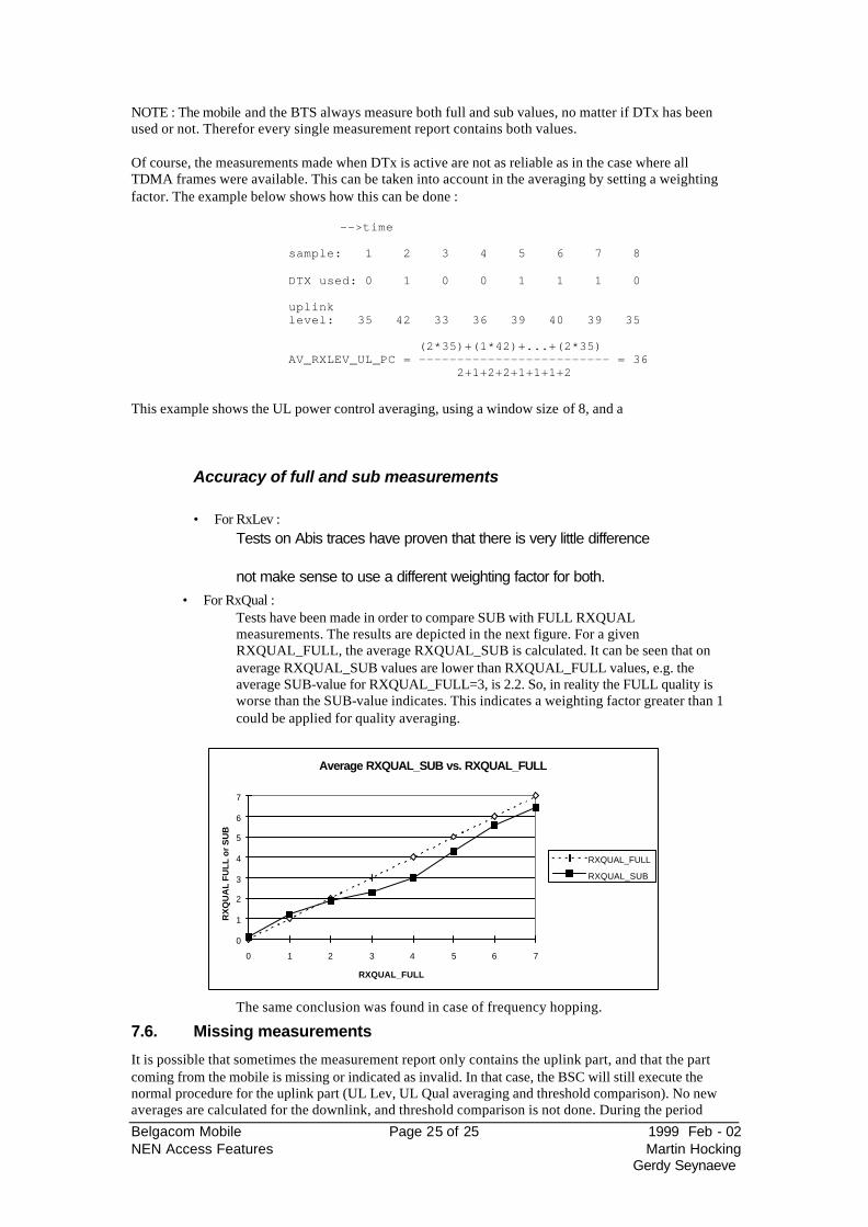
NOTE : The mobile and the BTS always measure both full and sub values, no matter if DTx has been used or not. Therefor every single measurement report contains both values. Of course, the measurements made when DTx is active are not as reliable as in the case where all TDMA frames were available. This can be taken into account in the averaging by setting a weighting factor. The example below shows how this can be done :
-->time sample: 1 2 3 4 5 6 7 8 DTX used: 0 1 0 0 1 1 1 0 uplink level: 35 42 33 36 39 40 39 35 (2*35)+(1*42)+...+(2*35) AV_RXLEV_UL_PC = ------------------------- = 36 2+1+2+2+1+1+1+2
This example shows the UL power control averaging, using a window size of 8, and a
Accuracy of full and sub measurements
• For RxLev : Tests on Abis traces have proven that there is very little difference
not make sense to use a different weighting factor for both. • For RxQual :
Tests have been made in order to compare SUB with FULL RXQUAL measurements. The results are depicted in the next figure. For a given RXQUAL_FULL, the average RXQUAL_SUB is calculated. It can be seen that on average RXQUAL_SUB values are lower than RXQUAL_FULL values, e.g. the average SUB-value for RXQUAL_FULL=3, is 2.2. So, in reality the FULL quality is worse than the SUB-value indicates. This indicates a weighting factor greater than 1 could be applied for quality averaging.
Average RXQUAL_SUB vs. RXQUAL_FULL
0
1
2
3
4
5
6
7
0 1 2 3 4 5 6 7
RXQUAL_FULL
RX
QU
AL
FU
LL
or
SU
B
RXQUAL_FULL
RXQUAL_SUB
The same conclusion was found in case of frequency hopping.
7.6. Missing measurements
It is possible that sometimes the measurement report only contains the uplink part, and that the part coming from the mobile is missing or indicated as invalid. In that case, the BSC will still execute the normal procedure for the uplink part (UL Lev, UL Qual averaging and threshold comparison). No new averages are calculated for the downlink, and threshold comparison is not done. During the period
Belgacom Mobile Page 26 of 26 1999 Feb - 02 NEN Access Features Martin Hocking
Gerdy Seynaeve
where the downlink reports are missing, the BSC is only able to control the power of the mobile and to perform handovers for uplink reasons. In case the featurecase of missing downlink measurements. (see further in this document)
7.7. Threshold comparison - N & P voting
Now that the raw measurement results coming from the BTS and the mobile have been averaged, they
that Px out of Nx averages should reach the threshold before any action can be taken. This is explained in more detail in the following sections.
Belgacom Mobile Page 27 of 27 1999 Feb - 02 NEN Access Features Martin Hocking
Gerdy Seynaeve
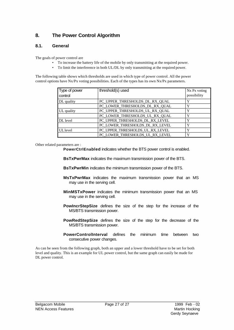
8. The Power Control Algorithm
8.1. General
The goals of power control are
• To increase the battery life of the mobile by only transmitting at the required power. • To limit the interference in both UL/DL by only transmitting at the required power.
The following table shows which thresholds are used in which type of power control. All the power control options have Nx/Px voting possibilities. Each of the types has its own Nx/Px parameters.
Type of power control
threshold(s) used Nx Px voting possibility
DL quality PC_UPPER_THRESHOLDS_DL_RX_QUAL Y PC_LOWER_THRESHOLDS_DL_RX_QUAL Y UL quality PC_UPPER_THRESHOLDS_UL_RX_QUAL Y PC_LOWER_THRESHOLDS_UL_RX_QUAL Y DL level PC_UPPER_THRESHOLDS_DL_RX_LEVEL Y PC_LOWER_THRESHOLDS_DL_RX_LEVEL Y UL level PC_UPPER_THRESHOLDS_UL_RX_LEVEL Y PC_LOWER_THRESHOLDS_UL_RX_LEVEL Y
Other related parameters are :
PowerCtrlEnabled indicates whether the BTS power control is enabled. BsTxPwrMax indicates the maximum transmission power of the BTS. BsTxPwrMin indicates the minimum transmission power of the BTS. MsTxPwrMax indicates the maximum transmission power that an MS
may use in the serving cell. MinMSTxPower indicates the minimum transmission power that an MS
may use in the serving cell. PowIncrStepSize defines the size of the step for the increase of the
MS/BTS transmission power. PowRedStepSize defines the size of the step for the decrease of the
MS/BTS transmission power. PowerControlInterval defines the minimum time between two
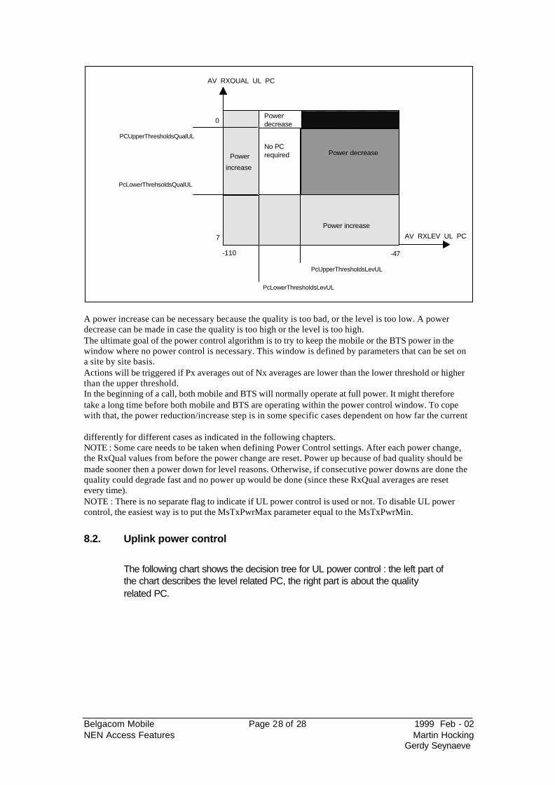
consecutive power changes. As can be seen from the following graph, both an upper and a lower threshold have to be set for both level and quality. This is an example for UL power control, but the same graph can easily be made for DL power control.
Belgacom Mobile Page 28 of 28 1999 Feb - 02 NEN Access Features Martin Hocking
Gerdy Seynaeve
7
0
PcLowerThrehsoldsQualUL
PCUpperThresholdsQualUL
PcUpperThresholdsLevUL
PcLowerThresholdsLevUL
AV_RXLEV_UL_PC
AV_RXQUAL_UL_PC
Power increase
Power
increase
Power decreasePowerdecrease
Power decreaseNo PCrequired
-110 -47
A power increase can be necessary because the quality is too bad, or the level is too low. A power decrease can be made in case the quality is too high or the level is too high. The ultimate goal of the power control algorithm is to try to keep the mobile or the BTS power in the window where no power control is necessary. This window is defined by parameters that can be set on a site by site basis. Actions will be triggered if Px averages out of Nx averages are lower than the lower threshold or higher than the upper threshold. In the beginning of a call, both mobile and BTS will normally operate at full power. It might therefore take a long time before both mobile and BTS are operating within the power control window. To cope with that, the power reduction/increase step is in some specific cases dependent on how far the current
differently for different cases as indicated in the following chapters. NOTE : Some care needs to be taken when defining Power Control settings. After each power change, the RxQual values from before the power change are reset. Power up because of bad quality should be made sooner then a power down for level reasons. Otherwise, if consecutive power downs are done the quality could degrade fast and no power up would be done (since these RxQual averages are reset every time). NOTE : There is no separate flag to indicate if UL power control is used or not. To disable UL power control, the easiest way is to put the MsTxPwrMax parameter equal to the MsTxPwrMin.
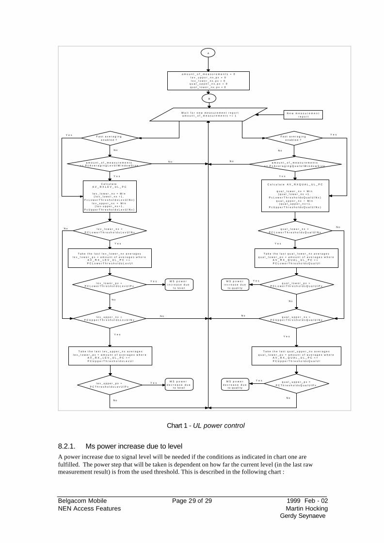
8.2. Uplink power control
The following chart shows the decision tree for UL power control : the left part of the chart describes the level related PC, the right part is about the quality related PC.
Belgacom Mobile Page 29 of 29 1999 Feb - 02 NEN Access Features Martin Hocking
Gerdy Seynaeve
A
a m o u n t _ o f _ m e a s u r e m e n t s = 0 l e v _ u p p e r _ n x , p x = 0 l e v _ l o w e r _ n x , p x = 0
q u a l _ u p p e r _ n x , p x = 0 q u a l _ l o w e r _ n x , p x = 0
N e w m e a s u r e m e n t r e p o r t
W a i t f o r n e w m e a s u r e m e n t r e p o r t a m o u n t _ o f _ m e a s u r e m e n t s + = 1
a m o u n t _ o f _ m e a s u r e m e n t s > = P c A v e r a g i n g L e v U l W i n d o w S i z e
C a l c u l a t e A V _ R X L E V _ U L _ P C
l e v _ l o w e r _ n x = M i n ( l e v _ l o w e r _ n x + 1 ,
P c L o w e r T h r e s h o l d s L e v U l N x ) l e v _ u p p e r _ n x = M i n
( l e v - u p p e r _ n x + 1 , P c U p p e r T h r e s h o l d s L e v U l N x )
T a k e t h e l a s t l e v _ l o w e r _ n x a v e r a g e s l e v _ l o w e r _ p x = a m o u n t o f a v e r a g e s w h e r e
A V _ R X _ L E V _ U L _ P C < = P C L o w e r T h r e s h o l d s L e v U l
l e v _ l o w e r _ p x = P C L o w e r T h r e s h o l d s L e v U l P x
M S p o w e r i n c r e a s e d u e
t o l e v e l
T a k e t h e l a s t l e v _ u p p e r _ n x a v e r a g e s l e v _ l o w e r _ p x = a m o u n t o f a v e r a g e s w h e r e
A V _ R X _ L E V _ U L _ P C > = P C U p p e r T h r e s h o l d s L e v U l
l e v _ l o w e r _ n x = P C L o w e r T h r e s h o l d s L e v U l N x
l e v _ u p p e r _ n x = P C U p p e r T h r e s h o l d s L e v U l N x
l e v _ u p p e r _ p x = P C T h r e s h o l d s L e v U l P x
M S p o w e r d e c r e a s e d u e
t o l e v e l
a m o u n t _ o f _ m e a s u r e m e n t s > = P c A v e r a g i n g Q u a l U l W i n d o w S i z e
C a l c u l a t e A V _ R X Q U A L _ U L _ P C
q u a l _ l o w e r _ n x = M i n ( q u a l _ l o w e r _ n x + 1 ,
P c L o w e r T h r e s h o l d s Q u a l U l N x ) q u a l _ u p p e r _ n x = M i n
( q u a l _ u p p e r _ n x + 1 , P c U p p e r T h r e s h o l d s Q u a l U l N x )
q u a l _ l o w e r _ n x = P C L o w e r T h r e s h o l d s Q u a l U l N x
T a k e t h e l a s t q u a l _ l o w e r _ n x a v e r a g e s q u a l _ l o w e r _ p x = a m o u n t o f a v e r a g e s w h e r e
A V _ R X _ Q U A L _ U L _ P C > = P C L o w e r T h r e s h o l d s Q u a l U l
q u a l _ l o w e r _ p x = P C L o w e r T h r e s h o l d s Q u a l U l P x
M S p o w e r i n c r e a s e d u e
t o q u a l i t y
q u a l _ u p p e r _ n x = P C U p p e r T h r e s h o l d s Q u a l U l N x
T a k e t h e l a s t q u a l _ u p p e r _ n x a v e r a g e s q u a l _ l o w e r _ p x = a m o u n t o f a v e r a g e s w h e r e
A V _ R X _ Q U A L _ U L _ P C < = P C U p p e r T h r e s h o l d s Q u a l U l
q u a l _ u p p e r _ p x = P C T h r e s h o l d s Q u a l U l P x
M S p o w e r d e c r e a s e d u e
t o q u a l i t y
B
N o
Y e s
Y e s
N o
Y e s
N o
Y e s
N o
N o
Y e s
Y e s
N o
N o
Y e s
Y e s
N o
F a s t a v e r a g i n g e n a b l e d ?
F a s t a v e r a g i n g e n a b l e d ?
N o
Y e s
N o
Y e s Y e s
N o
N o
Y e s
Chart 1 - UL power control
8.2.1. Ms power increase due to level A power increase due to signal level will be needed if the conditions as indicated in chart one are fulfilled. The power step that will be taken is dependent on how far the current level (in the last raw measurement result) is from the used threshold. This is described in the following chart :
Belgacom Mobile Page 30 of 30 1999 Feb - 02 NEN Access Features Martin Hocking
Gerdy Seynaeve
MS power increase due to
signal level
RxLevUL + 2 * PwrIncrStepSize <= PCLowerThresholdsLevUl
POWER_INCREASE_STEP = PcLowerThresholdsLevUl - RxLevUL
POWER_INCREASE_STEP = PowerIncrStepsize
Last power control longer then PowerControlInterval ago B
Send PC command
Successful ?A Send PC command Successful ?
A
B
No
Y e s
Y e s
No
Y e s No
Y e s
No
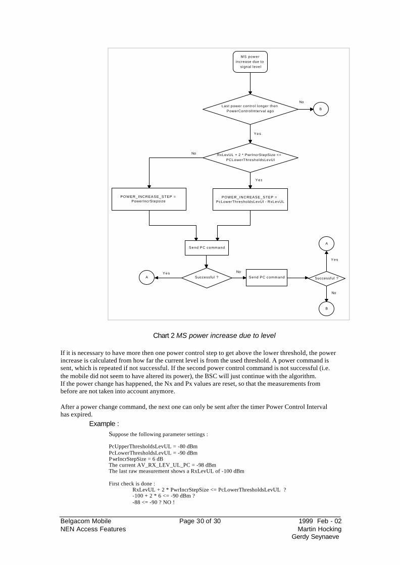
Chart 2 MS power increase due to level
If it is necessary to have more then one power control step to get above the lower threshold, the power increase is calculated from how far the current level is from the used threshold. A power command is sent, which is repeated if not successful. If the second power control command is not successful (i.e. the mobile did not seem to have altered its power), the BSC will just continue with the algorithm. If the power change has happened, the Nx and Px values are reset, so that the measurements from before are not taken into account anymore.
After a power change command, the next one can only be sent after the timer Power Control Interval has expired.
Example : Suppose the following parameter settings : PcUpperThresholdsLevUL = -80 dBm PcLowerThresholdsLevUL = -90 dBm PwrIncrStepSize = 6 dB The current AV_RX_LEV_UL_PC = -98 dBm The last raw measurement shows a RxLevUL of -100 dBm First check is done :
RxLevUL + 2 * PwrIncrStepSize <= PcLowerThresholdsLevUL ? -100 + 2 * 6 <= -90 dBm ? -88 <= -90 ? NO !
Belgacom Mobile Page 31 of 31 1999 Feb - 02 NEN Access Features Martin Hocking
Gerdy Seynaeve
This means that two stepsizes would be enough to get in the PC window, therefor the POWER_INCREASE_STEP equals 6 dB.
The Power Command will increase the MSTXPOWER with 6 dB. The expected new RxLevUL will be - 94 dBm
Belgacom Mobile Page 32 of 32 1999 Feb - 02 NEN Access Features Martin Hocking
Gerdy Seynaeve
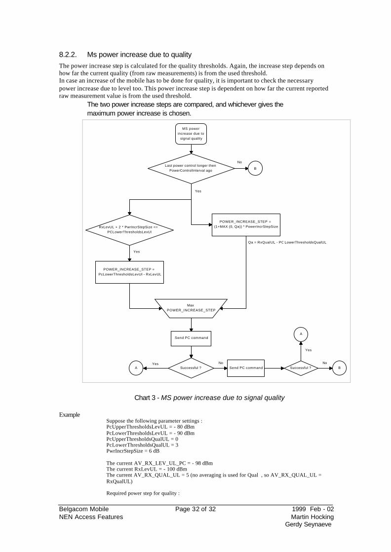
8.2.2. Ms power increase due to quality The power increase step is calculated for the quality thresholds. Again, the increase step depends on how far the current quality (from raw measurements) is from the used threshold. In case an increase of the mobile has to be done for quality, it is important to check the necessary power increase due to level too. This power increase step is dependent on how far the current reported raw measurement value is from the used threshold.
The two power increase steps are compared, and whichever gives the maximum power increase is chosen.
MS power increase due to
signal quality
Last power control longer then PowerControlInterval ago B
RxLevUL + 2 * PwrIncrStepSize <= PCLowerThresholdsLevUl
POWER_INCREASE_STEP = PcLowerThresholdsLevUl - RxLevUL
POWER_INCREASE_STEP = (1+MAX (0, Qa)) * PowerIncrStepSize
Qa = RxQualUL - PC LowerThresholdsQualUL
Max POWER_INCREASE_STEP
DSend PC command
Successful ?A Send PC command
A
BSuccessful ?
No
Yes
Yes
Yes No
Yes
No
Chart 3 - MS power increase due to signal quality
Example Suppose the following parameter settings : PcUpperThresholdsLevUL = - 80 dBm PcLowerThresholdsLevUL = - 90 dBm PcUpperThresholdsQualUL = 0 PcLowerThresholdsQualUL = 3 PwrIncrStepSize = 6 dB The current AV_RX_LEV_UL_PC = - 98 dBm The current RxLevUL = - 100 dBm The current AV_RX_QUAL_UL = 5 (no averaging is used for Qual , so AV_RX_QUAL_UL = RxQualUL) Required power step for quality :
Belgacom Mobile Page 33 of 33 1999 Feb - 02 NEN Access Features Martin Hocking
Gerdy Seynaeve
Qa = RxQualUL - PcLowerThresholdsQualUL (how far are we below the threshold ?) Qa = 5 - 3 = 2 POWER_INCREASE_STEP = (1 + Max(0,Qa)) * PwrIncrStepSize = (1 + 2) * 6 = 18 dB Required power step for level : RxLevUL + 2 * PwrIncrStepSize = -100 + 2 * 6 = -88 dBm
-88 dBm <= PcLowerThresholdsLevUL ? NO -> No change required for level The required power step for quality is far bigger then the one required for level. Result : POWER_INCREASE_STEP = 18 dB.
Belgacom Mobile Page 34 of 34 1999 Feb - 02 NEN Access Features Martin Hocking
Gerdy Seynaeve
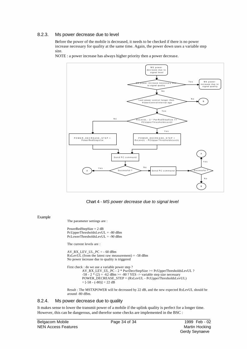
8.2.3. Ms power decrease due to level Before the power of the mobile is decreased, it needs to be checked if there is no power increase necessary for quality at the same time. Again, the power down uses a variable step size. NOTE : a power increase has always higher priority then a power decrease.
M S p o w e r d e c r e a s e d u e t o
s i g n a l l e v e l
L a s t p o w e r c o n t r o l l o n g e r t h e n P o w e r C o n t r o l I n t e r v a l a g o
B
R x L e v U L - 2 * P w r R e d S t e p S i z e > = P C U p p e r T h r e s h o l d s L e v U l
P O W E R _ D E C R E A S E _ S T E P = R x L e v U L - P C U p p e r T h r e s h o l d s L e v U L
P O W E R _ D E C R E A S E _ S T E P = P o w e r R e d S t e p s i z e
S e n d P C c o m m a n d
S u c c e s s f u l ?A S e n d P C c o m m a n d S u c c e s s f u l ?
A
B
M S p o w e r i n c r e a s e n e c e s s a r y d u e t o s i g n a l q u a l i t y
M S p o w e r i n c r e a s e d u e t o
s i g n a l q u a l i t y
Y e s
N o
N o
Y e s
N o
Y e s
Y e s N o
Y e s
N o
Chart 4 - MS power decrease due to signal level
Example
The parameter settings are : PowerRedStepSize = 2 dB PcUpperThresholdsLevUL = -80 dBm PcLowerThresholdsLevUL = -90 dBm The current levels are : AV_RX_LEV_UL_PC = - 60 dBm RxLevUL (from the latest raw measurement) = -58 dBm No power increase due to quality is triggered First check : do we use a variable power step ? AV_RX_LEV_UL_PC - 2 * PwrDecrStepSize >= PcUpperThresholdsLevUL ? -58 - 2 * (2) = -62 dBm >= -80 ? YES -> variable step size necessary POWER_DECREASE_STEP = (RxLevUL - PcUpperThresholdsLevUL) = [-58 - (-80)] = 22 dB Result : The MSTXPOWER will be decreased by 22 dB, and the new expected RxLevUL should be around -80 dBm.
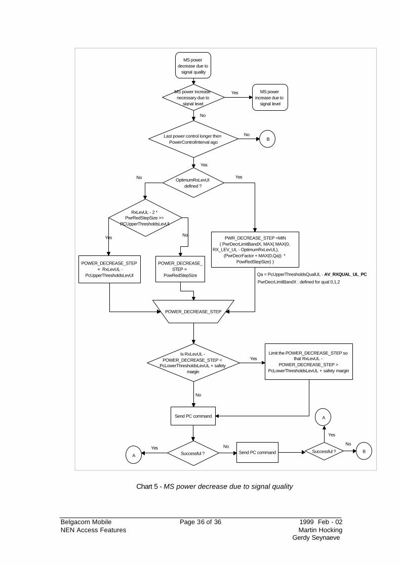
8.2.4. Ms power decrease due to quality It makes sense to lower the transmit power of a mobile if the uplink quality is perfect for a longer time. However, this can be dangerous, and therefor some checks are implemented in the BSC :
Belgacom Mobile Page 35 of 35 1999 Feb - 02 NEN Access Features Martin Hocking
Gerdy Seynaeve
• There should not be a power increase necessary for level at the same time • The power decrease due to quality should not trigger an increase due to level. The
RxLev has to stay above the lower threshold by a safety margin of 6 dB.
An additional parameter can be defined on a TRX basis which defines the
all, the maximum power decrease is defined as a PwrDecrLimit. A different power decrease limit can be defined depending on the value of the PcUpperThresholdsQualUL (0,1 and 2). The power decrease is also dependent on how far the current averaged UL level is from the optimum level, and how far the current received quality is from the used threshold.
This OptimumRxLevUL can be defined on a TRX per TRX basis. NOTE : The safety margin of (default 5 dB) is an UTPFIL parameter, and can be patched using MML commands. It is used for UL and DL power control.
The name of the parameter is SAFETY_MARGIN, the family is 1B3, parameter # 0xB. It can be patched as follows :
Use DFD command to find the first free record number is the UTP-file (5AC006B) ZDFD:MCMU,<active unit>:5AC006B; Us the DFS command to substitute the current value of the parameter
NOTE : A safety margin of 5 will ensure that the power control will not take the receive level lower then 6 dB above the lower threshold.
Belgacom Mobile Page 36 of 36 1999 Feb - 02 NEN Access Features Martin Hocking
Gerdy Seynaeve
MS power decrease due to
signal quality
Last power control longer then PowerControlInterval ago
B
RxLevUL - 2 * PwrRedStepSize >=
PCUpperThresholdsLevUl
POWER_DECREASE_STEP = RxLevUL -
PcUpperThresholdsLevUl
PWR_DECREASE_STEP =MIN ( PwrDecrLimitBandX, MAX( MAX(0,
RX_LEV_UL - OptimumRxLevUL), (PwrDecrFactor + MAX(0,Qa)) *
PowRedStepSize) )
Qa = PcUpperThresholdsQualUL - AV_RXQUAL_UL_PC
POWER_DECREASE_STEP
PwrDecrLimitBandX : defined for qual 0,1,2
OptimumRxLevUl defined ?
Send PC command
ASend PC command
A
BSuccessful ?Successful ?
MS power increase necessary due to
signal level
MS power increase due to
signal level
Yes
No
No
Yes
YesNo
Yes
NoYes
Yes
No
Is RxLevUL - POWER_DECREASE_STEP <
PcLowerThresholdsLevUL + safety margin
No
Yes
POWER_DECREASE_STEP =
PowRedStepSize
No
Limit the POWER_DECREASE_STEP so that RxLevUL -
POWER_DECREASE_STEP > PcLowerThresholdsLevUL + safety margin
Chart 5 - MS power decrease due to signal quality
Belgacom Mobile Page 37 of 37 1999 Feb - 02 NEN Access Features Martin Hocking
Gerdy Seynaeve
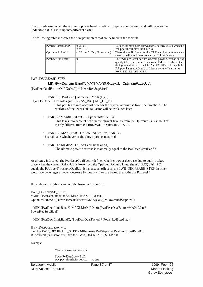
The formula used when the optimum power level is defined, is quite complicated, and will be easier to understand if it is split up into different parts : The following table indicates the new parameters that are defined in the formula
PwrDecrLimitBandX 0..38 dB X = 0,1,2
Defines the maximum allowed power decrease step when the PcUpperThresholdsQualUL = X
OptimumRxLevUL -109 .. -47 dBm, N (not used) The optimum Rx Level for this TRX which assures adequate speech quality and does not cause UL interference
PwrDecrQualFactor 0 1
The PwrDecrFactor defines whether power decrease due to quality takes place when the current RxLevUL is lower then the OptimumRxLevUL and the AV_RXQUAL_PC equals the PcUpperThresholdQualUL. It has also an effect on the PWR_DECREASE_STEP.
PWR_DECREASE_STEP
= MIN {PwrDecrLimitBandX, MAX[ MAX(0,RxLevUL OptimumRxLevUL), (PwrDecrQualFactor+MAX(Qa,0)) * PowerRedStepSize]}
• PART 1 : PwrDecrQualFactor + MAX (Qa,0) Qa = PcUpperThresholdsQualUL - AV_RXQUAL_UL_PC
This part takes into account how far the current average is from the threshold. The working of the PwrDecrQualFactor will be explained later.
• PART 2 : MAX(0, RxLevUL - OptimumRxLevUL)
This takes into account how far the current level is from the OptimumRxLevUL. This is only different from 0 if RxLevUL > OptimumRxLevUL.
• PART 3 : MAX (PART 1 * PowRedStepSize, PART 2)
This will take whichever of the above parts is maximal
• PART 4 : MIN(PART3, PwrDecrLimitBandX) The ultimate power decrease is maximally equal to the PwrDecrLimitBandX
As already indicated, the PwrDecrQualFactor defines whether power decrease due to quality takes place when the current RxLevUL is lower then the OptimumRxLevUL and the AV_RXQUAL_PC equals the PcUpperThresholdQualUL. It has also an effect on the PWR_DECREASE_STEP. In other words, do we trigger a power decrease for quality if we are below the optimum RxLevel ? If the above conditions are met the formula becomes : PWR_DECREASE_STEP = MIN {PwrDecrLimitBandX, MAX[ MAX(0,RxLevUL - OptimumRxLevUL),(PwrDecrQualFactor+MAX(Qa,0)) * PowerRedStepSize]} = MIN {PwrDecrLimitBandX, MAX[ MAX(0,X<0),(PwrDecrQualFactor+MAX(0,0)) * PowerRedStepSize]} = MIN {PwrDecrLimitBandX, (PwrDecrQualFactor) * PowerRedStepSize} If PwrDecrQualFactor = 1, then the PWR_DECREASE_STEP = MIN(PowerRedStepSize, PwrDecrLimitBandX) If PwrDecrQualFactor = 0, then the PWR_DECREASE_STEP = 0 Example :
The parameter settings are : PowerRedStepSize = 2 dB PcUpperThresholdsLevUL = -80 dBm
Belgacom Mobile Page 38 of 38 1999 Feb - 02 NEN Access Features Martin Hocking
Gerdy Seynaeve
PcLowerThresholdsLevUL = -90 dBm PcUpperTresholdsQualUL = 0, therefor PwrDecrLimitBand0 will be used PcLowerThresholdsQualUL = 5 PwrDecrLimitBand0 = 4 dB PwrDecrLimitBand1 = 2 dB PwrDecrLimitBand2 = 0 dB PowerDecrQualFactor = 1 OptimumRxLevUL = -85 dBm safety margin = 5 dB
The current levels are : AV_RX_LEV_UL_PC = -80 dBm RxLevUL (from the latest raw measurement) = -79 dBm AV_RX_QUAL_UL_PC = 0 No power increase due to level is triggered The PWR_DECREASE_STEP is then : PWR_DECREASE_STEP = MIN {PwrDecrLimitBandX, MAX[ MAX(0,RxLevUL - OptimumRxLevUL),(PwrDecrQualFactor+MAX(Qa,0)) * PowerRedStepSize]} =MIN {4, MAX[ MAX(0, -79 - (-85)),(1+MAX(0,0)) * 2]} =MIN {4, MAX(6,2)} =MIN {4, 6} = 4 dB Would this power decrease step of 4 dB trigger a power increase due to level ? Is RxLevUL - PWR_DECREASE_STEP > PcLowerThresholdsLevDL + safety margin Is -81 - 4 > -90 + 5 Is -85 > -85 ? NO In this case, a power decrease of 4 dB will be done.
Belgacom Mobile Page 39 of 39 1999 Feb - 02 NEN Access Features Martin Hocking
Gerdy Seynaeve
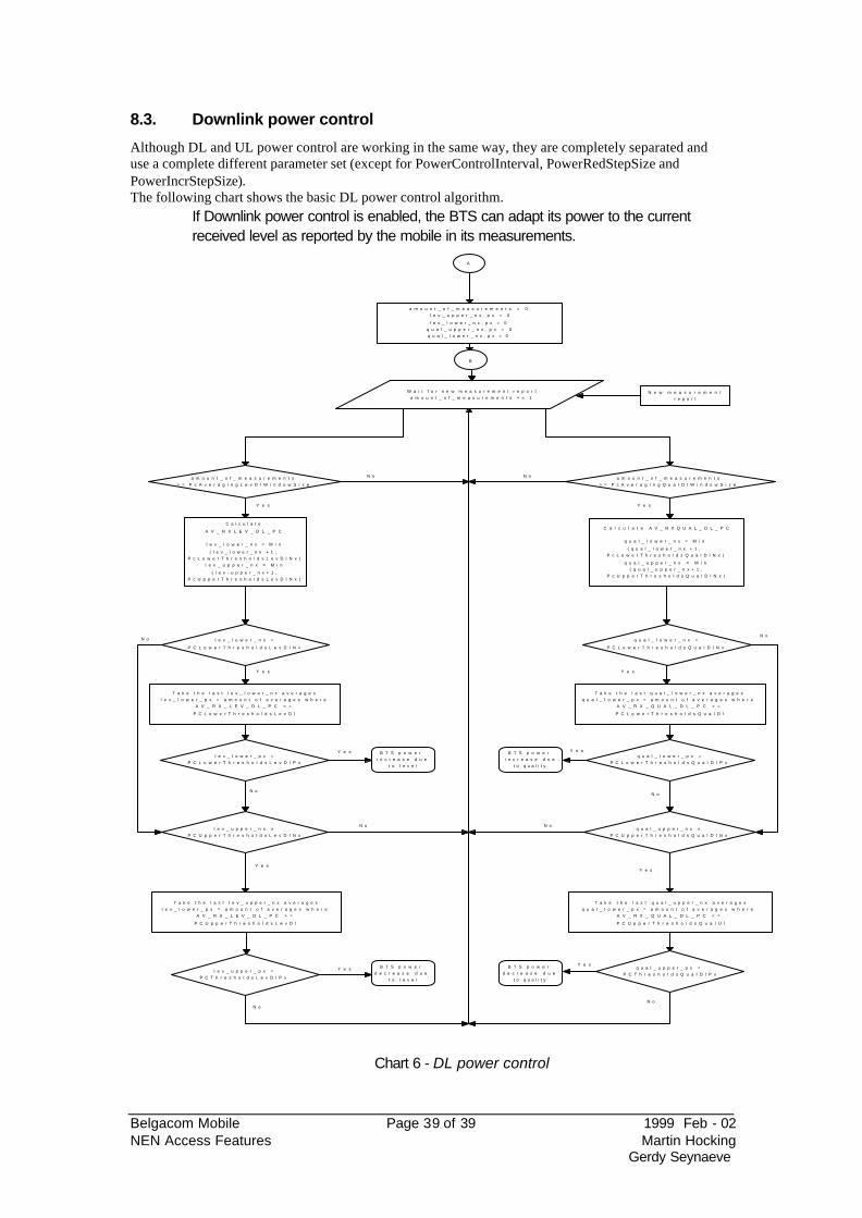
8.3. Downlink power control
Although DL and UL power control are working in the same way, they are completely separated and use a complete different parameter set (except for PowerControlInterval, PowerRedStepSize and PowerIncrStepSize). The following chart shows the basic DL power control algorithm.
If Downlink power control is enabled, the BTS can adapt its power to the current received level as reported by the mobile in its measurements.
A
a m o u n t _ o f _ m e a s u r e m e n t s = 0 l e v _ u p p e r _ n x , p x = 0
l e v _ l o w e r _ n x , p x = 0 q u a l _ u p p e r _ n x , p x = 0 q u a l _ l o w e r _ n x , p x = 0
N e w m e a s u r e m e n t r e p o r t
W a i t f o r n e w m e a s u r e m e n t r e p o r t a m o u n t _ o f _ m e a s u r e m e n t s + = 1
a m o u n t _ o f _ m e a s u r e m e n t s > = P c A v e r a g i n g L e v D l W i n d o w S i z e
C a l c u l a t e
A V _ R X L E V _ D L _ P C
l e v _ l o w e r _ n x = M i n
( l e v _ l o w e r _ n x + 1 , P c L o w e r T h r e s h o l d s L e v D l N x )
l e v _ u p p e r _ n x = M i n
( l e v - u p p e r _ n x + 1 , P c U p p e r T h r e s h o l d s L e v D l N x )
T a k e t h e l a s t l e v _ l o w e r _ n x a v e r a g e s l e v _ l o w e r _ p x = a m o u n t o f a v e r a g e s w h e r e
A V _ R X _ L E V _ D L _ P C < =
P C L o w e r T h r e s h o l d s L e v D l
l e v _ l o w e r _ p x = P C L o w e r T h r e s h o l d s L e v D l P x
B T S p o w e r i n c r e a s e d u e
t o l e v e l
T a k e t h e l a s t l e v _ u p p e r _ n x a v e r a g e s l e v _ l o w e r _ p x = a m o u n t o f a v e r a g e s w h e r e
A V _ R X _ L E V _ D L _ P C > =
P C U p p e r T h r e s h o l d s L e v D l
l e v _ l o w e r _ n x =
P C L o w e r T h r e s h o l d s L e v D l N x
l e v _ u p p e r _ n x = P C U p p e r T h r e s h o l d s L e v D l N x
l e v _ u p p e r _ p x = P C T h r e s h o l d s L e v D l P x
B T S p o w e r d e c r e a s e d u e
t o l e v e l
a m o u n t _ o f _ m e a s u r e m e n t s > = P c A v e r a g i n g Q u a l D l W i n d o w S i z e
C a l c u l a t e A V _ R X Q U A L _ D L _ P C
q u a l _ l o w e r _ n x = M i n
( q u a l _ l o w e r _ n x + 1 , P c L o w e r T h r e s h o l d s Q u a l D l N x )
q u a l _ u p p e r _ n x = M i n ( q u a l _ u p p e r _ n x + 1 ,
P c U p p e r T h r e s h o l d s Q u a l D l N x )
q u a l _ l o w e r _ n x =
P C L o w e r T h r e s h o l d s Q u a l D l N x
T a k e t h e l a s t q u a l _ l o w e r _ n x a v e r a g e s q u a l _ l o w e r _ p x = a m o u n t o f a v e r a g e s w h e r e
A V _ R X _ Q U A L _ D L _ P C > =
P C L o w e r T h r e s h o l d s Q u a l D l
q u a l _ l o w e r _ p x = P C L o w e r T h r e s h o l d s Q u a l D l P x
B T S p o w e r i n c r e a s e d u e
t o q u a l i t y
q u a l _ u p p e r _ n x = P C U p p e r T h r e s h o l d s Q u a l D l N x
T a k e t h e l a s t q u a l _ u p p e r _ n x a v e r a g e s q u a l _ l o w e r _ p x = a m o u n t o f a v e r a g e s w h e r e
A V _ R X _ Q U A L _ D L _ P C < =
P C U p p e r T h r e s h o l d s Q u a l U l
q u a l _ u p p e r _ p x = P C T h r e s h o l d s Q u a l D l P x
B T S p o w e r d e c r e a s e d u e
t o q u a l i t y
B
Y e s
N o
Y e s
Y e s
N o
Y e s
N o
Y e s
N o
N o N o
Y e s
N o
Y e s
Y e s
N o
N o
Y e s
Y e s
N o
Chart 6 - DL power control
Belgacom Mobile Page 40 of 40 1999 Feb - 02 NEN Access Features Martin Hocking
Gerdy Seynaeve
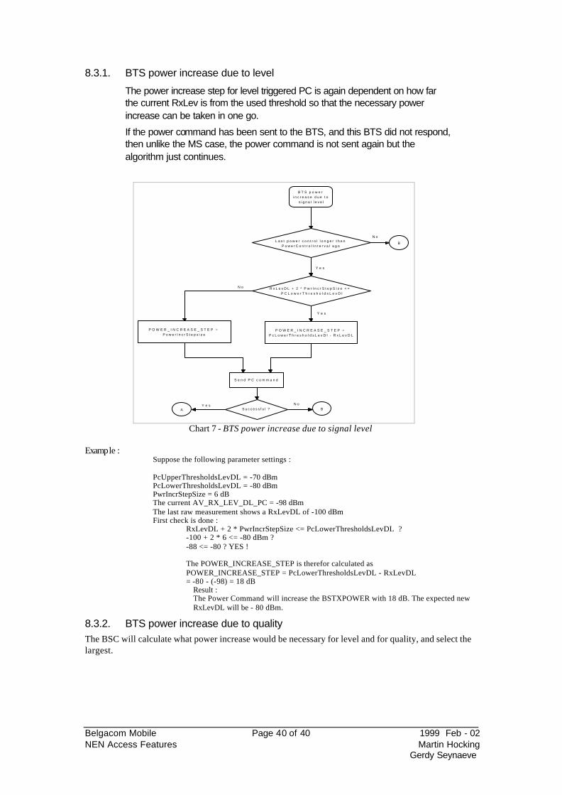
8.3.1. BTS power increase due to level
The power increase step for level triggered PC is again dependent on how far the current RxLev is from the used threshold so that the necessary power increase can be taken in one go.
If the power command has been sent to the BTS, and this BTS did not respond, then unlike the MS case, the power command is not sent again but the algorithm just continues.
B T S p o w e r i n c r e a s e d u e t o
s i g n a l l e v e l
R x L e v D L + 2 * P w r I n c r S t e p S i z e < = P C L o w e r T h r e s h o l d s L e v D l
P O W E R _ I N C R E A S E _ S T E P = P c L o w e r T h r e s h o l d s L e v D l - R x L e v D L
P O W E R _ I N C R E A S E _ S T E P = P o w e r I n c r S t e p s i z e
L a s t p o w e r c o n t r o l l o n g e r t h e n P o w e r C o n t r o l I n t e r v a l a g o
B
S e n d P C c o m m a n d
S u c c e s s f u l ?A B
N o
Y e s
Y e s
N o
Y e s N o
Chart 7 - BTS power increase due to signal level
Example :
Suppose the following parameter settings : PcUpperThresholdsLevDL = -70 dBm PcLowerThresholdsLevDL = -80 dBm PwrIncrStepSize = 6 dB The current AV_RX_LEV_DL_PC = -98 dBm The last raw measurement shows a RxLevDL of -100 dBm First check is done :
RxLevDL + 2 * PwrIncrStepSize <= PcLowerThresholdsLevDL ? -100 + 2 * 6 <= -80 dBm ? -88 <= -80 ? YES ! The POWER_INCREASE_STEP is therefor calculated as POWER_INCREASE_STEP = PcLowerThresholdsLevDL - RxLevDL = -80 - (-98) = 18 dB
Result : The Power Command will increase the BSTXPOWER with 18 dB. The expected new RxLevDL will be - 80 dBm.
8.3.2. BTS power increase due to quality The BSC will calculate what power increase would be necessary for level and for quality, and select the largest.
Belgacom Mobile Page 41 of 41 1999 Feb - 02 NEN Access Features Martin Hocking
Gerdy Seynaeve
BTS power increase due to
signal quality
Last power control longer then PowerControlInterval ago
B
RxLevDL + 2 * PwrIncrStepSize <= PCLowerThresholdsLevDl
POWER_INCREASE_STEP = PcLowerThresholdsLevDl - RxLevDL
POWER_INCREASE_STEP = (1+MAX (0, Qa) * PowerIncrStepSize
Qa = RxQualDL - PCLowerThresholdsQualDL
Max POWER_INCREASE_STEP
DSend PC command
Successful ?A B
No
Yes
Yes
Yes No
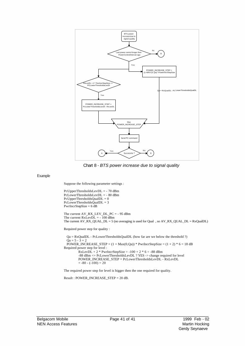
Chart 8 - BTS power increase due to signal quality
Example
Suppose the following parameter settings : PcUpperThresholdsLevDL = - 70 dBm PcLowerThresholdsLevDL = - 80 dBm PcUpperThresholdsQualDL = 0 PcLowerThresholdsQualDL = 3 PwrIncrStepSize = 6 dB The current AV_RX_LEV_DL_PC = - 95 dBm The current RxLevDL = - 100 dBm The current AV_RX_QUAL_DL = 5 (no averaging is used for Qual , so AV_RX_QUAL_DL = RxQualDL) Required power step for quality : Qa = RxQualDL - PcLowerThresholdsQualDL (how far are we below the threshold ?) Qa = 5 - 3 = 2 POWER_INCREASE_STEP = (1 + Max(0,Qa)) * PwrIncrStepSize = (1 + 2) * 6 = 18 dB Required power step for level :
RxLevDL + 2 * PwrIncrStepSize = -100 + 2 * 6 = -88 dBm -88 dBm <= PcLowerThresholdsLevDL ? YES -> change required for level POWER_INCREASE_STEP = PcLowerThresholdsLevDL - RxLevDL = -80 - (-100) = 20
The required power step for level is bigger then the one required for quality. Result : POWER_INCREASE_STEP = 20 dB.
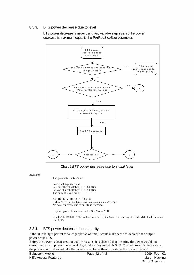
Belgacom Mobile Page 42 of 42 1999 Feb - 02 NEN Access Features Martin Hocking
Gerdy Seynaeve
8.3.3. BTS power decrease due to level
BTS power decrease is never using any variable step size, so the power decrease is maximum equal to the PwrRedStepSize parameter.
B T S p o w e r d e c r e a s e d u e t o
s i g n a l l e v e l
L a s t p o w e r c o n t r o l l o n g e r t h e n P o w e r C o n t r o l I n t e r v a l a g o
B
P O W E R _ D E C R E A S E _ S T E P = P o w e r R e d S t e p s i z e
S e n d P C c o m m a n d
S u c c e s s f u l ?A B
B T S p o w e r i n c r e a s e n e c e s s a r y d u e t o s i g n a l q u a l i t y
B T S p o w e r i n c r e a s e d u e t o
s i g n a l q u a l i t y
Y e s
N o
N o
Y e s
Y e s N o
Y e s
Chart 9 BTS power decrease due to signal level
Example The parameter settings are : PowerRedStepSize = 2 dB PcUpperThresholdsLevDL = -80 dBm PcLowerThresholdsLevDL = -90 dBm The current levels are : AV_RX_LEV_DL_PC = - 60 dBm RxLevDL (from the latest raw measurement) = -58 dBm No power increase due to quality is triggered Required power decrease = PwrRedStepSize = 2 dB Result : The BSTXPOWER will be decreased by 2 dB, and the new expected RxLevUL should be around - 60 dBm.
8.3.4. BTS power decrease due to quality If the DL quality is perfect for a longer period of time, it could make sense to decrease the output power of the BTS. Before the power is decreased for quality reasons, it is checked that lowering the power would not cause a increase in power due to level. Again, the safety margin is 5 dB. This will result in the fact that the power control does not take the receive level lower then 6 dB above the lower threshold.
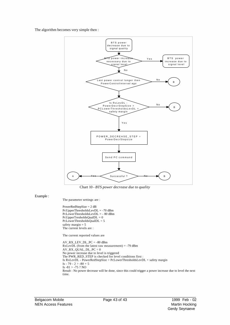
Belgacom Mobile Page 43 of 43 1999 Feb - 02 NEN Access Features Martin Hocking
Gerdy Seynaeve
The algorithm becomes very simple then :
B T S p o w e r d e c r e a s e d u e t o
s i g n a l q u a l i t y
L a s t p o w e r c o n t r o l l o n g e r t h e n P o w e r C o n t r o l I n t e r v a l a g o
B
B T S p o w e r i n c r e a s e n e c e s s a r y d u e t o
s i g n a l l e v e l
B T S p o w e r i n c r e a s e d u e t o
s i g n a l l e v e l
Y e s
N o
N o
S e n d P C c o m m a n d
S u c c e s s f u l ?A BY e s N o
P O W E R _ D E C R E A S E _ S T E P = P o w e r D e c r S t e p s i z e
I s R x L e v D L - P o w e r D e c r S t e p S i z e >
P C L o w e r T h r e s h o l d s L e v D L + s a f e t y m a r g i n
BN o
Y e s
Chart 10 - BTS power decrease due to quality
Example :
The parameter settings are : PowerRedStepSize = 2 dB PcUpperThresholdsLevDL = -70 dBm PcLowerThresholdsLevDL = - 80 dBm PcUpperTresholdsQualDL = 0 PcLowerThresholdsQualDL = 5 safety margin = 5 The current levels are : The current reported values are AV_RX_LEV_DL_PC = -80 dBm RxLevDL (from the latest raw measurement) = -79 dBm AV_RX_QUAL_DL_PC = 0 No power increase due to level is triggered The PWR_RED_STEP is checked for level conditions first : Is RxLevDL - PowerRedStepSize > PcLowerThresholdsLevDL + safety margin Is - 79 - 2 > -80 + 5 Is -81 > -75 ? NO Result : No power decrease will be done, since this could trigger a power increase due to level the next time.
Belgacom Mobile Page 44 of 44 1999 Feb - 02 NEN Access Features Martin Hocking
Gerdy Seynaeve
8.4. Power control performance indicators
The indicators based upon power control can give an indication on all the events described in the flowcharts above. The available counters are Ms_Pwr_Inc_Cmd The number of power control commands for MS PC due to low level Ms_Pwr_Dec_Cmd The number of power control commands for MS PC due to high level BS_Pwr_Inc_Cmd The number of power control commands for BTS PC due to low level BS_Pwr_Dec_Cmd The number of power control commands for BTS PC due to high level Ms_Pwr_Inc_Qual The number of power control commands for MS PC due to bad quality Ms_Pwr_Dec_Qual The number of power control commands for MS PC due to good quality BS_Pwr_Inc_Qual The number of power control commands for BTS PC due to bad quality BS_Pwr_Dec_Qual The number of power control commands for BTS PC due to good quality Moreover, some counters are available which are averaged values (averaged over 20sec) Ave_Ms_Power Average MS power level Ave_BS_Power Average BTS power level Ave_DL_Sig_Strength Average DL signal strength in the cell Ave_UL_Sig_Strength Average UL signal strength in the cell Ave_DL_Sig_Qual Average DL signal quality in the cell Ave_UL_Sig_Qual Average UL signal quality in the cell Ave_MS_BS_dist Average MS to BS distance in a cell These can be used to calculate the path balance as follows pathloss in UL : Ave_Ms_Power - Ave_UL_Sig_Strength pathloss in DL : Ave_BS_Power - Ave_DL_Sig_Strength The Ave_Ms_Power is an offset to 43 dBm, in steps of 2 dB. A value of 10 means 43 - (10*2) = 23 dBm. The Ave_Bs_Power is an offset in two dB power steps to the maximum power capability of the BTS (39 dBm for a 3rd generation, and 43 dBm for a second generation), so that a value of 10 means 23 dBm in case of a second gen BTS, and 19 dBm in case of a third generation. NOTE : Since BSS release S6 and OMC release T10, these are actually available on a per TRX basis
9. The handover algorithm
9.1. HO types
9.1.1. Intracell - intra BSC - inter BSC Depending on how the mobile is moving through the network and how the network is designed, different types of handover might be necessary. The mobile can :
• do a handover within the same cell : intracell handover, controlled by the BSC • roam within a BSC area : intercell - intra BSC handover, controlled by the BSC • move to a BTS connected to another BSC : intercell - inter BSC handover, controlled
by the MSC • move to a BTS connected to another MSC : interMSC handover
The signalling procedures are different for all these handovers types, but always contain the same steps :
1. The mobile sends measurement reports to the BTS. These are then forwarded to the BSC.
Belgacom Mobile Page 45 of 45 1999 Feb - 02 NEN Access Features Martin Hocking
Gerdy Seynaeve
2. The BSC processes these measurements and detects if a handover is required. 3. The source BSC will ask for a free channel on the target BTS by sending a message
to the target BSC. 4. The target BSC allocates a channel and sends this information back to the source
BSC. 5. The source BSC sends this information to the mobile. 6. The mobile accesses the new channel. 7. The target BSC detects the mobile and sends a message to the source BSC. 8. The source BSC releases the old channel.
NOTE : the source and the target BSC can be the same in the case of intra BSC handover.
The network is normally optimised by fixed net design to minimise the number of inter MSC handovers. This means that a handover controlled by a BSC is preferred over an MSC controlled handover. A BSC controlled handover is faster and more reliable then an MSC controlled handover.
Belgacom Mobile Page 46 of 46 1999 Feb - 02 NEN Access Features Martin Hocking
Gerdy Seynaeve
9.1.2. non-synchronised vs. synchronised non synchronised handover When a mobile is doing a non synchronised handover, it will (upon reception of a handover command) switch to the new channel and send access bursts to the target BTS. Upon reception of these access bursts, the target BTS can determine the power the mobile has to use, the timing advance and some other information. The source BTS will send this information to the mobile in the PHYSICAL INFORMATION message. The whole procedure is controlled by timers on both sides, so that if anything goes wrong, the mobile can still return to the old channel. If the mobile has received the physical information, the channels can be connected on the target BTS and the call can go on on the new channel. synchronised handover The mobile will send a maximum of 4 handover access bursts and activate the new channel. The mobile will know the new timing advance because it knows that the target BTS is synchronous within
bit period. The mobile can calculate the new Timing Advance itself. No physical information messages will be sent to the MS. It is clear that synchronised handover is only possible if between the timing of the source and target BTSs are correlated. Synchronous handover has the advantage that it is faster and therefor also more stable. Synchronous handover is for instance possible if the handover is triggered between two network elements which are controlled by the same device (e.g. two sectors controlled by the same BCF). It is possible to define on a per neighbour basis if a handover is synchronous or not.
9.1.3. Different HO reasons A handover can happen because of different reasons. The normal case for a handover is handover due to radio conditions (such as PBGT, Quality and Level). However, the Nokia algorithm is able to perform additional types of handovers :
• HO related to channel administration, e.g. before a cell or TRX is locked down, it is
possible to force all the calls to handover. • Due to congestion (no free TCHs), a call can be handed over to a traffic channel on
another cell. This is the so called directed retry. • The MSC requests to hand over traffic from one specific cell to other specified cells
for traffic reasons. • A handover from an extended cell to an inner cell. • A handover by BSC internal traffic control, such as an umbrella handover to a
microcell. • A handover based on mobile speed.
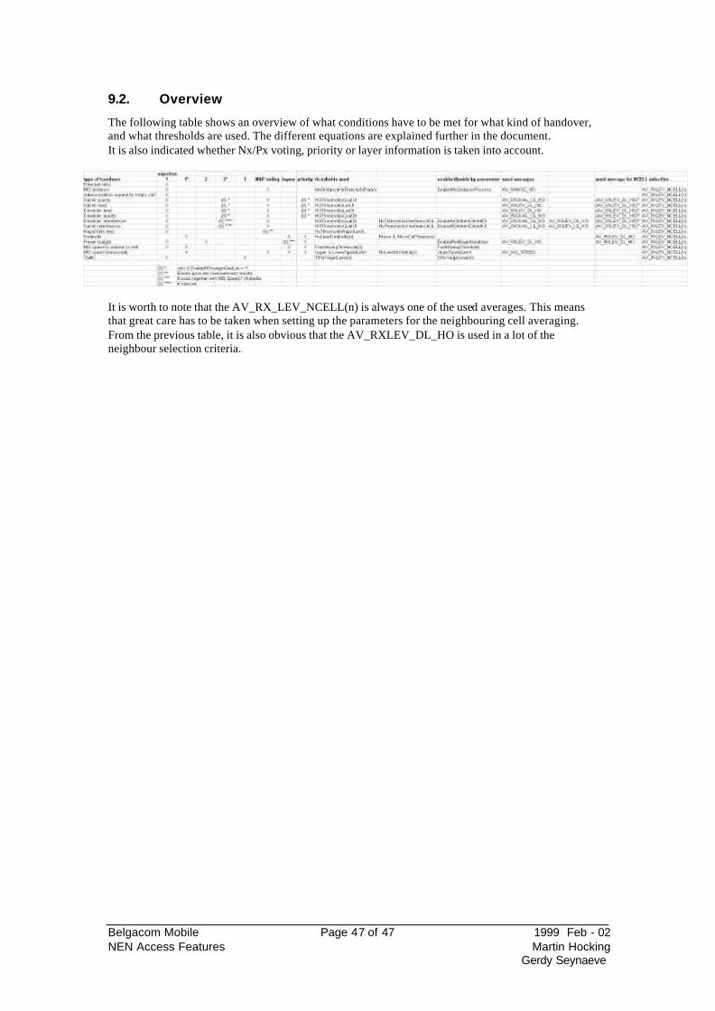
Belgacom Mobile Page 47 of 47 1999 Feb - 02 NEN Access Features Martin Hocking
Gerdy Seynaeve
9.2. Overview
The following table shows an overview of what conditions have to be met for what kind of handover, and what thresholds are used. The different equations are explained further in the document. It is also indicated whether Nx/Px voting, priority or layer information is taken into account.
It is worth to note that the AV_RX_LEV_NCELL(n) is always one of the used averages. This means that great care has to be taken when setting up the parameters for the neighbouring cell averaging. From the previous table, it is also obvious that the AV_RXLEV_DL_HO is used in a lot of the neighbour selection criteria.
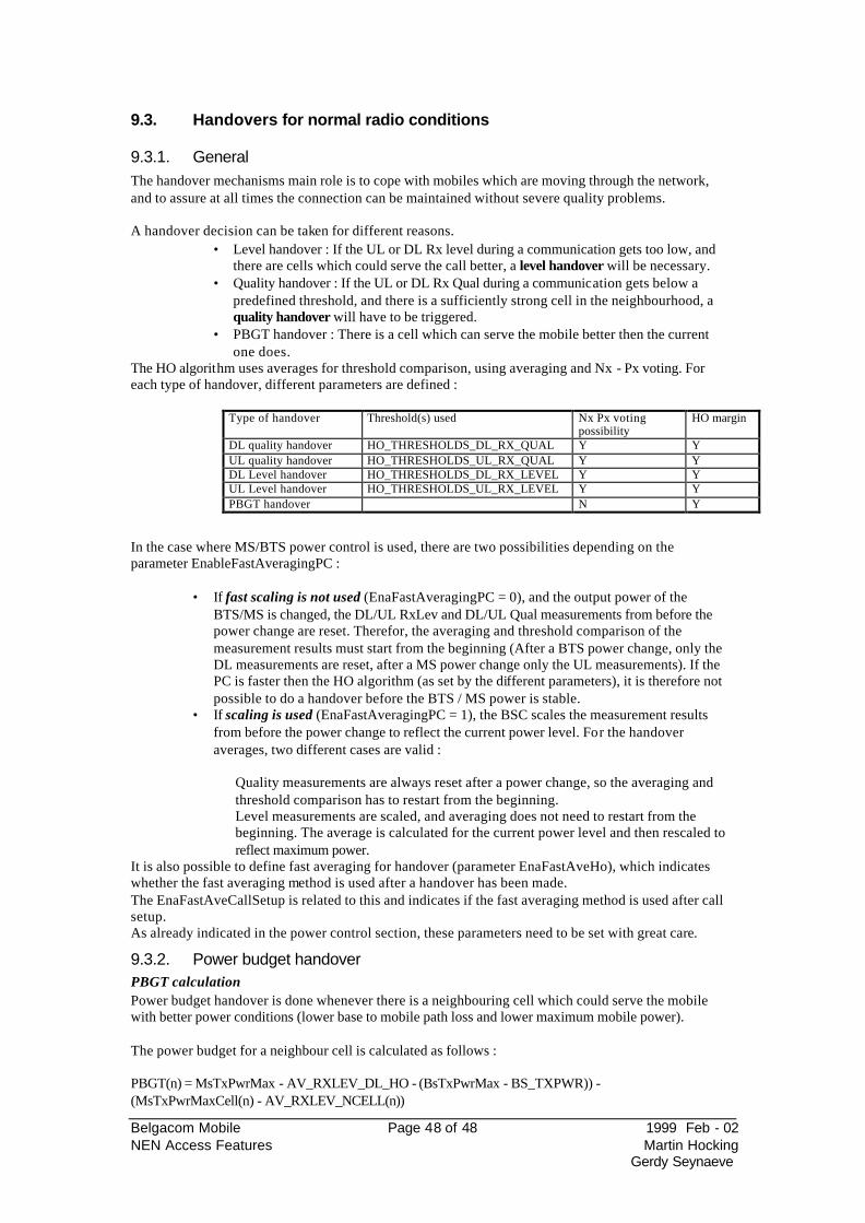
Belgacom Mobile Page 48 of 48 1999 Feb - 02 NEN Access Features Martin Hocking
Gerdy Seynaeve
9.3. Handovers for normal radio conditions
9.3.1. General The handover mechanisms main role is to cope with mobiles which are moving through the network, and to assure at all times the connection can be maintained without severe quality problems. A handover decision can be taken for different reasons.
• Level handover : If the UL or DL Rx level during a communication gets too low, and there are cells which could serve the call better, a level handover will be necessary.
• Quality handover : If the UL or DL Rx Qual during a communication gets below a predefined threshold, and there is a sufficiently strong cell in the neighbourhood, a quality handover will have to be triggered.
• PBGT handover : There is a cell which can serve the mobile better then the current one does.
The HO algorithm uses averages for threshold comparison, using averaging and Nx - Px voting. For each type of handover, different parameters are defined :
Type of handover Threshold(s) used Nx Px voting possibility
HO margin
DL quality handover HO_THRESHOLDS_DL_RX_QUAL Y Y UL quality handover HO_THRESHOLDS_UL_RX_QUAL Y Y DL Level handover HO_THRESHOLDS_DL_RX_LEVEL Y Y UL Level handover HO_THRESHOLDS_UL_RX_LEVEL Y Y PBGT handover N Y
In the case where MS/BTS power control is used, there are two possibilities depending on the parameter EnableFastAveragingPC :
• If fast scaling is not used (EnaFastAveragingPC = 0), and the output power of the BTS/MS is changed, the DL/UL RxLev and DL/UL Qual measurements from before the power change are reset. Therefor, the averaging and threshold comparison of the measurement results must start from the beginning (After a BTS power change, only the DL measurements are reset, after a MS power change only the UL measurements). If the PC is faster then the HO algorithm (as set by the different parameters), it is therefore not possible to do a handover before the BTS / MS power is stable.
• If scaling is used (EnaFastAveragingPC = 1), the BSC scales the measurement results from before the power change to reflect the current power level. For the handover averages, two different cases are valid :
Quality measurements are always reset after a power change, so the averaging and threshold comparison has to restart from the beginning. Level measurements are scaled, and averaging does not need to restart from the beginning. The average is calculated for the current power level and then rescaled to reflect maximum power.
It is also possible to define fast averaging for handover (parameter EnaFastAveHo), which indicates whether the fast averaging method is used after a handover has been made. The EnaFastAveCallSetup is related to this and indicates if the fast averaging method is used after call setup. As already indicated in the power control section, these parameters need to be set with great care.
9.3.2. Power budget handover PBGT calculation Power budget handover is done whenever there is a neighbouring cell which could serve the mobile with better power conditions (lower base to mobile path loss and lower maximum mobile power). The power budget for a neighbour cell is calculated as follows : PBGT(n) = MsTxPwrMax - AV_RXLEV_DL_HO - (BsTxPwrMax - BS_TXPWR)) - (MsTxPwrMaxCell(n) - AV_RXLEV_NCELL(n))
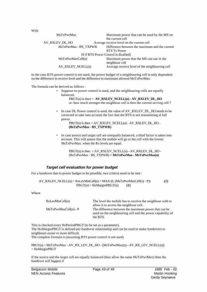
Belgacom Mobile Page 49 of 49 1999 Feb - 02 NEN Access Features Martin Hocking
Gerdy Seynaeve
With
MsTxPwrMax Maximum power that can be used by the MS on the current cell
AV_RXLEV_DL_HO Average receive level on the current cell BsTxPwrMax - BS_TXPWR Difference between the maximum and the current
BTS Tx Power (0 if BTS Power Control is disabled)
MsTxPwrMaxCell(n) Maximum power that the MS can use in the neighbour cell
AV_RXLEV_NCELL(n) Average receive level of the neighbouring cell
In the case BTS power control is not used, the power budget of a neighbouring cell is only dependent on the difference in receive level and the difference in maximum allowed MsTxPwrMax. The formula can be derived as follows :
• Suppose no power control is used, and the neighbouring cells are equally balanced.
PBGT(n) is then = AV_RXLEV_NCELL(n) - AV_RXLEV_DL_HO or: how much stronger the neighbour cell is then the current serving cell ?
• In case DL Power control is used, the value of AV_RXLEV_DL_HO needs to be
corrected to take into account the fact that the BTS is not transmitting at full power.
PBGT(n) is then = AV_RXLEV_NCELL(n) - AV_RXLEV_DL_HO - (BsTxPwrMax - BS_TXPWR)
• In case source and target cell are unequally balanced, a third factor is taken into
account. This will assure that the mobile will go to the cell with the lowest MsTxPwrMax. when the Rx levels are equal.
PBGT(n) is then = AV_RXLEV_NCELL(n) - AV_RXLEV_DL_HO - (BsTxPwrMax - BS_TXPWR) + MsTxPwrMax - MsTxPwrMax(n)
Target cell evaluation for power budget
For a handover due to power budget to be possible, two criteria need to be met :
AV_RXLEV_NCELL(n) > RxLevMinCell(n) + MAX (0, (MsTxPwrMaxCell(n) - P)) (1) PBGT(n) > HoMarginPBGT(n) (2)
Where
RxLevMinCell(n) The level the mobile has to receive the neighbour with to allow it to access the neighbour cell.
MsTxPwrMaxCell(n) - P The difference between the maximum power that can be used on the neighbouring cell and the power capability of the BTS.
This is checked every HoPeriodPBGT (to be set as a parameter). The HoMarginPBGT is defined per handover relationship and can be used to make handovers to neighbours easier or more difficult. The complete formula is (assuming BTS power control is not used) PBGT(n) = MsTxPwrMax - AV_RX_LEV_DL_HO - (MsTxPwrMax(n) - AV_RX_LEV_NCELL(n)) > HoMarginPBGT If the source and the target cell are equally balanced (they allow the same MsTxPwrMax) then the handover will happen if
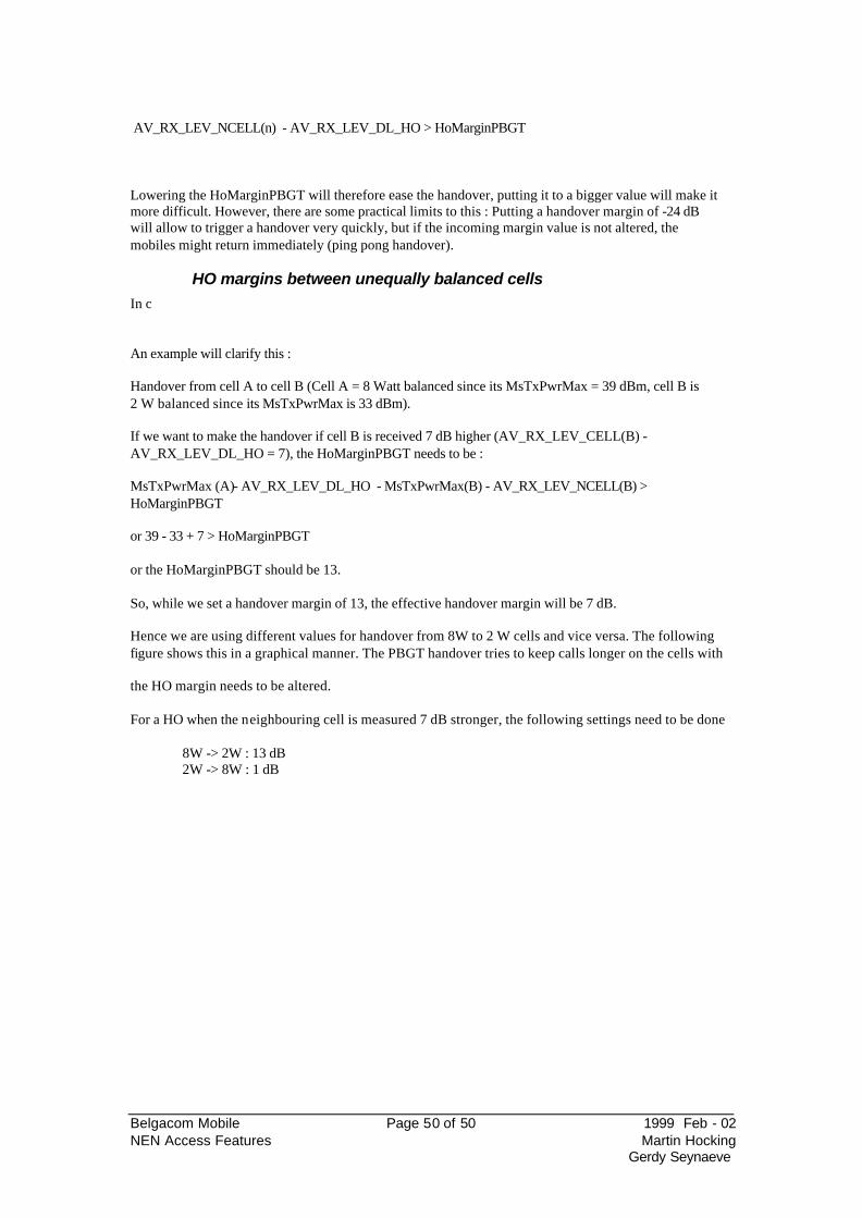
Belgacom Mobile Page 50 of 50 1999 Feb - 02 NEN Access Features Martin Hocking
Gerdy Seynaeve
AV_RX_LEV_NCELL(n) - AV_RX_LEV_DL_HO > HoMarginPBGT
Lowering the HoMarginPBGT will therefore ease the handover, putting it to a bigger value will make it more difficult. However, there are some practical limits to this : Putting a handover margin of -24 dB will allow to trigger a handover very quickly, but if the incoming margin value is not altered, the mobiles might return immediately (ping pong handover).
HO margins between unequally balanced cells
In c
An example will clarify this : Handover from cell A to cell B (Cell A = 8 Watt balanced since its MsTxPwrMax = 39 dBm, cell B is 2 W balanced since its MsTxPwrMax is 33 dBm). If we want to make the handover if cell B is received 7 dB higher (AV_RX_LEV_CELL(B) - AV_RX_LEV_DL_HO = 7), the HoMarginPBGT needs to be : MsTxPwrMax (A)- AV_RX_LEV_DL_HO - MsTxPwrMax(B) - AV_RX_LEV_NCELL(B) > HoMarginPBGT or 39 - 33 + 7 > HoMarginPBGT or the HoMarginPBGT should be 13. So, while we set a handover margin of 13, the effective handover margin will be 7 dB. Hence we are using different values for handover from 8W to 2 W cells and vice versa. The following figure shows this in a graphical manner. The PBGT handover tries to keep calls longer on the cells with
the HO margin needs to be altered. For a HO when the neighbouring cell is measured 7 dB stronger, the following settings need to be done 8W -> 2W : 13 dB 2W -> 8W : 1 dB
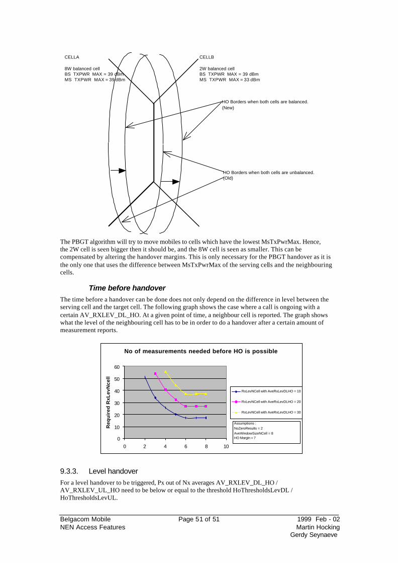
Belgacom Mobile Page 51 of 51 1999 Feb - 02 NEN Access Features Martin Hocking
Gerdy Seynaeve
CELLA CELLB
8W balanced cell 2W balanced cellBS_TXPWR_MAX = 39 dBm BS_TXPWR_MAX = 39 dBmMS_TXPWR_MAX = 39 dBm MS_TXPWR_MAX = 33 dBm
HO Borders when both cells are unbalanced.(Old)
HO Borders when both cells are balanced.(New)
The PBGT algorithm will try to move mobiles to cells which have the lowest MsTxPwrMax. Hence, the 2W cell is seen bigger then it should be, and the 8W cell is seen as smaller. This can be compensated by altering the handover margins. This is only necessary for the PBGT handover as it is the only one that uses the difference between MsTxPwrMax of the serving cells and the neighbouring cells.
Time before handover
The time before a handover can be done does not only depend on the difference in level between the serving cell and the target cell. The following graph shows the case where a call is ongoing with a certain AV_RXLEV_DL_HO. At a given point of time, a neighbour cell is reported. The graph shows what the level of the neighbouring cell has to be in order to do a handover after a certain amount of measurement reports.
9.3.3. Level handover For a level handover to be triggered, Px out of Nx averages AV_RXLEV_DL_HO / AV_RXLEV_UL_HO need to be below or equal to the threshold HoThresholdsLevDL / HoThresholdsLevUL.
No of measurements needed before HO is possible
0
10
20
30
40
50
60
0 2 4 6 8 10
Re
qu
ire
d R
xL
ev
Nc
ell
RxLevNCell with AveRxLevDLHO = 10
RxLevNCell with AveRxLevDLHO = 20
RxLevNCell with AveRxLevDLHO = 30
Assumptions :NoZeroResults = 2AveWindowSizeNCell = 8HO Margin = 7
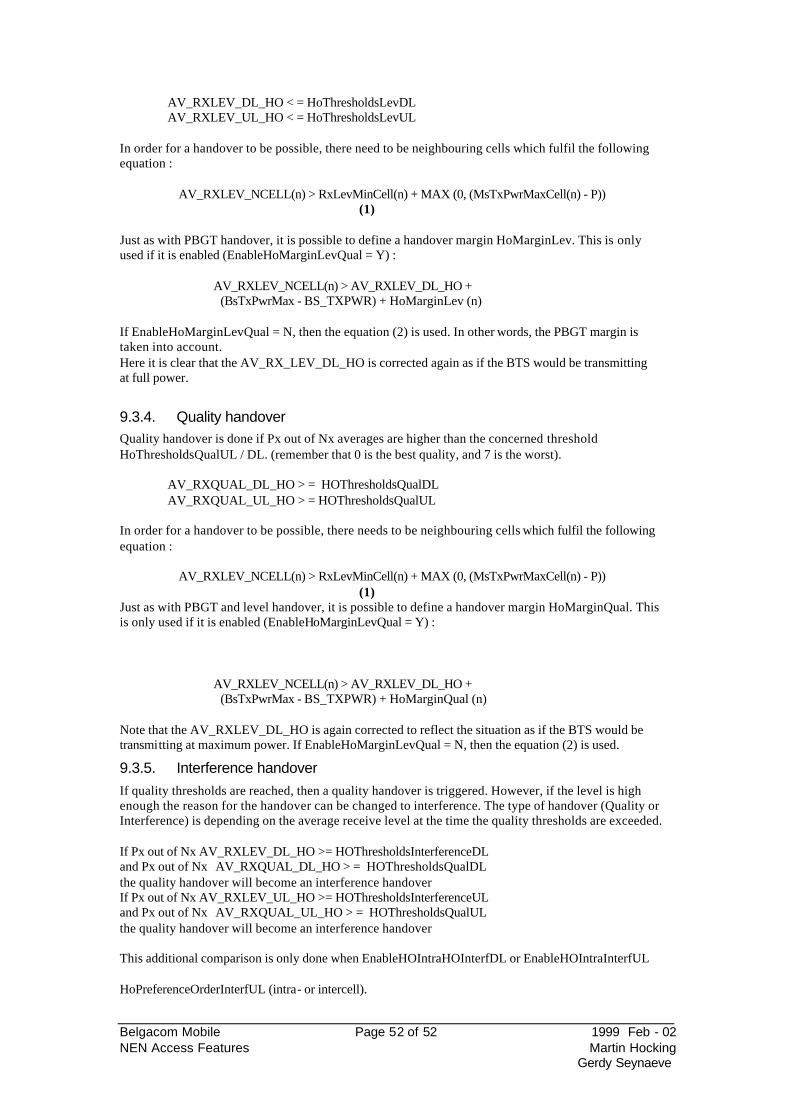
Belgacom Mobile Page 52 of 52 1999 Feb - 02 NEN Access Features Martin Hocking
Gerdy Seynaeve
AV_RXLEV_DL_HO < = HoThresholdsLevDL AV_RXLEV_UL_HO < = HoThresholdsLevUL In order for a handover to be possible, there need to be neighbouring cells which fulfil the following equation :
AV_RXLEV_NCELL(n) > RxLevMinCell(n) + MAX (0, (MsTxPwrMaxCell(n) - P)) (1)
Just as with PBGT handover, it is possible to define a handover margin HoMarginLev. This is only used if it is enabled (EnableHoMarginLevQual = Y) :
AV_RXLEV_NCELL(n) > AV_RXLEV_DL_HO + (BsTxPwrMax - BS_TXPWR) + HoMarginLev (n)
If EnableHoMarginLevQual = N, then the equation (2) is used. In other words, the PBGT margin is taken into account. Here it is clear that the AV_RX_LEV_DL_HO is corrected again as if the BTS would be transmitting at full power.
9.3.4. Quality handover Quality handover is done if Px out of Nx averages are higher than the concerned threshold HoThresholdsQualUL / DL. (remember that 0 is the best quality, and 7 is the worst). AV_RXQUAL_DL_HO > = HOThresholdsQualDL AV_RXQUAL_UL_HO > = HOThresholdsQualUL
In order for a handover to be possible, there needs to be neighbouring cells which fulfil the following equation :
AV_RXLEV_NCELL(n) > RxLevMinCell(n) + MAX (0, (MsTxPwrMaxCell(n) - P)) (1)
Just as with PBGT and level handover, it is possible to define a handover margin HoMarginQual. This is only used if it is enabled (EnableHoMarginLevQual = Y) :
AV_RXLEV_NCELL(n) > AV_RXLEV_DL_HO + (BsTxPwrMax - BS_TXPWR) + HoMarginQual (n)
Note that the AV_RXLEV_DL_HO is again corrected to reflect the situation as if the BTS would be transmitting at maximum power. If EnableHoMarginLevQual = N, then the equation (2) is used.
9.3.5. Interference handover If quality thresholds are reached, then a quality handover is triggered. However, if the level is high enough the reason for the handover can be changed to interference. The type of handover (Quality or Interference) is depending on the average receive level at the time the quality thresholds are exceeded. If Px out of Nx AV_RXLEV_DL_HO >= HOThresholdsInterferenceDL and Px out of Nx AV_RXQUAL_DL_HO > = HOThresholdsQualDL the quality handover will become an interference handover If Px out of Nx AV_RXLEV_UL_HO >= HOThresholdsInterferenceUL and Px out of Nx AV_RXQUAL_UL_HO > = HOThresholdsQualUL the quality handover will become an interference handover This additional comparison is only done when EnableHOIntraHOInterfDL or EnableHOIntraInterfUL
HoPreferenceOrderInterfUL (intra- or intercell).
Belgacom Mobile Page 53 of 53 1999 Feb - 02 NEN Access Features Martin Hocking
Gerdy Seynaeve
Belgacom Mobile Page 54 of 54 1999 Feb - 02 NEN Access Features Martin Hocking
Gerdy Seynaeve
9.4. Traffic reason handovers
9.4.1. Umbrella handover This type of handover can be activated when setting the EnaUmbrellaHO flag. This type of handover allows traffic to shift from the current cell to a neighbour cell whenever the call can be maintained on that neighbour cell. A comparison is done at regular intervals (HoPeriodUmbrella), and the AV_RXLEV_NCELL(n) is checked with the threshold HoLevelUmbrella(n). This parameter can be set on a per neighbour relationship basis.. This handover only takes the following equation into account:
AV_RXLEV_NCELL(n) > HoLevelUmbrella(n) The parameters the algorithm uses can be defined in order to move a certain type of mobiles to a certain layer. Therefore, it is possible to distinguish two classes of cells : macrocells and microcells. The BSC can make the distinction between both based upon two considerations : If MsTxPwrMaxNcell(n) >= MacroCellThreshold, the neighbouring cell is considered to be a macrocell. If MsTxPwrMaxNcell(n) <= MicroCellThreshold, the neighbouring cell is considered to be a microcell. The BSC takes into account the mobile power class as follows : If the maximum power capability of the mobile >= MacroCellThreshold, the cell must be considered as a macrocell before a handover is possible. If the maximum power capability of the mobile <= MicroCellThreshold, the cell must be considered as a microcell before a handover is possible. NOTE : This layering is disabled when MacroCellThreshold = 5 dBm At that time, the layer information based upon the MacroCellThreshold and the MicroCellThreshold is not used, and only the
HoLevelUmbrella(n)).
Combined umbrella and power budget If PBGT and Umbrella handover are both enabled (Enabl
but also the layer information. The layer of the source and the target cell must be equal before a PBGT handover is possible. There are two possibilities through which the BSC can know the layer information :
1.
MacroCellThreshold and MicroCellThreshold.
2. The AdjCellLayer parameter is set to the appropriate value (SAME, LOWER, HIGHER). The umbrella handover can then be based upon the fast moving threshold (FMT = 0 is a true umbrella, FMT > 0 is a fast moving mobile handover). (see later sections)
NOTE : The AdjCellLayer information is actually not taken into account by the Umbrella handover, but is only used to prevent PBGT handovers between different layers. This implies that if the layer definition based upon MacroCellThreshold and MicroCellThreshold is not used either, that Umbrella handover can happen between any of the layers. NOTE : Using Umbrella handover to shift traffic to the lower layer, is quite complicated to manage. This is clear from the following example (assuming that the layer information based upon Macro & MicroCellThresholds is not used).
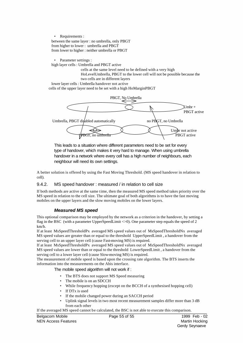
Belgacom Mobile Page 55 of 55 1999 Feb - 02 NEN Access Features Martin Hocking
Gerdy Seynaeve
• Requirements :
between the same layer : no umbrella, only PBGT from higher to lower : umbrella and PBGT from lower to higher : neither umbrella or PBGT
• Parameter settings : high layer cells : Umbrella and PBGT active
cells at the same level need to be defined with a very high HoLevelUmbrella, PBGT to the lower cell will not be possible because the two cells are in different layers
lower layer cells : Umbrella handover not active cells of the upper layer need to be set with a high HoMarginPBGT
PBGT, No Umbrella
Umbr + PBGT active
Umbrella, PBGT disabled automatically no PBGT, no Umbrella Umbr not active PBGT, no umbrella PBGT active
This leads to a situation where different parameters need to be set for every type of handover, which makes it very hard to manage. When using umbrella handover in a network where every cell has a high number of neighbours, each neighbour will need its own settings.
A better solution is offered by using the Fast Moving Threshold. (MS speed handover in relation to cell).
9.4.2. MS speed handover : measured / in relation to cell size If both methods are active at the same time, then the measured MS speed method takes priority over the MS speed in relation to the cell size. The ultimate goal of both algorithms is to have the fast moving mobiles on the upper layers and the slow moving mobiles on the lower layers.
Measured MS speed This optional comparison may be employed by the network as a criterion in the handover, by setting a flag in the BSC (with a parameter UpperSpeedLimit <>0). One parameter step equals the speed of 2 km/h. If at least MsSpeedThresholdPx averaged MS speed values out of MsSpeedThresholdNx averaged MS speed values are greater than or equal to the threshold UpperSpeedLimit , a handover from the serving cell to an upper layer cell (cause Fast-moving MS) is required. If at least MsSpeedThresholdPx averaged MS speed values out of MsSpeedThresholdNx averaged MS speed values are lower than or equal to the threshold LowerSpeedLimit , a handover from the serving cell to a lower layer cell (cause Slow-moving MS) is required. The measurement of mobile speed is based upon the crossing rate algorithm. The BTS inserts the information into the measurements on the Abis interface.
The mobile speed algorithm will not work if : • The BTS does not support MS Speed measuring • The mobile is on an SDCCH • While frequency hopping (except on the BCCH of a synthesised hopping cell) • If DTx is used • If the mobile changed power during an SACCH period • Uplink signal levels in two most recent measurement samples differ more than 3 dB
from each other If the averaged MS speed cannot be calculated, the BSC is not able to execute this comparison.
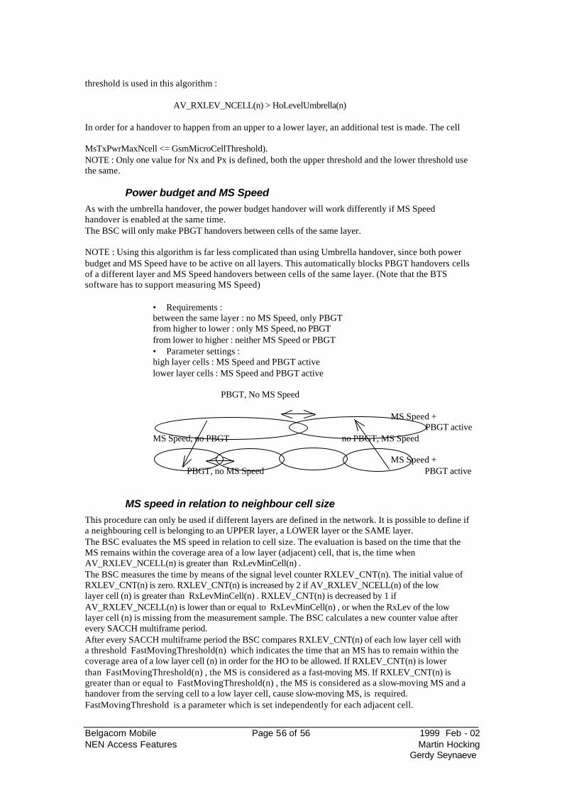
Belgacom Mobile Page 56 of 56 1999 Feb - 02 NEN Access Features Martin Hocking
Gerdy Seynaeve
threshold is used in this algorithm :
AV_RXLEV_NCELL(n) > HoLevelUmbrella(n) In order for a handover to happen from an upper to a lower layer, an additional test is made. The cell
MsTxPwrMaxNcell <= GsmMicroCellThreshold). NOTE : Only one value for Nx and Px is defined, both the upper threshold and the lower threshold use the same.
Power budget and MS Speed
As with the umbrella handover, the power budget handover will work differently if MS Speed handover is enabled at the same time. The BSC will only make PBGT handovers between cells of the same layer. NOTE : Using this algorithm is far less complicated than using Umbrella handover, since both power budget and MS Speed have to be active on all layers. This automatically blocks PBGT handovers cells of a different layer and MS Speed handovers between cells of the same layer. (Note that the BTS software has to support measuring MS Speed)
• Requirements : between the same layer : no MS Speed, only PBGT from higher to lower : only MS Speed, no PBGT from lower to higher : neither MS Speed or PBGT
• Parameter settings : high layer cells : MS Speed and PBGT active lower layer cells : MS Speed and PBGT active PBGT, No MS Speed MS Speed +
PBGT active MS Speed, no PBGT no PBGT, MS Speed
MS Speed +
PBGT, no MS Speed PBGT active
MS speed in relation to neighbour cell size
This procedure can only be used if different layers are defined in the network. It is possible to define if a neighbouring cell is belonging to an UPPER layer, a LOWER layer or the SAME layer. The BSC evaluates the MS speed in relation to cell size. The evaluation is based on the time that the MS remains within the coverage area of a low layer (adjacent) cell, that is, the time when AV_RXLEV_NCELL(n) is greater than RxLevMinCell(n) . The BSC measures the time by means of the signal level counter RXLEV_CNT(n). The initial value of RXLEV_CNT(n) is zero. RXLEV_CNT(n) is increased by 2 if AV_RXLEV_NCELL(n) of the low layer cell (n) is greater than RxLevMinCell(n) . RXLEV_CNT(n) is decreased by 1 if AV_RXLEV_NCELL(n) is lower than or equal to RxLevMinCell(n) , or when the RxLev of the low layer cell (n) is missing from the measurement sample. The BSC calculates a new counter value after every SACCH multiframe period. After every SACCH multiframe period the BSC compares RXLEV_CNT(n) of each low layer cell with a threshold FastMovingThreshold(n) which indicates the time that an MS has to remain within the coverage area of a low layer cell (n) in order for the HO to be allowed. If RXLEV_CNT(n) is lower than FastMovingThreshold(n) , the MS is considered as a fast-moving MS. If RXLEV_CNT(n) is greater than or equal to FastMovingThreshold(n) , the MS is considered as a slow-moving MS and a handover from the serving cell to a low layer cell, cause slow-moving MS, is required. FastMovingThreshold is a parameter which is set independently for each adjacent cell.
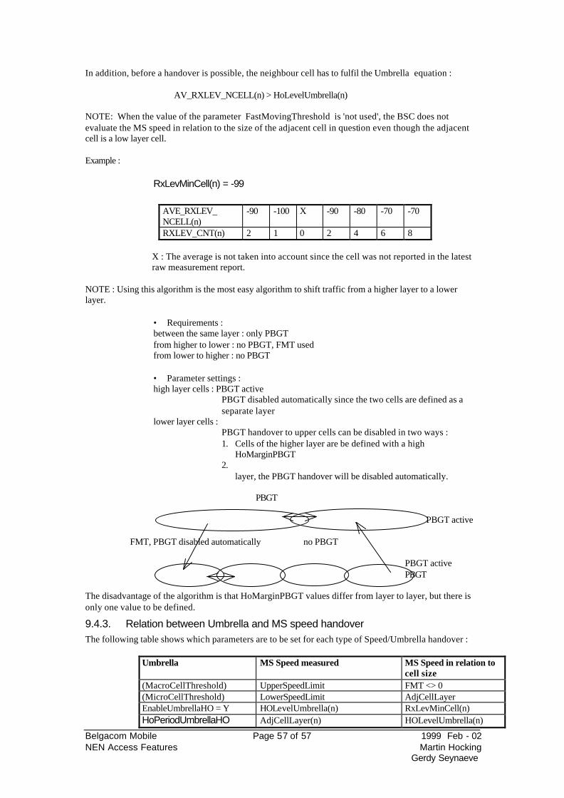
Belgacom Mobile Page 57 of 57 1999 Feb - 02 NEN Access Features Martin Hocking
Gerdy Seynaeve
In addition, before a handover is possible, the neighbour cell has to fulfil the Umbrella equation :
AV_RXLEV_NCELL(n) > HoLevelUmbrella(n) NOTE: When the value of the parameter FastMovingThreshold is 'not used', the BSC does not evaluate the MS speed in relation to the size of the adjacent cell in question even though the adjacent cell is a low layer cell. Example :
RxLevMinCell(n) = -99
AVE_RXLEV_ NCELL(n)
-90 -100 X -90 -80 -70 -70
RXLEV_CNT(n) 2 1 0 2 4 6 8
X : The average is not taken into account since the cell was not reported in the latest raw measurement report.
NOTE : Using this algorithm is the most easy algorithm to shift traffic from a higher layer to a lower layer.
• Requirements : between the same layer : only PBGT from higher to lower : no PBGT, FMT used from lower to higher : no PBGT
• Parameter settings : high layer cells : PBGT active
PBGT disabled automatically since the two cells are defined as a separate layer
lower layer cells : PBGT handover to upper cells can be disabled in two ways : 1. Cells of the higher layer are be defined with a high
HoMarginPBGT 2.
layer, the PBGT handover will be disabled automatically. PBGT
PBGT active FMT, PBGT disabled automatically no PBGT
PBGT active PBGT
The disadvantage of the algorithm is that HoMarginPBGT values differ from layer to layer, but there is only one value to be defined.
9.4.3. Relation between Umbrella and MS speed handover The following table shows which parameters are to be set for each type of Speed/Umbrella handover :
Umbrella MS Speed measured MS Speed in relation to cell size
(MacroCellThreshold) UpperSpeedLimit FMT <> 0 (MicroCellThreshold) LowerSpeedLimit AdjCellLayer EnableUmbrellaHO = Y HOLevelUmbrella(n) RxLevMinCell(n) HoPeriodUmbrellaHO AdjCellLayer(n) HOLevelUmbrella(n)
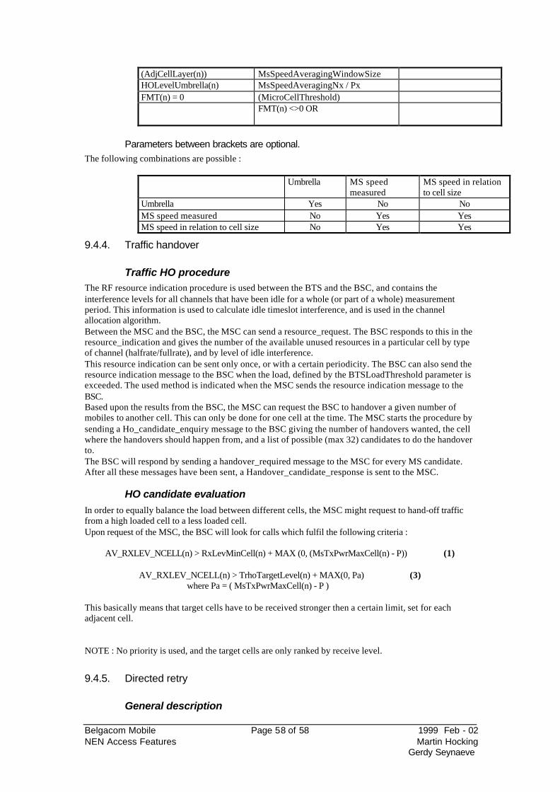
Belgacom Mobile Page 58 of 58 1999 Feb - 02 NEN Access Features Martin Hocking
Gerdy Seynaeve
(AdjCellLayer(n)) MsSpeedAveragingWindowSize HOLevelUmbrella(n) MsSpeedAveragingNx / Px FMT(n) = 0 (MicroCellThreshold) FMT(n) <>0 OR
Parameters between brackets are optional.
The following combinations are possible :
Umbrella MS speed measured
MS speed in relation to cell size
Umbrella Yes No No MS speed measured No Yes Yes MS speed in relation to cell size No Yes Yes
9.4.4. Traffic handover
Traffic HO procedure The RF resource indication procedure is used between the BTS and the BSC, and contains the interference levels for all channels that have been idle for a whole (or part of a whole) measurement period. This information is used to calculate idle timeslot interference, and is used in the channel allocation algorithm. Between the MSC and the BSC, the MSC can send a resource_request. The BSC responds to this in the resource_indication and gives the number of the available unused resources in a particular cell by type of channel (halfrate/fullrate), and by level of idle interference. This resource indication can be sent only once, or with a certain periodicity. The BSC can also send the resource indication message to the BSC when the load, defined by the BTSLoadThreshold parameter is exceeded. The used method is indicated when the MSC sends the resource indication message to the BSC. Based upon the results from the BSC, the MSC can request the BSC to handover a given number of mobiles to another cell. This can only be done for one cell at the time. The MSC starts the procedure by sending a Ho_candidate_enquiry message to the BSC giving the number of handovers wanted, the cell where the handovers should happen from, and a list of possible (max 32) candidates to do the handover to. The BSC will respond by sending a handover_required message to the MSC for every MS candidate. After all these messages have been sent, a Handover_candidate_response is sent to the MSC.
HO candidate evaluation
In order to equally balance the load between different cells, the MSC might request to hand-off traffic from a high loaded cell to a less loaded cell. Upon request of the MSC, the BSC will look for calls which fulfil the following criteria :
AV_RXLEV_NCELL(n) > RxLevMinCell(n) + MAX (0, (MsTxPwrMaxCell(n) - P)) (1)
AV_RXLEV_NCELL(n) > TrhoTargetLevel(n) + MAX(0, Pa) (3) where Pa = ( MsTxPwrMaxCell(n) - P )
This basically means that target cells have to be received stronger then a certain limit, set for each adjacent cell.
NOTE : No priority is used, and the target cells are only ranked by receive level.
9.4.5. Directed retry
General description
Belgacom Mobile Page 59 of 59 1999 Feb - 02 NEN Access Features Martin Hocking
Gerdy Seynaeve
In high traffic conditions, some cells may suffer from severe blocking. As traffic can be very localised, it is possible that the call could be maintained on another cell. The mobile is not able to reselect a cell in case of TCH congestion, but the network can allow the mobile to set up a call on the SDCCH of the congested cell, and allocate a TCH on another cell which does not suffer from congestion. It is possible to use directed retry between cells which are connected to the same BSC (internal directed retry), but it is also possible to do directed retry between cells on different BSC. In the latter case, the MSC has to support the feature (external directed retry). This feature is interlinked with call queuing, where calls are kept on an SDCCH channel until a TCH becomes available on the cell. Even when a call is in the SDCCH phase, the mobile will send measurement reports to the BTS. Before these measurement reports contain the required information (the BSIC of the neighbouring cells is decoded correctly), no directed retry is possible. During the time indicated by the parameter MinTimeLimitDR, the BSC builds up a handover candidate list for the call. The BSC will then start a directed retry handover to the best cell. This process can go one until the MaxTimeLimitDR timer expires. These timers can be set on a cell by cell basis. The handover candidates only have to fulfil the following criterion :
AV_RXLEV_NCELL(n) > RxLevMinCell(n) + MAX (0, (MsTxPwrMaxCell(n) - P)) (1)
When the timer MinLimitDR has expired, possible queuing is stopped, and the directed retry is initiated by sending a handover command to the mobile. Even if a timeslot becomes free on the BTS after the MinTimeLimitDR, the mobile will not be assigned to that free timeslot.
If queuing is active on the cell, and a TCH becomes available before the MinTimeLimitDR has expired, the directed retry procedure is stopped and the call goes on on the cell. After the DR procedure has been started, no queuing is possible in the target cell. If the TCH can not be allocated in the target BTS, the call will be cleared.
Important parameters The following parameters take part in the process of queuing / directed retry DrInUse Directed retry used Yes/No MinTimeLimitDirectedRetry (s) MaxTimeLimitDirectedRetry (s)
Max queue length (%) This value is the percentage of 8 * the number of TRXs. 50% on a 2 TRX BTS makes the queue length equal to 8.
TimeLimitCall (s) Maximum queuing time TimeLimitHandover The maximum queuing time for handover
attempts in the BTS DisableExternalDR indicates whether inter BSC directed retry is
allowed DisableInternalHO N : intra BSC handovers are completely
controlled within the BSC
Statistics on directed retry and queuing
In the S6 release, there are a number of important counters for directed retry :
Cause directed retry Handover TCH Qd call attempt Number of calls queued Traffic TCH Qd Ho attempt Number of handovers queued Traffic Ave Q seiz req Average number of TCH request queued Traffic Ave Q tim call att Average time a call attempt is queued for Traffic Ave Q tim Ho att Average time a handover is queued for Traffic Unsrv Qd call att Number of queued call attempts expiring Traffic Unsrv Qd Ho att Number of queued handovers expiring Traffic Nokia is working on new counters which indicate to what cell each directed retry went to.
Belgacom Mobile Page 60 of 60 1999 Feb - 02 NEN Access Features Martin Hocking
Gerdy Seynaeve
Examples
A few examples might clarify the working of directed retry when active simultaneously with queuing
Directed retry used Yes Min time limit directed retry 10 Max time limit directed retry 14 Max queue length 50% Time limit call 15 Time limit handover 5 Disable external DR Yes Disable internal HO No Radio link time-out 4
All but one timeslot blocked on originating cell and a mobile in use on that timeslot This mobile releases during the queuing period. è The queuing mobile will be assigned to this timeslot. Directed retry will never be
started. All but one timeslot blocked on originating cell and a mobile in use on that timeslot This mobile releases during the queuing period but after the min time limit directed retry. No free timeslots on the directed retry cell. è The mobile which is held in the queue is released after 14 seconds even though a
free timeslot is available on its own BTS. Queuing is stopped as soon as the min time for directed retry is exceeded.
9.4.6. Enhancements on the directed retry procedure with BSS SW rel S7 With the S7 BSS software release, a threshold can be taken into account when building the list of target cells. The use of this is defined by the parameter DirectedRetryMethod In case this parameter is set to 0, target cells must satisfy equation (1) before directed retry is possible (same case as 3.4.5)
AV_RXLEV_NCELL(n) > RxLevMinCell(n) + MAX (0, (MsTxPwrMaxCell(n) - P)) (1)
In case the parameter is set to 1, target cells must satisfy both equation (1) and equation (4) before directed retry is possible
AV_RXLEV_NCELL(n) > RxLevMinCell(n) + MAX (0, (MsTxPwrMaxCell(n) - P)) (1)
AV_RXLEV_NCELL(n) > DRThreshold(n) (4) The threshold DRThreshold(n) can be set for each individual neighbour cell. NOTE : The target cells are ranked only based upon radio link properties, priorities are not used
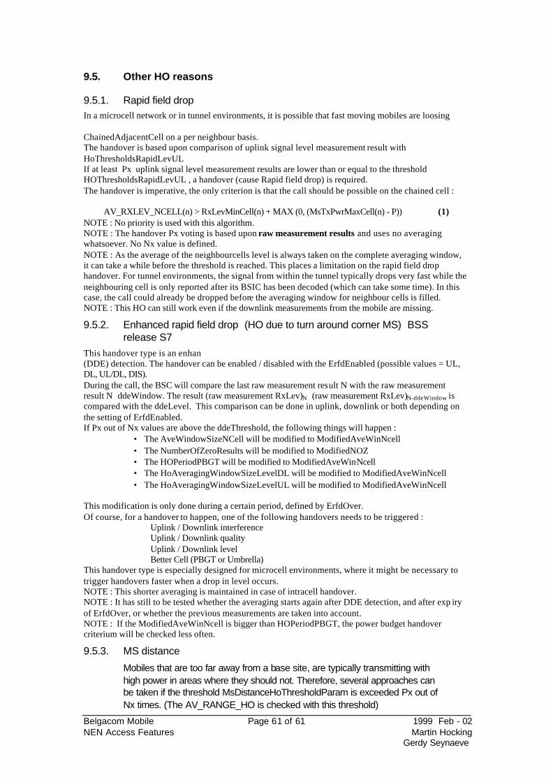
Belgacom Mobile Page 61 of 61 1999 Feb - 02 NEN Access Features Martin Hocking
Gerdy Seynaeve
9.5. Other HO reasons
9.5.1. Rapid field drop In a microcell network or in tunnel environments, it is possible that fast moving mobiles are loosing
ChainedAdjacentCell on a per neighbour basis. The handover is based upon comparison of uplink signal level measurement result with HoThresholdsRapidLevUL If at least Px uplink signal level measurement results are lower than or equal to the threshold HOThresholdsRapidLevUL , a handover (cause Rapid field drop) is required. The handover is imperative, the only criterion is that the call should be possible on the chained cell :
AV_RXLEV_NCELL(n) > RxLevMinCell(n) + MAX (0, (MsTxPwrMaxCell(n) - P)) (1) NOTE : No priority is used with this algorithm. NOTE : The handover Px voting is based upon raw measurement results and uses no averaging whatsoever. No Nx value is defined. NOTE : As the average of the neighbourcells level is always taken on the complete averaging window, it can take a while before the threshold is reached. This places a limitation on the rapid field drop handover. For tunnel environments, the signal from within the tunnel typically drops very fast while the neighbouring cell is only reported after its BSIC has been decoded (which can take some time). In this case, the call could already be dropped before the averaging window for neighbour cells is filled. NOTE : This HO can still work even if the downlink measurements from the mobile are missing.
9.5.2. Enhanced rapid field drop (HO due to turn around corner MS) BSS release S7
This handover type is an enhan(DDE) detection. The handover can be enabled / disabled with the ErfdEnabled (possible values = UL, DL, UL/DL, DIS). During the call, the BSC will compare the last raw measurement result N with the raw measurement result N ddeWindow. The result (raw measurement RxLev)N (raw measurement RxLev)N-ddeWindow is compared with the ddeLevel. This comparison can be done in uplink, downlink or both depending on the setting of ErfdEnabled. If Px out of Nx values are above the ddeThreshold, the following things will happen :
• The AveWindowSizeNCell will be modified to ModifiedAveWinNcell • The NumberOfZeroResults will be modified to ModifiedNOZ • The HOPeriodPBGT will be modified to ModifiedAveWinNcell • The HoAveragingWindowSizeLevelDL will be modified to ModifiedAveWinNcell • The HoAveragingWindowSizeLevelUL will be modified to ModifiedAveWinNcell
This modification is only done during a certain period, defined by ErfdOver. Of course, for a handover to happen, one of the following handovers needs to be triggered :
Uplink / Downlink interference Uplink / Downlink quality Uplink / Downlink level Better Cell (PBGT or Umbrella)
This handover type is especially designed for microcell environments, where it might be necessary to trigger handovers faster when a drop in level occurs. NOTE : This shorter averaging is maintained in case of intracell handover. NOTE : It has still to be tested whether the averaging starts again after DDE detection, and after exp iry of ErfdOver, or whether the previous measurements are taken into account. NOTE : If the ModifiedAveWinNcell is bigger than HOPeriodPBGT, the power budget handover criterium will be checked less often.
9.5.3. MS distance
Mobiles that are too far away from a base site, are typically transmitting with high power in areas where they should not. Therefore, several approaches can be taken if the threshold MsDistanceHoThresholdParam is exceeded Px out of Nx times. (The AV_RANGE_HO is checked with this threshold)
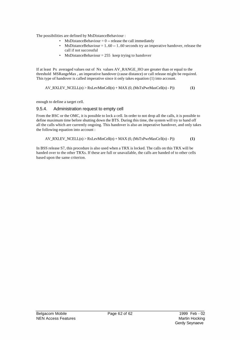
Belgacom Mobile Page 62 of 62 1999 Feb - 02 NEN Access Features Martin Hocking
Gerdy Seynaeve
The possibilities are defined by MsDistanceBehaviour :
• MsDistanceBehaviour = 0 -- release the call immediately • MsDistanceBehaviour = 1..60 -- 1..60 seconds try an imperative handover, release the
call if not successful • MsDistanceBehaviour = 255 keep trying to handover
If at least Px averaged values out of Nx values AV_RANGE_HO are greater than or equal to the threshold MSRangeMax , an imperative handover (cause distance) or call release might be required. This type of handover is called imperative since it only takes equation (1) into account.
AV_RXLEV_NCELL(n) > RxLevMinCell(n) + MAX (0, (MsTxPwrMaxCell(n) - P)) (1)
enough to define a target cell.
9.5.4. Administration request to empty cell From the BSC or the OMC, it is possible to lock a cell. In order to not drop all the calls, it is possible to define maximum time before shutting down the BTS. During this time, the system will try to hand off all the calls which are currently ongoing. This handover is also an imperative handover, and only takes the following equation into account :
AV_RXLEV_NCELL(n) > RxLevMinCell(n) + MAX (0, (MsTxPwrMaxCell(n) - P)) (1) In BSS release S7, this procedure is also used when a TRX is locked. The calls on this TRX will be handed over to the other TRXs. If these are full or unavailable, the calls are handed of to other cells based upon the same criterion.
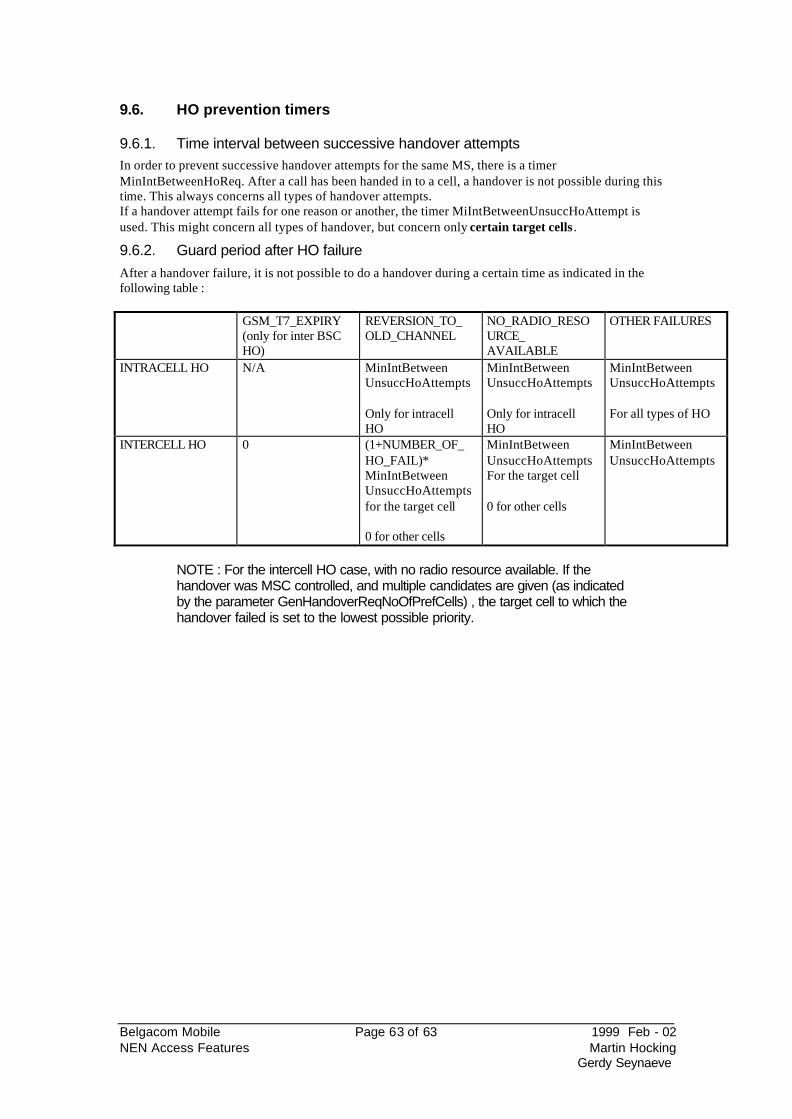
Belgacom Mobile Page 63 of 63 1999 Feb - 02 NEN Access Features Martin Hocking
Gerdy Seynaeve
9.6. HO prevention timers
9.6.1. Time interval between successive handover attempts In order to prevent successive handover attempts for the same MS, there is a timer MinIntBetweenHoReq. After a call has been handed in to a cell, a handover is not possible during this time. This always concerns all types of handover attempts. If a handover attempt fails for one reason or another, the timer MiIntBetweenUnsuccHoAttempt is used. This might concern all types of handover, but concern only certain target cells .
9.6.2. Guard period after HO failure After a handover failure, it is not possible to do a handover during a certain time as indicated in the following table : GSM_T7_EXPIRY
(only for inter BSC HO)
REVERSION_TO_OLD_CHANNEL
NO_RADIO_RESOURCE_ AVAILABLE
OTHER FAILURES
INTRACELL HO N/A MinIntBetween UnsuccHoAttempts Only for intracell HO
MinIntBetween UnsuccHoAttempts Only for intracell HO
MinIntBetween UnsuccHoAttempts For all types of HO
INTERCELL HO 0 (1+NUMBER_OF_HO_FAIL)* MinIntBetween UnsuccHoAttempts for the target cell 0 for other cells
MinIntBetween UnsuccHoAttempts For the target cell 0 for other cells
MinIntBetween UnsuccHoAttempts
NOTE : For the intercell HO case, with no radio resource available. If the handover was MSC controlled, and multiple candidates are given (as indicated by the parameter GenHandoverReqNoOfPrefCells) , the target cell to which the handover failed is set to the lowest possible priority.
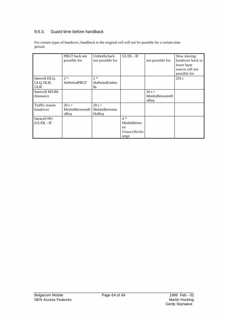
Belgacom Mobile Page 64 of 64 1999 Feb - 02 NEN Access Features Martin Hocking
Gerdy Seynaeve
9.6.3. Guard time before handback For certain types of handover, handback to the original cell will not be possible for a certain time period. PBGT back not
possible for Umbrella back not possible for
UL/DL - IF not possible for
Slow moving handover back to lower layer source cell not possible for
Intercell DLQ, ULQ, DLIF, ULIF
2 * HoPeriodPBGT
2 * HoPeriodUmbrella
255 s
Intercell MS-BS dinstance
20 s + MinIntBetweenHoReq
Traffic reason handover
20 s + MinIntBetweenHoReq
20 s + MinIntBetweenHoReq
Intracell HO (UL/DL - IF
4 * MinIntBetween UnsuccHoAttempt
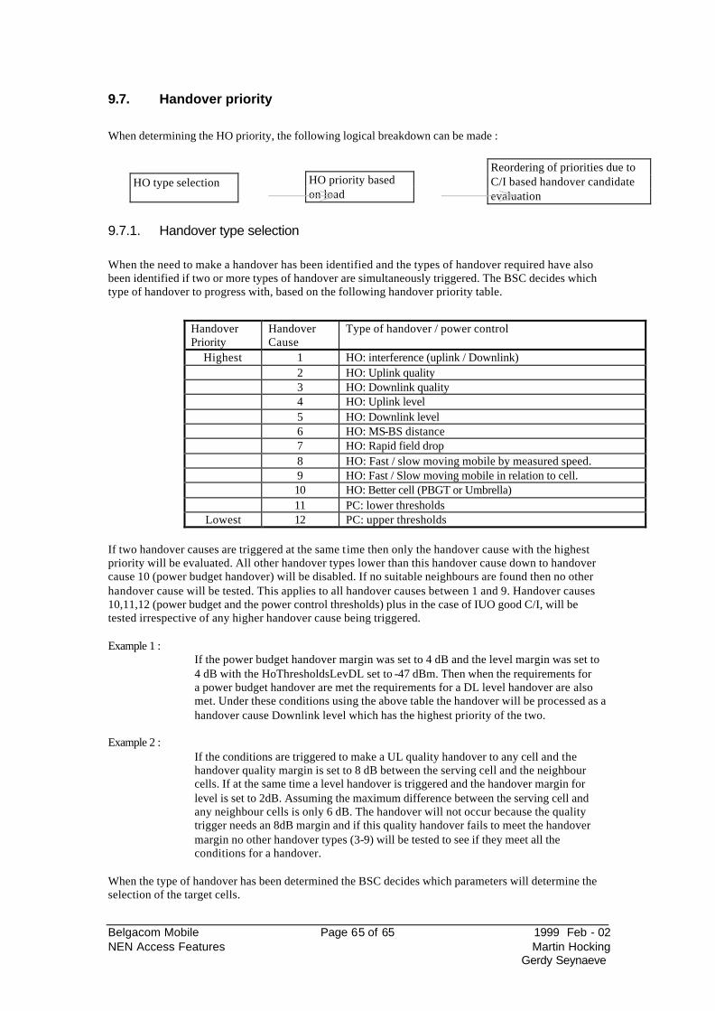
Belgacom Mobile Page 65 of 65 1999 Feb - 02 NEN Access Features Martin Hocking
Gerdy Seynaeve
9.7. Handover priority
When determining the HO priority, the following logical breakdown can be made :
9.7.1. Handover type selection When the need to make a handover has been identified and the types of handover required have also been identified if two or more types of handover are simultaneously triggered. The BSC decides which type of handover to progress with, based on the following handover priority table.
Handover Priority
Handover Cause
Type of handover / power control
Highest 1 HO: interference (uplink / Downlink) 2 HO: Uplink quality 3 HO: Downlink quality 4 HO: Uplink level 5 HO: Downlink level 6 HO: MS-BS distance 7 HO: Rapid field drop 8 HO: Fast / slow moving mobile by measured speed. 9 HO: Fast / Slow moving mobile in relation to cell. 10 HO: Better cell (PBGT or Umbrella) 11 PC: lower thresholds
Lowest 12 PC: upper thresholds If two handover causes are triggered at the same t ime then only the handover cause with the highest priority will be evaluated. All other handover types lower than this handover cause down to handover cause 10 (power budget handover) will be disabled. If no suitable neighbours are found then no other handover cause will be tested. This applies to all handover causes between 1 and 9. Handover causes 10,11,12 (power budget and the power control thresholds) plus in the case of IUO good C/I, will be tested irrespective of any higher handover cause being triggered. Example 1 :
If the power budget handover margin was set to 4 dB and the level margin was set to 4 dB with the HoThresholdsLevDL set to -47 dBm. Then when the requirements for a power budget handover are met the requirements for a DL level handover are also met. Under these conditions using the above table the handover will be processed as a handover cause Downlink level which has the highest priority of the two.
Example 2 :
If the conditions are triggered to make a UL quality handover to any cell and the handover quality margin is set to 8 dB between the serving cell and the neighbour cells. If at the same time a level handover is triggered and the handover margin for level is set to 2dB. Assuming the maximum difference between the serving cell and any neighbour cells is only 6 dB. The handover will not occur because the quality trigger needs an 8dB margin and if this quality handover fails to meet the handover margin no other handover types (3-9) will be tested to see if they meet all the conditions for a handover.
When the type of handover has been determined the BSC decides which parameters will determine the selection of the target cells.
Reordering of priorities due to C/I based handover candidate evaluation
HO priority based on load
HO type selection
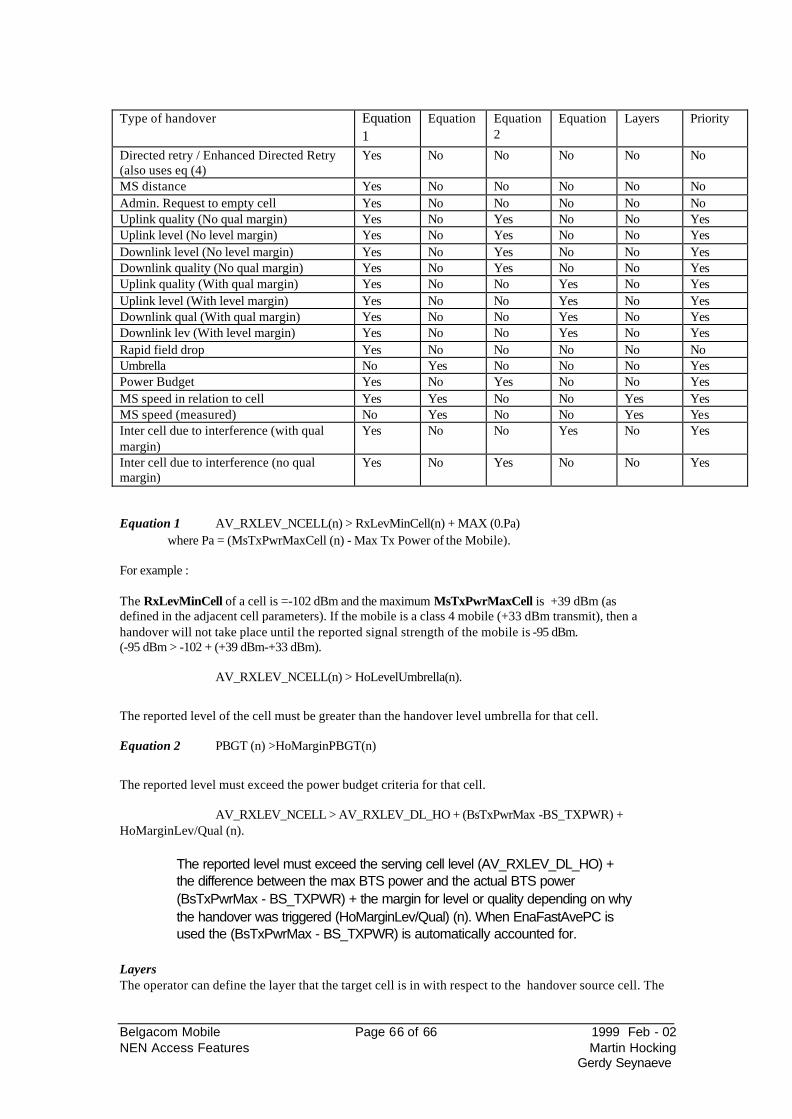
Belgacom Mobile Page 66 of 66 1999 Feb - 02 NEN Access Features Martin Hocking
Gerdy Seynaeve
Type of handover Equation
1 Equation
Equation2
Equation
Layers Priority
Directed retry / Enhanced Directed Retry (also uses eq (4)
Yes No No No No No
MS distance Yes No No No No No Admin. Request to empty cell Yes No No No No No Uplink quality (No qual margin) Yes No Yes No No Yes Uplink level (No level margin) Yes No Yes No No Yes Downlink level (No level margin) Yes No Yes No No Yes Downlink quality (No qual margin) Yes No Yes No No Yes Uplink quality (With qual margin) Yes No No Yes No Yes Uplink level (With level margin) Yes No No Yes No Yes Downlink qual (With qual margin) Yes No No Yes No Yes Downlink lev (With level margin) Yes No No Yes No Yes Rapid field drop Yes No No No No No Umbrella No Yes No No No Yes Power Budget Yes No Yes No No Yes MS speed in relation to cell Yes Yes No No Yes Yes MS speed (measured) No Yes No No Yes Yes Inter cell due to interference (with qual margin)
Yes No No Yes No Yes
Inter cell due to interference (no qual margin)
Yes No Yes No No Yes
Equation 1 AV_RXLEV_NCELL(n) > RxLevMinCell(n) + MAX (0.Pa) where Pa = (MsTxPwrMaxCell (n) - Max Tx Power of the Mobile). For example : The RxLevMinCell of a cell is =-102 dBm and the maximum MsTxPwrMaxCell is +39 dBm (as defined in the adjacent cell parameters). If the mobile is a class 4 mobile (+33 dBm transmit), then a handover will not take place until the reported signal strength of the mobile is -95 dBm. (-95 dBm > -102 + (+39 dBm-+33 dBm).
AV_RXLEV_NCELL(n) > HoLevelUmbrella(n).
The reported level of the cell must be greater than the handover level umbrella for that cell. Equation 2 PBGT (n) >HoMarginPBGT(n)
The reported level must exceed the power budget criteria for that cell.
AV_RXLEV_NCELL > AV_RXLEV_DL_HO + (BsTxPwrMax -BS_TXPWR) + HoMarginLev/Qual (n).
The reported level must exceed the serving cell level (AV_RXLEV_DL_HO) + the difference between the max BTS power and the actual BTS power (BsTxPwrMax - BS_TXPWR) + the margin for level or quality depending on why the handover was triggered (HoMarginLev/Qual) (n). When EnaFastAvePC is used the (BsTxPwrMax - BS_TXPWR) is automatically accounted for.
Layers The operator can define the layer that the target cell is in with respect to the handover source cell. The
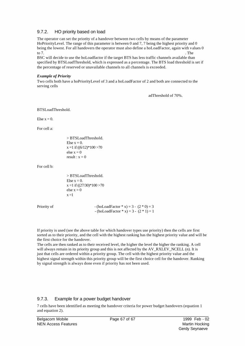
Belgacom Mobile Page 67 of 67 1999 Feb - 02 NEN Access Features Martin Hocking
Gerdy Seynaeve
9.7.2. HO priority based on load The operator can set the priority of a handover between two cells by means of the parameter HoPriorityLevel. The range of this parameter is between 0 and 7, 7 being the highest priority and 0 being the lowest. For all handovers the operator must also define a hoLoadFactor, again with values 0 to 7. . The BSC will decide to use the hoLoadfactor if the target BTS has less traffic channels available than specified by BTSLoadThreshold, which is expressed as a percentage. The BTS load threshold is set if the percentage of reserved or unavailable channels to all channels is exceeded. Example of Priority Two cells both have a hoPriorityLevel of 3 and a hoLoadFactor of 2 and both are connected to the serving cells
adThreshold of 70%.
BTSLoadThreshold. Else x = 0. For cell a:
> BTSLoadThreshold. Else x = 0. x =1 if ((6/12)*100 >70 else x = 0 result : x = 0
For cell b:
> BTSLoadThreshold. Else x = 0. x =1 if ((27/30)*100 >70 else x = 0 x =1
Priority of - (hoLoadFactor * x) = 3 - (2 * 0) = 3
- (hoLoadFactor * x) = 3 - (2 * 1) = 1
If priority is used (see the above table for which handover types use priority) then the cells are first sorted as to their priority, and the cell with the highest ranking has the highest priority value and will be the first choice for the handover. The cells are then ranked as to their received level, the higher the level the higher the ranking. A cell will always remain in its priority group and this is not affected by the AV_RXLEV_NCELL (n). It is just that cells are ordered within a priority group. The cell with the highest priority value and the highest signal strength within this priority group will be the first choice cell for the handover. Ranking by signal strength is always done even if priority has not been used.
9.7.3. Example for a power budget handover 7 cells have been identified as meeting the handover criteria for power budget handovers (equation 1 and equation 2).
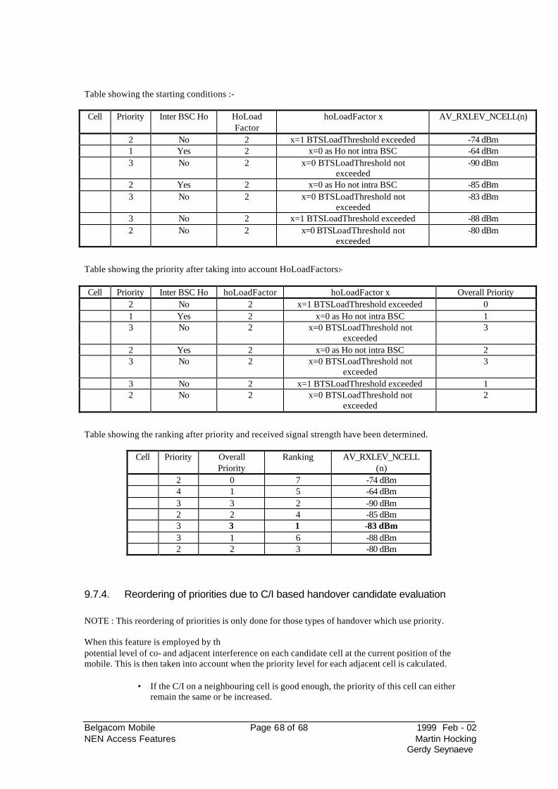
Belgacom Mobile Page 68 of 68 1999 Feb - 02 NEN Access Features Martin Hocking
Gerdy Seynaeve
Table showing the starting conditions :- Cell Priority Inter BSC Ho HoLoad
Factor hoLoadFactor x AV_RXLEV_NCELL(n)
2 No 2 x=1 BTSLoadThreshold exceeded -74 dBm 1 Yes 2 x=0 as Ho not intra BSC -64 dBm 3 No 2 x=0 BTSLoadThreshold not
exceeded -90 dBm
2 Yes 2 x=0 as Ho not intra BSC -85 dBm 3 No 2 x=0 BTSLoadThreshold not
exceeded -83 dBm
3 No 2 x=1 BTSLoadThreshold exceeded -88 dBm 2 No 2 x=0 BTSLoadThreshold not
exceeded -80 dBm
Table showing the priority after taking into account HoLoadFactors:- Cell Priority Inter BSC Ho hoLoadFactor hoLoadFactor x Overall Priority
2 No 2 x=1 BTSLoadThreshold exceeded 0 1 Yes 2 x=0 as Ho not intra BSC 1 3 No 2 x=0 BTSLoadThreshold not
exceeded 3
2 Yes 2 x=0 as Ho not intra BSC 2 3 No 2 x=0 BTSLoadThreshold not
exceeded 3
3 No 2 x=1 BTSLoadThreshold exceeded 1 2 No 2 x=0 BTSLoadThreshold not
exceeded 2
Table showing the ranking after priority and received signal strength have been determined.
Cell Priority Overall Priority
Ranking AV_RXLEV_NCELL (n)
2 0 7 -74 dBm 4 1 5 -64 dBm 3 3 2 -90 dBm 2 2 4 -85 dBm 3 3 1 -83 dBm 3 1 6 -88 dBm 2 2 3 -80 dBm
9.7.4. Reordering of priorities due to C/I based handover candidate evaluation NOTE : This reordering of priorities is only done for those types of handover which use priority. When this feature is employed by thpotential level of co- and adjacent interference on each candidate cell at the current position of the mobile. This is then taken into account when the priority level for each adjacent cell is calculated.
• If the C/I on a neighbouring cell is good enough, the priority of this cell can either remain the same or be increased.
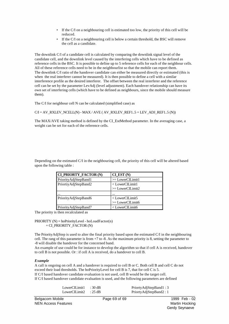
Belgacom Mobile Page 69 of 69 1999 Feb - 02 NEN Access Features Martin Hocking
Gerdy Seynaeve
• If the C/I on a neighbouring cell is estimated too low, the priority of this cell will be reduced.
• If the C/I on a neighbouring cell is below a certain threshold, the BSC will remove the cell as a candidate.
The downlink C/I of a candidate cell is calculated by comparing the downlink signal level of the candidate cell, and the downlink level caused by the interfering cells which have to be defined as reference cells in the BSC. It is possible to define up to 5 reference cells for each of the neighbour cells. All of these reference cells need to be in the neighbourlist so that the mobile can report them. The downlink C/I ratio of the handover candidate can either be measured directly or estimated (this is when the real interferer cannot be measured). It is then possible to define a cell with a similar interference profile as the desired interferer. The offset between the real interferer and the reference cell can be set by the parameter LevAdj (level adjustment). Each handover relationship can have its own set of interfering cells (which have to be defined as neighbours, since the mobile should measure them). The C/I for neighbour cell N can be calculated (simplified case) as C/I = AV_RXLEV_NCELL(N) - MAX / AVE ( AV_RXLEV_REF1..5 + LEV_ADJ_REF1..5 (N)) The MAX/AVE taking method is defined by the CI_EstMethod parameter. In the averaging case, a weight can be set for each of the reference cells. Depending on the estimated C/I in the neighbouring cell, the priority of this cell will be altered based upon the following table :
CI_PRIORTY_FACTOR (N) CI_EST (N) PriorityAdjStepBand1 >= LowerCILimit1 PriortiyAdjStepBand2 < LowerCILimit1
>= LowerCILimit2 ... ... PriorityAdjStepBand6 < LowerCILimit5
>= LowerCILimit6 PriorityAdjStepBand7 < LowerCILimit6
The priority is then recalculated as PRIORITY (N) = hoPriorityLevel - hoLoadFactor(n)
+ CI_PRIORITY_FACTOR (N) The PriorityAdjStep is used to alter the final priority based upon the estimated C/I in the neighbouring cell. The rang of this parameter is from +7 to -8. As the maximum priority is 8, setting the parameter to -8 will disable the handover for the concerned band. An example of use could be for instance to develop the algorithm so that if cell A is received, handover to cell B is not possible. Or : if cell A is received, do a handover to cell B. Example A call is ongoing on cell A and a handover is required to cell B or C. Both cell B and cell C do not exceed their load thresholds. The hoPriorityLevel for cell B is 7, that for cell C is 5. If C/I based handover candidate evaluation is not used, cell B would be the target cell. If C/I based handover candidate evaluation is used, and the following parameters are defined
LowerCILimit1 : 30 dB PriortyAdjStepBand1 : 3 LowerCILimit2 : 25 dB PriortyAdjStepBand2 : 1
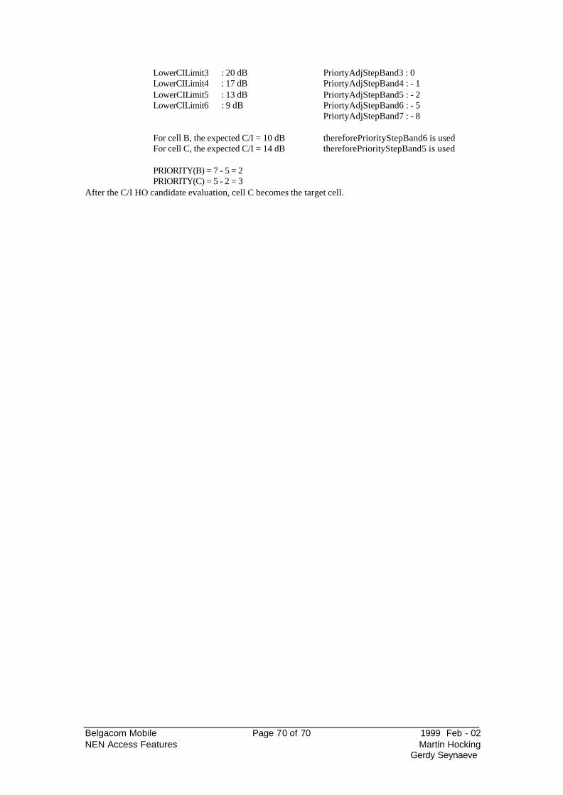
Belgacom Mobile Page 70 of 70 1999 Feb - 02 NEN Access Features Martin Hocking
Gerdy Seynaeve
LowerCILimit3 : 20 dB PriortyAdjStepBand3 : 0 LowerCILimit4 : 17 dB PriortyAdjStepBand4 : - 1 LowerCILimit5 : 13 dB PriortyAdjStepBand5 : - 2 LowerCILimit6 : 9 dB PriortyAdjStepBand6 : - 5 PriortyAdjStepBand7 : - 8 For cell B, the expected C/I = 10 dB thereforePriorityStepBand6 is used For cell C, the expected C/I = 14 dB thereforePriorityStepBand5 is used PRIORITY(B) = 7 - 5 = 2 PRIORITY(C) = 5 - 2 = 3
After the C/I HO candidate evaluation, cell C becomes the target cell.
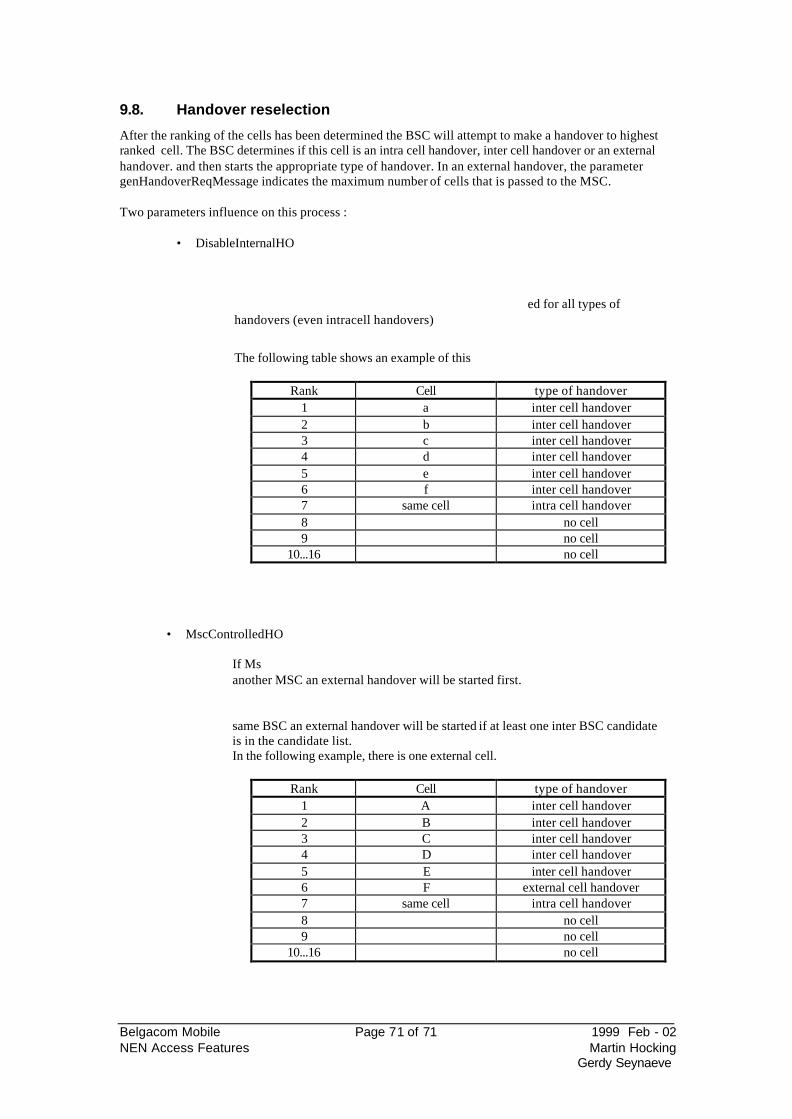
Belgacom Mobile Page 71 of 71 1999 Feb - 02 NEN Access Features Martin Hocking
Gerdy Seynaeve
9.8. Handover reselection
After the ranking of the cells has been determined the BSC will attempt to make a handover to highest ranked cell. The BSC determines if this cell is an intra cell handover, inter cell handover or an external handover. and then starts the appropriate type of handover. In an external handover, the parameter genHandoverReqMessage indicates the maximum number of cells that is passed to the MSC. Two parameters influence on this process :
• DisableInternalHO
ed for all types of
handovers (even intracell handovers)
The following table shows an example of this
Rank Cell type of handover 1 a inter cell handover 2 b inter cell handover 3 c inter cell handover 4 d inter cell handover 5 e inter cell handover 6 f inter cell handover 7 same cell intra cell handover 8 no cell 9 no cell
10...16 no cell
• MscControlledHO
If Msanother MSC an external handover will be started first.
same BSC an external handover will be started if at least one inter BSC candidate is in the candidate list. In the following example, there is one external cell.
Rank Cell type of handover
1 A inter cell handover 2 B inter cell handover 3 C inter cell handover 4 D inter cell handover 5 E inter cell handover 6 F external cell handover 7 same cell intra cell handover 8 no cell 9 no cell
10...16 no cell
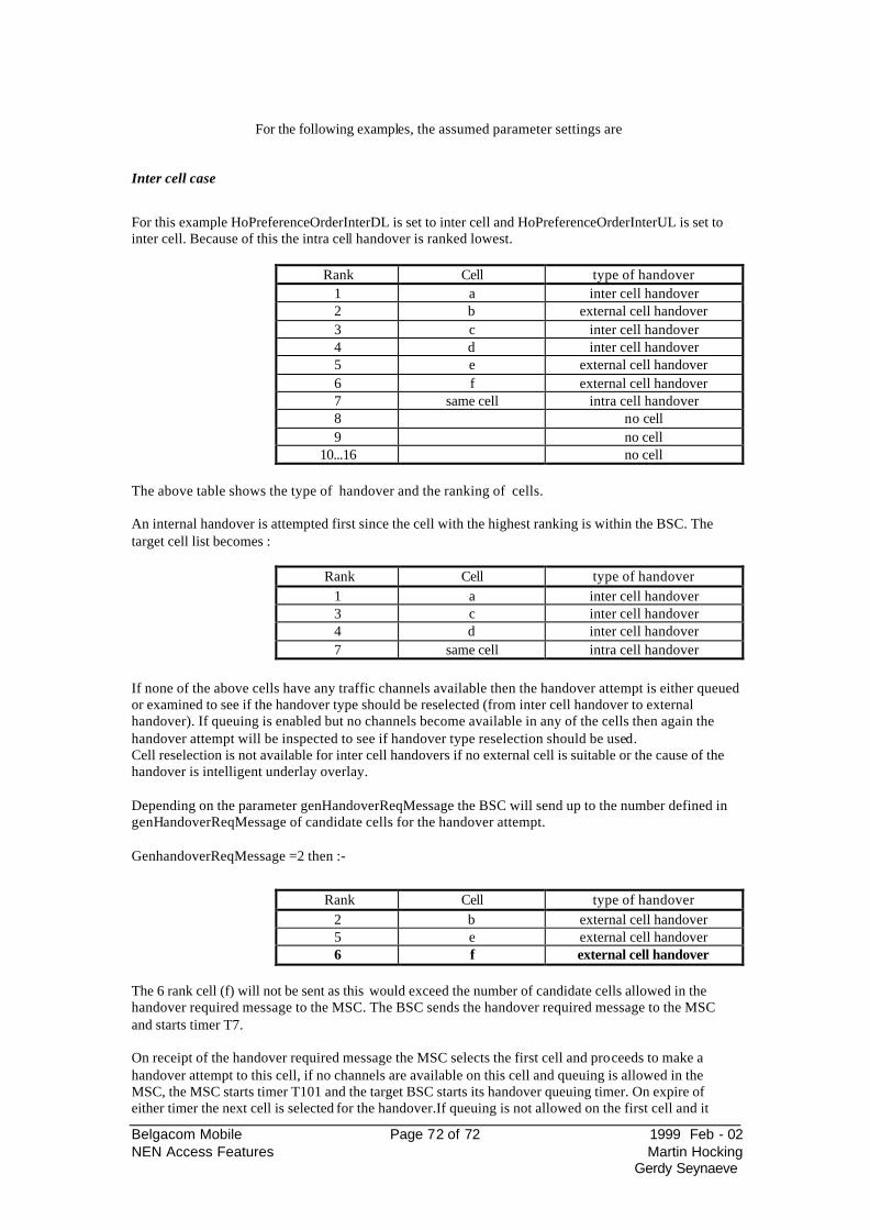
Belgacom Mobile Page 72 of 72 1999 Feb - 02 NEN Access Features Martin Hocking
Gerdy Seynaeve
For the following examples, the assumed parameter settings are
Inter cell case
For this example HoPreferenceOrderInterDL is set to inter cell and HoPreferenceOrderInterUL is set to inter cell. Because of this the intra cell handover is ranked lowest.
Rank Cell type of handover 1 a inter cell handover 2 b external cell handover 3 c inter cell handover 4 d inter cell handover 5 e external cell handover 6 f external cell handover 7 same cell intra cell handover 8 no cell 9 no cell
10...16 no cell The above table shows the type of handover and the ranking of cells. An internal handover is attempted first since the cell with the highest ranking is within the BSC. The target cell list becomes :
Rank Cell type of handover 1 a inter cell handover 3 c inter cell handover 4 d inter cell handover 7 same cell intra cell handover
If none of the above cells have any traffic channels available then the handover attempt is either queued or examined to see if the handover type should be reselected (from inter cell handover to external handover). If queuing is enabled but no channels become available in any of the cells then again the handover attempt will be inspected to see if handover type reselection should be used. Cell reselection is not available for inter cell handovers if no external cell is suitable or the cause of the handover is intelligent underlay overlay. Depending on the parameter genHandoverReqMessage the BSC will send up to the number defined in genHandoverReqMessage of candidate cells for the handover attempt. GenhandoverReqMessage =2 then :-
Rank Cell type of handover 2 b external cell handover 5 e external cell handover 6 f external cell handover
The 6 rank cell (f) will not be sent as this would exceed the number of candidate cells allowed in the handover required message to the MSC. The BSC sends the handover required message to the MSC and starts timer T7. On receipt of the handover required message the MSC selects the first cell and proceeds to make a handover attempt to this cell, if no channels are available on this cell and queuing is allowed in the MSC, the MSC starts timer T101 and the target BSC starts its handover queuing timer. On expire of either timer the next cell is selected for the handover.If queuing is not allowed on the first cell and it
Belgacom Mobile Page 73 of 73 1999 Feb - 02 NEN Access Features Martin Hocking
Gerdy Seynaeve
the next cell in the list. If this is busy then a Handover required reject message will be sent to the source BSC. When the source BSC has received a handover required reject message cause no channels available the timer MinIntervalBetweenHandoverAttempts is started. On expire of this timer a new handover can begin. In the case of no handover command being received or no handover required reject message being received the BSC timer T7 will expire and a new handover attempt can start immediately.
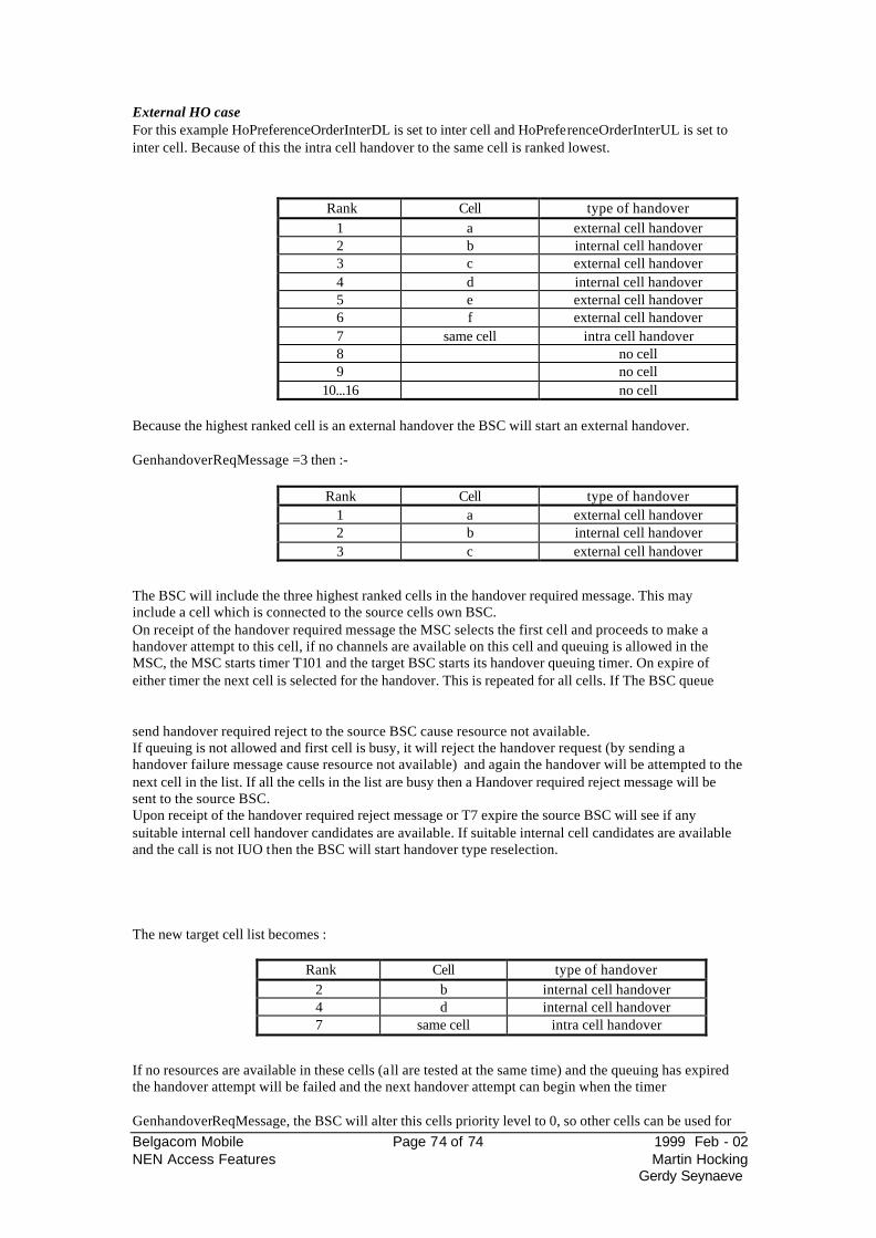
Belgacom Mobile Page 74 of 74 1999 Feb - 02 NEN Access Features Martin Hocking
Gerdy Seynaeve
External HO case For this example HoPreferenceOrderInterDL is set to inter cell and HoPreferenceOrderInterUL is set to inter cell. Because of this the intra cell handover to the same cell is ranked lowest.
Rank Cell type of handover 1 a external cell handover 2 b internal cell handover 3 c external cell handover 4 d internal cell handover 5 e external cell handover 6 f external cell handover 7 same cell intra cell handover 8 no cell 9 no cell
10...16 no cell Because the highest ranked cell is an external handover the BSC will start an external handover. GenhandoverReqMessage =3 then :-
Rank Cell type of handover 1 a external cell handover 2 b internal cell handover 3 c external cell handover
The BSC will include the three highest ranked cells in the handover required message. This may include a cell which is connected to the source cells own BSC. On receipt of the handover required message the MSC selects the first cell and proceeds to make a handover attempt to this cell, if no channels are available on this cell and queuing is allowed in the MSC, the MSC starts timer T101 and the target BSC starts its handover queuing timer. On expire of either timer the next cell is selected for the handover. This is repeated for all cells. If The BSC queue
send handover required reject to the source BSC cause resource not available. If queuing is not allowed and first cell is busy, it will reject the handover request (by sending a handover failure message cause resource not available) and again the handover will be attempted to the next cell in the list. If all the cells in the list are busy then a Handover required reject message will be sent to the source BSC. Upon receipt of the handover required reject message or T7 expire the source BSC will see if any suitable internal cell handover candidates are available. If suitable internal cell candidates are available and the call is not IUO then the BSC will start handover type reselection. The new target cell list becomes :
Rank Cell type of handover 2 b internal cell handover 4 d internal cell handover 7 same cell intra cell handover
If no resources are available in these cells (all are tested at the same time) and the queuing has expired the handover attempt will be failed and the next handover attempt can begin when the timer
GenhandoverReqMessage, the BSC will alter this cells priority level to 0, so other cells can be used for
Belgacom Mobile Page 75 of 75 1999 Feb - 02 NEN Access Features Martin Hocking
Gerdy Seynaeve
the handover. If on expire of T7 no internal handover candidates are available then a external handover can be attempted immediately without waiting for any other timers to expire.
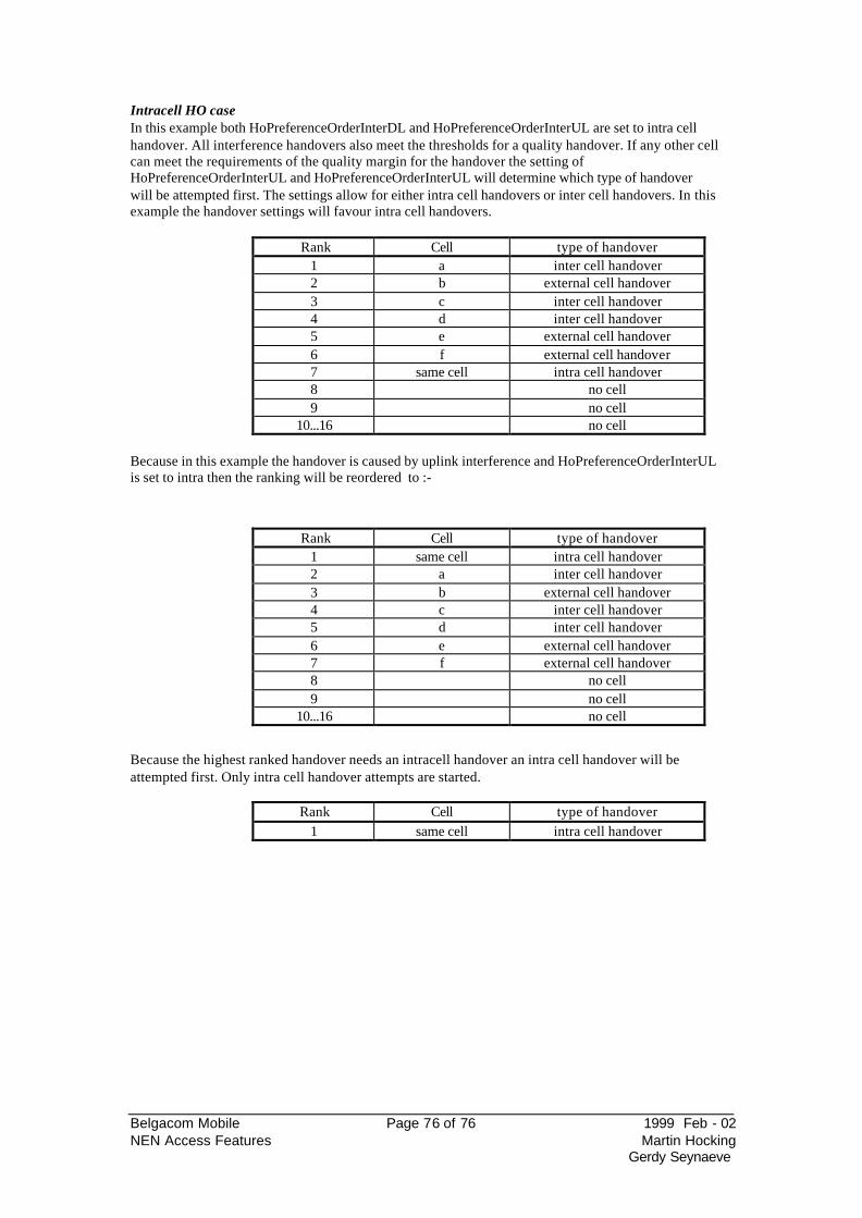
Belgacom Mobile Page 76 of 76 1999 Feb - 02 NEN Access Features Martin Hocking
Gerdy Seynaeve
Intracell HO case In this example both HoPreferenceOrderInterDL and HoPreferenceOrderInterUL are set to intra cell handover. All interference handovers also meet the thresholds for a quality handover. If any other cell can meet the requirements of the quality margin for the handover the setting of HoPreferenceOrderInterUL and HoPreferenceOrderInterUL will determine which type of handover will be attempted first. The settings allow for either intra cell handovers or inter cell handovers. In this example the handover settings will favour intra cell handovers.
Rank Cell type of handover 1 a inter cell handover 2 b external cell handover 3 c inter cell handover 4 d inter cell handover 5 e external cell handover 6 f external cell handover 7 same cell intra cell handover 8 no cell 9 no cell
10...16 no cell Because in this example the handover is caused by uplink interference and HoPreferenceOrderInterUL is set to intra then the ranking will be reordered to :-
Rank Cell type of handover 1 same cell intra cell handover 2 a inter cell handover 3 b external cell handover 4 c inter cell handover 5 d inter cell handover 6 e external cell handover 7 f external cell handover 8 no cell 9 no cell
10...16 no cell
Because the highest ranked handover needs an intracell handover an intra cell handover will be attempted first. Only intra cell handover attempts are started.
Rank Cell type of handover 1 same cell intra cell handover
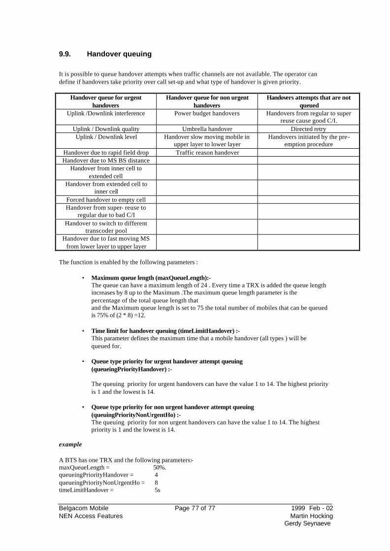
Belgacom Mobile Page 77 of 77 1999 Feb - 02 NEN Access Features Martin Hocking
Gerdy Seynaeve
9.9. Handover queuing
It is possible to queue handover attempts when traffic channels are not available. The operator can define if handovers take priority over call set-up and what type of handover is given priority.
Handover queue for urgent handovers
Handover queue for non urgent handovers
Handovers attempts that are not queued
Uplink /Downlink interference Power budget handovers Handovers from regular to super reuse cause good C/I.
Uplink / Downlink quality Umbrella handover Directed retry Uplink / Downlink level Handover slow moving mobile in
upper layer to lower layer Handovers initiated by the pre-
emption procedure Handover due to rapid field drop Traffic reason handover Handover due to MS BS distance
Handover from inner cell to extended cell
Handover from extended cell to inner cell
Forced handover to empty cell Handover from super- reuse to
regular due to bad C/I
Handover to switch to different transcoder pool
Handover due to fast moving MS from lower layer to upper layer
The function is enabled by the following parameters :
• Maximum queue length (maxQueueLength):- The queue can have a maximum length of 24 . Every time a TRX is added the queue length increases by 8 up to the Maximum .The maximum queue length parameter is the percentage of the total queue length that and the Maximum queue length is set to 75 the total number of mobiles that can be queued is 75% of (2 * 8) =12.
• Time limit for handover queuing (timeLimitHandover) :-
This parameter defines the maximum time that a mobile handover (all types ) will be queued for.
• Queue type priority for urgent handover attempt queuing
(queueingPriorityHandover) :-
The queuing priority for urgent handovers can have the value 1 to 14. The highest priority is 1 and the lowest is 14.
• Queue type priority for non urgent handover attempt queuing
(queuingPriorityNonUrgentHo) :- The queuing priority for non urgent handovers can have the value 1 to 14. The highest priority is 1 and the lowest is 14.
example A BTS has one TRX and the following parameters:- maxQueueLength = 50%. queueingPriorityHandover = 4 queueingPriorityNonUrgentHo = 8 timeLimitHandover = 5s
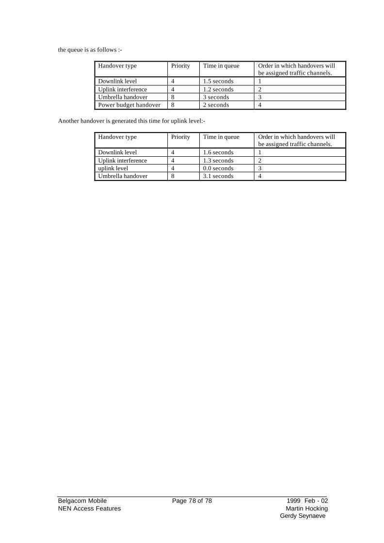
Belgacom Mobile Page 78 of 78 1999 Feb - 02 NEN Access Features Martin Hocking
Gerdy Seynaeve
the queue is as follows :-
Handover type Priority Time in queue Order in which handovers will be assigned traffic channels.
Downlink level 4 1.5 seconds 1 Uplink interference 4 1.2 seconds 2 Umbrella handover 8 3 seconds 3 Power budget handover 8 2 seconds 4
Another handover is generated this time for uplink level:-
Handover type Priority Time in queue Order in which handovers will be assigned traffic channels.
Downlink level 4 1.6 seconds 1 Uplink interference 4 1.3 seconds 2 uplink level 4 0.0 seconds 3 Umbrella handover 8 3.1 seconds 4
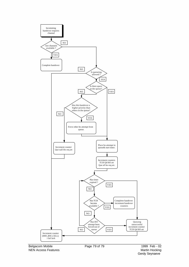
Belgacom Mobile Page 79 of 79 1999 Feb - 02 NEN Access Features Martin Hocking
Gerdy Seynaeve
Incomminghandover requires
channel
Are channelsavailable ?
Is queueingallowed ?
Is there spacein the queue?
Has this handover ahigher priority thanothers in the queue?
Force other ho attempt fromqueue.
Has timerexpired ?
Has TCHbecome
available ?
Has HOattempt beenforced out of
queue
Place ho attempt inqueue& start timer.
Completer handoverincrement handover
counters
Increment countersTCH Qd HO att
Que all ho req att.
Increment counter(MSC,BSC,CELL)
i fail lack
Increment counterQue nall Ho req att
Queuingunsuccesful
increment counterTCH Qd HO att
Complete handover
NO
YES
YES
YES
YES
YES
YES
YES
NO
NO
NO
NO
NO
NO
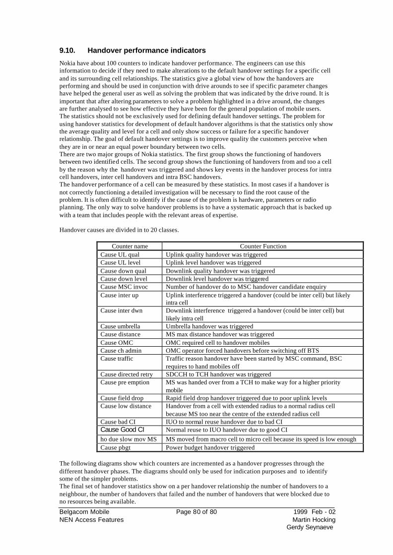
Belgacom Mobile Page 80 of 80 1999 Feb - 02 NEN Access Features Martin Hocking
Gerdy Seynaeve
9.10. Handover performance indicators
Nokia have about 100 counters to indicate handover performance. The engineers can use this information to decide if they need to make alterations to the default handover settings for a specific cell and its surrounding cell relationships. The statistics give a global view of how the handovers are performing and should be used in conjunction with drive arounds to see if specific parameter changes have helped the general user as well as solving the problem that was indicated by the drive round. It is important that after altering parameters to solve a problem highlighted in a drive around, the changes are further analysed to see how effective they have been for the general population of mobile users. The statistics should not be exclusively used for defining default handover settings. The problem for using handover statistics for development of default handover algorithms is that the statistics only show the average quality and level for a cell and only show success or failure for a specific handover relationship. The goal of default handover settings is to improve quality the customers perceive when they are in or near an equal power boundary between two cells. There are two major groups of Nokia statistics. The first group shows the functioning of handovers between two identified cells. The second group shows the functioning of handovers from and too a cell by the reason why the handover was triggered and shows key events in the handover process for intra cell handovers, inter cell handovers and intra BSC handovers. The handover performance of a cell can be measured by these statistics. In most cases if a handover is not correctly functioning a detailed investigation will be necessary to find the root cause of the problem. It is often difficult to identify if the cause of the problem is hardware, parameters or radio planning. The only way to solve handover problems is to have a systematic approach that is backed up with a team that includes people with the relevant areas of expertise. Handover causes are divided in to 20 classes.
Counter name Counter Function Cause UL qual Uplink quality handover was triggered Cause UL level Uplink level handover was triggered Cause down qual Downlink quality handover was triggered Cause down level Downlink level handover was triggered Cause MSC invoc Number of handover do to MSC handover candidate enquiry Cause inter up Uplink interference triggered a handover (could be inter cell) but likely
intra cell Cause inter dwn Downlink interference triggered a handover (could be inter cell) but
likely intra cell Cause umbrella Umbrella handover was triggered Cause distance MS max distance handover was triggered Cause OMC OMC required cell to handover mobiles Cause ch admin OMC operator forced handovers before switching off BTS Cause traffic Traffic reason handover have been started by MSC command, BSC
requires to hand mobiles off Cause directed retry SDCCH to TCH handover was triggered Cause pre emption MS was handed over from a TCH to make way for a higher priority
mobile Cause field drop Rapid field drop handover triggered due to poor uplink levels Cause low distance Handover from a cell with extended radius to a normal radius cell
because MS too near the centre of the extended radius cell Cause bad CI IUO to normal reuse handover due to bad CI Cause Good CI Normal reuse to IUO handover due to good CI
ho due slow mov MS MS moved from macro cell to micro cell because its speed is low enough Cause pbgt Power budget handover triggered
The following diagrams show which counters are incremented as a handover progresses through the different handover phases. The diagrams should only be used for indication purposes and to identify some of the simpler problems. The final set of handover statistics show on a per handover relationship the number of handovers to a neighbour, the number of handovers that failed and the number of handovers that were blocked due to no resources being available.
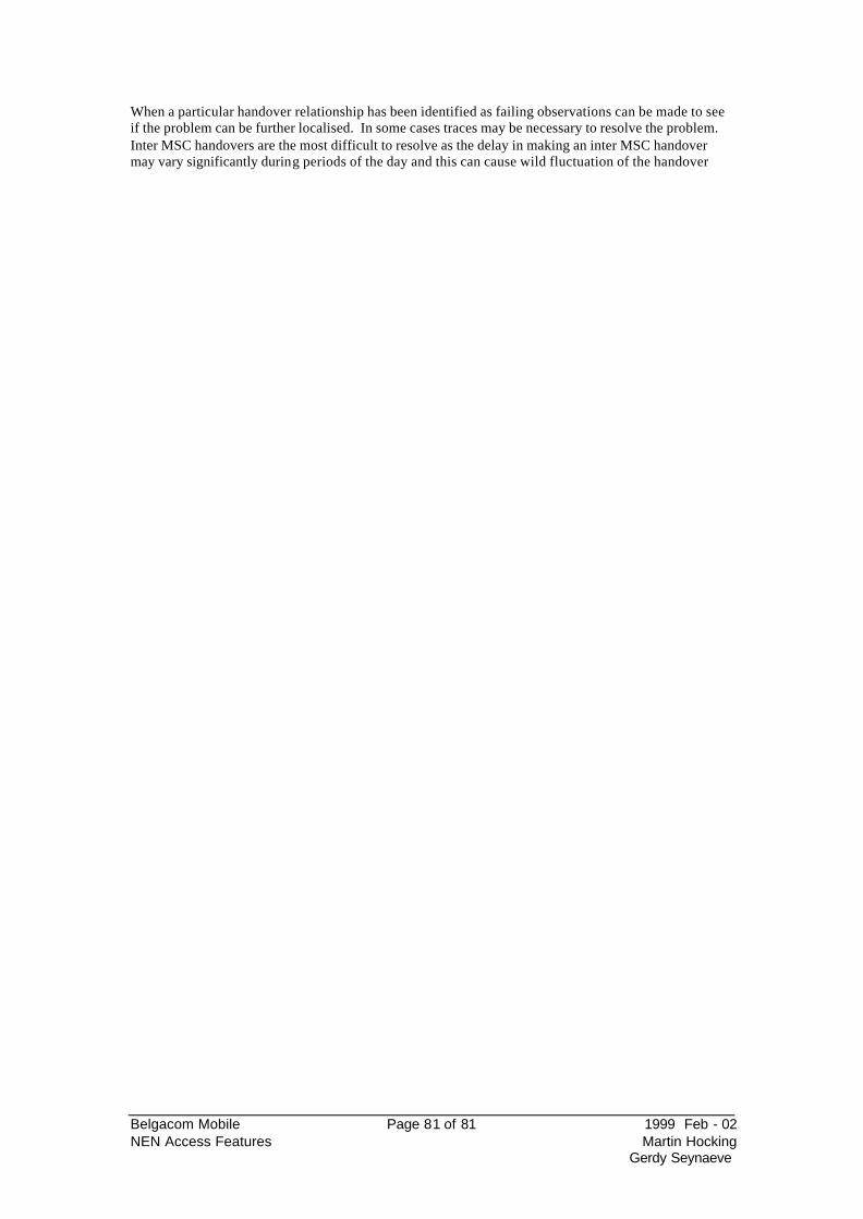
Belgacom Mobile Page 81 of 81 1999 Feb - 02 NEN Access Features Martin Hocking
Gerdy Seynaeve
When a particular handover relationship has been identified as failing observations can be made to see if the problem can be further localised. In some cases traces may be necessary to resolve the problem. Inter MSC handovers are the most difficult to resolve as the delay in making an inter MSC handover may vary significantly during periods of the day and this can cause wild fluctuation of the handover
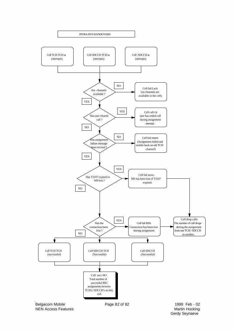
Belgacom Mobile Page 82 of 82 1999 Feb - 02 NEN Access Features Martin Hocking
Gerdy Seynaeve
INTRA BTS HANDOVERS
Cell TCH TCH at(attempts)
Cell SDCCH TCH at(attempts)
Cell SDCCH at(attempts)
YES
NO
Are channelsavailable ?
Cell fail Lack(no channels are
available in the cell)
Has assignmentfailure messagebeen recived ?
Has T3107 expired orMS lost ?
Cell fail return(Assignment failed and
mobile back on old TCHchannel)
Cell fail move.MS has been lost of T3107
expired.
Has theconnection been
lost ?
Cell fail BSS.Connection has been lost
during assignment
Cell TCH TCH(successful)
Cell SDCCH TCH(Successful)
Cell SDCCH(Successful)
NO
NO
Cell succ HOTotal number ofsuccessful BSC
assignments beweenTCH's/ SDCCH's on this
cell.
Cell drop callsThe number of call drops
during the assignmentfrom one TCH / SDCCH
to another.NO
YES
YES
YES
Has user clearedcall ?
Cell call clruser has ended callduring assignment
attempt.NO
YES
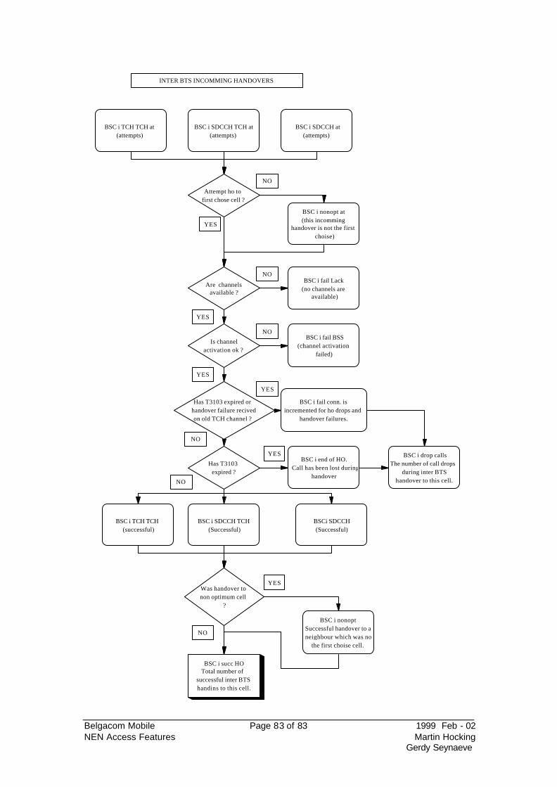
Belgacom Mobile Page 83 of 83 1999 Feb - 02 NEN Access Features Martin Hocking
Gerdy Seynaeve
INTER BTS INCOMMING HANDOVERS
BSC i TCH TCH at(attempts)
BSC i SDCCH TCH at(attempts)
BSC i SDCCH at(attempts)
Attempt ho tofirst chose cell ?
BSC i nonopt at(this incomming
handover is not the firstchoise)
Are channelsavailable ?
BSC i fail Lack(no channels are
available)
Is channelactivation ok ?
Has T3103 expired orhandover failure recivedon old TCH channel ?
BSC i fail BSS(channel activation
failed)
BSC i fail conn. isincremented for ho drops and
handover failures.
Has T3103expired ?
BSC i end of HO.Call has been lost during
handover
BSC i TCH TCH(successful)
BSC i SDCCH TCH(Successful)
BSCi SDCCH(Successful)
Was handover tonon optimum cell
?
BSC i nonoptSuccessful handover to aneighbour which was not
the first choise cell.
BSC i succ HOTotal number of
successful inter BTShandins to this cell.
BSC i drop callsThe number of call drops
during inter BTShandover to this cell.
NO
NO
NO
NO
NO
YES
YES
YES
YES
YES
YES
NO
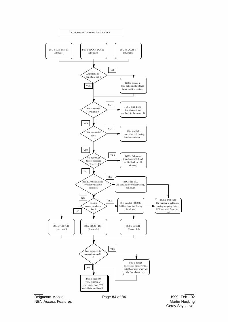
Belgacom Mobile Page 84 of 84 1999 Feb - 02 NEN Access Features Martin Hocking
Gerdy Seynaeve
INTER BTS OUT GOING HANDOVERS
BSC o TCH TCH at(attempts)
BSC o SDCCH TCH at(attempts)
BSC o SDCCH at(attempts)
Attempt ho tofirst chose cell ?
BSC o nonopt at(this out going handoveris not the first choise)
Are channelsavailable ?
BSC o fail Lack(no channels are
available in the new cell)
Has handoverfailure messagebeen recived ?
Has T3103 expired orconnection failure
recived ?
BSC o fail return(handover failed andmobile back on old
channel)
BSC o end HO.Call may have been lost during
handover.
Has theconnection been
lost ?
BSC o end of HO BSS.Call has been lost during
handover
BSC o TCH TCH(successful)
BSC o SDCCH TCH(Successful)
BSC o SDCCH(Successful)
Was handover tonon optimum cell
?
BSC o nonoptSuccessful handover to aneighbour which was not
the first choise cell.
BSC o succ HOTotal number of
successful inter BTShandoffs from this cell.
BSC o drop callsThe number of call drops
during out going interBTS handover from this
cell.
NO
NO
NO
NO
NO
NO
YES
YES
YES
YES
YES
YES
Has user endedcall ?
BSC o call clrUser ended call during
handover attempt.
YES
NO
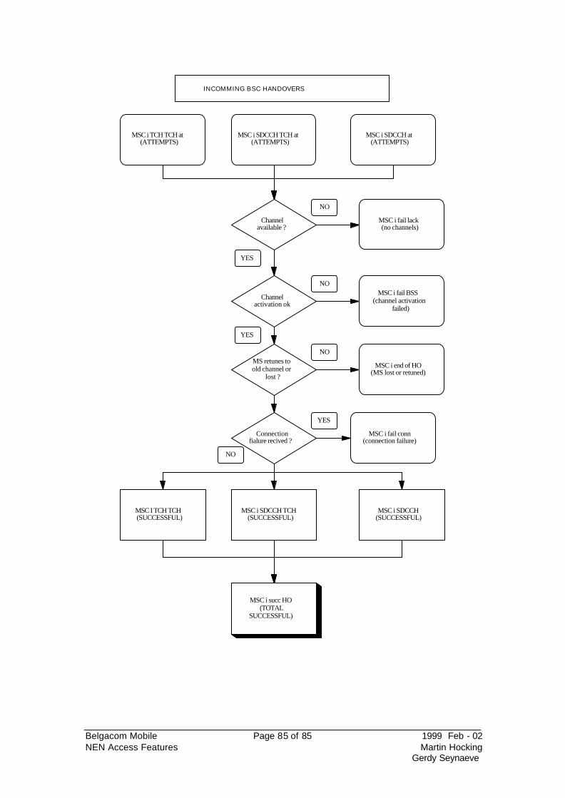
Belgacom Mobile Page 85 of 85 1999 Feb - 02 NEN Access Features Martin Hocking
Gerdy Seynaeve
MSC i TCH TCH at(ATTEMPTS)
MSC i SDCCH TCH at(ATTEMPTS)
MSC i SDCCH at(ATTEMPTS)
Channelavailable ?
Channelactivation ok
MS retunes toold channel or
lost ?
Connectionfialure recived ?
MSC I TCH TCH(SUCCESSFUL)
MSC i SDCCH TCH(SUCCESSFUL)
MSC i SDCCH(SUCCESSFUL)
MSC i succ HO(TOTAL
SUCCESSFUL)
INCOMMING BSC HANDOVERS
MSC i fail lack(no channels)
MSC i fail BSS(channel activation
failed)
MSC i end of HO(MS lost or retuned)
MSC i fail conn(connection failure)
NO
NO
NO
NO
YES
YES
YES
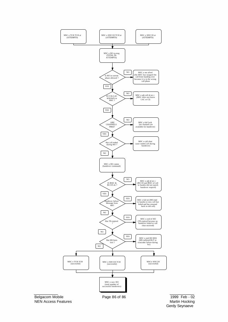
Belgacom Mobile Page 86 of 86 1999 Feb - 02 NEN Access Features Martin Hocking
Gerdy Seynaeve
MSC o TCH TCH at(ATTEMPTS)
MSC o SDCCH TCH at(ATTEMPTS)
MSC o SDCCH at(ATTEMPTS)
MSC o HO rq msg(TOTAL No
ATTEMPTS)
IS CI & LACKNOWN in
MSC ?
ARECHANNELS
FREE?
Has call endedduring HO ?
IS BSIC &BCCH ok ?
MSC o HO comm(handover command)
Has T8 expired ?
Has MS beenlost ?
MSC o SDCCH TCH(successful)
MSCo SDCCH(successful)
MSC o TCH TCH(successful)
MSC o adj cell id err c(MSC does not know
LAC or CI)
MSC o fail Lack (no channels are
available for handover)
MSC o call clear(user ended call during
handover)
MSC o adj id err c(BCCH and BSIC of cellto handin did not match
handover requird)
MSC o fail ret (MS triedto handin to new cell butfailed and has returned
back to old cell)
MSC o end HO BSS(MS suffered RLT or
trancoder failure duringho)
Handover failureMessage from
MS?
MSC o end of HO(T8 expired because nohandover failed or call
clear received)
MSC o succ HO(total number of
successful handovers)
Is HO in currentphase allowed ?
MSC o not allwd(the MSC has stopped the
call from handing overbecause it is in the wrong
call phase
YES
NO
NO
NO
NO
NO
NO
NO
NO
YES
YES
YES
YES
YES
YES
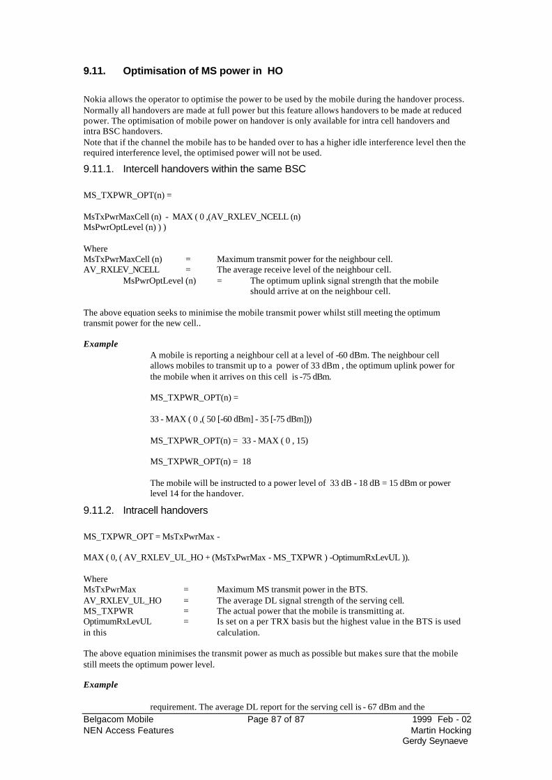
Belgacom Mobile Page 87 of 87 1999 Feb - 02 NEN Access Features Martin Hocking
Gerdy Seynaeve
9.11. Optimisation of MS power in HO
Nokia allows the operator to optimise the power to be used by the mobile during the handover process. Normally all handovers are made at full power but this feature allows handovers to be made at reduced power. The optimisation of mobile power on handover is only available for intra cell handovers and intra BSC handovers. Note that if the channel the mobile has to be handed over to has a higher idle interference level then the required interference level, the optimised power will not be used.
9.11.1. Intercell handovers within the same BSC MS_TXPWR_OPT(n) = MsTxPwrMaxCell (n) - MAX ( 0 ,(AV_RXLEV_NCELL (n) MsPwrOptLevel (n) ) ) Where MsTxPwrMaxCell (n) = Maximum transmit power for the neighbour cell. AV_RXLEV_NCELL = The average receive level of the neighbour cell.
MsPwrOptLevel (n) = The optimum uplink signal strength that the mobile should arrive at on the neighbour cell.
The above equation seeks to minimise the mobile transmit power whilst still meeting the optimum transmit power for the new cell.. Example
A mobile is reporting a neighbour cell at a level of -60 dBm. The neighbour cell allows mobiles to transmit up to a power of 33 dBm , the optimum uplink power for the mobile when it arrives on this cell is -75 dBm. MS_TXPWR_OPT(n) = 33 - MAX ( 0 ,( 50 [-60 dBm] - 35 [-75 dBm])) MS_TXPWR_OPT(n) = 33 - MAX ( 0 , 15) MS_TXPWR_OPT(n) = 18 The mobile will be instructed to a power level of 33 dB - 18 dB = 15 dBm or power level 14 for the handover.
9.11.2. Intracell handovers MS_TXPWR_OPT = MsTxPwrMax - MAX ( 0, ( AV_RXLEV_UL_HO + (MsTxPwrMax - MS_TXPWR ) -OptimumRxLevUL )). Where MsTxPwrMax = Maximum MS transmit power in the BTS. AV_RXLEV_UL_HO = The average DL signal strength of the serving cell. MS_TXPWR = The actual power that the mobile is transmitting at. OptimumRxLevUL = Is set on a per TRX basis but the highest value in the BTS is used in this calculation. The above equation minimises the transmit power as much as possible but makes sure that the mobile still meets the optimum power level. Example
requirement. The average DL report for the serving cell is - 67 dBm and the
Belgacom Mobile Page 88 of 88 1999 Feb - 02 NEN Access Features Martin Hocking
Gerdy Seynaeve
maximum MS power in the cell is +33 dBm. The mobile is currently transmitting at a level of +29 dBm TRX 1 OptimumRxLevUL = 30 TRX 2 OptimumRxLevUL = 28 TRX 3 OptimumRxLevUL = 32 TRX 4 OptimumRxLevUL = 30 The optimum power used for the calculation is 32 ( the highest value of all the
MS_TXPWR_OPT = 33 - MAX ( 0, (43 [-67 dBm] + ( 33 - 29 ) - 32) ) MS_TXPWR_OPT = 33 - Max ( 0, ( 43 + 4) -32 ) MS_TXPWR_OPT = 33 - (47 - 32) MS_TXPWR_OPT = 33 - 15 MS_TXPWR_OPT = 18 dBm or power step 12
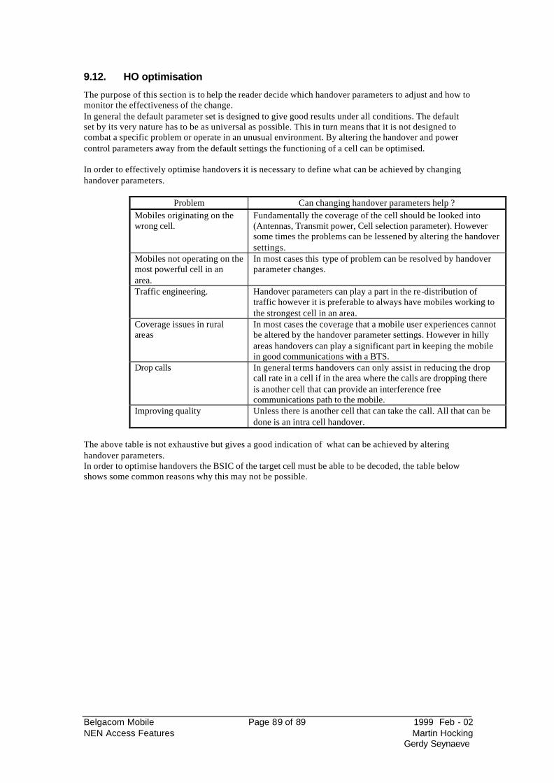
Belgacom Mobile Page 89 of 89 1999 Feb - 02 NEN Access Features Martin Hocking
Gerdy Seynaeve
9.12. HO optimisation
The purpose of this section is to help the reader decide which handover parameters to adjust and how to monitor the effectiveness of the change. In general the default parameter set is designed to give good results under all conditions. The default set by its very nature has to be as universal as possible. This in turn means that it is not designed to combat a specific problem or operate in an unusual environment. By altering the handover and power control parameters away from the default settings the functioning of a cell can be optimised. In order to effectively optimise handovers it is necessary to define what can be achieved by changing handover parameters.
Problem Can changing handover parameters help ? Mobiles originating on the wrong cell.
Fundamentally the coverage of the cell should be looked into (Antennas, Transmit power, Cell selection parameter). However some times the problems can be lessened by altering the handover settings.
Mobiles not operating on the most powerful cell in an area.
In most cases this type of problem can be resolved by handover parameter changes.
Traffic engineering. Handover parameters can play a part in the re-distribution of traffic however it is preferable to always have mobiles working to the strongest cell in an area.
Coverage issues in rural areas
In most cases the coverage that a mobile user experiences cannot be altered by the handover parameter settings. However in hilly areas handovers can play a significant part in keeping the mobile in good communications with a BTS.
Drop calls In general terms handovers can only assist in reducing the drop call rate in a cell if in the area where the calls are dropping there is another cell that can provide an interference free communications path to the mobile.
Improving quality Unless there is another cell that can take the call. All that can be done is an intra cell handover.
The above table is not exhaustive but gives a good indication of what can be achieved by altering handover parameters. In order to optimise handovers the BSIC of the target cell must be able to be decoded, the table below shows some common reasons why this may not be possible.
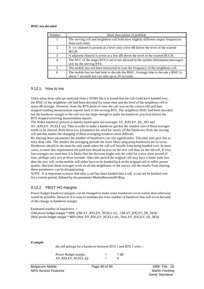
Belgacom Mobile Page 90 of 90 1999 Feb - 02 NEN Access Features Martin Hocking
Gerdy Seynaeve
BSIC not decoded
Number Short description of problem 1 The serving cell and neighbour cell both have slightly different output frequencies
from each other. 2 A co- channel is present at a level only a few dB below the level of the wanted
BCCH. 3 A adjacent channel is active at a few dB above the level of the wanted BCCH. 4 The NCC of the target BTS is set to not allowed in the system information messages
sent by the serving BTS. 5 The mobile has not been instructed to scan the frequency of the neighbour cell. 6 The mobile has not had time to decode the BSIC. Average time to decode a BSIC is
about 7 seconds but can take up to 20 seconds.
9.12.1. How to ma Often when drop calls are analysed from a TEMS file it is found that the call could have handed over, the BSIC of the neighbour cell had been decoded for some time and the level of the neighbour cell is many dB stronger. However, from the BTS point of view the call was on the correct cell and then stopped sending measurement reports back to the serving BTS. The neighbour BSIC had been decoded but the handover margin to the cell was not large enough to make the handover practical before the BTS stopped receiving measurement reports. The Nokia handover process is mainly based upon two averages AV_RXLEV_DL_HO and AV_RXLEV_NCELL (n). Thus in order to make a handover quicker the window size of these averages needs to be altered. Both these two parameters are used for nearly all the handovers from the serving cell and this makes the changing of these averaging windows more difficult. By altering these parameters the number of handovers can rise significantly. This may also give rise to extra drop calls. The smaller the averaging periods the more likely ping pong handovers are to occur. Handovers should in the main be only made when the call will benefit from being handed over. In most cases, to meet this requirement the path loss should be less on the new cell than on the old cell. If very fast averages are used then it is likely that the decision might only be valid for a very short period of time, perhaps only two or three seconds. After this period the original cell may have a better path loss then the new cell, so the mobile will either have to be handed back to the original cell or suffer poorer quality. Because these averages work on all the neighbours of the source cell the results from altering these parameters can be disappointing. NOTE : It is important to know that after a call has been handed into a cell, it can not be handed over for a certain period, defined by the parameter MinIntBetweenHOReq.
9.12.2. PBGT HO margins Power budget handover margins can be changed to make some handovers occur earlier than otherwise would be possible. However it is wise to estimate the extra number of handover that will occur because of the change in handover margin. Estimated number of handovers = (Old power budget margin * MIN (Old AV_RXLEV_NCELL (n) , Old AV_RXLEV_DL_HO)) / (New power budget margin * MIN (New AV_RXLEV_NCELL (n) , New AV_RXLEV_DL_HO))
Example
the old settings for a handover between BTS 1 and BTS 2 were :- Power Budget margin = 7 dB AV_RXLEV_NCELL (n) = 8
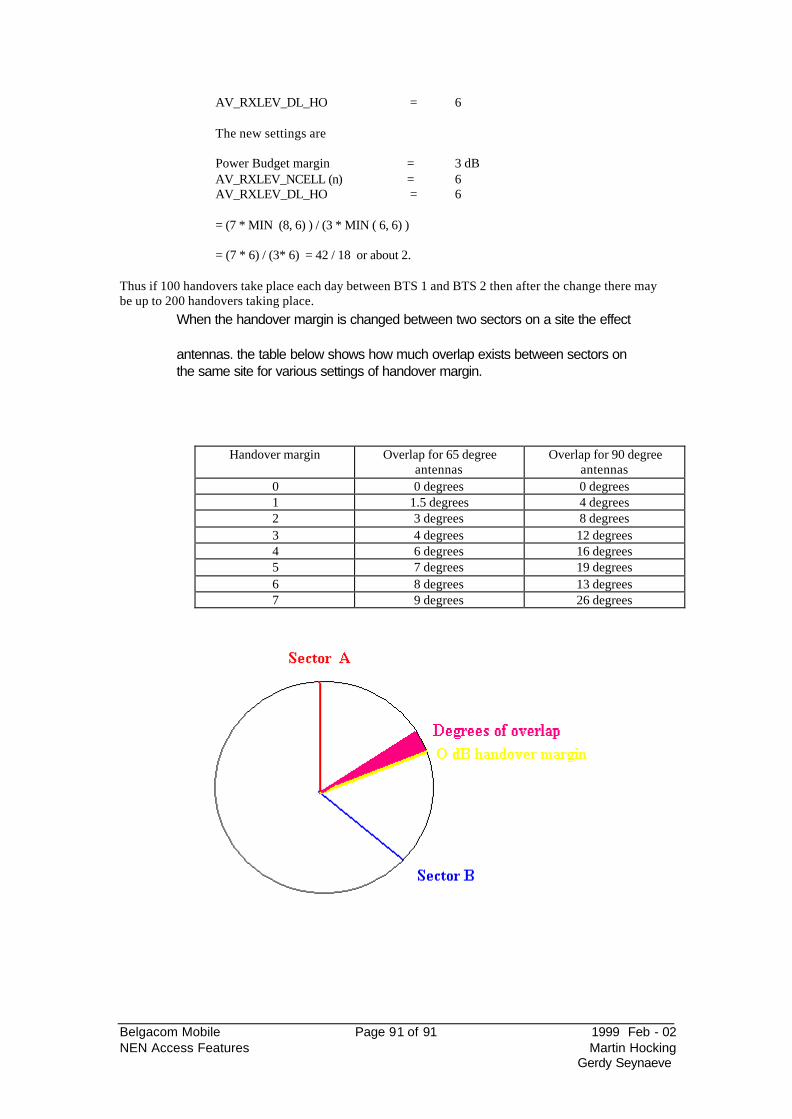
Belgacom Mobile Page 91 of 91 1999 Feb - 02 NEN Access Features Martin Hocking
Gerdy Seynaeve
AV_RXLEV_DL_HO = 6 The new settings are Power Budget margin = 3 dB AV_RXLEV_NCELL (n) = 6 AV_RXLEV_DL_HO = 6 = (7 * MIN (8, 6) ) / (3 * MIN ( 6, 6) ) = (7 * 6) / (3* 6) = 42 / 18 or about 2.
Thus if 100 handovers take place each day between BTS 1 and BTS 2 then after the change there may be up to 200 handovers taking place.
When the handover margin is changed between two sectors on a site the effect
antennas. the table below shows how much overlap exists between sectors on the same site for various settings of handover margin.
Handover margin Overlap for 65 degree antennas
Overlap for 90 degree antennas
0 0 degrees 0 degrees 1 1.5 degrees 4 degrees 2 3 degrees 8 degrees 3 4 degrees 12 degrees 4 6 degrees 16 degrees 5 7 degrees 19 degrees 6 8 degrees 13 degrees 7 9 degrees 26 degrees
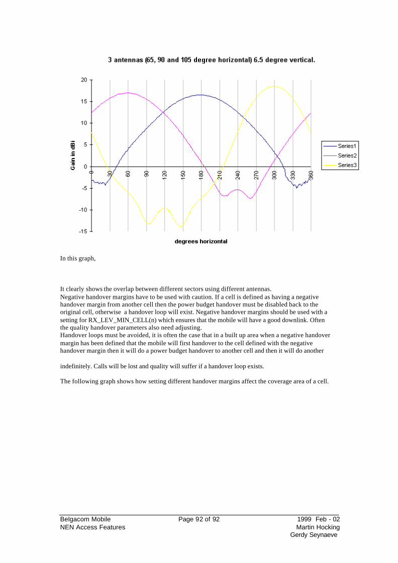
Belgacom Mobile Page 92 of 92 1999 Feb - 02 NEN Access Features Martin Hocking
Gerdy Seynaeve
In this graph, It clearly shows the overlap between different sectors using different antennas. Negative handover margins have to be used with caution. If a cell is defined as having a negative handover margin from another cell then the power budget handover must be disabled back to the original cell, otherwise a handover loop will exist. Negative handover margins should be used with a setting for RX_LEV_MIN_CELL(n) which ensures that the mobile will have a good downlink. Often the quality handover parameters also need adjusting. Handover loops must be avoided, it is often the case that in a built up area when a negative handover margin has been defined that the mobile will first handover to the cell defined with the negative handover margin then it will do a power budget handover to another cell and then it will do another
indefinitely. Calls will be lost and quality will suffer if a handover loop exists. The following graph shows how setting different handover margins affect the coverage area of a cell.
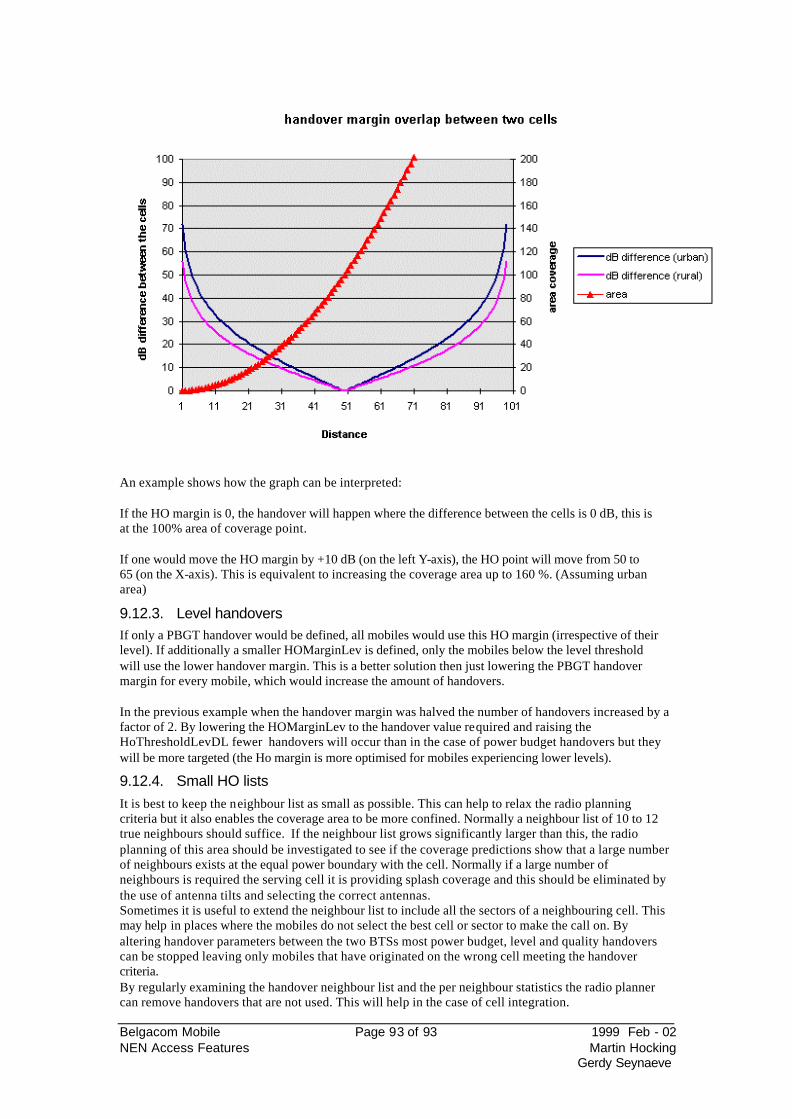
Belgacom Mobile Page 93 of 93 1999 Feb - 02 NEN Access Features Martin Hocking
Gerdy Seynaeve
An example shows how the graph can be interpreted: If the HO margin is 0, the handover will happen where the difference between the cells is 0 dB, this is at the 100% area of coverage point. If one would move the HO margin by +10 dB (on the left Y-axis), the HO point will move from 50 to 65 (on the X-axis). This is equivalent to increasing the coverage area up to 160 %. (Assuming urban area)
9.12.3. Level handovers If only a PBGT handover would be defined, all mobiles would use this HO margin (irrespective of their level). If additionally a smaller HOMarginLev is defined, only the mobiles below the level threshold will use the lower handover margin. This is a better solution then just lowering the PBGT handover margin for every mobile, which would increase the amount of handovers. In the previous example when the handover margin was halved the number of handovers increased by a factor of 2. By lowering the HOMarginLev to the handover value required and raising the HoThresholdLevDL fewer handovers will occur than in the case of power budget handovers but they will be more targeted (the Ho margin is more optimised for mobiles experiencing lower levels).
9.12.4. Small HO lists It is best to keep the neighbour list as small as possible. This can help to relax the radio planning criteria but it also enables the coverage area to be more confined. Normally a neighbour list of 10 to 12 true neighbours should suffice. If the neighbour list grows significantly larger than this, the radio planning of this area should be investigated to see if the coverage predictions show that a large number of neighbours exists at the equal power boundary with the cell. Normally if a large number of neighbours is required the serving cell it is providing splash coverage and this should be eliminated by the use of antenna tilts and selecting the correct antennas. Sometimes it is useful to extend the neighbour list to include all the sectors of a neighbouring cell. This may help in places where the mobiles do not select the best cell or sector to make the call on. By altering handover parameters between the two BTSs most power budget, level and quality handovers can be stopped leaving only mobiles that have originated on the wrong cell meeting the handover criteria. By regularly examining the handover neighbour list and the per neighbour statistics the radio planner can remove handovers that are not used. This will help in the case of cell integration.
Belgacom Mobile Page 94 of 94 1999 Feb - 02 NEN Access Features Martin Hocking
Gerdy Seynaeve
Having a large HO list can have another unwanted effect. As the network grows tighter, it is more likely to have two cells with the same BCCH/BCC in the neighbourhood of a cell. Only one of these
eports one of the cells, the BSC can trigger a handover only to the cell which is defined as a neighbour. This cell is not necessarily the one reported by the mobile.
9.12.5. Finding missing neighbours Some times a neighbour will have been missed from the neighbouring list. This can most easily be
level on all BCCH frequencies. This can be achieved by turning on the dual BA list. When this is enabled, cells which are not in the neighbour list are reported can be clearly identified by using the undefined measurement report.. By using this information missing neighbours or radio planning
This has to be used with care. When not allthis will stop handovers to any cell with a BCCH which is not in the list.
9.12.6. Drive arounds and statistics In most cases the default handover settings will operate very well so it is likely that any handover optimisation will be due to a drive test highlighting a problem in an area. The changing of any handover parameter should first be checked in the area the problem was identified to see if the change has solved the problem and then the statistics should be monitored to see if the change has had any adverse affect in other parts of the area. It is difficult to identify the problems with any one handover from the normal statistics but the OMC can be requested to make an observation of handovers between any two sites and see how well the handovers are operating. This can easily be done in the case where a handover has been added, but in the case of a parameter change to one of the averages or thresholds the performance of the whole site must be checked. This should be made a week after the changes have been made so that any short term variation can be ignored from the statistics. The statistics must at least show the number of radio drops, the number of handover drops and the quality. For the change to be a success none of the above parameters should show a deterioration. The number of handovers that take place can also give a an indication of how important the effect of the change has been, but this is of secondary importance unless the overall number has increased significantly.
9.12.7. Special Handovers Handover parameters that can be used for traffic redistribution need to be used with care. There are several ways in which traffic can be shifted from the optimum cell to another cell, but this has to be done with care. Each site needs to be assessed on its own merits. Fast moving mobile parameters can be used in conjunction with handover priorities. But these first need a site specific set of parameters and they need testing with the normal functioning of the BTS. It is recommended that the RF support group is consulted on a case by case basis so that the correct functioning of a parameter or setting can be tested before being deployed.
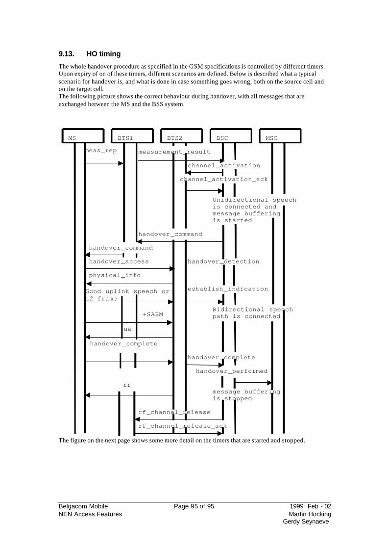
Belgacom Mobile Page 95 of 95 1999 Feb - 02 NEN Access Features Martin Hocking
Gerdy Seynaeve
9.13. HO timing
The whole handover procedure as specified in the GSM specifications is controlled by different timers. Upon expiry of on of these timers, different scenarios are defined. Below is described what a typical scenario for handover is, and what is done in case something goes wrong, both on the source cell and on the target cell. The following picture shows the correct behaviour during handover, with all messages that are exchanged between the MS and the BSS system.
MS BTS1 BTS2 BSC MSC
meas_rep measurement_result
channel_activation
channel_activation_ack
Unidirectional speechis connected andmessage bufferingis started
handover_command
handover_command
handover_access handover_detection
physical_info
Good uplink speech orL2 frame
establish_indication
Bidirectional speechpath is connected
ua
handover_complete
+SABM
rr
handover_complete
handover_performed
message bufferingis stopped
rf_channel_release
rf_channel_release_ack
The figure on the next page shows some more detail on the timers that are started and stopped.
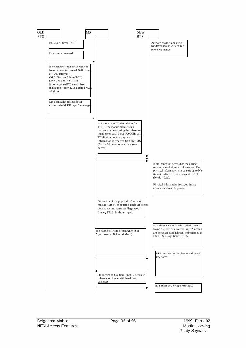
Belgacom Mobile Page 96 of 96 1999 Feb - 02 NEN Access Features Martin Hocking
Gerdy Seynaeve
OLDBTS
MS NEWBTS
BSC starts timer T3103
Handover command
If no acknowledgment is receivedfrom the mobile re-send N200 timesat T200 interval.(34 *120 ms to 220ms TCH)(23 * 235.5 ms SDCCH)If no response BTS sends Errorindication (timer T200 expired N200+1 times.
Activate channel and awaithandover access with correctreference number
MS acknowledges handovercommand with RR layer 2 message.
MS starts timer T3124 (320ms forTCH). The mobile then sends ahandover access (using the referencenumber) on each burst (FACCH) untilT3142 times out or physicalinformation is received from the BTS.(Max = 66 times to send handoveraccess).
If the handover access has the correctreference send physical information. Thephysical information can be sent up to NY1times (Nokia = 13) at a delay of T3105(Nokia =0.1s).
Physical information includes timingadvance and mobile power.
On receipt of the physical informationmessage MS stops sending handover accesscommands and starts sending speech
frames. T3124 is also stopped.
BTS detects either a valid uplink speechframe (BFI=0) or a correct layer 2 messageand sends an establishment indication to theBSC. BSC stops timer T3105.
The mobile starts to send SABM (SetAsynchronous Balanced Mode)
BTS receives SABM frame and sendsUA frame
On receipt of UA frame mobile sends aninformation frame with handovercomplete
BTS sends HO complete to BSC
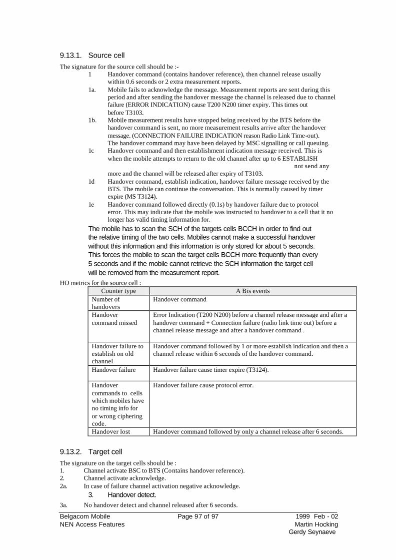
Belgacom Mobile Page 97 of 97 1999 Feb - 02 NEN Access Features Martin Hocking
Gerdy Seynaeve
9.13.1. Source cell The signature for the source cell should be :-
1 Handover command (contains handover reference), then channel release usually within 0.6 seconds or 2 extra measurement reports.
1a. Mobile fails to acknowledge the message. Measurement reports are sent during this period and after sending the handover message the channel is released due to channel failure (ERROR INDICATION) cause T200 N200 timer expiry. This times out before T3103.
1b. Mobile measurement results have stopped being received by the BTS before the handover command is sent, no more measurement results arrive after the handover message. (CONNECTION FAILURE INDICATION reason Radio Link Time-out). The handover command may have been delayed by MSC signalling or call queuing.
1c Handover command and then establishment indication message received. This is when the mobile attempts to return to the old channel after up to 6 ESTABLISH
not send any more and the channel will be released after expiry of T3103.
1d Handover command, establish indication, handover failure message received by the BTS. The mobile can continue the conversation. This is normally caused by timer expire (MS T3124).
1e Handover command followed directly (0.1s) by handover failure due to protocol error. This may indicate that the mobile was instructed to handover to a cell that it no longer has valid timing information for.
The mobile has to scan the SCH of the targets cells BCCH in order to find out the relative timing of the two cells. Mobiles cannot make a successful handover without this information and this information is only stored for about 5 seconds. This forces the mobile to scan the target cells BCCH more frequently than every 5 seconds and if the mobile cannot retrieve the SCH information the target cell will be removed from the measurement report.
HO metrics for the source cell : Counter type A Bis events
Number of handovers
Handover command
Handover command missed
Error Indication (T200 N200) before a channel release message and after a handover command + Connection failure (radio link time out) before a channel release message and after a handover command .
Handover failure to establish on old channel
Handover command followed by 1 or more establish indication and then a channel release within 6 seconds of the handover command.
Handover failure Handover failure cause timer expire (T3124).
Handover commands to cells which mobiles have no timing info for or wrong ciphering code.
Handover failure cause protocol error.
Handover lost Handover command followed by only a channel release after 6 seconds.
9.13.2. Target cell The signature on the target cells should be : 1. Channel activate BSC to BTS (Contains handover reference). 2. Channel activate acknowledge. 2a. In case of failure channel activation negative acknowledge.
3. Handover detect. 3a. No handover detect and channel released after 6 seconds.
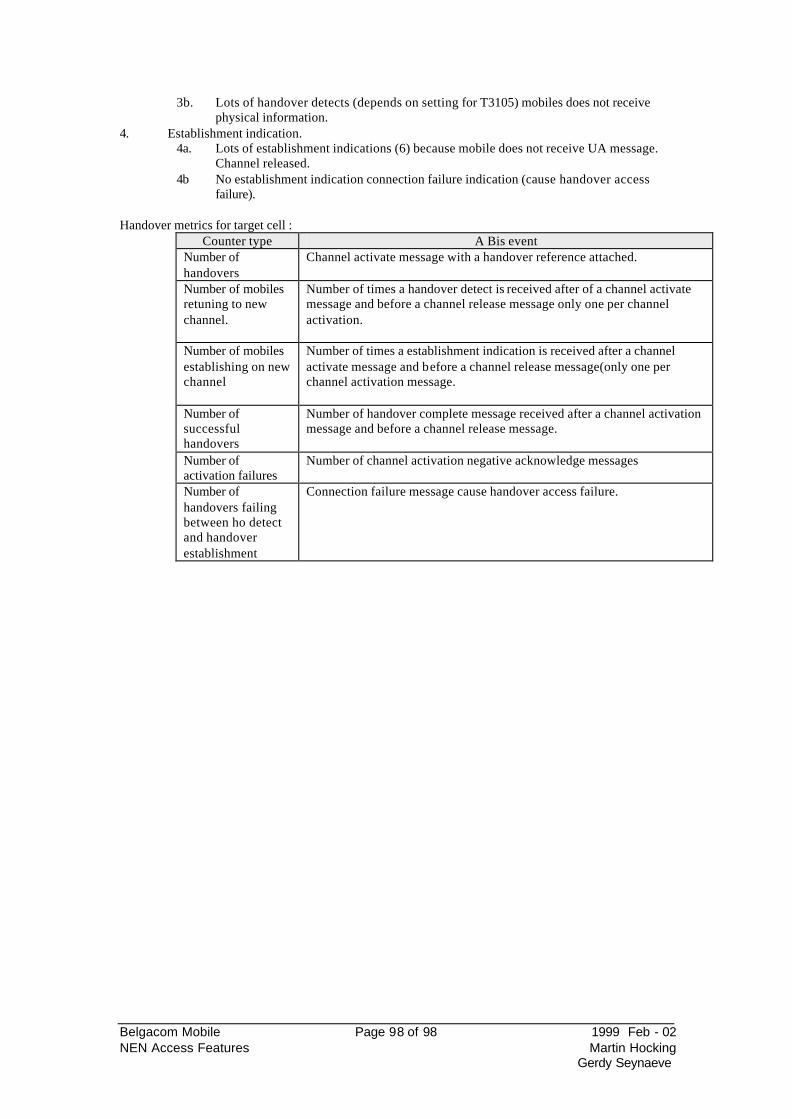
Belgacom Mobile Page 98 of 98 1999 Feb - 02 NEN Access Features Martin Hocking
Gerdy Seynaeve
3b. Lots of handover detects (depends on setting for T3105) mobiles does not receive physical information.
4. Establishment indication. 4a. Lots of establishment indications (6) because mobile does not receive UA message.
Channel released. 4b No establishment indication connection failure indication (cause handover access
failure). Handover metrics for target cell :
Counter type A Bis event Number of handovers
Channel activate message with a handover reference attached.
Number of mobiles retuning to new channel.
Number of times a handover detect is received after of a channel activate message and before a channel release message only one per channel activation.
Number of mobiles establishing on new channel
Number of times a establishment indication is received after a channel activate message and before a channel release message(only one per channel activation message.
Number of successful handovers
Number of handover complete message received after a channel activation message and before a channel release message.
Number of activation failures
Number of channel activation negative acknowledge messages
Number of handovers failing between ho detect and handover establishment
Connection failure message cause handover access failure.
Belgacom Mobile Page 99 of 99 1999 Feb - 02 NEN Access Features Martin Hocking
Gerdy Seynaeve
10. Interworking between HO and PC
Power control for BTS and MS runs independently. The handover control is aware of the current settings for MS and BTS power. The BSC will not attempt a power change and a handover attempt at the same time. Should both of the thresholds be fulfilled at the same time, then handover gets priority over power control.
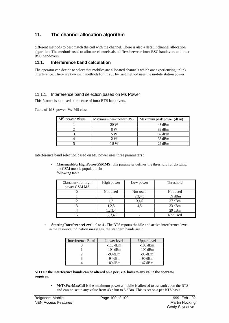
Belgacom Mobile Page 100 of 100 1999 Feb - 02 NEN Access Features Martin Hocking
Gerdy Seynaeve
11. The channel allocation algorithm
different methods to best match the call with the channel. There is also a default channel allocation algorithm. The methods used to allocate channels also differs between intra BSC handovers and inter BSC handovers.
11.1. Interference band calculation
The operator can decide to select that mobiles are allocated channels which are experiencing uplink interference. There are two main methods for this . The first method uses the mobile station power
11.1.1. Interference band selection based on Ms Power This feature is not used in the case of intra BTS handovers. Table of MS power Vs MS class
MS power class Maximum peak power (W) Maximum peak power (dBm)
1 20 W 43 dBm 2 8 W 39 dBm 3 5 W 37 dBm 4 2 W 33 dBm 5 0.8 W 29 dBm
Interference band selection based on MS power uses three parameters :
• ClassmarkForHighPowerGSMMS . this parameter defines the threshold for dividing the GSM mobile population infollowing table
Classmark for high
power GSM MS High power Low power Threshold
0 Not used Not used Not used 1 1 2,3,4,5 39 dBm 2 1,2 3,4,5 37 dBm 3 1,2,3 4,5 33 dBm 4 1,2,3,4 4 29 dBm 5 1,2,3,4,5 - Not used
• StartingInterferenceLevel : 0 to 4 . The BTS reports the idle and active interference level
in the resource indication messages, the standard bands are :
Interference Band Lower level Upper level
0 -110 dBm -105 dBm 1 -104 dBm -100 dBm 2 -99 dBm -95 dBm 3 -94 dBm -90 dBm 4 -89 dBm -47 dBm
NOTE : the interference bands can be altered on a per BTS basis to any value the operator requires.
• MsTxPwrMaxCell is the maximum power a mobile is allowed to transmit at on the BTS and can be set to any value from 43 dBm to 5 dBm. This is set on a per BTS basis.
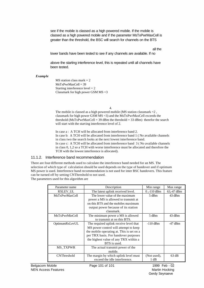
Belgacom Mobile Page 101 of 101 1999 Feb - 02 NEN Access Features Martin Hocking
Gerdy Seynaeve
see if the mobile is classed as a high powered mobile. If the mobile is classed as a high powered mobile and if the parameter MsTxPwrMaxCell is greater than the threshold, the BSC will search for channels on the BTS
all the lower bands have been tested to see if any channels are available. If no
above the starting interference level, this is repeated until all channels have been tested.
Example
MS station class mark = 2 MsTxPwrMaxCell = 39 Starting interference level = 2 Classmark for high power GSM MS =3
4. The mobile is classed as a high powered mobile (MS station classmark =2 , classmark for high power GSM MS =3) and the MsTxPwrMaxCell exceeds the threshold (MsTxPwrMaxCell = 39 dBm the threshold = 33 dBm) therefor the search will start with the starting interference level of 2. In case a : A TCH will be allocated from interference band 2. In case b: A TCH will be allocated from interference band 1 ( No available channels in class two the search looks at the next lowest interference band. In case c: A TCH will be allocated from interference band 3 ( No available channels in class 0, 1,2 so a TCH with worse interference must be allocated and therefore the TCH with the lowest interference is allocated).
11.1.2. Interference band recommendation There are four different methods used to calculate the interference band needed for an MS. The selection of which type of calculation should be used depends on the type of handover and if optimum MS power is used. Interference band recommendation is not used for inter BSC handovers. This feature can be turned off by setting CNThreshold to not used. The parameters used for this algorithm are
Parameter name Description Min range Max range RXLEV_UL The latest uplink received level. 0 ,-110 dBm 63,-47 dBm
MsTxPwrMaxCell The lower value of the maximum power a MS is allowed to transmit at
on this BTS and the mobiles maximum output power because of its station
classmark.
5 dBm 43 dBm
MsTxPwrMinCell The minimum power a MS is allowed to transmit at on this BTS.
5 dBm 43 dBm
OptimumRxLevUL The required uplink receive level that MS power control will attempt to keep
the mobile operating at. This is set on a per TRX basis. For handover purposes the highest value of any TRX within a
BTS is used.
-110 dBm -47 dBm
MS_TXPWR The actual transmit power of the mobile.
CNThreshold The margin by which uplink level must exceed the idle interference.
(Not used), 1 dB
63 dB
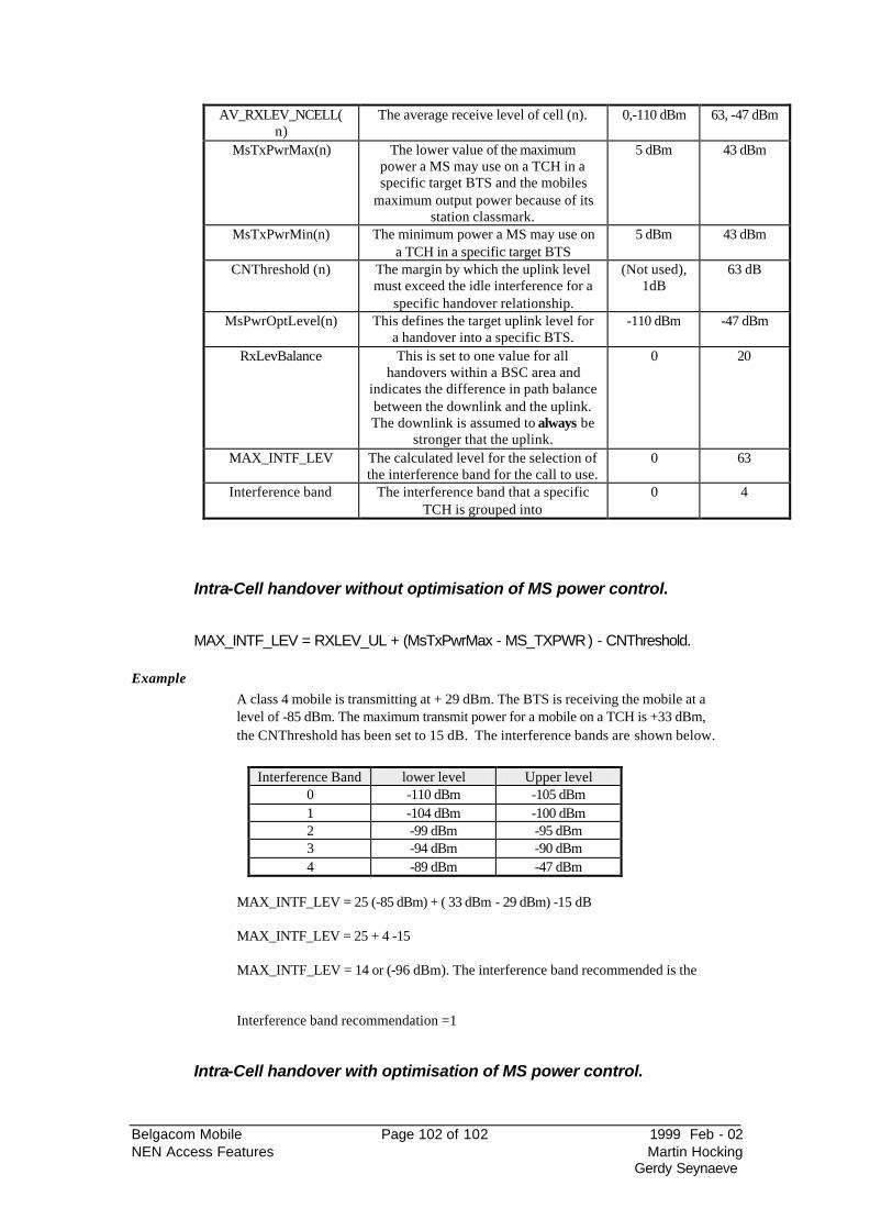
Belgacom Mobile Page 102 of 102 1999 Feb - 02 NEN Access Features Martin Hocking
Gerdy Seynaeve
AV_RXLEV_NCELL(n)
The average receive level of cell (n). 0,-110 dBm 63, -47 dBm
MsTxPwrMax(n) The lower value of the maximum power a MS may use on a TCH in a specific target BTS and the mobiles
maximum output power because of its station classmark.
5 dBm 43 dBm
MsTxPwrMin(n) The minimum power a MS may use on a TCH in a specific target BTS
5 dBm 43 dBm
CNThreshold (n) The margin by which the uplink level must exceed the idle interference for a
specific handover relationship.
(Not used), 1dB
63 dB
MsPwrOptLevel(n) This defines the target uplink level for a handover into a specific BTS.
-110 dBm -47 dBm
RxLevBalance This is set to one value for all handovers within a BSC area and
indicates the difference in path balance between the downlink and the uplink. The downlink is assumed to always be
stronger that the uplink.
0 20
MAX_INTF_LEV The calculated level for the selection of the interference band for the call to use.
0 63
Interference band The interference band that a specific TCH is grouped into
0 4
Intra-Cell handover without optimisation of MS power control.
MAX_INTF_LEV = RXLEV_UL + (MsTxPwrMax - MS_TXPWR ) - CNThreshold. Example
A class 4 mobile is transmitting at + 29 dBm. The BTS is receiving the mobile at a level of -85 dBm. The maximum transmit power for a mobile on a TCH is +33 dBm, the CNThreshold has been set to 15 dB. The interference bands are shown below.
Interference Band lower level Upper level
0 -110 dBm -105 dBm 1 -104 dBm -100 dBm 2 -99 dBm -95 dBm 3 -94 dBm -90 dBm 4 -89 dBm -47 dBm
MAX_INTF_LEV = 25 (-85 dBm) + ( 33 dBm - 29 dBm) -15 dB MAX_INTF_LEV = 25 + 4 -15 MAX_INTF_LEV = 14 or (-96 dBm). The interference band recommended is the
Interference band recommendation =1
Intra-Cell handover with optimisation of MS power control.
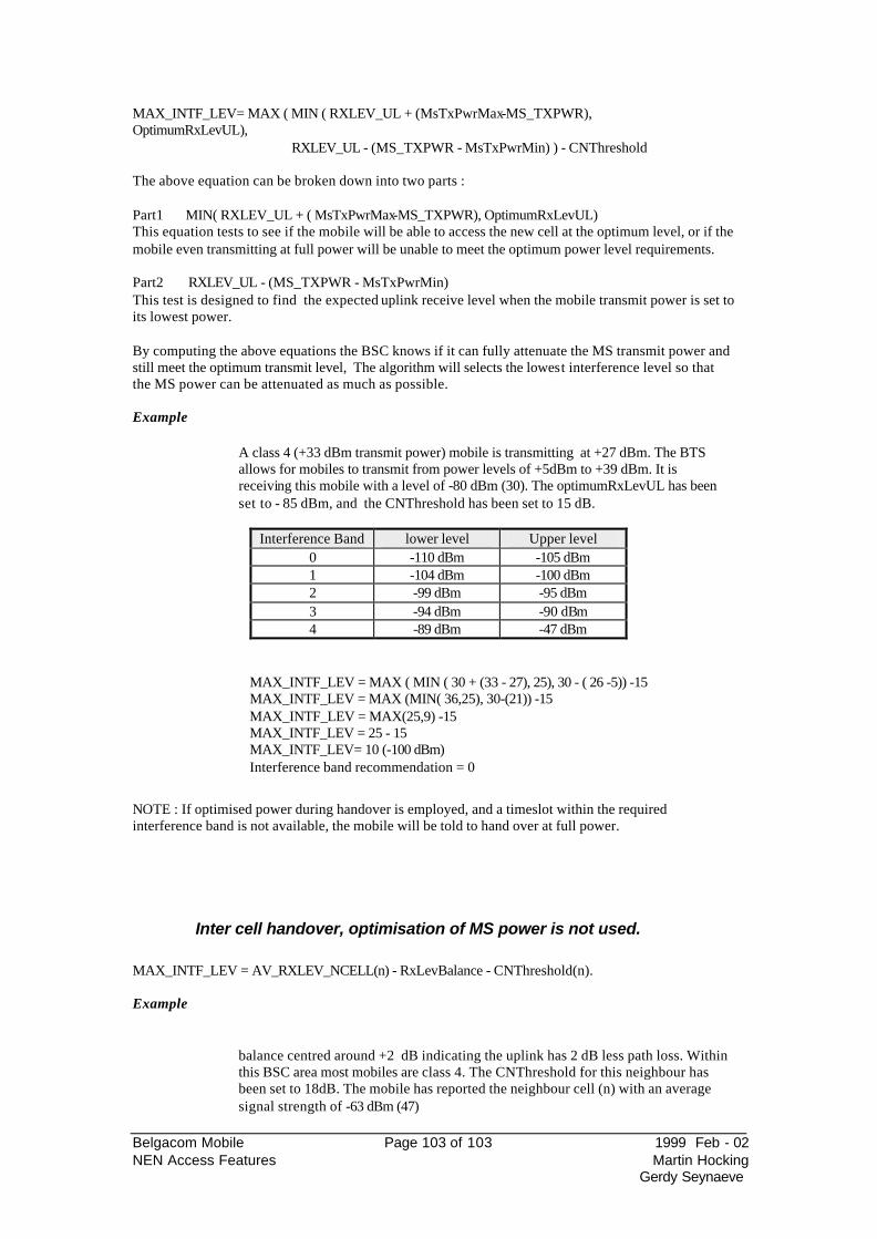
Belgacom Mobile Page 103 of 103 1999 Feb - 02 NEN Access Features Martin Hocking
Gerdy Seynaeve
MAX_INTF_LEV= MAX ( MIN ( RXLEV_UL + (MsTxPwrMax-MS_TXPWR), OptimumRxLevUL), RXLEV_UL - (MS_TXPWR - MsTxPwrMin) ) - CNThreshold The above equation can be broken down into two parts : Part1 MIN( RXLEV_UL + ( MsTxPwrMax-MS_TXPWR), OptimumRxLevUL) This equation tests to see if the mobile will be able to access the new cell at the optimum level, or if the mobile even transmitting at full power will be unable to meet the optimum power level requirements. Part2 RXLEV_UL - (MS_TXPWR - MsTxPwrMin) This test is designed to find the expected uplink receive level when the mobile transmit power is set to its lowest power. By computing the above equations the BSC knows if it can fully attenuate the MS transmit power and still meet the optimum transmit level, The algorithm will selects the lowest interference level so that the MS power can be attenuated as much as possible. Example
A class 4 (+33 dBm transmit power) mobile is transmitting at +27 dBm. The BTS allows for mobiles to transmit from power levels of +5dBm to +39 dBm. It is receiving this mobile with a level of -80 dBm (30). The optimumRxLevUL has been set to - 85 dBm, and the CNThreshold has been set to 15 dB.
Interference Band lower level Upper level
0 -110 dBm -105 dBm 1 -104 dBm -100 dBm 2 -99 dBm -95 dBm 3 -94 dBm -90 dBm 4 -89 dBm -47 dBm
MAX_INTF_LEV = MAX ( MIN ( 30 + (33 - 27), 25), 30 - ( 26 -5)) -15 MAX_INTF_LEV = MAX (MIN( 36,25), 30-(21)) -15 MAX_INTF_LEV = MAX(25,9) -15 MAX_INTF_LEV = 25 - 15 MAX_INTF_LEV= 10 (-100 dBm) Interference band recommendation = 0
NOTE : If optimised power during handover is employed, and a timeslot within the required interference band is not available, the mobile will be told to hand over at full power.
Inter cell handover, optimisation of MS power is not used.
MAX_INTF_LEV = AV_RXLEV_NCELL(n) - RxLevBalance - CNThreshold(n). Example
balance centred around +2 dB indicating the uplink has 2 dB less path loss. Within this BSC area most mobiles are class 4. The CNThreshold for this neighbour has been set to 18dB. The mobile has reported the neighbour cell (n) with an average signal strength of -63 dBm (47)
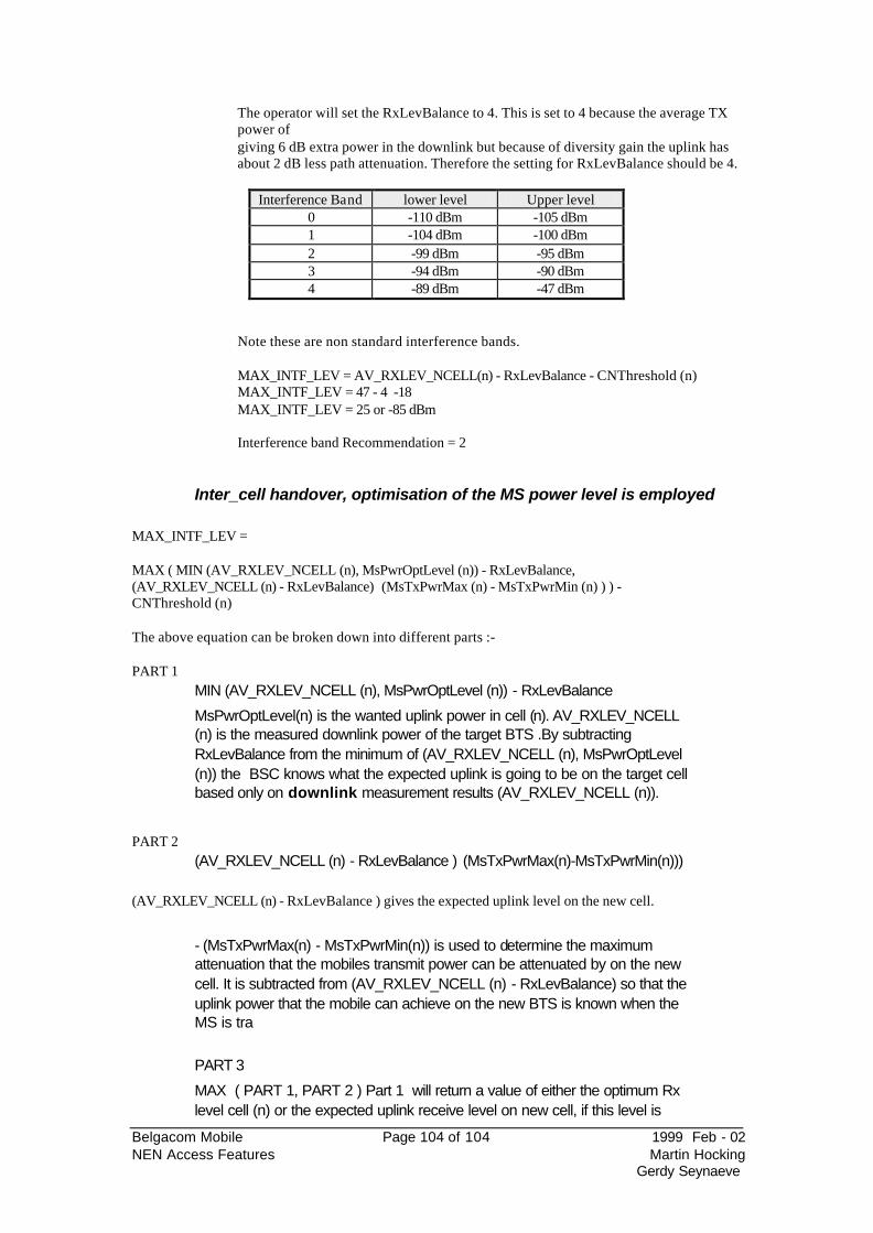
Belgacom Mobile Page 104 of 104 1999 Feb - 02 NEN Access Features Martin Hocking
Gerdy Seynaeve
The operator will set the RxLevBalance to 4. This is set to 4 because the average TX power ofgiving 6 dB extra power in the downlink but because of diversity gain the uplink has about 2 dB less path attenuation. Therefore the setting for RxLevBalance should be 4.
Interference Band lower level Upper level 0 -110 dBm -105 dBm 1 -104 dBm -100 dBm 2 -99 dBm -95 dBm 3 -94 dBm -90 dBm 4 -89 dBm -47 dBm
Note these are non standard interference bands.
MAX_INTF_LEV = AV_RXLEV_NCELL(n) - RxLevBalance - CNThreshold (n) MAX_INTF_LEV = 47 - 4 -18 MAX_INTF_LEV = 25 or -85 dBm Interference band Recommendation = 2
Inter_cell handover, optimisation of the MS power level is employed
MAX_INTF_LEV = MAX ( MIN (AV_RXLEV_NCELL (n), MsPwrOptLevel (n)) - RxLevBalance, (AV_RXLEV_NCELL (n) - RxLevBalance) (MsTxPwrMax (n) - MsTxPwrMin (n) ) ) - CNThreshold (n) The above equation can be broken down into different parts :- PART 1
MIN (AV_RXLEV_NCELL (n), MsPwrOptLevel (n)) - RxLevBalance
MsPwrOptLevel(n) is the wanted uplink power in cell (n). AV_RXLEV_NCELL (n) is the measured downlink power of the target BTS .By subtracting RxLevBalance from the minimum of (AV_RXLEV_NCELL (n), MsPwrOptLevel (n)) the BSC knows what the expected uplink is going to be on the target cell based only on downlink measurement results (AV_RXLEV_NCELL (n)).
PART 2
(AV_RXLEV_NCELL (n) - RxLevBalance ) (MsTxPwrMax(n)-MsTxPwrMin(n))) (AV_RXLEV_NCELL (n) - RxLevBalance ) gives the expected uplink level on the new cell.
- (MsTxPwrMax(n) - MsTxPwrMin(n)) is used to determine the maximum attenuation that the mobiles transmit power can be attenuated by on the new cell. It is subtracted from (AV_RXLEV_NCELL (n) - RxLevBalance) so that the uplink power that the mobile can achieve on the new BTS is known when the MS is tra
PART 3
MAX ( PART 1, PART 2 ) Part 1 will return a value of either the optimum Rx level cell (n) or the expected uplink receive level on new cell, if this level is
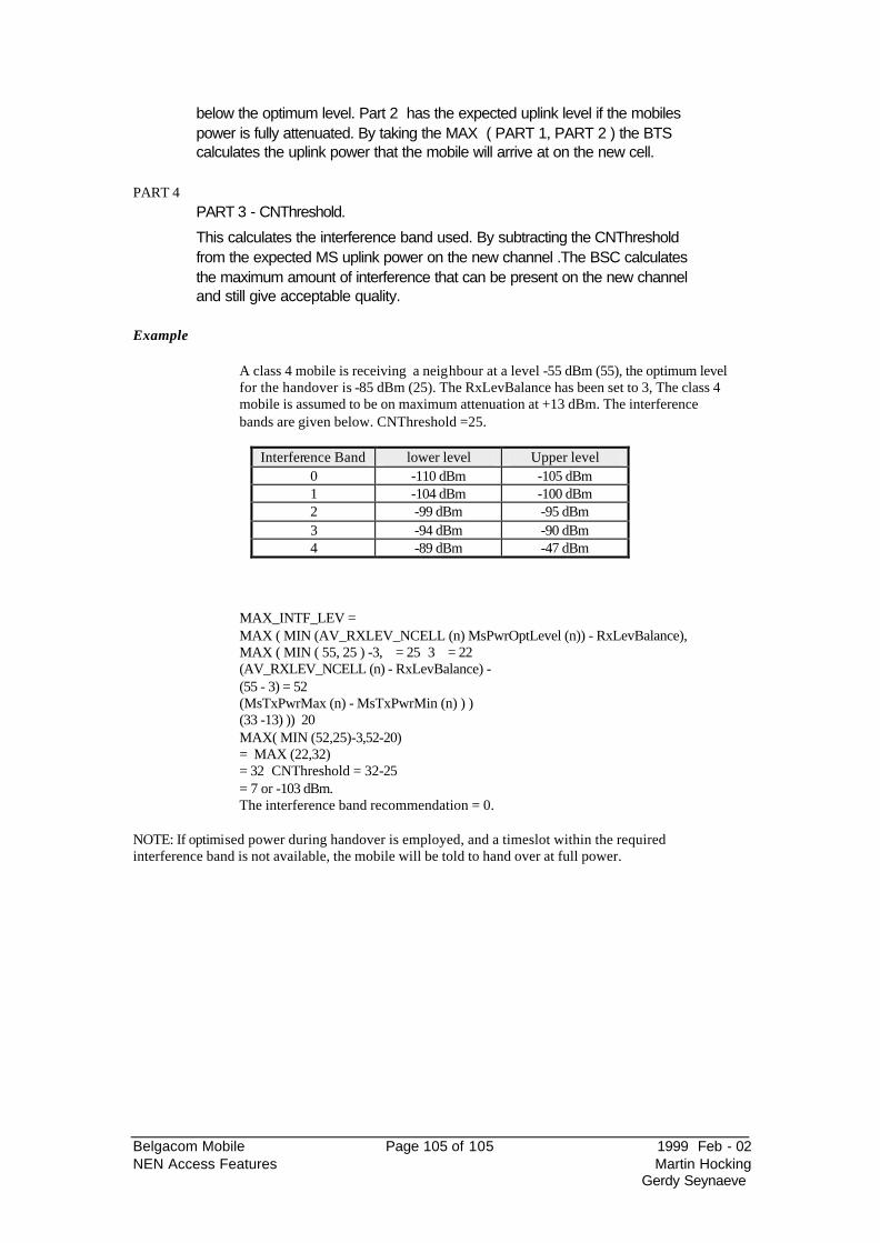
Belgacom Mobile Page 105 of 105 1999 Feb - 02 NEN Access Features Martin Hocking
Gerdy Seynaeve
below the optimum level. Part 2 has the expected uplink level if the mobiles power is fully attenuated. By taking the MAX ( PART 1, PART 2 ) the BTS calculates the uplink power that the mobile will arrive at on the new cell.
PART 4
PART 3 - CNThreshold.
This calculates the interference band used. By subtracting the CNThreshold from the expected MS uplink power on the new channel .The BSC calculates the maximum amount of interference that can be present on the new channel and still give acceptable quality.
Example
A class 4 mobile is receiving a neighbour at a level -55 dBm (55), the optimum level for the handover is -85 dBm (25). The RxLevBalance has been set to 3, The class 4 mobile is assumed to be on maximum attenuation at +13 dBm. The interference bands are given below. CNThreshold =25.
Interference Band lower level Upper level 0 -110 dBm -105 dBm 1 -104 dBm -100 dBm 2 -99 dBm -95 dBm 3 -94 dBm -90 dBm 4 -89 dBm -47 dBm
MAX_INTF_LEV = MAX ( MIN (AV_RXLEV_NCELL (n) MsPwrOptLevel (n)) - RxLevBalance), MAX ( MIN ( 55, 25 ) -3, = 25 3 = 22 (AV_RXLEV_NCELL (n) - RxLevBalance) - (55 - 3) = 52 (MsTxPwrMax (n) - MsTxPwrMin (n) ) ) (33 -13) )) 20 MAX( MIN (52,25)-3,52-20) = MAX (22,32) = 32 CNThreshold = 32-25 = 7 or -103 dBm. The interference band recommendation = 0.
NOTE: If optimised power during handover is employed, and a timeslot within the required interference band is not available, the mobile will be told to hand over at full power.
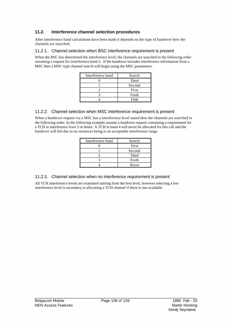
Belgacom Mobile Page 106 of 106 1999 Feb - 02 NEN Access Features Martin Hocking
Gerdy Seynaeve
11.2. Interference channel selection procedures
After interference band calculations have been made it depends on the type of handover how the channels are searched.
11.2.1. Channel selection when BSC interference requirement is present When the BSC has determined the interference level, the channels are searched in the following order assuming a request for interference band 2. If the handover includes interference information from a MSC then a MSC type channel search will begin using the MSC parameters.
Interference band Search 0 Third 1 Second 2 First 3 Forth 4 Fifth
11.2.2. Channel selection when MSC interference requirement is present When a handover request via a MSC has a interference level stated then the channels are searched in the following order. In the following example assume a handover request containing a requirement for a TCH in interference level 3 or better. A TCH in band 4 will never be allocated for this call and the handover will fail due to no resources being in an acceptable interference range.
Interference band Search 0 First 1 Second 2 Third 3 Forth 4 Never
11.2.3. Channel selection when no interference requirement is present All TCH interference levels are examined starting from the best level, however selecting a low interference level is secondary to allocating a TCH channel if there is one available .
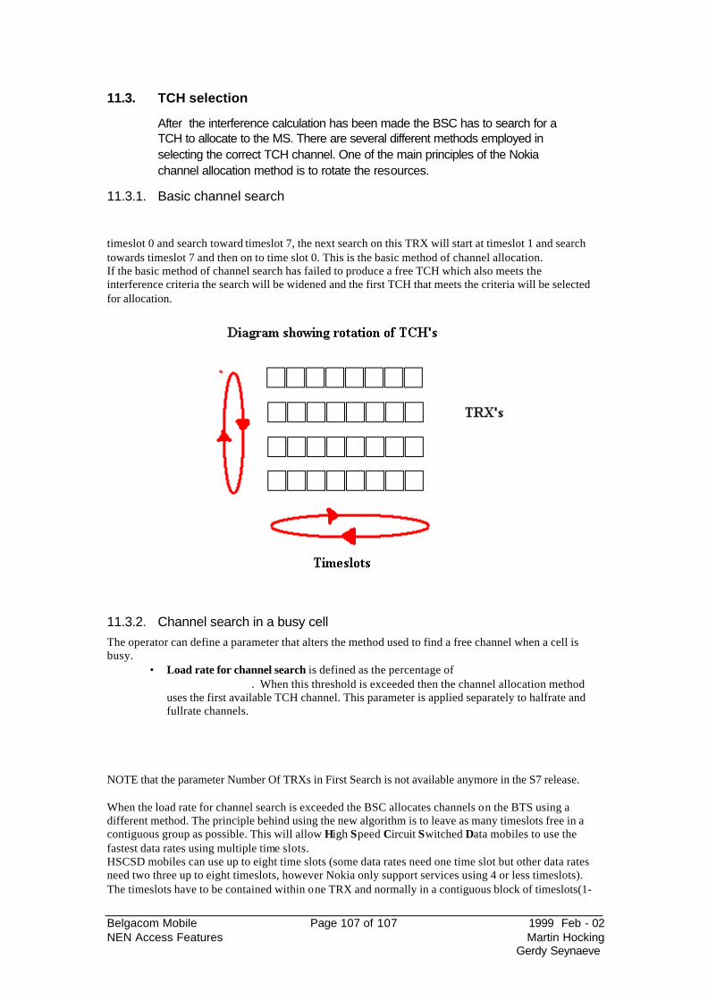
Belgacom Mobile Page 107 of 107 1999 Feb - 02 NEN Access Features Martin Hocking
Gerdy Seynaeve
11.3. TCH selection
After the interference calculation has been made the BSC has to search for a TCH to allocate to the MS. There are several different methods employed in selecting the correct TCH channel. One of the main principles of the Nokia channel allocation method is to rotate the resources.
11.3.1. Basic channel search
timeslot 0 and search toward timeslot 7, the next search on this TRX will start at timeslot 1 and search towards timeslot 7 and then on to time slot 0. This is the basic method of channel allocation. If the basic method of channel search has failed to produce a free TCH which also meets the interference criteria the search will be widened and the first TCH that meets the criteria will be selected for allocation.
11.3.2. Channel search in a busy cell The operator can define a parameter that alters the method used to find a free channel when a cell is busy.
• Load rate for channel search is defined as the percentage of . When this threshold is exceeded then the channel allocation method
uses the first available TCH channel. This parameter is applied separately to halfrate and fullrate channels.
NOTE that the parameter Number Of TRXs in First Search is not available anymore in the S7 release. When the load rate for channel search is exceeded the BSC allocates channels on the BTS using a different method. The principle behind using the new algorithm is to leave as many timeslots free in a contiguous group as possible. This will allow High Speed Circuit Switched Data mobiles to use the fastest data rates using multiple time slots. HSCSD mobiles can use up to eight time slots (some data rates need one time slot but other data rates need two three up to eight timeslots, however Nokia only support services using 4 or less timeslots). The timeslots have to be contained within one TRX and normally in a contiguous block of timeslots(1-

Belgacom Mobile Page 108 of 108 1999 Feb - 02 NEN Access Features Martin Hocking
Gerdy Seynaeve
4), (2-matching the allocation of non adjacent timeslots with the required service and the type of mobile. The algorithm uses the following decision processes in order. 1 Identify the TRX with the smallest gap between TCH/F time slots in use. 2
maximum gap between two TCH/F in use. 3
slots, then the TRX with the least free timeslots will be chosen. 4 When the TRX has been chosen, the timeslot to be used for the call is selected by first finding
the smallest gap between two in use TCH/F. If there are two or more non contiguous timeslots with the same minimum gap size, the BSC allocates the TCH/F to the gap nearest timeslot zero or seven.
An example will clarify this
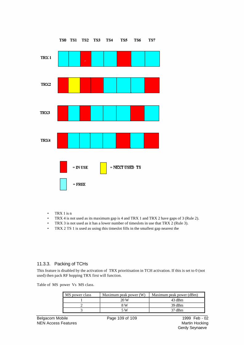
Belgacom Mobile Page 109 of 109 1999 Feb - 02 NEN Access Features Martin Hocking
Gerdy Seynaeve
• TRX 1 is n • TRX 4 is not used as its maximum gap is 4 and TRX 1 and TRX 2 have gaps of 3 (Rule 2). • TRX 3 is not used as it has a lower number of timeslots in use that TRX 2 (Rule 3). • TRX 2 TS 1 is used as using this timeslot fills in the smallest gap nearest the
11.3.3. Packing of TCHs This feature is disabled by the activation of TRX prioritisation in TCH activation. If this is set to 0 (not used) then pack RF hopping TRX first will function. Table of MS power Vs MS class.
MS power class Maximum peak power (W) Maximum peak power (dBm) 1 20 W 43 dBm 2 8 W 39 dBm 3 5 W 37 dBm
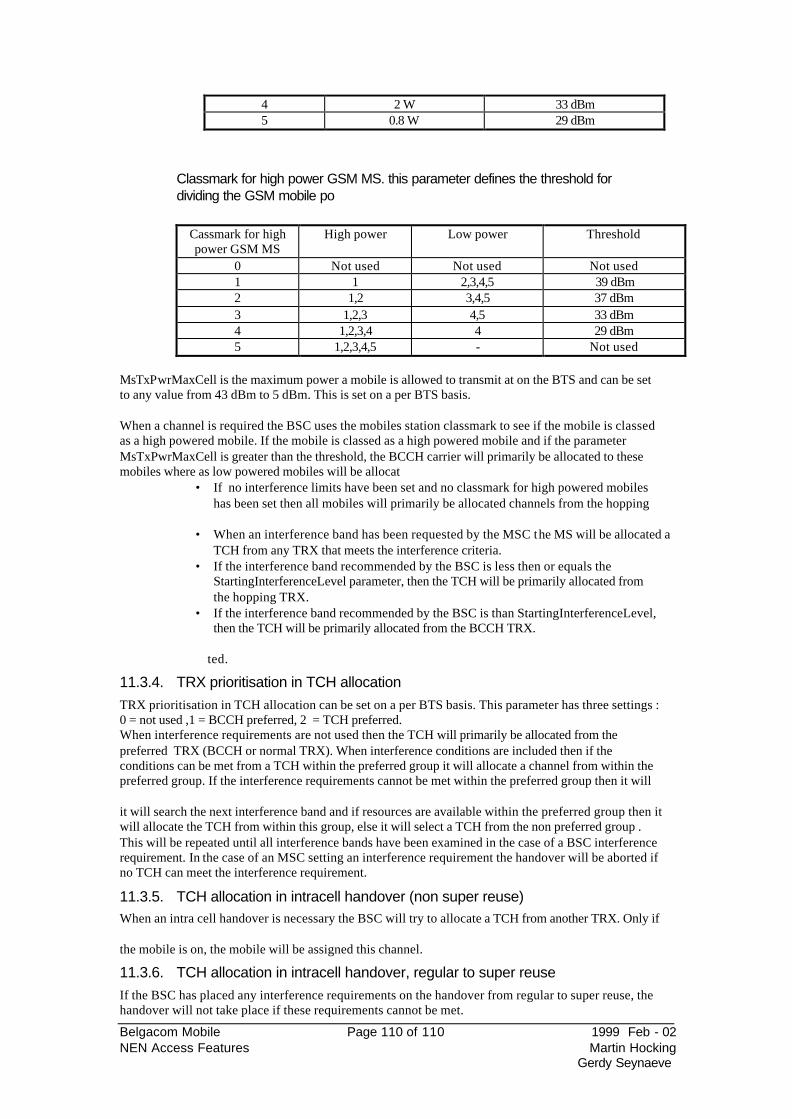
Belgacom Mobile Page 110 of 110 1999 Feb - 02 NEN Access Features Martin Hocking
Gerdy Seynaeve
4 2 W 33 dBm 5 0.8 W 29 dBm
Classmark for high power GSM MS. this parameter defines the threshold for dividing the GSM mobile po
Cassmark for high power GSM MS
High power Low power Threshold
0 Not used Not used Not used 1 1 2,3,4,5 39 dBm 2 1,2 3,4,5 37 dBm 3 1,2,3 4,5 33 dBm 4 1,2,3,4 4 29 dBm 5 1,2,3,4,5 - Not used
MsTxPwrMaxCell is the maximum power a mobile is allowed to transmit at on the BTS and can be set to any value from 43 dBm to 5 dBm. This is set on a per BTS basis. When a channel is required the BSC uses the mobiles station classmark to see if the mobile is classed as a high powered mobile. If the mobile is classed as a high powered mobile and if the parameter MsTxPwrMaxCell is greater than the threshold, the BCCH carrier will primarily be allocated to these mobiles where as low powered mobiles will be allocat
• If no interference limits have been set and no classmark for high powered mobiles has been set then all mobiles will primarily be allocated channels from the hopping
• When an interference band has been requested by the MSC the MS will be allocated a
TCH from any TRX that meets the interference criteria. • If the interference band recommended by the BSC is less then or equals the
StartingInterferenceLevel parameter, then the TCH will be primarily allocated from the hopping TRX.
• If the interference band recommended by the BSC is than StartingInterferenceLevel, then the TCH will be primarily allocated from the BCCH TRX.
ted.
11.3.4. TRX prioritisation in TCH allocation TRX prioritisation in TCH allocation can be set on a per BTS basis. This parameter has three settings : 0 = not used ,1 = BCCH preferred, 2 = TCH preferred. When interference requirements are not used then the TCH will primarily be allocated from the preferred TRX (BCCH or normal TRX). When interference conditions are included then if the conditions can be met from a TCH within the preferred group it will allocate a channel from within the preferred group. If the interference requirements cannot be met within the preferred group then it will
it will search the next interference band and if resources are available within the preferred group then it will allocate the TCH from within this group, else it will select a TCH from the non preferred group . This will be repeated until all interference bands have been examined in the case of a BSC interference requirement. In the case of an MSC setting an interference requirement the handover will be aborted if no TCH can meet the interference requirement.
11.3.5. TCH allocation in intracell handover (non super reuse) When an intra cell handover is necessary the BSC will try to allocate a TCH from another TRX. Only if
the mobile is on, the mobile will be assigned this channel.
11.3.6. TCH allocation in intracell handover, regular to super reuse If the BSC has placed any interference requirements on the handover from regular to super reuse, the handover will not take place if these requirements cannot be met.
Belgacom Mobile Page 111 of 111 1999 Feb - 02 NEN Access Features Martin Hocking
Gerdy Seynaeve
Example
The BSC requires an interference band of 3 or better and if the super reuse Tonly have TCH in interference band 4 then the handover will not take place.
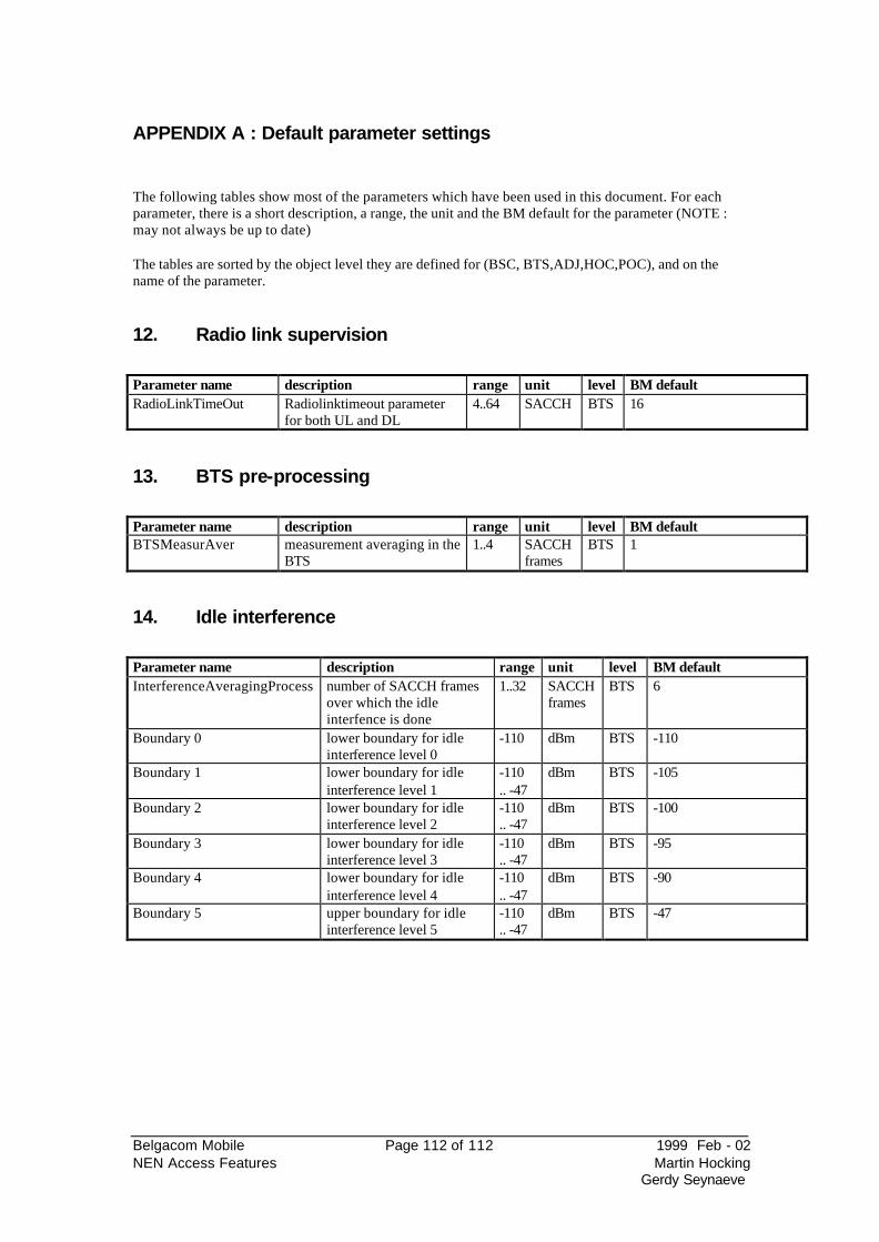
Belgacom Mobile Page 112 of 112 1999 Feb - 02 NEN Access Features Martin Hocking
Gerdy Seynaeve
APPENDIX A : Default parameter settings
The following tables show most of the parameters which have been used in this document. For each parameter, there is a short description, a range, the unit and the BM default for the parameter (NOTE : may not always be up to date) The tables are sorted by the object level they are defined for (BSC, BTS,ADJ,HOC,POC), and on the name of the parameter.
12. Radio link supervision
Parameter name description range unit level BM default RadioLinkTimeOut Radiolinktimeout parameter
for both UL and DL 4..64 SACCH BTS 16
13. BTS pre-processing
Parameter name description range unit level BM default BTSMeasurAver measurement averaging in the
BTS 1..4 SACCH
frames BTS 1
14. Idle interference
Parameter name description range unit level BM default InterferenceAveragingProcess number of SACCH frames
over which the idle interfence is done
1..32 SACCH frames
BTS 6
Boundary 0 lower boundary for idle interference level 0
-110 dBm BTS -110
Boundary 1 lower boundary for idle interference level 1
-110 .. -47
dBm BTS -105
Boundary 2 lower boundary for idle interference level 2
-110 .. -47
dBm BTS -100
Boundary 3 lower boundary for idle interference level 3
-110 .. -47
dBm BTS -95
Boundary 4 lower boundary for idle interference level 4
-110 .. -47
dBm BTS -90
Boundary 5 upper boundary for idle interference level 5
-110 .. -47
dBm BTS -47
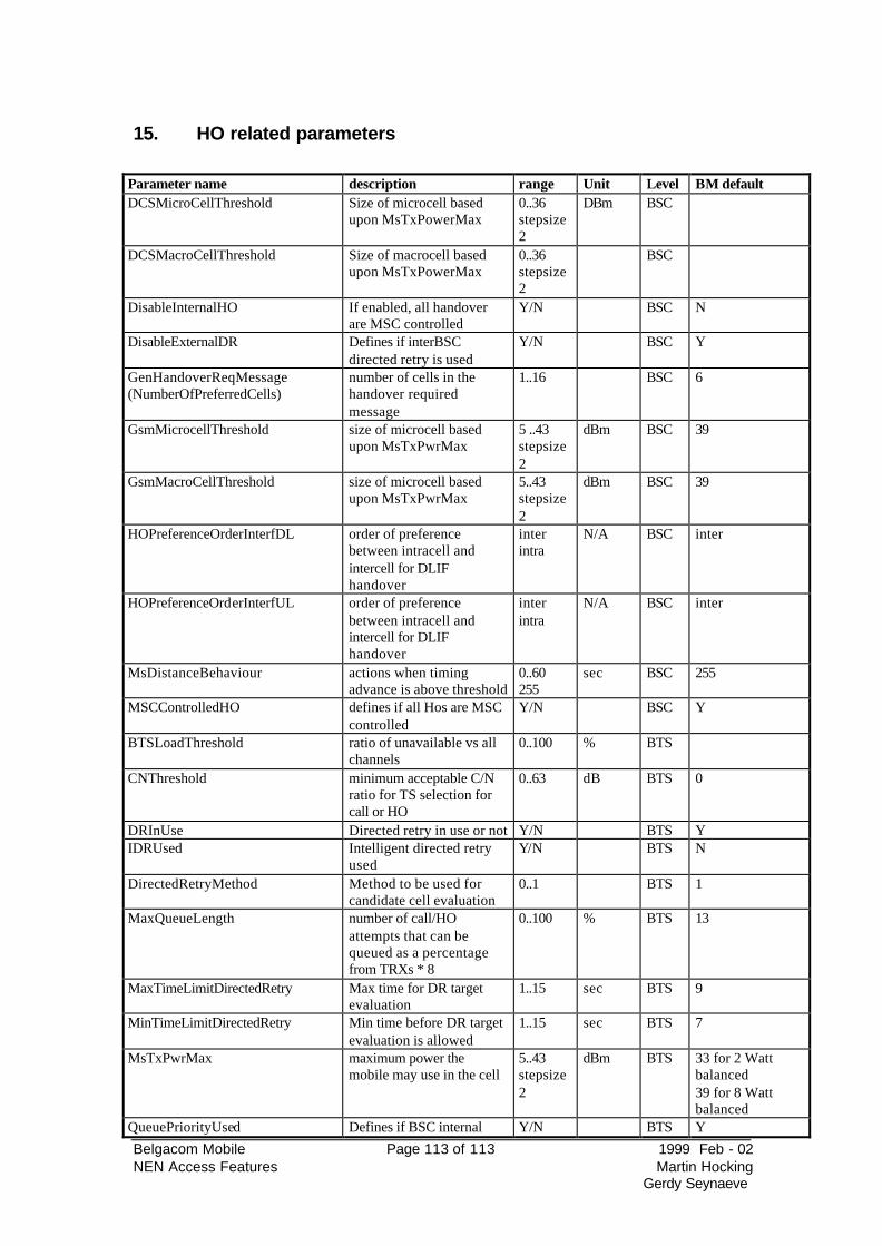
Belgacom Mobile Page 113 of 113 1999 Feb - 02 NEN Access Features Martin Hocking
Gerdy Seynaeve
15. HO related parameters
Parameter name description range Unit Level BM default DCSMicroCellThreshold Size of microcell based
upon MsTxPowerMax 0..36 stepsize 2
DBm BSC
DCSMacroCellThreshold Size of macrocell based upon MsTxPowerMax
0..36 stepsize 2
BSC
DisableInternalHO If enabled, all handover are MSC controlled
Y/N BSC N
DisableExternalDR Defines if interBSC directed retry is used
Y/N BSC Y
GenHandoverReqMessage (NumberOfPreferredCells)
number of cells in the handover required message
1..16 BSC 6
GsmMicrocellThreshold size of microcell based upon MsTxPwrMax
5 ..43 stepsize 2
dBm BSC 39
GsmMacroCellThreshold size of microcell based upon MsTxPwrMax
5..43 stepsize 2
dBm BSC 39
HOPreferenceOrderInterfDL order of preference between intracell and intercell for DLIF handover
inter intra
N/A BSC inter
HOPreferenceOrderInterfUL order of preference between intracell and intercell for DLIF handover
inter intra
N/A BSC inter
MsDistanceBehaviour actions when timing advance is above threshold
0..60 255
sec BSC 255
MSCControlledHO defines if all Hos are MSC controlled
Y/N BSC Y
BTSLoadThreshold ratio of unavailable vs all channels
0..100 % BTS
CNThreshold minimum acceptable C/N ratio for TS selection for call or HO
0..63 dB BTS 0
DRInUse Directed retry in use or not Y/N BTS Y IDRUsed Intelligent directed retry
used Y/N BTS N
DirectedRetryMethod Method to be used for candidate cell evaluation
0..1 BTS 1
MaxQueueLength number of call/HO attempts that can be queued as a percentage from TRXs * 8
0..100 % BTS 13
MaxTimeLimitDirectedRetry Max time for DR target evaluation
1..15 sec BTS 9
MinTimeLimitDirectedRetry Min time before DR target evaluation is allowed
1..15 sec BTS 7
MsTxPwrMax maximum power the mobile may use in the cell
5..43 stepsize 2
dBm BTS 33 for 2 Watt balanced 39 for 8 Watt balanced
QueuePriorityUsed Defines if BSC internal Y/N BTS Y
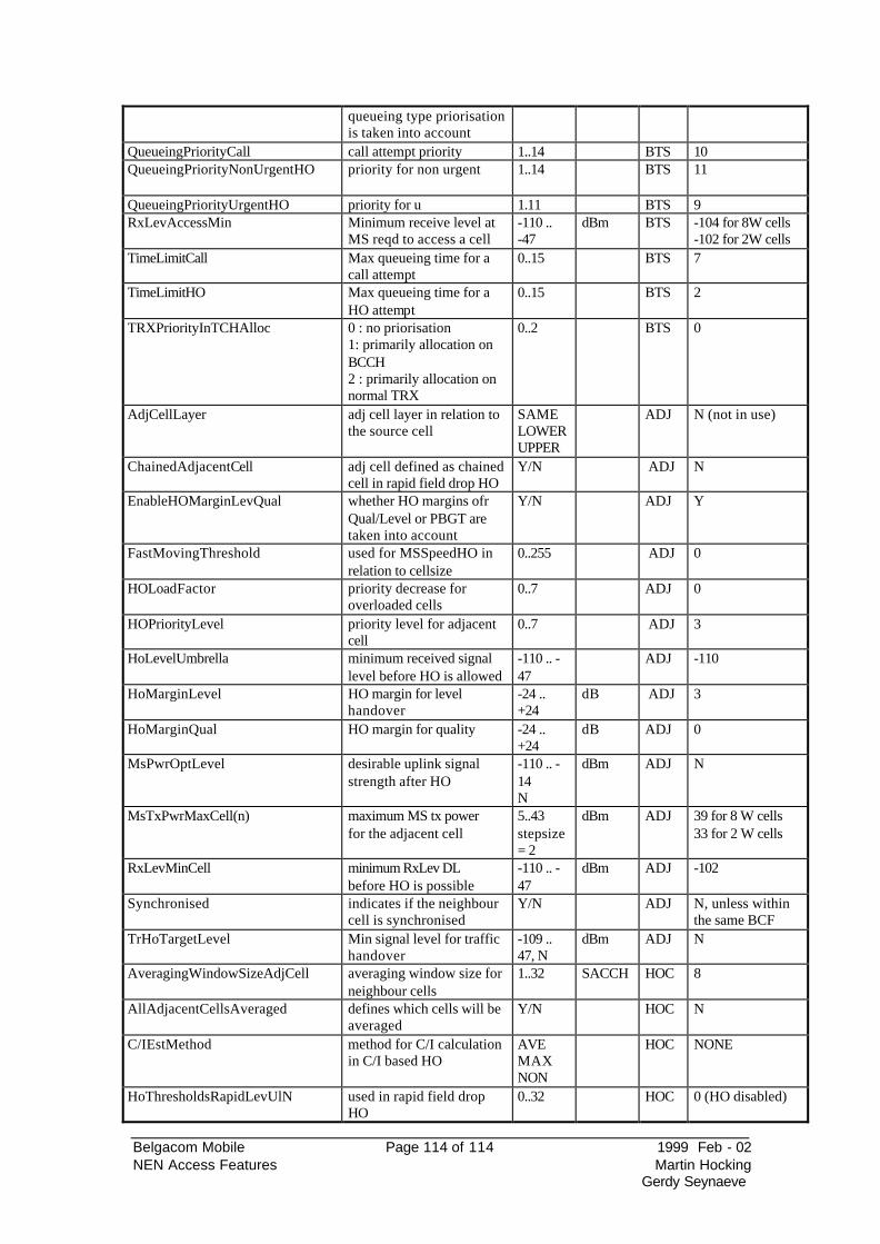
Belgacom Mobile Page 114 of 114 1999 Feb - 02 NEN Access Features Martin Hocking
Gerdy Seynaeve
queueing type priorisation is taken into account
QueueingPriorityCall call attempt priority 1..14 BTS 10 QueueingPriorityNonUrgentHO priority for non urgent
1..14 BTS 11
QueueingPriorityUrgentHO priority for u 1.11 BTS 9 RxLevAccessMin Minimum receive level at
MS reqd to access a cell -110 .. -47
dBm BTS -104 for 8W cells -102 for 2W cells
TimeLimitCall Max queueing time for a call attempt
0..15 BTS 7
TimeLimitHO Max queueing time for a HO attempt
0..15 BTS 2
TRXPriorityInTCHAlloc 0 : no priorisation 1: primarily allocation on BCCH 2 : primarily allocation on normal TRX
0..2 BTS 0
AdjCellLayer adj cell layer in relation to the source cell
SAME LOWER UPPER
ADJ N (not in use)
ChainedAdjacentCell adj cell defined as chained cell in rapid field drop HO
Y/N ADJ N
EnableHOMarginLevQual whether HO margins ofr Qual/Level or PBGT are taken into account
Y/N ADJ Y
FastMovingThreshold used for MSSpeedHO in relation to cellsize
0..255 ADJ 0
HOLoadFactor priority decrease for overloaded cells
0..7 ADJ 0
HOPriorityLevel priority level for adjacent cell
0..7 ADJ 3
HoLevelUmbrella minimum received signal level before HO is allowed
-110 .. -47
ADJ -110
HoMarginLevel HO margin for level handover
-24 .. +24
dB ADJ 3
HoMarginQual HO margin for quality -24 .. +24
dB ADJ 0
MsPwrOptLevel desirable uplink signal strength after HO
-110 .. -14 N
dBm ADJ N
MsTxPwrMaxCell(n) maximum MS tx power for the adjacent cell
5..43 stepsize = 2
dBm ADJ 39 for 8 W cells 33 for 2 W cells
RxLevMinCell minimum RxLev DL before HO is possible
-110 .. -47
dBm ADJ -102
Synchronised indicates if the neighbour cell is synchronised
Y/N ADJ N, unless within the same BCF
TrHoTargetLevel Min signal level for traffic handover
-109 .. 47, N
dBm ADJ N
AveragingWindowSizeAdjCell averaging window size for neighbour cells
1..32 SACCH HOC 8
AllAdjacentCellsAveraged defines which cells will be averaged
Y/N HOC N
C/IEstMethod method for C/I calculation in C/I based HO
AVE MAX NON
HOC NONE
HoThresholdsRapidLevUlN used in rapid field drop HO
0..32 HOC 0 (HO disabled)
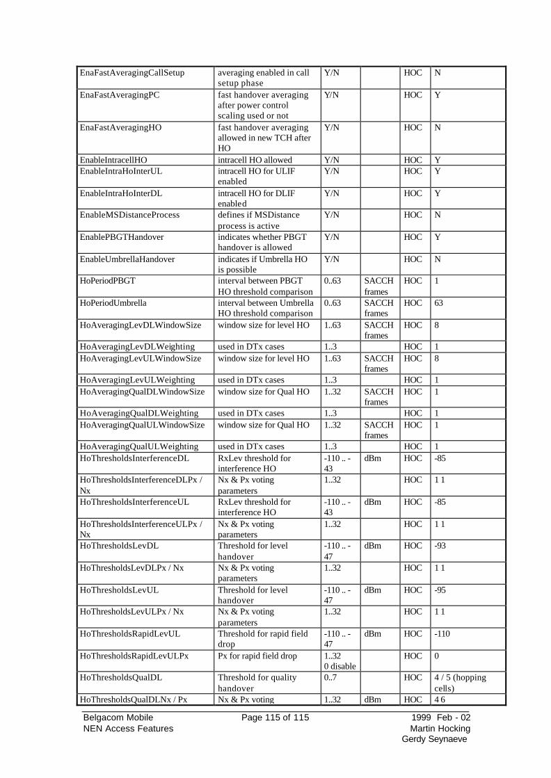
Belgacom Mobile Page 115 of 115 1999 Feb - 02 NEN Access Features Martin Hocking
Gerdy Seynaeve
EnaFastAveragingCallSetup averaging enabled in call setup phase
Y/N HOC N
EnaFastAveragingPC fast handover averaging after power control scaling used or not
Y/N HOC Y
EnaFastAveragingHO fast handover averaging allowed in new TCH after HO
Y/N HOC N
EnableIntracellHO intracell HO allowed Y/N HOC Y EnableIntraHoInterUL intracell HO for ULIF
enabled Y/N HOC Y
EnableIntraHoInterDL intracell HO for DLIF enabled
Y/N HOC Y
EnableMSDistanceProcess defines if MSDistance process is active
Y/N HOC N
EnablePBGTHandover indicates whether PBGT handover is allowed
Y/N HOC Y
EnableUmbrellaHandover indicates if Umbrella HO is possible
Y/N HOC N
HoPeriodPBGT interval between PBGT HO threshold comparison
0..63 SACCH frames
HOC 1
HoPeriodUmbrella interval between Umbrella HO threshold comparison
0..63 SACCH frames
HOC 63
HoAveragingLevDLWindowSize window size for level HO 1..63 SACCH frames
HOC 8
HoAveragingLevDLWeighting used in DTx cases 1..3 HOC 1 HoAveragingLevULWindowSize window size for level HO 1..63 SACCH
frames HOC 8
HoAveragingLevULWeighting used in DTx cases 1..3 HOC 1 HoAveragingQualDLWindowSize window size for Qual HO 1..32 SACCH
frames HOC 1
HoAveragingQualDLWeighting used in DTx cases 1..3 HOC 1 HoAveragingQualULWindowSize window size for Qual HO 1..32 SACCH
frames HOC 1
HoAveragingQualULWeighting used in DTx cases 1..3 HOC 1 HoThresholdsInterferenceDL RxLev threshold for
interference HO -110 .. -43
dBm HOC -85
HoThresholdsInterferenceDLPx / Nx
Nx & Px voting parameters
1..32 HOC 1 1
HoThresholdsInterferenceUL RxLev threshold for interference HO
-110 .. -43
dBm HOC -85
HoThresholdsInterferenceULPx / Nx
Nx & Px voting parameters
1..32 HOC 1 1
HoThresholdsLevDL Threshold for level handover
-110 .. -47
dBm HOC -93
HoThresholdsLevDLPx / Nx Nx & Px voting parameters
1..32 HOC 1 1
HoThresholdsLevUL Threshold for level handover
-110 .. -47
dBm HOC -95
HoThresholdsLevULPx / Nx Nx & Px voting parameters
1..32 HOC 1 1
HoThresholdsRapidLevUL Threshold for rapid field drop
-110 .. -47
dBm HOC -110
HoThresholdsRapidLevULPx Px for rapid field drop 1..32 0 disable
HOC 0
HoThresholdsQualDL Threshold for quality handover
0..7 HOC 4 / 5 (hopping cells)
HoThresholdsQualDLNx / Px Nx & Px voting 1..32 dBm HOC 4 6
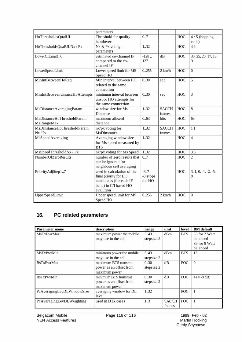
Belgacom Mobile Page 116 of 116 1999 Feb - 02 NEN Access Features Martin Hocking
Gerdy Seynaeve
parameters HoThresholdsQualUL Threshold for quality
handover 0..7 HOC 4 / 5 (hopping
cells) HoThresholdsQualULNx / Px Nx & Px voting
parameters 1..32 HOC 4 6
LowerCILimit1..6 estimated co-channel IF compared to the co-channel IF
-128 .. 127
dB HOC 30, 25, 20, 17, 13, 9
LowerSpeedLimit Lower speed limit for MS Speed HO
0..255 2 km/h HOC 0
MinIntBetweenHoReq Min interval between HO related to the same connection
0..30 sec HOC 5
MinIntBetweenUnsuccHoAttempts minimum interval between unsucc HO attempts for the same connection
0..30 sec HOC 3
MsDistanceAveragingParam window size for Ms Distance
1..32 SACCH frames
HOC 8
MsDistanceHoThresholdParam MsRangeMax
maximum allowed distance
0..63 bits HOC 63
MsDinstanceHoThresholdParam Nx / Px
nx/px voting for MsDinstance
1..32 SACCH frames
HOC 1 1
MsSpeedAveraging Averaging window size for Ms speed measured by BTS
1..32 HOC 4
MsSpeedThresholdNx / Px nx/px voting for Ms Speed 1..32 HOC 3 6 NumberOfZeroResults number of zero results that
can be ignored for neighbour cell averaging
0..7 HOC 2
PriorityAdjStep1..7 used in calculation of the final priority for HO candidates (for each IF band) in C/I based HO evalution
-8..7 -8 stops the HO
HOC 3, 1, 0, -1, -2, -5, -8
UpperSpeedLimit Upper speed limit for MS Speed HO
0..255 2 km/h HOC 0
16. PC related parameters
Parameter name description range unit level BM default MsTxPwrMax maximum power the mobile
may use in the cell 5..43 stepsize 2
dBm BTS 33 for 2 Watt balanced 39 for 8 Watt balanced
MsTxPwrMin minimum power the mobile may use in the cell
5..43 stepsize 2
dBm BTS 13
BsTxPwrMax maximum BTS transmit power as an offset from maximum power
0..30 stepsize 2
dB POC 0
BsTxPwrMin minimum BTS transmit power as an offset from maximum power
0..30 stepsize 2
dB POC 4 (= -8 dB)
PcAveragingLevDLWindowSize averaging window for DL level
1..32 POC 1
PcAveragingLevDLWeighting used in DTx cases 1..3 SACCHframes
POC 1
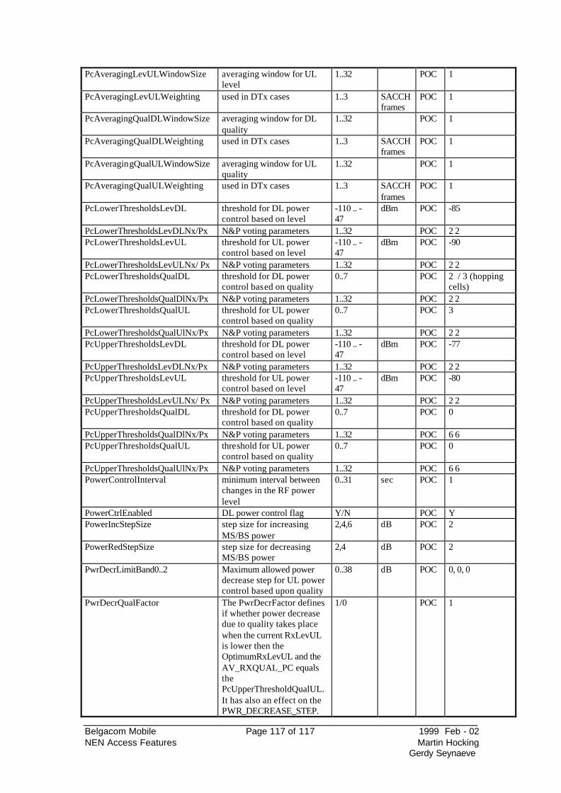
Belgacom Mobile Page 117 of 117 1999 Feb - 02 NEN Access Features Martin Hocking
Gerdy Seynaeve
PcAveragingLevULWindowSize averaging window for UL level
1..32 POC 1
PcAveragingLevULWeighting used in DTx cases 1..3 SACCHframes
POC 1
PcAveragingQualDLWindowSize averaging window for DL quality
1..32 POC 1
PcAveragingQualDLWeighting used in DTx cases 1..3 SACCHframes
POC 1
PcAveragingQualULWindowSize averaging window for UL quality
1..32 POC 1
PcAveragingQualULWeighting used in DTx cases 1..3 SACCHframes
POC 1
PcLowerThresholdsLevDL threshold for DL power control based on level
-110 .. -47
dBm POC -85
PcLowerThresholdsLevDLNx/Px N&P voting parameters 1..32 POC 2 2 PcLowerThresholdsLevUL threshold for UL power
control based on level -110 .. -47
dBm POC -90
PcLowerThresholdsLevULNx/ Px N&P voting parameters 1..32 POC 2 2 PcLowerThresholdsQualDL threshold for DL power
control based on quality 0..7 POC 2 / 3 (hopping
cells) PcLowerThresholdsQualDlNx/Px N&P voting parameters 1..32 POC 2 2 PcLowerThresholdsQualUL threshold for UL power
control based on quality 0..7 POC 3
PcLowerThresholdsQualUlNx/Px N&P voting parameters 1..32 POC 2 2 PcUpperThresholdsLevDL threshold for DL power
control based on level -110 .. -47
dBm POC -77
PcUpperThresholdsLevDLNx/Px N&P voting parameters 1..32 POC 2 2 PcUpperThresholdsLevUL threshold for UL power
control based on level -110 .. -47
dBm POC -80
PcUpperThresholdsLevULNx/ Px N&P voting parameters 1..32 POC 2 2 PcUpperThresholdsQualDL threshold for DL power
control based on quality 0..7 POC 0
PcUpperThresholdsQualDlNx/Px N&P voting parameters 1..32 POC 6 6 PcUpperThresholdsQualUL threshold for UL power
control based on quality 0..7 POC 0
PcUpperThresholdsQualUlNx/Px N&P voting parameters 1..32 POC 6 6 PowerControlInterval minimum interval between
changes in the RF power level
0..31 sec POC 1
PowerCtrlEnabled DL power control flag Y/N POC Y PowerIncStepSize step size for increasing
MS/BS power 2,4,6 dB POC 2
PowerRedStepSize step size for decreasing MS/BS power
2,4 dB POC 2
PwrDecrLimitBand0..2 Maximum allowed power decrease step for UL power control based upon quality
0..38 dB POC 0, 0, 0
PwrDecrQualFactor The PwrDecrFactor defines if whether power decrease due to quality takes place when the current RxLevUL is lower then the OptimumRxLevUL and the AV_RXQUAL_PC equals the PcUpperThresholdQualUL. It has also an effect on the PWR_DECREASE_STEP.
1/0 POC 1
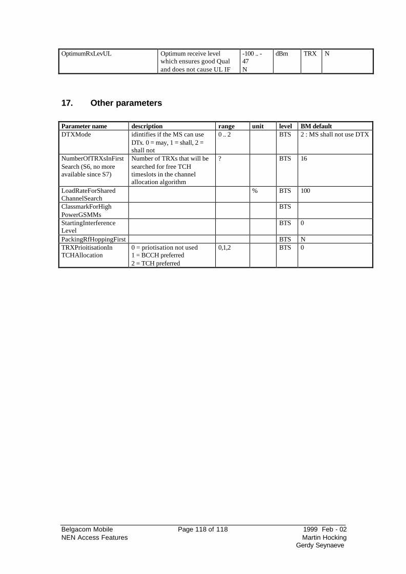
Belgacom Mobile Page 118 of 118 1999 Feb - 02 NEN Access Features Martin Hocking
Gerdy Seynaeve
OptimumRxLevUL Optimum receive level which ensures good Qual and does not cause UL IF
-100 .. -47 N
dBm TRX N
17. Other parameters
Parameter name description range unit level BM default DTXMode idintifies if the MS can use
DTx. 0 = may, 1 = shall, 2 = shall not
0 .. 2 BTS 2 : MS shall not use DTX
NumberOfTRXsInFirstSearch (S6, no more available since S7)
Number of TRXs that will be searched for free TCH timeslots in the channel allocation algorithm
? BTS 16
LoadRateForShared ChannelSearch
% BTS 100
ClassmarkForHigh PowerGSMMs
BTS
StartingInterference Level
BTS 0
PackingRfHoppingFirst BTS N TRXPrioitisationIn TCHAllocation
0 = priotisation not used 1 = BCCH preferred 2 = TCH preferred
0,1,2 BTS 0
Related Documents