1 CHAPTER ONE INTRODUCTION 1.1 Overview Today computers are available in many offices and homes and therefore there is a need to share data and programs among various computers with the advancement of data communication facilities. The communication between computers has increased and thus has extended the power of computer beyond the computer room. Now a user sitting at one place can communicate with computers at any remote sites through communication channel. Thus data transmission is the movement of information using some standard methods. These methods include electric signals carried along a conductor, optical signals along optical fibers a nd electromagnetic signals through space. If PCs are connected through communication channel, the data and information, computer files and any other program can be transmitted to other computer systems within seconds. Power line communication is a system for carrying data on a conductor which isalso used for electric power transmission. Broadband over Power Lines (BPL) uses PLC by sending and receiving information bearing signals over power lines to provide access to the Internet. Electrical power is transmitted over high voltage transmission lines, distributed over medium voltage, and used inside buildings at lower voltages. Power line communications can be applied at each stage. Most

Welcome message from author
This document is posted to help you gain knowledge. Please leave a comment to let me know what you think about it! Share it to your friends and learn new things together.
Transcript
8/7/2019 Pc to Pc Communication
http://slidepdf.com/reader/full/pc-to-pc-communication 1/48
1
CHAPTER ONE
INTRODUCTION
1.1 Overview
Today computers are available in many offices and homes and therefore there is a
need to share data and programs among various computers with the advancement
of data communication facilities. The communication between computers has
increased and thus has extended the power of computer beyond the computer
room. Now a user sitting at one place can communicate with computers at any
remote sites through communication channel. Thus data transmission is the
movement of information using some standard methods. These methods include
electric signals carried along a conductor, optical signals along optical fibers and
electromagnetic signals through space. If PCs are connected through
communication channel, the data and information, computer files and any other
program can be transmitted to other computer systems within seconds. Power line
communication is a system for carrying data on a conductor which isalso used for
electric power transmission. Broadband over Power Lines (BPL) uses PLC by
sending and receiving information bearing signals over power lines to provide
access to the Internet. Electrical power is transmitted over high voltage
transmission lines, distributed over medium voltage, and used inside buildings at
lower voltages. Power line communications can be applied at each stage. Most

8/7/2019 Pc to Pc Communication
http://slidepdf.com/reader/full/pc-to-pc-communication 2/48
2
PLC technologies limit themselves to one set of wires (for example, premises
wiring), but some can cross between two levels (for example, both the distribution
network and premises wiring). All power line communications systems operate by
impressing a modulated carrier signal on the wiring system. Different types of
power line communications use different frequency bands, depending on the signal
transmission characteristics of the power wiring used. Since the power wiring
system was originally intended for transmission of AC power, in conventional use,
the power wire circuits have only a limited ability to carry higher frequencies. The
propagation problem is a limiting factor for each type of power line
communications. A new discovery called E-Line that allows a single power
conductor on an overhead power line to operate as a waveguide to provide low
attenuation propagation of RF through microwave energy lines while providing
information rate of multiple Gbps is an exception to this limitation. Data rates over
a power line communication system vary widely. Low-frequency (about 100-
200 kHz) carriers impressed on high-voltage transmission lines may carry one or
two analog voice circuits, or telemetry and control circuits with an equivalent data
rate of a few hundred bits per second; however, these circuits may be many miles
long. Higher data rates generally imply shorter ranges; a local area network
operating at millions of bits per second may only cover one floor of an office
building, but eliminates installation of dedicated network cabling.
8/7/2019 Pc to Pc Communication
http://slidepdf.com/reader/full/pc-to-pc-communication 3/48
3
1.2 Literature Review
PC to PC is one of the most common forms of communication that could be found
in various offices, homes, industries and companies all over the world. Several
forms of PC to PC communication exist and one form [1] is by the Ethernet where
the PCs are connected to a common Bus system and share information together,
the connection arrangement between the computers could be Star, Mesh and Tree.
Two computers can also share information through the internet [2] which is the
widest form of communication between computers all over the world through the
help of routers, switches and gateways. It is important to also know that
communication between computers could be done through wireless
communication such as the infrared, however, infrared has high frequency thus its
signals cannot penetrate through obstacles and also cannot travel for a longer
distance. Bluetooth technology could also be use as a communication medium for
computers, although it has lower frequency as compare to infrared it signals cannot
travel for longer distances [3, 4]. Wireless fidelity (Wi-Fi) is another form of
communication medium for PCs and is one of the Wireless Personal Area
Networks (WPAN). Virtual Local Area Networks (VLAN) are another form of
communication medium for computers and is known to be the efficient and
inexpensive form of communication medium for computers [5]. Communication
8/7/2019 Pc to Pc Communication
http://slidepdf.com/reader/full/pc-to-pc-communication 4/48
4
through PCs could be achieved through the use of ZIGBEE (IEEE 802.15.4) which
uses low power transmitter and receivers and inexpensive hardware architecture
[6]. It could be seen that several methods are been employed as form of
communication between computers, however, there is room for exploring
inexpensive way of communication. Power line communication is known to be the
most inexpensive method of communication because the distribution or
transmission line is available in almost every part of the country [7].
1.3 Project Organization
This project, present an effective communication between the two PCs through a
communication line with the help of an embedded processor where embedded
processor is connected with a temperature sensor with the sensor output is an
analog data which is digitized with a help of an A/D converter and with help of
application software temperature data is logged into one PC and it is transmitted to
other PC through the communication line. The project is organized as follows:
chapter two deals with hardware description, chapter three deals with
microcontroller interfacing, chapter four deals with PC to PC communication using
PLC, chapter five deals with the description of the development system and finally,
chapter six deals conclusion and future works.
8/7/2019 Pc to Pc Communication
http://slidepdf.com/reader/full/pc-to-pc-communication 5/48
5
CHAPTER TWO
HARDWARE DESCRIPTION
2.1 Introduction
This chapter will focus on the features microcontroller (AT89C52) such as
memory unit, serial to parallel communication unit, timer unit and further look at
microcontroller interfacing including speed sensing mechanism and H-bridge to
change the direction of rotation of the motor
2.2 Features of AT89C51 Microcontroller (Target Processor)
AT89C52 is a slightly [9] more powerful microcontroller which provides
highly flexible and cost effective solutions to many embedded control applications.
Following are the features. It has 256 bytes of internal RAM compared to 128 in
the standard 8051.It is low power; high performance CMOS 8-bit microcomputers
with 8K bytes of flash programmable and erasable read only memory
(PEROM).Fully static operation: 0 Hz to 24 MHz. It has 32 programmable I/Olines. A third 16-bit Timer/counter is present inside this microcontroller to
strengthen its operation, compared to only 2 timers in standard 8051.It has eight
interrupt sources. One more additional feature of AT89C52 is that it has 26 special
function registers, 5 more than the standard 8051.The device is manufactured using
ATMEL s high-density non volatile memory technology and is compatible with
the industry-standard 80C51 and 80C52 instruction set and pin out. The AT89C52
[9] is a low-power, high-performance CMOS 8-bit microcomputer with 8K bytes
of Flash programmable and erasable read only memory (PEROM). The on-chip
Flash allows the program memory to be reprogrammed in-system or by a
conventional nonvolatile memory programmer.
8/7/2019 Pc to Pc Communication
http://slidepdf.com/reader/full/pc-to-pc-communication 6/48
6
2.3 Description to Embedded Controllers
Microcontroller, as the name suggests, are small controllers. These are like
single chip computers that are often embedded into systems to function as processing
/controllers unit. For example, a remote control may probably have microcontrollers
inside that do decoding and other controlling functions. They are also used in
automobiles, washing machines, microwave ovens, toys etc, where automation is
needed. The key feature of microcontrollers includes:
High integration of Functionality- Microcontrollers sometimes are called single chip
computers because they have on-chip memory and I/O circuitry and other circuitries
that enable them to function as small standalone computers without other supporting
circuitry.
Field Programmability, Flexibility- Microcontrollers often uses EEPROM or EPROM
as their storage device to allow field programmability so they are flexible to use. Once
the program is tested to be correct then large quantities of microcontrollers can be
programmed to be used in embedded systems.
Easy to Use - Assembly language is often used in microcontroller and since they
usually follow RISC architecture, the instruction set is small. The development package
of microcontrollers often includes an assembler ,a simulator ,a programmer to burn
8/7/2019 Pc to Pc Communication
http://slidepdf.com/reader/full/pc-to-pc-communication 7/48
7
the chip and a demonstration board .Some packages include a high level language
compiler such as a C compiler and more sophisticated libraries.
2.3.1 Memory Unit
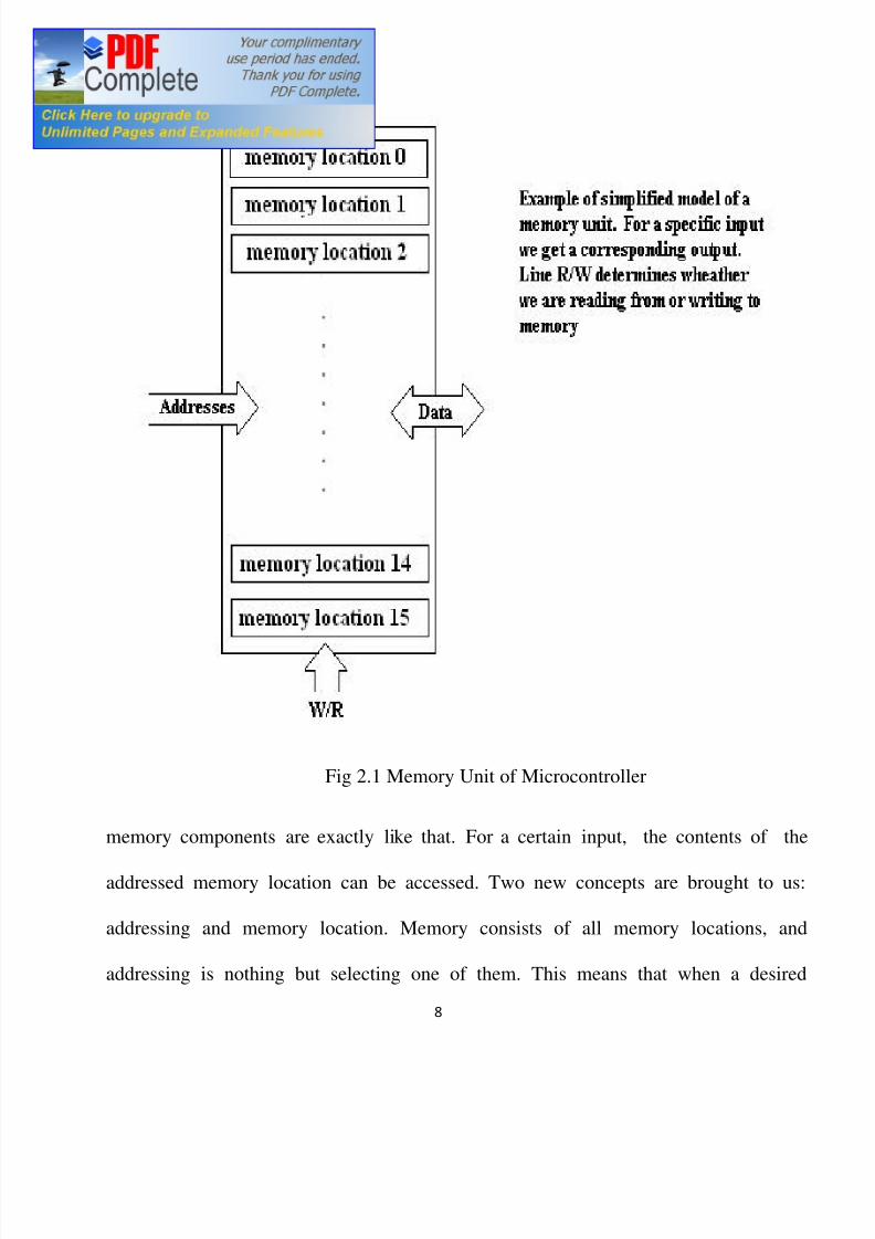
Memory is part of [10] the microcontrollers whose function is to store data. The
easiest way to explain it is to describe it as one big closet with lots of drawers. Suppose
that the drawers are marked in such a way that they cannot be confused, then their
contents will be easily accessible. It is enough to know the that all
8/7/2019 Pc to Pc Communication
http://slidepdf.com/reader/full/pc-to-pc-communication 8/48
8
Fig 2.1 Memory Unit of Microcontroller
memory components are exactly like that. For a certain input, the contents of the
addressed memory location can be accessed. Two new concepts are brought to us:
addressing and memory location. Memory consists of all memory locations, and
addressing is nothing but selecting one of them. This means that when a desired
8/7/2019 Pc to Pc Communication
http://slidepdf.com/reader/full/pc-to-pc-communication 9/48
9
memory location is selected, there is the need to wait for the contents of that location.
Besides reading from a memory location, memory must also provide for writing onto it.
This is done by supplying [11] an additional line called control line. This line is
designated R/W (read/write). Control line are used in the following way: if r/w=1,
reading is done, and if opposite is true then writing is done on the memory location.
Memory is the first element, and a few other operations are needed for the running of
the microcontroller.
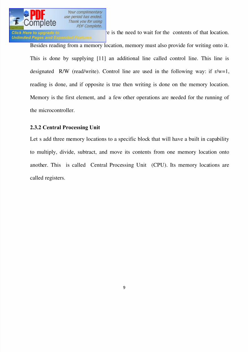
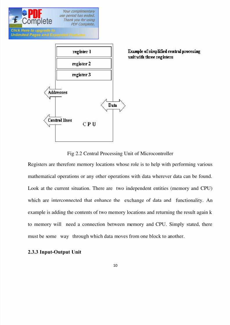
2.3.2 Central Processing Unit
Let s add three memory locations to a specific block that will have a built in capability
to multiply, divide, subtract, and move its contents from one memory location onto
another. This is called Central Processing Unit (CPU). Its memory locations are
called registers.
8/7/2019 Pc to Pc Communication
http://slidepdf.com/reader/full/pc-to-pc-communication 10/48
10
Fig 2.2 Central Processing Unit of Microcontroller
Registers are therefore memory locations whose role is to help with performing various
mathematical operations or any other operations with data wherever data can be found.
Look at the current situation. There are two independent entities (memory and CPU)
which are interconnected that enhance the exchange of data and functionality. An
example is adding the contents of two memory locations and returning the result again k
to memory will need a connection between memory and CPU. Simply stated, there
must be some way through which data moves from one block to another.
2.3.3 Input-Output Unit

8/7/2019 Pc to Pc Communication
http://slidepdf.com/reader/full/pc-to-pc-communication 11/48
11
The locations just added are called ports . There are several types of ports: Input,
output or bidirectional ports. When working with ports, first of all it is necessary to
choose which port is to be worked with, and then to send data to, or take it from the
port.
Fig 2.3 Input-Output Unit of Microcontroller
When working with it the port acts like a memory location. Something is simply being
written into or read from it, and it could be noticed on the pins of the microcontroller.

8/7/2019 Pc to Pc Communication
http://slidepdf.com/reader/full/pc-to-pc-communication 12/48
12
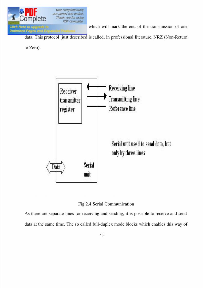
2.3.4 Serial Communication
Beside stated [9] above we ve added to the already existing unit the possibility of
communication with an outside world. However, this way of communicating has
drawbacks. One of the basic drawbacks is the number of lines which need to be used in
order to transfer data. What if it is being transferred to a distance of several kilometers?
The number of lines time s numbers of kilometers doesn t promise the economy of the
project. This means that the number of lines must be reduced in a manner that will
not lessen its functionality. Suppose we are working with three lines only, and that one
line is used for sending data ,other for receiving, and the third one is used as a reference
line for both the input and output side. In order for this to work, there is the need to set
the rules for the exchange of data. These rules are called protocol. Protocol is, therefor,
defined in advance so that there wouldn t be any misunderstanding between the sides
that are communicating with each other. The logical unit 1 is set up on the
transmitting line until transfer begins. Once the transfer starts, the transmission line is
lowered to logical 0 for a period of time, designated T, so the receiving side will
know that it is receiving data, and so it[10] will activate its mechanism for reception.
Returning to the transmission side and start putting logic zeros and ones in the
transmitter line in the order of a bit of the lowest value to a bit of the highest value. Let
each bit stay on line for a time period T, and in the end, or after the 8th
bit bring the
8/7/2019 Pc to Pc Communication
http://slidepdf.com/reader/full/pc-to-pc-communication 13/48
13
logical unit 1 back on the line which will mark the end of the transmission of one
data. This protocol just described is called, in professional literature, NRZ (Non-Return
to Zero).
Fig 2.4 Serial Communication
As there are separate lines for receiving and sending, it is possible to receive and send
data at the same time. The so called full-duplex mode blocks which enables this way of
8/7/2019 Pc to Pc Communication
http://slidepdf.com/reader/full/pc-to-pc-communication 14/48
14
communication is called a serial communication block. Unlike the parallel transmission,
data moves here bit by bit, or in a series of bits from which the term serial
communication is derived. After the reception of data, the need to read it from the
receiving location and [11] store it in memory as opposed to sending where the process
is reversed. Data goes from memory through the buys to the sending location, and then
to the receiving unit according to the protocol
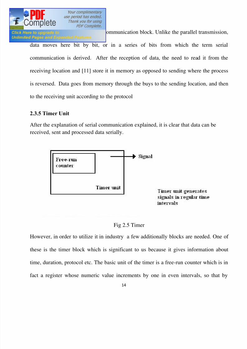
2.3.5 Timer Unit
After the explanation of serial communication explained, it is clear that data can be
received, sent and processed data serially.
Fig 2.5 Timer
However, in order to utilize it in industry a few additionally blocks are needed. One of
these is the timer block which is significant to us because it gives information about
time, duration, protocol etc. The basic unit of the timer is a free-run counter which is in
fact a register whose numeric value increments by one in even intervals, so that by

8/7/2019 Pc to Pc Communication
http://slidepdf.com/reader/full/pc-to-pc-communication 15/48
15
taking its value during periods T1 and T2 and on the basis of their difference the time
lapsed can be determined . This is a very important part of the microcontroller whose
understanding requires timing
8/7/2019 Pc to Pc Communication
http://slidepdf.com/reader/full/pc-to-pc-communication 16/48
16
CHAPTER THREE
MICROCONTROLLER INTERFACING
3.1 Introduction
This Chapter will focus on the microcontroller interfacing devices such as
Analogue to Digital Convertor (ADC)
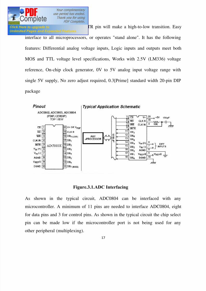
3.2 Description of ADC0804
The ability to convert analog signals to digital and vice-versa is very important in
signal processing. The objective of an A/D converter is to determine the output
digital word corresponding to an analog input signal. The Datasheet for
ADC0804LCN shows the pin out and a typical application schematic. The A/D
converter operates on the successive approximation principle. Analog switches
are closed sequentially by successive-approximation logic until the analog
differential input voltage [Vin(+) - Vin(-)] matches a voltage derived from a tapped
resistor string across the reference voltage. The normal operation proceeds as
follows. On the high-to-low transition of the WR input, the internal SAR latches
and the shift-register stages are reset, and the INTR output will be set high. As long
as the CS input and WR input remain low, the A/D will remain in a reset state.
Conversion will start from 1 to 8 clock periods after at least one of these inputs
makes a low-to-high transition. After the requisite number of clock pulses to
8/7/2019 Pc to Pc Communication
http://slidepdf.com/reader/full/pc-to-pc-communication 17/48
17
complete the conversion, the INTR pin will make a high-to-low transition. Easy
interface to all microprocessors, or operates "stand alone". It has the following
features: Differential analog voltage inputs, Logic inputs and outputs meet both
MOS and TTL voltage level specifications, Works with 2.5V (LM336) voltage
reference, On-chip clock generator, 0V to 5V analog input voltage range with
single 5V supply, No zero adjust required, 0.3[Prime] standard width 20-pin DIP
package
Figure.3.1.ADC Interfacing
As shown in the typical circuit, ADC0804 can be interfaced with any
microcontroller. A minimum of 11 pins are needed to interface ADC0804, eight
for data pins and 3 for control pins. As shown in the typical circuit the chip select
pin can be made low if the microcontroller port is not being used for any
other peripheral (multiplexing).
8/7/2019 Pc to Pc Communication
http://slidepdf.com/reader/full/pc-to-pc-communication 18/48
18
The ADC0804 IC is an 8-bit parallel ADC in the family of the ADC0800 series
from National Semiconductor. It work with +5 volts and has a resolution of 8 bits.
In the ADC0804, the conversion time varies depending on the clocking signals
applied to the CLK IN pin, but make sure it cannot be faster than 110us.
CS = Chip select is an active low input used to ACTIVATE the ADC0804 chip. To
access the ADC0804, this pin must be LOW
RD = The ADC converts the analog input to its binary equivalent and holds it in an
internal register. RD is used to get the converted data out of the ADC0804 chip.
When CS = 0, if H-to-L pulse is applied to the RD pin, the 8-bit digital output
shows up at the D0-D7 data pins. RD also known as output enables (OE)
WR = this is an active low input used to inform the ADC0804 to start the
conversion process. If CS = 0 when WR makes a low-to-high transition, the
ADC0804 start converting the analog input value of Vin to an 8-bit digital number.
When the data conversion is completed, the INTR pin is forced low by the
ADC0804
INTR = this is an output pin and is active low. It is a normally high pin and when
the conversion is finished, it goes low to signal the CPU that the converted data is
ready to be picked up. After INTR goes low, we make CS = 0 and send a high-to-
low pulse to the RD pin to get data out of the ADC0804 chip. CLK IN and CLK
R : CLK IN is an input pin connected to an external clock source when an external
clock is used for timing. However, the ADC chip has an internal clock generator.
To use the internal clock generator or known as self clocking of ADC chip, the
CLK IN and CLK R pins are connected to a capacitor and a resistor. In that case

8/7/2019 Pc to Pc Communication
http://slidepdf.com/reader/full/pc-to-pc-communication 19/48
19
the clock frequency is determined by the equation: f = 1/1.1 RC. Typical value are
R = 1 0 kohm and C = 150 pF. Substituting in the equation we will get the value of
f = 606 kHz. Vin(+) and Vin(-): These are the differential analog inputs where Vin
= Vin(+) - Vin(-). Often the pin Vin(-) is connected to ground and the Vin(+) pin is
used as the analog input to be converted to digital. Vcc = this is the +5 volt power
supply. It is used as a reference voltage when the Vref/2 input is not connected.
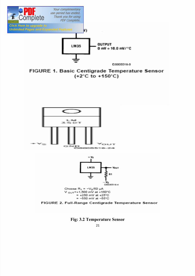
3.3 General Description of LM35 Temperature Sensor
The LM35 series are precision integrated-circuit temperature sensors, whose
output voltage is linearly proportional to the Celsius (Centigrade) temperature. The
LM35 thus has an advantage over linear temperature sensors calibrated in ° Kelvin,
as the user is not required to subtract a large constant voltage from its output to
obtain convenient Centigrade scaling. The LM35 does not require any external
calibration or trimming to provide typical accuracies of ±1 4°C at room
temperature and ±3 4°C over a full 55 to +150°C temperature range. Low cost is
assured by trimming and calibration at the wafer level. The LM35 s low output
impedance, linear output, and precise inherent calibration make interfacing to
readout or control circuitry especially easy. It can be used with single power
supplies, or with plus and minus supplies. As it draws only 60 A from its supply,
it has very low self-heating, less than 0.1°C in still air. The LM35 is rated to
operate over a 55° to +150°C temperature range, while the LM35C is rated for a
8/7/2019 Pc to Pc Communication
http://slidepdf.com/reader/full/pc-to-pc-communication 20/48
20
40° to +110°C range ( 10° with improved accuracy). The LM35 series is
available packaged in hermetic TO-46 transistor packages, while the LM35C,
LM35CA, and LM35D are also available in the plastic TO-92 transistor package.
The LM35D is also available in an 8-lead surface mount small outline package and
a plastic TO-220 package . It is calibrated directly in ° Celsius (Centigrade) ,
Linear + 10.0 mV/°C scale factor, 0.5°C accuracy guaranteeable (at +25°C), Rated
for full 55° to +150°C range, Suitable for remote applications, Low cost due to
wafer-level trimming, Operates from 4 to 30 volts, Less than 60 A current drain
8/7/2019 Pc to Pc Communication
http://slidepdf.com/reader/full/pc-to-pc-communication 21/48
21
Fig: 3.2 Temperature Sensor
8/7/2019 Pc to Pc Communication
http://slidepdf.com/reader/full/pc-to-pc-communication 22/48
22
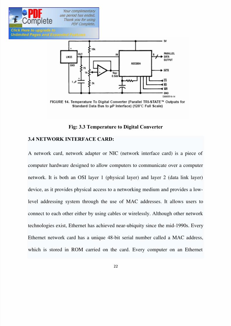
Fig: 3.3 Temperature to Digital Converter
3.4 NETWORK INTERFACE CARD:
A network card, network adapter or NIC (network interface card) is a piece of
computer hardware designed to allow computers to communicate over a computer
network. It is both an OSI layer 1 (physical layer) and layer 2 (data link layer)
device, as it provides physical access to a networking medium and provides a low-
level addressing system through the use of MAC addresses. It allows users to
connect to each other either by using cables or wirelessly. Although other network
technologies exist, Ethernet has achieved near-ubiquity since the mid-1990s. Every
Ethernet network card has a unique 48-bit serial number called a MAC address,
which is stored in ROM carried on the card. Every computer on an Ethernet
8/7/2019 Pc to Pc Communication
http://slidepdf.com/reader/full/pc-to-pc-communication 23/48
23
network must have a card with a unique MAC address. No two cards ever
manufactured share the same address. This is accomplished by the Institute of
Electrical and Electronics Engineers (IEEE), which is responsible for assigning
unique MAC addresses to the vendors of network interface controllers.
Whereas network cards used to be expansion cards that plug into a computer bus,
the low cost and ubiquity of the Ethernet standard means that most newer
computers have a network interface built into the motherboard. These
motherboards either have Ethernet capabilities integrated into the motherboard
chipset, or implemented via a low cost dedicated Ethernet chip, connected through
the PCI (or the newer PCI express bus). A separate network card is not required
unless multiple interfaces are needed or some other type of network is used. Newer
motherboards may even have dual network (Ethernet) interfaces built-in.
The card implements the electronic circuitry required to communicate using a
specific physical layer and data link layer standard such as Ethernet or token ring.
This provides a base for a full network protocol stack, allowing communication
among small groups of computers on the same LAN and large-scale network
communications through routable protocols, such as IP. There are four techniques
used to transfer data, the NIC may use one or more of these techniques.
8/7/2019 Pc to Pc Communication
http://slidepdf.com/reader/full/pc-to-pc-communication 24/48
24
· Polling is where the microprocessor examines the status of the peripheral
under program control.
· Programmed I/O is where the microprocessor alerts the designated
peripheral by applying its address to the system's address bus.
· Interrupt-driven I/O is where the peripheral alerts the microprocessor that it's
ready to transfer data.
· DMA is where the intelligent peripheral assumes control of the system bus
to access memory directly. This removes load from the CPU but requires a
separate processor on the card.
A network card typically has a twisted pair, BNC, or AUI socket where the
network cable is connected, and a few LEDs to inform the user of whether the
network is active, and whether or not there is data being transmitted on it. The
Network Cards are typically available in 10/100/1000 Mbit/s(Mbit/s). This means
they can support a transfer rate of 10 or 100 or 1000 Megabits per second.
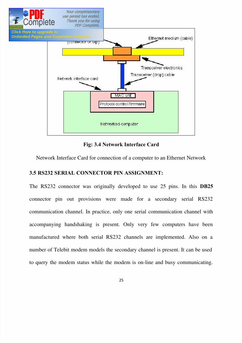
A network interface card is used to connect a computer to an Ethernet network.
The card (shown in the figure below) provides an interface to the media. This may
be either using an external transceiver (as shown) or through an internal integrated
transceiver mounted on the network interface card PCB. The card usually also
contains the protocol control firmware and Ethernet Controller needed to support
the Medium Access Control (MAC) data link protocol used by Ethernet.
8/7/2019 Pc to Pc Communication
http://slidepdf.com/reader/full/pc-to-pc-communication 25/48
25
Fig: 3.4 Network Interface Card
Network Interface Card for connection of a computer to an Ethernet Network
3.5 RS232 SERIAL CONNECTOR PIN ASSIGNMENT:
The RS232 connector was originally developed to use 25 pins. In this DB25
connector pin out provisions were made for a secondary serial RS232
communication channel. In practice, only one serial communication channel with
accompanying handshaking is present. Only very few computers have been
manufactured where both serial RS232 channels are implemented. Also on a
number of Telebit modem models the secondary channel is present. It can be used
to query the modem status while the modem is on-line and busy communicating.
8/7/2019 Pc to Pc Communication
http://slidepdf.com/reader/full/pc-to-pc-communication 26/48
26
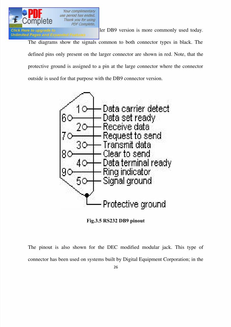
On personal computers, the smaller DB9 version is more commonly used today.
The diagrams show the signals common to both connector types in black. The
defined pins only present on the larger connector are shown in red. Note, that the
protective ground is assigned to a pin at the large connector where the connector
outside is used for that purpose with the DB9 connector version.
Fig.3.5 RS232 DB9 pinout
The pinout is also shown for the DEC modified modular jack. This type of
connector has been used on systems built by Digital Equipment Corporation; in the

8/7/2019 Pc to Pc Communication
http://slidepdf.com/reader/full/pc-to-pc-communication 27/48
27
early days, one of the leaders in the mainframe world. Although this serial
interface is differential (the receive and transmit have their own floating ground
level which is not the case with regular RS232) it is possible to connect RS232
compatible devices with this interface because the voltage levels of the bit streams
are in the same range.
8/7/2019 Pc to Pc Communication
http://slidepdf.com/reader/full/pc-to-pc-communication 28/48
28
CHAPTER FOUR
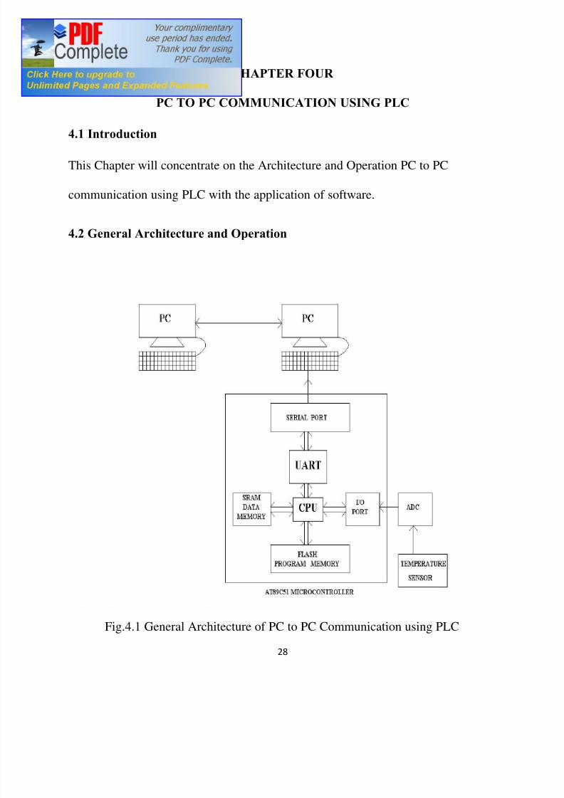
PC TO PC COMMUNICATION USING PLC
4.1 Introduction
This Chapter will concentrate on the Architecture and Operation PC to PC
communication using PLC with the application of software.
4.2 General Architecture and Operation
Fig.4.1 General Architecture of PC to PC Communication using PLC

8/7/2019 Pc to Pc Communication
http://slidepdf.com/reader/full/pc-to-pc-communication 29/48
8/7/2019 Pc to Pc Communication
http://slidepdf.com/reader/full/pc-to-pc-communication 30/48
30
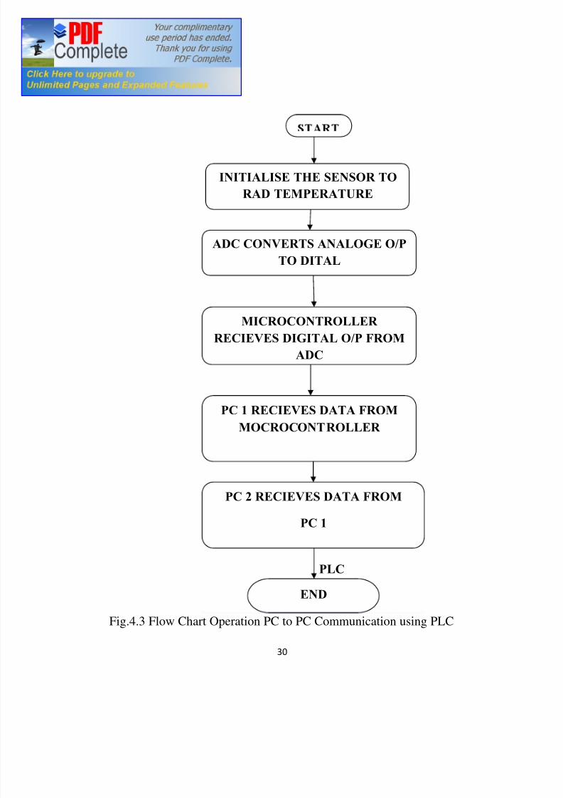
PLC
Fig.4.3 Flow Chart Operation PC to PC Communication using PLC
END
MICROCONTROLLER
RECIEVES DIGITAL O/P FROM
ADC
INITIALISE THE SENSOR TO
RAD TEMPERATURE
ADC CONVERTS ANALOGE O/P
TO DITAL
PC 1 RECIEVES DATA FROM
MOCROCONTROLLER
PC 2 RECIEVES DATA FROM
PC 1
8/7/2019 Pc to Pc Communication
http://slidepdf.com/reader/full/pc-to-pc-communication 31/48
31
4.3 Operation of PC to PC Communication using PLC
Here the embedded processor is connected to a temperature sensor. The sensor
output is an analog data which is digitized with a help of an A/D converter. The
temperature data is logged into one PC and it is transmitted to other PC through the
communication line. Application software has been developed to enable the
process easy using high level graphical programming language Visual Basic. All
power line communication systems operate by impressing a modulated carrier
signal on the wiring system. Different types of power line communications use
different frequency bands, depending on the signal transmission characteristics of
the power wiring used. Since the power wiring system was originally intended for
transmission of AC power, in conventional use, the power wire circuits have only a
limited ability to carry higher frequencies. The propagation problem is a limiting
factor for each type of power line communications. A new discovery called E-Line
that allows a single power conductor on an overhead power line to operate as a
waveguide to provide low attenuation propagation of RF through microwave
energy lines while providing information rate of multiple Gbps is an exception to
this limitation.
Data rates over a power line communication system vary widely. Low-frequency
(about 100-200 kHz) carriers impressed on high-voltage transmission lines may

8/7/2019 Pc to Pc Communication
http://slidepdf.com/reader/full/pc-to-pc-communication 32/48
32
carry one or two analog voice circuits, or telemetry and control circuits with an
equivalent data rate of a few hundred bits per second; however, these circuits
may be many miles long. Higher data rates generally imply shorter ranges; a local
area network operating at millions of bits per second may only cover one floor of
an office building, but eliminates installation of dedicated network cabling
8/7/2019 Pc to Pc Communication
http://slidepdf.com/reader/full/pc-to-pc-communication 33/48
8/7/2019 Pc to Pc Communication
http://slidepdf.com/reader/full/pc-to-pc-communication 34/48
34
converted code cannot be written directly on to the microcontroller. This means
there is the need to use a special technique to load the program into the
microcontroller. One of the methods is to use a microcontroller with a flash
memory. Flash memory is similar to erasable programmable read only memory. So
once program is written and debugged using cross compiler, we need to flash the
program on to the flash memory of the memory. Once program is flashed the
microcontroller is loaded with the hex code and it will be ready for execution
5.1.1 INTRODUCTION TO KEIL:
Keil software provides the premier 8051 development tools to industry .The keil
software comprises of different tool kits. A tool kit consist of several application
programs which can be used to create the 8051 application .When using keil
software for a project the development cycle is some what similar to a software
development project .It consist of creating source file in C or assembly language
compiling or assembling the source files, debugging error in the source file,
linking file from complier and assembler and finally building a project linking all
the files and testing the linked application.
5.1.2 FUNCTIONING OF KEIL
All files created through the micro vision integrated development environment
are passed to the C51 compiler or A51 assembler. The compiler and assembler
process the source files and create relocatable object files. Object files created by
the compiler or assembler may be used by the library manager to create a library.
A library is a specially formatted, ordered program collection of object modules
that a linker can process. When the linker processes a library, only the object
modules in the library necessary for program creation are used. Object files created
8/7/2019 Pc to Pc Communication
http://slidepdf.com/reader/full/pc-to-pc-communication 35/48
35
by the compiler and assembler and library files created by the library manager are
processed by the linker to create an absolute object module. An absolute object file
or module is an object file with no reloadable code. All the code in an absolute
object file resides at fixed locations.
The absolute object file created by the linker may be used to program EPROM or
other memory devices. The absolute object module may also be used with the
dScope-51 debugger / simulator or with an in-circuit emulator. The dScope-51
source level debugger/simulator is ideally suited for fast, reliable high-level-
language program debugging. The debugger contains a high-speed simulator and a
target debugger that let can be used to simulate an entire 8051 system including
on-chip peripherals. By loading specific I/O drivers, the attributes and peripherals
of a variety of 8051 family can be stimulated. The RTX-51 real time operating
system is a multitasking kernel for the 8051 family. The RTX-51 real time kernel
simplifies the system design, programming, and debugging of complex
applications where fast reaction to time critical events are essential. The kernel is
fully integrated into the C51compiler and is easy to use. Task description tablesand operating system consistency are automatically controlled by the BL51 code
banking linker/locater.
5.1.3 DEVELOPMENT TOOLS IN KEIL
The Fig 4.1 shows the full extent of the Keil Software 8051 development tools.
The tools listed in this diagram comprise the professional developer s kit. In
addition to the professional kit, Keil Software provides a number of other tool kits
for the 8051 developer. The most capable kit is the professional developer s kit is
described as follows:
8/7/2019 Pc to Pc Communication
http://slidepdf.com/reader/full/pc-to-pc-communication 36/48
36
The professional developer s k it includes everything the professional 8051
developer needs to create sophisticated embedded applications. This tool kit
includes the following components:
· C51 Optimizing C compiler,
· A51 Macro Assembler,
· BL51 Code Banking Linker/Locator,
· OC51 Banked Object file converter,
· OH51 Object-Hex converter,
· LIB51 Library Manager,
· dScope-1 Simulator/debugger,
· tScope-51 Target Debugger,
· Monitor-51 ROM Monitor and Terminal Program,
· Integrated Development Environment,
· RTX-51 Tiny Real-Time Operating System.
In addition, the professional developer s kit includes the following tools for
Windows users:
· dScope-51 Simulator/Debugger for windows,
· Micro Vision/51 Integrated Development Environment for windows.
The professional developer s kit can be configured for all 8051 derivatives. The
tools included in this kit can run any compatible computer.
5.1.4 C51 OPTIMIZING CROSS COMPILER
The C programming language is a general-purpose programming language that
provides code efficiency, elements of structured programming, and a rich set of
operators. Its generality, combined with its absence of restrictions, make C a
8/7/2019 Pc to Pc Communication
http://slidepdf.com/reader/full/pc-to-pc-communication 37/48
37
convenient and effective programming solution for a wide variety of software
tasks. Many applications can be solved more easily and effectively with C than
with other more specialized languages. The Keil software C51 optimizing cross
compiler for the MS-DOS operating system is a complete implementation of the
ANSI (American National Standards Institute) standard for the C language. The
C51 compiler generates code for the 8051 microprocessor but is not a universal C
compiler adapted for the 8051 target. It is a ground-up implementation dedicated to
generating extremely fast and compact code for the 8051 microprocessor. For most
8051 applications, the C51 compiler gives software developers the flexibility of
programming in /c while matching the code efficiency and speed of assembly
language. Using a high-level language like C has many advantages over assembly
language programming. For example:
§ Knowledge of the processor instruction set is not required. A rudimentary
knowledge of the 8051 s memory architecture is desirable but not necessary.
§ Register allocation and addressing mode details are managed by the
compiler.§ The ability to combine variable selection with specific operations improves
program readability.
§ Keywords and operational functions that more nearly resemble the human
thought process can be used.
§ Program development and debugging times are dramatically reduced when
compared to assembly language programming.
§ The library files that are supplied provide many standard routines (such as
formatted output, data conversions, and floating-point arithmetic) that may
be incorporated into our application.
8/7/2019 Pc to Pc Communication
http://slidepdf.com/reader/full/pc-to-pc-communication 38/48
38
§ Existing routine can be reused in new programs by utilizing modular
programming techniques available with C.
§ The C language is very portable and very popular. C compilers are available
for almost all target systems. Existing software investments can be quickly
and easily converted from or adapted to other processors or environments.
5.1.5 A51 MACRO ASSEMBLER
The A51 assembler is a macro assembler for the 8051 microcontroller family. It
translates symbolic assembly language mnemonics into relocatable object code
where the utmost speed, small code size, and hardware control are critical. The
macro facility speeds development and conserves maintenance time since common
sequences need only be developed once. The A51 assembler supports symbolic
access to all features of the 8051 architecture and is configurable for the numerous
8051 derivatives. The A51 assembler translates an assembler source file into a
relocatable object module. If the DEBUG control is used, the object file contains
full symbolic information for debugging with dScope or an in-circuit emulator. Inaddition to the object file, the A51 assembler generates a list file which may
optionally include symbol table and cross reference information. The A51
assembler is fully compatible with Intel ASM-51 source modules. The A51
assembler supports all members of the 8051 family. The special function register
(SFR) set of the 8051 is predefined. However, the NOMOD51 control lets you
override these definitions with processor-specific include files. The A51 assembler
is shipped with include files for the 8051, 8051fx, 8051GB, 8052, 80152, 80451,
80452, 80515, 80C517, 80C517A, 8x552, 8xC592, 8xCL782, 8xCL410 and
80C320 microcontrollers. You can easily create include files for other 8051 family
members.
8/7/2019 Pc to Pc Communication
http://slidepdf.com/reader/full/pc-to-pc-communication 39/48
39
5.1.6 BL51 CODE BANKING LINKER/LOCATOR
The 51 code banking linker/locator combines one or more object modules into a
single executable 8051 program. The linker also resolves external and public
references, and assigns absolute addresses to relocatable programs segments. The
BL51 code banking linker/locator processes object modules created by the keil
C51 compiler and A51 assembler and the Intel PL/M-51 compiler and ASM-51
assembler. The linker automatically selects the appropriate run-time library and
links only the library modules that are required. Normally, the BL51 code banking
linker/locator is invoked from the command line specifying the names of the object
modules to combine. The default controls for the BL51 code banking linker/locator
have been carefully chosen to accommodate most applications without the need to
specify additional directives. However, it is easy to specify custom settings for
applications.
5.1.7 OC51 BANKED OBJECT FILE CONVERTER
The OC51 banked object file converter creates absolute object modules for each
code bank in a banked object module. Banked object modules are created by the
BL51 code banking linker/locator when a bank switching application is created.
Symbolic debugging information is copied to the absolute object files and can be
used by dScope or an in-circuit emulator. The OC51 banked object file converter
may be used to create absolute object modules for the command area and for each
code bank in your banked object module. The Intel HEX files may then be
generated for each of the absolute object modules using the OH51 object-hex
converter.
8/7/2019 Pc to Pc Communication
http://slidepdf.com/reader/full/pc-to-pc-communication 40/48
40
5.1.8 OH51 OBJECT-HEX CONVETER
The OH51 object-hex converter creates Intel hex files from absolute objectmodules. Absolute object modules can be created by the BL51 code baking linker
or by the OC51 banked object file converter. Intel hex files are ASCII files that
contain a hexadecimal representation of an application. They can be easily loaded
into a device programmer for writing on Erasable programmable read only
memory.
LIB51 LIBRARY MANAGER
The LIB51 library manager allows for the creation and maintenance of library
files. A library file is a formatted collection of one or more object files. Library
files provide a convenient method of combining and referencing a large number of
object files. Libraries can be effectively used by the BL51 code banking
linker/locator. The LIB51 library manager allows for the creation of a library file,
addition or removal of object modules to or from a library file, and may be
controlled interactively or from the command line.
DSCOPE-51 FOR WINDOWS
DScope-51 is a source level debugger and simulator for programs created with the
keil C51 compiler and A51 assembler and the Intel PL/M-51 compiler and ASM-
51 assembler. Dscope-51 is a software-only product that allows for the simulation
of the features of an 8051 without actually having target hardware. Scope-51 may
be used to test and debug an embedded applications before actual 8051 hardware is
ready. Dscope-51 simulates a wide variety of 8051 peripherals including the
internal serial port, external I/O, and timers.
8/7/2019 Pc to Pc Communication
http://slidepdf.com/reader/full/pc-to-pc-communication 41/48
41
5.1.9 µVISION/51 FOR WINDOWS
Microvision/51 is an integrated software development platform that includes a full
function editor, project manager, make facility, and environment control for the
keil 8051 tools. When using a µVision/51 speeds the embedded applications
development may be enhance by providing the following:
§ Standard Windows user interface,
§ Dialog boxes for all environment and development tool settings,
§ Multiple file editing capability,
§ Full function editor with user-definable key sequences,
§ Application manager for adding external programs into the pull-down
menu,
§ Project manager for creating and maintaining projects,
§ Integrated make facility for building target programs from your
projects,
§ On-line help system.
5.2 TARGET PROCESSOR
In this project microcontroller AT89C52 (Target processor) is used to governs all
the essential process which has to be executed during acquisition.
Microcontroller, as the name suggests, are small controllers. These are like single chip
computers that are often embedded into systems to function as processing /controllers
unit. For example, a remote control may probably have microcontrollers inside that do
decoding and other controlling functions. They are also used in automobiles, washing
machines, microwave ovens, toys etc, where automation is needed. The key features
of microcontrollers include:
8/7/2019 Pc to Pc Communication
http://slidepdf.com/reader/full/pc-to-pc-communication 42/48
42
High integration of Functionality
Microcontrollers sometimes are called single chip computers because they have
on-chip memory and I/O circuitry and other circuitries that enable them to
function as small standalone computers without other supporting circuitry.
Field Programmability, Flexibility
Microcontrollers often use EEPROM or EPROM as their storage device to allow
field programmability so they are flexible to use. Once the program is tested to
be correct then large quantities of microcontrollers can be programmed to be used
in embedded systems.
Easy to Use
Assembly language is often used in microcontroller and since they usually follow
RISC architecture, the instruction set is small. The development package of
microcontrollers often includes an assembler ,a simulator ,a programmer to
burn the chip and a demonstration board .Some packages include a high level
language compiler such as a C compiler and more sophisticated libraries.
5.3 APPLICATION SOFTWARE DESCRIPTION
Application software is a computer program that functions and is operated by
means of a computer, with the purpose of supporting or improving the software
user s work. In other words, it is the subclass of computer software that employs
the capabilities of a computer directly and thoroughly to a task that the user wishes
to perform. This should be contrasted with system software (infrastructure) or
middleware (computer services/ processes integrators), which is involved in
integrating a computer s various capabilities, but typically does not directly apply
8/7/2019 Pc to Pc Communication
http://slidepdf.com/reader/full/pc-to-pc-communication 43/48
43
them in the performance of task s that benefit the user. In this context the term
application refers to both the application software and its implementation. In some
types of embedded systems, the application software and the operating system
software may be indistinguishable to the user, as in the case of software used to
control a VCR, DVD player or microwave oven.
The application software for this project has been developed from a high level
graphical programming language (visual basic).This method of implementation
gives the user a more flexibility to have hands on the system. The application
software is a virtual representation of the actual instrument and provides all
facilities for the user to control the working of the system. This technique of
operating the system (the actual instrument) is highly advantageous, as it does not
permit the actual instrument to be misused, for example, here, the minimum and
maximum ranges of the system is defined and hence prevents the user from
exceeding the limits. Thus the application software provides high security to the
actual instrument. Moreover certain graphical representation of the real time values
with high resolution can also be implemented.
8/7/2019 Pc to Pc Communication
http://slidepdf.com/reader/full/pc-to-pc-communication 44/48
44
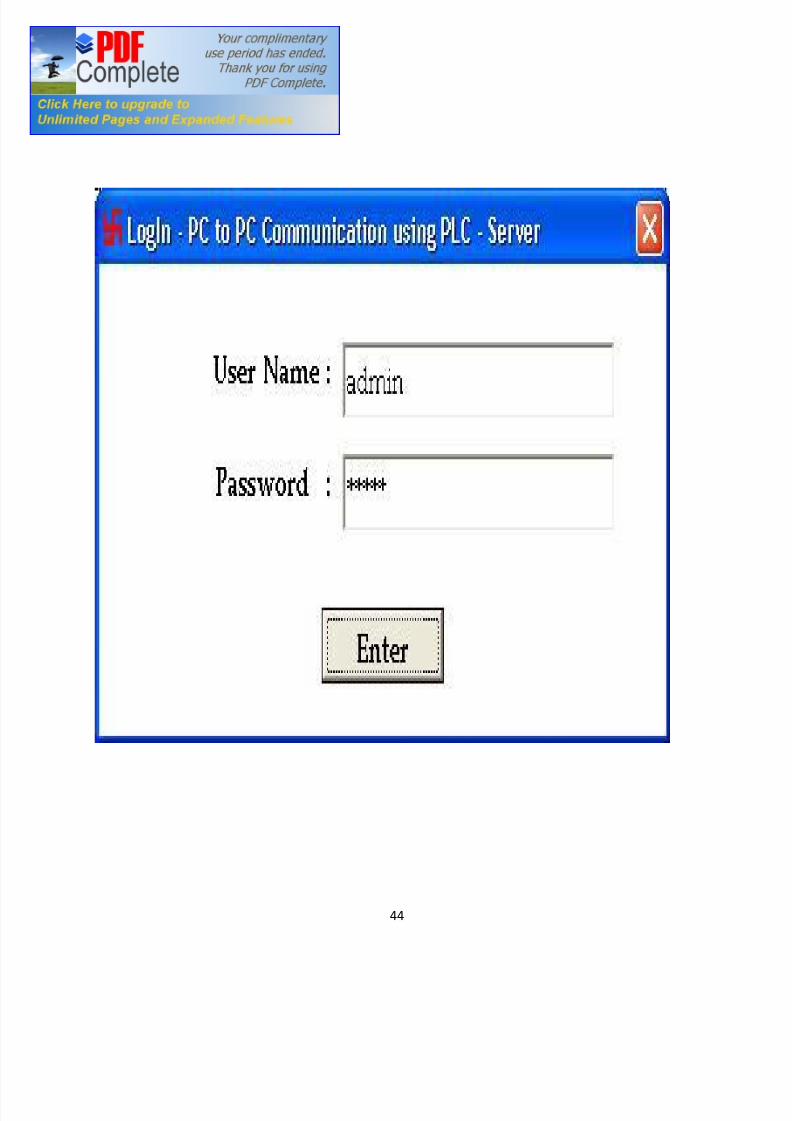
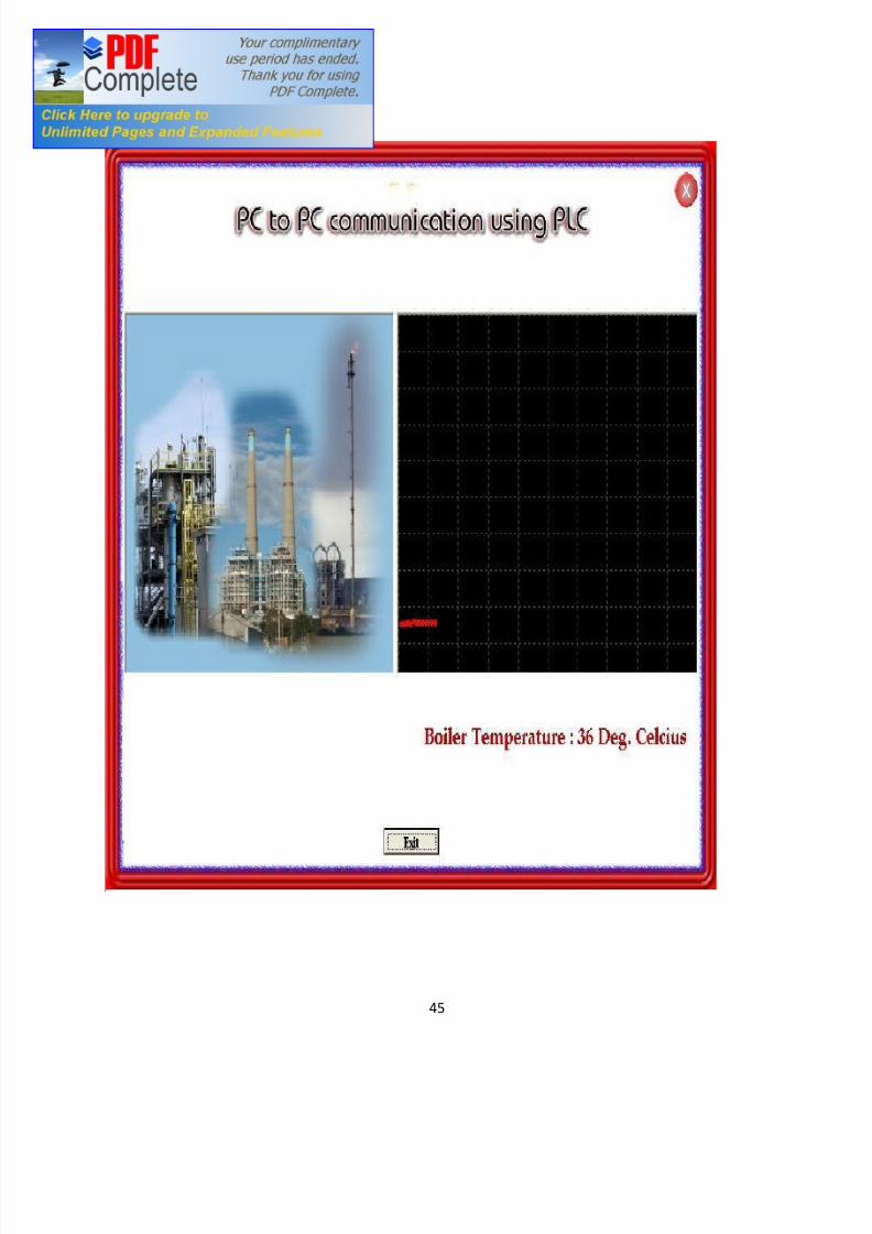
SCREEN SHOTS
8/7/2019 Pc to Pc Communication
http://slidepdf.com/reader/full/pc-to-pc-communication 45/48
45
8/7/2019 Pc to Pc Communication
http://slidepdf.com/reader/full/pc-to-pc-communication 46/48
46
CHAPTER SIX
CONCLUSION AND FUTURE WORK
In this project PC to PC communication using PLC has been designed and
implemented successfully. Though various modes of communication are present in
this time power line communication is a more secure method of data transfer. In
real time several thousands of PC can be connected, making communication
simpler. Custom built hardware along with application software is provided to
have a real time control over the programmable hardware. It be must be noted that
the information from the microcontroller to PC 1 could be transmitted using
wireless and could be considered as future work
8/7/2019 Pc to Pc Communication
http://slidepdf.com/reader/full/pc-to-pc-communication 47/48
47
REFERENCES
[1] B. L kakrati and A. K fsator, PLC, 24th
Edition, Scand and Company,
New Delhi, 2000.
[2] J. B Gupta, Electrical Technology, 12th
Edition, S. K Kataria and Sons,
Delhi, 2003.
[3] D. G. Fink and H. W. Beaty, Standard Handbook for Electrical Engineers,
13th
Edition, McGraw Hill, Singapore, 1993.
[4] E. Frounza, Data Communcation, 7th
Edition, Addison Weseley Longman
Limited, Edinburgh Gate, England, 1995.
[5] J. O. Bird and P. J Chivers, Engineering and Physical Science Pocket Book,
Newnew 1995.
[6] H. Uppal , Electrical Power System, 3rd
Edition, New Delhi, India, 1995.
[7] R. J. Surakumar, N. P. Subramaniam, and S. Ganesan, DC Motor Control
Through Remote Embedded Linux, IEEE Transactions, vol 12-35, page 34,
Nov 2005
[8] K. S. Ravash, RF-600DC Wireless Variable Speed DC Motor Controller,
IEEE Trans.Page 65, Dec 2007.

8/7/2019 Pc to Pc Communication
http://slidepdf.com/reader/full/pc-to-pc-communication 48/48
[9] http://meseec.ce.rit.edu/eecc250-winter99/250-2-9-2000.pdf
11/10/2009
[10] http://www.mikroe.com/en/books/picbook/1_chapter.htm
13/10/2009
[11] http://www.allheadlinenews.com/articles/7012111732#ixzz0TMaQxsK
15/10/2009
[12] http://www.c++.com/en/books/picbook/1_chapter.htm
15/10/2009
[13] http://microp.ce.rit.edu/eecc250-winter99/250-2-9-2000.pdf
17/10/2009
[14] http://spsen.ce.rit.edu/eecc250-winter99/250-2-9-2000.pdf
17/10/2009
[15] http://Hbridge.ce.rit.edu/eecc250-winter99/250-2-9-2000.pdf
19/10/2009
[16] http://dcmotor.ce.rit.edu/eecc250-winter99/250-2-9-2000.pdf
19/10/2009
Related Documents


![Industrial Communication With PG-PC[1]](https://static.cupdf.com/doc/110x72/552583d04a795907498b4c45/industrial-communication-with-pg-pc1.jpg)


