WHITEPAPER NEW FOAM TECHNOLOGY, NEW FOUND RESULTS International Aviation Fire Protection Association Conference Proceedings Sydney, 2005

Welcome message from author
This document is posted to help you gain knowledge. Please leave a comment to let me know what you think about it! Share it to your friends and learn new things together.
Transcript
Whitepaper
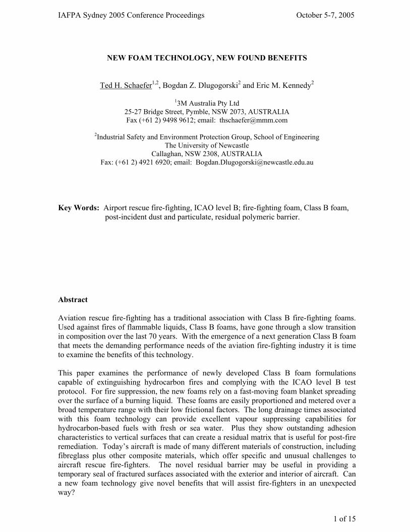
NeW Foam techNology, NeW FouNd resultsInternational Aviation Fire Protection AssociationConference ProceedingsSydney, 2005
IAFPA Sydney 2005 Conference Proceedings October 5-7, 2005
1 of 15
NEW FOAM TECHNOLOGY, NEW FOUND BENEFITS
Ted H. Schaefer1,2, Bogdan Z. Dlugogorski2 and Eric M. Kennedy2
13M Australia Pty Ltd 25-27 Bridge Street, Pymble, NSW 2073, AUSTRALIA Fax (+61 2) 9498 9612; email: [email protected]
2Industrial Safety and Environment Protection Group, School of Engineering
The University of Newcastle Callaghan, NSW 2308, AUSTRALIA
Fax: (+61 2) 4921 6920; email: [email protected]
Key Words: Airport rescue fire-fighting, ICAO level B; fire-fighting foam, Class B foam,
post-incident dust and particulate, residual polymeric barrier. Abstract Aviation rescue fire-fighting has a traditional association with Class B fire-fighting foams. Used against fires of flammable liquids, Class B foams, have gone through a slow transition in composition over the last 70 years. With the emergence of a next generation Class B foam that meets the demanding performance needs of the aviation fire-fighting industry it is time to examine the benefits of this technology. This paper examines the performance of newly developed Class B foam formulations capable of extinguishing hydrocarbon fires and complying with the ICAO level B test protocol. For fire suppression, the new foams rely on a fast-moving foam blanket spreading over the surface of a burning liquid. These foams are easily proportioned and metered over a broad temperature range with their low frictional factors. The long drainage times associated with this foam technology can provide excellent vapour suppressing capabilities for hydrocarbon-based fuels with fresh or sea water. Plus they show outstanding adhesion characteristics to vertical surfaces that can create a residual matrix that is useful for post-fire remediation. Today’s aircraft is made of many different materials of construction, including fibreglass plus other composite materials, which offer specific and unusual challenges to aircraft rescue fire-fighters. The novel residual barrier may be useful in providing a temporary seal of fractured surfaces associated with the exterior and interior of aircraft. Can a new foam technology give novel benefits that will assist fire-fighters in an unexpected way?
IAFPA Sydney 2005 Conference Proceedings October 5-7, 2005
2 of 15
Introduction 3M has been involved with fire-fighting foams since the 1960s. Recent product development work has centred on a new Class B foam technology that meets the fire-fighting performance criteria of the International Civil Aviation Organisation (ICAO) standard Level B performance, as witness and certified by Det Norske Veritas. Class B foam is a key tool for aircraft rescue fire-fighting (ARFF) and a foam technology that is known for its rapid fire control of flammable liquids, such as aviation fuels, and is preferred for crash rescue scenarios. In ARFF operations, foam is often used for post-crash aircraft fires for the suppression of fire, fuel vapours, and for cooling of the aircraft structure. Water, or weak foam solution, may be used for internal aircraft cabin fire-fighting. Exterior or interior structural components may be damaged in sections of the aircraft, which could include fractured composite panels that require stabilisation to reduce the risk of air-born particulate. The current method for stabilisation of damaged composites in post-incident control is the application of a polymeric coating to bind loose particulate. The stabilisation methodology uses a concentrated mix of floor wax to coat the aircraft surfaces. [DOT/FAA/AR-98/34, 1998] This is an effective process, but what transpires between fire-fighting operations and post-crash stabilisation? There is a time period when fractured or fire damaged aircraft structures may result in the release of dust particulate made up of aircraft materials of construction. This is a critical time period when emergency responders and other associated participants may have potential exposure if they are not wearing appropriate respiratory protection. However, airbourne particulate can be reduced if the fire-fighting foam technology being used leaves behind a residual barrier that can seal the surfaces until additional stabilisation can be carried out. New Foam Technology 3M Australia, a subsidiary of 3M Company, has developed a new generation of class B fire-fighting foam technology called 3M RF Series Foam. This new Class B foam technology brings new benefits to the fire-fighting industry. 3M RF Series foam technology uses a proprietary formula including hydrocarbon surfactants, combined with the complex sugar called xanthan gum polymer. The resulting foaming and fire performance characteristics result in world-class fire performance. 3M RF Series foam technology has resulted in products like 3M RF6 and RF3 fire-fighting foam technology that meet the high fire-fighting performance requirement of ICAO level B foams. Table 1 lists the ICAO level B fire test results of 3M RF6, with comparisons to the specification. [ICAO, 1990] Table 1: ICAO Level B Fire Performance (4.5 m2 pan) Test Results.
Note: Test terminated at 12:00 with no signs of burn-back.
ICAO Level Spec 3MTM RF3 Foam 3MTM RF6 Foam Test witnessed by DNV (Norway) DNV (Norway) Solution strength 3 or 6% 3 6 90% control - 30 s 30 s Extinguishment <60 s 38 s 46 s Burn-back time > 5:00 >12:00* >12:00*
IAFPA Sydney 2005 Conference Proceedings October 5-7, 2005
3 of 15
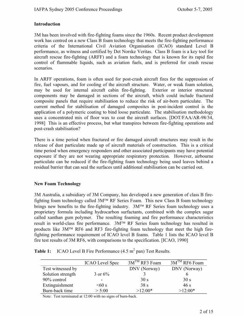
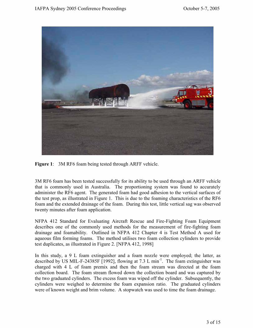
Figure 1: 3M RF6 foam being tested through ARFF vehicle. 3M RF6 foam has been tested successfully for its ability to be used through an ARFF vehicle that is commonly used in Australia. The proportioning system was found to accurately administer the RF6 agent. The generated foam had good adhesion to the vertical surfaces of the test prop, as illustrated in Figure 1. This is due to the foaming characteristics of the RF6 foam and the extended drainage of the foam. During this test, little vertical sag was observed twenty minutes after foam application. NFPA 412 Standard for Evaluating Aircraft Rescue and Fire-Fighting Foam Equipment describes one of the commonly used methods for the measurement of fire-fighting foam drainage and foamability. Outlined in NFPA 412 Chapter 4 is Test Method A used for aqueous film forming foams. The method utilises two foam collection cylinders to provide test duplicates, as illustrated in Figure 2. [NFPA 412, 1998] In this study, a 9 L foam extinguisher and a foam nozzle were employed; the latter, as described by US MIL-F-24385F [1992], flowing at 7.3 L min-1. The foam extinguisher was charged with 4 L of foam premix and then the foam stream was directed at the foam collection board. The foam stream flowed down the collection board and was captured by the two graduated cylinders. The excess foam was wiped off the cylinder. Subsequently, the cylinders were weighed to determine the foam expansion ratio. The graduated cylinders were of known weight and brim volume. A stopwatch was used to time the foam drainage.
IAFPA Sydney 2005 Conference Proceedings October 5-7, 2005
4 of 15
The foam expansion ratio was calculated from the following expression:
Brim volume of cylinder Foam expansion ratio =
Mass of cylinder and foam – tare mass of cylinder The 25% drain time, which is the time when 25% of the surfactant solution has already drained out of the foam layer, was also measured.
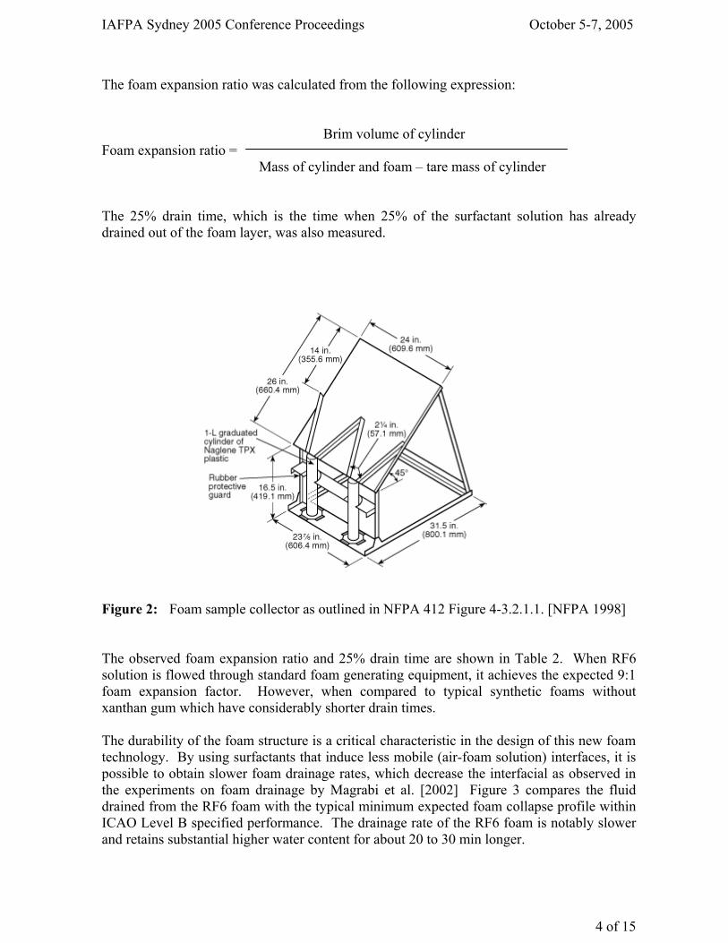
Figure 2: Foam sample collector as outlined in NFPA 412 Figure 4-3.2.1.1. [NFPA 1998] The observed foam expansion ratio and 25% drain time are shown in Table 2. When RF6 solution is flowed through standard foam generating equipment, it achieves the expected 9:1 foam expansion factor. However, when compared to typical synthetic foams without xanthan gum which have considerably shorter drain times. The durability of the foam structure is a critical characteristic in the design of this new foam technology. By using surfactants that induce less mobile (air-foam solution) interfaces, it is possible to obtain slower foam drainage rates, which decrease the interfacial as observed in the experiments on foam drainage by Magrabi et al. [2002] Figure 3 compares the fluid drained from the RF6 foam with the typical minimum expected foam collapse profile within ICAO Level B specified performance. The drainage rate of the RF6 foam is notably slower and retains substantial higher water content for about 20 to 30 min longer.
IAFPA Sydney 2005 Conference Proceedings October 5-7, 2005
5 of 15
Table 2: Comparison of foam expansion ratios and 25% drain time for expected ICAO Level B performance and RF6 foams.
Foam expansion ratio 25% Drain time
(min) ICAO Level B performance expectation 9:1 6.3 RF6 foam 9:1 14.3
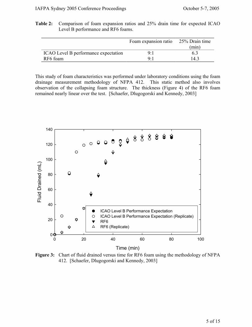
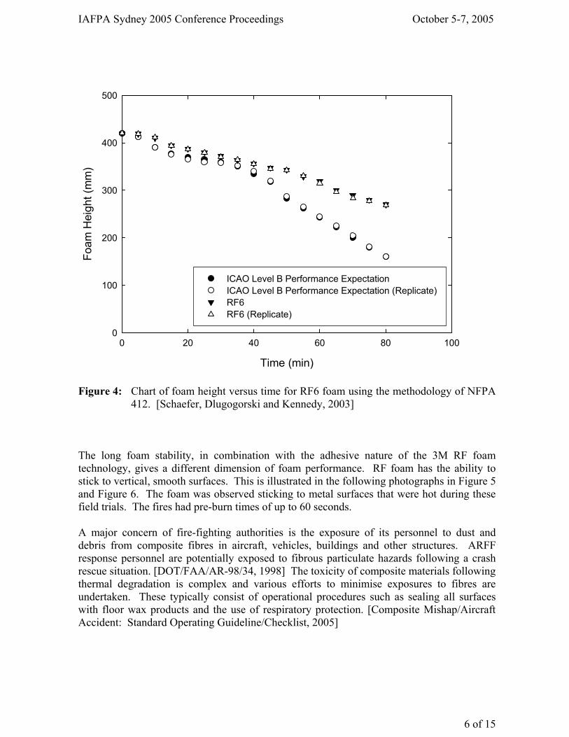
This study of foam characteristics was performed under laboratory conditions using the foam drainage measurement methodology of NFPA 412. This static method also involves observation of the collapsing foam structure. The thickness (Figure 4) of the RF6 foam remained nearly linear over the test. [Schaefer, Dlugogorski and Kennedy, 2003]
Time (min)
0 20 40 60 80 100
Flui
d D
rain
ed (m
L)
0
20
40
60
80
100
120
140
ICAO Level B Performance Expectation ICAO Level B Performance Expectation (Replicate) RF6 RF6 (Replicate)
Figure 3: Chart of fluid drained versus time for RF6 foam using the methodology of NFPA
412. [Schaefer, Dlugogorski and Kennedy, 2003]
IAFPA Sydney 2005 Conference Proceedings October 5-7, 2005
6 of 15
Figure 4: Chart of foam height versus time for RF6 foam using the methodology of NFPA
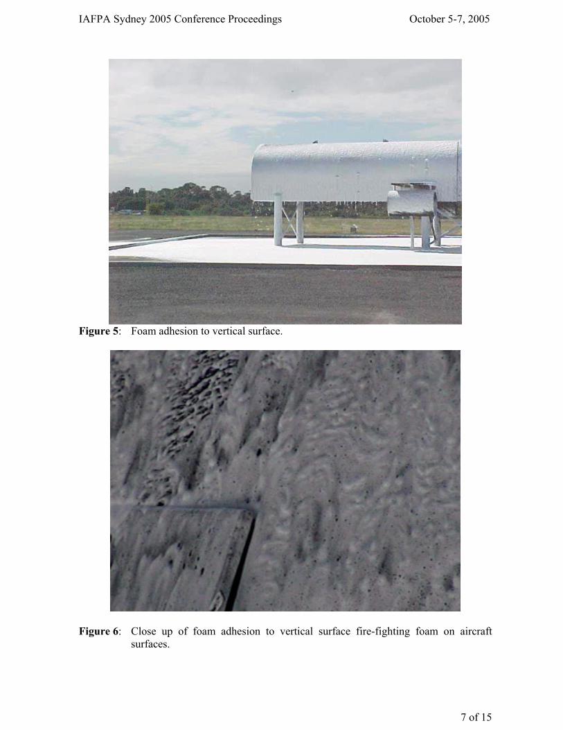
412. [Schaefer, Dlugogorski and Kennedy, 2003] The long foam stability, in combination with the adhesive nature of the 3M RF foam technology, gives a different dimension of foam performance. RF foam has the ability to stick to vertical, smooth surfaces. This is illustrated in the following photographs in Figure 5 and Figure 6. The foam was observed sticking to metal surfaces that were hot during these field trials. The fires had pre-burn times of up to 60 seconds. A major concern of fire-fighting authorities is the exposure of its personnel to dust and debris from composite fibres in aircraft, vehicles, buildings and other structures. ARFF response personnel are potentially exposed to fibrous particulate hazards following a crash rescue situation. [DOT/FAA/AR-98/34, 1998] The toxicity of composite materials following thermal degradation is complex and various efforts to minimise exposures to fibres are undertaken. These typically consist of operational procedures such as sealing all surfaces with floor wax products and the use of respiratory protection. [Composite Mishap/Aircraft Accident: Standard Operating Guideline/Checklist, 2005]
Time (min)
0 20 40 60 80 100
Foam
Hei
ght (
mm
)
0
100
200
300
400
500
ICAO Level B Performance ExpectationICAO Level B Performance Expectation (Replicate) RF6 RF6 (Replicate)
IAFPA Sydney 2005 Conference Proceedings October 5-7, 2005
7 of 15
Figure 5: Foam adhesion to vertical surface.
Figure 6: Close up of foam adhesion to vertical surface fire-fighting foam on aircraft
surfaces.
IAFPA Sydney 2005 Conference Proceedings October 5-7, 2005
8 of 15
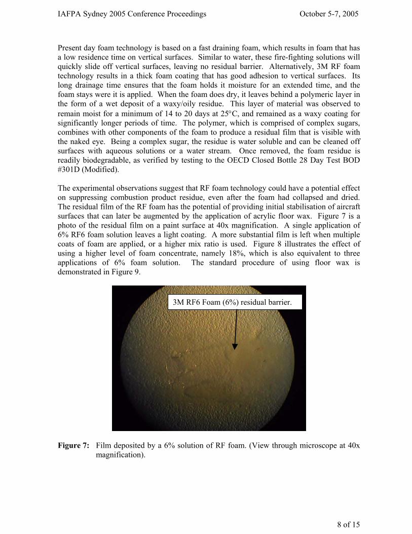
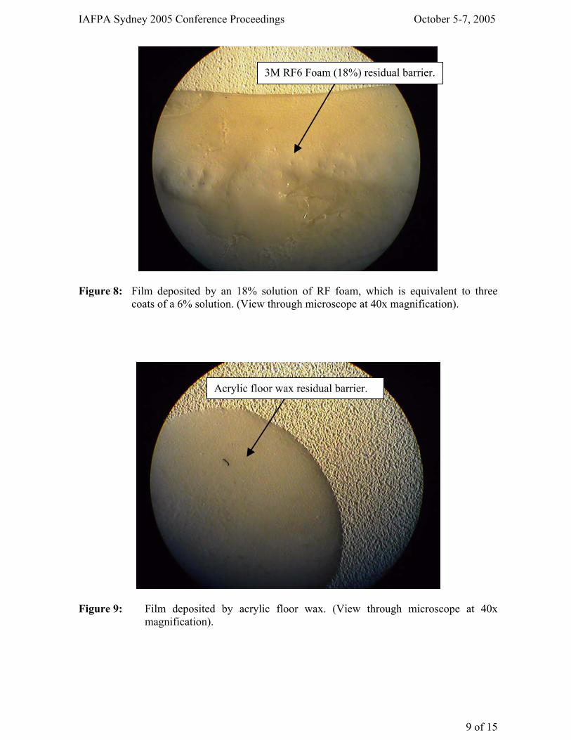
Present day foam technology is based on a fast draining foam, which results in foam that has a low residence time on vertical surfaces. Similar to water, these fire-fighting solutions will quickly slide off vertical surfaces, leaving no residual barrier. Alternatively, 3M RF foam technology results in a thick foam coating that has good adhesion to vertical surfaces. Its long drainage time ensures that the foam holds it moisture for an extended time, and the foam stays were it is applied. When the foam does dry, it leaves behind a polymeric layer in the form of a wet deposit of a waxy/oily residue. This layer of material was observed to remain moist for a minimum of 14 to 20 days at 25°C, and remained as a waxy coating for significantly longer periods of time. The polymer, which is comprised of complex sugars, combines with other components of the foam to produce a residual film that is visible with the naked eye. Being a complex sugar, the residue is water soluble and can be cleaned off surfaces with aqueous solutions or a water stream. Once removed, the foam residue is readily biodegradable, as verified by testing to the OECD Closed Bottle 28 Day Test BOD #301D (Modified). The experimental observations suggest that RF foam technology could have a potential effect on suppressing combustion product residue, even after the foam had collapsed and dried. The residual film of the RF foam has the potential of providing initial stabilisation of aircraft surfaces that can later be augmented by the application of acrylic floor wax. Figure 7 is a photo of the residual film on a paint surface at 40x magnification. A single application of 6% RF6 foam solution leaves a light coating. A more substantial film is left when multiple coats of foam are applied, or a higher mix ratio is used. Figure 8 illustrates the effect of using a higher level of foam concentrate, namely 18%, which is also equivalent to three applications of 6% foam solution. The standard procedure of using floor wax is demonstrated in Figure 9.
Figure 7: Film deposited by a 6% solution of RF foam. (View through microscope at 40x
magnification).
3M RF6 Foam (6%) residual barrier.
IAFPA Sydney 2005 Conference Proceedings October 5-7, 2005
9 of 15
Figure 8: Film deposited by an 18% solution of RF foam, which is equivalent to three
coats of a 6% solution. (View through microscope at 40x magnification).
Figure 9: Film deposited by acrylic floor wax. (View through microscope at 40x
magnification).
3M RF6 Foam (18%) residual barrier.
Acrylic floor wax residual barrier.
IAFPA Sydney 2005 Conference Proceedings October 5-7, 2005
10 of 15
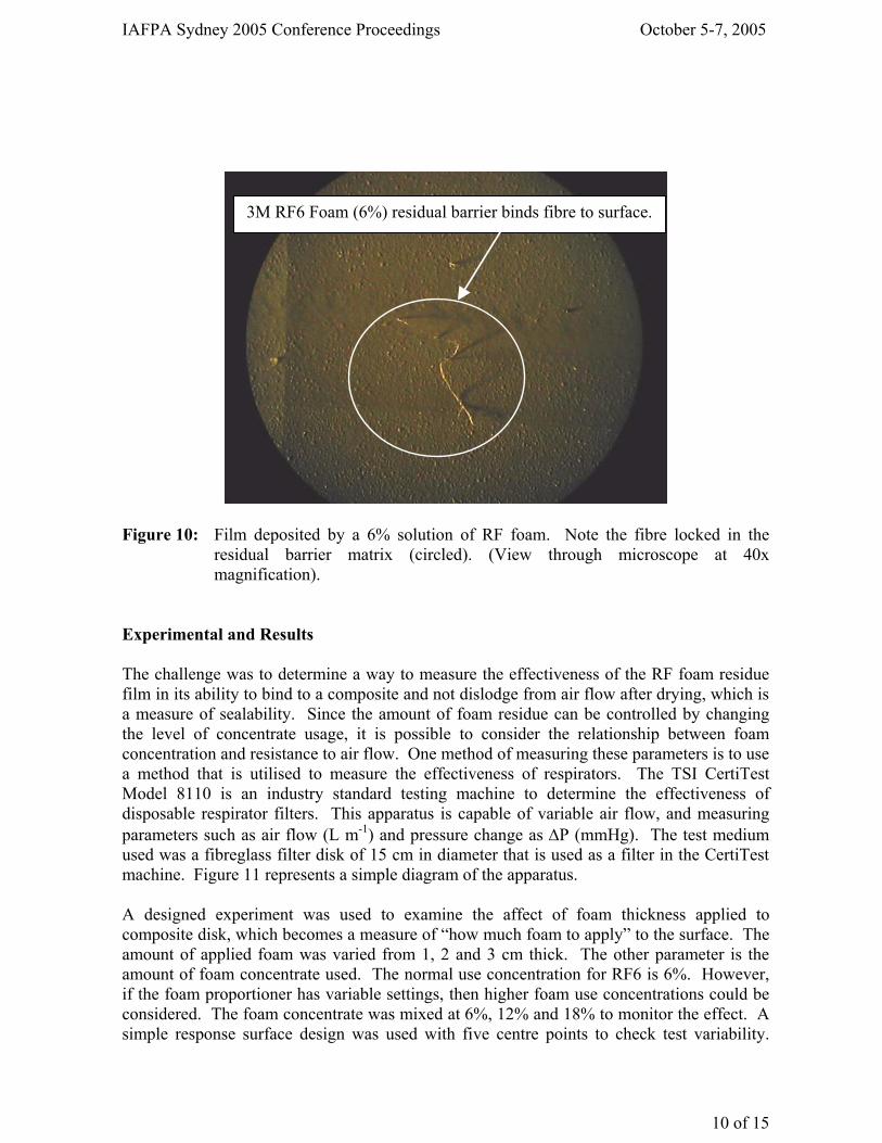
Figure 10: Film deposited by a 6% solution of RF foam. Note the fibre locked in the
residual barrier matrix (circled). (View through microscope at 40x magnification).
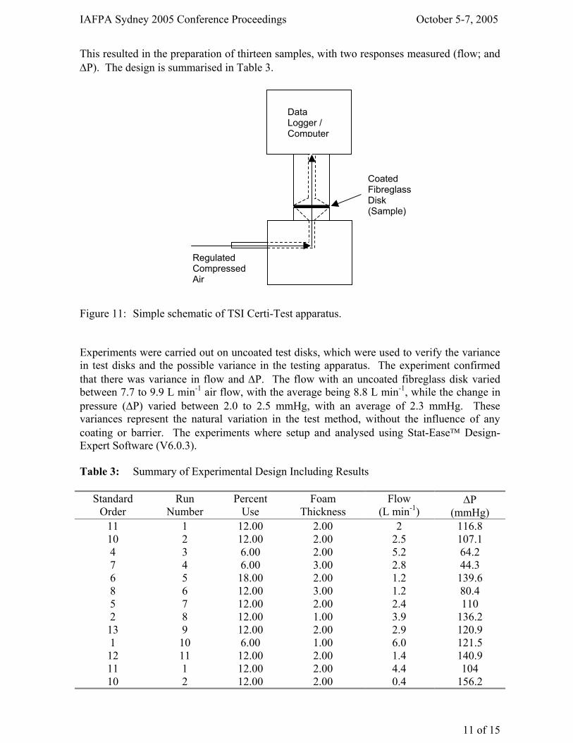
Experimental and Results The challenge was to determine a way to measure the effectiveness of the RF foam residue film in its ability to bind to a composite and not dislodge from air flow after drying, which is a measure of sealability. Since the amount of foam residue can be controlled by changing the level of concentrate usage, it is possible to consider the relationship between foam concentration and resistance to air flow. One method of measuring these parameters is to use a method that is utilised to measure the effectiveness of respirators. The TSI CertiTest Model 8110 is an industry standard testing machine to determine the effectiveness of disposable respirator filters. This apparatus is capable of variable air flow, and measuring parameters such as air flow (L m-1) and pressure change as ∆P (mmHg). The test medium used was a fibreglass filter disk of 15 cm in diameter that is used as a filter in the CertiTest machine. Figure 11 represents a simple diagram of the apparatus. A designed experiment was used to examine the affect of foam thickness applied to composite disk, which becomes a measure of “how much foam to apply” to the surface. The amount of applied foam was varied from 1, 2 and 3 cm thick. The other parameter is the amount of foam concentrate used. The normal use concentration for RF6 is 6%. However, if the foam proportioner has variable settings, then higher foam use concentrations could be considered. The foam concentrate was mixed at 6%, 12% and 18% to monitor the effect. A simple response surface design was used with five centre points to check test variability.
3M RF6 Foam (6%) residual barrier binds fibre to surface.
IAFPA Sydney 2005 Conference Proceedings October 5-7, 2005
11 of 15
This resulted in the preparation of thirteen samples, with two responses measured (flow; and ∆P). The design is summarised in Table 3. Figure 11: Simple schematic of TSI Certi-Test apparatus. Experiments were carried out on uncoated test disks, which were used to verify the variance in test disks and the possible variance in the testing apparatus. The experiment confirmed that there was variance in flow and ∆P. The flow with an uncoated fibreglass disk varied between 7.7 to 9.9 L min-1 air flow, with the average being 8.8 L min-1, while the change in pressure (∆P) varied between 2.0 to 2.5 mmHg, with an average of 2.3 mmHg. These variances represent the natural variation in the test method, without the influence of any coating or barrier. The experiments where setup and analysed using Stat-Ease Design- Expert Software (V6.0.3). Table 3: Summary of Experimental Design Including Results
Standard Order
Run Number
Percent Use
Foam Thickness
Flow (L min-1)
∆P (mmHg)
11 1 12.00 2.00 2 116.8 10 2 12.00 2.00 2.5 107.1 4 3 6.00 2.00 5.2 64.2 7 4 6.00 3.00 2.8 44.3 6 5 18.00 2.00 1.2 139.6 8 6 12.00 3.00 1.2 80.4 5 7 12.00 2.00 2.4 110 2 8 12.00 1.00 3.9 136.2 13 9 12.00 2.00 2.9 120.9 1 10 6.00 1.00 6.0 121.5 12 11 12.00 2.00 1.4 140.9 11 1 12.00 2.00 4.4 104 10 2 12.00 2.00 0.4 156.2
Regulated Compressed Air
Coated Fibreglass Disk (Sample)
Data Logger / Computer
IAFPA Sydney 2005 Conference Proceedings October 5-7, 2005
12 of 15
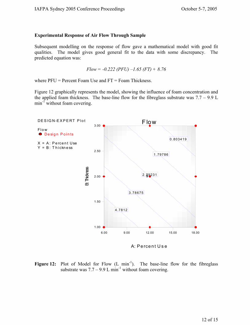
Experimental Response of Air Flow Through Sample Subsequent modelling on the response of flow gave a mathematical model with good fit qualities. The model gives good general fit to the data with some discrepancy. The predicted equation was:
Flow = -0.222 (PFU) –1.65 (FT) + 8.76 where PFU = Percent Foam Use and FT = Foam Thickness. Figure 12 graphically represents the model, showing the influence of foam concentration and the applied foam thickness. The base-line flow for the fibreglass substrate was 7.7 – 9.9 L min-1 without foam covering.
DE S IG N-E X P E RT P l o t
F l o wDe si g n P o i n ts
X = A : P e rce n t UseY = B : T h i ckn e ss
F low
A: Pe rce n t U s e
B: Th
ickne
ss
6.00 9.00 12.00 15.00 18.00
1.00
1.50
2.00
2.50
3.00
0 .803419
1.79786
2.79231
3.78675
4.7812
55555
Figure 12: Plot of Model for Flow (L min-1). The base-line flow for the fibreglass
substrate was 7.7 – 9.9 L min-1 without foam covering.
IAFPA Sydney 2005 Conference Proceedings October 5-7, 2005
13 of 15
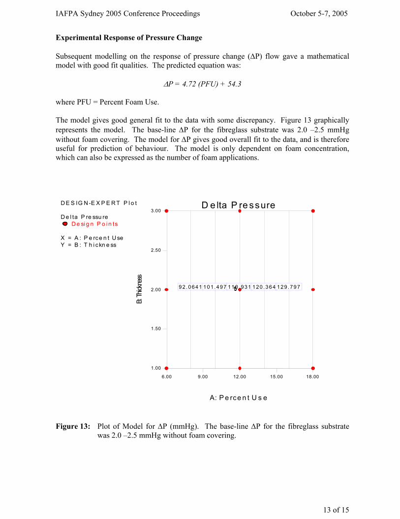
Experimental Response of Pressure Change Subsequent modelling on the response of pressure change (∆P) flow gave a mathematical model with good fit qualities. The predicted equation was:
∆P = 4.72 (PFU) + 54.3 where PFU = Percent Foam Use. The model gives good general fit to the data with some discrepancy. Figure 13 graphically represents the model. The base-line ∆P for the fibreglass substrate was 2.0 –2.5 mmHg without foam covering. The model for ∆P gives good overall fit to the data, and is therefore useful for prediction of behaviour. The model is only dependent on foam concentration, which can also be expressed as the number of foam applications.
D E S IG N -E X P E R T P l o t
D e l ta P re ssu reD e si g n P o i n ts
X = A : P e rce n t U seY = B : T h i ckn e ss
D e lta P re ssure
A: P e rce n t U s e
B: Th
ickne
ss
6.00 9.00 12.00 15.00 18.00
1.00
1.50
2.00
2.50
3.00
92 .0641 101 .497 110 .931 120 .364 129 .79755555
Figure 13: Plot of Model for ∆P (mmHg). The base-line ∆P for the fibreglass substrate
was 2.0 –2.5 mmHg without foam covering.
IAFPA Sydney 2005 Conference Proceedings October 5-7, 2005
14 of 15
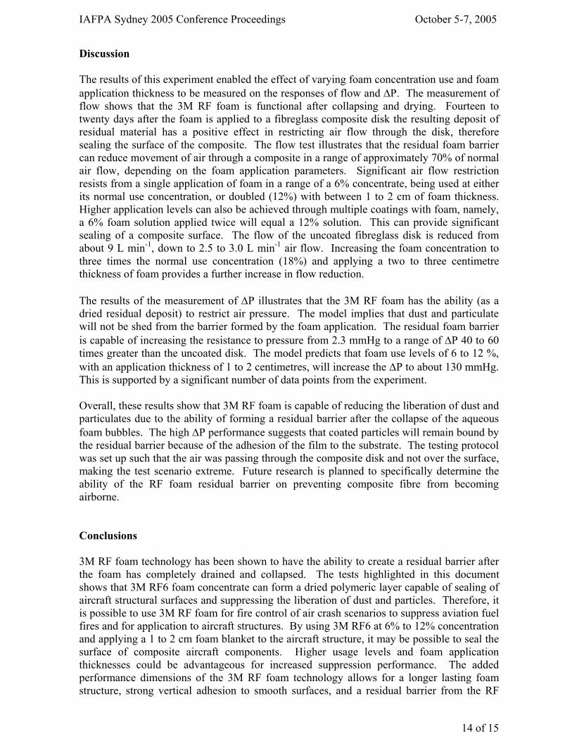
Discussion The results of this experiment enabled the effect of varying foam concentration use and foam application thickness to be measured on the responses of flow and ∆P. The measurement of flow shows that the 3M RF foam is functional after collapsing and drying. Fourteen to twenty days after the foam is applied to a fibreglass composite disk the resulting deposit of residual material has a positive effect in restricting air flow through the disk, therefore sealing the surface of the composite. The flow test illustrates that the residual foam barrier can reduce movement of air through a composite in a range of approximately 70% of normal air flow, depending on the foam application parameters. Significant air flow restriction resists from a single application of foam in a range of a 6% concentrate, being used at either its normal use concentration, or doubled (12%) with between 1 to 2 cm of foam thickness. Higher application levels can also be achieved through multiple coatings with foam, namely, a 6% foam solution applied twice will equal a 12% solution. This can provide significant sealing of a composite surface. The flow of the uncoated fibreglass disk is reduced from about 9 L min-1, down to 2.5 to 3.0 L min-1 air flow. Increasing the foam concentration to three times the normal use concentration (18%) and applying a two to three centimetre thickness of foam provides a further increase in flow reduction. The results of the measurement of ∆P illustrates that the 3M RF foam has the ability (as a dried residual deposit) to restrict air pressure. The model implies that dust and particulate will not be shed from the barrier formed by the foam application. The residual foam barrier is capable of increasing the resistance to pressure from 2.3 mmHg to a range of ∆P 40 to 60 times greater than the uncoated disk. The model predicts that foam use levels of 6 to 12 %, with an application thickness of 1 to 2 centimetres, will increase the ∆P to about 130 mmHg. This is supported by a significant number of data points from the experiment. Overall, these results show that 3M RF foam is capable of reducing the liberation of dust and particulates due to the ability of forming a residual barrier after the collapse of the aqueous foam bubbles. The high ∆P performance suggests that coated particles will remain bound by the residual barrier because of the adhesion of the film to the substrate. The testing protocol was set up such that the air was passing through the composite disk and not over the surface, making the test scenario extreme. Future research is planned to specifically determine the ability of the RF foam residual barrier on preventing composite fibre from becoming airborne. Conclusions 3M RF foam technology has been shown to have the ability to create a residual barrier after the foam has completely drained and collapsed. The tests highlighted in this document shows that 3M RF6 foam concentrate can form a dried polymeric layer capable of sealing of aircraft structural surfaces and suppressing the liberation of dust and particles. Therefore, it is possible to use 3M RF foam for fire control of air crash scenarios to suppress aviation fuel fires and for application to aircraft structures. By using 3M RF6 at 6% to 12% concentration and applying a 1 to 2 cm foam blanket to the aircraft structure, it may be possible to seal the surface of composite aircraft components. Higher usage levels and foam application thicknesses could be advantageous for increased suppression performance. The added performance dimensions of the 3M RF foam technology allows for a longer lasting foam structure, strong vertical adhesion to smooth surfaces, and a residual barrier from the RF
IAFPA Sydney 2005 Conference Proceedings October 5-7, 2005
15 of 15
foam polymeric resin system. The use of RF foam can augment the use of floor wax for stabilisation of aircraft composite surfaces between fire-fighting and post-crash stabilisation. The experimental results are supported by the photographic images of microscopic examination of the residual polymeric barrier. These images show the relative thickness and effectiveness of the polymeric layer when compared to acrylic floor wax. Part of the evidence supporting the functionality of the RF foam residual barrier is illustrated in Figure 10, which is a photograph of a large fibre locked in the polymeric matrix. The residual barrier of the 3M RF foam technology is not permanent and can be removed with water. If the residual barrier becomes damaged or compromised, it will not retain the same ability to suppress dust and particulate. The use of RF foam does not preclude the application of acrylic floor wax, which would augment the stability of the aircraft surfaces. The soft, and somewhat tacky, residual barrier will accept an acrylic wax coating. 3M RF foam technology does not remove the need for appropriate personal protective equipment (PPE), but potentially provides another means to help reduce exposure to particulate during emergency response operations. References DOT/FAA/AR-98/34 (1998), Health Hazards of Combustion Products From Aircraft Composite Materials, US Department of Transport, Office of Aviation Research, Washington DC, USA Composite Mishap/Aircraft Accident: Standard Operating Guideline/Checklist, (n.d.) Retrieved August 30, 2005, from http://www.arffwg.org/flash.htm ICAO (1990), Airport Services Manual; Part 1: Rescue and Fire-fighting, Chapter 8, pp. 29-32, 3rd Ed., International Civil Aviation Organization. Magrabi SA, Dlugogorski BZ and Jameson GJ (2002), “A comparative study of drainage characteristics in AFFF and FFFP compressed-air fire-fighting foams”, Fire Safety J 37, 21-52. NFPA 412 (1998), Standard for Evaluating Aircraft Rescue and Fire-Fighting Foam Equipment, National Fire Protection Association, Quincy, Massachusetts, USA. Schaefer TH, Dlugogorski BZ and Kennedy EM, (2003) "New non-fluorosurfactant-based formulations for replacement of class B foams", Proc Int Aviation Fire Prot Assoc, Singapore, CD-ROM, 1-28. US Mil-F-24385 (1992) Fire Extinguishing Agent, Aqueous Film-Forming Foam (AFFF) Liquid Concentrate, For Fresh and Sea Water, Military Specification (Navy).
EMEA Solberg Scandinavian aSradøyvegen 721 - olsvollstrandan-5938 SæbøvågennorwayTel: +47 56 34 97 00
AsiA-PAcific Solberg aSia Pacific PTy lTd3 charles StreetSt. Marys nSW 2760australiaTel: +61 2 9673 5300
AMEricAsThe Solberg coMPany1520 brookfield avenuegreen bay, Wi 54313USaTel: +1 920 593 9445
solbErgfoAM.coM
forM nUMber f-2012014 i ocT 2005
coPyrighT ©2013. all righTS reServed.Solberg® iS a TradeMarK of The Solberg coMPany or iTS affiliaTeS.
Related Documents