Network Manager IP Edition Version 4 Release 1 Topology Database Reference R4.1 E1

Welcome message from author
This document is posted to help you gain knowledge. Please leave a comment to let me know what you think about it! Share it to your friends and learn new things together.
Transcript

Network Manager IP EditionVersion 4 Release 1
Topology Database Reference
R4.1 E1
���

Network Manager IP EditionVersion 4 Release 1
Topology Database Reference
R4.1 E1
���

NoteBefore using this information and the product it supports, read the information in “Notices” on page 255.
This edition applies to version 4.1 of IBM Tivoli Network Manager IP Edition (product number 5724-S45) and to allsubsequent releases and modifications until otherwise indicated in new editions.
© Copyright IBM Corporation 2006, 2013.US Government Users Restricted Rights – Use, duplication or disclosure restricted by GSA ADP Schedule Contractwith IBM Corp.

Contents
About this publication . . . . . . . . viiIntended audience . . . . . . . . . . . . viiWhat this publication contains . . . . . . . . viiPublications . . . . . . . . . . . . . . viiiAccessibility . . . . . . . . . . . . . . xiTivoli technical training . . . . . . . . . . xiSupport and community information . . . . . . xiiConventions used in this publication . . . . . xiii
Chapter 1. NCIM topology database . . . 1
Chapter 2. About NCIM . . . . . . . . 3Topology database tasks . . . . . . . . . . 3Topology database architecture . . . . . . . . 3Topology database properties . . . . . . . . . 5Topology data . . . . . . . . . . . . . . 6
Domains and entities . . . . . . . . . . 6Relationships . . . . . . . . . . . . . 12
NCIM cache files . . . . . . . . . . . . 16SQL files for the NCIM schema. . . . . . . . 16
Chapter 3. Topology database queries 19Logging in to NCIM . . . . . . . . . . . 19Formatting used in the SQL queries . . . . . . 19Techniques used in the SQL queries . . . . . . 20
Choice of driving table . . . . . . . . . 20Aliasing . . . . . . . . . . . . . . 20Table joins . . . . . . . . . . . . . . 20Ordering the results of Informix 11.5 queries . . 21
Use of specific fields and tables in queries . . . . 21mainNodeEntityId field . . . . . . . . . 21entityType field . . . . . . . . . . . . 22Protocol endpoint tables . . . . . . . . . 22
Changing the command-line access password forthe topology database . . . . . . . . . . . 23Queries for domain information . . . . . . . 23
List all main nodes in a domain . . . . . . 23Count the number of entities in a domain . . . 25
Queries for main node information . . . . . . 26List all devices with class name and systemobject identifier . . . . . . . . . . . . 26List all IP addresses on all main node devices . . 28
Queries for containment information . . . . . . 30List all components on a device . . . . . . 30List all components on a device and showcomponent type . . . . . . . . . . . . 32Display the number of cards on each device . . 33Find all devices containing Three-Port GigabitEthernet cards . . . . . . . . . . . . 35Find entities within all cards. . . . . . . . 37
Queries for port and interface information . . . . 39List all interfaces on all devices. . . . . . . 39List all interfaces with specific attributes. . . . 40List all interfaces on all devices with interfacetype . . . . . . . . . . . . . . . . 41
List all IP addresses and the interfaces thatimplement them . . . . . . . . . . . . 44
Queries for connectivity information . . . . . . 46Types of connectivity . . . . . . . . . . 47Hierarchy modeling with the networkPipe andpipeComposition tables . . . . . . . . . 48Find devices connected to a named device . . . 48Find all devices connected to a named devicetogether with connecting interfaces . . . . . 50Identify all connections between routers . . . . 52
Queries for MPLS Traffic Engineered Tunnelinformation . . . . . . . . . . . . . . 54
List all Traffic Engineered tunnels . . . . . . 54Show interfaces utilized by Traffic Engineeredtunnels . . . . . . . . . . . . . . . 54Show Traffic Engineered tunnel configuration . . 55List supporting routers for a Traffic Engineeredtunnel . . . . . . . . . . . . . . . 55Show performance data for a Traffic Engineeredtunnel . . . . . . . . . . . . . . . 56
Queries for Radio Access Network information . . 57Find specific RAN entity types . . . . . . . 57Retrieve RAN connectivity . . . . . . . . 58Find RAN containment . . . . . . . . . 67Find RAN dependencies . . . . . . . . . 69
Queries for hosted services . . . . . . . . . 71Find all chassis devices hosting OSPF services . . 71
Queries for collection information . . . . . . . 72Show all PIM adjacencies . . . . . . . . . 72Show PIM adjacencies for a device . . . . . 72Find PIM enabled routers. . . . . . . . . 72Find all devices in each subnet . . . . . . . 73Find all devices in a given VPN . . . . . . 74
Queries for mapping and enumeration information 75Identify all the device hardware manufacturerslisted in the database . . . . . . . . . . 75Show all the entity types defined in the database 77
Extending NCIM . . . . . . . . . . . . 78Example of extending the database . . . . . 79Enabling polling and visualization using thecustom tags . . . . . . . . . . . . . 79Enabling visualization of custom attributes inTopoviz. . . . . . . . . . . . . . . 81
Chapter 4. NCIM topology databaseschemas . . . . . . . . . . . . . . 83Core schema . . . . . . . . . . . . . . 83Data schema . . . . . . . . . . . . . . 85
BGP . . . . . . . . . . . . . . . . 86Collections . . . . . . . . . . . . . 87Containment . . . . . . . . . . . . . 88Endpoints . . . . . . . . . . . . . . 89Geographical location . . . . . . . . . . 90GSM. . . . . . . . . . . . . . . . 91IP endpoints . . . . . . . . . . . . . 92
© Copyright IBM Corp. 2006, 2013 iii

MPLS traffic engineered (TE) tunnels . . . . . 93MPLS VPNs . . . . . . . . . . . . . 95OSPF . . . . . . . . . . . . . . . 96RAN collections . . . . . . . . . . . . 97RAN routing and location areas . . . . . . 98Services . . . . . . . . . . . . . . 99UMTS . . . . . . . . . . . . . . . 101VLANs . . . . . . . . . . . . . . 102
Chapter 5. Data dictionary . . . . . . 105NCIM topology database changes . . . . . . 105Core tables . . . . . . . . . . . . . . 107
aggregationDomain . . . . . . . . . . 108CIDRinfo . . . . . . . . . . . . . . 108classMembers . . . . . . . . . . . . 110collects . . . . . . . . . . . . . . 110connectActions . . . . . . . . . . . . 111connects . . . . . . . . . . . . . . 112connectSpeeds . . . . . . . . . . . . 113contains . . . . . . . . . . . . . . 114dependency . . . . . . . . . . . . . 114deviceFunction . . . . . . . . . . . . 115discoverySource . . . . . . . . . . . 115domainMembers . . . . . . . . . . . 116domainMgr . . . . . . . . . . . . . 117entityActions . . . . . . . . . . . . 118entityClass . . . . . . . . . . . . . 119entityData . . . . . . . . . . . . . 120entityDetails . . . . . . . . . . . . . 122entityNameCache . . . . . . . . . . . 123entityType . . . . . . . . . . . . . 124enumerations . . . . . . . . . . . . 127hostedService . . . . . . . . . . . . 129manager . . . . . . . . . . . . . . 129mappings . . . . . . . . . . . . . 130networkPipe. . . . . . . . . . . . . 131notes . . . . . . . . . . . . . . . 132pipeComposition . . . . . . . . . . . 132protocolEndPoint . . . . . . . . . . . 133topologyLinks . . . . . . . . . . . . 135
Core views . . . . . . . . . . . . . . 135discoveryOverview . . . . . . . . . . 135entity . . . . . . . . . . . . . . . 137interfaceDomain . . . . . . . . . . . 138interfaces . . . . . . . . . . . . . . 138mainNodeDetails . . . . . . . . . . . 141mainNodeDomain . . . . . . . . . . . 144
Entity attribute tables. . . . . . . . . . . 144atmEndPoint . . . . . . . . . . . . 144bgpAutonomousSystem . . . . . . . . . 145bgpCluster . . . . . . . . . . . . . 146bgpEndPoint . . . . . . . . . . . . 146bgpNetwork. . . . . . . . . . . . . 149bgpRouteAttribute. . . . . . . . . . . 149bgpService . . . . . . . . . . . . . 151computerSystem . . . . . . . . . . . 152cpu. . . . . . . . . . . . . . . . 159domainSummary . . . . . . . . . . . 159emsSystem . . . . . . . . . . . . . 160frameRelayEndPoint . . . . . . . . . . 160genericCollection . . . . . . . . . . . 161
genericRange . . . . . . . . . . . . 161geographicLocation . . . . . . . . . . 161geographicRegion . . . . . . . . . . . 162globalVlan . . . . . . . . . . . . . 162hsrpGroup . . . . . . . . . . . . . 163igmpEndPoint . . . . . . . . . . . . 163igmpGroup . . . . . . . . . . . . . 165igmpService . . . . . . . . . . . . . 165ipConnection . . . . . . . . . . . . 166ipEndPoint . . . . . . . . . . . . . 166ipMRouteDownstream . . . . . . . . . 167ipMRouteEndPoint . . . . . . . . . . 169ipMRouteGroup . . . . . . . . . . . 170ipMRouteMdt . . . . . . . . . . . . 170ipMRouteService . . . . . . . . . . . 171ipMRouteSource . . . . . . . . . . . 171ipMRouteUpstream . . . . . . . . . . 171ipPath . . . . . . . . . . . . . . . 173itnmService . . . . . . . . . . . . . 174lingerTime . . . . . . . . . . . . . 174localVlan . . . . . . . . . . . . . . 175managedStatus . . . . . . . . . . . . 175mplsTEService . . . . . . . . . . . . 176mplsTETunnel . . . . . . . . . . . . 177mplsTETunnelEndPoint . . . . . . . . . 179mplsTETunnelResource . . . . . . . . . 179mplsLSP . . . . . . . . . . . . . . 180multiplexer . . . . . . . . . . . . . 180netcoolAsmsRunning . . . . . . . . . . 180networkInterface . . . . . . . . . . . 180networkServiceEntityEndPoint. . . . . . . 184networkVpn . . . . . . . . . . . . . 184operatingSystem . . . . . . . . . . . 185ospfArea . . . . . . . . . . . . . . 188ospfEndPoint . . . . . . . . . . . . 188ospfNetworkLSA . . . . . . . . . . . 189ospfRoutingDomain . . . . . . . . . . 190ospfService . . . . . . . . . . . . . 190physicalBackplane . . . . . . . . . . . 191physicalCard . . . . . . . . . . . . 192physicalChassis. . . . . . . . . . . . 195physicalConnector . . . . . . . . . . . 198physicalFan . . . . . . . . . . . . . 199physicalOther . . . . . . . . . . . . 201physicalPowerSupply. . . . . . . . . . 203physicalSensor . . . . . . . . . . . . 204physicalSlot . . . . . . . . . . . . . 207pimEndpoint . . . . . . . . . . . . 208pimNetwork. . . . . . . . . . . . . 209pimService . . . . . . . . . . . . . 209portEndPoint . . . . . . . . . . . . 210ranBaseStation . . . . . . . . . . . . 211ranBaseStationController. . . . . . . . . 211ranCircuitSwitchedCore . . . . . . . . . 212ranGGSN. . . . . . . . . . . . . . 213ranGSMCell . . . . . . . . . . . . . 213ranLocationArea . . . . . . . . . . . 214ranMediaGateway . . . . . . . . . . . 215ranMobileSwitchingCentre . . . . . . . . 215ranMSS . . . . . . . . . . . . . . 216ranNodeB . . . . . . . . . . . . . 216
iv IBM Tivoli Network Manager IP Edition: Topology Database Reference

ranNodeBLocalCell . . . . . . . . . . 216ranPacketControlUnit. . . . . . . . . . 217ranPacketSwitchedCore . . . . . . . . . 217ranRadioCore . . . . . . . . . . . . 218ranRadioNetworkController . . . . . . . 219ranRoutingArea . . . . . . . . . . . 219ranSector . . . . . . . . . . . . . . 220ranSGSN . . . . . . . . . . . . . . 220ranTransceiver . . . . . . . . . . . . 221ranUtranCell . . . . . . . . . . . . 221rtExportList . . . . . . . . . . . . . 222rtImportList . . . . . . . . . . . . . 222snmpSystem. . . . . . . . . . . . . 223subnet . . . . . . . . . . . . . . . 224transmissionTp . . . . . . . . . . . . 224vlanCollection . . . . . . . . . . . . 225vlanTrunkEndPoint . . . . . . . . . . 225vpnRouteForwarding . . . . . . . . . . 226vpwsEndPoint . . . . . . . . . . . . 227vtpDomain . . . . . . . . . . . . . 227
Entity attribute views. . . . . . . . . . . 228backplane . . . . . . . . . . . . . 228chassis . . . . . . . . . . . . . . 229fan . . . . . . . . . . . . . . . . 233interface . . . . . . . . . . . . . . 234module . . . . . . . . . . . . . . 237other . . . . . . . . . . . . . . . 239psu . . . . . . . . . . . . . . . . 241sensor . . . . . . . . . . . . . . . 242slot . . . . . . . . . . . . . . . . 245sourceEms . . . . . . . . . . . . . 246
Common Data Model views . . . . . . . . 247
Appendix. Network Manager glossary 251
Notices . . . . . . . . . . . . . . 255Trademarks . . . . . . . . . . . . . . 257
Index . . . . . . . . . . . . . . . 259
Contents v

vi IBM Tivoli Network Manager IP Edition: Topology Database Reference
About this publication
IBM Tivoli Network Manager IP Edition provides detailed network discovery,device monitoring, topology visualization, and root cause analysis (RCA)capabilities. Network Manager can be extensively customized and configured tomanage different networks. Network Manager also provides extensive reportingfeatures, and integration with other IBM products, such as IBM Tivoli ApplicationDependency Discovery Manager, IBM Tivoli Business Service Manager and IBMSystems Director.
The IBM Tivoli Network Manager IP Edition Topology Database Reference describes theschemas of the database used for storing topology data in Network Manager.
Intended audienceThis publication is intended for system and network administrators who areresponsible for configuring IBM Tivoli Network Manager IP Edition.
IBM Tivoli Network Manager IP Edition works in conjunction with IBM TivoliNetcool/OMNIbus; this publication assumes that you understand how IBM TivoliNetcool/OMNIbus works. For more information on IBM Tivoli Netcool/OMNIbus,see the publications described in “Publications” on page viii.
What this publication contains
This publication contains the following sections:v Chapter 1, “NCIM topology database,” on page 1
Introduces the Network Connectivity and Inventory Model (NCIM) topologydatabase.
v Chapter 2, “About NCIM,” on page 3Provides an overview of the Network Connectivity and Inventory Model(NCIM) database.
v Chapter 3, “Topology database queries,” on page 19Provides sample SQL queries, which are based on real-world queries, as anexample of the kind of data that can be extracted, and as a basis for constructingfurther queries.
v Chapter 4, “NCIM topology database schemas,” on page 83Describes how the relationships between topology data are modelled.
v Chapter 5, “Data dictionary,” on page 105Describes the relational database tables that represent the topology model in theNCIM database.
© Copyright IBM Corp. 2006, 2013 vii
PublicationsThis section lists publications in the Network Manager library and relateddocuments. The section also describes how to access Tivoli publications online andhow to order Tivoli publications.
Your Network Manager library
The following documents are available in the Network Manager library:v IBM Tivoli Network Manager IP Edition Release Notes, GI11-9354-00
Gives important and late-breaking information about IBM Tivoli NetworkManager IP Edition. This publication is for deployers and administrators, andshould be read first.
v IBM Tivoli Network Manager Getting Started Guide, GI11-9353-00Describes how to set up IBM Tivoli Network Manager IP Edition after you haveinstalled the product. This guide describes how to start the product, make sure itis running correctly, and discover the network. Getting a good networkdiscovery is central to using Network Manager successfully. This guide describeshow to configure and monitor a first discovery, verify the results of thediscovery, configure a production discovery, and how to keep the networktopology up to date. Once you have an up-to-date network topology, this guidedescribes how to make the network topology available to Network Operators,and how to monitor the network. The essential tasks are covered in this shortguide, with references to the more detailed, optional, or advanced tasks andreference material in the rest of the documentation set.
v IBM Tivoli Network Manager IP Edition Product Overview, GC27-2759-00Gives an overview of IBM Tivoli Network Manager IP Edition. It describes theproduct architecture, components and functionality. This publication is foranyone interested in IBM Tivoli Network Manager IP Edition.
v IBM Tivoli Network Manager IP Edition Installation and Configuration Guide,SC27-2760-00Describes how to install IBM Tivoli Network Manager IP Edition. It alsodescribes necessary and optional post-installation configuration tasks. Thispublication is for administrators who need to install and set up IBM TivoliNetwork Manager IP Edition.
v IBM Tivoli Network Manager IP Edition Administration Guide, SC27-2761-00Describes administration tasks for IBM Tivoli Network Manager IP Edition, suchas how to administer processes, query databases and start and stop the product.This publication is for administrators who are responsible for the maintenanceand availability of IBM Tivoli Network Manager IP Edition.
v IBM Tivoli Network Manager IP Edition Discovery Guide, SC27-2762-00Describes how to use IBM Tivoli Network Manager IP Edition to discover yournetwork. This publication is for administrators who are responsible forconfiguring and running network discovery.
v IBM Tivoli Network Manager IP Edition Event Management Guide, SC27-2763-00Describes how to use IBM Tivoli Network Manager IP Edition to poll networkdevices, to configure the enrichment of events from network devices, and tomanage plug-ins to the Tivoli Netcool/OMNIbus Event Gateway, includingconfiguration of the RCA plug-in for root-cause analysis purposes. Thispublication is for administrators who are responsible for configuring andrunning network polling, event enrichment, root-cause analysis, and EventGateway plug-ins.
viii IBM Tivoli Network Manager IP Edition: Topology Database Reference

v IBM Tivoli Network Manager IP Edition Network Troubleshooting Guide,GC27-2765-00Describes how to use IBM Tivoli Network Manager IP Edition to troubleshootnetwork problems identified by the product. This publication is for networkoperators who are responsible for identifying or resolving network problems.
v IBM Tivoli Network Manager IP Edition Network Visualization Setup Guide,SC27-2764-00Describes how to configure the IBM Tivoli Network Manager IP Edition networkvisualization tools to give your network operators a customized workingenvironment. This publication is for product administrators or team leaders whoare responsible for facilitating the work of network operators.
v IBM Tivoli Network Manager IP Edition Management Database Reference,SC23-9906-00Describes the schemas of the component databases in IBM Tivoli NetworkManager IP Edition. This publication is for advanced users who need to querythe component databases directly.
v IBM Tivoli Network Manager IP Edition Topology Database Reference, SC27-2766-00Describes the schemas of the database used for storing topology data in IBMTivoli Network Manager IP Edition. This publication is for advanced users whoneed to query the topology database directly.
v IBM Tivoli Network Manager IP Edition Language Reference, SC27-2768-00Describes the system languages used by IBM Tivoli Network Manager IPEdition, such as the Stitcher language, and the Object Query Language. Thispublication is for advanced users who need to customize the operation of IBMTivoli Network Manager IP Edition.
v IBM Tivoli Network Manager IP Edition Perl API Guide, SC27-2769-00Describes the Perl modules that allow developers to write custom applicationsthat interact with the IBM Tivoli Network Manager IP Edition. Examples ofcustom applications that developers can write include Polling and DiscoveryAgents. This publication is for advanced Perl developers who need to write suchcustom applications.
v IBM Tivoli Monitoring for Tivoli Network Manager IP User's Guide, SC27-2770-00Provides information about installing and using IBM Tivoli Monitoring for IBMTivoli Network Manager IP Edition. This publication is for systemadministrators who install and use IBM Tivoli Monitoring for IBM TivoliNetwork Manager IP Edition to monitor and manage IBM Tivoli NetworkManager IP Edition resources.
Prerequisite publications
To use the information in this publication effectively, you must have someprerequisite knowledge, which you can obtain from the following publications:v IBM Tivoli Netcool/OMNIbus Installation and Deployment Guide, SC14-7604
Includes installation and upgrade procedures for Tivoli Netcool/OMNIbus, anddescribes how to configure security and component communications. Thepublication also includes examples of Tivoli Netcool/OMNIbus architectures anddescribes how to implement them.
v IBM Tivoli Netcool/OMNIbus User's Guide, SC14-7607Provides an overview of the desktop tools and describes the operator tasksrelated to event management using these tools.
v IBM Tivoli Netcool/OMNIbus Administration Guide, SC14-7605
About this publication ix
Describes how to perform administrative tasks using the TivoliNetcool/OMNIbus Administrator GUI, command-line tools, and process control.The publication also contains descriptions and examples of ObjectServer SQLsyntax and automations.
v IBM Tivoli Netcool/OMNIbus Probe and Gateway Guide, SC14-7608Contains introductory and reference information about probes and gateways,including probe rules file syntax and gateway commands.
v IBM Tivoli Netcool/OMNIbus Web GUI Administration and User's Guide SC14-7606Describes how to perform administrative and event visualization tasks using theTivoli Netcool/OMNIbus Web GUI.
Accessing terminology online
The IBM Terminology Web site consolidates the terminology from IBM productlibraries in one convenient location. You can access the Terminology Web site at thefollowing Web address:
http://www.ibm.com/software/globalization/terminology
Accessing publications online
IBM posts publications for this and all other Tivoli products, as they becomeavailable and whenever they are updated, to the Tivoli Information Center Website at:
http://publib.boulder.ibm.com/infocenter/tivihelp/v3r1/index.jsp
Note: If you print PDF documents on other than letter-sized paper, set the optionin the File > Print window that allows your PDF reading application to printletter-sized pages on your local paper.
Ordering publications
You can order many Tivoli publications online at the following Web site:
http://www.ibm.com/e-business/linkweb/publications/servlet/pbi.wss
You can also order by telephone by calling one of these numbers:v In the United States: 800-879-2755v In Canada: 800-426-4968
In other countries, contact your software account representative to order Tivolipublications. To locate the telephone number of your local representative, performthe following steps:1. Go to the following Web site:
http://www.ibm.com/e-business/linkweb/publications/servlet/pbi.wss2. Select your country from the list and click Go. The Welcome to the IBM
Publications Center page is displayed for your country.3. On the left side of the page, click About this site to see an information page
that includes the telephone number of your local representative.
x IBM Tivoli Network Manager IP Edition: Topology Database Reference

AccessibilityAccessibility features help users with a physical disability, such as restrictedmobility or limited vision, to use software products successfully.
Accessibility features
The following list includes the major accessibility features in Network Manager:v The console-based installer supports keyboard-only operation.v Network Manager provides the following features suitable for low vision users:
– All non-text content used in the GUI has associated alternative text.– Low-vision users can adjust the system display settings, including high
contrast mode, and can control the font sizes using the browser settings.– Color is not used as the only visual means of conveying information,
indicating an action, prompting a response, or distinguishing a visualelement.
v Network Manager provides the following features suitable for photosensitiveepileptic users:– Web pages do not contain anything that flashes more than two times in any
one second period.
The Network Manager Information Center is accessibility-enabled. The accessibilityfeatures of the information center are described in Accessibility and keyboardshortcuts in the information center.
Extra steps to configure Internet Explorer for accessibility
If you are using Internet Explorer as your web browser, you might need toperform extra configuration steps to enable accessibility features.
To enable high contrast mode, complete the following steps:1. Click Tools > Internet Options > Accessibility.2. Select all the check boxes in the Formatting section.
If clicking View > Text Size > Largest does not increase the font size, click Ctrl +and Ctrl -.
IBM® and accessibility
See the IBM Human Ability and Accessibility Center for more information aboutthe commitment that IBM has to accessibility.
Tivoli technical training
For Tivoli technical training information, refer to the following IBM TivoliEducation Web site:
http://www.ibm.com/software/tivoli/education
About this publication xi

Support and community informationUse IBM Support, Service Management Connect, and Tivoli user groups to connectwith IBM and get the help and information you need.
IBM Support
If you have a problem with your IBM software, you want to resolve it quickly. IBMprovides the following ways for you to obtain the support you need:
OnlineGo to the IBM Software Support site at http://www.ibm.com/software/support/probsub.html and follow the instructions.
IBM Support AssistantThe IBM Support Assistant (ISA) is a free local software serviceabilityworkbench that helps you resolve questions and problems with IBMsoftware products. The ISA provides quick access to support-relatedinformation and serviceability tools for problem determination. To installthe ISA software, go to http://www.ibm.com/software/support/isa
Tivoli user groups
Tivoli user groups are independent, user-run membership organizations thatprovide Tivoli users with information to assist them in the implementation ofTivoli Software solutions. Through these groups, members can share informationand learn from the knowledge and experience of other Tivoli users. Tivoli usergroups include the following members and groups:v 23,000+ membersv 144+ groups
Access the link for the Tivoli Users Group at www.tivoli-ug.org.
Service Management Connect
Access Service Management Connect at https://www.ibm.com/developerworks/servicemanagement/. Use Service Management Connect in the following ways:v Become involved with transparent development, an ongoing, open engagement
between other users and IBM developers of Tivoli products. You can access earlydesigns, sprint demonstrations, product roadmaps, and prerelease code.
v Connect one-on-one with the experts to collaborate and network about Tivoliand the (enter your community name here) community.
v Read blogs to benefit from the expertise and experience of others.v Use wikis and forums to collaborate with the broader user community.
xii IBM Tivoli Network Manager IP Edition: Topology Database Reference

Conventions used in this publicationThis publication uses several conventions for special terms and actions andoperating system-dependent commands and paths.
Typeface conventions
This publication uses the following typeface conventions:
Bold
v Lowercase commands and mixed case commands that are otherwisedifficult to distinguish from surrounding text
v Interface controls (check boxes, push buttons, radio buttons, spinbuttons, fields, folders, icons, list boxes, items inside list boxes,multicolumn lists, containers, menu choices, menu names, tabs, propertysheets), labels (such as Tip:, and Operating system considerations:)
v Keywords and parameters in text
Italic
v Citations (examples: titles of publications, diskettes, and CDsv Words defined in text (example: a nonswitched line is called a
point-to-point line)v Emphasis of words and letters (words as words example: "Use the word
that to introduce a restrictive clause."; letters as letters example: "TheLUN address must start with the letter L.")
v New terms in text (except in a definition list): a view is a frame in aworkspace that contains data.
v Variables and values you must provide: ... where myname represents....
Monospace
v Examples and code examplesv File names, programming keywords, and other elements that are difficult
to distinguish from surrounding textv Message text and prompts addressed to the userv Text that the user must typev Values for arguments or command options
Bold monospace
v Command names, and names of macros and utilities that you can typeas commands
v Environment variable names in textv Keywordsv Parameter names in text: API structure parameters, command
parameters and arguments, and configuration parametersv Process namesv Registry variable names in textv Script names
About this publication xiii

Operating system-dependent variables and paths
This publication uses environment variables without platform-specific prefixes andsuffixes, unless the command applies only to specific platforms. For example, thedirectory where the Network Manager core components are installed is representedas NCHOME.
On UNIX systems, preface environment variables with the dollar sign $. Forexample, on UNIX, NCHOME is $NCHOME.
xiv IBM Tivoli Network Manager IP Edition: Topology Database Reference
Chapter 1. NCIM topology database
The Network Connectivity and Inventory Model (NCIM) topology database is arelational database that Network Manager uses to consolidate topology data aboutthe physical and logical composition of devices, layer 1, layer 2, and 3 connectivity,routing protocols and network technologies such as OSPF, BGP and MPLS Layer 3VPNs.
Usage considerations
This information about the NCIM database assumes that you are familiar withrelational databases. It also assumes that you are familiar with SQL querytechniques used to extract data from relational databases. You can use these querytechniques to query the NCIM database to obtain topology data. Expert users canmanipulate data in the NCIM database using insert, update, and delete statements.Related reference:“Techniques used in the SQL queries” on page 20The SQL query examples use a variety of techniques that are aimed at extractinginformation efficiently. Use this information to familiarize yourself with thetechniques used in SQL queries.
© Copyright IBM Corp. 2006, 2013 1

2 IBM Tivoli Network Manager IP Edition: Topology Database Reference
Chapter 2. About NCIM
Use this information to understand how NCIM works, what you can use NCIMfor, and the how the NCIM database is structured to store data, and supportqueries and extensibility.Related tasks:“Extending NCIM” on page 78To store custom data on entities, and enable network operators to view customdata in network maps, extend the NCIM database.
Topology database tasksYou can use the NCIM topology database to perform the tasks, such as extractingdata topology using SQL queries, exporting data from the topology database tothird-party applications, and including data from third-party sources and fromcustomized discoveries by extending the database.
Use the NCIM topology database to perform the following tasks:
Extracting dataYou can write SQL queries to extract topology data from NCIM. SQLqueries can be made using ncp_oql as well as using third-party tools.
Integrating with third-party applicationsYou can export data from the topology database to third-party applications.In order to do this, you must understand the structure of the database.
Extending the databaseYou can extend the database to include data from third-party sources andfrom customized discoveries. For example, discovery stitchers may beconfigured to look up customer details from a third-party source based onIP address.
Topology database architectureUse this information to understand how the NCIM topology database works.
The following figure shows how Network Manager populates NCIM, and showshow the topology data is shared and accessed by different processes withinNetwork Manager.
© Copyright IBM Corp. 2006, 2013 3

Network Manager populates NCIM by means of the Discovery engine, ncp_disco,and Topology Manager, ncp_model, processes.
The topology data in NCIM can be shared and accessed by the following processesand applications:
�1� TopoVizUsed for displaying topology maps.
�2� Structure BrowserUsed for navigating within the containment structure of devices in thetopology.
�3� Asset reportingUsed for asset reporting software.
�4� Integrations with third-party applicationsUsed for example provisioning software that requires regularly updatedtopology data from Network Manager. These activities require knowledgeof programming languages such as Java™ and Perl.
Network
StructureBrowser
NCIMtopologydatabase
Third party
SQLqueries
Assetreporting
TopoViz
NetworkManager
1
2
34
Figure 1. NCIM working with Network Manager
4 IBM Tivoli Network Manager IP Edition: Topology Database Reference
Topology database propertiesUse this information to understand how the NCIM topology database is structuredto store data, and support queries and extensibility.
NCIM data storage
The NCIM relational database are divided into core tables and attribute tables.Core tables define all entities within NCIM together with the relationships betweenthese entities. Attribute tables contain attribute data for each entity; they arespecific to Network Manager.
NCIM database structure
Base information for the discovered network resources and relationships is heldwithin the entityData table. Resource-specific attribute data is held inproduct-specific extension tables that typically have a foreign key relationship withthe core-model entityData table.
The NCIM topology database also holds meta-data in tables such as the mappings,enumerations, CIDRInfo and deviceFunction tables. You can query this data to getuseful, typically human-readable information for device attributes. For example,you can determine the user-friendly name of BGP AS numbers.
The NCIM topology database has been designed to be familiar to users who workwith the MODEL database in legacy object-oriented format. This is most apparentin the naming of NCIM relational database tables and fields. Where possible, thenaming is the same as that used in MODEL.
Multiple domain queries
NCIM allows multiple network domains to be stored in the databasesimultaneously. A domain is a scoped set of entities discovered and managed byan application, such as Network Manager.
A single SQL query on the NCIM database can extract data from multipledomains. This is in contrast to Object Query Language (OQL) queries on theTopology manager, ncp_model, topology database, which are able to extractinformation only from a single domain at a time.
Extensibility
The NCIM topology database can hold additional data that is collected during acustomized discovery. For example, discovery stitchers can be configured to lookup customer details from a third-party source based on an IP address. It is possibleto configure MODEL to populate NCIM with this additional data and to configureNCIM to store this additional data in the form of key-value pairs.
Continuing the example, you might configure NCIM to store a customer name andcustomer type, associated with each main node entity discovered. It is also possibleto modify NCIM to create new multicolumn tables and configure MODEL topopulate these tables following a customized discovery. These modifications enableNCIM to store more custom data. For example, you might want to store a set ofdata on each customer associated with an IP address.
Chapter 2. About NCIM 5
Related concepts:“Domains”A domain is a scoped set of entities that are discovered and managed by anapplication, such as Network Manager. NCIM holds entity data related to multipledomains.
Topology dataWhen the network is discovered, both core NCIM tables and entity attribute tablesare updated with topology data. These tables include Layer 1, Layer 2, Layer 3,device structure, routing protocol, containment, and technology-specificinformation.
The NCIM tables are case sensitive for MySQL on Unix platforms and appear inlower case or mixed case. For MySQL on Windows and for all the other databaseson all platforms they are not case-sensitive.
The core and entity attribute tables are listed in the data dictionary.Related concepts:Chapter 5, “Data dictionary,” on page 105The NCIM topology database schema is made up of a set of relational databasetables that represent the topology model.
Domains and entitiesThe NCIM topology database models network domains and entities within thosedomains.
DomainsA domain is a scoped set of entities that are discovered and managed by anapplication, such as Network Manager. NCIM holds entity data related to multipledomains.
For more information on domains, see the IBM Tivoli Network Manager IP EditionNetwork Troubleshooting Guide and the IBM Tivoli Network Manager IP EditionInstallation and Configuration Guide.
EntitiesA Network Manager discovery returns many different types of entity. If youunderstand the entities that you might encounter, you can more easily restrict yourqueries to return only required information.
Basic information about discovered network resources is held within theentityData table. Resource-specific attribute data is held in product-specificextension tables that typically have a foreign key relationship with the core-modelentityData table. Information on relationships between discovered networkresources, such as containment and connectivity, is also held in tables, such as thecontains and connects tables.
Records in the entityData table are at least related to a given instance and thedomainMgr, manager, and domainMembers tables.
Discovered resources held in the entityData table can be any of the followingtypes:
6 IBM Tivoli Network Manager IP Edition: Topology Database Reference

v Physical and logical entities, including devices and their physical and logicalcharacteristics, such as slots, cards, ports, and interfaces, and the relationshipsbetween them.
v Protocol end points represent protocol or technology-specific information that istypically associated with an entity representing a port or interface resource.
v Device collections, including MPLS VPNs, global VLANs and subnets.v Hosted services, including BGP and OSPF services hosted on a device.
Network Manager populates the database with information about discovered layer1, layer 2 and layer 3 entities. To uniquely identify entities as they are discovered,the NCIM database uses a unique key, entityId. The entityId column appears in alldatabase tables that reference entities.
For example, the entityId column appears in the core entityData table, as well asin the physicalChassis, networkInterface, andphysicalPowerSupplyS other entityattribute tables.
The following table describes the discovery-related entities that are stored in theNCIM database.
Table 1. Network Manager entities
Entity type Entity NCIM table Description
0 Unknown
1 Chassis physicalChassis Main node device.
2 Interface networkInterface Interfaces with entityType 2 can bediscovered and polled.
3 Logical Interface Interfaces with entityType 3 are inferred butare not directly accessible. Hot StandbyRouting Protocol (HSRP) virtual IPinterfaces are an example of logicalinterfaces.
4 Local VLAN localVlan VLAN port on a main node device.
5 Module physicalCard Card within a switch or router. The termmodule is used to avoid confusion with theterm card which is used in layer 1networks.
6 PSU physicalPowerSupply Power® supply unit within a main nodedevice.
7 Logical Collection Examples of logical collections includeMPLS VPNs, global VLANs and subnets.NCIM can also model OSPF areas.
8 Daughter Card The child of a network card.
9 Fan physicalFan Fan component within a main node device.
10 Backplane physicalBackplane Backplane component within a main nodedevice. Backplanes usually contain slotentities.
11 Slot physicalSlot Slot component within a main node device.Slots usually contain module entities.
12 Sensor physicalSensor Sensor component within a main nodedevice.
13 Virtual Router virtualRouter Represents a instance of a virtual routerwithin a chassis device.
Chapter 2. About NCIM 7
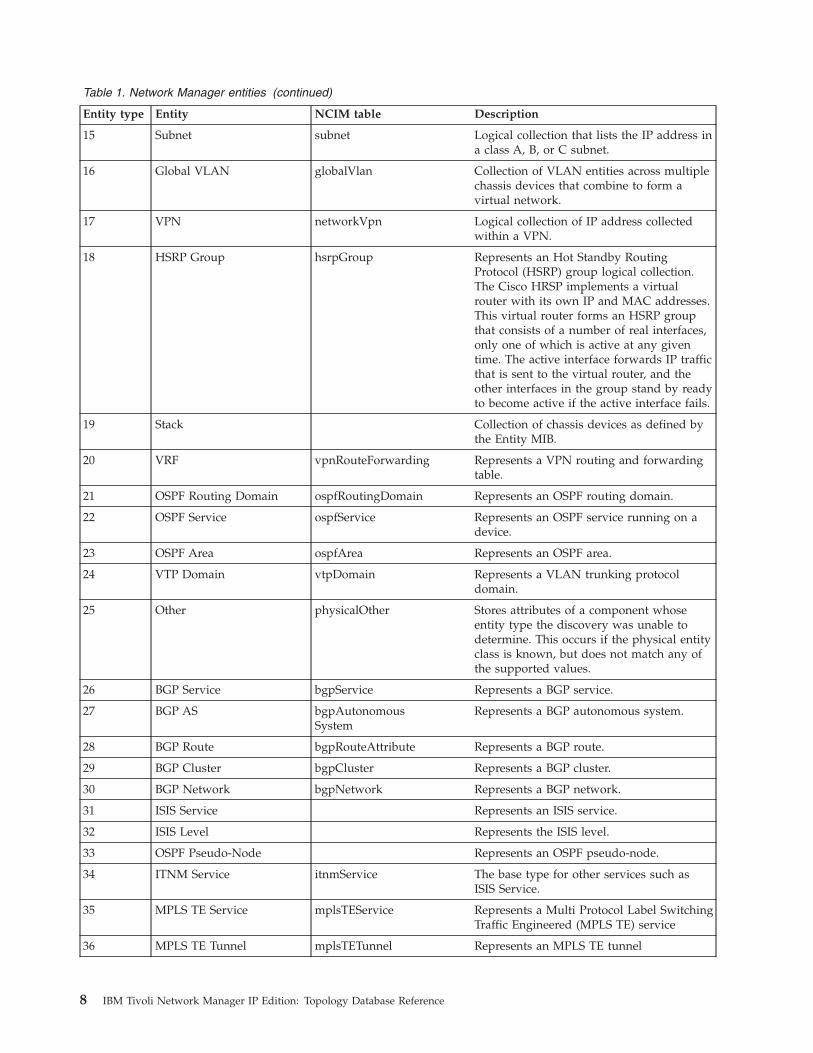
Table 1. Network Manager entities (continued)
Entity type Entity NCIM table Description
15 Subnet subnet Logical collection that lists the IP address ina class A, B, or C subnet.
16 Global VLAN globalVlan Collection of VLAN entities across multiplechassis devices that combine to form avirtual network.
17 VPN networkVpn Logical collection of IP address collectedwithin a VPN.
18 HSRP Group hsrpGroup Represents an Hot Standby RoutingProtocol (HSRP) group logical collection.The Cisco HRSP implements a virtualrouter with its own IP and MAC addresses.This virtual router forms an HSRP groupthat consists of a number of real interfaces,only one of which is active at any giventime. The active interface forwards IP trafficthat is sent to the virtual router, and theother interfaces in the group stand by readyto become active if the active interface fails.
19 Stack Collection of chassis devices as defined bythe Entity MIB.
20 VRF vpnRouteForwarding Represents a VPN routing and forwardingtable.
21 OSPF Routing Domain ospfRoutingDomain Represents an OSPF routing domain.
22 OSPF Service ospfService Represents an OSPF service running on adevice.
23 OSPF Area ospfArea Represents an OSPF area.
24 VTP Domain vtpDomain Represents a VLAN trunking protocoldomain.
25 Other physicalOther Stores attributes of a component whoseentity type the discovery was unable todetermine. This occurs if the physical entityclass is known, but does not match any ofthe supported values.
26 BGP Service bgpService Represents a BGP service.
27 BGP AS bgpAutonomousSystem
Represents a BGP autonomous system.
28 BGP Route bgpRouteAttribute Represents a BGP route.
29 BGP Cluster bgpCluster Represents a BGP cluster.
30 BGP Network bgpNetwork Represents a BGP network.
31 ISIS Service Represents an ISIS service.
32 ISIS Level Represents the ISIS level.
33 OSPF Pseudo-Node Represents an OSPF pseudo-node.
34 ITNM Service itnmService The base type for other services such asISIS Service.
35 MPLS TE Service mplsTEService Represents a Multi Protocol Label SwitchingTraffic Engineered (MPLS TE) service
36 MPLS TE Tunnel mplsTETunnel Represents an MPLS TE tunnel
8 IBM Tivoli Network Manager IP Edition: Topology Database Reference

Table 1. Network Manager entities (continued)
Entity type Entity NCIM table Description
37 MPLS TE Resource mplsTETunnelResource
Represents an MPLS TE resource
38 MPLS LSP mplsLSP Represents an MPLS Label Switch Path(LSP)
40 IP Connection ipConnection Represents a connection using TCP/IP.
41 PIM Service pimService Represents a Protocol IndependentMulticast (PIM) service.
42 PIM Network pimNetwork Represents a PIM network.
43 ipMRouteService ipMRouteService Represents an IP Multicast Routing service.
44 ipMRouteUpstreamElement
ipMRouteUpstream Stores the upstream (RPF) route statisticsfor each device or Multicast DistributionTree (MDT).
45 ipMRouteDownstreamElement
Stores the downstream route statistics perdevice or MDT.
46 ipMRouteMdt Collection ipMRouteMdt Stores the Collection entities representingthe MDTs for each Multicast Source orGroup.
47 ipMRouteSource Element ipMRouteSource Represents Multicast Sources, as containedby the MDT.
48 ipMRouteGroup Element ipMRouteGroup Represents Multicast Groups, as containedby the MDT.
49 IP Path ipPath Represents a network path between IPdevices.
50 IP End point ipEndPoint Represents a logical IP end point that isimplemented by a physical interface.
51 VLAN Trunk End point vlanTrunkEndPoint Represents a logical VLAN trunk end pointthat is implemented by a physical interface.
52 Frame Relay End point frameRelayEndPoint Represents a logical Frame Relay end pointthat is implemented by a physical interface.
53 OSPF End point ospfEndPoint Represents a logical OSPF end point that isimplemented by a physical interface.
54 ATM End point atmEndPoint Represents a logical ATM end point that isimplemented by a physical interface.
55 VPWS End point vpwsEndPoint Represents a logical VPWS end point that isimplemented by a physical interface.
56 BGP End Point bgpEndPoint Represents a logical BGP end point that isimplemented by a physical interface.
57 ISIS End Point Represents a logical ISIS end point that isimplemented by a physical interface.
58 MPLS Tunnel End Point mplsTETunnelEndPoint
Represents a logical MPLS tunnel end pointthat is implemented by a physical interface.
59 TCP/UDP End Point Represents a logical TCP/UDP end pointthat is implemented by a physical interface.
60 PIM End Point pimEndpoint Represents the Protocol IndependentMulticast (PIM) end points discovered inthe network and their associated attributes.
Chapter 2. About NCIM 9
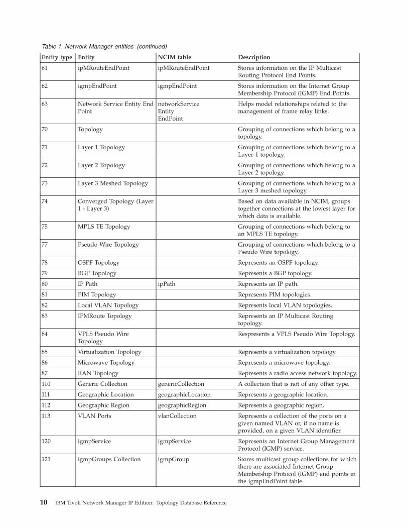
Table 1. Network Manager entities (continued)
Entity type Entity NCIM table Description
61 ipMRouteEndPoint ipMRouteEndPoint Stores information on the IP MulticastRouting Protocol End Points.
62 igmpEndPoint igmpEndPoint Stores information on the Internet GroupMembership Protocol (IGMP) End Points.
63 Network Service Entity EndPoint
networkServiceEntityEndPoint
Helps model relationships related to themanagement of frame relay links.
70 Topology Grouping of connections which belong to atopology.
71 Layer 1 Topology Grouping of connections which belong to aLayer 1 topology.
72 Layer 2 Topology Grouping of connections which belong to aLayer 2 topology.
73 Layer 3 Meshed Topology Grouping of connections which belong to aLayer 3 meshed topology.
74 Converged Topology (Layer1 - Layer 3)
Based on data available in NCIM, groupstogether connections at the lowest layer forwhich data is available.
75 MPLS TE Topology Grouping of connections which belong toan MPLS TE topology.
77 Pseudo Wire Topology Grouping of connections which belong to aPseudo Wire topology.
78 OSPF Topology Represents an OSPF topology.
79 BGP Topology Represents a BGP topology.
80 IP Path ipPath Represents an IP path.
81 PIM Topology Represents PIM topologies.
82 Local VLAN Topology Represents local VLAN topologies.
83 IPMRoute Topology Represents an IP Multicast Routingtopology.
84 VPLS Pseudo WireTopology
Respresents a VPLS Pseudo Wire Topology.
85 Virtualization Topology Represents a virtualization topology.
86 Microwave Topology Represents a microwave topology.
87 RAN Topology Represents a radio access network topology.
110 Generic Collection genericCollection A collection that is not of any other type.
111 Geographic Location geographicLocation Represents a geographic location.
112 Geographic Region geographicRegion Represents a geographic region.
113 VLAN Ports vlanCollection Represents a collection of the ports on agiven named VLAN or, if no name isprovided, on a given VLAN identifier.
120 igmpService igmpService Represents an Internet Group ManagementProtocol (IGMP) service.
121 igmpGroups Collection igmpGroup Stores multicast group collections for whichthere are associated Internet GroupMembership Protocol (IGMP) end points inthe igmpEndPoint table.
10 IBM Tivoli Network Manager IP Edition: Topology Database Reference

Table 1. Network Manager entities (continued)
Entity type Entity NCIM table Description
122 VSI (Virtual SwitchInstance)
virtualSwitchInstance Represents a virtual switch instance (VSI)configured on a Provider Edge (PE) devicethat is associated with a Virtual PrivateLAN Service (VPLS) Virtual PrivateNetwork (VPN) instance.
123 Data Center Represents a data center.
124 Virtual Cluster virtualCluster Represents a cluster of virtual machines.
125 Virtual ManagementService
virtualMgmtService Represents a virtual management service.
126 Hypervisor hypervisor Represents a hypervisor.
127 Port Group portGroup Represents a port group.
128 EMS System emsSystem Represents an EMS system accessed by acollector.
130 RAN GSM Cell ranGSMCell Represents a GSM cell.
131 RAN UTRAN Cell ranUtranCell Represents a UTRAN cell.
132 RAN Sector ranSector Represents a RAN sector.
133 RAN NodeB Local Cell ranNodeBLocalCell Represents a NodeB Local Cell.
134 RAN Location Area ranLocationArea Represents a RAN Location Area.
135 RAN Routing Area ranRoutingArea Represents a RAN Routing Area.
136 RAN Packet Core Represents RAN packet switch core entity.
137 RAN Circuit Core Represents a RAN circuit switched coreentity.
138 RAN Radio Core ranRadioCore Represents a RAN radio core entity.
139 RAN Transceiver ranTransceiver Represents a RAN transceiver.
Related reference:“entityType” on page 124The entityType table provides a comprehensive list of every entity type in NCIM.It belongs to the category entities.
entityData table and entity viewInformation on entities is held in the entityData table in Network Managerversions 3.9 and later. This table replaces the entity table used in earlier versions.To ensure backward compatibility an entity view has been created to hold thesame data as the entity table from earlier versions.
The difference between the entityData table and the earlier entity table is thatentities in the entityData can be members of more than one domain. In versions 3.8and earlier, an entity in the entity table could only be a member of a singledomain.
In order to facilitate this, the domainMgrId field that was in the earlier entitytables does not appear in the entityData table. Instead, in versions 3.9 and later anew domainMembers table maps entityId values from the entityData table to thedomainMgrId values from the domainMgr table. This enables a single entity to bea member of multiple domains.
Chapter 2. About NCIM 11
In versions 3.9 and later the entity view is created by joining the two tables,entityData and domainMembers.Related reference:“domainMembers” on page 116The domainMembers table stores information on membership of entities withindomains. This table belongs to the category domains.“domainMgr” on page 117The domainMgr table stores data on network domains. This table belongs to thecategory domains.“entity” on page 137The entity view joins data from the entityData and domainMembers tables and isequivalent to the entity table that existed in Network Manager versions 3.8 andearlier.The entity view stores data on entities and includes the domainMgrId,which the domain in which the entity is located.“entityData” on page 120The entityData table stores data on entities. This table belongs to the categoryentities.
Protocol-specific dataDevice entities, usually interfaces, can be associated with protocol-specific data.One example is the association of a device interface with the IP addressing data.Ports and interfaces can also be associated with other data, including ATM, BGPand OSPF protocol endpoints.
NCIM associates protocol-specific information with entities such as interfaces,using protocol endpoint tables. Examples of protocol endpoint tables are theatmEndPoint and ipEndPoint tables.
Technology-specific dataNCIM models a range of different network technologies, including IP, VLANs, andMPLS VLANs.Related reference:“ipEndPoint” on page 166The ipEndPoint table represents an IP end point and includes relevant data. Theendpoint is implemented by a physical interface, as modeled in theprotocolEndPoint table.
RelationshipsThe NCIM topology database models relationships between entities.
Connectivity dataConnectivity data defines how entities are connected in the network. It includesconnections between different devices, and VLAN-related connections within thesame device. Connectivity information is stored in the topologyLinks, networkPipe,and pipeComposition tables.
Bidirectional connections are only entered into the database once, either from the“A” end to the “Z” end or from the “Z” end to the “A” end. Therefore, SQLqueries that extract connectivity data must check for the connection in eitherdirection.
12 IBM Tivoli Network Manager IP Edition: Topology Database Reference

Representation of connectivity at different layers of the topology
The NCIM database represents the connectivity of entities in different independentlayers. Therefore representation of connectivity at layer 2 is representedindependently of the connectivity at layer 3. Each connection is associated with atopology entity.
Representation of connectivity within sub-topologies
The NCIM database represents complex connectivity scenarios. For example,within the MPLS VPN realm, NCIM can model the layer 3 connection between aprovider-edge (PE) router and multiple customer-edge (CE) routers. Connectivitybetween multiple devices that form a mini-topology is defined in thetopologyLinks table.Related reference:“Find devices connected to a named device” on page 48This query identifies all main node devices connected to a single specified mainnode device.
Containment dataContainment data defines logical and physical containment within your network.A containment model is generated at the end of the discovery process when thenetwork topology is created. This model reflects the real-world topology of thenetwork that is being modelled, in a physical, logical or business-oriented sense.
Overview of containment
Containment is a key principle of the network model. Containers are objects thatcan "hold" both elements and other containers. Elements and containers canrepresent logical or physical entities. You can put any object within a container andeven mix different objects within the same container.
An example of physical containment is a chassis containing network interface cards;the network interface cards can themselves contain individual ports. An exampleof logical containment is a set of ports or interfaces being contained by a particularVLAN. Network Manager also uses VLAN objects to model containment. VLANobjects are created by the stitchers. They contain all the interfaces that exist on eachVLAN.
Use of the containment model
When generated, the default containment model represents both physical andlogical containment:v The physical containment model enables you to perform device management
down to the port level.v The logical containment model shows how objects are contained within logical
containers that do not necessarily exist in the physical sense. One example is aVLAN container, which is a logical grouping of devices, cards, and ports that arenot necessarily physically connected together or in the same location. Thedefault logical containment model is based on VLAN containment.
Chapter 2. About NCIM 13
VLAN naming:
Network Manager uses different naming conventions. One approach is to identifythe entity name, card and port numbers of specific ports, in the format EntityName[ card [ port ] ].
For example, port 12 on card 1 of chassis A is identified as A[ 1 [ 12 ] ].
By using stitchers, VLAN names can also be modified to reflect the businesscontext in which a given VLAN is used.
The naming used also depends on configuration of the product. This means thatinterface naming might be used; for example, Se4/0.
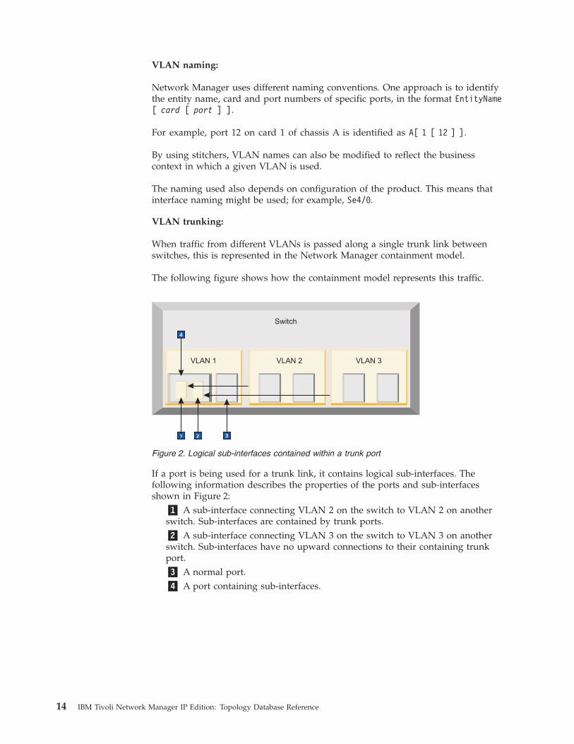
VLAN trunking:
When traffic from different VLANs is passed along a single trunk link betweenswitches, this is represented in the Network Manager containment model.
The following figure shows how the containment model represents this traffic.
If a port is being used for a trunk link, it contains logical sub-interfaces. Thefollowing information describes the properties of the ports and sub-interfacesshown in Figure 2:
�1� A sub-interface connecting VLAN 2 on the switch to VLAN 2 on anotherswitch. Sub-interfaces are contained by trunk ports.�2� A sub-interface connecting VLAN 3 on the switch to VLAN 3 on anotherswitch. Sub-interfaces have no upward connections to their containing trunkport.�3� A normal port.�4� A port containing sub-interfaces.
1 2 33
Switch
VLAN 1 VLAN 2 VLAN 3
34
Figure 2. Logical sub-interfaces contained within a trunk port
14 IBM Tivoli Network Manager IP Edition: Topology Database Reference
Customization of the containment model:
The containment model can be customized. This customization is an advancedfeature of the discovery process. To generate a custom containment model, youmust either modify the existing stitchers, or write a new stitcher and configure theexisting stitchers to run the new stitcher during the creation of the networktopology.
Two example stitchers, ExampleContainment1.stch and ExampleContainment2.stchare supplied to help you modify the containment model. These stitchers can beexecuted by removing the comments before the ExecuteStitcher(); statements atthe end of the CreateScratchTopology.stch stitcher.
These stitchers are stored in the following directory: $NCHOME/precision/disco/stitchers/.
For a syntax definition of the stitcher language, see the IBM Tivoli Network ManagerIP Edition Language Reference.
DependenciesWhen one entity in a system cannot meaningfully function without another entityit is said to be dependent. Dependencies can be defined by the containment model.A container can be dependent upon the objects it contains.
Network Manager applications take dependencies into account. The root-causeanalysis (RCA) engine (a plug-in to the Event Gateway, ncp_g_event), for example,can consider dependencies when performing root cause analysis of network faults.
Collection dataCollection data defines logical collections. Collections are defined in the collectstable. Examples of logical collections defined within NCIM include MPLS VPNs,global VLANs, and subnets.
NCIM can also model OSPF areas. Each row in the collects table holds a pair ofentity identifiers: the collecting entity, for example the VPN, and one of the entitieswithin that collecting entity.Related reference:“Find all devices in a given VPN” on page 74This query identifies all of the VPNs listed in the database. For each VPN thequery provides the name of that VPN and the list of IP addresses collected withinthat subnet. The IP address collected within a VPN might refer to main nodes orinterfaces; typically they refer to interfaces.“collects” on page 110The collects table stores data on collections of entities, such as subnets and MPLSVPNs. This table belongs to the category collections.
Chapter 2. About NCIM 15

Hosted servicesA hosted service is a service or application running on a specific device. Forexample, a device can host BGP or OSPF services. NCIM can also model the factthat a software application, is running on a workstation.Related reference:“Find all chassis devices hosting OSPF services” on page 71This query identifies all devices that are hosting OSPF services. These devices areserving as routers within an autonomous system (AS). Each device identified hasan IP address and a separate OSPF router IP address.
NCIM cache filesTopology updates are held in a set of files called the NCIM cache files.
There is one cache file for each type of update message and the name of eachcache file reflects the content. The format of each file matches the data in thencimCache database tables. The cache files are as follows:v NCHOME/var/precision/Store.Cache.ncimCache.collects.DOMAIN
v NCHOME/var/precision/Store.Cache.ncimCache.connectActions.DOMAIN
v NCHOME/var/precision/Store.Cache.ncimCache.connects.DOMAIN
v NCHOME/var/precision/Store.Cache.ncimCache.contains.DOMAIN
v NCHOME/var/precision/Store.Cache.ncimCache.dependency.DOMAIN
v NCHOME/var/precision/Store.Cache.ncimCache.domainMembers.DOMAIN
v NCHOME/var/precision/Store.Cache.ncimCache.entityActions.DOMAIN
v NCHOME/var/precision/Store.Cache.ncimCache.entityData.DOMAIN
v NCHOME/var/precision/Store.Cache.ncimCache.hostedService.DOMAIN
v NCHOME/var/precision/Store.Cache.ncimCache.lingerTime.DOMAIN
v NCHOME/var/precision/Store.Cache.ncimCache.managedStatus.DOMAIN
v NCHOME/var/precision/Store.Cache.ncimCache.pipeComposition.DOMAIN
v NCHOME/var/precision/Store.Cache.ncimCache.protocolEndPoint.DOMAIN
Where DOMAIN is the current domain.
SQL files for the NCIM schemaThe NCIM database schema is contained within several SQL files. The following isa list of SQL files that contain the schema.
The files are as follows:
DB2
$NCHOME/precision/scripts/sql/db2/createPrecisionMgmtTables.sql
$NCHOME/precision/scripts/sql/db2/createNetCoolCoreDb.sql
MySQL
$NCHOME/precision/scripts/sql/mysql/createPrecisionMgmtTables.sql
$NCHOME/precision/scripts/sql/mysql/createNetCoolCoreDb.sql
Oracle
$NCHOME/precision/scripts/sql/oracle/createPrecisionMgmtTables.sql
$NCHOME/precision/scripts/sql/oracle/createNetCoolCoreDb.sql
16 IBM Tivoli Network Manager IP Edition: Topology Database Reference

IDS
$NCHOME/precision/scripts/sql/informix/createPrecisionMgmtTables.sql
$NCHOME/precision/scripts/sql/informix/createNetCoolCoreDb.sql
The schema files below are common to all database products.v $NCHOME/precision/scripts/sql/data/populateMappings.sql
v $NCHOME/precision/scripts/sql/data/populateEnumerations.sql
v $NCHOME/precision/scripts/sql/data/populateDeviceFunction.sql
v $NCHOME/precision/scripts/sql/data/populateDefaults.sql
The database schema specific to Network Manager is contained in thecreatePrecisionIPDb.sql file.
The directory location of the Network Manager database schema is as follows:
DB2
$NCHOME/precision/scripts/sql/db2/createPrecisionIPDb.sql
MySQL
$NCHOME/precision/scripts/sql/mysql/createPrecisionIPDb.sql
Oracle
$NCHOME/precision/scripts/sql/oracle/createPrecisionIPDb.sql
IDS
$NCHOME/precision/scripts/sql/informix/createPrecisionIPDb.sql
To better understand how to formulate queries for purposes of correlating,analyzing, or reporting data, you can view these files, but do not attempt tomodify them.
Chapter 2. About NCIM 17

18 IBM Tivoli Network Manager IP Edition: Topology Database Reference
Chapter 3. Topology database queries
Use these sample SQL queries, which are based on real-world queries, as anexample of the kind of data that can be extracted, and as a basis for constructingfurther queries.
All the queries are presented in standard SQL syntax compatible with anyrelational database management system (RDBMS). Where specialist syntax for aspecific RDBMS is used, this is highlighted.
Tip: This information assumes that you are familiar with SQL syntax. For moreinformation about SQL, refer to an appropriate SQL tutorial or reference text.
Note: Earlier versions of this documentation contained a section on Extending theNCIM topology database. This section has now been replaced by the new topologyenrichment features. For more information see the Enriching the topology chapterwithin IBM Tivoli Network Manager IP Edition Discovery Guide.
Logging in to NCIMLog in to NCIM to run an SQL query that retrieves topology data.
To log in to NCIM using ncp_oql you must provide a valid NCIM user name andpassword. The default user name for the NCIM database user is ncim. The defaultpassword is ncim.
To log in to NCIM enter the following command:
ncp_oql -domain DOMAIN -service ncim -username USERNAME -password PASSWORD
Use the tabular display format capabilities of the ncp_oql command. The -tabularoption is useful when retrieving only a small number of columns. For moreinformation on the ncp_oql command, see the IBM Tivoli Network Manager IPEdition Administration Guide.
Formatting used in the SQL queriesThe SQL queries are formatted for readability.
The following formatting is used:v SQL keywords, such as SELECT and INNER JOIN, are presented in uppercase.v Code is spaced to aid scanning.v Each piece of data extracted by a SELECT statement is presented on a separate
line.v Capitalization is used within table and field names. For example, in the field
name mainNodeEntityId the M, E, and I are capitalized.
Note: Capitalization of table and field names is not required in the SQL queriesthat you submit to NCIM except if you are running NCIM on MySQL underUNIX. In this case, table names within SQL queries to the names of tables arecase sensitive, but field names are not.
© Copyright IBM Corp. 2006, 2013 19

Techniques used in the SQL queriesThe SQL query examples use a variety of techniques that are aimed at extractinginformation efficiently. Use this information to familiarize yourself with thetechniques used in SQL queries.Related reference:“Find devices connected to a named device” on page 48This query identifies all main node devices connected to a single specified mainnode device.
Choice of driving tableOne of the most important design decisions when creating a query is the choice ofdriving table. The choice of driving table is particularly important for ensuring theefficiency of queries.
The driving table is the table from which rows of data are first selected. Data isthen added from other tables by joining these tables, initially to the driving table.Therefore, choose the driving table so that a minimum of rows are initiallyselected. This ensures that the query is as efficient as possible. In many of thesample queries, the driving table is the domainMgr table, as there are generallyvery few rows in this table. This is in contrast to the entityData table, whichgenerally holds tens or hundreds of thousands of rows.
AliasingAliasing is the use of a temporary name for a column, sub-query or table within aquery.
Common reasons for using aliasing include:v Brevity: For example, use e to refer to the entityData table.v Distinguishing between table data in a meaningful way: For example, use
eComponent to refer to the entityData table when extracting component datafrom this table. Use eMainNode to refer to the entityData table when extractingmain node data from the table.
Aliasing can also be applied to columns, functions, and subqueries. For example,aliasing can be used to rename a results column.
Table joinsUse table joins to combine records from one or more tables. Two types of table joinare used, INNER JOIN and OUTER JOIN.
OUTER JOINAn OUTER JOIN table join preserves all the rows in one or both tables,even when they do not have corresponding rows in the other tables beingqueried. An example of when an OUTER JOIN table join is useful is if youwant to retrieve all interface and IP addressing data where applicable,bearing in mind that some interfaces may not have IP addresses.Commonly used outer joins include:
LEFT OUTER JOINRetains all records from the left table even if the join predicatedoes not find any matching record in the right table.
20 IBM Tivoli Network Manager IP Edition: Topology Database Reference
RIGHT OUTER JOINRetains all records from the right table even if the join predicatedoes not find any matching record in the left table.
INNER JOINAn INNER JOIN table join between tables combines the records from oneor more tables based on a given join predicate to produce a record set thatincorporates rows and columns from each table included in the join.Typically, a common attribute, such as the NCIM entityId, is used toretrieve sets of associated records. For example, an inner join could be usedto retrieve all of the records that contain other resources by joining theentity.entityId and contains.containingEntityId attributes.
Ordering the results of Informix 11.5 queriesInformix® 11.5 orders results in the same way as other databases, but you cannotuse functions within the ORDER BY clause. If you use an Informix NCIMdatabase, you must use different syntax to order the results. Informix 11.7 supportsORDER BY clauses.
Ordering queries using ORDER BY
In the example queries given in this information, a function in the ORDER BYclause is sometimes used to order the results, for example, ORDER BY LOWER(value).For Informix databases, this does not work.
If you want to order by a function-processed column, you must either:v Order on the value without the function, for example
SELECT valueORDER BY value
v Add the column to the SELECT statement first, for exampleSELECT LOWER(value) "orderedValue"ORDER BY orderedValue
Use of specific fields and tables in queriesYou can write more efficient SQL queries by making careful use of certain strategicfields and tables.
mainNodeEntityId fieldThe mainNodeEntityId field in the entityData table specifies the main node of theentity. This field provides a shortcut to the main node for a particular entity,avoiding the need to traverse the entire containment tree.
The mainNodeEntityId field is relevant only for entities that are wholly containedwithin a single main node device. It therefore has a non-NULL value only forentities that are related to a single main node device, such as:v The main node itselfv Physical and logical device components, such as interfaces, modules, PSUs,
sensors, backplanes, and fansv Logical interfaces entities on the main node, such as IP endpoints and VLAN
trunk endpointsv Local VLANs, which are local VLAN entities contained within a single main
node device. The interfaces contained by this VLAN are constrained to onlythose interfaces contained within the main node device.
Chapter 3. Topology database queries 21

Entities that are related to multiple main node devices, such as VPNs and globalVLANs, have a NULL value in the mainNodeEntityId field.
To retrieve only the entities that are wholly contained within a single main nodedevice, use an INNER JOIN statement on the entityData table. This statementensures that only entities that have a non-NULL value in the mainNodeEntityIdfield are retrieved.
entityType fieldThe entityType field can be used in SQL queries to limit the type of componentdata that is retrieved.
For example, if you specify the entity type 2, which corresponds to interfaces, in anSQL query, only component data of the type "interface" is retrieved. The entitytype of each entity is specified in the entityType field of the entityData table.
Protocol endpoint tablesThe protocolEndPoint and ipEndPoint tables can be used in SQL queries toidentify the IP addresses that are implemented by the device interfaces.
protocolEndPointThis table associates a device entity, usually an interface, withprotocol-specific information associated with that device entity. The mostcommon example of the contents of the protocolEndPoint table is a row ofdata that associates a device interface with the IP addressing dataassociated with that interface. The protocolEndPoint table refers toprotocol-specific information, such as IP addressing data, using an entityID.
ipEndPointThis table contains the IP addressing data.
Protocols other than IP have their own protocol endpoint tables, for example:v atmEndPoint table for ATMv bgpEndPoint for Border Gateway Protocol (BGP)v frameRelayEndPoint for Frame Relayv igmpEndPoint for Internet Group Multicast Protocol (IGMP)v ipmRouteEndPoint for IP Multicast routesv mplsTeTunnelEndPoint for Traffic Engineering tunnelsv OSPFEndPoint table for OSPFv pimEndPoint for Protocol Independent Multicastv portEndPoint for portsv vlanTrunkEndPoint table for VLAN trunksv vpwsEndPoint for Virtual Private Wire ServicesRelated reference:“protocolEndPoint” on page 133The protocolEndPoint table allows a higher-level connection to be defined in termsof lower-level connections. It associates a device entity, usually an interface, withprotocol-specific information associated with that device entity. TheprotocolEndPoint table belongs to the category connectivity.
22 IBM Tivoli Network Manager IP Edition: Topology Database Reference

Changing the command-line access password for the topologydatabase
For security reasons, change the password for command-line access to the topologydatabase regularly. The password must be encrypted.
Remember: You must also regularly change the password for Topoviz GUI access.
To change the password for command-line access:1. Change the password in the topology database. Refer to your database
documentation for instructions on how to do this.2. Change the password used by Tivoli Common Reporting by configuring the
data source properties for reports. For more information on configuring datasource properties for reporting, see the IBM Tivoli Network Manager IP EditionAdministration Guide.
3. To encrypt the password, enter the following command: ncp_crypt -passwordpassword
4. Paste the encrypted password into the DbLogins.DOMAIN.cfg file, whereDOMAIN is the name of your network domain. Repeat this step for eachnetwork domain.
5. Paste the encrypted password into the MibDbLogins.cfg file.
After changing the password, you can use the NCHOME/precision/scripts/perl/scripts/ncp_db_access.pl script to verify access. For more information on thencp_db_access.pl script, see the IBM Tivoli Network Manager IP EditionAdministration Guide.
Queries for domain informationThese queries retrieve information relevant to an entire domain or multipledomains. A domain is a scoped set of entities discovered and managed by anapplication. Sample queries extract information on the number of devices in adomain, names of devices in a domain, and so on.
Tip: A single SQL query on the NCIM database can extract data from multipledomains, whereas queries on the MODEL topology database, which can extractinformation from only a single domain at a time.
List all main nodes in a domainThis query provides a list of all main nodes in the database for a specified domain,or for all domains. The query provides the entity ID of the main node togetherwith the entity name.
Entity IDThe unique primary key of the entity within the entityData table. This isan integer value assigned to the entity by the database. Entities are notonly main nodes. Entities include any device component present in thedatabase, and other items recorded in the database, such as collections oflogical or physical network elements, for example, VPNs and VLANs.
Entity nameA string value used to refer to the entity. If the entity is a device, then theentity name might be the IP address of the device or the device name.
Note: Entity names are unique only within a given domain.
Chapter 3. Topology database queries 23
Example
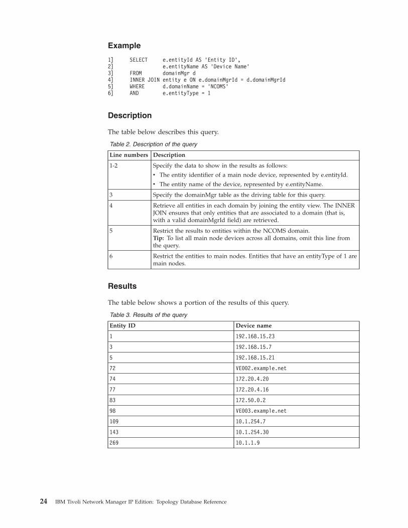
1]2]3]4]5]6]
SELECT e.entityId AS ’Entity ID’,e.entityName AS ’Device Name’
FROM domainMgr dINNER JOIN entity e ON e.domainMgrId = d.domainMgrIdWHERE d.domainName = ’NCOMS’AND e.entityType = 1
Description
The table below describes this query.
Table 2. Description of the query
Line numbers Description
1-2 Specify the data to show in the results as follows:
v The entity identifier of a main node device, represented by e.entityId.
v The entity name of the device, represented by e.entityName.
3 Specify the domainMgr table as the driving table for this query.
4 Retrieve all entities in each domain by joining the entity view. The INNERJOIN ensures that only entities that are associated to a domain (that is,with a valid domainMgrId field) are retrieved.
5 Restrict the results to entities within the NCOMS domain.Tip: To list all main node devices across all domains, omit this line fromthe query.
6 Restrict the entities to main nodes. Entities that have an entityType of 1 aremain nodes.
Results
The table below shows a portion of the results of this query.
Table 3. Results of the query
Entity ID Device name
1 192.168.15.23
3 192.168.15.7
5 192.168.15.21
72 VE002.example.net
74 172.20.4.20
77 172.20.4.16
83 172.50.0.2
98 VE003.example.net
109 10.1.254.7
143 10.1.254.30
269 10.1.1.9
24 IBM Tivoli Network Manager IP Edition: Topology Database Reference
Related reference:“Choice of driving table” on page 20One of the most important design decisions when creating a query is the choice ofdriving table. The choice of driving table is particularly important for ensuring theefficiency of queries.
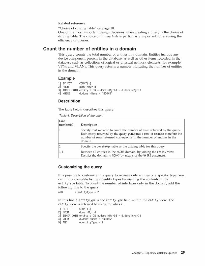
Count the number of entities in a domainThis query counts the total number of entities in a domain. Entities include anydevice component present in the database, as well as other items recorded in thedatabase such as collections of logical or physical network elements, for example,VPNs and VLANs. This query returns a number indicating the number of entitiesin the domain.
Example1] SELECT COUNT(*)2] FROM domainMgr d3] INNER JOIN entity e ON e.domainMgrId = d.domainMgrId4] WHERE d.domainName = ’NCOMS’
Description
The table below describes this query:
Table 4. Description of the query
Linenumber(s) Description
1 Specify that we wish to count the number of rows returned by the query.Each entity returned by the query generates a row of results; therefore thenumber of rows returned corresponds to the number of entities in thedomain.
2 Specify the domainMgr table as the driving table for this query.
3-4 Retrieve all entities in the NCOMS domain, by joining the entity view.Restrict the domain to NCOMS by means of the WHERE statement.
Customizing the query
It is possible to customize this query to retrieve only entities of a specific type. Youcan find a complete listing of entity types by viewing the contents of theentityType table. To count the number of interfaces only in the domain, add thefollowing line to the query:AND e.entityType = 2
In this line e.entityType is the entityType field within the entity view. Theentity view is referred to using the alias e.1] SELECT COUNT(*)2] FROM domainMgr d3] INNER JOIN entity e ON e.domainMgrId = d.domainMgrId4] WHERE d.domainName = ’NCOMS’5] AND e.entityType = 2
Chapter 3. Topology database queries 25
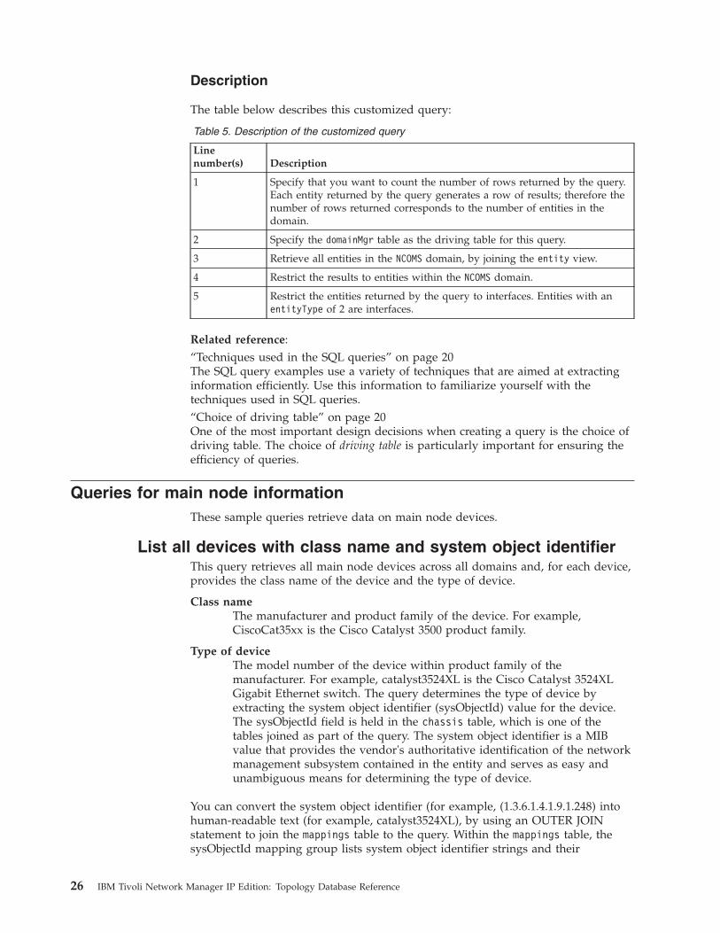
Description
The table below describes this customized query:
Table 5. Description of the customized query
Linenumber(s) Description
1 Specify that you want to count the number of rows returned by the query.Each entity returned by the query generates a row of results; therefore thenumber of rows returned corresponds to the number of entities in thedomain.
2 Specify the domainMgr table as the driving table for this query.
3 Retrieve all entities in the NCOMS domain, by joining the entity view.
4 Restrict the results to entities within the NCOMS domain.
5 Restrict the entities returned by the query to interfaces. Entities with anentityType of 2 are interfaces.
Related reference:“Techniques used in the SQL queries” on page 20The SQL query examples use a variety of techniques that are aimed at extractinginformation efficiently. Use this information to familiarize yourself with thetechniques used in SQL queries.“Choice of driving table” on page 20One of the most important design decisions when creating a query is the choice ofdriving table. The choice of driving table is particularly important for ensuring theefficiency of queries.
Queries for main node informationThese sample queries retrieve data on main node devices.
List all devices with class name and system object identifierThis query retrieves all main node devices across all domains and, for each device,provides the class name of the device and the type of device.
Class nameThe manufacturer and product family of the device. For example,CiscoCat35xx is the Cisco Catalyst 3500 product family.
Type of deviceThe model number of the device within product family of themanufacturer. For example, catalyst3524XL is the Cisco Catalyst 3524XLGigabit Ethernet switch. The query determines the type of device byextracting the system object identifier (sysObjectId) value for the device.The sysObjectId field is held in the chassis table, which is one of thetables joined as part of the query. The system object identifier is a MIBvalue that provides the vendor's authoritative identification of the networkmanagement subsystem contained in the entity and serves as easy andunambiguous means for determining the type of device.
You can convert the system object identifier (for example, (1.3.6.1.4.1.9.1.248) intohuman-readable text (for example, catalyst3524XL), by using an OUTER JOINstatement to join the mappings table to the query. Within the mappings table, thesysObjectId mapping group lists system object identifier strings and their
26 IBM Tivoli Network Manager IP Edition: Topology Database Reference

corresponding human-readable string values. The mappings table providesstring-to-string mappings, unlike the enumerations table, which providesinteger-to-string mappings.
If no entry exists in the mappings table for a specific system object identifier, thequery returns a NULL value for the device type. Use of an OUTER JOIN statementenables you to perform this conversion without losing any rows of main nodedata. If no string exists for any particular system object identifier, the OUTER JOINstatement ensures that you nevertheless do not lose the row of data for the mainnode device associated with that system object identifier.
Example1] SELECT e.entityName AS ’Entity Name’,2] ec.className AS ’Class Name’,3] s.sysObjectId AS ’System Object ID’,4] m.mappingValue AS ’Device Type’5] FROM entityData e6] INNER JOIN physicalChassis c ON c.entityId = e.entityId7] INNER JOIN snmpSystem s ON s.entityId = e.entityId8] INNER JOIN classMembers cm ON cm.entityId = e.entityId9] INNER JOIN entityClass ec ON ec.classId = cm.classId10] LEFT OUTER JOIN mappings m ON m.mappingGroup = ’sysObjectId’11] AND m.mappingKey = s.sysObjectId12] ORDER BY ec.className, s.sysObjectId
The following table describes this query:
Table 6. Description of the query
Line numbers Description
1-4 Specify the data to show in the results, as follows:
v The entity name of a device, represented by e.entityName.
v The class name of the device, indicating the manufacturer and productfamily. This is represented by ec.className, where ec is the alias used torefer to the entityClass table.
v The system object identifier for this device, represented by s.sysObjectId.(SNMP devices only)
v The device type, based on a lookup of the system object identifier in themappings table. This is represented by m.mappingValue.
5 Use the entityData table as the driving table for this query.
6 Limit the results of the query to main node devices, by joining thephysicalChassis table to the entityData table. There is now a line of datafor each main node device. Use an INNER JOIN statement to ensure thatonly entities that are main node devices are retrieved.
7 For SNMP devices determine the System Object ID.
8 Determine the class to which the device belongs. This is a two-stepprocess. The first step, shown in this line, is to use an INNER JOINstatement to the classMembers table to retrieve the classId value for theclass to which the device belongs.
9 Use the classId retrieved in line 7 as a lookup to determine the name of theclass to which the device belongs. Do this by performing an INNER JOINstatement with the entityClass table. The entityClass table holds classdetails, including class names, and the name of the superclass, thecontaining class in the class hierarchy.
Chapter 3. Topology database queries 27

Table 6. Description of the query (continued)
Line numbers Description
10-11 Look up the system object identifier in the mappings table in order toobtain a human-readable string for the device type. Do this by performinga join on the mappings table. Use an OUTER JOIN statement to enable youto perform this join without losing any rows of main node data. If nostring exists for any particular system object identifier, the OUTER JOINstatement ensures that you nevertheless do not lose the row of data for themain node device associated with that system object identifier.
12 Order the query results for maximum readability. In order to do this listthe devices first by manufacturer and product family (classname) and thenby model (system object identifier).
Results
The table below shows a portion of the results of the query.
Table 7. Results of the query
Entity name Class name System object ID Device type
192.168.15.23 3ComSuperStack 1.3.6.1.4.1.43.10.27.4.1.2.2
3Com SuperStack II
192.168.15.7 3ComSuperStack 1.3.6.1.4.1.43.10.27.4.1.2.2
3Com SuperStack II
172.20.4.16 Cisco26xx 1.3.6.1.4.1.9.1.185 cisco2610
10.1.1.8 Cisco26xx 1.3.6.1.4.1.9.1.186 cisco2611
10.1.1.9 Cisco26xx 1.3.6.1.4.1.9.1.209 cisco2621
172.20.4.15 Cisco36xx 1.3.6.1.4.1.9.1.122 cisco3620
10.1.254.1 Cisco72xx 1.3.6.1.4.1.9.1.222 cisco7206VXR
172.18.1.151 CiscoCat35xx 1.3.6.1.4.1.9.1.247 catalyst3512XL
172.18.1.203 CiscoCat35xx 1.3.6.1.4.1.9.1.248 catalyst3524XL
172.20.1.41 HuaweiARxx 1.3.6.1.4.1.2011.1.1.1.12809
NULL
10.1.1.5 MarconiASX 1.3.6.1.4.1.326.2.2.5 NULL
192.168.32.13 Sun 1.3.6.1.4.1.42 NULL
192.168.34.199
Sun 1.3.6.1.4.1.42.2.1.1 SunMicrosystemsServers
192.168.15.4 Windows 1.3.6.1.4.1.311.1.1.3.1.2 MicrosoftWindowsServer
List all IP addresses on all main node devicesThis query retrieves all IP addresses on all main node devices. For each IP address,the query lists the entity that implements the IP address. This entity is usually aninterface, but under certain conditions the IP address might be implemented by themain node itself.
This query lists the IP addresses implemented by each interface identified on amain node or by the main node itself. If an interface does not implement an IPaddress, that interface is not returned by this query.
28 IBM Tivoli Network Manager IP Edition: Topology Database Reference
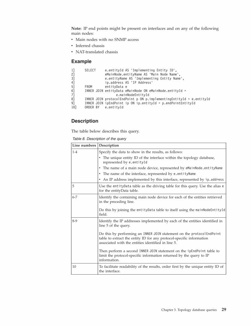
Note: IP end points might be present on interfaces and on any of the followingmain nodes:v Main nodes with no SNMP accessv Inferred chassisv NAT-translated chassis
Example
1]2]3]4]5]6]7]8]9]10]
SELECT e.entityId AS ’Implementing Entity ID’,eMainNode.entityName AS ’Main Node Name’,e.entityName AS ’Implementing Entity Name’,ip.address AS ’IP Address’
FROM entityData eINNER JOIN entityData eMainNode ON eMainNode.entityId =
e.mainNodeEntityIdINNER JOIN protocolEndPoint p ON p.implementingEntityId = e.entityIdINNER JOIN ipEndPoint ip ON ip.entityId = p.endPointEntityIdORDER BY e.entityId
Description
The table below describes this query.
Table 8. Description of the query
Line numbers Description
1-4 Specify the data to show in the results, as follows:
v The unique entity ID of the interface within the topology database,represented by e.entityId
v The name of a main node device, represented by eMainNode.entityName
v The name of the interface, represented by e.entityName
v An IP address implemented by this interface, represented by ip.address
5 Use the entityData table as the driving table for this query. Use the alias efor the entityData table.
6-7 Identify the containing main node device for each of the entities retrievedin the preceding line.
Do this by joining the entityData table to itself using the mainNodeEntityIdfield.
8-9 Identify the IP addresses implemented by each of the entities identified inline 5 of the query.
Do this by performing an INNER JOIN statement on the protocolEndPointtable to extract the entity ID for any protocol-specific informationassociated with the entities identified in line 5.
Then perform a second INNER JOIN statement on the ipEndPoint table tolimit the protocol-specific information returned by the query to IPinformation.
10 To facilitate readability of the results, order first by the unique entity ID ofthe interface.
Chapter 3. Topology database queries 29

Results
The table below shows the results of this query.
Table 9. Results of the query
Implementing EntityID Main Node Name
Implementing EntityName IP Address
270 172.20.4.11 172.20.4.11[0[5]] 172.50.0.2
338 172.18.1.196 172.18.1.196[0[2]] 172.50.0.3
366 172.18.1.54 172.18.1.54[0[2]] 172.50.0.4
370 172.18.1.54 172.18.1.54[0[1]] 172.50.0.5
373 172.20.4.13 172.20.4.13[0[1]] 172.50.0.6
377 172.20.4.20 172.20.4.20[0[1]] 172.50.0.7
417 192.168.139.7 192.168.139.7[ 0 [5 ] ]
172.20.11.1
417 192.168.139.7 192.168.139.7[ 0 [5 ] ]
172.20.1.2
Queries for containment informationThese queries retrieve data on logical and physical containment within yournetwork.
The containment model can reflect the real world topology of the network that isbeing modelled, in a physical, logical or business-oriented sense. Logicalcontainment includes the definition of local VLAN objects and VLAN trunkswithin main nodes.
The following sample queries extract containment information.
List all components on a deviceThis query retrieves all components on a named device, and lists each component.The query lists the components by entity ID and displays the name of thecomponent. All components are displayed, regardless of their type.
You can run this query in the following ways, which specify the main node devicedifferently:v Using the device name (entityName) and the name of the domain in which the
device is located (domainName). The device name might be an IP address or atextual name and should be unique within a given domain. This query is shownbelow.
v You can also write this query using the entityId for the device within theentityData table. This field contains an integer value unique across all domains.
Note: The SQL query in this section uses meaningful table aliases, such aseComponent and eMainNode . This makes the query more readable by enablingyou to distinguish between different types of data from the same table.
Example1] SELECT eComponent.entityId AS ’Component Entity ID’,2] eComponent.entityName AS ’Component Name’,3] eMainNode.entityName AS ’Main Node Name’
30 IBM Tivoli Network Manager IP Edition: Topology Database Reference
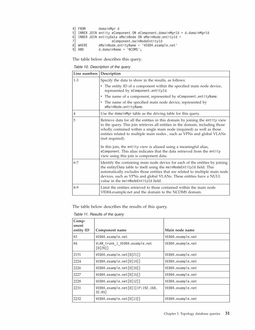
4] FROM domainMgr d5] INNER JOIN entity eComponent ON eComponent.domainMgrId = d.domainMgrId6] INNER JOIN entityData eMainNode ON eMainNode.entityId =7] eComponent.mainNodeEntityId8] WHERE eMainNode.entityName = ’VE004.example.net’9] AND d.domainName = ’NCOMS’;
The table below describes this query.
Table 10. Description of the query
Line numbers Description
1-3 Specify the data to show in the results, as follows:
v The entity ID of a component within the specified main node device,represented by eComponent.entityId.
v The name of a component, represented by eComponent.entityName.
v The name of the specified main node device, represented byeMainNode.entityName.
4 Use the domainMgr table as the driving table for this query.
5 Retrieve data for all the entities in this domain by joining the entity viewto the query. This join retrieves all entities in the domain, including thosewholly contained within a single main node (required) as well as thoseentities related to multiple main nodes , such as VPNs and global VLANs(not required).
In this join, the entity view is aliased using a meaningful alias,eComponent. This alias indicates that the data retrieved from the entityview using this join is component data.
6-7 Identify the containing main node device for each of the entities by joiningthe entityData table to itself using the mainNodeEntityId field. Thisautomatically excludes those entities that are related to multiple main nodedevices, such as VPNs and global VLANs. These entities have a NULLvalue in the mainNodeEntityId field.
8-9 Limit the entities retrieved to those contained within the main nodeVE004.example.net and the domain to the NCOMS domain.
The table below describes the results of this query.
Table 11. Results of the query
Comp-onententity ID Component name Main node name
83 VE004.example.net VE004.example.net
84 VLAN_trunk_1_VE004.example.net[0[26]]
VE004.example.net
2151 VE004.example.net[0[21]] VE004.example.net
2224 VE004.example.net[0[14]] VE004.example.net
2226 VE004.example.net[0[10]] VE004.example.net
2227 VE004.example.net[0[15]] VE004.example.net
2228 VE004.example.net[0[12]] VE004.example.net
2231 VE004.example.net[0[1]IP:192.168.32.65]
VE004.example.net
2232 VE004.example.net[0[13]] VE004.example.net
Chapter 3. Topology database queries 31
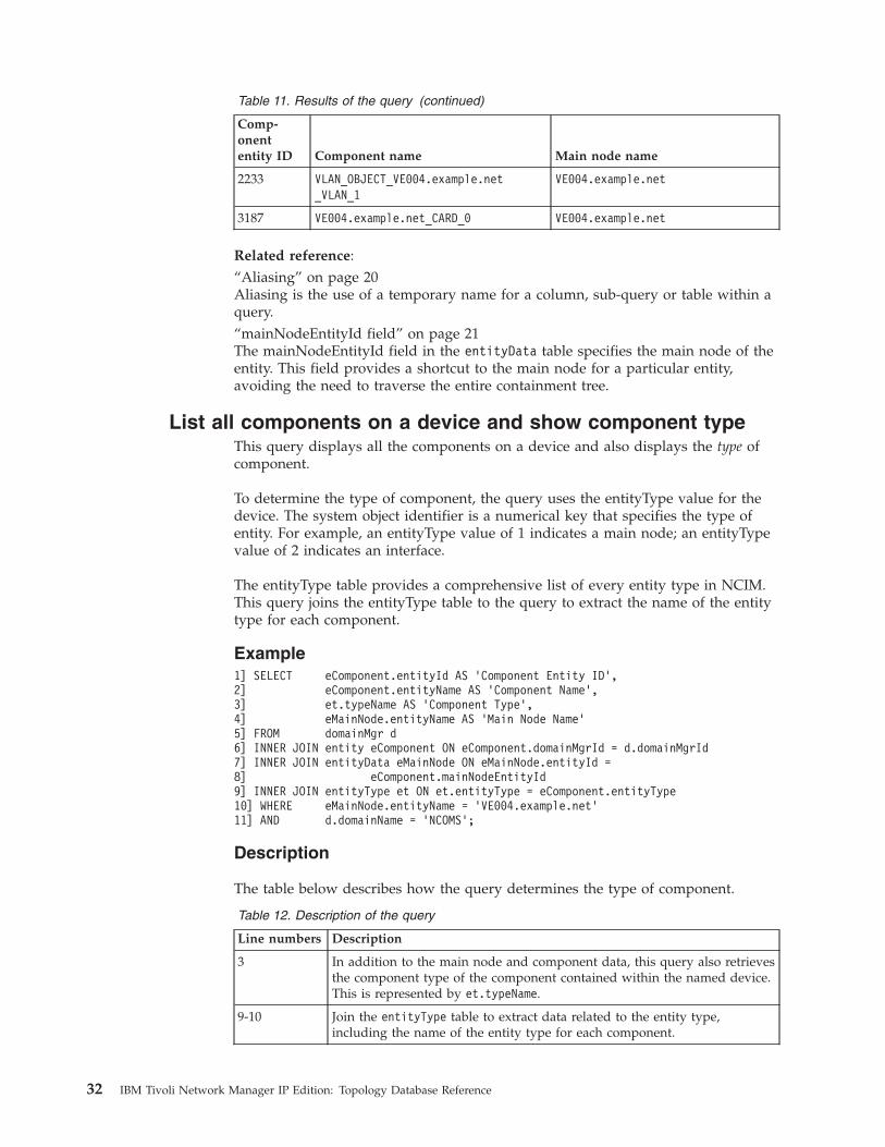
Table 11. Results of the query (continued)
Comp-onententity ID Component name Main node name
2233 VLAN_OBJECT_VE004.example.net_VLAN_1
VE004.example.net
3187 VE004.example.net_CARD_0 VE004.example.net
Related reference:“Aliasing” on page 20Aliasing is the use of a temporary name for a column, sub-query or table within aquery.“mainNodeEntityId field” on page 21The mainNodeEntityId field in the entityData table specifies the main node of theentity. This field provides a shortcut to the main node for a particular entity,avoiding the need to traverse the entire containment tree.
List all components on a device and show component typeThis query displays all the components on a device and also displays the type ofcomponent.
To determine the type of component, the query uses the entityType value for thedevice. The system object identifier is a numerical key that specifies the type ofentity. For example, an entityType value of 1 indicates a main node; an entityTypevalue of 2 indicates an interface.
The entityType table provides a comprehensive list of every entity type in NCIM.This query joins the entityType table to the query to extract the name of the entitytype for each component.
Example1] SELECT eComponent.entityId AS ’Component Entity ID’,2] eComponent.entityName AS ’Component Name’,3] et.typeName AS ’Component Type’,4] eMainNode.entityName AS ’Main Node Name’5] FROM domainMgr d6] INNER JOIN entity eComponent ON eComponent.domainMgrId = d.domainMgrId7] INNER JOIN entityData eMainNode ON eMainNode.entityId =8] eComponent.mainNodeEntityId9] INNER JOIN entityType et ON et.entityType = eComponent.entityType10] WHERE eMainNode.entityName = ’VE004.example.net’11] AND d.domainName = ’NCOMS’;
Description
The table below describes how the query determines the type of component.
Table 12. Description of the query
Line numbers Description
3 In addition to the main node and component data, this query also retrievesthe component type of the component contained within the named device.This is represented by et.typeName.
9-10 Join the entityType table to extract data related to the entity type,including the name of the entity type for each component.
32 IBM Tivoli Network Manager IP Edition: Topology Database Reference
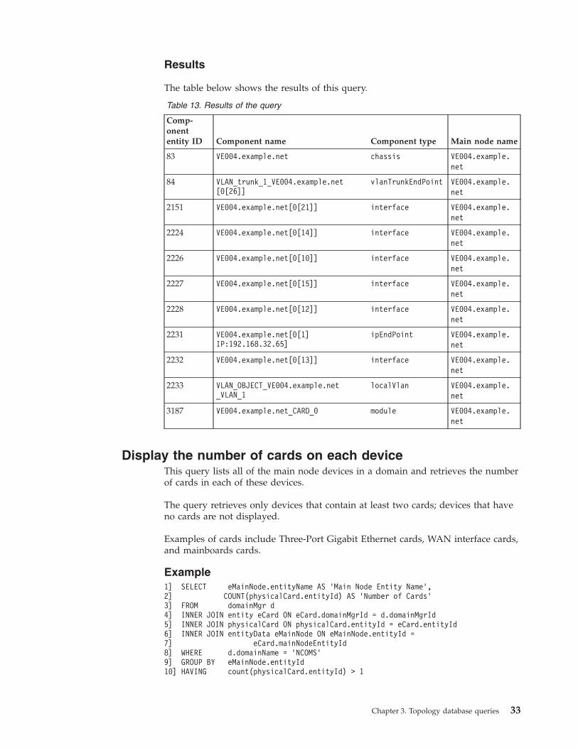
Results
The table below shows the results of this query.
Table 13. Results of the query
Comp-onententity ID Component name Component type Main node name
83 VE004.example.net chassis VE004.example.net
84 VLAN_trunk_1_VE004.example.net[0[26]]
vlanTrunkEndPoint VE004.example.net
2151 VE004.example.net[0[21]] interface VE004.example.net
2224 VE004.example.net[0[14]] interface VE004.example.net
2226 VE004.example.net[0[10]] interface VE004.example.net
2227 VE004.example.net[0[15]] interface VE004.example.net
2228 VE004.example.net[0[12]] interface VE004.example.net
2231 VE004.example.net[0[1]IP:192.168.32.65]
ipEndPoint VE004.example.net
2232 VE004.example.net[0[13]] interface VE004.example.net
2233 VLAN_OBJECT_VE004.example.net_VLAN_1
localVlan VE004.example.net
3187 VE004.example.net_CARD_0 module VE004.example.net
Display the number of cards on each deviceThis query lists all of the main node devices in a domain and retrieves the numberof cards in each of these devices.
The query retrieves only devices that contain at least two cards; devices that haveno cards are not displayed.
Examples of cards include Three-Port Gigabit Ethernet cards, WAN interface cards,and mainboards cards.
Example1] SELECT eMainNode.entityName AS ’Main Node Entity Name’,2] COUNT(physicalCard.entityId) AS ’Number of Cards’3] FROM domainMgr d4] INNER JOIN entity eCard ON eCard.domainMgrId = d.domainMgrId5] INNER JOIN physicalCard ON physicalCard.entityId = eCard.entityId6] INNER JOIN entityData eMainNode ON eMainNode.entityId =7] eCard.mainNodeEntityId8] WHERE d.domainName = ’NCOMS’9] GROUP BY eMainNode.entityId10] HAVING count(physicalCard.entityId) > 1
Chapter 3. Topology database queries 33

Description
The table below describes this query.
Table 14. Description of the query
Line numbers Description
1-2 Specify the data to show in the results, as follows:
v The name of a main node device, represented by eMainNode.entityname
v The number of cards in that device, represented byCOUNT(physicalCard.entityId)
4-6 Join relevant tables to the domainMgr table in order to retrieve therequired data. The joins are as described in the next two rows.
4 Retrieve all the entities in each domain. The INNER JOIN clause ensures thatonly entities that have a valid domainMgrId field are retrieved.
5 From all the entities, extract only that subset of entities that are cards. Usean INNER JOIN statement to ensure that only entities that havecorresponding entries in the physicalCard table are retrieved. There is aline of data for each card. This line of data consists of all columns from thedomain table, the entity view, and the physicalCard table related to thatcard.
6-7 Identify the containing main node device for each of the cards by joiningthe entityData table to itself using the mainNodeEntityId field. The join onthis field enables the query to go directly to the top of the containmenttree.
8 Limit the resulting data to the main node devices in the NCOMS domainonly.
9 Group the results by the name of the main node device. This means thatthe results show the number of cards within each main node.
10 Use the HAVING clause to specify that you want to retrieve only devicesthat contain two or more cards.
Results
The table below shows a portion of the results for this query.
Table 15. Results of the query
Main node entity name Number of cards
172.18.1.102 20
VE001.example.net 10
Related reference:“mainNodeEntityId field” on page 21The mainNodeEntityId field in the entityData table specifies the main node of theentity. This field provides a shortcut to the main node for a particular entity,avoiding the need to traverse the entire containment tree.
34 IBM Tivoli Network Manager IP Edition: Topology Database Reference

Find all devices containing Three-Port Gigabit Ethernet cardsThis query looks for specific containment information within a device. In thisexample, the query finds all main-node devices that contain a specific component:a Cisco Three-Port Gigabit Ethernet card.
This query also returns the following information about each Three-Port GigabitEthernet Card retrieved:v Serial number of the cardv Hardware revision of the cardv The physical position occupied within the main node device by the slot that
contains this card
Tip: To perform this type of query, you need to know the MIB OID of thecomponent contained within the device. In this example, you need to know thatthe OID of the Three-Port Gigabit Ethernet Card within the Cisco MIB is1.3.6.1.4.1.9.12.3.1.9.18.49.
Prerequisites
Before you run this query, you must have enabled the Entity agent to run duringthe discovery process. This enables the query to retrieve the required data. TheEntity agent discovers detailed containment information from the Entity MIB. Formore information about the Entity agent, see the IBM Tivoli Network Manager IPEdition Discovery Guide. By default the Entity agent is not configured to run duringdiscovery. You must therefore configure this agent manually if you want thetopology database to contain the detailed MIB information that is required forqueries of this type.
Example1] SELECT d.domainname AS "Domain",2] e2.entityName AS "Device Name",3] c.serialnumber AS "Serial Number",4] c.hwRevision AS "Hardware Revision",5] s.relativePosition AS "Slot Number"6] FROM domainmgr d7] INNER JOIN entity e1 ON e1.domainmgrid = d.domainmgrid8] INNER JOIN physicalCard c ON c.entityid = e1.entityid9] INNER JOIN entityData e2 ON e2.entityid = e1.mainnodeentityid10] INNER JOIN contains c2 ON c2.containedentityid = c.entityid11] INNER JOIN physicalSlot s ON s.entityid = c2.containingentityid12] WHERE c.vendorType = ’1.3.6.1.4.1.9.12.3.1.9.18.49’13] ORDER BY LOWER(d.domainname) ASC, LOWER(e2.entityName) ASC;
Chapter 3. Topology database queries 35
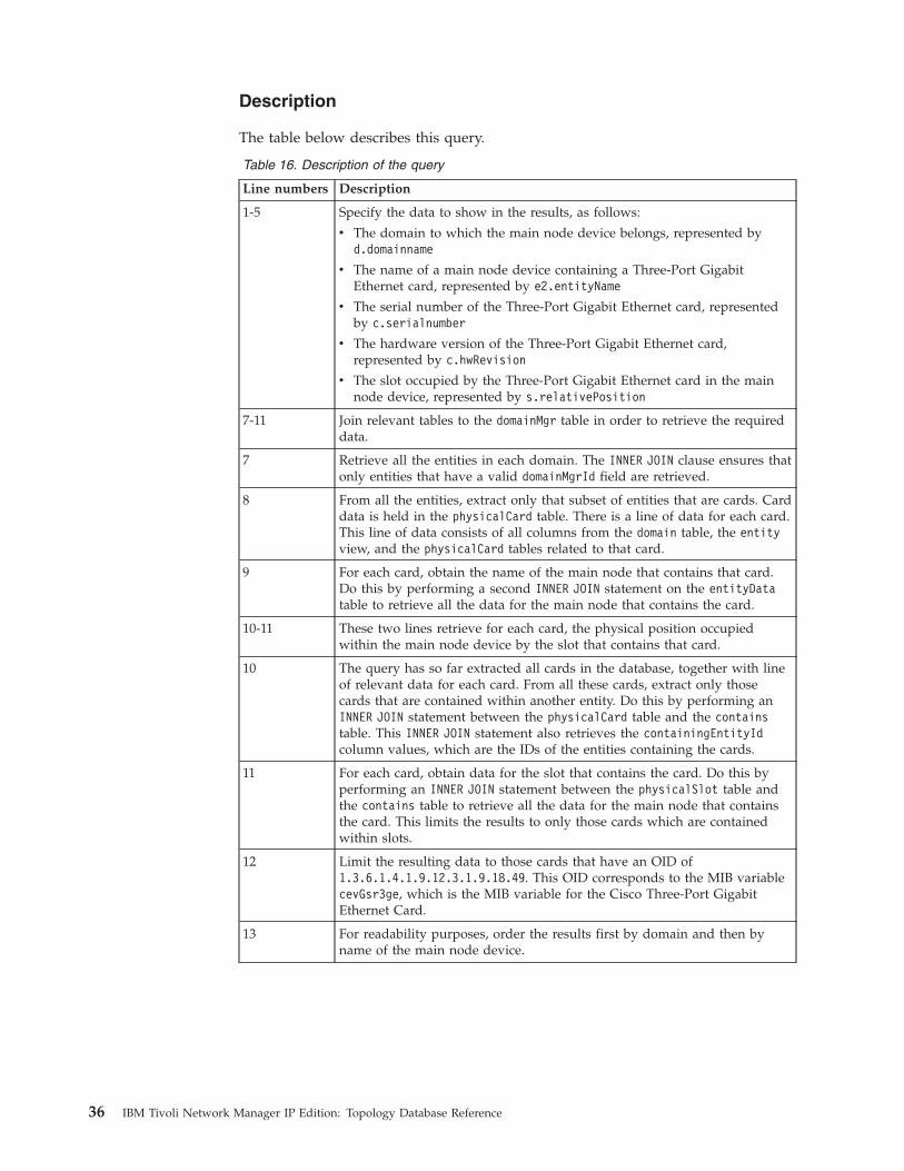
Description
The table below describes this query.
Table 16. Description of the query
Line numbers Description
1-5 Specify the data to show in the results, as follows:
v The domain to which the main node device belongs, represented byd.domainname
v The name of a main node device containing a Three-Port GigabitEthernet card, represented by e2.entityName
v The serial number of the Three-Port Gigabit Ethernet card, representedby c.serialnumber
v The hardware version of the Three-Port Gigabit Ethernet card,represented by c.hwRevision
v The slot occupied by the Three-Port Gigabit Ethernet card in the mainnode device, represented by s.relativePosition
7-11 Join relevant tables to the domainMgr table in order to retrieve the requireddata.
7 Retrieve all the entities in each domain. The INNER JOIN clause ensures thatonly entities that have a valid domainMgrId field are retrieved.
8 From all the entities, extract only that subset of entities that are cards. Carddata is held in the physicalCard table. There is a line of data for each card.This line of data consists of all columns from the domain table, the entityview, and the physicalCard tables related to that card.
9 For each card, obtain the name of the main node that contains that card.Do this by performing a second INNER JOIN statement on the entityDatatable to retrieve all the data for the main node that contains the card.
10-11 These two lines retrieve for each card, the physical position occupiedwithin the main node device by the slot that contains that card.
10 The query has so far extracted all cards in the database, together with lineof relevant data for each card. From all these cards, extract only thosecards that are contained within another entity. Do this by performing anINNER JOIN statement between the physicalCard table and the containstable. This INNER JOIN statement also retrieves the containingEntityIdcolumn values, which are the IDs of the entities containing the cards.
11 For each card, obtain data for the slot that contains the card. Do this byperforming an INNER JOIN statement between the physicalSlot table andthe contains table to retrieve all the data for the main node that containsthe card. This limits the results to only those cards which are containedwithin slots.
12 Limit the resulting data to those cards that have an OID of1.3.6.1.4.1.9.12.3.1.9.18.49. This OID corresponds to the MIB variablecevGsr3ge, which is the MIB variable for the Cisco Three-Port GigabitEthernet Card.
13 For readability purposes, order the results first by domain and then byname of the main node device.
36 IBM Tivoli Network Manager IP Edition: Topology Database Reference

Results
The following table shows an example of the results of this query.
Table 17. Results of the query
Domain Device name Serial number Hardware revisionSlotnumber
NCOMS VE001.example.net
SAD06A400WY 2.0 3
NCOMS 172.20.4.13 SDK04A70XV4 2.0 4
NCOMS 172.50.0.2 SAD06A300PY 2.0 5
Find entities within all cardsThis query retrieves entities contained within all cards. Cards might containentities of different types, including ports, slots, and sensors. The query lists eachof the cards identified and, for each card, lists the entities contained within thecard.
This query does not traverse the entire containment tree within the card. Therefore,the query only retrieves components at the top level within the card.
This query uses the contains table. This table defines all the containmentrelationships between entities. Each row in the contains table holds a pair of entityidentifiers: the containing entity and the contained entity identifier. For each cardidentified, the query joins to the contains table and extracts information about oneof the entities contained within that card.
Example1] SELECT container.entityName AS ’Card Name’,2] m.cardNumber AS ’Card Number’,3] part.entityName AS ’Contained Entity’4] FROM physicalCard m5] INNER JOIN entityData container ON container.entityId = m.entityId6] INNER JOIN contains c ON c.containingEntityId = m.entityId7] INNER JOIN entityData part ON part.entityId = c.containedEntityId8] ORDER BY container.entityName
The table below describes this query.
Table 18. Description of the query
Line numbers Description
1-3 Specify the data to show in the results, as follows:
v The name of the card, represented by container.entityName
v The number of the card within the main node device, represented bym.cardNumber
v The name of the interface, represented by part.entityName
4 Use the physicalCard table as the driving table for this query.
The FROM clause extracts data for all cards.
Chapter 3. Topology database queries 37

Table 18. Description of the query (continued)
Line numbers Description
5 For each card, extract the full set of entity data for that card. This ensuresthat the entity name of the card is retrieved for display in the queryresults, as specified in line 1). Use the alias container for the entityDatatable to indicate that data extracted using this alias is data for thecontaining card.
Do this by specifying an INNER JOIN statement with the entityData table.
6 For each card, extract records from the contains table on entities containedwithin that card. Limit the query results to those cards that contain otherentities.
Do this by specifying an INNER JOIN statement with the contains table.
The query extracts a record from the contains table for each entitycontained within a given card. Each of these records includes the entityidentifier for an entity contained within the card.
7 Extract the full set of entity data for each contained entity. Use the aliaspart for the entityData table to indicate that data extracted using this aliasis data for a contained entity.
Do this by specifying a second INNER JOIN statement with the entityDatatable.
8 To facilitate readability of the results, order by the entity name of thecontaining card.
The table below shows the results of this query.
Table 19. Results of the query
Card name Card number Contained entity
10.1.1.11_CARD_1 1 10.1.1.11[ 1 [ 1 ] ]
10.1.1.11_CARD_2 2 10.1.1.11[ 2 [ 1 ] ]
10.1.1.12_CARD_0 0 10.1.1.12[ 0 [ 14 ] ]
10.1.1.12_CARD_0 0 10.1.1.12[ 0 [ 10 ] ]
10.1.1.12_CARD_0 0 10.1.1.12[ 0 [ 12 ] ]
10.1.1.12_CARD_0 0 10.1.1.12[ 0 [ 11 ] ]
10.1.1.12_CARD_0 0 10.1.1.12[ 0 [ 13 ] ]
10.1.1.8_CARD_I3_R0 NULL 10.1.1.8_SLOT_I4_R0’
10.1.1.8_CARD_I3_R0 NULL 10.1.1.8_SLOT_I6_R1’
10.1.1.9_CARD_I3_R0 NULL 10.1.1.9_SLOT_I4_R0’
10.1.1.9_CARD_I3_R0 NULL 10.1.1.9_SLOT_I6_R1’
10.1.254.2_CARD_I1000_R1 NULL 10.1.254.2_SENSOR_I1002_R2
10.1.254.2_CARD_I1000_R1 NULL 10.1.254.2_SENSOR_I1001_R1
10.1.254.2_CARD_I1100_R1 NULL 10.1.254.2_PORT_I1102_R1
10.1.254.2_CARD_I1100_R1 NULL 10.1.254.2_PORT_I1101_R0
38 IBM Tivoli Network Manager IP Edition: Topology Database Reference

Related reference:“Aliasing” on page 20Aliasing is the use of a temporary name for a column, sub-query or table within aquery.“Table joins” on page 20Use table joins to combine records from one or more tables. Two types of table joinare used, INNER JOIN and OUTER JOIN.“Choice of driving table” on page 20One of the most important design decisions when creating a query is the choice ofdriving table. The choice of driving table is particularly important for ensuring theefficiency of queries.
Queries for port and interface informationThese sample queries extract interface and protocol information associated withinterfaces.
Device entities, usually interfaces, might be associated with protocol-specific data.The most common example is the association between a device interface with theIP addressing data. Interfaces might also be associated with other types ofaddressing data, including ATM protocol data and OSPF protocol data.
List all interfaces on all devicesThis query provides a list of all main node devices within a domain together withthe identifiers and names of the interfaces on each device.
Example1] SELECT eMainNode.entityName AS ’Main Node Name’,2] eInterface.entityId AS ’Interface Entity ID’,3] eInterface.entityName AS ’Interface Entity Name’4] FROM entityData eInterface5] INNER JOIN entityData eMainNode ON eMainNode.entityId =6] eInterface.mainNodeEntityId7] WHERE eInterface.entityType = 28] ORDER BY eMainNode.entityName, eInterface.entityName
Description
The table below describes this query.
Table 20. Description of the query
Line numbers Description
1-3 Specify the data to show in the results, as follows:
v The name of a main node device, represented by eMainNode.entityName
v The unique entity ID of the interface within the topology database,represented by eInterface.entityId
v The name of the interface, represented by eInterface.entityName
4 Use the entityData table as the driving table for this query. Use the aliaseInterface for the entityData table to indicate that the data extractedusing this alias is interface data.
5-6 Identify the containing main node device for each of the entities retrievedin the preceding line. Do this by joining the entityData table to itself usingthe mainNodeEntityId field.
Chapter 3. Topology database queries 39

Table 20. Description of the query (continued)
Line numbers Description
7 Limit the components of the device to interfaces only. Do this filtering thecomponents to retrieve only components with an entity type of 2, whichcorresponds to an interface.
8 To facilitate readability of the results, order first by main node name andthen by interface name.
Results
The table below shows a portion of the results for this query.
Table 21. Results of the query
Main node name Interface entity ID Interface entity name
172.20.1.41 1622 172.20.1.41[0[1]]
172.20.4.11 1621 172.20.4.11[0[1]]
172.20.4.11 1624 172.20.4.11[0[10]]
172.20.4.11 1479 172.20.4.11[0[11]
172.20.4.11 1632 172.20.4.11[0[12]
VE001.example.net 1631 VE001.example.net[0[1]]
Related reference:“mainNodeEntityId field” on page 21The mainNodeEntityId field in the entityData table specifies the main node of theentity. This field provides a shortcut to the main node for a particular entity,avoiding the need to traverse the entire containment tree.“entityType field” on page 22The entityType field can be used in SQL queries to limit the type of componentdata that is retrieved.
List all interfaces with specific attributesThis query provides a list of all interfaces within a domain that have specificattribute values.
The example given here retrieves interfaces that have an interface speed greaterthan 155 MB per second; however, you can construct a query using any of theattributes in the networkInterface table.
Example1] SELECT e.entityName AS ’Interface Name’,2] i.ifName AS ’IfName’,3] i.ifSpeed AS ’Interface Speed’4] FROM entityData e5] INNER JOIN networkInterface i ON i.entityId = e.entityId6] WHERE ifSpeed > 1550000007] ORDER BY i.ifSpeed DESC;
40 IBM Tivoli Network Manager IP Edition: Topology Database Reference

Description
The table below describes this query.
Table 22. Description of the query
Line numbers Description
1-3 Specify the data to show in the results, as follows:
v The name of an interface, represented by e.entityName
v The name of the interface stored in the MIB, represented by i.ifName
v The speed of the interface, represented by i.ifSpeed
4 Use the entityData table as the driving table for this query. This part ofthe query retrieves all entities held in the database.
5 Limit the results of the query to interfaces.
Do this by joining the networkInterface table to the entityData table usingthe mainNodeEntityId field. There is now a line of data for each interface inthe database. The INNER JOIN statement ensures that only interface data isretrieved.
6 Limit the results of the query to interfaces with interface speeds greaterthan 155 MB per second.
7 Order the results by the speed of the interface.
Results
The table below shows the results of this query.
Table 23. Results of the query
Interface name IfName Interface speed
10.1.254.2[ 1 [ 1 ] ] Gi1/1 1000000000
192.170.170.10[ 0 [ 51 ] ] Gi50 1000000000
192.170.170.10[ 0 [ 50 ] ] Gi49 1000000000
192.170.170.10[ 0 [ 1 ] ] FX1 1000000000
172.20.4.19[ 0 [ 1 ] ] ATM0/1/0 622080000
172.18.1.102[ 2 [ 1 ] ] FEC-9/39-42 400000000
172.20.4.19[ 0 [ 2 ] ] ATM0 155520000
192.170.170.10[ 0 [ 52 ] ] Co51 155520000
List all interfaces on all devices with interface typeThis query retrieves all interfaces on all devices across all domains, and alsoretrieves information about the interface.
For each interface the query retrieves the following information about the interface:v ifName
v ifType
v A textual description corresponding to the ifType field
In addition to using information from the entityData table to list the interfaces oneach device, this query provides a join to the networkInterface table to bring indetailed attribute data for the interfaces identified.
Chapter 3. Topology database queries 41
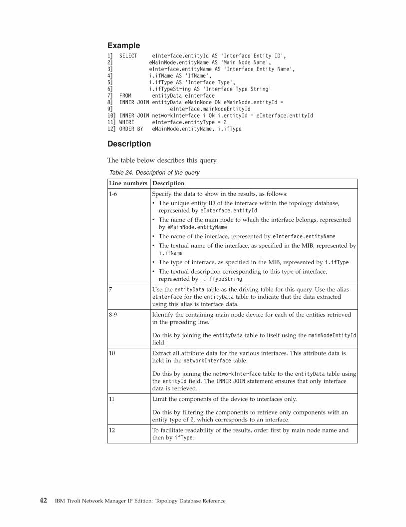
Example1] SELECT eInterface.entityId AS ’Interface Entity ID’,2] eMainNode.entityName AS ’Main Node Name’,3] eInterface.entityName AS ’Interface Entity Name’,4] i.ifName AS ’IfName’,5] i.ifType AS ’Interface Type’,6] i.ifTypeString AS ’Interface Type String’7] FROM entityData eInterface8] INNER JOIN entityData eMainNode ON eMainNode.entityId =9] eInterface.mainNodeEntityId10] INNER JOIN networkInterface i ON i.entityId = eInterface.entityId11] WHERE eInterface.entityType = 212] ORDER BY eMainNode.entityName, i.ifType
Description
The table below describes this query.
Table 24. Description of the query
Line numbers Description
1-6 Specify the data to show in the results, as follows:
v The unique entity ID of the interface within the topology database,represented by eInterface.entityId
v The name of the main node to which the interface belongs, representedby eMainNode.entityName
v The name of the interface, represented by eInterface.entityName
v The textual name of the interface, as specified in the MIB, represented byi.ifName
v The type of interface, as specified in the MIB, represented by i.ifType
v The textual description corresponding to this type of interface,represented by i.ifTypeString
7 Use the entityData table as the driving table for this query. Use the aliaseInterface for the entityData table to indicate that the data extractedusing this alias is interface data.
8-9 Identify the containing main node device for each of the entities retrievedin the preceding line.
Do this by joining the entityData table to itself using the mainNodeEntityIdfield.
10 Extract all attribute data for the various interfaces. This attribute data isheld in the networkInterface table.
Do this by joining the networkInterface table to the entityData table usingthe entityId field. The INNER JOIN statement ensures that only interfacedata is retrieved.
11 Limit the components of the device to interfaces only.
Do this by filtering the components to retrieve only components with anentity type of 2, which corresponds to an interface.
12 To facilitate readability of the results, order first by main node name andthen by ifType.
42 IBM Tivoli Network Manager IP Edition: Topology Database Reference

Results
The table below shows the results of this query.
Table 25. Results of the query
Inter-faceentityID
Main nodename Interface entity name IfName
Inter-facetype Interface type string
1479 10.1.1.11 10.1.1.11[ 0 [ 12 ] Fa0/11 6 ethernetCsmacd
1621 10.1.1.11 10.1.1.11[ 0 [ 10 ] Fa0/9 6 ethernetCsmacd
1622 10.1.1.11 10.1.1.11[ 0 [ 1 ] VL1 6 ethernetCsmacd
2466 10.1.1.5 10.1.1.5[ 0 [ 1029 ] 1B1 18 ds1
2471 10.1.1.5 10.1.1.5[ 0 [ 1035 ]]
1B4 18 ds1
2465 10.1.1.5 10.1.1.5[ 0 [ 1032 ]]
1B2 37 atm
2476 10.1.1.5 10.1.1.5[ 0 [ 1030 ]]
1B1 37 atm
2477 10.1.1.5 10.1.1.5[ 0 [ 1024 ]]
1CTL 37 atm
2474 10.1.1.5 10.1.1.5[ 0 [ 1059 ]]
44 frameRelayService
2480 10.1.1.5 10.1.1.5[ 0 [ 1053 ]]
44 frameRelayService
2482 10.1.1.5 10.1.1.5[ 0 [ 1055 ]]
44 frameRelayService
2488 10.1.1.5 10.1.1.5[ 0 [ 5 ] ] qaa1 114 ipOverAtm
2490 10.1.1.5 10.1.1.5[ 0 [ 4 ] ] qaa0 114 ipOverAtm
2496 10.1.1.5 10.1.1.5[ 0 [ 6 ] ] qaa2 114 ipOverAtm
1652 10.1.1.9 10.1.1.9[ 0 [ 1 ] ] Se0/0 22 propPointToPointSerial
1131 10.1.254.1 10.1.254.1[ 0 [ 20 ]]
Fa0/1.80 135 l2vlan
1130 10.1.254.1 10.1.254.1[ 0 [ 22 ]]
Se1/1:0 166 mpls
Related reference:“Techniques used in the SQL queries” on page 20The SQL query examples use a variety of techniques that are aimed at extractinginformation efficiently. Use this information to familiarize yourself with thetechniques used in SQL queries.“List all interfaces on all devices” on page 39This query provides a list of all main node devices within a domain together withthe identifiers and names of the interfaces on each device.“entityType field” on page 22The entityType field can be used in SQL queries to limit the type of componentdata that is retrieved.
Chapter 3. Topology database queries 43
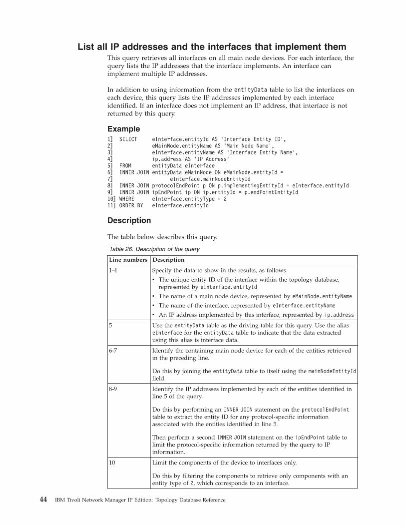
List all IP addresses and the interfaces that implement themThis query retrieves all interfaces on all main node devices. For each interface, thequery lists the IP addresses that the interface implements. An interface canimplement multiple IP addresses.
In addition to using information from the entityData table to list the interfaces oneach device, this query lists the IP addresses implemented by each interfaceidentified. If an interface does not implement an IP address, that interface is notreturned by this query.
Example1] SELECT eInterface.entityId AS ’Interface Entity ID’,2] eMainNode.entityName AS ’Main Node Name’,3] eInterface.entityName AS ’Interface Entity Name’,4] ip.address AS ’IP Address’5] FROM entityData eInterface6] INNER JOIN entityData eMainNode ON eMainNode.entityId =7] eInterface.mainNodeEntityId8] INNER JOIN protocolEndPoint p ON p.implementingEntityId = eInterface.entityId9] INNER JOIN ipEndPoint ip ON ip.entityId = p.endPointEntityId10] WHERE eInterface.entityType = 211] ORDER BY eInterface.entityId
Description
The table below describes this query.
Table 26. Description of the query
Line numbers Description
1-4 Specify the data to show in the results, as follows:
v The unique entity ID of the interface within the topology database,represented by eInterface.entityId
v The name of a main node device, represented by eMainNode.entityName
v The name of the interface, represented by eInterface.entityName
v An IP address implemented by this interface, represented by ip.address
5 Use the entityData table as the driving table for this query. Use the aliaseInterface for the entityData table to indicate that the data extractedusing this alias is interface data.
6-7 Identify the containing main node device for each of the entities retrievedin the preceding line.
Do this by joining the entityData table to itself using the mainNodeEntityIdfield.
8-9 Identify the IP addresses implemented by each of the entities identified inline 5 of the query.
Do this by performing an INNER JOIN statement on the protocolEndPointtable to extract the entity ID for any protocol-specific informationassociated with the entities identified in line 5.
Then perform a second INNER JOIN statement on the ipEndPoint table tolimit the protocol-specific information returned by the query to IPinformation.
10 Limit the components of the device to interfaces only.
Do this by filtering the components to retrieve only components with anentity type of 2, which corresponds to an interface.
44 IBM Tivoli Network Manager IP Edition: Topology Database Reference
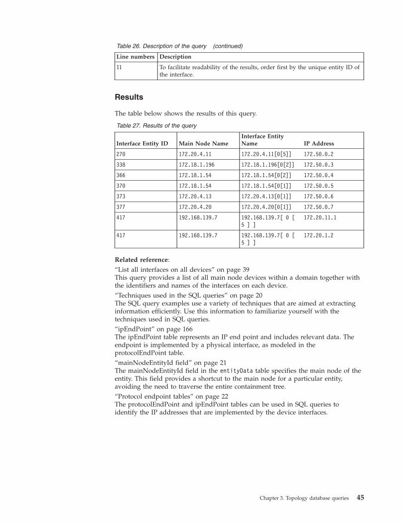
Table 26. Description of the query (continued)
Line numbers Description
11 To facilitate readability of the results, order first by the unique entity ID ofthe interface.
Results
The table below shows the results of this query.
Table 27. Results of the query
Interface Entity ID Main Node NameInterface EntityName IP Address
270 172.20.4.11 172.20.4.11[0[5]] 172.50.0.2
338 172.18.1.196 172.18.1.196[0[2]] 172.50.0.3
366 172.18.1.54 172.18.1.54[0[2]] 172.50.0.4
370 172.18.1.54 172.18.1.54[0[1]] 172.50.0.5
373 172.20.4.13 172.20.4.13[0[1]] 172.50.0.6
377 172.20.4.20 172.20.4.20[0[1]] 172.50.0.7
417 192.168.139.7 192.168.139.7[ 0 [5 ] ]
172.20.11.1
417 192.168.139.7 192.168.139.7[ 0 [5 ] ]
172.20.1.2
Related reference:“List all interfaces on all devices” on page 39This query provides a list of all main node devices within a domain together withthe identifiers and names of the interfaces on each device.“Techniques used in the SQL queries” on page 20The SQL query examples use a variety of techniques that are aimed at extractinginformation efficiently. Use this information to familiarize yourself with thetechniques used in SQL queries.“ipEndPoint” on page 166The ipEndPoint table represents an IP end point and includes relevant data. Theendpoint is implemented by a physical interface, as modeled in theprotocolEndPoint table.“mainNodeEntityId field” on page 21The mainNodeEntityId field in the entityData table specifies the main node of theentity. This field provides a shortcut to the main node for a particular entity,avoiding the need to traverse the entire containment tree.“Protocol endpoint tables” on page 22The protocolEndPoint and ipEndPoint tables can be used in SQL queries toidentify the IP addresses that are implemented by the device interfaces.
Chapter 3. Topology database queries 45

Queries for connectivity informationThese sample queries extract data on connectivity within your network.
Connectivity includes connections between different devices, and VLAN-relatedconnections within the same device. In addition, the NCIM database independentlyrepresents connectivity of entities in different layers, so that the connectivity atlayer 2 is represented independently of the connectivity at layer 3.
NCIM can model complex connectivity scenarios. For example, within the MPLSVPN realm, NCIM can model the layer 3 connection between a provider-edge (PE)router and multiple customer-edge (CE) routers.
Connectivity information is stored in the connects table. This table stores eachconnection as a single record. However, because two entities are involved in aconnection, the order of the connected entities in the connects table is random.
For example, the following figures shows the devices that are connected to themain node device VE001.example.net.
The following table shows how the connects table might store the data about theconnectivity between the device VE001.example.net and neighboring devices.
Table 28. Example data from the connects table for connections to main node deviceVE001.example.net
connectionId aEndEntityId zEndEntityId
101 VE001.example.net 192.168.35.225
102 VE001.example.net 192.168.34.86
103 192.168.39.175 VE001.example.net
192.168.39.17
VE001.example.net
192.168.34.86192.168.35.25
Figure 3. Devices connected to main node device VE001.example.net
46 IBM Tivoli Network Manager IP Edition: Topology Database Reference
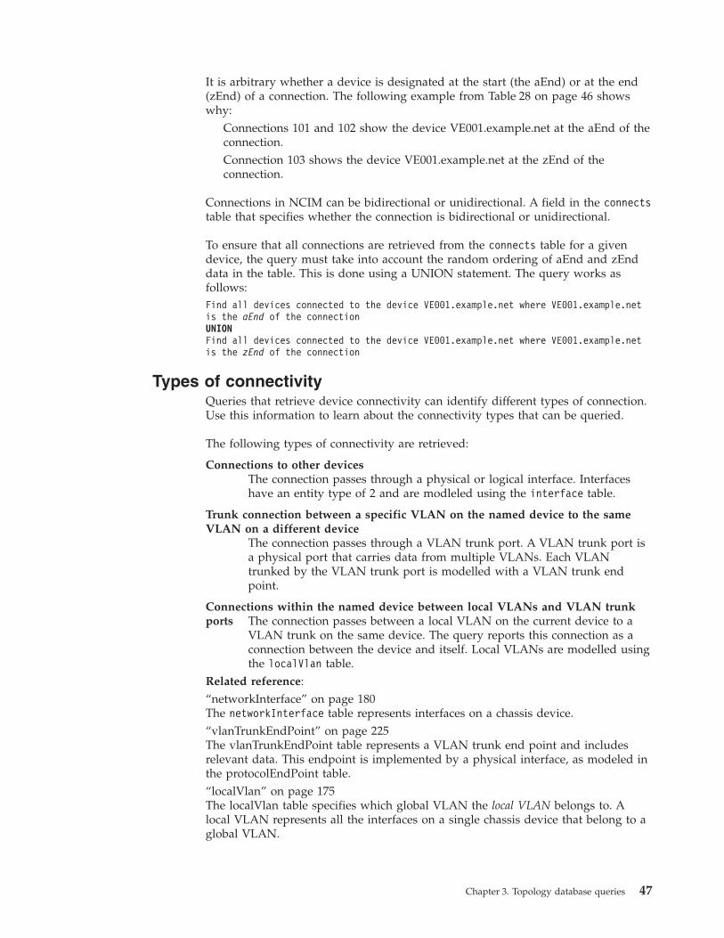
It is arbitrary whether a device is designated at the start (the aEnd) or at the end(zEnd) of a connection. The following example from Table 28 on page 46 showswhy:
Connections 101 and 102 show the device VE001.example.net at the aEnd of theconnection.Connection 103 shows the device VE001.example.net at the zEnd of theconnection.
Connections in NCIM can be bidirectional or unidirectional. A field in the connectstable that specifies whether the connection is bidirectional or unidirectional.
To ensure that all connections are retrieved from the connects table for a givendevice, the query must take into account the random ordering of aEnd and zEnddata in the table. This is done using a UNION statement. The query works asfollows:Find all devices connected to the device VE001.example.net where VE001.example.netis the aEnd of the connectionUNIONFind all devices connected to the device VE001.example.net where VE001.example.netis the zEnd of the connection
Types of connectivityQueries that retrieve device connectivity can identify different types of connection.Use this information to learn about the connectivity types that can be queried.
The following types of connectivity are retrieved:
Connections to other devicesThe connection passes through a physical or logical interface. Interfaceshave an entity type of 2 and are modleled using the interface table.
Trunk connection between a specific VLAN on the named device to the sameVLAN on a different device
The connection passes through a VLAN trunk port. A VLAN trunk port isa physical port that carries data from multiple VLANs. Each VLANtrunked by the VLAN trunk port is modelled with a VLAN trunk endpoint.
Connections within the named device between local VLANs and VLAN trunkports The connection passes between a local VLAN on the current device to a
VLAN trunk on the same device. The query reports this connection as aconnection between the device and itself. Local VLANs are modelled usingthe localVlan table.
Related reference:“networkInterface” on page 180The networkInterface table represents interfaces on a chassis device.“vlanTrunkEndPoint” on page 225The vlanTrunkEndPoint table represents a VLAN trunk end point and includesrelevant data. This endpoint is implemented by a physical interface, as modeled inthe protocolEndPoint table.“localVlan” on page 175The localVlan table specifies which global VLAN the local VLAN belongs to. Alocal VLAN represents all the interfaces on a single chassis device that belong to aglobal VLAN.
Chapter 3. Topology database queries 47
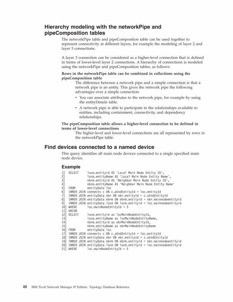
Hierarchy modeling with the networkPipe andpipeComposition tables
The networkPipe table and pipeComposition table can be used together torepresent connectivity at different layers, for example the modeling of layer 2 andlayer 3 connections.
A layer 3 connection can be considered as a higher-level connection that is definedin terms of lower-level layer 2 connections. A hierarchy of connections is modeledusing the networkPipe and pipeComposition tables, as follows:
Rows in the networkPipe table can be combined in collections using thepipeComposition table
The difference between a network pipe and a simple connection is that anetwork pipe is an entity. This gives the network pipe the followingadvantages over a simple connection:v You can associate attributes to the network pipe, for example by using
the entityDetails table.v A network pipe is able to participate in the relationships available to
entities, including containment, connectivity, and dependencyrelationships.
The pipeComposition table allows a higher-level connection to be defined interms of lower-level connections
The higher-level and lower-level connections are all represented by rows inthe networkPipe table.
Find devices connected to a named deviceThis query identifies all main node devices connected to a single specified mainnode device.
Example1] SELECT locm.entityid AS ’Local Main Node Entity ID’,2] locm.entityName AS ’Local Main Node Entity Name’,3] nbrm.entityid AS ’Neighbor Main Node Entity ID’,4] nbrm.entityName AS ’Neighbor Main Node Entity Name’5] FROM entityData loc6] INNER JOIN connects c ON c.aEndEntityId = loc.entityId7] INNER JOIN entityData nbr ON nbr.entityId = c.zEndEntityId8] INNER JOIN entityData nbrm ON nbrm.entityid = nbr.mainnodeentityid9] INNER JOIN entityData locm ON locm.entityid = loc.mainnodeentityid10] WHERE loc.mainNodeEntityId = 511] UNION12] SELECT locm.entityid as locMainNodeEntityId,13] locm.entityName as locMainNodeEntityName,14] nbrm.entityid as nbrMainNodeEntityId,15] nbrm.entityName as nbrMainNodeEntityName16] FROM entityData loc17] INNER JOIN connects c ON c.zEndEntityId = loc.entityId18] INNER JOIN entityData nbr ON nbr.entityId = c.aEndEntityId19] INNER JOIN entityData nbrm ON nbrm.entityid = nbr.mainnodeentityid20] INNER JOIN entityData locm ON locm.entityid = loc.mainnodeentityid21] WHERE loc.mainNodeEntityId = 5
48 IBM Tivoli Network Manager IP Edition: Topology Database Reference

Description
The table below describes this query.
Table 29. Description of the query
Line numbers Description
1-4 Specify the data to show in the results, as follows:
v The unique entity ID of a specified main node device, represented bylocm.entityId. This is the named device whose neighbors you want toextract from the database. The rest of this description refers to thisdevice as the local device
v The name of the local device, represented by locm.entityName
v The unique entity ID of a device that is next to the specified device,represented by nbrm.entityId
v The name of the neighboring device, represented by nbrm.entityName
5 Use the entityData table as the driving table for this query. Use the aliasloc for the entityData table to indicate that the data extracted using thisalias is for local entities.
6 Identify all the connections for the entities associated with the local device.
Do this by joining the connects table using the aEndEntityId value.
7 Extract the entity data for each neighboring entity.
Do this by joining the entityData table a second time using thezEndEntityId value. Use the alias nbr for the entityData table to indicatethat the data extracted using this alias is for neighboring entities.
8 Limit the results to neighboring main node devices only.
Do this by joining the entityData table a second time using themainNodeEntityId value.
Use the alias nbrm for the entityData table to indicate that the dataextracted using this alias is entity data for a neighboring main node device.
9 Limit the results to local main node devices only.
Do this by joining the entityData table a second time using themainNodeEntityId.
Use the alias locm for the entityData table to indicate that the dataextracted using this alias is entity data for a local main node device.
10 Specify the identity of the local device.
11 Use the UNION statement to ensure that all connections are retrieved.
12-21 This is the same code as line 1-10 with the difference that here thespecified device is considered to be the zend (see line 17) and theneighboring devices are all considered to be at the aend (see line 18).
Results
The table below shows the results of this query. This data includes examples ofdevices connected to themselves. These are connections within the same devicebetween local VLANs and VLAN trunk ports.
Chapter 3. Topology database queries 49
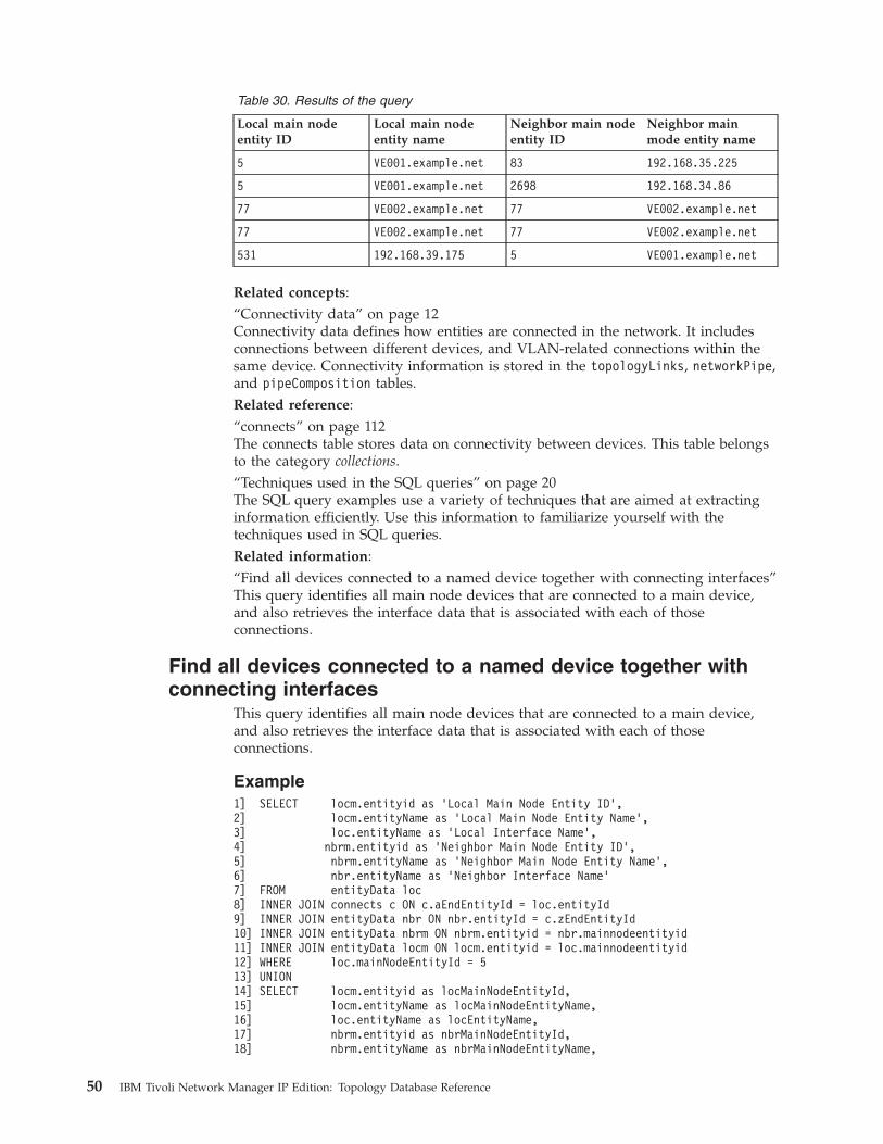
Table 30. Results of the query
Local main nodeentity ID
Local main nodeentity name
Neighbor main nodeentity ID
Neighbor mainmode entity name
5 VE001.example.net 83 192.168.35.225
5 VE001.example.net 2698 192.168.34.86
77 VE002.example.net 77 VE002.example.net
77 VE002.example.net 77 VE002.example.net
531 192.168.39.175 5 VE001.example.net
Related concepts:“Connectivity data” on page 12Connectivity data defines how entities are connected in the network. It includesconnections between different devices, and VLAN-related connections within thesame device. Connectivity information is stored in the topologyLinks, networkPipe,and pipeComposition tables.Related reference:“connects” on page 112The connects table stores data on connectivity between devices. This table belongsto the category collections.“Techniques used in the SQL queries” on page 20The SQL query examples use a variety of techniques that are aimed at extractinginformation efficiently. Use this information to familiarize yourself with thetechniques used in SQL queries.Related information:“Find all devices connected to a named device together with connecting interfaces”This query identifies all main node devices that are connected to a main device,and also retrieves the interface data that is associated with each of thoseconnections.
Find all devices connected to a named device together withconnecting interfaces
This query identifies all main node devices that are connected to a main device,and also retrieves the interface data that is associated with each of thoseconnections.
Example1] SELECT locm.entityid as ’Local Main Node Entity ID’,2] locm.entityName as ’Local Main Node Entity Name’,3] loc.entityName as ’Local Interface Name’,4] nbrm.entityid as ’Neighbor Main Node Entity ID’,5] nbrm.entityName as ’Neighbor Main Node Entity Name’,6] nbr.entityName as ’Neighbor Interface Name’7] FROM entityData loc8] INNER JOIN connects c ON c.aEndEntityId = loc.entityId9] INNER JOIN entityData nbr ON nbr.entityId = c.zEndEntityId10] INNER JOIN entityData nbrm ON nbrm.entityid = nbr.mainnodeentityid11] INNER JOIN entityData locm ON locm.entityid = loc.mainnodeentityid12] WHERE loc.mainNodeEntityId = 513] UNION14] SELECT locm.entityid as locMainNodeEntityId,15] locm.entityName as locMainNodeEntityName,16] loc.entityName as locEntityName,17] nbrm.entityid as nbrMainNodeEntityId,18] nbrm.entityName as nbrMainNodeEntityName,
50 IBM Tivoli Network Manager IP Edition: Topology Database Reference

19] nbr.entityName as nbrEntityName20] FROM entityData loc21] INNER JOIN connects c ON c.zEndEntityId = loc.entityId22] INNER JOIN entityData nbr ON nbr.entityId = c.aEndEntityId23] INNER JOIN entityData nbrm ON nbrm.entityid = nbr.mainnodeentityid24] INNER JOIN entityData locm ON locm.entityid = loc.mainnodeentityid25] WHERE loc.mainNodeEntityId = 5
Description
The table below describes this query.
Table 31. Description of the query
Linenumber(s) Description
1-6 Specify the data to show in the results, as follows:
v The unique entity ID of a specified main node device. This is the nameddevice whose neighbors you want to extract from the database. The restof this description refers to this device as the local device, represented bylocm.entityId
v The name of the local device, represented by locm.entityName
v The name of the interface on the local device, represented byloc.entityName
v The unique entity ID of a device that is adjacent to the specified device,represented by nbrm.entityId
v The name of the neighboring device, represented by nbrm.entityName
v The name of the interface on the neighboring device, represented bynbr.entityName
7 Extract the entity data for each neighboring entity.
Do this by joining the entityData table a second time using thezEndEntityId value. Use the alias nbr for the entityData table to indicatethat the data extracted using this alias is for neighboring entities.
8 Limit the results to neighboring main node devices only.
Do this by joining the entityData table a second time using themainNodeEntityId value.
Use the alias nbrm for the entityData table to indicate that the dataextracted using this alias is entity data for a neighboring main node device.
9 Limit the results to local main node devices only.
Do this by joining the entityData table a second time using themainNodeEntityId.
Use the alias locm for the entityData table to indicate that the dataextracted using this alias is entity data for a local main node device.
10 Specify the identity of the local device.
11 Use the UNION statement to to ensure that all connections are retrieved.
12-21 This is the same code as line 1-10 with the difference that here thespecified device is considered to be the zend (see line 21) and theneighboring devices are all considered to be at the aend (see line 22).
Chapter 3. Topology database queries 51
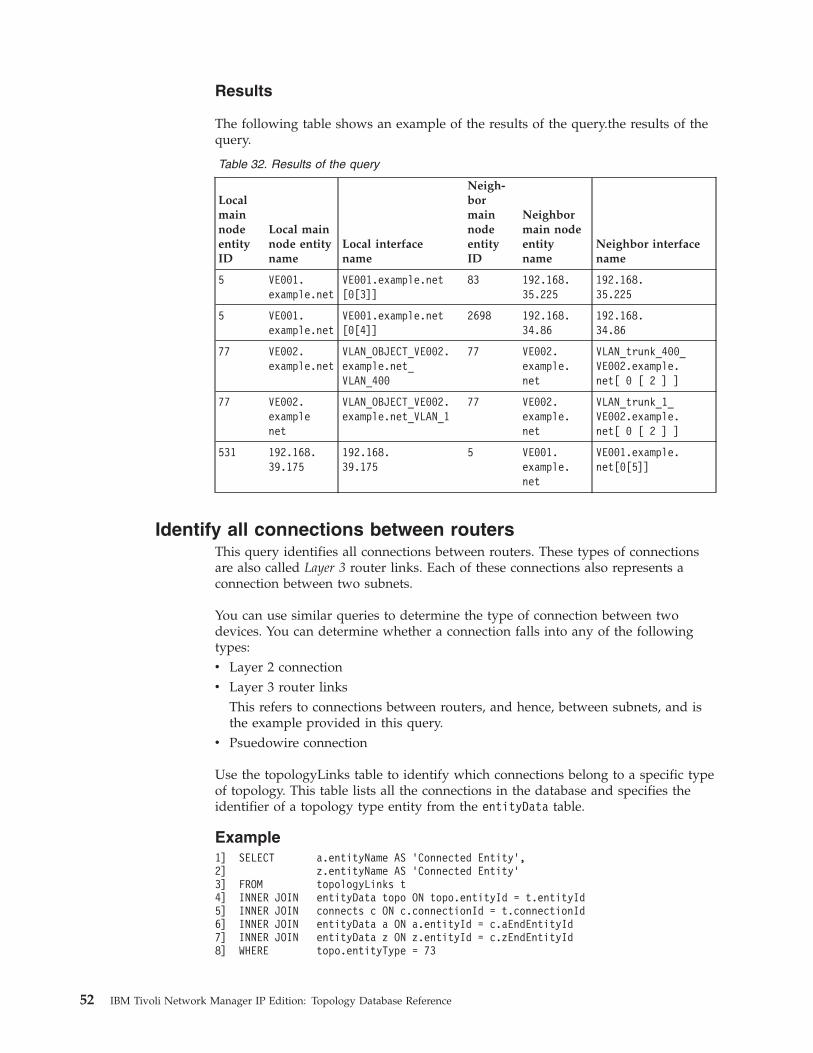
Results
The following table shows an example of the results of the query.the results of thequery.
Table 32. Results of the query
LocalmainnodeentityID
Local mainnode entityname
Local interfacename
Neigh-bormainnodeentityID
Neighbormain nodeentityname
Neighbor interfacename
5 VE001.example.net
VE001.example.net[0[3]]
83 192.168.35.225
192.168.35.225
5 VE001.example.net
VE001.example.net[0[4]]
2698 192.168.34.86
192.168.34.86
77 VE002.example.net
VLAN_OBJECT_VE002.example.net_VLAN_400
77 VE002.example.net
VLAN_trunk_400_VE002.example.net[ 0 [ 2 ] ]
77 VE002.examplenet
VLAN_OBJECT_VE002.example.net_VLAN_1
77 VE002.example.net
VLAN_trunk_1_VE002.example.net[ 0 [ 2 ] ]
531 192.168.39.175
192.168.39.175
5 VE001.example.net
VE001.example.net[0[5]]
Identify all connections between routersThis query identifies all connections between routers. These types of connectionsare also called Layer 3 router links. Each of these connections also represents aconnection between two subnets.
You can use similar queries to determine the type of connection between twodevices. You can determine whether a connection falls into any of the followingtypes:v Layer 2 connectionv Layer 3 router links
This refers to connections between routers, and hence, between subnets, and isthe example provided in this query.
v Psuedowire connection
Use the topologyLinks table to identify which connections belong to a specific typeof topology. This table lists all the connections in the database and specifies theidentifier of a topology type entity from the entityData table.
Example1] SELECT a.entityName AS ’Connected Entity’,2] z.entityName AS ’Connected Entity’3] FROM topologyLinks t4] INNER JOIN entityData topo ON topo.entityId = t.entityId5] INNER JOIN connects c ON c.connectionId = t.connectionId6] INNER JOIN entityData a ON a.entityId = c.aEndEntityId7] INNER JOIN entityData z ON z.entityId = c.zEndEntityId8] WHERE topo.entityType = 73
52 IBM Tivoli Network Manager IP Edition: Topology Database Reference

Description
The table below describes this query.
Table 33. Description of the query
Line numbers Description
1-2 Specify the data to show in the results, as follows:
v The name of an interface at one end of the connection, represented bya.entityName
v The name of an interface at the other end of the connection, representedby z.entityName
3 Use the topologyLinks table as the driving table for this query. Use thealias t for the topologyLinks table for purposes of brevity.
4 Identify all the types of topology listed in the topologyLinks table. Do thisby joining the entityData table using the entityId field.
5 Extract the connection data for each connection. Do this by joining theconnects table using the connectionId field.
6-7 Extract entity details for each of the interfaces at either end of theconnection.
Do this by joining the entityData table a second time using the entityIdfield in the entityData table and the aEndEntityId and zEndEntityId fieldsin turn in the connects table.
8 Limit the results to connections within layer 3 router links only. This limitsthe results to connections between routers, and hence, between subnets.
Results
The table below shows the results of the query.
Table 34. Results of the query
Connected entity Connected entity
172.20.4.16[ Et0/0 ] 172.20.4.11[ Fa0/0 ]
172.20.4.11[ Fa0/0 ] 172.20.4.16[ Et0/0 ]
172.20.4.16[ Et0/0 ] 172.20.4.12[ Fa0/0 ]
172.20.4.11[ Fa0/0 ] 172.20.4.12[ Fa0/0 ]
172.20.4.12[ Fa0/0 ] 172.20.4.16[ Et0/0 ]
172.20.4.12[ Fa0/0 ] 172.20.4.11[ Fa0/0 ]
172.20.4.16[ Et0/0 ] 172.20.4.15[ Fa0/1 ]
172.20.4.11[ Fa0/0 ] 172.20.4.15[ Fa0/1 ]
172.20.4.12[ Fa0/0 ] 172.20.4.15[ Fa0/1 ]
172.20.4.15[ Fa0/1 ] 172.20.4.12[ Fa0/0 ]
172.20.4.15[ Fa0/1 ] 172.20.4.11[ Fa0/0 ]
172.20.4.15[ Fa0/1 ] 172.20.4.16[ Et0/0 ]
172.20.4.16[ Et0/0 ] 172.20.4.28[ Gi0/0 ]
Chapter 3. Topology database queries 53

Related reference:“Techniques used in the SQL queries” on page 20The SQL query examples use a variety of techniques that are aimed at extractinginformation efficiently. Use this information to familiarize yourself with thetechniques used in SQL queries.
Queries for MPLS Traffic Engineered Tunnel informationThese sample queries retrieve information about the MPLS Traffic Engineeredtunnels that have been discovered.
List all Traffic Engineered tunnelsThis database query shows the names of the Traffic Engineered (TE) tunnels thathave been discovered, and the domain they are associated with.
Example1] SELECT e.entityName, e.displayLabel, d.domainName2] FROM entityData e3] INNER JOIN entityType t on t.entityType = e.entityType4] INNER JOIN domainMgr d on d.domainMgrId = e.domainMgrId5] WHERE t.typeName = ’MPLS TE Tunnel’;
Results
The following table provides an example of part of the result set for this query.
Table 35. Results of the query
entityName displayLabel domainName
172.20.1.6_MPLS_TE_Tunnel_Idx_10_Inst_0
172.20.1.6 Tunnel10 10:0 NCOMS
172.20.1.6_MPLS_TE_Tunnel_Idx_10_Inst_12
172.20.1.6 Tunnel10 10:12Primary
NCOMS
172.20.1.7_MPLS_TE_Tunnel_Idx_12_Inst_0
172.20.1.7 Tunnel12 12:0 NCOMS
172.20.1.7_MPLS_TE_Tunnel_Idx_12_Inst_13
172.20.1.7 Tunnel12 12:13Primary
NCOMS
172.20.1.7_MPLS_TE_Tunnel_Idx_50_Inst_0
172.20.1.7 Tunnel50 50:0 NCOMS
172.20.1.7_MPLS_TE_Tunnel_Idx_50_Inst_12
172.20.1.7 Tunnel50 50:12Primary
NCOMS
Show interfaces utilized by Traffic Engineered tunnelsThis database query shows the interfaces and physical ports used by a particularTraffic Engineered (TE) tunnel.
Example1] SELECT eTun.entityName as Tunnel, eInt.entityName as Interface3] FROM collects c4] INNER JOIN entityData eTun ON eTun.entityId = c.collectingEntityId5] INNER JOIN entityData eInt ON eInt.entityId = c.collectedEntityId6] WHERE eTun.entityName = ’172.20.1.7_MPLS_TE_Tunnel_Idx_50_Inst_12’;
54 IBM Tivoli Network Manager IP Edition: Topology Database Reference
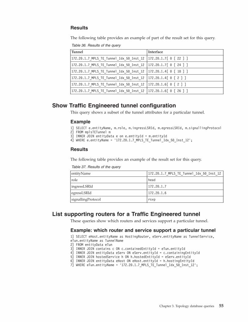
Results
The following table provides an example of part of the result set for this query.
Table 36. Results of the query
Tunnel Interface
172.20.1.7_MPLS_TE_Tunnel_Idx_50_Inst_12 172.20.1.7[ 0 [ 22 ] ]
172.20.1.7_MPLS_TE_Tunnel_Idx_50_Inst_12 172.20.1.7[ 0 [ 24 ] ]
172.20.1.7_MPLS_TE_Tunnel_Idx_50_Inst_12 172.20.1.4[ 0 [ 18 ] ]
172.20.1.7_MPLS_TE_Tunnel_Idx_50_Inst_12 172.20.1.4[ 0 [ 2 ] ]
172.20.1.7_MPLS_TE_Tunnel_Idx_50_Inst_12 172.20.1.6[ 0 [ 2 ] ]
172.20.1.7_MPLS_TE_Tunnel_Idx_50_Inst_12 172.20.1.6[ 0 [ 26 ] ]
Show Traffic Engineered tunnel configurationThis query shows a subset of the tunnel attributes for a particular tunnel.
Example1] SELECT e.entityName, m.role, m.ingressLSRId, m.egressLSRId, m.signallingProtocol2] FROM mplsTETunnel m3] INNER JOIN entityData e on e.entityId = m.entityId4] WHERE e.entityName = ’172.20.1.7_MPLS_TE_Tunnel_Idx_50_Inst_12’;
Results
The following table provides an example of the result set for this query.
Table 37. Results of the query
entityName 172.20.1.7_MPLS_TE_Tunnel_Idx_50_Inst_12
role head
ingressLSRId 172.20.1.7
egressLSRId 172.20.1.6
signallingProtocol rsvp
List supporting routers for a Traffic Engineered tunnelThese queries show which routers and services support a particular tunnel.
Example: which router and service support a particular tunnel1] SELECT eHost.entityName as HostingRouter, eServ.entityName as TunnelService,eTun.entityName as TunnelName2] FROM entityData eTun3] INNER JOIN contains c ON c.containedEntityId = eTun.entityId4] INNER JOIN entityData eServ ON eServ.entityId = c.containingEntityId5] INNER JOIN hostedService h ON h.hostedEntityId = eServ.entityId6] INNER JOIN entityData eHost ON eHost.entityId = h.hostingEntityId7] WHERE eTun.entityName = ’172.20.1.7_MPLS_TE_Tunnel_Idx_50_Inst_12’;
Chapter 3. Topology database queries 55
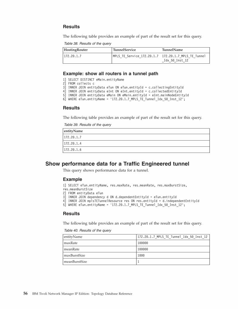
Results
The following table provides an example of part of the result set for this query.
Table 38. Results of the query
HostingRouter TunnelService TunnelName
172.20.1.7 MPLS_TE_Service_172.20.1.7 172.20.1.7_MPLS_TE_Tunnel_Idx_50_Inst_12
Example: show all routers in a tunnel path1] SELECT DISTINCT eMain.entityName2] FROM collects c3] INNER JOIN entityData eTun ON eTun.entityId = c.collectingEntityId4] INNER JOIN entityData eInt ON eInt.entityId = c.collectedEntityId5] INNER JOIN entityData eMain ON eMain.entityId = eInt.mainNodeEntityId6] WHERE eTun.entityName = ’172.20.1.7_MPLS_TE_Tunnel_Idx_50_Inst_12’;
Results
The following table provides an example of part of the result set for this query.
Table 39. Results of the query
entityName
172.20.1.7
172.20.1.4
172.20.1.6
Show performance data for a Traffic Engineered tunnelThis query shows performance data for a tunnel.
Example1] SELECT eTun.entityName, res.maxRate, res.meanRate, res.maxBurstSize,res.meanBurstSize2] FROM entityData eTun3] INNER JOIN dependency d ON d.dependentEntityId = eTun.entityId4] INNER JOIN mplsTETunnelResource res ON res.entityId = d.independentEntityId5] WHERE eTun.entityName = ’172.20.1.7_MPLS_TE_Tunnel_Idx_50_Inst_12’;
Results
The following table provides an example of part of the result set for this query.
Table 40. Results of the query
entityName 172.20.1.7_MPLS_TE_Tunnel_Idx_50_Inst_12
maxRate 100000
meanRate 100000
maxBurstSize 1000
meanBurstSize 1
56 IBM Tivoli Network Manager IP Edition: Topology Database Reference

Queries for Radio Access Network informationThese sample queries retrieve information about Radio Access Network (RAN)devices.
Find specific RAN entity typesThese queries retrieve details of specific entity types used in Radio AccessNetworks, for example, base stations, node B entities, or Mobile Switching Centres.
Example: find all discovered base stations
This query retrieves the details of all base stations that have been discovered.
1]2]3]4]5]6]7]8]
select e.entityId,e.entityName,c.className,rbs.baseStationId,rbs.ranTechnologyTypefrom ncim.entityData eINNER JOIN ncim.physicalChassis c ON c.entityId = e.entityIdINNER JOIN ncim.ranBaseStation rbs ON rbs.entityId = c.entityId
The table below describes this query.
Table 41. Description of the query
Line numbers Description
1-5 Specify the data to show in the results, as follows:
v The entity ID of the base station, represented by e.entityId.
v The name of the base station, represented by e.entityName.
v The Active Object Class assigned to the base station, represented byc.className.
v The unique identifier of the base station, represented byrbs.baseStationId.
v The type of wireless technology used by the base station, represented byrbs.ranTechnologyType.
6 Use the entityData table as the driving table for this query. This part ofthe query retrieves all entities held in the database.
7 Limit the results of the query to chassis entities.
Do this by joining the chassis table to the entityData table using theentityId field.
8 Limit the results of the query to entities that are present in theranBaseStation table, that is, to base stations.
Similar queries
The following example queries retrieve relevant data for different RAN entitytypes, using similar syntax to the above example.
Example: find all discovered Node B entities
This query retrieves the details of all Node B entities that have been discovered.
Chapter 3. Topology database queries 57

select e.entityId,e.entityName,c.className,rnb.nodebId,rnb.ranTechnologyTypefrom ncim.entityData eINNER JOIN ncim.physicalChassis c ON c.entityId = e.entityIdINNER JOIN ncim.ranNodeB rnb ON rnb.entityId = c.entityId
Example: find all discovered Base Station Controllers
This query retrieves the details of all base station controllers that have beendiscovered.select e.entityId,e.entityName,c.className,rbsc.baseStationControllerId,rbsc.ranTechnologyTypefrom ncim.entityData eINNER JOIN ncim.physicalChassis c ON c.entityId = e.entityIdINNER JOIN ncim.ranBaseStationController rbsc ON rbsc.entityId = c.entityId
Example: find all discovered Radio Network Controllers
This query retrieves the details of all Radio Network Controllers that have beendiscovered.select e.entityId,e.entityName,c.className,rrnc.rncId,rrnc.ranTechnologyTypefrom ncim.entityData eINNER JOIN ncim.physicalChassis c ON c.entityId = e.entityIdINNER JOIN ncim.ranRadioNetworkController rrnc ON rrnc.entityId = c.entityId
Example: find all discovered Mobile Switching Centers
This query retrieves the details of all Mobile Switching Centers that have beendiscovered.select e.entityId,e.entityName,c.className,rmsc.mscId,rmsc.msctype,rmsc.ranTechnologyTypefrom ncim.entityData eINNER JOIN ncim.physicalChassis c ON c.entityId = e.entityIdINNER JOIN ncim.ranMobileSwitchingCentre rmsc ON rmsc.entityId = c.entityId
Retrieve RAN connectivityThese queries retrieve the details of entities that are connected to RAN entities.
58 IBM Tivoli Network Manager IP Edition: Topology Database Reference
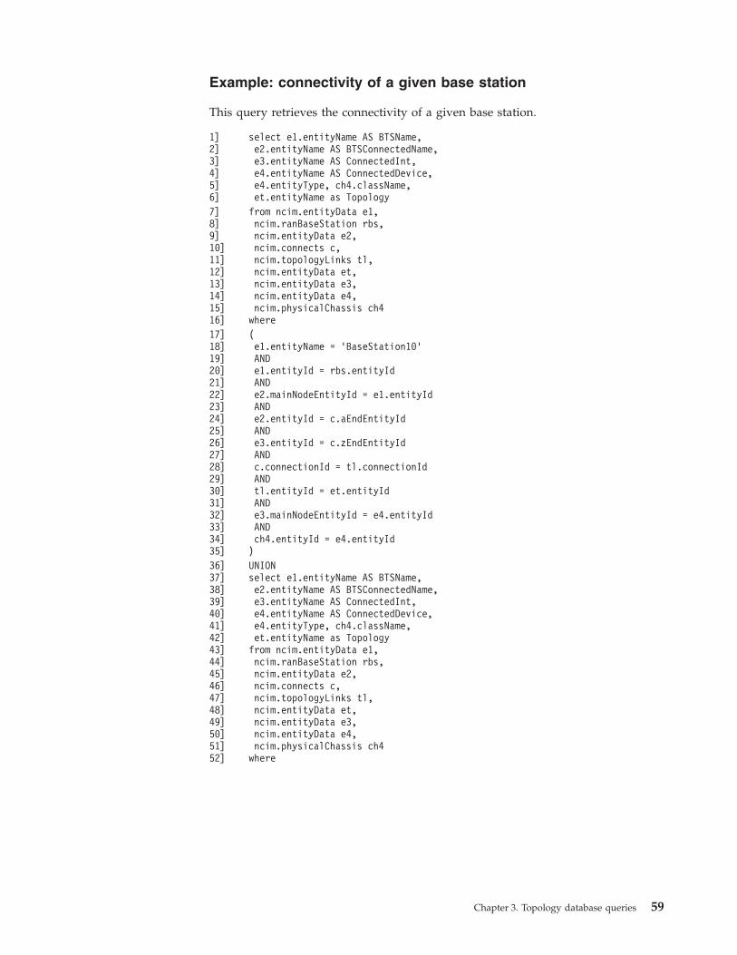
Example: connectivity of a given base station
This query retrieves the connectivity of a given base station.
1]2]3]4]5]6]
select e1.entityName AS BTSName,e2.entityName AS BTSConnectedName,e3.entityName AS ConnectedInt,e4.entityName AS ConnectedDevice,e4.entityType, ch4.className,et.entityName as Topology
7]8]9]10]11]12]13]14]15]16]
from ncim.entityData e1,ncim.ranBaseStation rbs,ncim.entityData e2,ncim.connects c,ncim.topologyLinks tl,ncim.entityData et,ncim.entityData e3,ncim.entityData e4,ncim.physicalChassis ch4where
17]18]19]20]21]22]23]24]25]26]27]28]29]30]31]32]33]34]35]
(e1.entityName = ’BaseStation10’ANDe1.entityId = rbs.entityIdANDe2.mainNodeEntityId = e1.entityIdANDe2.entityId = c.aEndEntityIdANDe3.entityId = c.zEndEntityIdANDc.connectionId = tl.connectionIdANDtl.entityId = et.entityIdANDe3.mainNodeEntityId = e4.entityIdANDch4.entityId = e4.entityId)
36]37]38]39]40]41]42]43]44]45]46]47]48]49]50]51]52]
UNIONselect e1.entityName AS BTSName,e2.entityName AS BTSConnectedName,e3.entityName AS ConnectedInt,e4.entityName AS ConnectedDevice,e4.entityType, ch4.className,et.entityName as Topologyfrom ncim.entityData e1,ncim.ranBaseStation rbs,ncim.entityData e2,ncim.connects c,ncim.topologyLinks tl,ncim.entityData et,ncim.entityData e3,ncim.entityData e4,ncim.physicalChassis ch4where
Chapter 3. Topology database queries 59
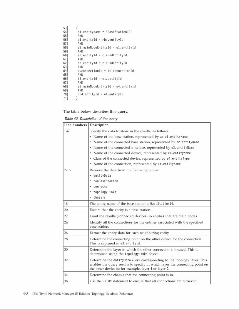
53]54]55]56]57]58]59]60]61]62]63]64]65]66]67]68]69]70]71]
(e1.entityName = ’BaseStation10’ANDe1.entityId = rbs.entityIdANDe2.mainNodeEntityId = e1.entityIdANDe2.entityId = c.zEndEntityIdANDe3.entityId = c.aEndEntityIdANDc.connectionId = tl.connectionIdANDtl.entityId = et.entityIdANDe3.mainNodeEntityId = e4.entityIdANDch4.entityId = e4.entityId)
The table below describes this query.
Table 42. Description of the query
Line numbers Description
1-6 Specify the data to show in the results, as follows:
v Name of the base station, represented by as e1.entityName
v Name of the connected base station, represented by e2.entityName
v Name of the connected interface, represented by e3.entityName
v Name of the connected device, represented by e4.entityName
v Class of the connected device, represented by e4.entityType
v Name of the connection, represented by et.entityName
7-15 Retrieve the data from the following tables:
v entityData
v ranBaseStation
v connects
v topologyLinks
v chassis
18 The entity name of the base station is BaseStation10.
20 Ensure that the entity is a base station.
22 Limit the results (connected devices) to entities that are main nodes.
24 Identify all the connections for the entities associated with the specifiedbase station.
26 Extract the entity data for each neighboring entity.
28 Determine the connecting point on the other device for the connection.This is captured in e3.entityId.
30 Determine the layer in which the other connection is located. This isdetermined using the topologyLinks object.
32 Determine the entityData entry corresponding to the topology layer. Thisenables the query results to specify in which layer the connecting point onthe other device is; for example, layer 1,or layer 2.
34 Determine the chassis that the connecting point is in.
36 Use the UNION statement to ensure that all connections are retrieved.
60 IBM Tivoli Network Manager IP Edition: Topology Database Reference

Table 42. Description of the query (continued)
Line numbers Description
37-71 This is the same code as line 1-36 with the difference that here thespecified device is considered to be the zend (see line 60) and theneighboring devices are all considered to be at the aend (see line 62).
Similar queries
The following example queries retrieve relevant data for different RANrelationships, using similar syntax to the above example.
Example: connectivity of a given Node B entity
This query retrieves the connectivity of a given Node B entity.select e1.entityName AS NodeBName,e2.entityName AS NodeBConnectedName,e3.entityName AS ConnectedInt,e4.entityName AS ConnectedDevice,e4.entityType, ch4.classNamefrom ncim.entityData e1,ncim.ranNodeB rnb,ncim.entityData e2,ncim.entityData et,ncim.topologyLinks tl,ncim.connects c,ncim.entityData e3,ncim.entityData e4, ncim.physicalChassis ch4where(e1.entityName = ’NodeB10’ANDe1.entityId = rnb.entityIdANDe2.mainNodeEntityId = e1.entityIdANDe2.entityId = c.aEndEntityIdANDe3.entityId = c.zEndEntityIdANDc.connectionId = tl.connectionIdANDtl.entityId = et.entityIdANDe3.mainNodeEntityId = e4.entityIdANDch4.entityId = e4.entityId)UNIONselect e1.entityName AS NodeBName,e2.entityName AS NodeBConnectedName,e3.entityName AS ConnectedInt,e4.entityName AS ConnectedDevice,e4.entityType,ch4.classNamefrom ncim.entityData e1,ncim.ranNodeB rnb,ncim.entityData e2,ncim.entityData et,ncim.topologyLinks tl,ncim.connects c,ncim.entityData e3,ncim.entityData e4,
Chapter 3. Topology database queries 61
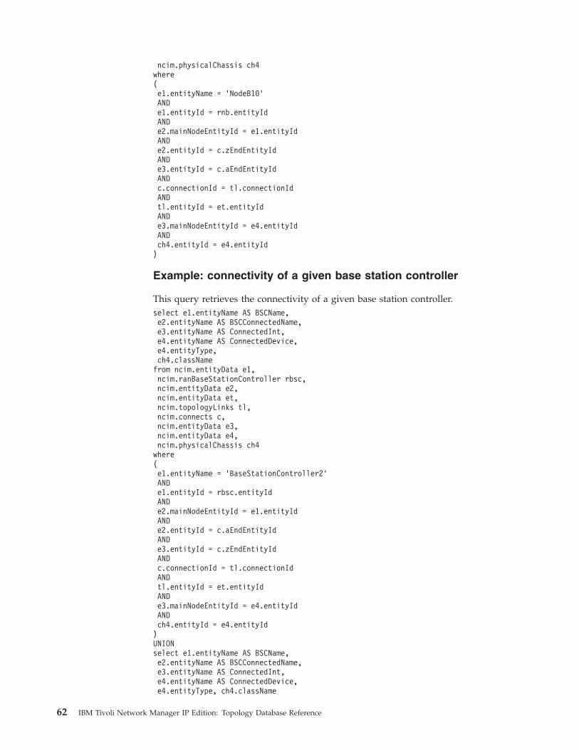
ncim.physicalChassis ch4where(e1.entityName = ’NodeB10’ANDe1.entityId = rnb.entityIdANDe2.mainNodeEntityId = e1.entityIdANDe2.entityId = c.zEndEntityIdANDe3.entityId = c.aEndEntityIdANDc.connectionId = tl.connectionIdANDtl.entityId = et.entityIdANDe3.mainNodeEntityId = e4.entityIdANDch4.entityId = e4.entityId)
Example: connectivity of a given base station controller
This query retrieves the connectivity of a given base station controller.select e1.entityName AS BSCName,e2.entityName AS BSCConnectedName,e3.entityName AS ConnectedInt,e4.entityName AS ConnectedDevice,e4.entityType,ch4.classNamefrom ncim.entityData e1,ncim.ranBaseStationController rbsc,ncim.entityData e2,ncim.entityData et,ncim.topologyLinks tl,ncim.connects c,ncim.entityData e3,ncim.entityData e4,ncim.physicalChassis ch4where(e1.entityName = ’BaseStationController2’ANDe1.entityId = rbsc.entityIdANDe2.mainNodeEntityId = e1.entityIdANDe2.entityId = c.aEndEntityIdANDe3.entityId = c.zEndEntityIdANDc.connectionId = tl.connectionIdANDtl.entityId = et.entityIdANDe3.mainNodeEntityId = e4.entityIdANDch4.entityId = e4.entityId)UNIONselect e1.entityName AS BSCName,e2.entityName AS BSCConnectedName,e3.entityName AS ConnectedInt,e4.entityName AS ConnectedDevice,e4.entityType, ch4.className
62 IBM Tivoli Network Manager IP Edition: Topology Database Reference

from ncim.entityData e1,ncim.ranBaseStationController rbsc,ncim.entityData e2,ncim.entityData et,ncim.topologyLinks tl,ncim.connects c,ncim.entityData e3,ncim.entityData e4,ncim.physicalChassis ch4where(e1.entityName = ’BaseStationController2’ANDe1.entityId = rbsc.entityIdANDe2.mainNodeEntityId = e1.entityIdANDe2.entityId = c.zEndEntityIdANDe3.entityId = c.aEndEntityIdANDc.connectionId = tl.connectionIdANDtl.entityId = et.entityIdANDe3.mainNodeEntityId = e4.entityIdANDch4.entityId = e4.entityId)
Example: connectivity of a given radio network controller
This query retrieves the connectivity of a given radio network controller.select e1.entityName AS RNCName,e2.entityName AS RNCConnectedName,e3.entityName AS ConnectedInt,e4.entityName AS ConnectedDevice,e4.entityType,ch4.classNamefrom ncim.entityData e1,ncim.ranRadioNetworkController rrnc,ncim.entityData e2,ncim.entityData et,ncim.topologyLinks tl,ncim.connects c,ncim.entityData e3,ncim.entityData e4,ncim.physicalChassis ch4where(e1.entityName = ’radioNetworkController2’ANDe1.entityId = rrnc.entityIdANDe2.mainNodeEntityId = e1.entityIdANDe2.entityId = c.aEndEntityIdANDe3.entityId = c.zEndEntityIdANDc.connectionId = tl.connectionIdANDtl.entityId = et.entityIdANDe3.mainNodeEntityId = e4.entityIdAND
Chapter 3. Topology database queries 63

ch4.entityId = e4.entityId)UNIONselect e1.entityName AS RNCName,e2.entityName AS RNCConnectedName,e3.entityName AS ConnectedInt,e4.entityName AS ConnectedDevice,e4.entityType,ch4.classNamefrom ncim.entityData e1,ncim.ranRadioNetworkController rrnc,ncim.entityData e2,ncim.entityData et,ncim.topologyLinks tl,ncim.connects c,ncim.entityData e3,ncim.entityData e4,ncim.physicalChassis ch4where(e1.entityName = ’radioNetworkController2’ANDe1.entityId = rrnc.entityIdANDe2.mainNodeEntityId = e1.entityIdANDe2.entityId = c.zEndEntityIdANDe3.entityId = c.aEndEntityIdANDc.connectionId = tl.connectionIdANDtl.entityId = et.entityIdANDe3.mainNodeEntityId = e4.entityIdANDch4.entityId = e4.entityId)
Example: connectivity of a given media gateway
This query retrieves the connectivity of a given media gateway.select e1.entityName AS MGWName,e2.entityName AS MGWConnectedName,e3.entityName AS ConnectedInt,e4.entityName AS ConnectedDevice,e4.entityType,ch4.classNamefrom ncim.entityData e1,ncim.ranMediaGateway rmgw,ncim.entityData e2,ncim.entityData et,ncim.topologyLinks tl,ncim.connects c,ncim.entityData e3,ncim.entityData e4,ncim.physicalChassis ch4where(e1.entityName = ’MediaGateway1’ANDe1.entityId = rmgw.entityIdANDe2.mainNodeEntityId = e1.entityIdANDe2.entityId = c.aEndEntityId
64 IBM Tivoli Network Manager IP Edition: Topology Database Reference

ANDe3.entityId = c.zEndEntityIdANDc.connectionId = tl.connectionIdANDtl.entityId = et.entityIdANDe3.mainNodeEntityId = e4.entityIdANDch4.entityId = e4.entityId)UNIONselect e1.entityName AS MGWName,e2.entityName AS MGWConnectedName,e3.entityName AS ConnectedInt,e4.entityName AS ConnectedDevice,e4.entityType,ch4.classNamefrom ncim.entityData e1,ncim.ranMediaGateway rmgw,ncim.entityData e2,ncim.entityData et,ncim.topologyLinks tl,ncim.connects c,ncim.entityData e3,ncim.entityData e4,ncim.physicalChassis ch4where(e1.entityName = ’MediaGateway1’ANDe1.entityId = rmgw.entityIdANDe2.mainNodeEntityId = e1.entityIdANDe2.entityId = c.zEndEntityIdANDe3.entityId = c.aEndEntityIdANDc.connectionId = tl.connectionIdANDtl.entityId = et.entityIdANDe3.mainNodeEntityId = e4.entityIdANDch4.entityId = e4.entityId)
Example: connectivity of a given serving GPRS support node
This query retrieves the connectivity of a given serving GPRS support node.select e1.entityName AS SGSNName,e2.entityName AS SGSNConnectedName,e3.entityName AS ConnectedInt,e4.entityName AS ConnectedDevice,e4.entityType, ch4.classNamefrom ncim.entityData e1,ncim.ranSGSN rsgsn,ncim.entityData e2,ncim.entityData et,ncim.topologyLinks tl,ncim.connects c,ncim.entityData e3,ncim.entityData e4,ncim.physicalChassis ch4where
Chapter 3. Topology database queries 65
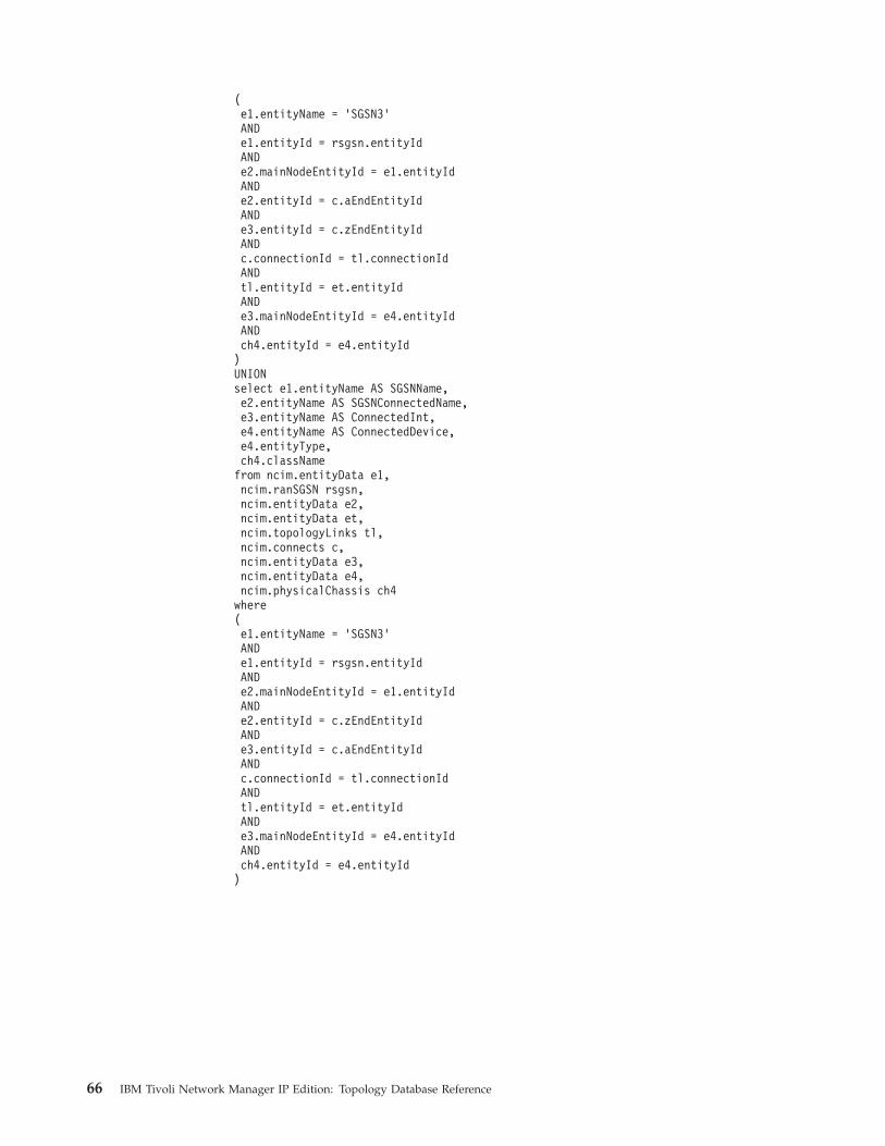
(e1.entityName = ’SGSN3’ANDe1.entityId = rsgsn.entityIdANDe2.mainNodeEntityId = e1.entityIdANDe2.entityId = c.aEndEntityIdANDe3.entityId = c.zEndEntityIdANDc.connectionId = tl.connectionIdANDtl.entityId = et.entityIdANDe3.mainNodeEntityId = e4.entityIdANDch4.entityId = e4.entityId)UNIONselect e1.entityName AS SGSNName,e2.entityName AS SGSNConnectedName,e3.entityName AS ConnectedInt,e4.entityName AS ConnectedDevice,e4.entityType,ch4.classNamefrom ncim.entityData e1,ncim.ranSGSN rsgsn,ncim.entityData e2,ncim.entityData et,ncim.topologyLinks tl,ncim.connects c,ncim.entityData e3,ncim.entityData e4,ncim.physicalChassis ch4where(e1.entityName = ’SGSN3’ANDe1.entityId = rsgsn.entityIdANDe2.mainNodeEntityId = e1.entityIdANDe2.entityId = c.zEndEntityIdANDe3.entityId = c.aEndEntityIdANDc.connectionId = tl.connectionIdANDtl.entityId = et.entityIdANDe3.mainNodeEntityId = e4.entityIdANDch4.entityId = e4.entityId)
66 IBM Tivoli Network Manager IP Edition: Topology Database Reference

Find RAN containmentThese queries retrieve the details of RAN entities that are contained, by otherentities.
Example: find all sectors within a given cell
This query retrieves the details of all sectors within a given cell. There is no directrelationship between a sector and a cell. Sectors are hosted by transceivers, andtransceivers are contained within a base station. There is a collects relationshipbetween cells and transceivers. The query also deals with fact that there are twodifferent types of cell: GSM cells and UTRAN cells.
1]2]3]4]5]6]7]8]9]10]11]12]13]14]15]16]17]18]19]20]21]22]23]24]
select e1.entityId AS sectorEntityId,e1.entityName AS sectorName,e2.entityId AS cellEntityId ,e2.entityName AS cellEntityName,COALESCE(rgc.cellid, ruc.cellid),COALESCE(rgc.rantechnologytype,’UMTS’) AS cellTypefrom ncim.entityData e1INNER JOIN ncim.ranSector rs ON rs.entityId = e1.entityIdINNER JOIN ncim.hostedService hs ON hs.hostedEntityId = e1.entityIdINNER JOIN ncim.entityData e3 ON e3.entityId = hs.hostingEntityIdINNER JOIN ncim.collects c ON c.collectedEntityId = e3.entityIdINNER JOIN ncim.entityData e2 ON e2.entityId = c.collectingEntityIdLEFT OUTER JOIN ncim.rangsmcell rgc ON rgc.entityId = e2.entityIdLEFT OUTER JOIN ncim.ranutrancell ruc ON ruc.entityId = e2.entityIdWHERE(e2.entityName = cell_nameAND(e2.entityType = 130ORe2.entityType = 131));
The table below describes this query.
Table 43. Description of the query
Line numbers Description
1-6 Specify the data to show in the results, as follows:
v The entity ID of the sector, represented by e1.entityId.
v The name of the sector, represented by e1.entityName
v The ID of the cell, represented by e2.entityId
v The name of the cell, represented by e2.entityName
v Use the COALESCE function to take either GSM or UTRAN cell IDs as areturn value.
7 Use the entityData table as the driving table for this query.
8 Limit the results of the query to RAN sectors
9-10 The alias e3 identifies the hosting transceiver. The JOIN operations onthese lines limit the results to the transceiver that hosts the RAN sectors.
11-12 The alias e2 identifies the cells that collect the transceivers. The JOINoperations on these lines limit the results to the cells that collect thetransceiver, that in turn hosts the RAN sectors.
Chapter 3. Topology database queries 67
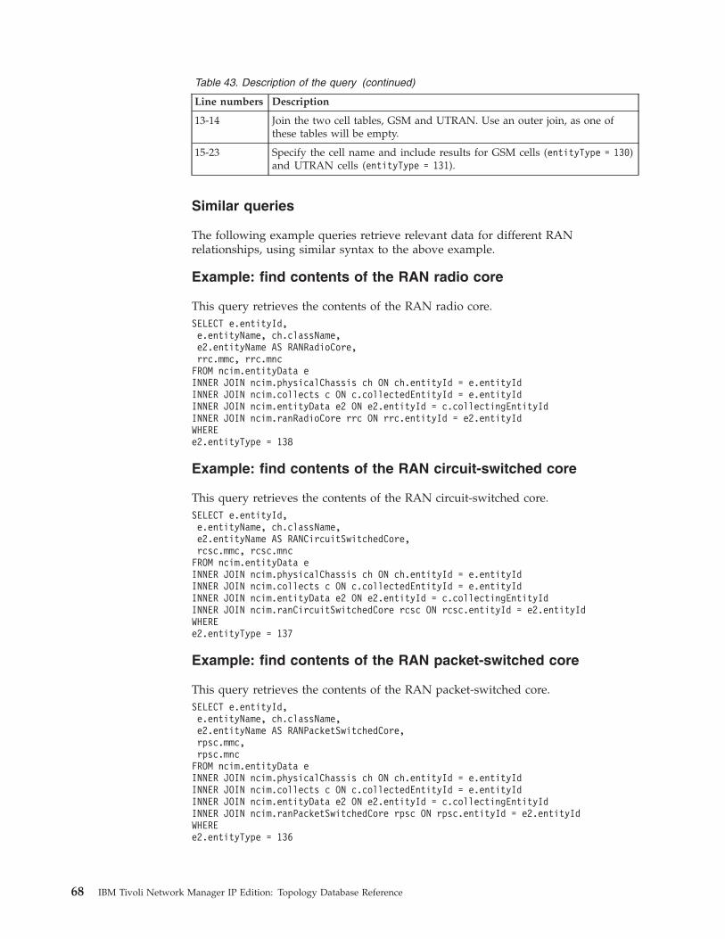
Table 43. Description of the query (continued)
Line numbers Description
13-14 Join the two cell tables, GSM and UTRAN. Use an outer join, as one ofthese tables will be empty.
15-23 Specify the cell name and include results for GSM cells (entityType = 130)and UTRAN cells (entityType = 131).
Similar queries
The following example queries retrieve relevant data for different RANrelationships, using similar syntax to the above example.
Example: find contents of the RAN radio core
This query retrieves the contents of the RAN radio core.SELECT e.entityId,e.entityName, ch.className,e2.entityName AS RANRadioCore,rrc.mmc, rrc.mncFROM ncim.entityData eINNER JOIN ncim.physicalChassis ch ON ch.entityId = e.entityIdINNER JOIN ncim.collects c ON c.collectedEntityId = e.entityIdINNER JOIN ncim.entityData e2 ON e2.entityId = c.collectingEntityIdINNER JOIN ncim.ranRadioCore rrc ON rrc.entityId = e2.entityIdWHEREe2.entityType = 138
Example: find contents of the RAN circuit-switched core
This query retrieves the contents of the RAN circuit-switched core.SELECT e.entityId,e.entityName, ch.className,e2.entityName AS RANCircuitSwitchedCore,rcsc.mmc, rcsc.mncFROM ncim.entityData eINNER JOIN ncim.physicalChassis ch ON ch.entityId = e.entityIdINNER JOIN ncim.collects c ON c.collectedEntityId = e.entityIdINNER JOIN ncim.entityData e2 ON e2.entityId = c.collectingEntityIdINNER JOIN ncim.ranCircuitSwitchedCore rcsc ON rcsc.entityId = e2.entityIdWHEREe2.entityType = 137
Example: find contents of the RAN packet-switched core
This query retrieves the contents of the RAN packet-switched core.SELECT e.entityId,e.entityName, ch.className,e2.entityName AS RANPacketSwitchedCore,rpsc.mmc,rpsc.mncFROM ncim.entityData eINNER JOIN ncim.physicalChassis ch ON ch.entityId = e.entityIdINNER JOIN ncim.collects c ON c.collectedEntityId = e.entityIdINNER JOIN ncim.entityData e2 ON e2.entityId = c.collectingEntityIdINNER JOIN ncim.ranPacketSwitchedCore rpsc ON rpsc.entityId = e2.entityIdWHEREe2.entityType = 136
68 IBM Tivoli Network Manager IP Edition: Topology Database Reference
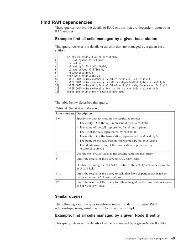
Find RAN dependenciesThese queries retrieve the details of RAN entities that are dependent upon otherRAN entities.
Example: find all cells managed by a given base station
This query retrieves the details of all cells that are managed by a given basestation.
1]2]3]4]5]6]7]8]9]10]11]12]
select e1.entityId AS cellEntityId,e1.entityName AS cellName,rc.cellid,e2.entityId AS btsEntityId,e2.entityName AS BTSname,rbs.baseStationIdfrom ncim.entityData e1INNER JOIN ncim.rangsmcell rc ON rc.entityId = e1.entityIdINNER JOIN ncim.dependency dep ON dep.dependentEntityId = e1.entityIdINNER JOIN ncim.entityData e2 ON e2.entityId = dep.independentEntityIdINNER JOIN ncim.ranBaseStation rbs ON rbs.entityId = e2.entityIdWHERE (e2.entityName = base_station_name)
The table below describes this query.
Table 44. Description of the query
Line numbers Description
1-6 Specify the data to show in the results, as follows:
v The entity ID of the cell, represented by e1.entityId.
v The name of the cell, represented by e1.entityName
v The ID of the cell, represented by rc.cellid
v The entity ID of the base station, represented by e2.entityId
v The name of the base station, represented by e2.entityName
v The identifying string of the base station, represented byrbs.baseStationId
7 Use the entityData table as the driving table for this query.
8 Limit the results of the query to RAN GSM cells.
Do this by joining the ranGSMCell table to the entityData table using theentityId field.
9-11 Limit the results of the query to cells that have dependencies listed onentities that are RAN base stations.
12 Limit the results of the query to cells managed by the base station knownas base_station_name.
Similar queries
The following example queries retrieve relevant data for different RANrelationships, using similar syntax to the above example.
Example: find all cells managed by a given Node B entity
This query retrieves the details of all cells managed by a given Node B entity.
Chapter 3. Topology database queries 69

select e1.entityId AS cellEntityId,e1.entityName AS cellName, rc.cellid,e2.entityId AS nodeBEntityId,e2.entityName AS nodeBName,rnb.nodeBIdfrom ncim.entityData e1INNER JOIN ncim.ranutrancell rc ON rc.entityId = e1.entityIdINNER JOIN ncim.dependency dep ON dep.dependentEntityId = e1.entityIdINNER JOIN ncim.entityData e2 ON e2.entityId = dep.independentEntityIdINNER JOIN ncim.ranNodeB rnb ON rnb.entityId = e2.entityIdWHERE(e2.entityName = node_b_name)
Example: find all base stations managed by a given base stationcontroller
This query retrieves the details of all base stations managed by a given base stationcontroller.select e1.entityId AS btsEntityId,e1.entityName AS btsName,rbs.basestationid,e2.entityId AS bscEntityId,e2.entityName AS bscName,rbsc.baseStationControllerIdfrom ncim.entityData e1INNER JOIN ncim.ranBaseStation rbs ON rbs.entityId = e1.entityIdINNER JOIN ncim.dependency d ON d.dependentEntityId = e1.entityIdINNER JOIN ncim.entityData e2 ON e2.entityId = d.independentEntityIdINNER JOIN ncim.ranBaseStationController rbsc ON rbsc.entityId = e2.entityIdWHERE(e2.entityName = base_station_controller_name);
Example: find all Node B entities managed by a given radionetwork controller
This query retrieves the details of all Node B entities managed by a given radionetwork controller.select e1.entityId AS nodeBEntityId,e1.entityName AS nodeBName,rnb.nodeBid,e2.entityId AS rncEntityId,e2.entityName AS rncName,rrnc.rncIdfrom ncim.entityData e1INNER JOIN ncim.ranNodeB rnb ON rnb.entityId = e1.entityIdINNER JOIN ncim.dependency d ON d.dependentEntityId = e1.entityIdINNER JOIN ncim.entityData e2 ON e2.entityId = d.independentEntityIdINNER JOIN ncim.ranRadioNetworkController rrnc ON rrnc.entityId = e2.entityIdWHERE(e2.entityName = radio_network_controller_name);
70 IBM Tivoli Network Manager IP Edition: Topology Database Reference
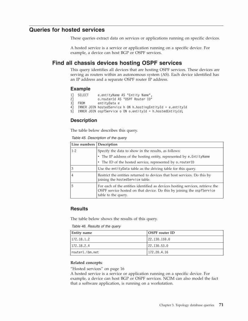
Queries for hosted servicesThese queries extract data on services or applications running on specific devices.
A hosted service is a service or application running on a specific device. Forexample, a device can host BGP or OSPF services.
Find all chassis devices hosting OSPF servicesThis query identifies all devices that are hosting OSPF services. These devices areserving as routers within an autonomous system (AS). Each device identified hasan IP address and a separate OSPF router IP address.
Example1] SELECT e.entityName AS "Entity Name",2] o.routerId AS "OSPF Router ID"3] FROM entityData e4] INNER JOIN hostedService h ON h.hostingEntityId = e.entityId5] INNER JOIN ospfService o ON o.entityId = h.hostedEntityId;
Description
The table below describes this query.
Table 45. Description of the query
Line numbers Description
1-2 Specify the data to show in the results, as follows:
v The IP address of the hosting entity, represented by e.EntityName
v The ID of the hosted service, represented by o.routerID
3 Use the entityData table as the driving table for this query.
4 Restrict the entities returned to devices that host services. Do this byjoining the hostedService table.
5 For each of the entities identified as devices hosting services, retrieve theOSPF service hosted on that device. Do this by joining the ospfServicetable to the query.
Results
The table below shows the results of this query.
Table 46. Results of the query
Entity name OSPF router ID
172.18.1.2 22.130.159.0
172.18.2.4 22.130.53.0
router1.ibm.net 172.20.4.16
Related concepts:“Hosted services” on page 16A hosted service is a service or application running on a specific device. Forexample, a device can host BGP or OSPF services. NCIM can also model the factthat a software application, is running on a workstation.
Chapter 3. Topology database queries 71

Queries for collection informationThese queries extract data on logical collections of devices.
Device collections are logical collections of devices. Examples of logical collectionsdefined within NCIM include MPLS VPNs, global VLANs, and subnets. NCIM canalso model OSPF areas.
Show all PIM adjacenciesThis query returns details of all Protocol Independent Multicast (PIM) adjacencies.
Example1] SELECT eA.entityName AS A,2] eZ.entityName AS Z,3] FROM from topologyLinks t,4] INNER JOIN connects c ON t.connectionId=c.connectionId5] INNER JOIN entityData eA ON eA.entityId=c.aEndEntityId6] INNER JOIN entityData eZ ON eZ.entityId=c.zEndEntityId7] INNER JOIN entityData et ON et.entityId = t.entityId8] WHERE et.entityName=’PIMTopology’;
Show PIM adjacencies for a deviceThis query shows Protocol Independent Multicast (PIM) adjacencies for a particulardevice.
Example
This example shows PIM adjacencies for the device 172.20.1.7.1] SELECT eA.entityName AS A,2] eZ.entityName AS Z,3] FROM from topologyLinks t4] INNER JOIN connects c ON t.connectionId=c.connectionId5] INNER JOIN entityData eA ON eA.entityId=c.aEndEntityId6] INNER JOIN entityData eZ ON eZ.entityId=c.zEndEntityId7] INNER JOIN entityData et ON et.entityId = t.entityId8] INNER JOIN entityData eAMain ON eAMain.entityId=eA.mainNodeEntityId9] INNER JOIN entityData eZMain ON eZMain.entityId=eZ.mainNodeEntityId10] WHERE et.entityName=’PIMTopology’11] and eAMain.entityName = ’172.20.1.7’ or eZMain.entityName = ’172.20.1.7’;
Find PIM enabled routersThis query returns a list of all routers that are enabled to use Protocol IndependentMulticast (PIM).
Example1] SELECT e.entityName,2] c.sysName,3] p.joinPruneInterval4] FROM pimService p5] INNER JOIN hostedService h ON h.hostedEntityId=p.entityId6] INNER JOIN entityData e ON e.entityId=h.hostingEntityId7] INNER JOIN physicalChassis c ON c.entityId = e.mainNodeEntityId;
72 IBM Tivoli Network Manager IP Edition: Topology Database Reference

Find all devices in each subnetThis query identifies all of the subnets listed in the database. For each subnet thequery provides the netmask of that subnet and the list of IP addresses collectedwithin that subnet. The IP address collected within a subnet might refer to mainnodes or interfaces; typically, they refer to interfaces.
Example1] SELECT s.network AS ’Network’,2] s.netmask AS ’Netmask’,3] e.entityName AS ’Entity Name’4] FROM subnet s5] INNER JOIN collects c ON c.collectingEntityId = s.entityId6] INNER JOIN entityData e ON e.entityId = c.collectedEntityId7] ORDER BY s.network
Description
The table below describes this query.
Table 47. Description of the query
Line numbers Description
1-3 Specify the data to show in the results, as follows:
v The IP address of the collecting subnet, represented by s.network
v The netmask of the subnet, represented by s.netmask
v The name – usually an IP address – of an interface or main node withinthis subnet, represented by e.entityName
4 Use the subnet table as the driving table for this query. This enables thequery to extract all the subnets in the database.
5 Retrieve a listing of all the collected entities within each subnet. At thispoint the collected entities are identified by their entity identifier only. Thecorresponding IP address is retrieved in the next line. Do this by joiningthe collects table.
6 Extract the entity data for each interface or main node collected withineach subnet. Do this by joining the entityData table to the query. Thisenables the query to retrieve the IP address for each of the collectedentities.
7 For readability purposes, order the results by the IP address of thecollecting subnet.
Results
The table below shows the results of this query.
Table 48. Results of the query
Network Netmask Entity name
10.1.1.0 255.255.255.0 10.1.1.6
10.1.1.0 255.255.255.0 10.1.1.8
10.1.1.0 255.255.255.0 10.1.1.9
10.1.1.0 255.255.255.0 10.1.1.25
10.1.1.0 255.255.255.0 10.1.1.26
10.1.1.0 255.255.255.0 10.1.1.27
Chapter 3. Topology database queries 73

Table 48. Results of the query (continued)
Network Netmask Entity name
172.18.1.0 255.255.255.0 172.18.1.30
172.18.1.0 255.255.255.0 172.18.1.31
172.20.11.0 255.255.255.248 172.20.11.54
172.20.11.0 255.255.255.248 172.20.11.75
Find all devices in a given VPNThis query identifies all of the VPNs listed in the database. For each VPN thequery provides the name of that VPN and the list of IP addresses collected withinthat subnet. The IP address collected within a VPN might refer to main nodes orinterfaces; typically they refer to interfaces.
Example1] SELECT v.VPNName AS ’VPN Name’,2] v.VPNType AS ’VPN Type’,3] e.entityName AS ’Entity Name’4] FROM networkVpn v5] INNER JOIN collects c ON c.collectingEntityId = v.entityId6] INNER JOIN entityData e ON e.entityId = c.collectedEntityId7] ORDER BY v.VPNName
Description
The table below describes this query.
Table 49. Description of the query
Line numbers Description
1-3 Specify the data to show in the results, as follows:
v The IP address of the VPN, represented by v.VPNName
v The VPN type, represented by v.VPNType
v The name – usually an IP address – of an interface or main node withinthis VPN, represented by e.entityName
4 Use the networkVpn table as the driving table for this query. This enablesthe query to extract all the VPNs in the database.
5 Retrieve a listing of all the collected entities within each VPN. At this pointthe collected entities are identified by their entity identifier only. Thecorresponding IP address is retrieved in the next line. Do this by joiningthe collects table.
6 Extract the entity data for each interface or main node collected withineach VPN. Do this by joining the entityData table to the query. Thisenables the query to retrieve the IP address for each of the collectedentities
7 For readability purposes, order the results by the name of the collectingVPN.
74 IBM Tivoli Network Manager IP Edition: Topology Database Reference

Results
The table below shows the results of this query.
Table 50. Results of the query
VPN name VPN type Entity name
VPN-BLUE MPLS L2 PseudoWire 172.18.1.31
VPN-BLUE MPLS L2 PseudoWire 172.20.11.54
VPN-BLUE MPLS L2 PseudoWire 172.20.11.75
VPN-GREEN MPLS L2 BGP VPN 10.1.1.26
VPN-GREEN MPLS L2 BGP VPN 10.1.1.27
VPN-GREEN MPLS L2 BGP VPN 172.18.1.30
VPN-PURPLE MPLS IP VPN RT PAIR 10.1.1.59
VPN-PURPLE MPLS IP VPN RT PAIR 10.1.1.75
VPN-RED MPLS IP VPN 172.20.11.103
VPN-RED MPLS IP VPN 172.20.11.111
VPN-WHITE MPLS IP VPN MESH 172.18.1.233
VPN-WHITE MPLS IP VPN MESH 172.18.1.240
VPN-YELLOW MPLS IP VPN 10.1.1.6
VPN-YELLOW MPLS IP VPN 10.1.1.8
VPN-YELLOW MPLS IP VPN 10.1.1.9
VPN-YELLOW MPLS IP VPN 10.1.1.25
Related concepts:“Collection data” on page 15Collection data defines logical collections. Collections are defined in the collectstable. Examples of logical collections defined within NCIM include MPLS VPNs,global VLANs, and subnets.
Queries for mapping and enumeration informationThese sample queries extract mapping and enumeration data from NCIM.
Mappings and enumerations provide a means of looking up a database value innumerical or textual format and retrieving corresponding human-readable text.
Identify all the device hardware manufacturers listed in thedatabase
This query provides a list of all device manufacturers held in the topologydatabase.
The query uses the mappings table. This table provides lookups for alternativetextual names. These lookups provide more human-readable text for fields. Youcan perform lookups in the mappings table for the types of information (ormapping groups) shown in the following table.
Chapter 3. Topology database queries 75
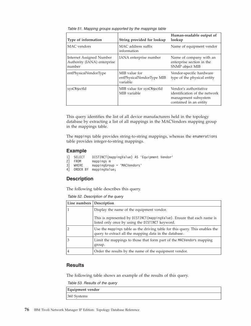
Table 51. Mapping groups supported by the mappings table
Type of information String provided for lookupHuman-readable output oflookup
MAC vendors MAC address suffixinformation
Name of equipment vendor
Internet Assigned NumberAuthority (IANA) enterprisenumber
IANA enterprise number Name of company with anenterprise section in theSNMP object MIB
entPhysicalVendorType MIB value forentPhysicalVendorType MIBvariable
Vendor-specific hardwaretype of the physical entity
sysObjectId MIB value for sysObjectIdMIB variable
Vendor's authoritativeidentification of the networkmanagement subsystemcontained in an entity
This query identifies the list of all device manufacturers held in the topologydatabase by extracting a list of all mappings in the MACVendors mapping groupin the mappings table.
The mappings table provides string-to-string mappings, whereas the enumerationstable provides integer-to-string mappings.
Example1] SELECT DISTINCT(mappingValue) AS ’Equipment Vendor’2] FROM mappings m3] WHERE mappingGroup = ’MACVendors’4] ORDER BY mappingValue;
Description
The following table describes this query.
Table 52. Description of the query
Line numbers Description
1 Display the name of the equipment vendor.
This is represented by DISTINCT(mappingValue). Ensure that each name islisted only once by using the DISTINCT keyword.
2 Use the mappings table as the driving table for this query. This enables thequery to extract all the mapping data in the database.
3 Limit the mappings to those that form part of the MACVendors mappinggroup.
4 Order the results by the name of the equipment vendor.
Results
The following table shows an example of the results of this query.
Table 53. Results of the query
Equipment vendor
360 Systems
76 IBM Tivoli Network Manager IP Edition: Topology Database Reference

Table 53. Results of the query (continued)
Equipment vendor
3COM
3e Technologies International Inc.
A-TREND TECHNOLOGY CO., LTD.
Abatron AG
ABB Automation Technology Products AB, Control
Abbey Systems Ltd
ABIT CORPORATION
AboveCable, Inc.
AbsoluteValue Systems, Inc.
AC Tech corporation DBA Advanced Digital
AC&T SYSTEM CO., LTD.
ACACIA NETWORKS, INC.
Related reference:“Identify all the device hardware manufacturers listed in the database” on page 75This query provides a list of all device manufacturers held in the topologydatabase.
Show all the entity types defined in the databaseThis query provides a list of entity types configured within the topology database.Entity type data includes a numerical key, a textual name for the entity type, and acategory of entity to which the entity belongs.
Network Manager has the following entity categories:v Elementv Collectionv Servicev Protocol endpointv Topology
This query uses the entityType table. This table contains every entity type inNCIM. If you want to define a new entity type, you need to update this table toinclude the entity type.
Example1] SELECT e.entityType AS ’Entity Type’,2] e.typeName AS ’Entity Name’,3] e.metaClass AS ’Category of Entity’4] FROM entityType e;
Chapter 3. Topology database queries 77
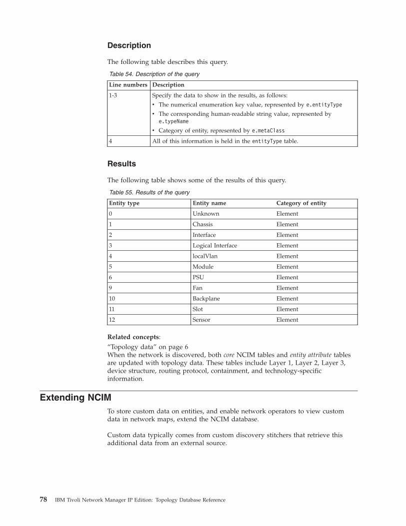
Description
The following table describes this query.
Table 54. Description of the query
Line numbers Description
1-3 Specify the data to show in the results, as follows:
v The numerical enumeration key value, represented by e.entityType
v The corresponding human-readable string value, represented bye.typeName
v Category of entity, represented by e.metaClass
4 All of this information is held in the entityType table.
Results
The following table shows some of the results of this query.
Table 55. Results of the query
Entity type Entity name Category of entity
0 Unknown Element
1 Chassis Element
2 Interface Element
3 Logical Interface Element
4 localVlan Element
5 Module Element
6 PSU Element
9 Fan Element
10 Backplane Element
11 Slot Element
12 Sensor Element
Related concepts:“Topology data” on page 6When the network is discovered, both core NCIM tables and entity attribute tablesare updated with topology data. These tables include Layer 1, Layer 2, Layer 3,device structure, routing protocol, containment, and technology-specificinformation.
Extending NCIMTo store custom data on entities, and enable network operators to view customdata in network maps, extend the NCIM database.
Custom data typically comes from custom discovery stitchers that retrieve thisadditional data from an external source.
78 IBM Tivoli Network Manager IP Edition: Topology Database Reference

Example of extending the databaseUse this example to learn how to extend the topology database to store customdata on entities.
The following example shows a set of interface records resulting from a discoverythat used custom stitchers to look up the customer name and type from anexternal source by using the IP address of each main node device discovered.Other discovery stitchers then add these customer attributes into the ExtraInfosection of the interface records in the MODEL database.{
ObjectId=45;EntityName=’host.example.com[ 0 [ 1 ] ]’;Address=[’192.168.3.4’,’00:04:DD:0D:00:76’,’’];EntityType=2;EntityOID=’1.3.6.1.4.1.9.1.326’;ExtraInfo={
.........m_IfIndex=1;m_ifType=6;m_LocalNbrPhysAddr=00:04:DD:0D:00:76;.........<lines ommitted>.........m_CustomerName=’MyCompany’;m_CustomerType=’Internal’;
};ClassName=’Cisco’;
}{
ObjectId=53;EntityName=’host.example.com[ 0 [ 1 ] ]’;Address=[’10.10.3.5’,’00:04:DD:0D:00:77’,’’];EntityType=2;EntityOID=’1.3.6.1.4.1.9.1.326’;ExtraInfo={
.........m_IfIndex=2;m_ifType=6;m_LocalNbrPhysAddr=00:04:DD:0D:00:77;.........<lines ommitted>.........m_CustomerName=’Acme’;m_CustomerType=’External’;
};ClassName=’Cisco’;
}
Enabling polling and visualization using the custom tagsAfter you have customized discovery to add custom tags you must ensure that theNCIM topology database entityDetails table is updated with the custom tags. Thisenables you to poll and visualize devices using these custom tags.
To enable polling and visualization based on custom tags:1. Go to the $NCHOME/etc/precision directory and edit the DbEntityDetails.cfg
file.2. Uncomment the insert statement. For an example of the insert statement, see
“Sample insert statement” on page 80.
Chapter 3. Topology database queries 79

MODEL checks the ExtraInfo section of each interface record for the followingfields:v m_CustomerNamev m_CustomerType
If either field is found, the value is inserted into the NCIM topology databaseentityDetails table and is associated with an entityId that is equal to the valuespecified in the current MODEL interface record. For more information on theentityDetails table, see the IBM Tivoli Network Manager IP Edition Topology DatabaseReference.
If a MODEL interface record does not contain an m_CustomerType or anm_CustomerName attribute in the ExtraInfo section, or if either of these fields hasa NULL value, no row is added to the entityDetails table for that interface record.
Sample insert statement///////////////////////////////////////////////////////////// This file provides a means to extend the NCIM database// schema by adding key-value pair data to the database// table named entityDetails.//////// The following example assumes that a custom stitcher has been created// with the ability to populate the ExtraInfo section of chassis// entities with the name and type of each customer.//// insert into dbModel.entityDetails// (// EntityType,// EntityDetails// )// values// (// 1, -- chassis// {// CustomerName = "eval(text, ’&ExtraInfo->m_CustomerName’)",// CustomerType = "eval(text, ’&ExtraInfo->m_CustomerType’)"// }// );
You can now run a full discovery to discover your network with the custom tags.Related reference:“entityDetails” on page 122The entityDetails table allows the addition of arbitrary data about an entity in theform of key-value pairs. This enables you to extend the database to provideadditional data on entities. The entityDetails table belongs to the category entities.
80 IBM Tivoli Network Manager IP Edition: Topology Database Reference
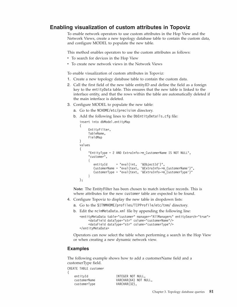
Enabling visualization of custom attributes in TopovizTo enable network operators to use custom attributes in the Hop View and theNetwork Views, create a new topology database table to contain the custom data,and configure MODEL to populate the new table.
This method enables operators to use the custom attributes as follows:v To search for devices in the Hop Viewv To create new network views in the Network Views
To enable visualization of custom attributes in Topoviz:1. Create a new topology database table to contain the custom data.2. Call the first field of the new table entityID and define the field as a foreign
key to the entityData table. This ensures that the new table is linked to theinterface entity, and that the rows within the table are automatically deleted ifthe main interface is deleted.
3. Configure MODEL to populate the new table:a. Go to the NCHOME/etc/precision directory.b. Add the following lines to the DbEntityDetails.cfg file:
insert into dbModel.entityMap(
EntityFilter,TableName,FieldMap
)values(
"EntityType = 2 AND ExtraInfo->m_CustomerName IS NOT NULL","customer",{
entityId = "eval(int, ’&ObjectId’)",CustomerName = "eval(text, ’&ExtraInfo->m_CustomerName’)",CustomerType = "eval(text, ’&ExtraInfo->m_CustomerType’)"
});
Note: The EntityFilter has been chosen to match interface records. This iswhere attributes for the new customer table are expected to be found.
4. Configure Topoviz to display the new table in dropdown lists:a. Go to the $ITNMHOME/profiles/TIPProfile/etc/tnm/ directory.b. Edit the ncimMetaData.xml file by appending the following line:
<entityMetaData table="customer" manager="AllManagers" entitySearch="true"><dataField dataType="str" column="customerName"/><dataField dataType="str" column="customerType"/>
</entityMetaData>
Operators can now select the table when performing a search in the Hop Viewor when creating a new dynamic network view.
Examples
The following example shows how to add a customerName field and acustomerType field.CREATE TABLE customer(
entityId INTEGER NOT NULL,customerName VARCHAR(64) NOT NULL,customerType VARCHAR(32),
Chapter 3. Topology database queries 81

CONSTRAINT customer_pk PRIMARY KEY (entityId),
CONSTRAINT customer_fk FOREIGN KEY (entityId)REFERENCES entityData(entityId) ON DELETE CASCADE
);
The following example shows how to add a customerName field and acustomerType field.CREATE TABLE customer(
entityId INTEGER NOT NULL,customerName VARCHAR(64) NOT NULL,customerType VARCHAR(32),
CONSTRAINT customer_pk PRIMARY KEY (entityId),
CONSTRAINT customer_fk FOREIGN KEY (entityId)REFERENCES entityData(entityId) ON DELETE CASCADE
) ENGINE=InnoDB DEFAULT CHARSET=utf8 COLLATE utf8_bin;
The following example shows how to add a customerName field and acustomerType field.CREATE TABLE customer(
entityId NUMBER(10) NOT NULL,customerName VARCHAR2(64) NOT NULL,customerType VARCHAR2(32),
--CONSTRAINT customer_pk PRIMARY KEY (entityId),
--CONSTRAINT customer_fk FOREIGN KEY (entityId)REFERENCES entityData(entityId) ON DELETE CASCADE
);
The following example shows how to add a customerName field and acustomerType field.CREATE TABLE ncim.customer(
entityId INTEGER NOT NULL,customerName VARCHAR(64) NOT NULL,customerType VARCHAR(32),
PRIMARY KEY (entityId) CONSTRAINT customer_pk,
FOREIGN KEY (entityId)REFERENCES entityData(entityId) ON DELETE CASCADECONSTRAINT customer_fk
);
82 IBM Tivoli Network Manager IP Edition: Topology Database Reference
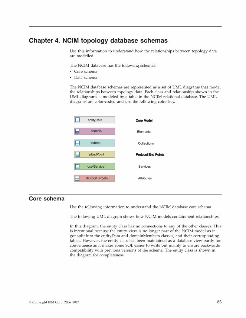
Chapter 4. NCIM topology database schemas
Use this information to understand how the relationships between topology dataare modelled.
The NCIM database has the following schemas:v Core schemav Data schema
The NCIM database schemas are represented as a set of UML diagrams that modelthe relationships between topology data. Each class and relationship shown in theUML diagrams is modeled by a table in the NCIM relational database. The UMLdiagrams are color-coded and use the following color key.
entityData
chassis
subnet
ipEndPoint
ospfService
rtExportTargets
Core ModelCore Model
Elements
Collections
Protocol End PointsProtocol End Points
Services
Attributes
Core schemaUse the following information to understand the NCIM database core schema.
The following UML diagram shows how NCIM models containment relationships.
In this diagram, the entity class has no connections to any of the other classes. Thisis intentional because the entity view is no longer part of the NCIM model as itgot split into the entityData and domainMembers classes, and their correspondingtables. However, the entity class has been maintained as a database view partly forconvenience as it makes some SQL easier to write but mainly to ensure backwardscompatibility with previous versions of the schema. The entity class is shown inthe diagram for completeness.
© Copyright IBM Corp. 2006, 2013 83

Table 56 describes the NCIM relationship database table and data dictionary thatcorrespond to each class and relationship in the core schema.
Table 56. Classes and relationships for the core schema
NCIM tableClass orrelationship
Related NCIM table orview Data dictionary
Collection Abstract Class Not applicable Not applicable
Figure 4. Core schema
84 IBM Tivoli Network Manager IP Edition: Topology Database Reference

Table 56. Classes and relationships for the core schema (continued)
NCIM tableClass orrelationship
Related NCIM table orview Data dictionary
collects Relationship collects “collects” on page 110
connects Relationship connects “connects” on page 112
contains Relationship contains “contains” on page 114
dependsOn Relationship entityDetails “dependency” on page114
domainMembers Class domainMembers “domainMembers” onpage 116
domainMgr Class domainMgr “domainMgr” on page117
Element Abstract Class NA NA
entity Class entity “entity” on page 137
entityClass Class entityClass “entityClass” on page119
entityData Class entityData “entityData” on page120
entityDetails Class entityDetails “entityDetails” on page122
entityNameCache Class entityNameCache “entityNameCache” onpage 123
entityType Class entityType “entityType” on page124
hostedService Relationship hostedService “hostedService” onpage 129
implementsEndPoint Relationship hostedService “protocolEndPoint” onpage 133
manager Class manager “manager” on page 129
networkPipe Class networkPipe “networkPipe” on page131
pipeComposition Class pipeComposition “pipeComposition” onpage 132
protocolEndPoint Class hostedService “protocolEndPoint” onpage 133
topologyLinks Relationship hostedService “topologyLinks” onpage 135
Data schemaIn the NCIM database, Network Manager topology data falls into differentcategories.
Chapter 4. NCIM schemas 85

BGPUse this information to understand how the NCIM database models BorderGateway Protocol (BGP).
The following UML diagram shows how NCIM models BGP.
Table 57 describes the NCIM relationship database tables and data dictionary thatcorrespond to each class and relationship used to model BGP.
Table 57. Classes and relationships for BGP
Item Class or relationship Data dictionary
bgpAutonomousSystem Class “bgpAutonomousSystem” onpage 145
bgpEndPoint Class “bgpEndPoint” on page 146
bgpNetwork Class “bgpNetwork” on page 149
bgpRouteAttribute Class “bgpRouteAttribute” on page 149
bgpService Class “bgpService” on page 151
chassis Class “physicalChassis” on page 195
collects Relationship “collects” on page 110
connects Relationship “connects” on page 112
contains Relationship “contains” on page 114
entity Class “entity” on page 137
hostedService Relationship “hostedService” on page 129
implementsEndPoint Class “protocolEndPoint” on page 133
interface Class “networkInterface” on page 180
topologyLinks Relationship “topologyLinks” on page 135
Figure 5. BGP schema
86 IBM Tivoli Network Manager IP Edition: Topology Database Reference

Related concepts:Chapter 4, “NCIM topology database schemas,” on page 83Use this information to understand how the relationships between topology dataare modelled.
CollectionsUse this information to understand how the NCIM database models devicecollections, such as subnets, VPNs, and VLANs.
The following UML diagram shows how NCIM models device collections, such assubnets, VPNs and VLANs.
Table 58 describes the NCIM relationship database tables and data dictionary thatcorrespond to each class and relationship used for modelling device collections.
Table 58. Classes and relationships for device collections
Item Class or relationship Data dictionary
bgpAutonomousSystem Class “bgpAutonomousSystem” onpage 145
bgpNetwork Class “bgpNetwork” on page 149
Collection Abstract Class Not applicable
collects Relationship “collects” on page 110
entity Class “entity” on page 137
globalVlan Class “globalVlan” on page 162
hsrpGroup Class “hsrpGroup” on page 163
networkVpn Class “networkVpn” on page 184
ospfArea Class “ospfArea” on page 188
ospfRoutingDomain Class “ospfRoutingDomain” on page190
pimNetwork Class “Collections”
VTPDomain
subnet
Class
Class
“vtpDomain” on page 227
“subnet” on page 224
Figure 6. Device collections schema
Chapter 4. NCIM schemas 87
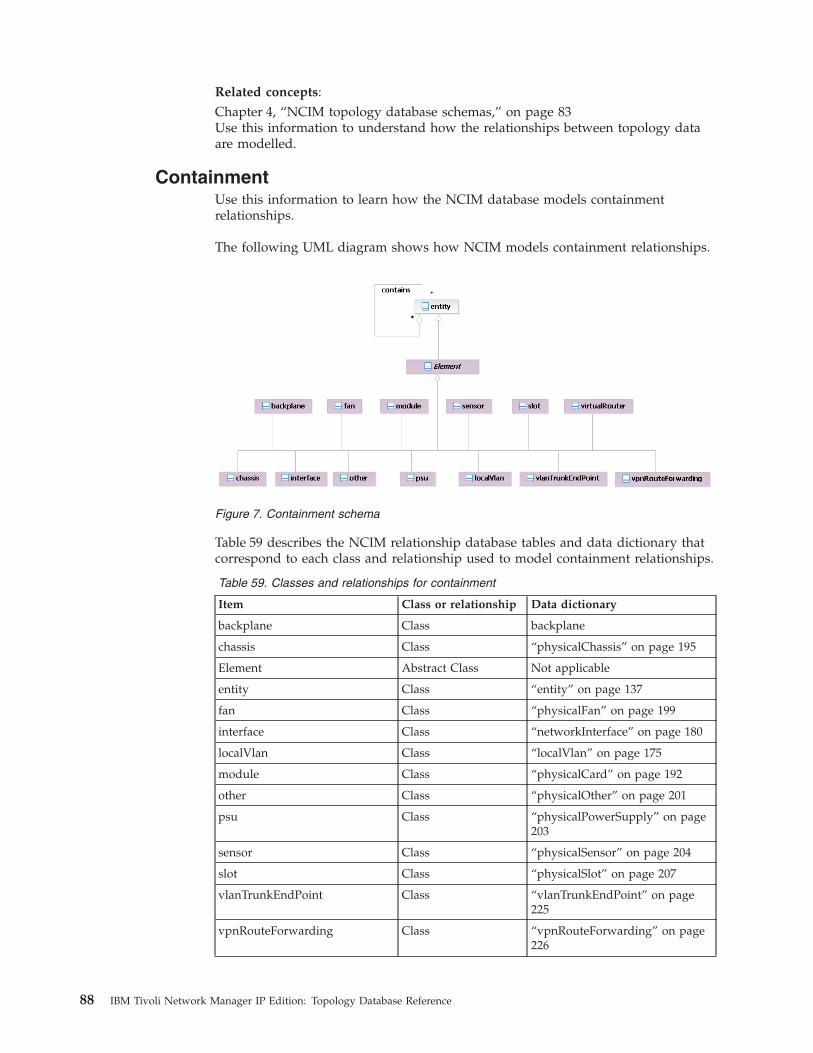
Related concepts:Chapter 4, “NCIM topology database schemas,” on page 83Use this information to understand how the relationships between topology dataare modelled.
ContainmentUse this information to learn how the NCIM database models containmentrelationships.
The following UML diagram shows how NCIM models containment relationships.
Table 59 describes the NCIM relationship database tables and data dictionary thatcorrespond to each class and relationship used to model containment relationships.
Table 59. Classes and relationships for containment
Item Class or relationship Data dictionary
backplane Class backplane
chassis Class “physicalChassis” on page 195
Element Abstract Class Not applicable
entity Class “entity” on page 137
fan Class “physicalFan” on page 199
interface Class “networkInterface” on page 180
localVlan Class “localVlan” on page 175
module Class “physicalCard” on page 192
other Class “physicalOther” on page 201
psu Class “physicalPowerSupply” on page203
sensor Class “physicalSensor” on page 204
slot Class “physicalSlot” on page 207
vlanTrunkEndPoint Class “vlanTrunkEndPoint” on page225
vpnRouteForwarding Class “vpnRouteForwarding” on page226
Figure 7. Containment schema
88 IBM Tivoli Network Manager IP Edition: Topology Database Reference
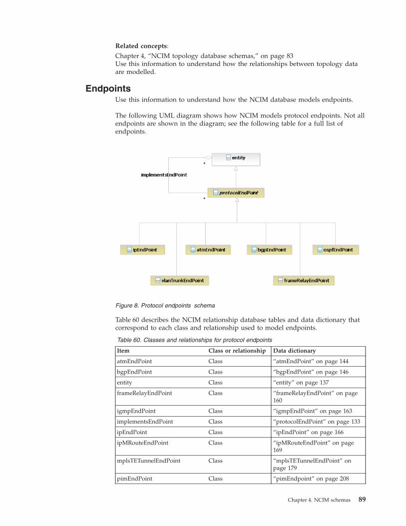
Related concepts:Chapter 4, “NCIM topology database schemas,” on page 83Use this information to understand how the relationships between topology dataare modelled.
EndpointsUse this information to understand how the NCIM database models endpoints.
The following UML diagram shows how NCIM models protocol endpoints. Not allendpoints are shown in the diagram; see the following table for a full list ofendpoints.
Table 60 describes the NCIM relationship database tables and data dictionary thatcorrespond to each class and relationship used to model endpoints.
Table 60. Classes and relationships for protocol endpoints
Item Class or relationship Data dictionary
atmEndPoint Class “atmEndPoint” on page 144
bgpEndPoint Class “bgpEndPoint” on page 146
entity Class “entity” on page 137
frameRelayEndPoint Class “frameRelayEndPoint” on page160
igmpEndPoint Class “igmpEndPoint” on page 163
implementsEndPoint Class “protocolEndPoint” on page 133
ipEndPoint Class “ipEndPoint” on page 166
ipMRouteEndPoint Class “ipMRouteEndPoint” on page169
mplsTETunnelEndPoint Class “mplsTETunnelEndPoint” onpage 179
pimEndPoint Class “pimEndpoint” on page 208
Figure 8. Protocol endpoints schema
Chapter 4. NCIM schemas 89

Table 60. Classes and relationships for protocol endpoints (continued)
Item Class or relationship Data dictionary
portEndPoint Class “portEndPoint” on page 210
protocolEndPoint Class “protocolEndPoint” on page 133
ospfEndPoint Class “ospfEndPoint” on page 188
vlanTrunkEndPoint Class “vlanTrunkEndPoint” on page225
vpwsEndPoint Class “vpwsEndPoint” on page 227
Related concepts:Chapter 4, “NCIM topology database schemas,” on page 83Use this information to understand how the relationships between topology dataare modelled.
Geographical locationThe NCIM database models geographical locations using several database tables.
The following UML diagram shows how NCIM models geographical locations.
Table 61 describes the NCIM relationship database tables and data dictionary thatcorrespond to each class and relationship used to model geographical locations.
Table 61. Classes and relationships for geographical locations
NCIM table Class or relationship Data dictionary
collects Relationship “collects” on page 110
entityData Class “entityData” on page 120
geographicLocation Class “geographicLocation” on page161
geographicRegion Class “geographicRegion” on page 162
entityData
geographicRegion
*
0..1
geographicLocation
*
0..1 *0..1
collects
collects collects
Figure 9. Geographical location schema
90 IBM Tivoli Network Manager IP Edition: Topology Database Reference

GSMThe NCIM database models GSM using several database tables.
The following UML diagram shows how NCIM models GSM.
Note: In addition to the standard relationships between entities shown in the coreschema diagram, the GSM schema diagram models extra relationships betweenRAN entities. These RAN entity relationships have been added to make it easier toprocess RAN data. For example, the dependency relationship betweenranBaseStation and ranBaseStationController was added to enable a single queryto retrieve all RAN base stations managed by a given RAN base station controller.
Table 62 describes the NCIM relationship database tables and data dictionary thatcorrespond to each class and relationship used to model GSM.
Table 62. Classes and relationships for GSM
NCIM table Class or relationship Data dictionary
collects Relationship “collects” on page 110
connects Relationship “connects” on page 112
contains Relationship “contains” on page 114
entityData
ranGSMCell
physicalChassis physicalChassis physicalChassis
ranBaseStationController ranBaseStation
ranPacketControlUnit
ranTransceiver ranSector
1
dependency
dependency
dependency
collects
contains
*
*
*
* *
0..1
0..1
11
1
1 hostedService
Figure 10. GSM schema
Chapter 4. NCIM schemas 91
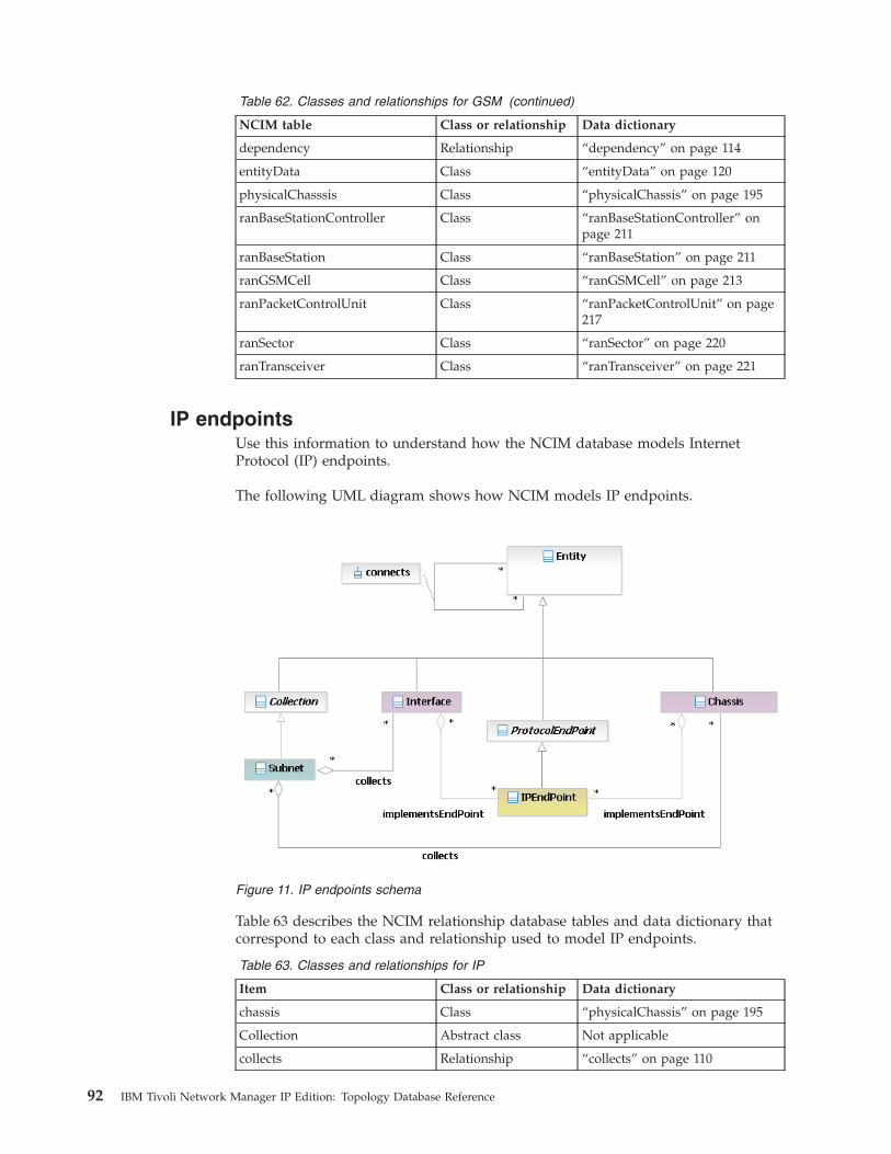
Table 62. Classes and relationships for GSM (continued)
NCIM table Class or relationship Data dictionary
dependency Relationship “dependency” on page 114
entityData Class “entityData” on page 120
physicalChasssis Class “physicalChassis” on page 195
ranBaseStationController Class “ranBaseStationController” onpage 211
ranBaseStation Class “ranBaseStation” on page 211
ranGSMCell Class “ranGSMCell” on page 213
ranPacketControlUnit Class “ranPacketControlUnit” on page217
ranSector Class “ranSector” on page 220
ranTransceiver Class “ranTransceiver” on page 221
IP endpointsUse this information to understand how the NCIM database models InternetProtocol (IP) endpoints.
The following UML diagram shows how NCIM models IP endpoints.
Table 63 describes the NCIM relationship database tables and data dictionary thatcorrespond to each class and relationship used to model IP endpoints.
Table 63. Classes and relationships for IP
Item Class or relationship Data dictionary
chassis Class “physicalChassis” on page 195
Collection Abstract class Not applicable
collects Relationship “collects” on page 110
Figure 11. IP endpoints schema
92 IBM Tivoli Network Manager IP Edition: Topology Database Reference

Table 63. Classes and relationships for IP (continued)
Item Class or relationship Data dictionary
connects Relationship “connects” on page 112
entity Class “entity” on page 137
implementsEndPoint Class “protocolEndPoint” on page 133
interface Class “networkInterface” on page 180
ipEndPoint Class “ipEndPoint” on page 166
protocolEndPoint Class “protocolEndPoint” on page 133
subnet Class “subnet” on page 224
Related concepts:Chapter 4, “NCIM topology database schemas,” on page 83Use this information to understand how the relationships between topology dataare modelled.
MPLS traffic engineered (TE) tunnelsThe NCIM database models MPLS TE tunnels using several databases.
The following UML diagram shows how NCIM models MPLS TE tunnels.
Chapter 4. NCIM schemas 93

Table 64 describes the NCIM relationship database tables and data dictionary thatcorrespond to each class and relationship used to model MPLS TE tunnels.
Table 64. Classes and relationships for MPLS TE tunnels
NCIM table Class or relationship Data dictionary
chasssis Class “physicalChassis” on page 195
contains Relationship “contains” on page 114
dependency Relationship “dependency” on page 114
entity Class “entity” on page 137
hostedService Class “hostedService” on page 129
interface Class “networkInterface” on page 180
mplsTEService Class “mplsTEService” on page 176
mplsTETunnel Class “mplsTETunnel” on page 177
mplsTETunnelEndPoint Class “mplsTETunnelEndPoint” onpage 179
mplsTETunnelResource Class “mplsTETunnelResource” onpage 179
mplsLSP Class “mplsLSP” on page 180
entity
networkPipe
protocolEndPoint elementservice
interface chassis
mplsTETunnelEndPoint mplsTESservice
mplsTETunnelResource
mplsTETunnel
mplsLSP
*
* * *
contains
1 *
implementsEndPoint
1
*
hostedService
1
0..1
dependency
1
*
1*
provides(dependency) 0..*
1
dependency1
0..1
connects
0..1 0..1
1
1..*
Figure 12. MPLS TE schema
94 IBM Tivoli Network Manager IP Edition: Topology Database Reference

MPLS VPNsUse this information to understand how the NCIM database models Multi ProtocolLabel Switching Virtual Private Networks (MPLS VPNs).
The following UML diagram shows how NCIM models MPLS VPNs.
Table 65 describes the NCIM relationship database tables and data dictionary thatcorrespond to each class and relationship used to model MPLS VPNs.
Table 65. Classes and relationships for MPLS VPNs
Item Class or relationship Data dictionary
chassis Class “physicalChassis” on page 195
collects Relationship “collects” on page 110
contains Relationship “contains” on page 114
entity Class “entity” on page 137
interface Class “networkInterface” on page 180
networkVpn Class “networkVpn” on page 184
RTExportTargets Relationship “rtExportList” on page 222
RTImportTargets Relationship “rtImportList” on page 222
vpnRouteForwarding Class “vpnRouteForwarding” on page226
Related concepts:Chapter 4, “NCIM topology database schemas,” on page 83Use this information to understand how the relationships between topology dataare modelled.
Figure 13. MPLS VPNs schema
Chapter 4. NCIM schemas 95

OSPFUse this information to understand how the NCIM database models Open ShortestPath First (OSPF) protocols .
The following UML diagram shows how NCIM models OSPF.
Table 66 describes the NCIM relationship database tables and data dictionary thatcorrespond to each class and relationship used to model OSPFs.
Table 66. Classes and relationships for OSPF
Item Class or relationship Data dictionary
chassis Class “physicalChassis” on page 195
collects Relationship “collects” on page 110
connects Relationship “connects” on page 112
contains Relationship “contains” on page 114
entity Class “entity” on page 137
hostedService Relationship “hostedService” on page 129
implementsEndPoint Class “protocolEndPoint” on page 133
interface Class “networkInterface” on page 180
ospfArea Class “ospfArea” on page 188
ospfEndPoint Class “ospfEndPoint” on page 188
ospfNetworkLSA Class “ospfNetworkLSA” on page 189
ospfRoutingDomain Class “ospfRoutingDomain” on page190
ospfService Class “ospfService” on page 190
topologyLinks Relationship “topologyLinks” on page 135
Figure 14. OSPF schema
96 IBM Tivoli Network Manager IP Edition: Topology Database Reference

Related concepts:Chapter 4, “NCIM topology database schemas,” on page 83Use this information to understand how the relationships between topology dataare modelled.
RAN collectionsThe NCIM database models RAN collections using several database tables.
The following UML diagram shows how NCIM models RAN collections.
Table 67 describes the NCIM relationship database tables and data dictionary thatcorrespond to each class and relationship used to model RAN collections.
Table 67. Classes and relationships for RAN collections
NCIM table Class or relationship Data dictionary
collects Relationship “collects” on page 110
dependency Relationship “dependency” on page 114
entityData Class “entityData” on page 120
physicalChasssis Class “physicalChassis” on page 195
ranBaseStationController Class “ranBaseStationController” onpage 211
entityData
ranCircuitSwitchedCore
ranMobileSwitchingCentre
physicalChassis
1
ranRadioCore ranPacketSwitchedCore
ranMediaGateway
ranRadioNetworkController
ranBaseStationController
ranPacketControlUnit
ranSGSN
ranGGSN
ranMSS
dependency
collects
collects
collects
collects
collects
collects
collects
1 1 1 1 1 1
*
*
*
*
*
*
*
1
0..1
Figure 15. RAN collections
Chapter 4. NCIM schemas 97
Table 67. Classes and relationships for RAN collections (continued)
NCIM table Class or relationship Data dictionary
ranCircuitSwitchedCore Class “ranCircuitSwitchedCore” onpage 212
ranGGSN Class “ranGGSN” on page 213
ranMediaGateway Class “ranMediaGateway” on page 215
ranMSS Class “ranMSS” on page 216
ranMobileSwitchingCentre Class “ranMobileSwitchingCentre” onpage 215
ranPacketControlUnit Class “ranPacketControlUnit” on page217
ranPacketSwitchedCore Class “ranPacketSwitchedCore” onpage 217
ranRadioCore Class “ranRadioCore” on page 218
ranRadioNetworkController Class “ranRadioNetworkController” onpage 219
ranSGSN Class “ranSGSN” on page 220
RAN routing and location areasThe NCIM database models RAN routing and location areas using severaldatabase tables.
A routing area is the region within which an end user can move using the dataservice without having to update the Serving GPRS Serving Nodes (SGSN). Thelocation area is the area within which an end user can move using the voiceservice without having to update the VLR (visitor location registrar, whichindicates where you are physically located). Therefore RAN routing and locationareas do not indicate geographic location but rather the responsibilities of thedevices in the system.
The following UML diagram shows how NCIM models RAN routing and locationareas.
98 IBM Tivoli Network Manager IP Edition: Topology Database Reference
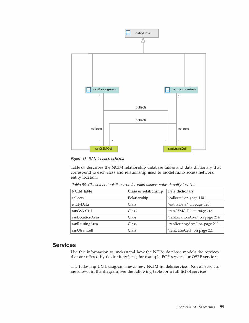
Table 68 describes the NCIM relationship database tables and data dictionary thatcorrespond to each class and relationship used to model radio access networkentity location.
Table 68. Classes and relationships for radio access network entity location
NCIM table Class or relationship Data dictionary
collects Relationship “collects” on page 110
entityData Class “entityData” on page 120
ranGSMCell Class “ranGSMCell” on page 213
ranLocationArea Class “ranLocationArea” on page 214
ranRoutingArea Class “ranRoutingArea” on page 219
ranUtranCell Class “ranUtranCell” on page 221
ServicesUse this information to understand how the NCIM database models the servicesthat are offered by device interfaces, for example BGP services or OSPF services.
The following UML diagram shows how NCIM models services. Not all servicesare shown in the diagram; see the following table for a full list of services.
entityData
ranRoutingArea
ranUtranCell
collects
*
ranLocationArea
ranGSMCell
collects
collects
collects
* * *
1 1
Figure 16. RAN location schema
Chapter 4. NCIM schemas 99
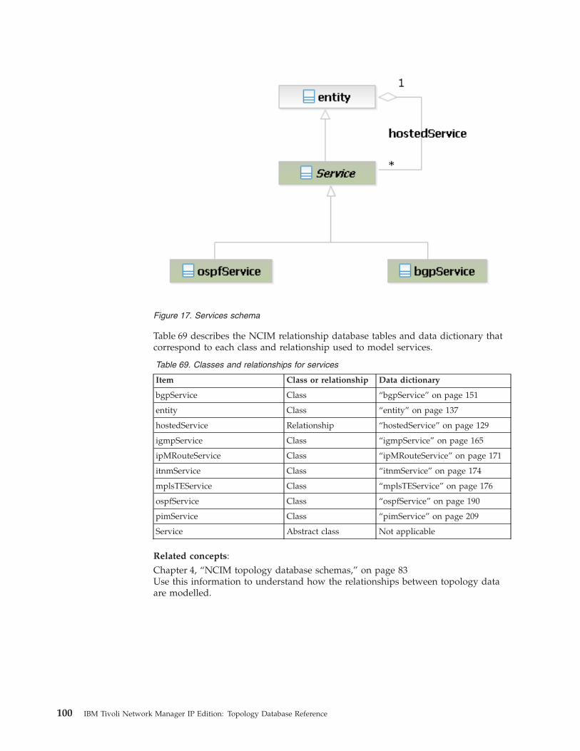
Table 69 describes the NCIM relationship database tables and data dictionary thatcorrespond to each class and relationship used to model services.
Table 69. Classes and relationships for services
Item Class or relationship Data dictionary
bgpService Class “bgpService” on page 151
entity Class “entity” on page 137
hostedService Relationship “hostedService” on page 129
igmpService Class “igmpService” on page 165
ipMRouteService Class “ipMRouteService” on page 171
itnmService Class “itnmService” on page 174
mplsTEService Class “mplsTEService” on page 176
ospfService Class “ospfService” on page 190
pimService Class “pimService” on page 209
Service Abstract class Not applicable
Related concepts:Chapter 4, “NCIM topology database schemas,” on page 83Use this information to understand how the relationships between topology dataare modelled.
Figure 17. Services schema
100 IBM Tivoli Network Manager IP Edition: Topology Database Reference

UMTSThe NCIM database models UMTS using several database tables.
The following UML diagram shows how NCIM models UMTS.
Note: In addition to the standard relationships between entities shown in the coreschema diagram, the UMTS schema diagram models extra relationships betweenRAN entities. These RAN entity relationships have been added to make it easier toprocess RAN data. For example, the dependency relationship betweenranUtranCell and ranNodeB was added to enable a single query to retrieve allUTRAN cells managed by a given Node B entity.
Table 70 describes the NCIM relationship database tables and data dictionary thatcorrespond to each class and relationship used to model UMTS.
Table 70. Classes and relationships for UMTS
NCIM table Class or relationship Data dictionary
collects Relationship “collects” on page 110
contains Relationship “contains” on page 114
dependency Relationship “dependency” on page 114
entityData
ranUtranCell
physicalChassis physicalChassis
ranRadioNetworkController ranNodeB
ranTransceiver ranSector
1
dependency
dependency
collects
contains
*
*
*
* *
0..1
1
1
1 hostedService
*
ranNodeBLocalCell
0..1
dependency
1
*
contains
Figure 18. UMTS schema
Chapter 4. NCIM schemas 101

Table 70. Classes and relationships for UMTS (continued)
NCIM table Class or relationship Data dictionary
entityData Class “entityData” on page 120
hostedService Relationship “hostedService” on page 129
physicalChasssis Class “physicalChassis” on page 195
ranNodeB Class “ranNodeB” on page 216
ranNodeBLocalCell Class “ranNodeBLocalCell” on page216
ranRadioNetworkController Class “ranRadioNetworkController” onpage 219
ranSector Class “ranSector” on page 220
ranTransceiver Class “ranTransceiver” on page 221
ranUtranCell Class “ranUtranCell” on page 221
VLANsUse this information to understand how the NCIM database models virtual localarea networks (VLANs).
The following UML diagram shows how NCIM models VLANs.
entity
VlanTrunkEndPoint
connects
SVlanTrunkEndPoint
*
1
contains
1
*
contains
1
*
implementsEndPoint
contains1
*
implementsEndPoint
1
1
1
*
collects
CVlanTrunkEndPoint1*
entitychassis
globalVlan interfaceinterface
VlanTrunkEndPointlocalVlan
connects
vtpDomainvtpDomain
SVlanTrunkEndPoint
vlanCollection
1
*
collects
Figure 19. VLAN schema
102 IBM Tivoli Network Manager IP Edition: Topology Database Reference

Table 71 describes the NCIM relationship database tables and data dictionary thatcorrespond to each class and relationship used to model VLANs.
Table 71. Classes and relationships for VLANs
Item Class or relationship Data dictionary
chassis Class “physicalChassis” on page 195
collects Relationship “collects” on page 110
contains Relationship “contains” on page 114
entity Class “entity” on page 137
globalVlan Class “globalVlan” on page 162
interface Class “networkInterface” on page 180
localVlan Class “localVlan” on page 175
implementsEndPoint Class “protocolEndPoint” on page 133
vlanCollection Class “vlanCollection” on page 225
vtpDomain Class “vtpDomain” on page 227
VLANTrunkEndPoint Class “vlanTrunkEndPoint” on page225
Related concepts:Chapter 4, “NCIM topology database schemas,” on page 83Use this information to understand how the relationships between topology dataare modelled.
Chapter 4. NCIM schemas 103

104 IBM Tivoli Network Manager IP Edition: Topology Database Reference
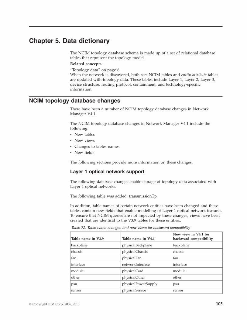
Chapter 5. Data dictionary
The NCIM topology database schema is made up of a set of relational databasetables that represent the topology model.Related concepts:“Topology data” on page 6When the network is discovered, both core NCIM tables and entity attribute tablesare updated with topology data. These tables include Layer 1, Layer 2, Layer 3,device structure, routing protocol, containment, and technology-specificinformation.
NCIM topology database changesThere have been a number of NCIM topology database changes in NetworkManager V4.1.
The NCIM topology database changes in Network Manager V4.1 include thefollowing:v New tablesv New viewsv Changes to tables namesv New fields
The following sections provide more information on these changes.
Layer 1 optical network support
The following database changes enable storage of topology data associated withLayer 1 optical networks.
The following table was added: transmissionTp
In addition, table names of certain network entities have been changed and thesetables contain new fields that enable modelling of Layer 1 optical network features.To ensure that NCIM queries are not impacted by these changes, views have beencreated that are identical to the V3.9 tables for these entities..
Table 72. Table name changes and new views for backward compatibility
Table name in V3.9 Table name in V4.1New view in V4.1 forbackward compatibility
backplane physicalBackplane backplane
chassis physicalChassis chassis
fan physicalFan fan
interface networkInterface interface
module physicalCard module
other physicalOther other
psu physicalPowerSupply psu
sensor physicalSensor sensor
© Copyright IBM Corp. 2006, 2013 105

Table 72. Table name changes and new views for backward compatibility (continued)
Table name in V3.9 Table name in V4.1New view in V4.1 forbackward compatibility
slot physicalSlot slot
Radio access network (RAN) network support
The following new tables have been added to store topology data for RANnetwork entities:v geographicLocationv geographicRegionv networkServiceEntityEndPointv ranBaseStationv ranBaseStationControllerv ranCircuitSwitchedCorev ranGGSNv ranGSMCellv ranLocationAreav ranMediaGatewayv ranMobileSwitchingCentrev ranMSSv ranNodeBv ranNodeBLocalCellv ranPacketControlUnitv ranPacketSwitchedCorev ranRadioCorev ranRadioNetworkControllerv ranRoutingAreav ranSectorv ranSGSNv ranTransceiverv ranUtranCell
Extended support for EMS-based discovery
The following new tables have been added to support the extended EMS-baseddiscovery provided in this release.v discoverySourcev emsSystem
Implementation of the IBM Common Data Model (CDM) withinNCIM
The following new tables have been created to model CDM entities.v computerSystemv cpuv operatingSystem
106 IBM Tivoli Network Manager IP Edition: Topology Database Reference

v snmpSystem
Cross-domain discoveries
The following new tables and views have been added to support storage ofnetwork data discovered in cross-domain discoveries.
Table 73. New tables and views for cross-domain discoveries
Name Table or view
aggregationDomain table
interfaceDomain view
mainNodeDomain view
.
Core tablesCore tables define entities and relationships between them. Core tables do notprovide detailed attribute information on the entities.
Core tables include those tables that define the domains, for example thedomainMgr table and the domainSummary table, and also the entityData table,which provides generic information about an entity, for example entityName andentityType.
The core table models the following categories of topology data:
DomainsA domain is a scoped set of entities that are discovered and managed byan application, such as Network Manager. Domains are represented usingthe domainMgr table. Membership of entities within these domains isrepresented using the domainMembers table.
EntitiesAn entity is a topology database concept. All devices and devicecomponents discovered by Network Manager are entities. Also devicecollections such as VPNs and VLANs, as well as pieces of topology thatform a complex connection, are entities. Generic information for all entitieswithin NCIM is held within the entityData table. The entity view joinsdata from the entityData and domainMembers tables and is equivalent tothe entity table that existed in Network Manager versions 3.8 and earlier.
Containment relationshipsContainment relationships express physical and logical containment. Theserelationships are represented by the contains table.
Connectivity relationshipsConnectivity relationships are relationships between entities. Theserelationships are represented by the connects table. Other tables used todefine connectivity include the networkPipe, pipeComposition, andtopologyLinks tables.
Collection relationshipsCollection relationships enable NCIM to model collections of entities, suchas MPLS VPNs, global VLANs and subnets. The relationship is representedby the collects table.
Chapter 5. Data dictionary 107
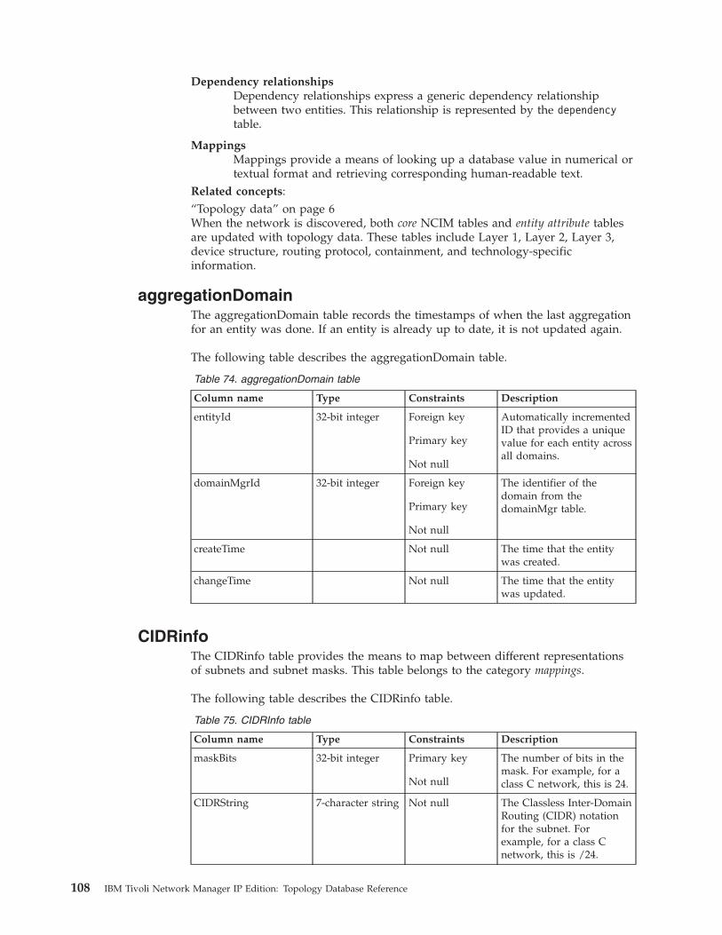
Dependency relationshipsDependency relationships express a generic dependency relationshipbetween two entities. This relationship is represented by the dependencytable.
MappingsMappings provide a means of looking up a database value in numerical ortextual format and retrieving corresponding human-readable text.
Related concepts:“Topology data” on page 6When the network is discovered, both core NCIM tables and entity attribute tablesare updated with topology data. These tables include Layer 1, Layer 2, Layer 3,device structure, routing protocol, containment, and technology-specificinformation.
aggregationDomainThe aggregationDomain table records the timestamps of when the last aggregationfor an entity was done. If an entity is already up to date, it is not updated again.
The following table describes the aggregationDomain table.
Table 74. aggregationDomain table
Column name Type Constraints Description
entityId 32-bit integer Foreign key
Primary key
Not null
Automatically incrementedID that provides a uniquevalue for each entity acrossall domains.
domainMgrId 32-bit integer Foreign key
Primary key
Not null
The identifier of thedomain from thedomainMgr table.
createTime Not null The time that the entitywas created.
changeTime Not null The time that the entitywas updated.
CIDRinfoThe CIDRinfo table provides the means to map between different representationsof subnets and subnet masks. This table belongs to the category mappings.
The following table describes the CIDRinfo table.
Table 75. CIDRInfo table
Column name Type Constraints Description
maskBits 32-bit integer Primary key
Not null
The number of bits in themask. For example, for aclass C network, this is 24.
CIDRString 7-character string Not null The Classless Inter-DomainRouting (CIDR) notationfor the subnet. Forexample, for a class Cnetwork, this is /24.
108 IBM Tivoli Network Manager IP Edition: Topology Database Reference
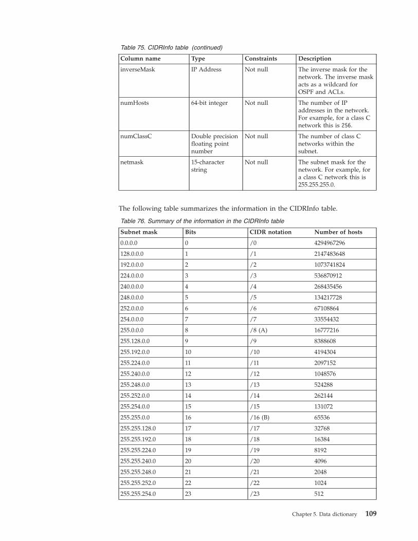
Table 75. CIDRInfo table (continued)
Column name Type Constraints Description
inverseMask IP Address Not null The inverse mask for thenetwork. The inverse maskacts as a wildcard forOSPF and ACLs.
numHosts 64-bit integer Not null The number of IPaddresses in the network.For example, for a class Cnetwork this is 256.
numClassC Double precisionfloating pointnumber
Not null The number of class Cnetworks within thesubnet.
netmask 15-characterstring
Not null The subnet mask for thenetwork. For example, fora class C network this is255.255.255.0.
The following table summarizes the information in the CIDRInfo table.
Table 76. Summary of the information in the CIDRInfo table
Subnet mask Bits CIDR notation Number of hosts
0.0.0.0 0 /0 4294967296
128.0.0.0 1 /1 2147483648
192.0.0.0 2 /2 1073741824
224.0.0.0 3 /3 536870912
240.0.0.0 4 /4 268435456
248.0.0.0 5 /5 134217728
252.0.0.0 6 /6 67108864
254.0.0.0 7 /7 33554432
255.0.0.0 8 /8 (A) 16777216
255.128.0.0 9 /9 8388608
255.192.0.0 10 /10 4194304
255.224.0.0 11 /11 2097152
255.240.0.0 12 /12 1048576
255.248.0.0 13 /13 524288
255.252.0.0 14 /14 262144
255.254.0.0 15 /15 131072
255.255.0.0 16 /16 (B) 65536
255.255.128.0 17 /17 32768
255.255.192.0 18 /18 16384
255.255.224.0 19 /19 8192
255.255.240.0 20 /20 4096
255.255.248.0 21 /21 2048
255.255.252.0 22 /22 1024
255.255.254.0 23 /23 512
Chapter 5. Data dictionary 109
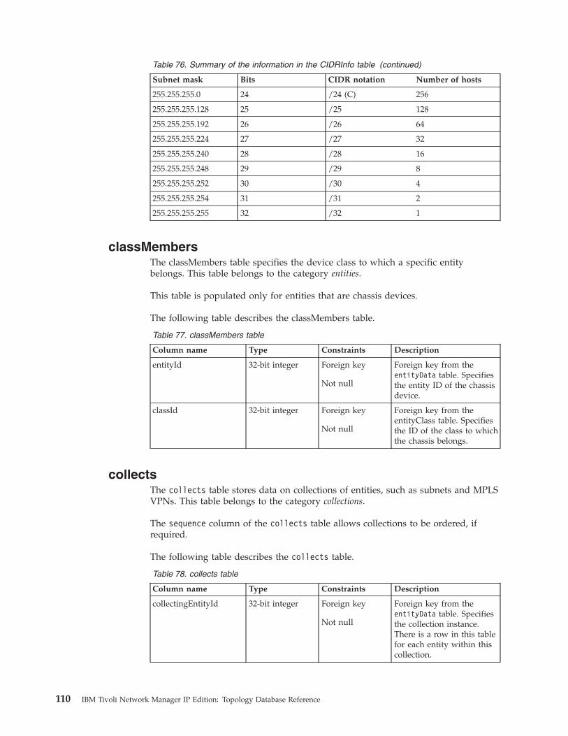
Table 76. Summary of the information in the CIDRInfo table (continued)
Subnet mask Bits CIDR notation Number of hosts
255.255.255.0 24 /24 (C) 256
255.255.255.128 25 /25 128
255.255.255.192 26 /26 64
255.255.255.224 27 /27 32
255.255.255.240 28 /28 16
255.255.255.248 29 /29 8
255.255.255.252 30 /30 4
255.255.255.254 31 /31 2
255.255.255.255 32 /32 1
classMembersThe classMembers table specifies the device class to which a specific entitybelongs. This table belongs to the category entities.
This table is populated only for entities that are chassis devices.
The following table describes the classMembers table.
Table 77. classMembers table
Column name Type Constraints Description
entityId 32-bit integer Foreign key
Not null
Foreign key from theentityData table. Specifiesthe entity ID of the chassisdevice.
classId 32-bit integer Foreign key
Not null
Foreign key from theentityClass table. Specifiesthe ID of the class to whichthe chassis belongs.
collectsThe collects table stores data on collections of entities, such as subnets and MPLSVPNs. This table belongs to the category collections.
The sequence column of the collects table allows collections to be ordered, ifrequired.
The following table describes the collects table.
Table 78. collects table
Column name Type Constraints Description
collectingEntityId 32-bit integer Foreign key
Not null
Foreign key from theentityData table. Specifiesthe collection instance.There is a row in this tablefor each entity within thiscollection.
110 IBM Tivoli Network Manager IP Edition: Topology Database Reference

Table 78. collects table (continued)
Column name Type Constraints Description
collectedEntityId 32-bit integer Foreign key
Not null
Foreign key from theentityData table. Specifiesan entity within thecollection.
sequence 32-bit integer For ordered collections,specifies the sequencenumber of the collection.
Related concepts:“Collection data” on page 15Collection data defines logical collections. Collections are defined in the collectstable. Examples of logical collections defined within NCIM include MPLS VPNs,global VLANs, and subnets.
connectActionsThe connectActions table records all manual connection additions and allconnection removals, including removal of connections that were discovered ratherthan manually added.
The following table describes the connectActions table.
Table 79. connectActions table
Column name Type Constraints Description
connectActionsId 32-bit integer Primary key
Automaticallyincremented
Not null
Unique auto generatedprimary key column.
aEndEntityId 32-bit integer Foreign key
Not null
Foreign key to theentityData table. EntityIdof the A-end of theconnection.
zEndEntityId 32-bit integer Foreign key
Not null
Foreign key to theentityData table. EntityIdof the Z-end of theconnection.
topologyEntityId 32-bit integer Foreign key
Not null
Foreign key to theentityData table. EntityIdof the topology for thisconnection.
unidirectional Boolean Not null
Not null
Boolean indicating if theconnection ID is directedor not.
action 6-character string Enumeration ofvalues “add” and“delete”
Not null
Indicates an action thatadded or deleted an entity.
changeTime Timestamp Not null Indicates when thisentityAction was lastupdated.
Chapter 5. Data dictionary 111
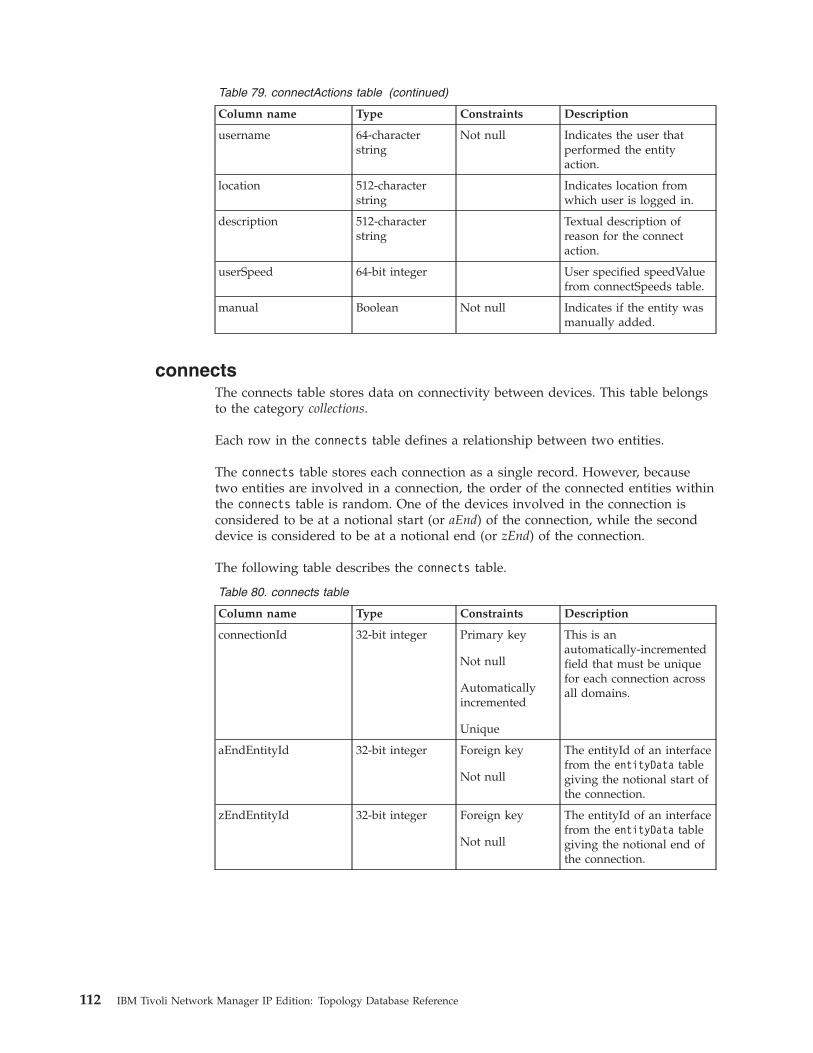
Table 79. connectActions table (continued)
Column name Type Constraints Description
username 64-characterstring
Not null Indicates the user thatperformed the entityaction.
location 512-characterstring
Indicates location fromwhich user is logged in.
description 512-characterstring
Textual description ofreason for the connectaction.
userSpeed 64-bit integer User specified speedValuefrom connectSpeeds table.
manual Boolean Not null Indicates if the entity wasmanually added.
connectsThe connects table stores data on connectivity between devices. This table belongsto the category collections.
Each row in the connects table defines a relationship between two entities.
The connects table stores each connection as a single record. However, becausetwo entities are involved in a connection, the order of the connected entities withinthe connects table is random. One of the devices involved in the connection isconsidered to be at a notional start (or aEnd) of the connection, while the seconddevice is considered to be at a notional end (or zEnd) of the connection.
The following table describes the connects table.
Table 80. connects table
Column name Type Constraints Description
connectionId 32-bit integer Primary key
Not null
Automaticallyincremented
Unique
This is anautomatically-incrementedfield that must be uniquefor each connection acrossall domains.
aEndEntityId 32-bit integer Foreign key
Not null
The entityId of an interfacefrom the entityData tablegiving the notional start ofthe connection.
zEndEntityId 32-bit integer Foreign key
Not null
The entityId of an interfacefrom the entityData tablegiving the notional end ofthe connection.
112 IBM Tivoli Network Manager IP Edition: Topology Database Reference

Table 80. connects table (continued)
Column name Type Constraints Description
unidirectional Boolean Not null
Takes one of thefollowing values:0: is not unidirectional1: is unidirectional
Indicates whether theconnection is unidirectionalor bidirectional. Currentlyall connections arebidirectional.
connectSpeedsThe connectSpeeds table stores data on connectivity speed between devices.
The connectSpeeds table stores each connection as a single record.
The following table describes the connectSpeeds table.
Table 81. connectSpeeds table
Column name Type Constraints Description
connectionId 32-bit integer Primary key
Foreign key
Not null
The connection ID from theNCIM connects table.
speedType 9-bit integer Primary key
Not null
The type of the speed ofthe connection. Thiscolumn can take one of thefollowing values:
DEFAULTThe standardspeed derivedfrom the datafrom the networkelement.
RATELIMITNot currentlyused.
USER The speedspecified by theuser.
speedValue 64-bit integer Foreign key The speed of theconnection, if known, inbits per second.
Chapter 5. Data dictionary 113
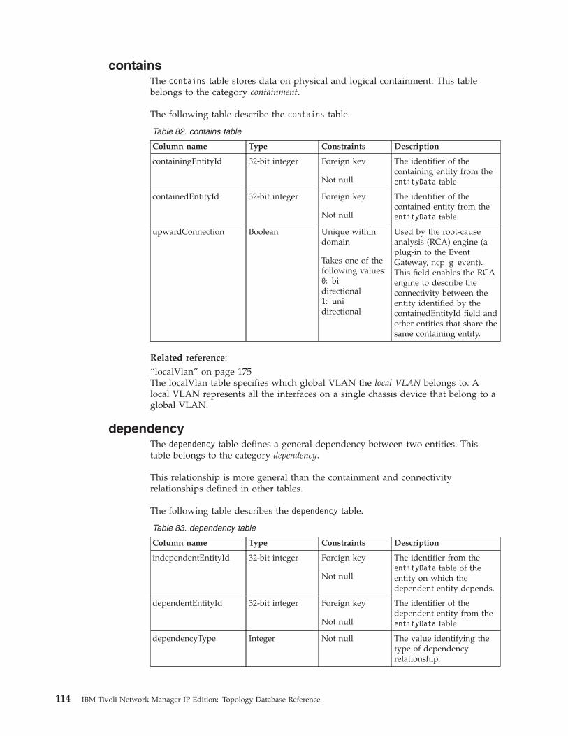
containsThe contains table stores data on physical and logical containment. This tablebelongs to the category containment.
The following table describe the contains table.
Table 82. contains table
Column name Type Constraints Description
containingEntityId 32-bit integer Foreign key
Not null
The identifier of thecontaining entity from theentityData table
containedEntityId 32-bit integer Foreign key
Not null
The identifier of thecontained entity from theentityData table
upwardConnection Boolean Unique withindomain
Takes one of thefollowing values:0: bidirectional1: unidirectional
Used by the root-causeanalysis (RCA) engine (aplug-in to the EventGateway, ncp_g_event).This field enables the RCAengine to describe theconnectivity between theentity identified by thecontainedEntityId field andother entities that share thesame containing entity.
Related reference:“localVlan” on page 175The localVlan table specifies which global VLAN the local VLAN belongs to. Alocal VLAN represents all the interfaces on a single chassis device that belong to aglobal VLAN.
dependencyThe dependency table defines a general dependency between two entities. Thistable belongs to the category dependency.
This relationship is more general than the containment and connectivityrelationships defined in other tables.
The following table describes the dependency table.
Table 83. dependency table
Column name Type Constraints Description
independentEntityId 32-bit integer Foreign key
Not null
The identifier from theentityData table of theentity on which thedependent entity depends.
dependentEntityId 32-bit integer Foreign key
Not null
The identifier of thedependent entity from theentityData table.
dependencyType Integer Not null The value identifying thetype of dependencyrelationship.
114 IBM Tivoli Network Manager IP Edition: Topology Database Reference
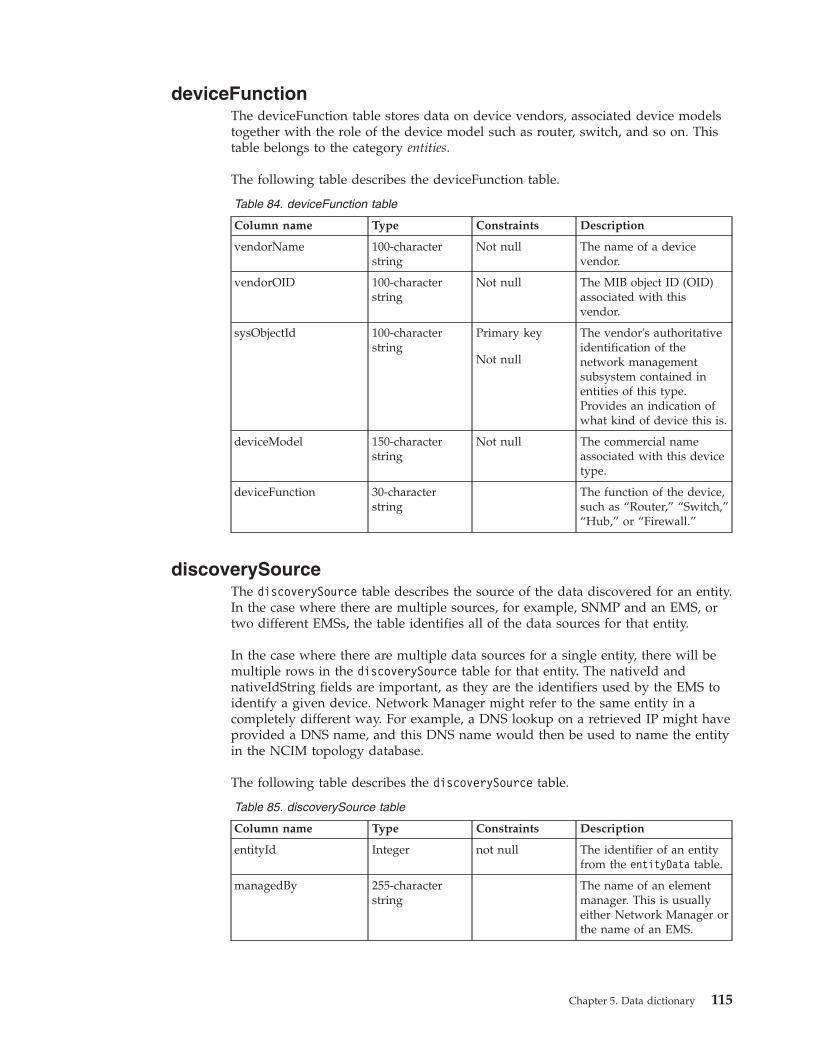
deviceFunctionThe deviceFunction table stores data on device vendors, associated device modelstogether with the role of the device model such as router, switch, and so on. Thistable belongs to the category entities.
The following table describes the deviceFunction table.
Table 84. deviceFunction table
Column name Type Constraints Description
vendorName 100-characterstring
Not null The name of a devicevendor.
vendorOID 100-characterstring
Not null The MIB object ID (OID)associated with thisvendor.
sysObjectId 100-characterstring
Primary key
Not null
The vendor's authoritativeidentification of thenetwork managementsubsystem contained inentities of this type.Provides an indication ofwhat kind of device this is.
deviceModel 150-characterstring
Not null The commercial nameassociated with this devicetype.
deviceFunction 30-characterstring
The function of the device,such as “Router,” “Switch,”“Hub,” or “Firewall.”
discoverySourceThe discoverySource table describes the source of the data discovered for an entity.In the case where there are multiple sources, for example, SNMP and an EMS, ortwo different EMSs, the table identifies all of the data sources for that entity.
In the case where there are multiple data sources for a single entity, there will bemultiple rows in the discoverySource table for that entity. The nativeId andnativeIdString fields are important, as they are the identifiers used by the EMS toidentify a given device. Network Manager might refer to the same entity in acompletely different way. For example, a DNS lookup on a retrieved IP might haveprovided a DNS name, and this DNS name would then be used to name the entityin the NCIM topology database.
The following table describes the discoverySource table.
Table 85. discoverySource table
Column name Type Constraints Description
entityId Integer not null The identifier of an entityfrom the entityData table.
managedBy 255-characterstring
The name of an elementmanager. This is usuallyeither Network Manager orthe name of an EMS.
Chapter 5. Data dictionary 115

Table 85. discoverySource table (continued)
Column name Type Constraints Description
source 14-characterstring
Source of the data. Thisfield takes one of thefollowing values:
v Unknown
v Other
v TopologyEditor
v PresetLayer
v Agent
v Collector
discoveryProtocol 13-characterstring
Protocol of the dataprovided by this discoverysource. This field takes oneof the following values:
v Unknown
v Other
v Manual
v FlatFile
v SNMP
v Telnet
v XML-RPC
v VSphere
v OtherJavaAPI
v TL1
v CORBA
nativeId Integer Identifier used by thediscovery source toidentify a given device.
nativeIdString 255-characterstring
String used by thediscovery source toidentify a given device.
managedElementId 255-characters String optionally used tohold a non-EMS specific IDfor a device. Useful wheremultiple systems need tomanage the device butmight use different EMSsto do so.
domainMembersThe domainMembers table stores information on membership of entities withindomains. This table belongs to the category domains.
The following table describes the domainMembers table.
116 IBM Tivoli Network Manager IP Edition: Topology Database Reference

Table 86. domainMembers table
Column name Type Constraints Description
entityId 32-bit integer Foreign keyNot nullAutomaticallyincremented
Foreign key to theentityNameCache table.
domainMgrId 32-bit integer Foreign key
Not null
The identifier of thedomain from thedomainMgr table.
Related concepts:“entityData table and entity view” on page 11Information on entities is held in the entityData table in Network Managerversions 3.9 and later. This table replaces the entity table used in earlier versions.To ensure backward compatibility an entity view has been created to hold thesame data as the entity table from earlier versions.
domainMgrThe domainMgr table stores data on network domains. This table belongs to thecategory domains.
The following table describes the domainMgr table.
Table 87. domainMgr table
Column name Type Constraints Description
domainMgrId 32-bit integer Primary key
Not null
Automaticallyincremented
Unique
This is anautomatically-incrementedfield that must be uniquefor each domain.
domainName 255-characterstring
Not null The name of the domain.
creationTime Timestamp Not null The timestamp indicatingwhen the domain wascreated.
lastUpdated Timestamp Not null The timestamp indicatingwhen this domain was lastupdated.
managerName 100-characterstring
Foreign key
Not null
The application thatmanages this domain. Thisis usually NetworkManager. This is one of thenetwork managerapplications specified inthe manager table.
description 255-characterstring
The textual description ofthe domain.
Chapter 5. Data dictionary 117

Table 87. domainMgr table (continued)
Column name Type Constraints Description
webtopDataSource 32-characterstring
The name of theTivoliNetcool/OMNIbus WebGUI data source thatTopoviz must connect to.The default value is NCOMS.If you change this value,then you must also edit theModelNcimDb.DOMAIN.cfgand insert the new valuethere.
domainHost 32-characterstring
Used by Topoviz tocommunicate with theNetwork Manager server.This value is automaticallyset by the ncp_modelprocess.
domainPort 32-characterstring
Used by Topoviz tocommunicate with theNetwork Manager server.This value is automaticallyset by the ncp_modelprocess.
batchUpdatePercent 8-bit integer This field is updated bythe domain managerduring batch updates.
Related concepts:“entityData table and entity view” on page 11Information on entities is held in the entityData table in Network Managerversions 3.9 and later. This table replaces the entity table used in earlier versions.To ensure backward compatibility an entity view has been created to hold thesame data as the entity table from earlier versions.
entityActionsThe entityActions table records all manual node additions and all node removals,including removal of nodes that were discovered rather than manually added andthe swapping of nodes into and out of a domain.
The following table describes the entityActions table.
Table 88. entityActions table
Column name Type Constraints Description
entityActionsId 32-bit integer Primary key
Automaticallyincremented
Not null
Unique auto generatedprimary key column.
entityId 32-bit integer Foreign key
Not null
Foreign key to theentityData table.
118 IBM Tivoli Network Manager IP Edition: Topology Database Reference

Table 88. entityActions table (continued)
Column name Type Constraints Description
domainMgrId 32-bit integer Foreign key
Not null
Foreign key to thedomainMgr. Indicatesdomain that an entity wasadded to or deleted from.
action 6-character string Enumeration ofvalues “add” and“delete"
Not null
Indicates an action thatadded or deleted an entity.
changeTime Timestamp Not null Indicates when thisentityAction was lastupdated.
username 64-characterstring
Not null Indicates the user thatperformed the entityaction.
location 512-characterstring
Indicates location fromwhich user is logged in.
description 512-characterstring
Textual description ofreason for the entity action.
manual Boolean Not null Indicates if the entity wasmanually added.
entityClassThe entityClass table stores information on all device classes and relationshipsbetween device classes. The table belongs to the category entities.
The following table describes the entityClass table.
Table 89. entityClass table
Column name Type Constraints Description
classId 32-bit integer Primary key
Not null
Automaticallyincremented
Unique
A unique field for eachclass.
className 32-characterstring
Not null The name of a class ofdevices.
Chapter 5. Data dictionary 119

Table 89. entityClass table (continued)
Column name Type Constraints Description
superClassId 32-bit integer Foreign key The classID valueassociated with the classthat contains the deviceclass specified by theclassName value.
For example, the classIdfor the NetworkDeviceclass is 5. Because Alcateland Cisco device classesare contained in theNetworkDevice deviceclass, they have asuperClassId of 5.
classType 32-characterstring
Not null The type of device or typeof class.
managerName 64-characterstring
Foreign key
Not null
The application thatmanages this device class.This is usually NetworkManager.
Related reference:“physicalChassis” on page 195The physicalChassis table stores the attributes of chassis entities.
entityDataThe entityData table stores data on entities. This table belongs to the categoryentities.
The following table describes the entityData table.
Table 90. entityData table
Column name Type Constraints Description
entityId 32-bit integer Foreign keyNot nullAutomaticallyincrementedUnique
Foreign key to theentityNameCache table.Must be unique for eachentity across all domains.
mainNodeEntityId 32-bit integer Foreign key This field is relevant onlyfor entities that are whollycontained within a singlemain node device. Thefield therefore has anon-null value only forentities that are related to asingle main node device,such as the main nodeitself, physical and logicaldevice components, orlogical interfaces (forexample IP end points orlocal VLAN entities).
120 IBM Tivoli Network Manager IP Edition: Topology Database Reference
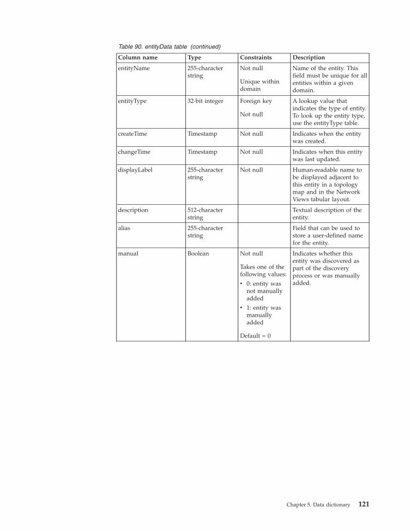
Table 90. entityData table (continued)
Column name Type Constraints Description
entityName 255-characterstring
Not null
Unique withindomain
Name of the entity. Thisfield must be unique for allentities within a givendomain.
entityType 32-bit integer Foreign key
Not null
A lookup value thatindicates the type of entity.To look up the entity type,use the entityType table.
createTime Timestamp Not null Indicates when the entitywas created.
changeTime Timestamp Not null Indicates when this entitywas last updated.
displayLabel 255-characterstring
Not null Human-readable name tobe displayed adjacent tothis entity in a topologymap and in the NetworkViews tabular layout.
description 512-characterstring
Textual description of theentity.
alias 255-characterstring
Field that can be used tostore a user-defined namefor the entity.
manual Boolean Not null
Takes one of thefollowing values:
v 0: entity wasnot manuallyadded
v 1: entity wasmanuallyadded
Default = 0
Indicates whether thisentity was discovered aspart of the discoveryprocess or was manuallyadded.
Chapter 5. Data dictionary 121
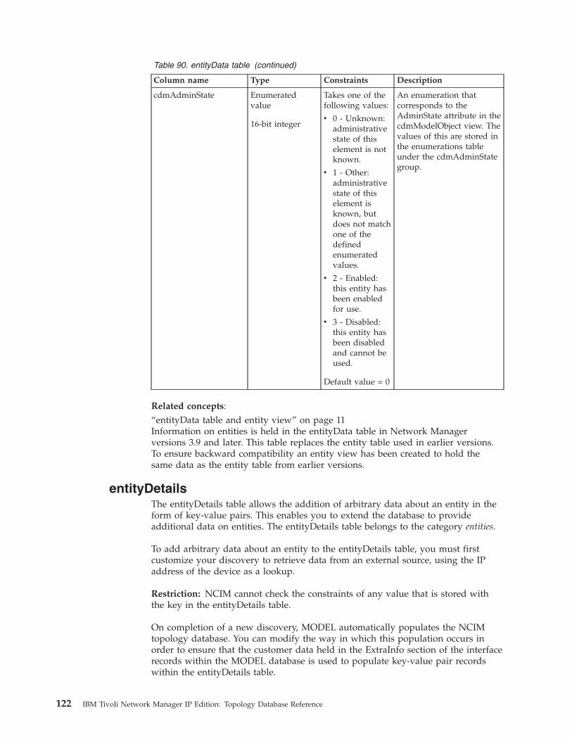
Table 90. entityData table (continued)
Column name Type Constraints Description
cdmAdminState Enumeratedvalue
16-bit integer
Takes one of thefollowing values:
v 0 - Unknown:administrativestate of thiselement is notknown.
v 1 - Other:administrativestate of thiselement isknown, butdoes not matchone of thedefinedenumeratedvalues.
v 2 - Enabled:this entity hasbeen enabledfor use.
v 3 - Disabled:this entity hasbeen disabledand cannot beused.
Default value = 0
An enumeration thatcorresponds to theAdminState attribute in thecdmModelObject view. Thevalues of this are stored inthe enumerations tableunder the cdmAdminStategroup.
Related concepts:“entityData table and entity view” on page 11Information on entities is held in the entityData table in Network Managerversions 3.9 and later. This table replaces the entity table used in earlier versions.To ensure backward compatibility an entity view has been created to hold thesame data as the entity table from earlier versions.
entityDetailsThe entityDetails table allows the addition of arbitrary data about an entity in theform of key-value pairs. This enables you to extend the database to provideadditional data on entities. The entityDetails table belongs to the category entities.
To add arbitrary data about an entity to the entityDetails table, you must firstcustomize your discovery to retrieve data from an external source, using the IPaddress of the device as a lookup.
Restriction: NCIM cannot check the constraints of any value that is stored withthe key in the entityDetails table.
On completion of a new discovery, MODEL automatically populates the NCIMtopology database. You can modify the way in which this population occurs inorder to ensure that the customer data held in the ExtraInfo section of the interfacerecords within the MODEL database is used to populate key-value pair recordswithin the entityDetails table.
122 IBM Tivoli Network Manager IP Edition: Topology Database Reference

The following table describes the entityDetails table.
Table 91. entityDetails table
Column name Type Constraints Description
entityId 32-bit integer Foreign key
Not null
The identifier from theentityData table of anentity. The current row ofthis table provideskey-value pair data for thisentity.
keyName 255-characterstring
Not null Name of the key part ofthe extra data. Forexample, this might be thename of the customer orlocation associated withthis device.
keyValue 1000-characterstring
Value of the key part of theextra data. For example,this might be a customertype.
Related tasks:“Extending NCIM” on page 78To store custom data on entities, and enable network operators to view customdata in network maps, extend the NCIM database.
entityNameCacheThe entityNameCache table is a lookup table that provides the entity name forevery entity in the entityData table. This table belongs to the category entities.
The following table describes the entityNameCache table.
Table 92. entityNameCache table
Column name Type Constraints Description
entityId 32-bit integer Primary key
Not null
Automatically-incrementedfield that provides aunique value for eachentity across all domains.
entityName 255-characterstring
Not null The name of the entity.
domainMgrId 32-bit integer Not null The identifier from thedomainMgr table of thedomain that contains thisentity.
Chapter 5. Data dictionary 123
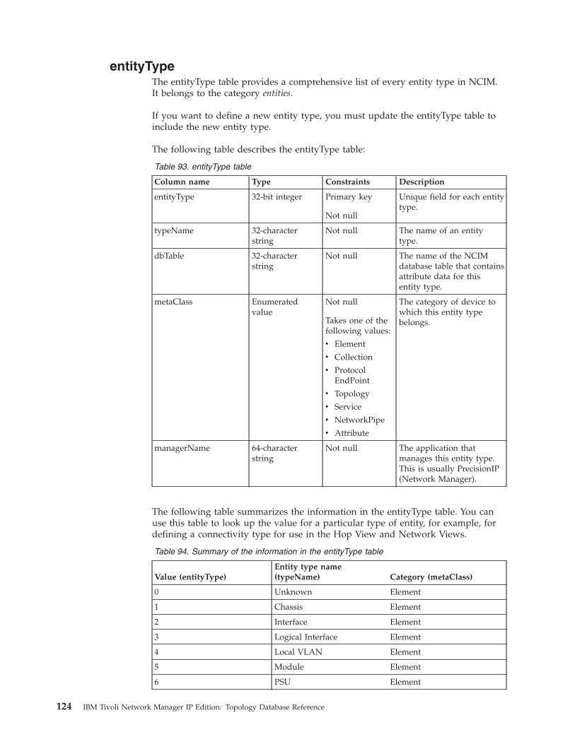
entityTypeThe entityType table provides a comprehensive list of every entity type in NCIM.It belongs to the category entities.
If you want to define a new entity type, you must update the entityType table toinclude the new entity type.
The following table describes the entityType table:
Table 93. entityType table
Column name Type Constraints Description
entityType 32-bit integer Primary key
Not null
Unique field for each entitytype.
typeName 32-characterstring
Not null The name of an entitytype.
dbTable 32-characterstring
Not null The name of the NCIMdatabase table that containsattribute data for thisentity type.
metaClass Enumeratedvalue
Not null
Takes one of thefollowing values:
v Element
v Collection
v ProtocolEndPoint
v Topology
v Service
v NetworkPipe
v Attribute
The category of device towhich this entity typebelongs.
managerName 64-characterstring
Not null The application thatmanages this entity type.This is usually PrecisionIP(Network Manager).
The following table summarizes the information in the entityType table. You canuse this table to look up the value for a particular type of entity, for example, fordefining a connectivity type for use in the Hop View and Network Views.
Table 94. Summary of the information in the entityType table
Value (entityType)Entity type name(typeName) Category (metaClass)
0 Unknown Element
1 Chassis Element
2 Interface Element
3 Logical Interface Element
4 Local VLAN Element
5 Module Element
6 PSU Element
124 IBM Tivoli Network Manager IP Edition: Topology Database Reference

Table 94. Summary of the information in the entityType table (continued)
Value (entityType)Entity type name(typeName) Category (metaClass)
7 Logical Collection Collection
8 Daughter Card Element
9 Fan Element
10 Backplane Element
11 Slot Element
12 Sensor Element
13 Virtual Router Element
14 CPU Element
15 Subnet Collection
16 Global VLAN Collection
17 VPN Collection
18 HSRP Group Collection
19 Stack Element
20 VRF Element
21 OSPF Routing Domain Collection
22 OSPF Service Service
23 OSPF Area Collection
24 VTP Domain Collection
25 Other Element
26 BGP Service Service
27 BGP AS (AutonomousSystem)
Collection
28 BGP Route Attribute
29 BGP Cluster Collection
30 BGP Network Collection
31 ISIS Service Service
32 ISIS Level Collection
33 OSPF Pseudo-Node Element
34 ITNM Service Collection
35 MPLS TE Service Service
36 MPLS TE Tunnel Element
37 MPLS TE Resource Element
38 MPLS LSP Element
40 IP Connection Element
41 PIM Service Service
42 PIM Network Collection
43 IPMRoute Service Service
44 IPMRoute Upstream Element
45 IPMRoute Downstream Element
Chapter 5. Data dictionary 125

Table 94. Summary of the information in the entityType table (continued)
Value (entityType)Entity type name(typeName) Category (metaClass)
46 IPMRoute MDT Collection
47 IPMRoute Source Element
48 IPMRoute Group Element
49 IP Path Collection
50 IP Endpoint Protocol Endpoint
51 VLAN Trunk Endpoint Protocol Endpoint
52 Frame Relay Endpoint Protocol Endpoint
53 OSPF Endpoint Protocol Endpoint
54 ATM Endpoint Protocol Endpoint
55 VPWS Endpoint Protocol Endpoint
56 BGP End Point Protocol Endpoint
57 ISIS End Point Protocol Endpoint
58 MPLS Tunnel End Point Protocol Endpoint
59 TCP/UDP End Point Protocol Endpoint
60 PIM End Point Protocol Endpoint
61 IPMRoute End Point ProtocolEndPoint
62 IGMP End Point ProtocolEndPoint
63 Network Service Entity EndPoint
ProtocolEndPoint
70 Topology Topology
72 Layer 2 Topology Topology
73 Layer 3 Meshed Topology Topology
75 MPLS TE Topology Topology
77 Pseudo Wire Topology Topology
78 OSPF Topology Topology
79 BGP Topology Topology
80 IP Path Topology Topology
81 PIM Topology Topology
82 Local VLAN Topology Topology
83 IPMRoute Topology Topology
84 VPLS Pseudo Wire Topology Topology
86 Microwave Topology Topology
110 Generic Collection Collection
111 Geographic Location Element
112 Geographic Region Collection
120 IGMP Service Service
121 IGMP Groups Collection
130 RAN GSM Cell Element
131 RAN UTRAN Cell Element
126 IBM Tivoli Network Manager IP Edition: Topology Database Reference

Table 94. Summary of the information in the entityType table (continued)
Value (entityType)Entity type name(typeName) Category (metaClass)
132 RAN Sector Element
133 RAN NodeB Local Cell Element
134 RAN Location Area Collection
135 RAN Routing Area Collection
136 RAN Packet Core Collection
137 RAN Circuit Core Collection
138 RAN Radio Core Collection
139 RAN Transceiver Element
Related concepts:“Entities” on page 6A Network Manager discovery returns many different types of entity. If youunderstand the entities that you might encounter, you can more easily restrict yourqueries to return only required information.
enumerationsThe enumerations table provides a means of looking up a human-readable stringvalue by providing a numerical value. Each enumeration is defined as a key-valuepair. The enumerations table belongs to the category mapping.
Description
The following table describes the enumerations table.
Table 95. enumerations table
Column Name Type Constraints Description
enumGroup 100-characterstring
Primary key withenumKey
Not null
Groups together all thekey-name pairs that formpart of a singleenumeration.
enumKey 32-bit integer Primary key withenumGroup
Not null
Integer value used as thekey by the enumeration.
enumValue 100-characterstring
Not null Human-readable stringvalue that corresponds tothe key.
enumDescription 100-characterstring
Brief description of theenumeration.
Chapter 5. Data dictionary 127
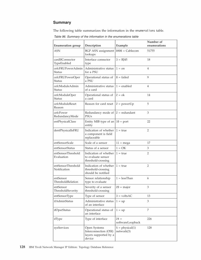
Summary
The following table summarizes the information in the enumerations table.
Table 96. Summary of the information in the enumerations table
Enumeration group Description ExampleNumber ofenumerations
ASN BGP ASN assignmentlookups
8406 = Cablecom 51755
cardIfConnectorTypeEnabled
Interface connectortype
3 = RJ45 18
cefcFRUPowerAdminStatus
Administrative statusfor a PSU
1 = on 4
cefcFRUPowerOperStatus
Operational status ofa PSU
8 = failed 9
cefcModuleAdminStatus
Administrative statusof a card
1 = enabled 4
cefcModuleOperStatus
Operational status ofa card
2 = ok 14
cefcModuleResetReason
Reason for card reset 2 = powerUp 5
cefcPowerRedundancyMode
Redundancy mode ofPSUs
2 = redundant 3
entPhysicalClass Entity MIB type of anentity
10 = port 22
dentPhysicalIsFRU Indication of whethera component is fieldreplaceable
1 = true 2
entSensorScale Scale of a sensor 11 = mega 17
entSensorStatus Status of a sensor 1 = OK 3
entSensorThresholdEvaluation
Indication of whetherto evaluate sensorthreshold-crossing
1 = true 2
entSensorThresholdNotification
Indication of whetherthreshold-crossingshould be notified
1 = true 2
entSensorThresholdRelation
Sensor relationshiptype to evaluate
1 = lessThan 6
entSensorThresholdSeverity
Severity of a sensorthreshold-crossing
20 = major 3
entSensorType Type of sensor 3 = voltsAC 13
ifAdminStatus Administrative statusof an interface
1 = up 3
ifOperStatus Operational status ofan interface
1 = up 7
ifType Type of interface 24 =softwareLoopback
226
sysServices Open SystemsInterconnection (OSI)layers supported by adevice
5 = physical(1)network(3)
128
128 IBM Tivoli Network Manager IP Edition: Topology Database Reference
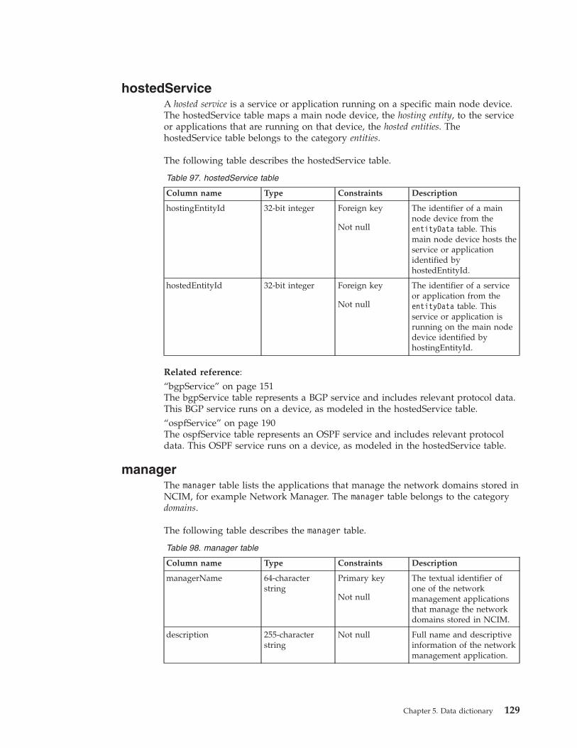
hostedServiceA hosted service is a service or application running on a specific main node device.The hostedService table maps a main node device, the hosting entity, to the serviceor applications that are running on that device, the hosted entities. ThehostedService table belongs to the category entities.
The following table describes the hostedService table.
Table 97. hostedService table
Column name Type Constraints Description
hostingEntityId 32-bit integer Foreign key
Not null
The identifier of a mainnode device from theentityData table. Thismain node device hosts theservice or applicationidentified byhostedEntityId.
hostedEntityId 32-bit integer Foreign key
Not null
The identifier of a serviceor application from theentityData table. Thisservice or application isrunning on the main nodedevice identified byhostingEntityId.
Related reference:“bgpService” on page 151The bgpService table represents a BGP service and includes relevant protocol data.This BGP service runs on a device, as modeled in the hostedService table.“ospfService” on page 190The ospfService table represents an OSPF service and includes relevant protocoldata. This OSPF service runs on a device, as modeled in the hostedService table.
managerThe manager table lists the applications that manage the network domains stored inNCIM, for example Network Manager. The manager table belongs to the categorydomains.
The following table describes the manager table.
Table 98. manager table
Column name Type Constraints Description
managerName 64-characterstring
Primary key
Not null
The textual identifier ofone of the networkmanagement applicationsthat manage the networkdomains stored in NCIM.
description 255-characterstring
Not null Full name and descriptiveinformation of the networkmanagement application.
Chapter 5. Data dictionary 129

Table 98. manager table (continued)
Column name Type Constraints Description
version 32-characterstring
Not null The current version of thenetwork managementapplication.
contact 64-characterstring
Contact person for thenetwork managementapplication.
mappingsThe mappings table provides a means of looking up an alternative textual name. Itis used to map non-human-readable data to human-readable data. The mappingstable belongs to the category mapping.
Description
The following table describes the mappings table.
Table 99. mappings table
Column name Type Constraints Description
mappingGroup 100-characterstring
Primary key withmappingkey
Not null
Groups together all thekey-value pairs that formpart of a single mappingtype.
mappingkey 100-characterstring
Primary key withmappingGroup
Not null
Non-human readable stringvalue used as the key bythe enumeration.
mappingValue 100-characterstring
Not null Human-readable stringvalue that corresponds tothe key.
mappingDescription 1000-characterstring
Description of the itemspecified by the key-valuepair.
Summary
The following table summarizes the information held in the mappings table.
Table 100. Summary of information held in the mappings table
Mapping group Description Example
entPhysicalVendorType Physical component lookups 1.3.6.1.4.1.9.12.3.1.9.20 .33= cevCat8500m4pDs3
IANAEnterprise Internet Assigned NumbersAuthority (IANA) vendorobject Identifier (OID) tovendor name
1.3.6.1.4.1.9=Cisco Systems, Inc
MACVendors Holds partial MAC addressesthat represent theOrganizationally UniqueIdentifier (OUI)
00:02:9C = 3COM
130 IBM Tivoli Network Manager IP Edition: Topology Database Reference
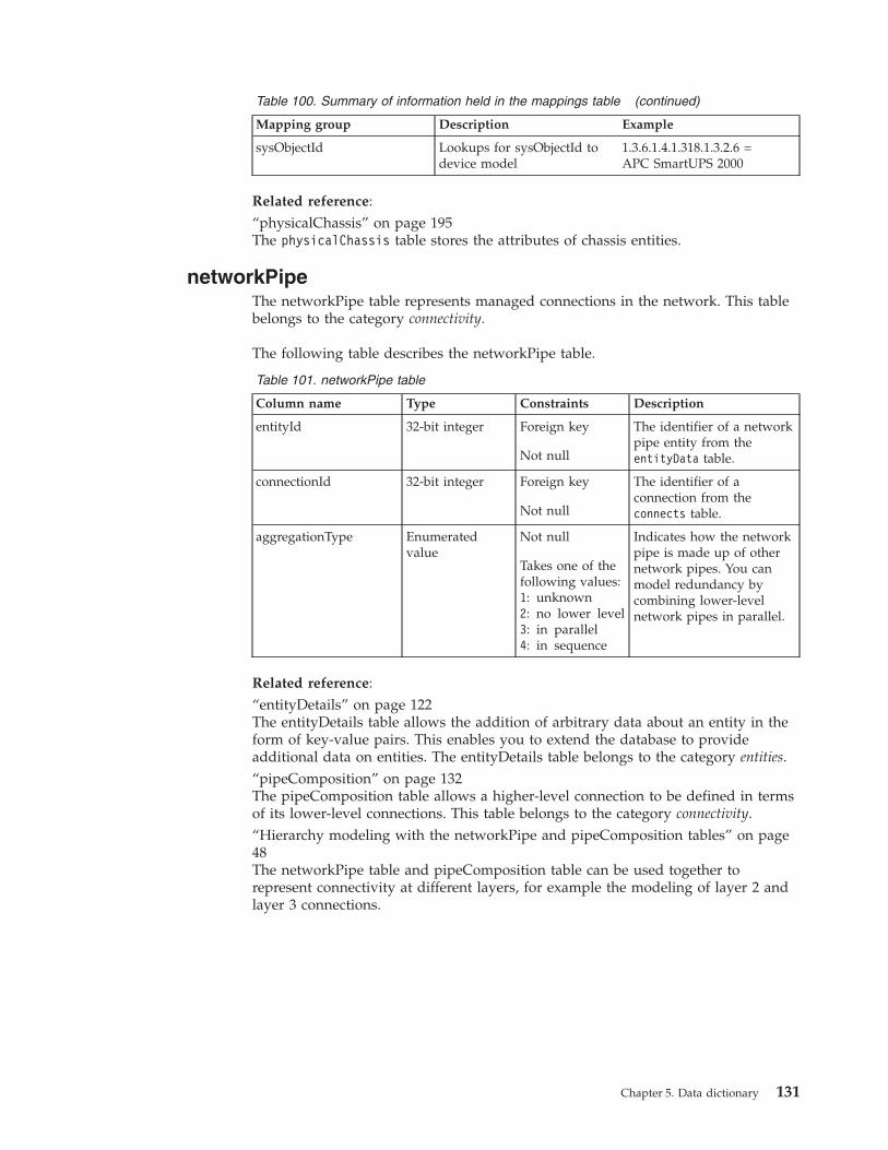
Table 100. Summary of information held in the mappings table (continued)
Mapping group Description Example
sysObjectId Lookups for sysObjectId todevice model
1.3.6.1.4.1.318.1.3.2.6 =APC SmartUPS 2000
Related reference:“physicalChassis” on page 195The physicalChassis table stores the attributes of chassis entities.
networkPipeThe networkPipe table represents managed connections in the network. This tablebelongs to the category connectivity.
The following table describes the networkPipe table.
Table 101. networkPipe table
Column name Type Constraints Description
entityId 32-bit integer Foreign key
Not null
The identifier of a networkpipe entity from theentityData table.
connectionId 32-bit integer Foreign key
Not null
The identifier of aconnection from theconnects table.
aggregationType Enumeratedvalue
Not null
Takes one of thefollowing values:1: unknown2: no lower level3: in parallel4: in sequence
Indicates how the networkpipe is made up of othernetwork pipes. You canmodel redundancy bycombining lower-levelnetwork pipes in parallel.
Related reference:“entityDetails” on page 122The entityDetails table allows the addition of arbitrary data about an entity in theform of key-value pairs. This enables you to extend the database to provideadditional data on entities. The entityDetails table belongs to the category entities.“pipeComposition” on page 132The pipeComposition table allows a higher-level connection to be defined in termsof its lower-level connections. This table belongs to the category connectivity.“Hierarchy modeling with the networkPipe and pipeComposition tables” on page48The networkPipe table and pipeComposition table can be used together torepresent connectivity at different layers, for example the modeling of layer 2 andlayer 3 connections.
Chapter 5. Data dictionary 131

notesThe notes table provides a means of storing textual data related to an entity. Thistable belongs to the category entities.
The following table describes the notes table.
Table 102. notes table
Column name Type Constraints Description
entityId 32-bit integer Foreign key
Not null
The identifier of an entityfrom the entityData table.
createTime Timestamp Not null The date and time of entitycreation.
note 1000-characterstring
A textual note associatedwith the entity.
pipeCompositionThe pipeComposition table allows a higher-level connection to be defined in termsof its lower-level connections. This table belongs to the category connectivity.
The pipeComposition table can be used together with the networkPipe table torepresent a hierarchy of connections.
The following table describes the pipeComposition table.
Table 103. pipeComposition table
Column name Type Constraints Description
groupComponent 32-bit integer Foreign key
Primary key withpartComponent
Not null
A foreign key from the rowin the entityData table thatrepresents the networkpipe instance.
partComponent 32-bit integer Foreign key
Primary key withgroupComponent
Not null
A foreign key from the rowin the entityData table thatrepresents the networkpipe that is part of thecomposition.
aggregationSequence 32-bit integer The sequence number ofthe composition. Forunordered paths this valuecan be null.
132 IBM Tivoli Network Manager IP Edition: Topology Database Reference

Related reference:“networkPipe” on page 131The networkPipe table represents managed connections in the network. This tablebelongs to the category connectivity.“Hierarchy modeling with the networkPipe and pipeComposition tables” on page48The networkPipe table and pipeComposition table can be used together torepresent connectivity at different layers, for example the modeling of layer 2 andlayer 3 connections.
protocolEndPointThe protocolEndPoint table allows a higher-level connection to be defined in termsof lower-level connections. It associates a device entity, usually an interface, withprotocol-specific information associated with that device entity. TheprotocolEndPoint table belongs to the category connectivity.
The following table describes the protocolEndPoint table.
Table 104. protocolEndPoint table
Column name Type Constraints Description
endPointEntityId 32-bit integer Foreign key
Not null
The identifier of an entityfrom the entityData tablethat specifiesprotocol-specificaddressing information forthis endpoint.
implementingEntityId 32-bit integer Foreign key
Not null
The identifier of an entityfrom the entityData tablethat implements thisprotocol end point. This isusually a device interface.
Chapter 5. Data dictionary 133

Related reference:“atmEndPoint” on page 144The atmEndPoint table represents a logical ATM end point and includes relevantATM data. This endpoint is implemented by a physical interface.“bgpEndPoint” on page 146The bgpEndPoint table represents a logical BGP end point and includes relevantBGP data. This endpoint is implemented by a physical interface, as modeled in theprotocolEndPoint table“igmpEndPoint” on page 163The igmpEndPoint table holds information on the Internet Group MembershipProtocol (IGMP) End Points.“ipMRouteEndPoint” on page 169The ipMRouteEndPoint table holds information on the IP Multicast RoutingProtocol End Points.“mplsTETunnelEndPoint” on page 179The mplsTETunnelEndPoint table represents an MPLS TE protocol end point and isimplemented on the interface associated with the configured tunnel. The end pointreferences the associated TE tunnels unique instance id.“ospfEndPoint” on page 188The ospfEndPoint table represents an OSPF end point and includes relevant data.This endpoint is implemented by a physical interface, as modeled in theprotocolEndPoint table.“pimEndpoint” on page 208The pimEndPoint table represents the Protocol Independent Multicast (PIM) endpoints discovered in the network and their associated attributes.“portEndPoint” on page 210The portEndPoint holds data about TCP/UDP endpoints found by the NMAPScanagent.“vlanTrunkEndPoint” on page 225The vlanTrunkEndPoint table represents a VLAN trunk end point and includesrelevant data. This endpoint is implemented by a physical interface, as modeled inthe protocolEndPoint table.“vpwsEndPoint” on page 227The vpwsEndPoint table represents a VPWS end point and includes relevant data.This endpoint is implemented by a physical interface, as modeled in theprotocolEndPoint table.“frameRelayEndPoint” on page 160The frameRelayEndPoint table represents a logical Frame Relay end point andincludes relevant data. This endpoint is implemented by a physical interface, asmodeled in the protocolEndPoint table.“ipEndPoint” on page 166The ipEndPoint table represents an IP end point and includes relevant data. Theendpoint is implemented by a physical interface, as modeled in theprotocolEndPoint table.“Protocol endpoint tables” on page 22The protocolEndPoint and ipEndPoint tables can be used in SQL queries toidentify the IP addresses that are implemented by the device interfaces.
134 IBM Tivoli Network Manager IP Edition: Topology Database Reference
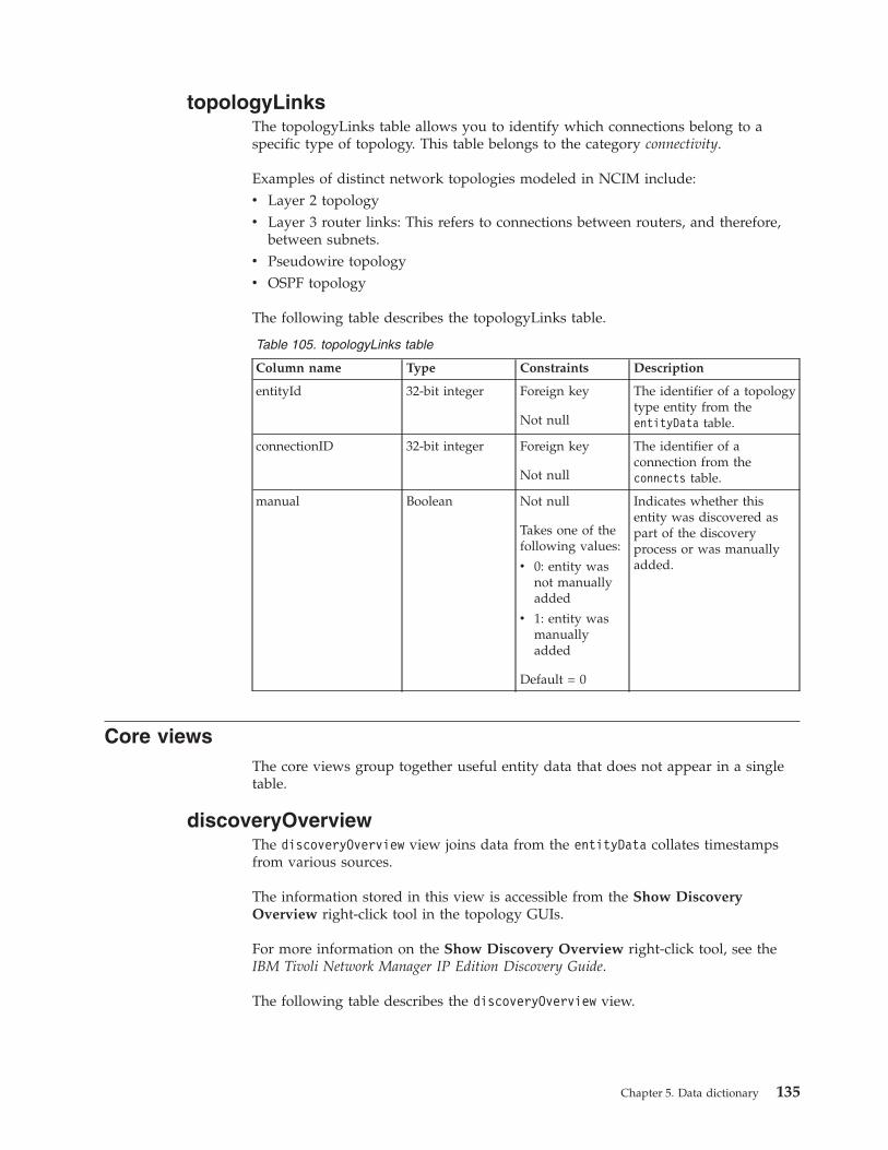
topologyLinksThe topologyLinks table allows you to identify which connections belong to aspecific type of topology. This table belongs to the category connectivity.
Examples of distinct network topologies modeled in NCIM include:v Layer 2 topologyv Layer 3 router links: This refers to connections between routers, and therefore,
between subnets.v Pseudowire topologyv OSPF topology
The following table describes the topologyLinks table.
Table 105. topologyLinks table
Column name Type Constraints Description
entityId 32-bit integer Foreign key
Not null
The identifier of a topologytype entity from theentityData table.
connectionID 32-bit integer Foreign key
Not null
The identifier of aconnection from theconnects table.
manual Boolean Not null
Takes one of thefollowing values:
v 0: entity wasnot manuallyadded
v 1: entity wasmanuallyadded
Default = 0
Indicates whether thisentity was discovered aspart of the discoveryprocess or was manuallyadded.
Core viewsThe core views group together useful entity data that does not appear in a singletable.
discoveryOverviewThe discoveryOverview view joins data from the entityData collates timestampsfrom various sources.
The information stored in this view is accessible from the Show DiscoveryOverview right-click tool in the topology GUIs.
For more information on the Show Discovery Overview right-click tool, see theIBM Tivoli Network Manager IP Edition Discovery Guide.
The following table describes the discoveryOverview view.
Chapter 5. Data dictionary 135
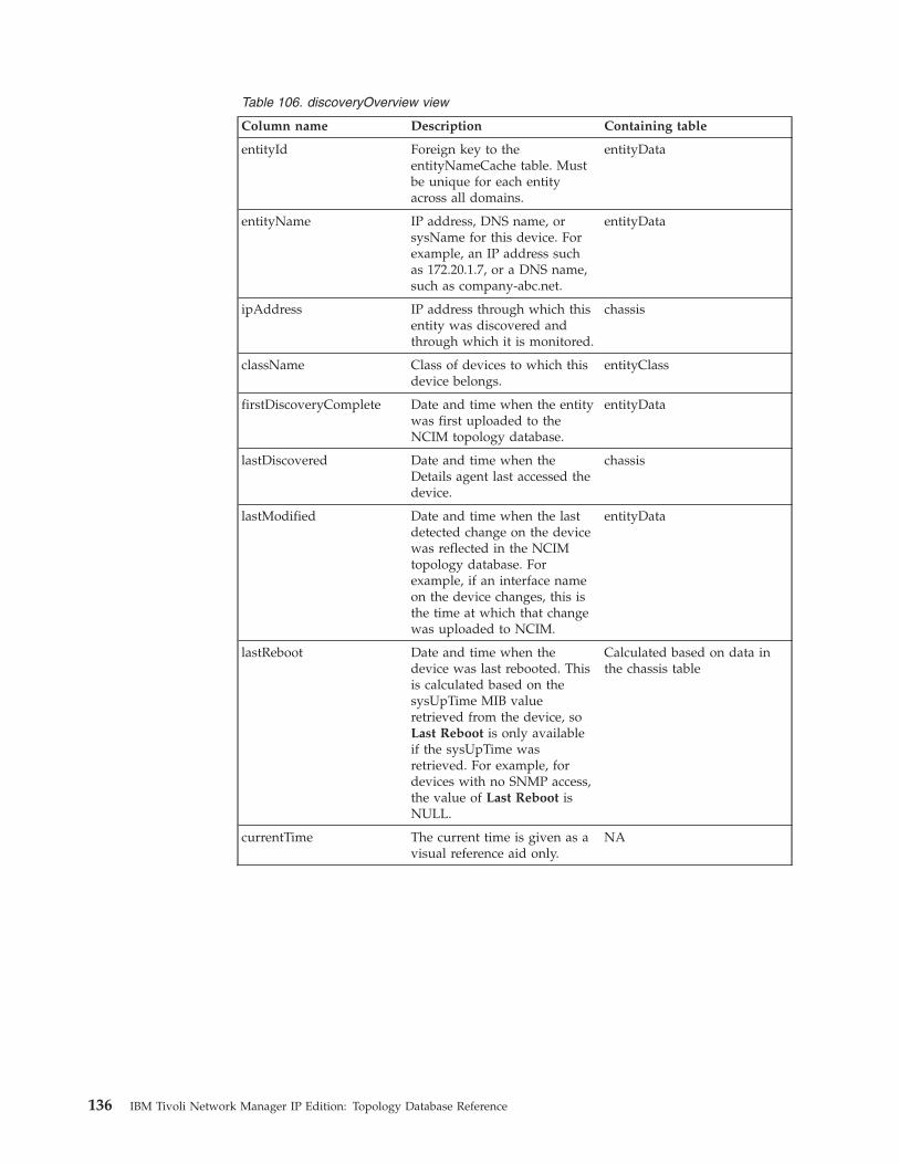
Table 106. discoveryOverview view
Column name Description Containing table
entityId Foreign key to theentityNameCache table. Mustbe unique for each entityacross all domains.
entityData
entityName IP address, DNS name, orsysName for this device. Forexample, an IP address suchas 172.20.1.7, or a DNS name,such as company-abc.net.
entityData
ipAddress IP address through which thisentity was discovered andthrough which it is monitored.
chassis
className Class of devices to which thisdevice belongs.
entityClass
firstDiscoveryComplete Date and time when the entitywas first uploaded to theNCIM topology database.
entityData
lastDiscovered Date and time when theDetails agent last accessed thedevice.
chassis
lastModified Date and time when the lastdetected change on the devicewas reflected in the NCIMtopology database. Forexample, if an interface nameon the device changes, this isthe time at which that changewas uploaded to NCIM.
entityData
lastReboot Date and time when thedevice was last rebooted. Thisis calculated based on thesysUpTime MIB valueretrieved from the device, soLast Reboot is only availableif the sysUpTime wasretrieved. For example, fordevices with no SNMP access,the value of Last Reboot isNULL.
Calculated based on data inthe chassis table
currentTime The current time is given as avisual reference aid only.
NA
136 IBM Tivoli Network Manager IP Edition: Topology Database Reference

entityThe entity view joins data from the entityData and domainMembers tables and isequivalent to the entity table that existed in Network Manager versions 3.8 andearlier.The entity view stores data on entities and includes the domainMgrId,which the domain in which the entity is located.
The following table describes the entity view.
Table 107. entity view
Column name Description Containing table
entityId Foreign key to theentityNameCache table. Mustbe unique for each entityacross all domains.
entityData
mainNodeEntityId This field is relevant only forentities that are whollycontained within a singlemain node device. The fieldtherefore has a non-null valueonly for entities that arerelated to a single main nodedevice, such as the main nodeitself, physical and logicaldevice components, or logicalinterfaces (for example IP endpoints or local VLAN entities).
entityData
entityName Name of the entity. This fieldmust be unique for all entitieswithin a given domain.
entityData
domainMgrId The identifier of the domainfrom the domainMgr table.
domainMgr
entityType A lookup value that indicatesthe type of entity. To look upthe entity type, use theentityType table.
entityData
createTime Indicates when the entity wascreated.
entityData
changeTime Indicates when this entity waslast updated.
entityData
displayLabel Human-readable name to bedisplayed adjacent to thisentity in a topology map andin the Network Views tabularlayout.
entityData
description Textual description of theentity.
entityData
alias Field that can be used to storea user-defined name for theentity.
entityData
manual Indicates if the entity wasmanually added.
Chapter 5. Data dictionary 137

Related concepts:“entityData table and entity view” on page 11Information on entities is held in the entityData table in Network Managerversions 3.9 and later. This table replaces the entity table used in earlier versions.To ensure backward compatibility an entity view has been created to hold thesame data as the entity table from earlier versions.Related reference:“entityType” on page 124The entityType table provides a comprehensive list of every entity type in NCIM.It belongs to the category entities.
interfaceDomainThe interfaceDomain view adds the domain name to the interface table. This viewis used to get the domain details of a particular interface.
The following table describes the interfaceDomain view.
Table 108. interfaceDomain view
Column name Description Containing table
ipAddress The IP address through whichthis entity was discovered andwill be monitored.Note: For non-IP entities, suchas layer 1 optical devices, thisfield is null.
chassis
In the chassis table, this fieldis called accessIpAddress.
ifName The name assigned to theinterface.
interface
ifDescr A description of the interface. interface
entityName Name of the entity. This fieldmust be unique for all entitieswithin a given domain.
entityData
entityId Foreign key to theentityNameCache table. Mustbe unique for each entityacross all domains.
entityData
domainMgrId The identifier of the domainfrom the domainMgr table.
domainMgr
domainName The name of the domain inwhich the node wasdiscovered.
domainMgr
interfacesThe interfaces view provides a consolidated set of data on all device interfaces.This view groups together data that appeared together in the legacy 3.6 MySQLdatabase.
The following table describes the interfaces view. The type, constraints, anddescription are automatically inherited, where appropriate, from the tables towhich the fields belong.
138 IBM Tivoli Network Manager IP Edition: Topology Database Reference

Table 109. interfaces view
Column name Description Containing table
displayLabel Human-readable name to bedisplayed adjacent to thisentity in a topology map andin the Network Views tabularlayout.
entityData
duplex Actual duplex of the interface.Takes one of the followingvalues:
v HalfDuplex
v FullDuplex
v Auto
v Unknown
v Other
interface
entPhysicalParentRelPos An indication of the relativeposition of this childcomponent among all itssibling components. Siblingcomponents are defined asentPhysicalEntries which sharethe same instance values ofeach of theentPhysicalContainedIn andentPhysicalClass objects.
chassis
entityId Foreign key to theentityNameCache table. Mustbe unique for each entityacross all domains.
entityData
entityName Name of the entity. This fieldmust be unique for all entitieswithin a given domain.
entityData
ifAdminStatus The required state of theinterface. Takes one of thefollowing values:
v Up
v Down
v Testing
interface
ifAlias The alias for the interface. interface
ifDescr A description of the interface. interface
ifHighSpeed An estimate of the currentbandwidth of the interface inunits of 1,000,000 bits persecond.
interface
ifIndex The index of the interface. interface
ifMTU The maximum transmissionunit for this interface.
interface
ifName The name assigned to theinterface.
interface
Chapter 5. Data dictionary 139
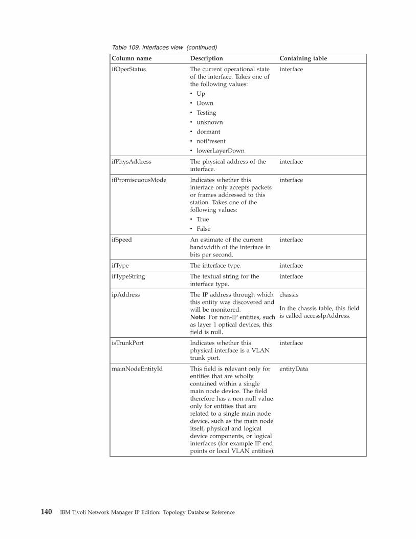
Table 109. interfaces view (continued)
Column name Description Containing table
ifOperStatus The current operational stateof the interface. Takes one ofthe following values:
v Up
v Down
v Testing
v unknown
v dormant
v notPresent
v lowerLayerDown
interface
ifPhysAddress The physical address of theinterface.
interface
ifPromiscuousMode Indicates whether thisinterface only accepts packetsor frames addressed to thisstation. Takes one of thefollowing values:
v True
v False
interface
ifSpeed An estimate of the currentbandwidth of the interface inbits per second.
interface
ifType The interface type. interface
ifTypeString The textual string for theinterface type.
interface
ipAddress The IP address through whichthis entity was discovered andwill be monitored.Note: For non-IP entities, suchas layer 1 optical devices, thisfield is null.
chassis
In the chassis table, this fieldis called accessIpAddress.
isTrunkPort Indicates whether thisphysical interface is a VLANtrunk port.
interface
mainNodeEntityId This field is relevant only forentities that are whollycontained within a singlemain node device. The fieldtherefore has a non-null valueonly for entities that arerelated to a single main nodedevice, such as the main nodeitself, physical and logicaldevice components, or logicalinterfaces (for example IP endpoints or local VLAN entities).
entityData
140 IBM Tivoli Network Manager IP Edition: Topology Database Reference

Table 109. interfaces view (continued)
Column name Description Containing table
portNumber The port number for thisinterface on the chassis device.The method of determiningthe port number is dependenton the make and model of thedevice that is discovered. Forthis reason, use this valuewith caution.
interface
domainMgrId The ID for the domain towhich this interface belongs.
domainMgr
mainNodeDetailsThe mainNodeDetails view provides a consolidated set of data on all networkdevices. This view groups together data that appeared together in the legacy 3.6MySQL database.
The following table describes the mainNodeDetails view. The type, constraints, anddescription are automatically inherited, where appropriate, from the tables towhich the fields belong.
Table 110. mainNodeDetails view
Column name Description Containing table
className The name of a class ofdevices. The masterclassName field is in theentityClass table.
chassis
classType The type of device or type ofclass.
entityClass
description Textual description of theentity.
entityData
displayLabel Human-readable name to bedisplayed adjacent to thisentity in a topology map andin the Network Views tabularlayout.
entityData
entPhysicalDescr A textual description ofphysical entity. This objectmust contain a string whichidentifies the manufacturer'sname for the physical entity.The value must be set to adistinct value for each versionor model of the physicalentity.
chassis
entPhysicalVendorType An indication of thevendor-specific hardware typeof the physical entity.
chassis
entityId Unique ID for each entityacross all domains.
entityData
Chapter 5. Data dictionary 141
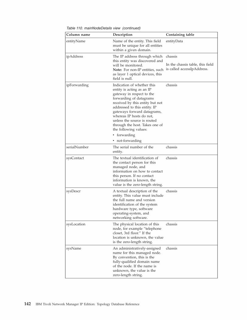
Table 110. mainNodeDetails view (continued)
Column name Description Containing table
entityName Name of the entity. This fieldmust be unique for all entitieswithin a given domain.
entityData
ipAddress The IP address through whichthis entity was discovered andwill be monitored.Note: For non-IP entities, suchas layer 1 optical devices, thisfield is null.
chassis
In the chassis table, this fieldis called accessIpAddress.
ipForwarding Indication of whether thisentity is acting as an IPgateway in respect to theforwarding of datagramsreceived by this entity but notaddressed to this entity. IPgateways forward datagrams,whereas IP hosts do not,unless the source is routedthrough the host. Takes one ofthe following values:
v forwarding
v not-forwarding
chassis
serialNumber The serial number of theentity.
chassis
sysContact The textual identification ofthe contact person for thismanaged node, andinformation on how to contactthis person. If no contactinformation is known, thevalue is the zero-length string.
chassis
sysDescr A textual description of theentity. This value must includethe full name and versionidentification of the systemhardware type, softwareoperating-system, andnetworking software.
chassis
sysLocation The physical location of thisnode, for example “telephonecloset, 3rd floor.” If thelocation is unknown, the valueis the zero-length string.
chassis
sysName An administratively-assignedname for this managed node.By convention, this is thefully-qualified domain nameof the node. If the name isunknown, the value is thezero-length string.
chassis
142 IBM Tivoli Network Manager IP Edition: Topology Database Reference
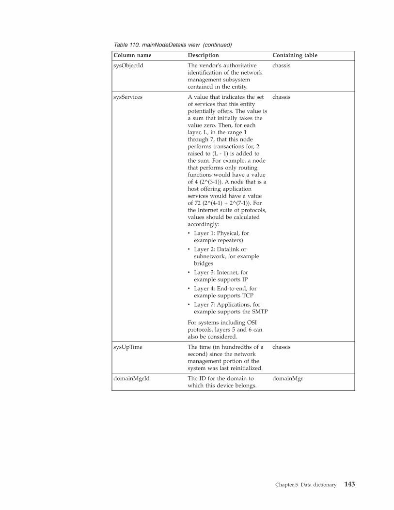
Table 110. mainNodeDetails view (continued)
Column name Description Containing table
sysObjectId The vendor's authoritativeidentification of the networkmanagement subsystemcontained in the entity.
chassis
sysServices A value that indicates the setof services that this entitypotentially offers. The value isa sum that initially takes thevalue zero. Then, for eachlayer, L, in the range 1through 7, that this nodeperforms transactions for, 2raised to (L - 1) is added tothe sum. For example, a nodethat performs only routingfunctions would have a valueof 4 (2^(3-1)). A node that is ahost offering applicationservices would have a valueof 72 (2^(4-1) + 2^(7-1)). Forthe Internet suite of protocols,values should be calculatedaccordingly:
v Layer 1: Physical, forexample repeaters)
v Layer 2: Datalink orsubnetwork, for examplebridges
v Layer 3: Internet, forexample supports IP
v Layer 4: End-to-end, forexample supports TCP
v Layer 7: Applications, forexample supports the SMTP
For systems including OSIprotocols, layers 5 and 6 canalso be considered.
chassis
sysUpTime The time (in hundredths of asecond) since the networkmanagement portion of thesystem was last reinitialized.
chassis
domainMgrId The ID for the domain towhich this device belongs.
domainMgr
Chapter 5. Data dictionary 143

mainNodeDomainThe mainNodeDomain view adds the domain name to the mainNodeDetails view.This view is used to get the domain details of a particular main node.
The following table describes the mainNodeDomain view.
Table 111. mainNodeDomain view
Column name Description Containing table
ipAddress The IP address through whichthis entity was discovered andwill be monitored.Note: For non-IP entities, suchas layer 1 optical devices, thisfield is null.
chassis
In the chassis table, this fieldis called accessIpAddress.
className The name of a class ofdevices. The masterclassName field is in theentityClass table.
chassis
entityName Name of the entity. This fieldmust be unique for all entitieswithin a given domain.
entityData
entityId Foreign key to theentityNameCache table. Mustbe unique for each entityacross all domains.
entityData
domainMgrId The identifier of the domainfrom the domainMgr table.
domainMgr
domainName The name of the domain inwhich the node wasdiscovered.
domainMgr
Entity attribute tablesEntity attribute tables define attributes for the entities discovered by NetworkManager, that is, layer 1, layer 2 and layer 3 entities.
If the entity is a physical element, such as a chassis or module, these are the tablesthat contain the attributes which relate specifically to that physical element, such assysDescr and sysObjectId for a chassis or serialNumber for a module. If the entityis a device collection, such as a VLAN or VPN, these tables containcollection-specific parameters, such as vlanId or vpnName.
atmEndPointThe atmEndPoint table represents a logical ATM end point and includes relevantATM data. This endpoint is implemented by a physical interface.
The following table describes the atmEndPoint table.
Table 112. atmEndPoint table
Column name Type Constraints Description
entityId 32-bit integer Foreign key
Not null
The identifier of a logicalATM end point from theentityData table.
144 IBM Tivoli Network Manager IP Edition: Topology Database Reference
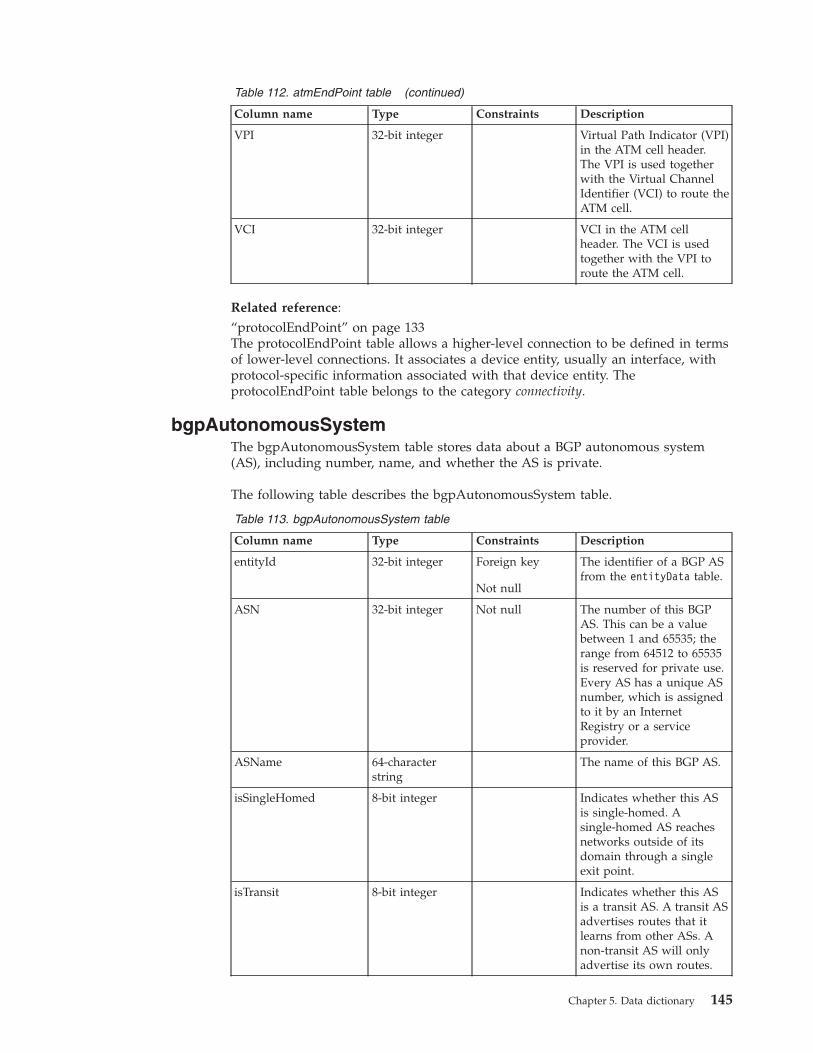
Table 112. atmEndPoint table (continued)
Column name Type Constraints Description
VPI 32-bit integer Virtual Path Indicator (VPI)in the ATM cell header.The VPI is used togetherwith the Virtual ChannelIdentifier (VCI) to route theATM cell.
VCI 32-bit integer VCI in the ATM cellheader. The VCI is usedtogether with the VPI toroute the ATM cell.
Related reference:“protocolEndPoint” on page 133The protocolEndPoint table allows a higher-level connection to be defined in termsof lower-level connections. It associates a device entity, usually an interface, withprotocol-specific information associated with that device entity. TheprotocolEndPoint table belongs to the category connectivity.
bgpAutonomousSystemThe bgpAutonomousSystem table stores data about a BGP autonomous system(AS), including number, name, and whether the AS is private.
The following table describes the bgpAutonomousSystem table.
Table 113. bgpAutonomousSystem table
Column name Type Constraints Description
entityId 32-bit integer Foreign key
Not null
The identifier of a BGP ASfrom the entityData table.
ASN 32-bit integer Not null The number of this BGPAS. This can be a valuebetween 1 and 65535; therange from 64512 to 65535is reserved for private use.Every AS has a unique ASnumber, which is assignedto it by an InternetRegistry or a serviceprovider.
ASName 64-characterstring
The name of this BGP AS.
isSingleHomed 8-bit integer Indicates whether this ASis single-homed. Asingle-homed AS reachesnetworks outside of itsdomain through a singleexit point.
isTransit 8-bit integer Indicates whether this ASis a transit AS. A transit ASadvertises routes that itlearns from other ASs. Anon-transit AS will onlyadvertise its own routes.
Chapter 5. Data dictionary 145

Table 113. bgpAutonomousSystem table (continued)
Column name Type Constraints Description
isPrivate 8-bit integer Indicates whether this ASis private.
bgpClusterThe bgpCluster table represents use of route reflectors within a BGP AS. This tableis currently not used.
The following table describes the bgpCluster table.
Table 114. bgpCluster table
Column name Type Constraints Description
entityId 32-bit integer Foreign key
Not null
The identifier of a BGP ASfrom the entityData table.
clusterID 15-characterstring
Not null Identifier for the BGP routereflector in the clusterwhen there is more thanone route reflector in thelocal AS.
bgpEndPointThe bgpEndPoint table represents a logical BGP end point and includes relevantBGP data. This endpoint is implemented by a physical interface, as modeled in theprotocolEndPoint table
The following table describes the bgpEndPoint table:
Table 115. bgpEndPoint Table
Column name Type Constraints Description
entityId 32-bit integer Foreign key
Not null
The identifier of a BGP ASfrom the entityData table.
isEBGP 8-bit integer Indicates whether this is aninstance of the externalversion of BGP (eBGP).
isEBGPMultiHop 8-bit integer Normally, two routersrunning eBGP must bephysically connected. Thisfield indicates whetherthere is a logicalconnection between tworouters that are runningeBGP. For example, theremight be an intermediaterouter or interface betweenthem.
146 IBM Tivoli Network Manager IP Edition: Topology Database Reference

Table 115. bgpEndPoint Table (continued)
Column name Type Constraints Description
localIdentifier 15-characterstring
The unique identifier of theBGP peer router. This isoften the router identifier,for example, an IP address.Corresponds to thebgpIdentifier MIB variablein BGP4-MIB.
peerIdentifier 15-characterstring
The unique identifier of thepeer BGP router. This isoften the router identifier,for example, an IP address.Corresponds to thebgpIdentifier MIB variablein BGP4-MIB.
peerState 20-characterstring
The BGP state of theconnection, as stored in thebgpPeerState MIB variablein BGP4-MIB.
adminStatus 5-character string Not null The required state of theBGP connection.
localAddress 15-characterstring
The local IP address of theBGP connection for thisrouter. Corresponds to thebgpPeerLocalAddr MIBvariable in BGP4-MIB.
localPort 32-bit integer The local port number forthe TCP connection of theBGP connection of therouter. Corresponds to thebgpPeerLocalPort MIBvariable in BGP4-MIB.
remoteAddress 15-characterstring
The remote IP address ofthe BGP connection for thisrouter. Corresponds to thebgpPeerRemoteAddressMIB variable in BGP4-MIB.
remotePort 32-bit integer Remote port number forthe TCP connection theBGP connection of thisrouter. Corresponds to thebgpPeerRemotePort MIBvariable in BGP4-MIB.
Chapter 5. Data dictionary 147
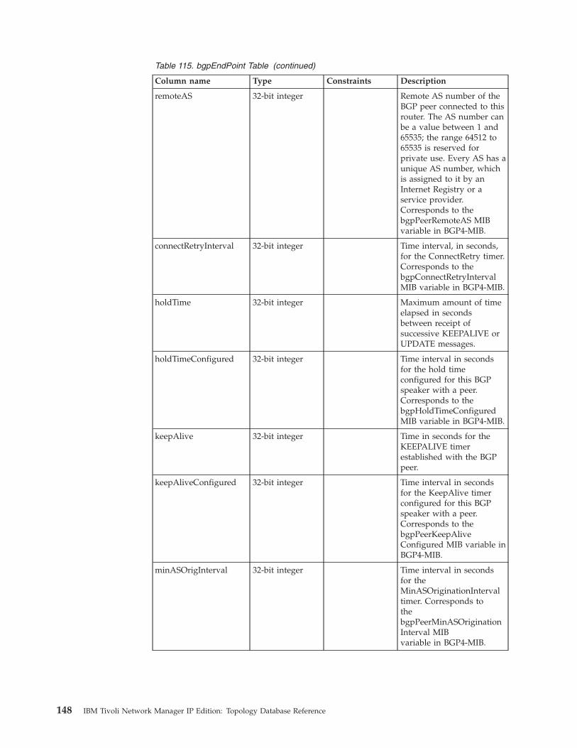
Table 115. bgpEndPoint Table (continued)
Column name Type Constraints Description
remoteAS 32-bit integer Remote AS number of theBGP peer connected to thisrouter. The AS number canbe a value between 1 and65535; the range 64512 to65535 is reserved forprivate use. Every AS has aunique AS number, whichis assigned to it by anInternet Registry or aservice provider.Corresponds to thebgpPeerRemoteAS MIBvariable in BGP4-MIB.
connectRetryInterval 32-bit integer Time interval, in seconds,for the ConnectRetry timer.Corresponds to thebgpConnectRetryIntervalMIB variable in BGP4-MIB.
holdTime 32-bit integer Maximum amount of timeelapsed in secondsbetween receipt ofsuccessive KEEPALIVE orUPDATE messages.
holdTimeConfigured 32-bit integer Time interval in secondsfor the hold timeconfigured for this BGPspeaker with a peer.Corresponds to thebgpHoldTimeConfiguredMIB variable in BGP4-MIB.
keepAlive 32-bit integer Time in seconds for theKEEPALIVE timerestablished with the BGPpeer.
keepAliveConfigured 32-bit integer Time interval in secondsfor the KeepAlive timerconfigured for this BGPspeaker with a peer.Corresponds to thebgpPeerKeepAliveConfigured MIB variable inBGP4-MIB.
minASOrigInterval 32-bit integer Time interval in secondsfor theMinASOriginationIntervaltimer. Corresponds tothebgpPeerMinASOriginationInterval MIBvariable in BGP4-MIB.
148 IBM Tivoli Network Manager IP Edition: Topology Database Reference
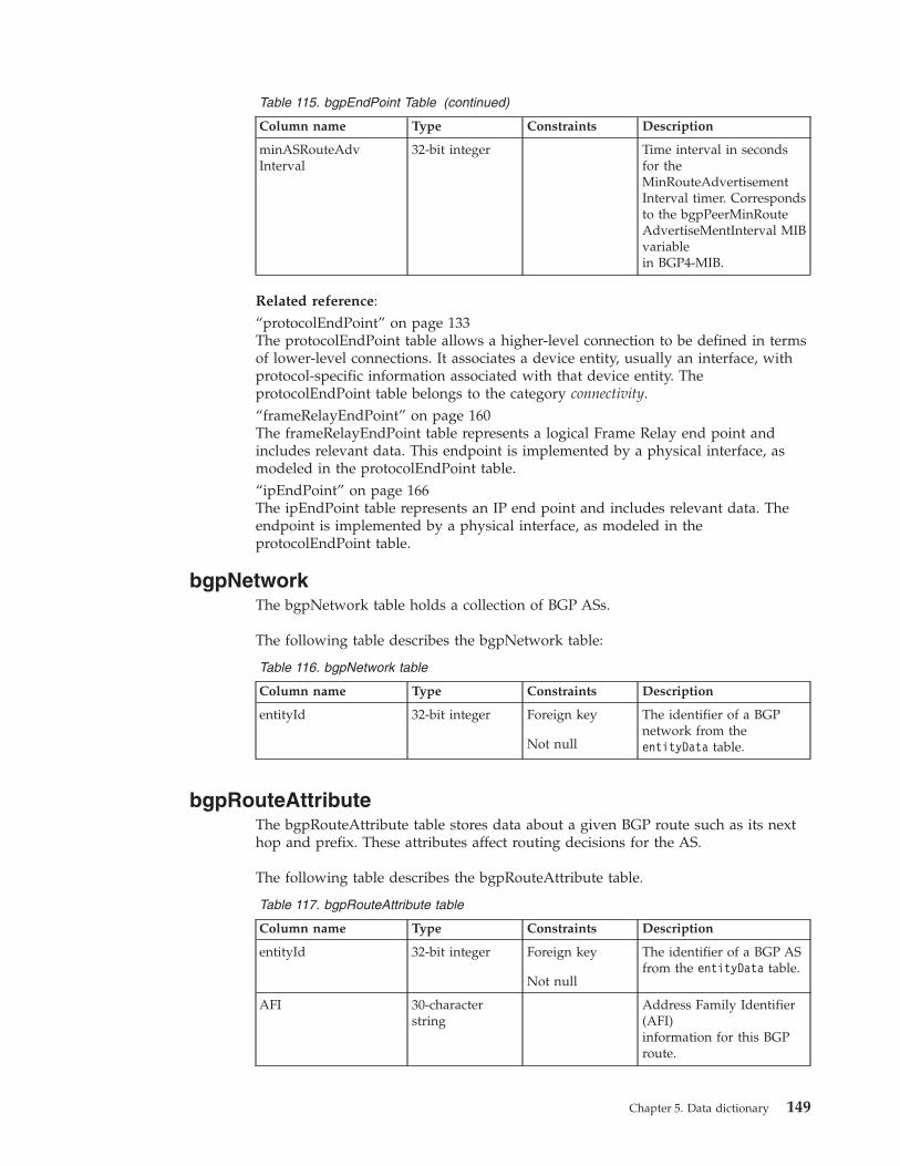
Table 115. bgpEndPoint Table (continued)
Column name Type Constraints Description
minASRouteAdvInterval
32-bit integer Time interval in secondsfor theMinRouteAdvertisementInterval timer. Correspondsto the bgpPeerMinRouteAdvertiseMentInterval MIBvariablein BGP4-MIB.
Related reference:“protocolEndPoint” on page 133The protocolEndPoint table allows a higher-level connection to be defined in termsof lower-level connections. It associates a device entity, usually an interface, withprotocol-specific information associated with that device entity. TheprotocolEndPoint table belongs to the category connectivity.“frameRelayEndPoint” on page 160The frameRelayEndPoint table represents a logical Frame Relay end point andincludes relevant data. This endpoint is implemented by a physical interface, asmodeled in the protocolEndPoint table.“ipEndPoint” on page 166The ipEndPoint table represents an IP end point and includes relevant data. Theendpoint is implemented by a physical interface, as modeled in theprotocolEndPoint table.
bgpNetworkThe bgpNetwork table holds a collection of BGP ASs.
The following table describes the bgpNetwork table:
Table 116. bgpNetwork table
Column name Type Constraints Description
entityId 32-bit integer Foreign key
Not null
The identifier of a BGPnetwork from theentityData table.
bgpRouteAttributeThe bgpRouteAttribute table stores data about a given BGP route such as its nexthop and prefix. These attributes affect routing decisions for the AS.
The following table describes the bgpRouteAttribute table.
Table 117. bgpRouteAttribute table
Column name Type Constraints Description
entityId 32-bit integer Foreign key
Not null
The identifier of a BGP ASfrom the entityData table.
AFI 30-characterstring
Address Family Identifier(AFI)information for this BGProute.
Chapter 5. Data dictionary 149

Table 117. bgpRouteAttribute table (continued)
Column name Type Constraints Description
SAFI 30-characterstring
Subsequent AddressFamily Identifier (SAFI)information for this BGProute.
prefix 15-characterstring
IP prefix for the advertizednetwork. Corresponds tothebgp4PathAttripAddrPrefixMIB variable in BGP4-MIB.
prefixLength 8-bit integer CIDR prefix length of theadvertized network.Corresponds to thebgp4PathAttripAddrPrefix-Length MIB variable inBGP4-MIB.
peerAddress 15-characterstring
IP address of the BGP peerfrom which this path waslearned.
nextHop 15-characterstring
Next hop IP address of theeBGP to reach a givennetwork. Corresponds tothe bgp4PathAttrNextHopMIB variable in BGP4-MIB.
origin 15-characterstring
Origin of this BGP route.
localPreference 32-bit integer Local preference of a routewith respect to other routesto the same destination.Higher value indicates apreferred route.Corresponds to thebgp4PathAttrLocalPref MIBvariable in BGP4-MIB.
aggregatingAddr 15-characterstring
Aggregating address forthis route.
aggregatingAS 32-bit integer AS number of the lastBGP4 speaker thatperformed routeaggregation. The ASnumber is a value between1 and 65535; the range64512 to 65535 is reservedfor private use. Every AShas a unique AS number,which is assigned to it byan Internet Registry or aservice provider.Corresponds to thebgp4PathAttrAggregatorASMIB variable in BGP4-MIB.
150 IBM Tivoli Network Manager IP Edition: Topology Database Reference

Table 117. bgpRouteAttribute table (continued)
Column name Type Constraints Description
ASPathSegment 100-characterstring
Sequence of AS pathsegments to a givennetwork. Corresponds tothe bgp4PathAttrASPathMIB variable in BGP4-MIB.
atomicAggregate 40-characterstring
Indicates whether a lessspecific route is selectedinstead of amore specific route.Corresponds to thebgp4PathAttrAtomic-AggregrateMIB variable in BGP4-MIB.
MED 8-bit integer Multi-Exit Discriminator(MED) value that indicatesa preferred entry point intothe AS for a givennetwork. Lower MEDvalues are preferred.Corresponds to thebgp4PathAttrMultiExitDiscMIB variable in BGP4-MIB.
bestRoute 10-characterstring
Indicates whether thisroute was chosen as thebest BGP4 route.
peerType 10-characterstring
Peer type for this BGProute attribute.
bgpServiceThe bgpService table represents a BGP service and includes relevant protocol data.This BGP service runs on a device, as modeled in the hostedService table.
Each row in this table corresponds to a single hosted BGP service. BGP routers canonly host one BGP service.
The following table describes the bgpService table.
Table 118. bgpService table
Column name Type Constraints Description
entityId 32-bit integer Foreign key
Not null
The identifier of a BGPservice from theentityData table.
BGPVersion 6-character string Not null Negotiated BGP versionnumber. Each peernegotiates this versionnumber from the vectorcontained in thebgpVersion MIB variablewithin the BGP4-MIB.
BGPLocalAS 32-bit integer Not null Local AS for this BGPservice.
Chapter 5. Data dictionary 151

Table 118. bgpService table (continued)
Column name Type Constraints Description
BGPIdentifier 15-characterstring
Not null Identifier for this BGPservice.
RouteReflectorMode 25-characterstring
Not null Router reflector mode forthis BGP service.
Related reference:“hostedService” on page 129A hosted service is a service or application running on a specific main node device.The hostedService table maps a main node device, the hosting entity, to the serviceor applications that are running on that device, the hosted entities. ThehostedService table belongs to the category entities.
computerSystemThe computerSystem table represents the logical or virtual perspective of thephysical device
The following table describes the computerSystem table.
Table 119. computerSystem table
Column name Type Constraints Description
entityId Integer not null The identifier of acomputerSystem entityfrom the entityData table.
architecture 255-characterstring
Architecture of the device.Valid values are
v alpha
v i686
v sun4
v PowerPC®
v PowerPC_POWER3
v PowerPC_POWER4
v PowerPC_POWER5
v PowerPC_604
v HP PA-RISC
assetID 255-characterstring
Asset identifier for thisentity.
assetTag 255-characterstring
Asset tag for this entity.
autoStart Tiny integer Indicates whether thecomputer system can beautomatically started.
v TRUE: computer systemcan be automaticallystarted.
v FALSE: computer systemcannot be automaticallystarted.
152 IBM Tivoli Network Manager IP Edition: Topology Database Reference

Table 119. computerSystem table (continued)
Column name Type Constraints Description
availableMemForAllVMs
64-bit integer Amount of memory (inbytes) currently availablefor all virtual machines.
bootOrder 255-characterstring
Boot sequence settings of asystem. The colon (:)character is used to delimitmultiple device names.Possible values for thisattribute are as follows:
v Hard Drive x (where x isoptional and is aninteger value startingfrom 0).
v DVD x.
v CD x.
v LAN PXE (including allvariants such as MBA,IGA and others).
ciCategory 255-characterstring
Configuration itemcategory for this entity.
ciRole Tiny integer Identifies the environment,or role, in which aconfiguration item (CI)resides. For example, if aCI is set aside for testpurposes, then this columncan be set to a value ofTest. If a role is neededthat is not defined in theenumeration for ciRole,then use the value Other.
cpuLimit 64-bit integer Maximum amount of CPUthat can be used by thisvirtual machine even ifthere is more CPUavailable in the resourcepool.
cpuReservation 64-bit integer Amount of CPU that isreserved for this virtualmachine.
Chapter 5. Data dictionary 153
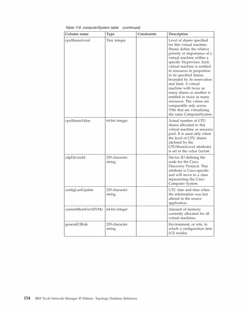
Table 119. computerSystem table (continued)
Column name Type Constraints Description
cpuSharesLevel Tiny integer Level of shares specifiedfor this virtual machine.Shares define the relativepriority or importance of avirtual machine within aspecific Hypervisor. Eachvirtual machine is entitledto resources in proportionto its specified shares,bounded by its reservationand limit. A virtualmachine with twice asmany shares as another isentitled to twice as manyresources. The values arecomparable only acrossVMs that are virtualizingthe same ComputerSystem.
cpuSharesValue 64-bit integer Actual number of CPUshares allocated to thisvirtual machine or resourcepool. It is used only whenthe level of CPU shares(defined by theCPUSharesLevel attribute)is set to the value Custom.
cdpDeviceId 255-characterstring
Device ID defining thenode for the CiscoDiscovery Protocol. Thisattribute is Cisco-specificand will move to a classrepresenting the CiscoComputer System.
configLastUpdate 255-characterstring
UTC date and time whenthe information was lastaltered in the sourceapplication.
currentMemForAllVMs 64-bit integer Amount of memorycurrently allocated for allvirtual machines.
generalCIRole 255-characterstring
Environment, or role, inwhich a configuration item(CI) resides.
154 IBM Tivoli Network Manager IP Edition: Topology Database Reference

Table 119. computerSystem table (continued)
Column name Type Constraints Description
isVMIDanLPAR Tiny integer Specifies if the computersystem is a LogicalPARtition (LPAR) or if thecomputer system is usingother virtual machinetypes, such as a centralprocessor complex (CPC) .An LPAR represents allIBM mainframe andnon-mainframevirtualization technologies,including zSeries, pSeries,iSeries®, and DS8000®.Possible value are:
v TRUE: computer systemis an LPAR.
v FALSE: computer systemis using a virtualmachine type other thanan LPAR.
lastAuditState Tiny integer Last audit state for thisdevice. Possible values are:
v 0 Unknown
v 1 Other
v 2 Good
v 3 No Physical CI
v 4 No CMDB Record
v 5 Inaccurate CMDBRecord
lastAuditTime Timestamp Last audit time this entity.
lastLifecycleStateTime Timestamp Last lifecycle state time forthis entity.
Chapter 5. Data dictionary 155
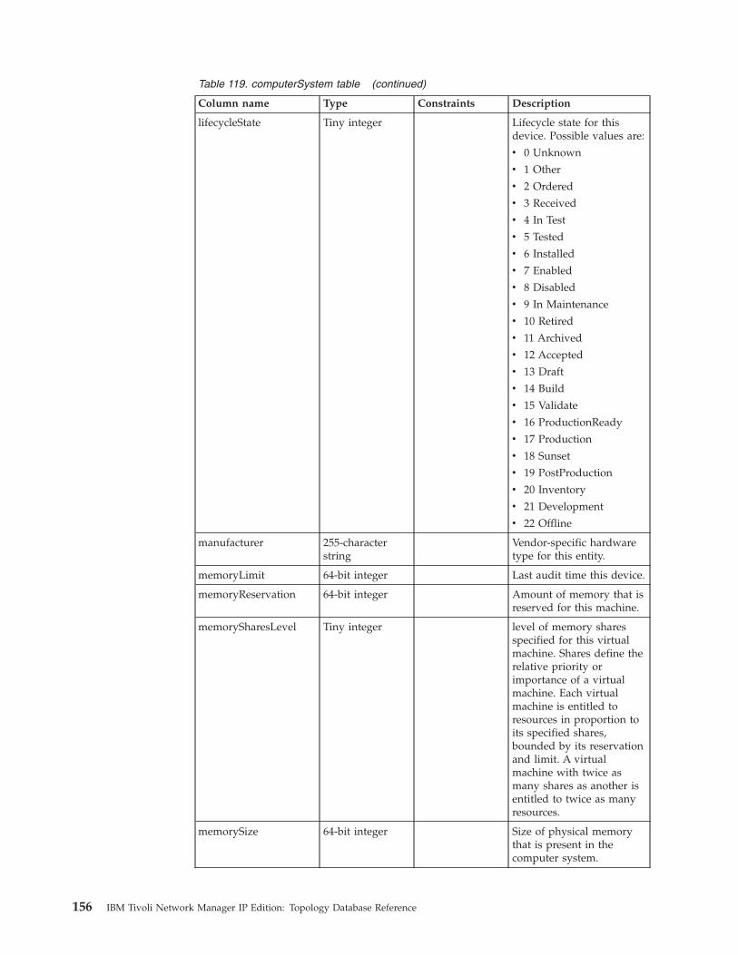
Table 119. computerSystem table (continued)
Column name Type Constraints Description
lifecycleState Tiny integer Lifecycle state for thisdevice. Possible values are:
v 0 Unknown
v 1 Other
v 2 Ordered
v 3 Received
v 4 In Test
v 5 Tested
v 6 Installed
v 7 Enabled
v 8 Disabled
v 9 In Maintenance
v 10 Retired
v 11 Archived
v 12 Accepted
v 13 Draft
v 14 Build
v 15 Validate
v 16 ProductionReady
v 17 Production
v 18 Sunset
v 19 PostProduction
v 20 Inventory
v 21 Development
v 22 Offline
manufacturer 255-characterstring
Vendor-specific hardwaretype for this entity.
memoryLimit 64-bit integer Last audit time this device.
memoryReservation 64-bit integer Amount of memory that isreserved for this machine.
memorySharesLevel Tiny integer level of memory sharesspecified for this virtualmachine. Shares define therelative priority orimportance of a virtualmachine. Each virtualmachine is entitled toresources in proportion toits specified shares,bounded by its reservationand limit. A virtualmachine with twice asmany shares as another isentitled to twice as manyresources.
memorySize 64-bit integer Size of physical memorythat is present in thecomputer system.
156 IBM Tivoli Network Manager IP Edition: Topology Database Reference

Table 119. computerSystem table (continued)
Column name Type Constraints Description
model 255-characterstring
Model name for this entity.
name 255-characterstring
The textual name of thephysical entity. The valueof this object must be thename of the component asassigned by the localdevice and is suitable foruse in commands enteredat the console of thedevice. Depending on thephysical componentnaming syntax of thedevice, this value might bea text name, for exampleconsole, or a singlecomponent number, forexample a port number ora module number.
namingRuleAlgorithms 255-characterstring
Proprietary attribute, usedinternally by IBM TivoliApplication DependencyDiscovery Manager.
primaryMACAddress 255-characterstring
MAC Address of thenetwork adapter in thecomputer system. If thereare multiple networkadapters in the computersystem, the primary MACAddress is determined byordering the MAC addressaccording to their numericvalue, selecting the lowestvalued MAC address.
processCapacityUnits Tiny integer Units in which theProcessingCapacity fieldvalue is expressed.
processingCapacity Floating-pointnumber
Processing capacity of thiscomputer system,including all of the CPUsassigned to it.
romVersion 255-characterstring
ROM (Read-Only Memory)or the BIOS (BasicInput/Output System)version of the motherboardin the computer system.
serialNumber 255-characterstring
The serial number of theentity.
serviceConsoleMemSize 64-bit integer Amount of memory that isreserved for the serviceconsole.
Chapter 5. Data dictionary 157
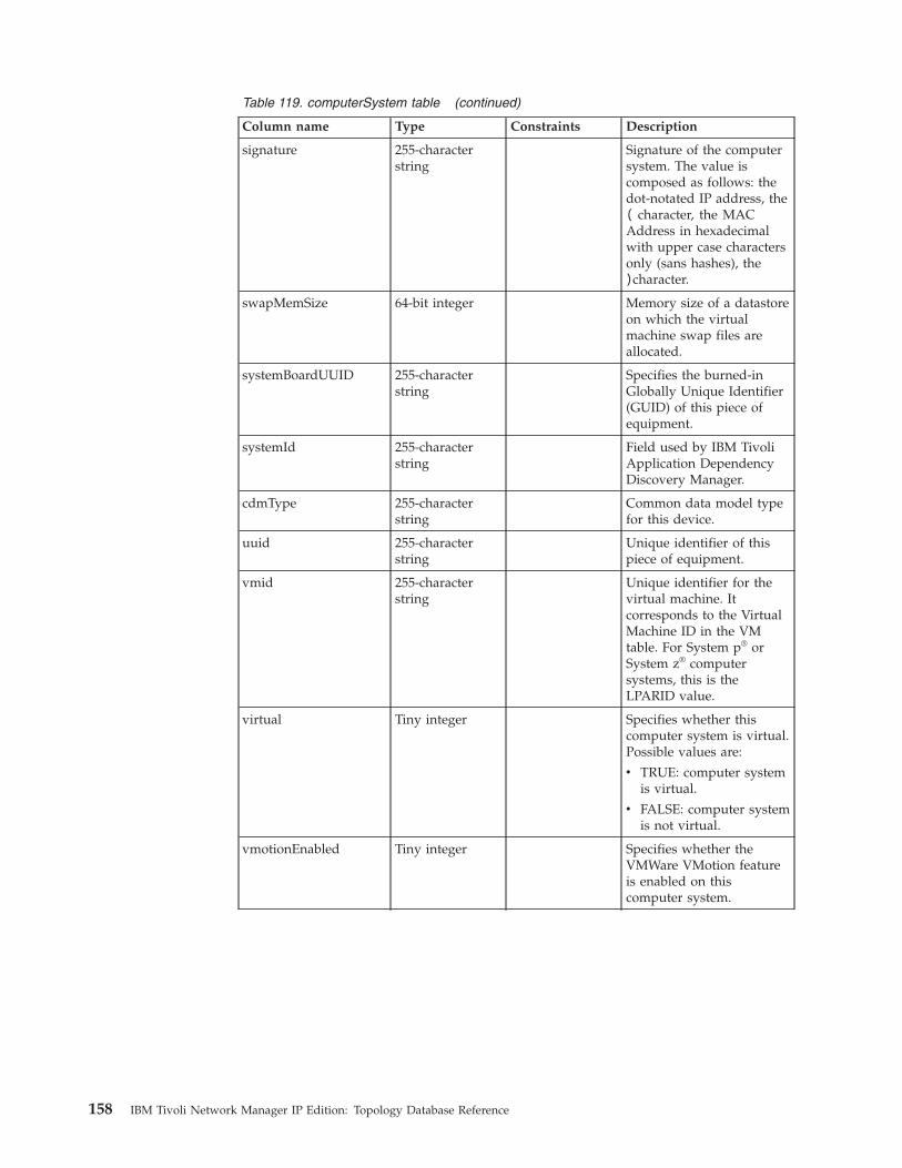
Table 119. computerSystem table (continued)
Column name Type Constraints Description
signature 255-characterstring
Signature of the computersystem. The value iscomposed as follows: thedot-notated IP address, the( character, the MACAddress in hexadecimalwith upper case charactersonly (sans hashes), the)character.
swapMemSize 64-bit integer Memory size of a datastoreon which the virtualmachine swap files areallocated.
systemBoardUUID 255-characterstring
Specifies the burned-inGlobally Unique Identifier(GUID) of this piece ofequipment.
systemId 255-characterstring
Field used by IBM TivoliApplication DependencyDiscovery Manager.
cdmType 255-characterstring
Common data model typefor this device.
uuid 255-characterstring
Unique identifier of thispiece of equipment.
vmid 255-characterstring
Unique identifier for thevirtual machine. Itcorresponds to the VirtualMachine ID in the VMtable. For System p® orSystem z® computersystems, this is theLPARID value.
virtual Tiny integer Specifies whether thiscomputer system is virtual.Possible values are:
v TRUE: computer systemis virtual.
v FALSE: computer systemis not virtual.
vmotionEnabled Tiny integer Specifies whether theVMWare VMotion featureis enabled on thiscomputer system.
158 IBM Tivoli Network Manager IP Edition: Topology Database Reference
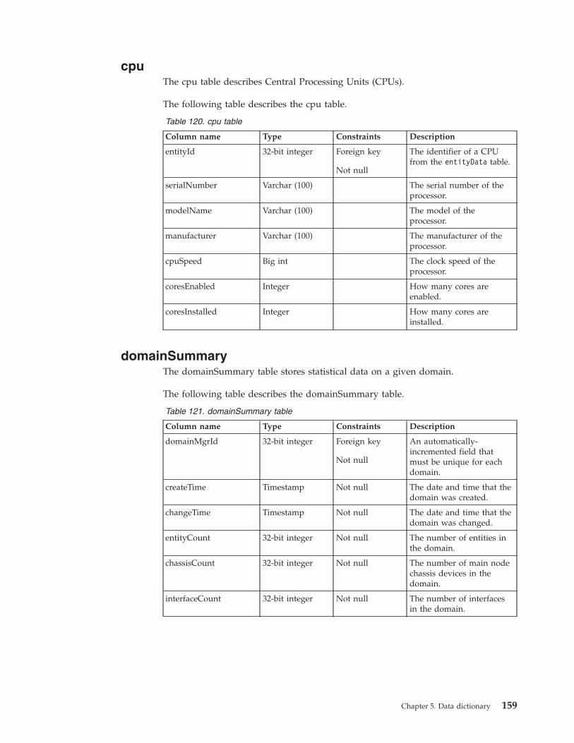
cpuThe cpu table describes Central Processing Units (CPUs).
The following table describes the cpu table.
Table 120. cpu table
Column name Type Constraints Description
entityId 32-bit integer Foreign key
Not null
The identifier of a CPUfrom the entityData table.
serialNumber Varchar (100) The serial number of theprocessor.
modelName Varchar (100) The model of theprocessor.
manufacturer Varchar (100) The manufacturer of theprocessor.
cpuSpeed Big int The clock speed of theprocessor.
coresEnabled Integer How many cores areenabled.
coresInstalled Integer How many cores areinstalled.
domainSummaryThe domainSummary table stores statistical data on a given domain.
The following table describes the domainSummary table.
Table 121. domainSummary table
Column name Type Constraints Description
domainMgrId 32-bit integer Foreign key
Not null
An automatically-incremented field thatmust be unique for eachdomain.
createTime Timestamp Not null The date and time that thedomain was created.
changeTime Timestamp Not null The date and time that thedomain was changed.
entityCount 32-bit integer Not null The number of entities inthe domain.
chassisCount 32-bit integer Not null The number of main nodechassis devices in thedomain.
interfaceCount 32-bit integer Not null The number of interfacesin the domain.
Chapter 5. Data dictionary 159
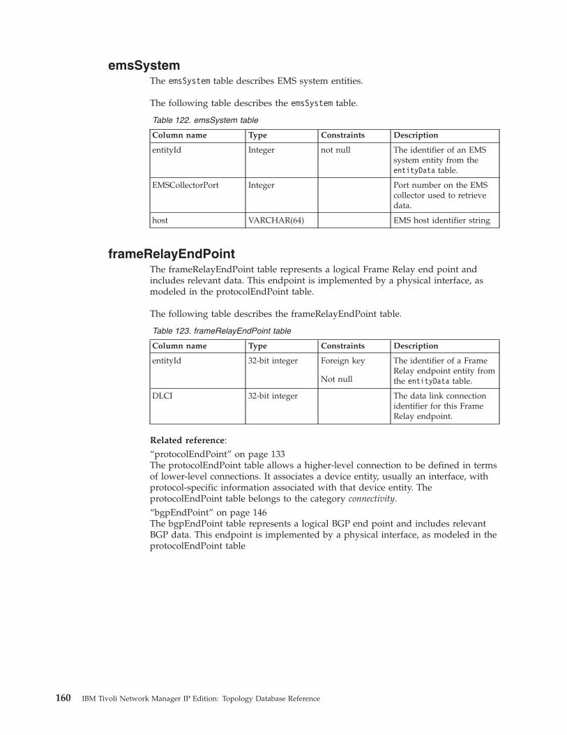
emsSystemThe emsSystem table describes EMS system entities.
The following table describes the emsSystem table.
Table 122. emsSystem table
Column name Type Constraints Description
entityId Integer not null The identifier of an EMSsystem entity from theentityData table.
EMSCollectorPort Integer Port number on the EMScollector used to retrievedata.
host VARCHAR(64) EMS host identifier string
frameRelayEndPointThe frameRelayEndPoint table represents a logical Frame Relay end point andincludes relevant data. This endpoint is implemented by a physical interface, asmodeled in the protocolEndPoint table.
The following table describes the frameRelayEndPoint table.
Table 123. frameRelayEndPoint table
Column name Type Constraints Description
entityId 32-bit integer Foreign key
Not null
The identifier of a FrameRelay endpoint entity fromthe entityData table.
DLCI 32-bit integer The data link connectionidentifier for this FrameRelay endpoint.
Related reference:“protocolEndPoint” on page 133The protocolEndPoint table allows a higher-level connection to be defined in termsof lower-level connections. It associates a device entity, usually an interface, withprotocol-specific information associated with that device entity. TheprotocolEndPoint table belongs to the category connectivity.“bgpEndPoint” on page 146The bgpEndPoint table represents a logical BGP end point and includes relevantBGP data. This endpoint is implemented by a physical interface, as modeled in theprotocolEndPoint table
160 IBM Tivoli Network Manager IP Edition: Topology Database Reference

genericCollectionThe genericCollection table stores information on generic collections of entities.
The following table describes the genericCollection table.
Table 124. genericCollection table
Column name Type Constraints Description
entityId Integer not null The identifier of a genericcollection from theentityData table.
genericRangeThe genericRange table holds information about which Customer VLANS areswitched through each Virtual Switch Instance (VSI).
The following table describes the genericRange table.
Table 125. genericRange table
Column name Type Constraints Description
entityId Integer Foreign key
Primary key
Not null
The entity ID of theinterface that is associatedwith the Customer VLANrange data.
minimumvalue Integer Not null The minimum value of therange. Customer VLANswithin the range areswitched through the VSI;Customer VLANs outsidethe range are discarded.
maximumvalue Integer Not null The maximum value of therange.
rangeType Enumerated Not null Can only take the valueCVlanRange.
geographicLocationThe geographicLocation table stores geographic location information for networkentities. It does this by creating collections of entities at a specific location.
The following table describes the geographicLocation table.
Table 126. geographicLocation table
Column name Type Constraints Description
entityId Integer not null The identifier of ageographical location fromthe entityData table.
Longitude varchar(64) Measurement of longitudefor this RAN entity.
Latitude varchar(64) Measurement of latitiudefor this RAN entity.
Chapter 5. Data dictionary 161
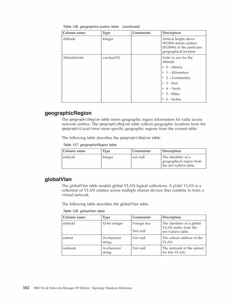
Table 126. geographicLocation table (continued)
Column name Type Constraints Description
Altitude Integer Vertical height aboveWGS84 datum surface(EGM96) at the particulargeographical location
AltitudeUnits varchar(10) Units to use for thealtitude.
v 0 – Meters
v 1 – Kilometers
v 2 – Centimeters
v 3 - Feet
v 4 – Yards
v 5 - Miles
v 6 - Inches
geographicRegionThe geographicRegion table stores geographic region information for radio accessnetwork entities. The geographicRegion table collects geographic locations from thegeographicLocationor more specific geographic regions from the current table.
The following table describes the geographicRegion table.
Table 127. geographicRegion table
Column name Type Constraints Description
entityId Integer not null The identifier of ageographical region fromthe entityData table.
globalVlanThe globalVlan table models global VLAN logical collections. A global VLAN is acollection of VLAN entities across multiple chassis devices that combine to form avirtual network.
The following table describes the globalVlan table.
Table 128. globalVlan table
Column name Type Constraints Description
entityId 32-bit integer Foreign key
Not null
The identifier of a globalVLAN entity from theentityData table.
subnet 16-characterstring
Not null The subnet address of theVLAN.
netmask 16-characterstring
Not null The netmask of the subnetfor this VLAN.
162 IBM Tivoli Network Manager IP Edition: Topology Database Reference

Table 128. globalVlan table (continued)
Column name Type Constraints Description
vlanClass Enumerated The class of the VLAN.Possible values are: cvlan(Customer VLAN usingQinQ), svlan (ServiceVLAN using QinQ), orlocal (VLAN not usingQinQ).
vlanDescr 255-characterstring
A description of thisVLAN.
hsrpGroupThe hsrpGroup table represents a Cisco Hot Standby Routing Protocol (HRSP)group logical collection.
The HRSP implements a virtual router with its own IP and MAC addresses. Thisvirtual router forms an HSRP group that consists of a number of real interfaces,only one of which is active at any given time. The active interface forwards IPtraffic that is sent to the virtual router and the other interfaces in the group standby ready to become active if the active interface fails.
The following table describes the hsrpGroup table.
Table 129. hsrpGroup table
Column name Type Constraints Description
entityId 32-bit integer Foreign key
Not null
The identifier of a HSRPgroup entity from theentityData table.
virtualIP 32-bit integer Foreign key
Not null
The virtual IP address usedby this HSRP group.
igmpEndPointThe igmpEndPoint table holds information on the Internet Group MembershipProtocol (IGMP) End Points.
Each End Point holds various attributes describing the interface that implements it.There is a dependency between the end point and service associated with it(modeled via the existing dependency table). The End Point is associated with theinterface which implements it using the existing protocolEndPoint table.
The following table describes the igmpEndPoint table.
Table 130. igmpEndPoint table
Column name Type Constraints Description
entityId 32-bit integer v Primary Key
v Foreign Key(entityDatatable)
v Not Null
The identifier of the IGMPEnd Point.
Chapter 5. Data dictionary 163

Table 130. igmpEndPoint table (continued)
Column name Type Constraints Description
groups 32-bit integer A count of the numberCache Table entries for thisend point
lastMembQueryIntvl 32-bit integer Holds the Last MemberQuery Interval
numJoins 32-bit integer Number of IGMP groupmembership joins thathave occurred
proxyIfIndex 32-bit integer Where IGMP proxying isused, this field holds theinterface index to whichIGMP Host MembershipReports are sent.
querier 25 characterstring
IP address of the IGMPQuerier
querierExpiryTime 32-bit integer Remaining time beforeexpiry of the Other QuerierPresent Timer expires. (0 iflocal system is the querier)
querierUpTime 32-bit integer Time ticks since theQuerier last changed
queryInterval 32-bit integer How often IGMP querymessages are sent on theinterface associated withthis End Point.
queryMaxResponseTime
32-bit integer Maximum response time intenths of a second
robustness 32-bit integer The Robustness Variableused to alter IGMPsensitivity to packet loss
status EnumeratedValue
Takes one of thefollowing values:
v ‘other'
v ‘unknown'
v ‘enabled'
v ‘disabled'
The status of IGMP on theinterface associated withthe End Point.
version 32-bit integer Version of IGMP running
versionQuerierTimer 32-bit integer Remaining time before it isassumed that no IGMProuters are present on theinterface associated withthe End Point
wrongVersionQueries 32-bit integer A count of number ofqueries received withunexpected IGMP versions.A non-zero value indicatesan IGMP configurationissue.
164 IBM Tivoli Network Manager IP Edition: Topology Database Reference

Related reference:“protocolEndPoint” on page 133The protocolEndPoint table allows a higher-level connection to be defined in termsof lower-level connections. It associates a device entity, usually an interface, withprotocol-specific information associated with that device entity. TheprotocolEndPoint table belongs to the category connectivity.
igmpGroupThe igmpGroup table holds multicast group collections for which there areassociated Internet Group Membership Protocol (IGMP) end points in theigmpEndPoint table. Entries in the igmpGroup table collect associatedigmpEndPoints using the existing collects table.
The following table describes the igmpGroup table.
Table 131. igmpGroup table
Column name Type Constraints Description
entityId 32-bit integer v Primary Key
v Foreign Key(entityDatatable)
v Not Null
The identifier of the IGMPgroup
groupAddress 25-characterstring
IP address of the multicastgroup
groupMask 25-characterstring
Mask of the multicastgroup
groupName 60-characterstring
Name associated with thegroup
igmpServiceThe igmpService table represents an Internet Group Management Protocol (IGMP)service. Each row in the table corresponds to a single hosted IGMP service. Theservice is associated with the device on which it runs using the hostedServicetable.
The following table describes the igmpService table.
Table 132. igmpService table
Column name Type Constraints Description
entityId 32-bit integer v Primary Key
v Foreign Key(entityDatatable)
v Not Null
The identifier of the IGMPService
Chapter 5. Data dictionary 165

ipConnectionThe ipConnection table stores information on IP connections.
The following table describes the ipConnection table.
Table 133. ipConnection table
Column name Type Constraints Description
entityId Integer not null The identifier of an IPconnection from theentityData table.
ipEndPointThe ipEndPoint table represents an IP end point and includes relevant data. Theendpoint is implemented by a physical interface, as modeled in theprotocolEndPoint table.
The following table describes the ipEndPoint table:
Table 134. ipEndPoint table
Column name Type Constraints Description
entityId 32–bit integer Foreign key
Not null
The identifier of an IP endpoint entity from theentityData table.
DNSName 255–characterstring
DNS name for the IPaddress associated withthis IP end point.
address 39–characterstring
Not null IP address associated withthis IP end point.
ipNumber 64–bit integer,unsigned
Not null For IPv4: IP addressrepresented as a 32–bitinteger.
For IPv6: First half of IPaddress represented as a128–bit integer.
netNumber 64–bit integer Not null For IPv4: Not applicable
For IPv6: Second half of IPaddress represented as a128–bit integer.
subnet 39–characterstring
Subnet to which the IPaddress belongs.
netmask 39–characterstring
Netmask for the subnet.
netmaskbits 32–bit integer Netmask bits for thesubnet
addressSpace 255–characterstring
Relevant NAT addressspace if network addresstranslation is being used.
166 IBM Tivoli Network Manager IP Edition: Topology Database Reference

Table 134. ipEndPoint table (continued)
Column name Type Constraints Description
protocol String value An integer representationof the IP protocol used bythe presently-defined zone:
v 1: IPv4
v 2: IPv4 that has beenthrough network addresstranslation (NAT)
v 3: IPv6
cdmAddressType 16-bit integer Not null
Default value: 0
The IBM Common DataModel defines an attributenamed AddressType in theIpV4Address andIPv6Address views and theipEndPoint class is theequivalent object in NCIM.Therefore to make theattributes in the classesconsistent, a new attributenamed cdmAddressTypehas been added to theipEndPoint table.
Related concepts:“Technology-specific data” on page 12NCIM models a range of different network technologies, including IP, VLANs, andMPLS VLANs.Related reference:“protocolEndPoint” on page 133The protocolEndPoint table allows a higher-level connection to be defined in termsof lower-level connections. It associates a device entity, usually an interface, withprotocol-specific information associated with that device entity. TheprotocolEndPoint table belongs to the category connectivity.“bgpEndPoint” on page 146The bgpEndPoint table represents a logical BGP end point and includes relevantBGP data. This endpoint is implemented by a physical interface, as modeled in theprotocolEndPoint table
ipMRouteDownstreamThe ipMRouteDownstream table holds the downstream route statistics per deviceor MDT. Each entity in this table will have a dependency relationship with theassociated MDT via the existing dependency table.
The following table describes the ipMRouteDownstream table.
Table 135. ipMRouteDownstream table
Column name Type Constraints Description
closestMemberHops 32-bit integer The number of hops that itwill take to reach theclosest member of thismulticast group.
Chapter 5. Data dictionary 167

Table 135. ipMRouteDownstream table (continued)
Column name Type Constraints Description
entityId 32-bit integer v Primary Key
v Foreign Key(entityDatatable)
v Not Null
The identifier of the IGMPEnd Point
expiryTime 32-bit integer Time ticks left before theroute entry expires
hopState Enumeratedvalue
Takes one of thefollowing values:
v unknown
v other
v pruned
v forwarding
Indicates whether thedownstream interface isbeing used to forwardpackets.
nextHop 15-characterstring
IP Address of the nextdownstream hop. Thisaddress may be themulticast group address.
outInterface 32-bit integer NULL if ifIndex was 0
packetCount 32-bit integer The number of packetsfrom sources destined forthe group.
protocol Enumeratedvalue
Takes one of thefollowing values:
v other
v local
v netmgmt
v DVMRP
v MOSPF
v
PIMSparseDense
v CBT
v
PIMSparseMode
v
PIMDenseMode
v IGMPOnly
v BGMP
v MSDP
The protocol used to learnthe downstream next hoproute
startTime Timestamp Approximate time that theroute entry was learnt;calculated using uptimeand the system time at thetime the device wasinterrogated.
uptime 32-bit integer Time ticks since this routeentry was learnt
168 IBM Tivoli Network Manager IP Edition: Topology Database Reference
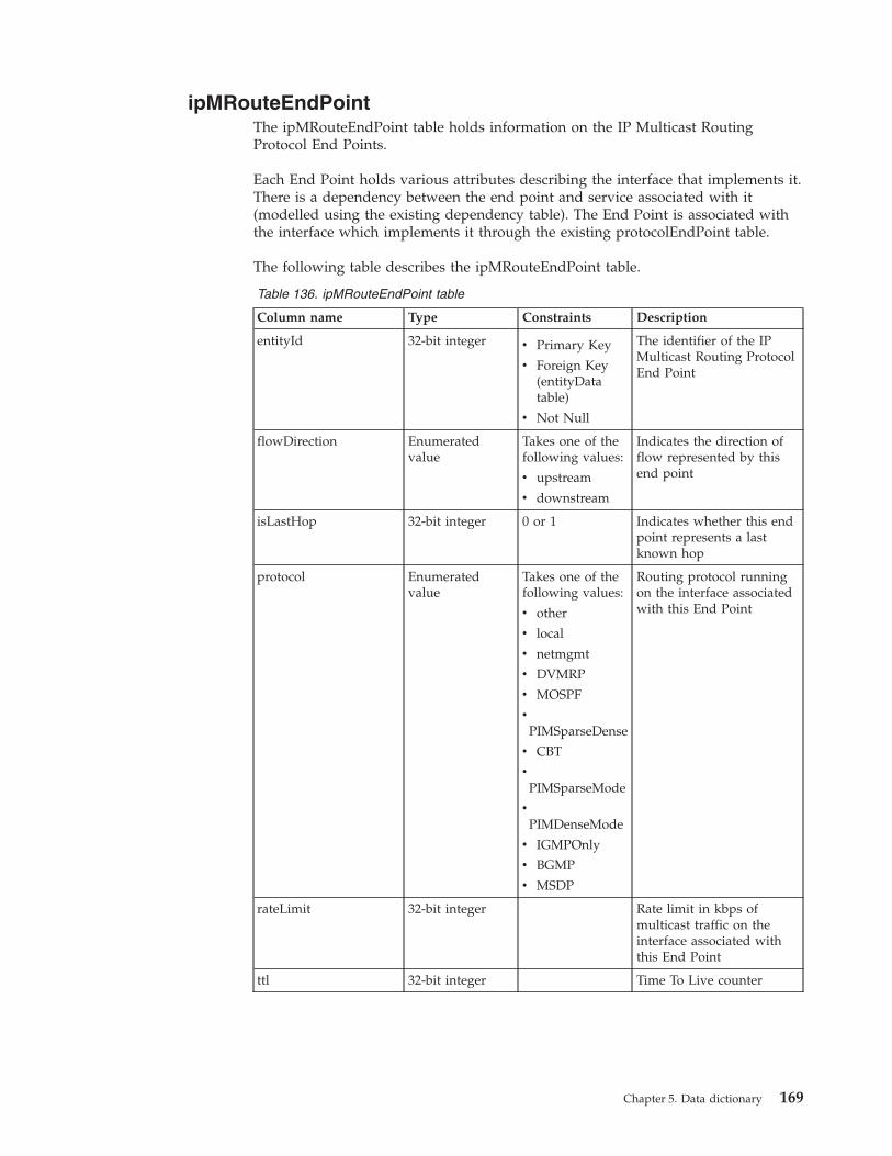
ipMRouteEndPointThe ipMRouteEndPoint table holds information on the IP Multicast RoutingProtocol End Points.
Each End Point holds various attributes describing the interface that implements it.There is a dependency between the end point and service associated with it(modelled using the existing dependency table). The End Point is associated withthe interface which implements it through the existing protocolEndPoint table.
The following table describes the ipMRouteEndPoint table.
Table 136. ipMRouteEndPoint table
Column name Type Constraints Description
entityId 32-bit integer v Primary Key
v Foreign Key(entityDatatable)
v Not Null
The identifier of the IPMulticast Routing ProtocolEnd Point
flowDirection Enumeratedvalue
Takes one of thefollowing values:
v upstream
v downstream
Indicates the direction offlow represented by thisend point
isLastHop 32-bit integer 0 or 1 Indicates whether this endpoint represents a lastknown hop
protocol Enumeratedvalue
Takes one of thefollowing values:
v other
v local
v netmgmt
v DVMRP
v MOSPF
v
PIMSparseDense
v CBT
v
PIMSparseMode
v
PIMDenseMode
v IGMPOnly
v BGMP
v MSDP
Routing protocol runningon the interface associatedwith this End Point
rateLimit 32-bit integer Rate limit in kbps ofmulticast traffic on theinterface associated withthis End Point
ttl 32-bit integer Time To Live counter
Chapter 5. Data dictionary 169
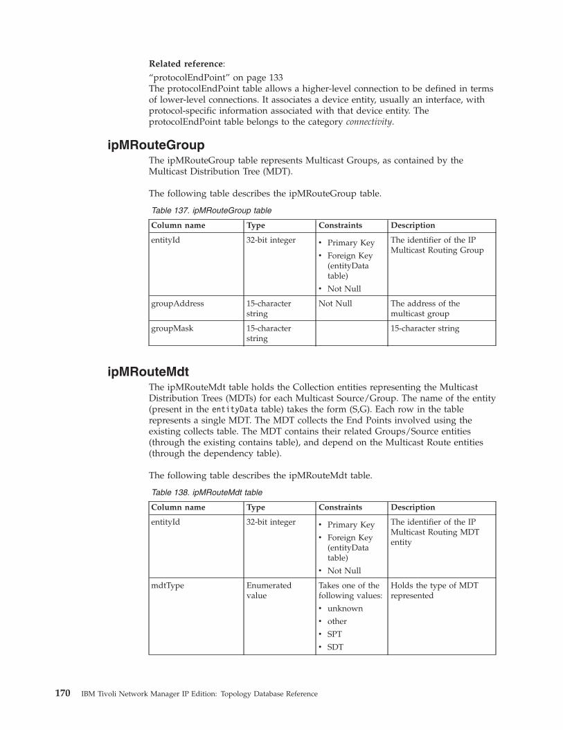
Related reference:“protocolEndPoint” on page 133The protocolEndPoint table allows a higher-level connection to be defined in termsof lower-level connections. It associates a device entity, usually an interface, withprotocol-specific information associated with that device entity. TheprotocolEndPoint table belongs to the category connectivity.
ipMRouteGroupThe ipMRouteGroup table represents Multicast Groups, as contained by theMulticast Distribution Tree (MDT).
The following table describes the ipMRouteGroup table.
Table 137. ipMRouteGroup table
Column name Type Constraints Description
entityId 32-bit integer v Primary Key
v Foreign Key(entityDatatable)
v Not Null
The identifier of the IPMulticast Routing Group
groupAddress 15-characterstring
Not Null The address of themulticast group
groupMask 15-characterstring
15-character string
ipMRouteMdtThe ipMRouteMdt table holds the Collection entities representing the MulticastDistribution Trees (MDTs) for each Multicast Source/Group. The name of the entity(present in the entityData table) takes the form (S,G). Each row in the tablerepresents a single MDT. The MDT collects the End Points involved using theexisting collects table. The MDT contains their related Groups/Source entities(through the existing contains table), and depend on the Multicast Route entities(through the dependency table).
The following table describes the ipMRouteMdt table.
Table 138. ipMRouteMdt table
Column name Type Constraints Description
entityId 32-bit integer v Primary Key
v Foreign Key(entityDatatable)
v Not Null
The identifier of the IPMulticast Routing MDTentity
mdtType Enumeratedvalue
Takes one of thefollowing values:
v unknown
v other
v SPT
v SDT
Holds the type of MDTrepresented
170 IBM Tivoli Network Manager IP Edition: Topology Database Reference
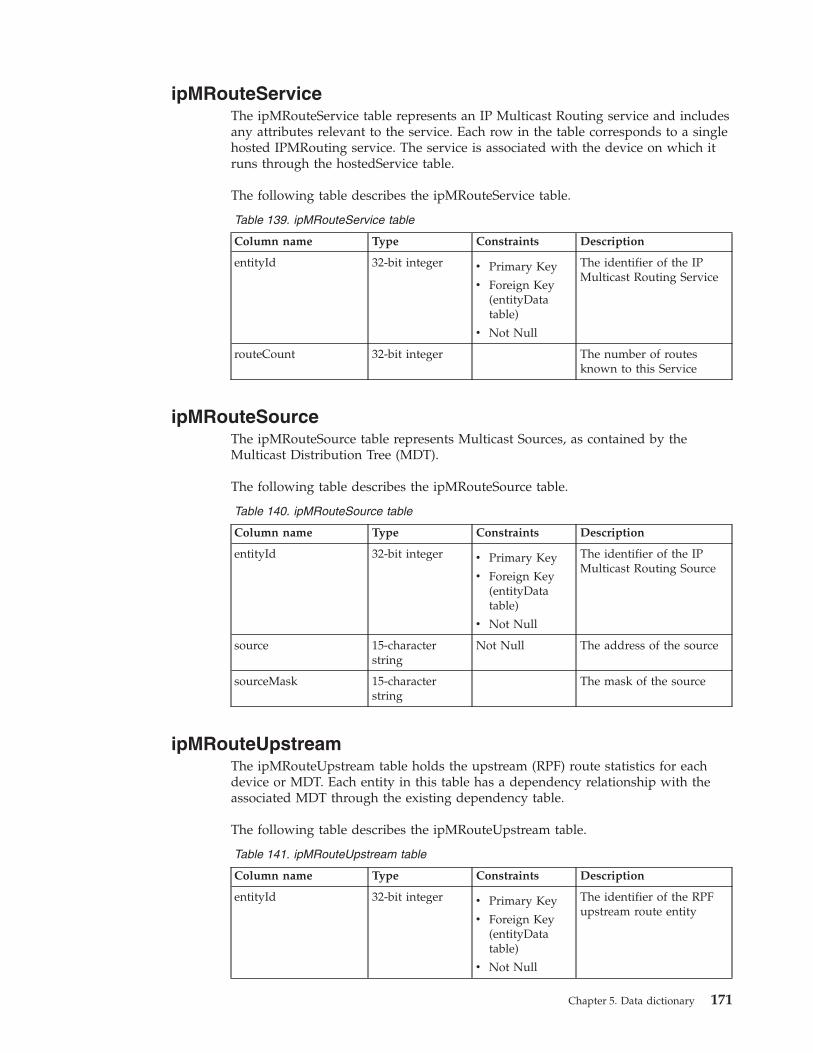
ipMRouteServiceThe ipMRouteService table represents an IP Multicast Routing service and includesany attributes relevant to the service. Each row in the table corresponds to a singlehosted IPMRouting service. The service is associated with the device on which itruns through the hostedService table.
The following table describes the ipMRouteService table.
Table 139. ipMRouteService table
Column name Type Constraints Description
entityId 32-bit integer v Primary Key
v Foreign Key(entityDatatable)
v Not Null
The identifier of the IPMulticast Routing Service
routeCount 32-bit integer The number of routesknown to this Service
ipMRouteSourceThe ipMRouteSource table represents Multicast Sources, as contained by theMulticast Distribution Tree (MDT).
The following table describes the ipMRouteSource table.
Table 140. ipMRouteSource table
Column name Type Constraints Description
entityId 32-bit integer v Primary Key
v Foreign Key(entityDatatable)
v Not Null
The identifier of the IPMulticast Routing Source
source 15-characterstring
Not Null The address of the source
sourceMask 15-characterstring
The mask of the source
ipMRouteUpstreamThe ipMRouteUpstream table holds the upstream (RPF) route statistics for eachdevice or MDT. Each entity in this table has a dependency relationship with theassociated MDT through the existing dependency table.
The following table describes the ipMRouteUpstream table.
Table 141. ipMRouteUpstream table
Column name Type Constraints Description
entityId 32-bit integer v Primary Key
v Foreign Key(entityDatatable)
v Not Null
The identifier of the RPFupstream route entity
Chapter 5. Data dictionary 171
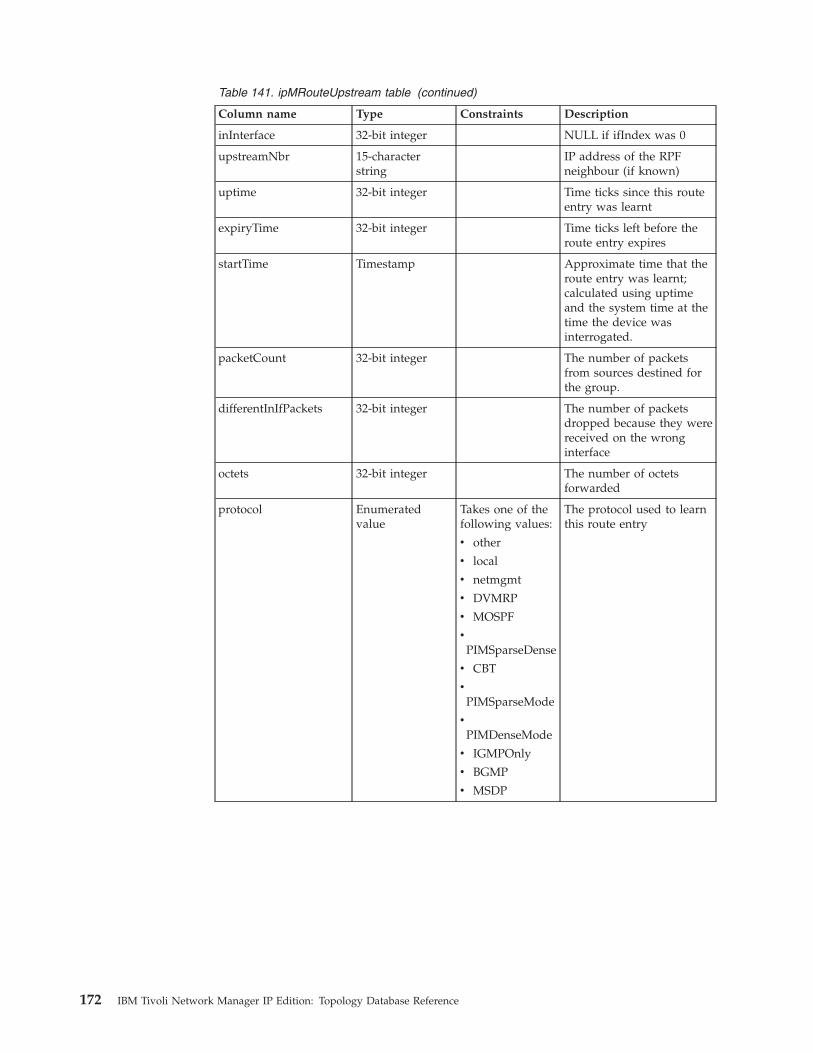
Table 141. ipMRouteUpstream table (continued)
Column name Type Constraints Description
inInterface 32-bit integer NULL if ifIndex was 0
upstreamNbr 15-characterstring
IP address of the RPFneighbour (if known)
uptime 32-bit integer Time ticks since this routeentry was learnt
expiryTime 32-bit integer Time ticks left before theroute entry expires
startTime Timestamp Approximate time that theroute entry was learnt;calculated using uptimeand the system time at thetime the device wasinterrogated.
packetCount 32-bit integer The number of packetsfrom sources destined forthe group.
differentInIfPackets 32-bit integer The number of packetsdropped because they werereceived on the wronginterface
octets 32-bit integer The number of octetsforwarded
protocol Enumeratedvalue
Takes one of thefollowing values:
v other
v local
v netmgmt
v DVMRP
v MOSPF
v
PIMSparseDense
v CBT
v
PIMSparseMode
v
PIMDenseMode
v IGMPOnly
v BGMP
v MSDP
The protocol used to learnthis route entry
172 IBM Tivoli Network Manager IP Edition: Topology Database Reference

Table 141. ipMRouteUpstream table (continued)
Column name Type Constraints Description
rtProto Enumeratedvalue
Takes one of thefollowing values;
v other
v local
v netmgmt
v ICMP
v EGP
v GGP
v hello
v RIP
v ISIS
v ESIS
v ciscoIGRP
v bbnSpfIGP
v OSPF
v BGP
v IDRP
v ciscoEIGRP
v DVMRP
The protocol used to learnthe upstream interface forthis route entry
rtAddress 15-characterstring
Address used to determinethe upstream interface
rtMask 15-characterstring
Mask used to determinethe upstream interface
rtType EnumeratedValue
Takes one of thefollowing values:
v unknown
v other
v unicast
v multicast
The type of route
ipPathThe ipPath table stores information on IP paths.
The following table describes the ipPath table.
Table 142. ipPath table
Column name Type Constraints Description
entityId Integer Not null The identifier of an IPpathfrom the entityDatatable.
fromIP 39-characterstring
Starting IP address for thispath.
toIP 39-characterstring
End IP address for thispath.
viaIP 39-characterstring
IP address that this pathmust traverse.
Chapter 5. Data dictionary 173

Table 142. ipPath table (continued)
Column name Type Constraints Description
hops 32-bit integer Not null Number of hops in thepath.
ecmp Indicates whetherequal-cost multi-pathrouting applies to thispath.
asymmetric Indicates whether this is anasymmetric path.
protocols 100-characterstring
Indicates the protocolsused in this path.
cost 32-bit integer
itnmServiceThe itnmService table represents Service-Affected Events (SAE); the table is usedby the SAE plug-ins in the Event Gateway, ncp_g_event. This table is used onlyindirectly by the SAE plug-ins, since the SAE plug-ins use the NCIM cache tables,which are based on NCIM tables.
The following table describes the itnmService table.
Table 143. itnmService table
Column name Type Constraints Description
entityID 32–bit integer Not null The identifier of theSAE entity from theentityData table.
serviceName 255–character string Not null The name of theSAE.
serviceType 64–character string Not null The type of SAE
lingerTimeThe lingerTime table stores the linger time for a device. The linger time is thenumber of discoveries that a device can fail to be found in before it is removedfrom the topology.
The linger time is set for a device when it is instantiated, from the default value inthe model.config table. Each time that a device in the topology is not discovered,the linger time is decreased by 1. When the linger time is zero, if the device is notdiscovered, it is removed from the topology.
The lingerTime table is described in the following table:
Table 144. lingerTime table
Column name Type Constraints Description
entityId 32-bit integer Foreign key
Not null
The identifier of a device.
lingerTime Integer Not null The current linger time ofthe device.
174 IBM Tivoli Network Manager IP Edition: Topology Database Reference

localVlanThe localVlan table specifies which global VLAN the local VLAN belongs to. Alocal VLAN represents all the interfaces on a single chassis device that belong to aglobal VLAN.
In addition, the contains table specifies the interfaces contained by the localVLAN.
Table 145. localVlan Ttable
Column name Type Constraints Description
entityId 32-bit integer Foreign key
Not null
The identifier of a localVLAN entity from theentityData table.
vlanClass Enumerated The class of the VLAN.Possible values are: cvlan(Customer VLAN usingQinQ), svlan (ServiceVLAN using QinQ), orlocal (VLAN not usingQinQ).
vlanId 32-bit integer Not null The identifier of aconnection from theconnects table.
vlanDescr 255-characterstring
The description of aconnection from theconnects table.
vlanName 64-characterstring
The name of a connectionfrom the connects table.
vlanType 32-characterstring
The type of a connectionfrom the connects table.
vlanState 32-characterstring
The state of a connectionfrom the connects table.
Related reference:“contains” on page 114The contains table stores data on physical and logical containment. This tablebelongs to the category containment.
managedStatusThe managedStatus table stores the managed status information for each networkentity in the topology.
The following table describes the managedStatus table.
Table 146. managedStatus table
Column name Type Constraints Description
entityId 32–bit integer Foreign keyNot null
Identifier of an entity from the entityData table.
Chapter 5. Data dictionary 175

Table 146. managedStatus table (continued)
Column name Type Constraints Description
status 8–bit integer Takes one of the following values:
0 Managed state. The entity is managed.
1 Unmanaged state. The entity is unmanaged. A devicecan be set to unmanaged using the Topoviz or theStructure Browser GUIs. Also, this value is set for newdevices in the topology when they are set to beexcluded from polling initially in theTagManagedEntities.stch stitcher.
2 Unmanaged by ncp_disco. This setting cannot bemodified from the GUI. This value is set by thePopulateDNCIM_ManagedStatus.stch stitcher.
3 Unmanaged because the IP address is out of thediscovery scope. The device has been discoveredthrough another IP address that is within thediscovery scope.
username 240–characterstring
Name of the user who last set the status of the entity.
changeTime Timestamp Date and time when the status of the entity was changed.
maintenanceStartTime
Timestamp Start time for device to be in unmanaged state.
maintenanceEndTime
Timestamp End time for device to be in unmanaged state.
mplsTEServiceThe mplsTEService table represents an MPLS TE service and includes relevantprotocol data. This MPLS TE service runs on a device, as modeled in thehostedService table. Each row in this table corresponds to a single hosted MPLS TEservice. MPLS TE configured devices will host only one MPLS TE service, which inturn can support multiple MPLS TE tunnels.
The following table describes the mplsTEService table.
Table 147. mplsTEService table
Column name Type Constraints Description
entityId 32-bit integer Foreign Key
Not Null
The identifier of an MPLSTE service from theentityData table.
numTunnelsConfigured 32-bit integer The number of configuredtunnels represented by thisservice.
numTunnelsActive 32-bit integer The number of activetunnels represented by thisservice.
teDistributionProtos 30-characterstring
Names of the TEdistribution protocols inuse by the service.
maxNumTunnelHops 32-bit integer Maximum number of hopsa TE tunnel is allowed tomake.
176 IBM Tivoli Network Manager IP Edition: Topology Database Reference

mplsTETunnelThe mplsTETunnel table represents the MPLS TE tunnels discovered in thenetwork and includes a number of tunnel attributes. Each row in this tablecorresponds to a TE tunnel discovered on a device.
The following table describes the mplsTETunnel table.
Table 148. mplsTETunnel table
Column name Type Constraints Description
adminStatus Enumeratedvalue
Takes one of thefollowing values:
v up
v down
v testing
Administrative status
creationTime Timestamp Time when tunnel wascreated
description 100-characterstring
The description of thetunnel
egressLSRId 15-characterstring
Egress LSR ID of thetunnel
entityId 32-bit integer Foreign Key
Not Null
The identifier of an MPLSTE service from theentityData table
excludeAllAffinity 32-bit integer Exclude-All constraint
holdPriority 32-bit integer Hold priority
includeAllAffinity 32-bit integer Include-All constraint
includeAnyAffinity 32-bit integer Include-Any constraint
ingressLSRId 15-characterstring
Ingress LSR ID of thetunnel
instanceId 25-characterstring
Unique tunnel identifier
instancePriority 32-bit integer Priority of this tunnelinstance
locallyProtected 8-bit integer Denotes whether tunnel islocally protected or not
name 50-characterstring
The name of the tunnel
numPathChanges 32-bit integer Number of times thetunnel path has changed
Chapter 5. Data dictionary 177

Table 148. mplsTETunnel table (continued)
Column name Type Constraints Description
operStatus Enumeratedvalue
Takes one of thefollowing values:
v up
v down
v testing
v unknown
v dormant
v notPresent
v lowerLayerDown
Operational status
owner 20-characterstring
Owner of the tunnel
resourcePointer 32-bit integer Index into the resourcetable for this tunnel.
role Enumeratedvalue
Takes one of thefollowing values:
v head
v transit
v tail
Role of this tunnel
sessionAttributes 90-characterstring
Tunnel session attributes intext form
setupPriority 32-bit integer Setup priority
signallingProtocol Enumeratedvalue
Takes one of thefollowing values:
v none
v rsvp
v crldp
v other
The protocol used to signalthe tunnel
transitions 32-bit integer Number of times the statehas changed
tunnelInstance 25-characterstring
Identifies a specificinstance of the tunnelidentified by tunnelIndex
tunnelIndex 25-characterstring
Tunnel index
uptime 32-bit integer Amount of time tunnel hasbeen up
xcPointer 128-characterstring
Index into the LSPcross-connect table for thistunnel
178 IBM Tivoli Network Manager IP Edition: Topology Database Reference

mplsTETunnelEndPointThe mplsTETunnelEndPoint table represents an MPLS TE protocol end point and isimplemented on the interface associated with the configured tunnel. The end pointreferences the associated TE tunnels unique instance id.
The following table describes the mplsTETunnelEndPoint table.
Table 149. mplsTETunnelEndPoint table
Column name Type Constraints Description
entityId 32-bit integer Foreign Key
Not Null
The identifier of an MPLSTE service from theentityData table
instanceId 25-characterstring
Unique tunnel identifier, asseen in the mplsTETunneltable
Related reference:“protocolEndPoint” on page 133The protocolEndPoint table allows a higher-level connection to be defined in termsof lower-level connections. It associates a device entity, usually an interface, withprotocol-specific information associated with that device entity. TheprotocolEndPoint table belongs to the category connectivity.
mplsTETunnelResourceThe mplsTETunnelResource table represents the MPLS TE Tunnel resourceconfigurations that tunnels might be associated with.
The following table describes the mplsTETunnelResource table.
Table 150. mplsTETunnelResource table
Column name Type Constraints Description
entityId 32-bit integer Foreign Key
Not Null
The identifier of an MPLSTE service from theentityData table.
resourceIndex 32-bit integer Resource index. This is thevalue associated with themplsTETunnel tablesresourcePointer.
maxRate 32-bit integer Maximum data rate in bitsper second, where 0 meansbest effort.
meanRate 32-bit integer Average data rate in bitsper second. 0 means besteffort
maxBurstSize 32-bit integer Maximum burst size inbytes
meanBurstSize 32-bit integer Average burst size in bytes
Chapter 5. Data dictionary 179

mplsLSPThe mplsLSP table represents LSPs (Label Switched Paths) that might be traversedby MPLS TE tunnels.
The following table describes the mplsLSP table.
Table 151. mplsLSP table
Column name Type Constraints Description
entityId 32-bit integer Foreign Key
Not Null
The identifier of an MPLSTE service from theentityData table.
lspID 40-characterstring
The ID of the LSP.
multiplexerThe multiplexer table describes multiplexer entities.
The following table describes the multiplexer table.
Table 152. multiplexer table
Column name Type Constraints Description
entityId Integer not null The identifier of amultiplexer entity from theentityData table.
netcoolAsmsRunningThe netcoolAsmsRunning table lists instances of ASM running on main nodedevices.
The following table describes the netcoolAsmsRunning table.
Table 153. netcoolAsmsRunning table
Column name Type Constraints Description
entityId 32-bit integer Foreign key
Not null
The identifier of a chassisdevice from the entityDatatable.
ASMName 64-characterstring
Not null The name of an ASMrunning on this chassisdevice.
networkInterfaceThe networkInterface table represents interfaces on a chassis device.
The following table describes the networkInterface table.
Table 154. networkInterface
Column name Type Constraints Description
entityId 32–bit integer Foreign keyNot null
The identifier of a physicalinterface from theentityData table.
180 IBM Tivoli Network Manager IP Edition: Topology Database Reference
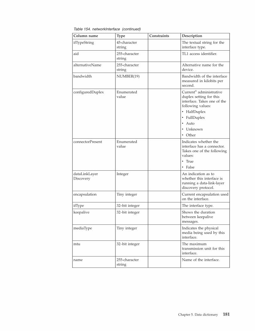
Table 154. networkInterface (continued)
Column name Type Constraints Description
ifTypeString 45-characterstring
The textual string for theinterface type.
aid 255-characterstring
TL1 access identifier.
alternativeName 255-characterstring
Alternative name for thedevice.
bandwidth NUMBER(19) Bandwidth of the interfacemeasured in kilobits persecond.
configuredDuplex Enumeratedvalue
Current® administrativeduplex setting for thisinterface. Takes one of thefollowing values:
v HalfDuplex
v FullDuplex
v Auto
v Unknown
v Other
connectorPresent Enumeratedvalue
Indicates whether theinterface has a connector.Takes one of the followingvalues:
v True
v False
dataLinkLayerDiscovery
Integer An indication as towhether this interface isrunning a data-link-layerdiscovery protocol.
encapsulation Tiny integer Current encapsulation usedon the interface.
ifType 32–bit integer The interface type.
keepalive 32–bit integer Shows the durationbetween keepalivemessages.
mediaType Tiny integer Indicates the physicalmedia being used by thisinterface.
mtu 32–bit integer The maximumtransmission unit for thisinterface.
name 255-characterstring
Name of the interface.
Chapter 5. Data dictionary 181
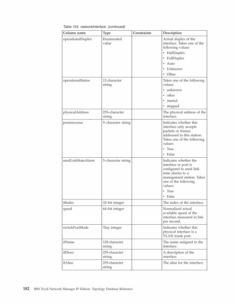
Table 154. networkInterface (continued)
Column name Type Constraints Description
operationalDuplex Enumeratedvalue
Actual duplex of theinterface. Takes one of thefollowing values:
v HalfDuplex
v FullDuplex
v Auto
v Unknown
v Other
operationalStatus 12-characterstring
Takes one of the followingvalues:
v unknown
v other
v started
v stopped
physicalAddress 255–characterstring
The physical address of theinterface.
promiscuous 5–character string Indicates whether thisinterface only acceptspackets or framesaddressed to this station.Takes one of the followingvalues:
v True
v False
sendLinkStateAlarm 5–character string Indicates whether theinterface or port isconfigured to send linkstate alarms to amanagement station. Takesone of the followingvalues:
v True
v False
ifIndex 32–bit integer The index of the interface.
speed 64–bit integer Normalized actualavailable speed of theinterface measured in bitsper second.
switchPortMode Tiny integer Indicates whether thisphysical interface is aVLAN trunk port.
ifName 128-characterstring
The name assigned to theinterface.
ifDescr 255-characterstring
A description of theinterface.
ifAlias 255-characterstring
The alias for the interface.
182 IBM Tivoli Network Manager IP Edition: Topology Database Reference

Table 154. networkInterface (continued)
Column name Type Constraints Description
ifSpeed 64–bit integer An estimate of the currentbandwidth of the interfacein bits per second.
ifHighSpeed 32–bit integer An estimate of the currentbandwidth of the interfacein units of 1,000,000 bitsper second.
ifAdminStatus Enumeratedvalue
The required state of theinterface. Takes one of thefollowing values:
v Up
v Down
v Testing
ifOperStatus Enumeratedvalue
The current operationalstate of the interface. Takesone of the followingvalues:
v Up
v Down
v Testing
v unknown
v dormant
v notPresent
v lowerLayerDown
accessIPAddress 39-characterstring
The IP address throughwhich this entity wasdiscovered and will bemonitored.Note: For non-IP entities,such as layer 1 opticaldevices, this field is null.
accessProtocol Enumerated type(string 7 chars)
An integer representationof the network protocolused by thepresently-defined zone:
v 0: Unknown
v 1: IPv4
v 2: IPv4 that has beenthrough network addresstranslation (NAT)
v 3: IPv6
v 4: Element ManagementSystem (EMS) key for anon-IP device
Chapter 5. Data dictionary 183
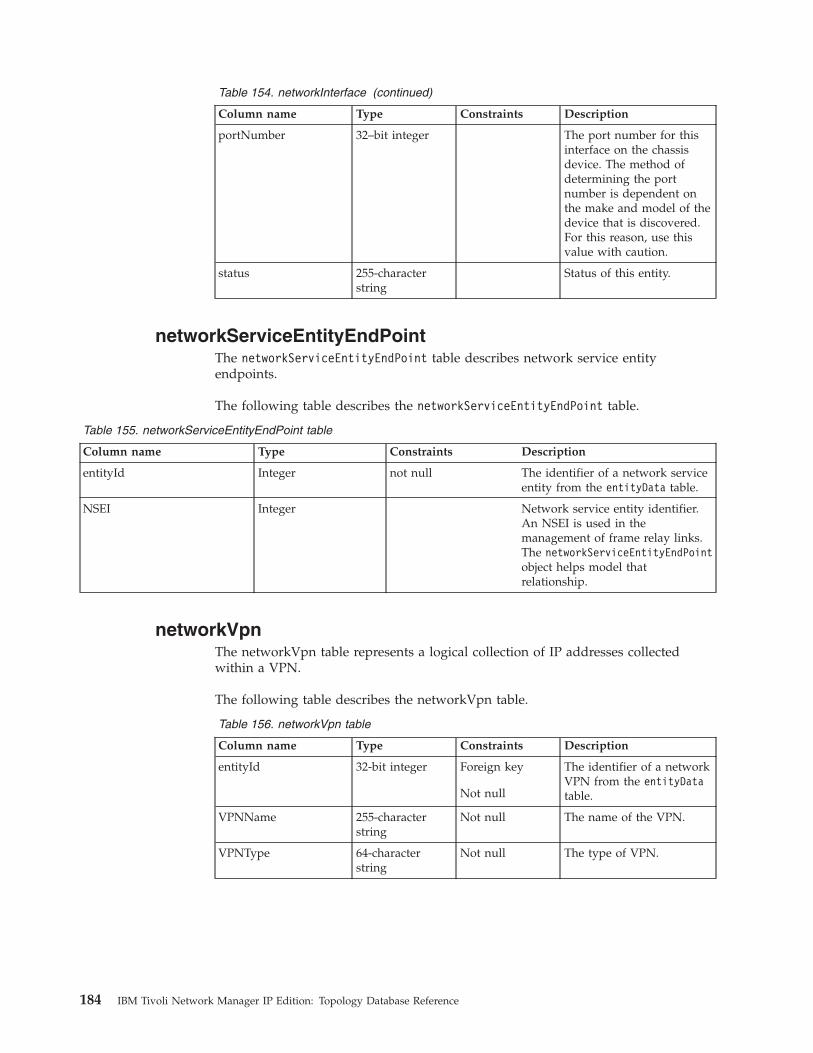
Table 154. networkInterface (continued)
Column name Type Constraints Description
portNumber 32–bit integer The port number for thisinterface on the chassisdevice. The method ofdetermining the portnumber is dependent onthe make and model of thedevice that is discovered.For this reason, use thisvalue with caution.
status 255-characterstring
Status of this entity.
networkServiceEntityEndPointThe networkServiceEntityEndPoint table describes network service entityendpoints.
The following table describes the networkServiceEntityEndPoint table.
Table 155. networkServiceEntityEndPoint table
Column name Type Constraints Description
entityId Integer not null The identifier of a network serviceentity from the entityData table.
NSEI Integer Network service entity identifier.An NSEI is used in themanagement of frame relay links.The networkServiceEntityEndPointobject helps model thatrelationship.
networkVpnThe networkVpn table represents a logical collection of IP addresses collectedwithin a VPN.
The following table describes the networkVpn table.
Table 156. networkVpn table
Column name Type Constraints Description
entityId 32-bit integer Foreign key
Not null
The identifier of a networkVPN from the entityDatatable.
VPNName 255-characterstring
Not null The name of the VPN.
VPNType 64-characterstring
Not null The type of VPN.
184 IBM Tivoli Network Manager IP Edition: Topology Database Reference
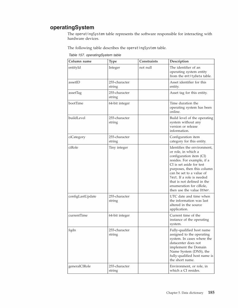
operatingSystemThe operatingSystem table represents the software responsible for interacting withhardware devices.
The following table describes the operatingSystem table.
Table 157. operatingSystem table
Column name Type Constraints Description
entityId Integer not null The identifier of anoperating system entityfrom the entityData table.
assetID 255-characterstring
Asset identifier for thisentity.
assetTag 255-characterstring
Asset tag for this entity.
bootTime 64-bit integer Time duration theoperating system has beenonline.
buildLevel 255-characterstring
Build level of the operatingsystem without anyversion or releaseinformation.
ciCategory 255-characterstring
Configuration itemcategory for this entity.
ciRole Tiny integer Identifies the environment,or role, in which aconfiguration item (CI)resides. For example, if aCI is set aside for testpurposes, then this columncan be set to a value ofTest. If a role is neededthat is not defined in theenumeration for ciRole,then use the value Other.
configLastUpdate 255-characterstring
UTC date and time whenthe information was lastaltered in the sourceapplication.
currentTime 64-bit integer Current time of theinstance of the operatingsystem.
fqdn 255-characterstring
Fully-qualified host nameassigned to the operatingsystem. In cases where thedatacenter does notimplement the DomainName System (DNS), thefully-qualified host name isthe short name.
generalCIRole 255-characterstring
Environment, or role, inwhich a CI resides.
Chapter 5. Data dictionary 185

Table 157. operatingSystem table (continued)
Column name Type Constraints Description
kernelArchitecture 255-characterstring
Raw details of thesupported systemarchitecture of the kernelcomponent of theoperating system.
kernelVersion 255-characterstring
Raw version of the kernelcomponent of theoperating system.
lastAuditState Tiny integer Last audit state for thisdevice. Possible values are:
v 0 Unknown
v 1 Other
v 2 Good
v 3 No Physical CI
v 4 No CMDB Record
v 5 Inaccurate CMDBRecord
lastAuditTime Timestamp Last audit time this entity.
lastLifecycleStateTime Timestamp Last lifecycle state time forthis entity.
osLevel Integer Operating system level.
lifecycleState Tiny integer Lifecycle state for thisdevice. Possible values are:
v 0 Unknown
v 1 Other
v 2 Ordered
v 3 Received
v 4 In Test
v 5 Tested
v 6 Installed
v 7 Enabled
v 8 Disabled
v 9 In Maintenance
v 10 Retired
v 11 Archived
v 12 Accepted
v 13 Draft
v 14 Build
v 15 Validate
v 16 ProductionReady
v 17 Production
v 18 Sunset
v 19 PostProduction
v 20 Inventory
v 21 Development
v 22 Offline
186 IBM Tivoli Network Manager IP Edition: Topology Database Reference
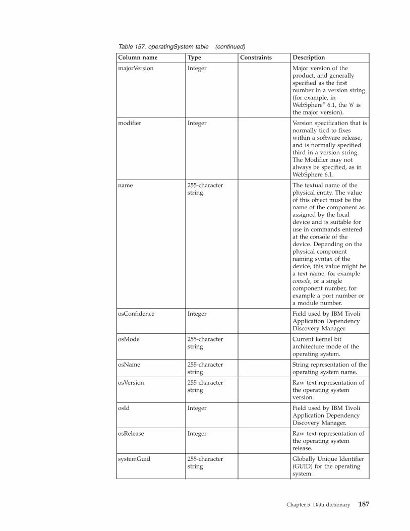
Table 157. operatingSystem table (continued)
Column name Type Constraints Description
majorVersion Integer Major version of theproduct, and generallyspecified as the firstnumber in a version string(for example, inWebSphere® 6.1, the '6' isthe major version).
modifier Integer Version specification that isnormally tied to fixeswithin a software release,and is normally specifiedthird in a version string.The Modifier may notalways be specified, as inWebSphere 6.1.
name 255-characterstring
The textual name of thephysical entity. The valueof this object must be thename of the component asassigned by the localdevice and is suitable foruse in commands enteredat the console of thedevice. Depending on thephysical componentnaming syntax of thedevice, this value might bea text name, for exampleconsole, or a singlecomponent number, forexample a port number ora module number.
osConfidence Integer Field used by IBM TivoliApplication DependencyDiscovery Manager.
osMode 255-characterstring
Current kernel bitarchitecture mode of theoperating system.
osName 255-characterstring
String representation of theoperating system name.
osVersion 255-characterstring
Raw text representation ofthe operating systemversion.
osId Integer Field used by IBM TivoliApplication DependencyDiscovery Manager.
osRelease Integer Raw text representation ofthe operating systemrelease.
systemGuid 255-characterstring
Globally Unique Identifier(GUID) for the operatingsystem.
Chapter 5. Data dictionary 187
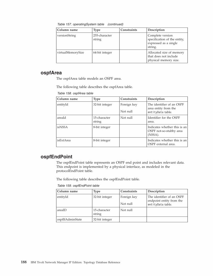
Table 157. operatingSystem table (continued)
Column name Type Constraints Description
versionString 255-characterstring
Complete versionspecification of the entity,expressed as a singlestring.
virtualMemorySize 64-bit integer Allocated size of memorythat does not includephysical memory size.
ospfAreaThe ospfArea table models an OSPF area.
The following table describes the ospfArea table.
Table 158. ospfArea table
Column name Type Constraints Description
entityId 32-bit integer Foreign key
Not null
The identifier of an OSPFarea entity from theentityData table.
areaId 15-characterstring
Not null Identifier for the OSPFarea.
isNSSA 8-bit integer Indicates whether this is anOSPF not-so-stubby area(NSSA).
isExtArea 8-bit integer Indicates whether this is anOSPF external area.
ospfEndPointThe ospfEndPoint table represents an OSPF end point and includes relevant data.This endpoint is implemented by a physical interface, as modeled in theprotocolEndPoint table.
The following table describes the ospfEndPoint table.
Table 159. ospfEndPoint table
Column name Type Constraints Description
entityId 32-bit integer Foreign key
Not null
The identifier of an OSPFendpoint entity from theentityData table.
areaID 15-characterstring
Not null
ospfIfAdminState 32-bit integer
188 IBM Tivoli Network Manager IP Edition: Topology Database Reference

Table 159. ospfEndPoint table (continued)
Column name Type Constraints Description
ospfIfState Enumeratedvalue
Takes one of thefollowing values:
1: down2: loopback3: waiting4: pointToPoint5: designated-Router6: backup-DesignatedRouter7: other-DesignatedRouter
The state of the OSPFinterface.
ospfIfType Enumeratedvalue
Takes one of thefollowing values:1: broadcast2: nbma3: pointTo-Point5: pointTo-Multipoint
The OSPF interface type.
defaultCost 32-bit integer
Related reference:“protocolEndPoint” on page 133The protocolEndPoint table allows a higher-level connection to be defined in termsof lower-level connections. It associates a device entity, usually an interface, withprotocol-specific information associated with that device entity. TheprotocolEndPoint table belongs to the category connectivity.
ospfNetworkLSAThe ospfNetworkLSA table represents an OSPF Link-State Advertisement (LSA)and includes relevant data.
The following table describes the ospfNetworkLSA table.
Table 160. ospfNetworkLSA table
Column name Type Constraints Description
entityId 32-bit integer Foreign key
Not null
The identifier of an OSPFLSA entity from theentityData table.
linkStateId 15-characterstring
Not null Specifies link state ID.
networkMask 15-characterstring
Specifies network mask.
networkType 10-characterstring
Indicates the network type.
Chapter 5. Data dictionary 189

ospfRoutingDomainThe ospfRoutingDomain table represents an OSPF routing domain.
The following table describes the ospfRoutingDomain table.
Table 161. ospfRoutingDomain table
Column name Type Constraints Description
entityId 32-bit integer Foreign key
Not null
The identifier of a networkpipe entity from theentityData table.
ospfDomain 32-bit integer Not null The domain of the OSPF.
ospfServiceThe ospfService table represents an OSPF service and includes relevant protocoldata. This OSPF service runs on a device, as modeled in the hostedService table.
The following table describes the ospfService table.
Table 162. ospfService table
Column name Type Constraints Description
entityId 32-bit integer Foreign key
Not null
The identifier of an OSPFservice entity from theentityData table.
routerId 15-characterstring
Not null The entity ID of the routeron which this OSPF serviceis running.
isAreaBdrRtr 8-bit integer Indicates whether thisrouter is an area borderrouter.
isAsBdrRtr 8-bit integer Indicates whether thisrouter is an AS borderrouter.
isDrRtr 8-bit integer Indicates whether thisrouter is acting as adesignated router.
isBdrRtr 8-bit integer Indicates whether thisrouter is acting as abackup designated router.
isDrOtherRtr 8-bit integer Indicates that this router isneither a designated routernor a backup designatedrouter.
Related reference:“hostedService” on page 129A hosted service is a service or application running on a specific main node device.The hostedService table maps a main node device, the hosting entity, to the serviceor applications that are running on that device, the hosted entities. ThehostedService table belongs to the category entities.
190 IBM Tivoli Network Manager IP Edition: Topology Database Reference

physicalBackplaneThe physicalBackplane table stores the attributes of chassis entities.
The following table describes the physicalBackplane table.
Table 163. physicalBackplane table
Column name Type Constraints Description
entityId 32-bit integer Foreign keyNot null
The identifier of a chassisentity from the entityDatatable.
fwRevision 255-characterstring
Firmware version for thisentity.
hwRevision 255-characterstring
Hardware version for thisentity.
manufacturer 255-characterstring
Vendor-specific hardwaretype for this entity.
manufacturingDate Timestamp Date of manufacture forthis entity.
model 255-characterstring
Model name for this entity.
name 255-characterstring
The textual name of thephysical entity. The valueof this object must be thename of the component asassigned by the localdevice and is suitable foruse in commands enteredat the console of thedevice. Depending on thephysical componentnaming syntax of thedevice, this value might bea text name, for exampleconsole, or a singlecomponent number, forexample a port number ora module number.
relativePosition 32-bit integer Indication of the relativeposition of this entitywithin the containment.
swRevision 255-characterstring
An indication of thevendor-specific hardwaretype of the physical entity.
serialNumber 255-characterstring
The serial number of theentity.
cdmType 32-bit integer The model name of theentity.
physicalIndex 32-bit integer The physical index for thisentity.
vendorType 255-characterstring
Vendor assigned typeinformation.
Chapter 5. Data dictionary 191

physicalCardThe physicalCard table represents card entities.
The following table describes the physicalCard table.
Table 164. physicalCard table
Column name Type Constraints Description
entityId 32-bit integer Foreign key
Not null
The identifier of a module(card) entity from theentityData table.
aisle 255-characterstring
Column or longitudinaldivision of an interior area.
altitude FLOAT Column or longitudinaldivision of an interior area.
cardConfigurationState NUMBER(3) Default value for this fieldis 0.
fruNumber 255-characterstring
Specifies the numberassigned to a FRU(field-replaceable unit) bythe manufacturer.
fruSerialNumber 255-characterstring
Specifies the serial numberassigned to a FRU(field-replaceable unit) bythe manufacturer.
fwRevision 255-characterstring
Firmware version for thisentity.
hwRevision 255-characterstring
Hardware version for thisentity.
manufacturer 255-characterstring
Vendor-specific hardwaretype for this entity.
manufacturingDate Timestamp Date of manufacture forthis entity.
model 255-characterstring
Model name for this entity.
name 255-characterstring
The textual name of thephysical entity. The valueof this object must be thename of the component asassigned by the localdevice and is suitable foruse in commands enteredat the console of thedevice. Depending on thephysical componentnaming syntax of thedevice, this value might bea text name, for exampleconsole, or a singlecomponent number, forexample a port number ora module number.
partNumber 255-characterstring
Orderable part number forthis entity.
192 IBM Tivoli Network Manager IP Edition: Topology Database Reference

Table 164. physicalCard table (continued)
Column name Type Constraints Description
rfidTag 255-characterstring
Radio frequency ID tagidentifier.
rackPosition NUMBER(10) Particular vertical positionon a data center rack.
relativePosition 32-bit integer Indication of the relativeposition of this entitywithin the containment.
cdmRow 255-characterstring
Latitudinal division of aninterior area.
swRevision 255-characterstring
Software revision.
serialNumber 255-characterstring
The serial number of theentity.
systemBoardUUID 255-characterstring
Specifies the burned-inGlobally Unique Identifier(GUID) of this piece ofequipment.
cdmType NUMBER(3) NOT NULL Default value for this fieldis 8.
userTracking 64-characterstring
Common language locationidentification (CLLI) code.
xCoordinate 255-characterstring
Angular distance (east andwest) from the primemeridian on the earth'ssurface.
yCoordinate 255-characterstring
Angular distance (northand south) from theequator on the earth'ssurface.
physicalIndex 32-bit integer The physical index for thisentity.
vendorType 255-characterstring
Vendor assigned typeinformation.
softwareImage 100-characterstring
isFRU Indication of whether thispiece of equipment isreplaceable in the field.Takes one of the followingvalues:
v True
v False
Chapter 5. Data dictionary 193

Table 164. physicalCard table (continued)
Column name Type Constraints Description
operStatus Enumeratedvalue
Operational status of thiscard. Takes one of thefollowing values:
v unknown
v ok
v disabled
v okButDiagFailed
v boot
v selfTest
v failed
v missing
v mismatchWithParent
v mismatchConfig
v diagFailed
v dormant
v outOfServiceAdmin
v outOfServiceEnvTemp
adminStatus Enumeratedvalue
Administrative status ofthis card. Takes one of thefollowing values:
v unknown
v enabled
v disabled
v reset
v outOfServiceAdmin
numItemsSupported 32-bit integer The number of itemssupported by this entity.For example, if the entitymodels a layer 1 card, thenthis number indicates thenumber of cards supportedon the entity. Negativevalues are ignored.
status 255-characterstring
Status of this entity.
primaryState 255-characterstring
Primary state of this entity.
This field only applieswhere the module is thecard of a layer 1 device.
secondaryState 255-characterstring
Secondary state of thisentity.
This field only applieswhere the module is thecard of a layer 1 device.
cardNumber 32-bit integer Card number.
194 IBM Tivoli Network Manager IP Edition: Topology Database Reference

physicalChassisThe physicalChassis table stores the attributes of chassis entities.
The following table describes the physicalChassis table.
Table 165. physicalChassis table
Column name Type Constraints Description
entityId 32-bit integer Foreign keyNot null
The identifier of a chassisentity from the entityDatatable.
aisle 255-characterstring
Column or longitudinaldivision of an interior area.
altitude FLOAT Vertical height above sealevel at the particulargeographical location.
chassisUUID 255-characterstring
Unique identifier of thischassis.
fruNumber 255-characterstring
Specifies the numberassigned to a FRU(field-replaceable unit) bythe manufacturer.
fruSerialNumber 255-characterstring
Specifies the serial numberassigned to a FRU(field-replaceable unit) bythe manufacturer.
fwRevision 255-characterstring
Firmware version for thisentity.
hwRevision 255-characterstring
Hardware version for thisentity.
manufacturer 255-characterstring
Vendor-specific hardwaretype for this entity.
manufacturingDate Timestamp Date of manufacture forthis entity.
model 255-characterstring
The model name of theentity.
name 255-characterstring
The textual name of thephysical entity. The valueof this object must be thename of the component asassigned by the localdevice and is suitable foruse in commands enteredat the console of thedevice. Depending on thephysical componentnaming syntax of thedevice, this value might bea text name, for exampleconsole, or a singlecomponent number, forexample a port number ora module number.
partNumber 255-characterstring
Orderable part number forthis entity.
Chapter 5. Data dictionary 195
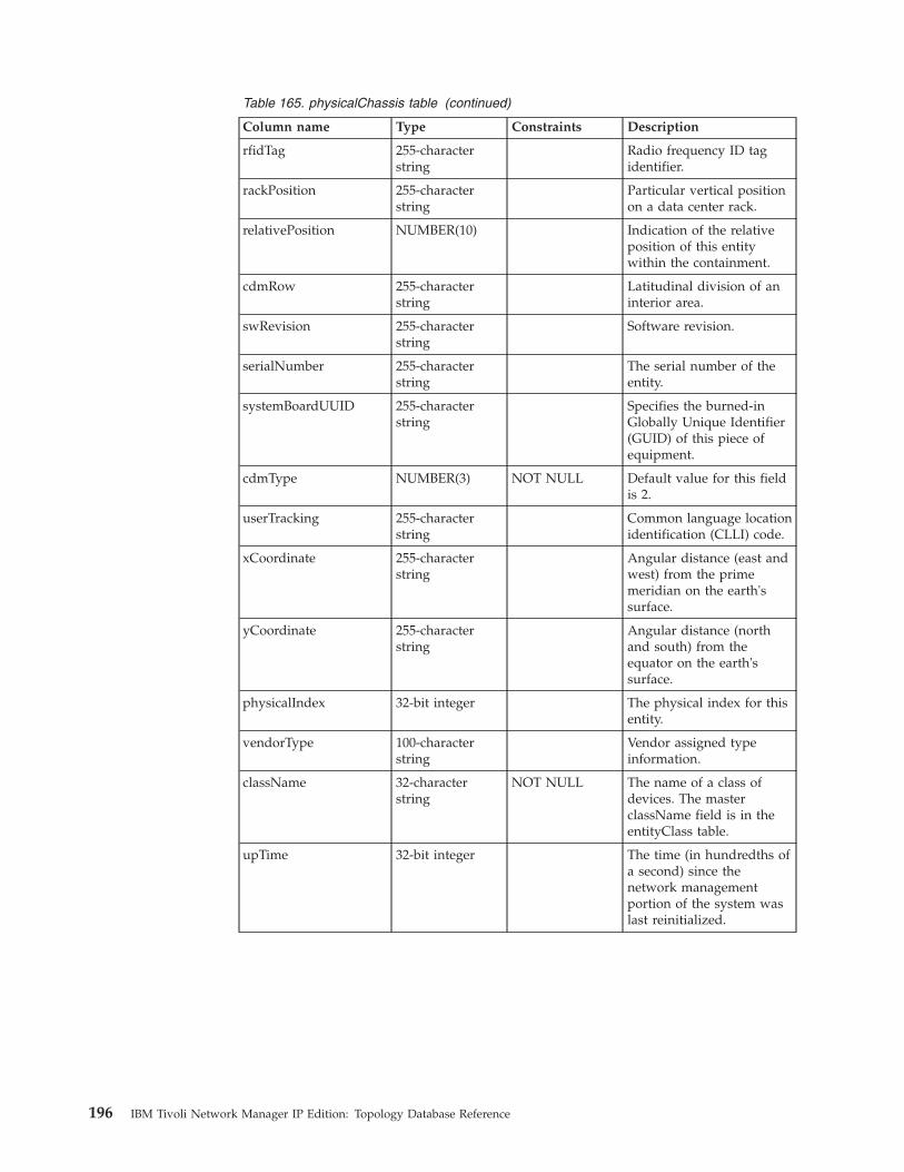
Table 165. physicalChassis table (continued)
Column name Type Constraints Description
rfidTag 255-characterstring
Radio frequency ID tagidentifier.
rackPosition 255-characterstring
Particular vertical positionon a data center rack.
relativePosition NUMBER(10) Indication of the relativeposition of this entitywithin the containment.
cdmRow 255-characterstring
Latitudinal division of aninterior area.
swRevision 255-characterstring
Software revision.
serialNumber 255-characterstring
The serial number of theentity.
systemBoardUUID 255-characterstring
Specifies the burned-inGlobally Unique Identifier(GUID) of this piece ofequipment.
cdmType NUMBER(3) NOT NULL Default value for this fieldis 2.
userTracking 255-characterstring
Common language locationidentification (CLLI) code.
xCoordinate 255-characterstring
Angular distance (east andwest) from the primemeridian on the earth'ssurface.
yCoordinate 255-characterstring
Angular distance (northand south) from theequator on the earth'ssurface.
physicalIndex 32-bit integer The physical index for thisentity.
vendorType 100-characterstring
Vendor assigned typeinformation.
className 32-characterstring
NOT NULL The name of a class ofdevices. The masterclassName field is in theentityClass table.
upTime 32-bit integer The time (in hundredths ofa second) since thenetwork managementportion of the system waslast reinitialized.
196 IBM Tivoli Network Manager IP Edition: Topology Database Reference
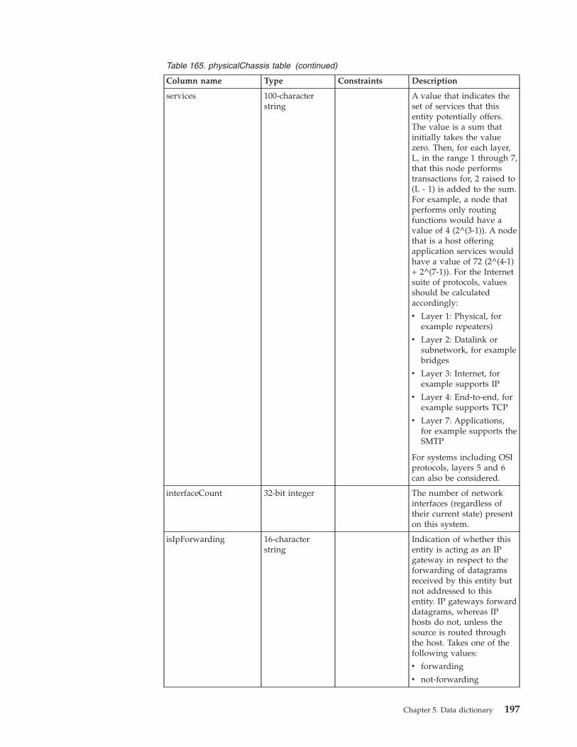
Table 165. physicalChassis table (continued)
Column name Type Constraints Description
services 100-characterstring
A value that indicates theset of services that thisentity potentially offers.The value is a sum thatinitially takes the valuezero. Then, for each layer,L, in the range 1 through 7,that this node performstransactions for, 2 raised to(L - 1) is added to the sum.For example, a node thatperforms only routingfunctions would have avalue of 4 (2^(3-1)). A nodethat is a host offeringapplication services wouldhave a value of 72 (2^(4-1)+ 2^(7-1)). For the Internetsuite of protocols, valuesshould be calculatedaccordingly:
v Layer 1: Physical, forexample repeaters)
v Layer 2: Datalink orsubnetwork, for examplebridges
v Layer 3: Internet, forexample supports IP
v Layer 4: End-to-end, forexample supports TCP
v Layer 7: Applications,for example supports theSMTP
For systems including OSIprotocols, layers 5 and 6can also be considered.
interfaceCount 32-bit integer The number of networkinterfaces (regardless oftheir current state) presenton this system.
isIpForwarding 16-characterstring
Indication of whether thisentity is acting as an IPgateway in respect to theforwarding of datagramsreceived by this entity butnot addressed to thisentity. IP gateways forwarddatagrams, whereas IPhosts do not, unless thesource is routed throughthe host. Takes one of thefollowing values:
v forwarding
v not-forwarding
Chapter 5. Data dictionary 197
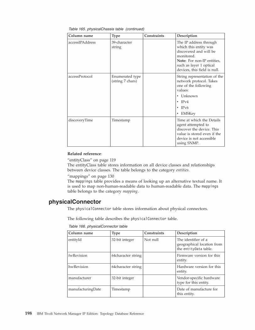
Table 165. physicalChassis table (continued)
Column name Type Constraints Description
accessIPAddress 39-characterstring
The IP address throughwhich this entity wasdiscovered and will bemonitored.Note: For non-IP entities,such as layer 1 opticaldevices, this field is null.
accessProtocol Enumerated type(string 7 chars)
String representation of thenetwork protocol. Takesone of the followingvalues:
v Unknown
v IPv4
v IPv6
v EMSKey
discoveryTime Timestamp Time at which the Detailsagent attempted todiscover the device. Thisvalue is stored even if thedevice is not accessibleusing SNMP.
Related reference:“entityClass” on page 119The entityClass table stores information on all device classes and relationshipsbetween device classes. The table belongs to the category entities.“mappings” on page 130The mappings table provides a means of looking up an alternative textual name. Itis used to map non-human-readable data to human-readable data. The mappingstable belongs to the category mapping.
physicalConnectorThe physicalConnector table stores information about physical connectors.
The following table describes the physicalConnector table.
Table 166. physicalConnector table
Column name Type Constraints Description
entityId 32-bit integer Not null The identifier of ageographical location fromthe entityData table.
fwRevision 64character string Firmware version for thisentity.
hwRevision 64character string Hardware version for thisentity.
manufacturer 32-bit integer Vendor-specific hardwaretype for this entity.
manufacturingDate Timestamp Date of manufacture forthis entity.
198 IBM Tivoli Network Manager IP Edition: Topology Database Reference
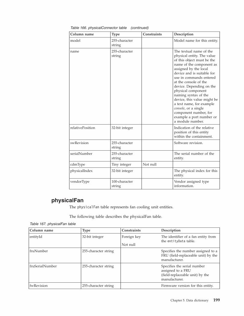
Table 166. physicalConnector table (continued)
Column name Type Constraints Description
model 255-characterstring
Model name for this entity.
name 255-characterstring
The textual name of thephysical entity. The valueof this object must be thename of the component asassigned by the localdevice and is suitable foruse in commands enteredat the console of thedevice. Depending on thephysical componentnaming syntax of thedevice, this value might bea text name, for exampleconsole, or a singlecomponent number, forexample a port number ora module number.
relativePosition 32-bit integer Indication of the relativeposition of this entitywithin the containment.
swRevision 255-characterstring
Software revision.
serialNumber 255-characterstring
The serial number of theentity.
cdmType Tiny integer Not null
physicalIndex 32-bit integer The physical index for thisentity.
vendorType 100-characterstring
Vendor assigned typeinformation.
physicalFanThe physicalFan table represents fan cooling unit entities.
The following table describes the physicalFan table.
Table 167. physicalFan table
Column name Type Constraints Description
entityId 32-bit integer Foreign key
Not null
The identifier of a fan entity fromthe entityData table.
fruNumber 255-character string Specifies the number assigned to aFRU (field-replaceable unit) by themanufacturer.
fruSerialNumber 255-character string Specifies the serial numberassigned to a FRU(field-replaceable unit) by themanufacturer.
fwRevision 255-character string Firmware version for this entity.
Chapter 5. Data dictionary 199
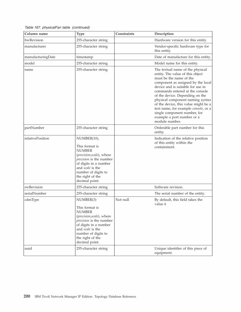
Table 167. physicalFan table (continued)
Column name Type Constraints Description
hwRevision 255-character string Hardware version for this entity.
manufacturer 255-character string Vendor-specific hardware type forthis entity.
manufacturingDate timestamp Date of manufacture for this entity.
model 255-character string Model name for this entity.
name 255-character string The textual name of the physicalentity. The value of this objectmust be the name of thecomponent as assigned by the localdevice and is suitable for use incommands entered at the consoleof the device. Depending on thephysical component naming syntaxof the device, this value might be atext name, for example console, or asingle component number, forexample a port number or amodule number.
partNumber 255-character string Orderable part number for thisentity.
relativePosition NUMBER(10),
This format isNUMBER(precision,scale), whereprecision is the numberof digits in a numberand scale is thenumber of digits tothe right of thedecimal point.
Indication of the relative positionof this entity within thecontainment.
swRevision 255-character string Software revision.
serialNumber 255-character string The serial number of the entity.
cdmType NUMBER(3)
This format isNUMBER(precision,scale), whereprecision is the numberof digits in a numberand scale is thenumber of digits tothe right of thedecimal point.
Not null By default, this field takes thevalue 6
uuid 255-character string Unique identifier of this piece ofequipment.
200 IBM Tivoli Network Manager IP Edition: Topology Database Reference
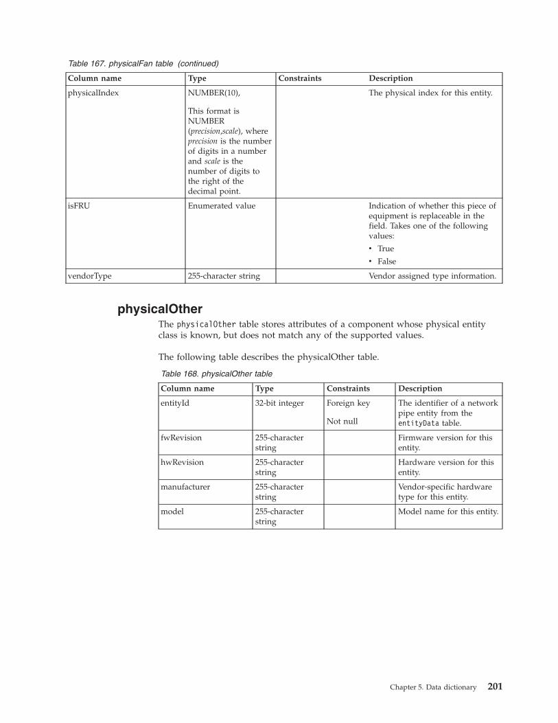
Table 167. physicalFan table (continued)
Column name Type Constraints Description
physicalIndex NUMBER(10),
This format isNUMBER(precision,scale), whereprecision is the numberof digits in a numberand scale is thenumber of digits tothe right of thedecimal point.
The physical index for this entity.
isFRU Enumerated value Indication of whether this piece ofequipment is replaceable in thefield. Takes one of the followingvalues:
v True
v False
vendorType 255-character string Vendor assigned type information.
physicalOtherThe physicalOther table stores attributes of a component whose physical entityclass is known, but does not match any of the supported values.
The following table describes the physicalOther table.
Table 168. physicalOther table
Column name Type Constraints Description
entityId 32-bit integer Foreign key
Not null
The identifier of a networkpipe entity from theentityData table.
fwRevision 255-characterstring
Firmware version for thisentity.
hwRevision 255-characterstring
Hardware version for thisentity.
manufacturer 255-characterstring
Vendor-specific hardwaretype for this entity.
model 255-characterstring
Model name for this entity.
Chapter 5. Data dictionary 201
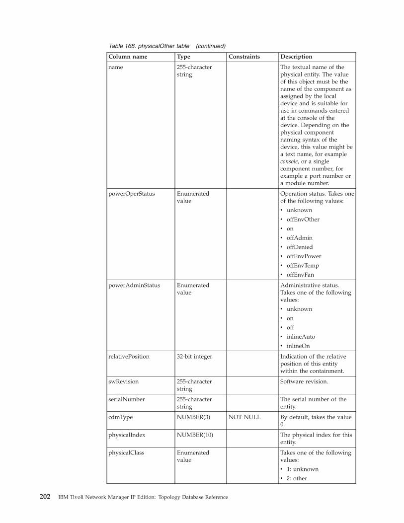
Table 168. physicalOther table (continued)
Column name Type Constraints Description
name 255-characterstring
The textual name of thephysical entity. The valueof this object must be thename of the component asassigned by the localdevice and is suitable foruse in commands enteredat the console of thedevice. Depending on thephysical componentnaming syntax of thedevice, this value might bea text name, for exampleconsole, or a singlecomponent number, forexample a port number ora module number.
powerOperStatus Enumeratedvalue
Operation status. Takes oneof the following values:
v unknown
v offEnvOther
v on
v offAdmin
v offDenied
v offEnvPower
v offEnvTemp
v offEnvFan
powerAdminStatus Enumeratedvalue
Administrative status.Takes one of the followingvalues:
v unknown
v on
v off
v inlineAuto
v inlineOn
relativePosition 32-bit integer Indication of the relativeposition of this entitywithin the containment.
swRevision 255-characterstring
Software revision.
serialNumber 255-characterstring
The serial number of theentity.
cdmType NUMBER(3) NOT NULL By default, takes the value0.
physicalIndex NUMBER(10) The physical index for thisentity.
physicalClass Enumeratedvalue
Takes one of the followingvalues:
v 1: unknown
v 2: other
202 IBM Tivoli Network Manager IP Edition: Topology Database Reference
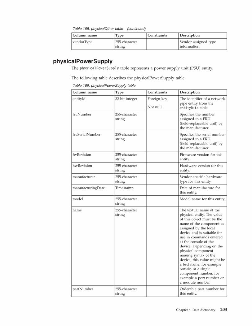
Table 168. physicalOther table (continued)
Column name Type Constraints Description
vendorType 255-characterstring
Vendor assigned typeinformation.
physicalPowerSupplyThe physicalPowerSupply table represents a power supply unit (PSU) entity.
The following table describes the physicalPowerSupply table.
Table 169. physicalPowerSupply table
Column name Type Constraints Description
entityId 32-bit integer Foreign key
Not null
The identifier of a networkpipe entity from theentityData table.
fruNumber 255-characterstring
Specifies the numberassigned to a FRU(field-replaceable unit) bythe manufacturer.
fruSerialNumber 255-characterstring
Specifies the serial numberassigned to a FRU(field-replaceable unit) bythe manufacturer.
fwRevision 255-characterstring
Firmware version for thisentity.
hwRevision 255-characterstring
Hardware version for thisentity.
manufacturer 255-characterstring
Vendor-specific hardwaretype for this entity.
manufacturingDate Timestamp Date of manufacture forthis entity.
model 255-characterstring
Model name for this entity.
name 255-characterstring
The textual name of thephysical entity. The valueof this object must be thename of the component asassigned by the localdevice and is suitable foruse in commands enteredat the console of thedevice. Depending on thephysical componentnaming syntax of thedevice, this value might bea text name, for exampleconsole, or a singlecomponent number, forexample a port number ora module number.
partNumber 255-characterstring
Orderable part number forthis entity.
Chapter 5. Data dictionary 203
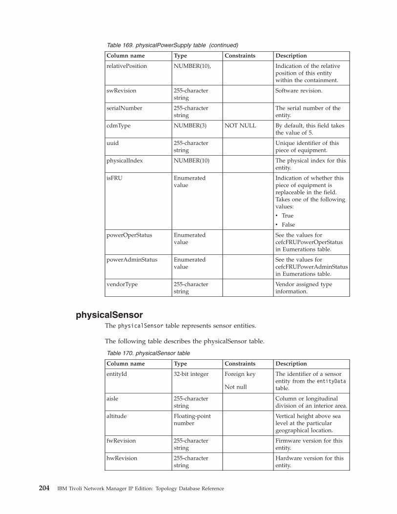
Table 169. physicalPowerSupply table (continued)
Column name Type Constraints Description
relativePosition NUMBER(10), Indication of the relativeposition of this entitywithin the containment.
swRevision 255-characterstring
Software revision.
serialNumber 255-characterstring
The serial number of theentity.
cdmType NUMBER(3) NOT NULL By default, this field takesthe value of 5.
uuid 255-characterstring
Unique identifier of thispiece of equipment.
physicalIndex NUMBER(10) The physical index for thisentity.
isFRU Enumeratedvalue
Indication of whether thispiece of equipment isreplaceable in the field.Takes one of the followingvalues:
v True
v False
powerOperStatus Enumeratedvalue
See the values forcefcFRUPowerOperStatusin Eumerations table.
powerAdminStatus Enumeratedvalue
See the values forcefcFRUPowerAdminStatusin Eumerations table.
vendorType 255-characterstring
Vendor assigned typeinformation.
physicalSensorThe physicalSensor table represents sensor entities.
The following table describes the physicalSensor table.
Table 170. physicalSensor table
Column name Type Constraints Description
entityId 32-bit integer Foreign key
Not null
The identifier of a sensorentity from the entityDatatable.
aisle 255-characterstring
Column or longitudinaldivision of an interior area.
altitude Floating-pointnumber
Vertical height above sealevel at the particulargeographical location.
fwRevision 255-characterstring
Firmware version for thisentity.
hwRevision 255-characterstring
Hardware version for thisentity.
204 IBM Tivoli Network Manager IP Edition: Topology Database Reference
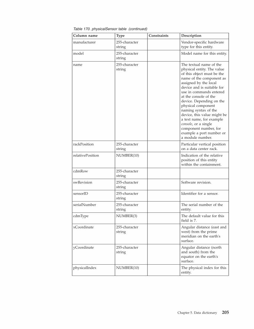
Table 170. physicalSensor table (continued)
Column name Type Constraints Description
manufacturer 255-characterstring
Vendor-specific hardwaretype for this entity.
model 255-characterstring
Model name for this entity.
name 255-characterstring
The textual name of thephysical entity. The valueof this object must be thename of the component asassigned by the localdevice and is suitable foruse in commands enteredat the console of thedevice. Depending on thephysical componentnaming syntax of thedevice, this value might bea text name, for exampleconsole, or a singlecomponent number, forexample a port number ora module number.
rackPosition 255-characterstring
Particular vertical positionon a data center rack.
relativePosition NUMBER(10) Indication of the relativeposition of this entitywithin the containment.
cdmRow 255-characterstring
swRevision 255-characterstring
Software revision.
sensorID 255-characterstring
Identifier for a sensor.
serialNumber 255-characterstring
The serial number of theentity.
cdmType NUMBER(3) The default value for thisfield is 7.
xCoordinate 255-characterstring
Angular distance (east andwest) from the primemeridian on the earth'ssurface.
yCoordinate 255-characterstring
Angular distance (northand south) from theequator on the earth'ssurface.
physicalIndex NUMBER(10) The physical index for thisentity.
Chapter 5. Data dictionary 205

Table 170. physicalSensor table (continued)
Column name Type Constraints Description
sensorType Enumeratedvalue
Sensor type. Takes one ofthe following values:
v other
v unknown
v voltsAC
v voltsDC
v amperes
v watts
v hertz
v celsius
v percentRH
v rpm
v cmm
v truthValue
v specialEnum
sensorScale Enumeratedvalue
Sensor scale. Takes one ofthe following values:
v unknown
v yocto
v zepto
v atto
v femto
v pico
v nano
v micro
v milli
v Units
v kilo
v mega
v giga
v tera
v exa
v peta
v zetta
v yotta
sensorStatus Enumeratedvalue
Sensor status. Takes one ofthe following values:
v ok
v unavailable
v nonoperational
v unknown
sensorValue 255-characterstring
The value for the sensor.
vendorType 255-characterstring
Vendor assigned typeinformation.
206 IBM Tivoli Network Manager IP Edition: Topology Database Reference

physicalSlotThe physicalSlot table represents slot entities.
If you want this table to be populated with MIB data, you must configure theEntity agent to run during the discovery process. The Entity agent discoversdetailed containment information from the Entity MIB. By default, the Entity agentis configured not to run during discovery.
The following table describes the physicalSlot table:
Table 171. physicalSlot table
Column name Type Constraints Description
entityId 32-bit integer Foreign key
Not null
The identifier of a slot entity fromthe entityData table.
fwRevision 255-character string Firmware version for this entity.
hwRevision 255-character string Hardware version for this entity.
manufacturer 255-character string Vendor-specific hardware type forthis entity.
model 255-character string Model name for this entity.
name 255-character string The textual name of the physicalentity. The value of this objectmust be the name of thecomponent as assigned by the localdevice and is suitable for use incommands entered at the consoleof the device. Depending on thephysical component naming syntaxof the device, this value might be atext name, for example console, or asingle component number, forexample a port number or amodule number.
slotNumber NUMBER(10) Slot number.
relativePosition NUMBER(10) Indication of the relative positionof this entity within thecontainment.
swRevision 255-character string Software revision.
serialNumber 255-character string The serial number of the entity.
slotState Current state of the slot.
cdmType NUMBER(3) The default value for this field is 7.
powerRedundancyMode
17-character string Takes one of the following values:
v unknown
v notSupported
v redundant
v combined
physicalIndex NUMBER(10) The physical index for this entity.
Chapter 5. Data dictionary 207
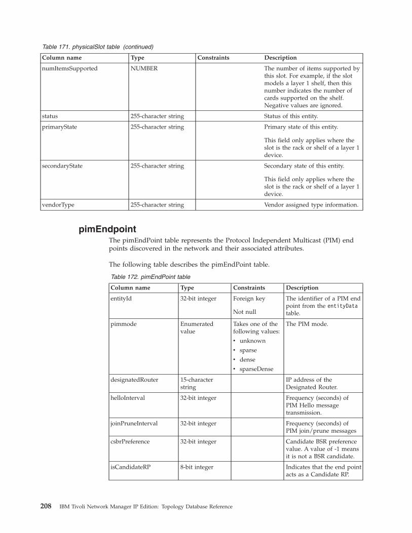
Table 171. physicalSlot table (continued)
Column name Type Constraints Description
numItemsSupported NUMBER The number of items supported bythis slot. For example, if the slotmodels a layer 1 shelf, then thisnumber indicates the number ofcards supported on the shelf.Negative values are ignored.
status 255-character string Status of this entity.
primaryState 255-character string Primary state of this entity.
This field only applies where theslot is the rack or shelf of a layer 1device.
secondaryState 255-character string Secondary state of this entity.
This field only applies where theslot is the rack or shelf of a layer 1device.
vendorType 255-character string Vendor assigned type information.
pimEndpointThe pimEndPoint table represents the Protocol Independent Multicast (PIM) endpoints discovered in the network and their associated attributes.
The following table describes the pimEndPoint table.
Table 172. pimEndPoint table
Column name Type Constraints Description
entityId 32-bit integer Foreign key
Not null
The identifier of a PIM endpoint from the entityDatatable.
pimmode Enumeratedvalue
Takes one of thefollowing values:
v unknown
v sparse
v dense
v sparseDense
The PIM mode.
designatedRouter 15-characterstring
IP address of theDesignated Router.
helloInterval 32-bit integer Frequency (seconds) ofPIM Hello messagetransmission.
joinPruneInterval 32-bit integer Frequency (seconds) ofPIM join/prune messages
csbrPreference 32-bit integer Candidate BSR preferencevalue. A value of -1 meansit is not a BSR candidate.
isCandidateRP 8-bit integer Indicates that the end pointacts as a Candidate RP.
208 IBM Tivoli Network Manager IP Edition: Topology Database Reference
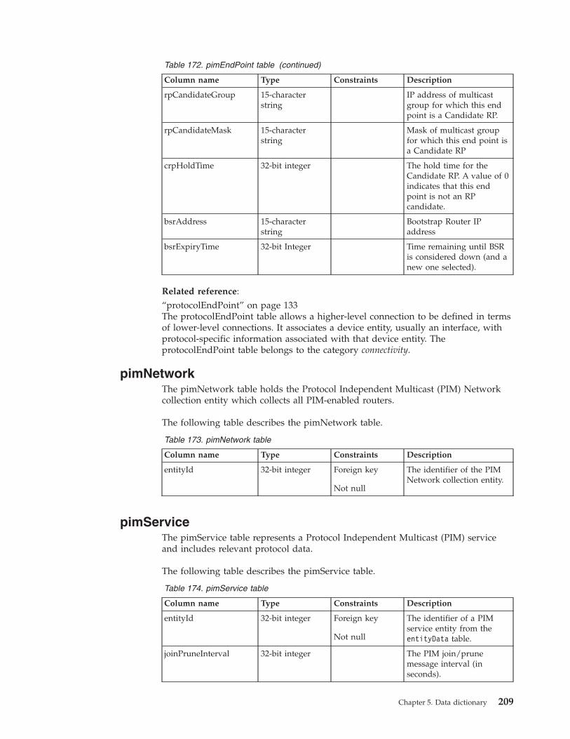
Table 172. pimEndPoint table (continued)
Column name Type Constraints Description
rpCandidateGroup 15-characterstring
IP address of multicastgroup for which this endpoint is a Candidate RP.
rpCandidateMask 15-characterstring
Mask of multicast groupfor which this end point isa Candidate RP
crpHoldTime 32-bit integer The hold time for theCandidate RP. A value of 0indicates that this endpoint is not an RPcandidate.
bsrAddress 15-characterstring
Bootstrap Router IPaddress
bsrExpiryTime 32-bit Integer Time remaining until BSRis considered down (and anew one selected).
Related reference:“protocolEndPoint” on page 133The protocolEndPoint table allows a higher-level connection to be defined in termsof lower-level connections. It associates a device entity, usually an interface, withprotocol-specific information associated with that device entity. TheprotocolEndPoint table belongs to the category connectivity.
pimNetworkThe pimNetwork table holds the Protocol Independent Multicast (PIM) Networkcollection entity which collects all PIM-enabled routers.
The following table describes the pimNetwork table.
Table 173. pimNetwork table
Column name Type Constraints Description
entityId 32-bit integer Foreign key
Not null
The identifier of the PIMNetwork collection entity.
pimServiceThe pimService table represents a Protocol Independent Multicast (PIM) serviceand includes relevant protocol data.
The following table describes the pimService table.
Table 174. pimService table
Column name Type Constraints Description
entityId 32-bit integer Foreign key
Not null
The identifier of a PIMservice entity from theentityData table.
joinPruneInterval 32-bit integer The PIM join/prunemessage interval (inseconds).
Chapter 5. Data dictionary 209
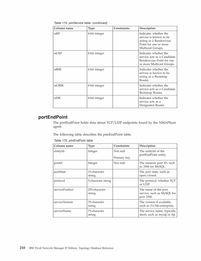
Table 174. pimService table (continued)
Column name Type Constraints Description
isRP 8-bit integer Indicates whether theservice is known to beacting as a RendezvousPoint for one or moreMulticast Groups.
isCRP 8-bit integer Indicates whether theservice acts as a CandidateRendezvous Point for oneor more Multicast Groups.
isBSR 8-bit integer Indicates whether theservice is known to beacting as a BootstrapRouter.
isCBSR 8-bit integer Indicates whether theservice acts as a CandidateBootstrap Router.
isDR 8-bit integer Indicates whether theservice acts as aDesignated Router.
portEndPointThe portEndPoint holds data about TCP/UDP endpoints found by the NMAPScanagent.
The following table describes the pimEndPoint table.
Table 175. pimEndPoint table
Column name Type Constraints Description
entityId Integer Not null
Primary key
The entityId of theportEndPoint entity.
portId Integer Not null The numeric port ID, suchas 3306 for MySQL.
portState 15-characterstring
The port state, such asopen/closed.
protocol 5-character string The protocol, whether TCPor UDP.
serviceProduct 255-characterstring
The name of the portservice, such as MySQL forport 3306.
serviceVersion 75-characterstring
The version if available,such as 5.0.54a-enterprise.
serviceName 75-characterstring
The service name, typicallyshort, such as mysql or ftp.
210 IBM Tivoli Network Manager IP Edition: Topology Database Reference

Related reference:“protocolEndPoint” on page 133The protocolEndPoint table allows a higher-level connection to be defined in termsof lower-level connections. It associates a device entity, usually an interface, withprotocol-specific information associated with that device entity. TheprotocolEndPoint table belongs to the category connectivity.
ranBaseStationThe ranBaseStation table describes Radio Access Network (RAN) base stations.
The following table describes the ranBaseStation table.
Table 176. ranBaseStation table
Column name Type Constraints Description
baseStationId varchar(64) not null A string identifying thebase station. In a namingconvention that follows theGSM 04.08 standard, thestring consists of theNetwork Color Code(NCC) and the Base StationCode (BSC).
entityId Integer not null The identifier of a basestation entity from theentityData table.
ranTechnologyType varchar(10) The type of wirelesstechnology used by thebase station. Possiblevalues are:
v Unknown
v Other
v GSM
v GPRS
v UMTS
ranBaseStationControllerThe ranBaseStationController table describes Radio Access Network (RAN) basestation controllers.
The following table describes the ranBaseStationController table.
Table 177. ranBaseStationController table
Column name Type Constraints Description
baseStationControllerId varchar(64) A string identifying thebase station controller. In anaming convention thatfollows the GSM 04.08standard, the stringconsists of the Base StationColor Code (BSC).
entityId Integer not null The identifier of a basestation controllers entityfrom the entityData table.
Chapter 5. Data dictionary 211

Table 177. ranBaseStationController table (continued)
Column name Type Constraints Description
ranTechnologyType varchar(10) The type of wirelesstechnology used by thebase station. Possiblevalues are:
v Unknown
v Other
v GSM
v GPRS
v UMTS
ranCircuitSwitchedCoreThe ranCircuitSwitchedCore table describes RAN circuit switched core entities,which are collection entities that collect the entities involved in the circuit switchedcore network of a given mobile phone network.
The following table describes the ranCircuitSwitchedCore table.
Table 178. ranCircuitSwitchedCore table
Column name Type Constraints Description
entityId Integer not null The identifier of a RANcircuit switched core entityfrom the entityData table.
mcc varchar(64) Mobile country code,which consists of threedigits. The MCC uniquelyidentifies the country ofdomicile of the mobilesubscriber.
mnc varchar(64) Mobile network code,which consists of two orthree digits for GSM andUMTS applications. TheMNC identifies the homePLMN (Public LandMobile Network) of themobile subscriber. Thelength of the MNC (two orthree digits) depends onthe value of the MCC.
212 IBM Tivoli Network Manager IP Edition: Topology Database Reference
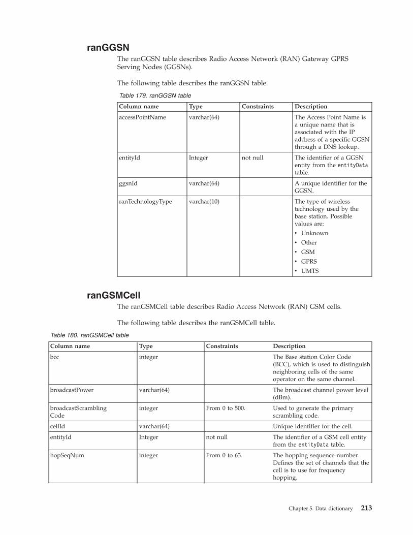
ranGGSNThe ranGGSN table describes Radio Access Network (RAN) Gateway GPRSServing Nodes (GGSNs).
The following table describes the ranGGSN table.
Table 179. ranGGSN table
Column name Type Constraints Description
accessPointName varchar(64) The Access Point Name isa unique name that isassociated with the IPaddress of a specific GGSNthrough a DNS lookup.
entityId Integer not null The identifier of a GGSNentity from the entityDatatable.
ggsnId varchar(64) A unique identifier for theGGSN.
ranTechnologyType varchar(10) The type of wirelesstechnology used by thebase station. Possiblevalues are:
v Unknown
v Other
v GSM
v GPRS
v UMTS
ranGSMCellThe ranGSMCell table describes Radio Access Network (RAN) GSM cells.
The following table describes the ranGSMCell table.
Table 180. ranGSMCell table
Column name Type Constraints Description
bcc integer The Base station Color Code(BCC), which is used to distinguishneighboring cells of the sameoperator on the same channel.
broadcastPower varchar(64) The broadcast channel power level(dBm).
broadcastScramblingCode
integer From 0 to 500. Used to generate the primaryscrambling code.
cellId varchar(64) Unique identifier for the cell.
entityId Integer not null The identifier of a GSM cell entityfrom the entityData table.
hopSeqNum integer From 0 to 63. The hopping sequence number.Defines the set of channels that thecell is to use for frequencyhopping.
Chapter 5. Data dictionary 213
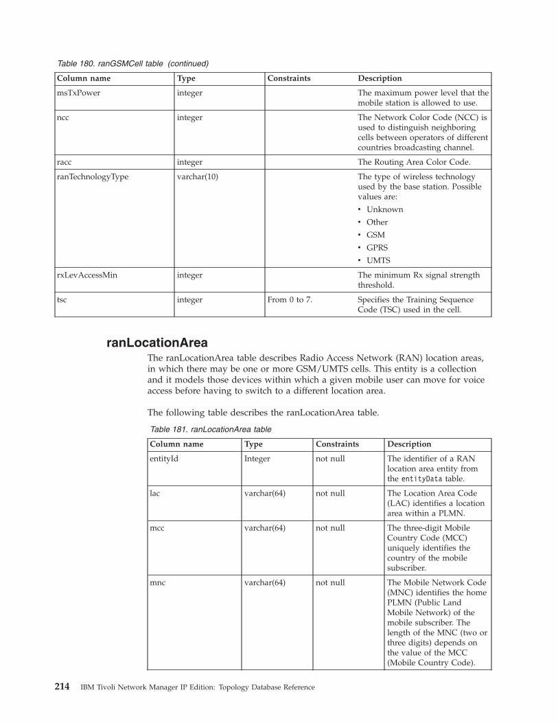
Table 180. ranGSMCell table (continued)
Column name Type Constraints Description
msTxPower integer The maximum power level that themobile station is allowed to use.
ncc integer The Network Color Code (NCC) isused to distinguish neighboringcells between operators of differentcountries broadcasting channel.
racc integer The Routing Area Color Code.
ranTechnologyType varchar(10) The type of wireless technologyused by the base station. Possiblevalues are:
v Unknown
v Other
v GSM
v GPRS
v UMTS
rxLevAccessMin integer The minimum Rx signal strengththreshold.
tsc integer From 0 to 7. Specifies the Training SequenceCode (TSC) used in the cell.
ranLocationAreaThe ranLocationArea table describes Radio Access Network (RAN) location areas,in which there may be one or more GSM/UMTS cells. This entity is a collectionand it models those devices within which a given mobile user can move for voiceaccess before having to switch to a different location area.
The following table describes the ranLocationArea table.
Table 181. ranLocationArea table
Column name Type Constraints Description
entityId Integer not null The identifier of a RANlocation area entity fromthe entityData table.
lac varchar(64) not null The Location Area Code(LAC) identifies a locationarea within a PLMN.
mcc varchar(64) not null The three-digit MobileCountry Code (MCC)uniquely identifies thecountry of the mobilesubscriber.
mnc varchar(64) not null The Mobile Network Code(MNC) identifies the homePLMN (Public LandMobile Network) of themobile subscriber. Thelength of the MNC (two orthree digits) depends onthe value of the MCC(Mobile Country Code).
214 IBM Tivoli Network Manager IP Edition: Topology Database Reference

ranMediaGatewayThe ranMediaGateway table describes Radio Access Network (RAN) mediagateways.
The following table describes the ranMediaGateway table.
Table 182. ranMediaGateway table
Column name Type Constraints Description
entityId Integer not null The identifier of a mediagateway entity from theentityData table.
mgwId varchar(64) Unique identifier for themedia gateway.
ranMobileSwitchingCentreThe ranMobileSwitchingCentre table describes Radio Access Network (RAN)Mobile Switching Centers.
The following table describes the ranMobileSwitchingCentre table.
Table 183. ranMobileSwitchingCentre table
Column name Type Constraints Description
entityId Integer not null The identifier of atransceiver entity from theentityData table.
mscId varchar(64) A unique,enterprise-specificidentifier for the mobileswitching center.
mscType varchar(10) The type of the mobileswitching centers. Possiblevalues are:
v Unknown
v Other
v Voice Switch
v MSCS
v Type2G3G
ranTechnologyType varchar(10) The type of wirelesstechnology used by thebase station. Possiblevalues are:
v Unknown
v Other
v GSM
v GPRS
v UMTS
Chapter 5. Data dictionary 215

ranMSSThe ranMSS table describes Radio Access Network (RAN) mobile switching centerservers.
The following table describes the ranMSS table.
Table 184. ranMSS table
Column name Type Constraints Description
entityId Integer not null The identifier of a mobileswitching center serverentity from the entityDatatable.
mssId varchar(64) Unique identifier for theMMS.
ranNodeBThe ranNodeB table describes Node B entities.
The following table describes the ranNodeB table.
Table 185. ranNodeB table
Column name Type Constraints Description
entityId Integer not null The identifier of a Node Bentity from the entityDatatable.
ranTechnologyType varchar(10) The wireless technologytype for this entity, whichcan take any of thefollowing values:
v 0: Unknown
v 1: Other
v 2: GSM
v 3: GPRS
v 4: UMTS
nodeBId varchar(64) not null Node B entity identifierstring
ranNodeBLocalCellThe ranNodeBLocalCell table models the local Node B identifier. This identifier isrelated to local hardware that is available to manage a given cell.
The following table describes the ranNodeBLocalCell table.
Table 186. ranNodeBLocalCell table
Column name Type Constraints Description
entityId Integer not null The identifier of a Node Blocal cell entity from theentityData table.
216 IBM Tivoli Network Manager IP Edition: Topology Database Reference
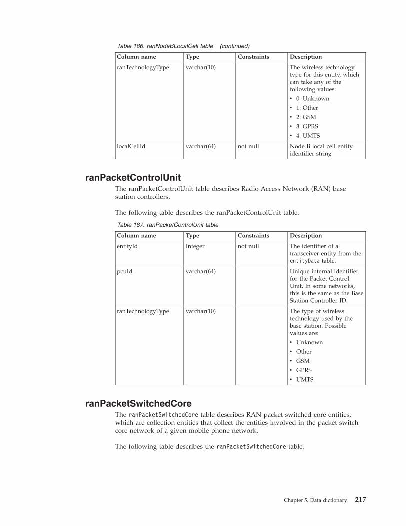
Table 186. ranNodeBLocalCell table (continued)
Column name Type Constraints Description
ranTechnologyType varchar(10) The wireless technologytype for this entity, whichcan take any of thefollowing values:
v 0: Unknown
v 1: Other
v 2: GSM
v 3: GPRS
v 4: UMTS
localCellId varchar(64) not null Node B local cell entityidentifier string
ranPacketControlUnitThe ranPacketControlUnit table describes Radio Access Network (RAN) basestation controllers.
The following table describes the ranPacketControlUnit table.
Table 187. ranPacketControlUnit table
Column name Type Constraints Description
entityId Integer not null The identifier of atransceiver entity from theentityData table.
pcuId varchar(64) Unique internal identifierfor the Packet ControlUnit. In some networks,this is the same as the BaseStation Controller ID.
ranTechnologyType varchar(10) The type of wirelesstechnology used by thebase station. Possiblevalues are:
v Unknown
v Other
v GSM
v GPRS
v UMTS
ranPacketSwitchedCoreThe ranPacketSwitchedCore table describes RAN packet switched core entities,which are collection entities that collect the entities involved in the packet switchcore network of a given mobile phone network.
The following table describes the ranPacketSwitchedCore table.
Chapter 5. Data dictionary 217
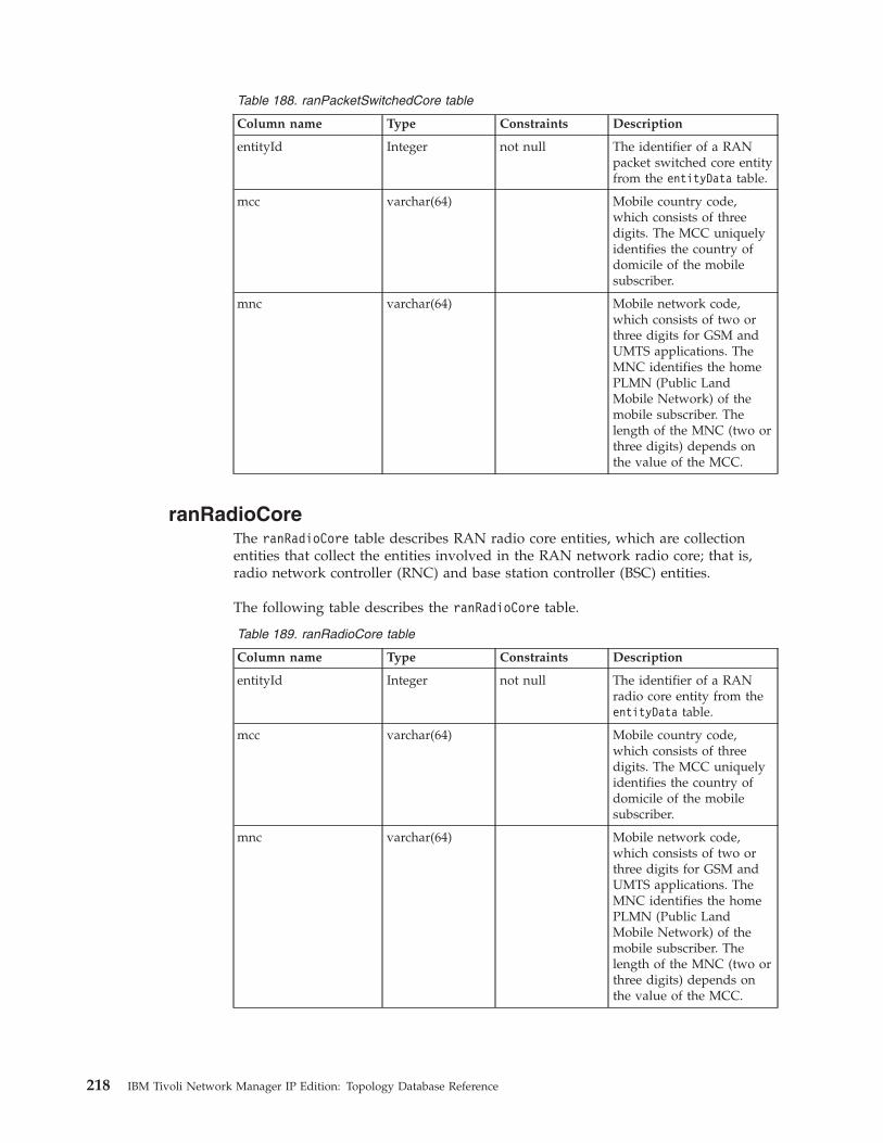
Table 188. ranPacketSwitchedCore table
Column name Type Constraints Description
entityId Integer not null The identifier of a RANpacket switched core entityfrom the entityData table.
mcc varchar(64) Mobile country code,which consists of threedigits. The MCC uniquelyidentifies the country ofdomicile of the mobilesubscriber.
mnc varchar(64) Mobile network code,which consists of two orthree digits for GSM andUMTS applications. TheMNC identifies the homePLMN (Public LandMobile Network) of themobile subscriber. Thelength of the MNC (two orthree digits) depends onthe value of the MCC.
ranRadioCoreThe ranRadioCore table describes RAN radio core entities, which are collectionentities that collect the entities involved in the RAN network radio core; that is,radio network controller (RNC) and base station controller (BSC) entities.
The following table describes the ranRadioCore table.
Table 189. ranRadioCore table
Column name Type Constraints Description
entityId Integer not null The identifier of a RANradio core entity from theentityData table.
mcc varchar(64) Mobile country code,which consists of threedigits. The MCC uniquelyidentifies the country ofdomicile of the mobilesubscriber.
mnc varchar(64) Mobile network code,which consists of two orthree digits for GSM andUMTS applications. TheMNC identifies the homePLMN (Public LandMobile Network) of themobile subscriber. Thelength of the MNC (two orthree digits) depends onthe value of the MCC.
218 IBM Tivoli Network Manager IP Edition: Topology Database Reference
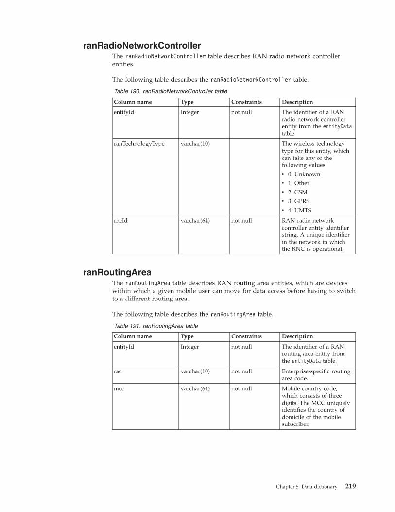
ranRadioNetworkControllerThe ranRadioNetworkController table describes RAN radio network controllerentities.
The following table describes the ranRadioNetworkController table.
Table 190. ranRadioNetworkController table
Column name Type Constraints Description
entityId Integer not null The identifier of a RANradio network controllerentity from the entityDatatable.
ranTechnologyType varchar(10) The wireless technologytype for this entity, whichcan take any of thefollowing values:
v 0: Unknown
v 1: Other
v 2: GSM
v 3: GPRS
v 4: UMTS
rncId varchar(64) not null RAN radio networkcontroller entity identifierstring. A unique identifierin the network in whichthe RNC is operational.
ranRoutingAreaThe ranRoutingArea table describes RAN routing area entities, which are deviceswithin which a given mobile user can move for data access before having to switchto a different routing area.
The following table describes the ranRoutingArea table.
Table 191. ranRoutingArea table
Column name Type Constraints Description
entityId Integer not null The identifier of a RANrouting area entity fromthe entityData table.
rac varchar(10) not null Enterprise-specific routingarea code.
mcc varchar(64) not null Mobile country code,which consists of threedigits. The MCC uniquelyidentifies the country ofdomicile of the mobilesubscriber.
Chapter 5. Data dictionary 219
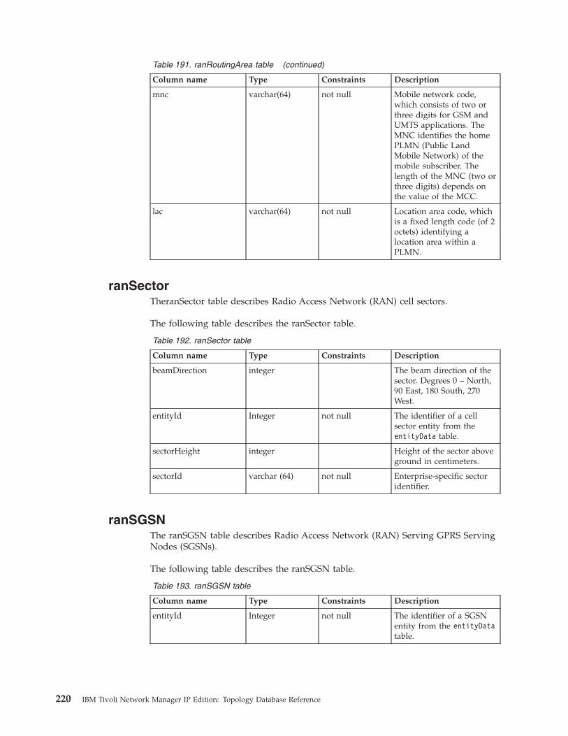
Table 191. ranRoutingArea table (continued)
Column name Type Constraints Description
mnc varchar(64) not null Mobile network code,which consists of two orthree digits for GSM andUMTS applications. TheMNC identifies the homePLMN (Public LandMobile Network) of themobile subscriber. Thelength of the MNC (two orthree digits) depends onthe value of the MCC.
lac varchar(64) not null Location area code, whichis a fixed length code (of 2octets) identifying alocation area within aPLMN.
ranSectorTheranSector table describes Radio Access Network (RAN) cell sectors.
The following table describes the ranSector table.
Table 192. ranSector table
Column name Type Constraints Description
beamDirection integer The beam direction of thesector. Degrees 0 – North,90 East, 180 South, 270West.
entityId Integer not null The identifier of a cellsector entity from theentityData table.
sectorHeight integer Height of the sector aboveground in centimeters.
sectorId varchar (64) not null Enterprise-specific sectoridentifier.
ranSGSNThe ranSGSN table describes Radio Access Network (RAN) Serving GPRS ServingNodes (SGSNs).
The following table describes the ranSGSN table.
Table 193. ranSGSN table
Column name Type Constraints Description
entityId Integer not null The identifier of a SGSNentity from the entityDatatable.
220 IBM Tivoli Network Manager IP Edition: Topology Database Reference
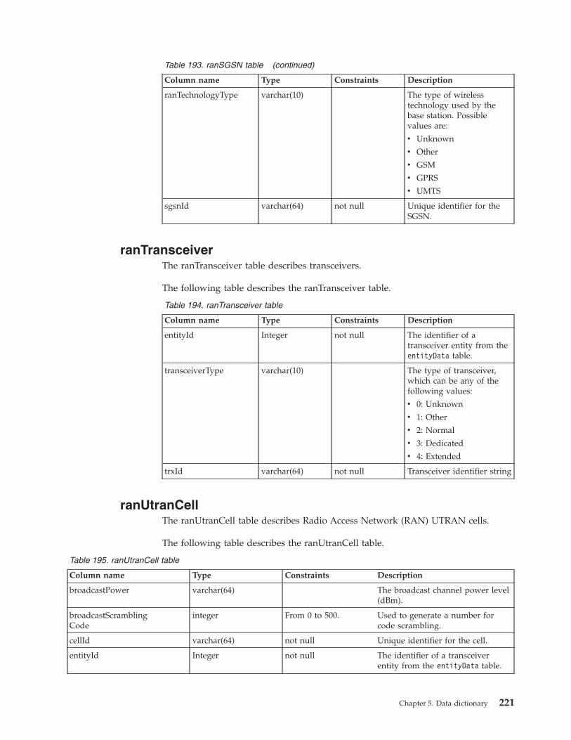
Table 193. ranSGSN table (continued)
Column name Type Constraints Description
ranTechnologyType varchar(10) The type of wirelesstechnology used by thebase station. Possiblevalues are:
v Unknown
v Other
v GSM
v GPRS
v UMTS
sgsnId varchar(64) not null Unique identifier for theSGSN.
ranTransceiverThe ranTransceiver table describes transceivers.
The following table describes the ranTransceiver table.
Table 194. ranTransceiver table
Column name Type Constraints Description
entityId Integer not null The identifier of atransceiver entity from theentityData table.
transceiverType varchar(10) The type of transceiver,which can be any of thefollowing values:
v 0: Unknown
v 1: Other
v 2: Normal
v 3: Dedicated
v 4: Extended
trxId varchar(64) not null Transceiver identifier string
ranUtranCellThe ranUtranCell table describes Radio Access Network (RAN) UTRAN cells.
The following table describes the ranUtranCell table.
Table 195. ranUtranCell table
Column name Type Constraints Description
broadcastPower varchar(64) The broadcast channel power level(dBm).
broadcastScramblingCode
integer From 0 to 500. Used to generate a number forcode scrambling.
cellId varchar(64) not null Unique identifier for the cell.
entityId Integer not null The identifier of a transceiverentity from the entityData table.
Chapter 5. Data dictionary 221
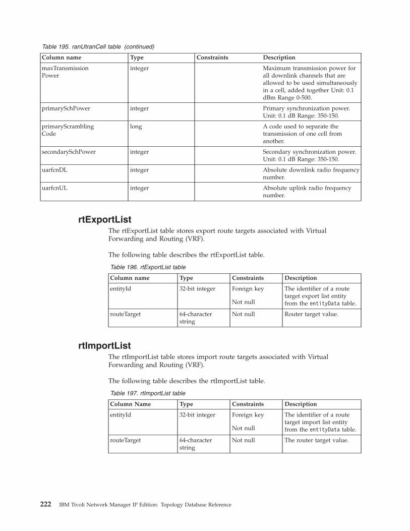
Table 195. ranUtranCell table (continued)
Column name Type Constraints Description
maxTransmissionPower
integer Maximum transmission power forall downlink channels that areallowed to be used simultaneouslyin a cell, added together Unit: 0.1dBm Range 0-500.
primarySchPower integer Primary synchronization power.Unit: 0.1 dB Range: 350-150.
primaryScramblingCode
long A code used to separate thetransmission of one cell fromanother.
secondarySchPower integer Secondary synchronization power.Unit: 0.1 dB Range: 350-150.
uarfcnDL integer Absolute downlink radio frequencynumber.
uarfcnUL integer Absolute uplink radio frequencynumber.
rtExportListThe rtExportList table stores export route targets associated with VirtualForwarding and Routing (VRF).
The following table describes the rtExportList table.
Table 196. rtExportList table
Column name Type Constraints Description
entityId 32-bit integer Foreign key
Not null
The identifier of a routetarget export list entityfrom the entityData table.
routeTarget 64-characterstring
Not null Router target value.
rtImportListThe rtImportList table stores import route targets associated with VirtualForwarding and Routing (VRF).
The following table describes the rtImportList table.
Table 197. rtImportList table
Column Name Type Constraints Description
entityId 32-bit integer Foreign key
Not null
The identifier of a routetarget import list entityfrom the entityData table.
routeTarget 64-characterstring
Not null The router target value.
222 IBM Tivoli Network Manager IP Edition: Topology Database Reference

snmpSystemThe snmpSystem table represents a Simple Network Management Protocol (SNMP)managed host on a network.
The following table describes the snmpSystem table.
Table 198. snmpSystem table
Column name Type Constraints Description
entityId Integer not null The identifier of ansnmpSystem entity fromthe entityData table.
sysContact 255-characterstring
The textual identificationof the contact person forthis managed node, andinformation on how tocontact this person. If nocontact information isknown, the value is thezero-length string.
sysDescr 255-characterstring
A textual description of theentity. This value mustinclude the full name andversion identification of thesystem hardware type,software operating-system,and networking software.
sysLocation 255-characterstring
The physical location ofthis node, for example“telephone closet, 3rdfloor.” If the location isunknown, the value is thezero-length string.
sysName 255-characterstring
An administratively-assigned name for thismanaged node. Byconvention, this is thefully-qualified domainname of the node. If thename is unknown, thevalue is the zero-lengthstring.
sysObjectId 100-characterstring
The vendor's authoritativeidentification of thenetwork managementsubsystem contained in theentity.
Chapter 5. Data dictionary 223
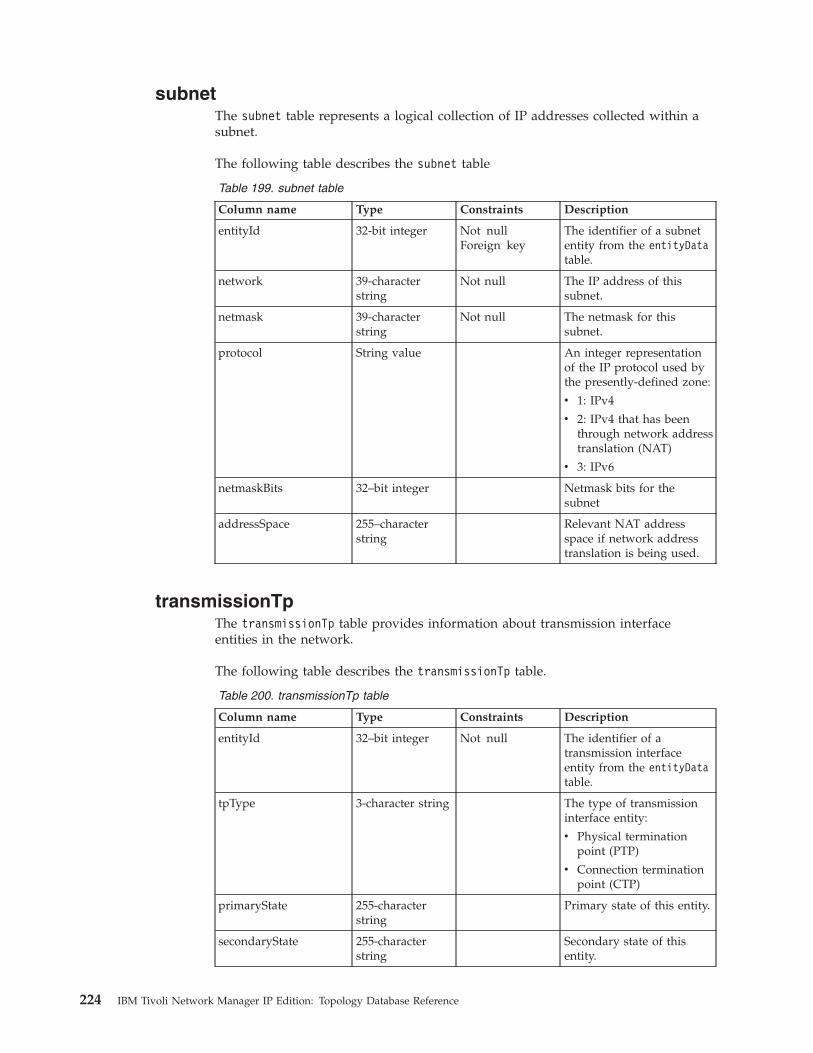
subnetThe subnet table represents a logical collection of IP addresses collected within asubnet.
The following table describes the subnet table
Table 199. subnet table
Column name Type Constraints Description
entityId 32-bit integer Not nullForeign key
The identifier of a subnetentity from the entityDatatable.
network 39-characterstring
Not null The IP address of thissubnet.
netmask 39-characterstring
Not null The netmask for thissubnet.
protocol String value An integer representationof the IP protocol used bythe presently-defined zone:
v 1: IPv4
v 2: IPv4 that has beenthrough network addresstranslation (NAT)
v 3: IPv6
netmaskBits 32–bit integer Netmask bits for thesubnet
addressSpace 255–characterstring
Relevant NAT addressspace if network addresstranslation is being used.
transmissionTpThe transmissionTp table provides information about transmission interfaceentities in the network.
The following table describes the transmissionTp table.
Table 200. transmissionTp table
Column name Type Constraints Description
entityId 32–bit integer Not null The identifier of atransmission interfaceentity from the entityDatatable.
tpType 3-character string The type of transmissioninterface entity:
v Physical terminationpoint (PTP)
v Connection terminationpoint (CTP)
primaryState 255-characterstring
Primary state of this entity.
secondaryState 255-characterstring
Secondary state of thisentity.
224 IBM Tivoli Network Manager IP Edition: Topology Database Reference
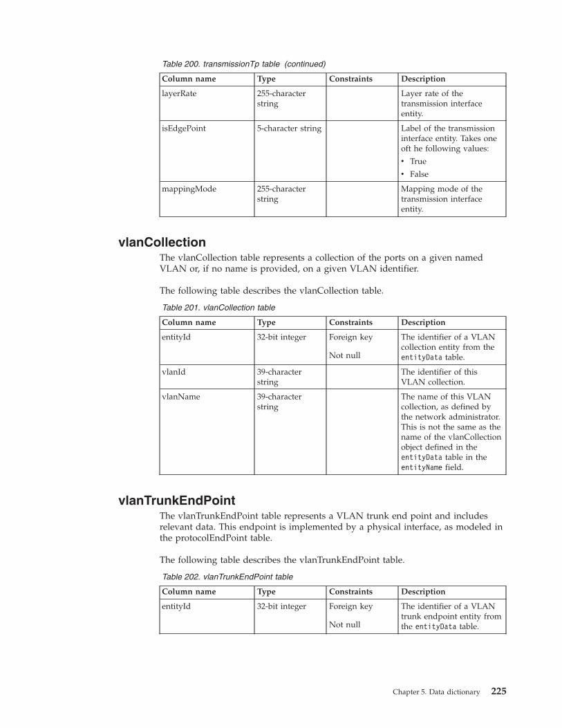
Table 200. transmissionTp table (continued)
Column name Type Constraints Description
layerRate 255-characterstring
Layer rate of thetransmission interfaceentity.
isEdgePoint 5-character string Label of the transmissioninterface entity. Takes oneoft he following values:
v True
v False
mappingMode 255-characterstring
Mapping mode of thetransmission interfaceentity.
vlanCollectionThe vlanCollection table represents a collection of the ports on a given namedVLAN or, if no name is provided, on a given VLAN identifier.
The following table describes the vlanCollection table.
Table 201. vlanCollection table
Column name Type Constraints Description
entityId 32-bit integer Foreign key
Not null
The identifier of a VLANcollection entity from theentityData table.
vlanId 39-characterstring
The identifier of thisVLAN collection.
vlanName 39-characterstring
The name of this VLANcollection, as defined bythe network administrator.This is not the same as thename of the vlanCollectionobject defined in theentityData table in theentityName field.
vlanTrunkEndPointThe vlanTrunkEndPoint table represents a VLAN trunk end point and includesrelevant data. This endpoint is implemented by a physical interface, as modeled inthe protocolEndPoint table.
The following table describes the vlanTrunkEndPoint table.
Table 202. vlanTrunkEndPoint table
Column name Type Constraints Description
entityId 32-bit integer Foreign key
Not null
The identifier of a VLANtrunk endpoint entity fromthe entityData table.
Chapter 5. Data dictionary 225

Table 202. vlanTrunkEndPoint table (continued)
Column name Type Constraints Description
vlanClass Enumerated The class of the VLAN.Possible values are: cvlan(Customer VLAN usingQinQ), svlan (ServiceVLAN using QinQ), orlocal (VLAN not usingQinQ).
vlanId 32-bit integer The identifier for theVLAN carried by thisprotocol end point object.If multiple VLANs arecarried by the trunk then avlanTrunkEndPoint entityshould be created for eachone.
vlanTag 32-bit integer The tag used for thisVLAN. In Cisco devices,this tag is usually the sameas the vlanId value.However, for othermanufacturers, the tagmight be different.
Related reference:“protocolEndPoint” on page 133The protocolEndPoint table allows a higher-level connection to be defined in termsof lower-level connections. It associates a device entity, usually an interface, withprotocol-specific information associated with that device entity. TheprotocolEndPoint table belongs to the category connectivity.
vpnRouteForwardingThe vpnRouteForwarding table models a VPN routing and forwarding table.
The following table describes the vpnRouteForwarding table.
Table 203. vpnRouteForwarding table
Column name Type Constraints Description
entityId 32-bit integer Foreign key
Not null
The identifier of a VPNRouting and Forwardingtable entity from theentityData table.
VRFName 255-characterstring
The name of the VPNRouting and Forwardingtable.
routeDistinguisher 255-characterstring
Not null The route distinguisher forthe VPN Routing andForwarding table.
226 IBM Tivoli Network Manager IP Edition: Topology Database Reference
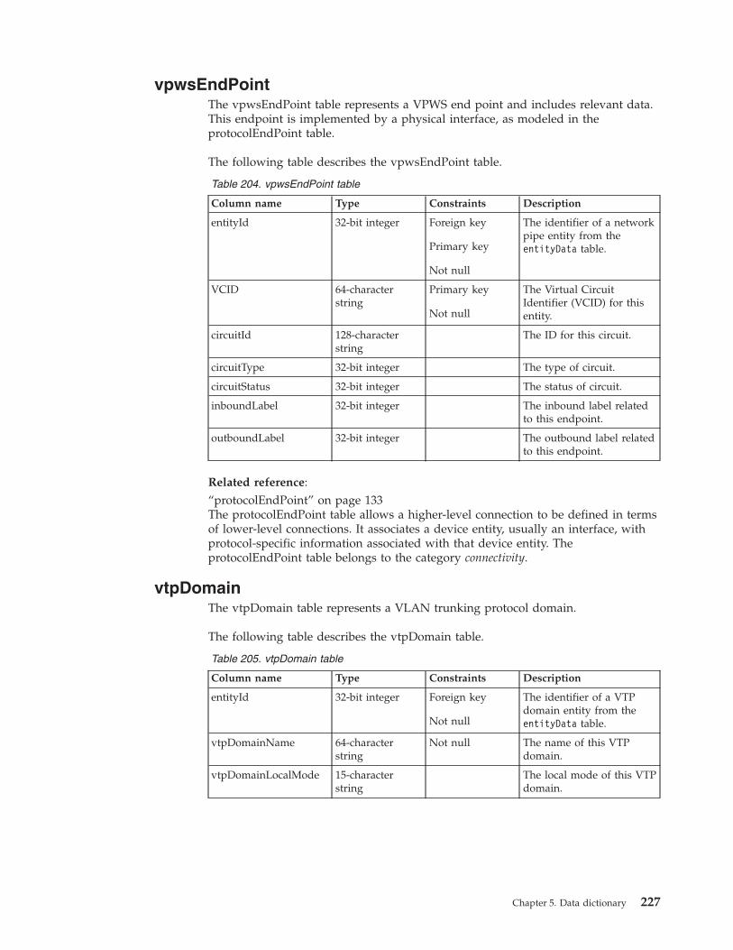
vpwsEndPointThe vpwsEndPoint table represents a VPWS end point and includes relevant data.This endpoint is implemented by a physical interface, as modeled in theprotocolEndPoint table.
The following table describes the vpwsEndPoint table.
Table 204. vpwsEndPoint table
Column name Type Constraints Description
entityId 32-bit integer Foreign key
Primary key
Not null
The identifier of a networkpipe entity from theentityData table.
VCID 64-characterstring
Primary key
Not null
The Virtual CircuitIdentifier (VCID) for thisentity.
circuitId 128-characterstring
The ID for this circuit.
circuitType 32-bit integer The type of circuit.
circuitStatus 32-bit integer The status of circuit.
inboundLabel 32-bit integer The inbound label relatedto this endpoint.
outboundLabel 32-bit integer The outbound label relatedto this endpoint.
Related reference:“protocolEndPoint” on page 133The protocolEndPoint table allows a higher-level connection to be defined in termsof lower-level connections. It associates a device entity, usually an interface, withprotocol-specific information associated with that device entity. TheprotocolEndPoint table belongs to the category connectivity.
vtpDomainThe vtpDomain table represents a VLAN trunking protocol domain.
The following table describes the vtpDomain table.
Table 205. vtpDomain table
Column name Type Constraints Description
entityId 32-bit integer Foreign key
Not null
The identifier of a VTPdomain entity from theentityData table.
vtpDomainName 64-characterstring
Not null The name of this VTPdomain.
vtpDomainLocalMode 15-characterstring
The local mode of this VTPdomain.
Chapter 5. Data dictionary 227
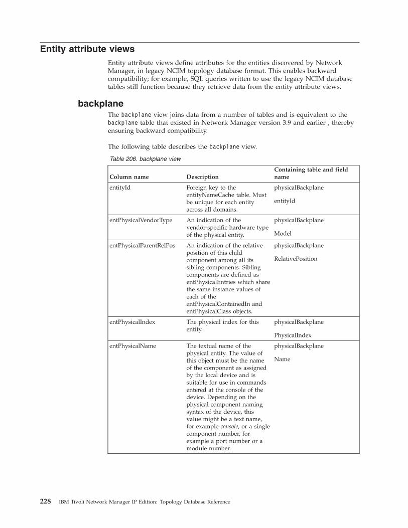
Entity attribute viewsEntity attribute views define attributes for the entities discovered by NetworkManager, in legacy NCIM topology database format. This enables backwardcompatibility; for example, SQL queries written to use the legacy NCIM databasetables still function because they retrieve data from the entity attribute views.
backplaneThe backplane view joins data from a number of tables and is equivalent to thebackplane table that existed in Network Manager version 3.9 and earlier , therebyensuring backward compatibility.
The following table describes the backplane view.
Table 206. backplane view
Column name DescriptionContaining table and fieldname
entityId Foreign key to theentityNameCache table. Mustbe unique for each entityacross all domains.
physicalBackplane
entityId
entPhysicalVendorType An indication of thevendor-specific hardware typeof the physical entity.
physicalBackplane
Model
entPhysicalParentRelPos An indication of the relativeposition of this childcomponent among all itssibling components. Siblingcomponents are defined asentPhysicalEntries which sharethe same instance values ofeach of theentPhysicalContainedIn andentPhysicalClass objects.
physicalBackplane
RelativePosition
entPhysicalIndex The physical index for thisentity.
physicalBackplane
PhysicalIndex
entPhysicalName The textual name of thephysical entity. The value ofthis object must be the nameof the component as assignedby the local device and issuitable for use in commandsentered at the console of thedevice. Depending on thephysical component namingsyntax of the device, thisvalue might be a text name,for example console, or a singlecomponent number, forexample a port number or amodule number.
physicalBackplane
Name
228 IBM Tivoli Network Manager IP Edition: Topology Database Reference

Table 206. backplane view (continued)
Column name DescriptionContaining table and fieldname
entPhysicalDescr A textual description ofphysical entity. This objectmust contain a string whichidentifies the manufacturer'sname for the physical entity.The value must be set to adistinct value for each versionor model of the physicalentity.
entityData
Description
chassisThe chassis view joins data a number of tables, and is equivalent to the chassistable that existed in Network Manager versions 3.9 and earlier, thereby ensuringbackward compatibility.
The following table describes the chassis view.
Table 207. chassis view
Column name DescriptionContaining table and fieldname
entityId Foreign key to theentityNameCache table. Mustbe unique for each entityacross all domains.
physicalChassis
entityId
className The name of a class ofdevices. The masterclassName field is in theentityClass table.
physicalChassis
className
sysName An administratively-assignedname for this managed node.By convention, this is thefully-qualified domain nameof the node. If the name isunknown, the value is thezero-length string.
physicalChassis
sysName
sysDescr A textual description of theentity. This value must includethe full name and versionidentification of the systemhardware type, softwareoperating-system, andnetworking software.
entityData
Description
sysObjectId The vendor's authoritativeidentification of the networkmanagement subsystemcontained in the entity.
physicalChassis
sysObjectId
sysLocation The physical location of thisnode, for example “telephonecloset, 3rd floor.” If thelocation is unknown, the valueis the zero-length string.
physicalChassis
Location
Chapter 5. Data dictionary 229
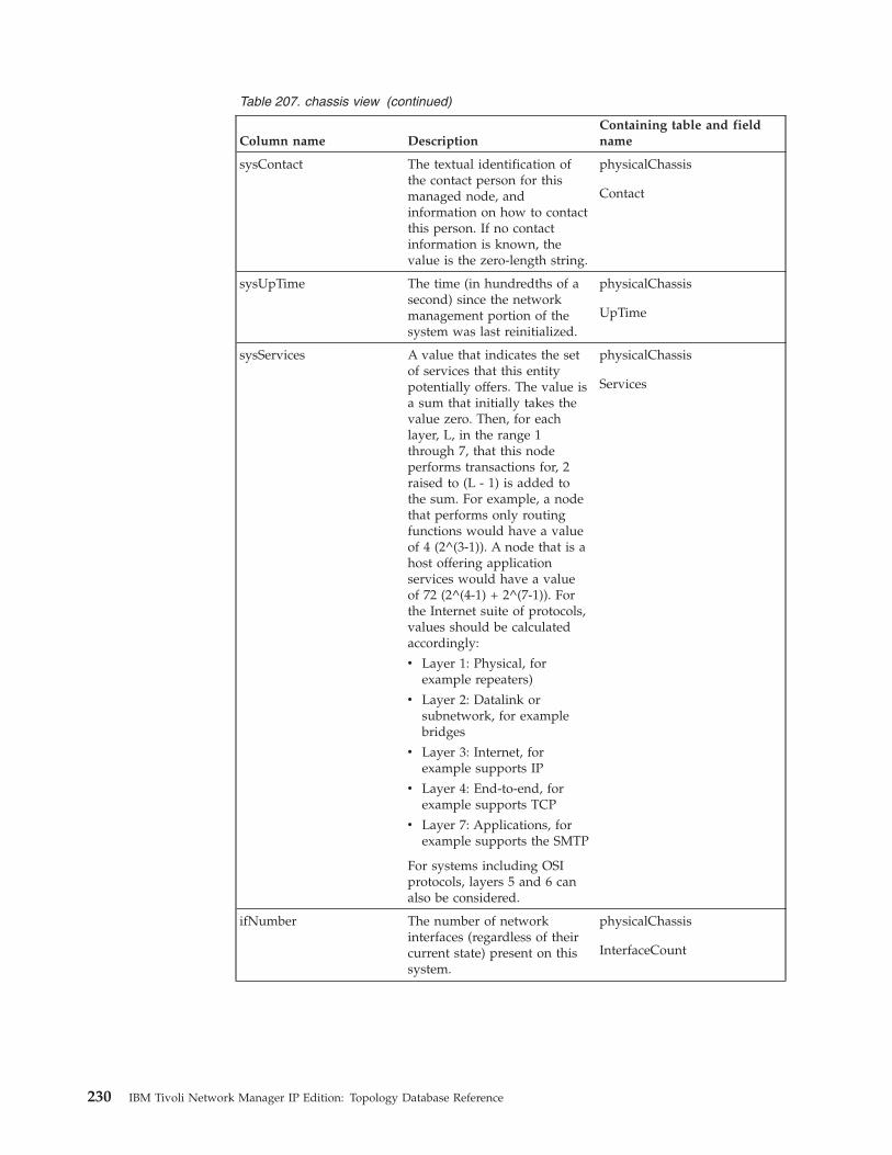
Table 207. chassis view (continued)
Column name DescriptionContaining table and fieldname
sysContact The textual identification ofthe contact person for thismanaged node, andinformation on how to contactthis person. If no contactinformation is known, thevalue is the zero-length string.
physicalChassis
Contact
sysUpTime The time (in hundredths of asecond) since the networkmanagement portion of thesystem was last reinitialized.
physicalChassis
UpTime
sysServices A value that indicates the setof services that this entitypotentially offers. The value isa sum that initially takes thevalue zero. Then, for eachlayer, L, in the range 1through 7, that this nodeperforms transactions for, 2raised to (L - 1) is added tothe sum. For example, a nodethat performs only routingfunctions would have a valueof 4 (2^(3-1)). A node that is ahost offering applicationservices would have a valueof 72 (2^(4-1) + 2^(7-1)). Forthe Internet suite of protocols,values should be calculatedaccordingly:
v Layer 1: Physical, forexample repeaters)
v Layer 2: Datalink orsubnetwork, for examplebridges
v Layer 3: Internet, forexample supports IP
v Layer 4: End-to-end, forexample supports TCP
v Layer 7: Applications, forexample supports the SMTP
For systems including OSIprotocols, layers 5 and 6 canalso be considered.
physicalChassis
Services
ifNumber The number of networkinterfaces (regardless of theircurrent state) present on thissystem.
physicalChassis
InterfaceCount
230 IBM Tivoli Network Manager IP Edition: Topology Database Reference

Table 207. chassis view (continued)
Column name DescriptionContaining table and fieldname
ipForwarding Indication of whether thisentity is acting as an IPgateway in respect to theforwarding of datagramsreceived by this entity but notaddressed to this entity. IPgateways forward datagrams,whereas IP hosts do not,unless the source is routedthrough the host. Takes one ofthe following values:
v forwarding
v not-forwarding
physicalChassis
isIpForwarding
entPhysicalVendorType An indication of thevendor-specific hardware typeof the physical entity.
physicalChassis
Model
entPhysicalParentRelPos An indication of the relativeposition of this childcomponent among all itssibling components. Siblingcomponents are defined asentPhysicalEntries which sharethe same instance values ofeach of theentPhysicalContainedIn andentPhysicalClass objects.
physicalChassis
RelativePosition
entPhysicalIndex The physical index for thisentity.
physicalChassis
physicalIndex
entPhysicalName The textual name of thephysical entity. The value ofthis object must be the nameof the component as assignedby the local device and issuitable for use in commandsentered at the console of thedevice. Depending on thephysical component namingsyntax of the device, thisvalue might be a text name,for example console, or a singlecomponent number, forexample a port number or amodule number.
physicalChassis
Name
entPhysicalDescr A textual description ofphysical entity. This objectmust contain a string whichidentifies the manufacturer'sname for the physical entity.The value must be set to adistinct value for each versionor model of the physicalentity.
entityData
Description
Chapter 5. Data dictionary 231
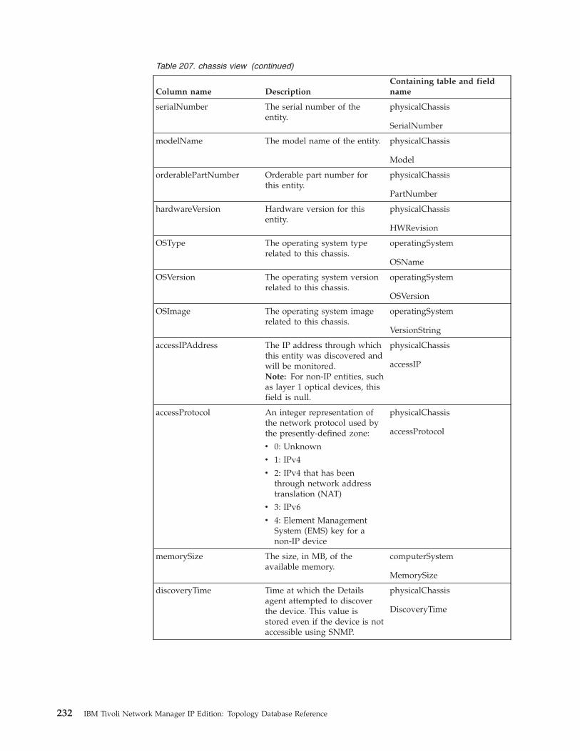
Table 207. chassis view (continued)
Column name DescriptionContaining table and fieldname
serialNumber The serial number of theentity.
physicalChassis
SerialNumber
modelName The model name of the entity. physicalChassis
Model
orderablePartNumber Orderable part number forthis entity.
physicalChassis
PartNumber
hardwareVersion Hardware version for thisentity.
physicalChassis
HWRevision
OSType The operating system typerelated to this chassis.
operatingSystem
OSName
OSVersion The operating system versionrelated to this chassis.
operatingSystem
OSVersion
OSImage The operating system imagerelated to this chassis.
operatingSystem
VersionString
accessIPAddress The IP address through whichthis entity was discovered andwill be monitored.Note: For non-IP entities, suchas layer 1 optical devices, thisfield is null.
physicalChassis
accessIP
accessProtocol An integer representation ofthe network protocol used bythe presently-defined zone:
v 0: Unknown
v 1: IPv4
v 2: IPv4 that has beenthrough network addresstranslation (NAT)
v 3: IPv6
v 4: Element ManagementSystem (EMS) key for anon-IP device
physicalChassis
accessProtocol
memorySize The size, in MB, of theavailable memory.
computerSystem
MemorySize
discoveryTime Time at which the Detailsagent attempted to discoverthe device. This value isstored even if the device is notaccessible using SNMP.
physicalChassis
DiscoveryTime
232 IBM Tivoli Network Manager IP Edition: Topology Database Reference

Related reference:“entityData” on page 120The entityData table stores data on entities. This table belongs to the categoryentities.“physicalChassis” on page 195The physicalChassis table stores the attributes of chassis entities.
fanThe fan view joins data from a number of tables and is equivalent to the fan tablethat existed in Network Manager versions 3.9 and earlier , thereby ensuringbackward compatibility.
The following table describes the fan view.
Table 208. fan view
Column name DescriptionContaining table and fieldname
entityId Foreign key to theentityNameCache table. Mustbe unique for each entityacross all domains.
entityData
entityId
entPhysicalVendorType An indication of thevendor-specific hardware typeof the physical entity.
physicalFan
Model
entPhysicalParentRelPos An indication of the relativeposition of this childcomponent among all itssibling components. Siblingcomponents are defined asentPhysicalEntries which sharethe same instance values ofeach of theentPhysicalContainedIn andentPhysicalClass objects.
physicalFan
RelativePosition
entPhysicalIndex The physical index for thisentity.
physicalFan
physicalIndex
entPhysicalName The textual name of thephysical entity. The value ofthis object must be the nameof the component as assignedby the local device and issuitable for use in commandsentered at the console of thedevice. Depending on thephysical component namingsyntax of the device, thisvalue might be a text name,for example console, or a singlecomponent number, forexample a port number or amodule number.
physicalFan
Name
Chapter 5. Data dictionary 233

Table 208. fan view (continued)
Column name DescriptionContaining table and fieldname
entPhysicalDescr A textual description of theentity. This value must includethe full name and versionidentification of the systemhardware type, softwareoperating-system, andnetworking software.
entityData
Description
serialNumber The serial number of theentity.
physicalFan
SerialNumber
modelName Model name for this entity. physicalFan
Model
isFieldReplaceable Indication of whether thispiece of equipment isreplaceable in the field. Takesone of the following values:
v True
v False
physicalFan
isFRU
Related reference:“entityData” on page 120The entityData table stores data on entities. This table belongs to the categoryentities.“physicalFan” on page 199The physicalFan table represents fan cooling unit entities.
interfaceThe interface view joins data from a number of tables and is equivalent to theinterface table that existed in Network Manager version 3.9 and earlier , therebyensuring backward compatibility.
The following table describes the interface view.
Table 209. interface view
Column name DescriptionContaining table and fieldname
entityId Foreign key to theentityNameCache table. Mustbe unique for each entityacross all domains.
networkInterface
entityData
ifIndex The index of the interface. networkInterface
SNMPIndex
ifPhysAddress The physical address of theinterface.
networkInterface
PhysicalAddress
ifName The name assigned to theinterface.
networkInterface
ifName
234 IBM Tivoli Network Manager IP Edition: Topology Database Reference
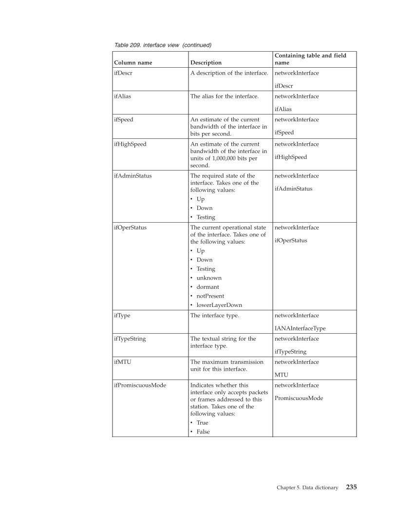
Table 209. interface view (continued)
Column name DescriptionContaining table and fieldname
ifDescr A description of the interface. networkInterface
ifDescr
ifAlias The alias for the interface. networkInterface
ifAlias
ifSpeed An estimate of the currentbandwidth of the interface inbits per second.
networkInterface
ifSpeed
ifHighSpeed An estimate of the currentbandwidth of the interface inunits of 1,000,000 bits persecond.
networkInterface
ifHighSpeed
ifAdminStatus The required state of theinterface. Takes one of thefollowing values:
v Up
v Down
v Testing
networkInterface
ifAdminStatus
ifOperStatus The current operational stateof the interface. Takes one ofthe following values:
v Up
v Down
v Testing
v unknown
v dormant
v notPresent
v lowerLayerDown
networkInterface
ifOperStatus
ifType The interface type. networkInterface
IANAInterfaceType
ifTypeString The textual string for theinterface type.
networkInterface
ifTypeString
ifMTU The maximum transmissionunit for this interface.
networkInterface
MTU
ifPromiscuousMode Indicates whether thisinterface only accepts packetsor frames addressed to thisstation. Takes one of thefollowing values:
v True
v False
networkInterface
PromiscuousMode
Chapter 5. Data dictionary 235

Table 209. interface view (continued)
Column name DescriptionContaining table and fieldname
ifConnectorPresent Indicates whether theinterface has a connector.Takes one of the followingvalues:
v True
v False
networkInterface
ConnectorPresent
accessIPAddress The IP address through whichthis entity was discovered andwill be monitored.Note: For non-IP entities,such as layer 1 opticaldevices, this field is null.
networkInterface
accessIP
accessProtocol An integer representation ofthe network protocol used bythe presently-defined zone:
v 0: Unknown
v 1: IPv4
v 2: IPv4 that has beenthrough network addresstranslation (NAT)
v 3: IPv6
v 4: Element ManagementSystem (EMS) key for anon-IP device
networkInterface
accessProtocol
entPhysicalVendorType The vendor-specific hardwaretype of this physical entity.
x_cdmPhysicalConnector
Model
entPhysicalParentRelPos The relative position of thisentity within the containment.
x_cdmPhysicalConnector
RelativePosition
entPhysicalIndex The physical index for thisentity.
x_cdmPhysicalConnector
physicalIndex
entPhysicalName The textual name of thisphysical entity.
x_cdmPhysicalConnector
Name
entPhysicalDescr The textual description of thisphysical entity.
x_cdmPhysicalConnector
entPhysicalDescr
portNumber The port number for thisinterface on the chassisdevice. The method ofdetermining the port numberis dependent on the make andmodel of the device that isdiscovered. For this reason,use this value with caution.
networkInterface
portNumber
isTrunkPort Indicates whether thisphysical interface is a VLANtrunk port.
networkInterface
SwitchPortMode
236 IBM Tivoli Network Manager IP Edition: Topology Database Reference

Table 209. interface view (continued)
Column name DescriptionContaining table and fieldname
duplex Actual duplex of the interface.Takes one of the followingvalues:
v HalfDuplex
v FullDuplex
v Auto
v Unknown
v Other
networkInterface
OperationalDuplex
Related reference:“entityData” on page 120The entityData table stores data on entities. This table belongs to the categoryentities.“networkInterface” on page 180The networkInterface table represents interfaces on a chassis device.
moduleThe module view joins data from a number of tables and is equivalent to the moduletable that existed in Network Manager version 3.9 and earlier , thereby ensuringbackward compatibility.
The following table describes the module view.
Table 210. module view
Column name DescriptionContaining table and fieldname
entityId Foreign key to theentityNameCache table. Mustbe unique for each entityacross all domains.
physicalCard
entityId
entPhysicalVendorType An indication of thevendor-specific hardware typeof the physical entity.
physicalCard
Model
entPhysicalParentRelPos An indication of the relativeposition of this childcomponent among all itssibling components. Siblingcomponents are defined asentPhysicalEntries which sharethe same instance values ofeach of theentPhysicalContainedIn andentPhysicalClass objects.
physicalCard
RelativePosition
entPhysicalIndex The physical index for thisentity.
physicalCard
Physical Index
Chapter 5. Data dictionary 237
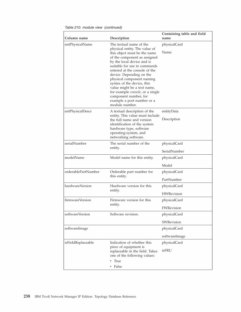
Table 210. module view (continued)
Column name DescriptionContaining table and fieldname
entPhysicalName The textual name of thephysical entity. The value ofthis object must be the nameof the component as assignedby the local device and issuitable for use in commandsentered at the console of thedevice. Depending on thephysical component namingsyntax of the device, thisvalue might be a text name,for example console, or a singlecomponent number, forexample a port number or amodule number.
physicalCard
Name
entPhysicalDescr A textual description of theentity. This value must includethe full name and versionidentification of the systemhardware type, softwareoperating-system, andnetworking software.
entityData
Description
serialNumber The serial number of theentity.
physicalCard
SerialNumber
modelName Model name for this entity. physicalCard
Model
orderablePartNumber Orderable part number forthis entity.
physicalCard
PartNumber
hardwareVersion Hardware version for thisentity.
physicalCard
HWRevision
firmwareVersion Firmware version for thisentity.
physicalCard
FWRevision
softwareVersion Software revision. physicalCard
SWRevision
softwareImage physicalCard
softwareImage
isFieldReplaceable Indication of whether thispiece of equipment isreplaceable in the field. Takesone of the following values:
v True
v False
physicalCard
isFRU
238 IBM Tivoli Network Manager IP Edition: Topology Database Reference
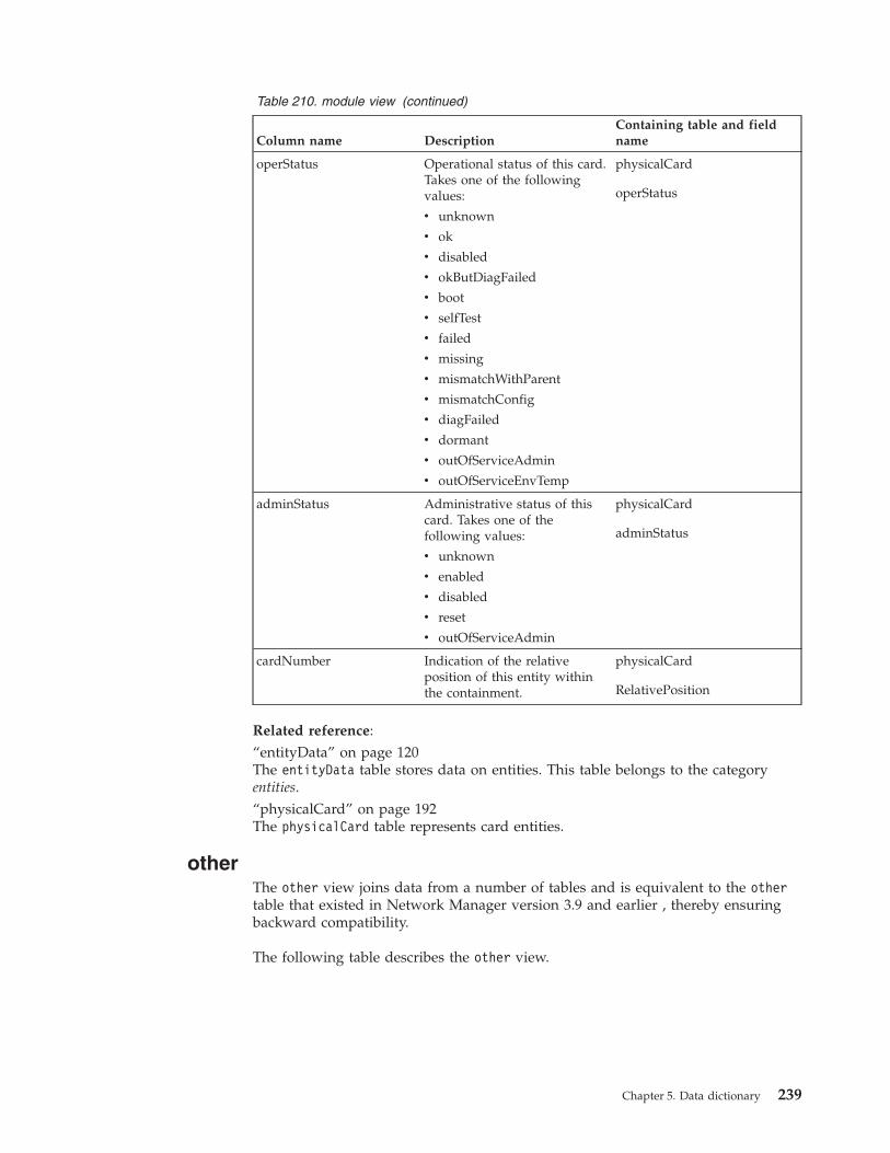
Table 210. module view (continued)
Column name DescriptionContaining table and fieldname
operStatus Operational status of this card.Takes one of the followingvalues:
v unknown
v ok
v disabled
v okButDiagFailed
v boot
v selfTest
v failed
v missing
v mismatchWithParent
v mismatchConfig
v diagFailed
v dormant
v outOfServiceAdmin
v outOfServiceEnvTemp
physicalCard
operStatus
adminStatus Administrative status of thiscard. Takes one of thefollowing values:
v unknown
v enabled
v disabled
v reset
v outOfServiceAdmin
physicalCard
adminStatus
cardNumber Indication of the relativeposition of this entity withinthe containment.
physicalCard
RelativePosition
Related reference:“entityData” on page 120The entityData table stores data on entities. This table belongs to the categoryentities.“physicalCard” on page 192The physicalCard table represents card entities.
otherThe other view joins data from a number of tables and is equivalent to the othertable that existed in Network Manager version 3.9 and earlier , thereby ensuringbackward compatibility.
The following table describes the other view.
Chapter 5. Data dictionary 239
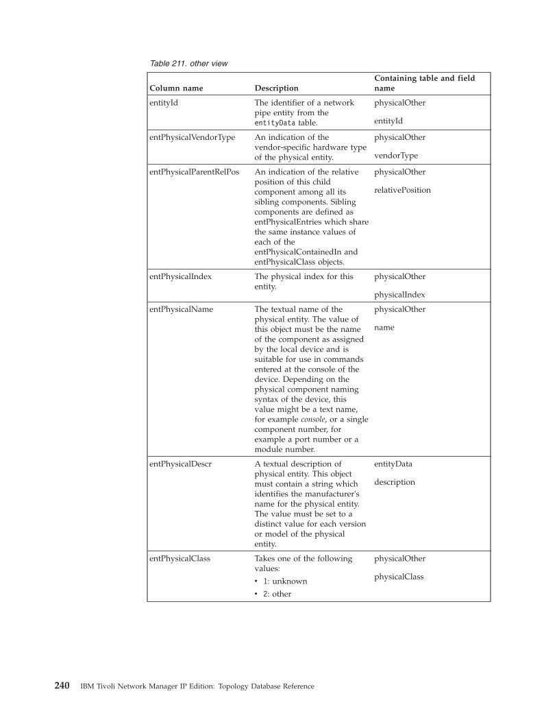
Table 211. other view
Column name DescriptionContaining table and fieldname
entityId The identifier of a networkpipe entity from theentityData table.
physicalOther
entityId
entPhysicalVendorType An indication of thevendor-specific hardware typeof the physical entity.
physicalOther
vendorType
entPhysicalParentRelPos An indication of the relativeposition of this childcomponent among all itssibling components. Siblingcomponents are defined asentPhysicalEntries which sharethe same instance values ofeach of theentPhysicalContainedIn andentPhysicalClass objects.
physicalOther
relativePosition
entPhysicalIndex The physical index for thisentity.
physicalOther
physicalIndex
entPhysicalName The textual name of thephysical entity. The value ofthis object must be the nameof the component as assignedby the local device and issuitable for use in commandsentered at the console of thedevice. Depending on thephysical component namingsyntax of the device, thisvalue might be a text name,for example console, or a singlecomponent number, forexample a port number or amodule number.
physicalOther
name
entPhysicalDescr A textual description ofphysical entity. This objectmust contain a string whichidentifies the manufacturer'sname for the physical entity.The value must be set to adistinct value for each versionor model of the physicalentity.
entityData
description
entPhysicalClass Takes one of the followingvalues:
v 1: unknown
v 2: other
physicalOther
physicalClass
240 IBM Tivoli Network Manager IP Edition: Topology Database Reference

Related reference:“entityData” on page 120The entityData table stores data on entities. This table belongs to the categoryentities.“physicalOther” on page 201The physicalOther table stores attributes of a component whose physical entityclass is known, but does not match any of the supported values.
psuThe psu view joins data from a number of tables and is equivalent to the psu tablethat existed in Network Manager version 3.9 and earlier , thereby ensuringbackward compatibility.
The following table describes the psu view.
Table 212. psu view
Column name DescriptionContaining table and fieldname
entityId Foreign key to theentityNameCache table. Mustbe unique for each entityacross all domains.
physicalPowerSupply
entityId
entPhysicalVendorType An indication of thevendor-specific hardware typeof the physical entity.
physicalPowerSupply
Model
entPhysicalParentRelPos An indication of the relativeposition of this childcomponent among all itssibling components. Siblingcomponents are defined asentPhysicalEntries which sharethe same instance values ofeach of theentPhysicalContainedIn andentPhysicalClass objects.
physicalPowerSupply
RelativePosition
entPhysicalIndex The physical index for thisentity.
physicalPowerSupply
PhysicalIndex
entPhysicalName The textual name of thephysical entity. The value ofthis object must be the nameof the component as assignedby the local device and issuitable for use in commandsentered at the console of thedevice. Depending on thephysical component namingsyntax of the device, thisvalue might be a text name,for example console, or a singlecomponent number, forexample a port number or amodule number.
physicalPowerSupply
Name
Chapter 5. Data dictionary 241

Table 212. psu view (continued)
Column name DescriptionContaining table and fieldname
entPhysicalDescr A textual description ofphysical entity. This objectmust contain a string whichidentifies the manufacturer'sname for the physical entity.The value must be set to adistinct value for each versionor model of the physicalentity.
entityData
Description
serialNumber The serial number of theentity.
physicalPowerSupply
SerialNumber
modelName Model name for this entity. physicalPowerSupply
Model
isFieldReplaceable Indication of whether thispiece of equipment isreplaceable in the field. Takesone of the following values:
v True
v False
physicalPowerSupply
isFRU
adminStatus See the values forcefcFRUPowerAdminStatus inEumerations table.
physicalPowerSupply
powerAdminStatus
operStatus See the values forcefcFRUPowerOperStatus inEumerations table.
physicalPowerSupply
powerOperStatus
Related reference:“entityData” on page 120The entityData table stores data on entities. This table belongs to the categoryentities.“physicalPowerSupply” on page 203The physicalPowerSupply table represents a power supply unit (PSU) entity.
sensorThe sensor view joins data from a number of tables and is equivalent to the sensortable that existed in Network Manager version 3.9 and earlier , thereby ensuringbackward compatibility.
The following table describes the sensor view.
Table 213. sensor view
Column name DescriptionContaining table and fieldname
entityId Foreign key to theentityNameCache table. Mustbe unique for each entityacross all domains.
physicalSensor
entityId
242 IBM Tivoli Network Manager IP Edition: Topology Database Reference
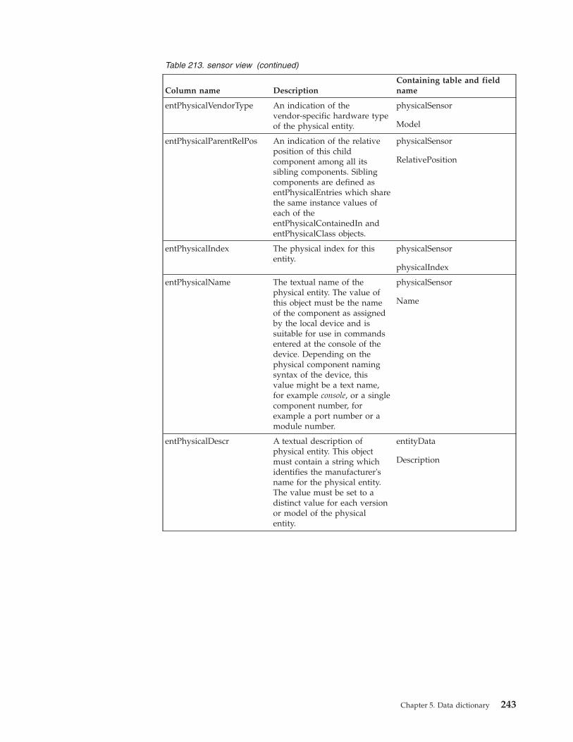
Table 213. sensor view (continued)
Column name DescriptionContaining table and fieldname
entPhysicalVendorType An indication of thevendor-specific hardware typeof the physical entity.
physicalSensor
Model
entPhysicalParentRelPos An indication of the relativeposition of this childcomponent among all itssibling components. Siblingcomponents are defined asentPhysicalEntries which sharethe same instance values ofeach of theentPhysicalContainedIn andentPhysicalClass objects.
physicalSensor
RelativePosition
entPhysicalIndex The physical index for thisentity.
physicalSensor
physicalIndex
entPhysicalName The textual name of thephysical entity. The value ofthis object must be the nameof the component as assignedby the local device and issuitable for use in commandsentered at the console of thedevice. Depending on thephysical component namingsyntax of the device, thisvalue might be a text name,for example console, or a singlecomponent number, forexample a port number or amodule number.
physicalSensor
Name
entPhysicalDescr A textual description ofphysical entity. This objectmust contain a string whichidentifies the manufacturer'sname for the physical entity.The value must be set to adistinct value for each versionor model of the physicalentity.
entityData
Description
Chapter 5. Data dictionary 243
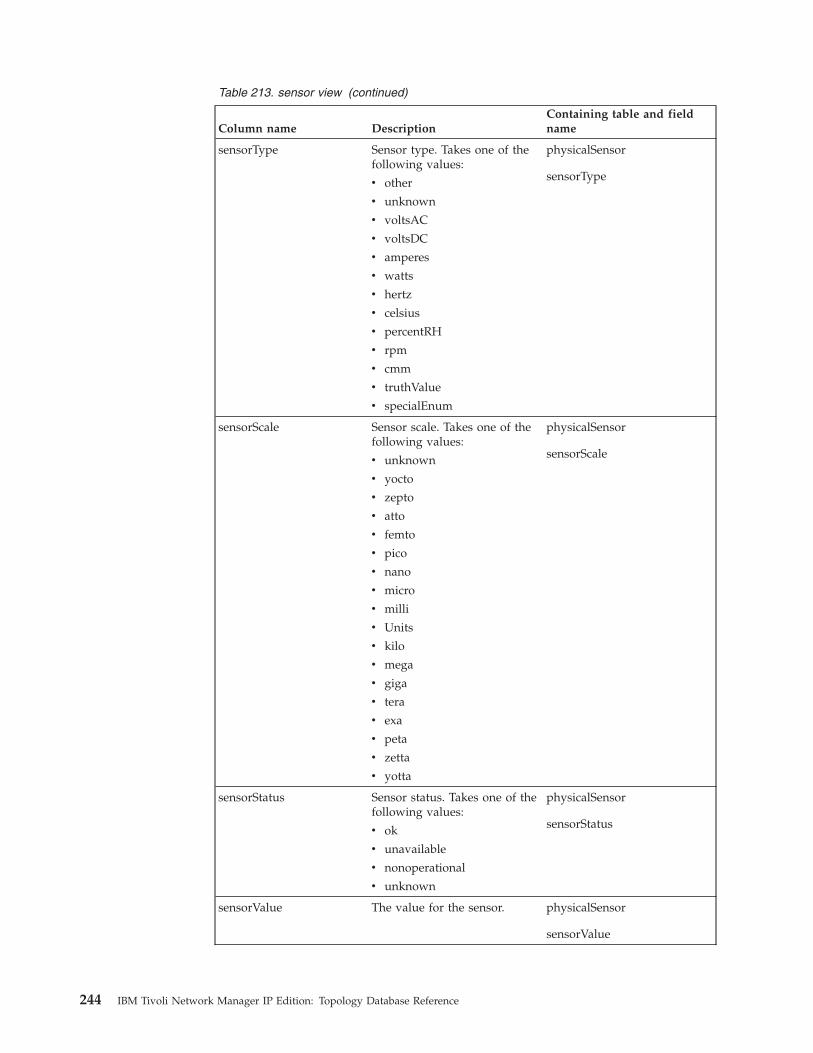
Table 213. sensor view (continued)
Column name DescriptionContaining table and fieldname
sensorType Sensor type. Takes one of thefollowing values:
v other
v unknown
v voltsAC
v voltsDC
v amperes
v watts
v hertz
v celsius
v percentRH
v rpm
v cmm
v truthValue
v specialEnum
physicalSensor
sensorType
sensorScale Sensor scale. Takes one of thefollowing values:
v unknown
v yocto
v zepto
v atto
v femto
v pico
v nano
v micro
v milli
v Units
v kilo
v mega
v giga
v tera
v exa
v peta
v zetta
v yotta
physicalSensor
sensorScale
sensorStatus Sensor status. Takes one of thefollowing values:
v ok
v unavailable
v nonoperational
v unknown
physicalSensor
sensorStatus
sensorValue The value for the sensor. physicalSensor
sensorValue
244 IBM Tivoli Network Manager IP Edition: Topology Database Reference
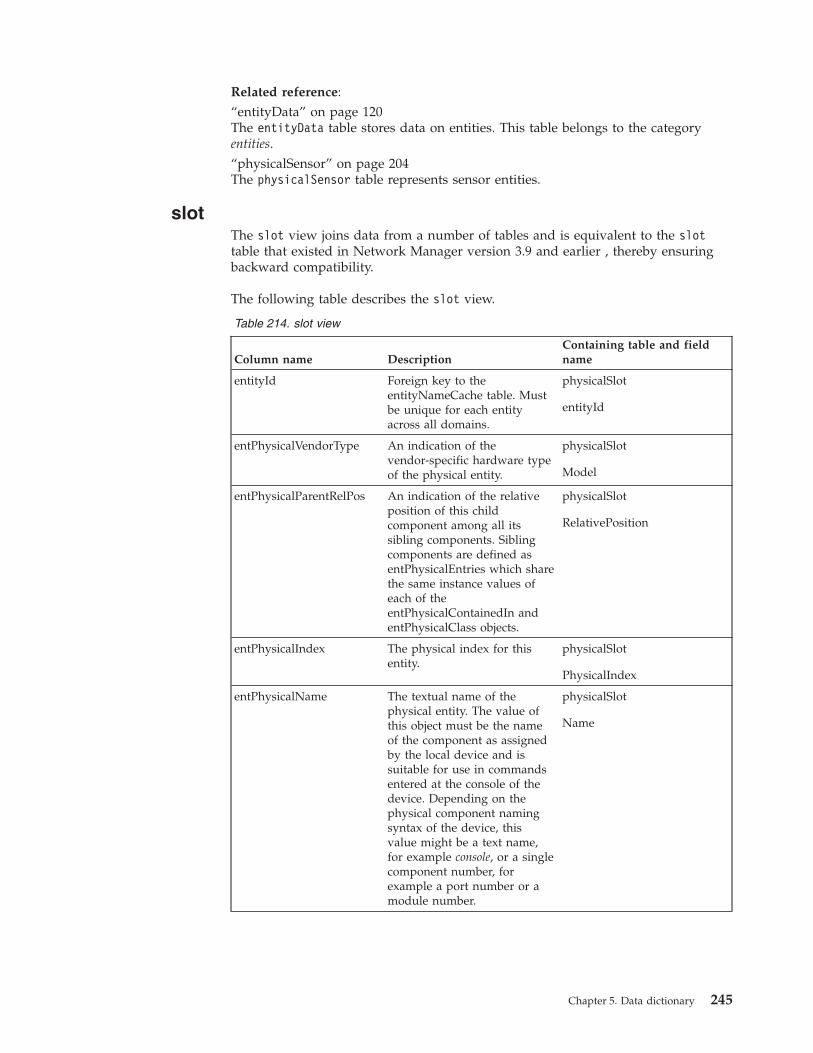
Related reference:“entityData” on page 120The entityData table stores data on entities. This table belongs to the categoryentities.“physicalSensor” on page 204The physicalSensor table represents sensor entities.
slotThe slot view joins data from a number of tables and is equivalent to the slottable that existed in Network Manager version 3.9 and earlier , thereby ensuringbackward compatibility.
The following table describes the slot view.
Table 214. slot view
Column name DescriptionContaining table and fieldname
entityId Foreign key to theentityNameCache table. Mustbe unique for each entityacross all domains.
physicalSlot
entityId
entPhysicalVendorType An indication of thevendor-specific hardware typeof the physical entity.
physicalSlot
Model
entPhysicalParentRelPos An indication of the relativeposition of this childcomponent among all itssibling components. Siblingcomponents are defined asentPhysicalEntries which sharethe same instance values ofeach of theentPhysicalContainedIn andentPhysicalClass objects.
physicalSlot
RelativePosition
entPhysicalIndex The physical index for thisentity.
physicalSlot
PhysicalIndex
entPhysicalName The textual name of thephysical entity. The value ofthis object must be the nameof the component as assignedby the local device and issuitable for use in commandsentered at the console of thedevice. Depending on thephysical component namingsyntax of the device, thisvalue might be a text name,for example console, or a singlecomponent number, forexample a port number or amodule number.
physicalSlot
Name
Chapter 5. Data dictionary 245
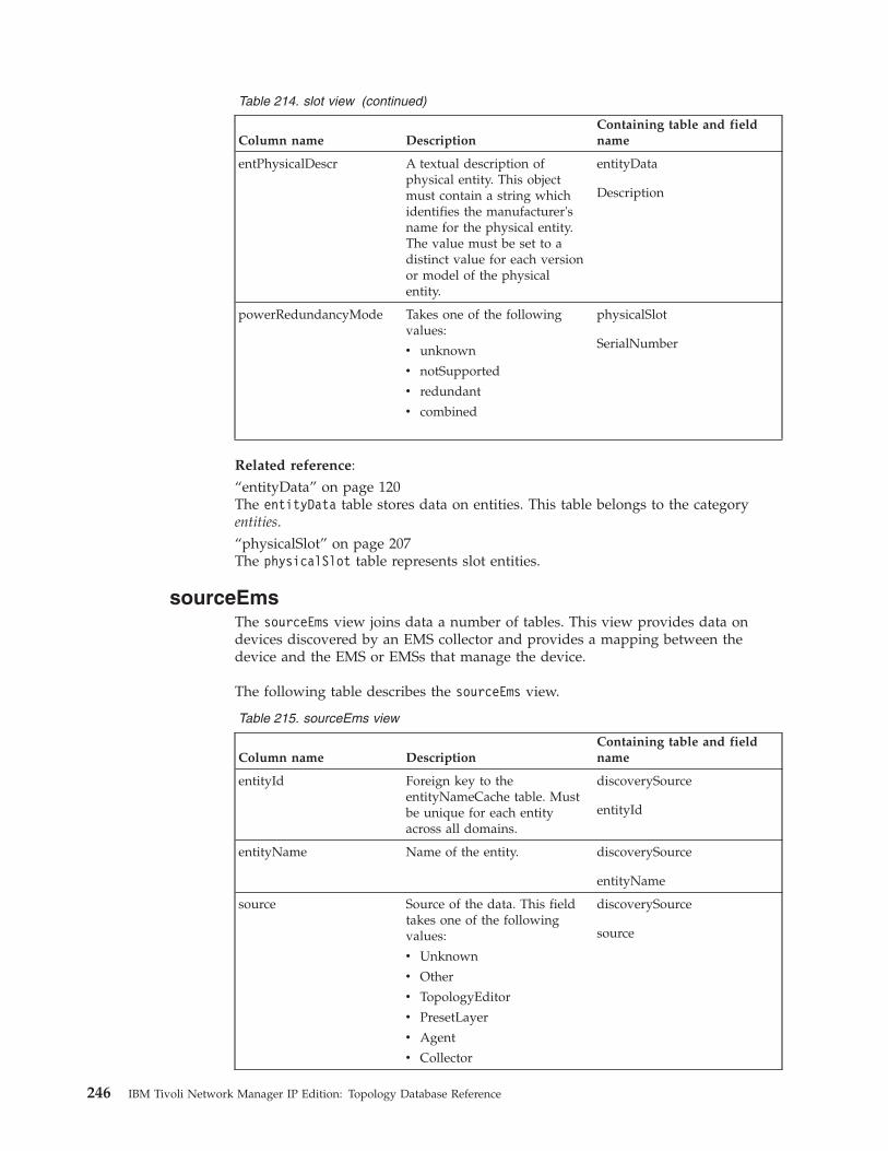
Table 214. slot view (continued)
Column name DescriptionContaining table and fieldname
entPhysicalDescr A textual description ofphysical entity. This objectmust contain a string whichidentifies the manufacturer'sname for the physical entity.The value must be set to adistinct value for each versionor model of the physicalentity.
entityData
Description
powerRedundancyMode Takes one of the followingvalues:
v unknown
v notSupported
v redundant
v combined
physicalSlot
SerialNumber
Related reference:“entityData” on page 120The entityData table stores data on entities. This table belongs to the categoryentities.“physicalSlot” on page 207The physicalSlot table represents slot entities.
sourceEmsThe sourceEms view joins data a number of tables. This view provides data ondevices discovered by an EMS collector and provides a mapping between thedevice and the EMS or EMSs that manage the device.
The following table describes the sourceEms view.
Table 215. sourceEms view
Column name DescriptionContaining table and fieldname
entityId Foreign key to theentityNameCache table. Mustbe unique for each entityacross all domains.
discoverySource
entityId
entityName Name of the entity. discoverySource
entityName
source Source of the data. This fieldtakes one of the followingvalues:
v Unknown
v Other
v TopologyEditor
v PresetLayer
v Agent
v Collector
discoverySource
source
246 IBM Tivoli Network Manager IP Edition: Topology Database Reference

Table 215. sourceEms view (continued)
Column name DescriptionContaining table and fieldname
discoveryProtocol Protocol of the data providedby this discovery source. Thisfield takes one of thefollowing values:
v Unknown
v Other
v Manual
v FlatFile
v SNMP
v Telnet
v XML-RPC
v VSphere
v OtherJavaAPI
v TL1
v CORBA
discoverySource
discoveryProtocol
nativeId Identifier used by thediscovery source to identify agiven device.
discoverySource
nativeId
nativeIdString String used by the discoverysource to identify a givendevice.
discoverySource
nativeIdString
emsEntityId Automatically-incrementedfield that provides a uniquevalue for each entity across alldomains.
entityNameCache
entityId
emsEntityName Name of the entity. entityNameCache
entityName
emsName Name of the EMS. emsSystem
emsName
domainMgrId Automatically-incrementedfield that is unique for eachdomain.
domainMgr
domainMgrId
domainName Name of the domain. domainMgr
domainName
Common Data Model viewsThe Common Data Model (CDM) is an information model that provides consistentdefinitions for managed resources, business systems and processes, and other data,and the relationships between those elements. CDM is based on the unifiedmodeling language (UML).
The IBM Common Data Model (CDM) overlay schema enables Network Managerto expose a subset of its data in a CDM-like relational representationcorresponding to aspects of the CDM Computer System, Networking, Operating
Chapter 5. Data dictionary 247
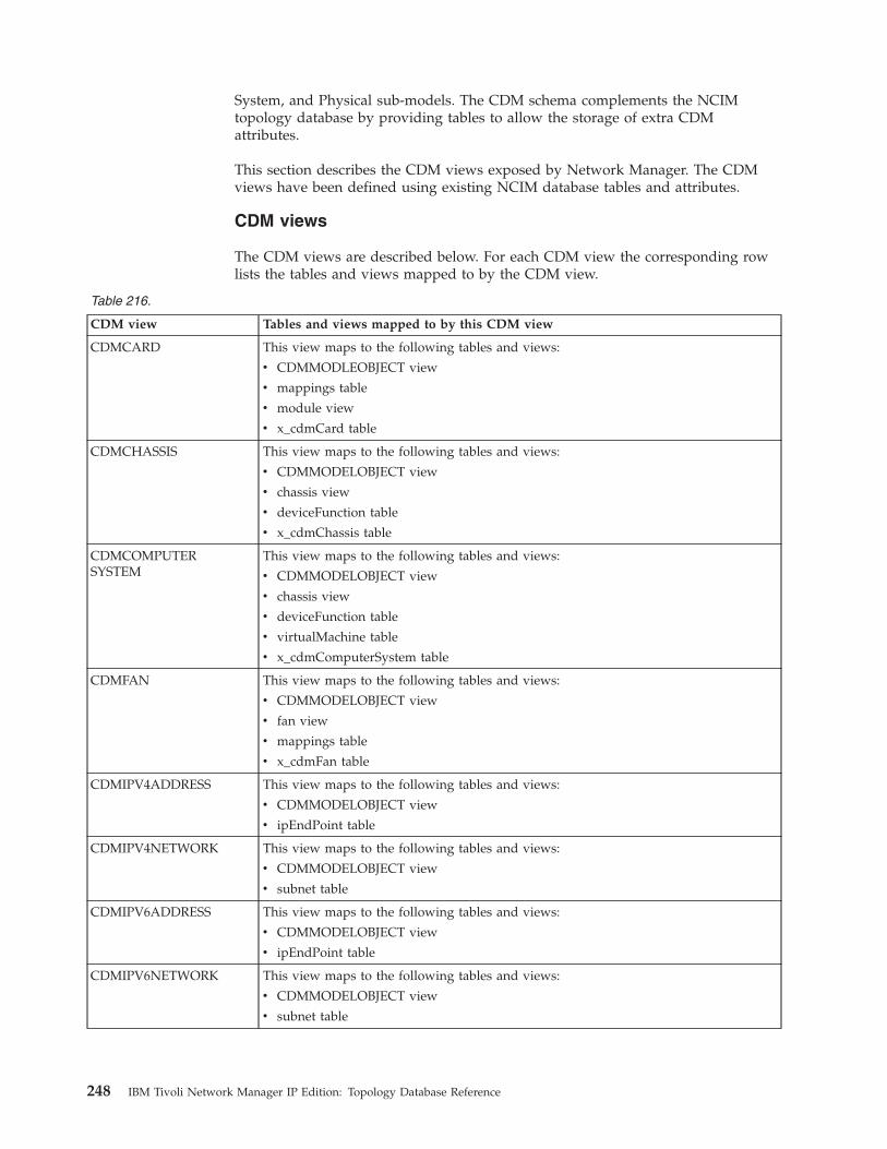
System, and Physical sub-models. The CDM schema complements the NCIMtopology database by providing tables to allow the storage of extra CDMattributes.
This section describes the CDM views exposed by Network Manager. The CDMviews have been defined using existing NCIM database tables and attributes.
CDM views
The CDM views are described below. For each CDM view the corresponding rowlists the tables and views mapped to by the CDM view.
Table 216.
CDM view Tables and views mapped to by this CDM view
CDMCARD This view maps to the following tables and views:
v CDMMODLEOBJECT view
v mappings table
v module view
v x_cdmCard table
CDMCHASSIS This view maps to the following tables and views:
v CDMMODELOBJECT view
v chassis view
v deviceFunction table
v x_cdmChassis table
CDMCOMPUTERSYSTEM
This view maps to the following tables and views:
v CDMMODELOBJECT view
v chassis view
v deviceFunction table
v virtualMachine table
v x_cdmComputerSystem table
CDMFAN This view maps to the following tables and views:
v CDMMODELOBJECT view
v fan view
v mappings table
v x_cdmFan table
CDMIPV4ADDRESS This view maps to the following tables and views:
v CDMMODELOBJECT view
v ipEndPoint table
CDMIPV4NETWORK This view maps to the following tables and views:
v CDMMODELOBJECT view
v subnet table
CDMIPV6ADDRESS This view maps to the following tables and views:
v CDMMODELOBJECT view
v ipEndPoint table
CDMIPV6NETWORK This view maps to the following tables and views:
v CDMMODELOBJECT view
v subnet table
248 IBM Tivoli Network Manager IP Edition: Topology Database Reference

Table 216. (continued)
CDM view Tables and views mapped to by this CDM view
CDMMODELOBJECT Provides generally applicable data to the other CDM views.
This view maps to the following tables and views:
v entityData
v domainMembers
v domainMgr
CDMNETWORKINTERFACE
This view maps to the following tables and views:
v CDMModelObject view
v enumerations table
v interface view
v x_cdmNetworkInterface table
CDMOPERATINGSYSTEM
This view maps to the following tables and views:
v CDMModelObject view
v chassis table
v x_cdmOperatingSystem table
CDMOTHERPHYSICALPACKAGE
This view maps to the following tables and views:
v CDMMODELOBJECT view
v chassis view
v x_cdmOperatingSystem table
CDMPHYSICALCONNECTOR
This view maps to the following tables and views:
v CDMMODELOBJECT view
v interface view
v mappings table
v x_cdmPhysicalConnector table
CDMPOWERSUPPLY
This view maps to the following tables and views:
v CDMMODELOBJECT view
v mappings table
v psu view
v x_cdmPowerSupply table
CDMSENSORThis view maps to the following tables and views:
v CDMMODELOBJECT view
v mappings table
v sensor view
v x_cdmSensor table
CDMSLOT This view maps to the following tables and views:
v CDMMODELOBJECT view
v mappings table
v sensor view
v x_cdmSensor table
CDMSNMPSYSTEMGROUP
This view maps to the following tables and views:
v CDMMODELOBJECT view
v chassis view
Chapter 5. Data dictionary 249

Related information:
IBM Tivoli Common Data Model: Guide to Best PracticesThe Common Data Model (CDM) is an information model that provides consistentdefinitions for managed resources, business systems and processes, and other data,and the relationships between those elements. CDM is based on the unifiedmodeling language (UML). This IBM Redpaper presents a set of example templatesand scenarios that help you learn and apply the basics of the Common DataModel.
250 IBM Tivoli Network Manager IP Edition: Topology Database Reference

Appendix. Network Manager glossary
Use this information to understand terminology relevant to the Network Managerproduct.
The following list provides explanations for Network Manager terminology.
AOC filesFiles used by the Active Object Class manager, ncp_class to classifynetwork devices following a discovery. Device classification is defined inAOC files by using a set of filters on the object ID and other device MIBparameters.
active object class (AOC)An element in the predefined hierarchical topology of network devicesused by the Active Object Class manager, ncp_class, to classify discovereddevices following a discovery.
agent See, discovery agent.
bookmarkSee, network view bookmark.
class hierarchyPredefined hierarchical topology of network devices used by the ActiveObject Class manager, ncp_class, to classify discovered devices following adiscovery.
configuration filesEach Network Manager process has one or more configuration files used tocontrol process behaviour by setting values in the process databases.Configuration files can also be made domain-specific.
discovery agentPiece of code that runs during a discovery and retrieves detailedinformation from discovered devices.
Discovery Configuration GUIGUI used to configure discovery parameters.
Discovery engine (ncp_disco)Network Manager process that performs network discovery.
discovery phaseA network discovery is divided into four phases: Interrogating devices,Resolving addresses, Downloading connections, and Correlatingconnectivity.
discovery seedOne or more devices from which the discovery starts.
discovery scopeThe boundaries of a discovery, expressed as one or more subnets andnetmasks.
Discovery Status GUIGUI used to launch and monitor a running discovery.
discovery stitcherPiece of code used during the discovery process. There are various
© Copyright IBM Corp. 2006, 2013 251

discovery stitchers, and they can be grouped into two types: data collectionstitchers, which transfer data between databases during the data collectionphases of a discovery, and data processing stitchers, which build thenetwork topology during the data processing phase.
dNCIM databaseThe dNCIM is a relational database embedded into the Discovery engine,ncp_disco, and it stores the containment model that is derived from thefullTopology database (and created by stitchers). This is the version of thetopology that is sent to the Topology manager, ncp_model. The dNCIMdatabase performs the same function as the scratchTopology database didin previous versions of Network Manager.
domainSee, network domain.
entity A topology database concept. All devices and device componentsdiscovered by Network Manager are entities. Also device collections suchas VPNs and VLANs, as well as pieces of topology that form a complexconnection, are entities.
event enrichmentThe process of adding topology information to the event.
Event Gateway (ncp_g_event)Network Manager process that performs event enrichment.
Event Gateway stitcherStitchers that perform topology lookup as part of the event enrichmentprocess.
failoverIn your Network Manager environment, a failover architecture can be usedto configure your system for high availability, minimizing the impact ofcomputer or network failure.
Failover plug-inReceives Network Manager health check events from the Event Gatewayand passes these events to the Virtual Domain process, which decideswhether or not to initiate failover based on the event.
Fault Finding ViewComposite GUI view consisting of an Active Event List (AEL) portletabove and a Network Hop View portlet below. Use the Fault Finding Viewto monitor network events.
full discoveryA discovery run with a large scope, intended to discover all of the networkdevices that you want to manage. Full discoveries are usually just calleddiscoveries, unless they are being contrasted with partial discoveries. Seealso, partial discovery.
message brokerComponent that manages communication between Network Managerprocesses. The message broker used byNetwork Manager is called ReallySmall Message Broker. To ensure correct operation of Network Manager,Really Small Message Broker must be running at all times.
NCIM databaseRelational database that stores topology data, as well as administrativedata such as data associated with poll policies and definitions, andperformance data from devices.
252 IBM Tivoli Network Manager IP Edition: Topology Database Reference
ncp_discoSee, Discovery engine.
ncp_g_eventSee, Event Gateway.
ncp_modelSee, Topology manager.
ncp_pollerSee, Polling engine.
network domainA collection of network entities to be discovered and managed. A singleNetwork Manager installation can manage multiple network domains.
Network Health ViewComposite GUI view consisting of a Network Views portlet above and anActive Event List (AEL) portlet below. Use the Network Health View todisplay events on network devices.
Network Hop ViewNetwork visualization GUI. Use the Network Hop View to search thenetwork for a specific device and display a specified network device. Youcan also use the Network Hop View as a starting point for networktroubleshooting. Formerly known as the Hop View.
Network Polling GUIAdministrator GUI. Enables definition of poll policies and poll definitions.
Network ViewsNetwork visualization GUI that shows hierarchically organized views of adiscovered network. Use the Network Views to view the results of adiscovery and to troubleshoot network problems.
network view bookmarkNetwork view bookmarks group together just those network views thatyou or your team need to monitor. Create new bookmarks or changeexisting bookmarks to help network operators visualize just those devicesthat they need to monitor.
OQL databasesNetwork Manager processes store configuration, management andoperational information in OQL databases.
OQL languageVersion of the Structured Query Language (SQL) that has been designedfor use in Network Manager. Network Manager processes create andinteract with their databases using OQL.
partial discoveryA subsequent rediscovery of a section of the previously discoverednetwork. The section of the network is usually defined using a discoveryscope consisting of either an address range, a single device, or a group ofdevices. A partial discovery relies on the results of the last full discovery,and can only be run if the Discovery engine, ncp_disco, has not beenstopped since the last full discovery. See also, full discovery.
Path ViewsNetwork visualization GUI that displays devices and links that make up a
Appendix. Network Manager glossary 253

network path between two selected devices. Create new path views orchange existing path views to help network operators visualize networkpaths.
performance dataPerformance data can be gathered using performance reports. Thesereports allow you to view any historical performance data that has beencollected by the monitoring system for diagnostic purposes.
Polling engine (ncp_poller)Network Manager process that polls target devices and interfaces. ThePolling engine also collects performance data from polled devices.
poll definitionDefines how to poll a network device or interface and further filter thetarget devices or interfaces.
poll policyDefines which devices to poll. Also defines other attributes of a poll suchas poll frequency.
Probe for Tivoli Netcool/OMNIbus (nco_p_ncpmonitor)Acquires and processes the events that are generated by Network Managerpolls and processes, and forwards these events to the ObjectServer.
RCA plug-inBased on data in the event and based on the discovered topology, attemptsto identify events that are caused by or cause other events using rulescoded in RCA stitchers.
RCA stitcherStitchers that process a trigger event as it passes through the RCA plug-in.
root-cause analysis (RCA)The process of determining the root cause of one or more device alerts.
SNMP MIB BrowserGUI that retrieves MIB variable information from network devices tosupport diagnosis of network problems.
SNMP MIB GrapherGUI that displays a real-time graph of MIB variables for a device and ussethe graph for fault analysis and resolution of network problems.
stitcherCode used in the following processes: discovery, event enrichment, androot-cause analysis. See also, discovery stitcher, Event Gateway stitcher,and RCA stitcher.
Structure BrowserGUI that enables you to investigate the health of device components inorder to isolate faults within a network device.
Topology Manager (ncp_model)Stores the topology data following a discovery and sends the topologydata to the NCIM topology database where it can be queried using SQL.
WebToolsSpecialized data retrieval tools that retrieve data from network devices andcan be launched from the network visualization GUIs, Network Views andNetwork Hop View, or by specifying a URL in a web browser.
254 IBM Tivoli Network Manager IP Edition: Topology Database Reference
Notices
This information applies to the PDF documentation set for IBM Tivoli NetworkManager IP Edition.
This information was developed for products and services offered in the U.S.A.
IBM may not offer the products, services, or features discussed in this document inother countries. Consult your local IBM representative for information on theproducts and services currently available in your area. Any reference to an IBMproduct, program, or service is not intended to state or imply that only that IBMproduct, program, or service may be used. Any functionally equivalent product,program, or service that does not infringe any IBM intellectual property right maybe used instead. However, it is the user's responsibility to evaluate and verify theoperation of any non-IBM product, program, or service.
IBM may have patents or pending patent applications covering subject matterdescribed in this document. The furnishing of this document does not grant youany license to these patents. You can send license inquiries, in writing, to:
IBM Director of LicensingIBM CorporationNorth Castle DriveArmonk, NY 10504-1785U.S.A.
For license inquiries regarding double-byte character set (DBCS) information,contact the IBM Intellectual Property Department in your country or sendinquiries, in writing, to:
Intellectual Property LicensingLegal and Intellectual Property LawIBM Japan, Ltd.19-21, Nihonbashi-Hakozakicho, Chuo-kuTokyo 103-8510, Japan
The following paragraph does not apply to the United Kingdom or any othercountry where such provisions are inconsistent with local law: INTERNATIONALBUSINESS MACHINES CORPORATION PROVIDES THIS PUBLICATION "AS IS"WITHOUT WARRANTY OF ANY KIND, EITHER EXPRESS OR IMPLIED,INCLUDING, BUT NOT LIMITED TO, THE IMPLIED WARRANTIES OFNON-INFRINGEMENT, MERCHANTABILITY OR FITNESS FOR A PARTICULARPURPOSE. Some states do not allow disclaimer of express or implied warranties incertain transactions, therefore, this statement may not apply to you.
This information could include technical inaccuracies or typographical errors.Changes are periodically made to the information herein; these changes will beincorporated in new editions of the publication. IBM may make improvementsand/or changes in the product(s) and/or the program(s) described in thispublication at any time without notice.
Any references in this information to non-IBM Web sites are provided forconvenience only and do not in any manner serve as an endorsement of those Web
© Copyright IBM Corp. 2006, 2013 255

sites. The materials at those Web sites are not part of the materials for this IBMproduct and use of those Web sites is at your own risk.
IBM may use or distribute any of the information you supply in any way itbelieves appropriate without incurring any obligation to you.
Licensees of this program who wish to have information about it for the purposeof enabling: (i) the exchange of information between independently createdprograms and other programs (including this one) and (ii) the mutual use of theinformation which has been exchanged, should contact:
IBM Corporation958/NH04IBM Centre, St Leonards601 Pacific HwySt Leonards, NSW, 2069AustraliaIBM Corporation896471/H128B76 Upper GroundLondonSE1 9PZUnited KingdomIBM CorporationJBF1/SOM1 294Route 100Somers, NY, 10589-0100United States of America
Such information may be available, subject to appropriate terms and conditions,including in some cases, payment of a fee.
The licensed program described in this document and all licensed materialavailable for it are provided by IBM under terms of the IBM Customer Agreement,IBM International Program License Agreement or any equivalent agreementbetween us.
Any performance data contained herein was determined in a controlledenvironment. Therefore, the results obtained in other operating environments mayvary significantly. Some measurements may have been made on development-levelsystems and there is no guarantee that these measurements will be the same ongenerally available systems. Furthermore, some measurements may have beenestimated through extrapolation. Actual results may vary. Users of this documentshould verify the applicable data for their specific environment.
Information concerning non-IBM products was obtained from the suppliers ofthose products, their published announcements or other publicly available sources.IBM has not tested those products and cannot confirm the accuracy ofperformance, compatibility or any other claims related to non-IBM products.Questions on the capabilities of non-IBM products should be addressed to thesuppliers of those products.
This information contains examples of data and reports used in daily businessoperations. To illustrate them as completely as possible, the examples include the
256 IBM Tivoli Network Manager IP Edition: Topology Database Reference
names of individuals, companies, brands, and products. All of these names arefictitious and any similarity to the names and addresses used by an actual businessenterprise is entirely coincidental.
COPYRIGHT LICENSE:
This information contains sample application programs in source language, whichillustrate programming techniques on various operating platforms. You may copy,modify, and distribute these sample programs in any form without payment toIBM, for the purposes of developing, using, marketing or distributing applicationprograms conforming to the application programming interface for the operatingplatform for which the sample programs are written. These examples have notbeen thoroughly tested under all conditions. IBM, therefore, cannot guarantee orimply reliability, serviceability, or function of these programs.
TrademarksThe terms in Table 217 are trademarks of International Business MachinesCorporation in the United States, other countries, or both:
Table 217. IBM trademarks
AIX® Informix RDN®
BNT iSeries solidDB®
ClearQuest® Lotus® System p
Cognos® Netcool® System z
DB2® NetView® Tivoli®
DB2 UniversalDatabase
Notes® WebSphere
developerWorks® OMEGAMON® z/OS®
DS8000 PowerPC z/VM®
EnterpriseStorage Server®
PowerVM® zSeries
IBM PR/SM™
Intel, Intel logo, Intel Inside, Intel Inside logo, Intel Centrino, Intel Centrino logo,Celeron, Intel Xeon, Intel SpeedStep, Itanium, and Pentium are trademarks orregistered trademarks of Intel Corporation or its subsidiaries in the United Statesand other countries.
Java and all Java-based trademarks and logos are trademarks orregistered trademarks of Oracle and/or its affiliates.
Notices 257

Linux is a registered trademark of Linus Torvalds in the United States, othercountries, or both.
UNIX is a registered trademark of The Open Group in the United States and othercountries.
Microsoft, Windows, Windows NT, and the Windows logo are trademarks ofMicrosoft Corporation in the United States, other countries, or both.
Privacy policy considerations
IBM Software products, including software as a service solutions, ("SoftwareOfferings") may use cookies or other technologies to collect product usageinformation, to help improve the end user experience, to tailor interactions withthe end user or for other purposes. In many cases no personally identifiableinformation is collected by the Software Offerings. Some of our Software Offeringscan help enable you to collect personally identifiable information. If this SoftwareOffering uses cookies to collect personally identifiable information, specificinformation about this offering's use of cookies is set forth below.
This Software Offering may collect IP addresses, user names and passwords for thepurpose of performing network discovery. Failure to enable the collection of thisinformation would likely eliminate important functionality provided by thisSoftware Offering. You as customer should seek your own legal advice about anylaws applicable to such data collection, including any requirements for notice andconsent.
For more information about the use of various technologies, including cookies, forthese purposes, See IBM's Privacy Policy at http://www.ibm.com/privacy andIBM's Online Privacy Statement at http://www.ibm.com/privacy/details thesection entitled "Cookies, Web Beacons and Other Technologies" and the "IBMSoftware Products and Software-as-a-Service Privacy Statement" athttp://www.ibm.com/software/info/product-privacy.
258 IBM Tivoli Network Manager IP Edition: Topology Database Reference
Index
Aaccessibility xiaggregationDomain table 108atmEndPoint table 144
Bbackplane view 228BGP 86bgpAutonomousSystem table 145bgpCluster table 146bgpEndPoint table 146bgpNetwork table 149bgpRouteAttribute table 149bgpService table 151
CCDM 247changing
passwords 23chassis view 229CIDRinfo table 108classMembers table 110collections 87collects table 110Common Data Model 247computerSystem table 152connectActions table 111connectivity
queriesdevices and interfaces connected to
a named device 50devices and interfaces connections
between routers 52devices connected to a named
device 48types 47
connectivity datadescription 46representation 12
connects table 12, 46, 112connectSpeeds table 113containment 88
queriescomponents on a device 30components on a device and
component type 32devices with Cisco Three-Port
Gigabit Ethernet cards 35entities in all cards 37number of cards per device 33
containment dataaltering the containment model 15description 13usage 13VLANs
dependencies on other entities 15naming 14trunking 14
contains table 37, 114conventions, typeface xiiicore schema 83core views 135cpu table 159custom tags
enabling network visualization basedon 79
enabling polling based on 79
Ddata dictionary
tablesaggregationDomain 108domainMembers 116
viewsbackplane 228chassis 229discoveryOverview 135entity 137fan 233interface 234interfaceDomain 138interfaces 138mainNodeDetails 141mainNodeDomain 144module 237other 239psu 241sensor 242slot 245sourceEms 246
databaseschema
endpoints 89database tables
collects 15core 6entity
resource types 6product-specific 6
dependency table 114device collections 87
description 72queries
devices per subnet 73devices per VPN 74
deviceFunction 115discoveryOverview view 135discoverySource table 115domainMembers table 116domainMgr table 117domains
description 6queries
description 23differences between NCIM and
MODEL queries 23main nodes 23number of entities 25
domainSummary table 159
Eeducation
see Tivoli technical training xiemsSystem table 160enabling
network visualization based oncustom tags 79
polling based on custom tags 79endpoints 89entity view 137entityActions table 118entityClass 119entityData table 44, 120
entityType 32mainNodeEntityId 21
entityDetails 122entityNameCache table 123entityType table 124enumerations
description 75queries
device hardwaremanufacturers 75
entity types 77enumerations table 127environment variables, notation xiii
Ffan view 233files
database schema 16for NCIM cache 16
frameRelayEndPoint table 160
GgenericCollection table 161genericRange table 161geographicLocation table 161geographicRegion table 162globalVlan 162glossary 251
HHop View 81hosted serves
description 71hosted services 16, 129
querieschassis devices for OSPF 71
hostedServices table 129hsrpGroup table 163
© Copyright IBM Corp. 2006, 2013 259

IigmpEndPoint table 163igmpGroup table 165igmpService table 165Informix
order by 21interface table 40interface view 234interfaceDomain view 138interfaces
IP addresses 44queries
attribute values 40main-node devices 39
interfaces view 138IP endpoints 92ipConnection table 166ipEndPoint table 22, 166ipMRouteDownstream table 167ipMRouteEndPoint table 169ipMRouteGroup table 170ipMRouteMdt table 170ipMRouteService table 171ipMRouteSource table 171ipMRouteUpstream table 171ipPath table 173itnmService table 174
LlingerTime table 174localVlan table 175
Mmain nodes
IP addresses 28queries
devices with class name and objectID 26
mainNodeDetails view 141mainNodeDomain view 144managedStatus table 175manager table 129manuals viiimappings
description 75queries
device hardwaremanufacturers 75
entity types 77mappings table 130module view 237MPLS
TE tunnelslisting all, query for 54listing dependencies, query for 54showing configuration, query
for 55showing performance data, query
for 56showing routers, query for 55
MPLS VLANs 95mplsLSP table 180mplsTEService table 176mplsTETunnel table 177
mplsTETunnelEndPoint table 179mplsTETunnelResource table 179
NNCIM
changing passwords 23core schema 83core tables
categories of topology data 107database schema 16database tables
core 6product-specific 6
description 1extending 3
example interface record 78Hop View 81Network Views 81
logging in 19querying domains 3, 23schema
BGP 86collections 87containment 88endpoints 89IP endpoints 92MPLS VLANs 95OSPF 96services 99VLANs 102
storing data 3structure 3supported technologies 12tables 105
aggregationDomain 108atmEndPoint 144bgpAutonomousSystem 145bgpCluster 146bgpEndPoint 146bgpNetwork 149bgpRouteAttribute 149bgpService 151CIDRinfo 108classMembers 110collects 110computerSystem 152connectActions 111connects 112connectSpeeds 113contains 114cpu 159dependency 114deviceFunction 115discoverySource 115domainMembers 116domainMgr 117domainSummary 159emsSystem 160entity attribute tables 144, 228entityActions 118entityClass 119entityData 120entityDetails 122entityNameCache 123entityType 124enumerations 127
NCIM (continued)tables (continued)
frameRelayEndPoint 160genericCollection 161genericRange 161geographicLocation 161geographicRegion 162globalVlan 162hostedService 129hsrpGroup 163igmpEndPoint 163igmpGroup 165igmpService 165ipConnection 166ipEndPoint 166ipMRouteDownstream 167ipMRouteEndPoint 169ipMRouteGroup 170ipMRouteMdt 170ipMRouteService 171ipMRouteSource 171ipMRouteUpstream 171ipPath 173itnmService 174lingerTime 174localVlan 175managedStatus 175manager 129mappings 130mplsLSP 180mplsTEService 176mplsTETunnel 177mplsTETunnelEndPoint 179mplsTETunnelResource 179netcoolAsmsRunning 180networkInterface 180networkPipe 131networkPipe hierarchy
modeling 48networkServiceEntityEndPoint 184networkVpn 184notes 132operatingSystem 185ospfArea 188ospfEndPoint 188ospfNetworkLSA 189ospfRoutingDomain 190ospfService 190physicalBackplane 191physicalCard 192physicalChassis 195physicalConnector 198physicalFan 199physicalOther 201physicalPowerSupply 203physicalSensor 204physicalSlot 207pimEndPoint 208pimNetwork 209pimService 209pipeComposition 132pipeComposition hierarchy
modeling 48portEndPoint 210protocolEndPoint 133ranBaseStation 211ranBaseStationController 211
260 IBM Tivoli Network Manager IP Edition: Topology Database Reference
NCIM (continued)tables (continued)
ranCircuitSwitchedCore 212ranGSMCell 213ranLocationArea 214ranMediaGateway 215ranMobileSwitchingCentre 215ranMSS 216ranMultiplexer 180ranNodeB 216ranNodeBLocalCell 216ranPacketControlUnit 217ranPacketSwitchedCore 217ranRadioCore 218ranRadioNetworkController 219ranRoutingArea 219ranSector 220ranSGSN 213, 220ranTransceiver 221ranUtranCell 221rtExportList 222rtImportList 222snmpSystem 223subnet 224topologyLinks 135transmissionTp 224vlanCollection 225vlanTrunkEndPoint 225vpnRouteForwarding 226vpwsEndPoint 227vtpDomain 227
usage considerations 1views
backplane 228chassis 229discoveryOverview 135entity 137fan 233interface 234interfaceDomain 138interfaces 138mainNodeDetails 141mainNodeDomain 144module 237other 239psu 241sensor 242slot 245sourceEms 246
NCIM cachefiles 16
netcoolAsmsRunning table 180network entities
collection data 15connectivity data 12containment data 13types 6
Network Manager glossary 251Network Views 81network visualization
enabling based on custom tags 79networkInterface 180networkPipe table 131networkServiceEntityEndPoint table 184networkVpn table 184notes table 132
Oonline publications viiioperatingSystem table 185ordering publications viiiOSPF 96OSPF areas
modelling 12ospfArea table 188ospfEndPoint table 188ospfNetworkLSA table 189ospfRoutingDomain table 190ospfService table 190other view 239
PphysicalBackplane table 191physicalCard table 192physicalChassis table 195physicalConnector table 198physicalFan 199physicalOther 201physicalPowerSupply table 203physicalSensor table 204physicalSlot table 207PIM
queriesadjacencies for device 72enabled routers 72show adjacencies 72
pimEndPoint table 208pimNetwork table 209pimService table 209pipeComposition table 132polling
enabling based on custom tags 79portEndPoint table 210protocalEndPoint table 133protocolEndPoint table 22protocols
association with devices 12psu view 241publications viii
Qqueries
connectivityconnections between routers 52devices and interfaces connected to
a named device 50devices connected to a named
device 48containment
components on a device 30components on a device and
component type 32devices with Cisco Three-Port
Gigabit Ethernet cards 35entities in all cards 37number of cards per device 33
device collectionsdevices per subnet 73devices per VPN 74
domainsdescription 23
queries (continued)domains (continued)
differences between NCIM andMODEL queries 23
main nodes 23number of entities 25
enumerationsdevice hardware
manufacturers 75entity types 77
interfacesattribute values 40IP addresses 44main-node devices 39
main nodesdevices with class name and object
ID 26IP addresses 28
mappingsdevice hardware
manufacturers 75entity types 77
PIMadjacencies for device 72enabled routers 72show adjacencies 72
RANconnectivity 59containment 67dependencies 69entity types 57
TE tunnelslist all 54show configuration 55show dependencies 54show performance data 56show routers 55
RRAN
queriesconnectivity 59containment 67dependencies 69entity types 57
ranBaseStation table 211ranBaseStationController table 211ranCircuitSwitchedCore table 212ranGGSN table 213ranGSMCell table 213ranLocationArea table 214ranMediaGateway table 215ranMobileSwitchingCentre table 215ranMSS table 216ranMultiplexer table 180ranNodeB table 216ranNodeBLocalCell table 216ranPacketControlUnit table 217ranPacketSwitchedCore table 217ranRadioCore table 218ranRadioNetworkController table 219ranRoutingArea table 219ranSector table 220ranSGSN table 220ranTransceiver table 221ranUtranCell table 221
Index 261
rtExportList table 222rtImportList table 222
SSAE plug-ins 174schema
BGP 86collections 87containment 88core tables
categories of topology data 107IP endpoints 92MPLS VLANs 95OSPF 96services 99tables 105
atmEndPoint 144bgpAutonomousSystem 145bgpCluster 146bgpEndPoint 146bgpNetwork 149bgpRouteAttribute 149bgpService 151CIDRinfo 108classMembers 110collects 110computerSystem 152connectActions 111connects 112connectSpeeds 113contains 114cpu 159dependency 114deviceFunction 115discoverySource 115domainMgr 117domainSummary 159emsSystem 160entity attribute tables 144, 228entityActions 118entityClass 119entityData 120entityDetails 122entityNameCache 123entityType 124enumerations 127frameRelayEndPoint 160genericCollection 161genericRange 161geographicLocation 161geographicRegion 162globalVlan 162hostedService 129hsrpGroup 163igmpEndPoint 163igmpGroup 165igmpService 165ipConnection 166ipEndPoint 166ipMRouteDownstream 167ipMRouteEndPoint 169ipMRouteGroup 170ipMRouteMdt 170ipMRouteService 171ipMRouteSource 171ipMRouteUpstream 171
schema (continued)tables (continued)
ipPath 173itnmService 174lingerTime 174localVlan 175managedStatus 175manager 129mappings 130mplsLSP 180mplsTEService 176mplsTETunnel 177mplsTETunnelEndPoint 179mplsTETunnelResource 179netcoolAsmsRunning 180networkInterface 180networkPipe 131networkPipe hierarchy
modeling 48networkServiceEntityEndPoint 184networkVpn 184notes 132operatingSystem 185ospfArea 188ospfEndPoint 188ospfNetworkLSA 189ospfRoutingDomain 190ospfService 190physicalBackplane 191physicalCard 192physicalChassis 195physicalConnector 198physicalFan 199physicalOther 201physicalPowerSupply 203physicalSensor 204physicalSlot 207pimEndPoint 208pimNetwork 209pimService 209pipeComposition 132pipeComposition hierarchy
modeling 48portEndPoint 210protocolEndPoint 133ranBaseStation 211ranBaseStationController 211ranCircuitSwitchedCore 212ranGGSN 213ranGSMCell 213ranLocationArea 214ranMediaGateway 215ranMobileSwitchingCentre 215ranMSS 216ranMultiplexer 180ranNodeB 216ranNodeBLocalCell 216ranPacketControlUnit 217ranPacketSwitchedCore 217ranRadioCore 218ranRadioNetworkController 219ranRoutingArea 219ranSector 220ranSGSN 220ranTransceiver 221ranUtranCell 221rtExportList 222
schema (continued)tables (continued)
rtImportList 222snmpSystem 223subnet 224topologyLinks 135transmissionTp 224vlanCollection 225vlanTrunkEndPoint 225vpnRouteForwarding 226vpwsEndPoint 227vtpDomain 227
VLANs 102sensor view 242service xiiservice management connect xiiService-Affected Events 174services 99slot view 245SMC xiisnmpSystem table 223sourceEms view 246sql
views 135SQL
aliasing 20driving tables 20formatting 19table joins 20
subnet table 224support xiisupport information xii
TTivoli software information center viiiTivoli technical training xitopology data 6topology database
architecture 3properties 5tasks 3
topologyLinks table 135training, Tivoli technical xitransmissionTp table 224typeface conventions xiii
Vvariables, notation for xiiiviews
core 135visualization
enabling based on custom tags 79vlanCollection table 225VLANs 102
dependencies on other entities 15naming 14trunking 14
vlanTrunkEndPoint table 225vpnRouteForwarding table 226vpwsEndPoint table 227vtpDomain table 227
262 IBM Tivoli Network Manager IP Edition: Topology Database Reference


����
Printed in the Republic of Ireland
Related Documents