NE1101 Green Mode PWM Operation Description 1

Welcome message from author
This document is posted to help you gain knowledge. Please leave a comment to let me know what you think about it! Share it to your friends and learn new things together.
Transcript

NE1101 Green Mode PWM Operation Description
1
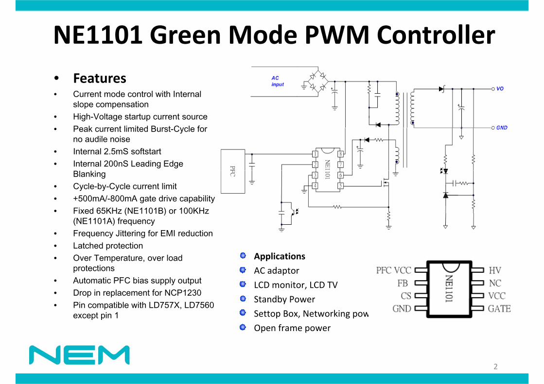
NE1101 Green Mode PWM ControllerNE1101 Green Mode PWM Controller• Features• Current mode control with Internal
slope compensation• High-Voltage startup current source• Peak current limited Burst Cycle for• Peak current limited Burst-Cycle for
no audile noise • Internal 2.5mS softstart• Internal 200nS Leading Edge
Blanking• Cycle-by-Cycle current limit• +500mA/-800mA gate drive capability• Fixed 65KHz (NE1101B) or 100KHzFixed 65KHz (NE1101B) or 100KHz
(NE1101A) frequency• Frequency Jittering for EMI reduction • Latched protection
O T t l d Applications• Over Temperature, over load protections
• Automatic PFC bias supply output • Drop in replacement for NCP1230
Applications
AC adaptor
LCD monitor, LCD TV
Standby Power• Pin compatible with LD757X, LD7560 except pin 1
Standby Power
Settop Box, Networking power
Open frame power
2
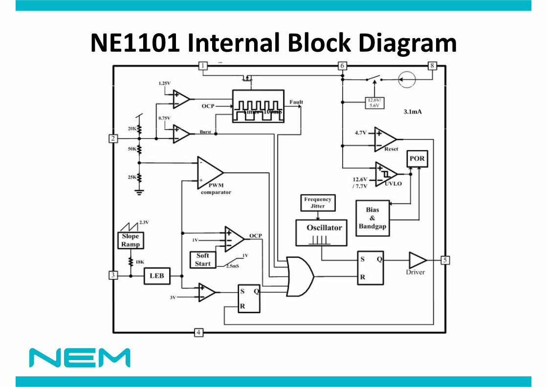
NE1101 Internal Block DiagramNE1101 Internal Block Diagram
Timer=100mS 3.1mA
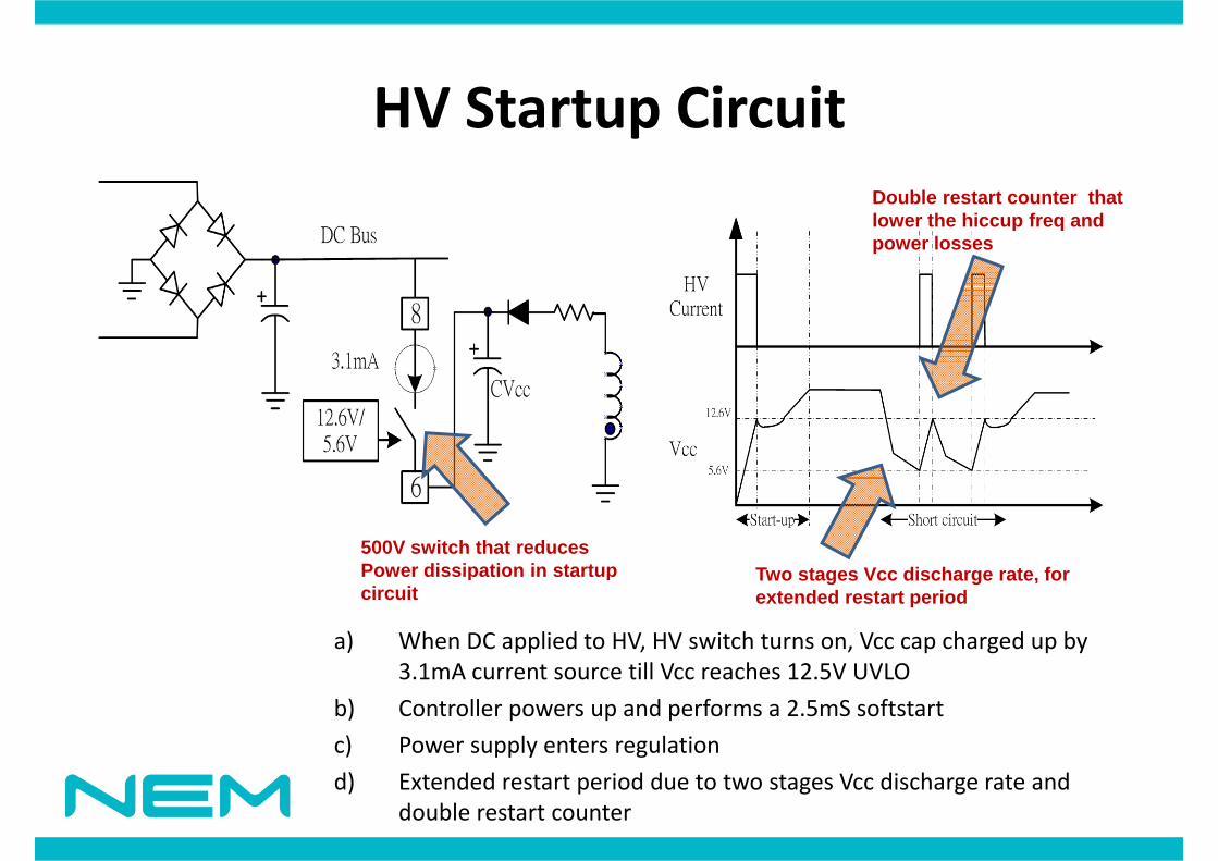
HV St t Ci itHV Startup CircuitD bl t t t th tDouble restart counter that lower the hiccup freq and power losses
500V switch that reduces Power dissipation in startup Two stages Vcc discharge rate forPower dissipation in startup circuit
Two stages Vcc discharge rate, for extended restart period
a) When DC applied to HV, HV switch turns on, Vcc cap charged up by 3 1mA current source till Vcc reaches 12 5V UVLO3.1mA current source till Vcc reaches 12.5V UVLO
b) Controller powers up and performs a 2.5mS softstart
c) Power supply enters regulation
d) Extended restart period due to two stages Vcc discharge rate and double restart counter
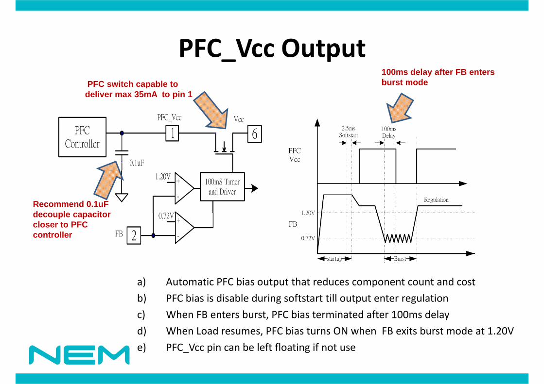
PFC V O t tPFC_Vcc OutputPFC switch capable to
100ms delay after FB enters burst mode PFC switch capable to
deliver max 35mA to pin 1
Recommend 0.1uF decouple capacitordecouple capacitor closer to PFC controller
a) Automatic PFC bias output that reduces component count and cost
b) PFC bias is disable during softstart till output enter regulationb) PFC bias is disable during softstart till output enter regulation
c) When FB enters burst, PFC bias terminated after 100ms delay
d) When Load resumes, PFC bias turns ON when FB exits burst mode at 1.20V
e) PFC_Vcc pin can be left floating if not use
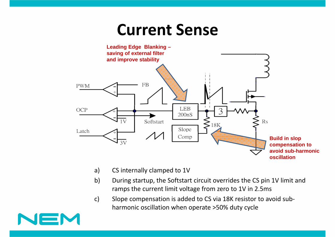
C t SCurrent SenseLeading Edge Blanking –saving of external filtersaving of external filter and improve stability
Build in slop compensation to avoid sub-harmonic oscillationoscillation
a) CS internally clamped to 1V
b) During startup, the Softstart circuit overrides the CS pin 1V limit and ramps the current limit voltage from zero to 1V in 2.5ms
c) Slope compensation is added to CS via 18K resistor to avoid sub‐harmonic oscillation when operate >50% duty cyclep y y
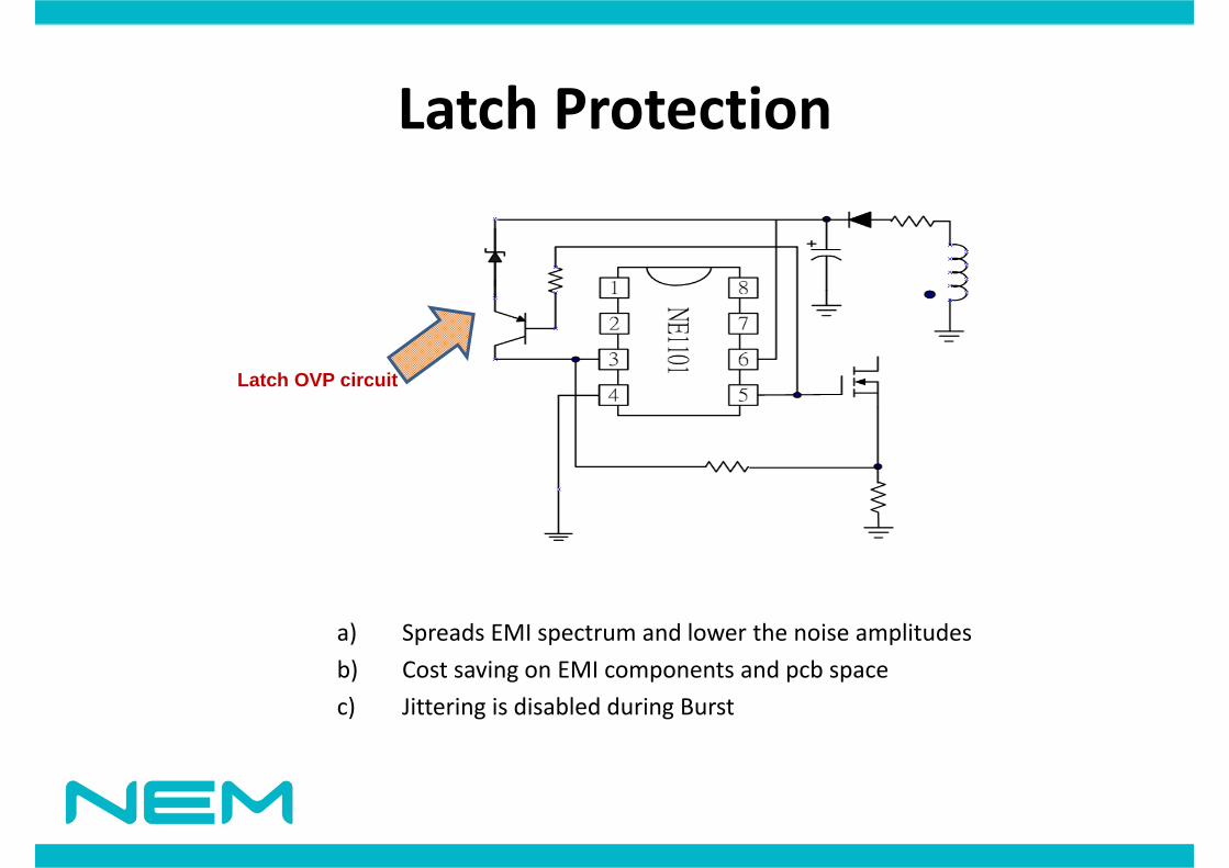
L t h P t tiLatch Protection
Latch OVP circuitLatch OVP circuit
a) Spreads EMI spectrum and lower the noise amplitudes
b) Cost saving on EMI components and pcb spaceb) Cost saving on EMI components and pcb space
c) Jittering is disabled during Burst
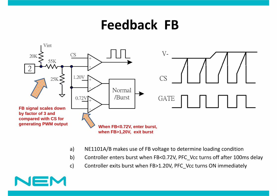
F db k FBFeedback FB
FB signal scales downFB signal scales down by factor of 3 and compared with CS for generating PWM output When FB<0.72V, enter burst,
h FB>1 20V it b t
a) NE1101A/B makes use of FB voltage to determine loading condition
when FB>1,20V, exit burst
b) Controller enters burst when FB<0.72V, PFC_Vcc turns off after 100ms delay
c) Controller exits burst when FB>1.20V, PFC_Vcc turns ON immediately
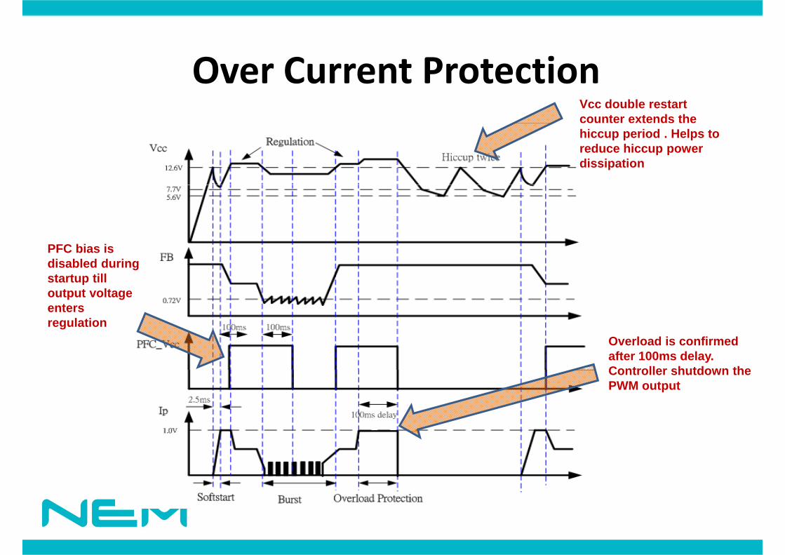
O C t P t tiOver Current ProtectionVcc double restart counter extends the hiccup period . Helps to reduce hiccup power dissipation
PFC bias isPFC bias is disabled during startup till output voltage enters
Overload is confirmed after 100ms delay. Controller shutdown the
enters regulation
Controller shutdown the PWM output
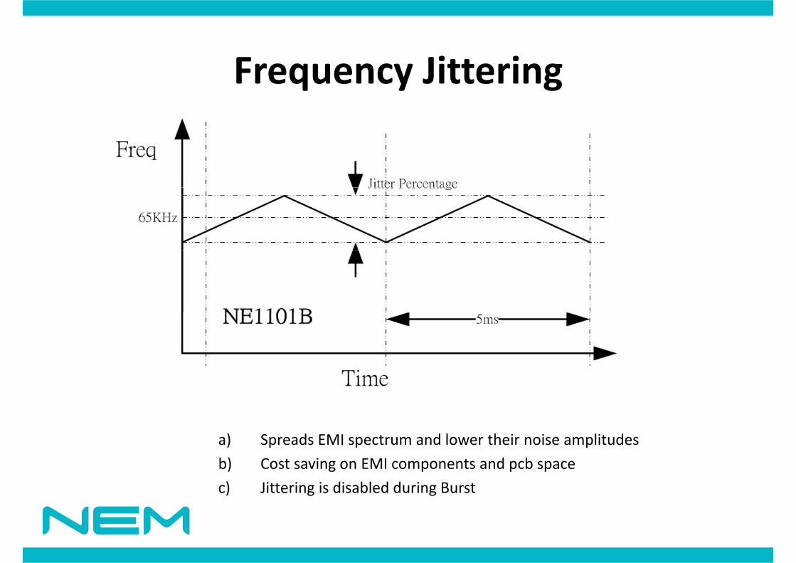
F Jitt iFrequency Jittering
a) Spreads EMI spectrum and lower their noise amplitudesa) Spreads EMI spectrum and lower their noise amplitudes
b) Cost saving on EMI components and pcb space
c) Jittering is disabled during Burst

Reference DesignsReference Designs
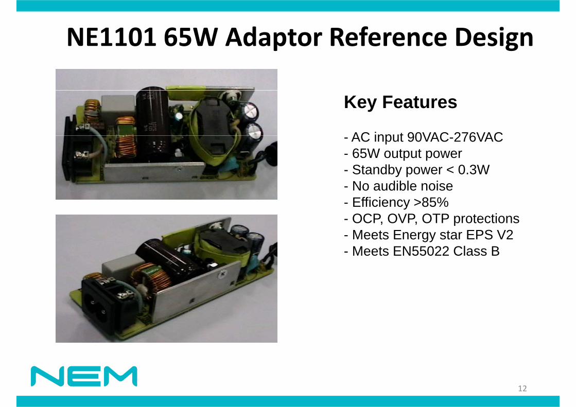
NE1101 65W Adaptor Reference DesignNE1101 65W Adaptor Reference Design
Key Features
AC input 90VAC 276VAC- AC input 90VAC-276VAC- 65W output power- Standby power < 0.3W
N dibl i- No audible noise - Efficiency >85%- OCP, OVP, OTP protections- Meets Energy star EPS V2- Meets EN55022 Class B
12
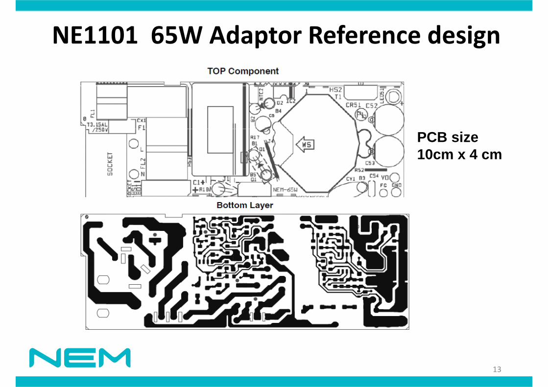
NE1101 65W Adaptor Reference designNE1101 65W Adaptor Reference design
PCB size10cm x 4 cm
13
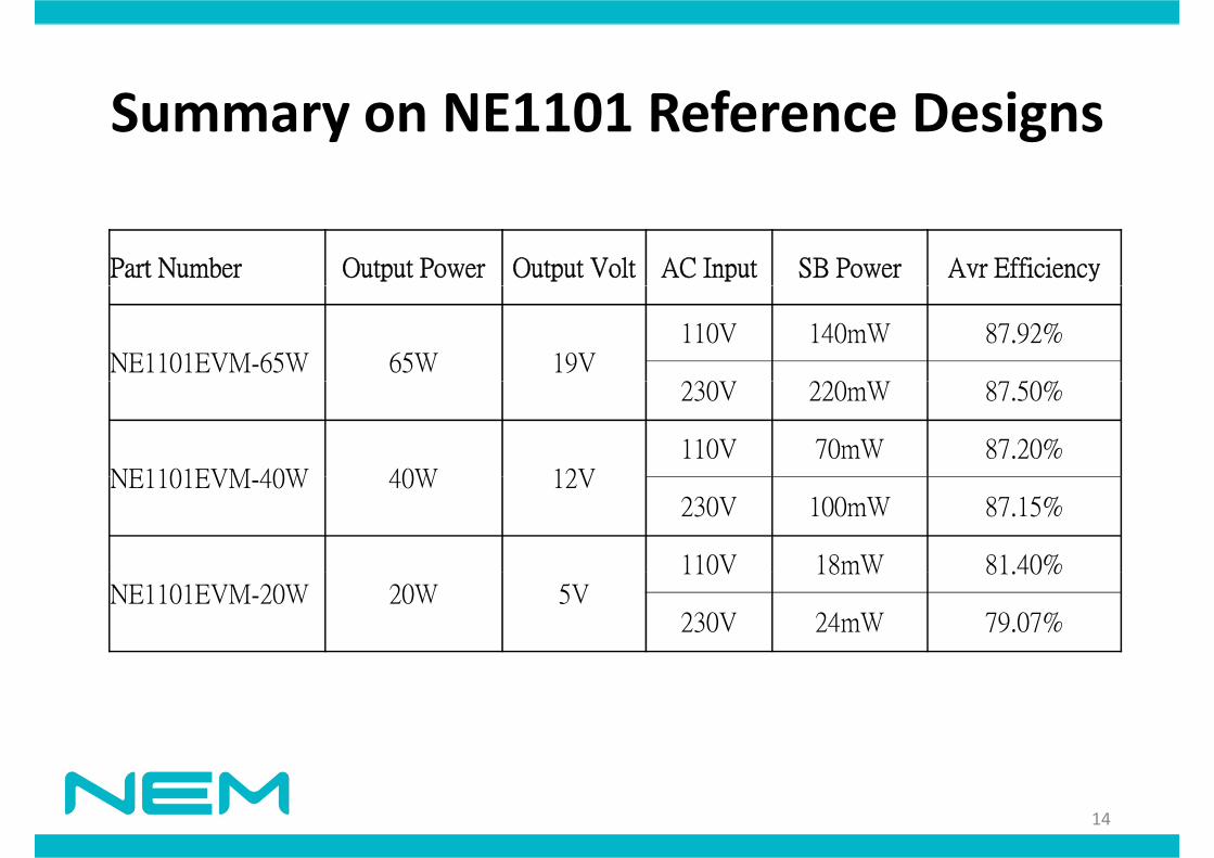
S NE1101 R f D iSummary on NE1101 Reference Designs
Part Number Output Power Output Volt AC Input SB Power Avr Efficiency
NE1101EVM-65W 65W 19V110V 140mW 87.92%
230 220 8 50%230V 220mW 87.50%
NE1101EVM 40W 40W 12V110V 70mW 87.20%
NE1101EVM-40W 40W 12V230V 100mW 87.15%
110V 18mW 81.40%NE1101EVM-20W 20W 5V
110V 18mW 81.40%
230V 24mW 79.07%
14
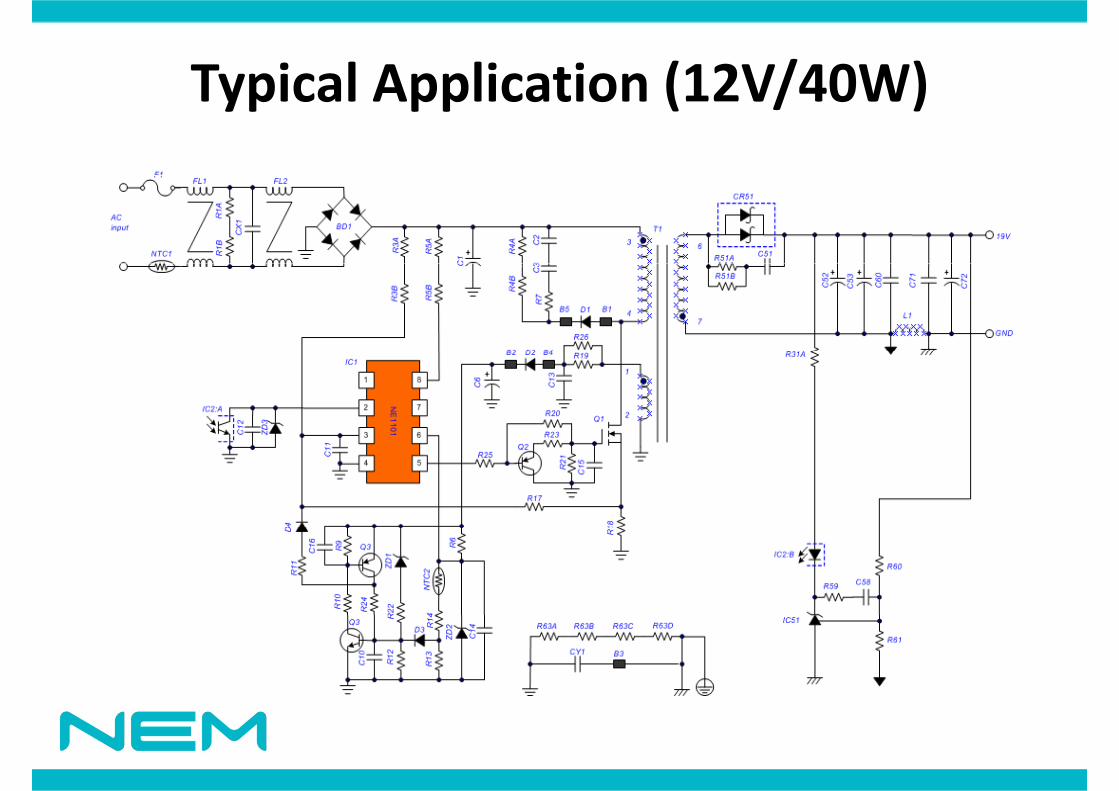
Typical Application (12V/40W)Typical Application (12V/40W)

S l d T h i l S tSales and Technical Supports
• Design‐in documents:Reference design schematics– Reference design schematics
– PCB layout Gerber files
– BOMBOM
– Mathcad external component calculation tool
• Sales contact: max hsieh@nem com tw• Sales contact: [email protected]
• FAE contacts: [email protected] [email protected]
Related Documents


![61BuckConv설계.ppt [호환 모드]bandi.chungbuk.ac.kr/~ysk/61BuckConvDesign.pdfPWM Buck Converter PSPICE Frequency Compensation? 19 Voltage Mode PWM 20 Current Mode PWM 21 Synchronous](https://static.cupdf.com/doc/110x72/5b24bc9c7f8b9a59098b5421/61buckconvppt-bandi-ysk61buckconvdesignpdfpwm-buck-converter.jpg)