AD-A241 739 I14ii I lIII II ! i III NAVAL POSTGRADUATE SCHOOL Monterey, California ",qSTATES. O'LCT i THESIS AN APPROACH TO A DEFENSE DATA NETWORK FOR THE SAUDI MINISTRY OF DEFENSE AND AVIATION by Abdulrahman Abdullah Al-Najashi December 1990 Thesis Advisor: Gary K. Poock Approved for public release; distribution is u'1lim ted 91-13941 3 - lII 'tI !I~ l l1111 ; ' iitilii !! 'll l

Welcome message from author
This document is posted to help you gain knowledge. Please leave a comment to let me know what you think about it! Share it to your friends and learn new things together.
Transcript

AD-A241 739
I14ii I lIII II ! i I II
NAVAL POSTGRADUATE SCHOOLMonterey, California
",qSTATES.
O'LCT i
THESIS
AN APPROACH TO A DEFENSE DATA NETWORK FOR THESAUDI MINISTRY OF DEFENSE AND AVIATION
by
Abdulrahman Abdullah Al-Najashi
December 1990
Thesis Advisor: Gary K. Poock
Approved for public release; distribution is u'1lim ted
91-13941 3 -
lII 'tI !I~ l l1111 ; ' iitilii !! 'll l

Unclassifiedc,!uritv Classification of ,his oaee
REPORT DOCUMENTATION PAGEla Report Security Classification U"'CLASSIFIED lb Restrictive Markings
2a Security Classification Authoritv 3 Distribution Availability of Report
2h DeclassificationDowngrading Schedule Approved for public release; distribution is unlimited.4 Performing Orgaruzation Report Number(s) 5 Monitoring Organization Report Numbers)ha Name of Performing Organization 6b Office Symbol 7 a Name of Monitoring OrganizationNaval Postgraduate School (If Applicable) Naval Postgraduate School
32hc Address Ocirt, state. ana ZIP codei 7b Address (city, state, and ZIP code)Monterev. CA 93943-5000 Monterey, CA 93943-50005a Name of Funiing/Sponsoring Organation 8b Office Symbol 9 Procurement Instrument Identification Number
(If Applicable
Sc Address io, s,,are. and /JP code) 10 Source of Funding Numbers, Program Element Number Pro ec No Task No Worx LnrL Ac .s)no: \
i Title (Include Security Classification) AN APPROACH TO DEFENSE DATA NETWORKS FOR THE SAUDIMINISTRY OF DEFENSE AND AVIATION12 Personai Authorvs) Abdulrahman Abdullah Al-Najashi
l3a Type of Report 13b Time Covered 14 Date of Report (year, month.day) 15 Page Count
Master's Thesis From To 1990, December /871 6 Suppiementary '4 otation The views expressed in this paper are those of the author and do not retect the officialpolicy or position of the De artment of Defense or tne U.S. Government.
7 Cosati Codes 18 Subject Terms (continue on reverse if necessary and identify by block number)
Field Group Subgroup DDN, Defense Data Network; Telecommunications
19 Abstrict (continue on reverse if necessary and identify by block number
Computer and data communication networks have become an integral part of the modern military structure.The technology of its software and hardware change rapidly. As a result, it is of paramount importance for theSaudi Ministry of Defense and Aviation (MODA) to remain abreast of such technology. Due to lack of actual dataabout MODA requirements, this theme is focused on the general concepts of computer and data communicationsnetworks. In addition, this thesis includes a detailed discussion of the U.S. DDN in order to provide guidelinesfor MODA if similar network design is to be developed. The framework of network-capacity planning is brieflydescribed as well.
Zo Disrihution'Availaoility of Abstract 21 Abstract Security Classification
unclassiiediu bmitd [ same as report ]- D] C users Unclassified
U Name of Responsible Individual ) Ik T,, . ,rea code) 22c Utti 5,'
G, K. Poock (408) 646-2636 OR,'Pk)[) FORM 1-473, 4 MAR 83 APR edition may he used until exhausted securitr classicationr ,
All )ther eitioi s ire obsolete ItCld ';iIC'1

Approved for public release; distribution is unlimited.
An Approach to A Defense Data Network for the Saudi Ministry of Defenseand Aviation
Abdulrahman Abdullah AI-NajashiCaptain, Saudi Arabian Air Defense Forces
B.S.E, Arizona State University, 1983
Submitted in partial fulfillment of thr requirements for the degree of
Master of Science in Telecommunication System Management
from the
Naval Postgraduate SchoolDecember 1990
Authors:i Adurahman Abdullah Al-Najashi
Approved by: ---------------Gary K. Poock, Thesis Advisor
Syung W. Suh, Seco eader
DaviX ,ippl ,- nman c-esDepartment of Administrative Sciences

ABSTRACT
Computer and data communication networks have become an integral
part of the modern military structure. The technology of its software and
hardware change rapidly. As a result. it is of paramo nt importancc fo.- t ' 2,
Saudi Ministry of Defense and Aviation (MODA) to remain abreast of such
technology. Due to lack of actual data about MODA requirements, this theme
is focused on the general concepts of computer and data communications
networks. In addition, this thesis includes a detailed discussion of the U.S.
DDN in order to provide guidelines for MODA if similar network design is to
be developed. The framework of network-capacity planning is briefly
,escribd as well.
,/
Accession For
NTIS GRA&IDTIC TABUnnniouriced ElJu st 1 f c nt Ion
By _
Av-,,Iitbllity Codes
. Av,,il and or-Dist j Special
iii

TABLE OF CONTENTS
1. INTRODUCTION ................................................................................................... 1
A. HISTORICAL BACKGROUND IN TELECOMMUNICATIONS ......... 1
1. Telegraphy and Telephony .............................................................. 1
2. Telegraphy and Telephony in the Military ......................... ... 2
3. The Impact of War on Telecommunications Technology ............ 5
B. TELECOMMUNICATIONS IN SAUDI ARABIA ...................... 6
1. The N ational N etw ork ...................................................................... 7
2. The Regional N etw ork .....................................................................
3. The International Network ............................................................. 9
C. PLANS FOR THE NEAR FUTURE ....................................................... 10
IL COMPUTER COMMUNICATION NETWORKS .................................... 11
A . IN T R O D U C TIO N ..................................................................................... 11
B . N ETW O R K IN G ........................................................................................ 11
1. Computer Network Structure ..................................................... 12
2. Computer Network Architecture ................................................ 14
C. SWITCHING TECHNOLOGIES ............................................................ 16
1. C ircuit Sw itching .............................................................................. 17
2. M essage Sw itching ......................................................................... 18
3. Packet Sw itching .............................................................................. 19
D. TRANSMISSION MEDIA ....................................................................... 20
1. T w isted P air ....................................................................................... 21
2. C oaxial C able ..................................................................................... 21
3. O p tical Fiber ..................................................................................... 22
4. Terrestrial M icrow ave ................................................................... 22
5. Communication Satellites ............................................................. 23
iv

IHl. U.S. DEI-ENSE DATA NETWORK ............................................................... 24
A . IN T R O D U C T IO N ..................................................................................... 24
B. D D N H IST O R Y ......................................................................................... 24
C . D D N STR U C TU R E ............................................................................... . 26
1. The D D N Segm ents ....................................................................... 26
2. The DDN Components ................................................................... 27
D. THE DDN ARCHITECTURE ................................................................... 32
1. DoD Communication Architectur2 ............................................. 32
2. The DDN Configuration ................................................................. 34
E. D D N FEA T U R ES ..................................................................................... 46
1. Su rv iv ab ility .................................................................................. . . 46
2 . A v ailab ility ..................................................................................... . . 50
3 . S e cu rity ............................................................................................ . . 53
F. DDN USES BY THE MILITARY ................................................................. 55
IV. THE PROPOSED MODA MODEL ................................................................. 56
A. MODA GOALS AND OBJECTIVES ..................................................... 56
B. NETWORK DESIGN: AN OVERVIEW ............................................ 57
1. N etw ork Structure .......................................................................... 57
2. Network Capacity Planning .......................................................... 62
C. THE TOPOLOGICAL DESIGN .............................................................. 65
1. The Network Access Design .......................................................... 66
2. The Backbone Design ..................................................................... 67
V. CONCLUSIONS AND RECOMMENDATIONS ........................................ 71
A . SU M M A R Y ................................................................................................ 71
B . C O N C LU SIO N S ....................................................................................... 71
C. RECOMMENDATIONS .......................................................................... 72
1. The Network-related Recommendation ..................................... 72
2. User-related Recommendations .............................. 72
v

LIST OF REFERENCES.......................................................................74
BIBLIOGRAPHY............................................................................... 76
IN TITIAL DISTRIBUTION LIST ............................................................ 78
vi

LIST OF TABLES
TABLE 1-1. REGIONAL TELECOMMUNICATIONS ........................................ 9
TABLE 3-1. DOD MILITARY STANDARD PROTOCOLS .............................. 34
TABLE 3-2. DDN SURVIVABILITY UNDER DIFFERENT THREAT
STRESS LEV ELS ............................................................................... 51
vii

LIST OF FIGURES
Figure 1-1 Growth of Local Exchange Capacity .............................. 8
Figure 2-1. The General Structure of a Network ................................................. 13
Figure 2-2. Peer Processes in a N etw ork ............................................................... 15
Figure 2-3. T he O SI Layers ................................................................................... 17
Figu re 2-4. C ircuit Sw itching .............................................................................. 18
Figure 2-5. M essage Sw itching ............................................................................ 19
Figure 2-6. Packet Sw itching .............................................................................. 20
Figure 3-1. Evolution of the Integrated DDN .................................................. 27
Figure 3-2. D D N C om ponents ........................................................................... 31
Figure 3-3. A Comparison between the OSI Model and DoDCommunications Architecture ....................................................... 3
Figure 3-4. Defense Data Network (DDN) ....................................................... 35
Figure 3-5. Encapsulation and Decapsulation Process .................................. 37
Figure 3-6. The Phases of a Connection-oriented Service ............................ 38
Figure 3-7. t'he DDN Addressing Scheme ..................................................... 39
Figure 3-8. Conceptual Structure of the FTP ........................................................ 43
Figure 3-9. The Electronic mail (SMTP) as Used in DDN ............................. 44
Figure 3-10. TELNET Protocol Conceptual Structure .................. 46
Figure 3-11. DDN Survivability Features ......................................................... 49
Figure 4-1. Design Consideration for Switched Data NetworkD evelo p m en t ..................................................................................... 58
Figure 4-2. Network Topography. (a) Centralized (Star) (b) Distributed ..... 59
Figure 4-3. Hierarchical and Non-hierarchical Networks ............................ 60
Figure 4-4. Ring (Loop) Topology ..................................................................... 61
Figure 4-5. Network-Capacity Planning Process ................................................ 63
Figure 4-6. Traffic-V olum e Taole...................................................................... 66
viii
I. INTRODUCTION
A. HISTORICAL BACKGROUND IN TELECOMMUNICATIONS
Humans started using symbols to communicate with each other many
years ago. Recorded history goes back to the year 15 BC when the Sceirites in
the Red Sea basin developed a system of employing letters (symbols) arranged
together to form sentences. That marked one of the first time when symbols
were used as a form of written and oral communications [Ref. l:p. 3]. Then,
man used birds to carry messages. Carrier pigeons were trained to fly to
distant destinations with written messages attached to their feet. As man
sought knowledge by exploring the secrets and mysteries of mother nature,
telegraphy, telephones and other means were invented to serve humans'
needs and fulfill their requirements.
1. Telegraphy and Telephony
Fhe idea of telegraphy came about around 1800 when a device called
voltaic pile (a battery) that converted chemical energy to electrical energy
provided a source of continuous eiectric curien.. Experimenrts betwecer' '120
and 1840 were carried out to reveal the fact that as current flows in a wire, it
causes movement in a magnet hanging freely nearby. Then the means of
receiving signals was discovered with the invention of electromagnetic
detectors in 1836-1837 by Sir William Cooke (1806-1879) and Sir Charles
Wheatstone (1802-1875) in Britain and by Samuel F. Morse (1791-1872) in the
United States.

The first successful telegraph communications took place in Great
Britain with the Paddington-west Drayton line of July 1839. In the United
States, the first successful telegraph communication was Morse's Baltimore-
Washington line of 1844. Shortly, the telegraph was rapidly adopted in the
European continent, in Asia as part of Great Britain's colonial Plans, and
quickly spanned throughout the United States [Ref. 2:p. 2081.
On the other hand the telephone is a device for reproducing scund at
a distance from its source bv means of the transmission of an electrical s. i1.
It was invented by Alexander Graham Bell in 1987. Bell realized that sond
waves do not travel very far nor very fast so he had to come up with a way to
convert sound waves to electrical oscillations which could be transmitted
long distances 900,000 times faster than sound. At the destination, these
oscillations were converted back into sound waves. Bell, with the assistance
of Thomas A. Watson, succeeded in developing a practical telephone by
making an electric current vary in intensity precisely as air varies in densitv
during the production of sound fRef. 3:p. 75].
2. Telegraphy and Telepho in the Military
One of the earliest uses of telegraphy for military purposes took place
in India in 1857 when the Indian revolution broke out against the colonial
British occupation of India. The British Army responded quickly to contain
the revolution in various locations of India by using the telegraph network,
which w;s already established, as a means of strategic and tactical
communications among military units to link all of them to the Command
Center of the British government in Calcutta.
2

Another early use of telegraph in military operations was executed by
the American government and its forces command during the Civil War
between 1861 and 1865. During that war, the first specialized tactical units in
communications evolved [Ref. 4 :p. 84]. Transmission of military messages
during the Civil War was a great factor in stimulating the further
development of telegraphy.
Early developments of military telephones began about 1900 due to
the great importance of telephone communications in the military. During
world War I, other special communicatic.r. systems including the necessary
station equipments were designed for the armed forces. The United States
Navy led the way in deploying shipboard systems and means of
communicating with captive balloons and airplanes. Developments of
special-plirpose military communications system were accelerating and the
production ard installation of such systems were accomplished incredibly
fast.
a. Ship-to-ship and Ship-to-shore Communications.
In 1916, about one year before the U.S. entered WWI, the Navv
was interested in voice communications between ships at sea and between
ships and I-leadqua.'ers on land. On May 7, Bell Systems demonstrated for
the Department of the Navy a long-distance radiotelephone utilizing a special
telephone set on the U.S.S. New Hampshire, transmitting equipment at
Arlington and receiving equipment at Norfolk, Virginia. This was the first
time the two-way telephone had been extended to a vessel at sea [Ref. 5:p. 370]
Short wavelengths were exploited at that time to avoid
interference between tclegraph and telephone and also to provide a wider
3
range of frequencies to accommodate more telephone channels. As a direct
resuit, the Navy investigated the operation of multiplexing radio-telephone
systems with radiotelegraph equipment between the USS Arkansas and USS
Florida on 2-1,200 kHz bandwidths at a distance of 30 miles apart. The results
were encouraging and led to the design of a multiplexer system with
subcarriers at 25, 35, and 45 kHz by R. Heising. After completion of
equipment installation on the USS Pennsylvania, USS Seattle, and USS
Wyoming in January 1917, the subcarriers were modulated by voice then
multiplexed so that nine conversations could be handled at the same time.
This was the first practical use of the "carrier" principle [Ref. 5:p. 3701.
As the U.S. declared war on April 5, 1917, radiotelephone projects
were changed from general to specific military applications. The Navy had
requested 15 sets in submarine chasers with short-range communications for
the rapid coordination of their movements. These sets were continuous-
wave telegraphy with an additional capability of telephone-modulating
attachments. Communication between submariae chasers was successful at
45 miles apart. This equipment became the first radiotelephone equipment
standardized by the Navy and it was designated CS-396 with a frequency range
of 500 to 1500 kHz and power -about five watts.
b. Aircraft Communications.
Since the U.S. Army Aviation Services, operated by the Army
Signal Corps, and the Navy had perceived the air force to be a striking power
at war time, they capitalized on the importance of radio communications
between airplanes and ground and airplanes themselves. On May 22, 1917,
Western Electric received a request for the development of an airplane set
4

with 2,000-yards range from Chief Signal Officer, General Squire. The
development took place rapidly. By August 20, two-way communication
between planes in flight was achieved up to two miles apart. The radio set
was coded SCR-68 and quantity orders were placed as well as a request for the
adaptation of the set to the submarine chasers. Transmission was
accomplished by the use of a trailing-wire antenna on the plane with a wind-
driven generator placed on the propeller's slipstream. Since tactical flights
require high maneuverability, the long trailing-wire antenna was a
disadvantage and a modification of design for smaller antenna was greatly
desirable. As the design was finalized, the war was coming to an end and
there was little, if any, production of the radio sets [Ref. 5:p. 372].
3. The Impact of War on Telecommunications Technology
The developments in radio communications in the early part of the
20th Century had some direct effect on the consequences of WWI. The war
had influenced most noticeably military thinking. It led military science into
a new era of feasible voice communication among military units in the air, at
sea, and on the ground.
Furthermore, wartime efforts substantially affected the
telecommunications technology. Due to the nature of doing things very
rapidly during wartime, there was little time or effort spent on requirements
study and analysis. Consequently, inventions and empirical solutions to
technical problems were stimulated by the pressures of necessity. In addition,
standardization and quantity production were achieved for equipment and
components as a result of wartime programs and experierce. Another factor
that contributes to the technological advances in the military communication
5

applications is that the cost of providing these facilities was not of major
concern.
As telecommunications technology advanced, particularly after
WWII, strategic communication for military applications was no longer
confined within one country but it had extended across the oceans and the
continents. The United States military bases in Europe and Southeast Asia
serve as a good example for the intercontinental communications
requirement.
Different types of media have been devised and employed such as
coax cables, submarine cables, optical fiber cables, microwave networks and
satellites. The last one possesses great importance since the beginning of the
space age in 1957 due to the fact that the United States and the Soviet Union
have competed fiercely to use space for strategic military surveillance and
communications. There are at least 273 satellites launched by the U.S.A. for
military applications between 1957 and 1970. This makes up 50% of the total
satellites orbiting in space [Ref. 4:p. 851.
B. TELECOMMUNICATIONS IN SAUDI ARABIA
In 1970, the Kingdom of Saudi Arabia started employing the five-year
planning method for the development of its civilization. In 1975, a second
five-year plan was approved in excess of 500 billion riyals ($150 billion U.S.
dollars). It was a huge budget due to the kingdom's increasing oil revenues.
The objective of this plan was to develop the overall infrastructure of the
country.
Telecommunications constitute a fundamental base for every aspect of
the present technological world. As a result, Saudi Arabia has capitalized on
6
modern telecommunications systems to assist the development of its
infrastructure and, accordingly, telecommunications has become a priority
due to several factors. [Ref. 6:p. 2]
The first is religion. Saudi Arabia is in a unique position relative to the
Islamic world since it is located at the heart of this world. The second is
geography. Saudi Arabia is a large country that contains a diversity of
geographical features varying from vast deserts to chains of mountains and
terrains. Therefore, its population is scattered over hundreds of towns and
villages isolated by long distances. The third is traditions. The society of
Saudi Arabia is characterized by strong family ties and the heritage of past
generations. These two aspects are strongly developed by the teachings of
Islam. The fourth is international presence. Saudi Arabia holds strong
relations economically and politically with most of the world as a result of its
moderate international policy.
Telecommunications networks in Saudi Arabia can be classified in three
categories [Ref. 6:p. 41:
1. The National Network
This network currently serves more than 400 cities and villages across
the country. Tb' plans call for a coverage of 700 cities and villages by 1990.
This network is composed of the following:
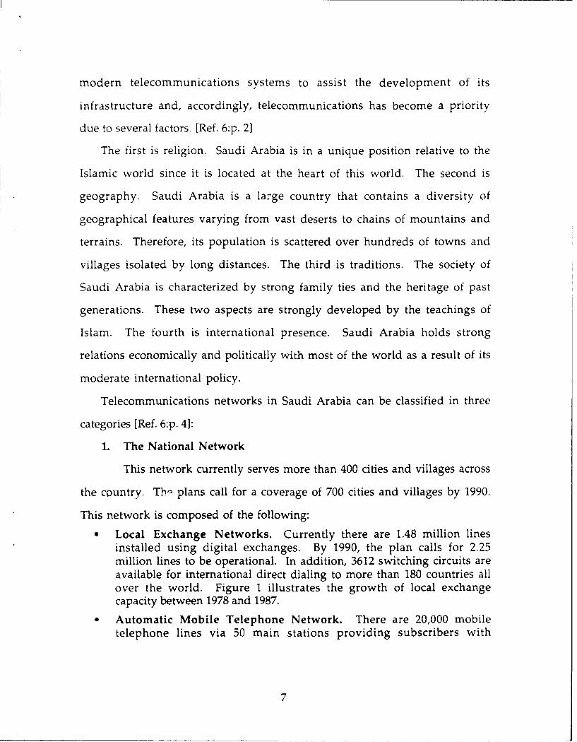
* Local Exchange Networks. Currently there are 1.48 million linesinstalled using digital exchanges. By 1990, the plan calls for 2.25million lines to be operational. In addition, 3612 switching circuits areavailable for international direct dialing to more than 180 countries allover the world. Figure 1 illustrates the growth of local exchangecapacity between 1978 and 1987.
* Automatic Mobile Telephone Network. There are 20,000 mobiletelephone lines via 50 main stations providing subscribers with
7

normal telephone services and access to the national and internationaltelecommunications networks.
200(
180(
160(
140(
120(
100410( •Total Exchange
. .................................. .... .... .... A nalog Exchange800
600
400
200
01978 1979 1980 1981 1982 1983 1984 1985 1986 1987
Year
Figure 1-1. Growth of Local Exchange Capacity [Ref. l:p. 81
Coaxial Cable Network. There are more than 5000 km. of 12, 18, and 60MHz coaxial cables that connect the kingdom from east to west a.- 'from north to south with a capacity of 27,000 telephone channels ai..two color TV channels.Microwave Network. A 20,000 km. microwave system is in placecarrying over 75,000 telephone channels and two color TV channels
within the country. This network is composed of 450 repeaters and 450towers.
2. The Regional Network
Due to the common religious and similar cultural background, Saudi
Arabia holds unique relationships with its neighboring Arab countries,
politically, socially and economically. These ties have been expressed by the
implementation of a regional telecommunications network. A satellite
8
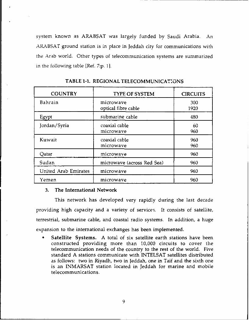
system known as ARABSAT was largely funded by Saudi Arabia. An
ARABSAT ground station is in place in Jeddah city for communications with
the Arab world. Other types of telecommunication systems are summarized
in the following table [Ref. 7 :p. 1].
TABLE 1-1. REGIONAL TELECOMMUNICATONS
COUNTRY TYPE OF SYSTEM CIRCUITS
Bahrain microwave 300optical fibre cable 1920
Egypt submarine cable 480
Jordan/Syria coaxial cable 60microwave 960
Kuwait coaxial cable 960microwave 960
Qatar microwave 960
Sudan microwave (across Red Sea) 960
United Arab Emirates microwave 960
Yemen microwave 960
3. The International Network
This network has developed very rapidly during the last decade
providing high capacity and a variety of service-. It consists of satellite,
terrestrial, submarine cable, and coastal radio systems. In addition, a huge
expansion to the international exchanges has been implemented.
Satellite Systems. A total of six satellite earth stations have beenconstructed providing more than 10,000 circuits to cover thetelecommunication needs of the country to the rest of the world. Fivestandard A stations communicate with INTELSAT satellites distributedas follows: two in Riyadh, two in Jeddah, one in Taif and the sixth oneis an INMARSAT station located in Jeddah for marine and mobiletelecommunications.
9
" Submarine and Marine Systems. Saudi Arabia is the major investor inthe submarine cable system which extends from Singapore to Francevia Jeddah with a length of 13,200 km. It owns 1,800 circuits; 916circuits are already in use among 23 countries [Ref. 8:p. 21.
* International Exchanges. Saudi Arabia has seven internationalexchanges located in Riyadh, Jeddah, and Dammam. Four exchangesare for telephone and the remaining are international telex exchanges.In addition, three packet switching exchanges for data transmissionhave been recently installed. This network provides more than 10,000circuits.
The Kingdom of Saudi Arabia also serves as a transit-gateway for
international telecommunications due to its geographical location at the
center of the world. International telecommunications traffic btween East
and West goes through the kingdom during off-peak hours [Ref. 7:p. 8].
C PLANS FOR THE NEAR FUTURE
In the near future, the PTT of Saudi Arabia is planning to establish a
modern public data network that consists of three PSN's (packet switching
nodes) and 40 packet concentrator locations to cover most of the major
population centers. In addition, three international gateways will be installed
to support data communications throughout the world.
Furthermore, these future plans set the stage for establishing the
necessary ground for introducing the Integrated Services Digital Network
(ISDN). Accordingly, PTT is enhancing the current networks for digital
operations, expanding the use of optical fiber cable network and installing
ISDN-compatible digital facilities. All of these efforts will facilitate the
imp!-mentation of ISDN enabling subscribers to send voice, data, and images
all over the world.
10

II. COMPUJTER COMMUNICATION NETWORKS
A. INTRODUCTION
As technology mad, its big stride when the industrial revolution started
in the 18th Century, rapid development followed in the different fields of
mechanical and electrical systems. The steam engine was the predominant
technology of the 19th Century.
Although telegraphy and telephony were invented during the 19th
Century, they also served as the bridge into the 20th Century. This century
can be characterized as the information technology age. On the other hand,
computer networking has changed dramatically just in the past 15 years to
accommodate the growing needs of the information and communications
technologies. Therefore, sharing resources such as databases, application
programs, and all different types of hardware is the primary objective of such
computer networks.
B. NETWORKING
The term network can be defined as the linking of groups of computers so
that they can communicate with each other and share resources. The linking
of computers can be implemented within an organization to connect
individuals or among several organizations.
Local area network (LAN) defines the configuration of a network within a
centralized organization whereas long-haul networks, known as Wide Area
Networks (WANs), typically cover users in different organizations spread
over entire countries [Ref. 9:p. 31.
11

A third category of networks, known as Metropolitan Area Networks
(MAN), defines a network that is between the LAN and the WAN. A MAN
network covers an area of an entire city using LAN technology. This was
used at the beginning of cable television but it is widely used to connect
computers within one city [Ref. 10:p. 1171. This section will focus on WAN
networks, their structure, and their architecture.
1. Computer Network Structure
In general, a wide area network consists of the following:
(1) The users
k2) fhe access facility (the access network)(3) The backbone network (the subnet)
The term user here is defined to be any entity that uses the network
to communicate with another entity. Examples of such users are terminals,
mainframe computers, and end-users. The term host has been widely used to
designate the user portion of the network.
The access network is defined as the area of the network that
facilitates a user's access (a host) into the subnet or the backbone in order to
establish connection across the whole network to another host. Components
of such an access network are the terminal access contollers (TAC) that allow
terminals to access the backbone. Network access components (NAC) is a
mini-TAC part of the access network and is a protocol translation device that
supports asynchronous devices and the IBM 3270 [Ref. 11:p. 30]. Gateways and
bridges fall into the access network area as well.
The third part of a computer network structure is the backbone
network. This is the heart of the network and it is sometimes referred to as
the communicatio ;ubnet. Its primary function is to carry messages from
12

host to host. It consists of two distinct components: 1) transmissions lines,
2) switching elements.
The function of the transmission lines, sometimes called circuits,
trunks, or channels, is to move data bits between machines. Switching
elements are special-purpose minicomputers used to connect two or more
transmission lines. When data arrive on the incoming lines, this
minicomputer decides on which output line to send them [Ref. 10:p. 6].
Figure 2-1 depicts thie general structure of a network.
TheBackbone,Network
Figure 2-1. The General Structure of a Network
The communication backbone has two types of design: point-to-point
and broadcast. In a point-to-point network (often called switched network)
communication is established between the source host and the destination
host through a series of switching elements (nodes). In broadcast networks a
sin6le communication medium is shared by all users on the network. When
13

a message is transmitted by any machine, it is received by other machines on
the network and the intended destination machine is specified by means of
an address field within the message [Ref. 10:p. 7].
2. Computer Network Architecture
a. Definitions
A network architecture is defined to be the formation of a
structure. It describes what components or elements exist, how they operate,
and what form they take. This generally includes hardware, software,
communications link control, topologies and protocols [Ref. l:p. 270].
A protocol is a set of rules and conventions that govern the
establishment of communications, the exchange of data, and the termination
of communications between entities in different systems. An entity is any
object with a capability of sending or receiving information such as a user
application program, electronic mail, and file transfer packages. On the other
hand, a system is a physically distinct object with one or more entities existing
within it. Examples of systems are computers and terminals [Ref. 12:p. 201
It should be noted that hardware in the field of computer
communication networks (CCN) is fairly standardized for
telecommunications. On the contrary, software is extremely complex.
Therefore, most networks are built using a layered approach to reduce the
design complexity of the communications protocols. Each layer or level in
the hierarchy performs certain functions to provide services to the next
higher layer. Accordingly, each layer is designated a protocol that
communicates with the corresponding layers on the different systems of the
14
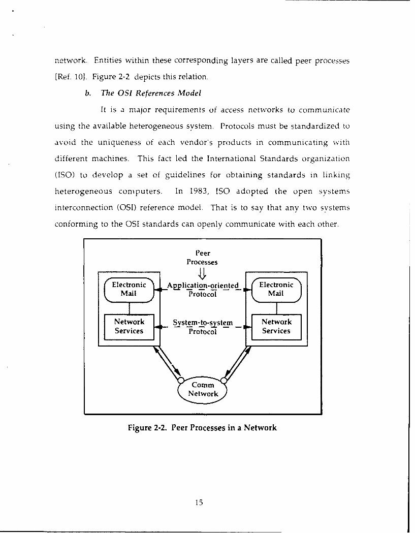
network. Entities within these corresponding layers are called peer processes
[Ref. 10]. Figure 2-2 depicts this relation.
b. The OSI References Model
It is a major requirements of access networks to communicate
using the available heterogeneous system. Protocols must be standardized to
avoid the uniqueness of each vendor's products in communicating with
different machines. This fact led the International Standards organization
(ISO) to develop a set of guidelines for obtaining standards in linking
heterogeneous computers. In 1983, ISO adopted the open systems
interconnection (OSI) reference model. That is to say that any two systems
conforming to the OSI standards can openly communicate with each other.
PeerProcesses
lJElectronic Application-oriented Electronic
Mail Protocol Mail
Network ystem-to-systern NewrServices Protocol Services
Figure 2-2. Peer Processes in a Network
15

The OSI reference model consists of seven layers numbered
sequentially from the lowest laver to the highest. Each layer is defined by the
services offered to the next higher layer. A brief summary of each laver
follows [Ref. 1, 10, 12]:
(1) The physical layer. This laver is the lowest in the hierarchy of the OSImodel. It deals with the transmission of unstructured raw bits over thephysical medium.
(2) The data risk layer. This layer is responsible for the transfer of dataover the channel. It also provides for synchronization, identity of data,error detection, and flow control.
(3) The network laver. This is the layer where the control of routingmessages in the subnet (backbone) takes place in a transparent mannerbetween the transport entities.
(4) The transport laver. This is the layer responsible for the exchange ofdata between processes in different systems in a sequential pattern withno loss, error, or duplication. It is also responsible for splitting up thedata into smaller units if needed.
(5) The session laver. It serves as user interface to establishcommunication session between entities on different machines. It alsoprovides mechanisms for retransmission if a failure occurs.
(6) The presentation layer. Its function is to provide for the syntax of dataexchanged between entities. It usually contains tables of syntax inASCII, EBCDIC -id Videotex. An example of a layer six .)tocol is thevirtual termina rotocol.
(7) The application layer. This layer provides facilities to support the end-user application processes. It generally consists of mechanisms tosupport management functions for distributed applications. Suchprotocols are file transfer and electronic mail. Figure 2-3 illustrates thelayers of the OSI reference model.
C. SWITCHING TECHNOLOGIES
A communication between two devices can be established by direct
connection. But a problem exists if the number of devices increases. The
number of links is related to the number of devices N as follows:
16

of full-duplex links = N(N-1)/2.
So, if there are ten devices, then 45 full-duplex links are required. Obviously,
it is impractical and it is not cost-effective. As a result, a communication ,
netvork is the appropriate approach to resolve the pioblem [Ref. 12:p. 1941.
Peeri Protocols ApplicationApplication----------- Ahcto
laver layer
Presentation Presentatiaon
iaver layer
Session -- Session
laver layer
Transport Transport
laver layer
Network Network
layer layer
Data Link Data Link
;aver -- layer
Physical - - - -- Physical
laver layer
Physical media
Figure 2-3. The OSI Layers
Three widely used switching techniques are employed in the switched
networks (point-to-point networks). They are circuit switching, message
switching, and packet switching.
1. Circuit Switching
In circuit switching, a connection path is dedicated between two
stations via a sequence of links among nodes (switching elements). The
process of communication using this technique involves three stages. The
17
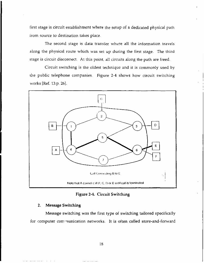
first stage is circuit establishment where the setup of a dedicated physical path
from source to destination takes place.
The second stage is data transfer where all the information travels
along the physical route which was set up during the first stage. The third
stage is circuit disconnect. At this point, all circuits along the path are freed.
Circuit switching is the oldest technique and it is commonly used by
the public telephone companies. Figure 2-4 shows how circuit switching
works [Ref. 13:p. 26].
(..,a11II I ii 1 (IgI(J. U tO 1. .
NOlO tha.t A caIflrol c~~Il Ii. C. I) or E uiitlil call is termlinlate-d
Figure 2-4. Circuit Switching
2. Message Switching
Message switching was the first type of switching tailored specifically
for computer conunication networks. It is often called store-and-forward
18

switching. As a message leaves its source machine, it is stored in the first
switching node and then it is forwarded to the next node along the path until
it reaches its destination.
A message is delayed at each node for the time required to receive all
bits of the message, to check for errors, and then to retransmit. Consequently,
this switching technology is used when time is not a critical factor since
transmission delays along the path can be significant. The routing of the
message can be static or dynamic as the message travels towards its
destination. Figure 2-5 depicts message switching [Ref. 3:p. 271.
C
B2
Figure 2-5. Message Switching
3. Packet Switching
Packet switching is similar to message switching except that packet
switching networks place a right upper limit on the block size with a
19
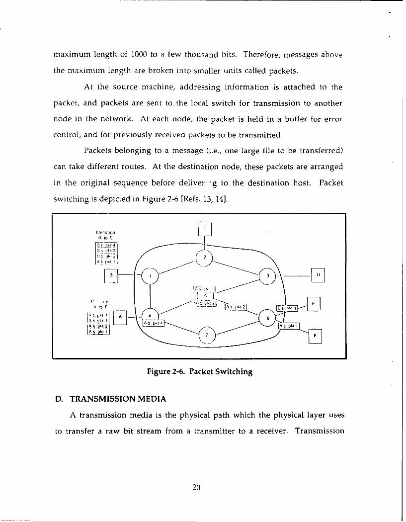
maximum length of 1000 to a few thousand bits. Therefore, messages above
the maximum length are broken into smaller units called packets.
At the source machine, addressing information is attached to the
packet, and packets are sent to the local switch for transmission to another
node in the network. At each node, the packet is held in a buffer for error
control, and for previously received packets to be transmitted.
Packets belonging to a message (i.e., one large file to be transferred)
can take different routes. At the destination node, these packets are arranged
in the original sequence before deliver --g to the destination host. Packet
switching is depicted in Figure 2-6 [Refs. 13, 14].
C,II Io t :-
l 4
pItp 2t I
-- [
A 0 A
Figure 2-6. Packet Switching
D. TRANSMISSION MEDIA
A transmission media is the physical path which the physical layer uses
to transfer a raw bit stream from a transmitter to a receiver. Transmission
20

media fall into two broad categories: hardwire (twisted pair, coaxial cable, and
optical film cable) or softwire (air, vacuum, and seawater) [Ref. 13 :p. 17].
In this section, the most commonly used media will be briefly discussed.
1. Twisted Pair
It is the oldest and still most common transmission media. It consists
of two insulated copper wires, typically about 1 mm thick, twisted together in
a helical pattern in order to reduce electrical interference. Telephone
companies are the primary user of it.
Twisted pair can be used for digital and analog transmission. It is
widely used in local networks due to its low cost, availability, and ease of use.
However, twisted pair is limited in distance, bandwidth and data rate
capability [Ref. 10:p. 58].
2. Coaxial Cable
A coaxial cable consists of a stiff copper wire as the core, surrounded
by an insulating material. On top of that, a cylindrical conductor in the form
of a braided mesh is covered in a protective plastic sheath.
Two kinds of coax cable are widely used for analog and digital
transmission. One kind, 50-ohm cable, usually termed baseband cable, is used
for digital transmtission. A data rate of 10 Mbps is feasible with a length of one
kilometer.
The other kind is the 75-ohm Community Antenna Television
(CATV) sometimes called broad band used for analog transmission. In
computer networks using broadband, an interface is needed to convert the
outgoing digital bit stream to an analog signal, and the incoming analog
signal to a bit steam [Ref. 10:p. 59].
21

3. Optical Fiber
Optical fiber is a thin (50 to 100 micrometer) rr .dium capable of
transmitting data by pulses of light. Optical fiber is made of various glasses
and plastics. Optical fiber is used extensively for long-distance
telecommunications and military applications [Ref. 13 :p. 191.
There are several advantages to using optical fiber as a transmission
medium. Fiber optics cable is small in size and lighter in weight. Data rate in
the giga bps is feasible over long distance. Another advantage is the signal
loss due to attenuation is much lower than in other media. In addition,
optical fiber systems are immune against noise and interference [Ref.
15:p. 5851.
4. Terrestrial Microwave
For long-distance communication, microwave transmission is
commonly used. Parabolic antennas are mounted on towers to send a beam
to another antenna which is in a line of sight to the sending antenna.
Microwave is an alternative to coaxial cable for transmitting television and
voice.
Lately, microwave has been widely used for short point-to-point links
between buildings. This can be used for closed-circuit TV or as a data link
between local networks. Moreover, terrestrial microwave has the potential
for transmitting digital data in small regions (radius < 10 km). This concept
has been termed "local data distribution," and would provide an alternative
to phone lines for digital networks [Ref. 12:p. 57].
22

5. Communication Satellites
A communications satellite is simply a microwave relay station
.ocated in a constant orbit above the Earth's atmosphere. It is used to link two
or more ground-based microwave transmittal receivers, known as earth
stations or ground stations [Ref. 12:p. 59].
The satellite operates on two different frequencies. One frequency,
called the up-link, is used to receive transmission from the ground stations.
It amplifies (analng transmission) or repeats (digital transmission) the signal.
Then, it transmits on the second frequency, which is called down-link.
For a communication satellite to be effective, it must be at an altitude
of approximately 36,000 km above the equator in order to have a period of
rotation equal to the Earth's period of rotation (24 hoursY.
Communication satellites are being used for international telephone
trunks, telex, and television over long distances. It is considered to be the
optimal medium for high-usage international traffic and is competitive with
line-of-sight microwave and coaxial cable for many applications [Ref. 12:p. 601.
23

III. U.S. DEFENSE DATA NETWORK
A. INTRODUCTION
The United States Defense Data Network (DDN) has been designec to
meet the U.S. Department of Defense (DoD) requirements for a secure,
reliable, and efficient computer communication network. It allows
communication of a variety of user applications ranging from logistics to the
most critical intelligence data transmitted among mainframe systems of
various securit) levels.
The commitment to DDN to be the common-user world-wide data
communication network is the result of the directive issued by the Secretary
of Defense in March 1983. The policy states
All DoD Automatic Data Processing (ADP) systems and data networksrequiring data communications services will be provided long haul andarea communications, interconnectivity, and the capacity forinteroperability by the DDN. Existing systems, systems being expandedand upgraded, and new ADP systems or data networks will become DDNsubscribers [Ref. 21:p. 2].
B. DDN HISTORY
In the early 1960s, the development of the message switching systems,
known as Automatic Digital Network I (AUTODIN I) was begun to provide
common-user automated data communication. AUTODIN I was considered
a major advance in digital communications and it set the stage for the later
development of the DDN [Ref. 18:p. 1211.
The Defense Advanced Research Projects Agency initiated the first packet-
switchi-g network pruject, known as ARPANET, in 196C The project was
24

designed as an intra-agency communications system and as an experiment
investigating new technologies. The research team desired to expand the
network functions across the continent of the United States as the need to
share information and to access remote databases grew rapidly [Ref. 9:p. 5].
As the research community proved that users of different types of
computers could share programs and communicate over long distances,
ARPANET allowed participation of users with operational requirements. As
the number of operational users of the network increased, the responsibility
for its operation was transferred to the Defense Communications Agency
(DCA) in 1975 [Ref. 21:p. 31.
During that time period, plans to replace AUTODIN I by AUTODIN II
were developed to employ packet-switching technology. Those plans were
driven by the fact that the DoD requirements for a highly secured military
communications network became inevitable. Moreover, the increased
common carrier costs for long distance leased lines were economically
unjustifiable due to the inherent limitations of AUTODIN I.
In September 1981, DCA initiated a study comparing the planned
AUTODIN II to ARPANET. The study revealed that it was no longer
beneficial to support the development of two packet-switched networks.
Therefore, the ARPANET technology was chosen over AUTODIN II to be the
basis for the development of the national DDN. The DDN project was started
and the AUTODIN II was canceled, in April 1982, based on risk assessment,
cost, and txpandability [Ref. 9:p. 51.
25

C. DDN STRUCTURE
The DDN is a large military common-user data communications
internetwork. It is designed to support military operations and critical
intelligence systems as well as general purpose automated data processing
(ADP) systems. Moreover, it supports distributed applications with iong-haul
data communications requirements.
The U.S. DDN consists of several networks. These networks have
compatible hardware and software which allows them to communicate with
each other. In this section, the DDN segments and components will be
looked at in order to achieve the overall picture of the network.
1. The DDN Segments
In reality, the DDN is composed of a family of network segments.
Each segment is a network in its own right that operates independently at its
own security level. Communication gateways exist between unclassified
networks. But at higher levels of classification, the physical separation of the
networks has been preserved to enhance security [Ref. 18:p. 121].
The major segments of the DDN serve different types of users in the
DoD community. The MILNET, a military operational network, and the
ARPANEY, a military research and development network, constitute the
unclassified segments of the DDN. The classified segments of the Defense
Data Network consists of several independent networks. These include the
Strategic Air Command Digital Information Network (SACDIN), the Defense
Integrated Secure Network (DISNET), now called Defense Secure Network
One (DSNET 1), the Secure Compartmented Information Network (SCINET),
now called DSNET 3, and the World X4Tde Military Command and Control
26

System (WWMCCS) Intercomputer Network (WIN), now called DSNET 2
[Ref. 2 1 :p. 191.
The evolution of the U.S. DDN progressed in distinct stages since
1982 to reach the mature configuration. The final configuration of the DDN
will be of a single, multi-level secure communication network. The
integrated DDN depicted in Figure 3-1 will be achieved by the
implementation and use of the Blacker technology. This technology,
available in the early 1990s, will allow the separate classified subnetworks to
merge into a single, shared, secure network, and will more readily support
multi-level secure computer systems [Ref. 21:p. 12].
DSNET I (DISNET)
SACD[N CLSIE
DSNET 2 (WN SEGMENTS
DSNET 3 (SCINET) / . '
. .....,N N BLACKER INTEGRATE",
MILNET RI; :'"[UNCL ASIFffED*
ARPANET - SEGMENTS
Figure 3-1. Evolution of the Integrated DDN
2. The DDN Components
The Defense Data Network uses packet-switching technology in its
components. Three major components make up the DDN:
27

a. Packet-switching nodes (PSNs)
PSNs, which link together the network trunk lines to route data
packets between source and destination, compose the DDN backbone. The
PSNs offer reliable and efficient transmission of data throughout the
network. The packet switch used in the DDN is a Bolt Beranek, and Newman
C/30E computer. It can serve as a point of entry, a relay, or a point of exit for
the DDN backbone.
The DDN backbone consists of hundreds of packet switches
located throughout the world. Most of the transmission links, within the
U.S.A., consist of digital leased terrestrial circuits operating at 56,000 bits per
second (bps). In addition, other transmission requirements for other speed
lines are available such as 9,600 bps and 64,000 bps. Outside the United States,
transmission links vary in speed depending upon service availability [Ref.
21:p. 4].
The PSN software includes a distributed, dynamic adaptive
routing algorithm which enables the nodes to cooperate automatically :n
routing traffic around congested or failed switches and trunks. At a node,
each incoming packet is time-stamped with an arrival time. A departure
.,.e is recorded when the packet is transmitted. If a positive
acknowledgement is returned from the next node, the delay for that packet is
recorded as the departure time minus the arrival time plus transmission time
and propagation delay.
Therefore, the node must know link data rate and propagation
time. If a negative acknowledgement is returned from the next node, the
d, irture time is updated and the node tries again until a measure of
28
successful transmission is achieved. The node computes the average delay
every ten seconds and updates its routing table. This adaptive algorithm has
proved to be responsive and reliable in the case of individual nodes and for
trunk line failures [Ref. 12:p. 271].
b. DDN Network Access
The access network of the DDN encompasses a variety of
computer and terminal connections. Three configurations are widely used to
connect mainframe computers.
First, in the direct method, where a host computer connects
directly to a PSN. Although it is not an efficient way of using a switching
node access port, the user does not depend on any other access equipment to
reach 'he DDN backbone.
The second configuration uses the Host Front End Processor
(HFEP) between one or more hosts and a PSN. This processor converts all
incoming data from the hosts into formats acceptable for DDN transmissions.
HFEP performs the networking functions and frees the hlost computer for
data processing. This is in contrast with the direct method where the host
performs the networking functions.
The third configuration uses a Terminal Emulation Processor
(TEP). This processor allows terminals to access their remote hosts through
the network instead of via a dedicated line to the host [Ref. 9:p. 271. Its
examples include TACs and NACs, which are described below.
Terminals which are not attached to a mainframe system can
access DDN by the use of Terminal Access Controller (TAC). Each TAC
consolidates the input of 63 asynchronouE terminals into one line that
29

connects to the PSN. TACs add more security to the network by requiring
user identification. The Network Access Controller (NAC) mini-Tac is
another network access component that allows 16 ports of synchronous and
asynchronous terminal connections.
Personal computers/systems (PC/PS) that can perform
mainframe systems type functions can be attached directly to a PSN port but
that is not efficient since networking functions will be done by the personal
computer/systems thereby wasting resources greatly needed for data
processing. A more cos effective and efficient way of accessing DDN is to
have a number of PCs/PSs on a LAN configuration via a gateway. A gateway
is a device that allows communications among heterogeneous networks and
does the networking functions, thus freeing the PC's/PS's processing
resources. Figure 3-2 illustrates the DDN components.
The transmission speeds of access network circuits are 9,600 to
56,000 bps. The TACs maximum transmiss.on rate is 9,600 bps. The
maximum transmission rates for the NACs are 9,600 bps asynchronous and
19,200 bps synchronous [Ref. 21:p. 16]. The Defense Communication Agency
(DCA) has deployed a device called Very Small Aperture Terminal (VSAT),
that allows high transmission rates over long distances. 'VSATs use a
government satellite to transmit and receive information at a rate of 56,000
bits per second [Ref. 15:p. 291.
c. The Network Monitoring Center (NMC)
An NMC is used to provide control, monitoring, and
management functions for the DDN. Currently, there are regional
monitoring centers in Europe, the Pacific and the Continental United States
30
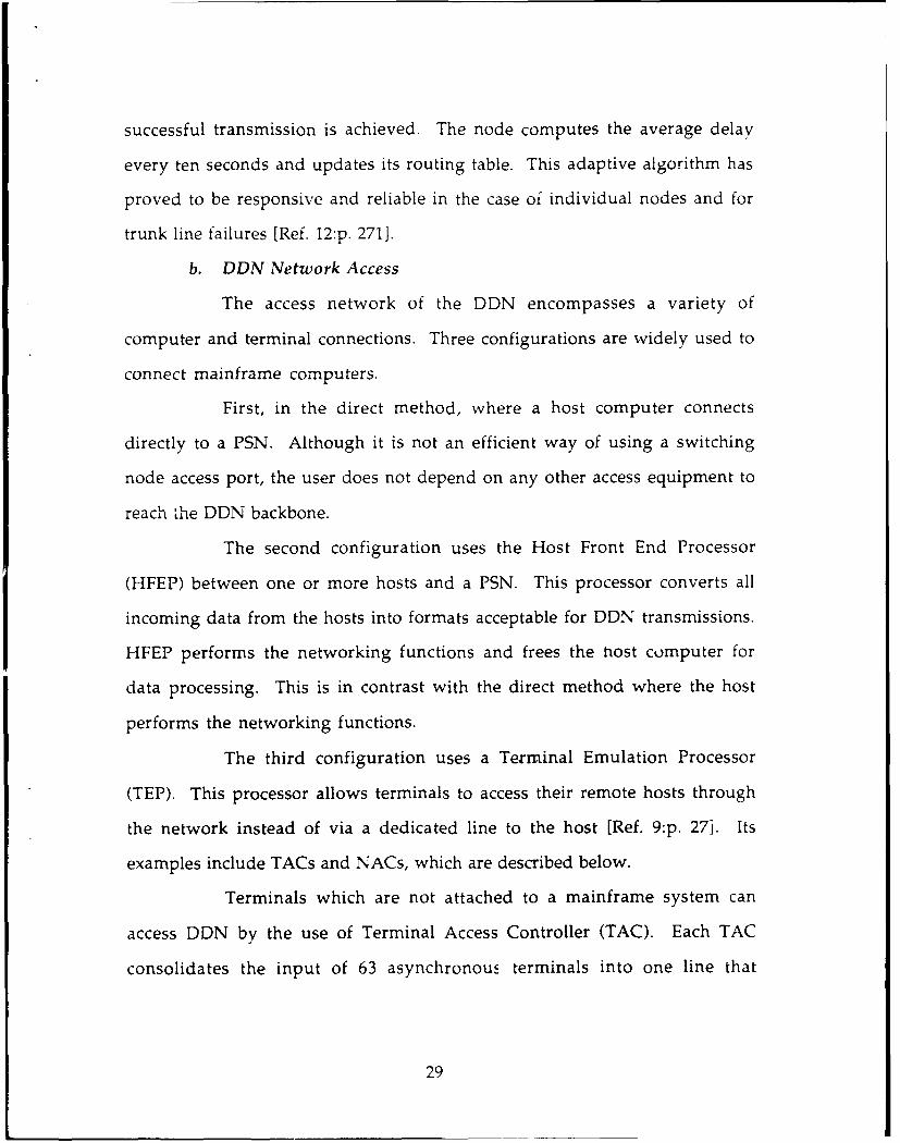
for the MILNET. In addition, there is an NMC for every other separate
segment of DDN.
Host - Emulation Center TAC .. "-'
Processor
Switch Switch Host
Host Front End Switch Switch " Gateway E. lProcessor
N 7
Figure 3-2. DDN Components
Each NMC contains a minicomputer with special applications
software. It provides fault detection and isolation, remote configuration of
PSNs, TACs and NACs, real-time monitoring and capacity planning, usage
accounting, and management reporting.
The NMC is not critical to the movement of data packets
throughout the network. Packet routing and congestion control are
completely independent of central network resources and can proceed even
in the event of temporary NMC failure [Refs. 18, 1211.
31

D. THE DDN ARCHITECTURE
The U.S. Department of Defense (DoD) has set military computer
communication standard protocols as a direct result of two factors. The first is
the rapid proliferation of computers and other signal processing elements
throughout the military and the requirement for the use of multiple vendors.
The second factor is the rapid proliferation of communication networks
throughout the military and the need for a variety of networking
technologies.
The DDN communications architecture is based on the U.S. DoD
communications architecture. The DoD protocols and standards were
specified and used prior to the completion of the OSI reference model
development by ISO. Furthermore, DoD specific requirements for security
and robustness were not reflected well in the OSI model. Therefore, knowing
that DoD's need was immediate, it was decided not to wait for the ISO
protocols to evolve and to stabilize. Figure 3-3 presents a comparison of the
OSI reference model and the DoD communications architecture [Ref. 16:p.
2,211.
1. DoD Communication Architecture
The Defense Communications Agency (DCA) based DoD architecture
on three parts: processes, m.ainframe systems (hosts), and networks.
Therefore, the transfer of information to a process is carried out by first
getting to the host where the process resides and then executing the process
within that host. A network is then concerned with routing data between
hosts as long as the rules (protocols) governing how to direct data to processes
are clearly established.
32
7 ApplicationPreenaton process/ 4
6 Presentation application
5 Session
4 Transport Host to Host 3
3 Network INTERNET 2
2 Data link NetworkAccess I
I Physical
Figure 3-3. A Comparison between the OSI Model and DoD CommunicationsArchitecture
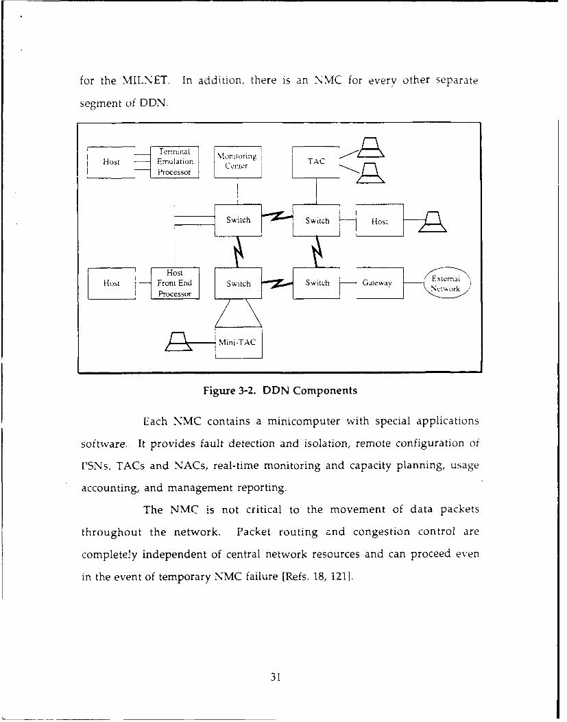
Keeping in mind the importance of the hierarchical ordering of
protocols, the DoD communications architecture is organized into four layers
as shown in Figure 3-3.
(1) The network access layer. This layer provides access to thecommunications network. The main functions of protocols at thislayer, which are between a PSN and an attached host or its logicalequivalent, are routing data, flow control and error control betweenmainframe systems and other quality of service functions such aspriority and security.
(2) The internet layer. A protocol at this layer is usually implemented onhosts and gateways to allow data to traverse several networks betweencomputers. The primary function of a gateway is to relay and transferdata between networks using an internetwork protocol.
(3) The host-to-host layer. At this level, the major function is to deliverdata between two processes on different host computers reliably. Asentities in this layer are invoked, they may (or may not) provide alogical connection between higher entities. Other functions of thishost-to-host layer include error and flow control and the ability to dealwith control signals not associated with a logical data connection. [Ref.20:p. 29]
33

(4) The process/application layer. In this layer, protocols, that facilita'eresource sharing such as computer-to-computer and remote access suchas terminal-to-computer, reside.
In accordance with this architecture, DoD, through DCA, has
issued a set of military protocol standards. Th,.se military standard protocols
are defined briefly in Table 3-1 [Ref. 20].
TABLE 3-1. DOD MILITARY STANDARD PROTOCOLS
MIL-STD-1777 Internet Provides the capability for end systems toProtocol (IP) communicate across one or more networks.
Does not depend on the network to be reliable
MI-STD-1778 Transmission A reliable end-to-end data transfer serviceControl Protocol (TCP) equivalent to the OSI reference model layer 4,
transport protocol
MIL-STD-1780 File Transfer A simple application for transfer of ASCII,Protocol (FIT) EBCIDC, and binary files
MIL-STD-1781 Simple Mail A simple electronic mail facilityTransfer Protocol (SMTP)
MIL-STD-1782 TELNET Provides simple asynchronous terminalProtocol capability
2. The DDN Configuration
As mentioned previously, "interoperability" is the major objective
set forth in the defense community. However, interoperability has become
one of the most vital echnical requirements so that internetworking
capabilities must be supported in a largely mixed-network environment, thus
requiring several gateways, like the DDN. Since the same protocols are
implemented on all data processing equipments of all DDN subscribers,
interoperability is achieved for the functions and services provided by those
protocols. The general DDN protocol configuration is illustrated in Figure 3-4
(Ref. l:p. 2901.
34
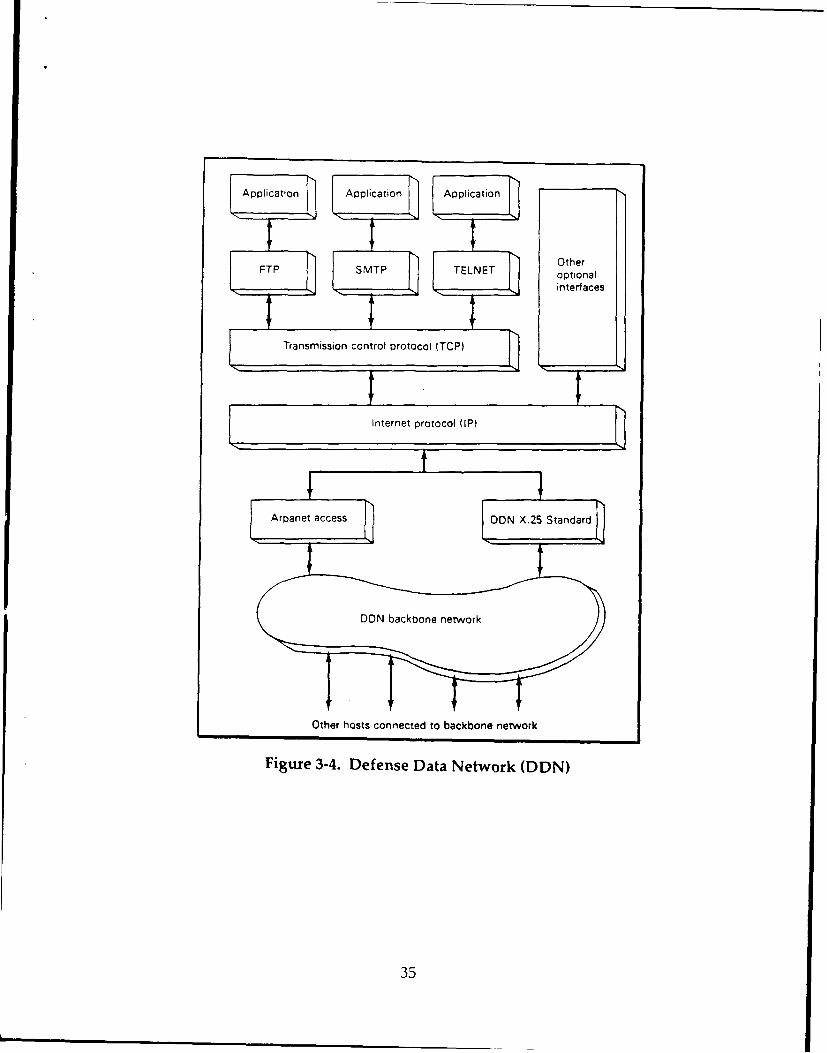
Applicatin I Application Application
FTP SMTP TELNET optional
interfaces
Transmission control protocol (TCP)
Internet protocol IP)
t
Aroanet acce'ss DON X.25 Standar~d
Other hosts connected to backbone network
Figure 3-4. Defense Data Network (DDN)
35
a. Protocol Mechanisms
The key protocol mechanisms involve four functions:
Segmentation and preassembly, encapsulation, connection control, and
addressing [Ref. 12:p. 3801. These functions facilitate the exchange of streams
of data between two entities.
The segmentation function can be defined as the process of
breaking up data into blocks of smaller bounded size. These blocks of data are
referred to as Protocol Data Units (PDU). The DDN may only accept packets
up to a maximum size of 1024 bytes. This results in a more efficient error
control and more equitable access to shared transmission media.
The segmentation function can occur at any of three layers of the
architecture below the process/application layer. As thenetwork access layer
receives a PDU from the internet layer, the network access, protocol splits the
internet datagram into a number of parts and places a packet header on each
one. These packets will be reassembled, the counterpart of the segmentation
function, into a single internet datagram by the destination network protocol
for delivery to its internet protocols.
Encapsulation is the addition of control information to data.
Each PDU contains data plus control information and some PDUs contain
only control information. As each PDU traverses through the layers, a header
that contains control information is added (encapsulated) to it. This becomes
the user data unit to the lower layers. Finally, the full PDU is transmitted.
At the destination host, a PDU arrives coming up through the
layers in the reverse order. The header that was added by the peer entity
(within the peer layer) at the source host is stripped off (deca-'sulated) by the
36

peer entity at the destination host. Functionally, the control information
contained in the header is instrumental in invoking the functions across the
network to the peer layer. In addition, control information may include the
address of the sender and/or receiver and error detecting code. Figure 3-5
shows the encapsulation and decapsulation process [Ref. l:p. 2841.
Encapsulation Transmitting Site Layers Receiving Site Decapsulation
jHi DataHiDt
NH2 H Dat -- H2 Hi Data
-HH2Hi aa ---- - H3 H2 Hi Data
Ix I
Transmission channel
H: Header
Figure 3-5. Encapsulation and Decapsulation Process
Connection control normally takes on two forms for data
transfer. If an entity may transmit data to another entity in an unplanned
fashion and without prior coordination, this service is known as
connectionless data transfer. The IP within DDN uses this kind of service in
order to provide a wider range of internetworking capability.
37

The second form is known as the connection-oriented service. It
:nvolves a logical association (connection) between the communicating
entities in three phases: connection establishment, data transfer, and
connection termination (see Figure 3-6). In DDN, TCP is connection-oriented
protocol to support reliable data transfer. Since FTP, SMTP, and TELNET use
TCP, they are connection-oriented as well. Figure 3-5 illustrates the steps
involved in connection-oriented service [Ref. 12:p. 3821.
Addressing is the means for two processes to uniquely identify
each other. DDN supports an environment of multiple networks, multiple
hosts on each network, and multiple processes/applications in each host.
Therefore, DDN maintains a complex addressing scheme.
Connection request
Connection accept
Data and Acknowledgements
multiple
Data and Acknowledgements exchanges
Terminate-connection request
Terminate-connection acknowledge
Figure 3-6. The Phases of a Connection-oriented Service
Each network must have a unique address for each host on that
network. The address is known as the subnetwork attachment point address.
The IP has the responsibility to deliver datagrams across multiple networks
from source to destination. Consequently, the IP is provided with a global
38

network address that uniquely identifies each host. Furthermore, a host may
have more tban one link into the same network. Acmr' rd!Igly, the host
address has a global significance while the subnetwork attachment point
address has significance within a network. So, the IP must translate from the
global address to the local address of the host to transmit data across the
network.
Finally, a data unit is delivered to a host through the host-to-host
layer for delivery to the ultimate user (process). Since there may be several
users, each is given a port number that is unique within the host. The
combination of port and global network address uniquely identifies a process
within DDN. The following host address: 26.3.0.16, for example, identifies
the host to be on MILNET since 26 is the MILNET network number [Ref. 141.
It occupies port 3 on PSN 16. Figure 3-7 illustrates the addressing scheme as
related to DDN.
HOST A
Applications Port Applications
TCP Global network TCPSaddress
EP [P
Network access Subnetwork Network accessProtocol I attachment Protocol 2
"" point address
Network Network1 NAP I NAP 2 2
Gateway
Figure 3-7. The DDN Addressing Scheme
39
b. The Network Access Protocol (NAP)
Th_ ,twu,,k access protocol defines he iiW:face be...ee. the
host computer, called DTE (Data Terminal Equipment) by CCITT, and the
network to which it is attached, called carrier's equipment CDE (Data Circuit-
terminating Equipment) by CCITT [Ref. 111.
Host computers can access the DDN using either CCITT X.25
protocol, the DDN standard protocol, or the old ARPANET Host Interface
Protocol (AHIP). These protocols can be supported on a PSN with full
interoperability. Computers supF ting these protocols can be attached
directly to a DDN node. Hosts on other networks, such as local area networks,
can use a X.25 gateway to obtain DDN access [Ref. 18:p. 122].
c. The Internet Protocol (IP)
The primary function of the IP is to interconnect all the network
segments under DDN and other networks so that any two users on any of the
constituent networks can communicate. Each segment of the DDN supports
communication among a number of attached devices. Additionally,
networks are connected by gateways providing a path for data exchange
between networks [Ref. 16].
As illustrated in Figure 3-7, IP is implemented in each endpoint
computer and in each gateway within the DDN. IP provides unreliable
connectionless service meaning that some PDUs may never reach its
intended destination or those that do may get there out of sequence. In this
situation, the TCP functions to assure reliable data transfer.
If two computers, A and B, on two different networks wish to
communicate, the operation of IP can be described as follows. The module
40

in host A builds a PDU that contains data from TCP and an IP header of
control information u-Pd bv TP The PMTT ic sent acrocss 's network to the
appropriate gateway. As the PDU arrives at the gateway, it must make a
routing decision. If host B is directly attached to one of the networks to which
the gateway is attached, the IP modale in the gateway sends the PDU across
that network.
On the other hand, if more additional gateways must be
traversed, the PDU is sent across a network to the next gateway on the proper
route. This situation is known as multiple-hop situation. Thus, the IP
module in each host and gateway must maintain a routing table that give for
each possible destination network, the next gateway on the route. The DDN
IP routing tables are updated every ten seconds [Ref. 12].
d. Transmission Control Protocol (TCP)
TCP is characterized as connection-oriented service that provide
reliable mechanisms for the transmission of data between entities in different
computers. It ensures that data are delivered error free, in sequence, with no
loss or duplication. TCP is one of the most complex communications
protocols because it relieves higher level software of performing the
communication functions; provides for high quality service, and deals with
different communication services.
The basic operation of TCP can be described as follows. When
data are passed from a transport user such as File Transfer Protocol (FTP) or a
simple mail transfer protocol (SMTP), TCP encapsulates those data into a PDU
containing the user data and TCP header with control information such as
the destination address. PDUs being transmitted are numbered sequentially
41
and subsequently acknowledged, by number, by the destination, TCP module.
Thus, PDUs that arrvc out of order can be reordered based on sequence
number. If a PDU is lost, it will not be acknowledged and the source TCP
module must retransmit it.
In addition to the basic service, TCP offers a number of other
services. A security classification or range may be used to label data provided
to TCP. Another service is the quality of service. A transport user can specify
the quality of transmission service to be provided. TCP will attempt to
optimize the use of the IP and th etwork resources. Parameters that may be
specified include precedence and delay.
Urgent delivery is another service that can be specified to TCP.
TCP then will attempt to transfer data as fast as possible. At destination, TCP
will notify the user via the use of interrupt mechanisms. [Ref. 16:p. 54]
e. File Transfer Protocol (FTP)
This protocol enables an on-line user to interactively transfer a
file or a portion of a file from one system to another. Three possibilities exist
for user to transfer a file. Fir--., a user at system A -ay wish a file in system B
to be transferred to system A. In this case, the user must have local access to
the content of the file. Second, a user at system A may wish to send a file
from system A to system B. The thiLd possibility is that a user at system A
may request a file be exchanged between system B, and a third system, C. This
involves the FTP entities at A, B, and C.
The operation of FTP involves first the host operating system in
order to facilitate the user's communication with FTP via the use of its
input/output (I/O) drivers. This provides a user interface to accept requests
42

from an interactive user or a program at the requesting system. The remote
FTP in a file tr-rnsfer in this case, doesn't interact with a user. Next, FTP uses
the services of TCP in order to communicate with other FTPs to achieve file
transfer. Finally, FTP must have an interface with the local file management
system to enable it to get at the file to be transferred. Figure 3-8 depicts FTP
interaction with the three entities.
FTP offers a numbers of options. Controlled user access is
provided by FTP; a user must have an authorized password/identification for
that system. Also, data compression can be invoked to reduce
communications cost. In addition, text files that use ASCII or EBCDIC
character codes may be transferred. Finally, a transparent bit stream type can
be employed to allow any sort of data or text file to be sent [Ref. 20:p. 32].
Terminal 1/0
FILEFTP 110
TCP
IP
Network Access
Figure 3-8. Conceptual Structure of the FTP
43

f. Simple Mail Transfer Protocol (SMTP)
This protocol provides the network electronic mail facility. Each
authorized user on the system has a mailbox. A user can send a message by
placing it in the mailbox of another user, and receive mail in the user's own
mailbox. These mailboxes are maintained by the file management system on
the host. Each mailbox maintains a directory of the messages text files. Users
may use the system editors or word processors. A single system facility is
known as the native mail facility. Figure 3-9 represents a conceptual structure
of the electronic mail system [Ref. 16:p. 122]. This facility, of course, is
provided as an application on a particular system.
SNative Mail File Mail
WO BoxesMail Transfer
TCP
IP
Network Access
Figure 3-9. The Electronic mail (SMTP) as Used in DDN
The basic service of SMTP can be used among separate systems. A
user can send mail not only to other users on the same system, but to users
anywhere in the DDN. SMTP accepts messages prepared by the native mail
entity and delivers them to that entity. SMTP uses TCP to send and receive
messages :ross the DDN. There is no user interface specified by SMTP.
44

Therefore, the user sees the same interface whPfhPr sending local mail or
remote mail.
g. TELNET
TELNET is a protocol that specifies how different types ;,f
terminals be linked to applications throughout the DDN. It specifies the
network standard terminals so that a variety of terminals can be connected to
a variety of hosts. It also takes into consideration different terminal
characteristics such as line width, page size, full-duplex or half-duplex, remote
and local echo.
Moreover, TELNET interacts directly with TCP to provide reliable
data transfer. Finally, TELNET supports a user to control an application in a
remote system transparently through his/her own terminal. TELNET
protocol provides a binary transmission option to allow not only
asynchronous scroll mode terminals but also any kind of terminal data
transparently without the need of converting to a network standard.
TELNET is usually configured in two modules, as shown in
Figure 3-10, user TELNET and server TELNET. User TELNET interacts with
the terminal I/O module of the host operating system. It converts the
characteristics of real terminals to the network standard virtual terminal and
vice versa. Server TELNET interacts as terminal handler for process and
applications. In the latter case, remote terminals appear as local to the process
or application invoked [Ref. 20:p. 34].
45

Application
Termidnal USER SERVER1/0 TELNET TELNET
TCP
IP
Network Access
Figure 3-10. TELNET Protocol Conceptual Structure
E. DDN FEATURES
The DDN has several features that contribute to its success and will lend
smoothly into future expansion. The most important ones are survivability,
availability, and security.
1. Survivability
No system is invulnerable, but DDN has the ability to function
during crisis providing vital DOD communications after a disaster has
occurred. Disasters may include natural types such as earthquakes and severe
storms. The other type of disaster is enemy-inflicted disaster including
conventional or nuclear attacks.
In addition to the physical security measures that are taken by the
users of DDN to protect their communications equipment, PSNs of the
shared backbone of DDN are often collocated wit- the subscriber's equipment
46

within a military installation. As a result, these PSNs benefit from military
installation protection.
Moreover, several survivability features are inherent to the DDN
structure. These features include (a) redundancy, (b) dynamic adaptive
routing (c) precedence, (d) dispersion, (e) graceful degradation, (f)
reconstitution, (g) hardening [Ref. 15:p. 13-241.
a. Redundancy
Most of the critical components of DDN equipment have spare
parts and redundant capability. The packet switching nodes within DDN
provide as backup spares for each other while each PSN can process traffic
from any source.
The access network of the DDN has redundant features as well. A
procedure called dual homing allows critical users to reach the DDN through
secondary lines which are connected to a second PSN.
b. Dynamic Adaptive Routing
This feature of the DDN enables data packets to avoid damaged
nodes and/or lines. This feature greatly enhances the survivability of the
DDN by allowing traffic to continue to flow over remaining portions of the
network.
c. Precedence
The DDN establishes precedence to ensure that critical users
receive the best possible network service under stress conditions. This feature
employs the preemption mechanisms which are related to the congestion
detection and avoidance [Ref. 19].
47

Each PSN in DDN processes messages according to precedence
procedures as well as to time in the system. During peacetime, precedence
mechanisms ensure faster delivery of time-sensitive traffic even if the
network is congested. During a crisis, precedence procedures allow critical
users to designate which traffic gets priority on whatever network resources
remain intact. Figure 3-11 illustrates the above survivability features [Ref. 221.
d. Dispersion
The DDN switching nodes are geographically distant from each
other. This dispersion enhances survivability while damaged portions of the
network are easily isolated. The large geographic spread of DDN backbone
elements minimizes the damage that any one disaster can inflict.
e. Graceful Degradation
Damaged elements of the DDN do not prevent the entire
network from functioning. DCA employs centralized regional centers to
monitor the status of DDN at all times. These monitors will assist with
congestion and equipment problems. Should a part of the network be
destroyed, the monitoring centers would use the remaining resources to
configure a limited network.
f . Reconstitution
Contingency plans must be prepared to ease restoration efforts in
case the DDN should become disabled. As those plans are invoked to keep
the network operating on a limited basis, DCA starts restoring DDN to its full
capability. DCA has five mobile switching centers that will be deployed to
provide packet switching during repairs of permanent node sites. This
process will increase the DDN flexibility during peacetime as well as war time.
48
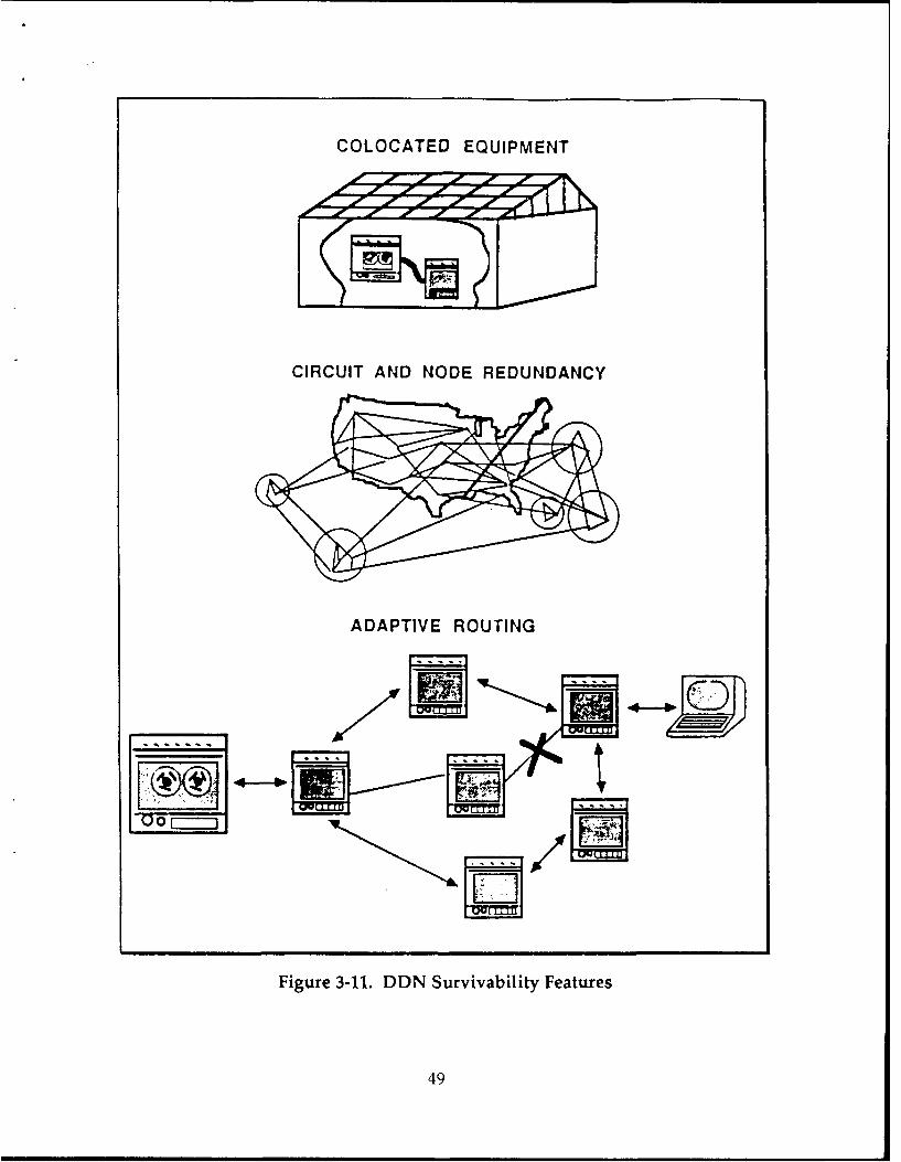
COLOCATED EQUIPMENT
CIRCUIT AND NODE REDUNDANCY
ADAPTIVE ROUTING
Figure 3-11. DDN Survivability Features
49
g. Hardening
Building structural reinforcement provides some protection
against enemy bombs. As previously mentioned, most of the DDN switching
nodes and access equipment are collocated within a subscriber's facilities. All
DDN components will have electromagnetic shielding and power surge
protection against High Altitude Electromagnetic Pulse (HEMP).
In addition, the diversity of transmission media reduces the
network's vulnerability to carriers problems, acts of sabotage, jamming and
other electronic countermeasures (ECM) attacks and to other threats ne
transmission base [Ref. 191.
All these survivability features enable DDN to function under
various stress levels. These levels of stress are threats defined by the U.S.
Joint Chiefs of Staff to ensure that survivability measures are met at the
network level, system level, node level, and user level. The primary DDN
roles in response to each stress level, major threats, and the survivability
features are described in Table 3-,.. -Ref. 19:p. 1501.
2. Availability
It is the mission of DDN to provide communications capabilities for
DOD continuously in order to support real-time handling of all user traffic.
The DDN backbone must be always available for access to host computers and
user terminals. The availability of the network recorded a 99.30% for single-
homed subscribers and 99.95% for dual-homed subscribers [Ref. 22]. This high
percentage availability of the DDN is directly affected by three factors (1)
reliability (2) delay, and (3) accuracy.
50
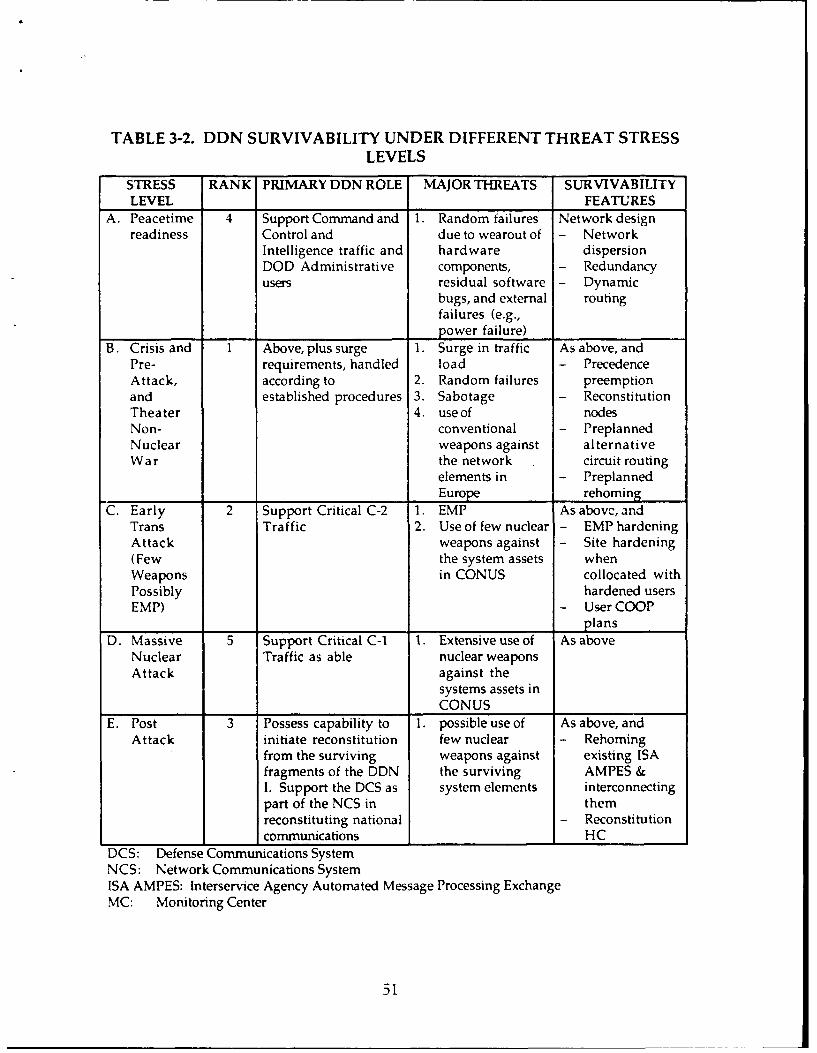
TABLE 3-2. DDN SURVIVABILITY UNDER DIFFERENT THREAT STRESSLEVELS
STRESS RANK PRIMARY DDN ROLE MAJOR THREATS SURVIVABILITYLEVEL FEATURES
A. Peacetime 4 Support Command and 1. Random failures Network designreadiness Control and due to wearout of - Network
Intelligence traffic and hardware dispersionDOD Administrative components, - Redundancyusers residual software - Dynamic
bugs, and external routingfailures (e.g.,power failure)
B. Crisis and 1 Above, plus surge 1. Surge in traffic As above, andPre- requirements, handled load - PrecedenceAttack, according to 2. Random failures preemptionand established procedures 3. Sabotage - ReconstitutionTheater 4. use of nodesNon- conventional - PreplannedNuclear weapons against alternativeWar the network circuit routing
elements in - PreplannedEurope rehoming
C. Early 2 Support Critical C-2 1. EMP As above, andTrans Traffic 2. Use of few nuclear - EMP hardeningAttack weapons against - Site hardening(Few the system assets whenWeapons in CONUS collocated withPossibly hardened usersEMP) - User COOP
plans
D. Massive 5 Support Critical C-1 I. Extensive use of As aboveNuclear Traffic as able nuclear weaponsAttack against the
systems assets inCONUS
E. Post 3 Possess capability to 1. possible use of As above, andAttack initiate reconstitution few nuclear - Rehoming
from the surviving weapons against existing ISAfragments of the DDN the surviving AMPES &I. Support the DCS as system elements interconnectingpart of the NCS in themreconstituting national - Reconstitutioncommunications HC
DCS: Defense Communications SystemNCS: Network Communications SystemISA AMPES: Interservice Agency Automated Message Processing ExchangeMC: Monitoring Center
51

First, the DCA has set minimum threshold standards for the
operational components of DDN. The minimum acceptable measure of
reliability for the PSNs is 98.5%. The performance of the PSNs has exceeded
99.45%. The interswitch trunks also achieved a 98.33% performance
reliability level exceeding the minimum acceptable threshold of 97%. The
composite system performance of the DDN backbone, PSNs plus the
interswitch trunks, recorded a reliability level of 98.89%.
Second, the amount of delay for a message to re.ich its destination is
an important factor of the availability of the DDN. Messages sent are broken
into packets with control information added to them. This addition causes
overhead that is reflected on the time it takes to reach the destination.
The average source-to-destination time for low precedence DDN
traffic within the U.S. is less than 200 milliseconds. But this speed does not
reflect accurately the user's situation since there are peak working hours
during which response time might not be acceptable. DCA encourages users
to postpone non-interactive, low priority traific to slack periods in order to
minimize the overall system delay.
Third, the accuracy of the DDN is reflected by the measures taken to
ensure error-free transmission through the access devices, access lines,
switching nodes, and interswitch trunks.
DDN uses techniques called 16-bit cyclic Redundancy Checks (CRC) to
detect errors in the access and trunk circuits. CRC requires the transmitter to
attach a sequence of bits to make the entire frame exactly divisible by a
predetermined number. The receiver divides the incoming frame by this
52

same number. If there is no remainder, the receiver does not request a
retransmission.
In addition, DDN must detect errors during data processing. The
subscriber computers use an error detecting mechanism that performs a
summation operation on the bits. These end-to-end accuracy checks areknown as 16-bit check sums. DCA projects that the probability of undetected
error is 4.2x10 "i 8 and the probability of misdelivering a packet is 5.5x10 "12 [Ref.
141. Accordingly, an error would skip through the network undetected only
once every 174,000 years.
3. Security
The defense community classifies its information according to its
sensitivity. DOD assigns security clearances that designate the highest
classification level of information that each person or equipment can handle
or process. DDN security concerns are related to communications security
and computer security.
a. Communications Security
This involves the process of recurring information as it is
transmitted from one location to another. Encryption has been the primary
method for establishing communications security. In addition, metallic
shielding of equipment, known as TEMPEST, is the DOD technique that is
used to contain signals.
Moreover, DOD has maintained the separation of DOD agencies
at different classification levels in order to enhance security. The DDN
segments that support classified data employ the Blacker front-end computer
devices to ensure encryption of data sent among host computers. Blacker
53
devices installed between switching nodes enable separate classified networks
to use the same backbone nodes and trunk circuits. Eventually, information
will flow from a host in one segment of DDN to a host in another segment, by
the end of 1992, by using the guard gateway equipment.
DDN has incorporated backbone link encryption by installing KG-
84 cryptographic equipment on all trunks among PSNs and on all access lines
between computers and the backbone network. Terminal link encryption is
also available to attach users - access lines. The installation of these
encryption devices, called LEADs, at user terminals provide protection of data
as it travels to host computers.
b. Computer Security
The major function of the computer security is to safeguard data
processors from outside tampering and unauthorized access. Physical security
measurez- provide some protection against outsiders gaining access to
terminals. However, DDN can be reached via dial-in telephone lines without
even being on a military base.
Therefore, the actua -omputer security features of the DDN
include user identification and authentication mechanisms. Access control
systems requires a user to enter an identification code and a password. The
identification code could be published for electronic mail addressing. But
passwords are only known to authorized individuals.
Users accessing DDN through terminals linked to TACs are
required to input to the TAC a TAC user ID and an access code before even
logging into their host computer systems.
54

F. DDN USES BY THE MILITARY
Since the DDN supports a wide range of hardware and utilizes X.25
protocol, it allows a variety of applications to be on-line. The U.S. Marine
Corps has its logistics and administrative systems on the network. The Air
Force has upgraded its personnel system for operations using the DDN, and
has its supply system on the network to provide worldwide coordination
among all Air Force bases. In addition, the Navy Regional Data Automation
Centers and the Army Inspector General MIS system are connected to DDN.
Many organizations within the DOD use the DDN for electronic mail.
Furthermore, most armed forces management functions such as payroll,
medical records, intelligence, and command, control and communication
(C3) are maintained on the DDN.
The DDN reliability and security features made it possible to establish
telecommunication links between contractors and the DOD. Information can
be transmitted securely between private firms and the different agencies
within DOD. It is expected that DDN will be used for the delivery of software
products as well as correspondence with contracting agencies [Ref. 18:p. 122].
55
IV. THE PROPOSED MODA MODEL
A. MODA GOALS AND OBJECTIVES
The major mission of the Ministry of Defense and Aviation (MODA) of
Saudi Arabia is to defend the country against aggression. Therefore, the
objective of MODA DDN is to improve combat readiness capability through
the rapid exchange of urgent and important messages among the Armed
Forces. This will result in good decision making and will contribute to
interservice cooperation regarding sharing of information, joint operations,
and supply coooeration.
Another objective of MODA DDN is office automation through the
application of computer and communications technology. This will
contribute to the productivity of clerical and administrative office work. In
addition, MODA DDN can serve as a general purpose computer network for
information exchange, and experimental or research network.
According to the objective set forth, several goals are desirable in the
proposed MODA model. These include, but are not limited to, efficiency,
security, reliability, survivability, flexibility, and cost-effectiveness.
The suggestion is to model the proposed computer communication
network for the MODA DDN using the current technology of the U.S. DDN
discussed in Chapter III. The following section will provide an overview of
the network design which can be applied to the MODA DDN. It must be
emphasized that this paper does not provide a solution to the design problem
but, rather, the general concepts are presente.
56

B. NETWORK DESIGN: AN OVERVIEW
Generally, a computer and data communications network is seen by the
users as a "transport mechanism" to pass data from one user to another. But
the internal environment of the network includes switches and transmission
lines among the switches. The number and capacity of these costly resources
have to be limited by the budget, users' demand, and possible future demand.
When dealing with switched data networks, the user must balance costs
of services with network capabilities and reliability. Furthermore, design
considerations such as connectivity, structure of the network, routing, the
type of community the network is trying to serve, and finally, how the
network is controlled, are of paramount importance. Figure 4-1 summarizes
these design considerations (Ref. 23:p. 41].
Usually, two approaches are commonly used in designing a computer
communication network. The first approach is the cost minimization where
the network designer tries to determine the most economical configuration of
the network components that will meet the users' requirements. The second
approach is to design a network with maximum reliability or survivability
under a given set of stress level scenarios, subject to a given budget. Military
networks are designed using the second approach.
1. Network Structure
The topology of the network directly affects it operation, reliability
and its operating costs. Therefore, data links can be arranged in certain
patterns in order to develop a specific topology.
57

Circuit switched
CncvSwitchedy Packet switched" ConnectivitY Concentration and multiplexing _ Trees
Centralized Loops
" Structure - Distributed Hierarchical
Non-hierarchical
Fixed
" Routing 4Dynamic realtime
on command
SCmHomogeneous
* Community NHeterogeneous
Centralized
@ Control Distributed
Figure 4-1. Design Consideration for Switched Data Network Development
a. Centralized Network
A centralized network is characterized by a central computer that
functions both as a switch and as a data base host. Since each
comn nications link is directly connected to the computer, there is no delay.
The centralized topology (or star) is suitable where each terminal has a large
volume of data traffic and must operate at 9,600 bits/s or another high data
rate on a leased line (Ref. 251. Figure 4-'1 illustrates the configuration of a
centralized network.
b. Distributed Network
This kind of network is characterized by the fact that the
intelligence of the ne ,ork, in the form of switching and processing, is
58

distributed throughout the geographic area [Ref. 231. This topology offers
considerable advantages with respect to communications costs and time
delays. See Figure 4-2b.
(a) Mb
Figure 4-2. Network Topography. (a) Centralized (Star) (b) Distributed
By interconnecting computers, more links are available through
which data transfer can occur. The rerouting capability of the network is
enhanced in case a failure or outage of any channel between computers
happens. In addition, overall network nprformance is improved by the
additional transmission paths [Ref. 24].
Distributed networks can be further divided into hierarchical and
non-hierarchical topologies. In the non-hierarchical distributed structure,
each switch has a similar function in the network topology. And all of the
network switches serve end users (host computer and/or terminals) and data
transfer can occur through several switches en route to its destination.
59
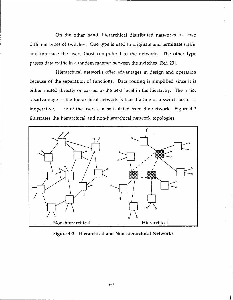
On the other hand, hierarchical distributed networks us t wo
different types of switches. One type is used to originate and terminate traffic
and interface the users (host computers) to the network. The other type
passes data traffic in a tandem manner between the switches [Ref. 231.
Hierarchical networks offer advantages in design and operation
because of the separation of functions. Data routing is simplified since it is
either routed directly or passed to the next level in the hierarchy. The rr iior
disadvantage -f the hierarchical network is that if a line or a switch beco. 's
inoperative, ie of the users can be isolated from the network. Figure 4-3
illustrates the hierarchical and non-hierarchical network topologies.
Non-hierarchical Hierarchical
Figure 4-3. Hierarchical and Non-hierarchical Networks
60
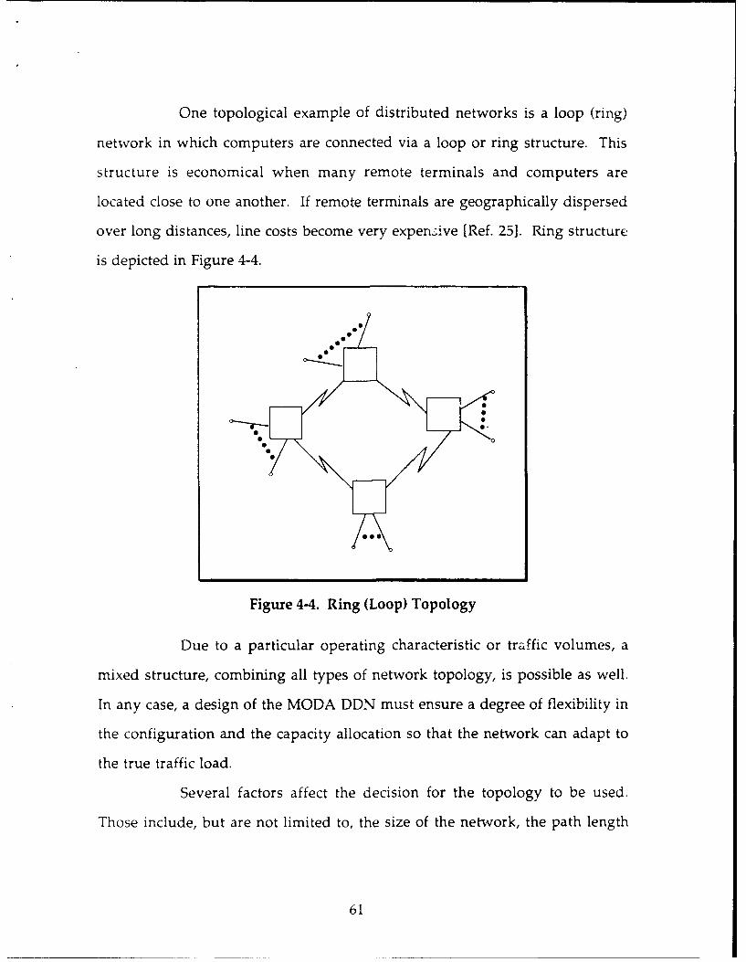
One topological example of distributed networks is a loop (ring)
network in which computers are connected via a loop or ring structure. This
structure is economical when many remote terminals and computers are
located close to one another. If remote terminals are geographically dispersed
over long distances, line costs become very expen:ive [Ref. 251. Ring structure
is depicted in Figure 4-4.
.1.
Figure 4-4. Ring (Loop) Topology
Due to a particular operating characteristic or traffic volumes, a
mixed structure, combining all types of network topology, is possible as well.
In any case, a design of the MODA DDN must ensure a degree of flexibility in
the configuration and the capacity allocation so that the network can adapt to
the true traffic load.
Several factors affect the decision for the topology to be used.
Those include, but are not limited to, the size of the network, the path length
61

between nodes, target reliability/availability level, number of channels
available from carriers, manufacturer philosophy, and the size of the network
[Ref. 26:p. 591.
2. Network Capacity Planning
iTe key step in the MODA network design process it to identify the
needs and requirements of the user community. This effort should include
all the activities performed by the different users and the use of the various
computer data bases in MODA.
The precise specification of the MODA user require- nts is actually
an integral part of the network capacity planning process. This process
determines the optimal, or, practically, the near-optimal network to meet the
organizational future service needs. The responsibilities of the network-
capacity planning can be summarized in four-stage methodology:
" Data collection,
* Establishing requirements,
* Design and optimization, and
* Implementation.
Figure 4-5 illustrates the process of the typical network-capacity planning and
and a brief summary of the steps involved will follow [Ref. 26:p. 453-505].
In data collection, the characterization of past and present workloads
must be developed statistically. This must include deadline requirements,
application cycles, daily cycles, and service requirements. Another milestone
in data collection is the identification of physical locations. This involves
drawing maps with a large number of individual sites that are to be
connected. Usually, the use of automated design tools is required.
62
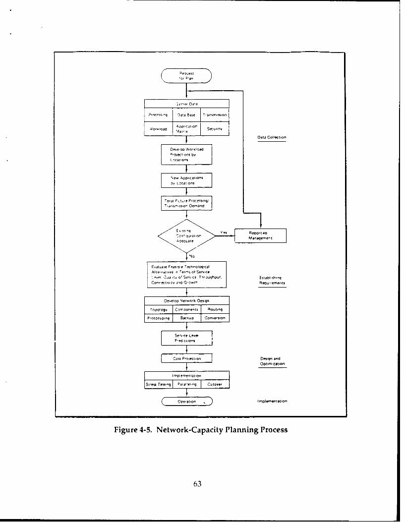
POcessnq Cata Base T~ansm~ss~on
,Vo,oad ~~~tn Security
Data Collection
Devetoo WVorkloadProtection$ by
Locavons
New~ Aocicatofls
orLcatlons
Total Fvtre Process ing,Tanri,rso Demand
Evaluate Feasoci TechrtoloqicalAlrerrratves r, Terrr' of ServiceLevei Ovallyt of Ser ce. Thro~ughput. Establishing
Connectivt and Growvth Requirements
Develop Network Design
Toooiogy Carrroonrits Routin
ProtOtvonq Backup Cornersion
T_Servyce LevelPr.d,ct~ons
Cost Prolection Design and
i~Optimization
imlnoementation
Stress Tesing Plrafleting uoe
( eaton . Implemenltation
Figure 4-5. Network-Capacity Planning Process
63

Projecting application systems is a ver- important factor in data
collection. It requires knowledge of the bL.-iness and the changing
environment around it. Management structure and reporting requirements
are also identified at this stage.
Requirement specification is dependent on the collected data on past
and present workload and estimated future networking requirements. As
mentioned earlier, a user consists of hosts and terminals which require access
to the network. Each device has a specific location, which can be represented
by VH coordinate [Ref. 25], a set of protocols, and an ntertace speed.
Another requirement is for each user to insfer data among each other. The
amount of traffic sent may vary over time or may be associated with various
scenarios such as a crisis scenario and a normal scenario [Ref. 11].
A User Requirement Data Base (URDB), similar to the U.S. DDN
URDB, must be established to contain information about every user's
hardware, its protocols, its application programs, its geographical location,
and the computer system to which it belongs. Of course, a survey
questionnaire should be designed to ga' r this information. Moreover, the
survey should include information about the volume, type, and distribution
of traffic from the user systems [Ref. 111.
Therefore, identification and projection of future workload can be
determined. Then, the application impact across time is analyzed to
determine the resource demand.
In order to come up with efficient and reliable computer
communications network service, new technologies and services must be
evaluated contirually. The evaluation of new alternatives must be
64

comprehensive enough to include the areas of distributed intelligence, office
automation, LANS, local site optimization, communications services, and
hardware equipment.
As the process goes on, a total figure on processing and transmission
demand is achieved. Then the network-capacity planners compare the
projected workload with the potential capacity to determine how well the
present capacity can accommodate the service requirements. Design
optimization and implementation will follow in the next section.
C. NETWORK DESIGN PROCESS
The complete computer communication network design problem can
be formulated as follows:
Given:
* terminal and host sites
* matrix of traffic requirements,
* delay requirements,
* reliability requirements,
* candidate topology for the backbone network, and
* cost elements.
Minimize:
* Total network Cost C where
C = (backbone line costs) + (backbone PSNs costs)
+ (local network access line costs) + (local access hardware costs)
Subject to:
The performance criteria such that throughput, delay, security, andreliability requirements are met.
Usually, the cost criteria establishes the objective function and the
performance criteria determines the constraints [Ref. 261. The major step in
65
the evaluation of performance constraints is the formulation of a detailed
traffic model. The model should specify a data rate during the network peak
hours. The number and size of the packets transmitted to the network will
vary according to the type of data, transactions (e.g., interactive,
query/response, electronic mail, or file transfer). Then, the traffic data,
augmented by the overhead which is produced from the application of the
network protocols, is fed into computer simulation programs.
The design process is usually divided into a network access design, which
is typically centralized systems, and a backbone design, which is generally a
distributed network.
1. The Network Access Design
The design of network access deals with the placement of terminal
concentrators (TACs or NACs), the connection of terminals to terminal
concentrators, and terminal concentrators to PSNs. In addition, the
determination of access line speeds is a critical part of the network access
design [Ref. 111.
Operations Research computerized techniques and algorithms
often employed to facilitate the network access design problem. The goal is to
achieve an objective function which will produce a cost-effective access
design such that traffic, delay, security, and reliability requirements are met.
Normally, these design constraints are set to some percentage of the known
physical limits [Refs. 11, 24].
Throughout this process, the capacities of the network component, or
the amount of traffic to a network component do not exceed the known
limits. Therefore, a traffic-volume table can be constructed to determine the
66

traffic-volume due to the homing of devices to PSNs. The traffic-volume
table is depicted in Figure 4-6 [Ref. 25]. The totals for the columns with
checkmarks are then used to compute a PSN-to-PSN traffic matrix. This
matrix is a primary input to the backbone design process and it contains the
traffic flowing at each priority level between eacL pair of PSNs. Moreover, it
reflects the user data and protocol overhead and describes data rates and
packet sizes [Ref. 11.
PSN #
AVERAGE
Calls/ Connect Total transit Msg/day to msg/day from characters/ characters/time/call time host host msg day
day avg peak avg peak av peak avg peak avg peak avg peak
Total LIiII "i
Figure 4-6. Traffic-Volume Table
2. The Backbone Design
The backbone design of a computer communication network is
characterized by parameters of cost, throughput, response time, and reliability.
Therefore, the properties of both the PSNs and the network's topological
structure must be considered [Ref. 24]. Some of the PSNs' important
properties are:
* packet handling and buffering,
* error control,- IILJVV I.UILLA4..J,
* routing,
* PSN throughput, and
67

* PSN reliability.
Some of the topological characteristics are:
* link location,
* link capacity assignment,
* network response time,
* network throughput, and
* network reliability.
The selection of the most effective network architecture, which
determines the number of levels and the type of access at each level, is the
most important step in the design process of WANs. But there exists a
number of alternatives for the backbone architecture within the packet
swtching concept as follows [Ref. 24]:
* Line alternatives: terrestrial links or combination of terrestrial andsatellite links. The most cost-effective selection of the available servicemust be made for a given connection.
* Node alternatives: a backbone architecture with several conventionalnodes in a fully interconnected cluster as a "super node" or with thehigher nodal capacity of the multiprocessor switch.
* Topological structure alternatives: For small or medium-sizedbackbone network, the structure is homogeneous with identicalsoftware and compatible hardware at the PSNs. or larger networks, atwo-level hierarchy within the backbone is mote cost effective. Thehigh-level net has higher node and link capacities than the low-levelsubnet. Subnets are connected to high-level net via gateways.
The most effective design techniques involve the heuristic
application of a family of optimization procedures, human intuition, and
engineering judgement. The goal is to reach the most cost-effective design
which satisfies the throughput, delay, security, and reliability requirements.
The approach employed is iterative [Ref. 111.
68

The technique starts with a candidate topology. Then, a
mathematical model of the routing algorithm is used to assign flows to the
link paths. Next, channel and PSN utilizations are computed. Using
queueing theory, a mathematical model is derived to estimate packet delays.
The candidate topology may be rejected if the trunk (channel) or PSN
utilizations are to high or the average packet delay is too large. In addition,
the candidate topology can be rejected if the reliability criteria are not met
[Ref. 101.
Once the candidate topology is rejected, a new candidate is selected.
The process is repeated until the desired optimal network is found and the
cost can no longer be lowered.
Another important step in the network design process is to design the
organizational and technical structure for restoring the communications
network after breakdowns. This step is called contingency planning, which
deals with situations where the network can be temporarily reconfigured to
overcome individual network components, such as a failing line, a failing
concentrator or PSN or an application failure and to allow for continued
operation during the time taken to resolve the problem.
Along with contingency plans, backup and recovery plans should be
prepared. These plans define the methods available to restore a part of the
network or the entire network to an operational status. It contains detailed
procedures to be used in fixing the problem.
Operational manuals should be also prepared based on the
operational guidelines gathered during data collection and the hardware-
software decisions from the requirement specification stage.
69
A step-by-step conversion plan must be taken into consideration.
This means the operations of the present systems should continue until the
new network has been thoroughly tested and proven.
Next, prototypes of the proposed network are presented for testing by
the customer. Depending on the test results, the principal requirements may
or may not be met. When requirements are not met, a return to the planning
phase may be required to modify or include alternatives. It could also be
necessary to go back to the design or, nization and to evaluate additional
topological alternatives. The process is iterative and finally, the prototype is
tuned, results are evaluated, and decisions are made for further action to be
taken.
The i-nplementation is primarily based on conversion plans. It
usually takes many steps, but the best way is to phase the implementation by
location or application. It is recommended that actual volumes and
transaction types be followed as closely as possible prior to cutover which
must be prepared with great care. Cutover should be accomplished over
night or over a weekend. CPM and PERT techniques are useful in timing. In
addition, stress testing is performed to test not only the fuctionality but also
the service level requirements. By using as many of the new network's
facilities as possible, the chances of identifying potential bottlenecks are
significantly improved.
Operation and communication networks personnel must be trained
to face all possibilities before actual cutover. Technical support,
administrative, and help-desk personnel should be prepared as well.
70

V. CONCLUSIONS AND RECOMMENDATIONS
A. SUMMARY
This thesis has provided the fundamental concepts for designing a
computer communications network for the MODA. The goal is to establish
an interoperable wide are network for MODA which will evolve into an
efficient Integrated Computer Communications Network (ICCN). Ultimately,
the Saudi DDN will serve the national defense.
Because of lack of actual data about the MODA requirements, this study
focused on the conceptual framework for building a data network. Therefore,
this study should serve as a guideline and not as a solution for constructing a
computer communications network that is needed to connect all of the Saudi
armed forces.
B. CONCLUSIONS
Based on the information provided in this study, the following
conclusions can be drawn:
(1) A computer communications network, such as the U.S. DDN, can beused operationally for military applications and it is performing verywell.
(2) Packet-switched networks provide for valuable networking andresource sharing.
(3) The Saudi MODA and the four services of the armed forces, Army, AirForce, Navy, Air Defense and their subordinate commands and units,will tremendously benefit from improved networking capabilitieswithin each service and among the four services.
(4) Increased sharing of resources and ideas within each service andamong the four services will be beneficial to the overall operations ofMODA.
71

(5) The computer communications network can be easily expanded toenhance administrative communications capabilities.
C RECOMMENDATIONS
The findings of this study result in recommendations related to two
different categories of the overall integrated computer communications
network. The first category relates to the development of the network itself
and the second one relates to the user community of the Saudi MODA.
1. The Network-related Recommendation
It is strongly recommended that the following basic elements be
considered during the developmenm ol the MLU)A DDN:
(1) The MODA Defense Data Network (DDN) must be designed to meetMODA goals and objectives.
(2) The MODA DDN must be designed with careful considerations of allcircumstances and possible consequences.
(3) Network security and survivability must be a primary considerationthroughout the development.
(4) MODA currently uses various communications links. But dedicateddata communications channels are needed as in the U.S. DDN.
(5) Many types of computers can be used for PSNs, TACs, NMCs, gateways,hosts, and terminals. MC 'A should acquire equipment which offershigh performance with the .east cost.
(6) MODA will need various types of software for the proposed DDNbackbone and the access network in order to communicate across thenetwork and provide access for the users. Standard software should bepurchased or developed to provide the interoperability required withinand among the services.
2. User-related Recommendations
Although all users within the defense community should be taken
into consideration when planning for the development of the network, the
following recommendations should be emphasized:
72

(1) Each command or unit which happens to be near an available MODAhost computer or TAC must investigate the possibility of accessing thenetwork so that the DDN capabilities can be used.
(2) The armed forces heads and communications managers shouldfamiliarize themselves with DDN operations and communicationsprocedures.
(3) MODA personnel involved in the transition to the proposed MODADDN should study the DDN concepts and apply them whereverapplicable during network development.
73

LIST OF REFERENCES
1. Black, U., Data Networks: Concepts, Theory, and Practice, Prentice-Hall,Inc., 1989.
2. International Encyclopedia for Communicatiorns, 1989.
3. Academic American Encyclopedia, Grolia Incorporated, Connecticut, 1983.
4. Al-Ali, M. M., Importance of Strategic Communications, Thesis, StaffCollege in Saudi Arabia, 1988.
5. Fagen, M. D., History of Engineering and Science in Bell Systems: TheEarly Years, New York: Bell Laboratories, 1975.
6. Ministry of PTT of Saudi Arabia, Telecommunications in the Kingdom ofSaudi Arabia: A Story of a Unique Experience, 1984.
7. Ministry of PTT of Saudi Arabia, Telecommunications in the Kingdom ofSaudi Arabia: Gateway to the World, 1987.
8. Ministry of PTT of Saudi Arabia, A Report on the Telephone Services inSaudi Arabia, 1988.
9. Eberhardt, J. M., Defense Data Network and the Naval Security Group,thesis, Naval Postgraduate School, 1988.
10. Tanenbaum, A. S., Computer Networks, Prentice-Hall, 1988.
11. Defense Communication Agency, The Defense Data Network: HighCapacity for DOD Data Transmission, 1986.
12. Stallings, W., Data and Computer Communications, MacMillanPublishing Company, 1988.
13. Lee, K. W., Design of Defense Data Network for the Republic of KoreaMilitary, thesis, Naval Postgraduate School, 1988.
14. Defense Communications Agency, DDN New User Guide, 1987.
15. Freeman, R. L., Telecommunication Transmission Handbook, JohnWiley & Sons, Inc., 1981.
74

16. Stallings, W., Computer Communications Standards, Volume 3: DODProtocol Standards, MacMillan Publishing Co., 1987.
17. Martin, J., Telecommunications and the Computer, Prentice-Hall, 1990.
18. Elsam, E. S., "The Defense Data Network Hits its Stride,"Telecommunications, May 1986.
19. Fidelman, M. R., and others, "Survivability of the Defense DataNetwork," Signal, May 1986.
20. Stallings, W., "The DOD Communications Protocol Standards," Signal,April 1986.
21. Defense Communications Agenc v , The DDN, 1989.
22. Defense Communications Agency, The Defense Data Network, 1987.
23. Rosner, R. D., Packet Switching, Lifetime Learning Publciation, 1982.
24. Boorstyn, R. R., and Howard, F., "Large-Scale Network TopologicalOptimization," IEEE Communications, v. COM-25, n. 1, January 1977.
25. Held, G., and Sarch, R., Data Communications: Comr -ehensiveApproach, MacGraw-Hill, 1989.
26. Terplan, K., Communication Networks Management, Prentice-Hall, Inc.,1987.
75

BIBLIOGRAPHY
Akgul, A., Transfer of Military Technology to Developing Countries, thesis,Naval Postgraduate School, Monterey, CA, 1989.
Bartree, T. C., Data Communications, Networks, and Systems, Howard W.Sams & Co., 1986.
Brewster, T. C., Data Communications, Networks, and Systems, PeterPeregrinus Ltd., London, 1986.
Burgelnman, R. A. and Maidique, M. A., Strategic Management of Technology
and Innovation, Irwin, 1988.
Burgess, L., Distributed Intelligence, Southwestern Publishing Co., 1987.
Gestel, V. K., "Corporate Data Networks for Information Exchange," ElectricalCommunication, v. 61, n. 2, 1987.
Held, G., Data Communications Networking Devices, John Wiley & Sons,1986.
Madron, T. W., Local Area Networks, John Wiley & Son., Inc., 1988.
Maybaum, F., and Duffield, H., Defense Data Network: An Overview, 1986.
Rodriguez, J. M., "Portable Computer Access to the DDN," IEEE Journal, 1987.
Schwartz, M., Telecommunications Networks: Protocols, Modeling, andAnalysis, Addition-Wesley, 1988.
Stanley, W. D., Electronic Communications Systems, Prentice-Hall Inc., 1982.
Strembler, F., Introduction to Communications Systems, Addison-Wesley,1990.
Taylor, L. D., Telecommunications Demand: A Survey and Critique,Ballinger Publishing Company., 1978.
Tice, R. M., "Connecting to the DDN," IEEE Journal, 1986.
76
Tushman, M. L. and Moore, W. L., Readings in the Management o.fInnovation, Ballinger Publishing Co., 1988.
Vijay, A., Design and Analysis of Computer Communications Networks,McGraw-Hill, 1982.
77

INITIAL DISTRIBUTION LIST
1. Defense Technical Information Center ....................................................... 2Cameron StationAlexandria, VA 22304-6145
2. Library, C od e 52 ............................................................................................ . . 2Naval Postgraduate SchoolMonterey, CA 93943-5000
3. Professor Myung W. Suh, Code AS/Su ...................................................... INaval Postgraduate SchoolMonterey, CA 93943-5000
4. Professor G ary Poock, O R /Pk ............................................................................... 1Naval Postgraduate SchoolMonterey, CA 93943-5000
5. Professor Dan C. Boger, Code AS/Bo ................................................................. 1Naval Postgraduate SchoolMonterey, CA 93943-5000
6. Abdullah A l-H odaithy, Lt. Col.. .................................................................... 1Royal Embassy of Saudi ArabiaArmed Forces Office2109 E Street N.W.Washington, DC 22307
7. A bdulrahm an A lnajashi, Capt ...................................................................... 3Ministry of Defense and AviationRoyal Saudi Air Defense Forces (RSADF)Center of Maintenance and Technical Support,Inventory Control DepartmentJeddah, Saudi Arabia
78
Related Documents