1 NPS-97-03-005 NAVAL POSTGRADUATE SCHOOL Monterey, California Approved for public release; distribution is unlimited. Prepared for: Navy Warfare Development Command Fleet Battle Experiment Juliet Final Reconstruction and Analysis Report Shelley Gallup, Gordon Schacher, Jack Jensen April 2003

Welcome message from author
This document is posted to help you gain knowledge. Please leave a comment to let me know what you think about it! Share it to your friends and learn new things together.
Transcript
1
NPS-97-03-005
NAVAL POSTGRADUATE SCHOOLMonterey, California
Approved for public release; distribution is unlimited.
Prepared for: Navy Warfare Development Command
Fleet Battle Experiment JulietFinal Reconstruction and Analysis Report
Shelley Gallup, Gordon Schacher, Jack Jensen
April 2003

ii
This page intentionally left blank.
iii
REPORT DOCUMENTATION PAGEForm approved
OMB No 0704-0188Public reporting burden for this collection of information is estimated to average 1 hour per response, including the time for reviewing instructions,searching existing data sources,gathering and maintaining the data needed, and completing and reviewing the collection of information. Send comments regarding this burden estimateor any other aspect of this collection of information, including suggestions for reducing this burden, to Washington Headquarters Services, Directorate forinformation Operations and Reports, 1215 Jefferson Davis Highway, Suite 1204, Arlington, VA 22202-4302, and to the Office of Management and Budget,Paperwork Reduction Project (0704-0188), Washington, DC 20503.
1. AGENCY USE ONLY (Leaveblank)
2. REPORT DATE 4 April 2003
3. REPORT TYPE AND DATES COVERED Research
4. TITLE AND SUBTITLE Fleet Battle Experiment Juliet Final Report
5. FUNDING
Navy Warfare Development Command
6. AUTHOR(S)
Shelley Gallup, Gordon Schacher, Jack Jensen
7. PERFORMING ORGANIZATION NAME(S) AND ADDRESS(ES)Wayen E. Meyer Institute of Systems EngineeringNaval Postgraduate School777 Dyer Road, Room 100D, Monterey, CA 93943
8. PERFORMING ORGANIZATION REPORT NUMBER
9. SPONSORING/MONITORING AGENCY NAME(S) ANDADDRESS(ES) Navy Warfare Development Command Naval War College Newport, Rhode Island
10. SPONSORING/MONITORING AGENCY REPORT NUMBER
11. SUPPLEMENTARY NOTES
12a. DISTRIBUTION/AVAILABILITY STATEMENT 12b. DISTRIBUTION CODE
13. ABSTRACT (Maximum 200 words.)
Final Summary Report, Reconstruction and Analysis Report and Appendices of data collection, analysisand results from Fleet Battle Experiment Juliet (conducted July and August 2002).
14. SUBJECT TERMSMaritime Planning Process, High Speed Vessel, Navy Fires Network, Anti-Submarine Warfare,Common Undersea Picture, ISR Management, Time Critical Targeting, Mine Warfare, InformationOperations, Remote Autonomous Vehicles, Knowledge Management, Theater Anti-Ballistic MissileDefense Planning, Joint Theater, Air and Missile Defense, Process Modeling, Experimentation
15. NUMBER OFPAGES 647
16. PRICE CODE
17. SECURITYCLASSIFICATION OF REPORT Unclassified
18. SECURITY CLASSIFICATION OF THIS PAGE Unclassified
19. SECURITY CLASSIFICATION OF ABSTRACT Unclassified
20. LIMITATION OF ABSTRACT
NSN 7540-01-280-5800 Standard Form 298 (Rev. 2-89) Prescribed by ANSI Std 239-18

iv
This page intentionally left blank.
v
NAVAL POSTGRADUATE SCHOOLMonterey, California 93943-5000
RADM David R. Ellison, USN Richard ElsterSuperintendent Provost
This report was prepared for: Navy Warfare Development Command and funded by NavyWarfare Development Command.
Reproduction of all or part of this report is authorized.
This report was prepared by:
_____________________ __________________________ _______________________Shelley Gallup Gordon Schacher Jack Jensen
Reviewed by: Released by:
______________________ ______________________________Phil Depoy, Director D. W. NetzerWayne E. Meyer Institute of Systems Engineering Associate Provost and Dean of Research

vi
This page intentionally left blank.
.
vii
Contributors
Shelley P. Gallup, Principle Investigator, Project Lead, Lead AnalystJack J. Jensen, Editor, Analyst
Gordon Schacher, Contributing Editor
JFMCC Maritime Planning ProcessShelley Gallup
Steve Saylor, Boeing CorporationJim Tangorra, LCDR, USNR
Steve Mute, CDR, USNRPaul Vebber, CDR, USNR
Joint FiresChuck Marashian
Nelson IrvineRich Kimmel
High Speed VesselDave Lumsden
Jack Jensen
Naval Fires Network – ExperimentalChuck Marashian
Nelson IrvineRich KimmelMark Gibbs
Naval Fires NetworkChuck Marashian
Nelson IrvineRich Kimmel
Intelligence, Surveillance, and Reconnaissance ManagementRich Kimmel
Orville Valencia
Mine WarfareJack Jensen
Nelson Irvine
Anti-Submarine WarfareSteve Pilnick
Information OperationsRich Kimmel
viii
Netted ForceRandy W. MauleBryan McClain
Elizabeth WakefieldKristina Hamill
Joint Theater Air Missile DefensePaul James
Sea Based Joint Command and ControlChuck Marashian
Paul Schmidle
Meteorology and OceanographyFrank Baker, CDR USN
Human Factors: Sailor Fatigue and Sleep PatternsNita Miller
Jeff Crowson
Network AnalysesNate BrinkerTom Nevitt
Mark RohrenMark SolesmanAlan St. JeanArun WelchMike White
ix
Table of Contents
Section I EXPERIMENT DESCRIPTION
1.0 Introduction 11.1 Fleet Battle Experiments Purpose and History1.2 FBE-Juliet: General Description
2.0 Initiative Descriptions 72.1 Joint Forces Maritime Component Commander (JFMCC) Maritime Planning Process (MPP)2.2 Joint Fires Initiative (JFI)2.3 High Speed Vessel (HSV)2.4 Naval Fires Network – Experimental (NFN (X))2.5 Intelligence, Surveillance, Reconnaissance Management (ISRM)2.6 Mine Warfare (MIW)2.7 Anti-Submarine Warfare (ASW)2.8 Information Operations (IO)2.9 Coalition Command and Control (Coalition C2)2.10 Netted Force (NF)2.11 Joint Theater Air Missile Defense (JTAMD)2.12 Sea-based Command and Control (Sea-based C2)
Section II PRINCIPAL RESULTS
3.0 Principal Results 173.1 Summary of Findings3.2 Initiatives’ Context3.3 FBE Experimentation Status and Recommendations
Section III RECONSTRUCTION
4.0 Experiment Reconstruction 674.1 Scenario and Timeline4.2 Actual Setting4.3 Joint Forces: Live and Computer Simulated Forces4.4 Operations Overview
Section IV -- KEY OBSERVATIONS
5.0 JFMCC Maritime Planning Process Initiative Key Observations 715.1 Experiment Objectives5.2 Analysis Specifics5.2.1 Experiment Design5.3 JFMCC/MPP Baseline Model5.3.1 Background5.3.2 MPP Processes5.3.3 Baseline MPP Decomposition by Process5.4 Experiment Design, Data Collection, and Analysis Methods5.5 Sub-Initiative Observations
x
5.5.1 MOD (JMOP) Production Process5.5.2 MARSUPREQ Production Process5.5.3 Master Maritime Attack Plan (MMAP) Production Process5.5.4 Maritime Tasking Order (MTO) Production Process5.5.5 MPP Synchronization, Manpower, and Production Quality5.6 Decision Support and Planning Tools5.6.1 Maritime Asset Optimization Tool (MAOT)5.6.2 JFMCC-JFC Coordination in Effect-Based Operations5.6.3 Theater Assessment Profiling System and Valuated State Space (TAPS-VSS)5.6.4 Web-Based Tools5.6.5 Knowledge Kinetics5.6.6 Naval Simulation System5.7 Modeling the Interaction Between MPP and ETO5.7.1 FBE-J Maritime Planning Process Simulation5.7.2 Key Attributes5.7.3 Input Parameters5.7.4 Model Execution5.7.5 Sample Results5.8 JFMCC Maritime Planning Process Key Observations Summary5.8.1 Structure5.8.2 Organization5.8.3 Management5.8.4 Feedback5.8.5 Optimization of Resources5.8.6 Situational Awareness5.9 General Conclusions
6.0 Joint Fires Initiative (JFI) Key Observations 1276.1 Experiment Objectives6.2 Analytic Questions6.2.1 Cross Component Architecture6.2.2 Common Toolset6.3 Sub-Initiative Observations6.3.1 Time Sensitive Targeting (TST) Operations and Situational Awareness: General
Observations6.3.2 Analysis of JFI Objective Data6.3.2.1 JFI Data Analyzed6.3.2.2 Nomination and Engagement Statistics6.3.2.3 Event Time Accuracy6.3.2.4 Experiment DTL Tactics, Techniques, and Procedures (TTP)6.3.2.5 Target Nomination6.3.2.6 Target Assignment6.3.2.7 Target Engagement6.3.2.8 Deconfliction6.3.2.9 Collection Management6.3.2.10 Battle Damage Assessment (BDA)6.3.2.11 Combat Assessment (CA)6.3.2.12 Not Later Than (NLT) Time6.3.2.13 Georefinement6.3.2.14 Restrikes6.4 Summary Comments and Observations
xi
7.0 High Speed Vessel (HSV) Initiative Key Observations 1437.1 Experiment Objectives7.1.1 Overarching Questions7.1.2 Analytic Questions7.1.3 Developmental Objectives7.1.4 Demonstration Objectives7.2 Sub-initiative Analytic Questions7.2.1 HSV Support to Mine Warfare (MIW)7.2.2 HSV Support to Navy Special Warfare (NSW)7.2.3 HSV Support to Ship to Objective Maneuver (STOM)7.2.4 HSV Logistics Support to Deployed Forces Ashore7.2.5 HSV Support to Army Intra-theater Force7.3 Summary of HSV Support in FBE-J7.4 HSV Analysis Results7.4.1 Suitability of HSVs for Maritime Operations7.4.1.1. Survivability7.4.1.2 Endurance7.4.1.2.1 Fuel Storage and Consumption7.4.1.2.2 Crew Manning and Performance7.4.1.2.3 Hotel Services7.4.1.3 Suitability Summary7.4.2 HSV Characteristics & Mission Performance7.4.2.1 High-Speed7.4.2.2 High Payload Fraction7.4.2.3 Shallow Draft and Vessel Maneuverability7.4.2.4 Support for Air, Surface and Sub-Surface Vehicle Operations7.4.2.4.1 Air Operations7.4.2.4.2 Surface and Sub-Surface Operations7.4.2.5 C4I Support for Command and Control7.4.2.6 Self-Deploying7.4.2.7 Reconfiguration and Modularity7.4.2.8 Characteristics Summary7.4.3 Other Considerations7.4.3.1 Health Services Support Assessment7.4.3.2 Vessel Allocation7.5 Sub-Initatives Results7.5.1 Results for HSV Support to Mine Warfare7.5.2 Results for HSV Support to Navy Special Warfare7.5.3 Results for HSV Support to STOM and Logistics7.5.4 Results for HSV Support to Army Intra-theater Force Deployment7.6 Summary7.6.1 Lessons Learned7.6.1.1 Value Added7.6.1.2 Appropriate Missions7.6.1.3 Netted Command and Control7.6.1.4 Conditions and Design Features7.6.1.4.1 Suitability7.6.1.4.2 Characteristics
8.0 Naval Fires Network – Experimental (NFN (X)) Initiative Key Observations 1718.1 Experiment Objectives8.2 Analytic Questions
xii
8.3 Ground COP8.4 TST Process8.4.1 Target Detection8.4.2 Target Identification8.4.3 Target Nominations8.4.4 NLT Time8.4.5 Georefinement8.4.6 Weapon Target Pairing8.4.7 Weapon Routes8.4.8 Mission Approval/Deconfliction Action8.4.9 The Fire Command8.4.10 Assessment Engagement8.4.11 Battle Damage Assessment8.5 Analysis of Objective Data8.5.1 Participating Nodes –Future Power Projection Platforms8.5.1.1 Self (Autonomous) Targeting8.5.1.2 NFN (X) Data Fidelity8.5.2 Land Attack Warfare System (LAWS)8.5.2.1 Mission Counts8.5.2.2 LAWS Engagements Timeline8.5.3 Global Command and Control System – Maritime Intelligence Surveillance
Reconnaissance Capability (GISRC)8.5.3.1 Nomination Counts8.5.3.2 GISRC Timelines8.5.3.3 Target Accountability8.5.4 Tactical Exploitation System – Navy (TES-N)8.5.4.1 Nomination Counts8.5.4.2 Nomination Characteristics8.5.5 Mensuration Management Observations8.5.5.1 Organization8.5.5.2 Georefinement Procedures8.5.5.3 Departures from the TTP8.5.6 Dynamic Target Management System (DTMS)8.5.6.1 DTMS Task Statistics8.5.7 Ready Room of the Future (RRF)8.5.7.1 RRF Task Statistics8.5.7.2 RRF Georefinement Times8.5.8 LAWS8.5.8.1 Georefinement Requests8.5.8.2 Georefinement Timeline8.5.8.3 Georefinement Accuracy8.6 Sub-initiative Observations8.6.1 RRF Workload8.6.2 Time to Mensurate8.6.3 The Need for Georefinement8.6.4 Georefinement Architecture and Autonomous Engagements8.6.5 The Contribution of the DTMS/Mensuration Manager8.7 Live Fly8.8 NFN (X) Key Observations Summary8.8.1 TST Operations Warfighting Context8.9 Common Operational Picture (COP)8.9.1 Background on the Analysis Process

xiii
8.9.2 Analysis Results8.9.3 COP Conclusions8.9.4 Lessons Learned
9.0 Naval Fires Network Initiative Key Observations 2239.1 Introduction9.2 NFN Analysis Concept in MC02/FBE-J9.2.1 MC02/FBE-J NFN Analytical Objective9.2.2 NFN Experiment Stimuli: Simulation Feeds9.2.3 NFN Experiment Stimuli: Live Feeds9.3 Joint Interoperability (USN/USAF)9.3.1 Joint Interoperability (USN/USAF): Objective9.3.2 Joint Interoperability (USN/USAF): Analytical Questions9.3.3 Joint Interoperability (USN/USAF): Findings9.4 NFN TST Engagement9.4.1 NFN TST Engagement/Timeline Observations9.4.2 NFN TST Engagement/Timeline Observations: Objective9.4.3 NFN TST Engagement/Timeline Observations: Analytical Questions9.4.4 NFN TST Engagement/Timeline: Findings9.4.5 NFN TST Engagement Process9.4.5.1 NFN Interface Impact on Engagement Process and Timeline9.5 TES-N Nominations9.5.1 TES-N Nominations Counts9.5.2 TES-N Nominations Characteristics9.5.2.1 TES-N Nominations: Time to Nominate9.5.2.2 TES-N Nominations: Dwell Times9.5.2.3 TES-N Nominations: Target Location Accuracy9.6 NFN Timeline Examples9.6.1 NFN Nominated Target Example – TS0068 Timeline9.6.2 NFN Nominated Target Example – TS0024 Timeline9.7 NFN Architecture Characteristics9.7.1 NFN Architecture Characteristics: Objective9.7.2 NFN Architecture Characteristics: Analytical Questions9.7.3 NFN Architecture Characteristics: Findings9.7.3.1 NFN Architecture Characteristics: TES-N – GCCS-M Interface Observations9.7.4 TES-N-DTMS/RRF Interface Characteristics9.8 NFN Contribution to Enhanced Situational Awareness9.8.1 NFN Contribution to Enhanced Situational Awareness: Analytical Questions9.8.2 NFN Contribution to Enhanced Situational Awareness: Findings
10.0 JFMCC ISR Management Initiative Key Observations 24110.1 Experiment Objectives10.2 Analytic Questions10.2.1 JFMCC ISR Planning Process10.2.2 Dynamic ISR Management10.2.3 Multi-platform SIGINT Tracking10.2.4 TES-N Role in ISR Management10.3 Sub-Initiative Observations10.3.1 JFMCC ISR Planning Process10.3.2 Exploitation and Dissemination10.4 JFMCC ISR Dynamic/Deliberate Targeting Process Observations10.4.1 Dynamic ISR Management Organization
xiv
10.4.2 Technical Architecture Capability to Support JFMCC10.4.3 Multi-Platform SIGINT Tracking10.4.4 TES-N ISR Observations10.4.5 Enhanced Situational Awareness Observations10.4.6 Georefinement10.5 Specific Emitter Identification (SEI)10.5.1 Networked SEI Sensors10.5.2 Correlation Using SEI (CORRUS)10.5.3 CORRUS Data Collection10.5.4 CORRUS Observations and Conclusions10.6 Micro-Internetted Unattended Ground Sensors (MIUGS)10.6.1 Estimating the Accuracy of the Target Data Generated by MIUGS10.6.2 Using MIUGS Data for Cueing Other Sensors10.7 JFMCC ISR Management Key Observations Summary
11.0 Mine Warfare (MIW) Initiative Key Observations 25911.1 Experiment Objectives11.1.1 Sub-Initiative: Collaboration of MIWC with JFMCC and PWCs11.1.2 Sub-initiative: HSVs as MCM Sensor Support and Management Platforms11.1.3 Sub-initiative: MIW Integration with NFN11.1.4 Sub-initiative: MIW Use of Common Undersea Picture (CUP)11.1.5 Sub-Initiative: Remote Autonomous Sensors (RAS)11.2 MIWC Organization and Command Structure11.2.1 Minewarfare C4ISR Architecture11.2.2 Net Centric MIW in Coordinated Operations11.2.3 Development of MIW Networks11.2.4 Remote Launched Precision Guided Munitions in Support of MIW11.3 Observations11.3.1 MIWC Collaboration with JFMCC and PWCs11.3.2 HSVs as a MCM Sensor Support and Management Platforms11.3.3 HSV as a Command and Control Platform11.3.3.1 HSV Reachback11.3.3.2 NMWS as COA Tool11.3.3.3 METOC Support to MIW11.3.4 MIW Integration with the NFN (X)11.3.4.1 Mine Warfare Target Engagements11.3.4.1.1 Mine Target Nominations11.3.4.1.2 Weapon-Target Pairing11.3.4.1.3 Target Engagement11.3.4.1.4 Battle Damage Assessment11.3.4.1.5 MCM Engagement Timelines11.3.4.2 Mine Warfare Engagement Summary11.3.5 Common Undersea Picture11.3.6 Operation of Remote Autonomous Sensors11.4 MIW Key Observations Summary
12.0 Anti-Submarine Warfare (ASW) Initiative Key Observations 28112.1 Experiment Objectives12.2 Analytic Questions12.3 ASW Sub-initiatives12.3.1 Submarine Locating Devices12.3.2 Use of Remote Autonomous Sensors (Distributed Mobile Sensor Field)
xv
12.3.3 Common Undersea Picture12.3.4 Theater ASWC12.3.5 USW Targets in NFN (X)12.3.6 System Architecture12.3.7 Submarine Locating Device12.3.8 The Decision Process for Employment12.3.9 Operational Value of Employment/Command and Control12.4 Current and Future Capabilities of SLDs12.4.1 ROE Implications for Installation of SLDs12.4.2 Use of SLD Data12.5 Use of Remote Autonomous Sensors (Distributed Mobile Sensor Field)12.5.1 Decision Process for Employment of Remote Autonomous Sensors in Theater12.5.2 C2 for Use of Remote Autonomous Sensors12.5.3 Utility and Potential for Importing Data from Unmanned Sensor Fields into the Naval
Fires Network Experimental (NFN) (X))12.5.4 Use of Distributed Sensor Field and Unmanned Surface Vessels (USVs) with Remote
Autonomous Sensors12.5.5 Relationship of Remote Autonomous Sensors Capability for ASW with the Maritime
Planning Process12.5.6 Usefulness of Remote Autonomous Sensors12.6 Experimental Common Undersea Picture (X-CUP)12.6.1 Use of X-CUP Tools for Situational Awareness12.6.2 Requirements for C2/ Communications Architecture and Bandwidth to Enable X-CUP12.6.3 Required Nodes in the X-CUP12.7 Theater ASW12.7.1 Requirements for Theater Level ASW C212.7.2 Reachback Requirements12.7.3 Manpower Requirements12.8 USW Targets in NFN (X)12.8.1 Technical requirements for Construct USW Time Critical Strike Architecture12.8.2 Operational Issues of USW Target Integration into NFN (X) and Engagement of USW
Targets as Time Critical Target12.8.3 Processing Times for USW TCTs12.9 ASW Key Observations Summary
13.0 Information Operations (IO) Initiative Key Observations 29913.1 Experiment Objectives13.1.1 IO Enrichment to the JFMCC Planning Process Objectives13.1.2 Collaborative IO Planning Objective13.1.3 Defensive IO Objective13.1.4 Offensive IO Objective13.2 Analytic Issues13.2.1 IO Enrichment to the JFMCC Planning Process13.2.1.1 Findings - IO Enrichment to the JFMCC Planning Process13.2.2 Collaborative IO Planning13.2.2.1 Collaborative IO Analytic Objectives13.2.2.2 Findings- Collaborative IO Planning13.2.3 Defensive IO (Hardened Client)13.2.3.1 Defensive IO Analytical Objectives13.2.3.2 Findings- Defensive IO (Hardened Client)13.2.4 Offensive IO General Observations13.2.4.1 E-Strike Munitions
xvi
13.2.4.2 Findings- E-Strike Munitions13.3 Summary of Key Observations
14.0 Coalition Command and Control Key Observations 31514.1 Experiment Objectives14.2 Analytic Questions14.2.1 Establish Interoperability14.2.2 Dynamic Network Reconfiguration14.2.3 Secure Information Sharing14.2.4 Develop Coalition Field Experimentation Capabilities14.3 Baseline Model
15.0 Netted Force Key Observations 31915.1 Experiment Objectives15.2 Analytic Questions15.2.1 Events and Data Knowledge Management Organization15.2.2 Collaborative Information Environment15.2.3 Ground COP15.3 Baseline Model15.4 Experiment Execution15.5 Knowledge Management Organization15.6 Collaborative Information Environment15.7 Ground COP15.8.1 Key Observation Summary15.8.2 Key Points15.8.3 Baseline Model versus Actual Performance15.8.4 Implications15.8.5 Recommendations
16.0 Joint Theater Air Missile Defense (JTAMD) Key Observations 34916.1.1 TAMD Experiment Objectives16.1.2 Overarching Questions16.1.3 Sub-initiatives16.1.4 Background: Command and Control Organization16.1.5 Background: Navy Air and Missile Defense Forces16.1.6 Background: AADC Model16.1.7 Manning16.2 Observations and Discussion16.2.1 Navy Missile Defense16.2.2 Navy Terminal Phase TBMD16.2.3 Sea-based Midcourse Defense (SMD)16.2.4 Joint Command and Control16.2.4.1 Role of RADC: Doctrine16.2.4.2 DCA Responsibilities16.2.5 Organization – Combined Roles of RADC and ADC16.2.6 Modeling Differences between Service Missile Defense Decision Aids16.2.7 Battle Management16.2.8 Navy Missile Defense Planning Process16.2.9 Situational Awareness/Access to Tactical Sensors16.2.10 Access to Intelligence Databases16.2.11 Enemy Course of Action Development16.2.12 AADC Module
xvii
16.2.13 Multi-TADIL Connectivity16.2.14 Threat Library16.2.15 User Defined Threats16.2.16 Defensive Counterair (DCA)/Combat Air Patrol (CAP) Stationing Calculations16.2.17 Emerging Friendly Capabilities16.2.18 Manning and Training16.2.19 Ability to Export Graphics16.2.20 Alternative Displays16.3 Key Observations
17.0 Sea-Based Joint Command and Control 36517.1 Experiment Objectives17.2 Analytic Questions17.3 Baseline Model17.4 Experiment Design17.5 Sub-Initiative Observations17.6 Sea-based C2 Key Observations Summary
Associated Analyses18.0 METOC 37118.1 METOC Observer’s Notes18.2 General Communications and Connectivity18.3 Product Creation and Dissemination18.3.1 Anti-submarine Warfare18.3.2 Mine Warfare18.3.3 JFMCC Planning Process18.3.4 Naval Fires Network18.4 The Use of METOC Information by Decision Makers18.4.1 JFMCC/MPP18.4.2 Anti-submarine Warfare18.4.3 Mine Warfare18.4.4 Naval Fires Network18.5 The Use of METOC in Modeling and Simulation18.6 METOC Impacts on Live Events18.7 Recommended METOC Manning in the JFMCC
19.0 Human Factors: Analysis of Sailor Fatigue and Sleep Patterns on the HSV Joint Venture 37919.1 Background19.2 Study Design19.3 Results19.4 Overarching Finding19.5 Caveats
xviii
Appendices
Appendix 1 Master Scenario Event List 383Appendix 2 Participants 385Appendix 3 Data Collection 389Appendix 4 Initiatives, Data, and Analysis 397Appendix 5 Collaborative Tools 403Appendix 6 Knowledge Management Supported Analysis 441Appendix 7 JFMCC SharePoint Portal Server 447Appendix 8 Observations, Comments, and Suggestions 455Appendix 9 Network Analyses – Sea-based C2, Netted Force, Bandwidth Utilization,
and NFN (X) Network Analysis 485Appendix 10 Simulation Within FBE-J 565Appendix 11 Human Factors – Sleep Patterns on HSV Joint Venture 571Appendix 12 Operational Sequence Diagrams 581Appendix 13 Acronyms 611

1
Section I: Experiment Description
1.0 Introduction
This Section provides a high-level overview of the entire experiment to acquaint the reader with thegeneral background, context, and objectives for each of the initiatives. Background on categorization,data collection, and analysis methodologies is also presented.
1.1 Fleet Battle Experiments Purpose and History
Historically, Fleet Battle Experiments (FBEs) have existed in order to streamline and invigorate warfaredoctrine refinement, and to bring innovation to the processes of developing and prosecuting warfareconcepts. They have been designed to speed the delivery of innovation and advanced warfare capabilitiesto the fleet by identifying concept-based requirements and evaluating the merit of new operationalcapabilities.
More recently, in an effort to improve the overall, integrated capabilities of U.S. forces, an over-archingset of experiments called Millennium Challenge (MC) was instituted. The MC experiments are sponsoredand implemented by U.S. Joint Forces Command and are operated at the same time as, and in theconjunction with, service experiments. MC-00, the first of the MC series, was carried out at the same timeas FBE-H. FBE-J was carried out with MC-02. This combination of over-arching joint and serviceexperiments provided a common venue for the service experiments, and leveraged them intoexaminations and improvements in joint warfighting capabilities.
A significant focus of both MC and FBE experiments has been the use of information to support warfareareas. The primary goal is to enable commanders to make fast, accurate decisions in battle. The range ofinformation-related objectives has been broad, including content, accuracy, timeliness, dissemination,distribution, display, and also the processes by which the information is used for decision making.
The experiments involve live forces but make extensive use of simulations to minimize the expense ofemploying operational resources. Simulation is especially valuable as a means to insert opposing forcesinto an operation. Simulation also permits playing some future systems, primarily weapons and sensors,by introducing their performance into the simulation.
The experiments improve awareness about the most pressing operational challenges of the future andhave led to recommendations for changes in doctrine, organization, training, material, leadership,personnel, or facilities (DOTMLPF). They examine how a robust, common information environmentcoupled with collaborative tools, increases shared battlespace awareness and simultaneous planningnecessary to achieve decision superiority. Weaknesses in today’s crisis action planning processes andbattlespace executions are identified, quantified, and appropriate resolutions are recommended.
2
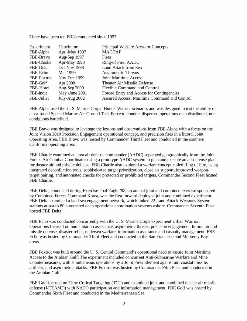
There have been ten FBEs conducted since 1997:
Experiment Timeframe Principal Warfare Areas or ConceptsFBE-Alpha Apr -May 1997 MAGTAFFBE-Bravo Aug-Sep 1997 FiresFBE-Charlie Apr-May 1998 Ring-of Fire; AADCFBE-Delta Oct-Nov 1998 Land Attack from SeaFBE-Echo Mar 1999 Asymmetric ThreatsFBE-Foxtrot Nov-Dec 1999 Joint Maritime AccessFBE-Golf Apr 2000 Theater Air Missile DefenseFBE-Hotel Aug-Sep 2000 Flexible Command and ControlFBE-India May -June 2001 Forced Entry and Access for ContingenciesFBE-Juliet July-Aug 2002 Assured Access; Maritime Command and Control
FBE Alpha used the U. S. Marine Corps’ Hunter Warrior scenario, and was designed to test the ability ofa sea-based Special Marine Air-Ground Task Force to conduct dispersed operations on a distributed, non-contiguous battlefield.
FBE Bravo was designed to leverage the lessons and observations from FBE Alpha with a focus on theJoint Vision 2010 Precision Engagement operational concept, and precision fires in a littoral JointOperating Area. FBE Bravo was hosted by Commander Third Fleet and conducted in the southernCalifornia operating area.
FBE Charlie examined an area air defense commander (AADC) separated geographically from the JointForces Air Combat Coordinator using a prototype AADC system to plan and execute an air defense planfor theater air and missile defense. FBE Charlie also explored a warfare concept called Ring of Fire, usingintegrated deconfliction tools, sophisticated target prioritization, close air support, improved weapon-target pairing, and automated checks for protected or prohibited targets. Commander Second Fleet hostedFBE Charlie.
FBE Delta, conducted during Exercise Foal Eagle ’98, an annual joint and combined exercise sponsoredby Combined Forces Command Korea, was the first forward deployed joint and combined experiment.FBE Delta examined a land-sea engagement network, which linked 22 Land Attack Weapons Systemstations at sea to 80 automated deep operations coordination systems ashore. Commander Seventh Fleethosted FBE Delta.
FBE Echo was conducted concurrently with the U. S. Marine Corps experiment Urban Warrior.Operations focused on humanitarian assistance, asymmetric threats, precision engagement, littoral air andmissile defense, disaster relief, undersea warfare, information assurance and casualty management. FBEEcho was hosted by Commander Third Fleet and conducted in the San Francisco and Monterey Bayareas.
FBE Foxtrot was built around the U. S. Central Command’s operational need to assure Joint MaritimeAccess to the Arabian Gulf. The experiment included concurrent Anti-Submarine Warfare and MineCountermeasures, with simultaneous operations by a Joint Fires Element against air, coastal missile,artillery, and asymmetric attacks. FBE Foxtrot was hosted by Commander Fifth Fleet and conducted inthe Arabian Gulf.
FBE Golf focused on Time Critical Targeting (TCT) and examined joint and combined theater air missiledefense (J/CTAMD) with NATO participation and information management. FBE Golf was hosted byCommander Sixth Fleet and conducted in the Mediterranean Sea.
3
FBE Hotel was conducted in conjunction with the U.S. Joint Forces Command Millennium Challengeexperiment, MC-00, the Army’s Joint Contingency Force Advanced Warfighting Experiment, the AirForce’s Joint Expeditionary Force experiment (JEFX-00) and the Marine Corps’ Millennium Dragonexperiment, making it the first all-service experiment. FBE Hotel focused on flexible command andcontrol processes, at the component level, using a Joint Force Maritime Component Commander(JFMCC) structure. FBE Hotel was hosted by Commander Second Fleet and conducted in the Gulf ofMexico and southern U.S.
FBE India was conducted in conjunction with the U.S. Marine Corps Capable Warrior (CW) andextending the Littoral Battlespace (ELB) initiatives focusing on forced entry and access for expeditionarycontingency operations. FBE India initiatives included information management and integration, battlespace preparation, real time sensor management, time critical targeting (TCT), medical casualty and non-governmental organization management, virtual collaborative planning and experimental command andcontrol (C2) architecture. FBE India was hosted by Commander Third Fleet and conducted in theSouthern California area.
1.2 FBE-Juliet: General Description
The two major experimentation areas for FBE-J were:
(1) Sea-based Joint and Maritime Command and Control(2) Assured Access
Sea-based joint command and control was an opportunity presented by Commander Joint Task Force(CJTF) and Joint Special Operations Task Force (JSOTF) plans to base portions of their staffs afloat onthe Fleet Command Ship. FBE-J examined C4ISR information and support needs to fully enable jointcommand from a Fleet Command Ship.
For assured access, the scenario presented concurrent threats by submarines, mines, coastal cruisemissiles, and enemy land and air assets. The joint environment and warfighting scenario presented anopportunity to experiment with Maritime Command and Control across almost all maritime warfare areasin a difficult littoral environment.
As noted above, FBE-J was conducted in conjunction with MC02. The experiments were conducted from24 July to 15 August 2002 in the US western sea and land ranges. The Congressional mandate for MC02included direction to integrate service and joint experimentation. MC02 was conducted primarily at thestrategic and operational levels while FBE-J was at the operational and tactical levels, with coordinationoccurring at the operational level. Separate simulations were utilized for the two experiments,necessitating passing information between them to coordinate tactical actions and joint-level decisions.
The timeframe for the experiment setting was 2007. This limited experimentation to those capabilitiesresident in the future years defense program (FYDP) in 2002 that are reasonably achievable by 2007.
MC02 was essentially a command post exercise. The JTFC staff passed directives to the servicecomponents where execution was accomplished. J9 operated a Red Cell that initiated OPFOR actions.The J9 simulation passed actions to service simulations, with situational awareness provided by GCCS. AWhite Cell provided adjudication, when needed. A high degree of coordination was needed between thevarious simulations if the play were to be realistic.
FBE-J was a mix of live and simulated activities in order to examine operational and tactical warfightingissues in a real environment. There were periods during the experiment when FBE-J operated independent

4
of the joint environment. At such times, Navy simulation provided Red-Force activities. At the servicelevel, simulation is used to examine systems that do not yet exist, to fill out orders of battle, and todetermine effects due to force numbers.
FBE-J was much more tightly integrated into a joint warfighting context than prior efforts. This involveda greatly increased level of effort, a need for subject matter expertise not resident at NWDC, and muchgreater expense. The advantage was an experimental venue that was completely joint. This providedgreater validity to Navy operational level experimentation and greater validity for acquisition-basedlessons learned.
FBE-J was an attempt to experiment in almost every maritime warfare area. The scenario supportedexperimentation in strike, anti-submarine warfare, mine warfare, anti-surface warfare, informationoperations, and intelligence, surveillance, and reconnaissance.
This FBE was preceded by a series of Limited Objective Experiments (LOEs) for high speed vessel andmine warfare. These iterative experimentation processes used the FBE as the largest venue in a series ofexperiments.
The FBE-J/MC02 pair involved concurrent and mutually reinforcing joint doctrine development andjoint/service experimentation. A coherent series of seminars, organizational process model development,organizational workflow depictions, and workshops were developed into a new paradigm for doctrinedevelopment. The experiment also provided a live, joint environment for field-testing proposed JointMaritime Component Commander doctrine.
Overview of Activities in FBE-J
FBE-J Activities in Joint and Maritime Command and Control
• Maritime Operational Planning Processo Objective: Field test the draft joint doctrine for JFMCC.o Action: Refine the roles, functions, and planning process for the Joint Force
Maritime Component Commander.
• Sea-Based Joint Command and Control (C2)o Objective: Lessons learned for doctrine, organization, training, manning, and
technology in support of ship-based joint command and control.o Action: Refine C4ISR and support for a sea-based Joint Force Commander.
• Netted Force (NF)o Objective: Provide lessons learned for development of expeditionary networks.o Actions: Develop innovative solutions to the seams between forward based
forces and rear echelon forces through exploration of innovative networking.Additionally, improve coalition information exchange using software agent-based systems.
• FBE-J Naval Fires Network (NFN (X))o Objective: Provide field-tested NFN TACMEMO for Fleet use. Provide lessons
learned for NFN converged architecture development. Provide lessons learnedfor joint doctrine, organizations, training, and manning when joint intelligence,surveillance, and reconnaissance (ISR) assets can be shared and distributedacross the CJTF.

5
o Actions: Assess Naval Fires Network (Experimental) (NFN (X)) system anddevelop TTP and CONOPS to support sea-based fires in a joint environment.Explore innovative linkage of NFN (X) to the joint fires network. Provide field-tested results for bandwidth, weapon-target pairing, and deconfliction.
FBE-J Activities in Assured Access
• Unmanned Sensors and Platformso Objective: Provide CONOPS leading to TACMEMOs for airspace, waterspace,
and sea-surface management; deconfliction; and asset optimization in a highlymixed manned and unmanned environment. Provide lessons learned for doctrine,organizations, training, and manning based on use of manned and unmannedsensors and platforms.
o Actions: Refine the concepts of employment for distributed, networked, mannedand unmanned platforms, and remote sensors, for anti-submarine warfare(ASW)/anti surface warfare (ASUW) / Mine Warfare (MIW).
• Theater Air and Missile Defenseo Objective: Provide field-tested CONOPS leading to TACMEMO for Navy lower
tier, Navy theater-wide, and Navy Area Air Defense Commander Modulesystems in a joint environment. Provide lessons learned for doctrine andorganizations in use of these emerging systems.
o Action: Examine multi-mission pull and joint C2 of Navy TBMD capable units.
• Anti-Submarine Warfare (ASW)o Objective: Provide field-tested CONOPS and technological recommendations to
mitigate seams between local and theater ASW efforts.o Action: Examine coordination from theater ASW commander to local ASW
Commander, in integrating unmanned sensors and platforms with mannedsensors and platforms.
• Anti- Surface Warfare (ASUW)o Objective: Provide field tested CONOPS leading to TACMEMO development or
fleet use of joint and Navy assets versus the swarming small boat threat.o Action: Examine joint tactical packages to counter swarming small boat threat.
• Mine Warfare (MIW)o Objective: Provide field tested CONOPS leading to TACMEMO development
for fleet use of emerging mine warfare systemso Action: Refine concepts of employment for organic and dedicated MIW forces in
assured access mission
• Information Operations (IO)o Objective: Determine if IO forward and JFMCC IO staff contribution were
incorporated in the Maritime Planning Process and were sufficient/insufficient toproduce the products, information, guidance, or feedback necessary to constructan MTO. Where insufficient, determine contributors to lack of process, products,information, collaboration, or control.
o Action: Integrate kinetic and non-kinetic engagement options to developcomputer network defense CONOPS. Evaluate the impact of cross-componentengagement network and supporting TTP.
6
MC-02 Activities Proposed by NWDC
• Joint Fireso Objective: Provide recommendations for acquisition of system enabling
coordination of joint Fires across the CJTF.o Action: Evaluate the impact of cross-component engagement network and
supporting TTP.
• High Speed Vessel (HSV)o Objective: Provide lessons learned for development of future Navy combatants
and support vessels to include littoral support craft, logistics, and vessels.o Action: Evaluate vessel speed, size, range, and endurance along with
reconfigurable payload characteristics for assured access missions. Explore useof HSV for transport, USW, fire support, sensor support, medical support, andsea-based C2.

7
2.0 Initiative Descriptions
Following are brief overviews of the individual initiatives. They provide an overall description of thebackground for each initiative; a statement relating the initiative to the warfighting challenge inapproximately five years; a brief characterization of the initiative itself; and then one or more questions,which provide the foci for the subsequent analyses.
2.1 Joint Forces Maritime Component Commander (JFMCC) Maritime Planning Process (MPP)
Description: The JFMCC process is a collective interaction among a number of processes that interpretguidance from the JFC, produce a Joint Maritime Operations Plan (JMOP), define Maritime SupportRequests (MARSUPREQs), prioritize actions in a Maritime Master Attack Plan (MMAP), and assignactions to individual maritime commanders in a Maritime Tasking Order (MTO).
Relationship to warfighting challenge in 2007: In the 2007 timeframe, there will be multi-functionalmaritime platforms with multiple weapons systems, sensors, organic capabilities, highly sophisticated C2systems, and low manning. Providing access to the littorals will be a requirement for maritime forces,often ahead of Time Phased Force Deployment and Joint capabilities. A Maritime Tasking Order will berequired to optimize, synchronize, and interrelate forces that are both maritime and joint. The principalwarfighting areas included in this initiative, as produced within the context of the experiment scenarioare:
• Production of a Maritime Tasking Order through a Maritime Planning Process.• Collaboration with Joint and Principal Warfare Commanders.• Support for, and feedback to, a jointly constructed Effects Tasking Order (ETO).• Tracking and redefinition of MTO events as they are executed.• Definition of requirements for manning, tools, and C2.
Initiative Definition: The JFMCC process was analyzed to determine the overall efficiency andeffectiveness in generating an MTO. The analysis was structured to decompose complex processes intotheir component sub-processes, and then assess their relative merit and contributions to the commander’sunderstanding of the operational situation. Processes that were overly complex or time consuming were tobe identified.
Overarching Question: Did the JFMCC Maritime Planning Process add structure, organization,management, feedback, optimization, and situational awareness to maritime force employment, and did itsupport the intent of a jointly developed Effects Tasking Order (ETO)?
2.2 Joint Fires Initiative (JFI)
Description: This was the application of common tools, processes, CONOPS, and architecture to conductjoint integrated Fires, which deconflicted Fires in space and time, but did not divide the battle spacegeographically according to land, sea, and air. NFN is the Naval subset of joint Fires.
Relationship to warfighting challenges (2007): The timely engagement and assessment of TSTs byJoint forces across components presents the following warfighting challenges:
• Establishment of a timely, accurate COP/CROP.• Application of effective cross-component collaborative capabilities.• Timely integration of Joint capabilities against tactical objectives.
8
Initiative Definition: Design and deliver a Joint Fires C2 network. The primary tool was ADOCS/LAWSsoftware that was modified to incorporate a joint TST Mission Manager (i.e. DTL Manager) function thatwas used for C2 among component level commands and the Joint Task Force. The Joint Fires Initiativerequired that a TST be developed and nominated by one component and the mission passed by thesupported Commander, to another component for execution.
Overarching Questions
• Did the proposed (experimental) joint targeting (cross-component) architecture enable timelyengagements of TSTs?
• In what ways did a common toolset within the joint architecture improve the ability of the jointforce to conduct effective cross-component TST operations?
• The initiative required the design and delivery of a joint Fires C2 network. The primary system ofthis network was ADOCS, modified to incorporate a joint TST mission manager (i.e. theDynamic Target List (DTL) Manager) function that was used for C2 by the component levelcommanders and the Joint Task Force. The Joint Fires initiative required that a TST be developedand nominated by one component, and the mission passed by the supported commander toanother component for execution
2.3 High Speed Vessel (HSV)
Description: The FBE-J/MC02 High Speed Vessel (HSV) joint initiative was a major milestone in theJoint HSV Project. The HSV project is a joint, multiyear effort between the Army, Navy, Marine Corps,and Naval Special Warfare Command. The project explores the concepts and capabilities associated withcommercially available advanced hull and propulsion technologies integrated with advancedcommunications technology. New designs for surface vessels permit significantly increased speeds thatcan improve support for Intra-theater logistics and combat service (logistics movements within theoperations area). Other characteristics possessed by the HSV appear to be particularly well suited tolittoral operations, especially mine warfare, command and control, and possibly support to medical forces.
For MC02/FBE-J, there were two test-bed HSVs (Joint Venture (HSV-X1), and Sea SLICE) serving assurrogate platforms in a number of LOEs. HSV-X1 is a semi-planing wave-piercing aluminum catamaranoriginally built and operated as a commercial high-speed car and passenger ferry. The project leasedHSV-X1, made enough modifications to the vessel to support experimentation and demonstration needs,and installed an advanced (and experimental) C4I system. The Sea SLICE is a small waterplane twin hull(SWATH) ship owned and built by Lockheed Martin on behalf of the Office of Naval Research as atechnology demonstrator. While significantly different in size and capabilities, both of these uniqueplatforms are a departure from traditional Navy monohull ships. FBE-J was a valuable opportunity todemonstrate the technology of these two vessels.
In addition to the test bed platforms, 5 simulated HSVs (Agile, Aggressive, Exultant, Impervious, andHercules) also participated in the experiment. All of these vessels are more fully described in chapter 7.
HSVs' participation in FBE-J/MC 02 provided an opportunity to validate previous LOE findings in anoperational setting. Against the backdrop provided by the experiment scenario, the Project’s partners putthe vessel and their experimental systems and concepts through their paces. Joint Venture's ability tosupport alternative mission configurations was tested as first multiple mine warfare (MIW) functionswere exercised; followed by simultaneous MIW C2 (MIWC) and Naval Special Warfare (NSW)operations; simultaneous MIW C2, NSW C2, and Marine Corps ship-to-objective-maneuver (STOM)operations; simultaneous logistics, surveillance, and NSW operations; and closing MC02 with an Armyvalidation of its ability to conduct an operational retrograde of a Stryker Brigade Combat Team (SBCT).In addition to Joint Venture's participation, FBE-J/MC02 provided an opportunity to:
9
• Conduct mine countermeasures, fires, surface warfare, and NSW experimentation with SeaSLICE.
• Experiment with a simulated force of five HSVs operating as a force of Littoral SurfaceCombatants to explore Fleet concepts of operation (CONOPS).
• Test the HSVs’ ability to quickly reconfigure in support of different mission areas.
Relationship to Warfighting Challenge in 2007: HSV technology in Joint Venture leverages provencommercial design to bring an added dimension to modern naval warfare. Commercial shipyards alreadymanufacture vessels with a number of militarily relevant capabilities including high-speed, long range atendurance speeds, reasonably good sea keeping ability, shallow draft, and rapid adaptability to multiple,changing missions. Additionally, the cost and manning requirements of a militarized version of thesevessels is estimated to be substantially less than that of a more traditional military ship of comparable sizeand capability. To the extent these commercial vessels can be further modified to meet military needs,they potentially offer significant, near term capabilities.
In 2007 these enhanced capabilities could offer clear advantages to the Joint Force Commander (JFC). AnHSV's inherent speed and ability to operate from austere ports enhance its operational mobility andreduces an enemy's ability to maintain situational awareness across extended battlespace. As sensorsimprove in numbers and capabilities, the HSV’s ability to deploy manned and unmanned sensors, collect,process and disseminate information, and host a forward-based commander and his staff will becomeincreasingly important to gaining and maintaining situational awareness. The HSVs’ increased mobilityand situational awareness create new opportunities to exploit those advantages. Ship designcharacteristics in the HSV such as high speed, high payload fraction, minimal manning requirement, andshallow draft lend themselves to sustaining combat forces across the access battlespace. Enable by systeminterfaces and a baseline architecture built into an HSV’s command, control, communications, computers,and intelligence (C4I) system, the HSV’s ability to accept C4I modules extends the JFC’s ability to pushhis command and control forward into the battlespace.
The improvement in capabilities that HSV technology offers has direct applications in Rapid DecisiveOperations (RDO) as they provide the JFC an enhanced ability to accelerate his tempo of operations. As aresult, HSV technology creates opportunities for developing transformational operational concepts aimedat bringing military power to bear from long range at responsive speeds.
Initiative Definition: The High Speed Vessel Joint initiative was part of a yearlong series of experimentsthat explored the military use and suitability of advanced hull and propulsion technologies integrated withadvanced communications technologies. For FBE-J/MC02 there were two test-bed HSVs (JOINTVENTURE (HSV-X1), and SEA SLICE). In addition to the test bed platforms, 4 simulated HSVs(AGILE, AGGRESSIVE, EXULTANT and IMPERVIOUS) also participated in the experiment. As anenabling technology, the HSV initiative overlapped other FBE-J/MC02 initiatives, as described below.
Sub-initiatives: The HSV sub-initiatives provided context and interactions between maritime missionsand potential HSV roles. HSV evaluations and analyses extended across a number of mission areas, e.g.,MIW, Naval Special Warfare (NSW), support to Ship to Maneuver (STOM), and Joint support (e.g.,IBCT redeployment and logistics ashore). The relationships between hull-type and the capabilitiesresulting from this hull form, and design for multi-purpose roles was the central analysis perspective inFBE-J.
In support of different missions, both the test-bed ships and simulated HSVs were reconfigured andswitched between missions during the experiment. Free-play within the scenario simulation also resultedin mission shifts and was an additional source of important data.
10
Overarching Questions
• What additional value added did having a number of high speed, reconfigurable, and multi-mission platforms provide the JFMCC and JFC in a littoral campaign as part of an accessmission?
• What are the appropriate missions best suited to this concept of maritime operations?• In a netted environment with many and varied types of sensors, what are the advantages or
disadvantages of the C2 construct used in this concept?• What conditions and design features must be considered in engineering the capabilities requisite
in meeting the challenges in a 2007 campaign?
2.4 Naval Fires Network – Experimental (NFN (X))
Description: This initiative was to provide support for fully autonomous platforms that were capable ofperforming all aspects of targeting and to simulate future power projection platforms and weaponsystems.
Relationship to warfighting challenges in 2007: In 2007, the timely engagement and assessment ofTSTs by the JFMCC will present the following warfighting challenges:
• Establishment of a timely, accurate COP/CROP.• Maintenance of effective collaborative capabilities among and within engagement nodes.• Timely integration of capabilities against tactical objectives.
Initiative Definition: The Naval Fires Network (Experimental) initiative in FBE-J / MC 02 was designedto implement experimental Navy targeting systems and processes. These support joint targeting and Firesrequirements across service components, up to CJTF and down to tactical Naval forces, using definedCONOPS, TTP, systems, architecture, and organization. Navy Fires was to project power ashore throughthe integration of long-range surface, sub-surface, and air-delivered fires.
Overarching Questions
• What was the contribution of Naval platform self-targeted engagements to the TST engagementproblem?
• What are the operational planning and employment considerations required for the effectiveutilization of future power projection platforms in the TST engagement process?
• How successful was the defined TST architecture in engaging asymmetric TST targets?• How successful were Naval platforms in responding to multi-mission tasking?• What was the contribution of the Mensuration Manager to the TST process?• What did the introduction of a ground COP contribute to the TST process?
2.5 Intelligence, Surveillance, Reconnaissance Management (ISRM)
Description: This initiative was to integrate the management of the JFMCC, ISR planning and execution,asset management, manning requirements, Unattended Ground Sensors (UGS), and multi-platformSIGINT tracking, with dynamic ISR management.
11
Relationship to warfighting challenges in 2007: In order to reduce the time needed to make criticaldecisions, particularly with regard to TCTs, it is vital to improve the efficiency of managing various ISRsystems. It is likewise important to improve the efficiency in the construction and management of theresultant comprehensive database and COP/CROP in order to make optimal decisions in minimum time.
Initiative Definition: The primary objective of this sub-initiative was to provide a representativeconstruct from which UAV ISR assets (e.g. a tiered-UAV architecture) can support the Maritime PlanningProcess (MPP), Joint Dynamic ISR Management (JDISRM), Time Sensitive Targeting (TST), andAssured Access (AA) experiment initiatives. In doing so, the areas of tactical utility, connectivity, and C2structures (e.g. concept of operations) of a tiered UAV ISR&T architecture, as well as the required levelof effective control of UAV assets to allow for dynamic management, could also be explored. For theexperiment, Global Hawk, Joint Operational Test Bed System (JOTBS), and Pioneer UAVs were used toexamine UAV tasking, data processing, exploitation and dissemination afloat.
Overarching Questions
• Can dynamic ISR management be effectively employed to engage high priority targets?• Can unattended ground sensors and unmanned aerial vehicles be effective sources of information
for DISRM?• Are the communications links sufficient for the purpose?
2.6 Mine Warfare (MIW)
Description: The overall objective of the MIW experiment in FBE-J was to examine the application ofnetwork-centric warfare concepts and other emerging technologies as they might apply to mine warfare.
Relationship to warfighting challenges in 2007: In 2007, the littorals will be increasingly important andchallenging for maritime and joint forces to access quickly and safely. New platforms such as High SpeedVessels (HSVs), and technological advances in sensor capabilities increase the organic MCM capabilityand present the MIWC with organizational, resource allocation, information, and C2 challenges, onlypartially addressed in FBE-J.
Initiative Definition: The command and control structure in FBE-J encompassed an experimentalorganization, an HSV as a surrogate future Mine Warfare Command and Support Ship (MCS) capableplatform, new command and control equipment,and some new MCM capabilities, which replicate futureMCM capabilities in the 2007-2010 time frame.
Overarching Question: How can the efficiency and effectiveness of mine warfare be enhanced throughthe use of network-centric operations?
2.7 Anti-Submarine Warfare (ASW)
Description: The anti-submarine warfare (ASW) initiative in FBE Juliet addressed tactical, operational,and command decision processes within this warfare area.
Relationship to warfighting challenges in 2007: Network-centric ASW is the underlying concept forsuccess in ASW in littoral waters. This concept of multi-level commands and multi-disciplinary forces,well-connected by common communications, and guided by solid doctrine, planning tools, andcommander’s guidance will be central to rapid and successful prosecution of submarines in these complexand dangerous situations.
12
Initiative Definition: There were four ASW sub-initiatives in FBE-J:
• The submarine locating device initiative investigated the operational concept of installingsubmarine locating devices. This included issues of when, where, and how to achieve theinstallation, and what type of capabilities the locating devices should have. The problems ofpermissive ROE were considered. Submarine Locating Device signals were utilized in the ASWpicture.
• The remote autonomous sensor initiative investigated the ability of remote, autonomous systemsto independently identify submarine contacts and report them in real time or near real time. Thepurpose was to determine if remote autonomous sensors could, if necessary, provide thecommander the ability to effectively cover large areas without risking manned assets, yet be ableto attack threat submarines efficiently with the use of air assets.
• The experimental common undersea picture initiative provided basic tools for network-centricASW. It had three major functions that provided the backbone for this operational concept: forcecollaborative planning, shared situational awareness, and common dynamic tactical decision aids.
• Using the experimental naval Fires network for ASW Targets sought to determine ifincorporating ASW targets in the experimental Navy Fires network (NFN (X)) in conjunctionwith the Land Attack Warfare System (LAWS) could improve the ability to attack ASW targetssuccessfully as time critical targets.
Overarching Question: How can network-centric ASW operations improve detection, classification,localization, and neutralization of enemy submarines to assure rapid and successful maritime access to,and operations in, littoral regions of interest?
2.8 Information Operations (IO)
Description: The FBE-J Information Operations initiative was designed to provide the full range of IOcapabilities (Offensive, Defensive, and Collaborative) in support of the JFMCC planning process. Itincorporated experimental and emerging organizational constructs, processes and capabilities toaccommodate simultaneous offensive and defensive operation at the tactical and operational levels.
Relationship to warfighting challenges in 2007: As the number of sensors, platforms, exploitation sites,and command and control nodes continue to proliferate with advances in technology, commanders andanalysts require assurance that data, information, and knowledge, are being managed effectively andefficiently. Likewise, any disruption that we can create in opposition force data flow, which will confuseor delay decision making by the opponent, provides us with a relative advantage. The role of IO and theIO Cell is to simultaneously protect friendly information and information systems while denying,degrading, disrupting, and destroying the adversary’s system to produce a more favorable informationdifferential between the two.
Initiative Definition: The following four sub-initiatives comprised the IO effort and were researchedduring FBE-J:
• IO enrichment to the JFMCC planning process.• Collaborative IO planning.• Defensive IO – Computer Network Defense.• Offensive IO – Tools incorporated to support deliberate and time critical targeting.
Overarching Question: Is IO sufficiently incorporated into the MPP operations to yield high qualityproducts, information, guidance, and feedback to support the MTO generation process?
13
2.9 Coalition Command and Control (Coalition C2)
Description: The operational commander should be able to ensure that coalition partners are assets toenhance relevant information exchange, and not a liability that could potentially decrease speed ofcommand. The use of coalition forces can reduce the risk to US forces, and increase nodal sensor (orweapons) coverage, as long as architecture exists to support their integration.
Relationship to Warfighting Challenge in 2007: Coalition operations, including those of ad hoccoalitions, have been a fundamental reality in virtually every recent operational engagement of the U.S.Navy and multi-service forces. Examples include operations Desert Storm, Allied Force, Joint Forge/Guardian, and Enduring Freedom. Coalition operations will be most effective if they serve as not only apolitical instrument of national power, but contribute to the warfighting effectiveness of the combinedforces. Situational awareness that combined Naval operations should be able to leverage might becompromised by the varying strengths that regional coalition partners bring to a theater of engagement.Interoperability is a potential source of friction between network-centric warfare and multi-nationaloperations. There are also potential concerns among allies and coalition partners that the disparity intechnology advancement between partners, particularly network-centric warfare, will inhibit effectivecoalition command and control.
Initiative Definition: The initiative addressed the following warfighting challenges:
• Multi-national interoperability.• Dynamic reconfiguration of networks supporting multi-tasked platforms or those with
disadvantaged or intermittent C4 capabilities.• Reliability of network-centric architectures to exchange relevant information for distributed
planning and decision-making.• Needs for a better mechanism to support secure information sharing to enhance the coordination
of operational forces while protecting national sources and data deemed not releasable.• The extent of future desired operational capability supported.• Information Superiority.• Secure cross-service, -platform, -discipline, -echelon, -coalition and -agency integration• Real-time battlespace awareness.• Comprehensive battlespace awareness to support the full range of military operations.
Overarching Questions
• Can a coalition force be effective and dynamic, reconfigurable, and tailored to the threat andtheater?
• Can partners join and leave C2 networks with minimum difficulty?• Can national information data and sources be protected while decision-making with a coalition
force is shared?
2.10 Netted Force (NF)
Description: This initiative consists of three sub-initiatives: Knowledge Management Organization(KMO), Collaborative Information Environment (CIE), and Ground COP. All are designed to improvethe management of, and access to, information within the battle force to permit fast, confident decision-making.
14
Relationship to warfighting challenges in 2007: The proliferation of data from disparate source sensors,particularly those generating continuous data streams, the potential reduction in platform signatures, andthe concomitant increases in speed and lethality of weapons systems all mandate efficient distribution andmanagement of information in order for a joint force to make the best decisions in battle.
Initiative Definition
• Knowledge Management Organization (KMO) Initiative focused on the Knowledge InformationOfficer who answered directly to the JFMCC and coordinated the JFMCC Commander, Chief ofStaff, and Battlewatch Captain to ensure that watch team knew where to find critical information.
• Collaborative Information Environment (CIE) Initiative focused on the ability of the CIE tosupport rapid decisive operations by giving the commanders the information they need to haveconfidence in their decisions.
• Ground COP Initiative- attempted to automate the linkage between traditional COP trackmanagement, engagement tools, target management, and intelligence order-of-battle tools usingthe capabilities of the emergent GCCS 4.X architecture.
Overarching Questions
• Does the netted force (NF) support improved planning and execution by improving thecommander's situational awareness while decreasing information overload?
• Does the KMO concept provide for improved bandwidth management in support of combatoperations?
• Does the NF improve the understanding and decision making of tactical ground forces?
2.11 Joint Theater Air Missile Defense (JTAMD)
Description: Navy Theater Air and Missile Defense (TAMD) capability was hosted as one of the multi-functional capabilities onboard select surface combatants.
Relationship to Warfare Challenge in 2007: Navy Theater Air and Missile Defense (TAMD) capabilitywill be hosted as one of the multi-functional capabilities onboard surface combatants. Navy planners willrequire solutions that balance joint (critical asset defense) and maritime (force protection and access)requirements and effectively, and more optimally, employ limited numbers of ships in a dynamicbattlespace environment. Doctrine and organizational constructs will have to support the command,control, and coordination of capabilities simultaneously shared by Navy and Joint commanders. Evolvinginnovations in technology include improvements to the Area Air Defense Commander (AADC) moduleto develop and evaluate alternative courses of action. Evolving weapons technical capabilities includesea-based mid-course and terminal phase TAMD capabilities, Cooperative Engagement Capabilities(CEC), and improvements in weapons platforms such as the enhanced E-2 and F/A-18 aircraft.
Initiative Definition: FBE-J provided the dynamic interactions necessary to further mature jointTAMD/AAW operations for TACMEMO development. Data were collected with respect to commandrelationships and mission planning processes to optimize allocations of multi-mission TAMD capabilitieson surface ships, using the capabilities of an AADC module. System elements were evaluated for jointemployment, providing input to a future USN AADC module TACMEMO and to mature the initiative forfurther refinement and analyses in upcoming LOEs and FBEs. JTAMD sub-initiatives were designed todefine further the internal processes developed within the AADC module to support the JFMCC'sMaritime Planning Process (MPP) and to provide guidance for the interaction of Navy TAMD withJTAMD.

15
Overarching Questions
• Can a single commander appointed as both the battle force Air Defense Commander (ADC, alsoAW) and a Regional Air Defense Commander (RADC), supported by the AADC Moduleplanning capability and process, effectively support the air and missile defense requirements ofboth commanders?
• Does the capability to rapidly wargame alternative courses of action with the embedded wargaming (M&S) capability and to provide graphic displays provide value added to the Joint ForceMaritime Component Commander (JFMCC) and Joint Forces Air Component Commander(JFACC)?
• What emerges as functional relationships between the JTFHQ (production of the Effects TaskingOrder and/or the Defended Asset List), the JFMCC (Maritime Tasking Order), andJFACC/AADC (Air Tasking Order)?
• What emerges as the organizational relationship between the SJTFHQ Theater Missile Defense(TMD) Cell, JFACC/AADC, Deputy Area Air Defense Commander (32nd AAMDC), RegionalAir Defense Commanders (RADC), and the maritime Air Defense Commander?
• What elements of the experimental organization, TTP and C2 learned from this event are suitablefor inclusion in a future USN AADC module TACMEMO?
• Does the JFMCC Maritime Planning Process mitigate the dilemma posed by competing demandsfor multi-purpose surface combatants?
2.12 Sea-based Command and Control (Sea-based C2)
Description: This initiative analyzed the potential for network-centric computing to support theobjectives of a sea-based CJTF, and provided insight to the manning structure and functional capability ofthe JFHQ.
Relationship to Warfighting Challenge in 2007: The network-centric computing paradigm of the nearfuture can provide a vastly improved exchange of information, with improved situational awareness andgreatly reduced response times, thus streamlining the execution of battlefield scenarios. This will requireimproved data communication capability in terms of bandwidth, reliability, and accessibility. Fleet BattleExperiment - Juliet (FBE-J) was a platform to demonstrate these increased capabilities and to test thefeasibility of network-centric solutions to naval warfighting situations of the future.
Initiative Definition: Network data were collected to determine the necessity, sufficiency andeffectiveness of the wide-area network connections used in FBE-J. An assessment was made as to theeffectiveness of the COP in supporting sea-based command and control.
Overarching Questions
• Document the CJTF staff perceptions of their capabilities as a CJTF that is sea-based within thecontext of the MC02 scenario and FBE-J/MC02 architecture.
• Are the manning, structure and functional capability of the JFHQ sufficient for the requirement?• Is the “reachback capability” of the JFHQ (Forward), on-board USS CORONADO, to the JFHQ
(Main) at Suffolk, VA, sufficient to ensure information superiority?

16
This page intentionally left blank.
17
Section II: Principal Results(Principal Results are also contained in the Summary Analysis Report.)
3.0 Principal Results3.1 Summary of Findings
The following principal results have been extracted from the Fleet Battle Experiment -Juliet (FBE-J)Reconstruction and Analysis Report's key observations. They are a fraction of the results that wereobtained from the experiment. They are deemed to be the most significant for reasons such as operationalimpact, importance of further study, etc.
These results have been determined under conditions that existed during FBE-Juliet. Whether they areapplicable outside those conditions is speculative. Section II of this report provides an abbreviateddescription of the general context for the experiment. A more complete description can be found in theReconstruction and Analysis Report. Section III provides a brief description of the context as related toany experiment, followed by the specific context that is pertinent for each initiative. These two Sectionswill allow one to assess the validity of these principal results and the conditions for which they apply. Italso allows one to plan the conditions under which further experimentation should be carried out.
Each principal result is presented in two formats. The first format is a set of brief summary pointspresented as in a table. The second is a brief description of each point on the same page. These formatscan be used for presentations, with the first being projected and the second to verbally describe theresults. Again, full descriptions of these results can be found in the Reconstruction and Analysis Report.
A semantic difficulty has been encountered in presenting these results. The distinction between a timesensitive target (TST) and a time critical target (TCT) has been lost in current common usage. Theirdefinitions are:
• TST. A target that is to be attacked by a particular time. Such a target can be on the deliberatetargeting list.
• TCT. A target that "appears" and must be attacked within a definite time period. This target willbe on a priority list, but will not be on the deliberate targeting list.
TCTs are a special class of TST. It is important to differentiate because they are managed differently andconclusions with respect to the ability to manage them can differ.
18
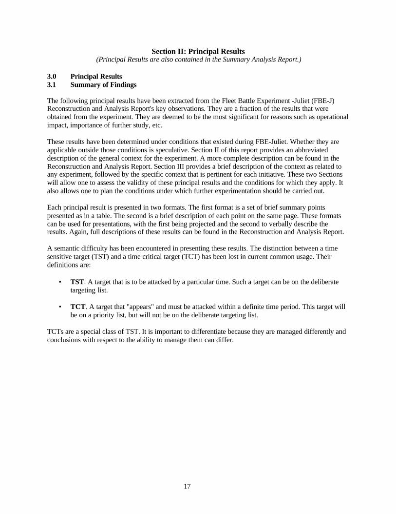
MPP #1 - The Maritime Planning Process Is Viable
• All required tasks were executed and required products produced.o Full process from ETO ingestion to MTO production executedo Three overlapping, 72-hour planning cycles executed simultaneously
• The range of planning done in the experiment was limited.o Competition for assets between PWCs was largely nonexistent.o Execution results were not fed back into the planning cycle.o There was no determination of the plans’ quality.
• Process difficulties need to be addressed.o Individuals needed to multi-task; there is no process for coordinating tasks with
individual availability.o Synchronization was ad-hoc rather than a planned process.
Maritime Planning Process #1
The maritime planning process (MPP) was implemented by a staff structure under the Joint ForcesMaritime Component Commander (JFMCC). Effects tasking orders (ETOs) from the Joint ForcesCommander (JFC) were ingested, and maritime tasking orders (MTOs) were produced and coordinatedwith the air tasking order (ATO). Principal warfare commanders (PWCs) participated in the process,producing maritime support requests (MARSUPREQs) that were a component of MTO production. Threeoverlapping planning cycles of 72-hours each were simultaneously executed. The process executed allrequired tasks and produced required products.
Applicability: The range of planning done in the experiment was limited. The range of situations that theprocess can manage is unknown.
• Competition for assets between PWCs was largely nonexistent. The process was not stressed.• There was no MTO-ATO feedback cycle for plan adjustment.• There was no determination made of the plans’ quality.• Execution results were not fed back into the planning cycle; no process exists to do this.
MPP details and causes. It was observed that the MPP is viable, but also observed was that the processdid not go well. Principal problems and their causes were:
• The need to simultaneously support three planning cycles with a limited number ofindividuals appeared to be a primary cause for process difficulties. Individuals needed to bemulti-tasked, and there was no process for coordinating tasks with individual availability.
• A high level of synchronization of tasks was needed, along with the information that supportsthe tasks, and the individuals that perform them. Synchronization was ad-hoc rather than aplanned process.
• Various inputs to a given MTO were observed to contain essentially the same content assubmissions for previous plans, creating the impression of resubmission rather than new plandevelopment. The cause for this duplication is not known, nor whether it is a real problem.Possible causes are overloading of multi-tasked individuals and information synchronizationdifficulties.
Recommendation• Assume at this time that MPP should be implemented and refer to the following MPP
principal result for pre-implementation requirements.
19
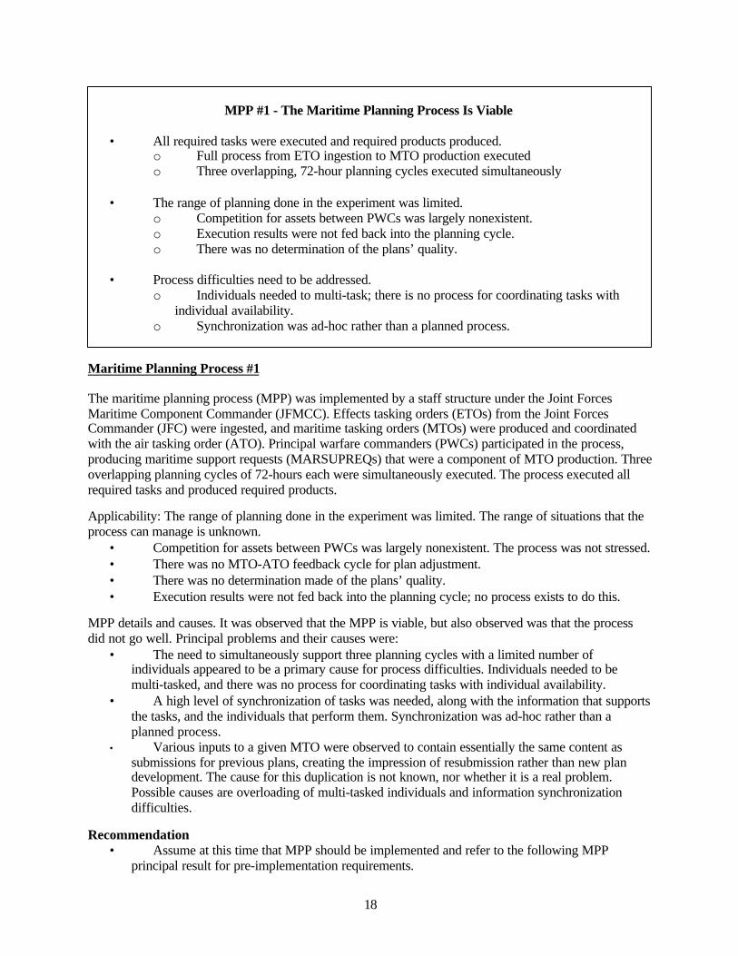
MPP #2 - MPP Implementation Study Needed
• Little information is available for MPP improvement.
• Further progress with MPP requires:o Detailed mapping of the planning architectureo Parameterization of planning sub-processeso Mapping of planning decision processeso Mapping of information flows that support planning and decisionso Better personnel assignments to tasks
• Process modeling is required.o Develop a detailed MPP process modelo Parameterize the model with data from FBE-J and other experimentso Determine from model simulation runs how to synchronize the processo Determine MPP personnel requirements and multi-task coordinationo Determine how to synchronize asynchronous feedback from execution
Maritime Planning Process #2
MPP principal result #1 identifies that the process is viable, that difficulties remain to be resolved, andoverarching problem areas. The experiment revealed process problems but provided little informationabout how to resolve them.
MPP implementation context. It is assumed that the MPP will be implemented with staffing that isapproximately the same as in FBE-J. This means that personnel multi-tasking and synchronization oftasks, supporting information, and the identification of the individuals performing tasks will be required.
A process is needed to feed back information into all three planning processes on the results of actionsand executions. An effects cell and a process for synchronizing its output with planning cells areproposed, and definition of this process is required.
Recommendations
Further progress with MPP requires detailed mapping of the planning architecture, parameterization ofplanning sub-processes, mapping of planning decision processes and information flows that support thedecisions, and better personnel assignments to tasks. This can only be done by process modeling.Specifically:
• Develop a detailed MPP process model. This should be done for both the system tested inFBE-J and for the more comprehensive system needed for adequate MPP execution.
• Parameterize the model with data from FBE-J and JFMCC limited objective experiments(LOEs). Run the model to identify principal process shortfalls.
• Determine, from a model, how to synchronize the process. Model iterations and runs canidentify requirements.
• Determine MPP personnel and multi-task coordination requirements from a model.• Determine how to use an effects cell to synchronize the asynchronous feedback from
execution.
20
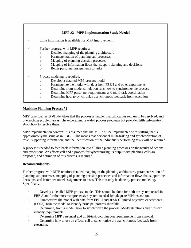
HSV #1 - HSV Rapid Reconfiguration For Different Missions Is Viable
• HSV reconfiguration was accomplished for:o C2 platform for MIWC and MCM operationso Navy Special Warfareo Intra-theater lift/movement of a brigade combat team unito Sensor management platformo Support for helicopters, small boats, USVs, and UUVs
• Five reconfigurations accomplished, time for each less than one-half day
• Further tests for more configurations and operations needed:o Reconfiguration profiles, their difficulty levels, resource needs, and times to
accomplisho Fits between reconfiguration profiles and orders of battleo CONOPS and TTP for HSV use and reconfiguration for littoral warfareo Numbers of ships needed to support various operationso Optimal reconfiguration profiles to minimize the required number of ships
High Speed Vessel #1
During the experiment HSV-X1 was reconfigured five times, with time to achieve reconfiguration nevermore than one-half day. It was tested as a command and control (C2) platform for Mine WarfareCommand (MIWC) as well as for mine countermeasures (MCM) operations, Navy Special Warfare(NSW), intra-theater lift/movement of a brigade combat team unit, and a sensor management platform.Opportunities arose during the experiment to provide support for helicopters, small boats, unmannedsurface vehicles (USVs), and unmanned underwater vehicles (UUVs).
Applicability: A subset of possible HSV missions was tested during the experiment. The full range ofmissions an HSV can support, and the numbers of ships needed to support a particular mission are not yetknown. Reconfiguration works, but will have differing difficulties and times to accomplish, dependent onspecific missions.
An operation may involve more than one HSV. Varying numbers of ships will be involved in the variousmissions within the operation. The number of ships to be reconfigured, and the schedule, will depend onhow missions and ships use are synchronized. A process will be needed to optimize reconfiguration.
Recommendations
Studies should be undertaken immediately to determine:
• Reconfiguration profiles, their levels of difficulty, resource needs, and times to accomplish• Numbers of ships needed to support various operations• Fits between reconfiguration schedules and orders of battle• CONOPS and TTP for HSV use and reconfiguration for littoral warfare• The optimal reconfiguration profiles necessary to minimize the required number of ships.
21
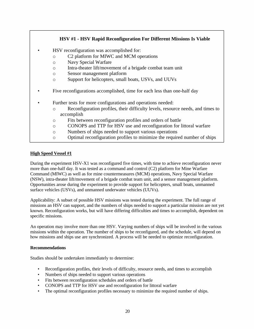
HSV #2 - HSV is Able to Operate as a Simultaneous, Multi-Mission Platform
• HSV-X1 simultaneously conducted MIWC, MCM, and STOM operations.
• A subset of possible HSV simultaneous missions was tested. Outstanding questions:o Efficient single ship multi-mission profileso How more than one ship would support several missionso How to coordinate multi-missions within and between HSVs
• Undertake studies to determine:o Needed simultaneous multi-mission support for various orders of battleo Manning required to support single-ship multi-mission capabilitieso Required information exchange and coordination for multi-ship simultaneous
missions
High Speed Vessel #2
During the experiment HSV-X1 conducted MIWC, MCM, and STOM operations simultaneously, whilealso functioning as a forward deployed sensor management/C4ISR platform.
Applicability: A subset of possible HSV simultaneous multi-mission support was tested during theexperiment. Multi-mission support with a small platform works, but the extent to which such support canbe provided is not known.
A single ship can perform two or more missions simultaneously. However, it is not known which multi-mission combinations are most efficient and for which mission conflicts might arise. This needs to bedetermined before multi-mission tactics, techniques, and procedures (TTP) can be developed.
How the Navy would use more than one ship to support several missions, and coordinate their activitieshas not been investigated. A combination of single-mission and multi-mission HSVs could be thepreferred option.
Coordination of the activities of all HSVs will be required. Planning such coordination would be a part ofthe MPP, would necessarily involve the HSVs, resulting in a distributed JFMCC. Standard operatingprocedures (SOPs) for command and control (C2) of multiple HSVs operating in the littoral, with an HSVas the principal C2 ship, must be developed.
Recommendations
Studies should be undertaken immediately to determine:
• Needed simultaneous multi-mission support for various orders of battle• Manning required for support of single-ship multi-mission capabilities• Required information exchange and coordination for multi-ship simultaneous missions• TTP for multi-ship, multi-mission command and control.
22
HSV #3 - HSV Vulnerabilities Not Understood
• Concern emerged about HSV vulnerabilities, even to small arms fire
• No information was obtained during the experiment to address this issue.
• A study should be conducted to:o Determine likely threats to an HSV operating in the littoralo Determine HSV vulnerabilities to these threatso Develop force protection systems and processes against those threatso Test and train to these force protection measures.
High Speed Vessel #3
Concern emerged about HSV vulnerabilities, even to small arms fire. No information was obtained duringthe experiment to address this issue.
Planned HSV operations are in the littoral. This will put it within range of numerous threats in addition tothose normally faced by Navy ships: shore batteries, small surface and air craft, hand-held launchers,small arms, etc. Threats can emerge rapidly, with little warning. Protection systems and processes thatallow rapid reaction are needed.
Physical vulnerabilities of these ships to a wide range of fires are not understood.
Recommendation
Conduct a study to:
• Determine threats that are likely to be encountered by an HSV operating in the littoral.• Determine the vulnerabilities of the current HSV to these threats.• Suggest the capabilities needed for new HSV designs.
New training procedures will be needed for these force protection measures.
23
HSV #4 - HSV Sleep Patterns May Interfere With Duty Performance
• Sleep quantity and quality were substantially less than sailors working nights duringcombat.
• Small number of test cases studied, factors neglected were:o Data compromise due to greater motion of an HSVo If HSV tasks more or less subject to interference from sleep deprivationo Effect of low manning and fast pace of HSV operations
• Studies are needed to:o Develop a methodology to account for HSV motion.o Perform a comprehensive study of HSV sleep patterns.o Determine if HSV duties' pace is unusual with respect to other Navy operations.o Compare HSV sleep patterns with those of personnel performing equivalent.
High Speed Vessel #4
Comparisons of data taken on the HSV with data previously obtained indicate that the quantity andquality of sleep are substantially less than that of USN recruits during boot camp and sailors workingnights during combat. Current human factors research indicates such sleep patterns lead to greatlyincreased risk of mishaps due to lapses in attention and fatigue.
Applicability: These results are preliminary, from a small number of test cases. Factors such as datacompromise due to the greater motion of an HSV have not been taken into account.
It is not known if tasks aboard the HSV are more or less subject to interference from sleep deprivation.Because of low manning and the fast pace of HSV operations, this may be a more critical factor than onother ships.
There has as yet, been no comparison of individual HSV tasks with equivalent tasks on other ships. Suchstudies should determine if there are substantial differences in the expectations of how tasks are to beperformed, as well as a determination of sleep patterns.
Causes: It is possible that ship motion and pace of operations could be contributing factors to sleepdeprivation. Causes are not understood, and their determination must wait until further data are obtainedto determine if sleep deprivation is a real effect.
Recommendations
• Develop a methodology to determine sleep patterns in the presence of HSV motion.• Perform a comprehensive study of HSV sleep patterns.• Determine if the pace of HSV duties is unusual with respect to other Navy operations.• Compare HSV sleep patterns with those of personnel performing equivalent Navy tasks.
24
COP #1 - GCCS-M Information Inconsistencies Exist
• GCCS-M versions 3.X and 4.X show inconsistent track information.
• GCCS-M displays on different platforms sometimes showed different information.
• Causes for inconsistencies and the impact of this observation are not known.o Reliability of the COP can be questioned.o Magnitudes of differences are not known.o Potential impact on operational decision-making is not known.
• An immediate study should be undertaken to determine causes and fix the problem.
Common Operational Picture #1
During the experiment, track information was displayed on both 3.X and 4.X versions of the GlobalCommand and Control System-Maritime (GCCS-M) and on different platforms. There were instances ofinformation not being the same on the two versions and between platforms with 3.X. The extent andmagnitude of inconsistencies are not known.
Causes: The causes of the inconsistencies are not known.
Impact: This observation causes the reliability of the common operational picture (COP) to be questioned.However, the significance of this difference is not known, either in terms of the magnitude or potentialimpact on operational decision-making.
It is believed that this is a technical problem that may have an easy fix. Thus, determination of the impactof the observed differences on operations is not deemed an efficient use of resources. Effort should beexpended on finding the cause and solution to the problem.
Recommendation
• Determine the reason(s) for the differences and fix the problem.
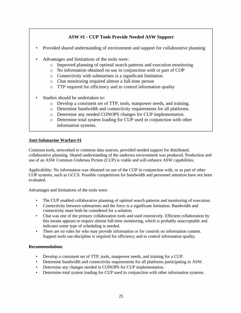
25
ASW #1 - CUP Tools Provide Needed ASW Support
• Provided shared understanding of environment and support for collaborative planning
• Advantages and limitations of the tools were:o Improved planning of optimal search patterns and execution monitoringo No information obtained on use in conjunction with or part of COPo Connectivity with submarines is a significant limitationo Chat monitoring required almost a full-time persono TTP required for efficiency and to control information quality
• Studies should be undertaken to:o Develop a consistent set of TTP, tools, manpower needs, and training.o Determine bandwidth and connectivity requirements for all platforms.o Determine any needed CONOPS changes for CUP implementation.o Determine total system loading for CUP used in conjunction with other
information systems.
Anti-Submarine Warfare #1
Common tools, networked to common data sources, provided needed support for distributed,collaborative planning. Shared understanding of the undersea environment was produced. Production anduse of an ASW Common Undersea Picture (CUP) is viable and will enhance ASW capabilities.
Applicability: No information was obtained on use of the CUP in conjunction with, or as part of otherCOP systems, such as GCCS. Possible competitions for bandwidth and personnel attention have not beenevaluated.
Advantages and limitations of the tools were:
• The CUP enabled collaborative planning of optimal search patterns and monitoring of execution.• Connectivity between submarines and the force is a significant limitation. Bandwidth and
connectivity must both be considered for a solution.• Chat was one of the primary collaboration tools and used extensively. Efficient collaboration by
this means appears to require almost full-time monitoring, which is probably unacceptable andindicates some type of scheduling is needed.
• There are no rules for who may provide information or for controls on information content.Support tools use-discipline is required for efficiency and to control information quality.
Recommendations
• Develop a consistent set of TTP, tools, manpower needs, and training for a CUP.• Determine bandwidth and connectivity requirements for all platforms participating in ASW.• Determine any changes needed in CONOPS for CUP implementation.• Determine total system loading for CUP used in conjunction with other information systems.
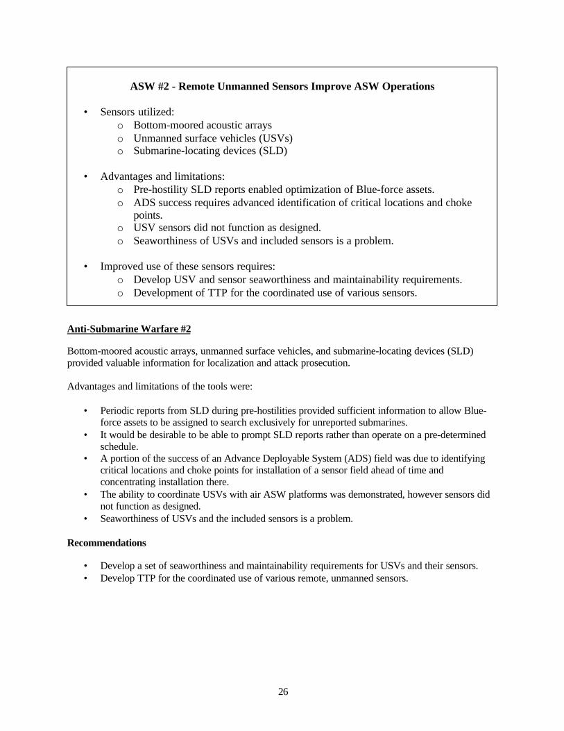
26
ASW #2 - Remote Unmanned Sensors Improve ASW Operations
• Sensors utilized:o Bottom-moored acoustic arrayso Unmanned surface vehicles (USVs)o Submarine-locating devices (SLD)
• Advantages and limitations:o Pre-hostility SLD reports enabled optimization of Blue-force assets.o ADS success requires advanced identification of critical locations and choke
points.o USV sensors did not function as designed.o Seaworthiness of USVs and included sensors is a problem.
• Improved use of these sensors requires:o Develop USV and sensor seaworthiness and maintainability requirements.o Development of TTP for the coordinated use of various sensors.
Anti-Submarine Warfare #2
Bottom-moored acoustic arrays, unmanned surface vehicles, and submarine-locating devices (SLD)provided valuable information for localization and attack prosecution.
Advantages and limitations of the tools were:
• Periodic reports from SLD during pre-hostilities provided sufficient information to allow Blue-force assets to be assigned to search exclusively for unreported submarines.
• It would be desirable to be able to prompt SLD reports rather than operate on a pre-determinedschedule.
• A portion of the success of an Advance Deployable System (ADS) field was due to identifyingcritical locations and choke points for installation of a sensor field ahead of time andconcentrating installation there.
• The ability to coordinate USVs with air ASW platforms was demonstrated, however sensors didnot function as designed.
• Seaworthiness of USVs and the included sensors is a problem.
Recommendations
• Develop a set of seaworthiness and maintainability requirements for USVs and their sensors.• Develop TTP for the coordinated use of various remote, unmanned sensors.
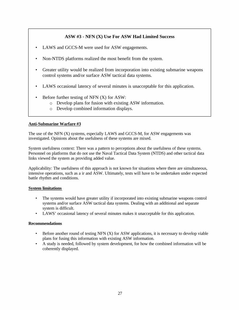
27
ASW #3 - NFN (X) Use For ASW Had Limited Success
• LAWS and GCCS-M were used for ASW engagements.
• Non-NTDS platforms realized the most benefit from the system.
• Greater utility would be realized from incorporation into existing submarine weaponscontrol systems and/or surface ASW tactical data systems.
• LAWS occasional latency of several minutes is unacceptable for this application.
• Before further testing of NFN (X) for ASW:o Develop plans for fusion with existing ASW information.o Develop combined information displays.
Anti-Submarine Warfare #3
The use of the NFN (X) systems, especially LAWS and GCCS-M, for ASW engagements wasinvestigated. Opinions about the usefulness of these systems are mixed.
System usefulness context: There was a pattern to perceptions about the usefulness of these systems.Personnel on platforms that do not use the Naval Tactical Data System (NTDS) and other tactical datalinks viewed the system as providing added value.
Applicability: The usefulness of this approach is not known for situations where there are simultaneous,intensive operations, such as a ir and ASW. Ultimately, tests will have to be undertaken under expectedbattle rhythm and conditions.
System limitations
• The systems would have greater utility if incorporated into existing submarine weapons controlsystems and/or surface ASW tactical data systems. Dealing with an additional and separatesystem is difficult.
• LAWS’ occasional latency of several minutes makes it unacceptable for this application.
Recommendations
• Before another round of testing NFN (X) for ASW applications, it is necessary to develop viableplans for fusing this information with existing ASW information.
• A study is needed, followed by system development, for how the combined information will becoherently displayed.
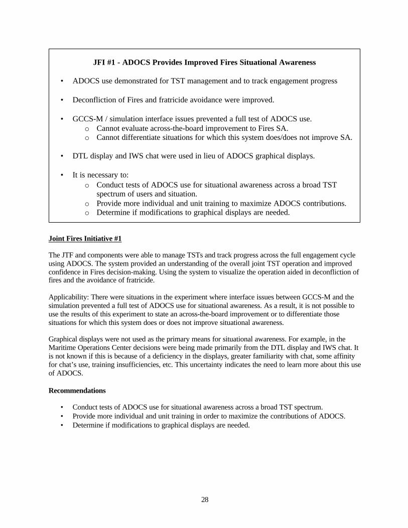
28
JFI #1 - ADOCS Provides Improved Fires Situational Awareness
• ADOCS use demonstrated for TST management and to track engagement progress
• Deconfliction of Fires and fratricide avoidance were improved.
• GCCS-M / simulation interface issues prevented a full test of ADOCS use.o Cannot evaluate across-the-board improvement to Fires SA.o Cannot differentiate situations for which this system does/does not improve SA.
• DTL display and IWS chat were used in lieu of ADOCS graphical displays.
• It is necessary to:o Conduct tests of ADOCS use for situational awareness across a broad TST
spectrum of users and situation.o Provide more individual and unit training to maximize ADOCS contributions.o Determine if modifications to graphical displays are needed.
Joint Fires Initiative #1
The JTF and components were able to manage TSTs and track progress across the full engagement cycleusing ADOCS. The system provided an understanding of the overall joint TST operation and improvedconfidence in Fires decision-making. Using the system to visualize the operation aided in deconfliction offires and the avoidance of fratricide.
Applicability: There were situations in the experiment where interface issues between GCCS-M and thesimulation prevented a full test of ADOCS use for situational awareness. As a result, it is not possible touse the results of this experiment to state an across-the-board improvement or to differentiate thosesituations for which this system does or does not improve situational awareness.
Graphical displays were not used as the primary means for situational awareness. For example, in theMaritime Operations Center decisions were being made primarily from the DTL display and IWS chat. Itis not known if this is because of a deficiency in the displays, greater familiarity with chat, some affinityfor chat’s use, training insufficiencies, etc. This uncertainty indicates the need to learn more about this useof ADOCS.
Recommendations
• Conduct tests of ADOCS use for situational awareness across a broad TST spectrum.• Provide more individual and unit training in order to maximize the contributions of ADOCS.• Determine if modifications to graphical displays are needed.

29
JFI #2 - DTL Manager Provides Cross-Component Fires Coordination,TTP Problems Exist
• DTL Manager was a successful cross-component coordination tool evidenced by:o Number of targets engagedo Components contributed to a usually complete and consistent display
• Departures from established TTP occurred:o Targets were passed from nominators with no indication of inability to engage.o MSN block was changed from white to yellow, an undefined action.o These departures can interfere with coordination.
• It is necessary to:o Provide better ADOCS TTP training for operators.o Determine if current TTP are adequate for all TST situations.
Joint Fires Initiative #2
The DTL manager was a successful cross-component coordination tool. Evidence is the number of targetsengaged and the degree to which all components contributed to a usually complete and consistent DTLmanager display. However, departures from established TTP, which can interfere with coordination, wereobserved.
TTP departure examples:
• Targets were passed from nominators who had not indicated an inability to engage.• The MSN block was, at times, changed from white to yellow, an undefined action.
Recommendations
• Provide better ADOCS TTP training for operators.• Determine if current TTP are adequate for all TST situations.

30
JFI #3 - 33 Minute Median Interval For ADOCCS Target Prosecution
• Interval is the median elapsed time from receipt of a target nomination in ADOCS untilweapon firing.
• The elapsed time includes the median time delays for the following processes:o Nomination receipt to mission passed 15 mino Mission passed to coordination block green 1 mino Block green to execution intent 2 mino Execution intent to weapon fire 15 min
• Interval may not include mensuration.o Nominating component was responsible for mensuration, and may have done this
before target nomination was received in ADOCS.
Joint Fires Initiative #3
This is the time elapsed from receipt of a target nomination in ADOCS until weapon firing.
This interval does not necessarily include target mensuration time. The nominating component wasresponsible for mensuration and may have done this before the target nomination was received inADOCS.
Recommendation: None
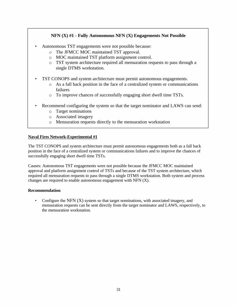
31
NFN (X) #1 - Fully Autonomous NFN (X) Engagements Not Possible
• Autonomous TST engagements were not possible because:o The JFMCC MOC maintained TST approval.o MOC maintained TST platform assignment control.o TST system architecture required all mensuration requests to pass through a
single DTMS workstation.
• TST CONOPS and system architecture must permit autonomous engagements.o As a fall back position in the face of a centralized system or communications
failureso To improve chances of successfully engaging short dwell time TSTs.
• Recommend configuring the system so that the target nominator and LAWS can send:o Target nominationso Associated imageryo Mensuration requests directly to the mensuration workstation
Naval Fires Network-Experimental #1
The TST CONOPS and system architecture must permit autonomous engagements both as a fall backposition in the face of a centralized system or communications failures and to improve the chances ofsuccessfully engaging short dwell time TSTs.
Causes: Autonomous TST engagements were not possible because the JFMCC MOC maintainedapproval and platform assignment control of TSTs and because of the TST system architecture, whichrequired all mensuration requests to pass through a single DTMS workstation. Both system and processchanges are required to enable autonomous engagement with NFN (X).
Recommendation
• Configure the NFN (X) system so that target nominations, with associated imagery, andmensuration requests can be sent directly from the target nominator and LAWS, respectively, tothe mensuration workstation.
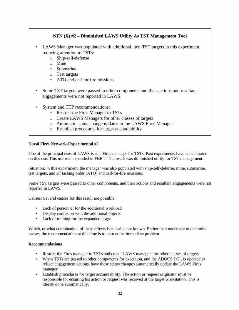
32
NFN (X) #2 – Diminished LAWS Utility As TST Management Tool
• LAWS Manager was populated with additional, non-TST targets in this experiment,reducing attention to TSTs:
o Ship-self-defenseo Mineo Submarineo Test targetso ATO and call for fire missions
• Some TST targets were passed to other components and their actions and resultantengagements were not reported in LAWS.
• System and TTP recommendations:o Restrict the Fires Manager to TSTso Create LAWS Managers for other classes of targetso Automatic status change updates in the LAWS Fires Managero Establish procedures for target accountability.
Naval Fires Network-Experimental #2
One of the principal uses of LAWS is as a Fires manager for TSTs. Past experiments have concentratedon this use. This use was expanded in FBE-J. The result was diminished utility for TST management.
Situation: In this experiment, the manager was also populated with ship-self-defense, mine, submarine,test targets, and air tasking order (ATO) and call-for-fire missions.
Some TST targets were passed to other components, and their actions and resultant engagements were notreported in LAWS.
Causes: Several causes for this result are possible:
• Lack of personnel for the additional workload• Display confusion with the additional objects• Lack of training for the expanded usage
Which, or what combination, of these effects is causal is not known. Rather than undertake to determinecauses, the recommendation at this time is to correct the immediate problem.
Recommendations
• Restrict the Fires manager to TSTs and create LAWS managers for other classes of targets.• When TSTs are passed to other components for execution, and the ADOCS DTL is updated to
reflect engagement actions, have these status changes automatically update the LAWS Firesmanager.
• Establish procedures for target accountability. The action or request originator must beresponsible for ensuring his action or request was received at the target workstation. This isideally done automatically.
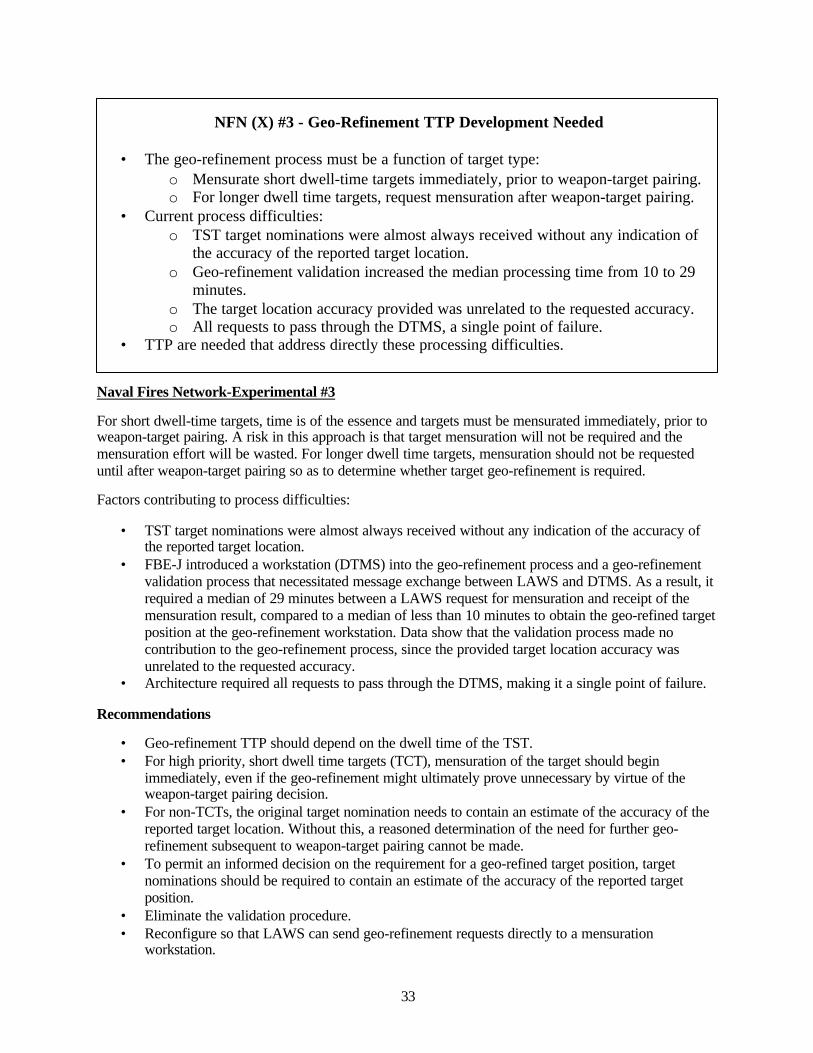
33
NFN (X) #3 - Geo-Refinement TTP Development Needed
• The geo-refinement process must be a function of target type:o Mensurate short dwell-time targets immediately, prior to weapon-target pairing.o For longer dwell time targets, request mensuration after weapon-target pairing.
• Current process difficulties:o TST target nominations were almost always received without any indication of
the accuracy of the reported target location.o Geo-refinement validation increased the median processing time from 10 to 29
minutes.o The target location accuracy provided was unrelated to the requested accuracy.o All requests to pass through the DTMS, a single point of failure.
• TTP are needed that address directly these processing difficulties.
Naval Fires Network-Experimental #3
For short dwell-time targets, time is of the essence and targets must be mensurated immediately, prior toweapon-target pairing. A risk in this approach is that target mensuration will not be required and themensuration effort will be wasted. For longer dwell time targets, mensuration should not be requesteduntil after weapon-target pairing so as to determine whether target geo-refinement is required.
Factors contributing to process difficulties:
• TST target nominations were almost always received without any indication of the accuracy ofthe reported target location.
• FBE-J introduced a workstation (DTMS) into the geo-refinement process and a geo-refinementvalidation process that necessitated message exchange between LAWS and DTMS. As a result, itrequired a median of 29 minutes between a LAWS request for mensuration and receipt of themensuration result, compared to a median of less than 10 minutes to obtain the geo-refined targetposition at the geo-refinement workstation. Data show that the validation process made nocontribution to the geo-refinement process, since the provided target location accuracy wasunrelated to the requested accuracy.
• Architecture required all requests to pass through the DTMS, making it a single point of failure.
Recommendations
• Geo-refinement TTP should depend on the dwell time of the TST.• For high priority, short dwell time targets (TCT), mensuration of the target should begin
immediately, even if the geo-refinement might ultimately prove unnecessary by virtue of theweapon-target pairing decision.
• For non-TCTs, the original target nomination needs to contain an estimate of the accuracy of thereported target location. Without this, a reasoned determination of the need for further geo-refinement subsequent to weapon-target pairing cannot be made.
• To permit an informed decision on the requirement for a geo-refined target position, targetnominations should be required to contain an estimate of the accuracy of the reported targetposition.
• Eliminate the validation procedure.• Reconfigure so that LAWS can send geo-refinement requests directly to a mensuration
workstation.
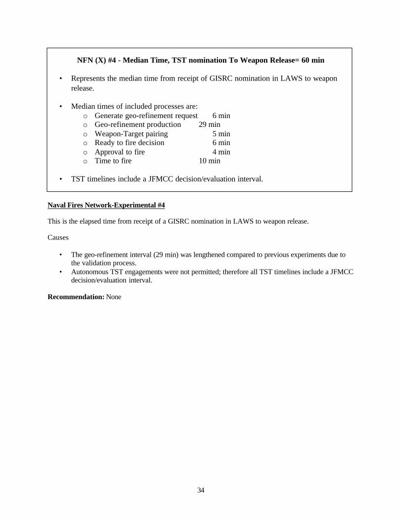
34
NFN (X) #4 - Median Time, TST nomination To Weapon Release= 60 min
• Represents the median time from receipt of GISRC nomination in LAWS to weaponrelease.
• Median times of included processes are:o Generate geo-refinement request 6 mino Geo-refinement production 29 mino Weapon-Target pairing 5 mino Ready to fire decision 6 mino Approval to fire 4 mino Time to fire 10 min
• TST timelines include a JFMCC decision/evaluation interval.
Naval Fires Network-Experimental #4
This is the elapsed time from receipt of a GISRC nomination in LAWS to weapon release.
Causes
• The geo-refinement interval (29 min) was lengthened compared to previous experiments due tothe validation process.
• Autonomous TST engagements were not permitted; therefore all TST timelines include a JFMCCdecision/evaluation interval.
Recommendation: None
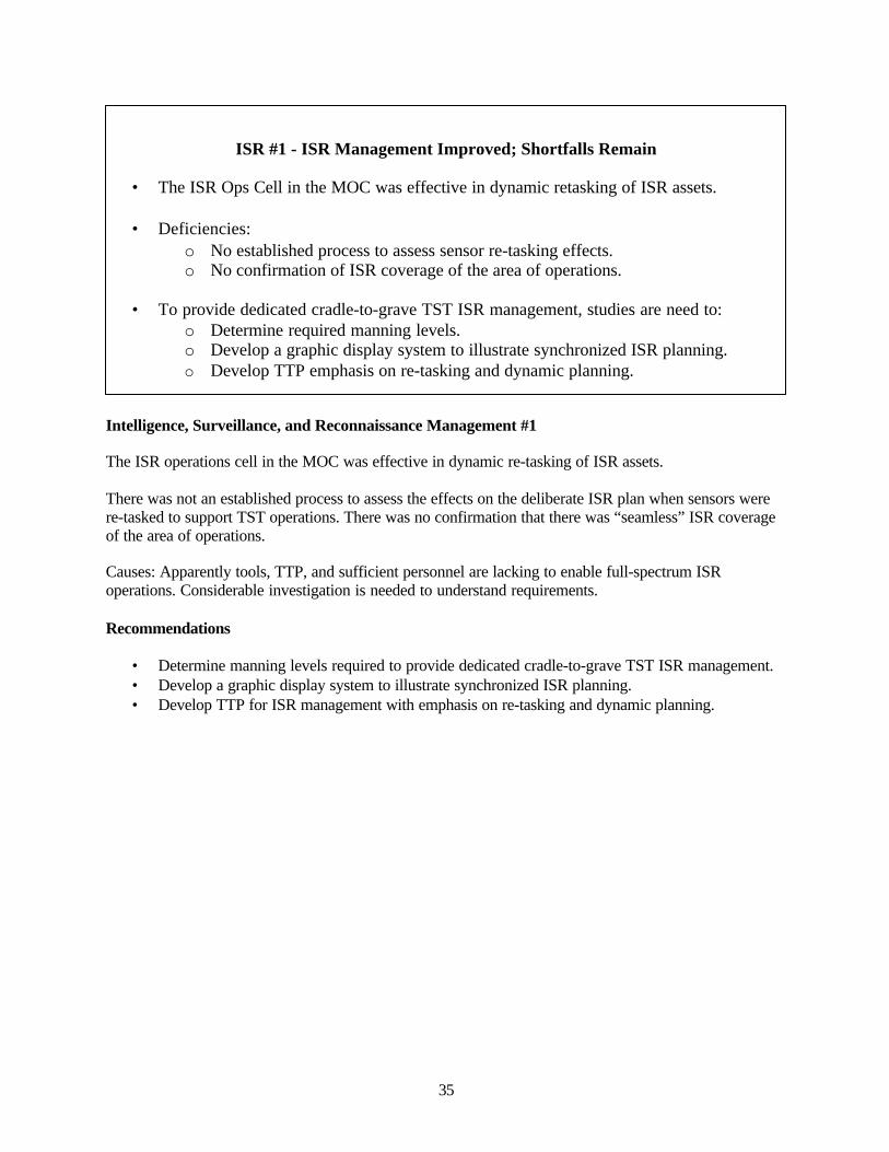
35
ISR #1 - ISR Management Improved; Shortfalls Remain
• The ISR Ops Cell in the MOC was effective in dynamic retasking of ISR assets.
• Deficiencies:o No established process to assess sensor re-tasking effects.o No confirmation of ISR coverage of the area of operations.
• To provide dedicated cradle-to-grave TST ISR management, studies are need to:o Determine required manning levels.o Develop a graphic display system to illustrate synchronized ISR planning.o Develop TTP emphasis on re-tasking and dynamic planning.
Intelligence, Surveillance, and Reconnaissance Management #1
The ISR operations cell in the MOC was effective in dynamic re-tasking of ISR assets.
There was not an established process to assess the effects on the deliberate ISR plan when sensors werere-tasked to support TST operations. There was no confirmation that there was “seamless” ISR coverageof the area of operations.
Causes: Apparently tools, TTP, and sufficient personnel are lacking to enable full-spectrum ISRoperations. Considerable investigation is needed to understand requirements.
Recommendations
• Determine manning levels required to provide dedicated cradle-to-grave TST ISR management.• Develop a graphic display system to illustrate synchronized ISR planning.• Develop TTP for ISR management with emphasis on re-tasking and dynamic planning.
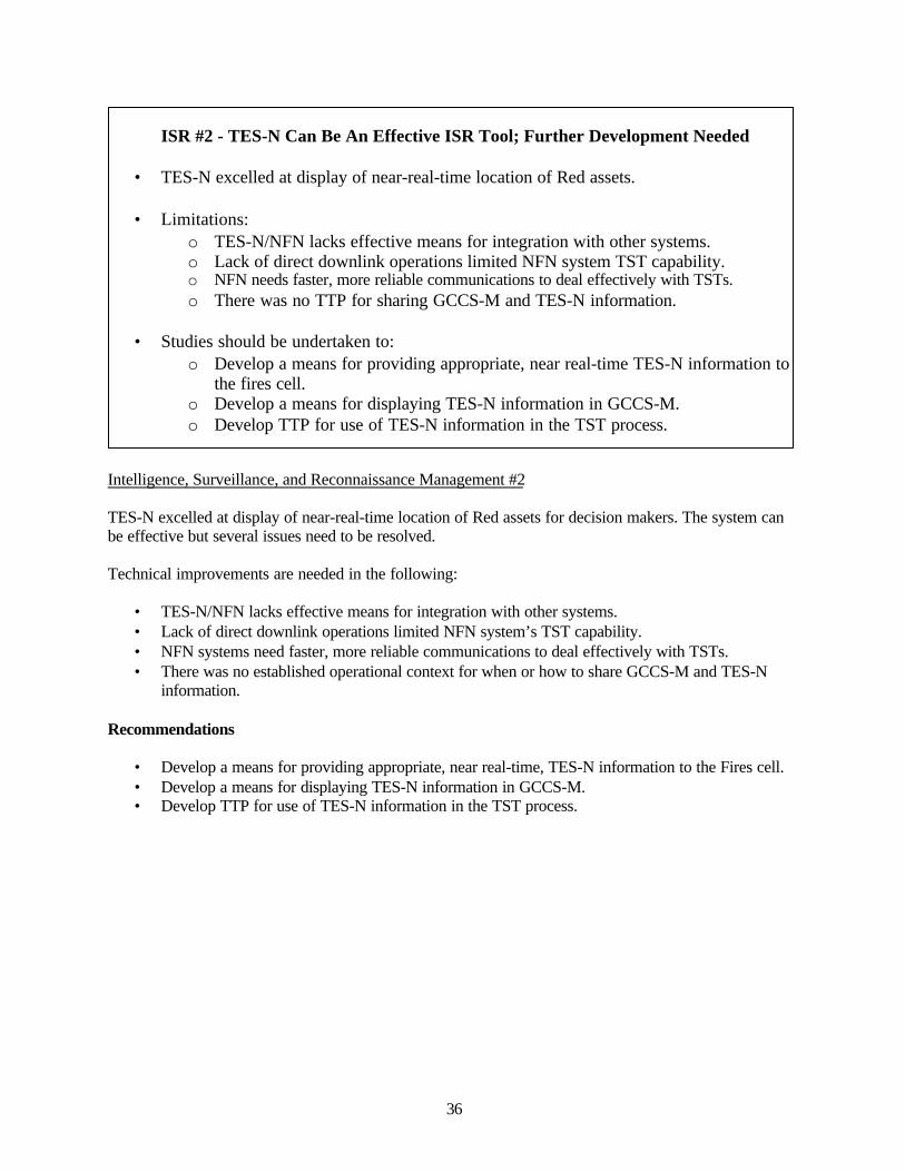
36
ISR #2 - TES-N Can Be An Effective ISR Tool; Further Development Needed
• TES-N excelled at display of near-real-time location of Red assets.
• Limitations:o TES-N/NFN lacks effective means for integration with other systems.o Lack of direct downlink operations limited NFN system TST capability.o NFN needs faster, more reliable communications to deal effectively with TSTs.o There was no TTP for sharing GCCS-M and TES-N information.
• Studies should be undertaken to:o Develop a means for providing appropriate, near real-time TES-N information to
the fires cell.o Develop a means for displaying TES-N information in GCCS-M.o Develop TTP for use of TES-N information in the TST process.
Intelligence, Surveillance, and Reconnaissance Management #2
TES-N excelled at display of near-real-time location of Red assets for decision makers. The system canbe effective but several issues need to be resolved.
Technical improvements are needed in the following:
• TES-N/NFN lacks effective means for integration with other systems.• Lack of direct downlink operations limited NFN system’s TST capability.• NFN systems need faster, more reliable communications to deal effectively with TSTs.• There was no established operational context for when or how to share GCCS-M and TES-N
information.
Recommendations
• Develop a means for providing appropriate, near real-time, TES-N information to the Fires cell.• Develop a means for displaying TES-N information in GCCS-M.• Develop TTP for use of TES-N information in the TST process.
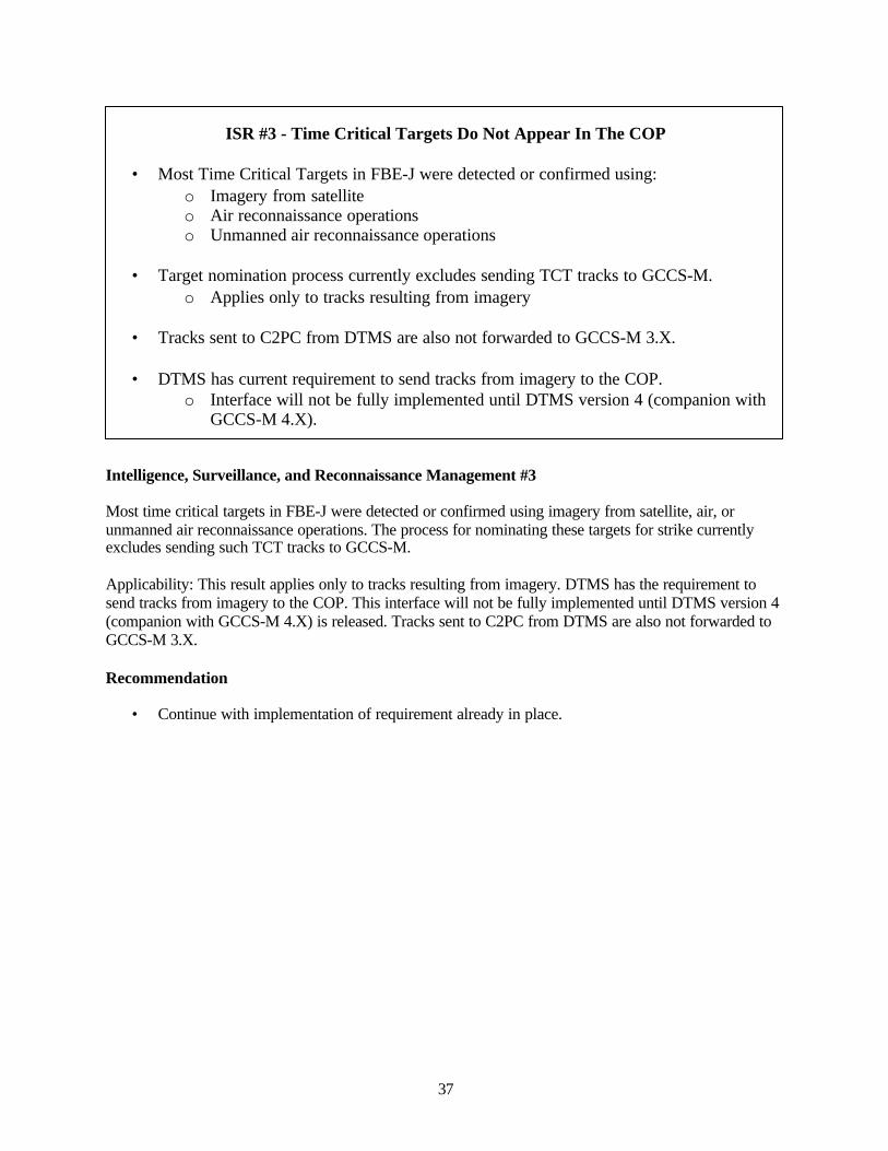
37
ISR #3 - Time Critical Targets Do Not Appear In The COP
• Most Time Critical Targets in FBE-J were detected or confirmed using:o Imagery from satelliteo Air reconnaissance operationso Unmanned air reconnaissance operations
• Target nomination process currently excludes sending TCT tracks to GCCS-M.o Applies only to tracks resulting from imagery
• Tracks sent to C2PC from DTMS are also not forwarded to GCCS-M 3.X.
• DTMS has current requirement to send tracks from imagery to the COP.o Interface will not be fully implemented until DTMS version 4 (companion with
GCCS-M 4.X).
Intelligence, Surveillance, and Reconnaissance Management #3
Most time critical targets in FBE-J were detected or confirmed using imagery from satellite, air, orunmanned air reconnaissance operations. The process for nominating these targets for strike currentlyexcludes sending such TCT tracks to GCCS-M.
Applicability: This result applies only to tracks resulting from imagery. DTMS has the requirement tosend tracks from imagery to the COP. This interface will not be fully implemented until DTMS version 4(companion with GCCS-M 4.X) is released. Tracks sent to C2PC from DTMS are also not forwarded toGCCS-M 3.X.
Recommendation
• Continue with implementation of requirement already in place.
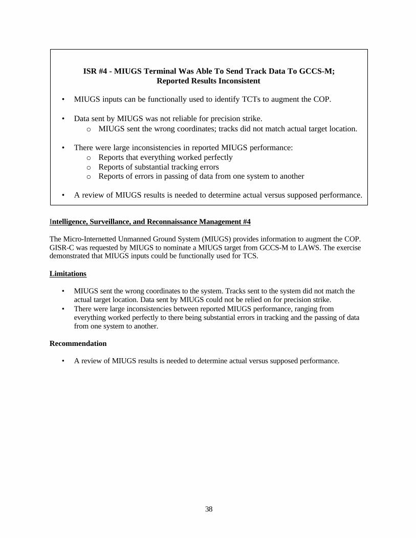
38
ISR #4 - MIUGS Terminal Was Able To Send Track Data To GCCS-M;Reported Results Inconsistent
• MIUGS inputs can be functionally used to identify TCTs to augment the COP.
• Data sent by MIUGS was not reliable for precision strike.o MIUGS sent the wrong coordinates; tracks did not match actual target location.
• There were large inconsistencies in reported MIUGS performance:o Reports that everything worked perfectlyo Reports of substantial tracking errorso Reports of errors in passing of data from one system to another
• A review of MIUGS results is needed to determine actual versus supposed performance.
Intelligence, Surveillance, and Reconnaissance Management #4
The Micro-Internetted Unmanned Ground System (MIUGS) provides information to augment the COP.GISR-C was requested by MIUGS to nominate a MIUGS target from GCCS-M to LAWS. The exercisedemonstrated that MIUGS inputs could be functionally used for TCS.
Limitations
• MIUGS sent the wrong coordinates to the system. Tracks sent to the system did not match theactual target location. Data sent by MIUGS could not be relied on for precision strike.
• There were large inconsistencies between reported MIUGS performance, ranging fromeverything worked perfectly to there being substantial errors in tracking and the passing of datafrom one system to another.
Recommendation
• A review of MIUGS results is needed to determine actual versus supposed performance.
39
MIW #1 - Engagement Of Mine Targets In LAWS Possible;Process Development Needed
• Feeding mine contacts into LAWS and engagement through that system is workable:o Procedures need to be simplified.o TTP needed.
• Treat mine nominations as another target within LAWS:o Mine nomination weapon-target pairedo Engagement conducted within mine nomination entry in LAWS Fires manager.
• Test of the concept is needed using a combination of live mine and other targets.
Mine Warfare #1
The concept of feeding mine contacts into LAWS and engaging them through that system appearsworkable. Procedures need to be simplified and codified. Mine nominations should be treated like othertarget nominations within LAWS, i.e., mine nomination weapon-target paired and the engagementconducted within the mine nomination entry in the LAWS Fires manager. This recommendation conflictsto some degree with NFN (X) #2, where a separate manager for non-Fires targets was recommended.
Applicability: The engagement problems were exacerbated and, to a degree caused, by problems with theFASM methodology and simulation. Thus, definitive results on this application are not yet available.
Recommendations
• Develop a methodology that handles mines the same as other targets within LAWS.• Test the concept with a combination of live mine and other targets.
40
Mine Warfare (MIW) #2
The HSV appears to be an excellent platform for supporting the MIWC and MCM.Advantages include:
• High speed to area of operations and while conducting various MIW missions• Shallow draft will allow operations in relatively shallow water• Large cargo volume can provide ample workspace and support areas for supporting future
RAVs and their operational mission and maintenance crewsDisadvantages and risks include:
• Potential vulnerability of the HSV to hostile fire due to its aluminum composition and smallcrew
• Loss of one HSV with large number of RAVs (est. 25 to 30) could risk the entire MIWmission success and/or timeline if additional resources are not readily available
• Under the concept of rapid reconfiguration for HSVs, MIW may be competing with othermissions for the use of the HSV
Recommendations
Undertake studies to mature the CONOPS for HSV support of MIW, including• Determine the appropriate number and overall distribution of MIW assets on HSVs• Assess the requirement for redundant back-up operational databases and MIWC SA in case of
loss• Likelihood that competition for HSV resources will impact on MIW mission success
MIW #2– HSV Appears to be Excellent Platform for Supporting MIW
• Advantages include:o High speedo Shallow drafto Large cargo volume to provide future hotel services for support of RAVs and
mission and maintenance crews
• Disadvantages and risks include:o Potential vulnerability of the HSV to hostile fireo Loss of one HSV with large number of RAVs (est. 25 to 30) could risk entire
MIW mission success and/or timeline if additional resources are not readilyavailable
o MIW may have to compete with other missions for the use of the HSV
• Studies are needed to mature the CONOPS for HSV support of MIWo Determine the appropriate number and distribution of MIW assets on HSVso Assess requirement for redundant back-up operational databases and MIWC SA
in case of losseso Estimate likelihood that competition for HSV resources will impact on MIW
mission success

41
Mine Warfare (MIW) #3
JFMCC management of MIW is a challenge that presently strains players on all sides. There are severalreasons for this:
• MIW missions are longer than typical JFMCC missions and may not be suitably managedwithin the overall JFMCC process at present. This is a resource allocation issue, as theJFMCC staff may reallocate HSVs and other resources after the expiration of the 24-hourMTO/ATO, but MIW missions initiated during the valid period may still be on-going, due tothe length of some MIW missions.
• The ATO tasking vehicles are not optimal for MIW missions• Direct tasking of platforms in MIW is preferable to the indirect tasking associated with MSRs• Present reduction of data and the development of tasking is unnecessarily manpower
intensive
Recommendations
Conduct studies to• Develop a more workable interaction dynamic between JFMCC and MIW• Evaluate the impact of lengthy MIW missions on shared resources• Evaluate the potential for manpower reductions achievable with automation of data reduction
and tasking in MIW
MIW #3 – JFMCC is Challenged in Management of MIW
• MIW missions are longer than typical JFMCC MSR missions and may not besuitably managed within the overall JFMCC process at present. .
• The ATO tasking vehicles are not optimal for MIW missions• Direct tasking of platforms in MIW is preferable to the indirect tasking associated
with MSRs• Present reduction of data and the development of tasking is unnecessarily manpower
intensive
• Studies are needed to:o Develop a more workable interaction dynamic between JFMCC and MIWo Evaluate the impact of lengthy MIW missions on shared resources and vice versao Evaluate the potential for manpower reductions with automation of data
reduction and tasking in MIW
42
Mine Warfare (MIW) #4
Remote Autonomous Vehicles (RAVs) offer tremendous potential for rapid, effective, and covert MIWoperations to ensure assured access to hostile territory. Future HSVs could host 25 to 30 of these RAVsper HSV. The management of a multiplicity of these systems, possibly among several HSVs will be farmore complex than anything experienced to date in MIW or demonstrated in FBE-J. There was nostressing of the RAV systems in FBE-J, so no assessment can be made of problems or issues that willarise when one HSV attempts to manage, control, and exploit a number of these systems.
Potential issues include:• Data should be retrievable in or near real-time so as not to delay follow-on planning actions• More complicated management and control can be expected• The present inability to operate in kelp requires additional engineering to RAVs to reduce
potential risks and mission impairment• Launching and retrieval of RAVs should be accomplished at reasonably high speeds
Recommendations• Assess methods to optimize the receipt and management of data• Develop reliable ways to control and minimize potential interference of multiple systems
operating concurrently• Re-engineer systems to reduce or eliminate their present vulnerability to kelp• Investigate alternative approaches to launching and retrieving RAVs at high speed
MIW #4 --- RAVs are the Future in MIW
• Remote Autonomous Vehicles (RAVs) offer advantages in speed, effectiveness, andcovertness. HSVs will be able to host 25 to 30 systems per HSV
• Potential issueso Data should be retrieved in or near real-timeo More complicated management and controlo Present inability to operate in kelp requires additional engineeringo Launching and retrieval should be done at high speeds
• Studies are needed to:o Assess methods to optimize the receipt and management of datao Develop reliable ways to control multiple systems operating concurrentlyo Re-engineer systems to reduce or eliminate their present vulnerability to kelpo Investigate alternative approaches to launching and retrieving RAVs at high
speed
43
IO #1 - Hardened Client Defeated Red-Team Attack.
• Hardened client successfully deflected direct Red team attack using:o Layer 1, e-mail wrappers blocked behavior contained in e-mail attachment
macros.o Layer 2, ADF prevented outbound FTP as well as outbound root shell jump point.
• ADF was an effective defensive technology scalable to full operational deployment,however:
o ADF equipped machines easily detected using basic scans.o Partial ADF coverage permits quick identification of unequipped computers and
an attack from that point.
• Configuration management issues associated with all machines containing ADF cards:o Scalability; ability to manage 1000+ systemso Legacy and custom software applications complicationso Correlation of audits across policy servers for incident handling
• A policy for ADF equipage as a function of network and machine is needed.
Information Operations #1
A Hardened Client successfully deflected direct Red team attacks through operating system (OS)wrappers and autonomic distributed firewall (ADF) configuration. The Red team was not successful inachieving the goal of disrupting time critical targeting during attack periods.
Defense systems
• First layer: safe e-mail wrappers blocked harmful behavior contained in e-mail attachment macrossent by Red team participants.
• Second layer: ADF prevented outbound file transfer protocol (FTP) as well as outbound root shelljump point. ADF demonstrated an effective defensive technology that can be scaled to fulloperational deployment.
Limitations
• ADF equipped machines were easily detected using basic scans. A network with only partialADF coverage would permit quick identification of unequipped computers and an attack fromthat point.
• Configuration management issues associated with incorporating ADF cards in all networkmachines include; scalability, the ability of one person to manage 1000+ systems, legacy andcustom software applications complications, and the correlation of audits across policy serversthat would make incident handling difficult.
Recommendation
• Develop a policy for ADF equipage as a function of network and machine.
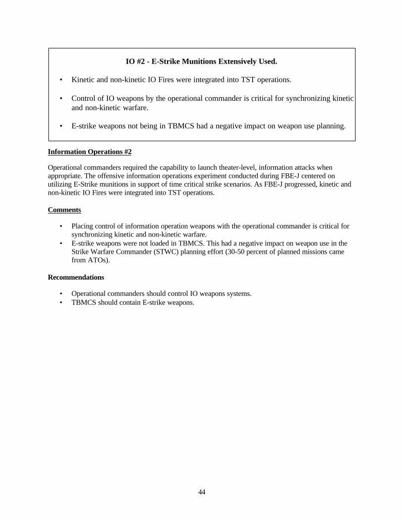
44
IO #2 - E-Strike Munitions Extensively Used.
• Kinetic and non-kinetic IO Fires were integrated into TST operations.
• Control of IO weapons by the operational commander is critical for synchronizing kineticand non-kinetic warfare.
• E-strike weapons not being in TBMCS had a negative impact on weapon use planning.
Information Operations #2
Operational commanders required the capability to launch theater-level, information attacks whenappropriate. The offensive information operations experiment conducted during FBE-J centered onutilizing E-Strike munitions in support of time critical strike scenarios. As FBE-J progressed, kinetic andnon-kinetic IO Fires were integrated into TST operations.
Comments
• Placing control of information operation weapons with the operational commander is critical forsynchronizing kinetic and non-kinetic warfare.
• E-strike weapons were not loaded in TBMCS. This had a negative impact on weapon use in theStrike Warfare Commander (STWC) planning effort (30-50 percent of planned missions camefrom ATOs).
Recommendations
• Operational commanders should control IO weapons systems.• TBMCS should contain E-strike weapons.
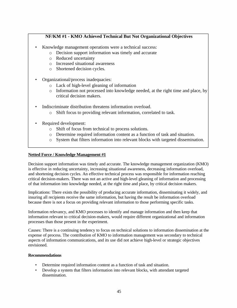
45
NF/KM #1 - KMO Achieved Technical But Not Organizational Objectives
• Knowledge management operations were a technical success:o Decision support information was timely and accurateo Reduced uncertaintyo Increased situational awarenesso Shortened decision cycles.
• Organizational/process inadequacies:o Lack of high-level gleaning of informationo Information not processed into knowledge needed, at the right time and place, by
critical decision makers.
• Indiscriminate distribution threatens information overload.o Shift focus to providing relevant information, correlated to task.
• Required development:o Shift of focus from technical to process solutions.o Determine required information content as a function of task and situation.o System that filters information into relevant blocks with targeted dissemination.
Netted Force / Knowledge Management #1
Decision support information was timely and accurate. The knowledge management organization (KMO)is effective in reducing uncertainty, increasing situational awareness, decreasing information overload,and shortening decision cycles. An effective technical process was responsible for information reachingcritical decision-makers. There was not an active and high-level gleaning of information and processingof that information into knowledge needed, at the right time and place, by critical decision makers.
Implications: There exists the possibility of producing accurate information, disseminating it widely, andinsuring all recipients receive the same information, but having the result be information overloadbecause there is not a focus on providing relevant information to those performing specific tasks.
Information relevancy, and KMO processes to identify and manage information and then keep thatinformation relevant to critical decision-makers, would require different organizational and informationprocesses than those present in the experiment.
Causes: There is a continuing tendency to focus on technical solutions to information dissemination at theexpense of process. The contribution of KMO to information management was secondary to technicalaspects of information communications, and its use did not achieve high-level or strategic objectivesenvisioned.
Recommendations
• Determine required information content as a function of task and situation.• Develop a system that filters information into relevant blocks, with attendant targeted
dissemination.
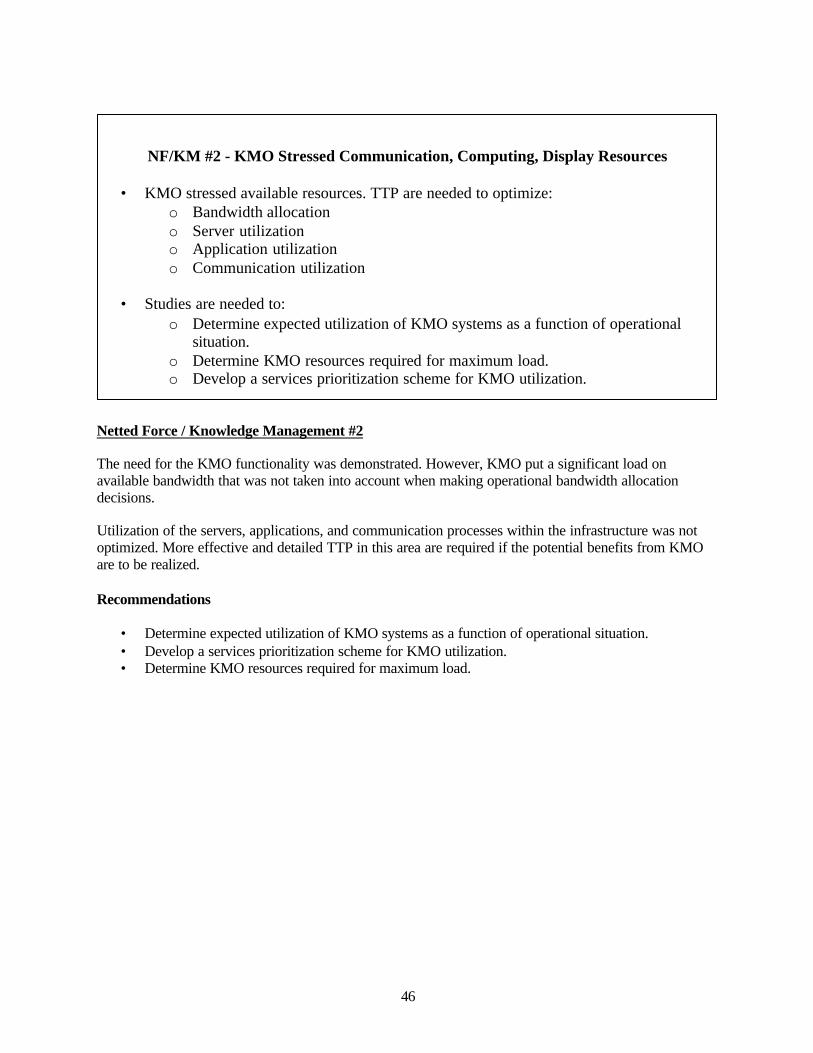
46
NF/KM #2 - KMO Stressed Communication, Computing, Display Resources
• KMO stressed available resources. TTP are needed to optimize:o Bandwidth allocationo Server utilizationo Application utilizationo Communication utilization
• Studies are needed to:o Determine expected utilization of KMO systems as a function of operational
situation.o Determine KMO resources required for maximum load.o Develop a services prioritization scheme for KMO utilization.
Netted Force / Knowledge Management #2
The need for the KMO functionality was demonstrated. However, KMO put a significant load onavailable bandwidth that was not taken into account when making operational bandwidth allocationdecisions.
Utilization of the servers, applications, and communication processes within the infrastructure was notoptimized. More effective and detailed TTP in this area are required if the potential benefits from KMOare to be realized.
Recommendations
• Determine expected utilization of KMO systems as a function of operational situation.• Develop a services prioritization scheme for KMO utilization.• Determine KMO resources required for maximum load.
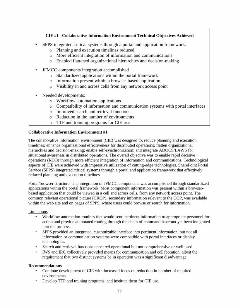
47
CIE #1 - Collaborative Information Environment Technical Objectives Achieved
• SPPS integrated critical systems through a portal and application framework.o Planning and execution timelines reducedo More efficient integration of information and communicationso Enabled flattened organizational hierarchies and decision-making
• JFMCC components integration accomplishedo Standardized applications within the portal frameworko Information present within a browser-based applicationo Visibility in and across cells from any network access point
• Needed developments:o Workflow automation applicationso Compatibility of information and communication systems with portal interfaceso Improved search and retrieval functionso Reduction in the number of environmentso TTP and training programs for CIE use
Collaborative Information Environment #1
The collaborative information environment (CIE) was designed to: reduce planning and executiontimelines; enhance organizational effectiveness for distributed operations; flatten organizationalhierarchies and decision-making; enable self-synchronization; and integrate ADOCS/LAWS forsituational awareness in distributed operations. The overall objective was to enable rapid decisiveoperations (RDO) through more efficient integration of information and communications. Technologicalaspects of CIE were achieved with impressive utilization of cutting-edge technologies. SharePoint PortalService (SPPS) integrated critical systems through a portal and application framework that effectivelyreduced planning and execution timelines.
Portal/browser structure: The integration of JFMCC components was accomplished through standardizedapplications within the portal framework. Most component information was present within a browser-based application that could be viewed in a cell and across cells, from any network access point. Thecommon relevant operational picture (CROP), secondary information relevant to the COP, was availablewithin the web site and on pages of SPPS, where users could browse or search for information.
Limitations• Workflow automation routines that would send pertinent information to appropriate personnel for
action and provide automated routing through the chain of command have not yet been integratedinto the process.
• SPPS provided an integrated, customizable interface into pertinent information, but not allinformation or communication systems were compatible with portal interfaces or displaytechnologies.
• Search and retrieval functions appeared operational but not comprehensive or well used.• IWS and IRC collectively provided means for communication and collaboration, albeit the
requirement that two distinct systems be in operation was a significant disadvantage.
Recommendations• Continue development of CIE with increased focus on reduction in number of required
environments.• Develop TTP and training programs, and institute them for CIE use.
48
JTAMD #1 - Navy Forces Provide Significant Contributions To TAMD/TBMD.
• Navy unique capabilities provide a JTAMD force multiplier:o Protected critical assets on the DALo Augmented PATRIOT unitso Provided the lower tier component for THAADo Projected missile defense over amphibious landingso Provided a key complement to Army Air Defense Artillery
• Critical support provided for:o Terminal phase TBMDo Mid-course TBMD
Joint Theater Anti-Missile Defense #1
The inherent mobility and flexibility of Naval forces constituted a unique joint capability and a forcemultiplier during the experiment. Navy ships protected critical assets on the Defended Assets List (DAL),augmented Patriot units, provided the lower tier component for Theater Phase High Altitude Defense(THAAD) system, and projected missile defense over amphibious landings ashore.
Ships provided a key complement to Army Air Defense Artillery (ADA) surging to meet anticipatedthreats or to respond to other operational changes, while THAAD and PATRIOT batteries focused on thedefense of fixed critical assets.
Applicability
For the situations tested during the experiment, Navy forces appeared especially valuable for thefollowing:
• Terminal Phase TBMD: A robust terminal phase TBMD capability was critical to joint missiledefense. Although extensive Army Air Defense Artillery (ADA) forces were in theater, Navyforces played a critical role defending designated critical assets either alone or in conjunctionwith sea-based mid-course defense (SMD), THAAD and PATRIOT.
• Mid-Course TBMD: The contingency SMD capability was critical to achieving the Joint TaskForce Commander’s (JTFC’s) desired probability of negation. Against longer-range threats theextensive defended footprint provided an upper tier component of a two-tiered defense for a largenumber of critical assets.
Recommendations: None
49
JTAMD #2 – Current Limitations To Navy Joint TAMD/TBMD
• Limitations experienced:o ADC/RADC was never fully integrated into Air Operations Center (AOC).o Unsuccessful integration of Army and Navy missile defense forces covering
common critical assets.o Limited ability to handle the threat posed by large numbers of relatively
unsophisticated short-range missiles and artillery rockets.o Weapons systems models in decision aids did not yield common solutions.
• Required developments:o Common TTP and joint doctrine for roles, missions, and responsibilities between
functional component commanders and their subordinate commanders.o Tactical decision aid models for short-range missile and artillery defense.o Cross-service planning and tactical decision aids.o Develop joint doctrine for cross-service JTAMD.
Joint Theater Anti-Missile Defense #2
The Air Defense Commander/Regional Air Defense Commander (ADC/RADC) was never fullyintegrated into AOC battle rhythm, and the organizational relationship between the Joint Forces AirComponent Commander/Area Air Defense Commander (JFACC/AADC) and the ADC/RADC remainedambiguous. The absence of joint doctrine defining the role of a RADC and the lack of directcommunication between the JFACC/AADC and the RADC most likely contributed to the difficulty.
Attempts to develop coordinated engagement procedures when both Army and Navy missile defenseforces covered common critical assets were unsuccessful. Doctrinal and technical differences betweenArmy firing units and Navy ships formed a barrier and did not allow coordination beyond spatialdeconfliction (“engagement zones”). Without changes to existing doctrine, systems, and operationalconcepts, dynamic battlespace coordination including integrated engagements will not be possible.
Though it received less high-level attention than longer-range missiles, the threat posed by large numbersof relatively unsophisticated short-range missiles (<300 km) and artillery rockets was a significant factorin operational planning and caught many planners by surprise. Coordination between the DAADC and themaritime ADC/RADC was hindered, as existing planning tools did not include models for these threatsand the numbers present required intense considerations of interceptor inventory. The widespreaddistribution of these types of weapons warrants increased consideration in operational planning.
Collaboration was hindered when weapons system decision aid models did not yield common solutions,even with identical data input. For distributed collaboration to be effective, all participants must have acommon understanding of the capabilities and limitations of the individual systems.
Recommendations
• Develop common TTP and joint doctrine that defines roles, missions, and responsibilitiesbetween functional component commanders and their subordinate commanders.
• Develop models that can be used as tactical decision aids for short-range missile and artillerydefense.
• Develop models and decision aids that yield identical solutions when given the same inputs andimplement their use across services.
• Develop joint doctrine for cross-service JTAMD.
50
3.2 Initiatives’ Context
Data and information are obtained from an experiment under a set of conditions. Analysis results haveknown validity only for those conditions, their range of applicability. Specifying its range of applicabilityis as important as the result. We refer to "context" as the set of conditions that existed during theexperiment. There is a hierarchy of conditions:
• General conditions - are the overall setting under which the experiment was conducted. This wasprovided in the former Section of this report.
• Initiative conditions - are special conditions that were set up to meet the objectives of aninitiative.
• Results conditions - are special conditions that are pertinent to understanding a particular result.For example, an initiative condition could be use of short-dwell-time transporter / erector /launchers (TELs) for Fires capabilities testing. A particular result condition could be three TELsper 15 minutes, causing TCT prosecution to break down. Results conditions, if needed, arereported along with the principal results in the first Section of this report.
From a carefully designed experiment it may be possible to extract cause-and-effect. This can provide amodel of the behaviors of systems and the processes within which the systems operate. Cause-and effectrelations allow extending results to conditions other than those under which they were obtained. Tworelated conditions are necessary if an experiment is to produce cause-and-effect understanding: control ofvariables and change. Knowledge of variable states is necessary, and control of variables is preferred, inorder to produce data for quantitative analyses. This is especially important for complicated experimentssuch as FBEs.
One cannot observe the effects produced by a variable without changing it. All cause-and-effectrelationships are "if this influence is applied, that happens". A force/influence being applied is a change inthat variable, and the response is a change in state of the system of interest. A well-designed experiment isone that controls and changes a variable so as to observe a desired effect, under desired conditions. Inexperimental situations as complicated as FBEs, it is not always possible to control variables. Whether ornot control can be exercised, it is necessary that everything that influences a result be recorded.
An assessment of "experiment quality" is also needed. This is an expression of how well the experimentwas designed to meet its stated objectives. FBEs consist essentially of many experiments within anoverarching exercise/experiment. Initiatives are individual experiments. Because there is variability inhow well individual initiatives are designed, an expression of experiment quality is needed for each.
The next part of this Section will be a description of the important facets of experiment quality. This isfollowed by context for each of the initiatives.
Experiment Quality Condition
Figure 3-1 illustrates experiment design principles for a particular initiative considering two parameters(A and B) that could influence the results. The initiative could be, for example, MIW, with parameter Arepresenting target density, and parameter B the transit and operational speed of a mine clearance vessel.These are only two of the many possible parameters that establish experiment conditions. We use speedand target density to describe the meanings of various parts of the figure.
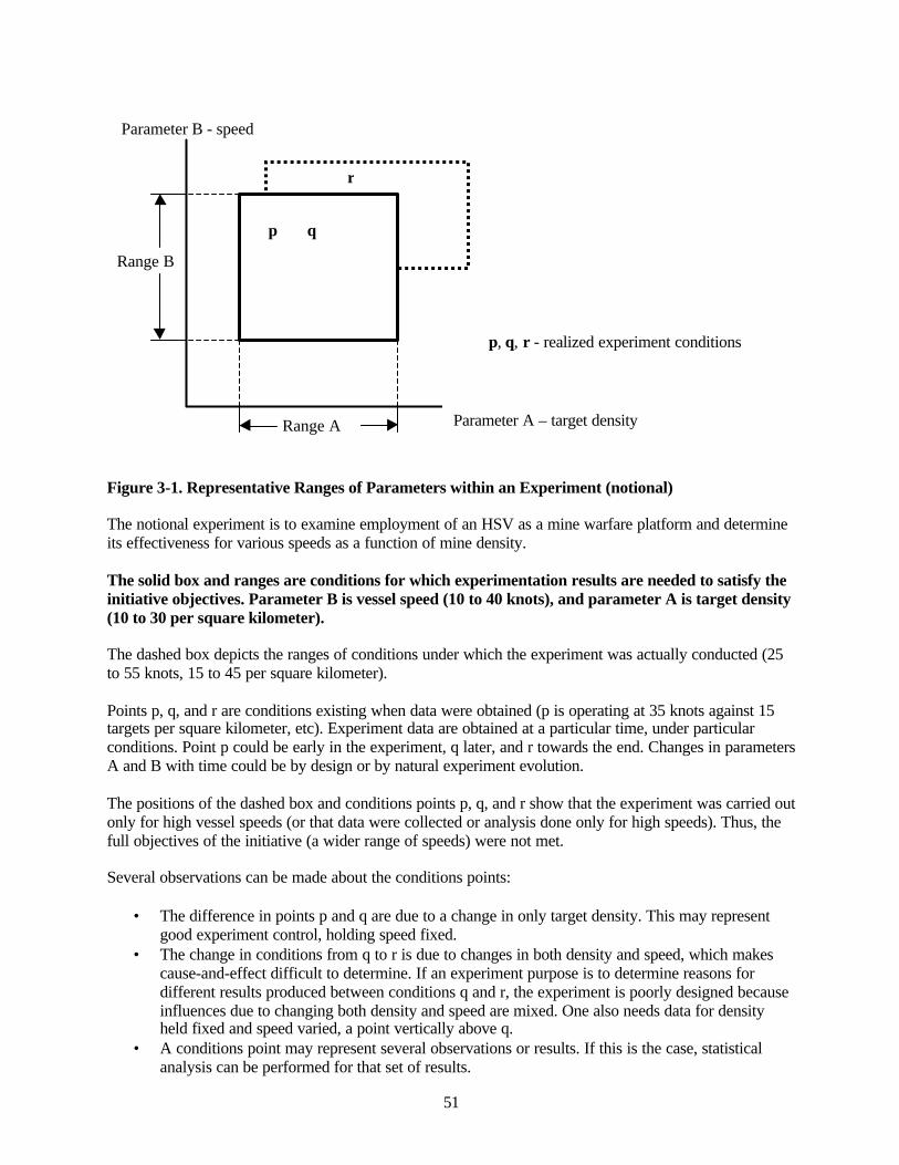
51
Figure 3-1. Representative Ranges of Parameters within an Experiment (notional)
The notional experiment is to examine employment of an HSV as a mine warfare platform and determineits effectiveness for various speeds as a function of mine density.
The solid box and ranges are conditions for which experimentation results are needed to satisfy theinitiative objectives. Parameter B is vessel speed (10 to 40 knots), and parameter A is target density(10 to 30 per square kilometer).
The dashed box depicts the ranges of conditions under which the experiment was actually conducted (25to 55 knots, 15 to 45 per square kilometer).
Points p, q, and r are conditions existing when data were obtained (p is operating at 35 knots against 15targets per square kilometer, etc). Experiment data are obtained at a particular time, under particularconditions. Point p could be early in the experiment, q later, and r towards the end. Changes in parametersA and B with time could be by design or by natural experiment evolution.
The positions of the dashed box and conditions points p, q, and r show that the experiment was carried outonly for high vessel speeds (or that data were collected or analysis done only for high speeds). Thus, thefull objectives of the initiative (a wider range of speeds) were not met.
Several observations can be made about the conditions points:
• The difference in points p and q are due to a change in only target density. This may representgood experiment control, holding speed fixed.
• The change in conditions from q to r is due to changes in both density and speed, which makescause-and-effect difficult to determine. If an experiment purpose is to determine reasons fordifferent results produced between conditions q and r, the experiment is poorly designed becauseinfluences due to changing both density and speed are mixed. One also needs data for densityheld fixed and speed varied, a point vertically above q.
• A conditions point may represent several observations or results. If this is the case, statisticalanalysis can be performed for that set of results.
Range B
Parameter B - speed
Range A
r
p q
Parameter A – target density
p, q, r - realized experiment conditions
52
• It is possible (likely) that conditions are not exactly the same for a set of results. The conditionpoints would then cover a small area (or line if only one parameter varies). Whether or not suchresults are treated as having the same conditions is a matter of initiative definition.
Subjective opinions (information rather than data) about experiment performance will often apply over arange of experiment conditions, perhaps the whole or some portion of the dashed box.
If there is no overlap between the solid and dashed boxes, either or both experiment design or execution ispoor. The objectives of the initiative will not be met. A statement of how well the two boxes overlap, the"quality" of the experiment, is part of initiative context. There are no quantitative measures for "quality"of experiment design or execution. Rather, a subjective statement is made about "quality" and anexplanation for the reason(s) included. Experiment Quality is stated on a sliding scale:Very low Low Marginal Good Very good
The fact that condition r is outside the design box is not necessarily an experiment flaw, however. It mayactually be beneficial because it can provide results by the process of discovery.
The variation of conditions with time, represented by p, q, and r being different, provide the opportunityto observe results changing in response to parameter changes. This is one potential source of informationfor determining cause-and effect. Especially unnerving, and of marginal use, are observed changes inresults that cannot be associated with parameter changes. Such results represent poor experiment designor execution.
Overarching Context
New initiatives within the Department of Defense focus largely on three things:
• Network-centric operations – wherein critical information is accessible throughout the force.• Transformation – integrating new technology and innovative operations fostered by new
technology into military operations to improve agility, effectiveness, and efficiency.• Joint operations – the ability for the military services to operate together seamlessly.
The initial experiment plan for FBE-J, which was the foundation for subsequent planning, mentioned net-centric, largely ignored transformation, and focused on joint capabilities. From subsequent plans throughactual execution of Juliet, however, there was a distinct metamorphosis toward emphasizing andexecuting the initiatives toward:
• More traditional and narrowly scoped military objectives, and• There was no injection of stress into operations execution.
Thus, a sense of transformation was not achieved and critical real-world pressures that typically affectdecision-making were absent.
Initiative Context Descriptions
The following provides context for each initiative, and characterizes experiment quality. Any neededconditions or details that are not contained in the general description in Section II are included here.
53
JFMCC Maritime Planning ProcessMPP context is the most difficult to describe of all initiatives. It is an evaluation of the effectiveness of anew process, one for which no definite data nor design conditions could be specified. The initiative wasan exploration of what is needed to make the process work, and also one where what was learned was tobe included in further development of the MPP as doctrine with included TTP.
A statement of what was to be learned was posed as a question: "Does the JFMCC maritime planningprocess provide the structure, organization, management, feedback, optimization, and situationalawareness to maritime force employment and support the intent of a joint effects tasking order (ETO)?"
The contextual meaning of this question is whether or not the specified attributes exist in the MPP.Clarifying definitions of the attributes are:
• Structure – information, knowledge, and decision structure relationships contributing to MPPsystem performance.
• Organization – functional, personnel, and task relationships contributing to MPP systemperformance.
• Management - the MPP operating as a C2 function, providing internal and externalsynchronization, and managing planning functions.
• Feedback - feedback information of different kinds and levels, contributing to organizationmanagement and process control at the operational level.
• Optimization – merging of battlespace situational awareness and asset planning to produce anoptimized plan.
• Situational Awareness – presentation of battlespace actions in a COP, within the context of theETO, providing continual assessment of operational and tactical status.
The following provides specific context for each attribute, followed by an experiment quality conditionfor the initiative as a whole, with an explanatory statement.
Structure Context; focus on workflow information• A workflow tool was integrated technically but not into the process.• Course of analysis tools (e.g., Navy Simulation System) were not integrated.• InfoWorkSpace (IWS) was integrated into the process.• Knowledge management provided only web-space maintenance.
Organization Context• Personnel assignment changes were made between spirals and experiment execution.• Insufficient training on systems, processes, and relationships was provided.• Relationships and organization could not be varied to observe effects.• Personnel and functional relationships, and their contributions, could not be well determined.
Management Context• Technical interfaces for internal MPP coordination were in place.• Plan changes were implemented only at Maritime Operations Center.• Inadequate integration of tools and processes made it difficult to evaluate adequately the MPP as
a C2 function.
Feedback Context• Feedback from and to different levels of organization, process, and command was nearly absent.• Feedback on changes in battlespace environment was absent or little used.
54
• The absence or use of feedback means this process could not be observed.
Optimization Context• Optimization software was not ready for the experiment; hence no results could be obtained.
Situational Awareness• Briefings were used for shared understanding rather than the COP or distributed knowledge
management. Information could not be obtained on use of knowledge systems for the MPP.
MPP Experiment Quality ConditionThe quality of the experiment with respect to being able to obtain information that applied directly tostated objectives within the initiative was very low. However, if one accepts that a significant part of thereason for this initiative was to determine if the MPP could work and to provide guidance for futuredevelopments, the quality was good for illuminating difficulties and possible cures.
A significant amount of detailed information emerged about process difficulties and means by which theycould be improved, basically through a process of discovery.
Joint FiresThe timely assessment and engagement of time sensitive targets (TSTs) across components poseschallenges in establishment of a timely and accurate common operational picture (COP), effectivecollaboration across components, and timely integration of joint capabilities against the target.
The overarching questions were:
• Does the proposed (experimental) joint targeting (cross component) architecture enable timelyengagements of TSTs?
• In what ways does a common toolset within the joint architecture affect the ability of the jointforce to conduct effective cross component TST operations?
Timely engagements context• No means were available to capture the interval between the component identification of the
target and the promotion of the target into the automated deep operations coordination system(ADOCS).
• The dynamic target list (DTL) was unstable due to frequent updates.
Contribution of architecture to cross-component engagements context• Training in the prescribed tactics, techniques, and procedures (TTP) was inadequate.
JFI Experiment Quality ConditionThe quality of the experiment with respect to being able to obtain information that applied directly to thestated objectives within the initiative was good.
High Speed Vessel (HSV)The High Speed Vessel initiative, with both real (JOINT VENTURE, HSV-X1, Sea Slice) and simulatedvessels, was to be an enabler of MIW and MC02 initiatives. In the FBE, these platforms were to providethe Mine Warfare Commander with a sensor platform and C4I platform. Within the context of MC02,HSVs were to provide the Joint Force Commander with an enhanced ability to accelerate the tempo ofoperations.
55
A statement of what was to be learned was posed as a question:
"What additional value added does having a number of high speed, reconfigurable, and multi-missionplatforms provide the JFMCC and JFC in a littoral campaign as part of an access mission?"
Specifically the desired added value was to contribute to support to the Mine Warfare Commander inplanning and execution of a mine warfare campaign, support to naval special warfare operations, supportin a ship-to-objective-maneuver, employment in an interim brigade team redeployment, and logisticssupport to deployed forces ashore.
Context of HSV Contribution to MIWC Operational Planning and Execution• ISR management procedures and processes were not in place at multiple levels.• There was lack of feedback from previous missions.• There was insufficient familiarity with use of such a vehicle amongst high-level planners so its
possible impact on operations and planning was not tested.
Context of support to Naval Special Warfare Operation• Only whether the ship would physically support Special Operations personnel was tested.
Context for Logistics Support to Deployed Forces Ashore• There was no "ownership" of the HSV asset because they were managed by placing them in a
common pool.
HSV Experiment Quality ConditionThis experiment was mainly to introduce the concept of using an HSV. This quality was good. Thequality of the experiment for testing how to physically use the ship, such as how to reconfigure was alsogood. Determination of the effect on operations was poor.
Naval Fires Network--Experimental (NFN(X))NFN (X) implemented experimental Navy targeting systems and processes that supported joint targetingand Fires requirements across components, up to CJTF and down to tactical Naval Forces through definedCONOPS, TTP, systems architecture, and organization. Navy Fires projected power ashore through theintegration of long-range surface, sub-surface, and air delivered Fires.
The overarching questions guiding this initiative were:
• What is the contribution of Naval platforms self-targeted engagements to the TST engagementproblem?
• What are the operational planning and employment considerations required for the effectiveutilization of future power projection platforms in the TST engagement process?
• How successful is the defined TST architecture in engaging asymmetric TST targets?• How successful were Naval platforms in responding to multi-mission tasking?• What is the contribution of the mensuration manager to the TST process?• What will the introduction of a ground COP contribute to the TST process?
Self-targeting context• Architecture prevented appropriate tests by requiring all target nominations to be centralized via
the DTMS.
56
• TTP also precluded testing by establishing rules of engagement that mandated that the MOCmaintain TST authority.
Operational planning and employment context• Minimal weapon systems discriminators were included to differentiate these new systems from
current systems.
Asymmetric target engagement context• Major asymmetric attacks that were planned for simulation were by small boats in a SWARMEX,
which was cancelled due to weather. Other smaller simulation-generated small boat attacks wereexecuted, but did not represent the equivalent intensity of the larger exercise.
• The weapon-target pairing system did not contain conventional arms to use against small boats.
Multi-mission targeting context• There was minimal, if any, multi-mission targeting undertaken.• Multi-mission targeting systems (including personnel roles) were not pressured, so that the range
of performance for these systems under stress could not be determined.
Mensuration manager context• The mensuration tasks were not demanding enough to test adequately the system over a range of
performance.• These systems were not tasked in a controlled manner to determine maximum capacity, thus no
“management” of the mensuration assets was required.
NFN (X) Experiment Quality ConditionThe quality of the NFN (X) initiative of FBE-J with respect to being able to obtain information thatapplied directly to stated objectives within the initiative was low. FBE-J did, however, produce a level ofdata for the mensuration process that was unprecedented in the history of FBEs. This permitted a detailedexamination of the mensuration process and led to recommendations for improvements.
Intelligence, Surveillance, Reconnaissance Management (ISRM)The Joint ISR concept of operations for MCO2 outlined a network-centric approach conducting joint-force-wide ISR in which all ISR players will be linked by a collaborative command and control ISR(C2ISR) network. The underlying JFCOM hypothesis was that this collaborative linkage of all ISRplayers would enable coordinated execution of ISR operations that were widely distributed, while at thesame time maintaining cohesion, coordination, and unity of effort.
The overarching objective for FBE-J was to examine doctrinal implications and to refine the TTP for jointand maritime C2 and assured access. FBE-J experimented with the convergence of deliberate anddynamic ISR management, in support of joint force and component-specific ISR requirements, within theJFMCC construct.
JFMCC ISR planning context• The ISR C2 architecture did not include a TST manager to validate targets. Decisions regarding
assets allocation were based on operator perspective only.• TES-N could not create manual contacts due to software problems and TES-N contacts were not
viewable on GCCS-M COP display.• There was no operationally sound interface to link TES-N and DTMS/RRF.
57
Dynamic ISR management context• There was no consistent live air picture for correlation of link tracks with the ATO.• There was no graphic depiction of the synchronized ISR plan.
Distributed UGS and unmanned UAV context• The unattended ground sensors (UGS) system was not fully tested prior to the experiment.• Data were not made available from the contractor to establish accuracy of MIUGS tracks.• Weather (fog) precluded many flight operations for the Predators, which were the last link in the
delivery of munitions to targets identified by the UGS. When Predator was available, MIUGStracks were not transmitted to the STWC, and when the communications systems worked, theUAVs were unavailable.
Multi-platform SIGINT context• Networked Specific Emitter Identification (SEI) was tested under reasonable battle scenario
conditions.
ISRM Experiment Quality ConditionThe quality of the experiment for obtaining information that applied directly to stated objectives was low.Much was learned which should lead to improved results from subsequent experiments.
Mine WarfareIt is likely over the near-term, that the littoral seas will become increasingly important and challenging formaritime and joint forces to access quickly and safely. New platforms such as high speed vessels (HSVs),and technological advances in sensor capabilities increase the organic MCM capability and present theMIWC with new challenges and opportunities in organization, resource allocations, informationmanagement, and C2.
As a first step in dealing with these new realities, the MIW experiment in FBE-J was to examine theapplication of network-centric warfare concepts and other emerging technologies as they might apply tomine warfare and to determine how they could enhance the efficiency and effectiveness of mine warfare.HSVs were to be assessed as MCM sensor support and management platforms, and an examination wasto be done of the integration of MIW with NFN, and the MIW use of the common undersea picture(CUP).
HSVs as MCM sensor support and management context• HSV operations were independent of JFMCC requirements and decisions. Planning was internal
to the ship and could not be related to the MPP.
MIW integration with NFN context• It is unknown whether mine contacts were valid physical realities. Reconstruction is required
before this initiative can be evaluated.
MIW use of the common undersea picture (CUP) context• MIW Cup and ASW CUP were independent, so no examination of a common picture can be
made.
MIW Experiment Quality ConditionOverall quality of the experiment was marginal because of an inability to match needed experimentconditions and execution.
58
Anti-Submarine WarfareBecause the naval contribution to rapid decisive operations requires assured access, ASW forces arerequired to establish zones of operations free of enemy submarines. To do this effectively, the forces areforced to employ network-centric ASW operations. This is the concept of multi-level commands andmulti-disciplinary forces that are well connected by common communications, doctrine, planning toolsand commander's guidance. In order to improve detection, classification, localization, and neutralizationof enemy submarines, these commands must possess the ability to:
• Rapidly share information.• Correlate their situational awareness as it pertains to the larger operational and tactical pictures.• Conduct distributed, collaborative planning and self-synchronize their actions with other joint or
coalition ASW platforms.
The primary issue formed as a question was:
“How can network-centric ASW operations improve detection, classification, localization andneutralization of enemy submarines to assure maritime access?”
Submarine locating devices context• The ASW commander had no control over the frequency of these reports.
Remote autonomous sensors context• Virtually all of the RAS initiative C2 procedures and processes were devoted to simulating the
autonomous distributed sensor (ADS) fields and autonomous USVs.• USV technical difficulties precluded successful observations.
Experimental common undersea picture (X-CUP) context• Parts of the undersea picture resided in several different, un-integrated systems.• Loss of satellite communications caused the loss of the network.
ASW Experiment Quality ConditionExperiment conditions matched the initiative well. Quality was good.
Information OperationsThis initiative was to develop specific functional responsibilities for each IO forward billet to ensuremaximum enrichments to all dimensions of JFMCC operations. IO rear critical support billets andfunctions were to be identified. Four IO sub-initiatives were incorporated in the experiment to investigateemerging organizational constructs, processes and capabilities to support JTF and JFMCC processes witha full range of IO options.
IO enrichment to the JFMCC planning process context• Originally, 28 billets were identified in joint doctrine to populate the IO cell, but the actual
manning was a less than adequate 11 people (inclusive of two each, USAF and USA liaison).• JFMCC maintained tactical control over individual units, effectively eliminating the need for the
IWC.• The MTO was not designed to accept missions without targets, such as typical in IO actions.• PWCs were removed from consistent JFMCC interaction and they lost touch with all dynamic
updates shared through the JFMCC staff and had insufficient oversight of the IO plans beingdeveloped.
59
Collaborative IO planning context• The JFMCC did not have an information warfare planning capability, which is required for
integrating, synchronizing, and optimizing IO weapons with kinetic and non-kinetic maritimeoperations.
• The presence of readily prepared operational net assessments (ONAs) largely minimized theopportunity to explore the full possibility of timely, extensive IWPC utility and potential.
• IO staff was largely forced to rely on ONA database vice real world information, so targeting didnot use IWPC data.
• An insufficient number of workstations forced collaboration to be face-to-face or via telephonerather than via the CIE, restricting data collection opportunities.
Offensive IO context• IO weapons were not integrated into the simulation (SIM) federation.• E-strike weapons were not loaded into the theater battle management core system (TBMCS).
Information Operations Experiment Quality ConditionTesting of the concept of including the IO Commander into the planning process was good. Testing ofdefensive IO capabilities was good especially for initial methods and a way ahead, overall developmentwas marginal. There was no way to test offensive IO results, quality for this aspect was very low.
Netted ForceThe Netted Force Initiative focused on knowledge processes, use of collaborative tools, and supportingorganizational structures. There were three sub-initiatives: knowledge management organization (KMO)(use of KMO to support JFMCC and battle-staff), collaborative information environment (CIE) (technicalsystems to support rapid decisive operations (RDO)), and ground common operational picture (COP)(links between traditional COP track management, engagement tools, target management, and intelligenceorder of battle tools). Each of the sub-initiatives was to document or define the KMO contribution to:
• Commander's situational awareness• Decrease in information overload• Bandwidth management in support of combat operations
KMO sub-initiative context• The contribution of KMO to information management was secondary to the technical aspects of
information communications. Data capture was at a lower level than originally envisioned.• Active bandwidth management was not implemented.
Context for CIE sub-initiative• Shared Point Portal System (SPPS) interface was used for collaboration.• LAWS/ADOCS were proprietary systems and difficult to integrate with SPPS or JFMCC
applications, although some displays were transitioned to other systems.
Netted Force Experiment Quality ConditionThe overall quality of the initiative was marginal, and the CIE sub-initiative was good. Greaterspecification of roles, objectives, processes, authority, and support will be needed for futureexperimentation.
60
Joint Theater Air Missile Defense (JTAMD)In the future, Navy theater air and missile defense (TAMD) capability will be hosted as one of the multi-functional capabilities onboard surface combatants. Navy planners will be required to balance joint(critical asset defense) and maritime (force protection and access) requirements and effectively andoptimally employ limited numbers of ships in a dynamic battlespace environment. FBE Juliet simulatedthe dynamic interactions necessary to assist in developing a Joint TAMD/AAW TACMEMO.
The overarching questions to be addressed were:• Can a single commander appointed as the Battle Force Air Defense Commander (ADC or "AW")
and a Regional Air Defense Commander (RADC) supported by the AADC module planningcapability and process effectively support the air and missile defense requirements of bothcommanders?
• Does the capability to rapidly wargame alternative courses of action with the embeddedwargaming (M&S) capability and provide graphic displays provide value added to the Joint ForceMaritime Component Commander (JFMCC) and Joint Forces Air Component Commander(JFACC)?
• What emerges as functional relationships between JTFHQ (and production of the effects taskingorder and/or the defended asset list), the JFMCC (maritime tasking order) and JFACC/AADC (airtasking order)?
• What emerges as the organizational relationship between the SJTFHQ theater missile defense(TMD) cell, JFACC/AADC, Deputy Area Air Defense Commander (32nd AAMDC), RegionalAir Defense Commanders (RADC) and the maritime Air Defense Commander?
• What elements of the experimental organization, TTP and C2 learned from this event are suitablefor inclusion in a future USN AADC module TACMEMO?
• Did the JFMCC maritime planning process mitigate the dilemma posed by competing demandsfor multi-purpose surface combatants?
Balancing requirements between joint and maritime responsibilities context• Focus was primarily on joint responsibilities.• There was little demand for assets to support maritime needs, thus competition was not exercised.
Optimal employment context• There was little to no competition for multi-mission ship resources so optimization, which would
typically occur in times of over-commitment, could not be analyzed.
Single commander context• The C2 structure was not predefined as part of TTP.• Role and responsibilities of the RADC were not well documented; complicating plans execution
of plans and attainment of experiment goals.• The RADC/ADC was not integrated into the AOC or battle rhythm.
Demands on multipurpose ship context• Without multiple, and conflicting, demands for support, it was not possible to analyze and draw
conclusions.
Functional and organizational relationships context• The relationships of the major commanders had to be structured informally and refined during the
experiment, because there was no formal joint architecture for C2.• FBE-J did not stress the relationships with conflicting, time-critical demands on resources; thus, it
was not possible to predict the ultimate endurance or success of the informal relationships.
61
The quality of the TAMD initiative of FBE-J with respect to being able to obtain information that applieddirectly to stated objectives within the initiative was marginal. However, the simulations of FBE-Jprovided a rich environment for constructing a joint architecture for missile defense, producing a goodmethodology for future experimentation.
3.3 FBE Experimentation Status and Recommendations
General Status
Fleet Battle Experiments are minor miracles in one sense, inappropriate events in another. They are minormiracles by virtue of the fact that such huge, complicated, multi-organization events get planned,executed, and produce results. They are inappropriate in that they are not the best means for obtaining theinformation desired.
The "good" in FBEs is in their intent-- i.e., to provide a multi-level and dynamic environment for process,practices and technology to work within, and which may be markedly or completely different fromcurrent status quo. "Concepts" can be better understood within this framework.
However, the question being asked in this Section is, "Are FBEs properly constructed to deliver theirmaximum learning potential?" The answer seems to be "no."
Therefore, the following focuses on improvements that need to be made to FBE experimentation— ratherthan what is right about them. The intent is to provide recommendations that, if incorporated, will yieldimproved results from future experimentation.
Expectations for Experiment Design
FBEs in general have experienced a mismatch between experiment plan (EXPLAN) expectations withregard to attaining experiment objectives derived from concepts and the realities of experiment design.Assumptions are made in the definition of experiment initiatives that find their way into experimentplanning without the benefit of experiment design and practicalities with respect to what is physicallypossible to be known from the experiment. These mismatches tend to continue as part of the planningprocess until handed off to data collectors, with an expectation that analysis will produce the intendedlearning. At the very least, there must be additional and close coupling between definition of theexperiment, its design, an analysis method that is attainable, and the data that is required by thosemethods. Current planning methodology for FBEs does not enhance this coupling.
Process Improvements
A more productive process would be:
• Define the learning objectives.• Determine the events (workshops, war games, T&E, experiments of all types) necessary to meet
those objectives.• Lay out a study plan in a coherent sequence of events.• Execute the events needed to build a body of knowledge.• When sufficient background knowledge is produced, execute an operational experiment, if
needed.
The above process recognizes that operational experiments are but one learning tool, rather than an end inthemselves, as has been the case to date.

62
Experimentation in general suffers from lack of internal cohesiveness. In essence, it is not thought of fromthe perspective of a "systems approach." Incorporating this systems perspective would automaticallyeliminate many of the emergent contradictions and constraints found in FBEs to date, and includes theanalysis of results in a "total systems analysis."
Total-System Analysis
Experimentation needs to concentrate on the total system. There is currently too much emphasis onhardware system performance and not enough on processes within which those systems operate. The"total system" is made up of:
• Hardware components• Systems of hardware components• Information structures• Command structures• Decision processes• TTP• Human machine interactions• Human factors, including training
In addition there are factors that have to do with the fact that a military operation is being investigated:
• Red and Blue objectives• Red-Blue physical interactions• Red-Blue psychological and political interactions
Experiment design needs to consider the "fitness" of all of these factors with learning objectives and theanalyses by which results may be determined.
The idea of "fitness" between concept, objective, execution, and evaluation (all within a total-systemperspective) has additional pieces, such as the role of high-level concepts (e.g., network-centric warfare),simulation, systems architecture, and various relations with data collection and analysis.
Net-Centric Warfare/Information Management
Net-centric warfare contains several basic concepts, three of which are especially pertinent to work thathas been done in FBEs.
• All pertinent battlefield information can reside in a common system (COP).• This information can be made available to all participants in an operation.• Decision quality will be improved by having this information available.
Realizing these concepts requires a different approach to data, information, and knowledge accession,maintenance, and distribution, yet the systems and processes in Juliet and other FBEs tend to bestraightforward extensions of the past.
FBE-J results demonstrate that more attention is needed toward providing information that is relevant to aparticular task and on designing new decision processes that recognize the new information environment.A significant shift from systems to processes is needed.
63
Transformations of concepts that are occurring:
• From a common "picture," to a common database from which information is drawn.• From "common" information, to information that is relevant to performing a task.• From common displays, to presenting information in a way that is task pertinent.• From fitting information to processes, to redesigning processes around information.
Achieving this transformation requires intelligent agents to fuse and sort information. It also requiresdeveloping processes that fit the new information environment, which can probably only be done bysophisticated process modeling. FBE examination of net-centric concepts needs to move in thesedirections.
Simulation
Simulation is used to provide event stimulation of FBEs. This is required for a variety of good reasons.The underlying physics for events reside in the simulation. From a total system understanding point ofview, one cannot adequately analyze experiment events without having a complete understanding of whatis occurring in the simulation. However, this level of understanding is not available to those analyzingFBEs. There are two issues:
• Reconstruction of events is an analysis imperative that requires simulation and live action data.Experiment objectives should define the kinds of reconstruction required, and must be engineeredprior to the experiment. Data extraction from simulation (e.g., joint semi-automated forces(JSAF) or the high level architecture of which it may be part) must be built in as part of thesimulation system requirements.
• Understanding events requires knowing their underlying physics, in this case the physics modeledinto the simulation. For example, is weapon-target interaction based on an extended range guidedmunitions (ERGM) or a Tomahawk; does a sensor's probability of detection depend on foliage;etc.? The needed level of understanding within the simulation is not available to analysts.
System Architecture
There is a tendency to bring systems into an FBE with an incomplete overall architecture design. One ofthe minor miracles is that the systems perform as well as they do. However, inconsistencies do emergeduring an experiment and they can obscure the information one is trying to gather. FBEs need a masterarchitect, who has appropriate authority, and focuses not only on whether systems will work together butalso on whether the resulting configuration and use will meet experiment objectives.
Data Capture
Each FBE initiative requires significant amounts of data and information in order to perform adequateanalyses. As experiments have moved toward more rapid uses of information, it has become increasinglynecessary to acquire data electronically in order to track processes. It has been difficult to acquire allneeded data. This applies to both simulation data (stated above), and transaction data (e.g., the electronicdata from systems such as the Land Attack Warfare System (LAWS)). FBE priorities need to placecapturing adequate electronic data near the top.
Data collection should be as automated as possible. All data should be regularly transported to a centralsite and copied to another site so that there is some measure of insurance against loss. Problems exist withhaving data stored on PCs that were then shipped to various organizations across the country,
64
necessitating a special effort to re-acquire the data, always with the potential that this effort may not besuccessful.
Besides the "fitness" described above, there are engineering standards and best practices that should befollowed, such as pre-experiment testing. Although the spiral structure of FBE Juliet provided someopportunity to perform testing, it could not make up the entire differential between immature systems andexperiment execution. At best, the final spiral event pre-FBE Juliet was an opportunity to wring outpossible threads that might be activated in execution. This was not the correct forum to engineer systemsinto proper performance. Those activities should have been accomplished in the process leading eachsystem towards successful performance in the FBE.
Process and Decision Structure Testing
In keeping with the net-centric approach, much FBE effort has been expended on use of information forrapid decision-making, with Fires as a major thrust. Adequate testing should include stressing the process.To date, FBEs have dealt with environments that are not target rich or do not have large numbers oftargets to deal with in a short time. Thus, it is not known what performance parameters will be underthose circumstances, which are critical in actual combat.
Engineering Support
Complete planning, engineering, and testing of systems needs to be done before trying to demonstratepossible functionality in an FBE. Several FBE-J initiatives relied on or evaluated equipment that failed.Examples include the micro-netted unattended ground sensors (MIUGS), ASW remote autonomoussensors (RAS), and knowledge kinetics (K2), a work-flow software program that at the technical levelwas successful, but was not integrated in processes to actually do the job it was intended to do. Becausemany initiatives are predicated on the successful operation of equipment or sensor suites, or integration ofnew software (as in the case of K2) new equipment should be given sensibly exhaustive checkoutsbeforehand so there will be reasonable certainty that it will work as advertised when it is expected to beoperating during the experiment.
It has been argued (incorrectly) that while systems, technology, processes or software may not perform;the experiment concept is not at risk. In other words, the thought is expressed that there is autonomybetween concept and the means to learn more about that concept in an experiment. This is a faulty notion.While it may in fact be true that the piece of hardware or software, or perhaps even system is not the pointof the experiment, furthering the concept (which is the point) cannot be accomplished in the face ofinadequate performance of supporting equipment.
ISRM MIUGS and the ASW RAS are examples that warrant description to better illustrate this point. Asyet there is no agreement on MIUGS performance emerging from the experiment. Characterizing thisperformance is a necessary component to modeling and supporting the larger concept of which this is apart. A thorough check of sensor performance and communication links beforehand would haveeliminated problems and enhanced what was learned. For the ASW system, robo-skis were understood tobe a difficult platform on which to place very sensitive sensors, which were designed for stationaryemployment. In another ASW example, modifications to DICASS buoys for use with helicopters movedthe power source too far from the transducer for adequate performance. Thus, neither experiment could besaid to adequately support the concept of autonomous sensor employment, nor was parameterization forfurther experimentation obtained. All three systems could have been matured and tested prior toSTARTEX in order to achieve a higher order of success. In addition, fielding the deficient systems duringan FBE did not provide good data on how to improve the systems, thus representing a waste of effort andresources.
65
There are other factors in the complex interrelations of these experiments that are not adequatelyaddressed, but would contribute to overall context and performance. An example is the role of logistics.
Logistics Metrics
FBEs are not realistic in terms of logistics or assets use, which leads to artificial/unrealistic results.Simulation provides most of the event stimulation necessary to engage experiment systems and processes.However, there is very little feedback that incorporates use of metrics to account for logistics andexpenditures, i.e., how long resupply would take, how many missiles are available in a particular ship. Inaddition to the tracking of expenditures, the quality of those expenditures is not considered. For example,Harpoon missiles were used to destroy motor whaleboats – a tremendous asymmetry in values and apotential future opportunity cost, thus an unrealistic action in the real world.
Post-Experiment Requirements
Past FBE analyses have suffered from a lack of continuing participation by the initiative leads, conceptdefiners, principal participants, observers, and analysts. To date, the only group engaged in all threephases of experimentation (planning, execution, analysis and reporting) is the data collection and analysisgroup, which has not included leads from planning. Post-experiment dialogue should include the entiregroup to determine what events took place, produce a narrative of the interactions, come to consensus oncontext that impacted results, and determine what is necessary for final reconstruction, analysis, andreporting. Quicklook reporting does not provide the necessary forum for this dialogue and providesneither cause and effect analyses nor quantitative conclusions.
It is highly recommended that all principal participants in each of the initiatives be retained for all threephases of the experiment, not just the first two.
Scope of Complex Experimentation
It is likely that the Navy would find value in narrowing the focus of the complex experiments, which willalso include “not to interfere” demonstrations. Rather than try to do many things, at great expense andwith insufficient designers, observers, or analysts, it would be better to focus on only a few initiatives anddo them very well. There must be assurance that this limited number of objectives are all well designed(with overall priorities and the ultimate analysis in mind), thoroughly observed and documented, andcomprehensively analyzed. Additionally, each formal Fleet Battle Experiment should be part of acontinuing mosaic, designed to build mounting improvement in capability beginning with the highestpriority processes over a number of years.

66
This page intentionally left blank.
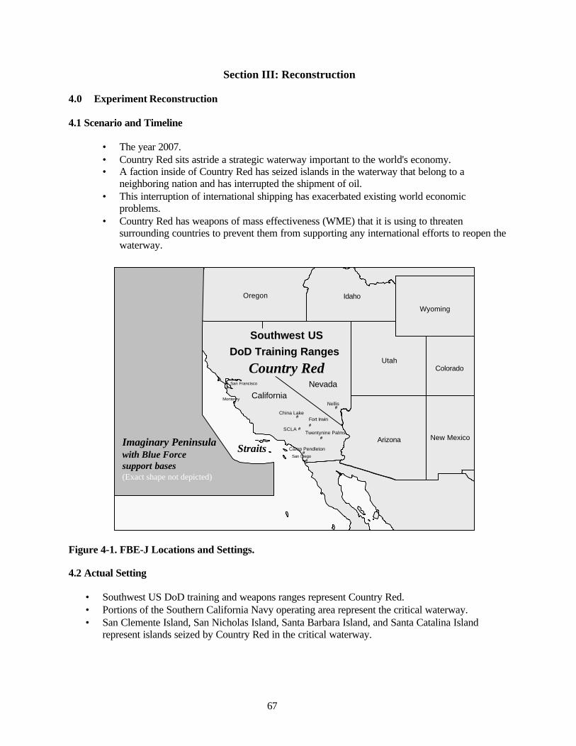
67
Section III: Reconstruction
4.0 Experiment Reconstruction
4.1 Scenario and Timeline
• The year 2007.• Country Red sits astride a strategic waterway important to the world's economy.• A faction inside of Country Red has seized islands in the waterway that belong to a
neighboring nation and has interrupted the shipment of oil.• This interruption of international shipping has exacerbated existing world economic
problems.• Country Red has weapons of mass effectiveness (WME) that it is using to threaten
surrounding countries to prevent them from supporting any international efforts to reopen thewaterway.
Figure 4-1. FBE-J Locations and Settings.
4.2 Actual Setting
• Southwest US DoD training and weapons ranges represent Country Red.• Portions of the Southern California Navy operating area represent the critical waterway.• San Clemente Island, San Nicholas Island, Santa Barbara Island, and Santa Catalina Island
represent islands seized by Country Red in the critical waterway.
#
#
#
#
#
#
#
#
San Diego
San Francisco
Monterey
Camp Pendleton
China Lake
Nellis
Fort Irwin
Twentynine Palms
Utah
CaliforniaNevada
Arizona
Oregon Idaho
Wyoming
Colorado
New MexicoImaginary Peninsulawith Blue Force support bases(Exact shape not depicted)
Southwest USDoD Training Ranges
Country Red
Straits
#SCLA
#
#
#
#
#
#
#
#
San Diego
San Francisco
Monterey
Camp Pendleton
China Lake
Nellis
Fort Irwin
Twentynine Palms
Utah
CaliforniaNevada
Arizona
Oregon Idaho
Wyoming
Colorado
New MexicoImaginary Peninsulawith Blue Force support bases(Exact shape not depicted)
Southwest USDoD Training Ranges
Country Red
Straits
#SCLA
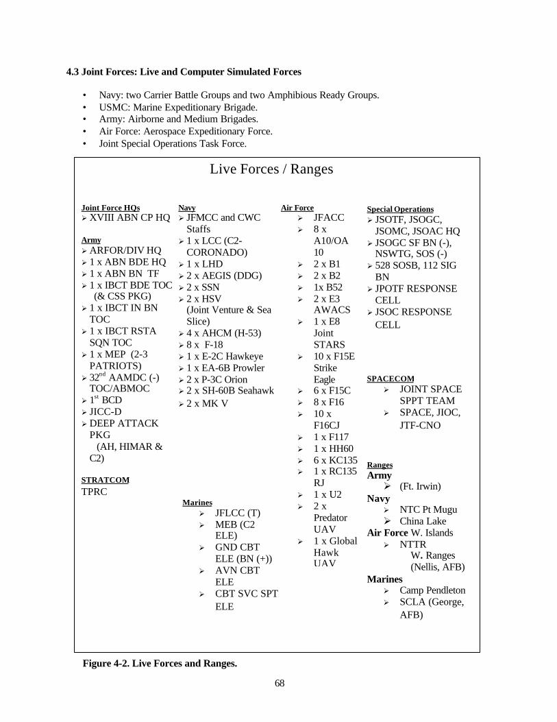
68
4.3 Joint Forces: Live and Computer Simulated Forces
• Navy: two Carrier Battle Groups and two Amphibious Ready Groups.• USMC: Marine Expeditionary Brigade.• Army: Airborne and Medium Brigades.• Air Force: Aerospace Expeditionary Force.• Joint Special Operations Task Force.
Figure 4-2. Live Forces and Ranges.
Joint Force HQsØ XVIII ABN CP HQ
ArmyØ ARFOR/DIV HQØ 1 x ABN BDE HQØ 1 x ABN BN TFØ 1 x IBCT BDE TOC (& CSS PKG)Ø 1 x IBCT IN BN
TOCØ 1 x IBCT RSTA
SQN TOCØ 1 x MEP (2-3
PATRIOTS)Ø 32nd AAMDC (-)
TOC/ABMOCØ 1st BCDØ JICC-DØ DEEP ATTACK
PKG (AH, HIMAR &
C2)
STRATCOMTPRC
NavyØ JFMCC and CWC
StaffsØ 1 x LCC (C2-
CORONADO)Ø 1 x LHDØ 2 x AEGIS (DDG)Ø 2 x SSNØ 2 x HSV
(Joint Venture & SeaSlice)
Ø 4 x AHCM (H-53)Ø 8 x F-18Ø 1 x E-2C HawkeyeØ 1 x EA-6B ProwlerØ 2 x P-3C OrionØ 2 x SH-60B SeahawkØ 2 x MK V
Special OperationsØ JSOTF, JSOGC,
JSOMC, JSOAC HQØ JSOGC SF BN (-),
NSWTG, SOS (-)Ø 528 SOSB, 112 SIG
BNØ JPOTF RESPONSE
CELLØ JSOC RESPONSE
CELL
RangesArmyØ (Ft. Irwin)
NavyØ NTC Pt MuguØ China Lake
Air Force W. IslandsØ NTTR
W. Ranges (Nellis, AFB)
MarinesØ Camp PendletonØ SCLA (George,
AFB)
SPACECOMØ JOINT SPACE
SPPT TEAMØ SPACE, JIOC,
JTF-CNO
MarinesØ JFLCC (T)Ø MEB (C2
ELE)Ø GND CBT
ELE (BN (+))Ø AVN CBT
ELEØ CBT SVC SPT
ELE
Air ForceØ JFACCØ 8 x
A10/OA10
Ø 2 x B1Ø 2 x B2Ø 1x B52Ø 2 x E3
AWACSØ 1 x E8
JointSTARS
Ø 10 x F15EStrikeEagle
Ø 6 x F15CØ 8 x F16Ø 10 x
F16CJØ 1 x F117Ø 1 x HH60Ø 6 x KC135Ø 1 x RC135
RJØ 1 x U2Ø 2 x
PredatorUAV
Ø 1 x GlobalHawkUAV
Live Forces / Ranges

69
4.3 Operations Overview
The overall Blue Mission was to conduct Rapid Decisive Operations to assure access through the strategicinternational waterway. The operations can be summarized as follows:
• A pre-hostilities situation existed through 27 July, during which both Red and Blue werepositioning forces.
• On 27 July, Red initiated hostilities by attacking the Abraham Lincoln Battle Group and theTarawa Amphibious Ready Group.
• From 27 through 29 July, the main effort was engagement of Red maritime forces and air strikesagainst critical Red C2 targets and TSTs.
• On the 30 July, the Joint Force executed a planned land assault on Red WME sites, includingship-to-objective-maneuver (STOM).
• Starting 2 August, the main effort shifted back to Maritime Access operations to support civiliantanker traffic through the straits to restore the flow of oil.
• The Fleet Battle Experiment concluded on 5 August 2002.
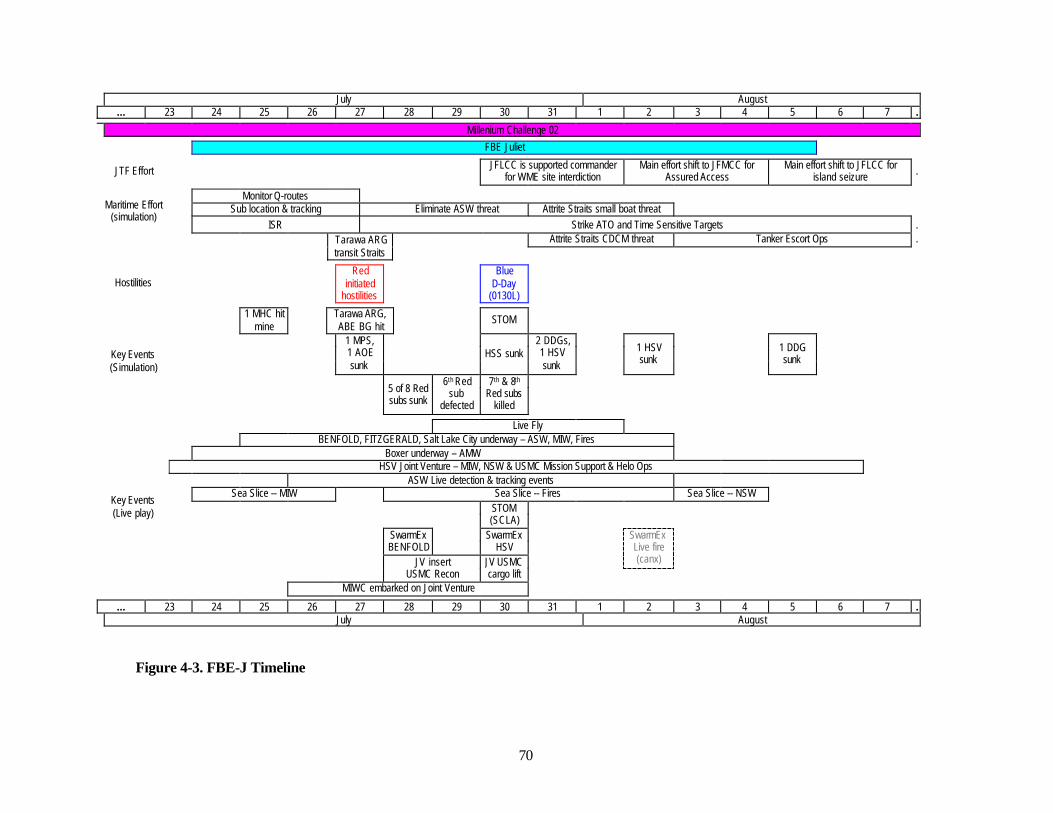
70
July August… 23 24 25 26 27 28 29 30 31 1 2 3 4 5 6 7 …
Millenium Challenge 02
FBE Juliet
JTF Effort JFLCC is supported commanderfor WME site interdiction
Main effort shift to JFMCC forAssured Access
Main effort shift to JFLCC forisland seizure …
Monitor Q-routesSub location & tracking Eliminate ASW threat Attrite Straits small boat threatMaritime Effort
(simulation)ISR Strike ATO and Time Sensitive Targets …
Attrite Straits CDCM threat Tanker Escort Ops …Tarawa ARGtransit Straits
HostilitiesRed
initiatedhostilities
BlueD-Day
(0130L)
1 MHC hitmine
Tarawa ARG,ABE BG hit
STOM
1 MPS,1 AOEsunk
HSS sunk2 DDGs,1 HSVsunk
1 HSVsunk
1 DDGsunkKey Events
(Simulation)
5 of 8 Redsubs sunk
6th Redsub
defected
7th & 8th
Red subskilled
Live FlyBENFOLD, FITZGERALD, Salt Lake City underway – ASW, MIW, Fires
Boxer underway – AMWHSV Joint Venture – MIW, NSW & USMC Mission Support & Helo Ops
ASW Live detection & tracking eventsSea Slice -- MIW Sea Slice -- Fires Sea Slice -- NSW
STOM(SCLA)
SwarmExBENFOLD
SwarmExHSV
SwarmExLive fire(canx)JV insert
USMC ReconJV USMCcargo lift
Key Events(Live play)
MIWC embarked on Joint Venture
… 23 24 25 26 27 28 29 30 31 1 2 3 4 5 6 7 …July August
Figure 4-3. FBE-J Timeline

71
Section IV: Key Observations
5.0 JFMCC Maritime Planning Process (MPP) Initiative Key Observations
In future maritime operations multi-functional maritime platforms are envisioned, with multiple weaponssystems, sensors, organic capabilities, highly sophisticated C2, and minimum manning. Providing accessto the littorals will be a requirement for maritime forces, often ahead of scheduled flows for jointcapabilities. A maritime tasking order will be required to optimize, synchronize, and interweave maritimeand joint forces.
Structures and processes exist to produce plans for using maritime forces in response to Commander’sGuidance. The increased pace of operations and increasing coordination needed between servicecomponents for joint operations have resulted in needed changes. The Joint Forces Maritime ComponentCommander (JFMCC) Maritime Planning Process (MPP) Initiative was a proposed system of processesfor deliberate planning and command and control (C2) to be employed by the JFMCC. In FBE-J, thisinitiative provided the first in-depth, critical examination of JFMCC and the MPP in a joint, operationalenvironment.
The JFMCC MPP is a collection of interactions between many processes with feedback required betweenthem (e.g., effects assessments resulting from actions). In discussing the MPP, as noted above, it shouldbe thought of as a system, vice process. Among other actions, the MPP interprets guidance from the JointForce Commander (JFC); produces a joint maritime operations directive (MOD); defines maritimesupport requests (MARSUPREQ’s); prioritizes actions in a master maritime attack plan (MMAP); andassigns action to individual maritime commanders in a maritime tasking order (MTO).
Because JFMCC and MPP are recent concepts, desired results were at a basic level:
• Did JFMCC and MPP work in Juliet?• Can they work or are there fundamental flaws?• What is needed for them to work sufficiently?• Was Juliet structured correctly to answer these questions?• Develop a set of recommendations for future JFMCC learning objectives.
The fundamental, overarching concern to be addressed by this initiative is flow of information and work.(A “process” is defined as an element of organization that does “work” to information, passing the resultto other processes or to storage for later use). MPP is a linear, segmented process, with seven basic steps(outlined in section 5.3 below) for the production and execution of the MTO. This is essentially acomplex workflow, analogous to an assembly-line type process. As an example of one assembly node:within the current planning cell, individuals acting as subject matter experts (SMEs) represent the needsof their Principal Warfare Commander (PWC), and do specific jobs in the production of the MTO. Theyneed a variety of information, such as available assets, guidance from their PWC and the effects taskingorder (ETO), etc., in order to produce their contribution to the MTO. Within a 72-hour period, there canbe as many as 3 MTOs in various stages of production at the same time.
The MPP is designed to coordinate activities of all principle warfare areas and support the production ofeffects desired by JFC and JFMCC. A "campaign" is developed to meet JFC objectives with each MTOmeant to optimize combined effects from each warfare area rather than sub-optimizing individual areas.Each PWC must contribute assets in a coordinated and coherent plan in order to perform optimized,maneuver operations. This implies a great deal of coordination between the SMEs, and between SMEsand their PWCs, during planning. Such coordination is complex, and it is theorized that different "battle
72
rhythms" associated with each warfare area contributes to this system’s complexity. Thus, shared assetutilization may not be constant through a full MTO execution cycle.
Information and work within this assembly line (actually three parallel lines) must be highlysynchronized. Sufficient coordination must be enabled between various Commands so that individual andcollective goals can be adjusted in a timely manner in order to produce an optimized plan. Thus, thefollowing basic MPP components examined in this initiative are:
• Coordination of asset utilization between Maritime or Joint commandso Some, but there is little evidence of this in data.
• Coordination/adjustment of daily goals between commandso From CINC to CJTF to JFMCC, principle coordination was by numerous briefings.
• Synchronization of information and worko Info Work Space (IWS) and SharePoint Portal System (SPPS) provided virtual briefing
space chat rooms and alternate virtual conference rooms for information sharing,synchronization of effort, and work.
• Information feedback, primarily BDAo Data do not reveal a high degree of coupling between the results of missions and the
MPP. Participant data and comments establish feedback as a critical area forimprovement. (As an experiment design note, the lack of feedback may or may notrepresent the same paucity of information from actual combat. However, the point of thisanalysis is that at the system level, feedback was largely not available as the enablerrequired to make the experimental MPP system perform adequately, or the process to useinformation in feedback was not part of the organizational construct. More is said on thistopic later in this report).
• Manpower requirements to maintain three MTO assembly lineso Heavy operational tasking is placed on available personnel. It is very likely that the
experimental organization would not be capable of performing 24-hour operations overan extended time. Also, the number of maritime support requests, approximately 3,000over a 10-day period, would not be adequately serviced. It is not possible, in these data,to separate, as independent variables, organization, technologies present, and thosetechnical capabilities that were assumed.
To properly understand the JFMCC MPP a process model to visualize complex relationships is required.One of the goals of this initiative is to produce a first iteration model based on the experimentalorganization structure and associated parameters, which may then be used for simulation studies fordifferent parameters associated with manpower, technology, organization, and CONOPS.
5.1 Experiment Objectives
The stated, primary objective of this initiative is to answer the following broad question:
• Does the JFMCC maritime planning process provide structure, organization, management,feedback, optimization, and situational awareness to maritime force employment and support theintent of a joint effects tasking order (ETO)?
73
In this experiment, specific terms from the question have specific meaning:
• Structure: The relationship of information and knowledge systems to the MPP system• Organization: Personnel and functional relationships, and how these contribute overall to the
MPP.• Management: The MPP as a C2 function, internal and external synchronization, management of
planning functions.• Feedback: Information as feedback of different kinds, and levels, that contributes to organization
management and process control at the operational level.• Optimization: As a potential measure of its utility, the MPP as a whole would be expected to
merge together battlespace situational awareness with asset planning in an optimized plan.• Situational awareness: Feedback from actions within the battlespace (e.g., BDA), a common
operational picture (COP), and the intent of the ETO to provide an overall and continualassessment that actions at the operational level are in accordance with a campaign plan.
Results from this initiative are almost completely reliant on the analysis of processes. The basic types ofoperational and tactical plans that need to be produced and general characteristics of organizations toproduce them in a maritime environment are understood and have been in use for some time. But, theMPP executed by JFMCC is a significant departure. Even though there is some mapping of past processeson the new organization, there are fundamentals in the processes that need to be investigated, understood,and for which implementation recommendations need to be developed. Former FBEs and LimitedObjective Experiments (LOEs) have produced initial, but limited, information. This FBE-J processanalysis produces the first set of detailed results. Using these results to produce a process model will thenproduce quantitative requirements for successful MPP implementation.
The required process analysis has the following distinct, interconnected objectives:
• Identify the products that are produced by the MPP process, information, and its flow, needed toproduce these products.
o This was proposed in pre-experiment CONOPS and observed in the experiment.
• Identify essential process components in the MPP, the organization elements that perform thoseprocesses, the interrelationships between components, and develop and evaluate performanceparameters for component processes.
o These processes were identified in pre-experiment CONOPS. An organization wasconstructed based on CONOPS definition. Interrelations were defined in social-networkanalysis of IWS chat data. Performance parameters are implied in results, but not directlydefined. The results are ambiguous due to combination of experiment organization,technologies, and lack of control over experiment conditions.
• Identify essential timing/synchronization within components of the MPP process, determinewhether required synchronization is achieved, and identify behavior cause-and-effect.
o Timing and synchronization are determined by context analysis, participant "requests forinformation," commentary, interviews, and surveys.
• Identify relationships between the MPP process and other processes outside of it. Identifyconstraints and requirements these relationships place on the MPP process.
o Primarily related to execution in the maritime operations center (MOC), ISR managementand feedback to the ETO.
74
• Determine the requirements for decision support and planning tools and evaluate tools currentlyin use within the MPP process.
It is important to note that there is much discovery at the current stage of the MPP process analysis ratherthan quantitative analysis of well-developed processes. For this reason, the above questions do not form acomplete definition of needed analyses. Other important questions and results, undoubtedly related insome way to the above, will emerge both during the experiment and analyses.
In support of the above objectives, the following data collection actions were undertaken:
• The production of an MTO was followed, through an MPP. System constraints, furtherrequirements, doctrinal implications, and utility within the scenario were determined.
• Quality and effect of collaboration between Joint and Principal Warfare Commanders on theconstruction of MTOs, and subsequent execution were collected.
• Instances of support to, and feedback of the results of MTO/ATO execution to the joint-constructed effects tasking order (ETO) were noted.
• MTO execution of events and changes to MTO requirements (MARSUPREQs) were collected.
• Recommended modifications to requirements for manning, tools and C2 to implement JFMCCcapability at sea were collected.
• The following planning tools were considered, with regard to the quality of decision supportprovided:
o TAPS-VSSo Naval Simulation System (NSS)o Info Work Space collaborative environmento Knowledge Kinetics (K2)o Theater Battle Management Core System (TBMCS)
5.2 Analysis Specifics
The following analysis objectives were specified in the data capture plan (DCP).
O1. Determine if processes are sufficient to produce the products, information, guidance orfeedback necessary to construct an MTO from an ETO.
O2. Where insufficient, determine contributors to lack of process, products, information,collaboration or control.
O3. Determine if decision support tools are enablers to decision making within the JFMCCprocess, or where lacking, what decision support tools are required.
O4. Characterize the information bandwidth requirement to conduct the JFMCC process afloat,and network characteristics, related to normative, specific events and usage distributions.
O5. Construct a mapping of intra-process constraints and synchronization across processes.O6. Investigate MMAP contributions to the USN mission and interactions with other processes in
the MPP.
75
The Data Capture Plan also specified the following measures associated with these objectives.Quantification methods for these measures were not specified.
M1. Manning sufficient to perform functions outlined in MPP CONOPS.M2. The experimental JFMCC maritime planning process does/does not adhere to the
experimental MPP CONOPS.M3. JFMCC MPP is/is not a capable means to coordinate requirements.M4. Planning tools (NSS, TAPS-VSS, Knowledge Kinetics (K2) contribute to MTO production
and synchronization of assets.M5. TBMCS is successfully used to translate MTO into an ATO format.M6. Future planning cell (FPC) produces a timely and effective maritime operations directive
(MOD) (as determined by requests for information, or re-work required to pass the MOD forward in theprocess).
M7. The FPC maritime operations directive is coupled to process in which maritime intelligencecell information (combat assessment, current enemy situation, etc.) is used.
M8. ISR plan developed in the MPP is flexible and adequate to support MTO (related torequirements for amplifying information, or reconstruction of ISR plans already forwarded).
M9. That the current planning cell (CPC) accomplishes the following tasks: prioritize tasks, focusefforts, apportion resources, articulate desired effects, conduct platform-mission pairing, ensure timing ofmissions.
M10. The CPC synchronizes maritime support requests (MARSUPREQ) requirements in termsof time, space, and assets (includes surface fires and TACAIR employment (related to requirements to fillinformation voids--using requirements for information (RFIs) or other information means; thatcoordinating instructions or other change is not required after CPC processing).
M11. The MTO production cell adequately synchronizes MTO with JFHQ and components(related to instances in which conflicts emerge after MTO is sent to PWCs).
M12. Web-based collaborative tools are sufficient and useful for the current planning cell andFPC to accomplish tasks
M13. The CPC produces an MTO that was stable, timely, flexible, and executable.M14. Interfaces between processes support participant's use of graphical user interfaces (GUIs)
and web tools (human factors).M15. The workload of current planning cell and future planning cell is in line with workload
requirements in a high tempo, operational environment.M16. Converging the MTO into the ATO format meets component commander’s requirements,
and PWC's requirements.M17. VSS-TAPS produces situational awareness visualization useful to decision makers in
employing effects in the battlespace. M18. Knowledge Kinetics workflow tool provides accurate, useful and timely processinginformation related to the production of multiple MTOs by contributing situational awareness of internalMPP processing to JFMCC CPC and FPC staffs.
M19. Tools and processes are used to synchronize the master maritime attack plan (MMAP)(related to shortfalls in required information, innovations in use of tools at hand, and documentation ofcapabilities shortfall).
The following, pertinent context questions arose during FBE-J execution:
Q1. What responsibility was assigned to the JFMCC by the JFC? (JP 3-32: “The JFC willestablish subordinate commands, assign responsibilities, establish or delegate appropriatecommand/support relationships and establish coordinating instructions for the coordinatingcommanders.")
76
Q3. What forces were assigned to the JFMCC by the JFC at the start of the experiment? Did theseforce assignments change as the experiment progressed?
Q4. Was a JFMCC area of operations (AO) established? How? (When an AO is defined for theJFMCC, the maritime component becomes the supported commander per JP 3-32.)
Q5. Were the authority and responsibility of the JFMCC in agreement with JP3-32, Chapter 2,and paragraph 3? Were they modified during the course of the experiment? (Note in particular that theJFMCC, “Provides the Deputy Area Air Defense Commander (DAADC) for maritime-based air andmissile defense or joint theater missile defense (JTMD), as assigned by the JFC.”)
Q6. What operational control (OPCON) and tactical control (TACON) relationships were definedby the JFC at the beginning of the experiment, and how did these relationships change? Did implicationsfor inter-component collaboration arise as a result?
Q7. What support relationships were defined by the JFC between components at the beginning ofthe experiment? Did these changes produce cross-component operational problems? Why and how? Whatwas done to resolve them?
Q8. What relationships and mechanisms existed between the JFMCC and JFC to provide forfeedback and control? Were there examples of the quality of these relationships?
Q9. How was targeting authority passed to JFMCC, and when?Q10. In what JTF boards, groups, and cells did the JFMCC have representation? (The JFMCC is
to maintain liaison with other service and functional components and agencies.)Q11. What examples of coordination and deconfliction can be cited, in which there was a
coordination or deconfliction recommendation to JFC, other components, or agencies?Q12. Did the JFMCC C4ISR architecture and plan support JFC operational requirements?Q13. What examples of recommendations from the JFMCC to the JFC for movement and
maneuver of assigned forces emerged in the course of the experiment?Q14. How were the JFMCC alternate courses of action (COAs) developed, tested and prioritized?Q15. What was the joint targeting concept established by the JFC? What did it include?Q16. What were the relationships established between JFMCC and JFACC for targeting
responsibilities at the beginning of the experiment? How and why did this relationship change over thecourse of the experiment?
This experiment was exploratory in its learning objectives, resulting in a lack of one-to-one mapping ofthe objectives, measures, and questions onto the MPP system results.
5.2.1 Experiment Design
Details of the operational and coordination level of FBE Juliet are found in the Experiment Plan1
published shortly before experiment execution. Each of the experiment initiatives shared somerequirements for data and control of conditions. Each initiative area also had specific learning objectivesfor the experiment.2 However, specific data design to meet experiment objectives was hampered by lackof design control by experiment designers. For the JFMCC MPP initiative, lack of experiment design hadsystemic (cascading) impacts on experiment control. These system effects became constraints to theproduction of useful experiment data, and are accounted for in the consequent constraints to analysis thatresults. These are stated for the purpose of bounding experiment results in this report, and as learningopportunities for future complex experiments. Specifically, for the MPP initiative:
• FBE Juliet was planned and executed within a larger effort, Joint Forces Command'sMillennium Challenge 02. Experiment control of the scenario was not possible at the level ofthe Maritime Component Commander.
1 Navy Warfare Development Command, FBE Juliet EXPLAN, July 2002.2 Meyer Institute, Naval Postgraduate School, FBE Juliet Data Collection Plan, July 2002
77
• Analysis objectives at the Joint level were greatly different from those of the Maritimecomponent, resulting in lack of data resolution required to meet some of the MaritimeComponent objectives. For example, quantitative data to produce TCT timelines was ofinterest to the Maritime Component, but at the Joint level, qualitative surveys of participantexpectations were sufficient.
• Within the Maritime component, most of the experiment objectives revolved around twocategories of interest, 1) process, and 2) technology. With both of these being immature,understanding the performance of process becomes very difficult when combined withmisunderstood, or immature technology.
• Simulation is necessary to complex experimentation. However, the Joint experiment tendedto over-play the tactical level of simulation, to the point that simulation operators wereexpected to fight their platforms as if involved in actual combat operations. While Juliet wasfocused at the process level of data collection, platforms could be lost from inadequatetactical employment by simulation operators, and not as a result of organization, C2, orprocess.
• Iterations of conditions or variables were not possible. With the Joint experiment in the lead,the decision was to employ nearly complete free-play, vice scripted events. This was valuableas a wargame experience, but worked against any possibility of resetting conditions formultiple iterations. In addition, it was very difficult to employ a Master Scenario Event List.
• For this mixed type of play there was not an opportunity to provide effects feedback into theprocess because there was little real correspondence between planning and execution play.This led to an unreality in planning and led to such things as reiterations of plans that weresimilar (nearly identical as someone reported) to those provided earlier. Also, it meant thatthere was no way to determine if a plan had been successful, and there was no learning for theplanners.
5.3 JFMCC/MPP Baseline Model
A "baseline" for the MPP refers to a current iteration of the concept, organization, technologies andsupporting structures present at the beginning of the event. Because the JFMCC MPP is not a standardused throughout the Navy, no other grounding reference is possible. One difficulty with attempting tobaseline this initiative for comparisons is the tendency to conduct rapid prototyping of the initiativeduring experiment execution, resulting in low stability of what was being observed. Also, metrics forcomparisons are not available.
5.3.1 Background
The maritime planning process (MPP) was developed in the course of FBEs Hotel through Juliet. Ingeneral the concept was intended as a response to the principal issue that: "The Maritime operationalplanning/execution process is not optimized to integrate Navy core competencies into the CJTF campaigndoctrine."3
3 Navy Warfare Development Command briefing, Maritime Planning Process Description, "Issue Statement."
78
A concept of operations (CONOPS, "baseline") document was produced to define the operational meansanswering the above issue.4 In addition, this baseline experimentation document was intended to provideinput to a Joint publication. 5
This section will summarize important aspects of the MPP as it was designed specifically for FBE Juliet.6
In this experiment, the MPP was intended to be an incremental step bridging past experimentation (FBEsH and I) and a next iteration of a Joint Publication (JP 3-32) or Navy Warfare Publication. In this iterationof the concept, the MPP was designed to specifically deal with shortcomings in Navy operationalplanning. The concept of operations (CONOPS) expresses these shortcomings as:
"Currently, the naval operational level planning process is not well defined and does notdynamically prioritize and assign joint maritime tasks to multi-mission platforms. Nor does it thenposition those platforms to best perform the tasking of the naval mission in the littorals, all withinthe construct of a Joint Task Force. To synchronize and schedule these naval air, surface, andsubsurface platforms, these units must operate within a planning and execution process to use thelimited platforms across surface warfare (ASUW), strike warfare (STW), mine countermeasures(MCM), air defense (AD), undersea warfare (USW), amphibious (AMW) while applying “in-stridetactics,” not sequential tasks. The JFMCC does not have a defined process of selecting precisiontargets, applying appropriate assets to those targets, wargaming for optimal positioning andscheduling, promulgating this plan in a CJTF parsable format and then execute the plan whileconducting time sensitive target acquisition, engagement and assessment utilizing dynamic weapontarget pairing."
FBE Juliet provided the venue for iteration of the MPP, but with the following constraints:
• The MPP would not replace the need for functional naval warfare commanders. Principle WarfareCommanders (PWCs) would still be required for tactical planning and execution of plans. PWCsfor FBE Juliet included:
o Sea Combat Commander (SCC, which also included duties as the ASWC and SurfaceWarfare Commander, SUWC),
o Mine Warfare Commander (MIWC),o Strike Warfare Commander (STWC),o Information Warfare Commander (IWC),o Amphibious Warfare Commander (AMWC), ando Air Defense Commander (ADC).
• The MPP would be required to support deliberate planning of a maritime campaign tasked withseveral separate naval warfighting missions.
• Many decision, planning, and awareness tools would be necessary to assist separate warfareareas. None were available to tie together all maritime missions together, yet such a tool is arequirement for a successful MPP.
4 NWDC produced "FBE Juliet JFMCC Concept of Operations"5 JP 3-326 The baseline documentation for these processes is included in the draft of JP 3-32, "Command and Control of JointMaritime Operations," and in "Concepts of Operations for Maritime Planning Process in FBE-J." Multiplebriefings, point papers, and e-mail memoranda provided additional information.

79
5.3.2 MPP Processes
An iterative model of the MPP is included in the CONOPS, beginning with a Maritime OperatingDirective (MOD).7
• Upon JFMCC approval of the MOD, Principle Warfare Commanders (PWCs) submit maritimesupport requirements (MARSUPREQs) to the MPP current planning cell (CPC).
• Subject matter experts, employing a variety of collaborative and decision support tools, produce amaster maritime attack plan (MMAP), for approval by the CPC Chief.
• Upon approval, a maritime tasking order (MTO) is produced, for approval by the JFMCC.
• In FBE Juliet, the approved MTO was then forwarded to the Joint Forces Air ComponentCommander (JFACC), for inclusion in the Air Tasking Order (ATO). The ATO was theneffective within the Joint Task Force, and was passed to the MOC for further distribution to thePWCs for execution.
• Assessment of execution results would be fed back into the next iteration of the MPP.
The time scale for a complete iteration of the cycle is 72-hours.
At a more detailed level, the MPP can be described as a set of sequential, interdependent (but also fairlylinear) steps:
• STEP 1 – Draft the MOD. The future planning cell drafts the maritime operations directivedelineating maritime operations to support the CJTF campaign plan. The MOD is distributed toPrincipal Warfare Commanders. Each day the JFMCC would focus priorities set forth in the PELand ETO based on battlespace dynamics and campaign tempo. (There were additional inputs tothe MOD, including a prioritized effects list (PEL) and effects tasking order. These, as well astheir relationship to the MOD production process, are defined later.).
• STEP 2 – Development of MARSUPREQs. Principal Warfare Commanders take the tasksdirected by the JFMCC in the MOD, as modified by daily guidance, and submit to the JFMCC alisting of assets required to accomplish the tasks required to support the commander’s priorities informatted maritime support requests (MARSUPREQs).
• STEP 3 – Develop the master maritime attack plan (MMAP). The current planning cell (CPC)combines tasks encompassed in the MOD, mission plans from PWCs submitted inMARSUPREQs, and current tactical environment to develop prioritized tasks, scheme ofmaneuver, apportionment, and desired effect for the next 48 hours, and detailed in a maritimemaster attack plan.
• STEP 4 – Collaboration between PWC’s, around the MMAP. The MMAP is distributedelectronically (in FBE Juliet, this was through the SharePoint Portal Service web space) toappropriate planning groups located within each PWC staff. Warfare commanders collaboratewith the current planning cell to modify the "shell" (an interface designed for this purpose) to
7 The term "MOD" had previously been referred to as the Joint Maritime Operations Plan (JMOP).
80
incorporate platforms. This could also include preplanned mission and asset pairing; the expectedsequence in which missions are to take place, time-on-target estimates, collection requirements tomeasure desired effects, and any other specific detail only available at the warfare commanderlevel.
• STEP 5 – Produce the maritime tasking order (MTO). In the baseline CONOPS, after the PWCshave agreed to the master maritime attack plan and it has been approved by the JFMCC, the MTOproduction cell coordinates missions with the JFACC and JFLCC and consolidates thisinformation into a single MTO, for promulgation. In the experiment, the output of the MTOproduction cell was sent directly to the JFACC for inclusion in the ATO, and subsequentpublication within that document.
• STEP 6 – Execution of the MTO and time critical targets (TCTs). A Maritime Operations Center(MOC) executes day-to-day missions published within the MTO (or in the case of FBE Juliet, theATO, hereafter referred to as M/ATO.) and asserts dynamic battle control of emerging targets andrequirements. Modifications to the M/ATO are published here. In addition, the MOC dynamicallymanages ISR assets, and is central to distributing feedback of battlespace damage assessments tothe MPP.
• STEP 7 - Combat Assessment. The maritime intelligence cell assesses maritime battlespaceresults and as quickly as possible, provides appropriate feedback at the required levels of theprocess.
Figure 5-1 shows the flow of information from the Joint Force Commander staff down through thevarious Navy levels of command to execution, and the feedback back up the chain. The principal productsbetween the levels are Commander’s Guidance, effects tasking order, maritime tasking order, maritimesupport requests, and direct commands to produce actions, which are not shown. Feedback is used asinput information at the beginning of a planning cycle. Feedback should also be inserted into planningthat is ongoing, which requires it be available at the proper time in the planning process if it is to be usefulin producing modifications.
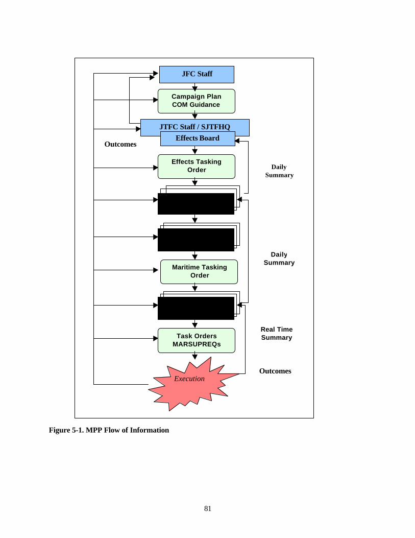
81
Figure 5-1. MPP Flow of Information
Outcomes
JFC Staff
Principal WarfareCommanders
Navy ComponentJFMCC
Campaign PlanCOM Guidance
JTFC Staff / SJTFHQ
Effects TaskingOrder
Maritime TaskingOrder
Task OrdersMARSUPREQs
ExecutionOutcomes
Real TimeSummary
Effects Board
DailySummary
DailySummary
Principal WarfareCommanders
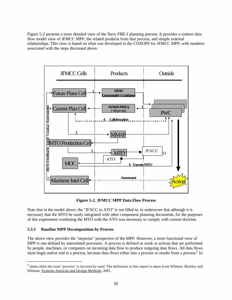
82
Figure 5-2 presents a more detailed view of the Navy FBE-J planning process. It provides a context dataflow model view of JFMCC MPP, the related products from that process, and simple externalrelationships. This view is based on what was developed in the CONOPS for JFMCC MPP, with numbersassociated with the steps discussed above.
Future Plans Cell
PWCCurrent Plan Cell
Collaboration
MMAPMTO Production Cell
MTO
MOC
Action
6 Execute MTO
JFMCC Cells Products Outside
MOD/Commander’s Guidance
MARSUPREQ(~100 per day)
Maritime Intel Cell Assessment
BD
A F
eedb
ack/
Int
el/ C
omba
tAss
essm
ent
1
2
3
4
5
7
ATO
Figure 5-2. JFMCC MPP Data Flow Process
Note that in the model above, the "JFACC to ATO" is not filled in, to underscore that although it isnecessary that the MTO be easily integrated with other component planning documents, for the purposesof this experiment combining the MTO with the ATO was necessary to comply with current doctrine.
5.3.3 Baseline MPP Decomposition by Process
The above view provides the "stepwise" perspective of the MPP. However, a more functional view ofMPP is one defined by interrelated processes. A process is defined as work or actions that are performedby people, machines, or computers on incoming data flow to produce outgoing data flows. All data flowsmust begin and/or end at a process, because data flows either into a process or results from a process.8 In
8 Quite often the term "process" is incorrectly used. The definition in this report is taken from Whitten, Bentley andDittman, Systems Analysis and Design Methods, 2001.
ATO
JFACC

83
other words, processes do work to information. The results of this work can only feed other processes, orbecome part of a repository of information for use later by other processes. A process model of JFMCCMPP was produced prior to experiment, as a means to help develop a CONOPS, but was not used furtheras a means to understand interactions or metrics in execution of FBE Juliet.
Process to Coordinate Joint Forces Commander (JFC) Effects Tasking and JFMCC Operations: TheETO is an output of the JFC, produced in collaboration with functional commanders and reachback cellsat the CINC's headquarters, supporting CINCs, and external agencies. ETO development is intended as acontinuous, interactive process between the plans team, component commands, and executingorganizations. The ETO expresses the Joint Forces Commander's intent by assignment of missions toappropriate functional commanders that are designed to achieve specific effects and outcomes. After it isdeveloped, the ETO is passed to components. At the component level the ETO is articulated incomponent plans. The JFMCC is responsible for the articulation of maritime plans to support the ETO.
Process to Produce a Maritime Operations Directive (MOD): This process specifies directives tointegrate and coordinate joint maritime operations. Producing the MOD serves to achieve the Joint ForceCommander's operational and/or overall campaign objectives. The MOD (which is modified as required,and reviewed and approved by the JFMCC at the beginning of each MTO cycle) is a compilation of plansused to achieve mission objectives based on the dynamics of the battlespace and the tempo of thecampaign.
As a general description of this process, the future planning cell (FPC) develops the JFMCC dailystrategy to accomplish JFMCC tasks. An integrated plan provides tasking to the Principle WarfareCommanders (maritime component PWCs), with requirements for effects to be accomplished by the otherfunctional warfare commanders (JFACC, JFLCC and JSOTF). Products from the FPC include an input tothe future ETO, inputs to a prioritized effects list (PEL), the joint integrated target list (JIPTL), and theMOD.
Participants in this process include the current planning cell Chief, and subject matter experts (SMEs)from Intel, Information Operations, Sea Combat Commander, ship to objective maneuver (STOM), strikewarfare, air defense, ISR (intelligence, surveillance and reconnaissance), mine warfare, ATFP (anti-terrorism and Force Protection), logistics, and amphibious warfare. In FBE Juliet, SMEs providedcoordination and collaboration horizontally between other PWC SMEs in the current planning cell, andvertically with the operational PWC. A representative from the current planning cell provided continuitybetween the current planning cell and the future planning cell.
Maritime Support Requests (MARSUPREQ) Production Process: This process is the means by whichPWCs list required assets submitted by the maritime service components and subordinate commanders tothe JFMCC to accomplish the maritime tasks specified in the MOD.
The current planning cell combines tasks from the MOD with mission plans and asset requirementssubmitted by PWCs in MARSUPREQs. The current tactical environment is an input to the CPC fordevelopment of prioritized tasks, scheme of maneuver, apportionment, and the desired effects for thecoming 48 hours.
Maritime Tasking Order (MTO) Production Process: This process tasks specific missions related tomaritime forces and maritime operations. It also may be used to disseminate projectedsorties/capabilities/forces against targets to components, subordinate units and command and controlagencies. Specifics such as call signs, targets, controlling agencies and general instructions are included.Some of the specific maritime missions and sorties included in the MTO may duplicate other component
84
commanders’ task orders. In FBE Juliet the MTO was merged with the Air Tasking Order (ATO) prior topublication and execution.
MTO Execution and Feedback Processes: These processes occur outside of the current plans or futureplanning cells. However, feedback from the results of MTO execution is required as an input to planningof follow-on MTOs.
Synchronization
Synchronization of interdependent processes is the most difficult task. The MTO is typically produced ona 72-hour cycle, but can vary dependent on JTF battle-rhythm. Normally, three MTOs are in variousstages of production at any one time. During execution of an MTO, results obtained (damageassessments) will impact planning of subsequent actions. These results must be inserted at an appropriatepoint in planning and at the correct time, or planning process components must be adaptable tomodifications at any time. Battle damage assessment is the primary feedback from current operations.
Planning by PWCs occurs in parallel. However, it is possible that different missions will require the sameassets. When this occurs, coordination between PWC staffs must occur or there must be an adjudicationfunction. In either case, planned synchronization of processes must occur or there can be a time-out forthe more rapid process until the other reaches the asset deconfliction point.
Processing Capacity:The rate at which required products can be produced depends on the processing capacity of the varioussystem process components of JFMCC and PWC staffs. In the absence of multi-tasking, it is fairly simpleto determine the capacity of each component and the manpower needed to complete expected workloadswithin time requirements. However, multi-tasking in the MPP can be expected to occur. If a processingcomponent has more than one task, and if tasks overlap during processing, determining needed manpowerbecomes complicated. It is not true that one can simply add the requirements for the two tasks because notasks are independent. Efficiency can be achieved if one component works on two tasks that are closelyrelated.
Process Requirements - The Baseline Model:The following requirements provide the parameters for the MPP baseline model as employed in FBE-Juliet. Baseline means these parameters reflect expected performance for JFMCC/MPP processes,established prior to the experiment. Results are compared to this baseline and deviations noted. Themodel consists of the above process architecture and process descriptions, and a set of expectations foroverall performance and performance of internal processes. At this point in MPP development, theexpectations are broadly stated and the parameters fairly loosely defined. The results of this experimentprovide recommendations for process improvement and better parameter definition to provide animproved baseline model.
MPP in total:• Produce one MTO per day.• Process three MTOs simultaneously• Provide daily effects summary to JFC• DPG courses of action analysis to FPC once per day
Future plans cell• Produce one MOD per day• Consideration of two future MODS in addition to current day

85
Deliberate plans group• Daily briefing at 1900
Current planning cell• Meet to de-conflict MARSUPREQs once per day prior to MMAP production• Produce one MMAP per day• Work on 2 MMAPs in queue
MTO production cell• Produce one MTO per day• Deconflict one MTO and ATO cycle per day
5.4 Experiment Design, Data Collection, and Analysis Methods
Data collection and analysis focused on information content, information flow, and decision-makingwithin the MPP process. Figure 5-2, discussed above, set forth the processing components of JFMCC andthe products being considered. Information regarding processing performance was obtained for authorityrelationships, synchronization with JFC processes, and the usefulness and requirements for decisionsupport tools. The basic quantities to be determined for all components of the MPP process, asappropriate, follow.
• Product quality is determined by its acceptability at the next for an input to their process. This ismeasured by
o Number of instances of request for clarificationo Number of instances of request for additional informationo Time spent on interpretationo Degree to which an input provided boundary conditions or guidance.
• Processing time is the elapsed time from the time the first data is provided that can initiate theprocess to the time the product is delivered to the next component. In addition, elapsed times forinternal sub-processes are needed.
• Process capacity is the number of operations that can be carried out per unit time. This applies toexisting sub-processes, not the complete process for which one product is produced per day, andfor which the basic measures are its quality and the processing time. For example, developmentof the MMAP will require processing several MARSUPREQs.
• Process capacity has several associated parameters that must be captured, which fall in thecontext category. They are:
o Number of personnel working on each sub-processo Instances of multi-tasking for personnel or unitso Multi-task time overlaps.
Note that the above three measures are not independent. Processing time will depend on qualityof input information, etc. There is no current methodology for quantifying these correlations andonly weak methods for identifying them.
86
• Coordination between production teams focuses on instances where there is possible or actualcompetition for assets, e.g., MIWC and ASWC needing to use the same ships for their missions.Two determinations are made:
o Whether PWCs coordinate when producing their MARSUPREQso If this coordination does not occur, whether subsequent adjudication occurs.
• Synchronization of processes is required throughout the MPP. This applies to:o Information passed between processing components during planningo Feedback during and after executiono Coordination of multitasking for the three simultaneous production cycles.
• Bottlenecks or constraints to process performance are determined for information flow andorganization relationships, particularly for decision-making authority. The data are the number ofinstances and when and where they occurred.
• Authority relationships are mostly predetermined and part of experiment context. Of specialinterest here are relationships when competition for assets occurs and what authority is utilizedfor the resultant asset allocation.
The data used to arrive at the observations presented below come from a number of sources:
• Subject matter expert observations• Participant surveys• Initiative stakeholder observations• Human factors• JFMCC briefings (including maritime operations directive decision briefings, and master
maritime attack plan decision briefings)• Maritime support requests• MTO catalogue• Battlespace context and scenario events• Principle Warfare Commander interviews• Chat room dialogue from Info Work Space (IWS).
5.5 Sub-Initiative Observations
Due to the exploratory nature of this initiative, the results include a determination of how the variousMPP sub-processes were executed. This is described at the start of each of the following observationsubsections for each of the products. Included in the subsections are summaries of significant subjectiveobservations about the processes. Indications are that MPP is a process in evolution, not yet robust, whichis to be expected.
A subsection on synchronization of the various aspects of the MPP follows discussions of production ofthe various products. Lastly, there is a discussion of the decision-support tools.
5.5.1 MOD (JMOP) Production Process
The maritime operations directive (formerly the joint maritime operations plan) specified instructions tointegrate and coordinate joint maritime operations to achieve the Joint Force Commander's operation oroverall campaign objectives. The MOD (which was modified as required, with at least an opportunity to
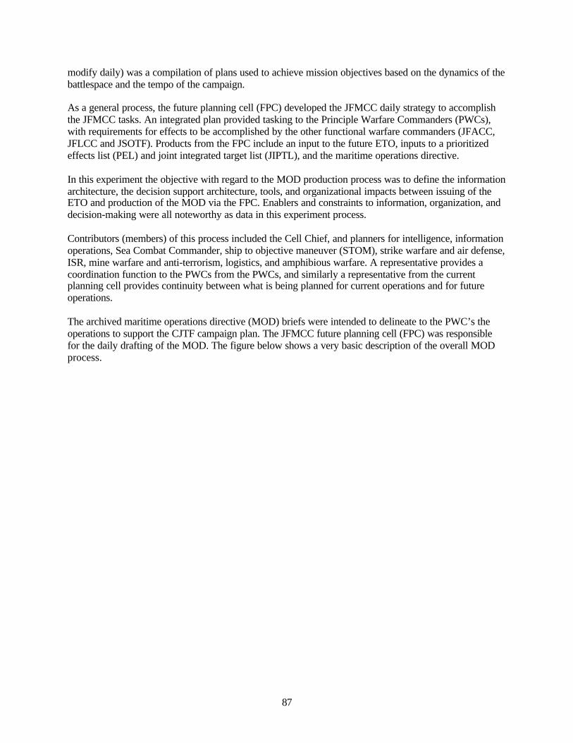
87
modify daily) was a compilation of plans used to achieve mission objectives based on the dynamics of thebattlespace and the tempo of the campaign.
As a general process, the future planning cell (FPC) developed the JFMCC daily strategy to accomplishthe JFMCC tasks. An integrated plan provided tasking to the Principle Warfare Commanders (PWCs),with requirements for effects to be accomplished by the other functional warfare commanders (JFACC,JFLCC and JSOTF). Products from the FPC include an input to the future ETO, inputs to a prioritizedeffects list (PEL) and joint integrated target list (JIPTL), and the maritime operations directive.
In this experiment the objective with regard to the MOD production process was to define the informationarchitecture, the decision support architecture, tools, and organizational impacts between issuing of theETO and production of the MOD via the FPC. Enablers and constraints to information, organization, anddecision-making were all noteworthy as data in this experiment process.
Contributors (members) of this process included the Cell Chief, and planners for intelligence, informationoperations, Sea Combat Commander, ship to objective maneuver (STOM), strike warfare and air defense,ISR, mine warfare and anti-terrorism, logistics, and amphibious warfare. A representative provides acoordination function to the PWCs from the PWCs, and similarly a representative from the currentplanning cell provides continuity between what is being planned for current operations and for futureoperations.
The archived maritime operations directive (MOD) briefs were intended to delineate to the PWC’s theoperations to support the CJTF campaign plan. The JFMCC future planning cell (FPC) was responsiblefor the daily drafting of the MOD. The figure below shows a very basic description of the overall MODprocess.
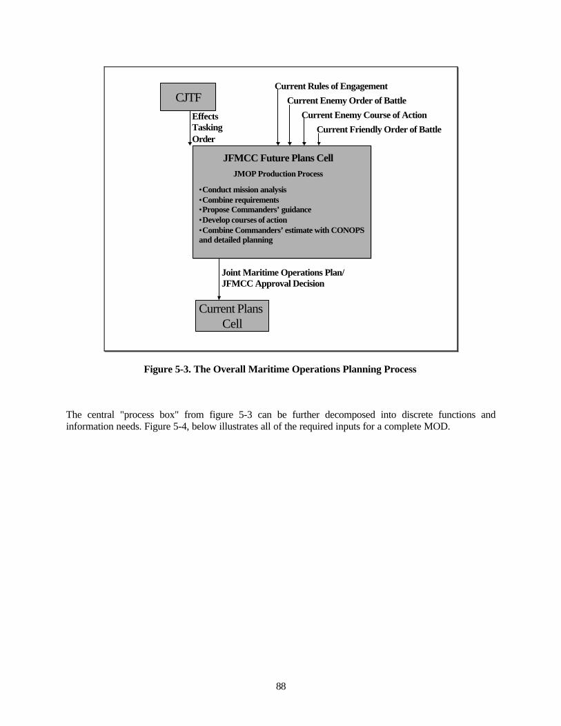
88
Current Rules of Engagement
Current Enemy Order of Battle
Current Enemy Course of Action
Current Friendly Order of Battle
CJTFEffects Tasking Order
Current Plans Cell
Joint Maritime Operations Plan/JFMCC Approval Decision
•Conduct mission analysis•Combine requirements•Propose Commanders’ guidance•Develop courses of action•Combine Commanders’ estimate with CONOPS and detailed planning
JFMCC Future Plans CellJMOP Production Process
Figure 5-3. The Overall Maritime Operations Planning Process
The central "process box" from figure 5-3 can be further decomposed into discrete functions andinformation needs. Figure 5-4, below illustrates all of the required inputs for a complete MOD.
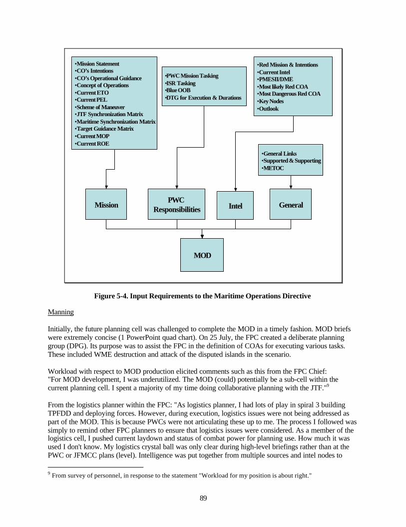
89
MOD
MissionPWC
Responsibilities Intel General
•Mission Statement•CO’s Intentions•CO’s Operational Guidance•Concept of Operations•Current ETO•Current PEL•Scheme of Maneuver•JTF Synchronization Matrix•Maritime Synchronization Matrix•Target Guidance Matrix•Current MOP•Current ROE
•PWC Mission Tasking•ISR Tasking•Blue OOB•DTG for Execution & Durations
•Red Mission & Intentions•Current Intel•PMESII/DME•Most likely Red COA•Most Dangerous Red COA•Key Nodes•Outlook
•General Links•Supported & Supporting•METOC
Figure 5-4. Input Requirements to the Maritime Operations Directive
Manning
Initially, the future planning cell was challenged to complete the MOD in a timely fashion. MOD briefswere extremely concise (1 PowerPoint quad chart). On 25 July, the FPC created a deliberate planninggroup (DPG). Its purpose was to assist the FPC in the definition of COAs for executing various tasks.These included WME destruction and attack of the disputed islands in the scenario.
Workload with respect to MOD production elicited comments such as this from the FPC Chief:"For MOD development, I was underutilized. The MOD (could) potentially be a sub-cell within thecurrent planning cell. I spent a majority of my time doing collaborative planning with the JTF."9
From the logistics planner within the FPC: "As logistics planner, I had lots of play in spiral 3 buildingTPFDD and deploying forces. However, during execution, logistics issues were not being addressed aspart of the MOD. This is because PWCs were not articulating these up to me. The process I followed wassimply to remind other FPC planners to ensure that logistics issues were considered. As a member of thelogistics cell, I pushed current laydown and status of combat power for planning use. How much it wasused I don't know. My logistics crystal ball was only clear during high-level briefings rather than at thePWC or JFMCC plans (level). Intelligence was put together from multiple sources and intel nodes to
9 From survey of personnel, in response to the statement "Workload for my position is about right."

90
include targeting and effects/BDA. I used both the face to face and collaborative tools to form a predictivepicture to insert into plans."
Other respondents reported negatively that their workload was not appropriate to their position, withoutamplifying information. The result of this survey is ambiguous. It cannot be determined from data that theworkload is, or is not appropriate due to manning, or whether negative responses were indicating that theywere under-employed. A more focused and controlled workflow analysis should be conducted, followedby execution in an experiment.
Information Content
Initially the MOD, as evidenced by the MOD briefings, did not contain sufficient information. Itconsisted of the following, presented in a single PowerPoint "quad chart" format:
• Section containing a geographic map of the exercise region with major OOB assets depicted• Section outlining: objectives, desired effects, and component and PWC relationships• Section outlining: PWC tasks• Section setting forth concerns and issues, such as ROEs, asset allocations and shifts, etc.
Concern was expressed that the briefing did not present "clarity" and the impression was created that theJFMCC Plans Chief was in a “planning vacuum” and having difficulty getting a good view of the PWC’s3-day outlook. Also there was little feedback on operations. It was decided to provide much moreextensive information and also include a "current operations summary," which would provide situationalawareness (SA) from the Principle Warfare Commander's perspective.
However, within the FPC the perspective with respect to applicability of MOD information was notconsistently the same as within the CPC:10
"The MOD process still needs work. Lack of interface between FPC SMEs and PWCs (from the logisticsperspective) perhaps affected this. (The) MOD had to balance being too specific with being too broad.Wanted the PWCs to have freedom to plan but within the bounds of the JFMCC intent/guidance."
The FPC Chief agreed, however, that: "(We) Tried to respond to (PWC) needs. Info was available eitherdirectly in the form or through links to files."
Finally, with regard to JFMCC structure (referring back to the overarching question), the MPP provided astructure within which to support the intent of the Joint ETO. That structure is incomplete, however,lacking firm definition of maritime operations directive process, as evidenced by the need to create thedeliberate planning group early in experiment execution. Documentation of the baseline planning processdoes not show the full range of inputs to MOD production. It mentions only “Feedback and assessments,BDA, and Intel and data collection,” with nothing input from the joint planning process. The CONOPSdescribes the future planning cell and adds the effects tasking order as an input, while also discussing theMPP as a TACTICAL (vice OPERATIONAL) planning model, despite numerous references to JFMCCPlanning as an operational level planning process. Additional structure regarding the interface betweenoperational and tactical level planning and the role of the future planning cell is required.
Planning and reporting evolution demonstrated a need for the following information to be included in theMOD:
• Operations update 10 Response to survey question: "The MOD has detail required for PWCs to initiate planning."

91
• From previous day, Mod Ka. MOD K force protection mapb. PWC tasking detailsc. PWC issues
• From SCC (Sea Combat Commander)a. SCC asset-to-mission allocation schemeb. SCC asset-to-mission allocation quad chartc. Maritime superiority metrics- last 24 hours’ histogramd. Maritime superiority metrics- current histograme. Maritime superiority metrics focus areas quad chart
• From ADC (Air Defense Coordinator)a. Air defense for island dispute detailsb. Defense of Alpha Islands mapc. SOH vice escort detailsd. 3-ship strait patrol plan mape. 2-ship strait patrol plan map
• From IWC (Information Operations Warfare Commander)a. IWC MOD K06 details
• From STWCC (Strike Warfare Commander)a. STWCC MOD K06 details
• From AMWC (Amphibious Warfare Commander)a. AMWC MOD K06 details
• From MIWC (Mine Warfare Commander)a. Q-route map of the exercise area undergoing mine clearing opsb. Second Q-route map of the exercise area undergoing mine clearing opsc. “RECOMMEND CONOPS APPROVED”d. “PROJECTED THREAT UPDATE”e. Projected operational CJTF-S threat graphf. JFMCC weight of effort listg. Force protection maph. PWC tasking detailsi. Issues details
Producing this quantity of information increases PWC inter-collaboration and planning and increases timespent preparing situational awareness overviews for JFMCC.
All evolutions during the experiment indicated the need for additional resources if MPP is to be a viableprocess.
The MOD needs to describe the JFMCC desires rather than present only a list of priorities.
Timeliness
The current planning cell doesn’t add the appropriate timely value to the direction given by the MOD.They do not have the tools, information, or personnel to understand what changes are necessary to react tocurrent events. The MMAP becomes a sequential manifestation of the MOD.
"JFMCMIWSME2 to MIWC and SCC: MARSUPREQ shell for B28 has been created.... theMARSUPREQs for B28 MOD are not due till 2100 tomorrow but we need your intent ofoperations for 28 Jul by 2100 tonight.... MARSUPREQ inputs for A27 MOD will close out at 2100.

92
Anything you want changed for today or tomorrow ops must be handled through the operationscell."11
"JFMCMIWSME2: I'll be reviewing the MARSUPREQs for B28 now to interpret your plan for28th.... our next time deadline here is any hard target nominations you want ISO C29 MOD whichwas briefed at noon in aud 112."12
"JFMCMIWSME2: Please rework your target nomination for MOD D30 using the TargetNomination Matrix found on JFMCC home page --> Warfighting --> Targets...our understandinghere is that the raids will be helo born and this will be a requirement for follow-on logistics MIWline 293"13
"JFMCMIWSME2: One other item on F01--I left 1805 as one mission of 2 rhibs since they weregoing to the same location.... your MOD slide was very useful and it's the image for the MMAPbrief at 0530. MIW 530"14
"I was the cell chief. I reviewed the MOD for approval. To get it ready, I led off the process bydeveloping the Commanders Intent on a daily basis. This started of the daily cycle. We had aninternal rhythm that culminated at noon each day with a MOD approval briefing."15
The current friendly order of battle (Blue force list) was never up-to-date with all available assets at gamestart or updated when assets were lost. MIWC was conducting covert ops long before tasked but wouldnot have been able to support the war if done with the MOD timeline. The MOD never stipulated whatnot to do.
Collaboration
Processes within the MPP matured as participants learned to coordinate and collaborate tasks in thecourse of the experiment. It was noted in participant comments that the CPC, FPC and MTO productionleads were competent at communicating with each other from the beginning.
"The cells act somewhat independently while producing their specific products, but the output ofone cell is the input to the next. The leads were good at hashing-out, and explaining to their watch-teams, details of the MOD, the MMAP, and the MTO so that the transfer of the plan from one cellto the next plan went well."
As expected, there were points of conflict between the different process nodes in the MPP. However,meetings between principles ironed out difficulties as operations progressed:
"There is too much ambiguity in the amphibious MOD process since JFLCC isn't following theJFMCC process. The amphibious warfare FPC LNO is not clear on how to best deal with the(individual needs between the) PWC (the AMWC) and JFLCC. They will meet at 0600 on 27 Jul torefine their process."16
11 Excerpted from IWC chat files for 25 July.12 Excerpted from IWC chat files for 26 July.13 Line 293 of MIW chat files for 27 July.14 Line 530 of MIW chat for 31 July15 FPC Cell Chief observation in survey16 Comment from From the JFLCC Amphibious warfare LNO.
93
Synchronization
A deliberate planning group (DPG) was established to assist the FPC to consider, in greater depth anddetail, multiple courses of actions (COA). The intent overall was to improve internal JFMCC planningand to try to better understand the needs of the supported PWC. This innovation to the process in thecourse of experiment execution resulted from participant perspectives that the organization andcapabilities of the baseline FPC was too heavily tasked and too inexperienced, to properly considernumerous COAs while creating the MOD in a 24 hour cycle. Also, the Current Plans Chief asserted nothaving this as part of the MPP process amounted to a fundamental flaw in the baseline MPP. Leadershipof this group was provided by a participant dedicated specifically to this task, with inputs provided by,PWCs, their subject matter experts as require, and LNOs. A 1900 daily DPG briefing was added to thebattle-rhythm schedule, as part of the FPC.
Initially the DPG cell was tasked to concentrate on COAs for employment of potential weapons of masseffect and campaign plans concerning the disputed islands included as part of the scenario (operations tobe conducted in day D+3). Additional DPG responsibilities were established:
• Provide early coordination for deliberate planning efforts identified at JFC and JFMCC levels.
• Provide an organized set of products to help the FPC "look" three days in advance, with respect tospecified tasks, assumptions and limitations of COAs, missions, mission analysis,recommendations, and threats.
Although the intent matched a perceived process requirement, the DPG was not provided any additionaltools to perform the functions required. It is also not clear that if provided an adequate COA analysiscapability, that the FPC would still require the DPG as a function apart from the FPC, or whether thosefunctions could be absorbed within the FPC. At the very least, the experiment provided this additionalrequirement to the MPP.Commentary by FPC participant:
"The DPG is just getting moving. They are working on COAs for WME and the attack of thedisputed islands. They (DPG) may have arrived too late in the game to be effective for thisparticular attack plan. The attack plans for WME and the disputed islands are to be executed aroundD+3 (30 July), so they have little, if any, time to consider options and give inputs to the FPC beforethe FPC begins the MOD process. FPC is working MOD C, for 29 July, on the 26th, and MOD D,for 30 July, on the 27th. The DPG has only a few dedicated workers, and the rest of the team ispulled from SMEs and LNOs from the FPC and the CPC. These people are already working issueswith the PWC in their capacity as members of the FPC and the CPC. The DPG adds the additionaltask of having the same PWCs develop CONOPS for optional plans that are more than three daysfrom execution. They are not necessarily over tasking the PWC, who is also fighting the war, butthe DPG must be careful in keeping straight current plans, future plans, and potential future planswhen they are discussing these over the phone with the PWCs."17
Of note in the above commentary is the multiple tasking of personnel to roles as PWC subjectmatter experts, to the FPC, and to the DPG. Difficulty for individuals to maintain task identificationwithout ambiguity between these roles is an issue for further human factors experimentation.Specific instances of task ambiguity, mis-identification or confusion were not observed directly. Itis also unknown whether the DPG was, or was not tasked to capacity in the course of theexperiment.
17 From JFMCC observer report and participant comments, 26 July.

94
MOD
"The JFMCC plan cell (FPC, CPC, and MTO) completed the first full cycle of MTO production -from MOD A27, published by the FPC on 24 Jul, through MTO production and MTO-ATO mergeon 26 Jul. I believe the process went surprisingly smooth. The CPC watch leads drove the current-plan cycle well, kept their subgroups pointed in the right direction, and established and met periodicdeadlines for the interim steps of the planning process (target noms, msrs from PWCs, MMAPproduction). In Lcdr Evart's words, he feels the watch team is operating at a "high school JV" level,when they need to be operating at a college, div-I, level. The watchstanders are certainly stillcoming up to speed with the JFMCC planning process, but they are doing it quickly."18
5.5.2 MARSUPREQ Production ProcessThe maritime support requests list assets submitted by the maritime service components and subordinatecommanders to the JFMCC to accomplish the maritime tasks in the MOD. A current planning cell (CPC)combined tasks from the MOD, mission plans from the PWCs that are submitted in MARSUPREQs, andcurrent tactical environment to develop prioritized tasks, scheme of maneuver, apportionment and desiredeffects for the coming 48 hours.
In this experiment the CPC was co-located with the FPC on the 5th deck of USS Coronado. It compriseda CPC Director, subject matter experts from each principal warfare area, joint subject matter experts fromUSAF (TACAIR, bomber, strike and ISR), an offensive coordinator for information operations, an ISRcoordinator, and a knowledge officer.
As with the FPC, data collection in this process was focused on the in-flow of information to themembership (architecture, usefulness, timeliness, validity) to support decision-making that contributes tocollation of MARSUPREQs. Also, at this level of the JFMCC process, the PWCs are enabled tocollaborate between themselves to coordinate resources and plans. This cross-collaboration is critical tothe success of the process. Data collection with respect to collaboration sought to determine the scope ofthe collaboration required for each PWC or SME, and other members of the CPC and FPC.
The following figure shows the process elements required to produce a MARSUPREQ.
18 Ibid
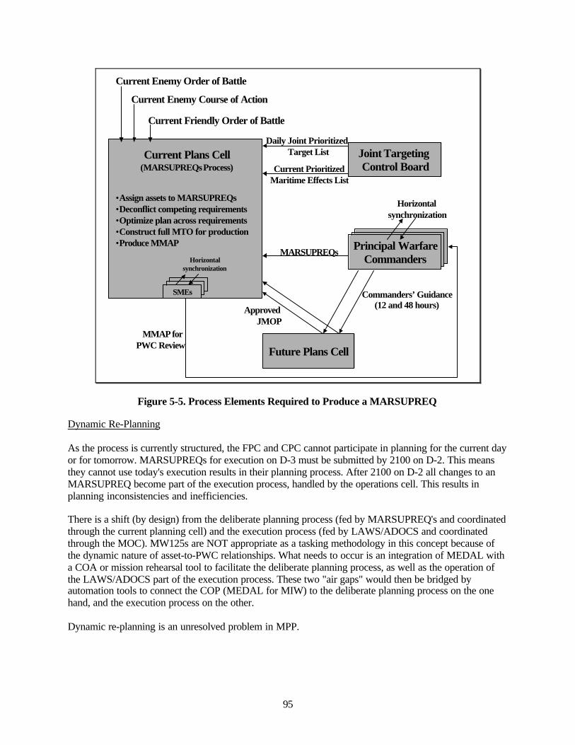
95
Current Enemy Order of Battle
Current Enemy Course of Action
Current Friendly Order of Battle
Joint Targeting Control Board
Principal WarfareCommanders
Daily Joint Prioritized Target List
Current PrioritizedMaritime Effects List
Horizontalsynchronization
MARSUPREQs
Future Plans Cell
ApprovedJMOP
Commanders’ Guidance(12 and 48 hours)
SMEs
Horizontalsynchronization
MMAP for PWC Review
Current Plans Cell(MARSUPREQsProcess)
•Assign assets to MARSUPREQs•Deconflict competing requirements•Optimize plan across requirements•Construct full MTO for production•Produce MMAP
Figure 5-5. Process Elements Required to Produce a MARSUPREQ
Dynamic Re-Planning
As the process is currently structured, the FPC and CPC cannot participate in planning for the current dayor for tomorrow. MARSUPREQs for execution on D-3 must be submitted by 2100 on D-2. This meansthey cannot use today's execution results in their planning process. After 2100 on D-2 all changes to anMARSUPREQ become part of the execution process, handled by the operations cell. This results inplanning inconsistencies and inefficiencies.
There is a shift (by design) from the deliberate planning process (fed by MARSUPREQ's and coordinatedthrough the current planning cell) and the execution process (fed by LAWS/ADOCS and coordinatedthrough the MOC). MW125s are NOT appropriate as a tasking methodology in this concept because ofthe dynamic nature of asset-to-PWC relationships. What needs to occur is an integration of MEDAL witha COA or mission rehearsal tool to facilitate the deliberate planning process, as well as the operation ofthe LAWS/ADOCS part of the execution process. These two "air gaps" would then be bridged byautomation tools to connect the COP (MEDAL for MIW) to the deliberate planning process on the onehand, and the execution process on the other.
Dynamic re-planning is an unresolved problem in MPP.
96
Process Efficiency and Manpower
The following are comments extracted from surveys of participants:19
“Lack of promulgation of information such as Q-routes, times of assaults, areas around islands needby AMWC, the planning part of the MARSUPREQ was done mostly in a vacuum. One suggestionfor future experimentation is to put a person and the tools from each of the PWC cells directly withthe JFMCC and do all of the future plans at the JFMCC level.”
“MIW is so dynamic that the MARSUPREQ process was difficult to incorporate. The only way towork with the MARSUPREQ process would be to incorporate a system that would allow changesthroughout the three-day timeline. I think the process increases the workload on the staffs. Not onlydo you have to do MARSUPREQ's but you also have to do the old way of tasking.”
“MARSUPREQ and MMAP database was not match with what was loaded in TBMCS...all UUVswere absent from TBMCS and were all virtually gamed.... improve this by turning MARSUPREQsdirectly into TBMCS (the procedure did not look that difficult), thereby eliminating MMAPs.”
“It doesn't allow for short notice task easily. It appears that it has caused more work. MIW is a veryslow process that changes quickly. It is hard to make accurate plan three days in advance when asmore data is gathered the plan constantly changes, and with each mirror change there was amountain of MARSUPREQ to do. It seems that it would be easier if the MARSUPREQ were moreflexible.”
“As was played in FBE-J/MC02, the MARSUPREQ submission-to-platform execution process wasmanpower intensive and ended up taking too much of the staff's time when it could have been betterspent developing COAs in NMWS, evaluating the choices, and selecting one to support theMARSUPREQ submission. Because the MARSUPREQ submission itself took so long, that couldnot be done. The MARSUPREQ format itself was also manpower intensive. Some time could becut if the PWC could have the ability to save MARSUPREQ shells and could merely select or cutand paste to fill out the basic parameters required for the platform.”
“MARSUPREQ forms would work better for MIW if it was used in conjunction with GCCS-Mposit windows. For instance, if you selected a ship in GCCS-M and its update window appeared, itwould be nice to have an option for MARSUPREQ for that specific unit. You should also be able touse MARSUPREQS in the same format as CASREPS, CASCORS, and CASCANS. This wouldprovide up to date and accurate info with regards to dynamic changes in MIW.”
“We had to work around MARSUPREQS with opnotes and phone calls due to the increase ofdynamic planning.”
In figure 5-6, below, the number of MARSUPREQs submitted by each Principle Warfare Commander iscompared for each experiment execution day, beginning with "Series A" and ending with "Series 010." Itis obvious that this is a large number, too large to be handled efficiently and allow for the neededcollaboration by the manpower that was available.
19 FBE-J Qualitative Survey, Mine Warfare – New Survey, Questions 1 and 2
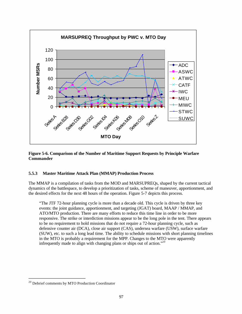
97
MARSUPREQ Throughput by PWC v. MTO Day
0
20
40
60
80
100
120
Series
A
Series
B28
Series
D30
Series
G02
Series
I04
Series
K06
Serie
s M08
Series
O10
Series
Z
MTO Day
Num
ber
MS
Rs ADC
ASWCATWCCATFIWCMEUMIWCSTWCSUWC
Figure 5-6. Comparison of the Number of Maritime Support Requests by Principle WarfareCommander
5.5.3 Master Maritime Attack Plan (MMAP) Production Process
The MMAP is a compilation of tasks from the MOD and MARSUPREQs, shaped by the current tacticaldynamics of the battlespace, to develop a prioritization of tasks, scheme of maneuver, apportionment, andthe desired effects for the next 48 hours of the operation. Figure 5-7 depicts this process.
“The JTF 72-hour planning cycle is more than a decade old. This cycle is driven by three keyevents: the joint guidance, apportionment, and targeting (JGAT) board, MAAP / MMAP, andATO/MTO production. There are many efforts to reduce this time line in order to be moreresponsive. The strike or interdiction missions appear to be the long pole in the tent. There appearsto be no requirement to hold missions that do not require a 72-hour planning cycle, such asdefensive counter air (DCA), close air support (CAS), undersea warfare (USW), surface warfare(SUW), etc. to such a long lead time. The ability to schedule missions with short planning timelinesin the MTO is probably a requirement for the MPP. Changes to the MTO were apparentlyinfrequently made to align with changing plans or ships out of action.”20
20 Debrief comments by MTO Production Coordinator
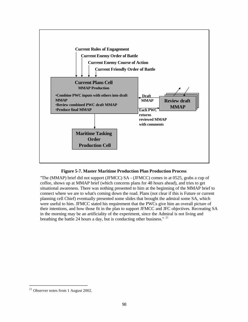
98
Current Rules of EngagementCurrent Enemy Order of Battle
Current Enemy Course of ActionCurrent Friendly Order of Battle
Review draft MMAP
Maritime Tasking Order
Production Cell
Draft MMAP
Each PWC returns reviewed MMAP with comments
•Combine PWC inputs with others into draft MMAP•Review combined PWC draft MMAP•Produce final MMAP
Current Plans CellMMAP Production
Figure 5-7. Master Maritime Production Plan Production Process"The (MMAP) brief did not support (JFMCC) SA - (JFMCC) comes in at 0525, grabs a cup ofcoffee, shows up at MMAP brief (which concerns plans for 48 hours ahead), and tries to getsituational awareness. There was nothing presented to him at the beginning of the MMAP brief toconnect where we are to what's coming down the road. Plans (not clear if this is Future or currentplanning cell Chief) eventually presented some slides that brought the admiral some SA, whichwere useful to him. JFMCC stated his requirement that the PWCs give him an overall picture oftheir intentions, and how those fit in the plan to support JFMCC and JFC objectives. Recreating SAin the morning may be an artificiality of the experiment, since the Admiral is not living andbreathing the battle 24 hours a day, but is conducting other business." 21
21 Observer notes from 1 August 2002.
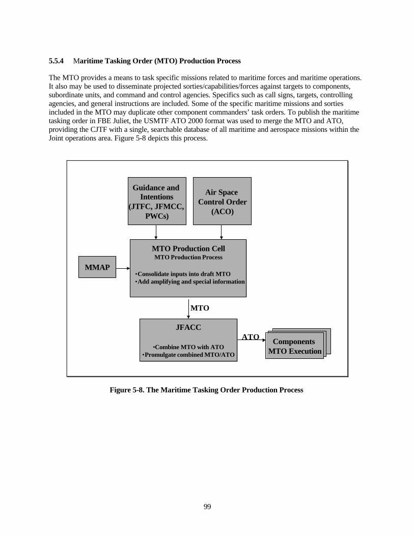
99
5.5.4 Maritime Tasking Order (MTO) Production Process
The MTO provides a means to task specific missions related to maritime forces and maritime operations.It also may be used to disseminate projected sorties/capabilities/forces against targets to components,subordinate units, and command and control agencies. Specifics such as call signs, targets, controllingagencies, and general instructions are included. Some of the specific maritime missions and sortiesincluded in the MTO may duplicate other component commanders’ task orders. To publish the maritimetasking order in FBE Juliet, the USMTF ATO 2000 format was used to merge the MTO and ATO,providing the CJTF with a single, searchable database of all maritime and aerospace missions within theJoint operations area. Figure 5-8 depicts this process.
Air Space Control Order
(ACO)
Guidance and Intentions
(JTFC, JFMCC, PWCs)
MMAP
JFACC
•Combine MTO with ATO•Promulgate combined MTO/ATO
Components MTO Execution
MTO
ATO
•Consolidate inputs into draft MTO•Add amplifying and special information
MTO Production CellMTO Production Process
Figure 5-8. The Maritime Tasking Order Production Process
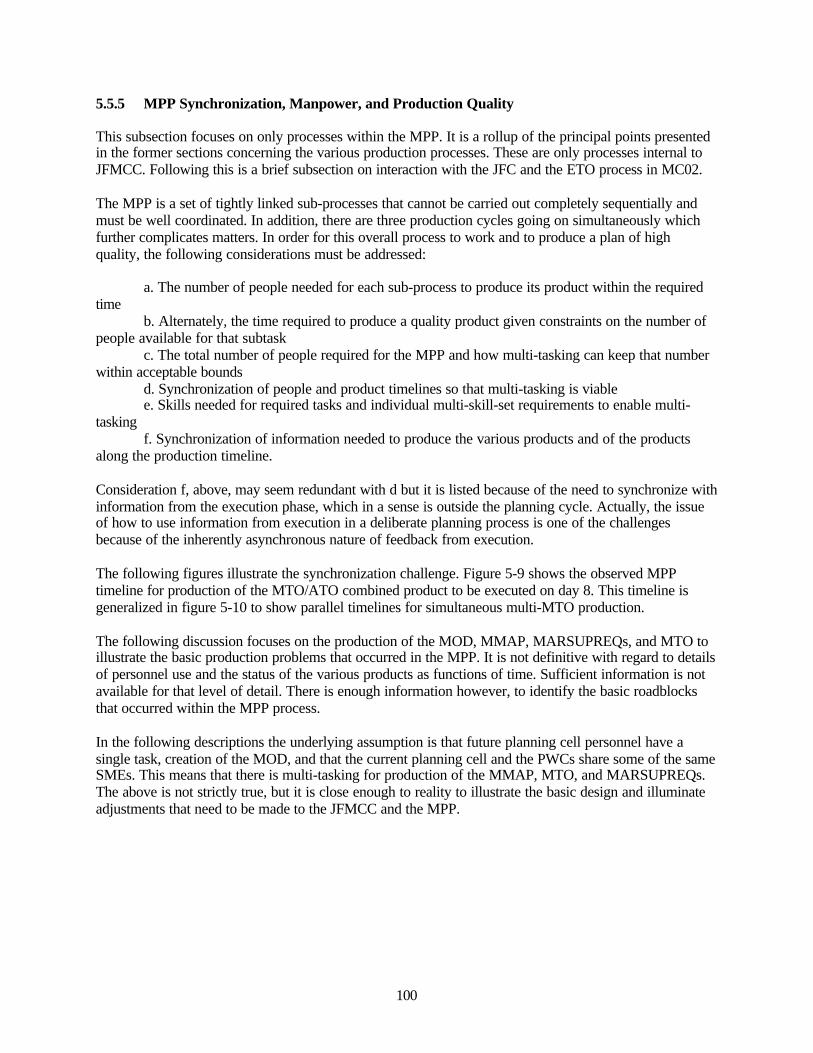
100
5.5.5 MPP Synchronization, Manpower, and Production Quality
This subsection focuses on only processes within the MPP. It is a rollup of the principal points presentedin the former sections concerning the various production processes. These are only processes internal toJFMCC. Following this is a brief subsection on interaction with the JFC and the ETO process in MC02.
The MPP is a set of tightly linked sub-processes that cannot be carried out completely sequentially andmust be well coordinated. In addition, there are three production cycles going on simultaneously whichfurther complicates matters. In order for this overall process to work and to produce a plan of highquality, the following considerations must be addressed:
a. The number of people needed for each sub-process to produce its product within the requiredtime
b. Alternately, the time required to produce a quality product given constraints on the number ofpeople available for that subtask
c. The total number of people required for the MPP and how multi-tasking can keep that numberwithin acceptable bounds
d. Synchronization of people and product timelines so that multi-tasking is viablee. Skills needed for required tasks and individual multi-skill-set requirements to enable multi-
taskingf. Synchronization of information needed to produce the various products and of the products
along the production timeline.
Consideration f, above, may seem redundant with d but it is listed because of the need to synchronize withinformation from the execution phase, which in a sense is outside the planning cycle. Actually, the issueof how to use information from execution in a deliberate planning process is one of the challengesbecause of the inherently asynchronous nature of feedback from execution.
The following figures illustrate the synchronization challenge. Figure 5-9 shows the observed MPPtimeline for production of the MTO/ATO combined product to be executed on day 8. This timeline isgeneralized in figure 5-10 to show parallel timelines for simultaneous multi-MTO production.
The following discussion focuses on the production of the MOD, MMAP, MARSUPREQs, and MTO toillustrate the basic production problems that occurred in the MPP. It is not definitive with regard to detailsof personnel use and the status of the various products as functions of time. Sufficient information is notavailable for that level of detail. There is enough information however, to identify the basic roadblocksthat occurred within the MPP process.
In the following descriptions the underlying assumption is that future planning cell personnel have asingle task, creation of the MOD, and that the current planning cell and the PWCs share some of the sameSMEs. This means that there is multi-tasking for production of the MMAP, MTO, and MARSUPREQs.The above is not strictly true, but it is close enough to reality to illustrate the basic design and illuminateadjustments that need to be made to the JFMCC and the MPP.
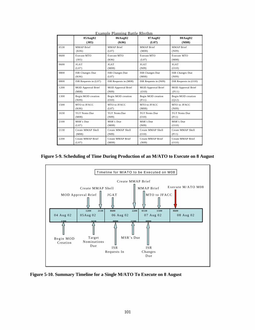
101
Begin MOD creation(Q12)
Begin MOD creation(P11)
Begin MOD creation(O10)
Begin MOD creation(N09)
1300
MTO to JFACC(N09)
MTO to JFACC(M08)
MTO to JFACC(L07)
MTO to JFACC(K06)
1500
Create MMAP Brief (L07)
Create MMAP Shell
(M08)
MSR’s Due (L07)
TGT Noms Due (M08)
MOD Approval Brief
(M08)
ISR Requests in (L07)
ISR Changes Due(K06)
JGAT(L07)
Execute MTO
(J05)
MMAP Brief(K06)
05Aug02 (J05)
2200
2130
2100
1630
1200
0800
0800
0600
0600
0530
Create MMAP Brief (O10)
Create MMAP Brief(N09)
Create MMAP Brief (M08)
Create MMAP Shell
(P11)
Create MMAP Shell
(O10)
Create MMAP Shell
(N09)
MSR’s Due (O10)
MSR’s Due (N09)
MSR’s Due(M08)
TGT Noms Due (P11)
TGT Noms Due (O10)
TGT Noms Due(N09)
MOD Approval Brief
(P11)
MOD Approval Brief
(O10)
MOD Approval Brief
(N09)
ISR Requests in (O10)ISR Requests in (N09)ISR Requests in (M08)
ISR Changes Due(N09)
ISR Changes Due(M08)
ISR Changes Due(L07)
JGAT (O10)
JGAT (N09)
JGAT(M08)
Execute MTO
(M08)
Execute MTO
(L07)
Execute MTO
(K06)
MMAP Brief (N09)
MMAP Brief(M08)
MMAP Brief (L07)
08Aug02 (M08)
07Aug02 (L07)
06Aug02 (K06)
Example Planning Battle Rhythm
Figure 5-9. Scheduling of Time During Production of an M/ATO to Execute on 8 August
06 Aug 02 07 Aug 02 08 Aug 02
Execu te M/ATO M08MMAP Br ie f
J G A T
ISR Requests In
MSR’s Due
Create MMAP Brief
ISR Changes
Due
05Aug 02
Crea te MMAP Shel l
Target Nominat ions
Due
MOD Approva l Br ie f
06000530
08002100
2200
0800
21301200
1630
0600
MTO to JFACC
1500
Timel ine for M/ATO to be Executed on M08
B e g i n M O DCreat ion
1300
04 Aug 02
Figure 5-10. Summary Timeline for a Single M/ATO To Execute on 8 August
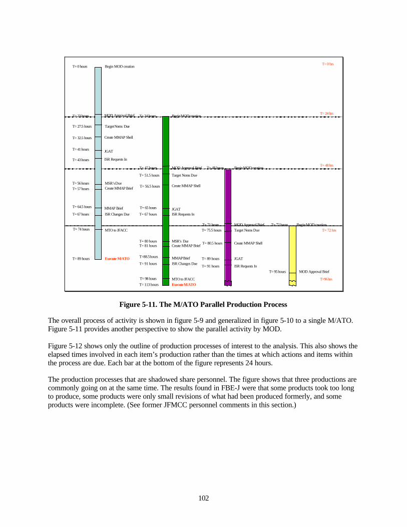
102
T= 48 hrs
T= 0 hrs
T= 24 hrs
T= 72 hrs
T=96 hrs
T= 89 hours Execute M/ATO
MTO to JFACC
ISR Changes Due
MMAP Brief
Create MMAP BriefMSR’sDue
ISR Requests In
JGAT
Create MMAP Shell
Target Noms Due
MOD Approval Brief
T= 74 hours
T= 67 hours
T= 64.5 hours
T= 57 hoursT= 56 hours
T= 43 hours
T= 41 hours
T= 32.5 hours
T= 27.5 hours
T= 23 hours
T= 0 hours Begin MOD creation
T= 113 hours Execute M/ATOMTO to JFACC
ISR Changes DueMMAP Brief
Create MMAP BriefMSR’s Due
ISR Requests InJGAT
Create MMAP Shell
Target Noms Due
MOD Approval Brief
T= 98 hours
T= 91 hours
T=88.5 hours
T= 81 hoursT= 80 hours
T= 67 hours
T= 65 hours
T= 56.5 hours
T= 51.5 hours
T= 47 hours
T= 24 hours Begin MOD creation
ISR Requests In
JGAT
Create MMAP Shell
Target Noms DueMOD Approval Brief
T= 91 hours
T= 89 hours
T= 80.5 hours
T= 75.5 hoursT= 71 hours
T= 48 hours Begin MOD creation
MOD Approval BriefT= 95 hours
T= 72 hours Begin MOD creation
Figure 5-11. The M/ATO Parallel Production Process
The overall process of activity is shown in figure 5-9 and generalized in figure 5-10 to a single M/ATO.Figure 5-11 provides another perspective to show the parallel activity by MOD.
Figure 5-12 shows only the outline of production processes of interest to the analysis. This also shows theelapsed times involved in each item’s production rather than the times at which actions and items withinthe process are due. Each bar at the bottom of the figure represents 24 hours.
The production processes that are shadowed share personnel. The figure shows that three productions arecommonly going on at the same time. The results found in FBE-J were that some products took too longto produce, some products were only small revisions of what had been produced formerly, and someproducts were incomplete. (See former JFMCC personnel comments in this section.)
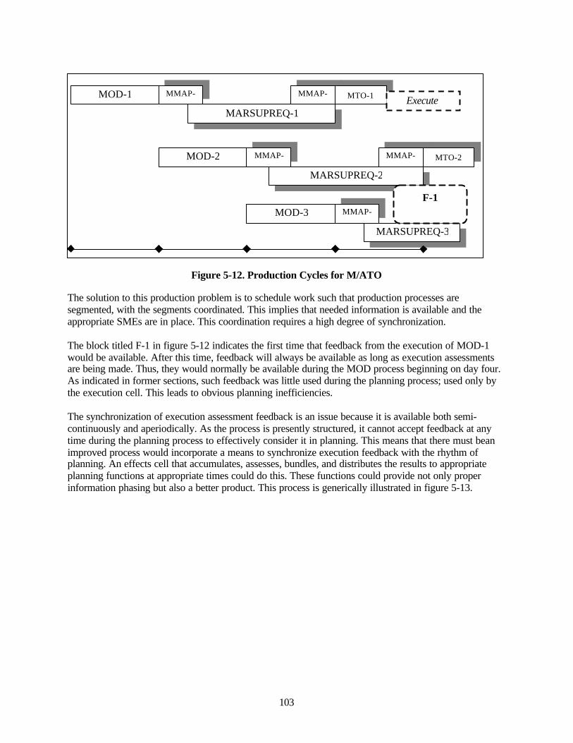
103
Figure 5-12. Production Cycles for M/ATO
The solution to this production problem is to schedule work such that production processes aresegmented, with the segments coordinated. This implies that needed information is available and theappropriate SMEs are in place. This coordination requires a high degree of synchronization.
The block titled F-1 in figure 5-12 indicates the first time that feedback from the execution of MOD-1would be available. After this time, feedback will always be available as long as execution assessmentsare being made. Thus, they would normally be available during the MOD process beginning on day four.As indicated in former sections, such feedback was little used during the planning process; used only bythe execution cell. This leads to obvious planning inefficiencies.
The synchronization of execution assessment feedback is an issue because it is available both semi-continuously and aperiodically. As the process is presently structured, it cannot accept feedback at anytime during the planning process to effectively consider it in planning. This means that there must beanimproved process would incorporate a means to synchronize execution feedback with the rhythm ofplanning. An effects cell that accumulates, assesses, bundles, and distributes the results to appropriateplanning functions at appropriate times could do this. These functions could provide not only properinformation phasing but also a better product. This process is generically illustrated in figure 5-13.
MOD-1
MOD-2
MOD-3
MMAP-1
MMAP-1
MMAP-2
MMAP-3
MMAP-2
MARSUPREQ-1
MARSUPREQ-2
MARSUPREQ-3
MTO-1
MTO-2
Execute
F-1
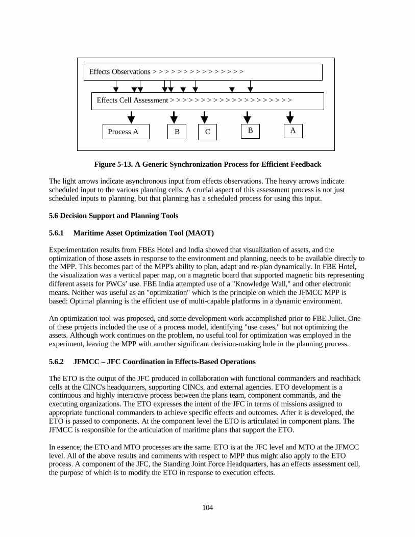
104
Figure 5-13. A Generic Synchronization Process for Efficient Feedback
The light arrows indicate asynchronous input from effects observations. The heavy arrows indicatescheduled input to the various planning cells. A crucial aspect of this assessment process is not justscheduled inputs to planning, but that planning has a scheduled process for using this input.
5.6 Decision Support and Planning Tools
5.6.1 Maritime Asset Optimization Tool (MAOT)
Experimentation results from FBEs Hotel and India showed that visualization of assets, and theoptimization of those assets in response to the environment and planning, needs to be available directly tothe MPP. This becomes part of the MPP's ability to plan, adapt and re-plan dynamically. In FBE Hotel,the visualization was a vertical paper map, on a magnetic board that supported magnetic bits representingdifferent assets for PWCs’ use. FBE India attempted use of a "Knowledge Wall," and other electronicmeans. Neither was useful as an "optimization" which is the principle on which the JFMCC MPP isbased: Optimal planning is the efficient use of multi-capable platforms in a dynamic environment.
An optimization tool was proposed, and some development work accomplished prior to FBE Juliet. Oneof these projects included the use of a process model, identifying "use cases," but not optimizing theassets. Although work continues on the problem, no useful tool for optimization was employed in theexperiment, leaving the MPP with another significant decision-making hole in the planning process.
5.6.2 JFMCC – JFC Coordination in Effects-Based Operations
The ETO is the output of the JFC produced in collaboration with functional commanders and reachbackcells at the CINC's headquarters, supporting CINCs, and external agencies. ETO development is acontinuous and highly interactive process between the plans team, component commands, and theexecuting organizations. The ETO expresses the intent of the JFC in terms of missions assigned toappropriate functional commanders to achieve specific effects and outcomes. After it is developed, theETO is passed to components. At the component level the ETO is articulated in component plans. TheJFMCC is responsible for the articulation of maritime plans that support the ETO.
In essence, the ETO and MTO processes are the same. ETO is at the JFC level and MTO at the JFMCClevel. All of the above results and comments with respect to MPP thus might also apply to the ETOprocess. A component of the JFC, the Standing Joint Force Headquarters, has an effects assessment cell,the purpose of which is to modify the ETO in response to execution effects.
Effects Observations > > > > > > > > > > > > > > >
Effects Cell Assessment > > > > > > > > > > > > > > > > > > > >
Process A B C B A
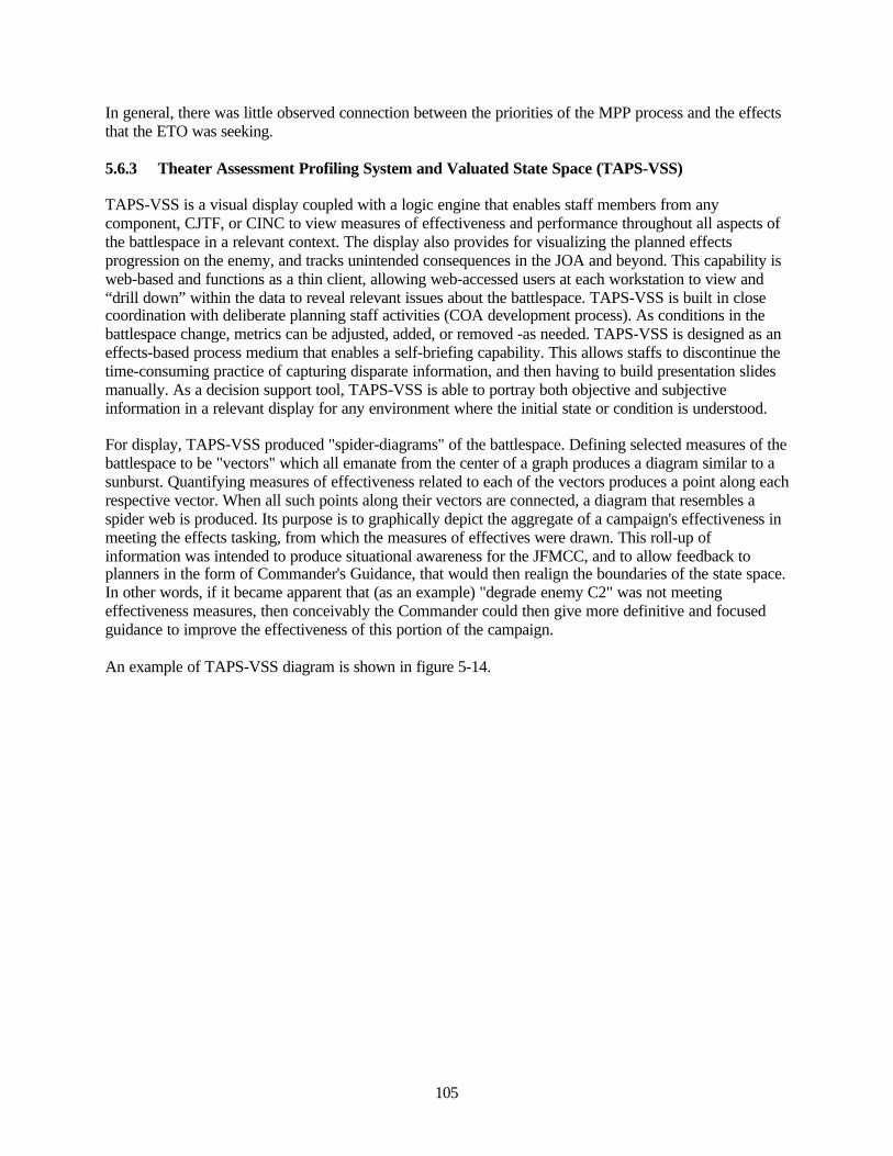
105
In general, there was little observed connection between the priorities of the MPP process and the effectsthat the ETO was seeking.
5.6.3 Theater Assessment Profiling System and Valuated State Space (TAPS-VSS)
TAPS-VSS is a visual display coupled with a logic engine that enables staff members from anycomponent, CJTF, or CINC to view measures of effectiveness and performance throughout all aspects ofthe battlespace in a relevant context. The display also provides for visualizing the planned effectsprogression on the enemy, and tracks unintended consequences in the JOA and beyond. This capability isweb-based and functions as a thin client, allowing web-accessed users at each workstation to view and“drill down” within the data to reveal relevant issues about the battlespace. TAPS-VSS is built in closecoordination with deliberate planning staff activities (COA development process). As conditions in thebattlespace change, metrics can be adjusted, added, or removed -as needed. TAPS-VSS is designed as aneffects-based process medium that enables a self-briefing capability. This allows staffs to discontinue thetime-consuming practice of capturing disparate information, and then having to build presentation slidesmanually. As a decision support tool, TAPS-VSS is able to portray both objective and subjectiveinformation in a relevant display for any environment where the initial state or condition is understood.
For display, TAPS-VSS produced "spider-diagrams" of the battlespace. Defining selected measures of thebattlespace to be "vectors" which all emanate from the center of a graph produces a diagram similar to asunburst. Quantifying measures of effectiveness related to each of the vectors produces a point along eachrespective vector. When all such points along their vectors are connected, a diagram that resembles aspider web is produced. Its purpose is to graphically depict the aggregate of a campaign's effectiveness inmeeting the effects tasking, from which the measures of effectives were drawn. This roll-up ofinformation was intended to produce situational awareness for the JFMCC, and to allow feedback toplanners in the form of Commander's Guidance, that would then realign the boundaries of the state space.In other words, if it became apparent that (as an example) "degrade enemy C2" was not meetingeffectiveness measures, then conceivably the Commander could then give more definitive and focusedguidance to improve the effectiveness of this portion of the campaign.
An example of TAPS-VSS diagram is shown in figure 5-14.
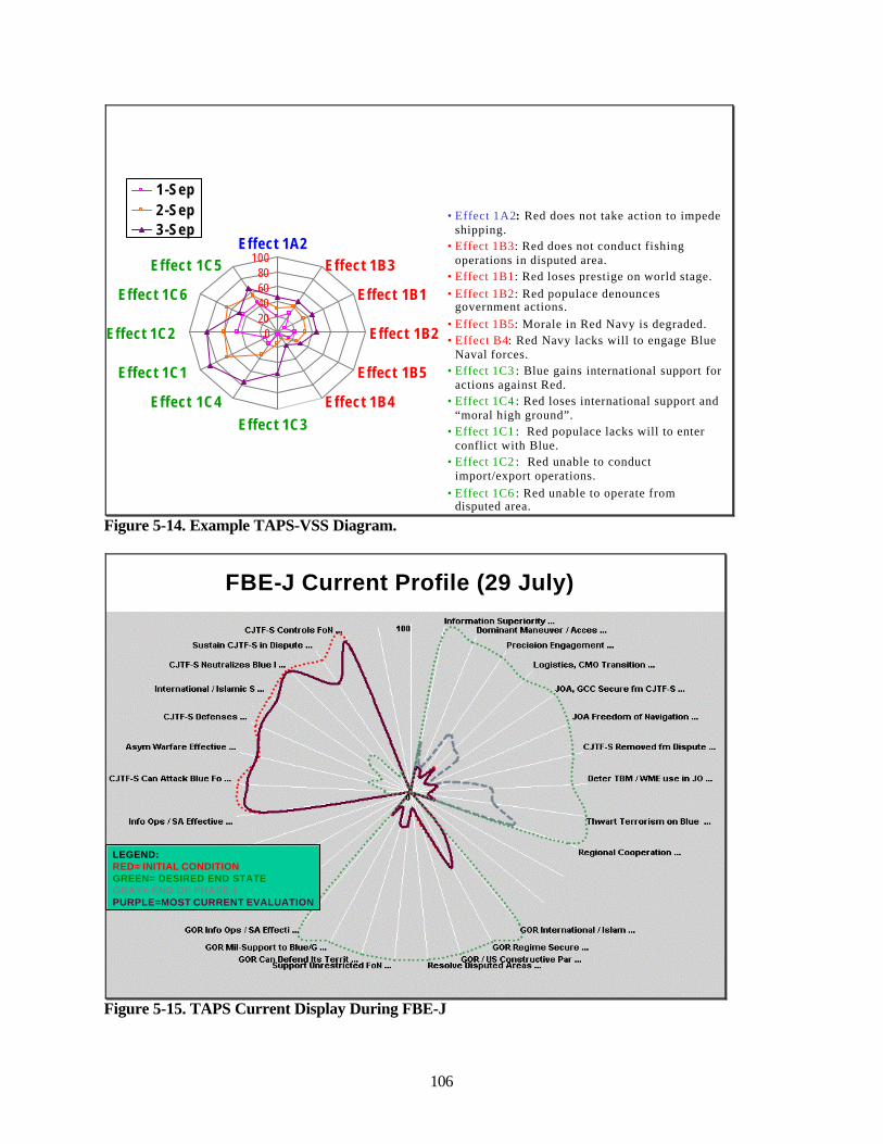
106
• Effect 1A2: Red does not take action to impede shipping.
• Effect 1B3: Red does not conduct fishing operations in disputed area.
• Effect 1B1: Red loses prestige on world stage. • Effect 1B2: Red populace denounces
government actions. • Effect 1B5: Morale in Red Navy is degraded. • Effect B4: Red Navy lacks will to engage Blue
Naval forces. • Effect 1C3 : Blue gains international support for
actions against Red. • Effect 1C4 : Red loses international support and
“moral high ground”. • Effect 1C1 : Red populace lacks will to enter
conflict with Blue. • Effect 1C2 : Red unable to conduct
import/export operations. • Effect 1C6 : Red unable to operate from
disputed area.
1 -Sep2 -Sep3 -Sep
0
406080
100Effect 1A2
Effect 1B3
Effect 1B1
Effect 1B2
Effect 1B5
Effect 1B4Effect 1C3
Effect 1C4
Effect 1C1
Effect 1C2
Effect 1C6
Effect 1C5
20
Figure 5-14. Example TAPS-VSS Diagram.
FBE-J Current Profile (29 July)
LEGEND: RED= INITIAL CONDITIONGREEN= DESIRED END STATEGRAY= END OF PHASE 1PURPLE=MOST CURRENT EVALUATION
Figure 5-15. TAPS Current Display During FBE-J
107
TAPS-VSS Observations
The TAPS-VSS display in figure 5-15 was presented to the JFMCC on 29 July, as part of the maritimeoperations directive brief. It was provided in response the JFMCC's request from the previous day thatmetrics be associated with warfare tasks, in order to build a day-to-day situational awareness for decisionmaking. The initial conditions are in red, and the desired end state is the green dashed line. The gray lineshows the state of the previous day's actions on the state space. Purple depicts the analysis of damage tothe enemy to date.
Although the vector displays could be opened by clicking a cursor over each of them, thereby openinghigh-resolution definitions of the measures of effectiveness and performance, this was not accomplishedin the course of the brief. Also, while the slide above depicts the environment for the Commander v. Redstate space, another TAPS-VSS display was created to specifically show the environment of Blue.
Neither display was useful to the JFMCC however. "This may be an OK tool for gauging long termeffects, but it fails miserably as a day to day tool," was a common perception. There were, however,contributing factors that are related to this view of TAPS-VSS in FBE J:
• TAPS-VSS was not integrated into the process for decision-making through the spiral process.Therefore, there was limited understanding of its intended use and potential utility. This fact wasamplified by the JFMCC request for MOEs and MOPs, which are included in this model, butwere not judged to be useful, because they were not immediately visible.
• TAPS-VSS was essentially a visualization of effects. However, there were many indications thatcoupling between the high level effects tasking order (ETO), the prioritized effects list (PEL) andthe maritime planning process (MPP) was not close (i.e., little direct relationship between each).As a result, there was little perceived need for information at this level.
• As the experiment continued, there was a continually perceived need for the JFMCC to interactwith information at the tactical level. TAPS-VSS is neither designed nor suited to supporting thetactical level. Rather, it is suited to providing high-level situation awareness, with the intent ofassisting in the development of the Commander’s Guidance.
In future experimentation, it is advisable to bring this capability to bear throughout experiment definition.This is an extremely information rich tool, and requires training of the operators and decision makers intranslation and entry of information relevant to the associated measures for each vector. It also requiresvery close coupling between an idealized effects-based campaign, and guidance for future intentions thatcan be turned into plans through the MPP.
5.6.4 Web-Based Tools
Information and a comprehensive discussion on a range of collaborative tools, including those thatsupported the JFMCC MPP, are contained in Chapter 15 and Appendix 5. Information on networkloading is contained in Appendix 9.
SharePoint Portal Server (SPPS) was a knowledge management success. The right data got to the rightuser at the right time. Specifically, the data could be found (search capabilities), the data was the mostcurrent (no other versions), and the data was authoritative (could be trusted). MC02/FBE-J may be thefirst exercise to use a customizable web portal as a single source of data for storage and retrieval. SPPS

108
was the one collaborative tool where Warfare Commanders or groups could publish and take ownershipof their data for JFMCC-wide use. Figure 5-16 depicts the usage of this resource.
The data from hit counters shows that in the first few days of the experiment, each major page received250 to 1000 hits per day as users explored the portals content. Subsequently, there was a steady decline toapproximately 100 hits per page per day. Indications were that users were figuring out where to find thedata they needed and were spending less time “surfing”. During this same time there was an increasinguse of the search page starting at about 500 hits per day and increasing to over 1000 hits per day. Itappears this was because users became more familiar with the search functionality and found it faster than“surfing.”
An important caveat to this success is that the JFMCC portal was not a real-time system. Its data oftenlagged the battlespace action by hours, unlike IWS, ADOCS, and GCCS, which were actively used inprosecuting the action. SPPS contained analysis and “knowledge” that reflected long-term trends andwhere the JFMCC was headed.
SPPS has several drawbacks that would need to be addressed prior to implementing it operationally:
• Configuration control was difficult to maintain. The functionality demonstrated on the JFMCCsite required the modification of several core SPPS files, which required extensive familiaritywith the program so as not to lose data.
• Standard tools for managing security should be developed. Managing security is labor intensiveand without tools, interest in maintenance soon wanes.
• SPPS should be integrated with other collaborative tools. Users typically worked in either SPPSor IWS, but not both. There would be value in linking these two programs and in linking SPPSwith other collaborative programs.
• More and better documentation is needed to realize the full potential of this program.
Information and a comprehensive discussion on collaborative tools, including those that supported theJFMCC MPP, are contained in Chapter 15 and Appendix 5. Information on network loading is containedin Appendix 9.
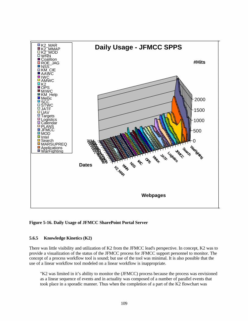
109
7/247/257/267/277/287/297/307/318/18/28/38/48/58/6K2_MAR
WNN
NSSIWC
OPSMetoc
JATF
Logistics
JFMCC
Search
WarFighting
0
500
1000
1500
2000
#Hits
Dates
Webpages
Daily Usage - JFMCC SPPSK2_MARK2_MMAPK2_MODWNNCoalitionROE_JAGNSSKM_CIEAAWCIWCAMWCK2OPSMIWCKM_HelpMetocSCCSTWCJATFUAVTargetsLogisticsCalendarPLANSJFMCCMODIntelSearchMARSUPREQApplicationsWarFighting
Figure 5-16. Daily Usage of JFMCC SharePoint Portal Server
5.6.5 Knowledge Kinetics (K2)
There was little visibility and utilization of K2 from the JFMCC lead's perspective. In concept, K2 was toprovide a visualization of the status of the JFMCC process for JFMCC support personnel to monitor. Theconcept of a process workflow tool is sound; but use of the tool was minimal. It is also possible that theuse of a linear workflow tool modeled on a linear workflow is inappropriate.
"K2 was limited in it’s ability to monitor the (JFMCC) process because the process was envisionedas a linear sequence of events and in actuality was composed of a number of parallel events thattook place in a sporadic manner. Thus when the completion of a part of the K2 flowchart was
110
entered, it was the culmination of a number of events and the details were not captured. So, whatwas envisioned as a linear process became a series of overlapping parallel tasks, leading to a finalresult."22
In many cases, some of the sub-processes were never completed if the information was not needed or wasnot available when the product was required. Additional information on the integration of workflow toolsin the dynamic environment of military operations needs to be developed.
Dynamic evolution of the JFMCC process throughout the experiment also limited K2 use. The flowdiagram used by K2 was the experiment baseline for the JFMCC process. A principle of the experimentwas to prototype by improving the process in-stride. However, the K2 flow diagram did not evolve. Thetool was more suited to mature process workflows vice experimental ones. As the JFMCC processmatured and changed, the less representative the K2 flow diagrams became. Post experiment web siteanalysis shows that the K2 website had over 600 hits. It is possible that the majority of these systeminquiries were from technology monitoring and not process utilization. No evidence is available that thetechnology was used in anywhere in the MPP.
Although there were a large number of new tools to be used in the experiments, there was no formal K2training for any of the JFMCC staff. Due to the already high learning curve, the JFMCC staff was notlikely to be interested in further training in support tools.
Knowledge Kinetics Observations, Opinions, and Recommendations
• Process. K2 may be useful if applied to a mature process, or if adequate time and effort areexpended to evolve K2 flow diagrams to accurately represent processes.
• Detail. K2 must have enough detail to adequately represent the processes it will be used tocontrol.
• Visibility. To be useful the tool would have to be visible to users, available and readily understoodin its application. K2 was not included in spiral development, with consequences for uservisibility and training. While the K2 server was tested technically on Spiral 3, there was nouser/functional use.
• Documentation. Make documentation readily available to the users.
• Training. Train the users. If the tool is visualized to be part of the process, the tool should beshown in the process.
• Overall Evaluation. Although process visualization, monitoring, and control, as implemented bythe K2 tool, may be a good objective and a possible requirement for complex process control, it’sapplication to the JFMCC process was incomplete, premature, immature, and less than successful.
5.6.6 Naval Simulation System (NSS)
The basic experiment design of the NSS demonstration in FBE Juliet was to locate the simulationcapability at the JFMCC CPC and FPC (onboard USS CORONADO), at the Sea Combat Commander(SCC), located ashore at Fleet Combat Training Center, Pacific, and at China Lake in support of the
22 Observer report by web developer SME
111
Strike Warfare Commander. The intent was to take inputs of current information, possible courses ofaction by decision makers, and simulation MOEs to produce the most likely COA for execution. This wasto be done within the time span that would necessitate course of action analysis be available inpreparation for deconfliction of MARSUPREQs that would contribute to producing the MMAP, and theproduction of the best possible MTO.
"NSS participated in previous Fleet Battle Experiments (FBEs) and Wargames, most recentlyGlobal ’01, where it supported the Naval Forces (NAVFOR) Commander and provided a course ofaction analysis (COAA) capability. Based in part from the successes achieved at Global ’01, NSSwas a late add-on into FBE-J to test its capability as a planning and decision support tool for theJoint Forces Maritime Component Commander (JFMCC) and Principal Warfare Commander(PWC) within the maritime planning process (MPP). FBE-J represents the first in a series ofplanned NSS-FBE integration events. Data from post-experiment analysis will be used to helpdetermine what capabilities or deficiencies exist with NSS as a JFMCC/PWC planning and decisionsupport tool. Furthermore, post-experiment analysis will help to focus development on refining andexpanding NSS capabilities so that the tool will better support the JFMCC/PWC planners in theMPP during FBEs K/L."23
"At the JFMCC level, the parser did not function to the level expected due to software problems,again causing a backup of data. This problem caused the NSS analyst to [perform] a man-hourintensive crunching of data, and only allowed the NSS tool to complete the single task ofdeconfliction of the MARSUPREQs for the entire duration of the experiment."24
Also, due to TMS database problems, NSS was not able to fully integrate itself in the planning process atthe Strike Warfare Commander. However, working in parallel, NSS was able to produce candidate plansfor weapon-to-target pairing to support strike missions.
A proposed stepwise process to fit within the MPP battle-rhythm was developed for the experiment. Thefollowing are elements of that process. (A full description is available in the NSS Final Report cited in thefootnotes):
1. PWC receives the MOD2. NSS used by PWC to develop metrics and help in determining the most appropriate COA for
upcoming 24-72 hours.3. NSS operator simulates each COA, using reachback capability for computational support if
required.4. PWC produces candidate plan, which is a shell for the MARSUPREQs to be submitted in the
next 24-72 hours.5. NSS Analyst reviews results with the PWC planners, allowing them to visualize the their plan.
The planner can choose to either accept the plan or modify and send back to NSS for anotherround of simulations based on the feedback received.
6. PWC accepts the chosen iteration with desired results and inputs the finalized MARSUPREQsinto the JFMCC web tool.
7. NSS Analyst aboard the USS Coronado downloads all PWCs MARSUPREQs from the JFMCCweb tool to NSS program. NSS automatically determines a variety of different conflict types(primarily time, distance, and mission).
8. Conflicts are brought to JFMCC planner’s attention, who manually adjust conflicts (incollaboration with the PWCs ) and modify the final draft plan.
23 SPAWAR PMW 153 "Final Report, NSS in Fleet Battle Experiment Juliet," 03 September 2002.24 Page 5, ibid
112
9. The deconflicted and synchronized MARSUPREQs from the PWCs are submitted for MMAPproduction.
The majority of NSS objectives in FBE Juliet were not conclusive. Technical problems described aboveprevented full inclusion of the simulation within the processes for planning and analysis of plans.However, some individual successes were attained, primarily by providing weapon to target pairing forSTWC, and in the SCC.
Details of SCC interactions with NSS are more fully described in the PMW 153 Final Report. In general,some COA analysis was performed, and as relationships between the NSS analyst and decision makersmatured, the NSS analyst was able to begin "tuning" of the simulation to meet SCC needs, and there areinstances in which innovative approaches were established to improve results. The following vignette isan example:
“Country Red’s primary threats were high speed small boats (swarm attack) CDCM, specificallymobile C-802 launchers. The liaison officer and NSS analyst had collected Red Force small boatdata, and assessed this threat against a variety of assets via previous simulations and were able tore-use a good portion of it for this scenario. From these previous simulations, the planners hadlearned that to reduce the impact of the small boat swarm it was important to have early warning tothe threat launch so that they could be engaged while still in tight formation, in this way AC-130 orhelo assets were most effective in eliminating the threat. If the small boat swarm was allowed todisperse, the effectiveness of single asset defenses went down significantly. Intel confirmed thatRed Forces would most probably launch small boat swarms in 20-30 boat strengths, 3-6(Boghammer, PTG) of which would have CDCM launcher capability and the remaining would beBoston Whaler type boats to provide OTH CDCM positioning for shore-based launchers.Merchants would be escorted both ways through the SOH. Through simple time-speed-distancecalculation we found that in one day only two transits could be accomplished (a round trip tookapproximately 20 hours). That meant that the planners had to find out how many merchants couldbe protected by the DDG at one time."
NSS represents both technology and process. To fully understand its contribution to defining courses ofaction, within the maritime planning process, both the MPP and NSS will need to be mature, and stablewithin an experiment. In this experiment, the MPP was executed for the purpose of furtheringunderstanding of process, meaning that the process is not yet mature. Few of the participants had fullappreciation for the use of the range of tools that were at hand, and therefore did not extend to any greaterdegree the utility of real-time simulation for decision-making embodied in NSS. Success at the SCC,however, indicates the road ahead for future NSS development.
It is recommended that MPP process modeling be conducted, with NSS functionality contributing as asingle process. From here, the process model should be further refined to include the details of NSSintegration into the process, in parallel with stabilizing its technical difficulties.
5.7 Modeling the Interaction Between MPP and ETO
To support post-experiment analysis and the development of recommendations for planning processimprovements for inclusion in future experiments, a simulation of the maritime planning processexercised during FBE-J was developed.
5.7.1 FBE-J Maritime Planning Process Simulation
113
The FBE-J MPP simulation models the execution of the seven-step planning process outlined above. Thegraphic below shows the top-level structure and functional outline of the model.25 Each segment of themodel contains a hierarchy of underlying logic to process, interconnect and execute the required sub-functions and information exchange.
Measures of effectiveness were calculated relating to MTO production, MARSUPREQ production,MMAP production, and overall resource staffing utilization.
5.7.2 Key Attributes:
In summary, the key attributes of the FBE-J MPP simulation are as listed below:
q Based on measured and observed data taken during FBE-Julietq Aligned with 72 hour cycle joint-service battle rhythmq Accounts for resource constraints and staffing levels available to support plan developmentq Accounts for interdependencies and feedback occurring between planning sub-processesq Measures the flexibility of the overall planning process to accommodate change and re-planning
required as a result of changes in the battlespace observed during plan execution
25 The FBE-J MPP simulation was built using the commercially available Extend simulation software.
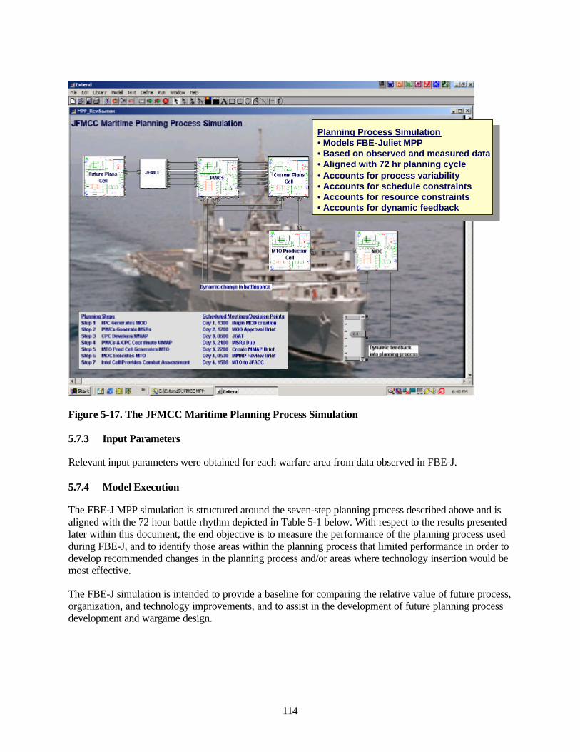
114
Figure 5-17. The JFMCC Maritime Planning Process Simulation
5.7.3 Input Parameters
Relevant input parameters were obtained for each warfare area from data observed in FBE-J.
5.7.4 Model Execution
The FBE-J MPP simulation is structured around the seven-step planning process described above and isaligned with the 72 hour battle rhythm depicted in Table 5-1 below. With respect to the results presentedlater within this document, the end objective is to measure the performance of the planning process usedduring FBE-J, and to identify those areas within the planning process that limited performance in order todevelop recommended changes in the planning process and/or areas where technology insertion would bemost effective.
The FBE-J simulation is intended to provide a baseline for comparing the relative value of future process,organization, and technology improvements, and to assist in the development of future planning processdevelopment and wargame design.
Planning Process Simulation• Models FBE-Juliet MPP• Based on observed and measured data• Aligned with 72 hr planning cycle• Accounts for process variability• Accounts for schedule constraints• Accounts for resource constraints• Accounts for dynamic feedback
Planning Process Simulation• Models FBE-Juliet MPP• Based on observed and measured data• Aligned with 72 hr planning cycle• Accounts for process variability• Accounts for schedule constraints• Accounts for resource constraints• Accounts for dynamic feedback
Planning Process Simulation• Models FBE-Juliet MPP• Based on observed and measured data• Aligned with 72 hr planning cycle• Accounts for process variability• Accounts for schedule constraints• Accounts for resource constraints• Accounts for dynamic feedback
iBiEifii|iiio]|asi.idjjij
O^aa llO|^i:^ ^*|.B0 >^ % % hMiiAlltDQfi\|-€t J h»»jie.jnTiim -_nijL]
^o%j""^r^ia a.m-i
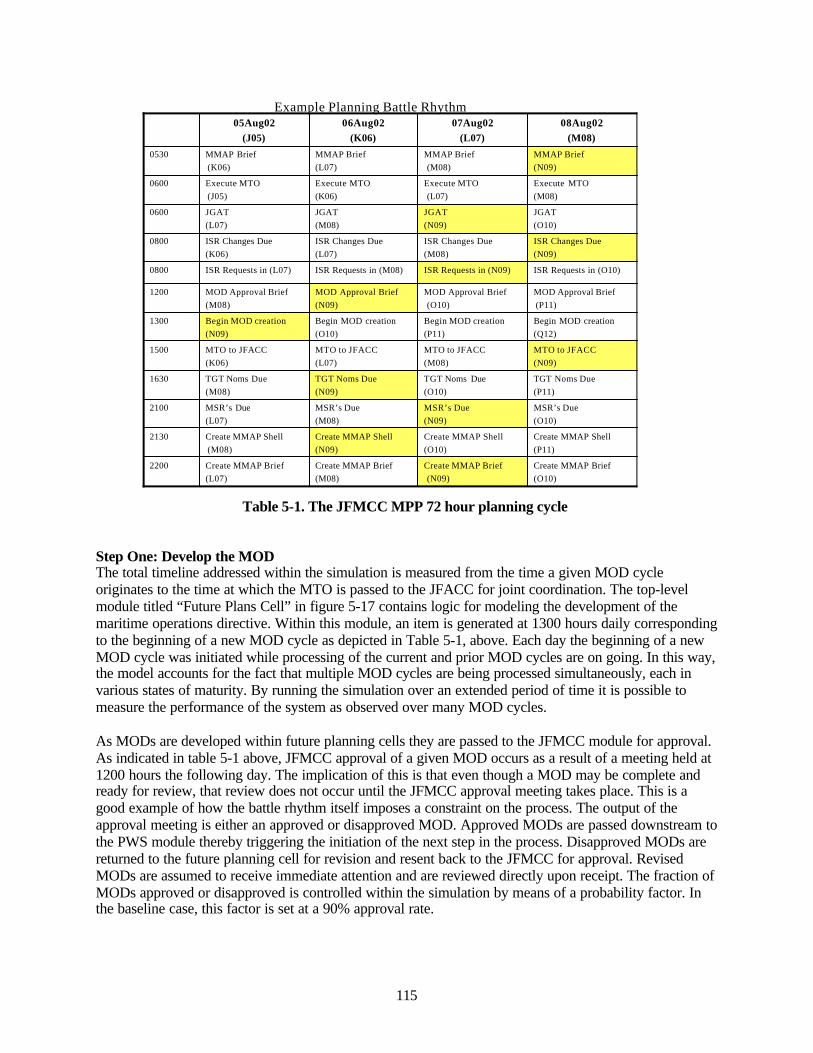
115
Table 5-1. The JFMCC MPP 72 hour planning cycle
Step One: Develop the MODThe total timeline addressed within the simulation is measured from the time a given MOD cycleoriginates to the time at which the MTO is passed to the JFACC for joint coordination. The top-levelmodule titled “Future Plans Cell” in figure 5-17 contains logic for modeling the development of themaritime operations directive. Within this module, an item is generated at 1300 hours daily correspondingto the beginning of a new MOD cycle as depicted in Table 5-1, above. Each day the beginning of a newMOD cycle was initiated while processing of the current and prior MOD cycles are on going. In this way,the model accounts for the fact that multiple MOD cycles are being processed simultaneously, each invarious states of maturity. By running the simulation over an extended period of time it is possible tomeasure the performance of the system as observed over many MOD cycles.
As MODs are developed within future planning cells they are passed to the JFMCC module for approval.As indicated in table 5-1 above, JFMCC approval of a given MOD occurs as a result of a meeting held at1200 hours the following day. The implication of this is that even though a MOD may be complete andready for review, that review does not occur until the JFMCC approval meeting takes place. This is agood example of how the battle rhythm itself imposes a constraint on the process. The output of theapproval meeting is either an approved or disapproved MOD. Approved MODs are passed downstream tothe PWS module thereby triggering the initiation of the next step in the process. Disapproved MODs arereturned to the future planning cell for revision and resent back to the JFMCC for approval. RevisedMODs are assumed to receive immediate attention and are reviewed directly upon receipt. The fraction ofMODs approved or disapproved is controlled within the simulation by means of a probability factor. Inthe baseline case, this factor is set at a 90% approval rate.
Begin MOD creation(Q12)
Begin MOD creation(P11)
Begin MOD creation(O10)
Begin MOD creation(N09)
1300
MTO to JFACC(N09)
MTO to JFACC(M08)
MTO to JFACC(L07)
MTO to JFACC(K06)
1500
Create MMAP Brief (L07)
Create MMAP Shell(M08)
MSR’s Due (L07)
TGT Noms Due (M08)
MOD Approval Brief (M08)
ISR Requests in (L07)
ISR Changes Due(K06)
JGAT(L07)
Execute MTO(J05)
MMAP Brief(K06)
05Aug02 (J05)
2200
2130
2100
1630
1200
0800
0800
0600
0600
0530
Create MMAP Brief (O10)
Create MMAP Brief(N09)
Create MMAP Brief (M08)
Create MMAP Shell (P11)
Create MMAP Shell (O10)
Create MMAP Shell (N09)
MSR’s Due (O10)
MSR’s Due (N09)
MSR’s Due(M08)
TGT Noms Due (P11)
TGT Noms Due (O10)
TGT Noms Due(N09)
MOD Approval Brief(P11)
MOD Approval Brief(O10)
MOD Approval Brief (N09)
ISR Requests in (O10)ISR Requests in (N09)ISR Requests in (M08)
ISR Changes Due(N09)
ISR Changes Due(M08)
ISR Changes Due(L07)
JGAT (O10)
JGAT (N09)
JGAT(M08)
Execute MTO (M08)
Execute MTO(L07)
Execute MTO (K06)
MMAP Brief (N09)
MMAP Brief(M08)
MMAP Brief (L07)
08Aug02 (M08)
07Aug02 (L07)
06Aug02 (K06)
Example Planning Battle Rhythm

116
Step Two: Develop Maritime Support RequestsThe module titled “PWCs” in figure 5-17, models the process of MARSUPREQ development performedby the staffs assigned to each primary warfare commander area.26 The size of the staffs assigned todevelop MARSUPREQs across each warfare area is controlled within the simulation by means ofresource pools. These pools represent shifts of people that are allocated to perform various tasks, asavailable. In this way, we directly account for time delays resulting from a resource not being available atthe current time to execute a given task because that resource is busy elsewhere. Tasks may be prioritizedsuch that a lower priority activity may be stopped part way through if a higher priority job comes in. Anadditional load on the system is due to the fact that multiple MARSUPREQs corresponding to MODcycles make are in work at any given time, but the pool of people available to process and/or revise theplans is fixed.
Within MARSUPREQ development, sub-process are defined for 1) initial MARSUPREQ generation, 2)MARSUPREQ coordination at the PWC level, and 3) MARSUPREQ revision and modification due tofeedback from battle assessment. Each of these sub-processes are defined by the time it takes, on average,to perform the task and the personnel required to perform the task.27 The percentage of MARSUPREQsthat need to be modified or regenerated as a result of combat assessment or a change in commander’sintent is controlled by means of an input probability factor.
The number of MARSUPREQs generated and processed during FBE-J varied significantly across eachwarfare area. Figure 5-18 presents data collected during the experiment showing the number ofMARSUPREQs processed during the course of the experiment.
26 PWC staffs are divided between MIWC, STWC, SUWC, ASWC, ADC, IWC, and AMWC warfare missions.27 Distributions for the time it takes to perform a given task are input into the simulation based on measured andobserved data taken from FBE-J post-experiment analysis
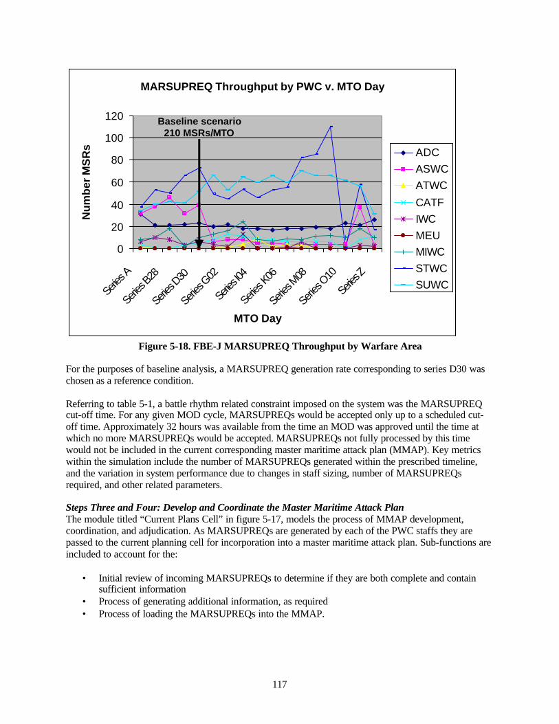
117
Figure 5-18. FBE-J MARSUPREQ Throughput by Warfare Area
For the purposes of baseline analysis, a MARSUPREQ generation rate corresponding to series D30 waschosen as a reference condition.
Referring to table 5-1, a battle rhythm related constraint imposed on the system was the MARSUPREQcut-off time. For any given MOD cycle, MARSUPREQs would be accepted only up to a scheduled cut-off time. Approximately 32 hours was available from the time an MOD was approved until the time atwhich no more MARSUPREQs would be accepted. MARSUPREQs not fully processed by this timewould not be included in the current corresponding master maritime attack plan (MMAP). Key metricswithin the simulation include the number of MARSUPREQs generated within the prescribed timeline,and the variation in system performance due to changes in staff sizing, number of MARSUPREQsrequired, and other related parameters.
Steps Three and Four: Develop and Coordinate the Master Maritime Attack PlanThe module titled “Current Plans Cell” in figure 5-17, models the process of MMAP development,coordination, and adjudication. As MARSUPREQs are generated by each of the PWC staffs they arepassed to the current planning cell for incorporation into a master maritime attack plan. Sub-functions areincluded to account for the:
• Initial review of incoming MARSUPREQs to determine if they are both complete and containsufficient information
• Process of generating additional information, as required• Process of loading the MARSUPREQs into the MMAP.
MARSUPREQ Throughput by PWC v. MTO Day
0
20
40
60
80
100
120
Series
A
Series
B28
Serie
s D30
Series
G02
Series
I04
Serie
s K06
Serie
s M08
Series
O10
Series
Z
MTO Day
Nu
mb
er M
SR
s ADCASWCATWC
CATFIWCMEUMIWCSTWCSUWC
Baseline scenario210 MSRs/MTO
MARSUPREQ Throughput by PWC v. MTO Day
0
20
40
60
80
100
120
Series
A
Series
B28
Serie
s D30
Series
G02
Series
I04
Serie
s K06
Serie
s M08
Series
O10
Series
Z
MTO Day
Nu
mb
er M
SR
s ADCASWCATWC
CATFIWCMEUMIWCSTWCSUWC
Baseline scenario210 MSRs/MTO

118
Within the simulation these sub-processes are modeled in terms of time delays and resources required.The MMAP is not complete until all MARSUPREQs have been incorporated.28 Once the MARSUPREQshave been incorporated into the MMAP shell, the draft MMAP is passed back to the PWC staffs forcoordination and approval. This coordination step takes additional time and imposes additional tasking onthe PWC and CPC staffs.
Step Five: Develop the Maritime Tasking OrderOnce the MMAP has been coordinated and finalized, it is passed to the MTO production cell responsiblefor developing the maritime tasking orders. As with the preceding steps, the time it takes to develop theMTO was characterized by random distributions selected based on data taken and observed during theactual experiment.
Steps Six and Seven: Execute the Maritime Tasking Order and Perform Combat AssessmentModeling of the actual execution of the MTO and subsequent combat assessment was beyond the scopeof the current effort. Rather, the focus here is in the planning process used to develop the maritime taskingorders. However, the ability of the system to respond to a requirement to re-plan missions and taskingorders based on combat assessment or other events was accounted for.
5.7.5 Sample Results
Results have been generated using the FBE-J simulation for comparison against actual data collectedduring the experiment and observation provided by personnel involved in the experiment.
The following charts provide a summary of top-level results. Five key top-level measures of effectivenessare presented:
• Time to develop the MTO• Percent of MTOs developed within the required 72 hour planning cycle• Percentage of MARSUPREQs generated and processed within required deadlines• Loading and utilization levels for each of the warfare staffs.
Figure 5-19 presents the top-level total end-to-end timeline for developing the MTO. The x-axis of thechart represents scenario duration. Superimposed on the chart is the 72 hour threshold required by thebattle rhythm in order for the MTO cycle to link up with the Air Force ATO cycle. While these resultswere generated over a long scenario duration, the input assumptions and scenario conditions were heldfixed for any given run. In this way, the system is allowed to run over a long duration in order to achievesteady state and observed any changes over time for a given set of input parameters.
As evidenced in the results, the time taken to develop the MTO is increasing over time indicating anincreasing backup in the overall process. Inspection of data generated within the simulation indicates thatthe current planning cell is the principal limiting constraint. This may be explained by recognizing thatthe FBE-J process evaluated had independent warfare area commanders, each of which were generatingmaritime support requests, that in turn were all sent to the CPC for final adjudication and incorporationwithin the MMAP. This planning cell represents a potential bottleneck in the overall process. Theimplication is that the MMAP production cell could not sustain these levels of MARSUPREQ generationrate over a sustained period of time. In fact, backups are predicted that will continue to increase over time.
28 The MMAP will only incorporate, at most, the number of MARSUPREQs generated by the CPC within theprescribed deadlines. In the event constraints in the system limit the number of MARSUPREQs generated, theresulting MMAP is considered incomplete. Thus one proposed metric related to the quality of a plan is thepercentage of plan completeness.
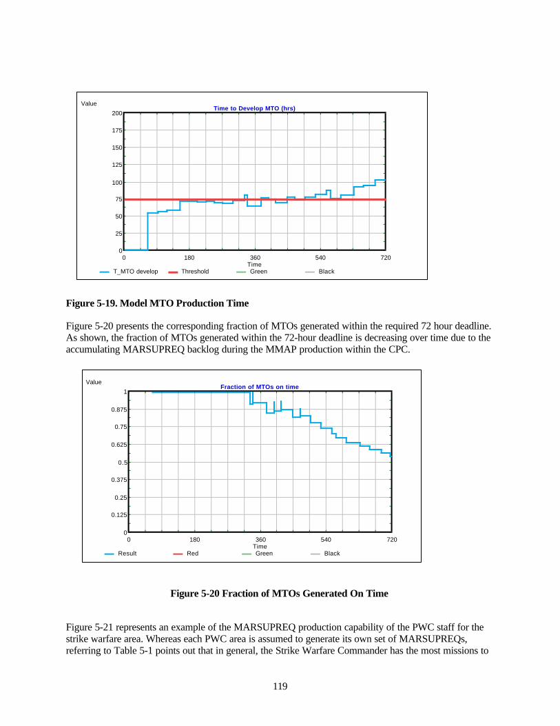
119
Figure 5-19. Model MTO Production Time
Figure 5-20 presents the corresponding fraction of MTOs generated within the required 72 hour deadline.As shown, the fraction of MTOs generated within the 72-hour deadline is decreasing over time due to theaccumulating MARSUPREQ backlog during the MMAP production within the CPC.
Figure 5-20 Fraction of MTOs Generated On Time
Figure 5-21 represents an example of the MARSUPREQ production capability of the PWC staff for thestrike warfare area. Whereas each PWC area is assumed to generate its own set of MARSUPREQs,referring to Table 5-1 points out that in general, the Strike Warfare Commander has the most missions to
0 180 360 540 7200
25
50
75
100
125
150
175
200
Time
ValueTime to Develop MTO (hrs)
T_MTO develop Threshold Green Black
0 180 360 540 7200
0.125
0.25
0.375
0.5
0.625
0.75
0.875
1
Time
ValueFraction of MTOs on time
Result Red Green Black
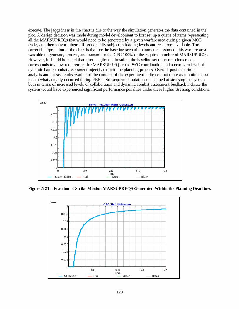
120
execute. The jaggedness in the chart is due to the way the simulation generates the data contained in theplot. A design decision was made during model development to first set up a queue of items representingall the MARSUPREQs that would need to be generated by a given warfare area during a given MODcycle, and then to work them off sequentially subject to loading levels and resources available. Thecorrect interpretation of the chart is that for the baseline scenario parameters assumed, this warfare areawas able to generate, process, and transmit to the CPC 100% of the required number of MARSUPREQs.However, it should be noted that after lengthy deliberation, the baseline set of assumptions madecorresponds to a low requirement for MARSUPREQ cross-PWC coordination and a near-zero level ofdynamic battle combat assessment inject back in to the planning process. Overall, post-experimentanalysis and on-scene observation of the conduct of the experiment indicates that these assumptions bestmatch what actually occurred during FBE-J. Subsequent simulation runs aimed at stressing the systemboth in terms of increased levels of collaboration and dynamic combat assessment feedback indicate thesystem would have experienced significant performance penalties under these higher stressing conditions.
Figure 5-21 – Fraction of Strike Mission MARSUPREQS Generated Within the Planning Deadlines
0 180 360 540 7200
0.125
0.25
0.375
0.5
0.625
0.75
0.875
1
Time
ValueSTWC - Fraction MSRs Generated
Fraction MSRs Red Green Black
0 180 360 540 7200
0.125
0.25
0.375
0.5
0.625
0.75
0.875
1
Time
ValueCPC Staff Utilization
Utilization Red Green Black
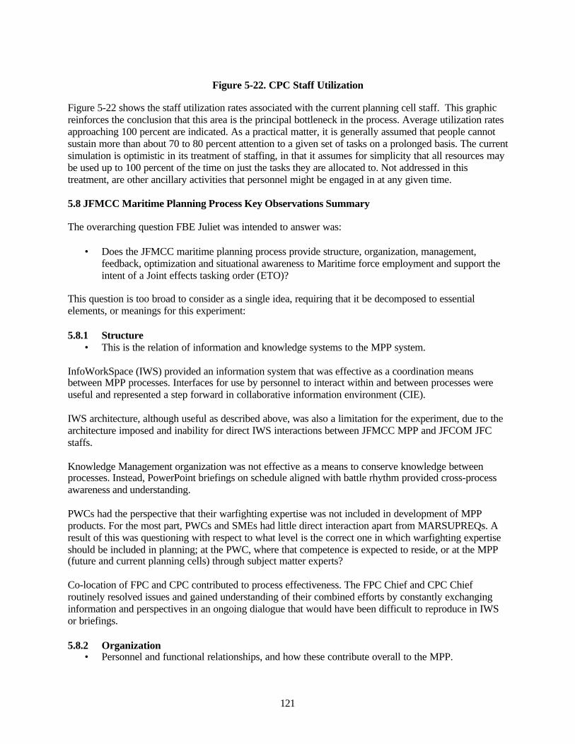
121
Figure 5-22. CPC Staff Utilization
Figure 5-22 shows the staff utilization rates associated with the current planning cell staff. This graphicreinforces the conclusion that this area is the principal bottleneck in the process. Average utilization ratesapproaching 100 percent are indicated. As a practical matter, it is generally assumed that people cannotsustain more than about 70 to 80 percent attention to a given set of tasks on a prolonged basis. The currentsimulation is optimistic in its treatment of staffing, in that it assumes for simplicity that all resources maybe used up to 100 percent of the time on just the tasks they are allocated to. Not addressed in thistreatment, are other ancillary activities that personnel might be engaged in at any given time.
5.8 JFMCC Maritime Planning Process Key Observations Summary
The overarching question FBE Juliet was intended to answer was:
• Does the JFMCC maritime planning process provide structure, organization, management,feedback, optimization and situational awareness to Maritime force employment and support theintent of a Joint effects tasking order (ETO)?
This question is too broad to consider as a single idea, requiring that it be decomposed to essentialelements, or meanings for this experiment:
5.8.1 Structure • This is the relation of information and knowledge systems to the MPP system.
InfoWorkSpace (IWS) provided an information system that was effective as a coordination meansbetween MPP processes. Interfaces for use by personnel to interact within and between processes wereuseful and represented a step forward in collaborative information environment (CIE).
IWS architecture, although useful as described above, was also a limitation for the experiment, due to thearchitecture imposed and inability for direct IWS interactions between JFMCC MPP and JFCOM JFCstaffs.
Knowledge Management organization was not effective as a means to conserve knowledge betweenprocesses. Instead, PowerPoint briefings on schedule aligned with battle rhythm provided cross-processawareness and understanding.
PWCs had the perspective that their warfighting expertise was not included in development of MPPproducts. For the most part, PWCs and SMEs had little direct interaction apart from MARSUPREQs. Aresult of this was questioning with respect to what level is the correct one in which warfighting expertiseshould be included in planning; at the PWC, where that competence is expected to reside, or at the MPP(future and current planning cells) through subject matter experts?
Co-location of FPC and CPC contributed to process effectiveness. The FPC Chief and CPC Chiefroutinely resolved issues and gained understanding of their combined efforts by constantly exchanginginformation and perspectives in an ongoing dialogue that would have been difficult to reproduce in IWSor briefings.
5.8.2 Organization• Personnel and functional relationships, and how these contribute overall to the MPP.
122
The MPP is primarily accomplished by linear workflow, similar to assembly line process (althoughvirtual) regulated by battle rhythm (process triggers are mostly initiated by clock and product) No clearrelationship between other triggers, e.g., emergent PWC requirements.
There were ambiguous results with regard to manning levels and workload. Some participants felt theworkload was appropriate, others that it was too high, and still others that it was too light. Further analysisneeds to map workload to functional requirements in each role of the FPC, CPC and MTO production.Experiment design had artificial work-hours, which loaded workflow into fewer hours. A better designwill allow workflow to be established by battlespace and PWC requirements.
Process synchronization, PWC synchronization and current operations synchronization were a challenge.Synchronization of interdependent processes was the most difficult task. The MTO was produced on a 72-hour cycle (or dependent on JTF battle-rhythm), with (possibly) three being in various stages ofproduction at any one time. During execution of an MTO, results obtained (damage assessments) impactthe planning of subsequent actions. These results must be inserted at an appropriate point in planning, atthe correct time, or planning process components must be adaptable to modifications at any time. Battledamage assessment is the primary feedback from current operations.
Time scales of maritime warfare areas may be quite different. This affects the planning timeline for eachwarfare area, and ultimately leads to cascading change in the MTO.
The synchronization of maritime and JTF targeting cycle is enhanced by the MTO. However, this is bothblessing and curse. Lack of feedback makes working effectively within the targeting cycle problematic,which contributes to cascading change in MTO and relationship to Joint missions.
Deconfliction management must be improved. Planning by PWCs occurs in parallel. However missionsmay require multi-tasking of the same assets. Adjudication and coordination between PWCs is required.Collaboration between PWCs was made possible by IWS, although there was little allocationcollaboration required. It was not clear throughout the experiment what was already being used, wasplanned to be used, or unavailable for other reasons. Asset levels and use of assets could be determined byreviewing MARSUPREQs and MTO/ATO, however, this was a lengthy process in itself. In either case,planned synchronization of processes must occur. Alternatively, a more rapid process could betemporarily halted until a slower process reached the asset deconfliction point.
5.8.3 Management• The MPP as a C2 function, internal and external synchronization, management of planning
functions.
FPC and PWCs: PWCs report the MOD did not have sufficient information for them to conduct planning,and hence place added burden at the PWC level to do this. It is not clear that this is a result of the processor the experiment (operational and other information may have not been of sufficient depth for FPC toproduce what was perceived to be needed by the PWCs).
There is continued confusion with regard to OPCON and TACON. This resulted in some confusion on theemployment of organic assets by PWCs.
Changes to the M/ATO were not possible within the experiment organization. Change was a function ofthe maritime operations cell, contributing to potential overload of those personnel, technologies andprocesses.
MPP afforded increased planning participation by Joint Forces in maritime mission planning.
123
MPP created a common lexicon between joint planners, which increased coordination.
A standardized MTO and ATO should allow greater sharing of assets to missions, and loweredmisunderstandings between component warfare commanders. Ultimately, this theoretically contributed tohigher degree of combat synchronization across all components, with an implication for improved combatpower. However, it is also not possible to prove any of this at this time.
5.8.4 Feedback• Information as feedback of different kinds, and levels, that contributes to organization
management and process control at the operational level.
The MPP MARSUPREQs by PWCs to the CPC for development of MMAP and ultimate output of themaritime tasking order (MTO) does not offer enough flexibility to be effective in an environment whereown force assets and enemy targets are continually moving. Continuous updates and changes to produceagility of the process, and account for MTO execution requires significant internal feedback processes.The experiment did not provide feedback possibilities (low level of BDA, for example), and internalprocesses to use feedback to change MTO within the production process were not developed.
5.8.5 Optimization of Resources• As a potential measure of its utility, the MPP as a whole would be expected to merge together
battlespace situational awareness with asset planning in an optimized plan.
Optimization tools were not available for use by the PWCs, their SMEs or decision makers within theprocess.
Accountability of assets was difficult to determine, which had direct impact on any requirement for assetallocation between competing warfighters. There were isolated asset deconflictions, e.g., around use oflive HSV assets. However, most simulation assets could be reconstituted, or were without feedback to asystem whereby use of an asset would decrement that asset from the pool of assets—with awareness byall those who might be interested in use of those assets. This had the effect of producing a never-endingpool of resources on the part of the planners within the CPC.
The Military Asset Optimization Tool (MAOT) was not present.
Knowledge Kinetics (K2) was not integrated into workflow processes, and therefore had no impact ondecision-making or workflow management of the MPP.
NSS was intended for use as a COA analysis tool at three sites: CORONADO, China Lake and at theSCC. NSS was ineffective (software and hardware difficulties) on CORONADO, partly successful atWTP COA comparisons at China Lake, and was most successful at the SCC in support of surface andASW COAs. A weak point is that an NSS operator analyst must currently be employed directly with thesupported staff, and this is not an organic capability.
Dominant Battlespace Command (DBC) system, a visualization tool, was present on CORONADO, inspaces at the SCC, and in support of the MIWC. It had low integration at STARTEX, with improvedvisualization and fidelity by the end of the experiment. In general, visualization has not been incorporatedinto decision making and planning and has not been thought out or understood in relation to the use ofother similar tools (e.g., MEDAL). There is considerable potential in this area, however, and greaterapplication will pay substantial dividends.

124
MPP software interfaces, for production of the MOD, MARSUPREQs and MMAP were quantum leapsahead of previous mission planning management tools employed in the MPP. These software tools werevery effective at collating information between planners. In general, once participants became adept atsuing these forms, they were comfortable with them. Many recommendations were made, however datacollection suffered from combination of these tools (as prototypes) with what was likewise, a prototypeMTO production process. The combination of new mission planning and management tools, within aprototype and evolving process yielded only ambiguous results. Additional wargaming of process andtools should be done, with one or the other held stable. It would be advisable to model first, wargame theprocess based on those results, and then mature the next generation prototypes of mission constructionand management tools.
5.8.6 Situational Awareness• Feedback from actions within the battlespace (e.g., BDA), a Common Operational Picture and
intent of ETO to provide an overall and continual assessment that actions at the operational levelare in accordance with a campaign plan.
The MTO/ATO may provide enhanced awareness of the maritime and joint asset employment, however itis not clear that this SA was used in this experiment, or that it would be considered high quality, timelyand accurate by participants.
SA of the immediate battlespace environment, or shifts in that battlespace in real time, were not availableto FPC, CPC or MTO production cells.
Internal SA of the MPP process was to be provided by the K2 workflow tool, which did not work in thisexperiment.
SA is one form of feedback, and feedback in general was very lacking, both internal to the MPP, andbetween MPP and current operations or joint operations.
5.9 General Conclusions on JFMCC MPP
The maritime planning process (MPP) was implemented by a staff structure under the Joint ForcesMaritime Component Commander (JFMCC). Effects tasking orders (ETOs) from the Joint ForcesCommander (JFC) were ingested, and maritime tasking orders (MTOs) were produced and coordinatedwith the air tasking order (ATO). Principal warfare commanders (PWCs) participated in the process,producing maritime support requests (MARSUPREQs) that were a component of MTO production. Threeoverlapping planning cycles of 72-hours each were simultaneously executed. The process executed allrequired tasks and produced required products.
The scope of MPP planning done in the experiment was limited. The range of situations that the processcan manage is unknown.
• Competition for assets between PWCs was largely nonexistent. The process was not stressed.• There was no MTO-ATO feedback cycle for plan adjustment.• There was no determination made of the plans’ quality.• Execution results were not fed back into the planning cycle; no process exists to do this.
It was observed that the MPP is viable, but also observed was that the process did not work well.Principal problems and their causes were:
125
• The need to simultaneously support three planning cycles with a limited number of individualsappeared to be a primary cause for process difficulties. Individuals needed to be multi-tasked, andthere was no process for coordinating tasks with individual availability.
• A high level of synchronization of tasks was needed, along with the information that supports thetasks, and the individuals that perform them. Synchronization was ad-hoc rather than a plannedprocess.
• Various inputs to a given MTO were observed to contain essentially the same content assubmissions for previous plans, creating the impression of resubmission rather than new plandevelopment. The cause for this duplication is not known, nor whether it is a real problem.Possible causes are overloading of multi-tasked individuals and information synchronizationdifficulties.
It is assumed that the MPP will be implemented with staffing that is approximately the same as in FBE-J.This means that personnel multi-tasking and synchronization of tasks, supporting information, and theidentification of the individuals performing tasks will be required.
A process is needed to feed back information into all three planning processes on the results of actionsand executions. An effects cell and a process for synchronizing its output with planning cells areproposed, and definition of this process is required.
Further progress with MPP requires detailed mapping of the planning architecture, parameterization ofplanning sub-processes, mapping of planning decision processes and information flows that support thedecisions, and better personnel assignments to tasks. Process modeling can only do this. Specifically:
• Develop a detailed MPP process model. This should be done for both the system tested in FBE-Jand for the more comprehensive system needed for adequate MPP execution.
• Parameterize the model with data from FBE-J and JFMCC limited objective experiments (LOEs).Run the model to identify principal process shortfalls.
• Determine, from a model, how to synchronize the process. Model iterations and runs can identifyrequirements.
• Determine MPP personnel and multi-task coordination requirements from a model.
• Determine how to use an effects cell to synchronize the asynchronous feedback from execution.

126
This page intentionally left blank.
127
6.0 Joint Fires Initiative (JFI) Key Observations
6.1 Experiment Objectives
• Produce measured means, medians, and distributions for various processes in the cross-component engagement timeline from target nomination to assignment including ADOCSapproval block actions.
• Determine the proportion of TSTs engaged that were cross-component engagements.• Determine what fraction of cross-component target engagements were performed using surface
Fires.• Determine the fraction of cross-component TSTs that were engaged by JFMCC controlled
weapons systems.• Determine the number of cross-component TSTs missions that were denied as a function of
reason for denial and denying component.• Determine how many maritime TSTs were nominated as cross-component targets.• Compare the timelines of TSTs engaged within the JFMCC with those timelines resulting when
the target was nominated by another component and passed to the JFMCC.• Apply timeline reconstructions and contextual information to identify architecture and TTP
improvements necessary to reducing the engagement timeline.• Determine the adequacy of the collaborative tools employed (ADOCS, IWS, IRC, etc) to provide
accurate SA and to support the successfully prosecution of TSTs.
6.2 Analytic Questions
6.2.1 Cross Component Architecture
• Does the proposed (experimental) Joint Targeting (cross-component) Architecture enable timelyengagements of TSTs?
6.2.2 Common Toolset
In what ways does a common toolset within the joint architecture affect the ability of the joint force toconduct effective cross-component TST operations?
Each component develops, nominates, and mensurates TST targets within its own engagement system(NFN (X) in the case of the JFMCC). If the component is unable to internally prosecute the target in atimely manner, the target is passed, through the ADOCS DTL Manager, to the supported commander(JFMCC, JFACC or JFLCC depending on the phase of the experiment) who passes it, using the ADOCS,to another component with the capability of executing the mission.
6.3 Sub-Initiative Observations
6.3.1 Time Sensitive Targeting (TST) Operations and Situational Awareness: GeneralObservations
The Joint Battle Center (JBC), US Joint Forces Command, conducted the MC 02 Joint Fires Initiativeprimary data collection and analysis effort. The Naval Postgraduate School agreed to support this datacollection analysis effort as it pertained to JFMCC operations in FBE-J.
128
FBE-J used a common set of automated tools and a common system architecture (JFI) that would enableeffective TST C2 and joint task force coordination. The JFI C2 architecture was designed to enable aseamless, cross-component coordination and transition from the supported to supporting commander role,and from a supporting to supported commander role.
The JFI interfaced to the JFMCC through the Naval Fires Network (Experimental) (NFN (X)). NFN (X)was a Navy initiative and was a system centered on Tactical Exploitation System-Navy (TES-N), GlobalCommand and Control System (GCCS-M), and the Land Attack Warfare System (LAWS). NFN (X) isdiscussed in chapter 8 of this report.29
The data collection efforts were confined to TST operations at the Maritime Operations Center (MOC) onUSS CORONADO. No attempt was made to collect internal data for analysis at the JOC at Suffolk, VA,JFASC at Nellis AFB, NV, or the JFLCC at Camp Lejune, NC. The initial data collection plan addressedthe following analytical objectives:
• Provide insight into decision making in joint TST operations.• Provide insight into joint situational awareness within the MOC.• Produce measured means, medians, and distributions for various processes in the engagement
timeline from target nomination to assignment including ADOCS approval block actions.• Determine the proportion of TSTs engaged that were cross-targeted (nominated by one
component and prosecuted by another).• Determine what fractions of cross-component target engagements were performed using surface
Fires.• Determine the number of TST missions that were denied as a function of reason for denial and
denying component.• Determine how many JFMCC TSTs were nominated as cross-component targets.• Determine the fraction of cross-component TSTs that were engaged by JFMCC controlled
weapons systems.• Compare the timelines of TSTs engaged within the JFMCC with those timelines resulting when
the target was nominated by another component and passed to the JFMCC.
Three types of data were collected: ADOCS/LAWS electronically provided time-tagged mission historydata. All participants in the Maritime Operations Center were surveyed using a TST operations surveythat covered all aspects of TST operations. Info Workspace collaborative tool chat files were recorded.Finally, observational data were recorded in the MOC.
TST Operations Survey – General Comments
A TST Operations survey was administered to participants in the Maritime Operations cell. The followingis a summary of the general comments provided by the participants:
• “With multiple parties entering information in the Dynamic Target List fields, it was difficult tomaintain situational awareness on what is happening, who is requesting ISR support, and how todeconflict with JFACC and other components to satisfy requirements.”
• “More training was needed to really employ the capabilities of the system.”• “It was a challenge to sort multiple targets by priority.”• “To maximize its capability, more screen space is needed on the computer.”• “It was hard to track moving targets.”
29 TST Concept of Operations for FBE-J, NWDC, June 2002.

129
• “ADOCS provided better situational awareness of TST operations.”• “Believe that lack of knowledge of the current situation was due to process problems.”• “It was difficult to maintain situational awareness on assigned sensor assets and monitor the
Dynamic Target List.”• “ADOCS along with chat capability provided pretty good situational awareness.”• “Most operators did not understand how to use the ADOCS collection request page. Use
improved later in the experiment.”• “Deconfliction of weapons was consistent using ADOCS.”• “There was some concern about fratricide because operators were restricted from using the fire
support control measures option.”• “An automated tool is needed to help the ISR manager see what happens to pre-planned
collection if a sensor is retasked to look at a TST.”• “JISR synch matrix was not useful as tactical/operational tool. Need a graphical tool to display
collection plan. Did not help visualize the impact on the collection plan if a sensor is retasked.”
TST Decision Event Timelines
Five event timelines were reconstructed using IWS chat and ADOCS mission histories. The purpose ofthese timelines was to provide insight into the decision making process in joint TST operations usingADOCS. These timelines should not be a reference to determine times. There were several constraints tothese timelines. Some of these constraints were individual and group training, COP latency, and GCCS-Msimulation interfaces. While operators identified several issues concerning ADOCS in TST operations;the reconstructed decision timelines indicate that TST operations were consistently executed usingADOCS.
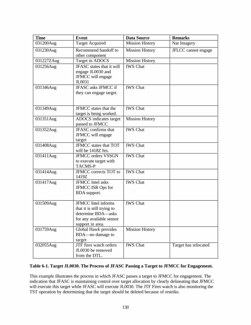
130
Time Event Data Source Remarks031200Aug Target Acquired Mission History Nat Imagery
031230Aug Recommend handoff toother component
Mission History JFLCC cannot engage
031227ZAug Target in ADOCS Mission History031256Aug JFASC states that it will
engage JL0030 andJFMCC will engageJL0031
IWS Chat
031346Aug JFASC asks JFMCC ifthey can engage target.
IWS Chat
031349Aug JFMCC states that thetarget is being worked.
IWS Chat
031351Aug ADOCS indicates targetpassed to JFMCC
Mission History
031352Aug JFASC confirms thatJFMCC will engagetarget
IWS Chat
031408Aug JFMCC states that TOTwill be 1418Z hrs.
IWS Chat
031411Aug JFMCC orders VSSGNto execute target withTACMS-P
IWS Chat
031414Aug JFMCC corrects TOT to1419Z
IWS Chat
031417Aug JFMCC Intel asksJFMCC ISR Ops forBDA support.
IWS Chat
031509Aug JFMCC Intel informsthat it is still trying todetermine BDA—asksfor any available sensorsupport in area.
IWS Chat
031759Aug Global Hawk providesBDA—no damage totarget
Mission History
032055Aug JTF fires watch ordersJL0030 be removedfrom the DTL.
IWS Chat Target has relocated
Table 6-1. Target JL0030. The Process of JFASC Passing a Target to JFMCC for Engagement.
This example illustrates the process in which JFASC passes a target to JFMCC for engagement. Theindication that JFASC is maintaining control over target allocation by clearly delineating that JFMCCwill execute this target while JFASC will execute JL0030. The JTF Fires watch is also monitoring theTST operation by determining that the target should be deleted because of restrike.
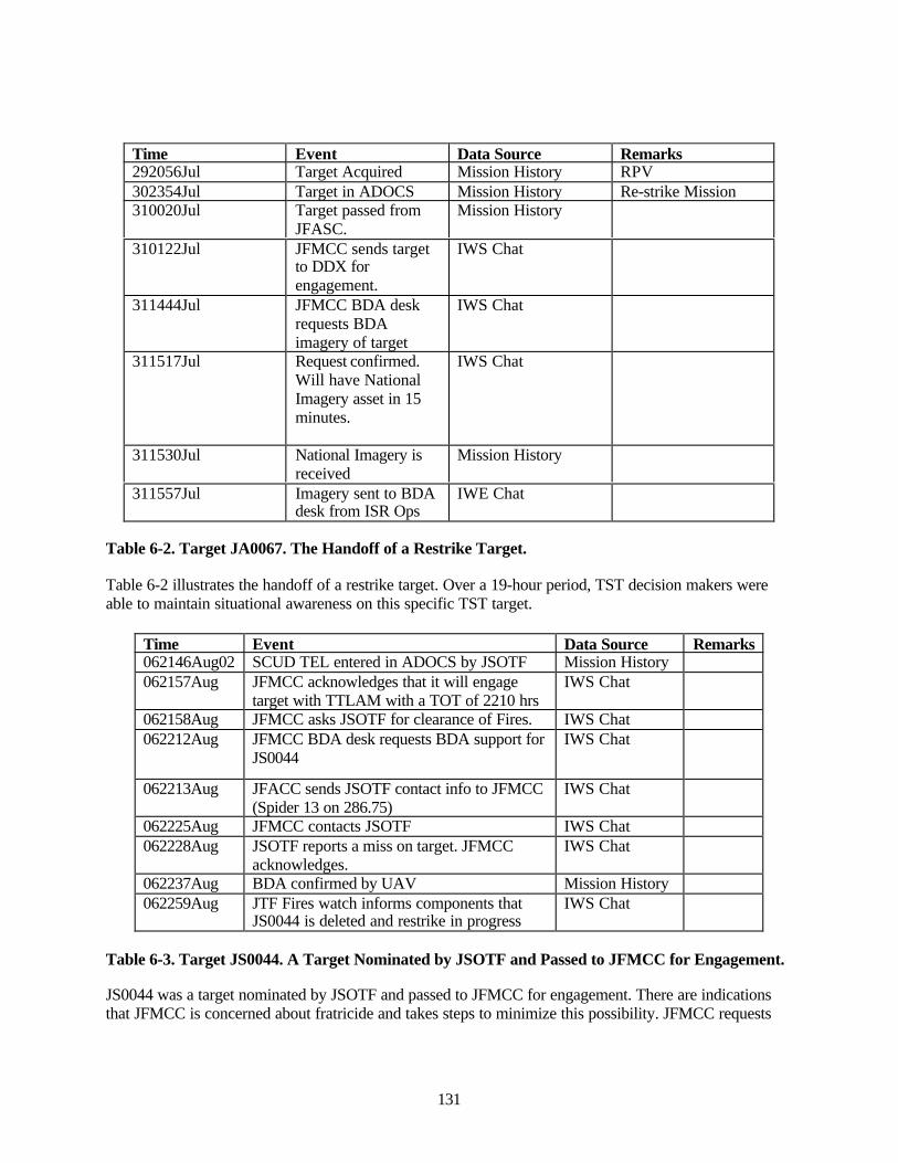
131
Time Event Data Source Remarks292056Jul Target Acquired Mission History RPV302354Jul Target in ADOCS Mission History Re-strike Mission310020Jul Target passed from
JFASC.Mission History
310122Jul JFMCC sends targetto DDX forengagement.
IWS Chat
311444Jul JFMCC BDA deskrequests BDAimagery of target
IWS Chat
311517Jul Request confirmed.Will have NationalImagery asset in 15minutes.
IWS Chat
311530Jul National Imagery isreceived
Mission History
311557Jul Imagery sent to BDAdesk from ISR Ops
IWE Chat
Table 6-2. Target JA0067. The Handoff of a Restrike Target.
Table 6-2 illustrates the handoff of a restrike target. Over a 19-hour period, TST decision makers wereable to maintain situational awareness on this specific TST target.
Time Event Data Source Remarks062146Aug02 SCUD TEL entered in ADOCS by JSOTF Mission History062157Aug JFMCC acknowledges that it will engage
target with TTLAM with a TOT of 2210 hrsIWS Chat
062158Aug JFMCC asks JSOTF for clearance of Fires. IWS Chat062212Aug JFMCC BDA desk requests BDA support for
JS0044IWS Chat
062213Aug JFACC sends JSOTF contact info to JFMCC(Spider 13 on 286.75)
IWS Chat
062225Aug JFMCC contacts JSOTF IWS Chat062228Aug JSOTF reports a miss on target. JFMCC
acknowledges.IWS Chat
062237Aug BDA confirmed by UAV Mission History062259Aug JTF Fires watch informs components that
JS0044 is deleted and restrike in progressIWS Chat
Table 6-3. Target JS0044. A Target Nominated by JSOTF and Passed to JFMCC for Engagement.
JS0044 was a target nominated by JSOTF and passed to JFMCC for engagement. There are indicationsthat JFMCC is concerned about fratricide and takes steps to minimize this possibility. JFMCC requests
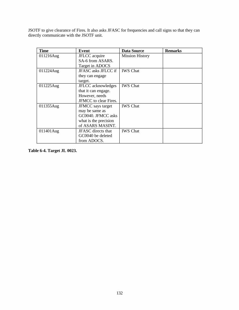
132
JSOTF to give clearance of Fires. It also asks JFASC for frequencies and call signs so that they candirectly communicate with the JSOTF unit.
Time Event Data Source Remarks011216Aug JFLCC acquire
SA-6 from ASARS.Target in ADOCS
Mission History
011224Aug JFASC asks JFLCC ifthey can engagetarget.
IWS Chat
011225Aug JFLCC acknowledgesthat it can engage.However, needsJFMCC to clear Fires.
IWS Chat
011355Aug JFMCC says targetmay be same asGC0040. JFMCC askswhat is the precisionof ASARS MASINT.
IWS Chat
011401Aug JFASC directs thatGC0040 be deletedfrom ADOCS.
IWS Chat
Table 6-4. Target JL 0023.
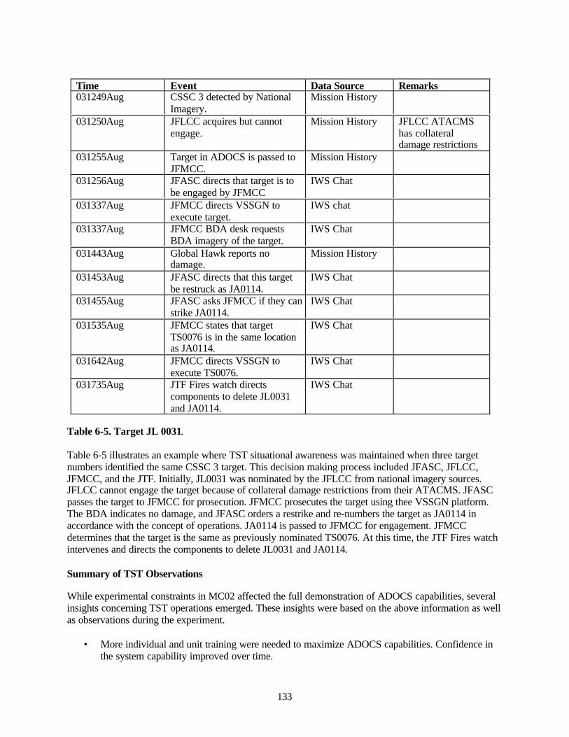
133
Time Event Data Source Remarks031249Aug CSSC 3 detected by National
Imagery.Mission History
031250Aug JFLCC acquires but cannotengage.
Mission History JFLCC ATACMShas collateraldamage restrictions
031255Aug Target in ADOCS is passed toJFMCC.
Mission History
031256Aug JFASC directs that target is tobe engaged by JFMCC
IWS Chat
031337Aug JFMCC directs VSSGN toexecute target.
IWS chat
031337Aug JFMCC BDA desk requestsBDA imagery of the target.
IWS Chat
031443Aug Global Hawk reports nodamage.
Mission History
031453Aug JFASC directs that this targetbe restruck as JA0114.
IWS Chat
031455Aug JFASC asks JFMCC if they canstrike JA0114.
IWS Chat
031535Aug JFMCC states that targetTS0076 is in the same locationas JA0114.
IWS Chat
031642Aug JFMCC directs VSSGN toexecute TS0076.
IWS Chat
031735Aug JTF Fires watch directscomponents to delete JL0031and JA0114.
IWS Chat
Table 6-5. Target JL 0031.
Table 6-5 illustrates an example where TST situational awareness was maintained when three targetnumbers identified the same CSSC 3 target. This decision making process included JFASC, JFLCC,JFMCC, and the JTF. Initially, JL0031 was nominated by the JFLCC from national imagery sources.JFLCC cannot engage the target because of collateral damage restrictions from their ATACMS. JFASCpasses the target to JFMCC for prosecution. JFMCC prosecutes the target using thee VSSGN platform.The BDA indicates no damage, and JFASC orders a restrike and re-numbers the target as JA0114 inaccordance with the concept of operations. JA0114 is passed to JFMCC for engagement. JFMCCdetermines that the target is the same as previously nominated TS0076. At this time, the JTF Fires watchintervenes and directs the components to delete JL0031 and JA0114.
Summary of TST Observations
While experimental constraints in MC02 affected the full demonstration of ADOCS capabilities, severalinsights concerning TST operations emerged. These insights were based on the above information as wellas observations during the experiment.
• More individual and unit training were needed to maximize ADOCS capabilities. Confidence inthe system capability improved over time.

134
• Cross-component sustained TST operations were conducted using ADOCS.• Because of GCCS-M—simulation interface issues, ADOCS could not be fully tested for
situational awareness.• The JTF and components managed TST targets in a warfighting environment, and were able to
track F-F-T-T-E-A progress with the assistance of ADOCS.• Graphical displays were not used as the primary means for situational awareness. For example, in
the Maritime Operations Center, decisions were primarily being made from the Dynamic TargetList display and IWS Chat.
• There are some indications that ADOCS aided in deconfliction of Fires.• There are indications that ADOCS contributed to fratricidal avoidance.• JISR synch function contribution to ISR management was minimal.• ADOCS capability to help visualize the enemy situation was rarely used.• Majority of the respondents in the JFMCC MOC (77 percent) agreed or strongly agreed that
ADOCS provided an understanding of the overall Joint TST operations.• Majority of the respondents (62 percent) agreed that that ADOCS provided situational awareness
confidence to make decisions without concern for fratricidal incidents.• Majority of the respondents agreed (83 percent) that they had confidence in the TST coordination
page to manage deconfliction of engagements.• Majority of the respondents (70 percent) disagreed that ADOCS provided them the enemy
situation.• 60 percent of the respondents agreed that the ADOCS assessment page provided sufficient
feedback on engagement effects.• 100 percent of the respondents used the ADOCS Collection Request page to manage pre- and
post-strike combat assessment requests (BDA).• The majority of the respondents (89 percent) agreed or strongly agreed that ADOCS Mission
Coordination: Time Sensitive Targets Page provided them situational awareness for current TSToperations.
6.3.2 Analysis of JFI Objective Data
6.3.2.1 JFI Data Analyzed
The Automated Deep Operations Coordination System (ADOCS) Joint Dynamic Target List (DTL)Manager was the mechanism used in MC02/FBE-J to implement the JFI. The JFI analysis discussed hereis based on a review of the data captured from ADOCS. These data include the end state of the ADOCSDTL Manager display, the Mission History Reports for each of the nominated targets, and the informationcontained in the tabs or pages linked to each target. The pages include: target data, engagement,coordination, collection request, BDA, and assessment.
The ADOCS database used for this analysis contained data from 24 July to 8 August and included 345target nominations. The analysis discussed below was limited to the 120 target nominations made in theinterval August 1 through 5 inclusive, for several reasons:
• The Mission Histories in the database for the period prior to July 30 were absent or fragmentary• Constraints on the time available for analysis limited the amount of data that could be reviewed• The period selected for review addressed the matured JFI TTP process (e.g., for the period of July
24 to 30 inclusive, of 73 target nominations, only six nominations were passed to anothercomponent using the DTL Passed (PSD) block; for the 120 nominations in the interval examinedhere, 67 were passed using the PSD block)
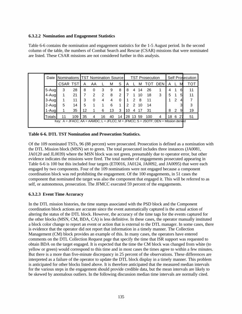
135
6.3.2.2 Nomination and Engagement Statistics
Table 6-6 contains the nomination and engagement statistics for the 1-5 August period. In the secondcolumn of the table, the numbers of Combat Search and Rescue (CSAR) missions that were nominatedare listed. These CSAR missions are not considered further in this analysis.
Date Nominations TST Nomination Source TST Prosecution Self Prosecution
CSAR TST A AA L M S A L M TOT DEN A L M TOT
5-Aug 3 28 8 0 3 9 8 8 4 14 26 1 4 1 6 114-Aug 1 21 7 2 2 8 2 7 1 10 18 3 5 1 5 113-Aug 1 11 3 0 4 4 0 1 2 8 11 1 2 4 72-Aug 5 14 5 1 1 6 1 2 2 10 14 3 31-Aug 1 35 12 1 6 13 3 10 4 17 31 8 2 9 19
Totals 11 109 35 4 16 40 14 28 13 59 100 4 18 6 27 51 Key: A = JFACC; AA = AAMDC; L = JFLCC; M = JFMCC; S = JSOTF; DEN = Mission denied
Table 6-6. DTL TST Nomination and Prosecution Statistics.
Of the 109 nominated TSTs, 96 (88 percent) were prosecuted. Prosecution is defined as a nomination withthe DTL Mission block (MSN) set to green. The total prosecuted includes three instances (JA0081,JA0120 and JL0039) where the MSN block was not green, presumably due to operator error, but otherevidence indicates the missions were fired. The total number of engagements prosecuted appearing inTable 6-6 is 100 but this included four targets (ET0016, JA0124, JA0092, and JA0095) that were eachengaged by two components. Four of the 109 nominations were not engaged because a componentcoordination block was red prohibiting the engagement. Of the 100 engagements, in 51 cases thecomponent that nominated the target was also the component that engaged it. This will be referred to asself, or autonomous, prosecution. The JFMCC executed 59 percent of the engagements.
6.3.2.3 Event Time Accuracy
In the DTL mission histories, the time stamps associated with the PSD block and the Componentcoordination block actions are accurate since the event automatically captured is the actual action ofaltering the status of the DTL block. However, the accuracy of the time tags for the events captured forthe other blocks (MSN, CM, BDA, CA) is less definitive. In these cases, the operator manually instituteda block color change to report an event or action that is external to the DTL manager. In some cases, thereis evidence that the operator did not report that information in a timely manner. The CollectionManagement (CM) block provides an example of this. In many cases, the operators have enteredcomments on the DTL Collection Request page that specify the time that ISR support was requested toobtain BDA on the target engaged. It is expected that the time the CM block was changed from white (toyellow or green) would correspond to this time and in most cases the times agree to within a few minutes.But there is a more than five-minute discrepancy in 25 percent of the observations. These differences areinterpreted as a failure of the operator to update the DTL block display in a timely manner. This problemis anticipated for other blocks listed above. It is therefore anticipated that the measured median intervalsfor the various steps in the engagement should provide credible data, but the mean intervals are likely tobe skewed by anomalous outliers. In the following discussion median time intervals are normally cited.
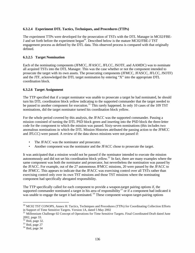
136
6.3.2.4 Experiment DTL Tactics, Techniques, and Procedures (TTPs)
The experiment TTPs were developed for the prosecution of TSTs with the DTL Manager in MC02/FBE-J and set forth before the experiment began30. Described below is the mature MC02/FBE-J TSTengagement process as defined by the DTL data. This observed process is compared with that originallydefined.
6.3.2.5 Target Nomination
Each of the nominating components (JFMCC, JFASCC, JFLCC, JSOTF, and AAMDC) was to nominateall acquired TSTs into the DTL Manager. This was the case whether or not the component intended toprosecute the target with its own assets. The prosecuting components (JFMCC, JFASCC, JFLCC, JSOTF)and the JTF, acknowledged the DTL target nomination by entering “X” into the appropriate DTLcoordination block.
6.3.2.6 Target Assignment
The TTP specified that if a target nominator was unable to prosecute a target he had nominated, he shouldturn his DTL coordination block yellow indicating to the supported commander that the target needed tobe passed to another component for execution.31 This rarely happened. In only 10 cases of the 109 TSTnominations, did the target nominator turned his coordination block yellow.
For the whole period covered by this analysis, the JFACC was the supported commander. Passing amission consisted of turning the DTL PSD block green and inserting into the PSD block the three-lettercode for the component to which the mission was passed. Sixty-seven nominations (this includes twoanomalous nominations in which the DTL Mission Histories attributed the passing action to the JFMCCand JFLCC) were passed. A review of the data shows missions were not passed if:
• The JFACC was the nominator and prosecutor.• Another component was the nominator and the JFACC chose to prosecute the target.
It was anticipated that a mission would not be passed if the nominator intended to execute the missionautonomously and did not set his coordination block yellow.32 In fact, there are many examples where thesame component was both the nominator and prosecutor, but nevertheless the nomination was passed bythe JFACC. For example, out of the 27 autonomous JFMCC missions, 20 were passed by the JFACC tothe JFMCC. This appears to indicate that the JFACC was exercising control over all TSTs rather thanexercising control only over its own TST missions and those TST missions where the nominatingcomponent had specifically abrogated responsibility.
The TTP specifically called for each component to provide a weapon-target pairing options if, thesupported commander nominated a target in his area of responsibility33 or if a component had indicated itwas unable to engage the target it had nominated. 34 These component weapon target-pairing options
30 MC02 TST CONOPS, Annex H: Tactics, Techniques and Procedures (TTPs) for Coordinating Collection Effortsin Support of Time Sensitive Targets. Version 1A, dated 5 May 200231 Millennium Challenge 02 Concept of Operations for Time Sensitive Targets. Final Coordinated Draft dated June2002, page 33.32 Ibid, page 32.33 Ibid, page 2734 Ibid, page 34
137
appear in the DTL engagement page. A review of this page for each engagement shows that these optionswere not normally offered. In 73 cases, only a single weapon-target pairing option appears, in 21 cases,there were two options offered and in three cases there were three.
Figure 6-1. DTLTST Engagement Timeline.
As seen in figure 6-1, the median interval between a nomination being received in ADOCS and thepassing of the nomination by the supported commander is 15 minutes.
6.3.2.7 Target Engagement
When the component responsible for engaging a target obtained a weapon-target pairing he turned hisDTL coordination block green. The interval between the nomination being passed and the targetprosecutor turning his coordination block green was very short. As shown in Table 6-7, the medianinterval for 59 observations was only one minute. In 18 cases, the coordination block turned green beforethe target was passed. Ten of these 18 cases were JFMCC autonomous missions implying JFMCC targetprocessing was proceeding independent of JFACC PSD actions.
NOM INADOCS
PSD = G
15 1 2
Coord =G
“EXE”ACTION
15
MSN = G
3
CMREQUEST
109
BDA = G/R
CA = G/R
- Times intervals in minutes- G and R indicate DTL blockcolor changes of green and red
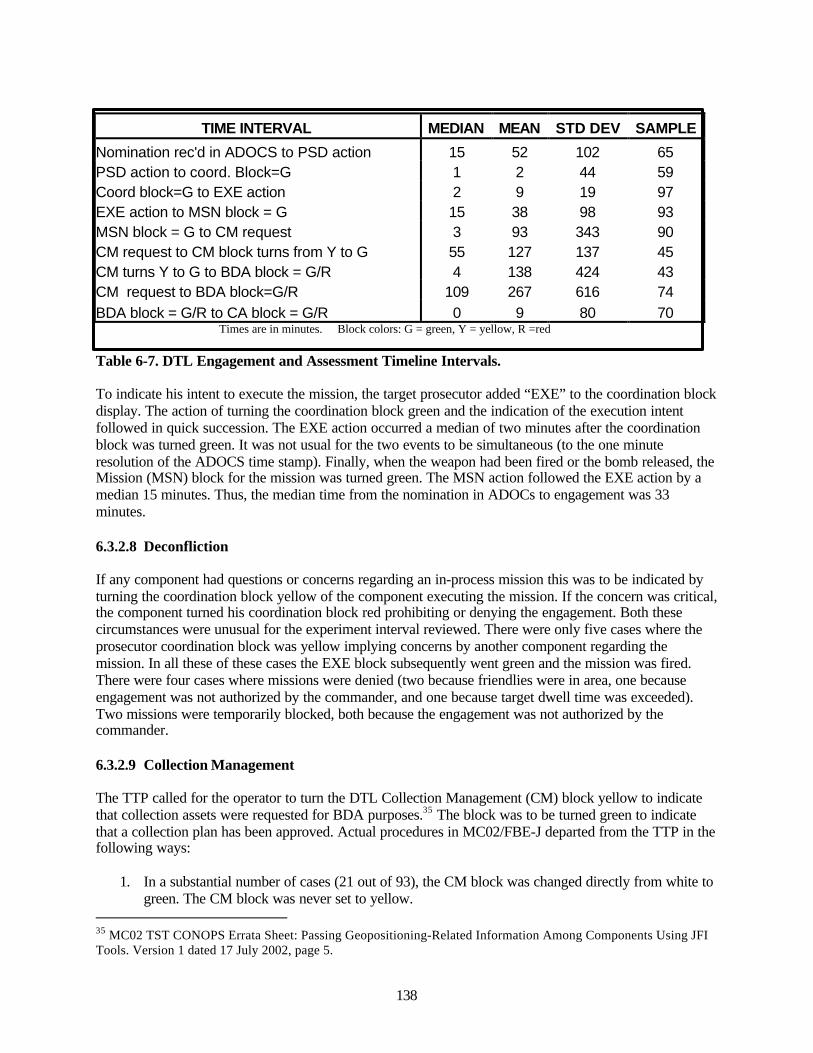
138
TIME INTERVAL MEDIAN MEAN STD DEV SAMPLE
Nomination rec'd in ADOCS to PSD action 15 52 102 65PSD action to coord. Block=G 1 2 44 59Coord block=G to EXE action 2 9 19 97EXE action to MSN block = G 15 38 98 93MSN block = G to CM request 3 93 343 90CM request to CM block turns from Y to G 55 127 137 45CM turns Y to G to BDA block = G/R 4 138 424 43CM request to BDA block=G/R 109 267 616 74BDA block = G/R to CA block = G/R 0 9 80 70 Times are in minutes. Block colors: G = green, Y = yellow, R =red
Table 6-7. DTL Engagement and Assessment Timeline Intervals.
To indicate his intent to execute the mission, the target prosecutor added “EXE” to the coordination blockdisplay. The action of turning the coordination block green and the indication of the execution intentfollowed in quick succession. The EXE action occurred a median of two minutes after the coordinationblock was turned green. It was not usual for the two events to be simultaneous (to the one minuteresolution of the ADOCS time stamp). Finally, when the weapon had been fired or the bomb released, theMission (MSN) block for the mission was turned green. The MSN action followed the EXE action by amedian 15 minutes. Thus, the median time from the nomination in ADOCs to engagement was 33minutes.
6.3.2.8 Deconfliction
If any component had questions or concerns regarding an in-process mission this was to be indicated byturning the coordination block yellow of the component executing the mission. If the concern was critical,the component turned his coordination block red prohibiting or denying the engagement. Both thesecircumstances were unusual for the experiment interval reviewed. There were only five cases where theprosecutor coordination block was yellow implying concerns by another component regarding themission. In all these of these cases the EXE block subsequently went green and the mission was fired.There were four cases where missions were denied (two because friendlies were in area, one becauseengagement was not authorized by the commander, and one because target dwell time was exceeded).Two missions were temporarily blocked, both because the engagement was not authorized by thecommander.
6.3.2.9 Collection Management
The TTP called for the operator to turn the DTL Collection Management (CM) block yellow to indicatethat collection assets were requested for BDA purposes.35 The block was to be turned green to indicatethat a collection plan has been approved. Actual procedures in MC02/FBE-J departed from the TTP in thefollowing ways:
1. In a substantial number of cases (21 out of 93), the CM block was changed directly from white togreen. The CM block was never set to yellow.
35 MC02 TST CONOPS Errata Sheet: Passing Geopositioning-Related Information Among Components Using JFITools. Version 1 dated 17 July 2002, page 5.
139
2. In the 43 cases where there is a reported time for the CM block change from yellow to green andthere is a reported time for the BDA block changing to green or red, the median differencebetween these two actions is only four minutes, and in a number of cases the changes weresimultaneous. It appears the CM block change from yellow to green is based on the receipt of theBDA information, rather than on the approval of the collection plan as required by the TTP.
3. In 15 cases, the final state of the CM block is yellow even though the BDA block was set to greenor red. This suggests the operator was negligent in setting the CM block to green.
As mentioned above, there was a discrepancy between the time the first CM color change was reported inthe Mission Histories and the time it was recorded that the CM request was issued in the DTL CollectionRequest page. In the 71 cases where both reports are available, the median difference between the timeswas one minute and the mean difference 13 minutes. Generally, when available, it is the CM request timeas reported in the collection request page that was used in calculations. Table 6-7 presents the statistics forthe interval between the MSN block going green and the issuance of the CM request. The median intervalis only three minutes, but in 35 of the 90 cases, the CM request was sent before the MSN block wentgreen. The individual measurements of this interval show a large dispersion.
6.3.2.10 Battle Damage Assessment (BDA)
The TTP required the BDA block to be turned yellow when the requested mission was flown but no BDAhad yet been received.36 On receipt of BDA, the block was to be turned green if the strike was successfulor red if unsuccessful.
Actual procedures in MC02/FBE-J departed from the TTP in the following ways:
• Of 96 cases in which BDA was reported (red or green block), only 38 went from white to yellow.The rest went directly from white to red/green.
• The CM block at times went from yellow to green at essentially the same time that the BDAblock was changed to green/red; these two actions were redundant.
The BDA block was changed to green/red a median interval of 109 minutes after the BDA request. Insome instances it was clear there was no clear-cut event that stimulated the BDA block action. Theoperator comments on the DTL BDA page indicate on some occasions the BDA block was turned red atan arbitrary time, after the operator had waited long and futilely for a BDA report or BDA confirmation.
6.3.2.11 Combat Assessment (CA)
The TTP dictates that the CA block was to be turned yellow when assets have been assigned.37 It was tobe turned green when the collection assessment was complete and the mission was accomplished; red ifthe mission had not been accomplished.
Actual procedures in MC02/FBE-J departed from the TTP in the following ways:
1. Few CA blocks were turned yellow. Of 74 instances in which a CA status was reported, only 16blocks first went from white to yellow, the rest all went from white to red/green.
2. The median interval between the BDA block turning red/green and the CA block turningred/green was zero minutes. These actions were essentially the same event.
36 MC02 TST CONOPS, Annex H: Tactics, Techniques and Procedures (TTPs) for Coordinating Collection Effortsin Support of Time Sensitive Targets. Version 1A, dated 5 May 2002, page 6.37 Ibid, page 9.
140
3. In the great majority of cases (66 out of 84) in which one or both of the BDA and CA blocks arered/green, the two blocks are the same color. Therefore the CA and BDA blocks are set at thesame time and almost always to the same colors. It appears the CA block adds little value to theDTL manager. In the 18 cases where the CA and BDA blocks are not the same colors some of theblock combinations do not make sense. For example, there are five cases in which the BDA blockis white or yellow but the CA block is red or green. How can an assessment be made if no BDAwas reported? These block settings appear erroneous.
6.3.2.12 Not Later Than (NLT) Time
Each target nomination is required to contain a target dwell time; an estimate of the time the nominatedtarget is expected to remain at the location where it has been detected. In ADOCS, this dwell time isautomatically converted to an absolute NLT time. In most cases, after performing the weapon-targetpairing, the ADOCS operator reported a Time On Target (TOT) in the DTL Target Data page. These twotimes permit a simplistic timeline measure of success for TST engagements.
For those engagements in which an NLT time and a TOT were both reported, the NLT time and TOTwere compared to determine if the engagement met the NLT time. In some cases, the TOT was less thanthe MSN time. This could either be due to the fact that the operator forgot to update in the DTL a revisionto the TOT time or that the MSN green status was reported late. In those cases, as well as those with noTOT time, the NLT time was compared to the MSN time. Of the 58 engagements evaluated, 25 did notmeet the NLT times.
6.3.2.13 Georefinement
The TTP requires that the component that nominated the target be responsible for the georefinement ofthe target when this is required.38 If the mission is passed to another component, the nominator a prioridoes not know what weapon will be paired to the target and whether georefinement will be required. Ifthe passed mission does require georefinement, the target prosecutor must request the nominator toprovide these data. The DTL display provided no means of displaying mission georefinement status or forcommunicating a georefinement requirement between components. If a target position was georefinedthis was indicated by the entry of Circular Error (CE) and Linear Error (LE) values on the DTL TargetData page. For the 109 nominated TSTs, only 22 were reported to have georefined positions. This appearsto be as a small percentage, but it is not possible to determine if this represents a problem withoutadditional information:
1. The DTL engagement page does not specify the aircraft-delivered weapons, therefore it is notknown whether they would require a georefined target position.
2. Do ATACMS and TACMS missions, particularly where multiple rounds were employed, requiregeorefined target positions?
3. Is it assumed that all SOF nominated target positions are specified to high accuracy and do notrequire georefinement?
All participants involved in weaponeering need to be issued a matrix that defines what level of targetpositional accuracy is required, for a specified level of damage, as a function of target type, weapon typeand number of rounds delivered. In addition, even for unmensurated targets, there must be someindication in the nomination of the accuracy to which the target position is known. At the least,
38 MC02 TST CONOPS Errata Sheet. Passing Geopositioning-Related Information Among Components Using JFITools. Version 1 dated 17 July 2002, page 3.

141
weaponeering participants need to be furnished with a matrix defining the expected positional accuracy asa function of the nomination source (Global Hawk, U2, Predator, SOF, etc.).The georefinement process and data for the JFMCC in MC02/FBE-J will be analyzed in a separate report.
6.3.2.14 Restrikes
The TTP indicates if a restrike of a mission was necessary the operator was to select the retarget button,which would generate a new mission number and mission, duplicate the track number, and appendRESTRIKE to the target description.39
In the data analyzed, 17 missions were identified as restrikes on the basis of the term RESTRIKEappended to the target description. In most cases, the original target number that was being restruck wasidentified in the remarks on the Target Data page. All the restrike missions were initiated by the JFACC.The automated process for generation of restrike missions described in the TTP did not function or didnot work reliably. The following anomalies were observed in the data.
• In seven cases, there were no track numbers, or the track numbers did not agree between therestruck and the original target
• In three cases in which the connection between the restruck and original target was made on thebasis of a common track number, the original and restruck targets were at different locations
6.4 Summary Comments and Observations
• Ninety-six (88 percent) of the 109 DTL TST targets were engaged. Another four (four percent)were denied execution. Nine targets were not engaged.
• Sixty-seven (61 percent) of the nominations were passed to a component for execution by thesupported commander (JFACC).
• Contrary to the TTP, the JFACC passed targets in cases where the nominator did not indicate hewas unable to engage the target; there are a number of cases where the JFACC passed the targetto the target nominator.
• The JFMCC executed 59 percent of the firings.
• A representative DTL engagement timeline is shown in figure 6-2. The times associated witheach of the intervals are the medians from the observations discussed in the above Sections.
The DTL Manager may be considered a successful cross-component coordination tool as indicated by thepercentage of targets engaged and the degree to which all components contributed to a usually completeand consistent DTL manager display. However, there were a number of instances, as described in thepreceding Sections, where block actions indicate the experiment TTP was neither understood norfollowed. The degree to which a collaborative or situational awareness tool is valuable depends on theconsistency, accuracy, and timeliness of the information it displays. Because operators in some instancesdeparted from the TTP, were time late in updating the display; and, in some cases, used componentunique rules in setting DTL blocks; the value of the DTL was degraded. An example of the latter point;the data contain eight instances where the MSN block was changed from white to yellow – an action thatis not defined in the TTP. In seven of those instances, the JFLCC was the prosecutor and turned the MSN
39 Ibid, page 12.
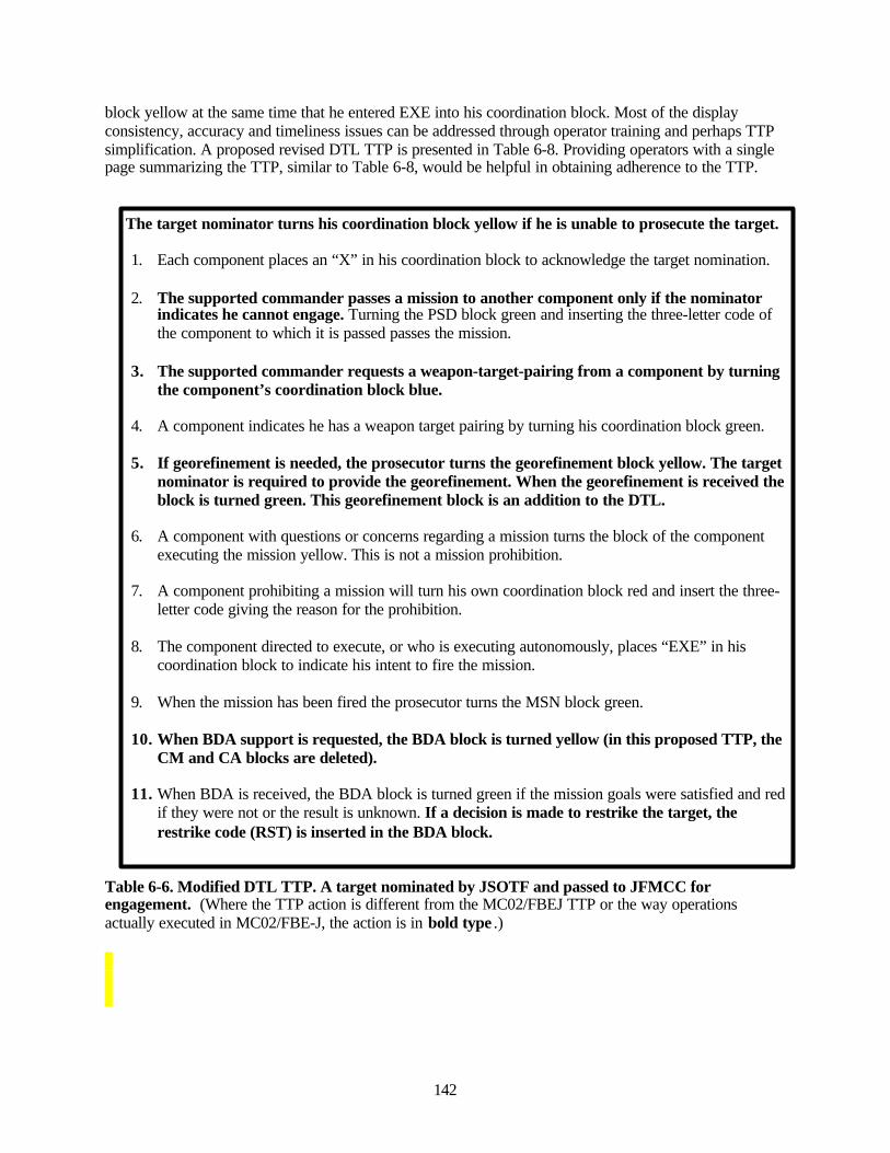
142
block yellow at the same time that he entered EXE into his coordination block. Most of the displayconsistency, accuracy and timeliness issues can be addressed through operator training and perhaps TTPsimplification. A proposed revised DTL TTP is presented in Table 6-8. Providing operators with a singlepage summarizing the TTP, similar to Table 6-8, would be helpful in obtaining adherence to the TTP.
The target nominator turns his coordination block yellow if he is unable to prosecute the target.
1. Each component places an “X” in his coordination block to acknowledge the target nomination.
2. The supported commander passes a mission to another component only if the nominatorindicates he cannot engage. Turning the PSD block green and inserting the three-letter code ofthe component to which it is passed passes the mission.
3. The supported commander requests a weapon-target-pairing from a component by turningthe component’s coordination block blue.
4. A component indicates he has a weapon target pairing by turning his coordination block green.
5. If georefinement is needed, the prosecutor turns the georefinement block yellow. The targetnominator is required to provide the georefinement. When the georefinement is received theblock is turned green. This georefinement block is an addition to the DTL.
6. A component with questions or concerns regarding a mission turns the block of the componentexecuting the mission yellow. This is not a mission prohibition.
7. A component prohibiting a mission will turn his own coordination block red and insert the three-letter code giving the reason for the prohibition.
8. The component directed to execute, or who is executing autonomously, places “EXE” in hiscoordination block to indicate his intent to fire the mission.
9. When the mission has been fired the prosecutor turns the MSN block green.
10. When BDA support is requested, the BDA block is turned yellow (in this proposed TTP, theCM and CA blocks are deleted).
11. When BDA is received, the BDA block is turned green if the mission goals were satisfied and redif they were not or the result is unknown. If a decision is made to restrike the target, therestrike code (RST) is inserted in the BDA block.
Table 6-6. Modified DTL TTP. A target nominated by JSOTF and passed to JFMCC forengagement. (Where the TTP action is different from the MC02/FBEJ TTP or the way operationsactually executed in MC02/FBE-J, the action is in bold type .)
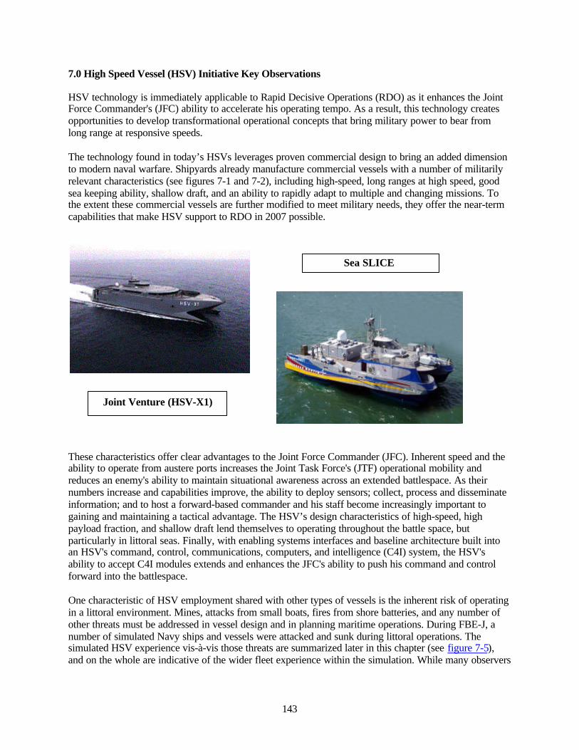
143
7.0 High Speed Vessel (HSV) Initiative Key Observations
HSV technology is immediately applicable to Rapid Decisive Operations (RDO) as it enhances the JointForce Commander's (JFC) ability to accelerate his operating tempo. As a result, this technology createsopportunities to develop transformational operational concepts that bring military power to bear fromlong range at responsive speeds.
The technology found in today’s HSVs leverages proven commercial design to bring an added dimensionto modern naval warfare. Shipyards already manufacture commercial vessels with a number of militarilyrelevant characteristics (see figures 7-1 and 7-2), including high-speed, long ranges at high speed, goodsea keeping ability, shallow draft, and an ability to rapidly adapt to multiple and changing missions. Tothe extent these commercial vessels are further modified to meet military needs, they offer the near-termcapabilities that make HSV support to RDO in 2007 possible.
These characteristics offer clear advantages to the Joint Force Commander (JFC). Inherent speed and theability to operate from austere ports increases the Joint Task Force's (JTF) operational mobility andreduces an enemy's ability to maintain situational awareness across an extended battlespace. As theirnumbers increase and capabilities improve, the ability to deploy sensors; collect, process and disseminateinformation; and to host a forward-based commander and his staff become increasingly important togaining and maintaining a tactical advantage. The HSV’s design characteristics of high-speed, highpayload fraction, and shallow draft lend themselves to operating throughout the battle space, butparticularly in littoral seas. Finally, with enabling systems interfaces and baseline architecture built intoan HSV's command, control, communications, computers, and intelligence (C4I) system, the HSV'sability to accept C4I modules extends and enhances the JFC's ability to push his command and controlforward into the battlespace.
One characteristic of HSV employment shared with other types of vessels is the inherent risk of operatingin a littoral environment. Mines, attacks from small boats, fires from shore batteries, and any number ofother threats must be addressed in vessel design and in planning maritime operations. During FBE-J, anumber of simulated Navy ships and vessels were attacked and sunk during littoral operations. Thesimulated HSV experience vis-à-vis those threats are summarized later in this chapter (see figure 7-5),and on the whole are indicative of the wider fleet experience within the simulation. While many observers
Sea SLICE
Joint Venture (HSV-X1)
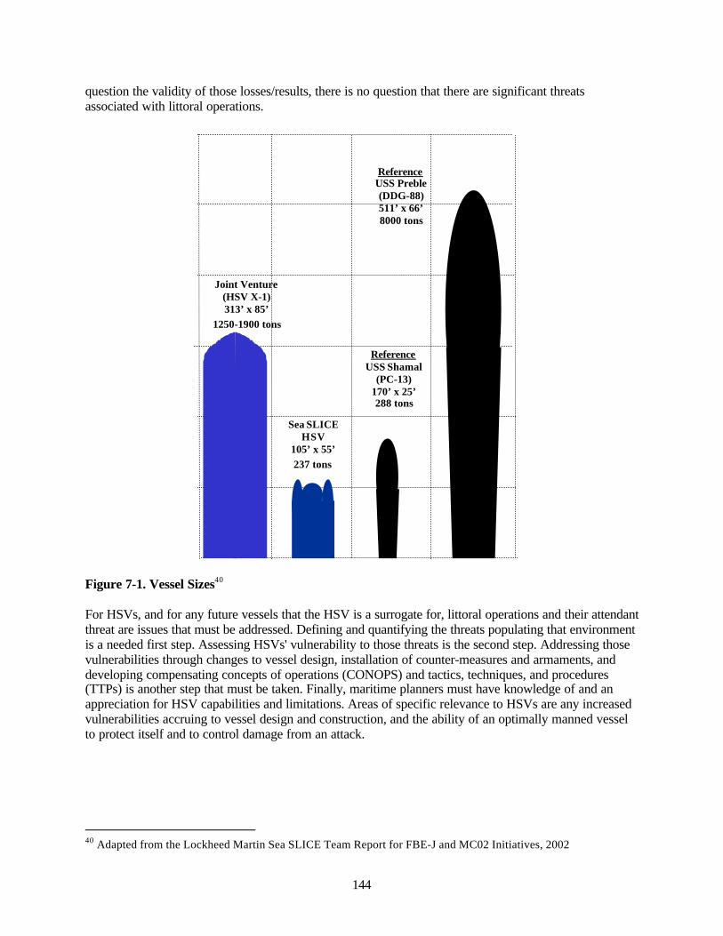
144
question the validity of those losses/results, there is no question that there are significant threatsassociated with littoral operations.
Figure 7-1. Vessel Sizes40
For HSVs, and for any future vessels that the HSV is a surrogate for, littoral operations and their attendantthreat are issues that must be addressed. Defining and quantifying the threats populating that environmentis a needed first step. Assessing HSVs' vulnerability to those threats is the second step. Addressing thosevulnerabilities through changes to vessel design, installation of counter-measures and armaments, anddeveloping compensating concepts of operations (CONOPS) and tactics, techniques, and procedures(TTPs) is another step that must be taken. Finally, maritime planners must have knowledge of and anappreciation for HSV capabilities and limitations. Areas of specific relevance to HSVs are any increasedvulnerabilities accruing to vessel design and construction, and the ability of an optimally manned vesselto protect itself and to control damage from an attack.
40 Adapted from the Lockheed Martin Sea SLICE Team Report for FBE-J and MC02 Initiatives, 2002
ReferenceUSS Shamal
(PC-13)170’ x 25’288 tons
Sea SLICEHSV
105’ x 55’237 tons
Joint Venture(HSV X-1)313’ x 85’
1250-1900 tons
ReferenceUSS Preble(DDG-88)511’ x 66’8000 tons
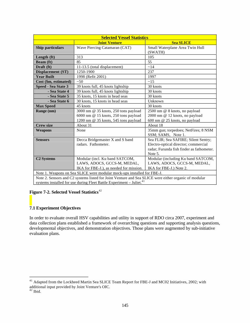
145
Selected Vessel StatisticsJoint Venture Sea SLICE
Ship particulars Wave Piercing Catamaran (CAT) Small Waterplane Area Twin Hull(SWATH)
Length (ft) 313 105Beam (ft) 85 55Draft (ft) 11-13.5 (total displacement) ~14Displacement (ST) 1250-1900 237Year Built 1998 (Refit 2001) 1997Cost ($m, estimated) ~50 ~15Speed - Sea State 3 39 knots full, 45 knots lightship 30 knots - Sea State 4 39 knots full, 45 knots lightship 30 knots - Sea State 5 35 knots, 15 knots in head seas 30 knots - Sea State 6 30 knots, 15 knots in head seas UnknownMax Speed 45 knots 30 knotsRange (nm) 3000 nm @ 35 knots, 250 tons payload
6000 nm @ 15 knots, 250 tons payload1200 nm @ 35 knots, 545 tons payload
2500 nm @ 8 knots, no payload2000 nm @ 12 knots, no payload600 nm @ 25 knots, no payload
Crew size About 31 About 18Weapons None 35mm gun; torpedoes; NetFires; 8 NSM
SSM; SAMS, Note 1.Sensors Decca Bridgemaster X and S band
radars. Fathometer.Sea FLIR; Sea SAFIRE; Silent Sentry;Electro-optical director; commercialradar; Furunda fish finder as fathometer.Note 5.
C2 Systems Modular (incl. Ku band SATCOM,LAWS, ADOCS, GCCS-M, MEDAL,IKA for FBE-J.), as needed for mission.
Modular (including Ku band SATCOM,LAWS, ADOCS, GCCS-M, MEDAL,IKA for FBE-J.) Note 2.
Note 1. Weapons on Sea SLICE were modular mock-ups installed for FBE-J.Note 2. Sensors and C2 systems listed for Joint Venture and Sea SLICE were either organic of modularsystems installed for use during Fleet Battle Experiment – Juliet.41
Figure 7-2. Selected Vessel Statistics42
7.1 Experiment Objectives
In order to evaluate overall HSV capabilities and utility in support of RDO circa 2007, experiment anddata collection plans established a framework of overarching questions and supporting analysis questions,developmental objectives, and demonstration objectives. Those plans were augmented by sub-initiativeevaluation plans.
41 Adapted from the Lockheed Martin Sea SLICE Team Report for FBE-J and MC02 Initiatives, 2002; withadditional input provided by Joint Venture's OIC.42 Ibid.

146
7.1.1 Overarching Questions
Experiment design and its supporting data collection plan addressed the following overarching questionsfor HSV participation in FBE-J.
• What added value do a number of high speed, reconfigurable, and multi-mission platformsprovide the JFMCC and the JFC in a littoral campaign as part of an access mission?
• What are the missions best suited (or appropriate) to this concept of maritime operations?• In a netted environment with many and varied types of sensors, what are the advantages or
disadvantages of the C2 construct used in this concept?• What conditions and design features must be considered in engineering the capabilities required
to meet the challenges in a 2007 campaign?
7.1.2 Analytic Questions
In order to answer the aforementioned overarching questions, the following supporting analyticalquestions were identified.
• HSVs would be suitable for maritime operations if:
ο They are capable of surviving in the natural and operational environment required forvessel employment.
ο The HSV has sufficient endurance to perform its missions.ο The HSV has sufficient sea-keeping ability to perform assigned missions (see the sub-
initiatives).
• Participation of HSVs could enhance maritime and joint mission performance, due to uniqueHSV characteristics related to:
ο High speedο High payload fractionο Shallow draftο Support for off-board vehicle operations (air, includes helicopter and UAVs; surface
includes USVs and small boats; and sub-surface includes UUVs)ο C4I support for command and controlο Self-deployingο Reconfiguration.
Analysis methodology relied primarily on comprehensive reconstruction of HSV events and case studyanalyses specific to the performance capabilities stated above.
Of the overarching questions and supporting analytical questions, data were gathered from live vesseloperations to address the appropriateness of missions, sensor employment, required operating conditions,and design features questions. For the supporting analysis objectives, benign weather in both live vesseland simulated vessel operations precluded testing the HSVs ability to survive its natural operatingenvironment.
147
7.1.3 Developmental Objectives
In addition to validating data gathered during previous project experimentation, FBE-J's operationalsetting was an opportunity to gather additional data in support of future ship and system design. Specificdevelopmental objectives or areas of interest included the HSV's ability to:
• Launch and recover helicopters, small boats, and unmanned vehicles (air, surface, and sub-surface).
• Pier-side loading and unloading of personnel, cargo, and equipment.• Support embarked crew and passengers (vessel habitability: berthing, messing, sanitation, work-
spaces).
7.1.4 Demonstration Objectives
HSV-X1 and Sea SLICE were used by a number of agencies to demonstrate agency-sponsored systemperformance during FBE-J. Some of those demonstration objectives were designed to show that a systemwas interoperable with the HSVs. Data collected against those systems are included in this section. Forother systems, the HSVs were merely platforms of opportunity to demonstrate system performance withno other HSV-system relationship. Results of this latter (opportune platform) grouping are not recountedin this chapter.
For both developmental and demonstration objectives, data collection relied on participant observationsof performance, documentation of processes used to perform tasks, and operator interviews.
7.2 Sub-initiative Analytic Questions
In addition to satisfying sponsoring command or agency experimentation requirements, the sub-initiativesalso provide data that helped answer the overarching, supporting analytical, and developmental questions.Sub-initiative objectives are summarized in the following paragraphs.
7.2.1 HSV Support to Mine Warfare (MIW)
Data collection on MIW missions evaluated a live and/or simulated HSV’s ability to provide or support:
• Live vessel C4I (including specialized tools for mission planning and execution), office space,and hotel services for the embarked MIW Commander (MIWC)
• Embarked mine counter measures (MCM) vehicles including SH-60 helicopters (simulatedvessels only) and a variety of remote off-board MCM systems (live and simulated vessels).Included in the evaluation is HSV's ability to support off-board MCM systems mission planning,maintenance, mobility, launch, and control during missions; recovery; and post-missionprocessing activities.
• An embarked explosive ordnance disposal mobile unit (EODMU) with dive boats and divingequipment, including mobility, office space, mission planning support, hotel services, andmaintenance and supply storage
• Providing force protection for other vessels and systems (Sea SLICE only)
• Towed sonar for environmental survey, search, detection, and localization of mine-like objects.
148
7.2.2 HSV Support to Navy Special Warfare (NSW)
Data collection on NSW missions evaluated a live and/or simulated HSV’s ability to provide an afloatforward operating base (FOB) for NSW forces. In the FOB role, the HSV-X1 embarked a task unit (TU)headquarters, three SEAL platoons, tactical mobility platforms (RHIB, SDV, etc.), and other requiredpersonnel and equipment. Included in this evaluation was the HSV's ability to provide or support:
• A platform for C4I support (including specialized tools for mission planning and executioncontrol), office space, and hotel services for the embarked TU headquarters
• A platform to move NSW forces and equipment
• Launch, recovery, mission preparation, and maintenance of tactical mobility platforms (smallboats).
7.2.3 HSV Support to Ship to Objective Maneuver (STOM)
In light of the fact that the Marine Corps developed an independent experiment and data collection plan,43
FBE-J planners opted not to duplicate their efforts with a separate Navy-generated evaluation of HSVsupport to Marine Corps STOM operations. Marine Corps evaluation of the HSV focused on assessingthe role of high-speed vessels during Marine Air-Ground Task Force (MAGTF) operations in a littoralenvironment. Included in that evaluation was the HSV's ability to provide or support:
• Insertion/extraction of Reconnaissance, Surveillance, Target Acquisition (RSTA) elements
• Reinforcement and sustainment of MAGTF forces ashore in order to maintain operationalmomentum
• Humanitarian evacuation of personnel (non-combatants)
• Command and Control of landward and seaward forces
• Operational intra-theater lift of cargo, vehicles, and personnel.
7.2.4 HSV in Logistics Support to Deployed Forces Ashore
As originally envisioned, live and simulated HSVs would be evaluated for their ability to supportsustaining logistics to forces deployed ashore. Due to competing requirements for simulated vessels, therewas very little logistics play within the simulation. Live vessel support to logistics operations wereincidental to the Marine Corps' STOM and the Army's Force Deployment LOEs. Those results areaddressed in other sections of this chapter.
43 Marine Corps Warfighting Lab (MCWL) report, "MILLENNIUM CHALLENGE 02 LIMITED OBJECTIVEEXPERIMENT, JOINT HIGH SPEED VESSEL ANALYSIS REPORT," 16 August 2002.
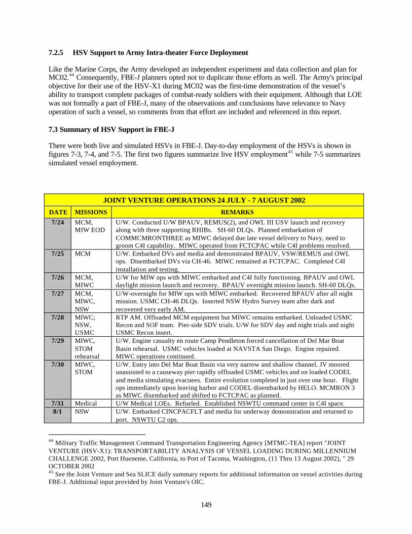
149
7.2.5 HSV Support to Army Intra-theater Force Deployment
Like the Marine Corps, the Army developed an independent experiment and data collection and plan forMC02.44 Consequently, FBE-J planners opted not to duplicate those efforts as well. The Army's principalobjective for their use of the HSV-X1 during MC02 was the first-time demonstration of the vessel’sability to transport complete packages of combat-ready soldiers with their equipment. Although that LOEwas not formally a part of FBE-J, many of the observations and conclusions have relevance to Navyoperation of such a vessel, so comments from that effort are included and referenced in this report.
7.3 Summary of HSV Support in FBE-J
There were both live and simulated HSVs in FBE-J. Day-to-day employment of the HSVs is shown infigures 7-3, 7-4, and 7-5. The first two figures summarize live HSV employment45 while 7-5 summarizessimulated vessel employment.
JOINT VENTURE OPERATIONS 24 JULY - 7 AUGUST 2002
DATE MISSIONS REMARKS
7/24 MCM,MIW EOD
U/W. Conducted U/W BPAUV, REMUS(2), and OWL III USV launch and recoveryalong with three supporting RHIBs. SH-60 DLQs. Planned embarkation ofCOMMCMRONTHREE as MIWC delayed due late vessel delivery to Navy, need togroom C4I capability. MIWC operated from FCTCPAC while C4I problems resolved.
7/25 MCM U/W. Embarked DVs and media and demonstrated BPAUV, VSW/REMUS and OWLops. Disembarked DVs via CH-46. MIWC remained at FCTCPAC. Completed C4Iinstallation and testing.
7/26 MCM,MIWC
U/W for MIW ops with MIWC embarked and C4I fully functioning. BPAUV and OWLdaylight mission launch and recovery. BPAUV overnight mission launch. SH-60 DLQs.
7/27 MCM,MIWC,NSW
U/W-overnight for MIW ops with MIWC embarked. Recovered BPAUV after all nightmission. USMC CH-46 DLQs. Inserted NSW Hydro Survey team after dark andrecovered very early AM.
7/28 MIWC;NSW,USMC
RTP AM. Offloaded MCM equipment but MIWC remains embarked. Unloaded USMCRecon and SOF team. Pier-side SDV trials. U/W for SDV day and night trials and nightUSMC Recon insert.
7/29 MIWC,STOMrehearsal
U/W. Engine casualty en route Camp Pendleton forced cancellation of Del Mar BoatBasin rehearsal. USMC vehicles loaded at NAVSTA San Diego. Engine repaired.MIWC operations continued.
7/30 MIWC,STOM
U/W. Entry into Del Mar Boat Basin via very narrow and shallow channel. JV mooredunassisted to a causeway pier rapidly offloaded USMC vehicles and on loaded CODELand media simulating evacuees. Entire evolution completed in just over one hour. Flightops immediately upon leaving harbor and CODEL disembarked by HELO. MCMRON 3as MIWC disembarked and shifted to FCTCPAC as planned.
7/31 Medical U/W Medical LOEs. Refueled. Established NSWTU command center in C4I space.8/1 NSW U/W. Embarked CINCPACFLT and media for underway demonstration and returned to
port. NSWTU C2 ops.
44 Military Traffic Management Command Transportation Engineering Agency [MTMC-TEA] report "JOINTVENTURE (HSV-X1): TRANSPORTABILITY ANALYSIS OF VESSEL LOADING DURING MILLENNIUMCHALLENGE 2002, Port Hueneme, California, to Port of Tacoma, Washington, (11 Thru 13 August 2002), " 29OCTOBER 200245 See the Joint Venture and Sea SLICE daily summary reports for additional information on vessel activities duringFBE-J. Additional input provided by Joint Venture's OIC.
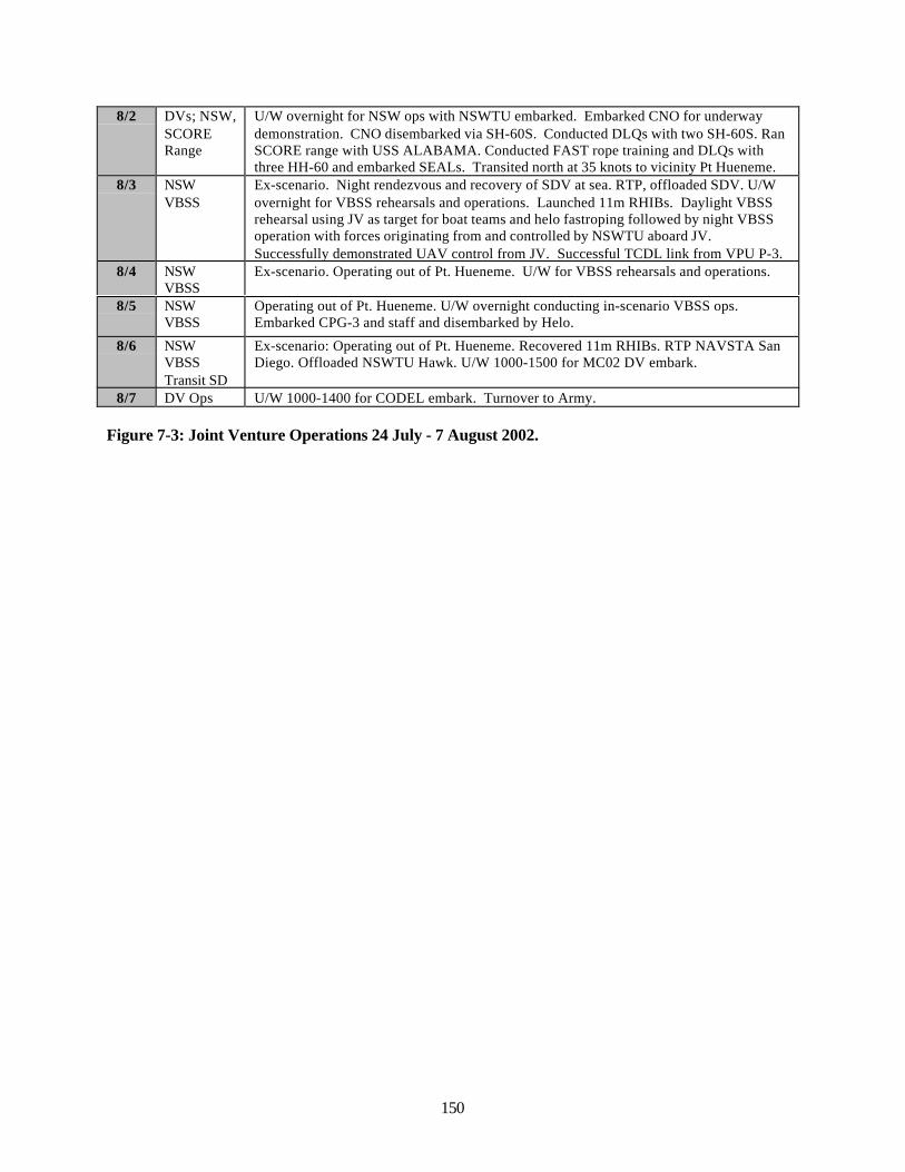
150
8/2 DVs; NSW,SCORERange
U/W overnight for NSW ops with NSWTU embarked. Embarked CNO for underwaydemonstration. CNO disembarked via SH-60S. Conducted DLQs with two SH-60S. RanSCORE range with USS ALABAMA. Conducted FAST rope training and DLQs withthree HH-60 and embarked SEALs. Transited north at 35 knots to vicinity Pt Hueneme.
8/3 NSWVBSS
Ex-scenario. Night rendezvous and recovery of SDV at sea. RTP, offloaded SDV. U/Wovernight for VBSS rehearsals and operations. Launched 11m RHIBs. Daylight VBSSrehearsal using JV as target for boat teams and helo fastroping followed by night VBSSoperation with forces originating from and controlled by NSWTU aboard JV.Successfully demonstrated UAV control from JV. Successful TCDL link from VPU P-3.
8/4 NSWVBSS
Ex-scenario. Operating out of Pt. Hueneme. U/W for VBSS rehearsals and operations.
8/5 NSWVBSS
Operating out of Pt. Hueneme. U/W overnight conducting in-scenario VBSS ops.Embarked CPG-3 and staff and disembarked by Helo.
8/6 NSWVBSSTransit SD
Ex-scenario: Operating out of Pt. Hueneme. Recovered 11m RHIBs. RTP NAVSTA SanDiego. Offloaded NSWTU Hawk. U/W 1000-1500 for MC02 DV embark.
8/7 DV Ops U/W 1000-1400 for CODEL embark. Turnover to Army.
Figure 7-3: Joint Venture Operations 24 July - 7 August 2002.
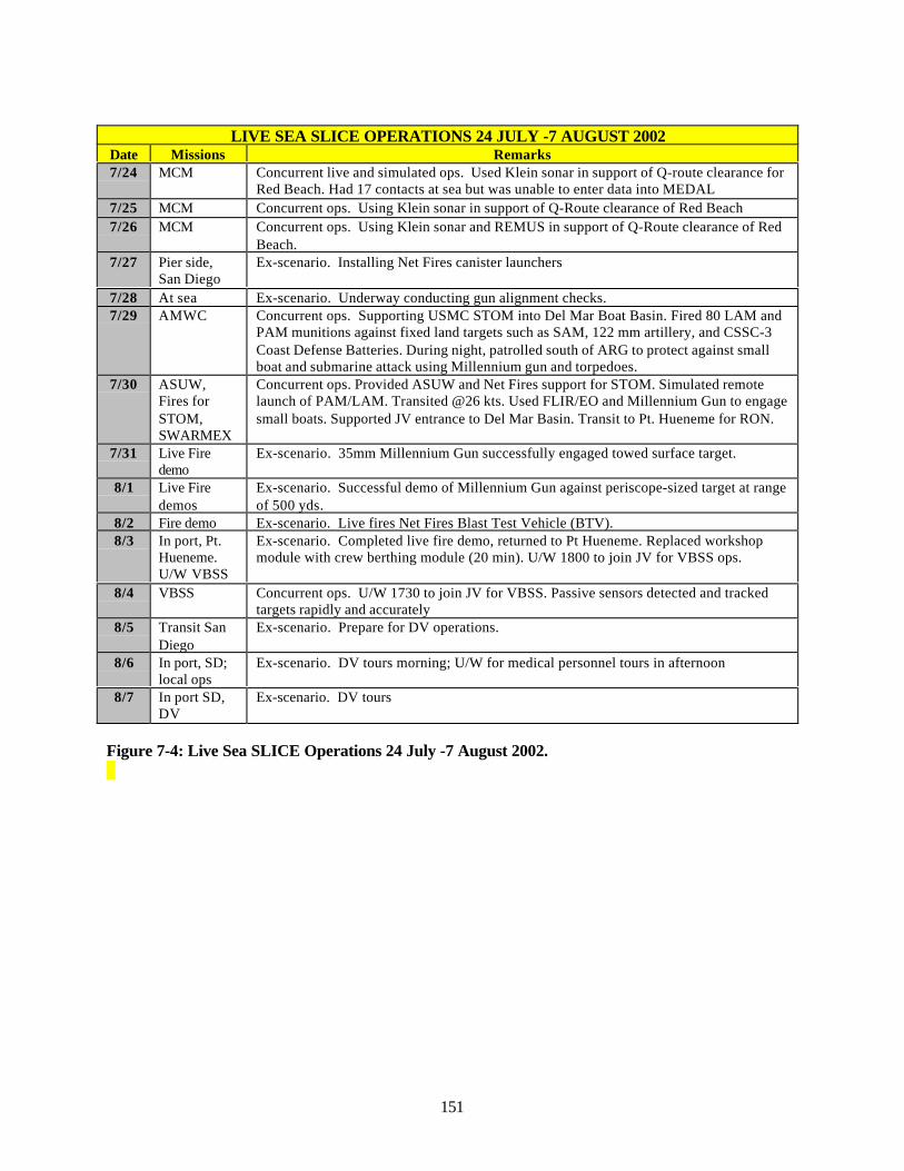
151
LIVE SEA SLICE OPERATIONS 24 JULY -7 AUGUST 2002Date Missions Remarks7/24 MCM Concurrent live and simulated ops. Used Klein sonar in support of Q-route clearance for
Red Beach. Had 17 contacts at sea but was unable to enter data into MEDAL7/25 MCM Concurrent ops. Using Klein sonar in support of Q-Route clearance of Red Beach7/26 MCM Concurrent ops. Using Klein sonar and REMUS in support of Q-Route clearance of Red
Beach.7/27 Pier side,
San DiegoEx-scenario. Installing Net Fires canister launchers
7/28 At sea Ex-scenario. Underway conducting gun alignment checks.7/29 AMWC Concurrent ops. Supporting USMC STOM into Del Mar Boat Basin. Fired 80 LAM and
PAM munitions against fixed land targets such as SAM, 122 mm artillery, and CSSC-3Coast Defense Batteries. During night, patrolled south of ARG to protect against smallboat and submarine attack using Millennium gun and torpedoes.
7/30 ASUW,Fires forSTOM,SWARMEX
Concurrent ops. Provided ASUW and Net Fires support for STOM. Simulated remotelaunch of PAM/LAM. Transited @26 kts. Used FLIR/EO and Millennium Gun to engagesmall boats. Supported JV entrance to Del Mar Basin. Transit to Pt. Hueneme for RON.
7/31 Live Firedemo
Ex-scenario. 35mm Millennium Gun successfully engaged towed surface target.
8/1 Live Firedemos
Ex-scenario. Successful demo of Millennium Gun against periscope-sized target at rangeof 500 yds.
8/2 Fire demo Ex-scenario. Live fires Net Fires Blast Test Vehicle (BTV).8/3 In port, Pt.
Hueneme.U/W VBSS
Ex-scenario. Completed live fire demo, returned to Pt Hueneme. Replaced workshopmodule with crew berthing module (20 min). U/W 1800 to join JV for VBSS ops.
8/4 VBSS Concurrent ops. U/W 1730 to join JV for VBSS. Passive sensors detected and trackedtargets rapidly and accurately
8/5 Transit SanDiego
Ex-scenario. Prepare for DV operations.
8/6 In port, SD;local ops
Ex-scenario. DV tours morning; U/W for medical personnel tours in afternoon
8/7 In port SD,DV
Ex-scenario. DV tours
Figure 7-4: Live Sea SLICE Operations 24 July -7 August 2002.
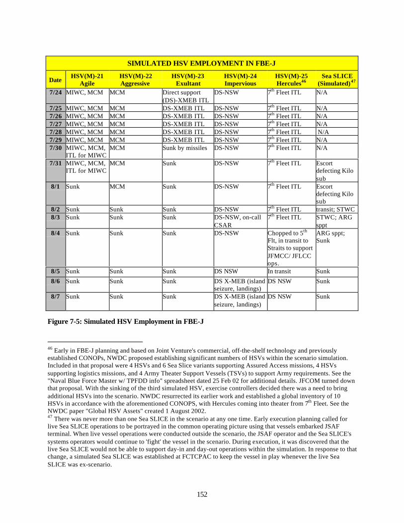
152
SIMULATED HSV EMPLOYMENT IN FBE-J
DateHSV(M)-21
AgileHSV(M)-22Aggressive
HSV(M)-23Exultant
HSV(M)-24Impervious
HSV(M)-25Hercules46
Sea SLICE(Simulated)47
7/24 MIWC, MCM MCM Direct support(DS)-XMEB ITL
DS-NSW 7th Fleet ITL N/A
7/25 MIWC, MCM MCM DS-XMEB ITL DS-NSW 7th Fleet ITL N/A7/26 MIWC, MCM MCM DS-XMEB ITL DS-NSW 7th Fleet ITL N/A7/27 MIWC, MCM MCM DS-XMEB ITL DS-NSW 7th Fleet ITL N/A7/28 MIWC, MCM MCM DS-XMEB ITL DS-NSW 7th Fleet ITL N/A7/29 MIWC, MCM MCM DS-XMEB ITL DS-NSW 7th Fleet ITL N/A7/30 MIWC, MCM,
ITL for MIWCMCM Sunk by missiles DS-NSW 7th Fleet ITL N/A
7/31 MIWC, MCM,ITL for MIWC
MCM Sunk DS-NSW 7th Fleet ITL Escortdefecting Kilosub
8/1 Sunk MCM Sunk DS-NSW 7th Fleet ITL Escortdefecting Kilosub
8/2 Sunk Sunk Sunk DS-NSW 7th Fleet ITL transit; STWC8/3 Sunk Sunk Sunk DS-NSW, on-call
CSAR7th Fleet ITL STWC; ARG
sppt8/4 Sunk Sunk Sunk DS-NSW Chopped to 5th
Flt, in transit toStraits to supportJFMCC/ JFLCCops.
ARG sppt;Sunk
8/5 Sunk Sunk Sunk DS NSW In transit Sunk
8/6 Sunk Sunk Sunk DS X-MEB (islandseizure, landings)
DS NSW Sunk
8/7 Sunk Sunk Sunk DS X-MEB (islandseizure, landings)
DS NSW Sunk
Figure 7-5: Simulated HSV Employment in FBE-J
46 Early in FBE-J planning and based on Joint Venture's commercial, off-the-shelf technology and previouslyestablished CONOPs, NWDC proposed establishing significant numbers of HSVs within the scenario simulation.Included in that proposal were 4 HSVs and 6 Sea Slice variants supporting Assured Access missions, 4 HSVssupporting logistics missions, and 4 Army Theater Support Vessels (TSVs) to support Army requirements. See the"Naval Blue Force Master w/ TPFDD info" spreadsheet dated 25 Feb 02 for additional details. JFCOM turned downthat proposal. With the sinking of the third simulated HSV, exercise controllers decided there was a need to bringadditional HSVs into the scenario. NWDC resurrected its earlier work and established a global inventory of 10HSVs in accordance with the aforementioned CONOPS, with Hercules coming into theater from 7th Fleet. See theNWDC paper "Global HSV Assets" created 1 August 2002.47 There was never more than one Sea SLICE in the scenario at any one time. Early execution planning called forlive Sea SLICE operations to be portrayed in the common operating picture using that vessels embarked JSAFterminal. When live vessel operations were conducted outside the scenario, the JSAF operator and the Sea SLICE'ssystems operators would continue to 'fight' the vessel in the scenario. During execution, it was discovered that thelive Sea SLICE would not be able to support day-in and day-out operations within the simulation. In response to thatchange, a simulated Sea SLICE was established at FCTCPAC to keep the vessel in play whenever the live SeaSLICE was ex-scenario.
153
7.4 HSV Analysis Results
This section discusses analysis results from those objectives adequately supported by data. Overarchingquestions are answered in this chapter's summary, section 7.6.
7.4.1 Suitability of HSVs for Maritime Operations
The HSV experiment and data collection plans posit that a force of littoral surface combatants with thecharacteristics of an HSV will be suitable for Naval operations.48 Suitability was addressed in those plansin terms of survivability, endurance, and sea keeping. Technical data on sea keeping had already beencollected for Joint Venture as part of the joint HSV project, so only those conclusions discussingsurvivability and endurance are summarized here.
7.4.1.1 Survivability
For any vessel, survivability is a function of its ability to operate in its natural (or physical) and itsphysical operating environment. For both live and simulated vessel operations, natural environmentalconditions were not tested due to the very benign weather and sea conditions experienced during FBE-J.Consequently, only issues associated with simulated vessel survivability in its operating environment areaddressed.
One characteristic of HSV employment shared with other types of vessels is the inherent risk of operatingin a littoral environment. Mines, attacks from small boats, fires from shore batteries or any number ofother threats must be addressed in vessel design and in planning maritime operations. During FBE-J, anumber of simulated Navy ships and vessels were attacked and sunk during littoral operations. Thesimulated HSV experience vis-à-vis those threats is summarized below, and on the whole is indicative ofthe wider fleet experience within the simulation.
• HSV (M)-23 sunk by a missile on 30 July 2007 while supporting the Marines.• HSV (M)-21 sunk on 1 August 2007 while conducting MCS/MCM ops. Cause unknown.• HSV (M)-22 sunk by a missile on 2 August 2007 while conducting MCM ops.• Sea SLICE (simulated) sunk by missiles on 4 August 2007 while providing fires support to the
TARAWA ARG.
Each loss was due to the vessel coming in range of a threat, primarily missiles. Vessel operations withinrange of a fatal threat can be attributed to not knowing of the threat's existence, a breakdown in commandand control, a lack of knowledge on vessel capabilities and limitations, or a determination by theoperational commander that such risk was warranted. There is no evidence from the simulation that thosevessels fired their weapons (SEARAM, machine guns, grenade lauchers) in defense against the threats.
While some observers question the validity of those losses/results, there was no question in participantminds of the significant threats associated with littoral operations.49 For HSVs, and for any vessels thatthe HSV acts as a surrogate, littoral operations and their attendant threat are issues that must be addressed.Defining and quantifying the threats populating that environment is a essential first step. Assessing HSVs'vulnerability to those threats is the second step. Addressing those vulnerabilities through changes tovessel design, installation of counter-measures and armaments, and developing compensating CONOPSand TTPs is another step that must be taken. Finally, maritime planners must have knowledge of and an
48 FBE-J Experiment Plan, Joint Initiatives – High Speed Vessel49 Qualitative Survey, MIW, Question 16
154
appreciation for HSV capabilities and limitations. Areas of specific relevance to HSVs are any increasedvulnerabilities accruing to vessel design and construction, and the ability of an optimally manned vesselto protect itself and to control damage from an attack.
7.4.1.2 Endurance
Endurance is directly related to a vessel's ability to conduct sustained operations. Endurance encompassesconsiderations such as equipment and systems reliability; fuel storage, fuel consumption; crew ability tosupport long-term, high tempo operations; and essential support to embarked systems and personnel, i.e.hotel services such as water, food, power, and air conditioning.
In a vessel where those considerations were not principal design factors, endurance is very limited. SeaSLICE, built as a hull-form technology demonstrator, is an example of such a vessel. Sea SLICE'sendurance during FBE-J was very limited, and experimentation CONOPS were developed toaccommodate that limitation. As a surrogate for other vessels however, Sea SLICE's limited endurancehad very little impact on its ability to meet planned experimentation objectives.
In vessels where endurance considerations were given more weight in their design, greater endurance canbe expected. Joint Venture, as a car ferry designed for short duration, high speed transits between ferryterminals, could be expected to have reliable commercial equipment and systems but only a limited abilityto conduct sustained, high tempo military operations. To the extent that the vessel was modified withextra fuel and water storage, water-making capability, food storage, increased crew size, permanent (butaustere) crew berthing, etc., its endurance increased. Due to funding and time constraints, thosemodifications were limited, so increases in vessel endurance were also limited.
Available data do not support drawing conclusions on equipment and systems reliability as they relate tothe vessels themselves. It is sufficient to observe that equipment reliability was adequate to the task andthat each vessel completed its planned experimentation. There are enough data, however, to evaluate theother endurance considerations of fuel storage and consumption, support from the crew, and support tothe crew and/or passengers.
7.4.1.2.1 Fuel Storage and Consumption
By far the best opportunity to evaluate vessel endurance as it relates to fuel storage and fuel consumptionis the Army's delivery voyage of Joint Venture from CENTCOM to San Diego and its subsequentturnover to the Navy for FBE-J execution. Covering a total distance of 13226 nautical miles in an elapsedtime of 23 days 6 hours, with an average underway speed of 28 knots, with only four stops for fuel thestatistics speak for themselves. HSV technology strongly enhances vessel endurance vis-à-vis fuel storageand consumption.50
7.4.1.2.2 Crew Manning and Performance
During FBE-J, both Joint Venture and Sea SLICE had core crews augmented by embarked personnel andstaffs to create their respective warfighting capabilities.
50 Additional information on the Army's transit voyage is available in a 16 July Power Point brief "Army RoutePersian Gulf to San Diego;" a 16 July spreadsheet "Army Route Persian Gulf to San Diego;" and U.S. ArmyCombined Arms Support Command report "HSV-X1 (Joint Venture), U.S. Army Snapshot, 20 March 02 to 13 July02" dtd 15 Jan 03.
155
Joint Venture's core (or baseline) crew consisted of 31 sailors and soldiers. As a result of lessons learnedfrom previous operations, crew size increased to 42 in order to support embarked staff operations.Embarked staff more than doubled those numbers. Sea SLICE's four core crewmembers were augmentedwith an additional 10 systems operators to give that vessel its warfighting capabilities.
While all deck evolutions, support for embarked staffs, and appropriate services were safely andeffectively accomplished, Joint Venture's experience during FBE-J suggests that assumptions regardingadequate crew size need to be reviewed for any vessel similar to HSVs. As an example, when the vesselwent to flight quarters, 19 crewmembers were pulled away from their primary duties to support flightoperations.51 Although not quantified, the opportunity cost associated with flight operations was notinsignificant.52
More insidious, and with more potential impact on vessel endurance and ability to accomplish assignedmissions, is the impact of reduced crew size and vessel habitability on individual crewmemberperformance. Optimal vessel manning only makes sense to the extent that it takes into account individualperformance.
During FBE-J, a small, very limited experiment was conducted to evaluate the relationship between theJoint Venture, its crew, and fatigue. Activity levels for 4 crewmembers were monitored during theexperiment. As a group, these crewmembers averaged approximately 3 hours sleep per night, with a rangefrom 2 to 5 hours. Individuals with sleep patterns such as those seen on the HSV have predictabledecrements in performance and a greatly increased risk of mishaps due to lapses in attention and fatigue.53
Given those conditions, Joint Venture's successful completion of missions without mishap during FBE-Jis testimony to a superb, well-led crew. Nonetheless, while the small sample size limits conclusions, theseresults warrant further investigation for their risk management implications and impact on future shipdesign (and endurance).54
Additional discussion and information on this issue is available in Chapter 19 and Appendix 11.
7.4.1.2.3 Hotel Services
As mentioned earlier, neither Joint Venture nor Sea SLICE were designed to accommodate significantnumbers of crew and embarked staff for long periods of time. The limited amount and quality of hotelservices limited each vessel's endurance. A known constraint before experiment execution, CONOPS forthese surrogate vessels was adjusted to compensate for these limitations. Participants, while notingshortfalls,55,56 took the minor hardships in stride and completed their missions. The predeterminedconclusion from this aspect of vessel operations is that if greater endurance is desired, more considerationmust be given to hotel services.
51 Fleet Battle Experiment – Juliet, HSV Initiative, Summary Report, Additional Information52 MCWL report, p. 2153 Hursh, S. R., Redmond, D. P., Johnson, M. L., Thorne, D. R., Belenky, G., Balkin, T. J., Storm, W. F., Miller, J.C., and Eddy, D. R. (in press). Fatigue Models for Applied Research in War Fighting. Aviation, Space, andEnvironmental Medicine, 2002.54 Manning lessons learned from FBE-J confirmed the need identified earlier to increase HSV crew size. While theFBE was being conducted, Navy planners were working on design criteria for Joint Venture's replacement. As aresult of this data, crew size for HSV-2 (scheduled for delivery to the Navy in July, 2003 is set at 40.55 Fleet Battle Experiment Juliet (FBE-J), Survey Results, HSV.56 MCWL report, p. 21.
156
7.4.1.3 Suitability Summary
Conclusions as to vessel suitability for Naval operations must be reached cautiously. Both Joint Ventureand Sea SLICE are surrogates for future vessels. As surrogates, during FBE-J they were super-imposedinto artificial operating environments in order to gather data on their suitability. Despite theseartificialities, there are enough data to suggest that HSV technology, and in the case of the Joint Venturethe vessel itself, are potentially suitable for Naval operations. To the extent that these surrogates weremodified, they became even more suitable. With greater emphasis given to survivability, manning,personnel services, and other considerations in vessel design, their suitability for Naval operations willincrease further.
7.4.2 HSV Characteristics and Mission Performance
As surrogates for future vessels, assessing the value of selected HSV characteristics provides programoffices with important data during their design deliberations. As an example, if one of the HSV's uniquecharacteristics is speed, then the FBE-J experience should identify numerous opportunities where speedwas a deciding factor in mission success. Confirming the value of HSV speed should suggest to programmanagers that there is a need to invest in future vessel's speed. Conversely, if the FBE-J experiencesuggests speed is not that critical, then the investment in speed can be reduced in favor of othercharacteristics more important to mission accomplishment. In this section, the HSV characteristics of highspeed, high payload fraction, shallow draft, support to other vehicle operations, and a sampling of otherconsiderations are discussed.
7.4.2.1 High Speed
Navy officers know intuitively that some speed is good, and more speed is better. At first glance, assimulated vessels conducted transits into the scenario's theater of operations, the ability to close the forcequickly by taking advantage of the vessels high speeds seems to bear out this intuition. The simulatedvessel HSV (M)-25 entered the theater of operations at 51 knots. 57 Joint Venture routinely demonstratedspeeds of 25 knots in transit and when engaged in VBSS operations. It also “conducted daily high-speedtransits to and from the southern California (SOCAL) operating areas in support of multiple tasking (toinclude 17 unassisted port entries and departures).”58 During the health services DV operationsdemonstration, its speeds averaged 31 knots in 2-3 foot seas.59 Sea SLICE transited at 26 knots duringFBE-J and made speeds of 30 knots during VBSS operations. The Army live vessel delivery of JointVenture from CENTCOM to the San Diego, the transit into and out of Del Mar Boat Basin, and somelimited anecdotal comments from the MIWC staff also reinforce the conclusion that speed has value.
A review of both live and simulated vessel usage during FBE-J suggests however that high speed, whilestill an important characteristic, was not as important as other characteristics within the scenario. With theexception of transits to, and occasionally within a theater, see tables 7-3, 7-4, and 7-5, high speed was nota principal determinant in mission success. The primary reason for the limited display of vessel speed istheir assigned missions. Speed has limited utility in MCS and MCM roles (HSV (M)-21 and -22), orwhile in port waiting for missions (HSV (M)-23 and -24). If those vessels' primary missions had beenlogistics support or force closure, speed as a premium would have been valuable.
57 IWS Chat Log, 6 Aug 0258 HSV Preliminary Quicklook Report59 “Underway Evaluation of the HSV for Health Service Support Capabilities,” NWDC Trip Report
157
The FBE-J experience suggests that future vessel designs should not ignore other HSV designcharacteristics in favor of speed. As an example, through modeling and careful analysis of anticipatedvessel CONOPS, program managers may find that vessel ability to enter austere ports and discharge cargomay have greater value than speed.
7.4.2.2 High Payload Fraction
Simply stated, payload fraction refers to that portion, or fraction, of total vessel displacement that can bedevoted to payload. Maximum payload (high payload fraction) is also a function of fuel and cargo. ForHSVs, the greater the fuel load and subsequently greater range and/or higher speeds, the smaller thecargo. Greater cargo loading, however, results in a smaller fuel load and subsequently shorter rangeand/or lower speeds.
Joint Venture's maximum payload is 840 tons; nearly equal to its deadweight 915 tons (the basic vesselweight without fuel or cargo). Sea SLICE, as a hull-form technology demonstrator, was not designed tohave a high payload fraction.
With one exception in an associated action, payload fraction was not a principal determinant for missionsuccess during FBE-J in either live or simulated vessel play. The exception was the Army's SBCTmovement from Port Hueneme, California to Tacoma, Washington. With vehicles (386 tons), trip fuel,and fuel reserve the Joint Venture's payload was only 668 tons, well under her maximum payload. Noother live HSV action in the experiment came close to demonstrating the values of high payload fraction.This one exception however, demonstrates the efficacy of ships with high payload fraction.
7.4.2.3 Shallow Draft and Vessel Maneuverability
Shallow draft and vessel maneuverability were principal determinants in the success of live vesselmissions. During FBE-J, both Joint Venture and Sea SLICE took advantage of their relatively shallowdrafts of 13 and 14 feet, respectively to provide support. Both vessels moved into shallow water, close toshore, to support MCM operations. Additionally, in a demonstration of fine seamanship and as avalidation of the value of shallow draft coupled with great maneuverability, Joint Venture entered DelMar boat basin, moored, offloaded equipment, and departed without assistance. To improve maneuveringvisibility, the vessel was backed up the relatively long, narrow (150 yards wide), and shallow (18 footdepth) channel. The transit took approximately 20 minutes at 2 to 5 knots, was done without assistancefrom tugs, and passed without problems. Once in the basin, the vehicle ramp was lowered onto a pre-positioned causeway and vehicles were offloaded, people loaded aboard, and the vessel departed, all inapproximately an hour.60 Joint Venture was by far the largest vessel to ever enter this basin.
The importance of Joint Venture's Del Mar boat basin operation to force closure; reception, staging,onward-movement, and integration (RSOI); STOM; and force sustainment, cannot be overstated.Depending on the operating theater, independent studies suggest that the number of ports available formilitary use increases by nearly 600% when depth requirements are reduced from 36 feet to 15 feet (orunder).61 Expanding the number of available ports in turn, expands the freedom and opportunitiesavailable to a joint force conducting the aforementioned operations.
60 MCWL report.61 CNA Research Memorandum D0005440.A1/Final, World Ports: Pier Depth and Harbor Size—Parts I & II: TheMediterranean and Black Sea, by Daniel P. Roek, January 2002.
158
7.4.2.4 Support for Air, Surface and Sub-Surface Vehicle Operations
HSVs' ability to support air, surface, and sub-surface operations was a principal determinant in successfulcompletion of their assigned missions. The ability to support these operations makes each vessel morethan just a ship moving through the water. The ability to support these operations transforms these vesselsfrom a car ferry or a technology demonstrator into a warship, even if only as a surrogate in an artificialenvironment. Support to those operations is discussed more fully in the following paragraphs.
7.4.2.4.1 Air Operations
Both vessels' ability to support helicopter operations contributed to successful mission completion. SeaSLICE, without a landing deck, was not able to support helicopter takeoff or landings. Nonetheless, itdemonstrated an ability to support limited vertical replenishment and movement operations when a CH-46 from HC-11 lifted Joint Warfighter's Counterfire System (JWCS) from Sea SLICE to shore. JWCSprovides fires support to troops ashore.
Although limited to day, visual flight rules operations by her Naval Air Systems CommandCertification,62 Joint Venture made good use of her ability to support helicopter operations.
• SH60F – Deck Landing Qualifications (DLQs) (30 takeoffs/landings)• HH60H - NSW fast rope (16 takeoffs/landings)• H60S - DLQ/CNO transfer (6 takeoffs/landings)• Navy CH46 - Passenger transfers (2 transfers)• USMC CH46- DLQs (14 takeoffs/landings)63
Joint Venture's helicopter support limitations are entirely due to previous decision to limit the amount ofmodifications made to this former car ferry. Only enough modifications were made to evaluate ordemonstrate the value of helicopter operations from HSVs during concepts-based experimentation. Nightlighting, NAVAIDs, fuel storage, and aviation refueling systems were not installed.
Among the comments accruing to FBE-J include the small size of the helicopter deck, and obstacles orrestrictions to approach and landing. 64 Lessons learned from Joint Venture's continuing helicopteroperations need to be distilled and provided to program offices using HSVs as surrogates for developmentof their vessels.
7.4.2.4.2 Surface and Sub-Surface Operations
Even more critical to HSV success during FBE-J than air operations were the vessel's ability to support animpressive array of surface and subsurface vehicle operations. The Joint Venture and/or Sea SLICEsuccessfully launched, operated, and retrieved the following vehicles:
• Battlespace Planning and Autonomous Undersea Vehicle (BPAUV)• Rigid Hull Inflatable Boat (RHIB)• Remote Minehunting System (RMS)• Remote Environmental Monitoring Unit System (REMUS)
62 COMNAVAIRSYSCOM PATUXENT RIVER MD R 172102Z DEC 01.63 Fleet Battle Experiment – Juliet, HSV Initiative, Summary Report, Additional Information64 MCWL report

159
• Klein side-scan radar• The Unmanned Harbor Security Vessel (UHSV) OWLIII• Swimmer/SEAL Delivery Vehicle (SDV)• Combat Rubber Reconnaissance Craft (CRRC)
Due to her small size and limited deck storage space, Sea SLICE support to surface and sub-surfaceoperations was limited to Klein sonar deployment and interoperability demonstrations with REMUS andRHIB deployment. CONOPS were developed to take advantage of her capabilities. Sea SLICE's Kleinside scan sonar operations in support of Q-route clearance for the Mine Warfare Commander provided avaluable demonstration of the vessel's capabilities to work in shallow waters while deploying surface andsub-surface systems.65
Joint Venture's greater size, particularly its 12,000+ square foot mission bay/vehicle deck make it ideallysuited to support surface and sub-surface operations. Advantages cited for using Joint Venture forautonomous underwater vehicles (AUVs) deployment included:
• The large bay to prepare for launch• Flexibility and room aboard• Robust C4I suite• Speed and maneuverability of the vessel• The large number of AUVs that can be carried and deployed. 66
With recognition that these were surrogate vessels and while applauding their capabilities, participantsnoted that both vessels vehicle deployment systems were not optimized for surface and sub-surfacesystem deployment and retrieval. Mention was made of Sea SLICE's knuckle-boom/A-frame.67 JointVenture's well-documented deficiencies in the crane used to launch and recover surface and sub-surfacevehicles were a source of comments as well. 68 Passenger unloading off of Joint Venture's port quarter wasidentified as an area of concern.69 All of these and other comments are valid concerns that should be takeninto account when the lessons learned from these surrogate vessels are carried forward into future shipdesign.
Additional discussion of HSV support to surface and sub-surface operations is available in Chapter 11(Mine Warfare).
7.4.2.5 C4I Support for Command and Control
Within the HSV initiative, evaluation of the vessels' ability to support C4I functions was limited todetermining the relative worth of C4I as an important vessel characteristic. Both live HSVs wereconfigured to provide C4I support through robust systems underpinned by high bandwidth Ku-bandsatellite communications.
Most of Joint Venture's C4I evaluation came from the MIWC and his staff (see chapter 11, MIW).Without duplicating the discussion in the MIW chapter, "… There was widespread support and praise forthe HSV [Joint Venture] as a command and control platform (Chapter 11, par. 11.3.3). The NSW Task
65 Lockheed-Martin Sea SLICE report66 Qualitative HSV Survey, Question 3167 Lockheed-Martin Sea SLICE report, p. 2668 MCWL report, pp. 8 & 969 Ibid, p. 14
160
Unit embarked and used their own C4I equipment, and Marine Corps STOM operations made only lightuse of the vessel's C4I capabilities (PRC-117, ICS 2003 Matrix Plus monitoring system).70
Sea SLICE's ability to support C4I functions was limited principally by her small spaces and consequentinability to support embarked C2 staffs.
Like the ability to support air, surface, and sub-surface operations, the HSVs' ability to support C4Ioperations is what distinguishes the HSVs in FBE-J from a car ferry or a technology demonstrator. C4I isa fundamental underpinning for RDO.
7.4.2.6 Self-deploying
As previously mentioned during the vessel endurance discussion, Joint Venture demonstrated a superbcapability to self-deploy over great distance at high speed with no support from auxiliary refuelingvessels. Although no data were gathered to evaluate the impact of that self-deployment, or the impact ofsimulated vessel self-deployment within the scenario, there should be no doubt as to this characteristic'svalue to the Joint Force Maritime Component Commander (JFMCC) and his staff.
7.4.2.7 Reconfiguration and Modularity
The value of these vessels to reconfigure for different mission sets was demonstrated through live vesseloperations, although only one simulated HSV was reconfigured. In order to meet the demand for livevessel access by various staffs, Joint Venture was configured or reconfigured for different missions fivetimes over a two and a half week period.71 Sea SLICE was configured or reconfigured four times over thatsame period, as shown in figure 7-4. In the fluid environment characterizing RDO, there is no question ofthe utility of vessels that can reinvent themselves to meet a variety of requirements.
Special note should be made of Sea SLICE's superb use of mission modules to give that hull-formtechnology demonstrator its warfighting capability. Sea SLICE had a comprehensive system for standardinstallation of deck-mounted equipment associated with particular missions. This standardizationpermitted installation and securing of equipment or modules very quickly, usually within minutes.72 Froma modularity perspective, the vessel itself was a communications backbone supported by a series ofinterfaces that allowed Sea SLICE to accept and integrate the following capabilities.
• Three C2 containers• A storage/maintenance shelter• Crew quarters• Weapons modules
o 35 mm Millennium Guno Torpedo Launcherso NetFires Live Fire Launchero JWCS STOM Support Launchero NetFires mock up launchers
• Small boat crane
There is much to learn from the Sea SLICE team's innovative approach to modularity.
70 Ibid, p. 2271 HSV Preliminary Quicklook Report.72 Lockheed Martin Sea SLICE Report.
161
7.4.2.8 Characteristics Summary
This brief review provides insight into how various HSV characteristics contributed to successful missionaccomplishment. Every one of the aforementioned characteristics has value. Clearly, HSV’s ability tosupport air, surface, and sub-surface operations enabled by a robust C4I system gives the vessels militaryutility and is arguably their most important characteristic. This 'most important' category also includesvehicle loading, unloading, and cargo handling considerations. A close second are the characteristics ofshallow draft and vessel maneuverability. The ability to move into and out of large numbers of austereports provides the JFC a distinct advantage in the conduct of his operations. While not fully exploitedduring this experiment, the value of high speed, high payload fraction, and self-deployment arecharacteristics that ship designers must keep in mind when developing future ships and vessels. Finally, inthe continuing era of austere funding, the flexibility inherent in reconfigurable vessels will be ofsignificant value to future JFMCCs as they shape the battlespace with ever-smaller numbers of ships.
7.4.3 Other Considerations
In addition to the discussion on the value of vessel characteristics or the vessel's suitability to supportNaval operations, there were other observations that should be noted in this report.
7.4.3.1 Health Services Support Assessment
Although not formally a part of the HSV initiative, NWDC took advantage of the proximity of San-Diegobased health services expertise to conduct a preliminary evaluation of the Joint Venture's ability to host orprovide health services support (HSS). Those evaluations, 73, 74 conducted before and during FBE-J,provided a wealth of information for use in HSV design and HSS CONOPS development. Included inthose reports were observations of certain environmental or other conditions aboard the vessel thatwarrant consideration in design or additional study. These include:
• Noise levels ranging from 85 to 96 decibels in the mission bay deck, requiring all personnelworking on that deck use hearing protection and interfered with basic medical procedures such ashearing manual blood pressure and lung sounds with a stethoscope
• The passageways were too narrow and elevators too small for litters• A ramping system is needed as a backup for the elevators• The vessel might be better suited to be rapid transportation out of a combat area rather than a
mobile treatment facility• Poor air quality due to diesel fumes was evident in the mission bay when the vehicle was loitering• Seasickness and fatigue while underway would impair the effectiveness of medical personnel.
7.4.3.2 Vessel Allocation
An unlooked for challenge affecting simulated HSV usage and the data that should have flowed from thatusage was the difficulty the JTF HQ and its component staffs had in effectively planning for and usingthis emerging, multi-mission asset. Symptomatic of the problem were simulated HSVs not showing up onmaritime tasking orders (MTOs), not planned for or requested in maritime support requests(MARSUPREQs), and not controlled in the simulation. While there is no evidence to suggest that a lackof control contributed to the sinking of any of the simulated HSVs, there is no evidence to suggest 73 "Underway Evaluation of the HSV for Health Service Support Capabilities," Trip Report, CDR Sara Marks, NC,USN74 "Fleet Hospital Specific Pier Side And Underway Evaluation Of The High Speed Vessel (HSV) For HealthService Support (HSS) Capabilities," Trip Report, 16-20 July 2002 and 31 July 2003.
162
otherwise. The challenges these staffs faced were primarily due to a still maturing maritime planningprocess (see chapter 5) and an immature HSV CONOPS.75
As the experiment continued to unfold, the JFMCC staff adopted a work-around procedure of placing allHSVs in a common-user pool used to manage logistics assets. This practice was widely acknowledged asa less than optimum solution as PWCs would always be uncertain as to HSV availability, and never have“ownership” of the asset for detailed planning. This problem was noted in MIW, when clearance taskstook several days to accomplish, but repetitive MARSUPREQs were not issued to ensure continuity oftasking. Unfortunately, no other allocation solution evolved during the experiment. The opportunity costassociated with this problem was a less-than-effective employment of the simulated HSV assets.76
7.5 Sub-Initiative Results
7.5.1 Results for HSV Support to Mine Warfare
Chapter 11, MIW, provides a detailed discussion of all aspects of MIW during FBE-J. Summarized hereare findings relevant to an evaluation of HSVs.
The HSV-X1 provided MIW support as a platform for experimentation from 23-28 July with launches ofBPUAV, REMUS, OWL III, and a VSW Detachment; and as the MIW Commander’s flagship from 26 –30 July. While functioning in that flagship capacity, it embarked the Tadpole data processing system forBPAUV and used MEDAL, LAWS, GCCS-M, and IWS software.77
Sea SLICE acted as an MCM platform from 24-26 July, clearing Q-routes with an embarked Klein sidescan sonar and REMUS. MEDAL was the software system used aboard Sea SLICE during MCMoperations.
"The concept of using the HSV as a MIW C4ISR platform to support the MIWC was highly successfully.The HSV proved to be a “good test platform and a suitable interim solution to the MIW C2 issue.”78 TheC4ISR suite provided the MIWC with adequate space and sufficient tools to participate in the JFMCCcollaborative environment and net-centric warfare. Communication interruptions had periodic adverseimpacts on the total effectiveness, but when the suite worked it was highly effective. Although there wereshortcomings, they did not stem from the location of the MIWC aboard the HSV.
• The HSV appears to be an excellent platform for supporting the MIWC and MCM. Advantagesinclude:
ο High speed to area of operations and while conducting various MIW missionsο Shallow draft will allow operations in relatively shallow waterο Large cargo volume can provide ample workspace and support areas for supporting
future remote autonomous vehicles (RAVs) and their operational mission andmaintenance crews.
• Disadvantages and risks include:ο Potential vulnerability of the HSV to hostile action due to design and construction
factors, lack of countermeasures or compensating CONOPS
75 Fleet Battle Experiment – Juliet, HSV Initiative, Summary Report, Additional Information76 Fleet Battle Experiment Juliet (FBE-J) Juliet Report, Final Summary Report, Section I. Principal Results77 Fleet Battle Experiment – Juliet, HSV Initiative, Summary Report, Additional Information78 JFMCC MIWC Top Three Lessons Learned Report, 3 Aug02
163
ο Loss of one HSV with large number of RAVs (est. 25 to 30) could risk the entire MIWmission success and/or timeline if additional resources are not readily available
ο Under the concept of rapid reconfiguration for HSVs, MIW may be competing with othermissions for the use of the HSV.
• Studies will need to be undertaken to mature the CONOPS for HSV support of MIW, includingο Determination of the appropriate number and overall distribution of MIW assets on HSVsο Assess the requirement for redundant back-up operational databases and MIWC SA in
case of lossο Assess the likelihood that competition for HSV resources will impact on MIW mission
successο Designing/determining launch and recovery systems optimized for surface and
subsurface vehicles.
7.5.2 Results for HSV Support to Navy Special Warfare
Both HSVs were used to support various NSW operations.
Joint Venture supported hydrographic reconnaissance missions on 27 and 28 July; SDV launch andrecovery operations on 28 July and 1 August; and provided an afloat forward operating base for anembarked NSW Task Unit commander (NSWTU Hawk) from 31 July through 6 August. During thelatter, 3 SEAL platoons, 2 11-meter RHIBs, and a SENTRY UAV control station were operated from theHSV-X1. Embarked NSW C4ISR equipment was supported by an HSV-provided TCDL data/video link.Voice communications, GCCS-M, and IWS software were also used in support of NSW operations.
These activities generated the following observations from the Joint Venture's crew:
• 16 NSW fast rope cycles were completed without discernable problems from an HH-60H (16bounces)
• The HSV's TCDL system supported a satisfactory video link with a VPU aircraft• Transom modifications (based on previous experimentation) made to the HSV to support NSW
11 meter RHIB operations were effective• An SDV full of water stresses the crane’s 10-ton limit. Further research is needed to identify the
full SDV’s weight.
The best overall evaluation of Joint Venture's NSW support comes from the NSWTU after action report.
“Live embarkation of HSV by a NSWTU proved the operational feasibility of using this platformas an afloat staging base. The embarked NSWTU was aboard the HSV for 5 days and conducted3 consecutive days of VBSS operations. This platform proved ideal for supporting NSWoperations but several major items were identified as needing modification to meet the followingneeds:
(1) Ability to launch, recover, and store 4 X NSW RHIBS at sea.(2) Ability to land and store a minimum of 2 X HH-60 helicopters.(3) Ability to house 2 X SEAL platoons and equipment.(4) Ability to house 1 X NSWTU headquarters element.
164
(5) Ability to have integrated comm. suite.”79
Sea SLICE teamed with Joint Venture from 3 to 5 August to successfully support NSW visit, board,search, and seizure (VBSS) operations. Her Sea FLIR and Sea Star SAFIRE II equipment provedparticularly beneficial in covertly locating targets from over four miles away. The equipment's laser andinfrared capability proved far superior to the standard starlight night vision equipment, particularly onnights when there was no starlight. It was also able to precisely observe and locate individualcrewmembers trying to hide on the target vessel before the SEAL team boarded. The FLIR also tracked atarget ship that tried to obscure its radar identification by merging its reflected signals with anothervessel.80
7.5.3 Results for HSV Support to STOM and Logistics
As mentioned earlier in this chapter, the Marine Corps Warfighting Lab (MCWL) developed anindependent experiment and data collection plan,81 and FBE-J planners opted not to duplicate their effortswith a separate Navy effort. Highlights and findings from MCWL's report follow:
• Over the period 28 to 30 July, Joint Venture supported an insertion of a reconnaissance team viaCRRCs, and introduced follow-on forces (3 LVS, 4 LAVs, 2 5-ton trucks) into an austere port (asrepresented by the Del Mar boat basin.
• Joint Venture successfully demonstrated its ability to support both MAGTF operational maneuverand the intra-theater movement of cargo and passengers between ports.
• Joint Venture acted as a communications relay between the Marine Reconnaissance and USSBoxer.
• Joint Venture successfully conducted SEAL swimmer delivery vehicle (SDV) operations and aMarine reconnaissance insertion at night. Different standard operational procedures were requiredfor each evolution.
• HSV advantages include its shallow draft, high speed, maneuverability, and the ability to conductindependent operations in austere ports permit operations not available to other shipping.
• Joint Venture is an excellent platform to move considerable equipment from ship to a non-hostileshore environment in minimal time.
• Since it is not armored or hardened, its aluminum hull is more vulnerable to shore-basedweapons. Its use in a hostile environment would pose considerable risks.
• CONOPS should take this vulnerability into account and call for its use after initial assaults createthe “permissive” environment needed for its employment.
• Support equipment presently available on Joint Venture was not optimized for the missionsundertaken. This includes everything from cranes for boat launches, the type of lines used assafety lines, essential night lighting, minimum widths for turning vehicles on the vehicle deck,insufficient crew to conduct multiple operations simultaneously, inadequacies of the helo deck,and other similar comments which were observed in various reports. 82
Sea SLICE support to STOM, while not included in the MCWL LOE, was provided on 29 and 30 July inthe form of ARG escort and protection, and fires support for the amphibious landings that ultimately led
79 Extracted, unclassified information from a confidential, Commander, Naval Special Warfare Group One report"Millennium Challenge-02, Post Exercise Quick-Look for Special Operations Task Force Raven," 10 Aug 2002. Toview the full report, see the Navy Warfare Development Command website at http://nwdc.navy.mil.smil/hsv.80 Fleet Battle Experiment – Juliet HSV Initiative, Sea SLICE Report81 MCWL report.82 MCWL report.

165
to the capture of the Del Mar boat basin. In support of those missions, Sea SLICE fired 80 LoiteringAttack Munitions (LAM) and Precision Attack Munitions (PAM) against fixed land targets such assurface to air missile (SAM), 122 mm artillery, and CSSC-3 Coast Defense Batteries. No data areavailable to evaluate Sea SLICE's impact on STOM operations.
7.5.4 HSV Support to Army Intra-theater Force Deployment
The Army also established an independent experiment and data collection plan. Highlights from theirpost-experiment report83 are summarized below.
• With 686 tons of passengers, cargo, and fuel, HSV-X1 completed a 1,200 nautical mile transitfrom Port Hueneme, California to Tacoma, Washington in 41.5 hours at an average speed of 29knots. Average speed would have been higher were it not for a 6-hour, 15 knot channel restrictionapproaching Tacoma.
• Offloading the cargo at Tacoma took only 13 minutes.
Specific observations from that experience include:
• In rough seas (sea state 5), vessel slamming caused Stryker combat vehicle suspensions to movein a violent vertical motion. Lashing gear became very loose on downward vehicle motion andthey slid on the wet deck (as much as one foot). Extra straps were needed to reduce movementand prevent damage.
• Vertical movement of this equipment was due to inadequate lashing gear and vessel tie-downstrength.
ο Tie downs should be flush with the deck and replaced with stronger fittings to avoiddamage.
ο Fittings should be placed on a 4’x 4’ grid throughout the cargo area.ο A minimum requirement for the Stryker tie down should be eight 35K Peck & Hale
restraints with rubber snubbers to absorb the shock load.
• Deck heights and axle load ratings on the interior ramps restrict the type of cargo that can bestowed in these areas. These areas should at least accommodate a fully loaded HMMWV andtrailer combination.
• The quarter stern ramp should be redesigned to automatically adjust to aprons of various heightsand tidal conditions without using wooden inserts.
• The center area of the mission bay/vehicle deck should be free of obstructions to supportmaneuvering large vehicles and truck trailer combinations.
7.6 Summary
While simulated vessel experimentation lagged, live vessel experimentation exceeded expectations.Flexibility, speed, and modular design made HSVs, particularly Joint Venture, high demand assets during
83 MTMC-TEA report.
166
FBE-J. The demonstrated value of open architecture, multi-mission platforms was clearly evident in JointVenture’s and Sea SLICE's support to MIW, NSW, STOM, and SBCT operations.
Indicative of the potential the potential inherent in these vessels is this excerpt from the FBE-J Quicklookreport.84
Joint Venture (HSV-X1) successfully demonstrated operational capabilities by (1) self-delivery intoexperiment joint operations area through the Army's actual 23 day, 13,000 nm, 4-refueling stopvoyage from Djibouti to San Diego; (2) configuring/reconfiguring the vessel five times … in a twoand half week period to support multiple missions; (3) … daily high speed transits to and from theSOCAL operating areas in support of multiple taskings (to include 17 unassisted port entries anddepartures); (4) delivering follow-on forces and sustainment into austere ports; (5) acting as aforward based C2 platform for MIWC operations; (6) acting as a NSW forward operating base; (7)demonstrating the value of an open architecture, multi-mission platform through simultaneousMIWC/MCM/NSW/STOM operations; and (8) highlighting the possibilities as forward deployedsensor employment and C4ISR platform.
Sea SLICE's contribution to HSV outcomes was also very strong, as she demonstrated the ability tosupport MCM, Fires, and NSW support, including 4 configurations or reconfigurations over that sameperiod. Sea SLICE's approach to systems integration and modularity are particularly noteworthy.
7.6.1 Lessons Learned
Accolades are fine, but the real value of system participation in FBE-J comes from the lessons that arelearned and addressed. For the HSVs, those lessons should help answer the overarching questionsidentified earlier in this chapter.
• What added value do a number of high speed, reconfigurable, and multi-mission platformsprovide the JFMCC and JFC in a littoral campaign as part of an access mission?
• What are the appropriate missions best suited to this concept of maritime operations?• In a netted environment with many and varied types of sensors, what are the advantages or
disadvantages of C2 construct used in this concept?• What conditions and design features must be considered in engineering the capabilities required
to meet the challenges in a 2007 campaign?
7.6.1.1 Value Added
The easiest way of providing an assessment of the value-added of HSVs is to start with results from thesub-initiatives and comments from supported staffs.
• "The concept of using the HSV as a MIW C4ISR platform to support the MIWC was highlysuccessful. The HSV proved to be a “good test platform and a suitable interim solution to theMIW C2 issue.”85
• "Live embarkation of HSV by a NSWTU proved the operational feasibility of using this platformas an afloat staging base. The embarked NSWTU was aboard the HSV for 5 days and conducted
84 COMNAVWARDEVCOM 271709Z AUG 02.85 JFMC MIWC Top Three Lessons Learned Report, 3 Aug02

167
3 consecutive days of HVBSS operations. This platform proved ideal for supporting NSWoperations …"86
• "Joint Venture successfully demonstrated its ability to support both MAGTF operationalmaneuver and the intra-theater movement of cargo and passengers between ports."87
• With 686 tons of passengers, cargo, and fuel, HSV-X1 completed a 1,200 nautical mile transitfrom Port Hueneme, California to Tacoma, Washington in 41.5 hours at an average speed of 29knots.88
As demonstrated by the Joint Venture, vessels that can cover great distances at high speed, that can entershallow, austere ports without assistance to discharge troops, cargo, and equipment, and that have theopen architecture and flexibility to fulfill mission requirements for the Army, Navy, Marine Corps, andNaval Special Warfare provide tremendous added value to not only the JFMCC, but to the entire JTF.
86 Naval Special Warfare Group One report.87 MCWL report.88 Paraphrased from the MTMC-TEA report.

168
7.6.1.2 Appropriate Missions
During FBE-J, Joint Venture successfully demonstrated its ability to support MIWC and MCM missions,NSW missions, STOM support, and intra-theater movement of forces. Sea SLICE successfully supportedMCM, Fires, and NSW missions. No mission failed, so at first glance it might appear that all of themissions assigned to the HSVs would be appropriate missions.
That assumption needs to be tempered by some of the questions raised during the experiment.
• First and foremost of those questions is that of vessel survivability. The loss of so manyvessels in the simulation, including HSVs, is cause for concern. For HSVs, and for anyvessels for which the HSV acts as a surrogate, littoral operations and their attendant threat areissues that must be addressed.
ο Defining and quantifying the threats populating the littoral environmentο Assessing HSVs' vulnerability to those threatsο Addressing those vulnerabilities through changes to vessel design, installation of
counter-measures and armaments, and developing compensating CONOPS andTTPs
ο Ensuring widely held knowledge of HSV capabilities and limitations.
• Vessel endurance for longer-term operations as it relates to crew size and the ability toprovide hotel services to embarked crew and passengers needs additional study.
ο The ability of a small crew to handle multiple requirements simultaneously, e.g.,flight operations during surface and subsurface vessel launches
ο Fatigue levels among crewmembers, whether induced by workload or vesselmotion
ο The ability to operate for long(er) periods of time with large numbers ofembarked staff or passengers.
• Observations surfaced (or resurfaced) of less than optimum on-vessel environmentalconditions that require additional attention.
ο High noise levels on the mission bay deckο Air quality/exhaust fumes on the mission bay deckο Crew motion sickness in response to sea conditions.
7.6.1.3 Netted Command and Control
The question of advantages and disadvantages of the networked C2 construct used in FBE-J transcendsthe HSV initiative and is arguably the major recurring theme throughout all of the experiments variousinitiatives. Results from the HSV-MIW experience discussed in chapter 11 can, however, answer parts ofthat question.
The variety of experimental autonomous sensors available to the MIWC aboard the HSVs enhancedoverall MIW capability. The size of Joint Venture permitted a comprehensive mix of MCM assets fromRHIBs, AUVs, and helicopters to be hosted. The experimental set of autonomous sensors significantlyincreased the overall capabilities of the MIWC in a qualitative sense. The HSVs were able to support theuse of embarked sensors, although there were issues of launch, recovery, and working conditions that
169
were largely associated with the use of vessels that had been modified to accomplish the MIW mission,but had not been specifically designed for MIW/MIWC.
The HSVs had a fully equipped, modular C4ISR command center and a state-of-the-art communicationsand computer suite, which provided unparalleled connectivity up and down the battle force. Thiscapability allowed real-time communications, chat, VTC, and the exchange of information, data and thecommon operational picture and common undersea picture. This exchange and data sharing was providedthrough a high speed, high data capacity shipboard local area network (LAN) tied into a robust newcommunications suite.
These two observations do not address the system-wide advantages and disadvantages of a network C2system. They do suggest that within MIW, the ability to employ off-board sensors, process data intoinformation, feed that data into common operating pictures, and then participate in the networkedplanning and execution process that takes advantage of that data is a valid concept.
7.6.1.4 Conditions and Design Features
The suitability and characteristics discussions in sections 7.4.1 and 7.4.2 address this question.
7.6.1.4.1 Suitability.
Greater emphasis should be given to:
• Survivability• Manning• Hotel services.
7.6.1.4.2 Characteristics.
From the FBE-J experience, all of the following characteristics are desirable:
• Ability to support air, surface, and sub-surface operations (and employ off-board sensors)• A robust C4I system• Vehicle loading/unloading and cargo handling capabilities• Shallow draft and vessel maneuverability• High speed• High payload fraction• Self-deployment• Reconfigurability

170
This page intentionally left blank.
171
8.0 Naval Fires Network – Experimental (NFN (X)) Initiative Key Observations
8.1 Experiment Objectives
MC02/FBE-J provided an opportunity to configure NFN related components for rapid decisive operationswithin the context of the MC02/FBE-J architecture and scenario. Data collection and analysis planningfocused on evaluating the experimental NFN technical architecture and procedural processes observedduring ISR and Fires engagement operations. The post-experiment analysis effort was not intended tofocus on a technical evaluation of NFN components, but rather the integration of capabilities and theimpact on the TST process.
One purpose of this initiative is to document preliminary NFN findings from the MC02/FBE-J effort forC3F, NWDC, and the NFN Virtual Program Office (PMS 454, PMA 281, PMW 157) representatives.The initiative focused on providing insights on the role, functions, and contribution of NFN in a relativelyhigh-tempo warfighting context defined by the MC02/FBE-J experimental design, scenario, andarchitecture. Key findings are relevant to the four primary analytical objectives for NFN in this effort:Joint Interoperability, NFN Impact on TST Timeline, NFN architecture characteristics evaluation, andNFN impact on enhanced situational awareness. NPS analysts’ review of manual logs, electronic systemdata, and discussions with operators and technical team members formed the basis for these preliminaryfindings.
8.2 Analytic Questions
The NFN in MC02/FBE-J high-level analytical objectives highlighted below were deduced by NPSanalysts from several informal documents plus discussions with NFN Program office representatives:
• Joint interoperability.• NFN contribution to timely engagements of time sensitive targets.• NFN architecture characteristics (Spiral 1a evaluation (GCCS-M/TES-N interface)).• NFN contribution to enhanced operational and tactical level situational awareness.
Enhancement of platform level self-targeting is follow-on to work initially done in earlier FBEs. Thehypothesis is that given a certain level of technological capability and specialized training in sensormanagement, target identification, and weaponeering, that a single naval platform can sense, target, andsuccessfully engage TSTs.
8.3 Ground COP
An accurate and complete ground COP is fundamental to the success of any aspect of Naval Fires. TheGCCS-M 4.x will provide extensions that will enhance the ground COP and contribute to the timelyengagements of TSTs. In FBE-J, GCCS-M was not a component of the TST engagement system and theintroduction of GCCS-M was in the form of a demonstration.
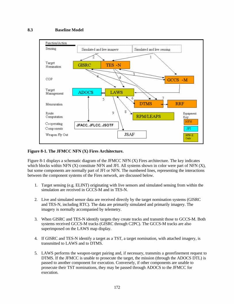
172
8.3 Baseline Model
Figure 8-1. The JFMCC NFN (X) Fires Architecture.
Figure 8-1 displays a schematic diagram of the JFMCC NFN (X) Fires architecture. The key indicateswhich blocks within NFN (X) constitute NFN and JFI. All systems shown in color were part of NFN (X),but some components are normally part of JFI or NFN. The numbered lines, representing the interactionsbetween the component systems of the Fires network, are discussed below.
1. Target sensing (e.g. ELINT) originating with live sensors and simulated sensing from within thesimulation are received in GCCS-M and in TES-N.
2. Live and simulated sensor data are received directly by the target nomination systems (GISRCand TES-N, including RTC). The data are primarily simulated and primarily imagery. Theimagery is normally accompanied by telemetry.
3. When GISRC and TES-N identify targets they create tracks and transmit those to GCCS-M. Bothsystems received GCCS-M tracks (GISRC through C2PC). The GCCS-M tracks are alsosuperimposed on the LAWS map display.
4. If GISRC and TES-N identify a target as a TST, a target nomination, with attached imagery, istransmitted to LAWS and to DTMS.
5. LAWS performs the weapon-target pairing and, if necessary, transmits a georefinement request toDTMS. If the JFMCC is unable to prosecute the target, the mission (through the ADOCS DTL) ispassed to another component for execution. Conversely, if other components are unable toprosecute their TST nominations, they may be passed through ADOCS to the JFMCC forexecution.
FinicHofi'Aclicu
Seuang
HDcninaluHL
COP
Mcnimalion
Route CDir^iitaticin
Cooperating
Compoiieirts
Wcapan Fly QiU
Simulaled and livt miajfefv Snniilatcd and IIVF sensing i
GISRC
ADOCS
GCCS -M
RRF
EqiiipnunL
JFACC.JFLCC.JSOTF NFN
JSAF
SF\
Onlv
173
6. Through an exchange of messages described as the georefinement validation process, LAWS andDTMS agree on required mensuration accuracy and a time within which the georefinement is tobe completed.
7. The Mensuration Manager at the DTMS assigns the mensuration task to one or more RRFworkstations. The RRF workstations return the mensuration result to DTMS. DTMS transmits theresult to LAWS.
8. If the mission involved TLAM or LOCAAS, LAWS transmits a route request to the appropriateroute generating workstation (RPM or LEAPS). The workstation responds to LAWS with theroute.
9. After the missions has been approved by the MOC TCSO, and georefined target locations andprojectile route have been received (if required), the mission is executed in LAWS, and the firecommand is transmitted to JSAF for projectile launch, fly out, impact and assessment.
After the mission has been approved by the MOC TCSO; and georefined target locations; and projectileroute have been received (if required); the mission is executed in LAWS and the fire command istransmitted to JSAF for projectile launch, fly out, impact, and assessment.
8.4 TST Process
This Section provides a qualitative description of the NFN (X) TST process in FBE J (Figure 8-1).
8.4.1 Target Detection
The great majority of target detections were made on the basis of imagery from simulated sensors(Predator, TUAV, Global Hawk, U2). Most of the targets were detected as targets of opportunity found inrandom searches of the patrol area rather than as a result of cued searches for TSTs. Each of the simulatedsensor assets appeared in the ATO with an assigned operational area and scheduled time of operation. Thesimulated ISR assets were essentially exclusively assigned to the prosecution, and Battle DamageAssessment (BDA), of TSTs.
There was some variation in the C2 procedures for ISR, but for the majority of the experiment theprocedures were as follows. The UAV operator controlled the path of the UAV within the ATO-assignedoperational area while the GISRC operator assigned to that UAV controlled the aircraft’s sensor. Therewere six separate IRC chat channels used for coordination between the paired GISRC and UAVoperators. If the UAV was re-tasked, the new tasking originated with the ISR OPS officer in the MOCand was passed to the ISR Manager at FCTCPAC who in turn communicated it to the UAV operator.Coordination between the JFMCC ISR OPS officer and the UAV Manager were conducted using the IWSISR chat room.
In FBE-J weather was introduced into the simulation. As a result, coastal cloud cover inhibited thesimulated UAVs’ E/O sensors for a significant percentage of the morning hours for most of theexperiment.
8.4.2 Target Identification
The GISRC or TES-N workstations received a streaming video feed and telemetry from the simulatedUAVs or U2. When the operators of these workstations recognized an imaged object of potential interest,
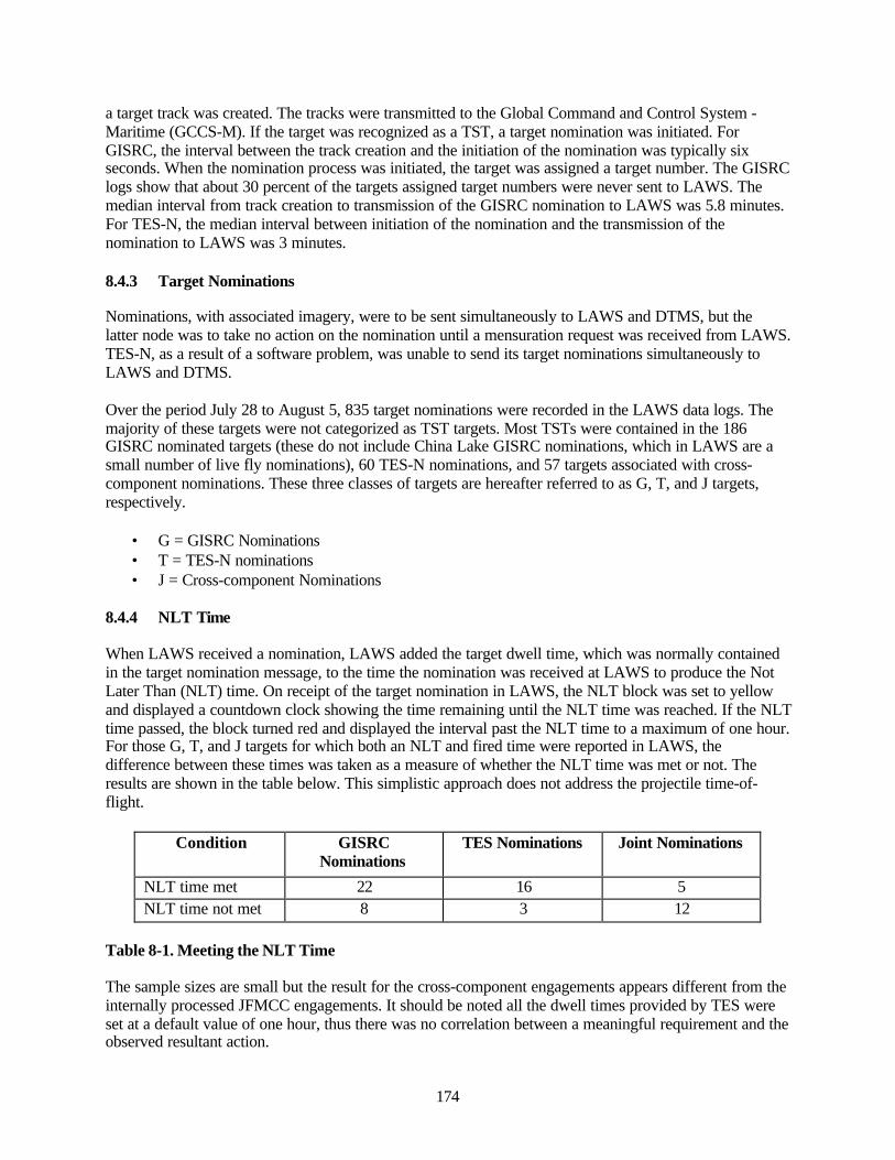
174
a target track was created. The tracks were transmitted to the Global Command and Control System -Maritime (GCCS-M). If the target was recognized as a TST, a target nomination was initiated. ForGISRC, the interval between the track creation and the initiation of the nomination was typically sixseconds. When the nomination process was initiated, the target was assigned a target number. The GISRClogs show that about 30 percent of the targets assigned target numbers were never sent to LAWS. Themedian interval from track creation to transmission of the GISRC nomination to LAWS was 5.8 minutes.For TES-N, the median interval between initiation of the nomination and the transmission of thenomination to LAWS was 3 minutes.
8.4.3 Target Nominations
Nominations, with associated imagery, were to be sent simultaneously to LAWS and DTMS, but thelatter node was to take no action on the nomination until a mensuration request was received from LAWS.TES-N, as a result of a software problem, was unable to send its target nominations simultaneously toLAWS and DTMS.
Over the period July 28 to August 5, 835 target nominations were recorded in the LAWS data logs. Themajority of these targets were not categorized as TST targets. Most TSTs were contained in the 186GISRC nominated targets (these do not include China Lake GISRC nominations, which in LAWS are asmall number of live fly nominations), 60 TES-N nominations, and 57 targets associated with cross-component nominations. These three classes of targets are hereafter referred to as G, T, and J targets,respectively.
• G = GISRC Nominations• T = TES-N nominations• J = Cross-component Nominations
8.4.4 NLT Time
When LAWS received a nomination, LAWS added the target dwell time, which was normally containedin the target nomination message, to the time the nomination was received at LAWS to produce the NotLater Than (NLT) time. On receipt of the target nomination in LAWS, the NLT block was set to yellowand displayed a countdown clock showing the time remaining until the NLT time was reached. If the NLTtime passed, the block turned red and displayed the interval past the NLT time to a maximum of one hour.For those G, T, and J targets for which both an NLT and fired time were reported in LAWS, thedifference between these times was taken as a measure of whether the NLT time was met or not. Theresults are shown in the table below. This simplistic approach does not address the projectile time-of-flight.
Condition GISRCNominations
TES Nominations Joint Nominations
NLT time met 22 16 5NLT time not met 8 3 12
Table 8-1. Meeting the NLT Time
The sample sizes are small but the result for the cross-component engagements appears different from theinternally processed JFMCC engagements. It should be noted all the dwell times provided by TES wereset at a default value of one hour, thus there was no correlation between a meaningful requirement and theobserved resultant action.
175
8.4.5 Georefinement
The FBE-J TTP requires a georefinement request to be directed from LAWS to DTMS. Thisgeorefinement request message contains requested mensuration accuracy. After an exchange of messages,mensuration accuracy, and the time interval required to produce it, were agreed upon between LAWS andDTMS. This validation process was to be completed before DTMS actually initiated the georefinementprocess. The implication of this mensuration validation process was that the weapon-target pairing wouldbe completed before the georefinement request in order that the selected weapon would provide the basisfor determining the needed mensuration accuracy (or whether mensuration was required at all). In fact, inthe experiment, the mensuration request for G and T targets was issued a median of 7 minutes afterreceipt of the nomination and usually long before the weapon-target pairing was performed.
After the georefinement request was validated, the Mensuration Manager, through DTMS, tasked thegeorefinement to one or more RRF workstations. On receipt of the georefined target positions from RRFat DTMS, the Mensuration Manager evaluated the positions and forwarded a result to LAWS. The DTMSMensuration Manager and the RRF operators used the targeting IRC chat channel to coordinate themensuration process.
As discussed in the georefinement Section below, this georefinement validation process appeared toprovide no benefit but it resulted in the lengthening of the georefinement process. The median timerequired for the actual georefinement measurement at an RRF workstation was 9.8 minutes, but thevalidation of the mensuration request and the overhead of the mensuration management process resultedin a median time between the issuance of the mensuration request and the receipt of the results in LAWSof 27 minutes.
In the LAWS Fires Manager display, on issuance of the mensuration request, the georefinement blockwould turn yellow and display a countdown clock showing the time remaining until the expected receiptof the mensurated target position. On receipt of that georefined target position, the block would turngreen. Otherwise the block would turn red if the expected receipt time was reached, and no mensurationdata were received. If the mensuration request could not satisfied by DTMS/RRF, the georefinementblock was turned purple.
Almost all nominations were received in LAWS without any indication of the accuracy of the reportedtarget position. Without these data, regardless of the weapon paired to the target, it is almost alwaysnecessary to request georefinement. To avoid unnecessary georefinement, all nominations need to includean estimate of the accuracy of the target position. In addition, weaponeers require tables relating weapon,target type, and target positional accuracy to the probability of successful engagement.
8.4.6 Weapon-Target Pairing
For all JFMCC TST engagements, the MOC Time Critical Strike Officer (TCSO) was the approvingauthority. His cell normally performed the weapon-target pairing and pushed the mission to a selectedplatform for execution. There were no autonomous target engagements in the experiment. The tablebelow shows the percentage of the nominated targets that were weapon-target paired in LAWS. Thispercentage is quite low for the G and T targets but it is somewhat misleading because some of thesetargets were pushed to other components for prosecution, although those actions are not reflected in theLAWS data.
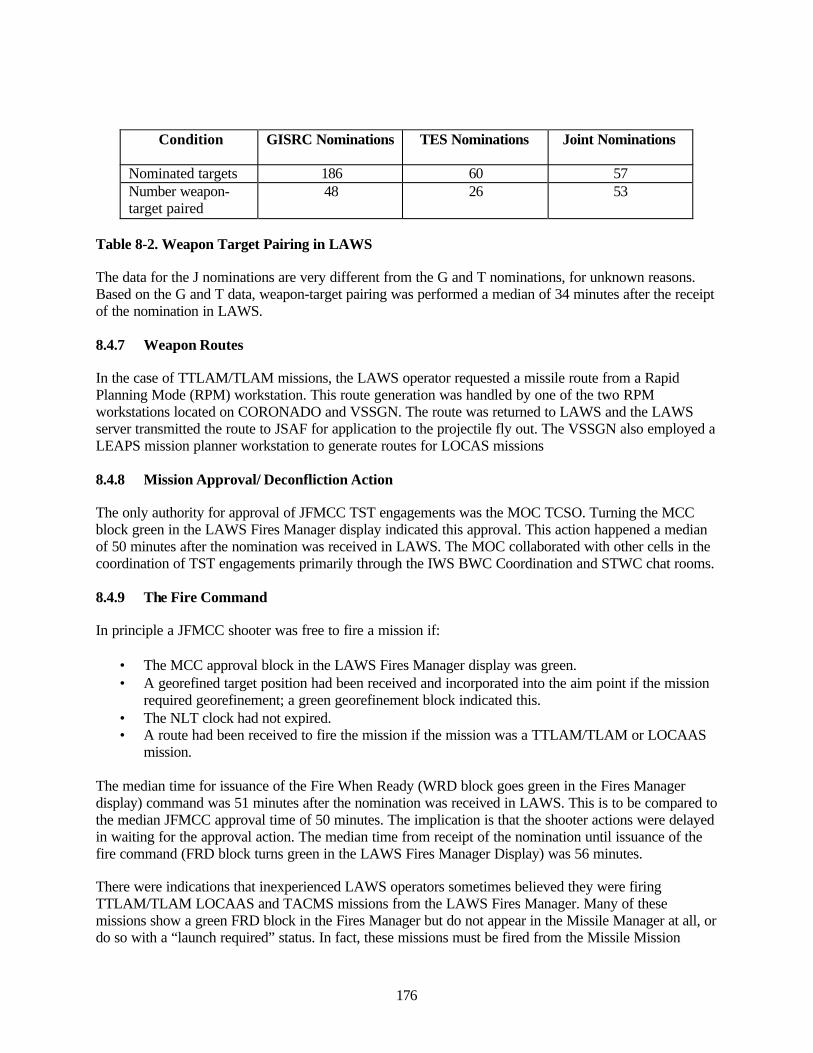
176
Condition GISRC Nominations TES Nominations Joint Nominations
Nominated targets 186 60 57Number weapon-target paired
48 26 53
Table 8-2. Weapon Target Pairing in LAWS
The data for the J nominations are very different from the G and T nominations, for unknown reasons.Based on the G and T data, weapon-target pairing was performed a median of 34 minutes after the receiptof the nomination in LAWS.
8.4.7 Weapon Routes
In the case of TTLAM/TLAM missions, the LAWS operator requested a missile route from a RapidPlanning Mode (RPM) workstation. This route generation was handled by one of the two RPMworkstations located on CORONADO and VSSGN. The route was returned to LAWS and the LAWSserver transmitted the route to JSAF for application to the projectile fly out. The VSSGN also employed aLEAPS mission planner workstation to generate routes for LOCAS missions
8.4.8 Mission Approval/ Deconfliction Action
The only authority for approval of JFMCC TST engagements was the MOC TCSO. Turning the MCCblock green in the LAWS Fires Manager display indicated this approval. This action happened a medianof 50 minutes after the nomination was received in LAWS. The MOC collaborated with other cells in thecoordination of TST engagements primarily through the IWS BWC Coordination and STWC chat rooms.
8.4.9 The Fire Command
In principle a JFMCC shooter was free to fire a mission if:
• The MCC approval block in the LAWS Fires Manager display was green.• A georefined target position had been received and incorporated into the aim point if the mission
required georefinement; a green georefinement block indicated this.• The NLT clock had not expired.• A route had been received to fire the mission if the mission was a TTLAM/TLAM or LOCAAS
mission.
The median time for issuance of the Fire When Ready (WRD block goes green in the Fires Managerdisplay) command was 51 minutes after the nomination was received in LAWS. This is to be compared tothe median JFMCC approval time of 50 minutes. The implication is that the shooter actions were delayedin waiting for the approval action. The median time from receipt of the nomination until issuance of thefire command (FRD block turns green in the LAWS Fires Manager Display) was 56 minutes.
There were indications that inexperienced LAWS operators sometimes believed they were firingTTLAM/TLAM LOCAAS and TACMS missions from the LAWS Fires Manager. Many of thesemissions show a green FRD block in the Fires Manager but do not appear in the Missile Manager at all, ordo so with a “launch required” status. In fact, these missions must be fired from the Missile Mission
177
Manager. Only when the mission is fired in Mission Missions Manager does LAWS send a fire commandto JSAF.
8.4.10 Assessment Engagement
On receipt of the fire command from LAWS, JSAF simulated the weapon firing, fly-out, and impact ofthe projectile. In FBE-J, many of the target entities were present in other simulations so that theassessment of the target required the exchange of entity status between different simulations in thefederation.
8.4.11 Battle Damage Assessme nt
Subsequent to weapon-target pairing, LAWS was to transmit an engagement message to the nominator,giving weapon TOT. The nominator was to respond to this with a BDA support message indicating whenBDA would be available. The BDA page in the LAWS Fires Mission Manager has fields to contain theexpected and received time for the BDA report. These fields are almost never filled, even when a BDAresult was given, indicating the BDA support message did not work reliably or was rarely used. In mostcases a BDA result was not reported for fired missions. Many missions reporting BDA results aremissions that were listed in LAWS as not having been fired.
When a BDA report was received the LAWS operator manually turned the BDA block green and inserteda three-letter code to indicate the target status. In the LAWS Fires Manager, in contrast to the ADOCSDTL Manager, the BDA block was turned green on receipt of a BDA report whether or not that reportwas favorable.
In many cases, the UAV that provided the imagery for the nominated target was kept on station at thetarget position to image the impact and provide BDA. The UAVs were often kept on station for hourswaiting for impacts that were never observed, at least some of the time because the weapons were neverfired in the simulator or because the weapons missed the target. The UAV operators frequently had noindication of when the impact was supposed to occur.
8.5 Analysis of Objective Data
8.5.1 Participating Nodes - Future Power Projection Platforms
The future power projection platforms were defined as: DD-X, VSSGN, ABCC, and Net Fires on the SeaSlice. Table 8-3 shows for the G, T, and J TST targets the final state of platform selection of weapon-target pairing as displayed in LAWS. The total absence of TACAIR is conspicuous. This is a dramaticchange from FBE-I where 45 percent of TST missions were weapon-target paired with TACAIR despitesoftware and command and control problems. The China Lake GISRC, which is not included in thenominations considered here, nominated a few TACAIR paired missions into LAWS, but these werespecifically intended to support the live fly missions out of China Lake. The Sea Slice made nosignificant contribution to the engagement of TSTs. The other two platforms, the VSSGN and DD-X,conducted the majority of the TST engagements.
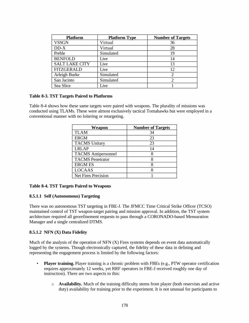
178
Platform Platform Type Number of TargetsVSSGN Virtual 36DD-X Virtual 28Preble Simulated 19BENFOLD Live 14SALT LAKE CITY Live 13FITZGERALD Live 12Arleigh Burke Simulated 2San Jacinto Simulated 2Sea Slice Live 1
Table 8-3. TST Targets Paired to Platforms
Table 8-4 shows how these same targets were paired with weapons. The plurality of missions wasconducted using TLAMs. These were almost exclusively tactical Tomahawks but were employed in aconventional manner with no loitering or retargeting.
Weapon Number of TargetsTLAM 34ERGM 23TACMS Unitary 23LRLAP 14TACMS Antipersonnel 8TACMS Penetrator 8ERGM ES 8LOCAAS 8Net Fires Precision 1
Table 8-4. TST Targets Paired to Weapons
8.5.1.1 Self (Autonomous) Targeting
There was no autonomous TST targeting in FBE-J. The JFMCC Time Critical Strike Officer (TCSO)maintained control of TST weapon-target pairing and mission approval. In addition, the TST systemarchitecture required all georefinement requests to pass through a CORONADO-based MensurationManager and a single centralized DTMS.
8.5.1.2 NFN (X) Data Fidelity
Much of the analysis of the operation of NFN (X) Fires systems depends on event data automaticallylogged by the systems. Though electronically captured, the fidelity of these data in defining andrepresenting the engagement process is limited by the following factors:
• Player training. Player training is a chronic problem with FBEs (e.g., PTW operator certificationrequires approximately 12 weeks, yet RRF operators in FBE-J received roughly one day ofinstruction). There are two aspects to this:
o Availability. Much of the training difficulty stems from player (both reservists and activeduty) availability for training prior to the experiment. It is not unusual for participants to
179
arrive at the start of the experiment with no training. The problem is exacerbated whennew participants (with no training) enter part-way through the experiment.
o Duration. In part because of the player availability problem, the system trainingprograms are often forced to be truncated and are provided in less than optimumenvironments. Consequently, even the trained operators often start the experiment with arelatively rudimentary knowledge of their systems.
• TTPs. Beyond the question of participant training, TTPs are often inadequately defined andsometimes evolve during the course of the experiment. This degrades participant and systemperformance and counters the normal improvement expected as teams work down the learningcurve.
• System Software. Many of the systems employed in NFN (X) are prototypes with unvalidatedsoftware. Inevitably, software problems are encountered and workarounds have to be developed,which delays and complicates the execution actions.
The issues addressed above undoubtedly contributed to a lengthening of the observed engagementtimelines in MC02/FBE-J. But these problems are more artifacts of the experiment than inherentlimitations in the systems or procedures. They are addressed in two ways in the treatment of the data:
• Statistics relating to intervals in the engagement process focus on the median rather than on themean. The latter statistic is much more affected by long intervals that are associated with anyproblems, such as those described above, which thus yield unrepresentative averages.
• Generally, the data collected in the first few days of the experiment are either not considered orare given low weight. Data collected near the completion of the experiment are assumed to be farmore valuable and representative of the performance typically expected.
8.5.2 Land Attack Warfare System (LAWS)
LAWS represents the core NFN (X) system. This Section provides counts for the target numbersappearing in LAWS and engagement timeline statistics for the actions that occur in LAWS in the courseof prosecuting TST targets.
8.5.2.1 Mission Counts
In previous FBEs, LAWS was populated almost exclusively with TSTs. In FBE J, many different types oftargets nominations were entered into LAWS. Table 8-5 presents a breakdown of the target nominationtypes, by day, for the interval July 29 to August 5. The nominations types are defined as follows:
• Mine Mission (M). These primarily have target numbers of the form MMxxxx and werenominated by the HSV LAWS. A few of these targets were nominated by HSV GISRC and havetarget numbers of the form GHxxxx.
• Test missions (X). These were test targets nominated by various nodes. Target numbers with theXX prefix indicates many of these missions. Others were identified on the basis of remarks in theLAWS targeting page.
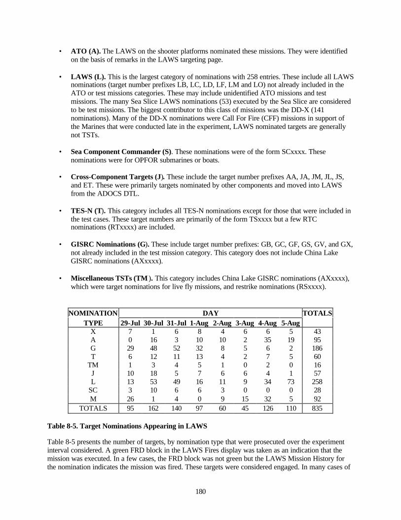
180
• ATO (A). The LAWS on the shooter platforms nominated these missions. They were identifiedon the basis of remarks in the LAWS targeting page.
• LAWS (L). This is the largest category of nominations with 258 entries. These include all LAWSnominations (target number prefixes LB, LC, LD, LF, LM and LO) not already included in theATO or test missions categories. These may include unidentified ATO missions and testmissions. The many Sea Slice LAWS nominations (53) executed by the Sea Slice are consideredto be test missions. The biggest contributor to this class of missions was the DD-X (141nominations). Many of the DD-X nominations were Call For Fire (CFF) missions in support ofthe Marines that were conducted late in the experiment, LAWS nominated targets are generallynot TSTs.
• Sea Component Commander (S). These nominations were of the form SCxxxx. Thesenominations were for OPFOR submarines or boats.
• Cross-Component Targets (J). These include the target number prefixes AA, JA, JM, JL, JS,and ET. These were primarily targets nominated by other components and moved into LAWSfrom the ADOCS DTL.
• TES-N (T). This category includes all TES-N nominations except for those that were included inthe test cases. These target numbers are primarily of the form TSxxxx but a few RTCnominations (RTxxxx) are included.
• GISRC Nominations (G). These include target number prefixes: GB, GC, GF, GS, GV, and GX,not already included in the test mission category. This category does not include China LakeGISRC nominations (AXxxxx).
• Miscellaneous TSTs (TM ). This category includes China Lake GISRC nominations (AXxxxx),which were target nominations for live fly missions, and restrike nominations (RSxxxx).
NOMINATION DAY TOTALSTYPE 29-Jul 30-Jul 31-Jul 1-Aug 2-Aug 3-Aug 4-Aug 5-Aug
X 7 1 6 8 4 6 6 5 43A 0 16 3 10 10 2 35 19 95G 29 48 52 32 8 5 6 2 186T 6 12 11 13 4 2 7 5 60
TM 1 3 4 5 1 0 2 0 16J 10 18 5 7 6 6 4 1 57L 13 53 49 16 11 9 34 73 258
SC 3 10 6 6 3 0 0 0 28M 26 1 4 0 9 15 32 5 92
TOTALS 95 162 140 97 60 45 126 110 835
Table 8-5. Target Nominations Appearing in LAWS
Table 8-5 presents the number of targets, by nomination type that were prosecuted over the experimentinterval considered. A green FRD block in the LAWS Fires display was taken as an indication that themission was executed. In a few cases, the FRD block was not green but the LAWS Mission History forthe nomination indicates the mission was fired. These targets were considered engaged. In many cases of
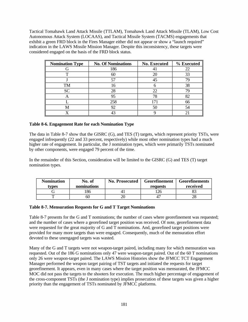
181
Tactical Tomahawk Land Attack Missile (TTLAM), Tomahawk Land Attack Missile (TLAM), Low CostAutonomous Attack System (LOCAAS), and Tactical Missile System (TACMS) engagements thatexhibit a green FRD block in the Fires Manager either did not appear or show a “launch required”indication in the LAWS Missile Mission Manager. Despite this inconsistency, these targets wereconsidered engaged on the basis of the FRD block status.
Nomination Type No. Of Nominations No. Executed % ExecutedG 186 41 22T 60 20 33J 57 45 79
TM 16 6 38SC 28 22 79A 95 78 82L 258 171 66M 92 50 54X 43 9 21
Table 8-6. Engagement Rate for each Nomination Type
The data in Table 8-7 show that the GISRC (G), and TES (T) targets, which represent priority TSTs, wereengaged infrequently (22 and 33 percent, respectively) while most other nomination types had a muchhigher rate of engagement. In particular, the J nomination types, which were primarily TSTs nominatedby other components, were engaged 79 percent of the time.
In the remainder of this Section, consideration will be limited to the GISRC (G) and TES (T) targetnomination types.
Nominationtypes
No. ofnominations
No. Prosecuted Georefinementrequests
Georefinementsreceived
G 186 41 126 83T 60 20 47 28
Table 8-7. Mensuration Requests for G and T Target Nominations
Table 8-7 presents for the G and T nominations; the number of cases where georefinement was requested;and the number of cases where a georefined target position was received. Of note, georefinement datawere requested for the great majority of G and T nominations. And, georefined target positions wereprovided for many more targets than were engaged. Consequently, much of the mensuration effortdevoted to these unengaged targets was wasted.
Many of the G and T targets were not weapon-target paired, including many for which mensuration wasrequested. Out of the 186 G nominations only 47 were weapon-target paired. Out of the 60 T nominationsonly 26 were weapon-target paired. The LAWS Mission Histories show the JFMCC TCT EngagementManager performed the weapon target pairing of TST targets and initiated the requests for targetgeorefinement. It appears, even in many cases where the target position was mensurated, the JFMCCMOC did not pass the targets to the shooters for execution. The much higher percentage of engagement ofthe cross-component TSTs (the J nomination type) implies prosecution of these targets was given a higherpriority than the engagement of TSTs nominated by JFMCC platforms.
182
8.5.2.2 LAWS Engagement Timeline
The LAWS engagement timeline consists of the following events in order:
1. Receipt of the target nomination in LAWS.2. Request for georefinement of the target location.3. Receipt of the georefined target location (Georef block goes green).4. Weapon-target pairing.5. Mission approval by appropriate warfare commander (approval block goes green).6. Issuance of Fire When Ready command (WRD block goes green).7. Fire command (FRD block goes green).8. Receipt of BDA.
Table 8-8 gives the median, mean, and standard deviations for each of these intervals. All the intervals,except the georefinement completion time, were measured with respect to the time the nomination wasreceived in LAWS. As is typical with FBE measured time intervals, extreme outliers drive the mean andthe median values and are more characteristic of system performance. Separate tallies are presented for Gand T targets. In most cases the median times are similar, but in a few cases they are different. The smallsample sizes and large dispersions make these differences of questionable significance.
The BDA block usage in the LAWS Fires Manager differs from the BDA block usage in the DTL. In thelatter, the BDA block was turned green if the result was favorable, i.e., the target was destroyed orsuppressed. If the result was unfavorable (e.g., no observed damage), the BDA block was turned red. Inthe LAWS Fires Manager, the BDA block was turned green when the BDA report was received whetherthe result was favorable or not.
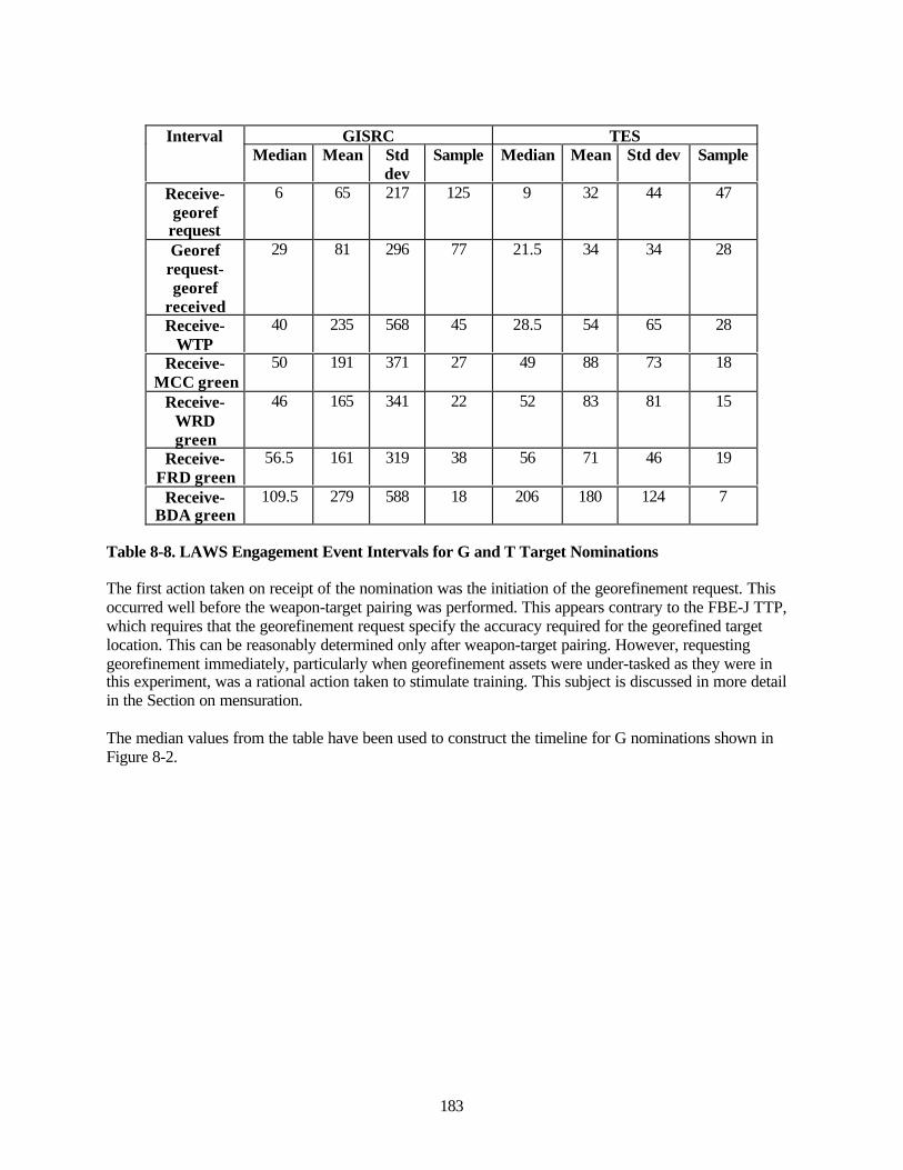
183
GISRC TESIntervalMedian Mean Std
devSample Median Mean Std dev Sample
Receive-georef
request
6 65 217 125 9 32 44 47
Georefrequest-georef
received
29 81 296 77 21.5 34 34 28
Receive-WTP
40 235 568 45 28.5 54 65 28
Receive-MCC green
50 191 371 27 49 88 73 18
Receive-WRDgreen
46 165 341 22 52 83 81 15
Receive-FRD green
56.5 161 319 38 56 71 46 19
Receive-BDA green
109.5 279 588 18 206 180 124 7
Table 8-8. LAWS Engagement Event Intervals for G and T Target Nominations
The first action taken on receipt of the nomination was the initiation of the georefinement request. Thisoccurred well before the weapon-target pairing was performed. This appears contrary to the FBE-J TTP,which requires that the georefinement request specify the accuracy required for the georefined targetlocation. This can be reasonably determined only after weapon-target pairing. However, requestinggeorefinement immediately, particularly when georefinement assets were under-tasked as they were inthis experiment, was a rational action taken to stimulate training. This subject is discussed in more detailin the Section on mensuration.
The median values from the table have been used to construct the timeline for G nominations shown inFigure 8-2.
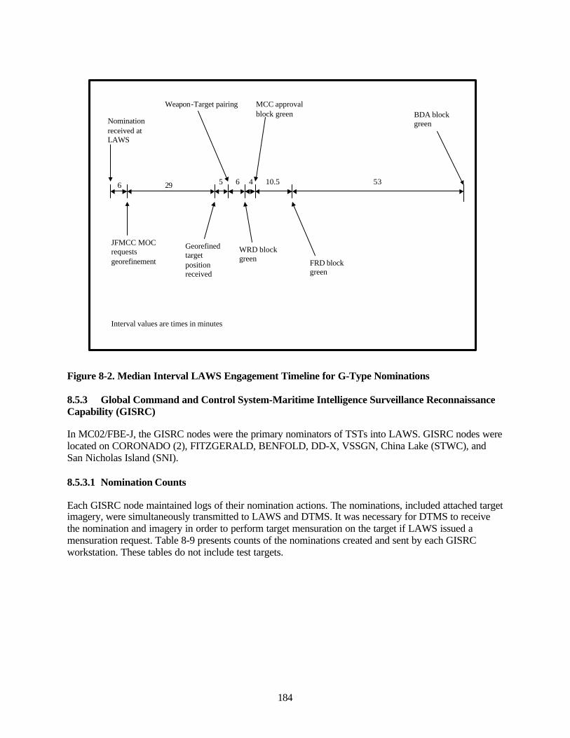
184
Nomination received at LAWS
JFMCC MOC requests georefinement
Georefined target position received
6 29
Interval values are times in minutes
Weapon-Target pairing
5 6
WRD block green
4
MCC approval block green
10.5
FRD block green
53
BDA block green
Figure 8-2. Median Interval LAWS Engagement Timeline for G-Type Nominations
8.5.3 Global Command and Control System-Maritime Intelligence Surveillance ReconnaissanceCapability (GISRC)
In MC02/FBE-J, the GISRC nodes were the primary nominators of TSTs into LAWS. GISRC nodes werelocated on CORONADO (2), FITZGERALD, BENFOLD, DD-X, VSSGN, China Lake (STWC), andSan Nicholas Island (SNI).
8.5.3.1 Nomination Counts
Each GISRC node maintained logs of their nomination actions. The nominations, included attached targetimagery, were simultaneously transmitted to LAWS and DTMS. It was necessary for DTMS to receivethe nomination and imagery in order to perform target mensuration on the target if LAWS issued amensuration request. Table 8-9 presents counts of the nominations created and sent by each GISRCworkstation. These tables do not include test targets.
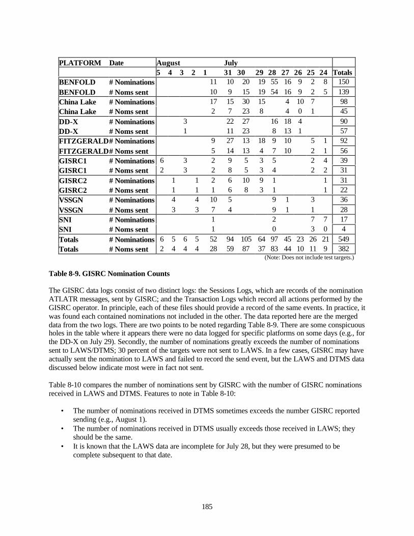
185
PLATFORM Date August July 5 4 3 2 1 31 30 29 28 27 26 25 24 TotalsBENFOLD # Nominations 11 10 20 19 55 16 9 2 8 150BENFOLD # Noms sent 10 9 15 19 54 16 9 2 5 139China Lake # Nominations 17 15 30 15 4 10 7 98China Lake # Noms sent 2 7 23 8 4 0 1 45DD-X # Nominations 3 22 27 16 18 4 90DD-X # Noms sent 1 11 23 8 13 1 57FITZGERALD# Nominations 9 27 13 18 9 10 5 1 92FITZGERALD# Noms sent 5 14 13 4 7 10 2 1 56GISRC1 # Nominations 6 3 2 9 5 3 5 2 4 39GISRC1 # Noms sent 2 3 2 8 5 3 4 2 2 31GISRC2 # Nominations 1 1 2 6 10 9 1 1 31GISRC2 # Noms sent 1 1 1 6 8 3 1 1 22VSSGN # Nominations 4 4 10 5 9 1 3 36VSSGN # Noms sent 3 3 7 4 9 1 1 28SNI # Nominations 1 2 7 7 17SNI # Noms sent 1 0 3 0 4Totals # Nominations 6 5 6 5 52 94 105 64 97 45 23 26 21 549Totals # Noms sent 2 4 4 4 28 59 87 37 83 44 10 11 9 382
(Note: Does not include test targets.)
Table 8-9. GISRC Nomination Counts
The GISRC data logs consist of two distinct logs: the Sessions Logs, which are records of the nominationATI.ATR messages, sent by GISRC; and the Transaction Logs which record all actions performed by theGISRC operator. In principle, each of these files should provide a record of the same events. In practice, itwas found each contained nominations not included in the other. The data reported here are the mergeddata from the two logs. There are two points to be noted regarding Table 8-9. There are some conspicuousholes in the table where it appears there were no data logged for specific platforms on some days (e.g., forthe DD-X on July 29). Secondly, the number of nominations greatly exceeds the number of nominationssent to LAWS/DTMS; 30 percent of the targets were not sent to LAWS. In a few cases, GISRC may haveactually sent the nomination to LAWS and failed to record the send event, but the LAWS and DTMS datadiscussed below indicate most were in fact not sent.
Table 8-10 compares the number of nominations sent by GISRC with the number of GISRC nominationsreceived in LAWS and DTMS. Features to note in Table 8-10:
• The number of nominations received in DTMS sometimes exceeds the number GISRC reportedsending (e.g., August 1).
• The number of nominations received in DTMS usually exceeds those received in LAWS; theyshould be the same.
• It is known that the LAWS data are incomplete for July 28, but they were presumed to becomplete subsequent to that date.
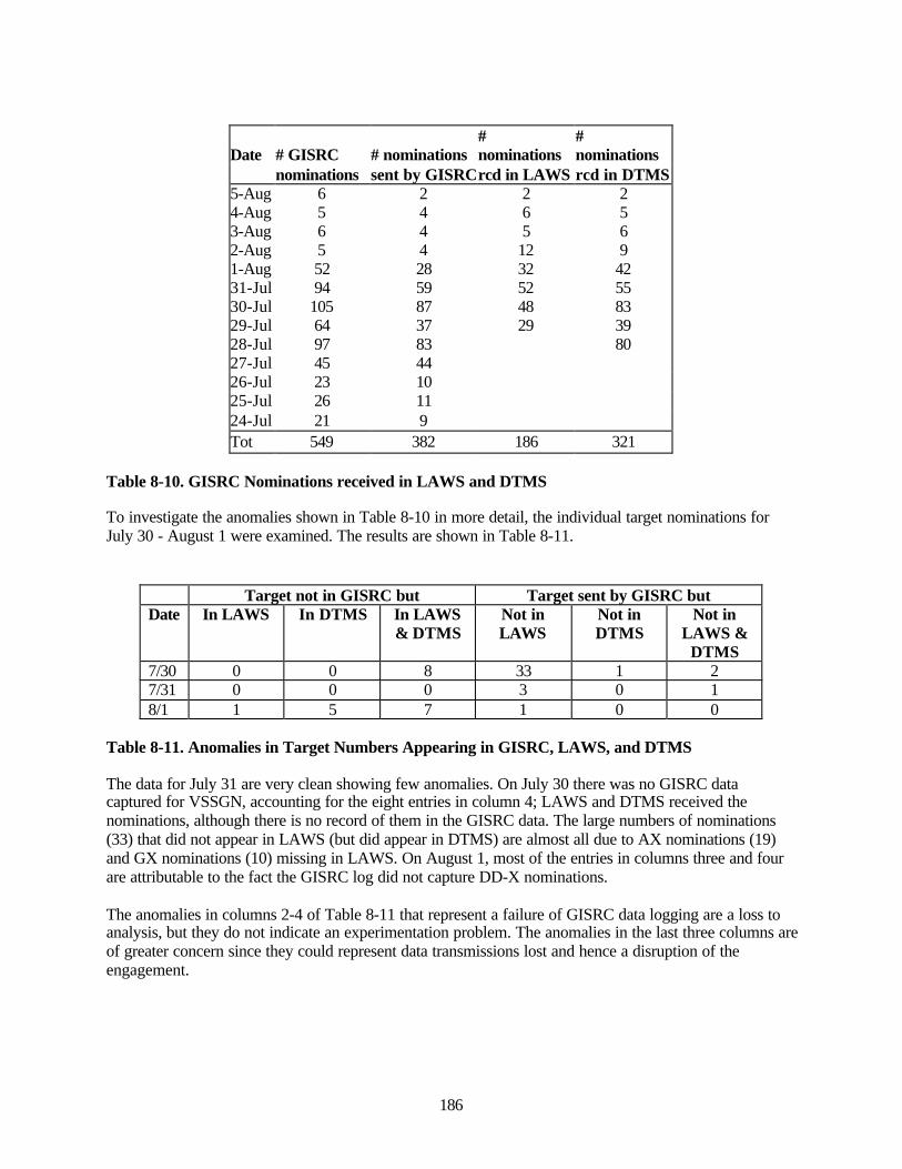
186
Date # GISRC # nominations#nominations
#nominations
nominations sent by GISRCrcd in LAWS rcd in DTMS5-Aug 6 2 2 24-Aug 5 4 6 53-Aug 6 4 5 62-Aug 5 4 12 91-Aug 52 28 32 4231-Jul 94 59 52 5530-Jul 105 87 48 8329-Jul 64 37 29 3928-Jul 97 83 8027-Jul 45 4426-Jul 23 1025-Jul 26 1124-Jul 21 9Tot 549 382 186 321
Table 8-10. GISRC Nominations received in LAWS and DTMS
To investigate the anomalies shown in Table 8-10 in more detail, the individual target nominations forJuly 30 - August 1 were examined. The results are shown in Table 8-11.
Target not in GISRC but Target sent by GISRC butDate In LAWS In DTMS In LAWS
& DTMSNot inLAWS
Not inDTMS
Not inLAWS &
DTMS7/30 0 0 8 33 1 27/31 0 0 0 3 0 18/1 1 5 7 1 0 0
Table 8-11. Anomalies in Target Numbers Appearing in GISRC, LAWS, and DTMS
The data for July 31 are very clean showing few anomalies. On July 30 there was no GISRC datacaptured for VSSGN, accounting for the eight entries in column 4; LAWS and DTMS received thenominations, although there is no record of them in the GISRC data. The large numbers of nominations(33) that did not appear in LAWS (but did appear in DTMS) are almost all due to AX nominations (19)and GX nominations (10) missing in LAWS. On August 1, most of the entries in columns three and fourare attributable to the fact the GISRC log did not capture DD-X nominations.
The anomalies in columns 2-4 of Table 8-11 that represent a failure of GISRC data logging are a loss toanalysis, but they do not indicate an experimentation problem. The anomalies in the last three columns areof greater concern since they could represent data transmissions lost and hence a disruption of theengagement.
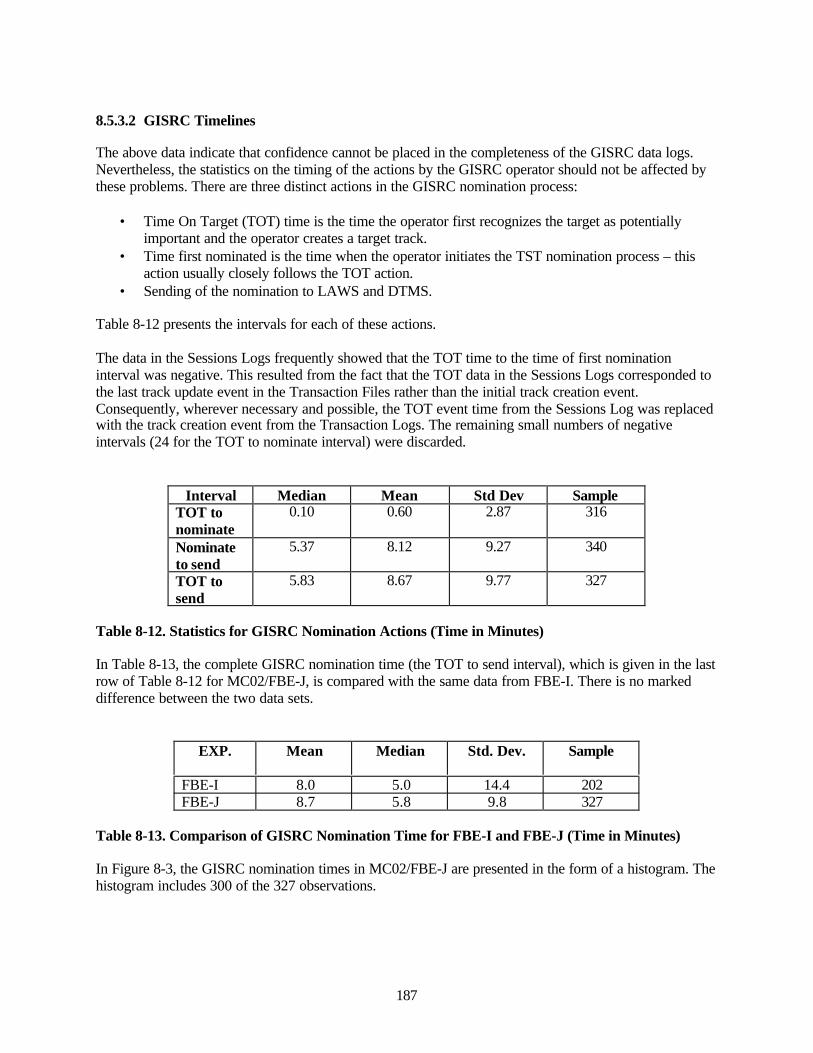
187
8.5.3.2 GISRC Timelines
The above data indicate that confidence cannot be placed in the completeness of the GISRC data logs.Nevertheless, the statistics on the timing of the actions by the GISRC operator should not be affected bythese problems. There are three distinct actions in the GISRC nomination process:
• Time On Target (TOT) time is the time the operator first recognizes the target as potentiallyimportant and the operator creates a target track.
• Time first nominated is the time when the operator initiates the TST nomination process – thisaction usually closely follows the TOT action.
• Sending of the nomination to LAWS and DTMS.
Table 8-12 presents the intervals for each of these actions.
The data in the Sessions Logs frequently showed that the TOT time to the time of first nominationinterval was negative. This resulted from the fact that the TOT data in the Sessions Logs corresponded tothe last track update event in the Transaction Files rather than the initial track creation event.Consequently, wherever necessary and possible, the TOT event time from the Sessions Log was replacedwith the track creation event from the Transaction Logs. The remaining small numbers of negativeintervals (24 for the TOT to nominate interval) were discarded.
Interval Median Mean Std Dev SampleTOT tonominate
0.10 0.60 2.87 316
Nominateto send
5.37 8.12 9.27 340
TOT tosend
5.83 8.67 9.77 327
Table 8-12. Statistics for GISRC Nomination Actions (Time in Minutes)
In Table 8-13, the complete GISRC nomination time (the TOT to send interval), which is given in the lastrow of Table 8-12 for MC02/FBE-J, is compared with the same data from FBE-I. There is no markeddifference between the two data sets.
EXP. Mean Median Std. Dev. Sample
FBE-I 8.0 5.0 14.4 202FBE-J 8.7 5.8 9.8 327
Table 8-13. Comparison of GISRC Nomination Time for FBE-I and FBE-J (Time in Minutes)
In Figure 8-3, the GISRC nomination times in MC02/FBE-J are presented in the form of a histogram. Thehistogram includes 300 of the 327 observations.
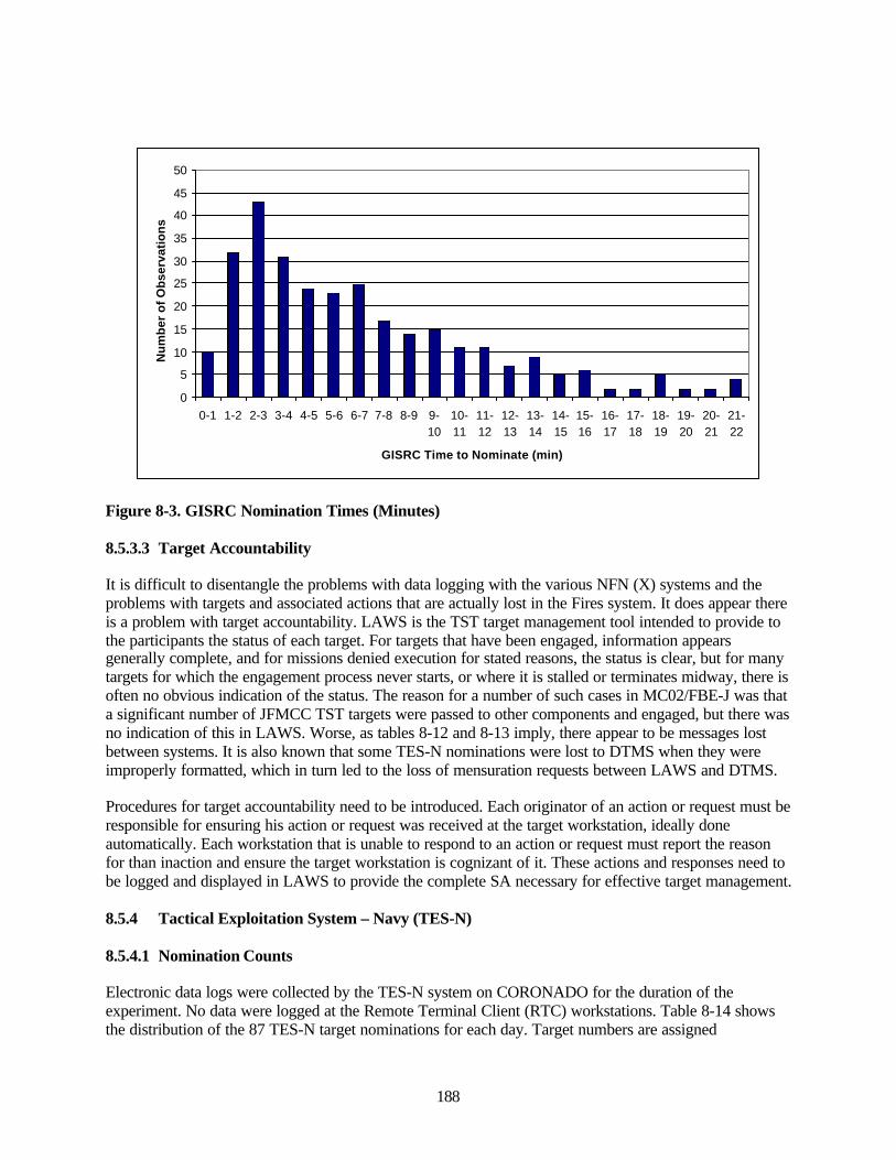
188
0
5
10
15
20
25
30
35
40
45
50
0-1 1-2 2-3 3-4 4-5 5-6 6-7 7-8 8-9 9-10
10-11
11-12
12-13
13-14
14-15
15-16
16-17
17-18
18-19
19-20
20-21
21-22
GISRC Time to Nominate (min)
Nu
mb
er o
f O
bse
rvat
ion
s
Figure 8-3. GISRC Nomination Times (Minutes)
8.5.3.3 Target Accountability
It is difficult to disentangle the problems with data logging with the various NFN (X) systems and theproblems with targets and associated actions that are actually lost in the Fires system. It does appear thereis a problem with target accountability. LAWS is the TST target management tool intended to provide tothe participants the status of each target. For targets that have been engaged, information appearsgenerally complete, and for missions denied execution for stated reasons, the status is clear, but for manytargets for which the engagement process never starts, or where it is stalled or terminates midway, there isoften no obvious indication of the status. The reason for a number of such cases in MC02/FBE-J was thata significant number of JFMCC TST targets were passed to other components and engaged, but there wasno indication of this in LAWS. Worse, as tables 8-12 and 8-13 imply, there appear to be messages lostbetween systems. It is also known that some TES-N nominations were lost to DTMS when they wereimproperly formatted, which in turn led to the loss of mensuration requests between LAWS and DTMS.
Procedures for target accountability need to be introduced. Each originator of an action or request must beresponsible for ensuring his action or request was received at the target workstation, ideally doneautomatically. Each workstation that is unable to respond to an action or request must report the reasonfor than inaction and ensure the target workstation is cognizant of it. These actions and responses need tobe logged and displayed in LAWS to provide the complete SA necessary for effective target management.
8.5.4 Tactical Exploitation System – Navy (TES-N)
8.5.4.1 Nomination Counts
Electronic data logs were collected by the TES-N system on CORONADO for the duration of theexperiment. No data were logged at the Remote Terminal Client (RTC) workstations. Table 8-14 showsthe distribution of the 87 TES-N target nominations for each day. Target numbers are assigned
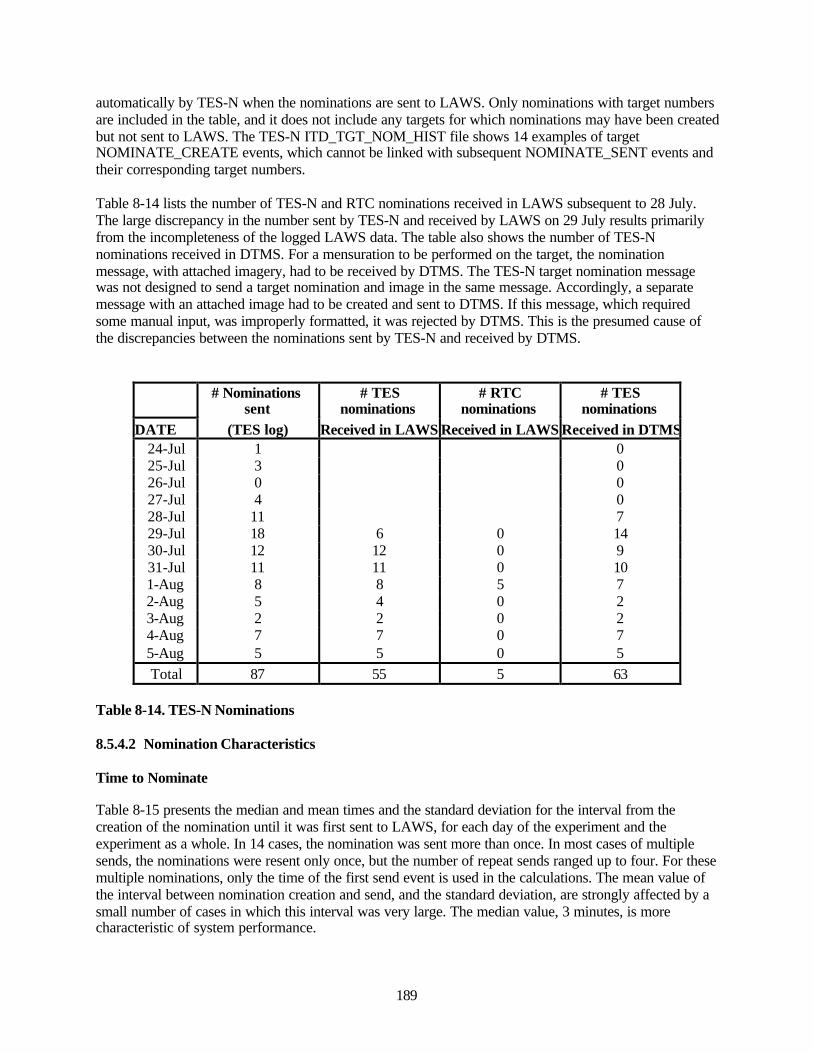
189
automatically by TES-N when the nominations are sent to LAWS. Only nominations with target numbersare included in the table, and it does not include any targets for which nominations may have been createdbut not sent to LAWS. The TES-N ITD_TGT_NOM_HIST file shows 14 examples of targetNOMINATE_CREATE events, which cannot be linked with subsequent NOMINATE_SENT events andtheir corresponding target numbers.
Table 8-14 lists the number of TES-N and RTC nominations received in LAWS subsequent to 28 July.The large discrepancy in the number sent by TES-N and received by LAWS on 29 July results primarilyfrom the incompleteness of the logged LAWS data. The table also shows the number of TES-Nnominations received in DTMS. For a mensuration to be performed on the target, the nominationmessage, with attached imagery, had to be received by DTMS. The TES-N target nomination messagewas not designed to send a target nomination and image in the same message. Accordingly, a separatemessage with an attached image had to be created and sent to DTMS. If this message, which requiredsome manual input, was improperly formatted, it was rejected by DTMS. This is the presumed cause ofthe discrepancies between the nominations sent by TES-N and received by DTMS.
# Nominations
sent# TES
nominations# RTC
nominations# TES
nominationsDATE (TES log) Received in LAWS Received in LAWS Received in DTMS
24-Jul 1 025-Jul 3 026-Jul 0 027-Jul 4 028-Jul 11 729-Jul 18 6 0 1430-Jul 12 12 0 931-Jul 11 11 0 101-Aug 8 8 5 72-Aug 5 4 0 23-Aug 2 2 0 24-Aug 7 7 0 75-Aug 5 5 0 5Total 87 55 5 63
Table 8-14. TES-N Nominations
8.5.4.2 Nomination Characteristics
Time to Nominate
Table 8-15 presents the median and mean times and the standard deviation for the interval from thecreation of the nomination until it was first sent to LAWS, for each day of the experiment and theexperiment as a whole. In 14 cases, the nomination was sent more than once. In most cases of multiplesends, the nominations were resent only once, but the number of repeat sends ranged up to four. For thesemultiple nominations, only the time of the first send event is used in the calculations. The mean value ofthe interval between nomination creation and send, and the standard deviation, are strongly affected by asmall number of cases in which this interval was very large. The median value, 3 minutes, is morecharacteristic of system performance.
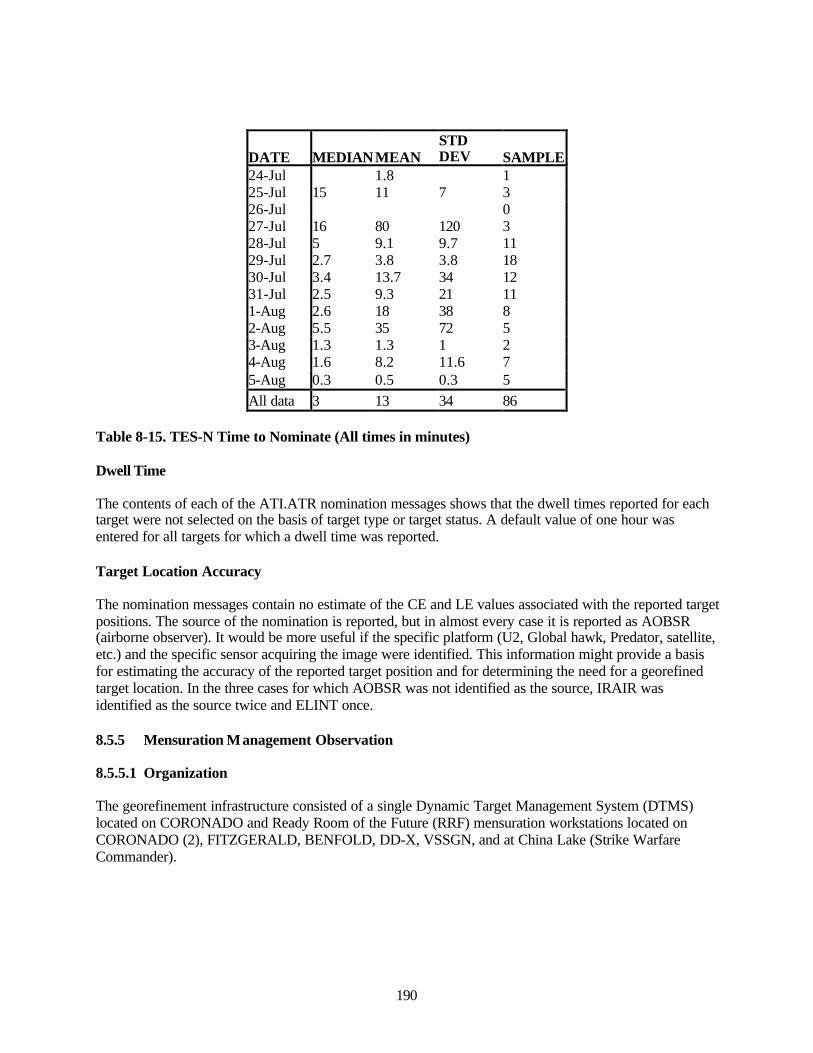
190
DATE MEDIANMEANSTDDEV SAMPLE
24-Jul 1.8 125-Jul 15 11 7 326-Jul 027-Jul 16 80 120 328-Jul 5 9.1 9.7 1129-Jul 2.7 3.8 3.8 1830-Jul 3.4 13.7 34 1231-Jul 2.5 9.3 21 111-Aug 2.6 18 38 82-Aug 5.5 35 72 53-Aug 1.3 1.3 1 24-Aug 1.6 8.2 11.6 75-Aug 0.3 0.5 0.3 5All data 3 13 34 86
Table 8-15. TES-N Time to Nominate (All times in minutes)
Dwell Time
The contents of each of the ATI.ATR nomination messages shows that the dwell times reported for eachtarget were not selected on the basis of target type or target status. A default value of one hour wasentered for all targets for which a dwell time was reported.
Target Location Accuracy
The nomination messages contain no estimate of the CE and LE values associated with the reported targetpositions. The source of the nomination is reported, but in almost every case it is reported as AOBSR(airborne observer). It would be more useful if the specific platform (U2, Global hawk, Predator, satellite,etc.) and the specific sensor acquiring the image were identified. This information might provide a basisfor estimating the accuracy of the reported target position and for determining the need for a georefinedtarget location. In the three cases for which AOBSR was not identified as the source, IRAIR wasidentified as the source twice and ELINT once.
8.5.5 Mensuration Management Observation
8.5.5.1 Organization
The georefinement infrastructure consisted of a single Dynamic Target Management System (DTMS)located on CORONADO and Ready Room of the Future (RRF) mensuration workstations located onCORONADO (2), FITZGERALD, BENFOLD, DD-X, VSSGN, and at China Lake (Strike WarfareCommander).
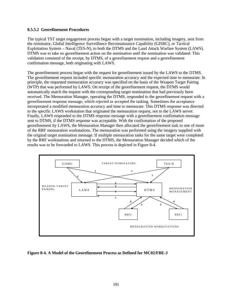
191
8.5.5.2 Georefinement Procedures
The typical TST target engagement process began with a target nomination, including imagery, sent fromthe nominator, Global Intelligence Surveillance Reconnaissance Capability (GISRC), or TacticalExploitation System – Naval (TES-N), to both the DTMS and the Land Attack Warfare System (LAWS).DTMS was to take no georefinement action on the nomination until the nomination was validated. Thisvalidation consisted of the receipt, by DTMS, of a georefinement request and a georefinementconfirmation message, both originating with LAWS.
The georefinement process began with the request for georefinement issued by the LAWS to the DTMS.The georefinement request included specific mensuration accuracy and the expected time to mensurate. Inprinciple, the requested mensuration accuracy was specified on the basis of the Weapon Target Pairing(WTP) that was performed by LAWS. On receipt of the georefinement request, the DTMS wouldautomatically match the request with the corresponding target nomination that had previously beenreceived. The Mensuration Manager, operating the DTMS, responded to the georefinement request with ageorefinement response message, which rejected or accepted the tasking. Sometimes the acceptanceincorporated a modified mensuration accuracy and time to mensurate. This DTMS response was directedto the specific LAWS workstation that originated the mensuration request, not to the LAWS server.Finally, LAWS responded to the DTMS response message with a georefinement confirmation messagesent to DTMS, if the DTMS response was acceptable. With the confirmation of the proposedgeorefinement by LAWS, the Mensuration Manager then allocated the georefinement task to one of moreof the RRF mensuration workstations. The mensuration was performed using the imagery supplied withthe original target nomination message. If multiple mensuration tasks for the same target were completedby the RRF workstations and returned to the DTMS, the Mensuration Manager decided which of theresults was to be forwarded to LAWS. This process is depicted in Figure 8-4.
G I S R C T E S -NT A R G E T N O M I N A T O R S
L A W S D T M SW E A P O N -T A R G E T P A I R I N G M E N S U R A T I O N
M A N A G E M E N T
3
1
11
2
4
7
R R F 1RRF2
5 566
M E N S U R A T I O N W O R K S T A T I O N S
1
Figure 8-4. A Model of the Georefinement Process as Defined for MC02/FBE-J
192
The numbered lines in Figure 8-4 address operations actions:
1. Transmission of the target nomination, including target imagery, to LAWS and DTMS.
2. A message requesting georefinement is sent from LAWS to DTMS. The request includes therequired accuracy of the target position.
3. A message is sent from DTMS to LAWS responding to the georefinement request. It accepts orrejects the tasking possibly modifying the requested accuracy.
4. A message is sent from LAWS to DTMS accepting the DTMS response to the georefinementrequest. On receipt of this, DTMS will start the mensuration action.
5. The mensuration task is assigned to one or more RRF workstations.
6. The RRF workstations send the mensuration result to DTMS. This may be either the georefinedtarget position of an unable to mensurate response.
7. DTMS sends the georefined target position to LAWS.
8.5.5.3 Departures from the TTP
In a number of ways or at specific times, the georefinement process actually employed in the experimentdiffered from the procedure described above.
For TES, imagery could not be attached to the nomination message; therefore a separate message wasgenerated and sent to DTMS with the imagery. If this nomination had not arrived at DTMS before thegeorefinement request was received from LAWS, DTMS could not match the request with a nominationand the request was automatically discarded.
There were cases where a georefinement result was received in LAWS but there is no evidence that ageorefinement request was sent. In some instances, test cases were created in GISRC and sent directly toDTMS for mensuration as an exercise – no georefinement requests would be expected in these cases.However, this anomaly is not limited to test targets.
Prior to the experiment, DTMS was coded so that the response to the georefinement request was directedto the LAWS server. LAWS was coded so that the DTMS response was expected to be directed to theLAWS workstation that originated the georefinement not the LAWS central server. During theexperiment this meant the DTMS had to manually send the response to individual LAWS adding time tothe mensuration process.
There were many cases where mensuration was requested but where no WTP was ever performed.
Occasionally the response and/or the acceptance messages were absent.
It was common, particularly for these mensuration procedures that did not go to completion, to see on theLAWS georefinement page, a response time that was later than the acceptance time. This resulted from aninitial response to the mission, which was accepted, but which was later followed by discovery that thetarget could not be mensurated (image resolution poor, no reference imagery). This necessitated a second
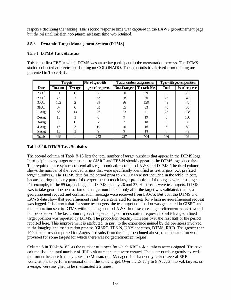
193
response declining the tasking. This second response time was captured in the LAWS georefinement pagebut the original mission acceptance message time was retained.
8.5.6 Dynamic Target Management System (DTMS)
8.5.6.1 DTMS Task Statistics
This is the first FBE in which DTMS was an active participant in the mensuration process. The DTMSstation collected an electronic data log on CORONADO. The task statistics derived from that log arepresented in Table 8-16.
No. of tgts with Date Total no. Test tgts georef requests No. of targets Tot task Nos Total % of requests28-Jul 106 8 35 30 69 9 2629-Jul 76 7 57 38 80 28 4930-Jul 102 2 69 36 120 48 7031-Jul 87 6 52 55 93 46 881-Aug 66 13 26 33 71 28 1082-Aug 18 1 8 9 19 8 1003-Aug 8 0 7 7 18 6 864-Aug 15 3 10 10 16 6 605-Aug 10 1 9 9 18 7 78Totals 488 41 273 227 504 186 68
Targets Task number assignments Tgts with georef position
Table 8-16. DTMS Task Statistics
The second column of Table 8-16 lists the total number of target numbers that appear in the DTMS logs.In principle, every target nominated by GISRC and TES-N should appear in the DTMS logs since theTTP required these systems to send all target nominations to both LAWS and DTMS. The third columnshows the number of the received targets that were specifically identified as test targets (XX prefixedtarget numbers). The DTMS data for the period prior to 28 July were not included in the table, in part,because during the early part of the experiment a much larger proportion of the targets were test targets.For example, of the 89 targets logged in DTMS on July 26 and 27, 39 percent were test targets. DTMSwas to take georefinement action on a target nomination only after the target was validated, that is, ageorefinement request and confirmation message were received from LAWS. But both the DTMS andLAWS data show that georefinement result were generated for targets for which no georefinement requestwas logged. It is known that for some test targets, the test target nomination was generated in GISRC andthe nomination sent to DTMS without being sent to LAWS. In these cases a georefinement request wouldnot be expected. The last column gives the percentage of mensuration requests for which a georefinedtarget position was reported by DTMS. The proportion steadily increases over the first half of the periodreported here. This improvement is attributed, in part, to the experience gained by the operators involvedin the imaging and mensuration process (GISRC, TES-N, UAV operators, DTMS, RRF). The greater than100 percent result reported for August 1 results from the fact, mentioned above, that mensuration wasprovided for some targets for which there was no georefinement request.
Column 5 in Table 8-16 lists the number of targets for which RRF task numbers were assigned. The nextcolumn lists the total number of RRF task numbers that were created. The latter number greatly exceedsthe former because in many cases the Mensuration Manager simultaneously tasked several RRFworkstations to perform mensuration on the same target. Over the 28 July to 5 August interval, targets, onaverage, were assigned to be mensurated 2.2 times.
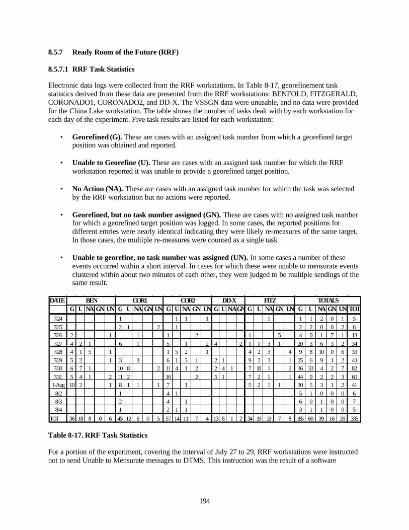
194
8.5.7 Ready Room of the Future (RRF)
8.5.7.1 RRF Task Statistics
Electronic data logs were collected from the RRF workstations. In Table 8-17, georefinement taskstatistics derived from these data are presented from the RRF workstations: BENFOLD, FITZGERALD,CORONADO1, CORONADO2, and DD-X. The VSSGN data were unusable, and no data were providedfor the China Lake workstation. The table shows the number of tasks dealt with by each workstation foreach day of the experiment. Five task results are listed for each workstation:
• Georefined (G). These are cases with an assigned task number from which a georefined targetposition was obtained and reported.
• Unable to Georefine (U). These are cases with an assigned task number for which the RRFworkstation reported it was unable to provide a georefined target position.
• No Action (NA). These are cases with an assigned task number for which the task was selectedby the RRF workstation but no actions were reported.
• Georefined, but no task number assigned (GN). These are cases with no assigned task numberfor which a georefined target position was logged. In some cases, the reported positions fordifferent entries were nearly identical indicating they were likely re-measures of the same target.In those cases, the multiple re-measures were counted as a single task
• Unable to georefine, no task number was assigned (UN). In some cases a number of theseevents occurred within a short interval. In cases for which these were unable to mensurate eventsclustered within about two minutes of each other, they were judged to be multiple sendings of thesame result.
DATEG U NA GN UN G U NA GN UN G U NA GN UN G U NAGN G U NA GN UN G U NA GN UN TOT
7/24 1 1 1 1 1 1 1 2 0 1 57/25 2 1 2 1 2 2 0 0 2 67/26 2 1 1 1 2 1 5 4 0 1 7 1 137/27 4 2 1 6 1 5 1 2 4 2 1 1 3 1 20 3 6 3 2 347/28 4 1 5 1 1 5 2 1 4 2 3 4 9 8 10 0 6 337/29 5 2 1 3 3 6 1 3 1 2 1 9 2 3 1 25 6 9 1 2 437/30 6 7 1 10 8 2 11 4 1 2 2 4 1 7 10 1 2 36 33 4 2 7 827/31 5 4 1 2 11 2 16 2 5 1 7 2 1 1 44 9 2 2 3 60
1-Aug 10 2 1 8 1 1 1 7 1 5 2 1 1 30 5 3 1 2 418/2 1 4 1 5 1 0 0 0 68/3 2 4 1 6 0 1 0 0 78/4 1 2 1 1 3 1 1 0 0 5
TOT 36 18 8 0 6 45 12 6 0 5 57 14 11 7 4 13 6 1 2 34 19 13 7 8 185 69 39 16 26 335
FITZ TOTALSBEN COR1 COR2 DD-X
Table 8-17. RRF Task Statistics
For a portion of the experiment, covering the interval of July 27 to 29, RRF workstations were instructednot to send Unable to Mensurate messages to DTMS. This instruction was the result of a software
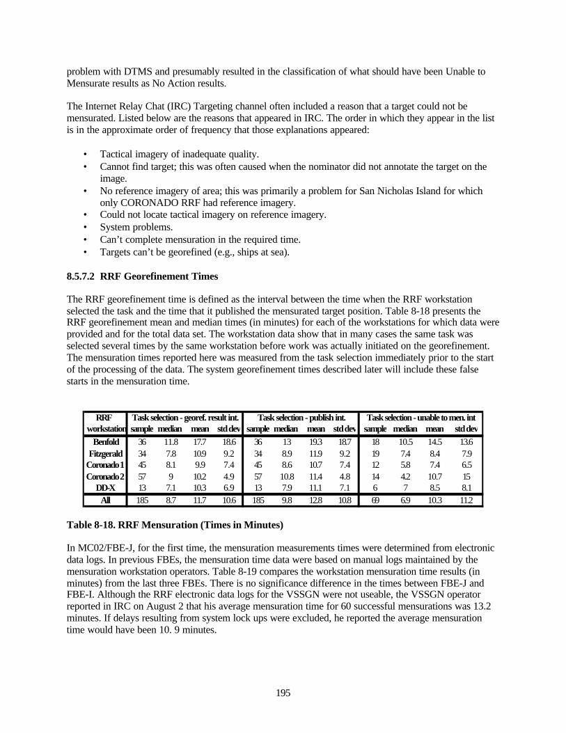
195
problem with DTMS and presumably resulted in the classification of what should have been Unable toMensurate results as No Action results.
The Internet Relay Chat (IRC) Targeting channel often included a reason that a target could not bemensurated. Listed below are the reasons that appeared in IRC. The order in which they appear in the listis in the approximate order of frequency that those explanations appeared:
• Tactical imagery of inadequate quality.• Cannot find target; this was often caused when the nominator did not annotate the target on the
image.• No reference imagery of area; this was primarily a problem for San Nicholas Island for which
only CORONADO RRF had reference imagery.• Could not locate tactical imagery on reference imagery.• System problems.• Can’t complete mensuration in the required time.• Targets can’t be georefined (e.g., ships at sea).
8.5.7.2 RRF Georefinement Times
The RRF georefinement time is defined as the interval between the time when the RRF workstationselected the task and the time that it published the mensurated target position. Table 8-18 presents theRRF georefinement mean and median times (in minutes) for each of the workstations for which data wereprovided and for the total data set. The workstation data show that in many cases the same task wasselected several times by the same workstation before work was actually initiated on the georefinement.The mensuration times reported here was measured from the task selection immediately prior to the startof the processing of the data. The system georefinement times described later will include these falsestarts in the mensuration time.
RRF workstation sample median mean std dev sample median mean std dev sample median mean std dev
Benfold 36 11.8 17.7 18.6 36 13 19.3 18.7 18 10.5 14.5 13.6Fitzgerald 34 7.8 10.9 9.2 34 8.9 11.9 9.2 19 7.4 8.4 7.9
Coronado 1 45 8.1 9.9 7.4 45 8.6 10.7 7.4 12 5.8 7.4 6.5Coronado 2 57 9 10.2 4.9 57 10.8 11.4 4.8 14 4.2 10.7 15
DD-X 13 7.1 10.3 6.9 13 7.9 11.1 7.1 6 7 8.5 8.1All 185 8.7 11.7 10.6 185 9.8 12.8 10.8 69 6.9 10.3 11.2
Task selection - georef. result int. Task selection - publish int. Task selection - unable to men. int
Table 8-18. RRF Mensuration (Times in Minutes)
In MC02/FBE-J, for the first time, the mensuration measurements times were determined from electronicdata logs. In previous FBEs, the mensuration time data were based on manual logs maintained by themensuration workstation operators. Table 8-19 compares the workstation mensuration time results (inminutes) from the last three FBEs. There is no significance difference in the times between FBE-J andFBE-I. Although the RRF electronic data logs for the VSSGN were not useable, the VSSGN operatorreported in IRC on August 2 that his average mensuration time for 60 successful mensurations was 13.2minutes. If delays resulting from system lock ups were excluded, he reported the average mensurationtime would have been 10. 9 minutes.
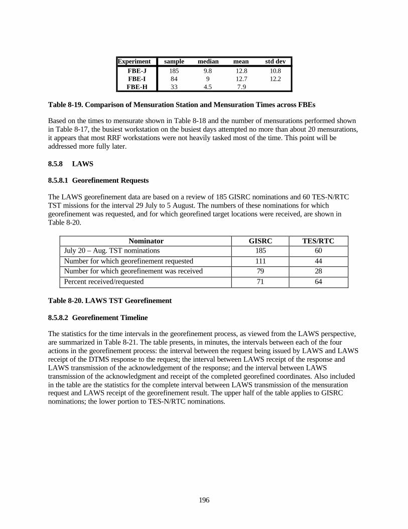
196
Experiment sample median mean std devFBE-J 185 9.8 12.8 10.8FBE-I 84 9 12.7 12.2FBE-H 33 4.5 7.9
Table 8-19. Comparison of Mensuration Station and Mensuration Times across FBEs
Based on the times to mensurate shown in Table 8-18 and the number of mensurations performed shownin Table 8-17, the busiest workstation on the busiest days attempted no more than about 20 mensurations,it appears that most RRF workstations were not heavily tasked most of the time. This point will beaddressed more fully later.
8.5.8 LAWS
8.5.8.1 Georefinement Requests
The LAWS georefinement data are based on a review of 185 GISRC nominations and 60 TES-N/RTCTST missions for the interval 29 July to 5 August. The numbers of these nominations for whichgeorefinement was requested, and for which georefined target locations were received, are shown inTable 8-20.
Nominator GISRC TES/RTCJuly 20 – Aug. TST nominations 185 60Number for which georefinement requested 111 44Number for which georefinement was received 79 28Percent received/requested 71 64
Table 8-20. LAWS TST Georefinement
8.5.8.2 Georefinement Timeline
The statistics for the time intervals in the georefinement process, as viewed from the LAWS perspective,are summarized in Table 8-21. The table presents, in minutes, the intervals between each of the fouractions in the georefinement process: the interval between the request being issued by LAWS and LAWSreceipt of the DTMS response to the request; the interval between LAWS receipt of the response andLAWS transmission of the acknowledgement of the response; and the interval between LAWStransmission of the acknowledgment and receipt of the completed georefined coordinates. Also includedin the table are the statistics for the complete interval between LAWS transmission of the mensurationrequest and LAWS receipt of the georefinement result. The upper half of the table applies to GISRCnominations; the lower portion to TES-N/RTC nominations.
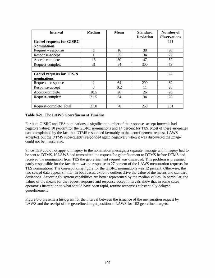
197
Interval Median Mean StandardDeviation
Number ofObservations
Georef requests for GISRCNominations
111
Request – response 3 16 38 98Response-accept 1 55 34 72Accept-complete 18 30 47 57Request-complete 31 84 300 73
Georef requests for TES-Nnominations
44
Request – response 2 64 290 32Response-accept 0 0.2 11 28Accept-complete 18.5 26 26 26Request-complete 21.5 34 34 28
Request-complete Total 27.0 70 259 101
Table 8-21. The LAWS Georefinement Timeline
For both GISRC and TES nominations, a significant number of the response- accept intervals hadnegative values; 18 percent for the GISRC nominations and 14 percent for TES. Most of these anomaliescan be explained by the fact that DTMS responded favorably to the georefinement request, LAWSaccepted, but the DTMS subsequently responded again negatively when it was discovered the imagecould not be mensurated.
Since TES could not append imagery to the nomination message, a separate message with imagery had tobe sent to DTMS. If LAWS had transmitted the request for georefinement to DTMS before DTMS hadreceived the nomination from TES the georefinement request was discarded. This problem is presumedpartly responsible for the fact there was no response to 27 percent of the LAWS mensuration requests forTES nominations. The corresponding figure for the GISRC nominations was 12 percent. Otherwise, thetwo sets of data appear similar. In both cases, extreme outliers drive the value of the means and standarddeviations. Accordingly system capabilities are better represented by the median values. In particular, thevalues of the means for the request-response and response-accept intervals show that in some casesoperator’s inattention to what should have been rapid, routine responses substantially delayedgeorefinement.
Figure 8-5 presents a histogram for the interval between the issuance of the mensuration request byLAWS and the receipt of the georefined target position at LAWS for 102 georefined targets.
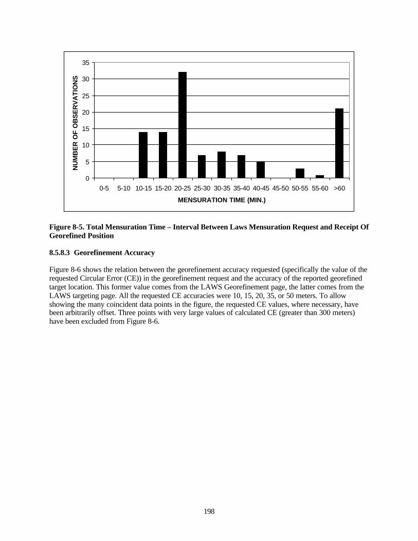
198
0
5
10
15
20
25
30
35
0-5 5-10 10-15 15-20 20-25 25-30 30-35 35-40 40-45 45-50 50-55 55-60 >60
MENSURATION TIME (MIN.)
NU
MB
ER
OF
OB
SE
RV
ATI
ON
S
Figure 8-5. Total Mensuration Time – Interval Between Laws Mensuration Request and Receipt OfGeorefined Position
8.5.8.3 Georefinement Accuracy
Figure 8-6 shows the relation between the georefinement accuracy requested (specifically the value of therequested Circular Error (CE)) in the georefinement request and the accuracy of the reported georefinedtarget location. This former value comes from the LAWS Georefinement page, the latter comes from theLAWS targeting page. All the requested CE accuracies were 10, 15, 20, 35, or 50 meters. To allowshowing the many coincident data points in the figure, the requested CE values, where necessary, havebeen arbitrarily offset. Three points with very large values of calculated CE (greater than 300 meters)have been excluded from Figure 8-6.
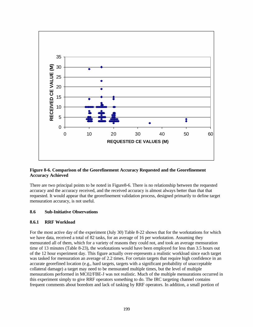
199
0
5
10
15
20
25
30
35
0 10 20 30 40 50 60
REQUESTED CE VALUES (M)
RE
CE
IVE
D C
E V
ALU
E (M
)
Figure 8-6. Comparison of the Georefinement Accuracy Requested and the GeorefinementAccuracy Achieved
There are two principal points to be noted in Figure8-6. There is no relationship between the requestedaccuracy and the accuracy received, and the received accuracy is almost always better than that thatrequested. It would appear that the georefinement validation process, designed primarily to define targetmensuration accuracy, is not useful.
8.6 Sub-Initiative Observations
8.6.1 RRF Workload
For the most active day of the experiment (July 30) Table 8-22 shows that for the workstations for whichwe have data, received a total of 82 tasks, for an average of 16 per workstation. Assuming theymensurated all of them, which for a variety of reasons they could not, and took an average mensurationtime of 13 minutes (Table 8-23), the workstations would have been employed for less than 3.5 hours outof the 12 hour experiment day. This figure actually over-represents a realistic workload since each targetwas tasked for mensuration an average of 2.2 times. For certain targets that require high confidence in anaccurate georefined location (e.g., hard targets, targets with a significant probability of unacceptablecollateral damage) a target may need to be mensurated multiple times, but the level of multiplemensurations performed in MC02/FBE-J was not realistic. Much of the multiple mensurations occurred inthis experiment simply to give RRF operators something to do. The IRC targeting channel containsfrequent comments about boredom and lack of tasking by RRF operators. In addition, a small portion of
200
the RRF tasking consisted of test targets. The conclusion is that the RRF workstation workload in thisexperiment was light.
8.6.2 Time to Mensurate
The median time to mensurate a target by RRF was 9.8 minutes (Table 8-19). The median time betweenLAWS issuing a georefinement request and receiving the mensuration result was 27 minutes (Table 8-21). It is not surprising that the introduction of the georefinement validation process and a newmensuration system (DTMS) lengthens the mensuration process. The georefinement validation processseems to contribute nothing but an increase in the mensuration time.
8.6.3 The Need for Georefinement
For high priority short dwell time targets, mensuration of the target should begin immediately even if thegeorefinement might ultimately prove unnecessary by virtue of the weapon-target pairing that is chosen.
For other targets, the original target nomination needs to contain an estimate of the accuracy of thereported target location. Without this, a reasoned determination of the need for further georefinementsubsequent to weapon-target pairing cannot be made.
8.6.4 Georefinement Architecture and Autonomous Engagements
The FBE-J mensuration architecture required all mensuration requests to pass through the DTMS. Thismade the DTMS a single point of failure. If DTMS, or the communication link to it, went down the wholemensuration process would fail. For this reason alone the mensuration system should have beenconfigured so that LAWS can send georefinement requests directly to RRF workstations and RRFworkstations can receive target nominations. Beyond that consideration, the TST TTP should specificallyaddress the cases of high priority short dwell time TSTs for which only a fully autonomous engagementhas much hope of success. The FBE-J mensuration architecture makes autonomous engagementsimpossible.
8.6.5 The Contribution of the DTMS/Mensuration Manager
The value added to the mensuration process by the DTMS/ Mensuration Manager should be the proactivemanagement of the process; efficient prioritization and allocation of tasks to those assets that have thetime and databases to accomplish the task. The DTMS/Mensuration Manager should also provide aknowledgeable focus for filtering out tasks that cannot be performed due to poor imagery, unmensurabletargets, or targets that do not require mensuration on the basis of weapon-target pairing. In the list ofreasons the RRF workstation gave for being unable to mensurate targets, some of the responses shouldnot occur, or should be greatly reduced in frequency by the actions of the Mensuration Manager. Forexample, if a workstation had no reference imagery of area, the Mensuration Manager would not allocatethe task to that workstation because it did not have the necessary database. A cursory preview of theimagery by the Mensuration Manager should reduce the number of RRF workstations responses wherethey reported the target couldn’t be georefined (e.g., ship at sea), the tactical imagery was of inadequatequality, and/or they can’t find the target.
The value of the DTMS system will not be as evident in an environment where there is a low level ofmensuration tasking and the RRF workstations could likely-self synchronize, as was the case in FBE-J. Itneeds to be demonstrated in an environment where mensuration resources are over tasked.
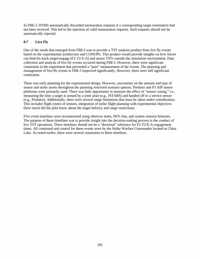
201
In FBE-J, DTMS automatically discarded mensuration requests if a corresponding target nomination hadnot been received. This led to the rejection of valid mensuration requests. Such requests should not beautomatically rejected.
8.7 Live Fly
One of the needs that emerged from FBE-I was to provide a TST analysis product from live fly eventsbased on the experimental architecture and CONOPS. This product would provide insights on how forcescan find-fix-track-target-engage (F2-T2-E-A) and assess TSTs outside the simulation environment. Datacollection and analysis of live-fly events occurred during FBE-I. However, there were significantconstraints in the experiment that prevented a “pure” measurement of the events. The planning andmanagement of live-fly events in FBE-J improved significantly. However, there were still significantconstraints.
There was early planning for the experimental design. However, uncertainty on the amount and type ofsensor and strike assets throughout the planning restricted scenario options. Predator and P3 AIP sensorplatforms were primarily used. There was little opportunity to measure the effect of “sensor cueing,” i.e.,measuring the time a target is sensed by a joint asset (e.g., JSTARS) and handed off to a service sensor(e.g., Predator). Additionally, there were several range limitations that must be taken under consideration.This includes flight routes of sensors, integration of strike flight planning with experimental objectives(how much did the pilot know about the target before), and range restrictions.
Five event timelines were reconstructed using observer notes, IWS chat, and system mission histories.The purpose of these timelines was to provide insight into the decision-making process in the conduct oflive TST operations. These timelines should not be a “doctrinal” reference for F2-T2-E-A engagementtimes. All command and control for these events were by the Strike Warfare Commander located at ChinaLake. As noted earlier, there were several constraints to these timelines.
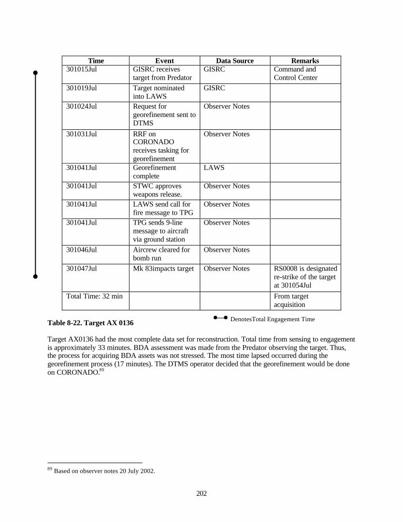
202
Time Event Data Source Remarks301015Jul GISRC receives
target from PredatorGISRC Command and
Control Center301019Jul Target nominated
into LAWSGISRC
301024Jul Request forgeorefinement sent toDTMS
Observer Notes
301031Jul RRF onCORONADOreceives tasking forgeorefinement
Observer Notes
301041Jul Georefinementcomplete
LAWS
301041Jul STWC approvesweapons release.
Observer Notes
301041Jul LAWS send call forfire message to TPG
Observer Notes
301041Jul TPG sends 9-linemessage to aircraftvia ground station
Observer Notes
301046Jul Aircrew cleared forbomb run
Observer Notes
301047Jul Mk 83impacts target Observer Notes RS0008 is designatedre-strike of the targetat 301054Jul
Total Time: 32 min From targetacquisition
Table 8-22. Target AX 0136
Target AX0136 had the most complete data set for reconstruction. Total time from sensing to engagementis approximately 33 minutes. BDA assessment was made from the Predator observing the target. Thus,the process for acquiring BDA assets was not stressed. The most time lapsed occurred during thegeorefinement process (17 minutes). The DTMS operator decided that the georefinement would be doneon CORONADO.89
89 Based on observer notes 20 July 2002.
DenotesTotal Engagement Time
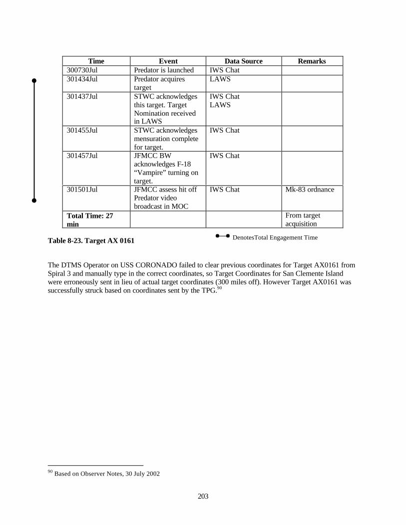
203
Time Event Data Source Remarks300730Jul Predator is launched IWS Chat301434Jul Predator acquires
targetLAWS
301437Jul STWC acknowledgesthis target. TargetNomination receivedin LAWS
IWS ChatLAWS
301455Jul STWC acknowledgesmensuration completefor target.
IWS Chat
301457Jul JFMCC BWacknowledges F-18“Vampire” turning ontarget.
IWS Chat
301501Jul JFMCC assess hit offPredator videobroadcast in MOC
IWS Chat Mk-83 ordnance
Total Time: 27min
From targetacquisition
Table 8-23. Target AX 0161
The DTMS Operator on USS CORONADO failed to clear previous coordinates for Target AX0161 fromSpiral 3 and manually type in the correct coordinates, so Target Coordinates for San Clemente Islandwere erroneously sent in lieu of actual target coordinates (300 miles off). However Target AX0161 wassuccessfully struck based on coordinates sent by the TPG.90
90 Based on Observer Notes, 30 July 2002
DenotesTotal Engagement Time
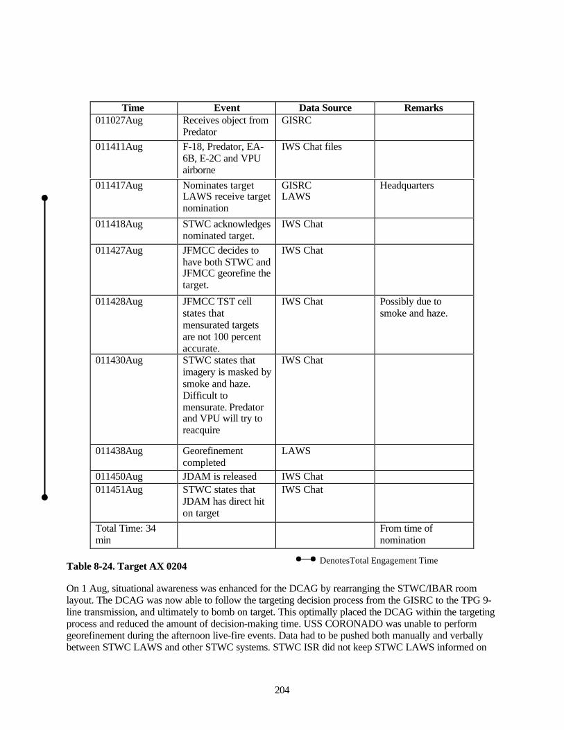
204
Time Event Data Source Remarks011027Aug Receives object from
PredatorGISRC
011411Aug F-18, Predator, EA-6B, E-2C and VPUairborne
IWS Chat files
011417Aug Nominates targetLAWS receive targetnomination
GISRCLAWS
Headquarters
011418Aug STWC acknowledgesnominated target.
IWS Chat
011427Aug JFMCC decides tohave both STWC andJFMCC georefine thetarget.
IWS Chat
011428Aug JFMCC TST cellstates thatmensurated targetsare not 100 percentaccurate.
IWS Chat Possibly due tosmoke and haze.
011430Aug STWC states thatimagery is masked bysmoke and haze.Difficult tomensurate. Predatorand VPU will try toreacquire
IWS Chat
011438Aug Georefinementcompleted
LAWS
011450Aug JDAM is released IWS Chat011451Aug STWC states that
JDAM has direct hiton target
IWS Chat
Total Time: 34min
From time ofnomination
Table 8-24. Target AX 0204
On 1 Aug, situational awareness was enhanced for the DCAG by rearranging the STWC/IBAR roomlayout. The DCAG was now able to follow the targeting decision process from the GISRC to the TPG 9-line transmission, and ultimately to bomb on target. This optimally placed the DCAG within the targetingprocess and reduced the amount of decision-making time. USS CORONADO was unable to performgeorefinement during the afternoon live-fire events. Data had to be pushed both manually and verballybetween STWC LAWS and other STWC systems. STWC ISR did not keep STWC LAWS informed on
DenotesTotal Engagement Time
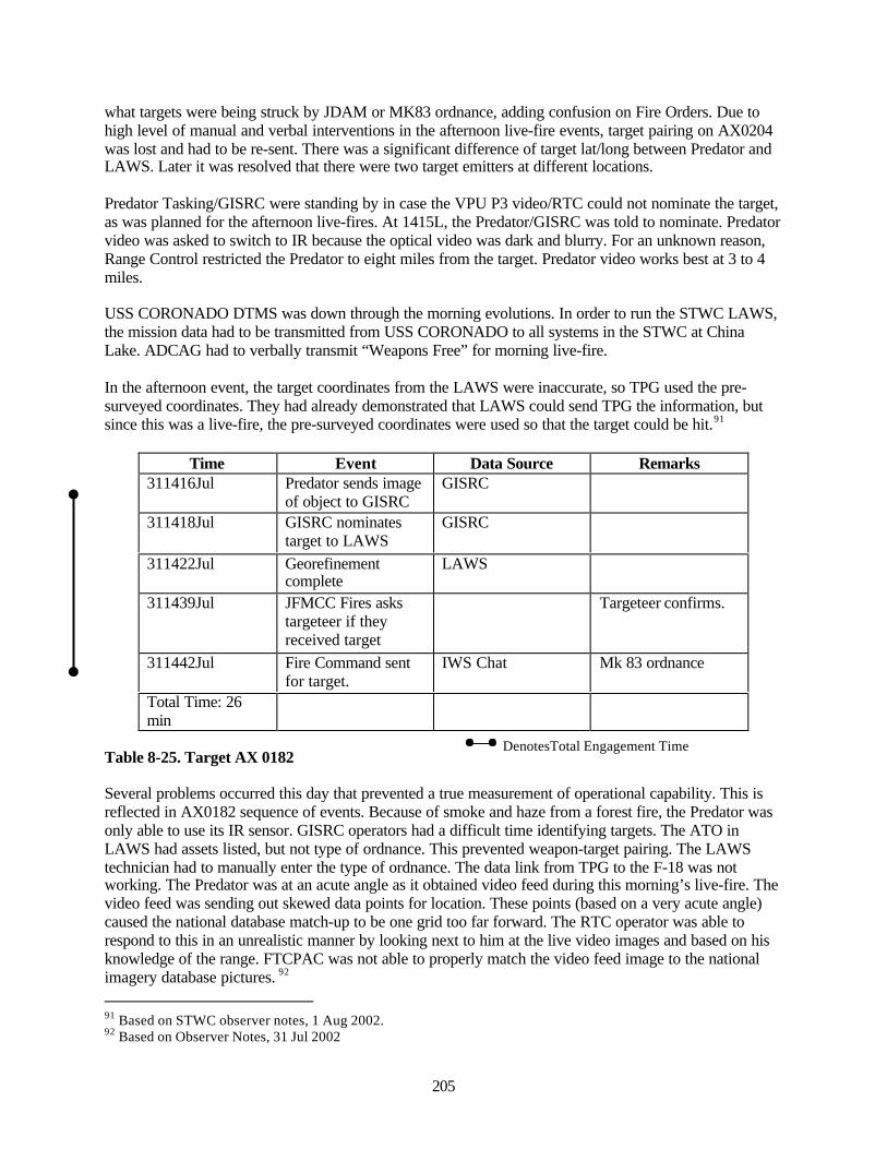
205
what targets were being struck by JDAM or MK83 ordnance, adding confusion on Fire Orders. Due tohigh level of manual and verbal interventions in the afternoon live-fire events, target pairing on AX0204was lost and had to be re-sent. There was a significant difference of target lat/long between Predator andLAWS. Later it was resolved that there were two target emitters at different locations.
Predator Tasking/GISRC were standing by in case the VPU P3 video/RTC could not nominate the target,as was planned for the afternoon live-fires. At 1415L, the Predator/GISRC was told to nominate. Predatorvideo was asked to switch to IR because the optical video was dark and blurry. For an unknown reason,Range Control restricted the Predator to eight miles from the target. Predator video works best at 3 to 4miles.
USS CORONADO DTMS was down through the morning evolutions. In order to run the STWC LAWS,the mission data had to be transmitted from USS CORONADO to all systems in the STWC at ChinaLake. ADCAG had to verbally transmit “Weapons Free” for morning live-fire.
In the afternoon event, the target coordinates from the LAWS were inaccurate, so TPG used the pre-surveyed coordinates. They had already demonstrated that LAWS could send TPG the information, butsince this was a live-fire, the pre-surveyed coordinates were used so that the target could be hit.91
Time Event Data Source Remarks311416Jul Predator sends image
of object to GISRCGISRC
311418Jul GISRC nominatestarget to LAWS
GISRC
311422Jul Georefinementcomplete
LAWS
311439Jul JFMCC Fires askstargeteer if theyreceived target
Targeteer confirms.
311442Jul Fire Command sentfor target.
IWS Chat Mk 83 ordnance
Total Time: 26min
Table 8-25. Target AX 0182
Several problems occurred this day that prevented a true measurement of operational capability. This isreflected in AX0182 sequence of events. Because of smoke and haze from a forest fire, the Predator wasonly able to use its IR sensor. GISRC operators had a difficult time identifying targets. The ATO inLAWS had assets listed, but not type of ordnance. This prevented weapon-target pairing. The LAWStechnician had to manually enter the type of ordnance. The data link from TPG to the F-18 was notworking. The Predator was at an acute angle as it obtained video feed during this morning’s live-fire. Thevideo feed was sending out skewed data points for location. These points (based on a very acute angle)caused the national database match-up to be one grid too far forward. The RTC operator was able torespond to this in an unrealistic manner by looking next to him at the live video images and based on hisknowledge of the range. FTCPAC was not able to properly match the video feed image to the nationalimagery database pictures. 92
91 Based on STWC observer notes, 1 Aug 2002.92 Based on Observer Notes, 31 Jul 2002
DenotesTotal Engagement Time
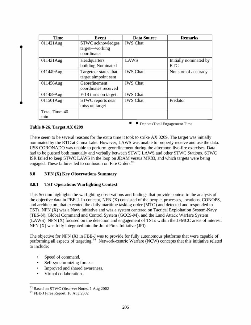
206
Time Event Data Source Remarks011421Aug STWC acknowledges
target—workingcoordinates
IWS Chat
011431Aug Headquartersbuilding Nominated
LAWS Initially nominated byRTC
011449Aug Targeteer states thattarget aimpoint sent
IWS Chat Not sure of accuracy
011456Aug Georefinementcoordinates received
IWS Chat
011459Aug F-18 turns on target IWS Chat011501Aug STWC reports near
miss on targetIWS Chat Predator
Total Time: 40min
Table 8-26. Target AX 0209
There seem to be several reasons for the extra time it took to strike AX 0209. The target was initiallynominated by the RTC at China Lake. However, LAWS was unable to properly receive and use the data.USS CORONADO was unable to perform georefinement during the afternoon live-fire exercises. Datahad to be pushed both manually and verbally between STWC LAWS and other STWC Stations. STWCISR failed to keep STWC LAWS in the loop on JDAM versus MK83, and which targets were beingengaged. These failures led to confusion on Fire Orders.93
8.8 NFN (X) Key Observations Summary
8.8.1 TST Operations Warfighting Context
This Section highlights the warfighting observations and findings that provide context to the analysis ofthe objective data in FBE-J. In concept, NFN (X) consisted of the people, processes, locations, CONOPS,and architecture that executed the daily maritime tasking order (MTO) and detected and responded toTSTs. NFN (X) was a Navy initiative and was a system centered on Tactical Exploitation System-Navy(TES-N), Global Command and Control System (GCCS-M), and the Land Attack Warfare System(LAWS). NFN (X) focused on the detection and engagement of TSTs within the JFMCC areas of interest.NFN (X) was fully integrated into the Joint Fires Initiative (JFI).
The objective for NFN (X) in FBE-J was to provide for fully autonomous platforms that were capable ofperforming all aspects of targeting. 94 Network-centric Warfare (NCW) concepts that this initiative relatedto include:
• Speed of command.• Self-synchronizing forces.• Improved and shared awareness.• Virtual collaboration.
93 Based on STWC Observer Notes, 1 Aug 200294 FBE-J Fires Report, 10 Aug 2002
DenotesTotal Engagement Time
207
• Increased tempo.• Increased responsiveness.• Sensor netting.
The primary nodes that were actively involved with this experimental initiative were:
• Maritime Operations Center (MOC) on USS CORONADO.• Strike Warfare Commander (STWC) at China Lake.• Principal Warfare Commanders located at FCTCPAC, the VSSGN at Newport, RI, USS Benfold,
and USS Fitzgerald.
The JFMCC MOC was the primary command and control operations center for TST operations, and othercurrent operations for the JFMCC. Their primary responsibility was to ensure that the Air Tasking Order(ATO) for the day was executed. Their other responsibilities were to have centralized control for F2T2EAof TST targets and to ensure that cross-component F2T2EA was executed according to the guidelines forthe Joint Fires Initiative (JFI).
The execution of the ATO was not an experiment objective. Rather, the Maritime Planning Cell wasexperimenting with processes to develop ATOs. The ATO would be handed to the MOC for executiondaily. However, because of the experiment design, the total focus of execution was on TST Operations.
In establishing the warfighting context for TST operations, the primary data collection methods that wereused for this initiative were surveys, observations, and interviews. The data from the surveys were in twoforms; general comments from the operators and watch officers and ratings by the respondents on certainaspects of TST operations. The general comments from the respondents were:
• Many of the issues that emerged were not necessarily technical issues, but rather process andCONOPS issues.
• Much of situational awareness came from IWS and IRC chat.• Situation awareness was hampered by latencies in the systems; lack of sufficient screen space;
and no visibility on the execution of the ATO.• The TST architecture and CONOPS were good against fixed targets, however they were not good
for targets that require meticulous search and long-term tracking.• Very difficult to track moving targets with ADOCS/LAWS.• ADOCS/LAWS provided little enemy situational awareness, and no awareness of weather;
moving targets, or targets in proximity to other targets.• There was little knowledge of the enemy’s COAs during the experiment.• It was very difficult to visualize the land operations.• Battle space area of responsibility was not clearly defined. TST strikes by aircraft cannot
effectively be coordinated without knowledge of the enemy air defense threat.• The information provided for each track in ADOCS/LAWS was inadequate to determine
movement over time, age of the data, and the reporting unit.• The “target cards” in LAWS needed to be defined better. A table was needed to improve and
standardize the description of the characteristics of damage.• Once a TST was hit, the subsequent process became confusing; there was no set process to
coordinate BDA, decision criteria for re-strike, and requests for imagery.• There needs to be better coordination and synchronization with the ISR and Fires cells.• There was no confidence in the BDA reports.
208
• Assessments lacked detail. A re-capitulation of DMPI and a recommendation for re-strike wereneeded.
• It was difficult to coordinate collection of post-strike BDA. With multiple targets being hit, it wasdifficult to coordinate collection so a single sensor could collect BDA on more than one target.
• The ISR workload and low situational awareness prevented me from doing air-deconfliction ofsensors and re-routing ISR assets based on the current situation.
• There was no situational awareness on the tasking and routes of all the sensors.• There was no idea of what effect it would have on a current mission if a sensor were re-tasked.• There was no idea on what sensors were available.• The ISR web page had to be used to understand current UAV tasking and status, and it was
poorly maintained.• There was no correlation between planned coverage and sensors available for dynamic tasking.
The above comments coupled with observations indicate that the ISR and Fires functions were notcompletely synchronized. There were five distinct functions that occurred in the MOC; Fires (bothJFMCC and joint), ISR management, targeteering, intelligence, and command.
Fires. The Fires cell was capable of managing TST operations. They were able to receive targets fromJFACC and the JFLCC and integrate them into the JFMCC internal targeting process. Almost all targetswere centrally controlled at the MOC and pushed directly to the engagement nodes for execution. ThePWCs primarily monitored the TST operation. The exception was the STWC. The STWC foughtautonomously most of the experiment. This decision was influenced by the STWC extensive involvementin live-fly events.
ISR Management. The ISR cell operations are covered in the ISR Section of this report. The survey dataindicates that there was not an established process to assess the effects on the deliberate ISR plan whensensors were re-tasked to support TST operations. The ISR manager had neither the tools nor theestablished TTPs to visualize ISR operations at any given time. Thus, there was no confirmation that therewas “seamless” ISR coverage of the area of operations.
Intelligence. There was an intelligence desk in the MOC. The role and TTPs for use the intelligence deskwas not completely defined. The Intelligence Officer would occasionally give updates orally ofsignificant “analyzed events” in the MOC. However, there was not any formal link between the ISRmanager and Intel desk. This is indicates that it was not clear how “fresh” TST operations informationfrom the ISR manager was being analyzed to build the current enemy situation.
Targeteering. The targeteer function was comprised of the DTMS and RRF. The primary tasks were tomanage and process georefinement requests for TSTs. While this process generally functioned, thetargeteers’ general observations were that they did not have a good understanding of the Fires process.Basically, there was no process defined that allowed for the targeteers to efficiently georefine targets.
Command. The command function was centered on the battle watch officer (BWO) in the MOC. Hisresponsibilities included supervising the other four functional areas in the MOC. For situationalawareness, he had two overhead screens. These screens displayed the GCCS-M and ADOCS DynamicTarget List and Fires Manager. The BWO had on his desk a six-screen display. He generally keptADOCS managers, Outlook Express and IWS Chat displayed. The BWO, Current Operations Officer,and Chief of Staff did not play an active role in synchronizing the cells within the MOC. Collaborationamong the cells was at the cell leader and worker level. There seemed to be little effort in maintainingsituational awareness at a higher level by analyzing the sum total of TST operations and its effect on the
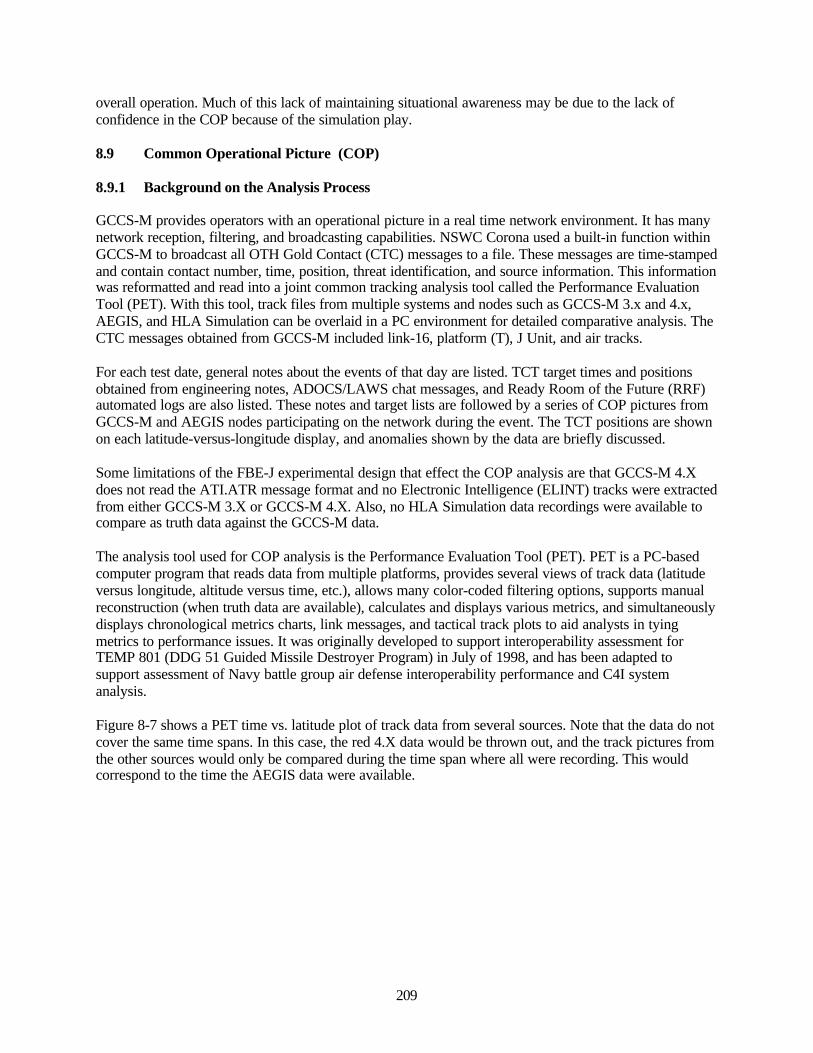
209
overall operation. Much of this lack of maintaining situational awareness may be due to the lack ofconfidence in the COP because of the simulation play.
8.9 Common Operational Picture (COP)
8.9.1 Background on the Analysis Process
GCCS-M provides operators with an operational picture in a real time network environment. It has manynetwork reception, filtering, and broadcasting capabilities. NSWC Corona used a built-in function withinGCCS-M to broadcast all OTH Gold Contact (CTC) messages to a file. These messages are time-stampedand contain contact number, time, position, threat identification, and source information. This informationwas reformatted and read into a joint common tracking analysis tool called the Performance EvaluationTool (PET). With this tool, track files from multiple systems and nodes such as GCCS-M 3.x and 4.x,AEGIS, and HLA Simulation can be overlaid in a PC environment for detailed comparative analysis. TheCTC messages obtained from GCCS-M included link-16, platform (T), J Unit, and air tracks.
For each test date, general notes about the events of that day are listed. TCT target times and positionsobtained from engineering notes, ADOCS/LAWS chat messages, and Ready Room of the Future (RRF)automated logs are also listed. These notes and target lists are followed by a series of COP pictures fromGCCS-M and AEGIS nodes participating on the network during the event. The TCT positions are shownon each latitude-versus-longitude display, and anomalies shown by the data are briefly discussed.
Some limitations of the FBE-J experimental design that effect the COP analysis are that GCCS-M 4.Xdoes not read the ATI.ATR message format and no Electronic Intelligence (ELINT) tracks were extractedfrom either GCCS-M 3.X or GCCS-M 4.X. Also, no HLA Simulation data recordings were available tocompare as truth data against the GCCS-M data.
The analysis tool used for COP analysis is the Performance Evaluation Tool (PET). PET is a PC-basedcomputer program that reads data from multiple platforms, provides several views of track data (latitudeversus longitude, altitude versus time, etc.), allows many color-coded filtering options, supports manualreconstruction (when truth data are available), calculates and displays various metrics, and simultaneouslydisplays chronological metrics charts, link messages, and tactical track plots to aid analysts in tyingmetrics to performance issues. It was originally developed to support interoperability assessment forTEMP 801 (DDG 51 Guided Missile Destroyer Program) in July of 1998, and has been adapted tosupport assessment of Navy battle group air defense interoperability performance and C4I systemanalysis.
Figure 8-7 shows a PET time vs. latitude plot of track data from several sources. Note that the data do notcover the same time spans. In this case, the red 4.X data would be thrown out, and the track pictures fromthe other sources would only be compared during the time span where all were recording. This wouldcorrespond to the time the AEGIS data were available.
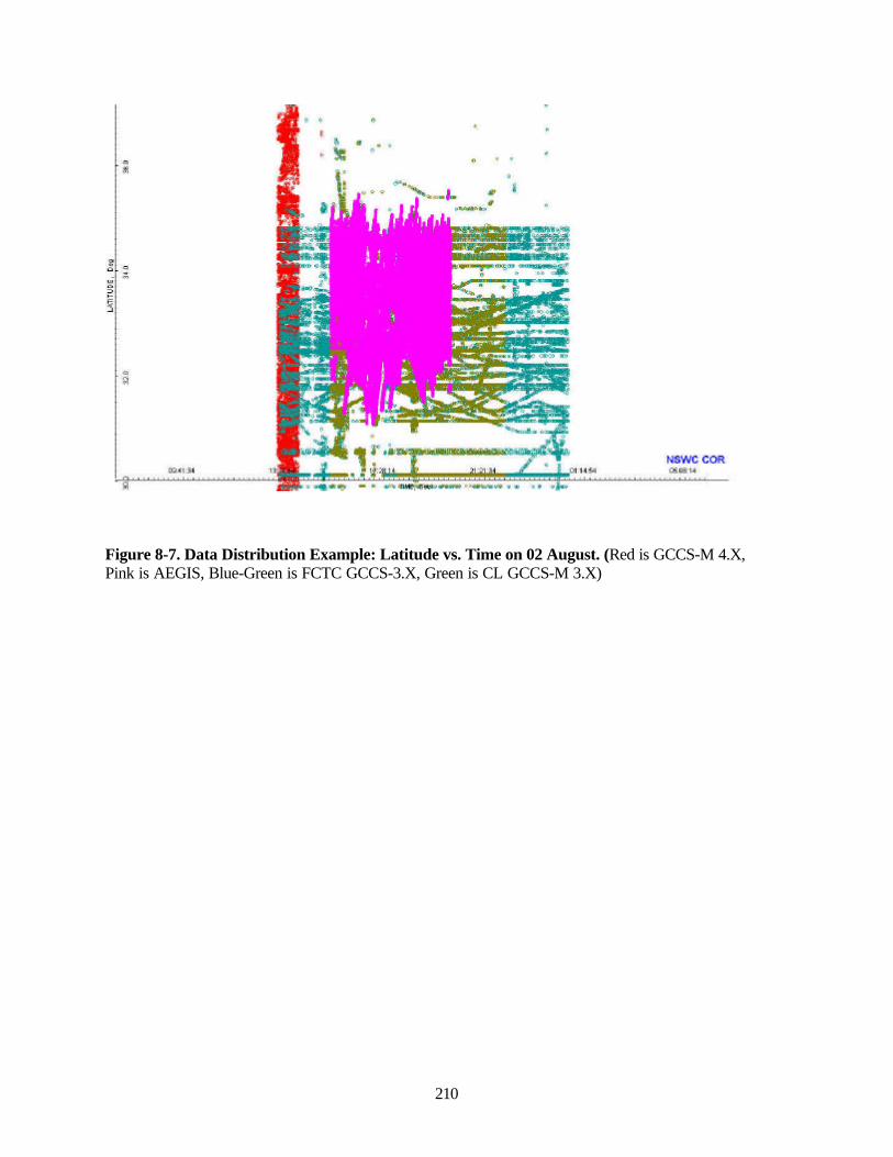
210
Figure 8-7. Data Distribution Example: Latitude vs. Time on 02 August. (Red is GCCS-M 4.X,Pink is AEGIS, Blue-Green is FCTC GCCS-3.X, Green is CL GCCS-M 3.X)
3

211
8.9.2 Analysis Results
The following COP relevant comments were excerpted from daily Imaging, Surveillance, andReconnaissance (ISR) Team reports:
• TES-N to DTMS ATI.ATR message and image transfer remains unsuccessful.
• TES-N cannot nominate targets from Live Predator due to lack of telemetry display.
• Live aircraft/surface tracks (e.g. Predator@China Lake, and AIP P-3 SOCAL AOR) are notappearing in the MOC COP.
• Multiple discrepancies remain between ADOCS, GCCS and TES-N COP.
• Multiple duplicate simulated tracks remain in MOC COP.
• Track labels pushed from FCTCPAC FOTC GCCS-M are displayed as TRK Numbers vicenames. Recommend FCTCPAC COP FOTC input and push tracks with call signs of units/aircraft(from daily ATO).
• Not all target nominations from GISRS are generating COP tracks.
• TES-N video/imagery problems have precluded verification of TES-N ability to generate tracks.
• MOC operators have no way of knowing which local ADOCS track number equates to whichGCCS-M link track number and equates to which live event on the ATO.
• Differences in target contact/track naming schemes between GISRC/C2PC, GCCS-M, andADOCS continue to prevent targets from appearing on ADOCS COP with the correct label (i.e.,target number used in the TST nomination). For example, AX0180 (CL GISRC TST nominationfor live JDAM drop) showed up in COP as BOA429 (the local C2PC track number assigned bythe CL GISRC)
• The 4x picture was somewhat cluttered due to a 3x/CST/Link-16 compatibility problem thatgenerated multiple link tracks for each platform track.
These comments are supported in the figures below which were produced from GCCS-M data.
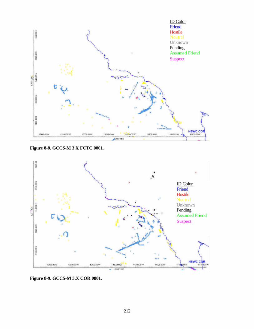
212
Figure 8-8. GCCS-M 3.X FCTC 0801.
Figure 8-9. GCCS-M 3.X COR 0801.
ID ColorFriendHostileNeutralUnknownPendingAssumed FriendSuspect
ID ColorFriendHostileNeutralUnknownPendingAssumed FriendSuspect
M^ Linil^UDE
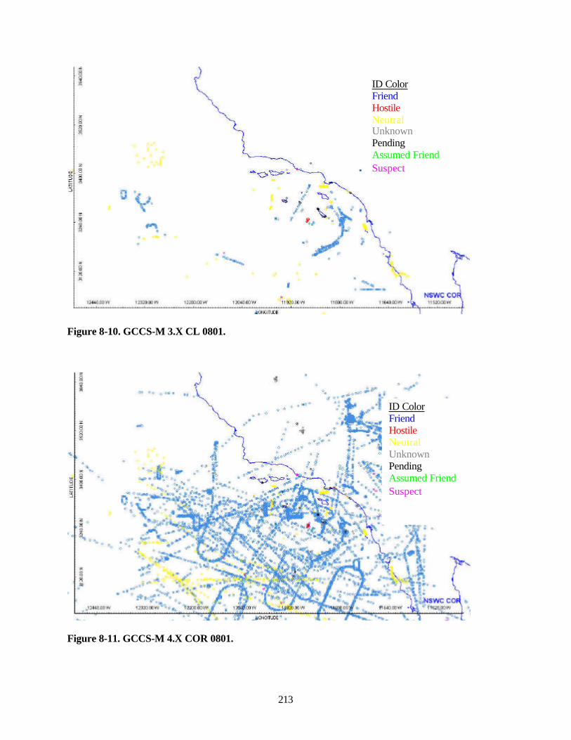
213
Figure 8-10. GCCS-M 3.X CL 0801.
Figure 8-11. GCCS-M 4.X COR 0801.
ID ColorFriendHostileNeutralUnknownPendingAssumed FriendSuspect
ID ColorFriendHostileNeutralUnknownPendingAssumed FriendSuspect
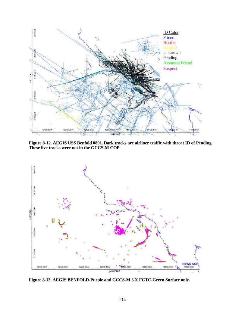
214
Figure 8-12. AEGIS USS Benfold 0801. Dark tracks are airliner traffic with threat ID of Pending.These live tracks were not in the GCCS-M COP.
Figure 8-13. AEGIS BENFOLD-Purple and GCCS-M 3.X FCTC-Green Surface only.
ID ColorFriendHostileNeutralUnknownPendingAssumed FriendSuspect
■ S ■■.-/
v
.*'"? »• i.
■^ t^-^
inaulD'' rznrjniTH- Silfcin^ WSWC COF
^i:M:<RCE
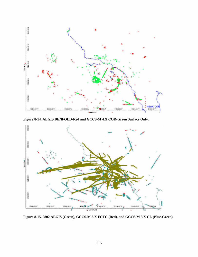
215
Figure 8-14. AEGIS BENFOLD-Red and GCCS-M 4.X COR-Green Surface Only.
Figure 8-15. 0802 AEGIS (Green), GCCS-M 3.X FCTC (Red), and GCCS-M 3.X CL (Blue-Green).
■.w *m
ijMnjiDi iTWJOi'* ijmonv iQim^ : NSWC COF
_ inf^inxt
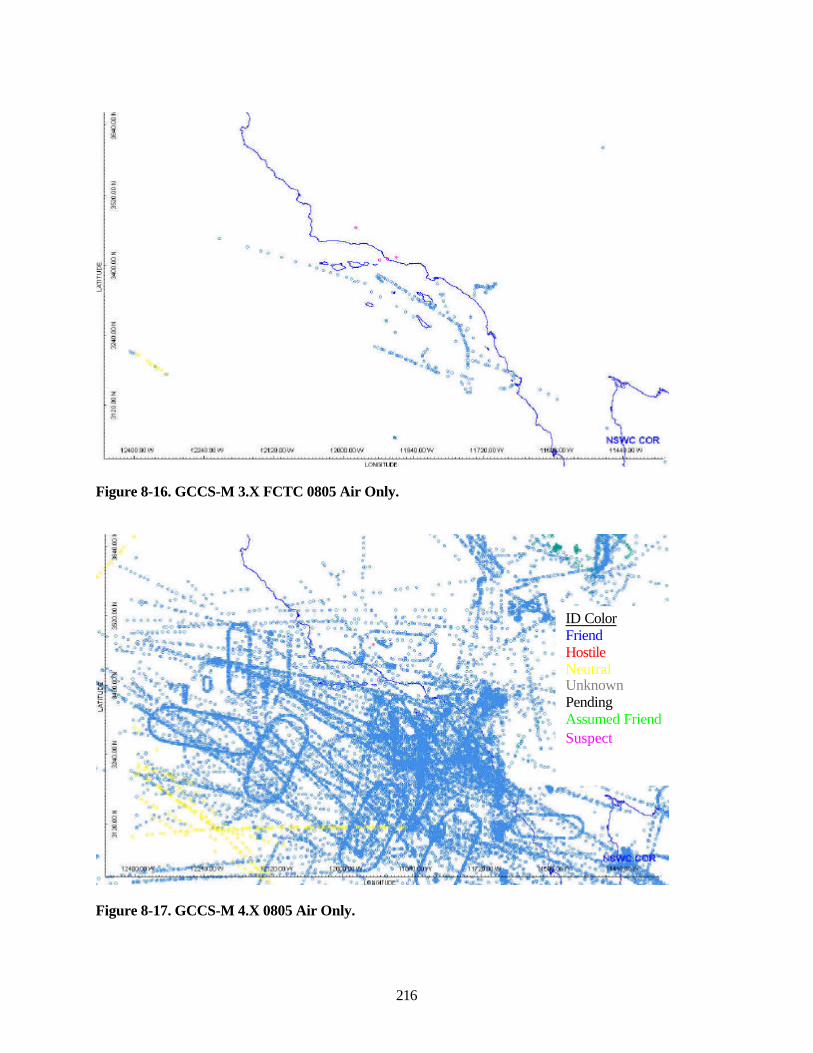
216
Figure 8-16. GCCS-M 3.X FCTC 0805 Air Only.
Figure 8-17. GCCS-M 4.X 0805 Air Only.
ID ColorFriendHostileNeutralUnknownPendingAssumed FriendSuspect
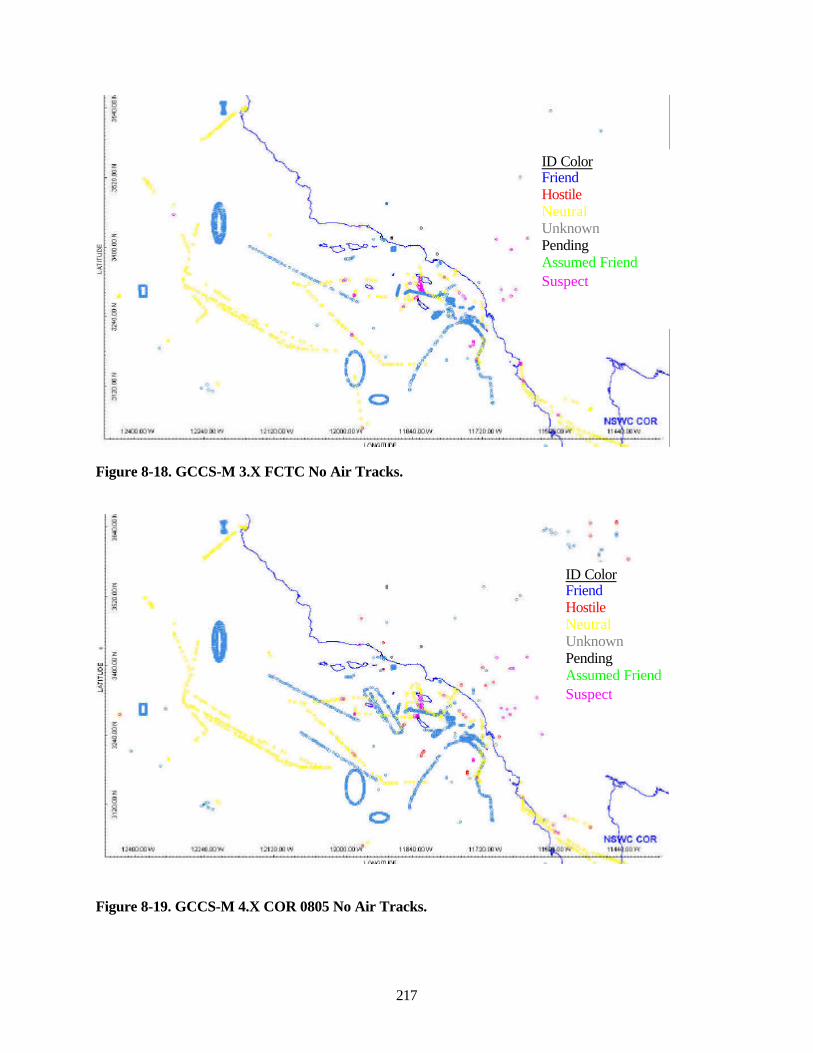
217
Figure 8-18. GCCS-M 3.X FCTC No Air Tracks.
Figure 8-19. GCCS-M 4.X COR 0805 No Air Tracks.
ID ColorFriendHostileNeutralUnknownPendingAssumed FriendSuspect
ID ColorFriendHostileNeutralUnknownPendingAssumed FriendSuspect
\/ty^mrf
|]4ltXI]IM l]]>UlKlW lilJDU^ IUUJXI' IIUHLUHI limUlM
I rtymrf
COR 11444 ilUlh
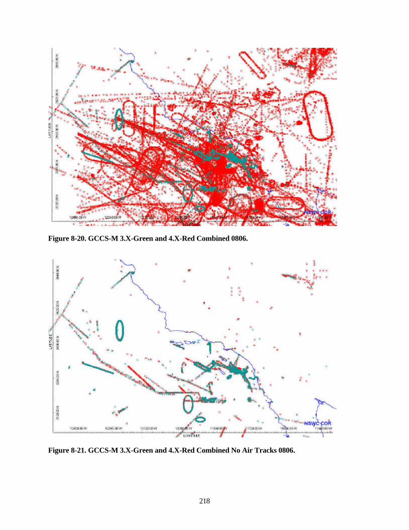
218
Figure 8-20. GCCS-M 3.X-Green and 4.X-Red Combined 0806.
Figure 8-21. GCCS-M 3.X-Green and 4.X-Red Combined No Air Tracks 0806.
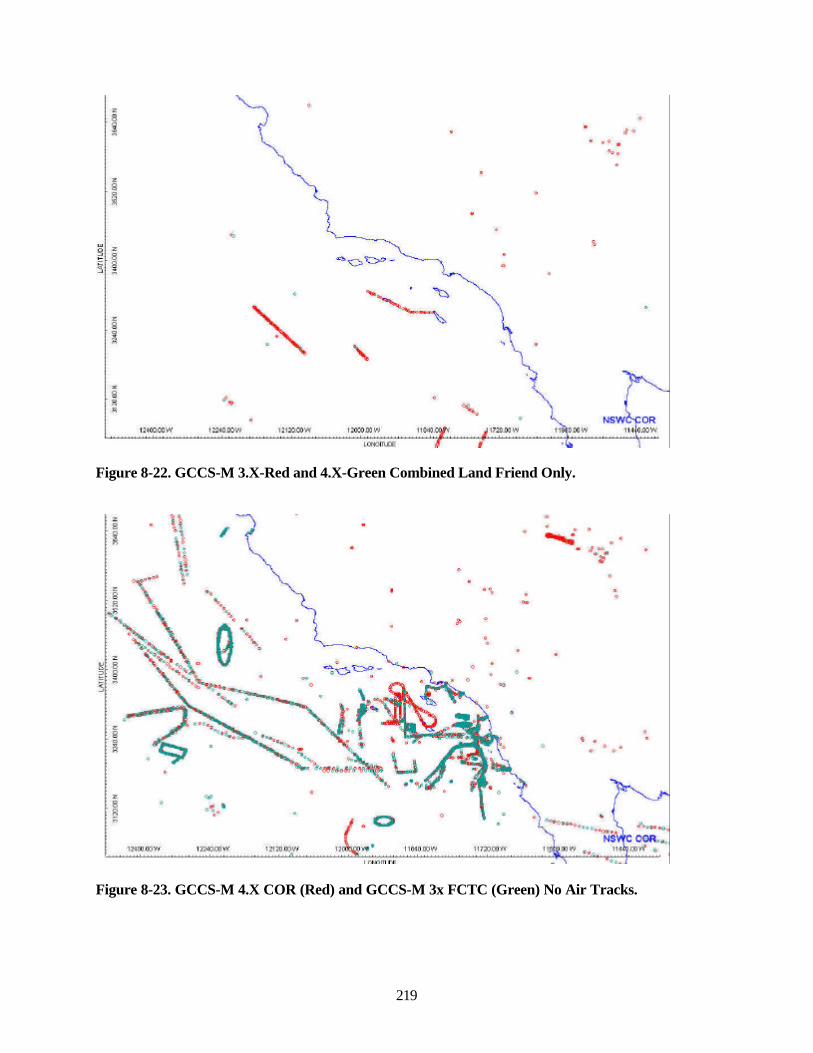
219
Figure 8-22. GCCS-M 3.X-Red and 4.X-Green Combined Land Friend Only.
Figure 8-23. GCCS-M 4.X COR (Red) and GCCS-M 3x FCTC (Green) No Air Tracks.
IZ4IKKCW m4DIKi» MMift-i
iJ4iiijn'' i^ajoii*
I r'lnmr'
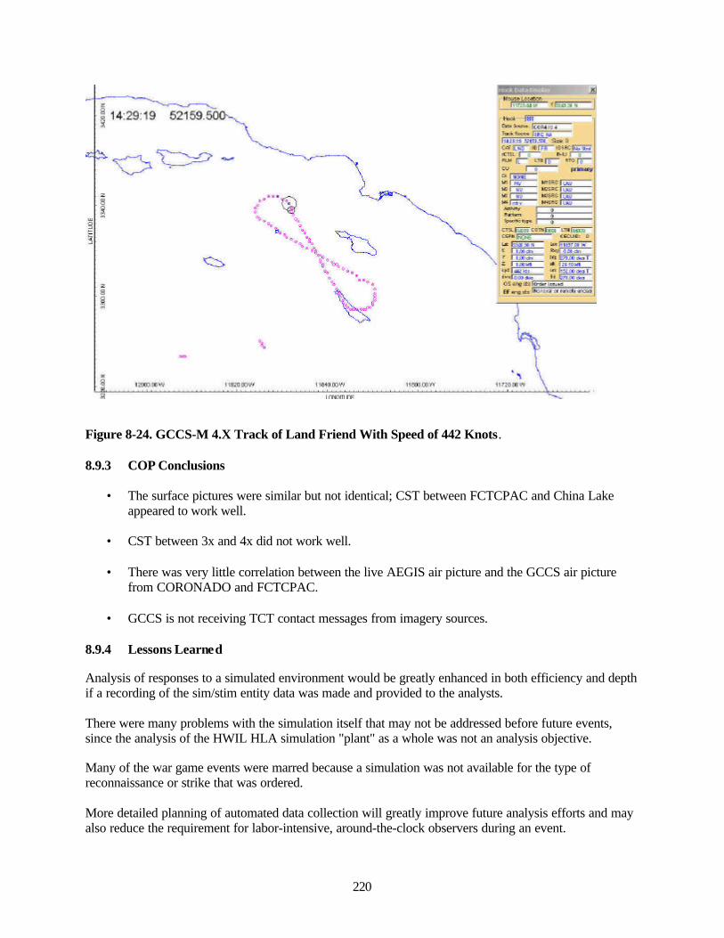
220
Figure 8-24. GCCS-M 4.X Track of Land Friend With Speed of 442 Knots.
8.9.3 COP Conclusions
• The surface pictures were similar but not identical; CST between FCTCPAC and China Lakeappeared to work well.
• CST between 3x and 4x did not work well.
• There was very little correlation between the live AEGIS air picture and the GCCS air picturefrom CORONADO and FCTCPAC.
• GCCS is not receiving TCT contact messages from imagery sources.
8.9.4 Lessons Learned
Analysis of responses to a simulated environment would be greatly enhanced in both efficiency and depthif a recording of the sim/stim entity data was made and provided to the analysts.
There were many problems with the simulation itself that may not be addressed before future events,since the analysis of the HWIL HLA simulation "plant" as a whole was not an analysis objective.
Many of the war game events were marred because a simulation was not available for the type ofreconnaissance or strike that was ordered.
More detailed planning of automated data collection will greatly improve future analysis efforts and mayalso reduce the requirement for labor-intensive, around-the-clock observers during an event.
im:.nrF

221
The technology being applied should be tested in a building block approach during a spiral type phase.For example, the process for a TCT contact message to propagate through each network node can betested in a very controlled environment using the type of setup that was available for Spiral 3. Problemsthat cannot be corrected before event commencement could then be documented, and that informationmade available to those "refereeing" the Red vs. Blue war game.

222
This page intentionally left blank.
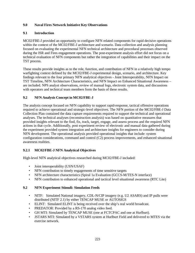
223
9.0 Naval Fires Network Initiative Key Observations
9.1 Introduction
MC02/FBE-J provided an opportunity to configure NFN related components for rapid decisive operationswithin the context of the MC02/FBE-J architecture and scenario. Data collection and analysis planningfocused on evaluating the experimental NFN technical architecture and procedural processes observedduring the ISR and Fires engagement operations. The post-experiment analysis effort did not focus on atechnical evaluation of NFN components but rather the integration of capabilities and their impact on theTST process.
These results provide insights as to the role, function, and contribution of NFN in a relatively high tempowarfighting context defined by the MC02/FBE-J experimental design, scenario, and architecture. Keyfindings relevant to the four primary NFN analytical objectives - Joint Interoperability, NFN Impact onTST Timeline, NFN Architecture Characteristics, and NFN Impact on Enhanced Situational Awareness –are included. NPS analyst observations, review of manual logs, electronic system data, and discussionswith operators and technical team members form the basis of these results.
9.2 NFN Analysis Concept in MC02/FBE-J
The analysis concept focused on NFN capability to support rapid-response, tactical offensive operationsrequired to achieve operational and strategic-level objectives. The NFN portion of the MC02/FBE-J DataCollection Plan contained the data capture requirements required to support the technical and operationalanalyses. The technical analyses (reconstruction analysis) was based on quantitative measures thatprovided insights relevant to the find, fix, track, target, engage, and assess process and the required NFNactions in that cycle. Additionally, post experiment review of electronic and manual data gathered duringthe experiment provided system integration and architecture insights for engineers to consider duringNFN development. The operational analysis provided operational insights that include: systemconfiguration considerations, command and control (C2) process improvements, and enhanced situationalawareness realities.
9.2.1 MC02/FBE-J NFN Analytical Objectives
High-level NFN analytical objectives researched during MC02/FBE-J included:
• Joint interoperability (USN/USAF)• NFN contribution to timely engagements of time sensitive targets• NFN architecture characteristics (Spiral 1a Evaluation (GCCS-M/TES-N interface)• NFN contribution to enhanced operational and tactical level situational awareness (RTC Lite)
9.2 NFN Experiment Stimuli: Simulation Feeds
• NITF: Simulated National imagery, CDL-N/CIP imagery (e.g. U2 ASARS) and IP pulls weredistributed (NITF 2.1) by either TENCAP MUSE or AUTOSIGS
• ELINT: Simulated ELINT is being received over the ship’s real world broadcast.• PREDATOR: Provided by a RS-170 analog video feed.• GH MTI: Simulated by TENCAP MUSE (one at FCTCPAC and one at Hurlburt).• JSTARS MTI: Simulated by a VSTARS system at Hurlburt Field and delivered to MTES via the
exercise network.

224
9.2.3 NFN Experiment Stimuli: Live Feeds
• JOTBS:Predator at China Lake – GBS downlink to CORONADO with no telemetry (metadata)• P-3 VPU: Downlink through video server at China Lake to RTC à TES-N (CORONADO)• ATARS: Post mission tapes reviewed by TES-N Image Analysts on CORONADO• ASARS 2a: Ad hoc imagery, telemetry, and Navy plan forwarded from ISR-M (Nellis) to TES-N
(CORONADO)• JSTARS: Live UHF SATCOM feed integrated in M-TES (GMTI) on CORONADO.
9.3 Joint Interoperability (USN/USAF)
9.3.1 Joint Interoperability (USN/USAF): Obje ctive
Observe and document technical and procedural processes related to Joint Interoperability between Navy(TES-N) and USAF (ISR-M/JSTARS) within MC02/FBE-J architecture and scenario constraints.
9.3.2 Joint Interoperability (USN/USAF): Analytical Questions
• What are the interfaces, TTPs and types of information exchange between sea, air and land-basedTES-N related nodes (ISR-M, RTC, and RTC-Lite) with USS CORONADO?
• What are the roles, functions, and interactions of NFN related systems in the Joint TSTengagement process.
9.3.3 Joint Interoperability (USN/USAF): Findings
Although limited in scope, USN/USAF interoperability was exercised during this experiment. Thefollowing highlights the key findings:
• The experiment environment provided an opportunity to exercise coordinated USN/USAF TTPfor sensor re-tasking (ASARS 2a) during live U-2 flights (31 Jul, 2, 8 Aug). The process torequest additional (ad hoc) images from JFMCC ISR Operations through the JFACC liaisonofficer on board CORONADO to the JFACC ISR Operations (Nellis) for reprogramming of thesensor was successful. However, post experiment analysis of JFMCC ISR OPS and JFACC ISRCOORD IWS chat rooms indicated that command and control (C2) between USAF liaison on-board CORONADO and JFACC ISR operations personnel at Nellis required extensivecoordination between the participants at both locations in order to achieve these results.95
• Although previously reported during an NFN VPO VTC in Jun 02, that DIOP (Data Input OutputPort) session between ISR-M baseline software (v4.1) and TES-N baseline software (v4.0) wasnot feasible because of software incompatibility, tests during MC02/FBE-J proved that reportincorrect. The experiment produced successful DIOP of ASARS 2a spot imagery between ISR-Mand TES-N during live U-2 flight (8 Aug 02). DIOP allowed real-time screening and exploitationof direct ASARS 2a downlink tactical imagery by TES-N operators on CORONADO. Successdid require significant effort and expertise of contractors on CORONADO and at Nellis.96
95 Analyst observations and review of JFMCC ISR chat files96 Analyst observations and interview with PMS454 and C3F representatives
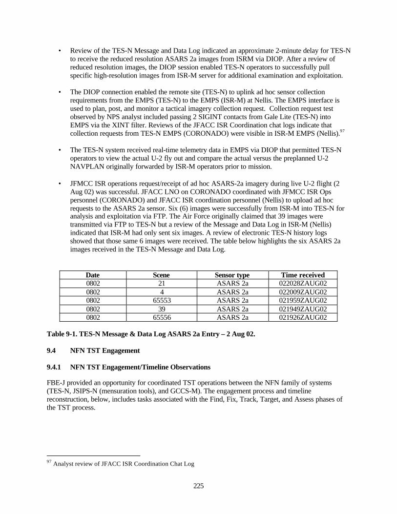
225
• Review of the TES-N Message and Data Log indicated an approximate 2-minute delay for TES-Nto receive the reduced resolution ASARS 2a images from ISRM via DIOP. After a review ofreduced resolution images, the DIOP session enabled TES-N operators to successfully pullspecific high-resolution images from ISR-M server for additional examination and exploitation.
• The DIOP connection enabled the remote site (TES-N) to uplink ad hoc sensor collectionrequirements from the EMPS (TES-N) to the EMPS (ISR-M) at Nellis. The EMPS interface isused to plan, post, and monitor a tactical imagery collection request. Collection request testobserved by NPS analyst included passing 2 SIGINT contacts from Gale Lite (TES-N) intoEMPS via the XINT filter. Reviews of the JFACC ISR Coordination chat logs indicate thatcollection requests from TES-N EMPS (CORONADO) were visible in ISR-M EMPS (Nellis).97
• The TES-N system received real-time telemetry data in EMPS via DIOP that permitted TES-Noperators to view the actual U-2 fly out and compare the actual versus the preplanned U-2NAVPLAN originally forwarded by ISR-M operators prior to mission.
• JFMCC ISR operations request/receipt of ad hoc ASARS-2a imagery during live U-2 flight (2Aug 02) was successful. JFACC LNO on CORONADO coordinated with JFMCC ISR Opspersonnel (CORONADO) and JFACC ISR coordination personnel (Nellis) to upload ad hocrequests to the ASARS 2a sensor. Six (6) images were successfully from ISR-M into TES-N foranalysis and exploitation via FTP. The Air Force originally claimed that 39 images weretransmitted via FTP to TES-N but a review of the Message and Data Log in ISR-M (Nellis)indicated that ISR-M had only sent six images. A review of electronic TES-N history logsshowed that those same 6 images were received. The table below highlights the six ASARS 2aimages received in the TES-N Message and Data Log.
Date Scene Sensor type Time received0802 21 ASARS 2a 022028ZAUG020802 4 ASARS 2a 022009ZAUG020802 65553 ASARS 2a 021959ZAUG020802 39 ASARS 2a 021949ZAUG020802 65556 ASARS 2a 021926ZAUG02
Table 9-1. TES-N Message & Data Log ASARS 2a Entry – 2 Aug 02.
9.4 NFN TST Engagement
9.4.1 NFN TST Engagement/Timeline Observations
FBE-J provided an opportunity for coordinated TST operations between the NFN family of systems(TES-N, JSIPS-N (mensuration tools), and GCCS-M). The engagement process and timelinereconstruction, below, includes tasks associated with the Find, Fix, Track, Target, and Assess phases ofthe TST process.
97 Analyst review of JFACC ISR Coordination Chat Log

226
9.4.2 NFN TST Engagement/Timeline Observations: Objective
Determine the TST Engagement process and representative timelines for NFN originated targets in the“Find-Fix-Track-Target and Assess” phases of the TST process.
9.4.3 NFN TST Engagement/Timeline Observations: Analytical Questions
• What are the NFN component roles and functions in the Find-Fix-Track-Target-Assess process?• What is the representative timeline for NFN originated targets in the “Find-Fix-Track and
Assess” phases of the TST process?
9.4.4 NFN TST Engagement Process/Timeline: Findings
9.4.5 NFN TST Engagement Process
The typical NFN TST target engagement process began with a target nomination, including imagery, sentfrom the nominator, the Tactical Exploitation System – Naval (TES-N), to both the DTMS and the LandAttack Warfare System (LAWS). DTMS was to take no georefinement action on the nomination until thenomination was validated. This validation consisted of the receipt, by DTMS, of a georefinement requestand a georefinement confirmation message, both originating with LAWS. The portion of this report,Section 8.5.5, on Mensuration Management Observations, contains detailed analysis of the completeFBE-J mensuration process.
The FBE-J mensuration architecture required all mensuration requests to pass through the DTMS. Thismade the DTMS a single point of failure. If DTMS, or the communication link to it, went down the wholemensuration process would fail. For this reason alone, the mensuration system should have beenconfigured so that LAWS could send georefinement requests directly to RRF workstations and RRFworkstations could receive target nominations. Beyond that consideration, the TST TTP shouldspecifically address the cases of high priority short dwell time TSTs, for which only a fully autonomousengagement has much hope of success. However, the FBE-J mensuration architecture made autonomousengagements impossible.98
The DTMS function should only be incorporated for target rich environments. FBE-J did not provide theenvironment required to assess DTMS functionality. The value added to the mensuration process by theDTMS/ Mensuration Manager should be the proactive management of the process – efficientprioritization and allocation of tasks to those assets that have the time and databases to accomplish thetask. The DTMS/Mensuration Manager should also provide a knowledgeable focus for filtering out tasksthat cannot be performed due to: poor imagery; unmensurateable targets; or targets that do not requiremensuration on the basis of weapon-target pairing For example, in the list of reasons that the RRFworkstations gave for being unable to mensurate targets, some of the responses should not occur or, at aminimum, they should be greatly reduced in frequency by the actions of the Mensuration Manager.Specifically, if they have no reference imagery of an area, a response would not occur because theMensuration Manager would not allocate the task to a workstation that did not have the necessarydatabase. A cursory preview of the imagery by the Mensuration Manager should reduce the number ofRRF workstations responses where they reported the target couldn’t be georefined (e.g. ship at sea); orthat the tactical imagery was of inadequate quality; or where they couldn’t find the target.99
98 Dr. Nelson Irvine NFN Mensuration Observations99 Dr. Nelson Irvine NFN Mensuration Observations
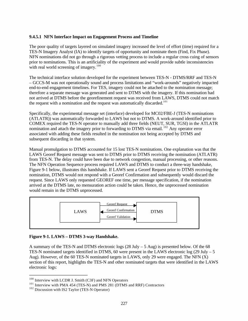
227
9.4.5.1 NFN Interface Impact on Engagement Process and Timeline
The poor quality of targets layered on simulated imagery increased the level of effort (time) required for aTES-N Imagery Analyst (IA) to identify targets of opportunity and nominate them (Find, Fix Phase).NFN nominations did not go through a rigorous vetting process to include a regular cross cuing of sensorsprior to nominations. This is an artificiality of the experiment and would provide subtle inconsistencieswith real world screening of imagery.100
The technical interface solution developed for the experiment between TES-N - DTMS/RRF and TES-N– GCCS-M was not operationally sound and process limitations and “work-arounds” negatively impactedend-to-end engagement timelines. For TES, imagery could not be attached to the nomination message;therefore a separate message was generated and sent to DTMS with the imagery. If this nomination hadnot arrived at DTMS before the georefinement request was received from LAWS, DTMS could not matchthe request with a nomination and the request was automatically discarded.101
Specifically, the experimental message set (interface) developed for MC02/FBE-J (TES-N nominations(ATI.ATR)) was automatically forwarded to LAWS but not to DTMS. A work-around identified prior toCOMEX required the TES-N operator to manually add three fields (NEUT, SUR, TGSI) in the ATI.ATRnomination and attach the imagery prior to forwarding to DTMS via email. 102 Any operator errorassociated with adding these fields resulted in the nomination not being accepted by DTMS andsubsequent discarding in that system.
Manual promulgation to DTMS accounted for 15 lost TES-N nominations. One explanation was that theLAWS Georef Request message was sent to DTMS prior to DTMS receiving the nomination (ATI.ATR)from TES-N. The delay could have been due to network congestion, manual processing, or other reasons.The NFN Operation Sequence process required LAWS and DTMS to conduct a three-way handshake,Figure 9-1 below, illustrates this handshake. If LAWS sent a Georef Request prior to DTMS receiving thenomination, DTMS would not respond with a Georef Confirmation and subsequently would discard therequest. Since LAWS only requested GEOREF one time, per message specification, if the nominationarrived at the DTMS late, no mensuration action could be taken. Hence, the unprocessed nominationwould remain in the DTMS unprocessed.
Figure 9-1. LAWS – DTMS 3-way Handshake.
A summary of the TES-N and DTMS electronic logs (28 July – 5 Aug) is presented below. Of the 68TES-N nominated targets identified in DTMS, 60 were present in the LAWS electronic log (29 July – 5Aug). However, of the 60 TES-N nominated targets in LAWS, only 29 were engaged. The NFN (X)section of this report, highlights the TES-N and other nominated targets that were identified in the LAWSelectronic logs:
100 Interview with LCDR J. Smith (C3F) and NFN Operators101 Interview with PMA 454 (TES-N) and PMS 281 (DTMS and RRF) Contractors102 Discussion with IS2 Taylor (TES-N Operator)
LAWS DTMS
Georef Request
Georef Confirmation
Georef Validation
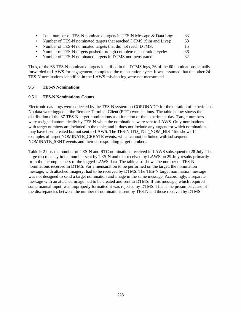
228
• Total number of TES-N nominated targets in TES-N Message & Data Log: 83• Number of TES-N nominated targets that reached DTMS (Sim and Live): 68• Number of TES-N nominated targets that did not reach DTMS: 15• Number of TES-N targets pushed through complete mensuration cycle: 36• Number of TES-N nominated targets in DTMS not mensurated: 32
Thus, of the 68 TES-N nominated targets identified in the DTMS logs, 36 of the 60 nominations actuallyforwarded to LAWS for engagement, completed the mensuration cycle. It was assumed that the other 24TES-N nominations identified in the LAWS mission log were not mensurated.
9.5 TES-N Nominations
9.5.1 TES-N Nominations Counts
Electronic data logs were collected by the TES-N system on CORONADO for the duration of experiment.No data were logged at the Remote Terminal Client (RTC) workstations. The table below shows thedistribution of the 87 TES-N target nominations as a function of the experiment day. Target numberswere assigned automatically by TES-N when the nominations were sent to LAWS. Only nominationswith target numbers are included in the table, and it does not include any targets for which nominationsmay have been created but not sent to LAWS. The TES-N ITD_TGT_NOM_HIST file shows 14examples of target NOMINATE_CREATE events, which cannot be linked with subsequentNOMINATE_SENT events and their corresponding target numbers.
Table 9-2 lists the number of TES-N and RTC nominations received in LAWS subsequent to 28 July. Thelarge discrepancy in the number sent by TES-N and that received by LAWS on 29 July results primarilyfrom the incompleteness of the logged LAWS data. The table also shows the number of TES-Nnominations received in DTMS. For a mensuration to be performed on the target, the nominationmessage, with attached imagery, had to be received by DTMS. The TES-N target nomination messagewas not designed to send a target nomination and image in the same message. Accordingly, a separatemessage with an attached image had to be created and sent to DTMS. If this message, which requiredsome manual input, was improperly formatted it was rejected by DTMS. This is the presumed cause ofthe discrepancies between the number of nominations sent by TES-N and those received by DTMS.
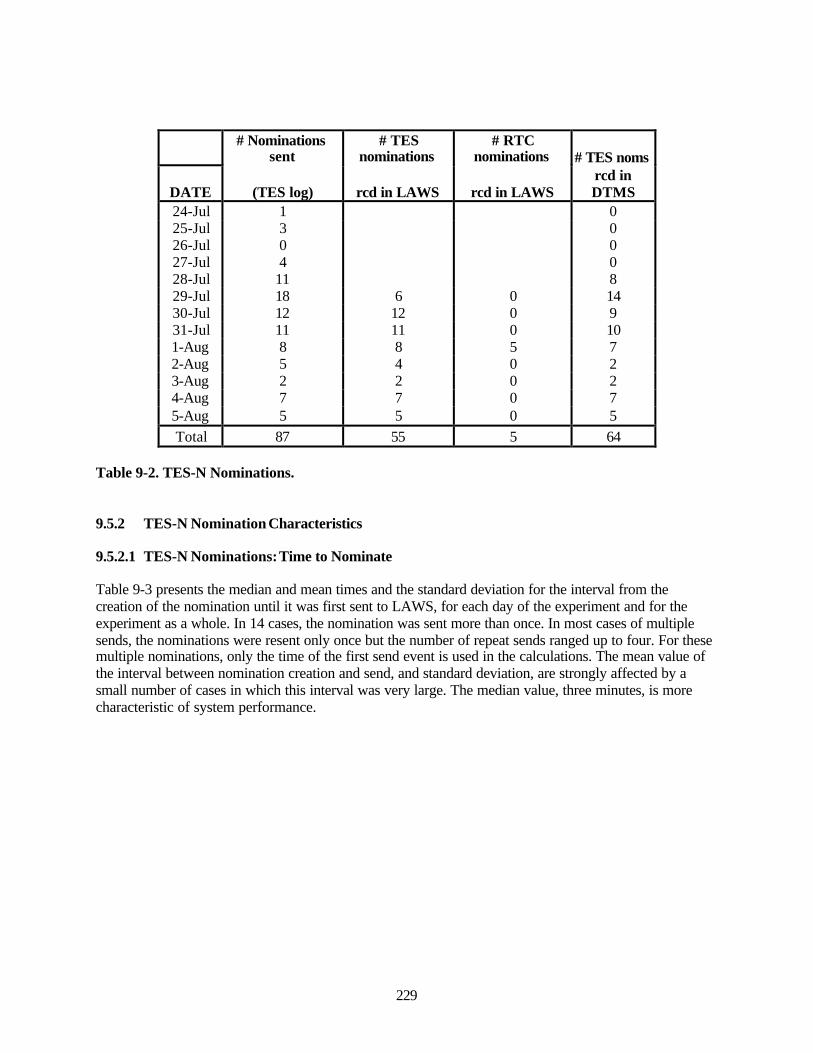
229
# Nominationssent
# TESnominations
# RTCnominations # TES noms
DATE (TES log) rcd in LAWS rcd in LAWSrcd inDTMS
24-Jul 1 025-Jul 3 026-Jul 0 027-Jul 4 028-Jul 11 829-Jul 18 6 0 1430-Jul 12 12 0 931-Jul 11 11 0 101-Aug 8 8 5 72-Aug 5 4 0 23-Aug 2 2 0 24-Aug 7 7 0 75-Aug 5 5 0 5Total 87 55 5 64
Table 9-2. TES-N Nominations.
9.5.2 TES-N Nomination Characteristics
9.5.2.1 TES-N Nominations: Time to Nominate
Table 9-3 presents the median and mean times and the standard deviation for the interval from thecreation of the nomination until it was first sent to LAWS, for each day of the experiment and for theexperiment as a whole. In 14 cases, the nomination was sent more than once. In most cases of multiplesends, the nominations were resent only once but the number of repeat sends ranged up to four. For thesemultiple nominations, only the time of the first send event is used in the calculations. The mean value ofthe interval between nomination creation and send, and standard deviation, are strongly affected by asmall number of cases in which this interval was very large. The median value, three minutes, is morecharacteristic of system performance.
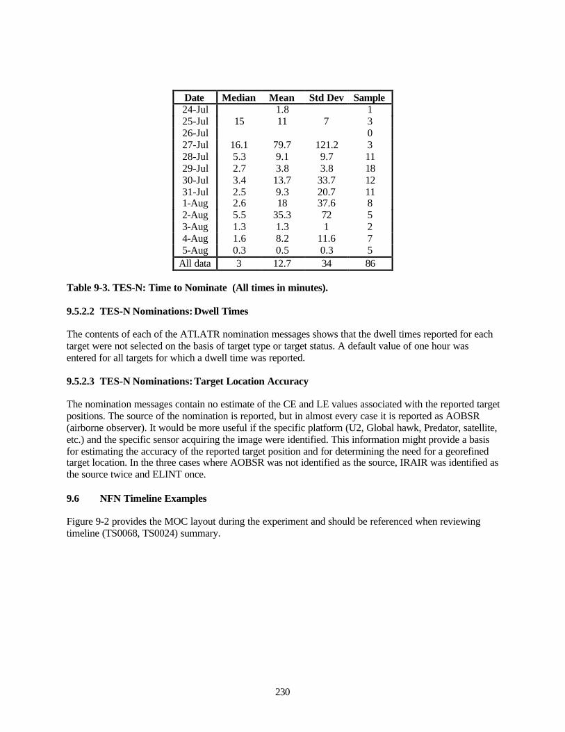
230
Date Median Mean Std Dev Sample24-Jul 1.8 125-Jul 15 11 7 326-Jul 027-Jul 16.1 79.7 121.2 328-Jul 5.3 9.1 9.7 1129-Jul 2.7 3.8 3.8 1830-Jul 3.4 13.7 33.7 1231-Jul 2.5 9.3 20.7 111-Aug 2.6 18 37.6 82-Aug 5.5 35.3 72 53-Aug 1.3 1.3 1 24-Aug 1.6 8.2 11.6 75-Aug 0.3 0.5 0.3 5
All data 3 12.7 34 86
Table 9-3. TES-N: Time to Nominate (All times in minutes).
9.5.2.2 TES-N Nominations: Dwell Times
The contents of each of the ATI.ATR nomination messages shows that the dwell times reported for eachtarget were not selected on the basis of target type or target status. A default value of one hour wasentered for all targets for which a dwell time was reported.
9.5.2.3 TES-N Nominations: Target Location Accuracy
The nomination messages contain no estimate of the CE and LE values associated with the reported targetpositions. The source of the nomination is reported, but in almost every case it is reported as AOBSR(airborne observer). It would be more useful if the specific platform (U2, Global hawk, Predator, satellite,etc.) and the specific sensor acquiring the image were identified. This information might provide a basisfor estimating the accuracy of the reported target position and for determining the need for a georefinedtarget location. In the three cases where AOBSR was not identified as the source, IRAIR was identified asthe source twice and ELINT once.
9.6 NFN Timeline Examples
Figure 9-2 provides the MOC layout during the experiment and should be referenced when reviewingtimeline (TS0068, TS0024) summary.
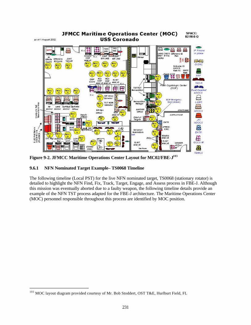
231
Figure 9-2. JFMCC Maritime Operations Center Layout for MC02/FBE-J103
9.6.1 NFN Nominated Target Example– TS0068 Timeline
The following timeline (Local PST) for the live NFN nominated target, TS0068 (stationary rotator) isdetailed to highlight the NFN Find, Fix, Track, Target, Engage, and Assess process in FBE-J. Althoughthis mission was eventually aborted due to a faulty weapon, the following timeline details provide anexample of the NFN TST process adapted for the FBE-J architecture. The Maritime Operations Center(MOC) personnel responsible throughout this process are identified by MOC position.
103 MOC layout diagram provided courtesy of Mr. Bob Stoddert, OST T&E, Hurlburt Field, FL
n o1 1 Augi>rt20Ci2
JFMCC Maritime Operations Center (MOC) US5 Coronado
SPACE: 02-9B-0'O
TBI«CS
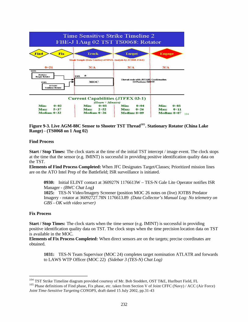
232
104
Figure 9-3. Live AGM-88C Sensor to Shooter TST Thread105. Stationary Rotator (China LakeRange) - (TS0068 on 1 Aug 02)
Find Process
Start / Stop Times: The clock starts at the time of the initial TST intercept / image event. The clock stopsat the time that the sensor (e.g. IMINT) is successful in providing positive identification quality data onthe TST.Elements of Find Process Completed: When JFC Designates Target/Classes; Prioritized mission linesare on the ATO Intel Prep of the Battlefield; ISR surveillance is initiated.
0930: Initial ELINT contact at 360927N 1176613W – TES-N Gale Lite Operator notifies ISRManager - (BWC Chat Log)1025: TES-N Video/Imagery Screener (position MOC 26 notes on (live) JOTBS PredatorImagery - rotator at 36092727.78N 1176613.89 (Data Collector’s Manual Log: No telemetry onGBS - OK with video server)
Fix Process
Start / Stop Times: The clock starts when the time sensor (e.g. IMINT) is successful in providingpositive identification quality data on TST. The clock stops when the time precision location data on TSTis available in the MOC.Elements of Fix Process Completed: When direct sensors are on the targets; precise coordinates areobtained.
1031: TES-N Team Supervisor (MOC 24) completes target nomination ATI.ATR and forwardsto LAWS WTP Officer (MOC 22) (Sidebar 3 (TES-N) Chat Log)
104 TST Strike Timeline diagram provided courtesy of Mr. Bob Stoddert, OST T&E, Hurlburt Field, FL105 Phase definitions of Find phase, Fix phase, etc. taken from Section V of Joint CFFC (Navy) / ACC (Air Force)Joint Time-Sensitive Targeting CONOPS, draft dated 15 July 2002, pp.31-43
Time Sensitive Strike Timeline 2 FBE-J 1 Aug 02 TST TS0068: Rotator
0->21
Sin^ Sui^k (Data CourlMy af NPGS, Analydj by JC2ISR JT&i;)
: N".'A : N.'A N'A
*
MOC TliTcsd eiuli with JSTARS Csnflrmatian
Of Pndator Ilt^NT
Current Capabilities (JTFEX 03-1) {Hours -+- minutes}
Min: 0+02 : Min: 0+Oi : Min: 0+04 Max: 5+37 : INlax: 2+52 ': IMax: 0+26 niedJan: 0+52 Median: 0+26 M:edian: 0+09
Min: 0+03 M:ax: 0+11 Median: 0+07
233
1036: TES-N Team Supervisor (position MOC 24) completes target nomination ATI.ATR andforwards to Mensuration Manager (MOC 35) / DTMS with image attached (5 minute ManualProcess) (Sidebar 3 (TES-N) Chat Log)1037: LAWS Weapons Target Pairing Officer (MOC 22) sends “validate” message toMensuration Manager (DTMS) (MOC 35). (LAWS Electronic Log)1038: Mensuration Manager (DTMS) (MOC 35) receives image but cannot mensurate becauseimage attached to ATI.ATR is too “zoomed in on”, chats in sidebar room 3, telling TES-NVideo/Imagery Screener (position MOC 26) that image was “too zoomed in” to allow tie pointsfor precision georeference. (DTMS Electronic Log), (Sidebar 3 (TES-N) Chat Log)1042: TES-N Team Supervisor (position MOC 24) acknowledges, and replies, in sidebar room3, that he will get image from database that is more zoomed out. (Sidebar 3 (TES-N) Chat Log)1044: TES-N Team Supervisor (position MOC 24) updates target nomination ATI.ATR withnew image and forwards to LAWS and manually updates and sends to DTMS Manager. (Sidebar3 (TES-N) Chat Log)
Track Process
Start / Stop Times: The clock starts when the time precision location data on TST is available in TSTcell. The clock stops at the time that enough data exists in the MOC to make an engagement decision.Elements of Track Process Completed: When continuous TST contact/track continuity andcollaborative target verification via multiple sensors are established, to validate, identify, and prioritizethe target.
1046: Confirmation from JSTARS (via GMTI Analyst (MOC C) on stationary rotator. (DataCollector Manual Log)1047: NFN-N Team Supervisor (position MOC 24) updates target nomination ATI.ATR. (DataCollector Manual Log)1054: Updated TST nomination arrives at LAWS Weapons Target Pairing Officer (MOC 22).(LAWS Electronic Log)1055: Mensuration Manager (MOC 35) receives “validate” message and assigns specific ReadyRoom of the Future (RRF) Analyst (MOC 33/34) to do precise georeference on TS0068.
Target Process
Start / Stop Times: The clock starts at the time that enough data exists in the MOC to make anengagement decision. The clock stops when the strike asset receives the time authorization.Elements of Target Process Completed: when weapons are matched to a prioritized target, thelikelihood of collateral damage is assessed, and an engagement order is issued and passed.
1110: Ready Room of the Future (RRF) Analyst (MOC 33/34) sends aim point on TS0068 toLAWS via DTMS. (RRF Electronic Log)1110 Aim point data on TS0068 received by LAWS Weapons Target Pairing Officer. (MOC22) (LAWS Electronic Log)1110: Target nomination from LAWS Weapons Target Pairing Officer (MOC 22) received atChina Lake for action. (LAWS Electronic Log)1111: STWC takes control to act as strike approval authority. (Data Collector Manual Log)1112: AGM 88C aborted - weapons malfunction, thread ends. (Data Collector Manual Log)
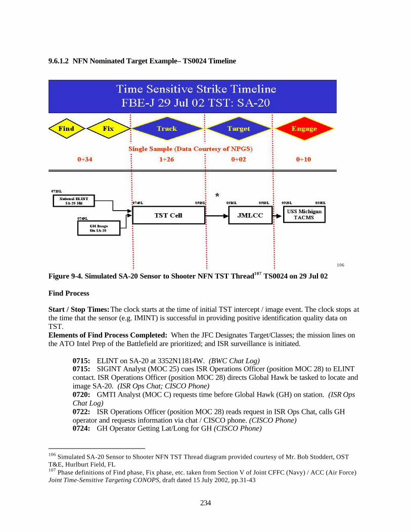
234
9.6.1.2 NFN Nominated Target Example– TS0024 Timeline
106
Figure 9-4. Simulated SA-20 Sensor to Shooter NFN TST Thread107 TS0024 on 29 Jul 02
Find Process
Start / Stop Times: The clock starts at the time of initial TST intercept / image event. The clock stops atthe time that the sensor (e.g. IMINT) is successful in providing positive identification quality data onTST.Elements of Find Process Completed: When the JFC Designates Target/Classes; the mission lines onthe ATO Intel Prep of the Battlefield are prioritized; and ISR surveillance is initiated.
0715: ELINT on SA-20 at 3352N11814W. (BWC Chat Log)0715: SIGINT Analyst (MOC 25) cues ISR Operations Officer (position MOC 28) to ELINTcontact. ISR Operations Officer (position MOC 28) directs Global Hawk be tasked to locate andimage SA-20. (ISR Ops Chat; CISCO Phone)0720: GMTI Analyst (MOC C) requests time before Global Hawk (GH) on station. (ISR OpsChat Log)0722: ISR Operations Officer (position MOC 28) reads request in ISR Ops Chat, calls GHoperator and requests information via chat / CISCO phone. (CISCO Phone)0724: GH Operator Getting Lat/Long for GH (CISCO Phone)
106 Simulated SA-20 Sensor to Shooter NFN TST Thread diagram provided courtesy of Mr. Bob Stoddert, OSTT&E, Hurlburt Field, FL107 Phase definitions of Find phase, Fix phase, etc. taken from Section V of Joint CFFC (Navy) / ACC (Air Force)Joint Time-Sensitive Targeting CONOPS, draft dated 15 July 2002, pp.31-43
Time Sensitive Strike Timeline FBE-J 29 Jul 02 TST: SA-20
0+54
Single Sample (Data Courtesy of NPGS)
; 1+26 : 0+02 0+10
Nalujkil ELINT SA-20 IGt
■ ft
CHbit^t On SA-7D
TSTCeU JMLCC USS Michigan
TAG MS
235
0725: ISR Operations Officer (MOC 28) requests from GMTI Analyst (MOC C) Lat/Long ofGH. (ISR Ops Chat Log)0728: GMTI Analyst (MOC C) replies with GH’s Lat/Long request via chat.(0736: Data Collector Comment: No estimated time on target (EOT) for GH yet from GMTIAnalyst (MOC C))0737: ISR Operations Officer (MOC 28) is advised that it will take 25 minutes for GH to arriveat FOV (within field of view) of SA-20 (CISCO Phone)
Fix Process
Start / Stop Times: The clock starts when the time sensor (e.g. IMINT) is successful in providingpositive identification quality data on the TST. The clock stops when the time precision location data onTST is available in the MOC.Elements of Find Process Completed: When direct sensors are on targets; and precise coordinates areobtained.
0748: GH image sent (of SA-20); file named GH_ADHOC1. (ISR Ops Chat)0749: ISR Video/Imagery Screener (position MOC 26) pulls SA-20 imagery at direction ofNFN-N Team Supervisor (position MOC 24). (Data Observer Manual Log)0800: ISR Video/Imagery Screener (position MOC 26) fills out target nomination ATI.ATR andforwards to NFN-N Team Supervisor (position MOC 24). (Data Observer Manual Log)
Track Process
Start / Stop Times: The clock starts when the time precision location data on TST is available in the TSTcell. The clock stops at the time that enough data exists in the MOC to make an engagement decision.Elements of Find Process Completed: When continuous TST contact and collaborative targetverification via multiple sensors is established, validated, identified, and prioritized.
0803: NFN-N Team Supervisor (position MOC 24) sends nomination to LAWS. (TES-NMessage & Data Log, LAWS Electronic Log)0806: NFN-N Team Supervisor (position MOC 24) completes message with IMINT attachmentof SA-20 for DTMS (an artificial step) TST designated TS0024. (TES-N Message & Data Log,Data Observer Manual Log)0812: DTMS receives TS0024 nomination and sends to LAWS for target validation. (DTMSElectronic Log)0820: DTMS validation message received at LAWS Weapons Target Pairing Officer (MOC22). (LAWS Electronic Log)0821: LAWS Weapons Target Pairing Officer (MOC 22) sends “validate” message toMensuration Manager (MOC 35). (LAWS Electronic Log)0824: Mensuration Manager (MOC 35). Receives “validate” message and assigns specificReady Room of the Future (RRF) Analyst (MOC 33/34) to do precise geolocation on TS0024.(DTMS Electronic Log)0824: Ready Room of the Future (RRF) Analyst (MOC 33/34) sends aim point on TS0024 toDTMS who forwards to LAWS. (RRF Electronic Log, DTMS Electronic Log, LAWS ElectronicLog)0854: “Mensuration block” in LAWS turns green. (Note: The LAWS Weapons Target PairingOfficer (MOC 22) is behind schedule and working to catch up prior to doing weapons-to-targetpairing.) (Data Observer Manual Log, LAWS Electronic Log)0856: LAWS Weapons Target Pairing Officer (MOC 22) starts weapons-to-target pairing onTS0024. (Data Observer Manual Log)
236
0856: LAWS Weapons Target Pairing Officer (MOC 22) would like to move Arleigh Burkecruiser (#) in close to use E-5 weapon. (SA-20 is in urban (e.g. downtown LA) area.) (VerbalRequest to SCC Anchor Desk – Data Observer Manual Log)0904: LAWS Weapons Target Pairing Officer (MOC 22) requests of Surface/SubsurfaceAnchor Desk Officer (MOC 14) to move Arleigh Burke in closer to shore to shoot ERGM.(Voice over IP)0907: LAWS weapons target pairing officer (MOC 22) tells assistant battle watch captain(MOC 19) about moving Arleigh Burke 20 nm closer to shore. (Voice over IP)0908: Surface/subsurface anchor desk officer (MOC 14) says; “You can’t trust (the Blue forceship’s position in) ADOCS.” Asks DESRON if Arleigh Burke in simulation (ADOCS) is in thecorrect position. (BWC Chat Log)0915: LAWS weapons target pairing officer (MOC 22) notified by DESRON that ArleighBurke cannot move closer to shore because of SEERSUCKER coastal defense missile site. (TSTChat Log)
Target Process
Start / Stop Times: The clock starts at the time that enough data exists in the MOC to make anengagement decision. The clock stops at the time that authorization is received by the strike asset.Elements of Find Process Completed: When weapons are matched to a prioritized target; anassessment is made of potential collateral damage; and an engagement order is issued and passed.
0916: LAWS weapons target pairing officer (MOC 22) talks with battle watch captain (MOC17) and requests a low casualty weapon. (Verbal – Data Observer Manual Log)0916: Battle watch captain (MOC 17) asks about collateral damage and is shown image ofTS0024. (Verbal – Data Observer Manual Log)0917: Battle watch captain (MOC 17) calls JFMCC for permission to use LOCAS on TS0024.(Telephone – Data Observer Manual Log)0918: JFMCC give authorization to strike TS0024 with TACMS. (Telephone – Data ObserverManual Log)0918: LAWS weapons target pairing officer (MOC 22) tags USS Michigan (VSSGN) forTS0024 strike. (LAWS Electronic Log)
Engage Process
Start / Stop Times: The clock starts at the time authorization is received by the strike asset. The clockstops at the time that the TST is struck.Elements of Find Process Completed: When the target is destroyed/neutralized via kinetic or non-kinetic options, and this is monitored by combat operations.
0920: LAWS weapons target pairing officer (MOC 22) receives message via private chat thatUSS Michigan has received the strike authorization message.0925: USS Michigan fires TALCM. (LAWS Electronic Log)0930: Estimated fly out time from USS Michigan to TS0024
Assess Process
Start / Stop Times; N/A
0944 Attempt to get BDA on TS0024 fizzles out. (Data Observer Manual Log)
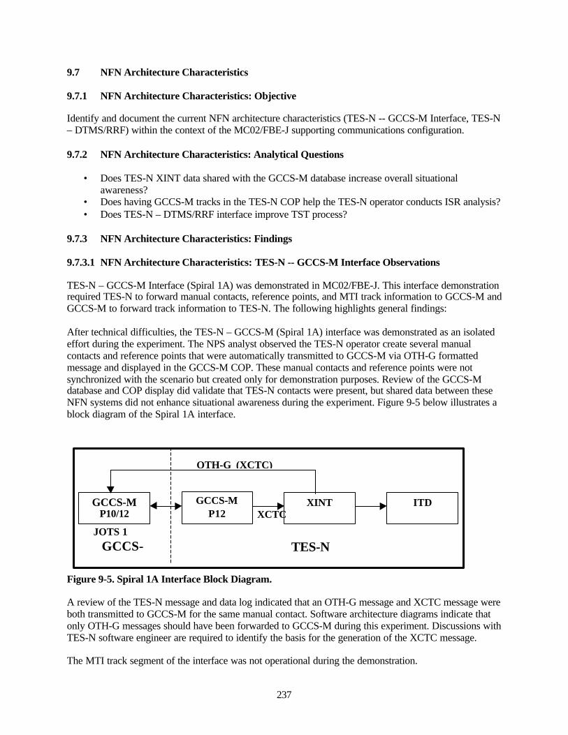
237
9.7 NFN Architecture Characteristics
9.7.1 NFN Architecture Characteristics: Objective
Identify and document the current NFN architecture characteristics (TES-N -- GCCS-M Interface, TES-N– DTMS/RRF) within the context of the MC02/FBE-J supporting communications configuration.
9.7.2 NFN Architecture Characteristics: Analytical Questions
• Does TES-N XINT data shared with the GCCS-M database increase overall situationalawareness?
• Does having GCCS-M tracks in the TES-N COP help the TES-N operator conducts ISR analysis?• Does TES-N – DTMS/RRF interface improve TST process?
9.7.3 NFN Architecture Characteristics: Findings
9.7.3.1 NFN Architecture Characteristics: TES-N -- GCCS-M Interface Observations
TES-N – GCCS-M Interface (Spiral 1A) was demonstrated in MC02/FBE-J. This interface demonstrationrequired TES-N to forward manual contacts, reference points, and MTI track information to GCCS-M andGCCS-M to forward track information to TES-N. The following highlights general findings:
After technical difficulties, the TES-N – GCCS-M (Spiral 1A) interface was demonstrated as an isolatedeffort during the experiment. The NPS analyst observed the TES-N operator create several manualcontacts and reference points that were automatically transmitted to GCCS-M via OTH-G formattedmessage and displayed in the GCCS-M COP. These manual contacts and reference points were notsynchronized with the scenario but created only for demonstration purposes. Review of the GCCS-Mdatabase and COP display did validate that TES-N contacts were present, but shared data between theseNFN systems did not enhance situational awareness during the experiment. Figure 9-5 below illustrates ablock diagram of the Spiral 1A interface.
Figure 9-5. Spiral 1A Interface Block Diagram.
A review of the TES-N message and data log indicated that an OTH-G message and XCTC message wereboth transmitted to GCCS-M for the same manual contact. Software architecture diagrams indicate thatonly OTH-G messages should have been forwarded to GCCS-M during this experiment. Discussions withTES-N software engineer are required to identify the basis for the generation of the XCTC message.
The MTI track segment of the interface was not operational during the demonstration.
GCCS-MP10/12
GCCS-MP12
XINT ITD
TES-NGCCS-M
JOTS 1
OTH-G (XCTC)
XCTC

238
A review of TES-N and GCCS-M databases indicated that there are no common track numbers associatedwith TES-N and GCCS-M. It is currently impossible for a GCCS-M operator to view a new track andcorrelate its origin to TES-N.The operational context for sharing GCCS-M and TES-N information was non-existent. Althoughproving the technical interface was a limited success, a full understanding of how to capitalizeoperationally on shared data was not gained. The experiment did not provide an opportunity to examinehow the TES-N XINT data, which was shared with the GCCS-M database, impacted the overallsituational awareness.
TES-N ingested GCCS-M tracks successfully but the current capability does not permit the TES-Noperator to filter on the desired GCCS-M track information. GCCS-M tracks flood the TES-N displaywhen the TES-N operator has GCCS-M tracks ‘ON’. Hence, the track data from GCCS-M was not usefulto TES-N operators.
9.7.4 TES-N – DTMS/RRF Interface Characteristics
Electronic logs of NFN threads captured during experiment indicate a median time of 9.8 minutes forRRF to process mensurated coordinates after receiving a request from DTMS.
NITF 2.1 formatted files created and sent by TES-N were not compatible with the format expected by theDTMS/RRF image screener tool. DTMS/RRF software engineers examined the TES-N NITF header andindicated it was missing Field 3 which was a field expected by DTMS. Additional research, dialogue, andcoordination are required between PMS-454 and PMA-281 to engineer a solution. 108
Because TES-N generated NITF 2.1 formatted image files were not compatible with the format expectedby DTMS/RRF, TES-N operators created JPEG image files as a required workaround during theexperiment. Although the DTMS was able to read the JPEG images, the TES-N Image Analystannotations that highlighted target coordinates and other amplifying information on the image were notpresent on the DTMS image screener terminal. This increased the time required to process targetnominations and resulted in additional coordination requirement between DTMS and TES-N operators toensure accurate target locations in the image prior to sending it to the RRF for generation of an aim point.
9.8 NFN Contribution to Enhanced Situational Awareness
The objective was to observe and document the NFN contribution to enhanced operational and tacticallevel situational awareness.
9.8.1 NFN Contribution to Enhanced Situational Awareness: Analytical Questions
• What NFN components enhance overall situational awareness?• How does the CJTF use the JFMCC NFN capability on CORONADO to support situational
awareness and targeting?• What products are not available to TES-N operator that should be in order to add to his
tactical/operational utility?
9.8.2 NFN Contribution to Enhanced Situational Awareness: Findings
Table 9-8 provides the NFN (TES-N) system components that participated in MC02/FBE-J. 108 Discussion with DTMS and RRF (PMS 281) Software Engineers
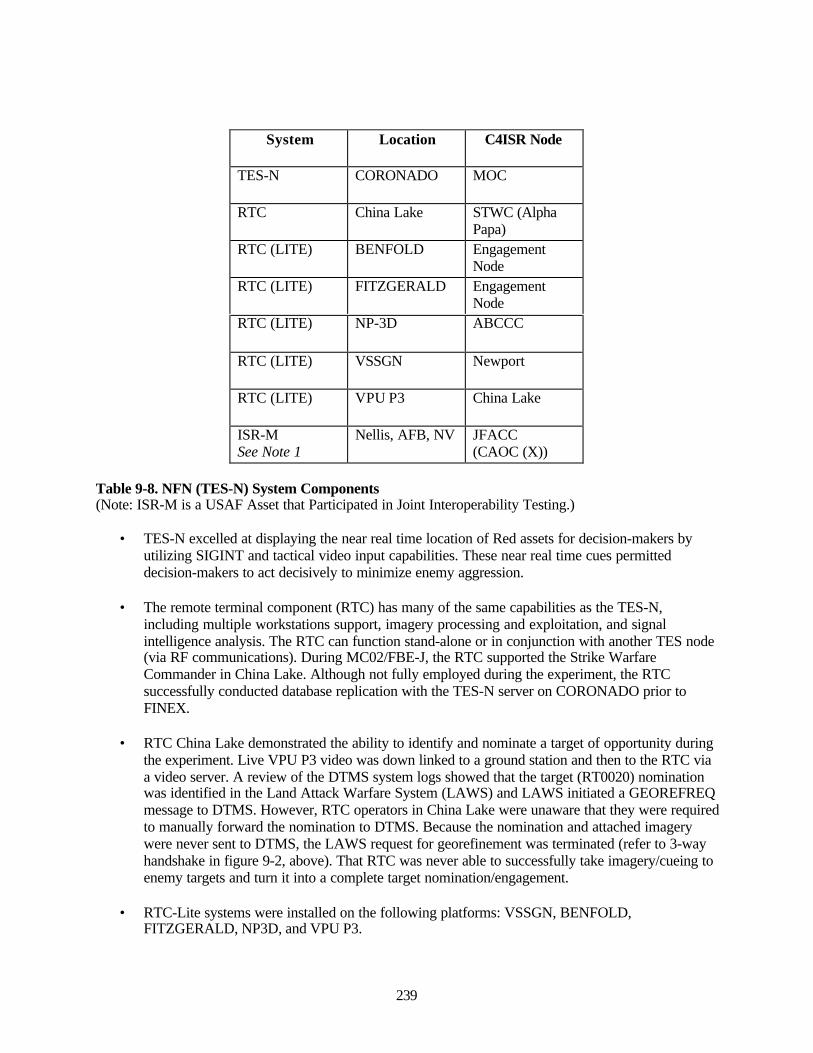
239
System Location C4ISR Node
TES-N CORONADO MOC
RTC China Lake STWC (AlphaPapa)
RTC (LITE) BENFOLD EngagementNode
RTC (LITE) FITZGERALD EngagementNode
RTC (LITE) NP-3D ABCCC
RTC (LITE) VSSGN Newport
RTC (LITE) VPU P3 China Lake
ISR-MSee Note 1
Nellis, AFB, NV JFACC(CAOC (X))
Table 9-8. NFN (TES-N) System Components(Note: ISR-M is a USAF Asset that Participated in Joint Interoperability Testing.)
• TES-N excelled at displaying the near real time location of Red assets for decision-makers byutilizing SIGINT and tactical video input capabilities. These near real time cues permitteddecision-makers to act decisively to minimize enemy aggression.
• The remote terminal component (RTC) has many of the same capabilities as the TES-N,including multiple workstations support, imagery processing and exploitation, and signalintelligence analysis. The RTC can function stand-alone or in conjunction with another TES node(via RF communications). During MC02/FBE-J, the RTC supported the Strike WarfareCommander in China Lake. Although not fully employed during the experiment, the RTCsuccessfully conducted database replication with the TES-N server on CORONADO prior toFINEX.
• RTC China Lake demonstrated the ability to identify and nominate a target of opportunity duringthe experiment. Live VPU P3 video was down linked to a ground station and then to the RTC viaa video server. A review of the DTMS system logs showed that the target (RT0020) nominationwas identified in the Land Attack Warfare System (LAWS) and LAWS initiated a GEOREFREQmessage to DTMS. However, RTC operators in China Lake were unaware that they were requiredto manually forward the nomination to DTMS. Because the nomination and attached imagerywere never sent to DTMS, the LAWS request for georefinement was terminated (refer to 3-wayhandshake in figure 9-2, above). That RTC was never able to successfully take imagery/cueing toenemy targets and turn it into a complete target nomination/engagement.
• RTC-Lite systems were installed on the following platforms: VSSGN, BENFOLD,FITZGERALD, NP3D, and VPU P3.
240
o VSSGN participants identified how to take advantage of the information that wasavailable through RTC Lite. VSSGN participants configured their RTC-Lite systemprofile to view desired characteristics of the battlespace (e.g., snapshot of SIGINT,imagery). The use of the RTC-Lite system for SA and mensuration planning increasedthroughout the experiment. Throughout the experiment RTC-Lite played an increasedrole in the TST mission area on the VSSGN. Several examples are provided below:109
• Example One: Mensuration is attempted at the RRF. The operator was unable tomensurate. The RTC-Lite operator brought up an image of the same general area.He had details that were on the nominated target image from the UAV that werenot on the RRF image. These details were used as reference points and allowedthe RRF operator to focus in to the correct coordinates needed for mensuration.
• Example Two: Suspected target area was verified with RTC-Lite enemySIGINT signals.
• Example Three: Time late target info on a SCUD launcher was updated withSIGINT information from RTC-Lite. RTC-Lite showed where the launcher hadmoved. These data were used as the coordinates for the TACMS-L (LOCASSpayload), which does need an exact position. Subsequent SIGINT analysisshowed one of the previous two SIGINT signals was gone. The second signalwas targeted as a second SCUD launcher with a second TACMS-L. Lateranalysis showed all SIGINT signatures gone from the area.
• RTC-Lite systems on BENFOLD and FITZGERALD were physically up and running butoperationally, they were not used. Unlike the VSSGN node, the ships did not have any concept ofhow to use RTC-Lite to support the mission. The staff did not understand how the informationfrom RTC-Lite could provide them with additional SA required for their mission. Training isneeded to explain how to integrate RTC-Lite capabilities in the battle plan/rhythm. 110
• RTC-Lite capability on the NP3D and the VPU P3 was not used due to faulty aircraftcommunication links.
109 Email from Mr. E. Chaum (VSSGN PM)110 NPS Analyst Observations on BENFOLD and FITZGERALD

241
10.0 JFMCC ISR Manageme nt Initiative Key Observations
10.1 Experiment Objectives
The objectives of the JISRM experiment were tied to each sub-initiative.
JFMCC ISR Planning. The JFMCC ISR Planning Process is a 72-hour planning cycle that the JFMCCStaff uses to develop an ISR collection plan aimed at meeting the commander's Priority IntelligenceRequirements (PIRs). The plan ensures proper employment of available assets to develop the commonISR picture. The prime objective within this sub-initiative was to determine the effectiveness of theJFMCC Current Planning Cell (CPC) ISR planning and execution process.
Dynamic ISR Management (DISRM). Dynamic ISR Management is the process whereby collectionassets are diverted from their pre-planned mission in response to rapidly changing requirements. Anexample of DISRM is when collection assets must be diverted to engage a high priority target that issuddenly detected. In that circumstance, the ISR Manager must assess which assets are appropriate andimmediately available, and take the necessary actions to assign them to the effort. The ability to rapidlyretask available sensors is essential to achieving effective Time Critical Targeting. The prime initiativewithin this sub-initiative was to determine the effectiveness of the MOC DISRM planning and executionprocess.
Distributed Unattended Ground Sensors (UGS) and Unmanned Aerial Vehicles (UAVs). UGS wereused during FBE-J in the China Lake ranges to detect and identify time sensitive/high priority groundtargets. The information was then relayed to operator consoles at China Lake and on the high-speedvessel (HSV) for dissemination to command personnel via the GCCS-M architecture for eventualincorporation into the time sensitive/critical targeting process. Mine Warfare UGS (MIUGS) data wereused as a cueing source for retasking of electro-optic and infrared (EO/IR) sensors, primarily on UAVsemployed at China Lake. UGS and UAVs were both used during FBE-J in support of the Dynamic ISRManagement process. The primary objective was to provide a representative construct from which UAVand ISR assets (e.g. a tiered UAV architecture) could support the MPP, JDISRM, TST, and AssuredAccess initiatives.
During the experiment, the following additional objectives were also sought:
• Evaluate the tools applied to ISR management.• Determine if UGS could provide track inputs to the COP via GCCS-M and whether those track
inputs were useable for queuing other ISR sensors.• Construct timelines for engagements initiated by UGS and SEID detections.• Assess the accuracy of the target data generated by UGS and SEID.
10.2 Analytic Questions
The overarching objective for FBE-J was to examine doctrinal implications and refine Tactics,Techniques and Procedures (TTP) for Joint and Maritime C2 and Assured Access. In this regard, one ofthe primary initiatives of FBE-J was to develop and evaluate a Joint Forces Maritime ComponentCommand (JFMCC) operational command and control process designed to provide a capability that couldprioritize multiple tasks with limited naval assets and conduct full range of Effects Based Operations(EBO) in a joint environment. It is in the context of this JFMCC construct that FBE-J experimented withthe convergence of deliberate and dynamic ISR management, in support of joint force and component-specific ISR requirements.
242
The primary objective of the FBE-J JFMCC ISR management initiative was to observe and document theJFMCC process to collaboratively plan and dynamically execute ISR operations, using limited ISRresources, in support of CJTF objectives, and in close coordination with other component commandersand supporting forces. FBE-J tested the capabilities of various automated systems, such as Naval FiresNetwork Experimental (NFN (X)), Automated Deep Operations Coordination System (ADOCS), and theSurveillance and Reconnaissance Management Tool (SRMT) to both plan ISR employment and, when thechanging operational situation dictated, dynamically manage available ISR assets.
10.2.1 JFMCC ISR Planning Process
The JFMCC ISR Planning process was a 72-hour planning cycle that the JFMCC Staff used to develop anISR collection plan aimed at meeting the commander's priority intelligence requirements. The intention ofthis plan was to ensure proper employment of available assets to develop the common ISR picture. Theprimary ISR Planning sub-initiative analytical questions researched during FBE-J included:
• Does the JFMCC MPP provide an adequate framework from which an ISR Plan can be generatedand effectively executed?
• Is the MTO an adequate ISR mission-tasking document?
• Did JFMCC organization effectively coordinate ISR planning, tasking, processing, exploitationand dissemination (TPED) with CJTF, other component commanders, and principle warfarecommanders?
10.2.2 Dynamic ISR Management
Dynamic ISR Management is the process by which collection assets are diverted from their pre-plannedmission due to changing operations. The most obvious situation requiring diversion of assets occurs ondetection of a high priority target. In response, the ISR manager must assess situations and courses ofaction and assign appropriate assets. The primary analysis goal of this sub-initiative was to examineorganization and technical (ADOCS, CIE, NFN) capabilities of afloat JFMCC organization todynamically task ISR assets/sensors, conduct multi-sensor cross cueing the correlation, and conduct hand-off between component commanders. The primary Dynamic ISR Management sub-initiative analyticalquestions researched during FBE-J included:
• Did the ISR operations officer (ISRO) functioning as the JFMCC-level ISR manager have thetools and situational awareness to gather, manage, and use all-source intelligence and COP duringdynamic operations?
• Did the ADOCS application provide adequate situational awareness of ISR assets across thebattlespace to allow the dynamic ISR manager to request support based on asset availability?
• Was the ISRO able to conduct sensor target pairing in response to battlespace dynamics?
• Did the JFMCC ISR Operations Officer maintain adequate control and oversight over all ISRassets from the theater to the tactical?
243
10.2.3 Multi-platform SIGINT Tracking
During FBE-J, live emitters provided targets for selected ELINT sensors. NFN (GCCS-M/SEID)correlated data gathered from these sensors with data received from national assets to ID and covertlytrack contacts of interest and land-based high threat emitters. The primary multi-platform SIGINTtracking sub-initiative analytical questions researched during FBE-J included:
• Does architecture of SEID-equipped platforms discriminate potential targets from backgroundmaritime traffic by electronically collecting and comparing emitter data to a database?
• Once identified, is the SEID information imported to and used by the planning and targetingprocesses in JFMCC and ISR organizations?
10.2.4 TES-N Role in ISR Management
• What is the specific TES-N role in the JFMCC deliberate planning process (i.e., IPB, situationalawareness, etc)?
• What TES-N products enhance overall situational awareness in support of ISR management?
10.3 Sub-Initiative Observations
10.3.1 JFMCC ISR Planning Process Observations
10.3.1.1 Maritime Planning Process
The MTO did not adequately provide a daily graphic depiction of the synchronized plan based on timeand geography. While the ISR cell within the Maritime Planning Process ensured USN ISR assets werescheduled in the MTO to meet collection requirements, there was no clear translation of commander’sintent into an understandable product for the war fighter.111
A combination of the skills and experience for both the intelligence designator and operations designator(with an ISR background) was critical for success. This mix of manning expertise created the symbioticrelationship between intelligence and ISR operations necessary to ensure optimal employment of USNISR assets through the Maritime Tasking Order (MTO) to support the commander’s operational andintelligence collection requirements.112
10.3.1.2 Exploitation and Dissemination
Technical difficulties in the COP, as maintained in GCCS-M and displayed to war fighters in ADOCS,impacted the ISR Operations Cell’s near-real time situational awareness and reduced its ability todynamically re-task live and simulated ISR assets. These difficulties included the inability to correlatelink tracks between the ATO and COP, and the inability to maintain a stable and consistent live airpicture.113
10.4 JFMCC ISR Dynamic/Deliberate Targeting Process Observations
111 Interview with LCDR D. Sleyton, ISR Manager112 LCDR W. Smith (NWDC); ISR Quicklook Summary113 Interview with LCDR D. Sleyton, ISR Manager; ISR Quicklook Summary
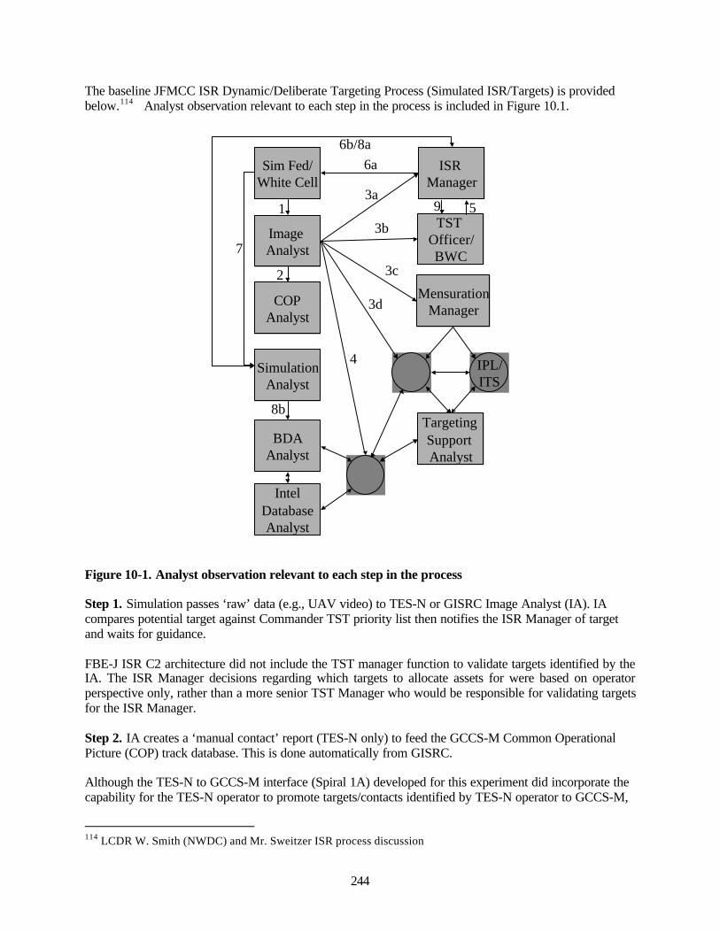
244
The baseline JFMCC ISR Dynamic/Deliberate Targeting Process (Simulated ISR/Targets) is providedbelow.114 Analyst observation relevant to each step in the process is included in Figure 10.1.
Sim Fed/White Cell
IntelDatabaseAnalyst
BDAAnalyst
COPAnalyst
SimulationAnalyst
Image Analyst
ISR Manager
Targeting Support Analyst
MensurationManager
TST Officer/BWC
1
2
IPL/ITS
3a
3b
3c
3d
4
5
6a
7
8b
9
6b/8a
Figure 10-1. Analyst observation relevant to each step in the process
Step 1. Simulation passes ‘raw’ data (e.g., UAV video) to TES-N or GISRC Image Analyst (IA). IAcompares potential target against Commander TST priority list then notifies the ISR Manager of targetand waits for guidance.
FBE-J ISR C2 architecture did not include the TST manager function to validate targets identified by theIA. The ISR Manager decisions regarding which targets to allocate assets for were based on operatorperspective only, rather than a more senior TST Manager who would be responsible for validating targetsfor the ISR Manager.
Step 2. IA creates a ‘manual contact’ report (TES-N only) to feed the GCCS-M Common OperationalPicture (COP) track database. This is done automatically from GISRC.
Although the TES-N to GCCS-M interface (Spiral 1A) developed for this experiment did incorporate thecapability for the TES-N operator to promote targets/contacts identified by TES-N operator to GCCS-M,
114 LCDR W. Smith (NWDC) and Mr. Sweitzer ISR process discussion
245
the process for TES-N to create manual contacts (reference points and MTI contacts as well) had softwareproblems and was not used to support COP management function. Hence, TES-N contacts were notviewed on GCCS-M COP display during the experiment, and thus could not enhance situationalawareness for those using GCCS-M COP to understand the battlespace. It should be noted that an isolatedtest was conducted, at the end of the experiment, to show that the interface was functional. However, theprocess for GCCS-M COP manager to coordinate with TES-N operators to ensure manual contacts werepromoted to GCCS-M was not evident. The GCCS-M COP did not reflect TES-N manual contacts,reference points, or MTI contacts.
Step 3. Image Analyst (IA) manually creates an ATI.ATR nomination message and attaches ‘chipped’image and sends simultaneously to:
a. ISR operations (LAWS/ADOCS) who begins Step 6.b. TST Officer (LAWS/ADOCS) who starts engagement sequence.c. Mensuration manager/image analyst (DTMS/RRF) who supports engagement sequence with aim
point generation. IA posts image products to JATF and/or IPL.d. New target folder is automatically created (JATF) and is available force-wide.e. Technical interface solutions developed for an experiment between TES-N - DTMS/RRF and
TES-N – GCCS-M were not operationally sound. Process limitations and workarounds negativelyimpacted end-to-end engagement timelines. For TES, the imagery could not be attached to theATI.ATR nomination message. After the ATI.ATR was completed, it was automaticallyforwarded to the TST officer but could not be forwarded to mensuration manager. A workaroundwas developed prior to COMEX that required the TES-N Operator to generate a separatemodified message and send to DTMS via email with the attached imagery. This manual processcaused several problems during the experiment. For example, if the nomination had not arrived atDTMS before the georefinement request was received from LAWS, DTMS could not match therequest with a nomination and the request was automatically discarded.115
f. Almost everything dynamic occurred within the collaborative environment. Only on rareoccasions did analysts observe ISR personnel accessing the target cards to obtain the status of thetarget.116
Step 4. The Image analyst sends message to the intelligence database analyst (MIDB) who ensures thatMIDB and JATF are synchronous.
Because of inadequate time to conduct a thorough comparative analysis of MIDB and JATF, analystswere not able to verify step four during this analysis phase.
Step 5. ISR operations officer monitors TST officer and BWC communication (chat, voice) to identifywhen BWC gives order to engage the target via LAWS/ADOCS).
Step 6. ISR operations officer coordinates with the Blue cell to have simulated collection platform(s) inposition to collect at strike weapon time-on-target (TOT) to collect ‘first look’ battle damage assessment(BDA).
Step 7. Simulation passes post-strike ‘raw’ data to IA (TES-N or GISRC) for review.
Analysts were not able to reconstruct any event that verified step seven.
115 Interview with PMA 454 (TES-N) and PMS 281 (DTMS and RRF) Contractors116 JFMCC ISR Post Experiment Collaborative Meeting (7 Aug 02)
246
Step 8. Simulation analyst takes ‘first look’ and:a. Recommends change in JFI BDA column to ISR/TST ops officer who has responsibility to make
a change, if required.b. Sends ‘chipped’ image to BDA analyst for further analysis.c. In current configuration, level 1 BDA required a single person to spend enormous amounts of
time on a single TST117.
Step 9. Based on the simulation analyst input, the TST/ISR ops officer makes a re-strike recommendationto TST officer/BWC. The TST officer could request additional ISR asset confirmation from the ISRmanager. The ISR manager would task or re-task an available asset.
10.4.1 Dynamic ISR Management Organization
A dynamic graphic depiction of the synchronized ISR plan based on time and geography is required fordynamic ISR management.
The ISR operations cell within the maritime operations center (MOC) effectively demonstrated the abilityto dynamically re-task simulated and live ISR assets in support of a simulated TST. Persistentcollaboration between JFMCC ISR operations, CJTF, component and distributed JFMCC ISR nodesenabled centralized or decentralized command and control as required. Shared use of the dynamic targetlists by both ISR ops and Fires personnel allowed shared TST.
ISR manning was insufficient to conduct a complete engagement process during experiment. The functionrequires dedicated personnel responsible for tracking a TST from cradle to grave.
10.4.2 Technical Architecture Capability to Support JFMCC
Lack of cross-joint available assets, whether sensor, TES-N "like", or C2 related, prevented fullrealization of the original experimental joint ISR objectives.
FBE-J achieved traditional data exchange between the systems throughout the experiment. Additionally,interoperability occurred on a single occasion when imagery from a U-2 ASARS 2a sensor was downlinked to the USAF common imagery ground system test bed at Nellis, using the prototype ISRmanagement system (ISR-M) for interface with TES-N on CORONADO. Automated system-to-systemtransfer of level 3 control, cross-intelligence data base exchange, and sharing of NAV/collection planswere not achieved
10.4.3 Multi-Platform SIGINT Tracking ObservationsThe value and power of SEI’s capability to uniquely identify and consistently re-identify radar signalscannot be overstated. SEI adds another piece to the puzzle to deconflict hostile radars from friendly radarsin dense, complex emitter environments. The true value added of operating SEI sensors in a networkedenvironment is the ability to move the SEI data from sensor-to-sensor and command authorities in near-real time. It was repeatedly demonstrated during FBE-J and MC-02 that the UYX-4 SEI sensor canconsistently re-ID shipboard, land-based and airborne radars on different days, utilizing SEI systems ondifferent platforms and operated by different operators. A distributed networked SEI capability,positioned on a variety of surface, air and land-based platforms, cooperatively identified emitters andtargets of interest. The following FBE-J findings were extracted from Naval Research Laboratory (NRL)AAR (Networked SEI Sensor Grid for Enhanced Situational Awareness Quicklook Report) plus post-
117 LCDR D. Sleyton, ISR Manager Notes

247
experiment interviews with key NRL engineers, and NWDC and C3F N2 representatives
Evidence shows that dissemination of SEI information in real-time will shorten the decision maker’stimeline to develop a course-of-action and task and manage ISR assets more effectively. 118
Command and control ships, such as CORONADO, are not particularly well-suited to positionthemselves for SEI collection operations at sea. However, Naval surface combatants, such as USSBenfold, are extremely well suited to conduct SEI operations at sea, and can provide positive COI ID andSEI re-ID on potentially hostile radars.119
During SOF VBSS Operations, the airborne carry-on/carry-off UYX-4 SEI Sensor on the VPU aircraftand the strategically located chokepoint monitoring site at Laguna Peak illustrated that remote SEIsensors can work together in real time to provide I&W, cue other sensors, and passively monitor themovement of hostile radars. This tactic has wide ranging implications for maritime interdiction operationsand Homeland Defense missions.120
The P-3C AIP aircraft is well-suited to conduct SEI operations in the littoral with its onboard ESM sensorsuite if it had an SEI capability to utilize an SEI TACELINT message sent from the TSC for COI re-ID,as well as the capability to produce a TACELINT message and send it to the Task Force Commander innear real time via UHF SATCOM.
Other means of communications, in addition to network messages, are essential to successfully executecomplex operations, and asset tasking, reporting hostile activity, coordinating and verifying receipt ofmessage to include network Voice over IP phones, network chat capability, MS NetMeeting chat, JOTSoperational notes (OpNotes), cell phones, and Iridium phones.121
10.4.4 TES-N ISR Observations
Lack of direct downlink operations limited the NFN (TES-N) system TST capability, but according toISR Manager and deputy, the NFN concept is sound, and the fleet needs this capability today. However,the current NFN system suffers from a lack of effective integration. The NFN family of systems does nottalk to each other as well as required to effectively accomplish TST. In addition, human factors issueswere not a priority during the development effort but must be considered in the subsequent developmentof NFN. 122
The TES-N Operators, all young Petty Officers, were instrumental to the success of TES-N during theexperiment. This combined team possessed the talent, imagination and potential to do anything with thelimited resources.123
Operational context for sharing GCCS-M and TES-N information was non-existent. Although proving thetechnical interface was a limited success, fully understanding how to capitalize operationally on shareddata was not implemented. The experiment did not provide opportunity to examine how TES-N XINTdata shared with GCCS-M database impacted overall situational awareness.
118 Interview with Mr. Dave Wallace, NRL Representative119 Interview with Mr. Guy Thomas, JHU APL – NWDC Representative120 Networked SEI Sensor Grid for Enhanced SA Quicklook121 Interview with John Williamson – NRL Contractor (SEI Installation/Integration)122 Interview with LCDR D. Sleyton and LCDR M. Aaron (ISR Managers)123 Interview with LCDR J. Smith (C3F – NFN Manager)

248
TES-N ingested GCCS-M tracks successfully, but current capability does not permit TES-N operator tofilter on desired GCCS-M track information. GCCS-M tracks flood the TES-N display when the TES-Noperator has GCCS-M tracks ‘ON’. Hence, track data from GCCS-M was not useful to the TES-Noperators.
10.4.5 Enhanced Situational Awareness Observations 124
TES-N excelled at displaying near real time location of RED assets for decision-makers by utilizingSIGINT and tactical video input capabilities. These near real time cues permitted decision-makers todecisively act to minimize enemy aggression.
Remote Terminal Component (RTC) has many of the same capabilities as the TES-N, including multipleworkstations support, imagery processing and exploitation, and signal intelligence analysis. The RTC canfunction stand-alone or in conjunction with another TES node (via RF communications). DuringMC02/FBE-J, the RTC supported the Strike Warfare Commander in China Lake. Although not fullyemployed during the experiment, the RTC successfully conducted database replication with the TES-Nserver on CORONADO prior to FINEX.
RTC (China Lake) demonstrated the ability to identify and nominate a target of opportunity during theexperiment. Live VPU P3 video was down linked to a ground station and then to RTC via a video server.A review of DTMS system logs showed that the target (RT0020) nomination was identified in the LandAttack Warfare System (LAWS) and LAWS initiated a GEOREFREQ message to DTMS. However,RTC operators in China Lake were unaware that they were required to manually forward the nominationto DTMS. Because the nomination and attached imagery was never sent to DTMS, the LAWS request forgeorefinement was terminated. The RTC was never able to successfully take imagery/cueing to enemytargets and turn it into a complete target nomination/engagement.
RTC-Lite systems were installed on the following platforms: VSSGN, BENFOLD, FITZGERALD, theNP3D, and the VPU P3.
VSSGN participants identified how to take advantage of the information that was available through RTCLite. VSSGN participants configured their RTC-Lite system profile to view desired characteristics of thebattlespace (e.g. snapshot of SIGINT, imagery). The use of the RTC-Lite system for SA and mensurationplanning increased throughout the experiment. Throughout the experiment, RTC-Lite played an increasedrole in the TST mission area on the VSSGN.
RTC-Lite systems on BENFOLD and FITZGERALD were running, but operationally they were notutilized. Unlike the VSSGN node, the ships did not have any concept of how to use RTC-Lite to supportthe mission. The staff did not understand how the information from RTC-Lite could provide them withadditional SA required for their mission. Training is needed to explain how to integrate RTC-Litecapabilities in the battle plan/rhythm. 125
The RTC-Lite capability on the NP3D and the VPU P3 was not utilized due to faulty aircraftcommunication links.
124 Extracted from FBE-J NFN Principal Results Section (MI-NPS)125 NPS Analyst Observations on BENFOLD and FITZGERALD
249
10.4.6 Georefinement Process for TES-N Generated Targets126
The typical TST target engagement process began with a target nomination, including imagery, sent fromthe nominator Tactical Exploitation System – Naval (TES-N), to both the DTMS and the Land AttackWarfare System (LAWS). DTMS was to take no georefinement action on the nomination until thenomination was validated. This validation consisted of the receipt, by DTMS, of a georefinement requestand a georefinement confirmation message, both originating with LAWS.
The georefinement process began with the request for georefinement issued by the LAWS to the DTMS.The georefinement request included specified mensuration accuracy and the expected time to mensurate.In principle, the requested mensuration accuracy was determined on the basis of the weapon target pairing(WTP) that was performed by LAWS. On receipt of the georefinement request, the DTMS wouldautomatically match the request with the corresponding target nomination that had previously beenreceived. The mensuration manager, operating the DTMS, responded to the georefinement request with ageorefinement response message, which rejected or accepted the tasking. Sometimes the acceptanceincorporated a modified mensuration accuracy and time to mensurate. This DTMS response was directedto the specific LAWS workstation that originated the mensuration request, not to the LAWS server.Finally, LAWS responded to the DTMS response message with a georefinement confirmation messagesent to DTMS, if the DTMS response was acceptable. With the confirmation of the proposedgeorefinement by LAWS, the mensuration manager then allocated the georefinement task to one of moreof the RRF mensuration workstations. The mensuration was performed using the imagery supplied withthe original target nomination message. If multiple mensuration tasks for the same target were completedby the RRF workstations and returned to the DTMS, the mensuration manager decided which of theresults was to be forwarded to LAWS.
10.5 Specific Emitter Identification
10.5.1 Networked SEI Sensor Play in FBE-J
Networked Specific Emitter Identification (SEI) was examined during FBE-J with instructive results.Surface Naval operations in the littorals often occur in regions with high shipping/background emitterdensities. Interdiction operations and strikes against surface platforms in restrictive ROE scenarios requirethe capability to positively identify surface contacts. However, large surface ship contact densities in thelittorals can preclude rapid establishment of the surface tactical picture using traditional surfacesurveillance coordination tactics. In addition, visual search methods could unknowingly place aircrew atrisk from potentially hostile vessels. SEI provides the ability to rapidly and safely specifically identify alarge number of surface contacts by extracting platform specific emitter characteristics and inserting anaccurate track into the common operational picture (COP).
Two different, but complimentary SEI systems were tested in FBE-J. The UYX-4 antenna withWINSEITACELINT automatic message generator system, and an SEI specific software modification tothe GCCS-M 4.x development package called CORRUS (Correlation Using SEI).
10.5.2 Correlation Using SEI (CORRUS)
CORRUS makes modifications to the core of the Integrated C4I System Framework (ICSF), which is thebasis for the GCCS-M build. CORRUS modifications are slated for introduction in the 4.6 version and
126 FBE-J Geolocation Analysis Section
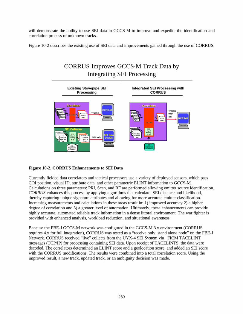
250
will demonstrate the ability to use SEI data in GCCS-M to improve and expedite the identification andcorrelation process of unknown tracks.
Figure 10-2 describes the existing use of SEI data and improvements gained through the use of CORRUS.
Existing Stovepipe SEI Processing
GCCSGCCS--MMTrack Track RptsRpts
Tracks with SEI
Contact Rpts w/
SEI
SEISignature Database
ContactReports
Track Track RptsRptsTrack
Rpts
ContactReportsContact
ReportsContactReportsContact
Rpts
CorrelateCorrelate
Contact Reports with SEI
Contact Reports with SEI
Contact Rpts w/
SEI
SEI SEI Signal Signal
Sorting Sorting & ID& IDContact
Rpts w/ SEI
CorrelatorCorrelator
SEI Info
GCCSGCCS--MMTrack Track RptsRpts Tracks
SEI Data SEI Data DisplayDisplay
Contact Rpts w/
SEI
SEI CollectorSEI Collector
SEISignature Database
ContactReports
Track Track RptsRptsTrack
Rpts
ContactReportsContact
ReportsContactReportsContact
Reports
CorrelateCorrelate
Contact Rpts w/
SEIContact Rpts w/
SEI
Contact Rpts w/
SEI
Sorted & ID’dEmtrs
SEI SEI Signal Signal
Sorting Sorting & ID& ID
Contact Rpts w/
SEI
CorrelatorCorrelator
Sorted & ID’dEmtrs
Sorted & ID’dEmtrs
Integrated SEI Processing with CORRUS
CORRUS Improves GCCS-M Track Data by Integrating SEI Processing
Figure 10-2. CORRUS Enhancements to SEI Data
Currently fielded data correlators and tactical processors use a variety of deployed sensors, which passCOI position, visual ID, attribute data, and other parametric ELINT information to GCCS-M.Calculations on three parameters: PRI, Scan, and RF are performed allowing emitter source identification.CORRUS enhances this process by applying algorithms that calculate: SEI distance and likelihood,thereby capturing unique signature attributes and allowing for more accurate emitter classification.Increasing measurements and calculations in these areas result in: 1) improved accuracy 2) a higherdegree of correlation and 3) a greater level of automation. Ultimately, these enhancements can providehighly accurate, automated reliable track information in a dense littoral environment. The war fighter isprovided with enhanced analysis, workload reduction, and situational awareness.
Because the FBE-J GCCS-M network was configured in the GCCS-M 3.x environment (CORRUSrequires 4.x for full integration), CORRUS was tested as a “receive only, stand alone node” on the FBE-JNetwork. CORRUS received “live” collects from the UYX-4 SEI System via FICM TACELINTmessages (TCP/IP) for processing containing SEI data. Upon receipt of TACELINTS, the data weredecoded. The correlators determined an ELINT score and a geolocation score, and added an SEI scorewith the CORRUS modifications. The results were combined into a total correlation score. Using theimproved result, a new track, updated track, or an ambiguity decision was made.
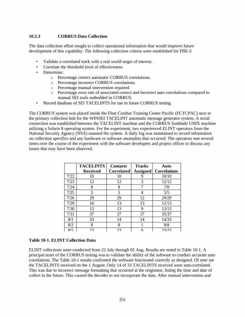
251
10.5.3 CORRUS Data Collection
The data collection effort sought to collect operational information that would improve futuredevelopment of this capability. The following collection criteria were established for FBE-J:
• Validate a correlated track with a real world target of interest.• Correlate the threshold level of effectiveness.• Determine:
o Percentage correct automatic CORRUS correlations.o Percentage incorrect CORRUS correlations.o Percentage manual intervention required.o Percentage error rate of associated correct and incorrect auto correlations compared to
manual SEI tools embedded in CORRUS.• Record database of SEI TACELINTS for use in future CORRUS testing.
The CORRUS system was placed inside the Fleet Combat Training Center Pacific (FCTCPAC) next tothe primary collection hub for the WINSEI TACELINT automatic message generator system. A serialconnection was established between the TACELINT machine and the CORRUS Sunblade UNIX machineutilizing a Solaris 8 operating system. For the experiment, two experienced ELINT operators from theNational Security Agency (NSA) manned the system. A daily log was maintained to record informationon collection specifics and any hardware or software anomalies that occurred. The operators met severaltimes over the course of the experiment with the software developers and project officer to discuss anyissues that may have been observed.
Table 10-1. ELINT Collection Data
ELINT collections were conducted from 22 July through 05 Aug. Results are noted in Table 10-1. Aprincipal tenet of the CORRUS testing was to validate the ability of the software to conduct accurate autocorrelations. The Table 10-1 results confirmed the software functioned correctly as designed. Of note arethe TACELINTS received on the 1 August. Only 14 of 33 TACELINTS received were auto-correlated.This was due to incorrect message formatting that occurred at the originator, listing the time and date ofcollect in the future. This caused the decoder to not incorporate the data. After manual intervention and
TACELINTSReceived
ContactsCorrelated
TracksAssigned
AutoCorrelations
7/22 10 10 9 10/107/23 12 12 3 12/127/24 8 8 7 7/87/25 5 5 4 5/57/26 29 29 12 29/297/29 16 13 13 12/137/30 13 13 9 13/137/31 37 37 37 35/378/1 33 14 14 14/338/2 8 8 1 8/88/5 23 23 0 23/23

252
correction, the messages were reprocessed correctly, but not listed as “auto-correlations” because of thisintervention.
10.5.4 CORRUS Observations and Conclusions
The CORRUS modifications to GCCS-M did perform as intended. Review of the experiment criteriashows that all the goals were met. A correlated track was validated with a real world target of interestmany times throughout the experiment. Because of the close proximity to the NRL SEI hub, the picturecould be confirmed with theground truth.
The correlation threshold level of effectiveness was evaluated upon the receipt of each FICMTACELINT. With the automatic threshold level set at 5, there was 100 percent correct automaticcorrelation with ground truth. In truth, a majority of correlation distances were extended to be closer to1.5 and at highest 3.5. The percentage correct automatic CORRUS correlations were 88 percent. Therewere no incorrect CORRUS correlations. The manual intervention required 12 percent. Besides one casewhere PRI tolerance limits had to be widened, the manual correlations occurred because of incorrectlyformatted FICM TACELINT messages that were generated by the collectors. The last goal, a recorddatabase of SEI TACELINTS for use in future CORRUS testing, was saved to disk and will be used fordetailed in-depth analyses.
Future Considerations
The only messages received during FBE-J were FICM TACELINTS that contained SEI data, so anycorrelation between messages with just classical parameters and messages with classical parameters andSEI data did not occur. CORRUS will perform these correlations, which need to be tested and validatedalong with the regular SEI correlation. A goal of the post-exercise testing is to mix in non-SEITACELINTS to evaluate the performance of the data. Another point for future testing is to increase thenumber of FICM TACELINTS that do not contain PLATID lines, or lines that specifically state whatplatform the emitter is on. Without it, there is greater reliance upon a SEI match to make an automaticcorrelation.
A large list of follow-on enhancements were generated from this experiment that were not part of theoriginal two year scope and would require more time and funding than remain. Some of these includekeeping SEI mode history reports, include storage for fields reported in USSID 351 format (16 staggerlegs), enhance the TACELINT decoder, etc. From these continued refinements, the tactical uses ofCORRUS capabilities will continue to be improved bringing it closer to the goal of supporting thewarfighter and time critical strike (TCS) efforts.
10.6 Micro-Internetted Unattended Ground Sensors (MIUGS)
FBE-J was the setting for the use of DARPA’s prototype Micro-Internetted Unattended Ground Sensors(MIUGS) in coordination with BAE Systems, Inc. The experiment integrated MIUGS with governmentoff the shelf (GOTS) communications and commercial off the shelf (COTS) networking components.During FBE-J MIUGS provided track inputs to the COP via China Lake’s GCCS-M. Targets detectedfrom the field by the MIUGS sensors were sent from the field to the MIUGS workstation, then to ChinaLake GCCS-M and eventually to the USS Coronado’s GCCS-M, as shown in figure 10-3. Approximately20 seconds of track history is displayed on the MIUGS workstation screen in the form of small circlestrailing behind the latest detection. A point from these tracks is selected, augmented with targetcharacteristics and forwarded to China Lake GCCS-M.
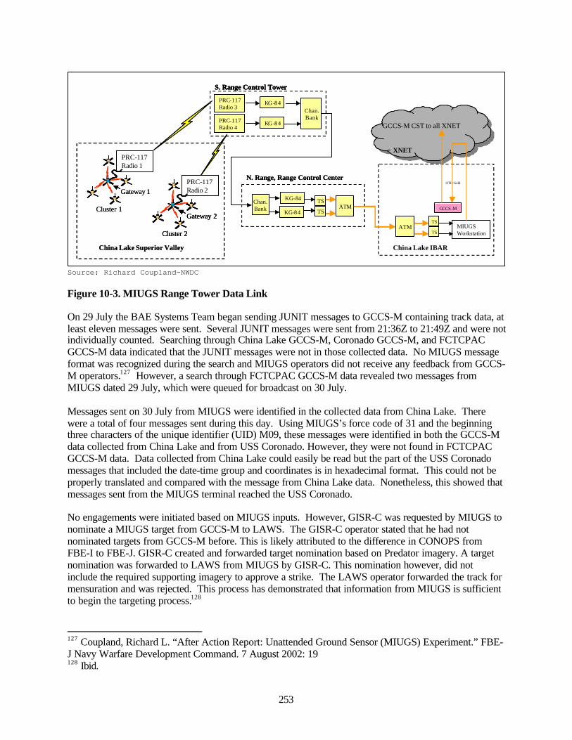
253
Source: Richard Coupland—NWDC
Figure 10-3. MIUGS Range Tower Data Link
On 29 July the BAE Systems Team began sending JUNIT messages to GCCS-M containing track data, atleast eleven messages were sent. Several JUNIT messages were sent from 21:36Z to 21:49Z and were notindividually counted. Searching through China Lake GCCS-M, Coronado GCCS-M, and FCTCPACGCCS-M data indicated that the JUNIT messages were not in those collected data. No MIUGS messageformat was recognized during the search and MIUGS operators did not receive any feedback from GCCS-M operators.127 However, a search through FCTCPAC GCCS-M data revealed two messages fromMIUGS dated 29 July, which were queued for broadcast on 30 July.
Messages sent on 30 July from MIUGS were identified in the collected data from China Lake. Therewere a total of four messages sent during this day. Using MIUGS’s force code of 31 and the beginningthree characters of the unique identifier (UID) M09, these messages were identified in both the GCCS-Mdata collected from China Lake and from USS Coronado. However, they were not found in FCTCPACGCCS-M data. Data collected from China Lake could easily be read but the part of the USS Coronadomessages that included the date-time group and coordinates is in hexadecimal format. This could not beproperly translated and compared with the message from China Lake data. Nonetheless, this showed thatmessages sent from the MIUGS terminal reached the USS Coronado.
No engagements were initiated based on MIUGS inputs. However, GISR-C was requested by MIUGS tonominate a MIUGS target from GCCS-M to LAWS. The GISR-C operator stated that he had notnominated targets from GCCS-M before. This is likely attributed to the difference in CONOPS fromFBE-I to FBE-J. GISR-C created and forwarded target nomination based on Predator imagery. A targetnomination was forwarded to LAWS from MIUGS by GISR-C. This nomination however, did notinclude the required supporting imagery to approve a strike. The LAWS operator forwarded the track formensuration and was rejected. This process has demonstrated that information from MIUGS is sufficientto begin the targeting process.128
127 Coupland, Richard L. “After Action Report: Unattended Ground Sensor (MIUGS) Experiment.” FBE-J Navy Warfare Development Command. 7 August 2002: 19128 Ibid.
MIUGSWorkstation
China Lake IBAR
XNET
GCCS-M
OTH Gold
ATMTS
TS
N. Range, Range Control Center
Chan.Bank ATM
TS
TSKG-84
KG-84
KG-84
PRC-117Radio 4
S. Range Control Tower
Serial
PRC-117Radio 3 Chan.
BankKG-84 GCCS-M CST to all XNET
China Lake Superior Valley
Cluster 1
PRC-117Radio 1
Gateway 1
Cluster 2
PRC-117Radio 2
Gateway 2MIUGSWorkstation
China Lake IBAR
XNET
GCCS-M
OTH Gold
ATMTS
TS
N. Range, Range Control Center
Chan.Bank ATM
TS
TSKG-84
KG-84
KG-84
PRC-117Radio 4
S. Range Control Tower
Serial
PRC-117Radio 3 Chan.
BankKG-84
KG-84
PRC-117Radio 4
S. Range Control Tower
Serial
PRC-117Radio 3 Chan.
BankKG-84 GCCS-M CST to all XNET
China Lake Superior Valley
Cluster 1
PRC-117Radio 1
Gateway 1
Cluster 2
PRC-117Radio 2
Gateway 2
Cluster 2
PRC-117Radio 2
Gateway 2
254
10.6.1 Estimating the accuracy of the target data generated by MIUGS
An individual track coordinate was chosen from a set of tracks that were generated by MIUGS. Thisindividual track was then sent to GCCS-M, as a JUNIT message with a description of what the track iswith a force code and a unique identifier specific for MIUGS. This message also included a JPOSmessage indicating the time, coordinate, heading and speed for the detected track. On 30 July fourindividual track points were selected from tracks generated by MIUGS. These individual track pointswere sent to the China Lake GCCS-M as JUNIT messages and were extracted.
Coordinates from these messages were compared to GPS data generated by vehicles tracked during theexperiment, which was in WGS-84 UTM format. Coordinates sent to GCCS-M were in latitude andlongitude. These points were converted to UTM coordinates using two different conversion softwaresystems. Both conversion systems converted the lat/long coordinates to the same UTM coordinates.
Comparing the data received by GCCS-M to field GPS track data indicates that GCCS-M receivedincorrect coordinates. Coordinates received by GCCS-M ranged from 580 to 1890 meters away from theactual target, with a median of 888 meters and average of 1085 meters. Figure 10-4 indicates the locationof the vehicles compared to the location received in GCCS-M. This chart does not take into account anytime delay from detection to track receipt at the MIUGS terminal. Nonetheless, it shows that the tracksreceived by GCCS-M were far from where the targets were located.
MIUGS Systems Engineers explained that this is attributed to the following errors.
• Sensor Reference Centroid. The gateway would report the GPS relative to a centroid of sensorsreporting into it. If local communication were lost to one sensor briefly, the gateway would shiftits reference coordinate. The reference positions would thus "jump" over time.
• Bit errors in messages from sensor to gateway caused apparent "jumps." These coordinates wereonly set once per minute to the gateway so you would see 1-minute intervals where positionswere constant, but values could be wildly wrong. The really bad errors could be thrown out, butsmaller errors got through.
• Bit errors in messages from gateway to operator console. Same net effect as immediately above.
• Message drop errors from gateway to operator console. These coordinates were also supposed tobe updated once per minute but when messages did not get through the ground links, referencecoordinates persisted longer then a minute. So if a message with errors in it arrived at the IBAR,it could persist longer than a minute due to messages being missed after the bad one wasaccepted.
BAE Systems is taking measures to correct these reference position issues by keeping GPS in stand-bymode, making longer term measures without updating the position until it’s stable and using the gatewayas the reference coordinate. To correct bit errors, BAE is inserting error detection code into the message.
In addition to reference position errors experienced during the experiment, there was also a discrepancywith time. Messages arrived at the operator console at random intervals. BAE estimated the error usingvehicle ground truth data and reported positions from MIUGS. By conducting time alignment of vehicle
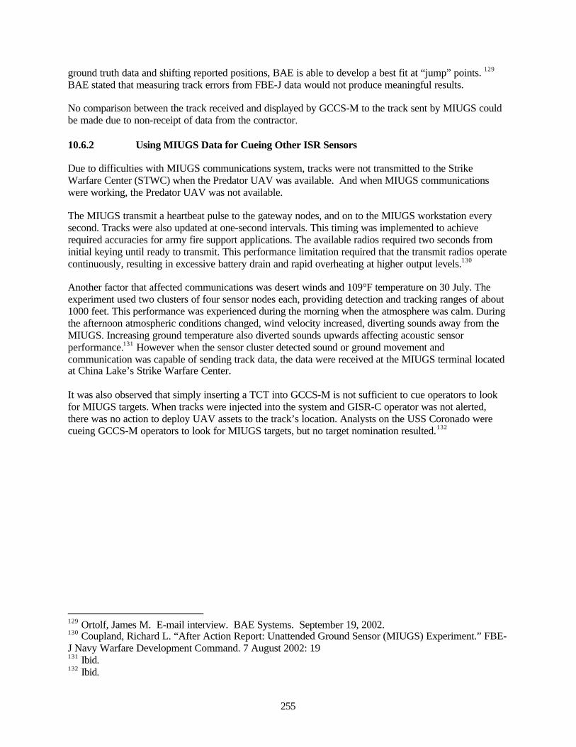
255
ground truth data and shifting reported positions, BAE is able to develop a best fit at “jump” points. 129
BAE stated that measuring track errors from FBE-J data would not produce meaningful results.
No comparison between the track received and displayed by GCCS-M to the track sent by MIUGS couldbe made due to non-receipt of data from the contractor.
10.6.2 Using MIUGS Data for Cueing Other ISR Sensors
Due to difficulties with MIUGS communications system, tracks were not transmitted to the StrikeWarfare Center (STWC) when the Predator UAV was available. And when MIUGS communicationswere working, the Predator UAV was not available.
The MIUGS transmit a heartbeat pulse to the gateway nodes, and on to the MIUGS workstation everysecond. Tracks were also updated at one-second intervals. This timing was implemented to achieverequired accuracies for army fire support applications. The available radios required two seconds frominitial keying until ready to transmit. This performance limitation required that the transmit radios operatecontinuously, resulting in excessive battery drain and rapid overheating at higher output levels.130
Another factor that affected communications was desert winds and 109°F temperature on 30 July. Theexperiment used two clusters of four sensor nodes each, providing detection and tracking ranges of about1000 feet. This performance was experienced during the morning when the atmosphere was calm. Duringthe afternoon atmospheric conditions changed, wind velocity increased, diverting sounds away from theMIUGS. Increasing ground temperature also diverted sounds upwards affecting acoustic sensorperformance.131 However when the sensor cluster detected sound or ground movement andcommunication was capable of sending track data, the data were received at the MIUGS terminal locatedat China Lake’s Strike Warfare Center.
It was also observed that simply inserting a TCT into GCCS-M is not sufficient to cue operators to lookfor MIUGS targets. When tracks were injected into the system and GISR-C operator was not alerted,there was no action to deploy UAV assets to the track’s location. Analysts on the USS Coronado werecueing GCCS-M operators to look for MIUGS targets, but no target nomination resulted.132
129 Ortolf, James M. E-mail interview. BAE Systems. September 19, 2002.130 Coupland, Richard L. “After Action Report: Unattended Ground Sensor (MIUGS) Experiment.” FBE-J Navy Warfare Development Command. 7 August 2002: 19131 Ibid.132 Ibid.

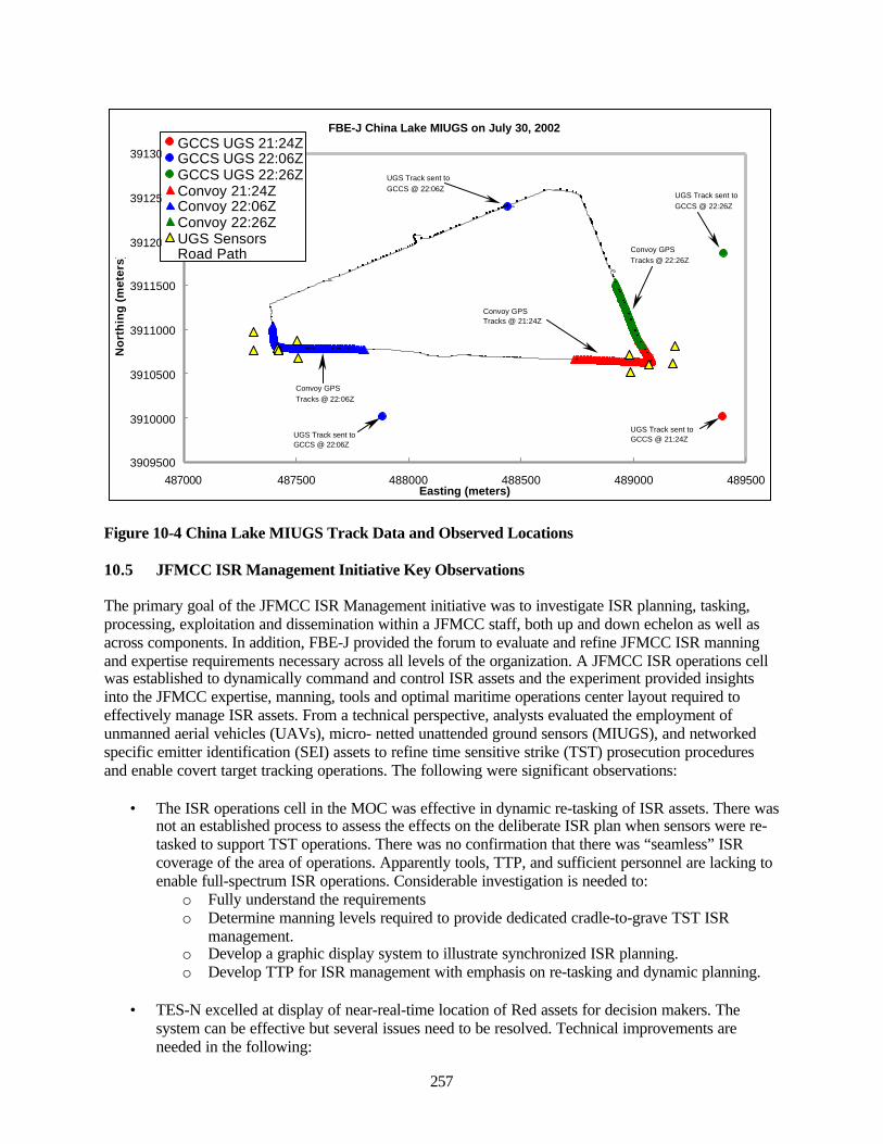
257
FBE-J China Lake MIUGS on July 30, 2002
3909500
3910000
3910500
3911000
3911500
3912000
3912500
3913000
487000 487500 488000 488500 489000 489500Easting (meters)
No
rth
ing
(m
eter
s)
GCCS UGS 21:24ZGCCS UGS 22:06ZGCCS UGS 22:26ZConvoy 21:24ZConvoy 22:06ZConvoy 22:26ZUGS SensorsRoad Path
Convoy GPS Tracks @ 22:06Z
UGS Track sent to GCCS @ 22:06Z
UGS Track sent to GCCS @ 22:06Z
Convoy GPS Tracks @ 21:24Z
UGS Track sent to GCCS @ 21:24Z
Convoy GPS Tracks @ 22:26Z
UGS Track sent to GCCS @ 22:26Z
Figure 10-4 China Lake MIUGS Track Data and Observed Locations
10.5 JFMCC ISR Management Initiative Key Observations
The primary goal of the JFMCC ISR Management initiative was to investigate ISR planning, tasking,processing, exploitation and dissemination within a JFMCC staff, both up and down echelon as well asacross components. In addition, FBE-J provided the forum to evaluate and refine JFMCC ISR manningand expertise requirements necessary across all levels of the organization. A JFMCC ISR operations cellwas established to dynamically command and control ISR assets and the experiment provided insightsinto the JFMCC expertise, manning, tools and optimal maritime operations center layout required toeffectively manage ISR assets. From a technical perspective, analysts evaluated the employment ofunmanned aerial vehicles (UAVs), micro- netted unattended ground sensors (MIUGS), and networkedspecific emitter identification (SEI) assets to refine time sensitive strike (TST) prosecution proceduresand enable covert target tracking operations. The following were significant observations:
• The ISR operations cell in the MOC was effective in dynamic re-tasking of ISR assets. There wasnot an established process to assess the effects on the deliberate ISR plan when sensors were re-tasked to support TST operations. There was no confirmation that there was “seamless” ISRcoverage of the area of operations. Apparently tools, TTP, and sufficient personnel are lacking toenable full-spectrum ISR operations. Considerable investigation is needed to:
o Fully understand the requirementso Determine manning levels required to provide dedicated cradle-to-grave TST ISR
management.o Develop a graphic display system to illustrate synchronized ISR planning.o Develop TTP for ISR management with emphasis on re-tasking and dynamic planning.
• TES-N excelled at display of near-real-time location of Red assets for decision makers. Thesystem can be effective but several issues need to be resolved. Technical improvements areneeded in the following:
258
o TES-N/NFN lacks effective means for integration with other systems.o Lack of direct downlink operations limited NFN system’s TST capability.o NFN systems need faster, more reliable communications to deal effectively with TSTs.o There was no established operational context for when or how to share GCCS-M and
TES-N information.o Develop a means for providing appropriate, near real-time, TES-N information to the
Fires cell.o Develop a means for displaying TES-N information in GCCS-M.o Develop TTP for use of TES-N information in the TST process.
• Most time critical targets in FBE-J were detected or confirmed using imagery from satellite, air,or unmanned air reconnaissance operations. The process for nominating these targets for strikecurrently excludes sending such TCT tracks to GCCS-M. This result applies only to tracksresulting from imagery. DTMS has the requirement to send tracks from imagery to the COP. Thisinterface will not be fully implemented until DTMS version 4 (companion with GCCS-M 4.X) isreleased. Tracks sent to C2PC from DTMS are also not forwarded to GCCS-M 3.X.
• The Micro-Internetted Unmanned Ground System (MIUGS) provides information to augment theCOP. GISR-C was requested by MIUGS to nominate a MIUGS target from GCCS-M to LAWS.The exercise demonstrated that MIUGS inputs could be functionally used for TCS. In theexperiment, however, serious limitations in performance were observed:
o MIUGS sent the wrong coordinates to the system. Tracks sent to the system did notmatch the actual target location. Data sent by MIUGS could not be relied on for precisionstrike.
o There were large inconsistencies between reported MIUGS performance, ranging fromeverything worked perfectly to there being substantial errors in tracking and the passingof data from one system to another.
259
11.0 Mine Warfare (MIW) Initiative Key Observations
11.1 Experiment Objectives
The overall objective of the MIW experiment in FBE-J was to examine the application of network centricoperations to mine warfare. The command and control structure in FBE-J encompassed an experimentalorganization, a high speed vessel (HSV) as a surrogate future mine countermeasures (MCM) capableplatform, new command and control equipment, and some new MCM capabilities, which replicate futureMCM capabilities in the 2007-2010 time frame. This analysis limits its focus to the issues above and doesnot include an analysis of finding mine locations or clearance operations in FBE-J.
In support of these objectives, the key questions that needed to be answered were:
• Did the HSV provide the Mine Warfare Commander (MIWC) with the command, control,communications, computer, intelligence, surveillance, and reconnaissance (C4ISR) toolsnecessary to participate in network-centric warfare?
• Did the variety of assets available to support the MIWC enhance the overall MIW ability? Couldthe HSVs also use those assets?
• Was the MIWC able to operate in a network-centric environment and to use the ISR and Firescapabilities of the Naval Fires Network (NFN)? Was the NFN, in turn, able to incorporate MIWsensor information and conduct Fires with MIW specific precision-guided munitions (PGMs)?
• Were the MIWC and Anti-Submarine Warfare Commander (ASWC) able to collaborate in themanagement and interpretation of the common undersea picture (CUP)?
11.1.1 Sub-initiative: Collaboration of MIWC with JFMCC and PWCs
A principal area of interest in FBE-J was the amount and type of collaboration that occurred between theMine Warfare Commander (MIWC) and the Principal Warfare Commanders (PWCs) and the Joint ForcesMaritime Component Commander (JFMCC). Through the services of the C4ISR suite onboard JointVenture (HSV-X1), the MIWC should have had several means of communicating with the JFMCC staffand other PWCs. A principal goal was to determine if the MIWC was able to effectively collaborate withthe JFMCC, other warfare commanders and the units conducting MCM. The successful accomplishmentof this objective would include achieving the following:
• The MIWC was able to share situational awareness (SA) with the Commander Amphibious TaskForce (CATF)/Commander Landing Force (CLF) and make dynamic changes to the sea lanesclear of mines (Q-routes) and mine searching/clearing plans if necessary.
• The JFMCC/CTF provided security for the MCM forces to successfully operate.• The JFMCC allocated assets to perform MCM.• The communications suite aboard the Joint Venture (HSV-X1) supported the embarked MIWC
with necessary tools.• The MIWC was able to provide the JFMCC with an opportunity to conduct timely operations
within a potentially mined area.
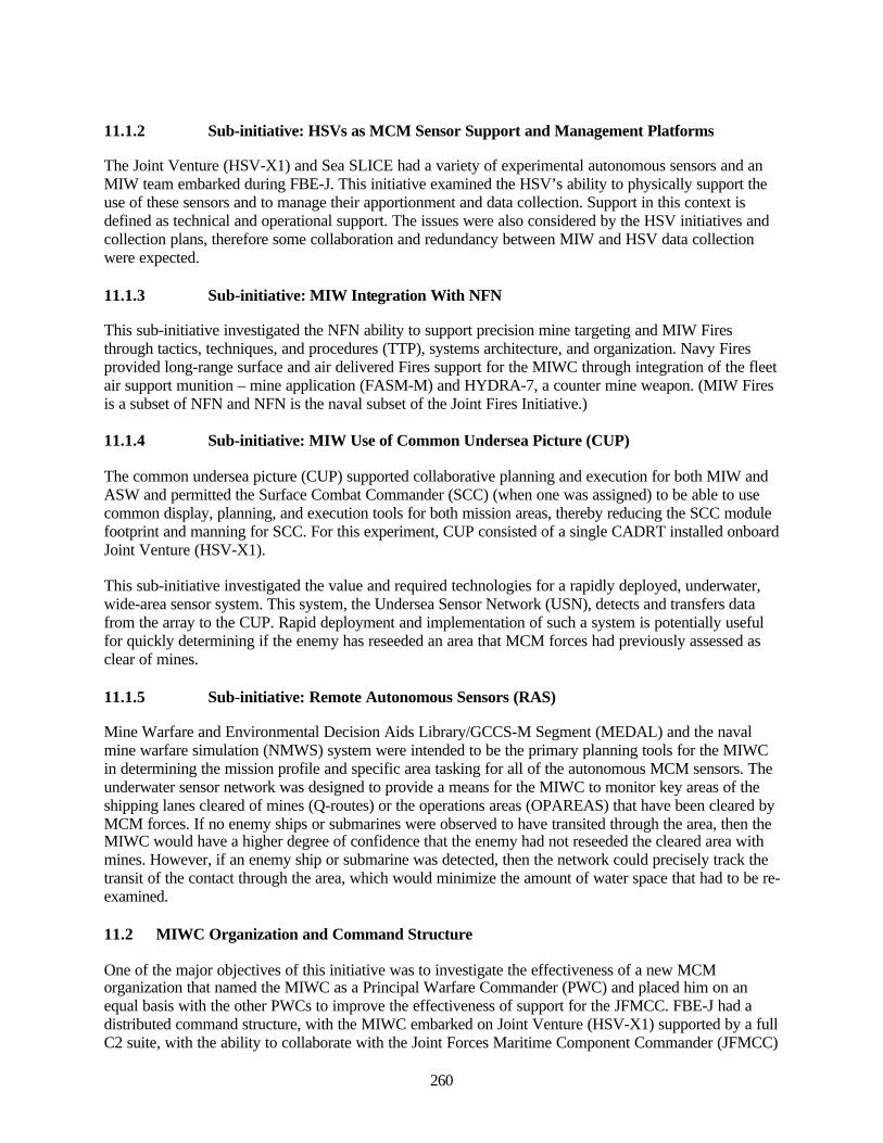
260
11.1.2 Sub-initiative: HSVs as MCM Sensor Support and Management Platforms
The Joint Venture (HSV-X1) and Sea SLICE had a variety of experimental autonomous sensors and anMIW team embarked during FBE-J. This initiative examined the HSV’s ability to physically support theuse of these sensors and to manage their apportionment and data collection. Support in this context isdefined as technical and operational support. The issues were also considered by the HSV initiatives andcollection plans, therefore some collaboration and redundancy between MIW and HSV data collectionwere expected.
11.1.3 Sub-initiative: MIW Integration With NFN
This sub-initiative investigated the NFN ability to support precision mine targeting and MIW Firesthrough tactics, techniques, and procedures (TTP), systems architecture, and organization. Navy Firesprovided long-range surface and air delivered Fires support for the MIWC through integration of the fleetair support munition – mine application (FASM-M) and HYDRA-7, a counter mine weapon. (MIW Firesis a subset of NFN and NFN is the naval subset of the Joint Fires Initiative.)
11.1.4 Sub-initiative: MIW Use of Common Undersea Picture (CUP)
The common undersea picture (CUP) supported collaborative planning and execution for both MIW andASW and permitted the Surface Combat Commander (SCC) (when one was assigned) to be able to usecommon display, planning, and execution tools for both mission areas, thereby reducing the SCC modulefootprint and manning for SCC. For this experiment, CUP consisted of a single CADRT installed onboardJoint Venture (HSV-X1).
This sub-initiative investigated the value and required technologies for a rapidly deployed, underwater,wide-area sensor system. This system, the Undersea Sensor Network (USN), detects and transfers datafrom the array to the CUP. Rapid deployment and implementation of such a system is potentially usefulfor quickly determining if the enemy has reseeded an area that MCM forces had previously assessed asclear of mines.
11.1.5 Sub-initiative: Remote Autonomous Sensors (RAS)
Mine Warfare and Environmental Decision Aids Library/GCCS-M Segment (MEDAL) and the navalmine warfare simulation (NMWS) system were intended to be the primary planning tools for the MIWCin determining the mission profile and specific area tasking for all of the autonomous MCM sensors. Theunderwater sensor network was designed to provide a means for the MIWC to monitor key areas of theshipping lanes cleared of mines (Q-routes) or the operations areas (OPAREAS) that have been cleared byMCM forces. If no enemy ships or submarines were observed to have transited through the area, then theMIWC would have a higher degree of confidence that the enemy had not reseeded the cleared area withmines. However, if an enemy ship or submarine was detected, then the network could precisely track thetransit of the contact through the area, which would minimize the amount of water space that had to be re-examined.
11.2 MIWC Organization and Command Structure
One of the major objectives of this initiative was to investigate the effectiveness of a new MCMorganization that named the MIWC as a Principal Warfare Commander (PWC) and placed him on anequal basis with the other PWCs to improve the effectiveness of support for the JFMCC. FBE-J had adistributed command structure, with the MIWC embarked on Joint Venture (HSV-X1) supported by a fullC2 suite, with the ability to collaborate with the Joint Forces Maritime Component Commander (JFMCC)
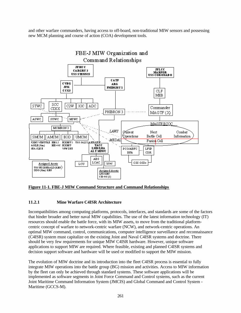
261
and other warfare commanders, having access to off-board, non-traditional MIW sensors and possessingnew MCM planning and course of action (COA) development tools.
Figure 11-1. FBE-J MIW Command Structure and Command Relationships
11.2.1 Mine Warfare C4ISR Architecture
Incompatibilities among computing platforms, protocols, interfaces, and standards are some of the factorsthat hinder broader and better naval MIW capabilities. The use of the latest information technology (IT)resources should enable the battle force, with its MIW assets, to move from the traditional platform-centric concept of warfare to network-centric warfare (NCW), and network-centric operations. Anoptimal MIW command, control, communications, computer intelligence surveillance and reconnaissance(C4ISR) system must capitalize on the existing Joint and Naval C4ISR systems and doctrine. Thereshould be very few requirements for unique MIW C4ISR hardware. However, unique softwareapplications to support MIW are required. Where feasible, existing and planned C4ISR systems anddecision support software and hardware will be used or modified to support the MIW mission.
The evolution of MIW doctrine and its introduction into the fleet C4ISR process is essential to fullyintegrate MIW operations into the battle group (BG) mission and activities. Access to MIW informationby the fleet can only be achieved through standard systems. These software applications will beimplemented as software segments in Joint Force Command and Control systems, such as the currentJoint Maritime Command Information System (JMCIS) and Global Command and Control System -Maritime (GCCS-M).
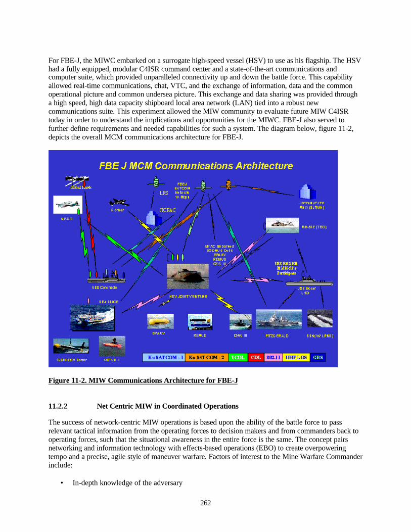
262
For FBE-J, the MIWC embarked on a surrogate high-speed vessel (HSV) to use as his flagship. The HSVhad a fully equipped, modular C4ISR command center and a state-of-the-art communications andcomputer suite, which provided unparalleled connectivity up and down the battle force. This capabilityallowed real-time communications, chat, VTC, and the exchange of information, data and the commonoperational picture and common undersea picture. This exchange and data sharing was provided througha high speed, high data capacity shipboard local area network (LAN) tied into a robust newcommunications suite. This experiment allowed the MIW community to evaluate future MIW C4ISRtoday in order to understand the implications and opportunities for the MIWC. FBE-J also served tofurther define requirements and needed capabilities for such a system. The diagram below, figure 11-2,depicts the overall MCM communications architecture for FBE-J.
Figure 11-2. MIW Communications Architecture for FBE-J
11.2.2 Net Centric MIW in Coordinated Operations
The success of network-centric MIW operations is based upon the ability of the battle force to passrelevant tactical information from the operating forces to decision makers and from commanders back tooperating forces, such that the situational awareness in the entire force is the same. The concept pairsnetworking and information technology with effects-based operations (EBO) to create overpoweringtempo and a precise, agile style of maneuver warfare. Factors of interest to the Mine Warfare Commanderinclude:
• In-depth knowledge of the adversary
263
• Real-time shared situational awareness• Decentralized, self-synchronizing execution• Focus on actions and reactions
FBE-J concentrated on information as a primary source of power to enable access and to provide real-time battlespace awareness for the MIWC and other commanders. It used a variety of dispersed sensors toachieve rapid and comprehensive MIW battlespace awareness
11.2.3 Development of the MIW Networks
Effective MIW relies upon the successful integration of key and relevant information from varioussources to identify and clear the mines and obstacles from deep water to the Beach Exit Zone (BEZ).Capabilities for detection by sensors varies by water depth and mine type. It is therefore very importantthat all commands are acting in consonance to provide all relevant information to the MIWC for mosteffective prosecution of the MIW objectives. An integrated C2 methodology to provide this informationas a common operational picture (COP) was formed around three logical networks as follows:
• Information network• Integrated Sensor network• Engagement Network
The Information Network
Enabled by an integrated, near real-time environmental data and MEDAL-GCCS-M and the LandAttack Warfare System (LAWS) architecture and a future alternative MIWC command structure, theinformation network functioned to integrate the full spectrum of sensors. Sensor inputs to the networkwere processed and correlated. Fused sensor information was pulled by the MIWC through adaptable,reconfigurable displays to provide situational awareness and the knowledge to make command,coordination, and synchronization possible at lower echelons.
The backbone for FBE-J common operational picture (COP) was the Global Command and ControlSystem – Maritime (GCCS-M). GCCS-M/MEDAL, a segment of MEDAL, provided the backbonefor the MIW C4ISR connectivity. MEDAL 7.4 and an engineering version MEDAL 8.0, installed onFITZGERALD only, were used in the experiment. GCCS-M/MEDAL and LAWS were interfaced toallow mine contacts to be displayed in the COP and passed to the Naval Fires Network Experimental(NFN (X)) to allow engagement of mine targets and to provide a means of getting battle damageassessment (BDA) back into MEDAL and the COP for those targets that were engaged.
The Integrated Sensor Network
A number of onboard and off-board unmanned overhead, airborne, surface and autonomousunderwater sensors were netted through MEDAL/LAWS and GCCS-M, to provide the MIWC withan the ability to more quickly gain battlespace knowledge. His situational awareness (SA) wasunderwritten by fused environmental and tactical mine warfare picture data into a comprehensivepicture. Sensors operated in FBE-J were as follows:
• Littoral Remote Sensing (LRS)• Coastal Battlefield Reconnaissance and Analysis (COBRA) System• Joint Surveillance and Target Attack Radar System (JSTARS)• Battlespace Preparation Autonomous Undersea Vehicle (BPAUV)
264
• Semi-Autonomous Hydrographic Reconnaissance Vehicle (SAHRV)• Remote Environmental Monitoring System (REMUS)• Composite Endoskeleton Test-bed Untethered Underwater Vehicle System (CETUS) II• HSV Joint Venture (HSV-X1) with BPAUV, SAHRV, REMUS, CETUS II, and EOD DET
embarked• Sea SLICE with Klein Side Scan Sonar, REMUS, CETUS II and VSW DET embarked• AN/BLQ-11 Long Term Mine Reconnaissance System (LMRS) (simulated)• AN/WLD-1 (REMOTE MINEHUNTING SYSTEM [RMS]) (simulated)• AN/AQS-20X Airborne Minehunting System (simulated)• Advanced Laser Detection System (ALMDS) (simulated)• MH-53E (4) with AN/AQS-14E (simulated) (simulated)• MCM-1 (2) with AN/SQQ-32, AN/SLQ-48 and EOD DET (simulated)• MHC-51 class (2) with AN/SQQ-32, AN/SLQ-48 and EOD DET (simulated)
The Engagement Network
The engagement network was designed to fully integrate MEDAL with LAWS and provided theMIWC with control of several future weapons in support of accomplishing his assigned mission. Theintegration of MEDAL with LAWS brings MIW into the Digital Fires Network, which allowed alldecision makers to have visibility into the MIW situation as it developed. These weapons couldenable the MIWC to clear minefields more quickly, thereby significantly reducing the overalltimeline for MIW operations.
11.2.4 Remote Launched Precision Guided Munitions in Support of MIW
A number of new Precision Guided Munitions (PGMs) are currently under development, primarily insupport of land warfare. As a complementary effort, there is potential for these systems to support themine warfare community. To assure the effectiveness of these weapons systems, MCM sensors mustprovide the precise target geo-locating data that the weapons require. These weapons must also have adistributed command and control system wherein mine warfare fires support planning and execution canbe integrated into the larger Naval Fires Network. Additionally, issues of deconfliction and battle damageassessment must be effectively considered. The descriptions below describe four future mine warfarerelated PGMs that could be effectively integrated into the NFN architecture for support to MIW.
• Fleet Air Support- Marine – Mine Warfare Application (FASM-M) MunitionOriginally designed as a land attack weapons system, FASM-M provides a 5" gun round withlong range, loiter capability and target imagery capability. Fitted with a different warhead tosupport the mine warfare mission and assuming advances in mine warfare sensor target geo-location accuracy, it is believed that a FASM-M-like capability for surface shooters will provide aneeded capability to support almost real-time tactical decisions by the Landing Force Commanderon LPP selection and STOM execution that cannot now be duplicated with existing weapons. Inaddition, it will support the single combatant, equipped with RMS, by providing a mineneutralization system option. Once the RMS has detected a mine target FASM can be the weaponof choice when an MH-60S helicopter with Airborne Mine Neutralization System (AMNS) orRAMICS is not available or cannot be used for tactical reasons. It is envisioned that the sameplanning tools to be incorporated into Naval Surface Fire Control System supporting extendedrange guided munition (ERGM) and Tactical Tomahawk Land attack missile (TLAM) planningcould be modified to support FASM-M operations, which, in this FBE, will be replicated throughthe use of Land Attack Warfare System (LAWS) and Navy Fires Network (Experimental). Thiscapability allows these MIW munitions to be integrated into land attack and strike operationsthrough the joint C4ISR architecture for Joint Air Operations and Joint Fires.
265
• Hydra 7HYDRA 7 is a potential future system. It is an air delivered, GPS guided, breaching munition thatspreads a number of hypervelocity burning darts to deflagrate surface and buried mines in thevery shallow water (VSW), surf zone (SZ), and beach zone (BZ). HYDRA-7 is intended toprovide a standoff air launched weapon as a counter measure to mines, particularly those thatthreaten amphibious landings.
• Rapid Airborne Mine IC System (RAMICS)RAMICS is a MH-60S mine neutralization system which uses a LIDAR system to providetargeting for a 30mm super cavitating gun system.
• Airborne Mine Neutralization System (AMNS)AMNS is an expendable mine neutralization vehicle which will be deployed from MH-53E andMH-60S to reacquire and neutralize moored or proud bottom mines. It will utilize a LIDARcapability to detect the mines then deploy the tethered AMNS to localize the mine with a highfrequency sonar and EO capability. Once identified, the helo will back off away from the mineand then shoot a mini-torpedo at the mine and destroy it. The AMNS can then move the AMNSvehicle back to the location of the mine to verify that it was destroyed.
11.3 Observations
11.3.1 MIWC Collaboration with JFMCC and PWCs
The overall collaboration between the MIWC, JFMCC and other PWCs began slowly. While the MIWCknew what was going on in MIW, he had little insight into the overall context that the MIW operationswere being conducted within, such as the larger tactical or operational picture and JFMCC/JTFoperational plans. Even collaboration with the Anti-Submarine Warfare Commander (ASWC) on thecommon undersea picture (CUP) did not occur because the MEDAL systems were not on a common localarea network (LAN). The MIWC requested that the local ship's SA be displayed in the C4ISR space. Thishad value in getting him a part of the bigger picture, but he still needed to know the overall commonoperating picture and the goals and objectives of the JTF.
Although the MIWC had newly elevated status as a PWC and the ability to employ a number ofexperimental assets and capabilities, there was little overall collaboration with other staffs or PWCs. Agradual awareness among the MIW staff of the need to work closely with other PWCs, particularly theAMWC and the SCC, eventually led to an improvement in collaboration. But there remained generalconfusion and varying opinions on the appropriate nature of this collaboration.
MIWC planning suffered because it was not co-located with the JFMCC planning. This would havealleviated much of the SA deficiency issue and would have eased the coordination between MIW andJFMCC/JTF planning personnel. However, with proper staff training in the use of collaboration andcommunication tools, these issues could have been resolved.
There was considerable frustration among participants associated with the dynamic between theMARSUPREQ and MIW processes.
• There was a lack of promulgation of critical MIW related information, such as Q-Routes, times ofassaults, and areas around islands needed by the Amphibious Warfare Commander (AMWC).
• The MPP process appeared to be done without adequate collaboration with MIWC. One observerfelt that the NATO process would be preferable to the JFMCC MPP process because it isperfected and familiar to the fleet.

266
• MARSUPREQs took too much time, overburdened the MIW staff, and detracted from the MCMbattle rhythm. They were also insufficiently flexible for MIW, where the process is slow butchanges need to be ingested and evaluated continuously. One staff member stated that there wassome question as to how many MARSUPREQs were needed to cover a MIW mission; one for theoverall mission or one for each functional segment.
• Virtually all were in agreement that the time consumed by managing the MARSUPREQs wouldhave been more productively employed in direct MIW-related work, such as evaluatingalternatives in the Naval Mine Warfare System (NMWS).
• A need was also expressed to integrate the MARSUPREQ process to the different systems usedto prosecute MIW, e.g., a ship selected in GCCS-M should link directly to a MARSUPREQ andthe format of the MARSUPREQ should match casualty reports (CASREPTs), casualtycorrections (CASCORs), and casualty cancellations (CASCANs).133
A number of MARSUPREQ workarounds were necessary to process tasking. Significant cutting andpasting from day before missions, printing out copies of old MARSUPREQs to compare tasking for newMARSUPREQs, OPNOTEs to MEDAL to change MIW tasking (because no direct link to theMARSUPREQ form was available), telephone calls, and other OPNOTEs are examples.
Early in the experiment, the MIW staff was waiting for information that the other PWCs may not haveknown was needed by the MIWC. The staff was slow to request the information and sometimes resortedto unilateral, educated guesses about what the other PWCs knew or what was needed.134 On 28 July,AMWC began to feed back information to the MIWC. By 7/31, the collaboration between AMWC andMIWC had continued to improve,135 perhaps in part due to the assignment of a Navy officer in the M&Scell for MIW to enhance the realism. Of note however, most of the improved collaboration with otherPWCs occurred after 28 July when all MIW operations were simulated, not actual.
There was little collaboration between the Sea Component Commander (SCC), the MIWC, and theASWC over unmanned undersea vehicle (UUV) placement and SSN operations as normally would havebeen anticipated. It may have been because RMS and LMRS were placed such that they were not aproblem, but one observer thought that not to be the case.136
Collaboration tools were used, but not to an optimal degree. Rather than use Information Work Space(IWS) or CISCO phones, representatives from other staffs would frequently walk into the MIW space totalk to the MIWC. Nonetheless, collaboration tools such as SharePoint Portal Service (SPPS) and IWSwere used regularly between staffs and these discussions served as collaboration. Review of the chat logspoints out that discipline is needed as there was both inappropriate items and significant uncorroboratedinformation were being discussed in this venue.
MIW planning tools included GCCS-M/MEDAL, Naval Oceanographic Office (NAVOCEANO) bottommapping and change detection (BM-CD), Naval Mine Warfare Simulation System (NMWS) and LandAttack Warfare System (LAWS). Their integration worked well to provide the MIWC a start-to-finishplanning-to-engagement toolset. Dominant Battlespace Command (DBC) provided an excellent 3-Dvisualization tool that MIWC used for overall situational awareness (SA), although the 3-D underwatervisualization was not demonstrated due to the integration program not being fully developed. GCCS-M/MEDAL requires some modifications to accommodate MPP MARSUPREQ to MCM taskingintegration to reduce the MIWC planning workload. MEDAL requires some additional tool refinements tofacilitate the quick planning of multiple UUV missions.
133 FBE-J Mine Warfare Survey – New Survey134 FBE-J Mine Warfare Survey135 MIW Daily Activity Reports of 28 July and 31 July.136 FBE-J Mine Warfare Qualitative Survey, ASWC, Undersea Sensor Placement
267
It may be that if the MIW staff had been embarked in the HSV for a longer period with more time toexperiment with the display capability, additional insight and collaboration might have occurred. Slowcommunications links affected their impression of the utility of collaboration and planning tools. Otherthan MEDAL, the best planning tools were NMWS and BM-CD, which for the MIWC were standalonesystems and were not affected by the HSV LAN slowdowns.137
Most watchstanders were unanimous in stating their need for a white board or something similar toeffectively manage the various tasks, deadlines, statuses, and the general SA. Several suggestedautomated status boards. All indicated frustration in trying to manage the process as it was.138 The lack ofa means to organize the tasking may lead to management chaos if and when high pressure, rapid clearanceoperations are undertaken.
Also, the length of time that it took to obtain the results of remote autonomous vehicle (RAV) missionsand get the new data into the systems had a definite impact on the efficiency of the MIW planningoperation. The most extreme example was the long duration of LMRS missions with the necessary postmission analysis (PMA), which meant that the MIWC had to wait as long as two days before receivingthe results of the mission and folding them into his plans.
For effective overall integrated operations, the MIWC must be able to export the MEDAL picture toCATF, CLF, JFMCC, and SCC in order to convey the MIW status, progress and level of effort foreffective collaboration. It was not apparent that the ASWC, SCC and AMWC had an appreciation for thescope of the MIW problem until sometime around 3 August. In FBE-J, the SCC had MEDAL in hisspace, but it was on a different LAN than the MIWC MEDAL machines so it was not able to copy theMIW COP. Due to this and periodic communications interruptions, some data had to be downloaded todisk and hand carried to the receiver site and uploaded into MEDAL. This delayed information flow,sometimes by as much as days. The PowerPoint presentations that were used to display the MIW statuswere time-consuming to prepare, and there was a perception that the other PWCs were pre-occupied withtheir own problems anyway.139 It appears that the most effective way to transfer information betweenPWCs must be a continuous, automatic, process standardized across all PWCs, the JFMCC, and othercommanders.
The new concept for MCM under a CVBG/ARG was not used, so potential improvements and problemsassociated with that process could not be evaluated.
11.3.2 HSVs as MCM Sensor Support and Management Platforms
The variety of experimental autonomous sensors available to the MIWC aboard the HSVs enhancedoverall MIW capability. The size of Joint Venture permitted a comprehensive mix of MCM assets fromRHIBs, AUVs, and helicopters to be hosted. The experimental set of autonomous sensors significantlyincreased the overall capabilities of the MIWC in a qualitative sense. The HSVs were able to support theuse of embarked sensors, although there were issues of launch, recovery, and working conditions thatwere largely associated with the use of vessels that had been modified to accomplish the MIW mission,but had not been specifically designed for MIW/MIWC.
The concept of organic mine countermeasures (OMCM) with the addition of AUVs means that any assetcan be an MCM asset, as was proven in FBE-J. The Quick Reaction Mine Warfare Action Groupconsisting of the HSV, SSN and DDG was very effective in clearing the initial Q-route to allow other
137 FBE-J Mine Warfare Qualitative Survey, HSV138 FBE-J Mine Warfare Survey – New Survey139 Ibid
268
forces to flow into the theater. The use of these assets provided the MIWC the ability to get to the areaquickly, to deploy a wide variety of assets and to quickly gain knowledge and localize the MIW threat.The HSV permitted the MIWC to get into and out of littoral waters quickly to deploy LMRS and UUVs.Shared MIW assets tended to focus on HSV RAV/UUV assets, however, and aspects of CV helicopters,sharing of the HSVs with other missions, and maintenance of the HSVs did not receive substantialattention in the experiment. The allocation of assets was skewed by the scenario to favor AUVs over theOMCM program of record systems because of the requirement by the MIWC to remain covert during theIPB and exploratory search phases.
The Joint Venture (HSV-X1) stern vehicle loading ramp was used to successfully load two supportmilvans (10x20), one support trailer (8x22), and EOD detachment equipment with a forklift and truck. Noproblems were encountered. Procedures developed for Joint Venture launch and recovery of BPAUV andEOD RHIB required Joint Venture to slow to approximately 3 knots for the evolutions, each of whichtook several minutes. Consideration should be given to design appropriate launch and recovery gear anddevelop procedures to conduct these evolutions at higher speeds. Trailers and equipment cradles weremoved around the vehicle deck with rented forklifts during FBE-J. Due to the anticipated increase of gearin the vehicle deck during future use, it might be appropriate for “yellow gear” to be provided to JointVenture to facilitate the movement of trailers and equipment cradles.140
The EOD detachment rigid hulled inflatable boat (RHIB) was successfully launched and recovered byJoint Venture several times. The single overhead crane, not optimized for at-sea launch and recovery ofRHIBs, proved difficult to manage. The cargo area low vertical clearance, and the inability of the crane toswivel its load restricted its utility for larger craft. The single crane configuration of Joint Ventureprovided the potential for a single point failure, and a failure would have denied the MIWC the ability tolaunch and recover MCM assets. A better mission specific system is required for operational use toconduct launch or recovery of RHIBs or UUVs. The installed system sufficed for experimental purposesbut is inadequate for fleet operations.141
For launching RAVs, important factors considered included the time taken to launch and retrieve,particularly in view of the concern that most respondents had regarding the vulnerability of the HSV.Because of the requirement to remain covert for most of the scenario, LMRS was the workhorse for theMIWC, with BPAUV, then RMS in that order. LMRS, because of its long legs and ability of submarineto remain covert to deploy it, it was the sensor of choice. However, when the MIWC needed informationas soon as possible, they chose RMS in deep water, and BPAUV in shallower water and REMUS in VSWbecause of the real time data transfer.142
11.3.3 HSV as a Command and Control Platform
There was widespread support and praise for the HSV as a command and control platform. This wasparticularly true of Joint Venture, which had substantially more room for staff than Sea SLICE. Peopleappreciated the availability of high speed to and from areas of operational interest, and in the case of JointVenture, the substantial staff space compared to Sea SLICE.
The concept of using the HSV as a MIW C4ISR platform to support the MIWC was highly successfullydemonstrated. The HSV proved to be a “good test platform and a suitable interim solution to the MIW C2issue.”143 The Joint Venture (HSV-X1) C4ISR suite provided the MIWC with adequate space andsufficient tools to participate in the JFMCC collaborative environment and net-centric warfare.
140 Ibid141 COMNAVWARDEVCOM Quicklook Report142 FBE-J MIW Survey143 JFMC MIWC Top Three Lessons Learned Report, 3 Aug02
269
Communication interruptions had periodic adverse impacts on the total effectiveness, but when the suiteworked it was highly effective. Although there were shortcomings, they did not stem from the location ofthe MIWC aboard the HSV.
Initially, Joint Venture (HSV-X1) was unable to support the MIWC due to the need for completion of theequipment setup. The C4I suite had an extremely short initial installation, setup and checkout period,which adversely impacted the ship’s company and staff training on the C4I suite. This led to inadequatesupport to MCMRON Three, especially during the first two days of the experiment. Contractor andshipboard techs troubleshot and corrected several problems with the C4I suite. Upon MIWC embarkation,Joint Venture (HSV-X1) provided excellent C4I support throughout the live portion of the MIWexperiment utilizing VPN, IWS and Shareport Portal System. Connectivity and reachback ability wasmaintained for the majority of the experiment although with the number of applications onboard, systemssuch as MEDAL appeared to operate slower than desired. Bandwidth was sufficient to permit large datafile transfer such as environmental data from UUVs and unmanned surface vessels (USVs), which thensupported the Naval Oceanographic Office (NAVOCEANO), the reachback center, in its rapidenvironmental assessment and bottom mapping change detection.144
11.3.3.1 HSV Reachback
An integral element to battlespace preparation during the early stages of MIW planning is the ability toaccess historical and archived databases to augment the data that are available on scene. This reachbackcapability facilitates an improved understanding of the battle space and more effective and efficientemployment of available forces. During MIW operations, this capability facilitates Q-route clearance bycomparing the characteristics of the bottom and objects found on the bottom with known bottomcharacteristics and objects previously observed and contained within the NAVOCEANO surveydatabases. Reachback is also used to leverage technical support centers and other agencies, such as:
• Command Mine Warfare Command (CMWC) for operational planning and force support• National Imaging and Mapping Agency (NIMA) for other hydrographic and bottom mapping data• Defense Intelligence Agency (DIA), Office of Naval Intelligence (ONI), Naval Intelligence
Support Centers (NISCs), and theater Commander in Chief’s (CINC) J-2 for all sourceintelligence data
• Naval Surface Warfare Center (NSWC): Dahlgren Division, Coastal Systems Station(NSWCDDCSS) for operational and technical support
• Naval Explosive Ordnance Disposal (EOD) Technology Division for explosive ordnance disposaloperational and technical support
NAVOCEANO was designated a reachback center145 and the NAVOCEANO bottom mapping andchange detection capability was able to ingest UUV/USV sensor data via reachback. After processing atNAVOCEANO, the data were sent back as updates to the MIWC for his use and display. The changedetection is currently a manual process, which is slow and subjective. For effective reachback, this andother similar processes associated with forward support should be automated.
Due to security restrictions, JFMCC and others could link to NAVOCEANO's secret Internet protocolrouting network (SIPRNET) FBE-J support web page, but NAVOCEANO had no visibility into the FBE-J/MC-02 tactical wide area network (WAN), thus it could not provide unprompted expert advice.
Survey respondent’s opinions on the effectiveness of the reachback capability ranged across the spectrumfrom “unable” to “highly effective.” Although no documentation was found to support the regular 144 COMNAVWARDEVCOM FBE-J MIW Quicklook Report145COMCARGRU THREE message dated 181700Z JUL 02 PSN 984285M36.
270
exploitation of this capability, it may have been used by some MIW operators to link to some of thecommands listed above, most probably via the JFMCC.
Nonetheless, this is an important and extremely valuable capability in the network-centric philosophy andit appears that training may be as much an issue as the connectivity by itself.
11.3.3.2 NMWS as COA Tool
The Naval Mine Warfare Simulation (NMWS) System is a stand-alone MIW course-of-action (COA)development tool. It was used to analyze the island exploratory search plan where it assessed the initialmission as unachievable in the allotted time. The system was then used to provide input to MIWmissions.146 The NMWS was used to verify every plan prior to submitting MARSUPREQs.147
Despite the apparent regular uses of NMWS for the applications stated above, most survey respondentsindicated that they had little or no experience with the system. One believed that the NMWS “processtook too long” There was also frustration in that due to the long planning cycle and the long run time ofthe NMWS changes were difficult to input and assess.148
The simulators were apparently not able to correlate mine locations. NMWS and JFAS simulatorpositions differed from the actual mine lay. 149
One suggestion was made to automate the process from ATO to execution. Upon an approvedMARSUPREQ coming back to the MIWC through an approved MTO, a task window for MEDAL-MCMTASK could appear. The MIWC could then enter in the additional data required for the approvedtasking for the unit selected which would include the Q-route/Area segment that is to be completed, andother basic information that the unit needs to plan the mission. For a unit that has multiple, simultaneoustasking, such as HSV with LMRS, RMS, BPAUV, REMUS and MH-60 missions, if working the samearea such as a Q-route, the MARSUPPREQ could be submitted as a plan, so the different sensors couldbe identified. At that point, the MIWC could run the plan through NMWS to determine the bestemployment of the systems that he is tasking, and it can be adjusted, if necessary. An updatedMARSUPREQ could be submitted as changes are made. Plans could be developed automatically for eachsensor system and automatically sent to MEDAL. It was suggested that such a process would eliminate alot of the guesswork that units have today with OPNOTE tasking. 150
MEDAL and NMWS had the capability to easily transfer information between each other. That capabilityhad the effect of reducing the staff's planning timeline, and had the effect of potentially increasing theeffectiveness of the COA selected. However, because of the MIW staff's lack of training on HSV'ssystems, they struggled too much just trying to get familiar with the Joint Operations Center (JOC) for thefirst few days of the experiment and did not get to focus on the use of NMWS and the products itproduced to help the MIW problem until the 25 or 26 July. NMWS usage increased after the MIW staffmoved to FCTCPAC.151
146 Daily Experiment Report, NMWS, MIW 27JUL02147 Observers Report-MIWC 25JUL02148 FBE-J-MIW, Qualitative Survey149 FBE-J MIW Team Survey150 JFMCC Initiative, MIW-JFMCC151 FBE-J Qualitative Survey, MIW-MEDAL

271
11.3.3.3 METOC Support to MIW
The Naval Oceanographic Office (NAVOCEANO) provided Special Tactical Oceanographic InformationCharts (STOICS) for MIW planning, bathymetry database to support MEDAL, and a vast amount ofoceanographic and bathymetric products via their web page.
MEDAL was the primary environmental situational awareness tool for current MIW operations. Thespecialized nature of the mission, compounded by the fact that mine warfare demands very precisenavigation, required a specialized environmental situational awareness tool. The MIWC's environmentalscale was often tens to hundreds of yards.
STOICS were available electronically via the NAVOCEANO FBE- support web page; however, plannersexpressed a desire for large paper STOIC charts. The MIWC planners, as in other cells observed,preferred to use paper charts.
NAVOCEANO provided a detachment of two bathymetry experts to embark on the JOINT VENTURE tosupport the Mine Warfare Commander. The NAVOCEANO riders used gathered bathymetry data usingtwo side-scan bathymetric sonars (Battlespace Planning and Undersea Vehicle (BPUAV) and a Klein).The data were then electronically transmitted from the JOINT VENTURE while underway toNAVOCEANO. NAVOCEANO compared the newly collected in-situ data with historical bathymetricdatabases. Changes in bathymetry were highlighted and transmitted electronically to the NAVOCEANOteam on the JOINT VENTURE. The MIWC's staff could then view the results of the "change detection"via a standard web browser. This resulted in faster, more efficient mine searches; there is no need tocheck every bottom contact, only the new, unidentified ones. Apparently this data was not received by theVSSGN, however, as the comment was made that “scenario environment (i.e. depth, bathymetry, soundvelocity profile (SVP), clutter, etc) to support MIW operating areas was not clearly defined which causedsome inefficiencies in tasking and planning of the system.”152
Awareness of the importance of the environment seemed to be uniformly high among the members of theMIWC staff. User survey results showed that the primary METOC product desired for MIW support wasbathymetry. All respondents indicated bathymetry, or some variation thereof (e.g. bottom type) as theirnumber one choice.
Although bathymetry was critical to the MIW staff, MEDAL’s ability to render high-resolutionbathymetry suffered in comparison to the personal computer interactive multisensor analysis trainer (PC-IMAT) or tactical control program (TCP). The displays MIW operators were using showed very linearcontour lines that did not appear to capture the complexity of the littoral. A 3-D type display, capable ofshowing exaggerated relief, would greatly assist operators trying to visualize the near shore bathymetryon their tactical display. If MEDAL has this capability it was not in evidence.
Worse, the World Vector Shoreline (WVS) database used to delineate the boundary between land and seadoes not appear to have adequate resolution for use in mine warfare. Mine survey data, when plotted onthe MEDAL display, carried over onto "land" when clearly it should have been plotted in the near shore.Discussions with the staff indicated this was a frequent problem with MEDAL. A high-resolutionshoreline in the area of operations, in addition to high-resolution bathymetry, needs to be added toincrease fidelity and enhance situational awareness.
152 NAVWARDEVCOM Quicklook Report

272
Weather did not rank high on any MIW user surveys, in most cases it was not listed at all. This seems oddsince sea state is known to reduce operator effectiveness, and the relatively small mine counter measuresvessels are more prone to the effects of higher sea states.153
11.3.4` MIW Integration with the NFN (X)
Is the MIWC able to operate in a net-centric environment and utilize the ISR and Fires capabilities of theNavy Fires Network (NFN)? Is NFN, in turn, able to incorporate MIW sensor information and conductFires with MIW specific precision-guided munitions (PGMs)?
MIW was not accustomed to accounting for BDA of PGMs in their planning. The degree to which MIWCcoordinated the use of ISR assets for MIW BDA is undetermined. The use of PGMs allows MIWC tosubstitute traditional MIW techniques (Helos, MHCs, MCMs) with stand off weapons. This permits MIWoperations to be conducted at distance, both extending the range of MIW operations and reducing theneed for traditional assets to entire hostile space.
In addition to substituting for the traditional mission, PGMs provide MIW with the ability to develop newtechniques and capabilities. One such example is the ability to rapidly and efficiently breakthrough minedareas just ahead of amphibious or naval forces. This would allow for greater flexibility and increasedoperational tempo in amphibious and littoral operations.
11.3.4.1 Mine Warfare Target Engagements
An objective of this initiative was to determine if the MIWC was able to operate in a net-centricenvironment and utilize the ISR and Fires capabilities of the Navy Fires Network (NFN). Also, whetheror not NFN (X) was able to incorporate MIW sensor information and conduct Fires with MIW-specificPGMs.
11.3.4.1.1 Mine Target Nominations
Mine contacts were nominated to LAWS through MEDAL and appear in the LAWS MCMREP Managerwith target numbers of the form MMxxxx. The originator and equipment attributed to each of the 114mine contacts as reported in the LAWS MCMREP Manager are listed in Table 11-1, below.
Those mine contacts appearing in the MCMREP manager that are intended to be engaged, are promotedinto the LAWS Fires manager and are shown in column 2 of Table 11-2 below. The total promoted was64, or 56 percent of the contacts in the MCMREP manager.
153 METOC Observer’s Report, FBE-J
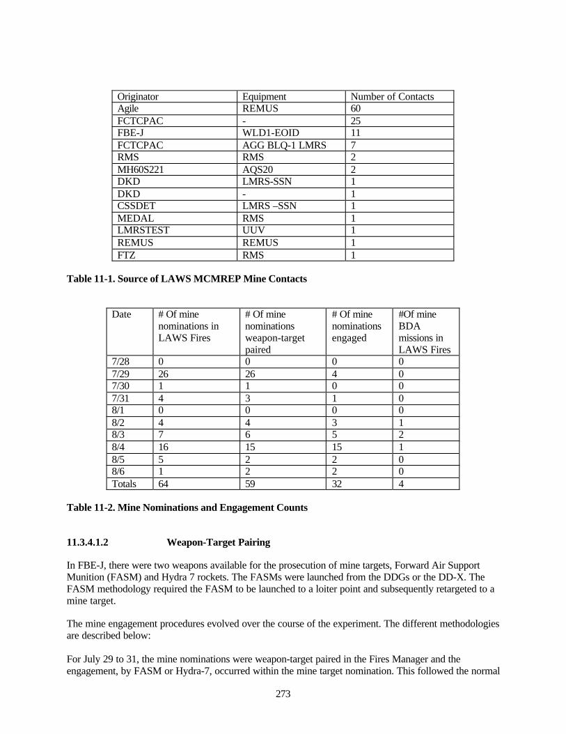
273
Originator Equipment Number of ContactsAgile REMUS 60FCTCPAC - 25FBE-J WLD1-EOID 11FCTCPAC AGG BLQ-1 LMRS 7RMS RMS 2MH60S221 AQS20 2DKD LMRS-SSN 1DKD - 1CSSDET LMRS –SSN 1MEDAL RMS 1LMRSTEST UUV 1REMUS REMUS 1FTZ RMS 1
Table 11-1. Source of LAWS MCMREP Mine Contacts
Date # Of minenominations inLAWS Fires
# Of minenominationsweapon-targetpaired
# Of minenominationsengaged
#Of mineBDAmissions inLAWS Fires
7/28 0 0 0 07/29 26 26 4 07/30 1 1 0 07/31 4 3 1 08/1 0 0 0 08/2 4 4 3 18/3 7 6 5 28/4 16 15 15 18/5 5 2 2 08/6 1 2 2 0Totals 64 59 32 4
Table 11-2. Mine Nominations and Engagement Counts
11.3.4.1.2 Weapon-Target Pairing
In FBE-J, there were two weapons available for the prosecution of mine targets, Forward Air SupportMunition (FASM) and Hydra 7 rockets. The FASMs were launched from the DDGs or the DD-X. TheFASM methodology required the FASM to be launched to a loiter point and subsequently retargeted to amine target.
The mine engagement procedures evolved over the course of the experiment. The different methodologiesare described below:
For July 29 to 31, the mine nominations were weapon-target paired in the Fires Manager and theengagement, by FASM or Hydra-7, occurred within the mine target nomination. This followed the normal
274
LAWS engagement procedures for weapon-target pairing and engagement. There were no Hydra 7engagements subsequent to July 30.
Starting on August 2, the mine targets were no longer engaged in the mine nomination. Instead, the HSVLAWS created a FASM mission entry in the Fires manager. After the FASM was launched to a loiterpoint, it was retargeted, by the MIWC, to one of the mine target nominations present in the Fires manager.In the LAWS Fires manager targeting page remarks and/or target description, the target number of themine to which the FASM was retargeted was specified.
Starting on August 4, all FASM missions inserted into the Fires manager were created by the HSV globalintelligence, surveillance, and reconnaissance capability (GISRC). With one exception, none of thesemissions specified to which mine target the FASM was retargeted.
Column 3 of Table 11-2 reports the number of mine targets that were weapon-target paired in the LAWSFires manager. The weapon-target pairing entries for July 31 and earlier refer to a weapon-target pairingreported in the mine nomination. From August 2 to August 4, an entry in the weapon-target pairingcolumn means that a FASM mission was linked, in the LAWS targeting page remarks and/or the targetdescription, to a specific mine nomination. From August 4 to August 6, the HSV GISRC FASM missionsdid not indicate the mine nomination to which they were paired. It is assumed they were paired to minetargets.
11.3.4.1.3 Target Engagement
Column 4 of Table 11-2 reports the number of mine targets that were engaged. Engaged is defined as agreen “fired” (FRD) block in the LAWS Fires manager. Prior to August 1 this refers to the status of theFRD block for the mine nomination, subsequent to that date is refers to the FRD block of the FASMmission. Of those 64 mine nominations pushed into the Fires manager, 32 were actually engaged. Almostall the unengaged mine targets were those pushed into the Fires manager on July 29.
11.3.4.1.4 Battle Damage Assessment
The last column of Table 2 lists the number of mine BDA missions that appears in the LAWS Firesmanager. There are only four, all loitering attack munition (LAM) missions launched from the SeaSLICE.
All BDA for mine targets was notional and generally BDA results were not reported in LAWS for theFASM missions or for the mine targets. There was an interval, covering part of 2 to 3 August, where fourFASM missions and seven mine targets exhibited green BDA blocks in LAWS. All reported the targetneutralized with an identical, unattributed message.
11.3.4.1.5 MCM Engagement Timelines
Almost all the mine target engagements occur subsequent to 1 August. Therefore, the reconstruction ofthe engagement timelines is limited to the period 2 through 6 August. There are two different types oftimelines; those associated with the mine nominations and those associated with the FASM missions.Table 11-3 presents the statistics for the timeline actions for each of these two types of timelines. All timeintervals are measured from the time the mission or nomination was received in LAWS. The values of themean values are determined primarily by values of extreme outliers. Therefore, the medians provide morerepresentative time values.
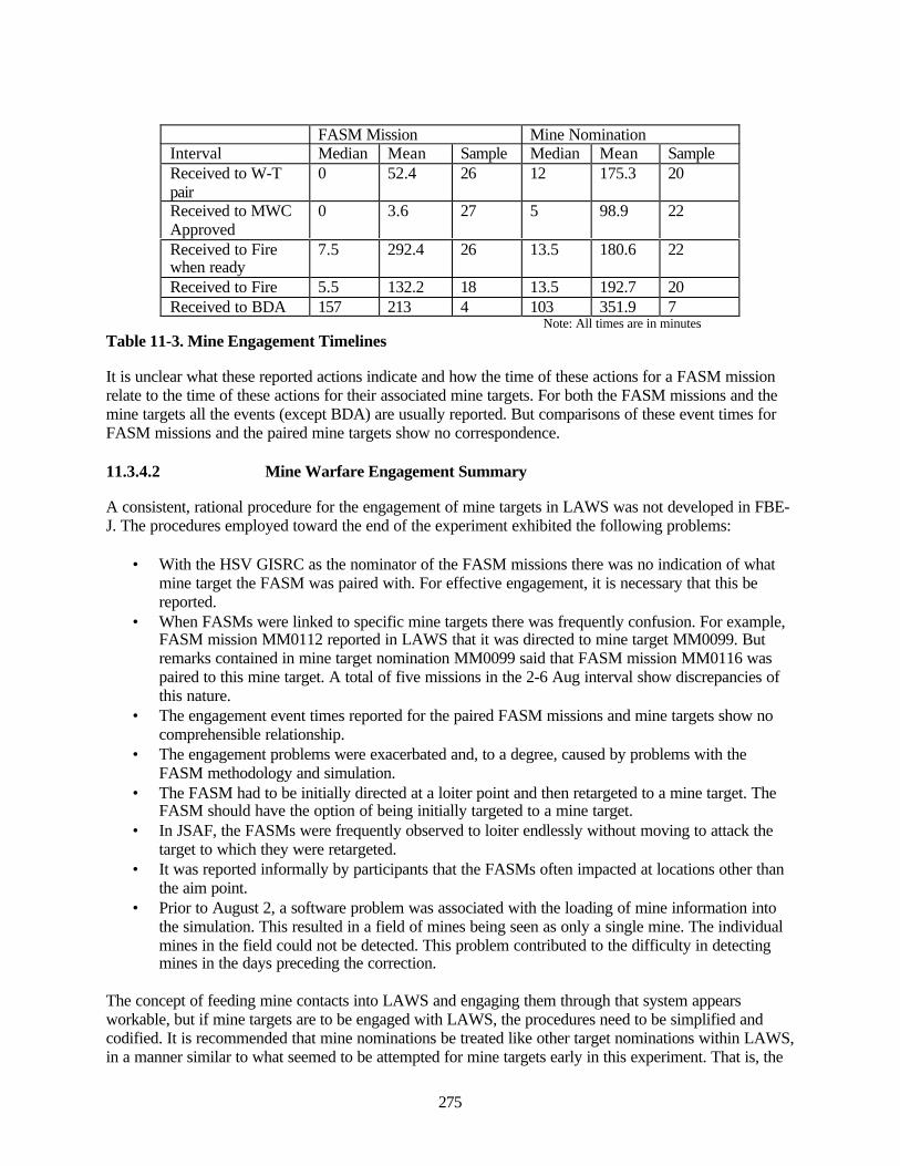
275
FASM Mission Mine NominationInterval Median Mean Sample Median Mean SampleReceived to W-Tpair
0 52.4 26 12 175.3 20
Received to MWCApproved
0 3.6 27 5 98.9 22
Received to Firewhen ready
7.5 292.4 26 13.5 180.6 22
Received to Fire 5.5 132.2 18 13.5 192.7 20Received to BDA 157 213 4 103 351.9 7
Note: All times are in minutesTable 11-3. Mine Engagement Timelines
It is unclear what these reported actions indicate and how the time of these actions for a FASM missionrelate to the time of these actions for their associated mine targets. For both the FASM missions and themine targets all the events (except BDA) are usually reported. But comparisons of these event times forFASM missions and the paired mine targets show no correspondence.
11.3.4.2 Mine Warfare Engagement Summary
A consistent, rational procedure for the engagement of mine targets in LAWS was not developed in FBE-J. The procedures employed toward the end of the experiment exhibited the following problems:
• With the HSV GISRC as the nominator of the FASM missions there was no indication of whatmine target the FASM was paired with. For effective engagement, it is necessary that this bereported.
• When FASMs were linked to specific mine targets there was frequently confusion. For example,FASM mission MM0112 reported in LAWS that it was directed to mine target MM0099. Butremarks contained in mine target nomination MM0099 said that FASM mission MM0116 waspaired to this mine target. A total of five missions in the 2-6 Aug interval show discrepancies ofthis nature.
• The engagement event times reported for the paired FASM missions and mine targets show nocomprehensible relationship.
• The engagement problems were exacerbated and, to a degree, caused by problems with theFASM methodology and simulation.
• The FASM had to be initially directed at a loiter point and then retargeted to a mine target. TheFASM should have the option of being initially targeted to a mine target.
• In JSAF, the FASMs were frequently observed to loiter endlessly without moving to attack thetarget to which they were retargeted.
• It was reported informally by participants that the FASMs often impacted at locations other thanthe aim point.
• Prior to August 2, a software problem was associated with the loading of mine information intothe simulation. This resulted in a field of mines being seen as only a single mine. The individualmines in the field could not be detected. This problem contributed to the difficulty in detectingmines in the days preceding the correction.
The concept of feeding mine contacts into LAWS and engaging them through that system appearsworkable, but if mine targets are to be engaged with LAWS, the procedures need to be simplified andcodified. It is recommended that mine nominations be treated like other target nominations within LAWS,in a manner similar to what seemed to be attempted for mine targets early in this experiment. That is, the
276
mine nomination is weapon target paired and the engagement is conducted within the mine nominationentry in the LAWS Fires manager. This procedure should avoid the confusion and complexity introducedby having separate entries for the target and the weapon that is to engage it.
11.3.5 Common Undersea Picture (CUP)
The data generated by the MIW sensors and provided to the MIWC must be made available to the largercommon operational picture (COP), and to that activity specifically below the surface, the commonundersea picture (CUP). Proper COP/CUP management is necessary in order to facilitate distributed,collaborative planning and to enhance shared situational awareness (SA).
In FBE-J, parts of the undersea picture were resident in several different systems, but because the systemswere not integrated, the picture was neither complete nor coherent. The commonality was that many, butnot all, of the participants had many of the systems available. Due to the length of RAV missions, thelocations of mine contacts were entered in non-real time into GCCS-M. Status on some contacts wasentered in LAWS. Operational level chat between the SCC and JFMCC was conducted using IWS chatrooms. Much of the management detail was maintained on paper plots. The MIW environment, searchplanning, and search plan status were modeled and maintained in a variety of computer tools. Some chatwas conducted on IWS, but it was not a comprehensive discussion link. The MIW undersea picture wasbest represented by the data on MEDAL, which was available on Joint Venture, Sea SLICE, FCTCPAC,VSSGN, and FITZGERALD. Bathymetry and other environmental data were provided by the BPAUV,REMUS, and OWL III, RAV systems and were transferred successfully to the CUP, although the datawere frequently time-late.
Although there were no inherent organizational impediments to doing it, MIWC and ASWC were not ableto collaborate effectively on the CUP because the MEDAL in the SCC Cell was on a separate LAN fromthe MIWC MEDAL. This deficiency was not discovered 01Aug02.154
A concern was the lack of a clear picture provided by chat rooms. While substantial data are availablefrom multiple sources, there was no clear sense of the overall picture of what was going on with mines.The SCC Watch Officer needs a clear battlespace picture available to him at his console 155. He should nothave to query several other operators to help provide situational awareness with this technology. While itis good to have multiple avenues of communication (CISCO IP phone, Chat room, WeCAN, LAWS)available to SCC, in the current state it is confusing to C2 functions.156 Primary and secondary lines ofcommunication for battlespace awareness need to be delineated.
The SCC large display, a DBC system did not match the MIWC large display. For example, the Q-routeswere displayed on the MIWC but not on the SCC large display. Knowing that mines are in an area is vitalto the plans and operations of JFMCC and other PWCs. 157
11.3.6 Operation of Remote Autonomous Sensors
A variety of experimental autonomous sensors were available to the MIWC and in general, were usedwith effectiveness, particularly in view of the covertness of some of the missions. The experimental set ofautonomous sensors significantly increased, qualitatively, the overall ability of the MIWC. The HSVswere able to support effectively the use of embarked sensors with various issues of launch, recovery, andworking conditions as discussed in chapter 7 and section 11.3.2, above. The specific achievement of theRAVs included:
154 FBEJ JFMCC Midway Assessment155 SCC Observation Notes 27 Jul 02156 SCC Observation Notes 26 Jul 02157 SCC-TSC X-CUP Observer Post-ex ASW Questionnaire
277
• BPAUV conducted exploratory operations detecting mine-like objects (MLOs) and insertingcontact reference numbers (CRNs) and environmental data into MEDAL. BPAUV alsodemonstrated the capability to successfully accomplish an extended duration (17hrs) mission andrapid turn around (less than thirty minutes).
• REMUS conducted multi-vehicle operations that demonstrated the ability to search and detectMLOs, process contact data, and send prioritized contact data to the HSV over an acousticmodem and radio frequency (RF) link. The second vehicle demonstrated the capability to receivea tasking from the HSV over an acoustic modem and RF link, reacquire the assigned target, andidentify it using a DIDSON HF imaging sonar. REMUS also demonstrated the capability toconduct an OTH mission using an onboard global positioning system (GPS).
• OWL III displayed the ability to conduct several missions simultaneously, and the transmission oflive video, including an infrared (IR)) feed and the transmission of real time sonar data to theMIWC from an autonomous USV.
• VSSGN LMRS was used to provide initial planning of the battlespace (IPB) at the start of theexperiment for Q-route clearance and potential assault sites for JFMCC/JFLCC commanders.Additionally, as the scenario progressed and a requirement for covertness continued, LMRS wasused in a more tactical manner to provide the MIWC with a better MIW picture. However, thelong duration of LMRS missions with the necessary post mission analysis (PMA) meant that theMIWC had to wait as long as two days before receiving the initial results of the mission. 158 Afterthe initial sortie, PMAs were sent out every 6 to 8 hours.
• In response to a request by the MIWC, the VSSGN was able to re-plan the LMRS in simulationduring a sortie via an RF window of opportunity to support a higher priority OPAREA.
• Synthetic Aperture Sonar (SAS) target images were transmitted to the MIWC. In some veryunique cases (non-cylindrical shapes), the MIWC was able to make mine identification calls onthose target images.
The inordinate delays at times in the ability to use RAV data had an adverse impact on decision-making.The delay in integration of RAV data into the CUP and the wide distribution of the CUP, led toinefficiencies and impacts throughout the MIW and JFMCC processes. These included the planning ofreconnaissance and MCM missions and the planning the missions of other PWCs. More contemporaneousreceipt of data from RAVs would pay dividends across the spectrum of operational planning anddecision-making in addition to reducing risks.
The use and demonstration of the experimental autonomous sensor systems (BPAUV, REMUS, CETUS,RMS, LMRS) and helicopters constituted the majority of the MIW operations during the experiment. TheMIWC had over 100 sensors and platforms at his disposal, not including airborne ISR assets.Management of these assets represents one of the greater MIW issues surfaced during the experiment.The ability to plan, task and maintain SA for such a large number of assets with minimal staff was achallenging task for the MIWC, and some shortfalls were observed in the ability of the MIWC MEDALoperator to plan multiple missions for a variety of assets.159 This has implications if and when high-pressure operations are undertaken where multiple missions would be the norm.
Theater waterspace management (WSM) and the prevention of mutual interference for the SSGN, SSNsand UUVs did not seem to be addressed thoroughly and could be problematic if multiple submarines andmultiple UUVs are operating in theater. The planned approach was that LMRS would exist in theVSSGN's waterspace, but for most of its operational time, LMRS operated in waterspace other thanVSSGN waterspace. Having the same approved waterspace for both submarines and offboard UUVscould put a considerable burden on a submarine's crew. 158 COMNAVWARDEVCOM FBE-J MIW Quicklook Report159 Ibid
278
Despite the fact that the MIWC had over 100 sensors and platforms at his disposal, not including airborneISR assets, nearly half the MIW participants and watchstanders under-estimated the assets available to theMIWC by over two thirds. Similar estimates of tasking of those assets ranged from less than 25% on atypical day to over 75%. Most felt that the number of assets was manageable, however. Automated toolsto transition data between C2 and MIW systems was believed to be key to improving the efficiency andeffectiveness of management of the assets.
The size of an RAV is far smaller than that of a crewed asset, so the MIWC had far more assets availableto apply toward accomplishing his mission, and was required to do so in less than the traditional time.This situation highlights the complications of requiring effective management in launching, tasking,tracking, recovering, and maintaining all those assets. Thus in some ways future MIW operations may belikened to today’s flight operations, and MIW may potentially be able to adapt similar asset and sensormanagement practices.
All autonomous systems performed their planned missions, although engine failures suffered by OWL IIIadversely impacted its operational availability. All RAVs experienced problems when they encounteredkelp beds, which ultimately proved to be inoperable areas. Sensor information data along with real timevideo (OWL) and side scan (REMUS), were passed to the C4I suite. After post mission analysis (PMA),contacts were passed to MEDAL for prosecution.
11.4 MIW Key Observations Summary
The key observations made concerning mine warfare include the following:
• The concept of feeding mine contacts into LAWS and engaging them through that system appearsworkable. Procedures need to be simplified and codified. Mine nominations should be treated likeother target nominations within LAWS, i.e., mine nomination weapon-target paired and theengagement conducted within the mine nomination entry in the LAWS Fires manager. Theengagement problems were exacerbated and, to a degree caused, by problems with the FASMmethodology and simulation. Thus, definitive results on this application are not yet available.This will require that a methodology be developed that handles mines the same as other targetswithin LAWS and that the concept tested with a combination of live mines and other targets.
• The HSV appears to be an excellent platform for supporting the MIWC and MCM. Advantagesinclude:
o High speed to area of operations and while conducting various MIW missionso Shallow draft will allow operations in relatively shallow watero Large cargo volume can provide ample workspace and support areas for supporting
future RAVs and their operational mission and maintenance crews.Disadvantages and risks include:
o Potential vulnerability of the HSV to hostile fire due to its aluminum composition andsmall crew
o Loss of one HSV with large number of RAVs (est. 25 to 30) could risk the entire MIWmission success and/or timeline if additional resources are not readily available
o Under the concept of rapid reconfiguration for HSVs, MIW may be competing with othermissions for the use of the HSV.
Studies will need to be undertaken to mature the CONOPS for HSV support of MIW, includingo Determination of the appropriate number and overall distribution of MIW assets on HSVso Assess the requirement for redundant back-up operational databases and MIWC SA in
case of loss
279
o Assess the likelihood that competition for HSV resources will impact on MIW missionsuccess.
• JFMCC management of MIW is a challenge that presently strains players on all sides. There areseveral reasons for this:
o MIW missions are longer than typical JFMCC missions and may not be suitably managedwithin the overall JFMCC process at present. This is a resource allocation issue, as theJFMCC staff may reallocate HSVs and other resources after the expiration of the 24-hourMTO/ATO, but MIW missions initiated during the valid period may still be on-going,due to the length of some MIW missions.
o The ATO tasking vehicles are not optimal for MIW missionso Direct tasking of platforms in MIW is preferable to the indirect tasking associated with
MSRso Present reduction of data and the development of tasking is unnecessarily manpower
intensive.Additional analyses should be able to
o Develop a more workable interaction dynamic between JFMCC and MIWo Evaluate the impact of lengthy MIW missions on shared resourceso Evaluate the potential for manpower reductions achievable with automation of data
reduction and tasking in MIW.
• Remote Autonomous Vehicles (RAVs) offer tremendous potential for rapid, effective, and covertMIW operations to ensure assured access to hostile territory. Future HSVs could host 25 to 30 ofthese RAVs per HSV. The management of a multiplicity of these systems, possibly amongseveral HSVs will be far more complex than anything experienced to date in MIW ordemonstrated in FBE-J. There was no stressing of the RAV systems in FBE-J, so no assessmentcan be made of problems or issues that will arise when one HSV attempts to manage, control, andexploit a number of these systems.
Potential issues include:o Data should be retrievable in or near real-time so as not to delay follow-on planning
actionso More complicated management and control can be expectedo The present inability to operate in kelp requires additional engineering to RAVs to reduce
potential risks and mission impairmento Launching and retrieval of RAVs should be accomplished at reasonably high speeds.
For optimal application, however the following assessments, at a minimum would be needed:o Assess methods to optimize the receipt and management of datao Develop reliable ways to control and minimize potential interference of multiple systems
operating concurrentlyo Re-engineer systems to reduce or eliminate their present vulnerability to kelpo Investigate alternative approaches to launching and retrieving RAVs at high speed.

280
This page intentionally left blank.
281
12.0 Anti-Submarine Warfare (ASW) Initiative Key Observations
12.1 Experiment Objectives
Because the naval contribution to Rapid Decisive Operations requires Assured Access, ASW forces wererequired to establish zones of operations free of enemy submarines. To do this effectively, the forces wereforced to employ Network-centric ASW Operations. This is the concept of multi-level commands andmulti-disciplinary forces, well connected by common communications, doctrine, planning tools, andcommander's guidance. In order to improve detection, classification, localization, and neutralization ofenemy submarines, commands had to possess the ability to:
• Share information quickly and accurately.• Correlate their situational awareness in conjunction with the larger operational and tactical
pictures.• Conduct distributed, collaborative planning and self-synchronize their actions with other joint or
coalition ASW forces.
There were five ASW sub-initiatives in FBE Juliet:
• Submarine Locating Devices.• Remote Autonomous Sensors.• Experimental Common Undersea Picture.• Theater ASWC.• Using the Experimental Naval Fires Network for ASW Targets.
12.2 Analytic Questions
Overarching Question
• How can Network-centric ASW Operations improve detection, classification, localization, andneutralization of enemy submarines to assure maritime access?
12.3 ASW Sub-Initiatives
12.3.1 Submarine Locating Devices
This ASW sub-initiative investigated the spectrum of activities associated with using Submarine LocatingDevices (SLDs). Many of the results are classified and not comprehensively discussed in this report,however the basic issues are were as follows:
• Investigate decision process for employment of SLDs.• Investigate C2 for installation of SLDs.• Explore current and future capabilities of SLDs.• Investigate ROE implications for installation of SLDs.• Investigate use of SLD data for decision-making.• Investigate use of SLD data for its impact on times to localize and engage submarines.
12.3.2 Use of Remote Autonomous Sensors (Distributed Mobile Sensor Field)
This ASW sub-initiative investigated the ability of remote, autonomous systems to independently identifysubmarine contacts and report them in real time or near real time. This could provide the commander the
282
ability to cover large areas without the expenditure of manned assets, to avoid threat contacts if necessary,and to be able to attack threat submarines efficiently with the use of air assets.
12.3.3 Common Undersea Picture
This ASW sub-initiative was intended to provide the basic tools for Network-centric ASW. It had threemajor functions that provided the backbone for this operational concept, force collaborative planning,shared situational awareness, and common dynamic tactical decision aids. The basic questions addressedwere as follows:
• Investigate the use of X-CUP tools for situational awareness.• Define the requirements for C2/COMM architecture and bandwidth to enable X-CUP.• Determine which ASW nodes are required to be included in the X-CUP.
12.3.4 Theater ASWC
• Define the requirements for Theater Level ASW Command and Control.• Determine the requirements for reach-back from local forces to TASWC.• Determine the manning requirements to support expanding the role of TASWC.• Investigate the ability of the TASWC to optimize the use of theater-wide ASW assets using X-
CUP tools designed for the tactical level.• Evaluate the doctrinal implications of relationships between the TASWC and the SCC and
JFMCC.
12.3.5 USW Targets in NFN (X)
This ASW sub-initiative was designed to determine if incorporating ASW targets into the experimentalNavy Fires Network in conjunction with LAWS could improve the ability to successfully attack them asTime Critical Targets. Associated issues are as follows:
• Determine the technical requirements to construct a USW Time Critical Strike architecture.• Investigate the operational issues of USW target integration into NFN (X) and engagement of
USW targets as Time Critical Targets.• Investigate the times to process USW TCTs in NFN (X).
12.3.6 System Architecture
Figure 12-1 shows the ASW chain of command for the experiment. The arrow from the TASWC to theSea Combat Commander (SCC) reflects the role of the TASWC, shore-based in Hawaii, providingsupport to the local SCC. This sub-initiative had originally been conceived to include a much greatercommand role by the TASWC, but was revised due to constraints on experimental participants because ofreal-world tasking.
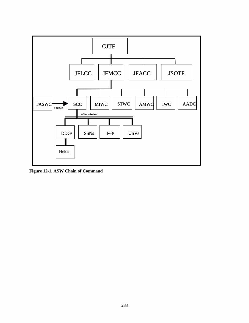
283
Figure 12-1. ASW Chain of Command
Helos
CJTF
JFLCC JFMCC JFACC JSOTF
MIWCSCCTASWC STWC AMWC IWC AADCsupport
SSNsDDGs P-3s USVs
ASW mission
CJTF
JFLCC JFMCC JFACC JSOTF
MIWCSCCTASWC STWC AMWC IWC AADCsupport
SSNsDDGs P-3s USVs
ASW mission
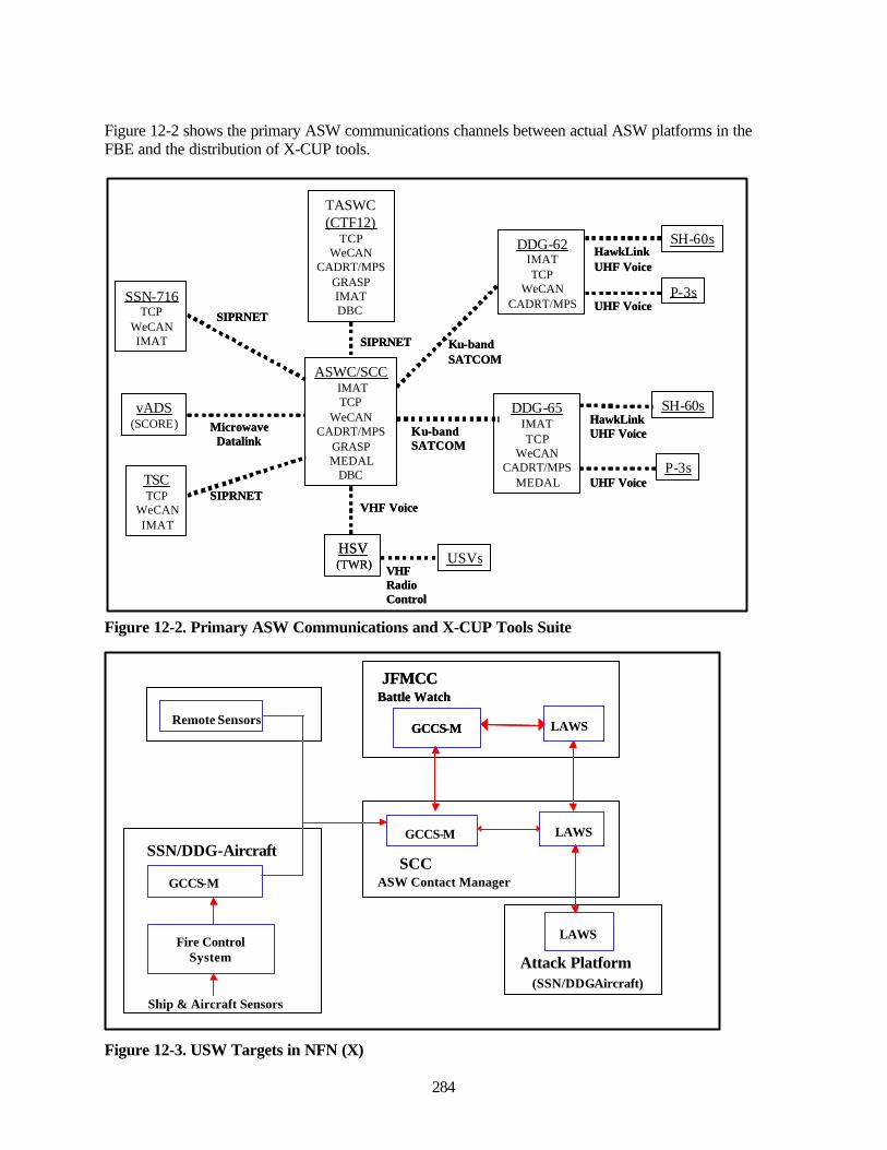
284
Figure 12-2 shows the primary ASW communications channels between actual ASW platforms in theFBE and the distribution of X-CUP tools.
Figure 12-2. Primary ASW Communications and X-CUP Tools Suite
Figure 12-3. USW Targets in NFN (X)
SSN-716TCP
WeCANIMAT
TASWC(CTF12)
TCPWeCAN
CADRT/MPSGRASPIMATDBC
TSCTCP
WeCANIMAT
DDG-62IMATTCP
WeCANCADRT/MPS
HSV(TWR)
DDG-65IMATTCP
WeCANCADRT/MPS
MEDAL
vADS(SCORE)
SIPRNET
SIPRNET
Ku-bandSATCOM
VHF Voice
SIPRNET
MicrowaveDatalink
VHFRadioControl
USVs
Ku-bandSATCOM
ASWC/SCCIMATTCP
WeCANCADRT/MPS
GRASPMEDAL
DBC
SH-60sHawkLinkUHF Voice
SH-60sHawkLinkUHF Voice
P-3sUHF Voice
P-3sUHF Voice
Remote Sensors
GCCS-M LAWS
GCCS-M
Fire ControlSystem
SSN/DDG-AircraftSCC
ASW Contact Manager
LAWS
Attack Platform
Ship & Aircraft Sensors
(SSN/DDG-Aircraft)
GCCS-M LAWS
Battle WatchJFMCC
Remote Sensors
GCCS-M LAWS
GCCS-M
Fire ControlSystem
SSN/DDG-AircraftSCC
ASW Contact Manager
LAWS
Attack Platform
Ship & Aircraft Sensors
(SSN/DDG-Aircraft)
GCCS-M LAWS
Battle WatchJFMCC

285
Figure 12-3 shows the architecture for Undersea Warfare targets in the Naval Fires Network(Experimental) from sensor to shooter.
12.3.7 Submarine Locating Devices
This ASW sub-initiative investigated the operational concept of installing submarine locating devices.This included issues of when, where, and how to achieve covert installation, and what type of capabilitiesthe locating devices should have. The problem of permissive ROE was also considered. As directed bythe operational commander, locating devices were covertly placed and their signals were utilized in theASW.
12.3.8 The Decision Process for Employment
The decision process for employment of submarine locating devices took place outside the FBE. TheCONOPS for SLDs contained in the FBE-J Experimentation Plan pertains. No further observations weremade during the FBE execution. Experience in the FBE prompted the suggestions from the SCC that theASW Commander should be involved in decisions concerning the installation and monitoring of SLDs.160
The use of SLDs should be part of the operational/theater level plan and integrated at the CJTF/CINClevel. 161
12.3.9 Operational Value of Employment / Command and Control
Command and control for the installation of Submarine Locating Devices is a classified activity outsidethe scope of this report.
12.4 Current and Future Capabilities of SLDs
One particular technology for submarine locating devices was demonstrated in three live events in FBE-J,and simulated for other events. Both live and simulated SLD events were based on a technology thatgenerated submarine locating signals at predetermined time intervals.
Two of the three live events functioned as designed and generated accurate and timely position reports(for example, one report took 2 minutes and 10 seconds from transmission until receipt by the SCC, witha measured accuracy of 267 yards between the instrumented SCORE range position and the SLD reportedposition162). One of the three live events had a technical failure.
Experience in the FBE prompted the following suggestions from FBE participants and observers:
• It would be very useful to be able to command prompt SLD reports rather than only have reportsat predetermined intervals.
• In some circumstances, the ASW Commander may prefer to have SLDs report less frequently toconserve a limited number of devices.
• In other circumstances, the ASW Commander may prefer to have SLDs report at greaterfrequency in order to have less time-late for a subsequent prosecution, or timely information thata particular area is free of enemy submarines (e.g., the Deputy SCC suggested that data should betwo hours old or less for pre-hostility transit of a maritime chokepoint; if no transit is in progress,then longer gaps between SLD reports can be adequate).
160 SCC Plans Post-ex ASW Questionnaire161 ASW Lead Final Report162 SCC Observation Notes 1 Aug 02

286
12.4.1 ROE Implications for Installation of SLDs
The issues surrounding rules of engagement as they pertain to SLD installation were addressed outsidethe FBE execution. During the pre-FBE Spiral 3 in June, the JFCOM JAG briefed that pre-hostility cross-border operations would require Presidential approval. Permission was assumed to have been obtained.When the FBE commenced on 24 July, it was reported that SLDs had been installed163. No furtherobservations were made during the FBE execution.
12.4.2 Use of SLD Data
SLD reports of enemy submarine positions during the FBE were highly regarded as valuable sources ofinformation on enemy submarine activity. When received, position reports were entered manually inelectronic logs, in various chat rooms, and in GCCS-M.164
Somewhat surprisingly however, but for various reasons that are explainable under the specificcircumstance in the FBE, most SLD reports did not result in command actions, other than recording thepositions reported (i.e., no ASW forces assigned to prosecute SLD reported positions, no modifications topreviously assigned ASW search missions, etc.). Although this was generally the case, it is likely exerciseartificiality and not a predictor of what might occur in the real world. Two general situations existed thataffected the use of SLD data, pre-hostilities and hostilities.
Pre-hostilities
During the pre-hostilities phase of the FBE, the SCC staff did consider alternative actions that might betaken based on received SLD reports, but decided not to take any action. They considered periodic reportsfrom the SLD as sufficient information on those enemy submarine locations, and chose to assign theirBlue ASW assets to search for unlocated or unreported enemy submarines.165
The experience in the FBE also prompted the following thoughts about possible use of SLDs in pre-hostilities:166
• If a Blue force asset is assigned to respond to every SLD signal, there is a concern that this maycompromise the intelligence.
• Over time, it may be possible to use SLD reports in conjunction with other ASW contactinformation to give a better situational awareness picture. For example, is the enemy submarinedriving a particular box, or patrol route?
During Hostilities
There were two basic SLD situations during the FBE, simulation SLD reports from simulationsubmarines and SLD reports of actual submarines during live ASW events. After hostilities commenced,the simulation killed the simulation enemy submarines that had simulation SLDs without interaction withthe actual experiment participants. This was an exercise artificiality that was somewhat obscured by allthe other simulation engagements that were occurring in the opening of hostilities. Accordingly, therewere no actions to be ordered by the SCC in these cases.
163 JFCOM In-brief 24 Jul 02164 SCC post-ex ASW Questionnaires, and observations and discussions with SCC staff throughout FBE-J execution165 SCC Observation Notes 25 Jul 02166 SCC Observation Notes 28 Jul 02

287
For live events, ASW forces were already assigned and appropriately committed at the time of each SLDreport. Accordingly, orders from the SCC to significantly redirect effort generally were not required.
In one instance, a surface unit was conducting an area search plan within the designated live play area.When the SLD report was received, considering the time and distance between the surface unit and thereported submarine position, it was determined that the original search plan already covered theuncertainty area surrounding the SLD datum. Therefore, no change was made to the search plan inprogress.167
In another instance, an SLD report did prompt the SCC to pass the position information to the surface unitthat was already assigned to the area for prosecution. This particular report resulted in both the SCCwatch and the surface unit to enter datum information into GCCS-M resulting in dual tracks. Thisexperience prompted the observation that specific procedures need to be developed for SLD reportingresponsibilities and methods.168
During one live ASW event with an actual prototype SLD, an SLD report arrived while the assignedsurface unit was prosecuting an actual sonar contact at a position different from the SLD reportedposition. This prompted the surface unit to reclassify their sonar contact as non-sub and pursue the realsubmarine. It was noted that although this was coincidental in this case, it was an actual result and thatsort of response could happen in a real world event.169
Experience in the FBE prompted the following additional idea from FBE participants to suggest that a P-3C is the preferred asset to have in the air on-station in anticipation of SLD release due to its long rangeand long on-station capability. It is not advisable to have a helo launched in anticipation of SLD reportsdue to the short on-station time of a helo. 170
12.5 Use of Remote Autonomous Sensors (Distributed Mobile Sensor Field)
The ADS distributed sensor field, simulated by actual use of the southern California instrumentedundersea acoustic range (SCORE Range) did provide contact reports on live submarines on the range. Theexperimental unmanned surface vessels (USVs) did not provide reports due to technical problems.
Although the technologies considered in the FBE could potentially evolve into autonomous capabilities inthe future, autonomy was not actually explored in the FBE.
12.5.1 Decision Process for Employment of Remote Autonomous Sensors in Theater
The decision process for employment of remote autonomous sensors in theater took place outside of theFBE. The CONOPS for Remote Autonomous Sensors contained in the FBE-J Experimentation Planpertains. No further observations were made during the FBE execution.
Experience in the FBE prompted the SCC staff to suggest that procedures should exist for the ASWCommander to request ADS field deployment via the JFMCC.171 Procedures and doctrine must have dueregard to lead-time requirements.
167 SCC Observation Notes 28 Jul 02168 SCC Observation Notes 30 Jul 02169 ASW Lead Daily Report 1 Aug 02170 SCC Observation Notes 28 Jul 02171 SCC Ops Post-ex ASW Questionnaire
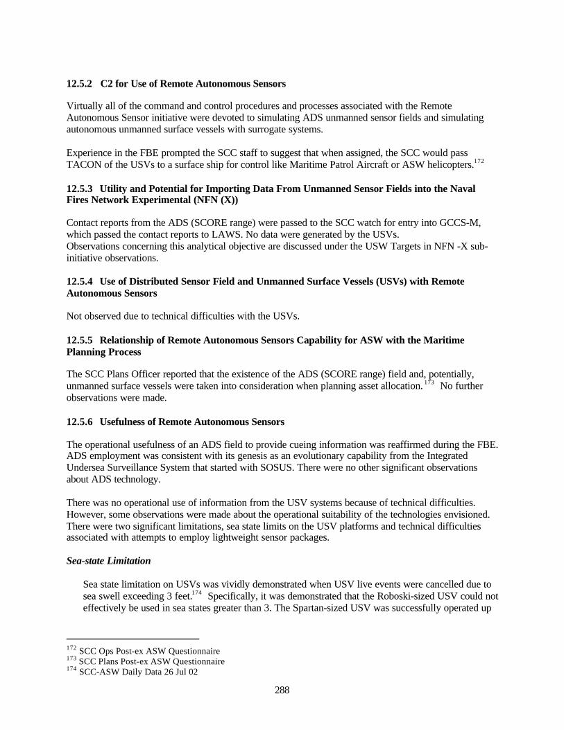
288
12.5.2 C2 for Use of Remote Autonomous Sensors
Virtually all of the command and control procedures and processes associated with the RemoteAutonomous Sensor initiative were devoted to simulating ADS unmanned sensor fields and simulatingautonomous unmanned surface vessels with surrogate systems.
Experience in the FBE prompted the SCC staff to suggest that when assigned, the SCC would passTACON of the USVs to a surface ship for control like Maritime Patrol Aircraft or ASW helicopters.172
12.5.3 Utility and Potential for Importing Data From Unmanned Sensor Fields into the NavalFires Network Experimental (NFN (X))
Contact reports from the ADS (SCORE range) were passed to the SCC watch for entry into GCCS-M,which passed the contact reports to LAWS. No data were generated by the USVs.Observations concerning this analytical objective are discussed under the USW Targets in NFN -X sub-initiative observations.
12.5.4 Use of Distributed Sensor Field and Unmanned Surface Vessels (USVs) with RemoteAutonomous Sensors
Not observed due to technical difficulties with the USVs.
12.5.5 Relationship of Remote Autonomous Sensors Capability for ASW with the MaritimePlanning Process
The SCC Plans Officer reported that the existence of the ADS (SCORE range) field and, potentially,unmanned surface vessels were taken into consideration when planning asset allocation. 173 No furtherobservations were made.
12.5.6 Usefulness of Remote Autonomous Sensors
The operational usefulness of an ADS field to provide cueing information was reaffirmed during the FBE.ADS employment was consistent with its genesis as an evolutionary capability from the IntegratedUndersea Surveillance System that started with SOSUS. There were no other significant observationsabout ADS technology.
There was no operational use of information from the USV systems because of technical difficulties.However, some observations were made about the operational suitability of the technologies envisioned.There were two significant limitations, sea state limits on the USV platforms and technical difficultiesassociated with attempts to employ lightweight sensor packages.
Sea-state Limitation
Sea state limitation on USVs was vividly demonstrated when USV live events were cancelled due tosea swell exceeding 3 feet.174 Specifically, it was demonstrated that the Roboski-sized USV could noteffectively be used in sea states greater than 3. The Spartan-sized USV was successfully operated up
172 SCC Ops Post-ex ASW Questionnaire173 SCC Plans Post-ex ASW Questionnaire174 SCC-ASW Daily Data 26 Jul 02
289
to sea state 4.175 The METOC observer in the SCC module commented that USVs must be capable ofoperations in sea states higher than sea state three. 176.
Backup events using ASW aircraft were conducted. If USVs were needed because of surface-to-airmissile threat to aircraft, however, the mission could not have been conducted.
Lightweight Sensor Package Limitations
The FBE also highlighted technical difficulties relating to the modification of the DICASS buoysensor packages onto the USVs. USV DICASS sensors were either inoperative or could not replicatethe acoustic performance of an unmodified DICASS buoy. These comparisons were made on a dailybasis with aircraft-dropped sonobuoys. The difficulties encountered related to the engineering of theDICASS transducer, with its power source located aboard the USV. While an unmodified DICASStransducer is a one-piece assembly with a lithium battery in close proximity to the transducer, theUSV power source involved a 200 foot or 400 foot cable between the battery and transducer. As such,inadequate power and acoustic output resulted due to impedance issues. Thus, should the DICASSpackage be used in future FBEs, a re-engineering of the power source to transducer assembly will berequired, and this modification tested against the performance of an unmodified DICASS buoy. 177
The transducers also experienced damage during transit and towing. Several transducers experienceddamage due to high tow speeds, up to 30 knots, which they were not designed to withstand. Withexisting lightweight sensor technology, USV transit and towing speeds must be lowered to limitDICASS transducer damage.178 Operationally however, high-speed capability is needed for themissions envisioned for USVs. The possibility exists that an alternate sensor package needs to beconsidered.
During the experiment it was necessary to physically modify the cable lengths for the USV sensorsbecause of acoustic propagation conditions. There is clearly a need for selective transducer depth forUSV sensors.
Experience in the FBE prompted the following observations from FBE participants and observersconcerning operational value of USVs:
• The unmanned surface vessel (USV), remote autonomous sensor concept has merit to work inareas where air ASW assets cannot fly due to the anti-air threat level encountered and wherewater may be too shallow for deep water combatants to effectively maneuver.179
• This concept also has the significant advantage of keeping manned units out of range of threatASW contacts. 180
• Innovative connectivity via UAVs, lighter-than-air vehicles, satellites, etc. should beconsidered.181
• USV CONOPS should be developed for wide area ASW search. 182
175 ASW Technical Lead lessons learned176 SCC Observation Notes 26 Jul 02177 NWDC USV Project Lead Trip Report178 NWDC USV Project Lead Trip Report179 SCC Ops Post-ex ASW Questionnaire180 ASW Lead Final Report181 ASW Lead Final Report182 ASW Lead Final Report
290
12.6 Experimental Common Undersea Picture (X-CUP)
The use of a robust set of collaborative ASW tools and common tactical decision aids facilitateddistributed, collaborative planning and enhanced shared situational awareness. 183
In the FBE, parts of the undersea picture resided in several different systems that were not integrated. Thecommonality was that many, but not all, of the participants had many of the systems available. Thelocations of enemy submarine contacts were entered non-real time into GCCS-M. Status on some contactswas entered in LAWS. A running tactical level chat on ASW contacts with some ASW platforms wasconducted with WeCAN. Operational level chat between SCC and JFMCC was conducted using InfoWorkspace chat rooms. Waterspace management for friendly submarine safety was maintained on paperplots. ASW environment, search planning, and search plan status were modeled and maintained in avariety of computer tools comprising the X-CUP tools suite.
The Experimental Common Undersea Picture initiative focused on the X-CUP tool suite as described inthe FBE-J ASW Experimentation Plan.
12.6.1 Use of X-CUP Tools for Situational Awareness
Full use of current technology and interpretation of data requires significant training and experience withASW tools. 184
Chat functions at several levels can improve data and information flow, but chat discipline is necessary toavoid misinformation flow. 185
Inclusion of attack C2 functionalities (similar to some contained in LAWS) would be a valuable additionto ASW CUP tool set. 186
The X-CUP planning tools were used extensively. The Sonar Performance Prediction (SPP) tools gavesome awareness of the environment. The AMAT search coverage diagrams conveyed how effective thecoverage could be and the Cumulative Detection Probability (CDP) curves gave the planners the ability toperform asset allocation and time trade-offs. SCC feedback from the SCC, Deputy Ops Officer, andothers indicated that AMAT was used to produce search plans. Specifically, AMAT was used todetermine the placement of assets, the number of assets required and the duration of the search. Theplanners indicated that the information was very important to the planning process and to the actualoperations (to a lesser extent). The information provided was complete, useful and used frequently. TheDeputy Ops Officer stated that “(AMAT) is an outstanding system with incredible potential. It needs to beinstalled on ships and SCC modules and personnel trained to use it. (The) whole ship needs to know theimportance of running the search plan.” They reported a high degree of confidence in the AMATinformation. 187
One point of concern was expressed at the length of time it took the computer to generate a search plan.Search plans developed in the Mission Planner were reported to take 20 minutes to 2 hours of computercalculation time to be developed.188
183 FBE-J Quicklook COMNAVWARDEVCOM NEWPORT RI 271709Z AUG 02184 ASW Lead Final Report185 ASW Lead Final Report186 ASW Lead Final Report187 SCC-TSC X-CUP Observer Post-ex ASW Questionnaire188 SCC Observation Notes

291
At the operational level the X-CUP tools were of limited use because of the artificial tactical picture set-up of the exercise. The exercise forced a non-integrated GCCS-M picture and Web-Centric ASWNetwork (WeCAN) to be used rather than an integrated Link 11/16 based picture. As a result the toolsdesigned for real-time situational awareness really had nothing to work on. For this reason, in only onecase was a tactical situation effectively displayed on the AMAT suite. That occurred as the AMATmetrics were used to provide participating unit location that allowed the SCC to monitor the unit attemptto maintain an effective standoff distance. It was noted, however, that the unit was using the “default”values. Had this been a real situation the SCC could have warned that the torpedo danger area being usedwas over 5,000 yards smaller than doctrine for the particular threat. 189
The GCCS-M track feed was the least useful capability in AMAT, in view of the FBE-J architecture. Thisdata could not be effectively transferred between units and obfuscated rather than clarified the situation.This is mostly an exercise in artificiality. Lack of a track manager hindered SCC operations.190
AMAT planning tools need to be more flexible. Currently a plan is linked to a specific unit. Given thatships can be re-assigned, this linkage is too strong. For example, a plan called for one active and onepassive DDG. This actually required the operators to have two plans, alternating the active and passiveship by name.191
Another concern was the lack of a clear picture provided by chat rooms. While great amounts of datawere available from multiple sources, there was no clear sense of the overall picture of what was going onwith enemy submarines. The SCC Watch Officer needs a clear battlespace picture available to him at hisconsole 192. He should not have to query several other operators to help provide situational awareness withthis technology. While it is good to have multiple avenues of communication (CISCO IP phone, Chatroom, WeCAN, LAWS) available to SCC, in the current state it is confusing to C2 functions.193 Primaryand secondary lines of communication for battlespace awareness need to be delineated.
The SCC large display (DBC system) did not match the MIWC large display. For example, the Q-routeswere displayed on the MIWC and not on the SCC large display. Knowing that mines are in a search areais vital to ASW operations. 194
The DBC large screen displays did not display information useful to the SCC watch. It was used more forprojecting PowerPoint briefings than for tactical or operational display. 195
12.6.2 Requirements for C2/Communications Architecture and Bandwidth to Enable X-CUP
AMAT and some of the other tools relied on WeCAN. Normally this is a distributed server but wasrestricted to a single site for FBE-J. This connection failed occasionally and all connectivity was lost. Nosignificant bandwidth restrictions were noted except when trying to transfer extremely large (5-10 MB)files. 196
189 SCC X-CUP Lead Post-ex ASW Questionnaire190 SCC X-CUP Lead Post-ex ASW Questionnaire191 SCC X-CUP Lead Post-ex ASW Questionnaire192 SCC Observation Notes 27 Jul 02193 SCC Observation Notes 26 Jul 02194 SCC-TSC X-CUP Observer Post-ex ASW Questionnaire195 SCC Observation Notes 26 Jul 02196 SCC X-CUP Lead Post-ex ASW Questionnaire
292
Firewalls were also a problem. Sometimes they seemed to go up for no reason at all. When that occurred,it totally cut off communications. 197
Reports indicate that engagement direction was interrupted in more than one instance by WeCAN failure.Backup systems need to be identified. 198
Upon inspection of the C2/COMM architecture and bandwidth to enable X-CUP, it was seen that the lossof SATCOM (K band) resulted in the net going down199. Of note, this was observed in a non-hostile EWenvironment. System vulnerabilities need to be explored in hostile EW environments.
The Blue Force submarine reported being able to access the SharePoint Portal System (SPPS) in port, butthat bandwidth limitations underway using EHF medium data rate through a 5.5 inch antenna precludedaccess to SPPS. Result was degraded crew situational awareness. 200
12.6.3 Required Nodes in the X-CUP
One area that was identified but not formally explored, was providing visibility between the SCC andMIWC. In the very first live event FITZGERALD had to de-conflict off-loading the RMS vehicle andmaking its initial ASW search point. Similarly MIW Q-routes were not displayed on AMAT or other X-CUP displays. Efforts were initially made to alleviate this, but were secondary for this experiment andtherefore did not get implemented. 201
There is some question as to the value of including the TSC as an X-CUP node. For most of the FBE,there was very little value added. 202 However, on the last two days at TSC the daily ASW brief of the P3crew included:
• Operating/Search Area developed using AMAT and displayed on the CADRT tactical plot.• Sound propagation profiles, sonobuoy performance predictions and various sonobuoy patterns
within the given search area, developed using PC-IMAT and SIIP.
TSC feedback from the TSC WO, ASW Analysis LPO and TACCOs indicated that the informationprovided by PC-IMAT and SIIP was used and useful. The TSC WO indicated that AMAT providedanother way to communicate planning information such as aircraft schedule, status, call signs, and buoyload-outs. TACCOs indicated that the information provided by AMAT was useful. 203
Waterspace Management (WSM) tools and procedures need to be incorporated into an automated systemwithin the Common Undersea Picture, as well as into USW target engagement command and controlarchitectures. Experience in the FBE prompted the specific suggestions that in order for the SCC tocoordinate waterspace assignments for Blue Subs, SCC planners had to chop all MARSUPREQssubmitted before approval by JFMCC. Also, SCC must work closely with JFMCC during MTOdevelopment to ensure the WSM plan supports the final product. 204
197 SCC X-CUP Lead Post-ex ASW Questionnaire198 Daily Observation Matrix 27 July199 Daily Observation Matrix 27 July200 USS Salt Lake City Observer After Action Report201 SCC X-CUP Lead Post-ex ASW Questionnaire202 TSC Daily Report 30 Jul 02203 SCC-TSC X-CUP Observer Post-ex ASW Questionnaire204 ASW Lead Daily Report 25 Jul 02
293
The need for submarine communications at speed and depth has been emphasized for purposes ofwaterspace management. The dynamic nature of a littoral battle of the magnitude in MC02 requires theability to attack submarines immediately whenever they are detected. The requirement to deconflict withUS subs in the manner that we do today could cause loss of Blue ships. Being able to locate any Bluesubmarines instantaneously will pay huge benefits. 205
12.7 Theater ASWC
CTF-12 as TASWC supported all ASW planning and operations at a rear site in Pearl Harbor. TASWCwas fully connected to the SCC with the common undersea picture. During the experiment CTF-12 wasable to provide significant direct support for planning and operations to SCC. TASWC recommendationswere immediately understood and useable because of the commonality of the tools. 206
12.7.1 Requirements for Theater Level ASW C2
Due to the revised scope of the TASWC role in the FBE, no observations were made concerningrequirements for Theater-level ASW C2.
12.7.2 Reachback Requirements
CTF-12 did not have access to the entire network systems shared by local participants such as InfoWorkspace and the SharePoint Portal Server due to network connection problems. This limited theirpotential contributions. 207
12.7.3 Manpower Requirements
The combination of regular CTF-12 watchstanders and reserve personnel was adequate to provide thesupport needed by the SCC during the FBE. No other observations were made.
12.8 USW Targets in NFN (X)
It appeared that the issue of USW targets in NFN (X)/LAWS was “a center of controversy.” 208 There wasmuch discussion on its usefulness with advocates and detractors. However, after closer examination, andconsideration of the underlying basis of the comments; a conclusion can be drawn that is entirelyconsistent with both sides of the debate.
Generally, the detractors were participants whose ASW experience was built around coordinated ASW,and whose platforms had existing, integrated sensor-fire control-tactical data-datalink-C2-systems. Theirsystems, such as the surface ship SQQ-89, P-3 integrated sensor-weapons system, SH-60 integratedsensor-weapons systems, Hawklink, NTDS, and Link-11, had all been developed to rapidly andautomatically pass target contact and tracking information, and relay prosecution and engagementinformation, including automated, networked means of keeping the ASWC and JFMCC informed of thestatus of the enemy submarine picture and engagements. For a variety of specific reasons,209 theseparticipants generally saw little value added through non-real-time use of NFN (X)/LAWS.
205 ASW Lead Daily Report 27 Jul 02206 FBE-J Quicklook COMNAVWARDEVCOM NEWPORT RI 271709Z AUG 02207 SCC Plans Post-ex ASW Questionnaire, and TASWC Daily Reports208 ASW Lead Daily Report 27 Jul 02209 Key observations are described in the following subSections.
294
And generally, the NFN (X)/LAWS advocates were FBE participants whose ASW experience was builtaround single platform ASW prosecution. Their systems, such as the submarine integrated sonar andweapons control systems, lack interfaces and connectivity for automated, high-data-rate networking ofASW information with distributed ASW forces and commanders. Generally, they saw tremendous valuein the rapid dissemination of ASW command and control information available to them through NFN(X)/LAWS, with the caveat that they needed that functionality to be fully integrated with their weaponscontrol systems. 210
The conclusion is that they are both right. All ASW platforms need fully integrated sensor-weaponscontrol-tactical data systems, capable of high-data-rate, network communications that are fullyinteroperable with common operational picture systems at all levels of the chain of command. Forplatforms lacking such networked capability, the functionality of NFN (X)/LAWS needs to be integratedwith their existing systems. But, as seen by participants whose platforms have networked capabilities,NFN (X)/LAWS itself is not the answer.
12.8.1 Technical Requirements to Construct USW Time Critical Strike Architecture
GCCS-M and LAWS did not work as hypothesized for this experiment. This was a combination of theexercise artificiality, lack of connectivity, and design. The hypothesis was that remote detections wouldbring down instantaneous firepower. The first failure was getting data into and out of the system. Sincethere was no connectivity to live systems, detections could not get entered and engagement orders couldnot get executed without manual data entry. Furthermore in most cases the data did not meet attackcriteria, meaning that the assigned unit then had to re-acquire the contact. 211 {Doctrine (TTP) issue}
The ability to use data from remote sensors is worthwhile, but is not new to ASW. With SOSUS, theASW community has been doing this for decades. If the sensors cannot provide attack criteria, thenincorporating them into the NFN is a mistake. There is a significant difference between a SCUD launcherand a sub. The launcher can be located within targeting parameters at a position from which it won’tmove for some time and is engaged by a Mach 1 aircraft, which can run it down. A sub probably can’teven be classified and the “shooter” is likely 15-30 minutes away and can’t even see the target when itgets there. 212 {Doctrine (TTP) issue}
LAWS/NFN (X) is not the right tool for ASW and ASUW targets any more than it is for air defense.There is no target that is more of a time critical target (TCT) than an incoming missile, but that doesn’timply that NFN (X) has any applicability for that type of TCT. Air defense has other target tracking/C2systems (i.e., NTDS, Link 11, Link 16, etc.) optimized to the air defense tempo of ops. And NFN (X) isevolving based on optimizing the timeline and interoperability with ground forces for engagement oftime-critical-targets on land. Other tools used for ASW and ASUW, such as ASW Common UnderseaPicture tools, NTDS, Link 11, etc. appear to be better suited to optimizing track management and C2 forASW and ASUW. The key insight is that just because NFN (X) is being used for Fires doesn’t mean thatit should be adapted to either Air Defense or ASW and ASUW. 213 {Materiel issue}
There do appear to be some positive lessons arising from allowing SCC to experiment with using LAWS.Comments from watchstanders include observations that some functions in LAWS are good ideas thatshould perhaps be incorporated into the ASW tool suite. For example, anti-submarine weapons load outand availability status, explicit submarine BDA status, and undersea target engagement status. 214
210 Key observations are described in the following subSections.211 SCC X-CUP Lead Post-ex ASW Questionnaire212 SCC X-CUP Lead Post-ex ASW Questionnaire213 SCC Observation Notes 28 Jul 02214 SCC Observation Notes 28 Jul 02

295
The Land Attack Warfare System (LAWS) was a centerpiece of the experiment onboard the submarine.It’s use allowed the rapid dissemination of not only Fires tasking, but also the assignment of ASW targets.Its value should only increase as the system is refined and bandwidth available for use by the submarineincreases. In order to fully realize its potential, however, it must be seamlessly integrated with the SSGNAttack Weapons System. 215
As noted under the X-CUP initiative observations, inclusion of attack C2 functionalities (similar to somecontained in LAWS) would be a valuable addition to ASW CUP tool set. 216
12.8.2 Operational Issues of USW Target Integration into NFN (X) and Engagement of USWTargets as Time Critical Target
The distinctions between the ASW process of cueing-to-prosecution, and the Fires process of sensor-to-shooter need more thought. During the FBE, the understanding about whether LAWS was being used forweapons firing, or being used to assign units to localize, has bounced back and forth. 217
The Blue Submarine units also need to be better integrated. This is both a bandwidth and combat systemintegration issue. 218
A USW time critical targeting system needs to be able to distinguish between deliberate and urgent ASWattacks.219 Also, ASW classification of PROBSUB or CERTSUB, and whether or not attack criteria aremet by sensor systems are pertinent to USW engagement orders.
Observations made regarding waterspace management (WSM), discussed under the X-CUP initiative,also apply to this initiative.
12.8.3 Processing Times for USW TCTs
Units reported that the time required to get data entered into LAWS and then receive an engagement orderresulted in a loss of attack criteria whether or not the unit in contact was ship or air.220
In one instance, a submarine locating device report got from the sub to the communications node to theSCC command center within seconds, but then took approximately 11 minutes until it was a nominatedtarget in LAWS. However, because the reported position was already 11 minutes late at that point (i.e., nolonger a fire control quality track), the SCC withheld permission to engage (Red color coding in LAWS).221
For the Blue submarine, communications connectivity for NFN (X)/LAWS is inadequate. The submarineexperienced on the order of 10 minutes to establish connections at periscope depth. This could be due tosignal propagation and bandwidth issues. 222
215 USS SALT LAKE CITY Observer After Action Report216 ASW Lead Final Report217 SCC Observation Notes 1 Aug 02218 SCC X-CUP Lead Post-ex ASW Questionnaire219 SCC Ops Post-ex ASW Questionnaire220 FITZGERALD X-CUP Tech Trip Report221 SCC Observation Notes 1 Aug 02222 SLC Daily Observations 28 July
296
12.9 ASW Key Observations Summary
Experimental Common Undersea Picture Tools for Network-centric ASW. (The use of an assortmentof network-centric ASW tools to support distributed, collaborative planning, shared situational awareness,and common tactical decision aids.)
• As intended, common tools, networked to common sources of data, did indeed support distributedcollaborative planning and a shared common understanding of the undersea acousticenvironment. Tools also permitted planning of optimal search patterns and monitoring of thesearch plan execution.
• Some limitations were also observed. Realization of the full potential of network-centricity islimited by some fundamental technology/design/policy restrictions. The most significantlimitation is the connectivity between submarines and the rest of the force. It appears that this ispartly a policy issue and partly a technology issue – with current technology, submarines tradeoffcontinuous high bandwidth communications for stealth and freedom to operate deep. Significantbandwidth and reliable connectivity must be assured to achieve improved ASW through thebenefits of network-centricity.
• Chat connectivity at several levels was utilized and created an environment of continuous andrapid information flow among all participants. In some cases, particularly amongst stations thatdid not traditionally have much direct communications connectivity by either voice or messagecommunications, such as in sonar spaces on ships, Chat was perceived as a significantenhancement. However, there were also two significant difficulties observed with Chat. One isthat Chat requires channel discipline to avoid transmission of bad information and to ensureuniformity of data transmission. Some policies (i.e., doctrine or tactics, techniques, andprocedures) are needed for the use of Chat tactically and for operational level C2. The seconddifficulty observed concerns manning. In many cases, Chat required almost full-time attentionfrom an operator monitoring and participating in from one to three Chat sessions (rooms)simultaneously.
Remote Unmanned Sensors. Bottom-moored acoustic arrays and a group of unmanned surface vehicles(USVs).
• ASW cues from the ADS fields were used to initiate prosecution (localization and attack) byother ASW platforms. It was noted that the ability to identify a critical location in an expectedchoke point and install a sensor field unknown to the enemy submarine force contributed to thesuccessful use of the ADS field.
• The ability to coordinate USVs with surface and air ASW platforms was demonstrated, but USVsand their sensors did not function as designed due to a combination of prototype equipmentlimitations and acoustic environmental conditions. None-the-less, positive lessons were seen. Thesize and design of the USV is critical to its ability to contribute consistently to warfighting due toseaworthiness and recoverability issues. The durability of the sensor and control systems is anissue due to their intended high operating speeds and impact of sea state that takes a toll on smallboats operating remotely. Availability and maintainability issues are critical if USVs are neededin more than just the most benign sea states.
Extending the Experimental Naval Fires Network to USW Targets. (Use of NFN (X), includingGCCS-M and the Land Attack Warfare System (LAWS) for ASW engagements.)
297
• Participants’ perceptions of the merits of using LAWS for ASW engagement command andcontrol depended significantly on platform type because of differing prior experience with andavailability of other tactical command and control systems and links (such as NTDS, Link 11, andHawk Link). Submarines that do not traditionally use NTDS and tactical data links saw moremerit with NFN-X for USW than others. This observation also adds to understanding the apparentpopularity of NFN-X for Fires, where NTDS and tactical data links are not used. In the case ofsubmarines, it was seen that the C2 functionality of NFN-X-LAWS did add value, but that thevalue added would be greater if the functionality were incorporated into existing Submarineweapons control systems. In the case of surface ships, including aircraft carriers (the notionallocation of the Sea Combat Commander), it was seen that some features of the NFN-X-LAWSfunctionality could add value if incorporated into existing ASW tactical data systems and/or aCommon Undersea Picture system.
• LAWS demonstrated latency of several minutes on occasion that made it currently unacceptablefor this application (compared to some existing ASW tactical command and control systems thatare quicker). With training and better system understanding, the operators were able to reduce thelatency to an acceptable level.
Expanding the Role of the Theater ASW Commander (TASWC). (TASWC reachback support for theSCC.)
• The TASWC provided significant direct support for ASW planning from a rear Headquarters inHawaii. TASWC was fully connected to the SCC with the Experimental Common UnderseaPicture tool set. TASWC recommendations were immediately understood and useable because ofthe commonality of the tools.
Submarine Locating Devices (SLD). (Devices used to report enemy submarines positions periodically.)
• SLD reports of enemy submarine positions during the FBE were highly regarded as valuablesources of information on enemy submarine activity. During pre-hostilities, the ASWCommander considered periodic reports from an SLD as sufficient information on those enemysubmarine locations, and was able to assign their Blue ASW platforms to search for un-located orunreported enemy submarines.
• It was noted that it would be highly desirable to be able to command prompt SLD reports ratherthan only have reports at predetermined intervals.

298
This page intentionally left blank.

299
13.0 Information Operations (IO) Initiative Key Observations
13.1 Experime nt Objectives
The Information Operations initiative objective provided the full range of IO capabilities in support of theJoint Forces Maritime Component Commander (JFMCC) planning process. The goals were to incorporateexperimental and emerging organizational constructs, processes, and capabilities to accommodatesimultaneous offensive and defensive operations at the tactical and operational levels and to provideadditional resources necessary for the JFMCC to synchronize all naval missions in the littorals.Experimenting with the IO organization embedded in the JFMCC planning process as well as utilizing IOtools and capabilities in FBE-J was intended to bring the traditionally stealthy IO capability to theforefront of the effects based planning process. The four components of the IO initiative included:
• IO enrichment to the JFMCC planning process.• Collaborative IO planning.• Defensive IO – Computer Network Defense.• Offensive IO – Tools incorporated to support deliberate and time critical targeting.
13.1.1 IO Enrichment to the JFMCC Planning Process Objectives
The primary objective of this sub-initiative was to identify and develop the specific functionalresponsibilities for each IO forward billet to ensure maximum enrichment to all dimensions of JFMCCoperations. In addition, identification was made of the critical IO rear support billets and functions.
The following were specific nodes where analysts captured process data to satisfy the over-archingobjective of this sub-initiative:
• The interface between IWC IO staff and JFMCC Future Planning Cell (FPC).Captured the process and synchronization requirements between IWC IO Cell representatives andFPC. Documented how the IO cell coordinated with FPC to ensure IO requirements (CommanderGuidance, JTF IO objectives, IWC objectives) were included in the planning process.Documented billets and dual-hat responsibilities and evaluated benefits and challenges associatedwith this particular organizational configuration.
• IO staff input to JMOP production process. Captured the process for producing the JointMaritime Operations Plan (JMOP). As a process, documented where IO inputs originate and theirrelationship to Commanders/JTF IO guidance. Documented the benefits and challengesassociated with incorporating IO objectives in JMOP using FBE-J organization structure.Evaluated relationships between IO staff and FPC to ensure that IO objectives were incorporatedin the JMOP with enough detail to adequately feed the MARSUPREQ process.
• IO staff input to MARSUPREQ production process. Captured the process for producing theMaritime Support Requirements (MARSUPREQ). Investigated the various IO staff interactionsrequired to evaluate the JMOP to ensure that the IO objectives were reflected, and that thedetailed IO requirements were incorporated in the MARSUPREQ for review by the IWC andJFMCC current plans officers.
• IO staff input to MMAP production process. Captured the process and the various IO staffinteractions required to support MMAP production process. This product is unique to the Navyand different from other component tasking orders. Investigated how JFMCC IO inputcontributed to the USN mission and examined interactions with other processes in the MaritimePlanning Process (MPP).
• IO staff input to MTO production process. Investigated the role of IO staff during MTOproduction process (The MTO should be adaptive to dynamic change, which occurred whether

300
Top down, or Bottom-up.). Investigated how dynamic IO staff contributions impact MTOmodifications and execution
13.1.2 Collaborative IO Planning Objective
The primary objective of this sub-initiative was to assess how IO planners, analysts, and operators utilizedInformation Warfare Planning Capability (IWPC) to develop, manage, and execute control over IO plansand campaigns in direct support of JFC IO and IWC requirements. Communication and coordinationbetween IO Fwd IWPC Operator and IO Rear IWPC operator for reach-back capability was observed todetermine the level that the IWPC toolset supported IO planning during FBE-J.
13.1.3 Defensive IO Objective
The primary objective of this experiment was to illustrate that a prevention strategy was a more effectiveapproach to computer network defense (CND) than a strategy based on detection, response, and recovery.This effort relied on the prevention of network services from an attacker who has successfully penetratedother defenses. It also served to protect the network from being misused by an unintentional insider. Thegoal was to use process improvements enabled by current technologies to mitigate risks inherent withnetworked computing and information systems. Although this effort incorporated a Red team from FIWC,Red was only permitted to exploit machines that contained the Autonomic Distributed Firewall (ADF) orOS Wrapper technologies. This, in effect, limited this effort to a demonstration of the technicalcapabilities of the ADF and Wrapper tools, rather than a comprehensive defense of the computer network.
13.1.4 Offensive IO Objective
The primary objective of this sub-initiative was to evaluate the use of non-kinetic IO from the sea, whichis designed to provide the JFC with a range of IO weapons immediately available at the operational level.In addition, a goal of the experiment included exploration of the intrinsic flexibility and complementarydimension of non-kinetic weapons available to the JTF commander, particularly those suited to arestrictive ROE environment such as:
• Electronic-Strike (simulated).• NAVSPACE capability (actual).• HSV suite (actual).
13.2 Analytic Issues
13.2.1 IO Enrichment to the JFMCC Planning Process
Specific sub-initiative analytic issues researched during this experiment included the following:
• Determine if IO forward and IWC IO staff contributions were incorporated in the MPP• Determine if IO contributions were sufficient/insufficient during the JFMCC planning process to
produce the products, information, guidance, or feedbacks necessary to construct an MTO. Whereinsufficient, determine the contributors to the lack of process, products, information,collaboration or control.
• Determine if the decision support tools (e.g., IWPC) were enablers to decision making within theJFMCC IO planning process, or where lacking, what decision support tools were required.
• Construct a mapping of IO staff collaboration process and constraints. Identify command andcontrol (C2) processes and any adaptive C2 processes incorporated.
301
Specific sub-initiative analytic issues researched during this experiment included the following:
• Determine if JFMCC IO cell and IWC IO staff contribution was incorporated in the MaritimePlanning Process.
• Determine if IO contributions were sufficient/insufficient during JFMCC planning process toproduce the products, information, guidance or feedbacks necessary to construct an MTO. Whereinsufficient, determine contributors to lack of process, products, information, collaboration, orcontrol.
13.2.1.1 Findings - IO Enrichment to the JFMCC Planning Process
• The experimental JFMCC IO cell (IO forward) did not contain manpower required to adequatelyrepresent IO options to the JFMCC staff during FBE-J. Certain IO tools (e.g., Electronic-StrikeWeapon) became the cornerstone of IO support to the JFMCC planning process and that becamethe primary IO focus for the JFMCC. The IO cell was neither robust nor constructed in a mannerthat permitted decision makers to regularly consider all IO integration efforts as part of theMaritime Planning Process (MPP).
• Utilizing scaled-down (lean) versions of ideal IO organizations at both component and tacticallevels, although somewhat self-imposed, highlighted the difficulty of conducting IO operationswithout sufficient depth and expertise.
• The experimental JFMCC IO Cell design of 28 personnel was derived from Joint doctrine thatdetailed requirements for a component level IO cell. However, constraints on the embarked IOcell footprint (USS CORONADO) diminished the original experimental construct from the 28personnel identified in Joint doctrine to a less than adequate 11 personnel (inclusive of two each,USAF and USA liaison) for execution. An additional five personnel were assigned to performspecific IWC staff responsibilities, but experiment dynamics forced IWC personnel to expandtheir role to incorporate a component level view (e.g., dual hat responsibility). This created adifficult environment for participants to synchronize operational and tactical focus. In addition,this personnel inadequacy made identification of specific functions and the ability to assess IOroles and responsibilities during the experiment difficult.223
• Experiment design forced a sharing of roles and responsibilities between the JFMCC IO and IWCpersonnel. Each was required to perform in a hybrid role through the experiment. Participantswere required to adapt to the changing experimental environment, which caused functional roleand responsibility uncertainty during the effort.224
• IO Subject Matter Experts (SME) distributed through the planning cells is an absolute essential tointegrating the various dimensions of IO and to synchronizing the effects into a scheme ofmaneuver, which is coordinated both vertically and horizontally.
• The JFMCC maintained tactical control over individual units during this experiment. Thisimpacted the original functional responsibility of the IWC throughout the effort and forced IWCpersonnel to re-define roles and responsibilities to support the operation as the scenariodeveloped. If the JFMCC maintains tactical control over units as during this experiment, the IWC
223 Post Experiment interview with CDR S. Orosz (NWDC IO Cell Lead) and CDR R. Sabo (IWC)224 Post-experiment interview with LT M. Smith (JFMCC Future Planning Cell)

302
function, as outlined in the FBE-J CONOP, would not be required, and IO coordination would beconducted at the operational level. 225
• Reviews of IO participant surveys indicate that the JFMCC IO staff must be robust and thegeneral IO knowledge level must be high. As an example, the IO liaison officer (LNO) to the SeaCombat Commander (SCC) must have a thorough understanding of surface and sub-surfaceoperations, the IO LNO to Strike must have a thorough understanding of strike operations, and IOrepresentatives to the plan cells is an absolute requirement if IO options are to be synchronizedwith other primary warfare options. It is also critical that plans personnel have a baselineunderstanding of the targeting process, IO capabilities, and the Tactics, Techniques, andProcedures of JFMCC assets.
• IO actions in general were difficult to integrate. The maritime tasking order (MTO) was notdesigned to accept missions without targets. If the targets were non-specific or regionallyoriented, they could not fit into MTO format. Navy planners are accustomed to being reactionary,that is maneuver when necessary (e.g. tactical in nature) and IO is not reactionary. Hence, it wasdifficult to integrate IO because it required the other PWC participants to understand how IOcapabilities could improve their specific PWC objectives. It was evident during the experimentthat other PWCs were not familiar with IO options and how they could support goals andobjectives.226
• Post-experiment debriefing discussions with the IO team revealed that the JFMCC processrequires current and future plans to be more robust with trained expertise from the appropriateNavy warfare areas and component LNOs. The production and JFMCC decision-making processadopted during FBE-J stymied the autonomous goals of the PWCs. Because PWCs were removedfrom consistent JFMCC interaction, they lost touch with all dynamic updates shared through theJFMCC staff and had zero oversight of a plan vision being developed by the JFMCC staff.227
• The IO representative in Current Plans highlighted that they added minimal IO missions into theplanning cycle other than the easy to do Electronic-Strike (E-strike) missions, which obtainedsignificant visibility. They further indicated that having an IWC made the process even moredifficult because IO objectives for the JFMCC were driven by the JTF IO organization and notthe IWC. One suggested recommendation is to include an IO representative to each of the otherPWCs to ensure IO options are emphasized and organize a master IO cell at the JTF level tomaintain coordination between component representatives.228
• The IO representative in the JFMCC Future Planning Cell indicated that it was difficult tointegrate IO in the planning process. JFMCC staff was not familiar with comprehensive IOcapabilities and how they could support dynamic objectives. The JFMCC commander’s intentionin the Maritime Operation Directive (MOD) reflected a conventional response to the targetselection process and did not include IO. Because the areas JFMCC indicated as his top priority atCOMEX (mines, subs), there was very little opportunity for the IO cell to recommend IO effectsto support objectives. Therefore, JFMCC IO personnel emphasized targeting C2 nodes, butbecause this did not support original JFMCC priorities, all strike assets were devoted to sub-surface and mine targets. Only when the JTF commander asked why JFMCC was not targetingC2 nodes were JFMCC controlled assets re-tasked to target those C2 nodes.229
225 Post-experiment interview with LCDR L. Chow (IO Effects Coordinator)226 Post-experiment interview with LCDR L. Chow (IO Effects Coordinator)227 Post-experiment IO Cell Debrief Discussion228 JFMCC Planning Process Survey – LT D. Snee (NPS)229 JFMCC Planning Process Survey – LT M. Smith (JFMCC Future Plans)
303
• The IO Effects Coordinator highlighted that IO participants and planners must have a commonfamiliarity with IO capabilities and assets. In order to argue for assets and asset positioningduring deconfliction efforts in the planning phase, IO participants must thoroughly understand theIO capabilities and limitations that reside on each JFMCC asset.230
• Review of surveys from IO participants and interviews with IWC decision-makers indicated thatchallenges encountered in meeting tasking, planning and synchronization requirements at theJFMCC level requires an IO cell staffing requirement of approximately 33 personnel. In addition,interviews with IO Cell leads highlighted an additional requirement for a JAG, Public Affairs,Political/Military expert, and Chaplain to support planning efforts. Recommended core billetsinclude:231
IO ChiefDeputy IO ChiefIO Head of OpsIW Anchor in Maritime Operations Center (MOC) x 2Computer Network Defense (CND) Watch in MOC x 2IO Admin (webmaster)IO Head of PlansSTO ChiefSTO AdminComputer Network Ops (CNO) plannerCNO planner – CNDPerception Management (PM) planner – PSYOPSPM planner – MILDECPM planner – OPSECPhysical Effects (PE) – Electronic Support/Protect (ES/EP)PE – Electronic Attack (EA)IO/IW Targeteer x 2IO/IW Battle Damage Assessment (BDA)IO/IW Intel liaison RFI/CM/ISR x 2IO/IW SME to FPCIO/IW SME to CPC x 2Liaison Officers to: JTF IO, JFLCC IO, JSOTF IO, JFACC IOLiaison Officers from: JTF IO, JPOTF, JFLCC IO, JSOTF IO, USSPACECOM LNO, JFACC IO Required augmentation necessary on a less than full-time basis:
JAGPublic AffairsPolitical/Military AdvisorChaplain
Total: Core JFMCC IO Cell Billets – 33
230 Interview with LCDR L. Chow (IO Effects Coordinator)231 Interview with CDR R. Sabo (IWC) and CDR S. Orosz (NWDC)
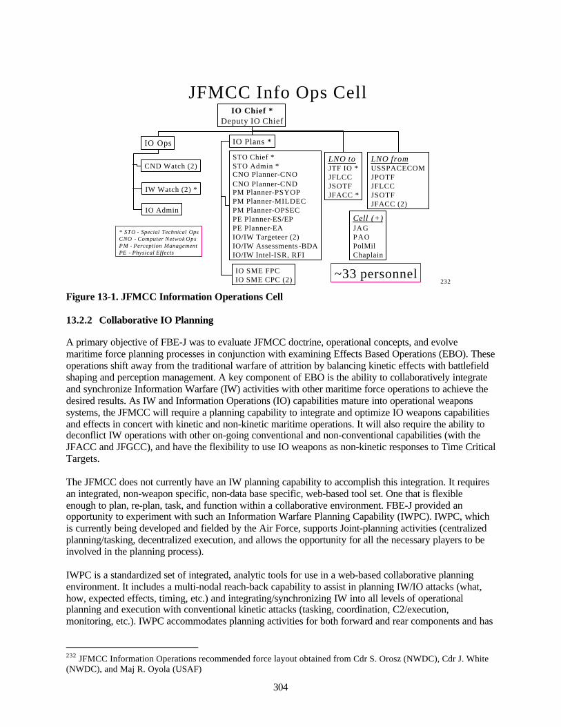
304
JFMCC Info Ops CellIO Chief *
Deputy IO Chief
IO Ops IO Plans *
CND Watch (2)
IW Watch (2) *
* STO - Special Technical OpsCNO - Computer Netwok OpsPM - Perception ManagementPE - Physical Effects
STO Chief *STO Admin *CNO Planner-CNOCNO Planner-CNDPM Planner-PSYOPPM Planner-MILDECPM Planner-OPSECPE Planner-ES/EPPE Planner-EAIO/IW Targeteer (2)IO/IW Assessments -BDAIO/IW Intel-ISR, RFI
IO Admin
IO SME FPCIO SME CPC (2)
LNO fromUSSPACECOMJPOTFJFLCCJSOTFJFACC (2)
Cell (+)JAGPAOPolMilChaplain
LNO toJTF IO *JFLCCJSOTFJFACC *
~33 personnel232
Figure 13-1. JFMCC Information Operations Cell
13.2.2 Collaborative IO Planning
A primary objective of FBE-J was to evaluate JFMCC doctrine, operational concepts, and evolvemaritime force planning processes in conjunction with examining Effects Based Operations (EBO). Theseoperations shift away from the traditional warfare of attrition by balancing kinetic effects with battlefieldshaping and perception management. A key component of EBO is the ability to collaboratively integrateand synchronize Information Warfare (IW) activities with other maritime force operations to achieve thedesired results. As IW and Information Operations (IO) capabilities mature into operational weaponssystems, the JFMCC will require a planning capability to integrate and optimize IO weapons capabilitiesand effects in concert with kinetic and non-kinetic maritime operations. It will also require the ability todeconflict IW operations with other on-going conventional and non-conventional capabilities (with theJFACC and JFGCC), and have the flexibility to use IO weapons as non-kinetic responses to Time CriticalTargets.
The JFMCC does not currently have an IW planning capability to accomplish this integration. It requiresan integrated, non-weapon specific, non-data base specific, web-based tool set. One that is flexibleenough to plan, re-plan, task, and function within a collaborative environment. FBE-J provided anopportunity to experiment with such an Information Warfare Planning Capability (IWPC). IWPC, whichis currently being developed and fielded by the Air Force, supports Joint-planning activities (centralizedplanning/tasking, decentralized execution, and allows the opportunity for all the necessary players to beinvolved in the planning process).
IWPC is a standardized set of integrated, analytic tools for use in a web-based collaborative planningenvironment. It includes a multi-nodal reach-back capability to assist in planning IW/IO attacks (what,how, expected effects, timing, etc.) and integrating/synchronizing IW into all levels of operationalplanning and execution with conventional kinetic attacks (tasking, coordination, C2/execution,monitoring, etc.). IWPC accommodates planning activities for both forward and rear components and has
232 JFMCC Information Operations recommended force layout obtained from Cdr S. Orosz (NWDC), Cdr J. White(NWDC), and Maj R. Oyola (USAF)
305
the reach-back capability into the necessary databases and supporting information (weapons capabilities,intelligence requirements, mission readiness status, etc.) to accomplish the required planning and C2.
13.2.2.1 Collaborative IO Analytical Objectives
Specific collaborative IO planning sub-initiative analytic issues researched during the experimentincluded the following:
• Identify level of horizontal and vertical collaboration. 233
• Identify IWPC capabilities that support JFMCC IO planning process.• Determine if the decision support tools (e.g., IWPC) are enablers to decision making within the
JFMCC IO planning process, or where lacking, what decision support tools are required.
13.2.2.2 Findings on Collaborative IO Planning
The presence of readily prepared operational net assessments (ONAs) largely minimized the opportunityto explore the full possibility of timely, extensive IWPC utility and potential. Known ‘experimentationand innovation trade-space’ in the Maritime Planning Process (MPP) created extensive confusion asindividuals endeavored to satisfy the expectations and requirements of JFMCC planning decision-makers.Meanwhile, the disparate interpretations of Primary Warfare Commanders (PWC) as to “what” the MPPentailed hindered cohesion and mutual understanding.
The FBE-J scenario lacked adequate fidelity to sufficiently and accurately replicate potential IO effects.
In this experiment the nature of IO/IW as a supporting mission area was predominant. Future multi-mission platforms, designed to facilitate the near simultaneous achievement of optimum effects, will findthat exploitation of intrinsic IO/IW capabilities distributed throughout the battle force will be critical tomission success. However, deriving the associated tailored, responsive, effects-oriented, Courses ofAction (COA) which are required to convert plans into effective operations will be dependent on supportfrom, and connectivity with, rear echelon entities. Information Warfare Planning Capability (IWPC) wasrelied upon to provide the principal means of dialogue and timeliness to meet JFMCC IO Cell and IWCrequirements. Though designed as a strategic level, deliberate planning system, IWPC was incorporatedinto the experiment to quantify what trade spaces exist in IWPC’s diverse toolkit that address operationalto tactical level planning demands.
Optimum use of IWPC was challenged for a number of reasons – most associated with taking it out of itsdesigned niche at the SCI level. However, excellent on-scene technical support allowed for every problemto be worked through and some innovative solutions/adaptations found. Initial experiment designenvisioned an SCI level IWPC in the IO forward space. This machine would have facilitated collaborationnot only with IO Rear at the Fleet Information Warfare Center, Norfolk, VA, but also the CJTF IO Cell,Suffolk VA, JFACC IO at Nellis AFB, NV, and the JSOTF IO, MacDill AFB, FL. However, componentand participation via IWPC was precluded as only Navy brought IWPC equipment to the experiment.Consequently, much of the vertical collaboration originally envisioned did not occur—a deficiency thatwas explicitly cited by the CJTF IO Chief during MC02 debriefs. SCI level collaboration did occur on anear daily basis between IO Forward and IO Rear, but the primary collaborative contribution occurred asthe result of two adaptive decisions:
• An ATI.ATR conversion utility was written to facilitate USMTF dialogue from IWPC to LAWS.This revision enabled automatic target/weapon pairing methodology that initially was key tonormalizing any IO target nomination in the Joint Fires Network.
233 Interview and After Action Report review from Mr. Matt Sedlacek, IWPC Operator, USS Coronado
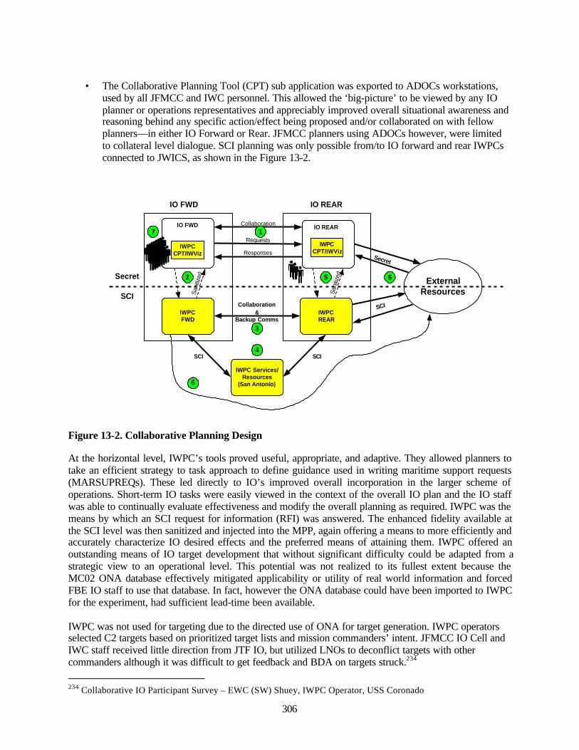
306
• The Collaborative Planning Tool (CPT) sub application was exported to ADOCs workstations,used by all JFMCC and IWC personnel. This allowed the ‘big-picture’ to be viewed by any IOplanner or operations representatives and appreciably improved overall situational awareness andreasoning behind any specific action/effect being proposed and/or collaborated on with fellowplanners—in either IO Forward or Rear. JFMCC planners using ADOCs however, were limitedto collateral level dialogue. SCI planning was only possible from/to IO forward and rear IWPCsconnected to JWICS, as shown in the Figure 13-2.
ExternalResources
Secret
IO FWD IO REAR
IWPCFWD
IWPCREAR
Collaboration&
Backup Comms
Collaboration
San
itize
d
SCI
IO FWD
IWPCCPT/IWViz
IO REAR
IWPCCPT/IWViz
Requests
Responses
Secret
SCI
IWPC Services/Resources
(San Antonio)
SCI
San
itize
d
SCI
2
4
3
5 6
1
6
7
Figure 13-2. Collaborative Planning Design
At the horizontal level, IWPC’s tools proved useful, appropriate, and adaptive. They allowed planners totake an efficient strategy to task approach to define guidance used in writing maritime support requests(MARSUPREQs). These led directly to IO’s improved overall incorporation in the larger scheme ofoperations. Short-term IO tasks were easily viewed in the context of the overall IO plan and the IO staffwas able to continually evaluate effectiveness and modify the overall planning as required. IWPC was themeans by which an SCI request for information (RFI) was answered. The enhanced fidelity available atthe SCI level was then sanitized and injected into the MPP, again offering a means to more efficiently andaccurately characterize IO desired effects and the preferred means of attaining them. IWPC offered anoutstanding means of IO target development that without significant difficulty could be adapted from astrategic view to an operational level. This potential was not realized to its fullest extent because theMC02 ONA database effectively mitigated applicability or utility of real world information and forcedFBE IO staff to use that database. In fact, however the ONA database could have been imported to IWPCfor the experiment, had sufficient lead-time been available.
IWPC was not used for targeting due to the directed use of ONA for target generation. IWPC operatorsselected C2 targets based on prioritized target lists and mission commanders’ intent. JFMCC IO Cell andIWC staff received little direction from JTF IO, but utilized LNOs to deconflict targets with othercommanders although it was difficult to get feedback and BDA on targets struck.234
234 Collaborative IO Participant Survey – EWC (SW) Shuey, IWPC Operator, USS Coronado
307
Daily collaboration on the PWC level occurred with the Sea Combat Commander, CommanderAmphibious Task Force, Strike Warfare Commander, and to a lesser degree Mine Warfare Commander.However, observer logs indicate that greater than 50 percent of this collaboration occurred on a face-to-face basis or via the telephone, rather than in the Collaborative Information Environment (CIE). This wasat least partially, the consequence of the less than one-to-one ratio of workstations to IWC planners,mentioned earlier. JFMCC IO collaboration was principally accomplished in the CIE, augmented with IPteleconference and it occurred throughout the day with all components. Principal among those wereJFACC, JPOTF, JFLCC and CJTF IO. Less collaboration occurred with JSOTF, USSPACECOM, allJFMCC planning cells, and anchor desks on the MOC floor. The nexus of collaboration, by far was theIW Anchor desk whose utilization of the CIE set the standard for not only IO, but also all JFMCCparticipants. It was not unusual for her to have as many as five IWS chat rooms, three IWS private chats,Outlook e-mail, ADOCS, LAWS Fires Mission Planner, ATO and Share Point Portal opensimultaneously. 235
Review of participant surveys indicate that IWPC was not utilized to the fullest due to dynamics of thescenario. There was little long range planning conducted for this experiment that would have benefitedfrom IWPC capability. A tool like IWPC is needed in today’s Navy at the battle group staff level andabove for theater planning purpose.
The majority of the IO planning occurred at the secret level. Very little IO planning occurred at the SCIlevel. The SCI support was primarily in an Intel/RFI support role to IO FWD. Critical observations fromthe collaborative process are noted below:236
• Mission planning and execution occurred on the secret network. Planning occurred at the IOforward (CORONADO) position. IO Rear (FIWC) was able to participate in this process byhaving access to the IWS collaborative network (meeting room and e-mail). This significantlyincreased the participation and awareness of IO rear into the overall experiment environment.
• Upon receiving RFIs, IO Rear had the option of researching the request on the secret network, onthe SCI IWPC workstations (using IWPC specific tools, other tools, or JWICS web searches), oron other SCI assets available at the rear. In addition, some phone calls were made to otherorganizations, in order to support responding to an RFI, if the IO rear did not have the expertiseor tools to answer the RFI. IO rear sanitized and downgraded any information obtained throughSCI sources to secret prior to translating it into an RFI response.
• For TST tasks, BE numbers were already known. They were entered into the CPT on the secretside under a new generic plan. As each BE number was entered, an MIDB update was performedby filling in the necessary target details (which was much faster than typing this in by hand). Theplan was then saved to floppy and loaded on the IWPC FWD system. The plan was loaded intoCPT and the targets were highlighted and exported to the TGIF database (located at LacklandAFB.). TGIF was started and a CTL was generated and exported to the local computer. CACUwas started and the CTL was converted to the USMTF FBE-J ATI.ATR message format. Thesemessages were copied and scrubbed to the floppy disk using the NT Toolbox functions SecureCopy, Flush, and Buster. Once scanned, the floppy was available for the IO Watch Commanderon the operations floor to load into ADOCS.
• When coordinating the planning for a few targets, operators found it was easier and faster tomanually enter the IO TCTs directly into ADOCS. However, if the IWPC server was installed on
235 Post-experiment interview with CDR S. Orosz (NWDC)236 Collaborative Tools AAR and interview with Mr. Matt Sedlacek, IWPC Operator, USS Coronado
308
the secret network and there were more than six or seven TCT targets, the creation of theATI.ATR messages was much easier and faster using the IWPC tools.
• Collaboration on IWS took place between SCI IO Forward and Rear. Primary focus was backupcommunications for secret COMMS path. The secret communication path dropped out often thefirst two weeks, thus having the backup COMMS was useful.
• Upon receiving RFIs, IO Rear had the option of researching the request on the secret network, onthe SCI IWPC workstations (using IWPC specific tools, other tools, or JWICS web searches), orother SCI assets available at the Rear. In addition, some phone calls were made to otherorganizations, in order to support responding to an RFI if IO rear did not have the expertise ortools to answer the RFI. IO rear downgraded any information obtained through SCI sources tosecret prior to translating it into an RFI response.
13.2.3 Defensive IO (Hardened Client)
The Hardened Client initiative addressed the prevention of network services from being misused by eitherthe unintentional insider or an intentional attacker that had successfully penetrated the other defenses. Thebasic paradigm of the Hardened Client being that prevention is a more effective approach to computernetwork defense (CND) than detection, response, and recovery. This initiative was intended toincorporate technology to augment today's perimeter defense strategy with an integrated layered defenseat the host level to prevent the misuse of computers. The Hardened Client integrates two host leveltechnologies, autonomic distributed firewall and the operating system wrappers, in an effort to harden theclient computer from being used for unintended purposes.
There were two major components of the Hardened Client that were integrated with the IT-21 (GOTSDelta) workstation or other specified NT workstation:
• Autonomic Distributed Firewall (ADF). The autonomic distributed firewall (ADF) is a distributedpacket filtering firewall with centralized management and auditing. It is intended to provide a tamperresistant, non-by-passable firewall between a host workstation or server and the ethernet cable. Note:The ADF is not an application layer proxy. Therefore, it makes no claims concerning protection fromhostile code carried by e-mail or delivered via a web browser. The ADF architecture uses a master-slave approach to provide scalability and centralized security policy management and is composed oftwo parts; the security policy server and the distributed policy-enforcing network interface cards(NIC) installed on each protected workstation. This centralized approach is critical for rapidimplementation of changes to security policy during high threat operations. The ADF NICs wereinstalled on selected workstations and servers on the FBE J experimental SECRET LAN. Each NICwas installed on a variety of workstations and several high value servers. The ADF Policy Servercontrolled the security policy for each NIC. The ADF Policy Server provided centralizedmanagement of packet filter rules in each NIC. Security policies were implemented from the PolicyServer for individual workstations or for implementation across the network. The NIC filtering enginesupported 64-packet filter rules including "No Sniffing" or "No Spoofing". New rules were easilywritten and applied for use in the dynamic FBE-J operational environment.
• Operating system wrappers. Operating system (OS) wrappers are small pieces of code resident onthe host workstation that mediate system calls in real time between the NT operating system (OS) andapplications. The OS wrappers mediation enforces fine-grained security policies in a transparentfashion, i.e., no user interaction and minimal performance degradation. The OS wrappers do not relyon conventional signature based detections but perform based on predetermined acceptable behaviorsfor applications. An example would be the prohibition of e-mail from electronically accessing the e-
309
mail address book; thus denying many self-propagating viruses their primary transmission mode.
13.2.3.1 Defensive IO Analytical Objectives
Specific defensive IO sub-initiative analytic issues researched during the experiment included thefollowing:
• Determine if Hardened Client technologies (ADF, OS wrappers) prevent network exploitations onthe information and/or computer resources from an adversary.
• Determine if ADF and OS wrappers alarm the system administrator when security policies on thecomputer under protection are violated.
• Evaluate the ability of ships force to install, establish security policies, operate, and modify ADFrule sets.
Measures of performance identified for the Hardened Client initiative included:
• Protection. Protection is the major metric evaluated for overall effectiveness. The ability of theHardened Client technologies to prevent network attacks on the information and/or computerresources on which it is installed will be qualitatively compared with similar attacks on un-protected computers.
• Detection. The ADF portion of the Hardened Client provides alarms to the policy manager serverwhen security policies on the computer under protection are violated. These alarms provide apotential early warning of security policy violation and possible computer misuse. The capabilityof the ADF alarms to automatically tip-off the system administrator of possible misuse will beevaluated.
• Operability. The ability of ships force to install, establish security policies, and operate theHardened Client technologies will be evaluated. Data will be collected through observationsduring the installation and execution of the experiment as well as post-experiment interviews withthe ships force.
13.2.3.2 Findings on Defensive IO (Hardened Client)
Hardened Client successfully deflected direct Red team attack through OS wrapper and ADFconfiguration. The Red team was not successful in achieving the flag of disrupting time critical targetingduring attack periods.
The first layer of defense, safe e-mail wrappers, blocked harmful behavior contained in e-mail attachmentmacro sent by Red team participants. The attacker assumed that users would open attachment and thedesktop configuration would permit macro to spawn. During experiment, e-mail with harmful macro(visual basic script) was sent from Red that was intended to provide an internal jump point for theattacker. However, the wrappers defeated attacks by effectively stopping writes to the registry and harddrive. The Red team was unsuccessful at starting a session intended to spawn the root shell back to a jumpbox for subsequent network exploitation. 237
The second layer of defense, ADF, prevented outbound FTP as well as outbound root shell jump point.ADF demonstrated an effective defensive technology that can be scaled to full operational deployment. 237 Review of DARPA presentation, 9 Sep 02
310
However, several configuration management issues associated with incorporating ADF cards in allnetwork machines provided by ADF operators during FBE-J include:
• Scalability; the ability of one person to manage 1000+ systems• Complications of legacy and custom software applications• Correlation of audits across policy servers makes incident handling difficult.
The Red team was successful in inserting spoofed e-mail. However, it should be noted that the softwareused to configure the mail server was ‘freeware,’ and the ADF rule sets incorporated for FBE-J permittedall traffic to and from the FBE-J mail server.238
Discussions with Red team participants indicated that the presence of ADF equipped machines wereeasily detected using basic scans. A network with only partial ADF coverage would permit an attacker toquickly identify unequipped computers and launch an attack from that point. The Red team would focusattacks on unprotected machines.
Red team surveys indicate that e-mail wrappers provided good protection in addition to anti-virussoftware, ADF provided an adequate layer of protection in defense-in-depth configuration, and overall,the Hardened Client was a deterrent to an adversary attack. However, as mentioned above, unless thecomplete network is configured with Hardened Client, a persistent adversary would eventually find theweaker hosts in a network enclave and would exploit.
From an operational environment perspective, the remote management of ADF policy servers oversatellite link worked smoothly and the CND staff was able to assume responsibility for operation withminimal training.
13.2.4 Offensive IO General Observations
Operational commanders required the capability to launch theater-level Information attacks whenappropriate. The Offensive Information Operations experiment conducted during FBE-J centered on usingE-Strike munitions in support of time critical strike scenarios. As FBE-J progressed, kinetic and non-kinetic IO fires were integrated in TST operations. Two critical findings are highlighted below:
• Placing control of IO weapons with the operational commander is critical for synchronizingkinetic and non-kinetic warfare.
•• Integration of IO with Joint Fires enhanced the experimental time critical strike scenario.
13.2.4.1 Electronic-Strike Munitions
The probability of effects/”kill” (Pk) was simulated during the experiment using Directed RadioFrequency Energy Assessment Model (DREAM). The Pk results were compiled and presented in the“Target Manual for RF Directed Energy Weapon (DEW) Vs. Selected Targets” (U) for the MC02/FBE-Jexecution effort. The process for e-strike employment manifested during FBE-J is provided below. E-strike munitions were used extensively throughout FBE-J.239
238 Interview with Ms. Dorene Ryder (DARPA/BBN), D-IO Lead239 Interview with Mr. Mark Henderson – Electronic-Strike Lead
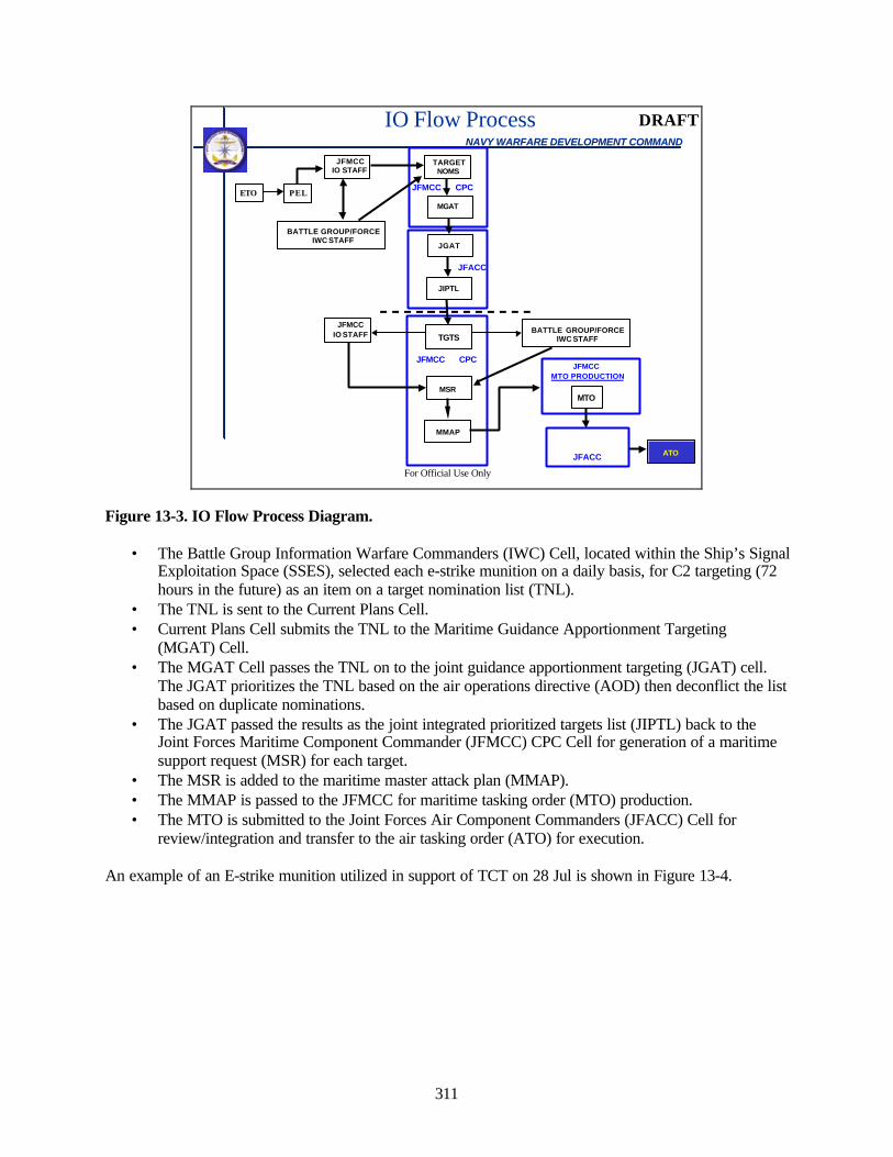
311
For Official Use Only
NAVY WARFARE DEVELOPMENT COMMANDNAVY WARFARE DEVELOPMENT COMMAND
TARGETNOMS
JGAT
JIPTL
ATO
JFMCC MTO PRODUCTION
IO Flow Process
MSR
MMAP
JFMCCIO STAFF
BATTLE GROUP/FORCEIWC STAFF
JFMCC CPC
JFACC
JFMCC CPC
JFMCCIO STAFF BATTLE GROUP/FORCE
IWC STAFF
PEL
TGTS
MTO
JFACC
MGAT
DRAFT
ETO
Figure 13-3. IO Flow Process Diagram.
• The Battle Group Information Warfare Commanders (IWC) Cell, located within the Ship’s SignalExploitation Space (SSES), selected each e-strike munition on a daily basis, for C2 targeting (72hours in the future) as an item on a target nomination list (TNL).
• The TNL is sent to the Current Plans Cell.• Current Plans Cell submits the TNL to the Maritime Guidance Apportionment Targeting
(MGAT) Cell.• The MGAT Cell passes the TNL on to the joint guidance apportionment targeting (JGAT) cell.
The JGAT prioritizes the TNL based on the air operations directive (AOD) then deconflict the listbased on duplicate nominations.
• The JGAT passed the results as the joint integrated prioritized targets list (JIPTL) back to theJoint Forces Maritime Component Commander (JFMCC) CPC Cell for generation of a maritimesupport request (MSR) for each target.
• The MSR is added to the maritime master attack plan (MMAP).• The MMAP is passed to the JFMCC for maritime tasking order (MTO) production.• The MTO is submitted to the Joint Forces Air Component Commanders (JFACC) Cell for
review/integration and transfer to the air tasking order (ATO) for execution.
An example of an E-strike munition utilized in support of TCT on 28 Jul is shown in Figure 13-4.
^
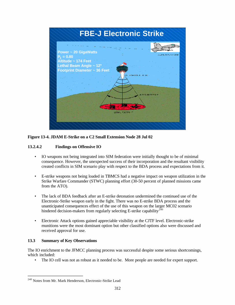
312
FBE-J Electronic Strike
Power ~ 20 GigaWattsPk = 0.80Altitude ~ 174 FeetLethal Beam Angle ~ 12ºFootprint Diameter ~ 36 Feet
Figure 13-4. JDAM E-Strike on a C2 Small Extension Node 28 Jul 02
13.2.4.2 Findings on Offensive IO
• IO weapons not being integrated into SIM federation were initially thought to be of minimalconsequence. However, the unexpected success of their incorporation and the resultant visibilitycreated conflicts in SIM scenario play with respect to the BDA process and expectations from it.
• E-strike weapons not being loaded in TBMCS had a negative impact on weapon utilization in theStrike Warfare Commander (STWC) planning effort (30-50 percent of planned missions camefrom the ATO).
• The lack of BDA feedback after an E-strike detonation undermined the continued use of theElectronic-Strike weapon early in the fight. There was no E-strike BDA process and theunanticipated consequences effect of the use of this weapon on the larger MC02 scenariohindered decision-makers from regularly selecting E-strike capability240
• Electronic Attack options gained appreciable visibility at the CJTF level. Electronic-strikemunitions were the most dominant option but other classified options also were discussed andreceived approval for use.
13.3 Summary of Key Observations
The IO enrichment to the JFMCC planning process was successful despite some serious shortcomings,which included:
• The IO cell was not as robust as it needed to be. More people are needed for expert support.
240 Notes from Mr. Mark Henderson, Electronic-Strike Lead
313
• IO was not fully integrated into the JFMCC planning cycle. This integration is difficult to dowithout having the expertise and experience on both the IO and JFMCC sides of the planningprocess.
• IO is a different approach to warfighting and requires a different kind of thinking; proactive vicereactive for planning missions without targets, and subject matter expertise is essential to have athand.
Collaborative IO planning in FBE-J was limited because the planning for this exercise did not require theIWPC capability. It is better applied at the theater planning level due to the SCI level of the support.
A hardened client successfully deflected direct Red team attacks through operating system (OS) wrappersand autonomic distributed firewall (ADF) configuration. The Red team was not successful in achievingthe goal of disrupting time critical targeting during attack periods.
Operational commanders required the capability to launch theater-level, information attacks whenappropriate. The offensive Information Operations experiment conducted during FBE-J, centered onutilizing E-Strike munitions in support of time critical strike scenarios. As FBE-J progressed, kinetic andnon-kinetic IO fires were integrated into TST operations.
• Placing control of Information Operation weapons with the operational commander is critical forsynchronizing kinetic and non-kinetic warfare.
• E-strike weapons were not loaded in TBMCS. This had a negative impact on weapon use in theStrike Warfare Commander (STWC) planning effort (30-50% of planned missions came fromATOs).

314
This page intentionally left blank.
315
14.0 Coalition Command and Control (C2) Initiative Key Observations
14.1 Experiment Objectives
The coalition initiative was the third and most ambitious experiment to examine multi-nationalparticipation in network-centric operations. FBE-F and FBE-H had examined a means for integratingcoalition partners into a digital Fires network using a small U.S. enclave onboard a British warship. Thisinitiative was to establish a multi-national command and control environment, facilitated by "smart agent"middleware technology, as a step toward pervasive sensing from an expeditionary sensor grid. It alsoserved as an experimentation building block for developing future multi-national concepts within the U.S.Navy concept of network-centric warfare.
Doctrinally, the operational commander should be able to conduct operations more freely with a leadnation concept than with a parallel command structure, and primary warfare commanders should be ableto assign forces based on how their sensor/weapon capabilities best complement U.S. forces, rather thanestablishing geographic separation of U.S. and other multi-national forces, creating artificial seams andvulnerabilities for a hostile force to exploit.
Information-based security should derive rule sets and policies based on the nature of the data to beexchanged and the sensor sources, rather than on platform nationalities and the connected hardwaresystems. It should be dynamic and responsive to the warfighter, not requiring months of review andcertification, before available to provide interoperability of an ad hoc coalition force, such as OperationEnduring Freedom. Nor should different hardware be required to communicate with different multi-national partners.
The initiative focused on four primary areas:
• Interoperability of different command and control systems, facilitated by agent-basedcomputing, to achieve shared awareness and improved collaboration thru a tacticalpicture derived from commonly shared data.
• Robust networking in a domain that allows for dynamic reconfiguration, using on-demand connectivity and tailored pull of relevant data for multi-mission assets. Use smartagents to improve communications reliability and network connectivity.
• Secure information sharing to constrain an environment where real-time "chat rooms"may predominate over record message traffic.
• A capability for improved collaboration with coalition partners for improvedcollaboration on network-centric issues.
The intention was to integrate live, virtual (manned), and simulated coalition forces across asecure wide area network, for collaboration associated with the detection, classification(including waterspace management), and localization of threat submarine contacts. Thiscollaboration was facilitated over a "grid" to which users could register, and "subscribe to" or"publish" tracks of interest. The tracks were then handled and disseminated by rule-basedsoftware "agents". The agents, distributed across the network, provided the mechanism to shareinformation for databases from the various, independent C2 systems.
The initiative was executed at the tactical level, with dedicated multi-national forces assignedunder the tactical command of the Sea Combat Commander (SCC), primarily providing anti-submarine warfare support to assure access for maritime and follow-on expeditionary forces ofthe joint campaign. Once maritime superiority had been achieved, the last two days of theexperiment were executed as a limited objective experiment (LOE) outside the main FBE-Jscenario, focusing on combined arms command and control for maritime interdiction operations,

316
and maintaining sea control/sea denial for logistics re-supply and freedom of navigation around alittoral chokepoint.
14.2 Analytic Questions
• What was the increase in combat capability? The intention was to quantify the value of allowingless capable coalition partners to strengthen their weaknesses in C4I and situational awarenessthrough connectivity to U.S. and other coalition forces. At the same time, they provide additionalsensor node information, which serves to augment and enhance the theater and local ASWcoverage.
• What warfighting challenges does it address?o Multi-national interoperability.o Dynamic reconfiguration of networks supporting multi-tasked platforms or those with
disadvantaged or intermittent C4 capabilities.o Reliability of network-centric architectures to exchange relevant information for
distributed planning and decision-making.o Need for a better mechanism to support secure information sharing to enhance the
coordination of operational forces while protecting national sources and data.
• What future desired operational capability does it support?
• Was it possible to:o Establish Coalition middleware environment in support of ASW mission?o Implement and use CoABS grid?o Evaluate information sharing/assurance requirements for Coalition ASW?o Integrate distributed heterogeneous C2 systems?
§ GCCS (US, CAN, UK), Horizon (AUS, CAN), and CSS (UK).o Use live sensors and pass live tactical data over the grid?
§ U.S. tactical data from DDG, SH-60, P-3.o Extend coalition battlespace awareness through rapid integration of new sensor sources
(e.g., rapidly deployable system (RDS))?o Improve Situational Awareness through collaboration, using grid-enabled applications
(browser-based collaborative sensor status, chat, e-mail)?o Preserve information security through the use of grid services?o Use policy-based tools for domain management?o Reduce operator workload through automation (agent-based data mining)?
• Determine if there is a common view of friendly and enemy situation by coalition participants.
• Determine if control of information available to coalition partners can be accomplished throughdatabase management.
• Identify the US/coalition security issues.
14.2.1 Establish Interoperability
This sub-initiative was primarily intended to identify developmental issues associated with implementingdistributed middleware and agent-based computing, as a potential solution for requiring the same orcompatible hardware (i.e. GCCS) for coalition interoperability. This effort integrated dissimilar
317
distributed C2 systems with middleware, in order to share tactical data among GCCS (U.S., CAN),Horizon (AUS, CAN), and MTP (UK), and to demonstrate the utility of this solution for interoperability.
A secondary experimental function was to examine the effectiveness of agent-based computing inservicing U.S. and coalition platform sensors, such that common relevant information was provided, thatenhanced the capability of the combined anti-submarine warfare (ASW) force in multi-national commandand control decision-making.
14.2.2 Dynamic Network Reconfiguration
This sub-initiative used middleware as a tool to enable a robust network-centric environment. It wasdesigned to permit rapid integration of sensor nodes within a wide area network. The architecture usedDefense Advance Research Programs Agency (DARPA)'s project for control of agent-based systems(CoABS) grid structure of distributed database sharing, with intelligent agents managing data on the grid.
14.2.3 Secure Information Sharing
This sub-initiative assessed the requirements for secure information sharing in a coalition network-centricenvironment, and provided a potential alternative to implementation of the RADIANT MERCURYGUARD system with its hard-coded policies, and long lead times for policy changes. This effortexperimented with the value of agent-based computing (ABC) to support selective disclosure anddissemination of information, as well as programmable firmware in network interface cards to implementpolicy-based management of the domain. This effort examined a model for information-based securityfocused on data and sensor sources, rather than on platform nationalities and connected hardware systems.
14.2.4 Develop Coalition Field Experimentation Capabilities
This sub-initiative was a "stepping stone" to build the capability to examine and resolve network-centricissues with coalition partners. The initiative gathered data for assessing the costs and benefits of agent-based computing. It was to identify technical issues and demonstrate the capability to leverage offdistributed laboratories to support examination of coalition concepts in field experiments. Experimentally,this effort also examined concepts for employment for a prototype Royal Australian Navy (RAN) acousticarray technology, the rapidly deployable system.
[Additional background and data for this initiative were under the control of a separate organization. Nobaseline model, observational data, or other raw data were forthcoming, so no analyses were possible.]

318
This page intentionally left blank.
319
15.0 Netted Force Key Observations
Netted Force was an integral facet of network-centric warfare (NCW), focusing on knowledge processes,collaborative tools, and supporting organizational structures. Within Netted Force there were three sub-initiatives: (1) knowledge management organization (KMO) focused on organizational effectiveness ofKMO officers in support of JFMCC command, chief of staff, and the battle watch captain; (2)collaborative information environment (CIE) addressed technical systems to support rapid decisiveoperations (RDO); and (3) ground COP assessed linkages between traditional COP track management,engagement tools, target management, and intelligence order of battle tools.
15.1 Experiment Objectives
The knowledge management organization was a new, exploratory concept for inclusion in FBEs. Inconcept the KMO could increase command situational awareness, decrease information overload, andprovide for bandwidth management in support of combat operations.
The collaborative information environment (CIE) addressed systems to support information needs ofdistributed staff for planning and execution. Tools included the WIN 2000 active directory (AD) forshared services in support of rapid decisive operations (RDO). SharePoint Portal Service (SPPS) provideda single customized interface into information needed by war-fighters with facilities for documentmanagement and version control, subscription services to critical data, and data search and retrieval. InfoWorkspace (IWS) was for collaboration and real-time conferencing in support of a common situationalawareness among distributed staff.
Ground COP was intended to simplify access to targeting information and thereby improve situationalawareness among war-fighters. A secondary focus was a set of beta tools to help warriors understand andmake decisions on targets, integrate target data from engagement systems into ground COP, and utilizeGCCS 4.X and MIDB to support tactical and operational users.
15.2 Analytic Questions
Netted Force addressed high-level questions with respect to effectiveness of war-fighters conductingdistributed operations, coordinated through online collaborative tools and environments. Systemsintegrated real-time sensor data to enable highly precise actions based on computer generated decisionsupport technologies and instant knowledge from participants, sensors, feedback systems, and automatedassistants.
Effectiveness was measured through assessment of systems and organizational processes supportingNetted Force, including KMO and CIE (and supporting systems). Performance was assessed throughexperiment reports, first-person observations and reports, surveys, and interviews.
KMO was observed for contributions that enabled a team of knowledge management officers to supportdecision-makers in their use of information, knowledge, and communications. Key participants included aJFMCC KMO that served as lead knowledge management officer, a plans KMO that worked with futureand current plans cells, and an operations KMO that interfaced with the battle watch captain andpersonnel in the maritime operations center (MOC).
Knowledge management officers were responsible for information access and knowledge distributionincluding sensor linkages, new information, and application of decision support tools. Information,communication, and network technical personnel reported to the JFMCC KMO.
Effectiveness and performance measures were related to:
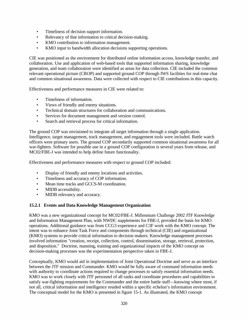
320
• Timeliness of decision support information.• Relevancy of that information to critical decision-making.• KMO contribution to information management.• KMO input to bandwidth allocation decisions supporting operations.
CIE was positioned as the environment for distributed online information access, knowledge transfer, andcollaboration. Use and application of web-based tools that supported information sharing, knowledgegeneration, and team collaboration were identified as areas for data collection. CIE included the commonrelevant operational picture (CROP) and supported ground COP through IWS facilities for real-time chatand common situational awareness. Data were collected with respect to CIE contributions in this capacity.
Effectiveness and performance measures in CIE were related to:
• Timeliness of information.• Views of friendly and enemy situations.• Technical domain structures for collaboration and communications.• Services for document management and version control.• Search and retrieval process for critical information.
The ground COP was envisioned to integrate all target information through a single application.Intelligence, target management, track management, and engagement tools were included. Battle watchofficers were primary users. The ground COP secondarily supported common situational awareness for allwar-fighters. Software for possible use in a ground COP configuration is several years from release, andMC02/FBE-J was intended to help define future functionality.
Effectiveness and performance measures with respect to ground COP included:
• Display of friendly and enemy locations and activities.• Timeliness and accuracy of COP information.• Mean time tracks and GCCS-M coordination.• MIDB accessibility.• MIDB relevancy and accuracy.
15.2.1 Events and Data Knowledge Management Organization
KMO was a new organizational concept for MC02/FBE-J. Millennium Challenge 2002 JTF Knowledgeand Information Management Plan, with NWDC supplements for FBE-J, provided the basis for KMOoperations. Additional guidance was from CCG3 experience and C3F work with the KMO concept. Theintent was to enhance Joint Task Force and components through technical (CIE) and organizational(KMO) systems to provide critical information to decision makers. Knowledge management processesinvolved information "creation, receipt, collection, control, dissemination, storage, retrieval, protection,and disposition." Doctrine, manning, training and organizational impacts of the KMO concept ondecision-making processes was the experimentation perspective taken in FBE-J.
Conceptually, KMO would aid in implementation of Joint Operational Doctrine and serve as an interfacebetween the JTF mission and Commander. KMO would be fully aware of command information needswith authority to coordinate actions required to change processes to satisfy essential information needs.KMO was to work closely with JTF personnel of all ranks and coordinate procedures and capabilities tosatisfy war-fighting requirements for the Commander and the entire battle staff—knowing where most, ifnot all, critical information and intelligence resided within a specific echelon’s information environment.The conceptual model for the KMO is presented in figure 15-1. As illustrated, the KMO concept
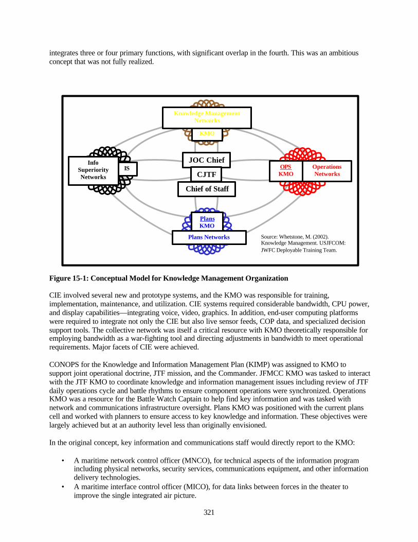
321
integrates three or four primary functions, with significant overlap in the fourth. This was an ambitiousconcept that was not fully realized.
Figure 15-1: Conceptual Model for Knowledge Management Organization
CIE involved several new and prototype systems, and the KMO was responsible for training,implementation, maintenance, and utilization. CIE systems required considerable bandwidth, CPU power,and display capabilities—integrating voice, video, graphics. In addition, end-user computing platformswere required to integrate not only the CIE but also live sensor feeds, COP data, and specialized decisionsupport tools. The collective network was itself a critical resource with KMO theoretically responsible foremploying bandwidth as a war-fighting tool and directing adjustments in bandwidth to meet operationalrequirements. Major facets of CIE were achieved.
CONOPS for the Knowledge and Information Management Plan (KIMP) was assigned to KMO tosupport joint operational doctrine, JTF mission, and the Commander. JFMCC KMO was tasked to interactwith the JTF KMO to coordinate knowledge and information management issues including review of JTFdaily operations cycle and battle rhythms to ensure component operations were synchronized. OperationsKMO was a resource for the Battle Watch Captain to help find key information and was tasked withnetwork and communications infrastructure oversight. Plans KMO was positioned with the current planscell and worked with planners to ensure access to key knowledge and information. These objectives werelargely achieved but at an authority level less than originally envisioned.
In the original concept, key information and communications staff would directly report to the KMO:
• A maritime network control officer (MNCO), for technical aspects of the information programincluding physical networks, security services, communications equipment, and other informationdelivery technologies.
• A maritime interface control officer (MICO), for data links between forces in the theater toimprove the single integrated air picture.
PlansKMO
Plans Networks
ISInfo
SuperiorityNetworks
OPSKMO
OperationsNetworks
JOC Chief
Chief of Staff
CJTF
KMO
Knowledge ManagementNetworks
Source: Whetstone, M. (2002).Knowledge Management. USJFCOM:JWFC Deployable Training Team.

322
• A common operational picture (COP) manager to provide a timely, fused, accurate, and relevantpicture to the JFMCC and Primary Warfare Commanders (PWCs) for feeding track data up to theTop COP, and for receiving Top COP data back for the JTF.
Database and web designers/developers maintained software, helped cells in the design of web sites (foraccess via SPPS), and assisted with maintenance of web-based decision support applications andcollaborative tools. While these organizational positions were active in FBE-J, the enacted organizationalreporting structure did not accurately conform to the original design.
In sum, it was the responsibility of the Knowledge Management Organization to know where most, if notall, critical information and intelligence resided. An Effects Tasking Order (ETO) would provide the basisthrough which information was translated into actable knowledge. The Collaborative InformationEnvironment (CIE) would be the medium for collection, integration, value-added dissemination andcoordination. These systems were in place, operational, and largely successful, albeit not at the levels orefficiency, or with the authority structure or stature originally envisioned.
15.2.2 Collaborative Information Environment
CIE is an umbrella term referring to a suite of tools intended to provide facilities through which war-fighters share information and ideas, thereby reducing planning timelines and enhancing organizationaleffectiveness. The environment was enabled by high-speed bandwidth connectivity and electroniccollaborative tools to facilitate exchanges of information among JTF and organizations supporting orbeing supported by the JTF.
The set of collaborative tools were designed to coordinate distributed operations, essentially eliminatingproblems due to geographic separation or different time zones, to enable a level of synchronization thatwould permit effects based operations (EBO) and rapid decisive operations (RDO). CONOPS andevaluation criteria were based on the JFCOM Knowledge and Information Management Plan (KIMP).Common relevant operational picture (CROP) and the tactical operational planner’s common operationalpicture (TOPCOP) were repositories for high-level decisions and CIE supported these tools by providinginformation targeted to tactical and operational as well as strategic personnel. Figure 15-2 illustrates thesystems structure and architecture for the CIE.
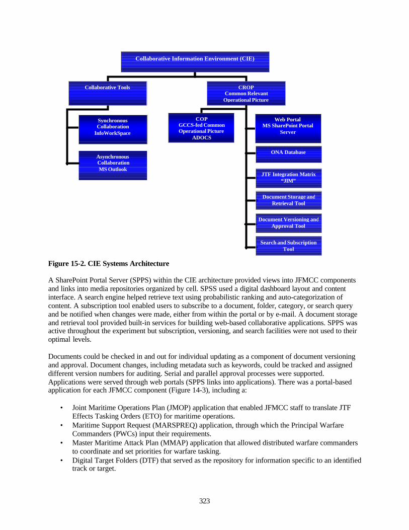
323
Figure 15-2. CIE Systems Architecture
A SharePoint Portal Server (SPPS) within the CIE architecture provided views into JFMCC componentsand links into media repositories organized by cell. SPSS used a digital dashboard layout and contentinterface. A search engine helped retrieve text using probabilistic ranking and auto-categorization ofcontent. A subscription tool enabled users to subscribe to a document, folder, category, or search queryand be notified when changes were made, either from within the portal or by e-mail. A document storageand retrieval tool provided built-in services for building web-based collaborative applications. SPPS wasactive throughout the experiment but subscription, versioning, and search facilities were not used to theiroptimal levels.
Documents could be checked in and out for individual updating as a component of document versioningand approval. Document changes, including metadata such as keywords, could be tracked and assigneddifferent version numbers for auditing. Serial and parallel approval processes were supported.Applications were served through web portals (SPPS links into applications). There was a portal-basedapplication for each JFMCC component (Figure 14-3), including a:
• Joint Maritime Operations Plan (JMOP) application that enabled JFMCC staff to translate JTFEffects Tasking Orders (ETO) for maritime operations.
• Maritime Support Request (MARSPREQ) application, through which the Principal WarfareCommanders (PWCs) input their requirements.
• Master Maritime Attack Plan (MMAP) application that allowed distributed warfare commandersto coordinate and set priorities for warfare tasking.
• Digital Target Folders (DTF) that served as the repository for information specific to an identifiedtrack or target.
Collaborative Tools
Asynchronous CollaborationMS Outlook
CROPCommon Relevant
Operational Picture
Collaborative Information Environment (CIE)
COPGCCS-fed CommonOperational Picture
ADOCS
SynchronousCollaboration
InfoWorkSpace
Search and SubscriptionTool
Document Versioning andApproval Tool
Document Storage andRetrieval Tool
JTF Integration Matrix“JIM”
ONA Database
Web PortalMS SharePoint Portal
Server
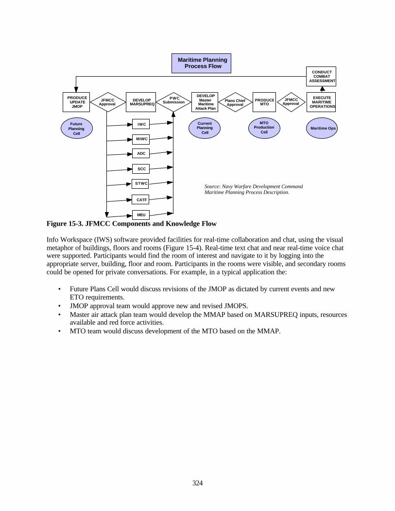
324
Figure 15-3. JFMCC Components and Knowledge Flow
Info Workspace (IWS) software provided facilities for real-time collaboration and chat, using the visualmetaphor of buildings, floors and rooms (Figure 15-4). Real-time text chat and near real-time voice chatwere supported. Participants would find the room of interest and navigate to it by logging into theappropriate server, building, floor and room. Participants in the rooms were visible, and secondary roomscould be opened for private conversations. For example, in a typical application the:
• Future Plans Cell would discuss revisions of the JMOP as dictated by current events and newETO requirements.
• JMOP approval team would approve new and revised JMOPS.• Master air attack plan team would develop the MMAP based on MARSUPREQ inputs, resources
available and red force activities.• MTO team would discuss development of the MTO based on the MMAP.
Maritime PlanningProcess Flow
PRODUCEUPDATEJMOP
DEVELOPMARSUPREQ
DEVELOPMasterMaritime
Attack Plan
PRODUCEMTO
EXECUTEMARITIME
OPERATIONS
CONDUCTCOMBAT
ASSESSMENT
JFMCCApproval
PWCSubmission Plans Chief
ApprovalJFMCC
Approval
IWC
MIWC
ADC
SCC
STWC
CATF
MEU
FuturePlanning
Cell
CurrentPlanning
Cell
MTOProduction
CellMaritime Ops
Source: Navy Warfare Development CommandMaritime Planning Process Description.
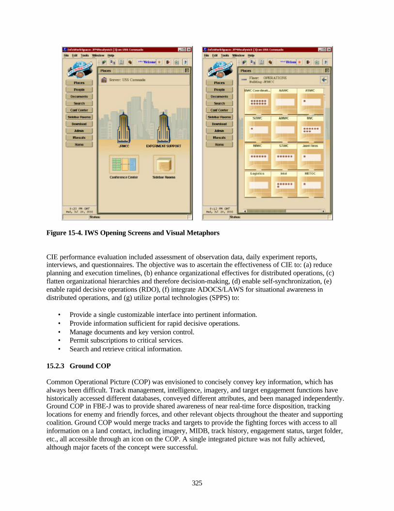
325
Figure 15-4. IWS Opening Screens and Visual Metaphors
CIE performance evaluation included assessment of observation data, daily experiment reports,interviews, and questionnaires. The objective was to ascertain the effectiveness of CIE to: (a) reduceplanning and execution timelines, (b) enhance organizational effectives for distributed operations, (c)flatten organizational hierarchies and therefore decision-making, (d) enable self-synchronization, (e)enable rapid decisive operations (RDO), (f) integrate ADOCS/LAWS for situational awareness indistributed operations, and (g) utilize portal technologies (SPPS) to:
• Provide a single customizable interface into pertinent information.• Provide information sufficient for rapid decisive operations.• Manage documents and key version control.• Permit subscriptions to critical services.• Search and retrieve critical information.
15.2.3 Ground COP
Common Operational Picture (COP) was envisioned to concisely convey key information, which hasalways been difficult. Track management, intelligence, imagery, and target engagement functions havehistorically accessed different databases, conveyed different attributes, and been managed independently.Ground COP in FBE-J was to provide shared awareness of near real-time force disposition, trackinglocations for enemy and friendly forces, and other relevant objects throughout the theater and supportingcoalition. Ground COP would merge tracks and targets to provide the fighting forces with access to allinformation on a land contact, including imagery, MIDB, track history, engagement status, target folder,etc., all accessible through an icon on the COP. A single integrated picture was not fully achieved,although major facets of the concept were successful.
i ImnViHliltiMK lilTliUiaw^ ■ H l>^ LH InfiHHMi 1^^^
vIp >il 2-, nm
^ttK- LQS Cnanok
1=1
i jiMn is*Eii]H(iiisuH>oin
C D 4B<fi[ r CrBtf
! ImnViHliltiMK lilTliUiaw^ ■ H l>^ LH InfiHHMi ^M
,tJ
3IIH I inure I HP:
!!!J !!!3 iS
vIp >ll r*, ^E?
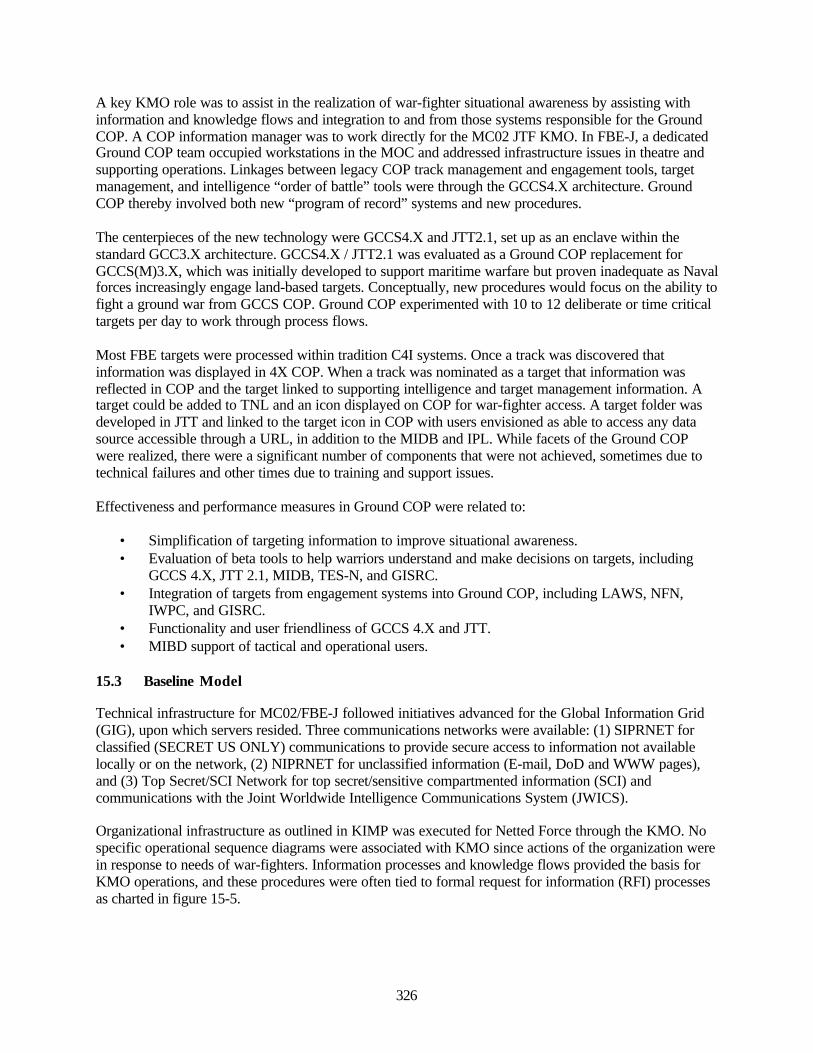
326
A key KMO role was to assist in the realization of war-fighter situational awareness by assisting withinformation and knowledge flows and integration to and from those systems responsible for the GroundCOP. A COP information manager was to work directly for the MC02 JTF KMO. In FBE-J, a dedicatedGround COP team occupied workstations in the MOC and addressed infrastructure issues in theatre andsupporting operations. Linkages between legacy COP track management and engagement tools, targetmanagement, and intelligence “order of battle” tools were through the GCCS4.X architecture. GroundCOP thereby involved both new “program of record” systems and new procedures.
The centerpieces of the new technology were GCCS4.X and JTT2.1, set up as an enclave within thestandard GCC3.X architecture. GCCS4.X / JTT2.1 was evaluated as a Ground COP replacement forGCCS(M)3.X, which was initially developed to support maritime warfare but proven inadequate as Navalforces increasingly engage land-based targets. Conceptually, new procedures would focus on the ability tofight a ground war from GCCS COP. Ground COP experimented with 10 to 12 deliberate or time criticaltargets per day to work through process flows.
Most FBE targets were processed within tradition C4I systems. Once a track was discovered thatinformation was displayed in 4X COP. When a track was nominated as a target that information wasreflected in COP and the target linked to supporting intelligence and target management information. Atarget could be added to TNL and an icon displayed on COP for war-fighter access. A target folder wasdeveloped in JTT and linked to the target icon in COP with users envisioned as able to access any datasource accessible through a URL, in addition to the MIDB and IPL. While facets of the Ground COPwere realized, there were a significant number of components that were not achieved, sometimes due totechnical failures and other times due to training and support issues.
Effectiveness and performance measures in Ground COP were related to:
• Simplification of targeting information to improve situational awareness.• Evaluation of beta tools to help warriors understand and make decisions on targets, including
GCCS 4.X, JTT 2.1, MIDB, TES-N, and GISRC.• Integration of targets from engagement systems into Ground COP, including LAWS, NFN,
IWPC, and GISRC.• Functionality and user friendliness of GCCS 4.X and JTT.• MIBD support of tactical and operational users.
15.3 Baseline Model
Technical infrastructure for MC02/FBE-J followed initiatives advanced for the Global Information Grid(GIG), upon which servers resided. Three communications networks were available: (1) SIPRNET forclassified (SECRET US ONLY) communications to provide secure access to information not availablelocally or on the network, (2) NIPRNET for unclassified information (E-mail, DoD and WWW pages),and (3) Top Secret/SCI Network for top secret/sensitive compartmented information (SCI) andcommunications with the Joint Worldwide Intelligence Communications System (JWICS).
Organizational infrastructure as outlined in KIMP was executed for Netted Force through the KMO. Nospecific operational sequence diagrams were associated with KMO since actions of the organization werein response to needs of war-fighters. Information processes and knowledge flows provided the basis forKMO operations, and these procedures were often tied to formal request for information (RFI) processesas charted in figure 15-5.
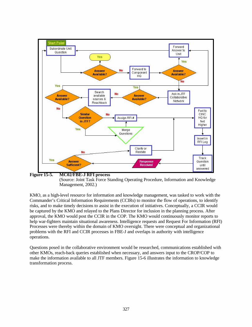
327
Figure 15-5. MC02/FBE-J RFI process(Source: Joint Task Force Standing Operating Procedure, Information and KnowledgeManagement, 2002.)
KMO, as a high-level resource for information and knowledge management, was tasked to work with theCommander’s Critical Information Requirements (CCIRs) to monitor the flow of operations, to identifyrisks, and to make timely decisions to assist in the execution of initiatives. Conceptually, a CCIR wouldbe captured by the KMO and relayed to the Plans Director for inclusion in the planning process. Afterapproval, the KMO would post the CCIR in the COP. The KMO would continuously monitor reports tohelp war-fighters maintain situational awareness. Intelligence requests and Request For Information (RFI)Processes were thereby within the domain of KMO oversight. There were conceptual and organizationalproblems with the RFI and CCIR processes in FBE-J and overlaps in authority with intelligenceoperations.
Questions posed in the collaborative environment would be researched, communications established withother KMOs, reach-back queries established when necessary, and answers input to the CROP/COP tomake the information available to all JTF members. Figure 15-6 illustrates the information to knowledgetransformation process.
Track Oueslion
until answered
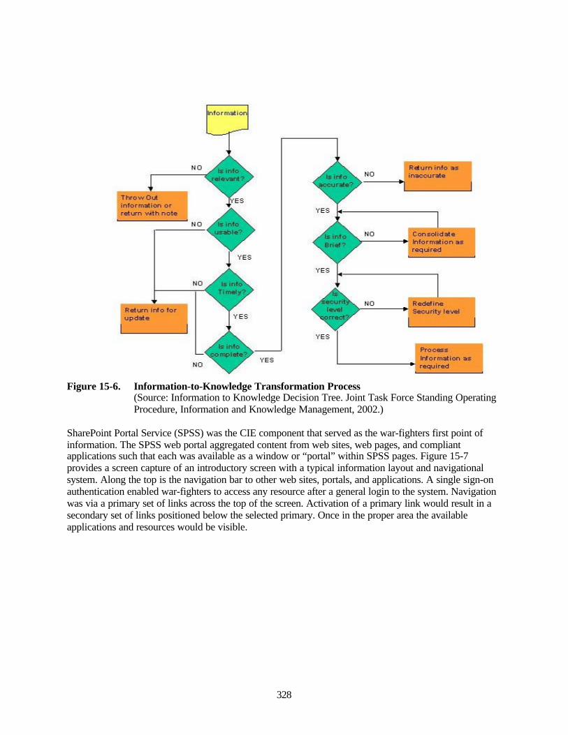
328
Figure 15-6. Information-to-Knowledge Transformation Process(Source: Information to Knowledge Decision Tree. Joint Task Force Standing OperatingProcedure, Information and Knowledge Management, 2002.)
SharePoint Portal Service (SPSS) was the CIE component that served as the war-fighters first point ofinformation. The SPSS web portal aggregated content from web sites, web pages, and compliantapplications such that each was available as a window or “portal” within SPSS pages. Figure 15-7provides a screen capture of an introductory screen with a typical information layout and navigationalsystem. Along the top is the navigation bar to other web sites, portals, and applications. A single sign-onauthentication enabled war-fighters to access any resource after a general login to the system. Navigationwas via a primary set of links across the top of the screen. Activation of a primary link would result in asecondary set of links positioned below the selected primary. Once in the proper area the availableapplications and resources would be visible.
I Throw Oul ^1 Informal Ion or relurn vjlh note
I ^um Info for
HD R^urrt info a In3f!cur;de 1
^Ja Consolidate ► Informal on ;
required
NO Redefine I Securilj level
Proce k~iformarion required
,-1
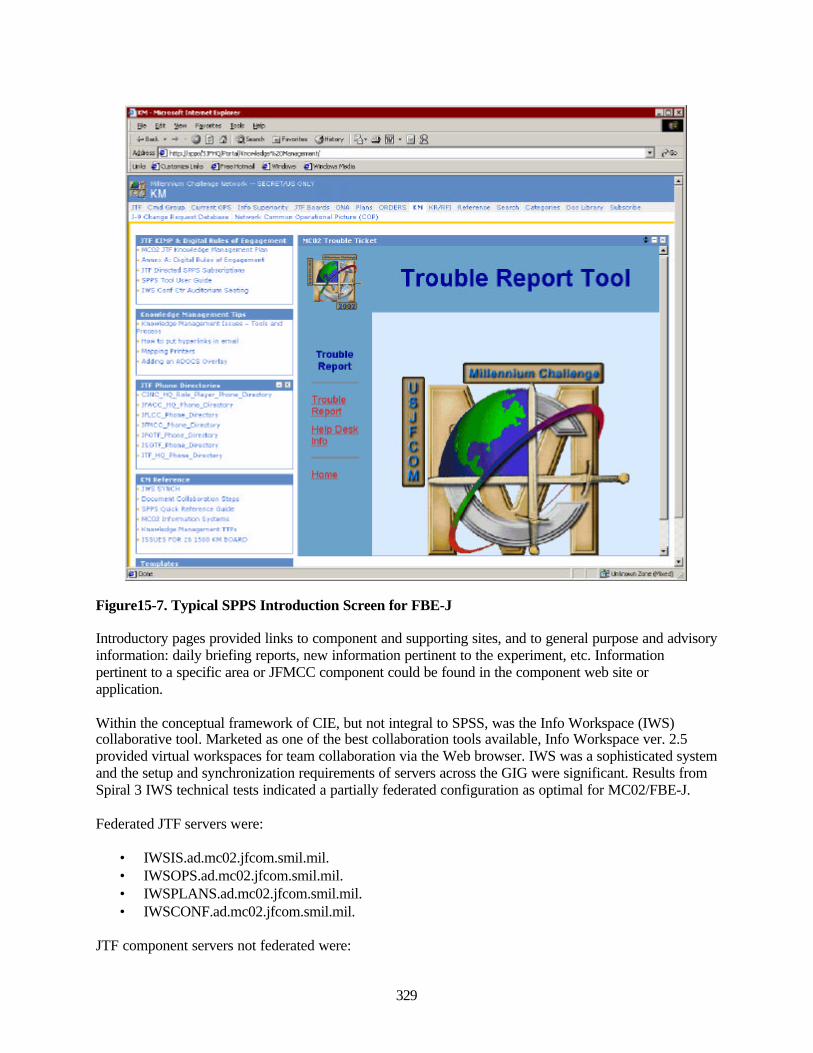
329
Figure15-7. Typical SPPS Introduction Screen for FBE-J
Introductory pages provided links to component and supporting sites, and to general purpose and advisoryinformation: daily briefing reports, new information pertinent to the experiment, etc. Informationpertinent to a specific area or JFMCC component could be found in the component web site orapplication.
Within the conceptual framework of CIE, but not integral to SPSS, was the Info Workspace (IWS)collaborative tool. Marketed as one of the best collaboration tools available, Info Workspace ver. 2.5provided virtual workspaces for team collaboration via the Web browser. IWS was a sophisticated systemand the setup and synchronization requirements of servers across the GIG were significant. Results fromSpiral 3 IWS technical tests indicated a partially federated configuration as optimal for MC02/FBE-J.
Federated JTF servers were:
• IWSIS.ad.mc02.jfcom.smil.mil.• IWSOPS.ad.mc02.jfcom.smil.mil.• IWSPLANS.ad.mc02.jfcom.smil.mil.• IWSCONF.ad.mc02.jfcom.smil.mil.
JTF component servers not federated were:
a*M - MKinnH IrHoxIdmloo
0^ til ^ FbP<r<
Prn^
'3£
■- KM
I J-U ^h<nqi Pi^^il Ov.tiii iMlFHDil- Cnmman UH"liDn<l Pirhin ^C(|P>
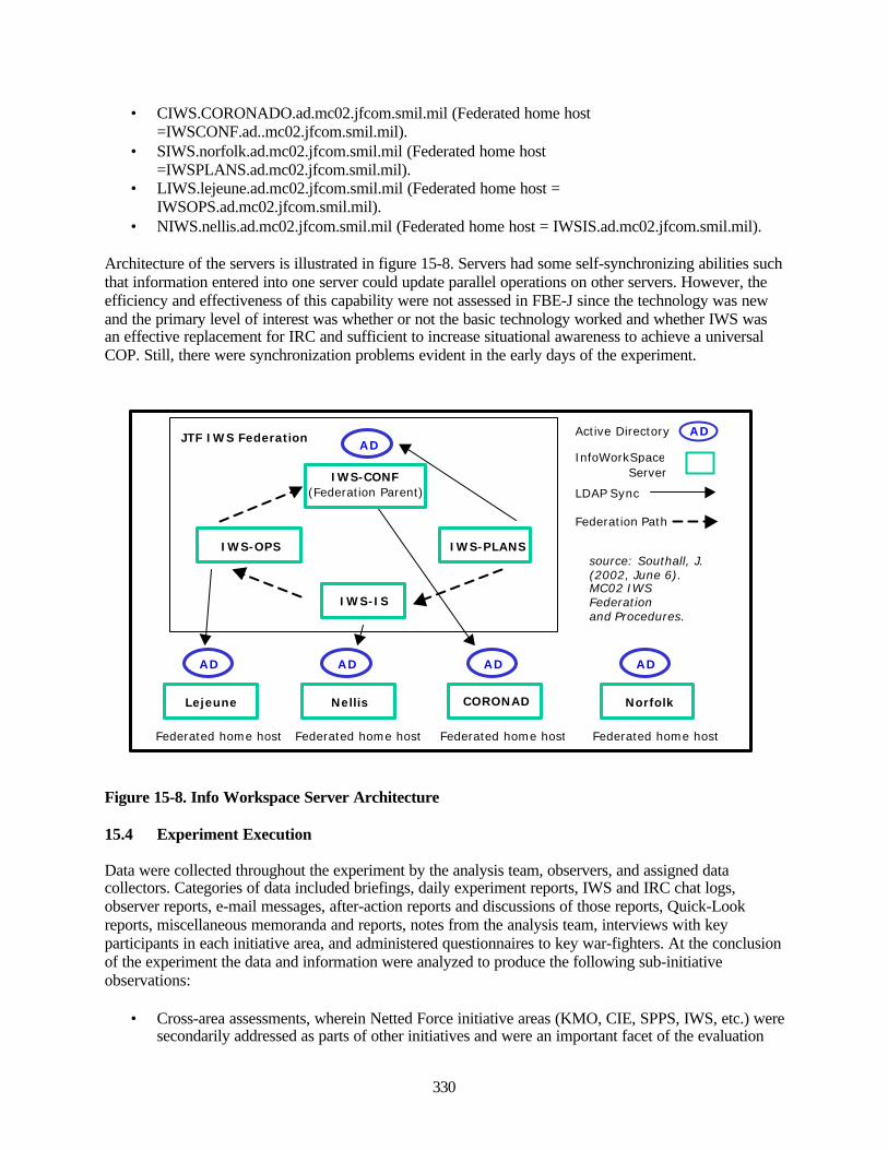
330
• CIWS.CORONADO.ad.mc02.jfcom.smil.mil (Federated home host=IWSCONF.ad..mc02.jfcom.smil.mil).
• SIWS.norfolk.ad.mc02.jfcom.smil.mil (Federated home host=IWSPLANS.ad.mc02.jfcom.smil.mil).
• LIWS.lejeune.ad.mc02.jfcom.smil.mil (Federated home host =IWSOPS.ad.mc02.jfcom.smil.mil).
• NIWS.nellis.ad.mc02.jfcom.smil.mil (Federated home host = IWSIS.ad.mc02.jfcom.smil.mil).
Architecture of the servers is illustrated in figure 15-8. Servers had some self-synchronizing abilities suchthat information entered into one server could update parallel operations on other servers. However, theefficiency and effectiveness of this capability were not assessed in FBE-J since the technology was newand the primary level of interest was whether or not the basic technology worked and whether IWS wasan effective replacement for IRC and sufficient to increase situational awareness to achieve a universalCOP. Still, there were synchronization problems evident in the early days of the experiment.
Figure 15-8. Info Workspace Server Architecture
15.4 Experiment Execution
Data were collected throughout the experiment by the analysis team, observers, and assigned datacollectors. Categories of data included briefings, daily experiment reports, IWS and IRC chat logs,observer reports, e-mail messages, after-action reports and discussions of those reports, Quick-Lookreports, miscellaneous memoranda and reports, notes from the analysis team, interviews with keyparticipants in each initiative area, and administered questionnaires to key war-fighters. At the conclusionof the experiment the data and information were analyzed to produce the following sub-initiativeobservations:
• Cross-area assessments, wherein Netted Force initiative areas (KMO, CIE, SPPS, IWS, etc.) weresecondarily addressed as parts of other initiatives and were an important facet of the evaluation
IWS-CONF(Federation Parent)
IWS-PLANS
JTF IWS FederationAD
IWS-OPS
IWS-IS
Lejeune
AD
Federated home host
Nellis
AD
Federated home host
CORONADO
AD
Federated home host
Norfolk
AD
Federated home host
LDAP Sync
Federation Path
Active Directory
InfoWorkSpace Server
AD
source: Southall, J.(2002, June 6).MC02 IWSFederationand Procedures.
331
process. They revealed the effectiveness of the Netted Force from war-fighter perspectives as itsupported other initiatives or operating areas (ASW, MIW, HSV, etc.).
• Cross-area synthesis, extraction, and analyses were enabled through the knowledge managementcapability of the Analysis Information and Knowledge Management System at the MeyerInstitute of Systems Engineering at the Naval Postgraduate School.
High-level effectiveness and performance measures with respect to Netted Force helped to determine howwell the Netted Force initiative, KMO concept, and CIE can:
• Reduce uncertainty.• Increase situational awareness.• Decrease information overload.• Shorten decision cycles.• Address bandwidth as a war-fighting tool.
KMO was assessed from command, staff, and war-fighter perspectives. CIE and its components wereevaluated primarily from war-fighter and secondarily from staff perspectives.
15.5 Knowledge Management Organization
The quantity of information available to war-fighters has increased exponentially over the past decade.Knowledge needs have escalated, and the ability to analyze, sort, associate, correlate and fuse informationto generate knowledge in support of command and war-fighter situational awareness has become apriority. KMO was intended to improve decision making through an organizational structure that ensuredthat the best information reached key decision makers at the correct time; that systems and processescritical to COP generation were operational and providing optimal levels of information flows andintegration; and that collaborative and information processing tools were used effectively by allexperiment participants.
KMO was a new organizational construct for FBE-J/MC02. Objectives were set at a high-level and weresomewhat ambiguous, with goals such as the facilitation of information flows across the JTF, and supportfor the JFMCC process. If implemented as envisioned, demands on KMO would be significant and acrossall mission areas. There were mixed results. KMO leadership and staff performed with efficiency andeffectiveness. There were operational problems in tasking, training, support and implementation.Technical issues prohibited a universal COP and high-efficiency CIE so in these areas KMO effectivenesswas limited. As an organizational construct, the KMO in FBE-J was without the organizational stature,support structure or authority, commensurate with the assigned responsibilities and high-level objectives.In addition, KMO duties overlapped with those filled by the N2 and N6, with N2-equivalent dutiesfocusing on the RFI process and finding critical information, and N6 duties on the management ofnetworks and infrastructure to access that information.
The following definitions are provided to help frame the analysis:
• “Data” are sensor or machine-based output• “Information” is processed or enhanced data, including both structured and unstructured
resources (e.g., memos, letters, briefs)• “Knowledge” is processed information such that context has been added sufficient for decision
support, including situational awareness and action based upon new understanding.
Knowledge is therefore, a value-added resource to information that provides guidance, clarification,insight, and understanding. Some background on knowledge operations in the private sector may be
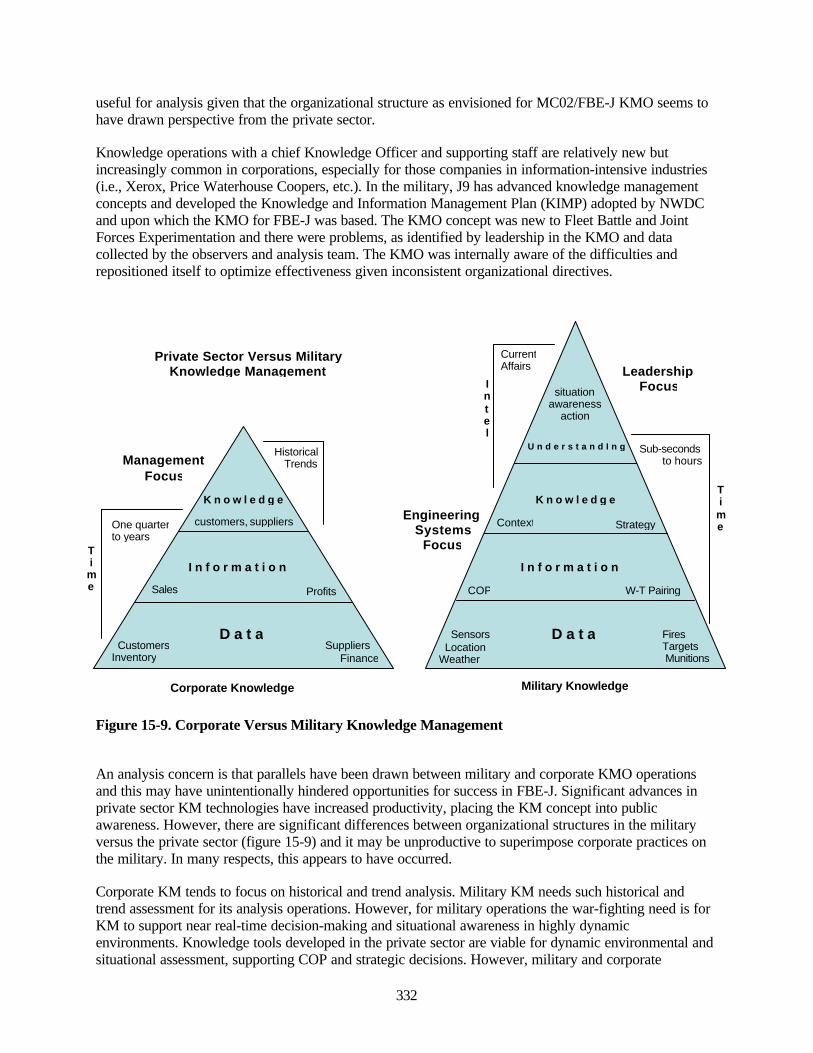
332
useful for analysis given that the organizational structure as envisioned for MC02/FBE-J KMO seems tohave drawn perspective from the private sector.
Knowledge operations with a chief Knowledge Officer and supporting staff are relatively new butincreasingly common in corporations, especially for those companies in information-intensive industries(i.e., Xerox, Price Waterhouse Coopers, etc.). In the military, J9 has advanced knowledge managementconcepts and developed the Knowledge and Information Management Plan (KIMP) adopted by NWDCand upon which the KMO for FBE-J was based. The KMO concept was new to Fleet Battle and JointForces Experimentation and there were problems, as identified by leadership in the KMO and datacollected by the observers and analysis team. The KMO was internally aware of the difficulties andrepositioned itself to optimize effectiveness given inconsistent organizational directives.
Figure 15-9. Corporate Versus Military Knowledge Management
An analysis concern is that parallels have been drawn between military and corporate KMO operationsand this may have unintentionally hindered opportunities for success in FBE-J. Significant advances inprivate sector KM technologies have increased productivity, placing the KM concept into publicawareness. However, there are significant differences between organizational structures in the militaryversus the private sector (figure 15-9) and it may be unproductive to superimpose corporate practices onthe military. In many respects, this appears to have occurred.
Corporate KM tends to focus on historical and trend analysis. Military KM needs such historical andtrend assessment for its analysis operations. However, for military operations the war-fighting need is forKM to support near real-time decision-making and situational awareness in highly dynamicenvironments. Knowledge tools developed in the private sector are viable for dynamic environmental andsituational assessment, supporting COP and strategic decisions. However, military and corporate
Corporate Knowledge Military KnowledgeSSManagement
D a t a
I n f o r m a t i o n
K n o w l e d g e
D a t a
I n f o r m a t i o n
K n o w l e d g e
U n d e r s t a n d I n g
customers, suppliers
situationawareness
action
One quarterto years
Time
HistoricalTrendsManagement
Focus
Sub-secondsto hours
LeadershipFocus
CurrentAffairs
Intel
Private Sector Versus MilitaryKnowledge Management
Sales
CustomersInventory
Profits
Suppliers Finance
EngineeringSystems
Focus
Sensors Location Weather
FiresTargets Munitions
W-T PairingCOP
Context Strategy
Time
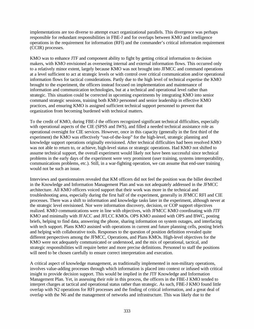
333
implementations are too diverse to attempt exact organizational parallels. This divergence was perhapsresponsible for redundant responsibilities in FBE-J and for overlaps between KMO and intelligenceoperations in the requirement for information (RFI) and the commander’s critical information requirement(CCIR) processes.
KMO was to enhance JTF and component ability to fight by getting critical information to decisionmakers, with KMO envisioned as overseeing internal and external information flows. This occurred onlyto a relatively minor extent, largely because KMO was not brought into JFMCC and command operationsat a level sufficient to act at strategic levels or with control over critical communication and/or operationalinformation flows for tactical considerations. Partly due to the high level of technical expertise the KMObrought to the experiment, the officers instead focused on implementation and maintenance ofinformation and communication technologies, but at a technical and operational level rather thanstrategic. This situation could be corrected in upcoming experiments by integrating KMO into seniorcommand strategic sessions, training both KMO personnel and senior leadership in effective KMOpractices, and ensuring KMO is assigned sufficient technical support personnel to prevent thatorganization from becoming burdened with technical matters.
To the credit of KMO, during FBE-J the officers recognized significant technical difficulties, especiallywith operational aspects of the CIE (SPSS and IWS), and filled a needed technical assistance role asoperational oversight for CIE services. However, once in this capacity (generally in the first third of theexperiment) the KMO was effectively “out-of-the-loop” for the high-level, strategic planning andknowledge support operations originally envisioned. After technical difficulties had been resolved KMOwas not able to return to, or achieve, high-level status or strategic operations. Had KMO not shifted toassume technical support, the overall experiment would likely not have been successful since technicalproblems in the early days of the experiment were very prominent (user training, systems interoperability,communications problems, etc.). Still, in a war-fighting operation, we can assume that end-user trainingwould not be such an issue.
Interviews and questionnaires revealed that KM officers did not feel the position was the billet describedin the Knowledge and Information Management Plan and was not adequately addressed in the JFMCCarchitecture. All KMO officers voiced support that their work was more in the technical andtroubleshooting area, especially during the first half of the experiment, generally in JFMCC RFI and CIEprocesses. There was a shift to information and knowledge tasks later in the experiment, although never atthe strategic level envisioned. Nor were information discovery, decision, or COP support objectivesrealized. KMO communications were in line with objectives, with JFMCC KMO coordinating with JTFKMO and minimally with JFACC and JFLCC KMOs. OPS KMO assisted with OPS and BWC, postingbriefs, helping to find data, answering the phone, sharing information on system outages, and interfacingwith tech support. Plans KMO assisted with operations in current and future planning cells, posting briefsand helping with collaborative tools. Responses to the question of position definition revealed quitedifferent perspectives among the JFMCC, Operations, and Plans KMOs. High-level objectives for theKMO were not adequately communicated or understood, and the mix of operational, tactical, andstrategic responsibilities will require better and more precise definitions. Personnel to staff the positionswill need to be chosen carefully to ensure correct interpretation and execution.
A critical aspect of knowledge management, as traditionally implemented in non-military operations,involves value-adding processes through which information is placed into context or infused with criticalinsight to provide decision support. This would be implied in the JTF Knowledge and InformationManagement Plan. Yet, in assessing their role in this process, the officers in the FBE-J KMO tended tointerpret charges at tactical and operational status rather than strategic. As such, FBE-J KMO found littleoverlap with N2 operations for RFI processes and the finding of critical information, and a great deal ofoverlap with the N6 and the management of networks and infrastructure. This was likely due to the
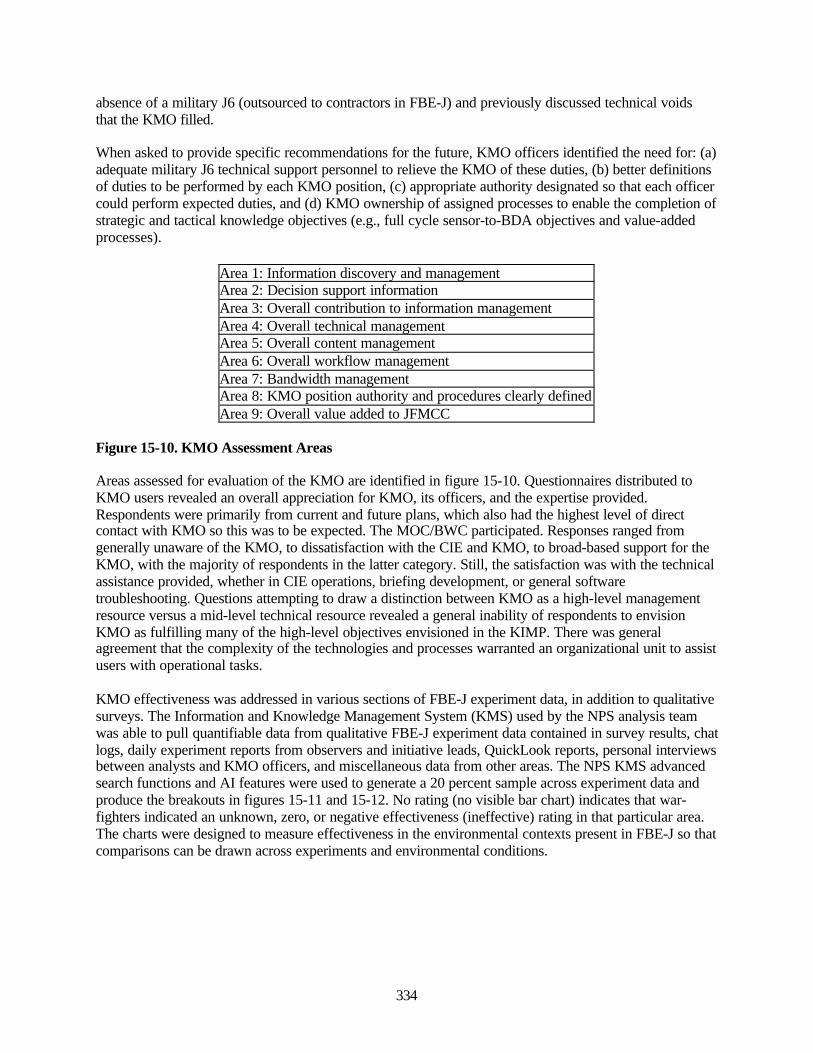
334
absence of a military J6 (outsourced to contractors in FBE-J) and previously discussed technical voidsthat the KMO filled.
When asked to provide specific recommendations for the future, KMO officers identified the need for: (a)adequate military J6 technical support personnel to relieve the KMO of these duties, (b) better definitionsof duties to be performed by each KMO position, (c) appropriate authority designated so that each officercould perform expected duties, and (d) KMO ownership of assigned processes to enable the completion ofstrategic and tactical knowledge objectives (e.g., full cycle sensor-to-BDA objectives and value-addedprocesses).
Area 1: Information discovery and managementArea 2: Decision support informationArea 3: Overall contribution to information managementArea 4: Overall technical managementArea 5: Overall content managementArea 6: Overall workflow managementArea 7: Bandwidth managementArea 8: KMO position authority and procedures clearly definedArea 9: Overall value added to JFMCC
Figure 15-10. KMO Assessment Areas
Areas assessed for evaluation of the KMO are identified in figure 15-10. Questionnaires distributed toKMO users revealed an overall appreciation for KMO, its officers, and the expertise provided.Respondents were primarily from current and future plans, which also had the highest level of directcontact with KMO so this was to be expected. The MOC/BWC participated. Responses ranged fromgenerally unaware of the KMO, to dissatisfaction with the CIE and KMO, to broad-based support for theKMO, with the majority of respondents in the latter category. Still, the satisfaction was with the technicalassistance provided, whether in CIE operations, briefing development, or general softwaretroubleshooting. Questions attempting to draw a distinction between KMO as a high-level managementresource versus a mid-level technical resource revealed a general inability of respondents to envisionKMO as fulfilling many of the high-level objectives envisioned in the KIMP. There was generalagreement that the complexity of the technologies and processes warranted an organizational unit to assistusers with operational tasks.
KMO effectiveness was addressed in various sections of FBE-J experiment data, in addition to qualitativesurveys. The Information and Knowledge Management System (KMS) used by the NPS analysis teamwas able to pull quantifiable data from qualitative FBE-J experiment data contained in survey results, chatlogs, daily experiment reports from observers and initiative leads, QuickLook reports, personal interviewsbetween analysts and KMO officers, and miscellaneous data from other areas. The NPS KMS advancedsearch functions and AI features were used to generate a 20 percent sample across experiment data andproduce the breakouts in figures 15-11 and 15-12. No rating (no visible bar chart) indicates that war-fighters indicated an unknown, zero, or negative effectiveness (ineffective) rating in that particular area.The charts were designed to measure effectiveness in the environmental contexts present in FBE-J so thatcomparisons can be drawn across experiments and environmental conditions.
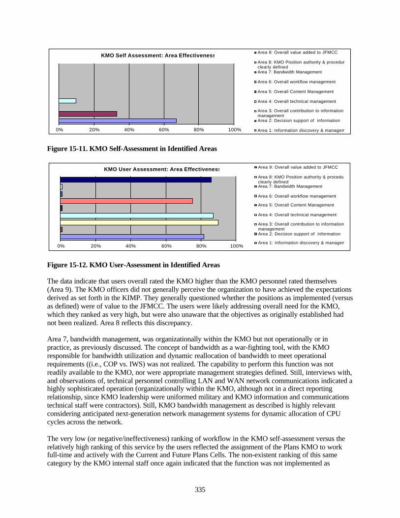
335
KMO Self Assessment: Area Effectiveness
0% 20% 40% 60% 80% 100%
Area 9: Overall value added to JFMCC
Area 8: KMO Position authority & proceduresclearly definedArea 7: Bandwidth Management
Area 6: Overall workflow management
Area 5: Overall Content Management
Area 4: Overall technical management
Area 3: Overall contribution to informationmanagementArea 2: Decision support of information
Area 1: Information discovery & management
Figure 15-11. KMO Self-Assessment in Identified Areas
KMO User Assessment: Area Effectiveness
0% 20% 40% 60% 80% 100%
Area 9: Overall value added to JFMCC
Area 8: KMO Position authority & proceduresclearly definedArea 7: Bandwidth Management
Area 6: Overall workflow management
Area 5: Overall Content Management
Area 4: Overall technical management
Area 3: Overall contribution to informationmanagementArea 2: Decision support of information
Area 1: Information discovery & management
Figure 15-12. KMO User-Assessment in Identified Areas
The data indicate that users overall rated the KMO higher than the KMO personnel rated themselves(Area 9). The KMO officers did not generally perceive the organization to have achieved the expectationsderived as set forth in the KIMP. They generally questioned whether the positions as implemented (versusas defined) were of value to the JFMCC. The users were likely addressing overall need for the KMO,which they ranked as very high, but were also unaware that the objectives as originally established hadnot been realized. Area 8 reflects this discrepancy.
Area 7, bandwidth management, was organizationally within the KMO but not operationally or inpractice, as previously discussed. The concept of bandwidth as a war-fighting tool, with the KMOresponsible for bandwidth utilization and dynamic reallocation of bandwidth to meet operationalrequirements ((i.e., COP vs. IWS) was not realized. The capability to perform this function was notreadily available to the KMO, nor were appropriate management strategies defined. Still, interviews with,and observations of, technical personnel controlling LAN and WAN network communications indicated ahighly sophisticated operation (organizationally within the KMO, although not in a direct reportingrelationship, since KMO leadership were uniformed military and KMO information and communicationstechnical staff were contractors). Still, KMO bandwidth management as described is highly relevantconsidering anticipated next-generation network management systems for dynamic allocation of CPUcycles across the network.
The very low (or negative/ineffectiveness) ranking of workflow in the KMO self-assessment versus therelatively high ranking of this service by the users reflected the assignment of the Plans KMO to workfull-time and actively with the Current and Future Plans Cells. The non-existent ranking of this samecategory by the KMO internal staff once again indicated that the function was not implemented as
336
originally designed, with the KMO operating effectively at the technical, operational, and perhaps tacticallevels, but not achieving the strategic levels envisioned.
The very low rankings in content management by both the KMO and users indicated that a core KMobjective was not realized. Technical management received a very high rating by users and a low ratingby KMO, likely reflecting that while KMO was active in technical management this was not a primaryobjective of the initiative, or at least the types of low-level technical management KMO performed inFBE-J. A similar situation in information management where users rated the service very high yet theKMO very low, reflecting that the types of information managed was not at the strategic levels envisionedbut rather at operational and tactical levels.
A reverse situation occurred with regards to decision support information where users rated help in thisarea very low, while KMO self-assessed at a moderate level. This discrepancy may be explained by anover-weighting of current and future plans cells in the KMO users survey (which was appropriate giventhe positioning and interaction responsibilities of the KMO). Decision support would typically be aprimary KMO duty, but visible results would not necessarily be apparent to most users since in anelectronic environment the matter of who produced the knowledge or made the knowledge processesavailable may not be readily discernable.
Area 1, information discovery and management, was rated highly by both the KMO and users. In this areaKMO was successful, and this is likely one of the most important areas in the KMO initiative. This wouldalso be considered a base or foundation upon which other areas could build. So, the foundation has beenlaid for a KMO through FBE-J, and what remains are the advanced functions for further refinement insubsequent experiments.
In sum, both technical management and knowledge coordination functions require redefinition ofdoctrine, manning, training, organizational practices, and implementation routines. Still, the concept ishighly viable, critically important, and should be continued into the future. There are some importantparallels, and differences, in the implementation of a military KMO versus a KMO in the private sector,from which the concept was likely derived. Hopefully the above discussion will aid in the recognition ofcritical strengths and differences between both approaches and will thereby aid in the development ofmore effective routines and objectives.
15.6 Collaborative Information Environment
The Collaborative Information Environment (CIE) was not a single technology but rather a collective ofonline services and applications. Included were facilities for information sharing, resource planning,timeline execution, workflow collaboration, and real-time multicast conferencing. CIE, along with TES-N, GCCS-M, and ADOCS/LAWS, was instrumental in realization of the COP. CIE supported radar,visualization, and weapon-target pairing operations. A prominent difference between CIE and sensor andweapon-target technologies was its focus on collaboration and knowledge transfer.
Routing within the network infrastructure was through a subscription-based multicast architecturewherein multiple war-fighters would receive the same communications at the same time, essentially thecapability of a broadcast architecture without the overhead and extraneous messaging to non-interestedwar-fighters. Multicast routing/messaging has time-efficiency advantages over unicast or point-to-pointcommunications but can directly impact overall bandwidth. Multicast would lend itself to the generationof an accurate and universal COP.
Bandwidth conservation requires specific identification of appropriate receivers and will likely need toaccommodate dynamic re-allocation based on changed war-fighter objectives, a difficult and complexissue perhaps beyond multicast architectures, especially for multimedia communications. Alternative
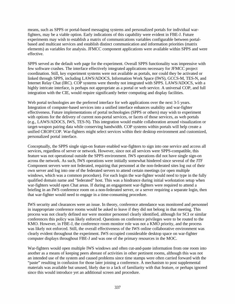
337
means, such as SPPS or portal-based messaging systems and personalized portals for individual war-fighters, may be a viable option. Early indications of this capability were evident in FBE-J. Futureexperiments may wish to establish a matrix of communications variables configurable between portal-based and multicast services and establish distinct communication and information priorities (matrixelements) as variables for analysis. JFMCC component applications were available within SPPS and wereeffective.
SPPS served as the default web page for the experiment. Overall SPPS functionality was impressive withfew software crashes. The interface effectively integrated applications necessary for JFMCC projectcoordination. Still, key experiment systems were not available as portals, nor could they be activated orlinked through SPPS, including LAWS/ADOCS, Information Work Space (IWS), GCCS-M, TES-N, andInternet Relay Chat (IRC). COP systems were thereby not integrated with SPPS. LAWS/ADOCS, with ahighly intricate interface, is perhaps not appropriate as a portal or web service. A universal COP, and fullintegration with the CIE, would require significantly better computing and display facilities.
Web portal technologies are the preferred interface for web applications over the next 3-5 years.Integration of computer-based services into a unified interface enhances usability and war-fightereffectiveness. Future implementations of portal technologies (SPPS or others) may wish to experimentwith options for the delivery of current non-portal services, or facets of those services, as web portals(e.g., LAWS/ADOCS, IWS, TES-N). This integration would enable collaboration around visualization ortarget-weapon pairing data while conserving bandwidth. COP systems within portals will help create aunified CROP/COP. War-fighters might select services within their desktop environment and customized,personalized portal interface.
Conceptually, the SPPS single sign-on feature enabled war-fighters to sign into one service and access allservices, regardless of server or network. However, since not all services were SPPS-compatible, thisfeature was not operational outside the SPPS environment. IWS operations did not have single sign-onacross the network. As such, IWS operations were initially somewhat hindered since several of the JTFComponent servers were not federated, requiring that personnel at the non-federated sites log out of theirown server and log into one of the federated servers to attend certain meetings (or open multiplewindows, which was a common procedure). For each login the war-fighter would need to type in the fullyqualified domain name and "federated" host. This was a hindrance during initial workstation setup whenwar-fighters would open Chat areas. If during an engagement war-fighters were required to attend abriefing in an IWS conference room on a non-federated server, or a server requiring a separate login, thenthat war-fighter would need to engage in a time-consuming procedure.
IWS security and clearances were an issue. In theory, conference attendance was monitored and personnelin inappropriate conference rooms would be asked to leave if they did not belong in that meeting. Thisprocess was not clearly defined nor were monitor personnel clearly identified, although for SCI or similarconferences this policy was likely enforced. Questions on conference privileges were to be routed to theKMO. However, in FBE-J, the conference room monitor role was not a KMO priority, and the processwas likely not enforced. Still, the overall effectiveness of the IWS online collaborative environment wasclearly evident throughout the experiment. IWS occupied considerable desktop space on war-fightercomputer displays throughout FBE-J and was one of the primary resources in the MOC.
War-fighters would open multiple IWS windows and often cut-and-paste information from one room intoanother as a means of keeping peers abreast of activities in other pertinent rooms, although this was notan intended use of the system and caused problems since time stamps were often carried forward with the“paste” resulting in confusion for those later joining a conference. A mechanism to post supplementalmaterials was available but unused, likely due to a lack of familiarity with that feature, or perhaps ignoredsince this would introduce yet an additional screen and procedure.
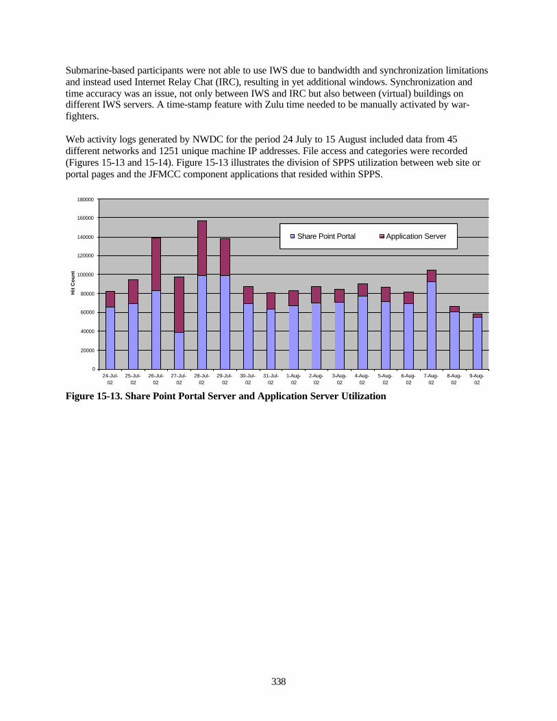
338
Submarine-based participants were not able to use IWS due to bandwidth and synchronization limitationsand instead used Internet Relay Chat (IRC), resulting in yet additional windows. Synchronization andtime accuracy was an issue, not only between IWS and IRC but also between (virtual) buildings ondifferent IWS servers. A time-stamp feature with Zulu time needed to be manually activated by war-fighters.
Web activity logs generated by NWDC for the period 24 July to 15 August included data from 45different networks and 1251 unique machine IP addresses. File access and categories were recorded(Figures 15-13 and 15-14). Figure 15-13 illustrates the division of SPPS utilization between web site orportal pages and the JFMCC component applications that resided within SPPS.
0
20000
40000
60000
80000
100000
120000
140000
160000
180000
24-Jul-02
25-Jul-02
26-Jul-02
27-Jul-02
28-Jul-02
29-Jul-02
30-Jul-02
31-Jul-02
1-Aug-02
2-Aug-02
3-Aug-02
4-Aug-02
5-Aug-02
6-Aug-02
7-Aug-02
8-Aug-02
9-Aug-02
Hit
Co
un
t
Share Point Portal Application Server
Figure 15-13. Share Point Portal Server and Application Server Utilization
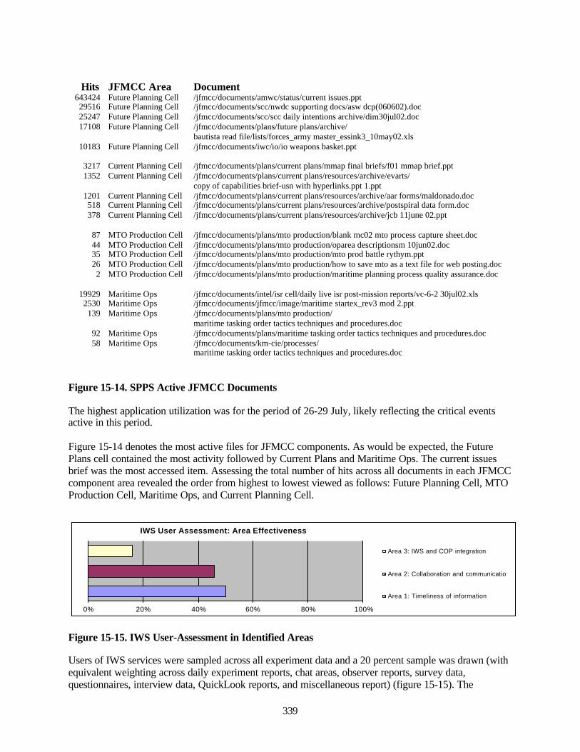
339
Hits JFMCC Area Document643424 Future Planning Cell /jfmcc/documents/amwc/status/current issues.ppt29516 Future Planning Cell /jfmcc/documents/scc/nwdc supporting docs/asw dcp(060602).doc25247 Future Planning Cell /jfmcc/documents/scc/scc daily intentions archive/dim30jul02.doc17108 Future Planning Cell /jfmcc/documents/plans/future plans/archive/
bautista read file/lists/forces_army master_essink3_10may02.xls10183 Future Planning Cell /jfmcc/documents/iwc/io/io weapons basket.ppt
3217 Current Planning Cell /jfmcc/documents/plans/current plans/mmap final briefs/f01 mmap brief.ppt1352 Current Planning Cell /jfmcc/documents/plans/current plans/resources/archive/evarts/
copy of capabilities brief-usn with hyperlinks.ppt 1.ppt1201 Current Planning Cell /jfmcc/documents/plans/current plans/resources/archive/aar forms/maldonado.doc518 Current Planning Cell /jfmcc/documents/plans/current plans/resources/archive/postspiral data form.doc378 Current Planning Cell /jfmcc/documents/plans/current plans/resources/archive/jcb 11june 02.ppt
87 MTO Production Cell /jfmcc/documents/plans/mto production/blank mc02 mto process capture sheet.doc44 MTO Production Cell /jfmcc/documents/plans/mto production/oparea descriptionsm 10jun02.doc35 MTO Production Cell /jfmcc/documents/plans/mto production/mto prod battle rythym.ppt26 MTO Production Cell /jfmcc/documents/plans/mto production/how to save mto as a text file for web posting.doc2 MTO Production Cell /jfmcc/documents/plans/mto production/maritime planning process quality assurance.doc
19929 Maritime Ops /jfmcc/documents/intel/isr cell/daily live isr post-mission reports/vc-6-2 30jul02.xls2530 Maritime Ops /jfmcc/documents/jfmcc/image/maritime startex_rev3 mod 2.ppt139 Maritime Ops /jfmcc/documents/plans/mto production/
maritime tasking order tactics techniques and procedures.doc92 Maritime Ops /jfmcc/documents/plans/maritime tasking order tactics techniques and procedures.doc58 Maritime Ops /jfmcc/documents/km-cie/processes/
maritime tasking order tactics techniques and procedures.doc
Figure 15-14. SPPS Active JFMCC Documents
The highest application utilization was for the period of 26-29 July, likely reflecting the critical eventsactive in this period.
Figure 15-14 denotes the most active files for JFMCC components. As would be expected, the FuturePlans cell contained the most activity followed by Current Plans and Maritime Ops. The current issuesbrief was the most accessed item. Assessing the total number of hits across all documents in each JFMCCcomponent area revealed the order from highest to lowest viewed as follows: Future Planning Cell, MTOProduction Cell, Maritime Ops, and Current Planning Cell.
IWS User Assessment: Area Effectiveness
0% 20% 40% 60% 80% 100%
Area 3: IWS and COP integration
Area 2: Collaboration and communications
Area 1: Timeliness of information
Figure 15-15. IWS User-Assessment in Identified Areas
Users of IWS services were sampled across all experiment data and a 20 percent sample was drawn (withequivalent weighting across daily experiment reports, chat areas, observer reports, survey data,questionnaires, interview data, QuickLook reports, and miscellaneous report) (figure 15-15). The
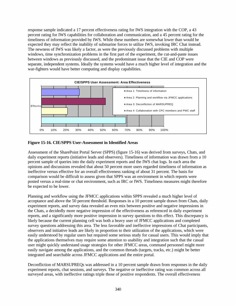
340
response sample indicated a 17 percent effectiveness rating for IWS integration with the COP, a 43percent rating for IWS capabilities for collaboration and communication, and a 45 percent rating for thetimeliness of information provided by IWS. While these numbers are somewhat lower than would beexpected they may reflect the inability of submarine forces to utilize IWS, invoking IRC Chat instead.The newness of IWS was likely a factor, as were the previously discussed problems with multiplewindows, time synchronization problems in the first part of the experiment, the cut-and-paste issuesbetween windows as previously discussed, and the predominant issue that the CIE and COP wereseparate, independent systems. Ideally the systems would have a much higher level of integration and thewar-fighters would have better computing and display capabilities.
CIE/SPPS User Assessment: Area Effectiveness
0% 10% 20% 30% 40% 50% 60% 70% 80% 90% 100%
Effective
Area 1: Timeliness of information
Area 2: Planning and workflow via JFMCC applications
Area 3: Deconfliction of MARSUPREQ
Area 4: Collaboration with CPC members and PWC staff
Figure 15-16. CIE/SPPS User-Assessment in Identified Areas
Assessment of the SharePoint Portal Server (SPPS) (figure 15-16) was derived from surveys, Chats, anddaily experiment reports (initiative leads and observers). Timeliness of information was drawn from a 10percent sample of queries into the daily experiment reports and the IWS chat logs. In each area theopinions and discussions revealed that about 50 percent more users regarded timeliness of information asineffective versus effective for an overall effectiveness ranking of about 31 percent. The basis forcomparison would be difficult to assess given that SPPS was an environment in which reports wereposted versus a real-time or chat environment, such as IRC or IWS. Timeliness measures might thereforebe expected to be lower.
Planning and workflow using the JFMCC applications within SPPS revealed a much higher level ofacceptance and above the 50 percent threshold. Responses in a 10 percent sample drawn from Chats, dailyexperiment reports, and survey data revealed an even mix between positive and negative impressions inthe Chats, a decidedly more negative impression of the effectiveness as referenced in daily experimentreports, and a significantly more positive impression in survey questions to this effect. This discrepancy islikely because the current planning cell was both a heavy user of JFMCC applications and completedsurvey questions addressing this area. The less favorable and ineffective impressions of Chat participants,observers and initiative leads are likely in proportion to their utilization of the applications, which wereeasily understood by regular users but required some serious study for casual users. This would imply thatthe applications themselves may require some attention to usability and integration such that the casualuser might quickly understand usage strategies for other JFMCC areas, command personnel might moreeasily navigate among the applications, and the common threads (targets, tracks, etc.) might be betterintegrated and searchable across JFMCC applications and the entire portal.
Deconfliction of MARSUPREQs was addressed in a 10 percent sample drawn from responses in the dailyexperiment reports, chat sessions, and surveys. The negative or ineffective rating was common across allsurveyed areas, with ineffective ratings triple those of positive respondents. The overall effectiveness
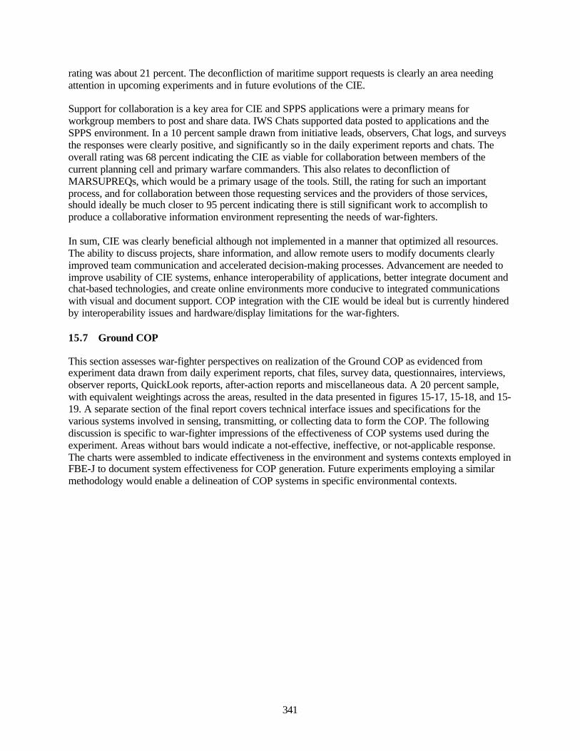
341
rating was about 21 percent. The deconfliction of maritime support requests is clearly an area needingattention in upcoming experiments and in future evolutions of the CIE.
Support for collaboration is a key area for CIE and SPPS applications were a primary means forworkgroup members to post and share data. IWS Chats supported data posted to applications and theSPPS environment. In a 10 percent sample drawn from initiative leads, observers, Chat logs, and surveysthe responses were clearly positive, and significantly so in the daily experiment reports and chats. Theoverall rating was 68 percent indicating the CIE as viable for collaboration between members of thecurrent planning cell and primary warfare commanders. This also relates to deconfliction ofMARSUPREQs, which would be a primary usage of the tools. Still, the rating for such an importantprocess, and for collaboration between those requesting services and the providers of those services,should ideally be much closer to 95 percent indicating there is still significant work to accomplish toproduce a collaborative information environment representing the needs of war-fighters.
In sum, CIE was clearly beneficial although not implemented in a manner that optimized all resources.The ability to discuss projects, share information, and allow remote users to modify documents clearlyimproved team communication and accelerated decision-making processes. Advancement are needed toimprove usability of CIE systems, enhance interoperability of applications, better integrate document andchat-based technologies, and create online environments more conducive to integrated communicationswith visual and document support. COP integration with the CIE would be ideal but is currently hinderedby interoperability issues and hardware/display limitations for the war-fighters.
15.7 Ground COP
This section assesses war-fighter perspectives on realization of the Ground COP as evidenced fromexperiment data drawn from daily experiment reports, chat files, survey data, questionnaires, interviews,observer reports, QuickLook reports, after-action reports and miscellaneous data. A 20 percent sample,with equivalent weightings across the areas, resulted in the data presented in figures 15-17, 15-18, and 15-19. A separate section of the final report covers technical interface issues and specifications for thevarious systems involved in sensing, transmitting, or collecting data to form the COP. The followingdiscussion is specific to war-fighter impressions of the effectiveness of COP systems used during theexperiment. Areas without bars would indicate a not-effective, ineffective, or not-applicable response.The charts were assembled to indicate effectiveness in the environment and systems contexts employed inFBE-J to document system effectiveness for COP generation. Future experiments employing a similarmethodology would enable a delineation of COP systems in specific environmental contexts.
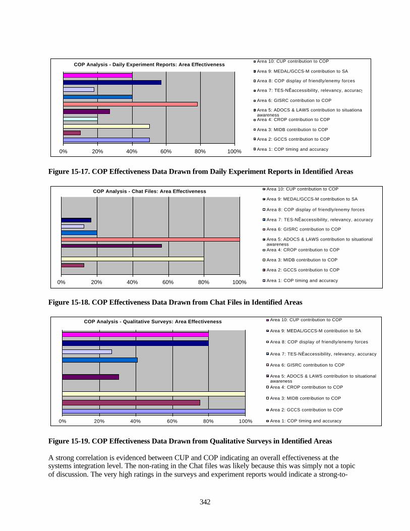
342
COP Analysis - Daily Experiment Reports: Area Effectiveness
0% 20% 40% 60% 80% 100%
Area 10: CUP contribution to COP
Area 9: MEDAL/GCCS-M contribution to SA
Area 8: COP display of friendly/enemy forces
Area 7: TES-NÊaccessibility, relevancy, accuracy
Area 6: GISRC contribution to COP
Area 5: ADOCS & LAWS contribution to situationalawarenessArea 4: CROP contribution to COP
Area 3: MIDB contribution to COP
Area 2: GCCS contribution to COP
Area 1: COP timing and accuracy
Figure 15-17. COP Effectiveness Data Drawn from Daily Experiment Reports in Identified Areas
COP Analysis - Chat Files: Area Effectiveness
0% 20% 40% 60% 80% 100%
Area 10: CUP contribution to COP
Area 9: MEDAL/GCCS-M contribution to SA
Area 8: COP display of friendly/enemy forces
Area 7: TES-NÊaccessibility, relevancy, accuracy
Area 6: GISRC contribution to COP
Area 5: ADOCS & LAWS contribution to situationalawarenessArea 4: CROP contribution to COP
Area 3: MIDB contribution to COP
Area 2: GCCS contribution to COP
Area 1: COP timing and accuracy
Figure 15-18. COP Effectiveness Data Drawn from Chat Files in Identified Areas
COP Analysis - Qualitative Surveys: Area Effectiveness
0% 20% 40% 60% 80% 100%
Area 10: CUP contribution to COP
Area 9: MEDAL/GCCS-M contribution to SA
Area 8: COP display of friendly/enemy forces
Area 7: TES-NÊaccessibility, relevancy, accuracy
Area 6: GISRC contribution to COP
Area 5: ADOCS & LAWS contribution to situationalawarenessArea 4: CROP contribution to COP
Area 3: MIDB contribution to COP
Area 2: GCCS contribution to COP
Area 1: COP timing and accuracy
Figure 15-19. COP Effectiveness Data Drawn from Qualitative Surveys in Identified Areas
A strong correlation is evidenced between CUP and COP indicating an overall effectiveness at thesystems integration level. The non-rating in the Chat files was likely because this was simply not a topicof discussion. The very high ratings in the surveys and experiment reports would indicate a strong-to-

343
moderate level of success in CUP/COP integration as perceived by the war-fighters, observers andinitiative leads. A question specific to CUP/COP was contained in the MIW survey.
A 58 percent (figure 15-17) and 80 percent (figure 15-19) effectiveness rating for MEDAL and GCCS-Mcontribution to situational awareness and the COP would indicate a strong approval for the use of thesesystems in the FBE-J context.
COP differentiation between friendly and enemy forces achieved only an average 20 percent level ofeffectiveness indicating failure for such a critical area. TES-N accessibility, relevancy, and accuracyachieved a 40 percent effectiveness rating from initiative leads and observer data, a similar result fromqualitative survey respondents, but only a 20 percent effectiveness rating from data drawn from chat files.Areas achieving an effectiveness rating below 50 percent indicate a need for improvement. In the case ofTES-N, improvement is likely needed in system accessibility and/or in the perceived value by war-fighters.
GISRC contribution to the COP was not significantly referenced in surveys but received overwhelmingpositive responses in the chat logs, observer data and initiative lead reports. GISRC is clearly a valuedresource with successful implementation and dissemination.
ADOCS/LAWS contribution to COP and situational awareness clearly received positive responses with a58 percent effectiveness rating from chat participants, but only a 28 percent effectiveness rating fromobservers and initiative leads and a 30 percent rating in survey questions specifically targeted to assessADOCS/LAWS effectiveness. Qualitative responses to these questions seemed to indicate that ADOCSwhen combined with BDA processes was not effective, as evidenced through statements such as “processbecame very confusing.... coordinating BDA, determining whether to re-strike, requesting new imagery,etc.” A particular area of concern involved BDA and processes for the identification of missed targets,with comments such as “putting re-strike targets back into the system as new targets makes things VERYconfusing.” Training for COP/ADOCS was addressed in the current plans cell survey, and the dataindicated that training was insufficient.
CROP/SPPS contribution to the COP was not a survey or discussion item but received somewhatfavorable mention in daily experiment reports. Lack of data, messaging, and communication integrationacross systems contributing to COP and situational awareness has been discussed earlier in this Section.
MIDB received very favorable ratings of effectiveness for COP and situational awareness with a 100percent effectiveness ratings from survey data, an 80 percent effectiveness rating from Chat participants,but only a 50 percent effectiveness from observer and initiative lead reports. This lower rating from thedaily experiment reports, from those assigned with lead and oversight responsibilities may indicate thatsome of the objectives for the MIDB were not achieved. This area would require further analysis todetermine the reason for the lower rating. Overall, the MIDB contribution to the COP in FBE-J would beconsidered successful, but with the above caveat and likely need for further improvement.
A divergence in effectiveness ratings was also evident for GCCS contribution to the COP, with theobservers and initiative leads awarding a rating of 10 percent, Chat participants 12 percent, but surveyrespondents 75 percent. This divergence warrants further investigation and assessment specific to thisarea in future experiments.
Overall accuracy and timing of COP data were not an active discussion area in the chats but received anoverwhelming positive (100 percent) rating in samples drawn from survey data, and a rating of 50 percenteffectiveness in samples drawn from daily experiment reports (observers and initiative leads). Interviewswith KMO and MOC personnel indicated that a universal and ubiquitous COP was not achieved in FBE-J. Variables cited included lack of systems integration and inefficiencies in display capabilities.
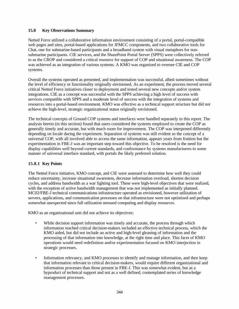
344
15.8 Key Observations Summary
Netted Force utilized a collaborative information environment consisting of a portal, portal-compatibleweb pages and sites, portal-based applications for JFMCC components, and two collaborative tools forChat, one for submarine-based participants and a broadband system with visual metaphors for non-submarine participants. CIE services, and the SharePoint Portal Server (SPPS) were collectively referredto as the CROP and considered a critical resource for support of COP and situational awareness. The COPwas achieved as an integration of various systems. A KMO was organized to oversee CIE and COPsystems.
Overall the systems operated as presented, and implementation was successful, albeit sometimes withoutthe level of efficiency or functionality originally envisioned. As an experiment, the process moved severalcritical Netted Force initiatives closer to deployment and tested several new concepts and/or systemintegrations. CIE as a concept was successful with the SPPS achieving a high level of success withservices compatible with SPPS and a moderate level of success with the integration of systems andresources into a portal-based environment. KMO was effective as a technical support structure but did notachieve the high-level, strategic organizational status originally envisioned.
The technical concepts of Ground COP systems and interfaces were handled separately in this report. Theanalysis herein (in this section) found that users considered the systems employed to create the COP asgenerally timely and accurate, but with much room for improvement. The COP was interpreted differentlydepending on locale during the experiment. Separation of systems was still evident so the concept of auniversal COP, with all involved able to access the same information, appears years from fruition but theexperimentation in FBE-J was an important step toward this objective. To be resolved is the need fordisplay capabilities well beyond current standards, and conformance by systems manufacturers to somemanner of universal interface standard, with portals the likely preferred solution.
15.8.1 Key Points
The Netted Force initiative, KMO concept, and CIE were assessed to determine how well they couldreduce uncertainty, increase situational awareness, decrease information overload, shorten decisioncycles, and address bandwidth as a war fighting tool. These were high-level objectives that were realized,with the exception of active bandwidth management that was not implemented as initially planned.MC02/FBE-J technical communications infrastructure operated as envisioned, however utilization ofservers, applications, and communication processes on that infrastructure were not optimized and perhapssomewhat unexpected since full utilization stressed computing and display resources.
KMO as an organizational unit did not achieve its objectives:
• While decision support information was timely and accurate, the process through whichinformation reached critical decision-makers included an effective technical process, which theKMO aided, but did not include an active and high-level gleaning of information and theprocessing of that information into knowledge, at the right time and place. This facet of KMOoperations would need redefinition and/or experimentation focused on KMO interjection instrategic processes.
• Information relevancy, and KMO processes to identify and manage information, and then keepthat information relevant to critical decision-makers, would require different organizational andinformation processes than those present in FBE-J. This was somewhat evident, but as abyproduct of technical support and not as a well defined, contemplated series of knowledgemanagement processes.
345
• Contribution of the KMO to information management was secondary to the technical aspects ofinformation communications and did not achieve the high-level or strategic objectivesenvisioned.
• KMO input to bandwidth allocation decisions supporting operations were not a facet of typicaloperations, albeit the need for this function was evident. More effective and detailed TTPs in thisarea would be required.
CIE was designed to reduce planning and execution timelines, enhance organizational effectives fordistributed operations, flatten organizational hierarchies and decision-making, enable self-synchronization, and integrate ADOCS/LAWS for situational awareness in distributed operations. Theoverall objective was to enable Rapid Decisive Operations through more efficient integration ofinformation and communications. Technological aspects of CIE were achieved with impressive utilizationof cutting-edge technologies:
• SPPS integrated critical systems through a portal and application framework that effectivelyreduced planning and execution timelines.
• Integration of JFMCC components through standardized applications within the portalframework enhanced organizational effectiveness for distributed operations since most directJFMCC component information was present within a browser-based application that could beviewed by war-fighters in the cell and across cells, from any network access point.
• CROP or secondary information relevant to the COP was available within the web site and pagesof SPPS where users could browse or search for information and this too would enhanceorganizational effectiveness for distributed operations.
• Flatted organizational hierarchies for faster decision-making were possible through the JFMCCcomponent applications within SPPS. This capability now exists as components can usenetworked applications to access and act upon information. Yet to be integrated into the processare workflow automation routines that would send pertinent information to appropriate personnelfor action and automated routing to the next war-fighter in the chain of command.
• Self-synchronization was evident in many of the systems. The databases were reportedly self-synchronizing with this capability also evident in the IWS servers.
• LAWS/ADOCS on displays were evident across the experiment thereby achieving this objective.LAWS/ADOCS remains a largely proprietary system without a readily available means forintegration with SPPS or JFMCC applications.
• SPPS provided an integrated, customizable interface into pertinent information, but not allinformation or communication systems were compatible with portal interfaces or displaytechnologies. The technical foundation for a unified system, with document management,version control, subscriptions, and single sign-on to the services was achieved. However,widespread optimization of the services was not achieved. Search and retrieval functionsappeared operational but not comprehensive or used to the level envisioned.
• IWS and IRC collectively provided means for communication and collaboration, albeit therequirement that two distinct systems be in operation was a significant disadvantage. Timingerrors between IWS servers in the early days of the experiment created significant difficultiesand the practice by war-fighters of cutting-and-pasting between IWS Chats as a means to keep
346
participants abreast of external activities caused confusion. The requirement that multiplewindows be opened to stay current, and an absence of some manner of triggering between chatareas, or the ability to identify and track events through the chats in real-time, hindered overalleffectiveness. Still, the IWS system efficiently conveyed timely information. IWS was notintegrated with LAWS/ADOCS, SPPS, or the JFMCC component applications.
The Ground COP in this section was assessed through questionnaires, surveys, observations, after-actionreports, Quick Look reports, and interviews to determine overall war-fighter impressions of the systems:
• Targeting information was simplified to improve situational awareness, but problems with theinput of missed targets into the systems as new targets caused some confusion.
• Views of friendly and enemy situations were not adequate, and war-fighters expressed concernswith their inability to make adequate differentiations.
• GCCS, MIDB, TES-N, and GISRC received strong levels of user-satisfaction as evidenced byutilization and effectiveness measures recorded in sampled user populations. MIDB supportedtactical and operational users and was considered accessible, relevant, and accurate.
• COP was perceived as timely and accurate by war-fighters, but reservations by knowledge andinformation leadership indicated that the COP had not been achieved to the level originallyanticipated.
15.8.2 Baseline Model versus Actual Performance
The MC02 broadband, wide-area infrastructure employed a component-based architecture consistent withmodels advanced for the Global Information Grid (GIG). Broadband was available within sites, betweensites, and across the grid or backbone at 10Mbps. There were complaints of bandwidth problemsthroughout the experiment. However, assessments of network management consoles and discussions withnetwork personnel indicated that bandwidth was less of a problem and server, router, and/or computer andapplication use more of an issue.
Non-essential voice communications within IWS, non-essential bitmaps within briefs, and multiple Chatwindows all open on a single PC would tend to increase bandwidth requirements in excess of essentialservices while dramatically increasing RAM requirements. To address these variables (voice, bitmaps,chats, videos) would require a more careful definition of the exact services required for each war-fighterand to support the COP. In sum, infrastructure services performed as expected and outlined in the baselinemodel. Particular applications and usages of the infrastructure were not optimized.
A core capability of the GIG (Global Information Grid) underlying MC02/FBE-J was synchronization ofservers across the grid such that servers coalesce to create a single virtual machine. This occurred only toa limited extent. While synchronization was evident, there were communication delays, problems with thesingle sign-on procedure, timing errors, and other technology errors. Overall the process efficiency acrossthe backbone was both efficient and impressive, but with ample room for improvement.
Active bandwidth management, a responsibility originally assigned to the KMO, was not achieved but isof significant importance given future opportunities for bandwidth and CPU cycle management of allmachines in an experiment. MC02/FBE-J was an important step toward grid-based computing and servicesynchronization.
SPSS as a portal to enterprise services was only moderately effective, yet a significant advance. War-fighters would uniformly access SPSS for morning and afternoon briefings, plans, and somewhat forgeneral analysis (information or knowledge gathering). JFMCC components had specialized applicationsserving their needs as applications within SPSS and this was highly effective. IWS, IRC, and the sensor
347
and targeting systems (LAWS/ADOCS) were not integrated into SPSS or available as portals or webservices.
A difference between chart data and information leadership viewpoints for COP effectiveness mayindicate objectives were met at certain levels but not at levels originally envisioned. Users may not havebeen aware of other areas or systems not included or immediately available to them (i.e., how much bettertheir awareness may have been given the integration of all available systems into the COP). Thisassumption would be supported from first-person assessment of war-fighters and the tendency for thoseWarriors to focus on information spaces within their immediate purview, but not to venture to othersystems. KMO and information leadership would be aware of all COP and situational awareness systemsand be in a position to judge that full integration and a universal COP has yet to be achieved.
15.8.3 Implications
CIE and COP as systems within Netted Force continue to evolve, with targeting and timing aspects ofCOP successful and integration aspects of CIE in support of COP yet to be achieved. High-level tasksassigned to KMO were not achieved. Effective implementation of the KMO concept, function and processcould be achieved by ascertaining information needs, likely users of that information, the most efficientmeans for dissemination, and the process through which context is added to the information to provideknowledge. This would require that KM officers act in strategic aspects of knowledge and informationmanagement processes rather than in the operational and technical support functions actually performed.
Personnel in communications, network, systems administration, and database operations were identifiedas working under KMO in organizational charts but in practice worked somewhat in parallel and incooperation, versus a strict reporting structure. In FBE-J, duties of KM officers overlapped with thosetraditionally filled by N2 and N6 and this caused confusion during the experiment. KMO N2 dutiesfocused on RFI processes and the finding of critical information. KMO N6 duties focused on themanagement of networks and infrastructure to access information. A clear definition of duties is neededprior to future KMO experimentation.
Interoperability is a significant issue given the difficulty of attaining synchronicity across diverse systems,technologies, platforms and networks. Overall, this level of synchronization is new, a projected corefuture capability of the GIG and grid computing model, and should therefore likely be a core initiative infuture experiments, with its own set of variables for analysis. Such a level of analysis will be critical asboth portal and non-portal environments use multimedia or voice/video enhanced communications.
Database and CIE application services supported clustering concepts with synchronization across a gridsuch that one server would update and synchronize other servers. Routine checks with IWS and databasestaff indicated that these operations were functional in varying degrees. A few days into the experiment(with all systems at full impact) indicated some discrepancies in this functionality. It was unclear whetherthis was a result of the network/grid, server processes, or the computer utilization habits employed by thewar-fighters.
15.8.4 Recommendations
Netted Force as a core component of next-generation war-fighters should provide the foundation fornetwork-centric activities and systems integration. Major facets of operational systems in the experimentlacked integration capabilities and inefficiencies were evident from redundant and non-communicatingsystems. Efforts to integrate proprietary technologies may require conformance to emerging informationstandards for interoperability at the display level initially, likely via portal protocols, and secondarily asdistinct messaging components, which may require that vendors rewrite their code into componentarchitectures.

348
While KMO did not achieve high-level objectives envisioned it was nevertheless an important steptoward a needed organizational structure. Formal objectives for FBE-J KMO were both aggressive andtimely, with a clear need for this organizational structure in joint forces operations. Factors hinderingcompletion of the objectives resulted from newness of the positions, lack of sufficient pre-planning,redundancies in position descriptions, inadequate training for KMO personnel, and insufficientoperational procedures for command units using or expected to use KMO services. A recommendation isthat KMO should serve as a high-level command resource and interface between command and strategicoperations. This will require significant transformation of existing decision-making support structures.
Documentation, training, and high-level integration of KMO into experiment strategy may further theconcept as a strategic component, but personnel selected will need to have an extensive command ofavailable knowledge across a wide variety or areas. This may require that Joint forces begin to train andeducate such individuals, along with commanders who will use them. Future experiments may help refinethe evolutionary process through which an effective KMO system and process is established. In an idealsetting, knowledge would be an integral, on-demand, and suggestive, providing a decision-supportadjunct to COP, JFMCC, or component operations. On-demand knowledge might be most effective ifdelivered as a web service within portals customized with planning, timeline, and collaborative systemsfor command personnel and war-fighters.
A more advanced portal environment would integrate all combat services and deliver components asportlets (or web application services configured as portlets) within personalized user interfaces.Environments personalized to the needs of each war-fighter would be optimal, and SPSS developers arelikely heading in this direction but will require that exact services needed by each war-fighter be fullydescribed in advance of the experiment and providers of those services able to deliver within portal-basedenvironments. This would provide significant additional capability in support of the COP and aid increating shared understanding between workgroups and war-fighters. This is the trend in industry, anddevelopers of pertinent services may want to consider adding SOAP or XML-remote capabilities to theirapplications.
349
16.0 Joint Theater Air Missile Defense (JTAMD) Key Observations
16.1 TAMD Experiment Objectives
FBE J/MC02 was intended to provide dynamic interactions necessary to further mature JointTAMD/AAW operations. Data were collected on the role of the RADC/ADC, interactions with theJFMCC Maritime Planning Process (MPP), the employment of multi-purpose surface combatants and thefunctions AADC Module. This information was intended to for inclusion in future TTP or doctrine asapplicable and for further refinement in future experimentation venues.
Navy air and missile defense experimentation was concentrated around the AADC Module located in theGeneral Dynamics Advanced Information Systems (GD AIS) facility in Greensboro, NC. The experimentwas not intended to evaluate the merits of the AADC Module, the adequacy of its embedded capabilities,or projected fielding plans. Instead the experiment was largely exploratory and was intended to developinsights in three major areas:
• Internal Module Planning Processes. Whether a developmental “Supplementary PlanningGuidance” supported module-planning procedures.
• Allocation of Multi-Purpose Surface Combatants. Whether an experimental planning processcentered on the staff of the Joint Force Maritime Component Commander (JFMCC) maximizedNavy force capabilities across competing operational demands.
• Combined RADC/ADC. Whether combining the roles of a Regional Air Defense Commander(RADC) reporting to the Joint Force Air Component Commander (JFACC) with the Air DefenseCommander (ADC or “AW”) reporting to the JFMCC was feasible.
16.1.1 Overarching Questions
FBE J was intended to gain insights into the following questions:
• Can a single commander appointed as the Battle Force Air Defense Commander (ADC or “AW”)and a Regional Air Defense Commander (RADC) supported by the AADC Module planningcapability and process effectively support the air and missile defense requirements of bothcommanders?
• Does the capability to rapidly wargame alternative courses of action with the embeddedwargaming (M&S) capability and provide graphic displays provide value added to the Joint ForceMaritime Component Commander (JFMCC) and Joint Forces Air Component Commander(JFACC)?
• What emerges as functional relationships between JTFHQ (and production of the EffectsTasking Order and/or the Defended Asset List), the JFMCC (Maritime Tasking Order) andJFACC/AADC (Air Tasking Order)?
• What emerges as the organizational relationship between the SJTFHQ Theater Missile Defense(TMD) Cell, JFACC/AADC, Deputy Area Air Defense Commander (32nd AAMDC), RegionalAir Defense Commanders (RADC) and the maritime Air Defense Commander?
• What elements of the experimental organization, TTP, and C2 learned from this event are suitablefor inclusion in a future USN AADC Module TACMEMO?
• Does the JFMCC Maritime Planning Process mitigate the dilemma posed by competing demandsfor multi-purpose surface combatants?

350
16.1.2 Sub-initiatives
The purpose of the JTAMD sub-initiatives was to further define the internal processes developed withinthe AADC Module necessary to support the JFMCC's Maritime Planning Process (MPP) and theJFACC/AADC.
• TAMD Mission Planning. Supplemental Planning Guidance was issued to the RADC/ADCstaff. High interest priorities included:
o Enemy Course of Action (ECOA) Development. Employ an internal Red Cell andsystematic method of predicting and evaluating alternative ECOA and selecting those thatwill be used to form the basis for planning efforts.
o Friendly Course of Action (COA) Development: Employ an internal process to developalternative objective based plans and evaluate the plans using embedded wargaming (M&S)capability.
o Risk Assessment. Employ a formalized process to identify and communicate the operationalrisk of various friendly courses of action.
• Allocation of Multi-Mission TAMD Capable Surface Combatants . Collect qualitative datafrom participants on whether the centralized asset allocation process within the JFMCC MaritimePlanning Process contributes to efficiently meeting both maritime force protection and joint airand missile defense tasking goals. Record instances of concurrent employment of individualunits, and document conflicts preventing concurrent tasking.
• Development of a Joint AADC Capability to Support an Ashore Based AADC and BattleForce Air Defense Commander. Assess what capabilities of the AADC Module provided valueadded to the planning processes of a JFACC/AADC ashore and the Navy Battle ForceCommander.
• Designation of the Battle Force Air Defense Commander (ADC) as a (Joint) Regional AirDefense Commander. Record the conflicts and challenges that emerged from organization fromthe concurrent designation of a single commander as the ADC responsible to the JFMCC for thedefense of naval forces and operations and to the JFACC/AADC for the defense of designatedcritical assets.
16.1.3 Background: Command and Control Organization
The C2 organization employed during FBE J/MC02 was largely based on existing joint doctrine. OneTAMD objective was to attempt to bridge the gap between the Combined Warfare Commander (CWC)organization detailed in Navy doctrine and the Joint Force Air Component Commander (JFACC)/AreaAir Defense Commander (AADC) described in Joint Doctrine (see Joint Publication 3-01 “Joint Doctrinefor Counterair”). In order to address this challenge responsibility for maritime force protection (Navy)and regional air and missile defense (joint) were assigned to a single sea-based commander. Within theexperiment construct, the Commanding Officer (O-6) of a simulated cruiser equipped with an AADCmodule was assigned duty as both the Air Defense Commander (ADC or “AW”) reporting to the JFMCCand Regional Air Defense Commander (RADC) reporting to the JFACC/AADC, as depicted in figure 1.
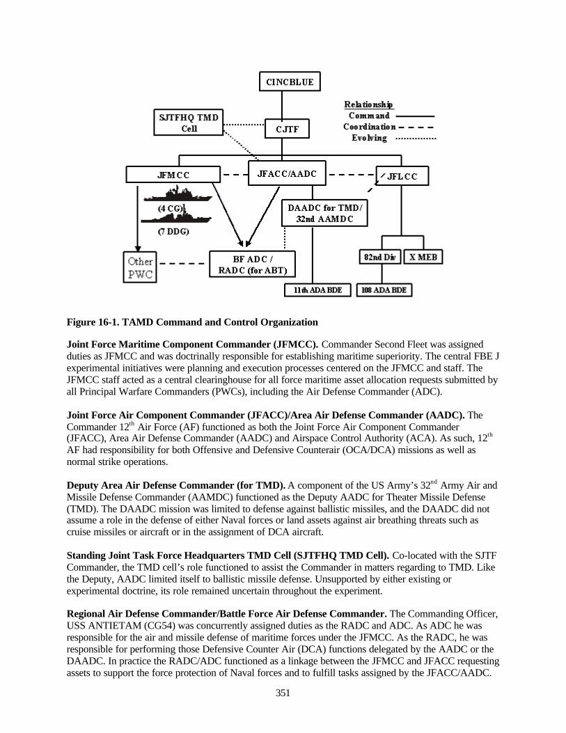
351
Figure 16-1. TAMD Command and Control Organization
Joint Force Maritime Component Commander (JFMCC). Commander Second Fleet was assignedduties as JFMCC and was doctrinally responsible for establishing maritime superiority. The central FBE Jexperimental initiatives were planning and execution processes centered on the JFMCC and staff. TheJFMCC staff acted as a central clearinghouse for all force maritime asset allocation requests submitted byall Principal Warfare Commanders (PWCs), including the Air Defense Commander (ADC).
Joint Force Air Component Commander (JFACC)/Area Air Defense Commander (AADC). TheCommander 12th Air Force (AF) functioned as both the Joint Force Air Component Commander(JFACC), Area Air Defense Commander (AADC) and Airspace Control Authority (ACA). As such, 12th
AF had responsibility for both Offensive and Defensive Counterair (OCA/DCA) missions as well asnormal strike operations.
Deputy Area Air Defense Commander (for TMD). A component of the US Army’s 32nd Army Air andMissile Defense Commander (AAMDC) functioned as the Deputy AADC for Theater Missile Defense(TMD). The DAADC mission was limited to defense against ballistic missiles, and the DAADC did notassume a role in the defense of either Naval forces or land assets against air breathing threats such ascruise missiles or aircraft or in the assignment of DCA aircraft.
Standing Joint Task Force Headquarters TMD Cell (SJTFHQ TMD Cell). Co-located with the SJTFCommander, the TMD cell’s role functioned to assist the Commander in matters regarding to TMD. Likethe Deputy, AADC limited itself to ballistic missile defense. Unsupported by either existing orexperimental doctrine, its role remained uncertain throughout the experiment.
Regional Air Defense Commander/Battle Force Air Defense Commander. The Commanding Officer,USS ANTIETAM (CG54) was concurrently assigned duties as the RADC and ADC. As ADC he wasresponsible for the air and missile defense of maritime forces under the JFMCC. As the RADC, he wasresponsible for performing those Defensive Counter Air (DCA) functions delegated by the AADC or theDAADC. In practice the RADC/ADC functioned as a linkage between the JFMCC and JFACC requestingassets to support the force protection of Naval forces and to fulfill tasks assigned by the JFACC/AADC.
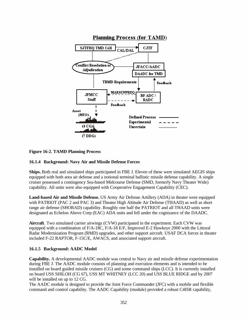
352
Figure 16-2. TAMD Planning Process
16.1.4 Background: Navy Air and Missile Defense Forces
Ships. Both real and simulated ships participated in FBE J. Eleven of these were simulated AEGIS shipsequipped with both area air defense and a notional terminal ballistic missile defense capability. A singlecruiser possessed a contingency Sea-based Midcourse Defense (SMD, formerly Navy Theater Wide)capability. All units were also equipped with Cooperative Engagement Capability (CEC).
Land-based Air and Missile Defense. US Army Air Defense Artillery (ADA) in theater were equippedwith PATRIOT (PAC 2 and PAC 3) and Theater High Altitude Air Defense (THAAD) as well as shortrange air defense (SHORAD) capability. Roughly one half the PATRIOT and all THAAD units weredesignated as Echelon Above Corp (EAC) ADA units and fell under the cognizance of the DAADC.
Aircraft. Two simulated carrier airwings (CVW) participated in the experiment. Each CVW wasequipped with a combination of F/A-18C, F/A-18 E/F, Improved E-2 Hawkeye 2000 with the LittoralRadar Modernization Program (RMD) upgrades, and other support aircraft. USAF DCA forces in theaterincluded F-22 RAPTOR, F-15C/E, AWACS, and associated support aircraft.
16.1.5 Background: AADC Model
Capability. A developmental AADC module was central to Navy air and missile defense experimentationduring FBE J. The AADC module consists of planning and execution elements and is intended to beinstalled on board guided missile cruisers (CG) and some command ships (LCC). It is currently installedon board USS SHILOH (CG 67), USS MT WHITNEY (LCC 20) and USS BLUE RIDGE and by 2007will be installed on up to 12 CG.The AADC module is designed to provide the Joint Force Commander (JFC) with a mobile and flexiblecommand and control capability. The AADC Capability (module) provided a robust C4ISR capability,
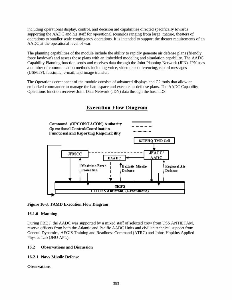
353
including operational display, control, and decision aid capabilities directed specifically towardssupporting the AADC and his staff for operational scenarios ranging from large, mature, theaters ofoperations to smaller scale contingency operations. It is intended to support the theater requirements of anAADC at the operational level of war.
The planning capabilities of the module include the ability to rapidly generate air defense plans (friendlyforce laydown) and assess those plans with an imbedded modeling and simulation capability. The AADCCapability Planning function sends and receives data through the Joint Planning Network (JPN). JPN usesa number of communication methods including voice, video teleconferencing, record messages(USMTF), facsimile, e-mail, and image transfer.
The Operations component of the module consists of advanced displays and C2 tools that allow anembarked commander to manage the battlespace and execute air defense plans. The AADC CapabilityOperations function receives Joint Data Network (JDN) data through the host TDS.
Figure 16-3. TAMD Execution Flow Diagram
16.1.6 Manning
During FBE J, the AADC was supported by a mixed staff of selected crew from USS ANTIETAM,reserve officers from both the Atlantic and Pacific AADC Units and civilian technical support fromGeneral Dynamics, AEGIS Training and Readiness Command (ATRC) and Johns Hopkins AppliedPhysics Lab (JHU APL).
16.2 Observations and Discussion
16.2.1 Navy Missile Defense
Observations
Execution Flow Diagram
Command (OPCON/TACON)Authority Operational ControtCoordination FmictionalandRqiorting Responsibility
JFMCC I
SJITHQ IMD Cen
DAADC H-
LM Maritiine Force Protection
I I I I
JFACC/ A ADC
^Ballistic Missife Defense
SHIPS u
Regional Air Defense
CU USS Antietam, (Greensboro)
354
• The missile active defense capability provided by mobile Navy ships provided the Joint ForceCommander with a unique joint capability during FBE J/MC02.
• The mobility and flexibility of Navy missile defense forces provided a complementary capabilityto the sustainability of Army Air Defense Artillery (ADA) missile defense forces.
Discussion. The inherent mobility and flexibility of Naval forces provided a unique joint capability andconstituted a force multiplier during MC02/FBE J. Though the Joint Force had extensive Army AirDefense Artillery (missile defense) capability in theater, the Deputy AADC required the participation ofNavy ships to defend designated critical assets to the desired Probability of Negation (Pn). Navy shipsprovided a complementary capability to ADA, each occupying a unique operational niche. Ships whichfeature great mobility but limited interceptor inventory provided an important adjunct to ADA that wascapable of providing sustained defense but which could not be readily moved. With PATRIOT andTHAAD defending fixed logistic ports of debarkation and friendly troop concentrations, AEGIS cruisersand destroyers provided the DAADC with a mobile and flexible capability that supported initial access,surged to meet emergent requirements and when required, provided sustained defense of fixed criticalassets. During the course of the experiment Navy ships performed the following missions:
• Upper and lower tier coverage of fixed sites including friendly countries and critical Ports ofDebarkation (APOD).
• Provided lower tier component to upper tier THAAD coverage in order to meet the requiredProbability of Negation.
• Augmented existing THAAD and PATRIOT coverage when required by an enhanced threat tocritical assets.
• Surged to provide short notice missile defense to hostile islands following their surrender tofriendly forces. This provided an incentive for enemy defection and prevented action inretaliation.
• Provided a mobile missile defense capability suitable for covering amphibious landings ondisputed islands held by hostile CJTF South Forces.
16.2.2 Navy Terminal Phase TBMD
Observations. A Navy terminal phase ballistic missile defense capability was essential to accomplishingthe joint missile defense requirements.
Discussion. An adversary armed with large numbers of short-range ballistic missiles (less than 300km),the necessity to provide missile defense against short-range threats on short notice and the JFCrequirement for a 0.99 Probability of Negation (Pn), combined to make the notional terminal phasecapability used in FBE J/MC02 essential to accomplishing the missile defense mission.
• The large inventory of short-range missiles could only be engaged by missile defense systemswith an endo-atmospheric intercept capability. In the dynamic combat environment there wereseveral short notice requirements that required rapid deployment of missile defenses best met byNaval Forces241. These included defending islands off the coast of the hostile country followingtheir defection and supporting amphibious operations.
• The requirement to provide a .99 Pn necessitated a two-tier coverage. Despite the relatively largenumber of PATRIOT forces in theater and the decision to minimize the forces within the
241 A more mobile PATRIOT capability referred to as “PATRIOT Light” was utilized when Navy forces could notprovide defense. Though very effective, PATRIOT Light still required runways and sorties that could be spentdeploying other combat capability. In general the Deputy AADC employed Navy assets for emergent requirementswhen he could and PATRIOT Light when he had to.
355
adversary’s missile range, Navy ships were required to provide the lower tier component to bothSea-Based Mid-Course Defense (SMD) and THAAD.
16.2.3 Sea-based Midcourse Defense (SMD)
Observations
• The large defended footprint of the contingency Sea-Based Mid-Course Defense (SMD)capability was critical to achieving the Joint Task Force Commander’s desired probability ofnegation for a large number of critical assets.
• The primary mission of the ship hosting the contingency SMD capability did not changethroughout the experiment.
• The capabilities of SMD were not well understood by the Joint missile defense community.
Discussion
• The requirement to provide two-tier coverage over a large number of critical assets distributedthroughout a extensive geographic area could not be met by available THAAD forces. As a resultthe DAADC deployed THAAD units defending POD closer to the hostile country where thecapabilities against shorter-range missiles and more extensive interceptor inventory provided acomparative advantage. SMD was then assigned to defend critical assets in an extensive landmassagainst limited numbers of longer-range threat missiles. Only the large footprint provided by theascent and midcourse intercept capability permitted the defense of all required critical assets.
• While the ship with the contingency capability performed other missions such as TLAM strike,its primary mission did not change throughout the experiment. The maneuver area was not asignificant factor as the ship could fulfill its defensive requirements from virtually all navigablewaters.242 The unique capability of the ship appeared to be recognized by both the DAADC andthe ADC/RADC and the issue of concurrent employment where the ship would face increasedrisk did not arise. However, as there were a large number of combatants available, it was unclearto what extent employment of the ship for other missions would have been impacted had the needbeen greater.
• The ability of the SMD missile, the SM-3 to intercept ballistic missiles in the ascent andmidcourse phases of flight provides a comparatively much greater defended area and differs fromother theater missile defense systems. Explaining the performance of the system anddifferentiating between the defended area and the area where intercepts would occur was aconsistent requirement during FBE J/MC02 and indicated that the workings of the system werenot well understood throughout the joint missile defense community.
16.2.4 Joint Command and Control
Missile Defense may be the “jointest” of the warfare areas. It requires the integration of Army, Air Forceand Navy capabilities in a complex planning environment and execution within the most challenging oftimelines. FBE-J/MC02 demonstrated considerable progress in the formation of a truly joint capabilitybut exposed several areas where additional attention will be required.
242 Note. The maneuver area was calculated by the AADC module only. Radar resource limitations may have led toa more constrained maneuver area but were not modeled.
356
16.2.4.1 Role of the RADC: Doctrine
The lack of an accepted definition of the roles and responsibilities of a Regional Air Defense Commander(RADC) hindered missile defense planning and execution within the joint force.
Discussion
• Intense effort and the dedication of the JFACC/AADC, DAADC and RADC/ADC resulted in aworkable C2 structure during FBE-J/MC02. However, these relationships were not supported byexisting doctrine, and the experiment exposed considerable gaps in service operational conceptsand procedures
• Difficulties in combining the maritime force protection duties of the Battle Force ADC with aRADC were exacerbated by the lack of an accepted definition of the roles and responsibilities ofa RADC. FBE-J/MC02 exposed gaps between the Air Force and JFACC doctrine of “centralizedcontrol and decentralized execution” and the considerable autonomy that is normal for a Navy AirDefense Commander. The RADC/ADC believed that as a “commander”, he was responsible fordefense of the assigned region within the context of JFACC/AADC guidance and not merelydefense of maritime forces. To achieve this, he requested USAF assets through Air SupportRequests (AIRSUPPREQ) and Navy assets via MARSUPREQ and stationed them according to aplan briefed by a liaison element to the JFACC/AADC. Despite this, a fissure was exposed whenJFACC/ADC assigned additional DCA stations within the assigned region without notifying theRADC/ADC. The JFACC did this after assessing DCA coverage inadequate and presumablybelieving that the RADC/ADC only requested those necessary for fleet air defense. That theJFACC/AADC did not directly challenge the RADC/ADC plan or instruct him to request andassign additional assets indicated that JFACC/AADC and RADC relationships are far fromsettled. Though the situation was discovered and resolved without incident, such confusion couldhave had consequences ranging from inefficient use of scarce DCA assets to blue on blueengagements.
• Despite the presence of a considerable liaison at the Air Operations Center (AOC), theRADC/ADC was not integrated in AOC battle rhythm. It appeared that the very concept of aregional commander reporting to the JFACC simply did not fit within the centralized planningstructure of the AOC. Unlike the forums conducted by the Deputy AADC, the RADC/ADC(actual) was not routinely invited to participate nor were the liaisons adequately able to brief theRADC/ADC overall concepts of operations within the region. The results included theassignment of redundant DCA stations and the inability to integrate maritime force protectionmission within the greater scheme of theater air superiority.
• Multi-purpose missile defense units posed a conceptual difficulty for joint missile defenseplanners. Concurrent assignment of tasks such as TLAM strike and missile defense causedconsiderable angst, particularly at the Deputy AADC. Whereas Navy commanders tended to becomfortable with dual chains of command and with resolving conflicts if and when they occurred,the Deputy AADC felt clearer chains of command and control were needed.
• The support/supporting relationship between maritime forces and the JFACC/AADC andDAADC was not well understood. FBE J/MC02 exposed considerable concern on the part of theJFACC/AADC and Deputy AADC over the degree that Navy forces could be expected to supportassigned objectives. Through considerable effort the RADC/ADC was able to convince theJFACC/AADC and Deputy AADC that Navy forces would not abandon their assignments whensome competing maritime mission arose. However the experiment indicated the need to develop
357
an “establishing directive” detailing the support/supporting relationships including the relativepriority of the supported mission versus other missions (including self defense).
16.2.4.2 DCA Responsibilities
Observation. The division ballistic missile defense from other DCA mission placed the RADC/ADC inan ambiguous organizational position and may have hindered integration of joint capabilities.
Discussion
• During FBE J/MC02 responsibility for ballistic missile defense was separated from otherDefensive Counterair (DCA)243 responsibilities and placed under the Deputy AADC (Army O-7).The division of the overall mission resulted in some ambiguity for the RADC/ADC whoanswered to the JFACC/AADC (Air Force O-9) for defense of theater assets against fixed wingaircraft, to the Deputy AADC for the assignment of ships to ballistic missile defense mission and,of course to the Joint Force Maritime Component Commander for the force protection ofmaritime assets. This arrangement proved workable if organizationally ungainly.
• The separation of ballistic missile defense from other DCS mission and the accepted doctrinaldefinitions of Point, Area and Self Defense do not match with the capabilities of Navy weaponssystems. The comparatively long range of Navy surface to air missile systems and doctrine ofemploying aircraft and missile systems in an integrated engagement scheme, did not match USAFand USA concepts based on the clear delineation of the battlespace.
• Anti-Ship Cruise Missiles (ASCM) launched either from aircraft or mobile surface launchersprovided a quandary for the MC02 C2 architecture. Although ASCM are air breathing threats(ABT), they did not readily fit into the JFACC/AADC planning process nor did they fall underthe purview of the Deputy AADC. Without the direct input of the combined RADC/ADC it wasunclear whether Joint commanders would have understood the ASCM posed to Joint operations.One outgrowth of the experiment was that cruise missiles, both ASCM and soon, Land AttackCruise Missiles (LACM)/Overland Cruise Missiles (OCM) will need to be a greater jointplanning consideration.
16.2.5 Organization – Combined Roles of RADC and ADC
Observation. Assigning the joint duties of Regional Air Defense Commander (RADC) with the maritimeforce protection duties of the Air Defense Commander was effective.
Discussion. Despite the ambiguity over the roles and responsibilities of the various command elements(JFACC/AADC, Deputy AADC, RADC etc.) most members of the RADC/AADC staff felt thatcombining these duties under a single commander was the best solution. The reasons expressed centeredon two factors. The first was related to planning and addressed the difficulty in dividing common multi-purpose assets among even more command entities (for example a RADC and separate ADC’s). Thesecond factor was the difficulty in execution with long-range weapons in common airspace. The practicalexample cited was if a ship engaged a hostile aircraft at maximum range over land was that an airsuperiority mission or a maritime force protection mission. Most questioned felt that such distinction
243 Defensive Counterair. DCA is all defensive measures designed to detect, identify, intercept, and destroy or negateenemy air and missile forces attempting to attack or penetrate the friendly air environment. DCA employs bothactive and passive measures to protect US or multinational forces, assets, population centers, and interests.(JointPublication 3-01)
358
didn’t matter and the attempt to distinguish between the missions would have been artificial and presentedpotential seems that could be exploited.
16.2.6 Modeling Differences between Service Missile Defense Decision Aids
Observations. Distributed collaborative planning was hindered by differences in the manner in which thedecision aids modeled system performance and displayed the results.
Discussion. The tools used by the RADC/ADC and by the Deputy AADC (elements of the 32nd Army Airand Missile Defense Command) often yielded conflicting recommendations and assessments even whenusing identical entering data. Assets positioning and probability assessment are complex calculations, anddecision aids were critical to the planning process. Operators were well trained in using the tools but weregenerally less skilled in evaluating why the tools produced a particular recommendation. The tools alsodisplayed the results in formats that could not easily be fused or compared. With differingrecommendations, unfamiliar displays, and no common basis to evaluate the products of the aids, thecollaborative planning process often stalled. Satisfactory compromises between the Deputy AADC andthe RADC/ADC were generally reached but this was usually due to trust developed over the course of theexperiment and may have been influenced by the experimental nature of the problem itself.
AADC module assessment of Army capabilities normally exceeded those predicted by the Army ADA. Itwas unclear whether doctrinal restrictions entered in the ADA systems accounted for the reducedperformance. In general, the AADC module appears to have fewer restrictions in determining possibleengagement outcomes than the Deputy AADC system. For example, the AADC module allowed plannersto increase the interceptor salvo size to reach a desired Pk while the Army planners would consider only adual salvo. While there is a potential danger in the Navy approach if the probability calculations are notunderstood, it did appear a more flexible approach.
Planners at AADC module were generally unable to interpret the recommendations produced by theAADC module. This situation appeared to be paralleled at the Deputy AADC. Beyond the enteringfactors (EOB, FOB, DAL, and ECOA), planners experienced difficulties determining how or why aparticular recommendation was reached. This observation mirrors an earlier observation from Fleet BattleExperiment Charlie (FBE C) that operators need to know what is “under the hood”. (Note: During muchof the experiment, JHU APL personnel were present and performed the interpretation and evaluation.This expertise was valuable, and consideration should be given to this capability when determiningeventual manning plans.)
16.2.7 Battle Management
Observation. Doctrinal and Material differences between Army and Navy missile defense forcesprevented coordinated engagement and dynamic battle management.
Discussion. Attempts to coordinate engagements between Army ADA and Navy were unsuccessful dueto differences in the manner in which the services perceive engagement coordination and control theengagement of targets by firing units. On a Navy ship, a command element and a firing element are co-located and supported by extensive communications and organic sensors. This allows more generalguidance to ship and dynamic management of engagements (“take track X with birds”). Army firing unitsand command elements are however, separate, and the Army tends toward procedural engagement criteriaat the firing unit level. Coordination at the battalion or perhaps battery level is possible but the concept ofdynamic battle management common to the Navy is very foreign to the Army.

359
16.2.8 Navy Missile Defense Planning Process
Intelligence. Access to timely intelligence is critical to successful missile defense operations. The AADCmodule requires four inputs to calculate friendly force disposition (stationing) and determine effectivenessof the joint force. These include two specific intelligence inputs, an accurate Enemy Order of Battle(EOB) and an assessment of Enemy Course of Action (ECOA). Participants generally assessedintelligence support to be inadequate during FBE-J/MC02 for several reasons that ranged from shortfallsin the module itself to experiment specific difficulties. The critical findings are detailed in the followingsection.
16.2.9 Situational Awareness/Access to Tactical Sensors
Critical Findings . RADC/ADC required near real time access to Intelligence, Surveillance, andReconnaissance information.
Discussion. In order to support the planning requirements of subordinate units, the RADC/ADC neededimproved access to Intelligence, Surveillance, and Reconnaissance information. In particular timelypositional information is critical for individual ships to determine appropriate radar doctrine for ballisticmissile defense or weapons conditions for cruise missile threats. The RADC/ADC was not integrated intothe ISR operational cycle, and the intelligence cycle appeared out of step with operational requirements.
Immediate knowledge of the location of ballistic missile or cruise missile Transporter- Erector-Launchers(TEL) is critical for the RADC/ADC to evaluate the adequacy of the existing force laydown. Tacticalsensors such as Unmanned Aerial Vehicles (UAV) or ISR aircraft often gained this information. Althoughthere is a recognized danger in the release of unevaluated sensor information, the information on mobileTEL is time sensitive and the intelligence community must disseminate this information to defensiveunits in the same manner as Time Sensitive Targeting nodes.
Access to “negative sensor information” is an important adjunct to the planning process. The results of amission that does not locate enemy forces can assist planners in determining most likely ECOA. Thedisconnect between the RADC/ADC planning effort and the ISR denied planners the ability to determineECOA based on where enemy forces were not and may have steered ECOA development toward worstcase scenarios.
16.2.10 Access to Intelligence Databases
Critical Findings. AADC module requires access to databases such as the ModernizedIntegrated/Intelligence Database (MIDB) and additional connectivity to utilize the full range of existingintelligence.
16.2.11 Enemy Course of Action Development
Critical Findings. Determination of potential Enemy Courses of Action is critical to the planning processbut current processes do not support the level of ECOA needed by a combined RADC/ADC.
Discussion. A commander with a tactical focus such as the RADC/ADC requires tactical level ECOAoften tied to specific events or operations. For example an assessment of the maximum salvo capability ofan adversary does not meet the planning requirements of a commander attempting to determine how anadversary will oppose the transit of a convoy through a critical strait on a particular day. In the absence ofa developed process, the commander must make the determination of what an adversary will do based on
360
his/her own assumptions and best judgment. During FBE J/MC02, an experiment node was introducedwithin the AADC module to assist the commander in that decision making process.
Determination of ECOA is not solely an intelligence function. Intelligence trained personnel providedcritical information into what an adversary could do and had done, but were less able to answer thequestion what is the adversary likely to do now or alternately “what would I do?”
During FBE J/MC02, developing tactical ECOA was hindered by an inability to access timely adversarydispositions. In order to assess what how an adversary would choose to oppose a specific action, plannersneeded to know what specific units could be brought into action. That information was not readilyavailable.
16.2.12 AADC Module
General. The AADC module was developed to support a commander at the operational level of war. Itwas never intended to support the tactical requirements of a Regional Air Defense Commander or a BattleForce Air Defense Commander (“AW”). Nevertheless in the assessment of majority of the participants,the planning side of the module demonstrated considerable utility when pressed into this role and some ofthe features were a marked improvement over existing RADC/ADC planning methods. (Note:Experimentation was limited to the planning component of the module during FBE J/MC02.) Most of theparticipants felt that planning support for a RADC/ADC offered a potential role for the module when aJFACC retained the additional responsibility of the AADC and was located ashore. Those participantswho felt the module should not be used to support the requirements of a RADC/ADC normallycommented on specific technical shortfalls in the modules current configuration rather than on the basicmethodology or planning processes employed by the AADC module. Observations on the moduleperformance and any modifications that the participants detailed are noted below. Most modificationsapply strictly to expanding the mission to include support of a tactical commander, though where theadditional capability was required to support an AADC, it is noted.
Observation. The AADC Module demonstrated value in supporting a geographically separate Area AirDefense Commander (12th AF at Nellis AFB) and augmenting the planning capabilities of the DeputyArea Air Defense Commander (32nd AAMDC at Nellis AFB).
Discussion. The planning capability supported extensive collaboration between the RADC/ADC and theDeputy AADC (32nd Army Air and Missile Defense Command). Coverage diagrams, force laydowns andother information were routinely exchanged. The output from the module was routinely used to positionships though on at least one occasion PATRIOT batteries were shifted to increase coverage and reduceredundancy on the basis of a recommendation provided by the AADC module. The ability to model bothNavy and Army Air Defense Artillery (THAAD and PATRIOT) systems was a unique capability as theDeputy AADC lacked the ability to either position or test (“wargame”) the effectiveness of forcelaydowns that employed Navy systems alone or in concert with ADA systems.
16.2.13 Multi-TADIL Connectivity
Observations. Most participants noted that requirements for the addition of Link 16 and several notedthat utilizing the module in support of a RADC/ADC would require access to the Global Command andControl System (GCCS) and Advanced Deep Operations Coordination System/Land Attack WarfareSystem (ADOCS/LAW).
Discussion. TADIL connectivity in the module is currently limited to Link 11. During the experiment anAir Defense System Integrator (ADSI) was added to allow access to Link 16/TADIL J tracks. This provedworkable though the limited play of the operations component of the module prevented a full analysis.

361
During FBE J/MC02, GCCS and ADOCS/LAWS were used to maintain the common operational picture(COP). These were accessible through consoles in both the planning and execution side of the module andproved essential to the RADC/ADC’s situational awareness. In an actual operation access to theinformation on these displays would have been essential. This experiment focused on planning viceexecution and thus prevented more complete analyses of the necessity and impact of this capability.
16.2.14 Threat Library
Observations. The adversary force contained both air breathing threats (ABT) and ballistic missiles thatwere not included in the threat library.
Discussion. The AADC module performs its calculations of friendly force laydown and effectivenessbased in part on the specific performance characteristics of the threat. The lack of complete coverage ofABT forced operators to use modeled systems whose performance was felt to be “close enough” to thethreat or to adapt existing systems and extrapolate results. This was unsatisfactory and many participantsnoted the need for an immediate increase in the AADC module threat library particularly in the area ofshort-range (<300KM) ballistic missiles and Anti-Ship Cruise Missiles (ASCM).
16.2.15 User Defined Threats
Observations. The current module configuration does not include the ability for operators to manuallyenter threats.
Discussion. Several participants noted that the operators should have a contingency capability tomanually enter threats based on a generic set of performance characteristics. This would allow on siteentry of threats either not included in the original load or those who performance differed from pre-hostilities estimates. While this was acknowledged as backup, most participants felt that it was preferableto the ad hoc extrapolations that were used during the experiment.
16.2.16 Defensive Counterair (DCA)/Combat Air Patrol (CAP) Stationing Calculations
Observation. The ability of the module to support decisions in DCA/CAP stationing was extremelylimited.
Discussion. Support for a RADC/ADC during the FBE J/MC02 required greater emphasis on stationingDCA/CAP than was normal during most previous AADC exercises. The ability of the module to supportstationing decisions was extremely limited. The “CAP Attrit” feature, which is not strictly a stationingaid, was not used and DCA/CAP and Airborne Early Warning (AEW) stationing was conducted manuallywith little input from the module.
16.2.17 Emerging Friendly Capabilities
Observation. AADC module calculations did not appear to incorporate increases in sensor and weaponsperformance.
Discussion. Planned or programmed improvements to sensor performance or tracking ability were notincorporated in the current AADC configuration. The addition of Cooperative Engagement Capability(CEC) or E-2 Littoral Radar Modification Program (RMP) improvements were not reflected in increasedprobabilities of kill.
16.2.18 Manning and Training
362
Observation. Operations of a tactical commander (RADC/ADC) exposed the need for need for additionalair defense training and experience in fleet air defense operations.
Discussion. During FBE J/MC02, the majority of the module staff consisted of Navy reserve officers withthe remainder being drawn from an active duty CG (USS ANTIETAM). Using the module to support anRADC/ADC shifted the emphasis away from generation of alternative force lay downs or courses ofaction to more immediate near term planning involving on-going operations or emergent threats tofriendly air and surface forces. In general, the reserve officers were well versed in the operation of themodule and the capabilities of both ballistic missiles and ballistic missile defense systems. The activeduty officers generally had less experience in fleet air defense operations and less training in thecapabilities of hostile air breathing threats and air defense systems. Employing the module in support of aRADC/ADC will require reexamination of the training and experience requirements and the mix of activeand reserve personnel.
16.2.19 Ability to Export Graphics
Observation. Collaboration between the ADC/RADC and the Deputy AADC was hindered byincompatibility of file formats and inability to automatically export graphic images.
Discussion. In order to exchange graphic displays with the Deputy AADC, the RADC/ADC staff wasrequired to create a power point slide and send it via email. Neither AADC consoles nor those of theDeputy AADC had the ability to export graphics directly. Data from this slide was then manuallyextracted and re-entered into Army displays systems. This slowed the collaboration process andeffectively eliminated the ability of individual planners at the nodes to exchange ideas and/or divide tasks.For example the AADC module has an unrivaled capability to evaluate alternative potential ECOA or inother words evaluate “what if” situations. This capability might have been of benefit to Army plannershad the opportunity for closer operator collaboration existed.
16.2.20 Alternative Displays
Observation. Operations in support of a RADC/ADC require alternative display options.
Discussion. The AADC module uses a lifelike three-dimensional display in which aircraft appear asaircraft, missiles as missiles etc. While most participants appeared to feel this was valuable for anoperational level commander such as a theater AADC, several noted it was less suited to a commanderwith a more tactical focus such as a RADC/ADC. Focusing on a small geographic area with numerouscontacts presented a problem to operators trying to monitor or control tactical interactions. Operatorsexpressed that the symbol size was too large and that it was difficult to determine aircraft course andspeed. In such a situation, several participants noted that the display less informative than conventionalNaval Tactical Data System (NTDS) symbology. There was no expressed desire to entirely replace thethree dimensional display however, many felt that operators needed to be able to choose from alternativedisplays based on their requirements.
16.3 Key Observations and Conclusions
• Navy TAMD/TBMD. The inherent mobility and flexibility of Naval forces constituted a uniquejoint capability and a force multiplier during the experiment. Navy ships protected critical assetson the DAL, augmented PATRIOT units, provided the lower tier component for THAAD andprojected missile defense over amphibious landings ashore. Ships provided a key compliment toArmy Air Defense Artillery (ADA) surging to meet anticipated threats or to respond to other
363
operational changes while THAAD and PATRIOT batteries focused on the defense of fixedcritical assets.
• AADC Module Tactical Operations. The AADC Module successfully supported the BattleForce Air Defense Commander (“AW”), a geographically separate Area Air Defense Commander(12th AF at Nellis AFB) and augmented the planning capabilities of the Deputy Area Air DefenseCommander (32nd AAMDC at Nellis AFB). The module routinely positioned ships though on atleast one occasion PATRIOT batteries were shifted to increase coverage and reduce redundancyon the basis of a recommendation provided by the AADC module. Note: The operations functionof the module was not extensively tested in the experiment.
• Joint Command and Control. Though a significant effort was made during MC02/FBE J, theADC/RADC was never fully integrated into the Air Operations Center (AOC) battle rhythm andthe organizational relationship between the JFACC/AADC and the ADC/RADC remainedambiguous. The absence of joint doctrine defining the role of a RADC and the lack of directcommunication between the JFACC/AADC and the RADC most likely contributed to thedifficulty. In contrast, a high degree of coordination and collaboration occurred between theRADC/ADC and Deputy AADC for missile defense. In the end a workable process evolved butthe experiment highlighted the need for the development of common tactics, techniques and jointdoctrine that defines roles, missions and responsibilities between functional componentcommanders and their subordinate commanders.
• Navy Terminal Phase TBMD. A robust terminal phase TBMD capability was critical to jointmissile defense. Although extensive Army Air Defense Artillery (ADA) forces were in theater,Navy forces played a critical role defending designated critical assets either alone or inconjunction with Sea-Based Mid-Course (SMD), THAAD, and PATRIOT. In the experimentscenario in which the adversary was armed with large numbers of short range (range less than300km), a terminal phase capability and extensive interceptor inventory proved invaluable. Thiswas particularly true when forces were out of reach of ADA forces.
• Sea-Based Mid-Course TBMD. The contingency Sea-based Midcourse Defense (SMD)capability was critical to achieving the Joint Task Force Commander’s desired probability ofnegation. Against longer-range threats, the extensive defended footprint provided an upper tiercomponent of a two-tiered defense for a large number of critical assets. It was indicative of theimportance of this mission that the primary mission of the single ship with this capability did notchange throughout the experiment. Despite the ship’s primary tasking however, the flexibility ofmulti-purpose surface combatants was demonstrated when the ship conducted Tomahawk LandAttack Missile (TLAM) strikes and sea control missions.
• Enemy Course of Action (ECOA) Generation. TAMD planning in general and the performanceof the AADC module in particular are dependent on development of accurate assessment ofpotential Enemy Courses of Action (ECOA). During FBE J/MC02, a local Red Cell defined theworst and most likely case enemy courses of action at the tactical level of war. The ECOA wasessential in developing counters to air and missile threats to specific friendly operations such astransits through critical straits or amphibious assaults. The input of this team was critical to theplanning effort but highlighted the need for specific training and skills for the Red Team.
• Intelligence Support. Inadequate intelligence in FBE J/MC02 hindered planning but illuminatedshortfalls in current intelligence support. In FBE J/MC02 there was sufficient information onenemy tactics and systems and little linkage between theater ISR operations and the RADC/ADCorganization. In order to maximize the effectiveness of assigned forces an RADC/ADC requires
364
improved situational awareness based on access to existing intelligence databases and thecapability to blend historic information, and intelligence from national or strategic systems withintelligence gained from tactical or in-theater sensors.
• Joint Doctrine and Firing Policy. Attempts to develop coordinated engagement procedures ininstances when both Army and Navy missile defense forces covered common critical assets, wereunsuccessful. Doctrinal and technical differences between Army firing units and Navy shipsformed a barrier and did allow coordination beyond spatial deconfliction (“engagement zones”).Without changes to existing doctrine, systems, and operational concepts, dynamic battlespacecoordination including integrated engagements will not be possible.
• Modeling. Collaboration was hindered when weapons systems models in decision aids did notyield common solutions even when all entering data were identical. The AADC moduleconsistently ascribed capabilities to the Theater High Altitude Air Defense (THAAD) thatsurpassed those developed by Army decision aids. Since the complexity of engagementcalculations requires dependence on decision aids the result was a “stalemate.” For distributedcollaboration to be effective, all participants must have a common understanding of thecapabilities and limitations of the individual systems, and decision aids should develop identicalsolutions when given identical inputs.
• Short Range Ballistic Missile Threat. Though it received less high-level attention than longer-range missiles, the threat posed by large numbers of relatively unsophisticated short-rangemissiles (<300km) and artillery rockets was a significant factor in operational planning andcaught many planners by surprise. Coordination between the DAADC and the maritimeADC/RADC was hindered, as existing planning tools did not include models for these threats andthe numbers present required intense considerations of interceptor inventory. The widespreaddistribution of these types of weapons warrants increased consideration in operational planning.

365
17.0 Sea-Based Joint Command and Control
17.1 Experiment Objectives
The goals of the sea-based joint C2 initiative were to refine C4ISR and to validate the manning supportrequired for a sea-based Joint Force Commander. MC-02/FBE-J offered a unique analytic opportunity toassess sea-based joint C2 because the most modern US Navy command ship was participating and therewas a unique mix of forward Joint and Component Commanders and JFMCC staff embarked.
The SBJC2 initiative was executed on USS CORONADO from 29 to 31 July 2002. The main Joint ForceHeadquarters (JFHQ-(M)) for MC02 (US Army III Corps) deployed a 37-person forward headquarters(JFHQ-(F)) to USS CORONADO. A three-man advance party preceded the JFHQ-F. The primarypurpose of this initiative was to document the JFHQ staff perceptions of their capabilities as a JFHQ (i.e.,sea-based within the context of the MC02 scenario and FBE-J/MC02 architecture).
The analytical objectives for this initiative were structured to take advantage of the existing experimentalC2 construct, within the current design of MC 02/FBE-J, to provide insight into the reasonableness of theJCC (X) C4ISR requirements and manning, as stated in the Operational Requirements Document (ORD)and to Conduct C4ISR requirements studies.
The fundamental objectives for this experiment were:
• Provide insight into whether the requirements for sea-based C2 (as defined in JCC (X) ORD andstudies) were sufficient. If not, where does the Navy need to do further study or experimentation?Determine what was learned from JFMCC afloat that could improve/validate JFMCC JP 3-32, interms of manning and C4ISR requirements.
• Provide insights on the adequacy of the baseline in the above sub-initiative (relative to ORD,studies, and experimental results) in supporting staffs afloat in executing their mission and tasks,i.e., how well were they able to do their job given the BW, manning, C4ISR constraints.
• Doctrinal: Determine the considerations and advantages/disadvantages of sea-basing C2• Organizational: Was the manning sufficient to perform tasks assigned? Determine the functions
that were/were not adequately supported from the sea.• Material: Analyze the software tools and communications structure (including required
characteristics) that the staffs need to do their jobs. Was this sufficient? If not, what more wouldbe needed?
17.2 Analytical Questions
• Did the JFHQ (Forward) at USS CORONADO have sufficient “reach-back capability” to theJFHQ (Main) at Suffolk VA to ensure information superiority?
• What insights can be derived from the manning, structure, and functional capabilities of theJFHQ?
• What are the CJTF staff perceptions of their capabilities as a CJTF that is sea-based within thecontext of the MC02 scenario and FBE-J/MC02 C4ISR architecture?
17.3 Baseline Model
The US Army III Corps (as the JFHQ) forward deployed the staff. Since this was the prototypedeployment of this kind, there was little detailed, advance planning as to the specific organization orfunctioning of the forward staff. No baseline model for the organization was implemented.
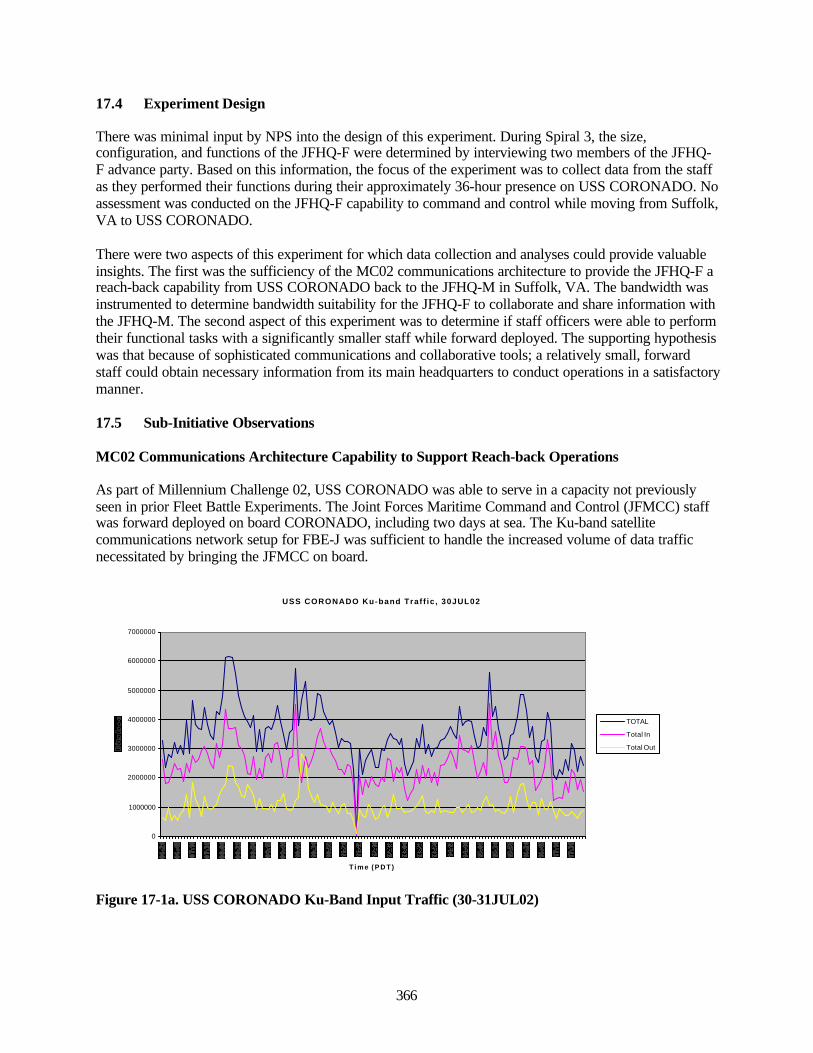
366
17.4 Experiment Design
There was minimal input by NPS into the design of this experiment. During Spiral 3, the size,configuration, and functions of the JFHQ-F were determined by interviewing two members of the JFHQ-F advance party. Based on this information, the focus of the experiment was to collect data from the staffas they performed their functions during their approximately 36-hour presence on USS CORONADO. Noassessment was conducted on the JFHQ-F capability to command and control while moving from Suffolk,VA to USS CORONADO.
There were two aspects of this experiment for which data collection and analyses could provide valuableinsights. The first was the sufficiency of the MC02 communications architecture to provide the JFHQ-F areach-back capability from USS CORONADO back to the JFHQ-M in Suffolk, VA. The bandwidth wasinstrumented to determine bandwidth suitability for the JFHQ-F to collaborate and share information withthe JFHQ-M. The second aspect of this experiment was to determine if staff officers were able to performtheir functional tasks with a significantly smaller staff while forward deployed. The supporting hypothesiswas that because of sophisticated communications and collaborative tools; a relatively small, forwardstaff could obtain necessary information from its main headquarters to conduct operations in a satisfactorymanner.
17.5 Sub-Initiative Observations
MC02 Communications Architecture Capability to Support Reach-back Operations
As part of Millennium Challenge 02, USS CORONADO was able to serve in a capacity not previouslyseen in prior Fleet Battle Experiments. The Joint Forces Maritime Command and Control (JFMCC) staffwas forward deployed on board CORONADO, including two days at sea. The Ku-band satellitecommunications network setup for FBE-J was sufficient to handle the increased volume of data trafficnecessitated by bringing the JFMCC on board.
USS CORONADO Ku-band Traf f ic , 30JUL02
0
1000000
2000000
3000000
4000000
5000000
6000000
7000000
T i m e ( P D T )
TOTAL
Total In
Total Out
Figure 17-1a. USS CORONADO Ku-Band Input Traffic (30-31JUL02)
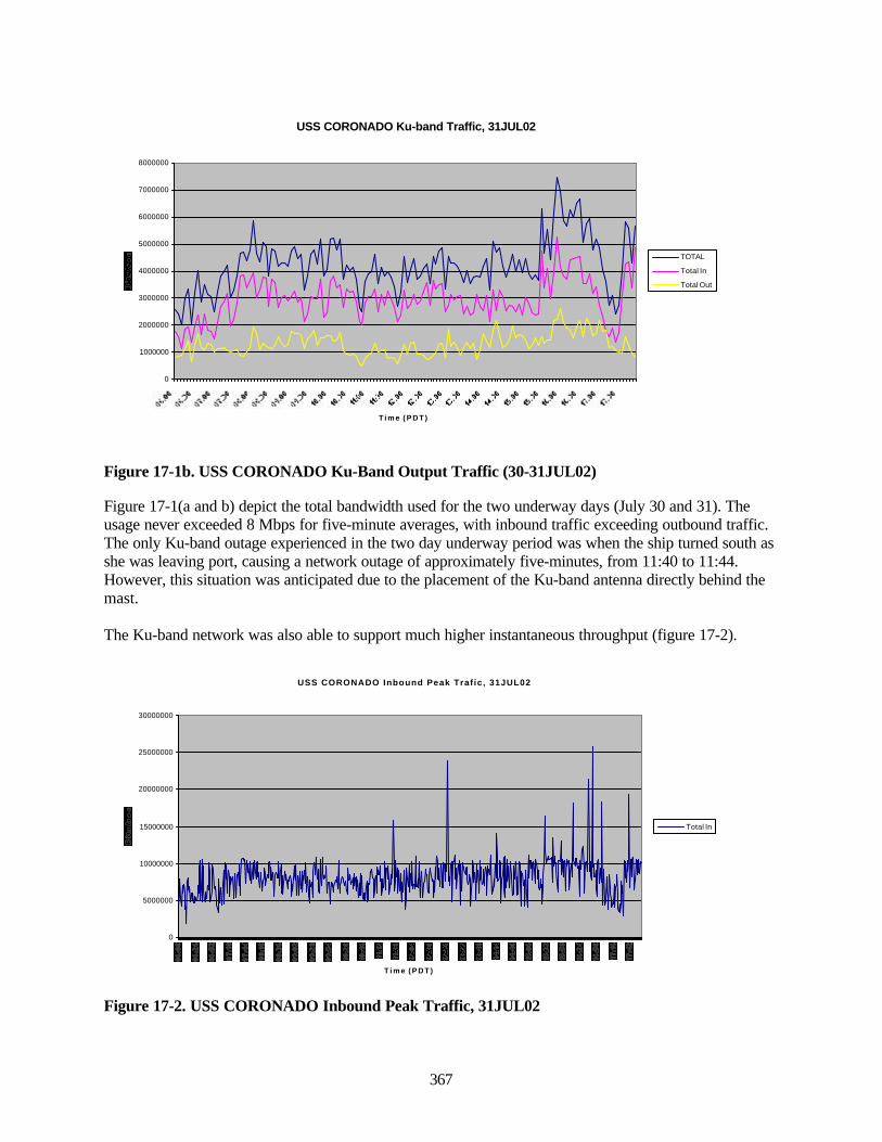
367
USS CORONADO Ku-band Traffic, 31JUL02
0
1000000
2000000
3000000
4000000
5000000
6000000
7000000
8000000
T i m e ( P D T )
TOTAL
Total In
Total Out
Figure 17-1b. USS CORONADO Ku-Band Output Traffic (30-31JUL02)
Figure 17-1(a and b) depict the total bandwidth used for the two underway days (July 30 and 31). Theusage never exceeded 8 Mbps for five-minute averages, with inbound traffic exceeding outbound traffic.The only Ku-band outage experienced in the two day underway period was when the ship turned south asshe was leaving port, causing a network outage of approximately five-minutes, from 11:40 to 11:44.However, this situation was anticipated due to the placement of the Ku-band antenna directly behind themast.
The Ku-band network was also able to support much higher instantaneous throughput (figure 17-2).
USS CORONADO Inbound Peak Trafic, 31JUL02
0
5000000
10000000
15000000
20000000
25000000
30000000
T i m e ( P D T )
Total In
Figure 17-2. USS CORONADO Inbound Peak Traffic, 31JUL02
*■ »? t o o «■ »!■
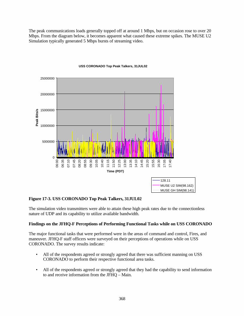
368
The peak communications loads generally topped off at around 1 Mbps, but on occasion rose to over 20Mbps. From the diagram below, it becomes apparent what caused these extreme spikes. The MUSE U2Simulation typically generated 5 Mbps bursts of streaming video.
USS CORONADO Top Peak Talkers, 31JUL02
0
5000000
10000000
15000000
20000000
25000000
06:0
0
06:3
5
07:1
0
07:4
5
08:2
0
08:5
5
09:3
0
10:0
5
10:4
0
11:1
5
11:5
0
12:2
5
13:0
0
13:3
5
14:1
0
14:4
5
15:2
0
15:5
5
16:3
0
17:0
5
17:4
0Time (PDT)
Pea
k B
its/
s
128.11
MUSE U2 SIM(98.162)MUSE GH SIM(98.141)
Figure 17-3. USS CORONADO Top Peak Talkers, 31JUL02
The simulation video transmitters were able to attain these high peak rates due to the connectionlessnature of UDP and its capability to utilize available bandwidth.
Findings on the JFHQ-F Perceptions of Performing Functional Tasks while on USS CORONADO
The major functional tasks that were performed were in the areas of command and control, Fires, andmaneuver. JFHQ-F staff officers were surveyed on their perceptions of operations while on USSCORONADO. The survey results indicate:
• All of the respondents agreed or strongly agreed that there was sufficient manning on USSCORONADO to perform their respective functional area tasks.
• All of the respondents agreed or strongly agreed that they had the capability to send informationto and receive information from the JFHQ – Main.
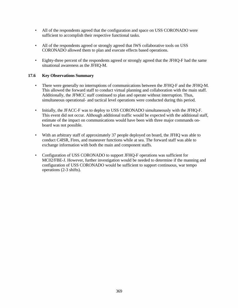
369
• All of the respondents agreed that the configuration and space on USS CORONADO weresufficient to accomplish their respective functional tasks.
• All of the respondents agreed or strongly agreed that IWS collaborative tools on USSCORONADO allowed them to plan and execute effects based operations.
• Eighty-three percent of the respondents agreed or strongly agreed that the JFHQ-F had the samesituational awareness as the JFHQ-M.
17.6 Key Observations Summary
• There were generally no interruptions of communications between the JFHQ-F and the JFHQ-M.This allowed the forward staff to conduct virtual planning and collaboration with the main staff.Additionally, the JFMCC staff continued to plan and operate without interruption. Thus,simultaneous operational- and tactical level operations were conducted during this period.
• Initially, the JFACC-F was to deploy to USS CORONADO simultaneously with the JFHQ-F.This event did not occur. Although additional traffic would be expected with the additional staff,estimate of the impact on communications would have been with three major commands on-board was not possible.
• With an arbitrary staff of approximately 37 people deployed on board, the JFHQ was able toconduct C4ISR, Fires, and maneuver functions while at sea. The forward staff was able toexchange information with both the main and component staffs.
• Configuration of USS CORONADO to support JFHQ-F operations was sufficient forMC02/FBE-J. However, further investigation would be needed to determine if the manning andconfiguration of USS CORONADO would be sufficient to support continuous, war tempooperations (2-3 shifts).

370
This page intentionally left blank.

371
Associated Analyses
18.0 METOC
18.1 METOC Observer's Notes
The following is the final report from the senior METOC observer. It differs from the major initiatives inthat there were no specific goals, MOEs, or MOPs established for the METOC support in FBE-J. Rather,the community looked at its support to the various initiatives and offered comments and suggestions as tohow the environmental support to the initiative could be improved.
18.2 General Communications and Connectivity
The Naval Pacific METOC Center San Diego (NPMOC-SD) was designated a reach back center inJFMCC METOC letter of instruction message244. Due to security restrictions, JFMCC could link toNPMOC-SD's SIPRNET FBE-J support web page, but NPMOC-SD had no visibility into the FBE-J/MC-02 WAN. Support personnel at NPMOC-SD noted that greater situational awareness of the scenario,gained by having access to the experiment WAN, would have improved METOC support at the reachback center. METOC support personnel who have an understanding of the current scenario and thewarfighter's intentions are better able to anticipate the warfighter's METOC support requirements andfulfill them in a shorter time.
NPMOC-SD was able to collaborate with the USAF 25th Operational Weather Squadron, the USAFreachback center, via Net Meeting software. The CJTF METOC officer was able to participate in thesediscussions.
NPMOC-SD also achieved connectivity to JFMCC METOC via legacy communications through theCOMTHIRDFLT METOC division office on USS CORONADO. Products could be delivered to theMETOC division office and either viewed directly by the JFMCC METOC officer or manuallytransferred ("Sneakernet") to the FBE-J/MC-02 WAN.
NPMOC-SD was not normally included in experiment-related naval message traffic such as pre-exercisecoordination messages, further degrading situational awareness. Decreased situational awareness leads tomore generalized forecasts covering typical METOC parameters over the operating area, reducing theMETOC support providers the ability to provide specific support to the warfighter's operations, therebyreducing customer satisfaction.
18.3 Product Creation and Dissemination
Figure 18-1 describes the general support and products that the METOC community provided to FBE-Jforces.
244 COMCARGRU THREE message dated 181700Z JUL 02 PSN 984285M36
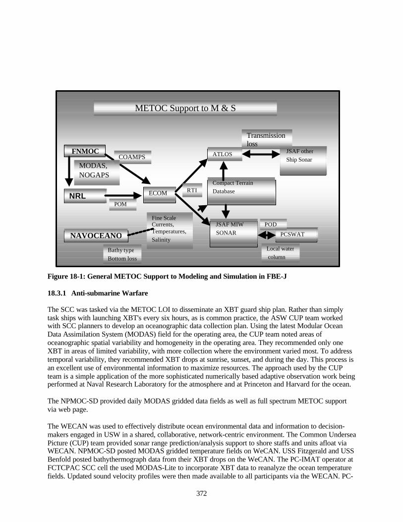
372
Figure 18-1: General METOC Support to Modeling and Simulation in FBE-J
18.3.1 Anti-submarine Warfare
The SCC was tasked via the METOC LOI to disseminate an XBT guard ship plan. Rather than simplytask ships with launching XBT's every six hours, as is common practice, the ASW CUP team workedwith SCC planners to develop an oceanographic data collection plan. Using the latest Modular OceanData Assimilation System (MODAS) field for the operating area, the CUP team noted areas ofoceanographic spatial variability and homogeneity in the operating area. They recommended only oneXBT in areas of limited variability, with more collection where the environment varied most. To addresstemporal variability, they recommended XBT drops at sunrise, sunset, and during the day. This process isan excellent use of environmental information to maximize resources. The approach used by the CUPteam is a simple application of the more sophisticated numerically based adaptive observation work beingperformed at Naval Research Laboratory for the atmosphere and at Princeton and Harvard for the ocean.
The NPMOC-SD provided daily MODAS gridded data fields as well as full spectrum METOC supportvia web page.
The WECAN was used to effectively distribute ocean environmental data and information to decision-makers engaged in USW in a shared, collaborative, network-centric environment. The Common UnderseaPicture (CUP) team provided sonar range prediction/analysis support to shore staffs and units afloat viaWECAN. NPMOC-SD posted MODAS gridded temperature fields on WeCAN. USS Fitzgerald and USSBenfold posted bathythermograph data from their XBT drops on the WeCAN. The PC-IMAT operator atFCTCPAC SCC cell the used MODAS-Lite to incorporate XBT data to reanalyze the ocean temperaturefields. Updated sound velocity profiles were then made available to all participants via the WECAN. PC-
METOC Support to M & S
FNMOC
NRL
SSC
NAVOCEANO
ECOM
ATLOS
Compact TerrainDatabase
JSAF MIW SONAR PCSWAT
JSAF other Ship SonarCOAMPS
Bathy typeBottom loss
Fine ScaleCurrents,Temperatures,Salinity
RTI
Transmissionloss
Local water column
POD
POM
MODAS,NOGAPS

373
IMAT and TCP were able to provide updated sonar range predictions to participants via WECAN.GRASP used the updated range prediction information to refine ASW search plans.
18.3.2 Mine Warfare
The Naval Oceanographic Office (NAVOCEANO) provided Special Tactical Oceanographic InformationCharts (STOICS) for MIW planning, bathymetry database to support MEDAL, and a vast amount ofoceanographic and bathymetric products via their web page. NAVOCEANO was designated a reach backcenter per JFMCC METOC Letter of instruction. 245 Due to security restrictions, JFMCC could link toNAVOCEANO's SIPRNET FBE-J support web page, but NAVOCEANO had no visibility into the FBE-J/MC-02 WAN.
MEDAL was primary environmental situational awareness tool for current MIW operations. Thespecialized nature of the mission, compounded by the fact that mine warfare demands very precisenavigation, required a specialized environmental situational awareness tool. The MIWC's environmentalscale was often tens to hundreds of yards.
STOICS were available electronically via the NAVOCEANO FBE- support web page; however, plannersexpressed a desire for large paper STOIC charts. The MIWC planners, as in other cells observed,preferred to use paper charts.
NAVOCEANO provided a detachment of two bathymetry experts to embark on the JOINT VENTURE tosupport the Mine Warfare Commander. The NAVOCEANO riders used gathered bathymetry data usingtwo side-scan bathymetric sonars (Battlespace Planning and Undersea Vehicle (BPUAV) and a Klein).The data were then electronically transmitted from the JOINT VENTURE while underway toNAVOCEANO. NAVOCEANO compared the newly collected in-situ data with historical bathymetricdatabases. Changes in bathymetry were highlighted and transmitted electronically to the NAVOCEANOteam on the JOINT VENTURE. The MIWC's staff could then view the results of the "change detection"via a standard web browser. This resulted in faster, more efficient mine searches; there is no need tocheck every bottom contact, only the new, unidentified ones.
18.3.3 JFMCC Maritime Planning Process
JFMCC METOC used the JFMCC web page as one way to disseminate METOC information amongJFMCC elements (other JFMCC staff, Primary Warfare Commanders). Although it is a very roughmetric, hit counters on the pages of the JFMCC web site may offer some insight to how broad anaudience the JFMCC METOC products reached. The JFMCC home page registered 82,014 hits as of1755Z 5 August. To reach the METOC page, one had to click on the "Warfighter" page (10,861 hits),then "METOC" (564 hits). Since there are no indications of where the METOC page is, potentialcustomers must be told how to locate it. One of the first orders of business for METOC personnel in FBE-J was establishing awareness of their services. Face-to-face meetings usually accomplished this withprospective customers. A different web design that features a shortcut to the METOC page would easethis burden.
Although METOC hits were just 5.19 percent of total Warfighter hits, METOC compares favorably withStrike (778 hits), and had far more hits than AAWC (323), MIW (399), or AMWC (336). One mustremember that the web page hit counters did not count unique users, or if the user actually read the page,only the number of times a page was accessed. A further confound is the fact that the METOC page asavailable through a link from the Master Maritime Attack Plan (MMAP) page in the plans section of theJFMCC web page. Although a more sophisticated analysis of web page utilization would yield further
245 Ibid.
374
insights, it is worthy to note the METOC web page hits were above the median of all options in thewarfighter section of the JFMCC page.
The JFMCC METOC Officer also provided METOC information via traditional briefings, whether inperson or via Info Workspace collaboration tools.
18.3.4 Naval Fires Network
As follow-on to the efforts in FBE-I, NPMOC-SD provided METOC support to the NFN via the TacticalExploitation System Navy (TES-N). NPMOC-SD created geospatially enabled METOC files (shapefiles)using XIS Viewpoint software. The shapefiles can be viewed in any geospatial information serviceviewer, in this case Arcview in TES-N. Shapefiles contain geolocation information - they "know" wherethey are on the globe, so they can be overlaid in a geographic display and match underlying maps,satellite images, etc. The power of this is the warfighter can visualize METOC information on his tacticaldisplay, regardless of what other datasets he may be viewing. Basic METOC parameters such as wind, orthreshold-defined products, such as winds greater than 20 knots, can be displayed in TES-N. NPMOC-SDhas made considerable progress in automating shapefile creation (from hours to minutes) so that it nowcan respond in a timely fashion to requests for information (RFI).
18.4 The Use of METOC Information by Decision Makers
Although data collection, analysis, product preparation and dissemination are all vital to supporting thewarfighter, if the warfighter does not use the METOC products the result is effort wasted and sub-optimized tactical and operational plans. During FBE-J a major focus of the collection effort was how thewarfighters used the information available to them. In many cases, the planners failed to take advantageof the information available until the environment adversely impacted operations.
18.4.1 JFMCC/MPP
Manning for the JFMCC included a METOC officer in the Current Plans Cell (CPC). The officer wasfamiliar with the experimental Maritime Planning Process. Although assigned to the Current Plans Cell,the CPC was co-located with the Future Plans Cell (FPC) so on site METOC expertise was available inboth the CPC and FPC. The JFMCC METOC officer provided mission impact assessments based onforecasts to FPC planners drafting the Maritime Operations Directive (MOD). Since the MOD addressesoperations in the 72-96 hour timeframe, METOC guidance is focused on broad parameters at theoperational level. The JFMCC METOC officer identified MOD development as a critical METOC injectpoint. Since the MOD initiates the planning cycle, incorporating METOC impacts into the MOD willhave effects that ripple through the remainder of the MPP. Warfighter interest varied with the projectedseverity of weather impacts. When METOC impacts were assessed to be significant, the METOC officerwas invited to brief the JFMCC during the afternoon MOD brief, and the late afternoon "fireside chat."That the JFMCC officer did brief on several occasions is evidence that the JFMCC staff was cognizant ofMETOC impacts on operational planning and aware of forecast METOC impacts.
The next step in the MPP cycle is development and submission of Maritime Support Requests(MARSUPREQs). MARSUPREQs were submitted by the Primary Warfare Commanders (PWCs) inresponse to tasking set out in the MOD. Due to experiment artificialities, the PWCs were in buildings, notships that lacked organic METOC support. Typically the SCC, AMWC and AADC would be co-locatedwith METOC support. During FBE-J their primary means of acquiring METOC information was eitherthrough briefs over IWS, or by going to the JFMCC METOC web page. Consequently, the PWCs werenot poised to make best advantage of the environmental information available. Moreover, planners in theMIWC, AMWC, and SCC all used large paper charts and relocatable markers (yellow stickies) tovisualize the battlespace when making their plans. This was not conducive to incorporating environmental
375
information into PWC plans. Fortunately, if the MOD does include METOC impacts, the MARSUPREQssubmitted to fulfill the MOD should implicitly incorporate METOC impacts to some extent.
The MMAPs served to prioritize tasks and allocate resources based on the MARSUPREQs submitted bythe PWCs. Since the MMAP is focused on the 24-36 hour timeframe, the METOC forecast can be morefocused and more certain. More specific guidance on tactical impacts is available. There is evidence thatMETOC was incorporated into some portions of the Master Maritime Attack Plans (MMAPs). Strikeaircraft weapons load outs incorporated the cloud deck forecast when determining weapon selection(LGB vs. GPS). ISR planning, however, seemed not to acknowledge the forecast. Missions wererepeatedly scheduled in areas of low cloud decks, even though the METOC impact charts were red forISR, signifying severe impacts, and even though the maritime environment stayed relatively unchangedthroughout the experiment.
18.4.2 Anti-Submarine Warfare
Combined with in-situ XBTs, MODAS fields were used by the operators of TCP, PC-IMAT and GRASPto produce sonar range prediction products. SCC planners used GRASP, which produces recommendedsearch plans based on environmental inputs, to determine the number and types of assets required toconduct ASW searches. Although the CUP provided excellent near-real time awareness of both the blueforce locations and the environment, the SCC did not use the CUP as the primary situational awareness orplanning tools. Discussions with the CUP operators and SCC staff indicated that the CUP provided anexcellent tactical depiction of a single mission area. However, the SCC staff required an operational levelview of a multi-mission environment. The SCC was tasked with resource allocation among many missionareas, not monitoring a tactical level ASW prosecution.
Although products were available, there were no requests for non-acoustic ASW detection products bythe SCC.
18.4.3 Mine Warfare
Awareness of the importance of the environment seemed to be uniformly high among the members of theMIWC staff. User survey results showed that the primary METOC product desired for MIW support wasbathymetry. All respondents indicated bathymetry, or some variation thereof (e.g. bottom type) as theirnumber one choice.
The MIW planning tools of choice were MEDAL and paper charts. Although bathymetry was critical tothe MIW staff, MEDAL’s ability to render high-resolution bathymetry suffered in comparison to PC-IMAT or TCP. The displays MIW operators were using showed very linear contour lines that did notappear to capture the complexity of the littoral. A 3-D type display, capable of showing exaggeratedrelief, would greatly assist operators trying to visualize the near shore bathymetry on their tactical display.If MEDAL has this capability it was not in evidence.
Worse, the World Vector Shoreline database used to delineate the boundary between land and sea doesnot appear to have adequate resolution for use in mine warfare. Mine survey data, when plotted on theMEDAL display, carried over onto "land" when clearly it should have been plotted in the near shore.Discussions with the staff indicated this was a frequent problem with MEDAL. A high-resolutionshoreline in the area of operations, in addition to high-resolution bathymetry, needs to be added toincrease fidelity and enhance situational awareness.
Weather did not rank high on any MIW user surveys, in most cases it was not listed at all. This seems oddsince sea state is known to reduce operator effectiveness, and the relatively small mine counter measuresvessels are more prone to the effects of higher sea states.
376
18.4.4 Naval Fires Network
METOC shapefiles were available for display on TES-N. An interview with the JFMCC NFN METOCparticipant revealed that the TES-N operators under used them. The primary reason is TES-N operatorsare tasked with executing, not planning. The job of the TES-N operator is to precisely locate targets.Forecast METOC parameters are of little value. Obstructions to visibility will be apparent in the imagerybeing viewed; either he can see targets or he cannot. Further the Intelligence Specialists (ISs) at TES-Nstations generally do not have the requisite knowledge to use METOC products. Recommend a METOCperson be stationed with a TES-N. At the present, TES-N is being used as a very narrowly focusedtactical workstation.
The METOC concept of operations to support time critical strike needs to be re-examined. It may be thatthe best way to address METOC impacts in time critical strike is not to provide overlays on a specializedworkstation manned by an IS, but a more generalized situational awareness tool used by higher leveldecision makers. Fortunately, the shapefiles produced by NPMOC-SD can be viewed by virtually anygeospatial visualization system; they are not limited to TES-N. Shapefiles were made available toDominant Battlespace Command (DBC), a higher-level situational awareness tool available to the BattleWatch Captain in the Maritime Operations Center, but technical difficulties with the DBC interfacerendered DBC unable to display METOC shapefiles.
18.5 The Use of METOC in Modeling and Simulation
A new Acoustic Transmission Loss Server (ATLoS) and a dynamic Synthetic Natural Environment(SNE) were brought to FBE-J by the Naval Research Laboratory (NRL), Advanced InformationTechnology (AIT). Anteon Corporation and Lockheed Martin (LMIS) also contributed to ATLoS. Theprincipal simulation entities using ATLoS and this ocean representation were Joint Semi-AutomatedForces (JSAF) ship’s sonars, developed by Northrop Grumman. The Acoustic Transmission Loss Server(ATLoS) supplied these ship’s sonars with acoustic transmission loss estimates due to the effects of thedynamic ocean as a propagation medium. ATLoS uses a fast gaussian ray beam model, called Fey Ray, tocompute this. This allowed the sonar models to determine the “visibility” of ships and submarines usingan ocean representation closely approximating the true ocean environment.
Geotranslation posed a number of challenges to effective environmental simulation. The bathymetry andwater mass data in the JSAF simulation were based on Southern California. Real life water mass data,including oceanographic data collected by fleet units participating in FBE-J, were input to JSAF. Theguiding principle was to ensure the live and simulation environments were the same to facilitate live forceand simulation force integration. This was in concert with the JFCOM METOC officer's directive to uselive weather throughout the experiment, as well as the desires of the NWDC Chief Engineer. However,the White Cell was adjudicating from the geotranslated positions, using other bathymetry. This wasfrustrating to ASW forces, which believed they made valid prosecutions of OPFOR submarines based ontheir tactical decision aid outputs and simulation outputs, only to have them disallowed by a White Cellworking in a different environment.
Cloud decks were manually input into the MUSE UAV simulation. Cloud deck/ceiling forecastinformation was obtained from the Joint Oparea Forecast (JOAF) promulgated by the CJTF METOCofficer each morning. The MUSE operators manually input the cloud deck/ceiling information. MUSEthen displayed a textured cloud field that was a reasonable depiction of stratus cloud deck - quite similarto the cloud deck on live Predator video feed from the same area. MUSE has the clouds "follow" theUAV, so the different weather regimes present in different geographic areas could not be input. Theworkaround was to input cloud information into MUSE consoles supporting UAV missions in areaswhere clouds were forecast, but not for missions in areas clouds were not forecast. Seeing the cloud deck
377
in the UAV simulation so similar to the live video feed from Pioneer enhanced the believability of thesimulation and the weather forecast. Some simulation operators tried to work around the low cloud decksby flying below them, only to quickly learn that aircraft that fly low and slow get shot down.
18.6 METOC Impacts on Live Events
Table 18-1 details some of the impact that METOC conditions had on live events.
Date Platform/Event Weather impact26-Jul Pioneer from SCI Cancelled due to weather
26-Jul USV on SCORE range Cancelled due to sea state > 3
29-Jul Pioneer from SCIDelayed 56 min due to weather. Flew for 45minutes, returned to base due to weather.Afternoon flight cancelled due to low ceilings.
30-Jul Pioneer from SCI AM flight cancelled due to weather
31-Jul Pioneer from SCI AM flight cancelled due to weather
1-Aug Pioneer from SCI AM flight cancelled due to weather
1-Aug SH-60 ASW ops cancelled due to low ceiling
2-Aug SWARMEX Cancelled due to weather - low visibility, high seastate
2-Aug ATARS No imagery due to solid cloud cover2-Aug P-3 Cancelled due to low visibility3-Aug UAV controlled by JV Returned to base - low ceilings limited utility
3-Aug P-3 Bear Trap EnvironmentalCharacterization (BTEC) Flight
Limited RF ranges - had to fly low to remainunder cloud deck
Table 18-1: Impacts of the Environment on Operations During FBE-J
While many operators think of hurricanes, storms, and other types of severe weather when they think ofweather impacts, the weather impacts in FBE-J were less dramatic, yet more long lasting, pervasive, and ahindrance to some operations, particularly UAV operations. Because there was little variation in theweather pattern throughout FBE-J, forecast verification was very good throughout the experiment - therewere no weather "surprises." Furthermore, forecasters were able to shift their attention from the broadsynoptic scale to forecasting finer mesoscale effects (e.g. exactly when the stratus deck will burn off overSan Clemente Island). This is far more difficult, but the military forecasters gained valuable experiencedealing with tactical level forecasts in tactical timescales in data sparse areas.
Low stratus cloud decks prevented visual surveillance of the maritime regions of the area of operations ona daily basis. Since most of the UAVs in FBE-J had visual sensors only, the clouds rendered themineffective. Serious consideration should be given to equipping UAVs with additional sensors that operateoutside of visual wavelengths (e.g. RADAR). Low ceilings and reduced visibility severely impactedPioneer flights from San Clemente Island. Many mornings the Pioneer was unable to fly because ceilingand visibility were below NATOPS minima for safe flight. Nevertheless, the Pioneer was routinelyscheduled for morning flights, even after a pattern of cancelled sorties had been well established.

378
Sea state also impacted operations on several occasions. Traditionally, METOC centers issues high seaswarnings when seas are forecast to exceed 12-foot significant wave height. Although seas in the FBE-Jareas of operations never came close to meeting this criterion (maximum observed 7 feet), they weresufficient to cancel USV operations (limited to seas 4 feet or less) and small boat SWARMEX (limited toseas 4 feet or less). It should be understood that significant wave heights of 5 feet and higher are notuncommon in many locations worldwide. USVs need to be designed to be effective in sea states higherthat sea state 3. Joint Venture (HSV-X1) transits were not adversely impacted by sea state at any timeduring FBE-J.
Commodore Yoshihara (COMDESRON 9) noted that a possible tactic to deter small boat attack would beto route or position Navy ships in areas where seas would disrupt small boats, but not seriously degradethe larger Navy ships. This tactic, essentially validated during FBE-J, should be incorporated into theappropriate doctrinal publications.
18.7 Recommended METOC Manning in the JFMCC
During FBE-J, one METOC officer billet was assigned to the Current Plans Cell. He represented theJFMCC during Joint METOC collaboration meetings, supervised the production of the maritime portionsof the Joint Forecast, tailored the Joint Forecast to address JFMCC operations and maritimeenvironmental effects, ensured METOC impacts were considered in the Maritime Planning Process, andmonitored current METOC conditions to assess their impacts on JFMCC forces and operations.
Two weather forecasters were assigned to the Current Plans Cell. They produced maritime METOCforecasts with the assistance of designated reach back METOC centers, assessed METOC impacts onJFMCC forces and operations, and monitored current METOC conditions to assess impacts on JFMCCforces and operations.
One NFN METOC support person was assigned to the JFMCC. This billet was intended to assist NFNoperators with display and interpretation of METOC products on TES-N. Due to technical difficulties,almost all of this person's time was devoted to troubleshooting.
In an interview near the end of the experiment, the JFMCC METOC Officer indicated that in addition tothe above manning, two additional billets are necessary to provide the required support to the JFMCC: aJFMCC OPS METOC billet and a JFMCC weather observer/technician.
The JFMCC OPS METOC billet should be an E-6, NEC 7412 with battle group experience. The JFMCCOPS METOC sailor would monitor Battle Watch coordination circuit and respond to short-term requestsfor METOC information effecting JFMCC forces - somebody to worry about the "now" while the JFMCCMETOC officer concerns himself with tomorrow and the days following. The JFMCC OPS METOCsailor would also provide tactical METOC decision aid products to JFMCC forces.
The JFMCC weather observer technician billet should be an E-4.
379
19.0 Human Factors: Analysis of Sailor Fatigue and Sleep Patterns on the Joint Venture (HSV-X1)
19.1 Background
The high-speed vessel Joint Venture (HSV-X1) participated in the Navy’s Fleet Battle Experiment –Juliet (FBE-J) and concurrently with the Joint Forces Command’s Millennium Challenge 2002. The HSVwas outfitted for a variety of roles (MIW, NSW, STOM, etc.) and spent a large portion of the experimentat sea attempting to assess the utility of the craft for such missions. As part of the assessment procedure,subject matter experts were embarked to determine if the vessel was capable of performing each assignedmission. The ship’s crew consisted of a standard complement of 31 Navy personnel augmented bycivilian mission specialists to run experimental or prototype systems. When staffs embarked, the Navycrew was increased to 42 plus civilian mission specialists. Navy personnel only accomplished the actualoperation of the vessel. This was done to determine if such a vessel could operate below the manninglevels typically associated with a naval vessel of this size, and particularly one with such non-traditionalconstruction, speed, and maneuverability.
The Navy is attempting to determine if the reduced manning aboard such a vessel will allow for optimalcrew and vessel performance. A reduction in personnel makes sense only if manning is a at a level thatwill not overwork the crew, degrade combat or mission effectiveness, increase injuries, or risk damageand/or loss of the vessel itself. The driving forces behind crew reductions are twofold. First, with theongoing difficulty and expense of recruiting, training, and retaining qualified personnel, the ability tooperate effectively on fewer crewmembers makes sense from a purely personnel perspective. Andsecondly, fewer personnel aboard a warship means that fewer people are required to “…go in harm’sway” with the attendant risk of loss of life. Such reductions in personnel are already being designed intofuture combat platforms, with the DD (X) being designed from the keel up with reduced manpower andautomated control, weapon systems, and damage-control capabilities.
19.2 Study Design
During FBE-J, the HSV-X1 was operated with most crewmembers (including officers) required toaccomplish a wide variety of both technical and traditional shipboard jobs during a typical day. The XOreported that it was typical for each of his crew to be required to serve in 3 or 4, perhaps even morecapacities, often doing jobs typically assigned only to specific ratings. For example, a MM1 might berequired to perform traditional engine room duties, but to also help with line handling, mess deck duty,serving as a lookout, and perhaps assisting with navigation duties. Such cross-discipline job duties,however, are not atypical on smaller vessels. What is unusual, however, is that due to design andperformance capabilities, the HSV does not require any tug assistance when docking/departing, and whileat sea is capable of speeds in excess of 45 knots. Such speeds allow significantly less time for the crew toreact to other shipping, obstructions, navigation hazards, etc.
Because fatigue and lack of sleep often result from an individual having to perform a wide variety of jobfunctions, it was decided to outfit a small sub sample of the enlisted crewmembers with wrist activitymonitors. These wristwatch-like devices, called Actigraphs, contain an accelerometer that records anindividual’s physical activity level. Actigraphy is a reasonably accurate representation of the sleep-wakecycle of the individual wearing the device. Four male Petty Officer volunteers were recruited toparticipate in the study and each wore an Actigraph for an average for 13 days. At the completion of thisperiod, the devices were collected and the data were downloaded from each for statistical analysis.
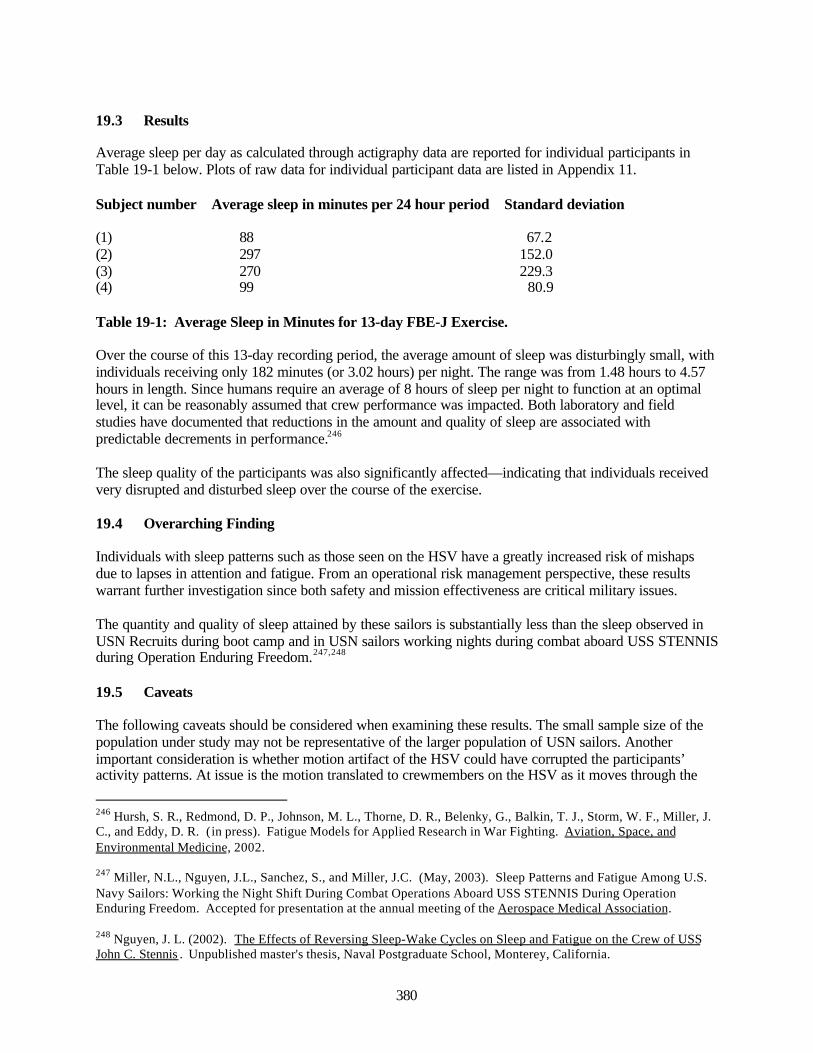
380
19.3 Results
Average sleep per day as calculated through actigraphy data are reported for individual participants inTable 19-1 below. Plots of raw data for individual participant data are listed in Appendix 11.
Subject number Average sleep in minutes per 24 hour period Standard deviation
(1) 88 67.2(2) 297 152.0(3) 270 229.3(4) 99 80.9
Table 19-1: Average Sleep in Minutes for 13-day FBE-J Exercise.
Over the course of this 13-day recording period, the average amount of sleep was disturbingly small, withindividuals receiving only 182 minutes (or 3.02 hours) per night. The range was from 1.48 hours to 4.57hours in length. Since humans require an average of 8 hours of sleep per night to function at an optimallevel, it can be reasonably assumed that crew performance was impacted. Both laboratory and fieldstudies have documented that reductions in the amount and quality of sleep are associated withpredictable decrements in performance.246
The sleep quality of the participants was also significantly affected—indicating that individuals receivedvery disrupted and disturbed sleep over the course of the exercise.
19.4 Overarching Finding
Individuals with sleep patterns such as those seen on the HSV have a greatly increased risk of mishapsdue to lapses in attention and fatigue. From an operational risk management perspective, these resultswarrant further investigation since both safety and mission effectiveness are critical military issues.
The quantity and quality of sleep attained by these sailors is substantially less than the sleep observed inUSN Recruits during boot camp and in USN sailors working nights during combat aboard USS STENNISduring Operation Enduring Freedom.247,248
19.5 Caveats
The following caveats should be considered when examining these results. The small sample size of thepopulation under study may not be representative of the larger population of USN sailors. Anotherimportant consideration is whether motion artifact of the HSV could have corrupted the participants’activity patterns. At issue is the motion translated to crewmembers on the HSV as it moves through the
246 Hursh, S. R., Redmond, D. P., Johnson, M. L., Thorne, D. R., Belenky, G., Balkin, T. J., Storm, W. F., Miller, J.C., and Eddy, D. R. (in press). Fatigue Models for Applied Research in War Fighting. Aviation, Space, andEnvironmental Medicine, 2002.
247 Miller, N.L., Nguyen, J.L., Sanchez, S., and Miller, J.C. (May, 2003). Sleep Patterns and Fatigue Among U.S.Navy Sailors: Working the Night Shift During Combat Operations Aboard USS STENNIS During OperationEnduring Freedom. Accepted for presentation at the annual meeting of the Aerospace Medical Association.
248 Nguyen, J. L. (2002). The Effects of Reversing Sleep-Wake Cycles on Sleep and Fatigue on the Crew of USSJohn C. Stennis . Unpublished master's thesis, Naval Postgraduate School, Monterey, California.

381
water. This motion may be important because actigraphy measurements could have been affected by themotion of the ship and therefore may not be an accurate assessment of the amount and quality of sleepreceived by the participants. Since actigraphy measures the activity levels of a human, the unusualwaveform motions of the HSV may have interfered or added extraneous motion to this recording. Thiseffect would be particularly problematic during sleep periods, when the absence of motion is used toassess whether an individual is asleep and to measure the quality of that sleep period. Future studiesshould ensure that any background noise due to ship motion is recorded and explained.

382
This page intentionally left blank.

383
Appendix 1: Master Scenario Event ListFinal Report: Fleet Battle Experiment - Juliet
FBE-J Pre-Execution / Execution Overview
The FBE – J execution and pre-execution schedule was integrated within the construct of MC 02. Thepre-execution phase involved installation and integration of equipment, technical testing, and operatortraining in a spiral development approach. The execution phase involved both live and simulated forces.All live play integrated with MC 02 was scenario driven.
Pre-Execution Phase (10 Jul-23 Jul 02)
Technical Integration and Testing Event: Technical testing included operational sequence diagram(OSD) testing 18-20 JUL 2002, which built upon testing completed in Spiral 3. Testing priorities in OSDtesting included: HSV Joint Venture, USS Fitzgerald, USS Benfold, USS Salt Lake City, Sea SLICE. andChina Lake Strike Warfare Commander Strike Cell. FCTCPAC JECG and technical support commenced24-hour operations on 22 July.
Experimental installs and technical integration: Installations and integration were required on variousplatforms including: USS Benfold, USS Fitzgerald, USS Salt Lake City, JointVenture and Sea SLICE. Inaddition, additional workstations were installed at numerous FBEJ/MC 02 sites.
Functional training events : Training priorities were designed to: (a) train the JFMCC and PWCpersonnel who had no previous training or did not attend Spiral 3; (b) provide XC4I tools refreshertraining for operators; and (c) provide JECG and observer training for reservists. In addition, eachJFMCC cell and PWC staff had refresher functional training specific to that cell.
Integrated training FBEJ / MC 02
Date of Event Comments10-21 JULY End To End Connectivity / Communications Test (MC 02)11 JUL JTF Commander's VTC (1200-1330 EDT)12 JUL INTSUM Roll Up15 JUL FBE J Ops & Technical Team Deploys For San Diego15-16 JUL XC4I Tools Training JTASC16 JUL JECG Wargame (JTASC)16-17 JUL Technical Set-Up (FCTCPAC)16-17 JUL Live Fly & Pre-Sail Conference San Diego17-18 JUL XC4I Tools Training JTASC17 JUL U2 Collection For JFMCC17 JUL JFCOM Working VTC (13-1430 EDT)17 JUL All MC 02 Systems Fully Up18 JUL MC 02 Network Up For All USN Participants (Except BENFOLD, NP3D, HSV, and N24 VPU)18-19 JUL July JDN Conference (NELLIS)18-20 JUL Navy OSD Testing18-21 JUL JFI Testing18 JUL JTF Commander’s VTC (1200-1330 EDT)19 JUL COP VTC19 JUL U2 Collection for JFMCC19 JUL JECG In-processing JFCOM20 JUL BENFOLD, NP3D and HSV Enter MC02 Network
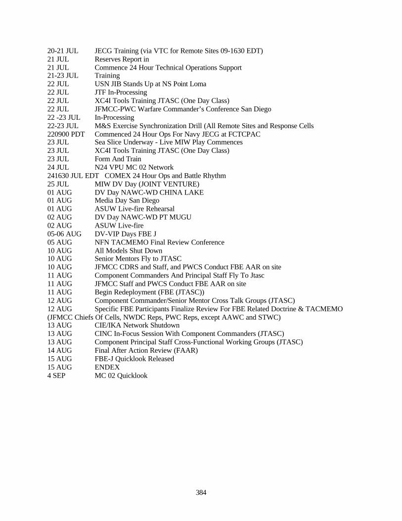
384
20-21 JUL JECG Training (via VTC for Remote Sites 09-1630 EDT)21 JUL Reserves Report in21 JUL Commence 24 Hour Technical Operations Support21-23 JUL Training22 JUL USN JIB Stands Up at NS Point Loma22 JUL JTF In-Processing22 JUL XC4I Tools Training JTASC (One Day Class)22 JUL JFMCC-PWC Warfare Commander’s Conference San Diego22 -23 JUL In-Processing22-23 JUL M&S Exercise Synchronization Drill (All Remote Sites and Response Cells220900 PDT Commenced 24 Hour Ops For Navy JECG at FCTCPAC23 JUL Sea Slice Underway - Live MIW Play Commences23 JUL XC4I Tools Training JTASC (One Day Class)23 JUL Form And Train24 JUL N24 VPU MC 02 Network241630 JUL EDT COMEX 24 Hour Ops and Battle Rhythm25 JUL MIW DV Day (JOINT VENTURE)01 AUG DV Day NAWC-WD CHINA LAKE01 AUG Media Day San Diego01 AUG ASUW Live-fire Rehearsal02 AUG DV Day NAWC-WD PT MUGU02 AUG ASUW Live-fire05-06 AUG DV-VIP Days FBE J05 AUG NFN TACMEMO Final Review Conference10 AUG All Models Shut Down10 AUG Senior Mentors Fly to JTASC10 AUG JFMCC CDRS and Staff, and PWCS Conduct FBE AAR on site11 AUG Component Commanders And Principal Staff Fly To Jtasc11 AUG JFMCC Staff and PWCS Conduct FBE AAR on site11 AUG Begin Redeployment (FBE (JTASC))12 AUG Component Commander/Senior Mentor Cross Talk Groups (JTASC)12 AUG Specific FBE Participants Finalize Review For FBE Related Doctrine & TACMEMO(JFMCC Chiefs Of Cells, NWDC Reps, PWC Reps, except AAWC and STWC)13 AUG CIE/IKA Network Shutdown13 AUG CINC In-Focus Session With Component Commanders (JTASC)13 AUG Component Principal Staff Cross-Functional Working Groups (JTASC)14 AUG Final After Action Review (FAAR)15 AUG FBE-J Quicklook Released15 AUG ENDEX4 SEP MC 02 Quicklook
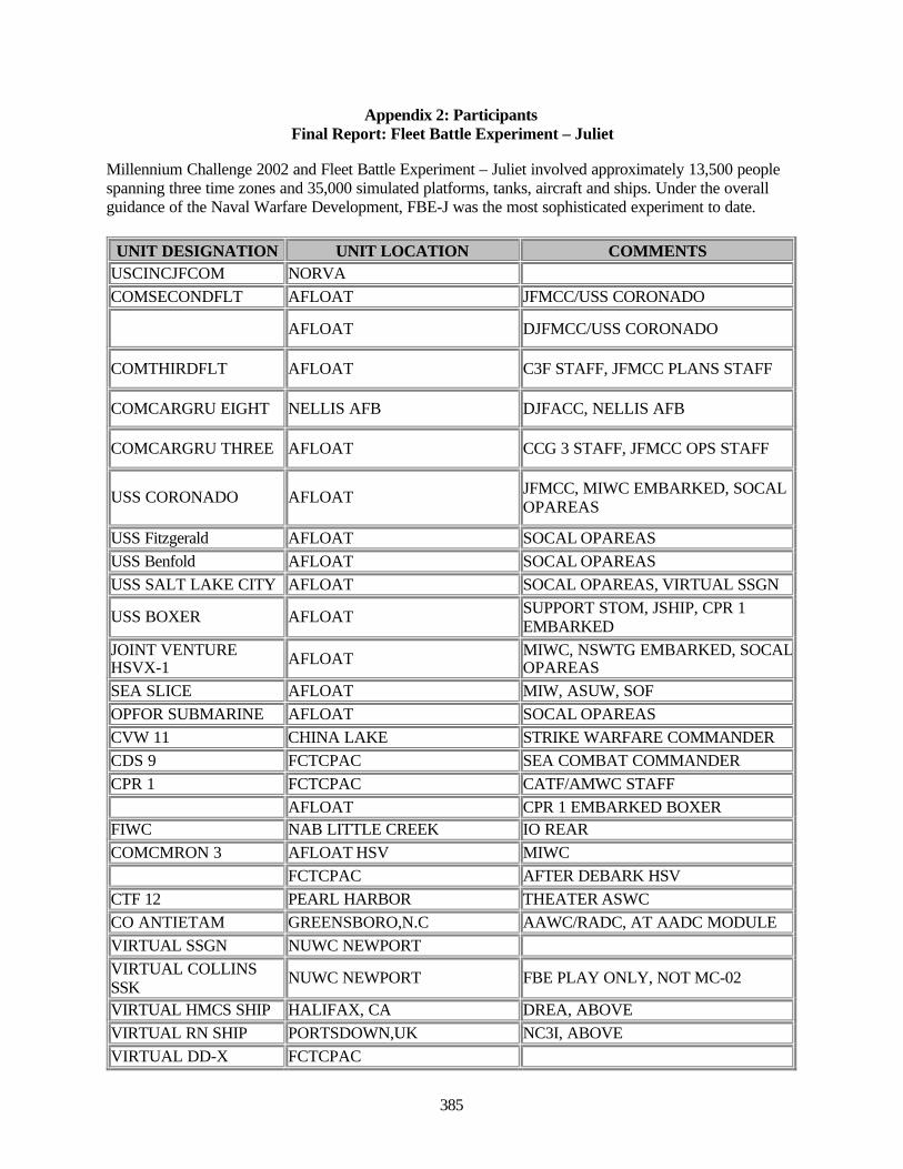
385
Appendix 2: ParticipantsFinal Report: Fleet Battle Experiment – Juliet
Millennium Challenge 2002 and Fleet Battle Experiment – Juliet involved approximately 13,500 peoplespanning three time zones and 35,000 simulated platforms, tanks, aircraft and ships. Under the overallguidance of the Naval Warfare Development, FBE-J was the most sophisticated experiment to date.
UNIT DESIGNATION UNIT LOCATION COMMENTSUSCINCJFCOM NORVA COMSECONDFLT AFLOAT JFMCC/USS CORONADO
AFLOAT DJFMCC/USS CORONADO
COMTHIRDFLT AFLOAT C3F STAFF, JFMCC PLANS STAFF
COMCARGRU EIGHT NELLIS AFB DJFACC, NELLIS AFB
COMCARGRU THREE AFLOAT CCG 3 STAFF, JFMCC OPS STAFF
USS CORONADO AFLOAT JFMCC, MIWC EMBARKED, SOCALOPAREAS
USS Fitzgerald AFLOAT SOCAL OPAREASUSS Benfold AFLOAT SOCAL OPAREASUSS SALT LAKE CITY AFLOAT SOCAL OPAREAS, VIRTUAL SSGN
USS BOXER AFLOAT SUPPORT STOM, JSHIP, CPR 1EMBARKED
JOINT VENTUREHSVX-1 AFLOAT MIWC, NSWTG EMBARKED, SOCAL
OPAREASSEA SLICE AFLOAT MIW, ASUW, SOFOPFOR SUBMARINE AFLOAT SOCAL OPAREASCVW 11 CHINA LAKE STRIKE WARFARE COMMANDERCDS 9 FCTCPAC SEA COMBAT COMMANDERCPR 1 FCTCPAC CATF/AMWC STAFF AFLOAT CPR 1 EMBARKED BOXERFIWC NAB LITTLE CREEK IO REARCOMCMRON 3 AFLOAT HSV MIWC FCTCPAC AFTER DEBARK HSVCTF 12 PEARL HARBOR THEATER ASWCCO ANTIETAM GREENSBORO,N.C AAWC/RADC, AT AADC MODULEVIRTUAL SSGN NUWC NEWPORT VIRTUAL COLLINSSSK NUWC NEWPORT FBE PLAY ONLY, NOT MC-02
VIRTUAL HMCS SHIP HALIFAX, CA DREA, ABOVEVIRTUAL RN SHIP PORTSDOWN,UK NC3I, ABOVEVIRTUAL DD-X FCTCPAC
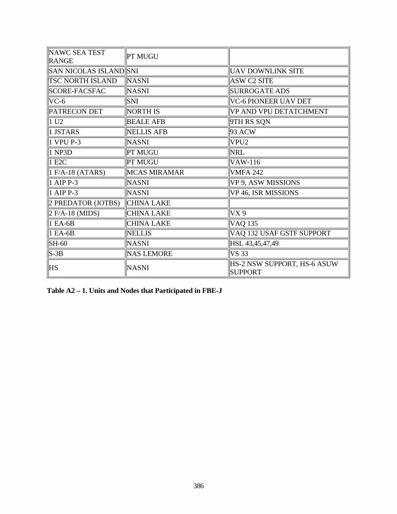
386
NAWC SEA TESTRANGE PT MUGU
SAN NICOLAS ISLAND SNI UAV DOWNLINK SITETSC NORTH ISLAND NASNI ASW C2 SITESCORE-FACSFAC NASNI SURROGATE ADSVC-6 SNI VC-6 PIONEER UAV DETPATRECON DET NORTH IS VP AND VPU DETATCHMENT1 U2 BEALE AFB 9TH RS SQN1 JSTARS NELLIS AFB 93 ACW1 VPU P-3 NASNI VPU21 NP3D PT MUGU NRL1 E2C PT MUGU VAW-1161 F/A-18 (ATARS) MCAS MIRAMAR VMFA 2421 AIP P-3 NASNI VP 9, ASW MISSIONS1 AIP P-3 NASNI VP 46, ISR MISSIONS2 PREDATOR (JOTBS) CHINA LAKE 2 F/A-18 (MIDS) CHINA LAKE VX 91 EA-6B CHINA LAKE VAQ 1351 EA-6B NELLIS VAQ 132 USAF GSTF SUPPORTSH-60 NASNI HSL 43,45,47,49S-3B NAS LEMORE VS 33
HS NASNI HS-2 NSW SUPPORT, HS-6 ASUWSUPPORT
Table A2 – 1. Units and Nodes that Participated in FBE-J
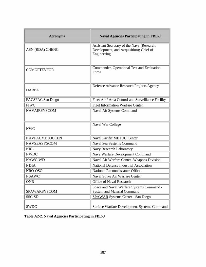
387
Acronyms Naval Agencies Participating in FBE-J
ASN (RDA) CHENGAssistant Secretary of the Navy (Research,Development, and Acquisition); Chief ofEngineering
COMOPTEVFOR Commander, Operational Test and EvaluationForce
DARPADefense Advance Research Projects Agency
FACSFAC San Diego Fleet Air / Area Control and Surveillance FacilityFIWC Fleet Information Warfare CenterNAVAIRSYSCOM Naval Air Systems Command
NWCNaval War College
NAVPACMETOCCEN Naval Pacific METOC CenterNAVSEASYSCOM Naval Sea Systems CommandNRL Navy Research LaboratoryNWDC Navy Warfare Development CommandNAWC-WD Naval Air Warfare Center -Weapons DivisionNDIA National Defense Industrial AssociationNRO-OSO National Reconnaissance OfficeNSAWC Naval Strike Air Warfare CenterONR Office of Naval Research
SPAWARSYSCOMSpace and Naval Warfare Systems Command -System and Material Command
SSC-SD SPAWAR Systems Center - San Diego
SWDG Surface Warfare Development Systems Command
Table A2-2. Naval Agencies Participating in FBE-J

388
This page intentionally left blank.
389
Appendix 3: Data CollectionFinal Report: Fleet Battle Experiment – Juliet
Success in Fleet Battle Experiments (as learned in previous FBE experience), in both data collection andanalysis of complex and large-scale experiments such as the series of FBEs, depends upon a fullunderstanding of underlying planning and execution requirements. In general, it is necessary to:
• Understand senior leadership experimentation goals.• Define analytic objectives.• Determine the operational details of each experiment or demonstration initiative.• Define the experiment and supporting technical architecture.• Support each warfighting finding with context.• Actively engage in dialogue with the initiative leads and participants.• Build flexibility into all of the above.
Great effort was taken to ensure that experiment data collection and analyses, within the confines of theexperimental design, would support Fleet and senior leadership's intent and expectations. Analysesobjectives for Fleet Battle Experiment Juliet were focused on six areas of high interest to senior Navyleadership:
• Service interoperability in the Joint environment.• Reduction of the timeline for location and engagement of time sensitive targets (TSTs).• Enhanced Situational Awareness (SA) for decision-making.• DOTMPLF recommendations for Joint Forces Maritime Component Commander (JFMCC), Joint
Fires Initiative (JFI), Navy Fires Network (NFN), ISR, and High Speed Vessel (HSV) initiatives• Provide supporting data that contribute to systems acquisition decisions.• Provide supporting data that contribute to defining requirements for advanced Joint and Navy
communications and information architecture.
Fleet Battle Experiments do not follow standard practice for experiment design. A standard practicewould begin with analysis objectives. Based on these objectives, an event would be designed to producethe data content and analysis necessary in order to produce the results that are being sought. Postexperiment analysis would include an examination of the methodology and experiment design, as contextfor the results. An iteration of the entire chain would then be planned, as necessary in order to deepen anunderstanding of the operating hypothesis on which the analysis objective was based. This is essentiallythe scientific method. Fleet Battle Experiments to date have tended to invert this process, so that datacollection planning and analysis are determined by the scope and development of initiatives that maturein-stride with operational planning for an event.
The above is not intended as critique (although there is an active ongoing discussion on this subject apartfrom FBE Juliet), but as an explanation to the trained methodologist as to the structure of the DataCollection Plan (DCP). This document is a description of the process that has emerged in Fleet BattleExperiments; it is not necessarily a set of best practices for experiment design.
Because of the complex planning required to produce an executable plan and near-continuous refinementof the operable initiatives, the FBE Juliet data collection plan was continuously modified until the start ofthe experiment. In general (as part of the FBE process), data planning often continues in real-time duringexperiment execution as conditions and systems are modified in-stride. Prior to execution, the datacollection plan process builds from extensive interviews with initiative leads and experiment stakeholders
390
that includes the Navy Warfare Development Command (NWDC) Maritime Battle Center, NWDCConcepts, NWDC Doctrine, and Fleet participants.
Data collection planning is dynamic and is required to be flexible enough to respond to changes inConcepts of Operations (CONOPS), architecture, and experiment scope. The Meyer Institute of SystemsEngineering, Naval Postgraduate School (MISE) has been fully engaged with experimental initiativeleads to improve the definition of appropriate analytic objectives and consequent data collection plans.
MISE was the lead to ensure FBE-J data collection efforts were coordinated between all agencies. To theextent other agencies are participating in FBE-J analyses, coordination will continue with JFCOM, theNaval Fires Network Virtual Program Office (NFN VPO), ForceNet, and the Army Space Program Office(ASPO).
Data Collection Plan Goals and Objectives
The Data Collection Plan ensured that data collection supported analysis and reporting requirements ofthe Fleet, NWDC and the stakeholder. In support of the DCP, the data management process ensured thatcollected data were appropriate and sufficient to analyze properly and support experimental initiatives.
The DCP formally documented the intended course of action for collection, distribution, analysis,reporting, and archiving of data products relevant to FBE-J initiatives. In addition, this plan definedexperiment Measures of Performance (MOP) and Measures of Effectiveness (MOE) that providedguidance to plan and execute data collection and analysis of this experiment.
Objectives of the Data Collection Plan
• Manage all data collection planning and processes from a central organization (MISE).• Ensure the collected data were adequate to provide analysis of initiatives and to meet NWDC and
Fleet requirements.• Ensure electronic data requirements were articulated early to systems managers so that adequate
plans, software, and instrumentation were in place to collect required data.• Ensure proper and timely collection, reduction, reproduction, and distribution of data.• Minimize unnecessary collection, reproduction, and distribution of data.• Minimize confusion in the data collection and distribution process.
The strategy for collecting sufficient electronic and manually recorded data for analysis was an extensionof lessons learned from previous Fleet Battle Experiments (most recently, FBE India). This included anaggressive process to understand thoroughly the experiment technical architecture and Concept ofOperations (CONOPS) during the experiment planning and architectures development phase. Also, dataelements required to answer initiative MOEs and MOPs were identified. Thus, the data collection andanalysis strategy were focused on providing a robust, comprehensive quantitative and qualitative databaseto address MOEs and MOPs. These questions were continually refined and targeted to specificexperiment areas of interest and changes to the CONOPS.
There was strong emphasis and support to derive quantitative (generally analogous to digital) data. It wasimportant that electronic data collection requirements were clearly defined to ensure systems managerscould support analyses by providing sufficient, usable data. Data collection and analysis planning wereconducted in parallel to the development of the architecture and CONOPS.
Data Requirements Definition
391
In general there were opportunities to collect four types of data in FBE-J:
• Time stamped data: As an example, reconstruction of time sensitive target (TST) eventsnecessitated recording precise times at which significant events took place along the timelinefrom detection to attack and to mission success. A time stamp was recorded for everycontact/target event as it passed through the TST process.
• Quantitative and contextual data: To meet the objectives of the Fires ISR and TST initiative, itwas necessary to determine the number of contacts detected, cross-cued, nominated and engaged.In addition, each contact event needed to be tracked as it proceeded through the TST timeline inorder to specify process impacts on the timeline.
• Technical performance data: Technical analysis was used to assess system reliability,connectivity, and/or interoperability. Data collection methodology included recording downtimes, malfunctions, file transfer rates, and times when connectivity was lost. Obtaining specifictechnical data were generally the responsibility of the system owner as the system participated inthe FBE. In addition, trouble logs were collected and evaluated.
• Qualitative observations and measurement: Observations by participants, interviews and limitedsample surveys were used to bring warfighting context to quantitative MOPs. Analysts withoperational experience located at key decision-making nodes gathered data on C4I structure andprocesses.
As stated earlier, data collection planning occurred in parallel with the development of the architectureand CONOPS. Since the FBE-J Initial Planning Conference (IPC), a dialogue has continued with systemsmanagers from all initiatives to define data requirements and determine system capabilities and functionduring the experiment. Data planners continued this discussion through SPIRAL 3 and further identifiedelectronic and manual data to be collected during FBE-J. Data formats and data reduction capabilities ofeach system were also defined. MISE planners used this information to construct analysis tools for postexperiment use on data collected during the experiment.
An electronic data capture "Operations Center" was created in the vicinity of the modeling and simulationcenter and experiment control locations at the Fleet Combat Training Center, Pacific. MISE personnelmanned this center for data collection coordination, and for monitoring the day-to-day electronic datacapture events and making adjustments to the data collection plan, as required. The data collection leadfrom each experiment node communicated with the operations center daily through an IWS chat channelor voice communication circuit to ensure that the data collection plan was functional.
Observation And Data Collection Guidance
Data collection is demanding and intellectual work. Data collectors must understand how to observe orcollect what is important, defined through questions specified for each area, and also what might beimportant as the experiment unfolds. In other words, effective data collection includes the collection ofrequired data and also those data from unintended and unplanned actions.
Each section of the data collection plan included questions that were defined as important toexperimentation data collection within a specific area. Questionnaires, participant observations, data logs,electronic chat dialog, interview questions, and electronic data all contributed dimensions that togetherimproved the quality and validity of answers to these core questions.
392
General Guidance Given to Data Collectors
• Define the context in which observations were made. For example, if there were delays in TSTengagements, it is important to note the time delay, and the situation that may have contributed tothe delay at the time of the observation (e.g., prosecution of pre-planned targets, shift incommander's intent, changes to the organization for TST, equipment/personnel problems etc.).This context is essential to analysis of complex interactions.
• Part of the context is ground truth. Note all positions (for example, ship's position, or targetposition) that would be necessary to understanding how a particular event evolved. Time is alsoan element to ground truth. You need to record time as a part of all observations. This is criticalto tracking data in later analysis.
• Use data logs to assist in cataloguing observations. These will prove invaluable later as youreconstruct an event. Be very organized about this. Back of the envelope data collection is notuseful later.
• Use a tape recorder as a means to help you fill in notes later. This technique works better forsome than others. However, do not depend on a tape recorder as your principle collection means--transcription of taped notes is difficult, and interview notes are generally very reliable inreconstructing important respondent comments later, and can be verified by recordings. Also,quality recording on a ship is nearly impossible!
• Note exceptions to the "routine." As the flow of a problem becomes more and more routine, notethose instances which are not routine, or which cause the system being observed to behave in adifferent way.
• Note changes in organization, CONOPS or other "baselines" that were the basis for theexperiment at STARTEX. As well as you can, define reasons and consequences. This assumesthat the data collector is well versed in what is considered the initial conditions for theexperiment. It is essential that data collectors have this expertise, or changes to routines and tobaselines will not be captured.
• Besides the basic set of questions and data sheets provided to you, adapt data collection to whatyou are observing. That is, if we aren't asking the right questions, what are the correct ones?
• Understand the system you are observing! Draw it out at the level you are observing it. Don'tsimply repeat the system from the EXPLAN, or operational sequence diagram (OSD) but try toconstruct it as a diagram based on what is actually happening (using the baseline architecture as apoint of comparison).
• Be completely conversant with the overarching data goals for your portion of the experiment.Your expertise and depth of understanding will have a direct relation to what you notice, and thequality of those observations and notes.
• Do not interfere with operations and participants. However, "wallflowers" do not make good datacollectors. If it is important to ask a participant a question, simply try to do this in a way that doesnot interfere, but in the end, it is the data that are most important. Post event interviews are anexcellent way to obtain the "deck plate" view from participants, and there will be a structured setof interviews and focus groups that all data collectors will have an opportunity to work with.
393
Afterwards, it is critical that notes be immediately transcribed--the relevant information isgenerally perishable and will be difficult to reproduce in a few days.
• Preparation is required for each day's events. Data collectors must be familiar with the MSELevents anticipated in each day’s operations (noting that much of the experiment is unscripted andvariable). Think through the data collection opportunities inherent in each of the events, and planaccordingly. If there is a crossover to another initiative area, collaborate with the data collectionlead in that area.
Electronic Data
Electronic data from systems comprising the FBE-J architecture were essential to quantitatively describethe TST engagement process and to document command and control decision-making processes. Inaddition, logs from collaborative tools (Info Workspace, IWS) provided qualitative experiment contextand offered explanations that validated quantitative results. The systems and data element requirementsrequired to support FBE-J analysis are highlighted below.
Electronic data (system logs) from ALL systems that are components of the targeting process (e.g.GISRC, TES-N, GCCS-M, ADOCS/LAWS, DTMS/PTW, RPM, RPTS, etc.) were required for FBE-Jpost experiment reconstruction analysis. Individual system managers were required to maintain electroniclogs that define system performance and permit a timeline analysis, by event, of the operation of thesystem. These logs were an essential element of the data collection plan and overall test analysis effortand were submitted to MISE upon experiment completion. Details of initiative data elements requiredfrom electronic systems were identified within each initiative section in this data collection plan.
The general requirements for data from participating systems participating in FBE-JJ included:
• All systems were expected to record externally generated messages received by the system andthe response sent from the system.
• Systems were to record the nature of any significant internal action performed by the system.• All recorded data were to be time tagged.• All time tags were to be time synched.• All logged events and consequent actions (cause and effect) were to identify associated target or
track number.
The format in which data were provided was to have been documented. The format was expected to beeasily exportable to spreadsheets or databases (i.e., comma separated files).
Data were provided for daily analysis or immediately, post-experiment, depending on reportingrequirements. Daily collection management and field analysis were discussed in the Data Collection Plan(Data Collection C2 and Battle-Rhythm). Post experiment data analysis was discussed in a separateExperiment Analysis Plan (EAP). Data were provided on floppy discs, zip discs, CDs, e-mailed or byFTP to NPS.
Data Collection Plan (DCP) Organization
For each of the initiatives in FBE Juliet the following elements were included in the DCP:
• An explanation of the relationship between the initiative and a warfighting challenge in 2007, asit was to be played within the FBE Juliet and MC02 scenario (scripted in the Master ScenarioEvents List (MSEL)), or as it emerged in unscripted free-play.
394
• A definition of the general theme of the initiative. Specifics with regard to background for aninitiative could be examined in the Experiment Plan (EXPLAN).
• A Statement of Sub-Initiatives. Elements that contributed to sub-initiatives (sub-sub initiatives)were stated under each. A summary description of the contribution each of these elements madeto the Sub-Initiative was also provided.
• Analysis Objectives were stated, which may have included objectives across sub-initiative areas• Measures of Effectiveness and Measures of Performance, with associated requirements for data.• Required data elements, which specified data needs for the initiative area.• Synchronization between analysis objectives and MOPs and MOEs.• Requirements for data collection instruments (questionnaires, surveys, interview questions, etc.)
and log sheets.• Data collection points, nodes, or positions.• Lead data collection responsibility (by name).• Coordinating instructions, including requirements for daily data summaries, media collection, and
data collection, C2 etc…
Measures of Effectiveness (MOEs) and Measures of Performance (MOPs) were identified as a means tocharacterize or compare systems and processes to a structured requirement that contributed to fullunderstanding of the observed system.
• MOE is defined as a measure that expressed the extent to which a system accomplished orsupported a mission or task (in other words, a capability).
• A MOP is purposely more quantitative, and is a measure of a system's capabilities or specificperformance.
While it would be convenient to succinctly capture performance/effectiveness in a single number,MOPs/MOEs alone do not generally provide the context needed to express the interrelations between acause and an effect. For this reason, MOPs/MOEs are best used when coupled with contributing context.
Examples
• A JFMCC MOE: "Sufficient manning to perform functions outlined in MPP CONOPS.“Sufficient” is the condition in which the processes required in the MPP are not delayed as aresult of lack of personnel resources alone."
• A JFMCC MOP: "Percent of orders synchronized prior to being issued to a warfarecommanders."
• Contributing context would include: “Although adequate personnel were sitting at workstations,they were not conversant in JFMCC MPP process details. The result was a constrained process.”Or, “The percentage of orders synchronized was time dependent; i.e., that there were gapsbetween required actions to conduct synchronizations, so that they tended to pile up all at once.”
Data Collection Command and Control (C2), and Battle Rhythm
Lead Data Collector. A lead data collector was assigned for each principle node and for each initiativearea. These roles were specified in a matrix of manning attached as an appendix to the DCP. In eachinitiative area, this individual was responsible for (including, but not an all encompassing list):
395
• Data collection requirements.• Data collection media.• Data collection instruments.• Coordination of data collection events (e.g., MSEL or other scheduled events).• Collaboration with other data collection leads for cross-cueing of data requirements of events
crossing initiative areas.• Training of respondents to become active participants in the data collection process.• Status of electronic data in their initiative area.• Collection, retrieval, or archiving of electronic and respondent data.• Forwarding of principle daily results to the analysis lead.• Forwarding any issues with respect to data collection that impacts ability to collect, retrieve,
archive, or forward data.• Recommendations with respect to improvements to data collection requirements, collection, or
C2.• Participating in all operational, planning, and data collection events.• Uploading of instruments in the Joint Data Collection and Analysis Tool (JDCAT) in
collaboration with the data instrument lead.• Providing all coordination means possible in order to ensure collaboration between data
collection areas and data management (e.g., establishing contact through e-mail and IWC or IRCchat accounts).
• Downloading of essential IWC or IRC chat in chat rooms used in the course of operations in yourinitiative area.
There were daily chat sessions in either IWC or IRC between the Analysis Lead and all Lead DataCollectors. These sessions typically occurred in the morning, just after the Experiment Director had metwith the experiment leads.
A Principal Results Review took place each evening at 1700. In order to prepare, it was essential thatinputs be provided to the Analysis Lead by 1600 of each experiment day. These times could be adjustedaccording to the operational battle rhythm.
Data Collection Instruments
Surveys, questionnaires, interview sheets, event logs were all included as data collection instruments. Allwere focused to meet the data collection requirement that supported an analysis objective. In general,surveys, questionnaires, interviews, and focus groups were used to elicit responses from participants thatdeepened and provided context to data in logs, chat files, and in electronic data files. Quality indicators(e.g., how a participant felt about a particular process that was indicated in a set of scales) did providesome information about how something was valued, but it did not provide insight into why. All FBEinstruments therefore leaned toward understanding context and relationships (the why part), vice quality,as an experimentation issue.
Both participants and observers filled in logs. The value of logs was their utility in helping to reconstructcontext in post experiment analysis. From past experience, it was very difficult to ask participants andobservers to do this in any detail after the experiment has been completed. If done electronically, theselogs became an invaluable source for immediate analysis. Data leads for each initiative were responsiblefor cultivating the filling in of log sheets, and for retrieval of the sheets for submittal.
A process for implementing the use of instruments across all of the data initiatives includes the following:
• Construction of the instrument by the data collection lead.
396
• Submission of the instrument to the instrument lead for review.• Validated instruments were sent to KM for inclusion in the database.• A validated instrument could be loaded in the Joint Data Collection Analysis Tool (JDCAT). This
required that the instrument be physically uploaded or typed into the JDCAT interface as part ofthe bank of surveys and questionnaires to be accessed via the SharePoint Portal Server (SPPS)and the JFMCC web site during the experiment.
• During the experiment, data leads asked for their instrument to be activated/deactivated inJDCAT. This meant that the instrument would be available for respondents to answer whenactivated, and would not be accessible when deactivated.
• Emergent requirements for new instruments followed the same procedure as above, but data leadswere expected to discuss them directly with the instrument lead.
• Results and statistics for each survey were held in a folder specifically for that instrument, andwere available for download at FCTCPAC or on USS CORONADO for immediate review.
• If paper copies of the instruments were required for distribution, data leads were responsible forthe publication, distribution, retrieval, data reduction and requests for analysis based on thatparticular instrument. Employment of the electronic means at hand greatly increased the utility ofthese instruments.
• At experiment end, data leads were responsible for ensuring that data from instruments in theirarea were collected and archived safely for further analysis.
The resulting JDCAT database has been incorporated into the MISE KM system for further analyses.
397
Appendix 4: Initiatives, Data, and AnalysisFinal Report: Fleet Battle Experiment – Juliet
Initiatives are not all of the same type. An initiative may have very definite objectives, from whichdefinitive data and events to obtain the data are derived. Or an initiative may be more of an exploration,perhaps even to get an initial determination of what needs to be learned. Differing types of planning, datacollection, and analyses will be used for different initiative types.
This Appendix describes three highly interdependent aspects that control results obtained from anexperiment:
• Initiative type, and how each is conducted.• The types of data available.• Methods used to analyze the data.
Initiative Categorizations
Initiatives are segmented into two categories:
• Experimentation (which is then further subdivided into either)o Explorationo Developmental
• Demonstration, which can be of a system or process
These categorizations have implications for data collection and results. For example, a demonstrationimplies a lessened set of requirements for data, analysis, and reporting, when compared to an experiment.
Experimentation implies that the initiative:
• Must have some potential for replication. It may not be possible to run exactly the same test manytimes and obtain statistical data, but it is possible to conduct the same category of event for thesame data collection and analysis purpose.
• Must have a clear analytic –objective; one, that leads to data requirements and connected analysismethods.
• Must have some form of "baseline." A baseline, in this case, can be a process model, proposedperformance, CONOP, Operation Sequence Diagram, or architecture. There must be a proposedway in which a system or component is to perform in the experiment.
• Must have a well-defined experiment protocol.
These criteria do not rule out experimentation that will yield largely subjective information.
Exploration refers to including something new in FBEs that has not been done before, and hence there issome risk. Failure or discoveries are acceptable options. Experimental conditions will be set up but it isexpected that deviations will occur; unanticipated lessons will be learned, in the course of the experiment.
Developmental refers to initiatives that are being furthered from previous FBE work; require additionalwork to mature them before results are finalized. The conditions for which one wishes to undertakeadditional development are well known. Control is more rigorous and discovery is not expected.
For a demonstration, one installs a system or process then observes it to see if it works. Subjectiveopinions can be gathered as to whether it did or did not, but little analysis is expected to determine why.
398
Data Types
Fleet Battle Experiments always produce a diverse collection of data and information. This diversity hasseveral aspects:
• Data/Information - from objective data to opinions.• Opinion quality - from well-located, qualified observers to those with preformed opinions.• Appropriateness - from a well-designed event to a happening not connected to an objective or
from a system operating within appropriate physical context to physical conditions notappropriate to an objective.
• Context - is a class of data that provides background or situation understanding for other data andinformation.
As noted above, a demonstration may require only data that are operator opinions about whether thesystem or process being demonstrated works. If one is doing detailed Test and Evaluation (T&E) of asystem, there will be a full plan, objective data, and MOPs.
Developmental Experimentation will also have planned events to produce objective data and quantitativeanalysis. Exploration Experiments will be a mix; because of the exploratory nature, some subjectiveinformation will be obtained through discovery.
Analysis
Analyses are designed to deal appropriately with this diversity. This is largely an art, however, more thanit is a well-defined set of procedures (e.g., in some cases it was most appropriate to throw away suspectinformation, whereas in others it was appropriate to combine it with other information to produce a usefulresult, with caveats). In all cases, an analysis result must be accompanied by context; this gives itmeaning. Combining results with Context provides limits of validity and can produce cause-and-effectrelationships.
Analysis Limitations
Analysis results could not be blindly accepted as "truth". If they were to be used for some purpose, theresults were examined carefully to determine their meaning and validity with respect to the intendedpurpose. Process and system performance measures, with humans-in-the-loop, during operations, werethe desired results from FBE-J. Brief explanations of limitations follow:
• Context. Results have meaning only if they are accompanied by context. Regardless of theanalysis technique used, if the conditions under which a result was obtained are not available, theresult is of little use. Interpreting context/conditions and the impact on results was one of the mostchallenging aspects of analysis, yet context subtleties could be easily overlooked. With alloperational experimentation, results obtained applied only to circumstances that existed duringthat operation. The subsequent extrapolation to other conditions is not necessarily valid. Thus,reconstruction of an event stream provided important context for analysis.
• Subjective Information. Most of the information obtained from FBEs is subjective, and Julietwas no exception. A full range of human impacts influences subjective opinions:misinterpretation, prejudice, and overloading; but they can also provide correct, perceptive insightgained from personal expertise and experience in similar situations. Regardless of limitations,there were many reasons for developing results from these opinions. They might have been all
399
that were available. Also, when trying to determine the performance of systems, processes, andincluded human operators, the opinions obtained may have provided the best understanding ofhow these human-included systems will perform in an operational environment. However,caution must be used when attempting to develop too-rigorous analyses from subjectiveinformation.
• Range of Validity. Results were valid only for the conditions for which they were determined.Conditions were not a constant throughout the experiment. Reconstruction and carefulobservations or data collection at critical nodes provided the specific conditions under which aparticular result was obtained, yielding the range of validity. Although FBEs do not have processmodels available so that one can only assume the results are valid for the conditions that existed,some extensions are possible in certain circumstances, i.e., the ability to maintain a somewhatslower rate of actions successfully demonstrated.
• Anecdotes. This is a problem that occurs for all experimental results for which there is notcontrol and replication. If the system under analysis was unstable, then every result becomes ananecdote. One has no means for generalizing the result to other circumstances.
Analysis Methods
Analysis methods are grouped into four general classes:
• Objective Results• Context and Subjective Results• Comparisons• Reconstruction
This grouping is useful, but the methods do not belong exclusively to one class. A particular result canuse methods from more than one class.
To delineate the method used in each analysis, a code was provided for each of the methods. These codesare included with the various results to indicate the method(s) used for their production.
Objective Results
This class of results comes from objective data, i.e., data that have a specific quantification, such as anelapsed time, a number of objects, or a number of occurrences. The analysis methods are analyticallyrigorous. For FBEs, objective data are almost completely event occurrence times within various electronicsystems. Context was still needed to give these results meaning.
• SP - System Performance . Process execution within systems was logged, often electronically.These data were used to determine analytic performance parameters for that system. This methodis appropriate to Test and Evaluation and was used only occasionally within FBE-J.
• SA - Statistical Analysis. SA requires that data from a sufficient numbers of similar events becollected so that statistical parameters have precision. This was the case only for the componentsof Fires events timelines.
• SC - Statistical Comparisons. Means and variances were compared for situations where thesituations/contexts are known and different, allowing rough cause-and-effect to be established.
400
• CS - Case Studies. Unique results can sometimes be associated with context, providing a casestudy. Derived distributions, however, often have outliers; a type of unique result, andexamination of outliers can provide more significant information than stating the distributionmean and variance. Case studies are a good method for uncovering cause-and-effect. A difficultyis that a unique event may be only an anecdote, and may not replicate even under the same, orthought to be the same, conditions.
• MBA - Model-Based Analysis. A model can be used to predict behavior or process results.Experiment execution determined what occurred, either what was predicted or something else.MBA is a comparison of predicted and actual results, with a goal of parameterizing or modifyingthe model. The model could be as simple as a set of expected task completion times for thedetect-to-engage cycle. It could also be a complex model underlying a simulation, and simulationruns provided the prediction.
Subjective Results
In the context of these experiments, there should be no implication that either objective or subjectiveresults are of greater validity or value. Both have meaning only when accompanied by appropriate contextand getting accurate context is difficult because of the human-in-the-loop and operational (fog of war)nature of the experiments. There are subtleties of context that are difficult to determine.
• PO - Process Observations . Subject matter experts logged process behavior observations. Theevent logs included observation times, observed incidents/conditions, and opinions. Theinformation in the logs was correlated with other data, such as detect-to-engage timeline data, tobuild a complete sequential picture of the operation. This provided both context and results. Theresults were opinions about performance. The context was observations, such as a person isoverloaded, fatigued, or lacks understanding.
• SO - System Observations . The method was the same as for Process Observations.
• Text. Analysis of the texts of Chat, e-mail, for relationships and communication processes.Besides revealing processes actually used, the texts provided additional context.
• SUB - Subjective Opinions . Operators were queried about their judgment of process or systemwith regard to its meeting needs or requirements. These opinions are appropriate to a segment orthe whole of the experiment rather than an individual event (SO or PO). Judgments are providedfrom different perspectives, and they can conflict.
Subjective analysis consisted of correlating judgments with situations. An attempt was made to generalizethe result by correlating judgments from different perspectives. Context was used to determine cause-and-effect. Additional analyses attempted to determine if results provided implications about the relativesuccess of various configurations of systems and processes, such as distributed versus centralized.
Comparisons
• ComS - Compare to Standard. Standards exist for process performance. This was a comparisonof the performance achieved to the standard.
• ComE - Compare to Expectation. Processes and systems were expected/planned to operate in aparticular way. This was a comparison of expectation and what was done in the experiment. Thisis the simplest type of MBA, presented separately because no actual model was used.

401
• FID – Fidelity. This refers specifically to whether or not information was correct, or whetherdifferent instances of what was supposed to be the same information were the same. (The humanfactors concern of whether different individuals have the same perception when viewinginformation was not pursued in this experiment.)
Reconstruction
• Rec – Reconstruction. was essentially zero order analysis. It provided what actually occurred,down to the level of detail needed for subsequent analyses. It provided the basic context withinwhich results were cast. Reconstruction was assumed as part of all analysis methods; when thiscode appears it meant that only reconstruction would be done.
• RecT. Reconstruction of engagement timelines from system electronic data and participantcommunications.

402
This page intentionally left blank.
403
Appendix 5: Collaborative ToolsFinal Report: Fleet Battle Experiment – Juliet
SharePoint Portal Server (SPPS)
SharePoint Portal Server (SPPS) was the chosen system for a web based document collaboration andportal tool. As a new Microsoft product, SPPS ran very smoothly, and will improve over time. DuringFBE-J, only a subset of SPPS’s features were used, but one of the most import aspects of SPPS was thatwarfighters could take ownership of their portal. The following will briefly discuss the JFMCC use ofSPPS in Site Navigation, PWC Ownership, Security Settings, Search Engine, Publishing Process,Subscriptions, Personal Dashboards, and Unused Features.
Site Navigation
The site was divided into five major sections: JFMCC Home, Warfighting, Applications, and DocumentLibrary, and Help. “JFMCC Home” was similar to a Yahoo front page. It contained a status for each ofthe FBE-J nodes, along with all the most current and admin information. “Warfighting” was split up intowarfighting area sub portals. Each area then received ownership of their portal. They were given a generictemplate for their portal and then given the necessary training and rights to modify it as they saw fit.
All web-based applications were located in the portal “Applications.” Applications such as the MOD,MARSUPREQS, and the MMAP were located here. Although all applications were placed in this portal,they were not fully integrated into the portal and the planning processes. More cross-references werenecessary. One way to solve this problem would be to create an applications web-part containing links toall the applications a warfighting area would use. The warfighter would determine which application isuseful and should be visible in the part. This web-part is an example of passing ownership to thewarfighting area and distributing the web infrastructure control.
At the start of the experiment, the major complaint about the portal was lack of content. As more usersbecame familiar with posting methods, content increased. However, with this increase came a newcomplaint; how do you find the information? The information was placed into sections although it mighthave best resided elsewhere. The poorly placed information possibly created a direct correlation to thesteady increase in use of the search function. The web structure was roughly modeled after the K-Webapplication, used by CCG3. Once it was implemented, it became difficult to change the layout. If the K-Web structure is not the best solution, then some research and development needs to take place, to designa more efficient portal architecture for experimentation.
Information on any site, including SPPS, needs to be user-friendly and easily navigable. JFCOM’s SPPSwas a good example of a user-unfriendly web site. On the JFCOM site, users were presented with manyinadequately labeled links, as well as multiple clicks to reach specific information. During one review ofthe JCFOM site, it took 8 clicks in order to reach specific information. Unfortunately, this was not aunique circumstance.
Primary Warfare Commander (PWC) Ownership
Although there were some growing pains in Spiral 3 with training and using Office 2000 instead of OfficeXP, the PWC took ownership over their portals. This was the first FBE where the operators were givencontrol over their own web sites. They maintained them and configured them to their liking.
Office XP is tightly integrated with SPPS. Once XP was installed, users could easily add and modifydocuments. Users had the ability to click on a document, modify it, and then save it. Office XP automated
404
the upload and replacement process, and made the entire process seamless to the user. In Spiral 3, usersthey had to download the document to their local computer, modify it, and then re-upload it to the SPPS,with Office 2000. This was a time consuming process, which left most users frustrated and annoyed.During execution there were no issues with users posting to SPPS, with XP. The cells took completeownership and had little difficulties doing it.
Security Settings
CORONADO SPPS was setup with open security settings policies. The open security policy was set upfor two reasons. First, there were difficulties setting the access rights for CORONADO SPPS. Second,there were a lack of identified file posters and site administrators. To solve these problems, everybodywas given coordinator rights. Thus, anyone who entered the site had the ability to modify its structure allthe way down to the web part level. Users, in general, were responsible administrators. Some documentswere accidentally deleted, but were able to be recovered. SPPS does have a document recovery tool,which was not used, but and needs to be examined more closely for the future. An interesting outcomefrom this experiment is was USS CORONADO SPPS wide-open security policies led to relatively littleharm. There were some accidental deletions and some web site style edits, but overall nothing major. Thisopen architecture should be avoided in the future though, because too many unrecoverable modificationscan occur. Next time SPPS is used, security groups in Active Directory should be created for each area ofthe site. Users can then be added to they appropriate groups which then will give them the proper accessrights. JFCOM set up their SPPS’s user permissions in this manner.
The JFCOM share point was set up using a structured permission scheme. JFCOM maintained tightcontrol on the accounts that were able to view, change, and post to the JFCOM SPPS site. Often the userson the JFMCC site needed access and were locked out due to the permissions policy. Gaining access tothe section was difficult. It required contacting the JFCOM help desk, which would then try to track downthe SPPS administrators, who were often gone. Once an administrator was contacted, an explanation wasneeded as to why access was necessary. JFCOM did not publish their permission schema. This wouldhave enabled restoration of the access rights when the permissions were deleted or reset. Restoration ofaccess rights was a “wait and see who complains” process. This greatly affected the logistics, targeting,and JECG cells, and affected all others to a lesser extent.
Search Engine
SPPS has a powerful indexing engine included. Not only does it index itself, it can index other folderssystems such as a share drive, another IIS server, public folders, or other http web sites. The MC02 SPPSused some of its inherent indexing capabilities. The SPPS/SJFHQ had a global index of all the SPPSs inthe MC02 architecture. This provided a global search catalogue for all the components. Each component’sSPPS did not have a global search because of the necessary resources and bandwidth required to executethe indexing engine. Further testing is necessary to see if other SIPRNET sites could be indexed to makean even more powerful search engine for an experiment.
Publishing Process
A feature that was not truly used on the JFMCC SPPS was the publishing process, which has a built-inauthoring, approval, and publishing process. The publishing process is part of the enhanced folder optionin SPPS. Much of the JFMCC site had the enhanced folder option turned off. This allowed documents tobe visible to all as soon as they were posted to the SPPS. and made the posting process less confusing forthe operators. A three-step process was reduced to a one-step process. In the future, the publishingprocess should be implemented to see how much more overhead is necessary by the operators, or if theyfind it reduces the document approval timeline.

405
Subscriptions
Subscriptions allow users to get email updates of new content in a designated folder or document. Theywere not used during execution as well. Anonymous access was granted for all users which madesubscriptions disabled. Subscriptions could have played a large role for the local KMO. The KMO couldhave dispersed key folders and documents that would be useful subscriptions to the warfighters. This listcould have been tailored to warfighting areas and cells. For future use subscriptions can play an importantpart in Knowledge Management vs. Information Management.
Personal Dashboards
Personal dashboards were enabled for FBE-J, but were not used. Several users created dashboards but didlittle with them. One reason why they did little with them was there was not an active web-part gallery.Unless a user knew how to create a custom web-part, they were unable to do any customization to theirweb-part. With extensive and robust galleries, personal dashboards are possible and may become a vitalinformation source.
Unused Features
Many of the unused features such as Enhanced Folders, Subscriptions, Publishing Process, Categories,and Personal Dashboards can all add significant functionality to a website. It is difficult in during a shortexercise to use all the available features. For feature experimentation it would be useful to identify a celland train them on the full SPPS functionality. This would give us a better bearing on what is too difficultand what are not usable features.
Web Applications
Questionnaire System
Joint Data Collection and Analysis Tool (JDCAT) was used by JFCOM and NWDC. There were twoservers one at JFCOM and one on CORONADO. The JFCOM server was used for MC02 questionnairesand CORONADO server was used for FBE-J questionnaires. There was some confusion on who shouldrespond to which questionnaire system. Constructing an instructions page and pointing users to thedesired questionnaire system alleviated some of the confusion. The questionnaires were only responded toif the operators went to the website and submitted their questionnaires. More management is necessary forthe system to be more effective and to collect the desired inputs. One way to improve the system wouldbe to push the surveys to the users via email. This would bring the surveys to the operators and makethem aware their inputs are needed.
JDCATS is not the optimal solution for Fleet Battle experiments. It has a poor database design and is noteasily scalable. NWDC should find or create a suitable questionnaire system, which can be used for all ofNWDC’s experimentation.
Info Workspace (IWS)
Info Workspace was the chosen collaboration tool for MC02. JFCOM sent servers to each of thecomponents and had five servers located at JFCOM. The JFCOM servers were in a federatedenvironment. This means users could browse to any server in the federation. The component servers werenot in a federation, so logging directly into them was the only way to access them. See Figure A5-1. IWSFederation Architecture. IWS user accounts were integrated with LDAP. Each IWS server was pointed toa LDAP and synchronized its users with the LDAP users. The following will cover how IWS was usedand how well it performed.

406
Warfighter Use
The warfighter used mainly three features: voice over IP, text chat, and file cabinets. Features that wentmostly unused were discussion groups, room events, whiteboard, text tool, shared view, and voting. Withmore time and more training users may discover some of the other useful features IWS has to offer. Butwhen it comes down to it people revert to what they know: voice, chat, and email. Voice was abandonedin many cases because of poor voice quality caused by network overload or poor quality of microphone.Users resorted to text based chat, which is freely available as IRC. So if all the features are used then IWShas promise, but if users resort to chat then there are more effective and robust chat programs available.
Reliability
IWS reliability was suspect for many users. Many issues caused its unreliability, which makes it difficultto say what the largest contributor was. There were problems with Multicast routes, poor microphones,ADF cards, and over loading the IWS servers. Multicast routes weren’t fixed until a week into theexperiment. There was a large reduction in traffic as seen in theInfoWorkSpace/Placeware Multicast and bandwidth usage. The poor quality of microphones was also anissue. Some peoples’ voices were so faint you could hardly hear them; while others were so loud theywere distorted. ADF cards presented another issue, which most users did not understand. ADF cardspushed network policies to the NIC card on a client machine. Many of the policies applied did not take inconsideration the Audio requirements for IWS. There were several mornings when all ADF clientmachines did not have audio, printing, or map drive capabilities. Finally, in some cases the IWS servercould not handle the user load and would disconnect users on a regular basis. IWS was relatively stableonce the network and the ADF policies were fixed
Federated Environment
During Spiral 3, all the IWS servers were federated. This allowed users from anywhere in the MC02forest to access any IWS server. IWS was not designed for a federation of nine servers and thus could nothandle it. Several days into Spiral 3, JFCOM broke the federation and set up the architecture pictured inFigure A5-1. IWS Federation Architecture. The five JFCOM IWS servers remained federated, but thecomponent servers were separated. In order to let the components communicate at the JFCOM level,JFCOM pointed a server in their federation to each of the components LDAP. This worked forcommunicating at the JFCOM level, but not at the cross-component level. A more ideal solution would beto have an IWS server point to multiple LDAPs. This would have avoided an IWS server for eachdomain.
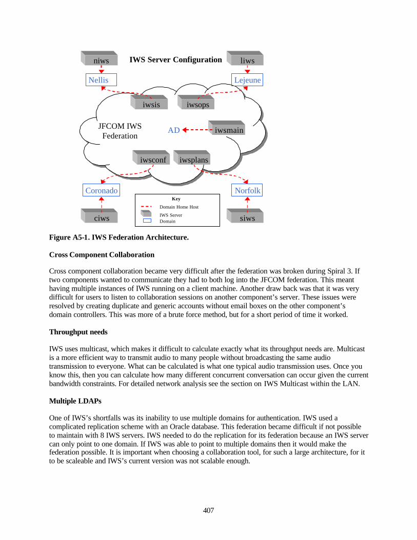
407
Figure A5-1. IWS Federation Architecture.
Cross Component Collaboration
Cross component collaboration became very difficult after the federation was broken during Spiral 3. Iftwo components wanted to communicate they had to both log into the JFCOM federation. This meanthaving multiple instances of IWS running on a client machine. Another draw back was that it was verydifficult for users to listen to collaboration sessions on another component’s server. These issues wereresolved by creating duplicate and generic accounts without email boxes on the other component’sdomain controllers. This was more of a brute force method, but for a short period of time it worked.
Throughput needs
IWS uses multicast, which makes it difficult to calculate exactly what its throughput needs are. Multicastis a more efficient way to transmit audio to many people without broadcasting the same audiotransmission to everyone. What can be calculated is what one typical audio transmission uses. Once youknow this, then you can calculate how many different concurrent conversation can occur given the currentbandwidth constraints. For detailed network analysis see the section on IWS Multicast within the LAN.
Multiple LDAPs
One of IWS’s shortfalls was its inability to use multiple domains for authentication. IWS used acomplicated replication scheme with an Oracle database. This federation became difficult if not possibleto maintain with 8 IWS servers. IWS needed to do the replication for its federation because an IWS servercan only point to one domain. If IWS was able to point to multiple domains then it would make thefederation possible. It is important when choosing a collaboration tool, for such a large architecture, for itto be scaleable and IWS’s current version was not scalable enough.
iwsis
AD
Coronado
Nellis Lejeune
Norfolk
iwsplans
iwsops
iwsconf
iwsmain
ciws siws
liwsniws
Domain Home Host
IWS ServerDomain
Key
IWS Server Configuration
JFCOM IWSFederation
408
Impact on FBE-J
IWS had a tremendous impact on FBE-J and MC02. As with any new tool, there is a learning curve. Oncethe players and operators became familiar and comfortable with the tool, there were few problems. Themost difficult aspect of IWS for the user was logging into the servers. The complicated scheme devisedafter the federation was broken in Spiral 3 left users confused about how to get to specific rooms. Goingto another component's server was even more confusing because their user name and passwords did notexist there. (See Figure A5-1. IWS Federation Architecture) Once these difficulties were overcome, crossPWC and component collaboration became a real time activity. Although all the features were not used,with time and training more functionality would have been used. The time period for an experiment is notlong enough for such collaboration tools to be used to its full extent.
PlaceWare Conferencing
Placeware is a separate program purchased by IWS and integrated into their collaboration suite.Placeware was used as the conferencing server for MC02. It was set up much like a real life auditorium.There were presenters and audience members. Presenters could give interactive briefs and audiencemembers could interact via questions and chatting with fellow audience members. Placeware was heavilyused and was an essential part of the experiment. There was a misconception that Placeware was IWS, butit was actually a program that operates normally without IWS and was incorporated into IWS.
Warfighter Use
The Warfighters used Placeware primarily for JFCOM briefings and Fire Side Chat. As they becamemore comfortable with the system they JFMC began using auditorium 112 for more briefings. There weresome frustrations by the warfighter because of Audio problems. This was not necessarily a problem withthe software though. There were the ADF cards which were blocking Multi-cast audio and there were thenetwork multicast issues. Once all the problems were resolved it worked well, besides the occasional badmicrophone. A feature not used was the meeting room. This was a smaller room where people could haveheld group sessions. These meeting rooms had many of the features IWS contains and some others suchas application sharing.
Throughput needs
Placeware advertises that a 56k modem will work. Since the audio is the same as IWS, SectionInfoWorkSpace/Placeware Multicast and bandwidth usage will contain the audio network results. Whenmulti-cast was working there were relatively few problems with the conference server.
FBE-J Impact
The high utility of the system leads to the need for something similar for future experiments. Asexperiments become more and more dispersed, something more than just a teleconference is needed. Evenexpensive videoconference systems do not have some of the capabilities Placeware provided. With furtherresearch it was discovered Placeware could be integrated with outlook for scheduling and invitation lists.If Placeware is not the answer for the future then some research needs to be done to find a suitablesystem, which contains many of the features of Placeware.
Domains and Exchange Systems
MC02 used the Windows 2000 Advanced server forest and trees architecture. There were a total of 7domains in the forest. The AD domain was the parent and all others were located below it. (See Figure
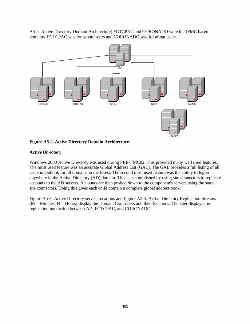
409
A5-2. Active Directory Domain Architecture) FCTCPAC and CORONADO were the JFMC baseddomains. FCTCPAC was for ashore users and CORONADO was for afloat users.
Figure A5-2. Active Directory Domain Architecture.
Active Directory
Windows 2000 Active Directory was used during FBE-J/MC02. This provided many well used features.The most used feature was an accurate Global Address List (GAL). The GAL provides a full listing of allusers in Outlook for all domains in the forest. The second most used feature was the ability to logonanywhere in the Active Directory (AD) domain. This is accomplished by using site connectors to replicateaccounts to the AD servers. Accounts are then pushed down to the component's servers using the samesite connectors. Doing this gives each child domain a complete global address book.
Figure A5-3. Active Directory server Locations and Figure A5-4. Active Directory Replication Streams(M = Minutes, H = Hours) display the Domain Controllers and their locations. The later displays thereplication interaction between AD, FCTCPAC, and CORONADO.
AD
Coronado LejeuneFCTCPAC Nellis Norfolk
JFASCC
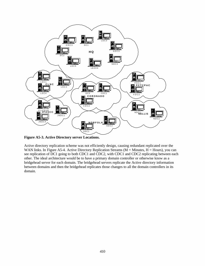
410
Figure A5-3. Active Directory server Locations.
Active directory replication scheme was not efficiently design, causing redundant replicated over theWAN links. In Figure A5-4. Active Directory Replication Streams (M = Minutes, H = Hours), you cansee replication of DC1 going to both CDC1 and CDC2, with CDC1 and CDC2 replicating between eachother. The ideal architecture would be to have a primary domain controller or otherwise know as abridgehead server for each domain. The bridgehead servers replicate the Active directory informationbetween domains and then the bridgehead replicates those changes to all the domain controllers in itsdomain.
H Q
C D C 3 D C 1
D C 2
L D C 3
L D C 5L E X C H
N D C 3
S D C 3
C L N CL D C 1
L D C 2
L D C 4
C O R O N A D OC D C 1D C 3
C D C 2
F C T C P A CF D C 1
F D C 2
J F A S C CF I L E S V R
J N D C 1
J N D C 4
N E L L I SN D C 1
N D C 2
N O R F O L K
S D C 1
S D C 2
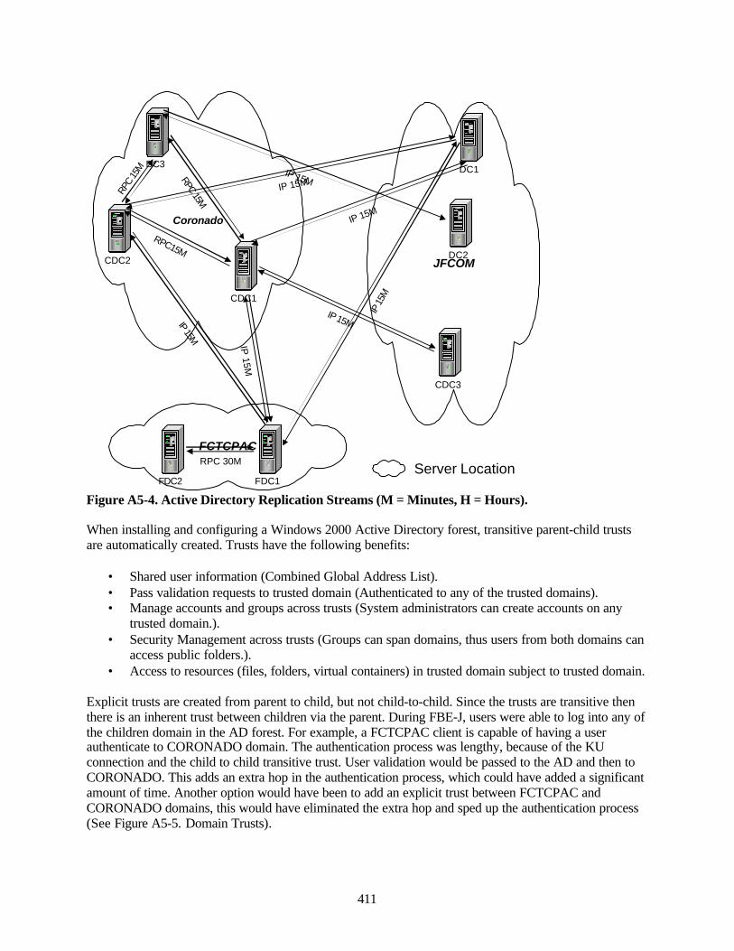
411
Figure A5-4. Active Directory Replication Streams (M = Minutes, H = Hours).
When installing and configuring a Windows 2000 Active Directory forest, transitive parent-child trustsare automatically created. Trusts have the following benefits:
• Shared user information (Combined Global Address List).• Pass validation requests to trusted domain (Authenticated to any of the trusted domains).• Manage accounts and groups across trusts (System administrators can create accounts on any
trusted domain.).• Security Management across trusts (Groups can span domains, thus users from both domains can
access public folders.).• Access to resources (files, folders, virtual containers) in trusted domain subject to trusted domain.
Explicit trusts are created from parent to child, but not child-to-child. Since the trusts are transitive thenthere is an inherent trust between children via the parent. During FBE-J, users were able to log into any ofthe children domain in the AD forest. For example, a FCTCPAC client is capable of having a userauthenticate to CORONADO domain. The authentication process was lengthy, because of the KUconnection and the child to child transitive trust. User validation would be passed to the AD and then toCORONADO. This adds an extra hop in the authentication process, which could have added a significantamount of time. Another option would have been to add an explicit trust between FCTCPAC andCORONADO domains, this would have eliminated the extra hop and sped up the authentication process(See Figure A5-5. Domain Trusts).
DC1DC3
CDC3
CDC1
CDC2
RPC15M
IP 15M
IP 15M
RPC 15M
IP 15M
RPC
15M
FDC1
IP 15M
DC2
IP 15M
IP 15M
IP 15
M
RPC 30M
FDC2
JFCOM
FCTCPAC
Coronado
Server Location
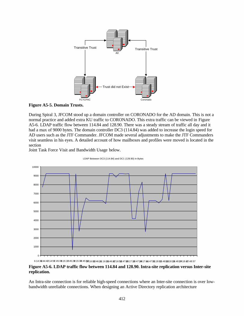
412
Figure A5-5. Domain Trusts.
During Spiral 3, JFCOM stood up a domain controller on CORONADO for the AD domain. This is not anormal practice and added extra KU traffic to CORONADO. This extra traffic can be viewed in FigureA5-6. LDAP traffic flow between 114.84 and 128.90. There was a steady stream of traffic all day and ithad a max of 9000 bytes. The domain controller DC3 (114.84) was added to increase the login speed forAD users such as the JTF Commander. JFCOM made several adjustments to make the JTF Commandersvisit seamless in his eyes. A detailed account of how mailboxes and profiles were moved is located in thesectionJoint Task Force Visit and Bandwidth Usage below.
Figure A5-6. LDAP traffic flow between 114.84 and 128.90. Intra-site replication versus Inter-sitereplication.
An Intra-site connection is for reliable high-speed connections where an Inter-site connection is over low-bandwidth unreliable connections. When designing an Active Directory replication architecture
LDAP Between DC3 (114.84) and DC1 (128.90) in Bytes
0
1000
2000
3000
4000
5000
6000
7000
8000
9000
10000
6:14:32 6:44:43 7:14:55 7:45:05 8:15:17 8:45:28 9:15:38 9:45:50 10:16:02 10:46:26 11:16:36 11:46:47 12:16:58 12:47:08 13:17:19 13:47:30 14:17:41 14:47:51 15:18:02 15:48:13 16:18:23 16:48:34 17:18:45 17:48:57
AD
CoronadoFCTCPAC
Transitive Trust Transitive Trust
Trust did not Exist
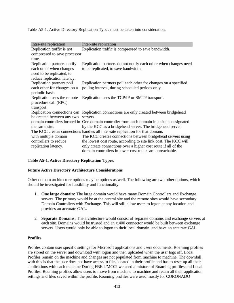
413
Table A5-1. Active Directory Replication Types must be taken into consideration.
Intra-site replication Inter-site replicationReplication traffic is notcompressed to save processortime.
Replication traffic is compressed to save bandwidth.
Replication partners notifyeach other when changesneed to be replicated, toreduce replication latency.
Replication partners do not notify each other when changes needto be replicated, to save bandwidth.
Replication partners polleach other for changes on aperiodic basis.
Replication partners poll each other for changes on a specifiedpolling interval, during scheduled periods only.
Replication uses the remoteprocedure call (RPC)transport.
Replication uses the TCP/IP or SMTP transport.
Replication connections canbe created between any twodomain controllers located inthe same site.The KCC creates connectionswith multiple domaincontrollers to reducereplication latency.
Replication connections are only created between bridgeheadservers.One domain controller from each domain in a site is designatedby the KCC as a bridgehead server. The bridgehead serverhandles all inter-site replication for that domain.The KCC creates connections between bridgehead servers usingthe lowest cost route, according to site link cost. The KCC willonly create connections over a higher cost route if all of thedomain controllers in lower cost routes are unreachable.
Table A5-1. Active Directory Replication Types.
Future Active Directory Architecture Considerations
Other domain architecture options may be options as well. The following are two other options, whichshould be investigated for feasibility and functionality.
1. One large domain: The large domain would have many Domain Controllers and Exchangeservers. The primary would be at the central site and the remote sites would have secondaryDomain Controllers with Exchange. This will still allow users to logon at any location andprovides an accurate GAL.
2. Separate Domains: The architecture would consist of separate domains and exchange servers ateach site. Domains would be trusted and an x.400 connector would be built between exchangeservers. Users would only be able to logon to their local domain, and have an accurate GAL.
Profiles
Profiles contain user specific settings for Microsoft applications and users documents. Roaming profilesare stored on the server and download with logon and then uploaded when the user logs off. LocalProfiles remain on the machine and changes are not populated from machine to machine. The downfallwith this is that the user does not have access to files located in their profile and has to reset up all theirapplications with each machine During FBE-J/MC02 we used a mixture of Roaming profiles and LocalProfiles. Roaming profiles allow users to move from machine to machine and retain all their applicationsettings and files saved within the profile. Roaming profiles were used mostly for CORONADO
414
participants. We did not use roaming profiles for users located on remote sites due to the size that aprofile can reach (20+ MEG). One option would be to provide a profile server at each location and havethe user accounts point to the local profile server. This would enable local downloads for profiles andexpedite the Windows 2000 authentication process.
Exchange
Exchange 2000 was used as the backend email server with Outlook XP as the client. The only issueexperienced with Exchange was a corrupted GAL on CORONADO exchange server, causingundeliverable mail to FCTCPAC recipients. Public folders were not used at the JFMCC level, but wereused at the Standing Joint Forces Headquarters (SJFHQ). The public folders were accessible by bothShare Point Portal Server and Outlook. Public folders provided replication and document storage. WithSPPS you can display public folders in a web format giving the users an alternate way of accessinginformation. We did not use the exchange conferencing and chat server, along with any of the advancedfeatures.
During Spiral 3 the JFCOM server on CORONADO used the display name only to populate the exchangeattributes. FCTCPAC servers had all possible exchange attributes entered. Doing this forcedCORONADO participants to be looked up using only billet description. During execution we useddisplay name as billet then populated first name, last name, and IP phone giving the users information toensure they were sending their email to the correct person.
Video Conferences (Vigo)
ViGO by VCON was used for desktop Video Teleconferencing. ViGO companied the camera, speaker,microphone and headset into a small desktop unit requiring only one cable to be plugged into the USBport on the computer. This made installation very simple. ViGO was a stand-alone VTC system usingVCON MXM as a locator and dialer service.
Cisco IP Phone
Cisco IP phones (IP Telephony) was used for point-to-point and multipoint-to-multipoint voicecommunications. IP phones provide very clear and reliable communications both LAN and WAN based.IP phones were set for the 80 Kilobyte; when not in a call the phones sent a 60 byte keep a live packet tothe Call Manager every minute. Quality of Service was established with the routers to guarantee 5 percentof the bandwidth to IP phones and 1 percent for the JFMC Commander’s phone. When the IP phones arenot in use the guaranteed bandwidth is released for use by other applications.
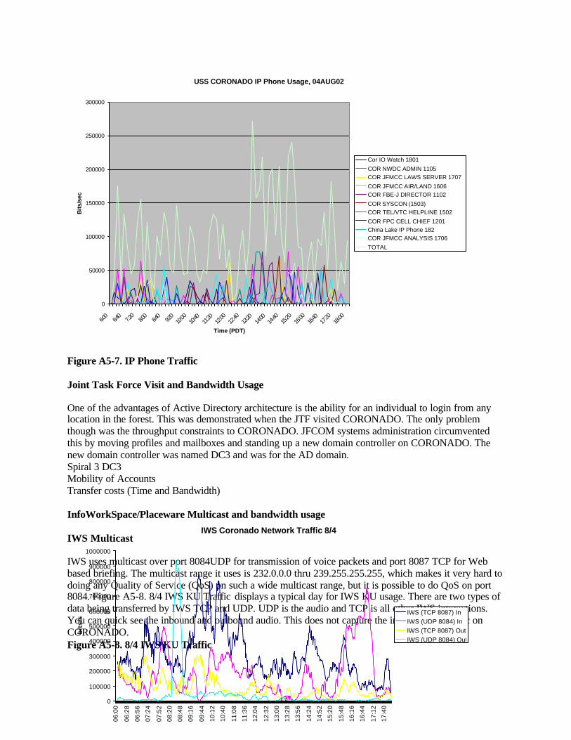
415
Figure A5-7. IP Phone Traffic
Joint Task Force Visit and Bandwidth Usage
One of the advantages of Active Directory architecture is the ability for an individual to login from anylocation in the forest. This was demonstrated when the JTF visited CORONADO. The only problemthough was the throughput constraints to CORONADO. JFCOM systems administration circumventedthis by moving profiles and mailboxes and standing up a new domain controller on CORONADO. Thenew domain controller was named DC3 and was for the AD domain.Spiral 3 DC3Mobility of AccountsTransfer costs (Time and Bandwidth)
InfoWorkSpace/Placeware Multicast and bandwidth usage
IWS Multicast
IWS uses multicast over port 8084UDP for transmission of voice packets and port 8087 TCP for Webbased briefing. The multicast range it uses is 232.0.0.0 thru 239.255.255.255, which makes it very hard todoing any Quality of Service (QoS) on such a wide multicast range, but it is possible to do QoS on port8084. Figure A5-8. 8/4 IWS KU Traffic displays a typical day for IWS KU usage. There are two types ofdata being transferred by IWS TCP and UDP. UDP is the audio and TCP is all other IWS interactions.You can quick see the inbound and outbound audio. This does not capture the internal IWS traffic onCORONADO.Figure A5-8. 8/4 IWS KU Traffic
IWS Coronado Network Traffic 8/4
0
100000
200000
300000
400000
500000
600000
700000
800000
900000
1000000
06:0
0
06:2
8
06:5
6
07:2
4
07:5
2
08:2
0
08:4
8
09:1
6
09:4
4
10:1
2
10:4
0
11:0
8
11:3
6
12:0
4
12:3
2
13:0
0
13:2
8
13:5
6
14:2
4
14:5
2
15:2
0
15:4
8
16:1
6
16:4
4
17:1
2
17:4
0
bit
s/s
IWS (TCP 8087) InIWS (UDP 8084) InIWS (TCP 8087) OutIWS (UDP 8084) Out
USS CORONADO IP Phone Usage, 04AUG02
0
50000
100000
150000
200000
250000
300000
6:00
6:40
7:20
8:00
8:40
9:20
10:00
10:40
11:20
12:00
12:40
13:20
14:00
14:40
15:20
16:00
16:40
17:20
18:00
Time (PDT)
Bits
/sec
Cor IO Watch 1801
COR NWDC ADMIN 1105 COR JFMCC LAWS SERVER 1707
COR JFMCC AIR/LAND 1606 COR FBE-J DIRECTOR 1102
COR SYSCON (1503) COR TEL/VTC HELPLINE 1502
COR FPC CELL CHIEF 1201 China Lake IP Phone 182COR JFMCC ANALYSIS 1706
TOTAL
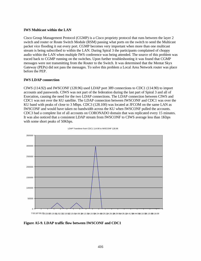
416
IWS Multicast within the LAN
Cisco Group Management Protocol (CGMP) is a Cisco propriety protocol that runs between the layer 2switch and router or Route Switch Module (RSM) passing what ports on the switch to send the Multicastpacket vice flooding it out every port. CGMP becomes very important when more than one multicaststream is being subscribed to within the LAN. During Spiral 3 the participants complained of choppyaudio within the LAN when multiple IWS conference was being attended. The source of this problem wastraced back to CGMP running on the switches. Upon further troubleshooting it was found that CGMPmessages were not transmitting from the Router to the Switch. It was determined that the Mentat SkyxGateway (PEPs) did not pass the messages. To solve this problem a Local Area Network router was placebefore the PEP.
IWS LDAP connection
CIWS (114.92) and IWSCONF (128.96) used LDAP port 389 connections to CDC1 (114.90) to importaccounts and passwords. CIWS was not part of the federation during the last part of Spiral 3 and all ofExecution, causing the need for the two LDAP connections. The LDAP connection between CIWS andCDC1 was not over the KU satellite. The LDAP connection between IWSCONF and CDC1 was over theKU band with peaks of close to 3 Mbps. CDC3 (128.100) was located at JFCOM on the same LAN asIWSCONF and would have taken no bandwidth across the KU when IWSCONF pulled the accounts.CDC3 had a complete list of all accounts on CORONADO domain that was replicated every 15 minutes.It was also noticed that a consistent LDAP stream from IWSCONF to CIWS average less than 1Kbpswith some short peaks of 50Kbps.
LDAP Transferer from CDC1 114.90 to IWSCONF 128.96
0
50000
100000
150000
200000
250000
300000
350000
7:53:18 7:55:27 10:23:07 10:15:01 11:52:23 12:15:52 12:15:01 14:08:10 14:13:31 14:15:02 14:24:42 14:25:13 14:26:10 14:29:06 14:35:12 14:41:56 14:44:58 16:10:33 16:15:06 16:16:09
Figure A5-9. LDAP traffic flow between IWSCONF and CDC1
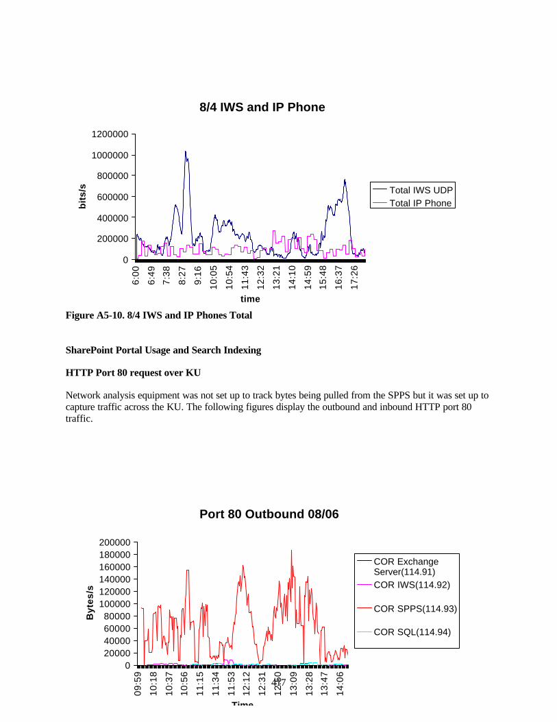
417
Port 80 Outbound 08/06
020000400006000080000
100000120000140000160000180000200000
09:5
9
10:1
8
10:3
7
10:5
6
11:1
5
11:3
4
11:5
3
12:1
2
12:3
1
12:5
0
13:0
9
13:2
8
13:4
7
14:0
6
Time
Byt
es/s
COR ExchangeServer(114.91)COR IWS(114.92)
COR SPPS(114.93)
COR SQL(114.94)
Figure A5-10. 8/4 IWS and IP Phones Total
SharePoint Portal Usage and Search Indexing
HTTP Port 80 request over KU
Network analysis equipment was not set up to track bytes being pulled from the SPPS but it was set up tocapture traffic across the KU. The following figures display the outbound and inbound HTTP port 80traffic.
8/4 IWS and IP Phone
0
200000
400000
600000
800000
1000000
12000006:
00
6:49
7:38
8:27
9:16
10:0
5
10:5
4
11:4
3
12:3
2
13:2
1
14:1
0
14:5
9
15:4
8
16:3
7
17:2
6
time
bit
s/s Total IWS UDP
Total IP Phone
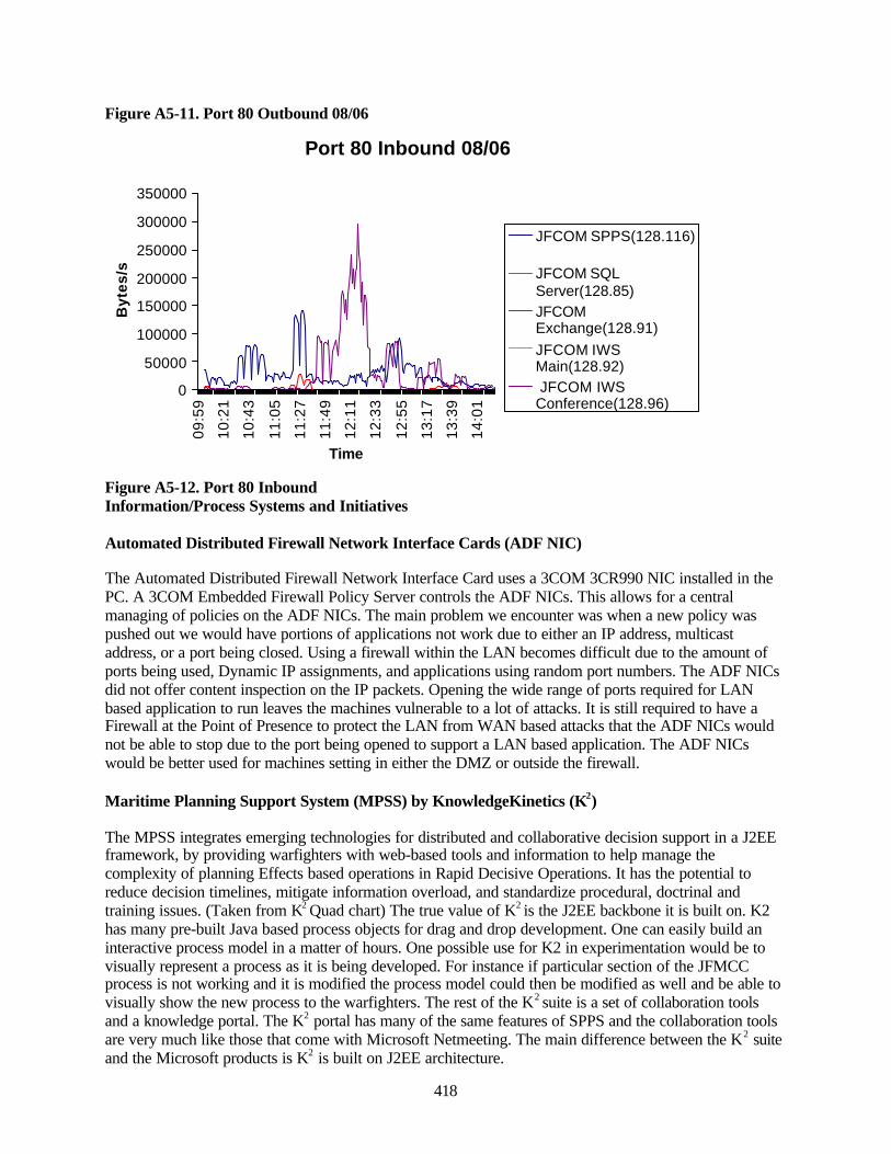
418
Figure A5-11. Port 80 Outbound 08/06
Figure A5-12. Port 80 InboundInformation/Process Systems and Initiatives
Automated Distributed Firewall Network Interface Cards (ADF NIC)
The Automated Distributed Firewall Network Interface Card uses a 3COM 3CR990 NIC installed in thePC. A 3COM Embedded Firewall Policy Server controls the ADF NICs. This allows for a centralmanaging of policies on the ADF NICs. The main problem we encounter was when a new policy waspushed out we would have portions of applications not work due to either an IP address, multicastaddress, or a port being closed. Using a firewall within the LAN becomes difficult due to the amount ofports being used, Dynamic IP assignments, and applications using random port numbers. The ADF NICsdid not offer content inspection on the IP packets. Opening the wide range of ports required for LANbased application to run leaves the machines vulnerable to a lot of attacks. It is still required to have aFirewall at the Point of Presence to protect the LAN from WAN based attacks that the ADF NICs wouldnot be able to stop due to the port being opened to support a LAN based application. The ADF NICswould be better used for machines setting in either the DMZ or outside the firewall.
Maritime Planning Support System (MPSS) by KnowledgeKinetics (K2)
The MPSS integrates emerging technologies for distributed and collaborative decision support in a J2EEframework, by providing warfighters with web-based tools and information to help manage thecomplexity of planning Effects based operations in Rapid Decisive Operations. It has the potential toreduce decision timelines, mitigate information overload, and standardize procedural, doctrinal andtraining issues. (Taken from K2 Quad chart) The true value of K2 is the J2EE backbone it is built on. K2has many pre-built Java based process objects for drag and drop development. One can easily build aninteractive process model in a matter of hours. One possible use for K2 in experimentation would be tovisually represent a process as it is being developed. For instance if particular section of the JFMCCprocess is not working and it is modified the process model could then be modified as well and be able tovisually show the new process to the warfighters. The rest of the K2 suite is a set of collaboration toolsand a knowledge portal. The K2 portal has many of the same features of SPPS and the collaboration toolsare very much like those that come with Microsoft Netmeeting. The main difference between the K2 suiteand the Microsoft products is K2 is built on J2EE architecture.
Port 80 Inbound 08/06
0
50000
100000
150000
200000
250000
300000
35000009
:59
10:2
1
10:4
3
11:0
5
11:2
7
11:4
9
12:1
1
12:3
3
12:5
5
13:1
7
13:3
9
14:0
1
Time
Byt
es/s
JFCOM SPPS(128.116)
JFCOM SQLServer(128.85)JFCOMExchange(128.91)JFCOM IWSMain(128.92) JFCOM IWSConference(128.96)
419
JFMCC process Integration
K2 was integrated with the JFMCC process at the highest level. It was designed to mimic Brad Poelter’sJFMCC process flow diagram in Figure A5-13. Maritime Planning Process. In order to track the processthe K2 team created a set of tags, which would interact with the Cold Fusion JFMCC process webapplications. These tags notified the K2 process flow for MOD, MARSUPREQ, and MMAP changes. Theinteraction was highly successful and worked well with the Cold Fusion applications. The integratedevent tags only covered Future plans and Current Plans in the process flow. MTO production andexecution Event tags were not part of the process flow. There were some hard coded interactions but itwas used sparsely if used at all. For future builds there must be event tags developed with TBMCS forMTO production, BDA, and MTO execution. Once the execution piece is added the process loop iscomplete and will show how the process feeds back into itself. There are many JFMCC sub process. AfterFBE-J the sub process will become more defined, and then they can be added to the MPSS process flowand add significant enhancements to the process flow. Other warfare areas would then be able to view thecurrent needs and status for each PWC. The process flow would contain more useful information andwould be more reflective of the process instead of the current top-level view.
420
Highlights
K2 was successfully integrated with the Cold Fusion JFMCC process applications. A series of customCold Fusion tags were created to send events to the K2 object model. It captured events for MOD Sectionstatus, MOD complete, MARSUPREQ submitted, MARSUPREQ completed, MMAP item added, andMMAP completed. This enable the MPSS to represent the state of the JFMCC process in a real timemanner. The background K2 process object model is also easily modified. During execution the processmodel was significantly modified. All user notifications were removed and the MARSUPREQ to MMAPwas change from a serial process to a parallel process.
Improvements
As the JFMCC process becomes more defined so will the usefulness of the MPSS. The current high levelprocess flow does not show anything a typical warfighter does not already know. As the process becomesmore detail so will the complexity of information, and thus the need for a process flow model to help thewarfighter gain better insight into the process state. More automation is needed. If things have to beentered in manually there are greater chances the process flow will not be up to date. So as the process isdefined system events need to be identified which will help facilitate the automation of the process flow.
Frequency of Use
The product was not used to the degree desired. There were thee main reasons for its lack of use.
1. Training. During Spiral 3 there were several attempts to train the JFMCC cell on MPPS and K2.Due to the hectic nature of Spiral 3 the proper time was not allotted for the K2 representatives’time on CORONADO. If the MPPS is to be an integral part of the JFMCC process then it must befully integrated into the JFMCC training package.
2. JFMCC process definition. The K2 system is designed to create interactive process flows. If theprocess it is not well defined then the interactive flow diagrams will not meet the users needs.Post FBE-J analysis should bring more definition to the JFMCC process at the lower levels.These inputs will significantly improve the process flow for the warfighter with more in-depthinformation and more interactive flows.
3. Lack of Time and Resources. To make a truly integrated product more time and resourceswould be necessary. System integration is not an easy task when there are many systems,technologies, and groups to work with.
Domain Security Settings
Domain policy manager was used to control security settings on client machines. This made controllingthe machine policies very simple and setting only had to be set at one place. It was also used to presetusers’ homepage and Internet Explore security settings. Domain policy manager can also be used tocontrol application settings, but we did not use it for that. The domain policy manager needs to be usedmore. We spent countless hours configuring client machines. If application and security settings can beset from the domain level then this needs to be done to save time and money.
Remote Administration
Virtual Networking Client (VNC) was installed on the ADOCS/IKA workstations and was used forremote administration and trouble shooting. VNC was invaluable for helping the remote sites were
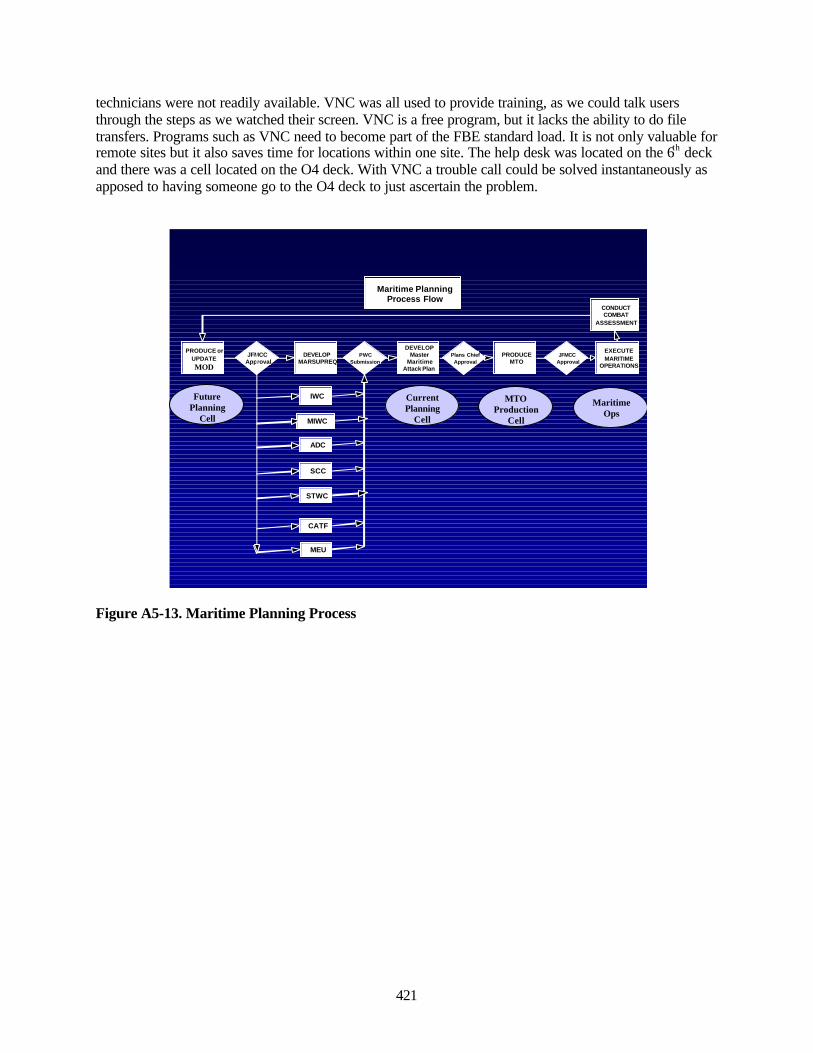
421
technicians were not readily available. VNC was all used to provide training, as we could talk usersthrough the steps as we watched their screen. VNC is a free program, but it lacks the ability to do filetransfers. Programs such as VNC need to become part of the FBE standard load. It is not only valuable forremote sites but it also saves time for locations within one site. The help desk was located on the 6th deckand there was a cell located on the O4 deck. With VNC a trouble call could be solved instantaneously asapposed to having someone go to the O4 deck to just ascertain the problem.
Figure A5-13. Maritime Planning Process
Maritime PlanningProcess Flow
PRODUCE orUPDATEMOD
DEVELOPMARSUPREQ
DEVELOPMaster
MaritimeAttack Plan
PRODUCEMTO
EXECUTEMARITIME
OPERATIONS
CONDUCTCOMBAT
ASSESSMENT
JFMCCApproval
PWCSubmission
Plans ChiefApproval
JFMCCApproval
IWC
MIWC
ADC
SCC
STWC
CATF
MEU
Future Planning
Cell
Current Planning
Cell
MTO Production
Cell
Maritime Ops
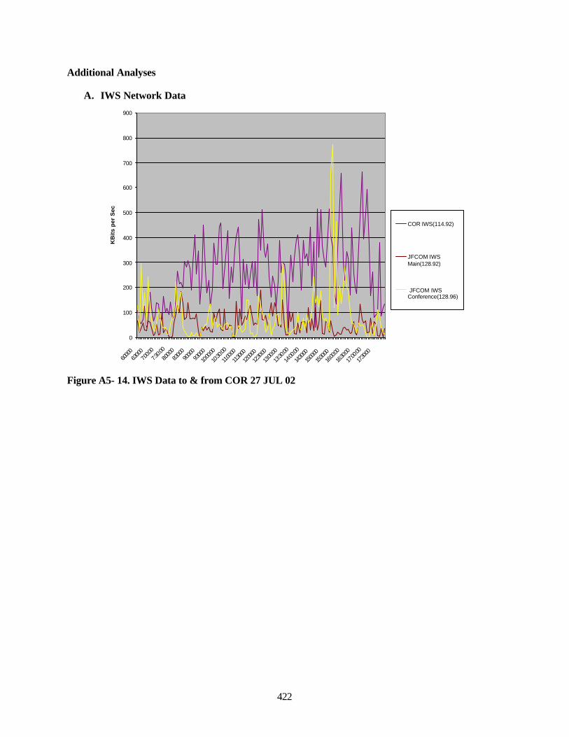
422
Additional Analyses
A. IWS Network Data
0
100
200
300
400
500
600
700
800
900
6:00:0
06:3
0:007:0
0:007:3
0:00
8:00:0
08:3
0:009:0
0:009:3
0:00
10:00
:00
10:30
:00
11:00:
00
11:30:
00
12:00:
00
12:30:
00
13:00
:00
13:30
:00
14:00
:00
14:30:
00
15:00:
00
15:30:
00
16:00
:00
16:30
:00
17:00
:00
17:30:
00
KB
its
per
Sec
COR IWS(114.92)
JFCOM IWSMain(128.92)
JFCOM IWSConference(128.96)
Figure A5- 14. IWS Data to & from COR 27 JUL 02
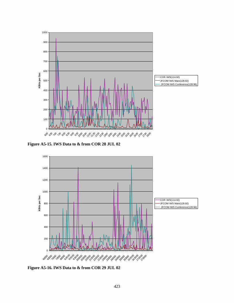
423
0
100
200
300
400
500
600
700
800
900
1000
6:00
6:30
7:00
7:30
8:00
8:30
9:00
9:30
10:00
10:30
11:00
11:30
12:00
12:30
13:00
13:30
14:00
14:30
15:00
15:30
16:00
16:30
17:00
17:30
18:00
KB
its
per
Sec
COR IWS(114.92)
JFCOM IWS Main(128.92) JFCOM IWS Conference(128.96)
Figure A5-15. IWS Data to & from COR 28 JUL 02
0
200
400
600
800
1000
1200
1400
1600
6:00:0
06:3
0:007:0
0:007:3
0:008:0
0:008:3
0:00
9:00:0
0
9:30:0
0
10:00
:00
10:30:
00
11:00:
00
11:30
:00
12:00
:00
12:30
:00
13:00:
00
13:30:
00
14:00:
00
14:30:
00
15:00:
00
15:30:
00
16:00
:00
16:30
:00
17:00
:00
17:30
:00
KB
its
per
Sec
COR IWS(114.92)JFCOM IWS Main(128.92)
JFCOM IWS Conference(128.96)
Figure A5-16. IWS Data to & from COR 29 JUL 02
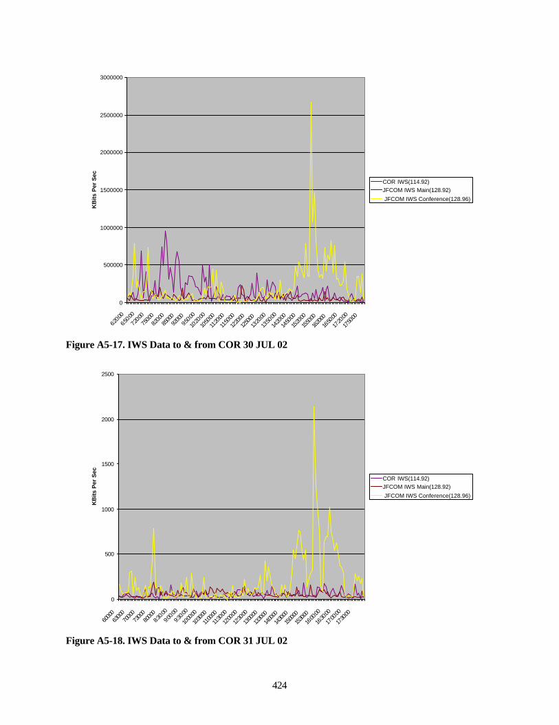
424
0
500000
1000000
1500000
2000000
2500000
3000000
6:20:0
0
6:50:0
0
7:20:0
0
7:50:0
08:2
0:008:5
0:009:2
0:009:5
0:00
10:20
:00
10:50
:00
11:20
:00
11:50
:00
12:20:
00
12:50:
00
13:20
:00
13:50
:00
14:20
:00
14:50
:00
15:20
:00
15:50:
00
16:20:
00
16:50
:00
17:20
:00
17:50
:00
KB
its P
er S
ec
COR IWS(114.92)JFCOM IWS Main(128.92)
JFCOM IWS Conference(128.96)
Figure A5-17. IWS Data to & from COR 30 JUL 02
0
500
1000
1500
2000
2500
6:00:0
06:3
0:007:0
0:007:3
0:008:0
0:008:3
0:00
9:00:0
0
9:30:0
0
10:00
:00
10:30:
00
11:00:
00
11:30
:00
12:00
:00
12:30
:00
13:00:
00
13:30:
00
14:00:
00
14:30:
00
15:00:
00
15:30:
00
16:00
:00
16:30
:00
17:00
:00
17:30
:00
KB
its P
er S
ec
COR IWS(114.92)JFCOM IWS Main(128.92)
JFCOM IWS Conference(128.96)
Figure A5-18. IWS Data to & from COR 31 JUL 02

425
0
100
200
300
400
500
600
700
800
900
6:00:0
06:3
0:007:0
0:007:3
0:008:0
0:008:3
0:00
9:00:0
0
9:30:0
0
10:00
:00
10:30:
00
11:00:
00
11:30
:00
12:00
:00
12:30
:00
13:00:
00
13:30:
00
14:00:
00
14:30:
00
15:00:
00
15:30:
00
16:00
:00
16:30
:00
17:00
:00
17:30
:00
KB
its P
er S
ec
COR IWS(114.92)JFCOM IWS Main(128.92)
JFCOM IWS Conference(128.96)
Figure A5-19. IWS Data to & from COR 1 AUG 02
0
200000
400000
600000
800000
1000000
1200000
6:00
:00
6:30
:00
7:00
:00
7:30
:00
8:00
:00
8:30
:00
9:00
:00
9:30
:00
10:0
0:00
10:3
0:00
11:0
0:00
11:3
0:00
12:0
0:00
12:3
0:00
13:0
0:00
13:3
0:00
14:0
0:00
14:3
0:00
15:0
0:00
15:3
0:00
16:0
0:00
16:3
0:00
17:0
0:00
17:3
0:00
KB
its
Per
Sec
COR IWS(114.92)
JFCOM IWS Main(128.92) JFCOM IWS Conference(128.96)
Figure A5-20. IWS Data to & from COR 2 AUG 02
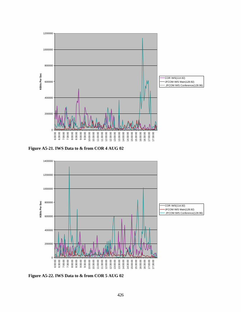
426
0
200000
400000
600000
800000
1000000
1200000
6:00
:00
6:30
:00
7:00
:00
7:30
:00
8:00
:00
8:30
:00
9:00
:00
9:30
:00
10:0
0:00
10:3
0:00
11:0
0:00
11:3
0:00
12:0
0:00
12:3
0:00
13:0
0:00
13:3
0:00
14:0
0:00
14:3
0:00
15:0
0:00
15:3
0:00
16:0
0:00
16:3
0:00
17:0
0:00
17:3
0:00
KB
its
Per
Sec
COR IWS(114.92)
JFCOM IWS Main(128.92) JFCOM IWS Conference(128.96)
Figure A5-21. IWS Data to & from COR 4 AUG 02
0
200000
400000
600000
800000
1000000
1200000
1400000
6:00
:00
6:30
:00
7:00
:00
7:30
:00
8:00
:00
8:30
:00
9:00
:00
9:30
:00
10:0
0:00
10:3
0:00
11:0
0:00
11:3
0:00
12:0
0:00
12:3
0:00
13:0
0:00
13:3
0:00
14:0
0:00
14:3
0:00
15:0
0:00
15:3
0:00
16:0
0:00
16:3
0:00
17:0
0:00
17:3
0:00
KB
its
Per
Sec
COR IWS(114.92)
JFCOM IWS Main(128.92) JFCOM IWS Conference(128.96)
Figure A5-22. IWS Data to & from COR 5 AUG 02
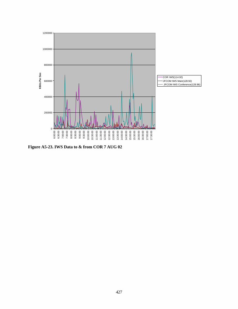
427
0
200000
400000
600000
800000
1000000
1200000
6:00
:00
6:30
:00
7:00
:00
7:30
:00
8:00
:00
8:30
:00
9:00
:00
9:30
:00
10:0
0:00
10:3
0:00
11:0
0:00
11:3
0:00
12:0
0:00
12:3
0:00
13:0
0:00
13:3
0:00
14:0
0:00
14:3
0:00
15:0
0:00
15:3
0:00
16:0
0:00
16:3
0:00
17:0
0:00
17:3
0:00
KB
its
Per
Sec
COR IWS(114.92)
JFCOM IWS Main(128.92) JFCOM IWS Conference(128.96)
Figure A5-23. IWS Data to & from COR 7 AUG 02
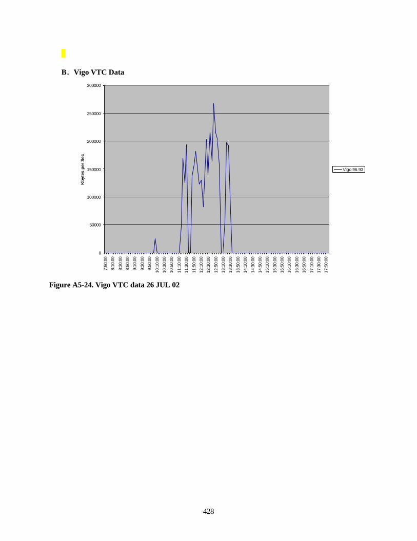
428
B. Vigo VTC Data
0
50000
100000
150000
200000
250000
300000
7:50
:00
8:10
:00
8:30
:00
8:50
:00
9:10
:00
9:30
:00
9:50
:00
10:1
0:00
10:3
0:00
10:5
0:00
11:1
0:00
11:3
0:00
11:5
0:00
12:1
0:00
12:3
0:00
12:5
0:00
13:1
0:00
13:3
0:00
13:5
0:00
14:1
0:00
14:3
0:00
14:5
0:00
15:1
0:00
15:3
0:00
15:5
0:00
16:1
0:00
16:3
0:00
16:5
0:00
17:1
0:00
17:3
0:00
17:5
0:00
Kby
tes
per
Sec
Vigo 96.93
Figure A5-24. Vigo VTC data 26 JUL 02
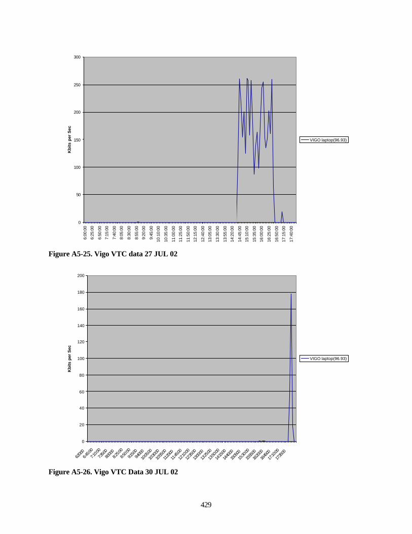
429
0
50
100
150
200
250
300
6:00
:00
6:25
:00
6:50
:00
7:15
:00
7:40
:00
8:05
:00
8:30
:00
8:55
:00
9:20
:00
9:45
:00
10:1
0:00
10:3
5:00
11:0
0:00
11:2
5:00
11:5
0:00
12:1
5:00
12:4
0:00
13:0
5:00
13:3
0:00
13:5
5:00
14:2
0:00
14:4
5:00
15:1
0:00
15:3
5:00
16:0
0:00
16:2
5:00
16:5
0:00
17:1
5:00
17:4
0:00
Kb
its
per
Sec
VIGO laptop(96.93)
Figure A5-25. Vigo VTC data 27 JUL 02
0
20
40
60
80
100
120
140
160
180
200
6:20:0
06:4
5:00
7:10:0
0
7:35:0
08:0
0:008:2
5:00
8:50:0
0
9:15:0
09:4
0:00
10:05
:00
10:30
:00
10:55
:00
11:20:
00
11:45
:00
12:10
:00
12:35
:00
13:00:
00
13:25
:00
13:50
:00
14:15
:00
14:40:
00
15:05:
00
15:30
:00
15:55:
00
16:20:
00
16:45:
00
17:10
:00
17:35:
00
Kbi
ts p
er S
ec
VIGO laptop(96.93)
Figure A5-26. Vigo VTC Data 30 JUL 02
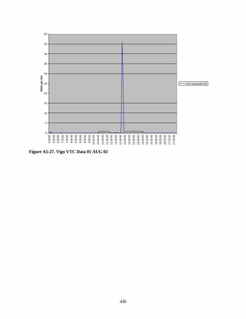
430
0
5
10
15
20
25
30
35
40
45
50
6:00
:00
6:25
:00
6:50
:00
7:15
:00
7:40
:00
8:05
:00
8:30
:00
8:55
:00
9:20
:00
9:45
:00
10:1
0:00
10:3
5:00
11:0
0:00
11:2
5:00
11:5
0:00
12:1
5:00
12:4
0:00
13:0
5:00
13:3
0:00
13:5
5:00
14:2
0:00
14:4
5:00
15:1
0:00
15:3
5:00
16:0
0:00
16:2
5:00
16:5
0:00
17:1
5:00
17:4
0:00
Kb
its
per
Sec
VIGO laptop(96.93)
Figure A5-27. Vigo VTC Data 01 AUG 02
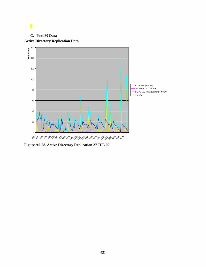
431
C. Port 80 DataActive Directory Replication Data
0
20
40
60
80
100
120
140
160
6:00
6:30
7:00
7:30
8:00
8:30
9:00
9:30
10:00
10:30
11:00
11:30
12:00
12:30
13:00
13:30
14:00
14:30
15:00
15:30
16:00
16:30
17:00
17:30
Th
ou
san
ds
COR PDC(114.90)JFCOM PDC(128.90)
FCTCPAC PDC/Exchange(98.20)TOTAL
Figure A5-28. Active Directory Replication 27 JUL 02
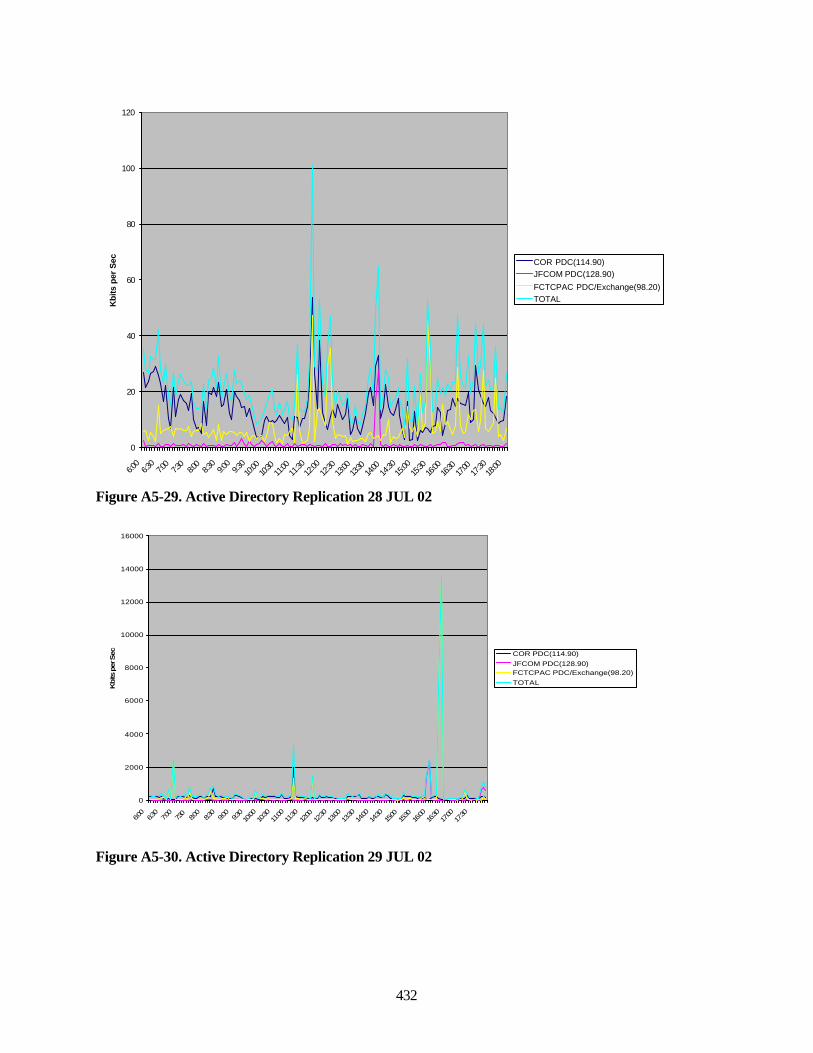
432
0
20
40
60
80
100
120
6:00
6:30
7:00
7:30
8:00
8:30
9:00
9:30
10:00
10:30
11:00
11:30
12:00
12:30
13:00
13:30
14:00
14:30
15:00
15:30
16:00
16:30
17:00
17:30
18:00
Kbi
ts p
er S
ec COR PDC(114.90)JFCOM PDC(128.90)
FCTCPAC PDC/Exchange(98.20)TOTAL
Figure A5-29. Active Directory Replication 28 JUL 02
0
2000
4000
6000
8000
10000
12000
14000
16000
6:00
6:30
7:00
7:30
8:00
8:30
9:00
9:30
10:00
10:30
11:00
11:30
12:00
12:30
13:00
13:30
14:00
14:30
15:00
15:30
16:00
16:30
17:00
17:30
Kbits
per
Sec COR PDC(114.90)
JFCOM PDC(128.90)FCTCPAC PDC/Exchange(98.20)TOTAL
Figure A5-30. Active Directory Replication 29 JUL 02
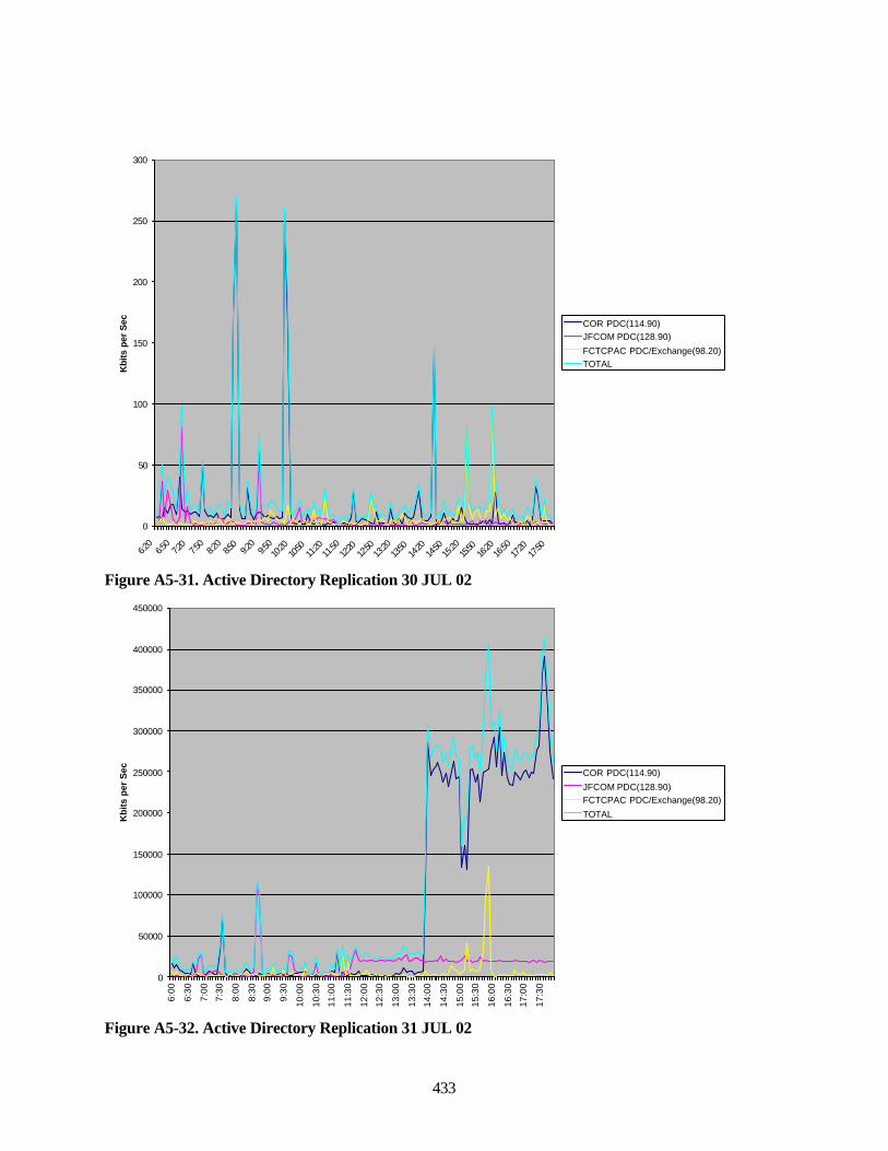
433
0
50
100
150
200
250
300
6:20
6:50
7:20
7:50
8:20
8:50
9:20
9:50
10:20
10:50
11:20
11:50
12:20
12:50
13:20
13:50
14:20
14:50
15:20
15:50
16:20
16:50
17:20
17:50
Kbi
ts p
er S
ec COR PDC(114.90)JFCOM PDC(128.90)
FCTCPAC PDC/Exchange(98.20)TOTAL
Figure A5-31. Active Directory Replication 30 JUL 02
0
50000
100000
150000
200000
250000
300000
350000
400000
450000
6:00
6:30
7:00
7:30
8:00
8:30
9:00
9:30
10:0
0
10:3
0
11:0
0
11:3
0
12:0
0
12:3
0
13:0
0
13:3
0
14:0
0
14:3
0
15:0
0
15:3
0
16:0
0
16:3
0
17:0
0
17:3
0
Kb
its
per
Sec COR PDC(114.90)
JFCOM PDC(128.90)FCTCPAC PDC/Exchange(98.20)
TOTAL
Figure A5-32. Active Directory Replication 31 JUL 02
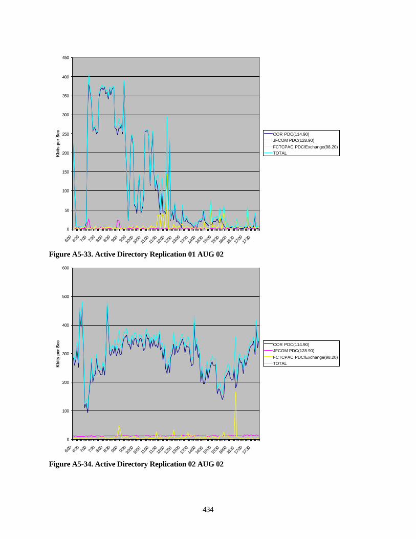
434
0
50
100
150
200
250
300
350
400
450
6:00
6:30
7:00
7:30
8:00
8:30
9:00
9:30
10:00
10:30
11:00
11:30
12:00
12:30
13:00
13:30
14:00
14:30
15:00
15:30
16:00
16:30
17:00
17:30
Kbi
ts p
er S
ec COR PDC(114.90)JFCOM PDC(128.90)
FCTCPAC PDC/Exchange(98.20)TOTAL
Figure A5-33. Active Directory Replication 01 AUG 02
0
100
200
300
400
500
600
6:00
6:30
7:00
7:30
8:00
8:30
9:00
9:30
10:00
10:30
11:00
11:30
12:00
12:30
13:00
13:30
14:00
14:30
15:00
15:30
16:00
16:30
17:00
17:30
Kbi
ts p
er S
ec COR PDC(114.90)JFCOM PDC(128.90)
FCTCPAC PDC/Exchange(98.20)TOTAL
Figure A5-34. Active Directory Replication 02 AUG 02
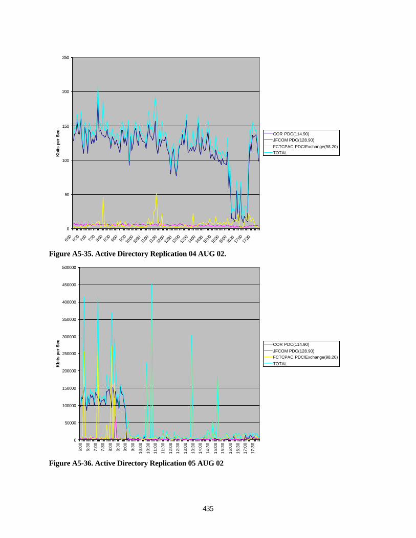
435
0
50
100
150
200
250
6:00
6:30
7:00
7:30
8:00
8:30
9:00
9:30
10:00
10:30
11:00
11:30
12:00
12:30
13:00
13:30
14:00
14:30
15:00
15:30
16:00
16:30
17:00
17:30
Kbi
ts p
er S
ec COR PDC(114.90)JFCOM PDC(128.90)
FCTCPAC PDC/Exchange(98.20)TOTAL
Figure A5-35. Active Directory Replication 04 AUG 02.
0
50000
100000
150000
200000
250000
300000
350000
400000
450000
500000
6:00
6:30
7:00
7:30
8:00
8:30
9:00
9:30
10:0
0
10:3
0
11:0
0
11:3
0
12:0
0
12:3
0
13:0
0
13:3
0
14:0
0
14:3
0
15:0
0
15:3
0
16:0
0
16:3
0
17:0
0
17:3
0
Kb
its
per
Sec COR PDC(114.90)
JFCOM PDC(128.90)FCTCPAC PDC/Exchange(98.20)
TOTAL
Figure A5-36. Active Directory Replication 05 AUG 02
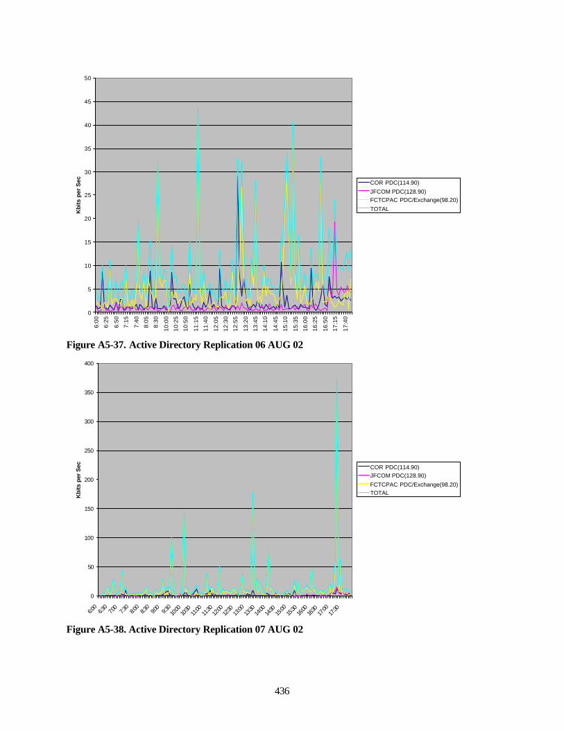
436
0
5
10
15
20
25
30
35
40
45
50
6:00
6:25
6:50
7:15
7:40
8:05
8:30
10:0
0
10:2
5
10:5
0
11:1
5
11:4
0
12:0
5
12:3
0
12:5
5
13:2
0
13:4
5
14:1
0
14:4
5
15:1
0
15:3
5
16:0
0
16:2
5
16:5
0
17:1
5
17:4
0
Kb
its
per
Sec COR PDC(114.90)
JFCOM PDC(128.90)FCTCPAC PDC/Exchange(98.20)
TOTAL
Figure A5-37. Active Directory Replication 06 AUG 02
0
50
100
150
200
250
300
350
400
6:00
6:30
7:00
7:30
8:00
8:30
9:00
9:30
10:00
10:30
11:00
11:30
12:00
12:30
13:00
13:30
14:00
14:30
15:00
15:30
16:00
16:30
17:00
17:30
Kbi
ts p
er S
ec COR PDC(114.90)JFCOM PDC(128.90)
FCTCPAC PDC/Exchange(98.20)TOTAL
Figure A5-38. Active Directory Replication 07 AUG 02
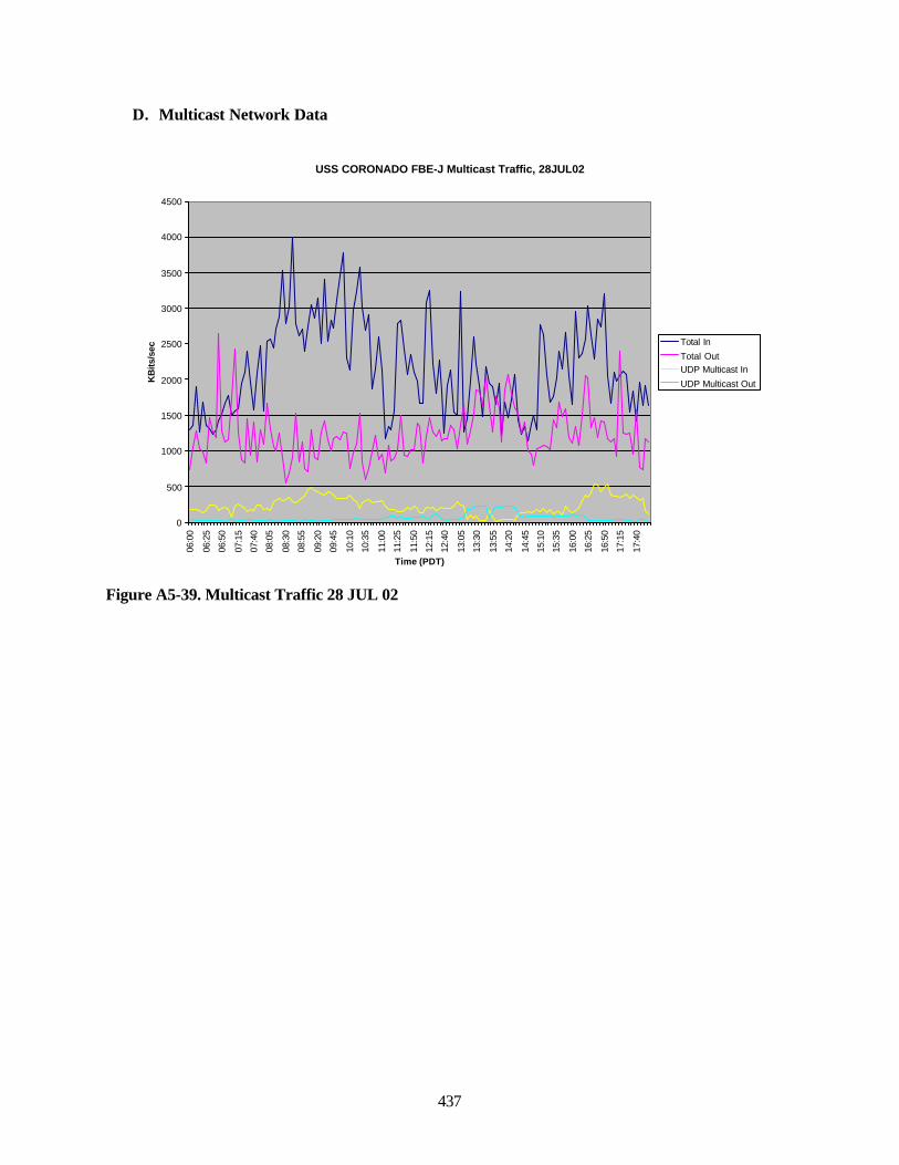
437
D. Multicast Network Data
USS CORONADO FBE-J Multicast Traffic, 28JUL02
0
500
1000
1500
2000
2500
3000
3500
4000
450006
:00
06:2
5
06:5
0
07:1
5
07:4
0
08:0
5
08:3
0
08:5
5
09:2
0
09:4
5
10:1
0
10:3
5
11:0
0
11:2
5
11:5
0
12:1
5
12:4
0
13:0
5
13:3
0
13:5
5
14:2
0
14:4
5
15:1
0
15:3
5
16:0
0
16:2
5
16:5
0
17:1
5
17:4
0
Time (PDT)
KB
its/s
ec
Total In
Total OutUDP Multicast In
UDP Multicast Out
Figure A5-39. Multicast Traffic 28 JUL 02
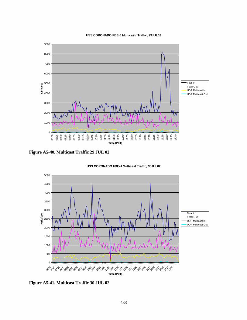
438
USS CORONADO FBE-J Multicastr Traffic, 29JUL02
0
1000
2000
3000
4000
5000
6000
7000
8000
9000
06:0
0
06:2
5
06:5
0
07:1
5
07:4
0
08:0
5
08:3
0
08:5
5
09:2
0
09:4
5
10:1
0
10:3
5
11:0
0
11:2
5
11:5
0
12:1
5
12:4
0
13:0
5
13:3
0
13:5
5
14:2
0
14:4
5
15:1
0
15:3
5
16:0
0
16:2
5
16:5
0
17:1
5
17:4
0
Time (PDT)
KB
its/s
ec
Total In
Total OutUDP Multicast In
UDP Multicast Out
Figure A5-40. Multicast Traffic 29 JUL 02
USS CORONADO FBE-J Multicast Traffic, 30JUL02
0
500
1000
1500
2000
2500
3000
3500
4000
4500
5000
06:20
06:45
07:10
07:35
08:00
08:25
08:50
09:15
09:40
10:05
10:30
10:55
11:20
11:45
12:10
12:35
13:00
13:25
13:50
14:15
14:40
15:05
15:30
15:55
16:20
16:45
17:10
17:35
Time (PDT)
KB
its/s
ec
Total InTotal Out
UDP Multicast InUDP Multicast Out
Figure A5-41. Multicast Traffic 30 JUL 02
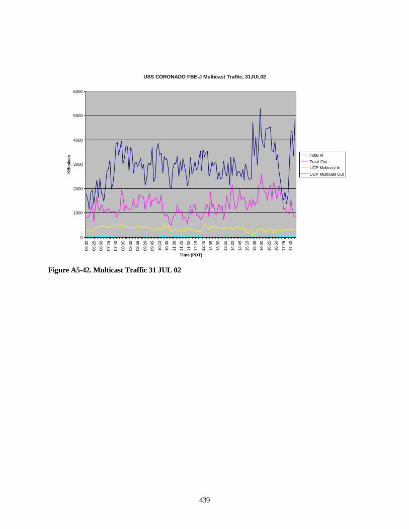
439
USS CORONADO FBE-J Multicast Traffic, 31JUL02
0
1000
2000
3000
4000
5000
600006
:00
06:2
5
06:5
0
07:1
5
07:4
0
08:0
5
08:3
0
08:5
5
09:2
0
09:4
5
10:1
0
10:3
5
11:0
0
11:2
5
11:5
0
12:1
5
12:4
0
13:0
5
13:3
0
13:5
5
14:2
0
14:4
5
15:1
0
15:3
5
16:0
0
16:2
5
16:5
0
17:1
5
17:4
0
Time (PDT)
KB
its/s
ec
Total In
Total OutUDP Multicast In
UDP Multicast Out
Figure A5-42. Multicast Traffic 31 JUL 02
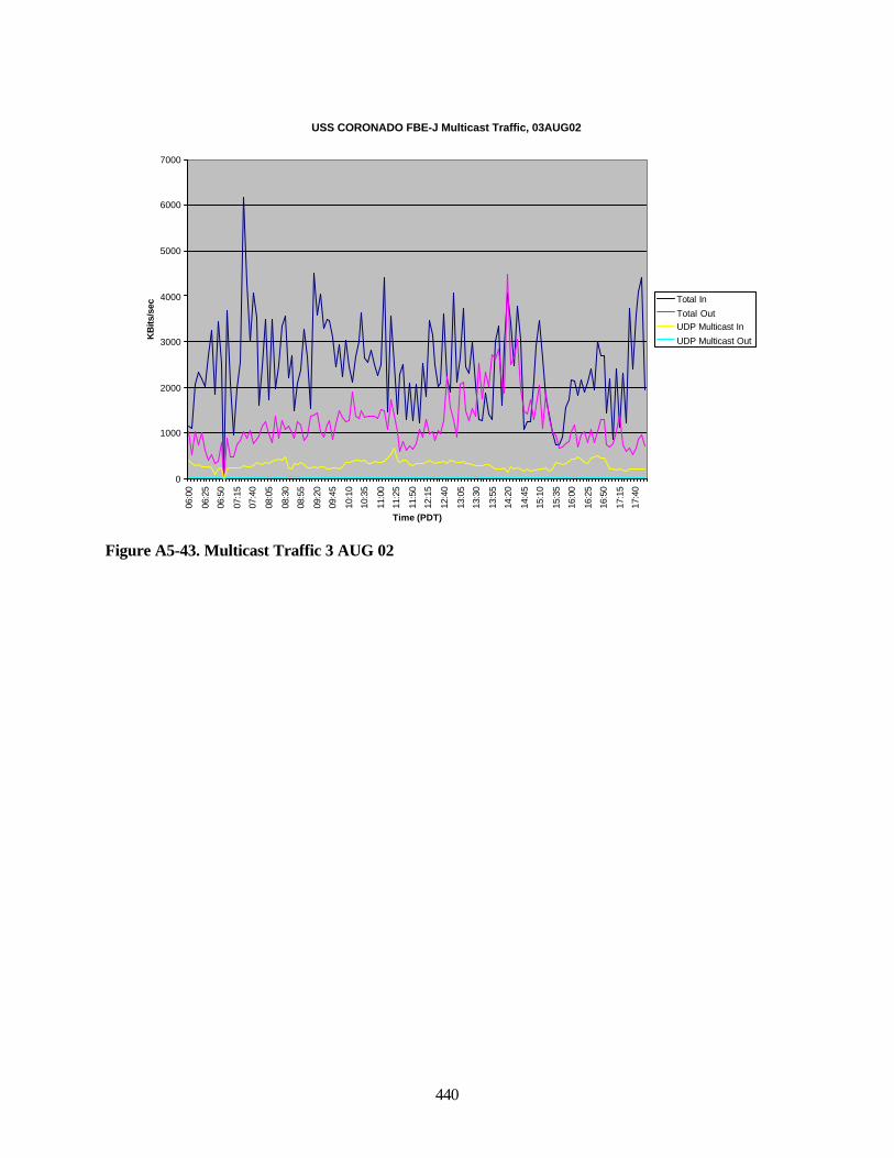
440
USS CORONADO FBE-J Multicast Traffic, 03AUG02
0
1000
2000
3000
4000
5000
6000
7000
06:0
0
06:2
5
06:5
0
07:1
5
07:4
0
08:0
5
08:3
0
08:5
5
09:2
0
09:4
5
10:1
0
10:3
5
11:0
0
11:2
5
11:5
0
12:1
5
12:4
0
13:0
5
13:3
0
13:5
5
14:2
0
14:4
5
15:1
0
15:3
5
16:0
0
16:2
5
16:5
0
17:1
5
17:4
0
Time (PDT)
KB
its/s
ec
Total In
Total OutUDP Multicast In
UDP Multicast Out
Figure A5-43. Multicast Traffic 3 AUG 02

441
This page intentionally left blank.

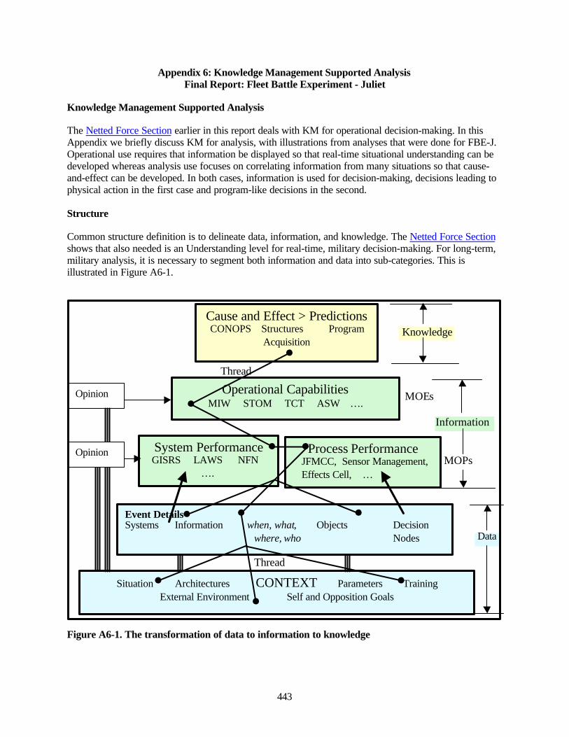
443
Appendix 6: Knowledge Management Supported AnalysisFinal Report: Fleet Battle Experiment - Juliet
Knowledge Management Supported Analysis
The Netted Force Section earlier in this report deals with KM for operational decision-making. In thisAppendix we briefly discuss KM for analysis, with illustrations from analyses that were done for FBE-J.Operational use requires that information be displayed so that real-time situational understanding can bedeveloped whereas analysis use focuses on correlating information from many situations so that cause-and-effect can be developed. In both cases, information is used for decision-making, decisions leading tophysical action in the first case and program-like decisions in the second.
Structure
Common structure definition is to delineate data, information, and knowledge. The Netted Force Sectionshows that also needed is an Understanding level for real-time, military decision-making. For long-term,military analysis, it is necessary to segment both information and data into sub-categories. This isillustrated in Figure A6-1.
Knowledge
Thread
MOEs
Information
MOPs
Data
Thread
Figure A6-1. The transformation of data to information to knowledge
Situation Architectures CONTEXT Parameters TrainingExternal Environment Self and Opposition Goals
Event DetailsSystems Information when, what, Objects Decision
where, who Nodes
System Performance GISRS LAWS NFN
….
Process Performance JFMCC, Sensor Management, Effects Cell, …
Operational CapabilitiesMIW STOM TCT ASW ….
Cause and Effect > PredictionsCONOPS Structures Program
Acquisition
Opinion
Opinion

444
This structure is best discussed from the inside out. At the core is information about system performance,performance of processes within which systems operate, and operational capabilities provided by thesesystems and processes. Figure A6-1 shows just a few examples of the many systems and processes beinginvestigated with FBEs. Performance includes many factors, often expressed in terms of Measures ofPerformance (MOPs). These Measures express desired and realized performance. Systems operate withinprocesses, thus there are MOPs associated with system/process combinations, probably the mostimportant Measures.
Examples
• JFMCC MOP: Percent of orders synchronized prior to being issued to warfare commanders.
• MIW MOE related to JFMCC: Ratio of the number of days required to clear mines in a definedzone to the number of days specified by JFC for the operation, with JFMCC as the managingauthority.
• Context for this MOE: a) There was no competition for assets needed by MIWC for the mineclearing operation. b) The area to be cleared was 5 x 1 miles and the mine density was 1 per 500yards square. c) There were no shore batteries or other Red capabilities to threaten the operation.
Systems and processes can cover wide or narrow ranges. TCT is a process within which there are manysub-processes, e.g. mensuration, and sub-systems, e.g., LAWS. MOPs can, and should, be defined forindividual sub-systems and processes and for agglomerates.
Development of improved operational capabilities is a principal goal of FBEs. Measures of Effectiveness(MOEs) are determined for defined areas of interest, e.g. MIW, ASW. STOM is a broad area,encompassing several other operational areas. An MOE is a measure of how well an operation can beprosecuted compared to set goals - essentially, a measure of success. Parameters such as how rapidly anoperation is concluded; the fraction of targets destroyed; how many friendly forces were lost; etc. measuresuccess.
The data level contains two distinct types, events and context. Events are things that occur at a specifictime. Description of an event requires what is happening, when, where, and who is involved. Events areassociated with entities, noted as Systems, Information, Objects, and Decision Nodes. They occur at theinputs to, outputs from, and within systems. They occur at physical objects, such as a UAV moving to alocation or erecting a TEL. A near continuous stream of decision-events is occurring at decision nodessuch as the Battle Watch Captain.
Information is shown as a separate Event class. A sensor detecting a target is an information event. Weclass the detection with the sensor. Sending the detection information from the sensor to another locationis an information event. It is useful to track information as packets that move through systems andprocesses.
Context provides the framework within which events occur. Situation and external environment arestraightforward. Architecture has broad meaning. It applies to the mapping of system interconnections,organization structures, information flow, decision authorities, etc. The complete architecture provides thestructure within which processes operate, and also includes definition of the processes, (rules or TTPs). Aprocess model can be built from the complete architecture and run as a simulation. This requires havingquantified parameters that define specifics of systems and processes operation.
The functioning of military processes depends significantly on the level of personnel training andexperience. A measure of training levels provides an indication of the competence of those who are
445
operating systems and making decisions and is important context. Correlations between results and priortraining provide information on training needs.
Goals that have been established for an operation dictate the actions that will occur. Goals arecommunicated and passed down through the chain-of-command through various directives, such asEffects and Air Tasking Orders. These directives have a strong influence on how systems and processeswill be operated. Goals and directives are important context.
Not all performance and capabilities information comes from data. Personnel involved in an operationwill have opinions, which are valid and important sources of information. This information is included,with clear indication that it is subjective.
The triple solid lines in the figure indicate that all data and information must have associated context. Animportant factor, often overlooked, is that results from an experiment are only known for those situationsthat were examined. Context provides the range of validity for results. If one can determine cause-and-effect from an experiment it may be possible to extend results to situations other than those examined.Doing this is an important aspect of analysis and is within the Knowledge realm.
What has been defined as the Knowledge level has two distinct components:
• Cause-and-effect• Decisions
Cause-and-effect is determined by correlating performance or capabilities results with systems andprocesses that were responsible for those results. Systems and/or processes are changed and the resultsbefore and after the change are determined. Unequivocal cause-and-effect can be determined if a singlefactor is varied (ignoring correlation between factors). Unfortunately, this is seldom possible with FBEs,several factors vary simultaneously, and one must sort influences to determine approximate cause-and-effect. The KM system allows this to be done efficiently.
The purpose of most analyses is to provide information for decision-making. As was noted above, real-time operational analysis provides information such as target tracks, using a display designed forsituational awareness (COP), and an appropriate authority makes decisions and commands action.Analysis of FBE results also provides decision-enabling information, which involves predictions ofoperational success resulting from new systems, processes, structures, etc. These predictions lead todecisions about how to conduct future operations, including acquisition of new equipment andmodification of processes.
Direct and Threaded Information and Knowledge Extraction
As with all Knowledge Management System uses, military analysis processes consist of accessingappropriate data, using it to develop information, followed by developing knowledge to be used forspecific purposes. The Figure A6-1 shows two ways this is done, solid arrows indicating directinformation extraction and the multi-branch line Thread analysis.
Direct extraction is used to determine the performance of specific systems or processes from data that wascaptured specifically for that purpose. An example is construction of detect-to-engage timelines forsystems and processes within NFN. Another is tracking construction of the MTO within the JFMCCprocess. Having results from such analyses available as information in the KM system makes subsequentanalysis of operational capabilities more efficient.
446
A distinct class of information is opinion. Opinions are distinct because they address performance andcapabilities directly rather than being extracted from data.
All information must be associated with Context if it is to be of use (shown by triple lines in Figure A6-1). Context provides the situation that existed when data and information were obtained. It will allow oneto determine limits to results validity, their range of applicability. Changes in context, with associatedchanges in results, are what one uses to extract cause-and-effect. Note that opinions must also beassociated with Context. We have not shown Knowledge associated with Context. It may or may not benecessary to do so. An acquisition decision can stand alone, or Context may be desired because more thanone acquisition may be needed to cover more than one operational Context.
Thread construction is the process used for most analyses (even the direct extraction noted above). Thereare two types:
• Extraction of all data and information related a topic of interest.• Extraction of all data and information related to an event.
For both cases tools are needed to identify and extract appropriate information. Events are the easiest toreconstruct because most of the data needed can be extracted using time of occurrence. Context may nothave the same time stamp because it will normally apply to a broader time range, but time association stillapplies.
Extraction of data related to a topic requires more extensive tools. Keyword searches are usedextensively. Keywords can refer to systems, processes, and functions. If TCT is the topic of interest,keywords such as LAWS, Tomahawk, sensor management, mensuration, etc., would all apply. Each ofthese keywords alone would provide too broad a range of information; focus is needed. Construction ofcombinations of keywords and use of advanced search techniques to produce the needed focus is ananalysis function.
Figure A6-1 shows thread analysis beginning at the knowledge level and working back down thehierarchy, but it can begin at any level. If performance of a system is the topic of interest, the Threadbegins at that level and reaches to lower levels to acquire needed data. Military analysis is often todetermine operational capabilities, for which the thread would begin at that level. It may be thatappropriate MOPs are already available, if not they will be determined in the course of the analysis.MOPs will be agglomerated into operational capabilities, by calculating appropriate MOEs.
Thread analysis can be very extensive when major decisions are to be the end result, e.g. CONOP changesor acquisition. Threads begin at the knowledge level with a clear understanding of needed cause-and-effect relationships. E.g., one may be considering acquiring a particular system. The proposed operationaluse of the system will be known, the structures within which it will operate will be known orhypothesized, and from these types of information Threads can be constructed. A significant amount ofinformation will be needed from all levels of the knowledge system to make the acquisition decision.
Threads can be constructed in the reverse direction. The purpose of FBEs is to evaluate operationalcapabilities. These results can lead to change or acquisition recommendations, by design or through aprocess of discovery. In this case, a thread starts at the operational capabilities level, includes data andinformation at lower levels, and extends upward to the knowledge level. It will often be the case thatrecommendations will not involve a single aspect, but be multi-factored, e.g. if a particular system is to beacquired, it will be necessary to change CONOPS in order to use it effectively. The KM system supportsdeveloping such correlations.
447
KM Analysis Examples
The NPS KM system provides efficient means to do the above analyses through various informationextraction tools. The existing NPS system has been used extensively for FBE-J analysis, with attendanttimesavings and increased results validity. The following are two examples of such analyses, includingbrief descriptions of methods and tools used.
Example 1: In the course of the analysis, the question arose as to the number of times that the authorityfor time sensitive target engagement was transferred between major commanders. The KM system wasused as follows:
• All documents (1642) were searched for those that reported experimental data (1017).• The data-related documents were searched for “TST” and “Authority”.• The KM system then displayed the context for either or both of the searched words in the relevant
documents—typically documents which related to observations, reports, logs, etc. from the FBE-Jexperiment.
• The transfers of authority, including principals, dates, and times were quickly identified.
The total time required accomplishing this process – approximately twenty minutes.
Example 2. During the course of the analysis, it became obvious that the chat logs contained potentiallysignificant information, but the value would typically be lost because the majority of the issues wouldnever be reflected in formal reports. To improve the overall analysis, the chat logs were examined withinthe KM system. It was noted that, in general, chat logs reflect a series of “vignettes” which characterizevarious actions associated with the experiment. Many of these vignettes provided unusual insight intosuccesses, frustrations, inefficiencies, and even failures within the experiment. Thus, the chat logvignettes, provided by the KM system, brought a new dimension to the formal analysis.

448
This page intentionally left blank.
449
Appendix 7: JFMCC SharePoint Portal ServerFinal Report: Fleet Battle Experiment – Juliet
I. Observations
Objectives
The objective of web-based displays is to improve the distribution of knowledge through development ofa Common Relevant Operational Picture (CROP). This includes improved situation awareness, perceptionof data patterns, alerting & attention management, memory augmentation for dynamic events, andsituation-based data fusion.
Developing knowledge depends on dynamic, synchronous and asynchronous collaboration that changesover time. It requires adaptive information flow and team structure. In other words it depends on people,and their ability to recognize and communicate patterns. This adaptability requires a flexible interface thatcan be modified over time to adjust to circumstances.
The continual flow of information and the updates to situational awareness eliminate the need fortraditional briefs. Current information is continually being updated, and reviews of the situation can betied to specific alerts or trends. Providing continuous information access implies an increase in speed ofcommand.
Each user group has different needs. This implies that web tools and concepts must be significantlyscalable. The provider of information must understand his audience. But the provider cannot cover allsituations or formats. So the users of information need the ability to customize on the fly, to pick andchoose.
Results Summary
A web portal or content management system is at the top of the information pyramid. At the bottom liesensors, raw data and communication networks. Next come applications that collect the data to presentinformation. And finally comes the synthesis of information into knowledge. The top cannot exist withoutthe bottom. When MC02 started, the entire pyramid was in place, but not functioning. It took time for thecommunication issues at the bottom to resolve themselves and enable the development of knowledge atthe top. This is a long way of saying that SPPS reflected the knowledge within the organization during theMC02 experiment. As communication problems were resolved and people learned how to use the tools,knowledge increased and was reflected on SPPS.
SharePoint Portal Server (SPPS) was a valuable tool for knowledge management. The right data got to theright user at the right time. Specifically, the data could be found (search capabilities), the data werecurrent (no other versions), and the data were authoritative (could be trusted). It provided users with acustomizable web portal that was a single source of data for storage and retrieval. SPPS was the onecollaborative tool where Warfare Commanders and others could publish their data for JFMCC-wide use.SPPS enabled the dispersed and estranged JFMCC organization to coalesce rapidly, and engage theenemy.
Hit counter data shows that in the first few days of the experiment, each major page was viewed 250 to1000 times per day as users explored the portals content. Then there was a steady decline to about 100hits per page. Pending further analysis, early indications are that users were figuring out where to find thedata they needed and were spending less time “surfing”. During this same time there was an increasinguse of the Search page starting at about 500 hits per day and increasing to over 1000 hits per day. Itappears that as the volume of data increased, users became more familiar with the Search functionality
450
and found it faster than “surfing”. This ability to successfully search the web site is at the heart of a webportal’s value. Subscriptions would have further improved users abilities to get timely data had we hadmore time to implement this function (more discussion on this later).
An important note about the JFMCC Portal is that it was not real-time. Its data often lagged the battlefieldby hours, unlike IWS, ADOCS, and GCCS where the war was being fought. SPPS contained analysis and“knowledge” that reflected long-term trends and the direction of the JFMCC. Many of the web pagescould be automated to make the information near-real time.
Each component commander (JFACC, JFMCC, JFLCC, etc.) had a different implementation of SPPS thatvaried by organization, content and functionality. The JFMCC implementation was adapted from theKnowledge Web (KWeb) and used in Operation Enduring Freedom by CARGRU 3. This design, firstdeveloped and tested by SPAWAR during Global 2000, organizes the portal by warfare areas and majoractivities. Each page includes functionality for communicating status through the use of stoplights. Thesestoplights are linked to a composite page that shows the overall health of the JFMCC. Comments from theother components indicate that users found this organization easiest to use.
For the Navy, SPPS may have had the added advantage of demonstrating a bridge between Collaborationat Sea (CAS) and KWeb. It merges the document storage and retrieval functionality of CAS, with the userinterface of KWeb. (Since SPPS is customizable, interfaces other than KWeb could have been designed).
This is the first version of SPPS. While sporting lots of features, its simplicity and easy customizationmade it an ideal choice for demonstrating the power of web portals. It also showed the potential ofContent Management software. A good overview of CM software is located athttp://www.cmswatch.com. This site lists many of the large enterprise and upper tier packages. Thefollowing list is provided to show the breadth of software available:
Enterprise platforms. Large-scale packages that are meant to scale across an enterprise. These run overquarter of a million dollars.
• Vignette - V/6 Content Management Suite*
• Documentum - 4I WCM Edition*
• Broadvision - One-To-One Publishing• Divine - (OpenMarket) Content Server*
• Interwoven - TeamSite*
Upper Tier. These packages target large departments and corporations; expect base licensing of less than$200k for most implementations.
• Stellent - Stellent Content Management Suite*
• Percussion - Rhythmyx 4.0*
• Microsoft - Content Management Server*
• FatWire - UpdateEngine6*
• FileNET - eGrail (now FileNET)*
• Gauss - Interprise VIP Enterprise Content Management Platform• Enigma - Insight*
• Day - Communiqué*
• Tridion – DialogServer
These products have more features for improved reliability, security, accessibility, functionality, etc. thatare necessary for large-scale implementations of critical data.
451
Due to the limited duration of FBE-J, SPPS lacked some production features that would be required forreal-world implementations. The first was configuration control. The functionality demonstrated on theJFMCC site required the modification of several core SPPS files. The modification of these files wasuncontrolled and irreversible (without saving copies of the original) due to temporary value of the code.Large-scale implementations would require strategies and utilities to make each web part self contained.Given more time and resources, an extensive web part gallery similar to JFCOMs could have beendeveloped.
The other weakness in the FBE-J implementation was the lack of standard tools for managing security.Managing security is labor intensive and leads to its disuse. Each page must be checked individually. Inaddition, there is no easy way to audit and document security settings, or to track any changes.
It is also important to note that some of the functionality on the JFMCC site was developed using ColdFusion, SQL Server, and VB Script. This is noteworthy because SPPS achieves its simplicity byproviding a web template with limited functionality. As users began to demand greater sophistication,developers began to break out of the SPPS template. Once this begins to happen, more powerful tools,such as InterDev or Dream Weaver, should be used for efficient page design and development.
Findings and Recommendations
• SPPS worked well for storing and retrieving data. Basic functions worked well and were easy tolearn and use.
• As a web based tool, it can be accessed from anywhere and easily modified.• SPPS was under-utilized! Due to several problems, many SPPS features were not used, including
subscriptions and enhanced folders (versions and publishing). FBE-J did not test the full potentialof SPPS.
o The first problem was that we were learning the software along with the users. We werenot able to field a robust implementation ahead of users. They were encounteringproblems as fast as we were fielding features. In the future, an administrator billet shouldbe assigned to each group that is responsible for training and administering SPPS. Thisperson can set up privileges and help with the daily administration of the software.
o The second problem was a lack of sophisticated documentation. Most of the availabledocumentation was simplistic and obvious. One week prior to Execution, we finallyfound the book “Microsoft SharePoint Portal Server”, by Kevin Laahs, Emer McKenna,and Don Vickers, published in 2002 by Digital Press. It documents the guts of SPPS andis essential to achieving its full potential. This book is essential and should come with thesoftware!
o Third, users were under a non-stop time crunch to execute the game scenario (no breaks).In this environment users were reluctant to innovate or try something new.
• SPPS was not integrated with other collaborative tools. Users were either working in IWSor working on SPPS, never both. The difficulty in linking these applications stems from theproprietary nature of IWS. If IWS authentication was integrated with Windows NTauthentication, integration would be simpler. Some ideas include:
o An icon displayed in SPPS next to a document being discussed in IWS. Click on the iconto enter the discussion.
o Link SPPS documents through IWS. The file cabinet in IWS would be replaced with theDocument Library in SPPS.
o IWS Chat rooms could be integral to SPPS pages. Go to the Strike web page and view theIWS chat in progress.
• SPPS competed for attention. There were too many applications trying to get usersattention and not enough screen real estate to show them all. SPPS was often competing with
452
ADOCS, IWS, SPPS, email, Chat, and IP Phones. Data needs to be coming through a commonmedium. SPPS is the most flexible application available and provides the best platform forintegration through the use of web parts.
• There were many flows of information including asynchronous & synchronous, push & pull. Theexperiment did not run long enough to determine which systems were best in differentcircumstances. For instance, could the IWS/SPPS combination eliminate the need forphones/email. During FBE-J users initially struggled with IWS/SPPS, then settled back into thefamiliar use of email and phones.
• Too many documents published multiple times. It was not until Execution that Office XP wasinstalled. This made it simpler to use a link rather than simply copying the document again. AfterSpiral 3, an inventory of the contents revealed a lot of duplication. During Execution, thesituation improved dramatically.
• SPPS is sensitive to browser and server configurations. SPPS runs best on Internet Explorer 5.5.It will not work well with Netscape Navigator due to the lack of ActiveX Controls. The browsersettings for proxy, and local network are critical to performance. IIS settings for AnonymousUser, Proxy, etc must be right. Installing Office XP adds the ActiveX controls required forbrowser integration with the other Office Applications (like the Outlook Calendar) and is a must!
• Extensive reliance on ActiveX controls. The use of ActiveX controls is generally considered asecurity hole because it enables the web page to modify files and registry settings on the user’scomputer. The Browser is no longer a read-only application. But this is what enables theintegration of SPPS with the Windows environment and Office applications.
II. Design Guidelines
• Web pages were arranged by organization. People, especially in the military, know who ownswhat data. This is a natural organization and reinforces command and control. It also aids authorsin the early days to know where they can put data. (Users are hesitant to publish data on pagesthey don’t own).
• All pages display a focal’s name with email link if possible. This enables users to quickly correctproblems and ask questions for data. While not universally implemented, this is one of thosethings that improve over time as PWCs take ownership of their pages.
• The Help link at the top of each page was tied to a help Section rather than the MS boilerplatepages.
• Standard web parts were put on each page to demonstrate the capabilities of SPPS to users.• Status – stop light to provide status.• Document library list – showing the contents of the folder for the same page.• Image – to provide a visual depiction of status, if appropriate.• Banner – to alert users to significant situations or events.• Web Links – to give users a simple place to collect links.• Link to Group Folder – linked to the folder for the same page.• All the data in the document library was accessible on a web page. This prevents data from
getting lost and accumulating in forgotten folders.• Page size was limited to a single screen size of 1024 x 768. It is tempting to put more data on a
page, but many studies have shown that most users do not scroll down. Since SPPS web parts canhave an expanded or collapsed state, page size can be reduced and usability can be improved bychoosing a “collapsed” default.
• Load time was limited to 5-7 seconds. This was not scientific, but a general rule. Pages that taketoo long to load are termed “heavy”. One strategy to reduce the weight of a page is to build a linkto the data (like the calendar) and have it pop up in its own window. This reduces load time andallows users to choose whether they want to see this data.
453
• Use of links to reduce duplication of data. This was difficult to enforce. Users need to get used tobuilding links to data they find useful, not copying it. Linking to the original data ensures the dataare always current. More importantly it avoids duplication of the data in the Portal. Duplication isa problem because the Search function returns multiple documents, and the user has no way ofknowing which one is the original that will be maintained.
• Folder Hierarchy matched web pages and matched organizations. Folders need clear owners orthe data rapidly multiplies without accountability. There needs to be a long term way to archivedata. The best way is to have clear owners that can clean out their folders.
III. Review of JFMCC Web Pages
• Pages were changed several times throughout the experiment as users asked for additional data,or as it became clear that certain areas were not being used. Screen shots are available ifrequested. Screen shots of the pages are available.
• JFMCC Home. This page contained information critical to all JFMCC users. It included the FBE-J Status, links to the Outlook Calendar and Personal Dashboards, links to other componentcommanders, MC02 news updates, Phone lists and General Administration.
• Warfighting. The Warfighting page was modeled after KWeb and was a composite status of allthe PWCs and several other critical areas of concern. This page automatically updatedperiodically and is one reason it had so many hits. The following is a list of sub-pages (tabs):AAWC, AMWC, JFMCC, IWC, MIWC, SCC, STWC, Plans, Coalition, Intel, KM-CIE,Logistics, Metoc, ROE-JAG, and Targets.
• Applications. The applications tab was the gateway for all the Maritime Planning Process tools aswell as other JFMCC applications. This provided a one-stop shop to find all the applications usersneeded. If we could have figured it out, we would have added ADOCS and IWS so we didn’tneed to find them on the desktop. Applications included ONA, TAP-VSS, ETO, MOD,MARSUPREQ, MMAP, MTO, JATF, Intel Queries, UAV, JTF RFI Database, MPSS, FitRep,WNN and NSS. UAV really belonged in the Warfighting area but was too hard to move.
• Calendar. This was a Public Outlook calendar that had many of the MC02 scheduled events. Ingeneral users were unaware of how to update this calendar and it lacked critical data.
• Help. This was a number of tabs designed to help users. It included a Trouble Log for enteringand reviewing problems (written in Cold Fusion). It also included an automatic network statusmatrix using What’sUp Gold. Given more time, it would have been interesting to try a discussiongroup and FAQ Section. This could have been facilitated by the Help group and been used toreduce phone traffic, as well as resolve and record more complex problems. This would havebeen especially useful if there had been lots of administrators distributed to the PWCs and groups
• Personal Dashboards were enabled but not used. Mainly because there were not needed. Mostpeople were suffering from information overload and didn’t want to create another view of thedata. The button was out there and it was only clicked 5 times. A robust Web Part Gallery couldhave provided more incentive and functionality.
IV. Configuration & Features

454
SPPS Service Pack 1. Service Pack 1 provides significant performance enhancements. Specifically itsability to render pages based on cached data accelerates page rendering ten-fold. During Spiral 3, ServicePack 1 was overwritten during the restore process. It turns out that moving a Workspace from one serverto another copies the Service Pack level. We built the initial workspace on a non-SP1 server. When theworkspace was transferred to CORONADO, the process converted that server to a non-SP1 configuration.This problem was not recognized until preparations for Execution. SP1 was reinstalled and theperformance (and user satisfaction) was noticeably better. Many of the problems associated with lack ofbandwidth disappeared.
Office XP Installed. Office XP was installed on half the PCs during Spiral 3 (the JFCOM laptops) and allthe PCs during Execution. Office XP installs all the Active X controls needed to make SPPS perform atits best. Specifically it enables the integration of other Office applications, and the Windows 2000 OS.For example, users can view an Outlook Calendar or Inbox. (Some Office 2000 installs come with theOutlook viewer ActiveX control as well). Without it, the user has to launch the application separately.Another example is the updating of files. With Office XP the process is streamlined through theintegration of Windows Explorer folders and browse functions.
Internet Explorer 5.5. SPPS is advertised to work with IE 4.5 or greater and Netscape Navigator.However this is only for Readers. For full functionality as an Author or Coordinator, SPPS requires IE5.5. Netscape Navigator will not work because it does not recognize ActiveX controls. This also means itwill not display pages built with integrated Office Applications like Outlook Calendars.
Coordinator Permissions – Everyone Group. Initially users were allowed maximum freedom to useSPPS in the FBE experimental setting. Then midway through Spiral 3, as focals were identified and useraccounts stabilized, we began trying to limit user’s privileges. Several problems immediately surfaced.The biggest was an error in the server setup (caused by the way we restored SPPS) that treated all users(including administrators) as Readers. Suddenly nobody could modify their data and we were forced toreset and relax all privileges. (Errors on our configuration may have been the problem. JFCOM was ableto successfully configure its security policies).
SPPS lacks powerful admin tools to manage permissions. So when we encountered permission problems,the only available solution was to use inheritance and push the privileges from the top folder. In solvingthe problem just mentioned, this wiped out 2 days worth of work. Using User Groups would have helped,but initially JFCOM controlled the server and was unwilling to create groups or add users to existinggroups. There was also a lack of visibility as to the current permission settings. A person with adminprivileges had to check the settings Page by Page. Admins should be able to print the permissions as arecord at a given point in time that can be restored independently of the data. Also, the admin tools needan audit feature that shows the current privileges, recent changes, and who made them.
The other nuisance was that the security screen for each page took several minutes to load. With about 30pages and 30 folders, it took several hours to update permissions. User Groups would have made thissimpler, but assumes the pages have similar permission schemes.
The open access policy avoided all these headaches, plus had the added advantage of allowing users toinnovate. The only downside was the potential for inadvertent deletion of data or the untraceablemanipulation of pages. Surprisingly, this rarely occurred during the experiment. (In a real-worlddeployment, this would be a major concern).
The ideal solution would have been to identify an admin for each group able to provide privileges locally.
Enhanced Folders – OFF, Auto Publishing, No versions
455
The Enhanced Folders feature was turned off due to its added complexity, its lack of value (in thisenvironment) and increased load on the network. The JFMCC and PWCs ran on a 24-hour battle rhythm,and the majority of documents were updated on a daily basis. During Spiral 3 it was noted that the statusof most documents always showed “checked out”. This was because the documents were continuallybeing updated. As soon as a document was published, it was checked out again within hours to begin thenext revision cycle. The problem was that many users needed to see the last published document, not theinterim update.
Users saw the interim documents because the default privilege was set to Coordinator. SPPS hides therevisions for a user that is a Reader. To make this work properly, the default user should have been aReader, with Author and Coordinator User Groups created for each organization (PWCs, Initiatives, etc.).With about 10 groups, this would have required about 20 User Groups. In addition it was difficult todetermine who the Approvers would be as accounts and people kept changing. This is another layer ofcomplexity that points to the need for local admins that can set up the permissions tailored to meet localconditions (user expertise, security requirements, update rates, local procedures, etc.).
For this experiment, document versioning and approval lacked value. Users knew who was publishing thedocuments because the pages were arranged organizationally. Documents published by mistake wererapidly detected by the page owners and deleted. And because the simulation moved forward so rapidly,older versions were seldom needed, and consumed lots of memory.
The version also burdened the network. Once a document is Checked Out for revision, an openconnection is maintained with the user. During Spiral 3, the sporadic reliability of the network createdproblems with users losing data. SPPS interpreted a loss of connection as the user logging off. Thedocument is then reset to the last published version. The user must know to save his data to his desktop,recheck the document, and then replace the checked document with the desktop version. Most peoplefound this recovery procedure confusing and lost their data. (With Office XP, the procedure was morestraightforward).
In reviewing other SPPS web sites (JTF, JFLCC, etc.), there were only a handful of cases that usedversioning.
Subscriptions – OFFSubscriptions were on during part of Spiral 3, and disabled throughout Execution. This was an unintendedconsequence of enabling “Anonymous User” on the web server (IIS). During Spiral 3, many users hadaccount and access problems. They were continually confronted with login screens, and their NT IDrequired frequent authentication by IIS and Active Directory. This was an added burden on the networkand often required the user to wait while authentication was delayed. This was solved by addingjfcom.smil.mil as an intranet “sit” in the domain policies.Enabling Anonymous Users initially solved this problem. The downside was it disabled subscriptions.The reason was that an NT ID is required by SPPS to store subscription data, and Anonymous users donot have a name SPPS can use. The trade-off was considered acceptable since few people were usingsubscriptions and everyone was complaining about the frequent login screens. A later change to theInternet Explorer browser solved the problem without the Anonymous User, but by then the experimentwas too far along for another configuration change.
Personal Dashboards – ONThe idea was to allow users to make the greatest possible use of the data available. Personal Dashboardsenable users to display data important to them by importing Web Parts. When users find useful data onother pages, they export the Web Part to their Desktop, and then import it to their Personal Dashboard.
456
An alternative is to create a Web Part Catalog for users. The web parts are collected on a “PersonalDashboard” that is referenced in the SPPS code. This is not obvious to set up, but should be tried nexttime. One problem in allowing reuse of web parts is that many require more coding for generalized use.As it was, many of the Web Parts required changes in variable names for use elsewhere.
Creating Personal Dashboards requires time for users to test, review, and customize for their own use.Most users were not inclined to spend their free time experimenting with the tool. Only five people triedthis feature.
Categories – NOT USEDThis feature was the biggest disappointment. We could easily create Categories, but could not developWeb Parts to use them. Most of the lists on the SPPS web pages were simply the contents of a folder.Categories held the potential to build lists based on subjects. Potentially, users could add a Category to adocument and it would automatically show up on a web page. A simple example would have been thePhone Lists. Each group could have created a local phone directory and tagged it with the PhoneDirectory category. Then the home page could have listed all the documents with category PhoneDirectory. This scheme could have been used for the Fireside Chat, Conops, etc.
Document Discussions - EnabledThis feature enables users to add comments to documents. Unfortunately, there is no indication of thecomments being made. This was intended as a collaborative tool. Users could pass the document alongwith comments for the author to incorporate. With all the other collaborative tools available, this featurewas rarely used.
Backup and Restore
When a backup is performed, the entire workspace is captured. There are no other options, such asincremental or differential backup. The backup routine is very quick. The file size with no data in theworkspace is about 400 KB. The final JFMCC workspace was on the order of 2 GB.The backup includes all the SPPS settings and application files.
The restore option is limited to restoring the entire workspace. There is no way to restore an individualpiece of data. The strategy used for recovery of data was to restore the workspace on another server, andthen transfer the restored data back to the original server. Because the backup file was so large it wasdifficult to transfer. The typical method was to load it on a laptop hard drive and carry the laptop.
The only replication strategy is to restore SPPS to a new location. This strategy is only helpful when theinformation is not time sensitive and all the users are Readers. The data on the server is only as fresh asthe last backup and restore procedure. Any data changed on the “replicated” server will be lost when thenext restore operation is performed.
Integrated Applications
Cold Fusion and SQL Server were used to provide some additional functionality. Specifically they wereused for page Hit Counters, Status of Nodes and Sites, and for the Trouble Desk Problem Entry andReporting.
What’sUp Gold was used to show the status of various network nodes
457
Appendix 8: Observations, Comments, and SuggestionsFinal Report: Fleet Battle Experiment – Juliet
The pages in this appendix represent a selection of observations, comments, and suggestions byparticipants. They have been extracted from various reports and logs. They are unedited and withoutcontext. That is:
• An expert or a journeyman may have made the comment.• The comment may have been made before or after training.• The comment may have been made early in the experiment before operations were smooth; later
after the team gained experience; or even in a report following; etc.
When a comment appeared to have applicability to another area, it was also inserted into that area foreasy reference.
The value of these insights is that a decision maker can quickly review a particular area for relevantcomments from within FBE-J without needing to pour over the entire volume of logs, reports and otherpotential sources, and without reading the reports from all initiatives on the chance that something mightapply to his/her area of interest. However, if in reading a Section something isn’t of interest, it can beeasily ignored, although someone else reading the same subject area may have great interest in the issue.
Where two or more comments conflict, additional consideration and study by the decision maker may berequired in order to determine the most accurate course of action to resolve a problem. There is value,however, in identifying the issue as a potential problem and bringing possibly worthwhile suggestions tolight.
Finally, this appendix represents only a small portion of the potential total number of observations,comments, and suggestions that are contained within the various documents associated with FBE-J. Ahighly experienced Naval Officer and scientist subjectively compiled it as a demonstration, based on hisbelief that this type of information has value to program managers, sponsors, and others who areresponsible for structuring comprehensive programs and fixing extant problems.
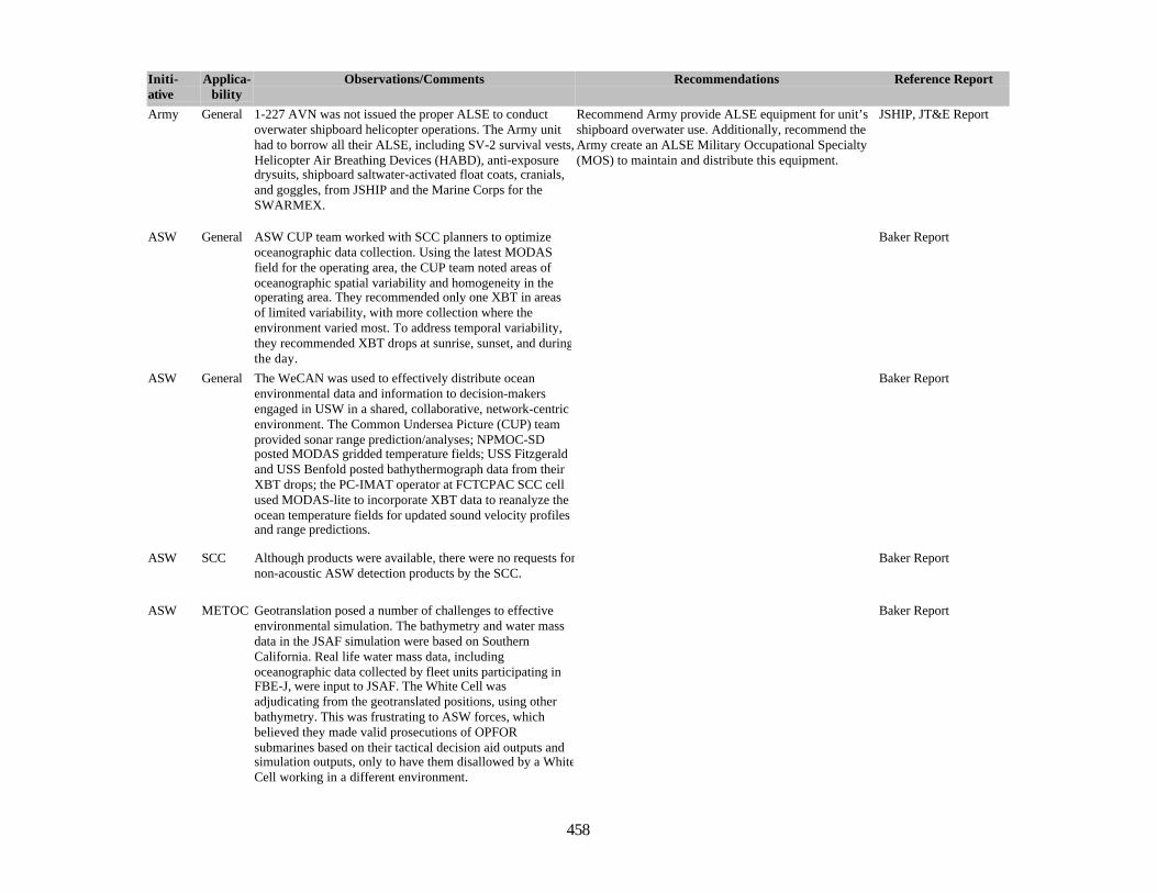
458
Initi-ative
Applica-bility
Observations/Comments Recommendations Reference Report
Army General 1-227 AVN was not issued the proper ALSE to conductoverwater shipboard helicopter operations. The Army unithad to borrow all their ALSE, including SV-2 survival vests,Helicopter Air Breathing Devices (HABD), anti-exposuredrysuits, shipboard saltwater-activated float coats, cranials,and goggles, from JSHIP and the Marine Corps for theSWARMEX.
Recommend Army provide ALSE equipment for unit’sshipboard overwater use. Additionally, recommend theArmy create an ALSE Military Occupational Specialty(MOS) to maintain and distribute this equipment.
JSHIP, JT&E Report
ASW General ASW CUP team worked with SCC planners to optimizeoceanographic data collection. Using the latest MODASfield for the operating area, the CUP team noted areas ofoceanographic spatial variability and homogeneity in theoperating area. They recommended only one XBT in areasof limited variability, with more collection where theenvironment varied most. To address temporal variability,they recommended XBT drops at sunrise, sunset, and duringthe day.
Baker Report
ASW General The WeCAN was used to effectively distribute oceanenvironmental data and information to decision-makersengaged in USW in a shared, collaborative, network-centricenvironment. The Common Undersea Picture (CUP) teamprovided sonar range prediction/analyses; NPMOC-SDposted MODAS gridded temperature fields; USS Fitzgeraldand USS Benfold posted bathythermograph data from theirXBT drops; the PC-IMAT operator at FCTCPAC SCC cellused MODAS-lite to incorporate XBT data to reanalyze theocean temperature fields for updated sound velocity profilesand range predictions.
Baker Report
ASW SCC Although products were available, there were no requests fornon-acoustic ASW detection products by the SCC.
Baker Report
ASW METOC Geotranslation posed a number of challenges to effectiveenvironmental simulation. The bathymetry and water massdata in the JSAF simulation were based on SouthernCalifornia. Real life water mass data, includingoceanographic data collected by fleet units participating inFBE-J, were input to JSAF. The White Cell wasadjudicating from the geotranslated positions, using otherbathymetry. This was frustrating to ASW forces, whichbelieved they made valid prosecutions of OPFORsubmarines based on their tactical decision aid outputs andsimulation outputs, only to have them disallowed by a WhiteCell working in a different environment.
Baker Report
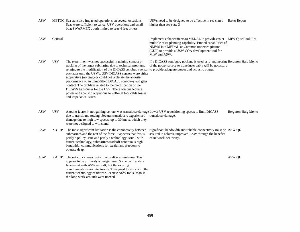
459
ASW METOC Sea state also impacted operations on several occasions.Seas were sufficient to cancel USV operations and smallboat SWARMEX , both limited to seas 4 feet or less.
USVs need to be designed to be effective in sea stateshigher than sea state 3
Baker Report
ASW General Implement enhancements to MEDAL to provide easiermultiple asset planning capability. Embed capabilities ofNMWS into MEDAL or Common undersea picture(CUP) to provide a USW COA development tool forMIW and ASW.
MIW Quicklook Rpt
ASW USV The experiment was not successful in gaining contact ortracking of the target submarine due to technical problemsrelating to the modification of the DICASS sonobuoy sensorpackages onto the USV's. USV DICASS sensors were eitherinoperative (no ping) or could not replicate the acousticperformance of an unmodified DICASS sonobuoy and gaincontact. The problem related to the modification of theDICASS transducer for the USV. There was inadequatepower and acoustic output due to 200-400 foot cable lossesand impedance issues.
If a DICASS sonobuoy package is used, a re-engineeringof the power source to transducer cable will be necessaryto provide adequate power and acoustic output.
Bergeron-Haig Memo
ASW USV Another factor in not gaining contact was transducer damagedue to transit and towing. Several transducers experienceddamage due to high tow speeds, up to 30 knots, which theywere not designed to withstand.
Lower USV repositioning speeds to limit DICASStransducer damage.
Bergeron-Haig Memo
ASW X-CUP The most significant limitation is the connectivity betweensubmarines and the rest of the force. It appears that this ispartly a policy issue and partly a technology issue - withcurrent technology, submarines tradeoff continuous highbandwidth communications for stealth and freedom tooperate deep.
Significant bandwidth and reliable connectivity must beassured to achieve improved ASW through the benefitsof network-centricity.
ASW QL
ASW X-CUP The network connectivity to aircraft is a limitation. Thisappears to be primarily a design issue. Some tactical datalinks exist with ASW aircraft, but the existingcommunications architecture isn't designed to work with thecurrent technology of network-centric ASW tools. Man-in-the-loop work-arounds were needed.
ASW QL

460
ASW X-CUP Chat connectivity permitted continuous and rapidinformation flow between all participants. There were twosignificant difficulties observed with Chat. First, Chatrequires channel discipline to avoid transmission of badinformation and to ensure uniformity of data transmission.The second difficulty concerns manning. In many cases,Chat required almost full-time attention from an operatormonitoring and participating in from one to three Chatsessions (rooms) simultaneously.
Policies (i.e., doctrine or tactics, techniques, andprocedures) are needed for the use of Chat tactically andfor operational level C2.
ASW QL
ASW RemoteUnmanned Sensors
The size and design of the USV is critical to its ability tocontribute consistently to warfighting due to seaworthinessand recoverability issues. The durability of the sensor andcontrol systems is an issue due to their intended highoperating speeds and impact of sea state that takes a toll onsmall boats operating remotely. Availability andmaintainability issues are critical if USVs are needed inmore than just the most benign sea states.
ASW QL
ASW Extending NFN toUSW
In the case of submarines, it was seen that the C2functionality of NFNX-LAWS did add value, but that thevalue added would be greater if the functionality wereincorporated into existing submarine weapons controlsystems. In the case of surface ships, including aircraftcarriers (the notional location of the Sea CombatCommander), it was seen that some features of the NFNX-LAWS functionality could add value if incorporated intoexisting ASW tactical data systems and/or a CommonUndersea Picture system.
ASW QL
ASW Extending NFN toUSW
LAWS demonstrated latency of several minutes on occasionthat made it currently unacceptable for this application(compared to some existing ASW tactical command andcontrol systems that are quicker). With training and bettersystem understanding the operators were able to reduce thelatency to an acceptable level. With improvements inbandwidth and system design the latency problem could beovercome entirely.
ASW QL
ASW TASWC The quality of the connectivity between the TASWC and therest of the force was key and must have redundancy andhigh bandwidth.
ASW QL

461
ASW DynamicNetworkMngmt
The experimental network provided the coalition force withreliable communications and enhanced bandwidthcontributing to an overall improvement in battlespaceawareness. At one point the DREN connection betweenFCTCPAC and NUWC was lost due to operator actions, andwhen restored, the agent-based computing environmentdynamically reconfigured and automatically restored the"grid" COP for all registered users within 15 seconds. Theback-up COP took 15 minutes to recognize loss of updatesand manually restore.
Coalition C2 QL
ASW DynamicNetworkMngmt
Agent-based computing is possible across secure WANS toa network-centric naval force, but requires somemanagement of bandwidth traffic priority to ensurebottlenecks do not occur.
Coalition C2 QL
ASW DynamicNetworkMngmt
The value of collaboration and shared awareness with otherelements of the coalition ASW force encouraged tactics thatmaximized time connected to the grid.
Coalition C2 QL
ASW Doctrine The capability of near-continuous communications andfault-tolerant, dynamically reconfigurable networks in 2007shows that there may be potential for more doctrinalflexibility in waterspace management (WSM), and a moreresponsive approach to manned and autonomous unmannedundersea vehicle battlespace management. The concept of amoving NOTACK area, supported by a robust and currentmulti-national COP, may have merit for improved ASWprosecution timelines while maintaining safety of U.S. andcoalition subs.
Coalition C2 QL
ASW DynamicNetworkMngmt
An expeditionary sensor grid with pervasive sensing needsto have a reporting scheme with a C2 node, which canpackage and possibly prioritize numerous contact reports(perhaps once per minute, at least for the underseabattlespace), rather than have each sensor report individuallyhandled and routed.
Coalition C2 QL

462
ASW DynamicNetworkMngmt
It is critical for all nodes of a network-centric force to notonly know when connectivity is established or regained, butequally important to know when it is lost. Although agentshave been able to quickly recognize and restore a networkgrid for data exchange, they have not been configured tosupport recognizing loss of connectivity. The health andstatus of the network-centric environment is particularlyimportant for the employment of autonomous sensors, aswell as for coalition forces, which lack the same level ofgrid/agent administrative support.
Coalition C2 QL
ASW SecureInfoSharing
FBE-J architecture for agent-based coalition chat wasdesigned to experimentally operate in a secret high coalitionenvironment, in parallel with a U.S. chat capability, forinformation security reasons. Field implementation of theagent-facilitated chat capability would not be effectiveunless the architecture for a multi-national chat capabilityexisted as a single integrated system, with a means todesignate a user's chat stream as being U.S. only, orreleasable to multi-national force, perhaps by prefacing thechat stream with a flag (/c) to indicate the text is meant forall coalition. Implementation of a dual system, air-gapped onU.S. platforms would be ineffective. C2 with coalition needsto rely on the content of the information exchange, not onthe platform or system being used. Secure informationsharing needs to be managed and tagged at the data levelwith users. U.S. enclaves on foreign ships, and foreignliaison officers are not the answer to managing information.
Coalition C2 QL
ASW NettedForce
Significant bandwidth and reliable connectivity must beprovided if we are to achieve improved ASW through thebenefits of network-centricity.
ASW QL
ASW NettedForce
Chat connectivity at several levels was utilized and createdan environment of continuous and rapid information flowbetween all assets that markedly improved individualcapability. It requires channel discipline to avoidtransmission of misinformation and to ensure uniformity ofdata transmission.
ASW QL
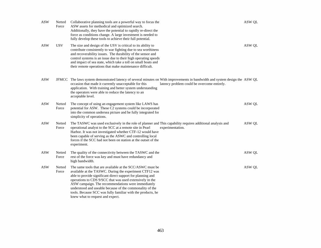
463
ASW NettedForce
Collaborative planning tools are a powerful way to focus theASW assets for methodical and optimized search.Additionally, they have the potential to rapidly re-direct theforce as conditions change. A large investment is needed tofully develop these tools to achieve their full potential.
ASW QL
ASW USV The size and design of the USV is critical to its ability tocontribute consistently to war fighting due to sea worthinessand recoverability issues. The durability of the sensor andcontrol systems is an issue due to their high operating speedsand impact of sea state, which take a toll on small boats andtheir remote operations that make maintenance difficult.
ASW QL
ASW JFMCC The laws system demonstrated latency of several minutes onoccasion that made it currently unacceptable for thisapplication. With training and better system understandingthe operators were able to reduce the latency to anacceptable level.
With improvements in bandwidth and system design thelatency problem could be overcome entirely.
ASW QL
ASW NettedForce
The concept of using an engagement system like LAWS haspotential for ASW. These C2 systems could be incorporatedinto the common undersea picture and be fully integrated forsimplicity of operations.
ASW QL
ASW NettedForce
The TASWC was used exclusively in the role of planner andoperational analyst to the SCC at a remote site in PearlHarbor. It was not investigated whether CTF-12 would havebeen capable of serving as the ASWC and controlling localforces if the SCC had not been on station at the outset of theexperiment.
This capability requires additional analysis andexperimentation.
ASW QL
ASW NettedForce
The quality of the connectivity between the TASWC and therest of the force was key and must have redundancy andhigh bandwidth.
ASW QL
ASW NettedForce
The same tools that are available at the SCC/ASWC must beavailable at the TASWC. During the experiment CTF12 wasable to provide significant direct support for planning andoperations to CDS 9/SCC that was used extensively in theASW campaign. The recommendations were immediatelyunderstood and useable because of the commonality of thetools. Because SCC was fully familiar with the products, heknew what to request and expect.
ASW QL

464
ASW General FBE J simulation architecture was fully integrated with MC02 architecture that federated over 50 different models fromall services. As a result, there were discontinuities in theCOP and simulation interactions, which precluded fightingNaval Forces at the tactical level.
ASW QL
ASW General MC 02 utilized a fully interactive OPFOR in a two-sidedgame. The simulation and COP limitations for both REDand BLUE did not support realistic interactions solely basedon modeled outcomes and as a result, extensive adjudicationby a WHITE cell was required.
ASW QL
ASW General The experimental network provided the joint task force withreliable communications and enhanced bandwidth,contributing to an overall improvement in Battlespaceawareness. The warfighter’s ability to monitor anddynamically change the network bandwidth allocationproved significant.
ASW QL
ASW General The virtual SSGN effectively demonstrated both largevolume sub-surface Fires and time-critical strike capabilityfrom a submerged, relatively stealthy platform.
ASW QL
ASW HSV The C4I suite is adequate. Circuits should be fully operational for NSW operations:4 SATCOM channels are optimal, 2 channels are theminimum; 6 UHF/VHF channels are optimal with 3minimum. All circuits should be thoroughly tested toensure minimal interference with other ships’ electronicsand optimum placement.
HSV STOM MIWSummary
ASW HSV HSV method of launching and recovering small boats(RHIBs and SDV) is unsatisfactory. HSV method of usingthe hydraulic crane for the launching and recovery of smallboats is inefficient, slow, and not optimally safe.
A combination of a stern ramp and a deck cradle systemwould enhance all aspects of small boat operations.
HSV STOM MIWSummary
ASW HSV A two spot helicopter deck to accommodate thelaunching and recovery of 2 HH-60 helicopters isneeded. Additionally a helicopter maintenance bay isrecommended to allow continuous operations at sea.
HSV STOM MIWSummary
ASW General The degree to which a collaborative or situational awarenesstool is valuable depends on the consistency, accuracy andtimeliness of the information it displays.
JFI Analysis
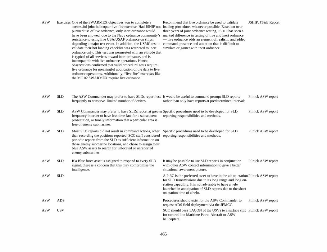
465
ASW Exercises One of the SWARMEX objectives was to complete asuccessful joint helicopter live-fire exercise. Had JSHIP notpursued use of live ordnance, only inert ordnance wouldhave been allowed, due to the Navy ordnance community’sresistance to using live USA/USAF ordnance on ships,degrading a major test event. In addition, the USMC test tovalidate their hot loading checklist was restricted to inertordnance only. This test was permeated with an attitude thatis typical of all services toward inert ordnance, and isincompatible with live ordnance operations. Hence,observations confirmed that valid procedural tests requirelive ordnance for meaningful application of the data to liveordnance operations. Additionally, “live-fire” exercises likethe MC 02 SWARMEX require live ordnance.
Recommend that live ordnance be used to validateloading procedures whenever possible. Based on overthree years of joint ordnance testing, JSHIP has seen amarked difference in testing of live and inert ordnance— live ordnance adds an element of realism, and addedcommand presence and attention that is difficult tosimulate or garner with inert ordnance.
JSHIP, JT&E Report
ASW SLD The ASW Commander may prefer to have SLDs report lessfrequently to conserve limited number of devices.
It would be useful to command prompt SLD reportsrather than only have reports at predetermined intervals.
Pilnick ASW report
ASW SLD ASW Commander may prefer to have SLDs report at greaterfrequency in order to have less time-late for a subsequentprosecution, or timely information that a particular area isfree of enemy submarines.
Specific procedures need to be developed for SLDreporting responsibilities and methods.
Pilnick ASW report
ASW SLD Most SLD reports did not result in command actions, otherthan recording the positions reported. SCC staff consideredperiodic reports from the SLD as sufficient information onthose enemy submarine locations, and chose to assign theirblue ASW assets to search for unlocated or unreportedenemy submarines.
Specific procedures need to be developed for SLDreporting responsibilities and methods.
Pilnick ASW report
ASW SLD If a Blue force asset is assigned to respond to every SLDsignal, there is a concern that this may compromise theintelligence.
It may be possible to use SLD reports in conjunctionwith other ASW contact information to give a bettersituational awareness picture.
Pilnick ASW report
ASW SLD A P-3C is the preferred asset to have in the air on-stationfor SLD transmissions due to its long range and long on-station capability. It is not advisable to have a helolaunched in anticipation of SLD reports due to the shorton-station time of a helo.
Pilnick ASW report
ASW ADS Procedures should exist for the ASW Commander torequest ADS field deployment via the JFMCC.
Pilnick ASW report
ASW USV SCC should pass TACON of the USVs to a surface shipfor control like Maritime Patrol Aircraft or ASWhelicopters.
Pilnick ASW report
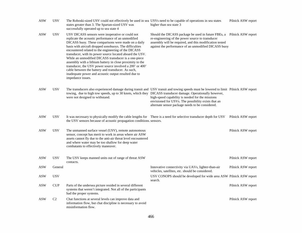
466
ASW USV The Roboski-sized USV could not effectively be used in seastates greater than 3. The Spartan-sized USV wassuccessfully operated up to sea state 4
USVs need to be capable of operations in sea stateshigher than sea state 3
Pilnick ASW report
ASW USV USV DICASS sensors were inoperative or could notreplicate the acoustic performance of an unmodifiedDICASS buoy. These comparisons were made on a dailybasis with aircraft dropped sonobuoys. The difficultiesencountered related to the engineering of the DICASStransducer, with its power source located aboard the USV.While an unmodified DICASS transducer is a one-pieceassembly with a lithium battery in close proximity to thetransducer, the USV power source involved a 200’ or 400’cable between the battery and transducer. As such,inadequate power and acoustic output resulted due toimpedance issues.
Should the DICASS package be used in future FBEs, are-engineering of the power source to transducerassembly will be required, and this modification testedagainst the performance of an unmodified DICASS buoy
Pilnick ASW report
ASW USV The transducers also experienced damage during transit andtowing, due to high tow speeds, up to 30 knots, which theywere not designed to withstand.
USV transit and towing speeds must be lowered to limitDICASS transducer damage. Operationally however,high-speed capability is needed for the missionsenvisioned for USVs. The possibility exists that analternate sensor package needs to be considered.
Pilnick ASW report
ASW USV It was necessary to physically modify the cable lengths forthe USV sensors because of acoustic propagation conditions.
There is a need for selective transducer depth for USVsensors.
Pilnick ASW report
ASW USV The unmanned surface vessel (USV), remote autonomoussensor, concept has merit to work in areas where air ASWassets cannot fly due to the anti-air threat level encounteredand where water may be too shallow for deep watercombatants to effectively maneuver.
Pilnick ASW report
ASW USV The USV keeps manned units out of range of threat ASWcontacts.
Pilnick ASW report
ASW General Innovative connectivity via UAVs, lighter-than-airvehicles, satellites, etc. should be considered.
Pilnick ASW report
ASW USV USV CONOPS should be developed for wide area ASWsearch.
Pilnick ASW report
ASW CUP Parts of the undersea picture resided in several differentsystems that weren’t integrated. Not all of the participantshad the proper systems.
Pilnick ASW report
ASW C2 Chat functions at several levels can improve data andinformation flow, but chat discipline is necessary to avoidmisinformation flow.
Pilnick ASW report
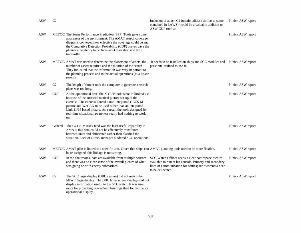
467
ASW C2 Inclusion of attack C2 functionalities (similar to somecontained in LAWS) would be a valuable addition toASW CUP tool set.
Pilnick ASW report
ASW METOC The Sonar Performance Prediction (SPP) Tools gave someawareness of the environment. The AMAT search coveragediagrams conveyed how effective the coverage could be andthe Cumulative Detection Probability (CDP) curves gave theplanners the ability to perform asset allocation and timetrade-offs.
Pilnick ASW report
ASW METOC AMAT was used to determine the placement of assets, thenumber of assets required and the duration of the search.They indicated that the information was very important tothe planning process and to the actual operations (to a lesserextent).
It needs to be installed on ships and SCC modules andpersonnel trained to use it.
Pilnick ASW report
ASW C2 The length of time it took the computer to generate a searchplans was too long.
Pilnick ASW report
ASW CUP At the operational level the X-CUP tools were of limited usebecause of the artificial tactical picture set-up of theexercise. The exercise forced a non-integrated GCCS-Mpicture and WeCAN to be used rather than an integratedLink 11/16 based picture. As a result the tools designed forreal-time situational awareness really had nothing to workon
Pilnick ASW report
ASW General The GCCS-M track feed was the least useful capability inAMAT; this data could not be effectively transferredbetween units and obfuscated rather than clarified thesituation. Lack of a track manager hindered SCC operations.
Pilnick ASW report
ASW METOC AMAT plan is linked to a specific unit. Given that ships canbe re-assigned, this linkage is too strong.
AMAT planning tools need to be more flexible. Pilnick ASW report
ASW CUP In the chat rooms, data are available from multiple sourcesand there was no clear sense of the overall picture of whatwas going on with enemy submarines.
SCC Watch Officer needs a clear battlespace pictureavailable to him at his console. Primary and secondarylines of communication for battlespace awareness needto be delineated.
Pilnick ASW report
ASW C2 The SCC large display (DBC system) did not match theMIWC large display. The DBC large screen displays did notdisplay information useful to the SCC watch. It was usedmore for projecting PowerPoint briefings than for tactical oroperational display.
Pilnick ASW report
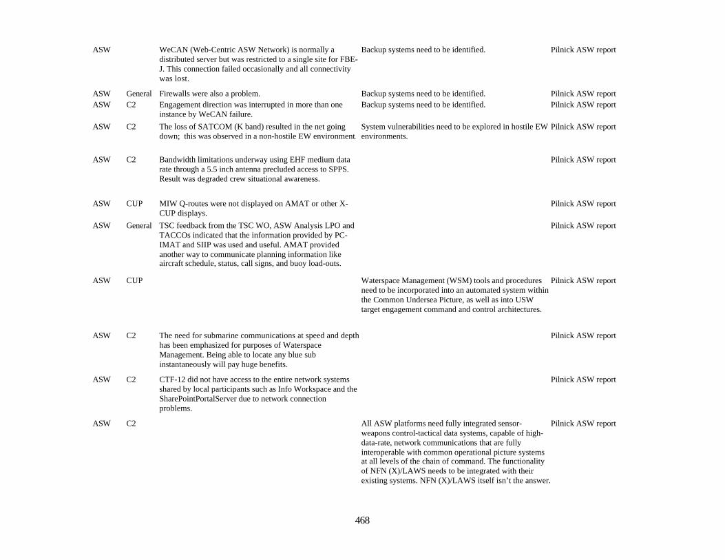
468
ASW WeCAN (Web-Centric ASW Network) is normally adistributed server but was restricted to a single site for FBE-J. This connection failed occasionally and all connectivitywas lost.
Backup systems need to be identified. Pilnick ASW report
ASW General Firewalls were also a problem. Backup systems need to be identified. Pilnick ASW reportASW C2 Engagement direction was interrupted in more than one
instance by WeCAN failure.Backup systems need to be identified. Pilnick ASW report
ASW C2 The loss of SATCOM (K band) resulted in the net goingdown; this was observed in a non-hostile EW environment.
System vulnerabilities need to be explored in hostile EWenvironments.
Pilnick ASW report
ASW C2 Bandwidth limitations underway using EHF medium datarate through a 5.5 inch antenna precluded access to SPPS.Result was degraded crew situational awareness.
Pilnick ASW report
ASW CUP MIW Q-routes were not displayed on AMAT or other X-CUP displays.
Pilnick ASW report
ASW General TSC feedback from the TSC WO, ASW Analysis LPO andTACCOs indicated that the information provided by PC-IMAT and SIIP was used and useful. AMAT providedanother way to communicate planning information likeaircraft schedule, status, call signs, and buoy load-outs.
Pilnick ASW report
ASW CUP Waterspace Management (WSM) tools and proceduresneed to be incorporated into an automated system withinthe Common Undersea Picture, as well as into USWtarget engagement command and control architectures.
Pilnick ASW report
ASW C2 The need for submarine communications at speed and depthhas been emphasized for purposes of WaterspaceManagement. Being able to locate any blue subinstantaneously will pay huge benefits.
Pilnick ASW report
ASW C2 CTF-12 did not have access to the entire network systemsshared by local participants such as Info Workspace and theSharePointPortalServer due to network connectionproblems.
Pilnick ASW report
ASW C2 All ASW platforms need fully integrated sensor-weapons control-tactical data systems, capable of high-data-rate, network communications that are fullyinteroperable with common operational picture systemsat all levels of the chain of command. The functionalityof NFN (X)/LAWS needs to be integrated with theirexisting systems. NFN (X)/LAWS itself isn’t the answer.
Pilnick ASW report
469
ASW C2 LAWS must be seamlessly integrated with the SSGNAttack Weapons System.
Pilnick ASW report
ASW C2 If the remote sensors cannot provide attack criteria, thenincorporating them into the NFN is a mistake.
Pilnick ASW report
ASW C2 Inclusion of attack C2 functionalities (similar to somecontained in LAWS) would be a valuable addition toASW CUP tool set.
Pilnick ASW report
ASW C2 The distinctions between the ASW process of cueing-to-prosecution, and the Fires process of sensor-to-shooterneed more thought.
Pilnick ASW report
ASW C2 For the blue submarine, communications connectivity forNFN (X)/LAWS is inadequate. This could be due to signalpropagation and bandwidth issues.
Blue Submarine units also need to be better integrated.This is both a bandwidth and combat system integrationissue.
Pilnick ASW report
ASW C2 The time required to get data entered into LAWS and thenreceive an engagement order resulted in a loss of attackcriteria whether or not the unit in contact was ship or air.
Pilnick ASW report
ASW C2 Common tools, networked to common sources of data, didindeed support distributed collaborative planning and ashared common understanding of the undersea acousticenvironment. Tools also permitted planning of optimalsearch patterns and monitoring of the search plan execution.
Pilnick ASW report
ASW C2 Realization of the full potential of network-centricity islimited by some fundamental technology/design/policyrestrictions. The most significant limitation is theconnectivity between submarines and the rest of the force.This is partly a policy issue and partly a technology issue –with current technology, submarines tradeoff continuoushigh bandwidth communications for stealth and freedom tooperate deep.
Significant bandwidth and reliable connectivity must beassured to achieve improved ASW through the benefitsof network-centricity.
Pilnick ASW report
ASW C2 Chat connectivity at several levels was utilized and createdan environment of continuous and rapid information flowbetween all participants.
Chat requires channel discipline to avoid transmission ofbad information and to ensure uniformity of datatransmission. Some policies (i.e., doctrine or tactics,techniques, and procedures) are needed for the use ofChat tactically and for operational level C2. Chatrequired almost full-time attention from an operatormonitoring and participating in from one to three Chatsessions (rooms) simultaneously.
Pilnick ASW report
ASW C2 The ability to identify a critical location in an expectedchoke point and install a sensor field unknown to the enemysubmarine force contributed to the successful use of theADS field.
Pilnick ASW report
470
ASW C2 The ability to coordinate USVs with surface and air ASWplatforms was demonstrated, but USVs and their sensors didnot function as designed due to a combination of prototypeequipment limitations and acoustic environmentalconditions. The size and design of the USV is critical to itsability to contribute consistently to warfighting due toseaworthiness and recoverability issues. The durability ofthe sensor and control systems is an issue due to theirintended high operating speeds and impact of sea state thattakes a toll on small boats operating remotely.
Pilnick ASW report
ASW C2 LAWS demonstrated latency of several minutes on occasionthat made it currently unacceptable for this application.
Pilnick ASW report
ASW C2 The TASWC provided significant direct support for ASWplanning from a rear Headquarters in Hawaii. TASWC wasfully connected to the SCC with the Experimental CommonUndersea Picture tool set. TASWC recommendations wereimmediately understood and useable.
Pilnick ASW report
C3 HSV The JV HSV C4I space is not currently the “heartbeat” ofthe ship.
SPECWAR TOC (Tactical Operations Center) and C4Ishould be together for SA.
HSV STOM MIWSummary
C3 HSV The video feed of the P3 FLIR camera was invaluable in theplanning and the execution of the series of VBSS (Visit,Board, Search and Seizure) Operations; the feed wasdisplayed in the C4I suite on one of the Large ScreenDisplays and provided a large degree of SA.
HSV STOM MIWSummary
C3 HSV The communication between the ship’s bridge and the C4Isuite is cumbersome at best. The information is currentlyrelayed via a hand held radio.
Provide the location data that the P3 is providing, intoGCCS.
HSV STOM MIWSummary
C3 HSV Information from the C4I space to the bridge is unsecured.Communication from bridge to C4I space has to bereevaluated both in terms of space design, location, andarchitecture.
HSV STOM MIWSummary
C3 HSV The transition from MIW operations to NSW operations wasvirtually seamless and transparent. The same JV HSV C4Ispace can be and was utilized by both commanders.
HSV STOM MIWSummary
471
C3 General During initial planning, JSHIP had to request a waiver forthe UH-60L in order to conduct class III flight deck andhangar operations onboard USS BOXER. NAVAIR AircraftLaunch and Recovery Equipment program (PMA 251) hasapproved UH-60A, MH-60K, and more recently the MH-60S aircraft for this level of operations. All three of thesehelicopters are very similar to the UH-60L.
Recommend NAVAIR Aircraft Launch and RecoveryEquipment program (PMA 251) approve UH-60Laircraft for class III flight deck and hangar operationsaboard LHD class ships.
JSHIP, JT&E Report
C3 No process is in place to inform embarked units or ships ofreclassification of ammunition. A Notice of AmmunitionReclassification (NAR) is issued when the class(serviceable, not serviceable, etc.) of specific lots ofordnance has changed. Current NARs must be received byunits and ammunition storage facilities to ensure properdisposition of the affected lots. When a NAR is issuedagainst a USA/USAF lot, it is sent from the AmmunitionSupply Point (ASP) to the receiving unit. If the unit and theammunition are embarked, there is no process to ensure theNAR also goes to the ship or has in fact been received by theunit. It is imperative the ship receive the NAR as it is thestorage facility for the ammunition and is responsible for itsproper disposition until it is received by the unit on the flightdeck. For MC 02, an ad hoc arrangement was made where aJSHIP rep ashore would check daily with the ASP for NARson the lots of embarked ammunition. If a NAR was issued,the JSHIP rep would then notify SURFPAC to forward thisinfo to the ship. This worked for the exercise, but apermanent solution is required.
Recommend the Joint Ordnance Commander’s Group(JOCG) assess this problem and work to establish astandard process for shipboard notification of jointammunition reclassifications.
JSHIP, JT&E Report
C3 Exercises One of the SWARMEX objectives was to complete asuccessful joint helicopter live-fire exercise. Had JSHIP notpursued use of live ordnance, only inert ordnance wouldhave been allowed, due to the Navy ordnance community’sresistance to using live USA/USAF ordnance on ships,degrading a major test event. In addition, the USMC test tovalidate their hot loading checklist was restricted to inertordnance only. This test was permeated with an attitude thatis typical of all services toward inert ordnance, and isincompatible with live ordnance operations. Hence,observations confirmed that valid procedural tests requirelive ordnance for meaningful application of the data to liveordnance operations. Additionally, “live-fire” exercises likethe MC 02 SWARMEX require live ordnance.
Recommend that live ordnance be used to validateloading procedures whenever possible. Based on overthree years of joint ordnance testing, JSHIP has seen amarked difference in testing of live and inert ordnance— live ordnance adds an element of realism, and addedcommand presence and attention that is difficult tosimulate or garner with inert ordnance.
JSHIP, JT&E Report
472
CoalitionC2
General SCC should pass TACON of the USVs to a surface shipfor control like Maritime Patrol Aircraft or ASWhelicopters.
Pilnick ASW report
CoalitionC2
ASW The unmanned surface vessel (USV), remote autonomoussensor, concept has merit to work in areas where air ASWassets cannot fly due to the anti-air threat level encounteredand where water may be too shallow for deep watercombatants to effectively maneuver.
Pilnick ASW report
CoalitionC2
ASW The USV keeps manned units out of range of threat ASWcontacts.
Pilnick ASW report
CoalitionC2
General Innovative connectivity via UAVs, lighter-than-airvehicles, satellites, etc. should be considered.
Pilnick ASW report
CoalitionC2
General USV CONOPS should be developed for wide area ASWsearch.
Pilnick ASW report
CoalitionC2
General Parts of the undersea picture resided in several differentsystems that weren’t integrated. Not all of the participantshad the proper systems.
Pilnick ASW report
CoalitionC2
METOC AMAT was used to determine the placement of assets, thenumber of assets required and the duration of the search.They indicated that the information was very important tothe planning process and to the actual operations (to a lesserextent).
It needs to be installed on ships and SCC modules andpersonnel trained to use it.
Pilnick ASW report
CoalitionC2
ASW The length of time it took the computer to generate a searchplans was too long.
Pilnick ASW report
CoalitionC2
ASW At the operational level the X-CUP tools were of limited usebecause of the artificial tactical picture set-up of theexercise. The exercise forced a non-integrated GCCS-Mpicture and WeCAN to be used rather than an integratedLink 11/16 based picture. As a result the tools designed forreal-time situational awareness really had nothing to workon
Pilnick ASW report
CoalitionC2
General Firewalls were also a problem. Backup systems need to be identified. Pilnick ASW report
CoalitionC2
C2 Engagement direction was interrupted in more than oneinstance by WeCAN failure.
Backup systems need to be identified. Pilnick ASW report
CoalitionC2
C2 The loss of SATCOM (K band) resulted in the net goingdown; this was observed in a non-hostile EW environment.
System vulnerabilities need to be explored in hostile EWenvironments.
Pilnick ASW report
CoalitionC2
CUP MIW Q-routes were not displayed on AMAT or other X-CUP displays.
Pilnick ASW report
473
CoalitionC2
CUP For the SCC to coordinate waterspace assignments forblue Subs, all MARSUPREQs must be chopped by SCCplanners before approval by JFMCC. SCC must workclosely with JFMCC during MTO development to ensurethe WSM plan supports the final product.
Pilnick ASW report
CoalitionC2
C2 The need for submarine communications at speed and depthhas been emphasized for purposes of WaterspaceManagement. Being able to locate any blue subinstantaneously will pay huge benefits.
Pilnick ASW report
CoalitionC2
C2 CTF-12 did not have access to the entire network systemsshared by local participants such as Info Workspace and theSharePointPortalServer due to network connectionproblems.
Pilnick ASW report
CoalitionC2
C2 Common tools, networked to common sources of data, didindeed support distributed collaborative planning and ashared common understanding of the undersea acousticenvironment. Tools also permitted planning of optimalsearch patterns and monitoring of the search plan execution.
Pilnick ASW report
CoalitionC3
Interoper.C2 Syst
Agents were extremely effective in restoring c2 functionalityafter connectivity losses.
Coalition C2 QL
CoalitionC3
Interoper.C2 Syst
Operations and planning on separate siprnet and coalitionwan environments still presents obstacles for highlyeffective integration of coalition forces, particularly if thejfmcc planning process used in fbe-j is adopted.
Coalition C2 QL
CoalitionC3
Interoper.C2 Syst
Foreign disclosure and multi-level security issues were notadequately addressed by smart agents, although agents canprovide limited protection from inadvertent disclosure in acollaborative chat environment.
Coalition C2 QL
CoalitionC3
Interoper.C2 Syst
The current internet protocol-based system handles tracks asfirst-in/first-out, which is particularly inefficient for speed ofcommand, especially for reports from disadvantagedcommunications nodes such as submarines, UUVs, andother autonomous/remote sensors.
Coalition C2 QL
474
CoalitionC3
Interoper.C2 Syst
Users believe that based on demonstrated agent capabilities,the application of agent technology into the U.S.C2 system(GCCS-M) could reduce manning for FOTC managementby about 2 watchstanders. Agents could execute most optaskFOTC functions automatically, and present some (red trackmanagement) functions to an operator for executionapproval.
Coalition C2 QL
CoalitionC3
Interoper.C2 Syst
Agents should support the decision-maker in providinginformation to the COP, but should not be delegated theauthority for weapons employment based on informationsubmitted to the COP. Chat collaboration on designatedtracks of interest, with a man-in-the-loop C2 decision, was avital procedural step in using agents in the end-to-endengagement cycle, to avoid possible fratricide frommislabeled COP tracks.
Coalition C2 QL
CoalitionC3
Interoper.C2 Syst
The SCC GCCS-M operator was coordinating the entry ofmulti-sensor, multi-platform reports on a suspect hostileSSK, including reports from coalition forces. Rather thanmerging correlated contact reports or coordinating themanagement of these reports, all but the most recent reportwas deleted at the TOPCOP level without consulting theSCC. This resulted in loss of the richness in coordinatinglocalization of the submarine and effective prosecution.
PWC cells should retain FOTC-like authority to manageclasses of threat reports associated with their warfaremission.
Coalition C2 QL
CoalitionC3
Interoper.C2 Syst
The situational awareness provided by the COABS/CASTgrid was most effective in confirming the TMA generated bythe submarine combat system, and supporting optimizedTMA tactical maneuvers, but not replacing the need toconduct TMA. The COP generated from agent-basedcomputing improved the confidence level of submarinecommanding officer in his own tactical picture, andprovided cueing for correlation and rapid assessment ofcontacts that were beyond organic sensor range, until theywere sensed
Coalition C2 QL
CoalitionC3
Interoper.C2 Syst
Agent-based computing environment is a management toolto support the decision making, it should not be the solediscriminator on employment of weapons.
Coalition C2 QL

475
CoalitionC3
Interoper.C2 Syst
The simulated Australian rapidly deployable system (RDS),a prototype FY2007 tactical autonomous array, was highlyeffective for chokepoint sea control, particularly forqueueing against a surface threat in support of indications &warning missions or maritime interdiction operations.
Recommend continued investigation of autonomoussensor conops and ttp in future experiments. Particularemphasis should be placed on the network interface forautomating queuing from autonomous sensor fields, andundersea connectivity to all manned and unmannedundersea vehicles, including coalition submarines.
Coalition C2 QL
CoalitionC3
Interoper.C2 Syst
CAST agents provided an immediate warfighter benefit byreliably delivering and exchanging track data, andimproving battlespace awareness for cross-platform cueingof threats. Further experimentation with CAST is warrantedto extend agent-based computing to managing sensor leveldata.
Coalition C2 QL
CoalitionC3
DynamicNetwork
The experimental network provided the coalition force withreliable communications and enhanced bandwidthcontributing to an overall improvement in battlespaceawareness. At one point the DREN connection betweenFCTCPAC and NUWC was lost due to operator actions, andwhen restored, the agent-based computing environmentdynamically reconfigured and automatically restored the"grid" COP for all registered users within 15 seconds. Theback-up COP took 15 minutes to recognize loss of updatesand manually restore.
Coalition C2 QL
CoalitionC3
DynamicNetworkMngmt
Agent-based computing is possible across secure WANS toa network-centric naval force, but requires somemanagement of bandwidth traffic priority to ensurebottlenecks do not occur.
Coalition C2 QL
CoalitionC3
DynamicNetworkMngmt
The value of collaboration and shared awareness with otherelements of the coalition ASW force encouraged tactics thatmaximized time connected to the grid.
Coalition C2 QL
CoalitionC3
DynamicNetworkMngmt
The capability of near-continuous communications andfault-tolerant, dynamically reconfigurable networks in 2007shows that there may be potential for more doctrinalflexibility in waterspace management (WSM), and a moreresponsive approach to manned and autonomous unmannedundersea vehicle battlespace management. The concept of amoving NOTACK area, supported by a robust and currentmulti-national COP, may have merit for improved ASWprosecution timelines while maintaining safety of U.S. andcoalition subs.
Coalition C2 QL
476
CoalitionC3
DynamicNetworkMngmt
An expeditionary sensor grid with pervasive sensing needsto have a reporting scheme with a C2 node, which canpackage and possibly prioritize numerous contact reports(perhaps once per minute, at least for the underseabattlespace), rather than have each sensor report individuallyhandled and routed.
Coalition C2 QL
CoalitionC3
DynamicNetworkMngmt
It is critical for all nodes of a network-centric force to notonly know when connectivity is established or regained, butequally important to know when it is lost. Although agentshave been able to quickly recognize and restore a networkgrid for data exchange, they have not been configured tosupport recognizing loss of connectivity. The health andstatus of the network-centric environment is particularlyimportant for the employment of autonomous sensors, aswell as for coalition forces, which lack the same level ofgrid/agent administrative support.
Coalition C2 QL
CoalitionC3
SecureInfoSharing
FBE-J architecture for agent-based coalition chat wasdesigned to experimentally operate in a secret high coalitionenvironment, in parallel with a U.S. chat capability, forinformation security reasons. Field implementation of theagent-facilitated chat capability would not be effectiveunless the architecture for a multi-national chat capabilityexisted as a single integrated system, with a means todesignate a user's chat stream as being U.S. only, orreleasable to multi-national force, perhaps by prefacing thechat stream with a flag (/c) to indicate the text is meant forall coalition. Implementation of a dual system, air-gapped onU.S. platforms would be ineffective. C2 with coalition needsto rely on the content of the information exchange, not onthe platform or system being used. Secure informationsharing needs to be managed and tagged at the data levelwith users. U.S. enclaves on foreign ships, and foreignliaison officers are not the answer to managing information.
Coalition C2 QL
477
CoalitionC3
MPP The use of coalition forces as core (dedicated) assets underTACOM and TACON to the SCC, highlights the need forany JFMCC/MTO process to incorporate the concept of"sorties held in reserve" rather than give up all assets to theJFMCC as a default for allocation. There should be someassets that can assure continuity of effort, readiness, missionexecution proficiency, and effective planning, that SCCretains as core. Due to the mobile nature of multi-missionmaritime assets in the JFMCC apportionment, there are C2challenges that are unique to this maritime environment.They need to be assigned as part of the core capability uponwhich PWCs such as SCC can rely for planning andexecution. Having coalition forces in this categoryfacilitated planning for ASW and for branch plans such asMER ship or ARG escort duties. Such assets might still haveMSR inputs with SCC as a non-negotiable PWC assignment,to allow for inclusion in the MMAP and MTO for overallvisibility.
Coalition C2 QL
CoalitionC3
MPP The maritime tasking order (MTO) process does not providesufficient flexibility to the dynamic maritime taskingenvironment to warrant the additional time commitment andSCC planning overhead. The ability to task coalition forcesfor merchant "safe haven" management and escort or prizeships, those missions with lower priority than TCT re-roll,more effectively supported SCC execution of sea controlmission, because it was offline from MTO process.
Coalition C2 QL
CoalitionC3
General The degree to which a collaborative or situational awarenesstool is valuable depends on the consistency, accuracy andtimeliness of the information it displays.
JFI Analysis
CoalitionC3
General While classified communication is not impossible, itremains a significant challenge that must be addressed whenconducting Joint shipboard helicopter operations. A varietyof solutions exist; recommend the units involved in aparticular scenario proactively explore the best option basedupon their available resources for classifiedcommunications. Classified communication will continue tobe important to successful Joint operations.
Army tactical units do not have easy access to eitherofficial message traffic Plain Language Address (PLA),nor classified Secure Internet Routing Protocol Network(SIRPNET). The Navy, on the other hand, almostexclusively uses these systems to communicate withother units/levels. USS BOXER had difficulty intransmitting classified information to the Army unit—this impacted various aspects of the operation, includingrequired overhead times for helicopters, radiofrequencies used for inbound flight operations, andordnance logistics.
JSHIP, JT&E Report
478
CoalitionC3
General Secure voice communications and IFF Mode IV were notplanned for in support of the SWARMEX becauseparticipants believed they were too hard to coordinate, eventhough it was a requirement for all other MC 02participating fixed-wing aircraft. JSHIP has previouslyevaluated Mode IV/secure voice aboard ships with Armyhelicopters with success.
In order to test in a realistic scenario, recommendexercising the tools required for actual missions and usesecure communications and MODE IV IFF.
JSHIP, JT&E Report
CoalitionC3
General US Navy air-capable ships are equipped with Tactical Aid toNavigation (TACAN) and an Ultra-High Frequency (UHF)Non-Directional Beacon (NDB) for use as aircraft aids tonavigation. Most conventional Army helicopters are notequipped to use these systems, and therefore lack the meansto independently navigate to a ship. USS BOXERtransmitted a signal (50 watts at 2199 KHz) to assist the AH-64D aircraft flying inbound to the ship. However, due tomiscommunication, the AH-64D pilots did not have thefrequency (see Inter-Service Unit-Level ClassifiedCommunication Issue), so they were vectored in by radar,radio voice and visual contact. Although not required in thiscase because of the close proximity of USS BOXER toshore, conventional joint helicopter operations will normallyrequire radio navigation aids while inbound to ships.
Recommend using HF homing for all future Armyhelicopter inbound flight operations with Navy ships.JSHIP has successfully tested a procedure that will workwith both models of Army ADF receivers and all NavyHF transmitters. Emission Control (EMCON)permitting, the ship transmits a continuous wave HFfrequency signal between the frequency range of 2000-2199 KHz at a power level of approximately 50 watts.The transmitter must be set to "CW" modulation. Thissignal can then be received by the aircraft's ADFreceiver and will provide a directional needle pointing tothe ship. Distance information will not be available usingthis method.
JSHIP, JT&E Report
CoalitionC3
General The SWARMEX was representative of a Joint Task Force(JTF) assembled for a short-term contingency, involvingdissimilar helicopter and fixed-wing units and severalamphibious task force ships. The 1-227 AVN unit wasunfamiliar with the personnel requirements for missionplanning and the process for coordinating with the TacticalAir Control Squadron (TACRON) or the ship’s AirOperations department for scheduling and planningshipboard flight operations and ordnance load plans. Thiscreated difficulty at times, especially when a passengertransfer between USS BOXER and USS Benfold wasrequired on short notice. Furthermore, no dedicated staff orship liaisons were provided to the 1-227 AVN unit once theyembarked. Consequently, JSHIP personnel performed theinitial shipboard flight operations planning and schedulingsupport for the 1-227 AVN and provided most of the liaisonbetween the staff, the ship, and the embarking unit requiredfor the Air Plan. Effective coordination between embarkingaviation units and the appropriate ship personnel is critical toproper planning and successful mission execution.
This issue is well documented by JSHIP and has been arecurring problem associated with Army and Air Forceunits embarking Navy ships when liaisons betweenservices were not exchanged. It further demonstrates theneed for a prebriefed command element/liaison, familiarwith naval shipboard flight operations, to embark withthese units. If such a joint command element/liaisioncannot be embarked, recommend USN/USMC units andship’s company provide this dedicated liaision support,especially for scheduling and planning shipboard flightoperations and ordnance loads. Also, JSHIPrecommends embarked units bring additional personneldedicated to the planning process.
JSHIP, JT&E Report
479
CoalitionC3
General During initial planning, JSHIP had to request a waiver forthe UH-60L in order to conduct class III flight deck andhangar operations onboard USS BOXER. NAVAIR AircraftLaunch and Recovery Equipment program (PMA 251) hasapproved UH-60A, MH-60K, and more recently the MH-60S aircraft for this level of operations. All three of thesehelicopters are very similar to the UH-60L.
Recommend NAVAIR Aircraft Launch and RecoveryEquipment program (PMA 251) approve UH-60Laircraft for class III flight deck and hangar operationsaboard LHD class ships.
JSHIP, JT&E Report
CoalitionC3
General The effects of the ship's radar and communicationtransmitters on USA/USAF aircraft flight control andavionics systems continues to be an unfamiliar issue for theNavy. The Navy/Marine Corps aircraft have fewer EMVproblems since they are designed to operate in the shipboardelectromagnetic environment. The Army and Air Forcehelicopters are not designed for the shipboard environmentand certain shipboard transmitters must be turned off oroperated at reduced power to prevent ElectromagneticInterference (EMI) to the Army and Air Force helicopters.JSHIP engineers have developed an EMV database for allUSA/USAF helicopters. In preparation for MC 02, USSBOXER was given transmitter guidance by JSHIP engineersthrough use of this database to ensure safe joint helicopteroperations. EMV was not a problem for the SWARMEXbecause JSHIP planning and intervention insured safeoperations. Because Army and Air Force helicopters are notEMV hardened by design, EMV will remain an area thatmust be addressed to prevent aircraft damage or mishaps.
Recommend future joint exercises use the JSHIP-developed EMV database and place emphasis on EMVprotection. This function should be incorporated intoJoint Force planning process, and is best suited forintegration with the Joint Spectrum Center’s (JSC) E3Engineering Support Program. Second, recommendfuture USA/USAF rotorcraft acquisition programsincorporate shielding and protective methods for aircraftelectrical and avionics systems to reduce their EMV inthe shipboard environment.
JSHIP, JT&E Report
CoalitionC3
General HERO classification of Army ordnance also continues to bean issue since these items are usually not contained in theNavy's HERO publication, OP 3565. Each time non-Navyordnance comes aboard a Navy ship, a special HEROassessment to determine the HERO classification must beperformed by Naval Surface Warfare Center, DahlgrenDivision (NSWCDD). For MC 02, a special assessment wasperformed by NSWCDD that resulted in severe andunnecessary restrictions to USS BOXER transmitters. JSHIPengineers and officers reviewed existing HERO test data andcontacted the helicopter program managers to gather data soNSWCDD could reevaluate the HERO shipboard transmitterrestrictions. Due to their efforts, the special HEROassessment was modified by NSWCDD, ultimately resultingin a workable solution and a less restrictive environment.
Recommend NSWCDD develop a procedure to ensurethat all relevant information is considered prior toestablishing HERO conditions.
JSHIP, JT&E Report

480
CoalitionC3
General No accepted joint processes are in place for USA/USAFordnance handling, movement, and storage aboard Navyships. In addition, the process for transferring USA/USAFordnance from its parent service to a Navy site ashore is notdefined. Over the course of two years, JSHIP has worked todevelop a standardized process which Joint helicopter unitsmay use to employ their aviation ordnance safely andeffectively aboard ships. Problems that were previouslyaddressed and resolved through this process resurfacedduring this MC 02 test period. This indicated that decisionsto allow specific ordnance onboard a ship can be personalitydriven, rather than procedurally based. Navy OrdnancePamphlet 4’s (OP4) use of the words, “authorizedcontainers” was construed to mean “prohibited” for Army2.75” rocket storage, because the storage containers wereauthorized by the Army rather than the Navy. Although OP4and various ship Naval Aviation Training and OperatingProcedures Standardization (NATOPS) manuals addressnaval ordnance procedures, USA/USAF ordnance andprocedures are not included. Naval ordnance policies aredesigned to support operations in close quarters and in ahigh electromagnetic transmission environment. Navalordnance procedures are, by requirement, appliedrestrictively; e.g., if not expressly permitted, the procedure isnot allowed without an approved waiver. USA/USAFordnance procedures have not been developed for the closequarters and high electromagnetic environment encounteredaboard ship. For these reasons, USA/USAF units operateoutside the Naval ordnance system and therefore requirewaivers to conduct operations. Knowing how to generate therequest for waivers, determining addressees and using thecorrect format should not be tasks expected of theembarking unit. Further, JSHIP experience has shown that arequest for a wavier may elicit completely differentresponses from different commands based on personalinterpretations. For MC 02, the BOXER, with the assistanceof Naval Surface Force, U.S. Pacific Fleet (SURFPAC),should have requested the waiver, as the ship was tasked byhigher headquarters to support the live-fire exercise. Onlybecause JSHIP is an OSD organization specifically charteredto investigate Joint interoperability, and with considerableeffort and OPNAV-level intervention, were Army 2.75”aerial rockets with inert warheads and loaded inFASTPACKS allowed onboard the ship. Clearly, tacticalunits forced to use the Naval ordnance procedures currentlyin place have insurmountable obstacles to overcome toconduct Joint exercises with aviation ordnance aboard ships.
The services should develop and implement a processusing JSHIP products and recommendations that definesthe logistics steps required for joint use of aviationordnance (Navy certified or non-certified) aboard ships.
JSHIP, JT&E Report
481
CoalitionC3
General No process is in place to inform embarked units or ships ofreclassification of ammunition. A Notice of AmmunitionReclassification (NAR) is issued when the class(serviceable, not serviceable, etc.) of specific lots ofordnance has changed. Current NARs must be received byunits and ammunition storage facilities to ensure properdisposition of the affected lots. When a NAR is issuedagainst a USA/USAF lot, it is sent from the AmmunitionSupply Point (ASP) to the receiving unit. If the unit and theammunition are embarked, there is no process to ensure theNAR also goes to the ship or has in fact been received by theunit. It is imperative the ship receive the NAR as it is thestorage facility for the ammunition and is responsible for itsproper disposition until it is received by the unit on the flightdeck. For MC 02, an ad hoc arrangement was made where aJSHIP rep ashore would check daily with the ASP for NARson the lots of embarked ammunition. If a NAR was issued,the JSHIP rep would then notify SURFPAC to forward thisinfo to the ship. This worked for the exercise, but apermanent solution is required.
Recommend the Joint Ordnance Commander’s Group(JOCG) assess this problem and work to establish astandard process for shipboard notification of jointammunition reclassifications.
JSHIP, JT&E Report
CoalitionC3
General BOXER’s Ship Safety/Orientation Brief shown on closed-circuit television (CCTV) was inadequate for Armypersonnel unfamiliar with shipboard safety. Joint units havea natural tendency to assume that routine operations on landcan be easily conducted aboard ship. Because the briefingwas presented on CCTV, it lacked dynamic interaction andthe option to ask impromptu questions.
Recommend that ship’s companies provide an officer orsenior NCO to conduct an in-person safety/orientationbrief for embarking Army units. Although the briefpresented over CCTV contained all essentialinformation, an in-person briefing would help enforcethe inherent safety issues encountered on Navy ships.
JSHIP, JT&E Report
482
CoalitionC3
General BOXER supply personnel were not aware that Navy andArmy pay systems were incompatible. The issue wasidentified when the Assistant Supply Officer (ASUPPO) wastold by JSHIP that they would not be able to deduct from the1-227 AVN enlisted personnel Basic Allowance forSubsistence (BAS) pay while embarked aboard BOXER,precluding meal deductions from their pay. The issue is evenmore evident when Joint embarking units pay for fuel takenby their helicopters. No standard method exists forArmy/Air Force units to pay for these supply items; severaloptions have been tried without success. Navy ships are notequipped to accept standard Army fuel credit cards, andmost USA/USAF helicopter units are not familiar with theDD-1348 payment form, routinely used by Navy and MarineCorps units for transactions.
Recommend payment for supply items such as food andfuel be addressed at the service level. Even though allservices have competent systems in place to handle theirown needs (MIPR, credit cards, DD-1348), a standardshould be established to handle joint operations whenone service provides goods/services to another.
JSHIP, JT&E Report
HSS HSV Major physical modifications would be needed to ensureproper casualty handling and decontamination.
Passageways need to be at least 50 inches in width(hospitals require 8 feet for passage ways) to easilymove patients in litters. There must be direct access fromhelicopter deck. A ramping system, as a back up forelevators, to move litter patients throughout the vessel isnecessary (Most commercial ships incorporate this dueto needing to be wheel chair accessible). Higher ceilingsare necessary on vehicle deck (for buses). Elevatorshould be able to accommodate the length of a litter plusa minimum of 2 litter bearers--approx 8 ft in length perlitter. Increase sizes of passageways and midship roomswhere care and transportation is much easier in highersea states. Access from flight deck should be straight anddirect and wider.
Marks Trip Report
HSS HSV Skid proof flooring for when it is wet. Marks Trip ReportHSV C2 The JFMCC retains OPCON of all assets and provides them
to tasked PWCs to accomplish their assigned missions. TheMTO does not indicate reporting processes forreconfigurable or multiuse platforms. The assumption thatOPTASKs (which are developed in advance of operations)are an adequate means to convey C2 relationships is risky.
The relationship between OPTASKs and the MTO needsto be evaluated.
Lumsden InformationReport
HSV Medical The noise levels in the aft Section vehicle bay and atmidship precluded hearing (with a stethoscope) manualblood pressure and lung sounds.
Noise attenuation at lower frequencies, especially in thevehicle deck and engineering spaces, is greatly needed.There is the possibility of using hand signals, but thisdevelops a concern about visual cues and resultingmistakes. Should consider using headsets forcommunication.
Marks Trip Report
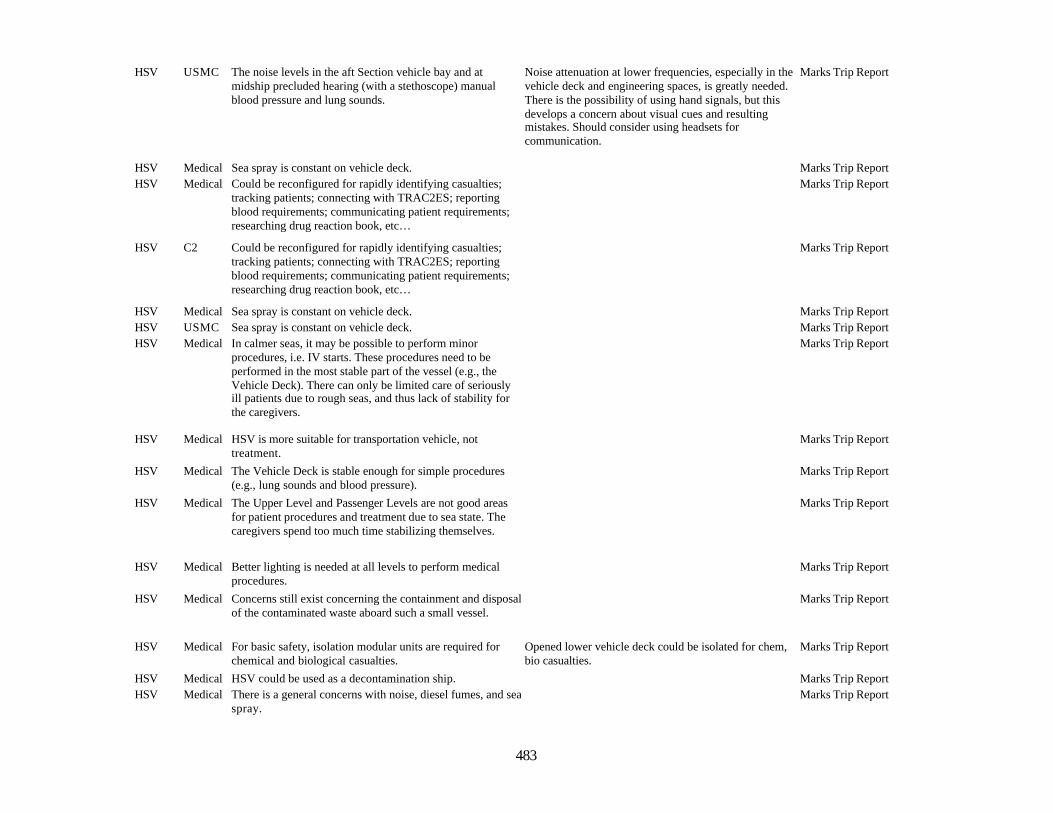
483
HSV USMC The noise levels in the aft Section vehicle bay and atmidship precluded hearing (with a stethoscope) manualblood pressure and lung sounds.
Noise attenuation at lower frequencies, especially in thevehicle deck and engineering spaces, is greatly needed.There is the possibility of using hand signals, but thisdevelops a concern about visual cues and resultingmistakes. Should consider using headsets forcommunication.
Marks Trip Report
HSV Medical Sea spray is constant on vehicle deck. Marks Trip ReportHSV Medical Could be reconfigured for rapidly identifying casualties;
tracking patients; connecting with TRAC2ES; reportingblood requirements; communicating patient requirements;researching drug reaction book, etc…
Marks Trip Report
HSV C2 Could be reconfigured for rapidly identifying casualties;tracking patients; connecting with TRAC2ES; reportingblood requirements; communicating patient requirements;researching drug reaction book, etc…
Marks Trip Report
HSV Medical Sea spray is constant on vehicle deck. Marks Trip ReportHSV USMC Sea spray is constant on vehicle deck. Marks Trip ReportHSV Medical In calmer seas, it may be possible to perform minor
procedures, i.e. IV starts. These procedures need to beperformed in the most stable part of the vessel (e.g., theVehicle Deck). There can only be limited care of seriouslyill patients due to rough seas, and thus lack of stability forthe caregivers.
Marks Trip Report
HSV Medical HSV is more suitable for transportation vehicle, nottreatment.
Marks Trip Report
HSV Medical The Vehicle Deck is stable enough for simple procedures(e.g., lung sounds and blood pressure).
Marks Trip Report
HSV Medical The Upper Level and Passenger Levels are not good areasfor patient procedures and treatment due to sea state. Thecaregivers spend too much time stabilizing themselves.
Marks Trip Report
HSV Medical Better lighting is needed at all levels to perform medicalprocedures.
Marks Trip Report
HSV Medical Concerns still exist concerning the containment and disposalof the contaminated waste aboard such a small vessel.
Marks Trip Report
HSV Medical For basic safety, isolation modular units are required forchemical and biological casualties.
Opened lower vehicle deck could be isolated for chem,bio casualties.
Marks Trip Report
HSV Medical HSV could be used as a decontamination ship. Marks Trip ReportHSV Medical There is a general concerns with noise, diesel fumes, and sea
spray.Marks Trip Report
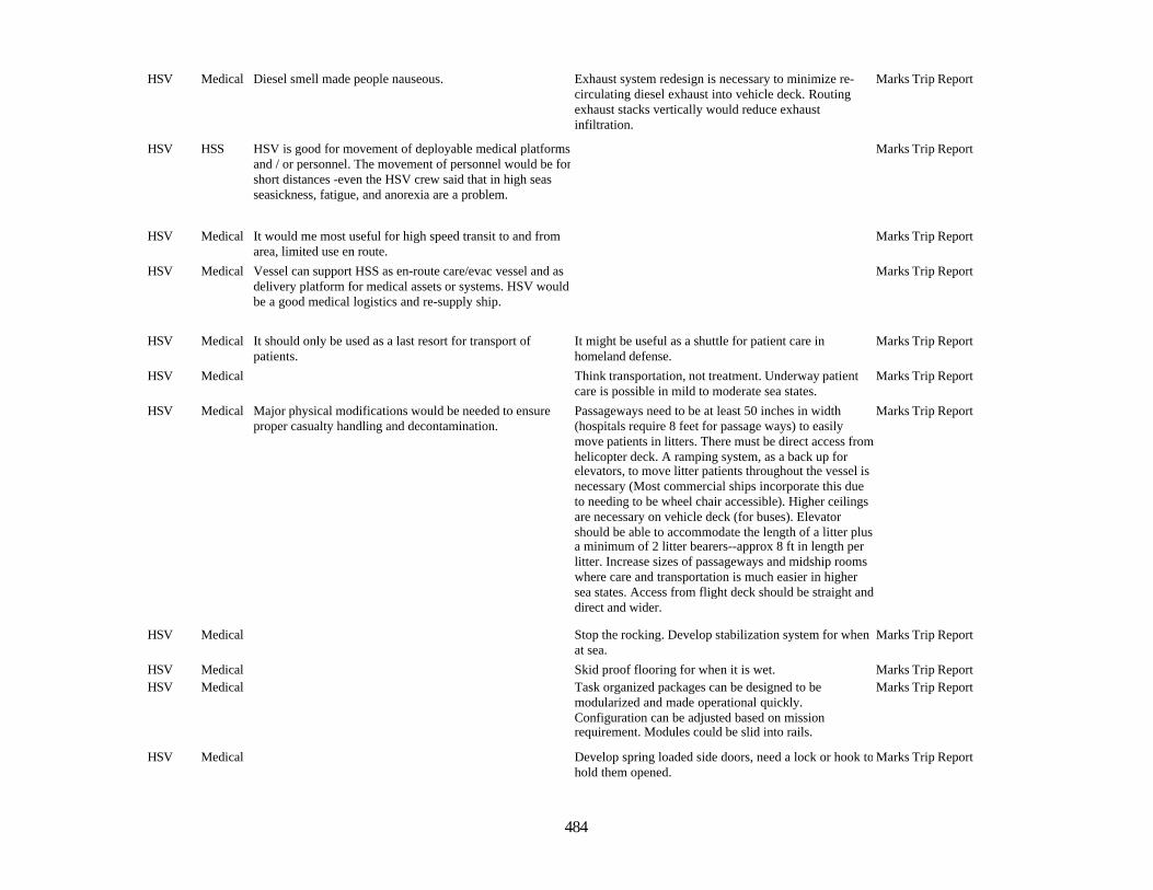
484
HSV Medical Diesel smell made people nauseous. Exhaust system redesign is necessary to minimize re-circulating diesel exhaust into vehicle deck. Routingexhaust stacks vertically would reduce exhaustinfiltration.
Marks Trip Report
HSV HSS HSV is good for movement of deployable medical platformsand / or personnel. The movement of personnel would be forshort distances -even the HSV crew said that in high seasseasickness, fatigue, and anorexia are a problem.
Marks Trip Report
HSV Medical It would me most useful for high speed transit to and fromarea, limited use en route.
Marks Trip Report
HSV Medical Vessel can support HSS as en-route care/evac vessel and asdelivery platform for medical assets or systems. HSV wouldbe a good medical logistics and re-supply ship.
Marks Trip Report
HSV Medical It should only be used as a last resort for transport ofpatients.
It might be useful as a shuttle for patient care inhomeland defense.
Marks Trip Report
HSV Medical Think transportation, not treatment. Underway patientcare is possible in mild to moderate sea states.
Marks Trip Report
HSV Medical Major physical modifications would be needed to ensureproper casualty handling and decontamination.
Passageways need to be at least 50 inches in width(hospitals require 8 feet for passage ways) to easilymove patients in litters. There must be direct access fromhelicopter deck. A ramping system, as a back up forelevators, to move litter patients throughout the vessel isnecessary (Most commercial ships incorporate this dueto needing to be wheel chair accessible). Higher ceilingsare necessary on vehicle deck (for buses). Elevatorshould be able to accommodate the length of a litter plusa minimum of 2 litter bearers--approx 8 ft in length perlitter. Increase sizes of passageways and midship roomswhere care and transportation is much easier in highersea states. Access from flight deck should be straight anddirect and wider.
Marks Trip Report
HSV Medical Stop the rocking. Develop stabilization system for whenat sea.
Marks Trip Report
HSV Medical Skid proof flooring for when it is wet. Marks Trip ReportHSV Medical Task organized packages can be designed to be
modularized and made operational quickly.Configuration can be adjusted based on missionrequirement. Modules could be slid into rails.
Marks Trip Report
HSV Medical Develop spring loaded side doors, need a lock or hook tohold them opened.
Marks Trip Report
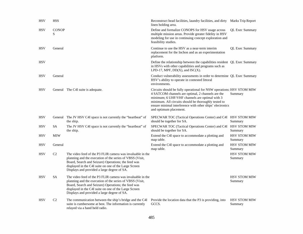
485
HSV HSS Reconstruct head facilities, laundry facilities, and dirtylinen holding area.
Marks Trip Report
HSV CONOPS
Define and formalize CONOPS for HSV usage acrossmultiple mission areas. Provide greater fidelity in HSVmodeling for use in continuing concept exploration andfeasibility studies.
QL Exec Summary
HSV General Continue to use the HSV as a near-term interimreplacement for the Inchon and as an experimentationplatform.
QL Exec Summary
HSV Define the relationship between the capabilities residentin HSVs with other capabilities and programs such asLPD-17, MPF, DD(X), and ISC(X).
QL Exec Summary
HSV General Conduct vulnerability assessments in order to determineHSV’s ability to operate in contested littoralenvironments.
QL Exec Summary
HSV General The C4I suite is adequate. Circuits should be fully operational for NSW operations:4 SATCOM channels are optimal, 2 channels are theminimum; 6 UHF/VHF channels are optimal with 3minimum. All circuits should be thoroughly tested toensure minimal interference with other ships’ electronicsand optimum placement.
HSV STOM MIWSummary
HSV General The JV HSV C4I space is not currently the “heartbeat” ofthe ship.
SPECWAR TOC (Tactical Operations Center) and C4Ishould be together for SA.
HSV STOM MIWSummary
HSV SA The JV HSV C4I space is not currently the “heartbeat” ofthe ship.
SPECWAR TOC (Tactical Operations Center) and C4Ishould be together for SA.
HSV STOM MIWSummary
HSV MIW Extend the C4I space to accommodate a plotting andmap table.
HSV STOM MIWSummary
HSV General Extend the C4I space to accommodate a plotting andmap table.
HSV STOM MIWSummary
HSV C2 The video feed of the P3 FLIR camera was invaluable in theplanning and the execution of the series of VBSS (Visit,Board, Search and Seizure) Operations; the feed wasdisplayed in the C4I suite on one of the Large ScreenDisplays and provided a large degree of SA.
HSV STOM MIWSummary
HSV SA The video feed of the P3 FLIR camera was invaluable in theplanning and the execution of the series of VBSS (Visit,Board, Search and Seizure) Operations; the feed wasdisplayed in the C4I suite on one of the Large ScreenDisplays and provided a large degree of SA.
HSV STOM MIWSummary
HSV C2 The communication between the ship’s bridge and the C4Isuite is cumbersome at best. The information is currentlyrelayed via a hand held radio.
Provide the location data that the P3 is providing, intoGCCS.
HSV STOM MIWSummary

486
HSV C2 Information from the C4I space to the bridge is unsecured.Communication from bridge to C4I space has to bereevaluated both in terms of space design, location, andarchitecture.
HSV STOM MIWSummary
HSV General Information from the C4I space to the bridge is unsecured.Communication from bridge to C4I space has to bereevaluated both in terms of space design, location, andarchitecture.
HSV STOM MIWSummary
HSV General All heads, galley, and billeting areas are too small toadequately support an entire Seal Team.
HSV STOM MIWSummary
HSV General MOGAS supply and storage is not capable of handling longduration mission requirements for NSW small boats.
HSV STOM MIWSummary
HSV General HSV method of launching and recovering small boats(RHIBs and SDV) is unsatisfactory. HSV method of usingthe hydraulic crane for the launching and recovery of smallboats is inefficient, slow, and not optimally safe.
A combination of a stern ramp and a deck cradle systemwould enhance all aspects of small boat operations.
HSV STOM MIWSummary
HSV MIW A two spot helicopter deck to accommodate thelaunching and recovery of 2 HH-60 helicopters isneeded. Additionally a helicopter maintenance bay isrecommended to allow continuous operations at sea.
HSV STOM MIWSummary
HSV MIW The communication between small boat operators and theship’s crew was accomplished by shouting, hand and armsignals, and chemical light signals.
There needs to be an efficient and reliablecommunications system in place, for the small boatoperators to coordinate with the JV HSV deck crew. Thesystem needs to be hands free and wireless.
HSV STOM MIWSummary
HSV General The communication between small boat operators and theship’s crew was accomplished by shouting, hand and armsignals, and chemical light signals.
There needs to be an efficient and reliablecommunications system in place, for the small boatoperators to coordinate with the JV HSV deck crew. Thesystem needs to be hands free and wireless.
HSV STOM MIWSummary
487
Appendix 9: Network Analysis for Joint Sea-based Command and Control; Netted Force;Bandwidth Utilization; and Naval Fires Network, Experimental (NFN (X))
Final Report Fleet Battle Experiment – Juliet
One of the key efforts in Fleet Battle Experiment, Juliet (FBE-J) was to demonstrate the capability of adeployed Naval force to engage in network-centric warfare, where planning, execution, command andcontrol can be conducted using a common data network. FBE-J saw the participation of four ships (USSCORONADO, acting as the Command and Control ship, as well as USS Benfold, USS Fitzgerald and theHigh-Speed Vessel (HSV-X1)). The ships were linked together with high-speed Ku-band satellitecommunications, providing up to 15 Mbps bandwidth for CORONADO and 1 Mbps for the other ships.
To measure network utilization and data flows, laptops were placed at six key positions (the wide-area-network (WAN) choke points for CORONADO, BENFOLD, FITZGERALD and HSV-X1 satellite links,as well as the choke points inside the Defense Research and Engineering Network (DREN) at FleetCombat Training Center, Pacific (FCTCPAC) in San Diego, and the FBE-J local area network at NavalAir Warfare Center, China Lake, California. Each laptop used Network Associates’ Sniffer Basic packetcapture software, with the exception of BENFOLD, which used Windump, a Windows-based, open-source packet capture program. Data capture generally began at 0600 local (Pacific Daylight Time) andended at 1800 local. Due to the considerable volume of data collected, packet capture was limited to thefist 128 bytes of each packet, and external hard disk drives of 80 to 160 gigabytes capacity were attachedto the laptops. Data was reduced using Perl scripts developed at Naval Surface Warfare Center, Corona,into comma-separated variable (CSV) files for importation into Microsoft Excel.
This report uses that data to gain insight on four initiatives important to FBE-J: Joint Sea-basedCommand and Control; Netted Force; the Naval Fires Network, Experimental; and BandwidthUtilization.
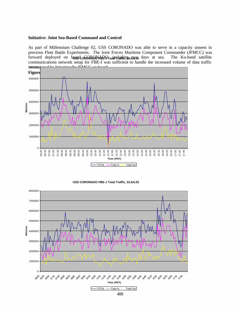
488
Initiative: Joint Sea-Based Command and Control
As part of Millennium Challenge 02, USS CORONADO was able to serve in a capacity unseen inprevious Fleet Battle Experiments. The Joint Forces Maritime Component Commander (JFMCC) wasforward deployed on board CORONADO, including two days at sea. The Ku-band satellitecommunications network setup for FBE-J was sufficient to handle the increased volume of data trafficnecessitated by bringing the JFMCC on board.Figure A9-1. USS Coronado Total Traffic, 30 July 02
USS CORONADO FBE-J Total Traffic, 30JUL02
0
1000000
2000000
3000000
4000000
5000000
6000000
7000000
06:2
0
06:4
0
07:0
0
07:2
0
07:4
0
08:0
0
08:2
0
08:4
0
09:0
0
09:2
0
09:4
0
10:0
0
10:2
0
10:4
0
11:0
0
11:2
0
11:4
0
12:0
0
12:2
0
12:4
0
13:0
0
13:2
0
13:4
0
14:0
0
14:2
0
14:4
0
15:0
0
15:2
0
15:4
0
16:0
0
16:2
0
16:4
0
17:0
0
17:2
0
17:4
0
Time (PDT)
Bit
s/se
c
TOTAL Total In Total Out
USS CORONADO FBE-J Total Traffic, 31JUL02
0
1000000
2000000
3000000
4000000
5000000
6000000
7000000
8000000
06:00
06:25
06:50
07:15
07:40
08:05
08:30
08:55
09:20
09:45
10:10
10:35
11:00
11:25
11:50
12:15
12:40
13:05
13:30
13:55
14:20
14:45
15:10
15:35
16:00
16:25
16:50
17:15
17:40
Time (PDT)
Bit
s/se
c
TOTAL Total In Total Out
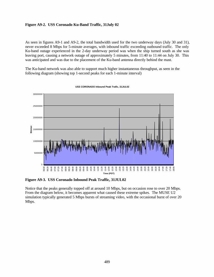
489
Figure A9-2. USS Coronado Ku-Band Traffic, 31July 02
As seen in figures A9-1 and A9-2, the total bandwidth used for the two underway days (July 30 and 31),never exceeded 8 Mbps for 5-minute averages, with inbound traffic exceeding outbound traffic. The onlyKu-band outage experienced in the 2-day underway period was when the ship turned south as she wasleaving port, causing a network outage of approximately 5 minutes, from 11:40 to 11:44 on July 30. Thiswas anticipated and was due to the placement of the Ku-band antenna directly behind the mast.
The Ku-band network was also able to support much higher instantaneous throughput, as seen in thefollowing diagram (showing top 1-second peaks for each 1-minute interval)
Figure A9-3. USS Coronado Inbound Peak Traffic, 31JUL02
Notice that the peaks generally topped off at around 10 Mbps, but on occasion rose to over 20 Mbps.From the diagram below, it becomes apparent what caused these extreme spikes. The MUSE U2simulation typically generated 5 Mbps bursts of streaming video, with the occasional burst of over 20Mbps.
USS CORONADO Inbound Peak Trafic, 31JUL02
0
5000000
10000000
15000000
20000000
25000000
30000000
06:0
0
06:2
0
06:4
0
07:0
0
07:2
0
07:4
0
08:0
0
08:2
0
08:4
0
09:0
0
09:2
0
09:4
0
10:0
0
10:2
0
10:4
0
11:0
0
11:2
0
11:4
0
12:0
0
12:2
0
12:4
0
13:0
0
13:2
0
13:4
0
14:0
0
14:2
0
14:4
0
15:0
0
15:2
0
15:4
0
16:0
0
16:2
0
16:4
0
17:0
0
17:2
0
17:4
0
18:0
0Time (PDT)
Bits
/sec
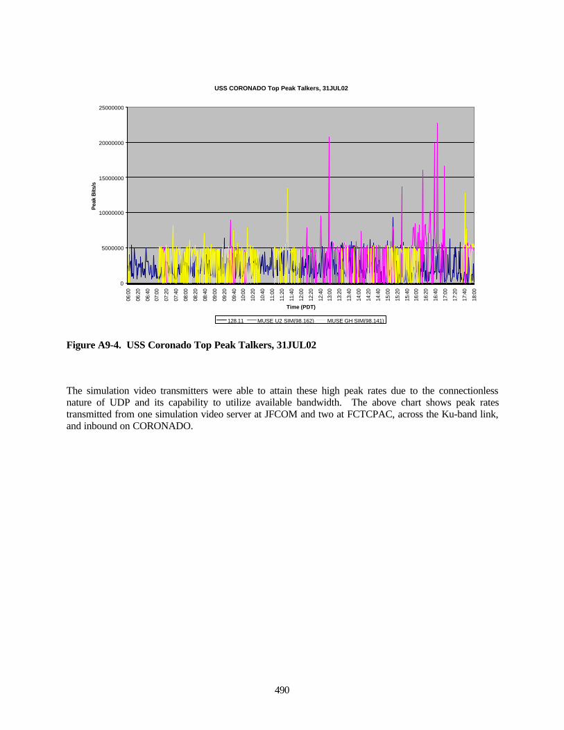
490
Figure A9-4. USS Coronado Top Peak Talkers, 31JUL02
The simulation video transmitters were able to attain these high peak rates due to the connectionlessnature of UDP and its capability to utilize available bandwidth. The above chart shows peak ratestransmitted from one simulation video server at JFCOM and two at FCTCPAC, across the Ku-band link,and inbound on CORONADO.
USS CORONADO Top Peak Talkers, 31JUL02
0
5000000
10000000
15000000
20000000
25000000
06:0
0
06:2
0
06:4
0
07:0
0
07:2
0
07:4
0
08:0
0
08:2
0
08:4
0
09:0
0
09:2
0
09:4
0
10:0
0
10:2
0
10:4
0
11:0
0
11:2
0
11:4
0
12:0
0
12:2
0
12:4
0
13:0
0
13:2
0
13:4
0
14:0
0
14:2
0
14:4
0
15:0
0
15:2
0
15:4
0
16:0
0
16:2
0
16:4
0
17:0
0
17:2
0
17:4
0
18:0
0
Time (PDT)
Pea
k B
its/s
128.11 MUSE U2 SIM(98.162) MUSE GH SIM(98.141)
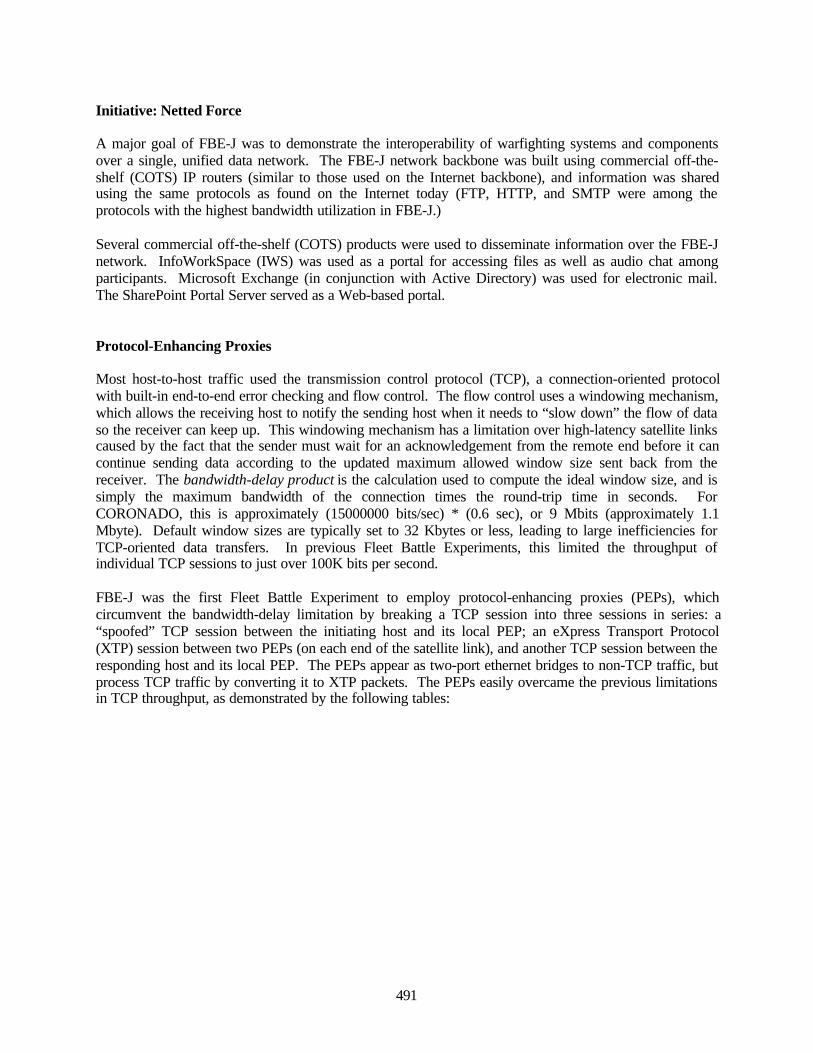
491
Initiative: Netted Force
A major goal of FBE-J was to demonstrate the interoperability of warfighting systems and componentsover a single, unified data network. The FBE-J network backbone was built using commercial off-the-shelf (COTS) IP routers (similar to those used on the Internet backbone), and information was sharedusing the same protocols as found on the Internet today (FTP, HTTP, and SMTP were among theprotocols with the highest bandwidth utilization in FBE-J.)
Several commercial off-the-shelf (COTS) products were used to disseminate information over the FBE-Jnetwork. InfoWorkSpace (IWS) was used as a portal for accessing files as well as audio chat amongparticipants. Microsoft Exchange (in conjunction with Active Directory) was used for electronic mail.The SharePoint Portal Server served as a Web-based portal.
Protocol-Enhancing Proxies
Most host-to-host traffic used the transmission control protocol (TCP), a connection-oriented protocolwith built-in end-to-end error checking and flow control. The flow control uses a windowing mechanism,which allows the receiving host to notify the sending host when it needs to “slow down” the flow of dataso the receiver can keep up. This windowing mechanism has a limitation over high-latency satellite linkscaused by the fact that the sender must wait for an acknowledgement from the remote end before it cancontinue sending data according to the updated maximum allowed window size sent back from thereceiver. The bandwidth-delay product is the calculation used to compute the ideal window size, and issimply the maximum bandwidth of the connection times the round-trip time in seconds. ForCORONADO, this is approximately (15000000 bits/sec) * (0.6 sec), or 9 Mbits (approximately 1.1Mbyte). Default window sizes are typically set to 32 Kbytes or less, leading to large inefficiencies forTCP-oriented data transfers. In previous Fleet Battle Experiments, this limited the throughput ofindividual TCP sessions to just over 100K bits per second.
FBE-J was the first Fleet Battle Experiment to employ protocol-enhancing proxies (PEPs), whichcircumvent the bandwidth-delay limitation by breaking a TCP session into three sessions in series: a“spoofed” TCP session between the initiating host and its local PEP; an eXpress Transport Protocol(XTP) session between two PEPs (on each end of the satellite link), and another TCP session between theresponding host and its local PEP. The PEPs appear as two-port ethernet bridges to non-TCP traffic, butprocess TCP traffic by converting it to XTP packets. The PEPs easily overcame the previous limitationsin TCP throughput, as demonstrated by the following tables:
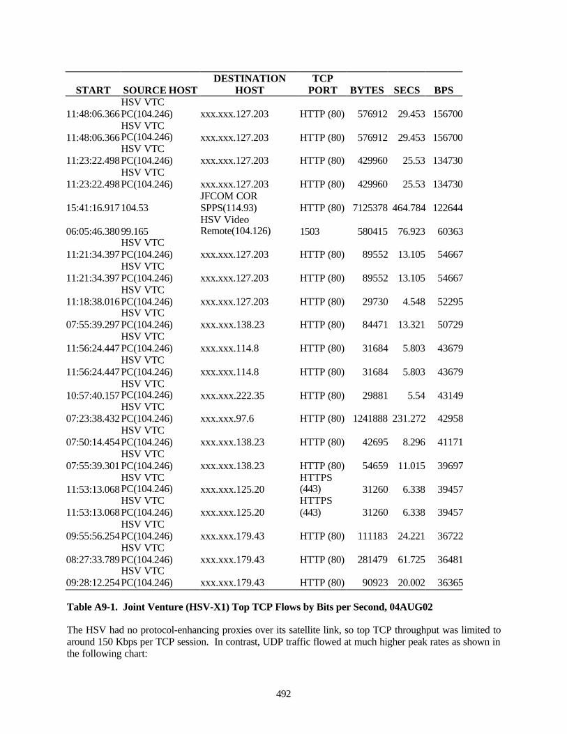
492
START SOURCE HOSTDESTINATION
HOSTTCP
PORT BYTES SECS BPS
11:48:06.366HSV VTCPC(104.246) xxx.xxx.127.203 HTTP (80) 576912 29.453 156700
11:48:06.366HSV VTCPC(104.246) xxx.xxx.127.203 HTTP (80) 576912 29.453 156700
11:23:22.498HSV VTCPC(104.246) xxx.xxx.127.203 HTTP (80) 429960 25.53 134730
11:23:22.498HSV VTCPC(104.246) xxx.xxx.127.203 HTTP (80) 429960 25.53 134730
15:41:16.917104.53JFCOM CORSPPS(114.93) HTTP (80) 7125378 464.784 122644
06:05:46.38099.165HSV VideoRemote(104.126) 1503 580415 76.923 60363
11:21:34.397HSV VTCPC(104.246) xxx.xxx.127.203 HTTP (80) 89552 13.105 54667
11:21:34.397HSV VTCPC(104.246) xxx.xxx.127.203 HTTP (80) 89552 13.105 54667
11:18:38.016HSV VTCPC(104.246) xxx.xxx.127.203 HTTP (80) 29730 4.548 52295
07:55:39.297HSV VTCPC(104.246) xxx.xxx.138.23 HTTP (80) 84471 13.321 50729
11:56:24.447HSV VTCPC(104.246) xxx.xxx.114.8 HTTP (80) 31684 5.803 43679
11:56:24.447HSV VTCPC(104.246) xxx.xxx.114.8 HTTP (80) 31684 5.803 43679
10:57:40.157HSV VTCPC(104.246) xxx.xxx.222.35 HTTP (80) 29881 5.54 43149
07:23:38.432HSV VTCPC(104.246) xxx.xxx.97.6 HTTP (80) 1241888 231.272 42958
07:50:14.454HSV VTCPC(104.246) xxx.xxx.138.23 HTTP (80) 42695 8.296 41171
07:55:39.301HSV VTCPC(104.246) xxx.xxx.138.23 HTTP (80) 54659 11.015 39697
11:53:13.068HSV VTCPC(104.246) xxx.xxx.125.20
HTTPS(443) 31260 6.338 39457
11:53:13.068HSV VTCPC(104.246) xxx.xxx.125.20
HTTPS(443) 31260 6.338 39457
09:55:56.254HSV VTCPC(104.246) xxx.xxx.179.43 HTTP (80) 111183 24.221 36722
08:27:33.789HSV VTCPC(104.246) xxx.xxx.179.43 HTTP (80) 281479 61.725 36481
09:28:12.254HSV VTCPC(104.246) xxx.xxx.179.43 HTTP (80) 90923 20.002 36365
Table A9-1. Joint Venture (HSV-X1) Top TCP Flows by Bits per Second, 04AUG02
The HSV had no protocol-enhancing proxies over its satellite link, so top TCP throughput was limited toaround 150 Kbps per TCP session. In contrast, UDP traffic flowed at much higher peak rates as shown inthe following chart:
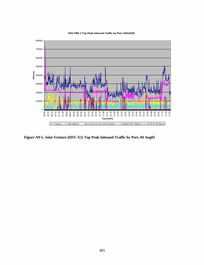
493
Figure A9-5. Joint Venture (HSV-X1) Top Peak Inbound Traffic by Port, 04 Aug02
HSV FBE-J Top Peak Inbound Traffic by Port, 04AUG02
0
100000
200000
300000
400000
500000
600000
700000
800000
06:0
0
06:2
1
06:4
2
07:0
3
07:2
4
07:4
5
08:0
6
08:2
7
08:4
8
09:0
9
09:3
0
09:5
1
10:1
2
10:3
3
10:5
4
11:1
5
11:3
6
11:5
7
12:1
8
12:3
9
13:0
0
13:2
1
13:4
2
14:0
3
14:2
4
14:4
5
15:0
6
15:2
7
15:4
8
16:0
9
16:3
0
16:5
1
17:1
2
17:3
3
17:5
4
Time (PDT)
Bit
s/se
c
Total In UDP 4000 In GCCS-M 3.X CST (TCP 9119) In C4IGW (TCP 2020) In HTTP (TCP 80) In
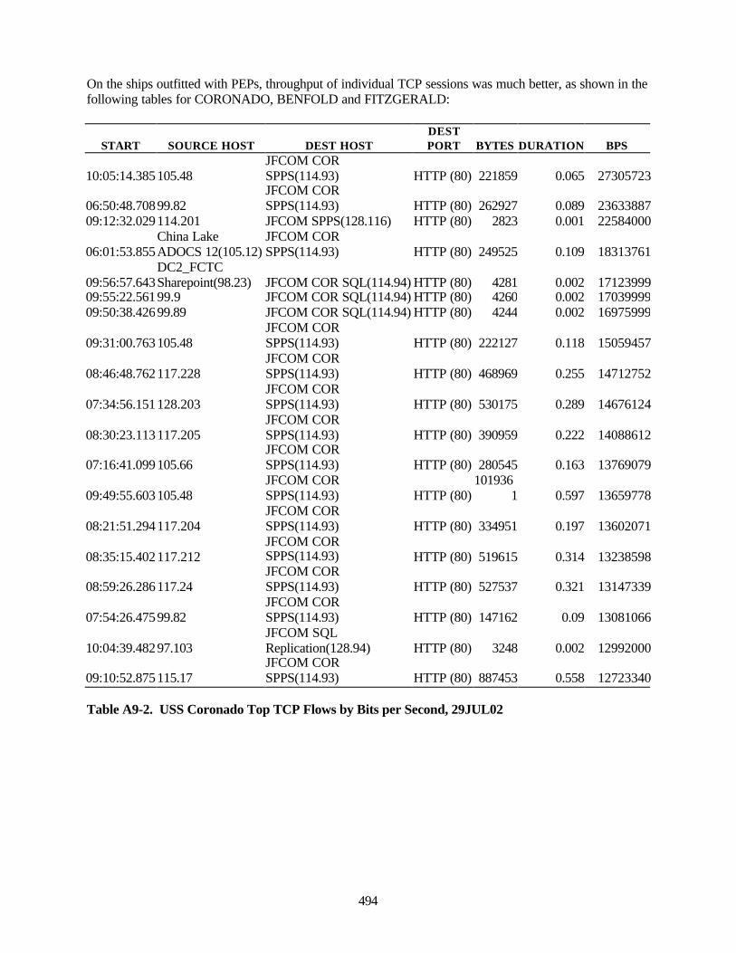
494
On the ships outfitted with PEPs, throughput of individual TCP sessions was much better, as shown in thefollowing tables for CORONADO, BENFOLD and FITZGERALD:
START SOURCE HOST DEST HOSTDESTPORT BYTES DURATION BPS
10:05:14.385105.48JFCOM CORSPPS(114.93) HTTP (80) 221859 0.065 27305723
06:50:48.70899.82JFCOM CORSPPS(114.93) HTTP (80) 262927 0.089 23633887
09:12:32.029114.201 JFCOM SPPS(128.116) HTTP (80) 2823 0.001 22584000
06:01:53.855China LakeADOCS 12(105.12)
JFCOM CORSPPS(114.93) HTTP (80) 249525 0.109 18313761
09:56:57.643DC2_FCTCSharepoint(98.23) JFCOM COR SQL(114.94) HTTP (80) 4281 0.002 17123999
09:55:22.56199.9 JFCOM COR SQL(114.94) HTTP (80) 4260 0.002 1703999909:50:38.42699.89 JFCOM COR SQL(114.94) HTTP (80) 4244 0.002 16975999
09:31:00.763105.48JFCOM CORSPPS(114.93) HTTP (80) 222127 0.118 15059457
08:46:48.762117.228JFCOM CORSPPS(114.93) HTTP (80) 468969 0.255 14712752
07:34:56.151128.203JFCOM CORSPPS(114.93) HTTP (80) 530175 0.289 14676124
08:30:23.113117.205JFCOM CORSPPS(114.93) HTTP (80) 390959 0.222 14088612
07:16:41.099105.66JFCOM CORSPPS(114.93) HTTP (80) 280545 0.163 13769079
09:49:55.603105.48JFCOM CORSPPS(114.93) HTTP (80)
1019361 0.597 13659778
08:21:51.294117.204JFCOM CORSPPS(114.93) HTTP (80) 334951 0.197 13602071
08:35:15.402117.212JFCOM CORSPPS(114.93) HTTP (80) 519615 0.314 13238598
08:59:26.286117.24JFCOM CORSPPS(114.93) HTTP (80) 527537 0.321 13147339
07:54:26.47599.82JFCOM CORSPPS(114.93) HTTP (80) 147162 0.09 13081066
10:04:39.48297.103JFCOM SQLReplication(128.94) HTTP (80) 3248 0.002 12992000
09:10:52.875115.17JFCOM CORSPPS(114.93) HTTP (80) 887453 0.558 12723340
Table A9-2. USS Coronado Top TCP Flows by Bits per Second, 29JUL02
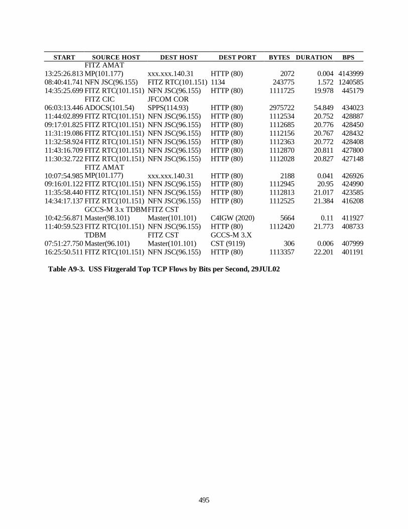
495
START SOURCE HOST DEST HOST DEST PORT BYTES DURATION BPS
13:25:26.813FITZ AMATMP(101.177) xxx.xxx.140.31 HTTP (80) 2072 0.004 4143999
08:40:41.741 NFN JSC(96.155) FITZ RTC(101.151) 1134 243775 1.572 124058514:35:25.699 FITZ RTC(101.151) NFN JSC(96.155) HTTP (80) 1111725 19.978 445179
06:03:13.446FITZ CICADOCS(101.54)
JFCOM CORSPPS(114.93) HTTP (80) 2975722 54.849 434023
11:44:02.899 FITZ RTC(101.151) NFN JSC(96.155) HTTP (80) 1112534 20.752 42888709:17:01.825 FITZ RTC(101.151) NFN JSC(96.155) HTTP (80) 1112685 20.776 42845011:31:19.086 FITZ RTC(101.151) NFN JSC(96.155) HTTP (80) 1112156 20.767 42843211:32:58.924 FITZ RTC(101.151) NFN JSC(96.155) HTTP (80) 1112363 20.772 42840811:43:16.709 FITZ RTC(101.151) NFN JSC(96.155) HTTP (80) 1112870 20.811 42780011:30:32.722 FITZ RTC(101.151) NFN JSC(96.155) HTTP (80) 1112028 20.827 427148
10:07:54.985FITZ AMATMP(101.177) xxx.xxx.140.31 HTTP (80) 2188 0.041 426926
09:16:01.122 FITZ RTC(101.151) NFN JSC(96.155) HTTP (80) 1112945 20.95 42499011:35:58.440 FITZ RTC(101.151) NFN JSC(96.155) HTTP (80) 1112813 21.017 42358514:34:17.137 FITZ RTC(101.151) NFN JSC(96.155) HTTP (80) 1112525 21.384 416208
10:42:56.871GCCS-M 3.x TDBMMaster(98.101)
FITZ CSTMaster(101.101) C4IGW (2020) 5664 0.11 411927
11:40:59.523 FITZ RTC(101.151) NFN JSC(96.155) HTTP (80) 1112420 21.773 408733
07:51:27.750TDBMMaster(96.101)
FITZ CSTMaster(101.101)
GCCS-M 3.XCST (9119) 306 0.006 407999
16:25:50.511 FITZ RTC(101.151) NFN JSC(96.155) HTTP (80) 1113357 22.201 401191
Table A9-3. USS Fitzgerald Top TCP Flows by Bits per Second, 29JUL02
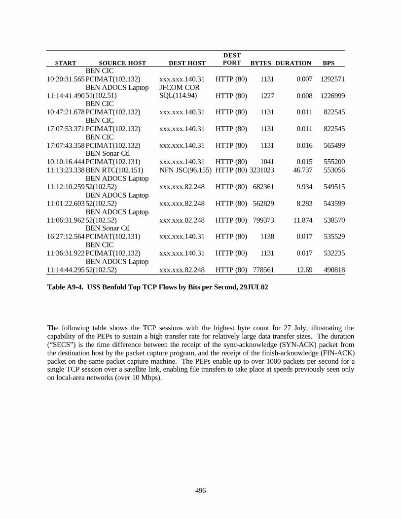
496
START SOURCE HOST DEST HOSTDESTPORT BYTES DURATION BPS
10:20:31.565BEN CICPCIMAT(102.132) xxx.xxx.140.31 HTTP (80) 1131 0.007 1292571
11:14:41.490BEN ADOCS Laptop51(102.51)
JFCOM CORSQL(114.94) HTTP (80) 1227 0.008 1226999
10:47:21.678BEN CICPCIMAT(102.132) xxx.xxx.140.31 HTTP (80) 1131 0.011 822545
17:07:53.371BEN CICPCIMAT(102.132) xxx.xxx.140.31 HTTP (80) 1131 0.011 822545
17:07:43.358BEN CICPCIMAT(102.132) xxx.xxx.140.31 HTTP (80) 1131 0.016 565499
10:10:16.444BEN Sonar CtlPCIMAT(102.131) xxx.xxx.140.31 HTTP (80) 1041 0.015 555200
11:13:23.338BEN RTC(102.151) NFN JSC(96.155) HTTP (80) 3231023 46.737 553056
11:12:10.259BEN ADOCS Laptop52(102.52) xxx.xxx.82.248 HTTP (80) 682361 9.934 549515
11:01:22.603BEN ADOCS Laptop52(102.52) xxx.xxx.82.248 HTTP (80) 562829 8.283 543599
11:06:31.962BEN ADOCS Laptop52(102.52) xxx.xxx.82.248 HTTP (80) 799373 11.874 538570
16:27:12.564BEN Sonar CtlPCIMAT(102.131) xxx.xxx.140.31 HTTP (80) 1138 0.017 535529
11:36:31.922BEN CICPCIMAT(102.132) xxx.xxx.140.31 HTTP (80) 1131 0.017 532235
11:14:44.295BEN ADOCS Laptop52(102.52) xxx.xxx.82.248 HTTP (80) 778561 12.69 490818
Table A9-4. USS Benfold Top TCP Flows by Bits per Second, 29JUL02
The following table shows the TCP sessions with the highest byte count for 27 July, illustrating thecapability of the PEPs to sustain a high transfer rate for relatively large data transfer sizes. The duration(“SECS”) is the time difference between the receipt of the sync-acknowledge (SYN-ACK) packet fromthe destination host by the packet capture program, and the receipt of the finish-acknowledge (FIN-ACK)packet on the same packet capture machine. The PEPs enable up to over 1000 packets per second for asingle TCP session over a satellite link, enabling file transfers to take place at speeds previously seen onlyon local-area networks (over 10 Mbps).
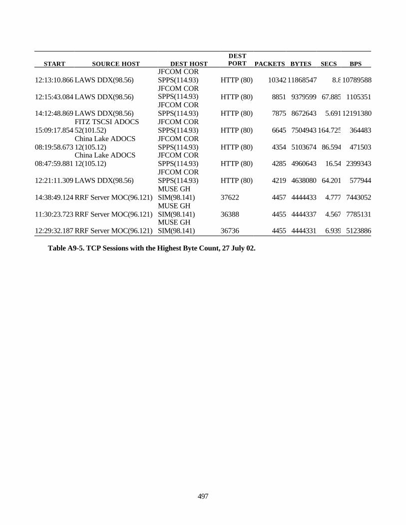
497
START SOURCE HOST DEST HOSTDESTPORT PACKETS BYTES SECS BPS
12:13:10.866 LAWS DDX(98.56)JFCOM CORSPPS(114.93) HTTP (80) 10342 11868547 8.810789588
12:15:43.084 LAWS DDX(98.56)JFCOM CORSPPS(114.93) HTTP (80) 8851 9379599 67.885 1105351
14:12:48.869 LAWS DDX(98.56)JFCOM CORSPPS(114.93) HTTP (80) 7875 8672643 5.69112191380
15:09:17.854FITZ TSCSI ADOCS52(101.52)
JFCOM CORSPPS(114.93) HTTP (80) 6645 7504943 164.725 364483
08:19:58.673China Lake ADOCS12(105.12)
JFCOM CORSPPS(114.93) HTTP (80) 4354 5103674 86.594 471503
08:47:59.881China Lake ADOCS12(105.12)
JFCOM CORSPPS(114.93) HTTP (80) 4285 4960643 16.54 2399343
12:21:11.309 LAWS DDX(98.56)JFCOM CORSPPS(114.93) HTTP (80) 4219 4638080 64.201 577944
14:38:49.124 RRF Server MOC(96.121)MUSE GHSIM(98.141) 37622 4457 4444433 4.777 7443052
11:30:23.723 RRF Server MOC(96.121)MUSE GHSIM(98.141) 36388 4455 4444337 4.567 7785131
12:29:32.187 RRF Server MOC(96.121)MUSE GHSIM(98.141) 36736 4455 4444331 6.939 5123886
Table A9-5. TCP Sessions with the Highest Byte Count, 27 July 02.
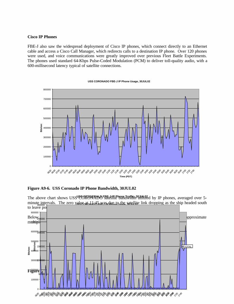
498
Cisco IP Phones
FBE-J also saw the widespread deployment of Cisco IP phones, which connect directly to an Ethernetcable and access a Cisco Call Manager, which redirects calls to a destination IP phone. Over 120 phoneswere used, and voice communications were greatly improved over previous Fleet Battle Experiments.The phones used standard 64-Kbps Pulse-Coded Modulation (PCM) to deliver toll-quality audio, with a600-millisecond latency typical of satellite connections.
Figure A9-6. USS Coronado IP Phone Bandwidth, 30JUL02
The above chart shows USS CORONADO satellite bandwidth utilized by IP phones, averaged over 5-minute intervals. The zero value at 11:45 was due to the satellite link dropping as the ship headed southto leave port.
Below is the same data for FITZGERALD on July 30. Notice that most of the peaks are approximatemultiples of 64 Kbps.
Figure A9-7. USS Coronado IP Phone Traffic, 30 July 02
USS CORONADO FBE-J IP Phone Usage, 30JUL02
0
100000
200000
300000
400000
500000
600000
700000
800000
06:20
06:40
07:00
07:20
07:40
08:00
08:20
08:40
09:00
09:20
09:40
10:00
10:20
10:40
11:00
11:20
11:40
12:00
12:20
12:40
13:00
13:20
13:40
14:00
14:20
14:40
15:00
15:20
15:40
16:00
16:20
16:40
17:00
17:20
17:40
Bits
/sec
USS FITZGERALD FBE-J IP Phone Traffic, 30JUL02
0
50000
100000
150000
200000
250000
300000
06:00
06:25
06:50
07:15
07:40
08:05
08:30
08:55
09:20
09:45
10:10
10:35
11:00
11:25
11:50
12:15
12:40
13:05
13:30
13:55
14:20
14:45
15:10
15:35
16:00
16:25
16:50
17:15
17:40
Bit
s/se
c
TOTAL
USS CORONADO FBE-J IP Phone Usage, 30JUL02
0
100000
200000
300000
400000
500000
600000
700000
800000
06:20
06:40
07:00
07:20
07:40
08:00
08:20
08:40
09:00
09:20
09:40
10:00
10:20
10:40
11:00
11:20
11:40
12:00
12:20
12:40
13:00
13:20
13:40
14:00
14:20
14:40
15:00
15:20
15:40
16:00
16:20
16:40
17:00
17:20
17:40
Time (PDT)
Bits
/sec
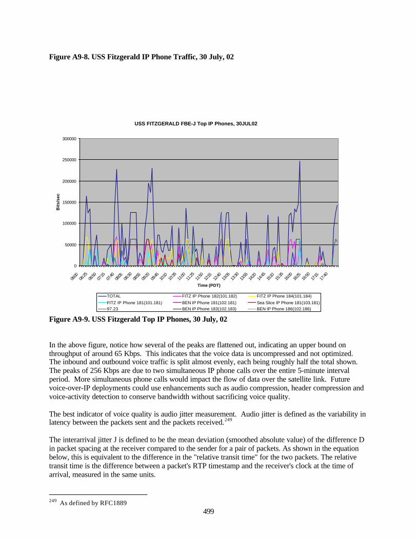
499
Figure A9-8. USS Fitzgerald IP Phone Traffic, 30 July, 02
Figure A9-9. USS Fitzgerald Top IP Phones, 30 July, 02
In the above figure, notice how several of the peaks are flattened out, indicating an upper bound onthroughput of around 65 Kbps. This indicates that the voice data is uncompressed and not optimized.The inbound and outbound voice traffic is split almost evenly, each being roughly half the total shown.The peaks of 256 Kbps are due to two simultaneous IP phone calls over the entire 5-minute intervalperiod. More simultaneous phone calls would impact the flow of data over the satellite link. Futurevoice-over-IP deployments could use enhancements such as audio compression, header compression andvoice-activity detection to conserve bandwidth without sacrificing voice quality.
The best indicator of voice quality is audio jitter measurement. Audio jitter is defined as the variability inlatency between the packets sent and the packets received.249
The interarrival jitter J is defined to be the mean deviation (smoothed absolute value) of the difference Din packet spacing at the receiver compared to the sender for a pair of packets. As shown in the equationbelow, this is equivalent to the difference in the "relative transit time" for the two packets. The relativetransit time is the difference between a packet's RTP timestamp and the receiver's clock at the time ofarrival, measured in the same units.
249 As defined by RFC1889
USS FITZGERALD FBE-J Top IP Phones, 30JUL02
0
50000
100000
150000
200000
250000
300000
06:00
06:25
06:50
07:15
07:40
08:05
08:30
08:55
09:20
09:45
10:10
10:35
11:00
11:25
11:50
12:15
12:40
13:05
13:30
13:55
14:20
14:45
15:10
15:35
16:00
16:25
16:50
17:15
17:40
Time (PDT)
Bit
s/se
c
TOTAL FITZ IP Phone 182(101.182) FITZ IP Phone 184(101.184)
FITZ IP Phone 181(101.181) BEN IP Phone 181(102.181) Sea Slice IP Phone 181(103.181)97.23 BEN IP Phone 183(102.183) BEN IP Phone 186(102.186)
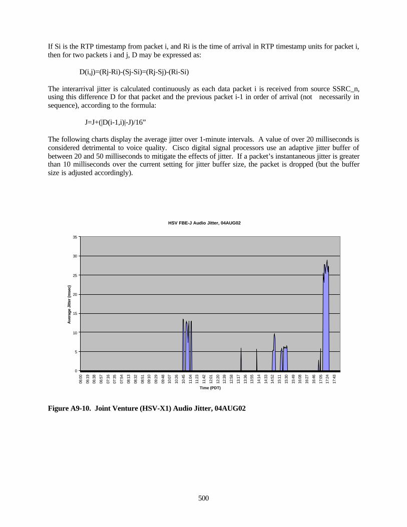
500
If Si is the RTP timestamp from packet i, and Ri is the time of arrival in RTP timestamp units for packet i,then for two packets i and j, D may be expressed as:
D(i,j)=(Rj-Ri)-(Sj-Si)=(Rj-Sj)-(Ri-Si)
The interarrival jitter is calculated continuously as each data packet i is received from source SSRC_n,using this difference D for that packet and the previous packet i-1 in order of arrival (not necessarily insequence), according to the formula:
J=J+(|D(i-1,i)|-J)/16”
The following charts display the average jitter over 1-minute intervals. A value of over 20 milliseconds isconsidered detrimental to voice quality. Cisco digital signal processors use an adaptive jitter buffer ofbetween 20 and 50 milliseconds to mitigate the effects of jitter. If a packet’s instantaneous jitter is greaterthan 10 milliseconds over the current setting for jitter buffer size, the packet is dropped (but the buffersize is adjusted accordingly).
Figure A9-10. Joint Venture (HSV-X1) Audio Jitter, 04AUG02
HSV FBE-J Audio Jitter, 04AUG02
0
5
10
15
20
25
30
35
06:0
0
06:1
9
06:3
8
06:5
7
07:1
6
07:3
5
07:5
4
08:1
3
08:3
2
08:5
1
09:1
0
09:2
9
09:4
8
10:0
7
10:2
6
10:4
5
11:0
4
11:2
3
11:4
2
12:0
1
12:2
0
12:3
9
12:5
8
13:1
7
13:3
6
13:5
5
14:1
4
14:3
3
14:5
2
15:1
1
15:3
0
15:4
9
16:0
8
16:2
7
16:4
6
17:0
5
17:2
4
17:4
3
Time (PDT)
Ave
rage
Jitt
er (m
sec)
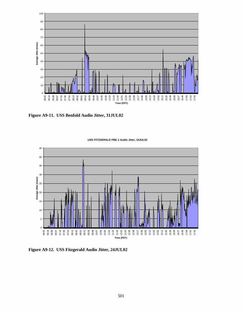
501
Figure A9-11. USS Benfold Audio Jitter, 31JUL02
Figure A9-12. USS Fitzgerald Audio Jitter, 24JUL02
USS FITZGERALD FBE-J Audio Jitter, 24JUL02
0
5
10
15
20
25
30
35
40
45
06:0
0
06:1
9
06:3
8
06:5
7
07:1
6
07:3
5
07:5
4
08:1
3
08:3
2
08:5
1
09:1
0
09:2
9
09:4
8
10:0
7
10:2
6
10:4
5
11:0
4
11:2
3
11:4
2
12:0
1
12:2
0
12:3
9
12:5
8
13:1
7
13:3
6
13:5
5
14:1
4
14:3
3
14:5
2
15:1
1
15:3
0
15:4
9
16:0
8
16:2
7
16:4
6
17:0
5
17:2
4
17:4
3
Time (PDT)
Ave
rage
Jitt
er (m
sec)
0
10
20
30
40
50
60
70
80
90
100
06:0
0
06:1
9
06:3
8
06:5
7
07:1
6
07:3
5
07:5
4
08:1
3
08:3
2
08:5
1
09:1
0
09:2
9
09:4
8
10:0
7
10:2
6
10:4
5
11:0
4
11:2
3
11:4
2
12:0
1
12:2
0
12:3
9
12:5
8
13:1
7
13:3
6
13:5
5
14:1
4
14:3
3
14:5
2
15:1
1
15:3
0
15:4
9
16:0
8
16:2
7
16:4
6
17:0
5
17:2
4
17:4
3
Time (PDT)
Ave
rage
Jitt
er (m
sec)
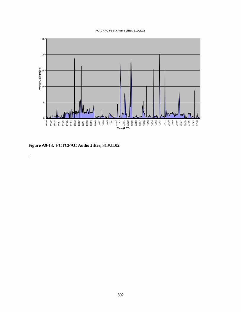
502
Figure A9-13. FCTCPAC Audio Jitter, 31JUL02
.
FCTCPAC FBE-J Audio Jitter, 31JUL02
0
5
10
15
20
25
06:0
0
06:1
9
06:3
8
06:5
7
07:1
6
07:3
5
07:5
4
08:1
3
08:3
2
08:5
1
09:1
0
09:2
9
09:4
8
10:0
7
10:2
6
10:4
5
11:0
4
11:2
3
11:4
2
12:0
1
12:2
0
12:3
9
12:5
8
13:1
7
13:3
6
13:5
5
14:1
4
14:3
3
14:5
2
15:1
1
15:3
0
15:4
9
16:0
8
16:2
7
16:4
6
17:0
5
17:2
4
17:4
3
Time (PDT)
Ave
rage
Jitt
er (m
sec)
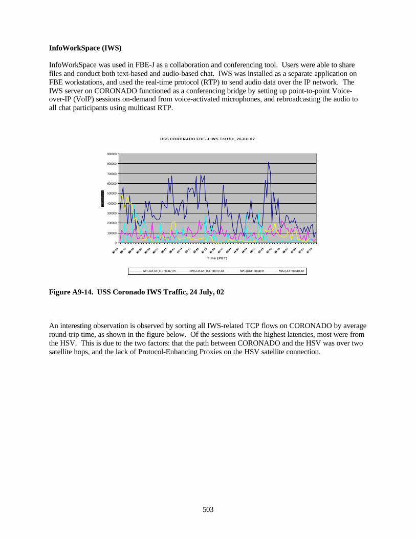
503
InfoWorkSpace (IWS)
InfoWorkSpace was used in FBE-J as a collaboration and conferencing tool. Users were able to sharefiles and conduct both text-based and audio-based chat. IWS was installed as a separate application onFBE workstations, and used the real-time protocol (RTP) to send audio data over the IP network. TheIWS server on CORONADO functioned as a conferencing bridge by setting up point-to-point Voice-over-IP (VoIP) sessions on-demand from voice-activated microphones, and rebroadcasting the audio toall chat participants using multicast RTP.
U S S C O R O N A D O F B E - J I W S T r a f f i c , 2 6 J U L 0 2
0
100000
200000
300000
400000
500000
600000
700000
800000
900000
T i m e ( P D T )
IWS DATA (TCP 8087) In IWS DATA (TCP 8087) Out IWS (UDP 8084) In IWS (UDP 8084) Out
Figure A9-14. USS Coronado IWS Traffic, 24 July, 02
An interesting observation is observed by sorting all IWS-related TCP flows on CORONADO by averageround-trip time, as shown in the figure below. Of the sessions with the highest latencies, most were fromthe HSV. This is due to the two factors: that the path between CORONADO and the HSV was over twosatellite hops, and the lack of Protocol-Enhancing Proxies on the HSV satellite connection.
c c c
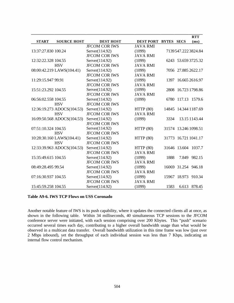
504
START SOURCE HOST DEST HOST DEST PORT BYTES SECSRTT(ms)
13:37:27.830 100.24JFCOM COR IWSServer(114.92)
JAVA RMI(1099) 7139547.222 3824.84
12:32:22.328 104.55JFCOM COR IWSServer(114.92)
JAVA RMI(1099) 6243 53.659 3725.32
08:00:42.219HSVLAWS(104.41)
JFCOM COR IWSServer(114.92)
JAVA RMI(1099) 7056 27.885 2622.17
11:29:15.947 99.91JFCOM COR IWSServer(114.92)
JAVA RMI(1099) 1397 16.665 2616.97
15:51:23.292 104.55JFCOM COR IWSServer(114.92)
JAVA RMI(1099) 2808 16.723 1798.86
06:56:02.558 104.55JFCOM COR IWSServer(114.92)
JAVA RMI(1099) 6780 117.13 1579.6
12:36:19.273HSVADOCS(104.53)
JFCOM COR IWSServer(114.92) HTTP (80) 14845 14.344 1187.69
16:09:50.568HSVADOCS(104.53)
JFCOM COR IWSServer(114.92)
JAVA RMI(1099) 3334 13.15 1143.44
07:51:10.324 104.55JFCOM COR IWSServer(114.92) HTTP (80) 31574 13.246 1098.51
10:28:30.160HSVLAWS(104.41)
JFCOM COR IWSServer(114.92) HTTP (80) 31773 16.721 1041.17
12:33:39.963HSVADOCS(104.53)
JFCOM COR IWSServer(114.92) HTTP (80) 31646 13.604 1037.7
15:35:49.615 104.55JFCOM COR IWSServer(114.92)
JAVA RMI(1099) 1888 7.849 982.15
08:49:28.495 99.54JFCOM COR IWSServer(114.92)
JAVA RMI(1099) 16069 31.254 946.18
07:16:30.937 104.55JFCOM COR IWSServer(114.92)
JAVA RMI(1099) 15967 18.973 910.34
15:45:59.258 104.55JFCOM COR IWSServer(114.92)
JAVA RMI(1099) 1583 6.613 878.45
Table A9-6. IWS TCP Flows on USS Coronado
Another notable feature of IWS is its push capability, where it updates the connected clients all at once, asshown in the following table. Within 34 milliseconds, 40 simultaneous TCP sessions to the JFCOMconference server were initiated, with each session comprising over 200 Kbytes. This “push” scenariooccurred several times each day, contributing to a higher overall bandwidth usage than what would beobserved in a multicast data transfer. Overall bandwidth utilization in this time frame was low (just over2 Mbps inbound), yet the throughput of each individual session was less than 7 Kbps, indicating aninternal flow control mechanism.
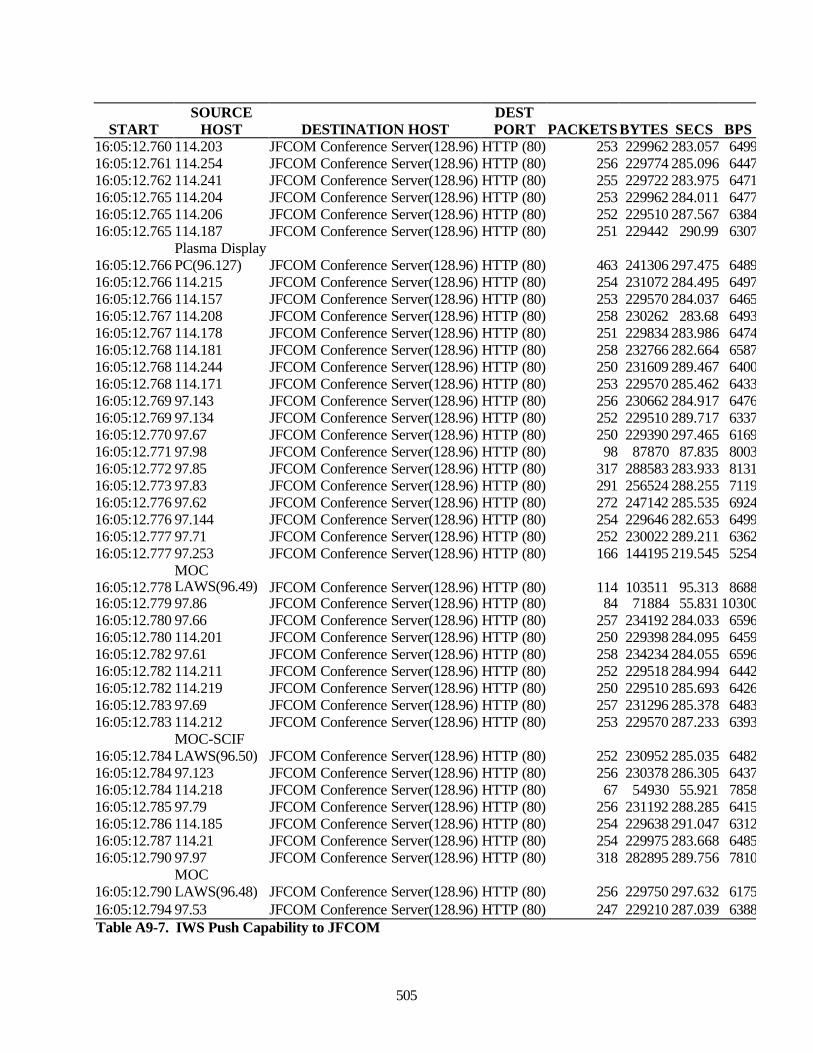
505
STARTSOURCE
HOST DESTINATION HOSTDESTPORT PACKETS BYTES SECS BPS
16:05:12.760 114.203 JFCOM Conference Server(128.96) HTTP (80) 253 229962 283.057 649916:05:12.761 114.254 JFCOM Conference Server(128.96) HTTP (80) 256 229774 285.096 644716:05:12.762 114.241 JFCOM Conference Server(128.96) HTTP (80) 255 229722 283.975 647116:05:12.765 114.204 JFCOM Conference Server(128.96) HTTP (80) 253 229962 284.011 647716:05:12.765 114.206 JFCOM Conference Server(128.96) HTTP (80) 252 229510 287.567 638416:05:12.765 114.187 JFCOM Conference Server(128.96) HTTP (80) 251 229442 290.99 6307
16:05:12.766Plasma DisplayPC(96.127) JFCOM Conference Server(128.96) HTTP (80) 463 241306 297.475 6489
16:05:12.766 114.215 JFCOM Conference Server(128.96) HTTP (80) 254 231072 284.495 649716:05:12.766 114.157 JFCOM Conference Server(128.96) HTTP (80) 253 229570 284.037 646516:05:12.767 114.208 JFCOM Conference Server(128.96) HTTP (80) 258 230262 283.68 649316:05:12.767 114.178 JFCOM Conference Server(128.96) HTTP (80) 251 229834 283.986 647416:05:12.768 114.181 JFCOM Conference Server(128.96) HTTP (80) 258 232766 282.664 658716:05:12.768 114.244 JFCOM Conference Server(128.96) HTTP (80) 250 231609 289.467 640016:05:12.768 114.171 JFCOM Conference Server(128.96) HTTP (80) 253 229570 285.462 643316:05:12.769 97.143 JFCOM Conference Server(128.96) HTTP (80) 256 230662 284.917 647616:05:12.769 97.134 JFCOM Conference Server(128.96) HTTP (80) 252 229510 289.717 633716:05:12.770 97.67 JFCOM Conference Server(128.96) HTTP (80) 250 229390 297.465 616916:05:12.771 97.98 JFCOM Conference Server(128.96) HTTP (80) 98 87870 87.835 800316:05:12.772 97.85 JFCOM Conference Server(128.96) HTTP (80) 317 288583 283.933 813116:05:12.773 97.83 JFCOM Conference Server(128.96) HTTP (80) 291 256524 288.255 711916:05:12.776 97.62 JFCOM Conference Server(128.96) HTTP (80) 272 247142 285.535 692416:05:12.776 97.144 JFCOM Conference Server(128.96) HTTP (80) 254 229646 282.653 649916:05:12.777 97.71 JFCOM Conference Server(128.96) HTTP (80) 252 230022 289.211 636216:05:12.777 97.253 JFCOM Conference Server(128.96) HTTP (80) 166 144195 219.545 5254
16:05:12.778MOCLAWS(96.49) JFCOM Conference Server(128.96) HTTP (80) 114 103511 95.313 8688
16:05:12.779 97.86 JFCOM Conference Server(128.96) HTTP (80) 84 71884 55.831 1030016:05:12.780 97.66 JFCOM Conference Server(128.96) HTTP (80) 257 234192 284.033 659616:05:12.780 114.201 JFCOM Conference Server(128.96) HTTP (80) 250 229398 284.095 645916:05:12.782 97.61 JFCOM Conference Server(128.96) HTTP (80) 258 234234 284.055 659616:05:12.782 114.211 JFCOM Conference Server(128.96) HTTP (80) 252 229518 284.994 644216:05:12.782 114.219 JFCOM Conference Server(128.96) HTTP (80) 250 229510 285.693 642616:05:12.783 97.69 JFCOM Conference Server(128.96) HTTP (80) 257 231296 285.378 648316:05:12.783 114.212 JFCOM Conference Server(128.96) HTTP (80) 253 229570 287.233 6393
16:05:12.784MOC-SCIFLAWS(96.50) JFCOM Conference Server(128.96) HTTP (80) 252 230952 285.035 6482
16:05:12.784 97.123 JFCOM Conference Server(128.96) HTTP (80) 256 230378 286.305 643716:05:12.784 114.218 JFCOM Conference Server(128.96) HTTP (80) 67 54930 55.921 785816:05:12.785 97.79 JFCOM Conference Server(128.96) HTTP (80) 256 231192 288.285 641516:05:12.786 114.185 JFCOM Conference Server(128.96) HTTP (80) 254 229638 291.047 631216:05:12.787 114.21 JFCOM Conference Server(128.96) HTTP (80) 254 229975 283.668 648516:05:12.790 97.97 JFCOM Conference Server(128.96) HTTP (80) 318 282895 289.756 7810
16:05:12.790MOCLAWS(96.48) JFCOM Conference Server(128.96) HTTP (80) 256 229750 297.632 6175
16:05:12.794 97.53 JFCOM Conference Server(128.96) HTTP (80) 247 229210 287.039 6388Table A9-7. IWS Push Capability to JFCOM
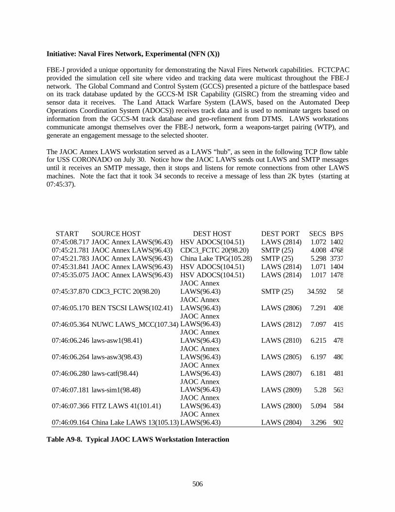
506
Initiative: Naval Fires Network, Experimental (NFN (X))
FBE-J provided a unique opportunity for demonstrating the Naval Fires Network capabilities. FCTCPACprovided the simulation cell site where video and tracking data were multicast throughout the FBE-Jnetwork. The Global Command and Control System (GCCS) presented a picture of the battlespace basedon its track database updated by the GCCS-M ISR Capability (GISRC) from the streaming video andsensor data it receives. The Land Attack Warfare System (LAWS, based on the Automated DeepOperations Coordination System (ADOCS)) receives track data and is used to nominate targets based oninformation from the GCCS-M track database and geo-refinement from DTMS. LAWS workstationscommunicate amongst themselves over the FBE-J network, form a weapons-target pairing (WTP), andgenerate an engagement message to the selected shooter.
The JAOC Annex LAWS workstation served as a LAWS “hub”, as seen in the following TCP flow tablefor USS CORONADO on July 30. Notice how the JAOC LAWS sends out LAWS and SMTP messagesuntil it receives an SMTP message, then it stops and listens for remote connections from other LAWSmachines. Note the fact that it took 34 seconds to receive a message of less than 2K bytes (starting at07:45:37).
START SOURCE HOST DEST HOST DEST PORT SECS BPS07:45:08.717 JAOC Annex LAWS(96.43) HSV ADOCS(104.51) LAWS (2814) 1.072 140207:45:21.781 JAOC Annex LAWS(96.43) CDC3_FCTC 20(98.20) SMTP (25) 4.008 476807:45:21.783 JAOC Annex LAWS(96.43) China Lake TPG(105.28) SMTP (25) 5.298 373707:45:31.841 JAOC Annex LAWS(96.43) HSV ADOCS(104.51) LAWS (2814) 1.071 140407:45:35.075 JAOC Annex LAWS(96.43) HSV ADOCS(104.51) LAWS (2814) 1.017 1478
07:45:37.870 CDC3_FCTC 20(98.20)JAOC AnnexLAWS(96.43) SMTP (25) 34.592 58
07:46:05.170 BEN TSCSI LAWS(102.41)JAOC AnnexLAWS(96.43) LAWS (2806) 7.291 408
07:46:05.364 NUWC LAWS_MCC(107.34)JAOC AnnexLAWS(96.43) LAWS (2812) 7.097 419
07:46:06.246 laws-asw1(98.41)JAOC AnnexLAWS(96.43) LAWS (2810) 6.215 478
07:46:06.264 laws-asw3(98.43)JAOC AnnexLAWS(96.43) LAWS (2805) 6.197 480
07:46:06.280 laws-catf(98.44)JAOC AnnexLAWS(96.43) LAWS (2807) 6.181 481
07:46:07.181 laws-sim1(98.48)JAOC AnnexLAWS(96.43) LAWS (2809) 5.28 563
07:46:07.366 FITZ LAWS 41(101.41)JAOC AnnexLAWS(96.43) LAWS (2800) 5.094 584
07:46:09.164 China Lake LAWS 13(105.13)JAOC AnnexLAWS(96.43) LAWS (2804) 3.296 902
Table A9-8. Typical JAOC LAWS Workstation Interaction
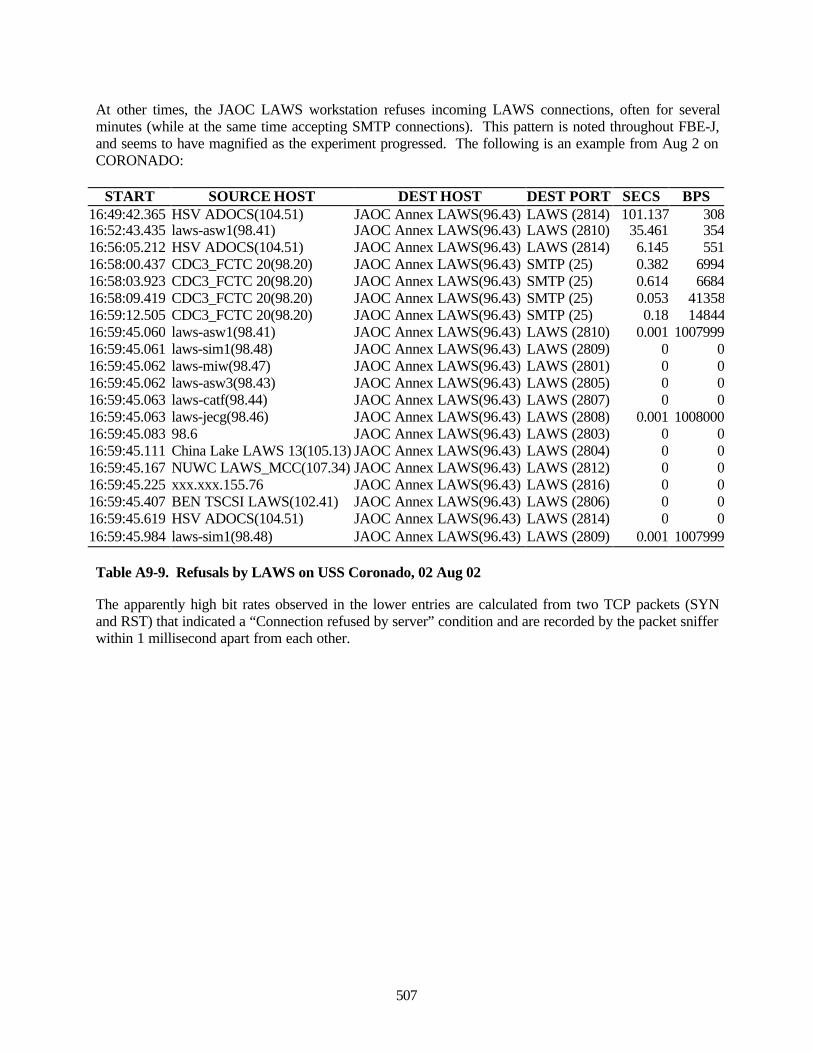
507
At other times, the JAOC LAWS workstation refuses incoming LAWS connections, often for severalminutes (while at the same time accepting SMTP connections). This pattern is noted throughout FBE-J,and seems to have magnified as the experiment progressed. The following is an example from Aug 2 onCORONADO:
START SOURCE HOST DEST HOST DEST PORT SECS BPS16:49:42.365 HSV ADOCS(104.51) JAOC Annex LAWS(96.43) LAWS (2814) 101.137 30816:52:43.435 laws-asw1(98.41) JAOC Annex LAWS(96.43) LAWS (2810) 35.461 35416:56:05.212 HSV ADOCS(104.51) JAOC Annex LAWS(96.43) LAWS (2814) 6.145 55116:58:00.437 CDC3_FCTC 20(98.20) JAOC Annex LAWS(96.43) SMTP (25) 0.382 699416:58:03.923 CDC3_FCTC 20(98.20) JAOC Annex LAWS(96.43) SMTP (25) 0.614 668416:58:09.419 CDC3_FCTC 20(98.20) JAOC Annex LAWS(96.43) SMTP (25) 0.053 4135816:59:12.505 CDC3_FCTC 20(98.20) JAOC Annex LAWS(96.43) SMTP (25) 0.18 1484416:59:45.060 laws-asw1(98.41) JAOC Annex LAWS(96.43) LAWS (2810) 0.001 100799916:59:45.061 laws-sim1(98.48) JAOC Annex LAWS(96.43) LAWS (2809) 0 016:59:45.062 laws-miw(98.47) JAOC Annex LAWS(96.43) LAWS (2801) 0 016:59:45.062 laws-asw3(98.43) JAOC Annex LAWS(96.43) LAWS (2805) 0 016:59:45.063 laws-catf(98.44) JAOC Annex LAWS(96.43) LAWS (2807) 0 016:59:45.063 laws-jecg(98.46) JAOC Annex LAWS(96.43) LAWS (2808) 0.001 100800016:59:45.083 98.6 JAOC Annex LAWS(96.43) LAWS (2803) 0 016:59:45.111 China Lake LAWS 13(105.13) JAOC Annex LAWS(96.43) LAWS (2804) 0 016:59:45.167 NUWC LAWS_MCC(107.34) JAOC Annex LAWS(96.43) LAWS (2812) 0 016:59:45.225 xxx.xxx.155.76 JAOC Annex LAWS(96.43) LAWS (2816) 0 016:59:45.407 BEN TSCSI LAWS(102.41) JAOC Annex LAWS(96.43) LAWS (2806) 0 016:59:45.619 HSV ADOCS(104.51) JAOC Annex LAWS(96.43) LAWS (2814) 0 016:59:45.984 laws-sim1(98.48) JAOC Annex LAWS(96.43) LAWS (2809) 0.001 1007999
Table A9-9. Refusals by LAWS on USS Coronado, 02 Aug 02
The apparently high bit rates observed in the lower entries are calculated from two TCP packets (SYNand RST) that indicated a “Connection refused by server” condition and are recorded by the packet snifferwithin 1 millisecond apart from each other.
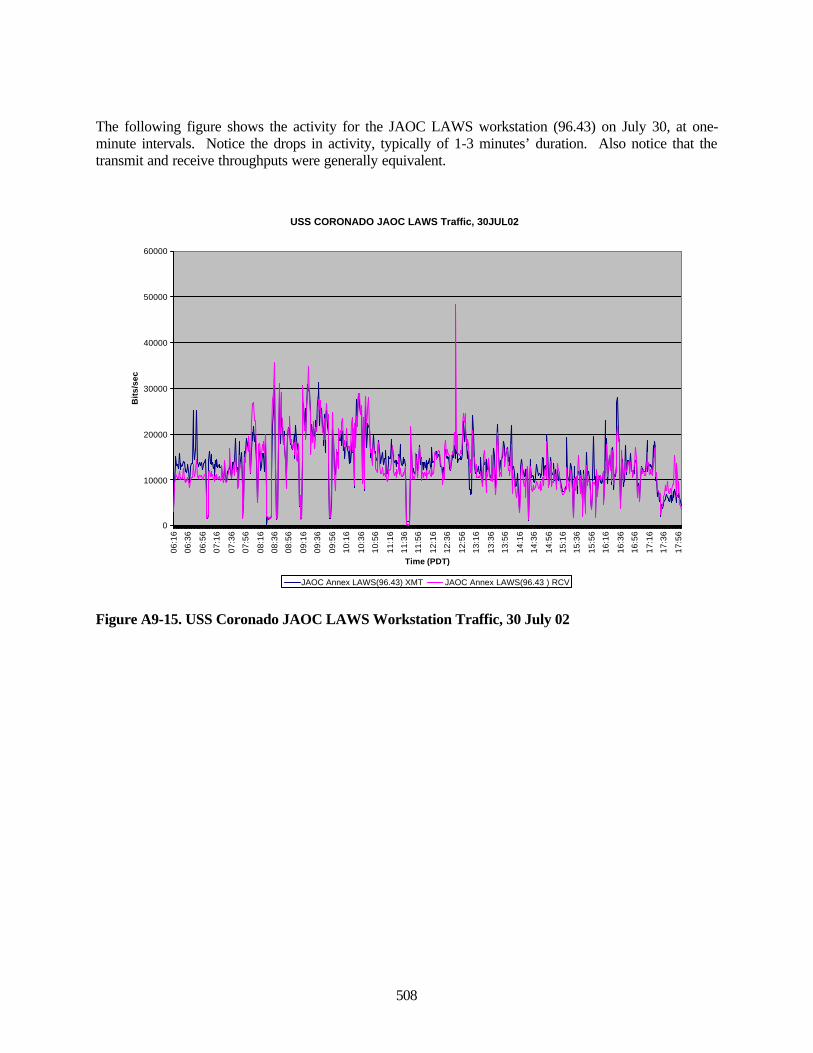
508
The following figure shows the activity for the JAOC LAWS workstation (96.43) on July 30, at one-minute intervals. Notice the drops in activity, typically of 1-3 minutes’ duration. Also notice that thetransmit and receive throughputs were generally equivalent.
Figure A9-15. USS Coronado JAOC LAWS Workstation Traffic, 30 July 02
USS CORONADO JAOC LAWS Traffic, 30JUL02
0
10000
20000
30000
40000
50000
60000
06:1
6
06:3
6
06:5
6
07:1
6
07:3
6
07:5
6
08:1
6
08:3
6
08:5
6
09:1
6
09:3
6
09:5
6
10:1
6
10:3
6
10:5
6
11:1
6
11:3
6
11:5
6
12:1
6
12:3
6
12:5
6
13:1
6
13:3
6
13:5
6
14:1
6
14:3
6
14:5
6
15:1
6
15:3
6
15:5
6
16:1
6
16:3
6
16:5
6
17:1
6
17:3
6
17:5
6
Time (PDT)
Bit
s/se
c
JAOC Annex LAWS(96.43) XMT JAOC Annex LAWS(96.43 ) RCV
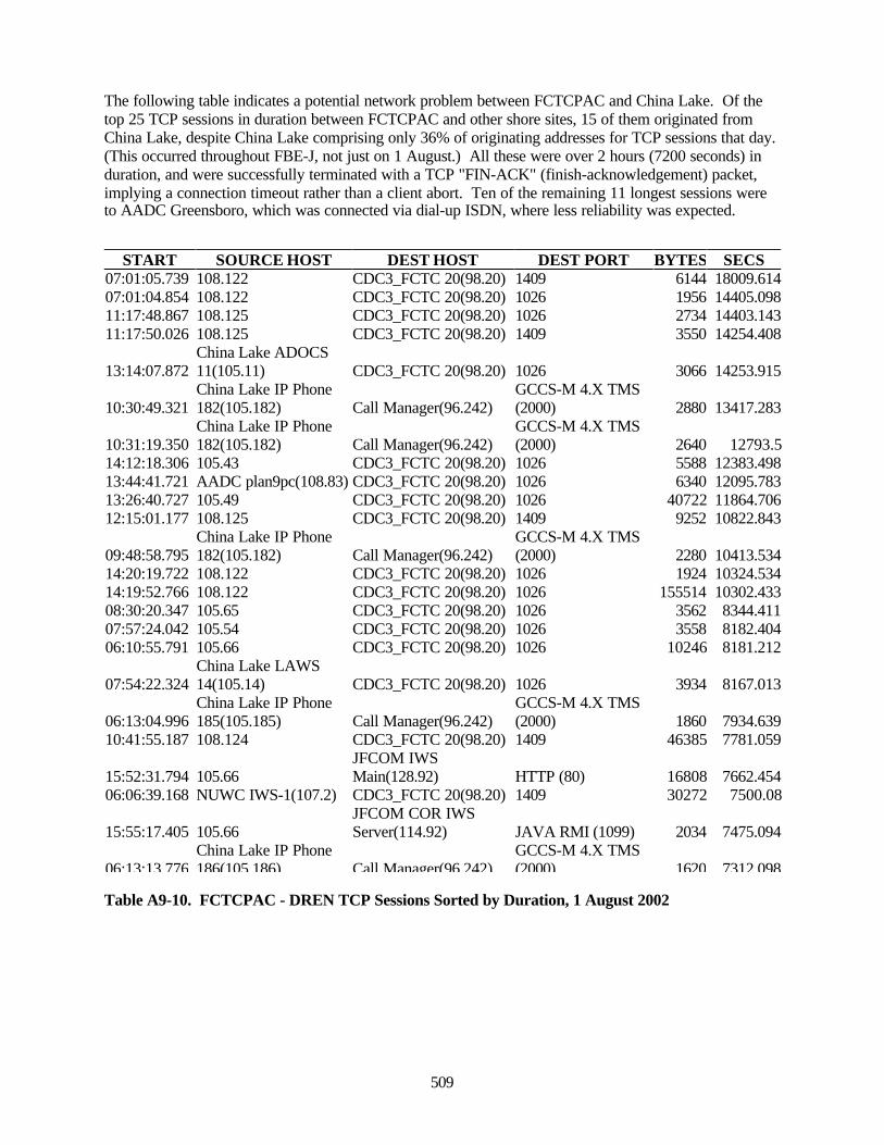
509
The following table indicates a potential network problem between FCTCPAC and China Lake. Of thetop 25 TCP sessions in duration between FCTCPAC and other shore sites, 15 of them originated fromChina Lake, despite China Lake comprising only 36% of originating addresses for TCP sessions that day.(This occurred throughout FBE-J, not just on 1 August.) All these were over 2 hours (7200 seconds) induration, and were successfully terminated with a TCP "FIN-ACK" (finish-acknowledgement) packet,implying a connection timeout rather than a client abort. Ten of the remaining 11 longest sessions wereto AADC Greensboro, which was connected via dial-up ISDN, where less reliability was expected.
Table A9-10. FCTCPAC - DREN TCP Sessions Sorted by Duration, 1 August 2002
START SOURCE HOST DEST HOST DEST PORT BYTES SECS07:01:05.739 108.122 CDC3_FCTC 20(98.20) 1409 6144 18009.61407:01:04.854 108.122 CDC3_FCTC 20(98.20) 1026 1956 14405.09811:17:48.867 108.125 CDC3_FCTC 20(98.20) 1026 2734 14403.14311:17:50.026 108.125 CDC3_FCTC 20(98.20) 1409 3550 14254.408
13:14:07.872China Lake ADOCS11(105.11) CDC3_FCTC 20(98.20) 1026 3066 14253.915
10:30:49.321China Lake IP Phone182(105.182) Call Manager(96.242)
GCCS-M 4.X TMS(2000) 2880 13417.283
10:31:19.350China Lake IP Phone182(105.182) Call Manager(96.242)
GCCS-M 4.X TMS(2000) 2640 12793.5
14:12:18.306 105.43 CDC3_FCTC 20(98.20) 1026 5588 12383.49813:44:41.721 AADC plan9pc(108.83) CDC3_FCTC 20(98.20) 1026 6340 12095.78313:26:40.727 105.49 CDC3_FCTC 20(98.20) 1026 40722 11864.70612:15:01.177 108.125 CDC3_FCTC 20(98.20) 1409 9252 10822.843
09:48:58.795China Lake IP Phone182(105.182) Call Manager(96.242)
GCCS-M 4.X TMS(2000) 2280 10413.534
14:20:19.722 108.122 CDC3_FCTC 20(98.20) 1026 1924 10324.53414:19:52.766 108.122 CDC3_FCTC 20(98.20) 1026 155514 10302.43308:30:20.347 105.65 CDC3_FCTC 20(98.20) 1026 3562 8344.41107:57:24.042 105.54 CDC3_FCTC 20(98.20) 1026 3558 8182.40406:10:55.791 105.66 CDC3_FCTC 20(98.20) 1026 10246 8181.212
07:54:22.324China Lake LAWS14(105.14) CDC3_FCTC 20(98.20) 1026 3934 8167.013
06:13:04.996China Lake IP Phone185(105.185) Call Manager(96.242)
GCCS-M 4.X TMS(2000) 1860 7934.639
10:41:55.187 108.124 CDC3_FCTC 20(98.20) 1409 46385 7781.059
15:52:31.794 105.66JFCOM IWSMain(128.92) HTTP (80) 16808 7662.454
06:06:39.168 NUWC IWS-1(107.2) CDC3_FCTC 20(98.20) 1409 30272 7500.08
15:55:17.405 105.66JFCOM COR IWSServer(114.92) JAVA RMI (1099) 2034 7475.094
06:13:13.776China Lake IP Phone186(105.186) Call Manager(96.242)
GCCS-M 4.X TMS(2000) 1620 7312.098
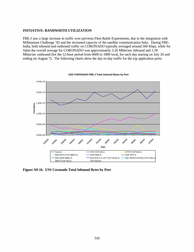
510
INITIATIVE: BANDWIDTH UTILIZATION
FBE-J saw a large increase in traffic over previous Fleet Battle Experiments, due to the integration withMillennium Challenge ’02 and the increased capacity of the satellite communication links. During FBE-India, both inbound and outbound traffic on CORONADO typically averaged around 500 Kbps, while forJuliet the overall average for CORONADO was approximately 3.26 Mbits/sec inbound and 1.39Mbits/sec outbound (for the 12-hour period from 0600 to 1800 local, for each day starting on July 26 andending on August 7). The following charts show the day-to-day traffic for the top application ports.
Figure A9-16. USS Coronado Total Inbound Bytes by Port
USS CORONADO FBE-J Total Inbound Bytes by Port
0.00E+00
5.00E+09
1.00E+10
1.50E+10
2.00E+10
2.50E+10
7/26/2
002
7/27/2
002
7/28/2
002
7/29/2
002
7/30/2
002
7/31/2
002
8/1/20
02
8/2/20
02
8/3/20
02
8/4/20
02
8/5/20
02
8/6/20
02
8/7/20
02
Date
To
tal B
ytes
Total In FTP (TCP 20) In HTTP (TCP 80) InIWS DATA (TCP 8087) In UDP 4000 In UDP RTP In
IWS (UDP 8084) In GCCS-M 3.X CST (TCP 9119) In SQL REPLICATION (TCP 445) InSMTP (TCP 25) In TCP 4310 In
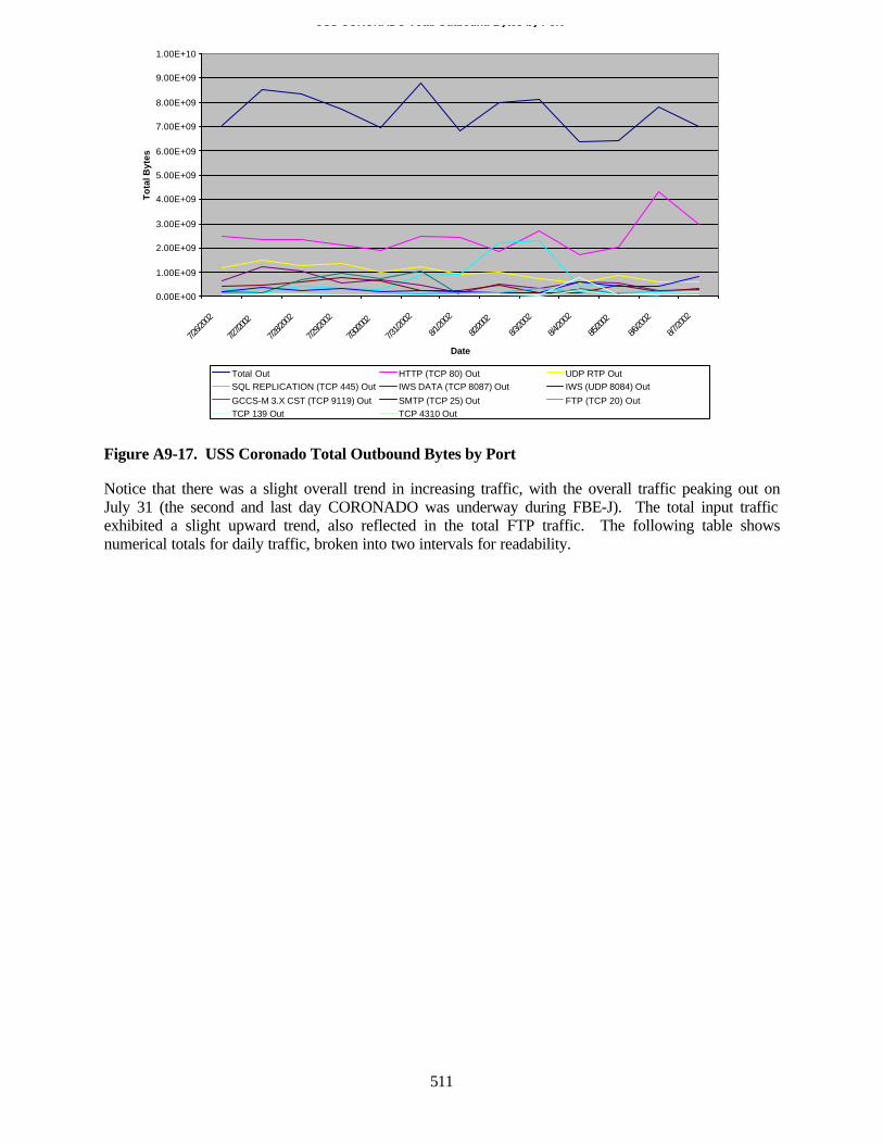
511
Figure A9-17. USS Coronado Total Outbound Bytes by Port
Notice that there was a slight overall trend in increasing traffic, with the overall traffic peaking out onJuly 31 (the second and last day CORONADO was underway during FBE-J). The total input trafficexhibited a slight upward trend, also reflected in the total FTP traffic. The following table showsnumerical totals for daily traffic, broken into two intervals for readability.
USS CORONADO Total Outbound Bytes by Port
0.00E+00
1.00E+09
2.00E+09
3.00E+09
4.00E+09
5.00E+09
6.00E+09
7.00E+09
8.00E+09
9.00E+09
1.00E+10
7/26/2
002
7/27/2
002
7/28/2
002
7/29/2
002
7/30/2
002
7/31/2
002
8/1/20
02
8/2/20
02
8/3/20
02
8/4/20
02
8/5/20
02
8/6/20
02
8/7/20
02
Date
To
tal B
ytes
Total Out HTTP (TCP 80) Out UDP RTP OutSQL REPLICATION (TCP 445) Out IWS DATA (TCP 8087) Out IWS (UDP 8084) Out
GCCS-M 3.X CST (TCP 9119) Out SMTP (TCP 25) Out FTP (TCP 20) OutTCP 139 Out TCP 4310 Out
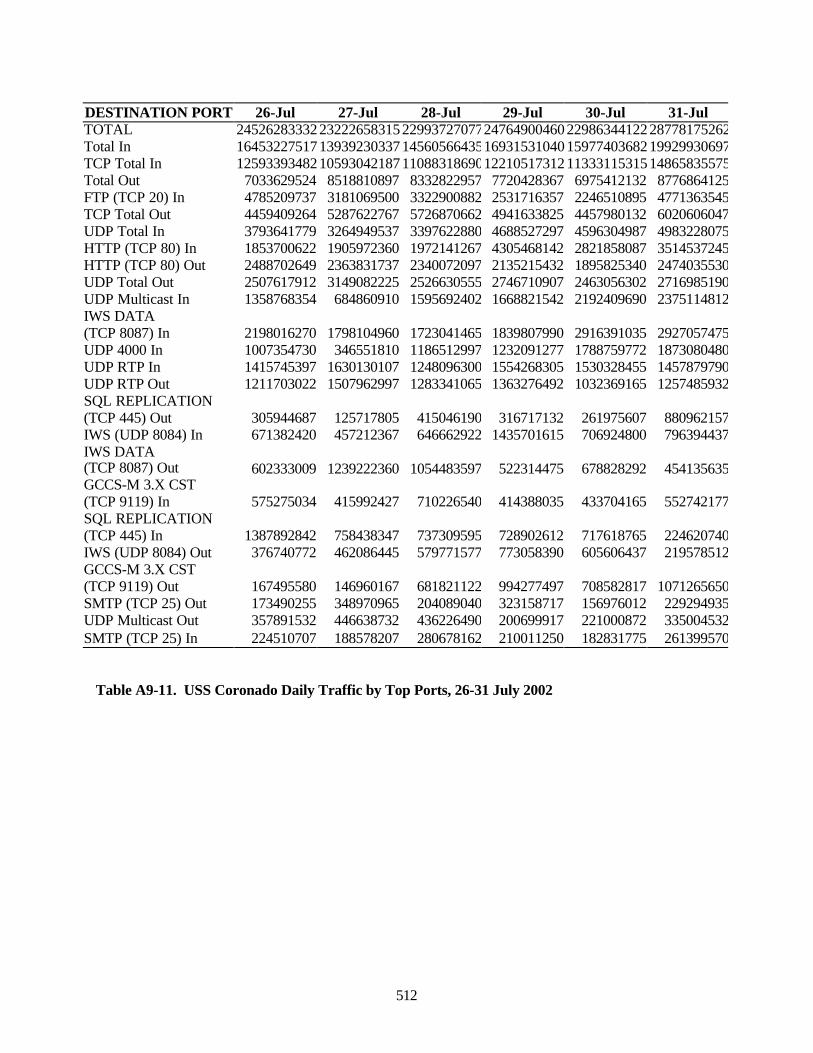
512
DESTINATION PORT 26-Jul 27-Jul 28-Jul 29-Jul 30-Jul 31-JulTOTAL 245262833322322265831522993727077247649004602298634412228778175262Total In 164532275171393923033714560566435169315310401597740368219929930697TCP Total In 125933934821059304218711088318690122105173121133311531514865835575Total Out 7033629524 8518810897 8332822957 7720428367 6975412132 8776864125FTP (TCP 20) In 4785209737 3181069500 3322900882 2531716357 2246510895 4771363545TCP Total Out 4459409264 5287622767 5726870662 4941633825 4457980132 6020606047UDP Total In 3793641779 3264949537 3397622880 4688527297 4596304987 4983228075HTTP (TCP 80) In 1853700622 1905972360 1972141267 4305468142 2821858087 3514537245HTTP (TCP 80) Out 2488702649 2363831737 2340072097 2135215432 1895825340 2474035530UDP Total Out 2507617912 3149082225 2526630555 2746710907 2463056302 2716985190UDP Multicast In 1358768354 684860910 1595692402 1668821542 2192409690 2375114812IWS DATA(TCP 8087) In 2198016270 1798104960 1723041465 1839807990 2916391035 2927057475UDP 4000 In 1007354730 346551810 1186512997 1232091277 1788759772 1873080480UDP RTP In 1415745397 1630130107 1248096300 1554268305 1530328455 1457879790UDP RTP Out 1211703022 1507962997 1283341065 1363276492 1032369165 1257485932SQL REPLICATION(TCP 445) Out 305944687 125717805 415046190 316717132 261975607 880962157IWS (UDP 8084) In 671382420 457212367 646662922 1435701615 706924800 796394437IWS DATA(TCP 8087) Out 602333009 1239222360 1054483597 522314475 678828292 454135635GCCS-M 3.X CST(TCP 9119) In 575275034 415992427 710226540 414388035 433704165 552742177SQL REPLICATION(TCP 445) In 1387892842 758438347 737309595 728902612 717618765 224620740IWS (UDP 8084) Out 376740772 462086445 579771577 773058390 605606437 219578512GCCS-M 3.X CST(TCP 9119) Out 167495580 146960167 681821122 994277497 708582817 1071265650SMTP (TCP 25) Out 173490255 348970965 204089040 323158717 156976012 229294935UDP Multicast Out 357891532 446638732 436226490 200699917 221000872 335004532SMTP (TCP 25) In 224510707 188578207 280678162 210011250 182831775 261399570
Table A9-11. USS Coronado Daily Traffic by Top Ports, 26-31 July 2002
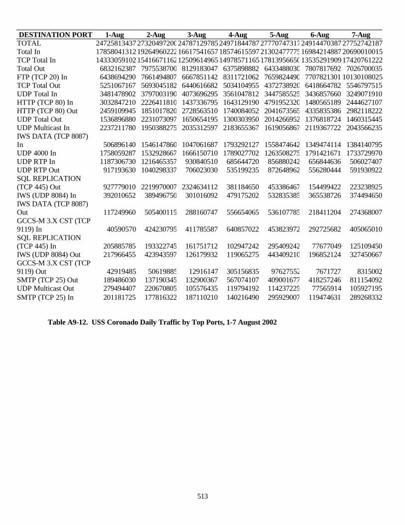
513
Table A9-12. USS Coronado Daily Traffic by Top Ports, 1-7 August 2002
DESTINATION PORT 1-Aug 2-Aug 3-Aug 4-Aug 5-Aug 6-Aug 7-AugTOTAL 24725813437273204972002478712978524971844787277707473172491447038727752742187Total In 17858041312192649602221661754165718574615597213024777751698421488720690010015TCP Total In 14333059102154166711621250961496514978571165178139566501353529190917420761222Total Out 6832162387 7975538700 8129183047 6375898882 6433488030 7807817692 7026700035FTP (TCP 20) In 6438694290 7661494807 6667851142 8311721062 7659824490 7707821301 10130108025TCP Total Out 5251067167 5693045182 6440616682 5034104955 4372738920 6418664782 5546797515UDP Total In 3481478902 3797003190 4073696295 3561047812 3447585525 3436857660 3249071910HTTP (TCP 80) In 3032847210 2226411810 1437336795 1643129190 4791952320 1480565189 2444627107HTTP (TCP 80) Out 2459109945 1851017820 2728563510 1740084052 2041673565 4335835386 2982118222UDP Total Out 1536896880 2231073097 1650654195 1300303950 2014266952 1376818724 1460315445UDP Multicast In 2237211780 1950388275 2035312597 2183655367 1619056867 2119367722 2043566235IWS DATA (TCP 8087)In 506896140 1546147860 1047061687 1793292127 1558474642 1349474114 1384140795UDP 4000 In 1758059287 1532928667 1666150710 1789027702 1263508275 1791421671 1733729970UDP RTP In 1187306730 1216465357 930840510 685644720 856880242 656844636 506027407UDP RTP Out 917193630 1040298337 706023030 535199235 872648962 556280444 591930922SQL REPLICATION(TCP 445) Out 927779010 2219970007 2324634112 381184650 453386467 154499422 223238925IWS (UDP 8084) In 392010652 389496750 301016092 479175202 532835385 365538726 374494650IWS DATA (TCP 8087)Out 117249960 505400115 288160747 556654065 536107785 218411204 274368007GCCS-M 3.X CST (TCP9119) In 40590570 424230795 411785587 640857022 453823972 292725682 405065010SQL REPLICATION(TCP 445) In 205885785 193322745 161751712 102947242 295409242 77677049 125109450IWS (UDP 8084) Out 217966455 423943597 126179932 119065275 443409210 196852124 327450667GCCS-M 3.X CST (TCP9119) Out 42919485 50619885 12916147 305156835 97627552 7671727 8315002SMTP (TCP 25) Out 189486030 137190345 132900367 567074107 409001677 418257246 811154092UDP Multicast Out 279494407 220670805 105576435 119794192 114237225 77565914 105927195SMTP (TCP 25) In 201181725 177816322 187110210 140216490 295929007 119474631 289268332
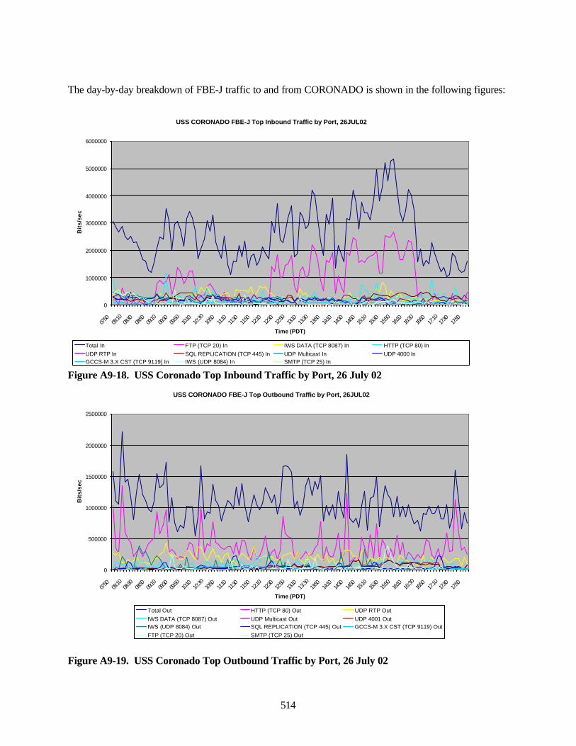
514
The day-by-day breakdown of FBE-J traffic to and from CORONADO is shown in the following figures:
Figure A9-18. USS Coronado Top Inbound Traffic by Port, 26 July 02
Figure A9-19. USS Coronado Top Outbound Traffic by Port, 26 July 02
USS CORONADO FBE-J Top Inbound Traffic by Port, 26JUL02
0
1000000
2000000
3000000
4000000
5000000
6000000
07:50
08:10
08:30
08:50
09:10
09:30
09:50
10:10
10:30
10:50
11:10
11:30
11:50
12:10
12:30
12:50
13:10
13:30
13:50
14:10
14:30
14:50
15:10
15:30
15:50
16:10
16:30
16:50
17:10
17:30
17:50
Time (PDT)
Bit
s/se
c
Total In FTP (TCP 20) In IWS DATA (TCP 8087) In HTTP (TCP 80) InUDP RTP In SQL REPLICATION (TCP 445) In UDP Multicast In UDP 4000 InGCCS-M 3.X CST (TCP 9119) In IWS (UDP 8084) In SMTP (TCP 25) In
USS CORONADO FBE-J Top Outbound Traffic by Port, 26JUL02
0
500000
1000000
1500000
2000000
2500000
07:50
08:10
08:30
08:50
09:10
09:30
09:50
10:10
10:30
10:50
11:10
11:30
11:50
12:10
12:30
12:50
13:10
13:30
13:50
14:10
14:30
14:50
15:10
15:30
15:50
16:10
16:30
16:50
17:10
17:30
17:50
Time (PDT)
Bit
s/se
c
Total Out HTTP (TCP 80) Out UDP RTP OutIWS DATA (TCP 8087) Out UDP Multicast Out UDP 4001 OutIWS (UDP 8084) Out SQL REPLICATION (TCP 445) Out GCCS-M 3.X CST (TCP 9119) OutFTP (TCP 20) Out SMTP (TCP 25) Out
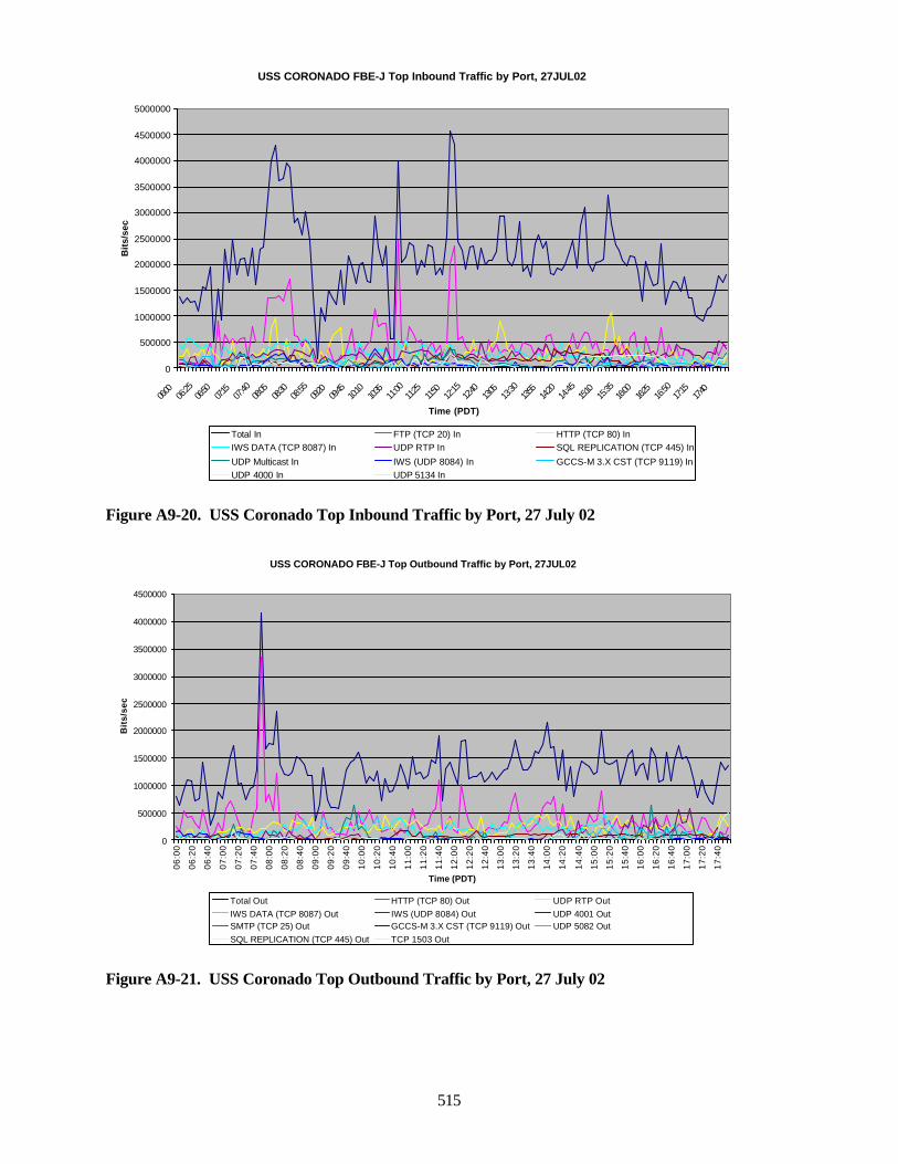
515
Figure A9-20. USS Coronado Top Inbound Traffic by Port, 27 July 02
Figure A9-21. USS Coronado Top Outbound Traffic by Port, 27 July 02
USS CORONADO FBE-J Top Inbound Traffic by Port, 27JUL02
0
500000
1000000
1500000
2000000
2500000
3000000
3500000
4000000
4500000
5000000
06:00
06:25
06:50
07:15
07:40
08:05
08:30
08:55
09:20
09:45
10:10
10:35
11:00
11:25
11:50
12:15
12:40
13:05
13:30
13:55
14:20
14:45
15:10
15:35
16:00
16:25
16:50
17:15
17:40
Time (PDT)
Bit
s/se
c
Total In FTP (TCP 20) In HTTP (TCP 80) InIWS DATA (TCP 8087) In UDP RTP In SQL REPLICATION (TCP 445) In
UDP Multicast In IWS (UDP 8084) In GCCS-M 3.X CST (TCP 9119) InUDP 4000 In UDP 5134 In
USS CORONADO FBE-J Top Outbound Traffic by Port, 27JUL02
0
500000
1000000
1500000
2000000
2500000
3000000
3500000
4000000
4500000
06:0
0
06:2
0
06:4
0
07:0
0
07:2
0
07:4
0
08:0
0
08:2
0
08:4
0
09:0
0
09:2
0
09:4
0
10:0
0
10:2
0
10:4
0
11:0
0
11:2
0
11:4
0
12:0
0
12:2
0
12:4
0
13:0
0
13:2
0
13:4
0
14:0
0
14:2
0
14:4
0
15:0
0
15:2
0
15:4
0
16:0
0
16:2
0
16:4
0
17:0
0
17:2
0
17:4
0
Time (PDT)
Bit
s/se
c
Total Out HTTP (TCP 80) Out UDP RTP OutIWS DATA (TCP 8087) Out IWS (UDP 8084) Out UDP 4001 OutSMTP (TCP 25) Out GCCS-M 3.X CST (TCP 9119) Out UDP 5082 OutSQL REPLICATION (TCP 445) Out TCP 1503 Out
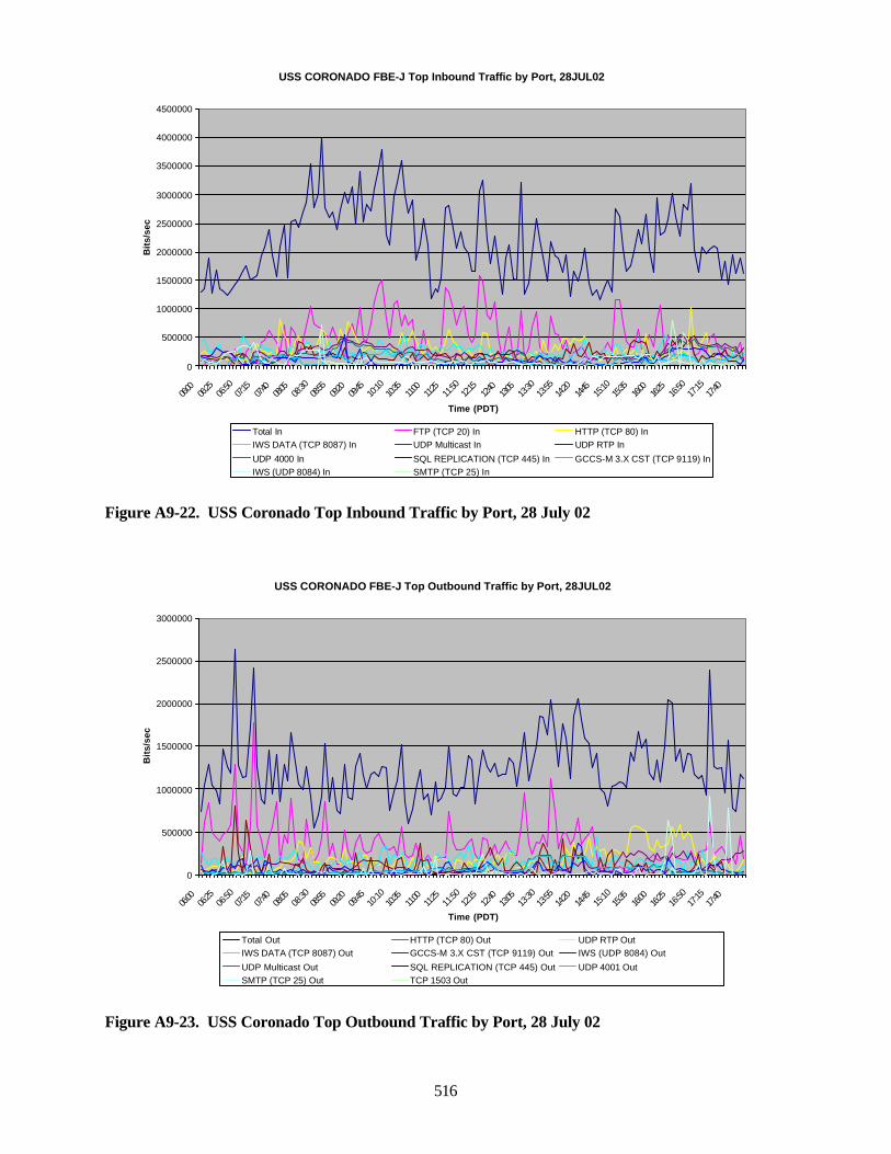
516
Figure A9-22. USS Coronado Top Inbound Traffic by Port, 28 July 02
Figure A9-23. USS Coronado Top Outbound Traffic by Port, 28 July 02
USS CORONADO FBE-J Top Inbound Traffic by Port, 28JUL02
0
500000
1000000
1500000
2000000
2500000
3000000
3500000
4000000
4500000
06:00
06:25
06:50
07:15
07:40
08:05
08:30
08:55
09:20
09:45
10:10
10:35
11:00
11:25
11:50
12:15
12:40
13:05
13:30
13:55
14:20
14:45
15:10
15:35
16:00
16:25
16:50
17:15
17:40
Time (PDT)
Bit
s/se
c
Total In FTP (TCP 20) In HTTP (TCP 80) InIWS DATA (TCP 8087) In UDP Multicast In UDP RTP In
UDP 4000 In SQL REPLICATION (TCP 445) In GCCS-M 3.X CST (TCP 9119) InIWS (UDP 8084) In SMTP (TCP 25) In
USS CORONADO FBE-J Top Outbound Traffic by Port, 28JUL02
0
500000
1000000
1500000
2000000
2500000
3000000
06:00
06:25
06:50
07:15
07:40
08:05
08:30
08:55
09:20
09:45
10:10
10:35
11:00
11:25
11:50
12:15
12:40
13:05
13:30
13:55
14:20
14:45
15:10
15:35
16:00
16:25
16:50
17:15
17:40
Time (PDT)
Bit
s/se
c
Total Out HTTP (TCP 80) Out UDP RTP OutIWS DATA (TCP 8087) Out GCCS-M 3.X CST (TCP 9119) Out IWS (UDP 8084) Out
UDP Multicast Out SQL REPLICATION (TCP 445) Out UDP 4001 OutSMTP (TCP 25) Out TCP 1503 Out
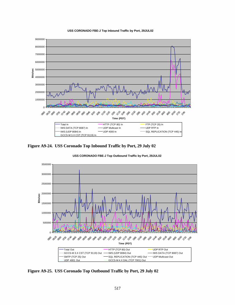
517
Figure A9-24. USS Coronado Top Inbound Traffic by Port, 29 July 02
Figure A9-25. USS Coronado Top Outbound Traffic by Port, 29 July 02
USS CORONADO FBE-J Top Inbound Traffic by Port, 29JUL02
0
1000000
2000000
3000000
4000000
5000000
6000000
7000000
8000000
9000000
06:00
06:25
06:50
07:15
07:40
08:05
08:30
08:55
09:20
09:45
10:10
10:35
11:00
11:25
11:50
12:15
12:40
13:05
13:30
13:55
14:20
14:45
15:10
15:35
16:00
16:25
16:50
17:15
17:40
Time (PDT)
Bit
s/se
c
Total In HTTP (TCP 80) In FTP (TCP 20) InIWS DATA (TCP 8087) In UDP Multicast In UDP RTP In
IWS (UDP 8084) In UDP 4000 In SQL REPLICATION (TCP 445) InGCCS-M 3.X CST (TCP 9119) In
USS CORONADO FBE-J Top Outbound Traffic by Port, 29JUL02
0
500000
1000000
1500000
2000000
2500000
3000000
3500000
06:00
06:25
06:50
07:15
07:40
08:05
08:30
08:55
09:20
09:45
10:10
10:35
11:00
11:25
11:50
12:15
12:40
13:05
13:30
13:55
14:20
14:45
15:10
15:35
16:00
16:25
16:50
17:15
17:40
Time (PDT)
Bit
s/se
c
Total Out HTTP (TCP 80) Out UDP RTP OutGCCS-M 3.X CST (TCP 9119) Out IWS (UDP 8084) Out IWS DATA (TCP 8087) Out
SMTP (TCP 25) Out SQL REPLICATION (TCP 445) Out UDP Multicast OutUDP 4001 Out GCCS-M 4.X DAL (TCP 7001) Out
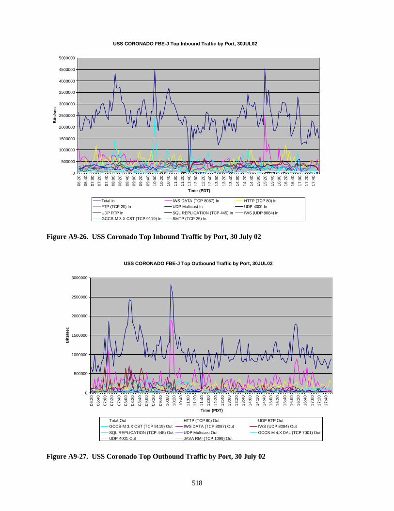
518
Figure A9-26. USS Coronado Top Inbound Traffic by Port, 30 July 02
Figure A9-27. USS Coronado Top Outbound Traffic by Port, 30 July 02
USS CORONADO FBE-J Top Inbound Traffic by Port, 30JUL02
0
500000
1000000
1500000
2000000
2500000
3000000
3500000
4000000
4500000
5000000
06:2
0
06:4
0
07:0
0
07:2
0
07:4
0
08:0
0
08:2
0
08:4
0
09:0
0
09:2
0
09:4
0
10:0
0
10:2
0
10:4
0
11:0
0
11:2
0
11:4
0
12:0
0
12:2
0
12:4
0
13:0
0
13:2
0
13:4
0
14:0
0
14:2
0
14:4
0
15:0
0
15:2
0
15:4
0
16:0
0
16:2
0
16:4
0
17:0
0
17:2
0
17:4
0
Time (PDT)
Bit
s/se
c
Total In IWS DATA (TCP 8087) In HTTP (TCP 80) InFTP (TCP 20) In UDP Multicast In UDP 4000 In
UDP RTP In SQL REPLICATION (TCP 445) In IWS (UDP 8084) InGCCS-M 3.X CST (TCP 9119) In SMTP (TCP 25) In
USS CORONADO FBE-J Top Outbound Traffic by Port, 30JUL02
0
500000
1000000
1500000
2000000
2500000
3000000
06:2
0
06:4
0
07:0
0
07:2
0
07:4
0
08:0
0
08:2
0
08:4
0
09:0
0
09:2
0
09:4
0
10:0
0
10:2
0
10:4
0
11:0
0
11:2
0
11:4
0
12:0
0
12:2
0
12:4
0
13:0
0
13:2
0
13:4
0
14:0
0
14:2
0
14:4
0
15:0
0
15:2
0
15:4
0
16:0
0
16:2
0
16:4
0
17:0
0
17:2
0
17:4
0
Time (PDT)
Bit
s/se
c
Total Out HTTP (TCP 80) Out UDP RTP OutGCCS-M 3.X CST (TCP 9119) Out IWS DATA (TCP 8087) Out IWS (UDP 8084) Out
SQL REPLICATION (TCP 445) Out UDP Multicast Out GCCS-M 4.X DAL (TCP 7001) OutUDP 4001 Out JAVA RMI (TCP 1099) Out
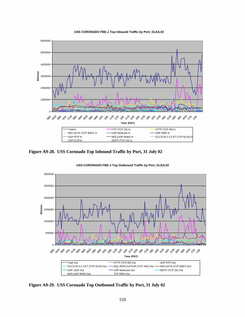
519
Figure A9-28. USS Coronado Top Inbound Traffic by Port, 31 July 02
Figure A9-29. USS Coronado Top Outbound Traffic by Port, 31 July 02
USS CORONADO FBE-J Top Inbound Traffic by Port, 31JUL02
0
1000000
2000000
3000000
4000000
5000000
6000000
06:00
06:25
06:50
07:15
07:40
08:05
08:30
08:55
09:20
09:45
10:10
10:35
11:00
11:25
11:50
12:15
12:40
13:05
13:30
13:55
14:20
14:45
15:10
15:35
16:00
16:25
16:50
17:15
17:40
Time (PDT)
Bit
s/se
c
Total In FTP (TCP 20) In HTTP (TCP 80) InIWS DATA (TCP 8087) In UDP Multicast In UDP 4000 In
UDP RTP In IWS (UDP 8084) In GCCS-M 3.X CST (TCP 9119) InUDP 5178 In SMTP (TCP 25) In
USS CORONADO FBE-J Top Outbound Traffic by Port, 31JUL02
0
500000
1000000
1500000
2000000
2500000
3000000
06:00
06:25
06:50
07:15
07:40
08:05
08:30
08:55
09:20
09:45
10:10
10:35
11:00
11:25
11:50
12:15
12:40
13:05
13:30
13:55
14:20
14:45
15:10
15:35
16:00
16:25
16:50
17:15
17:40
Time (PDT)
Bit
s/se
c
Total Out HTTP (TCP 80) Out UDP RTP OutGCCS-M 3.X CST (TCP 9119) Out SQL REPLICATION (TCP 445) Out IWS DATA (TCP 8087) Out
UDP 1035 Out UDP Multicast Out SMTP (TCP 25) OutIWS (UDP 8084) Out TCP 5004 Out
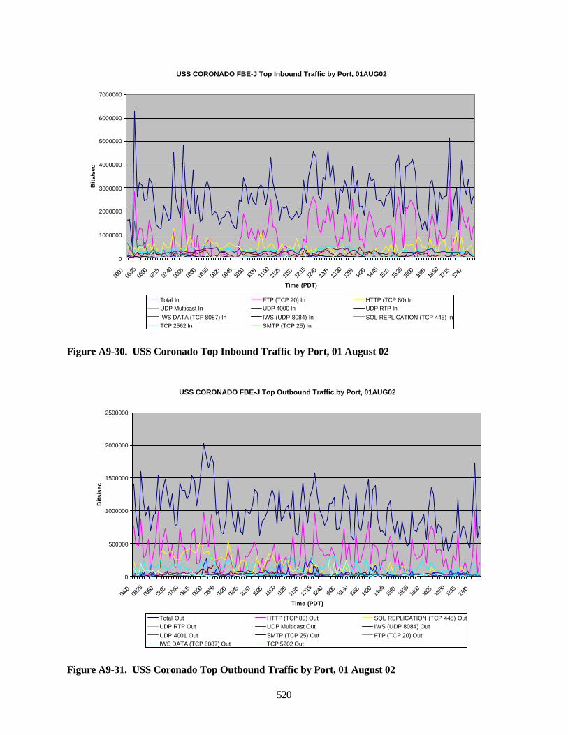
520
Figure A9-30. USS Coronado Top Inbound Traffic by Port, 01 August 02
Figure A9-31. USS Coronado Top Outbound Traffic by Port, 01 August 02
USS CORONADO FBE-J Top Inbound Traffic by Port, 01AUG02
0
1000000
2000000
3000000
4000000
5000000
6000000
7000000
06:00
06:25
06:50
07:15
07:40
08:05
08:30
08:55
09:20
09:45
10:10
10:35
11:00
11:25
11:50
12:15
12:40
13:05
13:30
13:55
14:20
14:45
15:10
15:35
16:00
16:25
16:50
17:15
17:40
Time (PDT)
Bit
s/se
c
Total In FTP (TCP 20) In HTTP (TCP 80) InUDP Multicast In UDP 4000 In UDP RTP In
IWS DATA (TCP 8087) In IWS (UDP 8084) In SQL REPLICATION (TCP 445) InTCP 2562 In SMTP (TCP 25) In
USS CORONADO FBE-J Top Outbound Traffic by Port, 01AUG02
0
500000
1000000
1500000
2000000
2500000
06:00
06:25
06:50
07:15
07:40
08:05
08:30
08:55
09:20
09:45
10:10
10:35
11:00
11:25
11:50
12:15
12:40
13:05
13:30
13:55
14:20
14:45
15:10
15:35
16:00
16:25
16:50
17:15
17:40
Time (PDT)
Bit
s/se
c
Total Out HTTP (TCP 80) Out SQL REPLICATION (TCP 445) OutUDP RTP Out UDP Multicast Out IWS (UDP 8084) Out
UDP 4001 Out SMTP (TCP 25) Out FTP (TCP 20) OutIWS DATA (TCP 8087) Out TCP 5202 Out
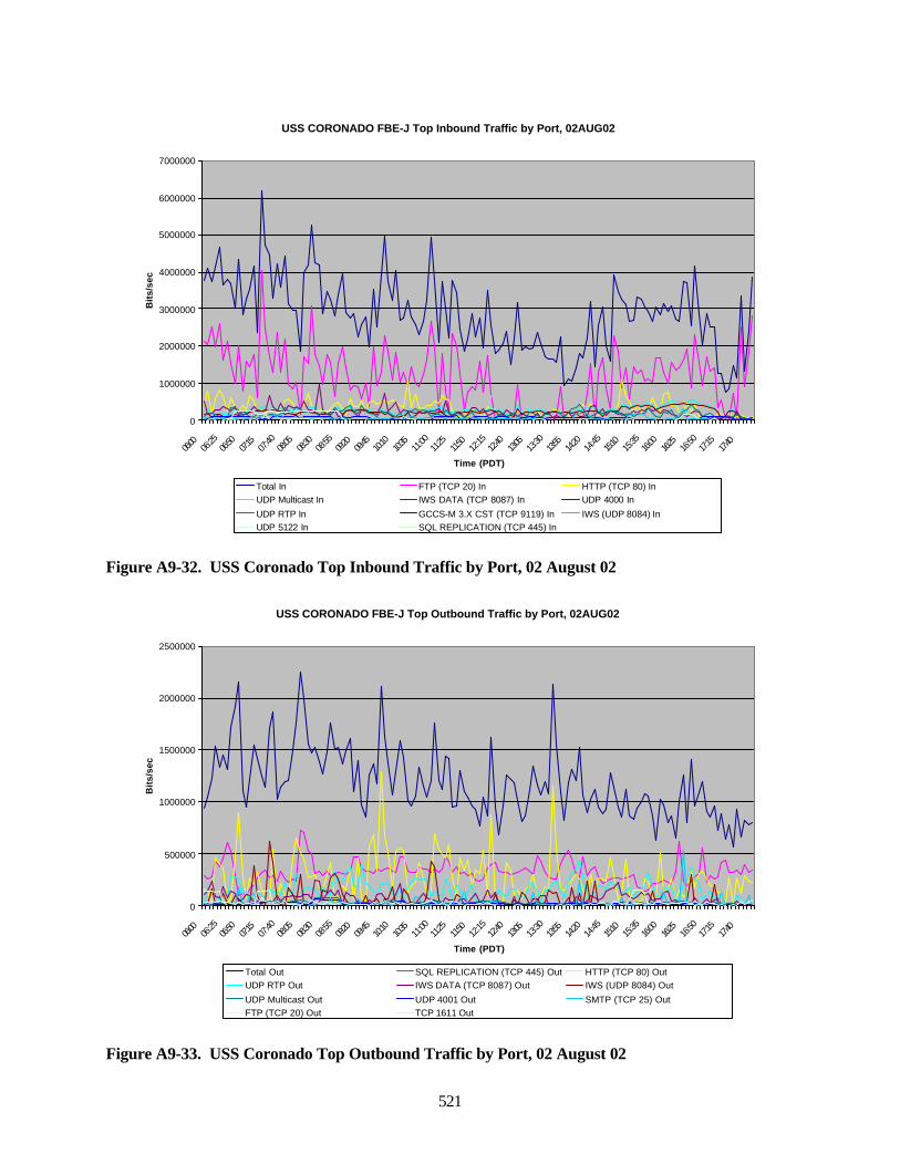
521
Figure A9-32. USS Coronado Top Inbound Traffic by Port, 02 August 02
Figure A9-33. USS Coronado Top Outbound Traffic by Port, 02 August 02
USS CORONADO FBE-J Top Inbound Traffic by Port, 02AUG02
0
1000000
2000000
3000000
4000000
5000000
6000000
7000000
06:00
06:25
06:50
07:15
07:40
08:05
08:30
08:55
09:20
09:45
10:10
10:35
11:00
11:25
11:50
12:15
12:40
13:05
13:30
13:55
14:20
14:45
15:10
15:35
16:00
16:25
16:50
17:15
17:40
Time (PDT)
Bit
s/se
c
Total In FTP (TCP 20) In HTTP (TCP 80) InUDP Multicast In IWS DATA (TCP 8087) In UDP 4000 In
UDP RTP In GCCS-M 3.X CST (TCP 9119) In IWS (UDP 8084) InUDP 5122 In SQL REPLICATION (TCP 445) In
USS CORONADO FBE-J Top Outbound Traffic by Port, 02AUG02
0
500000
1000000
1500000
2000000
2500000
06:00
06:25
06:50
07:15
07:40
08:05
08:30
08:55
09:20
09:45
10:10
10:35
11:00
11:25
11:50
12:15
12:40
13:05
13:30
13:55
14:20
14:45
15:10
15:35
16:00
16:25
16:50
17:15
17:40
Time (PDT)
Bit
s/se
c
Total Out SQL REPLICATION (TCP 445) Out HTTP (TCP 80) OutUDP RTP Out IWS DATA (TCP 8087) Out IWS (UDP 8084) Out
UDP Multicast Out UDP 4001 Out SMTP (TCP 25) OutFTP (TCP 20) Out TCP 1611 Out
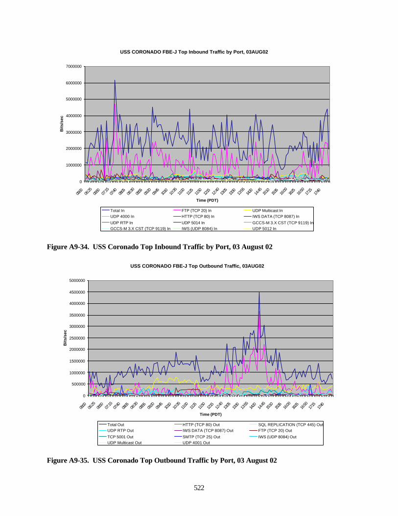
522
Figure A9-34. USS Coronado Top Inbound Traffic by Port, 03 August 02
Figure A9-35. USS Coronado Top Outbound Traffic by Port, 03 August 02
USS CORONADO FBE-J Top Inbound Traffic by Port, 03AUG02
0
1000000
2000000
3000000
4000000
5000000
6000000
7000000
06:00
06:25
06:50
07:15
07:40
08:05
08:30
08:55
09:20
09:45
10:10
10:35
11:00
11:25
11:50
12:15
12:40
13:05
13:30
13:55
14:20
14:45
15:10
15:35
16:00
16:25
16:50
17:15
17:40
Time (PDT)
Bit
s/se
c
Total In FTP (TCP 20) In UDP Multicast InUDP 4000 In HTTP (TCP 80) In IWS DATA (TCP 8087) In
UDP RTP In UDP 5014 In GCCS-M 3.X CST (TCP 9119) InGCCS-M 3.X CST (TCP 9119) In IWS (UDP 8084) In UDP 5012 In
USS CORONADO FBE-J Top Outbound Traffic, 03AUG02
0
500000
1000000
1500000
2000000
2500000
3000000
3500000
4000000
4500000
5000000
06:00
06:25
06:50
07:15
07:40
08:05
08:30
08:55
09:20
09:45
10:10
10:35
11:00
11:25
11:50
12:15
12:40
13:05
13:30
13:55
14:20
14:45
15:10
15:35
16:00
16:25
16:50
17:15
17:40
Time (PDT)
Bit
s/se
c
Total Out HTTP (TCP 80) Out SQL REPLICATION (TCP 445) OutUDP RTP Out IWS DATA (TCP 8087) Out FTP (TCP 20) Out
TCP 5001 Out SMTP (TCP 25) Out IWS (UDP 8084) OutUDP Multicast Out UDP 4001 Out
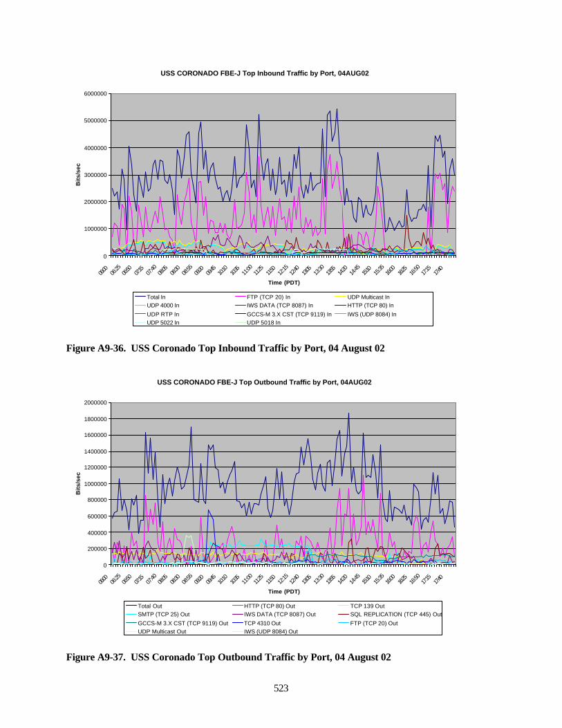
523
Figure A9-36. USS Coronado Top Inbound Traffic by Port, 04 August 02
Figure A9-37. USS Coronado Top Outbound Traffic by Port, 04 August 02
USS CORONADO FBE-J Top Inbound Traffic by Port, 04AUG02
0
1000000
2000000
3000000
4000000
5000000
6000000
06:00
06:25
06:50
07:15
07:40
08:05
08:30
08:55
09:20
09:45
10:10
10:35
11:00
11:25
11:50
12:15
12:40
13:05
13:30
13:55
14:20
14:45
15:10
15:35
16:00
16:25
16:50
17:15
17:40
Time (PDT)
Bit
s/se
c
Total In FTP (TCP 20) In UDP Multicast InUDP 4000 In IWS DATA (TCP 8087) In HTTP (TCP 80) In
UDP RTP In GCCS-M 3.X CST (TCP 9119) In IWS (UDP 8084) InUDP 5022 In UDP 5018 In
USS CORONADO FBE-J Top Outbound Traffic by Port, 04AUG02
0
200000
400000
600000
800000
1000000
1200000
1400000
1600000
1800000
2000000
06:00
06:25
06:50
07:15
07:40
08:05
08:30
08:55
09:20
09:45
10:10
10:35
11:00
11:25
11:50
12:15
12:40
13:05
13:30
13:55
14:20
14:45
15:10
15:35
16:00
16:25
16:50
17:15
17:40
Time (PDT)
Bit
s/se
c
Total Out HTTP (TCP 80) Out TCP 139 OutSMTP (TCP 25) Out IWS DATA (TCP 8087) Out SQL REPLICATION (TCP 445) Out
GCCS-M 3.X CST (TCP 9119) Out TCP 4310 Out FTP (TCP 20) OutUDP Multicast Out IWS (UDP 8084) Out
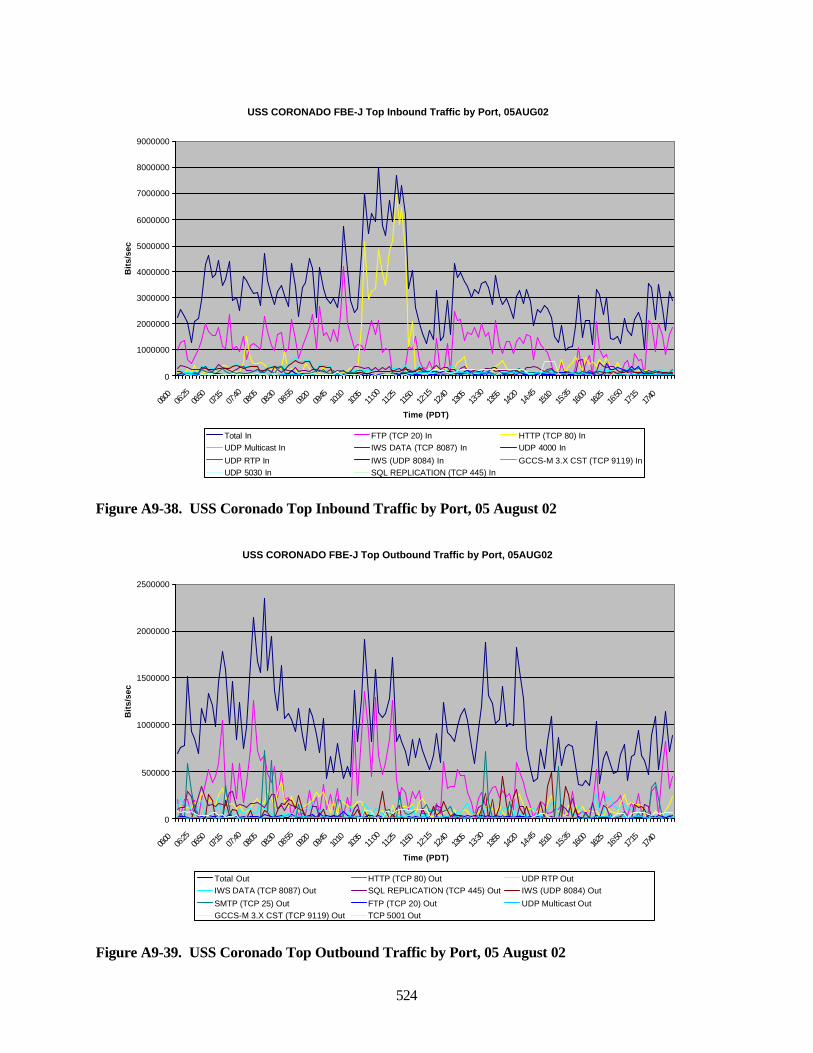
524
Figure A9-38. USS Coronado Top Inbound Traffic by Port, 05 August 02
Figure A9-39. USS Coronado Top Outbound Traffic by Port, 05 August 02
USS CORONADO FBE-J Top Inbound Traffic by Port, 05AUG02
0
1000000
2000000
3000000
4000000
5000000
6000000
7000000
8000000
9000000
06:00
06:25
06:50
07:15
07:40
08:05
08:30
08:55
09:20
09:45
10:10
10:35
11:00
11:25
11:50
12:15
12:40
13:05
13:30
13:55
14:20
14:45
15:10
15:35
16:00
16:25
16:50
17:15
17:40
Time (PDT)
Bit
s/se
c
Total In FTP (TCP 20) In HTTP (TCP 80) InUDP Multicast In IWS DATA (TCP 8087) In UDP 4000 In
UDP RTP In IWS (UDP 8084) In GCCS-M 3.X CST (TCP 9119) InUDP 5030 In SQL REPLICATION (TCP 445) In
USS CORONADO FBE-J Top Outbound Traffic by Port, 05AUG02
0
500000
1000000
1500000
2000000
2500000
06:00
06:25
06:50
07:15
07:40
08:05
08:30
08:55
09:20
09:45
10:10
10:35
11:00
11:25
11:50
12:15
12:40
13:05
13:30
13:55
14:20
14:45
15:10
15:35
16:00
16:25
16:50
17:15
17:40
Time (PDT)
Bit
s/se
c
Total Out HTTP (TCP 80) Out UDP RTP OutIWS DATA (TCP 8087) Out SQL REPLICATION (TCP 445) Out IWS (UDP 8084) Out
SMTP (TCP 25) Out FTP (TCP 20) Out UDP Multicast OutGCCS-M 3.X CST (TCP 9119) Out TCP 5001 Out
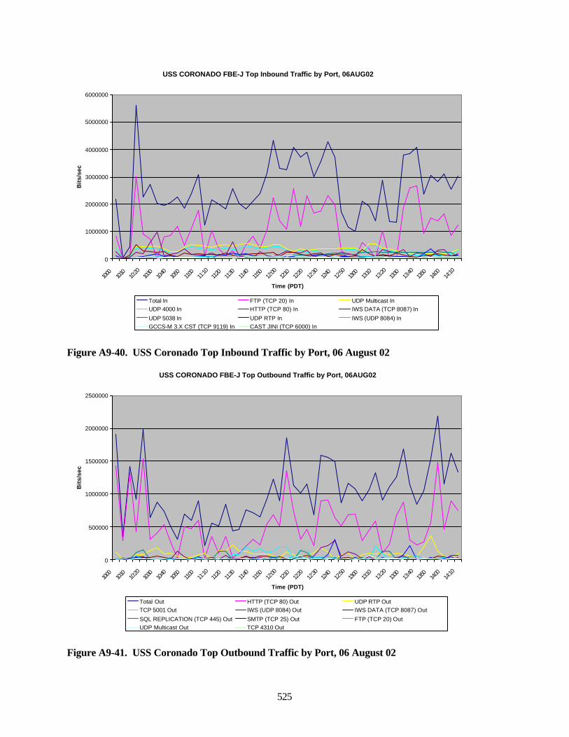
525
Figure A9-40. USS Coronado Top Inbound Traffic by Port, 06 August 02
Figure A9-41. USS Coronado Top Outbound Traffic by Port, 06 August 02
USS CORONADO FBE-J Top Inbound Traffic by Port, 06AUG02
0
1000000
2000000
3000000
4000000
5000000
6000000
10:00
10:10
10:20
10:30
10:40
10:50
11:00
11:10
11:20
11:30
11:40
11:50
12:00
12:10
12:20
12:30
12:40
12:50
13:00
13:10
13:20
13:30
13:40
13:50
14:00
14:10
Time (PDT)
Bit
s/se
c
Total In FTP (TCP 20) In UDP Multicast InUDP 4000 In HTTP (TCP 80) In IWS DATA (TCP 8087) In
UDP 5038 In UDP RTP In IWS (UDP 8084) InGCCS-M 3.X CST (TCP 9119) In CAST JINI (TCP 6000) In
USS CORONADO FBE-J Top Outbound Traffic by Port, 06AUG02
0
500000
1000000
1500000
2000000
2500000
10:00
10:10
10:20
10:30
10:40
10:50
11:00
11:10
11:20
11:30
11:40
11:50
12:00
12:10
12:20
12:30
12:40
12:50
13:00
13:10
13:20
13:30
13:40
13:50
14:00
14:10
Time (PDT)
Bit
s/se
c
Total Out HTTP (TCP 80) Out UDP RTP OutTCP 5001 Out IWS (UDP 8084) Out IWS DATA (TCP 8087) Out
SQL REPLICATION (TCP 445) Out SMTP (TCP 25) Out FTP (TCP 20) OutUDP Multicast Out TCP 4310 Out
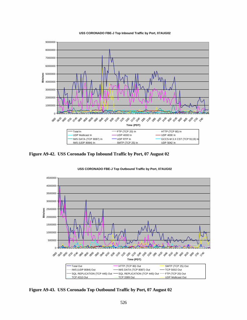
526
Figure A9-42. USS Coronado Top Inbound Traffic by Port, 07 August 02
Figure A9-43. USS Coronado Top Outbound Traffic by Port, 07 August 02
USS CORONADO FBE-J Top Inbound Traffic by Port, 07AUG02
0
1000000
2000000
3000000
4000000
5000000
6000000
7000000
8000000
9000000
06:00
06:25
06:50
07:15
07:40
08:05
08:30
08:55
09:20
09:45
10:10
10:35
11:00
11:25
11:50
12:15
12:40
13:05
13:30
13:55
14:20
14:45
15:10
15:35
16:00
16:25
16:50
17:15
17:40
Time (PDT)
Bit
s/se
c
Total In FTP (TCP 20) In HTTP (TCP 80) InUDP Multicast In UDP 4000 In UDP 4000 In
IWS DATA (TCP 8087) In UDP RTP In GCCS-M 3.X CST (TCP 9119) InIWS (UDP 8084) In SMTP (TCP 25) In UDP 5042 In
USS CORONADO FBE-J Top Outbound Traffic by Port, 07AUG02
0
500000
1000000
1500000
2000000
2500000
3000000
3500000
4000000
4500000
06:00
06:25
06:50
07:15
07:40
08:05
08:30
08:55
09:20
09:45
10:10
10:35
11:00
11:25
11:50
12:15
12:40
13:05
13:30
13:55
14:20
14:45
15:10
15:35
16:00
16:25
16:50
17:15
17:40
Time (PDT)
Bit
s/se
c
Total Out HTTP (TCP 80) Out SMTP (TCP 25) OutIWS (UDP 8084) Out IWS DATA (TCP 8087) Out TCP 5002 Out
SQL REPLICATION (TCP 445) Out SQL REPLICATION (TCP 445) Out FTP (TCP 20) OutTCP 4310 Out TCP 3389 Out UDP Multicast Out
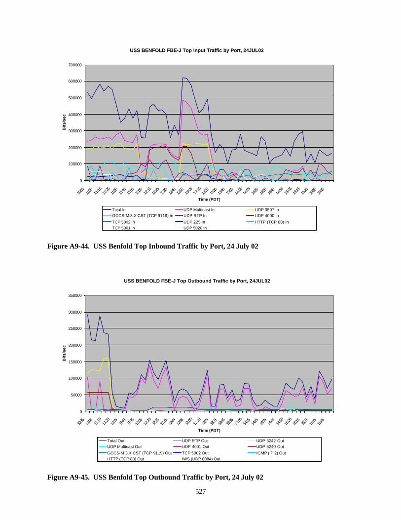
527
Figure A9-44. USS Benfold Top Inbound Traffic by Port, 24 July 02
Figure A9-45. USS Benfold Top Outbound Traffic by Port, 24 July 02
USS BENFOLD FBE-J Top Input Traffic by Port, 24JUL02
0
100000
200000
300000
400000
500000
600000
700000
10:55
11:05
11:15
11:25
11:35
11:45
11:55
12:05
12:15
12:25
12:35
12:45
12:55
13:05
13:15
13:25
13:35
13:45
13:55
14:05
14:15
14:25
14:35
14:45
14:55
15:05
15:15
15:25
15:35
15:45
Time (PDT)
Bit
s/se
c
Total In UDP Multicast In UDP 3597 InGCCS-M 3.X CST (TCP 9119) In UDP RTP In UDP 4000 In
TCP 5002 In UDP 225 In HTTP (TCP 80) InTCP 5001 In UDP 5020 In
USS BENFOLD FBE-J Top Outbound Traffic by Port, 24JUL02
0
50000
100000
150000
200000
250000
300000
350000
10:55
11:05
11:15
11:25
11:35
11:45
11:55
12:05
12:15
12:25
12:35
12:45
12:55
13:05
13:15
13:25
13:35
13:45
13:55
14:05
14:15
14:25
14:35
14:45
14:55
15:05
15:15
15:25
15:35
15:45
Time (PDT)
Bit
s/se
c
Total Out UDP RTP Out UDP 5242 OutUDP Multicast Out UDP 4001 Out UDP 5240 Out
GCCS-M 3.X CST (TCP 9119) Out TCP 5002 Out IGMP (IP 2) OutHTTP (TCP 80) Out IWS (UDP 8084) Out
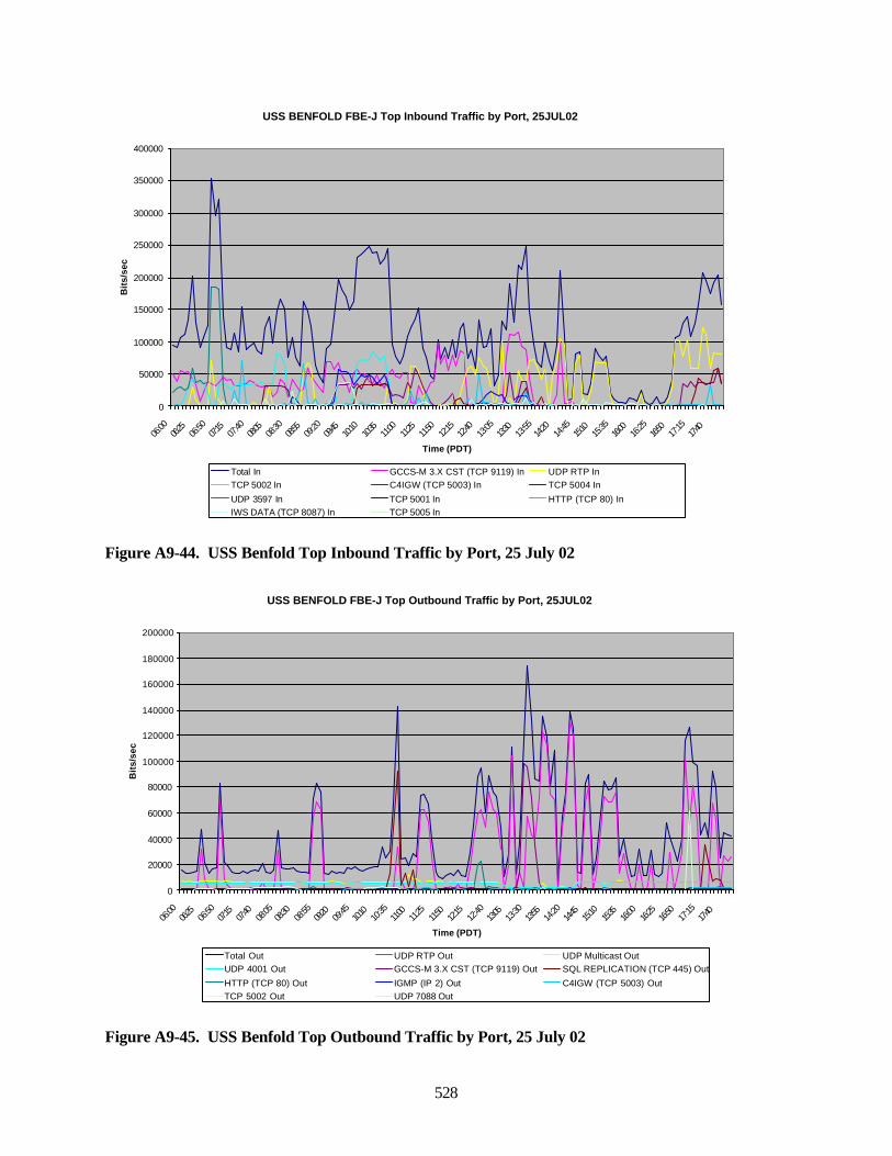
528
Figure A9-44. USS Benfold Top Inbound Traffic by Port, 25 July 02
Figure A9-45. USS Benfold Top Outbound Traffic by Port, 25 July 02
USS BENFOLD FBE-J Top Inbound Traffic by Port, 25JUL02
0
50000
100000
150000
200000
250000
300000
350000
400000
06:00
06:25
06:50
07:15
07:40
08:05
08:30
08:55
09:20
09:45
10:10
10:35
11:00
11:25
11:50
12:15
12:40
13:05
13:30
13:55
14:20
14:45
15:10
15:35
16:00
16:25
16:50
17:15
17:40
Time (PDT)
Bit
s/se
c
Total In GCCS-M 3.X CST (TCP 9119) In UDP RTP InTCP 5002 In C4IGW (TCP 5003) In TCP 5004 In
UDP 3597 In TCP 5001 In HTTP (TCP 80) InIWS DATA (TCP 8087) In TCP 5005 In
USS BENFOLD FBE-J Top Outbound Traffic by Port, 25JUL02
0
20000
40000
60000
80000
100000
120000
140000
160000
180000
200000
06:00
06:25
06:50
07:15
07:40
08:05
08:30
08:55
09:20
09:45
10:10
10:35
11:00
11:25
11:50
12:15
12:40
13:05
13:30
13:55
14:20
14:45
15:10
15:35
16:00
16:25
16:50
17:15
17:40
Time (PDT)
Bit
s/se
c
Total Out UDP RTP Out UDP Multicast OutUDP 4001 Out GCCS-M 3.X CST (TCP 9119) Out SQL REPLICATION (TCP 445) Out
HTTP (TCP 80) Out IGMP (IP 2) Out C4IGW (TCP 5003) OutTCP 5002 Out UDP 7088 Out
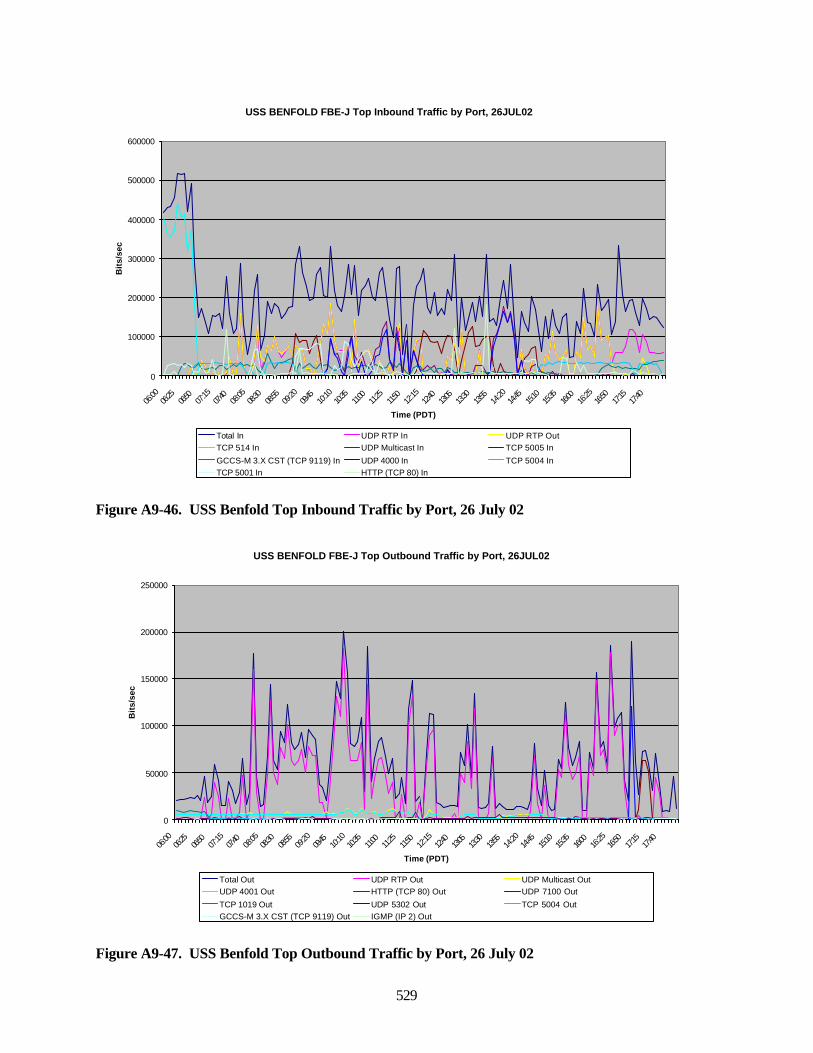
529
Figure A9-46. USS Benfold Top Inbound Traffic by Port, 26 July 02
Figure A9-47. USS Benfold Top Outbound Traffic by Port, 26 July 02
USS BENFOLD FBE-J Top Inbound Traffic by Port, 26JUL02
0
100000
200000
300000
400000
500000
600000
06:00
06:25
06:50
07:15
07:40
08:05
08:30
08:55
09:20
09:45
10:10
10:35
11:00
11:25
11:50
12:15
12:40
13:05
13:30
13:55
14:20
14:45
15:10
15:35
16:00
16:25
16:50
17:15
17:40
Time (PDT)
Bit
s/se
c
Total In UDP RTP In UDP RTP OutTCP 514 In UDP Multicast In TCP 5005 In
GCCS-M 3.X CST (TCP 9119) In UDP 4000 In TCP 5004 InTCP 5001 In HTTP (TCP 80) In
USS BENFOLD FBE-J Top Outbound Traffic by Port, 26JUL02
0
50000
100000
150000
200000
250000
06:00
06:25
06:50
07:15
07:40
08:05
08:30
08:55
09:20
09:45
10:10
10:35
11:00
11:25
11:50
12:15
12:40
13:05
13:30
13:55
14:20
14:45
15:10
15:35
16:00
16:25
16:50
17:15
17:40
Time (PDT)
Bit
s/se
c
Total Out UDP RTP Out UDP Multicast OutUDP 4001 Out HTTP (TCP 80) Out UDP 7100 Out
TCP 1019 Out UDP 5302 Out TCP 5004 OutGCCS-M 3.X CST (TCP 9119) Out IGMP (IP 2) Out
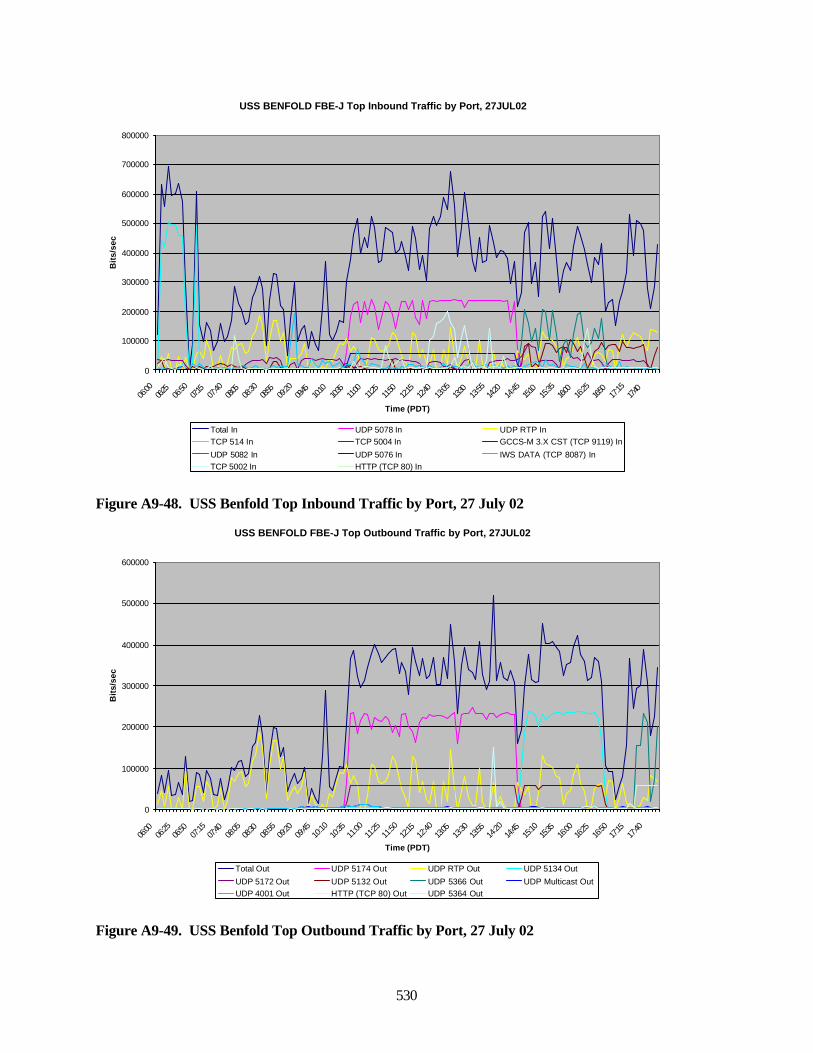
530
Figure A9-48. USS Benfold Top Inbound Traffic by Port, 27 July 02
Figure A9-49. USS Benfold Top Outbound Traffic by Port, 27 July 02
USS BENFOLD FBE-J Top Inbound Traffic by Port, 27JUL02
0
100000
200000
300000
400000
500000
600000
700000
800000
06:00
06:25
06:50
07:15
07:40
08:05
08:30
08:55
09:20
09:45
10:10
10:35
11:00
11:25
11:50
12:15
12:40
13:05
13:30
13:55
14:20
14:45
15:10
15:35
16:00
16:25
16:50
17:15
17:40
Time (PDT)
Bit
s/se
c
Total In UDP 5078 In UDP RTP InTCP 514 In TCP 5004 In GCCS-M 3.X CST (TCP 9119) In
UDP 5082 In UDP 5076 In IWS DATA (TCP 8087) InTCP 5002 In HTTP (TCP 80) In
USS BENFOLD FBE-J Top Outbound Traffic by Port, 27JUL02
0
100000
200000
300000
400000
500000
600000
06:00
06:25
06:50
07:15
07:40
08:05
08:30
08:55
09:20
09:45
10:10
10:35
11:00
11:25
11:50
12:15
12:40
13:05
13:30
13:55
14:20
14:45
15:10
15:35
16:00
16:25
16:50
17:15
17:40
Time (PDT)
Bit
s/se
c
Total Out UDP 5174 Out UDP RTP Out UDP 5134 Out
UDP 5172 Out UDP 5132 Out UDP 5366 Out UDP Multicast OutUDP 4001 Out HTTP (TCP 80) Out UDP 5364 Out
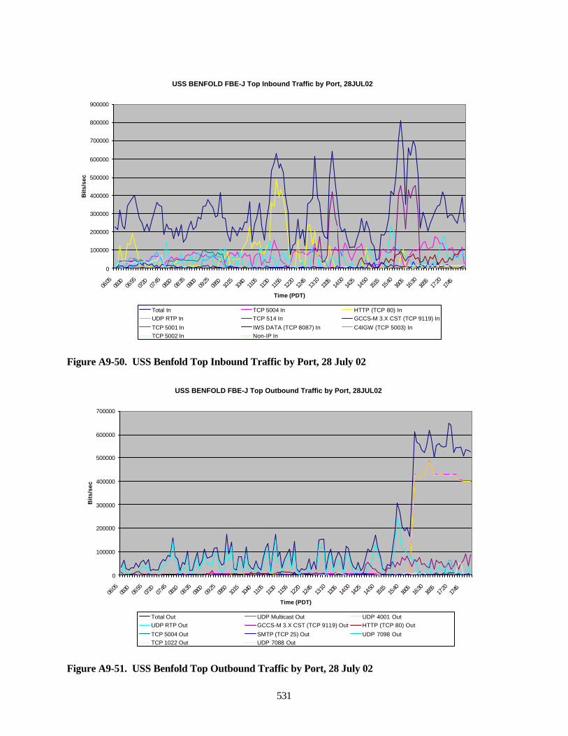
531
Figure A9-50. USS Benfold Top Inbound Traffic by Port, 28 July 02
Figure A9-51. USS Benfold Top Outbound Traffic by Port, 28 July 02
USS BENFOLD FBE-J Top Inbound Traffic by Port, 28JUL02
0
100000
200000
300000
400000
500000
600000
700000
800000
900000
06:05
06:30
06:55
07:20
07:45
08:10
08:35
09:00
09:25
09:50
10:15
10:40
11:05
11:30
11:55
12:20
12:45
13:10
13:35
14:00
14:25
14:50
15:15
15:40
16:05
16:30
16:55
17:20
17:45
Time (PDT)
Bit
s/se
c
Total In TCP 5004 In HTTP (TCP 80) InUDP RTP In TCP 514 In GCCS-M 3.X CST (TCP 9119) In
TCP 5001 In IWS DATA (TCP 8087) In C4IGW (TCP 5003) InTCP 5002 In Non-IP In
USS BENFOLD FBE-J Top Outbound Traffic by Port, 28JUL02
0
100000
200000
300000
400000
500000
600000
700000
06:05
06:30
06:55
07:20
07:45
08:10
08:35
09:00
09:25
09:50
10:15
10:40
11:05
11:30
11:55
12:20
12:45
13:10
13:35
14:00
14:25
14:50
15:15
15:40
16:05
16:30
16:55
17:20
17:45
Time (PDT)
Bit
s/se
c
Total Out UDP Multicast Out UDP 4001 OutUDP RTP Out GCCS-M 3.X CST (TCP 9119) Out HTTP (TCP 80) Out
TCP 5004 Out SMTP (TCP 25) Out UDP 7098 OutTCP 1022 Out UDP 7088 Out
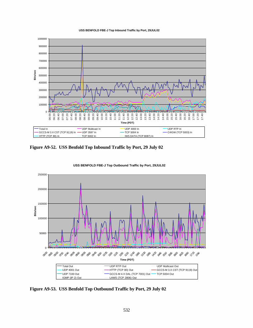
532
Figure A9-52. USS Benfold Top Inbound Traffic by Port, 29 July 02
Figure A9-53. USS Benfold Top Outbound Traffic by Port, 29 July 02
USS BENFOLD FBE-J Top Inbound Traffic by Port, 29JUL02
0
100000
200000
300000
400000
500000
600000
700000
800000
900000
1000000
06:0
0
06:2
0
06:4
0
07:0
0
07:2
0
07:4
0
08:0
0
08:2
0
08:4
0
09:0
0
09:2
0
09:4
0
10:0
0
10:2
0
10:4
0
11:0
0
11:2
0
11:4
0
12:0
0
12:2
0
12:4
0
13:0
0
13:2
0
13:4
0
14:0
0
14:2
0
14:4
0
15:0
0
15:2
0
15:4
0
16:0
0
16:2
0
16:4
0
17:0
0
17:2
0
17:4
0
Time (PDT)
Bit
s/se
c
Total In UDP Multicast In UDP 4000 In UDP RTP InGCCS-M 3.X CST (TCP 9119) In UDP 3597 In TCP 5004 In C4IGW (TCP 5003) InHTTP (TCP 80) In TCP 5002 In IWS DATA (TCP 8087) In
USS BENFOLD FBE-J Top Outbound Traffic by Port, 29JUL02
0
50000
100000
150000
200000
250000
06:00
06:25
06:50
07:15
07:40
08:05
08:30
08:55
09:20
09:45
10:10
10:35
11:00
11:25
11:50
12:15
12:40
13:05
13:30
13:55
14:20
14:45
15:10
15:35
16:00
16:25
16:50
17:15
17:40
Time (PDT)
Bit
s/se
c
Total Out UDP RTP Out UDP Multicast OutUDP 4001 Out HTTP (TCP 80) Out GCCS-M 3.X CST (TCP 9119) Out
UDP 7100 Out GCCS-M 4.X DAL (TCP 7001) Out TCP 5004 OutIGMP (IP 2) Out LAWS (TCP 2806) Out
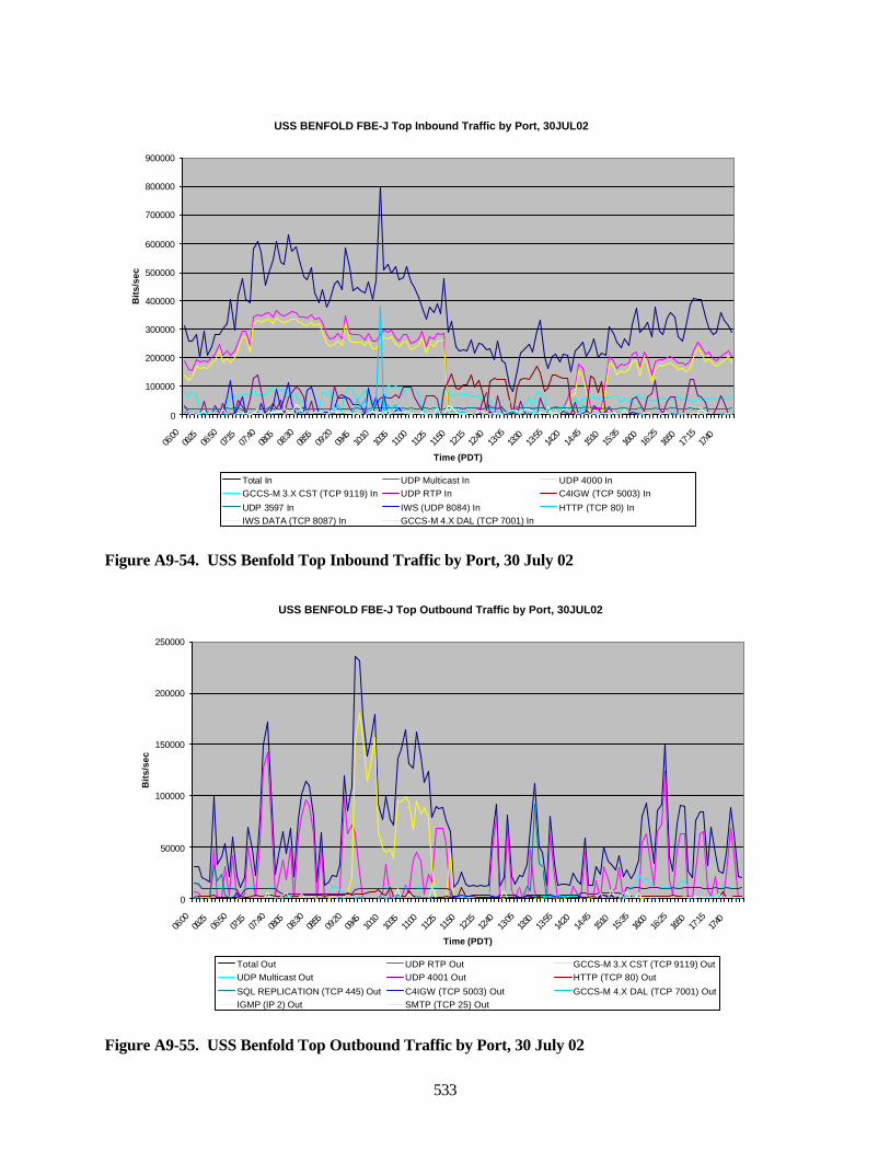
533
Figure A9-54. USS Benfold Top Inbound Traffic by Port, 30 July 02
Figure A9-55. USS Benfold Top Outbound Traffic by Port, 30 July 02
USS BENFOLD FBE-J Top Inbound Traffic by Port, 30JUL02
0
100000
200000
300000
400000
500000
600000
700000
800000
900000
06:00
06:25
06:50
07:15
07:40
08:05
08:30
08:55
09:20
09:45
10:10
10:35
11:00
11:25
11:50
12:15
12:40
13:05
13:30
13:55
14:20
14:45
15:10
15:35
16:00
16:25
16:50
17:15
17:40
Time (PDT)
Bit
s/se
c
Total In UDP Multicast In UDP 4000 InGCCS-M 3.X CST (TCP 9119) In UDP RTP In C4IGW (TCP 5003) In
UDP 3597 In IWS (UDP 8084) In HTTP (TCP 80) InIWS DATA (TCP 8087) In GCCS-M 4.X DAL (TCP 7001) In
USS BENFOLD FBE-J Top Outbound Traffic by Port, 30JUL02
0
50000
100000
150000
200000
250000
06:00
06:25
06:50
07:15
07:40
08:05
08:30
08:55
09:20
09:45
10:10
10:35
11:00
11:25
11:50
12:15
12:40
13:05
13:30
13:55
14:20
14:45
15:10
15:35
16:00
16:25
16:50
17:15
17:40
Time (PDT)
Bit
s/se
c
Total Out UDP RTP Out GCCS-M 3.X CST (TCP 9119) OutUDP Multicast Out UDP 4001 Out HTTP (TCP 80) Out
SQL REPLICATION (TCP 445) Out C4IGW (TCP 5003) Out GCCS-M 4.X DAL (TCP 7001) OutIGMP (IP 2) Out SMTP (TCP 25) Out
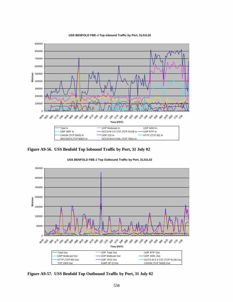
534
Figure A9-56. USS Benfold Top Inbound Traffic by Port, 31 July 02
Figure A9-57. USS Benfold Top Outbound Traffic by Port, 31 July 02
USS BENFOLD FBE-J Top Inbound Traffic by Port, 31JUL02
0
100000
200000
300000
400000
500000
600000
700000
800000
900000
06:00
06:25
06:50
07:15
07:40
08:05
08:30
08:55
09:20
09:45
10:10
10:35
11:00
11:25
11:50
12:15
12:40
13:05
13:30
13:55
14:20
14:45
15:10
15:35
16:00
16:25
16:50
17:15
17:40
Time (PDT)
Bit
s/se
c
Total In UDP Multicast In UDP 4000 InUDP 3597 In GCCS-M 3.X CST (TCP 9119) In UDP RTP In
C4IGW (TCP 5003) In UDP 225 In HTTP (TCP 80) InIWS DATA (TCP 8087) In GCCS-M 4.X DAL (TCP 7001) In
USS BENFOLD FBE-J Top Outbound Traffic by Port, 31JUL02
0
50000
100000
150000
200000
250000
300000
350000
06:00
06:25
06:50
07:15
07:40
08:05
08:30
08:55
09:20
09:45
10:10
10:35
11:00
11:25
11:50
12:15
12:40
13:05
13:30
13:55
14:20
14:45
15:10
15:35
16:00
16:25
16:50
17:15
17:40
Time (PDT)
Bit
s/se
c
Total Out UDP Total Out UDP RTP OutUDP Multicast Out UDP Multicast Out UDP 4001 Out
HTTP (TCP 80) Out UDP 7070 Out GCCS-M 3.X CST (TCP 9119) OutTCP 1503 Out IGMP (IP 2) Out C4IGW (TCP 5003) Out
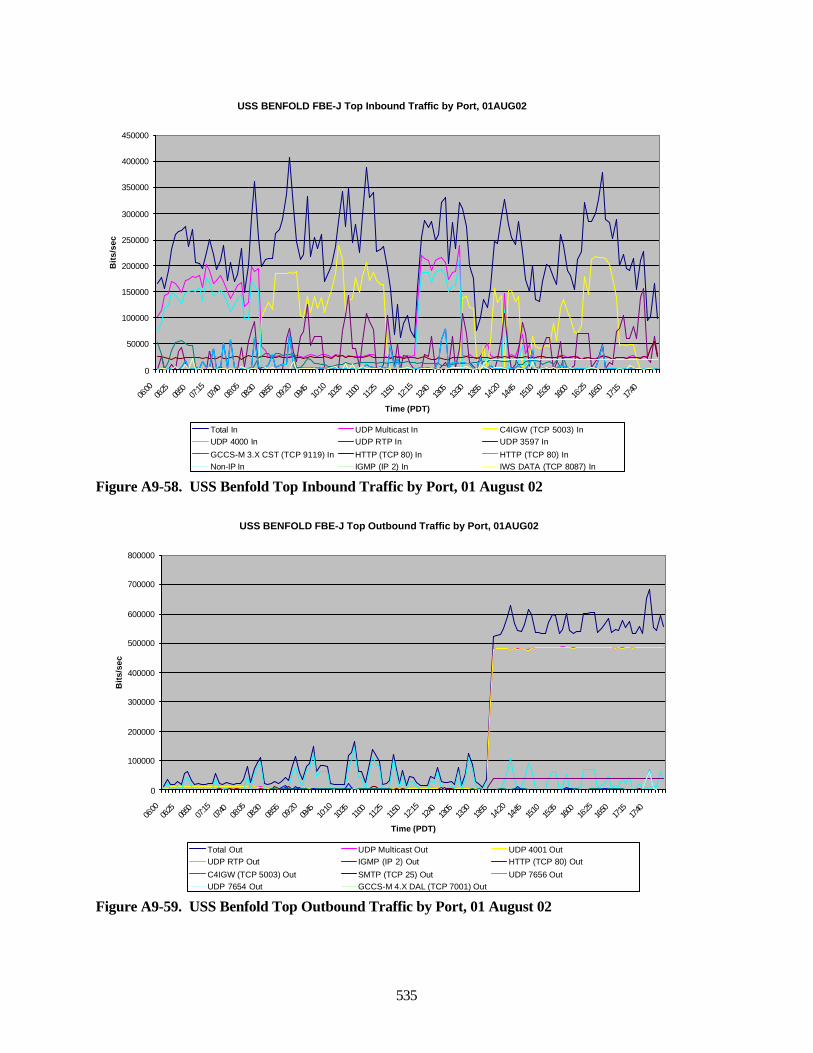
535
Figure A9-58. USS Benfold Top Inbound Traffic by Port, 01 August 02
Figure A9-59. USS Benfold Top Outbound Traffic by Port, 01 August 02
USS BENFOLD FBE-J Top Inbound Traffic by Port, 01AUG02
0
50000
100000
150000
200000
250000
300000
350000
400000
450000
06:00
06:25
06:50
07:15
07:40
08:05
08:30
08:55
09:20
09:45
10:10
10:35
11:00
11:25
11:50
12:15
12:40
13:05
13:30
13:55
14:20
14:45
15:10
15:35
16:00
16:25
16:50
17:15
17:40
Time (PDT)
Bit
s/se
c
Total In UDP Multicast In C4IGW (TCP 5003) InUDP 4000 In UDP RTP In UDP 3597 In
GCCS-M 3.X CST (TCP 9119) In HTTP (TCP 80) In HTTP (TCP 80) InNon-IP In IGMP (IP 2) In IWS DATA (TCP 8087) In
USS BENFOLD FBE-J Top Outbound Traffic by Port, 01AUG02
0
100000
200000
300000
400000
500000
600000
700000
800000
06:00
06:25
06:50
07:15
07:40
08:05
08:30
08:55
09:20
09:45
10:10
10:35
11:00
11:25
11:50
12:15
12:40
13:05
13:30
13:55
14:20
14:45
15:10
15:35
16:00
16:25
16:50
17:15
17:40
Time (PDT)
Bit
s/se
c
Total Out UDP Multicast Out UDP 4001 OutUDP RTP Out IGMP (IP 2) Out HTTP (TCP 80) Out
C4IGW (TCP 5003) Out SMTP (TCP 25) Out UDP 7656 OutUDP 7654 Out GCCS-M 4.X DAL (TCP 7001) Out
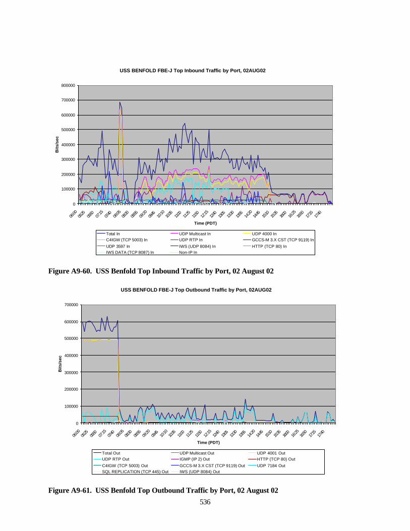
536
Figure A9-60. USS Benfold Top Inbound Traffic by Port, 02 August 02
Figure A9-61. USS Benfold Top Outbound Traffic by Port, 02 August 02
USS BENFOLD FBE-J Top Inbound Traffic by Port, 02AUG02
0
100000
200000
300000
400000
500000
600000
700000
800000
06:00
06:25
06:50
07:15
07:40
08:05
08:30
08:55
09:20
09:45
10:10
10:35
11:00
11:25
11:50
12:15
12:40
13:05
13:30
13:55
14:20
14:45
15:10
15:35
16:00
16:25
16:50
17:15
17:40
Time (PDT)
Bit
s/se
c
Total In UDP Multicast In UDP 4000 InC4IGW (TCP 5003) In UDP RTP In GCCS-M 3.X CST (TCP 9119) In
UDP 3597 In IWS (UDP 8084) In HTTP (TCP 80) InIWS DATA (TCP 8087) In Non-IP In
USS BENFOLD FBE-J Top Outbound Traffic by Port, 02AUG02
0
100000
200000
300000
400000
500000
600000
700000
06:00
06:25
06:50
07:15
07:40
08:05
08:30
08:55
09:20
09:45
10:10
10:35
11:00
11:25
11:50
12:15
12:40
13:05
13:30
13:55
14:20
14:45
15:10
15:35
16:00
16:25
16:50
17:15
17:40
Time (PDT)
Bit
s/se
c
Total Out UDP Multicast Out UDP 4001 OutUDP RTP Out IGMP (IP 2) Out HTTP (TCP 80) Out
C4IGW (TCP 5003) Out GCCS-M 3.X CST (TCP 9119) Out UDP 7184 OutSQL REPLICATION (TCP 445) Out IWS (UDP 8084) Out
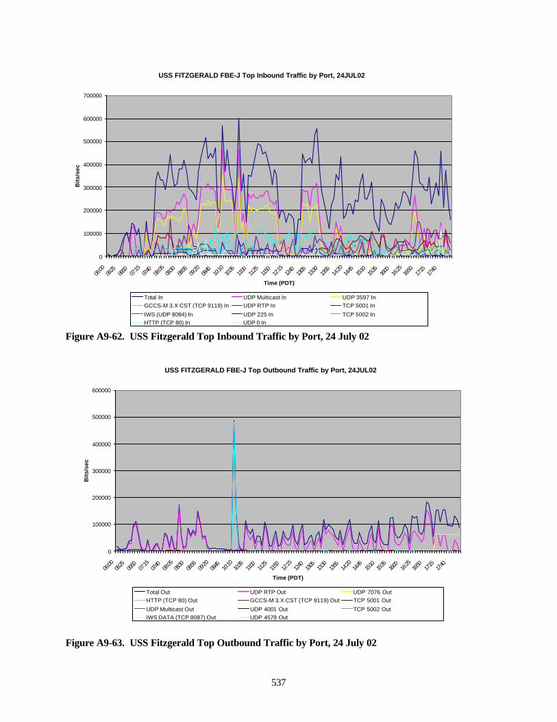
537
Figure A9-62. USS Fitzgerald Top Inbound Traffic by Port, 24 July 02
Figure A9-63. USS Fitzgerald Top Outbound Traffic by Port, 24 July 02
USS FITZGERALD FBE-J Top Inbound Traffic by Port, 24JUL02
0
100000
200000
300000
400000
500000
600000
700000
06:00
06:25
06:50
07:15
07:40
08:05
08:30
08:55
09:20
09:45
10:10
10:35
11:00
11:25
11:50
12:15
12:40
13:05
13:30
13:55
14:20
14:45
15:10
15:35
16:00
16:25
16:50
17:15
17:40
Time (PDT)
Bit
s/se
c
Total In UDP Multicast In UDP 3597 InGCCS-M 3.X CST (TCP 9119) In UDP RTP In TCP 5001 In
IWS (UDP 8084) In UDP 225 In TCP 5002 InHTTP (TCP 80) In UDP 0 In
USS FITZGERALD FBE-J Top Outbound Traffic by Port, 24JUL02
0
100000
200000
300000
400000
500000
600000
06:00
06:25
06:50
07:15
07:40
08:05
08:30
08:55
09:20
09:45
10:10
10:35
11:00
11:25
11:50
12:15
12:40
13:05
13:30
13:55
14:20
14:45
15:10
15:35
16:00
16:25
16:50
17:15
17:40
Time (PDT)
Bit
s/se
c
Total Out UDP RTP Out UDP 7076 OutHTTP (TCP 80) Out GCCS-M 3.X CST (TCP 9119) Out TCP 5001 Out
UDP Multicast Out UDP 4001 Out TCP 5002 OutIWS DATA (TCP 8087) Out UDP 4579 Out
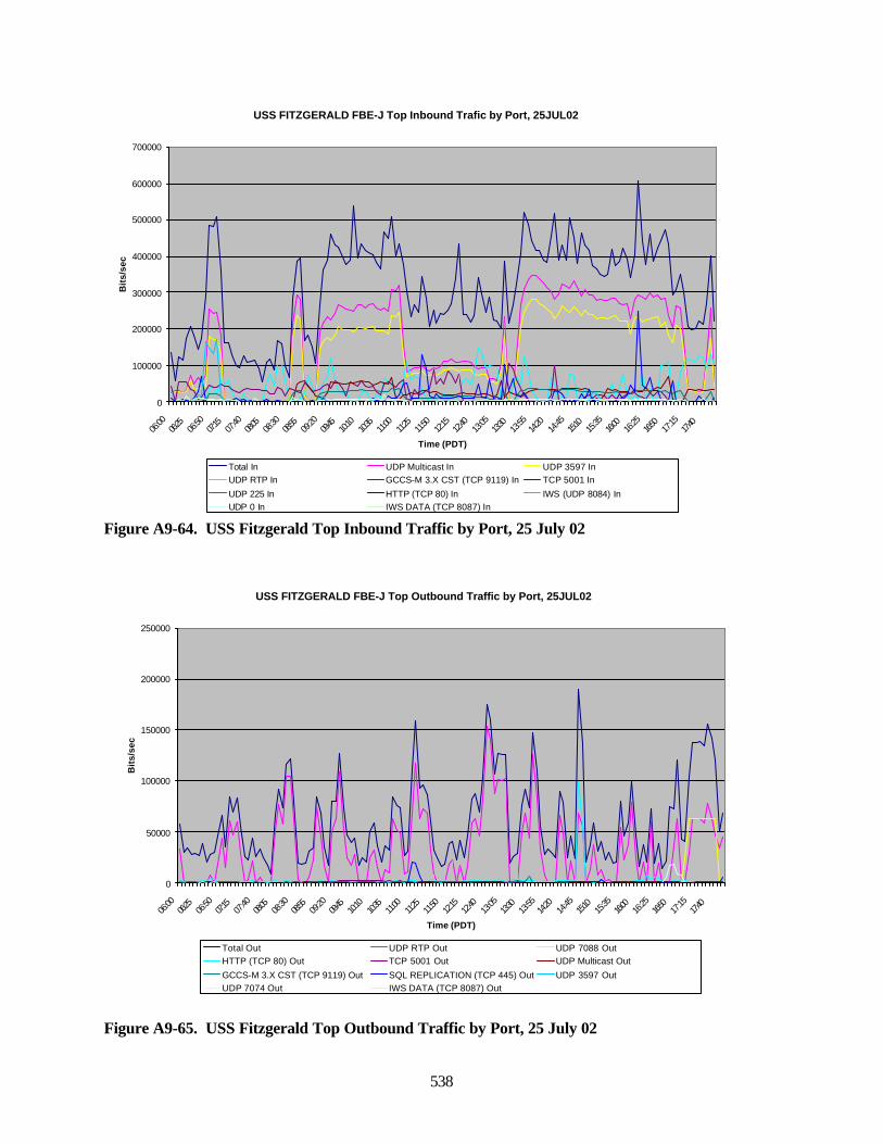
538
Figure A9-64. USS Fitzgerald Top Inbound Traffic by Port, 25 July 02
Figure A9-65. USS Fitzgerald Top Outbound Traffic by Port, 25 July 02
USS FITZGERALD FBE-J Top Inbound Trafic by Port, 25JUL02
0
100000
200000
300000
400000
500000
600000
700000
06:00
06:25
06:50
07:15
07:40
08:05
08:30
08:55
09:20
09:45
10:10
10:35
11:00
11:25
11:50
12:15
12:40
13:05
13:30
13:55
14:20
14:45
15:10
15:35
16:00
16:25
16:50
17:15
17:40
Time (PDT)
Bit
s/se
c
Total In UDP Multicast In UDP 3597 InUDP RTP In GCCS-M 3.X CST (TCP 9119) In TCP 5001 In
UDP 225 In HTTP (TCP 80) In IWS (UDP 8084) InUDP 0 In IWS DATA (TCP 8087) In
USS FITZGERALD FBE-J Top Outbound Traffic by Port, 25JUL02
0
50000
100000
150000
200000
250000
06:00
06:25
06:50
07:15
07:40
08:05
08:30
08:55
09:20
09:45
10:10
10:35
11:00
11:25
11:50
12:15
12:40
13:05
13:30
13:55
14:20
14:45
15:10
15:35
16:00
16:25
16:50
17:15
17:40
Time (PDT)
Bit
s/se
c
Total Out UDP RTP Out UDP 7088 OutHTTP (TCP 80) Out TCP 5001 Out UDP Multicast Out
GCCS-M 3.X CST (TCP 9119) Out SQL REPLICATION (TCP 445) Out UDP 3597 OutUDP 7074 Out IWS DATA (TCP 8087) Out
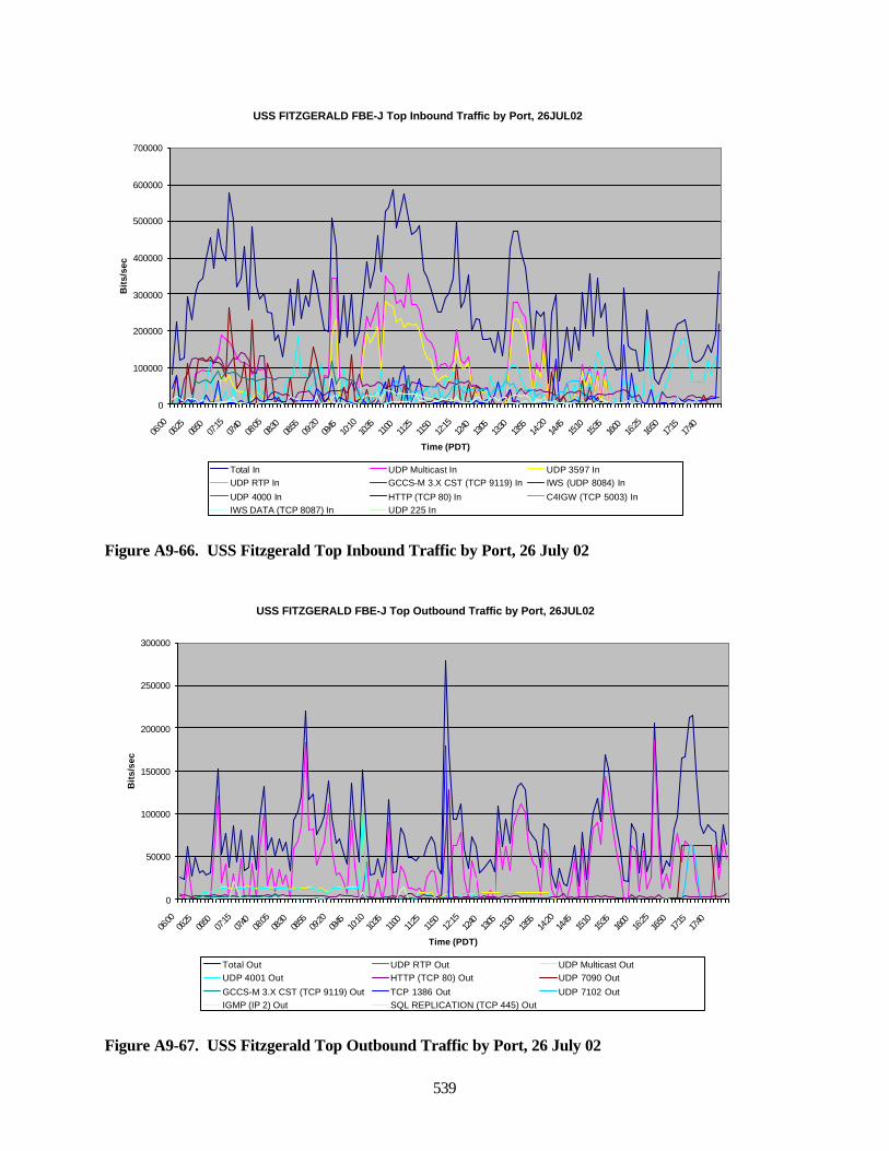
539
Figure A9-66. USS Fitzgerald Top Inbound Traffic by Port, 26 July 02
Figure A9-67. USS Fitzgerald Top Outbound Traffic by Port, 26 July 02
USS FITZGERALD FBE-J Top Outbound Traffic by Port, 26JUL02
0
50000
100000
150000
200000
250000
300000
06:00
06:25
06:50
07:15
07:40
08:05
08:30
08:55
09:20
09:45
10:10
10:35
11:00
11:25
11:50
12:15
12:40
13:05
13:30
13:55
14:20
14:45
15:10
15:35
16:00
16:25
16:50
17:15
17:40
Time (PDT)
Bit
s/se
c
Total Out UDP RTP Out UDP Multicast OutUDP 4001 Out HTTP (TCP 80) Out UDP 7090 Out
GCCS-M 3.X CST (TCP 9119) Out TCP 1386 Out UDP 7102 OutIGMP (IP 2) Out SQL REPLICATION (TCP 445) Out
USS FITZGERALD FBE-J Top Inbound Traffic by Port, 26JUL02
0
100000
200000
300000
400000
500000
600000
700000
06:00
06:25
06:50
07:15
07:40
08:05
08:30
08:55
09:20
09:45
10:10
10:35
11:00
11:25
11:50
12:15
12:40
13:05
13:30
13:55
14:20
14:45
15:10
15:35
16:00
16:25
16:50
17:15
17:40
Time (PDT)
Bit
s/se
c
Total In UDP Multicast In UDP 3597 InUDP RTP In GCCS-M 3.X CST (TCP 9119) In IWS (UDP 8084) In
UDP 4000 In HTTP (TCP 80) In C4IGW (TCP 5003) InIWS DATA (TCP 8087) In UDP 225 In
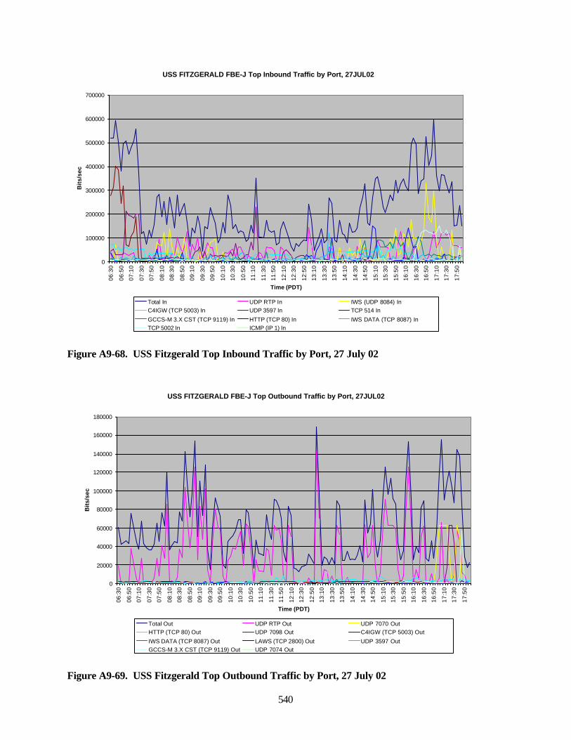
540
Figure A9-68. USS Fitzgerald Top Inbound Traffic by Port, 27 July 02
Figure A9-69. USS Fitzgerald Top Outbound Traffic by Port, 27 July 02
USS FITZGERALD FBE-J Top Inbound Traffic by Port, 27JUL02
0
100000
200000
300000
400000
500000
600000
700000
06:3
0
06:5
0
07:1
0
07:3
0
07:5
0
08:1
0
08:3
0
08:5
0
09:1
0
09:3
0
09:5
0
10:1
0
10:3
0
10:5
0
11:1
0
11:3
0
11:5
0
12:1
0
12:3
0
12:5
0
13:1
0
13:3
0
13:5
0
14:1
0
14:3
0
14:5
0
15:1
0
15:3
0
15:5
0
16:1
0
16:3
0
16:5
0
17:1
0
17:3
0
17:5
0
Time (PDT)
Bit
s/se
c
Total In UDP RTP In IWS (UDP 8084) InC4IGW (TCP 5003) In UDP 3597 In TCP 514 In
GCCS-M 3.X CST (TCP 9119) In HTTP (TCP 80) In IWS DATA (TCP 8087) InTCP 5002 In ICMP (IP 1) In
USS FITZGERALD FBE-J Top Outbound Traffic by Port, 27JUL02
0
20000
40000
60000
80000
100000
120000
140000
160000
180000
06:3
0
06:5
0
07:1
0
07:3
0
07:5
0
08:1
0
08:3
0
08:5
0
09:1
0
09:3
0
09:5
0
10:1
0
10:3
0
10:5
0
11:1
0
11:3
0
11:5
0
12:1
0
12:3
0
12:5
0
13:1
0
13:3
0
13:5
0
14:1
0
14:3
0
14:5
0
15:1
0
15:3
0
15:5
0
16:1
0
16:3
0
16:5
0
17:1
0
17:3
0
17:5
0
Time (PDT)
Bit
s/se
c
Total Out UDP RTP Out UDP 7070 OutHTTP (TCP 80) Out UDP 7098 Out C4IGW (TCP 5003) Out
IWS DATA (TCP 8087) Out LAWS (TCP 2800) Out UDP 3597 OutGCCS-M 3.X CST (TCP 9119) Out UDP 7074 Out
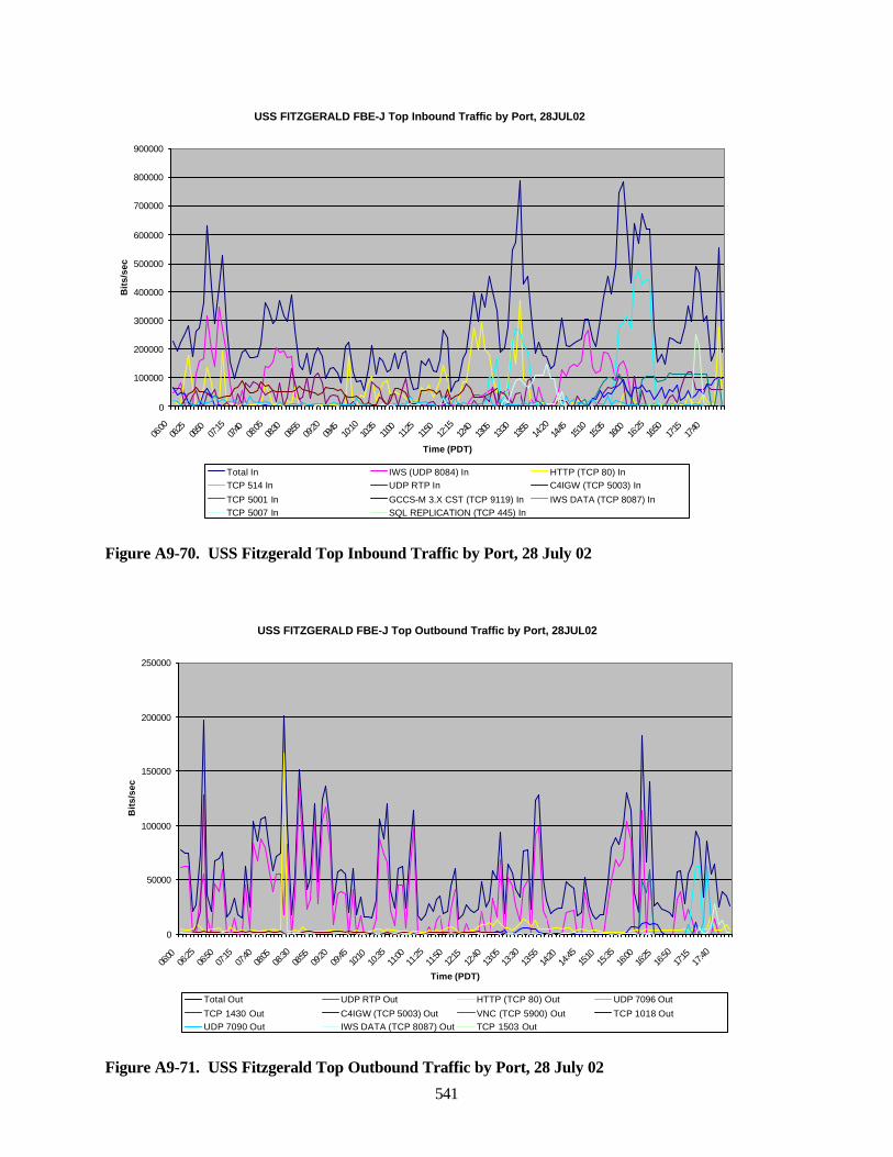
541
Figure A9-70. USS Fitzgerald Top Inbound Traffic by Port, 28 July 02
Figure A9-71. USS Fitzgerald Top Outbound Traffic by Port, 28 July 02
USS FITZGERALD FBE-J Top Inbound Traffic by Port, 28JUL02
0
100000
200000
300000
400000
500000
600000
700000
800000
900000
06:00
06:25
06:50
07:15
07:40
08:05
08:30
08:55
09:20
09:45
10:10
10:35
11:00
11:25
11:50
12:15
12:40
13:05
13:30
13:55
14:20
14:45
15:10
15:35
16:00
16:25
16:50
17:15
17:40
Time (PDT)
Bit
s/se
c
Total In IWS (UDP 8084) In HTTP (TCP 80) InTCP 514 In UDP RTP In C4IGW (TCP 5003) In
TCP 5001 In GCCS-M 3.X CST (TCP 9119) In IWS DATA (TCP 8087) InTCP 5007 In SQL REPLICATION (TCP 445) In
USS FITZGERALD FBE-J Top Outbound Traffic by Port, 28JUL02
0
50000
100000
150000
200000
250000
06:00
06:25
06:50
07:15
07:40
08:05
08:30
08:55
09:20
09:45
10:10
10:35
11:00
11:25
11:50
12:15
12:40
13:05
13:30
13:55
14:20
14:45
15:10
15:35
16:00
16:25
16:50
17:15
17:40
Time (PDT)
Bit
s/se
c
Total Out UDP RTP Out HTTP (TCP 80) Out UDP 7096 Out
TCP 1430 Out C4IGW (TCP 5003) Out VNC (TCP 5900) Out TCP 1018 OutUDP 7090 Out IWS DATA (TCP 8087) Out TCP 1503 Out
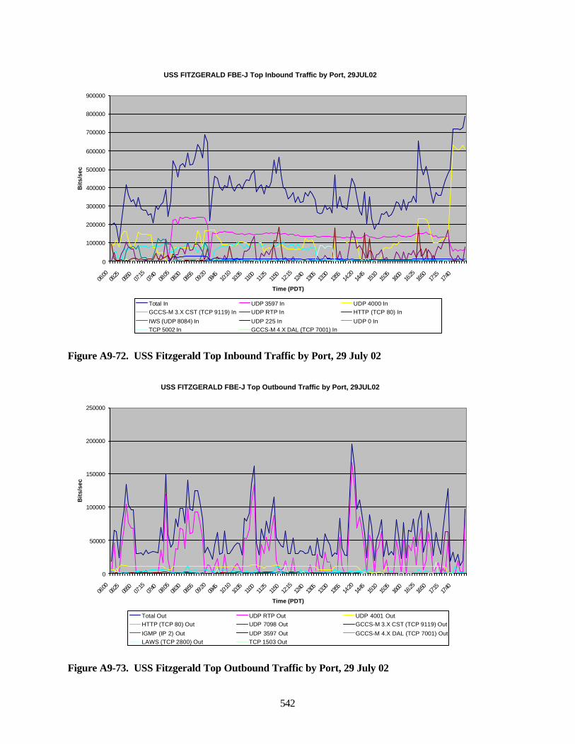
542
Figure A9-72. USS Fitzgerald Top Inbound Traffic by Port, 29 July 02
Figure A9-73. USS Fitzgerald Top Outbound Traffic by Port, 29 July 02
USS FITZGERALD FBE-J Top Inbound Traffic by Port, 29JUL02
0
100000
200000
300000
400000
500000
600000
700000
800000
900000
06:00
06:25
06:50
07:15
07:40
08:05
08:30
08:55
09:20
09:45
10:10
10:35
11:00
11:25
11:50
12:15
12:40
13:05
13:30
13:55
14:20
14:45
15:10
15:35
16:00
16:25
16:50
17:15
17:40
Time (PDT)
Bit
s/se
c
Total In UDP 3597 In UDP 4000 InGCCS-M 3.X CST (TCP 9119) In UDP RTP In HTTP (TCP 80) In
IWS (UDP 8084) In UDP 225 In UDP 0 InTCP 5002 In GCCS-M 4.X DAL (TCP 7001) In
USS FITZGERALD FBE-J Top Outbound Traffic by Port, 29JUL02
0
50000
100000
150000
200000
250000
06:00
06:25
06:50
07:15
07:40
08:05
08:30
08:55
09:20
09:45
10:10
10:35
11:00
11:25
11:50
12:15
12:40
13:05
13:30
13:55
14:20
14:45
15:10
15:35
16:00
16:25
16:50
17:15
17:40
Time (PDT)
Bit
s/se
c
Total Out UDP RTP Out UDP 4001 OutHTTP (TCP 80) Out UDP 7098 Out GCCS-M 3.X CST (TCP 9119) Out
IGMP (IP 2) Out UDP 3597 Out GCCS-M 4.X DAL (TCP 7001) OutLAWS (TCP 2800) Out TCP 1503 Out
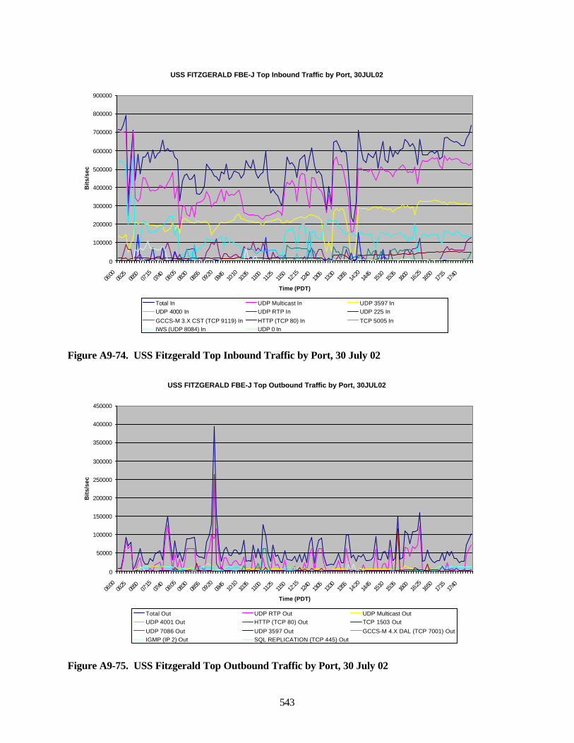
543
Figure A9-74. USS Fitzgerald Top Inbound Traffic by Port, 30 July 02
Figure A9-75. USS Fitzgerald Top Outbound Traffic by Port, 30 July 02
USS FITZGERALD FBE-J Top Inbound Traffic by Port, 30JUL02
0
100000
200000
300000
400000
500000
600000
700000
800000
900000
06:00
06:25
06:50
07:15
07:40
08:05
08:30
08:55
09:20
09:45
10:10
10:35
11:00
11:25
11:50
12:15
12:40
13:05
13:30
13:55
14:20
14:45
15:10
15:35
16:00
16:25
16:50
17:15
17:40
Time (PDT)
Bit
s/se
c
Total In UDP Multicast In UDP 3597 InUDP 4000 In UDP RTP In UDP 225 In
GCCS-M 3.X CST (TCP 9119) In HTTP (TCP 80) In TCP 5005 InIWS (UDP 8084) In UDP 0 In
USS FITZGERALD FBE-J Top Outbound Traffic by Port, 30JUL02
0
50000
100000
150000
200000
250000
300000
350000
400000
450000
06:00
06:25
06:50
07:15
07:40
08:05
08:30
08:55
09:20
09:45
10:10
10:35
11:00
11:25
11:50
12:15
12:40
13:05
13:30
13:55
14:20
14:45
15:10
15:35
16:00
16:25
16:50
17:15
17:40
Time (PDT)
Bit
s/se
c
Total Out UDP RTP Out UDP Multicast OutUDP 4001 Out HTTP (TCP 80) Out TCP 1503 Out
UDP 7086 Out UDP 3597 Out GCCS-M 4.X DAL (TCP 7001) OutIGMP (IP 2) Out SQL REPLICATION (TCP 445) Out
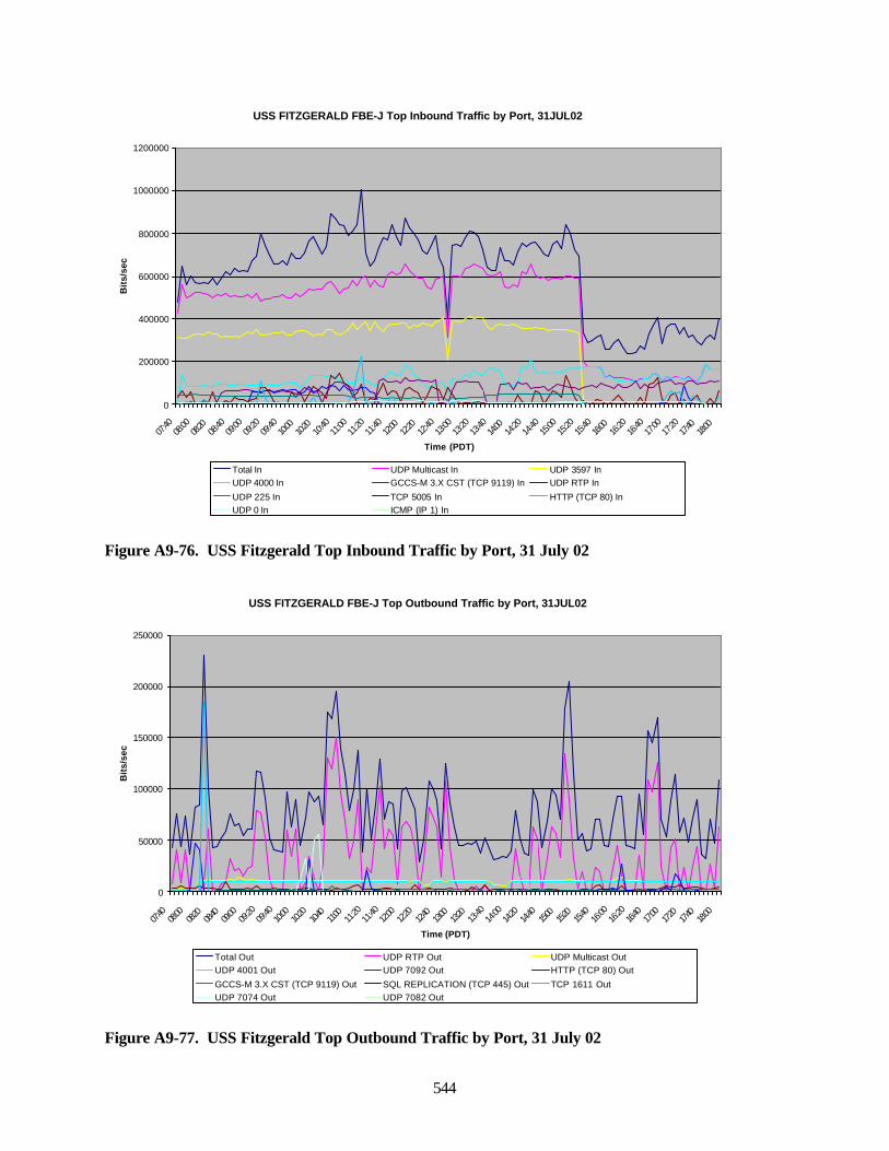
544
Figure A9-76. USS Fitzgerald Top Inbound Traffic by Port, 31 July 02
Figure A9-77. USS Fitzgerald Top Outbound Traffic by Port, 31 July 02
USS FITZGERALD FBE-J Top Inbound Traffic by Port, 31JUL02
0
200000
400000
600000
800000
1000000
1200000
07:40
08:00
08:20
08:40
09:00
09:20
09:40
10:00
10:20
10:40
11:00
11:20
11:40
12:00
12:20
12:40
13:00
13:20
13:40
14:00
14:20
14:40
15:00
15:20
15:40
16:00
16:20
16:40
17:00
17:20
17:40
18:00
Time (PDT)
Bit
s/se
c
Total In UDP Multicast In UDP 3597 InUDP 4000 In GCCS-M 3.X CST (TCP 9119) In UDP RTP In
UDP 225 In TCP 5005 In HTTP (TCP 80) InUDP 0 In ICMP (IP 1) In
USS FITZGERALD FBE-J Top Outbound Traffic by Port, 31JUL02
0
50000
100000
150000
200000
250000
07:40
08:00
08:20
08:40
09:00
09:20
09:40
10:00
10:20
10:40
11:00
11:20
11:40
12:00
12:20
12:40
13:00
13:20
13:40
14:00
14:20
14:40
15:00
15:20
15:40
16:00
16:20
16:40
17:00
17:20
17:40
18:00
Time (PDT)
Bit
s/se
c
Total Out UDP RTP Out UDP Multicast OutUDP 4001 Out UDP 7092 Out HTTP (TCP 80) Out
GCCS-M 3.X CST (TCP 9119) Out SQL REPLICATION (TCP 445) Out TCP 1611 OutUDP 7074 Out UDP 7082 Out
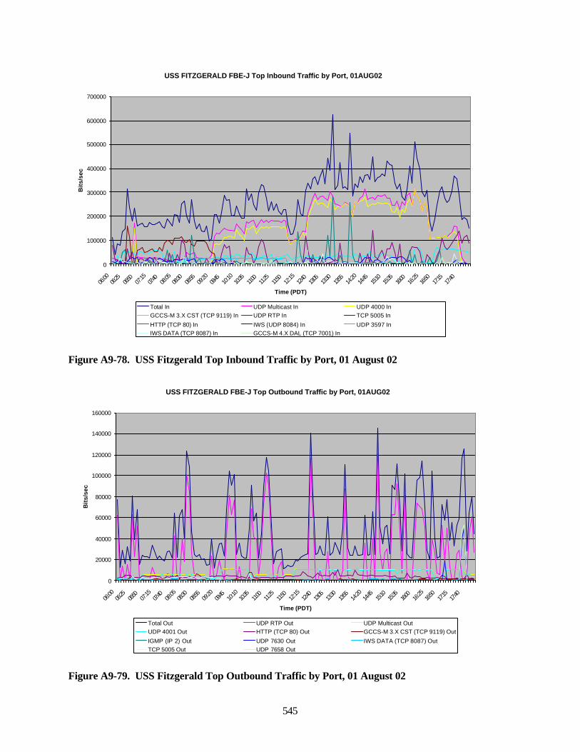
545
Figure A9-78. USS Fitzgerald Top Inbound Traffic by Port, 01 August 02
Figure A9-79. USS Fitzgerald Top Outbound Traffic by Port, 01 August 02
USS FITZGERALD FBE-J Top Inbound Traffic by Port, 01AUG02
0
100000
200000
300000
400000
500000
600000
700000
06:00
06:25
06:50
07:15
07:40
08:05
08:30
08:55
09:20
09:45
10:10
10:35
11:00
11:25
11:50
12:15
12:40
13:05
13:30
13:55
14:20
14:45
15:10
15:35
16:00
16:25
16:50
17:15
17:40
Time (PDT)
Bit
s/se
c
Total In UDP Multicast In UDP 4000 InGCCS-M 3.X CST (TCP 9119) In UDP RTP In TCP 5005 In
HTTP (TCP 80) In IWS (UDP 8084) In UDP 3597 InIWS DATA (TCP 8087) In GCCS-M 4.X DAL (TCP 7001) In
USS FITZGERALD FBE-J Top Outbound Traffic by Port, 01AUG02
0
20000
40000
60000
80000
100000
120000
140000
160000
06:00
06:25
06:50
07:15
07:40
08:05
08:30
08:55
09:20
09:45
10:10
10:35
11:00
11:25
11:50
12:15
12:40
13:05
13:30
13:55
14:20
14:45
15:10
15:35
16:00
16:25
16:50
17:15
17:40
Time (PDT)
Bit
s/se
c
Total Out UDP RTP Out UDP Multicast OutUDP 4001 Out HTTP (TCP 80) Out GCCS-M 3.X CST (TCP 9119) Out
IGMP (IP 2) Out UDP 7630 Out IWS DATA (TCP 8087) OutTCP 5005 Out UDP 7658 Out
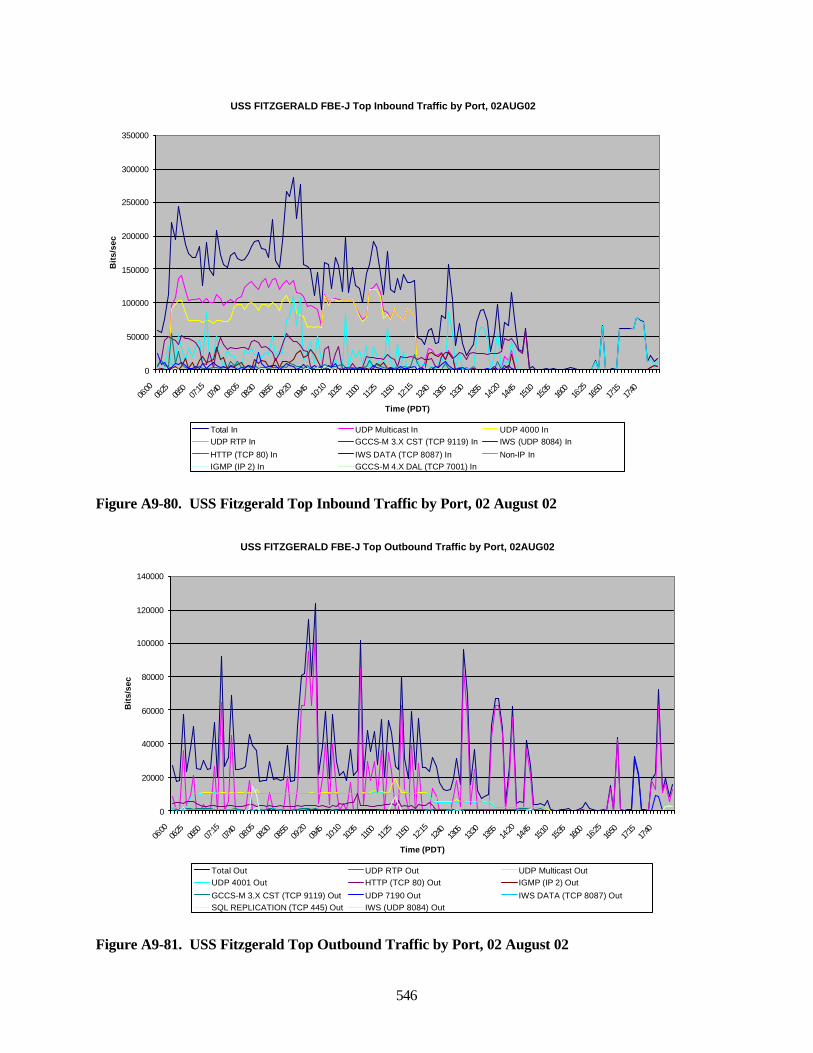
546
Figure A9-80. USS Fitzgerald Top Inbound Traffic by Port, 02 August 02
Figure A9-81. USS Fitzgerald Top Outbound Traffic by Port, 02 August 02
USS FITZGERALD FBE-J Top Inbound Traffic by Port, 02AUG02
0
50000
100000
150000
200000
250000
300000
350000
06:00
06:25
06:50
07:15
07:40
08:05
08:30
08:55
09:20
09:45
10:10
10:35
11:00
11:25
11:50
12:15
12:40
13:05
13:30
13:55
14:20
14:45
15:10
15:35
16:00
16:25
16:50
17:15
17:40
Time (PDT)
Bit
s/se
c
Total In UDP Multicast In UDP 4000 InUDP RTP In GCCS-M 3.X CST (TCP 9119) In IWS (UDP 8084) In
HTTP (TCP 80) In IWS DATA (TCP 8087) In Non-IP InIGMP (IP 2) In GCCS-M 4.X DAL (TCP 7001) In
USS FITZGERALD FBE-J Top Outbound Traffic by Port, 02AUG02
0
20000
40000
60000
80000
100000
120000
140000
06:00
06:25
06:50
07:15
07:40
08:05
08:30
08:55
09:20
09:45
10:10
10:35
11:00
11:25
11:50
12:15
12:40
13:05
13:30
13:55
14:20
14:45
15:10
15:35
16:00
16:25
16:50
17:15
17:40
Time (PDT)
Bit
s/se
c
Total Out UDP RTP Out UDP Multicast OutUDP 4001 Out HTTP (TCP 80) Out IGMP (IP 2) Out
GCCS-M 3.X CST (TCP 9119) Out UDP 7190 Out IWS DATA (TCP 8087) OutSQL REPLICATION (TCP 445) Out IWS (UDP 8084) Out
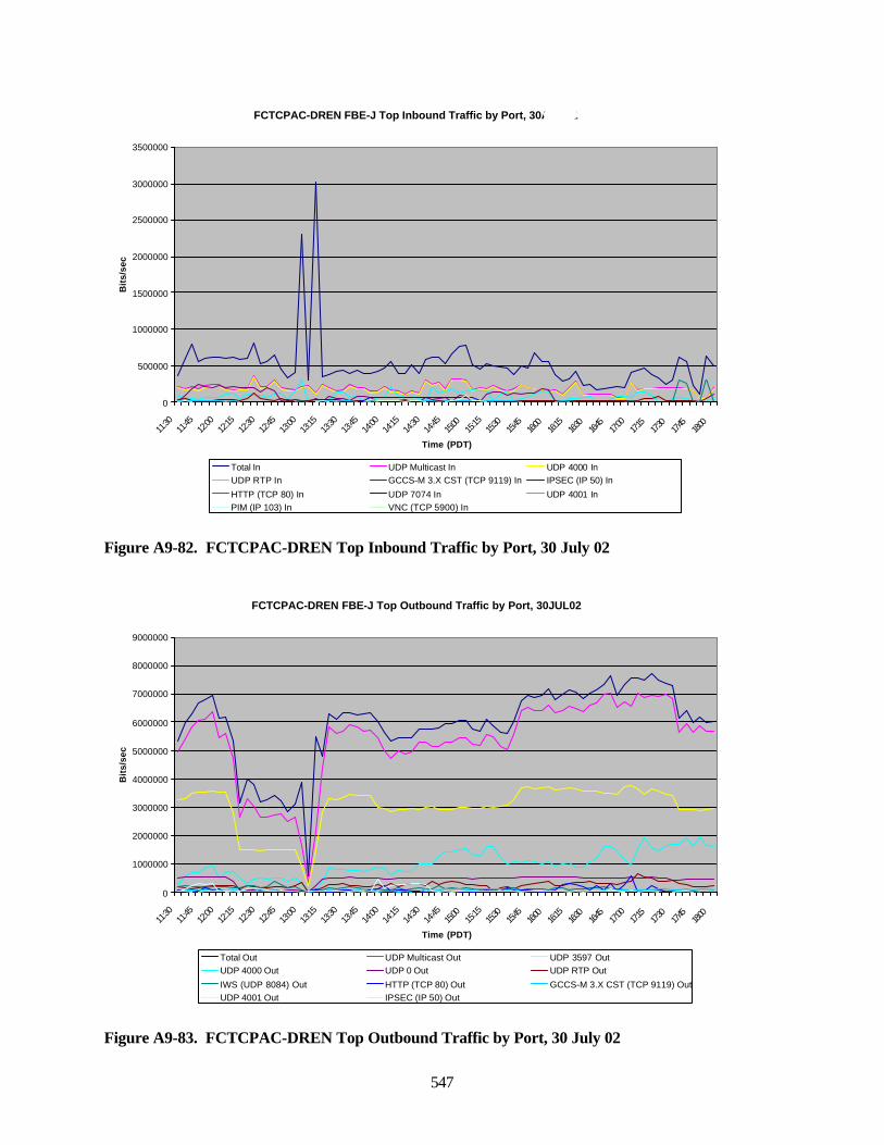
547
Figure A9-82. FCTCPAC-DREN Top Inbound Traffic by Port, 30 July 02
Figure A9-83. FCTCPAC-DREN Top Outbound Traffic by Port, 30 July 02
FCTCPAC-DREN FBE-J Top Inbound Traffic by Port, 30AUG02
0
500000
1000000
1500000
2000000
2500000
3000000
3500000
11:30
11:45
12:00
12:15
12:30
12:45
13:00
13:15
13:30
13:45
14:00
14:15
14:30
14:45
15:00
15:15
15:30
15:45
16:00
16:15
16:30
16:45
17:00
17:15
17:30
17:45
18:00
Time (PDT)
Bit
s/se
c
Total In UDP Multicast In UDP 4000 InUDP RTP In GCCS-M 3.X CST (TCP 9119) In IPSEC (IP 50) In
HTTP (TCP 80) In UDP 7074 In UDP 4001 InPIM (IP 103) In VNC (TCP 5900) In
FCTCPAC-DREN FBE-J Top Outbound Traffic by Port, 30JUL02
0
1000000
2000000
3000000
4000000
5000000
6000000
7000000
8000000
9000000
11:30
11:45
12:00
12:15
12:30
12:45
13:00
13:15
13:30
13:45
14:00
14:15
14:30
14:45
15:00
15:15
15:30
15:45
16:00
16:15
16:30
16:45
17:00
17:15
17:30
17:45
18:00
Time (PDT)
Bit
s/se
c
Total Out UDP Multicast Out UDP 3597 OutUDP 4000 Out UDP 0 Out UDP RTP Out
IWS (UDP 8084) Out HTTP (TCP 80) Out GCCS-M 3.X CST (TCP 9119) OutUDP 4001 Out IPSEC (IP 50) Out
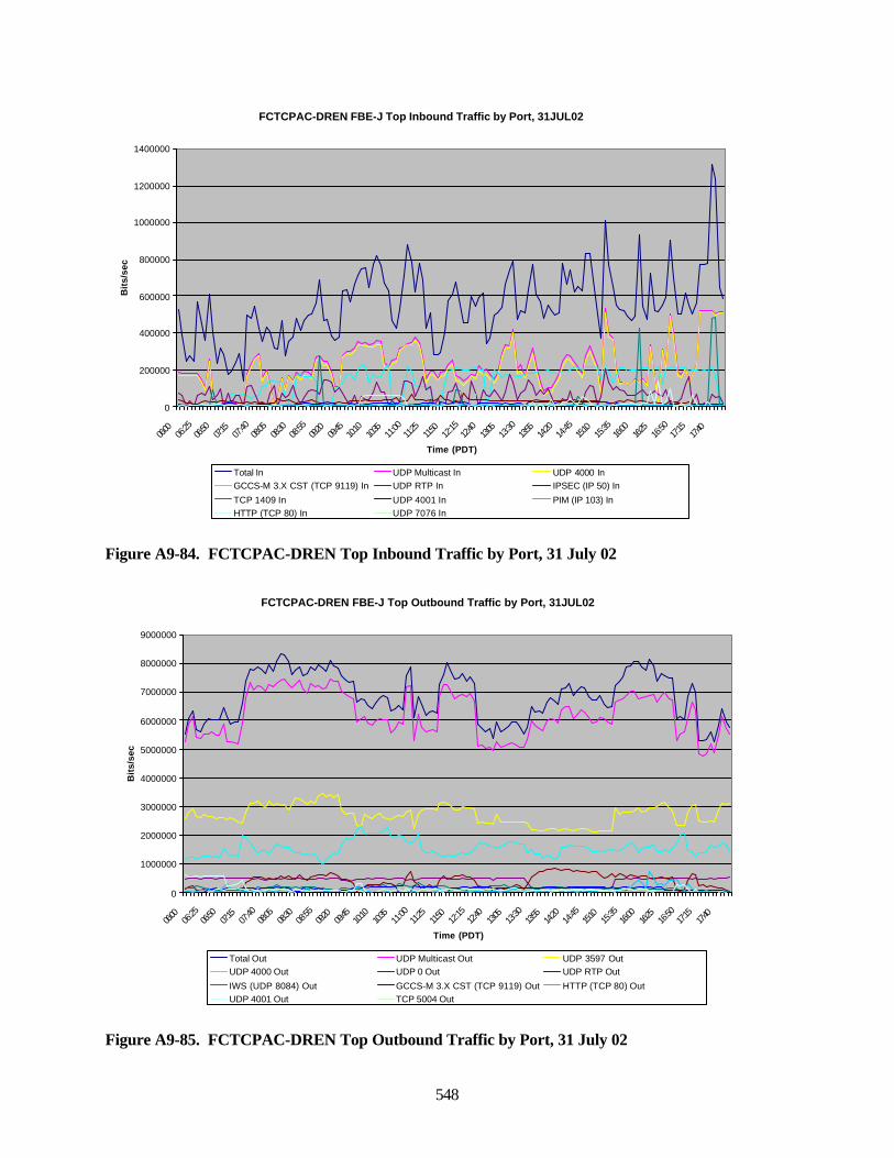
548
Figure A9-84. FCTCPAC-DREN Top Inbound Traffic by Port, 31 July 02
Figure A9-85. FCTCPAC-DREN Top Outbound Traffic by Port, 31 July 02
FCTCPAC-DREN FBE-J Top Inbound Traffic by Port, 31JUL02
0
200000
400000
600000
800000
1000000
1200000
1400000
06:00
06:25
06:50
07:15
07:40
08:05
08:30
08:55
09:20
09:45
10:10
10:35
11:00
11:25
11:50
12:15
12:40
13:05
13:30
13:55
14:20
14:45
15:10
15:35
16:00
16:25
16:50
17:15
17:40
Time (PDT)
Bit
s/se
c
Total In UDP Multicast In UDP 4000 InGCCS-M 3.X CST (TCP 9119) In UDP RTP In IPSEC (IP 50) In
TCP 1409 In UDP 4001 In PIM (IP 103) InHTTP (TCP 80) In UDP 7076 In
FCTCPAC-DREN FBE-J Top Outbound Traffic by Port, 31JUL02
0
1000000
2000000
3000000
4000000
5000000
6000000
7000000
8000000
9000000
06:00
06:25
06:50
07:15
07:40
08:05
08:30
08:55
09:20
09:45
10:10
10:35
11:00
11:25
11:50
12:15
12:40
13:05
13:30
13:55
14:20
14:45
15:10
15:35
16:00
16:25
16:50
17:15
17:40
Time (PDT)
Bit
s/se
c
Total Out UDP Multicast Out UDP 3597 OutUDP 4000 Out UDP 0 Out UDP RTP Out
IWS (UDP 8084) Out GCCS-M 3.X CST (TCP 9119) Out HTTP (TCP 80) OutUDP 4001 Out TCP 5004 Out
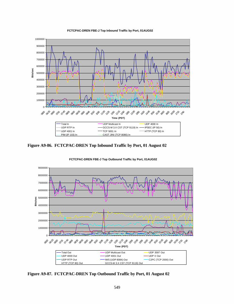
549
Figure A9-86. FCTCPAC-DREN Top Inbound Traffic by Port, 01 August 02
Figure A9-87. FCTCPAC-DREN Top Outbound Traffic by Port, 01 August 02
FCTCPAC-DREN FBE-J Top Inbound Traffic by Port, 01AUG02
0
100000
200000
300000
400000
500000
600000
700000
800000
900000
1000000
06:00
06:25
06:50
07:15
07:40
08:05
08:30
08:55
09:20
09:45
10:10
10:35
11:00
11:25
11:50
12:15
12:40
13:05
13:30
13:55
14:20
14:45
15:10
15:35
16:00
16:25
16:50
17:15
17:40
Time (PDT)
Bit
s/se
c
Total In UDP Multicast In UDP 4000 InUDP RTP In GCCS-M 3.X CST (TCP 9119) In IPSEC (IP 50) In
UDP 4001 In TCP 5001 In HTTP (TCP 80) InPIM (IP 103) In CAST JINI (TCP 8080) In
FCTCPAC-DREN FBE-J Top Outbound Traffic by Port, 01AUG02
0
1000000
2000000
3000000
4000000
5000000
6000000
7000000
8000000
9000000
06:00
06:25
06:50
07:15
07:40
08:05
08:30
08:55
09:20
09:45
10:10
10:35
11:00
11:25
11:50
12:15
12:40
13:05
13:30
13:55
14:20
14:45
15:10
15:35
16:00
16:25
16:50
17:15
17:40
Time (PDT)
Bit
s/se
c
Total Out UDP Multicast Out UDP 3597 OutUDP 4000 Out UDP 4001 Out UDP 0 Out
UDP RTP Out IWS (UDP 8084) Out C2PC (TCP 2000) OutHTTP (TCP 80) Out GCCS-M 3.X CST (TCP 9119) Out
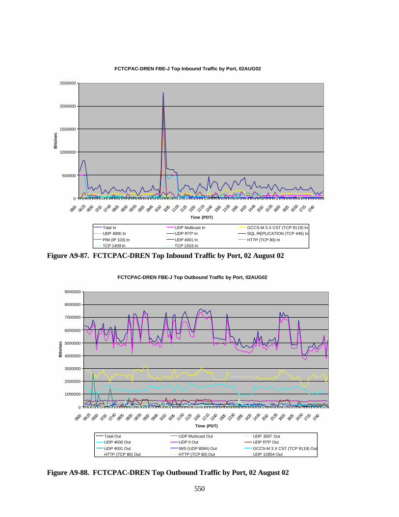
550
Figure A9-87. FCTCPAC-DREN Top Inbound Traffic by Port, 02 August 02
Figure A9-88. FCTCPAC-DREN Top Outbound Traffic by Port, 02 August 02
FCTCPAC-DREN FBE-J Top Inbound Traffic by Port, 02AUG02
0
500000
1000000
1500000
2000000
2500000
06:00
06:25
06:50
07:15
07:40
08:05
08:30
08:55
09:20
09:45
10:10
10:35
11:00
11:25
11:50
12:15
12:40
13:05
13:30
13:55
14:20
14:45
15:10
15:35
16:00
16:25
16:50
17:15
17:40
Time (PDT)
Bit
s/se
c
Total In UDP Multicast In GCCS-M 3.X CST (TCP 9119) InUDP 4000 In UDP RTP In SQL REPLICATION (TCP 445) In
PIM (IP 103) In UDP 4001 In HTTP (TCP 80) InTCP 1409 In TCP 1503 In
FCTCPAC-DREN FBE-J Top Outbound Traffic by Port, 02AUG02
0
1000000
2000000
3000000
4000000
5000000
6000000
7000000
8000000
9000000
06:00
06:25
06:50
07:15
07:40
08:05
08:30
08:55
09:20
09:45
10:10
10:35
11:00
11:25
11:50
12:15
12:40
13:05
13:30
13:55
14:20
14:45
15:10
15:35
16:00
16:25
16:50
17:15
17:40
Time (PDT)
Bit
s/se
c
Total Out UDP Multicast Out UDP 3597 OutUDP 4000 Out UDP 0 Out UDP RTP Out
UDP 4001 Out IWS (UDP 8084) Out GCCS-M 3.X CST (TCP 9119) OutHTTP (TCP 80) Out HTTP (TCP 80) Out UDP 12854 Out
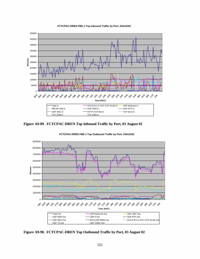
551
Figure A9-89. FCTCPAC-DREN Top Inbound Traffic by Port, 03 August 02
Figure A9-90. FCTCPAC-DREN Top Outbound Traffic by Port, 03 August 02
FCTCPAC-DREN FBE-J Top Inbound Traffic by Port, 03AUG02
0
50000
100000
150000
200000
250000
300000
350000
400000
450000
500000
06:00
06:25
06:50
07:15
07:40
08:05
08:30
08:55
09:20
09:45
10:10
10:35
11:00
11:25
11:50
12:15
12:40
13:05
13:30
13:55
14:20
14:45
15:10
15:35
16:00
16:25
16:50
17:15
17:40
Time (PDT)
Bit
s/se
c
Total In GCCS-M 3.X CST (TCP 9119) In UDP Multicast InPIM (IP 103) In UDP 4000 In UDP RTP In
UDP 4001 In HTTP (TCP 80) In TCP 5013 InTCP 1409 In TCP 1503 In
FCTCPAC-DREN FBE-J Top Outbound Traffic by Port, 03AUG02
0
1000000
2000000
3000000
4000000
5000000
6000000
7000000
8000000
9000000
06:00
06:25
06:50
07:15
07:40
08:05
08:30
08:55
09:20
09:45
10:10
10:35
11:00
11:25
11:50
12:15
12:40
13:05
13:30
13:55
14:20
14:45
15:10
15:35
16:00
16:25
16:50
17:15
17:40
Time (PDT)
Bit
s/se
c
Total Out UDP Multicast Out UDP 3597 OutUDP 4000 Out UDP 0 Out UDP RTP Out
UDP 4001 Out IWS (UDP 8084) Out GCCS-M 3.X CST (TCP 9119) OutUDP 74 Out UDP 12854 Out
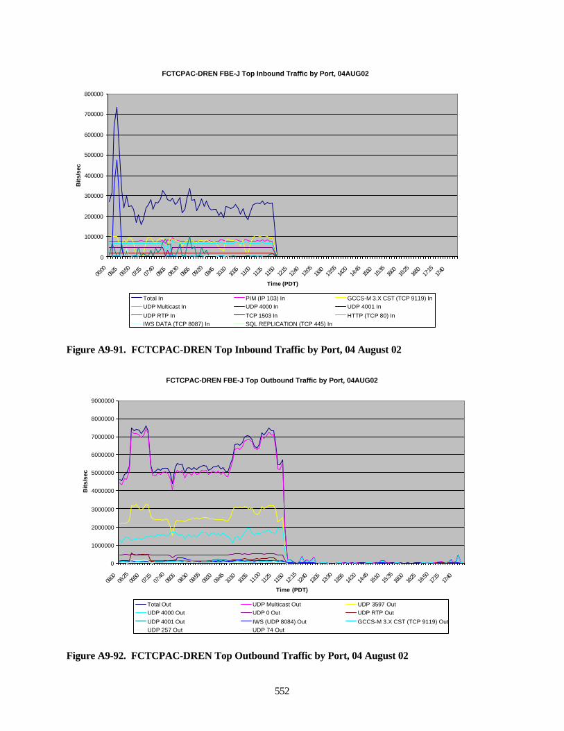
552
Figure A9-91. FCTCPAC-DREN Top Inbound Traffic by Port, 04 August 02
Figure A9-92. FCTCPAC-DREN Top Outbound Traffic by Port, 04 August 02
FCTCPAC-DREN FBE-J Top Inbound Traffic by Port, 04AUG02
0
100000
200000
300000
400000
500000
600000
700000
800000
06:00
06:25
06:50
07:15
07:40
08:05
08:30
08:55
09:20
09:45
10:10
10:35
11:00
11:25
11:50
12:15
12:40
13:05
13:30
13:55
14:20
14:45
15:10
15:35
16:00
16:25
16:50
17:15
17:40
Time (PDT)
Bit
s/se
c
Total In PIM (IP 103) In GCCS-M 3.X CST (TCP 9119) InUDP Multicast In UDP 4000 In UDP 4001 In
UDP RTP In TCP 1503 In HTTP (TCP 80) InIWS DATA (TCP 8087) In SQL REPLICATION (TCP 445) In
FCTCPAC-DREN FBE-J Top Outbound Traffic by Port, 04AUG02
0
1000000
2000000
3000000
4000000
5000000
6000000
7000000
8000000
9000000
06:00
06:25
06:50
07:15
07:40
08:05
08:30
08:55
09:20
09:45
10:10
10:35
11:00
11:25
11:50
12:15
12:40
13:05
13:30
13:55
14:20
14:45
15:10
15:35
16:00
16:25
16:50
17:15
17:40
Time (PDT)
Bit
s/se
c
Total Out UDP Multicast Out UDP 3597 OutUDP 4000 Out UDP 0 Out UDP RTP Out
UDP 4001 Out IWS (UDP 8084) Out GCCS-M 3.X CST (TCP 9119) OutUDP 257 Out UDP 74 Out
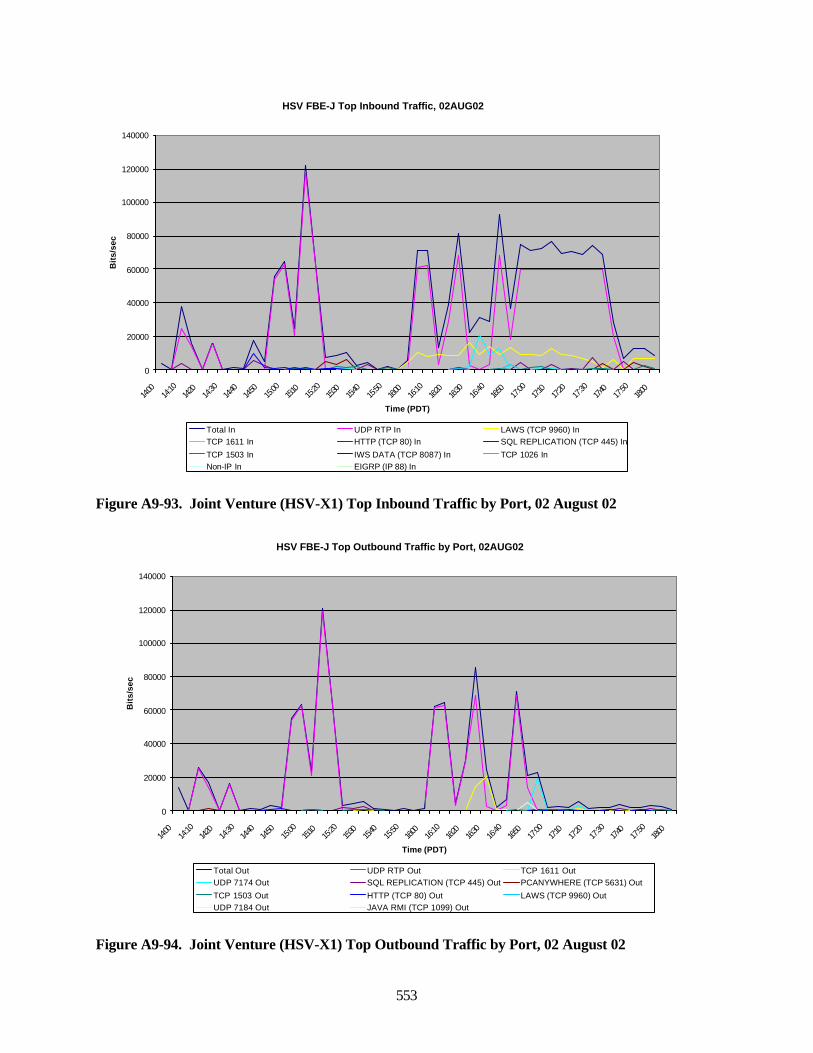
553
Figure A9-93. Joint Venture (HSV-X1) Top Inbound Traffic by Port, 02 August 02
Figure A9-94. Joint Venture (HSV-X1) Top Outbound Traffic by Port, 02 August 02
HSV FBE-J Top Inbound Traffic, 02AUG02
0
20000
40000
60000
80000
100000
120000
140000
14:00
14:10
14:20
14:30
14:40
14:50
15:00
15:10
15:20
15:30
15:40
15:50
16:00
16:10
16:20
16:30
16:40
16:50
17:00
17:10
17:20
17:30
17:40
17:50
18:00
Time (PDT)
Bit
s/se
c
Total In UDP RTP In LAWS (TCP 9960) InTCP 1611 In HTTP (TCP 80) In SQL REPLICATION (TCP 445) In
TCP 1503 In IWS DATA (TCP 8087) In TCP 1026 InNon-IP In EIGRP (IP 88) In
HSV FBE-J Top Outbound Traffic by Port, 02AUG02
0
20000
40000
60000
80000
100000
120000
140000
14:00
14:10
14:20
14:30
14:40
14:50
15:00
15:10
15:20
15:30
15:40
15:50
16:00
16:10
16:20
16:30
16:40
16:50
17:00
17:10
17:20
17:30
17:40
17:50
18:00
Time (PDT)
Bit
s/se
c
Total Out UDP RTP Out TCP 1611 OutUDP 7174 Out SQL REPLICATION (TCP 445) Out PCANYWHERE (TCP 5631) Out
TCP 1503 Out HTTP (TCP 80) Out LAWS (TCP 9960) OutUDP 7184 Out JAVA RMI (TCP 1099) Out
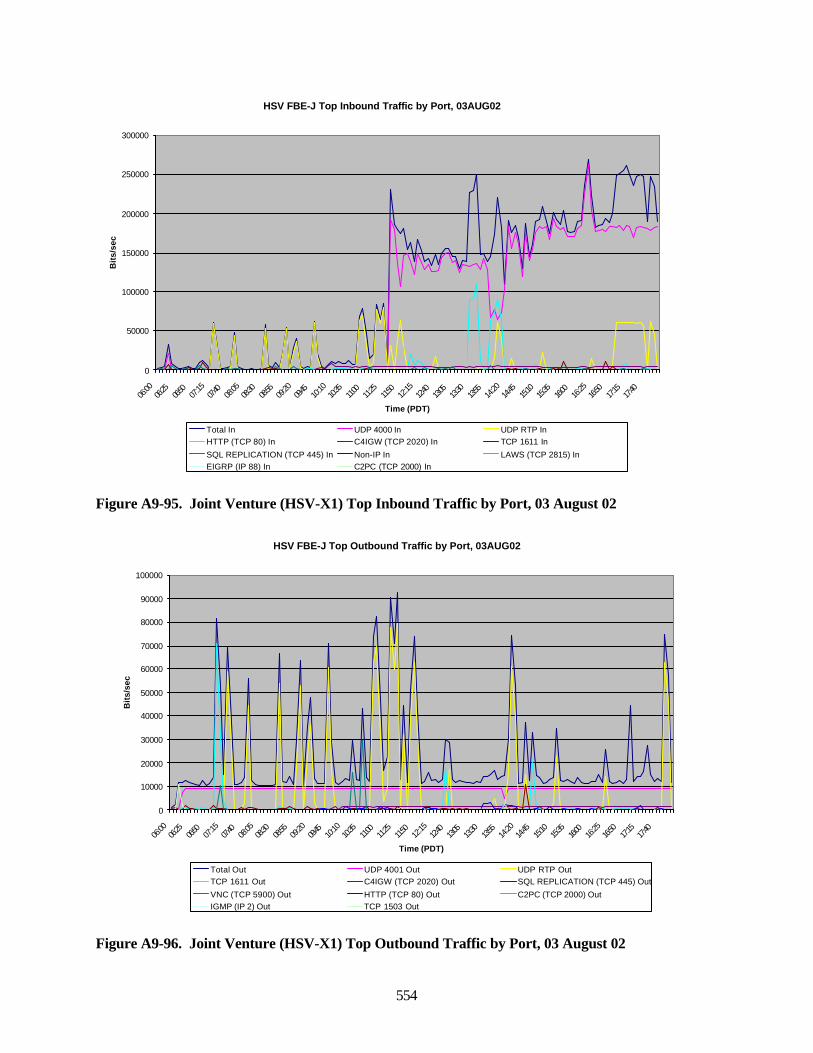
554
Figure A9-95. Joint Venture (HSV-X1) Top Inbound Traffic by Port, 03 August 02
Figure A9-96. Joint Venture (HSV-X1) Top Outbound Traffic by Port, 03 August 02
HSV FBE-J Top Inbound Traffic by Port, 03AUG02
0
50000
100000
150000
200000
250000
300000
06:00
06:25
06:50
07:15
07:40
08:05
08:30
08:55
09:20
09:45
10:10
10:35
11:00
11:25
11:50
12:15
12:40
13:05
13:30
13:55
14:20
14:45
15:10
15:35
16:00
16:25
16:50
17:15
17:40
Time (PDT)
Bit
s/se
c
Total In UDP 4000 In UDP RTP InHTTP (TCP 80) In C4IGW (TCP 2020) In TCP 1611 In
SQL REPLICATION (TCP 445) In Non-IP In LAWS (TCP 2815) InEIGRP (IP 88) In C2PC (TCP 2000) In
HSV FBE-J Top Outbound Traffic by Port, 03AUG02
0
10000
20000
30000
40000
50000
60000
70000
80000
90000
100000
06:00
06:25
06:50
07:15
07:40
08:05
08:30
08:55
09:20
09:45
10:10
10:35
11:00
11:25
11:50
12:15
12:40
13:05
13:30
13:55
14:20
14:45
15:10
15:35
16:00
16:25
16:50
17:15
17:40
Time (PDT)
Bit
s/se
c
Total Out UDP 4001 Out UDP RTP OutTCP 1611 Out C4IGW (TCP 2020) Out SQL REPLICATION (TCP 445) Out
VNC (TCP 5900) Out HTTP (TCP 80) Out C2PC (TCP 2000) OutIGMP (IP 2) Out TCP 1503 Out
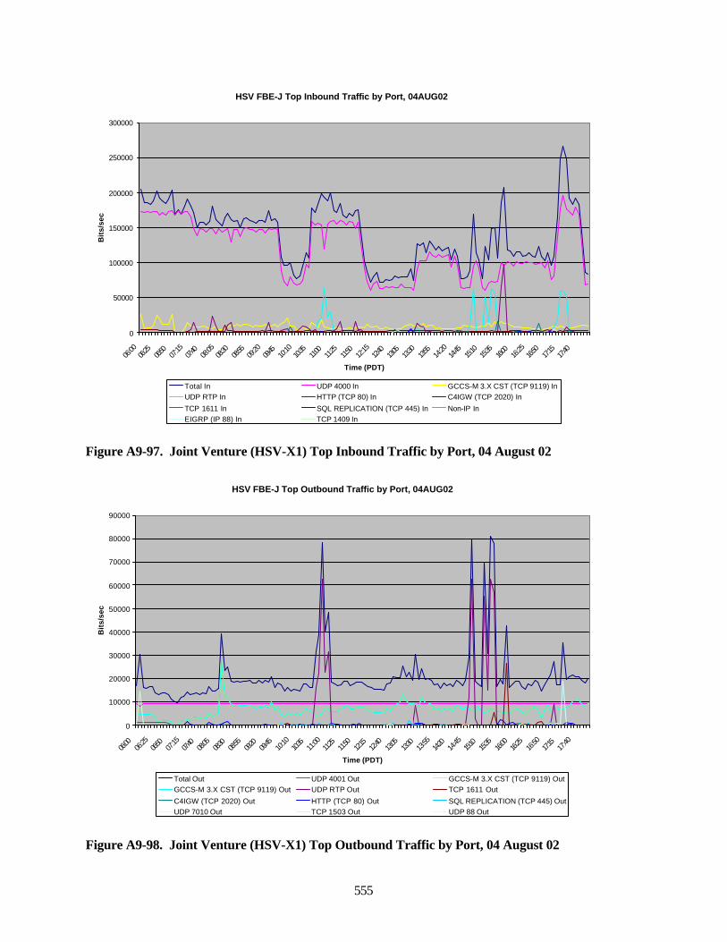
555
Figure A9-97. Joint Venture (HSV-X1) Top Inbound Traffic by Port, 04 August 02
Figure A9-98. Joint Venture (HSV-X1) Top Outbound Traffic by Port, 04 August 02
HSV FBE-J Top Inbound Traffic by Port, 04AUG02
0
50000
100000
150000
200000
250000
300000
06:00
06:25
06:50
07:15
07:40
08:05
08:30
08:55
09:20
09:45
10:10
10:35
11:00
11:25
11:50
12:15
12:40
13:05
13:30
13:55
14:20
14:45
15:10
15:35
16:00
16:25
16:50
17:15
17:40
Time (PDT)
Bit
s/se
c
Total In UDP 4000 In GCCS-M 3.X CST (TCP 9119) InUDP RTP In HTTP (TCP 80) In C4IGW (TCP 2020) In
TCP 1611 In SQL REPLICATION (TCP 445) In Non-IP InEIGRP (IP 88) In TCP 1409 In
HSV FBE-J Top Outbound Traffic by Port, 04AUG02
0
10000
20000
30000
40000
50000
60000
70000
80000
90000
06:00
06:25
06:50
07:15
07:40
08:05
08:30
08:55
09:20
09:45
10:10
10:35
11:00
11:25
11:50
12:15
12:40
13:05
13:30
13:55
14:20
14:45
15:10
15:35
16:00
16:25
16:50
17:15
17:40
Time (PDT)
Bit
s/se
c
Total Out UDP 4001 Out GCCS-M 3.X CST (TCP 9119) OutGCCS-M 3.X CST (TCP 9119) Out UDP RTP Out TCP 1611 Out
C4IGW (TCP 2020) Out HTTP (TCP 80) Out SQL REPLICATION (TCP 445) OutUDP 7010 Out TCP 1503 Out UDP 88 Out
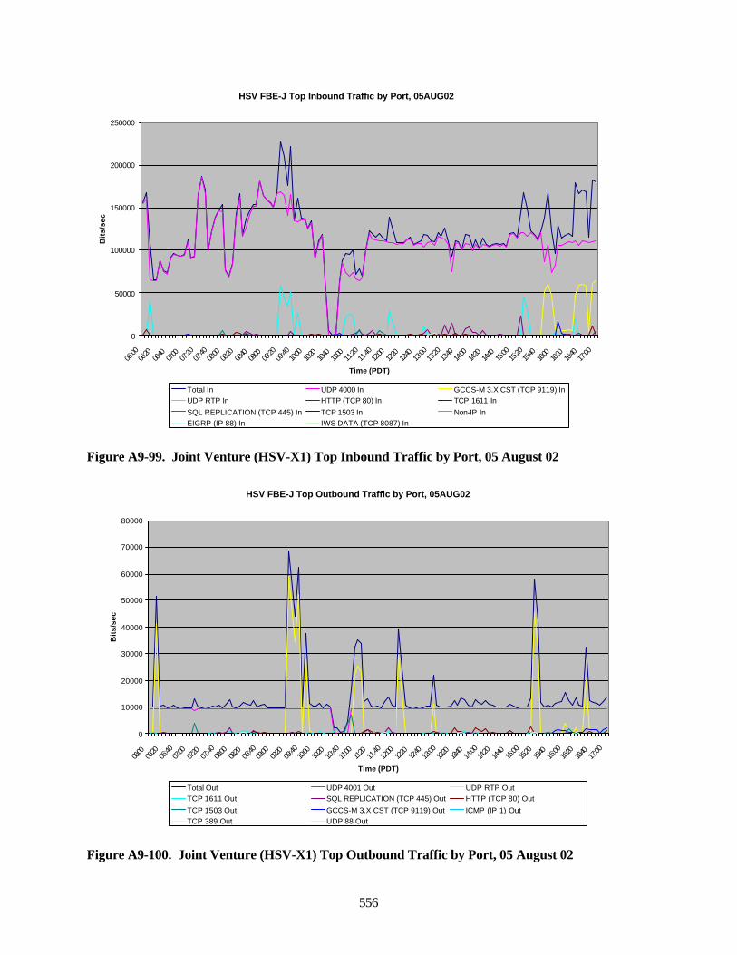
556
Figure A9-99. Joint Venture (HSV-X1) Top Inbound Traffic by Port, 05 August 02
Figure A9-100. Joint Venture (HSV-X1) Top Outbound Traffic by Port, 05 August 02
HSV FBE-J Top Inbound Traffic by Port, 05AUG02
0
50000
100000
150000
200000
250000
06:00
06:20
06:40
07:00
07:20
07:40
08:00
08:20
08:40
09:00
09:20
09:40
10:00
10:20
10:40
11:00
11:20
11:40
12:00
12:20
12:40
13:00
13:20
13:40
14:00
14:20
14:40
15:00
15:20
15:40
16:00
16:20
16:40
17:00
Time (PDT)
Bit
s/se
c
Total In UDP 4000 In GCCS-M 3.X CST (TCP 9119) InUDP RTP In HTTP (TCP 80) In TCP 1611 In
SQL REPLICATION (TCP 445) In TCP 1503 In Non-IP InEIGRP (IP 88) In IWS DATA (TCP 8087) In
HSV FBE-J Top Outbound Traffic by Port, 05AUG02
0
10000
20000
30000
40000
50000
60000
70000
80000
06:00
06:20
06:40
07:00
07:20
07:40
08:00
08:20
08:40
09:00
09:20
09:40
10:00
10:20
10:40
11:00
11:20
11:40
12:00
12:20
12:40
13:00
13:20
13:40
14:00
14:20
14:40
15:00
15:20
15:40
16:00
16:20
16:40
17:00
Time (PDT)
Bit
s/se
c
Total Out UDP 4001 Out UDP RTP OutTCP 1611 Out SQL REPLICATION (TCP 445) Out HTTP (TCP 80) Out
TCP 1503 Out GCCS-M 3.X CST (TCP 9119) Out ICMP (IP 1) OutTCP 389 Out UDP 88 Out
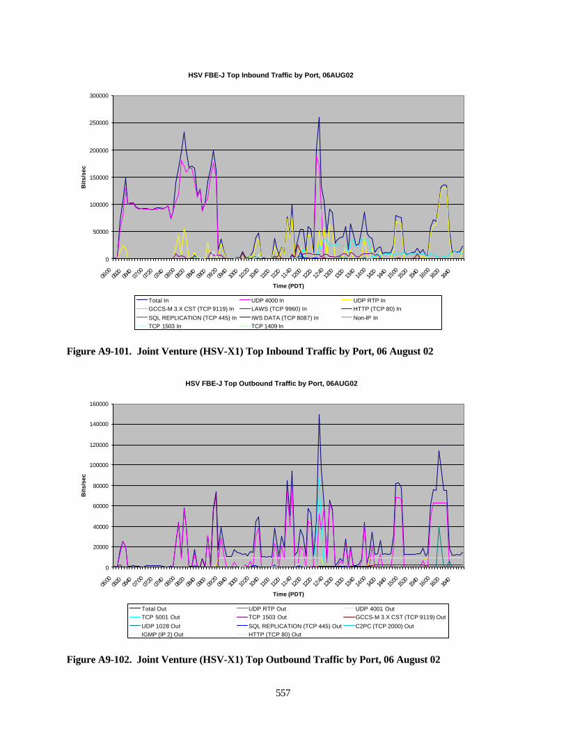
557
Figure A9-101. Joint Venture (HSV-X1) Top Inbound Traffic by Port, 06 August 02
Figure A9-102. Joint Venture (HSV-X1) Top Outbound Traffic by Port, 06 August 02
HSV FBE-J Top Inbound Traffic by Port, 06AUG02
0
50000
100000
150000
200000
250000
300000
06:00
06:20
06:40
07:00
07:20
07:40
08:00
08:20
08:40
09:00
09:20
09:40
10:00
10:20
10:40
11:00
11:20
11:40
12:00
12:20
12:40
13:00
13:20
13:40
14:00
14:20
14:40
15:00
15:20
15:40
16:00
16:20
16:40
Time (PDT)
Bit
s/se
c
Total In UDP 4000 In UDP RTP InGCCS-M 3.X CST (TCP 9119) In LAWS (TCP 9960) In HTTP (TCP 80) In
SQL REPLICATION (TCP 445) In IWS DATA (TCP 8087) In Non-IP InTCP 1503 In TCP 1409 In
HSV FBE-J Top Outbound Traffic by Port, 06AUG02
0
20000
40000
60000
80000
100000
120000
140000
160000
06:00
06:20
06:40
07:00
07:20
07:40
08:00
08:20
08:40
09:00
09:20
09:40
10:00
10:20
10:40
11:00
11:20
11:40
12:00
12:20
12:40
13:00
13:20
13:40
14:00
14:20
14:40
15:00
15:20
15:40
16:00
16:20
16:40
Time (PDT)
Bit
s/se
c
Total Out UDP RTP Out UDP 4001 OutTCP 5001 Out TCP 1503 Out GCCS-M 3.X CST (TCP 9119) Out
UDP 1028 Out SQL REPLICATION (TCP 445) Out C2PC (TCP 2000) OutIGMP (IP 2) Out HTTP (TCP 80) Out
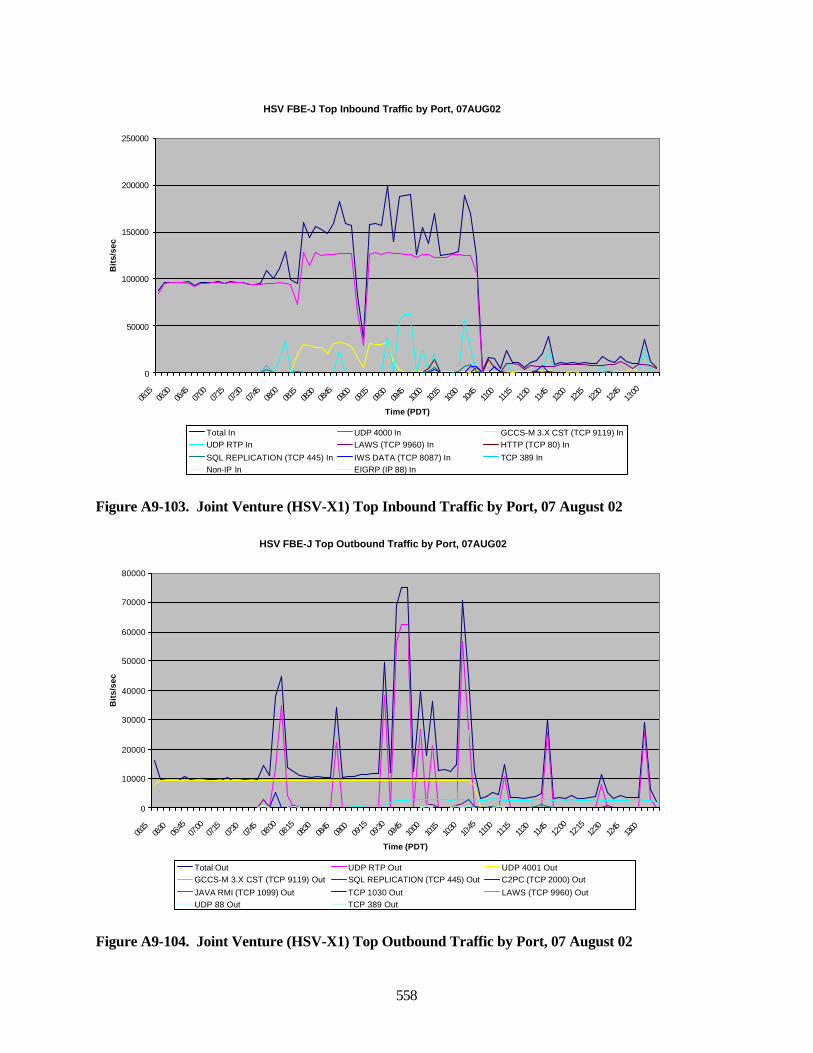
558
Figure A9-103. Joint Venture (HSV-X1) Top Inbound Traffic by Port, 07 August 02
Figure A9-104. Joint Venture (HSV-X1) Top Outbound Traffic by Port, 07 August 02
HSV FBE-J Top Inbound Traffic by Port, 07AUG02
0
50000
100000
150000
200000
250000
06:15
06:30
06:45
07:00
07:15
07:30
07:45
08:00
08:15
08:30
08:45
09:00
09:15
09:30
09:45
10:00
10:15
10:30
10:45
11:00
11:15
11:30
11:45
12:00
12:15
12:30
12:45
13:00
Time (PDT)
Bit
s/se
c
Total In UDP 4000 In GCCS-M 3.X CST (TCP 9119) InUDP RTP In LAWS (TCP 9960) In HTTP (TCP 80) In
SQL REPLICATION (TCP 445) In IWS DATA (TCP 8087) In TCP 389 InNon-IP In EIGRP (IP 88) In
HSV FBE-J Top Outbound Traffic by Port, 07AUG02
0
10000
20000
30000
40000
50000
60000
70000
80000
06:15
06:30
06:45
07:00
07:15
07:30
07:45
08:00
08:15
08:30
08:45
09:00
09:15
09:30
09:45
10:00
10:15
10:30
10:45
11:00
11:15
11:30
11:45
12:00
12:15
12:30
12:45
13:00
Time (PDT)
Bit
s/se
c
Total Out UDP RTP Out UDP 4001 OutGCCS-M 3.X CST (TCP 9119) Out SQL REPLICATION (TCP 445) Out C2PC (TCP 2000) Out
JAVA RMI (TCP 1099) Out TCP 1030 Out LAWS (TCP 9960) OutUDP 88 Out TCP 389 Out
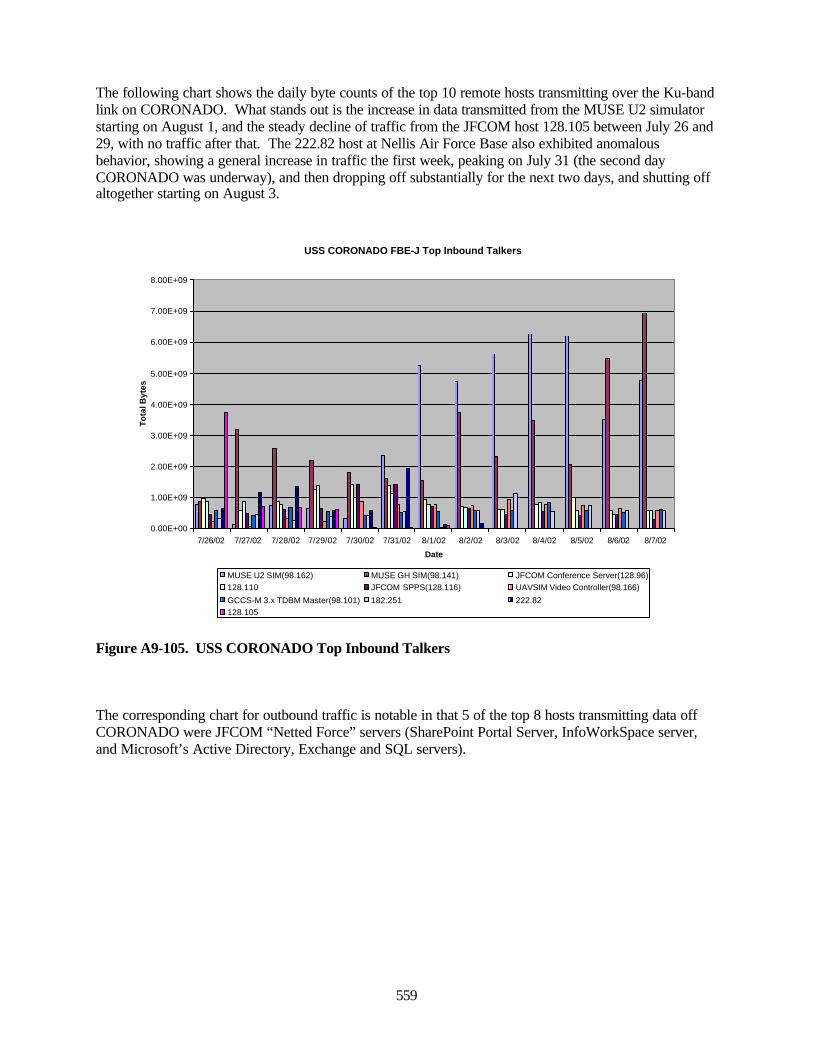
559
The following chart shows the daily byte counts of the top 10 remote hosts transmitting over the Ku-bandlink on CORONADO. What stands out is the increase in data transmitted from the MUSE U2 simulatorstarting on August 1, and the steady decline of traffic from the JFCOM host 128.105 between July 26 and29, with no traffic after that. The 222.82 host at Nellis Air Force Base also exhibited anomalousbehavior, showing a general increase in traffic the first week, peaking on July 31 (the second dayCORONADO was underway), and then dropping off substantially for the next two days, and shutting offaltogether starting on August 3.
Figure A9-105. USS CORONADO Top Inbound Talkers
The corresponding chart for outbound traffic is notable in that 5 of the top 8 hosts transmitting data offCORONADO were JFCOM “Netted Force” servers (SharePoint Portal Server, InfoWorkSpace server,and Microsoft’s Active Directory, Exchange and SQL servers).
USS CORONADO FBE-J Top Inbound Talkers
0.00E+00
1.00E+09
2.00E+09
3.00E+09
4.00E+09
5.00E+09
6.00E+09
7.00E+09
8.00E+09
7/26/02 7/27/02 7/28/02 7/29/02 7/30/02 7/31/02 8/1/02 8/2/02 8/3/02 8/4/02 8/5/02 8/6/02 8/7/02
Date
To
tal B
ytes
MUSE U2 SIM(98.162) MUSE GH SIM(98.141) JFCOM Conference Server(128.96)128.110 JFCOM SPPS(128.116) UAVSIM Video Controller(98.166)
GCCS-M 3.x TDBM Master(98.101) 182.251 222.82128.105
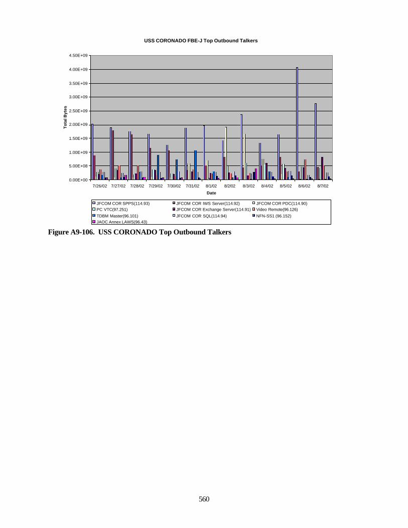
560
Figure A9-106. USS CORONADO Top Outbound Talkers
USS CORONADO FBE-J Top Outbound Talkers
0.00E+00
5.00E+08
1.00E+09
1.50E+09
2.00E+09
2.50E+09
3.00E+09
3.50E+09
4.00E+09
4.50E+09
7/26/02 7/27/02 7/28/02 7/29/02 7/30/02 7/31/02 8/1/02 8/2/02 8/3/02 8/4/02 8/5/02 8/6/02 8/7/02
Date
To
tal B
ytes
JFCOM COR SPPS(114.93) JFCOM COR IWS Server(114.92) JFCOM COR PDC(114.90)PC VTC(97.251) JFCOM COR Exchange Server(114.91) Video Remote(96.126)
TDBM Master(96.101) JFCOM COR SQL(114.94) NFN-SS1 (96.152)JAOC Annex LAWS(96.43)

561
Data Collection, Reduction and Analysis
In the 15 days of FBE-J data collection, over 330 gigabytes of packet header data were collected at the 6sites (CORONADO, FITZGERALD, BENFOLD, HSV, FCTCPAC and China Lake). The data werestored locally on external hard disk drives (with the exception of the HSV) and reduced nightly onCORONADO, BENFOLD and FITZGERALD. The main reduction script (“snifcap.pl”) reduced outputfrom either a series of Sniffer capture files (ending in “.cap”) or a Windump capture file (ending in“.dmp”). The reduction process typically reduced about 3 gigabytes of data per hour. The reduced datawere in the form of comma-separated files showing inbound and outbound per-minute average and one-second peak rates of each minute for all TCP and UDP port numbers, IP type numbers; average and peakrates transmitted from and received by all IP addresses; and data for each TCP session, consisting of startand stop times, source and destination IP addresses, source and destination TCP ports, packet and bytecounts, average bits per second, total retransmissions for each session, and average round-trip time perpacket in milliseconds. Other scripts were used to extend the interval from 1 to 5 minutes, to save andsort the top 250 ports or IP addresses (to get around the 255-column limitation of Microsoft Excel), and toselect user-specified IP address or ports from these files.
The IP addresses were sanitized by substituting “nnn.nnn” for the FBE-J network portion of the address,and “xxx.xxx” for the network portion of non-FBE network addresses. Due to SIPRNET connectivity,the packet capture files remain classified, and the reduced text data were run through a rigorous 11-stepsanitization procedure (detailed at the Navy information security Web site athttps://infosec.navy.mil/sectips.html) before further reduction on the unclassified side.
In addition to bit rates, RTP audio and video jitter as well as RTP dropped packets and total packet countswere logged for each minute. Other data produced in the reduction process (Web server usage and UDPflow data) remain on the classified side. Entire SMTP packets on CORONADO and at FCTCPAC werecaptured using the “windump” open-source packet capture program, and message traffic wasreconstructed from these captures using a Perl script developed at NSWC Corona. These data also remainon the classified side.
Several problems occurred in the data collection effort, most notably those related to the switched natureof the local area networks. The analysis laptop placement at FCTCPAC originally allowed for packetcapture over the Ku-band and DREN connections simultaneously, but ended up being shut down for 3days (July 26-29) due to potential impact on the LAN switch it was connected to. From July 29 onward,the laptop captured only the packets between FCTCPAC and the DREN connection. Futureimplementations of network analysis laptops at the shore-based satellite site should include two separatepacket capture programs and interfaces (one for the satellite link and the other for the link to the othershore sites). Also, China Lake encountered a problem with switch performance when port-mirroring theDREN data onto the network analysis port. Network engineers at China Lake were able to work aroundthis problem by making the mirrored port receive-only, which still allowed for packet capture but maderemote administration impossible. Reliable data collection for China Lake was limited to 5 days (July 28– August 1, when most of the action on the ground was taking place).
The HSV encountered many issues relating to network analysis data collection. This was the only sitewhere a laptop was not used (due to space limitations). A rack-mounted PC was put to use, andcontrolled through a keyboard-video-mouse (KVM) matrix switch as well as remotely using pcAnywhere.This led to some user contention problems as personnel aboard the HSV easily accessed the PC. Thescreen-saver password was changed first to alleviate this problem, but then the network analysis PC wasrebooted in an apparent attempt to get around the password change. The packet capture was stoppedseveral times between July 25 and August 2, limiting the amount of good data collected.
In addition, the LAN switch port did not appear to mirror all the packets entering and leaving the HSV viathe Ku-band satellite link. From July 25-29, very little TCP data was captured other than that to and from
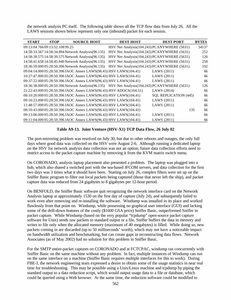
562
the network analysis PC itself. The following table shows all the TCP flow data from July 26. All theLAWS sessions shown below represent only one (inbound) packet for each session.
START STOP SOURCE HOST DEST HOST DEST PORT BYTES09:13:04.766 09:13:52.108 99.25 HSV Net Analysis(104.243) PCANYWHERE (5631) 5413714:58:33.567 14:58:34.894 Network Analysis(96.135) HSV Net Analysis(104.243) PCANYWHERE (5631) 25214:58:39.575 14:58:39.575 Network Analysis(96.135) HSV Net Analysis(104.243) PCANYWHERE (5631) 12614:58:41.658 14:58:45.940 Network Analysis(96.135) HSV Net Analysis(104.243) PCANYWHERE (5631) 25818:36:59.000 05:28:50.396 Network Analysis(96.135) HSV Net Analysis(104.243) PCANYWHERE (5631) 19209:04:14.000 05:28:50.396 JAOC Annex LAWS(96.43) HSV LAWS(104.41) LAWS (2811) 6610:27:47.000 05:28:50.396 JAOC Annex LAWS(96.43) HSV LAWS(104.41) LAWS (2811) 6609:37:22.000 05:28:50.396 JAOC Annex LAWS(96.43) HSV LAWS(104.41) LAWS (2811) 6618:36:38.000 05:28:50.396 Network Analysis(96.135) HSV Net Analysis(104.243) PCANYWHERE (5631) 12621:22:43.000 05:28:50.396 JAOC Annex LAWS(96.43) HSV ADOCS(104.51) LAWS (2814) 6608:10:20.000 05:28:50.396 JAOC Annex LAWS(96.43) HSV LAWS(104.41) SQL REPLICATION (445) 6609:16:23.000 05:28:50.396 JAOC Annex LAWS(96.43) HSV LAWS(104.41) LAWS (2811) 6611:48:57.000 05:28:50.396 JAOC Annex LAWS(96.43) HSV LAWS(104.41) LAWS (2811) 6608:10:43.000 05:28:50.396 JAOC Annex LAWS(96.43) HSV LAWS(104.41) 135 6609:13:06.000 05:28:50.396 JAOC Annex LAWS(96.43) HSV LAWS(104.41) LAWS (2811) 6609:11:04.000 05:28:50.396 JAOC Annex LAWS(96.43) HSV LAWS(104.41) LAWS (2811) 66
Table A9-13. Joint Venture (HSV-X1) TCP Data Flow, 26 July 02
The port-mirroring problem was resolved on July 30, but due to other reboots and outages, the only fulldays where good data was collected on the HSV were August 2-6. Although running a dedicated laptopon the HSV for network analysis data collection was not an option, future data collection efforts need torestrict access to the packet capture machine by removing it from the KVM matrix switch menu.
On CORONADO, analysis laptop placement also presented a problem. The laptop was plugged into ahub, which also shared a switched port with the sea-based JFCOM servers, and data collection for the firsttwo days was 3 times what it should have been. Starting on July 26, complex filters were set up on theSniffer Basic program to filter out local packets being captured (those that never left the ship), and packetcapture data was reduced from 24 gigabytes to 8 gigabytes per 12-hour period.
On BENFOLD, the Sniffer Basic software quit recognizing the network interface card on the NetworkAnalysis laptop at approximately 1530 on the first day of capture (July 24), and subsequently failed towork even after removing and re-installing the software. Windump was installed in its place and workedflawlessly from that point on. Windump, while possessing no graphical user interface (GUI) and lackingsome of the drill-down features of the costly ($1600 GSA price) Sniffer Basic, outperformed Sniffer inpacket capture. While Windump (based on the very popular “tcpdump” open-source packet capturesoftware for Unix) sends raw packets to standard output or a file, Sniffer buffers the data in memory andwrites to file only when the allocated memory (maximum of 40 megabytes) is filled. While doing so, newpackets coming in are discarded (up to 50 milliseconds’ worth), which may not have a noticeable impacton bandwidth utilization and benchmarking, but can create gaps in reconstructing data flows. NetworkAssociates (as of May 2002) had no solution for this problem in Sniffer Basic.
For the SMTP entire-packet captures on CORONADO and at FCTCPAC, windump ran concurrently withSniffer Basic on the same machine without any problem. In fact, multiple instances of Windump can runon the same interface on a machine (Sniffer Basic requires multiple interfaces for this to work). DuringFBE-J, the network engineering team expressed a desire to obtain some of the usage statistics in near realtime for troubleshooting. This may be possible using a Unix/Linux machine and tcpdump by piping thestandard output to a data reduction script, which would output usage data to a file or database, whichcould be queried using a Web browser. At the same time, the reduction software could be modified to
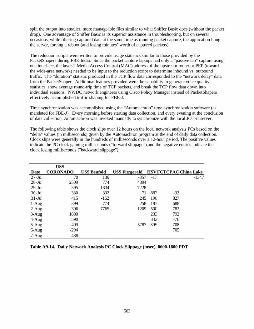
563
split the output into smaller, more manageable files similar to what Sniffer Basic does (without the packetdrop). One advantage of Sniffer Basic is its superior assistance in troubleshooting, but on severaloccasions, while filtering captured data at the same time as running packet capture, the application hungthe server, forcing a reboot (and losing minutes’ worth of captured packets).
The reduction scripts were written to provide usage statistics similar to those provided by thePacketShapers during FBE-India. Since the packet capture laptops had only a “passive tap” capture usingone interface, the layer-2 Media Access Control (MAC) address of the upstream router or PEP (towardthe wide-area network) needed to be input to the reduction script to determine inbound vs. outboundtraffic. The “duration” statistic produced in the TCP flow data corresponded to the “network delay” datafrom the PacketShaper. Additional features provided were the capability to generate voice qualitystatistics, show average round-trip time of TCP packets, and break the TCP flow data down intoindividual sessions. NWDC network engineers using Cisco Policy Manager instead of PacketShaperseffectively accomplished traffic shaping for FBE-J.
Time synchronization was accomplished using the “Automachron” time-synchronization software (asmandated for FBE-J). Every morning before starting data collection, and every evening at the conclusionof data collection, Automachron was invoked manually to synchronize with the local JOTS1 server.
The following table shows the clock slips over 12 hours on the local network analysis PCs based on the“delta” values (in milliseconds) given by the Automachron program at the end of daily data collection.Clock slips were generally in the hundreds of milliseconds over a 12-hour period. The positive valuesindicate the PC clock gaining milliseconds ("forward slippage"),and the negative entries indicate theclock losing milliseconds ("backward slippage").
DateUSS
CORONADO USS Benfold USS Fitzgerald HSVFCTCPAC China Lake27-Jul 70 136 -357 -17 -134728-Jul 2509 774 439429-Jul 395 1834 -722830-Jul 330 392 71 887 -3231-Jul 415 -162 245 190 8271-Aug 399 774 258 183 6882-Aug 396 7765 1209 500 7823-Aug 1880 232 7924-Aug 590 342 -765-Aug 409 5787 -395 7086-Aug -294 7057-Aug 438
Table A9-14. Daily Network Analysis PC Clock Slippage (msec), 0600-1800 PDT

564
This page intentionally left blank.
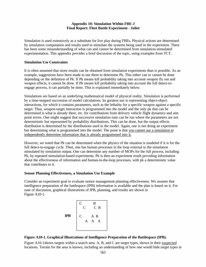
565
Appendix 10: Simulation Within FBE-JFinal Report: Fleet Battle Experiment - Juliet
Simulation is used extensively as a substitute for live play during FBEs. Physical actions are determinedby simulation computation and results used to stimulate the systems being used in the experiment. Therehas been some misunderstanding of what can and cannot be determined from simulation-stimulatedexperimentation. This appendix provides a brief discussion of the topic, using examples from TCT.
Simulation Use Constraints
It is often assumed that more results can be obtained from simulation experiments than is possible. As anexample, suggestions have been made to use them to determine Pk. This either can or cannot be donedepending on the definition of Pk. If Pk means kill probability taking into account weapon fly out andweapon effects, it cannot be done. If Pk means kill probability taking into account the full detect-to-engage process, it can partially be done. This is explained immediately below.
Simulations are based on an underlying mathematical model of physical reality. Simulation is performedby a time-stepped succession of model calculations. Its greatest use is representing object-objectinteractions, for which it contains parameters, such as the lethality for a specific weapon against a specifictarget. Thus, weapon-target interaction is programmed into the model and the only pk that can bedetermined is what is already there, etc. for contributions from delivery vehicle flight dynamics and aimpoint errors. One might suggest that successive simulation runs can be run where the parameters are notdeterministic but represented by probability distributions. This can be done, but the output effectsdistribution is determined by the distributions used in the model. Again, one is not doing an experimentbut determining what is programmed into the model. The point is that you cannot use a simulation toindependently determine information that is already programmed into it.
However, we noted that Pk can be determined when the physics of the situation is modeled if it is for thefull detect-to-engage cycle. Then, one has human processes in the loop external to the simulationstimulated by simulation output. One can determine any number of MOPs for the full process, includingPk, by repeated stimulation-based experiments. Pk is then an experiment result providing informationabout the effectiveness of information and human-in-the-loop processes, with pk a deterministic valuethat contributes to it.
Sensor Planning Effectiveness, a Simulation Use Example
Consider an experiment goal to evaluate sensor management planning effectiveness. We assume thatintelligence preparation of the battlespace (IPB) information is available and the plan is based on it. Forease of discussion, graphical illustrations of IPB, planning, and results are shown inFigure A10-1.
Figure A10-1. Graphical Illustrations of Intelligence Preparation of the Battlespace (IPB).Figure A10-1shows targets within a search area. A, B, and C are target types, shown in their suspectedlocations. Terrain for the area is known, including an understanding of how one would hide target types in
C B C C B
C A B A A A
IPB
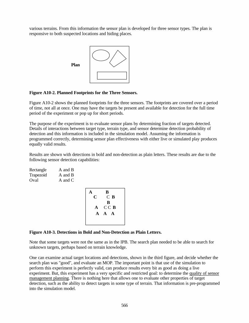
566
various terrains. From this information the sensor plan is developed for three sensor types. The plan isresponsive to both suspected locations and hiding places.
Figure A10-2. Planned Footprints for the Three Sensors.
Figure A10-2 shows the planned footprints for the three sensors. The footprints are covered over a periodof time, not all at once. One may have the targets be present and available for detection for the full timeperiod of the experiment or pop up for short periods.
The purpose of the experiment is to evaluate sensor plans by determining fraction of targets detected.Details of interactions between target type, terrain type, and sensor determine detection probability ofdetection and this information is included in the simulation model. Assuming the information isprogrammed correctly, determining sensor plan effectiveness with either live or simulated play producesequally valid results.
Results are shown with detections in bold and non-detection as plain letters. These results are due to thefollowing sensor detection capabilities:
Rectangle A and BTrapezoid A and BOval A and C
Figure A10-3. Detections in Bold and Non-Detection as Plain Letters.
Note that some targets were not the same as in the IPB. The search plan needed to be able to search forunknown targets, perhaps based on terrain knowledge.
One can examine actual target locations and detections, shown in the third figure, and decide whether thesearch plan was "good", and evaluate an MOP. The important point is that use of the simulation toperform this experiment is perfectly valid, can produce results every bit as good as doing a liveexperiment. But, this experiment has a very specific and restricted goal: to determine the quality of sensormanagement planning. There is nothing here that allows one to evaluate other properties of targetdetection, such as the ability to detect targets in some type of terrain. That information is pre-programmedinto the simulation model.
A B C C B B A C C B A A A
Plan

567
One important factor with respect to this example is that results will depend on the physics programmedinto the simulation model, e.g., if sensor detection probabilities are incorrect, results will be skewed. It isnecessary to understand a simulation's underlying model when interpreting experimentation results—apoint that will be important in the following discussion.
Simulation in FBEs, TCT Example, Data Capture Requirements
This sub-Section illustrates types of information needed at the interfaces with, and within a simulation inorder to have sufficient data for analysis. The notional TCT process used is not meant to be complete;rather to illustrate some processes to discuss simulation-stimulated experimentation. Not included are amyriad of processes that would only complicate the discussion. We assume a common informationbackbone, labeled "Info Backbone", rather than discuss realities of how various types of information areexchanged. The only live play is people involved in the human detect-to-engage processes. Thus, thisexample is much like the one above, our interest being in how well humans perform their tasks and howwell they are supported by software systems designed to be part of the process.
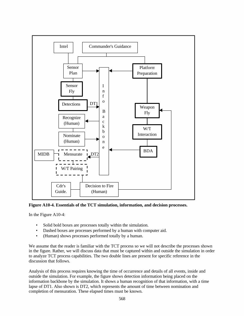
568
DT1
DT2
Figure A10-4. Essentials of the TCT simulation, information, and decision processes.
In the Figure A10-4:
• Solid bold boxes are processes totally within the simulation.• Dashed boxes are processes performed by a human with computer aid.• (Human) shows processes performed totally by a human.
We assume that the reader is familiar with the TCT process so we will not describe the processes shownin the figure. Rather, we will discuss data that must be captured within and outside the simulation in orderto analyze TCT process capabilities. The two double lines are present for specific reference in thediscussion that follows.
Analysis of this process requires knowing the time of occurrence and details of all events, inside andoutside the simulation. For example, the figure shows detection information being placed on theinformation backbone by the simulation. It shows a human recognition of that information, with a timelapse of DT1. Also shown is DT2, which represents the amount of time between nomination andcompletion of mensuration. These elapsed times must be known.
Commander's Guidance
PlatformPreparation
SensorPlan
Recognize(Human)
Nominate(Human)
Mensurate
W/T Pairing
MIDBBDA
Intel
SensorFly
Detections
Cdr'sGuide.
Decision to Fire(Human)
WeaponFly
W/TInteraction
Info
Backbone
569
Determining DT1 requires capturing first the time of simulation information output. This requires anautomatic data capture process wither within the simulation or the information backbone. The secondtime to capture is when the human recognizes the information is available. This may seem a peculiar thingto determine, but it bears on quality of the display system and on human training and capabilities in thistype of situation. Capturing this time can be done either by a separate observer or by the person loggingthe event.
DT2 is the time between target nomination and the completion of mensuration. Deciding to nominate is apurely human decision. Its occurrence can be logged or captured on the information backbone when thehuman enters the nomination. A human with software performs mensuration and the time of completionof the process can be captured either within that software or on the information backbone. There are timeswithin the mensuration process that will also be needed for complete evaluation of the TCT process.
To summarize to this point, determining DT1 and DT2 (and other associated times not discussed) requireslogging event times:
• Within the simulation.• On the information backbone.• Within software/hardware systems .• At human decision nodes.
This may seem, and is, fairly obvious, but obtaining these times has been a challenge.
It is not possible to evaluate the TCT process without a determination of the quality of informationavailable for making various decisions. Poor imagery or incorrect target locations will lead to poortargeting decisions and results. The simulation provides this information. Thus, analysis requires detailedknowledge of:
• Sensor parameterization within the simulation model.• Target parameterization within the simulation model.• How sensors are flown by the simulation.• How terrain is represented within the simulation, etc…
Commander's guidance will prompt many actions, including moving platforms to be in position toperform assigned tasks. The two double lines are between platforms, weapon fly out, and weapon/targetinteraction. They are there to indicate interdependences between these actions. Ship location willinfluence whether it can engage a particular target and how long it takes a weapon to be on target oncefired. Weapon/target interaction depends on impact location, which depends on weapon fly out. All thesefactors affect TCT results and all are within the simulation.
Summary
The purpose of TCT analysis as described here is to determine the effectiveness of human-includedprocesses. These processes include:
• Information flow• Decision structures• Support systems• Human capabilities

570
These processes are stimulated by simulation output and depend on details of provided information. Inlive operations operators have an understanding of physical effects, such as how long it takes for aweapon to reach a target and whether a particular weapon is effective against a given hard target. Thisinfluences their decisions. In order for a simulation-based experiment to produce sensible results, theremust be a correspondence between operator understanding of physical effects and what is occurringwithin the simulation. Analysis must be able to verify that this correspondence is present or, if not, havean understanding of the differences.
In order for the operators in an experiment to make sensible decisions, they must be trained to understandhow the supporting simulation behaves or the simulation must provide an accurate representation ofreality. Analysis of experiment results will only produce accurate results if these details are known.Again, this requires capture of events within and at simulation interfaces with TCT processes and detailedunderstanding of the underlying physics used to calculate the effects.
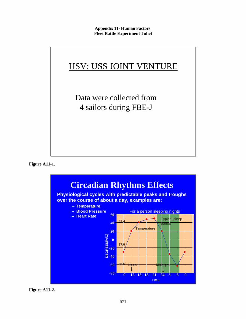
571
Appendix 11- Human FactorsFleet Battle Experiment-Juliet
HSV: USS JOINT VENTURE
Data were collected from 4 sailors during FBE-J
Figure A11-1.
-80
-60
-40
-20
0
20
40
60
9 12 15 18 21 24 3 6 9
37.4
37.0
36.6
DE
GR
EE
S(%
/C)
TIME
Temperature
Physiological cycles with predictable peaks and troughs over the course of about a day, examples are:
-- Temperature-- Blood Pressure For a person sleeping nights-- Heart Rate
Circadian Rhythms Effects
Typical sleep period
MidnightNoon
Figure A11-2.
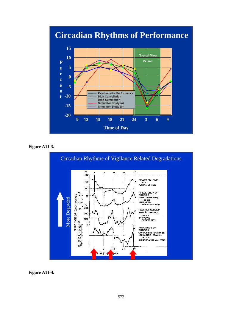
572
Circadian Rhythms of Performance
-20
-15
-10
-5
0
5
10
15
Percent
9 12 15 18 21 24 3 6 9
--------- Psychomotor Performance--------- Digit Cancellation--------- Digit Summation--------- Simulator Study (a)--------- Simulator Study (b)
Time of Day
Typical Sleep
Period
Figure A11-3.
Circadian Rhythms of Vigilance Related Degradations
Mor
e D
egra
ded
Figure A11-4.
<
Q
Vo no
105
100
V. ,[ 300
200 -
iS UOr ^ 130- g^ 120-
110- 100- 90- 80- 70- 60L
REACTION TIME
(VOtGTet 01.1968)
FREQUENCY OF ERRORS (SHIFT WORKERS)
n=62.000 (QJERNER&
SWENSSON 1953)
FALLING ASLEEP WHILE DRIVING
n=-500 (PROKOP &
PROKOP 19S5)
FREQENCY OF ERRORS (COMPULSIVE BRAKINGS) LOCOMOTIVE DRIVERS
nz2 238
<HILOEBRANOT «t at. 197&)
9 15 3h
TIME OF DAY
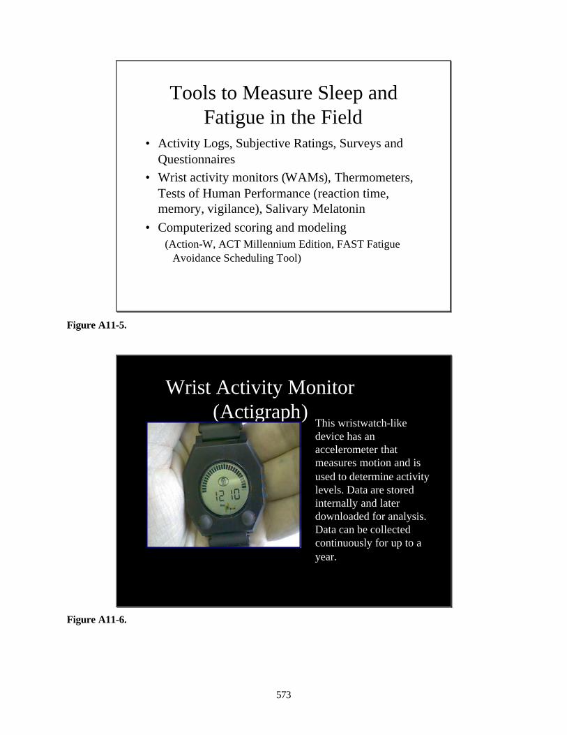
573
Tools to Measure Sleep and Fatigue in the Field
• Activity Logs, Subjective Ratings, Surveys and Questionnaires
• Wrist activity monitors (WAMs), Thermometers, Tests of Human Performance (reaction time, memory, vigilance), Salivary Melatonin
• Computerized scoring and modeling(Action-W, ACT Millennium Edition, FAST Fatigue
Avoidance Scheduling Tool)
Figure A11-5.
Wrist Activity Monitor (Actigraph)
This wristwatch-like device has an accelerometer that measures motion and is used to determine activity levels. Data are stored internally and later downloaded for analysis. Data can be collected continuously for up to a year.
Figure A11-6.
fc
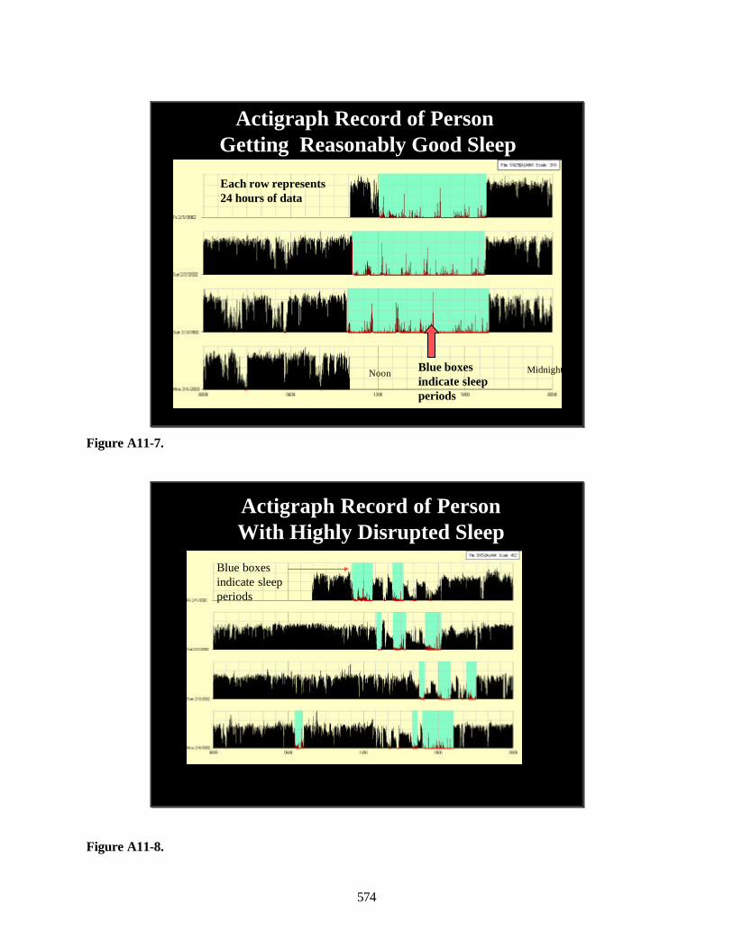
574
Actigraph Record of PersonGetting Reasonably Good Sleep
Blue boxes indicate sleep periods
Each row represents 24 hours of data
Noon Midnight
Figure A11-7.
Actigraph Record of Person With Highly Disrupted Sleep
Blue boxes indicate sleep periods
Figure A11-8.
rH iinhL--i iiH "'
m I mnii Biiliiiliiiii ill iiiilii ii^^^BI
|g|||j|iLii||iy^ II j ^ini
ii.iiilil,.iiiiiiiiit I , I lii^JLJ
III ngm
iVflV-i-i 1:V V
iii„.il,t.kjliiiMi
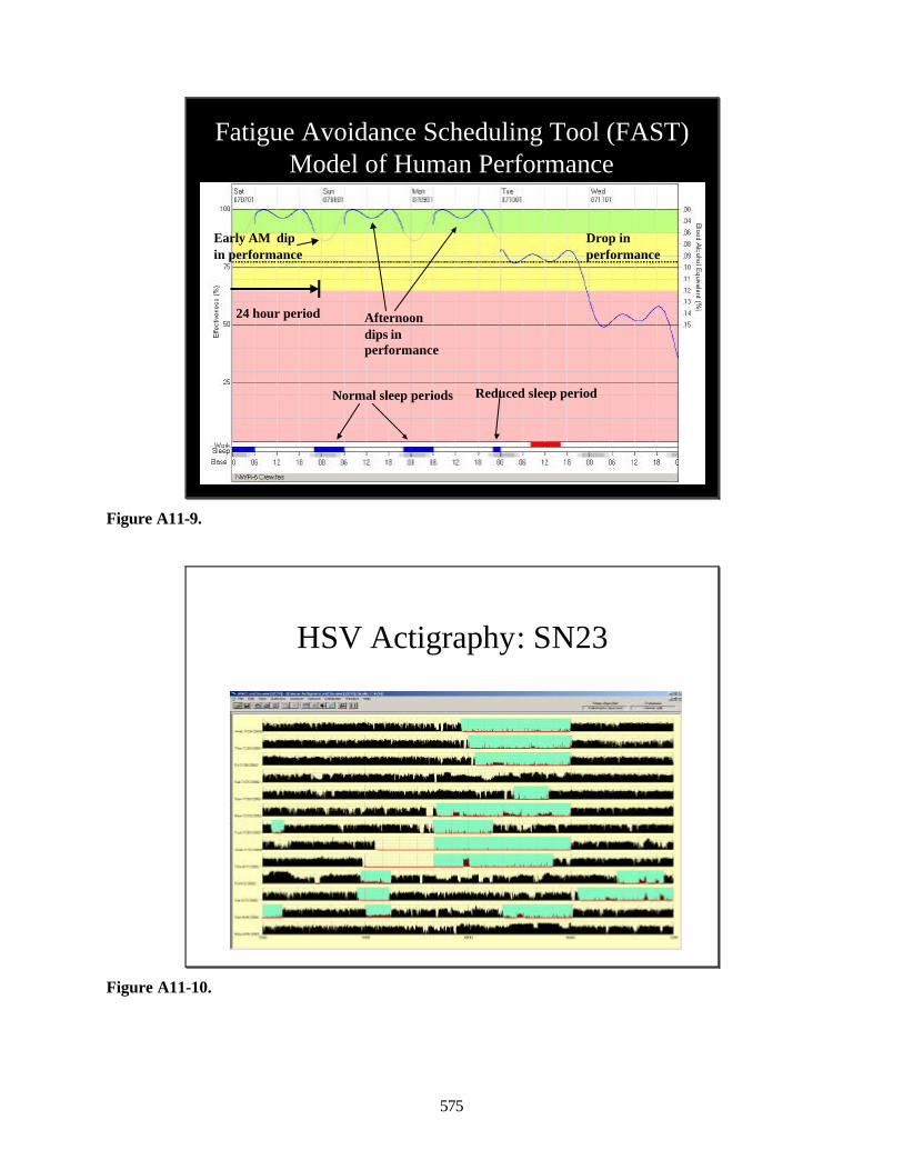
575
Fatigue Avoidance Scheduling Tool (FAST) Model of Human Performance
24 hour period Afternoon dips in performance
Reduced sleep periodNormal sleep periods
Drop in performance
Early AM dip in performance
Figure A11-9.
HSV Actigraphy: SN23
Figure A11-10.
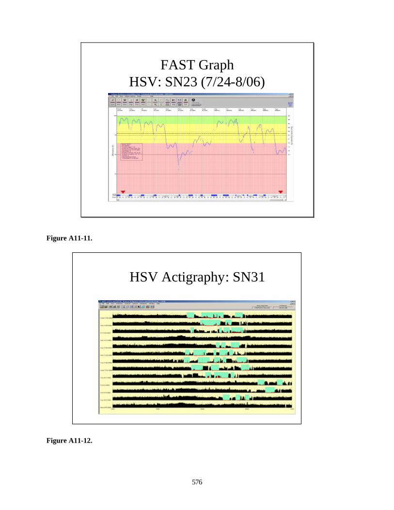
576
FAST Graph HSV: SN23 (7/24-8/06)
Figure A11-11.
HSV Actigraphy: SN31
Figure A11-12.
'^nnr (^.fi'. ¥-
j-
V
^ U
E^t"7.'*t^j«...-«-;3&:.;.'A..4fl'i.9iv.'W.=-.Tt:','fr:"-;xiTr.'*S..-i'.
HdlMIIB aUIUUUU U D ■TS
._™Jl
m
JJ. B.JL_JII
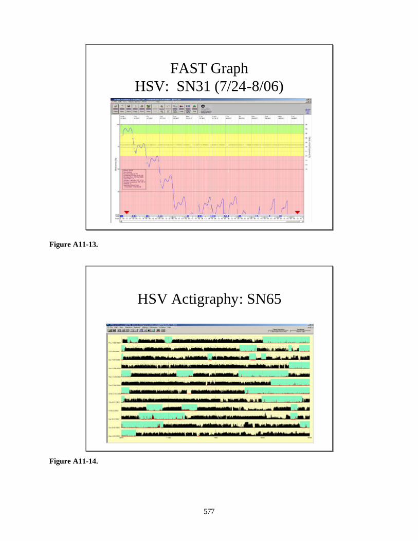
577
FAST Graph HSV: SN31 (7/24-8/06)
Figure A11-13.
HSV Actigraphy: SN65
Figure A11-14.
rA
'r". WVI^
^^^■■^-■■-
AAA r"!
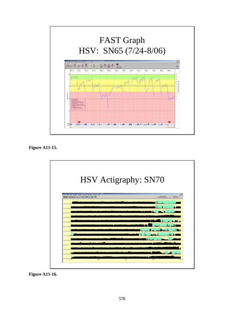
578
FAST Graph HSV: SN65 (7/24-8/06)
Figure A11-15.
HSV Actigraphy: SN70
Figure A11-16.
ia -1. v_ lb «. Fit ijfr fr«
fM r>
:*i---:^ ■■;---7^
[JM rjuwrj.i .Hpj«u Al li] TT^
^^^^^_ rvi^-i T'^^^^^^^^^^^^B ^^r"J A^^^^iiB*^^^^^ b ^m 1^^^^ lfc^ L- \ ^^^^^^^^^^^B H^I^HH ̂ ^^^^^^^^■■u ^Ba J_i.__l_ii^^H
'""""*"*'" "*"""" ^ UuL 1 ilfcfcJBBi ^i^^ 1 d . \ ilfcd ■. J HI
" '""^^^^ ^^i^iHi
M^ta 1 -A J ri h 1 ■■ ik^^^H
—:!:^^^ ^^H 1 L mJbiL - _ .LIlill^^H
'■-^^^TIT ^^^^^^^^^^^*
-- -^ ■ -
■■■■■ll L—■ J_-.<j.J^-^.—'■■■
—^jitmmm ■ rw *#w
1
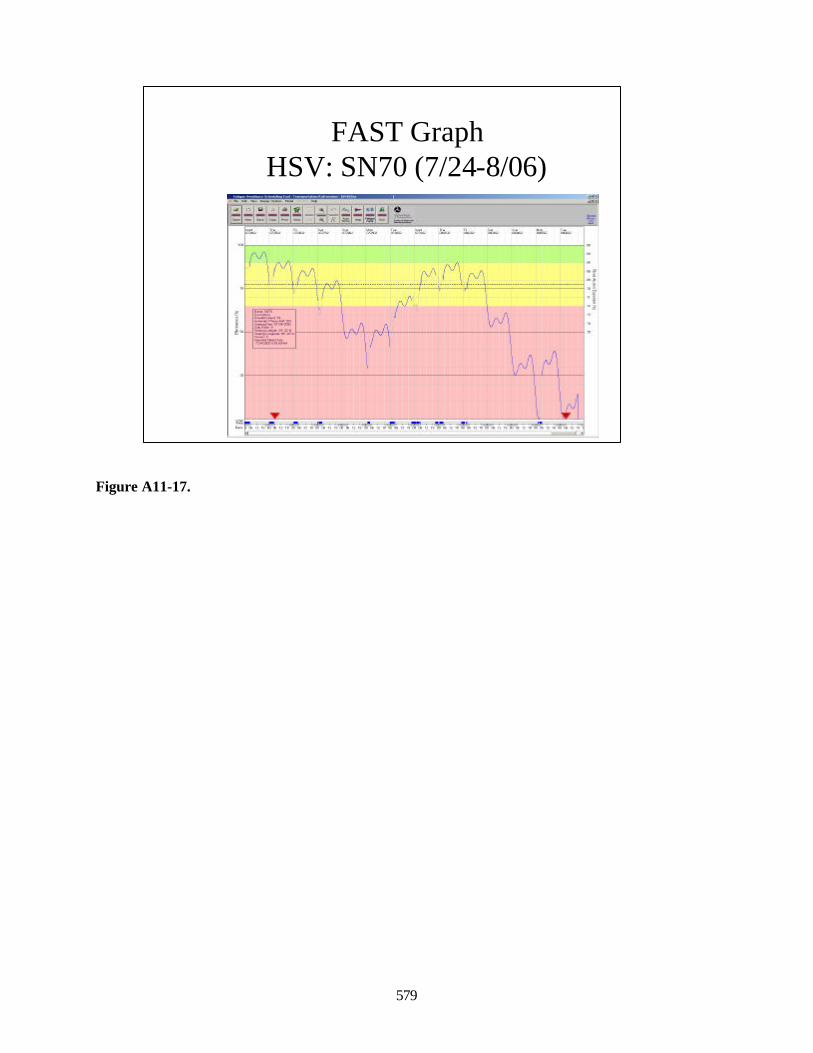
579
FAST GraphHSV: SN70 (7/24-8/06)
Figure A11-17.
'-I^'J^^^I^I ] - _'^l^ ^i *„
---==^4^--=WF __^/ap^._. :
;■"
i-

580
This page intentionally left blank.
581
Appendix 12: Operational Sequence DiagramsFleet Battle Experiment – Juliet
This list provides a quick reference to the operational sequence diagrams that follow.
Figure TitleA12-1 Messages and Transport MethodsA12-2 ISR-1: Live Pioneer UAV EO/IR Detection and Target NominationA12-3 ISR-2: Live Predator UAV EO/IR Detection and Target NominationA12-4 ISR-3: T-39 LADAR Detection and Target NominationA12-5 Mensuration-1: Target Nomination with No Georefinement Options
Specified (Engagement does not require georefinement)A12-6 Mensuration-2: Target Nomination with No Georefinement Options
Specified (Engagement requires georefinement)A12-7 Mensuration-3: Target Nomination with No Georefinement Options
Specified (Engagement cancels request for georefinement)A12-8 Mensuration-4: Target Nomination with Georefinement Options
(Engagement requests georefinement)A12-9 Mensuration-5: Target Nomination with Georefinement Options (Cancels request for
georefinement)A12-10 Mensuration-6: Target Nomination with Georefinement Options
(Engagement requests georefinement; Mensuration CANTCO)A12-11 COP-1: MIDB Track-Target AssociationA12-12 COP 2: MIDB Intel Database ReplicationA12-13 COP-3: JTT Target Validation and NominationA12-14 Engagement-1: Organic Target Nomination on Live Ship Employing ERGMA12-15 Engagement-2: Organic Target Nomination on Live Ship Employing LOCAASA12-16 Engagement-3a: Organic Target Nomination on Live Ship Employing ALAMA12-17 Engagement-3b: Organic Target Nomination on Live Ship Employing S/LTACMS-A/C/UA12-18 Engagement-4: Organic Target Nomination on Live Ship Employing TTLAMA12-19 Engagement-5: Mission to JFMCC MOC for Weapon Target Pairing Employing ERGM on
Sim ShipA12-20 Engagement-6: Mission to JFMCC MOC for Weapon Target Pairing Employing ALAM on
Sim ShipA12-21 Engagement-7: Mission to JFMCC MOC for Weapon Target Pairing Employing TTLAM on
Sim ShipA12-22 Engagement-8: Mission to JFMCC MOC for Weapon Target Pairing Employing ERGM on
Live ShipA12-23 Engagement-9: Mission to JFMCC MOC for Weapon Target Pairing Employing PAM on
Live ShipA12-24 Engagement-10: Mission to JFMCC MOC for Weapon Target Pairing Employing LAM on
Live ShipA12-25 Engagement-11: Mission to JFMCC MOC for Weapon Target Pairing Employing LOCAAS
on Live ShipA12-26 Engagement-12a: Mission to JFMCC MOC for Weapon Target Pairing Employing ALAM on
Live ShipA12-27 Engagement-12b: Mission to JFMCC MOC for Weapon Target Pairing Employing
S/LTACMS-A/C/U on Live ShipA12-28 Engagement-13: Mission to JFMCC MOC for Weapon Target Pairing Employing TTLAM
on Live ShipA12-29 Engagement-14: Mission to Air C2 Node for Weapon Target Pairing Employing Stand-Off
Weapon with Sim Aircraft
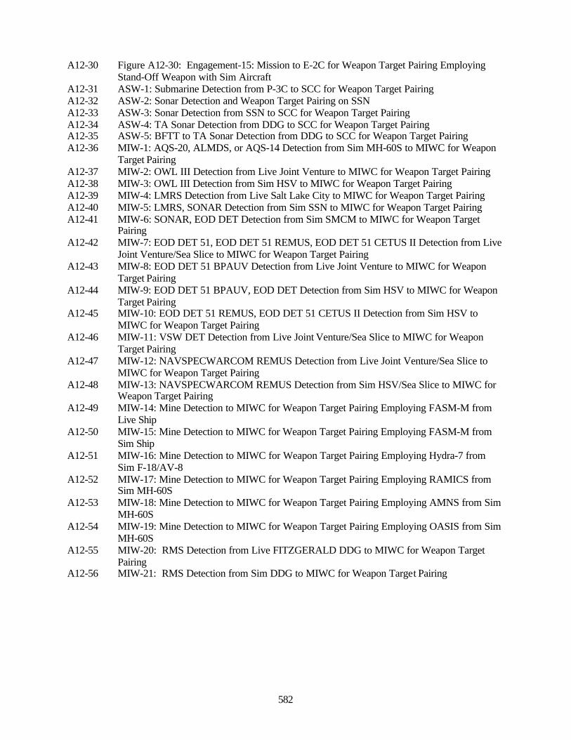
582
A12-30 Figure A12-30: Engagement-15: Mission to E-2C for Weapon Target Pairing EmployingStand-Off Weapon with Sim Aircraft
A12-31 ASW-1: Submarine Detection from P-3C to SCC for Weapon Target PairingA12-32 ASW-2: Sonar Detection and Weapon Target Pairing on SSNA12-33 ASW-3: Sonar Detection from SSN to SCC for Weapon Target PairingA12-34 ASW-4: TA Sonar Detection from DDG to SCC for Weapon Target PairingA12-35 ASW-5: BFTT to TA Sonar Detection from DDG to SCC for Weapon Target PairingA12-36 MIW-1: AQS-20, ALMDS, or AQS-14 Detection from Sim MH-60S to MIWC for Weapon
Target PairingA12-37 MIW-2: OWL III Detection from Live Joint Venture to MIWC for Weapon Target PairingA12-38 MIW-3: OWL III Detection from Sim HSV to MIWC for Weapon Target PairingA12-39 MIW-4: LMRS Detection from Live Salt Lake City to MIWC for Weapon Target PairingA12-40 MIW-5: LMRS, SONAR Detection from Sim SSN to MIWC for Weapon Target PairingA12-41 MIW-6: SONAR, EOD DET Detection from Sim SMCM to MIWC for Weapon Target
Pairing A12-42 MIW-7: EOD DET 51, EOD DET 51 REMUS, EOD DET 51 CETUS II Detection from Live
Joint Venture/Sea Slice to MIWC for Weapon Target PairingA12-43 MIW-8: EOD DET 51 BPAUV Detection from Live Joint Venture to MIWC for Weapon
Target PairingA12-44 MIW-9: EOD DET 51 BPAUV, EOD DET Detection from Sim HSV to MIWC for Weapon
Target PairingA12-45 MIW-10: EOD DET 51 REMUS, EOD DET 51 CETUS II Detection from Sim HSV to
MIWC for Weapon Target PairingA12-46 MIW-11: VSW DET Detection from Live Joint Venture/Sea Slice to MIWC for Weapon
Target PairingA12-47 MIW-12: NAVSPECWARCOM REMUS Detection from Live Joint Venture/Sea Slice to
MIWC for Weapon Target PairingA12-48 MIW-13: NAVSPECWARCOM REMUS Detection from Sim HSV/Sea Slice to MIWC for
Weapon Target PairingA12-49 MIW-14: Mine Detection to MIWC for Weapon Target Pairing Employing FASM-M from
Live ShipA12-50 MIW-15: Mine Detection to MIWC for Weapon Target Pairing Employing FASM-M from
Sim ShipA12-51 MIW-16: Mine Detection to MIWC for Weapon Target Pairing Employing Hydra-7 from
Sim F-18/AV-8A12-52 MIW-17: Mine Detection to MIWC for Weapon Target Pairing Employing RAMICS from
Sim MH-60SA12-53 MIW-18: Mine Detection to MIWC for Weapon Target Pairing Employing AMNS from Sim
MH-60SA12-54 MIW-19: Mine Detection to MIWC for Weapon Target Pairing Employing OASIS from Sim
MH-60SA12-55 MIW-20: RMS Detection from Live FITZGERALD DDG to MIWC for Weapon Target
PairingA12-56 MIW-21: RMS Detection from Sim DDG to MIWC for Weapon Target Pairing
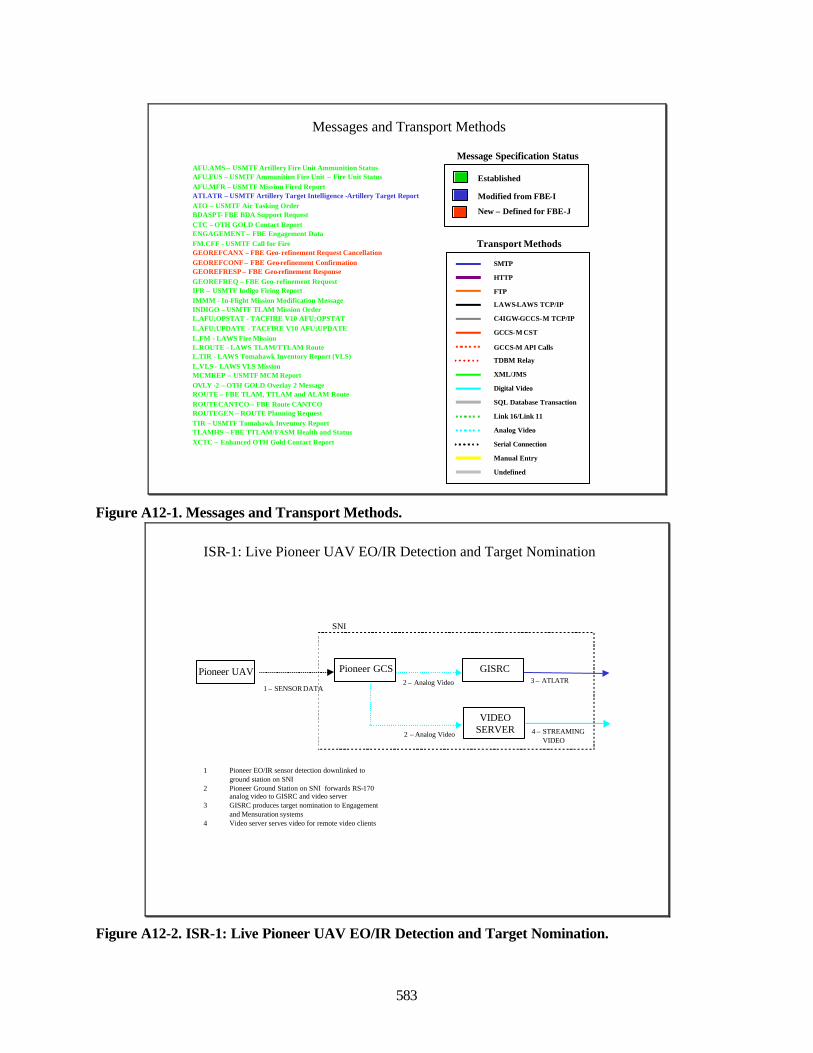
583
Messages and Transport Methods
AFU.AMS – USMTF Artillery Fire Unit Ammunition StatusAFU.FUS – USMTF Ammunition Fire Unit – Fire Unit StatusAFU.MFR – USMTF Mission Fired ReportATI.ATR – USMTF Artillery Target Intelligence -Artillery Target ReportATO – USMTF Air Tasking OrderBDASPT- FBE BDA Support RequestCTC – OTH GOLD Contact ReportENGAGEMENT – FBE Engagement DataFM.CFF - USMTF Call for FireGEOREFCANX – FBE Geo-refinement Request CancellationGEOREFCONF – FBE Geo-refinement ConfirmationGEOREFRESP – FBE Geo-refinement ResponseGEOREFREQ – FBE Geo-refinement RequestIFR – USMTF Indigo Firing ReportIMMM - In-Flight Mission Modification MessageINDIGO – USMTF TLAM Mission OrderL.AFU;OPSTAT - TACFIRE V10 AFU;OPSTATL.AFU;UPDATE - TACFIRE V10 AFU;UPDATEL.FM - LAWS Fire MissionL.ROUTE - LAWS TLAM/TTLAM RouteL.TIR - LAWS Tomahawk Inventory Report (VLS)L.VLS - LAWS VLS MissionMCMREP – USMTF MCM ReportOVLY -2 – OTH GOLD Overlay 2 MessageROUTE – FBE TLAM, TTLAM and ALAM RouteROUTECANTCO – FBE Route CANTCOROUTEGEN – ROUTE Planning RequestTIR – USMTF Tomahawk Inventory ReportTLAMHS – FBE TTLAM/FASM Health and StatusXCTC – Enhanced OTH Gold Contact Report
SMTP
HTTP
Serial Connection
FTP
GCCS-M CST
LAWS-LAWS TCP/IP
SQL Database Transaction
Transport Methods
Established
Modified from FBE-I
New – Defined for FBE-J
Message Specification Status
Link 16/Link 11
Analog Video
Manual Entry
TDBM Relay
XML/JMS
Digital Video
C4IGW-GCCS-M TCP/IP
Undefined
GCCS-M API Calls
Figure A12-1. Messages and Transport Methods.
ISR-1: Live Pioneer UAV EO/IR Detection and Target Nomination
1 Pioneer EO/IR sensor detection downlinked to ground station on SNI
2 Pioneer Ground Station on SNI forwards RS-170 analog video to GISRC and video server
3 GISRC produces target nomination to Engagement and Mensuration systems
4 Video server serves video for remote video clients
Pioneer GCS2 – Analog Video
SNI
Pioneer UAV
1 – SENSOR DATA
GISRC3 – ATI.ATR
VIDEO SERVER2 – Analog Video 4 – STREAMING
VIDEO
Figure A12-2. ISR-1: Live Pioneer UAV EO/IR Detection and Target Nomination.
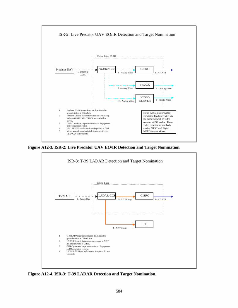
584
ISR-2: Live Predator UAV EO/IR Detection and Target Nomination
1 Predator EO/IR sensor detection downlinked to ground station at China Lake
2 Predator Ground Station forwards RS-170 analog video to GISRC, NRL TRUCK van and video server.
3 GISRC produces target nomination to Engagement and Mensuration system
4 NRL TRUCK van forwards analog video to GBS5 Video server forwards digital streaming video to
FBE WAN video clients.
Predator GCS2 – Analog Video
China Lake IBAR
Predator UAV1 – SENSOR
DATA
GISRC3 – ATI.ATR
Note: M&S also provided simulated Predator video via Ku-band network to video remotes at ISR nodes. These video remotes served both analog NTSC and digital MPEG format video.
TRUCK2 – Analog Video
2 – Analog Video
VIDEO SERVER
4 – Analog Video
5 – Digital Video
Figure A12-3. ISR-2: Live Predator UAV EO/IR Detection and Target Nomination.
ISR-3: T-39 LADAR Detection and Target Nomination
1 T-39 LADAR sensor detection downlinked to ground station at China Lake
2 LADAR Ground Station converts image to NITF 2.0 and forwards to GISRC
3 GISRC produces target nomination to Engagement and Mensuration systems
4 LADAR GCS ftp’s high interest images to IPL on Coronado
LADAR GCS2 – NITF image
China Lake
T-39 Acft1 – Sensor Data
GISRC3 – ATI.ATR
IPL4 – NITF image
Figure A12-4. ISR-3: T-39 LADAR Detection and Target Nomination.
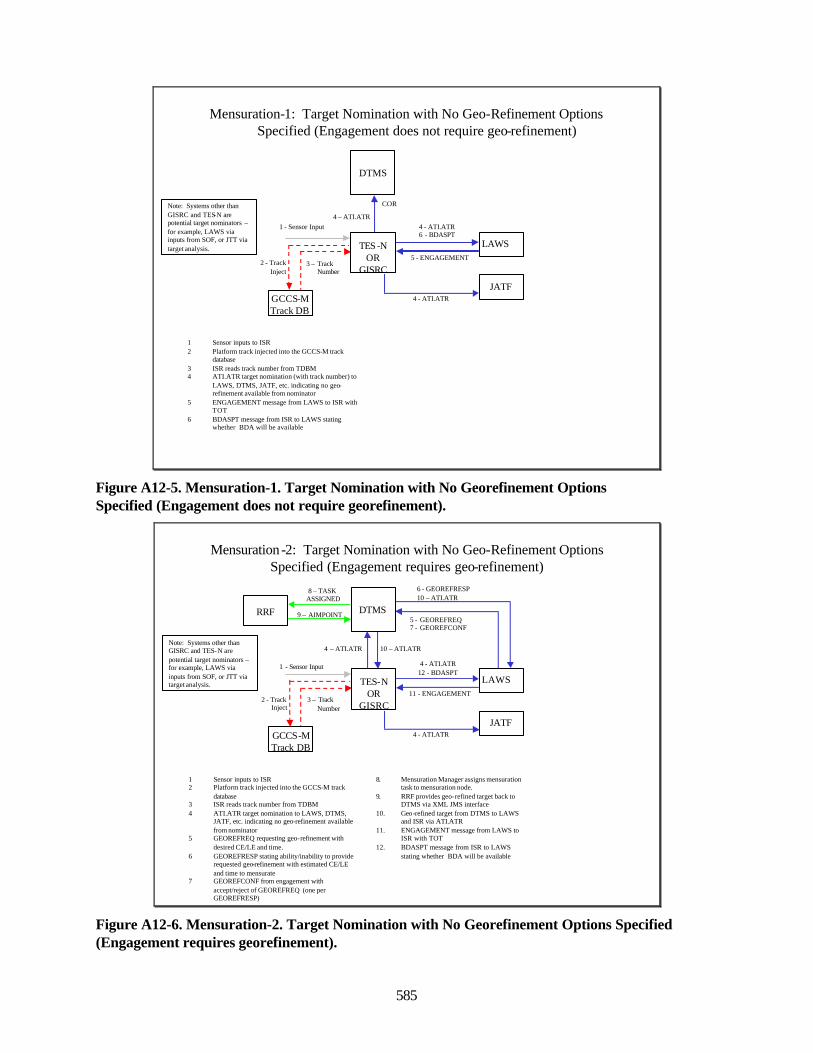
585
Mensuration-1: Target Nomination with No Geo-Refinement Options Specified (Engagement does not require geo-refinement)
1 Sensor inputs to ISR2 Platform track injected into the GCCS-M track
database3 ISR reads track number from TDBM4 ATI.ATR target nomination (with track number) to
LAWS, DTMS, JATF, etc. indicating no geo-refinement available from nominator
5 ENGAGEMENT message from LAWS to ISR with TOT
6 BDASPT message from ISR to LAWS stating whether BDA will be available
LAWS
GCCS-MTrack DB
1 - Sensor Input 4 - ATI.ATR6 - BDASPT
2 - Track Inject
5 - ENGAGEMENT
JATF4 - ATI.ATR
DTMS
4 – ATI.ATR
TES -N OR
GISRC3 – Track
Number
Note: Systems other than GISRC and TES-N are potential target nominators –for example, LAWS via inputs from SOF, or JTT via target analysis.
COR
Figure A12-5. Mensuration-1. Target Nomination with No Georefinement OptionsSpecified (Engagement does not require georefinement).
Mensuration -2: Target Nomination with No Geo-Refinement OptionsSpecified (Engagement requires geo-refinement)
1 Sensor inputs to ISR2 Platform track injected into the GCCS-M track
database3 ISR reads track number from TDBM4 ATI.ATR target nomination to LAWS, DTMS,
JATF, etc. indicating no geo-refinement available from nominator
5 GEOREFREQ requesting geo-refinement with desired CE/LE and time.
6 GEOREFRESP stating ability/inability to provide requested geo-refinement with estimated CE/LE and time to mensurate
7 GEOREFCONF from engagement with accept/reject of GEOREFREQ (one per GEOREFRESP)
LAWS
GCCS-MTrack DB
1 - Sensor Input 4 - ATI.ATR12 - BDASPT
2 - Track Inject
11 - ENGAGEMENT
JATF4 - ATI.ATR
8. Mensuration Manager assigns mensuration task to mensuration node.
9. RRF provides geo-refined target back to DTMS via XML JMS interface
10. Geo-refined target from DTMS to LAWS and ISR via ATI.ATR
11. ENGAGEMENT message from LAWS to ISR with TOT
12. BDASPT message from ISR to LAWS stating whether BDA will be available
6 - GEOREFRESP10 – ATI.ATR
DTMS5 - GEOREFREQ7 - GEOREFCONF
RRF
4 – ATI.ATR 10 – ATI.ATR
3 – TrackNumber
Note: Systems other than GISRC and TES-N are potential target nominators –for example, LAWS via inputs from SOF, or JTT via target analysis.
8 – TASK ASSIGNED
9 – AIMPOINT
TES-N OR
GISRC
Figure A12-6. Mensuration-2. Target Nomination with No Georefinement Options Specified(Engagement requires georefinement).
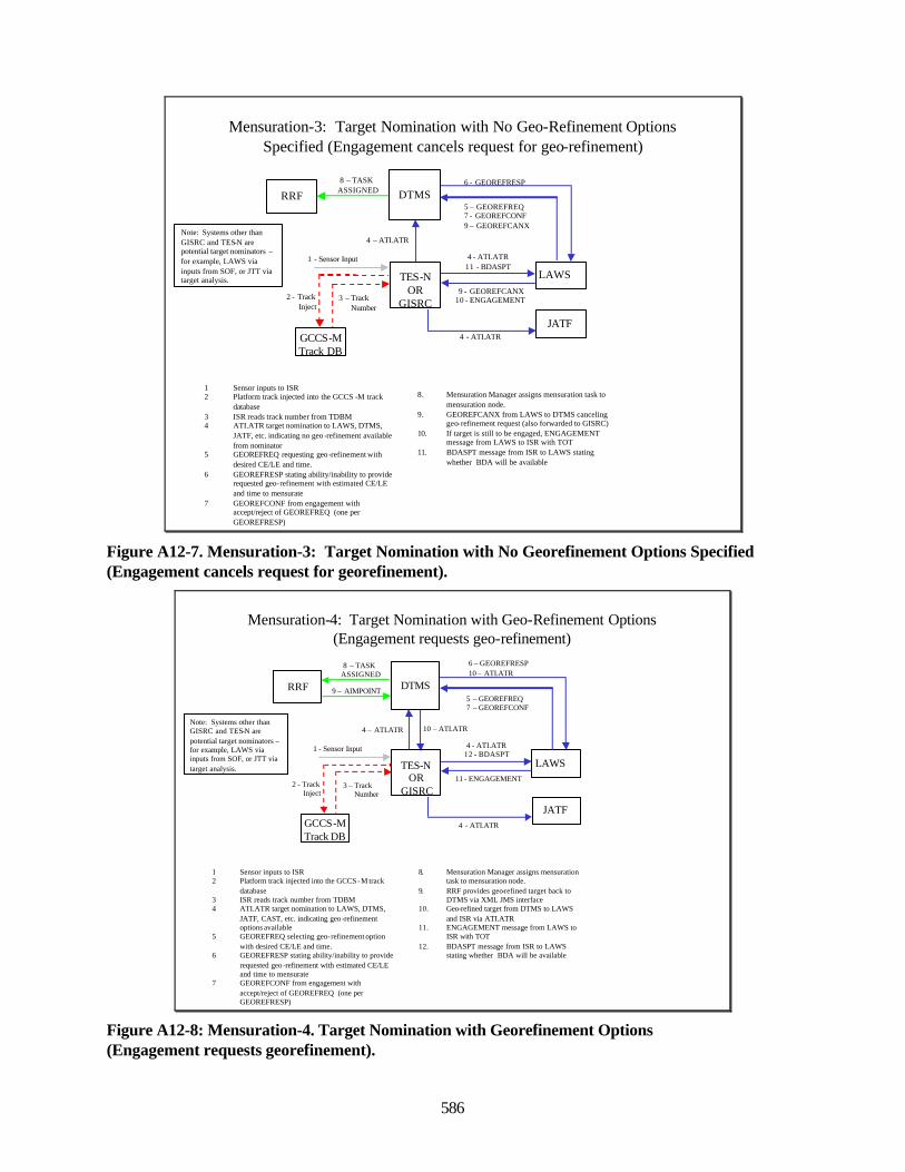
586
Mensuration-3: Target Nomination with No Geo-Refinement OptionsSpecified (Engagement cancels request for geo-refinement)
1 Sensor inputs to ISR2 Platform track injected into the GCCS -M track
database3 ISR reads track number from TDBM4 ATI.ATR target nomination to LAWS, DTMS,
JATF, etc. indicating no geo -refinement available from nominator
5 GEOREFREQ requesting geo -refinement with desired CE/LE and time.
6 GEOREFRESP stating ability/inability to provide requested geo-refinement with estimated CE/LE and time to mensurate
7 GEOREFCONF from engagement with accept/reject of GEOREFREQ (one per GEOREFRESP)
LAWS
GCCS-MTrack DB
1 - Sensor Input 4 - ATI.ATR11 - BDASPT
2 - Track Inject
9 - GEOREFCANX10 - ENGAGEMENT
JATF4 - ATI.ATR
8. Mensuration Manager assigns mensuration task to mensuration node.
9. GEOREFCANX from LAWS to DTMS canceling geo-refinement request (also forwarded to GISRC)
10. If target is still to be engaged, ENGAGEMENT message from LAWS to ISR with TOT
11. BDASPT message from ISR to LAWS stating whether BDA will be available
6 - GEOREFRESP
DTMS5 – GEOREFREQ7 - GEOREFCONF9 – GEOREFCANX
RRF8 – TASK
ASSIGNED
3 – TrackNumber
4 – ATI.ATRNote: Systems other than GISRC and TES-N are potential target nominators –for example, LAWS via inputs from SOF, or JTT via target analysis. TES-N
OR GISRC
Figure A12-7. Mensuration-3: Target Nomination with No Georefinement Options Specified(Engagement cancels request for georefinement).
Mensuration-4: Target Nomination with Geo-Refinement Options(Engagement requests geo-refinement)
1 Sensor inputs to ISR2 Platform track injected into the GCCS -M track
database3 ISR reads track number from TDBM4 ATI.ATR target nomination to LAWS, DTMS,
JATF, CAST, etc. indicating geo -refinement options available
5 GEOREFREQ selecting geo-refinement option with desired CE/LE and time.
6 GEOREFRESP stating ability/inability to provide requested geo -refinement with estimated CE/LE and time to mensurate
7 GEOREFCONF from engagement with accept/reject of GEOREFREQ (one per GEOREFRESP)
LAWS
GCCS-MTrack DB
1 - Sensor Input 4 - ATI.ATR12 - BDASPT
2 - Track Inject
11 - ENGAGEMENT
JATF4 - ATI.ATR
8. Mensuration Manager assigns mensuration task to mensuration node.
9. RRF provides geo-refined target back to DTMS via XML JMS interface
10. Geo-refined target from DTMS to LAWS and ISR via ATI.ATR
11. ENGAGEMENT message from LAWS to ISR with TOT
12. BDASPT message from ISR to LAWS stating whether BDA will be available
5 – GEOREFREQ7 – GEOREFCONF
DTMS
6 – GEOREFRESP10 – ATI.ATR
RRF
8 – TASK ASSIGNED
9 – AIMPOINT
4 – ATI.ATR 10 – ATI.ATR
3 – TrackNumber
Note: Systems other than GISRC and TES-N are potential target nominators –for example, LAWS via inputs from SOF, or JTT via target analysis. TES-N
OR GISRC
Figure A12-8: Mensuration-4. Target Nomination with Georefinement Options(Engagement requests georefinement).
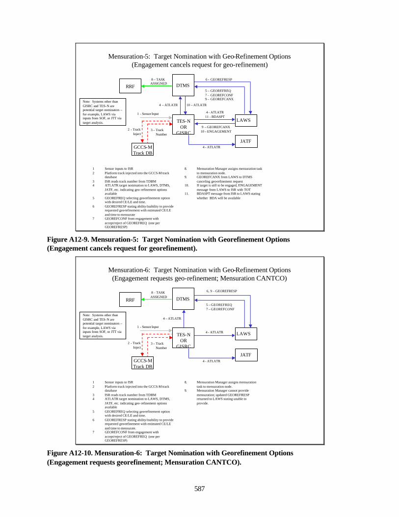
587
Mensuration-5: Target Nomination with Geo-Refinement Options(Engagement cancels request for geo-refinement)
1 Sensor inputs to ISR2 Platform track injected into the GCCS-M track
database3 ISR reads track number from TDBM4 ATI.ATR target nomination to LAWS, DTMS,
JATF, etc. indicating geo-refinement options available
5 GEOREFREQ selecting geo-refinement option with desired CE/LE and time.
6 GEOREFRESP stating ability/inability to provide requested geo-refinement with estimated CE/LE and time to mensurate
7 GEOREFCONF from engagement with accept/reject of GEOREFREQ (one per GEOREFRESP)
LAWS
GCCS-MTrack DB
1 - Sensor Input 4 - ATI.ATR11 - BDASPT
2 - Track Inject
9 – GEOREFCANX10 - ENGAGEMENT
JATF4 - ATI.ATR
8. Mensuration Manager assigns mensuration task to mensuration node.
9. GEOREFCANX from LAWS to DTMS canceling geo-refinement request
10. If target is still to be engaged, ENGAGEMENT message from LAWS to ISR with TOT
11. BDASPT message from ISR to LAWS stating whether BDA will be available
6 - GEOREFRESP
DTMS5 – GEOREFREQ7 – GEOREFCONF9 – GEOREFCANX
RRF8 – TASK
ASSIGNED
4 – ATI.ATR 10 – ATI.ATR
3 – TrackNumber
Note: Systems other than GISRC and TES-N are potential target nominators –for example, LAWS via inputs from SOF, or JTT via target analysis. TES-N
OR GISRC
Figure A12-9. Mensuration-5: Target Nomination with Georefinement Options(Engagement cancels request for georefinement).
Mensuration-6: Target Nomination with Geo-Refinement Options(Engagement requests geo-refinement; Mensuration CANTCO)
1 Sensor inputs to ISR2 Platform track injected into the GCCS-M track
database3 ISR reads track number from TDBM4 ATI.ATR target nomination to LAWS, DTMS,
JATF, etc. indicating geo-refinement options available
5 GEOREFREQ selecting geo-refinement option with desired CE/LE and time.
6 GEOREFRESP stating ability/inability to provide requested geo-refinement with estimated CE/LE and time to mensurate.
7 GEOREFCONF from engagement with accept/reject of GEOREFREQ (one per GEOREFRESP)
LAWS
GCCS-MTrack DB
1 - Sensor Input
4 - ATI.ATR
2 - Track Inject
JATF4 - ATI.ATR
8. Mensuration Manager assigns mensuration task to mensuration node.
9. Mensuration Manager cannot provide mensuration; updated GEOREFRESP returned to LAWS stating unable to provide.
5 – GEOREFREQ7 – GEOREFCONF
DTMS
6, 9 – GEOREFRESP
RRF
8 – TASK ASSIGNED
4 – ATI.ATR
3 – TrackNumber
Note: Systems other than GISRC and TES-N are potential target nominators –for example, LAWS via inputs from SOF, or JTT via target analysis. TES-N
OR GISRC
Figure A12-10. Mensuration-6: Target Nomination with Georefinement Options(Engagement requests georefinement; Mensuration CANTCO).
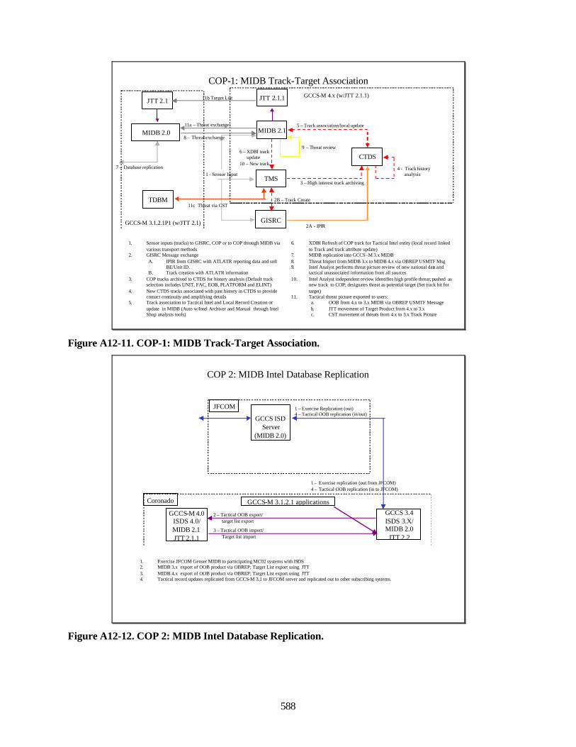
588
COP-1: MIDB Track-Target Association
1. Sensor inputs (tracks) to GISRC, COP or to COP through MIDB via various transport methods
2. GISRC Message exchangeA. IPIR from GISRC with ATI.ATR reporting data and soft
BE/Unit ID. B. Track creation with ATI.ATR information
3. COP tracks archived to CTDS for history analysis (Default track selection includes UNIT, FAC, EOB, PLATFORM and ELINT)
4. New CTDS tracks associated with past history in CTDS to provide contact continuity and amplifying details
5. Track association to Tactical Intel and Local Record Creation orupdate in MIDB (Auto w/Intel Archiver and Manual through IntelShop analysis tools)
1 - Sensor InputTMS
MIDB 2.1
CTDS
GISRC2A - IPIR
3 – High interest track archiving
4 - Track history analysis
5 – Track association/local update
6. XDBI Refresh of COP track for Tactical Intel entity (local record linked to Track and track attribute update)
7. MIDB replication into GCCS-M 3.x MIDB8. Threat Import from MIDB 3.x to MIDB 4.x via OBREP USMTF Msg9. Intel Analyst performs threat picture review of new national data and
tactical unassociated information from all sources10. Intel Analyst independent review identifies high profile threat; pushed as
new track to COP; designates threat as potential target (Set track bit for target)
11. Tactical threat picture exported to users:a. OOB from 4.x to 3.x MIDB via OBREP USMTF Messageb. JTT movement of Target Product from 4.x to 3.xc. CST movement of threats from 4.x to 3.x Track Picture
6 – XDBI trackupdate
10 – New track7 – Database replication
MIDB 2.0
9 – Threat review
8 – Threat exchange
GCCS-M 4.x (w/JTT 2.1.1)
TDBM
GCCS-M 3.1.2.1P1 (w/JTT 2.1)
11c Threat via CST
JTT 2.1.1JTT 2.1 11b Target List
11a – Threat exchange
2B – Track Create
Figure A12-11. COP-1: MIDB Track-Target Association.
COP 2: MIDB Intel Database Replication
1. Exercise JFCOM Genser MIDB to participating MC02 systems with ISDS2. MIDB 3.x export of OOB product via OBREP; Target List export using JTT 3. MIDB 4.x export of OOB product via OBREP; Target List export using JTT 4. Tactical record updates replicated from GCCS-M 3.1 to JFCOM server and replicated out to other subscribing systems.
GCCS ISD Server
(MIDB 2.0)
GCCS-M 4.0ISDS 4.0/MIDB 2.1JTT 2.1.1
GCCS-M 3.1.2.1 applications
1 – Exercise Replication (out)4 – Tactical OOB replication (in/out)
JFCOM
Coronado
1 – Exercise replication (out from JFCOM)4 – Tactical OOB replication (in to JFCOM)
2 – Tactical OOB export/target list export
3 – Tactical OOB import/Target list import
GCCS 3.4ISDS 3.X/MIDB 2.0
JTT 2.2
Figure A12-12. COP 2: MIDB Intel Database Replication.
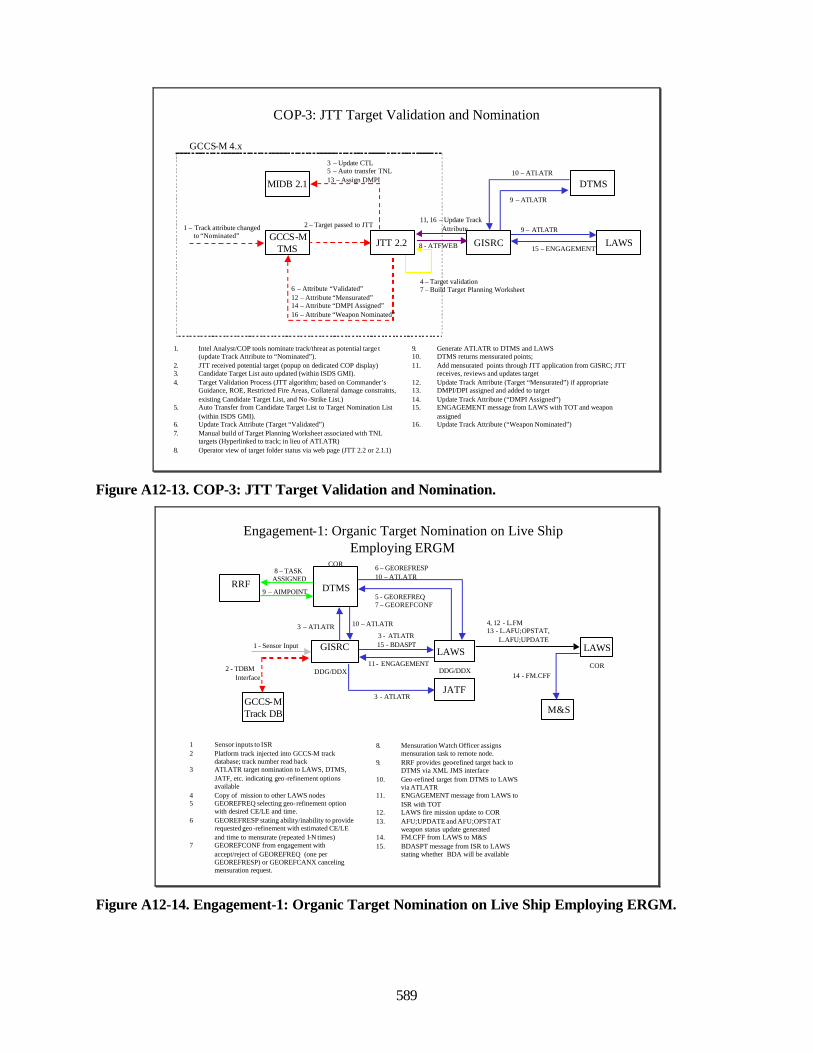
589
COP-3: JTT Target Validation and Nomination
GCCS-MTMS
MIDB 2.1
1. Intel Analyst/COP tools nominate track/threat as potential targe t (update Track Attribute to “Nominated”).
2. JTT received potential target (popup on dedicated COP display)3. Candidate Target List auto updated (within ISDS GMI).4. Target Validation Process (JTT algorithm; based on Commander’s
Guidance, ROE, Restricted Fire Areas, Collateral damage constraints, existing Candidate Target List, and No -Strike List.)
5. Auto Transfer from Candidate Target List to Target Nomination List (within ISDS GMI).
6. Update Track Attribute (Target “Validated”)7. Manual build of Target Planning Worksheet associated with TNL
targets (Hyperlinked to track; in lieu of ATI.ATR) 8. Operator view of target folder status via web page (JTT 2.2 or 2.1.1)
9. Generate ATI.ATR to DTMS and LAWS10. DTMS returns mensurated points; 11. Add mensurated points through JTT application from GISRC; JTT
receives, reviews and updates target12. Update Track Attribute (Target “Mensurated”) if appropriate13. DMPI/DPI assigned and added to target14. Update Track Attribute (“DMPI Assigned”)15. ENGAGEMENT message from LAWS with TOT and weapon
assigned16. Update Track Attribute (“Weapon Nominated”)
JTT 2.2
1 – Track attribute changedto “Nominated”
2 – Target passed to JTT
3 – Update CTL5 – Auto transfer TNL13 – Assign DMPI
4 – Target validation7 – Build Target Planning Worksheet6 – Attribute “Validated”
12 – Attribute “Mensurated”14 – Attribute “DMPI Assigned”16 – Attribute “Weapon Nominated”
DTMS
LAWS
9 – ATI.ATR
9 – ATI.ATR
10 – ATI.ATR
15 – ENGAGEMENT
GCCS-M 4.x
GISRC
11, 16 – Update TrackAttribute
8 - ATFWEB
Figure A12-13. COP-3: JTT Target Validation and Nomination.
Engagement-1: Organic Target Nomination on Live Ship Employing ERGM
LAWS
4, 12 - L.FM13 - L.AFU;OPSTAT,
L.AFU;UPDATE
M&S
14 - FM.CFF
LAWS
GCCS-MTrack DB
1 - Sensor Input3 - ATI.ATR15 - BDASPT
2 - TDBM Interface
11 - ENGAGEMENT
JATF3 - ATI.ATR
6 – GEOREFRESP10 – ATI.ATR
5 - GEOREFREQ7 – GEOREFCONF
DTMSRRF
3 – ATI.ATR
8 – TASK ASSIGNED
1 Sensor inputs to ISR2 Platform track injected into GCCS-M track
database; track number read back3 ATI.ATR target nomination to LAWS, DTMS,
JATF, etc. indicating geo -refinement options available
4 Copy of mission to other LAWS nodes5 GEOREFREQ selecting geo-refinement option
with desired CE/LE and time.6 GEOREFRESP stating ability/inability to provide
requested geo -refinement with estimated CE/LE and time to mensurate (repeated 1-N times)
7 GEOREFCONF from engagement with accept/reject of GEOREFREQ (one per GEOREFRESP) or GEOREFCANX canceling mensuration request.
8. Mensuration Watch Officer assigns mensuration task to remote node.
9. RRF provides geo-refined target back to DTMS via XML JMS interface
10. Geo-refined target from DTMS to LAWS via ATI.ATR
11. ENGAGEMENT message from LAWS to ISR with TOT
12. LAWS fire mission update to COR13. AFU;UPDATE and AFU;OPSTAT
weapon status update generated14. FM.CFF from LAWS to M&S15. BDASPT message from ISR to LAWS
stating whether BDA will be available
GISRC
10 – ATI.ATR
9 – AIMPOINT
DDG/DDXCOR
COR
DDG/DDX
Figure A12-14. Engagement-1: Organic Target Nomination on Live Ship Employing ERGM.
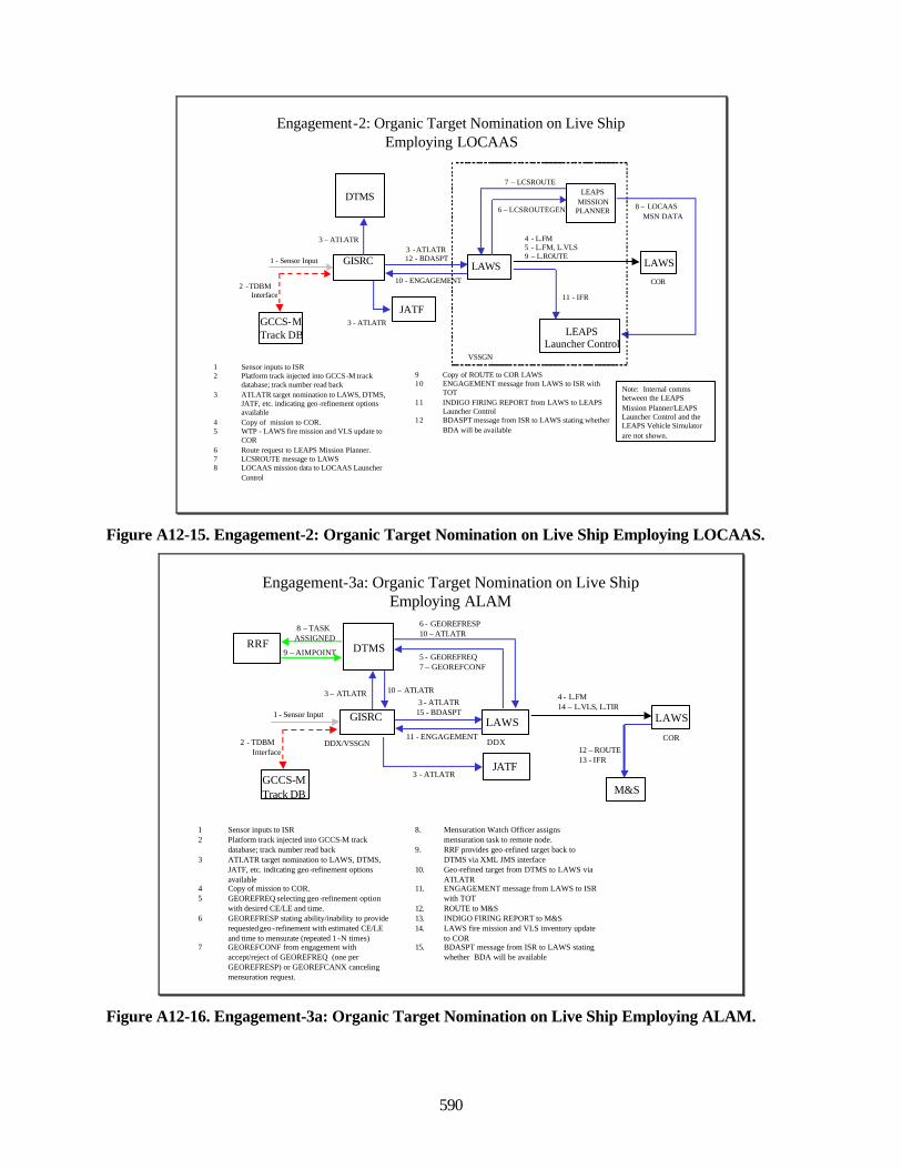
590
Engagement-2: Organic Target Nomination on Live Ship Employing LOCAAS
LAWS
GCCS-MTrack DB
3 -ATI.ATR12 - BDASPT
10 - ENGAGEMENT
JATF3 - ATI.ATR
DTMS
3 – ATI.ATR
VSSGN1 Sensor inputs to ISR2 Platform track injected into GCCS -M track
database; track number read back3 ATI.ATR target nomination to LAWS, DTMS,
JATF, etc. indicating geo -refinement options available
4 Copy of mission to COR.5 WTP - LAWS fire mission and VLS update to
COR6 Route request to LEAPS Mission Planner.7 LCSROUTE message to LAWS8 LOCAAS mission data to LOCAAS Launcher
Control
9 Copy of ROUTE to COR LAWS10 ENGAGEMENT message from LAWS to ISR with
TOT11 INDIGO FIRING REPORT from LAWS to LEAPS
Launcher Control12 BDASPT message from ISR to LAWS stating whether
BDA will be available
GISRC LAWS
4 - L.FM5 - L.FM, L.VLS9 – L.ROUTE
LEAPS Launcher Control
1 - Sensor Input
2 -TDBM Interface 11 - IFR
COR
6 – LCSROUTEGEN
7 – LCSROUTE
8 – LOCAASMSN DATA
LEAPSMISSION
PLANNER
Note: Internal comms between the LEAPS Mission Planner/LEAPS Launcher Control and the LEAPS Vehicle Simulator are not shown.
Figure A12-15. Engagement-2: Organic Target Nomination on Live Ship Employing LOCAAS.
Engagement-3a: Organic Target Nomination on Live Ship Employing ALAM
LAWS
4 - L.FM14 – L.VLS, L.TIR
M&S
LAWS
GCCS-MTrack DB
3 - ATI.ATR15 - BDASPT
11 - ENGAGEMENT
JATF3 - ATI.ATR
5 - GEOREFREQ7 – GEOREFCONF
DTMS
6 - GEOREFRESP10 – ATI.ATR
RRF
3 – ATI.ATR
8 – TASK ASSIGNED
DDX
1 Sensor inputs to ISR2 Platform track injected into GCCS-M track
database; track number read back3 ATI.ATR target nomination to LAWS, DTMS,
JATF, etc. indicating geo -refinement options available
4 Copy of mission to COR.5 GEOREFREQ selecting geo -refinement option
with desired CE/LE and time.6 GEOREFRESP stating ability/inability to provide
requested geo -refinement with estimated CE/LE and time to mensurate (repeated 1 -N times)
7 GEOREFCONF from engagement with accept/reject of GEOREFREQ (one per GEOREFRESP) or GEOREFCANX canceling mensuration request.
8. Mensuration Watch Officer assigns mensuration task to remote node.
9. RRF provides geo -refined target back to DTMS via XML JMS interface
10. Geo -refined target from DTMS to LAWS via ATI.ATR
11. ENGAGEMENT message from LAWS to ISR with TOT
12. ROUTE to M&S13. INDIGO FIRING REPORT to M&S14. LAWS fire mission and VLS inventory update
to COR15. BDASPT message from ISR to LAWS stating
whether BDA will be available
GISRC
10 – ATI.ATR
9 – AIMPOINT
1 - Sensor Input
2 - TDBM Interface
DDX/VSSGN12 – ROUTE13 - IFR
COR
Figure A12-16. Engagement-3a: Organic Target Nomination on Live Ship Employing ALAM.
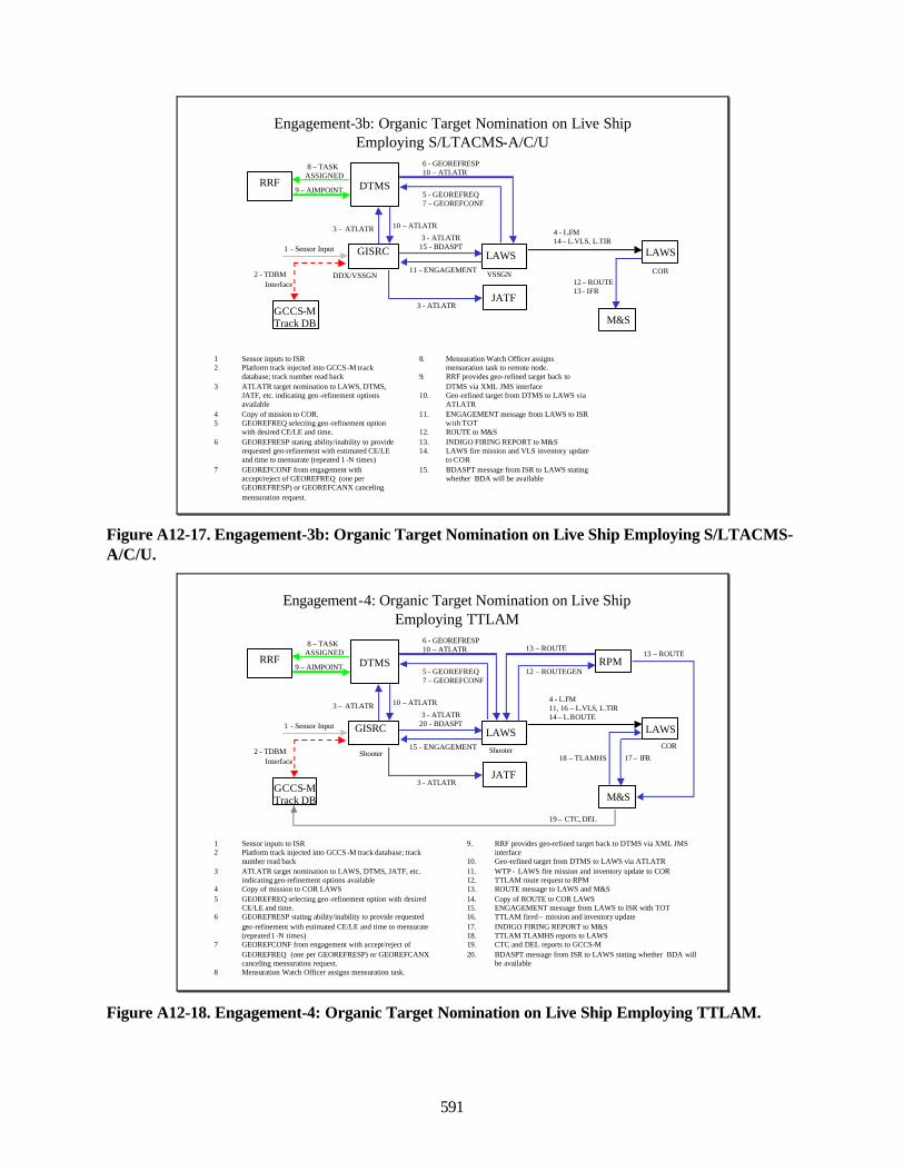
591
Engagement-3b: Organic Target Nomination on Live Ship Employing S/LTACMS-A/C/U
LAWS
4 - L.FM14 – L.VLS, L.TIR
M&S
LAWS
GCCS-MTrack DB
3 - ATI.ATR15 - BDASPT
11 - ENGAGEMENT
JATF3 - ATI.ATR
5 - GEOREFREQ7 – GEOREFCONF
DTMS
6 - GEOREFRESP10 – ATI.ATR
RRF
3 – ATI.ATR
8 – TASK ASSIGNED
VSSGN
1 Sensor inputs to ISR2 Platform track injected into GCCS -M track
database; track number read back3 ATI.ATR target nomination to LAWS, DTMS,
JATF, etc. indicating geo -refinement options available
4 Copy of mission to COR.5 GEOREFREQ selecting geo -refinement option
with desired CE/LE and time.6 GEOREFRESP stating ability/inability to provide
requested geo-refinement with estimated CE/LE and time to mensurate (repeated 1 -N times)
7 GEOREFCONF from engagement with accept/reject of GEOREFREQ (one per GEOREFRESP) or GEOREFCANX canceling mensuration request.
8. Mensuration Watch Officer assigns mensuration task to remote node.
9. RRF provides geo-refined target back to DTMS via XML JMS interface
10. Geo-refined target from DTMS to LAWS via ATI.ATR
11. ENGAGEMENT message from LAWS to ISR with TOT
12. ROUTE to M&S13. INDIGO FIRING REPORT to M&S14. LAWS fire mission and VLS inventory update
to COR15. BDASPT message from ISR to LAWS stating
whether BDA will be available
GISRC
10 – ATI.ATR
9 – AIMPOINT
1 - Sensor Input
2 - TDBM Interface
DDX/VSSGN12 – ROUTE13 - IFR
COR
Figure A12-17. Engagement-3b: Organic Target Nomination on Live Ship Employing S/LTACMS-A/C/U.
Engagement-4: Organic Target Nomination on Live Ship Employing TTLAM
LAWSCOR
4 - L.FM11, 16 – L.VLS, L.TIR14 – L.ROUTE
M&S
17 – IFR
LAWS
GCCS-MTrack DB
3 - ATI.ATR20 - BDASPT
15 - ENGAGEMENT
JATF3 - ATI.ATR
5 - GEOREFREQ7 – GEOREFCONF
DTMS
6 - GEOREFRESP10 – ATI.ATR
RRF
3 – ATI.ATR
8 – TASK ASSIGNED
Shooter
1 Sensor inputs to ISR2 Platform track injected into GCCS -M track database; track
number read back3 ATI.ATR target nomination to LAWS, DTMS, JATF, etc.
indicating geo-refinement options available4 Copy of mission to COR LAWS5 GEOREFREQ selecting geo -refinement option with desired
CE/LE and time.6 GEOREFRESP stating ability/inability to provide requested
geo-refinement with estimated CE/LE and time to mensurate (repeated 1 -N times)
7 GEOREFCONF from engagement with accept/reject of GEOREFREQ (one per GEOREFRESP) or GEOREFCANX canceling mensuration request.
8 Mensuration Watch Officer assigns mensuration task.
9. RRF provides geo-refined target back to DTMS via XML JMS interface
10. Geo-refined target from DTMS to LAWS via ATI.ATR11. WTP - LAWS fire mission and inventory update to COR12. TTLAM route request to RPM13. ROUTE message to LAWS and M&S14. Copy of ROUTE to COR LAWS15. ENGAGEMENT message from LAWS to ISR with TOT16. TTLAM fired – mission and inventory update17. INDIGO FIRING REPORT to M&S18. TTLAM TLAMHS reports to LAWS19. CTC and DEL reports to GCCS-M20. BDASPT message from ISR to LAWS stating whether BDA will
be available
RPM12 – ROUTEGEN
13 – ROUTE13 – ROUTE
18 – TLAMHS
19 – CTC, DEL
GISRC
10 – ATI.ATR
9 – AIMPOINT
1 - Sensor Input
2 - TDBM Interface
Shooter
Figure A12-18. Engagement-4: Organic Target Nomination on Live Ship Employing TTLAM.
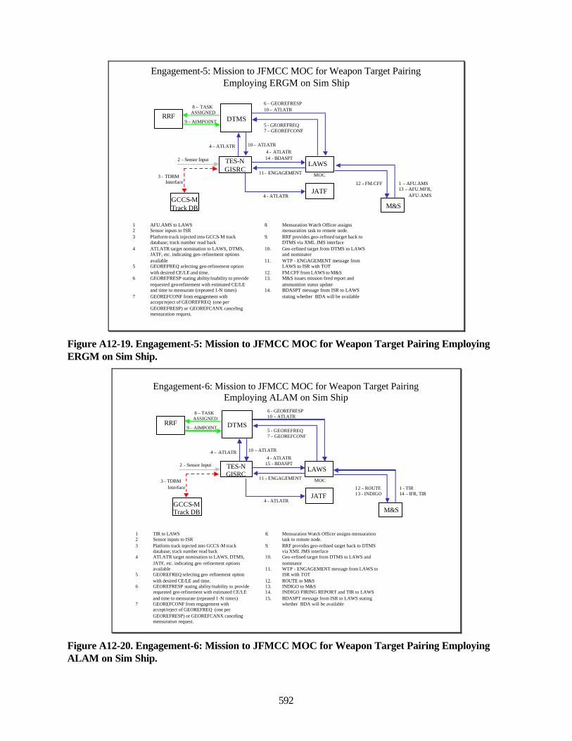
592
M&S
12 - FM.CFF
LAWS
GCCS-MTrack DB
4 - ATI.ATR14 - BDASPT
11 - ENGAGEMENT
JATF4 - ATI.ATR
6 – GEOREFRESP10 – ATI.ATR
5 - GEOREFREQ7 – GEOREFCONF
DTMSRRF
4 – ATI.ATR
8 – TASK ASSIGNED
MOC
1 AFU.AMS to LAWS2 Sensor inputs to ISR3 Platform track injected into GCCS-M track
database; track number read back4 ATI.ATR target nomination to LAWS, DTMS,
JATF, etc. indicating geo-refinement options available
5 GEOREFREQ selecting geo-refinement option with desired CE/LE and time.
6 GEOREFRESP stating ability/inability to provide requested geo-refinement with estimated CE/LE and time to mensurate (repeated 1-N times)
7 GEOREFCONF from engagement with accept/reject of GEOREFREQ (one per GEOREFRESP) or GEOREFCANX canceling mensuration request.
8. Mensuration Watch Officer assigns mensuration task to remote node.
9. RRF provides geo-refined target back to DTMS via XML JMS interface
10. Geo-refined target from DTMS to LAWS and nominator
11. WTP - ENGAGEMENT message from LAWS to ISR with TOT
12. FM.CFF from LAWS to M&S13. M&S issues mission fired report and
ammunition status update14. BDASPT message from ISR to LAWS
stating whether BDA will be available
Engagement-5: Mission to JFMCC MOC for Weapon Target Pairing Employing ERGM on Sim Ship
1 – AFU.AMS13 – AFU.MFR,
AFU.AMS
TES-N GISRC
10 – ATI.ATR
9 – AIMPOINT
2 - Sensor Input
3 - TDBM Interface
Figure A12-19. Engagement-5: Mission to JFMCC MOC for Weapon Target Pairing EmployingERGM on Sim Ship.
M&S
12 – ROUTE13 - INDIGO
LAWS
GCCS-MTrack DB
4 - ATI.ATR15 - BDASPT
11 - ENGAGEMENT
JATF4 - ATI.ATR
5 - GEOREFREQ7 – GEOREFCONF
DTMS
6 - GEOREFRESP10 – ATI.ATR
RRF
4 – ATI.ATR
8 – TASK ASSIGNED
MOC
1 TIR to LAWS2 Sensor inputs to ISR3 Platform track injected into GCCS -M track
database; track number read back4 ATI.ATR target nomination to LAWS, DTMS,
JATF, etc. indicating geo -refinement options available
5 GEOREFREQ selecting geo -refinement option with desired CE/LE and time.
6 GEOREFRESP stating ability/inability to provide requested geo-refinement with estimated CE/LE and time to mensurate (repeated 1 -N times)
7 GEOREFCONF from engagement with accept/reject of GEOREFREQ (one per GEOREFRESP) or GEOREFCANX canceling mensuration request.
8. Mensuration Watch Officer assigns mensuration task to remote node.
9. RRF provides geo-refined target back to DTMS via XML JMS interface
10. Geo-refined target from DTMS to LAWS and nominator
11. WTP - ENGAGEMENT message from LAWS to ISR with TOT
12. ROUTE to M&S13. INDIGO to M&S14. INDIGO FIRING REPORT and TIR to LAWS15. BDASPT message from ISR to LAWS stating
whether BDA will be available
Engagement-6: Mission to JFMCC MOC for Weapon Target Pairing Employing ALAM on Sim Ship
1 - TIR14 – IFR, TIR
TES-N GISRC
10 – ATI.ATR
9 – AIMPOINT
2 - Sensor Input
3 - TDBM Interface
Figure A12-20. Engagement-6: Mission to JFMCC MOC for Weapon Target Pairing EmployingALAM on Sim Ship.
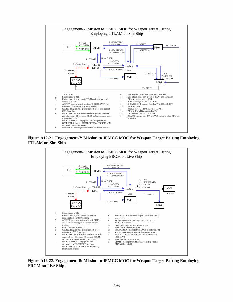
593
M&S
14 – INDIGO
LAWS
GCCS-MTrack DB
4 - ATI.ATR18 - BDASPT
13 - ENGAGEMENT
JATF4 - ATI.ATR
5 - GEOREFREQ7 – GEOREFCONF
DTMS
6 - GEOREFRESP10 – ATI.ATR
RRF
4 – ATI.ATR
8 – TASK ASSIGNED
MOC
1 TIR to LAWS2 Sensor inputs to ISR3 Platform track injected into GCCS -M track database; track
number read back4 ATI.ATR target nomination to LAWS, DTMS, JATF, etc.
indicating geo-refinement options available5 GEOREFREQ selecting geo -refinement option with desired
CE/LE and time.6 GEOREFRESP stating ability/inability to provide requested
geo-refinement with estimated CE/LE and time to mensurate (repeated 1 -N times)
7 GEOREFCONF from engagement with accept/reject of GEOREFREQ (one per GEOREFRESP) or GEOREFCANX canceling mensuration request.
8 Mensuration Lead assigns mensuration task to remote node.
9 RRF provides geo-refined target back to DTMS10 Geo-refined target from DTMS to LAWS and nominator11 TTLAM route request to RPM12 ROUTE message to LAWS and M&S13 ENGAGEMENT message from LAWS to ISR with TOT14 INDIGO to M&S15 INDIGO FIRING REPORT, TIR to LAWS16 TTLAM TLAMHS reports to LAWS17 CTC and DEL reports to GCCS-M18 BDASPT message from ISR to LAWS stating whether BDA will
be available
RPM11 – ROUTEGEN
12 – ROUTE12 – ROUTE
1 - TIR15 – IFR, TIR16 - TLAMHS
17 – CTC, DEL
Engagement-7: Mission to JFMCC MOC for Weapon Target Pairing Employing TTLAM on Sim Ship
TES-N GISRC
10 – ATI.ATR
9 – AIMPOINT
2 - Sensor Input
3 - TDBM Interface
Figure A12-21. Engagement-7: Mission to JFMCC MOC for Weapon Target Pairing EmployingTTLAM on Sim Ship.
4, 11 - L.FM
M&S
15 - FM.CFF
LAWS
GCCS-MTrack DB
3 - ATI.ATR16 - BDASPT
12 - ENGAGEMENT
JATF3 - ATI.ATR
6 – GEOREFRESP10 – ATI.ATR
5 - GEOREFREQ7 – GEOREFCONF
DTMSRRF
3 – ATI.ATR
8 – TASK ASSIGNED
MOC
1 Sensor inputs to ISR2 Platform track injected into GCCS -M track
database; track number read back3 ATI.ATR target nomination to LAWS, DTMS,
JATF, etc. indicating geo -refinement options available
4 Copy of mission to shooter5 GEOREFREQ selecting geo -refinement option
with desired CE/LE and time.6 GEOREFRESP stating ability/inability to provide
requested geo-refinement with estimated CE/LE and time to mensurate (repeated 1 -N times)
7 GEOREFCONF from engagement with accept/reject of GEOREFREQ (one per GEOREFRESP) or GEOREFCANX canceling mensuration request.
8 Mensuration Watch Officer assigns mensuration task to remote node.
9. RRF provides geo-refined target back to DTMS via XML JMS interface
10. Geo-refined target from DTMS to LAWS11. WTP – Fires mission to shooter12. ENGAGEMENT message from LAWS to ISR with TOT13. Shooter “fires” mission, updated fire mission to MOC14. AFU;UPDATE and AFU;OPSTAT from “shooter” to
MOC LAWS15. FM.CFF from LAWS to M&S16. BDASPT message from ISR to LAWS stating whether
BDA will be available
Engagement-8: Mission to JFMCC MOC for Weapon Target Pairing Employing ERGM on Live Ship
DDG/DDX
13 - L.FM 14 – AFU;UPDATE, AFU;OPSTAT
TES-N GISRC
10 – ATI.ATR
9 – AIMPOINT
1 - Sensor Input
2 - TDBM Interface
LAWS
Figure A12-22. Engagement-8: Mission to JFMCC MOC for Weapon Target Pairing EmployingERGM on Live Ship.
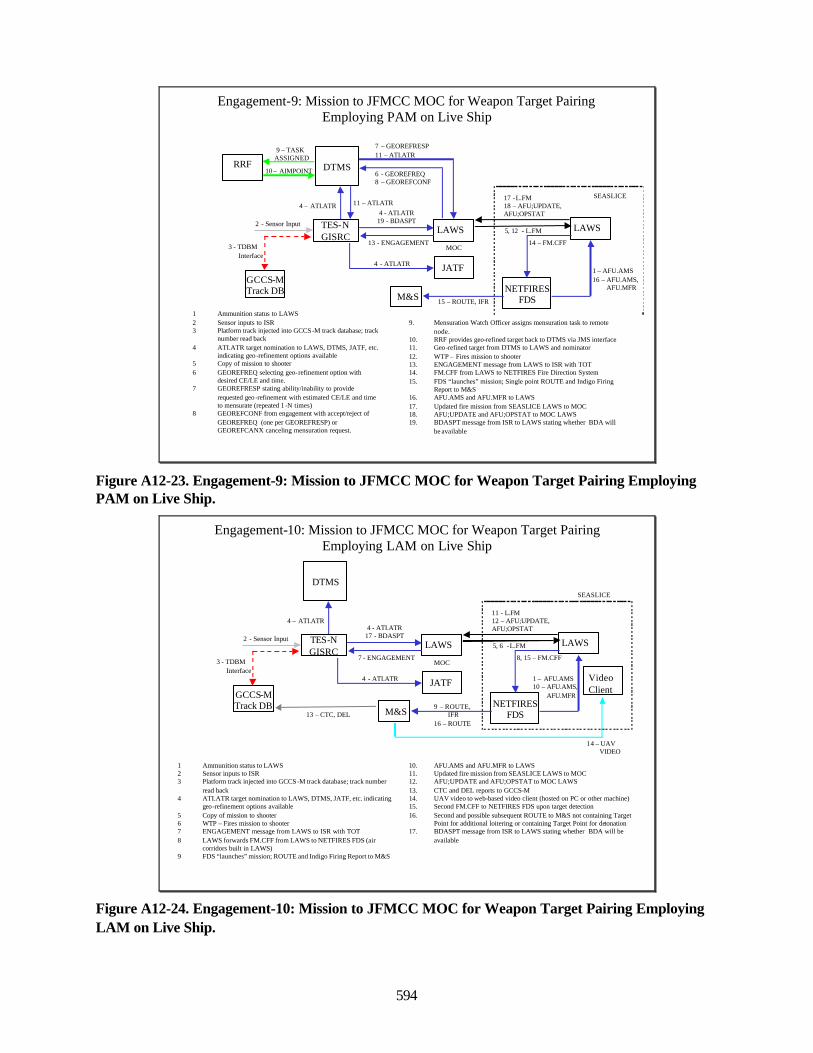
594
5, 12 - L.FM
M&S
1 – AFU.AMS16 – AFU.AMS,
AFU.MFR
LAWS
GCCS-MTrack DB
4 - ATI.ATR19 - BDASPT
13 - ENGAGEMENT
JATF4 - ATI.ATR
7 – GEOREFRESP11 – ATI.ATR
6 - GEOREFREQ8 – GEOREFCONF
DTMSRRF
4 – ATI.ATR
9 – TASK ASSIGNED
MOC
1 Ammunition status to LAWS2 Sensor inputs to ISR3 Platform track injected into GCCS -M track database; track
number read back4 ATI.ATR target nomination to LAWS, DTMS, JATF, etc.
indicating geo -refinement options available5 Copy of mission to shooter6 GEOREFREQ selecting geo-refinement option with
desired CE/LE and time.7 GEOREFRESP stating ability/inability to provide
requested geo -refinement with estimated CE/LE and time to mensurate (repeated 1 -N times)
8 GEOREFCONF from engagement with accept/reject of GEOREFREQ (one per GEOREFRESP) or GEOREFCANX canceling mensuration request.
9. Mensuration Watch Officer assigns mensuration task to remote node.
10. RRF provides geo-refined target back to DTMS via JMS interface11. Geo-refined target from DTMS to LAWS and nominator12. WTP – Fires mission to shooter13. ENGAGEMENT message from LAWS to ISR with TOT14. FM.CFF from LAWS to NETFIRES Fire Direction System15. FDS “launches” mission; Single point ROUTE and Indigo Firing
Report to M&S16. AFU.AMS and AFU.MFR to LAWS17. Updated fire mission from SEASLICE LAWS to MOC18. AFU;UPDATE and AFU;OPSTAT to MOC LAWS19. BDASPT message from ISR to LAWS stating whether BDA will
be available
Engagement-9: Mission to JFMCC MOC for Weapon Target Pairing Employing PAM on Live Ship
SEASLICE17 -L.FM 18 – AFU;UPDATE, AFU;OPSTAT
TES-N GISRC
11 – ATI.ATR
10 – AIMPOINT
2 - Sensor Input
3 - TDBM Interface
LAWS
NETFIRESFDS
14 – FM.CFF
15 – ROUTE, IFR
Figure A12-23. Engagement-9: Mission to JFMCC MOC for Weapon Target Pairing EmployingPAM on Live Ship.
5, 6 -L.FM
M&S
1 – AFU.AMS10 – AFU.AMS,
AFU.MFR
LAWS
GCCS-MTrack DB
4 - ATI.ATR17 - BDASPT
7 - ENGAGEMENT
JATF4 - ATI.ATR
DTMS
4 – ATI.ATR
MOC
1 Ammunition status to LAWS2 Sensor inputs to ISR3 Platform track injected into GCCS -M track database; track number
read back4 ATI.ATR target nomination to LAWS, DTMS, JATF, etc. indicating
geo-refinement options available5 Copy of mission to shooter6 WTP – Fires mission to shooter7 ENGAGEMENT message from LAWS to ISR with TOT8 LAWS forwards FM.CFF from LAWS to NETFIRES FDS (air
corridors built in LAWS)9 FDS “launches” mission; ROUTE and Indigo Firing Report to M&S
10. AFU.AMS and AFU.MFR to LAWS11. Updated fire mission from SEASLICE LAWS to MOC12. AFU;UPDATE and AFU;OPSTAT to MOC LAWS13. CTC and DEL reports to GCCS-M14. UAV video to web-based video client (hosted on PC or other machine)15. Second FM.CFF to NETFIRES FDS upon target detection16. Second and possible subsequent ROUTE to M&S not containing Target
Point for additional loitering or containing Target Point for detonation17. BDASPT message from ISR to LAWS stating whether BDA will be
available
Engagement-10: Mission to JFMCC MOC for Weapon Target Pairing Employing LAM on Live Ship
SEASLICE
11 - L.FM 12 – AFU;UPDATE, AFU;OPSTAT
TES-N GISRC
2 - Sensor Input
3 - TDBM Interface
LAWS
NETFIRESFDS
8, 15 – FM.CFF
9 – ROUTE,IFR
16 – ROUTE13 – CTC, DEL
14 – UAVVIDEO
VideoClient
Figure A12-24. Engagement-10: Mission to JFMCC MOC for Weapon Target Pairing EmployingLAM on Live Ship.
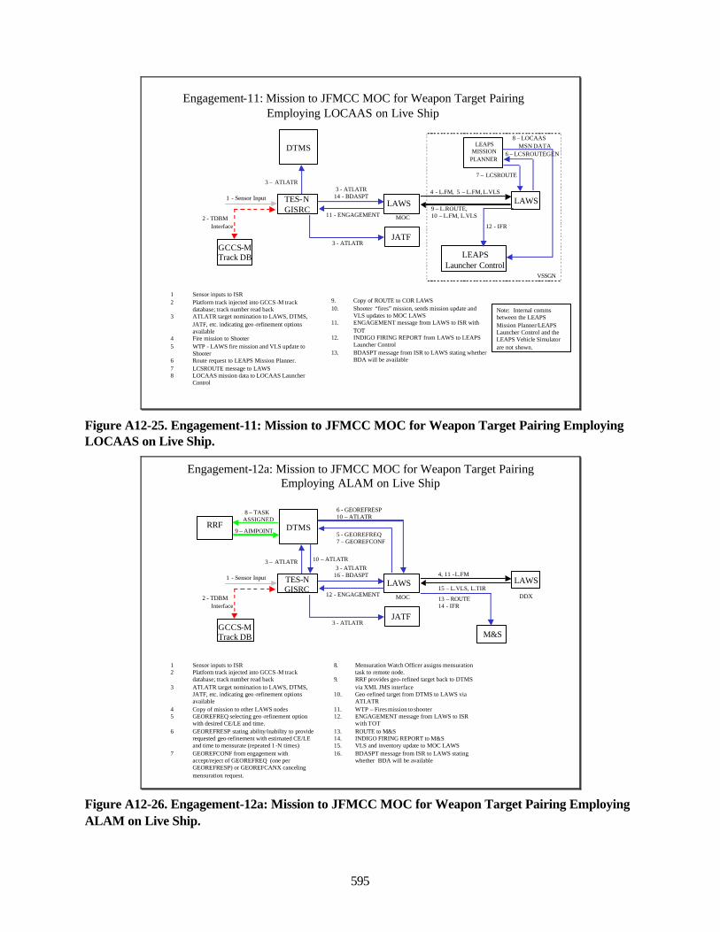
595
Engagement-11: Mission to JFMCC MOC for Weapon Target Pairing Employing LOCAAS on Live Ship
LAWS
GCCS-MTrack DB
3 - ATI.ATR14 - BDASPT
11 - ENGAGEMENT
JATF3 - ATI.ATR
DTMS
3 – ATI.ATR
MOC
1 Sensor inputs to ISR2 Platform track injected into GCCS -M track
database; track number read back3 ATI.ATR target nomination to LAWS, DTMS,
JATF, etc. indicating geo -refinement options available
4 Fire mission to Shooter5 WTP - LAWS fire mission and VLS update to
Shooter6 Route request to LEAPS Mission Planner.7 LCSROUTE message to LAWS8 LOCAAS mission data to LOCAAS Launcher
Control
9. Copy of ROUTE to COR LAWS10. Shooter “fires” mission, sends mission update and
VLS updates to MOC LAWS11. ENGAGEMENT message from LAWS to ISR with
TOT12. INDIGO FIRING REPORT from LAWS to LEAPS
Launcher Control13. BDASPT message from ISR to LAWS stating whether
BDA will be available
TES-N GISRC
LAWS4 - L.FM, 5 – L.FM, L.VLS
LEAPS Launcher Control
1 - Sensor Input
2 - TDBM Interface 12 - IFR
6 – LCSROUTEGEN
7 – LCSROUTE
8 – LOCAASMSN DATALEAPS
MISSIONPLANNER
Note: Internal comms between the LEAPS Mission Planner/LEAPS Launcher Control and the LEAPS Vehicle Simulator are not shown.
9 – L.ROUTE, 10 – L.FM, L.VLS
VSSGN
Figure A12-25. Engagement-11: Mission to JFMCC MOC for Weapon Target Pairing EmployingLOCAAS on Live Ship.
LAWS4, 11 -L.FM
M&S
13 – ROUTE14 - IFR
LAWS
GCCS-MTrack DB
3 - ATI.ATR16 - BDASPT
12 - ENGAGEMENT
JATF3 - ATI.ATR
5 - GEOREFREQ7 – GEOREFCONF
DTMS
6 - GEOREFRESP10 – ATI.ATR
RRF
3 – ATI.ATR
8 – TASK ASSIGNED
MOC
1 Sensor inputs to ISR2 Platform track injected into GCCS -M track
database; track number read back3 ATI.ATR target nomination to LAWS, DTMS,
JATF, etc. indicating geo -refinement options available
4 Copy of mission to other LAWS nodes5 GEOREFREQ selecting geo -refinement option
with desired CE/LE and time.6 GEOREFRESP stating ability/inability to provide
requested geo-refinement with estimated CE/LE and time to mensurate (repeated 1 -N times)
7 GEOREFCONF from engagement with accept/reject of GEOREFREQ (one per GEOREFRESP) or GEOREFCANX canceling mensuration request.
8. Mensuration Watch Officer assigns mensuration task to remote node.
9. RRF provides geo-refined target back to DTMS via XML JMS interface
10. Geo-refined target from DTMS to LAWS via ATI.ATR
11. WTP – Fires mission to shooter12. ENGAGEMENT message from LAWS to ISR
with TOT13. ROUTE to M&S14. INDIGO FIRING REPORT to M&S15. VLS and inventory update to MOC LAWS16. BDASPT message from ISR to LAWS stating
whether BDA will be available
Engagement-12a: Mission to JFMCC MOC for Weapon Target Pairing Employing ALAM on Live Ship
15 – L.VLS, L.TIRDDX
TES-N GISRC
10 – ATI.ATR
9 – AIMPOINT
1 - Sensor Input
2 - TDBM Interface
Figure A12-26. Engagement-12a: Mission to JFMCC MOC for Weapon Target Pairing EmployingALAM on Live Ship.
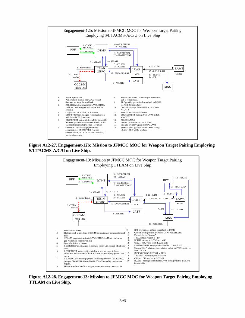
596
LAWS4, 11 -L.FM
M&S
13 – ROUTE14 - IFR
LAWS
GCCS-MTrack DB
3 - ATI.ATR16 - BDASPT
12 - ENGAGEMENT
JATF3 - ATI.ATR
5 - GEOREFREQ7 – GEOREFCONF
DTMS
6 - GEOREFRESP10 – ATI.ATR
RRF
3 – ATI.ATR
8 – TASK ASSIGNED
MOC
1 Sensor inputs to ISR2 Platform track injected into GCCS -M track
database; track number read back3 ATI.ATR target nomination to LAWS, DTMS,
JATF, etc. indicating geo -refinement options available
4 Copy of mission to other LAWS nodes5 GEOREFREQ selecting geo -refinement option
with desired CE/LE and time.6 GEOREFRESP stating ability/inability to provide
requested geo-refinement with estimated CE/LE and time to mensurate (repeated 1 -N times)
7 GEOREFCONF from engagement with accept/reject of GEOREFREQ (one per GEOREFRESP) or GEOREFCANX canceling mensuration request.
8. Mensuration Watch Officer assigns mensuration task to remote node.
9. RRF provides geo-refined target back to DTMS via XML JMS interface
10. Geo-refined target from DTMS to LAWS via ATI.ATR
11. WTP – Fires mission to shooter12. ENGAGEMENT message from LAWS to ISR
with TOT13. ROUTE to M&S14. INDIGO FIRING REPORT to M&S15. VLS and inventory update to MOC LAWS16. BDASPT message from ISR to LAWS stating
whether BDA will be available
Engagement-12b: Mission to JFMCC MOC for Weapon Target Pairing Employing S/LTACMS-A/C/U on Live Ship
15 – L.VLS, L.TIRVSSGN
TES-N GISRC
10 – ATI.ATR
9 – AIMPOINT
1 - Sensor Input
2 - TDBM Interface
Figure A12-27. Engagement-12b: Mission to JFMCC MOC for Weapon Target Pairing EmployingS/LTACMS-A/C/U on Live Ship.
LAWS4, 11 – L.FM
M&S
17 – IFR
LAWS
GCCS-MTrack DB
3 - ATI.ATR20 - BDASPT
15 - ENGAGEMENT
JATF3 - ATI.ATR
5 - GEOREFREQ7 – GEOREFCONF
DTMS
6 - GEOREFRESP10 – ATI.ATR
RRF
3 – ATI.ATR
8 – TASK ASSIGNED
MOC
1 Sensor inputs to ISR2 Platform track injected into GCCS-M track database; track number read
back3 ATI.ATR target nomination to LAWS, DTMS, JATF, etc. indicating
geo-refinement options available4 Copy of mission to shooter5 GEOREFREQ selecting geo-refinement option with desired CE/LE and
time.6 GEOREFRESP stating ability/inability to provide requested geo-
refinement with estimated CE/LE and time to mensurate (repeated 1-N times)
7 GEOREFCONF from engagement with accept/reject of GEOREFREQ (one per GEOREFRESP) or GEOREFCANX canceling mensuration request.
8 Mensuration Watch Officer assigns mensuration task to remote nod e.
9 RRF provides geo -refined target back to DTMS10 Geo-refined target from DTMS to LAWS via ATI.ATR11 Fire mission to “shooter”12 TTLAM route request to RPM13 ROUTE message to LAWS and M&S14 Copy of ROUTE to MOC LAWS node15 ENGAGEMENT message from LAWS to ISR with TOT16 Shooter “fires” mission, sends mission update and VLS updates to
MOC LAWS17 INDIGO FIRING REPORT to M&S18 TTLAM TLAMHS reports to LAWS19 CTC and DEL reports to GCCS-M20 BDASPT message from ISR to LAWS stating whether BDA will
be available
RPM
12 – ROUTEGEN
13 – ROUTE
13 – ROUTE
18 - TLAMHS
19 – CTC, DEL
Engagement-13: Mission to JFMCC MOC for Weapon Target Pairing Employing TTLAM on Live Ship
Shooter
14 – L.ROUTE, 16 – L.FM, L.VLSTES-N GISRC
10 – ATI.ATR
9 – AIMPOINT
1 - Sensor Input
2 - TDBM Interface
Figure A12-28. Engagement-13: Mission to JFMCC MOC for Weapon Target Pairing EmployingTTLAM on Live Ship.
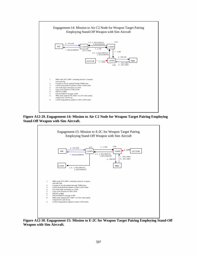
597
Engagement-14: Mission to Air C2 Node for Weapon Target PairingEmploying Stand-Off Weapon with Sim Aircraft
LAWS
Air C2 Node
M&S
5 – L.FMLAWS
E-2C4 – ATI.ATR 3, 9 – L.AFU;OPSTAT,
L.AFU;UPDATE
7 - ENGAGEMENT
ISR
LAWS
COR
GCCS-M 2 – LINK
6 – FM.CFF
1 – AFU.AMS+8 – AFU.AMS+
5 – L.FM3, 9 – L.AFU;OPSTAT,
L.AFU;UPDATE
1. M&S sends AFU.AMS+ containing mission #, weapons, and ready flag
2. Location of aircraft updated through TDBM relay3. LAWS firing platform updates to other LAWS nodes4. ATI.ATR target nomination to LAWS5. Copy of fire mission to COR LAWS6. FM.CFF to M&S7. ENGAGEMENT message to ISR8. M&S sends updated AFU.AMS+ on CAP, when tasked,
weapons free, and off cap.9. LAWS firing platform updates to other LAWS nodes
Figure A12-29. Engagement-14: Mission to Air C2 Node for Weapon Target Pairing EmployingStand-Off Weapon with Sim Aircraft.
Engagement-15: Mission to E-2C for Weapon Target PairingEmploying Stand-Off Weapon with Sim Aircraft
LAWS
M&S
1. M&S sends AFU.AMS+ containing misson #, weapons, and ready flag
2. Location of aircraft updated through TDBM relay3. LAWS firing platform updates to other LAWS nodes4. ATI.ATR target nomination to LAWS5. Copy of fire mission to COR LAWS6. FM.CFF to M&S7. ENGAGEMENT message to ISR8. M&S sends updated AFU.AMS+ on CAP, when tasked,
weapons free, and off cap.9. LAWS firing platform updates to other LAWS nodes
E-2C
3, 9 – L.AFU;OPSTAT,L.AFU;UPDATE
4 – ATI.ATR
7 - ENGAGEMENT
ISR
LAWS
LAWS
COR
GCCS-M2 - LINK
6 – FM.CFF1 – AFU.AMS+8 – AFU.AMS+
3, 9 – L.AFU;OPSTAT,L.AFU;UPDATE
5 – L.FM
Figure A12-30. Engagement-15: Mission to E-2C for Weapon Target Pairing Employing Stand-OffWeapon with Sim Aircraft.
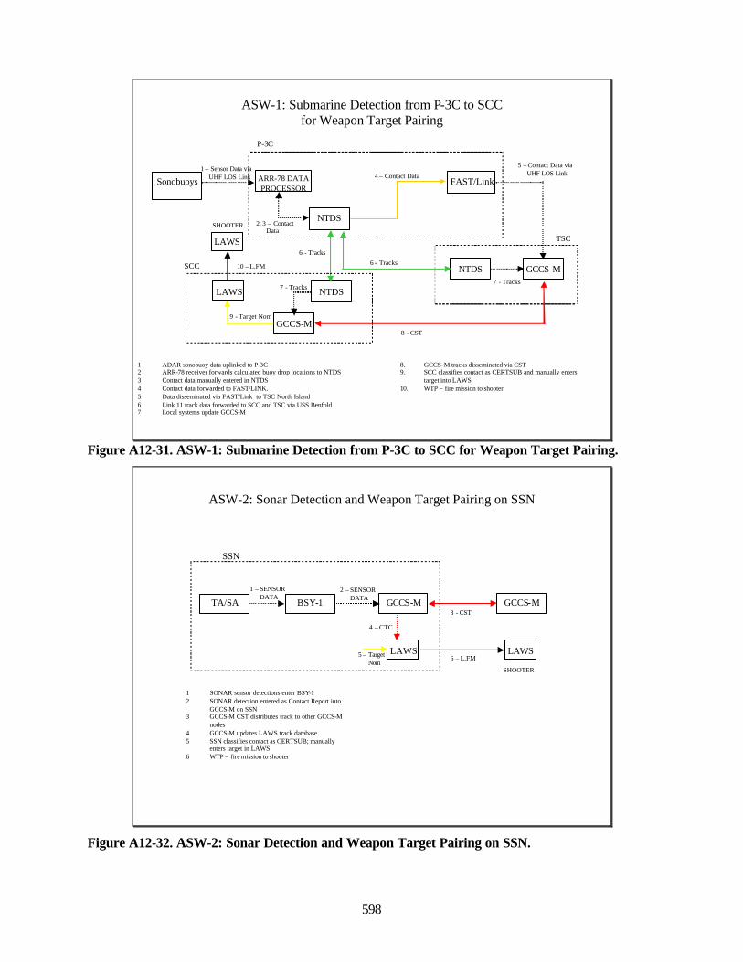
598
ASW-1: Submarine Detection from P-3C to SCC for Weapon Target Pairing
GCCS-M
1 ADAR sonobuoy data uplinked to P-3C2 ARR-78 receiver forwards calculated buoy drop locations to NTDS3 Contact data manually entered in NTDS4 Contact data forwarded to FAST/LINK.5 Data disseminated via FAST/Link to TSC North Island6 Link 11 track data forwarded to SCC and TSC via USS Benfold7 Local systems update GCCS-M
ARR-78 DATA PROCESSOR
P-3C
Sonobuoys
LAWS
1 – Sensor Data viaUHF LOS Link
6 - Tracks
NTDS2, 3 – Contact
Data
NTDS
4 – Contact Data
NTDS
GCCS-M
FAST/Link
6 - Tracks
5 – Contact Data viaUHF LOS Link
TSC
SCC
8. GCCS-M tracks disseminated via CST9. SCC classifies contact as CERTSUB and manually enters
target into LAWS10. WTP – fire mission to shooter
8 - CST
7 - Tracks7 - Tracks
9 - Target Nom
LAWS
SHOOTER
10 – L.FM
Figure A12-31. ASW-1: Submarine Detection from P-3C to SCC for Weapon Target Pairing.
ASW-2: Sonar Detection and Weapon Target Pairing on SSN
1 SONAR sensor detections enter BSY-12 SONAR detection entered as Contact Report into
GCCS-M on SSN3 GCCS-M CST distributes track to other GCCS-M
nodes4 GCCS-M updates LAWS track database5 SSN classifies contact as CERTSUB; manually
enters target in LAWS6 WTP – fire mission to shooter
GCCS-M3 - CST
SSN
GCCS-MBSY-12 – SENSOR
DATATA/SA
1 – SENSORDATA
LAWS5 – TargetNom
4 – CTC
LAWS
SHOOTER
6 – L.FM
Figure A12-32. ASW-2: Sonar Detection and Weapon Target Pairing on SSN.
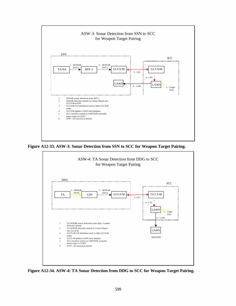
599
ASW-3: Sonar Detection from SSN to SCCfor Weapon Target Pairing
1 SONAR sensor detections enter BSY-12 SONAR detection entered as Contact Report into
GCCS-M on SSN3 GCCS-M CST distributes track to other GCCS-M
nodes4 GCCS-M updates LAWS track database5 SCC classifies contact as CERTSUB; manually
enters target in LAWS6 WTP – fire mission to shooter
GCCS-M3 - CST
SSN
GCCS-MBSY-1
2 – SENSORDATA
TA/SA
1 – SENSORDATA
LAWS5 – Target
Nom
4 – CTC
SCC
LAWS6 – L.FM
Figure A12-33. ASW-3: Sonar Detection from SSN to SCC for Weapon Target Pairing.
ASW-4: TA Sonar Detection from DDG to SCCfor Weapon Target Pairing
1 TA SONAR sensor detections enter ship’s Combat Direction System
2 TA SONAR detection entered as Contact Report into GCCS-M
3 GCCS-M CST distributes track to other GCCS-M nodes
4 GCCS-M updates LAWS track database5 SCC classifies contact as CERTSUB; manually
enters target in LAWS6 WTP – fire mission to shooter
GCCS-M3 - CST
DDG
GCCS-MCDS
2 – SENSORDATA
TA
1 – SENSORDATA
LAWS5 – Target
Nom
4 – CTC
SCC
LAWS
SHOOTER
6 – L.FM
Figure A12-34. ASW-4: TA Sonar Detection from DDG to SCC for Weapon Target Pairing.
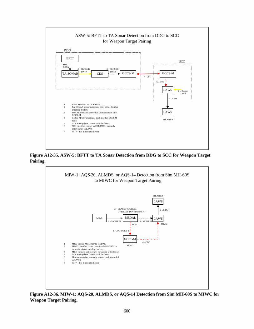
600
ASW-5: BFTT to TA Sonar Detection from DDG to SCCfor Weapon Target Pairing
1 BFFT SIM data to TA SONAR2 TA SONAR sensor detections enter ship’s Combat
Direction System3 SONAR detection entered as Contact Report into
GCCS-M4 GCCS-M CST distributes track to other GCCS-M
nodes5 GCCS-M updates LAWS track database6 SCC classifies contact as CERTSUB; manually
enters target in LAWS7 WTP – fire mission to shooter
GCCS-M4 - CST
DDG
GCCS-MCDS
3 – SENSORDATA
TA SONAR
2 – SENSORDATA
LAWS 6 – TargetNom
5 – CTC
SCC
LAWS
SHOOTER
7 – L.FM
BFTT
1 – SIMDATA
Figure A12-35. ASW-5: BFTT to TA Sonar Detection from DDG to SCC for Weapon TargetPairing.
MIW-1: AQS-20, ALMDS, or AQS-14 Detection from Sim MH-60Sto MIWC for Weapon Target Pairing
GCCS-M1 M&S outputs MCMREP to MEDAL2 MIWC classifies contact as mine (MRN/CRN) or
non-mine object; develops overlays3 MRN contacts and overlays forwarded to GCCS-M4 GCCS-M updates LAWS track database 5 Mine contact data manually selected and forwarded
to LAWS6 WTP – fire mission to shooter
LAWSM&S MEDAL1 - MCMREP
LAWS
SHOOTER
MIWC
2 – CLASSIFICATION, OVERLAY DEVELOPMENT
3 –CTC, OVLY-2
5 - MCMREP
4 –CTCMIWC
MIWC
6 – L.FM
Figure A12-36. MIW-1: AQS-20, ALMDS, or AQS-14 Detection from Sim MH-60S to MIWC forWeapon Target Pairing.
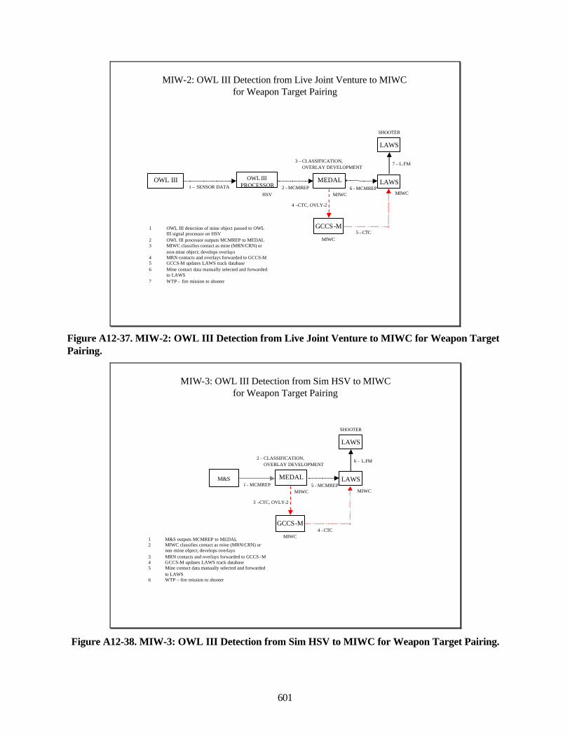
601
MIW-2: OWL III Detection from Live Joint Venture to MIWC for Weapon Target Pairing
GCCS-M1 OWL III detection of mine object passed to OWL III signal processor on HSV
2 OWL III processor outputs MCMREP to MEDAL3 MIWC classifies contact as mine (MRN/CRN) or
non-mine object; develops overlays4 MRN contacts and overlays forwarded to GCCS-M5 GCCS-M updates LAWS track database 6 Mine contact data manually selected and forwarded
to LAWS7 WTP – fire mission to shooter
LAWSOWL III
PROCESSORMEDAL
2 - MCMREPHSV
OWL III
LAWS
SHOOTER
1 – SENSOR DATA
MIWC
3 – CLASSIFICATION, OVERLAY DEVELOPMENT
4 –CTC, OVLY-2
6 - MCMREP
5 –CTCMIWC
MIWC
7 – L.FM
Figure A12-37. MIW-2: OWL III Detection from Live Joint Venture to MIWC for Weapon TargetPairing.
MIW-3: OWL III Detection from Sim HSV to MIWC for Weapon Target Pairing
GCCS-M
1 M&S outputs MCMREP to MEDAL2 MIWC classifies contact as mine (MRN/CRN) or
non -mine object; develops overlays3 MRN contacts and overlays forwarded to GCCS -M4 GCCS-M updates LAWS track database 5 Mine contact data manually selected and forwarded
to LAWS6 WTP – fire mission to shooter
LAWSMEDAL1 - MCMREP
LAWS
SHOOTER
MIWC
2 – CLASSIFICATION, OVERLAY DEVELOPMENT
3 –CTC, OVLY-2
5 - MCMREP
4 –CTCMIWC
MIWC
6 – L.FM
M&S
Figure A12-38. MIW-3: OWL III Detection from Sim HSV to MIWC for Weapon Target Pairing.
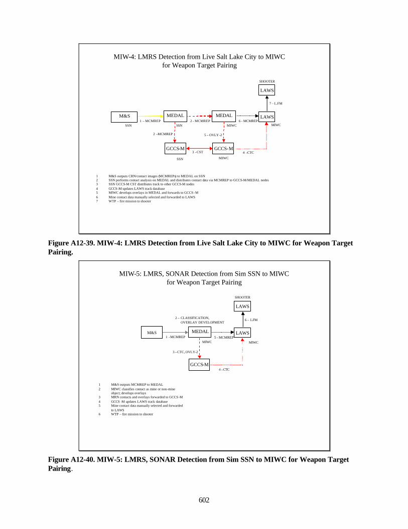
602
MIW-4: LMRS Detection from Live Salt Lake City to MIWC for Weapon Target Pairing
GCCS-M
1 M&S outputs CRN/contact images (MCMREPs) to MEDAL on SSN2 SSN performs contact analysis on MEDAL and distributes contact data via MCMREP to GCCS-M/MEDAL nodes3 SSN GCCS-M CST distributes track to other GCCS-M nodes4 GCCS-M updates LAWS track database 5 MIWC develops overlays in MEDAL and forwards to GCCS -M6 Mine contact data manually selected and forwarded to LAWS7 WTP – fire mission to shooter
LAWSMEDAL2 - MCMREP
SSN
LAWS
SHOOTER
MIWC
5 – OVLY -2
6 - MCMREP
4 –CTC
MIWC
MIWC
7 – L.FM
MEDAL
GCCS-M
2 –MCMREP
3 -CST
M&S
SSN
SSN1 – MCMREP
Figure A12-39. MIW-4: LMRS Detection from Live Salt Lake City to MIWC for Weapon TargetPairing.
MIW-5: LMRS, SONAR Detection from Sim SSN to MIWC for Weapon Target Pairing
GCCS-M
LAWSMEDAL1 -MCMREP
LAWS
SHOOTER
MIWC
2 – CLASSIFICATION, OVERLAY DEVELOPMENT
3 –CTC, OVLY-2
5 - MCMREP
4 –CTC
6 – L.FM
M&S
MIWC
1 M&S outputs MCMREP to MEDAL2 MIWC classifies contact as mine or non -mine
object; develops overlays3 MRN contacts and overlays forwarded to GCCS -M4 GCCS -M updates LAWS track database 5 Mine contact data manually selected and forwarded
to LAWS6 WTP – fire mission to shooter
Figure A12-40. MIW-5: LMRS, SONAR Detection from Sim SSN to MIWC for Weapon TargetPairing.
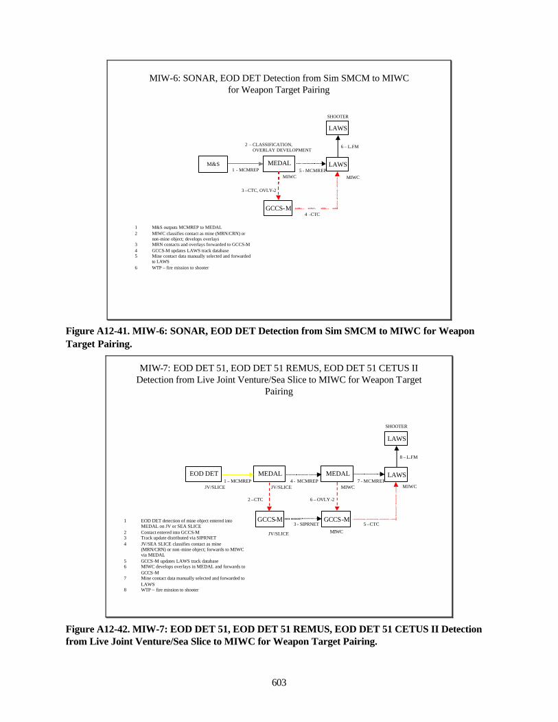
603
MIW-6: SONAR, EOD DET Detection from Sim SMCM to MIWC for Weapon Target Pairing
GCCS-M
LAWSMEDAL1 - MCMREP
LAWS
SHOOTER
MIWC
2 – CLASSIFICATION, OVERLAY DEVELOPMENT
3 –CTC, OVLY-2
5 - MCMREP
4 –CTC
6 – L.FM
M&S
MIWC
1 M&S outputs MCMREP to MEDAL2 MIWC classifies contact as mine (MRN/CRN) or
non-mine object; develops overlays3 MRN contacts and overlays forwarded to GCCS-M4 GCCS-M updates LAWS track database 5 Mine contact data manually selected and forwarded
to LAWS6 WTP – fire mission to shooter
Figure A12-41. MIW-6: SONAR, EOD DET Detection from Sim SMCM to MIWC for WeaponTarget Pairing.
MIW-7: EOD DET 51, EOD DET 51 REMUS, EOD DET 51 CETUS II Detection from Live Joint Venture/Sea Slice to MIWC for Weapon Target
Pairing
GCCS-M1 EOD DET detection of mine object entered into MEDAL on JV or SEA SLICE
2 Contact entered into GCCS-M3 Track update distributed via SIPRNET4 JV/SEA SLICE classifies contact as mine
(MRN/CRN) or non-mine object; forwards to MIWC via MEDAL
5 GCCS-M updates LAWS track database 6 MIWC develops overlays in MEDAL and forwards to
GCCS-M7 Mine contact data manually selected and forwarded to
LAWS8 WTP – fire mission to shooter
LAWSMEDAL4 - MCMREP
JV/SLICE
LAWS
SHOOTER
MIWC
6 – OVLY-2
7 - MCMREP
5 –CTC
MIWC
MIWC
8 – L.FM
MEDALEOD DET
JV/SLICE1 – MCMREP
GCCS-M
2 –CTC
3 - SIPRNET
JV/SLICE
Figure A12-42. MIW-7: EOD DET 51, EOD DET 51 REMUS, EOD DET 51 CETUS II Detectionfrom Live Joint Venture/Sea Slice to MIWC for Weapon Target Pairing.
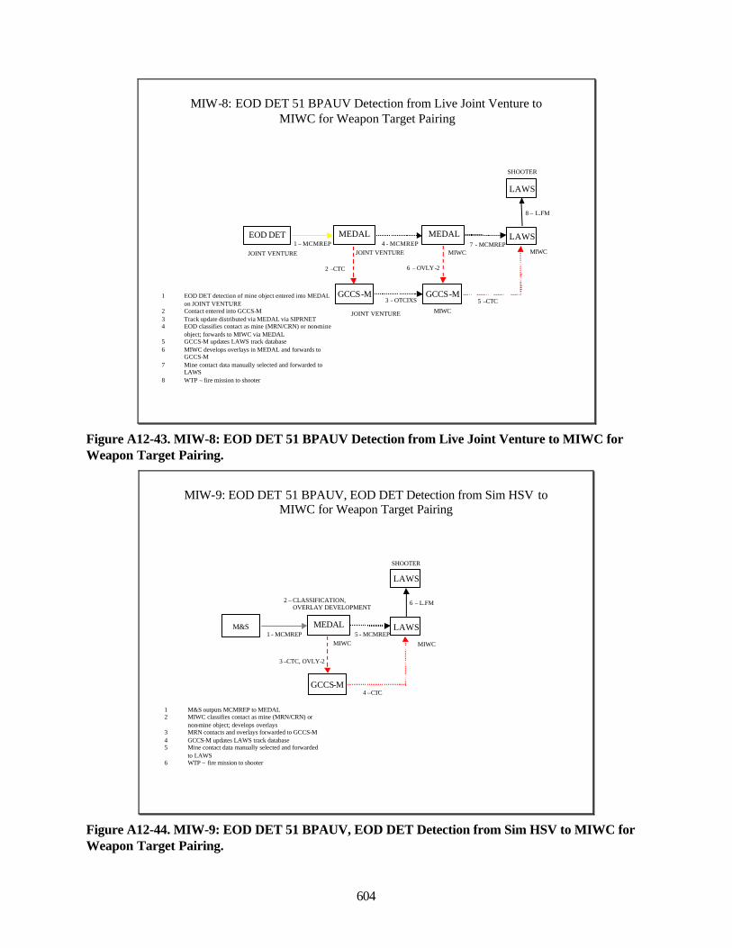
604
MIW-8: EOD DET 51 BPAUV Detection from Live Joint Venture to MIWC for Weapon Target Pairing
GCCS-M1 EOD DET detection of mine object entered into MEDAL on JOINT VENTURE
2 Contact entered into GCCS-M3 Track update distributed via MEDAL via SIPRNET4 EOD classifies contact as mine (MRN/CRN) or non-mine
object; forwards to MIWC via MEDAL5 GCCS-M updates LAWS track database 6 MIWC develops overlays in MEDAL and forwards to
GCCS-M7 Mine contact data manually selected and forwarded to
LAWS8 WTP – fire mission to shooter
LAWSMEDAL4 - MCMREP
JOINT VENTURE
LAWS
SHOOTER
MIWC
6 – OVLY-2
7 - MCMREP
5 –CTC
MIWC
MIWC
8 – L.FM
MEDALEOD DET
JOINT VENTURE
1 – MCMREP
GCCS-M
2 –CTC
3 - OTCIXS
JOINT VENTURE
Figure A12-43. MIW-8: EOD DET 51 BPAUV Detection from Live Joint Venture to MIWC forWeapon Target Pairing.
MIW-9: EOD DET 51 BPAUV, EOD DET Detection from Sim HSV to MIWC for Weapon Target Pairing
GCCS-M
LAWSMEDAL1 - MCMREP
LAWS
SHOOTER
MIWC
2 – CLASSIFICATION, OVERLAY DEVELOPMENT
3 –CTC, OVLY-2
5 - MCMREP
4 –CTC
6 – L.FM
M&S
MIWC
1 M&S outputs MCMREP to MEDAL2 MIWC classifies contact as mine (MRN/CRN) or
non-mine object; develops overlays3 MRN contacts and overlays forwarded to GCCS-M4 GCCS-M updates LAWS track database 5 Mine contact data manually selected and forwarded
to LAWS6 WTP – fire mission to shooter
Figure A12-44. MIW-9: EOD DET 51 BPAUV, EOD DET Detection from Sim HSV to MIWC forWeapon Target Pairing.
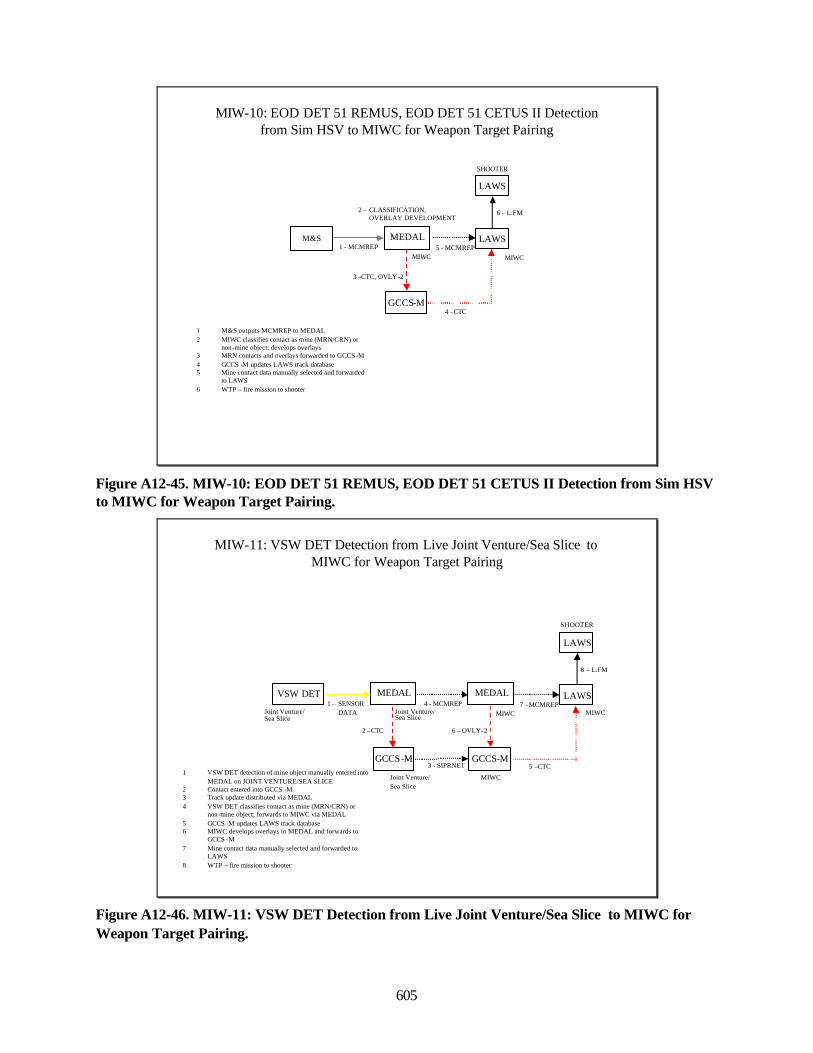
605
MIW-10: EOD DET 51 REMUS, EOD DET 51 CETUS II Detection from Sim HSV to MIWC for Weapon Target Pairing
GCCS-M
LAWSMEDAL1 - MCMREP
LAWS
SHOOTER
MIWC
2 – CLASSIFICATION, OVERLAY DEVELOPMENT
3 –CTC, OVLY -2
5 - MCMREP
4 –CTC
6 – L.FM
M&S
MIWC
1 M&S outputs MCMREP to MEDAL2 MIWC classifies contact as mine (MRN/CRN) or
non -mine object; develops overlays3 MRN contacts and overlays forwarded to GCCS -M4 GCCS -M updates LAWS track database 5 Mine contact data manually selected and forwarded
to LAWS6 WTP – fire mission to shooter
Figure A12-45. MIW-10: EOD DET 51 REMUS, EOD DET 51 CETUS II Detection from Sim HSVto MIWC for Weapon Target Pairing.
MIW-11: VSW DET Detection from Live Joint Venture/Sea Slice to MIWC for Weapon Target Pairing
GCCS-M1 VSW DET detection of mine object manually entered into
MEDAL on JOINT VENTURE/SEA SLICE2 Contact entered into GCCS -M3 Track update distributed via MEDAL4 VSW DET classifies contact as mine (MRN/CRN) or
non -mine object; forwards to MIWC via MEDAL5 GCCS-M updates LAWS track database 6 MIWC develops overlays in MEDAL and forwards to
GCCS-M7 Mine contact data manually selected and forwarded to
LAWS8 WTP – fire mission to shooter
LAWSMEDAL4 - MCMREP
Joint Venture/ Sea Slice
LAWS
SHOOTER
MIWC
6 – OVLY-2
7 -MCMREP
5 –CTC
MIWC
MIWC
8 – L.FM
MEDALVSW DET
Joint Venture/ Sea Slice
1 – SENSORDATA
GCCS-M
2 –CTC
3 - SIPRNET
Joint Venture/ Sea Slice
Figure A12-46. MIW-11: VSW DET Detection from Live Joint Venture/Sea Slice to MIWC forWeapon Target Pairing.
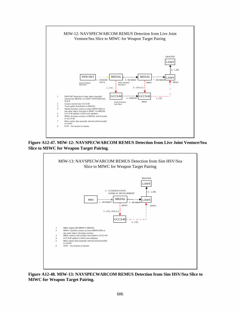
606
MIW-12: NAVSPECWARCOM REMUS Detection from Live Joint Venture/Sea Slice to MIWC for Weapon Target Pairing
GCCS-M1 NSW DET detection of mine object manually entered into MEDAL on JOINT VENTURE/SEA SLICE
2 Contact entered into GCCS-M3 Track update distributed via MEDAL4 Skjold classifies contact as mine (MRN/CRN) or
non -mine object; forwards to MIWC via MEDAL5 GCCS-M updates LAWS track database 6 MIWC develops overlays in MEDAL and forwards
to GCCS-M7 Mine contact data manually selected and forwarded
to LAWS8 WTP – fire mission to shooter
LAWSMEDAL4 - MCMREP
LAWS
SHOOTER
MIWC
6 – OVLY-2
7 - MCMREP
5 –CTC
MIWC
MIWC
8 – L.FM
MEDALNSW DET1 – SENSOR
DATA
GCCS-M
2 –CTC
3 - SIPRNET
Joint Venture/ Sea Slice
Joint Venture/ Sea Slice
Joint Venture/ Sea Slice
Figure A12-47. MIW-12: NAVSPECWARCOM REMUS Detection from Live Joint Venture/SeaSlice to MIWC for Weapon Target Pairing.
MIW-13: NAVSPECWARCOM REMUS Detection from Sim HSV/Sea Slice to MIWC for Weapon Target Pairing
GCCS-M
LAWSMEDAL1 - MCMREP
LAWS
SHOOTER
MIWC
2 – CLASSIFICATION, OVERLAY DEVELOPMENT
3 –CTC, OVLY-2
5 - MCMREP
4 –CTC
6 – L.FM
M&S
MIWC
1 M&S outputs MCMREP to MEDAL2 MIWC classifies contact as mine (MRN/CRN) or
non-mine object; develops overlays3 MRN contacts and overlays forwarded to GCCS-M4 GCCS-M updates LAWS track database 5 Mine contact data manually selected and forwarded
to LAWS6 WTP – fire mission to shooter
Figure A12-48. MIW-13: NAVSPECWARCOM REMUS Detection from Sim HSV/Sea Slice toMIWC for Weapon Target Pairing.
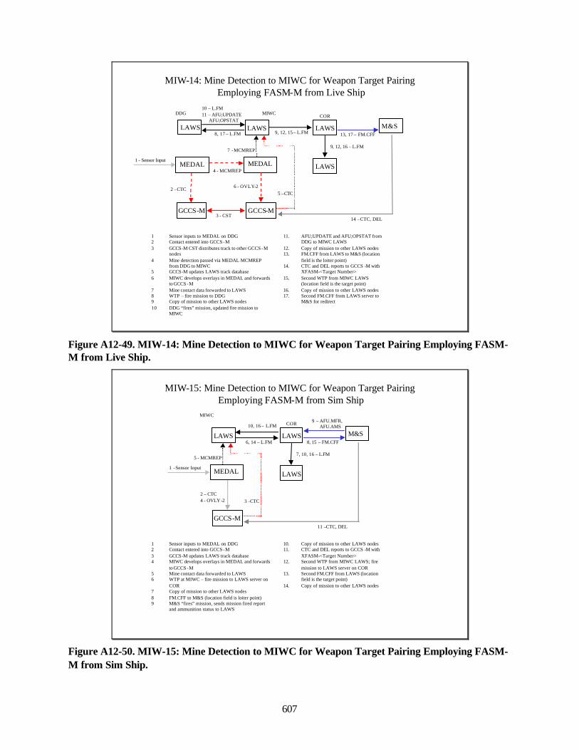
607
MIW-14: Mine Detection to MIWC for Weapon Target PairingEmploying FASM-M from Live Ship
MIWC
LAWS
MEDAL
7 -MCMREP
M&S9, 12, 15 – L.FM 13, 17 – FM.CFF
GCCS-M
6 - OVLY-25 –CTC
14 –CTC, DEL
LAWS
COR
LAWS
9, 12, 16 – L.FM
LAWS
1 - Sensor InputMEDAL
4 - MCMREP
DDG
8, 17 – L.FM
10 – L.FM11 – AFU;UPDATE
AFU;OPSTAT
GCCS-M3 - CST
2 –CTC
1 Sensor inputs to MEDAL on DDG2 Contact entered into GCCS -M3 GCCS-M CST distributes track to other GCCS -M
nodes4 Mine detection passed via MEDAL MCMREP
from DDG to MIWC5 GCCS-M updates LAWS track database 6 MIWC develops overlays in MEDAL and forwards
to GCCS -M7 Mine contact data forwarded to LAWS8 WTP – fire mission to DDG9 Copy of mission to other LAWS nodes10 DDG “fires” mission, updated fire mission to
MIWC
11. AFU;UPDATE and AFU;OPSTAT from DDG to MIWC LAWS
12. Copy of mission to other LAWS nodes13. FM.CFF from LAWS to M&S (location
field is the loiter point)14. CTC and DEL reports to GCCS -M with
XFASM-<Target Number>15. Second WTP from MIWC LAWS
(location field is the target point)16. Copy of mission to other LAWS nodes17. Second FM.CFF from LAWS server to
M&S for redirect
Figure A12-49. MIW-14: Mine Detection to MIWC for Weapon Target Pairing Employing FASM-M from Live Ship.
MIW-15: Mine Detection to MIWC for Weapon Target PairingEmploying FASM-M from Sim Ship
MIWC
1 -Sensor Input
1 Sensor inputs to MEDAL on DDG2 Contact entered into GCCS -M3 GCCS-M updates LAWS track database 4 MIWC develops overlays in MEDAL and forwards
to GCCS -M5 Mine contact data forwarded to LAWS6 WTP at MIWC – fire mission to LAWS server on
COR7 Copy of mission to other LAWS nodes8 FM.CFF to M&S (location field is loiter point)9 M&S “fires” mission, sends mission fired report
and ammunition status to LAWS
10. Copy of mission to other LAWS nodes11. CTC and DEL reports to GCCS -M with
XFASM-<Target Number>12. Second WTP from MIWC LAWS; fire
mission to LAWS server on COR13. Second FM.CFF from LAWS (location
field is the target point)14. Copy of mission to other LAWS nodes
LAWS
MEDAL
5 - MCMREP
M&S6, 14 – L.FM 8, 15 – FM.CFF
10, 16 – L.FM9 – AFU.MFR,
AFU.AMS
GCCS-M
2 – CTC4 - OVLY -2 3 –CTC
11 –CTC, DEL
LAWS
COR
LAWS
7, 10, 16 – L.FM
Figure A12-50. MIW-15: Mine Detection to MIWC for Weapon Target Pairing Employing FASM-M from Sim Ship.
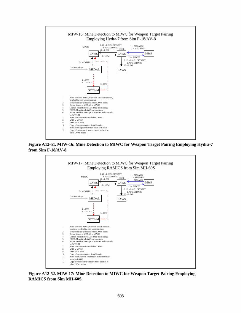
608
MIW-16: Mine Detection to MIWC for Weapon Target PairingEmploying Hydra-7 from Sim F-18/AV-8
LAWS
3 - Sensor Input
1 M&S provides AFU.AMS+ with aircraft mission #, availability, and weapons status
2 Weapon status updates to other LAWS nodes3 Sensor inputs to MEDAL at MIWC4 Contact entered into GCCS-M (if not already)5 GCCS-M updates LAWS track database 6 MIWC develops overlays in MEDAL and forwards
to GCCS-M7 Mine contact data forwarded to LAWS8 WTP at MIWC9 FM.CFF to M&S10 Copy of mission to other LAWS nodes11 M&S sends updated aircraft status to LAWS12 Copy of mission and weapon status updates to
other LAWS nodes
MEDAL
7 - MCMREP
M&S9 – FM.CFF
1 – AFU.AMS+11 – AFU.AMS+
MIWC
GCCS-M
4 – CTC6 - OVLY-2
5 –CTC
8 – L.FM
2, 12 – L.AFU;OPTSTAT,L.AFU;UPDATE
12 – L.FM
LAWS
COR
LAWS
2, 12 – L.AFU;OPTSTAT,L.AFU;UPDATE
12 – L.FM
Figure A12-51. MIW-16: Mine Detection to MIWC for Weapon Target Pairing Employing Hydra-7from Sim F-18/AV-8.
MIW-17: Mine Detection to MIWC for Weapon Target PairingEmploying RAMICS from Sim MH-60S
LAWS
3 - Sensor Input
1 M&S provides AFU.AMS with aircraft mission location, availability, and weapons status
2 Weapon status updates to other LAWS nodes3 Sensor inputs to MEDAL at MIWC4 Contact entered into GCCS-M (if not already)5 GCCS-M updates LAWS track database 6 MIWC develops overlays in MEDAL and forwards
to GCCS-M7 Mine contact data forwarded to LAWS8 WTP at MIWC9 FM.CFF to M&S10 Copy of mission to other LAWS nodes11 M&S sends mission fired report and ammunition
status to LAWS12 Copy of mission and weapon status updates to
other LAWS nodes
MEDAL
7 - MCMREP
M&S9 – FM.CFF
1 – AFU.AMS11 – AFU.MFR,
AFU.AMS
MIWC
GCCS-M
4 – CTC6 - OVLY-2
5 –CTC
8 – L.FM
2, 12 – L.AFU;OPTSTAT,L.AFU;UPDATE
12 – L.FM
LAWS
COR
LAWS
2, 12 – L.AFU;OPTSTAT,L.AFU;UPDATE
12 – L.FM
Figure A12-52. MIW-17: Mine Detection to MIWC for Weapon Target Pairing EmployingRAMICS from Sim MH-60S.
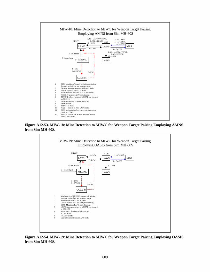
609
MIW-18: Mine Detection to MIWC for Weapon Target PairingEmploying AMNS from Sim MH-60S
LAWS
3 - Sensor Input
1 M&S provides AFU.AMS with aircraft mission location, availability, and weapons status
2 Weapon status updates to other LAWS nodes3 Sensor inputs to MEDAL at MIWC4 Contact entered into GCCS -M (if not already)5 GCCS-M updates LAWS track database 6 MIWC develops overlays in MEDAL and forwards
to GCCS -M7 Mine contact data forwarded to LAWS8 WTP at MIWC9 FM.CFF to M&S10 Copy of mission to other LAWS nodes11 M&S sends mission fired report and ammunition
status to LAWS12 Copy of mission and weapon status updates to
other LAWS nodes
MEDAL
7 -MCMREP
M&S9 – FM.CFF
1 – AFU.AMS11 – AFU.MFR,
AFU.AMSMIWC
GCCS-M
4 – CTC6 - OVLY-2 5 –CTC
8 – L.FM
2, 12 – L.AFU;OPTSTAT,L.AFU;UPDATE
12 – L.FM
LAWS
COR
LAWS
2, 12 – L.AFU;OPTSTAT,L.AFU;UPDATE
12 – L.FM
Figure A12-53. MIW-18: Mine Detection to MIWC for Weapon Target Pairing Employing AMNSfrom Sim MH-60S.
MIW-19: Mine Detection to MIWC for Weapon Target PairingEmploying OASIS from Sim MH-60S
LAWS
2 - Sensor Input
1 M&S provides AFU.AMS with aircraft mission location, availability, and weapons status
2 Sensor inputs to MEDAL at MIWC3 Contact entered into GCCS-M (if not already)4 GCCS-M updates LAWS track database 5 MIWC develops overlays in MEDAL and forwards
to GCCS-M6 Mine contact data forwarded to LAWS7 WTP at MIWC8 FM.CFF to M&S9 Copy of mission to other LAWS nodes
MEDAL
6 - MCMREP
M&S8 – FM.CFF
1 – AFU.AMSMIWC
GCCS-M
3 – CTC5 - OVLY-2
4 –CTC
7 – L.FM
9 – L.FM
LAWS
COR
LAWS
9 – L.FM
Figure A12-54. MIW-19: Mine Detection to MIWC for Weapon Target Pairing Employing OASISfrom Sim MH-60S.
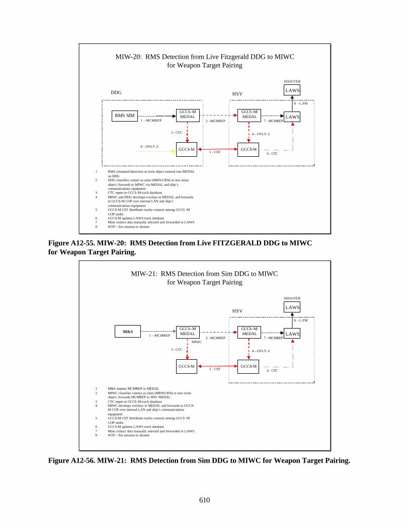
610
MIW-20: RMS Detection from Live Fitzgerald DDG to MIWC for Weapon Target Pairing
GCCS-M
1 RMS simulated detection of mine object entered into MEDAL on DDG
2 DDG classifies contact as mine (MRN/CRN) or non -mine object; forwards to MIWC via MEDAL and ship’s communications equipment
3 CTC report to GCCS-M track database4 MIWC and DDG develops overlays in MEDAL and forwards
to GCCS-M COP over internal LAN and ship’s communications equipment
5 GCCS-M CST distributes tracks contacts among GCCS -M COP nodes
6 GCCS-M updates LAWS track database7 Mine contact data manually selected and forwarded to LAWS8 WTP – fire mission to shooter
LAWSGCCS-M/MEDAL
2 -MCMREPRMS SIM
LAWS
SHOOTER
1 – MCMREP
4 – OVLY -2
7 - MCMREP
8 – L.FM
GCCS-MMEDAL
5 - CSTGCCS-M
4 – OVLY -2
3 - CTC
DDG HSV
6 - CTC
Figure A12-55. MIW-20: RMS Detection from Live FITZGERALD DDG to MIWCfor Weapon Target Pairing.
MIW-21: RMS Detection from Sim DDG to MIWC for Weapon Target Pairing
GCCS-M
1 M&S outputs MCMREP to MEDAL2 MIWC classifies contact as mine (MRN/CRN) or non -mine
object; forwards MCMREP to HSV MEDAL3 CTC report to GCCS-M track database4 MIWC develops overlays in MEDAL and forwards to GCCS-
M COP over internal LAN and ship’s communications equipment
5 GCCS-M CST distributes tracks contacts among GCCS -M COP nodes
6 GCCS-M updates LAWS track database7 Mine contact data manually selected and forwarded to LAWS8 WTP – fire mission to shooter
LAWSGCCS-M/MEDAL
2 -MCMREP
LAWS
SHOOTER
1 – MCMREP
4 – OVLY -2
7 - MCMREP
8 – L.FM
GCCS-MMEDAL
5 - CSTGCCS-M
3 - CTC
HSV
6 - CTC
M&S
MIWC
Figure A12-56. MIW-21: RMS Detection from Sim DDG to MIWC for Weapon Target Pairing.
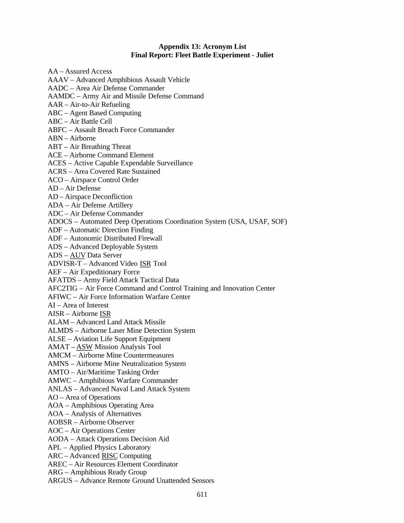
611
Appendix 13: Acronym ListFinal Report: Fleet Battle Experiment - Juliet
AA – Assured AccessAAAV – Advanced Amphibious Assault VehicleAADC – Area Air Defense CommanderAAMDC – Army Air and Missile Defense CommandAAR – Air-to-Air RefuelingABC – Agent Based ComputingABC – Air Battle CellABFC – Assault Breach Force CommanderABN – AirborneABT – Air Breathing ThreatACE – Airborne Command ElementACES – Active Capable Expendable SurveillanceACRS – Area Covered Rate SustainedACO – Airspace Control OrderAD – Air DefenseAD – Airspace DeconflictionADA – Air Defense ArtilleryADC – Air Defense CommanderADOCS – Automated Deep Operations Coordination System (USA, USAF, SOF)ADF – Automatic Direction FindingADF – Autonomic Distributed FirewallADS – Advanced Deployable SystemADS – AUV Data ServerADVISR-T – Advanced Video ISR ToolAEF – Air Expeditionary ForceAFATDS – Army Field Attack Tactical DataAFC2TIG – Air Force Command and Control Training and Innovation CenterAFIWC – Air Force Information Warfare CenterAI – Area of InterestAISR – Airborne ISRALAM – Advanced Land Attack MissileALMDS – Airborne Laser Mine Detection SystemALSE – Aviation Life Support EquipmentAMAT – ASW Mission Analysis ToolAMCM – Airborne Mine CountermeasuresAMNS – Airborne Mine Neutralization SystemAMTO – Air/Maritime Tasking OrderAMWC – Amphibious Warfare CommanderANLAS – Advanced Naval Land Attack SystemAO – Area of OperationsAOA – Amphibious Operating AreaAOA – Analysis of AlternativesAOBSR – Airborne ObserverAOC – Air Operations CenterAODA – Attack Operations Decision AidAPL – Applied Physics LaboratoryARC – Advanced RISC ComputingAREC – Air Resources Element CoordinatorARG – Amphibious Ready GroupARGUS – Advance Remote Ground Unattended Sensors
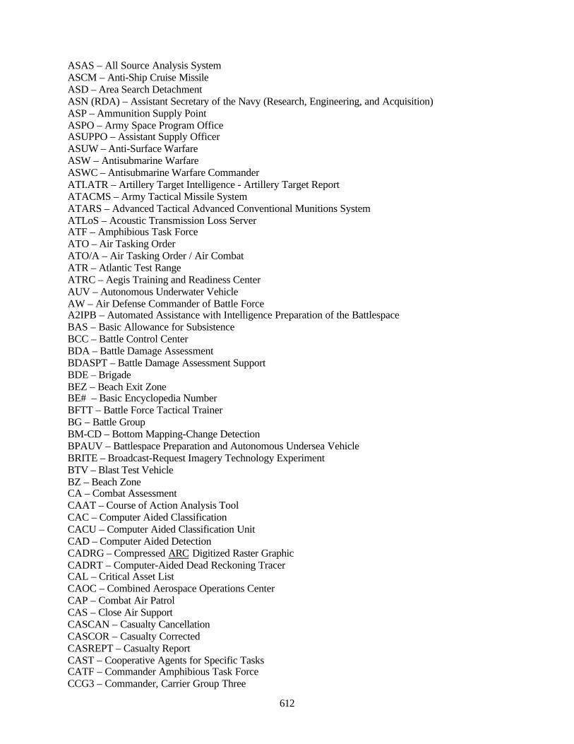
612
ASAS – All Source Analysis SystemASCM – Anti-Ship Cruise MissileASD – Area Search DetachmentASN (RDA) – Assistant Secretary of the Navy (Research, Engineering, and Acquisition)ASP – Ammunition Supply PointASPO – Army Space Program OfficeASUPPO – Assistant Supply OfficerASUW – Anti-Surface WarfareASW – Antisubmarine WarfareASWC – Antisubmarine Warfare CommanderATI.ATR – Artillery Target Intelligence - Artillery Target ReportATACMS – Army Tactical Missile SystemATARS – Advanced Tactical Advanced Conventional Munitions SystemATLoS – Acoustic Transmission Loss ServerATF – Amphibious Task ForceATO – Air Tasking OrderATO/A – Air Tasking Order / Air CombatATR – Atlantic Test RangeATRC – Aegis Training and Readiness CenterAUV – Autonomous Underwater VehicleAW – Air Defense Commander of Battle ForceA2IPB – Automated Assistance with Intelligence Preparation of the BattlespaceBAS – Basic Allowance for SubsistenceBCC – Battle Control CenterBDA – Battle Damage AssessmentBDASPT – Battle Damage Assessment SupportBDE – BrigadeBEZ – Beach Exit ZoneBE# – Basic Encyclopedia NumberBFTT – Battle Force Tactical TrainerBG – Battle GroupBM-CD – Bottom Mapping-Change DetectionBPAUV – Battlespace Preparation and Autonomous Undersea VehicleBRITE – Broadcast-Request Imagery Technology ExperimentBTV – Blast Test VehicleBZ – Beach ZoneCA – Combat AssessmentCAAT – Course of Action Analysis ToolCAC – Computer Aided ClassificationCACU – Computer Aided Classification UnitCAD – Computer Aided DetectionCADRG – Compressed ARC Digitized Raster GraphicCADRT – Computer-Aided Dead Reckoning TracerCAL – Critical Asset ListCAOC – Combined Aerospace Operations CenterCAP – Combat Air PatrolCAS – Close Air SupportCASCAN – Casualty CancellationCASCOR – Casualty CorrectedCASREPT – Casualty ReportCAST – Cooperative Agents for Specific TasksCATF – Commander Amphibious Task ForceCCG3 – Commander, Carrier Group Three

613
CCIR – Commander’s Critical Information RequirementCCTV - Closed-Circuit TelevisionCENTCOM – U.S. Central CommandCETUS – Composite Endoskeleton Test-bed Untethered Underwater Vehicle SystemCDCM – Coastal Defense Cruise MissilesCDE – Collateral Damage EstimateCDL-N – Common Data Link – NavyCDS – Combat Direction SystemCDP – Cumulative Detection ProbabilityCFACC – Combined Force Air Component CommanderCHAT – Conversational Hypertext Access TechnologyCHENG – Chief of EngineeringCID – Combat IdentificationCIE – Collaborative Information EnvironmentCINC – Commander in ChiefCJTF – Commander Joint Task ForceCLA – Contact Localization AccuracyCLF – Commander Landing ForceCM – Collection ManagementCM – Counter MeasuresCMA – Collection Management AuthorityCMTC – Critical Mobile Target CellCMWC – Commander Mine Warfare CommandCAN – Center for Naval AnalysesCNA – Computer Network AttackCND – Computer Network DefenseCO – Commanding OfficerCOA – Course of ActionCOABS – Control of Agent Based SystemsCOAMPS – Coupled Ocean Atmosphere Mesoscale Prediction SystemCOBRA – Coastal Battlefield Reconnaissance and Analysis [System]CODEL – Congressional DelegationCOE – Common Operating EnvironmentCOI – Contact of InterestCOMCMRON – Commander Mine Countermeasures SquadronComE – Compare to ExpectationCOMEX – Commencement of the ExerciseCOMMS – CommunicationsComS – Compare to StandardCOMOPTEVFOR – Commander, Operational Test and Evaluation ForceCOMPTS – ComponentsCONOPS – Concept of OperationsCONUS – Continental United StatesCOP – Common Operational PictureCORRUS – Correlation Using SEICOTS – Commercial Off-The-ShelfCPC – Current Planning CellCPM – Chokepoint MonitoringCPS –Current Planning ShellCPT – Collaborative Planning ToolCRC – Control and Reporting CenterCRD – Capstone RequirementsCRN – Contact Reference Number

614
CROP – Common Relevant Operational PictureCRRC – Combat Rubber Reconnaissance CraftCS – Case StudiesCSAR – Combat Search and RescueCSNP – Causeway Section, Non-PoweredCSS – Coastal Systems StationCST – COP (Common Operational Picture) Synchronous ToolsCTDL – Common Tactical Data LinkCTF-12 – Commander, Task Force TwelveCTII – Combat Track IICVBG – Carrier Battle GroupCWC – Composite Warfare CommanderCWT – Collaborative Workflow Tool (IWPC)C2 – Command and ControlC2PC – Command and Control Personal ComputerC2/COMM – Command and Control CommunicationsC3 – Command, Control, and CommunicationsC4I – Command, Control, Communications, Computer, and IntelligenceC4ISR – Command, Control, Communications, Computer, Intelligence, Surveillance, & ReconnaissanceDAADC – Deputy Area Air Defense CommanderDAL – Defended Asset ListDAMA – Demand Assigned Multiple AccessDARPA – Defense Advance Research Projects AgencyDAS – Dynamic Attack SectionDBC – Dominant Battlespace CommandDBO – Dynamic Battle OrderDCA – Defensive CounterairDCAG – Deputy Carrier Air Group CommanderDCGS – Distributed Common Ground StationDCP – Data Collection PlanDCP – Distributed Collaborative PlanningDC&A – Data Collection and AnalysisDD – DestroyerDET – DetachmentDEW – Directed Energy WeaponsDGPS – Diffential GPSDIA – Defense Intelligence AgencyDICASS – Directional Command Active Sonobuoy SystemDID – Defense in DepthDIDSON – Dual Frequency Identification SonarDII – Defense Information InfrastructureDIM – Daily Intentions MessageDIME – Diplomatic Information, Military and EconomicDIOP – Data Input/Output PortDISRM – Dynamic ISR ManagementDLQ – Deck Landing QualificationDMPI – Desired Mean Point of ImpactDOD – Department of DefenseDOTMPLF – Doctrine, Organization, Training, Material, Leadership, Personnel, and FacilitiesDPG – Deliberate Planning GroupDRMS – Distance Root Mean SquareDREAM – Directed Radio Frequency Energy Assessment ModelDREN – Defense Research and Engineering Network
615
DS – Direct SupportDSCS – Defense Satellite Communications SystemDSP – Defense Satellite ProgramDTF – Digital Target FoldersDTL – Dynamic Target ListDTM – Dynamic Target ManagerDTMS/PTW – Dynamic Target Management System/Precision Targeting WorkstationDTP – Dynamic Target PlannerDTQ – Dynamic Target QueueDTS – Dynamic Targeting SectionDV – Distinguished VisitorD3A – Detect, Decide, Deliver, AssessD&S – Deployment and SustainmentEA – Effects AssessmentEAP – Experiment Analysis PlanEBO – Effects-Based OperationsEBP – Effects-Based PlanningECOA – Enemy Course of ActionECOM – Estuarian and Coastal Ocean ModelEDIP – Experiment Design and Implementation PlanEEI – Essential Elements of InformationEFW – Embedded FirewallEHF – Extra High FrequencyELINT – Electronic IntelligenceEMC – Execution Management ControlEMCON - Emission ControlEMI - Electromagnetic InterferenceEMPS – Enhanced Mission Planning Sub-SystemEMV - Electromagnetic VulnerabilityEMW – Expeditionary Maneuver WarfareENDEX – End of Exercise/ExperimentENTR – Embedded National Tactical ReceiverEO – Electro-OpticalEOB – Enemy Order of BattleEOD – Explosive Ordnance DisposalEODC – Explosive Ordnance Disposal CoordinatorEODMU – Explosive Ordnance Disposal Mobile UnitEO/IR – Electro Optical and Infra RedEPLRS – Enhanced Position Location Reporting SystemERGM – Extended Range Guided MunitionsESG – Expeditionary Strike GroupESG – Expeditionary Sensor GridE-Stk – Electronic-StrikeETCTL – Emerging Time Critical Target ListETF – Electronic Target FolderETL – Emerging Target ListEMCON - Emission ControlETO – Effects Tasking OrderEW – Electronic WarfareEXPLAN – Exercise PlanE2E – End to End (Testing)FACSFAC – Fleet Air / Area Control and Surveillance FacilityFASM-M – Fleet Air Support Munition – Mine Application

616
FBE – Fleet Battle ExperimentFCS – Future Combat SystemFCTCPAC – Fleet Combat Training Center, PacificFFLD – Friendly Force LaydownFFTTEA – Find-Fix-Track-Target-Engage-AssessFID – FidelityFIWC – Fleet Information Warfare CenterFLIR – Forward Looking InfraredFLS – Forward Looking SonarFM-CCF – Fire Mission Call for FireFNMOC – Fleet Numerical Meteorology and Oceanography CenterFOB – Forward Operating BaseFOTC – Force Over-the-Horizon Track CoordinatorFPC – Future Planning CellFRAGO – Fragmentary Orders; Tasking OrdersFRD -- FiredFSCL – Fire Support Coordination LineFSW – Feet Salt WaterFTI – Fast Tactical ImageryFTP – File Transfer ProtocolFYDP – Future-Years Defense ProgramF2T2EA – Find, Fix, Track, Target, Engage, and Assess (kill chain)GAT – Guidance, Apportionment, and TargetingGCCS-M – Global Command and Control System - MaritimeGCS – Ground CommunicationsGDAIS – General Dynamics Advanced Information SystemsGFE – Government Furnished EquipmentGIG – Global Information GridGISRC – Global Intelligence, Surveillance, and Reconnaissance CapabilityGLOBIXS – Global Information Exchange SystemGPS – Global Positioning SystemGSTF – Global Strike Task ForceGUI – Graphical User InterfaceG&I – Guidance and IntentHABD – Helicopter Air Breathing DevicesHARM – High Speed Air Radiation MissileHC – Hardened ClientHEC – Helicopter Element CoordinatorHERO – Hazards of Electromagnetic Radiation to OrdnanceHFSP – High Frequency Sonar ProgramHITS – Hostile Forces Integrated Targeting Sub-SystemHMMWV – High Mobility MultipurposeWheeled VehicleHPM – High Power MicrowaveHPT – High payoff TargetHQ -- HeadquartersHSI – Hyper Spectral ImageryHSS – Health Service SupportHSV – High Speed VesselHTTP – Hyper Text Transmission ProtocolHVT – High Value TargetIA – Image AnalystIBAR – Integrated Battlespace Arena (a facility at NAWC -WD China Lake)IBCT – Interim Brigade Combat Team
617
IBS – Intelligence Broadcast SystemICAPS II – Integrated Carrier ASW Prediction System IIICSF – Integrated C4I System FrameworkID – IdentificationIDM – Improved Data ModemIDS – Identification SensorIFF – Identification Friend or FoeIKA – Information and Knowledge AdvantageIMINT – Imagery IntelligenceIO – Information OperationsIP – Internet ProtocolIPB – Intelligence Preparation of the BattlespaceIPC – Initial Planning ConferenceIPL – Image Product License/LibraryIPT – Integrated Process TeamIRAIR – Infrared (from an) AircraftIRC – Internet Relay ChatISDN – Integrated Services Digital NetworkISG – Information Superiority GroupISR – Intelligence, Surveillance, and ReconnaissanceISRM – ISR Manager/ManagementIT – Information TechnologyITA – Inner Transit AreaITD – Integrated Topside DesignITL – In Theater LogisticsIWC – Information Warfare CommanderIWPC – Information Warfare Planning CapabilityIWS – Information Work SpaceI&W – Indications and WarningJAG – Judge Advocate GeneralJAOP – Joint Air Operations PlanJASSM – Joint Air to Surface Standoff MissileJATF – Joint Automated Targeting FolderJCPT – Joint Collaborative Planning ToolJDAM – Joint Direct Attack MunitionJDCAT – Joint Data Collection Analysis ToolJDN – Joint Data NetworkJDTL – Joint Dynamic Target ListJECG – Joint Exercise Control GroupJEFX – Joint Expeditionary Force ExperimentJET – Joint Execution Tool (USAF)JEZ – Joint Engagement ZoneJFACC – Joint Force Air Component CommanderJFC – Joint Force CommanderJFI – Joint Force InitiativeJFLCC – Joint Force Land Component CommanderJFMCC – Joint Force Maritime Component CommanderJGAT – Joint (Combined) Guidance, Apportionment, and TargetingJGL – JFACC Guidance LetterJHU – Johns Hopkins UniversityJIACG – Joint Interagency Coordination GroupJIBP – Joint Intelligence Preparation of the BattlespaceJIM – JTF Integration Matrix
618
JIP – Joint Interactive PlanningJIPTL – Joint Integrated Prioritized Target ListJISC – Joint Information Superiority CenterJISR – Joint Intelligence, Surveillance, and ReconnaissanceJIVA – Joint Intelligence Virtual ArchitectureJI&I – Joint Interoperability and Integration (USJFCOM J8)JMCIS – Joint Maritime Communication and Information SystemJMOP – Joint Maritime Operations PlanJMS – Java Messaging ServerJMPS – Joint Mission Planning SystemJPSD – Joint Precision Strike DemonstrationJOA – Joint Operations AreaJOAF – Joint Operations Area ForecastJOC – Joint Operations CenterJOCG – Joint Ordnance Commander’s GroupJOPES – Joint Operations Planning and Execution SystemJP – Joint PublicationJPC – Joint Planning CenterJPN – Joint Planning NetworkJPOTF – Joint Psychological Operations Task ForceJSAF – Joint Semi-Automated ForcesJSHIP – Joint Shipboard Helicopter Integration ProcessJSIPS-N – Joint Services Image Processing System – NavyJSOTF – Joint Special Operations Task ForceJSTARS – Joint Surveillance and Target Attack Radar SystemJSOW – Joint Stand Off WeaponJSWS – Joint Service Work StationJTA – Joint Tactical ActionJTAA – Joint Tactical Action AreaJTAT – Joint Terrain Analysis ToolkitJTCB – Joint Targeting Coordination BoardJT&E – Joint Test and EvaluationJTF – Joint Task ForceJTFEX – Joint Task Force ExercisesJTT – Joint Targeting ToolboxJWCS – Joint Warfighter Counterfires SystemJWICS – Joint Worldwide Intelligence Communications SystemJWIS – Joint Weather Information SystemKK – Knowledge Kinetics (also K2)KM – Knowledge ManagementKMO – Knowledge Management Officer/OrganizationKTS – Knots (Nautical Miles per Hour)K2 – Knowledge Kinetics (also KK)LAM – Loitering Attack MunitionLANTIRN – Low Altitude Navigation and Targeting Infrared for NightLASM – Land Attack Standard MissileLAV – Light Armored VehicleLAWS – Land Attack Warfare System (USN, USMC)LCAC – Landing Craft Air CushionLCS – Littoral Combat ShipLEAPS – LOCAAS Engagement Analysis Program and SimulationLBL – Long Base LineLGB – Laser Guided Bomb
619
LHD – Landing Ship Helicopter Dock/Amphibious Assault ShipLIO – Littoral Intercept OperationsLMRS – Long Term Mine Reconnaissance SystemLNO – Liaison OfficerLOC – Line of CommunicationLOCAAS – Low Cost Autonomous Attack SystemLOE – Limited Objective ExperimentLPD – Amphibious Transport DockLRLAP – Long Range Land Attack PlanLRS – Littoral Remote SensingLST – Landing Ship Tank (former amphibious support vessel)LVS – Logistics Vehicle SystemMAAP – Master Air Attack PlanMAC – Media Access ControlMAGTF – Marine Air Ground Task ForceMAOT – Maritime Asset Optimization ToolMARSUPREQ – Maritime Support Request (also MSR)MASINT – Measures and Signals IntelligenceMBA – Model Based AnalysisMCC – Maritime Command and ControlMCC – Maritime Component CommanderMCM – Mine CountermeasuresMCWL – Marine Corps Warfighting LaboratoryMC02 – Millennium Challenge 2002MDA – Mine Danger AreaMDR – Medium Data RateMDS – Mission Design SeriesMEDAL – Mine Warfare and Environmental Decision Aids Library/GCCS-M SegmentMETOC – Meteorology and OceanographyMGAT – Maritime Guidance Apportionment TargetingMHC – Coastal Mine HunterMIC – Maritime Intelligence CellMICO – Maritime Interface Control OfficerMIDB – Modernized Integrated DatabaseMILC – Minelike ContactsMILDEC – Military DeceptionMIO – Maritime Intercept OperationsMIPR – Military Interdepartmental Procurement RequestmIRC – shareware Internet Relay Chat (for Windows)MISE – Meyer Institute of Systems Engineering, Naval Postgraduate SchoolMIUGS – Micro-Internetted Unattended Ground SensorsMIW – Mine WarfareMIWC – Mine Warfare CommanderMLO – Mine-Like ObjectsMLRS – Multiple Launch RocketMMAP – Master Maritime Attack PlanMMS – Marine Mammals SystemMMTI – Maritime Moving Target IndicatorMNCO – Maritime Network Control OfficerMNS – Mine Neutralization SystemMOA – Military Operations AreaMOC – Maritime Operations CenterMOD – Maritime Operations Directive (formerly Joint Maritime Ops Plan –JMOP)
620
MODAS – Modular Ocean Data Assimilation SystemMOE – Measure of EffectivenessMOP – Magnetic Orange PipeMOP – Measure of PerformanceMOS – Military Occupational SpecialtyMPA – Maritime Patrol AircraftMPF – Minefield Planning FolderMPP – Maritime Planning ProcessMPS – Maritime Planning ShellMRN – Mine Reference NumberMSEL – Master Scenario Events ListMSIC – Missile Systems Intelligence CenterMSN – MissionMSR – Maritime Support Request (also MARSUPREQ)MTA – Mine Threat AreaMTE – Moving Target ExploitationMTI – Moving Target IndicatorMTO – Maritime Tasking OrderMTP – Mission Data System Tactical ProcessorMUSE – Multi-User Shared EnvironmentMUST – Multimission UHF SATCOM TerminalMWMF – Microsoft Windows Media FrameworkM&S – Modeling and SimulationM&S – Monitoring and SurveillanceNALE – Naval Liaison ElementNAR – Notice of Ammunition ReclassificationNAT IPT – Naval Afloat Targeting Integrated Process TeamNATOPS – Naval Air Training and Operating Procedures StandardizationNAV – NavigationNAVAID – Navigation AidNAVAIRSYSCOM – Naval Air Systems CommandNAVOCEANO – Naval Oceanographic CenterNAVPACMETOCCEN – Naval Pacific METOC CenterNAVSEASYSCOM – Naval Sea Systems CommandNAWC-WD – Naval Air Warfare Center -Weapons DivisionNCA – National Command AuthoritiesNCC – Naval Component CommanderNCCT – Network-Centric Collaborative TargetingNCO – Non-Commissioned OfficerNCS – Naval Control of ShippingNCW – Network-Centric WarfareNDB – Non-Directional BeaconNDIA – National Defense Industrial AssociationNEO – Noncombatant Evacuation OperationNETWARCOM – Naval Network Warfare CommandNF – Netted ForceNFCS – Naval Fire Control SystemNFN-VPO – Naval Fires Network Virtual Program OfficeNFN (X) – Naval Fires Network (Experimental)NIC – Network Interface CardNIMA – National Imaging and Mapping AgencyNISC – Naval Intelligence Support CenterNITES – Naval Integrated Tactical Environmental Subsystem
621
NLT – Not Later ThanNM – Nautical MileNMWS – Naval Mine Warfare SimulationNOMBO – Non-Mine or Mine-like Bottom ObjectNOTACK – No Attack (Zone – for (submarine) safety)NPMOC-SD – Naval Pacific METOC Center, San DiegoNPS – Naval Postgraduate SchoolNRF – Naval Reserve ForceNRL – Navy Research LaboratoryNRO-OSO – National Reconnaissance OfficeNS – Naval StationNSAWC – Naval Strike Air Warfare CenterNSFS – Naval Surface Fire SupportNSS – Naval Simulation SystemNSW – Naval Special WarfareNSWC – Naval Surface Warfare CenterNSWCDDCSS – Naval Surface Warfare Center, Dahlgren Division, Coastal Systems StationNSWTU – Naval Special Warfare Task UnitNTR – Nothing to ReportNUWC – Naval Undersea Warfare CenterNWC – Naval War CollegeNWDC – Naval Warfare Development CommandNWP – Naval Warfare PublicationOASIS – Organic Airborne Surface Influence SweepOCD – Ordnance Clearance DetachmentOIO – Offensive Information OperationsOMCM – Organic Mine Counter MeasuresONA – Operational Net AssessmentONI – Office of Naval IntelligenceONR – Office of Naval ResearchOODA – Observe, Orient, Decide, ActOPGEN – Operating Instruction, GeneralOPLAN – Operations PlanOPNOTE – Operational NoteOPORD – Operations OrderOPTASK – Operational TaskOS – Operating SystemOSC – Operational Support CenterOSD – Operational Sequence DiagramsOTA – Operational Test AreaOTC – Officer in Tactical CommandOTH – Over the HorizonOTHT-GOLD – Over the Horizon Target (“-Gold” is a message format)PAA – Phased Array AntennaPAM – Precision Attack MunitionPCIDM – Personal Computer Improved Data ModemPCIMAT – Personal Computer Interactive Multisensor Analysis TrainerPCL – Passive Correlation and LocalizationPCMCIA – Personal Computer Memory Card International AssociationPCSWAT – Personal Computer Shallow Water Acoustic ToolkitPEDS – Processing, Exploitation, and Dissemination SystemPEL – Priority Effects ListPEP – Protocol Enhancing Proxy
622
PGM – Precision Guided MunitionsPIM – Plan of Intended MovementPIR – Priority Intelligence RequirementPK– Probability of KillPLA – Plain Language AddressPLATID – Platform IdentificationPMA – Post Mission AnalysisPn – Probability of NegationPO – Process ObservationsPOD – Ports of DebarkationPOD – Probability of DetectionPOM – Princeton Ocean ModelPRI – Pulse Repetition IntervalPRISM – PhotoReconnaissance Intelligence Strike ModePSAB – Prince Sultan Air BasePSAS – Precision SIGINT Analysis SystemPSD – Passed (block in JFI form)PTW – Precision Targeting WorkstationPWC – Principal Warfare CommandersQOS – Quality of ServiceQRMAG – Quick Reaction Mine Warfare Action GroupQ-Route – A sea lane clear of minesRADC – Regional Air Defense CommanderRAMICS – Rapid Airborne Mine Clearance SystemRAV – Remote Autonomous VehicleRCS – Radar Cross-SectionRDF – Radio Direction FinderRDO – Rapid Decisive OperationsRDS – Rapidly Deployable SystemRec – ReconstructionRecT – Reconstruction TimelinesREMUS – Remote Environmental Monitoring Unit SystemRF – Radio FrequencyRFI – Requirement for InformationRHIB – Rigid Hull Inflatable BoatRISC – Reduced Instruction Set ComputingRISTA – Reconnaissance, Surveillance and Target AcquisitionRITA – Run Time InterfaceRMG – Radiant Mercury GuardRMS – Remote Minehunting SystemRMV – Remote Minehunting VehicleROE – Rules of EngagementROZ – Restricted Operating ZonesRPM – Rapid Planning ModeRPTS – ReportsRP&A – Resource Planning and AssessmentRRDF – Roll-on Roll-off Discharge FacilityRRF – Ready Room of the FutureRSOI – Reception, Staging, Onward movement, IntegrationRSTA – Reconnaissance, Surveillance, and Target AcquisitionRTC – Remote Terminal Capability/ComponentRTCL – Remote Terminal Capability-LiteRTI – Run Time Interface
623
RTIC – Real Time Information to CockpitRTO – RISTA Tasking OrderRTP – Return to PortRVR – Remote View ReaderR&S – Reconnaissance and SurveillanceR/V – Research VesselSA – Situational AwarenessSA – Statistical AnalysisSAA – Situation Awareness and AssessmentSABER – Situational Awareness Beacon with ReplySADO – Senior Air Defense Duty OfficerSAHRV – Semi-Autonomous Hydrographic Reconnaissance VehicleSAM – Surface-to-Air MissileSAR – Search and RescueSATCOM – Satellite CommunicationsSBCT – Stryker Brigade Combat TeamSC – Statistical ComparisonsSCI – Special Compartmented InformationSCC – Sea Combat CommanderSCC – Strike Control CellSCE – Strike Control ElementSCIF – Special Compartmented Information FacilitySCORE – Southern California Offshore RangeSCUD – Surface-to-surface Missile SystemSDV – Swimmer/SEAL Delivery VehicleSEA – Sea Echelon AreaSEAL – Sea, Air, LandSEAD – Suppression of Enemy Air DefensesSEARAM – Sea Launched Rolling Airframe MissileSEI/SEID – Specific Emitter IdentificationSEPCOR – Separate CorrespondenceSFMPL – Submarine Fleet Mission Program LibrarySIAP – Single Integrated Air PictureSIDO – Senior Intelligence Duty OfficerSIGINT – Signals IntelligenceSIIP –SPPEDS and ICAPS II Integrated ProductSIM – SimulationSIPRNET – Secret Internet Protocol Router NetworkSITREP – Situation ReportSJC2E – Standing Joint Command and Control ElementSJFHQ – Standing Joint Force HeadquartersSLAMER – Standoff Land Attack Missile Expanded ResponseSLC – USS Salt Lake CitySLD – Submarine Locating DeviceSLOC – Sea Line of CommunicationSLWT – Side Loadable Warping TugSMD – Sea-based Mid-course DefenseSME – Subject Matter ExpertSO – System ObservationsSOA – Speed of AdvanceSOAR – Southern California ASW RangeSOCA – Submarine Operations Control AuthoritySOF – Special Operations Forces
624
SOH – Straits of HormuzSOI – Ship of InterestSOLE – Special Operations Forces Liaison ElementSOCAL – Southern CaliforniaSODO – Senior Offensive Duty OfficerSOSUS – Sound Surveillance SystemSLOC – Sea Line of CommunicationSMCM – Surface Mine CountermeasuresSMD – Sea-based Mid-course DefenseSP – System PerformanceSPAWAR – Space and Naval Warfare Systems CommandSPAWARSYSCOM – Space and Naval Warfare Systems CommandSPINS – Special InstructionsSPP – Sonar Performance PredictionSPPEDS – Sensor Performance Prediction Expeditionary Decision SystemSPPS – SharePoint Portal Service (Microsoft Software)SRAS – Surveillance, Reconnaissance, and Assessment SectionSRMT – Surveillance and Reconnaissance Management ToolSRS – Surveillance and Reconnaissance SectionSSC-SD – SPAWAR Systems Center - San DiegoSSEE – Ship Signal Exploitation EquipmentSSS – Side Scan SonarST – Surface TerminalSTARTEX – Start of the Exercise/ExperimentSTO – Special Technical OperationsSTOICS – Special Tactical Oceanographic Information ChartsSTOM – Ship to ManeuverSTWC – Strike Warfare CommanderSTWDA – Strike Warfare Decision Aid (NSS tool)SUB – Subjective OpinionsSURFPAC - Naval Surface Force, U.S. Pacific FleetSUW – Surface WarfareSUWC – Surface Warfare CommanderSVP – Sound Velocity ProfileSWARMEX – Exercise against a Swarming Surface ThreatSWDG – Surface Warfare Development Systems CommandSZ – Surf ZoneTACELINT – Tactical Electronic IntelligenceTACMS – Tactical Missile SystemTACAN – Tactical Aid to NavigationTACON – Tactical ControlTACREC – Tactical ReconnaissanceTADIL-A –Tactical Automated Data Information Link – ATADIL-J – Joint Tactical Automated Data Information LinkTADILS – Tactical Data Information Link SystemTAMDA – Tactical Acoustic Measurement and Decision AidTAPS-VSS – Theater Assessment Profiling System – Valuated State SpaceTARPS – Tactical Airborne Reconnaissance Pod SystemTASWC – Theater ASW CommanderTBD – To Be DeterminedTBM – Tactical Ballistic MissileTBMCS – Theater Battle Management Core SystemTBMD – Theater Ballistic Missile Defense
625
TCDL – Tactical Communications Data LinkTCP – Tactical Control ProgramTCP – Transmission Control ProtocolTCP/IP – Transmission Control Protocol/Internet ProtocolTCS – Time Critical StrikeTCS-UAV – Tactical Control System Unmanned Air VehicleTCSO – Time Critical Strike OfficerTCT – Time Critical TargetTDA – Tactical Decision AidTDDS – TRAP Data Dissemination SystemTDM – Tactical DisseminationTEG – Tactical Exploitation GroupTEL – Transporter/Erector/LauncherTES-N – Tactical Exploitation System – NavyTGT – TargetTHAAD – Theater High-Altitude Area DefenseT-Hawk – Tomahawk Land AttackTIBS – Tactical Information Broadcast ServiceTLAM – Tomahawk Land Attack MissileTMA – Target Motion AnalysisTMS – Tactical Missile SystemTNL – Target Nomination ListTOC – Tactical Operations CenterTOPCOP – Tactical Operations Planner COPTOT – Time On TargetTPED – Tasking, Processing, Exploitation, and DisseminationTPFDD – Time Phase Force Deployment DataTPFDL – Time Phase Force Deployment ListTPG – Target Package GeneratorTPPU – Tasking, Posting, Processing, and UseTPS / MDS – Tomahawk Planning System / Mission Distribution SystemTRAP – Tactical Related ApplicationTSC – Tactical Support CenterTST – Time Sensitive TargetTTLAM – Tactical TLAMTTP – Tactics, Techniques, and ProceduresTU – Task UnitT3 – Transformational Tactical TargetingUAV – Unmanned Air VehicleUCS – Unified Cryptological SystemUDP – User Data ProtocolUEP – Underwater Electric PotentialUGS – Unattended Ground SensorsUHF – Ultra High FrequencyUHSV – Unmanned Harbor Security Vessel (e.g. OWL Mk III)UMCM – Undersea Mine CountermeasuresUNISIPS – Unified Image Sonar Processor SoftwareUNTL – Universal Naval Task ListUSMTF – United States Message Text FormatUSN – United States NavyUSN – Undersea Sensor NetworkUSV – Unmanned Surface VehicleUUV – Unmanned Underwater Vehicles

626
U/W – UnderwayU2 – Strategic Reconnaissance AircraftVBSS – Visit, Board, Search, and SeizureVDA – Video Distribution ArchitectureVDS – Variable-Depth SensorVHF – Very High FrequencyVID – Visual IdentificationVMR – Virtual Missile RangeVPN – Voice Product NetVPU – Video Processor UnitVSW – Very Shallow WaterVTC – Video TeleconferenceWAN – Wide Area NetworkWARCON – Warfighting ConceptsWCS – Weapon Control SystemWeCAN – Web-Centric ASW NetworkWHOI – Woods Hole Oceanographic InstitutionWMD – Weapons of Mass DestructionWME – Weapons of Mass EffectWMF – Windows Media FrameworkWO – Watch OfficerWSM – Waterspace ManagementWTP – Weapons Target PairingWVS – World Vector ShorelineXC4I – Exercise Command, Control, Communications, Computers, and IntelligenceXMEB – Exercise Marine Expeditionary BrigadeXO – Executive OfficerXTP – Express Transport Protocol

627
DISTRIBUTION LIST
1. Defense Technical Information Center......................................................1 (CD only)8725 John J. Kingman Road, Suite 0944Ft. Belvoir, VA 22060-6218
2. Dudley Knox Library..................................................................................................1Naval Postgraduate School411 Dyer RoadMonterey, CA 93943-51013
3. Research Office Code 09 ............................................................................................1Naval Postgraduate SchoolMonterey, CA 93943-5138
4. Wayne E. Meyer Institute of Systems Engineering ....................................................3Naval Postgraduate SchoolMonterey, CA 93943
5. Commander .................................................................................................................1Navy Warfare Development Command686 Cushing RoadNewport, RI 02841
6. Technical Director.......................................................................................................1Navy Warfare Development Command686 Cushing RoadNewport, RI 02841
7. Director........................................................................................................................1Maritime Battle CenterNavy Warfare Development Command686 Cushing RoadNewport, RI 02841
8. Ms. Christine Fox, Vice President ………………………… ………………………1Center for Naval Analyses4401 Ford AvenueAlexandria, VA 22302-0268
9. Dr. Ralph Passarelli ....................................................................................................1Center for Naval Analyses4401 Ford AvenueAlexandria, VA 22302-0268
10. Mr. Ervin Kapos ....................................................................................................1The Office of Naval Research800 North Quincy StreetArlington, VA 22217-5660

628
11. Prof. Phil Depoy..........................................................................................................1DirectorMeyer Institute of Systems EngineeringNaval Postgraduate SchoolMonterey, CA 93943-5101
12. Prof. Shelley P. Gallup, Jr...........................................................................................1Meyer Institute of Systems EngineeringNaval Postgraduate SchoolMonterey, CA 93943-5101

629
Related Documents