Multi-Element Optical Systems using Transformation Optics Saul Wiggin 1 , Wenxuan Tang 2 , Robert Foster 1 , Clive Parini 1 , Yang Hao 1∗ , Ian Youngs 3 1 School of Electronic Engineering and Computer Science Queen Mary University of London, London, E1 4NS, UK 2 Southeast University, China 3 Defence Science and Technology Laboratory, xx, UK [email protected] Abstract: A lens has been designed using transformation optics theory, based on a Cooke triplet lens used to reduce image aberrations. Numerical simulations of wave propagation in FDTD were used to determine the performance of the lens. Comparisons are drawn between the original lens and TO-based equivalents, one using a full metamaterial implementation and another using an all-dielectric approximation. © 2014 Optical Society of America OCIS codes: (220.3620) Lens System Design, (220.0220) Aberrations, (160.3918) Metamat- erials References and links 1. J. L. Synge, “The absolute optical instrument,” Trans. Amer. Math Soc. 44: 32–26 (1938). 2. T. Tyc and A. Danner, “Frequency spectra of absolute optical instruments,” N. J. Phys. 14, 085023 (2012). 3. J. Hunt, N. Kundtz, N. Landy, V. Nguyen, T. Perram, A. Starr, D. R. Smith, “Broadband wide angle lens imple- mented with dielectric metamaterials,” Sensors 11: 7982-7991 (2011). 4. E. Wolf, “The diffraction theory of aberrations,” Rep. Prog. Phys. 14: 95–120 (1951). 5. J. B. Pendry, “Negative Refraction Makes A Perfect Lens,” Phys. Rev. Lett 85, 18 (2000). 6. V. G. Veselago, “The Electrodynamics of Substances with Simultaneously Negative Values of Epsilon and Mu,” Soviet Physics Uspekhi 10 509 (1968). 7. D. Schurig and D. R. Smith, “Negative Index Lens Aberrations”, Physical Rev E 70 065601, (2004). 8. J. Chen, C. Radu and A. Puri, “Aberration-free negative-refractive-index lens,” Appl. Phys. Lett. 86, 071119 (2006). 9. U. Leonhardt, “Optical Conformal Mapping,” Science 23 312, 1777-1780 (2006). 10. J. B. Pendry, D. Schurig, D. R. Smith, “Controlling Electromagnetic Fields”, Science 321 1780-1782, (2006). 11. E. J. Post, Formal Structure of Electromagnetics (Wiley, New York, 1962). 12. Y. Zhao, C. Argyropoulos, Y. Hao, “Full -Wave Finite - Difference Time - Domain Simulation Of Electromag- netic Cloaking Structures”, Optics Express 16, 6717-6730, (2008). 13. Y. Hao, R. Mittra, FDTD Modelling of Metamaterials: Theory and Applications (Artech House Inc, MA, 2009). 14. M. J. Kidger, Fundamental Optical Design, (SPIE Press Bellingham, Washington, DC, 2002). 15. J. Li, J. B. Pendry, “Hiding Under The Carpet: A New Strategy For Cloaking”, Phys. Rev. Lett. 101, 3901 (2008). 16. W. Tang, C. Argyropoulos, E. Kallos, W. Song, Y. Hao, “Discrete Coordinate Transformation for Designing All-Dielectric Flat Antennas,” IEEE Trans. Antennas Propag, 58 3795-3804, (2010). 17. A. Taflove, Computational Electrodynamics: The Finite - Difference Time - Domain Method (Artech House, MA, 1995). 18. Milligan, Thomas A, “Modern antenna design” 2005 John Wiley & Sons 19. J. Cogdell and J. Davis, “Astigmatism in reflector antennas” IEEE Trans. Ant. Prop. 21: 4565–567 (1973). 1. Introduction A perfect imaging device is one that produces a stigmatic (sharp) image, meaning a point in the object space is a point in image space. Absolute optical instruments, such as the plane mirror

Welcome message from author
This document is posted to help you gain knowledge. Please leave a comment to let me know what you think about it! Share it to your friends and learn new things together.
Transcript
Multi-Element Optical Systems usingTransformation Optics
Saul Wiggin1, Wenxuan Tang2, Robert Foster1, Clive Parini1, YangHao1∗, Ian Youngs3
1School of Electronic Engineering and Computer ScienceQueen Mary University of London, London, E1 4NS, UK
2Southeast University, China3Defence Science and Technology Laboratory, xx, UK
Abstract: A lens has been designed using transformation optics theory,based on a Cooke triplet lens used to reduce image aberrations. Numericalsimulations of wave propagation in FDTD were used to determine theperformance of the lens. Comparisons are drawn between the original lensand TO-based equivalents, one using a full metamaterial implementationand another using an all-dielectric approximation.
© 2014 Optical Society of AmericaOCIS codes: (220.3620) Lens System Design, (220.0220) Aberrations, (160.3918) Metamat-erials
References and links1. J. L. Synge, “The absolute optical instrument,” Trans. Amer. Math Soc.44: 32–26 (1938).2. T. Tyc and A. Danner, “Frequency spectra of absolute optical instruments,” N. J. Phys.14, 085023 (2012).3. J. Hunt, N. Kundtz, N. Landy, V. Nguyen, T. Perram, A. Starr, D. R. Smith, “Broadband wide angle lens imple-
mented with dielectric metamaterials,” Sensors11: 7982-7991 (2011).4. E. Wolf, “The diffraction theory of aberrations,” Rep. Prog. Phys.14: 95–120 (1951).5. J. B. Pendry, “Negative Refraction Makes A Perfect Lens,”Phys. Rev. Lett85, 18 (2000).6. V. G. Veselago, “The Electrodynamics of Substances with Simultaneously Negative Values of Epsilon and Mu,”
Soviet Physics Uspekhi10 509 (1968).7. D. Schurig and D. R. Smith, “Negative Index Lens Aberrations”, Physical Rev E70 065601, (2004).8. J. Chen, C. Radu and A. Puri, “Aberration-free negative-refractive-index lens,” Appl. Phys. Lett.86, 071119
(2006).9. U. Leonhardt, “Optical Conformal Mapping,” Science23 312, 1777-1780 (2006).
10. J. B. Pendry, D. Schurig, D. R. Smith, “Controlling Electromagnetic Fields”, Science321 1780-1782, (2006).11. E. J. Post,Formal Structure of Electromagnetics (Wiley, New York, 1962).12. Y. Zhao, C. Argyropoulos, Y. Hao, “Full - Wave Finite - Difference Time - Domain Simulation Of Electromag-
netic Cloaking Structures”, Optics Express16, 6717-6730, (2008).13. Y. Hao, R. Mittra,FDTD Modelling of Metamaterials: Theory and Applications (Artech House Inc, MA, 2009).14. M. J. Kidger,Fundamental Optical Design, (SPIE Press Bellingham, Washington, DC, 2002).15. J. Li, J. B. Pendry, “Hiding Under The Carpet: A New Strategy For Cloaking”, Phys. Rev. Lett.101, 3901 (2008).16. W. Tang, C. Argyropoulos, E. Kallos, W. Song, Y. Hao, “Discrete Coordinate Transformation for Designing
All-Dielectric Flat Antennas,” IEEE Trans. Antennas Propag, 58 3795-3804, (2010).17. A. Taflove,Computational Electrodynamics: The Finite - Difference Time - Domain Method (Artech House, MA,
1995).18. Milligan, Thomas A, “Modern antenna design” 2005 John Wiley & Sons19. J. Cogdell and J. Davis, “Astigmatism in reflector antennas” IEEE Trans. Ant. Prop.21: 4565–567 (1973).
1. Introduction
A perfect imaging device is one that produces a stigmatic (sharp) image, meaning a point in theobject space is a point in image space. Absolute optical instruments, such as the plane mirror
and Maxwell’s fish eye lens, image stigmatically a region of space within geometrical optics [1,2]. Aberration-free imaging can also be achieved theoretically using gradient index lenses, suchas the Luneburg lens (for parallel rays incident from any direction [3]). In general, however,optical devices (e.g., lenses and systems of lenses) are notideal and possess aberrations thatdistort the image. Most optical devices will always possessaberrations and a major objectivein optical design is to minimise these aberrations for the application. The primary (Seidel)aberrations are spherical, coma, astigmatism, distortionand field curvature. Typically, systemsof lenses are used to balance these aberrations, as in the Cooke Triplet (discussed below). Evenideal (aberration-free) devices are limited by the effects of diffraction, such that a point becomesa region in image space [4]. Recently, perfect imaging usingnegative refractive index materials[5, 6] has attracted much attention, including the issue of aberrations in such lenses [7, 8].
Metamaterials are artificial materials which give greater control of electromagnetic propa-gation, including effects not normally seen in natural materials, such as negative refraction.The interest in metamaterials was intensified by the introduction of transformation optics (TO)[9, 10]. TO uses the mathematics of general relativity [11] to describe wave propagation in anwarped space-time geometry that is equivalent to an inhomogeneous medium, with the variationin the geometry being interpreted as a change in medium properties, rather than a real changein coordinate system, allowing significant control of propagation not previously observed orobtainable using conventional materials.
The limitations of metamaterials are that they are narrow-band and lossy, due to the resonantnature of their constituents. In order to overcome this limitation, conformal or quasi-conformaltransformations can be employed that minimize the need for material parameters less than thoseof free space, hence minimizing the need to employ metamaterials. The Finite-Difference Time-Domain (FDTD) method provides a powerful tool for the simulation of the cloak using the ADEequations to model the dispersive metamaterial [12, 13].
The Cooke triplet was first designed and patented in 1893 by Dennis Taylor, who worked forTT&H Cooke and Sons of York. The Cooke triplet minimizes all the primary Seidel aberrations,as well as chromatic aberration [14]. The Cooke triplet usesa combination of two converginglenses of crown glass surrounding a diverging lens of flint glass. There are fourteen degreesof freedom in the design of a Cooke triplet, compared with only four for a single lens, withup to eleven degrees of freedom available for use in minimizing the Seidel aberrations in theCooke triplet. Spherical aberration can be reduced using a combination of concave and convexlenses, whilst off-axis aberrations (coma and astigmatism) can be reduced by tailoring the lensspacings. Field curvature can also be reduced by adjusting the lens spacings and through the useof a stop, and distortion can be controlled by use of a symmetrical system. The Cooke tripletis still used to capture images and reduce optical aberrations in a variety of applications today,from mass-produced cameras to expensive systems used by thefilm industry.
This paper uses TO in the design of gradient index lenses thatperform the function of aoptical system of lenses optimised for low aberrations. Thenext section describes the designprocess. A comparison of the performance of the original lens systems and the TO-derivedequivalents is provided in section 3. A discussion is provided to conclude the paper.
2. Spatial Transformations of a System of Lenses
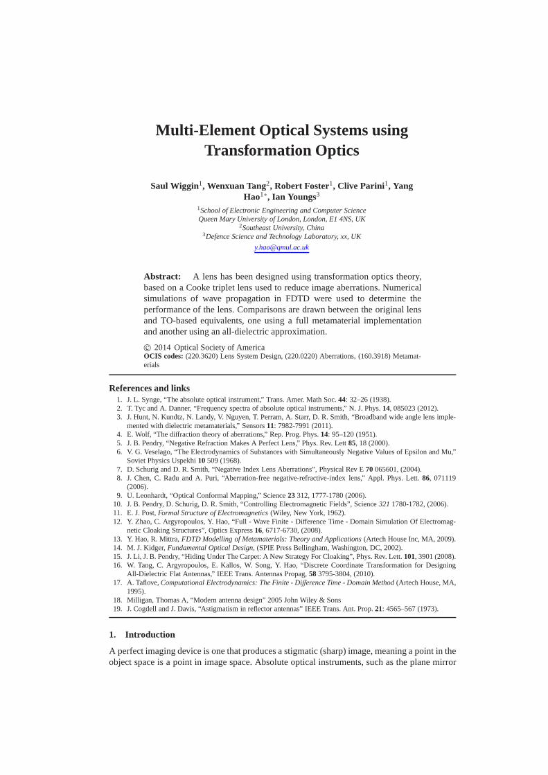
Fig. 1 shows the design process for the transformed equivalent to the Cooke triplet. The firstpanel [Fig. 1(a)] shows the Cooke triplet itself, together with the variables, curvature and rayheight for a chief ray and a marginal ray [14] along with the radius, thickness and glass type.The focal length of the Cooke triplet is 50 cm and the field of view is 20◦. The material forthe two converging lenses is made from glass type SK16 (n = 2.6257), and the single diverginglens is made from glass type F2 (n = 2.6245). The triplet is optimized for all major primary
Fig. 1. The design process from the creation of the general optical system to the finallens created from transformation optics. The first panel (a)shows the Cooke triplet and aparaxial ray tracing diagram, which was simulated in the commercially-available packageZEMAX. The next stage in the design process (b) is to import these rays into a grid gener-ation software package, where they form the boundaries for aseries of grids. These gridsare optimized to be as orthogonal as possible using smoothing methods. Discrete transfor-mation optics is then applied to the combined grid to yield a map of permittivity values (c)for the metamaterial lens and the performance is determinedin a 2D FDTD simulation (d).
aberrations in ZEMAX using the merit function, which optimizes the surface shape factors andlens thickness around an initial estimate.
Fig. 1(b) shows the grid generated by generation software package POINTWISE. The raysare imported and used as boundaries for the virtual space, which is sub-divided into smallerregions by the rays. An optimization regime was establishedto determine the optimal numberof rays required to ensure that the grid modeled the ray propagation in the triplet. The smoothingfunction is used to make a better match the boundary points and to improve cell orthogonality.The modified Liao functional [15] is used at the boundaries, allowing a quasi-orthogonal grid tobe generated with the condition that the boundary grid points are allowed to slip. The outcomeis quasi-orthogonal cells which will be used in a discrete coordinate transformation (DCT) tocreate the permittivity map of the device [16].
Fig. 1(c) shows the permittivity map for the Cooke triplet equivalent lens, the behavior ofwhich is determined using FDTD. The permittivity map was calculated for a 2D E-polarizedfield, where the material is invariant in thez direction and onlyǫzz, µxx, µxy, µyy andµyx con-tribute. The 2D Jacobian matrixΛ is used, which simplifies to
ǫ′z ≡ ǫ′zz =ǫ0
√
det(g), (1)
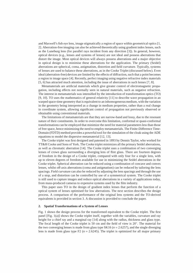
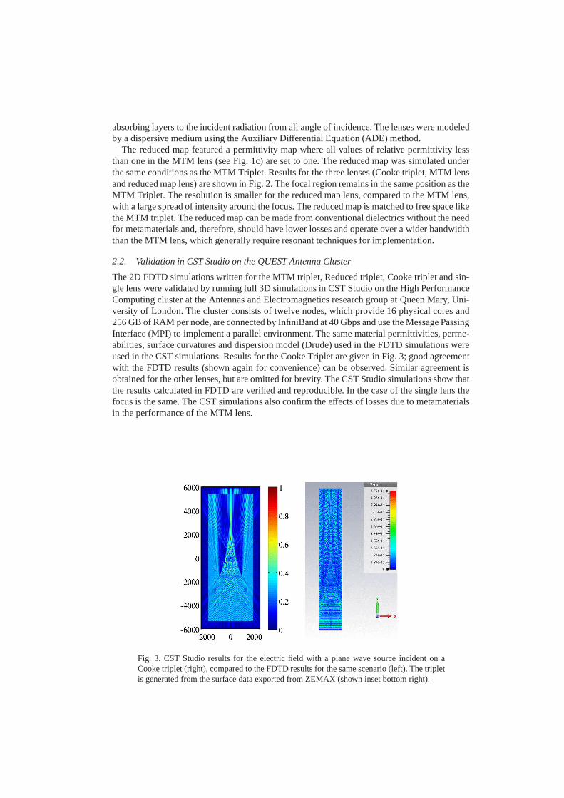
Fig. 2. This figure shows the results of the FDTD calculation for the permittivity map of theMTM Triplet in the top figure. Below, is the result of the FDTD simulation for the reducedmap where the lines denote the PML layer and amplitude is normalise to one.
µ′ =µ0ΛΛ
T
√
det(g). (2)
whereg is the metric tensor. The map is generated using the DCT method [16]. The permeabil-ity equals unity, as the DCT method uses quasi-conformal transformations. The distorted gridis only a function of refractive index and, hence, of permittivity. Compression of the grid cells(with respect to an orthogonal, equi-spaced grid) leads to asmaller area and a larger refractiveindex; an expansion leads to a refractive index less than theoriginal background medium.
n2 ≈ ǫzǫ0=
1
det(√
(g))(3)
2.1. Dispersive 2D FDTD Simulation
The lens operated at 8 GHz and the FDTD resolution wasλ/20, with a time-step satisfying thestability condition [17]. A high quality sinusoidal sourcewas launched using the Total-FieldScattered-Field (TFSF) formulation for the TM mode (Hx, Hy andEz). The boundary conditionsto the simulation domain were rectangular Perfectly Matched Layers (PMLs), which acted as
absorbing layers to the incident radiation from all angle ofincidence. The lenses were modeledby a dispersive medium using the Auxiliary Differential Equation (ADE) method.
The reduced map featured a permittivity map where all valuesof relative permittivity lessthan one in the MTM lens (see Fig. 1c) are set to one. The reduced map was simulated underthe same conditions as the MTM Triplet. Results for the threelenses (Cooke triplet, MTM lensand reduced map lens) are shown in Fig. 2. The focal region remains in the same position as theMTM Triplet. The resolution is smaller for the reduced map lens, compared to the MTM lens,with a large spread of intensity around the focus. The reduced map is matched to free space likethe MTM triplet. The reduced map can be made from conventional dielectrics without the needfor metamaterials and, therefore, should have lower lossesand operate over a wider bandwidththan the MTM lens, which generally require resonant techniques for implementation.
2.2. Validation in CST Studio on the QUEST Antenna Cluster
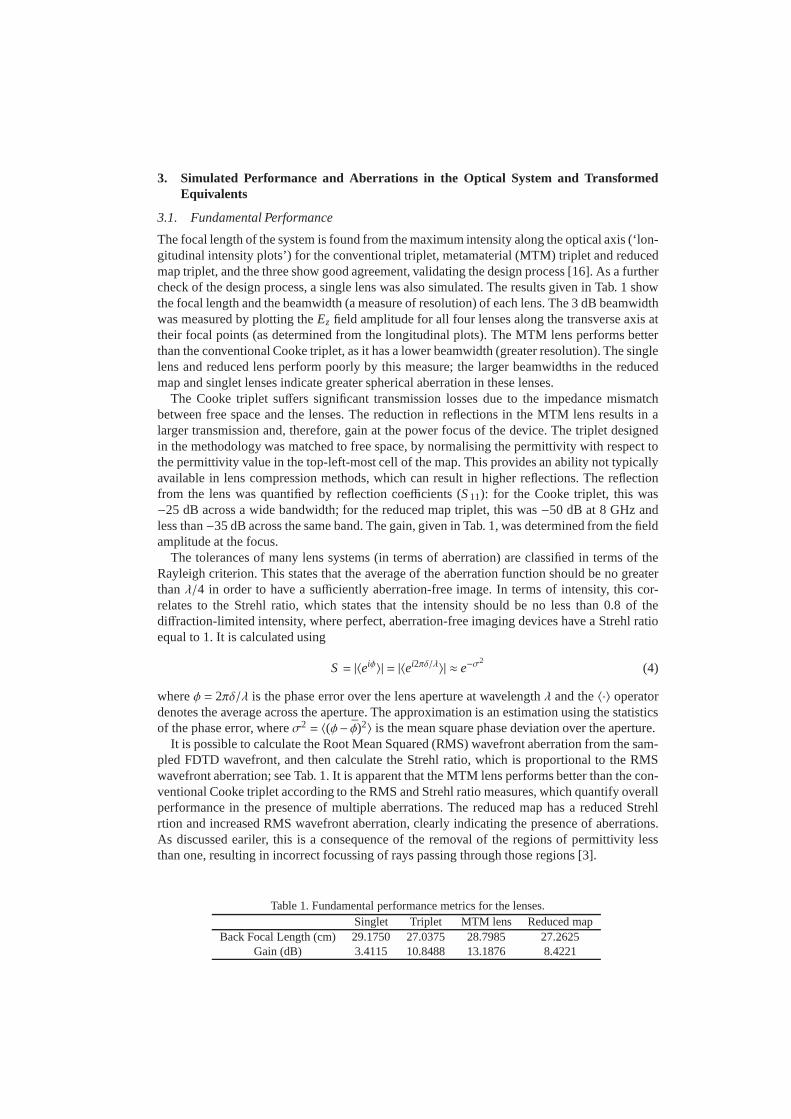
The 2D FDTD simulations written for the MTM triplet, Reducedtriplet, Cooke triplet and sin-gle lens were validated by running full 3D simulations in CSTStudio on the High PerformanceComputing cluster at the Antennas and Electromagnetics research group at Queen Mary, Uni-versity of London. The cluster consists of twelve nodes, which provide 16 physical cores and256 GB of RAM per node, are connected by InfiniBand at 40 Gbps and use the Message PassingInterface (MPI) to implement a parallel environment. The same material permittivities, perme-abilities, surface curvatures and dispersion model (Drude) used in the FDTD simulations wereused in the CST simulations. Results for the Cooke Triplet are given in Fig. 3; good agreementwith the FDTD results (shown again for convenience) can be observed. Similar agreement isobtained for the other lenses, but are omitted for brevity. The CST Studio simulations show thatthe results calculated in FDTD are verified and reproducible. In the case of the single lens thefocus is the same. The CST simulations also confirm the effects of losses due to metamaterialsin the performance of the MTM lens.
Fig. 3. CST Studio results for the electric field with a plane wave source incident on aCooke triplet (right), compared to the FDTD results for the same scenario (left). The tripletis generated from the surface data exported from ZEMAX (shown inset bottom right).
3. Simulated Performance and Aberrations in the Optical System and TransformedEquivalents
3.1. Fundamental Performance
The focal length of the system is found from the maximum intensity along the optical axis (‘lon-gitudinal intensity plots’) for the conventional triplet,metamaterial (MTM) triplet and reducedmap triplet, and the three show good agreement, validating the design process [16]. As a furthercheck of the design process, a single lens was also simulated. The results given in Tab. 1 showthe focal length and the beamwidth (a measure of resolution)of each lens. The 3 dB beamwidthwas measured by plotting theEz field amplitude for all four lenses along the transverse axisattheir focal points (as determined from the longitudinal plots). The MTM lens performs betterthan the conventional Cooke triplet, as it has a lower beamwidth (greater resolution). The singlelens and reduced lens perform poorly by this measure; the larger beamwidths in the reducedmap and singlet lenses indicate greater spherical aberration in these lenses.
The Cooke triplet suffers significant transmission losses due to the impedance mismatchbetween free space and the lenses. The reduction in reflections in the MTM lens results in alarger transmission and, therefore, gain at the power focusof the device. The triplet designedin the methodology was matched to free space, by normalisingthe permittivity with respect tothe permittivity value in the top-left-most cell of the map.This provides an ability not typicallyavailable in lens compression methods, which can result in higher reflections. The reflectionfrom the lens was quantified by reflection coefficients (S 11): for the Cooke triplet, this was−25 dB across a wide bandwidth; for the reduced map triplet, this was−50 dB at 8 GHz andless than−35 dB across the same band. The gain, given in Tab. 1, was determined from the fieldamplitude at the focus.
The tolerances of many lens systems (in terms of aberration)are classified in terms of theRayleigh criterion. This states that the average of the aberration function should be no greaterthanλ/4 in order to have a sufficiently aberration-free image. In terms of intensity, thiscor-relates to the Strehl ratio, which states that the intensityshould be no less than 0.8 of thediffraction-limited intensity, where perfect, aberration-free imaging devices have a Strehl ratioequal to 1. It is calculated using
S = |〈eiφ〉| = |〈ei2πδ/λ〉| ≈ e−σ2
(4)
whereφ = 2πδ/λ is the phase error over the lens aperture at wavelengthλ and the〈·〉 operatordenotes the average across the aperture. The approximationis an estimation using the statisticsof the phase error, whereσ2 = 〈(φ− φ̄)2〉 is the mean square phase deviation over the aperture.
It is possible to calculate the Root Mean Squared (RMS) wavefront aberration from the sam-pled FDTD wavefront, and then calculate the Strehl ratio, which is proportional to the RMSwavefront aberration; see Tab. 1. It is apparent that the MTMlens performs better than the con-ventional Cooke triplet according to the RMS and Strehl ratio measures, which quantify overallperformance in the presence of multiple aberrations. The reduced map has a reduced Strehlrtion and increased RMS wavefront aberration, clearly indicating the presence of aberrations.As discussed eariler, this is a consequence of the removal ofthe regions of permittivity lessthan one, resulting in incorrect focussing of rays passing through those regions [3].
Table 1. Fundamental performance metrics for the lenses.Singlet Triplet MTM lens Reduced map
Back Focal Length (cm) 29.1750 27.0375 28.7985 27.2625Gain (dB) 3.4115 10.8488 13.1876 8.4221
3.2. Other Monochromatic Aberrations
The evaluation of spherical aberration was discussed in theprevious section, but the other Seidelaberrations cannot be evaluated with a plane wave at normal incidence. Hence, the four lenseswere tested with a plane wave source incident at a range of angles to the lens, from 14◦ to 27◦,to see the off-axis performance. The resulting field distribution in the focal plane shows thecoma in the lens for an example plot for a wave incident at 18◦ (similar results were observedfor the other angles of incidence, but are omitted for brevity). The coma is a result of rays farfrom the paraxial axis being refracted more or less than those at the center. This results in afocal plane with multiple peaks, a distinguishing feature of coma aberration.
The field curvature is a Seidel aberration resulting in a curvature in the focal plane [18]. Thevariation in the position of the focus was calculated by measuring the focus for each of the fourlenses for a plane wave incident at 0◦, 14◦, 18◦ and 27◦; see Tab. 2. Deviations of the focus fromthe ideal are also due to distortion and astigmatism, which cannot easily be separated from fieldcurvature [19]. A full analysis of field curvature, astigmatism and distortion would require bothsagital and tangential planes modeled simultaneously (i.e., a 3D simulation), which could beachieved using the Body of Revolution Finite Difference Time Domain Method (BOR-FDTD).However, this is left for future work.
Table 2. Variation in the focus for the different lenses as a function of angle of incidence.
Angle of incidence Singlet Triplet MTM lens Reduced map0 ◦ (x) 50.71 47.25 49.61 44.920 ◦ (y) 0 0 0 014◦ (x) 38.03 42.15 33.45 38.0314◦ (y) 15.86 11.21 8.775 10.65
3.3. Chromatic Aberration and Operating Bandwidth
The chromatic aberration is due to dispersion in a medium (i.e., the permittivity is a functionof frequency); therefore, this is related to the operating bandwidth of the lens. The chromaticaberration for the four lenses was calculated using a Gaussian pulse launched at 0◦ incidence.The Fourier amplitude was calculated at three frequencies contained in the pulse. Optical en-gineers typically use the difference in focus between red, green and blue light to measure thechromatic aberration.
It is observed that there is considerable variation in the position of the focus for the MTMlens, compared to the other lenses; this is likely a consequence of the dispersion of the materialswith permittivity less than one. There is also greater variation in the observed intensity for theMTM lens, attributed to the losses associated with metamaterials.
4. Fitting the Wavefront Aberration Function
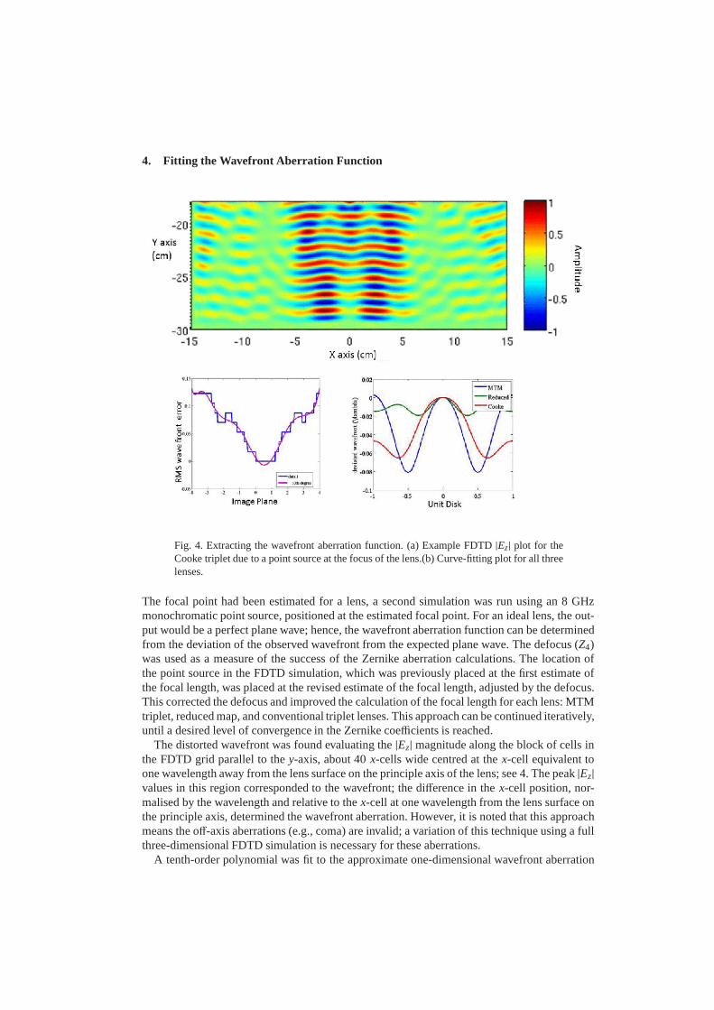
Fig. 4. Extracting the wavefront aberration function. (a) Example FDTD|Ez | plot for theCooke triplet due to a point source at the focus of the lens.(b) Curve-fitting plot for all threelenses.
The focal point had been estimated for a lens, a second simulation was run using an 8 GHzmonochromatic point source, positioned at the estimated focal point. For an ideal lens, the out-put would be a perfect plane wave; hence, the wavefront aberration function can be determinedfrom the deviation of the observed wavefront from the expected plane wave. The defocus (Z4)was used as a measure of the success of the Zernike aberrationcalculations. The location ofthe point source in the FDTD simulation, which was previously placed at the first estimate ofthe focal length, was placed at the revised estimate of the focal length, adjusted by the defocus.This corrected the defocus and improved the calculation of the focal length for each lens: MTMtriplet, reduced map, and conventional triplet lenses. This approach can be continued iteratively,until a desired level of convergence in the Zernike coefficients is reached.
The distorted wavefront was found evaluating the|Ez| magnitude along the block of cells inthe FDTD grid parallel to they-axis, about 40x-cells wide centred at thex-cell equivalent toone wavelength away from the lens surface on the principle axis of the lens; see 4. The peak|Ez|values in this region corresponded to the wavefront; the difference in thex-cell position, nor-malised by the wavelength and relative to thex-cell at one wavelength from the lens surface onthe principle axis, determined the wavefront aberration. However, it is noted that this approachmeans the off-axis aberrations (e.g., coma) are invalid; a variation of this technique using a fullthree-dimensional FDTD simulation is necessary for these aberrations.
A tenth-order polynomial was fit to the approximate one-dimensional wavefront aberration
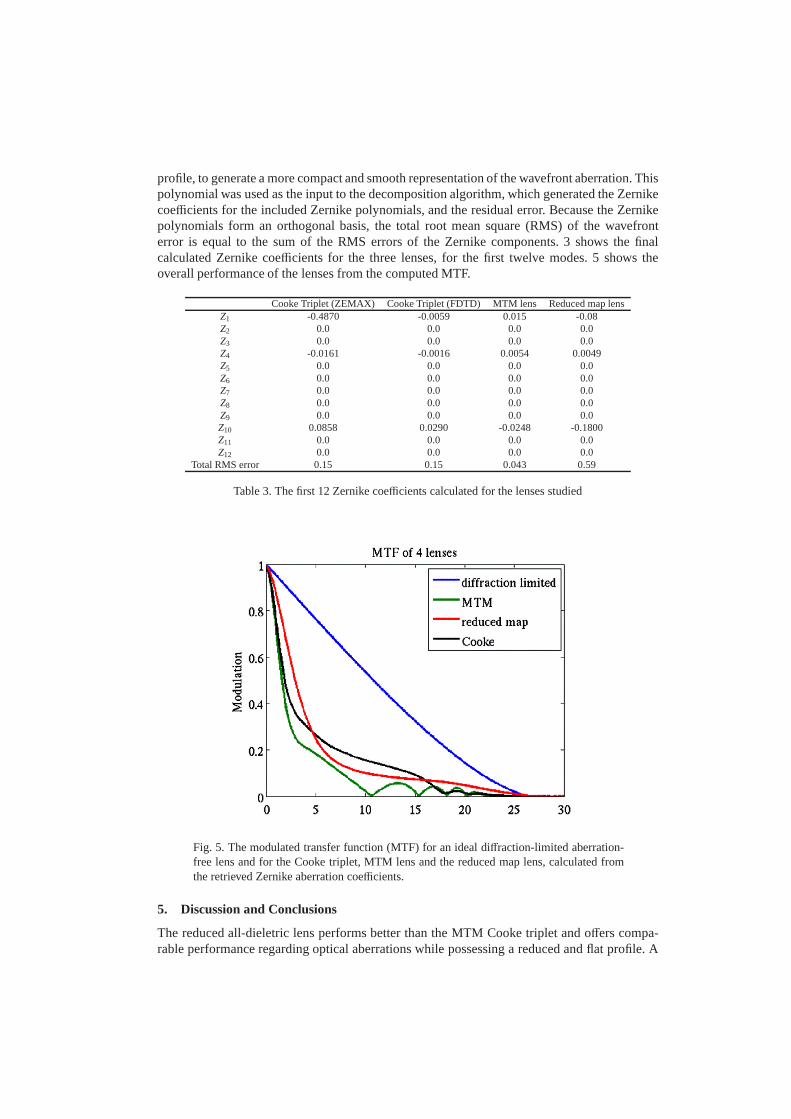
profile, to generate a more compact and smooth representation of the wavefront aberration. Thispolynomial was used as the input to the decomposition algorithm, which generated the Zernikecoefficients for the included Zernike polynomials, and the residual error. Because the Zernikepolynomials form an orthogonal basis, the total root mean square (RMS) of the wavefronterror is equal to the sum of the RMS errors of the Zernike components. 3 shows the finalcalculated Zernike coefficients for the three lenses, for the first twelve modes. 5 shows theoverall performance of the lenses from the computed MTF.
Cooke Triplet (ZEMAX) Cooke Triplet (FDTD) MTM lens Reducedmap lensZ1 -0.4870 -0.0059 0.015 -0.08Z2 0.0 0.0 0.0 0.0Z3 0.0 0.0 0.0 0.0Z4 -0.0161 -0.0016 0.0054 0.0049Z5 0.0 0.0 0.0 0.0Z6 0.0 0.0 0.0 0.0Z7 0.0 0.0 0.0 0.0Z8 0.0 0.0 0.0 0.0Z9 0.0 0.0 0.0 0.0Z10 0.0858 0.0290 -0.0248 -0.1800Z11 0.0 0.0 0.0 0.0Z12 0.0 0.0 0.0 0.0
Total RMS error 0.15 0.15 0.043 0.59
Table 3. The first 12 Zernike coefficients calculated for the lenses studied
Fig. 5. The modulated transfer function (MTF) for an ideal diffraction-limited aberration-free lens and for the Cooke triplet, MTM lens and the reduced map lens, calculated fromthe retrieved Zernike aberration coefficients.
5. Discussion and Conclusions
The reduced all-dieletric lens performs better than the MTMCooke triplet and offers compa-rable performance regarding optical aberrations while possessing a reduced and flat profile. A
metamaterial (MTM) lens has been designed by applying spatial transformations to a conven-tionally-designed Cooke triplet lens. The MTM lens can be used to replace the existing opticalsystem with a single block of graded dielectric material. The MTM design can be fabricated inone block without the need for multiple lenses and lens mounts. As metamaterials are typicallycomposed of resonant structures, with narrow bandwidths, an approximation was also consid-ered, where all regions with relative permittivity less than one were replaced with unity relativepermittivity. This approximation is valid for TM polarisations. Impedance-matching of the TOlenses was also implemented.
As observed in the results of section 3.1, the MTM triplet performs as well as the con-ventional triplet at the center frequency, as measured by the Strehl ratio and RMS aberrationparameters. Furthermore, the MTM lens possesses, in some cases, superior performance, suchas wide-angle focusing, resolution, and gain, due to the inherent impedance-matching and con-sequent reduced reflections. The main limitation of the MTM lens can be seen in the chromaticaberration, indicating a lower operating bandwidth compared to the other lenses. This is notunexpected, and is attributed to the dispersive nature of the metamaterial.
Acknowledgement
This work was supported by a DSTL CASE studentship and conducted in partnership withthe QUEST Programme Grant, funded by EPSRC, UK (grant numberEP/I034548/1), in theAntennas and Electromagnetics Group at Queen Mary, University of London.
Related Documents