MUFFAKHAM JAH COLLEGE OF ENGINEERING AND TECHNOLOGY (Affliated to Osmania University) Banjara Hills, Hyderabad, Telangana INFORMATION TECHNOLOGY DEPARTMENT OOSD AND CC LAB MANUAL

Welcome message from author
This document is posted to help you gain knowledge. Please leave a comment to let me know what you think about it! Share it to your friends and learn new things together.
Transcript

MUFFAKHAM JAH COLLEGE OF ENGINEERING AND TECHNOLOGY
(Affliated to Osmania University) Banjara Hills, Hyderabad, Telangana
INFORMATION TECHNOLOGY DEPARTMENT
OOSD AND CC LAB MANUAL

OOSD AND CC LAB MANUAL
TABLE OF CONTENTS S.No
. CONTENTS PAGE No.
1. Institute Vision I
2. Institute Mission I
3. Department Vision II
4. Department Mission II
5. PEOs III
6. POs IV
7. PSOs V
8. Introduction to OOSD & CC laboratory VI
Programs
OBJECT ORIENTED SYSTEM DEVELOPMENT
1. Use Case Diagram 1
2. Activity Diagram 4
3. Class Diagram 6
4. Object Diagram 9
5. Interaction Diagram 10
6. State Chart Diagram 14
7. Component Diagram 17
8. Deployment Diagram 18
9. Forward Engineering 19

OOSD AND CC LAB MANUAL
10. Reverse Engineering 20
COMPILER CONSTRUCTION
11. Program 1: Basic Lex program to echo the given input. 21
12. Program 2: Lex program to prepend the line numbers to each line of a file. 22
13. Program 3: Lex Program to count number of identifiers 24
14. Program 4: Lex Program to count number of spaces, lines, words and
characters.
25
15. Program 5: Program to implement scanner using Lex. 27
16. Program 6: Program to implement LALR parser using YACC. 28
17. Program 7: C program to implement recursive descent parser. 30
18. Program 8: C program to find First elements of a grammar. 32
19. Program 9: C program to find Follow elements of a grammar. 34
20. Program 10: C program for code generation. 36
21. Program 11: C program for code optimization. 37
22. Program 12: Code generation for if-statement 38
23. Program 13: Code generation for while-statement 42
TESTING
24. Program 14: Identification of test cases and finding defects in the application
44
25. Program 15: Data Verification, Image Verification 47
26. Program 16: Data Driven Actions using RFT 51
27. Program 17: Requirements management using RQM 54
Annexure – I : OU prescribed programs for Java Programming Laboratory 58

OOSD AND CC LAB MANUAL
INFORMATION TECHNOLOGY DEPARTMENT, MJCET I
1. Vision of the Institution:
To be part of universal human quest for development and progress by
contributing high calibre, ethical and socially responsible engineers who
meet the global challenge of building modern society in harmony with
nature.
2. Mission of the Institution
To attain excellence in imparting technical education from the
undergraduate through doctorate levels by adopting coherent and
judiciously coordinated curricular and co-curricular programs
To foster partnership with industry and government agencies through
collaborative research and consultancy
To nurture and strengthen auxiliary soft skills for overall development
and improved employability in a multi-cultural work space
To develop scientific temper and spirit of enquiry in order to harness the
latent innovative talents
To develop constructive attitude in students towards the task of nation
building and empower them to become future leaders
To nourish the entrepreneurial instincts of the students and hone their
business acumen.
To involve the students and the faculty in solving local community
problems through economical and sustainable solutions.

OOSD AND CC LAB MANUAL
INFORMATION TECHNOLOGY DEPARTMENT, MJCET II
3. Department Vision
Fostering a bright technological future by enabling the students to
function as leaders in software industry and serve as means of
transformation to empower society through ITeS.
4. Department Mission
To create an ambience of academic excellence through state of art
infrastructure and learner-centric pedagogy leading to employability in
multi-disciplinary fields.

OOSD AND CC LAB MANUAL
INFORMATION TECHNOLOGY DEPARTMENT, MJCET III
5. Programme Education Objectives
1. Graduates will demonstrate technical competence and leadership in their
chosen fields of employment by identifying, formulating, analyzing and
creating efficient IT solutions.
2. Graduates will communicate effectively as individuals or team members
and be successful in varied working environment.
3. Graduates will demonstrate lifelong learning through continuing
education and professional development.
4. Graduates will be successful in providing viable and sustainable solutions
within societal, professional, environmental and ethical context

OOSD AND CC LAB MANUAL
INFORMATION TECHNOLOGY DEPARTMENT, MJCET IV
6. Programme Outcomes 1. Engineering knowledge: Apply the knowledge of mathematics, science,
engineering fundamentals and an engineering specialization to the solution of
complex engineering problems.
2. Problem analysis: Identify, formulate, review research literature, and analyze complex engineering problems reaching substantiated conclusions using first principles of mathematics, natural sciences, and engineering sciences.
3. Design/development of solutions: Design solutions for complex engineering problems and design system components or processes that meet the specified needs with appropriate consideration for the public health and safety, and the cultural, societal, and environmental considerations.
4. Conduct investigations of complex problems: Use research-based knowledge and research methods including design of experiments, analysis and interpretation of data, and synthesis of the information to provide valid conclusions.
5. Modern tool usage: Create, select, and apply appropriate techniques, resources, and modern engineering and IT tools including prediction and modeling to complex engineering activities with an understanding of the limitations.
6. The engineer and society: Apply reasoning informed by the contextual knowledge to assess societal, health, safety, legal and cultural issues and the consequent responsibilities relevant to the professional engineering practice.
7. Environment and sustainability: Understand the impact of the professional engineering solutions in societal and environmental contexts, and demonstrate the knowledge of, and need for sustainable development.
8. Ethics: Apply ethical principles and commit to professional ethics and responsibilities and norms of the engineering practice.
9. Individual and team work: Function effectively as an individual, and as a member or leader in diverse teams, and in multidisciplinary settings.
10. Communication: Communicate effectively on complex engineering activities with the engineering community and with society at large, such as, being able to comprehend and write effective reports and design documentation, make effective presentations, and give and receive clear instructions.
11. Project management and finance: Demonstrate knowledge and understanding of the engineering and management principles and apply these to one’s own work, as a member and leader in a team, to manage projects and in multidisciplinary environments.
12. Lifelong learning: Recognize the need for, and have the preparation and ability to engage in independent and lifelong learning in the broadest context of technological change.
OOSD AND CC LAB MANUAL
INFORMATION TECHNOLOGY DEPARTMENT, MJCET V
7. Programme Specific Outcomes:
PSO1: The IT graduates will work as software engineers for providing
solutions to real world problems using structured and object oriented
programming languages and open source software.
PSO2: The IT graduates will work as System engineer, Software analyst and
Tester for IT and ITes.

OOSD AND CC LAB MANUAL
INFORMATION TECHNOLOGY DEPARTMENT, MJCET VI
8. Introduction TO OOSD and CC Laboratory
Laboratory Objective
Upon successful completion of this Lab students will be able to:
1. Create models which visualize, specify, construct and document the artifacts of a
software-intensive system.
2. Model systems from concept to executable artifacts using object oriented
techniques.
3. Perform forward and reverse engineering.
4. Understand the working of lex and yacc compiler for debugging of programs.
2. Understand and define the role of lexical analyzer and use of regular expressions.
3. Develop programs for solving parsing problems.
4. Convert the high level language program to target language
5. Learn how to write programs that execute faster.
6. Understand and identify various software testing problems, and solve these
problems by using the testing tool.
7. Design and conduct a software test process for a software testing project.
OBJECT ORIENTED SYSTEM DEVELOPMENT
UNIFIED MODELING LANGUAGE (UML):
1.Model A model is a simplification of reality. A model provides the blueprints of a system. A model may be structural, emphasizing the organization of the system, or it may be behavioral, emphasizing the dynamics of the system. We build models so that we can better understand the system we are developing. We build models of complex systems because we cannot comprehend such a system in its entirety.
Through modeling, we achieve four aims. Models help us to visualize a system as it is or as we want it to be. Models permit us to specify the structure or behavior of a system. Models give us a template that guides us in constructing as system. Models document the decisions we have made

OOSD AND CC LAB MANUAL
INFORMATION TECHNOLOGY DEPARTMENT, MJCET VII
2. Principles of Modeling The choice of what models to create has a profound influence on how a problem is attacked and how a solution is shaped Every model may be expressed at different levels of precision The best models are connected to reality No single model is sufficient. Every nontrivial system is best approached through a small set of nearly independent models
UML is a graphical notation used to visualize, specify, construct and document the artifact of software intensive. UML is appropriate for modeling systems ranging from Enterprise Information Systems to Distributed Web-based Application and even to Hard Real-time Embedded systems. UML effectively starts with forming a conceptual modeling of the language. There are 2 types of diagrams. They are
1. Static Diagrams a) Use case diagrams b) Class diagrams c) Object diagrams d) Component diagrams e) Deployment diagrams
2. Dynamic diagrams a) Interaction diagrams
i) Sequence diagrams ii) Collaboration diagrams
b) State machine diagrams c) Activity diagrams
Applications of UML:
UML is intended primarily for software intensive systems. It has been used effectively for such domains as
1. Enterprise Information Systems 2. Banking and Financial Services 3. Telecommunications 4. Transportation 5. Defense and Aerospace 6. Retail 7. Medical Electronics 8. Scientific 9. Distributed Web-based Services
Basic building blocks of UML:
The building blocks of UML can be categorized as 1. Things 2. Relationships and 3. Diagrams

OOSD AND CC LAB MANUAL
INFORMATION TECHNOLOGY DEPARTMENT, MJCET VIII
Things:- Things are the most important building blocks of UML. Things can be a) Structural b) Behavioral c) Grouping d) Annotational
a) Structural Things: They define the static part of the model. They represent physical and
conceptual elements. Following are the structural things – 1. Class: - It describes a set of objects that share the same attributes, operations, relationships and semantics.
Class name Attributes
Operations 2.Object: - It is a collection of operations that specifies a service of a class or a component.
3. Collaboration: - It defines interaction between elements.
4. Use case: - They are used to identify different use case components of a particular software project. It is used to model the operation.
5. Component: - It is a physical and replaceable part that confirms to and provides realization of set of interfaces.
6. Node: - A physical resource that exists in runtime and represent a computational resource.

OOSD AND CC LAB MANUAL
INFORMATION TECHNOLOGY DEPARTMENT, MJCET IX
7. Actor: - The outside entity that communicates with a system. Typically a person playing a role on an external device.
b) Behavioral Things: They consist of dynamic parts of the UML model.
The following are behavioral things – 1. Interaction: - It is defined as a behavior that consists of a group of message
exchanged among elements to accomplish a specific task. message
2. State machine: - It is useful when the states of an object in its life cycle. It defines the sequence of states and object goes through in response to events.
c) Grouping Things: They can be defined as a mechanism to group elements of UML model together. There is only one grouping thing available i.e., Package. Package is used for gathering structural and behavioral things.
d) Annotational Things: - They can be defined as a mechanism to capture remarks,
description and comments of UML model elements. There is only one annotational thing available i.e., Note. Note is used to render comments, constraints and so on of a UML element.
Relationships: -
The relationship is another most important building block of UML. They show how elements are associated with each other and their association describes the functionality of application. There are 5 types of relationships. They are
1. Dependency: It is a relationship between two things in which change in one element also affects another.

OOSD AND CC LAB MANUAL
INFORMATION TECHNOLOGY DEPARTMENT, MJCET X
2. Generalization: It can be defined as a relationship which connects a specialized
element with a generalized element. It basically describes inheritance relationship in the object. It is a ‘is_a ‘ hierarchy.
3. Realization: It can be defined as a relationship in which two elements are connected. One element describes some responsibility which is not implemented and the other one implement then. This relationship exists in case of interfaces.
4. Association: It is a set of links that connects elements of an UML model.
UML Diagrams: -
1. Use case diagram 2. Activity diagram 3. Class diagram 4. Interaction diagrams
i) Sequence diagram ii) Collaboration diagram
5. State machine diagram 6. Object diagram 7. Component diagram 8. Deployment diagram
Rational Software Architect(RSA) is a modeling and development environment that uses the Unified Modeling Language (UML) for designing architecture for C++ and Java EE (JEE) applications and web services. Rational Software Architect is built on the Eclipse open-source software framework and includes capabilities focused on architectural code analysis, C++, and model-driven development (MDD) with the UML for creating applications and web services.

OOSD AND CC LAB MANUAL
INFORMATION TECHNOLOGY DEPARTMENT, MJCET XI
COMPILER CONSRTUCTION
Translator
A translator is a program that takes as input a program written in one language and produces
as output a program in another language. Beside program translation, the translator performs
another very important role, the error-detection. Any violation of d HLL specification would
be detected and reported to the programmers. Important role of translator are:
1. Translating the HLL program input into an equivalent ML program.
2. Providing diagnostic messages wherever the programmer violates specification of
the HLL.
Type of translators
1. Interpreter
2. Compiler
3. Preprocessor
Compiler
Compiler is a translator program that translates a program written in (HLL)source
program and translate it into an equivalent program in (MLL) the target program. As
an important part of a compiler is error showing to the programmer.
Source Program target program
Error message
Executing a program written n HLL programming language is basically of two parts. the
source program must first be compiled translated into a object program. Then the results
object program is loaded into a memory executed.
Source program object program
Object program input object program output
Compiler
Compiler
Obj pgm

OOSD AND CC LAB MANUAL
INFORMATION TECHNOLOGY DEPARTMENT, MJCET XII
I. Structure of the compilers Compilation process is partitioned into no-of-sub processes called ‘phases’.
Lexical Analysis
Lexical Analyzer or Scanners reads the source program one character at a time,
carving the source program into a sequence of atomic units called tokens.
Syntax Analysis
The second stage of translation is called Syntax analysis or parsing. In this phase
expressions, statements, declarations etc… are identified by using the results of
lexical analysis. Syntax analysis is aided by using techniques based on formal
grammar of the programming language.
Intermediate Code Generations
An intermediate representation of the final machine language code is produced. This
phase bridges the analysis and synthesis phases of translation.
Code Optimization
This is optional phase described to improve the intermediate code so that the output
runs faster and takes less space.
Code Generation
The last phase of translation is code generation. A number of optimizations to reduce
the length of machine language program are carried out during this phase. The output
of the code generator is the machine language program of the specified computer.

OOSD AND CC LAB MANUAL
INFORMATION TECHNOLOGY DEPARTMENT, MJCET XIII
Table Management
This is the portion to keep the names used by the program and records essential
information about each. The data structure used to record this information called a
‘Symbol Table’.
Error Handlers
It is invoked when a flaw error in the source program is detected.
Passes
One (or) more phases one combined into a module called a pass.
Single-pass Compiler
All the phases are combined into a single
Multi-pass Compiler
More than one phase are combined into a number of groups called multi-pass.
(Multi pass compiler can be made to use less space than single pass compiler.).
II. Lexical Analyzer Lexical analyzer is the first phase of compiler which takes the source program as input and
produces the stream of tokens as output. Lexhelps write programs whose control flowis
directed by instances of regular expressionsintheinputstream.It is well suited for editor-script
type transformations and for segmenting input in preparation for a parsing routine.
Lexsource is a table of regular expressions and corresponding programfragments. The table is
translated to a programwhich reads an input stream, copying itto an output stream and
partitioning the input intostrings which match the given expressions.As each such string is
recognized the corresponding programfragment isexecuted. The recognition of the
expressions is performed by a deterministic finite automaton generated by Lex. The
programfragments written by the user are executed in the order in which
thecorrespondingregular expressions occur in the input stream.
Thelexical analysis programs written with Lex accept ambiguous specifications and choose
the longest match possible at each input point. If necessary, substantial lookahead is
performed on the input, but the input streamwill be backed up tothe end of the current
partition, sothat the user has general freedomto manipulate it.
Lexcan generate analyzers in either C orRatfor, a language which can be translated
automatically to portable Fortran. It is available on the PDP-11 UNIX, Honeywell GCOS,
and IBM OS systems.

OOSD AND CC LAB MANUAL
INFORMATION TECHNOLOGY DEPARTMENT, MJCET XIV
Lexis a programgenerator designed for lexical processing of character input streams. It
accepts a high-level, problemoriented specification for character string matching, and
produces a programin a general purpose language which recognizes regular expressions. The
regular expressions are specifiedby the user in the source specifications given to Lex. The
Lex written code recognizes these expressions in an input streamand partitions the input
streaminto strings matching the expressions. At the boundaries between strings
programsections provided by the user are executed. The Lex source file associates the regular
expressions and the programfragments. As each expression appears in the input to the
programwritten by Lex, the corresponding fragment is executed.
Lex Source
Thegeneral format of Lex source is: {definitions}
%%
{rules}
%%
{user subroutines}
%%
Where the definitions andthe user subroutines are often omitted. The second %%
isoptional,but the first is required to mark the beginning ofthe rules. The absolute minimum
Lex programis thus(nodefinitions, no rules) which translates into a programwhich
copiestheinputtotheoutputunchanged.
Inthe outline of Lex programs shown above, the rules represent the user's control decisions;
they are a table, in which the leftcolumn contains regular expressions and the right column
contains actions,programfragments to be executed when the expressions are recognized.
Thus an individual rule might appear Integer printf("found keyword INT");
tolook for the string integer in the input streamand print the message ``found
keywordINT''whenever it appears. In this example the host procedural language is C and the
C library function printf is used to print the string. The end of the expression is indicated by
the first blank or tab character. If the action ismerely a single C expression, it can just be
given on the right side ofthe line; if it is compound, or takes more than a line, it should be
enclosed in braces.
LexActions
Whenan expression written as above ismatched, Lex executes the corresponding action. This
section describes some features of Lex which aid in writing actions. Note that there is a

OOSD AND CC LAB MANUAL
INFORMATION TECHNOLOGY DEPARTMENT, MJCET XV
default action, which consistsof copying the input tothe output. This is performed on all
strings not otherwise matched. Thus the Lex user who wishes to absorb the entire input,
without producing any output, must provide rules to match everything. When Lex is being
used with Yacc, this is the normal situation. One may consider that actions are what
isdoneinstead of copying the input to the output; thus, in general, a rule which merely copies
can be omitted. Also, a character combination which isomitted fromthe rules and which
appears as input is likely to be printed on the output, thus calling attention to the gap in the
rules.
LexSourceDefinitions
Definitionsintended for Lex are given before the first %% delimiter. Any line in this section
not contained between %{ and %}, and beginning in column 1, is assumed to define Lex
substitution strings. The format ofsuch lines is name translation and it causes the string given
as a translation to be associated with the name. The name and translation must be separated
by at least one blank or tab, and the name must begin with a letter.The translation can then be
called out by the {name}syntax in a rule. Using {D} for the digits and {E} for an exponent
field, for example, might abbreviate rules to recognize numbers: D [0-9]
E [DEde][-+]?{D}+
%%
{D}+ printf("integer");
{D}+"."{D}*({E})? |
{D}*"."{D}+({E})? |
{D}+{E}
Notethe first two rules for real numbers; both require a decimal point and contain an
optionalexponent field, but thefirst requires at least one digit before the decimal point and
the second requires at leastone digit after the decimal point. To correctly handle the
problemposed by a Fortran expression such as 35.EQ.I, which does not contain a real
number, a context-sensitive rule suchas [0-9]+/"."EQ printf("integer");
couldbe used in addition to the normal rule for integers.
Thedefinitions section may also contain other commands, including the selection ofa host
language, a character set table, a list of start conditions, oradjustmentsto the default size
ofarrays within Lexitself for larger source programs

OOSD AND CC LAB MANUAL
INFORMATION TECHNOLOGY DEPARTMENT, MJCET XVI
Lex source program lex.yy.c
lex.l
lex.yy.c a.out
input stream stream of tokens
First, a specification of a lexical analyzer is prepared by creating a program lex.1 in
theLex language. Then, lex.l is run through the Lex compiler to produce a C
program lex.yy.c. The program lex.yy.c consists of a tabular representation of a
transition diagram constructed from the regular expressions of lex.l together with a
standard routine that uses the table to recognize lexemes. The actions associated
with regular expressions in lex.1 are pieces of C code and are carried over directly
to lex.yy.c. Finally, lex.yy.c is run through the C compiler to produce an object
program a.oat, which is the lexical analyzer that transforms an input stream into a
sequence of tokens.
III. YACC
YACC is one of the compiler construction Tools which will produce a parser for a given
grammar.
A YACC source program is structurally similar to a LEX one.
declarations
%%
rules
%%
routines
The declaration section may be empty. Moreover, if the routines section is omitted, the
second %% mark may be omitted also.
Blanks, tabs, and newlines are ignored except that they may not appear in names.
The declaration section may contain the following items.
Declarations of tokens. Yacc requires token names to be declared as such using the
keyword %token.
Declaration of the start symbol using the keyword %start
C declarations: included files, global variables, types.
Lex compiler
C compiler
a.out

OOSD AND CC LAB MANUAL
INFORMATION TECHNOLOGY DEPARTMENT, MJCET XVII
C code between %{ and %}.
Rules Section
A rule has the form:
nonterminal : sentential form
| sentential form
.................
| sentential form
;
Actions may be associated with rules and are executed when the associated sentential form is
matched.
LEX-YACC Interaction
yyparse() calls yylex() when it needs a new token.
LEX YACC
return(TOKEN) %token TOKEN
TOKEN is used in production
The external variable yylval
is used in a LEX source program to return values of lexemes,
yylval is assumed to be integer if you take no other action.
YACC (Yet Another Compiler Compiler) is a program designed to compile a LALR(1)
grammar and to produce the source code of the syntactic analyzer of the language produced
by this grammar.
The LALR ( Look Ahead-LR ) parsing method is between SLR and Canonical LR both
in terms of power of parsing grammars and ease of implementation. This method is
often used in practice because the tables obtained by it are considerably smaller than the
Canonical LR tables, yet most common syntactic constructs of programming languages can
be expressed conveniently by an LALR grammar. The same is almost true for SLR
grammars, but there are a few constructs that can not be handled by SLR techniques.
IV.Code Generation
Code Generation is the final activity of compiler. Code generation phase creates assembly
language or machine language statements which will perform the operations specified by the
source program when they run.
Properties of this phase are:

OOSD AND CC LAB MANUAL
INFORMATION TECHNOLOGY DEPARTMENT, MJCET XVIII
1. Correctness: It should produce a correct code and do not alter the purpose of
source code.
2. High quality: it should produce a high quality code.
3. Efficient use of recourses of the target machine
4. Quick code generation.
This is optional phase described to improve the intermediate code so that the output faster
and takes less space. Its output is another intermediate code program that does the same job
as the original, but in a way that saves time and / or spaces.
1. Local Optimization
There are local transformations that can be applied to a program to make an improvement.
For example,
If A > B goto L2
Goto L3
L2 :
This can be replaced by a single statement
If A < B goto L3
Another important local optimization is the elimination of common sub-expressions
A := B + C + D
E := B + C + F
Might be evaluated as
T1 := B + C
A := T1 + D
E := T1 + F
Take this advantage of the common sub-expressions B + C.
2. Loop Optimization

OOSD AND CC LAB MANUAL
INFORMATION TECHNOLOGY DEPARTMENT, MJCET XIX
Another important source of optimization concerns about increasing the speed of loops. A
typical loop improvement is to move a computation that produces the same result each time
around the loop to a point, in the program just before the loop is entered.
In this we use gcc compiler for compiling the program. Why because in cc compiler it is not
possible to create assembly code file. To create assembly file we use –S option, through this
we generate assembly file named as filename.s. To optimize this assembly code we use -O2
option
V. System Requirement
HardwareConfiguration
Processor PIV(1.8Ghz)
RAM 256MB
HDD 40GB FDD,
1.44 MB
Software Configuration
Operating System Windows XP
Lexand Yacc tools (A Linux Utility)
Language: C/C++

OOSD AND CC LAB MANUAL
INFORMATION TECHNOLOGY DEPARTMENT, MJCET XX
SOFTWARE TESTING
Software testing is a process of executing a program or application with the intent of finding
the software bugs. It can also be stated as the process of validating and verifying that
a software program or application or product.
Software testing involves the execution of a software component or system component to
evaluate one or more properties of interest. In general, these properties indicate the extent to
which the component or system under test:
meets the requirements that guided its design and development,
responds correctly to all kinds of inputs,
performs its functions within an acceptable time,
is sufficiently usable,
can be installed and run in its intended environments, and
achieves the general result its stakeholders desire.
Software Testing Tools
The following tools can be used for automation testing:
HP Quick Test Professional
Selenium
IBM Rational Functional Tester
SilkTest
TestComplete
Testing Anywhere
WinRunner
LoadRunner
Visual Studio Test Professional
WATIR
I. Software Testing Methods Black-Box Testing
The technique of testing without having any knowledge of the interior workings of
the application is called black-box testing. The tester is oblivious to the system
architecture and does not have access to the source code. Typically, while performing
a black-box test, a tester will interact with the system's user interface by providing

OOSD AND CC LAB MANUAL
INFORMATION TECHNOLOGY DEPARTMENT, MJCET XXI
inputs and examining outputs without knowing how and where the inputs are worked
upon.
White-Box Testing
White-box testing is the detailed investigation of internal logic and structure of the
code. White-box testing is also called glass testing or open-box testing. In order to
perform white-box testing on an application, a tester needs to know the internal
workings of the code.
The tester needs to have a look inside the source code and find out which unit/chunk
of the code is behaving inappropriately.
Grey-Box Testing
Grey-box testing is a technique to test the application with having a limited
knowledge of the internal workings of an application. In software testing, the phrase
the more you know, the better carries a lot of weight while testing an application.
Mastering the domain of a system always gives the tester an edge over someone with
limited domain knowledge. Unlike black-box testing, where the tester only tests the
application's user interface; in grey-box testing, the tester has access to design documents
and the database. Having this knowledge, a tester can prepare better test data and test
scenarios while making a test plan.
II.Software Testing Levels Levels of testing include different methodologies that can be used while conducting
software testing. The main levels of software testing are:
Functional Testing
Non-functional Testing
Functional Testing
This is a type of black-box testing that is based on the specifications of the software that is
to be tested. The application is tested by providing input and then the results are examined
that need to conform to the functionality it was intended for. Functional testing of
software is conducted on a complete, integrated system to evaluate the system's
compliance with its specified requirements.
Unit Testing
This type of testing is performed by developers before the setup is handed over to the
testing team to formally execute the test cases. Unit testing is performed by the respective

OOSD AND CC LAB MANUAL
INFORMATION TECHNOLOGY DEPARTMENT, MJCET XXII
developers on the individual units of source code assigned areas. The developers use test
data that is different from the test data of the quality assurance team.
The goal of unit testing is to isolate each part of the program and show that individual
parts are correct in terms of requirements and functionality.
Integration Testing
Integration testing is defined as the testing of combined parts of an application to
determine if they function correctly. Integration testing can be done in two ways: Bottom-
up integration testing and Top-down integration testing.
System Testing
System testing tests the system as a whole. Once all the components are integrated, the
application as a whole is tested rigorously to see that it meets the specified Quality
Standards. This type of testing is performed by a specialized testing team.
Regression Testing
Whenever a change in a software application is made, it is quite possible that other areas
within the application have been affected by this change. Regression testing is performed
to verify that a fixed bug hasn't resulted in another functionality or business rule violation.
The intent of regression testing is to ensure that a change, such as a bug fix should not
result in another fault being uncovered in the application.
Acceptance Testing
This is arguably the most important type of testing, as it is conducted by the Quality
Assurance Team who will gauge whether the application meets the intended specifications
and satisfies the client’s requirement. The QA team will have a set of pre-written
scenarios and test cases that will be used to test the application.
Non-Functional Testing
This section is based upon testing an application from its non-functional attributes. Non-
functional testing involves testing a software from the requirements which are
nonfunctional in nature but important such as performance, security, user interface, etc.
Performance Testing
It is mostly used to identify any bottlenecks or performance issues rather than finding
bugs in software. There are different causes that contribute in lowering the performance of
software:
Network delay
Client-side processing

OOSD AND CC LAB MANUAL
INFORMATION TECHNOLOGY DEPARTMENT, MJCET XXIII
Database transaction processing
Load Testing
It is a process of testing the behavior of a software by applying maximum load in terms of
software accessing and manipulating large input data. It can be done at both normal and
peak load conditions. This type of testing identifies the maximum capacity of software
and its behavior at peak time.
Stress Testing
Stress testing includes testing the behavior of a software under abnormal conditions. For
example, it may include taking away some resources or applying a load beyond the actual
load limit.
The aim of stress testing is to test the software by applying the load to the system and
taking over the resources used by the software to identify the breaking point.
III. IBM Rational Functional Tester IBM Rational Functional Tester is an automated functional testing and regression testing
tool. This software provides automated testing capabilities for functional, regression,
GUI, and data-driven testing. Rational Function Tester supports a range of applications,
such as web-based, .Net, Java, Siebel, SAP, terminal emulator-based applications,
PowerBuilder, Ajax, Adobe Flex, Dojo Toolkit, GEF, Adobe PDF documents, zSeries,
iSeries, and pSeries.
Storyboard testing: Simplifies test visualization and editing using natural language
and rendered screenshots.
Automated testing: Enables testers to automate tests resilient to frequent
application user interface changes with ScriptAssure technology.
Data-driven testing: Lets you perform the same series of test actions with a
varying set of test data.
Test scripting: Combines a recorder of user actions with multiple customization
options and intelligent script maintenance capabilities.
Integrations: Integrates with IBM Rational Team Concert and IBM Rational
Quality Manager to provide access to work items and logical or compound SCM
test asset support.

OOSD AND CC LAB MANUAL
INFORMATION TECHNOLOGY DEPARTMENT, MJCET 1
OBJECT ORIENTED SYSTEM DEVELOPMENT LAB CASE STUDY FOR ATM SYSTEM
1. USE CASE DIAGRAM
Problem Definition To draw use case diagram for ATM System. Problem Description A use case diagram describes a set of sequences in which each sequence indicates the relation with outside things. A use case involves the interaction of actor and system. There exist 3 types of relationships-
1. Association 2. Dependency 3. Generalization
Use case diagrams can contain � Actors – “things” outside the system � Use cases – system boundaries identifying what the system should do.
Use case diagram can be used during analysis to capture the system requirements and to understand how the system should work. During the design phase, you can use use-case diagrams to specify the behavior of the system as implemented.
Actor:- An actor represents system users. They help delimit the system requirements and give a clearer picture of what the system should do. An actor is someone or something that
Interacts with or uses the system. Provides input to and receives information from the system. Is external to the system and has no control over the use cases.
Customer (actor)
Actors are discovered by examining, Who directly uses the system Who is responsible for maintaining the system? External hardware used by the system. Other systems that need to interact with the system.
Use case: - A use case can be described as a specific way of using the system from users (actors) perspective. Use case can be characterized as-
A pattern of behavior the system exhibits. A sequence of related transactions performed by an actor and the system. Delivering something of value to the actor.

OOSD AND CC LAB MANUAL
INFORMATION TECHNOLOGY DEPARTMENT, MJCET 2
Note: Use cases often start with a “verb”.
Use cases provide a means to, Capture system requirements. Communicate with end users and domain experts. Test the system.
Every graphical representation has a textual description. The description of each use case is written in a use case specification. Use Case specification has :
Precondition – which states how and when the use case starts.
Main Flow – which lists the set of actions performed by the use case.
Alternate Flow – which lists the exceptions that are possible during executing the use case.
Post condition – which shows the result after the use case completes successfully.
Use Case Specification For Deposit Use Case
Pre-Condition: Customer must have an account with bank.
Main Flow:
1. Select branch of the bank.
2. Enter 10-digit phone number
3. Confirm the phone number
4. Enter account number
5. Re-enter account number
6.Enter the amount to be deposited.
7.Confirm
Alternate Flow:
1.Entered Phone number may not be registered.
2. Account number may be invalid.

OOSD AND CC LAB MANUAL
INFORMATION TECHNOLOGY DEPARTMENT, MJCET 3
Post-Condition:
On successful completion cash is deposited in the account.
Pseudo code 1. Right click on the model 2. Select Add Diagram – Use case diagram
Use case diagram for ATM System

OOSD AND CC LAB MANUAL
INFORMATION TECHNOLOGY DEPARTMENT, MJCET 4
2. ACTIVITY DIAGRAM
Problem Definition To draw activity diagram for ATM System.
Problem Description An activity diagram is a special case of state diagram. An activity diagram is like a flow Machine showing the flow a control from one activity to another. An activity diagram is used to model dynamic aspects of the system. Activity diagram contains:
1.Activity states and action states 2.Transition 3. Object
Action state:- These are atomic, executable computation which represents the execution of an action.
Activity state:- They can be decomposed. That is, their activity is represented by other activity diagrams. Branching:- In branching, we have one incoming transition and two or more outgoing transitions. Decision Forking:- It is a process of splitting a single flow of control into multiple flow of controls. Generally a fork has a single incoming flow of control but multi outgoing flow of control.
Joining:- It is exactly opposite of forking. It generally has multiple incoming flows of control but single outgoing flow of control.
Swim-lanes:- They represent the columns in the activity diagram to group the related activities. These are represented in the form of partitioned region.Swim-lanes are helpful when modeling a business work flow because they can represent organizational units or role with in a business model. Swim-lanes are very similar to an object because they provide a way to tell who is performing a certain role.

OOSD AND CC LAB MANUAL
INFORMATION TECHNOLOGY DEPARTMENT, MJCET 5
Pseudo code 1. Right click on the model 2. Select Add Diagram – Activity diagram
Activity diagram with swim lanes for withdraw use case

OOSD AND CC LAB MANUAL
INFORMATION TECHNOLOGY DEPARTMENT, MJCET 6
3. CLASS DIAGRAM
Problem Definition To draw class diagram for ATM System.
Problem Description
Class diagram contains icons representing classes, interfaces and their relationships.
Class:- A class is a set of objects that share a common structure and common behavior (the same attributes, operations and semantics). A class is a abstraction of real-world items. When these items exist in the real-world, they are instances of the class and are referred to as objects.
A class icon is a 3-part box.
Class name Attributes
Operations Generalization relationship for classes: It shows that sub classes share the structure or behavior defined in one or more super classes. Use a generalize relationship to show “is_a” relationship.
Super class
Sub class 1 Sub class2
Dependency Relationship: The dependency is a relationship between two model elements in which change in one element will affect the other model element. Typically in class diagrams, a dependency relationship indicates that the operations of the client invoke operation of the supplier. Cardinality Adornment:- Cardinality specifies how many instances of one class may be associated with single instance of other class. When you apply a cardinality adornment to a class, you are indicating number of instances allowed for that class. A relationship, you are indicating number of links allowed between one instance of a class and the instances of another class.

OOSD AND CC LAB MANUAL
INFORMATION TECHNOLOGY DEPARTMENT, MJCET 7
Valid Values: Value Description
0..0 zero
0..1 zero or one
0..n zero or more
1..1 one
1..n one or more
n unlimited number
Interface:- An interface specifies the externally visible operations of a class and/or component, and has no implementation of its own. An interface specifies only a limited part of behavior of class or a component.
Association relationship: An association provides a pathway of communications. The communication can be between use cases, actors, classes or interfaces. If two classes are usually considered independently, the relationship is an association.
Unidirectional Bi directional
An association is an orthogonal or straight solid line.
Aggregate relationship: Use the aggregate relationship to show a whole or part relationship between two classes.
The diamond end represents the class which is whole.

OOSD AND CC LAB MANUAL
INFORMATION TECHNOLOGY DEPARTMENT, MJCET 8
Pseudo code 1. Right click on the model 2. Select Add Diagram – Class diagram
Class diagram for ATM System

OOSD AND CC LAB MANUAL
INFORMATION TECHNOLOGY DEPARTMENT, MJCET 9
4. OBJECT DIAGRAM
Problem Definition To draw object diagram for ATM System.
Problem Description
Object diagrams model the instances of things contained in the class diagrams. Object diagrams show a set of objects and their relationships at a point in time. They are used to model the static design view of a system. Object diagrams contain: Objects Links
Pseudo code 1. Right click on the model 2. Select Add Diagram – Object diagram
Object Diagram for ATM System

OOSD AND CC LAB MANUAL
INFORMATION TECHNOLOGY DEPARTMENT, MJCET 10
5. INTERACTION DIAGRAM
Problem Definition To draw interaction diagrams for ATM System.
Problem Description
An interaction is an important sequence of interactions between objects. There are two types of interaction diagrams,
1. Sequence Diagrams. 2. Collaboration diagrams.
1.Sequence Diagram : A sequence diagram is a graphical view of a scenario that shows object interaction in a time based sequence, what happens first, what happens next. Sequence diagrams establish the roles of objects and help provide essential information to determine class responsibilities and interfaces. A sequence diagram has two dimensions: vertical placement represents time and horizontal placement represents different objects. Link: Objects interact through their links to other objects. A link is an instance of an association, analogous to an object being instance of a class. A link should exist between two objects, including class utilities, only if there is a relationship between their corresponding classes.
Message icons: A message icon represents the communication between objects indicating that an action will follow. The message icon is a horizontal, solid arrow connecting two lifelines together.A message icon in a sequence diagram represents exactly one message.
Lifeline: Each object appearing on the sequence diagram contains a dashed vertical line, called lifeline, which represents the location of an object at a particular point in time. The lifeline also serves as a place for messages to start and stop and a place for the focus of control to reside.

OOSD AND CC LAB MANUAL
INFORMATION TECHNOLOGY DEPARTMENT, MJCET 11
Lifeline
Message or Event: a message is a communication carried between two objects that trigger an event. A message is represented in collaboration and sequence diagrams by a message icon which usually indicates its synchronization.
Synchronization types that are supported.
1. Synchronous Call 2. Asynchronous Call 3. Asynchronous Signal 4. Create 5. Delete 6. Reply
Message to self: It is a tool that sends a message from one object back to the same object. The sender of the message is same as the receiver.
Tools:
1. Object
2. Object message
3. Message to self
OOSD AND CC LAB MANUAL
INFORMATION TECHNOLOGY DEPARTMENT, MJCET 12
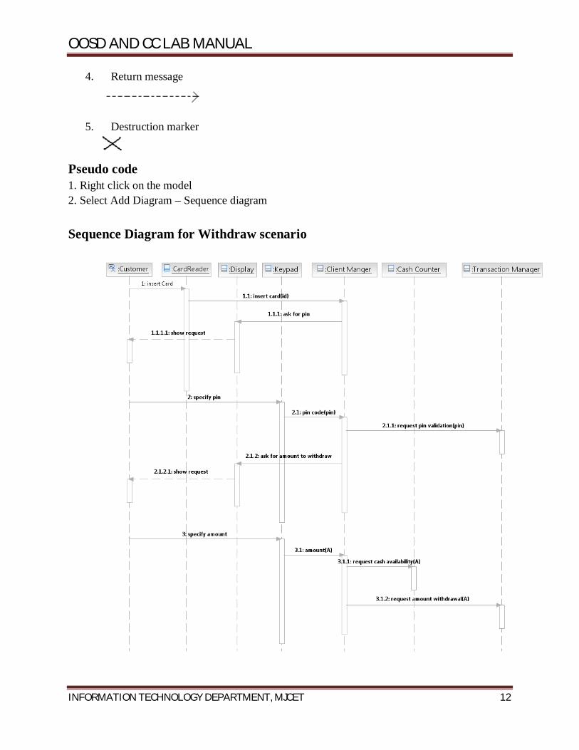
4. Return message
5. Destruction marker
Pseudo code 1. Right click on the model 2. Select Add Diagram – Sequence diagram Sequence Diagram for Withdraw scenario

OOSD AND CC LAB MANUAL
INFORMATION TECHNOLOGY DEPARTMENT, MJCET 13
2. Collaboration diagram : A collaboration diagram is an interaction diagram that shows the order of messages that implement an operation or a transaction. Collaboration diagrams show objects, their links, and their messages. They can also contain simple class instances and class utility instances. Each collaboration diagram provides a view of the interactions or structural relationships that occur between objects and object-like entities in the current model. Collaboration diagrams contain icons representing objects. Sequence and collaboration diagrams are semantically equivalent as both show the interaction among objects. From one diagram we can generate another diagram. To generate a collaboration diagram from sequence diagram, right click on sequence diagram, select - Add Diagram - communication diagram . Similarly, a sequence diagram can be generated from collaboration diagram. Pseudo code 1. Right click on the model 2. Select Add Diagram – Communication diagram
Collaboration Diagram for Withdraw Scenario
OOSD AND CC LAB MANUAL
INFORMATION TECHNOLOGY DEPARTMENT, MJCET 14
6. STATE MACHINE DIAGRAM
Problem Definition To draw a state Machine diagram for ATM System.
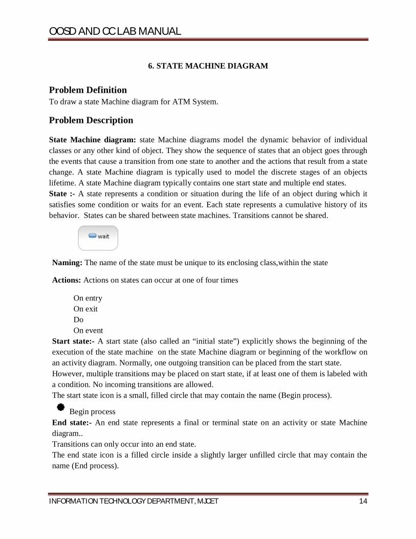
Problem Description State Machine diagram: state Machine diagrams model the dynamic behavior of individual classes or any other kind of object. They show the sequence of states that an object goes through the events that cause a transition from one state to another and the actions that result from a state change. A state Machine diagram is typically used to model the discrete stages of an objects lifetime. A state Machine diagram typically contains one start state and multiple end states. State :- A state represents a condition or situation during the life of an object during which it satisfies some condition or waits for an event. Each state represents a cumulative history of its behavior. States can be shared between state machines. Transitions cannot be shared.
Naming: The name of the state must be unique to its enclosing class,within the state
Actions: Actions on states can occur at one of four times
On entry On exit Do On event
Start state:- A start state (also called an “initial state”) explicitly shows the beginning of the execution of the state machine on the state Machine diagram or beginning of the workflow on an activity diagram. Normally, one outgoing transition can be placed from the start state. However, multiple transitions may be placed on start state, if at least one of them is labeled with a condition. No incoming transitions are allowed. The start state icon is a small, filled circle that may contain the name (Begin process).
Begin process End state:- An end state represents a final or terminal state on an activity or state Machine diagram.. Transitions can only occur into an end state. The end state icon is a filled circle inside a slightly larger unfilled circle that may contain the name (End process).

OOSD AND CC LAB MANUAL
INFORMATION TECHNOLOGY DEPARTMENT, MJCET 15
End process State transition:- A state transition indicates that an action in the source state will perform certain specified actions and enter the destination state when a specified event occurs or when certain conditions are satisfied. A state transition is a relationship between two states, two activities or between an activity or a state. The icon for a state transition is a line with an arrow head pointing toward the destination state or activity.
We can show one or more state transitions from a state as long as each transition is unique. Transitions originating from a state cannot have the same event, unless there are conditions on the event. Naming: We should label each state transition with the name of at least one event that causes the state transition. We do not have to use unique labels for the state transitions because the same event can cause a transition to many different states or activities. Tools:
1. State
2. Activity
3. Start state
4. End state
5. State transition
6. Transition to self
7. Horizontal synchronization

OOSD AND CC LAB MANUAL
INFORMATION TECHNOLOGY DEPARTMENT, MJCET 16
8. Vertical synchronization
9. Decision
Pseudo code 1. Right click on the model 2. Select Add Diagram – State Machine diagram
State Machine diagram for ATM System
OOSD AND CC LAB MANUAL
INFORMATION TECHNOLOGY DEPARTMENT, MJCET 17
7. COMPONENT DIAGRAM
Problem Definition To draw a component diagram for ATM System.
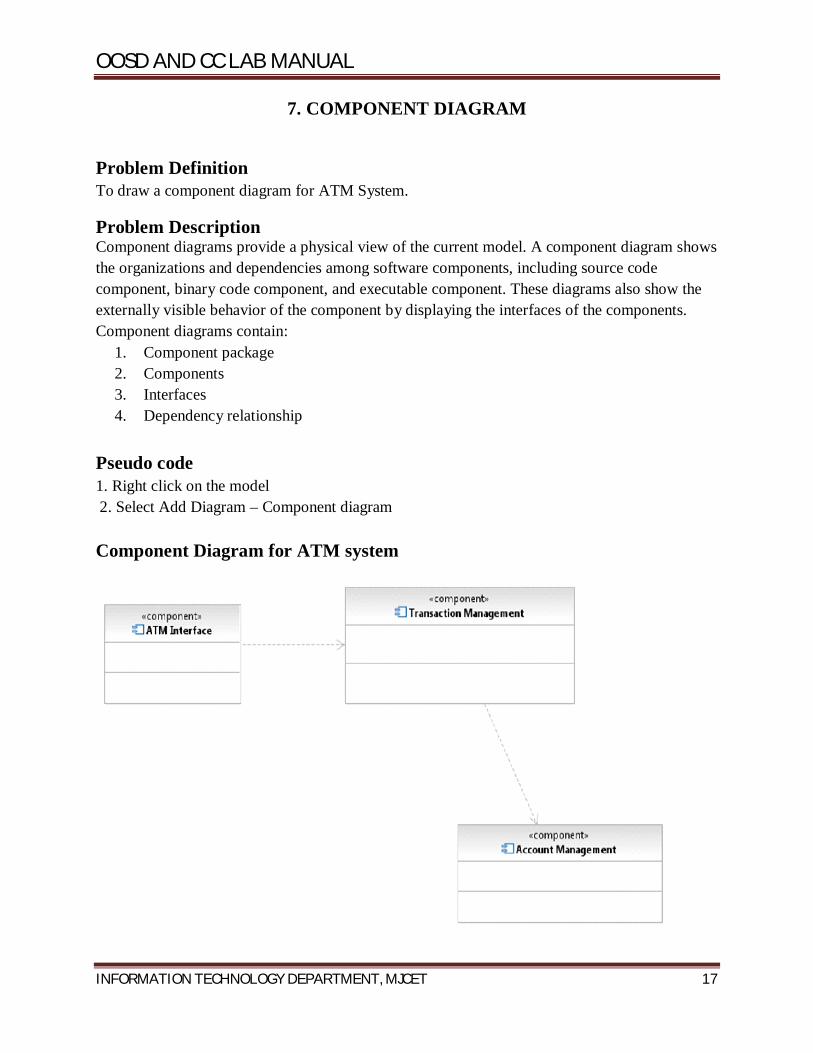
Problem Description Component diagrams provide a physical view of the current model. A component diagram shows the organizations and dependencies among software components, including source code component, binary code component, and executable component. These diagrams also show the externally visible behavior of the component by displaying the interfaces of the components. Component diagrams contain:
1. Component package 2. Components 3. Interfaces 4. Dependency relationship
Pseudo code 1. Right click on the model 2. Select Add Diagram – Component diagram Component Diagram for ATM system

OOSD AND CC LAB MANUAL
INFORMATION TECHNOLOGY DEPARTMENT, MJCET 18
8. DEPLOYMENT DIAGRAM
Problem Definition To draw a deployment diagram for ATM System.
Problem Description A deployment diagram shows processors, devices and connections. Each model contains a single deployment diagram which shows the connections between nodes. Node:- A node is a hardware component capable of executing programs. Each node must have a name, there are no constraints on the node name because nodes denote hardware rather than software entities. Pseudo code 1. Right click on the model 2. Select Add Diagram – Deployment diagram
Deployment diagram for ATM System

OOSD AND CC LAB MANUAL
INFORMATION TECHNOLOGY DEPARTMENT, MJCET 19
9. FORWARD ENGINEERING
Problem Definition
To perform forward engineering of the class diagram.
Problem Description
Forward Engineering is the process of transforming model into code.
Pseudo code Following are the steps to generate java code from UML class diagram.
1. Start IBM Rational Software Architect
2. Create a class diagram
3. Go to File Menu
3.1 Select New
3.1.1. Click on Transformation configuration
3.1.2. Provide the file name (e.g., fwd.tc)
3.1.3. Select a transformation
3.1.3. Click UML to Java V1.3
3.1.5. Click next
3.1.6. Select the Source (The model which contains class diagram)
3.1.7. Create a new target container( Java project to hold java code)
3.1.8. Provide the java project name
3.1.9. Click next
3.1.10. Click finish
A transformation configuration file (fwd.tc) is created in the UML project.
4. Right click on fwd.tc
4.1. Click on transform
4.1.2. Click on UML to Java V1.3
5. Java code for the model is generated.

OOSD AND CC LAB MANUAL
INFORMATION TECHNOLOGY DEPARTMENT, MJCET 20
10. REVERSE ENGINEERING
Problem Definition
To perform Reverse Engineering.
Problem Description Reverse Engineering is the process of transforming code to UML model.
Pseudo code Following are the steps to generate UML model from java code.
1. Start IBM Rational Software Architect
2. Go to file
2.1 New
2.1.1 Click on Transformation configuration
2.1.2. Provide the file name (e.g., rev.tc)
2.1.3. Select a transformation
2.1.4 Click Java to UML.
2.1.5. Click next
2.1.6. Select the Source ( java project)
2.1.7. Select a target container (UML model to hold the class diagram)
2.1.8. Click next
2.1.9. Click Finish
A transformation configuration file (rev.tc) is created in the Java project.
3. Right click on rev.tc
3.1. Click on transform
3.1.2. Click on Java to UML
4. The Classes and interfaces present in java project will be listed in UML model.
5. Drag and drop from the model the graphical representation of classes and interfaces onto the class diagram window.
6. UML class diagram is created with appropriate relationships.Some relationships may not be reflected in the class diagram as there is loss of information during reverse engineering.

OOSD AND CC LAB MANUAL
INFORMATION TECHNOLOGY DEPARTMENT, MJCET 21
COMPILER CONSTRUCTION PROGRAMS
Program 1
Basic Lex Program
Problem Definition To generate a lex Program to echo the given input.
Problem Description During the first phase the compiler reads the input and converts strings in the source to
tokens. With regular expressions we can specify patterns to lex so it can generate code
that will allow it to scan and match strings in the input.
In this program we simply print the matched string rather than return a token
value. Pseudo code 1. Start the program by skipping the declaration section. 2. The rules section will be left empty to match the whole string. 3. In the auxillary routines section specify the main function which includes yylex()
which is an entry point to the lex. 4. Define yywrap() to perform wrapping of the input stream.
Problem Validation Execution Steps
Lex prog. l c lex.yy.c . /a.out Input
Hello wor ld Output
Hello wor ld
OOSD AND CC LAB MANUAL
INFORMATION TECHNOLOGY DEPARTMENT, MJCET 22
Program 2
Problem Definition To generate a lex Program to prepend line numbers to each line of a file.
Problem Description During the first phase the compiler reads the input and converts strings in the source to
tokens. With regular expressions we can specify patterns to lex so it can generate code
that will allow it to scan and match strings in the input.
In this program we match the beginning of the string and add line number to
every line in the program.The lex tool constructs a Finite state machine using the
provided regular expression that matches the beginning of every line. Pseudo code 1. Start the program by declaring the variable lineno in the declaration section.
2. In the rules section define the regular expression ^(.*)\n to match the beginning of the
line.
3. In the auxillary routines section specify the main function which includes yylex()
which is an entry point to the lex.
4. Open a file for reading in the main.
5. Define yywrap() to perform wrapping of the input stream.
Problem Validation Execution Steps
Lex prog. l file1.c
c lex.yy.c
. /a.outInput
#include<stdio.h>
main()
{
printf(“hello world\n”);
}

OOSD AND CC LAB MANUAL
INFORMATION TECHNOLOGY DEPARTMENT, MJCET 23
Output
1 #include<stdio.h>
2 main()
3 {
4 printf(“hello world\n”);
5 }
OOSD AND CC LAB MANUAL
INFORMATION TECHNOLOGY DEPARTMENT, MJCET 24
Program 3 Problem Definition Lex Program to count the number of Identifiers. Problem Description During the first phase the compiler reads the input and converts strings in the source to
tokens. With regular expressions we can specify patterns to lex so it can generate code
that will allow it to scan and match strings in the input.
In this program we take a file and count the identifiers present in it using regular
expression for matching identifier. The lex tool constructs a Finite state machine using
the provided regular expression that matches all the identifiers. Pseudo code 1. Start the program by declaring the variable count in the declare section.
2. Declare digit and letter using the regular expressions [0-9] and [A-Za-z].
3. In the rules section define the regular expression that matches an identifier
{letter}({letter}|{digit})*.
4. Increment the count for every matched string.
5. In main function,
i. open a file for reading.
ii. Call lex using yylex(),
iii. print the value of count,
iv. close the file opened.
6. Write yywrap() function.
Problem Validation Execution Steps
lex iden.l
cc lex.yy.c
./a.out hello.c
Input
welcome to the lab
Output
The numbers of identifiers are:4

OOSD AND CC LAB MANUAL
INFORMATION TECHNOLOGY DEPARTMENT, MJCET 25
Program 4
Problem Definition Lex Program to count number of spaces, lines, words and characters. Problem Description During the first phase the compiler reads the input and converts strings in the source to
tokens. With regular expressions we can specify patterns to lex so it can generate code
that will allow it to scan and match strings in the input.
In this program we take a file and count the spaces, lines, words and characters
present in it using regular expressions. The lex tool constructs a Finite state machine
using the provided regular expressions that matches the words ,lines and spaces. Pseudo code 1. Start the program by declaring variable c,w,l,s and initializing them to zero.
2. In rules section write the regular expressions for counting words,characters,lines and
spaces as [^ \t\n]+, c+=yyleng, [\n], [ \t]+ respectively.
3. In main,
i. open a file for reading,
ii. call lex using yylex()
iii. print the count of characters, words, lines and spaces
iv. close the file after reading.
4. Define yywrap() function.
Problem Validation Execution Steps
lex iden.l
cc lex.yy.c
./a.out hello.c
Input
hello.c
welcome to the lab
hello world

OOSD AND CC LAB MANUAL
INFORMATION TECHNOLOGY DEPARTMENT, MJCET 26
Output
Number of characters are 25
Number of words are 6
Number of lines are 2
Number of spaces are 4

OOSD AND CC LAB MANUAL
INFORMATION TECHNOLOGY DEPARTMENT, MJCET 27
Program 5 Problem Definition Program to implementscanner using Lex. Problem Description During the first phase the compiler reads the input and converts strings in the source to
tokens. With regular expressions we can specify patterns to lex so it can generate code
that will allow it to scan and match strings in the input. Each pattern in the input to lex
has an associated action. Typically an action returns a token that represents the matched
string for subsequent use by the parser. Pseudo code 1. Start the program by declaring the regular expressions for digit, letter, number,
identifier as [0-9], [A-Za-z], {digit}+, {letter}({letter}|{digit})* respectively in declare
section
2. In rules section, for every regular expression defined above call the display function.
3. In main, invoke lexer using yylex() command.
4. Call yywrap() function to return 1.
5. In display function, using switch construct call different cases for the regular
expressions defined in the program.
Problem Validation Execution Steps
Lex scanner. l
cc lex.yy.c
. /a.out
Input
i. Main
ii. Hello
iii. 45
Output
i. Keyword
ii. Identifier
iii. Number

OOSD AND CC LAB MANUAL
INFORMATION TECHNOLOGY DEPARTMENT, MJCET 28
Program 6
Problem Definition Program to implementLALRparser usingYACC. Problem Description Yacc (Yet another compiler compiler) is a computer program for the Unix operating system.
It is a LALR parser generator, generating a parser, the part of a compiler that tries to
make syntactic sense of thesource code, specifically a LALR parser, based on an analytic
grammar written in it. Yacc produces only a parser, for full syntactic analysis this
requires an external lexical analyzer to perform the first tokenization stage (word
analysis), which is then followed by the parsing stage.
Pseudo code The program contains 2 files lalr.l and lalr.y
Lalr.y
1. Start the program by declaring a token num using %token command.
2. In the rules section give the rules of the grammar for implementing a simple
calculator that performs addition and multiplication using stack
3. In main, invoke parser using yyparse().
4. Define yyerror() function to catch the errors.
Lalr.l
1. In the declare section, include “y.tab.h” header file and yylval generated by lalr.y file.
2. In the rules section, give the regular expression for a number and store itsinteger
value in yylval.
3. Everything else should be stored as it is by matching them with a dot.
4. Call yywrap() function to return 1;
Problem Validation Execution Steps
Lex lalr.l
cc lex.yy.c
yacc lalr.y
cc lex.yy.c –d y.tab.c

OOSD AND CC LAB MANUAL
INFORMATION TECHNOLOGY DEPARTMENT, MJCET 29
./a.out
Input
i. 2+3
ii. 2++3
Output
i. 5
ii. ERROR

OOSD AND CC LAB MANUAL
INFORMATION TECHNOLOGY DEPARTMENT, MJCET 30
Program 7
Problem Definition C program to implementrecursivedescentparser. Problem Description One of the most straightforward forms of parsing is recursive descent parsing. This is a
top-down process in which the parser attempts to verify that the syntax of the input
stream is correct as it is read from left to right. A basic operation necessary for this
involves reading characters from the input stream and matching then with terminals from
the grammar that describes the syntax of the input. Our recursive descent parsers will
look ahead one character and advance the input stream reading pointer when proper
matches occur.
Pseudo code Grammar used:
E→T+E/T
T→F*T/F
F→(E)/num
7. Start the program by declaring the functions expr(), term(), factor() and match()
8. In main, take the first character as input and call expr().
9. Print success for successful completion of parsing, error otherwise.
10. In match() function, match the input stream with the terminals from the grammar.
11. In expr(),
i. call term()
ii. match ‘+’ (according to the grammar)
iii. call expr() if ‘+’ matches
12. in term(),
i. call factor()
ii. match ‘*’ (according to the grammar)
iii. call term() if ‘*’ matches
13. in factor()
i. match token ‘(‘
OOSD AND CC LAB MANUAL
INFORMATION TECHNOLOGY DEPARTMENT, MJCET 31
ii. call expr() if ‘(‘ matches
iii. match ‘)’ if expr() returns true
iv. else match ‘digit’
v. else return error
Problem Validation Execution Steps
cc recdes.c
./a.out
Input
i. 2+3
ii. 2++3
Output
1. Success 2 . Error

OOSD AND CC LAB MANUAL
INFORMATION TECHNOLOGY DEPARTMENT, MJCET 32
Program 8
Problem Definition C program to find First elements of a grammar. Problem Description TocomputeFIRST(X)forallgrammarsymbolsx,applythefollowingrulesuntilnomoreterminal
s can be added to any FIRST set.
1. IfX is terminal, then FIRST(X) is {X}.
2. IfXisnonterminalandX->aαisaproduction,thenaddatoFIRST(X).ifX->€toFIRST(X)
3. If->Y1,Y2,…….Ykisaproduction,thenforallisuchthatallofY1,….Yi-1are nonterminals
and FIRST(Yj) contains € for j=1,2,…… i-1, add every non-€
symbolinFIRST(Y1)toFIRST(x).ifVisinFIRST(Yj)forj=1,2,………k,then add € to
FIRST(X).
Pseudo code 1. Start the program by entering the productions of the grammar and the input symbol.
2. If the input symbol is a terminal, add it to the output.
3. If the input symbol is a non-terminal, then
i. If it is the head symbol of the production, and has € on the RHS then add € to its
output.
ii. Else if it has a terminal as the first symbol on RHS then add that terminal to the
output.
iii. Else if it has a non-terminal as the first symbol on RHS then find FIRST of that
symbol.
Problem Validation Execution Steps
cc prog.c
./a.out
Input
S->ABc
A->eD
B->b

OOSD AND CC LAB MANUAL
INFORMATION TECHNOLOGY DEPARTMENT, MJCET 33
D->i
Output
FIRST(S) = {e}
FIRST(A) = {e}
FIRST(B) = {b}
FIRST(D) = {i}

OOSD AND CC LAB MANUAL
INFORMATION TECHNOLOGY DEPARTMENT, MJCET 34
Program 9
Problem Definition C program to find Follow elements of a grammar. Problem Description To compute FOLLOW(A) for all nonterminals A, apply the following rulesuntil nothing
can be added to any FOLLOW set.
1. Place $ in FOLLOW(S) where S is the start symbol, and $ is the inputright
endmarker.
2. If there is a production A -> aBβ, then everything in FIRST(β) except ԑis in
FOLLOW(B).
3. If there is a production A ->aB, or a production A -> aBβ, where
FIRST(β) contains ԑ, then everything in FOLLOW (A) is in FOLLOW (B) .
Pseudo code 1. Start the program by entering the productions of the grammar and the input symbol.
2. Call follow() of the input.
3. In Follow(),
i. If the input symbol is the start symbol, add # (end marker) to the output.
ii. Search all the productions on the RHS for the input symbol
iii. Wherever the input symbol matches, find the first() of its following string.
iv. If there is no string following the matched input symbol, then add follow of the
head symbol of the production to the output.
4. In First(),
i. If the input symbol is a terminal, add it to the output.
ii. If the input symbol is a non-terminal, then
If it is the head symbol of the production, and has € on the RHS then add € to
its output.
Else if it has a terminal as the first symbol on RHS then add that terminal to
the output.
Else if it has a non-terminal as the first symbol on RHS then find FIRST of
that symbol.

OOSD AND CC LAB MANUAL
INFORMATION TECHNOLOGY DEPARTMENT, MJCET 35
Problem Validation Execution Steps
cc prog.c
./a.out
Input
S->ABc
A->eD
B->b
D->i
Output
FOLLOW(B) = {c,$}
FOLLOW(e) = {i}

OOSD AND CC LAB MANUAL
INFORMATION TECHNOLOGY DEPARTMENT, MJCET 36
Program 10
Problem Definition C program for code generation. Problem Description Code generation can be considered as the final phase of compilation. Through post code
generation, optimization process can be applied on the code, but that can be seen as a
part of code generation phase itself. The code generated by the compiler is an object
code of some lower-level programming language, for example, assembly language. We
have seen that the source code written in a higher-level language is transformed into a
lower-level language that results in a lower-level object code, which should have the
following minimum properties:
It should carry the exact meaning of the source code.
It should be efficient in terms of CPU usage and memory management.
Pseudo code 1. Start the program by taking a c-statement to be converted as input.
2. Use a switch construct to define various cases for addition, subtraction, multiplication
and division. 3. Using assembly language instructions like LOAD, ADD/SUB/MUL/DIV AND
STORE convert the given C-statement into assembly language code
Problem Validation Execution Steps
cc prog.c
./a.out
Input
A=B+C
Output
LOAD R0,B
ADD R0,C
STORE A,R0
OOSD AND CC LAB MANUAL
INFORMATION TECHNOLOGY DEPARTMENT, MJCET 37
Program 11
Problem Definition C program for code optimization. Problem Description Optimization is a program transformation technique, which tries to improve the code by
making it consume less resource (i.e. CPU, Memory) and deliver high speed.In
optimization, high-level general programming constructs are replaced by very efficient
low-level programming codes.
Constant Folding
Expressions with constant operands can be evaluated at compile time, thus improving
run-time performance and reducing code size by avoiding evaluation at compile-time.
In the code fragment below, the expression (3 + 5) can be evaluated at compile time and
replaced with the constant 8.Programmers generally do not write expressions such as (3 +
5) directly, but these expressions are relatively common after macro expansion and other
optimizations.
Pseudo code 1. Start the program by taking two C-statements as input. One with a direct value such
as b=1 and the other a general statement containing ‘b’ on RHS.
2. Traverse the first statement and Store the variable (b)in var1 and its value (1) in var2.
3. Traverse the second statement beyond ‘=’ searching for var1.
4. Replace var1 in second statement by var2.
5. The optimized code will be second statement.
Problem Validation Execution Steps cc prog.c ./a.out Input B=1 A=B+C Output A=1+C

OOSD AND CC LAB MANUAL
INFORMATION TECHNOLOGY DEPARTMENT, MJCET 38
Program 12
Problem Definition Code generation for if-statement. Problem Description Code generation can be considered as the final phase of compilation. Through post code
generation, optimization process can be applied on the code, but that can be seen as a
part of code generation phase itself. The code generated by the compiler is an object
code of some lower-level programming language, for example, assembly language. We
have seen that the source code written in a higher-level language is transformed into a
lower-level language that results in a lower-level object code, which should have the
following minimum properties:
It should carry the exact meaning of the source code.
It should be efficient in terms of CPU usage and memory management.
Pseudo code 1. Start the program by taking 2 c-statements representing if-statement as input. 2. Using assembly language instructions, move the 2 variables in if-condition to the
registers. 3. Compare both the variables using cmp command.
4. If true, execute the second statement and store the result in a new register.
Problem Validation Execution Steps cc codegenif.c ./a.out Input
if(a<b)
a=a+1
Output
Mov r1,a
Mov r2,b
Cmp
Jge nxt
mov r3,a
Add r3,1
store a,r3
Nxt:

OOSD AND CC LAB MANUAL
INFORMATION TECHNOLOGY DEPARTMENT, MJCET 42
Program 13
Problem Definition Code generation for while-statement. Problem Description Code generation can be considered as the final phase of compilation. Through post code
generation, optimization process can be applied on the code, but that can be seen as a
part of code generation phase itself. The code generated by the compiler is an object
code of some lower-level programming language, for example, assembly language. We
have seen that the source code written in a higher-level language is transformed into a
lower-level language that results in a lower-level object code, which should have the
following minimum properties:
It should carry the exact meaning of the source code.
It should be efficient in terms of CPU usage and memory management.
Pseudo code 1. Start the program by taking 2 C-statements representing while loop as input. 2. If the value in the while condition is true jump to a new label begin. 3. Execute the second instruction and store the result. 4. Repeat the code in the label begin until the condition in while is true. Problem Validation Execution Steps
cc codegenif.c
./a.out
Input
while(i=1)
x=x+1
Output
Mov r1,i
Jmp begin
xx: mov r2,x
Mov r2,1
Store x,r2
begin: cmp r1,1
Je xx

OOSD AND CC LAB MANUAL
INFORMATION TECHNOLOGY DEPARTMENT, MJCET 44
Program 14
Problem Definition Identification of test cases and finding defects in the application using RFT Problem Description Black-box testing is a method of software testing that examines the functionality of an
application (e.g. what the software does) without peering into its internal structures or
workings. This method of test can be applied to virtually every level of software
testing: unit, integration, system and acceptance. It typically comprises most if not all
higher level testing, but can also dominate unit testing as well.
Test cases: Test cases are built around specifications and requirements, i.e., what the
application is supposed to do. Test cases are generally derived from external
descriptions of the software, including specifications, requirements and design
parameters. Although the tests used are primarily functional in nature, non-functional
tests may also be used. The test designer selects both valid and invalid inputs and
determines the correct output without any knowledge of the test object's internal
structure.
Pseudo code 1. Start IBM software delivery platform – IBM rational functional tester – Java
scripting.
2. Make a new functional test project
3. Configure the application for testing
4. Generate a test script by starting the recording of the events for placing the order.
5. Stop the recording.
6. Playback the test script generated.
Problem Validation Input
APPLICATION NAME:CLASS JAVA A
Test Case ID
Credit Card No. Expiry Date Result Expected
Result Observed
Status
1 1234123412341234 12/16 order placed order placed Pass
2 111111111111 12/16 order not placed
order placed Fail
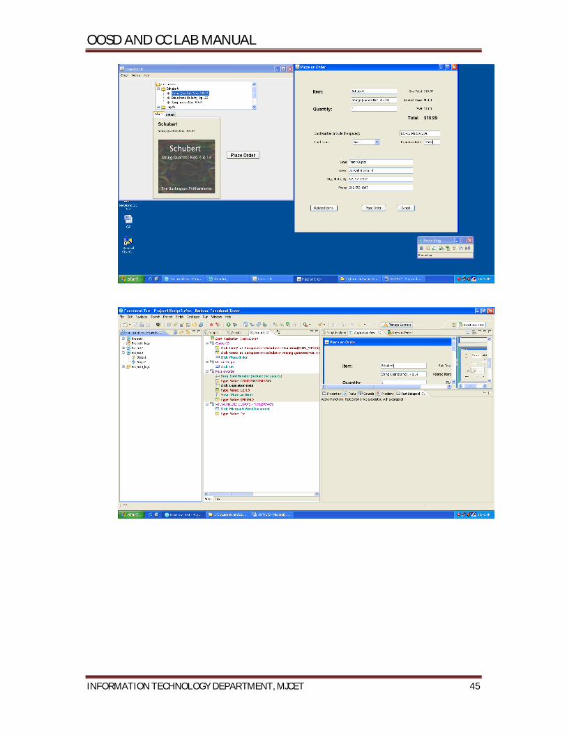
OOSD AND CC LAB MANUAL
INFORMATION TECHNOLOGY DEPARTMENT, MJCET 45

OOSD AND CC LAB MANUAL
INFORMATION TECHNOLOGY DEPARTMENT, MJCET 46
Output

OOSD AND CC LAB MANUAL
INFORMATION TECHNOLOGY DEPARTMENT, MJCET 47
Program 15
Problem Definition DataVerification,ImageVerification Problem Description
Unit testing is a software development process in which the smallest testable parts of
an application, called units, are individually and independently scrutinized for proper
operation. Unit testing is often automated but it can also be done manually.
In this experiment, unit testing is applied to perform data and image
verification.
Same Data/image point is taken from two different versions of the same application
and compared to find any modifications done.
Pseudo code 1. Start IBM software delivery platform – IBM rational functional tester – Java
scripting.
2. Make a new functional test project
3. Configure the application for testing
4. Generate a test script by starting the recording of the events for placing the order.
5. After starting the recording, select the data/image point using fourth option from
the recording window.
6. Stop the recording.
7. Change the application name in the test script to the new version of the
application.
8. Playback the test script to generate the report.
Problem Validation Input

OOSD AND CC LAB MANUAL
INFORMATION TECHNOLOGY DEPARTMENT, MJCET 48

OOSD AND CC LAB MANUAL
INFORMATION TECHNOLOGY DEPARTMENT, MJCET 49
Output

OOSD AND CC LAB MANUAL
INFORMATION TECHNOLOGY DEPARTMENT, MJCET 50

OOSD AND CC LAB MANUAL
INFORMATION TECHNOLOGY DEPARTMENT, MJCET 51
Program 16
Problem Definition DataDrivenActions usingRFT Problem Description Functional testing is a quality assurance (QA) process and a type of black-box
testing that bases its test cases on the specifications of the software component under
test. Functions are tested by feeding them input and examining the output, and
internal program structure is rarely considered. Functional testing usually
describes what the system does. Unit testing is a software development process in which the smallest testable parts of
an application, called units, are individually and independently scrutinized for proper
operation. Unit testing is often automated but it can also be done manually.
In this experiment, we perform functional testingby creating a test data pool. A
datapool can be populated with data from the application. A datapool is a collection of
related data records. A datapool supplies data values to the variables in a test script
during test script playback.
Pseudo code 1. Start IBM software delivery platform – IBM rational functional tester – Java
scripting.
2. Make a new functional test project
3. Configure the application for testing
4. Generate a test script by starting the recording of the events for placing the order.
5. On the Recording toolbar, click Insert Data Driven Commands.
6. The test script recording pauses and the Insert Data Driven Actions page opens.
In the application-under-test, type the initial values that you want to see in the
datapool in the fields that you want to data drive.
7. Use the mouse to drag the hand, the Object Finder too, to the object in the
application that you want to select. Functional Tester outlines the object with a red
border.
8. Release the mouse button.
The Data Drive Actions page opens. In the Data Drive Actions page, under
the DataDriven Commands table, information appears about the objects you
selected.

OOSD AND CC LAB MANUAL
INFORMATION TECHNOLOGY DEPARTMENT, MJCET 52
9. In the data drive actions page (data pool) insert more records.
10. Playback the script by selecting iterate until done option.
Problem Validation Input

OOSD AND CC LAB MANUAL
INFORMATION TECHNOLOGY DEPARTMENT, MJCET 53
Output
OOSD AND CC LAB MANUAL
INFORMATION TECHNOLOGY DEPARTMENT, MJCET 54
Program 17
Problem Definition Requirements management using RQM. Problem Description IBM® Rational Quality Manager™, built on the Jazz platform, is a collaborative,
web-based, quality management solution that offers comprehensive test planning and
test asset management from requirements to defects. This software helps teams share
information seamlessly, use automation to accelerate project schedules and report on
metrics for informed release decisions.
Rational Quality Manager helps quality assurance teams:
Collaborate—share project information and status updates seamlessly so team
members can synchronize teamwork throughout the lifecycle.
Automate—reduce labor-intensive activities to accelerate project schedules.
Govern—understand and report on project metrics to enable accurate, reliable and
timely release decisions.
Pseudo code 1. Start IBM RQM – IBM RQM server (in Mozilla firefox).
2. Create and save requirements from the dashboard on the left side.
3. Create and save test cases from the dashboard on the left side.
4. Add few requirements (leave other requirements as it is) to the test cases created.
Save.
5. Create a test plan from the dashboard and add all the requirements and test cases
to it.
6. Generate report from the dashboard by selecting plan requirements coverage by
test cases (present on the second page of reports).
7. Select the test plan created and run it.
8. A pie Machine is generated in the report which shows the coverage of
requirements by the test cases.

OOSD AND CC LAB MANUAL
INFORMATION TECHNOLOGY DEPARTMENT, MJCET 55
Problem Validation Input

OOSD AND CC LAB MANUAL
INFORMATION TECHNOLOGY DEPARTMENT, MJCET 56

OOSD AND CC LAB MANUAL
INFORMATION TECHNOLOGY DEPARTMENT, MJCET 57
Output

OOSD AND CC LAB MANUAL
INFORMATION TECHNOLOGY DEPARTMENT, MJCET 58
Annexure – I
List of programs according to O.U. curriculum
Related Documents


![ECE Department MPMC Lab-PC652EC...ECE Department MPMC Lab-PC652EC MJCET Page 6 PART–B [Experiments for 8051 using any C- Cross Compiler & appropriate hardware] 1. Familiarity and](https://static.cupdf.com/doc/110x72/60ae19e52273f87fcc0cda0b/ece-department-mpmc-lab-pc652ec-ece-department-mpmc-lab-pc652ec-mjcet-page-6.jpg)