ISSN: 2180 - 1843 Vol. 5 No. 1 January - June 2013 37 Ridza Azri Ramlee, Daphne Tang Hui Zyen, Mohd Azlishah Othman, Mohd Muzafar Ismail, Hamzah Asyrani Sulaiman, Mohamad Harris Misran, Maizatul Alice Meor, Mohamad Zoinol Abidin Abd Aziz Faculty of Electronic and Computer Engineering, Universiti Teknikal Malaysia Melaka (UTeM), Malaysia [email protected] Mobile Phone Controlling Home Appliances Abstract—Advancement in wireless technology nowadays has allowed the creation of various remote control systems, one of which is the famous Smart Home concept. This project focuses on the development of a smart home system that allows user control of electrical appliances using devices such as laptop or an Android phone via Bluetooth. The system adapts serial connection of the devices with a Bluetooth module and a PIC microcontroller attached on the main circuit board where the microcontroller will then control the home appliances via a relay circuit. The smart home system will be able to ease the effort of physically challenged individuals in controlling their home appliances such as lamps, fan, air-con and etc. Users can trigger the switches anywhere as long as the device is within the vicinity of the Bluetooth signal in the main panel. Moreover, users can also control the appliances via internet connection by sending an email to a specified address. However, this addition requires that the laptop be wirelessly connected to the main board at all times and have internet connection. Generally, the project software application together with its Graphical User Interface was developed using Microsoft© Visual Studio in VB language for the computer platform and Eclipse IDE for the Android platform. The microcontroller, PIC16F877A located on the main circuit board was programmed in C language using MPLAB IDE software and debugged together with the circuit design using Proteus 7 ISIS. The PCB was designed using Proteus 7 ARES. The final prototype of the system was built to demonstrate the proposed functionality of the system. Index Terms— Android, Bluetooth, Home automation, PIC, Smart home I. INTRODUCTION Smart home system is a system that eases user’s control over their home appliances and further improves their lifestyle. This project focuses on the adaptation of a low- cost smart home system for domestic purposes. With its target audience set, the project implementations utilize smart technologies such as PIC microcontroller as the main controller for the system. Its user interface is designed for the installation on Windows OS computer and also for the Android platform. Apart from integration of sensors into the system for monitoring purposes, the system integrates Internet technologies where the system can be controlled via messaging system using electronic mail. The system’s feedback mechanism allows user to check or prompt for home conditions and further enhances the interactivity of the system. The system is targeted for application in conventional homes for people with disabilities or for the elderly. The nature of this system will provide these people with additive comfort in their own homes and further increase their productivity in their everyday lives. The main objective of this project is to design a smart system that allows remote control characteristics in easing the controls of home appliances. This will require the integration of the latest wireless technologies such as Bluetooth and Wi-Fi components into the system’s concept and application. Also, the other objective of this project is to allow the system to portray a two-way communication system between the house-hold appliances and user’s controlling device. This allows the implementation of a feedback mechanism in the system. Since the invention of mechanical switches, its function has always been simple and direct; which was to connect and disconnect power supply of an electric or electronic device. However, its usage requires that users make direct contact with the switches for it to work. It is deduced from that, direct contact switches will cause problems to arise, such as if the user accidentally touches the switch with wet hands, and if at crucial times, a physically challenged individual or a child could not reach a switch to prevent mishaps. These minor events may lead to accidents or people getting hurt. Apart from that, conventional switches do not allow control over a distance. With this limitation, users will have less flexibility in controlling their home appliances when they are not at home and prevents remote monitoring of their home devices. In sense, if a house is not occupied, or does not seem occupied for a period of time, it is bound to attract unwanted visitors to our homes such as thieves. Prevention of these mishaps can be further improved by introducing remote controlling of devices. This project focuses on developing a working model of a remote control smart home system which includes the GUI application for user interaction with a PIC microcontroller attached on a main circuit board. The main circuit board and the GUI will be designed to resemble a working miniature model or prototype of the product. The project will also include adaptation of appliance control over Internet services. However, the research to install this system into existing home circuitries will not be covered. II. LITERATURE REVIEW The review was done based on studying proceeding papers and journal articles which were obtained from UTeM’s digital library subscription especially from IEEE Xplore website. Some were obtained online from random sources such as university websites. These sources were found by searching the database using phrases such as ‘mobile phone controlling home appliances’, ‘home automation using ‘Bluetooth’, ‘home

Welcome message from author
This document is posted to help you gain knowledge. Please leave a comment to let me know what you think about it! Share it to your friends and learn new things together.
Transcript
ISSN: 2180 - 1843 Vol. 5 No. 1 January - June 2013
Mobile Phone Controlling Home Appliances
37
Abstract—Advancement in wireless technology nowadays has allowed the creation of various remote control systems, one of which is the famous Smart Home concept. This project focuses on the development of a smart home system that allows user control of electrical appliances using devices such as laptop or an Android phone via Bluetooth. The system adapts serial connection of the devices with a Bluetooth module and a PIC microcontroller attached on the main circuit board where the microcontroller will then control the home appliances via a relay circuit. The smart home system will be able to ease the effort of physically challenged individuals in controlling their home appliances such as lamps, fan, air-con and etc. Users can trigger the switches anywhere as long as the device is within the vicinity of the Bluetooth signal in the main panel. Moreover, users can also control the appliances via internet connection by sending an email to a specified address. However, this addition requires that the laptop be wirelessly connected to the main board at all times and have internet connection. Generally, the project software application together with its Graphical User Interface was developed using Microsoft© Visual Studio in VB language for the computer platform and Eclipse IDE for the Android platform. The microcontroller, PIC16F877A located on the main circuit board was programmed in C language using MPLAB IDE software and debugged together with the circuit design using Proteus 7 ISIS. The PCB was designed using Proteus 7 ARES. The final prototype of the system was built to demonstrate the proposed functionality of the system.
Index Terms— Android, Bluetooth, Home automation, PIC, Smart home
I. INTRODUCTION Smart home system is a system that eases user’s control over their home appliances and further improves their lifestyle. This project focuses on the adaptation of a low-cost smart home system for domestic purposes. With its target audience set, the project implementations utilize smart technologies such as PIC microcontroller as the main controller for the system. Its user interface is designed for the installation on Windows OS computer and also for the Android platform. Apart from integration of sensors into the system for monitoring purposes, the system integrates Internet technologies where the system can be controlled via messaging system using electronic mail. The system’s feedback mechanism allows user to check or prompt for home conditions and further enhances the interactivity of the system. The system is targeted for application in conventional homes for people with disabilities or for the elderly. The nature of this system will provide these people with additive comfort in their own homes and further increase their productivity in their everyday lives.
The main objective of this project is to design a smart system that allows remote control characteristics in easing the controls of home appliances. This will require the integration of the latest wireless technologies such as Bluetooth and Wi-Fi components into the system’s concept and application. Also, the other objective of this project is to allow the system to portray a two-way communication system between the house-hold appliances and user’s controlling device. This allows the implementation of a feedback mechanism in the system.
Since the invention of mechanical switches, its function has always been simple and direct; which was to connect and disconnect power supply of an electric or electronic device. However, its usage requires that users make direct contact with the switches for it to work. It is deduced from that, direct contact switches will cause problems to arise, such as if the user accidentally touches the switch with wet hands, and if at crucial times, a physically challenged individual or a child could not reach a switch to prevent mishaps. These minor events may lead to accidents or people getting hurt.
Apart from that, conventional switches do not allow control over a distance. With this limitation, users will have less flexibility in controlling their home appliances when they are not at home and prevents remote monitoring of their home devices. In sense, if a house is not occupied, or does not seem occupied for a period of time, it is bound to attract unwanted visitors to our homes such as thieves. Prevention of these mishaps can be further improved by introducing remote controlling of devices.
This project focuses on developing a working model of a remote control smart home system which includes the GUI application for user interaction with a PIC microcontroller attached on a main circuit board. The main circuit board and the GUI will be designed to resemble a working miniature model or prototype of the product. The project will also include adaptation of appliance control over Internet services. However, the research to install this system into existing home circuitries will not be covered.
II. LITERATURE REVIEW The review was done based on studying proceeding
papers and journal articles which were obtained from UTeM’s digital library subscription especially from IEEE Xplore website. Some were obtained online from random sources such as university websites.
These sources were found by searching the database using phrases such as ‘mobile phone controlling home appliances’, ‘home automation using ‘Bluetooth’, ‘home
Ridza Azri Ramlee, Daphne Tang Hui Zyen, Mohd Azlishah Othman, Mohd Muzafar Ismail, Hamzah Asyrani Sulaiman, Mohamad Harris Misran, Maizatul Alice Meor,
Mohamad Zoinol Abidin Abd Aziz Faculty of Electronic and Computer Engineering,
Universiti Teknikal Malaysia Melaka (UTeM), Malaysia [email protected]
Mobile Phone Controlling Home Appliances
ISSN: 2180 - 1843 Vol. 5 No. 1 January - June 2013
Journal of Telecommunication, Electronic and Computer Engineering
38
automation for disabled people’ and ‘smart home for elderly and disabled’. These phrases were also used while looking up journals available through Google search engine. However, only some of the main related journals were cited in this report.
In this section will categorize past systems and literatures according to their cost and further discusses the varieties and concepts of their systems. Discussions will include the analysis of how all these systems are implemented.
A. Low Cost Systems The latest related journal was produced by [1] which used
the open source microcontroller, the Arduino Bluetooth (BT) platform comprising of ATmega 168 and Bluegiga‘WT II’ Bluetooth module, paired with smartphone application built using Phyton running on Symbian OS. The journal highlighted its low cost installation but did not offer customization for the user in adding appliances and devices. Its limitation to operate on only Symbian phones has limited the operability of the system. However, [1] provided a useful concept in connecting the appliances to a control board controlled by the ATmega microcontroller that uses relay in controlling power supply to the appliances; the concept can be adapted into the current project.
Another study done by[2] achieved a very complete and moneywise concept by using GPRS as the medium to control and monitor home appliances. They summarized that at low polling rates at 30 seconds, monthly cost of using their system reaches only US$ 5.10. This tactic however, requires the setup of 4 main systems including the central server, and 3 sub-systems at home, on the web, and on the mobile platform which is tedious. It utilizes Local Area Network (LAN) at home using RabbitCore modules and is capable of alerting, controlling and monitoring premises at the user’s home. The special feature covered in this journal is its concept to map the appliances at home from the web which would provide a neat configuration of the household controllable appliances.[2]
B. High Cost Systems The concept studied by referee[3]can be seen
implemented by referee [4], in 1995 where they had conducted a long term research on disability categories and developed the AUTONOMY system applying Environmental Control Systems (ECS) and Alternative and Augmentative Communication (AAC). The unavailability of wireless technologies then, limited the systems interconnection to European Installation Bus (EIB) standards and home installation of this system was tedious and complex. However, the remote control context had been developed to control Infrared (IR) electronics such as television (TV) and CD players, development of a mobile platform to run the UI, video door control, telephone and internet connectivity, and finally the emulation of keyboard and mouse for ease of control for disabled people. The implemented system was highly customizable in sense that the UI could be easily configured by the care-taker of the disabled person to suit each disabled person’s capability to control.
Utilizing smart home concept in helping the disabled and elderly people, [5] created a modular system which was easier to install in conventional houses. Their primary
concern was towards the convergence of disability due to accidents and aging effects. As these individuals were not subjected to limitations by birth, their condition required different outlines where the B-live system was made modular so that the system could be implemented to suit different cases. Every module would provide control of different categories of devices. The system designed was complex as its modules can be integrated with several local (SPI, I2C, etc.) and remote (CAN, Zigbee, etc.) communication technologies simultaneously.
C. Research and Analytic Systems Referee [3] on the other hand, studied on the knowledge
of smart home technologies for disabled people and the factors involved in providing better systems and services for the smart home concept of these cases. The research pointed out the increasing numbers of disabled people around the world based on statistics due to increasing population growth, and that improving the lifestyle for this category is crucial in sustaining their independence and comfort. Referee [6] also conducted research in relation to interest as described in [3] by applying Semantic Matching Framework (SMF) to provide personalization of smart home services based on the semantics matching of user’s model (capabilities) and linking to environmental model (preference). SMF here is used to identify suitable configurations and relevant smart home adaptations to be implemented into different individual cases.
Several journals such as [7], [8] provided a different approach to home automation for the elderly and disabled. Instead, they developed systems to monitor movements and habits of these groups and through records, depict their habits and recording these information in their activity profiles. The concept applies large amounts of sensor built on to the Human Machine Interaction (HMI) and surrounding.
D. Analysis of Literature In terms of concept, it was found that the original project
proposal resembled the idea of referee [1] in the sense of the appliances connection to the main control board and also the use of relays to control two state switches. Difference can be found in the application’s specification of this project to use PIC16F877A instead of the AVR Atmega 168 microcontroller used by [1]. Also, referee [1] only provided UI for Symbian OS phones where other OS users could not use the system. As proposed in this project, there will be two main UI, namely on Windows 7 OS and Android OS to offer a larger platform variant.
From referee [4], the idea to control IR electronics such as television and radio could be used. However, due to time limitations, the implementation of this idea could only be jotted down for future improvements. However, unlike journal [4], this project will only rely on simple design and will not include emulation of user input devices to suit each disabled person’s disability. However, the customizability of the system could be studied. This project will also not be a research or analytic based system to monitor human behavior. It will only provide ease of access to control house appliances and also monitor certain areas of the house.
In terms of connection variant, this project proposed mixture of wired and wireless connection, where wired
ISSN: 2180 - 1843 Vol. 5 No. 1 January - June 2013
Mobile Phone Controlling Home Appliances
39
connection will run from the home appliances to the main control board while wireless connection will only exist in between the main control board and the UI platform, which is the phone or PC connected via Bluetooth.
III. METHODOLOGY This chapter explains the ideas and methods of this
project. Details of how the project will be implemented will be explained under the project components section to describe how each component assists in the development of this project.
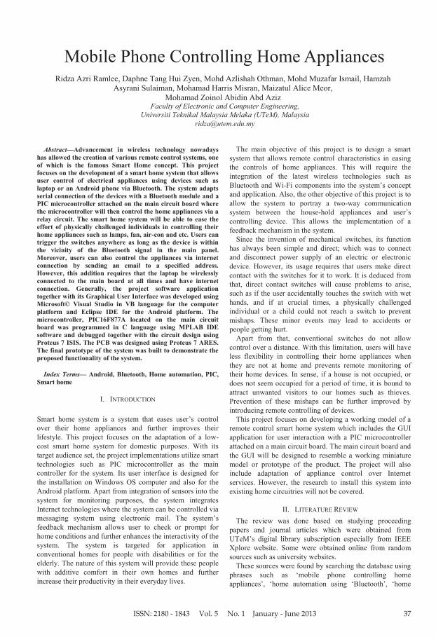
A. System Design Apart from wireless connections, the smart home system
will connect to the appliances grid via wired electrical connection. The illustration of the whole system will be provided in block diagram form including the system’s functionality flow chart (Figure 1). Figure 2 shows the block diagram for main controller panel.
Figure 1: General Block Diagram of Smart Home System. Wireless connections are shown in dashed line while wired ones are shown in
completed lines
Figure 2: Block Diagram of Main Control Panel and Appliances. Elements
in the blocks are important for the hardware design of the system
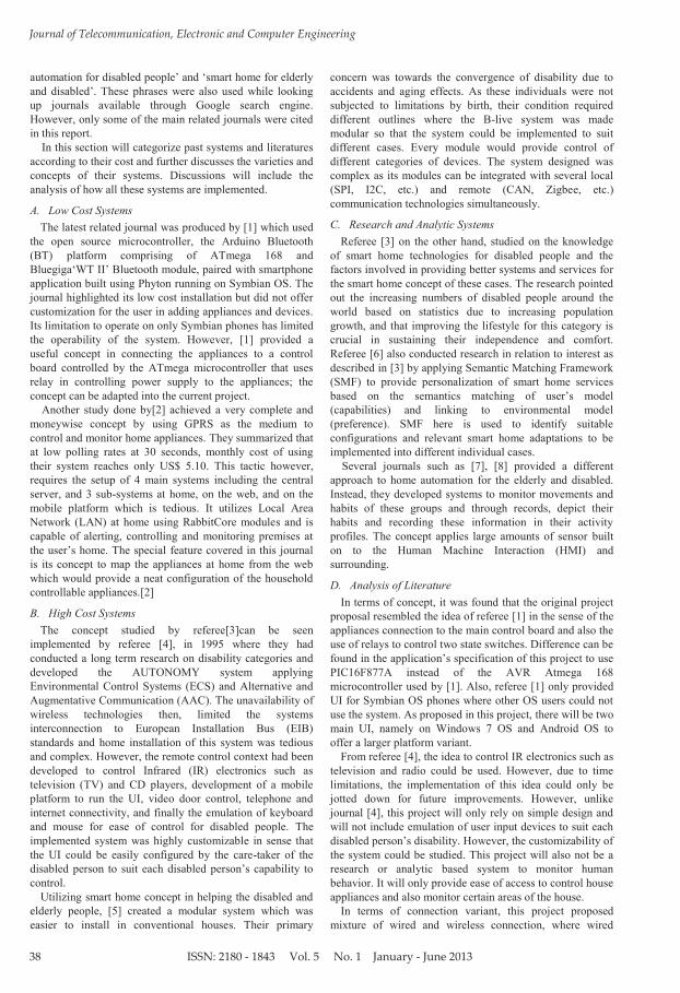
B. System Flow Chart To describe the flow of the system’s logic, a general flow
chart will be included to illustrate the idea of the project (Figure 3). Two parts will be focused in this section which is the interaction of Windows GUI and Android GUI (Figure 4) with the main control panel. The Windows application will serve as a controller and also a server of the system. The flow chart will show how elements of the system interact with each other (Figure 5).
Figure 3: System Flow Chart for Server Application. Red box shows server
actions
Figure 4: System Flow Chart for Android Application. Green box shows
Android application actions
Figure 5: Server to Main Control Panel System Flow Chart. The figure
shows the integration of all the devices
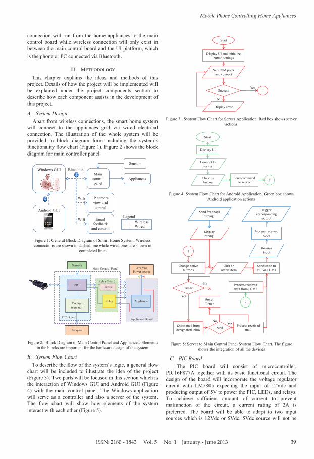
C. PIC Board The PIC board will consist of microcontroller,
PIC16F877A together with its basic functional circuit. The design of the board will incorporate the voltage regulator circuit with LM7805 expecting the input of 12Vdc and producing output of 5V to power the PIC, LEDs, and relays. To achieve sufficient amount of current to prevent malfunction of the circuit, a current rating of 2A is preferred. The board will be able to adapt to two input sources which is 12Vdc or 5Vdc. 5Vdc source will not be
Android GUI
Windows GUI Main
control panel
IP camera view and control
Sensors
Appliances
Bluetooth
Wifi
Email feedback
and control
Wifi Wireless Wired
Legend
PIC Board
PIC
Sensors
Relay Board
Appliance Board
Voltage regulator
Adapter
240 Vac Power source
Driver
Appliance Relay
Main Control Panel
tart
isplay UI and initialize button settings
et C M ports and connect
uccess
isplay error
es
o
end command to server
Start
isplay UI
Connect to server
Click on button
Process received mail
es
o
o es
ISSN: 2180 - 1843 Vol. 5 No. 1 January - June 2013
Journal of Telecommunication, Electronic and Computer Engineering
40
feed through the voltage regulator but will directly supply for the components.
Another main requirement for the PIC board is the placing of the RS232 port together with its MAX232 circuit. This driver serves as the communication port between the Bluetooth module and PIC microcontroller. However, the PIC board (Figure 6) will mainly serve as a simple breakout board for interfacing of other components to the board such as the relay board and the appliance mapping circuit. The power supply is not included in the diagram because it only serves as a supply on the PIC board.
Figure 6: PIC Board Inputs and Outputs. Inputs are shown in red arrows
and outputs in blue arrows
The relay board (Figure 7) will be designed based on its function to trigger relays based on the microcontroller pins output. Since that the relay driver, ULN2003, can only control seven relays per chip, the system prototype will be built to contain seven appliances or switches. This means that the relay board will contain a seven pin input, one power supply input and eight connections to the seven relays and their common pin. The power supply’s positive terminal serves to energize the relay so the switch will be connected to the ‘ ormally open’ port.
Figure 7: Relay Board Inputs and Outputs. Inputs are shown in red arrows
and outputs in blue arrows
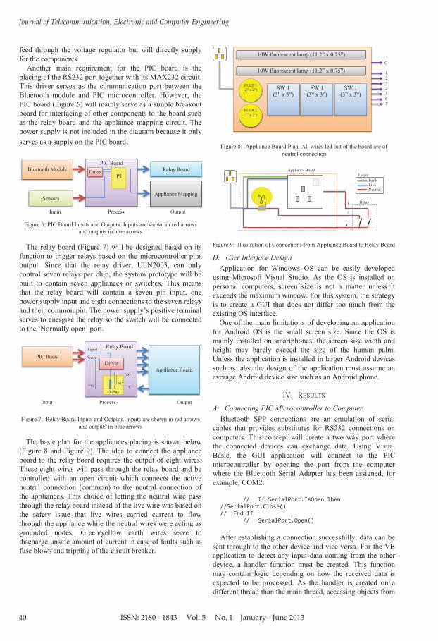
The basic plan for the appliances placing is shown below (Figure 8 and Figure 9). The idea to connect the appliance board to the relay board requires the output of eight wires. These eight wires will pass through the relay board and be controlled with an open circuit which connects the active neutral connection (common) to the neutral connection of the appliances. This choice of letting the neutral wire pass through the relay board instead of the live wire was based on the safety issue that live wires carried current to flow through the appliance while the neutral wires were acting as grounded nodes. Green/yellow earth wires serve to discharge unsafe amount of current in case of faults such as fuse blows and tripping of the circuit breaker.
Figure 8: Appliance Board Plan. All wires led out of the board are of neutral connection
Figure 9: Illustration of Connections from Appliance Board to Relay Board
D. User Interface Design Application for Windows OS can be easily developed
using Microsoft Visual Studio. As the OS is installed on personal computers, screen size is not a matter unless it exceeds the maximum window. For this system, the strategy is to create a GUI that does not differ too much from the existing OS interface.
One of the main limitations of developing an application for Android OS is the small screen size. Since the OS is mainly installed on smartphones, the screen size width and height may barely exceed the size of the human palm. Unless the application is installed in larger Android devices such as tabs, the design of the application must assume an average Android device size such as an Android phone.
IV. RESULTS
A. Connecting PIC Microcontroller to Computer Bluetooth SPP connections are an emulation of serial
cables that provides substitutes for RS232 connections on computers. This concept will create a two way port where the connected devices can exchange data. Using Visual Basic, the GUI application will connect to the PIC microcontroller by opening the port from the computer where the Bluetooth Serial Adapter has been assigned, for example, COM2.
// If SerialPort.IsOpen Then //SerialPort.Close() // End If // SerialPort.Open()
After establishing a connection successfully, data can be sent through to the other device and vice versa. For the VB application to detect any input data coming from the other device, a handler function must be created. This function may contain logic depending on how the received data is expected to be processed. As the handler is created on a different thread than the main thread, accessing objects from
Bluetooth Module
Sensors
Relay Board
Appliance Mapping
Input Process Output
PIC
Driver PIC Board
PIC Board
Appliance Board
Input Process Output
Driver
NC
NO
C +ve
Signal
Power
Relay Board
Relay
SW 1 (3” x 3”)
BULB 1 ( ” x ”)
0W fluorescent lamp ( . ” x 0.75”)
0W fluorescent lamp ( . ” x 0.75”)
BULB 2 ( ” x ”)
SW 1 (3” x 3”)
SW 1 (3” x 3”)
C
1 2 3 4 5 6 7
C
1
2
Earth Live Neutral
Legend
Relay Board
Appliance Board
ISSN: 2180 - 1843 Vol. 5 No. 1 January - June 2013
Mobile Phone Controlling Home Appliances
41
this thread requires invoke of the function that accesses other thread.
// Private Sub SerialPort_DataReceived(ByVal sender As System.Object, ByVal As System.IO.Ports.SerialDataReceivedEventArgs) Handles SerialPort.DataReceived // Dim temp as String = SerialPort.ReadExisting // BeginInvoke(New myDelegate(AddressOfoutFunction), New Object() {})
B. Mail Parsing in VB Parsing means the interpretation of data to extract its
meaning. In this project, codes sent through the e-mail will be processed based on the limited set of codes with format shown in the next table. Extraction of messages from the inbox of the mail uses Google Atom feed (Table 1).
Table 1 Email to Server Commands
ON OFF Explanation
LO LF Controls all lights in the house simultaneously
BOxxx BFxxx Control bedroom lights TOxxx TFxxx Control toilet lights VOxxx VFxxx Control living room lights COxxx CFxxx Control corridor lights AOxxx Afxxx Control appliances or switches Characters denoted by ‘x’ represent numbers to indicate appliances.
To promote security to the user, only codes sent with the
user defined verification code will be recognized; thus extending the format to include a four pin number in front, ‘ 34: B 3;V ;TF ;AF3’, where 34 is the example verification code.
To send multiple codes at a time, codes should be separated by the semi-colon symbol, ‘;’. Example of valid e-mail code is such as, ‘B 3;V ;TF ;AF3’. Any wrong format or syntax of received data will not be processed and overlooked. However, after processing the e-mail codes, an updated condition of the house will be sent to the user defined address; either an e-mail address or a phone number. The details can only be set via the server program which is the VB application. Any user may check the house condition but the feedback will only be sent to one address or phone number to prevent misuse of the system. This ensures that only the owner of the system will know the condition of the house. To check for appliances condition, just send an e-mail to the server’s address with the subject “CHECK”.
To promote security to the user, only codes sent with the user defined verification code will be recognized; thus extending the format to include a four pin number in front, ‘ 34: B 3;V ;TF ;AF3’, where 34 is the example verification code. The figure below shows testing demonstration of using the e-mail control function. Even if the user sends the mail in lower case characters, the program can still understand the command. This is permitted by using the ‘.ToUpper’ function for string manipulation technique in VB before processing the commands.
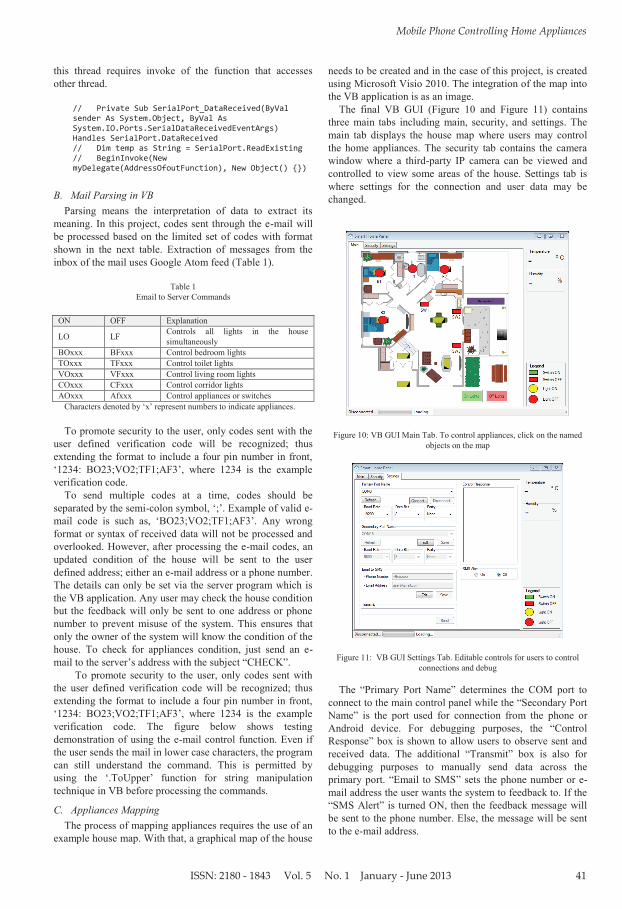
C. Appliances Mapping The process of mapping appliances requires the use of an
example house map. With that, a graphical map of the house
needs to be created and in the case of this project, is created using Microsoft Visio 2010. The integration of the map into the VB application is as an image.
The final VB GUI (Figure 10 and Figure 11) contains three main tabs including main, security, and settings. The main tab displays the house map where users may control the home appliances. The security tab contains the camera window where a third-party IP camera can be viewed and controlled to view some areas of the house. Settings tab is where settings for the connection and user data may be changed.
Figure 10: VB GUI Main Tab. To control appliances, click on the named objects on the map
Figure 11: VB GUI Settings Tab. Editable controls for users to control connections and debug
The “Primary Port ame” determines the C M port to
connect to the main control panel while the “ econdary Port ame” is the port used for connection from the phone or Android device. For debugging purposes, the “Control Response” box is shown to allow users to observe sent and received data. The additional “Transmit” box is also for debugging purposes to manually send data across the primary port. “Email to M ” sets the phone number or e-mail address the user wants the system to feedback to. If the “ M Alert” is turned , then the feedback message will be sent to the phone number. Else, the message will be sent to the e-mail address.
ISSN: 2180 - 1843 Vol. 5 No. 1 January - June 2013
Journal of Telecommunication, Electronic and Computer Engineering
42
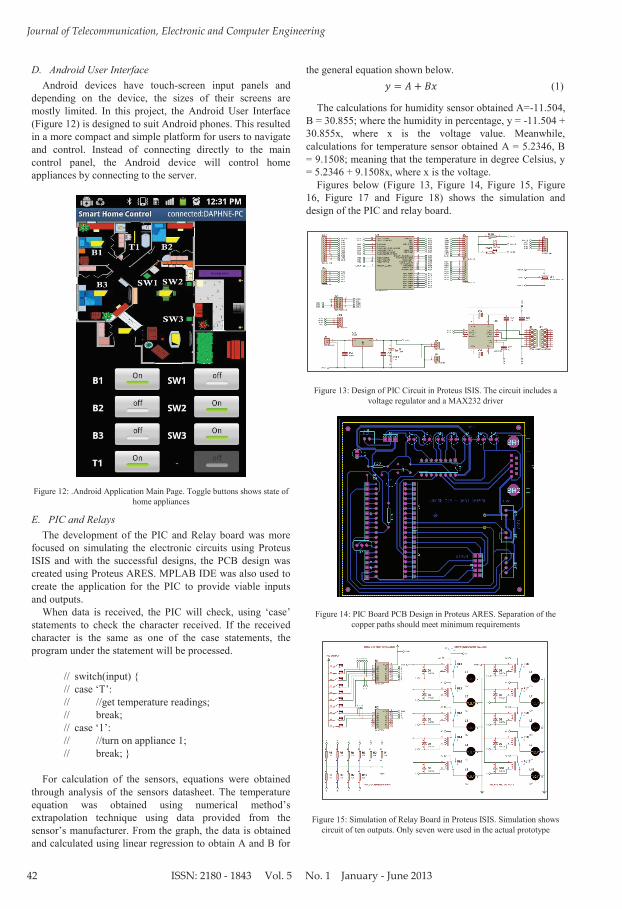
D. Android User Interface Android devices have touch-screen input panels and
depending on the device, the sizes of their screens are mostly limited. In this project, the Android User Interface (Figure 12) is designed to suit Android phones. This resulted in a more compact and simple platform for users to navigate and control. Instead of connecting directly to the main control panel, the Android device will control home appliances by connecting to the server.
Figure 12: .Android Application Main Page. Toggle buttons shows state of
home appliances
E. PIC and Relays The development of the PIC and Relay board was more
focused on simulating the electronic circuits using Proteus ISIS and with the successful designs, the PCB design was created using Proteus ARES. MPLAB IDE was also used to create the application for the PIC to provide viable inputs and outputs.
When data is received, the PIC will check, using ‘case’ statements to check the character received. If the received character is the same as one of the case statements, the program under the statement will be processed.
// switch(input) { // case ‘T’: // //get temperature readings; // break; // case ‘ ’: // //turn on appliance 1; // break; } For calculation of the sensors, equations were obtained
through analysis of the sensors datasheet. The temperature equation was obtained using numerical method’s extrapolation technique using data provided from the sensor’s manufacturer. From the graph, the data is obtained and calculated using linear regression to obtain A and B for
the general equation shown below. (1)
The calculations for humidity sensor obtained A=-11.504, B = 30.855; where the humidity in percentage, y = -11.504 + 30.855x, where x is the voltage value. Meanwhile, calculations for temperature sensor obtained A = 5.2346, B = 9.1508; meaning that the temperature in degree Celsius, y = 5.2346 + 9.1508x, where x is the voltage. Figures below (Figure 13, Figure 14, Figure 15, Figure 16, Figure 17 and Figure 18) shows the simulation and design of the PIC and relay board.
Figure 13: Design of PIC Circuit in Proteus ISIS. The circuit includes a voltage regulator and a MAX232 driver
Figure 14: PIC Board PCB Design in Proteus ARES. Separation of the copper paths should meet minimum requirements
Figure 15: Simulation of Relay Board in Proteus ISIS. Simulation shows circuit of ten outputs. Only seven were used in the actual prototype
ISSN: 2180 - 1843 Vol. 5 No. 1 January - June 2013
Mobile Phone Controlling Home Appliances
43
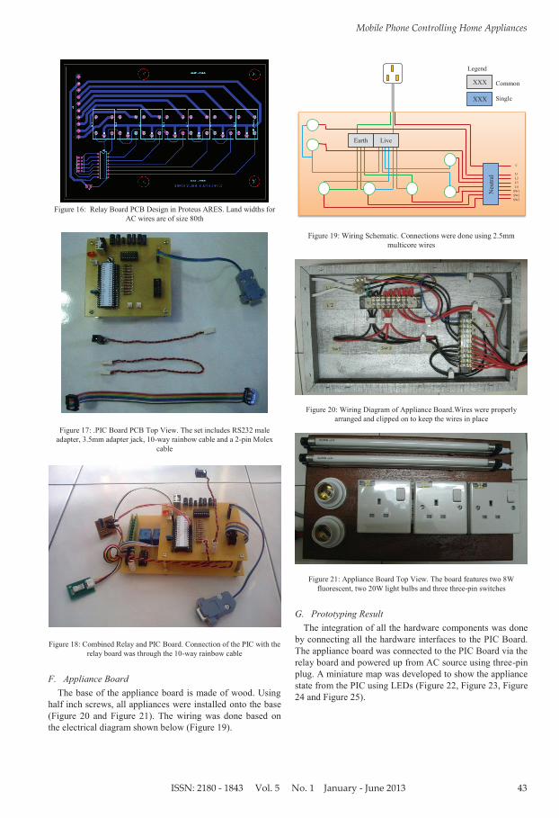
Figure 16: Relay Board PCB Design in Proteus ARES. Land widths for
AC wires are of size 80th
Figure 17: .PIC Board PCB Top View. The set includes RS232 male adapter, 3.5mm adapter jack, 10-way rainbow cable and a 2-pin Molex
cable
Figure 18: Combined Relay and PIC Board. Connection of the PIC with the
relay board was through the 10-way rainbow cable
F. Appliance Board The base of the appliance board is made of wood. Using
half inch screws, all appliances were installed onto the base (Figure 20 and Figure 21). The wiring was done based on the electrical diagram shown below (Figure 19).
Figure 19: Wiring Schematic. Connections were done using 2.5mm multicore wires
Figure 20: Wiring Diagram of Appliance Board.Wires were properly arranged and clipped on to keep the wires in place
Figure 21: Appliance Board Top View. The board features two 8W fluorescent, two 20W light bulbs and three three-pin switches
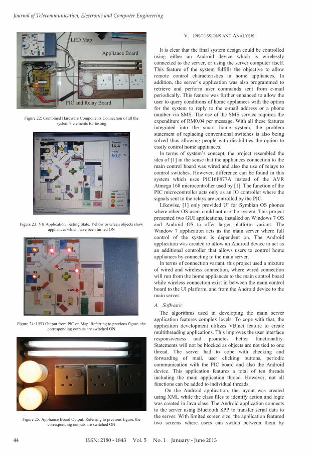
G. Prototyping Result The integration of all the hardware components was done
by connecting all the hardware interfaces to the PIC Board. The appliance board was connected to the PIC Board via the relay board and powered up from AC source using three-pin plug. A miniature map was developed to show the appliance state from the PIC using LEDs (Figure 22, Figure 23, Figure 24 and Figure 25).
C
L1 L2 L3 L4
SW1 SW2 SW3
XXX
XXX
Legend
Common
Single
Live Earth
Neu
tral
ISSN: 2180 - 1843 Vol. 5 No. 1 January - June 2013
Journal of Telecommunication, Electronic and Computer Engineering
44
Figure 22: Combined Hardware Components.Connection of all the system’s elements for testing
Figure 23: VB Application Testing State. Yellow or Green objects show appliances which have been turned ON
Figure 24: LED Output from PIC on Map. Referring to previous figure, the
corresponding outputs are switched ON
Figure 25: Appliance Board Output. Referring to previous figure, the corresponding outputs are switched ON
V. DISCUSSIONS AND ANALYSIS
It is clear that the final system design could be controlled using either an Android device which is wirelessly connected to the server, or using the server computer itself. This feature of the system fulfills the objective to allow remote control characteristics in home appliances. In addition, the server’s application was also programmed to retrieve and perform user commands sent from e-mail periodically. This feature was further enhanced to allow the user to query conditions of home appliances with the option for the system to reply to the e-mail address or a phone number via SMS. The use of the SMS service requires the expenditure of RM0.04 per message. With all these features integrated into the smart home system, the problem statement of replacing conventional switches is also being solved thus allowing people with disabilities the option to easily control home appliances.
In terms of system’s concept, the project resembled the idea of [1] in the sense that the appliances connection to the main control board was wired and also the use of relays to control switches. However, difference can be found in this system which uses PIC16F877A instead of the AVR Atmega 168 microcontroller used by [1]. The function of the PIC microcontroller acts only as an IO controller where the signals sent to the relays are controlled by the PIC.
Likewise, [1] only provided UI for Symbian OS phones where other OS users could not use the system. This project presented two GUI applications, installed on Windows 7 OS and Android OS to offer larger platform variant. The Window 7 application acts as the main server where full control of the system is dependent on. The Android application was created to allow an Android device to act as an additional controller that allows users to control home appliances by connecting to the main server.
In terms of connection variant, this project used a mixture of wired and wireless connection, where wired connection will run from the home appliances to the main control board while wireless connection exist in between the main control board to the UI platform, and from the Android device to the main server.
A. Software The algorithms used in developing the main server
application features complex levels. To cope with that, the application development utilizes VB.net feature to create multithreading applications. This improves the user interface responsiveness and promotes better functionality. Statements will not be blocked as objects are not tied to one thread. The server had to cope with checking and forwarding of mail, user clicking buttons, periodic communication with the PIC board and also the Android device. This application features a total of ten threads including the main application thread. However, not all functions can be added to individual threads.
On the Android application, the layout was created using XML while the class files to identify action and logic was created in Java class. The Android application connects to the server using Bluetooth SPP to transfer serial data to the server. With limited screen size, the application featured two screens where users can switch between them by
Appliance Board
PIC and Relay Board
LED Map
ISSN: 2180 - 1843 Vol. 5 No. 1 January - June 2013
Mobile Phone Controlling Home Appliances
45
flipping the screen to left or right. In terms of the PIC microcontroller, the integration of
sensors into the circuit used the ADC module of the PIC. Two ports, AN1 and AN2 were used to input voltage readings from the temperature and the humidity sensors. The conversion of the data was based on the calculation as shown using equation 4.1. Even though the sensors were not precise, the integration of the sensors were according to the specification as specified in the sensor’s manual and fulfilled the objective to implement two way communication in the system. The server will periodically prompt for sensors reading using specific commands and the PIC microcontroller will reply accordingly in a proper format.
B. Hardware Integration of the relay board and PIC board was
achieved by connection via a ten way rainbow cable. The rainbow cable was used because it is more flexible and durable compared to single core copper wires. Since the relay board, PIC board and the LED outputs shared a same voltage and current source, an adapter of 5 Volts and 2 Amperes was used to power the circuit and via testing, was enough to power up the whole system without heating up. However, the relays showed signs of slight heat. This was one of the disadvantages of using mechanical relays. A way to solve this was to design a new circuit that replaces the relays with transistors. This method could also eliminate the relay switching sound.
When fixing the appliance board and the wirings, caution must be put when cutting the wires. It must be ensured that no copper were accidentally removed as it affects the power rating of the cable. In terms of connection, it is better to not let the live wire be passed through the relays. This is because live wire carries the current for the AC connection. However, doing so disallows users from directly changing any components such as a light bulb when the main switch powering the appliance board is still active. This is a caution that must be taken to prevent electric shock.
VI. PROJECT SIGNIFICANCE AND IMPLICATIONS Comparing to past literatures, this project integrated
valuable ideas in developing a low cost smart home system. With a highly remote control platform, the system added also control via Internet features which improves the functionality of the system. Users are not only allowed to control but also check for appliances condition. The system is capable of providing feedback via e-mail or even through M to the user’s phone number.
Adding the ideas of the literature [2], the concept of mapping was applied by creating customized house floor maps with indication of the location of the home appliances. This greatly eases the user’s control over the appliances instead of a GUI displaying only buttons like the system in literature [1]. Also adopting a different idea from referee [1], another GUI was developed for the popular Android platform. Regardless of that, the microcontroller used created a wider range of applicability for the system. With its lower cost, the system can be integrated in more areas especially in places where it is needed, such as home for the elderly and etc.
VII. CONCLUSIONS The smart home system was created to allow user’s
control over home appliances from a remote distance. One of the controllable platforms is the Android device that controls home appliances by connecting to the main server. The main server, which can also control home appliances, is also programmed to perform commands received from the email to control appliances. Apart from that, users may prompt for appliances condition also through email and the reply can be sent to the user’s email address or phone number through SMS. All the features stated above has fulfilled the first project objective to design a smart system that allows remote controlling of home appliances. The second objective to portray a two way communication between the GUI and the microcontroller was achieved by adding temperature and humidity sensors to the microcontroller circuit where its values are prompted periodically by the GUI application. By accomplishing the objectives, the problem statement to replace control of home appliances via conventional switches have been solved.
VIII. RECOMMENDATIONS
A. Improvements for Hardware In terms of installation, the system is designed to be
installed in new houses where existing electrical wirings are still not laid out. This creates a disadvantage where there is a limited range of customers that could purchase this product. To solve this issue, further research needs to be done to create or modify this system so that it can be installed into homes with existing electrical wirings.
Also, due to time constraints, the system’s development only achieved the control of two state switches at home such as lighting and switches. Improvement of the system can be achieved by integrating techniques to control IR devices such as the television, the air conditioner or even the washing machine. These additions would be able to improve the system’s range of control at home. Even further additions could include security features with the installation of sensors and alarms around the house. This would require the design of a flexible PIC board that is easily extensible so that there are enough ports to support the system.
Apart from that, seeming that this project aimed at producing a low cost smart home system, the system’s integrity is questionable. However, with a proper power source that can supply enough current, the system can still be applied in domestic homes. To target larger enterprises or locations, the system may be improved to integrate a more industrial applicable controller such as PLC. However, this dramatically increases the cost of the system especially if there is the need to control a large number of appliances.
B. Improvements for Software In terms of the system’s software, this project still utilizes
third-party web services such as Google’s Atom feed and the SMS mail. If this system was to be improved into an independent product, these two services need to be created so as to cut off the dependencies of the system. If the services were discontinued, the system’s server application needs to be reprogrammed to find for replacements of those services. This may be a tedious process but by making the
ISSN: 2180 - 1843 Vol. 5 No. 1 January - June 2013
Journal of Telecommunication, Electronic and Computer Engineering
46
system independent, this product can be a stable stand-alone system.
C. Applications for Smart Home System The current smart home system targets domestic homes
where ease of control is of major concern. This includes homes for people with disabilities, elderly, or for anyone with difficulties moving around. Nevertheless, these people must still at least have functionality of at least one finger as it is possible to navigate the Android device GUI with a single finger. Home installed with this system will have a higher sense of controllability over their home appliances even when they are not at home. For instance, if a family went for a vacation, leaving their house vacant for some time, it could easily be targeted by robbers. With this system, home users can monitor and control the appliances in the house from anywhere with Internet connection. Switching on some appliances from time to time may make the house seem occupied and minimize the chances of having unwanted visitors.
ACKNOWLEDGMENT
I would like to thank Universiti Teknikal Malaysia Melaka (UTeM) which has financially supported this research to be accomplished.
REFERENCES
[1] R. Piyare and M. Tazil, “Bluetooth Based Home Automation ystem using Cell Phone,” in Consumer Electronics, 0 , pp. 9 -195.
[2] K. Atukorala, D. Wijekoon, M. Tharugasini, I. Perera, and C. Silva, “ martEye Integrated olution to Home Automation, ecurity and Monitoring through Mobile Phones,” in 009 Third International Conference on Next Generation Mobile Applications, Services and Technologies, 2009, pp. 64-69.
[3] J. jasalo and . uomalainen, “Better Technologies and ervices for mart Homes of isabled People : Empirical Findings from an Explorative tudy among Intellectually isabled,” in Applied Sciences, 2010, no. 2, pp. 251-259.
[4] P. Panek, W. L. Zagler, C. Beck, and G. eisenbacher, “ mart Home Applications for disabled Persons - Experiences and Perspectives,” in Electronics, 00 , pp. -10.
[5] J. Fonseca, A. Mota, V. Santos, P. Bartolomeu, M. I. O. Servi, and . Electrnica, “B-Live - A Home Automation System for Disabled and Elderly People,” in IEEE, 007, pp. 333-336.
[6] R. Kadouche, M. Mokhtari, S. Giroux, and B. Abdulrazak, “Personalization in mart Homes for isabled People,” in 008 Second International Conference on Future Generation Communication and Networking, 2008, pp. 411-415.
[7] M. Marschollek et al., “Multimodal home monitoring of elderly people – first results from the LASS study,” no. , 007.
[8] M. Chan et al., “ mart House Automation ystem for the Elderly and the isabled,” eural etworks, no.IEEE, pp. 586-1589, 1995.
Related Documents


![Toward Visualising and Controlling Household Electrical ... · information on controlling the household appliances. There are numerous research patents [22] and literature [23] explaining](https://static.cupdf.com/doc/110x72/5f2d4948ce6858740e424f64/toward-visualising-and-controlling-household-electrical-information-on-controlling.jpg)
