Mobile Panel 277 RO ___________________ ___________________ ___________________ ___________________ ___________________ ___________________ ___________________ ___________________ ___________________ ___________________ ___________________ ___________________ ___________________ SIMATIC HMI HMI device Mobile Panel 277 RO Operating Instructions 10/2015 A5E36824256-AA Preface Overview 1 Safety instructions and general notes 2 Planning application 3 Mounting and connecting 4 Operator controls and displays 5 Configuring the operating system 6 Using RemoteOperate Client 7 Backing up and restoring data 8 Maintenance and care 9 Technical specifications 10 Appendix A Abbreviations B

Welcome message from author
This document is posted to help you gain knowledge. Please leave a comment to let me know what you think about it! Share it to your friends and learn new things together.
Transcript

Mobile Panel 277 RO
___________________
___________________
___________________
___________________
___________________
___________________
___________________
___________________
___________________
___________________
___________________
___________________
___________________
SIMATIC HMI
HMI device Mobile Panel 277 RO
Operating Instructions
10/2015 A5E36824256-AA
Preface
Overview 1
Safety instructions and general notes
2
Planning application 3
Mounting and connecting 4
Operator controls and displays
5
Configuring the operating system
6
Using RemoteOperate Client 7
Backing up and restoring data
8
Maintenance and care 9
Technical specifications 10
Appendix A
Abbreviations B
Siemens AG Division Digital Factory Postfach 48 48 90026 NÜRNBERG GERMANY
A5E36824256-AA Ⓟ 11/2015 Subject to change
Copyright © Siemens AG 2015. All rights reserved
Legal information Warning notice system
This manual contains notices you have to observe in order to ensure your personal safety, as well as to prevent damage to property. The notices referring to your personal safety are highlighted in the manual by a safety alert symbol, notices referring only to property damage have no safety alert symbol. These notices shown below are graded according to the degree of danger.
DANGER indicates that death or severe personal injury will result if proper precautions are not taken.
WARNING indicates that death or severe personal injury may result if proper precautions are not taken.
CAUTION indicates that minor personal injury can result if proper precautions are not taken.
NOTICE indicates that property damage can result if proper precautions are not taken.
If more than one degree of danger is present, the warning notice representing the highest degree of danger will be used. A notice warning of injury to persons with a safety alert symbol may also include a warning relating to property damage.
Qualified Personnel The product/system described in this documentation may be operated only by personnel qualified for the specific task in accordance with the relevant documentation, in particular its warning notices and safety instructions. Qualified personnel are those who, based on their training and experience, are capable of identifying risks and avoiding potential hazards when working with these products/systems.
Proper use of Siemens products Note the following:
WARNING Siemens products may only be used for the applications described in the catalog and in the relevant technical documentation. If products and components from other manufacturers are used, these must be recommended or approved by Siemens. Proper transport, storage, installation, assembly, commissioning, operation and maintenance are required to ensure that the products operate safely and without any problems. The permissible ambient conditions must be complied with. The information in the relevant documentation must be observed.
Trademarks All names identified by ® are registered trademarks of Siemens AG. The remaining trademarks in this publication may be trademarks whose use by third parties for their own purposes could violate the rights of the owner.
Disclaimer of Liability We have reviewed the contents of this publication to ensure consistency with the hardware and software described. Since variance cannot be precluded entirely, we cannot guarantee full consistency. However, the information in this publication is reviewed regularly and any necessary corrections are included in subsequent editions.
Mobile Panel 277 RO Operating Instructions, 10/2015, A5E36824256-AA 3
Preface Purpose of the operating instructions
These operating instructions provide information based on the requirements defined by DIN EN 62079 for mechanical engineering documentation. This information relates to the place of use, transport, storage, mounting, use and maintenance. These operating instructions are intended for the following user groups:
● Operators Operators operate and monitor the system during the process control phase. The following chapters are relevant to the operator:
– Overview – Operator controls and displays – Configuring the operating system – Using RemoteOperate Client – Backing up and restoring data
● Commissioning engineers Commissioning engineers integrate the HMI device into the system and ensure the operating capability of the device for the process control phase. The entire set of operating instructions is relevant to commissioning engineers in principle. Depending on the use of the HMI device, however, certain chapters may not be relevant to them, e.g., the chapter on "Maintenance and care".
● Service technicians Service technicians rectify faults that occur during the process control phase. The entire set of operating instructions is relevant to service technicians in principle. Depending on the use of the HMI device, however, certain chapters may not be relevant to them, e.g., the chapter on "Maintenance and care".
● Maintenance technicians Maintenance technicians carry out regular maintenance work during the process control phase. The chapter on "Maintenance and care" is relevant to maintenance technicians.
All user groups must pay special attention to the chapter on "Safety instructions and general notes".
Basic knowledge required General knowledge of automation technology and process communication is needed to understand the operating instructions. It is also assumed that those using the manual have experience in using personal computers and knowledge of Microsoft operating systems.
Scope of the operating instructions These operating instructions apply to the SIMATIC Mobile Panel 277 RO HMI device in combination with the RemoteOperate V4 software.

Preface
Mobile Panel 277 RO 4 Operating Instructions, 10/2015, A5E36824256-AA
Associated documents Additional information on the RemoteOperate V4 software is available in the RemoteOperate V4 programming manual.
Pictures The HMI device is sometimes shown in the form of photographs in these operating instructions. The photographs of the HMI device may differ slightly from the factory state of the HMI device.
Conventions The following designations for hardware and software are used in this manual: Designation Meaning RemoteOperate Server The RemoteOperate Server software package RemoteOperate Client The RemoteOperate Client software package RemoteOperate The RemoteOperate software package (Server and Client) Server A system on which the RemoteOperate Server software is installed or runs. Client, HMI device A system on which the RemoteOperate Client software package runs.
The following text notation will facilitate reading this manual: Notation Scope "Add figure" • Terminology that appears in the user interface, for example dialog
names and buttons. • Required inputs, for example, an IP address. • Path information
"File > Edit" Operating sequences, for example, menu commands, shortcut menu commands.
<F1>, <Alt + P> Keyboard actions
Please observe notes labeled as follows:
Note
Notes containing important information about the product and its use or a specific section of the documentation to which you should pay particular attention.
Registered trademarks ● HMI®
● SIMATIC®
● SIMATIC HMI®
Third parties using for their own purposes any other names in this document which refer to trademarks might infringe upon the rights of the trademark owners.

Mobile Panel 277 RO Operating Instructions, 10/2015, A5E36824256-AA 5
Table of contents
Preface ...................................................................................................................................................... 3
1 Overview .................................................................................................................................................... 9
1.1 Product overview ...................................................................................................................... 9
1.2 Design of the HMI device .......................................................................................................... 9
1.3 Accessories ............................................................................................................................. 12 1.3.1 Connecting cable .................................................................................................................... 12 1.3.2 Connection box ....................................................................................................................... 13 1.3.3 Rechargeable buffer battery ................................................................................................... 14 1.3.4 Wall-mounting bracket ............................................................................................................ 15 1.3.5 PC/PPI cable ........................................................................................................................... 15 1.3.6 USB/PPI cable ........................................................................................................................ 16 1.3.7 Protective foil .......................................................................................................................... 16 1.3.8 Touch pens ............................................................................................................................. 16 1.3.9 Memory card ........................................................................................................................... 16
1.4 The HMI device in the operating process ............................................................................... 17
2 Safety instructions and general notes ...................................................................................................... 19
2.1 General safety instructions ..................................................................................................... 19
2.2 Standards, certificates and approvals..................................................................................... 22
2.3 Operating safety ...................................................................................................................... 23
2.4 Voltage supply ........................................................................................................................ 24
2.5 Notes about usage .................................................................................................................. 24
2.6 Risk assessment ..................................................................................................................... 25
2.7 Enabling button ....................................................................................................................... 26
2.8 STOP button ........................................................................................................................... 28
2.9 Electromagnetic compatibility ................................................................................................. 29
2.10 Transport and storage conditions ........................................................................................... 31
3 Planning application ................................................................................................................................. 33
3.1 Notes about usage .................................................................................................................. 33
3.2 Mounting positions and type of fixation................................................................................... 35
3.3 Preparing for mounting ........................................................................................................... 36
3.4 Information on insulation tests, protection class and degree of protection ............................. 37
3.5 Rated voltages ........................................................................................................................ 38
Table of contents
Mobile Panel 277 RO 6 Operating Instructions, 10/2015, A5E36824256-AA
4 Mounting and connecting ......................................................................................................................... 39
4.1 Checking the package contents ............................................................................................. 39
4.2 Mounting the connection box and wall-mounting bracket ...................................................... 39
4.3 Electrical installation .............................................................................................................. 41
4.4 Connecting the connection box .............................................................................................. 41 4.4.1 Overview ................................................................................................................................ 41 4.4.2 Opening and closing the connection box ............................................................................... 42 4.4.3 Stripping the insulation of cables ........................................................................................... 44 4.4.4 Connecting the equipotential bonding circuit ......................................................................... 45 4.4.5 Connecting the server ............................................................................................................ 47 4.4.6 Connecting the power supply ................................................................................................. 47 4.4.7 Connecting the connecting cable ........................................................................................... 49
4.5 Connecting the Mobile Panel 277 RO ................................................................................... 51 4.5.1 Connecting the HMI device .................................................................................................... 51 4.5.2 Opening and closing the terminal compartment .................................................................... 51 4.5.3 Mobile Panel 277 RO ports .................................................................................................... 53 4.5.4 Connecting a PC .................................................................................................................... 56
4.6 Switching on and testing the HMI device ............................................................................... 57
5 Operator controls and displays ................................................................................................................ 59
5.1 Operator controls and displays on the Mobile Panel 277 RO ................................................ 59 5.1.1 Overview ................................................................................................................................ 59 5.1.2 Enabling button ...................................................................................................................... 60 5.1.3 STOP button .......................................................................................................................... 62 5.1.3.1 Overview ................................................................................................................................ 62 5.1.3.2 Safety functions of the STOP button ..................................................................................... 64 5.1.3.3 STOP button on the connection box Plus .............................................................................. 66 5.1.4 Using memory cards .............................................................................................................. 67
5.2 Changing the touch pen ......................................................................................................... 68
5.3 Holding the mobile panel and fixing it to the wall ................................................................... 69
5.4 Displays on the connection box PN ....................................................................................... 71
6 Configuring the operating system ............................................................................................................ 73
6.1 Loader .................................................................................................................................... 73
6.2 Control Panel ......................................................................................................................... 75 6.2.1 Overview ................................................................................................................................ 75 6.2.2 Reference ............................................................................................................................... 76 6.2.3 Operating the Control Panel .................................................................................................. 77
6.3 Changing settings for operation ............................................................................................. 79 6.3.1 Configuring the screen keyboard ........................................................................................... 79 6.3.2 Setting the character repeat rate of the screen keyboard ..................................................... 80 6.3.3 Setting the double-click .......................................................................................................... 81 6.3.4 Calibrating the touch screen .................................................................................................. 82
6.4 Changing password protection .............................................................................................. 84

Table of contents
Mobile Panel 277 RO Operating Instructions, 10/2015, A5E36824256-AA 7
6.5 Changing HMI device settings ................................................................................................ 85 6.5.1 Setting the date and time ........................................................................................................ 85 6.5.2 Backup registry information .................................................................................................... 87 6.5.3 Changing monitor settings ...................................................................................................... 88 6.5.4 Setting the screen saver ......................................................................................................... 89 6.5.5 Restarting the HMI device ...................................................................................................... 91 6.5.6 Displaying information about the HMI device ......................................................................... 92 6.5.7 Displaying system properties .................................................................................................. 93
6.6 Setting the delay time ............................................................................................................. 95
6.7 Communication settings ......................................................................................................... 96 6.7.1 Configuring the data channel .................................................................................................. 96 6.7.2 Checking the PROFINET IO settings ..................................................................................... 98
6.8 Configuring network operation ................................................................................................ 99 6.8.1 Setting the device name of the HMI device ............................................................................ 99 6.8.2 Changing the network configuration ..................................................................................... 100 6.8.3 Changing the logon data ....................................................................................................... 101
6.9 Backup and restore with the memory card ........................................................................... 102 6.9.1 Backup to the memory card .................................................................................................. 102 6.9.2 Restore from the memory card ............................................................................................. 104
6.10 Display rechargeable battery charge level ........................................................................... 106
7 Using RemoteOperate Client ................................................................................................................. 107
7.1 Creating/editing a server selection list .................................................................................. 107
7.2 Connecting a client ............................................................................................................... 110
7.3 Changing the server .............................................................................................................. 114
7.4 Start client ............................................................................................................................. 115
7.5 Closing the RemoteOperate Client ....................................................................................... 115
7.6 Example: Assigning operator authorization .......................................................................... 117
8 Backing up and restoring data ............................................................................................................... 121
9 Maintenance and care ........................................................................................................................... 123
9.1 Maintenance and care .......................................................................................................... 123
9.2 Update HMI device image .................................................................................................... 124
9.3 Spare parts and repairs ........................................................................................................ 125

Table of contents
Mobile Panel 277 RO 8 Operating Instructions, 10/2015, A5E36824256-AA
10 Technical specifications ......................................................................................................................... 127
10.1 Dimension drawings ............................................................................................................. 127 10.1.1 Mobile Panel 277 RO ........................................................................................................... 127 10.1.2 Wall-mounting bracket ......................................................................................................... 129 10.1.3 Connection box PN Plus ...................................................................................................... 130
10.2 Specifications ....................................................................................................................... 131 10.2.1 Mobile Panel 277 RO ........................................................................................................... 131 10.2.2 Rechargeable buffer battery ................................................................................................ 132 10.2.3 Safety characteristics ........................................................................................................... 133 10.2.4 Connection box PN Plus ...................................................................................................... 134
10.3 Mobile Panel 277 RO interface assignment ........................................................................ 135 10.3.1 RS 485 (IF 2) ........................................................................................................................ 135 10.3.2 USB ...................................................................................................................................... 135 10.3.3 RJ45 for connecting cable PN ............................................................................................. 136 10.3.4 Post connector for connecting cable PN .............................................................................. 136
10.4 Connection box PN Plus interface assignment .................................................................... 137
10.5 Wiring Examples for Enabling Switch and STOP Button ..................................................... 142
A Appendix ................................................................................................................................................ 145
A.1 Service and support ............................................................................................................. 145
A.2 ESD guideline ...................................................................................................................... 146
B Abbreviations ......................................................................................................................................... 149
B.1 Abbreviations ....................................................................................................................... 149
Glossary ................................................................................................................................................ 151
Index ...................................................................................................................................................... 153
Mobile Panel 277 RO Operating Instructions, 10/2015, A5E36824256-AA 9
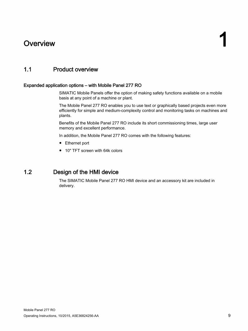
Overview 1 1.1 Product overview
Expanded application options – with Mobile Panel 277 RO SIMATIC Mobile Panels offer the option of making safety functions available on a mobile basis at any point of a machine or plant.
The Mobile Panel 277 RO enables you to use text or graphically based projects even more efficiently for simple and medium-complexity control and monitoring tasks on machines and plants.
Benefits of the Mobile Panel 277 RO include its short commissioning times, large user memory and excellent performance.
In addition, the Mobile Panel 277 RO comes with the following features:
● Ethernet port
● 10" TFT screen with 64k colors
1.2 Design of the HMI device The SIMATIC Mobile Panel 277 RO HMI device and an accessory kit are included in delivery.

Overview 1.2 Design of the HMI device
Mobile Panel 277 RO 10 Operating Instructions, 10/2015, A5E36824256-AA
Front view of the Mobile Panel 277 RO
① STOP button ② Display with touch screen
Side view of the Mobile Panel 277 RO
① Impact guards ② Enabling buttons, positioned on both sides of the Mobile Panel 277 RO ③ Handle
Overview 1.2 Design of the HMI device
Mobile Panel 277 RO Operating Instructions, 10/2015, A5E36824256-AA 11
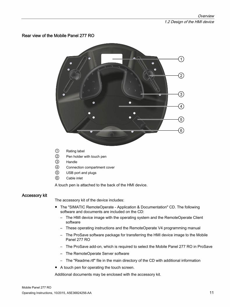
Rear view of the Mobile Panel 277 RO
① Rating label ② Pen holder with touch pen ③ Handle ④ Connection compartment cover ⑤ USB port and plugs ⑥ Cable inlet
A touch pen is attached to the back of the HMI device.
Accessory kit The accessory kit of the device includes:
● The "SIMATIC RemoteOperate - Application & Documentation" CD. The following software and documents are included on the CD: – The HMI device image with the operating system and the RemoteOperate Client
software – These operating instructions and the RemoteOperate V4 programming manual
– The ProSave software package for transferring the HMI device image to the Mobile Panel 277 RO
– The ProSave add-on, which is required to select the Mobile Panel 277 RO in ProSave
– The RemoteOperate Server software
– The "Readme.rtf" file in the main directory of the CD with additional information
● A touch pen for operating the touch screen.
Additional documents may be enclosed with the accessory kit.

Overview 1.3 Accessories
Mobile Panel 277 RO 12 Operating Instructions, 10/2015, A5E36824256-AA
1.3 Accessories
1.3.1 Connecting cable The Mobile Panel 277 RO is compatible with the connecting cable PN:
① Metallic push-pull circular connector ② Strain relief and antikink device for the connecting cable ③ RJ45 connector ④ Plug connector, 12-pin
Connect the connecting cable to the Mobile Panel 277 RO so that it is not detachable. The connection to the connection box PN Plus is achieved by means of a detachable connector. The connecting cable PN is an industrial cable and is therefore resistant to many solvents and lubricants. The flexural strength of the connecting cable is geared to the actual usage conditions.
Note Degree of protection
When inserted, the circular connector guarantees IP65 degree of protection..
Ordering information The connecting cable PN is not included with the HMI device. The connecting cable PN is available in various lengths under the following article numbers: Length of the connecting cable Article number 5 m 6XV1440-4BH50 10 m 6XV1440-4BN10 25 m 6XV1440-4BN25

Overview 1.3 Accessories
Mobile Panel 277 RO Operating Instructions, 10/2015, A5E36824256-AA 13
1.3.2 Connection box The Mobile Panel 277 RO is compatible with the connection box PN Plus:
① Screwed joint for process data line ② LEDs ③ Threaded assembly for power supply cable ④ Threaded assembly for cable with supplementary Stop and enabling button signals and for
PLC-accompanying signals ⑤ Connecting socket for the connecting cable - covered with dummy cap
A mechanical foolproofing device means that only the connecting cable PN can be connected to the connection box PN Plus.
Note Degree of protection
Degree of protection IP65 is guaranteed for the connection box when the Mobile Panel 277 RO is connected or when a dummy cap is inserted.
Note Recovery time
Wait for approximately one second after you have removed the connecting cable from the connection box before you plug the connecting cable back in.
After power failures lasting less than one second the connecting cable has to be disconnected.
Ordering information The connection box PN Plus is not included with the HMI device. The connection box PN Plus is available under article number 6AV6671-5AE11-0AX0.

Overview 1.3 Accessories
Mobile Panel 277 RO 14 Operating Instructions, 10/2015, A5E36824256-AA
Division of the system into zones You can divide a system into various zones or functional areas by using numerous connection boxes. You can also set up the safety functions zone-dependently. This means that both enabling buttons and STOP buttons can act in only one particular zone and not in others.
1.3.3 Rechargeable buffer battery The rechargeable buffer battery avoids the need to restart the Mobile Panel when changing between different connection boxes. The maximum buffer time is 10 minutes. The rechargeable battery is able to bridge the buffer time 5 times without recharging. During the buffer time, the backlight of the display is switched off. When the mobile panel is connected to a connection box, the rechargeable battery is charged automatically.
Note Recharging and discharging the rechargeable battery In the following cases, there is a risk of fire and, in extreme cases, explosion! • Incorrect charging and discharging of the rechargeable battery • Reverse polarity • Short-circuit
The rechargeable battery may only be recharged in the mobile panel.
Note The HMI device may supply the same system alarms as it would do in the event of a communication interrupt when reconnecting the HMI device to another connection box.
Safety instructions The rechargeable battery is a Li-ion rechargeable battery. The following safety notes apply to these rechargeable batteries: ● Do not crush. ● Do not expose to heat and do not burn. ● Do not short-circuit. ● Do not take apart. ● Do not immerse in liquid – the battery might crack or burst.
Ordering information The rechargeable buffer battery is not included with the HMI device.
Note
You may only use the battery option package as of product version 02. The product version is available on the battery.
The rechargeable battery is available under the article number 6AV6671-5AD00-0AX0.
Overview 1.3 Accessories
Mobile Panel 277 RO Operating Instructions, 10/2015, A5E36824256-AA 15
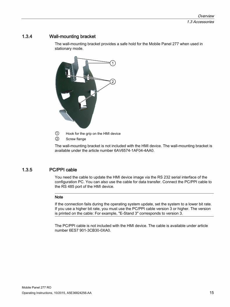
1.3.4 Wall-mounting bracket The wall-mounting bracket provides a safe hold for the Mobile Panel 277 when used in stationary mode.
① Hook for the grip on the HMI device ② Screw flange
The wall-mounting bracket is not included with the HMI device. The wall-mounting bracket is available under the article number 6AV6574-1AF04-4AA0.
1.3.5 PC/PPI cable You need the cable to update the HMI device image via the RS 232 serial interface of the configuration PC. You can also use the cable for data transfer. Connect the PC/PPI cable to the RS 485 port of the HMI device.
Note
If the connection fails during the operating system update, set the system to a lower bit rate. If you use a higher bit rate, you must use the PC/PPI cable version 3 or higher. The version is printed on the cable: For example, "E-Stand 3" corresponds to version 3.
The PC/PPI cable is not included with the HMI device. The cable is available under article number 6ES7 901-3CB30-0XA0.

Overview 1.3 Accessories
Mobile Panel 277 RO 16 Operating Instructions, 10/2015, A5E36824256-AA
1.3.6 USB/PPI cable You need the cable to update the operating system by resetting to factory settings via the USB port of the configuration PC. Connect the PC/PPI cable to the RS 485 port of the HMI device.
Note
Use a USB/PPI cable, version 5 or higher. The version is printed on the cable: For example, "E-Stand 5" corresponds to version 5.
The USB/PPI cable is not included with the HMI device. The cable is available under article number 6ES7 901-3DB30-0XA0.
1.3.7 Protective foil The protective foil prevents the touch screen from being scratched or soiled.
The protective foil kit is not included with the HMI device. The protective foil kit contains 10 protective foils and has the following article numbers:
● 6AV6671-5BC00-0AX0 for Mobile Panel 277 8"
● 6AV6645-7AB15-0AS0 for Mobile Panel 277 10"
1.3.8 Touch pens The touch pens make it easier to operate the touch screen.
The touch pen set is not included with the HMI device. The touch pen set contains 5 pens and is available under article number 6AV6645-7AB14-0AS0.
1.3.9 Memory card You can use a memory card to back up data from the HMI device and to copy data onto the HMI device. Only use the SD memory cards or multimedia cards tested and released by Siemens.
A memory card is not included with the HMI device. The memory card can be ordered using the Siemens online catalog. For additional information, refer to the Internet at Industry Mall (https://mall.industry.siemens.com).

Overview 1.4 The HMI device in the operating process
Mobile Panel 277 RO Operating Instructions, 10/2015, A5E36824256-AA 17
1.4 The HMI device in the operating process The HMI device is part of the operating process. The operating process is marked by three-way communication between the HMI device, server and PLC. The following figure shows an exemplary system design.
The HMI device is used for monitoring or controlling the operating process. The PLC in turn supplies the server with the results of the operating process, which are displayed on the HMI device.

Overview 1.4 The HMI device in the operating process
Mobile Panel 277 RO 18 Operating Instructions, 10/2015, A5E36824256-AA
The RemoteOperate software package Communication between the HMI device and the server is handled using the RemoteOperate software package.
Using RemoteOperate you can monitor or operate a server from a client. The range of operations covers all the functions of the server.
The RemoteOperate software package comprises two components:
● The RemoteOperate Server software
● The RemoteOperate Client software
A detailed description of the RemoteOperate software can be found in the "RemoteOperate V4" programming manual.

Mobile Panel 277 RO Operating Instructions, 10/2015, A5E36824256-AA 19
Safety instructions and general notes 2 2.1 General safety instructions
Safety regulations
WARNING
Personal injury or material damage due to non-compliance with safety regulations
Strictly observe all instructions in these operating instructions at all times. Otherwise, hazardous situations can arise or the safety mechanisms in the HMI device can be rendered ineffective.
Observe the safety and accident prevention instructions applicable to your application in addition to the safety instructions given in this manual.
WARNING
Operational safety in the plant
The configuration engineer for a machine or system PLC must take precautions so that an interrupted program can be restarted normally after voltage dips or power failures. Dangerous operating conditions must not occur, even temporarily.
If faults in the system can cause bodily injury or significant property damage, additional measures must be taken outside of the system. These measures must also ensure safe operating conditions in the system in the event of a fault.
The system's configuration engineer must take precautions to ensure that memory changes that could lead to a dangerous situation can only be undertaken by authorized persons.
The STOP button and enabling button must be checked periodically for proper functioning.

Safety instructions and general notes 2.1 General safety instructions
Mobile Panel 277 RO 20 Operating Instructions, 10/2015, A5E36824256-AA
WARNING
Operational reliability of the HMI device
After a hard impact to the HMI device, check the safety-relevant features for functional capability, for example in the event that the HMI device is dropped.
Manual actions performed with the HMI device may only occur in conjunction with the enabling buttons and at reduced velocity.
During operation, note: • The hazardous location must be visible from the operating position taken by the
personnel. • Ensure that current operation is only possible by means of the HMI device and not from
any other point on the system.
Proper use
WARNING
Potential personal injury or material damage due to non-compliance with machine regulations
Commissioning of the HMI device is forbidden until it has been absolutely ensured that the machine in which the HMI device is to be installed complies with Directive 98/37/EC or Directive 2006/42/EC as of 29 December 2009.
Note
All safety functions of the HMI device have a 2-channel configuration and can achieve PL d in accordance with EN ISO 13849-1:2008/AC:2009.
High frequency radiation
Note Observe immunity to RF radiation
The device has increased immunity to RF radiation according to the specifications on electromagnetic compatibility in the technical specifications.
Radiation exposure in excess of the specified immunity limits can impair device functions and result in malfunctions and therefore injuries or damages.
Read the information on immunity to RF radiation in the technical specifications.
Safety instructions and general notes 2.2 Standards, certificates and approvals
Mobile Panel 277 RO Operating Instructions, 10/2015, A5E36824256-AA 21
Industrial Security Siemens offers products and solutions with Industrial Security functions that support the safe operation of equipment, solutions, machines, devices and/or networks. They are important components in a comprehensive Industrial Security concept. As a result the products and solutions from Siemens are constantly evolving. Siemens recommends obtaining regular information regarding product updates.
For safe operation of Siemens products and solutions appropriate protective measures (e.g., cell protection concept) must be taken and each component must be integrated in a comprehensive Industrial Security concept, which corresponds with the current state of technology. The products of other manufacturers need to be taken into consideration if they are also used. You can find addition information on Industrial Security under (http://www.siemens.com/industrialsecurity).
Sign up for our product-specific newsletter to receive the latest information on product updates. For more information, see under (https://support.industry.siemens.com).
Disclaimer for third-party software updates This product includes third-party software. Siemens AG only provides a warranty for updates/patches of the third-party software, if these have been distributed as part of a Siemens software update service contract or officially released by Siemens AG. Otherwise, updates/patches are undertaken at your own risk. You can find more information about our Software Update Service offer on the Internet at Software Update Service (http://www.automation.siemens.com/mcms/automation-software/en/software-update-service).
Notes on protecting administrator accounts A user with administrator privileges has extensive access and manipulation options in the system.
Therefore, ensure there are adequate safeguards for protecting the administrator accounts to prevent unauthorized changes. To do this, use secure passwords and a standard user account for normal operation. Other measures, such as the use of security policies, should be applied as needed.
Safety instructions and general notes 2.2 Standards, certificates and approvals
Mobile Panel 277 RO 22 Operating Instructions, 10/2015, A5E36824256-AA
2.2 Standards, certificates and approvals
Approvals
CAUTION
Only the approvals on the rear are valid
The following overview shows possible approvals.
The only valid approvals for the HMI device and the connection box itself are those shown on the label on the rear panel.
CE approval The HMI device and the connection box satisfy the requirements and protection objectives of the following EC directives. The HMI device and the connection box comply with the harmonized European standards (EN), promulgated in the Official Journals of the European Community for programmable controllers: ● 2004/108/EC Electromagnetic Compatibility Directive (EMC Directive) ● Directive 2006/42/EC of the European Parliament and Council dated 17 May 2006, on
machinery, and amending Directive 95/16/EC (revised version)
EC Declaration of Conformity The EC Declarations of Conformity are available to the relevant authorities at the following address:
Siemens AG Digital Factory Factory Automation DF FA AS DH AMB Postfach 1963 D-92209 Amberg
UL approval Underwriters Laboratories Inc., to ● UL 508 (Industrial Control Equipment) ● CSA C22.2 No. 142 (Process Control Equipment)
SIBE Switzerland Certification Service The HMI device and the connection box satisfy Category 3 PL d in accordance with EN ISO 13849-1:2008/AC:2009. The enabling device safety function for special operation control and the STOP button satisfy the following requirements: ● Category 3 PL d according to EN ISO 13849-1:2008/AC:2009 ● Requirements of EN 60204-1:2006, under compliance with the safety instructions
detailed in the operating instructions
IEC 61131 The HMI device meets the requirements and criteria according to IEC 61131-2, Programmable Controllers, Part 2: Equipment requirements and tests.
Safety instructions and general notes 2.3 Operating safety
Mobile Panel 277 RO Operating Instructions, 10/2015, A5E36824256-AA 23
2.3 Operating safety
Standards The HMI device complies with the following standards:
● EN 60204-1
Safety of Machinery – Electrical Equipment of Machines
● EN 61131-1 and EN 61131-2
Programmable Controllers
● The HMI device was tested for EMC in accordance with the following standards:
– EN 50081-2, EMC – Unwanted emissions
– EN 61000-6-2, Generic standard, Immunity, industrial environments
– EN 61131-2, Programmable Controllers
● STOP button for fast machine stop
EN 60947-5-1:1997, K 2.2, Low-voltage Switchgear and Control Gear, Positive-Opening Contacts
With external monitoring device, Category 3 PL d according to EN ISO 13849-1:2008/AC:2009 is achievable. Two potential-free switches for the connection of external I/O devices for a rated voltage of 24 V and max. current 500 mA (safety low voltage according to EN 61131-2 or EN 50178, equipment for power installations with electronic resources).
● Enabling control device (enabling button) according to EN 60204-1:2006 (IEC 60204-1:2005, modified) in categories according to EN ISO 13849-1:2008, safety-related parts of controllers
– With external monitoring device, Category 3 PL d according to EN ISO 13849-1:2008/AC:2009 is achievable.
– 2 floating normally open contacts switched in parallel for connection of external I/O, rated voltage of 24 V DC (safety extra-low voltage in accordance with EN 61131-2 or EN 50178), maximum current of 400 mA.
If the HMI device is used in a system, the following standards are fulfilled:
● prEN 1921, Industrial automation systems – safety of integrated manufacturing systems
● EN 12417:2001, Machine tools – safety – machining centers
● UL 508, Industrial Control Equipment
● CSA C22.2 No.14, Industrial Control Equipment

Safety instructions and general notes 2.4 Voltage supply
Mobile Panel 277 RO 24 Operating Instructions, 10/2015, A5E36824256-AA
2.4 Voltage supply
Safety specifications
WARNING
The HMI device corresponds to protection class III according to EN 61131-2 or EN 50178. The 24 VDC supply must be isolated from touch-hazardous voltages, for example by means of a safety isolation transformer or similar equipment.
Protect the power supply circuit with a 3.15 A fuse.
Allowance should be made for the loss of voltage on the connecting cable during dimensional analysis of the supply!
2.5 Notes about usage
Use in industry The HMI device is designed for industrial use. For this reason, the following standards are met:
● Requirements for emissions EN 61000-6-4: 2007
● Requirements for interference immunity DIN EN 61000-6-2: 2005
Residential use
Note
The HMI device is not suitable for use in residential areas: If you use the HMI device in residential areas, the radio/TV reception may be impeded.
If the HMI device is used in a residential area, you must take measures to achieve Limit Class B conforming to EN 55011 for RF interference.
A suitable measure for achieving the required RF interference level for Limit Class B includes for example:
● Use of filters in electrical supply lines
Individual acceptance is required.

Safety instructions and general notes 2.6 Risk assessment
Mobile Panel 277 RO Operating Instructions, 10/2015, A5E36824256-AA 25
2.6 Risk assessment
Performing risk assessment The following standards must be used to perform the risk assessment:
● EN ISO 12100:2010, General principles for design of machinery
● ISO 14121-1:2007, Risk Assessment for Machinery
● EN ISO 13849-1:2008/AC:2009, Safety-related parts of control systems
These considerations result in a performance level (PL a to e) in accordance with EN ISO 13849-1:2008/AC:2009 which ultimately dictates how the safety-related parts of the system to be monitored must be procured.
For evaluations of safety functions according to IEC EN 62061, the specified performance level (PL) can be converted to SIL according to the EN ISO 13849-1 equivalence table:
Performance Level (PL)
Safety Integrity Level (SIL) (IEC 61508-1, for information
purposes only) High/continuous operating mode
Average probability of one hazardous failure per hour
1/h
a No equivalent ≥ 10-5 to < 10-4 b 1 ≥ 3 x 10⁻⁶ to < 10-5 c 1 ≥ 10-6 to < 3 x 10⁻⁶ d 2 ≥ 10-7 to < 10-6 e 3 ≥ 10-8 to < 10-7
Note: Aside from the average probability of one hazardous failure per hour, additional measures are necessary to achieve the PL.
The connection examples with various monitoring devices in the section "Wiring Examples for Enabling Switch and STOP Button (Page 142)" show how the safety-related parts of the mobile panel can achieve Category 3 PL d in accordance with EN ISO 13849-1:2008/AC:2009. Attention must be paid that the overall concept of the system is designed with this in mind.

Safety instructions and general notes 2.7 Enabling button
Mobile Panel 277 RO 26 Operating Instructions, 10/2015, A5E36824256-AA
2.7 Enabling button
Introduction The enabling control device comprises the two enabling buttons mounted on both sides of the Mobile Panel 277 RO.
Numerically controlled machines and systems are equipped with the operating modes "Automatic mode" and "Special operation".
Safety is ensured in automatic mode by means of closed, isolating protective devices and/or with functional non-isolating protective devices that block access.
In special operation, safety has to be ensured in a different manner than in automatic mode. In special operation mode, the danger zones of the machine or system are entered, where controlled movements have to be possible.
Special operation A reduced speed on the machine or in the system has to be specified for special operation based on the risk assessment. An action must be possible only when the enabling control device is activated. The operator must have the necessary qualifications and be acquainted with the details of the intended application.
Safety instructions The safety-related aspects of the velocity reduction control and those for the enabling control device are designed in such a way that they satisfy the EN ISO 13849-1:2008/AC:2009 category determined by the risk assessment.
The enabling buttons meet the requirements of Category 3 PL d in accordance with EN ISO 13849-1:2008/AC:2009 when used in combination with an external monitoring device.
Category 3 in accordance with EN ISO 13849-1:2008/AC:2009 can be achieved by implementing the enabling control device with 2 circuits and suitable monitoring for shorting and crossing of these circuits.
The draft C standard for machine tools notes the following: "Enabling devices can either be a 2-position command device in conjunction with a Stop device or a 3-position command device. The 3-position command device is preferable."
The operating principle of an enabling control device is described in EN 60204-1:2006. Through the findings from accident investigations and the existence of technical solutions, the 3-stage enabling button became state of the art. Positions 1 and 3 of the enabling button are Off functions. Only the middle position allows the enabling function.

Safety instructions and general notes 2.7 Enabling button
Mobile Panel 277 RO Operating Instructions, 10/2015, A5E36824256-AA 27
The Stop category of the enabling control device must be selected on the basis of a risk assessment and correspond to a Category 0 or 1 Stop.
WARNING
Conditions for the use of enabling buttons
Enabling buttons may only be used if the person activating them promptly recognizes a danger to personnel and can immediately take steps to avoid the danger!
Commands for unsafe conditions are not permitted to be issued with one enabling button alone. For this purpose, a secondary, conscious start command by means of a button on the Mobile Panel 277 RO is required. The only person allowed to remain in the danger zone is the person who is activating the enabling button.
In special operating modes, safety is achieved through use of the enabling button in combination with reduction in the velocity of the drives that are posing the danger.
Risk from improper use Unauthorized fixing of the enabling button in the "Enable" position by mechanical means is considered foreseeable misuse which can be prevented. We recommend the following measures for this, which result in standstill of the machine in manual mode:
● Scan the enabling buttons
The scan has to be carried out for the following processes:
– When the system being monitored is switched on
– When the operating mode changes from "Automatic" to "Manual mode"
In both cases, the enabling function may not be used.
● The enabling button must be released within a specified time frame and returned to the "Enable" position.
Select the time frame according to the activity on the system being monitored.

Safety instructions and general notes 2.8 STOP button
Mobile Panel 277 RO 28 Operating Instructions, 10/2015, A5E36824256-AA
2.8 STOP button
Safety instructions The STOP button on the HMI device brings about a safety-related stop of the system or machine in accordance with EN 60204-1:2006, Section 9.2.5.3. You have the option of implementing a Category 0, 1, or 2 Stop function in accordance with EN 60204-1:2006, Section 9.2.2. The stop function category must be selected on the basis of a risk assessment.
Stop loop through The Stop or Emergency Stop circuit of the system or machine is looped through the connection box PN Plus and not interrupted. Interruption of the Stop or Emergency Stop circuit takes place in the following cases:
● If the Stop button is pressed on a connected Mobile Panel 277 RO
● If a Mobile Panel 277 RO with pressed STOP button is connected
WARNING
HMI device with STOP button
If the HMI device is equipped with a STOP button and is not connected to the connection box, a Stop cannot be initiated using the HMI device. The STOP button of the HMI device is then ineffective!
Install stationary Emergency Stop buttons that are available at all times in the system. Category 0 or 1 Stop
If a Category 0 or 1 Stop circuit is implemented, the stop function must be in effect regardless of the operating mode. A Category 0 Stop must have precedence. Releasing the STOP button must not cause a hazardous situation (see also EN 60204-1:2006 Section 9.2.5.3).
The stop function is not to be used as a replacement for safety equipment.
Note Connection boxes in a system
Install only one type of connection box in your system - in other words, only PN Plus connection boxes. Mobile Panel 277 RO connected
If the Mobile Panel 277 RO is connected to the connection box, the STOP button on the Mobile Panel 277 RO can trip if it falls, thus causing the system to come to a standstill.

Safety instructions and general notes 2.9 Electromagnetic compatibility
Mobile Panel 277 RO Operating Instructions, 10/2015, A5E36824256-AA 29
2.9 Electromagnetic compatibility
Introduction The HMI device satisfies, among other things, the requirements of the EMC laws pertaining to the European domestic market.
EMC-compliant installation The EMC-compliant installation of the connection box and the application of interference-proof cable is the basis for interference-free operation. The "Guidelines for interference-free installation of PLCs" description and the "PROFIBUS Networks" manual also apply to the installation of connection boxes.
Pulse-shaped interference The following table shows the electromagnetic compatibility of modules with regard to pulse-shaped interference. This requires the HMI device to meet the specifications and directives for electrical installation. Pulse-shaped interference Test voltage Degree of severity Electrostatic discharge in accordance with IEC 61000-4-2
Air discharge: 8 kV Contact discharge: 6 kV
3
Bursts (high-speed transient interference) in accordance with IEC 61000-4-4
2 kV power supply cable 2 kV signal cable, > 30 m 1 kV signal cable, < 30 m
3
High-power surge pulses in accordance with IEC 61000-4-5, external protective circuit required (refer to controller S7-300, Installation, chapter "Lightning and surge voltage protection")
• Asymmetrical coupling 2 kV power cable DC voltage with protective elements 2 kV signal/data cable, > 30 m, with protective elements as required
3
• Symmetrical coupling 1 kV power cable DC voltage with protective elements 1 KV signal cable, > 30 m, with protective elements as required
3
Safety instructions and general notes 2.9 Electromagnetic compatibility
Mobile Panel 277 RO 30 Operating Instructions, 10/2015, A5E36824256-AA
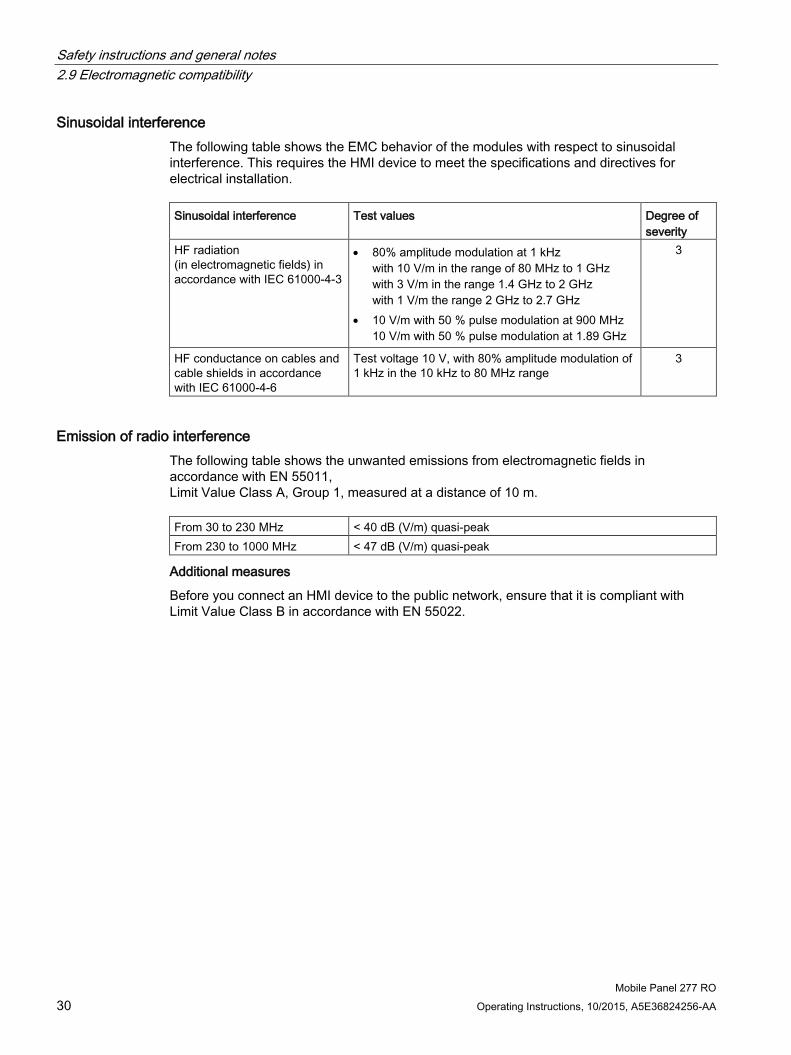
Sinusoidal interference The following table shows the EMC behavior of the modules with respect to sinusoidal interference. This requires the HMI device to meet the specifications and directives for electrical installation. Sinusoidal interference Test values Degree of
severity HF radiation (in electromagnetic fields) in accordance with IEC 61000-4-3
• 80% amplitude modulation at 1 kHz with 10 V/m in the range of 80 MHz to 1 GHz with 3 V/m in the range 1.4 GHz to 2 GHz with 1 V/m the range 2 GHz to 2.7 GHz
• 10 V/m with 50 % pulse modulation at 900 MHz 10 V/m with 50 % pulse modulation at 1.89 GHz
3
HF conductance on cables and cable shields in accordance with IEC 61000-4-6
Test voltage 10 V, with 80% amplitude modulation of 1 kHz in the 10 kHz to 80 MHz range
3
Emission of radio interference The following table shows the unwanted emissions from electromagnetic fields in accordance with EN 55011, Limit Value Class A, Group 1, measured at a distance of 10 m. From 30 to 230 MHz < 40 dB (V/m) quasi-peak From 230 to 1000 MHz < 47 dB (V/m) quasi-peak
Additional measures
Before you connect an HMI device to the public network, ensure that it is compliant with Limit Value Class B in accordance with EN 55022.

Safety instructions and general notes 2.10 Transport and storage conditions
Mobile Panel 277 RO Operating Instructions, 10/2015, A5E36824256-AA 31
2.10 Transport and storage conditions
Mechanical and climatic transport and storage conditions The transport and storage conditions of this HMI device exceed requirements in accordance with IEC 61131-2. The following specifications apply to the transport and storage of an HMI device in its original packaging.
The climatic conditions comply with the following standards:
● IEC 60721-3-3, Class 3K7 for storage
● IEC 60721-3-2, Class 2K4 for transport
The mechanical conditions are compliant with IEC 60721-3-2, Class 2M2.
The following table shows the transportation and storage conditions for the HMI device. Type of condition Permitted range Drop test (in transport package) ≤ 1 m Temperature From –20 to +60 °C Atmospheric pressure From 1080 hPa to 660 hPa,
corresponds to an elevation –1000 to 3,500 m Relative humidity From 10 % to 90 %, without condensation Sinusoidal vibration in accordance with IEC 60068-2-6
5 Hz to 8.4 Hz: 3.5 mm 8.4 to 500 Hz: 9.8 m/s2
Shock in accordance with IEC 60068-2-29 250 m/s2, 6 ms, 1000 shocks
The following table shows the transportation and storage conditions for the terminal device. Type of condition Permitted range Drop test (in transport package) ≤ 1 m Temperature From –20 to +70 °C Atmospheric pressure From 1080 hPa to 660 hPa,
corresponds to an elevation –1000 to 3,500 m Relative humidity From 35 % to 85 %, without condensation Sinusoidal vibration in accordance with IEC 60068-2-6
5 Hz to 8.4 Hz: 3.5 mm 8.4 to 500 Hz: 9.8 m/s2
Shock in accordance with IEC 60068-2-29 250 m/s2, 6 ms, 1000 shocks

Safety instructions and general notes 2.10 Transport and storage conditions
Mobile Panel 277 RO 32 Operating Instructions, 10/2015, A5E36824256-AA
Note
In the following cases, ensure that no moisture can settle on or in the HMI device (dew): • Transportation of the HMI device in low temperatures • Under extreme temperature variations
The HMI device must have acquired room temperature before it is put into operation. Do not expose the HMI device to direct radiation from a heater in order to warm it up. If dewing has developed, wait approximately four hours until the HMI device has dried completely before switching it on.
The following points must be adhered to in order to ensure fault-free and safe operation of the HMI device:
● Proper transportation and storage
● Proper installation and mounting
● Careful operation and maintenance
The warranty for the HMI device will be deemed void if these stipulations are not heeded.

Mobile Panel 277 RO Operating Instructions, 10/2015, A5E36824256-AA 33
Planning application 3 3.1 Notes about usage
Mechanical and climatic conditions of use The HMI device is designed for use in a location protected from the effects of the weather. The conditions of use are compliant with requirements to DIN IEC 60721-3-3:
● Class 3M3 (mechanical requirements)
● Class 3K3 (climatic requirements)
Use with additional measures Examples of applications where the use of the HMI device requires additional measures:
● In locations with a high degree of ionizing radiation
● In locations with difficult operating conditions - for example due to:
– Corrosive vapors, gases, oils or chemicals
– Electrical or magnetic fields of high intensity
● In systems that require special monitoring - for example:
– Elevators
– Systems in especially hazardous rooms
Mechanical ambient conditions The following table shows the mechanical ambient conditions for the HMI device in the form of sinusoidal vibration. Frequency range in Hz Constant Occasional 10 ≤ f ≤ 58 Amplitude 0.0375 mm Amplitude 0.075 mm 58 ≤ f ≤ 150 Constant acceleration 0.5 g Constant acceleration 1 g
Reducing vibrations If the HMI device is subjected to greater shocks or vibrations, you must take appropriate measures to reduce acceleration or amplitudes.
We recommend fitting the HMI device to vibration-absorbent material (on metal shock absorbers, for example).

Planning application 3.1 Notes about usage
Mobile Panel 277 RO 34 Operating Instructions, 10/2015, A5E36824256-AA
Testing mechanical ambient conditions The following table provides information on the type and scope of tests for mechanical ambient conditions. Tested for Test standard Comments Vibrations Vibration test in accordance
with IEC 60068, part 2–6 (sinusoidal)
Type of vibration: Frequency cycles at a rate of change of 1 octave/minute. 10 ≤ f ≤ 58, constant amplitude 0.075 mm 58 ≤ f ≤ 150, constant acceleration 1 g Vibration duration: 10 frequency cycles per axis in each of the three axes vertical to each other
Shock Shock test in accordance with IEC 60068, Part 2 –27
Type of shock: half-sine Severity of shock: Peak value 15 g, duration 11 ms Direction of shock: 3 shocks in ± direction of axis in each of the three axes vertical to each other
Falling Fall test in accordance with EN 60068-2-32
Climatic ambient conditions for the mobile panel The following table shows the permitted climatic ambient conditions for use of the mobile panel. Ambient conditions Permitted range Comments Temperature, operation From 0 to 40 °C Temperature, storage/transport From –20 to 60 °C Relative humidity 10 % to 90 %, no condensation Corresponds to relative humidity,
stress level 2 in accordance with IEC 61131, part 2
Atmospheric pressure 1080 hPa to 795 hPa Corresponds to an elevation of –1,000 to 2,000 m
Pollutant concentration SO2 < 0.5 ppm Relative humidity < 60%, no condensation
Check: 10 cm3/m3; 10 days
H2S: < 0.1 ppm; relative humidity < 60%, no condensation
Check: 1 cm3/m3; 10 days

Planning application 3.2 Mounting positions and type of fixation
Mobile Panel 277 RO Operating Instructions, 10/2015, A5E36824256-AA 35
Climatic ambient conditions for the connection box The following table shows the permitted climatic ambient conditions for use of the connection box. Ambient conditions Permitted range Comments Temperature, operation From 0 to 50 °C Temperature, storage/transport From –20 to 70 °C Relative humidity, operation 35 % to 85 % Without condensation, corresponds
to relative humidity, stress level 2 in accordance with IEC 61131, part 2
Relative humidity, storage / transport Atmospheric pressure 1080 hPa to 795 hPa Corresponds to an elevation of
–1,000 to 2,000 m Pollutant concentration SO2 < 0.5 ppm
Relative humidity < 60%, no condensation
Check: 10 cm3/m3; 10 days
H2S: < 0.1 ppm; relative humidity < 60%, no condensation
Check: 1 cm3/m3; 10 days
3.2 Mounting positions and type of fixation
Mounting position The wall-mounting bracket is designed for vertical mounting.
The connection box is designed for surface mounting independently of cabinets or control panels.
The connection box is self-ventilated and is approved for all mounting positions. Note that the guaranteed protection rating is only ensured if the connecting cable or the dummy cap is plugged into the connection box.

Planning application 3.3 Preparing for mounting
Mobile Panel 277 RO 36 Operating Instructions, 10/2015, A5E36824256-AA
3.3 Preparing for mounting
Choose the mounting location for the wall-mounting bracket Observe the following points when selecting the mounting location:
● Position the wall-mounting bracket so that the display of the hooked-in HMI device is not exposed to direct sunlight.
● Position the wall-mounting bracket so that the HMI device can be ergonomically inserted by the user. Choose a suitable mounting height.
Maintaining clearances The following clearances are required around the wall-mounting bracket:
Planning application 3.4 Information on insulation tests, protection class and degree of protection
Mobile Panel 277 RO Operating Instructions, 10/2015, A5E36824256-AA 37
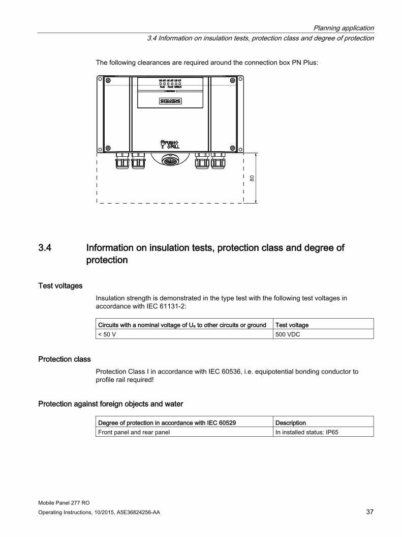
The following clearances are required around the connection box PN Plus:
3.4 Information on insulation tests, protection class and degree of protection
Test voltages Insulation strength is demonstrated in the type test with the following test voltages in accordance with IEC 61131-2: Circuits with a nominal voltage of Ue to other circuits or ground Test voltage < 50 V 500 VDC
Protection class Protection Class I in accordance with IEC 60536, i.e. equipotential bonding conductor to profile rail required!
Protection against foreign objects and water Degree of protection in accordance with IEC 60529 Description Front panel and rear panel In installed status: IP65

Planning application 3.5 Rated voltages
Mobile Panel 277 RO 38 Operating Instructions, 10/2015, A5E36824256-AA
3.5 Rated voltages The following table shows the rated voltage and the corresponding tolerance range. Rated voltage Tolerance range +24 VDC 20.4 V to 28.8 V (–15 %, +20 %)

Mobile Panel 277 RO Operating Instructions, 10/2015, A5E36824256-AA 39
Mounting and connecting 4 4.1 Checking the package contents
Check the package contents for visible signs of transport damage and for completeness.
Note
Do not install parts damaged during shipment. In the case of damaged parts, contact your Siemens representative.
The documentation belongs to the HMI device and is required for subsequent commissioning. Retain all enclosed documentation for the entire service life of the HMI device. You must pass on the enclosed documentation to any subsequent owner or user of the HMI device. Make sure that every supplement to the documentation that you receive is stored together with the operating instructions.
4.2 Mounting the connection box and wall-mounting bracket
Requirements The following are required for mounting:
● Three M5 cylinder head screws for the wall-mounting bracket of the HMI device
● Four M4 cylinder head screws for the connection box
If the HMI device is to be operated while hooked into the wall-mounting bracket, ensure that the connecting cable is long enough.
Procedure for mounting the wall-mounting bracket
Note
In order to ensure that the HMI device can be hooked in securely, select a vertical surface or one inclined slightly to the rear as the mounting surface.
For HMI device with STOP button:
The HMI device can fall down if it is not securely hooked in. In the process the STOP button might be triggered unintentionally, thus causing the machine or system to stop.

Mounting and connecting 4.2 Mounting the connection box and wall-mounting bracket
Mobile Panel 277 RO 40 Operating Instructions, 10/2015, A5E36824256-AA
Note Positioning
A position at eye level is recommended. This enables the Mobile Panel 277 RO to be operated when it is hooked into the wall-mounting bracket.
Proceed as follows:
1. Select a position for the wall-mounting bracket that is easy and safe to reach.
2. Place the wall-mounting bracket from the front onto the mounting surface.
3. Mark the mounting holes with a marking tool.
4. Drill three through holes or three threaded holes M5.
5. Attach the wall-mounting bracket.
Procedure for mounting the connection box
Note Length of the connecting cable
Allow for the maximum length of the connecting cable when selecting the position for the connection box.
Proceed as follows:
1. Select a position for the connection box that is easy and safe to reach.
2. Place the connection box from the front onto the mounting surface.
3. Mark the mounting holes with a marking tool.
4. Drill four through holes or four threaded holes M4.
NOTICE
Permissible torque
The connection box housing is made of plastic. Therefore, the mounting hole threads cannot handle the same amount of stress as a comparable metallic housing. Do not exceed 0.4 to 0.5 Nm of torque when tightening the screws.
If the screws are tightened more than 20 times, there is risk of damage to the threads.
5. Attach the connection box.

Mounting and connecting 4.3 Electrical installation
Mobile Panel 277 RO Operating Instructions, 10/2015, A5E36824256-AA 41
4.3 Electrical installation
Electrical connections The electrical installation comprises the components:
● Connection box PN Plus
● Mobile Panel 277 RO
You can connect the following devices or operator controls to these components:
Device/Operator control Mobile Panel 277 RO Connection box Panel PC Yes Yes Supply voltage – Yes Connection to Stop circuit – Yes Monitoring signal of the STOP button – Yes Connection to enable circuit – Yes
4.4 Connecting the connection box
4.4.1 Overview
Requirements ● The connection box PN Plus must be mounted in accordance with the specifications in
these operating instructions.
● Always use only shielded standard cables.
Note
The maximum length of the cable for connecting the Stop button and the enabling button may not exceed 30 m.
Mounting and connecting 4.4 Connecting the connection box
Mobile Panel 277 RO 42 Operating Instructions, 10/2015, A5E36824256-AA
Connection sequence Connect the connection box in the following sequence:
1. Equipotential bonding
2. Supply voltage
NOTICE
Connection sequence
Always follow the correct sequence for connecting the connection box PN Plus. Non-observance can cause damage to the connection box PN Plus.
4.4.2 Opening and closing the connection box Follow the instructions below before opening the connection box PN Plus:
NOTICE
Short circuit in the connection box
If a short-circuit occurs in the connection box PN Plus, there is a risk that the function of the Mobile Panel 277 RO will be impaired.
Take care when working on the opened connection box, that conducting materials, such as cable remains, do not come into contact with the electrical circuits. ESD
When working in the open housing, ensure that current-carrying conductors do not come into contact with electrical circuits.
Note the ESD instructions.
Requirements ● Torx screwdriver, Size 10

Mounting and connecting 4.4 Connecting the connection box
Mobile Panel 277 RO Operating Instructions, 10/2015, A5E36824256-AA 43
Procedure
① Screws ② Cover
Proceed as follows:
1. Loosen the four marked screws.
2. Remove the screws and the cover.
Protective cover
① Protective cover
Note Protective cover
Do not remove the protective cover. Otherwise there is a risk that the electronics of the connection box will be damaged or destroyed.

Mounting and connecting 4.4 Connecting the connection box
Mobile Panel 277 RO 44 Operating Instructions, 10/2015, A5E36824256-AA
Notes for closing
Note Permissible torque
The connection box housing is made of plastic. Therefore, the mounting hole threads cannot handle the same amount of stress as a comparable metallic housing. Do not exceed 0.4 to 0.5 Nm of torque when tightening the screws.
If the screws are tightened more than 20 times, there is risk of damage to the threads. Degree of protection not fulfilled
When assembling the unit, be sure to fit plugs to all unused screw glands and to insert the appropriate seal for the cover. Otherwise degree of protection IP65 is not ensured.
4.4.3 Stripping the insulation of cables
Stripping insulation The following figure shows you how to strip an Ethernet cable.
Note
Use a wire stripper as specified in the online catalog under Industry Mall (https://mall.industry.siemens.com) for fast and accurate stripping of the insulation.
Mounting and connecting 4.4 Connecting the connection box
Mobile Panel 277 RO Operating Instructions, 10/2015, A5E36824256-AA 45
4.4.4 Connecting the equipotential bonding circuit
Potential differences Differences in potential between spatially separated system parts can lead to high equalizing currents via the data cables and therefore to the destruction of their ports. This situation may arise if the cable shielding is terminated at both ends and grounded at different system parts.
Differences in potential may develop when a system is connected to different mains supplies.
General requirements for equipotential bonding Differences in potential must be reduced by means of equipotential bonding in order to ensure trouble-free operation of the relevant components of the electronic system. The following must therefore be observed when installing the equipotential bonding circuit:
● The effectiveness of equipotential bonding increases as the impedance of the equipotential bonding conductor decreases or as its cross-section increases.
● If two parts of the system are connected to each other by means of shielded data cables, and its shielding is connected at both ends with the grounding / protective grounding conductor, then the impedance of the additionally-laid equipotential bonding may amount to a maximum of 10% of the screened impedance.
● The cross-section of a selected equipotential bonding conductor must be capable of handling the maximum equalizing current. Between switching cabinets, equipotential bonding conductors as detailed in the "Guidelines for interference-free installation of PLCs" description and the "PROFIBUS networks" manual have proven themselves reliable in practice.
● Use equipotential bonding conductors made of copper or galvanized steel. Establish a large surface contact between the equipotential bonding conductors and the grounding/protective conductor and protect these from corrosion.
● Clamp the shielding of the data cable on the HMI device flush and near the equipotential busbar using suitable cable clamps.
● Route the equipotential bonding conductor and data cables in parallel with minimum clearance between them.
Note
Equipotential bonding conductor
Cable shielding is not suitable for equipotential bonding. Always use the prescribed equipotential bonding conductors. When installing MPI and PROFIBUS DP networks, always use cables with an adequate cross-section. Otherwise there is a risk that interface components will be damaged or destroyed.

Mounting and connecting 4.4 Connecting the connection box
Mobile Panel 277 RO 46 Operating Instructions, 10/2015, A5E36824256-AA
Connection graphic The following figure shows how to connect the equipotential bonding conductor to the connection box PN Plus.
① PE connection on the connection box (terminal strip 1, pin 1) ② Equipotential bonding conductor cross-section: 2.5 mm2 ③ Switching cabinet ④ Equipotential bonding conductor cross-section: min. 16 mm2 ⑤ Ground connection ⑥ Cable clip ⑦ Voltage bus ⑧ Parallel routing of the equipotential bonding conductor and data cable
Mounting and connecting 4.4 Connecting the connection box
Mobile Panel 277 RO Operating Instructions, 10/2015, A5E36824256-AA 47
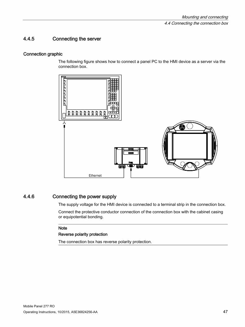
4.4.5 Connecting the server
Connection graphic The following figure shows how to connect a panel PC to the HMI device as a server via the connection box.
4.4.6 Connecting the power supply The supply voltage for the HMI device is connected to a terminal strip in the connection box.
Connect the protective conductor connection of the connection box with the cabinet casing or equipotential bonding.
Note Reverse polarity protection
The connection box has reverse polarity protection.

Mounting and connecting 4.4 Connecting the connection box
Mobile Panel 277 RO 48 Operating Instructions, 10/2015, A5E36824256-AA
Connection graphic The following figure shows how to connect the power supply to the connection box PN Plus.
The abbreviations in the figure are defined as follows:
● PE stands for protective conductor.
● M24 stands for ground.
● P24 stands for +24 VDC.
Please refer to the technical data for the supply voltage requirements.
WARNING
Personal injury and damage to property
Configure the 24 VDC supply of the Mobile Panel 277 RO correctly. Otherwise there is a risk that the components of your automation system will be damaged and that people will be injured.
Use only voltage generated as safety extra-low voltage (SELV) for the 24 VDC supply of the Mobile Panel 277 RO.
NOTICE
Safe electrical separation
Use only power supply units with safety isolation complying with IEC 60364-4-41 or HD 384.04.41 (VDE 0100, Part 410), for example according to the PELV standard, for the 24 VDC supply.
The supply voltage must be within the specified voltage range. Otherwise there is a risk that the HMI device will malfunction.
Applies to non-isolated system design:
Connect the connection for GND 24 V from the 24 V power supply output to equipotential bonding for uniform reference potential.

Mounting and connecting 4.4 Connecting the connection box
Mobile Panel 277 RO Operating Instructions, 10/2015, A5E36824256-AA 49
4.4.7 Connecting the connecting cable
Introduction The connecting cable can be connected to the connection box with the help of a connector (metallic push-pull circular connector). The plug connector is coded anti-rotationally using a slot and key system.
Interlocking mechanism
① Interlocking claws ② Outer sleeve ③ Clamping nut ④ Cable ⑤ Strain direction
If you pull on the cable or the clamping nut, the taper sleeve moves under the interlocking claws and presses them into the interlocking slot. The plug connection cannot be separated.
① Interlocking claws ② Outer sleeve ③ Strain direction
If you pull on the outer sleeve, the interlocking claws slide out of the interlocking slot. The plug connection can be separated.

Mounting and connecting 4.4 Connecting the connection box
Mobile Panel 277 RO 50 Operating Instructions, 10/2015, A5E36824256-AA
Procedure for plugging in the connector Proceed as follows:
1. Retract the outer sleeve on the plug connector.
2. Plug the connector with retracted outer sleeve into the socket of the connection box.
3. Now release the outer sleeve.
The outer sleeve glides automatically in the direction of the connection box and thereby locks the connector.
Procedure for removing the connector Proceed as follows:
1. Retract the outer sleeve on the plug connector.
2. Pull the connector with retracted outer sleeve out of the socket of the connection box.
If you do not intend to use the HMI device with a different connection box, place the HMI device securely in its wall-mounting bracket.

Mounting and connecting 4.5 Connecting the Mobile Panel 277 RO
Mobile Panel 277 RO Operating Instructions, 10/2015, A5E36824256-AA 51
4.5 Connecting the Mobile Panel 277 RO
4.5.1 Connecting the HMI device
Connecting the cables When connecting the cables, ensure that the contact pins are not bent. Secure the connectors with screws.
The pin assignment of the ports is described in the technical specifications.
4.5.2 Opening and closing the terminal compartment
Before you begin
NOTICE
Malfunctions
If the HMI device is lying on its front, there is a risk that the STOP button can be activated, leading to a malfunction.
When you open the terminal compartment, you must therefore disconnect the connection cable for the Mobile Panel 277 RO from the connection box. Mobile panel with rechargeable battery
Never open the terminal compartment if the HMI device is live. Wait until the HMI device switches itself off. An HMI device with inserted battery initially switches to standby mode. After around 10 minutes, when the rechargeable battery has discharged, the HMI device will switch off. ESD
When working in the open housing, ensure that current-carrying conductors do not come into contact with electrical circuits.
Note the ESD instructions.
NOTICE
Damage to the HMI device
Pay attention to cleanliness. Foreign bodies or liquids must not come into contact with the printed circuit board or penetrate the inside of the HMI device.
Place the HMI device with the front side facing down on a flat, clean surface to protect against damage.
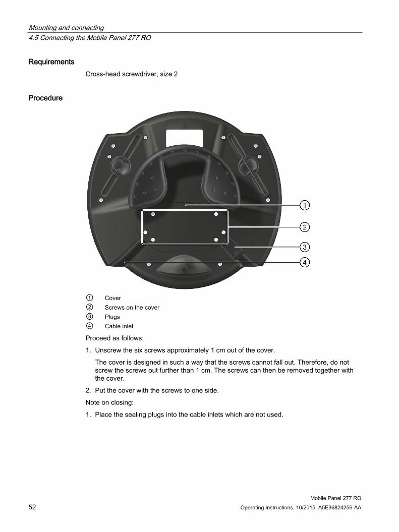
Mounting and connecting 4.5 Connecting the Mobile Panel 277 RO
Mobile Panel 277 RO 52 Operating Instructions, 10/2015, A5E36824256-AA
Requirements Cross-head screwdriver, size 2
Procedure
① Cover ② Screws on the cover ③ Plugs ④ Cable inlet
Proceed as follows:
1. Unscrew the six screws approximately 1 cm out of the cover.
The cover is designed in such a way that the screws cannot fall out. Therefore, do not screw the screws out further than 1 cm. The screws can then be removed together with the cover.
2. Put the cover with the screws to one side.
Note on closing:
1. Place the sealing plugs into the cable inlets which are not used.

Mounting and connecting 4.5 Connecting the Mobile Panel 277 RO
Mobile Panel 277 RO Operating Instructions, 10/2015, A5E36824256-AA 53
Notes for closing
NOTICE
Permissible torque
The connection box housing is made of plastic. Therefore, the mounting hole threads cannot handle the same amount of stress as a comparable metallic housing. Only tighten the screws with the permitted torque of 0.4 to 0.5 Nm.
If the screws are tightened more than 20 times, there is risk of damage to the threads. Degree of protection not fulfilled
Ensure that the seal belonging to the cover is present during assembly. When you have finished working on the connections, check to make sure that the unused threaded cable entry holes are fitted with rubber plugs. Otherwise degree of protection IP65 is not ensured.
4.5.3 Mobile Panel 277 RO ports For reasons of clarity, the following figures depict the terminal compartment without the Velcro strip for fastening the memory card.
The figure below shows the Ethernet port area.
① Port designation ② Ethernet ports
The following figure shows additional ports on the Mobile Panel 277 RO which you can use.

Mounting and connecting 4.5 Connecting the Mobile Panel 277 RO
Mobile Panel 277 RO 54 Operating Instructions, 10/2015, A5E36824256-AA
① Slot for a memory card ② RJ45 socket for connecting cable PN ③ Post connector, 12-pole for the connecting cable PN ④ USB socket ⑤ RS 485 port (IF 2) ⑥ Connection for the rechargeable battery
NOTICE
RJ45 socket
Only use the RJ45 socket for the connection box's connecting cable.
When connecting the cable, remember that the functional reliability of the Mobile Panel 277 RO is only ensured by means of the connecting cable's RJ45 socket. Note the warning signs in the opened Mobile Panel 277 RO.

Mounting and connecting 4.5 Connecting the Mobile Panel 277 RO
Mobile Panel 277 RO Operating Instructions, 10/2015, A5E36824256-AA 55
USB socket The USB socket is built as a sealing plug. You can deploy the USB socket in either of the two cable inlets.
① USB socket ② Cap ③ Cable inlet
NOTICE
Degree of protection not fulfilled
Degree of protection IP65 is only ensured if the cap on the USB socket is plugged and sealed tight.
Connection sequence Connect the connecting cable's connector in the following sequence:
1. Place the USB socket in the other cable inlet if necessary.
2. Plug in the connecting cable.
3. Connect the connector for the power supply.
4. Connect the connector for the data communication.

Mounting and connecting 4.5 Connecting the Mobile Panel 277 RO
Mobile Panel 277 RO 56 Operating Instructions, 10/2015, A5E36824256-AA
4.5.4 Connecting a PC When you update the operating system on the HMI device or want to reset the HMI device to factory settings, you have the transfer the image once again to the HMI device. To do this, connect a PC to the HMI device and then start to transfer the image using ProSave.
Connection graphic The figure below illustrates how you connect the HMI with a PC using the connection box and Ethernet.
See also Connecting the connecting cable (Page 49)
Update HMI device image (Page 124)

Mounting and connecting 4.6 Switching on and testing the HMI device
Mobile Panel 277 RO Operating Instructions, 10/2015, A5E36824256-AA 57
4.6 Switching on and testing the HMI device
Procedure Proceed as follows:
1. Switch on the power supply.
The display lights up after power is switched on. A progress bar is displayed during startup.
If the HMI device does not start, it is possible that the wires on the terminal block have been crossed. Check the connected wires and change the connections if necessary.
At the end of the delay time, the RemoteOperate Client software starts.
Result The server selection list is displayed.

Mounting and connecting 4.6 Switching on and testing the HMI device
Mobile Panel 277 RO 58 Operating Instructions, 10/2015, A5E36824256-AA
Switching off the HMI device Quit the RemoteOperate Client software by pressing the button before switching off the HMI device.
You have the following options for switching off an HMI device with no rechargeable battery:
● Switch off the power supply.
● Pull out the connecting cable from the connection box.
Note
Recovery time
Wait for approximately one second after you have removed the connecting cable from the connection box before you plug the connecting cable back into the connection box.
Wait approximately one second after switching off the power supply before you switch it back on again.
After power failures lasting less than one second the connecting cable has to be disconnected.
If the HMI device is fitted with a rechargeable buffer battery, wait until the HMI device has switched off.
An HMI device with a rechargeable battery will switch into standby mode first. After around 10 minutes, when the rechargeable battery has discharged, the HMI device will switch off.
See also Setting the delay time (Page 95)
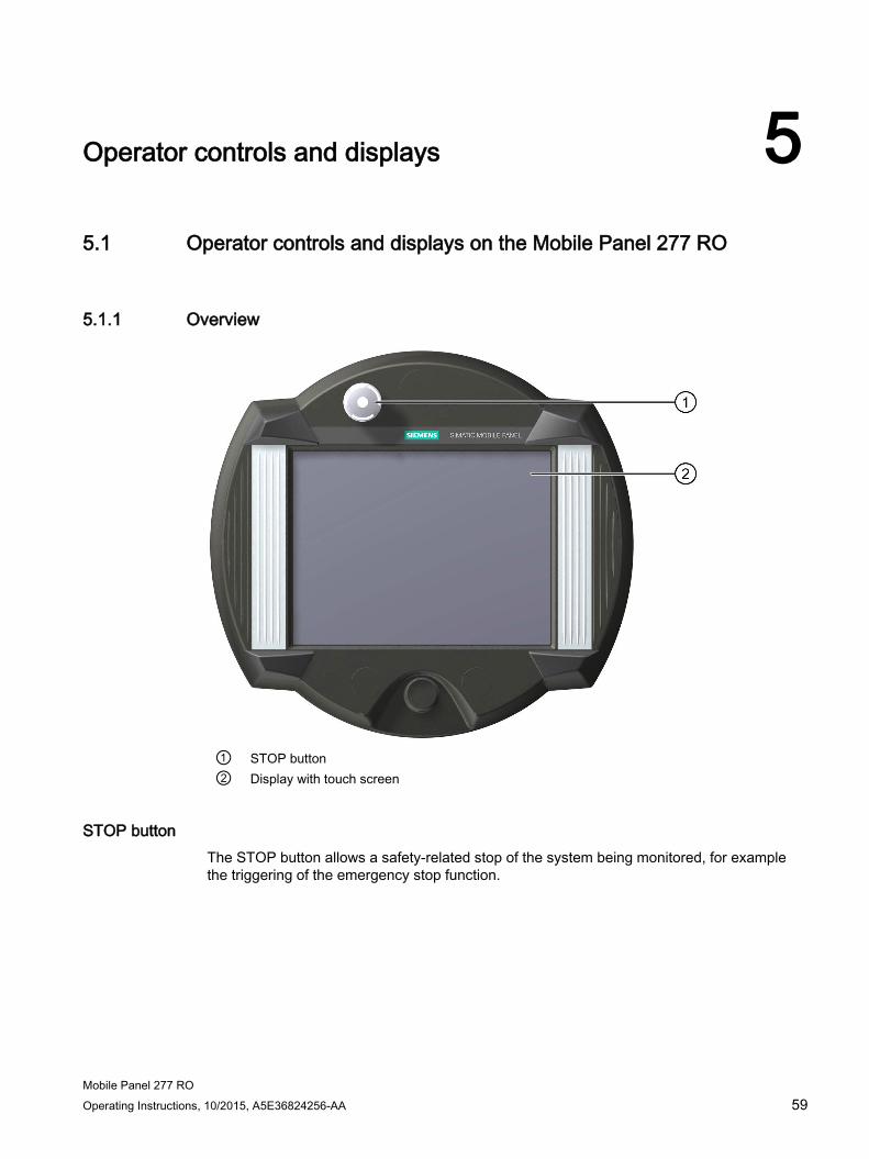
Mobile Panel 277 RO Operating Instructions, 10/2015, A5E36824256-AA 59
Operator controls and displays 5 5.1 Operator controls and displays on the Mobile Panel 277 RO
5.1.1 Overview
① STOP button ② Display with touch screen
STOP button The STOP button allows a safety-related stop of the system being monitored, for example the triggering of the emergency stop function.

Operator controls and displays 5.1 Operator controls and displays on the Mobile Panel 277 RO
Mobile Panel 277 RO 60 Operating Instructions, 10/2015, A5E36824256-AA
Standard input unit The standard input unit on the HMI device is the touch screen. All operating elements required for touch operation are displayed on the touch screen once the HMI device has started.
Note Damage to the touch screen
Never touch the touch screen with pointed or sharp objects. Avoid applying excessive pressure to the touch screen with hard objects. Both these will substantially reduce the useful life of the touch screen and even lead to total failure.
Always operate the HMI touch screen with your fingers or with a touch pen.
5.1.2 Enabling button
Introduction The enabling control device comprises two enabling buttons mounted on both sides of the Mobile Panel 277 RO. The switch setting of the two enabling buttons is determined by electrical momentary contact switches. The associated evaluation logic is dual-channel. This means that one channel processes the enabling button information digitally and the second channel analogously (diversity).
① Enabling button
Operation You only have to activate one enabling button. It is not possible for the PLC to determine whether the Mobile Panel 277 RO is being operated with one hand or two.
The enabling buttons meet the requirements of Category 3 PL d in accordance with EN ISO 13849-1:2008/AC:2009 when used in combination with an external monitoring device.
Category 3 PL d in accordance with EN ISO 13849-1:2008/AC:2009 can be achieved by implementing the enabling apparatus with 2 circuits and suitable monitoring for shorting and crossing of these circuits.

Operator controls and displays 5.1 Operator controls and displays on the Mobile Panel 277 RO
Mobile Panel 277 RO Operating Instructions, 10/2015, A5E36824256-AA 61
Circuit diagram The figure below shows the operating positions and interconnections of the enabling button.
Switch settings The primary function of the evaluating logic is to recognize the three switch settings:
Switch setting Functions Enabling button Switch state 1 Neutral position Not activated OFF (open) 2 Enable Activated ON (closed) 3 Panic Pressed OFF (open)
The following figure shows the switching sequence during normal usage.

Operator controls and displays 5.1 Operator controls and displays on the Mobile Panel 277 RO
Mobile Panel 277 RO 62 Operating Instructions, 10/2015, A5E36824256-AA
The following figure shows the switching sequence during panic usage.
If the operator has pressed the enabling button through to the "Panic" setting, the "Enable" setting will be skipped when the switch is released.
The signals of the enabling button are fed to the connection box via the connecting cable. For manual special operating modes, these signals must be interconnected from the connection box to the safety circuit using two channels for power interruption.
Note
Releasing the enabling button or pressing through to the Panic setting does not require acknowledgment of the safety cut-out.
5.1.3 STOP button
5.1.3.1 Overview
Overview The STOP button is designed with two circuits and allows a safety-related stop of the system being monitored.
The STOP button meets the requirements of Category 3 PL d in accordance with EN ISO 13849-1:2008/AC:2009 when used in combination with an external monitoring device. For further safety information, refer to the safety instructions and general notes chapter.
When you unplug the Mobile Panel 277 RO from the connection box, the Stop circuit of the system being monitored remains closed.

Operator controls and displays 5.1 Operator controls and displays on the Mobile Panel 277 RO
Mobile Panel 277 RO Operating Instructions, 10/2015, A5E36824256-AA 63
Possible application areas for the STOP button:
● The STOP button can be used to initiate a process-cycle-specific rapid stop of a monitored system (plant, machine or machine zone). The Stop operation can occur with or without a power shutdown.
Advantages:
– Limitation of effective range
– Fast restart
– No loss of machine coordinates and thus no recalibration upon restart
– Preservation of tool and workpiece
● Triggering of the Emergency Stop function of a monitored system by means of looping in the Emergency Stop circuit.
Advantage:
Simple integration in an existing Emergency Stop circuit when the system to be monitored has no option for a fast process stop.
① STOP button
Due to its position, the STOP button is equally accessible to both left-handed and right-handed individuals.
Due to its profiled design, the STOP button is easily accessible. The STOP button can be activated if the HMI device is dropped.

Operator controls and displays 5.1 Operator controls and displays on the Mobile Panel 277 RO
Mobile Panel 277 RO 64 Operating Instructions, 10/2015, A5E36824256-AA
Operation The STOP button is operated by pressing the button. Once the stop operation has been initiated, the STOP button remains engaged in the stop position.
Note
The STOP button engages compulsorily when activated!
Releasing the STOP button
WARNING
Releasing the STOP button
If you have activated the STOP button and thereby brought the monitored system to a standstill, the STOP button may only be released under the following conditions: • The reasons for the stop have been eliminated. • A safe restart is possible.
In order to release the STOP button, turn it in a clockwise direction. The STOP button then returns on its own to the starting position.
5.1.3.2 Safety functions of the STOP button
The STOP button on the Mobile Panel 277 RO brings about a stop of the system being monitored in accordance with EN 60204-1:2006, Section 9.2.5.3. You have the option of implementing a Category 0, 1, or 2 Stop function in accordance with EN 60204-1:2006, Section 9.2.2. The stop function category must be selected on the basis of a risk assessment.
The stop function of the mobile panel can therefore be used as a safe machine stop as well as for looping in the emergency stop circuit of the system to be monitored.

Operator controls and displays 5.1 Operator controls and displays on the Mobile Panel 277 RO
Mobile Panel 277 RO Operating Instructions, 10/2015, A5E36824256-AA 65
In the connection box Plus, the signals of the Stop or Emergency Stop circuit are routed via the STOP button. If the Mobile Panel 277 RO is not connected, the Stop or Emergency Stop circuit of the system being monitored remains closed.
WARNING
Mobile Panel 277 RO with STOP button
If the Mobile Panel 277 RO is not connected to the connection box, a Stop cannot be initiated using the Mobile Panel 277 RO. The STOP button of the Mobile Panel 277 RO is then ineffective.
Install stationary Emergency Stop buttons that are available at all times on the system being monitored. Category 0 or 1 Stop
If a Category 0 or 1 Stop circuit is implemented, the stop function must be in effect regardless of the operating mode. A Category 0 Stop must have precedence. Releasing the STOP button must not cause a hazardous situation (see also EN 60204-1:2006 Section 9.2.5.3).
The stop function is not to be used as a replacement for safety equipment.
Note Several connection boxes
Install only one type of connection box in the system to be monitored - in other words, only Plus connection boxes.
Note STOP button can be activated if the panel is dropped
The standstill of the monitored system can be activated under the following conditions:
The Mobile Panel 277 RO is connected to the connection box and the STOP button is activated due to the Mobile Panel 277 RO falling down or being dropped.

Operator controls and displays 5.1 Operator controls and displays on the Mobile Panel 277 RO
Mobile Panel 277 RO 66 Operating Instructions, 10/2015, A5E36824256-AA
5.1.3.3 STOP button on the connection box Plus
Overview The "Stop loop" function is implemented on the connection box PN Plus. The double-circuit loop is provided by four relays mounted on the printed-circuit board.
① Board ② Relays
Switching states of the Stop or Emergency Stop circuit with connection box Plus Switching states of the Stop or Emergency Stop circuit for a connected Mobile Panel 277 RO with STOP button and connection box PN Plus: Mobile Panel 277 RO STOP button Status of the Stop or Emergency Stop circuit Is connected Not pressed The Stop or Emergency Stop circuit remains closed. Is connected Pressed The Stop or Emergency Stop circuit is open.
The system being monitored is shut down. Is not connected – The Stop or Emergency Stop circuit remains closed.
WARNING
Disconnecting the Mobile Panel 277 RO If you disconnect the Mobile Panel 277 RO from the connection box PN Plus, the Stop or Emergency Stop circuit is closed and the Stop status of the system being monitored is nullified. This is independent of whether or not the STOP button was pressed on the Mobile Panel 277 RO.
Note Approximately 100 ms elapse between the time the STOP button is pressed and response of the Stop contacts at the connection box Plus.

Operator controls and displays 5.1 Operator controls and displays on the Mobile Panel 277 RO
Mobile Panel 277 RO Operating Instructions, 10/2015, A5E36824256-AA 67
5.1.4 Using memory cards
Requirements The terminal compartment of the Mobile Panel 277 RO is open.
① Slot ② Memory card symbol ③ Velcro strip for fastening the memory card
Procedure for inserting a memory card Proceed as follows:
1. Remove the Velcro strip.
2. Insert the memory card into the slot.
Pay attention to the memory card symbol when inserting the memory card. An arrow on the memory card indicates the front side and the direction of insertion. When the memory card is correctly inserted into the slot, it stands approx. 3mm proud of the slot.
3. Close the Velcro strip.
Procedure for unplugging a memory card Proceed as follows:
1. Remove the Velcro strip.
2. Pull the memory card out of the slot.
3. Deposit the memory card in a safe place.

Operator controls and displays 5.2 Changing the touch pen
Mobile Panel 277 RO 68 Operating Instructions, 10/2015, A5E36824256-AA
5.2 Changing the touch pen
Requirements You need the following tool to replace the touch pen:
● Phillips screwdriver, size 2
Procedure Proceed as follows to replace the touch pen:
1. Close the RemoteOperate Client software.
2. Switch off the HMI device.
3. Place the HMI device front-down on a clean, level surface.
On the back of the HMI device, you will find a screw ① in the top left and top right corners to fasten the impact guards. These screws are identified by a tool symbol.
4. Open the screw ① on that side on which the touch pen is located that you would like to
replace.
5. Remove the impact guard ②. The pin ③ for retaining the touch pen is now freely accessible.
6. Replace the touch pen.

Operator controls and displays 5.3 Holding the mobile panel and fixing it to the wall
Mobile Panel 277 RO Operating Instructions, 10/2015, A5E36824256-AA 69
7. Place the impact guard ② once again on the front of the HMI device.
8. Fasten the impact guard to the back of the HMI device with screws.
Result
You have replaced the touch pen.
5.3 Holding the mobile panel and fixing it to the wall
Holding the Mobile Panel The following illustrations show the correct method for holding the device on the forearm for right- and left-handed people.
The depicted method of holding enables you, for example, to undertake movements while servicing the monitored system.
The depicted forearm holding method enables both right and left-handed persons to use the HMI device with equal ease. The free hand can be used to operate the operator controls on the front side. The hand holding the HMI device can also be used to activate the enabling button. The acknowledgment of the control input is also given if you only press one of the enabling buttons.
The enabling button is required for the confirmation of axis movements. The enabling button is optimally accessible. The enabling button triggers a safety shutdown in the event of a panic reaction to danger (release or cramping).
The STOP button can also be quickly reached with your free hand.

Operator controls and displays 5.3 Holding the mobile panel and fixing it to the wall
Mobile Panel 277 RO 70 Operating Instructions, 10/2015, A5E36824256-AA
Fixing the Mobile Panel in position A wall-mounting bracket is available for securely fixing the HMI device in position. The Mobile Panel can be used as a stationary HMI device when it is hooked into the wall -mounting bracket.
The following picture shows the Mobile Panel in the wall-mounting bracket:
Note Operability
If the Mobile Panel is not hooked into the wall-mounting bracket, the operability of the STOP button can be impaired.

Operator controls and displays 5.4 Displays on the connection box PN
Mobile Panel 277 RO Operating Instructions, 10/2015, A5E36824256-AA 71
5.4 Displays on the connection box PN
Introduction On the front of the connection box PN Plus there are six LEDs which indicate the communication status.
① LED display ② LED
There is an "LNK" and "ACT" LED available for the following connections:
● PROFINET connection Port1
● PROFINET connection Port2
● Mobile Panel 277 RO
Meaning of the LED displays ● LED "LNK"
The LED is permanently lit if the associated port of the connection box PN Plus is connected to a cable and the connection is error-free.
● LED "ACT"
The LED flashes when data is being transferred via the associated port of the connection box PN Plus.

Operator controls and displays 5.4 Displays on the connection box PN
Mobile Panel 277 RO 72 Operating Instructions, 10/2015, A5E36824256-AA

Mobile Panel 277 RO Operating Instructions, 10/2015, A5E36824256-AA 73
Configuring the operating system 6 6.1 Loader
Loader The following figure shows the Loader.
The Loader buttons have the following functions:
● Press the "Transfer" button to set the HMI device to "Transfer" mode.
The transfer mode can only be activated when at least one data channel has been enabled for the transfer.
● Press the "Start" button to start the RemoteOperate Client application.
If you do not execute a command, RemoteOperate Client starts automatically after the delay time set in the Control Panel.
● Press the "Control Panel" button to open the HMI device Control Panel.
You can change various settings in the Control Panel, for example the transfer settings.

Configuring the operating system 6.1 Loader
Mobile Panel 277 RO 74 Operating Instructions, 10/2015, A5E36824256-AA
● Press the "Taskbar" button to activate the taskbar with the Windows CE start menu open:
Open Loader The following options are available to open the Loader:
● The Loader appears briefly after starting the HMI device
● The loader is displayed after exiting the RemoteOperate Client application
Password protection
Note If the password is no longer available, you can only cancel password protection by updating the operating system. All data on the HMI device will be deleted when you update the operating system.
You can protect the Control Panel and taskbar from unauthorized access. When password protection is enabled, the message "password protect" is displayed in the loader.
If the password is not entered, only the "Transfer" and "Start" buttons are operable.
This prevents inadvertent operations and increases security for the plant or machine.
See also Setting the delay time (Page 95)

Configuring the operating system 6.2 Control Panel
Mobile Panel 277 RO Operating Instructions, 10/2015, A5E36824256-AA 75
6.2 Control Panel
6.2.1 Overview
Control Panel of the HMI device
The following settings, for example, can be made in the Control Panel of the HMI device:
● Password protection for the HMI device
● The delay time for starting the RemoteOperate Client application
● The date/time on the HMI device
● A screen saver
Opening the Control Panel The Control Panel can be opened as follows:
● In the startup phase or after exiting the RemoteOperate Client application:
Press "Control Panel" to open the HMI device Control Panel in the loader.
● During operation:
– Open the Windows CE Start menu by touching the button on the alphanumeric screen keyboard twice.
– Open the Control Panel with "Settings > Control Panel".
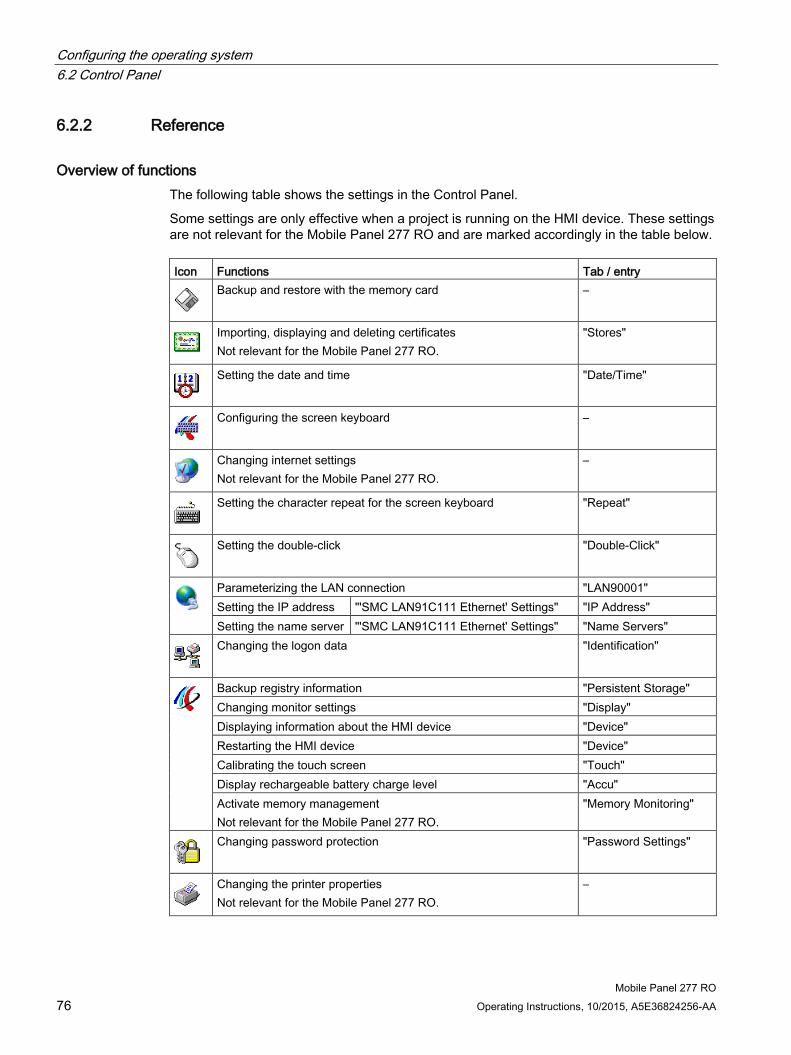
Configuring the operating system 6.2 Control Panel
Mobile Panel 277 RO 76 Operating Instructions, 10/2015, A5E36824256-AA
6.2.2 Reference
Overview of functions The following table shows the settings in the Control Panel.
Some settings are only effective when a project is running on the HMI device. These settings are not relevant for the Mobile Panel 277 RO and are marked accordingly in the table below. Icon Functions Tab / entry
Backup and restore with the memory card –
Importing, displaying and deleting certificates Not relevant for the Mobile Panel 277 RO.
"Stores"
Setting the date and time "Date/Time"
Configuring the screen keyboard –
Changing internet settings Not relevant for the Mobile Panel 277 RO.
–
Setting the character repeat for the screen keyboard "Repeat"
Setting the double-click "Double-Click"
Parameterizing the LAN connection "LAN90001" Setting the IP address "'SMC LAN91C111 Ethernet' Settings" "IP Address" Setting the name server "'SMC LAN91C111 Ethernet' Settings" "Name Servers"
Changing the logon data "Identification"
Backup registry information "Persistent Storage" Changing monitor settings "Display" Displaying information about the HMI device "Device" Restarting the HMI device "Device" Calibrating the touch screen "Touch" Display rechargeable battery charge level "Accu" Activate memory management Not relevant for the Mobile Panel 277 RO.
"Memory Monitoring"
Changing password protection "Password Settings"
Changing the printer properties Not relevant for the Mobile Panel 277 RO.
–

Configuring the operating system 6.2 Control Panel
Mobile Panel 277 RO Operating Instructions, 10/2015, A5E36824256-AA 77
Icon Functions Tab / entry
Changing the PROFINET IO setting –
Changing regional settings Not relevant for the Mobile Panel 277 RO.
–
Changing S7 transfer settings Not relevant for the Mobile Panel 277 RO.
–
Setting the screen saver Reducing the backlighting
–
Displaying the system information "General" Displaying memory information "Memory" Setting the device name of the HMI device "Device Name"
Configuring the data channel "Channel" Setting the delay time "Directories"
Changing e-mail settings Not relevant for the Mobile Panel 277 RO.
–
6.2.3 Operating the Control Panel
Introduction The Control Panel is operated with the HMI device touch screen.
Procedure Proceed as follows to change settings in the Control Panel:
1. Exit the RemoteOperate Client application by pressing .
The Loader appears.
2. Open the Control Panel by means of the "Control Panel" button.
3. To open the required dialog, double-click its symbol.
4. Change as required by touching the tab.
5. Now make the necessary changes.
Touch the respective input object to make entries.
– Use the screen keyboard of the HMI device to enter the new values in the text boxes.
– Touch a button to operate it.
– Touch the selection box to open a drop down list box. Touch the required entry from the drop down list box.
– Touch the check box to activate or deactivate a check box.
– Touch a radio button to select it.

Configuring the operating system 6.2 Control Panel
Mobile Panel 277 RO 78 Operating Instructions, 10/2015, A5E36824256-AA
6. Confirm the selection with the button or abort the entry with the button.
The dialog closes.
7. Close the Control Panel with the button.
8. Start the RemoteOperate Client application by pressing "Start" in the loader.
Input with the screen keyboard A screen keyboard is available for data input. The screen keyboard is displayed as soon as you touch a text box. You can also call up the screen keyboard directly from the Control Panel.
Display methods for the screen keyboard
The display method for the screen keyboard can be changed and its position on the screen can be fixed. Confirm the entry with the button or abort the entry with the key. Either action closes the screen keyboard.
● Numerical screen keyboard
● Alphanumerical screen keyboard
The alphanumerical screen keyboard has various levels.
– Normal level
– Shift level
● Reduced screen keyboard
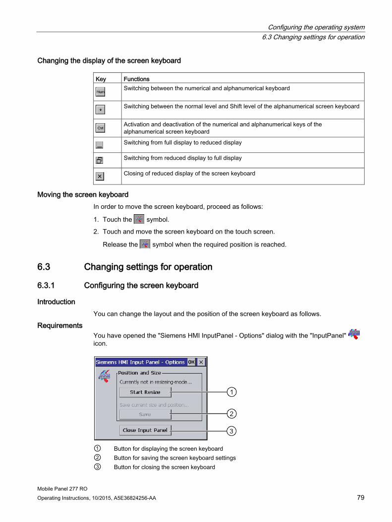
Configuring the operating system 6.3 Changing settings for operation
Mobile Panel 277 RO Operating Instructions, 10/2015, A5E36824256-AA 79
Changing the display of the screen keyboard Key Functions
Switching between the numerical and alphanumerical keyboard
Switching between the normal level and Shift level of the alphanumerical screen keyboard
Activation and deactivation of the numerical and alphanumerical keys of the alphanumerical screen keyboard
Switching from full display to reduced display
Switching from reduced display to full display
Closing of reduced display of the screen keyboard
Moving the screen keyboard In order to move the screen keyboard, proceed as follows:
1. Touch the symbol.
2. Touch and move the screen keyboard on the touch screen.
Release the symbol when the required position is reached.
6.3 Changing settings for operation
6.3.1 Configuring the screen keyboard
Introduction You can change the layout and the position of the screen keyboard as follows.
Requirements You have opened the "Siemens HMI InputPanel - Options" dialog with the "InputPanel" icon.
① Button for displaying the screen keyboard ② Button for saving the screen keyboard settings ③ Button for closing the screen keyboard

Configuring the operating system 6.3 Changing settings for operation
Mobile Panel 277 RO 80 Operating Instructions, 10/2015, A5E36824256-AA
Procedure Proceed as follows:
1. Press the "Open Input Panel" button to display the screen keyboard.
2. By pressing the button, you can switch between the numerical and alphanumerical screen keyboard.
3. Set the position of the screen keyboard by moving the screen keyboard on the screen.
4. Store the settings by pressing the "Save" button.
5. Close the screen keyboard by pressing the "Close Input Panel" button.
6. Close the dialog.
Result The screen keyboard settings have been modified.
6.3.2 Setting the character repeat rate of the screen keyboard
Introduction You can set the character repeat for the screen keyboard in the Control Panel.
Requirements You have opened the "Keyboard Properties" dialog with the "Keyboard" icon.
① Check box for activating the character repeat ② Slider control and buttons for the delay time before character repeat ③ Slider control and buttons for the rate of the character repeat ④ Test field

Configuring the operating system 6.3 Changing settings for operation
Mobile Panel 277 RO Operating Instructions, 10/2015, A5E36824256-AA 81
Procedure Proceed as follows:
1. Activate the "Enable character repeat" check box to enable the character repeat.
2. Use the buttons to set the delay and rate of the character repeat. You can also use the slider control for this.
3. Verify your settings.
– Touch the test field. The screen keyboard opens.
– Move the screen keyboard as needed.
– Touch any character and keep it pressed.
– Check the implementation of the character repetition and the rate of the character repetition in the test field.
– Correct your setting if necessary.
4. Confirm your entries.
The dialog closes.
Result The character repeat for the screen keyboard has been altered.
6.3.3 Setting the double-click
Introduction You can start applications in the Control Panel and in Windows CE with a double-click. A double-click corresponds to two brief touches in sequence.
In the "Mouse Properties" dialog box, you can set the time interval between the two touches of the touch screen.
Requirements You have opened the "Mouse Properties" dialog with the "Mouse" icon.
① Pattern ② Icon
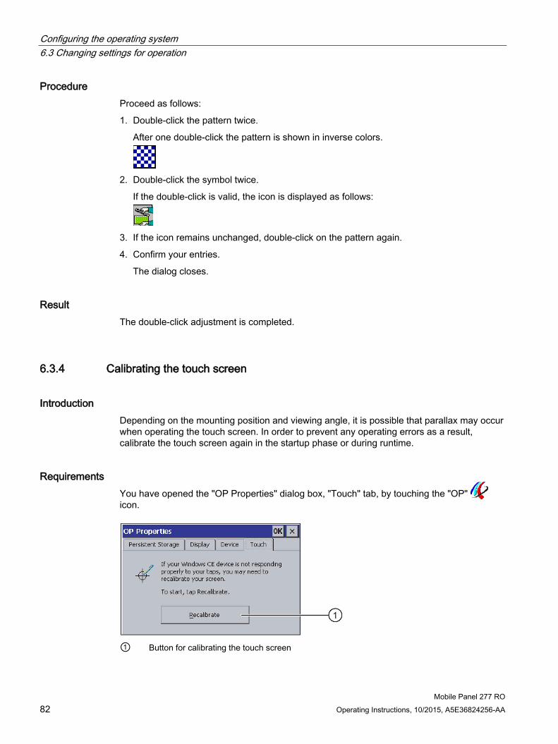
Configuring the operating system 6.3 Changing settings for operation
Mobile Panel 277 RO 82 Operating Instructions, 10/2015, A5E36824256-AA
Procedure Proceed as follows:
1. Double-click the pattern twice.
After one double-click the pattern is shown in inverse colors.
2. Double-click the symbol twice.
If the double-click is valid, the icon is displayed as follows:
3. If the icon remains unchanged, double-click on the pattern again.
4. Confirm your entries.
The dialog closes.
Result The double-click adjustment is completed.
6.3.4 Calibrating the touch screen
Introduction Depending on the mounting position and viewing angle, it is possible that parallax may occur when operating the touch screen. In order to prevent any operating errors as a result, calibrate the touch screen again in the startup phase or during runtime.
Requirements You have opened the "OP Properties" dialog box, "Touch" tab, by touching the "OP" icon.
① Button for calibrating the touch screen

Configuring the operating system 6.3 Changing settings for operation
Mobile Panel 277 RO Operating Instructions, 10/2015, A5E36824256-AA 83
Procedure Proceed as follows:
1. Touch the "Recalibrate" button to open the following dialog:
2. Briefly touch the middle of the calibration crosshairs ①.
The calibration crosshairs is then displayed at four more positions. Touch the middle of the calibration crosshairs for each position. If you do not touch the middle of the calibration crosshairs, the procedure is repeated.
Once you have touched the calibration crosshairs for all positions, the following dialog appears:
3. Touch the screen within 30 seconds.
The new calibration is saved. If you wait longer than 30 seconds, the new calibration is discarded and the original calibration remains in effect.
The "OP Properties" dialog , "Touch" tab is displayed again.
4. Close the dialog.
Result The HMI device touch screen is now recalibrated.

Configuring the operating system 6.4 Changing password protection
Mobile Panel 277 RO 84 Operating Instructions, 10/2015, A5E36824256-AA
6.4 Changing password protection
Introduction You can protect the Control Panel and Windows CE taskbar with a password.
Requirements You have opened the "Password Properties" dialog box by touching the "Password" icon.
① Password text box ② Text box for entering the password a second time
Note
If the password is no longer available, you cannot do the following until you have updated the operating system. • Making changes to the Control Panel • Operating the Windows CE task bar
All data on the HMI device will be overwritten when you update the operating system!
Procedure for activating password protection Proceed as follows:
1. Enter a password in the "Password" text box.
2. Repeat the password entry in the "Confirm Password" text box.
3. Confirm your entries.
The dialog closes.
Note
The following characters cannot be used in passwords: • Blank • Special characters * ? . % / \ ' "
Result You cannot open the Control Panel or Windows CE taskbar without entering a password.

Configuring the operating system 6.5 Changing HMI device settings
Mobile Panel 277 RO Operating Instructions, 10/2015, A5E36824256-AA 85
Procedure for deactivating password protection Proceed as follows:
1. Delete the entries in the "Password" and "Confirm password" text boxes.
2. Confirm your entries.
The dialog closes.
Result Password protection for the Control Panel and Windows CE taskbar is disabled.
6.5 Changing HMI device settings
6.5.1 Setting the date and time
Introduction You can set the date and time on the HMI device. The HMI must be restarted in the following cases:
● You have changed the time zone setting
● You have changed the "Daylight savings time currently in effect" check box setting
Requirements You have opened the "Date/Time Properties" dialog with the "Date/Time Properties" icon.
① Time zone selection box ② Input field for the time ③ Date selection box ④ "Daylight savings" check box ⑤ Button for applying changes
Configuring the operating system 6.5 Changing HMI device settings
Mobile Panel 277 RO 86 Operating Instructions, 10/2015, A5E36824256-AA
Procedure Proceed as follows:
1. Select the appropriate time zone for the HMI device from the "Time Zone" selection field.
2. Touch the "Apply" button to confirm your entry.
The time of day shown in the "Current Time" field is adjusted correspondingly to the selected time zone.
3. Set the date in the selection box.
4. Set the current time of day in the "Current Time" input field.
Note
The system does not automatically switch between winter and summer time.
5. If you want to switch from winter to summer time, activate the "Daylight savings time currently in effect" check box.
The time is moved forward one hour.
6. If you want to switch from summer to winter time, deactivate the "Daylight savings time currently in effect" check box.
The time is set back one hour.
7. Touch the "Apply" button to confirm your input.
The values you have set are now in effect.
8. Confirm your entries.
The dialog closes.
Result The settings for the data and time of day have now been changed.
Internal clock The HMI device has an internal buffered clock.

Configuring the operating system 6.5 Changing HMI device settings
Mobile Panel 277 RO Operating Instructions, 10/2015, A5E36824256-AA 87
6.5.2 Backup registry information
Registry information and temporary data You can install and uninstall your own programs on the HMI devices under Windows CE. You must save the registry settings after installation or uninstallation.
You can save the following data to the flash memory:
● Registry Information
● Temporary files
Restoring the file system of a memory card If memory cards are used, the file system on the memory card may become damaged, perhaps due to a power failure. The HMI device detects the defective file system on start-up or when the memory card is inserted. The HMI device can restore the file system automatically or on request.
Requirements
You have opened the "OP Properties" dialog box, "Persistent Storage" tab, by touching the
"OP" icon.
① Meaning of the text in the dialog:
Saves the current registry information to the flash memory. The HMI device loads the saved registry information the next time it boots.
② Button for saving registry information ③ Button for saving temporary files ④ Meaning of the text in the dialog:
Saves all the files in temporary storage to the flash memory (for example, from the "Program Files" directory). These files are written back when the HMI device is started. The "\Temp" directory is not saved.
⑤ Check box for automatically restoring the file system on the memory card when the HMI de-vice starts up and when a memory card is inserted.

Configuring the operating system 6.5 Changing HMI device settings
Mobile Panel 277 RO 88 Operating Instructions, 10/2015, A5E36824256-AA
Procedure Proceed as follows:
1. Select the "Save Registry" button to save the current registry settings.
2. Select the "Save Files" button to save temporary files.
3. Specify how the file system on the memory card should be restored.
– Activate the check box "Automatically Repair ..." to activate automatic restore.
– Deactivate the check box "Automatically Repair ..." if you wish to have the files system restored only upon prompting.
4. Confirm your entries.
The dialog closes.
Result The HMI device uses the saved registry information the next time it starts. The temporary files are copied back.
6.5.3 Changing monitor settings
Requirements You have opened the "OP Properties" dialog box, "Display" tab, by touching the "OP" icon.
① Button for increasing the brightness ② Button for reducing the brightness

Configuring the operating system 6.5 Changing HMI device settings
Mobile Panel 277 RO Operating Instructions, 10/2015, A5E36824256-AA 89
Procedure Proceed as follows:
1. You can increase the brightness of the screen by pressing the "UP" button. Alternatively, you can reduce the brightness of the screen with the "DOWN" button.
2. Confirm your entries.
The dialog closes.
Result The screen settings have been changed.
6.5.4 Setting the screen saver
Introduction You can set the following time intervals on the HMI device:
● For the automatic activation of the screen saver
● For the automatic reduction in the screen's backlighting
If no input is made within the predefined time interval, the function is activated automatically.
The screen saver and the reduced screen backlighting functions are switched back off by means of the following actions:
● By pressing any key
● By touching the touch screen
The function associated to the key or button will not be executed by this.
Note Reduce backlighting
The brightness of the backlighting decreases incrementally during its operational life. In order to increase the operational lifetime of the backlighting, activate the backlighting reduction. Activating the screen saver
Generally, you should always activate the screen saver. Otherwise, the screen contents may leave a burn-in effect in the background if they appear too long.
This effect is reversible.
When the screen saver is active, the backlighting is reduced at the same time.

Configuring the operating system 6.5 Changing HMI device settings
Mobile Panel 277 RO 90 Operating Instructions, 10/2015, A5E36824256-AA
Requirements You have opened the "Screensaver" dialog with the "ScreenSaver" icon.
① Time interval in minutes until backlighting is reduced ② Period of time in minutes before the screen saver is activated ③ Screen saver setting
Procedure Proceed as follows:
1. Enter the interval in minutes after which the backlighting is to be reduced.
Entering "0" will deactivate the backlighting reduction.
2. Enter the number of minutes before the screen saver is to be activated.
The minimum time is 5 minutes and the maximum time is 71582 minutes.
Entering "0" disables the screen saver.
3. Select either the standard screen saver or an empty screen.
– In order to select the standard screen saver, activate the "Standard" option.
– In order to select an empty screen as screen saver, activate the "Blank Screen" option.
4. Confirm your entries.
The dialog closes.
Result The screen saver and the reduced backlighting for the HMI device is set.

Configuring the operating system 6.5 Changing HMI device settings
Mobile Panel 277 RO Operating Instructions, 10/2015, A5E36824256-AA 91
6.5.5 Restarting the HMI device
Introduction You need to reboot the HMI device if you have changed the setting for the time zone.
CAUTION
Data loss when the HMI device is restarted
All volatile data is lost when the HMI device is rebooted.
Check the following: • The RemoteOperate Client application is not running • No data is being written to the flash memory
Requirements You have opened the "OP Properties" dialog box by touching the "OP" icon.
Procedure 1. Change to the "Device" tab in the "OP Properties" dialog box.
2. Press "Reboot" to reboot the HMI device.
A warning is displayed.
The HMI device reboots immediately if you confirm this warning.
Result The HMI device starts.
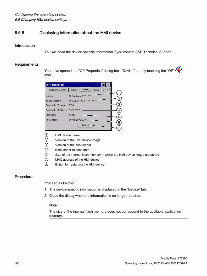
Configuring the operating system 6.5 Changing HMI device settings
Mobile Panel 277 RO 92 Operating Instructions, 10/2015, A5E36824256-AA
6.5.6 Displaying information about the HMI device
Introduction You will need the device-specific information if you contact A&D Technical Support.
Requirements You have opened the "OP Properties" dialog box, "Device" tab, by touching the "OP" icon.
① HMI device name ② Version of the HMI device image ③ Version of the boot loader ④ Boot loader release date ⑤ Size of the internal flash memory in which the HMI device image are stored ⑥ MAC address of the HMI device ⑦ Button for restarting the HMI device
Procedure Proceed as follows:
1. The device-specific information is displayed in the "Device" tab.
2. Close the dialog when the information is no longer required.
Note
The size of the internal flash memory does not correspond to the available application memory.

Configuring the operating system 6.5 Changing HMI device settings
Mobile Panel 277 RO Operating Instructions, 10/2015, A5E36824256-AA 93
6.5.7 Displaying system properties
Introduction The system-specific information provides you with information about the processor, operating system and memory of the HMI device.
Requirements You have opened the "System Properties" dialog with the "System" icon.
① Copyright to Microsoft Windows CE ② Information about the processor, size of the internal flash memory, and capacity of a memory
card when inserted
Displaying the system information The system information is displayed. This dialog is read-only.
Close the dialog.

Configuring the operating system 6.5 Changing HMI device settings
Mobile Panel 277 RO 94 Operating Instructions, 10/2015, A5E36824256-AA
Procedure for displaying memory information
Note "Memory" tab
Do not change the memory distribution in the "Memory" tab.
Only applies for the usage of options: An alteration to the memory distribution may be necessary. Please refer to the accompanying documentation for further information.
Proceed as follows:
1. Change to the "Memory" tab.
The memory information is displayed.
2. Close the dialog.

Configuring the operating system 6.6 Setting the delay time
Mobile Panel 277 RO Operating Instructions, 10/2015, A5E36824256-AA 95
6.6 Setting the delay time
Introduction After switching on the HMI device, the RemoteOperate Client application starts after a delay time. The Loader is displayed during the delay time.
Requirements
You have opened the "Transfer Settings" dialog box, "Directories" tab, by touching the
"Transfer" icon.
① Location of the project file. Not relevant for the Mobile Panel 277 RO. ② Directory where the compressed source file of your project is saved
Not relevant for the Mobile Panel 277 RO. ③ Location and start file for RemoteOperate Client ④ Selection box for the delay time
Note Settings under "Path"
Do not change the settings in the "Path" field. If changes are made here, the RemoteOperate Client software may not start the next time the HMI device is switched on.
Procedure for setting the delay time 1. Select the desired delay time in seconds in the "Wait [sec]" selection box.
With the value "0", RemoteOperate Client starts immediately. It is then no longer possible to call the Loader after switching on the HMI device. Set a value greater than "0" if you need to access the loader.
2. Confirm your entries.
The dialog closes.
Result The delay time for the HMI device is now set.

Configuring the operating system 6.7 Communication settings
Mobile Panel 277 RO 96 Operating Instructions, 10/2015, A5E36824256-AA
6.7 Communication settings
6.7.1 Configuring the data channel
Introduction If you disable all data channels, the HMI device is protected against unintentional overwriting of the HMI device image.
Note
An image can only be transferred from a PC to the HMI device if at least one of the data channels is enabled on the HMI device.
Requirements You have opened the "Transfer Settings" dialog with the "Transfer Settings" icon.
① Group for the data channel 1 (Channel 1) ② Group for the data channel 2 (Channel 2) ③ Button for the "MPI/DP-Transfer Settings" and/or "Network and Dial-Up Connections" dialog
Note "Remote Control" for channel 1
Only activate the "Remote Control" check box in the "Channel 1" group if serial transfer is in progress. Clear the check box before changing to "Online" mode.

Configuring the operating system 6.7 Communication settings
Mobile Panel 277 RO Operating Instructions, 10/2015, A5E36824256-AA 97
Procedure Proceed as follows:
1. You can enable the required data channel by activating the corresponding "Enable Channel" check box in the "Channel 1" or "Channel 2" group.
In the "Channel 1" group, the RS-422/RS-485 port is enabled for the serial data transfer.
– Activate the "Enable Channel" check box to enable the data channel.
– Deactivate the "Enable Channel" check box to disable the data channel.
2. You can enable automatic transfer by activating the corresponding "Remote Control" check box in the "Channel 1" or "Channel 2" group.
3. Select the required protocol for "Channel 2" in the selection box.
4. Enter further parameters if required.
– Applies to "MPI/PROFIBUS DP"
Press the "Advanced" button to switch to the "S7-Transfer Settings" dialog box. You can change the settings for MPI/PROFIBUS DP there.
Confirm your entries.
The "S7-Transfer Settings" dialog box closes.
– Applies to "ETHERNET":
Press the "Advanced" button to switch to the "Network&Dial-Up Connections" dialog box.
Open the "LAN9001" entry. You can change the TCP/IP settings there.
Confirm your entries.
Close the "Network&Dial-Up Connections" dialog.
– Applies to "USB"
No further settings are required for "USB".
5. Confirm your entries.
The dialog closes.
Result The data channel is configured.
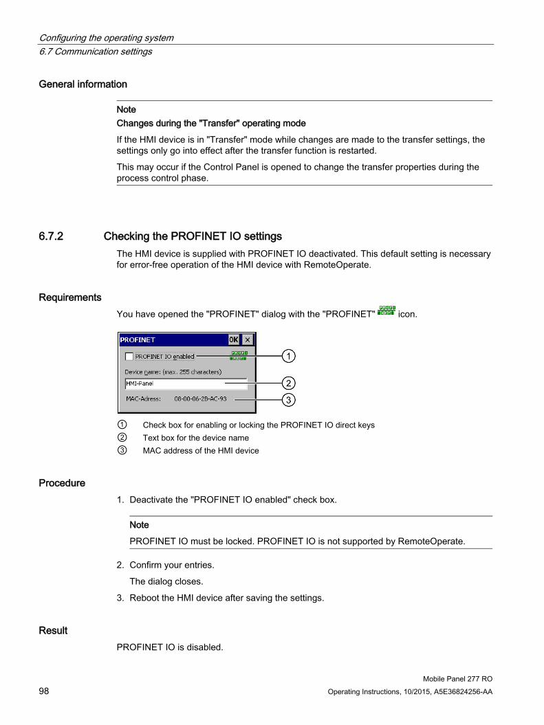
Configuring the operating system 6.7 Communication settings
Mobile Panel 277 RO 98 Operating Instructions, 10/2015, A5E36824256-AA
General information
Note Changes during the "Transfer" operating mode
If the HMI device is in "Transfer" mode while changes are made to the transfer settings, the settings only go into effect after the transfer function is restarted.
This may occur if the Control Panel is opened to change the transfer properties during the process control phase.
6.7.2 Checking the PROFINET IO settings The HMI device is supplied with PROFINET IO deactivated. This default setting is necessary for error-free operation of the HMI device with RemoteOperate.
Requirements You have opened the "PROFINET" dialog with the "PROFINET" icon.
① Check box for enabling or locking the PROFINET IO direct keys ② Text box for the device name ③ MAC address of the HMI device
Procedure 1. Deactivate the "PROFINET IO enabled" check box.
Note
PROFINET IO must be locked. PROFINET IO is not supported by RemoteOperate.
2. Confirm your entries.
The dialog closes.
3. Reboot the HMI device after saving the settings.
Result PROFINET IO is disabled.
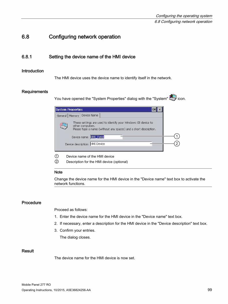
Configuring the operating system 6.8 Configuring network operation
Mobile Panel 277 RO Operating Instructions, 10/2015, A5E36824256-AA 99
6.8 Configuring network operation
6.8.1 Setting the device name of the HMI device
Introduction The HMI device uses the device name to identify itself in the network.
Requirements You have opened the "System Properties" dialog with the "System" icon.
① Device name of the HMI device ② Description for the HMI device (optional)
Note
Change the device name for the HMI device in the "Device name" text box to activate the network functions.
Procedure Proceed as follows:
1. Enter the device name for the HMI device in the "Device name" text box.
2. If necessary, enter a description for the HMI device in the "Device description" text box.
3. Confirm your entries.
The dialog closes.
Result The device name for the HMI device is now set.

Configuring the operating system 6.8 Configuring network operation
Mobile Panel 277 RO 100 Operating Instructions, 10/2015, A5E36824256-AA
6.8.2 Changing the network configuration
Overview You can change the network settings for the LAN connection under "Network & Dial-Up Connections".
Requirement - changing LAN connection settings You have opened the following display by touching the "Network&Dial-Up Connections" icon.
Procedure Proceed as follows:
1. Open the "LAN90001" entry.
– The "'SMC LAN91C111 Ethernet' Settings" dialog opens.
2. Select either automatic address assignment via DHCP or manual address assignment.
3. If you assign the address manually, enter the corresponding addresses in the entry fields for "IP Address", "Subnet Mask" and, if used, "Default Gateway".

Configuring the operating system 6.8 Configuring network operation
Mobile Panel 277 RO Operating Instructions, 10/2015, A5E36824256-AA 101
4. If a name server is used in the network, change to the "Name Server" tab.
5. Enter the respective addresses in the text boxes.
6. Confirm your entries.
The dialog closes.
7. Close the "Network&Dial-Up Connections" display.
The Control Panel is displayed again.
Result The LAN connection parameters for the HMI device have been changed.
6.8.3 Changing the logon data
Introduction Windows CE uses this information to gain access to the network resources. Enter the user name, password and domain you have received from your administrator.
Requirements You have opened the "Network ID" dialog with the "Network ID" icon.

Configuring the operating system 6.9 Backup and restore with the memory card
Mobile Panel 277 RO 102 Operating Instructions, 10/2015, A5E36824256-AA
Procedure Proceed as follows:
1. Enter the user name in the "User name" text box.
2. Enter your password in the "Password" text box.
3. Enter the domain name in the "Domain" text box.
4. Confirm your entries.
The dialog closes.
Result The logon information has now been set.
6.9 Backup and restore with the memory card
6.9.1 Backup to the memory card
Introduction Backup involves copying the operating system, applications and data from the internal flash memory of the HMI device to a memory card.
Requirements A memory card with sufficient free capacity is inserted in the HMI device. The size of the internal flash memory is displayed with information about the HMI device. A warning is displayed and backup is aborted if the available space is insufficient.
You have opened the "Backup/Restore" dialog with the "Backup/Restore" icon.
① Button for backup to memory card ② Button for restore from memory card

Configuring the operating system 6.9 Backup and restore with the memory card
Mobile Panel 277 RO Operating Instructions, 10/2015, A5E36824256-AA 103
Procedure Proceed as follows:
1. Select "BACKUP" to start Backup.
2. The HMI device checks the memory card.
If no memory card is inserted in the card slot of the HMI device or if the memory card is damaged:
– The following warning is displayed:
"No storage card detected!"
– Acknowledge the warning and the following message "Backup aborted".
The Control Panel is displayed again.
A message is displayed if the memory card already contains data. Follow the instructions of the HMI device.
3. The following messages and dialogs are displayed in sequence during backup:
– "Checking Registry"
– "Backup Progress"
– "Saving CE-Image"
A progress bar shows the status of the backup process.
4. If backup was successful, the following message is displayed:
"Backup successfully completed. Press OK and remove your storage card."
5. Click "OK" button to acknowledge the message.
Remove the memory card.
Result The HMI device data is now saved on the memory card.

Configuring the operating system 6.9 Backup and restore with the memory card
Mobile Panel 277 RO 104 Operating Instructions, 10/2015, A5E36824256-AA
6.9.2 Restore from the memory card
Introduction A restore operation deletes the old data from flash memory of the HMI device on confirmation. The data stored on the memory card is then copied to the internal flash memory.
CAUTION
All data on the HMI device will be deleted during a restore operation. Existing licenses are retained.
Requirements The memory card with the backup is inserted in the HMI device.
You have opened the "Backup/Restore" dialog with the "Backup/Restore" icon.
① Button for backup to memory card ② Button for restore from memory card
Procedure Proceed as follows:
1. Select "RESTORE" to start Restore.
The HMI device checks the memory card.
2. If no memory card is inserted in the card slot of the HMI device or if the memory card is damaged:
– The following warning is displayed:
"Storage card couldn't be detected. Try restore again? Insert storage card and Press 'OK' or abort restore with 'CANCEL'."
– Replace the defective memory card and restart Restore with "OK".

Configuring the operating system 6.9 Backup and restore with the memory card
Mobile Panel 277 RO Operating Instructions, 10/2015, A5E36824256-AA 105
3. The data to be restored is checked.
The following messages are displayed in sequence during the check:
– "Starting Restore"
– "Checking data".
4. When the data has been checked, the following prompt for confirmation is displayed:
"You are starting RESTORE now. All files (except files on storage cards) and the registry will be erased. Are you sure? "
At this point you can abort the restore if required in order to prevent the data on the HMI device from being deleted.
5. Start to restore the data by selecting "Yes".
The following messages are displayed in sequence during the restore:
– "Deleting files on flash"
– "Restore CE Image"
A progress bar shows the status of the restoration of the Windows CE image.
6. After successful restoration of the Windows CE image, the following message is displayed: "Restore of CE Image is finished. The device will be rebooted now. Don`t remove the storage card."
Acknowledge this message.
7. The HMI device starts. The operating system boots, opening the "Loader" and "Restore" dialog in sequence.
8. The restore process is resumed. All data stored on the flash file system is restored. Afterwards the following message is displayed: "Restore succesfully finished. Press ok, remove your storage card and reboot your device."
Remove the memory card.
Acknowledge this message.
9. The HMI device starts.
Result The data from the memory card is now on the HMI device.

Configuring the operating system 6.10 Display rechargeable battery charge level
Mobile Panel 277 RO 106 Operating Instructions, 10/2015, A5E36824256-AA
6.10 Display rechargeable battery charge level
Introduction The rechargeable battery is an optional accessory. The "OP Properties" dialog box, "Accu" tab, displays the remaining capacity and temperature of the rechargeable battery.
Requirements You have opened the "OP Properties" dialog box, "Accu" tab, by touching the "OP" icon.
Procedure Proceed as follows:
1. Update the display if required by pressing the "Update" button.
2. Close the dialog.

Mobile Panel 277 RO Operating Instructions, 10/2015, A5E36824256-AA 107
Using RemoteOperate Client 7 7.1 Creating/editing a server selection list
When you switch on the HMI device and once the HMI device starts up, the server selection list is displayed in the "Client - RemoteOperate" dialog box:
Note
When you switch on the HMI device for the first time, the server selection list is empty. You must first create a new server.
Password protection
If your HMI device is password-protected, the icon also appears in the "Client - RemoteOperate" dialog box.
The password will be queried with the following actions:
● Create server
● Change server properties
● Delete server
● Close RemoteOperate Client
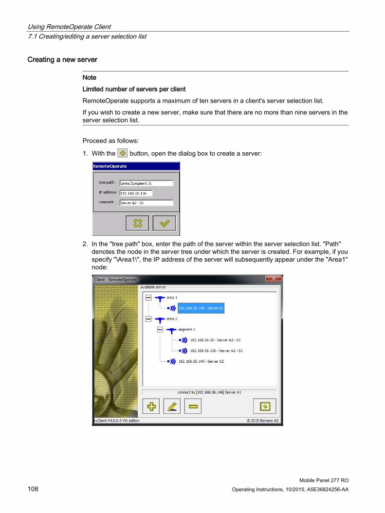
Using RemoteOperate Client 7.1 Creating/editing a server selection list
Mobile Panel 277 RO 108 Operating Instructions, 10/2015, A5E36824256-AA
Creating a new server
Note
Limited number of servers per client
RemoteOperate supports a maximum of ten servers in a client's server selection list.
If you wish to create a new server, make sure that there are no more than nine servers in the server selection list.
Proceed as follows:
1. With the button, open the dialog box to create a server:
2. In the "tree path" box, enter the path of the server within the server selection list. "Path"
denotes the node in the server tree under which the server is created. For example, if you specify "\Area1\", the IP address of the server will subsequently appear under the "Area1" node:

Using RemoteOperate Client 7.1 Creating/editing a server selection list
Mobile Panel 277 RO Operating Instructions, 10/2015, A5E36824256-AA 109
Note
The path of the server selection list has a maximum of three levels. Specify no more than three path levels for a server, for example "\Area2\Segment1\Place2\". If the path already exists in the server selection list, the new server will be inserted at this point. If the path does not yet exist, it is created automatically.
3. Enter the IP address of the new server in the "IP address:" input box.
4. Enter a description of the new server in the "comment:" input box. This comment is displayed next to the IP address in the tree of the server selection list.
5. Confirm your settings with .
Changing the properties of a server Proceed as follows:
1. Select the server whose properties you wish to edit.
2. With the button, open the dialog box to change the server properties.
3. Follow steps 2 to 5 of the instructions for creating a new server.
Remove server Proceed as follows:
1. Select the server that you wish to remove from the server selection list.
2. Remove the selected server from the server selection list using the button.
Result You have created a new server selection list or changed an existing server selection list.

Using RemoteOperate Client 7.2 Connecting a client
Mobile Panel 277 RO 110 Operating Instructions, 10/2015, A5E36824256-AA
7.2 Connecting a client
Requirement ● You have switched on the HMI device.
Note
If you have switched on the HMI device for the first time, the server selection list is empty. Create a new server selection list.
Procedure 1. Select the name of the server to which you want to connect.
DANGER
Full access to the server
Depending on your access authorization, when you connect to the server, you have full access.
Improper use of the server by unauthorized personnel may cause the server to malfunction. Malfunctions can result in death or serious injury. You should assign passwords to the HMI devices. Develop an operator authorization plan. This will enable you to ensure that only authorized personnel are given full access to the server.

Using RemoteOperate Client 7.2 Connecting a client
Mobile Panel 277 RO Operating Instructions, 10/2015, A5E36824256-AA 111
2. Connect the client to the selected server using the button.
While the client is trying to connect to the server, the following message is displayed on your HMI device:
Note Response to a network fault
If a transient or long-term network fault occurs, the client repeatedly tries to establish a connection to the server. You can abort this repeated attempt to establish a connection with the button.
Result Once a connection to the server has been established, the following options are available:
● The server grants you access. The project running on the server is displayed. Depending on your authorization, you can either monitor or operate the project on the server.
● The server grants you access. The Windows desktop of the server is displayed. If you have operator authorization, you can launch your project via the appropriate desktop icon.
● The server does not grant you access. The following message is displayed on your HMI device:
You can abort the attempt to establish a connection using the button.
Once the server has rejected your access attempt, your client will remain unauthorized until the server explicitly grants you access.

Using RemoteOperate Client 7.2 Connecting a client
Mobile Panel 277 RO 112 Operating Instructions, 10/2015, A5E36824256-AA
The operator authorization window ("traffic lights") The operator authorization window, known as "traffic lights", is displayed in the foreground on the server screen and the screens of all connected clients with operator authorization. The traffic lights can assume the following states: Traffic light icon Activated by Meaning
Touching the touch screen on a client with operator authorization or enabling exclusive operator authorization on another client with operator authorization.
You have authorization to operate the server. Other clients can make an operator request.
Two rapid touches (double-click) on the traffic lights of the current client with operator authorization.
You have exclusive authorization to operate the server. Other clients will only be able to make an operator request when you relinquish the exclusive operator authorization by double-clicking the traffic light once again.
Enable the "Forced Exclusive" mode, for example with a switch close to the Mobile Panel.
You have exclusive authorization to operate the server. Other clients will only be able to make an operator request when you relinquish the exclusive operator authorization disabling the "Forced Exclusive" mode.
Touching the touch screen on another client with operator authorization.
Another client has authorization to operate the server. You can make an operator request on your client by touching the touch screen.
Double-click on the traffic lights on another client with operator authorization.
Another client has exclusive authorization to operate the server. You cannot make another operator request until the other client has given up the exclusive operator authorization by double-clicking the traffic light.
Enable the "Forced Exclusive" mode, for example with a switch close to the Mobile Panel.
Another client has exclusive authorization to operate the server. You cannot make another operator request until the other client has given up the exclusive operator authorization by disabling the "Forced Exclusive" mode.

Using RemoteOperate Client 7.2 Connecting a client
Mobile Panel 277 RO Operating Instructions, 10/2015, A5E36824256-AA 113
The RemoteOperate toolbar If you press the touch screen for more than five seconds (time can be configured in the roServer.ini), the RemoteOperate toolbar is displayed in the foreground on your screen.
Alternatively, if you have operator authorization, you can left-click the traffic light to open the RemoteOperate toolbar.
Note
The length of time you need to press the touch screen before the RemoteOperate toolbar is displayed is defined in the "roServer.ini" file.
The special functions of the RemoteOperate toolbar are shown in the table below: Buttons Functions
Executes a right-click on the server. Proceed as follows: 1. Select a screen object which has a right-click function. 2. Touch the "Right-click" button. 3. Execute the desired function.
Opens the screen keyboard (only with the Windows CE operating system).
Operates the Windows button on the server.
Executes the <Ctrl+Alt+Del> shortcut on the server, e.g., to log onto the server.
Terminates the connection to the server.
Closes the RemoteOperate toolbar.
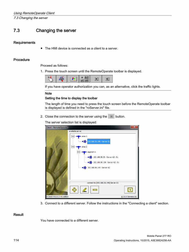
Using RemoteOperate Client 7.3 Changing the server
Mobile Panel 277 RO 114 Operating Instructions, 10/2015, A5E36824256-AA
7.3 Changing the server
Requirements ● The HMI device is connected as a client to a server.
Procedure Proceed as follows:
1. Press the touch screen until the RemoteOperate toolbar is displayed.
If you have operator authorization you can, as an alternative, click the traffic lights.
Note
Setting the time to display the toolbar
The length of time you need to press the touch screen before the RemoteOperate toolbar is displayed is defined in the "roServer.ini" file.
2. Close the connection to the server using the button.
The server selection list is displayed:
3. Connect to a different server. Follow the instructions in the "Connecting a client" section.
Result You have connected to a different server.
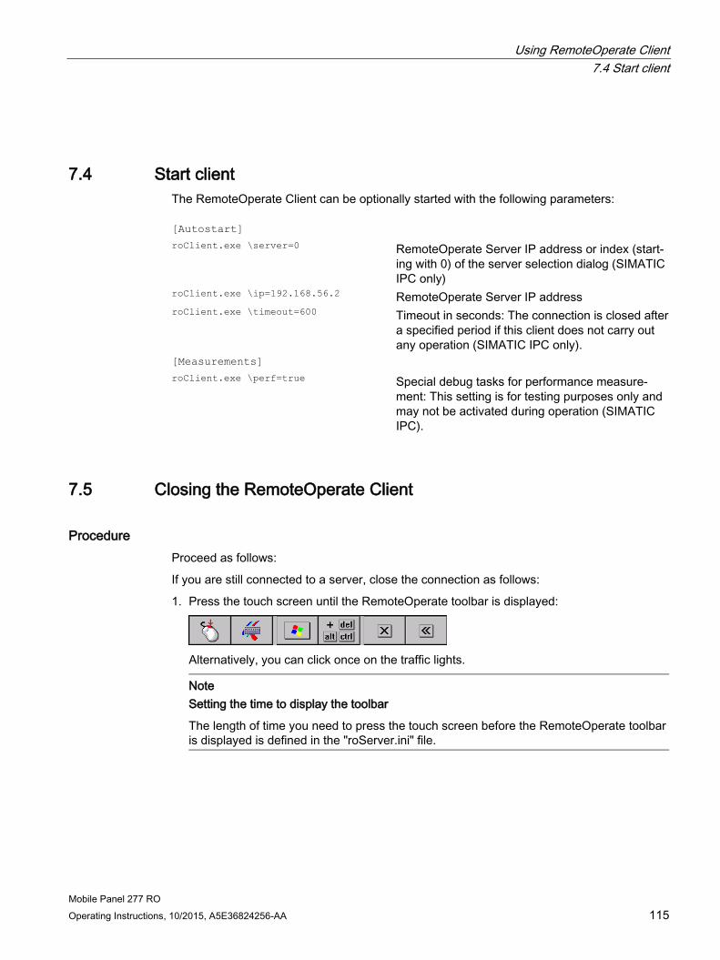
Using RemoteOperate Client 7.4 Start client
Mobile Panel 277 RO Operating Instructions, 10/2015, A5E36824256-AA 115
7.4 Start client The RemoteOperate Client can be optionally started with the following parameters: [Autostart] roClient.exe \server=0 RemoteOperate Server IP address or index (start-
ing with 0) of the server selection dialog (SIMATIC IPC only)
roClient.exe \ip=192.168.56.2 RemoteOperate Server IP address roClient.exe \timeout=600 Timeout in seconds: The connection is closed after
a specified period if this client does not carry out any operation (SIMATIC IPC only).
[Measurements] roClient.exe \perf=true Special debug tasks for performance measure-
ment: This setting is for testing purposes only and may not be activated during operation (SIMATIC IPC).
7.5 Closing the RemoteOperate Client
Procedure Proceed as follows:
If you are still connected to a server, close the connection as follows:
1. Press the touch screen until the RemoteOperate toolbar is displayed:
Alternatively, you can click once on the traffic lights.
Note
Setting the time to display the toolbar
The length of time you need to press the touch screen before the RemoteOperate toolbar is displayed is defined in the "roServer.ini" file.
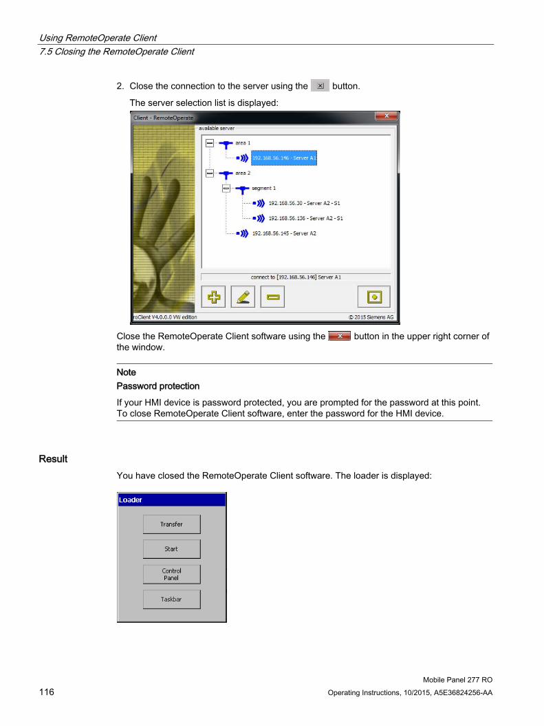
Using RemoteOperate Client 7.5 Closing the RemoteOperate Client
Mobile Panel 277 RO 116 Operating Instructions, 10/2015, A5E36824256-AA
2. Close the connection to the server using the button.
The server selection list is displayed:
Close the RemoteOperate Client software using the button in the upper right corner of the window.
Note Password protection
If your HMI device is password protected, you are prompted for the password at this point. To close RemoteOperate Client software, enter the password for the HMI device.
Result You have closed the RemoteOperate Client software. The loader is displayed:

Using RemoteOperate Client 7.6 Example: Assigning operator authorization
Mobile Panel 277 RO Operating Instructions, 10/2015, A5E36824256-AA 117
The loader contains the following four buttons:
● Use the "Transfer" button to transfer data from a PC to the HMI device.
● Use the "Start" button to open the server selection list.
● Use the "Control Panel" button to configure the operating system.
● Use the "Taskbar" button to activate the taskbar when the Windows CE Start menu is open.
7.6 Example: Assigning operator authorization
Introduction This chapter describes how to assign operator authorization on the server to different clients in succession.
The description uses an example configuration with one server and three HMI devices connected to the server as clients via Ethernet.

Using RemoteOperate Client 7.6 Example: Assigning operator authorization
Mobile Panel 277 RO 118 Operating Instructions, 10/2015, A5E36824256-AA
Sequence of the example scenario During the operation of a plant control system, the request, refusal and transfer of operator authorizations could look like this:
Client 1, client 2, and client 3 are entered in the list of "available clients" on the server. All clients are granted the right to connect to the server and to operate on the server.
● Client 1, client 2, and client 3 connect to the server. All clients can see the project that is running on the server on their screen. If neither client executes an operation, all traffic lights are green at first:
Client 1 Client 2 Client 3 Server
● A user starts to operate on client 1 by pressing the touch screen. Client 1 is immediately granted operator authorization since no other user is operating on the server. The traffic light for client 1 stays green. The traffic lights for client 2, client 3, and the server turn red:
Client 1 Client 2 Client 3 Server
● The user on client 1 touches the green traffic light twice in quick succession (double-click). Client 1 is granted exclusive operator authorization. The traffic light for client 1 turns entirely green. The traffic lights for client 2, client 3, and the server turn completely red:
Client 1 Client 2 Client 3 Server
● A user tries to operate on client 2. Client 2 is not granted operator authorization because the user on client 1 has exclusive operator authorization. All traffic lights remain unchanged.

Using RemoteOperate Client 7.6 Example: Assigning operator authorization
Mobile Panel 277 RO Operating Instructions, 10/2015, A5E36824256-AA 119
● The user on client 1 touches the green traffic light twice in quick succession (double-click) and gives up exclusive operator authorization. Client 1 continues to operate. The traffic light for client 1 turns green. The traffic lights for client 2, client 3, and the server turn red:
Client 1 Client 2 Client 3 Server
● A user tries to operate on client 2. The operator request dialog opens on the screens of client 1, client 2, client 3 as well as the server screen:
● Since the user on client 1 has operator authorization, he decides on whether to transfer
operator authorization:
– If the operator on client 1 with the button denies the operator request of client 2 within the specified time, client 1 will still have operator authorization. All traffic lights will remain unchanged.
– If the user on client 1 ignores the operator request, client 2 is granted operator authorization after a predefined time. The traffic light for client 2 turns green. The traffic lights for client 1, client 3, and the server turn red:
Client 1 Client 2 Client 3 Server
Note
The time interval for the automatic transfer of operator authorization is defined by the "TIMEWAITACCESS" variable in the "roServer.ini" file on the server. The "roServer.ini" file is part of the advanced server settings.

Using RemoteOperate Client 7.6 Example: Assigning operator authorization
Mobile Panel 277 RO 120 Operating Instructions, 10/2015, A5E36824256-AA
● The operator at client 1 enables the "Forced Exclusive" mode, for example with a switch close to the HMI device. The traffic light of client 1 turns completely green and all other traffic lights turn completely red. The traffic lights also come equipped with a key symbol:
Client 1 Client 2 Client 3 Client 4
Client 1 has exclusive operator authorization. Only when the operator at client 1 has
disabled the "Forced Exclusive" mode, will operators at other clients or the server be able to make other operator requests.
● The operator at client 1 disables the "Forced Exclusive" mode, for example by pressing the switch close to the HMI device.
If the operator at client 1 continues operation, the traffic light will stay green while all other traffic lights will turn red:
Client 1 Client 2 Client 3 Server
If the operator at client 1 stops operation, all traffic lights will turn green:
Client 1 Client 2 Client 3 Server

Mobile Panel 277 RO Operating Instructions, 10/2015, A5E36824256-AA 121
Backing up and restoring data 8
Requirements ● The HMI device is connected to a PC by means of the connection box and Ethernet.
● The ProSave application is installed on the PC. The ProSave software is located on the "SIMATIC RemoteOperate - Applications & Documentation" CD.
● The ProSave add-on with the information for the HMI device is installed on the PC. The ProSave add-on is located on the "SIMATIC RemoteOperate - Applications & Documentation" CD.
● The data channel on the HMI device is configured.
● The PC is switched on.
Procedure for backup Proceed as follows:
1. Start ProSave from the Windows Start menu on the PC.
2. Select the HMI device type "Mobile Panel 277 RO" in the "General" tab.
3. Select "Ethernet" as the connection type between the HMI device and the PC.
4. Enter the IP address or the name of the HMI device.
5. Select the data to be backed up in the "Backup" tab.
6. Select a destination folder and a file name for the "*.psb" backup file.
7. Set "Transfer" mode on the HMI device.
If automatic transfer mode is enabled on the HMI device, the HMI device automatically sets "Transfer" mode when a backup is initiated.
8. Start the backup operation in ProSave with "Start Backup".
Follow the instructions in ProSave.
A status view opens to indicate the progress of the operation.
Result The system outputs a message when the backup is completed.
You have backed up the selected HMI device data to the PC.

Backing up and restoring data
Mobile Panel 277 RO 122 Operating Instructions, 10/2015, A5E36824256-AA
Procedure for restoring Proceed as follows:
1. Start ProSave from the Windows Start menu on the PC.
2. Select the HMI device type "Mobile Panel 277 RO" in the "General" tab.
3. Select "Ethernet" as the connection type between the HMI device and the PC.
4. Enter the IP address or the name of the HMI device.
5. Select the "*.psb" backup file to be restored from the "Restore" tab.
You can see the HMI device for which the backup file was created and the type of backup data the file contains.
6. Set "Transfer" mode on the HMI device.
If automatic transfer mode is enabled on the HMI device, the device automatically sets "Transfer" mode when a restore operation is initiated.
7. Start the restore operation in ProSave on the PC with "Start Restore".
If there are license keys on both the HMI device and in the backup, you are asked whether you wish to overwrite the license keys or to cancel the restore operation.
– If necessary, abort the backup and first back up the HMI device's license keys.
– Then restart the restore process.
Follow the instructions in ProSave.
A status view opens to indicate the progress of the operation.
Result You have successfully transferred the backed up data from the PC to the HMI device.
See also Configuring the data channel (Page 96)
Setting the device name of the HMI device (Page 99)
Changing the network configuration (Page 100)

Mobile Panel 277 RO Operating Instructions, 10/2015, A5E36824256-AA 123
Maintenance and care 9 9.1 Maintenance and care
Scope of maintenance The HMI device is designed for maintenance-free operation. You should clean the touch screen at regular intervals, however.
CAUTION
Inadvertent operation
Always switch off the HMI device before cleaning it. This will ensure that you do not trigger functions unintentionally when you touch the keys.
NOTICE
Do not clean the HMI device with compressed air or steam jet blowers. Never use aggressive solvents or scouring powder.
Use a cleaning cloth dampened with a cleaning agent to clean the equipment. Only use water with a little liquid soap or a screen cleaning foam.
Procedure Proceed as follows:
1. Switch off the HMI device.
2. Spray the cleaning solution onto a cleaning cloth.
Do not spray directly onto the HMI device.
3. Clean the HMI device.
When cleaning the display wipe from the screen edge inwards.

Maintenance and care 9.2 Update HMI device image
Mobile Panel 277 RO 124 Operating Instructions, 10/2015, A5E36824256-AA
9.2 Update HMI device image The following applications are pre-installed on the HMI device:
● The Microsoft Windows CE 5.0 operating system
● The RemoteOperate Client software
The operating system and the RemoteOperate Client software are located in an image on the "SIMATIC RemoteOperate - Applications & Documentation" CD.
When you update the operating system on the HMI device or want to reset the HMI device to factory settings, you have the transfer the image once again to the HMI device. To do this, connect a PC to the HMI device and then start to transfer the image using ProSave.
Requirements ● The HMI device is connected to a PC by means of the connection box and Ethernet.
● The ProSave application is installed on the PC. The ProSave software is located on the "SIMATIC RemoteOperate - Applications & Documentation" CD.
● The ProSave add-on with the information for the HMI device is installed on the PC. The ProSave add-on is located on the "SIMATIC RemoteOperate - Applications & Documentation" CD.
● The data channel on the HMI device is configured.
Procedure Proceed as follows:
1. Check that the HMI device is turned off.
2. Turn on the PC.
3. Start ProSave from the Windows Start menu on the PC.
4. Select the HMI device type in the "General" tab.
5. Select the type of connection between the HMI device and the PC.
6. Select the "OS Update" tab.
7. Select the HMI device image file "*.img" from the "Image Path" area.
8. The HMI device image file is located on the "SIMATIC RemoteOperate - Applications & Documentation" CD. In the output area, you are provided information on the version of the HMI device image file after it is opened.
9. Start the operating system update by means of the "Update OS" button.
10. Click on the "Transfer" button in the loader.
11. Follow the instructions in ProSave.
During the operating system update a status view opens to indicate progress. A message is displayed when the operating system update is successfully completed.

Maintenance and care 9.3 Spare parts and repairs
Mobile Panel 277 RO Operating Instructions, 10/2015, A5E36824256-AA 125
Result You have successfully installed the operating system and the RemoteOperate Client application on the HMI device.
See also Connecting a PC (Page 56)
Configuring the data channel (Page 96)
9.3 Spare parts and repairs
Repairs In case of repair, the HMI device must be shipped to the Return Center in Fürth. Repairs may only be carried out at the Return Center in Fürth.
The Mobile Panel 277 RO HMI device is covered by the conditions of repair and return of equipment, as follows:
1. You return the defective device to the A&D returned goods center. The address is:
Siemens AG Industry Sector Returns Center Siemensstr. 2 90766 Fürth Germany
2. After it has been repaired, the device is returned to you. A new device will not be supplied in exchange.
Depending on the work necessary to repair the device, the Center may decide to give you a credit note. In this case, it is your responsibility to order a new device.
For additional information, refer to the Internet at Spare parts and repairs (http://support.automation.siemens.com/WW/view/en/16611927).
See also Accessories (Page 12)
Due to the low levels of pollutants in the HMI devices described in these Operating Instructions, they can be recycled. For environment-friendly recycling and disposal of your old equipment, contact a certified disposal facility for electronic scrap.

Maintenance and care 9.3 Spare parts and repairs
Mobile Panel 277 RO 126 Operating Instructions, 10/2015, A5E36824256-AA

Mobile Panel 277 RO Operating Instructions, 10/2015, A5E36824256-AA 127
Technical specifications 10 10.1 Dimension drawings
10.1.1 Mobile Panel 277 RO
Front view
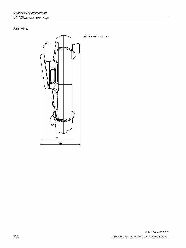
Technical specifications 10.1 Dimension drawings
Mobile Panel 277 RO 128 Operating Instructions, 10/2015, A5E36824256-AA
Side view

Technical specifications 10.1 Dimension drawings
Mobile Panel 277 RO Operating Instructions, 10/2015, A5E36824256-AA 129
10.1.2 Wall-mounting bracket

Technical specifications 10.1 Dimension drawings
Mobile Panel 277 RO 130 Operating Instructions, 10/2015, A5E36824256-AA
10.1.3 Connection box PN Plus

Technical specifications 10.2 Specifications
Mobile Panel 277 RO Operating Instructions, 10/2015, A5E36824256-AA 131
10.2 Specifications
10.2.1 Mobile Panel 277 RO
HMI device Weight without packing Approx. 2.3 kg
Display Type Color TFT-LC Display Display area, active (W x H) 211.2 mm x 158.4 mm (10") Resolution 800 x 600 pixels Colors, displayable 64k colors Brightness control Yes Back-lighting Half Brightness Life Time, typical
CCFL 50,000 h
Input unit Type Touch screen, analog, resistive Enabling button 2-circuit, 3-level
Connection voltage: 24 V DC Amperage, max.: 400 mA Amperage, min.: 10 mA
STOP button (optional) 2-circuit Connection voltage: 24 V DC Amperage, max.: 500 mA Amperage, min.: 10 mA These are normally closed contacts.
Memory Application memory 6 MB

Technical specifications 10.2 Specifications
Mobile Panel 277 RO 132 Operating Instructions, 10/2015, A5E36824256-AA
Ports 1 x RS 485 Max. 12 Mbit/s 1 x USB • USB host; conforms to USB standard 1.1 (supporting low-
speed and full-speed USB devices) • Maximum load 500 mA
1 x RS 45 For Ethernet 1 x plug-in terminal strips (12-pin) For Ethernet
Supply voltage Supply voltage Via connection box
Additional specifications Fall height Max. 1 m Buffer time with internal clock Without rechargeable battery Approx. 3 days
With rechargeable battery Approx. 6 months
10.2.2 Rechargeable buffer battery The following technical specifications are in effect for all new batteries. The batteries are delivered uncharged. Type Lithium ion accumulator Bridging time 10 min Charging cycles 500 Charging time Approx. 5 h
Number of changes between connection boxes With fully charged battery 5 changes With empty battery after a charging time of 1 h 2 changes
Please note that a battery is subject to a natural self-discharge. The self-discharge can lead to a complete discharge over long periods of disuse.

Technical specifications 10.2 Specifications
Mobile Panel 277 RO Operating Instructions, 10/2015, A5E36824256-AA 133
10.2.3 Safety characteristics
Note
The fail-safe performance characteristics in the technical data apply to a proof-test interval of 20 years.
STOP button Rated voltage 24 V DC Minimum current 10 mA, per contact Max. current carrying capacity 500 mA, per contact Utilization category DC-13, in accordance with IEC 60947-5-1 B10d 100 000
Enabling button Output type Solid-state output Rated voltage, switchable 24 V DC, tolerance 19.2 to 30 V DC in accordance with EN 611312 Rated current, switchable, max. 400 mA Breaking current, max. Circuit 1 1.5 A
Circuit 2 0.8 A Inductive load, max. Circuit 1 145 mJ/1.16 H at 24 V DC, 500 mA
(comparable to 13 DC in accordance with EN 60947-5-1)
Circuit 2 145 mJ/1.16 H at 24 V DC, 500 mA (comparable to 13 DC in accordance with EN 60947-5-1)
Reverse polarity protection Circuit 1 Yes Circuit 2 Yes
Short-circuit and overload pro-tection
Circuit 1 Yes, integrated in the output FET Circuit 2 Yes, through protective circuit
Switching cycles Switch position 2 10 5 Switch position 3 5 * 104
Actuation forces From switch position 1 to 2, typical
5 N
From switch position 2 to 3, typical
20 N
Specifications in accordance with EN ISO 13849-1 Stop with PLUS connection box Category 3 1.01 * 10–7
PFHd for both channels 1.01 * 10–7 Enable Category 3 PL d
PFHd 1.35 * 10–7 Panic Category 3 PL d
PFHd 1.14 * 10–7

Technical specifications 10.2 Specifications
Mobile Panel 277 RO 134 Operating Instructions, 10/2015, A5E36824256-AA
10.2.4 Connection box PN Plus
Weight Weight without packing Approx. 700 g
Supply voltage Rated voltage +24 VDC Permitted voltage range 20.4 V to 28.8 V (–15 %, +20 %) Transients, maximum permissible 35 V (500 ms) Time between two transients, minimum 50 s Power consumption connection box PN without Mobile Panel
Typical Approx. 100 mA Constant current, maximum Approx. 150 mA Power on current surge I2t Approx. 0.5 A2s
Power consumption connection box PN with Mobile Panel
Typical Approx. 600 mA Constant current, maximum Approx. 750 mA Power on current surge I2t Approx. 0.6 A2s
Enabling button Connection voltage 24 V DC Amperage, max. 400 mA Amperage, min. 10 mA
STOP button Connection voltage 24 V DC Amperage, max. 500 mA Amperage, min. 10 mA
Fuse, internal Electronic Current load PLC-accompanying signals Max. 100 mA Recovery time After 1 s
Note Recovery time
Wait for approximately one second after you have removed the connecting cable from the connection box before you plug the connecting cable back into the connection box. Power failure
It is necessary to remove and replace the connecting cable in the event of power failures lasting less than a second in order to eliminate possible malfunctions.

Technical specifications 10.3 Mobile Panel 277 RO interface assignment
Mobile Panel 277 RO Operating Instructions, 10/2015, A5E36824256-AA 135
10.3 Mobile Panel 277 RO interface assignment
10.3.1 RS 485 (IF 2) Sub-D socket, 9-pin, with screw lock
Pin Assignment 1 n. c. 2 GND 24 V 3 Data channel B (+) 4 n. c. 5 GND 5 V, floating 6 +5 VDC, floating 7 +24 VDC, out (max. 100 mA) 8 Data channel A (–) 9 n. c.
10.3.2 USB USB socket
Pin Assignment 1 +5 VDC, out (max. 500 mA) 2 USB-DN 3 USB-DP 4 GND

Technical specifications 10.3 Mobile Panel 277 RO interface assignment
Mobile Panel 277 RO 136 Operating Instructions, 10/2015, A5E36824256-AA
10.3.3 RJ45 for connecting cable PN RJ45 plug connector, 8-pin
Pin Assignment 1 TD+ 2 TD– 3 RD+ 4 n. c. 5 n. c. 6 RD– 7 ICD+ 8 ICD–
10.3.4 Post connector for connecting cable PN Post connector, 12-pin
Pin Assignment Circuit 1 +24 VDC Power supply 2 GND 24 V 3 Stop 23 STOP circuit 4 Stop 24 5 Stop 13 6 Stop 14 7 Enable 1+ Enable circuit 8 Enable 1– 9 Enable 2+
10 Enable 2– 11 ICD+ Box ID 12 ICD–

Technical specifications 10.4 Connection box PN Plus interface assignment
Mobile Panel 277 RO Operating Instructions, 10/2015, A5E36824256-AA 137
10.4 Connection box PN Plus interface assignment
Position of the ports
① Fast connector ② Terminal strip 1 ③ Terminal strip 2
Fast connector, 4-pin The connection box contains two fast connectors for connecting the PROFINET data cables. The figure below illustrates the assignment of the fast connector:
Pin Color Assignment connection box Assignment PLC *) 1 yellow RD+ TD+ 2 white TD+ RD+ 3 orange RD- TD– 4 blue TD- RD–
*) Only important if the PLC is connected directly to the connection box.

Technical specifications 10.4 Connection box PN Plus interface assignment
Mobile Panel 277 RO 138 Operating Instructions, 10/2015, A5E36824256-AA
Terminal strip 1, for power supply, 3-pin The figure below illustrates the assignment of terminal strip 1:
Pin Assignment 1 PE 2 M24 3 P24
Terminal strip 2, 12-pin The safety and additional functions are connected to this terminal strip. The terminal strip has a mechanical coding to prevent it from being mixed up with terminal strip 1. The figure below illustrates the assignment of terminal strip 2:
Pin Connection box Plus Circuit 1 STOP13 STOP button
See also post connectors 2 STOP14 3 STOP23 4 STOP24 5 CTL31 1) PLC auxiliary signals 6 CTL32 1) 7 PRESENT31 2) 8 PRESENT32 9 ENABLE2+ Enabling button
See also post connectors and connection examples
10 ENABLE1– 11 ENABLE1+ 12 ENABLE2–
1) Active if Emergency Stop pressed 2) Active if Mobile Panel connected The "STOP button depressed" signal has no error detection and must therefore not be used for safety-critical applications.

Technical specifications 10.4 Connection box PN Plus interface assignment
Mobile Panel 277 RO Operating Instructions, 10/2015, A5E36824256-AA 139
Typical circuit diagrams for connection box Plus Typical circuit diagram: Mobile Panel 277 RO not connected and power supply switched on:
Typical circuit diagram: Mobile Panel 277 RO connected, power supply switched on and Emergency Stop inactive:

Technical specifications 10.4 Connection box PN Plus interface assignment
Mobile Panel 277 RO 140 Operating Instructions, 10/2015, A5E36824256-AA
Typical circuit diagram: Mobile Panel 277 RO connected, power supply switched on and Emergency Stop active:

Technical specifications 10.4 Connection box PN Plus interface assignment
Mobile Panel 277 RO Operating Instructions, 10/2015, A5E36824256-AA 141
Typical circuit diagram: Power supply switched off

Technical specifications 10.5 Wiring Examples for Enabling Switch and STOP Button
Mobile Panel 277 RO 142 Operating Instructions, 10/2015, A5E36824256-AA
10.5 Wiring Examples for Enabling Switch and STOP Button
Introduction This chapter contains connection examples for enabling and STOP buttons corresponding to Category 3 PL d in accordance with EN ISO 13849-1:2008/AC:2009.
Note To ensure Category 3 PL d in accordance with EN ISO 13849-1:2008/AC:2009, be sure to follow the operating instructions for the monitoring device being used. The monitoring devices shown in the following examples satisfy Category 4 PL e in accordance with EN ISO 13849-1:2008/AC:2009. The monitoring device and downstream components should be taken into consideration when calculating the overall "Stop" and "Enabling" safety function.
Connection – Enabling button with evaluation device The following figure shows the connection of an evaluating device to the enabling button of the mobile panel.
All contacts of the safety relay (contactor) KA and KB are fitted with positively-driven contacts in accordance with EN 50205:2002.

Technical specifications 10.5 Wiring Examples for Enabling Switch and STOP Button
Mobile Panel 277 RO Operating Instructions, 10/2015, A5E36824256-AA 143
Connection example 1 – Enabling button with safety circuit device The following figure shows the connection of a SIRIUS 3TK2841 safety circuit device to the enabling button of the mobile panel.
All contacts of the safety relay (contactor) KA and KB are fitted with positively-driven contacts in accordance with EN 50205:2002.

Technical specifications 10.5 Wiring Examples for Enabling Switch and STOP Button
Mobile Panel 277 RO 144 Operating Instructions, 10/2015, A5E36824256-AA
Connection example 2 – STOP button with safety circuit device The following figure shows the connection of a SIRIUS 3TK2822 or SIRIUS 3TK2841 to the STOP button of the mobile panel.
All contacts of the safety relay (contactor) KA and KB are fitted with positively-driven contacts in accordance with EN 50205:2002.
Monitoring outputs may not be used for safety-related functions.

Mobile Panel 277 RO Operating Instructions, 10/2015, A5E36824256-AA 145
Appendix A A.1 Service and support
You can find additional information and support for the products described on the Internet at the following addresses:
● Technical support (https://support.industry.siemens.com)
● Support request form (http://www.siemens.com/automation/support-request)
● After Sales Information System SIMATIC IPC/PG (http://www.siemens.com/asis)
● SIMATIC Documentation Collection (http://www.siemens.com/simatic-tech-doku-portal)
● Your local representative (http://www.automation.siemens.com/mcms/aspa-db/en/Pages/default.aspx)
● Training center (http://sitrain.automation.siemens.com/sitrainworld/?AppLang=en)
● Industry Mall (https://mall.industry.siemens.com)
When contacting your local representative or Technical Support, please have the following information at hand:
● MLFB of the device
● BIOS version for industrial PC or image version of the device
● Other installed hardware
● Other installed software
Tools & downloads Please check regularly if updates and hotfixes are available for download to your device. The download area is available on the Internet at the following link:
After Sales Information System SIMATIC IPC/PG (http://www.siemens.com/asis)

Appendix A.2 ESD guideline
Mobile Panel 277 RO 146 Operating Instructions, 10/2015, A5E36824256-AA
A.2 ESD guideline
Definition of ESD All electronic modules are equipped with large-scale integrated ICs or components. Due to their design, these electronic elements are highly sensitive to overvoltage, and thus to any electrostatic discharge. These electronic components are therefore specially identified as ESDs.
Abbreviations The following abbreviation is commonly used for electrostatic sensitive devices:
● EGB – Elektrostatisch Gefährdete Bauteile/Baugruppen (Germany)
● ESD – Electrostatic Sensitive Device (internationally recognized term)
Labeling ESDs are labeled with the following symbol:

Appendix A.2 ESD guideline
Mobile Panel 277 RO Operating Instructions, 10/2015, A5E36824256-AA 147
Electrostatic charging
NOTICE
Electrostatic charging
ESDs may be destroyed by voltages far below the level perceived by human beings. Voltages of this kind develop when a component or an assembly is touched by a person who is not grounded against static electricity. Usually, it is unlikely that damage to an ESD as a result of overvoltage is detected immediately but may become apparent only after a longer period of operation.
Prevent electrostatic charging of your body before you touch the ESD!
Anyone who is not connected to the electrical potential of their surroundings is subjected to electrostatic charging.
The following figure indicates the maximum electrostatic charge anyone is subjected to when coming into contact with the materials shown. These values correspond with specifications to IEC 801-2.
① Synthetic materials ② Wool ③ Antistatic materials such as wood or concrete

Appendix A.2 ESD guideline
Mobile Panel 277 RO 148 Operating Instructions, 10/2015, A5E36824256-AA
Protective measures against electrostatic discharge
NOTICE
Observe grounding measures
When working with electrostatic sensitive devices, make sure that the person, the workplace and the packaging are properly grounded. This helps to avoid electrostatic charging.
As a rule, only touch the ESD if this is unavoidable, for example for maintenance. When you touch modules, make sure that you do not touch the pins on the modules or the PCB tracks. In this way, the discharged energy cannot reach and damage the sensitive devices.
Discharge electrostatic electricity from your body if you are performing measurements on an ESD. Do so by touching grounded metallic parts.
Always use grounded measuring instruments.

Mobile Panel 277 RO Operating Instructions, 10/2015, A5E36824256-AA 149
Abbreviations B B.1 Abbreviations
DC Direct Current DHCP Dynamic Host Configuration Protocol DNS Domain Name System ESD Components and modules endangered by electrostatic discharge EMC Electromagnetic Compatibility EN European standard ESD Components and modules endangered by electrostatic discharge GND Ground HF High Frequency HMI Human Machine Interface IEC International Electronic Commission IF Interface IP Internet Protocol LED Light Emitting Diode MAC Media Access Control MPI Multipoint Interface (SIMATIC S7) n. c. Not connected PC Personal Computer PPI Point-to-Point Interface (SIMATIC S7) PELV Protective Extra Low Voltage RJ45 Registered Jack Type 45 RO RemoteOperate SD Security Digital SELV Safety Extra Low Voltage Sub-D Subminiature D (plug) TCP/IP Transmission Control Protocol/Internet Protocol TFT Thin Film Transistor UL Underwriter’s Laboratory USB Universal Serial Bus WINS Windows Internet Naming Service

Abbreviations B.1 Abbreviations
Mobile Panel 277 RO 150 Operating Instructions, 10/2015, A5E36824256-AA

Mobile Panel 277 RO Operating Instructions, 10/2015, A5E36824256-AA 151
Glossary
Automation system Controller of the SIMATIC S7 series such as a SIMATIC S7-300
Bootloader Used to start the operating system. Automatically started when the HMI device is switched on. After the operating system has been loaded, the Loader opens.
EMC Electromagnetic compatibility is the ability of electrical equipment to function properly in its electromagnetic environment without influencing this environment.
Flash memory Non-volatile memory with EEPROM chips, used as mobile storage medium or as memory module installed permanently on the motherboard.
Hardcopy Output of the screen content to a printer.
HMI device An HMI device is a device used for the operation and monitoring of machines and plants. The statuses of the machine or plant are indicated by means of graphic elements or by indicator lamps on the HMI device. The operator controls of the HMI device allow the operator to interact with the processes of the machine or plant.
HMI device image The HMI device image is a file that can be transferred from a connected PC to the HMI device. The HMI device image contains the operating system for the HMI device and the RemoteOperate Client software.
Operating element Component of a project used to enter values and trigger functions. A button, for example, is an operating element.

Glossary
Mobile Panel 277 RO 152 Operating Instructions, 10/2015, A5E36824256-AA
Plant General term referring to machines, processing centers, systems, plants and processes which are operated and monitored on an HMI device.
PLC A PLC is a general term for devices and systems with which the HMI device communicates, e.g. SIMATIC S7.
Project Result of a configuration using a configuration software. The project normally contains several screens with embedded system-specific objects, basic settings and alarms.
RemoteOperate Using RemoteOperate you can monitor or operate a server from a client. The range of operations covers all the functions of the server.
STEP 7 STEP 7 is the programming software for SIMATIC S7, SIMATIC C7 and SIMATIC WinAC PLCs.
Transfer Transfer is the transfer of an image from a PC to the HMI device.

Mobile Panel 277 RO Operating Instructions, 10/2015, A5E36824256-AA 153
Index
A Abbreviations, 149 Accessories
Accessory kit, 11 Accessory kit, 11 Activate
Password protection, 84 Address assignment
TCP/IP network, 100 Ambient conditions
Climatic, connection box, 35 Mechanical, 33 Mobile panel, 34 Tested for, 34
Approvals, 22
B Backlighting
Reducing, 89 Setting, 77
Backup, 76, 102, 121 Registry Information, 76, 87 Temporary files, 87 To memory card, 76, 102 With ProSave, 121
Backup time Internal clock, 132
Basic knowledge Required, 3
Booting, 91 Brightness
Changing, 89 Buttons
Advanced, 96 Apply, 85 BACKUP, 102, 104 Close Input Panel, 79 Close RemoteOperate Client, 116 Close toolbar, 113 Connect client, 111 Control Panel, 73 Create server, 108 Ctrl+Alt+Del, 113 DOWN, 88
Editing server properties, 109 Reboot, 92 Recalibrate, 82 Remove server, 109 RESTORE, 102, 104 Right-click, 113 Save, 79 Save Files, 87 Save Registry, 87 Screen keyboard, 113 Start, 73 Start Resize, 79 Taskbar, 74 Terminate connection, 113 Transfer, 73 UP, 88 Update, Windows button, 113
C Cable
Connecting, 51 Cable cross-section, 48 Calibrating
Touch screen, 82 Care, 123 Category 3 PL d
Connection example, 142 CD
Applications & Documentation, 11 CE approval, 22 Changing
Brightness, 89 Monitor setting, 89 Server, 114 Server properties, 109 Server selection list, 108
Character repeat, 76 Screen keyboard, 80 Setting, 80
Charge level LED, 76
Charging Electrostatic, 147
Circuit diagram, 61

Index
Mobile Panel 277 RO 154 Operating Instructions, 10/2015, A5E36824256-AA
Clearance Connection box, 36 Wall-mounting bracket, 36
Client Closing, 115 Connect to a new server, 114 Connect to a server, 110 Definition, 4
Climatic Storage conditions, 31 Transport conditions, 31
Closing RemoteOperate Client, 115
Comment input box Server comment box, 109
Configure Operating system, 73 Screen keyboard, 76, 79
Connect Client to a server, 110
Connecting Cable, 51 Connecting cable, 49 Connection box, 42 Connection sequence, 42 Equipotential bonding, 45 PC, 56 Server, 47
Connecting cable Connecting, 49
Connection Electrical, 41
Connection box Clearance, 36 Connecting, 42 EMC-compliant installation, 29 Fast connector, 137 IF1 port, 138 LEDs, 71 Mounting position, 35 Open, 43 Overall dimensions, 130 Position of the ports, 137 Power failure, 134 Recovery time, 13, 134 Safety instruction, 42, 65 Switching states Emergency Stop circuit, 66 Switching states Stop circuit, 66 Terminal strip 1, 138 Terminal strip 2, 138 Typical circuit diagram, 139
Connection example, 142 Enabling button, 143 Safety circuit device, 144 STOP button, 144 with category 3 PL d, 142, 143, 144
Connection graphic Equipotential bonding, 46 PC, 56 Power supply, 48 Server, 47
Connection sequence, 42 Control Panel
Open, 75 Operating, 77 Password protection, 74 Screen keyboard, 78
Control Panel button, 117 Conventions, 4 Creating
Server in server selection list, 108
D Data channel
Enabling, 96 Locking, 96 Parameter assignment, 77, 96
Date, 76 Setting, 85
Date/time properties, 76, 85 Deactivating
Password protection, 85 Default gateway, 100 Degree of protection
Safety instruction, 44, 55 Delay time
Setting, 77, 95 Device name
For network operation, 99 Setting, 77
DHCP, 100 Display
Specifications, 131 Disposal, 125 DNS, Documentation
Enclosed, 39 User manual, 9
Double-click, 76 Setting, 81

Index
Mobile Panel 277 RO Operating Instructions, 10/2015, A5E36824256-AA 155
E EC Declaration of Conformity, 22 Editing
Server properties, 109 Server selection list, 107
Electrical Installation, 41
Electrical potential difference, 45 Electrostatic charging, 147 Electrostatic discharge
Precautions, 148 EMC, 29
Guideline, 22 Emission, 24, 30 Enabling button, 26, 60
Circuit diagram, 61 Operating, 60 Panic activation, 62 Risk from improper use, 27 Safety characteristics, 133 Switch settings, 61
Enabling control device, 26 Enabling device, 26 Equipotential bonding
Cable, 45 Connecting, 45 Connection graphic, 46 Requirements, 45
ESD Abbreviations, 146 Labeling, 146 Safety instruction, 42
Ethernet Strip cable, 44
Ethernet settings IP address, 100
F Fast connector
Assignment, 137 Front view, 10, 127 Full access to the server, 110
H High frequency radiation, 20 HMI device, 4
Cold restart, 91 in the operating process, 17 Information, 76, 92 Ports, 53
Restarting, 76 Specifications, 131 Switch off, 58
HMI Input Panel Options, 79
I Identification, 101 IF1 port
Assignment, 138 Input Panel, 76 Input unit, 60
Specifications, 131 Installation
Electrical, 41 EMC-compliant, 29
Interference Pulse-shaped, 29 Sinusoidal, 30
Interlocking mechanism, 49 Internal clock, 86, 132 IP address
Ethernet, 100 Setting, 76
IP address input box IP address of server, 109
IP65 degree of protection Safety instruction, 53
K Keyboard properties, 76, 80
L LAN connection, 76 LED
HMI device information, 76 Memory information, 94 System information, 93
LED display Connection box PN Plus, 71
Loader, 116 Buttons, 73 'Control Panel' button, 117 Open, 74 'Start' button, 117 'Taskbar' button, 117 'Transfer' button, 117
Logon Server, 113
Logon data, 101
Index
Mobile Panel 277 RO 156 Operating Instructions, 10/2015, A5E36824256-AA
M MAC address, 92 Maintenance, 123 Mechanical
Storage conditions, 31 Transport conditions, 31
Memory Specifications, 131
Memory card Backup to, 102 Inserting, 67 Restoring file system, 87 Restoring from, 102 Unplug, 67
Memory information, 77 LED, 94
Mobile Panel Applications, 9 Enabling button, 60 Front view, 10 Holding, 69 Information, 92 Mounting position, 35 Overall dimensions, 127 Placing, 70 Ports, 53, 132 Rear view, 11 Replugging, 14 Side view, 10 STOP button, 62 Switching on, 57 Testing, 57
Monitor setting Changing, 76, 89
Monitoring device SIRIUS 3TK2841, 143
Mounting location Wall-mounting bracket, 36
Mounting position Connection box, 35 Mobile Panel, 35 Wall-mounting bracket, 39
Mouse properties, 76, 81
N Name server, 101
Setting, 76 Network
Logon data, 76 Response to a fault, 111 Setting, 100
Network & dial-up connections, 76 Network fault, 111 Network ID, 76 Network operation
Device name, 99
O OP properties, 76
Device, 92 Persistent storage, 87 Touch, 82
Open Loader, 74
Operating Control Panel, 77 Enabling button, 60 Safety instruction, 70 STOP button, 62, 64
Operating instructions Purpose of, 3 Scope, 3
Operating process, 17 Operating safety
Standards, 23, 25 Operating system
Configure, 73 Operator authorization, 117 Operator authorization window, 112 Overall dimensions
Connection box PN Plus, 130 Mobile Panel 277, 127 Wall-mounting bracket, 129
P Panic activation
Enabling button, 62 Parameter assignment
Data channel, 77, 96 Password
Specifying, 84 Password properties, 76, 84 Password protection, 74, 76, 107
Activate, 84 Deactivating, 85 For closing the client, 116 Symbol, 107
PC Connecting, 56
PC/PPI cable, 15 PELV, 48
Index
Mobile Panel 277 RO Operating Instructions, 10/2015, A5E36824256-AA 157
Ports, 53 Mobile Panel 277, 132
Power failure, 134 Power supply
Cable cross-section, 48 Connection graphic, 48
Precautions Electrostatic discharge, 148
PROFINET IO Setting, 77
Proper use, 20 Protective cover, 43
R Radiation
High frequency, 20 Radio interference, 24
Emission, 30 Rated voltage, 38 Real-time clock
Internal, 86 Rear view, 11 Rechargeable battery, 14
Safety instruction, 51 State, 106
Rechargeable buffer battery, 14 Recovery time, 13, 58, 134 Recycling, 125 Registered trademarks, 4 Registry Information
Backup, 76, 87 Regulations for the prevention of accidents, 19 RemoteOperate, 18
Definition, 4 RemoteOperate Client
Changing the server, 114 Closing, 115 Definition, 4
RemoteOperate Server Definition, 4
Removing Server from server selection list, 109
Repairs, 125 Replugging
Mobile Panel, 14 Restore, 76, 102 Restoring, 122
From memory card, 76, 87, 102 With ProSave, 122
Reverse polarity protection, 47 Risk assessment, 25
Special operation, 26
Risk from improper use Enabling button, 27
RJ45 socket Safety instruction, 54
S Safe electrical separation, 48 Safety
Standards, 23, 25 Safety characteristics, 133 Safety circuit device
SIRIUS 3TK2822, 144 SIRIUS 3TK2841, 144
Safety instruction Backlighting, 89 Cable for Stop button, 41 Category 0 Stop, 28, 65 Category 1 Stop, 28, 65 Cold restart, 91 Connection box, 28, 42, 65 Connection sequence, 42 Degree of protection, 13, 44, 55 Disconnecting the Mobile Panel, 66 Electrostatic charging, 147 Enabling button, 20, 26 Equipotential bonding conductor, 45 ESD, 42 General, 24 High frequency radiation, 20 IP65 degree of protection, 53 Malfunctions, 51 Memory distribution, 94 Observe grounding measures, 148 Operating the Mobile Panel, 70 Path, 95 Preventing inadvertent operation, 123 Rechargeable battery, 14, 51 Remote control for channel 1, 96 RJ45 socket, 54 STOP button, 19, 28, 39, 65 Storage, 32 Touch screen, 60 Transfer mode, 98 Transport, 32 Voltage supply, 24
Safety regulations, 19 Screen keyboard, 76
Change layout, 79 Character repeat, 80 Configure, 79 For Control Panel, 78 Representation types, 78

Index
Mobile Panel 277 RO 158 Operating Instructions, 10/2015, A5E36824256-AA
Screen saver, 77, 77, 90 Setting, 89
Server Changing, 114 Comment, 109 Connecting, 47 Definition, 4 Full access, 110 IP address, 109
Server selection list Changing the server, 109 Create server, 108 Creating, 107 Password protection, 107 Remove server, 109
Setting Backlighting, 77 Character repeat, 80 Date, 85 Date/Time, 76 Delay time, 77, 95 Device name, 77 Double-click, 81 IP address, 76 Name server, 76 Network, 100 PROFINET IO, 77 Screen saver, 89 Time, 85
SIBE Switzerland Certification Service, 22 Side view, 10, 128 Siemens HMI input panel options, 76 Special operation
Risk assessment, 26 Specifications
Display, 131 HMI device, 131 Input unit, 131 Memory, 131 Mobile Panel 277, 132 Supply voltage, 132, 134 Weight, 134
Standard input unit, 60 Start
HMI device, 91 Start button, 117 Stop
Safety instruction, 65
STOP button, 28 Operating, 62, 64 Release, 64 Safety characteristics, 133 Safety instruction, 28, 65
Storage conditions, 31 Stripping insulation
Ethernet cable, 44 Subnet mask, 100 Supply voltage, 134
Specifications, 132 Switch off
HMI device, 58 Switch setting
Enabling button, 61 Switching on
Mobile Panel, 57 System, 93 System information, 77
LED, 93 System properties, 77
Device name, 99 General, 93 Memory, 94
T Taskbar button, 117 TCP/IP address, 100 Temporary files
Backup, 87 Test
For ambient conditions, 34 Testing
Mobile Panel, 57 Time, 76
Setting, 85 Time zone
Setting, 85 Toolbar
"Screen keyboard" button, 113 'Close' button, 113 'Ctrl+Alt+Del' button, 113 'Right-click' button, 113 'Terminate' button, 113 'Windows' button, 113
Touch screen Calibrating, 76, 82 Safety instruction, 60

Index
Mobile Panel 277 RO Operating Instructions, 10/2015, A5E36824256-AA 159
Traffic lights, 112 Transfer button, 117 Transfer settings, 77, 96
Channel, 96 Directories, 95
Transport conditions, 31 Transport damage, 39 Tree path input box, 108 Typical circuit diagram
Connection box, 139
U UL approval, 22 Usage
Conditions, 33 In industry, 24 In residential areas, 24 Mobile Panel, 9 With additional measures, 33
USB socket, 55 USB/PPI cable, 16 User name, 101, 101
V Voltage supply, 24
W wall-mounting bracket, 15 Wall-mounting bracket
Clearance, 36 Mounting location, 36 Mounting position, 39 Overall dimensions, 129
Weight, 134 Windows CE taskbar, 74
Password protection, 74 WINS, 101 Wiring
Enabling button, 142

Index
Mobile Panel 277 RO 160 Operating Instructions, 10/2015, A5E36824256-AA
Related Documents