WB 255-277 CALIBRATION Command Panel – key 1. Data display 2. Luminous diodes for direction of imbalance point 3. Point of imbalance (LED) 4. Rim distance set-up keys 5. Rim diameter set-up keys 6. Rim width set-up keys 7. SPLIT key 8. Unit of measurement selector for rim width or diam. (mm/inch) 9. Control functions key (MENU) 10. Balancing program selection key (MODE) ( FIG. 1 ). CALIBRATION 1) Press down the menu key (number 9 of FIG. 1) until the display on the left shows CAL and within 1.5 seconds press the mm/inch key (key 8 fig.1)

Welcome message from author
This document is posted to help you gain knowledge. Please leave a comment to let me know what you think about it! Share it to your friends and learn new things together.
Transcript
WB 255-277 CALIBRATION
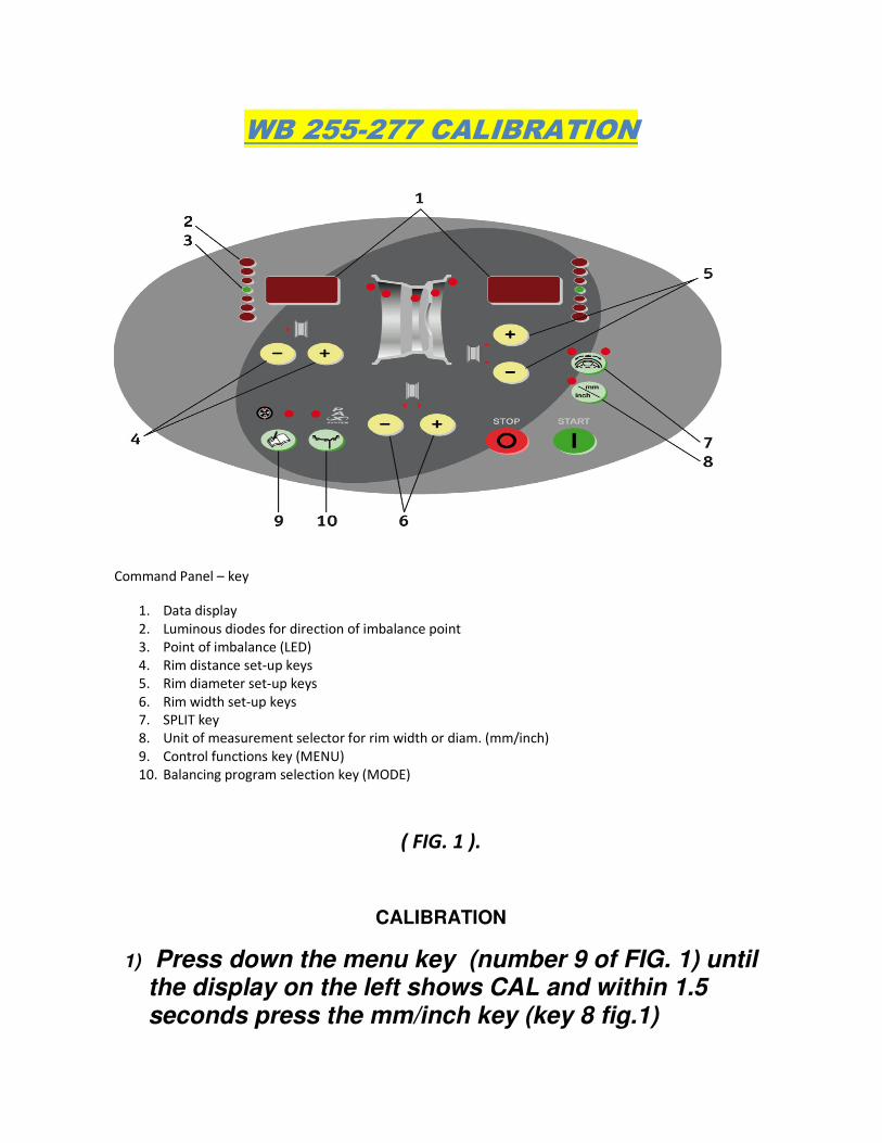
Command Panel – key
1. Data display
2. Luminous diodes for direction of imbalance point
3. Point of imbalance (LED)
4. Rim distance set-up keys
5. Rim diameter set-up keys
6. Rim width set-up keys
7. SPLIT key
8. Unit of measurement selector for rim width or diam. (mm/inch)
9. Control functions key (MENU)
10. Balancing program selection key (MODE)
( FIG. 1 ).
CALIBRATION
1) Press down the menu key (number 9 of FIG. 1) until the display on the left shows CAL and within 1.5 seconds press the mm/inch key (key 8 fig.1)

2) The display on the left will show C-1 = flange imbalance reset. Mount the flange with cones supplied on the balancer shaft. Fix it firmly, take off the wing nut and all the cones present and carry out a run by lowering the protection cover. At the end of the run the display on the left shows C-2.
3) C-2 = mount an iron wheel with tyre, if possible in
good condition, on the flange. Set the wheel measurements: (distance, diameter and width) and do a run with the wheel by lowering the protection cover. At the end of the run the display on the left shows C3 and the display on the right 100.
4) C-3 = set-up of the calibration weight (weight advised
is the 100 g supplied) normally already pre-set-up. If you use a different weight, to change the value of the weight use the +/- keys (number 5 of FIG. 1). Apply the weight to the inside of the tyre and do a run by lowering the protection cover. At the end of the run, the display on the left shows C4 and the display on the right 100.
5) C- 4 = take off the 100 g weight previously applied to
the inside of the wheel and apply it to the outside of the wheel in about the same symmetric position, then do a run by lowering the protection cover. At the end of the run the display on the left shows C5.
6) C-5 = adjustment of the position of the calibration
weight. Turn the wheel manually to position the
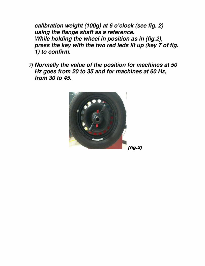
calibration weight (100g) at 6 o’clock (see fig. 2) using the flange shaft as a reference. While holding the wheel in position as in (fig.2), press the key with the two red leds lit up (key 7 of fig. 1) to confirm.
7) Normally the value of the position for machines at 50 Hz goes from 20 to 35 and for machines at 60 Hz, from 30 to 45.
(fig.2)

Diagnostic menu for WB 255-277 Balancers
COMMAND PANEL – KEY
1. Data display
2. Luminous diodes for direction of unbalance point
3. Point of unbalance (LED)
4. Rim distance set-up keys
5. Rim diameter set-up keys
6. Rim width set-up keys
7. SPLIT key
8. Unit of measurement selector for rim width or diam. (mm/inch)
9. Control functions key (MENU)
10. Balancing program selection key (MODE)
To enter the diagnostic menu press the menu key (KEY 9) until tSt is shown on the
display on the left and after 1.5 seconds press the key mm/inch to enter the
diagnostic menu. If the key mm/inch is pressed in time, the display on the left
visualises NSr meaning that you have entered the menu. If, instead, the key
mm/inch is not pressed in time, the display on the right and the display on the left
show 0-0.

NSr : this menu is used to visualise the tensions of the pick-ups.
To visualise exactly the tensions of the two pick-ups, before entering this menu
carry out a run with a 100 grams weight applied to the outside of the wheel, after
which the tension of the two pick-ups can be visualised.
By pressing the distance plus key (KEY 4) a green led appears on the display on the
left and numbers on the display on the right. This means the tension of the interior
pick-up is being shown, that is, the one with the black connector or with the black
cable REFERENCE VALUE 550 +/- 30% (715-385)
By pressing the diameter plus key (KEY 4) a green led and some numbers appear
on the display on the right. This means that the tension of the exterior pick-up is
being shown, that is, the one with the red connector or the one with the red cable
REFERENCE VALUE 790 +/-30% (1027-553)
By pressing the distance plus key (KEY 4) two green leds and numbers appear on
both the display on the right and the display on the left meaning that the phase
difference between the two pick-ups is being shown. The numbers on the display
on the right are the numbers after the comma REFERENCE VALUE: 180+/-1 (179-
181) .
BEFORE VISUALISING THESE VALUES, IT IS VERY IMPORTANT TO DO A RUN WITH
100 GRAMS APPLIED TO THE OUTSIDE OF THE WHEEL.
By pressing the menu key (KEY 9) the word EnC appears on the display on the left
and numbers on the display on the right. In this menu you can check if the encoder
is working. The numbers to be visualised are from 0 to 255 and by moving the
flange or the wheel you can check if the encoder is working.
By pressing the menu key (KEY 9), the word SP appears on the display on the left
and 0 on the display on the right. By lowering the cover and pressing the start key
the number of revolutions per minute of the motor can be checked REFERENCE
VALUE 170 +/- 10 (160-180)for machines at 50 Hz, for machines at 60 Hz 200+/-
10 (190-210). To stop the machine press the stop key. .
By pressing the menu key (KEY 9) An0 appears on the display on the left and 513
on the display on the right. Here the unamplified value of the interior pick-up is
visualised. By pushing on the flange or on the wheel you can see if the pick-up is
working because by pushing down the value goes to 0 and then returns to 513. By
pushing up the flange or the wheel the numbers go to the bottom of the scale, that
is, 999 and then return to 513.
By pressing the distance plus key (KEY 4) the display on the left shows An1 and the
display on the right 513. Here the amplified value of the interior pick-up is shown.
By pressing the distance plus key (KEY 4) the display on the left shows An2 and the
display on the right 513. Here the amplified value of the interior pick-up is shown.
By pressing the distance plus key (KEY 4) the display on the left shows An3 and the
display on the right 513. Here the amplified value of the exterior pick-up is shown.
By pressing the distance plus key (KEY 4) the display on the left shows An4 only for
WB 277and on the display on the right the STARTING REFERENCE VALUE numbers,
that is, with the gauge resting on the wheel cover tube, from 50 to 150. By moving
the gauge towards the inside of the machine, the numbers increase, meaning that
the exterior gauge is working and receiving input.
By pressing the distance plus key (KEY 4) the display on the left shows An5 and the
display on the right shows the numbers for the STARTING REFERENCE VALUE from
150 to 250. By moving the distance gauge, the numbers change meaning that the
gauge potentiometer is working and receiving input.
By pressing the distance plus key (KEY 4) the display on the left shows An6 and
numbers on the display on the right. By moving the feeler pin up or down the
numbers change meaning that the diameter potentiometer is working and
receiving input. STARTING REFERENCE VALUE FROM 140 – 180.
By pressing the distance plus key (KEY 4) the display on the left shows An7 and the
display on the right 650. Here the card input value is shown. REFERENCE VALUE
650 +/- 20%
By pressing the menu key (KEY 9) the display on the left shows inP and the display
on the right on. By lowering the cover, the protection micro-switch is activated and
the display on the right passes from on to off.
By pressing the menu key (KEY 9) the display on the left shows Cnt and the display
on the right shows nothing. By pressing the distance plus key (KEY 4) the display on
the right shows the total number of runs of the machine. By pressing the distance
plus key (KEY 4) again the display on the right shows the partial runs, that is, from
when the machine was last switched on. For example, if the number shown is 0,
this means that the machine has not done any runs. If the number is 50, it means
that from when the machine was started is has done 50 runs. The total number of
runs can be reset as follows:
switch off the machine
switch on the machine then press the following keys very quickly: key plus number
4, key number 7, key number 8, key plus number 5, all in not more than two
seconds.
By pressing the menu key (KEY 9) the word Led appears on the display on the left.
By pressing the distance plus key (KEY 4) a test of all the leds on the panel can be
carried out. Starting from the left and going to the right, with each press sector
after sector is checked.
By pressing the menu key (KEY 9) the display on the left shows tAr. This menu is for
the card designers, not for technicians.
By pressing the menu key (KEY 9) the display on the left shows the word rEl and
the display on the right shows off. This menu is also for the machine
manufacturers and not for technicians.
By pressing the menu key (KEY 9) the display on the left shows LrG and the display
on the right shows oFF, meaning that the width gauge is deactivated. If, instead,
on the display on the right “on” appears, it means that the width gauge is
activated. To go from off to on, press the diameter plus key. It is very important to
carry out this operation when the card on a WB 277 is substituted. This must be
done before beginning the machine calibration.
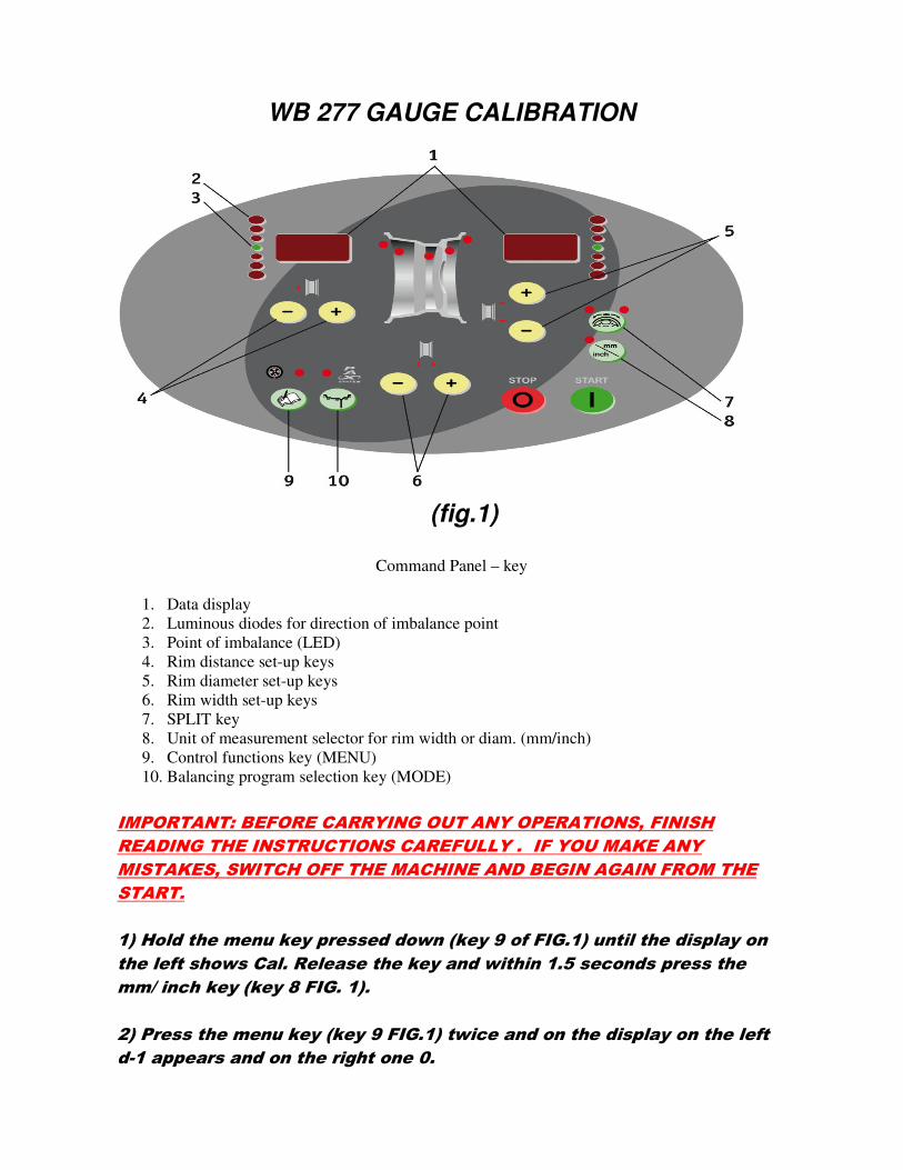
WB 277 GAUGE CALIBRATION
(fig.1)
Command Panel – key
1. Data display
2. Luminous diodes for direction of imbalance point
3. Point of imbalance (LED)
4. Rim distance set-up keys
5. Rim diameter set-up keys
6. Rim width set-up keys
7. SPLIT key
8. Unit of measurement selector for rim width or diam. (mm/inch)
9. Control functions key (MENU)
10. Balancing program selection key (MODE)
IMPORTANT: BEFORE CARRYING OUT ANY OPERATIONS, FINISH
READING THE INSTRUCTIONS CAREFULLY . IF YOU MAKE ANY
MISTAKES, SWITCH OFF THE MACHINE AND BEGIN AGAIN FROM THE
START.
1) Hold the menu key pressed down (key 9 of FIG.1) until the display on
the left shows Cal. Release the key and within 1.5 seconds press the
mm/ inch key (key 8 FIG. 1).
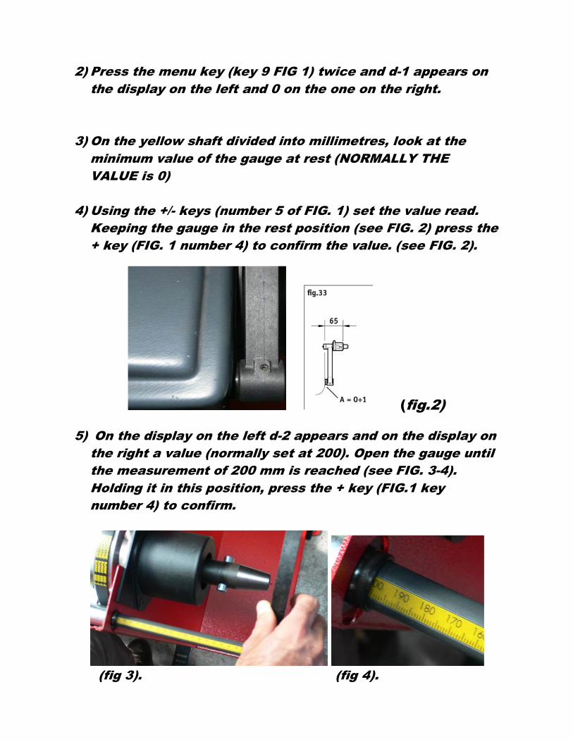
2) Press the menu key (key 9 FIG.1) twice and on the display on the left
d-1 appears and on the right one 0.
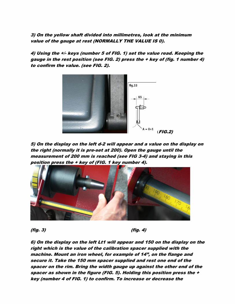
3) On the yellow shaft divided into millimetres, look at the minimum
value of the gauge at rest (NORMALLY THE VALUE IS 0).
4) Using the +/- keys (number 5 of FIG. 1) set the value read. Keeping the
gauge in the rest position (see FIG. 2) press the + key of (fig. 1 number 4)
to confirm the value. (see FIG. 2).
(FIG.2)
5) On the display on the left d-2 will appear and a value on the display on
the right (normally it is pre-set at 200). Open the gauge until the
measurement of 200 mm is reached (see FIG 3-4) and staying in this
position press the + key of (FIG. 1 key number 4).
(fig. 3) (fig. 4)
6) On the display on the left Lt1 will appear and 150 on the display on the
right which is the value of the calibration spacer supplied with the
machine. Mount an iron wheel, for example of 14”, on the flange and
secure it. Take the 150 mm spacer supplied and rest one end of the
spacer on the rim. Bring the width gauge up against the other end of the
spacer as shown in the figure (FIG. 5). Holding this position press the +
key (number 4 of FIG. 1) to confirm. To increase or decrease the
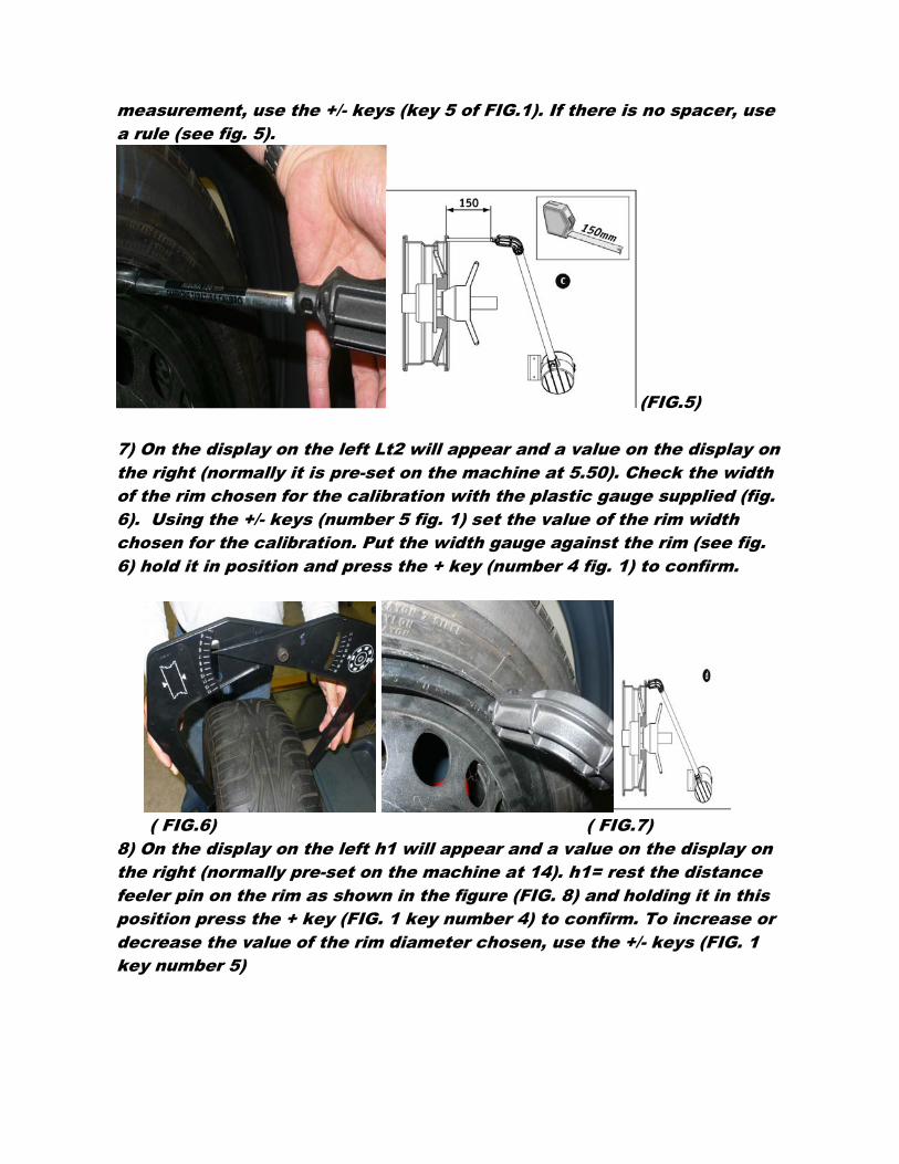
measurement, use the +/- keys (key 5 of FIG.1). If there is no spacer, use
a rule (see fig. 5).
(FIG.5)
7) On the display on the left Lt2 will appear and a value on the display on
the right (normally it is pre-set on the machine at 5.50). Check the width
of the rim chosen for the calibration with the plastic gauge supplied (fig.
6). Using the +/- keys (number 5 fig. 1) set the value of the rim width
chosen for the calibration. Put the width gauge against the rim (see fig.
6) hold it in position and press the + key (number 4 fig. 1) to confirm.
( FIG.6) ( FIG.7)
8) On the display on the left h1 will appear and a value on the display on
the right (normally pre-set on the machine at 14). h1= rest the distance
feeler pin on the rim as shown in the figure (FIG. 8) and holding it in this
position press the + key (FIG. 1 key number 4) to confirm. To increase or
decrease the value of the rim diameter chosen, use the +/- keys (FIG. 1
key number 5)

(fig. 8)
Wait for the first beep for confirmation and do not move from that
position until the second bip signalling acquisition of the measurement.
The value of the distance appears on the display on the left and the
gauge can now be put back in the rest position.
9) The acquisition of gauge calibration has finished. To exit from the
calibration, press menu (key number 9 fig. 1) and then press the STOP
key (fig. 1), or switch off the machine.

GAUGE CALIBRATION WB 255
(fig.1)
Command Panel – key
1. Data display
2. Luminous diodes for direction of imbalance point
3. Point of imbalance (LED)
4. Rim distance set-up keys
5. Rim diameter set-up keys
6. Rim width set-up keys
7. SPLIT key
8. Unit of measurement selector for rim width or diam. (mm/inch)
9. Control functions key (MENU)
10. Balancing program selection key (MODE)
IMPORTANT: BEFORE CARRYING OUT ANY OPERATIONS,
FINISH READING THE INSTRUCTIONS. IF YOU MAKE ANY
MISTAKES, SWITCH OFF THE MACHINE AND BEGIN AGAIN
FROM THE START.
1) Hold the menu key pressed (key 9 of FIG. 1) until the display
on the left shows Cal, release the key and within 1.5
seconds press the mm/inch key (key 8 FIG 1).
2) Press the menu key (key 9 FIG 1) twice and d-1 appears on
the display on the left and 0 on the one on the right.
3) On the yellow shaft divided into millimetres, look at the
minimum value of the gauge at rest (NORMALLY THE
VALUE is 0)
4) Using the +/- keys (number 5 of FIG. 1) set the value read.
Keeping the gauge in the rest position (see FIG. 2) press the
+ key (FIG. 1 number 4) to confirm the value. (see FIG. 2).
(fig.2)
5) On the display on the left d-2 appears and on the display on
the right a value (normally set at 200). Open the gauge until
the measurement of 200 mm is reached (see FIG. 3-4).
Holding it in this position, press the + key (FIG.1 key
number 4) to confirm.
(fig 3). (fig 4).

6) On the display on the left h1 appears and on the display on
the right a value (normally set at 14).
7) h 1 = mount an iron wheel on the flange, for example, a 14”
one. Rest the feeler pin on the rim as shown in the figure
(FIG. 5). Holding it in this position press the + key (FIG. 1
key number 4) to confirm. To increase or decrease the
diameter of the rim chosen, use the keys +/- (FIG. 1 key
number 5).
(fig. 5)
Wait for the first confirm beep and do not move from that
position until the second beep, which is for the measurement
acquisition. The value of the distance appears on the display
on the left and the gauge can now be put back in the rest
position.
8) The gauge calibration acquisition is finished. To exit from
the calibration press the menu key (key number 9 FIG. 1)
and then press the STOP key (fig. 1) or switch off the
machine.
Setting Technical Manual for WB 255-277
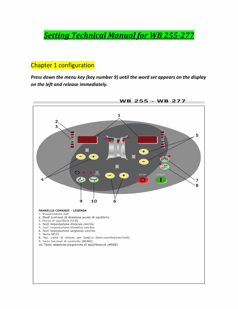
Chapter 1 configuration
Press down the menu key (key number 9) until the word set appears on the display
on the left and release immediately.
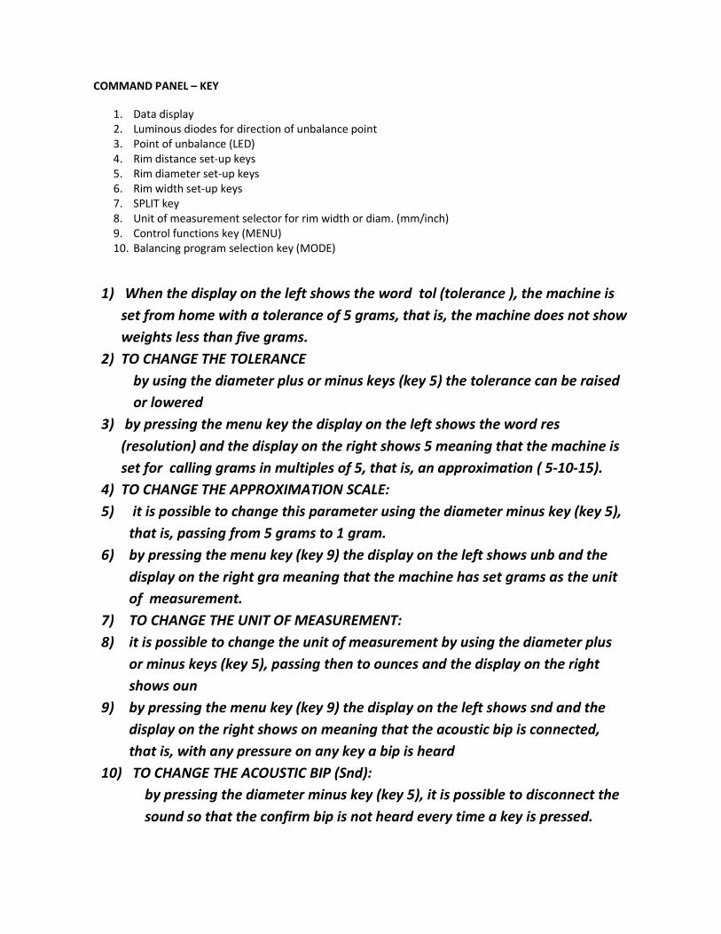
COMMAND PANEL – KEY
1. Data display
2. Luminous diodes for direction of unbalance point
3. Point of unbalance (LED)
4. Rim distance set-up keys
5. Rim diameter set-up keys
6. Rim width set-up keys
7. SPLIT key
8. Unit of measurement selector for rim width or diam. (mm/inch)
9. Control functions key (MENU)
10. Balancing program selection key (MODE)
1) When the display on the left shows the word tol (tolerance ), the machine is
set from home with a tolerance of 5 grams, that is, the machine does not show
weights less than five grams.
2) TO CHANGE THE TOLERANCE
by using the diameter plus or minus keys (key 5) the tolerance can be raised
or lowered
3) by pressing the menu key the display on the left shows the word res
(resolution) and the display on the right shows 5 meaning that the machine is
set for calling grams in multiples of 5, that is, an approximation ( 5-10-15).
4) TO CHANGE THE APPROXIMATION SCALE:
5) it is possible to change this parameter using the diameter minus key (key 5),
that is, passing from 5 grams to 1 gram.
6) by pressing the menu key (key 9) the display on the left shows unb and the
display on the right gra meaning that the machine has set grams as the unit
of measurement.
7) TO CHANGE THE UNIT OF MEASUREMENT:
8) it is possible to change the unit of measurement by using the diameter plus
or minus keys (key 5), passing then to ounces and the display on the right
shows oun
9) by pressing the menu key (key 9) the display on the left shows snd and the
display on the right shows on meaning that the acoustic bip is connected,
that is, with any pressure on any key a bip is heard
10) TO CHANGE THE ACOUSTIC BIP (Snd):
by pressing the diameter minus key (key 5), it is possible to disconnect the
sound so that the confirm bip is not heard every time a key is pressed.

11) by pressing the menu key (key 9) the display on the left shows CAr and the
display on the right shows on meaning that when the wheel cover protection
is lowered, the machine starts automatically
12) TO CHANGE THE AUTOMATIC START (CAr)
13) by pressing the diameter minus key (key 5) you go from on to off meaning
that when the wheel cover protection has been lowered, the machine no
longer starts automatically but will start only when the start is pressed.
14) by pressing the menu key (key 9) the display on the left shows Pot and the
display on the right shows on meaning that the gauge potentiometers are
active
15) DEACTIVATION OF THE POTENTIOMETER UNITS (Pot)
16) by pressing the diameter minus key (key 5) the display on the right shows off
meaning that the gauge potentiometers have been deactivated and that
consequently the automatic gauges do not work now. This operation must
only be carried out in the case of breakdown of the automatic gauges.
17) by pressing the menu key (key 9) the display on the left shows Con and the
display on the right Eur meaning that the machine has standard
configuration with a tolerance of 5 grams and grams as the unit of
measurement.
18) TO CHANGE THE CONFIGURATION (Con)
19) by pressing the diameter plus key (key 5) the display on the right passes
from Eur to Usa meaning that the machine is now set up for American values
varying the tolerance from 5 to 7 grams and the unit of measurement from
grams to ounces.
20) by pressing the menu key (key 9) the left and right displays both show 0
meaning that you have exited from the set-up menu.
Related Documents