TISSUE ENGINEERING Volume 8, Number 6, 2002 © Mary Ann Liebert, Inc. Microsyringe-Based Deposition of Two-Dimensional and Three-Dimensional Polymer Scaffolds with a Well-Defined Geometry for Application to Tissue Engineering p G. VOZZI, Ph.D., A. PREVITI, M.S., D. DE ROSSI, M.S., and A. AHLUWALIA, Ph.D. ABSTRACT A technique for controlled deposition of biomaterials and cells in specific and complex architectures is described. It employs a highly accurate three-dimensional micropositioning system with a pres- sure-controlled syringe to deposit biopolymer structures with a lateral resolution of 5 mm. The pres- sure-activated microsyringe is equipped with a fine-bore exit needle and a wide variety of two- and three-dimensional patterns on which cells to be deposited can adhere. The system has been char- acterized in terms of deposition parameters such as applied pressure, motor speed, line width and height, and polymer viscosity, and a fluid dynamic model simulating the deposition process has been developed, allowing an accurate prediction of the topological characteristics of the polymer struc- tures. 1089 INTRODUCTION M OST TYPES OF TISSUE that are now in advanced stages of engineering are either amorphous or isotropic (such as bone and cartilage) or have a planar structure (the skin and blood vessels). However, some of the more complex organs and tissues, such as the liver, heart, and neural tissue, are proving more difficult to en- gineer because they have a specific three-dimensional cell distribution in which the three-dimensional structure is inextricably linked to its function. For this type of tissue, it is considered essential to have a method of creating biomaterial scaffolds having a known and well-defined topology. An important example of structurally organized tissue is neural tissue, such as the retina. The retina has a mod- ular architecture and is made up of three main layers sep- arated by interweaving layers of cell processes. Within their layers neurons of the same type commonly form nonrandom planar arrays known as mosaics. 1 The cor- rect topographic development of a single layer of cells leads to correct connections between each layer, which then leads to a functional retina. Another example of a tissue with a well-defined architectural organization is the liver, in which hepatocytes form a close packed hexago- nal structure interlaced with blood vessels and bile ducts. The efficient transport, exchange, and collection of nu- trients and wastes depend enormously on the exquisite organization, at the cellular level, of the liver. Several methods for the deposition of biopolymers with controlled architecture have been described in the literature. The most well known, perhaps, is that pio- neered by the Mechanical Engineering Group at the Massachusetts Institute of Technology (MIT, Cambridge, MA), 2 known as 3DP (3-dimensional printing). In this method the polymer powder is spread on a plate, and the solvent or binder is sprayed by an ink-jet head onto the powder. The ink-jet head is machine driven and raster Interdepartmental Research Center E. Piaggio, University of Pisa, and Consiglio Nazionale delle Ricerche, Institute of Clini- cal Physiology, Pisa, Italy. p Part of this work was presented at the Davos Tissue Engineering Workshop, February 16–20, 2000, Davos, Switzerland.

Welcome message from author
This document is posted to help you gain knowledge. Please leave a comment to let me know what you think about it! Share it to your friends and learn new things together.
Transcript

TISSUE ENGINEERINGVolume 8 Number 6 2002copy Mary Ann Liebert Inc
Microsyringe-Based Deposition of Two-Dimensional andThree-Dimensional Polymer Scaffolds with a Well-Defined
Geometry for Application to Tissue Engineering p
G VOZZI PhD A PREVITI MS D DE ROSSI MS and A AHLUWALIA PhD
ABSTRACT
A technique for controlled deposition of biomaterials and cells in specific and complex architecturesis described It employs a highly accurate three-dimensional micropositioning system with a pres-sure-controlled syringe to deposit biopolymer structures with a lateral resolution of 5 mm The pres-sure-activated microsyringe is equipped with a fine-bore exit needle and a wide variety of two- andthree-dimensional patterns on which cells to be deposited can adhere The system has been char-acterized in terms of deposition parameters such as applied pressure motor speed line width andheight and polymer viscosity and a fluid dynamic model simulating the deposition process has beendeveloped allowing an accurate prediction of the topological characteristics of the polymer struc-tures
1089
INTRODUCTION
MOST TYPES OF TISSUE that are now in advancedstages of engineering are either amorphous or
isotropic (such as bone and cartilage) or have a planarstructure (the skin and blood vessels) However some ofthe more complex organs and tissues such as the liverheart and neural tissue are proving more difficult to en-gineer because they have a specific three-dimensional celldistribution in which the three-dimensional structure isinextricably linked to its function For this type of tissueit is considered essential to have a method of creatingbiomaterial scaffolds having a known and well-definedtopology
An important example of structurally organized tissueis neural tissue such as the retina The retina has a mod-ular architecture and is made up of three main layers sep-arated by interweaving layers of cell processes Withintheir layers neurons of the same type commonly form
nonrandom planar arrays known as mosaics1 The cor-rect topographic development of a single layer of cellsleads to correct connections between each layer whichthen leads to a functional retina Another example of atissue with a well-defined architectural organization is theliver in which hepatocytes form a close packed hexago-nal structure interlaced with blood vessels and bile ductsThe efficient transport exchange and collection of nu-trients and wastes depend enormously on the exquisiteorganization at the cellular level of the liver
Several methods for the deposition of biopolymerswith controlled architecture have been described in theliterature The most well known perhaps is that pio-neered by the Mechanical Engineering Group at theMassachusetts Institute of Technology (MIT CambridgeMA)2 known as 3DP (3-dimensional printing) In thismethod the polymer powder is spread on a plate and thesolvent or binder is sprayed by an ink-jet head onto thepowder The ink-jet head is machine driven and raster
Interdepartmental Research Center E Piaggio University of Pisa and Consiglio Nazionale delle Ricerche Institute of Clini-cal Physiology Pisa Italy
p Part of this work was presented at the Davos Tissue Engineering Workshop February 16ndash20 2000 Davos Switzerland
scans the plates depositing binder wherever necessaryWhere the binder lands the powder binds Successivelayers can be built up in this way and have been usedto fabricate 3-D scaffolds for the adhesion of hepato-cytes3 It does however have a fairly low resolution forexample about 300-mm structures of polylactic acid canbe patterned
Another well-known method is that developed by theWhitesides group at Harvard University (Boston MA)4
This method called soft lithography is based on poly-dimethoxysilane stamps and self-assembly to producehigh-resolution structures with depths of a few micronsSo far this method has been used successfully to pro-duce cell patterns using sophisticated surface chemistrybut it is limited to low-depth 3-D
Another method reported by Odde and Renn is that oflaser-directed guided writing5 In this method proteinand small biomaterial particles can be made to assemblein particular locations using a technique similar to lasertweezers
The CADCAM (computer-aided designcomputer-aided manufacturing) approach developed at CarnegieMellon University (Pittsburgh PA)6 uses sheets of pre-formed biomaterial and stacks them vertically to make3-D structures Because the current resolution is only 05mm by 12 mm in diameter it is not entirely suited tocontrolling the fine structure of a scaffold
In this article we present a novel method for the de-position of biopolymers in high-resolution structures us-ing a pressure-activated syringe It is a highly versatileinstrument not just for its potential application to tissueengineering but also to study cell motility organizationand cell reaction to various topographies The presentwork is focused on the characterization of the depositionsystem and on the patterns produced using a variety ofpolymers at different concentrations
MATERIALS AND METHODS
Polymers
Two different polymers were used poly-L-lactic acid(PLLA MW 300000 Boehringer Ingelheim IngelheimGermany) and polycaprolactone (PCL MW 65000Sigma St Louis MO) The biopolymers employed havebeen studied by our group in the form of spin-coatedfilms and their surface properties (surface charge den-sity dielectric constant morphology and contact angle)and their suitability for cell adhesion have been evalu-ated7 The polymers were dissolved in chloroform to give1 2 and 3 (wv) solutions of PLLA and 10 15 and20 (wv) solutions of PCL PLLA was also blendedwith PCL to provide additional carboxyl groups to per-mit surface derivatization in ensuing studies A blend of25 PLLA and 20 PCL (wv) prepared by mixing
VOZZI ET AL
equal quantities of 5 PLLA and 40 PCL was foundto be optimal for syringe deposition
To provide input concerning the parameters of the fluiddynamic model the viscosity of each solution was mea-sured with a Saybolt viscosimeter Measured viscositiesare tabulated in Table 1
Deposition system
The deposition system utilized consists of a stainlesssteel syringe with a 20-mm glass capillary needle as thetip A home-built vertical puller was used to pull the tipswhich were prepared from soda glass hematocrit capil-laries (Globe Scientific Paramus NJ) with an outer di-ameter of 15 mm and an inner diameter of 115 mm Asshown in Fig 1 the tip has a flat end and is gently ta-pered a characteristic that lends itself to streamlined flowin the narrowest parts of the capillary Each capillary ispulled under the same conditions and the internal diam-eter of the tips is 20 6 2 mm The two tips obtained fromeach capillary tube pulled are not symmetrical as one isslightly longer than the other The needle is connected tothe syringe barrel and held in place by a small O ring Asolution of the polymer is placed inside the syringewhich has a capacity of about 5 ml
The syringe which has no plunger but is driven by fil-tered compressed air at a pressure of about 10ndash500mmHg is attached to the vertical z axis of a three-axisstepper-motor micropositioning system (Ealing UK)with a resolution of 01 mm A planar substrate gener-ally a 3 3 3 cm glass slide is fixed on the horizontal xand y axes of the micropositioner and is made to moveunder the syringe during deposition When pressure is ap-plied to the syringe tiny amounts of polymer ooze outthrough the tip If the needle is too far from the surfacethe polymer solidifies on the tip preventing further de-position However if the tip is ldquodrawnrdquo along the sub-strate keeping it just high enough that it does not con-tact the substrate and break fine lines of polymer aretraced on the substrate Precise measurements of the op-timum height of the tip with respect to the substrate have
1090
TABLE 1 VISCOSITIES OF SOLUTIONS
ViscosityPolymer solution (cP)
PCL10 3915 11520 271
PLLA1 852 4193 1127
Blend 390
not been made we estimate it to be on the order of thetip diameter In preliminary experiments it was ascer-tained that the most reproducible technique for obtainingsmooth even microsized patterns was to apply a low andconstant pressure (rather than a pulsed pressure) to thesyringe and to allow the polymer to be dragged acrossthe surface of the substrate much like writing with an
ACCURATE 2- AND 3-D MICROPOSITIONING
ink pen Moreover it was established that the concen-tration of polymer must lie within an optimal range be-tween about 100 and 700 cP Low-viscosity solutionsleak out of the tip whereas highly viscous solutions re-quire pressures that may damage the tip and be a dangerto the operator A schematic illustration of the pressure-controlled deposition system is shown in Fig 2
1091
FIG 1 Photograph and optical micrograph (inset) of the capillary tip Original magnification (inset) 310
FIG 2 Schematic illustration of the pressure-controlled deposition system
The entire system including valves pressure sensorsand position controllers is interfaced to and controlled bya personal computer through a GPIB (general program-ming interface bus) card Appropriate software to drivethe system written in C language allows simple patternssuch as lines rectangular hexagonal or triangular gridsand spirals to be deposited More complex patterns such
VOZZI ET AL
as dendritic structures are easy to design and have beenincorporated into the software
The pressure sensor and associated control system al-lows the applied pressure to be controlled to within 65mmHg in the range of 10 to 1000 mmHg and the ve-locity of the substrate with respect to the syringe to bevaried between 05 and 25 mms Each polymer con-centration was deposited at different applied pressuresand x y motor velocities in order to determine a range ofoptimum operating conditions
Pattern depositions and characterization
Simple 2- and 3-D patterns of the polymers at variousconcentrations were deposited at different pressures anddeposition speeds In particular a series of connectinghairpins of varying dimensions were fabricated under dif-ferent conditions and analyzed with an optical micro-scope (AX 70 Olympus Tokyo Japan) to determine thewidth of deposited lines and the distance between adja-cent lines The mean width was found by averaging mea-sured widths over each line deposited and the measure-ment accuracy was 61 mm At least six measurementsof line width and distance between lines were made foreach sample Atomic force microscopy8 was used to mea-sure the profiles of the patterns
MODEL
Complex models such as those used in dynamic wet-ting systems can be used to predict the line width and
1092
FIG 3 Forces at play during expulsion of the polymer fromthe syringe tip Rs is the internal radius of the tip Other detailsare given in text
FIG 4 Square grid with sides of 500 mm of PCLndashPLLA blend The motor speed was 25 mms and the driving pressure was50 mmHg Original magnification 3125
height of the patterns deposited These models use thedynamic contact angle which requires flow visualizationtechniques to be measured to describe the equilibriumconfiguration of a liquid in a coating system9 As a firstapproximation we developed a simple fluid-dynamicmodel that enables the prediction of the width and heightof the patterns The model is focused on the conditionsat the tip of the needle at the point where the polymerexits
We assume that there is a simple geometry at the tipand that the polymer solution does not change dimen-sions as the solvent evaporates As shown in Fig 3 theforces in play at the tip where the fluid is expelled are asfollows
Driving pressure P and the weight of the polymer inthe syringe barrel
Additional pressure P p due to vapor pressure of thesolvent
Surface tension between polymer solution and air g Dynamic friction between fluid and glass which is
a function of the viscosity m of the solution
If the balance of all forces and energies at the tip ofthe syringe is considered a multivariable system of equa-tions with an infinite number of solutions is obtained Tosimplify the model we assume that the driving pressureis the predominant force in this system and the otherforces are negligible
The flow of polymer from the needle is
Q 5 d
d
V
t (1)
where V is the volume of polymer deposited and t is timeAccording to the atomic force microscopy (AFM) mea-surements reported in the following section the profilesof the lines can be approximated to an elliptical segment
ACCURATE 2- AND 3-D MICROPOSITIONING
Given the high aspect ratio (ratio of line width to height)the product of height and width can be used to estimatethe cross-sectional area of the deposited structures Thuswe can approximate the flow as
Q 5 ah 5 ahv0 (2)
where a is the line width and h is the height of the poly-mer pattern l is the length of polymer deposited in timet and hence v0 is the velocity of the substrate with re-spect to the syringe If we assume streamlined flowand take the polymer to be a viscous Newtonian fluidthe flow inside the capillary is given by Poiseullersquosequation
Q 5 (3)
where Rs is the internal radius of the tip of needle dpdzthe applied pressure gradient and m is the viscosity ofthe polymer
Substituting Eq (2) into Eq (3) and rearranging anexpression for the line width a can be obtained
a 5 (4)
Before the fluid exits the tip a certain critical pressurePcrit proportional to the viscosity of the solution mustbe applied Below this critical threshold deposition can-not occur because the frictional forces are greater thanthe driving pressure The pressure gradient in the syringeis negligible in the widest part of the syringe and is max-imum in the tapered region of the tip In this model dpdzhas been approximated to (P + Pcrit)hz where P + Pcrit
is the applied driving pressure and hz is the length of thetapered zone of the capillary Equation (4) can then beexpressed as
dpdz
pR4s
8mv0h
dpdz
pR4s
8m
dldt
1093
FIG 5 Hexagonal grids of the PCLndashPLLA blend The motor speed was 25 mms (a) Hexagons with sides of 500 mm de-posited with increasing driving pressure (30 to 60 mmHg) in the direction of the arrow (b) Hexagons with sides of 250 mmdriving pressure 70 mmHg Original magnification 3125
a b
a 5 (5)
The experimental pressure-versus-line width data forthe polymers deposited were fitted to Eq (5) Valuesof viscosity used in the model were interpolated fromthe experimental data in Table 1 and h the height ofthe polymer structures was obtained by averaging theAFM data for each polymer concentration Because hz
varies between 118 and 92 mm from tip to tip an av-erage value of 105 mm was used in the numerical cal-culations
For a given profile aspect ratio the model can be usedto predict line width a as a function of applied pressureP0 motor velocity v0 and polymer viscosity m If theprofile of the pattern has not been measured the width-to-height ratio of the deposited lines can be estimatedfrom an experimental plot of driving pressure against linewidth by recursive means assuming a rectangular pro-file
(P 1 Pcrit)
hz
pRs8mv0h
VOZZI ET AL
RESULTS
Geometric analysis of deposited patterns
Various types of pattern were deposited for exampleFig 4 shows a square grid of the PLLAndashPCL blend withsides of 500 mm deposited at a pressure of 50 mmHgand a motor velocity of 25 mms To reproduce thehexagonal organisation of hepatic and retinal tissue wealso deposited hexagonal grids in which the sides of thehexagons were varied in length Figure 5a and b are op-tical micrographs of the hexagonal grids of thePCLndashPLLA blend with sides of 500 and 250 mm re-spectively In Fig 5a the driving pressure is increasedfrom 30 to 60 mmHg during deposition to demonstratethe effect of pressure on line width
To analyze the relationship between the width andheight profile of the polymer patterns and the control-lable experimental parameters namely applied pressurepolymer concentration and motor speed a series of con-necting hairpins were deposited and each parameter was
1094
FIG 6 Hairpin structures of (a) 20 PCL (b) 2 PLLA and (c) PLLAndashPCL blend Increasing driving pressure (in the di-rection of the arrows) is applied during deposition The range of pressures (in mmHg) used are shown Original magnification3125
b
c
a
ACCURATE 2- AND 3-D MICROPOSITIONING
varied in turn Figure 6andashc illustrates the hairpin lines of20 PCL 2 PLLA and the PCLndashPLLA blend re-spectively All lines were deposited at a constant motorspeed of 25 mms while the pressure was increased by5 mmHg every two lines The ability to finely modulateline width by applying small variations in pressure is ev-ident In Fig 7 height profiles as obtained from AFMmeasurements of 3 PLLA are reported All the poly-mers were observed to have profiles approximating asquashed elliptical arc which decreased in roughness asthe pressure was increased The height of each polymer
1095
FIG 7 Profiles of 3 PLLA Curve a pertains to a drivingpressure of 100 mmHg curve b 120 mmHg curve c 140mmHg
FIG 8 Heights of polymer lines deposited at various pressures as measured with an atomic force microscope In all cases thedeposition speed was 25 mms Deviations are on the order of 615 mm
deposited did not change appreciably with increasingpressure particularly in the case of the PLLA solutions(Fig 8) so for the purpose of the model the height wastaken to be constant and independent of pressure for agiven concentration
Figure 9andashc shows the measured line widths of solu-tions of PCL PLLA and the PCLndashPLLA mixture re-spectively as a function of applied pressure for each con-centration The fitted data obtained from the model arealso shown
Line widths as a function of the deposition velocity forPCL are plotted in Fig 10 As predicted by the modelline width is inversely proportional to deposition veloc-ity At present with a maximum motor velocity of 25mms the minimum line width obtained was on the or-der of 10 to 20 mm In principle the line width can alsobe decreased by using faster motors The y intercept ofthe plots can be used to estimate the minimum line widthexpected for a given deposition speed although given thelimitations of the model at low pressures this value canonly be taken as indicative
Three-dimensional structures
We also attempted to make three-dimensional struc-tures by depositing a rectangular or hexagonal grid al-lowing it to dry thoroughly and then depositing anotheron top This was done for several layers On subsequentexamination with a scanning electron microscope it ap-peared that the layers had fused into one another indi-cating that the solvent in overlying layers penetrates anddissolves those underneath thus producing a dense andcompact monolithic structure
An alternative method was also tested in which rectan-gular grids were deposited and then stacked together andheld in place by gluing the corners with chloroform In the
FIG 9 Line widths of (a) PCL (b) PLLA and (c) PLLAndashPCL blend at different concentrations as a function of applied pres-sure The points refer to experimental data and the lines pertain to the model Deposition speed 25 mms Deviations betweenindividual samples were on the order of 6 5 mm for all pressures
a
c
b
resulting structure individual layers were distinguishablehowever this technique is not strictly three-dimensional mi-crofabrication as part of the fabrication process is manualTo obtain truly three-dimensional microstructures it is nec-essary to separate adjacent layers with an inert yet easilyremovable material during the deposition process This wasachieved by depositing layers of polymer interleaved withlayers of a water-soluble polymer deposited with a secondsyringe Using this technique three-dimensional structuresof PLLA as shown in Fig 11 were obtained These struc-tures are currently under investigation
DISCUSSION
As demonstrated by the graphs and photographs inFigs 4 to 10 the syringe-based deposition method de-scribed is capable of fabricating microscale structures ofpolymers in a wide variety of patterns and with a widerange of thicknesses This versatility is useful for thestudy of optimal scaffold topology to promote desiredcellular behavior The operating system is user friendlyand does not require special skills Once the geometry ofthe scaffold has been chosen and input to the PC and thesyringe is filled with a few milliliters of solution severalscaffolds can be microfabricated in the space of 1 h (tomake a 1-cm2 two-dimensional hexagonal scaffold asshown in Fig 5 takes about 6ndash7 min)
Figures 8 and 9a and b illustrate that for a given pres-sure both the height and width of the pattern are inverselyproportional to the concentration At high viscosities or con-centrations the volume flow rate for a fixed pressure is low
ACCURATE 2- AND 3-D MICROPOSITIONING
so as expected the dimensions of the lines are reducedThis can also be inferred from Eq (5) To achieve high res-olutions it is thus necessary to use viscous solutions withlow flow and spreading rates The minimum line width ob-tainable is limited by the dimensions of the syringe tip andis on the order of 20 mm Smaller capillaries down to about5 mm could be used to produce structures with a resolutionof 5ndash10 mm although they require higher driving pressuresand great care must be taken to avoid tip breakage
Any type of polymer or polymer blends can be utilized
1097
FIG 10 Line width as a function of deposition speed for PCL (20) and PLLA (3) for driving pressures of 120 and 50mmHg respectively Both discrete experimental data points and fitted curves are shown
FIG 11 Optical micrograph of a hexagonal 3-D grid of thePCLndashPLLA blend Original magnification 340
for microsyringe deposition the only requirements arethat the polymers be soluble in a volatile solvent and thatthe solutions have a viscosity between 100 and 700 cPThe balance between viscous forces which cause thefluid to shear and surface tension forces which tend tominimize the surface area of the fluid is given by thecapillary number9
Ca 5
The capillary number can be used to distinguish betweenthe two flow regimes Highly fluid solutions of viscosi-ties less than 100 cP tend to drip out of the syringe tipas discrete drops even without the application of pres-sure because the capillary number is low and fluid flowis dominated by surface tension effects More viscous so-lutions on the other hand have high capillary numbersand fluid flow is due to the applied pressure gradientThe upper limit of viscosities was determined principallyby safety considerations
Albeit highly simplified and despite several physical as-sumptions the model faithfully reflects the experimentalresults in the range of pressures tested and can be used topredict the geometric parameters of any polymer depositedby this technique A major limitation of the model is thatit requires a priori knowledge of the profile of depositedstructure However the profile can be easily predicted froma pressure-versus-line width plot as shown in Fig 9andashcBecause all forces except the force due to the driving pres-sure were ignored the model is not accurate at low valuesof driving pressure where surface tension and other forcesmay be competitive In fact the critical pressure requiredto expel fluid from the needle Pcrit was calculated by ex-trapolating the model to the x intercept In practice the min-imum pressure required to initiate deposition was in therange of 10 to 30 mmHg for all solutions whereas Pcritaccording to the model ranges from 1 to 20 mmHg de-pending on the viscosity of the solution
CONCLUSIONS
The syringe-based fabrication technique describedhere is based on a pressure-controlled 2- and 3-D depo-sition system The main advantages of this technique overother scaffold fabrication methods are its simplicity andthe possibility of modulating line widths and heights overa wide range by varying the polymer concentration orviscosity applied pressure and deposition speed Otherapplications of this technique have been proposed in thefield of actuator microengineering10 and demonstrate theuniversality and flexibility of the technique A simplefluid dynamic model has been developed to describe thephysical dimensions of the fluid as it is expelled fromthe syringe tip The model enables the prediction of es-sential topological parameters of the structures deposited
mv0
g
VOZZI ET AL
Future investigations into the feasibility of this depo-sition technique for tissue-engineering purposes will befocused on improving and demarcating cell adhesion onthree-dimensional stacked structures
ACKNOWLEDGMENTS
The authors thank G Tarone and G Basta for provid-ing cells C Ascoli and P Baschieri for the AFM scansand above all Prof Mario Pellegrino for the inexhaustiblesupply of tips
REFERENCES
1 Galli Resta L Patterning the vertebrate retina The earlyappearance of retinal mosaics Semin Cell Dev Biol 9279 1998
2 Giordano RA Wu BM Borland SW Cima LGSachs EM and Cima MJJ Mechanical properties ofdense polylactic acid structures fabricated by three dimen-sional printing J Biomater Sci Polym Ed 8 63 1996
3 Kim SS Utsunomiya H Koski JA Wu BM CimaMJ Sohn J Mukai K Griffith LG and Vacanti JPSurvival and function of hepatocytes on a novel three-di-mensional synthetic biodegradable polymer scaffold withan intrinsic network of channels Ann Surg 228 8 1998
4 Kane RS Takayama S Ostuni E Ingber DE andWhitesides GM Patterning proteins and cells using softlithography Biomaterials 20 2363 1999
5 Odde DJ and Renn MJ Laser-guided direct writing ofliving cells Biotechnol Biotechnol Bioeng 67 312 2000
6 Crawford RH Beaman JJ Cavello C Jackson J WeissLE and Seacutequin CH Solid freeform fabrication A new man-ufacturing paradigm IEEE Spectrum 36 34 1999
7 Vozzi G Tissue Engineering Characterisation of bio-erodable polymeric matrices for application to vascularprosthesis [Laurea Thesis] Department of Electronic En-gineering University of Pisa Pisa Italy 1998
8 Mariani T Musio A Frediani C Sbrana I and AscoliCJ An atomic force microscope for cytological and his-tological investigations J Microsc 176 121 1994
9 Stokes RJ and Evans DF Fundamentals of InterfacialEngineering New York Wiley-VCH 1997
10 Ahulwalia A De Rossi D Giuntini F Mazzoldi Aand Vozzi G Microfabricated electroactive polymer ben-ders for cell handling In Proceedings of the 1st AnnualInternational IEEE-EMBS Special Topic Conference onMicrotechnologies in Medicine and Biology October12ndash14 2000 Lyon France p 292 poster 51
Address reprint requests toArti Ahluwalia PhD
Centro Interdipartimentale di Ricerca E PiaggioVia Diotisalvi 2
56126 Pisa Italy
E-mail artiahluwaliaingunipiit
1098

ACCURATE 2- AND 3-D MICROPOSITIONING
varied in turn Figure 6andashc illustrates the hairpin lines of20 PCL 2 PLLA and the PCLndashPLLA blend re-spectively All lines were deposited at a constant motorspeed of 25 mms while the pressure was increased by5 mmHg every two lines The ability to finely modulateline width by applying small variations in pressure is ev-ident In Fig 7 height profiles as obtained from AFMmeasurements of 3 PLLA are reported All the poly-mers were observed to have profiles approximating asquashed elliptical arc which decreased in roughness asthe pressure was increased The height of each polymer
1095
FIG 7 Profiles of 3 PLLA Curve a pertains to a drivingpressure of 100 mmHg curve b 120 mmHg curve c 140mmHg
FIG 8 Heights of polymer lines deposited at various pressures as measured with an atomic force microscope In all cases thedeposition speed was 25 mms Deviations are on the order of 615 mm
deposited did not change appreciably with increasingpressure particularly in the case of the PLLA solutions(Fig 8) so for the purpose of the model the height wastaken to be constant and independent of pressure for agiven concentration
Figure 9andashc shows the measured line widths of solu-tions of PCL PLLA and the PCLndashPLLA mixture re-spectively as a function of applied pressure for each con-centration The fitted data obtained from the model arealso shown
Line widths as a function of the deposition velocity forPCL are plotted in Fig 10 As predicted by the modelline width is inversely proportional to deposition veloc-ity At present with a maximum motor velocity of 25mms the minimum line width obtained was on the or-der of 10 to 20 mm In principle the line width can alsobe decreased by using faster motors The y intercept ofthe plots can be used to estimate the minimum line widthexpected for a given deposition speed although given thelimitations of the model at low pressures this value canonly be taken as indicative
Three-dimensional structures
We also attempted to make three-dimensional struc-tures by depositing a rectangular or hexagonal grid al-lowing it to dry thoroughly and then depositing anotheron top This was done for several layers On subsequentexamination with a scanning electron microscope it ap-peared that the layers had fused into one another indi-cating that the solvent in overlying layers penetrates anddissolves those underneath thus producing a dense andcompact monolithic structure
An alternative method was also tested in which rectan-gular grids were deposited and then stacked together andheld in place by gluing the corners with chloroform In the
FIG 9 Line widths of (a) PCL (b) PLLA and (c) PLLAndashPCL blend at different concentrations as a function of applied pres-sure The points refer to experimental data and the lines pertain to the model Deposition speed 25 mms Deviations betweenindividual samples were on the order of 6 5 mm for all pressures
a
c
b
resulting structure individual layers were distinguishablehowever this technique is not strictly three-dimensional mi-crofabrication as part of the fabrication process is manualTo obtain truly three-dimensional microstructures it is nec-essary to separate adjacent layers with an inert yet easilyremovable material during the deposition process This wasachieved by depositing layers of polymer interleaved withlayers of a water-soluble polymer deposited with a secondsyringe Using this technique three-dimensional structuresof PLLA as shown in Fig 11 were obtained These struc-tures are currently under investigation
DISCUSSION
As demonstrated by the graphs and photographs inFigs 4 to 10 the syringe-based deposition method de-scribed is capable of fabricating microscale structures ofpolymers in a wide variety of patterns and with a widerange of thicknesses This versatility is useful for thestudy of optimal scaffold topology to promote desiredcellular behavior The operating system is user friendlyand does not require special skills Once the geometry ofthe scaffold has been chosen and input to the PC and thesyringe is filled with a few milliliters of solution severalscaffolds can be microfabricated in the space of 1 h (tomake a 1-cm2 two-dimensional hexagonal scaffold asshown in Fig 5 takes about 6ndash7 min)
Figures 8 and 9a and b illustrate that for a given pres-sure both the height and width of the pattern are inverselyproportional to the concentration At high viscosities or con-centrations the volume flow rate for a fixed pressure is low
ACCURATE 2- AND 3-D MICROPOSITIONING
so as expected the dimensions of the lines are reducedThis can also be inferred from Eq (5) To achieve high res-olutions it is thus necessary to use viscous solutions withlow flow and spreading rates The minimum line width ob-tainable is limited by the dimensions of the syringe tip andis on the order of 20 mm Smaller capillaries down to about5 mm could be used to produce structures with a resolutionof 5ndash10 mm although they require higher driving pressuresand great care must be taken to avoid tip breakage
Any type of polymer or polymer blends can be utilized
1097
FIG 10 Line width as a function of deposition speed for PCL (20) and PLLA (3) for driving pressures of 120 and 50mmHg respectively Both discrete experimental data points and fitted curves are shown
FIG 11 Optical micrograph of a hexagonal 3-D grid of thePCLndashPLLA blend Original magnification 340
for microsyringe deposition the only requirements arethat the polymers be soluble in a volatile solvent and thatthe solutions have a viscosity between 100 and 700 cPThe balance between viscous forces which cause thefluid to shear and surface tension forces which tend tominimize the surface area of the fluid is given by thecapillary number9
Ca 5
The capillary number can be used to distinguish betweenthe two flow regimes Highly fluid solutions of viscosi-ties less than 100 cP tend to drip out of the syringe tipas discrete drops even without the application of pres-sure because the capillary number is low and fluid flowis dominated by surface tension effects More viscous so-lutions on the other hand have high capillary numbersand fluid flow is due to the applied pressure gradientThe upper limit of viscosities was determined principallyby safety considerations
Albeit highly simplified and despite several physical as-sumptions the model faithfully reflects the experimentalresults in the range of pressures tested and can be used topredict the geometric parameters of any polymer depositedby this technique A major limitation of the model is thatit requires a priori knowledge of the profile of depositedstructure However the profile can be easily predicted froma pressure-versus-line width plot as shown in Fig 9andashcBecause all forces except the force due to the driving pres-sure were ignored the model is not accurate at low valuesof driving pressure where surface tension and other forcesmay be competitive In fact the critical pressure requiredto expel fluid from the needle Pcrit was calculated by ex-trapolating the model to the x intercept In practice the min-imum pressure required to initiate deposition was in therange of 10 to 30 mmHg for all solutions whereas Pcritaccording to the model ranges from 1 to 20 mmHg de-pending on the viscosity of the solution
CONCLUSIONS
The syringe-based fabrication technique describedhere is based on a pressure-controlled 2- and 3-D depo-sition system The main advantages of this technique overother scaffold fabrication methods are its simplicity andthe possibility of modulating line widths and heights overa wide range by varying the polymer concentration orviscosity applied pressure and deposition speed Otherapplications of this technique have been proposed in thefield of actuator microengineering10 and demonstrate theuniversality and flexibility of the technique A simplefluid dynamic model has been developed to describe thephysical dimensions of the fluid as it is expelled fromthe syringe tip The model enables the prediction of es-sential topological parameters of the structures deposited
mv0
g
VOZZI ET AL
Future investigations into the feasibility of this depo-sition technique for tissue-engineering purposes will befocused on improving and demarcating cell adhesion onthree-dimensional stacked structures
ACKNOWLEDGMENTS
The authors thank G Tarone and G Basta for provid-ing cells C Ascoli and P Baschieri for the AFM scansand above all Prof Mario Pellegrino for the inexhaustiblesupply of tips
REFERENCES
1 Galli Resta L Patterning the vertebrate retina The earlyappearance of retinal mosaics Semin Cell Dev Biol 9279 1998
2 Giordano RA Wu BM Borland SW Cima LGSachs EM and Cima MJJ Mechanical properties ofdense polylactic acid structures fabricated by three dimen-sional printing J Biomater Sci Polym Ed 8 63 1996
3 Kim SS Utsunomiya H Koski JA Wu BM CimaMJ Sohn J Mukai K Griffith LG and Vacanti JPSurvival and function of hepatocytes on a novel three-di-mensional synthetic biodegradable polymer scaffold withan intrinsic network of channels Ann Surg 228 8 1998
4 Kane RS Takayama S Ostuni E Ingber DE andWhitesides GM Patterning proteins and cells using softlithography Biomaterials 20 2363 1999
5 Odde DJ and Renn MJ Laser-guided direct writing ofliving cells Biotechnol Biotechnol Bioeng 67 312 2000
6 Crawford RH Beaman JJ Cavello C Jackson J WeissLE and Seacutequin CH Solid freeform fabrication A new man-ufacturing paradigm IEEE Spectrum 36 34 1999
7 Vozzi G Tissue Engineering Characterisation of bio-erodable polymeric matrices for application to vascularprosthesis [Laurea Thesis] Department of Electronic En-gineering University of Pisa Pisa Italy 1998
8 Mariani T Musio A Frediani C Sbrana I and AscoliCJ An atomic force microscope for cytological and his-tological investigations J Microsc 176 121 1994
9 Stokes RJ and Evans DF Fundamentals of InterfacialEngineering New York Wiley-VCH 1997
10 Ahulwalia A De Rossi D Giuntini F Mazzoldi Aand Vozzi G Microfabricated electroactive polymer ben-ders for cell handling In Proceedings of the 1st AnnualInternational IEEE-EMBS Special Topic Conference onMicrotechnologies in Medicine and Biology October12ndash14 2000 Lyon France p 292 poster 51
Address reprint requests toArti Ahluwalia PhD
Centro Interdipartimentale di Ricerca E PiaggioVia Diotisalvi 2
56126 Pisa Italy
E-mail artiahluwaliaingunipiit
1098
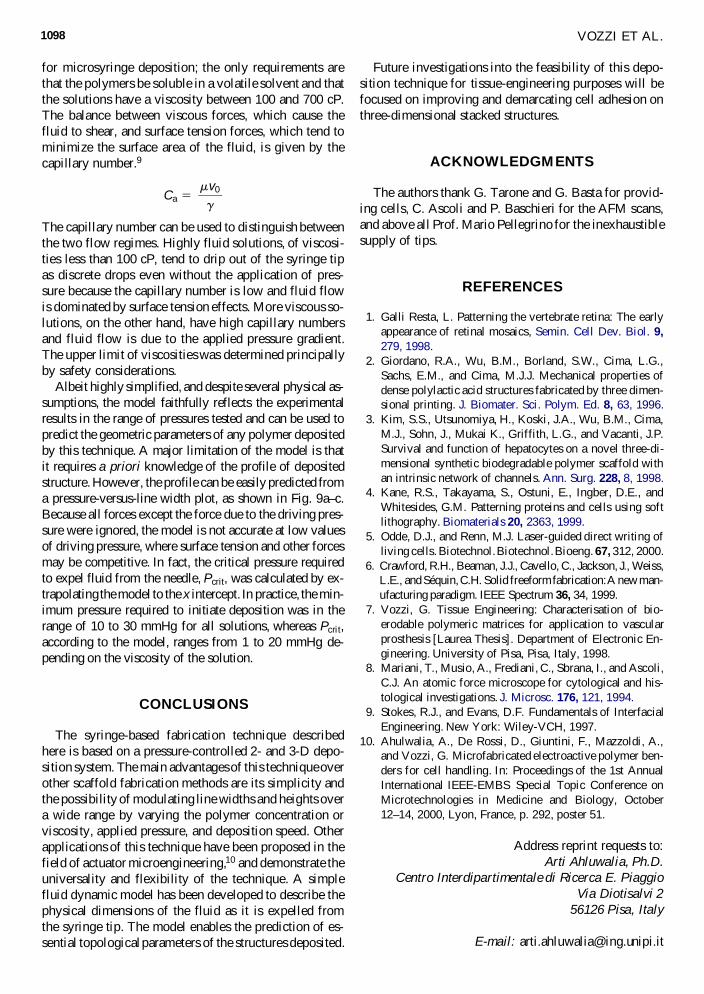
Related Documents