Operating instructions EN Welding machine microplasma 20 microplasma 50 microplasma 120 099-007010-EW501 07.09.2016

Welcome message from author
This document is posted to help you gain knowledge. Please leave a comment to let me know what you think about it! Share it to your friends and learn new things together.
Transcript
Operating instructions
EN
Welding machine
microplasma 20 microplasma 50 microplasma 120
099-007010-EW501 07.09.2016
General instructions
WARNING
Read the operating instructions!
The operating instructions provide an introduction to the safe use of the products.
• Read and observe the operating instructions for all system components, especially the safety instructions and warning notices!
• Observe the accident prevention regulations and any regional regulations!
• The operating instructions must be kept at the location where the machine is operated.
• Safety and warning labels on the machine indicate any possible risks. Keep these labels clean and legible at all times.
• The machine has been constructed to state-of-the-art standards in line with any applicable regulations and industrial standards. Only trained personnel may operate, service and repair the machine.
• Technical changes due to further development in machine technology may lead to a differing welding behaviour.
In the event of queries on installation, commissioning, operation or special conditions at the installation site, or on usage, please contact your sales partner or our customer service department on +49 2680 181-0.
A list of authorised sales partners can be found at www.ewm-group.com.
Liability relating to the operation of this equipment is restricted solely to the function of the equipment. No other form of liability, regardless of type, shall be accepted. This exclusion of liability shall be deemed accepted by the user on commissioning the equipment. The manufacturer is unable to monitor whether or not these instructions or the conditions and methods are observed during installation, operation, usage and maintenance of the equipment.
An incorrectly performed installation can result in material damage and injure persons as a result. For this reason, we do not accept any responsibility or liability for losses, damages or costs arising from incorrect installation, improper operation or incorrect usage and maintenance or any actions connected to this in any way.
© EWM AG
Dr. Günter-Henle-Straße 8
56271 Mündersbach Germany
The copyright to this document remains the property of the manufacturer.
Copying, including extracts, only permitted with written approval.
The content of this document has been prepared and reviewed with all reasonable care. The information provided is subject to change; errors excepted.

Contents Safety instructions
099-007010-EW501
07.09.2016 3
1 Contents
1 Contents .................................................................................................................................................. 3 1.1 Safety instructions .......................................................................................................................... 5 1.2 Notes on the use of these operating instructions .......................................................................... 5
1.2.1 Explanation of icons ....................................................................................................... 6 1.3 Safety instructions .......................................................................................................................... 7 1.4 Transport and installation ............................................................................................................ 11
2 Intended use ......................................................................................................................................... 12 2.1 Documents which also apply ....................................................................................................... 12
2.1.1 Warranty ....................................................................................................................... 12 2.1.2 Declaration of Conformity ............................................................................................. 12 2.1.3 Welding in environments with increased electrical hazards ......................................... 12 2.1.4 Service documents (spare parts and circuit diagrams) ................................................ 12 2.1.5 Calibration/Validation ................................................................................................... 12
3 Machine description – quick overview .............................................................................................. 13 3.1 Front view .................................................................................................................................... 13
3.1.1 microplasma 20, 50 ...................................................................................................... 13 3.1.2 microplasma 120 .......................................................................................................... 15
3.2 Rear view ..................................................................................................................................... 17 3.3 Machine control – Operating elements ........................................................................................ 18
4 Design and function ............................................................................................................................. 19 4.1 Transport and installation ............................................................................................................ 19
4.1.1 Ambient conditions ....................................................................................................... 19 4.1.1.1 In operation ................................................................................................... 19 4.1.1.2 Transport and storage ................................................................................... 19
4.1.2 Machine cooling ............................................................................................................ 20 4.1.3 Workpiece lead, general ............................................................................................... 20 4.1.4 Welding torch cooling system ....................................................................................... 20
4.1.4.1 Connection .................................................................................................... 20 4.1.5 Notes on the installation of welding current leads ........................................................ 21
4.1.5.1 Stray welding currents................................................................................... 22 4.1.6 Mains connection .......................................................................................................... 23
4.1.6.1 Mains configuration ....................................................................................... 23 4.1.7 Shielding and plasma gas supply ................................................................................. 24
4.1.7.1 Pressure regulator connection ...................................................................... 24 4.1.7.2 Shielding gas hose connection ..................................................................... 25 4.1.7.3 Gas test ......................................................................................................... 26
4.1.8 Welding torch and workpiece line connection .............................................................. 27 4.1.8.1 microplasma 20, 50 ....................................................................................... 27 4.1.8.2 microplasma 120 ........................................................................................... 28
4.1.9 Function sequences/operating modes ......................................................................... 29 4.1.9.1 Currentless Test - Simulation mode .............................................................. 29 4.1.9.2 Explanation of signs and functions ............................................................... 29 4.1.9.3 Non-latched operation without Up- und Downslope ..................................... 29
4.1.10 Welding task selection .................................................................................................. 32 4.1.10.1 Pilot arc ......................................................................................................... 32
4.2 Remote control ............................................................................................................................. 33 4.2.1 FR21 14POL ................................................................................................................. 33
4.3 Interfaces for automation ............................................................................................................. 34 4.3.1 Remote control connection socket, 14-pole ................................................................. 34
5 Maintenance, care and disposal ......................................................................................................... 35 5.1 General ........................................................................................................................................ 35 5.2 Maintenance work, intervals ........................................................................................................ 35
5.2.1 Daily maintenance tasks .............................................................................................. 35 5.2.1.1 Visual inspection ........................................................................................... 35 5.2.1.2 Functional test ............................................................................................... 35
5.2.2 Monthly maintenance tasks .......................................................................................... 36

Contents Safety instructions
4 099-007010-EW501
07.09.2016
5.2.2.1 Visual inspection ........................................................................................... 36 5.2.2.2 Functional test ............................................................................................... 36
5.2.3 Annual test (inspection and testing during operation) .................................................. 36 5.3 Disposing of equipment ................................................................................................................ 36
5.3.1 Manufacturer's declaration to the end user .................................................................. 36 5.4 Meeting the requirements of RoHS .............................................................................................. 36
6 Rectifying faults.................................................................................................................................... 37 6.1 Checklist for rectifying faults ........................................................................................................ 37
7 Technical data....................................................................................................................................... 38 7.1 microplasma 20-120 ..................................................................................................................... 38
8 Accessories .......................................................................................................................................... 39 8.1 Welding torch cooling system ...................................................................................................... 39 8.2 General accessories .................................................................................................................... 39 8.3 Remote controls and accessories ................................................................................................ 39
9 Appendix A ............................................................................................................................................ 40 9.1 Overview of EWM branches......................................................................................................... 40

Contents Safety instructions
099-007010-EW501
07.09.2016 5
1.1 Safety instructions
1.2 Notes on the use of these operating instructions
DANGER Working or operating procedures which must be closely observed to prevent imminent
serious and even fatal injuries.
• Safety notes include the "DANGER" keyword in the heading with a general warning symbol.
• The hazard is also highlighted using a symbol on the edge of the page.
WARNING Working or operating procedures which must be closely observed to prevent serious
and even fatal injuries.
• Safety notes include the "WARNING" keyword in the heading with a general warning symbol.
• The hazard is also highlighted using a symbol in the page margin.
CAUTION Working or operating procedures which must be closely observed to prevent possible
minor personal injury.
• The safety information includes the "CAUTION" keyword in its heading with a general warning symbol.
• The risk is explained using a symbol on the edge of the page.
Special technical points which users must observe.
Instructions and lists detailing step-by-step actions for given situations can be recognised via bullet points, e.g.:
• Insert the welding current lead socket into the relevant socket and lock.

Contents Notes on the use of these operating instructions
6 099-007010-EW501
07.09.2016
1.2.1 Explanation of icons
Symbol Description Symbol Description
Indicates technical aspects which the
user must observe.
Activate and release/tap/tip
Switch off machine Release
Switch on machine Press and keep pressed
Switch
Wrong Turn
Correct Numerical value – adjustable
Menu entry
Signal light lights up in green
Navigating the menu
Signal light flashes green
Exit menu
Signal light lights up in red
Time representation (e.g.: wait
4 s/activate)
Signal light flashes red
Interruption in the menu display (other
setting options possible)
Tool not required/do not use
Tool required/use

Contents Safety instructions
099-007010-EW501
07.09.2016 7
1.3 Safety instructions
WARNING
Risk of accidents due to non-compliance with the safety instructions!
Non-compliance with the safety instructions can be fatal!
• Carefully read the safety instructions in this manual!
• Observe the accident prevention regulations and any regional regulations!
• Inform persons in the working area that they must comply with the regulations!
WARNING
Risk of injury from electrical voltage!
Voltages can cause potentially fatal electric shocks and burns on contact. Even low voltages can cause a shock and lead to accidents.
• Never touch live components such as welding current sockets or stick, tungsten or wire electrodes!
• Always place torches and electrode holders on an insulated surface!
• Wear the full personal protective equipment (depending on the application)!
• The machine may only be opened by qualified personnel!
Hazard when interconnecting multiple power sources!
If a number of power sources are to be connected in parallel or in series, only a technical specialist may interconnect the sources as per standard IEC 60974-9:2010: Installation and use and German Accident Prevention Regulation BVG D1 (formerly VBG 15) or country-specific regulations.
Before commencing arc welding, a test must verify that the equipment cannot exceed the maximum permitted open circuit voltage.
• Only qualified personnel may connect the machine.
• When taking individual power sources out of operation, all mains and welding current leads must be safely disconnected from the welding system as a whole. (Hazard due to reverse polarity voltage!)
• Do not interconnect welding machines with pole reversing switch (PWS series) or machines for AC welding since a minor error in operation can cause the welding voltages to be combined, which is not permitted.

Contents Safety instructions
8 099-007010-EW501
07.09.2016
WARNING
Risk of injury due to improper clothing!
During arc welding, radiation, heat and voltage are sources of risk that cannot be avoided. The user has to be equipped with the complete personal protective equipment at all times. The protective equipment has to include:
• Respiratory protection against hazardous substances and mixtures (fumes and vapours); otherwise implement suitable measures such as extraction facilities.
• Welding helmet with proper protection against ionizing radiation (IR and UV radiation) and heat.
• Dry welding clothing (shoes, gloves and body protection) to protect against warm environments with conditions comparable to ambient temperatures of 100 °C or higher and arcing and work on live components.
• Hearing protection against harming noise.
WARNING
Risk of injury due to radiation or heat!
Arc radiation results in injury to skin and eyes. Contact with hot workpieces and sparks results in burns.
• Use welding shield or welding helmet with the appropriate safety level (depending on the application)!
• Wear dry protective clothing (e.g. welding shield, gloves, etc.) according to the relevant regulations in the country in question!
• Protect persons not involved in the work against arc beams and the risk of glare using safety curtains!
WARNING
Explosion risk!
Apparently harmless substances in closed containers may generate excessive pressure when heated.
• Move containers with inflammable or explosive liquids away from the working area!
• Never heat explosive liquids, dusts or gases by welding or cutting!
Fire hazard!
Due to the high temperatures, sparks, glowing parts and hot slag that occur during welding, there is a risk of flames.
• Be watchful of potential sources of fire in the working area!
• Do not carry any easily inflammable objects, e.g. matches or lighters.
• Ensure suitable fire extinguishers are available in the working area!
• Thoroughly remove any residue of flammable materials from the workpiece prior to starting to weld.
• Only further process workpieces after they have cooled down. Do not allow them to contact any flammable materials!

Contents Safety instructions
099-007010-EW501
07.09.2016 9
CAUTION
Smoke and gases!
Smoke and gases can lead to breathing difficulties and poisoning. In addition, solvent vapour (chlorinated hydrocarbon) may be converted into poisonous phosgene due to the ultraviolet radiation of the arc!
• Ensure that there is sufficient fresh air!
• Keep solvent vapour away from the arc beam field!
• Wear suitable breathing apparatus if appropriate!
CAUTION
Noise exposure!
Noise exceeding 70 dBA can cause permanent hearing damage!
• Wear suitable ear protection!
• Persons located within the working area must wear suitable ear protection!
Obligations of the operator!
The respective national directives and laws must be complied with when operating the machine!
• Implementation of national legislation relating to framework directive 89/391/EEC on the introduction of measures to encourage improvements in the safety and health of workers at work and associated individual guidelines.
• In particular, directive 89/655/EEC concerning the minimum safety and health requirements for the use of work equipment by workers at work.
• The regulations applicable to occupational safety and accident prevention in the country concerned.
• Setting up and operating the machine as per IEC 60974.-9.
• Brief the user on safety-conscious work practices on a regular basis.
• Regularly inspect the machine as per IEC 60974.-4.
The manufacturer's warranty becomes void if non-genuine parts are used!
• Only use system components and options (power sources, welding torches, electrode holders, remote controls, spare parts and replacement parts, etc.) from our range of products!
• Only insert and lock accessory components into the relevant connection socket when the machine is switched off.
Requirements for connection to the public mains network
High-performance machines can influence the mains quality by taking current from the mains network. For some types of machines, connection restrictions or requirements relating to the maximum possible line impedance or the necessary minimum supply capacity at the interface with the public network (Point of Common Coupling, PCC) can therefore apply. In this respect, attention is also drawn to the machines' technical data. In this case, it is the responsibility of the operator, where necessary in consultation with the mains network operator, to ensure that the machine can be connected.

Contents Safety instructions
10 099-007010-EW501
07.09.2016
CAUTION
Electromagnetic fields!
The power source may cause electrical or electromagnetic fields to be produced which could affect the correct functioning of electronic equipment such as IT or CNC devices, telecommunication lines, power cables, signal lines and pacemakers.
• Observe the maintenance instructions > see 5.2 chapter!
• Unwind welding leads completely!
• Shield devices or equipment sensitive to radiation accordingly!
• The correct functioning of pacemakers may be affected (obtain advice from a doctor if necessary).
According to IEC 60974-10, welding machines are divided into two classes of electromagnetic compatibility (the EMC class can be found in the Technical data) > see 7 chapter:
Class A machines are not intended for use in residential areas where the power supply comes from the low-voltage public mains network. When ensuring the electromagnetic compatibility of class A machines, difficulties can arise in these areas due to interference not only in the supply lines but also in the form of radiated interference.
Class B machines fulfil the EMC requirements in industrial as well as residential areas, including residential areas connected to the low-voltage public mains network.
Setting up and operating
When operating arc welding systems, in some cases, electro-magnetic interference can occur although all of the welding machines comply with the emission limits specified in the standard. The user is responsible for any interference caused by welding.
In order to evaluate any possible problems with electromagnetic compatibility in the surrounding area, the user must consider the following: (see also EN 60974-10 Appendix A)
• Mains, control, signal and telecommunication lines
• Radios and televisions
• Computers and other control systems
• Safety equipment
• The health of neighbouring persons, especially if they have a pacemaker or wear a hearing aid
• Calibration and measuring equipment
• The immunity to interference of other equipment in the surrounding area
• The time of day at which the welding work must be carried out
Recommendations for reducing interference emission
• Mains connection, e.g. additional mains filter or shielding with a metal tube
• Maintenance of the arc welding system
• Welding leads should be as short as possible and run closely together along the ground
• Potential equalization
• Earthing of the workpiece. In cases where it is not possible to earth the workpiece directly, it should be connected by means of suitable capacitors.
• Shielding from other equipment in the surrounding area or the entire welding system

Contents Transport and installation
099-007010-EW501
07.09.2016 11
1.4 Transport and installation
WARNING
Risk of injury due to improper handling of shielding gas cylinders!
Improper handling and insufficient securing of shielding gas cylinders can cause serious injuries!
• Observe the instructions from the gas manufacturer and any relevant regulations concerning the use of compressed air!
• Do not attach any element to the shielding gas cylinder valve!
• Prevent the shielding gas cylinder from heating up.
CAUTION
Risk of accidents due to supply lines!
During transport, attached supply lines (mains leads, control cables, etc.) can cause risks, e.g. by causing connected machines to tip over and injure persons!
• Disconnect all supply lines before transport!
Risk of tipping!
There is a risk of the machine tipping over and injuring persons or being damaged itself during movement and set up. Tilt resistance is guaranteed up to an angle of 10° (according to IEC 60974-1).
• Set up and transport the machine on level, solid ground.
• Secure add-on parts using suitable equipment.
The units are designed for operation in an upright position!
Operation in non-permissible positions can cause equipment damage.
• Only transport and operate in an upright position!
Accessory components and the power source itself can be damaged by incorrect connection!
• Only insert and lock accessory components into the relevant connection socket when the machine is switched off.
• Comprehensive descriptions can be found in the operating instructions for the relevant accessory components.
• Accessory components are detected automatically after the power source is switched on.
Protective dust caps protect the connection sockets and therefore the machine against dirt and damage.
• The protective dust cap must be fitted if there is no accessory component being operated on that connection.
• The cap must be replaced if faulty or if lost!

Intended use Documents which also apply
12 099-007010-EW501
07.09.2016
2 Intended use
WARNING
Hazards due to improper usage!
The machine has been constructed to the state of the art and any regulations and standards applicable for use in industry and trade. It may only be used for the welding procedures indicated at the rating plate. Hazards may arise for persons, animals and material objects if the equipment is not used correctly. No liability is accepted for any damages arising from improper usage!
• The equipment must only be used in line with its designated purpose and by trained or expert personnel!
• Do not improperly modify or convert the equipment!
Arc welding machine for microplasma DC welding with HF start (contactless). It may be possible to expand the range of functions by using accessories (see the documentation in the relevant chapter).
2.1 Documents which also apply 2.1.1 Warranty
For more information refer to the "Warranty registration" brochure supplied and our information regarding warranty, maintenance and testing at www.ewm-group.com!
2.1.2 Declaration of Conformity
The labelled machine complies with the following EC directives in terms of its design and construction:
• Low Voltage Directive (LVD)
• Electromagnetic Compatibility Directive (EMC)
• Restriction of Hazardous Substance (RoHS)
In case of unauthorised changes, improper repairs, non-compliance with specified deadlines for "Arc Welding Equipment – Inspection and Testing during Operation", and/or prohibited modifications which have not been explicitly authorised by EWM, this declaration shall be voided. An original document of the specific declaration of conformity is included with every product.
2.1.3 Welding in environments with increased electrical hazards
In compliance with IEC / DIN EN 60974, VDE 0544 the machines can be used in environments with an increased electrical hazard.
2.1.4 Service documents (spare parts and circuit diagrams)
WARNING
Do not carry out any unauthorised repairs or modifications!
To avoid injury and equipment damage, the unit must only be repaired or modified by specialist, skilled persons! The warranty becomes null and void in the event of unauthorised interference.
• Appoint only skilled persons for repair work (trained service personnel)!
Original copies of the circuit diagrams are enclosed with the unit.
Spare parts can be obtained from the relevant authorised dealer.
2.1.5 Calibration/Validation We hereby confirm that this machine has been tested using calibrated measuring equipment, as stipulated in IEC/EN 60974, ISO/EN 17662, EN 50504, and complies with the admissible tolerances. Recommended calibration interval: 12 months
Machine description – quick overview Front view
099-007010-EW501
07.09.2016 13
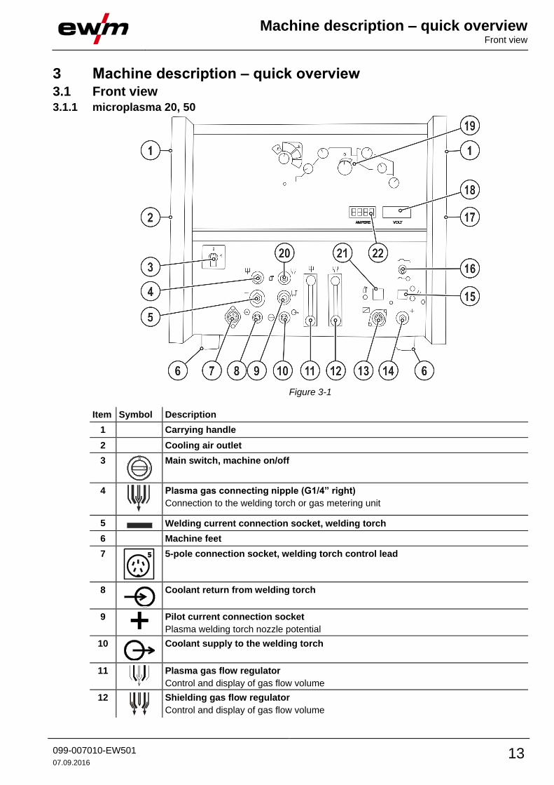
3 Machine description – quick overview 3.1 Front view 3.1.1 microplasma 20, 50
Figure 3-1
Item Symbol Description 0
1 Carrying handle
2 Cooling air outlet
3
Main switch, machine on/off
4
Plasma gas connecting nipple (G1/4” right)
Connection to the welding torch or gas metering unit
5 Welding current connection socket, welding torch
6 Machine feet
7
5-pole connection socket, welding torch control lead
8
Coolant return from welding torch
9
Pilot current connection socket
Plasma welding torch nozzle potential
10
Coolant supply to the welding torch
11
Plasma gas flow regulator
Control and display of gas flow volume
12
Shielding gas flow regulator
Control and display of gas flow volume

Machine description – quick overview Front view
14 099-007010-EW501
07.09.2016
Item Symbol Description 0
13
Connection socket, 14-pole
Remote control connection
14
Connection socket, “+” welding current
Connection for workpiece lead
15
Pilot arc button with signal light
Signal light off: pilot arc off
Signal light on: pilot arc lit
16
Toggle switch for no-power test
Simulation option for the set parameter values without welding
17 Cooling air inlet
18
Three-figure display
Display of the welding voltage
19 Machine control > see 3.3 chapter
20
Shielding gas connecting nipple (G1/4” left)
Connection to the welding torch or gas metering unit
21
Gas test push-button > see 4.1.7.3 chapter
22
Three-figure display
Display of the welding current
Machine description – quick overview Front view
099-007010-EW501
07.09.2016 15
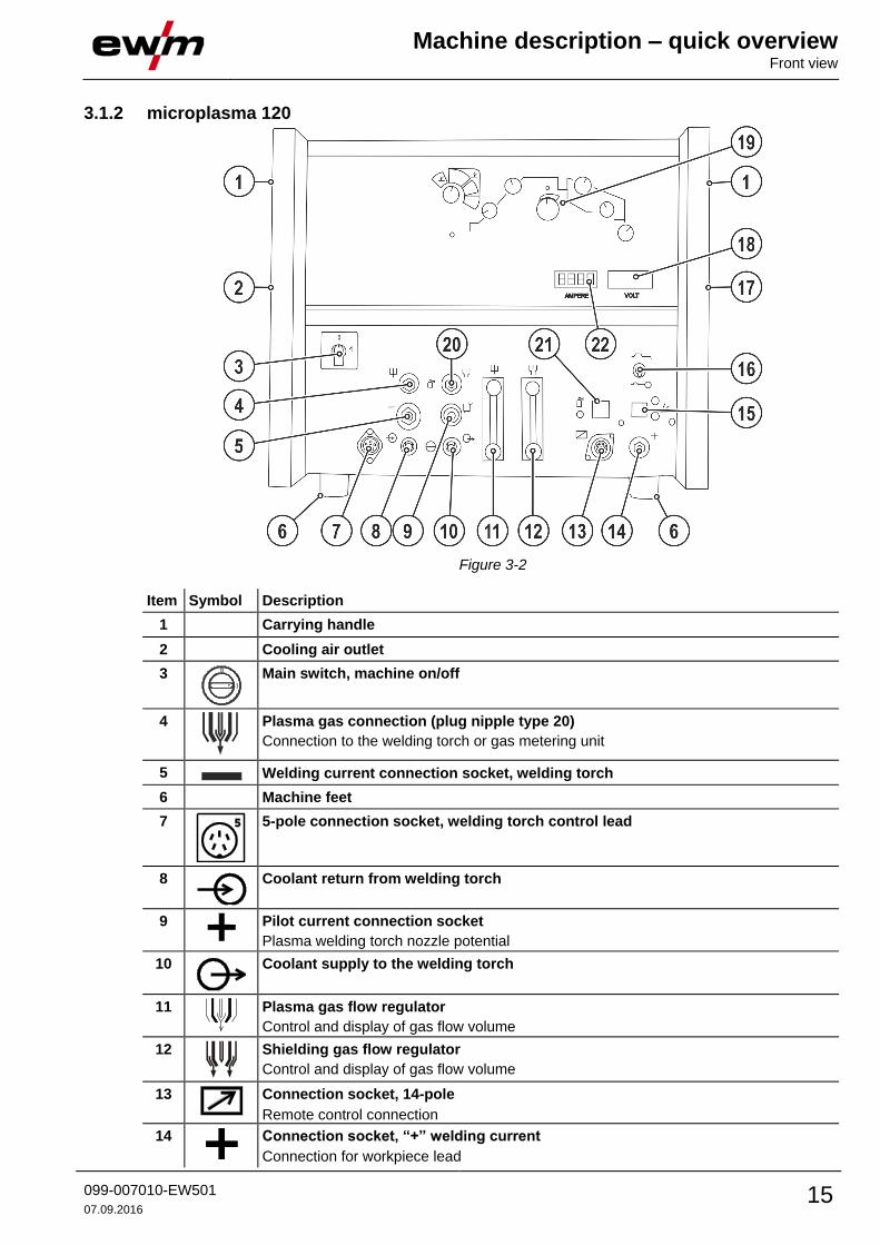
3.1.2 microplasma 120
Figure 3-2
Item Symbol Description 0
1 Carrying handle
2 Cooling air outlet
3
Main switch, machine on/off
4
Plasma gas connection (plug nipple type 20)
Connection to the welding torch or gas metering unit
5 Welding current connection socket, welding torch
6 Machine feet
7
5-pole connection socket, welding torch control lead
8
Coolant return from welding torch
9
Pilot current connection socket
Plasma welding torch nozzle potential
10
Coolant supply to the welding torch
11
Plasma gas flow regulator
Control and display of gas flow volume
12
Shielding gas flow regulator
Control and display of gas flow volume
13
Connection socket, 14-pole
Remote control connection
14
Connection socket, “+” welding current
Connection for workpiece lead

Machine description – quick overview Front view
16 099-007010-EW501
07.09.2016
Item Symbol Description 0
15
Pilot arc button with signal light
Signal light off: pilot arc off
Signal light on: pilot arc lit
16
Toggle switch for no-power test
Simulation option for the set parameter values without welding
17 Cooling air inlet
18
Three-figure display
Display of the welding voltage
19 Machine control > see 3.3 chapter
20
Shielding gas connection (coupling type 20)
Connection to the welding torch or gas metering unit
21
Gas test push-button > see 4.1.7.3 chapter
22
Three-figure display
Display of the welding current
Machine description – quick overview Rear view
099-007010-EW501
07.09.2016 17
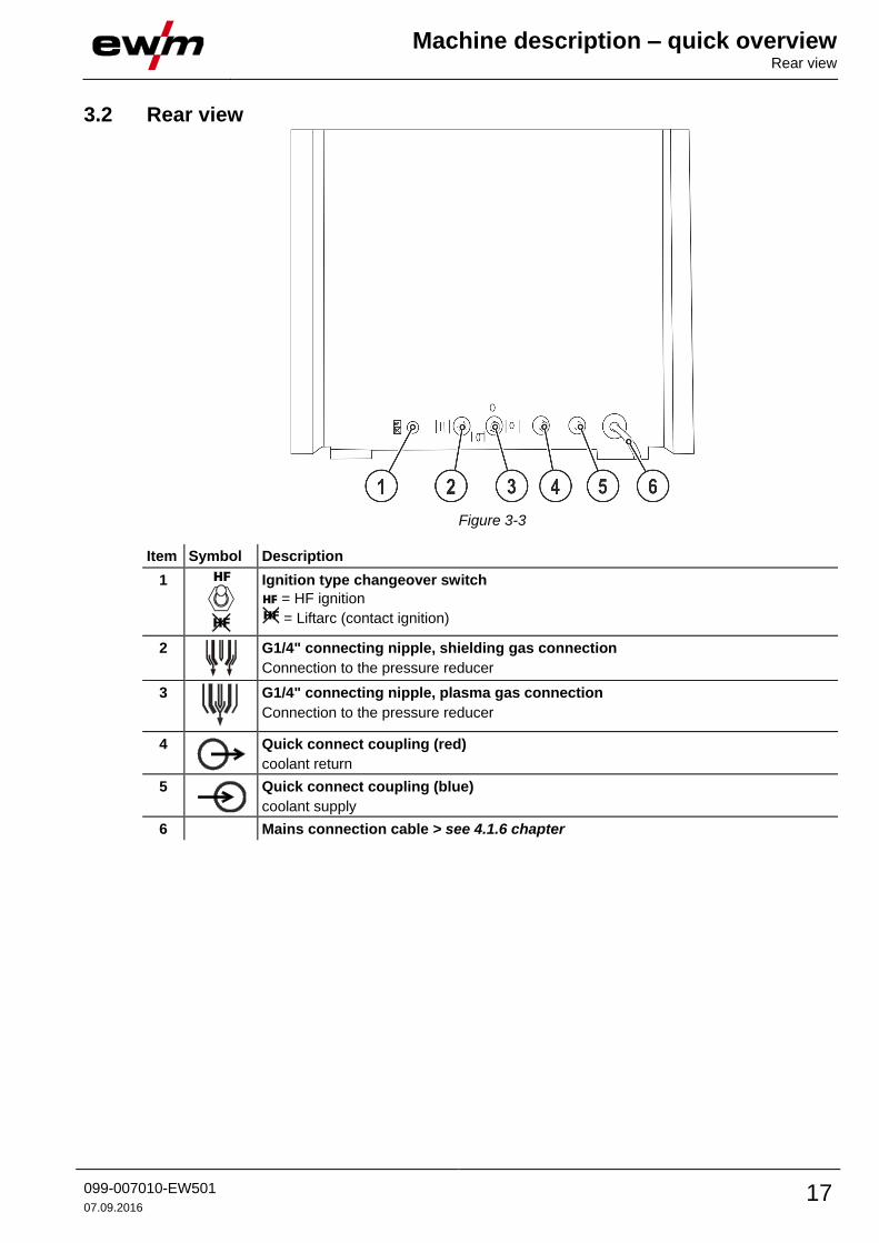
3.2 Rear view
Figure 3-3
Item Symbol Description 0
1
Ignition type changeover switch
= HF ignition
= Liftarc (contact ignition)
2
G1/4" connecting nipple, shielding gas connection
Connection to the pressure reducer
3
G1/4" connecting nipple, plasma gas connection
Connection to the pressure reducer
4
Quick connect coupling (red)
coolant return
5
Quick connect coupling (blue)
coolant supply
6 Mains connection cable > see 4.1.6 chapter

Machine description – quick overview Machine control – Operating elements
18 099-007010-EW501
07.09.2016
3.3 Machine control – Operating elements
Figure 3-4
Item Symbol Description 0
1
Operating mode rotary switch
------ not available
-- Operating mode non-latched
------ Operating mode non-latched with Up- and Downslope
---- Operating mode latched with Up- und Downslope
2
Excess temperature signal light / Welding torch cooling failure
For error messages > see 6 chapter
3
Ignition current
Setting range 0% to 100% depending on the main current.
4
Rotary dial Upslope time
Setting range 0 s to 25 s
5 Torch trigger signal light
Illuminates immediately torch trigger 1 is activated.
6
Welding current setting rotary dial
Infinite setting of the welding current across the whole power range.
7
Rotary dial Downslope time
Setting range 0 s to 25 s
8
Rotary dial Secondary current
Setting range 1% to 100% depending on the main current.
9
Gas post-flow time dial
Setting range 0 s to 20 s

Design and function Transport and installation
099-007010-EW501
07.09.2016 19
4 Design and function 4.1 Transport and installation
WARNING
Risk of injury from electric shock!
Contact with live parts, e.g. welding current sockets, is potentially fatal!
• Follow safety instructions on the opening pages of the operating instructions.
• Commissioning may only be carried out by persons who have the relevant expertise of working with arc welding machines!
• Connection and welding leads (e.g. electrode holder, welding torch, workpiece lead, interfaces) may only be connected when the machine is switched off!
Risk of accident due to improper transport of machines that must not be lifted!
Do not lift or suspend the machine! The machine can drop and cause injuries! The handles, straps or brackets are suitable for transport by hand only!
• The machine must not be suspended or lifted using a crane.
Read and observe the documentation to all system and accessory components!
A connected and ready-to-use welding torch cooling unit is required for the operation of this plasma welding machine!
4.1.1 Ambient conditions
T he machine must not be operated in the open air and must only be set up and operated on a suitable, stable and level base!
• The operator must ensure that the ground is non-slip and level, and provide sufficient lighting for the place of work.
• Safe operation of the machine must be guaranteed at all times.
Unusually high quantities of dust, acid, corrosive gases or substances may damage the equipment.
• Avoid high volumes of smoke, vapour, oil vapour and grinding dust!
• Avoid ambient air containing salt (sea air)!
4.1.1.1 In operation
Temperature range of the ambient air:
• -25 °C to +40 °C
Relative air humidity:
• Up to 50% at 40 °C
• Up to 90% at 20 °C
4.1.1.2 Transport and storage
Storage in an enclosed space, temperature range of the ambient air:
• -30 °C to +70 °C
Relative air humidity
• Up to 90% at 20 °C

Design and function Transport and installation
20 099-007010-EW501
07.09.2016
4.1.2 Machine cooling
Insufficient ventilation results in a reduction in performance and equipment damage.
• Observe the ambient conditions!
• Keep the cooling air inlet and outlet clear!
• Observe the minimum distance of 0.5 m from obstacles!
4.1.3 Workpiece lead, general
CAUTION
Risk of burning due to incorrect welding current connection!
If the welding current plugs (machine connections) are not locked or if the workpiece connection is contaminated (paint, corrosion), these connections and leads can heat up and cause burns when touched!
• Check welding current connections on a daily basis and lock by turning to the right when necessary.
• Clean workpiece connection thoroughly and secure properly. Do not use structural parts of the workpiece as welding current return lead!
4.1.4 Welding torch cooling system
4.1.4.1 Connection
Figure 4-1
Item Symbol Description 0
1 Welding torch cooling unit
2
Coolant return from the welding torch cooling unit
3
Coolant forward flow to the welding torch cooling unit
• Lock connecting nipples of the cooling water tubes into the corresponding quick connect couplings: Return line red to quick connect coupling, red (coolant return) and supply line blue to quick connect coupling, blue (coolant supply).

Design and function Transport and installation
099-007010-EW501
07.09.2016 21
4.1.5 Notes on the installation of welding current leads
Incorrectly installed welding current leads can cause faults in the arc (flickering).
Lay the workpiece lead and hose package of power sources without HF igniter (MIG/MAG) for as long and as close as possible in parallel.
Lay the workpiece lead and hose package of power sources with HF igniter (TIG) for as long as possible in parallel with a distance of 20 cm to avoid HF sparkover.
Always keep a distance of at least 20 cm to leads of other power sources to avoid interferences
Always keep leads as short as possible! For optimum welding results max. 30 m (welding lead + intermediate hose package + torch lead).
Figure 4-2
Use an individual welding lead to the workpiece for each welding machine!
Figure 4-3

Design and function Transport and installation
22 099-007010-EW501
07.09.2016
Fully unroll welding current leads, torch hose packages and intermediate hose packages. Avoid loops!
Always keep leads as short as possible!
Lay any excess cable lengths in meanders.
Figure 4-4
4.1.5.1 Stray welding currents
WARNING
Risk of injury due to stray welding currents!
Stray welding currents can destroy protective earth conductors, damage machines and electronic devices and cause overheating of components, leading to fire.
• Check that all welding current connections are firmly secured and electrical connections are in perfect condition.
• Set up, attach or suspend all conductive power source components such as casing, transport vehicles and crane frames so they are insulated.
• Do not place any other electronic devices such as drills or angle grinders on the power source, transport vehicle or crane frames unless they are insulated.
• Always put welding torches and electrode holders on an insulated surface when they are not in use.
Figure 4-5

Design and function Transport and installation
099-007010-EW501
07.09.2016 23
4.1.6 Mains connection
DANGER
Hazards caused by improper mains connection!
An improper mains connection can cause injuries or damage property!
• Only operate machine using a socket that has correctly fitted protective earth.
• The mains voltage indicated on the rating plate must match the supply voltage.
• If a new mains plug must be fitted, only an electrician may do so as per the relevant national legislation or regulations.
• Mains plug, socket and lead must be checked by an electrician on a regular basis.
• When operating the generator, always ensure it is earthed as stipulated in the operating instructions. The network created must be suitable for operating machines according to protection class I.
4.1.6.1 Mains configuration
The machine may only be connected to a one-phase system with two conductors and an earthed neutral conductor.
Figure 4-6
Legend
Item Designation Colour code
L Outer conductor brown
N Neutral conductor blue
PE Protective conductor green-yellow
• Insert mains plug of the switched-off machine into the appropriate socket.

Design and function Transport and installation
24 099-007010-EW501
07.09.2016
4.1.7 Shielding and plasma gas supply
WARNING
Risk of injury due to improper handling of shielding gas cylinders!
Improper handling and insufficient securing of shielding gas cylinders can cause serious injuries!
• Place shielding gas cylinder into the designated holder and secure with fastening elements (chain/belt)!
• Attach the fastening elements within the upper half of the shielding gas cylinder!
• The fastening elements must tightly enclose the shielding gas cylinder!
An unhindered shielding gas supply from the shielding gas cylinder to the welding torch is a fundamental requirement for optimum welding results. In addition, a blocked shielding gas supply may result in the welding torch being destroyed.
• Always re-fit the yellow protective cap when not using the shielding gas connection.
• All shielding gas connections must be gas tight.
4.1.7.1 Pressure regulator connection
Figure 4-7
Item Symbol Description 0
1 Pressure regulator
2 Shielding gas cylinder
3 Output side of the pressure regulator
4 Cylinder valve
• Before connecting the pressure regulator to the gas cylinder, open the cylinder valve briefly to blow out any dirt.
• Tighten the pressure regulator screw connection on the gas bottle valve to be gas-tight.
• Screw gas hose connection crown nut onto the output side of the pressure regulator.
Design and function Transport and installation
099-007010-EW501
07.09.2016 25
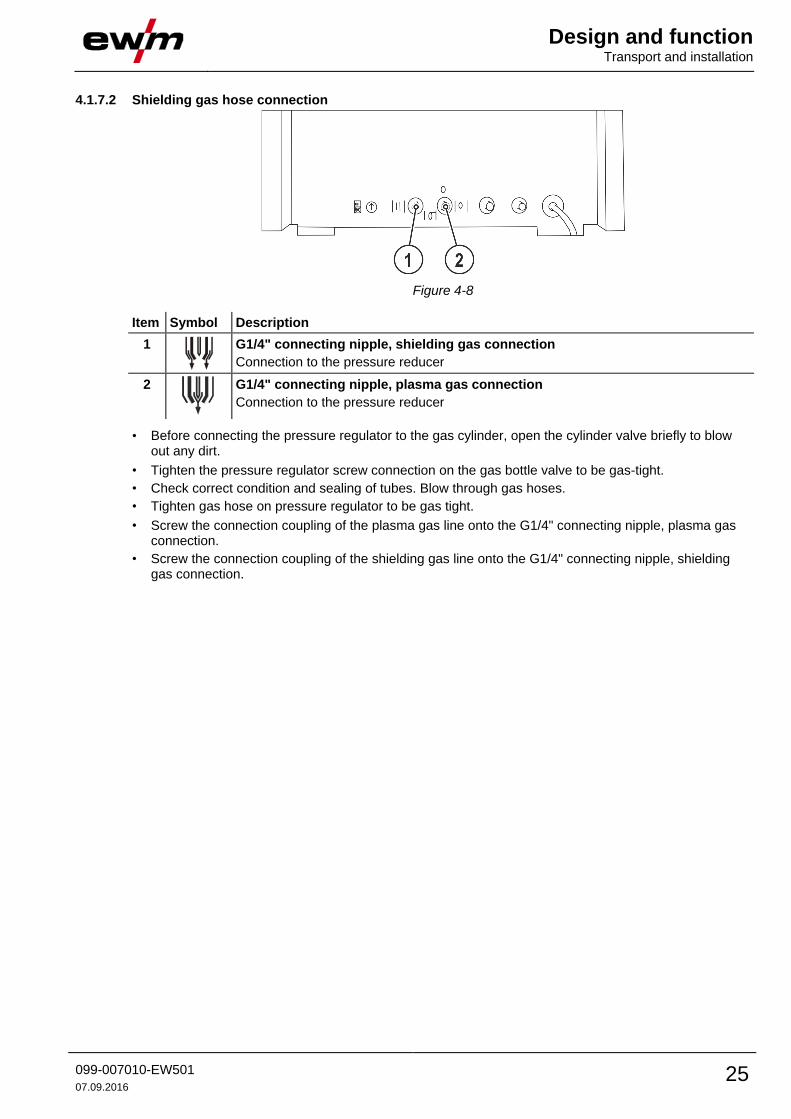
4.1.7.2 Shielding gas hose connection
Figure 4-8
Item Symbol Description 0
1
G1/4" connecting nipple, shielding gas connection
Connection to the pressure reducer
2
G1/4" connecting nipple, plasma gas connection
Connection to the pressure reducer
• Before connecting the pressure regulator to the gas cylinder, open the cylinder valve briefly to blow out any dirt.
• Tighten the pressure regulator screw connection on the gas bottle valve to be gas-tight.
• Check correct condition and sealing of tubes. Blow through gas hoses.
• Tighten gas hose on pressure regulator to be gas tight.
• Screw the connection coupling of the plasma gas line onto the G1/4" connecting nipple, plasma gas connection.
• Screw the connection coupling of the shielding gas line onto the G1/4" connecting nipple, shielding gas connection.

Design and function Transport and installation
26 099-007010-EW501
07.09.2016
4.1.7.3 Gas test
The connected gas lines should each have a pre-pressure of 4.5 bar (tolerance limits: plasma gas 4 bar to 5 bar, shielding gas 4 bar to 5 bar).
The functional sequence for the gas test is carried out in the same way for shielding gas and plasma gas. The gas test is only possible if:
• the pilot arc is not ignited and
• no welding process is being carried out.
Shielding and plasma gas setting can be checked without welding current flowing (currentless) and set if required. Activation of the gas test button releases both gas valves simultaneously and the gas setting can be made at the corresponding flow regulator.
Figure 4-9
Item Symbol Description 0
1
Plasma gas flow regulator
Control and display of gas flow volume
2
Shielding gas flow regulator
Control and display of gas flow volume
3
Gas test push-button > see 4.1.7.3 chapter
• Press and hold the shielding or plasma gas test pushbutton.
• Release the pushbutton (test procedure complete).
• Press the torch trigger and set the shielding gas quantity with the flow gauge of the pressure regulator.
The flow quantity cannot be set higher on the gas flow regulator for fine adjustment of the gas flow than specified on the shielding gas cylinder pressure reducer.
Design and function Transport and installation
099-007010-EW501
07.09.2016 27
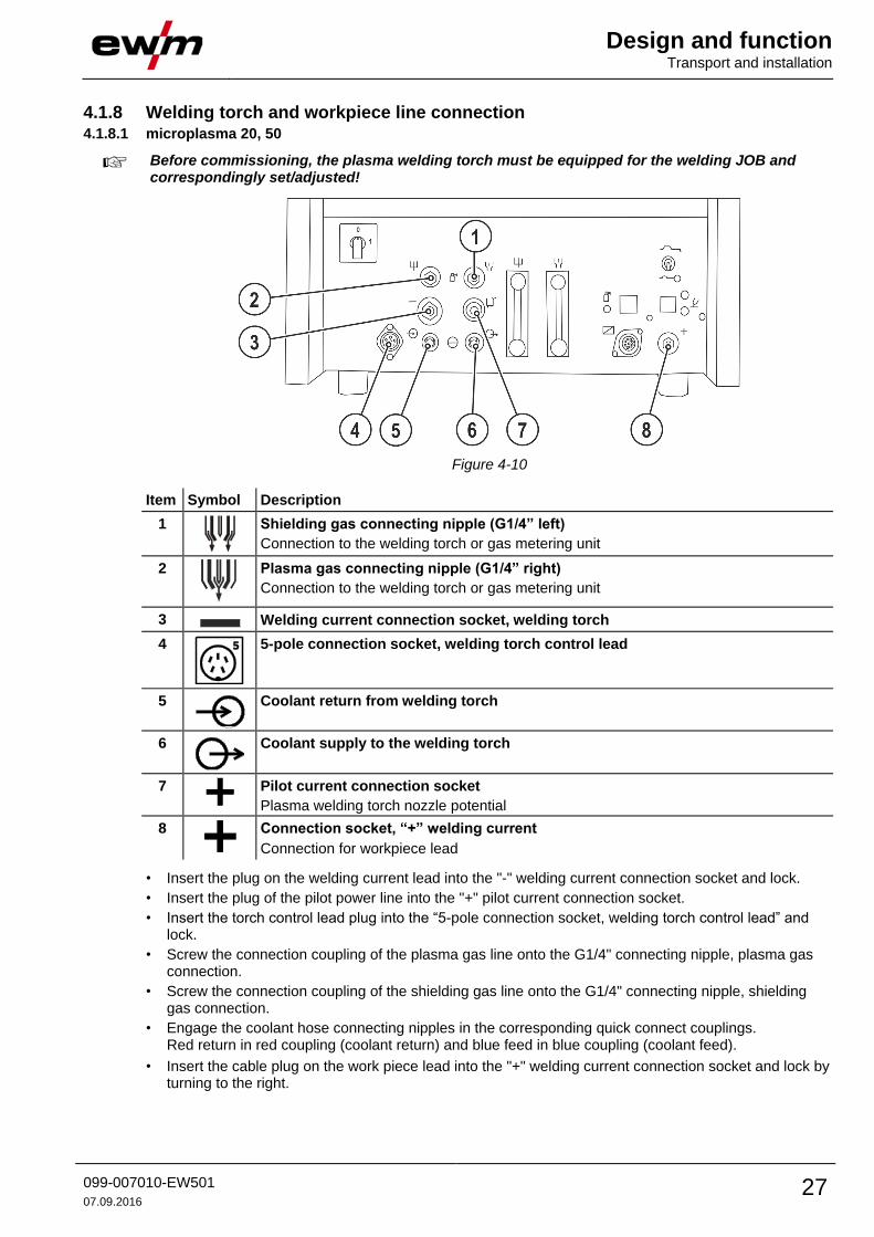
4.1.8 Welding torch and workpiece line connection 4.1.8.1 microplasma 20, 50
Before commissioning, the plasma welding torch must be equipped for the welding JOB and correspondingly set/adjusted!
Figure 4-10
Item Symbol Description 0
1
Shielding gas connecting nipple (G1/4” left)
Connection to the welding torch or gas metering unit
2
Plasma gas connecting nipple (G1/4” right)
Connection to the welding torch or gas metering unit
3 Welding current connection socket, welding torch
4
5-pole connection socket, welding torch control lead
5
Coolant return from welding torch
6
Coolant supply to the welding torch
7
Pilot current connection socket
Plasma welding torch nozzle potential
8
Connection socket, “+” welding current
Connection for workpiece lead
• Insert the plug on the welding current lead into the "-" welding current connection socket and lock.
• Insert the plug of the pilot power line into the "+" pilot current connection socket.
• Insert the torch control lead plug into the “5-pole connection socket, welding torch control lead” and lock.
• Screw the connection coupling of the plasma gas line onto the G1/4" connecting nipple, plasma gas connection.
• Screw the connection coupling of the shielding gas line onto the G1/4" connecting nipple, shielding gas connection.
• Engage the coolant hose connecting nipples in the corresponding quick connect couplings. Red return in red coupling (coolant return) and blue feed in blue coupling (coolant feed).
• Insert the cable plug on the work piece lead into the "+" welding current connection socket and lock by turning to the right.

Design and function Transport and installation
28 099-007010-EW501
07.09.2016
4.1.8.2 microplasma 120
Before commissioning, the plasma welding torch must be equipped for the welding JOB and correspondingly set/adjusted!
Figure 4-11
Item Symbol Description 0
1
Shielding gas connection (coupling type 20)
Connection to the welding torch or gas metering unit
2
Plasma gas connection (plug nipple type 20)
Connection to the welding torch or gas metering unit
3 Welding current connection socket, welding torch
4
5-pole connection socket, welding torch control lead
5
Coolant return from welding torch
6
Coolant supply to the welding torch
7
Pilot current connection socket
Plasma welding torch nozzle potential
8
Connection socket, “+” welding current
Connection for workpiece lead
• Insert the plug on the welding current lead into the "-" welding current connection socket and lock.
• Insert the plug of the pilot power line into the "+" pilot current connection socket.
• Insert the torch control lead plug into the “5-pole connection socket, welding torch control lead” and lock.
• Screw the connection coupling of the plasma gas line onto the G1/4" connecting nipple, plasma gas connection.
• Screw the connection coupling of the shielding gas line onto the G1/4" connecting nipple, shielding gas connection.
• Lock connecting nipples of the cooling water tubes into the corresponding quick connect couplings: Return line red to quick connect coupling, red (coolant return) and supply line blue to quick connect coupling, blue (coolant supply).
• Insert the cable plug on the work piece lead into the "+" welding current connection socket and lock by turning to the right.

Design and function Transport and installation
099-007010-EW501
07.09.2016 29
4.1.9 Function sequences/operating modes 4.1.9.1 Currentless Test - Simulation mode
Prior to beginning welding, the user can simulate the selected current and time parameters without actually welding. The toggle switch for no-power test is used for this. The selected current and time parameters can now be simulated as for the normal welding process.
4.1.9.2 Explanation of signs and functions
Symbol Meaning
Press torch trigger 1
Release torch trigger 1
I1 Main current (minimum to maximum current)
I2 Secondary current (0 % to 100 % of AMP)
IS Ignition current
IE End-crater current
Gas pre-flows (shielding gas)
Gas post-flows (shielding gas)
4.1.9.3 Non-latched operation without Up- und Downslope
Figure 4-12
1st cycle:
• Activate torch trigger 1 or the foot-operated remote control.
• The gas pre-flow time elapses.
• The arc ignites.
• Welding current I1 flows.
2nd cycle:
• Release torch trigger 1 or the foot-operated remote control.
• Arc is extinguished.
• The set gas post-flow time elapses.

Design and function Transport and installation
30 099-007010-EW501
07.09.2016
Non-latched mode
Figure 4-13
1st cycle:
• Press and hold torch trigger 1.
• The gas pre-flow time elapses.
• The arc ignites.
• The welding current flows and immediately assumes the value of the starting current Is.
• The welding current increases over the set Up-slope time to the main current I1.
2nd cycle:
• Release torch trigger 1.
• The main current I1 falls over the set Down-slope time to the end-crater current IE (minimum current).
• Arc is extinguished.
• The set gas post-flow time elapses.

Design and function Transport and installation
099-007010-EW501
07.09.2016 31
Latched mode
Figure 4-14
1st cycle
• Press torch trigger 1, the gas pre-flow time elapses.
• The arc ignites.
• Welding current flows and immediately assumes the set ignition current value (search arc at minimum setting). HF is switched off.
2nd cycle
• Release torch trigger 1.
• The welding current increases over the set Up-slope time to the main current I1.
Switching from the main current I1 to the secondary current I2:
• Press torch trigger 2
3rd cycle
• Press torch trigger 1.
• The main current falls over the set Down-slope time to the end-crater current IE (minimum current).
4th cycle
• Release torch trigger 1, arc is extinguished.
• The set gas post-flow time elapses.
Immediate termination of the welding procedure without down-slope and end-crater current:
• Briefly press the 1st torch trigger (3rd cycle and 4th cycle). The current drops to zero and the gas post-flow time begins..
Design and function Transport and installation
32 099-007010-EW501
07.09.2016
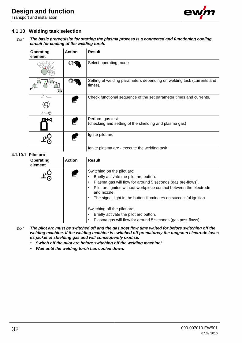
4.1.10 Welding task selection
The basic prerequisite for starting the plasma process is a connected and functioning cooling circuit for cooling of the welding torch.
Operating element
Action Result
Select operating mode
Setting of welding parameters depending on welding task (currents and times).
Check functional sequence of the set parameter times and currents.
Perform gas test (checking and setting of the shielding and plasma gas)
Ignite pilot arc
Ignite plasma arc - execute the welding task
4.1.10.1 Pilot arc
Operating element
Action Result
Switching on the pilot arc:
• Briefly activate the pilot arc button.
• Plasma gas will flow for around 5 seconds (gas pre-flows).
• Pilot arc ignites without workpiece contact between the electrode and nozzle.
• The signal light in the button illuminates on successful ignition.
Switching off the pilot arc:
• Briefly activate the pilot arc button.
• Plasma gas will flow for around 5 seconds (gas post-flows).
The pilot arc must be switched off and the gas post flow time waited for before switching off the welding machine. If the welding machine is switched off prematurely the tungsten electrode loses its jacket of shielding gas and will consequently oxidise.
• Switch off the pilot arc before switching off the welding machine!
• Wait until the welding torch has cooled down.

Design and function Remote control
099-007010-EW501
07.09.2016 33
4.2 Remote control The remote controls are operated on the 14-pole remote control connection socket.
4.2.1 FR21 14POL
Functions
• Foot-operated remote control, current
• Infinitely adjustable welding current (0% to 100%) depending on the main current preselected at the welding machine
• Setting of operating point directly at the welding location.

Design and function Interfaces for automation
34 099-007010-EW501
07.09.2016
4.3 Interfaces for automation 4.3.1 Remote control connection socket, 14-pole
Unsuitable control cables or incorrect input/output signal assignment can cause damage to the machine. Use shielded control cables only.
Figure 4-15
Item Description
X3/1 PE
X3/2 NC (not assigned)
X3/3 0 V
X3/4 Current relay, current flowing signal (I>0)
X3/5 Current relay, current flowing signal (I>0)
X3/6 –15 V (output max. 25 mA)
X3/7 +15 V (output max. 75 mA)
X3/8 Pulser (I2)
X3/9 ISIN (nominal value input)
X3/10 TSPOT spot time
X3/11 FBT (start/stop torch trigger)
X3/12 ISUM ( = 0 V, remote control connected)
X3/13 SPOTON (spot welding)
X3/14 ISAUS (output +10 V, max. 10 mA)
A Start/stop torch trigger
B Remote control detection bridge
C Potentiometer 10–100 k
0 V = IMIN
10 V = IMAX

Maintenance, care and disposal General
099-007010-EW501
07.09.2016 35
5 Maintenance, care and disposal
DANGER
Incorrect maintenance and testing!
The machine may be cleaned, repaired and tested by skilled and qualified personnel only. A qualified person is one who, due to their training, knowledge and experience, can detect any hazards and possible consequential damage when checking the machine, and can take the necessary safety measures.
• Observe the maintenance instructions > see 5.2 chapter!
• The machine may only be put into operation again once the testing has been successful.
Risk of injury due to electrical voltage after switching off!
Working on an open machine can lead to fatal injuries!
Capacitors are loaded with electrical voltage during operation. Voltage remains present for up to four minutes after the mains plug is removed.
1. Switch off machine.
2. Remove the mains plug.
3. Wait for at last 4 minutes until the capacitors have discharged!
Repair and maintenance work may only be performed by qualified authorised personnel; otherwise the right to claim under warranty is void. In all service matters, always consult the dealer who supplied the machine. Return deliveries of defective equipment subject to warranty may only be made through your dealer. When replacing parts, use only original spare parts. When ordering spare parts, please quote the machine type, serial number and item number of the machine, as well as the type designation and item number of the spare part.
5.1 General Under the specified ambient conditions and normal working conditions this machine is essentially maintenance-free and requires just a minimum of care.
Contamination of the machine may impair service life and duty cycle. The cleaning intervals depend on the ambient conditions and the resulting contamination of the machine. The minimum interval is every six months.
5.2 Maintenance work, intervals 5.2.1 Daily maintenance tasks
• Check that all connections and wearing parts are hand-tight and tighten if necessary.
• Check that all screw and plug connections and replaceable parts are secured correctly, tighten if necessary.
• Remove any spatter.
• Clean the wire feed rollers on a regular basis (depending on the degree of soiling).
5.2.1.1 Visual inspection • Check hose package and power connections for exterior damage and replace or have repaired by
specialist staff as necessary!
• Mains supply lead and its strain relief
• Gas tubes and their switching equipment (solenoid valve)
• Other, general condition
5.2.1.2 Functional test
• Check correct mounting of the wire spool.
• Welding current cables (check that they are fitted correctly and secured)
• Gas cylinder securing elements
• Operating, message, safety and adjustment devices (Functional test)

Maintenance, care and disposal Disposing of equipment
36 099-007010-EW501
07.09.2016
5.2.2 Monthly maintenance tasks 5.2.2.1 Visual inspection
• Casing damage (front, rear and side walls)
• Wheels and their securing elements
• Transport elements (strap, lifting lugs, handle)
• Check coolant tubes and their connections for impurities
5.2.2.2 Functional test
• Selector switches, command devices, emergency stop devices, voltage reducing devices, message and control lamps
• Check that the wire guide elements (inlet nipple, wire guide tube) are fitted securely.
5.2.3 Annual test (inspection and testing during operation)
The welding machine may only be tested by competent, capable personsl. A capable person is one who, because of his training, knowledge and experience, is able to recognise the dangers that can occur while testing welding power sources as well as possible subsequent damage and who is able to implement the required safety procedures.
For more information refer to the "Warranty registration" brochure supplied and our information regarding warranty, maintenance and testing at www.ewm-group.com!
A periodic test according to IEC 60974-4 "Periodic inspection and test" has to be carried out. In addition to the regulations on testing given here, the relevant local laws and regulations must also be observed.
5.3 Disposing of equipment
Proper disposal!
The machine contains valuable raw materials, which should be recycled, and electronic components, which must be disposed of.
• Do not dispose of in household waste!
• Observe the local regulations regarding disposal!
5.3.1 Manufacturer's declaration to the end user • According to European provisions (guideline 2012/19/EU of the European Parliament and the Council
of Juli, 4th 2021), used electric and electronic equipment may no longer be placed in unsorted municipal waste. It must be collected separately. The symbol depicting a waste container on wheels indicates that the equipment must be collected separately. This machine is to be placed for disposal or recycling in the waste separation systems provided for this purpose.
• According to German law (law governing the distribution, taking back and environmentally correct disposal of electric and electronic equipment (ElektroG) from 16.03.2005), used machines are to be placed in a collection system separate from unsorted municipal waste. The public waste management utilities (communities) have created collection points at which used equipment from private households can be disposed of free of charge.
• Information about giving back used equipment or about collections can be obtained from the respective municipal administration office.
• EWM participates in an approved waste disposal and recycling system and is registered in the Used Electrical Equipment Register (EAR) under number WEEE DE 57686922.
• In addition to this, returns are also possible throughout Europe via EWM sales partners.
5.4 Meeting the requirements of RoHS We, EWM AG in Mündersbach, Germany, hereby confirm that all products which we supply to you and that are subject to the RoHS directive comply with RoHS requirements (also see applicable EC directives on the Declaration of Conformity on your machine).

Rectifying faults Checklist for rectifying faults
099-007010-EW501
07.09.2016 37
6 Rectifying faults All products are subject to rigorous production checks and final checks. If, despite this, something fails to work at any time, please check the product using the following flowchart. If none of the fault rectification procedures described leads to the correct functioning of the product, please inform your authorised dealer.
6.1 Checklist for rectifying faults
Legend Symbol Description
Fault/Cause
Remedy
The correct machine equipment for the material and process gas in use is a fundamental requirement for perfect operation!
No arc ignition
Incorrect ignition type setting.
Ignition type: Select “HF start”. Depending on the machine, the setting is defined by the changeover switch for ignition types or the parameter in one of the machine menus (see the “Control operating instructions”, if applicable).
Excess temperature signal light / Welding torch cooling failure is on
Welding torch cooling failure
Check correct connection of the welding torch cooling unit
Check operational readiness of the welding torch cooling unit
Eliminate kinks in conduit system (hose packages)
Check coolant level and refill if necessary
Excess temperature, welding machine
Allow the machine to cool down whilst still switched on
Welding torch overheated
Loose welding current connections
Tighten power connections on the torch and/or on the workpiece
Tighten contact tip correctly
Overload
Check and correct welding current setting
Use a more powerful welding torch
Unstable arc
Material inclusions in the tungsten electrode due to contact with filler material or workpiece
Regrind or replace the tungsten electrode
Incompatible parameter settings
Check settings and correct if necessary
Pore formation
Inadequate or missing gas shielding
Check shielding gas setting and replace shielding gas cylinder if necessary
Shield welding site with protective screens (draughts affect the welding result)
Use gas lens for aluminium applications and high-alloy steels
Unsuitable or worn welding torch equipment
Check size of gas nozzle and replace if necessary
Condensation (hydrogen) in the gas tube
Purge hose package with gas or replace

Technical data microplasma 20-120
38 099-007010-EW501
07.09.2016
7 Technical data
Performance specifications and guarantee only in connection with original spare and replacement parts!
7.1 microplasma 20-120 Machine type microplasma 20 microplasma 50 microplasma 120
Setting range for welding current 0.1 A to 20 A 0.1 A to 50 A 0.5 A to 120 A
Setting range for welding voltage 25.0 V to 25.8 V 25.0 V to 27 V 25.0 V to 29.8 V
Pilot arc current 5 A
Duty cycle 40 °C 20 A (100% DC) 50 A (100% DC) 120 A (35% DC) 70 A (100% DC)
Load cycle 10 min. (60% DC 6 min. welding, 4 min. pause)
Open circuit voltage 95 V
Mains voltage (tolerances) 1 x 230 V (–40% to +15%)
Frequency 50/60 Hz
Mains fuse (safety fuse, slow-blow)
1 x 10 A 1 x 16 A
Mains connection lead H07RN-F3G2,5
Maximum connected load 0.9 kVA 2.0 kVA 5.2 kVA
Recommended generator rating 1.2 kVA 2.7 kVA 7.0 kVA
cos/efficiency 0.99/86%
Ambient temperature –25 °C to +40 °C *
Machine cooling Fan (AF)
Torch cooling (external cooling unit)
Coolant
Workpiece lead (minimum) 25 mm2 50 mm
2
Insulation class/protection classification
H/IP 23
EMC class A
Safety identification / /
Harmonised standards used IEC 60974-1, -3, -10
Dimensions L/W/H 520 x 550 x 480 mm
Weight 50 kg
*Ambient temperature depends on coolant! Observe the coolant temperature range for the welding torch cooling!

Accessories Welding torch cooling system
099-007010-EW501
07.09.2016 39
8 Accessories
Performance-dependent accessories like torches, workpiece leads, electrode holders or intermediate hose packages are available from your authorised dealer.
8.1 Welding torch cooling system Type Designation Item no.
UK 500 Air cooling unit 090-008026-00504
RK1 Reverse cooling unit 094-002283-00000
UKV4SET 4M Hose connection set 092-000587-00000
8.2 General accessories Type Designation Item no.
Tigex Ar/Mix 200 bar 5l/min Pressure regulator with flow meter 094-001812-00001
Tigex N/H2 T 200bar 20l G3/8"L
Pressure regulator with flow meter 094-001813-00001
Maxex AR/MIX 200bar 30m³ G1/4"
Pressure regulator 096-000000-00000
Maxex Hydrogen 200bar 30m³ G3/8"L
Pressure regulator 096-000001-00000
2M-G1/4"+G3/8"/DIN EN 559 Gas tube, 2 m 092-000525-00001
GH 2X1/4'' 2M Gas hose 094-000010-00001
ADAP3 G1/4-G1/4 LKS Threaded adapter 094-001652-00000
8.3 Remote controls and accessories Type Designation Item no.
FR21 14POL 5M Foot-operated remote control, current 094-000051-00000
FRP10 14POL 5m Spot welding/pulsing remote control 090-008002-00000
FRP10 14POL 10m Spot welding/pulsing remote control 090-008002-00010
FRP15 14POL 5m Pulsing remote control 090-008045-00000
FRP15 14POL 10m Pulsing remote control 090-008045-00010

Appendix A Overview of EWM branches
40 099-007010-EW501
07.09.2016
9 Appendix A 9.1 Overview of EWM branches
Related Documents