Abstract Miniaturizing all dimensions of apparatus, such as electronics and computers, is the current trend followed by scientists in various fields. The idea of Lab-on-a-Chip has significantly expanded and found its broad applications in analytical chemistry. Microplasmas can act as a sample excitation source and are the miniaturized versions of full-sized plasmas. These can be created in various forms, such as direct current, microwave induced, capacitively coupled and inductively coupled plasmas. Scaling down the size would reduce the amount of gases, liquids and consumables required, as well as the sample analysis time, which in turn would decrease the operating costs. Therefore, several research groups are involved in the development of microplasmas for utilisation in analytical instruments. Keywords Microplasma Discharge Miniaturization Plasma detector Introduction Miniaturization finds a continous integration into the application field of analytical spectrometry. Sample preparation, injection and manipulation are already reduced in dimensions. A great importance should be emphasised in assembly of small devices that are portable, use less analyte and produce as close as possible, the same results obtained as with commercially available classical devices. This idea is called ‘Micro Total Analysis System’ [1]. Part of this effort is also endeavoured to development of microplasmas. The plasmas are sometimes irreplaceable detectors of molecular fragments or elements. The miniaturisation of plasmas brings the advantage of atmospheric pressure operation. With a few exceptions, most of them operate at atmospheric pressure. Due to the confinement in small volumes, they have significantly higher gas tem- perature compared to the non-thermal low pressure plasmas. M. Miclea J. Franzke (&) ISAS-Institute for Analytical Science, Bunsen-Kirchhoff Str.11, 44139 Dortmund, Germany e-mail: [email protected] 123 Plasma Chem Plasma Process (2007) 27:205–224 DOI 10.1007/s11090-007-9056-4 REVIEW PAPER Analytical Detectors Based on Microplasma Spectrometry Manuela Miclea Joachim Franzke Received: 17 January 2007 / Accepted: 6 March 2007 / Published online: 13 March 2007 Ó Springer Science+Business Media, LLC 2007

Welcome message from author
This document is posted to help you gain knowledge. Please leave a comment to let me know what you think about it! Share it to your friends and learn new things together.
Transcript
Abstract Miniaturizing all dimensions of apparatus, such as electronics andcomputers, is the current trend followed by scientists in various fields. The idea ofLab-on-a-Chip has significantly expanded and found its broad applications inanalytical chemistry. Microplasmas can act as a sample excitation source and are theminiaturized versions of full-sized plasmas. These can be created in various forms,such as direct current, microwave induced, capacitively coupled and inductivelycoupled plasmas. Scaling down the size would reduce the amount of gases, liquidsand consumables required, as well as the sample analysis time, which in turn woulddecrease the operating costs. Therefore, several research groups are involved in thedevelopment of microplasmas for utilisation in analytical instruments.
Keywords Microplasma Æ Discharge Æ Miniaturization Æ Plasma detector
Introduction
Miniaturization finds a continous integration into the application field of analyticalspectrometry. Sample preparation, injection and manipulation are already reducedin dimensions. A great importance should be emphasised in assembly of smalldevices that are portable, use less analyte and produce as close as possible, the sameresults obtained as with commercially available classical devices. This idea is called‘Micro Total Analysis System’ [1].
Part of this effort is also endeavoured to development of microplasmas. Theplasmas are sometimes irreplaceable detectors of molecular fragments or elements.The miniaturisation of plasmas brings the advantage of atmospheric pressureoperation. With a few exceptions, most of them operate at atmospheric pressure.Due to the confinement in small volumes, they have significantly higher gas tem-perature compared to the non-thermal low pressure plasmas.
M. Miclea Æ J. Franzke (&)ISAS-Institute for Analytical Science, Bunsen-Kirchhoff Str.11, 44139 Dortmund, Germanye-mail: [email protected]
123
Plasma Chem Plasma Process (2007) 27:205–224DOI 10.1007/s11090-007-9056-4
REVIEW PAPER
Analytical Detectors Based on MicroplasmaSpectrometry
Manuela Miclea Æ Joachim Franzke
Received: 17 January 2007 / Accepted: 6 March 2007 / Published online: 13 March 2007� Springer Science+Business Media, LLC 2007
The miniaturization of plasmas is based on the Paschen law, which means that theproduct pressure times distance between electrodes is kept constant. By reducing thedimensions, the pressure has to increase. In order to ignite a plasma at atmosphericpressure, the distance between electrodes should be in the lm range. The extent ofthe implications of atmospheric pressure operation goes further than just reducingthe dimensions. At low pressure, the heavy particles temperature is much lower thanthe electron temperature and the collisions between electrons and heavy particleslead mostly to excitation and ionization. In this way, the temperature of heavyparticles cannot rise too much. By increasing the pressure, the mean free path of theelectrons and heavy particles is decreased, hence the frequency of collisions isincreased. This leads to more frequently inelastic collisions between electrons andheavy particles, inducing an efficient energy exchange between the plasma species.This induces higher plasma chemistry. The elastic collisions grow at higher pressures,leading to an increase in the heavy particles temperature. The plasma state is closerto the local thermal equilibrium but without reaching it. The density of excitedspecies, especially metastable states, also increases with the pressure. Some otherfavourite processes appear, for example, the three body collisions leading to theformation of dimer molecules. These molecules emit UV radiation which signifi-cantly contributes also to the plasma chemistry.
The purpose of this review is to aid the reader to get an overview of plasmaminiaturization in analytical spectrometry with the advantages and sometimes theproblems encountered upon this development.
Some miniaturized plasmas will be described and their significant analyticalperformances will be presented. It is impossible to cover all microplasmas developedin the last years; They can be obtained from the last reviews and references herein[2–5]. In this review only those microplasmas who have analytical results will bepresented and mainly the use of microplasmas as optical emission detectors or asexcitation and ionization source for gas chromatography and mass spectrometry willbe mentioned.
Analytical Plasma Detectors
Three types of plasmas namely the glow discharge (GD), the microwave inducedplasma (MIP) and the inductively coupled plasma (ICP) are the commonly usedplasma sources in analytical spectrometry [6]. They are used as analytical detectorsfor solid, liquid and gaseous samples. For example, the GD is used for the analysis ofsolid samples due to the presence of heavy ions colliding with the cathode, which isnormally the sample to be analyzed. Liquid samples are analyzed with the ICP dueto the high gas temperatures, up to 6000 K present in this type of plasma. Thisparameter enables the evaporation and dissociation of any kind of samples and itis also robust enough not to be greatly influenced by the presence of water. The ICPis normally coupled either with mass or optical emission spectrometry. The MIP ismostly used for the detection of gaseous or volatile substances. In comparison withthe ICP, it is not so hot but its properties are appropriate for the excitation of non-metals. It is already commercially implemented as detector for gas chromatography.It operates also at atmospheric pressure and when coupled with optical emissionspectrometry, it delivers detection limits in the range of pg/s for non-metals.
206 Plasma Chem Plasma Process (2007) 27:205–224
123
These classical plasma sources were miniaturized and the implementation in theanalytics is possible. Various kinds of miniaturized plasmas were developed, startingwith dc plasmas, low and high frequency plasmas. Most of them are the ‘small’version of the classical ones, some others are created from the scretch. In thefollowing, some significant microplasma sources will be briefly described and theirmost important analytical results will be presented. They can be classified in manyways, either by their function as excitation or ionization source (optical emission ormass spectrometry detectors) or by their operation conditions. A classification upontheir frequency operation will be made in this paper.
Microplasmas for the Analysis of Gaseous Samples
Direct Current Plasmas
Glow Discharge on a Chip
The first molecular emission detector on a glass chip, employing a miniaturizeddirect current helium plasma was reported by Eijkel et al. [7] The channels and theplasma chamber were produced by HF-etching. The electrodes were made of 50 nmchromium and 250 nm of gold. The plasma was generated in chambers of differentgeometrical dimensions at a pressure of about 100 hPa. A chamber with a volume of50 nl at a typical operating pressure of 170 hPa was used as an excitation source.Methane could be detected with a detection limit of 3 · 10–12 g/s (600 ppm v/v), byobserving the molecular emission of the CH radical. The lifetime of the device waslimited to 2 h due to cathode sputtering.
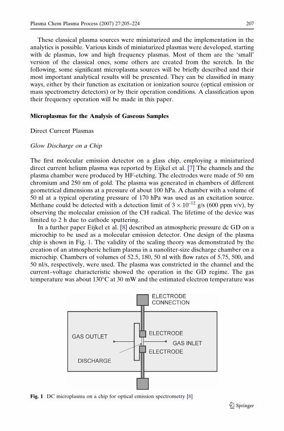
In a further paper Eijkel et al. [8] described an atmospheric pressure dc GD on amicrochip to be used as a molecular emission detector. One design of the plasmachip is shown in Fig. 1. The validity of the scaling theory was demonstrated by thecreation of an atmospheric helium plasma in a nanoliter-size discharge chamber on amicrochip. Chambers of volumes of 52.5, 180, 50 nl with flow rates of 5.75, 500, and50 nl/s, respectively, were used. The plasma was constricted in the channel and thecurrent–voltage characteristic showed the operation in the GD regime. The gastemperature was about 130�C at 30 mW and the estimated electron temperature was
Fig. 1 DC microplasma on a chip for optical emission spectrometry [8]
Plasma Chem Plasma Process (2007) 27:205–224 207
123
about 2.2 eV. In this device, the dissociation and excitation of the analyte speciesoccur by collisions with electrons and excited helium atoms. The detection ofmethane in the helium gas flow by measuring molecular bands of CH was tested. Thelimits of detection were 7 ppm, 3 ppm and 400 ppb, which correspond to 10–14, 10–12,10–13 g/s, respectively. In the case of low flow rates, the analytical signal was linearover two decades. It was shown that the microchip plasma could be successfullyapplied for molecular emission detection. It was also tested with some other organiccompunds like propionic acid, triethylamine, benzylamine. The authors are claimingthat the simple instrumentation, the small detector size and the good sensitivitymake the device highly suitable for integration in microanalysis systems.
In the following paper, the same group coupled the plasma chip described aboveto a conventional gas chromatograph, in order to investigate its performance as anoptical emission detector [9]. Although the lowest detection limit of 10–14 g/s wasobtained earlier when the plasma volume was 52.5 nl and the flow rate of 5.75 nl/s, a180 nl volume plasma with a higher flow rate of 320 nl/s was applied for the benefitof preventing broadening and tailing of the chromatographic peaks. The plasma wasgenerated in helium and the applied power was 9 mW (770 V, 12 lA). A number ofcarbon-compounds were detected in the column effluent, recording the CO-emissionat 519 nm. For hexane, the detector showed a linear dynamic range over two dec-ades and a detection limit of 10–12 g/s (800 ppb). However, all components of thechromatogram showed considerable broadening and tailing. The authors proved thatthese effects were not related to the performance of the plasma but to dead volumesin the connection tubes and the channels of the glass chip. It can be expected that theintegration of the chromatographic column and the plasma detector on a single chipreduces the dead volumes and improves the signals. The device was operated formore than 24 h without a significant change in performance. The operation is stableand instrumental requirements are simple.
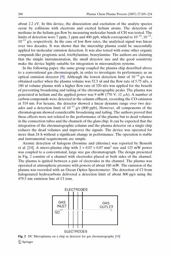
Atomic detection of halogens (bromine and chlorine) was reported by Bessothet al. [10]. A micro-plasma chip with 2 · 0.07 · 0.07 mm3 size and 125 mW powerwas coupled to a conventional, large size gas chromatograph. The design presentedin Fig. 2 consists of a channel with electrodes placed at both sides of the channel.The plasma is ignited between a pair of electrodes in the channel. The plasma wasoperated at atmospheric pressure with powers of about 160 mW. The emission of theplasma was recorded with an Ocean Optics Spectrometer. The detection of Cl fromhalogenated hydrocarbons delivered a detection limit of about 800 pg/s using the479.5 nm emission line of Cl ions.
Fig. 2 DC Microplasma on a chip as detector for gas chromatography [10]
208 Plasma Chem Plasma Process (2007) 27:205–224
123
Another direct-current, chip-based plasma has been used for gas sample injectionin gas chromatography [11]. A second identical plasma chip has been used as theexcitation source for an optical emission detector. The first plasma is normallycontinually sustained during operation, causing continuous ionisation/fragmentationof the sample, whilst the second plasma records the optical emission downstream.For injection, the first plasma is briefly interrupted, introducing a ‘‘plug’’ ofunmodified sample into the system. Injection plug sizes of between 5 ml and 50 mlhave been reproducibly obtained, although significantly smaller volumes may bepossible with the use of smaller cross-section columns, lower flow rates and/orshorter plasma interruption times.
Microhollow Cathode Discharge
The microhollow cathode discharge (MHCD), also called microstructured electrodedischarge (MSE) is a multilayer system consisting of two metallic foils of Cu, Ni, Ptor W separated by an insulator (e.g., Kapton, mica or ceramic). The thickness of thelayers is typically 30–150 lm. A bore with a diameter of 10–500 lm is drilled throughthe structure [12]. A weakly ionized plasma is produced in the hole between theelectrodes in noble gases, gas mixtures or air using ac or dc current voltage. A veryhigh current density is generated in the discharge due to the fact that the electronsare captured in the negative glow of the discharge inside the hollow cathode.
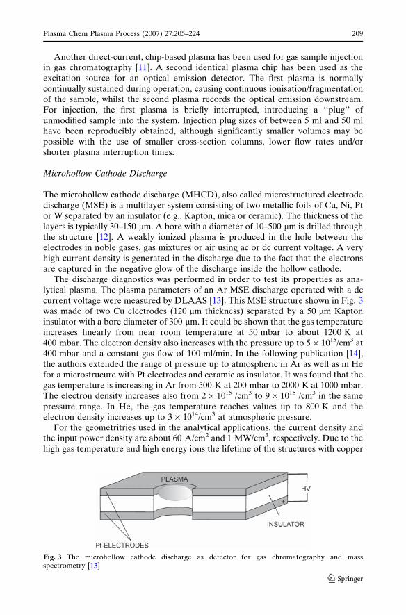
The discharge diagnostics was performed in order to test its properties as ana-lytical plasma. The plasma parameters of an Ar MSE discharge operated with a dccurrent voltage were measured by DLAAS [13]. This MSE structure shown in Fig. 3was made of two Cu electrodes (120 lm thickness) separated by a 50 lm Kaptoninsulator with a bore diameter of 300 lm. It could be shown that the gas temperatureincreases linearly from near room temperature at 50 mbar to about 1200 K at400 mbar. The electron density also increases with the pressure up to 5 · 1015/cm3 at400 mbar and a constant gas flow of 100 ml/min. In the following publication [14],the authors extended the range of pressure up to atmospheric in Ar as well as in Hefor a microstrucure with Pt electrodes and ceramic as insulator. It was found that thegas temperature is increasing in Ar from 500 K at 200 mbar to 2000 K at 1000 mbar.The electron density increases also from 2 · 1015 /cm3 to 9 · 1015 /cm3 in the samepressure range. In He, the gas temperature reaches values up to 800 K and theelectron density increases up to 3 · 1014/cm3 at atmospheric pressure.
For the geometritries used in the analytical applications, the current density andthe input power density are about 60 A/cm2 and 1 MW/cm3, respectively. Due to thehigh gas temperature and high energy ions the lifetime of the structures with copper
Fig. 3 The microhollow cathode discharge as detector for gas chromatography and massspectrometry [13]
Plasma Chem Plasma Process (2007) 27:205–224 209
123
was only a few days. However, the lifetime was improved by using ceramic as aninsulator and the Pt or other metal electrodes with low sputtering rates.
Atomic emission spectrometry of the MSE discharge was applied for the detec-tion of chlorine and fluorine resulting from the decomposition of the halogenatedmolecules (CCl2F2, CHClF2) introduced into the He plasma gas [15]. The detectionlimits for CCl2F2 are 20 ppb v/v using either Cl 912.114 nm or the F 739.868 nm.
Besides using the MHCD for emission spectrometry it was also investigated as apromising miniaturized ionization source for mass spectrometry [16]. The plasmaproduced in the bore of the structure was expanded in a low pressure region pro-ducing a supersonic plasma jet. The plasma jet reached the skimmer of the interfaceand the ions were selected and accelerated towards the quadrupole detector.Different sample introduction systems were used like gas mixtures, coupling to gaschromatography or permeation bottles. The MHCD—mass spectrometry deliversdetection limits in the pg/s range (corresponding to a few ppbv/v) for halogenatedmolecules in gaseous or volatile samples.
Low and High Frequency Microplasmas
AC Plasma at 20 kHz
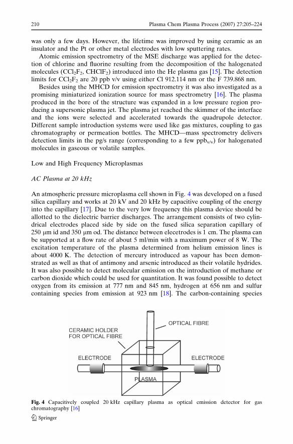
An atmospheric pressure microplasma cell shown in Fig. 4 was developed on a fusedsilica capillary and works at 20 kV and 20 kHz by capacitive coupling of the energyinto the capillary [17]. Due to the very low frequency this plasma device should beallotted to the dielectric barrier discharges. The arrangement consists of two cylin-drical electrodes placed side by side on the fused silica separation capillary of250 lm id and 350 lm od. The distance between elecetrodes is 1 cm. The plasma canbe supported at a flow rate of about 5 ml/min with a maximum power of 8 W. Theexcitation temperature of the plasma determined from helium emission lines isabout 4000 K. The detection of mercury introduced as vapour has been demon-strated as well as that of antimony and arsenic introduced as their volatile hydrides.It was also possible to detect molecular emission on the introduction of methane orcarbon dioxide which could be used for quantitation. It was found possible to detectoxygen from its emission at 777 nm and 845 nm, hydrogen at 656 nm and sulfurcontaining species from emission at 923 nm [18]. The carbon-containing species
Fig. 4 Capacitively coupled 20 kHz capillary plasma as optical emission detector for gaschromatography [16]
210 Plasma Chem Plasma Process (2007) 27:205–224
123
CH4, CO, and CO2 could be determined from an emission band at 385 nm due toCN. Detection limits in the range between about 1 and 10 ng were obtained using aminiature diode array spectrometer.
The microplasma was also implemented as an on-column optical emissiondetector [19]. The capillary column was paced directly in front of the plasma. Thedetection of volatile organic compounds was possible via the emission from atomiccarbon at 247.9 nm and from CN at 385.2 nm. Benzene was determined with adetection limit of approximately 80 pg of carbon.
The detection of Br, Cl, F, I, P, Se and S in organic compounds separated in ahelium carrier was possible by monitoring emission lines at 827.24, 837.59, 685.60,804.37, 956.40, 888.50 and 921.28 nm for the 7 elements, respectively [20]. The sys-tem showed the following detection limits: Br 0.3, Cl 0.1, F 20, I 158, P 1805, Se 153and S 6.6 pg s–1. The determination of environmentally relevant halogenated vola-tile organic compounds and pesticides was demonstrated.
Radio Frequency Plasma at 350 kHz
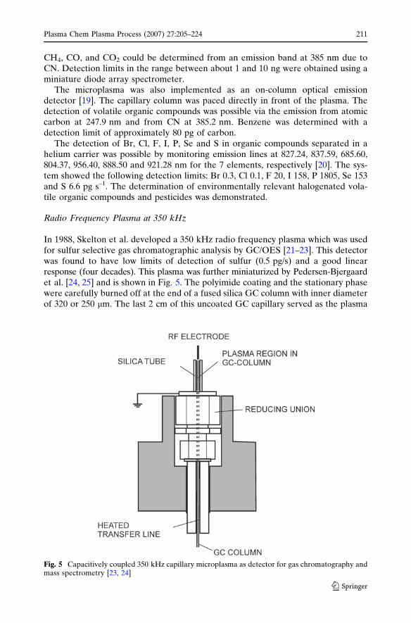
In 1988, Skelton et al. developed a 350 kHz radio frequency plasma which was usedfor sulfur selective gas chromatographic analysis by GC/OES [21–23]. This detectorwas found to have low limits of detection of sulfur (0.5 pg/s) and a good linearresponse (four decades). This plasma was further miniaturized by Pedersen-Bjergaardet al. [24, 25] and is shown in Fig. 5. The polyimide coating and the stationary phasewere carefully burned off at the end of a fused silica GC column with inner diameterof 320 or 250 lm. The last 2 cm of this uncoated GC capillary served as the plasma
Fig. 5 Capacitively coupled 350 kHz capillary microplasma as detector for gas chromatography andmass spectrometry [23, 24]
Plasma Chem Plasma Process (2007) 27:205–224 211
123
tube placed inside a piece of silica tube for protection. One electrode consists of asteel wire placed at the output of the column, while the ground electrode electrode isthe holder of the column. The plasma with a length of 3.5–4 cm was generated inside,at the end of the fused silica GC column between the top electrode and the groundedreducing union by a radio frequency power supply. It was possible to sustain theplasma only with small gas flow rates between 1.5 ml and 5 ml/min. The optimumpower coupled into the discharge was 25 W. Above this value, the plasma becameunstable and above 40 W the capillary was destroyed. Atomic emission was measuredside on through the wall of the fused silica column and the protecting silica tube. Thedetection limits for halogens and S were between 0.9 pg/s and 13 pg/s.
A further paper reports on the application of this plasma device for mass spec-trometric detection in capillary gas chromatography [26]. The plasma was sustainedat low pressure in the capillary GC column, which was put inside of the ion sourcehousing of a quadrupole mass spectrometer. This allowed direct introduction of ionsfrom the plasma into the mass analyzer, using only a repeller and electrostatic lensesto focus the ions. The plasma was sustained only with 25 ml/min of helium, whichwas accepted by the mass spectrometer vacuum system. This low gas flow also servedto enhance the energy density of the discharge and to produce a narrow spray of ionstoward the mass analyzer. Due to the miniaturized nature of the plasma, it wasoperated at a low power level (2.0 W), and traces of oxygen were added to avoiddeposition of carbon on the capillary wall. Chlorine was successfully monitoreddown to the 2.2 pg/s level without interference from elements such as C, S, P, O, F,and N. Up to now, the detection limits obtained at the detection of halogenatedmolecules are the lowest reported with a microplasma and they are comparable andsometimes better than that of a classical plasma GC detector employing a MIP.
Capacitively Coupled Microplasmas 13.56 MHz
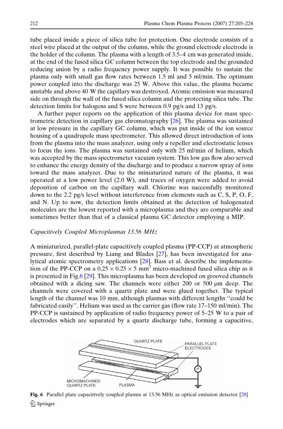
A miniaturized, parallel-plate capacitively coupled plasma (PP-CCP) at atmosphericpressure, first described by Liang and Blades [27], has been investigated for ana-lytical atomic spectrometry applications [28]. Bass et al. describe the implementa-tion of the PP-CCP on a 0.25 · 0.25 · 5 mm3 micro-machined fused silica chip as itis presented in Fig.6 [29]. This microplasma has been developed on grooved channelsobtained with a dicing saw. The channels were either 200 or 500 lm deep. Thechannels were covered with a quartz plate and were glued together. The typicallength of the channel was 10 mm, although plasmas with different lengths ‘‘could befabricated easily’’. Helium was used as the carrier gas (flow rate 17–150 ml/min). ThePP-CCP is sustained by application of radio frequency power of 5–25 W to a pair ofelectrodes which are separated by a quartz discharge tube, forming a capacitive,
Fig. 6 Parallel plate capacitively coupled plasma at 13.56 MHz as optical emission detector [28]
212 Plasma Chem Plasma Process (2007) 27:205–224
123
transverse discharge. The plasma is normally operated at 13.56, 27.12 or 40.68 MHzusing He as a plasma gas. Water-cooling was required. Background spectra werecollected using an Ocean Optics micro-spectrometer. The emission lines of OH, NH,N2, N2
+ and He were measured applying 20 W He plasma and a gas flow of 70 ml/min. Although the PP-CCP has been investigated for application in analytical atomicspectrometry, no element selective measurements were done by Bass et al. so farwith the miniaturized version.
Yoshiki and coworkers developed a self-igniting, parallel-plate, atmosphericpressure micro-CCP [30–32]. Although different fabrication methods were used, theabove described plasma is quite similar to that of Blades. Helium CCPs (flow rate upto about 750 ml/min) were formed in quartz channels (typically 5 mm long) withdepths varying between 65 lm and 500 lm and widths varying between 500 lm and5 mm. For maximum power transfer, a miniaturized (150 · 100 · 40 mm3) matchingnetwork was designed and utilized. Copper electrodes were placed on each side ofthe channels to bring power to the CCP (1–5 W, 13.56 MHz). Windows were cut onthe top electrode so that optical emission could be monitored using a fiber opticspectrometer. Helium background spectra of this self-igniting plasma and relativelylow excitation temperatures (between 1850 K and 2300 K using He lines) werereported at atmospheric and sub-atmospheric pressure operation. A cooling of thechip was reported to be necessary at power levels above 10 W (although typicalpower levels were between 1 W and 3 W). In addition, a CCP was also used toimprove (by plasma treatment) the surface of the inner wall of polymeric capillariesfor use in capillary electrophoresis applications [31].
Capacitively Coupled Microplasmas, 27.12 MHz and 40.68 MHz
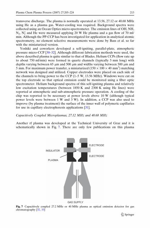
Another rf plasma was developed at the Technical University of Graz and it isschematically shown in Fig. 7. There are only few publications on this plasma
Fig. 7 Capacitively coupled 27.2 MHz or 40 MHz plasma as optical emission detector for gaschromatography [32, 33]
Plasma Chem Plasma Process (2007) 27:205–224 213
123
technique despite its promising results. Some patents [33, 34] and a PhD thesis [35]report about the implementation of this microplasma as an emission detector forGC. The capacitively coupled plasma consists of two disc shaped electrodes made ofgold deposited on tungsten. These two electrodes are separated by an insulator discmade of ruby, sapphire or ceramic. All three discs have a hole. The plasma isconfined in the hole of the ceramic piece which has a diameter between 110 lm and150 lm. The thickness of the ceramic is about 150 lm. The three discs are pressedtogether in order to ensure that helium plasma gas is flowing only through the hole.The plasma is operated at 27.5 MHz but some other frequencies can also be used.The gas flow through the plasma is smaller than 35 ml/min with an addition of up to40 ll/min of oxygen. The power coupled into the discharge is between 10 W and15 W. The overheating is eliminated by cooling the electrodes with 25 ml/min ofoxygen gas flow. The plasma was developed as multielement detector for gaschromatography. The GC column is placed directly in front of the lower disc elec-trode. The analytical results with this microplasma show the detection of chlorinatedcompounds with a detection limit for Cl of 8.5 pg (corresponding to 3.5 pg/s) [36].The detection limits for some other halogens like F, Br and also S are presented inthe pg range.
Inductively Coupled Plasmas, 13.56–900 MHz
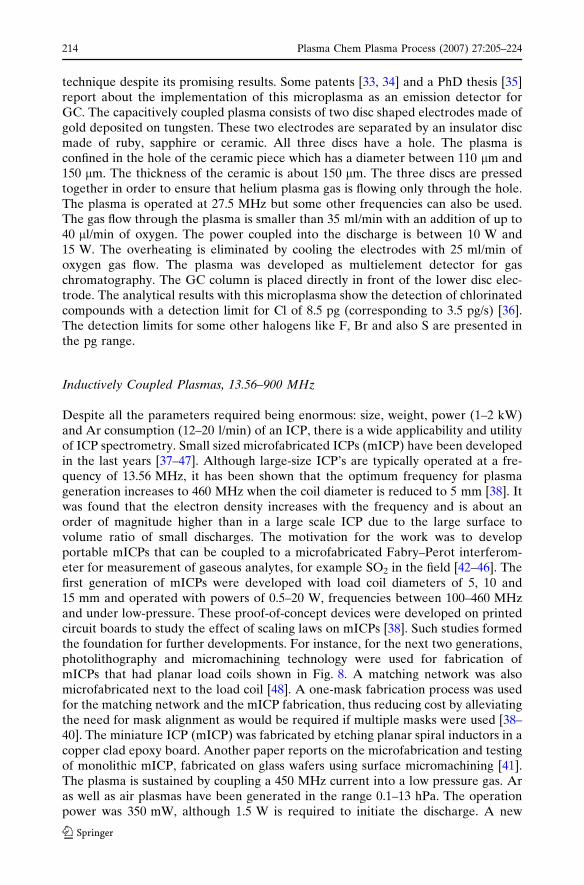
Despite all the parameters required being enormous: size, weight, power (1–2 kW)and Ar consumption (12–20 l/min) of an ICP, there is a wide applicability and utilityof ICP spectrometry. Small sized microfabricated ICPs (mICP) have been developedin the last years [37–47]. Although large-size ICP’s are typically operated at a fre-quency of 13.56 MHz, it has been shown that the optimum frequency for plasmageneration increases to 460 MHz when the coil diameter is reduced to 5 mm [38]. Itwas found that the electron density increases with the frequency and is about anorder of magnitude higher than in a large scale ICP due to the large surface tovolume ratio of small discharges. The motivation for the work was to developportable mICPs that can be coupled to a microfabricated Fabry–Perot interferom-eter for measurement of gaseous analytes, for example SO2 in the field [42–46]. Thefirst generation of mICPs were developed with load coil diameters of 5, 10 and15 mm and operated with powers of 0.5–20 W, frequencies between 100–460 MHzand under low-pressure. These proof-of-concept devices were developed on printedcircuit boards to study the effect of scaling laws on mICPs [38]. Such studies formedthe foundation for further developments. For instance, for the next two generations,photolithography and micromachining technology were used for fabrication ofmICPs that had planar load coils shown in Fig. 8. A matching network was alsomicrofabricated next to the load coil [48]. A one-mask fabrication process was usedfor the matching network and the mICP fabrication, thus reducing cost by alleviatingthe need for mask alignment as would be required if multiple masks were used [38–40]. The miniature ICP (mICP) was fabricated by etching planar spiral inductors in acopper clad epoxy board. Another paper reports on the microfabrication and testingof monolithic mICP, fabricated on glass wafers using surface micromachining [41].The plasma is sustained by coupling a 450 MHz current into a low pressure gas. Aras well as air plasmas have been generated in the range 0.1–13 hPa. The operationpower was 350 mW, although 1.5 W is required to initiate the discharge. A new
214 Plasma Chem Plasma Process (2007) 27:205–224
123
single-loop mICP source which is three times more efficient than the former one hasbeen fabricated [42]. In this case the coil was situated closer to the plasma and wasoperated with even higher frequencies up to 818 MHz. Ion densities of 1011/ cm3 inAr at 0.5 hPa were obtained with only 1 W.
First calibration curves for SO2 were measured in Ar mICP by optical emissionspectrometry of the sulfur atomic 469.5 nm line. The plasma chamber consisted of acylindrical hole of 6 mm diameter and 6 mm in length. The pressure was 7.4 hPa andthe plasma power 3.5 W. The limit of detection of SO2 was about 190 ppb v/v[43].
Microwave Induced Plasmas, 900MHz–2.45 GHz
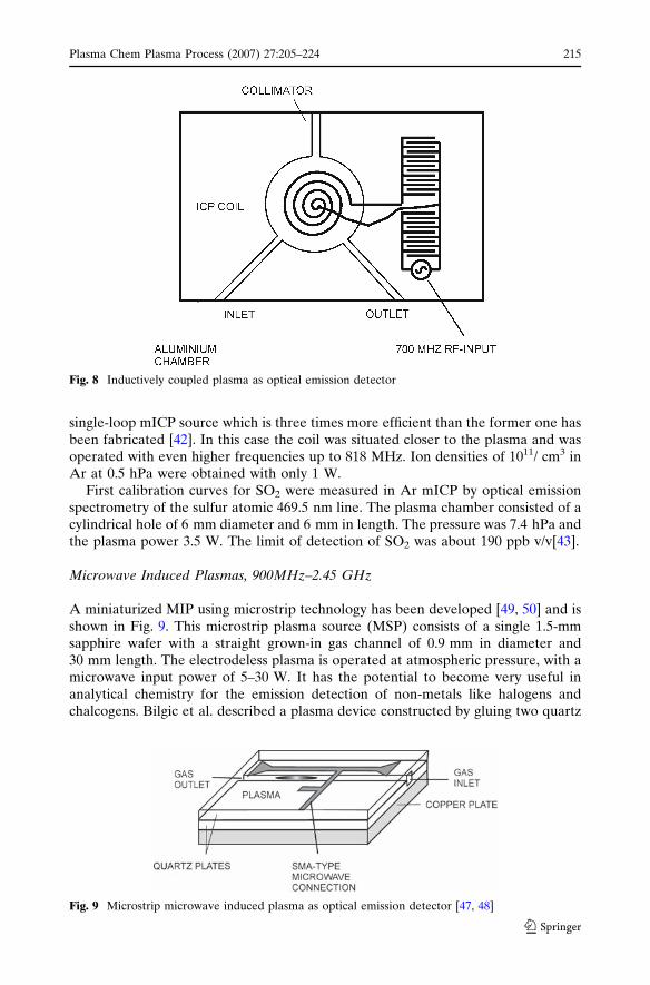
A miniaturized MIP using microstrip technology has been developed [49, 50] and isshown in Fig. 9. This microstrip plasma source (MSP) consists of a single 1.5-mmsapphire wafer with a straight grown-in gas channel of 0.9 mm in diameter and30 mm length. The electrodeless plasma is operated at atmospheric pressure, with amicrowave input power of 5–30 W. It has the potential to become very useful inanalytical chemistry for the emission detection of non-metals like halogens andchalcogens. Bilgic et al. described a plasma device constructed by gluing two quartz
Fig. 8 Inductively coupled plasma as optical emission detector
Fig. 9 Microstrip microwave induced plasma as optical emission detector [47, 48]
Plasma Chem Plasma Process (2007) 27:205–224 215
123
plates, in both of which a grove is made with the aid of a diamond saw, together withwater glass. Microstrips were used for power transmission and produced by plasmavapor deposition with a subsequent sealing by galvanic covering with copper, up to athickness of about 1 lm. The latter passes the skin depth of microwaves at a2.45 GHz frequency, namely 2 lm. The underlying copper block has a thickness ofup to 1 cm and acts both as a ground electrode and a cooling medium. The micro-strip has a sidearm acting as an artificial load. Its length is selected so that fluctua-tions in the plasma load, e.g., when igniting or changing the sample flows into theplasma, have a lowest possible influence on the resonance conditions.
The device, of which the novel aspects are described in [51], could be operated forhours without any deterioration of the microstrips or of the channel in the quartz. Itcould be used with 0.5 l/min of argon and a power of 15 W in conjunction with themercury cold vapor technique for the determination of mercury detection limitswere observed to be 50 pg/ml and had excellent short- and long-term precision [52].For leachates of soils, accurate determinations of traces of mercury were shown to bepossible. The chip could even be made smaller by using a 30 · 30 mm2 and 1.5-mm-thick quartz plate, in which a cylindrical channel with a diameter of 0.9 mm isprovided parallel to the surface. By adjusting the length of the matching element,also with helium, a stable plasma discharge could be obtained at power of 5–30 Wand a gas flow of 50–1000 ml/min [53]. This plasma was shown to be able to breakdown halogenated hydrocarbons and in atomic emission signals for the Cl I 912.1 nmline were obtained.
The plasma configuration could also be modified so that the plasma exits from thechip, which however requires an adaptation of the matching element length. Then,the space angle in optical emission work is no longer limiting. At a power of 30 Wand with an argon flow of 0.5 l/min, mercury concentrations in argon below 10 ng/lcan easily be detected when using the Hg I 253.65 nm line [54].
A further stable microstrip microwave plasma (MSP) operated at atmosphericpressure with a power of some 10–20 W and at a gas flow of 0.2–0.8 l/min of argon isdescribed. A resonant structure was produced with the aid of microstructuringtechnology on a 5 · 5 cm2 quartz wafer provided with a 0.6-mm diameter plasmachannel. The device is shown to be useful for the excitation of atomic and molecularspecies and for the atomic emission spectrometric determination of metals and ofnonmetals in gases at the trace level, down to the ng/l-level, as shown for the case ofsulfur [55].
The development of a new, very small coaxial plasma source based on a micro-wave plasma torch (MPT) is described [56]. It generates a plasma jet up to 4 mmlong and can be operated with an argon gas flow rate less than 70 ml/min at down to2 W microwave power (2.45 GHz) at atmospheric pressure. It also works well withhelium and does not show any wear during a test period of 30 h of operation withargon. It is, in particular, thought to be a source for the atomic spectrometry ofgaseous species. The excitation temperature is found to be about 4700 K for thisdevice operating with helium and 17 W microwave power. A detection limit for anexample application in which Cl is detected from HCCl3 is found to be below66 ppb. The design considerations for the microstrip circuits are discussed and anapproximated calculation for the layout is presented. With the introduced proce-dure, it is possible to design even smaller MPTs for special applications.
The design and initial characterization of a low-power microwave plasma sourcebased on a microstrip split-ring resonator that is capable of operating at pressures
216 Plasma Chem Plasma Process (2007) 27:205–224
123
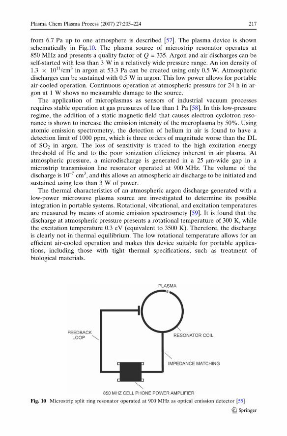
from 6.7 Pa up to one atmosphere is described [57]. The plasma device is shownschematically in Fig.10. The plasma source of microstrip resonator operates at850 MHz and presents a quality factor of Q = 335. Argon and air discharges can beself-started with less than 3 W in a relatively wide pressure range. An ion density of1.3 · 1011/cm3 in argon at 53.3 Pa can be created using only 0.5 W. Atmosphericdischarges can be sustained with 0.5 W in argon. This low power allows for portableair-cooled operation. Continuous operation at atmospheric pressure for 24 h in ar-gon at 1 W shows no measurable damage to the source.
The application of microplasmas as sensors of industrial vacuum processesrequires stable operation at gas pressures of less than 1 Pa [58]. In this low-pressureregime, the addition of a static magnetic field that causes electron cyclotron reso-nance is shown to increase the emission intensity of the microplasma by 50%. Usingatomic emission spectrometry, the detection of helium in air is found to have adetection limit of 1000 ppm, which is three orders of magnitude worse than the DLof SO2 in argon. The loss of sensitivity is traced to the high excitation energythreshold of He and to the poor ionization efficiency inherent in air plasma. Atatmospheric pressure, a microdischarge is generated in a 25 lm-wide gap in amicrostrip transmission line resonator operated at 900 MHz. The volume of thedischarge is 10–7 cm3, and this allows an atmospheric air discharge to be initiated andsustained using less than 3 W of power.
The thermal characteristics of an atmospheric argon discharge generated with alow-power microwave plasma source are investigated to determine its possibleintegration in portable systems. Rotational, vibrational, and excitation temperaturesare measured by means of atomic emission spectrosmety [59]. It is found that thedischarge at atmospheric pressure presents a rotational temperature of 300 K, whilethe excitation temperature 0.3 eV (equivalent to 3500 K). Therefore, the dischargeis clearly not in thermal equilibrium. The low rotational temperature allows for anefficient air-cooled operation and makes this device suitable for portable applica-tions, including those with tight thermal specifications, such as treatment ofbiological materials.
Fig. 10 Microstrip split ring resonator operated at 900 MHz as optical emission detector [55]
Plasma Chem Plasma Process (2007) 27:205–224 217
123
Microplasmas for Liquid Sample Analysis
All plasmas described above deliver excellent results in analysis of gaseous samples.The difficulty starts to appear when trying to analyze liquid samples for differentreasons. First of all, the introduction of liquid samples in form of aerosols is difficultbecause the dimensions of the plasmas are very small. Even if such a miniaturizeddevice would exist, its efficiency is reduced. Secondly, for miniaturized plasmas, thevolume and discharge power is such that even small amounts of liquid can easilyextinguish the discharge. The increase of the plasma power over a certain limit (20–30 W) is not possible due to the strong thermal stress by a extremely high powerdensity. However, some developments of microplasmas that are able to analyzeliquid samples were investigated and they will be presented in the following.
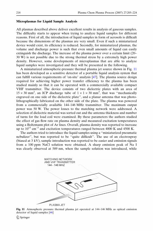
A miniaturized atmospheric-pressure thermal plasma jet source shown in Fig. 11has been developed as a sensitive detector of a portable liquid analysis system thatcan fulfill various requirements of ’on-site’ analysis [47]. The plasma source designrequired for achieving higher power transfer efficiency to the plasma has beenstudied mainly so that it can be operated with a commercially available compactVHF transmitter. The device consists of two dielectric plates with an area of15 · 30 mm2, an ICP discharge tube of 1 · 1 · 30 mm3, that was ‘‘mechanicallyengraved on one side of the dielectric plate’’, and a planar antenna that was photo-lithographically fabricated on the other side of the plate. The plasma was poweredfrom a commercially available 144–146 MHz transmitter. The maximum outputpower was 50 W. The power losses to the matching network were addressed. Aselection of dielectric material was sorted out and the antenna thickness and numberof turns for the load coil were examined. By these parameters the authors studiedthe effect of gas flow rate on plasma density and measured excitation temperaturesusing a Boltzmann plot of Ar lines. Overall, plasma density was reported to increaseup to 1015 cm–3 and excitation temperatures ranged between 4000 K and 4500 K.
The authors tried to introduce the liquid samples using a ‘‘miniaturized pneumaticnebulizer’’, but was reported to be ‘‘quite difficult’’. The use of an electrospray(biased at 3 kV), sample introduction was reported to be easier and emission signalsfrom a 100 ppm NaCl solution were obtained. A sharp emission peak of Na Iwas clearly observed at 589 nm, when the sample solution was introduced, while
Fig. 11 Atmospheric pressure thermal plasma jet operated at 144–146 MHz as optical emissiondetector of liquid samples [46]
218 Plasma Chem Plasma Process (2007) 27:205–224
123
intensities of Ar I emission peaks hardly shifted. A detection limit of 5 ppm has beenattained.
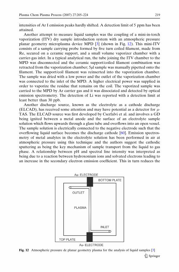
Another attempt to measure liquid samples was the coupling of a mini-in-torchvaporization (ITV) dry sample introduction system with an atmospheric pressureplanar geometry microplasma device MPD [3] (shown in Fig. 12). This mini-ITVconsists of a sample carrying probe formed by five turn coiled filament, made fromRe, secured on a ceramic support, and a small volume vaporizer chamber with acarrier-gas inlet. In a typical analytical run, the tube joining the ITV chamber to theMPD was disconnected and the ceramic support/coiled filament combination wasretracted from the vaporization chamber; 5ll sample was manually pipetted onto thefilament. The support/coil filament was reinserted into the vaporization chamber.The sample was dried with a low power and the outlet of the vaporization chamberwas connected to the inlet of the MPD. A higher electrical power was supplied inorder to vaporize the residue that remains on the coil. The vaporized sample wascarried to the MPD by Ar carrier gas and it was dissociated and detected by opticalemission spectrometry. The detection of Li was reported with a detection limit atleast better than 30 ppb.
Another discharge source, known as the electrolyte as a cathode discharge(ELCAD), has received some attention and may have potential as a detector for l-TAS. The ELCAD source was first developed by Cserfalvi et al. and involves a GDbeing ignited between a metal anode and the surface of an electrolyte samplesolution which flows upwards through a glass tube and overflows into an open vessel.The sample solution is electrically connected to the negative electrode such that theoverflowing liquid surface becomes the discharge cathode [60]. Emission spectros-metry of metal analytes in the electrolyte solution has been performed in air atatmospheric pressure using this technique and the authors suggest the cathodicsputtering as being the key mechanism of sample transport from the liquid to gasphase. A relationship between pH and spectral line intensity was interpreted asbeing due to a reaction between hydroxonium ions and solvated electrons leading toan increase in the secondary electron emission coefficient. This in turn reduces the
Fig. 12 Atmospheric pressure dc planar geometry plasma for the analysis of liquid samples [3]
Plasma Chem Plasma Process (2007) 27:205–224 219
123
cathode fall potential, which otherwise inhibits transport of sputtered ions into thenegative glow region of the discharge. Acidification of the sample solution is thusapplied to most ELCAD sources to increase sample transport into the discharge.
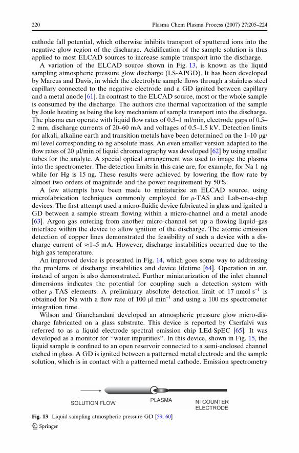
A variation of the ELCAD source shown in Fig. 13, is known as the liquidsampling atmospheric pressure glow discharge (LS-APGD). It has been developedby Marcus and Davis, in which the electrolyte sample flows through a stainless steelcapillary connected to the negative electrode and a GD ignited between capillaryand a metal anode [61]. In contrast to the ELCAD source, most or the whole sampleis consumed by the discharge. The authors cite thermal vaporization of the sampleby Joule heating as being the key mechanism of sample transport into the discharge.The plasma can operate with liquid flow rates of 0.3–1 ml/min, electrode gaps of 0.5–2 mm, discharge currents of 20–60 mA and voltages of 0.5–1.5 kV. Detection limitsfor alkali, alkaline earth and transition metals have been determined on the 1–10 lg/ml level corresponding to ng absolute mass. An even smaller version adapted to theflow rates of 20 ll/min of liquid chromatography was developed [62] by using smallertubes for the analyte. A special optical arrangement was used to image the plasmainto the spectrometer. The detection limits in this case are, for example, for Na 1 ngwhile for Hg is 15 ng. These results were achieved by lowering the flow rate byalmost two orders of magnitude and the power requirement by 50%.
A few attempts have been made to miniaturize an ELCAD source, usingmicrofabrication techniques commonly employed for l-TAS and Lab-on-a-chipdevices. The first attempt used a micro-fluidic device fabricated in glass and ignited aGD between a sample stream flowing within a micro-channel and a metal anode[63]. Argon gas entering from another micro-channel set up a flowing liquid–gasinterface within the device to allow ignition of the discharge. The atomic emissiondetection of copper lines demonstrated the feasibility of such a device with a dis-charge current of �1–5 mA. However, discharge instabilities occurred due to thehigh gas temperature.
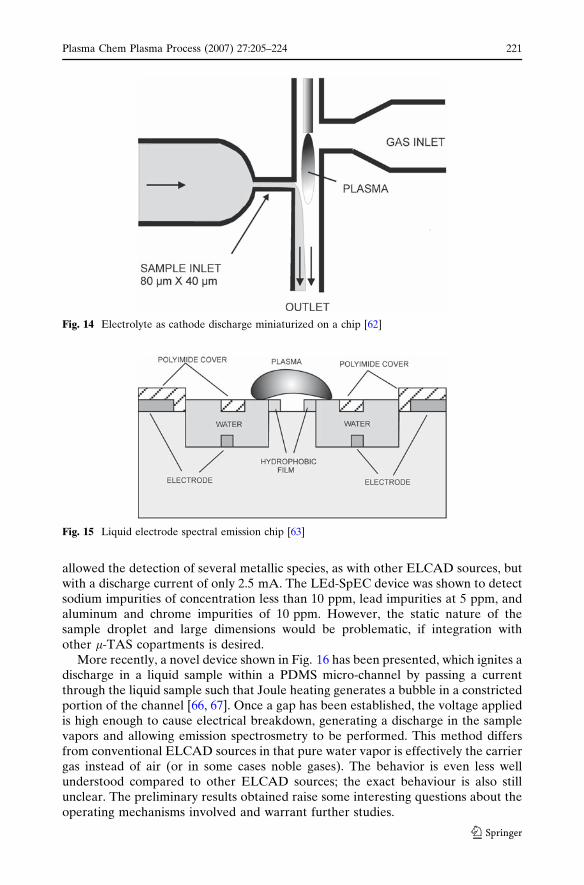
An improved device is presented in Fig. 14, which goes some way to addressingthe problems of discharge instabilities and device lifetime [64]. Operation in air,instead of argon is also demonstrated. Further miniaturization of the inlet channeldimensions indicates the potential for coupling such a detection system withother l-TAS elements. A preliminary absolute detection limit of 17 nmol s–1 isobtained for Na with a flow rate of 100 ll min–1 and using a 100 ms spectrometerintegration time.
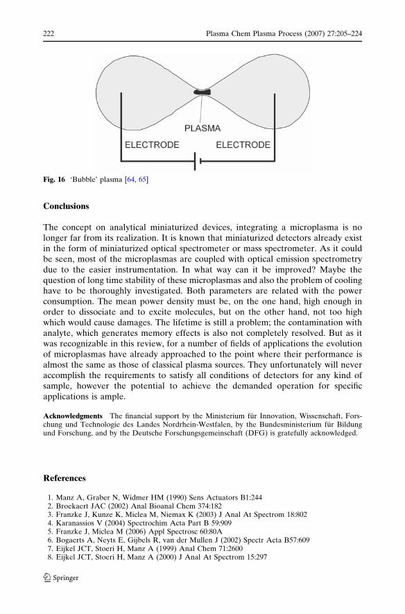
Wilson and Gianchandani developed an atmospheric pressure glow micro-dis-charge fabricated on a glass substrate. This device is reported by Cserfalvi wasreferred to as a liquid electrode spectral emission chip LEd-SpEC [65]. It wasdeveloped as a monitor for ‘‘water impurities’’. In this device, shown in Fig. 15, theliquid sample is confined to an open reservoir connected to a semi-enclosed channeletched in glass. A GD is ignited between a patterned metal electrode and the samplesolution, which is in contact with a patterned metal cathode. Emission spectrometry
Fig. 13 Liquid sampling atmospheric pressure GD [59, 60]
220 Plasma Chem Plasma Process (2007) 27:205–224
123
allowed the detection of several metallic species, as with other ELCAD sources, butwith a discharge current of only 2.5 mA. The LEd-SpEC device was shown to detectsodium impurities of concentration less than 10 ppm, lead impurities at 5 ppm, andaluminum and chrome impurities of 10 ppm. However, the static nature of thesample droplet and large dimensions would be problematic, if integration withother l-TAS copartments is desired.
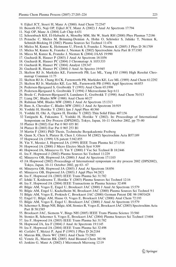
More recently, a novel device shown in Fig. 16 has been presented, which ignites adischarge in a liquid sample within a PDMS micro-channel by passing a currentthrough the liquid sample such that Joule heating generates a bubble in a constrictedportion of the channel [66, 67]. Once a gap has been established, the voltage appliedis high enough to cause electrical breakdown, generating a discharge in the samplevapors and allowing emission spectrosmetry to be performed. This method differsfrom conventional ELCAD sources in that pure water vapor is effectively the carriergas instead of air (or in some cases noble gases). The behavior is even less wellunderstood compared to other ELCAD sources; the exact behaviour is also stillunclear. The preliminary results obtained raise some interesting questions about theoperating mechanisms involved and warrant further studies.
Fig. 14 Electrolyte as cathode discharge miniaturized on a chip [62]
Fig. 15 Liquid electrode spectral emission chip [63]
Plasma Chem Plasma Process (2007) 27:205–224 221
123
Conclusions
The concept on analytical miniaturized devices, integrating a microplasma is nolonger far from its realization. It is known that miniaturized detectors already existin the form of miniaturized optical spectrometer or mass spectrometer. As it couldbe seen, most of the microplasmas are coupled with optical emission spectrometrydue to the easier instrumentation. In what way can it be improved? Maybe thequestion of long time stability of these microplasmas and also the problem of coolinghave to be thoroughly investigated. Both parameters are related with the powerconsumption. The mean power density must be, on the one hand, high enough inorder to dissociate and to excite molecules, but on the other hand, not too highwhich would cause damages. The lifetime is still a problem; the contamination withanalyte, which generates memory effects is also not completely resolved. But as itwas recognizable in this review, for a number of fields of applications the evolutionof microplasmas have already approached to the point where their performance isalmost the same as those of classical plasma sources. They unfortunately will neveraccomplish the requirements to satisfy all conditions of detectors for any kind ofsample, however the potential to achieve the demanded operation for specificapplications is ample.
Acknowledgments The financial support by the Ministerium fur Innovation, Wissenschaft, Fors-chung und Technologie des Landes Nordrhein-Westfalen, by the Bundesministerium fur Bildungund Forschung, and by the Deutsche Forschungsgemeinschaft (DFG) is gratefully acknowledged.
References
1. Manz A, Graber N, Widmer HM (1990) Sens Actuators B1:2442. Broekaert JAC (2002) Anal Bioanal Chem 374:1823. Franzke J, Kunze K, Miclea M, Niemax K (2003) J Anal At Spectrom 18:8024. Karanassios V (2004) Spectrochim Acta Part B 59:9095. Franzke J, Miclea M (2006) Appl Spectrosc 60:80A6. Bogaerts A, Neyts E, Gijbels R, van der Mullen J (2002) Spectr Acta B57:6097. Eijkel JCT, Stoeri H, Manz A (1999) Anal Chem 71:26008. Eijkel JCT, Stoeri H, Manz A (2000) J Anal At Spectrom 15:297
Fig. 16 ‘Bubble’ plasma [64, 65]
222 Plasma Chem Plasma Process (2007) 27:205–224
123
9. Eijkel JCT, Stoeri H, Manz A (2000) Anal Chem 72:254710. Bessoth FG, Naji OP, Eijkel JCT, Manz A (2002) J Anal At Spectrom 17:79411. Naji OP, Manz A (2004) Lab Chip 4:43112. Schoenbach KH, El-Habachi A, Moselhy MM, Shi W, Stark RH (2000) Phys Plasmas 7:218613. Penache C, Miclea M, Brauning-Demian A, Hohn O, Schossler S, Jahnke T, Niemax K,
Schmidt-Bocking H (2002) Plasma Sources Sci Technol 11:47614. Miclea M, Kunze K, Heitmann U, Florek S, Franzke J, Niemax K (2005) J Phys D 38:170915. Miclea M, Kunze K, Franzke J, Niemax K (2002) Spectrochim Acta Part B 57:158516. Micea M, Kunze K, Franzke J, Niemax K (2004) JAAS 19:99017. Guchardi R, Hauser P (2003) J Anal At Spectrom 18:105618. Guchardi R, Hauser PC (2004) J Chromatogr A 1033:33319. Guchardi R, Hauser PC (2004) Analyst 129:34720. Guchardi R, Hauser PC (2004) J Anal At Spectro 19:94521. Skelton RJ Jr, Markides KE, Farnsworth PB, Lee ML, Yang FJJ (1988) High Resolut Chro-
matogr Commun 11:7522. Skelton RJ Jr, Chang H-CK, Farnsworth PB, Markides KE, Lee ML (1989) Anal Chem 61:229223. Skelton RJ Jr, Markides KE, Lee ML, Farnsworth PB (1990) Appl Spectrosc 44:85324. Pedersen-Bjergaard S, Greibrokk T (1993) Anal Chem 65:199825. Pedersen-Bjergaard S, Greibrokk T (1994) J Microcolumn Sep 6:1126. Brede C, Pedersen-Bjergaard S, Lundanes E, Greibrokk T (1998) Anal Chem 70:51327. Liang DC, Blades MW (1988) Anal Chem 60:2728. Rahman MM, Blades MW (2000) J Anal At Spectrom 15:131329. Bass A, Chevalier C, Blades MW (2001) J Anal At Spectrom 16:91930. Yoshiki H, Horiike Y (2001) Jpn J Appl Phys 40:36031. Yoshiki H, Oki A, Ogawa H, Horiike Y (2002) Thin Solid Films 407:15632 Taniguchi K, Fukasawa T, Yoshiki H, Horiike Y (2002). In: Proceedings of International
Symposium on Dry Process (DPS2002), Tokyo, Japan, 10–11 October 2002, pp 75–8033 Platzer B (2002) Eur Pat 0 965 035 B134 Platzer B (2003) Eur Pat 0 965 253 B135 Martin F (2001) PhD Thesis, Technische Bergakademie Freiberg36. Quan X, Chen S, Platzer B, Chen J, Gfrerer M (2002) Spectrochim Acta B57:18937 Hopwood JA (1999) US patent 5.942.85538. Yin Y, Messier J, Hopwood JA (1999) IEEE Trans Plasma Sci 27:151639. Hopwood JA (2000) J Micro Electro Mech Syst 9:30940. Hopwood JA, Minayeva O, Yin Y (2000) J Vac Sci Technol B 18:244641. Iza F, Hopwood J (2002) Plasma Sources Sci Technol 11:22942. Minayeva OB, Hopwood JA (2000) J Anal At Spectrom 17:110343 JA Hopwood (2002) Proceedings of International symposium on dry process 2002 (DPS2002),
Tokyo, Japan, 10–11 October 2002, pp 63– 6744. Minayeva OB, Hopwood JA (2003) J Anal At Spectrom 18:85645. Minayeva OB, Hopwood JA (2003) J Appl Phys 94:282146. Iza F, Hopwood JA (2003) IEEE Trans Plasma Sci 31:78247. Ichiki T, Koidesawa T, Horiike Y (2003) Plasma Sources Sci Technol 12:1648. Iza F, Hopwood JA (2004) IEEE Transactions in Plasma Science 32:49849. Bilgic AM, Voges E, Engel U, Broekaert JAC (2000) J Anal At Spectrom 15:57950. Bilgic AM, Engel U, Kuckelheim M, Broekaert JAC (2000) Plasma Sources Sci Technol 9:151 Bilgic AM, Voges E, Prokisch C, Broekaert JAC (2000) German Patent DE 98-1985162852. Engel U, Bilgic AM, Haase O, Voges E, Broekaert JAC (2000) Anal Chem 72:19353. Bilgic AM, Voges E, Engel U, Broekaert JAC (2000) J Anal At Spectrom 15:57954. Schermer S, Bings NH, Bilgic AM, Stonies R, Voges E, Broekaert JAC (2003) Spectrochim Acta
Part B 58:158555. Broekaert JAC, Siemens V, Bings NH (2005) IEEE Trans Plasma Science 33:56056. Stonies R, Schermer S, Voges E, Broekaert JAC (2004) Plasma Sources Sci Technol 13:60457. Iza F, Hopwood JA (2003) IEEE Trans Plasma Sci 31:78258. Hopwood JA, Iza F (2004) J Anal At Spectrom 19:114559. Iza F, Hopwood JA (2004) IEEE Trans Plasma Sci 32:49860. Cerfalvi T, Metzei P, Apai P (1993) J Phys D 26:218461. Marcus RK, Davis WC (2001) Anal Chem 73:290362. Venzie JL, Marcus RK (2005) Anal Bioanal Chem 381:9663. Jenkins G, Manz A (2002) J Micromech Microeng 12:19
Plasma Chem Plasma Process (2007) 27:205–224 223
123

64. Jenkins G, Franzke J, Manz A (2005) Lab Chip 5:71165. Wilson CG, Gianchandani YB (2002) IEEE Trans Electron Dev 49:231766 Iiduka A, Morita Y, Tamiya E, Takamura Y (2004) In: Micro total analysis systems proceedings,
The Royal Society of Chemistry, p 42367 Matsumoto H, Iiduka A, Yamamoto T, Tamiya E, Takamura Y (2005) In: Micro total analysis
systems proceedings, The Royal Society of Chemistry, p 427
224 Plasma Chem Plasma Process (2007) 27:205–224
123
Related Documents