MICE Radiation Shield Installation 1 18 th October2012 Summary of initial test N. Collomb

MICE Radiation Shield Installation 1 18 th October2012 Summary of initial test N. Collomb.
Dec 24, 2015
Welcome message from author
This document is posted to help you gain knowledge. Please leave a comment to let me know what you think about it! Share it to your friends and learn new things together.
Transcript
MICE Radiation Shield Installation
118th October2012
Summary of initial test
N. Collomb
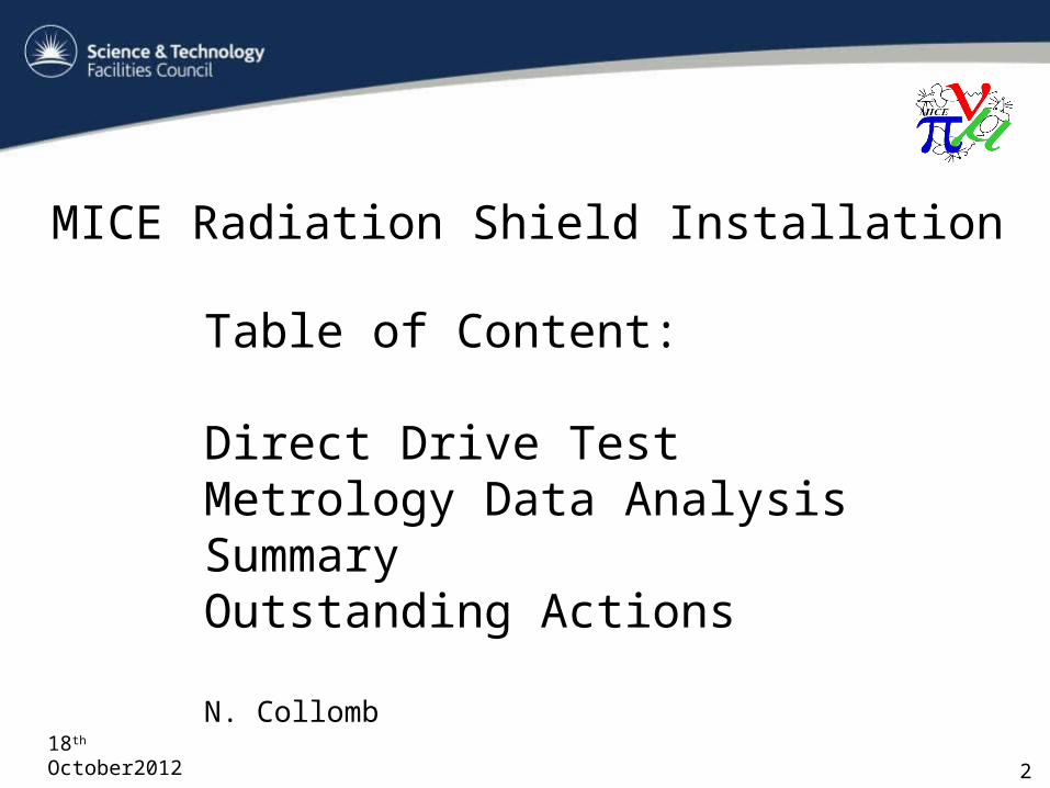
MICE Radiation Shield Installation
218th October2012
Table of Content:
Direct Drive TestMetrology Data AnalysisSummaryOutstanding Actions
N. Collomb
3
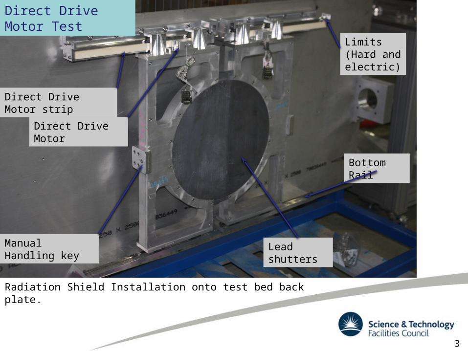
Radiation Shield Installation onto test bed back plate.
Direct Drive Motor
Direct Drive Motor strip
Manual Handling key Lead shutters
Bottom Rail
Limits (Hard and electric)
Direct Drive Motor Test
4
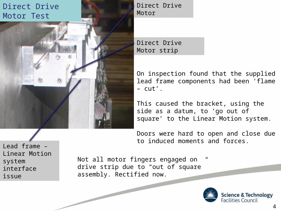
On inspection found that the supplied lead frame components had been ‘flame – cut’.
This caused the bracket, using the side as a datum, to ‘go out of square’ to the Linear Motion system.
Doors were hard to open and close due to induced moments and forces.
Direct Drive Motor
Direct Drive Motor strip
Lead frame – Linear Motion system interface issue
Direct Drive Motor Test
Not all motor fingers engaged on drive strip due to “out of square” assembly. Rectified now.
5
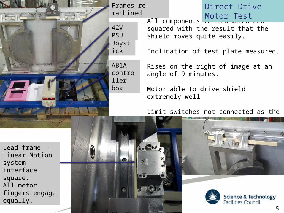
All components re-assembled and squared with the result that the shield moves quite easily.
Inclination of test plate measured.
Rises on the right of image at an angle of 9 minutes.
Motor able to drive shield extremely well.
Limit switches not connected as the Joystick controller is only borrowed (plugs into AB1A controller box via 25 Pin D-Type)
Frames re-machined
Joystick
Lead frame – Linear Motion system interface square.All motor fingers engage equally.
42V PSU
AB1A controller box
Direct Drive Motor Test
6
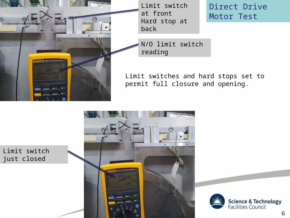
Limit switches and hard stops set to permit full closure and opening.
Limit switch at frontHard stop at back
N/O limit switch reading
Limit switch just closed
Direct Drive Motor Test
7
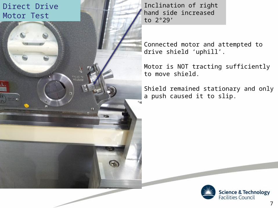
Connected motor and attempted to drive shield ‘uphill’.
Motor is NOT tracting sufficiently to move shield.
Shield remained stationary and only a push caused it to slip.
Inclination of right hand side increased to 2°29’
Direct Drive Motor Test
8
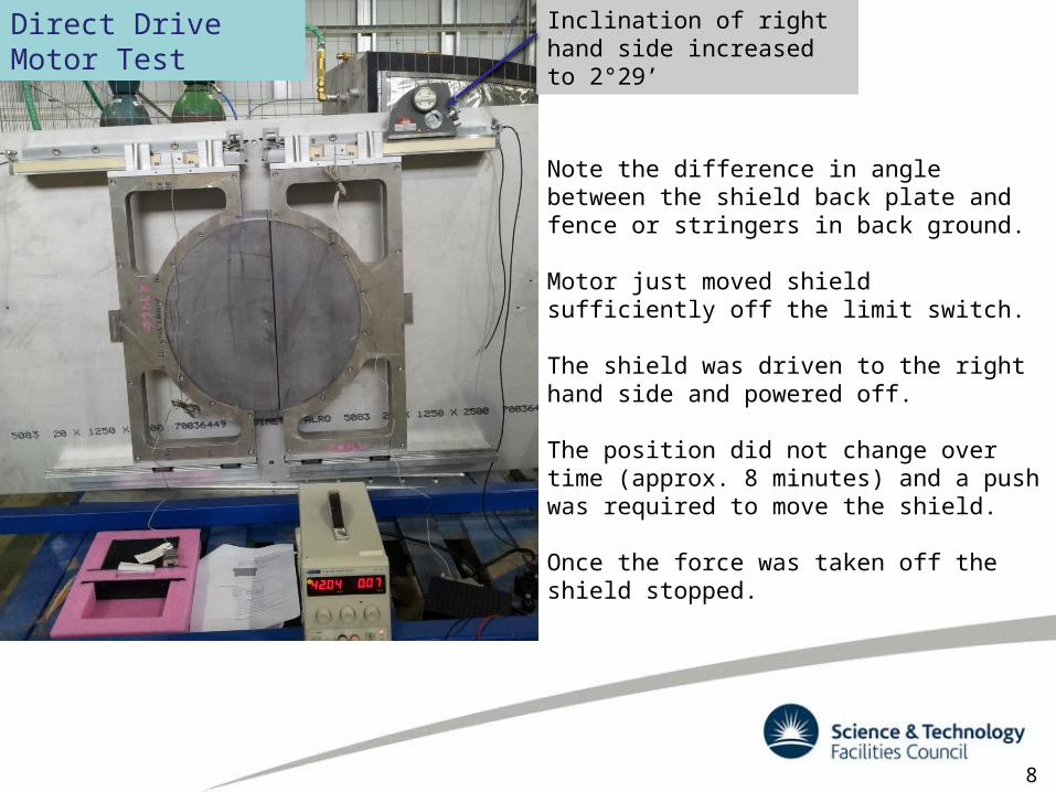
Note the difference in angle between the shield back plate and fence or stringers in back ground.
Motor just moved shield sufficiently off the limit switch.
The shield was driven to the right hand side and powered off.
The position did not change over time (approx. 8 minutes) and a push was required to move the shield.
Once the force was taken off the shield stopped.
Inclination of right hand side increased to 2°29’
Direct Drive Motor Test
9
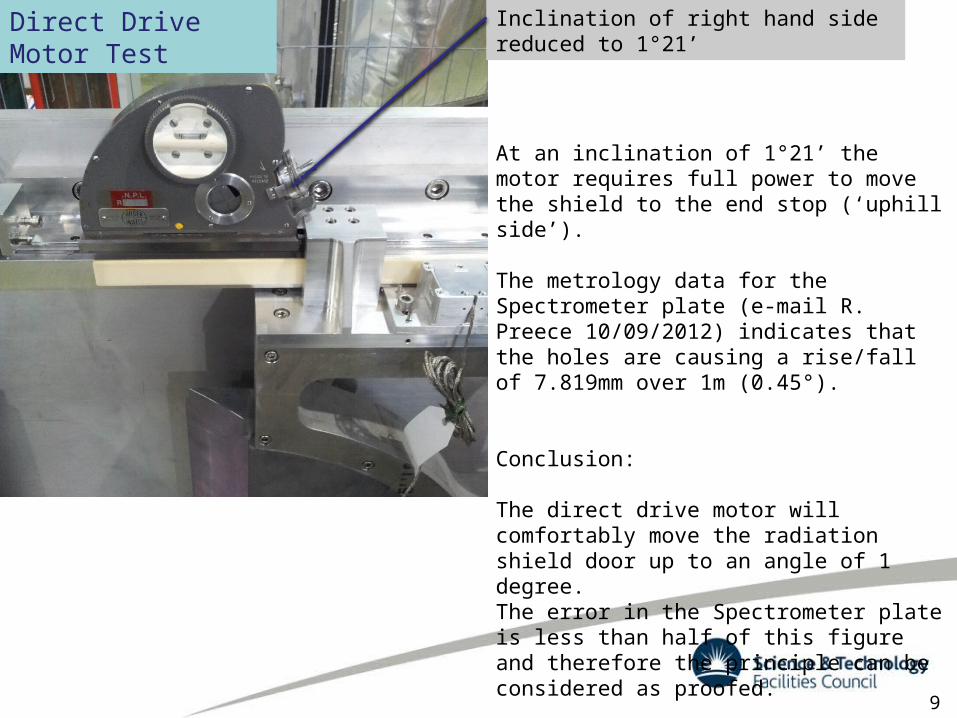
At an inclination of 1°21’ the motor requires full power to move the shield to the end stop (‘uphill side’).
The metrology data for the Spectrometer plate (e-mail R. Preece 10/09/2012) indicates that the holes are causing a rise/fall of 7.819mm over 1m (0.45°).
Conclusion:
The direct drive motor will comfortably move the radiation shield door up to an angle of 1 degree.The error in the Spectrometer plate is less than half of this figure and therefore the principle can be considered as proofed.
Inclination of right hand side reduced to 1°21’Direct Drive Motor Test

10
The datum for the metrology data and nominal spectrometer plate are coincident.
Coordinate systems represent Metrology data
‘Nominal’ Spectrometer plate Metrology Data Analysis
11
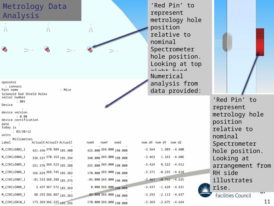
‘Red Pin’ to represent metrology hole position relative to nominal Spectrometer hole position. Looking at top right hand corner of arrangement.
operator : connorsPart name : Mice Solenoid Rad Shield Holesserial number : 001Device : device version : 0.00device certification date : today is : 03/30/12units : MillimetresLabel ActualX ActualY ActualZ nomX nomY nomZ nom dX nom dY nom dZM_CIRCLE003_I -421.436 370.989 -185.400 -425.000 369.000 -190.000 -3.564 1.989 -4.600M_CIRCLE004_I -336.537 370.163 -185.394 -340.000 369.000 -190.000 -3.463 1.163 -4.606M_CIRCLE005_I -251.576 369.523 -185.388 -255.000 369.000 -190.000 -3.424 0.523 -4.612M_CIRCLE006_I -166.629 368.745 -185.382 -170.000 369.000 -190.000 -3.371 -0.255 -4.618M_CIRCLE007_I -81.533 368.288 -185.375 -85.000 369.000 -190.000 -3.467 -0.712 -4.625M_CIRCLE008_I 3.437 367.572 -185.369 0.000 369.000 -190.000 -3.437 -1.428 -4.631M_CIRCLE009_I 88.293 366.887 -185.363 85.000 369.000 -190.000 -3.293 -2.113 -4.637M_CIRCLE010_I 173.369 366.325 -185.356 170.000 369.000 -190.000 -3.369 -2.675 -4.644M_CIRCLE011_I 258.334 365.688 -185.350 255.000 369.000 -190.000 -3.334 -3.312 -4.650M_CIRCLE012_I 343.280 364.992 -185.343 340.000 369.000 -190.000 -3.280 -4.008 -4.657M_CIRCLE013_I 428.278 364.345 -185.337 425.000 369.000 -190.000 -3.277 -4.655 -4.663
M_CIRCLE014_I -427.214 -366.881 -187.040 -425.000 -369.000 -190.000 2.214 2.119 -2.960M_CIRCLE015_I -342.242 -367.539 -187.034 -340.000 -369.000 -190.000 2.242 1.462 -2.966M_CIRCLE016_I -257.268 -368.193 -187.027 -255.000 -369.000 -190.000 2.268 0.807 -2.973M_CIRCLE017_I -172.323 -368.899 -187.021 -170.000 -369.000 -190.000 2.323 0.101 -2.979M_CIRCLE018_I -87.342 -369.600 -187.015 -85.000 -369.000 -190.000 2.342 -0.600 -2.985M_CIRCLE019_I -2.320 -370.249 -187.009 0.000 -369.000 -190.000 2.320 -1.249 -2.992M_CIRCLE020_I 82.668 -370.922 -187.002 85.000 -369.000 -190.000 2.332 -1.922 -2.998M_CIRCLE021_I 167.632 -371.570 -186.996 170.000 -369.000 -190.000 2.368 -2.570 -3.004M_CIRCLE022_I 252.604 -372.225 -186.990 255.000 -369.000 -190.000 2.396 -3.225 -3.011M_CIRCLE023_I 337.637 -372.910 -186.983 340.000 -369.000 -190.000 2.363 -3.910 -3.017M_CIRCLE024_I 422.655 -373.618 -186.977 425.000 -369.000 -190.000 2.345 -4.618 -3.023
‘Red Pin’ to represent metrology hole position relative to nominal Spectrometer hole position. Looking at arrangement from RH side illustrates rise.
Numerical analysis from data provided:
Metrology Data Analysis
12
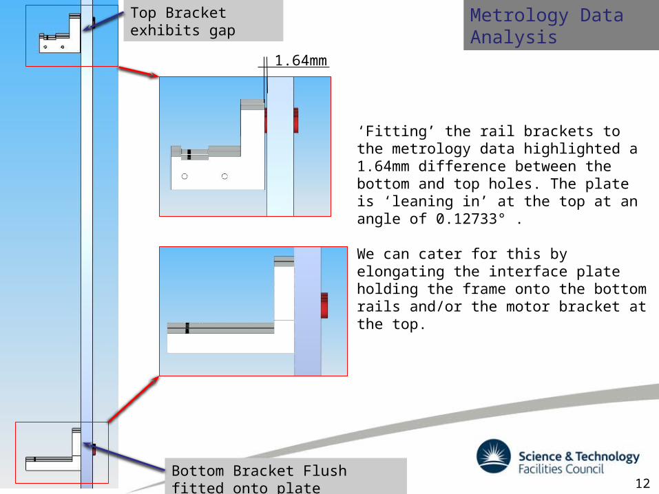
‘Fitting’ the rail brackets to the metrology data highlighted a 1.64mm difference between the bottom and top holes. The plate is ‘leaning in’ at the top at an angle of 0.12733° .
We can cater for this by elongating the interface plate holding the frame onto the bottom rails and/or the motor bracket at the top.
Bottom Bracket Flush fitted onto plate
Metrology Data AnalysisTop Bracket exhibits gap
1.64mm
13
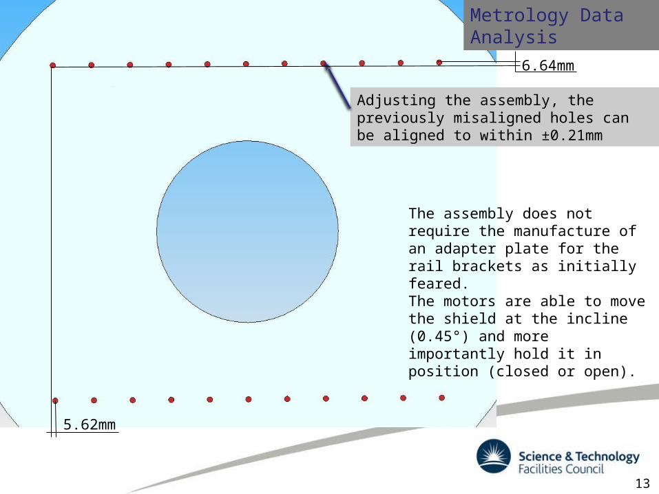
The assembly does not require the manufacture of an adapter plate for the rail brackets as initially feared.The motors are able to move the shield at the incline (0.45°) and more importantly hold it in position (closed or open).
Metrology Data Analysis
Adjusting the assembly, the previously misaligned holes can be aligned to within ±0.21mm
5.62mm
6.64mm
MICE Radiation Shield Installation
1418th October2012
SummaryThe Direct Drive design passed the proof of principle testing with ease.Motion is achieved up to an angle of 1.5° and holding is achieved at 2.5° quite easily.The misaligned spectrometer plate had caused concerns initially, indicating the need for an adapter plate between it and the rail brackets.Re-arranging the assembly slightly, opening/elongating of holes (in CAD) guarantees the shield to remain vertical.Sufficient allowance has been made to cater for this.

MICE Radiation Shield Installation
1518th October2012
Outstanding Actions:1. The Manual Handling arrangement needs to be
assembled and tested.2. The cable routing (inside Spectrometer) determined
and finalised.3. Some machining of components (enlarge and elongate
holes) to cater for misalignment from metrology data.4. Vacuum compatible rails to be ordered.5. Wiring up to feed-through of electrical components.6. Final testing (electrical and mechanical).7. Determine location of AB1A Controller Box.
Radiation Shield µ-vie
https://www.dropbox.com/s/s1qpq4j4ph4rmd8/MICE_Rad_Shield_Motion_12-09-28.mp4

Magnetic modelling
A magnetic model was requested to establish the influence on the magnetic field and the forces generated on the system.
The magnetic permeability was unknown for rail systems, thus a sample was analysed with a full B-H curve created by the National Physic Laboratory (NPL).

Magnetic modelling
A CAD model was created showing the rail system relative to the solenoids and imported into OPERA 3D.
Acknowledgement to M. Courthold and V. Bayliss
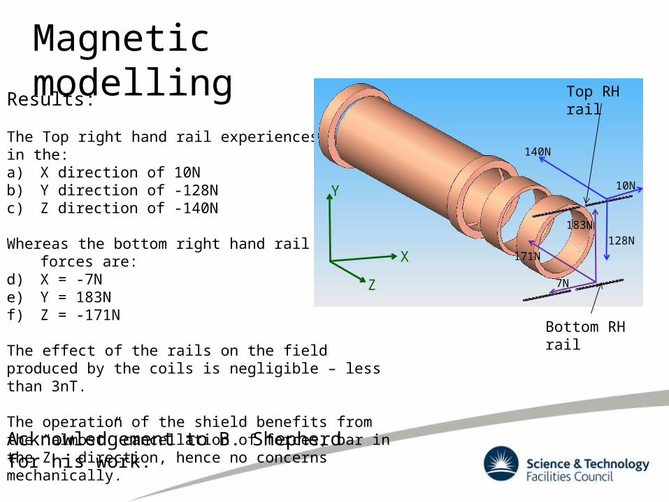
Magnetic modellingResults:
The Top right hand rail experiences a force in the:a) X direction of 10Nb) Y direction of -128Nc) Z direction of -140N
Whereas the bottom right hand rail the forces are:d) X = -7Ne) Y = 183Nf) Z = -171N
The effect of the rails on the field produced by the coils is negligible – less than 3nT.
The operation of the shield benefits from the “almost” cancellation of forces, bar in the Z – direction, hence no concerns mechanically.
10N
140N
128N
7N
171N
183N
Top RH rail
Bottom RH rail
Y
X
Z
Acknowledgement to B. Shepherd for his work.
Magnetic modelling conclusion
Looking at the forces exerted by the magnetic field on the rail system the conclusion is that these are of no concern at a first estimate.
The diminutive field distortion the components cause can also be considered negligible.
There is still the need to change the rails for vacuum compatible units (current system only purchased due to long lead time).
Related Documents