MEMS Thermal Sensors MEMS Thermal Sensors User’s Manual A284-E1-03 D6T

Welcome message from author
This document is posted to help you gain knowledge. Please leave a comment to let me know what you think about it! Share it to your friends and learn new things together.
Transcript
MEMS Thermal Sensors
MEMS Thermal Sensors
User’s Manual
A284-E1-03
D6T
1 D6T MEMS Thermal Sensors User’s Manual (A284)
Table of Contents 1 Overview .................................................................................................................................. 2 2 Structure (Part Configuration) .................................................................................................. 2 3 External Dimensions ................................................................................................................ 2 4 Principles of Operation ............................................................................................................ 2 5 Product Features ..................................................................................................................... 3 6 Usage Procedure ..................................................................................................................... 5
6.1 Connectors ....................................................................................................................... 5 6.2 Example Electrical Connections ....................................................................................... 6 6.3 I2C Specifications ............................................................................................................. 8 6.4 Example Temperature Value Retrieval Program ............................................................. 14 6.5 Example PEC Check Routine ......................................................................................... 17 6.6 Clock Stretch (Wait) ........................................................................................................ 18 6.7 Communication Timeouts ............................................................................................... 19 6.8 Surface Cover Material ................................................................................................... 19 6.9 Sensor Securement ........................................................................................................ 20
7 FAQ ....................................................................................................................................... 21 8 Definition of Terms ................................................................................................................. 22
D6T MEMS Thermal Sensors User’s Manual (A284) 2
1 Overview
This user manual describes the usage procedures, precautions, and other information regarding D6T-series MEMS Thermal Sensors. This document also serves as a supplement to the product catalog. Reference this document together with the product catalog when using this device.
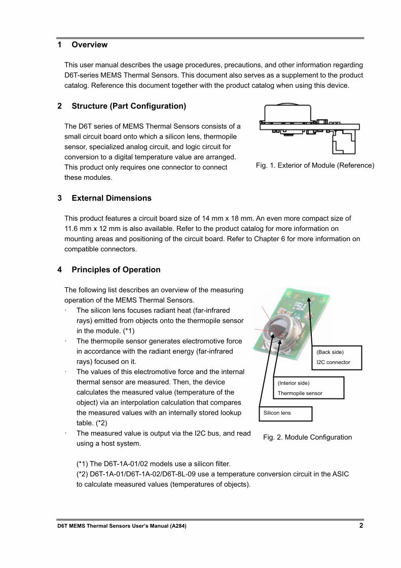
2 Structure (Part Configuration)
The D6T series of MEMS Thermal Sensors consists of a small circuit board onto which a silicon lens, thermopile sensor, specialized analog circuit, and logic circuit for conversion to a digital temperature value are arranged. This product only requires one connector to connect these modules.
3 External Dimensions
This product features a circuit board size of 14 mm x 18 mm. An even more compact size of 11.6 mm x 12 mm is also available. Refer to the product catalog for more information on mounting areas and positioning of the circuit board. Refer to Chapter 6 for more information on compatible connectors.
4 Principles of Operation
The following list describes an overview of the measuring operation of the MEMS Thermal Sensors. · The silicon lens focuses radiant heat (far-infrared
rays) emitted from objects onto the thermopile sensor in the module. (*1)
· The thermopile sensor generates electromotive force in accordance with the radiant energy (far-infrared rays) focused on it.
· The values of this electromotive force and the internal thermal sensor are measured. Then, the device calculates the measured value (temperature of the object) via an interpolation calculation that compares the measured values with an internally stored lookup table. (*2)
· The measured value is output via the I2C bus, and read using a host system. (*1) The D6T-1A-01/02 models use a silicon filter. (*2) D6T-1A-01/D6T-1A-02/D6T-8L-09 use a temperature conversion circuit in the ASIC to calculate measured values (temperatures of objects).
(Interior side)
Thermopile sensor
Silicon lens
(Back side)
I2C connector
Fig. 1. Exterior of Module (Reference)
Fig. 2. Module Configuration
3 D6T MEMS Thermal Sensors User’s Manual (A284)
5 Product Features
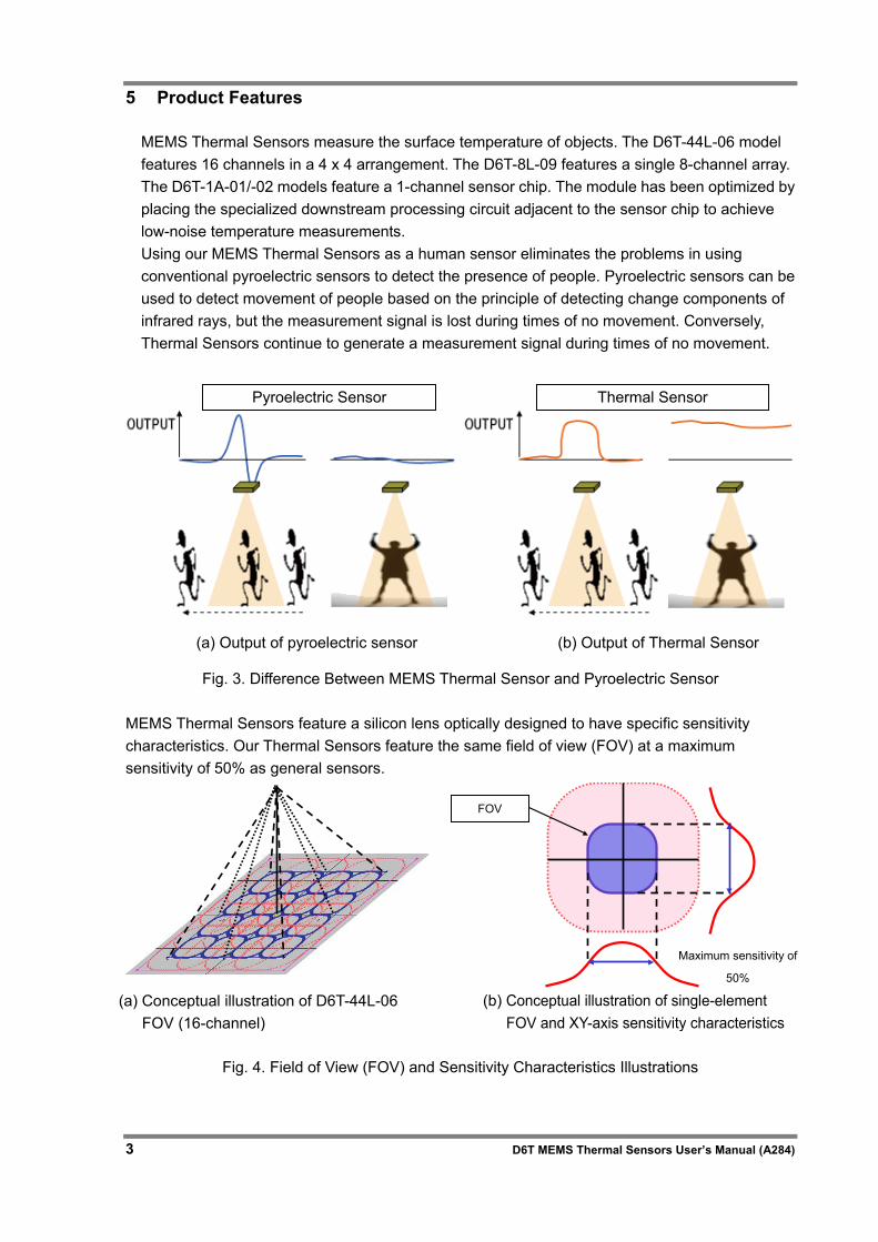
MEMS Thermal Sensors measure the surface temperature of objects. The D6T-44L-06 model features 16 channels in a 4 x 4 arrangement. The D6T-8L-09 features a single 8-channel array. The D6T-1A-01/-02 models feature a 1-channel sensor chip. The module has been optimized by placing the specialized downstream processing circuit adjacent to the sensor chip to achieve low-noise temperature measurements. Using our MEMS Thermal Sensors as a human sensor eliminates the problems in using conventional pyroelectric sensors to detect the presence of people. Pyroelectric sensors can be used to detect movement of people based on the principle of detecting change components of infrared rays, but the measurement signal is lost during times of no movement. Conversely, Thermal Sensors continue to generate a measurement signal during times of no movement.
Fig. 3. Difference Between MEMS Thermal Sensor and Pyroelectric Sensor
MEMS Thermal Sensors feature a silicon lens optically designed to have specific sensitivity characteristics. Our Thermal Sensors feature the same field of view (FOV) at a maximum sensitivity of 50% as general sensors.
Fig. 4. Field of View (FOV) and Sensitivity Characteristics Illustrations
FOV
Pyroelectric Sensor Thermal Sensor
(a) Output of pyroelectric sensor (b) Output of Thermal Sensor
(a) Conceptual illustration of D6T-44L-06 FOV (16-channel)
Maximum sensitivity of
50%
(b) Conceptual illustration of single-element FOV and XY-axis sensitivity characteristics
D6T MEMS Thermal Sensors User’s Manual (A284) 4
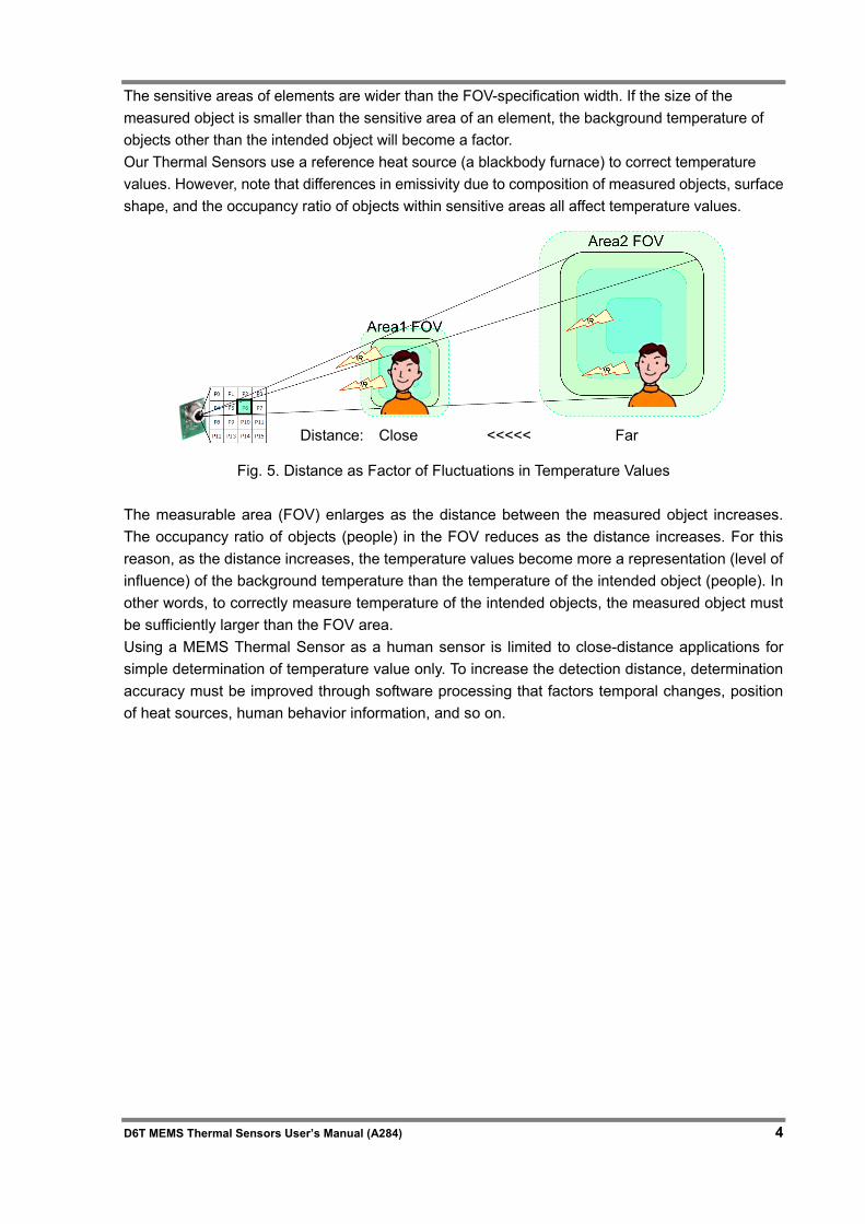
The sensitive areas of elements are wider than the FOV-specification width. If the size of the measured object is smaller than the sensitive area of an element, the background temperature of objects other than the intended object will become a factor. Our Thermal Sensors use a reference heat source (a blackbody furnace) to correct temperature values. However, note that differences in emissivity due to composition of measured objects, surface shape, and the occupancy ratio of objects within sensitive areas all affect temperature values.
Fig. 5. Distance as Factor of Fluctuations in Temperature Values
The measurable area (FOV) enlarges as the distance between the measured object increases. The occupancy ratio of objects (people) in the FOV reduces as the distance increases. For this reason, as the distance increases, the temperature values become more a representation (level of influence) of the background temperature than the temperature of the intended object (people). In other words, to correctly measure temperature of the intended objects, the measured object must be sufficiently larger than the FOV area. Using a MEMS Thermal Sensor as a human sensor is limited to close-distance applications for simple determination of temperature value only. To increase the detection distance, determination accuracy must be improved through software processing that factors temporal changes, position of heat sources, human behavior information, and so on.
Distance: Close <<<<< Far
5 D6T MEMS Thermal Sensors User’s Manual (A284)
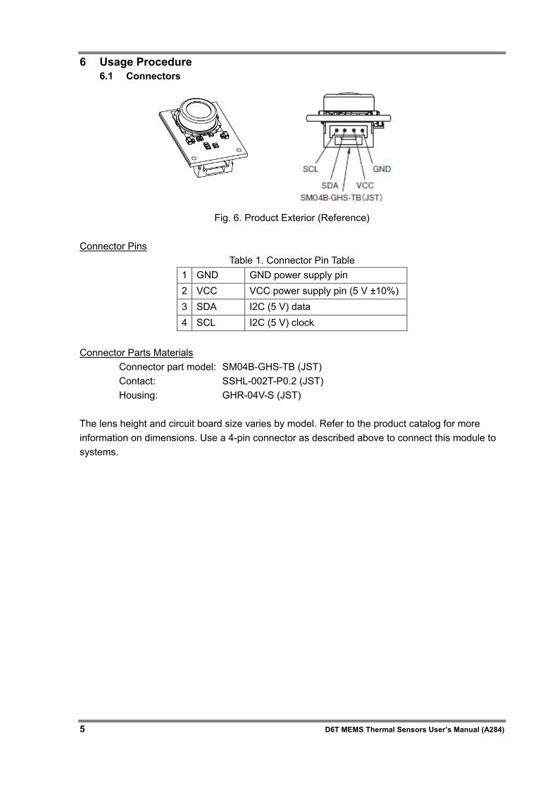
6 Usage Procedure 6.1 Connectors
Fig. 6. Product Exterior (Reference)
Connector Pins
Table 1. Connector Pin Table 1 GND GND power supply pin 2 VCC VCC power supply pin (5 V ±10%) 3 SDA I2C (5 V) data 4 SCL I2C (5 V) clock
Connector Parts Materials
Connector part model: SM04B-GHS-TB (JST) Contact: SSHL-002T-P0.2 (JST) Housing: GHR-04V-S (JST)
The lens height and circuit board size varies by model. Refer to the product catalog for more information on dimensions. Use a 4-pin connector as described above to connect this module to systems.
D6T MEMS Thermal Sensors User’s Manual (A284) 6
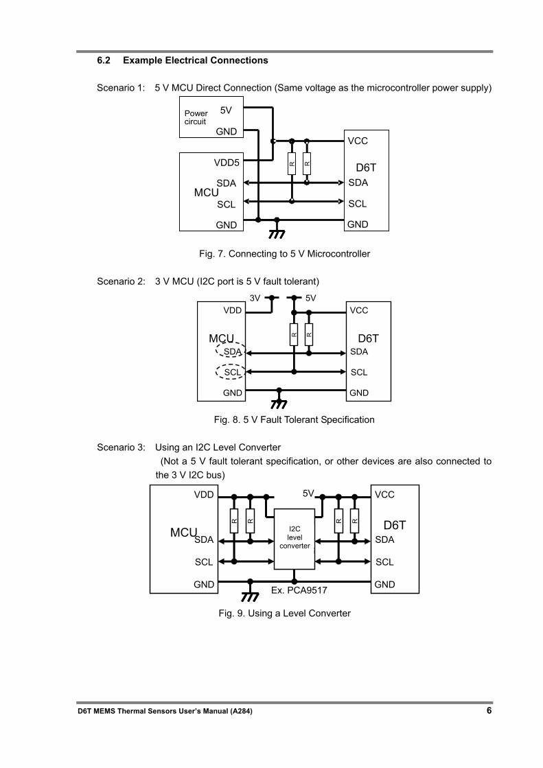
6.2 Example Electrical Connections
Scenario 1: 5 V MCU Direct Connection (Same voltage as the microcontroller power supply)
Fig. 7. Connecting to 5 V Microcontroller
Scenario 2: 3 V MCU (I2C port is 5 V fault tolerant)
D6T
VCC
SDA
SCL
GND
VDD
SDA
SCL
GND
MCU R R5V3V
Fig. 8. 5 V Fault Tolerant Specification
Scenario 3: Using an I2C Level Converter
(Not a 5 V fault tolerant specification, or other devices are also connected to the 3 V I2C bus)
D6T
VCC
SDA
SCL
GND
VDD
SDA
SCL
GND
MCU
R R
I2CLevel
Translating
R R
5V
Ex. PCA9517
Fig. 9. Using a Level Converter
D6T
VCC
SDA
SCL
GND
VDD5
SDA
SCL
GND
MCU
Power circuit
5V
GND
R R
I2C level
converter
7 D6T MEMS Thermal Sensors User’s Manual (A284)
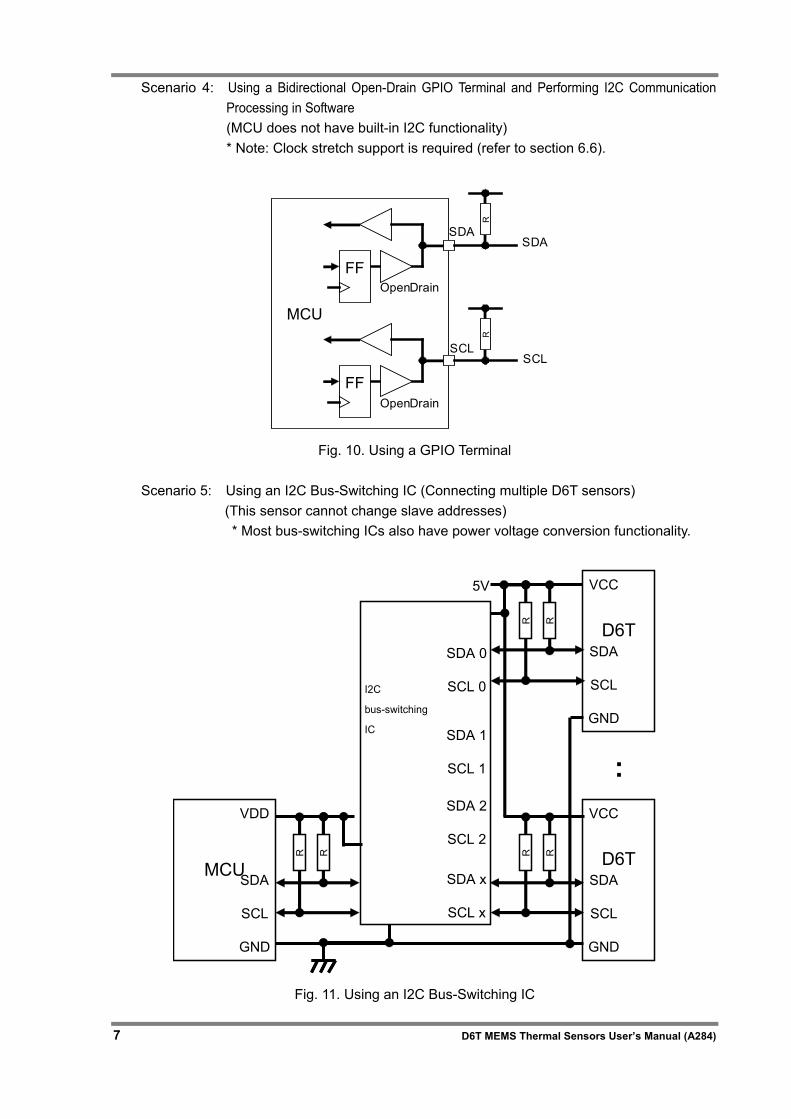
Scenario 4: Using a Bidirectional Open-Drain GPIO Terminal and Performing I2C Communication Processing in Software (MCU does not have built-in I2C functionality) * Note: Clock stretch support is required (refer to section 6.6).
MCU
R
FFOpenDrain
SDA
SCL
R
FFOpenDrain
SDA
SCL
Fig. 10. Using a GPIO Terminal
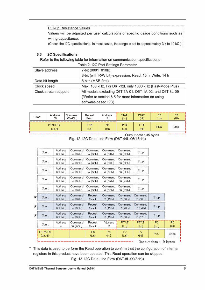
Scenario 5: Using an I2C Bus-Switching IC (Connecting multiple D6T sensors) (This sensor cannot change slave addresses) * Most bus-switching ICs also have power voltage conversion functionality.
D6T
VCC
SDA
SCL
GND
VDD
SDA
SCL
GND
MCU
R R
I2C busswitch
R R
5V
R R
D6T
VCC
SDA
SCL
GND
:
SDA 0
SCL 0
SDA x
SCL x
SDA 1
SCL 1
SDA 2
SCL 2
Fig. 11. Using an I2C Bus-Switching IC
I2C
bus-switching
IC
D6T MEMS Thermal Sensors User’s Manual (A284) 8
Pull-up Resistance Values Values will be adjusted per user calculations of specific usage conditions such as wiring capacitance. (Check the I2C specifications. In most cases, the range is set to approximately 3 k to 10 kΩ.)
6.3 I2C Specifications
Refer to the following table for information on communication specifications Table 2. I2C Port Settings Parameter
Slave address
7-bit (0001_010b) 8-bit (with R/W bit) expression: Read: 15 h, Write: 14 h
Data bit length 8 bits (MSB-first) Clock speed Max. 100 kHz, For D6T-32L only 1000 kHz (Fast-Mode Plus) Clock stretch support All models excluding D6T-1A-01, D6T-1A-02, and D6T-8L-09
(*Refer to section 6.5 for more information on using software-based I2C)
Fig. 12. I2C Data Line Flow (D6T-44L-06(16ch))
* This data is used to perform the Read operation to confirm that the configuration of internal
registers in this product have been updated. This Read operation can be skipped. Fig. 13. I2C Data Line Flow (D6T-8L-09(8ch))
Output data : 35 bytes
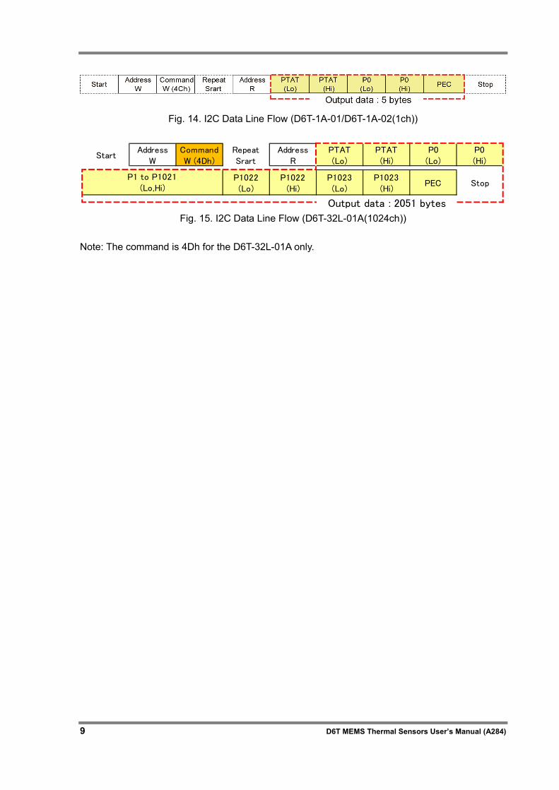
9 D6T MEMS Thermal Sensors User’s Manual (A284)
Fig. 14. I2C Data Line Flow (D6T-1A-01/D6T-1A-02(1ch))
StartAddress
WCommandW (4Dh)
RepeatSrart
AddressR
PTAT(Lo)
PTAT(Hi)
P0(Lo)
P0(Hi)
P1022(Lo)
P1022(Hi)
P1023(Lo)
P1023(Hi)
PEC Stop
Output data : 2051 bytes
P1 to P1021(Lo,Hi)
Fig. 15. I2C Data Line Flow (D6T-32L-01A(1024ch))
Note: The command is 4Dh for the D6T-32L-01A only.
D6T MEMS Thermal Sensors User’s Manual (A284) 10
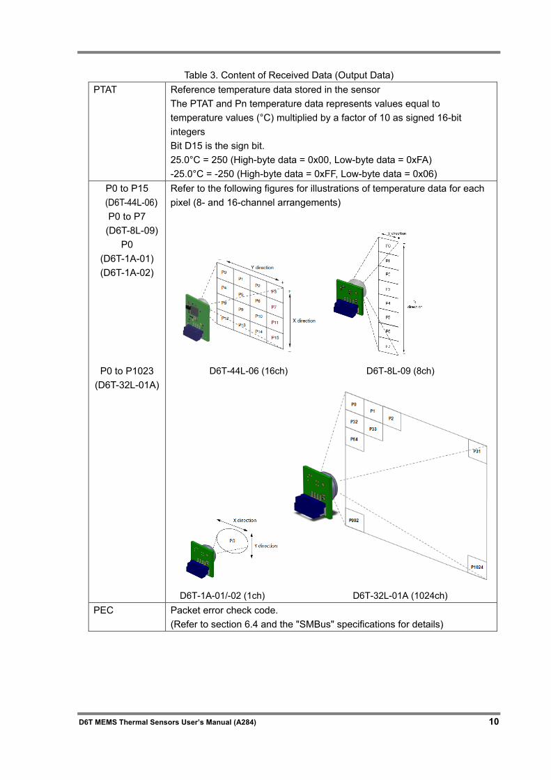
Table 3. Content of Received Data (Output Data)
PTAT Reference temperature data stored in the sensor The PTAT and Pn temperature data represents values equal to temperature values (°C) multiplied by a factor of 10 as signed 16-bit integers Bit D15 is the sign bit. 25.0°C = 250 (High-byte data = 0x00, Low-byte data = 0xFA) -25.0°C = -250 (High-byte data = 0xFF, Low-byte data = 0x06)
P0 to P15 (D6T-44L-06) P0 to P7 (D6T-8L-09)
P0 (D6T-1A-01) (D6T-1A-02)
P0 to P1023 (D6T-32L-01A)
Refer to the following figures for illustrations of temperature data for each pixel (8- and 16-channel arrangements)
D6T-44L-06 (16ch) D6T-8L-09 (8ch)
D6T-1A-01/-02 (1ch) D6T-32L-01A (1024ch) PEC Packet error check code.
(Refer to section 6.4 and the "SMBus" specifications for details)
11 D6T MEMS Thermal Sensors User’s Manual (A284)
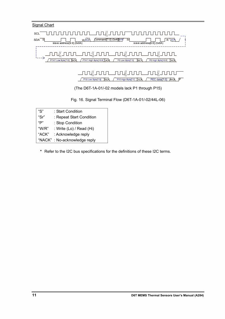
Signal Chart
(The D6T-1A-01/-02 models lack P1 through P15)
Fig. 16. Signal Terminal Flow (D6T-1A-01/-02/44L-06)
* Refer to the I2C bus specifications for the definitions of these I2C terms.
“S” : Start Condition “Sr” : Repeat Start Condition “P” : Stop Condition “W/R” : Write (Lo) / Read (Hi) “ACK” : Acknowledge reply “NACK” : No-acknowledge reply
D6T MEMS Thermal Sensors User’s Manual (A284) 12
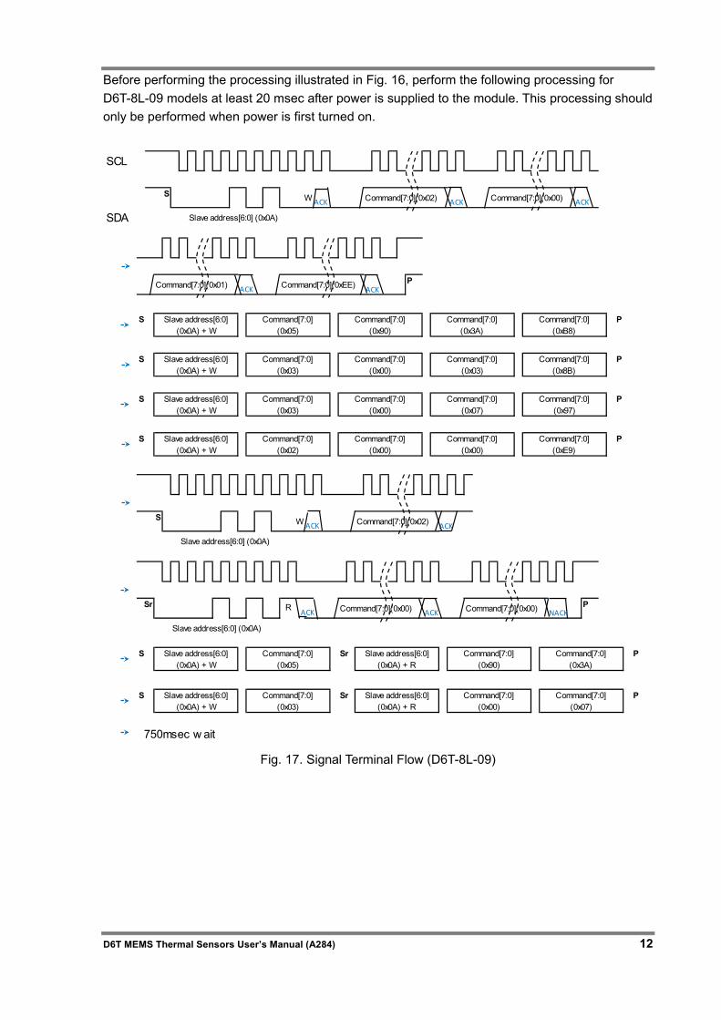
Before performing the processing illustrated in Fig. 16, perform the following processing for D6T-8L-09 models at least 20 msec after power is supplied to the module. This processing should only be performed when power is first turned on.
Fig. 17. Signal Terminal Flow (D6T-8L-09)
SCL
S W Command[7:0](0x02) Command[7:0](0x00)
SDA Slave address[6:0] (0x0A)
Command[7:0](0x01) Command[7:0](0xEE) P
S P
S P
S P
S P
S W Command[7:0](0x02)
Slave address[6:0] (0x0A)
Sr Command[7:0](0x00) Command[7:0](0x00) P
Slave address[6:0] (0x0A)
S Sr P
S Sr PCommand[7:0](0x00)
Command[7:0](0x07)
Command[7:0](0xE9)
Slave address[6:0](0x0A) + W
Command[7:0](0x05)
Slave address[6:0](0x0A) + R
Command[7:0](0x90)
Command[7:0](0x3A)
R
Command[7:0](0x97)
Slave address[6:0](0x0A) + W
Command[7:0](0x03)
Command[7:0](0x00)
Command[7:0](0x03)
Command[7:0](0x8B)
Slave address[6:0](0x0A) + W
Command[7:0](0x05)
Command[7:0](0x90)
Command[7:0](0x3A)
Command[7:0](0xB8)
750msec w ait
Slave address[6:0](0x0A) + W
Command[7:0](0x03)
Command[7:0](0x00)
Command[7:0](0x07)
Slave address[6:0](0x0A) + W
Command[7:0](0x02)
Command[7:0](0x00)
Command[7:0](0x00)
Slave address[6:0](0x0A) + W
Command[7:0](0x03)
Slave address[6:0](0x0A) + R
ACK
ACK ACK
ACK ACK
ACK ACK NACK
ACK ACK
13 D6T MEMS Thermal Sensors User’s Manual (A284)
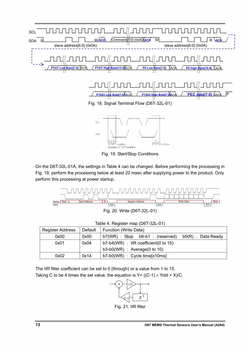
Fig. 18. Signal Terminal Flow (D6T-32L-01)
Fig. 19. Start/Stop Conditions
On the D6T-32L-01A, the settings in Table 4 can be changed. Before performing the processing in Fig. 19, perform the processing below at least 20 msec after supplying power to the product. Only perform this processing at power startup.
Fig. 20. Write (D6T-32L-01)
Table 4. Register map (D6T-32L-01) Register Address Default Function (Write Data)
0x00 0x00 b7(WR) : Stop b6-b1 : (reserved) b0(R) : Data Ready 0x01 0x04 b7-b4(WR) : IIR coefficient(0 to 15)
b3-b0(WR) : Average(0 to 10) 0x02 0x14 b7-b0(WR) : Cycle time[x10ms]
The IIR filter coefficient can be set to 0 (through) or a value from 1 to 15. Taking C to be 4 times the set value, the equation is Y= ((C-1) × Yold + X)/C.
Z
1/C
C-1
+
-1
Fig. 21. IIR filter
SCL
SDA S ACK ACK Sr slave address[6:0] (0x0A)
ACK W Command[7:0] (0x4D) R slave address[6:0] (0x0A)
ACK ACK NACK PEC data[7:0] P P1023 Low Byte[7:0] P1023 Hign Byte[7:0]
ACK ACK PTAT Low Byte[7:0] ACK ACK PTAT High Byte[15:8] P0 Low Byte[7:0] P0 High Byte[15:8]
StopWrite DataAck
Slave Address WAck
Start Registor AddressAck
MasterSlave
D6T MEMS Thermal Sensors User’s Manual (A284) 14
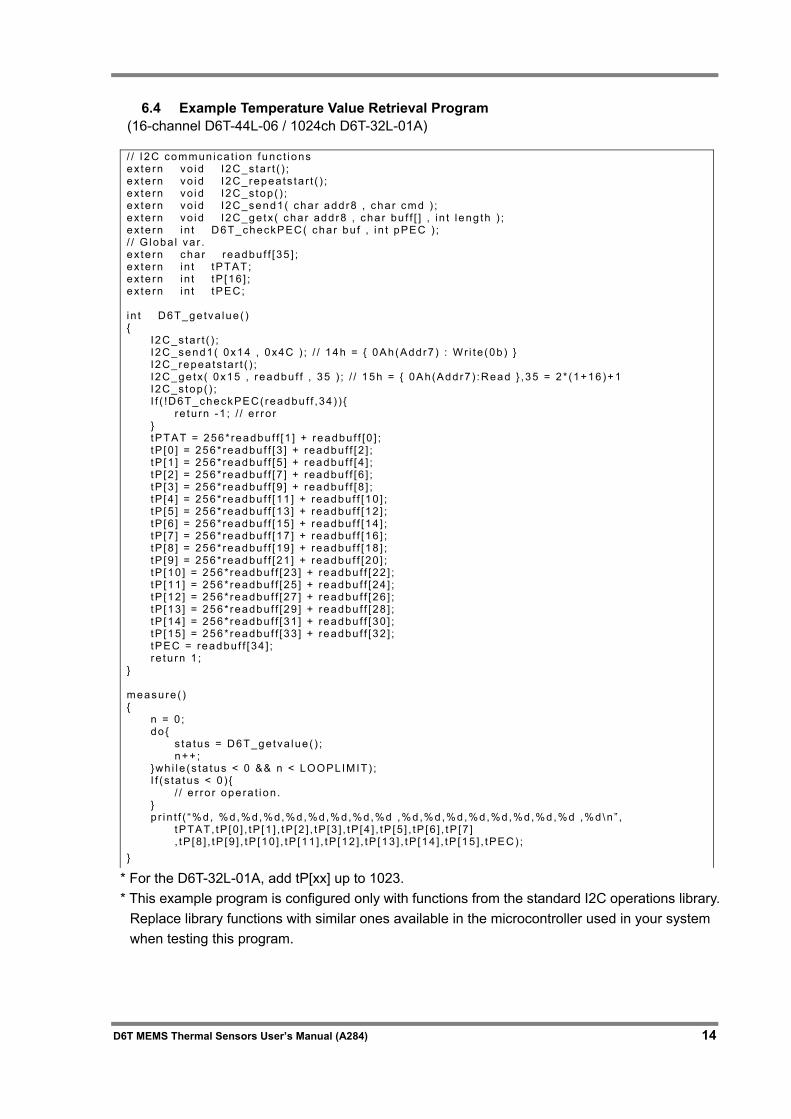
6.4 Example Temperature Value Retrieval Program
(16-channel D6T-44L-06 / 1024ch D6T-32L-01A) / / I 2C commun ica t i on func t i ons ex te rn vo id I2C_s ta r t ( ) ; ex te rn vo id I2C_repeats ta r t ( ) ; ex te rn vo id I2C_s top ( ) ; ex te rn vo id I2C_send1( char addr8 , cha r cmd ) ; ex te rn vo id I2C_ge tx ( char addr8 , cha r bu f f [ ] , i n t l eng th ) ; ex te rn i n t D6T_checkPEC( char bu f , i n t pPEC ) ; / / G loba l va r . ex te rn char readbu f f [35 ] ; ex te rn i n t tPTAT; ex te rn i n t tP [16 ] ; ex te rn i n t tPEC; i n t D6T_ge tva lue ( ) { I 2C_s ta r t ( ) ; I 2C_send1( 0x14 , 0x4C ) ; / / 14h = { 0Ah(Addr7 ) : Wr i te (0b ) } I 2C_repea ts ta r t ( ) ; I 2C_ge tx( 0x15 , readbu f f , 35 ) ; / / 15h = { 0Ah(Addr7 ) :Read } ,35 = 2* (1+16)+1 I 2C_s top( ) ; I f ( !D6T_checkPEC( readbu f f ,34 ) ) { re tu rn -1 ; / / e r ro r } tPTAT = 256* readbu f f [1 ] + readbuf f [0 ] ; tP [0 ] = 256* readbu f f [3 ] + readbu f f [2 ] ; tP [1 ] = 256* readbu f f [5 ] + readbu f f [4 ] ; tP [2 ] = 256* readbu f f [7 ] + readbu f f [6 ] ; tP [3 ] = 256* readbu f f [9 ] + readbu f f [8 ] ; tP [4 ] = 256* readbu f f [11 ] + readbuf f [10 ] ; tP [5 ] = 256* readbu f f [13 ] + readbuf f [12 ] ; tP [6 ] = 256* readbu f f [15 ] + readbuf f [14 ] ; tP [7 ] = 256* readbu f f [17 ] + readbuf f [16 ] ; tP [8 ] = 256* readbu f f [19 ] + readbuf f [18 ] ; tP [9 ] = 256* readbu f f [21 ] + readbuf f [20 ] ; tP [10 ] = 256* readbu f f [23 ] + readbu f f [22 ] ; tP [11 ] = 256* readbu f f [25 ] + readbu f f [24 ] ; tP [12 ] = 256* readbu f f [27 ] + readbu f f [26 ] ; tP [13 ] = 256* readbu f f [29 ] + readbu f f [28 ] ; tP [14 ] = 256* readbu f f [31 ] + readbu f f [30 ] ; tP [15 ] = 256* readbu f f [33 ] + readbu f f [32 ] ; tPEC = readbu f f [34 ] ; re tu rn 1 ; } measure ( ) { n = 0 ; do { s ta tus = D6T_getva lue ( ) ; n++ ; }wh i l e (s ta tus < 0 && n < LOOPLIMIT) ; I f ( s ta tus < 0 ) { / / e r ro r opera t i on . } p r i n t f ( “%d, %d,%d,%d,%d,%d,%d,%d,%d ,%d,%d,%d,%d,%d,%d,%d,%d ,%d\n ” , tPTAT, tP [0 ] , tP [1 ] , tP [2 ] , tP [3 ] , tP [4 ] , tP [5 ] , tP [6 ] , tP [7 ] , tP [8 ] , tP [9 ] , tP [10 ] , tP [11 ] , tP [12 ] , tP [13 ] , tP [14 ] , tP [15 ] , tPEC) ; }
* For the D6T-32L-01A, add tP[xx] up to 1023. * This example program is configured only with functions from the standard I2C operations library.
Replace library functions with similar ones available in the microcontroller used in your system when testing this program.
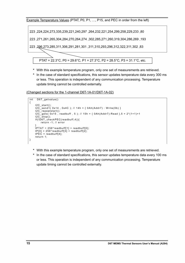
15 D6T MEMS Thermal Sensors User’s Manual (A284)
Example Temperature Values (PTAT, P0, P1, …, P15, and PEC in order from the left)
223 ,224,224,273,335,239,221,240,297 ,264,232,221,254,299,258,229,233 ,80 223 ,271,261,265,304,284,270,264,274 ,302,285,271,260,319,304,286,269 ,193 223 ,296,273,285,311,306,291,281,301 ,311,310,293,296,312,322,311,302 ,83
* With this example temperature program, only one set of measurements are retrieved. * In the case of standard specifications, this sensor updates temperature data every 300 ms
or less. This operation is independent of any communication processing. Temperature update timing cannot be controlled externally.
(Changed sections for the 1-channel D6T-1A-01/D6T-1A-02)
i n t D6T_ge tva lue ( ) { I 2C_s ta r t ( ) ; I 2C_send1( 0x14 , 0x4C ) ; / / 14h = { 0Ah(Addr7 ) : Wr i te (0b ) } I 2C_repea ts ta r t ( ) ; I 2C_ge tx( 0x15 , readbu f f , 5 ) ; / / 15h = { 0Ah(Addr7 ) :Read } ,5 = 2* (1+1)+1 I 2C_s top( ) ; I f ( !D6T_checkPEC( readbu f f ,4 ) ) { re tu rn -1 ; / / e r ro r } tPTAT = 256* readbu f f [1 ] + readbuf f [0 ] ; tP [0 ] = 256* readbu f f [3 ] + readbu f f [2 ] ; tPEC = readbu f f [4 ] ; re tu rn 1 ; }
* With this example temperature program, only one set of measurements are retrieved. * In the case of standard specifications, this sensor updates temperature data every 100 ms
or less. This operation is independent of any communication processing. Temperature update timing cannot be controlled externally.
PTAT = 22.3°C, P0 = 29.6°C, P1 = 27.3°C, P2 = 28.5°C, P3 = 31.1°C, etc.
D6T MEMS Thermal Sensors User’s Manual (A284) 16
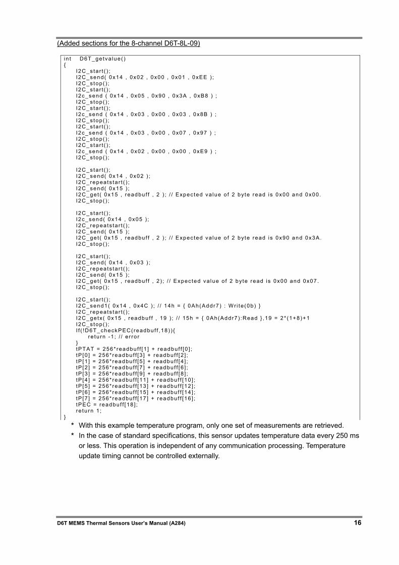
(Added sections for the 8-channel D6T-8L-09)
i n t D6T_ge tva lue ( ) { I 2C_s ta r t ( ) ; I 2C_send( 0x14 , 0x02 , 0x00 , 0x01 , 0xEE ) ; I 2C_s top( ) ; I 2C_s ta r t ( ) ; I 2c_send ( 0x14 , 0x05 , 0x90 , 0x3A , 0xB8 ) ; I 2C_s top( ) ; I 2C_s ta r t ( ) ; I 2c_send ( 0x14 , 0x03 , 0x00 , 0x03 , 0x8B ) ; I 2C_s top( ) ; I 2C_s ta r t ( ) ; I 2c_send ( 0x14 , 0x03 , 0x00 , 0x07 , 0x97 ) ; I 2C_s top( ) ; I 2C_s ta r t ( ) ; I 2c_send ( 0x14 , 0x02 , 0x00 , 0x00 , 0xE9 ) ; I 2C_s top( ) ; I 2C_s ta r t ( ) ; I 2C_send( 0x14 , 0x02 ) ; I 2C_repea ts ta r t ( ) ; I 2C_send( 0x15 ) ; I 2C_ge t ( 0x15 , readbu f f , 2 ) ; / / Expec ted va lue o f 2 by te read i s 0x00 and 0x00 . I 2C_s top( ) ; I 2C_s ta r t ( ) ; I 2c_send( 0x14 , 0x05 ) ; I 2C_repea ts ta r t ( ) ; I 2C_send( 0x15 ) ; I 2C_ge t ( 0x15 , readbu f f , 2 ) ; / / Expec ted va lue o f 2 by te read i s 0x90 and 0x3A. I 2C_s top( ) ; I 2C_s ta r t ( ) ; I 2C_send( 0x14 , 0x03 ) ; I 2C_repea ts ta r t ( ) ; I 2C_send( 0x15 ) ; I 2C_ge t ( 0x15 , readbu f f , 2 ) ; / / Expec ted va lue o f 2 by te read i s 0x00 and 0x07 . I 2C_s top( ) ; I 2C_s ta r t ( ) ; I 2C_send1( 0x14 , 0x4C ) ; / / 14h = { 0Ah(Addr7 ) : Wr i te (0b ) } I 2C_repea ts ta r t ( ) ; I 2C_ge tx( 0x15 , readbu f f , 19 ) ; / / 15h = { 0Ah(Addr7 ) :Read } ,19 = 2* (1+8)+1 I 2C_s top( ) ; I f ( !D6T_checkPEC( readbu f f ,18 ) ) { re tu rn -1 ; / / e r ro r } tPTAT = 256* readbu f f [1 ] + readbuf f [0 ] ; tP [0 ] = 256* readbu f f [3 ] + readbu f f [2 ] ; tP [1 ] = 256* readbu f f [5 ] + readbu f f [4 ] ; tP [2 ] = 256* readbu f f [7 ] + readbu f f [6 ] ; tP [3 ] = 256* readbu f f [9 ] + readbu f f [8 ] ; tP [4 ] = 256* readbu f f [11 ] + readbuf f [10 ] ; tP [5 ] = 256* readbu f f [13 ] + readbuf f [12 ] ; tP [6 ] = 256* readbu f f [15 ] + readbuf f [14 ] ; tP [7 ] = 256* readbu f f [17 ] + readbuf f [16 ] ; tPEC = readbu f f [18 ] ; re tu rn 1 ; }
* With this example temperature program, only one set of measurements are retrieved. * In the case of standard specifications, this sensor updates temperature data every 250 ms
or less. This operation is independent of any communication processing. Temperature update timing cannot be controlled externally.
17 D6T MEMS Thermal Sensors User’s Manual (A284)
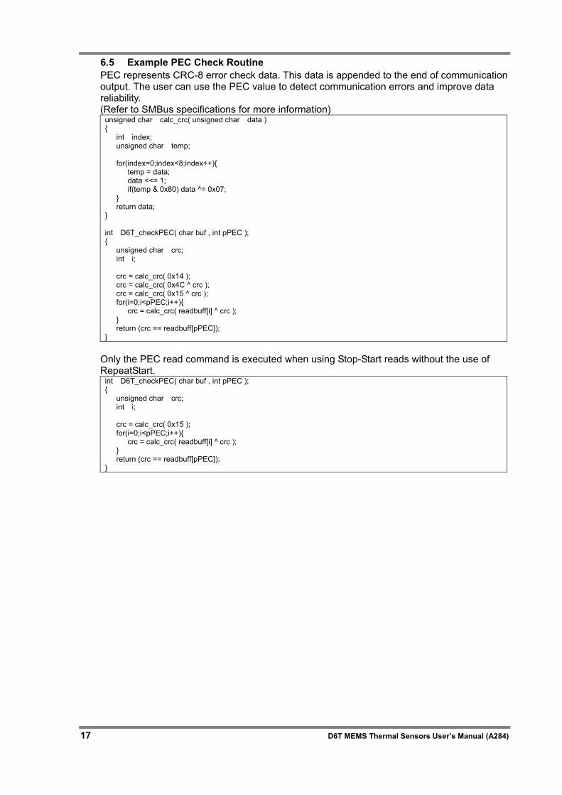
6.5 Example PEC Check Routine PEC represents CRC-8 error check data. This data is appended to the end of communication output. The user can use the PEC value to detect communication errors and improve data reliability. (Refer to SMBus specifications for more information)
unsigned char calc_crc( unsigned char data ) { int index; unsigned char temp; for(index=0;index<8;index++){ temp = data; data <<= 1; if(temp & 0x80) data ^= 0x07; } return data; } int D6T_checkPEC( char buf , int pPEC ); { unsigned char crc; int i; crc = calc_crc( 0x14 ); crc = calc_crc( 0x4C ^ crc ); crc = calc_crc( 0x15 ^ crc ); for(i=0;i<pPEC;i++){ crc = calc_crc( readbuff[i] ^ crc ); } return (crc == readbuff[pPEC]); }
Only the PEC read command is executed when using Stop-Start reads without the use of RepeatStart.
int D6T_checkPEC( char buf , int pPEC ); { unsigned char crc; int i; crc = calc_crc( 0x15 ); for(i=0;i<pPEC;i++){ crc = calc_crc( readbuff[i] ^ crc ); } return (crc == readbuff[pPEC]); }
D6T MEMS Thermal Sensors User’s Manual (A284) 18
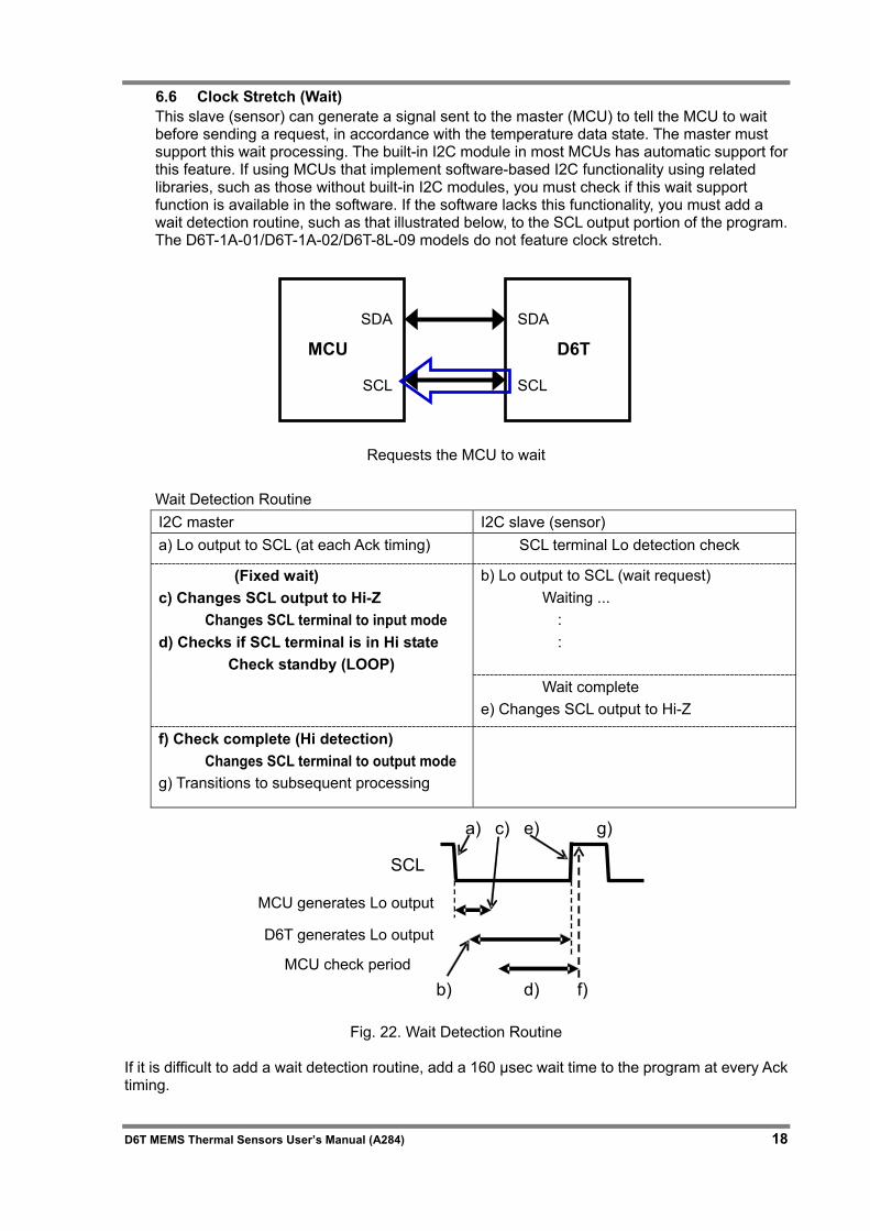
6.6 Clock Stretch (Wait) This slave (sensor) can generate a signal sent to the master (MCU) to tell the MCU to wait before sending a request, in accordance with the temperature data state. The master must support this wait processing. The built-in I2C module in most MCUs has automatic support for this feature. If using MCUs that implement software-based I2C functionality using related libraries, such as those without built-in I2C modules, you must check if this wait support function is available in the software. If the software lacks this functionality, you must add a wait detection routine, such as that illustrated below, to the SCL output portion of the program. The D6T-1A-01/D6T-1A-02/D6T-8L-09 models do not feature clock stretch.
Requests the MCU to wait Wait Detection Routine I2C master I2C slave (sensor) a) Lo output to SCL (at each Ack timing) SCL terminal Lo detection check
(Fixed wait) c) Changes SCL output to Hi-Z Changes SCL terminal to input mode d) Checks if SCL terminal is in Hi state Check standby (LOOP)
b) Lo output to SCL (wait request) Waiting ...
: :
Wait complete e) Changes SCL output to Hi-Z
f) Check complete (Hi detection) Changes SCL terminal to output mode g) Transitions to subsequent processing
Fig. 22. Wait Detection Routine
If it is difficult to add a wait detection routine, add a 160 μsec wait time to the program at every Ack timing.
SCL
a)
b)
c)
d)
e)
f)
g)
MCU generates Lo output
MCU check period
D6T generates Lo output
SDA
SCL
SDA SCL
MCU D6T
19 D6T MEMS Thermal Sensors User’s Manual (A284)
6.7 Communication Timeouts This sensor determines that a timeout has occurred and stops communication if low input continues to be received on the SDA or SCL terminal for the following times.
· D6T-44L-06 : 1 sec · D6T-1A-01/D6T-1A-02/D6T-8L-09 : 70 msec
When the sensor determines that a communication timeout has occurred, a NACK is returned during a Write access operation. For Read access operations, the read value is set to FFFFh. Using PEC for data checking enables the system to determine that read values are in error. As such, we recommend using PEC data checking.
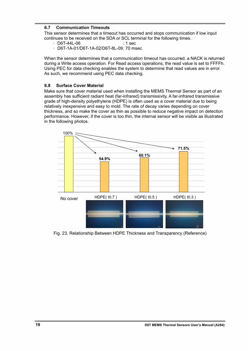
6.8 Surface Cover Material Make sure that cover material used when installing the MEMS Thermal Sensor as part of an assembly has sufficient radiant heat (far-infrared) transmissivity. A far-infrared transmissive grade of high-density polyethylene (HDPE) is often used as a cover material due to being relatively inexpensive and easy to mold. The rate of decay varies depending on cover thickness, and so make the cover as thin as possible to reduce negative impact on detection performance. However, if the cover is too thin, the internal sensor will be visible as illustrated in the following photos.
None cover HDPE( t0.7 )
54.9%
HDPE( t0.5 ) HDPE( t0.3 )
60.1%
71.5%
100%
Fig. 23. Relationship Between HDPE Thickness and Transparency (Reference)
No cover
D6T MEMS Thermal Sensors User’s Manual (A284) 20
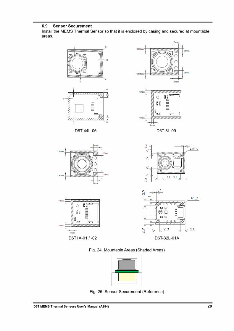
6.9 Sensor Securement Install the MEMS Thermal Sensor so that it is enclosed by casing and secured at mountable areas.
D6T-44L-06 D6T-8L-09
D6T1A-01 / -02 D6T-32L-01A
Fig. 24. Mountable Areas (Shaded Areas)
Fig. 25. Sensor Securement (Reference)
21 D6T MEMS Thermal Sensors User’s Manual (A284)
7 FAQ
Question Is it possible to increase the field of view? Answer
The FOV is set as such due to silicon lens thickness and refractive index constraints. Increasing the FOV per pixel would reduce temperature detection performance. This is another reason why the FOV cannot be increased easily. To measure temperature over a wider range, you must move the sensor in some way or install multiple sensors.
Question
Do signals emitted from infrared ray remote controllers cause the sensor to operate incorrectly?
Answer
The silicon lens used in this sensor allows virtually zero energy within a range of visible light, having a wavelength of 1.2 μm or less, to infrared rays to pass through. As such, infrared rays from remote controllers will not cause incorrect operation. The far-infrared rays that generates radiant heat are between 4 to 14 μm.
Question Can the sensor distinguish between people, animals, and appliances? Answer
Thermal Sensors only retrieve temperature data. This temperature data can be used in user-developed software to distinguish between different objects. The accuracy of such determinations can be improved by developing software specific to usage conditions.
Question
What is the usable detection distance when using this sensor as a human sensor?
Answer
This distance depends significantly on the installation conditions and performance of the determination algorithm used in conjunction with the sensor. This distance also depends on the FOV area per thermopile sensor pixel and the size of the intended object. However, in general, this distance would be approximately 5 to 6 m.
Question Can power consumption be reduced further? Answer
The D6T series of sensors is not configured with a "operation mode for power-conserving sleep". As such, the power to the sensor must be shut off to reduce power consumption.
Question Can the 3 V drive and slave address be changed? Answer The D6T series of sensors does not feature such functionality.
Question
How long does it take for the sensor to become fully operational after power is supplied to the sensor?
Answer
Output temperatures will be within the range of temperature accuracy within a few seconds after power is supplied to the sensor. However, fully stable operation takes approximately 15 minutes. (Reference value)
D6T MEMS Thermal Sensors User’s Manual (A284) 22
8 Definition of Terms
Thermopile A device cascaded to a thermocouple to increase voltage. Thermocouples are arranged so that hot junctions are adjacent.
NETD (used in catalogs) Acronym for Noise Equivalent Temperature Difference. This represents the conversion of noise into a temperature value. This term is often used to represent temperature resolution as the estimated minimum value by which changes in temperature can be determined.
FOV Acronym for Field of View. This term is used to represent the viewing angle index. This value is often defined using a sensitivity peak of 50%.
I2C is a registered trademark of Phillips Electronics. SMBus is a registered trademark of Intel Corporation.

Please check each region's Terms & Conditions by region website.
OMRON CorporationElectronic and Mechanical Components Company
Regional Contact
Cat. No. A284-E1-03 1019 (0718)(O)
Americas Europehttps://www.components.omron.com/ http://components.omron.eu/
Asia-Pacific Chinahttps://ecb.omron.com.sg/ https://www.ecb.omron.com.cn/
Korea Japanhttps://www.omron-ecb.co.kr/ https://www.omron.co.jp/ecb/
In the interest of product improvement, specifications are subject to change without notice. © OMRON Corporation 2018-2019 All Rights Reserved.
Related Documents