Copyright ©2009 Durham Geo-Enterprises. All Rights Reserved. This equipment should be installed, maintained, and operated by technically qualified personnel. Any errors or omissions in data, or the interpretation of data, are not the responsibility of Durham Geo-Enterprises. The information herein is subject to change without notification. This document contains information that is proprietary to Durham Geo-Enterprises and is subject to return upon request. It is transmitted for the sole purpose of aiding the transaction of business between Durham Geo-Enterprises and the recipient. All information, data, designs, and drawings contained herein are propri- etary to and the property of Durham Geo-Enterprises and may not be reproduced or copied in any form, by photocopy or any other means, including disclosure to outside parties, directly or indirectly, without permis- sion in writing from Durham Geo-Enterprises. SLOPE INDICATOR 12123 Harbour Reach Drive Mukilteo, Washington, USA, 98275 Tel: 425-493-6200 Fax: 425-493-6250 E-mail: [email protected] Website: www.slopeindicator.com MEMS Vertical IPI Serial Sensors 57804599

Welcome message from author
This document is posted to help you gain knowledge. Please leave a comment to let me know what you think about it! Share it to your friends and learn new things together.
Transcript

Copyright ©2009 Durham Geo-Enterprises. All Rights Reserved.
This equipment should be installed, maintained, and operated by technically qualified personnel. Any errors or omissions in data, or the interpretation of data, are not the responsibility of Durham Geo-Enterprises. The information herein is subject to change without notification.
This document contains information that is proprietary to Durham Geo-Enterprises and is subject to return upon request. It is transmitted for the sole purpose of aiding the transaction of business between Durham Geo-Enterprises and the recipient. All information, data, designs, and drawings contained herein are propri-etary to and the property of Durham Geo-Enterprises and may not be reproduced or copied in any form, by photocopy or any other means, including disclosure to outside parties, directly or indirectly, without permis-sion in writing from Durham Geo-Enterprises.
SLOPE INDICATOR12123 Harbour Reach DriveMukilteo, Washington, USA, 98275Tel: 425-493-6200 Fax: 425-493-6250E-mail: [email protected]: www.slopeindicator.com
MEMSVertical IPI
Serial Sensors57804599

Contents
Introduction . . . . . . . . . . . . . . . . . . . . . . . 1
Preparations for Installation . . . . . . . 5
Installation . . . . . . . . . . . . . . . . . . . . . . . . .6
Data Reduction . . . . . . . . . . . . . . . . . . . 10
Connection to Data Logger . . . . . . . 14
MEMS Vertical IPI Serial Sensors, 2014/9/11
Introduction
Vertical In-PlaceInclinometers
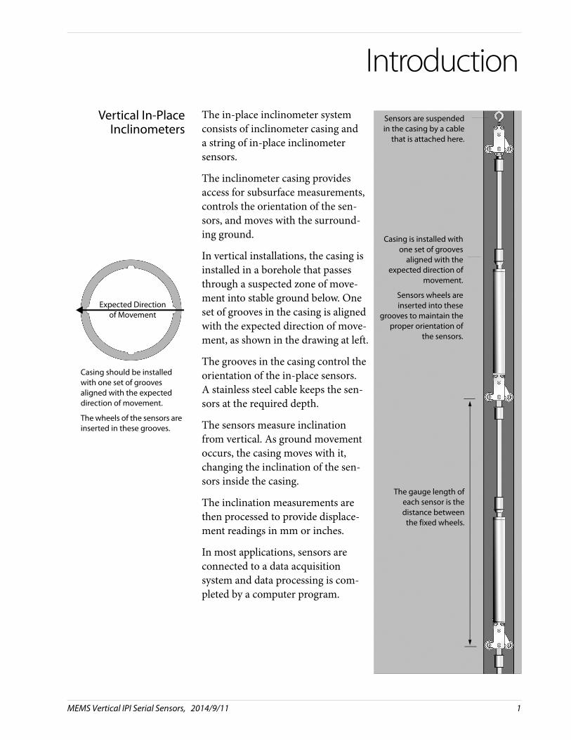
The in-place inclinometer system consists of inclinometer casing anda string of in-place inclinometersensors.
The inclinometer casing provides access for subsurface measurements, controls the orientation of the sen-sors, and moves with the surround-ing ground.
In vertical installations, the casing is installed in a borehole that passes through a suspected zone of move-ment into stable ground below. One set of grooves in the casing is aligned with the expected direction of move-ment, as shown in the drawing at left.
The grooves in the casing control the orientation of the in-place sensors. A stainless steel cable keeps the sen-sors at the required depth.
The sensors measure inclination from vertical. As ground movement occurs, the casing moves with it, changing the inclination of the sen-sors inside the casing.
The inclination measurements are then processed to provide displace-ment readings in mm or inches.
In most applications, sensors are connected to a data acquisitionsystem and data processing is com-pleted by a computer program.
Casing should be installed with one set of grooves aligned with the expected direction of movement.
The wheels of the sensors are inserted in these grooves.
Expected Direction of Movement
Casing is installed withone set of grooves
aligned with theexpected direction of
movement.
Sensors wheels areinserted into these
grooves to maintain theproper orientation of
the sensors.
The gauge length ofeach sensor is thedistance between
the fixed wheels.
Sensors are suspendedin the casing by a cable
that is attached here.
MEMS Vertical IPI Serial Sensors, 2014/9/11 1
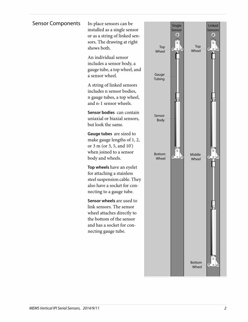
Sensor Components In-place sensors can be installed as a single sensor or as a string of linked sen-sors. The drawing at right shows both.
An individual sensor includes a sensor body, a gauge tube, a top wheel, and a sensor wheel.
A string of linked sensors includes n sensor bodies, n gauge tubes, a top wheel, and n-1 sensor wheels.
Sensor bodies can contain uniaxial or biaxial sensors, but look the same.
Gauge tubes are sized to make gauge lengths of 1, 2, or 3 m (or 3, 5, and 10') when joined to a sensor body and wheels.
Top wheels have an eyelet for attaching a stainless steel suspension cable. They also have a socket for con-necting to a gauge tube.
Sensor wheels are used to link sensors. The sensor wheel attaches directly to the bottom of the sensor and has a socket for con-necting gauge tube.
Bottom Wheel
TopWheel
GaugeTubing
TopWheel
Middle Wheel
Bottom Wheel
SensorBody
SingleSensor
LinkedSensors
MEMS Vertical IPI Serial Sensors, 2014/9/11 2
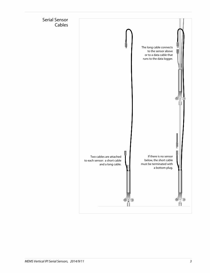
Serial SensorCables
Two cables are attachedto each sensor: a short cable
and a long cable.
The long cable connectsto the sensor above
or to a data cable thatruns to the data logger.
If there is no sensorbelow, the short cable
must be terminated witha bottom plug.
MEMS Vertical IPI Serial Sensors, 2014/9/11 3
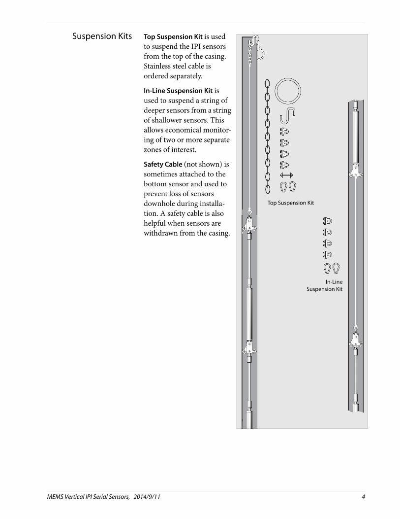
Suspension Kits Top Suspension Kit is used to suspend the IPI sensors from the top of the casing. Stainless steel cable is ordered separately.
In-Line Suspension Kit is used to suspend a string of deeper sensors from a string of shallower sensors. This allows economical monitor-ing of two or more separate zones of interest.
Safety Cable (not shown) is sometimes attached to the bottom sensor and used to prevent loss of sensors downhole during installa-tion. A safety cable is also helpful when sensors are withdrawn from the casing.
Top Suspension Kit
In-LineSuspension Kit
MEMS Vertical IPI Serial Sensors, 2014/9/11 4
Preparations for Installation
Check Sensors 1. Check each sensor.
2. Identify the bottom sensor for each string. The bottom sensor will require a plug for the bottom connector.
3. Make a note of the serial number of each sensor and its intended depth of installation.
4. Mark sensors for order of installation.
5. Check the length of the data cable to make sure it will run from the top sensor to the datalogger.
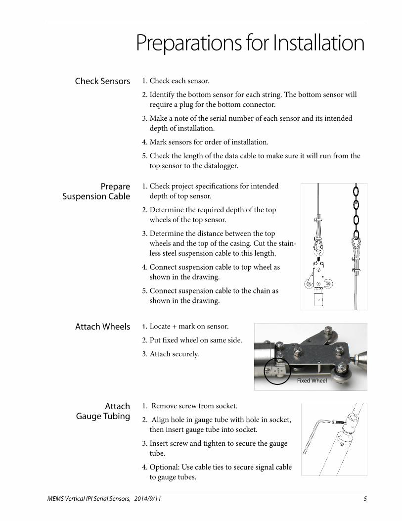
PrepareSuspension Cable
1. Check project specifications for intended depth of top sensor.
2. Determine the required depth of the top wheels of the top sensor.
3. Determine the distance between the top wheels and the top of the casing. Cut the stain-less steel suspension cable to this length.
4. Connect suspension cable to top wheel as shown in the drawing.
5. Connect suspension cable to the chain as shown in the drawing.
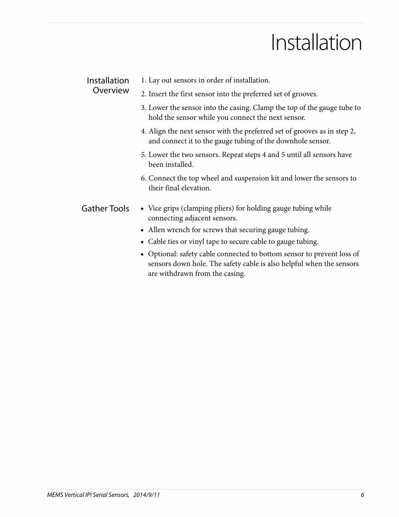
Attach Wheels 1. Locate + mark on sensor.
2. Put fixed wheel on same side.
3. Attach securely.
AttachGauge Tubing
1. Remove screw from socket.
2. Align hole in gauge tube with hole in socket, then insert gauge tube into socket.
3. Insert screw and tighten to secure the gauge tube.
4. Optional: Use cable ties to secure signal cable to gauge tubes.
Fixed Wheel
MEMS Vertical IPI Serial Sensors, 2014/9/11 5
Installation
InstallationOverview
1. Lay out sensors in order of installation.
2. Insert the first sensor into the preferred set of grooves.
3. Lower the sensor into the casing. Clamp the top of the gauge tube to hold the sensor while you connect the next sensor.
4. Align the next sensor with the preferred set of grooves as in step 2, and connect it to the gauge tubing of the downhole sensor.
5. Lower the two sensors. Repeat steps 4 and 5 until all sensors have been installed.
6. Connect the top wheel and suspension kit and lower the sensors to their final elevation.
Gather Tools Vice grips (clamping pliers) for holding gauge tubing whileconnecting adjacent sensors.
Allen wrench for screws that securing gauge tubing. Cable ties or vinyl tape to secure cable to gauge tubing. Optional: safety cable connected to bottom sensor to prevent loss of
sensors down hole. The safety cable is also helpful when the sensors are withdrawn from the casing.
MEMS Vertical IPI Serial Sensors, 2014/9/11 6
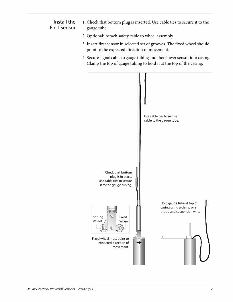
Install the First Sensor
1. Check that bottom plug is inserted. Use cable ties to secure it to the gauge tube.
2. Optional: Attach safety cable to wheel assembly.
3. Insert first sensor in selected set of grooves. The fixed wheel should point to the expected direction of movement.
4. Secure signal cable to gauge tubing and then lower sensor into casing. Clamp the top of gauge tubing to hold it at the top of the casing.
Hold gauge tube at top of casing using a clamp or a tripod and suspension wire.
Check that bottomplug is in place.
Use cable ties to secureit to the gauge tubing.
Use cable ties to secure cable to the gauge tube.
FixedWheel
SprungWheel
Fixed wheel must point toexpected direction of
movement.
MEMS Vertical IPI Serial Sensors, 2014/9/11 7
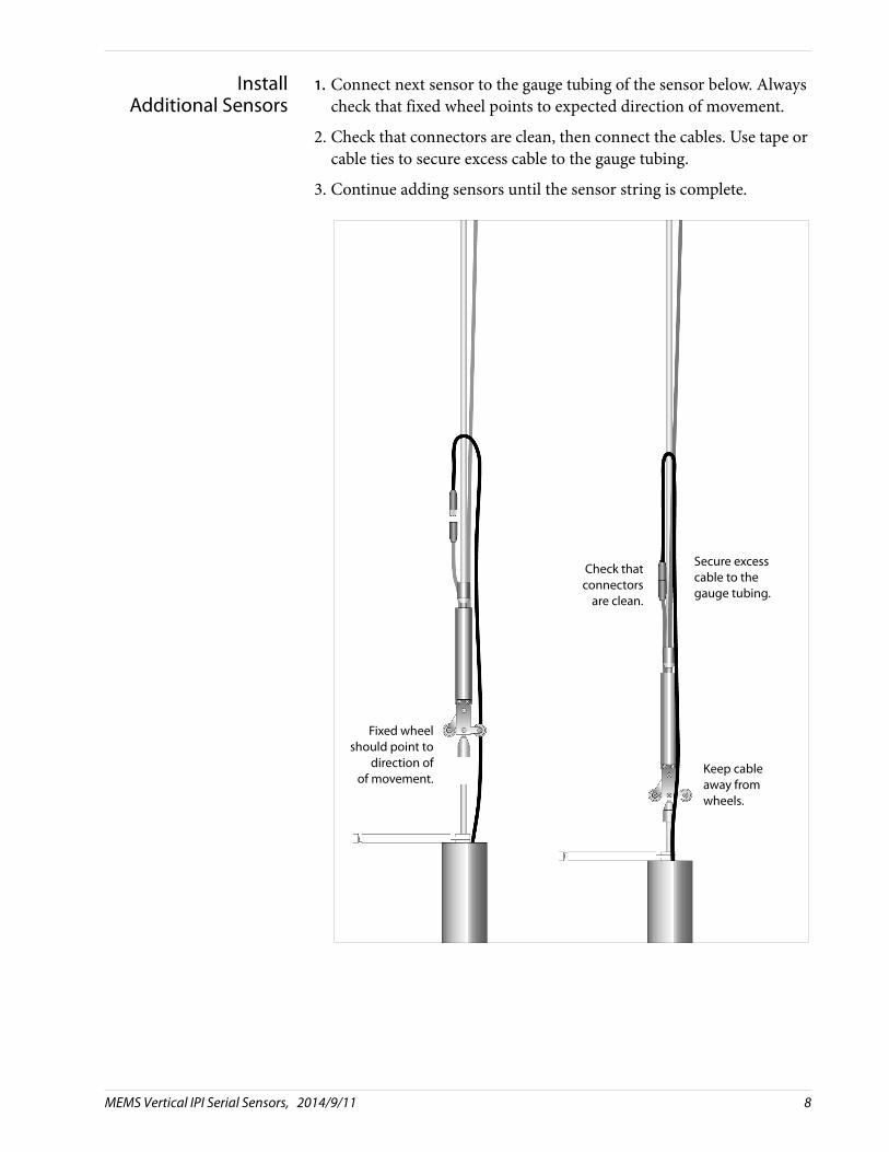
InstallAdditional Sensors
1. Connect next sensor to the gauge tubing of the sensor below. Always check that fixed wheel points to expected direction of movement.
2. Check that connectors are clean, then connect the cables. Use tape or cable ties to secure excess cable to the gauge tubing.
3. Continue adding sensors until the sensor string is complete.
Keep cable away from wheels.
Secure excess cable to the gauge tubing.
Check thatconnectors
are clean.
Fixed wheelshould point to
direction ofof movement.
MEMS Vertical IPI Serial Sensors, 2014/9/11 8
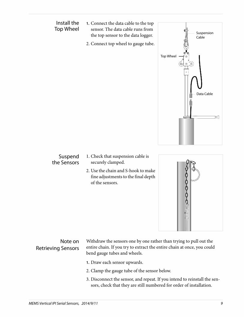
Install the Top Wheel
1. Connect the data cable to the top sensor. The data cable runs from the top sensor to the data logger.
2. Connect top wheel to gauge tube.
Suspendthe Sensors
1. Check that suspension cable is securely clamped.
2. Use the chain and S-hook to make fine adjustments to the final depth of the sensors.
Note onRetrieving Sensors
Withdraw the sensors one by one rather than trying to pull out the entire chain. If you try to extract the entire chain at once, you could bend gauge tubes and wheels.
1. Draw each sensor upwards.
2. Clamp the gauge tube of the sensor below.
3. Disconnect the sensor, and repeat. If you intend to reinstall the sen-sors, check that they are still numbered for order of installation.
Top Wheel
SuspensionCable
Data Cable
MEMS Vertical IPI Serial Sensors, 2014/9/11 9

Data Reduction
Introduction Data reduction is usually automated because it involves a large number of readings and a large number of calculations.
Here, we explain the sensor calibration record and provide an example of converting a single reading in volts to tilt in mm per meter and tilt in degrees.
Calibration Record A calibration record is provided with each sensor. Use sensor serial numbers to match sensors with their calibrations. Calibrations are unique for each sensor.
Factors for tilt are C0, C1, C2, C3, C4, and C5. A-axis factors have an A prefix: AC0, AC1, AC2, AC3, AC4, and AC5. B-axis factors have a B prefix.
Converting Voltsto Tilt
To convert a reading in volts to tilt, use the following formula:Tilt = C5 x Volts2 + C4 x Volts + C3 + C2 x TdegC + C1 x TdegC2 + C0 x Volts x TdegC
Where:
Tilt is a value in mm/m.
C5...C0 are factors for A-axis or B-axis.Volts is the sensor reading in volts.
TdegC is the temperature reading in degrees Centigrade
MEMS Vertical IPI Serial Sensors, 2014/9/11 10
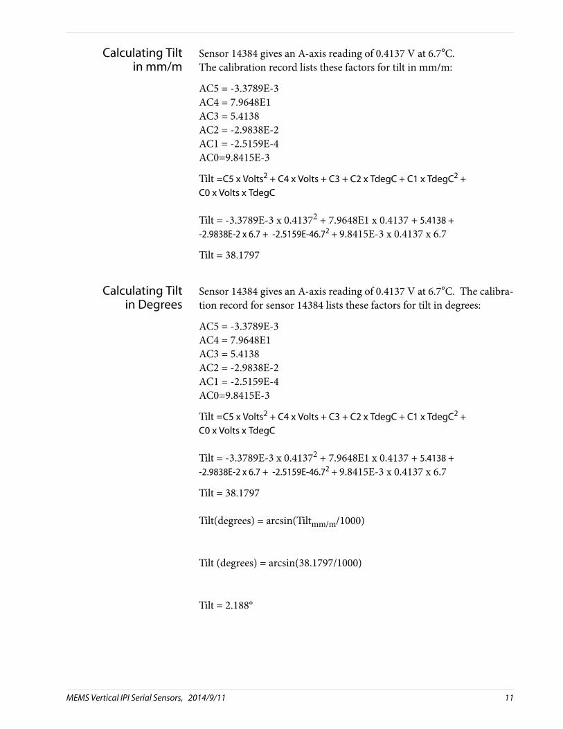
Calculating Tiltin mm/m
Sensor 14384 gives an A-axis reading of 0.4137 V at 6.7°C. The calibration record lists these factors for tilt in mm/m:
AC5 = -3.3789E-3AC4 = 7.9648E1AC3 = 5.4138AC2 = -2.9838E-2AC1 = -2.5159E-4AC0=9.8415E-3
Tilt =C5 x Volts2 + C4 x Volts + C3 + C2 x TdegC + C1 x TdegC2 + C0 x Volts x TdegC
Tilt = -3.3789E-3 x 0.41372 + 7.9648E1 x 0.4137 + 5.4138 + -2.9838E-2 x 6.7 + -2.5159E-46.72 + 9.8415E-3 x 0.4137 x 6.7
Tilt = 38.1797
Calculating Tiltin Degrees
Sensor 14384 gives an A-axis reading of 0.4137 V at 6.7°C. The calibra-tion record for sensor 14384 lists these factors for tilt in degrees:
AC5 = -3.3789E-3AC4 = 7.9648E1AC3 = 5.4138AC2 = -2.9838E-2AC1 = -2.5159E-4AC0=9.8415E-3
Tilt =C5 x Volts2 + C4 x Volts + C3 + C2 x TdegC + C1 x TdegC2 + C0 x Volts x TdegC
Tilt = -3.3789E-3 x 0.41372 + 7.9648E1 x 0.4137 + 5.4138 + -2.9838E-2 x 6.7 + -2.5159E-46.72 + 9.8415E-3 x 0.4137 x 6.7
Tilt = 38.1797
Tilt(degrees) = arcsin(Tiltmm/m/1000)
Tilt (degrees) = arcsin(38.1797/1000)
Tilt = 2.188°
MEMS Vertical IPI Serial Sensors, 2014/9/11 11

Calculating Deviation To calculate deviation over the gauge length of the sensor, use eitherformula below:
Deviationmm = Tiltmm/m x gauge_lengthmorDeviationmm = sin(Tiltdeg) x gauge_lengthmm
Example: Sensor 14384 has a gauge length of 2 meters. The examples below use the temperature corrected tilt values.
Deviationmm = 38.1797 mm/m x 2 mDeviationmm = 76.3594
Deviationmm = sin(2.188) x 2000 mmDeviationmm = 76.3570
CalculatingDisplacement
Displacement (movement) is the change in deviation:
Displacement = Deviation current – Deviation initial
MEMS Vertical IPI Serial Sensors, 2014/9/11 12
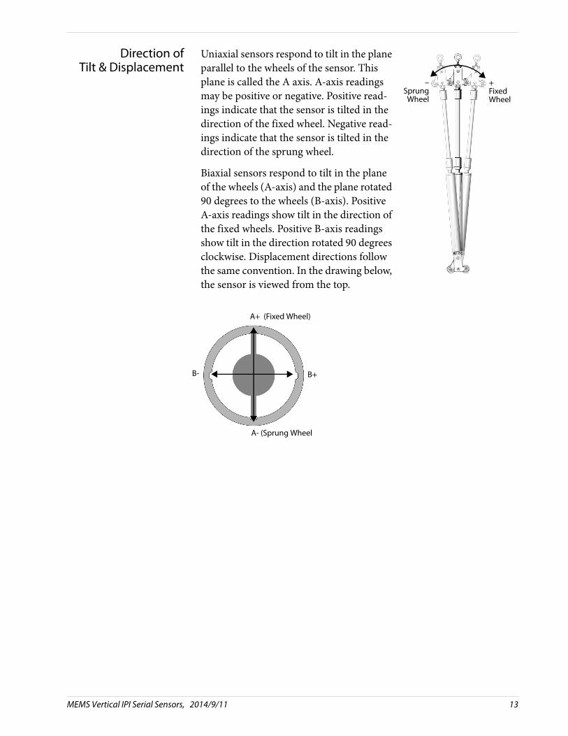
Direction ofTilt & Displacement
Uniaxial sensors respond to tilt in the plane parallel to the wheels of the sensor. This plane is called the A axis. A-axis readings may be positive or negative. Positive read-ings indicate that the sensor is tilted in the direction of the fixed wheel. Negative read-ings indicate that the sensor is tilted in the direction of the sprung wheel.
Biaxial sensors respond to tilt in the plane of the wheels (A-axis) and the plane rotated 90 degrees to the wheels (B-axis). Positive A-axis readings show tilt in the direction of the fixed wheels. Positive B-axis readings show tilt in the direction rotated 90 degrees clockwise. Displacement directions follow the same convention. In the drawing below, the sensor is viewed from the top.
–SprungWheel
+FixedWheel
A+ (Fixed Wheel)
B+
A- (Sprung Wheel
B-
MEMS Vertical IPI Serial Sensors, 2014/9/11 13
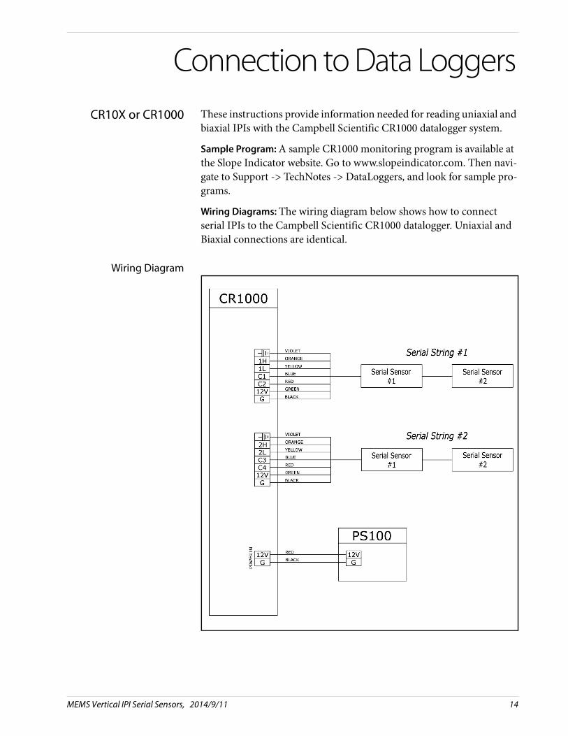
Connection to Data Loggers
CR10X or CR1000 These instructions provide information needed for reading uniaxial and biaxial IPIs with the Campbell Scientific CR1000 datalogger system.
Sample Program: A sample CR1000 monitoring program is available at the Slope Indicator website. Go to www.slopeindicator.com. Then navi-gate to Support -> TechNotes -> DataLoggers, and look for sample pro-grams.
Wiring Diagrams: The wiring diagram below shows how to connect serial IPIs to the Campbell Scientific CR1000 datalogger. Uniaxial and Biaxial connections are identical.
Wiring Diagram
MEMS Vertical IPI Serial Sensors, 2014/9/11 14

Limitations The last sensor in the chain must receive 8 volts. This limits the number of serial sensors that can be connected. the following table assumes that the logger supplies 12 volts:
Length of Data Cable: Limit to Sensors in the Chain:
1 m 16 sensors
50 m 13 sensors
100 m 9 sensors
150 m 6 sensors
200 m 4 sensors
300 m 3 sensors
800 m 1 sensors
MEMS Vertical IPI Serial Sensors, 2014/9/11 15
Related Documents


![Modeling MEMS Sensors [SUGAR: A Computer Aided Design Tool for MEMS ]](https://static.cupdf.com/doc/110x72/56815c78550346895dca8e2b/modeling-mems-sensors-sugar-a-computer-aided-design-tool-for-mems--56ba8b4f53b9b.jpg)


