Model MC600 Multi-Channel Controller for Hydrocarbon, H 2 S and Toxic Gas Monitoring Applications The information and technical data disclosed in this document may be used and disseminated only for the purposes and to the extent specifically authorized in writing by General Monitors. Instruction Manual 02-12 General Monitors reserves the right to change published specifications and designs without prior notice. MANMC600 Part No. MANMC600 Revision Q/02-12

Welcome message from author
This document is posted to help you gain knowledge. Please leave a comment to let me know what you think about it! Share it to your friends and learn new things together.
Transcript

Model MC600
Multi-Channel Controller for Hydrocarbon, H2S and Toxic
Gas Monitoring Applications
The information and technical data disclosed in this document may be used and disseminated only for the purposes and to the extent specifically authorized in writing by General Monitors. Instruction Manual 02-12 General Monitors reserves the right to change published specifications and designs without prior notice.
MANMC600
Part No. MANMC600 Revision Q/02-12

Model MC600
ii
Warranty General Monitors warrants the Model MC600 to be free from defects in workmanship or material under normal use and service within two (2) years from the date of shipment.
General Monitors will repair or replace without charge any such defective equipment found to be deficient during the warranty period. General Monitors’ personnel will make full determination of the nature of and responsibility for, defective equipment.
Defective or damaged equipment must be shipped prepaid to General Monitors’ plant or representative from which shipment was made. In all cases, this warranty is limited to the cost of equipment supplied by General Monitors. The customer will assume all liability for the misuse of this equipment by its employees or other personnel.
NOTE: The Model MC600 Multi-Channel Controller System is easy to install; however, this manual should be read and understood before attempting to install or operate the device.
All warranties are contingent upon proper use in the application for which the product was intended and do not cover products which have been modified or repaired without General Monitors’ approval, or which have been subjected to neglect, accident, improper installation or application, or on which the original identification marks have been removed or altered.
Except for the express warranty stated above, General Monitors disclaims all warranties with regard to the products sold, including all implied warranties of merchantability and fitness and the express warranty stated herein are in lieu of all obligations or liabilities on the part of General Monitors for damages including, but not limited to, consequential damages arising out of, or in connection with, the use or performance of the product.
Warnings This instruction manual includes numerous cautions and warnings that are included to prevent injury to technicians who are handling the equipment and to prevent damage to your detection system.
WARNING: TOXIC, COMBUSTIBLE AND FLAMMABLE GASES AND VAPORS ARE VERY DANGEROUS. USE EXTREME CAUTION WHEN THESE HAZARDS ARE PRESENT.
WARNING: HYDROGEN SULFIDE (H2S) IS AN EXTREMELY TOXIC GAS AND EXPOSURE MAY RESULT IN A LOSS OF CONSCIOUSNESS OR DEATH.

Model MC600
iii
System Integrity Verification General Monitors’ mission is to benefit society by providing solutions through industry-leading safety products, services, and systems that save lives and protect capital resources from the dangers of hazardous flames, gases, and vapors.
The safety products you have purchased should be handled carefully and installed, calibrated, and maintained in accordance with their product instruction manuals. Remember, these products are for your safety.
To ensure operation at optimum performance, General Monitors recommends that certain preventive startup and maintenance tasks be performed.
Commissioning Safety Systems Before power up, verify wiring, terminal connection, and stability of mounting for all integral safety equipment including, but not limited to:
• Power Supplies
• Control Modules
• Field detection devices
• Signaling/output devices
• Accessories connected to field and signaling devices
After the initial application of power (and any factor-specified warm-up period) to the safety system, verify that all signal outputs to and from devices and modules are within the manufacturer’s specifications. Initial calibration, calibration checking and testing should be performed per the manufacturer’s recommendations and instructions.
Proper system operation should be verified by performing a full, functional test of all component devices of the safety system, ensuring that the proper levels of alarming occur.
Fault/Malfunction circuit operation should be verified.
Periodic Testing/Calibration of Field Devices Periodic testing/calibrating should be performed per the manufacturer’s recommendations and instructions. Testing/Calibration procedures should include, but not be limited to:
• Verify zero reading
• Apply a known concentration of gas, or simulated test device provided by the manufacturer
• Verify integrity of all optical surfaces and devices
When testing produces results outside of the manufacturers’ specifications, recalibration or repair/replacement of the suspect device(s) should be performed as necessary. Calibration intervals should be independently established through a documented procedure, including a calibration log maintained by plant personnel or third party testing services.

Model MC600
iv
Periodic System Verification The following system verifications should be performed at least annually:
Verify wiring, terminal connections and stability of mounting for all integral safety equipment, including, but not limited to:
• Power supplies
• Control modules
• Field detection devices
• Signaling/output devices
• Accessories connected to field and signaling devices
Proper system operation should be verified by performing a full, functional test of all component devices of the safety system, ensuring that the proper levels of alarming occur.
Fault/Malfunction circuit operation should be verified. In addition, calibration intervals should be independently established through a documented procedure, including a calibration log maintained by plant personnel or third party testing services.

Model MC600
v
About This Manual This manual provides instructions for installing and operating the Model MC600 Multi-Channel Controller. Maintenance and specification information is also provided, as well as, programming information for the MODBUS registers. The intended audience includes field service technicians, MODBUS programmers and other technical staff involved in installing and using an MC600 system.
Format Conventions Several format conventions are used throughout the book for notes and cautions, warnings, as well as, MODBUS notations.
Notes, Cautions and Warnings
NOTE: Notes provide supplementary details such as, exception conditions, alternate methods for a task, time saving tips and references to related information.
CAUTION: Cautions describe precautions to prevent damage to equipment.
WARNING: Warnings describe precautions to prevent serious injury to people working with equipment.
MC600 Menu Formats • Menu keywords and LCD digital display messages are shown in bold,
e.g. Cal Fault.
• MC600 navigation buttons are shown in text paragraphs formatted in bold, surrounded by square brackets, e.g. [ACCEPT] or [MODE]
MODBUS Register Formats Hexadecimal numbers are indicated by a trailing lowercase “h”, such as, 000Eh.
Other Sources of Help General Monitors provides extensive documentation, white papers and product literature for its complete selection of safety products, many of which can be used in combination with the MC600. A selection of these documents is available online at the General Monitors’ website at http://www.generalmonitors.com or www.mc600.com.

Model MC600
vi
Related Documentation The detection instruments that you connect to the MC600 each have their own documentation and you will need to refer to the instruction manual for each instrument in order to calibrate and maintain the instrument. A list of the manuals for the MC600-compatible detection instruments follows:
• Model TS400 Instruction Manual, part number MANTS400
• Model TS420 Instruction Manual, part number MANTS420
• Model TS4000 Instruction Manual; part number MANTS4000
• Model TS4000H Instruction Manual; part number MANTS4000H
• Model IR400 Instruction Manual, part number MANIR400
• Model IR700 Instruction Manual, part number MANIR700
• Model IR2100 Instruction Manual, part number MANIR2100
• Model IR5000 Instruction Manual, part number MANIR5000
• Model IR5500 Instruction Manual, part number MANIR5500
• Model IR7000 Instruction Manual, part number MANIR7000
• Model S4000C Instruction Manual, part number MANS4000C
• Model S4000CH Instruction Manual, part number MANS4000CH
• Model S4000T Instruction Manual, part number MANS4000T
• Model S4000TH Instruction Manual, part number MANS4000TH
• Model S4100C Instruction Manual, part number MANS4100C
• Model S4100T Instruction Manual, part number MANS4100T
• Model S214 Instruction Manual, part number MANS214
• Model S216A Instruction Manual, part number MANS216A
• Model S104 Instruction Manual, part number MANS104
• Model S106A Instruction Manual, part number MANS106A
• Gassonic Observer Instruction Manual
• Gassonic Observer-H Instruction Manual, part number MANOBSERVER-H
• Gassonic Surveyor Instruction Manual, part number BB6019
Contacting Customer Support For additional product information not contained in this manual, please contact General Monitors Customer Support; refer to Section 6.0 for contact information.

Model MC600
vii
1.0 Quick Start Installation Instructions The main steps in a typical MC600 installation are listed below. There is some variation in the installation process at each site, depending on the exact site configuration.
Installation Step Refer to Section
1. Unpack the equipment and prepare for the installation.
Section 1.1, 1.2
2. Mount the MC600 cabinet in place Section 1.3
3. Mounting sensors and instruments Section 1.4
4. Connecting sensors and instruments to the MC600
Section 1.5
5. Connecting Modbus, HART, and relay devices from instruments to MC600
Section 1.6, 1.7, 1.8
6. Connect the MC600 cabinet to an external power supply if necessary, and then power on the MC600 system
Section 1.9
Table 1: MC600 Installation Overview
1.1 Unpacking the MC600 Equipment Please keep the following precautions in mind when you unpack and install the MC600 cabinet and cabling.
Installation and maintenance must be carried out by suitably, skilled and competent personnel only.
Contact with the PCB components should be avoided in order to prevent damage from static electricity to equipment and personnel. Special care must be taken to wear grounding apparel and to ensure that only the connection points are touched whenever you are handling or installing the MC600.
Each MOS H2S sensor is shipped with a red plastic cap fitted over the sensor head. Inside the cap is a desiccant. DO NOT remove this cap until you are ready to power the system. SAVE the cap and RE-CAP the sensor anytime the system power is off for more than one hour.
All equipment shipped by General Monitors is packaged in shock absorbing containers, which provide considerable protection against physical damage. The contents should be carefully removed and checked against the packing list.
If any damage has occurred or there is any discrepancy in the order, please notify General Monitors as soon as possible. All subsequent correspondence

Model MC600
viii
with General Monitors must specify the equipment part number and the serial number.
NOTE: Each Model MC600 is thoroughly tested at the factory. However, a system checkout is required upon initial start-up to ensure system integrity.
1.2 Preparing for the Installation To prepare installing the MC600 cabinet, you will need to choose a location and gather the required tools. Separate preparation guidelines for mounting sensors are provided in Section 1.5
1.2.1 Choosing a Location The MC600 cabinet should be wall-mounted in a non-hazardous area. It can be placed indoors or outdoors. You will need to select a location for the MC600 that is near enough to the field-mounted devices to conform to the maximum cable lengths specified for the field-mounted device.
NOTE: If a Class I Division 2 power supply is used, the cabinet can be mounted in a hazardous Class I Division 2 area.
There must be adequate clearance beneath the MC600 cabinet to allow for cable installation. Weather-protected locations with minimal shock and vibration are preferred. Although the MC600 is largely immune to electromagnetic interference (EMI), it should not be mounted in close proximity to radio transmitters or similar equipment. The MC600 is provided with two ferrite clamps for use on the power supply cable in case any interference is observed. Before installation, carefully review the Environmental Specifications in Section 10.3 for allowable temperature ranges and the Electrical Specifications in Section 10.4 for power supply requirements.
1.2.2 Tools You Will Need The following tools will be needed to install and cable the MC600:
• Flat-head screwdriver maximum 3/16” (5 mm) width for terminal block connections (included with unit)
• Adjustable wrench for conduit or cable gland connections (not included)
• #2 Phillips-head screwdriver (not included)

Model MC600
ix
1.3 Mounting the MC600 Cabinet in Place
MODEL MC600
CAUTION:READ AND UNDERSTAND THE INSTRUCTION MANUAL BEFORE OPERATING OR SERVICING.
P/N 65000 -
GALWAY, IRELAND
RATED 24VDC, " " 185 W MAX., (STANDARD)
CONTACT RATINGS: 8A @ 30VDC RESISTIVE MAX
115/230 VAC 50 TO 60 Hz, 185 W MAX., (OPTIONAL)
TEMP. (-20°C To +60°C), (STANDARD)TEMP. (-10°C To +60°C), (OPTIONAL POWER SUPPLY)
GENERAL MONITORS, INC.LAKE FOREST, CALIFORNIA, USA
MULTI-CHANNEL CONTROLLER
8A @ 250-VAC
CONFIGURATION
MANUAL DATE
SERIAL #
65079-1
Figure 1: Mounting Dimensions for the MC600 Cabinet
To mount the MC600 Cabinet in place:
• Before bolting the cabinet in place, make sure it is level. Fasten four ¼-inch bolts into the four mounting holes on the corners of the enclosure. Use appropriate mounting screws/bolts in regard to the mounting surface i.e. concrete, wood, etc. Do not mount the MC600 onto drywall unless it is secured to the wooden studs behind the drywall.
1.4 Mounting the Sensors and Instruments The catalytic HC sensors, MOS H2S sensors and 4-20mA instruments, which will be connected to the MC600, must be mounted in locations where they are needed for gas detection. This can take place either before or after the MC600 cabinet is mounted in place. For detailed guidelines on selecting catalytic HC and MOS H2S sensor locations, refer to Section 3.5.1.
1.4.1 Mounting Sensors with General Monitors’ Accessories Section 11.0 provides ordering information for several accessories for sensor mounting, such as explosion-proof junction boxes, duct mounting kits,

Model MC600
x
splashguards, dust guards and remote calibration devices. Instructions for mounting each type of 4-20mA instrument are provided in the instruction manual for the instrument. For detailed guidelines on installing a sensor with a junction box or duct mounting kit, refer to the following sections:
• Mounting a Sensor with a GM Junction Box (Section 3.5.3)
• Mounting a Sensor with a Duct Mounting Kit (Section 3.5.4)
1.4.2 Applying Sealants to Conduit Entries Please keep the following warning in mind when installing housings and cabling from catalytic HC and MOS H2S sensors and 4-20mA instruments in hazardous areas. Make sure that the equipment maintains the appropriate seals for a Class I hazardous location.
WARNING: Each conduit run within a hazardous location (and from a hazardous to a non-hazardous location) must be sealed so that gases, vapors, and/or flames cannot pass beyond the seal. The purpose of seals in a Class I hazardous location is to prevent the passage of gases, vapors, or flames from one electrical installation to another through the conduit system. For information on Class I hazardous location seals, see NEC articles 501-5 and 500-3d.
NOTE: For additional warnings and cautions, refer to Section 3.6.1
1.5 Connecting Sensors and Instruments to the MC600
Once the MC600 cabinet is installed, you are ready to begin cabling from the signal conditioning cards in the MC600 cabinet slots to field-mounted catalytic HC sensors, MOS H2S sensors and 4-20mA instruments. To install wiring from MOS H2S and catalytic HC sensors or instruments to the MC600, the end of the wires that will be fastened to the MC600 signal card connector should be stripped to approximately 0.25 inches, as shown below.
Figure 2: Pre-stripping Wiring
1.5.1 Cabling Warnings and Cautions Please review the following cautions before proceeding to install cabling. For information on non-hazardous location cabling to the MC600 cabinet, see NEC article 504. For information on Class I location seals for sensors mounted in hazardous areas, see NEC articles 501-5 and 500-3d
CAUTION: Under no circumstances should equipment be connected or disconnected when under power. This is contrary to hazardous area regulations and may also lead to serious damage to the

Model MC600
xi
equipment. Equipment damaged in this manner is not covered under warranty.
CAUTION: The MC600 Multi-Channel Controller System and field-mounted sensor devices contain components that can be damaged by static electricity. Special care must be taken when wiring the system to ensure that only the connection points are touched.
Removing or installing cards or field devices while power is applied may cause permanent damage.
1.5.2 Connecting a MOS H2S Sensor to the MC600 NOTE: Only MOS H2S sensors designed by General Monitors will work with the
MC600. Any attempt to use a sensor that has not been designed by General Monitors will void the MC600 warranty.
Four-wire cabling is required to connect from the MOS H2S signal-conditioning card to a field-mounted MOS H2S sensor. The maximum cable lengths are indicated in Table 27; MOS H2S Sensor Cable Lengths.
To connect to a MOS H2S sensor:
1. Thread four-wire cabling from the MOS H2S sensor into the MC600 cabinet through one of the conduit openings in the bottom of the cabinet.
2. Remove the connector from the MOS H2S signal-conditioning card by loosening the two recessed screws that hold it in place and lift the connector forwards.
3. Loosen the five-wire receptacle screws on the bottom of the connector. Secure each wire from the field device into the connector receptacle and tighten the screw that holds it in place. Fasten the cabling shield in the far right receptacle.
4. Once the wires are secured in the connector, replace the connector on the card and tighten the connector mounting screws at each side.
Figure 3: MOS H2S Connection
1.5.3 Connecting a Catalytic HC Sensor to the MC600 NOTE: Only catalytic HC sensors designed by General Monitors will work with
the MC600. Any attempt to use a sensor that has not been designed by General Monitors will void the MC600 warranty.
MOS H2S Card 2 Connector Screws
White Green Black Red Shield

Model MC600
xii
Three-wire or four-wire cabling is used to connect from the catalytic HC signal-conditioning card to a field-mounted catalytic HC sensor. The maximum cable lengths are indicated in Table 26; Catalytic HC Sensor Cable Lengths.
To connect a catalytic HC sensor:
1. Thread cabling from the catalytic HC sensor into the MC600 cabinet through one of the conduit openings in the bottom of the cabinet.
2. Remove the connector from the catalytic HC signal-conditioning card by loosening the two recessed screws that hold it in place and lift the connector forwards
3. Loosen the wire receptacle screws. Then secure the red, black and white wires from the field device in the receptacles and tighten the screws to hold them in place. Fasten the cabling shield in the far right receptacle.
4. Once the wires are secured in the connector, replace the connector on the card and tighten the connector mounting screws at each side.
Figure 4: 4-20mA Instrument Connection
NOTE: If you have four-wire cabling, you can fasten the green wire into the empty second receptacle; however, no signal will be carried on this wire.
1.5.4 Connecting a 4-20mA Instrument to the MC600 Instruments with their own control circuitry, such as the, S4000 Series, S4100 Series, IR2100, Gassonic Observer and Gassonic Surveyor - are connected to the MC600 through a 4-20mA signal-conditioning card.
To connect a 4-20mA instrument:
1. Thread four-wire cabling from the instrument into the MC600 cabinet through one of the conduit openings in the bottom of the cabinet. The maximum cable lengths are indicated in the manuals for each device.
2. Remove the connector from the 4-20mA signal-conditioning card by loosening the two recessed screws that hold it in place and lift the connector forwards.
3. Loosen the five-wire receptacle screws, then secure each wire from the field device into the connector receptacle and tighten the screws that hold them in place. Fasten the cabling shield to the rightmost receptacle.
Catalytic HC Card 2 Connector Screws
White N/C Black Red Shield

Model MC600
xiii
• The Analog Out signal from the detection instrument must be routed to the Analog In receptacle on the signal-conditioning card connector.
NOTE: When the field instrument is an IR5000/IR5500, there are two Analog Out signals from the field instrument. Connect them to the Analog In receptacles of any two channels of the MC600 system.
• COM (DC Ground) must also be connected from the field device to the MC600 signal-conditioning card connector.
• Connect the +24VDC signal wire from the detection instrument to the second connector receptacle, if the MC600 power supply is to be used to provide power to that instrument. If you choose to connect the instrument to a separate power supply other than the MC600, do not connect the +24VDC power signal wire.
• The Analog Out receptacle on the signal-conditioning card connector is provided to forward the 4-20mA input from the field instrument on to another monitoring device, such as a PLC. Ground must also be connected to this device.
4. Once the wires are secured in the connector, replace the connector on the card and tighten the connector mounting screws at each side.
Figure 5: Cabling Shield
NOTE: For some 4-20mA instruments, the MC600 message Fld Dev Fault will appear while the instrument is in start-up mode. Refer to the instrument documentation for information on the start-up process.
COM- Ground (+24VDC)Analog In
Analog Out Ground
Wire Receptacle Screws
63 mA Fuse (250 Volts)
500 mA Fuse (250 Volts)
Cable fromInstrument

Model MC600
xiv
CAUTION: The MC600 Multi-Channel Controller System cannot provide sufficient power for an IR5000/IR5500 field instrument. When an IR5000/IR5500 is being connected to the MC600, the user should provide their own 24V power supply for the IR5000/IR5500 source and receiver units, as outlined in the IR5000/IR5500 manual. Do not use the +24V DC signal connection from the MC600 signal-conditioning card, or damage to the system may occur.
1.6 Connecting a MODBUS Device Connector J8 near the bottom left side of the main MC600 controller (Figure 8) is provided for connecting the two MC600 MODBUS channels to control room MODBUS devices. Refer to the manual for the field device to determine maximum cable lengths.
1.7 Connecting a HART Field Device A HART field device like the IR400, S4000CH, S4000TH, IR5500 and TS4000H can only operate with the MC600 through analog current communication. In order to make the full range of analog signal available to the MC600, the field devices must have HART disabled. Please consult the instruction manual of the field device on disabling the bi-directional communication.
WARNING: Field devices equipped with HART must have the HART function disabled to work properly with the MC600. If the devices are not disabled, the multi-point controller will not recognize fault conditions from HART.
1.8 Connecting Alarm Relay Devices Connectors J10 and J11 at the bottom of the MC600 main PCB (Figure 8) connect Relays 1 to 6 to alarm devices, such as, sirens and bells. The functioning of the Alarm and Warning relay connections varies depending on whether the relays are configured as energized or de-energized, latching, non-latching or Timed.
Figure 6: MC600 MODBUS & Alarm Relay Connectors
There are nine inputs in connectors J10 and J11 to connect to a relay, for total of 18 connections. Each input label indicates what it is used for.
• The first digit in the receptacle label represents the channel number, from 1 to 6
• The last digit in the receptacle label indicates the function of the receptacle.

Model MC600
xv
• If the last digit is C, then the receptacle is for Relay Common.
• If the relays are set up as de-energized (the default), the last digit 1 is for normally closed and the last digit 2 is for normally open.
• If the relays are set up as energized, the last digit 1 is normally open and the last digit 2 is normally closed.
NOTE: Connector J12 (Figure 9) is connected to Fault relays. The Fault relay is normally energized. It will change state after power-up.
The default MC600 configuration setting for the Warning and Alarm relays is de-energized. Use Table 2 as a guide for determining the normally open (NO) and the normally closed (NC) contacts for the energized vs. de-energized setting.
Table 2: Normally Open and Closed Relays
WARNING: Relay contacts must be protected against transient and over-voltage conditions (Figure 27).
1.9 Connecting Power and Starting Operation Once the mounting, cabling, and alarm relay installation is complete, the MC600 Multi-Channel Controller System is ready to begin the power-on sequence. Please review this section carefully before powering on the system.
1.9.1 Start-up Readiness Checklist Prior to applying power to the system for the first time, check the following items:
• Verify that all signal wiring (except for +24V) is installed correctly.
• Verify that the MC600 cabinet is properly mounted. Make sure that the conduit/cable entries are securely installed.
• Make sure to inhibit any external devices, such as, Trip Amplifiers, PLC devices or DCS systems until after the start-up sequence has completed.

Model MC600
xvi
NOTE: The +24V wire(s) to the power supply (supplies) should be connected after the readiness checklist is verified to protect the system from shorting.
NOTE: The SHIELD terminal of J9 should be connected to an earth ground.
1.9.2 Connecting the MC600 to a Power Supply
WARNING: The MC600 power supply or connected external power supply should be left OFF and unconnected to its power source until after you have completed cabling connections.
If you have ordered a power supply pre-installed for the MC600, the unit will be shipped with cabling from the power supply to the control board pre-installed. You will only need to connect the onboard power supply to a 115/230 VAC power source.
USC
NL FG
OUTPUT: +24V 6.5A
INPUT: 110-120VAC 3.2AS-150-24 220-240VAC 1.6A
50/60HzCAUTION:
115V
Figure 7: MC600 Connections to an Onboard Power Supply
To connect the MC600 onboard power supply to a power source:
Refer to Figure 9 as you follow these steps.
1. Verify the voltage switch on the power supply is set appropriately for you site’s AC power connection, either 115VAC or 230VAC.
2. Connect cabling from the connector beneath the power supply to the power supply’s external power source. Three wires will be needed to carry AC line, AC neutral and frame ground to the power source.
Voltage Switch
Frame Ground
AC Line
AC Neutral
To Power

Model MC600
xvii
Figure 8: Onboard Class I Division 2 Power Supply
To connect the MC600 onboard Class I Division 2 power supply to a power source:
Refer to Figure 10 when following these steps
Connect cabling from the connector beneath the power supply to the power supply’s external power source. Three wires will be needed to carry the AC line AC neutral, and frame ground to the power source.
NOTE: This is 100VAC – 240VAC/50Hz-60Hz auto-switching power supply, you do not need to select the input voltage.
To connect the MC600 to an external power source:
If the MC600 does not have an onboard power supply, you will need to install cabling form the MC600 J9 connector to an external primary DC power supply (Figure 11). See Table 26 for cable length specifications.
Refer to your power supply manual for the location of the ground and +24VDC terminals and connections from the external power supply to a power source.

Model MC600
xviii
Figure 9: MC600 Connections to an External Power Supply
Refer to Figure 11 when following these steps
1. Connect a wire from the MC600 J9 connector COM receptacle to the power supply DC Ground connector.
2. Connect the MC600 J9 connector +24VDC receptacle to the power supply +24VDC terminal
3. The Model MC600 operates on nominal power of +24VDC. When you are ready to power on the MC600, connect the external power supply to a power source. Refer to your power supply manual for instructions on connecting it to a power supply.
Model MC600
xix
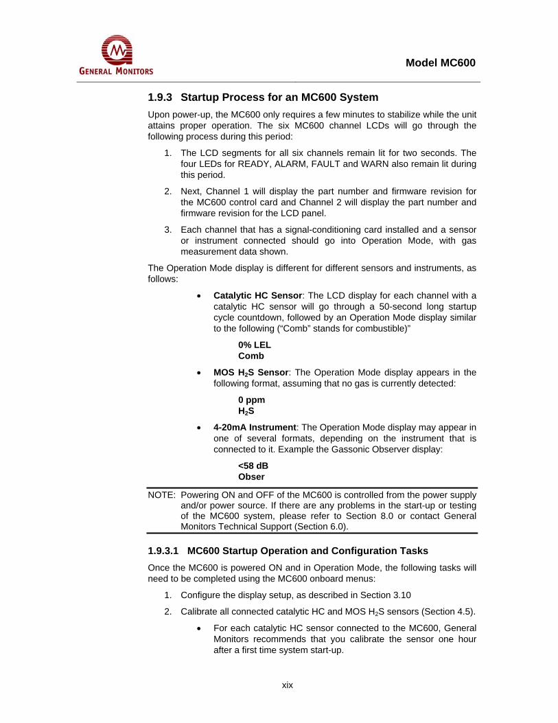
1.9.3 Startup Process for an MC600 System Upon power-up, the MC600 only requires a few minutes to stabilize while the unit attains proper operation. The six MC600 channel LCDs will go through the following process during this period:
1. The LCD segments for all six channels remain lit for two seconds. The four LEDs for READY, ALARM, FAULT and WARN also remain lit during this period.
2. Next, Channel 1 will display the part number and firmware revision for the MC600 control card and Channel 2 will display the part number and firmware revision for the LCD panel.
3. Each channel that has a signal-conditioning card installed and a sensor or instrument connected should go into Operation Mode, with gas measurement data shown.
The Operation Mode display is different for different sensors and instruments, as follows:
• Catalytic HC Sensor: The LCD display for each channel with a catalytic HC sensor will go through a 50-second long startup cycle countdown, followed by an Operation Mode display similar to the following (“Comb” stands for combustible)”
0% LEL Comb
• MOS H2S Sensor: The Operation Mode display appears in the following format, assuming that no gas is currently detected:
0 ppm H2S
• 4-20mA Instrument: The Operation Mode display may appear in one of several formats, depending on the instrument that is connected to it. Example the Gassonic Observer display:
<58 dB Obser
NOTE: Powering ON and OFF of the MC600 is controlled from the power supply and/or power source. If there are any problems in the start-up or testing of the MC600 system, please refer to Section 8.0 or contact General Monitors Technical Support (Section 6.0).
1.9.3.1 MC600 Startup Operation and Configuration Tasks Once the MC600 is powered ON and in Operation Mode, the following tasks will need to be completed using the MC600 onboard menus:
1. Configure the display setup, as described in Section 3.10
2. Calibrate all connected catalytic HC and MOS H2S sensors (Section 4.5).
• For each catalytic HC sensor connected to the MC600, General Monitors recommends that you calibrate the sensor one hour after a first time system start-up.

Model MC600
xx
• For each MOS H2S sensor connected to the MC600, General Monitors recommends that you calibrate the sensor one hour after start-up and again 24 hours later.
3. Recalibrate the LCD channel display for 4-20mA signal-conditioning cards (Section 4.6).
4. Configure the Alarm and Warning relay set points, as needed (Section 4.9.1).
5. Configure the relays, as needed, for energized versus de-energized, latching versus non-latching or timed (Section 4.9.3).
NOTE: For general instructions on navigating the MC600 menu system, see Section 4.1.

Model MC600
xxi
Table of Contents WARRANTY ................................................................................................................................. II
WARNINGS .................................................................................................................................. II
SYSTEM INTEGRITY VERIFICATION........................................................................................ III Commissioning Safety Systems ............................................................................................... iii Periodic Testing/Calibration of Field Devices ........................................................................... iii Periodic System Verification ..................................................................................................... iv
ABOUT THIS MANUAL............................................................................................................... V Format Conventions................................................................................................................................v
Notes, Cautions and Warnings ..................................................................................................v MC600 Menu Formats ...............................................................................................................v MODBUS Register Formats.......................................................................................................v
Other Sources of Help.............................................................................................................................v Related Documentation ............................................................................................................ vi Contacting Customer Support................................................................................................... vi
1.0 QUICK START INSTALLATION INSTRUCTIONS ............................................................. VII 1.1 Unpacking the MC600 Equipment ........................................................................................... vii 1.2 Preparing for the Installation ................................................................................................... viii
1.2.1 Choosing a Location .................................................................................................. viii 1.2.2 Tools You Will Need .................................................................................................. viii
1.3 Mounting the MC600 Cabinet in Place ..................................................................................... ix 1.4 Mounting the Sensors and Instruments .................................................................................... ix
1.4.1 Mounting Sensors with General Monitors’ Accessories .............................................. ix 1.4.2 Applying Sealants to Conduit Entries ...........................................................................x
1.5 Connecting Sensors and Instruments to the MC600.................................................................x 1.5.1 Cabling Warnings and Cautions ...................................................................................x 1.5.2 Connecting a MOS H2S Sensor to the MC600 ............................................................ xi 1.5.3 Connecting a Catalytic HC Sensor to the MC600........................................................ xi 1.5.4 Connecting a 4-20mA Instrument to the MC600 ........................................................ xii
1.6 Connecting a MODBUS Device .............................................................................................. xiv 1.7 Connecting a HART Field Device ........................................................................................... xiv 1.8 Connecting Alarm Relay Devices ........................................................................................... xiv 1.9 Connecting Power and Starting Operation .............................................................................. xv
1.9.1 Start-up Readiness Checklist...................................................................................... xv 1.9.2 Connecting the MC600 to a Power Supply................................................................ xvi 1.9.3 Startup Process for an MC600 System ..................................................................... xix
2.0 INTRODUCTION.....................................................................................................................1 2.1 Features and Benefits ................................................................................................................3 2.2 Applications................................................................................................................................3
3.0 INSTALLATION......................................................................................................................4 3.1 Unpacking the MC600 Equipment .............................................................................................4

Model MC600
xxii
3.2 Preparing for the Installation ......................................................................................................5 3.2.1 Choosing a Location .....................................................................................................5 3.2.2 Tools You Will Need .....................................................................................................5
3.3 Mounting the MC600 Cabinet in Place ......................................................................................5 3.4 Mounting the Sensors and Instruments .....................................................................................6
3.4.1 Sensor Location Considerations ...................................................................................7 3.4.2 Sensor Poisons.............................................................................................................7 3.4.3 Mounting a Sensor with a GM Junction Box.................................................................7 3.4.4 Mounting a Sensor with a Duct Mounting Kit................................................................9 3.4.5 Applying Sealants to Conduit Entries ...........................................................................9
3.5 Connecting Sensors and Instruments to the MC600...............................................................10 3.5.1 Warnings, Cautions and Standards ............................................................................11 3.5.2 Connecting a MOS H2S Sensor to the MC600 ...........................................................12 3.5.3 Connecting a Catalytic HC Sensor to the MC600.......................................................13 3.5.4 Connecting a 4-20mA Instrument to the MC600 ........................................................14
3.6 Connecting a MODBUS Device ...............................................................................................16 3.7 Connecting a HART Field Device ............................................................................................16 3.8 Connecting Alarm Relay Devices ............................................................................................16 3.9 Connecting Power and Starting Operation ..............................................................................18
3.9.1 Start-up Readiness Checklist......................................................................................18 3.9.2 Connecting the MC600 to a Power Supply.................................................................19 3.9.3 Startup Process for an MC600 System ......................................................................21
3.10 Configuring the Front Panel Setup...........................................................................................24 3.11 Maintaining the X/P Integrity ....................................................................................................25
4.0 BASIC OPERATION AND CONFIGURATION.....................................................................26 4.1 Entering and Exiting from the MC600 Menus ..........................................................................26 4.2 Using the Front Panel Navigation Buttons...............................................................................27 4.3 Menu Flowchart Legend ..........................................................................................................27 4.4 MC600 Menu Overview ...........................................................................................................28 4.5 Calibrating Catalytic HC and MOS H2S Sensors.....................................................................29
4.5.1 Calibration Schedule...................................................................................................30 4.5.2 Preparing for Calibration .............................................................................................30 4.5.3 Sensor Calibration Equipment ....................................................................................30 4.5.4 Calibration Procedure for Catalytic HC and MOS H2S Sensors.................................32 4.5.5 Stopping Sensor Calibration .......................................................................................33
4.6 Calibrating the LCD Display for 4-20mA Instruments ..............................................................34 4.7 Checking Calibration for Sensors ............................................................................................35 4.8 Inhibiting Alarms for Selected Channels..................................................................................37 4.9 Using the Basic Setup Menu Options ......................................................................................38
4.9.1 Configuring Alarm and Warning Set points.................................................................40 4.9.2 Configuring alarm delay time (Gassonic products only) .............................................45 4.9.3 Configuring a Calibration Point for Catalytic HC Sensors ..........................................46 4.9.4 Configuring the MC600 Relays ...................................................................................46
5.0 ADVANCED CONFIGURATION ..........................................................................................49 5.1 Using the Advanced Setup Menu Options...............................................................................50
5.1.1 Selecting a Model Option............................................................................................50 5.1.2 Selecting the Channel Mode for the Alarm and Warning Indicators...........................53 5.1.3 Configuring Zoning (for Relay Allocation) ...................................................................54

Model MC600
xxiii
5.1.4 Configuring Horn Relay...............................................................................................59 5.1.5 Configuring Card Tests ...............................................................................................59 5.1.6 Configuring Setup and Inhibit Passwords...................................................................60 5.1.7 Configuring the Fault Relays.......................................................................................62 5.1.8 Configuring MODBUS Parameters .............................................................................63 5.1.9 Loading Default Settings.............................................................................................64
5.2 Using the Setup Check Menu ..................................................................................................65 5.3 Using the Self Test Menu.........................................................................................................67
6.0 CUSTOMER SUPPORT .......................................................................................................68 6.1 GENERAL MONITORS’ OFFICES..........................................................................................68
7.0 MAINTENANCE....................................................................................................................69 7.1 Developing a Maintenance Schedule ......................................................................................69 7.2 Calibration and Calibration Checks..........................................................................................69
7.2.1 Alternate Calibration Equipment .................................................................................69 7.3 Cleaning the MC600 ................................................................................................................72 7.4 Lubrication................................................................................................................................72 7.5 Storage.....................................................................................................................................72
8.0 TROUBLESHOOTING..........................................................................................................73 8.1 MC600 Controller Error Codes and Remedies ........................................................................73
8.1.1 CON FAIL/COMM .......................................................................................................73 8.1.2 CON FAIL / EEPROM.................................................................................................73 8.1.3 CON FAIL / LOW LINE ...............................................................................................73 8.1.4 CON FAIL / PROGRAM..............................................................................................73 8.1.5 CON FAIL / RAM.........................................................................................................73 8.1.6 CON FAIL / DATA RAM..............................................................................................73
8.2 Channel Error Codes and Remedies .......................................................................................74 8.2.1 Setup Channel (Sensors and Instruments).................................................................74 8.2.2 Cal Channel (Sensors and Instruments).....................................................................74 8.2.3 Cal Fault (Sensors and Instruments) ..........................................................................74 8.2.4 Card Removed (Sensors and Instruments) ................................................................74 8.2.5 Fld Dev Fault (Instruments Only) ................................................................................74 8.2.6 Invalid Card (Sensors and Instruments) .....................................................................75 8.2.7 Sensor Fault (Sensors Only).......................................................................................75 8.2.8 Field Device Offline: ....................................................................................................75
9.0 MC600 MODBUS INTERFACE ............................................................................................76 9.1 General MODBUS Information ................................................................................................76
9.1.1 Serial Communication Settings...................................................................................76 9.1.2 Function Codes Supported .........................................................................................76 9.1.3 MODBUS Read Protocol (Query/Response)..............................................................77 9.1.4 MODBUS Write Command Protocol (Query/Response) ............................................78 9.1.5 Exception Response Messages and Codes ...............................................................79
9.2 MC600 MODBUS Registers Summary....................................................................................80 9.3 MC600 MODBUS Register Details ..........................................................................................85
9.3.1 MC600 Mode (0001h, Read-Only)..............................................................................85 9.3.2 Unit Error Status (0002h, Read-Only).........................................................................85 9.3.3 Calibration and Calibration Check Mode Status (0003h, Read/Write) .......................85

Model MC600
xxiv
9.3.4 Model Type (0004h, Read-Only).................................................................................87 9.3.5 Control Card Firmware Revision (0005h, Read-Only) ................................................87 9.3.6 LCD Card Firmware Revision (0006h, Read-Only) ....................................................87 9.3.7 Temperature (0007h, Read-Only)...............................................................................87 9.3.8 Maximum Temperature (0008h, Read-Only) ..............................................................87 9.3.9 Minimum Temperature (0009h, Read-Only) ...............................................................87 9.3.10 Accept/Reset (000Ah, Write-Only)..............................................................................87 9.3.11 MODBUS Channel 1 Address (000Fh, Read/Write)...................................................87 9.3.12 MODBUS Channel 1 Baud Rate (0010h, Read/Write) ...............................................88 9.3.13 MODBUS Channel 1 Data Format (0011h, Read/Write) ............................................88 9.3.14 MODBUS Channel 2 Address (0012h, Read/Write) ...................................................88 9.3.15 MODBUS Channel 2 Data Format (0014h, Read/Write) ............................................89 9.3.16 MODBUS Channel 1 Total Receive Errors (0020h, Read-Only) ................................89 9.3.17 MODBUS Channel 1 Address Errors (0021h, Read-Only).........................................89 9.3.18 MODBUS Channel 1 Function Code Errors (0022h, Read-Only)...............................89 9.3.19 MODBUS Channel 1 Starting Address Errors (0023h, Read-Only) ...........................89 9.3.20 MODBUS Channel 1 No. of Register Errors (0024h, Read-Only) ..............................90 9.3.21 MODBUS Channel 1 RXD CRC Errors (0025h, Read-Only)......................................90 9.3.22 MODBUS Channel 1 Byte Timing Errors (0026h, Read-Only) ...................................90 9.3.23 MODBUS Channel 1 Framing Errors (0027h, Read-Only).........................................90 9.3.24 MODBUS Channel 1 Parity Errors (0028h, Read-Only) .............................................90 9.3.25 MODBUS Channel 1 Noise Errors (0029h, Read-Only) .............................................90 9.3.26 MODBUS Channel 1 SCI Interrupt Errors (002Ah, Read-Only) .................................90 9.3.27 MODBUS Channel 1 Clear MODBUS Errors (002Bh, Write-Only) ............................90 9.3.28 MODBUS Channel 2 Total Receive Errors (0030h, Read-Only) ................................90 9.3.29 MODBUS Channel 2 Address Errors (0031h, Read-Only).........................................91 9.3.30 MODBUS Channel 2 Function Code Errors (0032h, Read-Only)...............................91 9.3.31 MODBUS Channel 2 Starting Address Errors (0033h, Read-Only) ...........................91 9.3.32 MODBUS Channel 2 Number of Register Errors (0034h, Read-Only).......................91 9.3.33 MODBUS Channel 2 RXD CRC Errors (0035h, Read-Only)......................................91 9.3.34 MODBUS Channel 2 Byte Timing Errors (0036h, Read-Only) ...................................91 9.3.35 MODBUS Channel 2 Framing Errors (0037h, Read-Only).........................................91 9.3.36 MODBUS Channel 2 Parity Errors (0038h, Read-Only) .............................................92 9.3.37 MODBUS Channel 2 Noise Errors (0039h, Read-Only) .............................................92 9.3.38 MODBUS Channel 2 SCI Interrupt Errors (003Ah, Read-Only) .................................92 9.3.39 MODBUS Channel 2 Clear MODBUS Errors (003Bh, Write-Only) ............................92 9.3.40 Channel Mode (0040h for Channel 1, 0050h for Channel 2, etc.)..............................92 9.3.41 Device Type (0041h for Channel 1, 0051h for Channel 2, etc.) .................................94 9.3.42 Sensor Full-scale (Read-Only, 0042h for Chan 1, 0052h for Chan 2, etc.)................96 9.3.43 Sensor Value (Read-Only, 0043h for Chan 1, 0053h for Chan 2, etc.) ......................96 9.3.44 Alarm High Set point (Read/Write, 0044h for Chan 1, 0054h for Chan 2, etc.)..........97 9.3.45 Alarm Low Set point (Read/Write, 0045h for Chan 1, 0055h for Chan 2, etc.) ..........97 9.3.46 Warning Set point (Read/Write, 0046h for Chan. 1, 0056h for Chan. 2, etc.) ............98 9.3.47 Alarm State (0047h for Chan 1, 0057h for Chan 2, etc.) ............................................98 9.3.48 Sensor Life (0048h for Chan 1, 0058h for Chan 2, etc.).............................................99 9.3.49 Calibration Point (0049h for Chan 1, 0059h for Chan 2, etc.) ....................................99 9.3.50 Alarm Mode (004Ah for Chan 1, 005Ah for Chan 2, etc.)...........................................99 9.3.51 Alarm Delay Time (004Bh for Chan 1, 005Bh for Chan 2, etc.) .................................99
10.0 MC600 SPECIFICATIONS......................................................................................100 10.1 System Specifications............................................................................................................100

Model MC600
xxv
10.1.1 MC600 System Unit ..................................................................................................100 10.1.2 MC600 System Unit Continued.................................................................................101 10.1.3 4-20mA GM Instrument Specifications .....................................................................101
10.2 Mechanical Specifications......................................................................................................101 10.3 Environmental Specifications.................................................................................................104 10.4 Electrical Specifications .........................................................................................................104
10.4.1 Relay Ratings............................................................................................................105 10.4.2 RS-485 Output ..........................................................................................................105
10.5 Approvals ...............................................................................................................................105
11.0 SENSORS AND ACCESSORIES...........................................................................106 11.1 Catalytic Bead Hydrocarbon (HC) Sensors ...........................................................................106 11.2 Catalytic HC Sensor Spare Parts and Accessories ...............................................................107
11.2.1 Catalytic HC Sensor Part Numbers ..........................................................................107 11.2.2 Sensor Housing (Junction Box) ................................................................................107 11.2.3 Sensor Accessories ..................................................................................................108 11.2.4 Calibration Equipment...............................................................................................108
11.3 Metal Oxide Semiconductor (MOS H2S) Sensors..................................................................109 11.4 MOS H2S Sensor Spare Parts and Accessories....................................................................110
11.4.1 Sensors .....................................................................................................................110 11.4.2 Sensor Housing (Junction Box) ................................................................................110 11.4.3 Sensor Accessories ..................................................................................................111 11.4.4 Calibration Equipment...............................................................................................111
11.5 MC600 System Upgrades and Accessories ..........................................................................112 11.5.1 MC600 Upgrade Modules .........................................................................................112 11.5.2 MC600 Accessories ..................................................................................................112
12.0 INSTALLING UPGRADES......................................................................................113 12.1 Adding a Signal-Conditioning Card........................................................................................113 12.2 Adding a Power Supply to the MC600 Chassis .....................................................................114 12.3 Adding a Class 1 Division 2 Power Supply to MC600 Chassis .............................................115 12.4 Adding a Sounder ..................................................................................................................116

Model MC600
xxvi
Table of Figures Figure 1: Mounting Dimensions for the MC600 Cabinet ........................................................................................ix Figure 2: Pre-stripping Wiring................................................................................................................................. x Figure 3: MOS H2S Connection..............................................................................................................................xi Figure 4: 4-20mA Instrument Connection .............................................................................................................xii Figure 5: Cabling Shield ....................................................................................................................................... xiii Figure 6: MC600 MODBUS & Alarm Relay Connectors ......................................................................................xiv Figure 7: MC600 Connections to an Onboard Power Supply ..............................................................................xvi Figure 8: Onboard Class I Division 2 Power Supply ........................................................................................... xvii Figure 9: MC600 Connections to an External Power Supply ............................................................................. xviii Figure 10: MC600 Multi Channel Controller System.............................................................................................. 1 Figure 11: MC600 Cabinet Front Panel and Interior .............................................................................................. 2 Figure 12: Mounting Dimensions for the MC600 Cabinet ...................................................................................... 6 Figure 13: Sensor Housing and Junction Box ........................................................................................................ 8 Figure 14: Duct Mounting Kit Assembly ................................................................................................................. 9 Figure 15: Pre-stripping Wiring............................................................................................................................. 10 Figure 16: MOS H2S Sensor ................................................................................................................................ 12 Figure 17: Connector Receptacle......................................................................................................................... 12 Figure 18: Catalytic HC Sensor ............................................................................................................................ 13 Figure 19: Cabling Shield for HC Sensor ............................................................................................................. 13 Figure 20: 4-20mA Instrument Card..................................................................................................................... 14 Figure 21: Connector Receptacle......................................................................................................................... 15 Figure 22: MC600 MODBUD & Alarm Relay Connectors .................................................................................... 17 Figure 23: Relay Protection for DC and AC Loads............................................................................................... 18 Figure 24: MC600 Connections to an Onboard Power Supply ............................................................................ 19 Figure 25: Onboard Class I Division 2 Power Supply .......................................................................................... 20 Figure 26: MC600 Connections to an External Power Supply ............................................................................. 21 Figure 27: Sample Operation Mode Display ........................................................................................................ 23 Figure 28: Display Setup Menu Sequence........................................................................................................... 24 Figure 29: Front Panel Menu Display and Navigation Buttons ............................................................................ 26 Figure 30: MC600 Menu Overview....................................................................................................................... 28 Figure 31: Portable Purge Calibration Equipment................................................................................................ 31 Figure 32: Field Calibrator (Breaker Bottle) with H2S Gas Ampoule.................................................................... 32 Figure 33: Setup Channels Submenu .................................................................................................................. 39 Figure 34: Alarm Delay Setup .............................................................................................................................. 40 Figure 35: Setup Relays Submenu....................................................................................................................... 47 Figure 36: MC600 Advanced Menu Options ........................................................................................................ 49 Figure 37: Setup Channels, Options Model Submenu......................................................................................... 51 Figure 38: Model Options for a 4-20mA Signal Conditioning Card ...................................................................... 52 Figure 39: Option Mode Submenu ....................................................................................................................... 55 Figure 40: Zoning Submenu ................................................................................................................................. 57 Figure 41: Relay Assignment Options with No Zoning......................................................................................... 58 Figure 42: Setup Card Test Submenu.................................................................................................................. 59 Figure 43: Setup Password Submenu.................................................................................................................. 60 Figure 44: Setup Fault Relays Submenu ............................................................................................................. 62 Figure 45: Setup MODBUS Submenu.................................................................................................................. 63 Figure 46: Setup Load Defaults Submenu ........................................................................................................... 64 Figure 47: Setup Check Menu.............................................................................................................................. 66 Figure 48: Self-Test Menu .................................................................................................................................... 67

Model MC600
xxvii
Figure 49: Remote Test Gas Applicator (TGA-1) ................................................................................................. 70 Figure 50: Three-Liter Chamber for Liquid and Solvent Vapors .......................................................................... 70 Figure 51: H2S Portable Purge Calibrator ............................................................................................................ 71 Figure 52: Outline and Dimensional Drawing (Cabinet Dimensions and Mounting Holes)................................ 102 Figure 53: Outline and Dimension Drawing, Cabinet Door and Bottom............................................................. 103 Figure 54: Catalytic Bead, Combustible Gas Sensor ......................................................................................... 106 Figure 55: MOS H2S Gas Sensor....................................................................................................................... 109 Figure 56: Movement of Electrons on MOS H2S Film ........................................................................................ 110 Figure 57: Power Supply .................................................................................................................................... 114 Figure 58: Power Supply Connector .................................................................................................................. 115 Figure 59: MC600 Class I Division 2 Power Supply........................................................................................... 116 Figure 60: Sounder Unit ..................................................................................................................................... 117 Figure 61: LCD Board......................................................................................................................................... 117

Model MC600
xxviii
Table of Tables Table 1: MC600 Installation Overview...................................................................................................................vii Table 2: Normally Open and Closed Relays .........................................................................................................xv Table 3: MC600 Installation Overview.................................................................................................................... 4 Table 4: Normally Open and Closed Relay Contacts........................................................................................... 17 Table 5: MC600 Device Measurement Ranges, Minimum and Maximum Set Points and Increments ............... 43 Table 6: Default Allocation of Relays to Channels and Alarms............................................................................ 47 Table 7: Zoning Options and Relay Assignments ................................................................................................ 56 Table 8: Serial Data Formats................................................................................................................................ 76 Table 9: MODBUS Read Query Message............................................................................................................ 77 Table 10: MODBUS Read Response Message ................................................................................................... 77 Table 11: MODBUS Write Query Message.......................................................................................................... 78 Table 12: MODBUS Write Response Message ................................................................................................... 78 Table 13: MODBUS Exception Response Message............................................................................................ 79 Table 14: MODBUS Exception Codes ................................................................................................................. 80 Table 15: MC600 MODBUS Register Summary .................................................................................................. 84 Table 16: Bitmap for Unit Error Status (Lower Byte Only) ................................................................................... 85 Table 17: Calibration and Calibration Check Modes............................................................................................ 86 Table 18: Baud Rates for MODBUS Channel 1 ................................................................................................... 88 Table 19: Data Formats for MODBUS Channel 1 ................................................................................................ 88 Table 20: Baud Rates for MODBUS Channel 2 ................................................................................................... 89 Table 21: Data Formats for MODBUS Channel 2 ................................................................................................ 89 Table 22: Channel Mode Descriptions ................................................................................................................. 94 Table 23: Sensor Types (Catalytic HC and MOS H2S) ........................................................................................ 94 Table 24: Instrument Types (4-20mA Instruments).............................................................................................. 95 Table 25: Alarm States (Bit Map) ......................................................................................................................... 98 Table 26: VDC Cable Lengths............................................................................................................................ 105 Table 27: Catalytic HC Sensor Cable Lengths................................................................................................... 105 Table 28: MOS H2S Sensor Cable Lengths ....................................................................................................... 105

Model MC600
1
2.0 Introduction This manual provides instructions for installing and operating the Model MC600 Multi-Channel Controller System for gas detection. Task procedures for installation, menu-based configuration, and operation are provided, along with, maintenance instructions, specifications, and MODBUS programming information.
The MC600 is a microprocessor-based controller that provides six channels of continuous gas detection. It is directly compatible with General Monitors’ catalytic bead hydrocarbon sensors (referred to in this manual as catalytic HC sensors) and with General Monitors’ Metal Oxide Semiconductor hydrogen sulfide sensors (referred to as MOS H2S sensors). The MC600 also interfaces with numerous General Monitors’ instruments based on infrared, catalytic HC, MOS H2S and electrochemical sensors. The compatible instruments include General Monitors’ models: S4000C and T, S4000CH and TH, S4100C and T, S104, S106A, S214, S216A, TS400, TS420, TS4000/H, IR2100, IR400, IR700, IR5000/IR5500, and IR7000. Gassonic models: Observer, Observer-H and Surveyor.
The MC600 is housed in a glass-filled polyester, NEMA Type 4X cabinet enclosure that must be mounted in a safe (non-hazardous) area with an optional onboard power supply. For mounting in hazardous areas, the MC600 Class I Division 2 must be used. Signal-conditioning input cards for catalytic HC sensors, MOS H2S sensors and 4-20mA interface input can easily be installed and removed from slots in the controller cabinet for maximum flexibility. The MC600 includes card slots and front panel displays for up to six connected devices.
Figure 10: MC600 Multi Channel Controller System

Model MC600
2
Once sensors and instruments are connected to the MC600 signal cards via cabling, you can set up and monitor the devices using the MC600 front panel LCD displays and menu controls (or using the MODBUS communications interface). The six backlit LCD modules have two lines each, with eight characters per line. READY, ALARM, WARNING and FAULT indicators supplement the LCD digital displays and keyboard controls are provided for setup, calibration and gas reading functions.
Figure 13 shows the front panel and the inside of the MC600 cabinet. The front panel includes six LCD displays for up to six connected field devices; the inside of the cabinet has an optional power supply installed and slots for six signal-conditioning cards.
Figure 11: MC600 Cabinet Front Panel and Interior
The MC600 provides six auxiliary 8-amp relays that are user-configurable to activate external devices such as a horn and/or beacon on any of the six channels’ alarm or warning set points. These relays have several independent, user-configurable options:
• Warning
• Low alarm and High alarm activation set points
• Discrete activation set points for different channels
• Settings for energized vs. de-energized, latching, non-latching or timed in the range from 1-120 minutes
The MC600 has one common Fault relay that activates upon any system or individual channel malfunction. The Fault relay has two user-selectable options: activated or de-activated, during setup or calibration mode operation.
OptionalPower Supply
Six Card Slots
Six LCD Displays
Keypad Control
Optional Sounder

Model MC600
3
2.1 Features and Benefits The following is a partial list of features and benefits for the MC600 Multi-Channel Controller System:
• Gas detection and calibration control
• Stored detector and gas table information for the General Monitors’ catalytic HC and MOS H2S sensors.
• Interfacing and monitoring via 4-20mA input with numerous General Monitors fixed point detection instruments for combustible and toxic gases.
• One to six channels for continuous monitoring for all connected gas detection equipment, with reporting via LCD display and MODBUS commands in % by volume, % LEL, ppm or dB.
• System expandability and modularity based on plug-in signal-conditioning cards.
• Dual redundant MODBUS communications
• Removable terminal block plugs
• Six user-configurable 8-Amp relays.
• Up to three zones with independent voting and relay configuration.
• Application flexibility, ease of setup and ease of installation and wiring.
• Class I Division 2 power supply option for hazardous location mounting
2.2 Applications There are many applications suitable for the Model MC600 Multi-Channel Controller and its connected gas detection sensors. The following list of applications is available for the MC600 when combined with catalytic HC sensors, MOS H2S sensors and a variety of gas detection instruments:
• Wastewater & Utilities
• Petrochemical and Chemical Plants
• Pulp & Paper Mills
• Steel Industry
• Compressor Stations
• Refineries, drilling platforms and rigs
• Gas and oil production platforms
• Gas collection facilities
• Mud-logging operations
• Sulfur recovery plants
• De-sulfurization facilities
• Sewage disposal/treatment plants
Model MC600
4
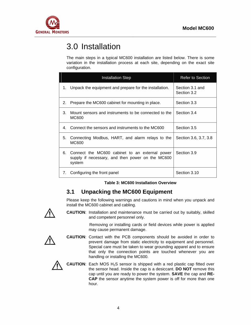
3.0 Installation The main steps in a typical MC600 installation are listed below. There is some variation in the installation process at each site, depending on the exact site configuration.
Installation Step Refer to Section
1. Unpack the equipment and prepare for the installation. Section 3.1 and Section 3.2
2. Prepare the MC600 cabinet for mounting in place. Section 3.3
3. Mount sensors and instruments to be connected to the MC600
Section 3.4
4. Connect the sensors and instruments to the MC600 Section 3.5
5. Connecting Modbus, HART, and alarm relays to the MC600
Section 3.6, 3.7, 3.8
6. Connect the MC600 cabinet to an external power supply if necessary, and then power on the MC600 system
Section 3.9
7. Configuring the front panel Section 3.10
Table 3: MC600 Installation Overview
3.1 Unpacking the MC600 Equipment Please keep the following warnings and cautions in mind when you unpack and install the MC600 cabinet and cabling.
CAUTION: Installation and maintenance must be carried out by suitably, skilled and competent personnel only.
Removing or installing cards or field devices while power is applied may cause permanent damage.
CAUTION: Contact with the PCB components should be avoided in order to prevent damage from static electricity to equipment and personnel. Special care must be taken to wear grounding apparel and to ensure that only the connection points are touched whenever you are handling or installing the MC600.
CAUTION: Each MOS H2S sensor is shipped with a red plastic cap fitted over the sensor head. Inside the cap is a desiccant. DO NOT remove this cap until you are ready to power the system. SAVE the cap and RE-CAP the sensor anytime the system power is off for more than one hour.

Model MC600
5
All equipment shipped by General Monitors is packaged in shock absorbing containers, which provide considerable protection against physical damage. The contents should be carefully removed and checked against the packing list.
If any damage has occurred or there is any discrepancy in the order, please notify General Monitors as soon as possible. All subsequent correspondence with General Monitors must specify the equipment part number and the serial number.
NOTE: Each Model MC600 is thoroughly tested at the factory. However, a system checkout is required upon initial start-up to ensure system integrity.
3.2 Preparing for the Installation To prepare installing the MC600 cabinet, you will need to choose a location and gather the required tools. Separate preparation guidelines for mounting sensors are provided in Section 3.5.
3.2.1 Choosing a Location The MC600 cabinet should be wall-mounted in a non-hazardous area. It can be placed indoors or outdoors. You will need to select a location for the MC600 that is near enough to the field-mounted devices to conform to the maximum cable lengths specified for the field-mounted device.
NOTE: If a Class I Division 2 power supply is used, the cabinet can be mounted in a hazardous Class I Division 2 area.
There must be adequate clearance beneath the MC600 cabinet to allow for cable installation. Weather-protected locations with minimal shock and vibration are preferred. Although the MC600 is largely immune to electromagnetic interference (EMI), it should not be mounted in close proximity to radio transmitters or similar equipment. The MC600 is provided with two ferrite clamps for use on the power supply cable in case any interference is observed. Before installation, carefully review the environmental specifications for allowable temperature ranges and the electrical specifications for power supply requirements.
3.2.2 Tools You Will Need The following tools will be needed to install and cable the MC600:
• Flat-head screwdriver maximum 3/16” (5 mm) width for terminal block connections (included with unit)
• Adjustable wrench for conduit or cable gland connections (not included)
• #2 Phillips-head screwdriver (not included)
3.3 Mounting the MC600 Cabinet in Place Once the MC600 cabinet is prepared for installation, it should be mounted in place.

Model MC600
6
MODEL MC600
CAUTION:READ AND UNDERSTAND THE INSTRUCTION MANUAL BEFORE OPERATING OR SERVICING.
P/N 65000 -
GALWAY, IRELAND
RATED 24VDC, " " 185 W MAX., (STANDARD)
CONTACT RATINGS: 8A @ 30VDC RESISTIVE MAX
115/230 VAC 50 TO 60 Hz, 185 W MAX., (OPTIONAL)
TEMP. (-20°C To +60°C), (STANDARD)TEMP. (-10°C To +60°C), (OPTIONAL POWER SUPPLY)
GENERAL MONITORS, INC.LAKE FOREST, CALIFORNIA, USA
MULTI-CHANNEL CONTROLLER
8A @ 250-VAC
CONFIGURATION
MANUAL DATE
SERIAL #
65079-1
Figure 12: Mounting Dimensions for the MC600 Cabinet
To mount the MC600 Cabinet in place:
• Before bolting the cabinet in place, make sure it is level. Fasten four ¼-inch bolts into the four mounting holes on the corners of the enclosure. Use appropriate mounting screws/bolts in regard to the mounting surface i.e. concrete, wood, etc. Do not mount the MC600 onto drywall unless it is secured to the wooden studs behind the drywall.
3.4 Mounting the Sensors and Instruments The gas detection devices that will be connected to the MC600 must be mounted in locations where they are needed for gas detection. This can take place either before or after the MC600 cabinet is mounted in place.
• This section provides some guidelines for selecting sensor locations for catalytic HC and MOS H2S sensors; later sections describe how to mount a sensor using a General Monitors’ explosion-proof sensor housing and duct mounting kit.

Model MC600
7
• Instructions for mounting each type of 4-20mA instrument are provided in the instruction manual for that instrument.
Section 11.0 provides ordering information for several accessories that can be installed during sensor mounting, splash guards, dust guards and remote calibration devices.
3.4.1 Sensor Location Considerations Given that the optimum sensor location is different for each application, there are no standard rules for sensor placement. The customer must evaluate conditions at the sensor site in order to make this determination. The following are some general guidelines:
• The sensor should be easily accessible for calibration checks. Ensure that there is sufficient clearance to use field calibration devices, such as, the breaker bottle and gas ampoules or a Portable Purge Calibrator (Section 4.5.3).
• The sensor head should always point downward to prevent water buildup on the sensing element. Remember that some combustible gases are heavier than air; however, do not rely on this fact when selecting a sensor position.
• The sensor should be located in areas where leaks are suspected (i.e. near valves & pipe connections, etc.). It should not be placed where contaminating substances may coat it.
3.4.2 Sensor Poisons Sensors may be adversely affected by prolonged exposure to certain atmospheres. The more important poisons are:
• For catalytic HC sensors only, prolonged exposure to Hydrogen Sulfide (H2S) Gas
• Halides (compounds containing Fluorine, Chlorine, Bromine and Iodine)
• Glycol
• Heavy Metals (e.g. Tetraethyl lead)
• Silicones contained in greases or aerosols are the most common “coating” agents. These are not true sensor poisons, but they do reduce sensor response.
Other damaging materials that can harm the sensor include mineral acids and caustic vapors. The presence of such poisons and vapors does not exclude the use of MOS H2S and catalytic HC sensors; however, a careful analysis of ambient conditions should be undertaken and the customer should be aware that sensor calibration might need to occur at more frequent intervals.
3.4.3 Mounting a Sensor with a GM Junction Box Figure 17 shows a GM explosion-proof housing for catalytic HC and MOS H2S sensors that is rated for use in Class I, Division I, Groups B, C & D hazardous locations. Both housing entries are tapped for ¾” NPT threads. The sensor

Model MC600
8
connects to one of these entries, while the other entry is for conduit runs. The lid of the housing is also threaded to allow the user to gain entry to the sensor connections in the field.
When a sensor is attached to the housing, it must be screwed into the housing using five to seven turns to ensure that the explosion-proof integrity of the housing is maintained.
Once the sensor is installed/operating in the field, no attempt should be made to disconnect the sensor, the conduit or the housing lid without removing power from the unit. This would compromise the explosion-proof integrity of the field device. There is a four-position terminal block inside the junction box housing to route the wires from the sensor to the MC600.
Figure 13: Sensor Housing and Junction Box
Splash Guard
Sensor Housing
Junction Box

Model MC600
9
3.4.4 Mounting a Sensor with a Duct Mounting Kit General Monitors produces a Duct Mounting Kit (P/N 10041) for applications that require the sensor to be mounted in an air-conditioning system or heating duct.
Figure 14: Duct Mounting Kit Assembly
To install a sensor using the Duct Mounting Kit Assembly:
1. Select a location on the duct and cut out a hole large enough for the sensor to be inserted into the duct.
2. Place the O-Ring over the sensor threads, against the 1 ¼-inch hexagon on the wiring side of the sensor.
3. Insert the wiring side of the sensor through the gasket and cover.
4. Screw the lock-nut onto the wiring side of the sensor
5. Use the four screws to attach the mounted sensor to the duct. The sensor should be oriented so that when the plate is attached to the duct, the sensing element is inside the duct.
NOTE: For an explosion-proof installation, the Duct Mounting Kit is combined with a junction box, such as, the one shown in Figure 13. The junction box would be attached to the sensor housing on the other side of the duct mounting cover plate.
3.4.5 Applying Sealants to Conduit Entries Please keep the following warnings and cautions in mind when you install housings and cabling from catalytic HC and MOS H2S sensors, as well as, instruments mounted in hazardous areas, to make sure that the equipment maintains the appropriate seals for a Class I hazardous location.
WARNING: Each conduit run within a hazardous location (and from a hazardous to a non-hazardous location) must be sealed so that gases, vapors and/or flames cannot pass beyond the seal. For information on Class I location seals, see NEC Articles 501-5 and 500-3d

Model MC600
10
WARNING: Unused cable entry holes in each sensor housing must be sealed with approved explosion-proof stopping plugs. Red caps supplied by General Monitors are for dust protection only and must not be left on the unit when installed.
CAUTION: Acetic acid will cause damage to metal components, metal hardware, ceramic IC’s, etc. If damage results from the use of a sealant that contains acetic acid (RTV silicone), the warranty will be void.
CAUTION: To prevent corrosion due to moisture or condensation, it is recommended that the conduit connected to the sensor housings be sealed or contain a drain loop.
3.5 Connecting Sensors and Instruments to the MC600
Once the MC600 cabinet is installed, you are ready to begin cabling from the signal-conditioning cards in the MC600 cabinet slots to field-mounted catalytic HC sensors, MOS H2S sensors and 4-20mA instruments. You can connect one sensor or instrument to each signal-conditioning card in the cabinet by routing standard cabling from the device to the wiring connector on the card. Separate procedures are provided for installing cabling to MOS H2S, catalytic HC and 4-20mA cards.
The signal-conditioning cards are preinstalled in the cabinet; the white label in the cabinet above the card connection slots indicates what type of card is in each channel. Channel numbers 1 to 6 are silk-screened on the PCB adjacent to each slot.
To install wiring from MOS H2S and catalytic HC sensors or instruments to the MC600, the end of the wires that will be fastened to the MC600 signal card connector should be stripped to approximately 0.25 inches (Figure 19).
Figure 15: Pre-stripping Wiring

Model MC600
11
3.5.1 Warnings, Cautions and Standards Please review the following warning and caution statements before proceeding to install cabling. For information on non-hazardous location cabling to the MC600 cabinet, see NEC article 504. For information on Class I location seals for sensors mounted in hazardous areas, see NEC articles 501-5 and 500-3d
WARNING: Under no circumstances should equipment be connected or disconnected when under power. This is contrary to hazardous area regulations and may also lead to serious damage to the equipment. Equipment damaged in this manner is not covered under warranty.
CAUTION: The MC600 Multi-Channel Controller System and field-mounted sensor devices contain components that can be damaged by static electricity. Special care must be taken when wiring the system to ensure that only the connection points are touched.
CAUTION: Use wire with insulation rated to at least 105°C
3.5.1.1 European Union (EU) Approved Cable Armor and Screens Interconnecting cables must have an overall screen or screen and armor. Cables BS5308 Part 2, Type 2 or equivalent are suitable. The cable armor must be terminated in a suitable cable gland at the detector to ensure a positive electrical connection.
NOTE: The terms ‘screen’ and ‘shield’ are equivalent for the purpose of this manual.
3.5.1.2 Cable Termination in Non-Hazardous Areas • The cable armor must be connected to safety earth in the safe area.
• The cable screen (drain wire) must be connected to an instrument earth in the safe area.
• The power supply OV return must be connected to an instrument earth in the safe area.
• The interconnecting cables should be segregated from power and other noisy cables. Avoid proximity to cables associated with radio transmitters, welders, switch mode power supplies, inverters, battery chargers, ignition systems, generators, switch gear, arc lights and other high frequency or high power switching process equipment.
• In general, maintain separation of at least 1 meter between instrument and other cables. Greater separations are required where long parallel cable runs are unavoidable. Avoid running instrument cable trenches close to lightning conductor earthing pits.
• Complete all cable insulation testing before connecting the cable at either end.
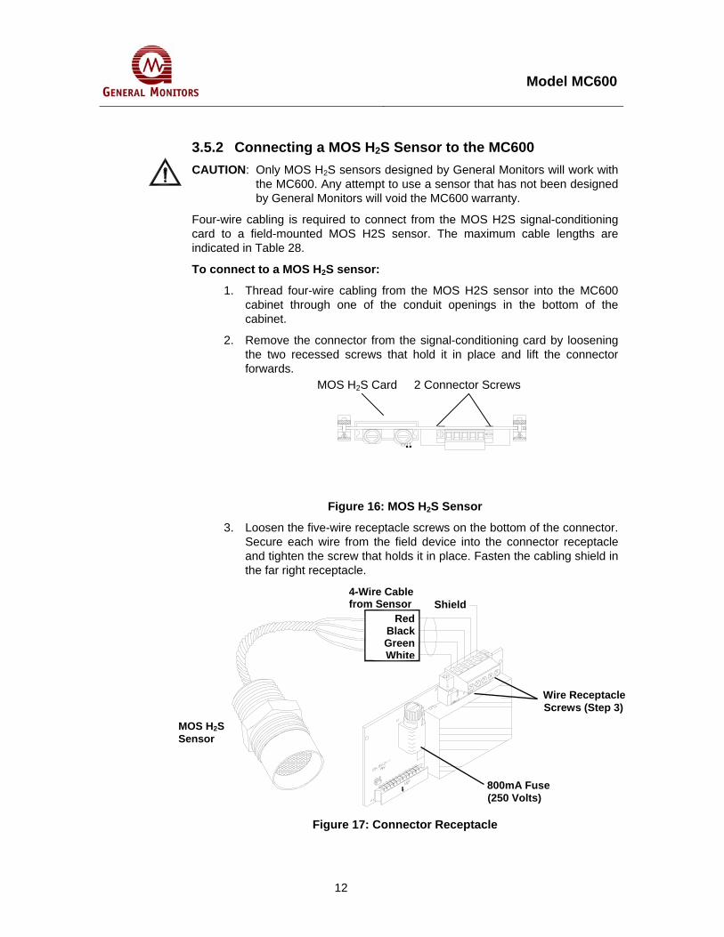
Model MC600
12
3.5.2 Connecting a MOS H2S Sensor to the MC600 CAUTION: Only MOS H2S sensors designed by General Monitors will work with
the MC600. Any attempt to use a sensor that has not been designed by General Monitors will void the MC600 warranty.
Four-wire cabling is required to connect from the MOS H2S signal-conditioning card to a field-mounted MOS H2S sensor. The maximum cable lengths are indicated in Table 28.
To connect to a MOS H2S sensor:
1. Thread four-wire cabling from the MOS H2S sensor into the MC600 cabinet through one of the conduit openings in the bottom of the cabinet.
2. Remove the connector from the signal-conditioning card by loosening the two recessed screws that hold it in place and lift the connector forwards.
Figure 16: MOS H2S Sensor
3. Loosen the five-wire receptacle screws on the bottom of the connector. Secure each wire from the field device into the connector receptacle and tighten the screw that holds it in place. Fasten the cabling shield in the far right receptacle.
Figure 17: Connector Receptacle
MOS H2S Card 2 Connector Screws
Shield4-Wire Cable from Sensor
Wire Receptacle Screws (Step 3)
800mA Fuse (250 Volts)
Red Black Green
White
MOS H2S Sensor

Model MC600
13
4. Once the wires are secured in the connector, replace the connector on the card and tighten the connector mounting screws at each side.
5. The fuse on the signal conditioning card may need to be replaced if a sensor fault error appears during power-on (Section 8.2.7)
3.5.3 Connecting a Catalytic HC Sensor to the MC600 CAUTION: Only catalytic HC sensors designed by General Monitors will work
with the MC600. Any attempt to use a sensor that has not been designed by General Monitors will void the MC600 warranty.
Three-wire cabling is used to connect from the catalytic HC signal-conditioning card to a field-mounted catalytic HC sensor. The maximum cable lengths are indicated in Table 27.
To connect a catalytic HC sensor:
1. Thread cabling from the catalytic HC sensor into the MC600 cabinet through one of the conduit openings in the bottom of the cabinet.
2. Remove the connector from the catalytic HC signal-conditioning card by loosening the two recessed screws that hold it in place and lift the connector forwards
Figure 18: Catalytic HC Sensor
3. Loosen the wire receptacle screws. Then secure the red, black and white wires from the field device in the receptacles and tighten the screws to hold them in place. Fasten the cabling shield in the far right receptacle.
Figure 19: Cabling Shield for HC Sensor
Catalytic HC Card 2 Connector Screws
Wire Receptacle Screws
Red
Black
White
Shield
Catalytic HC Sensor
Cable fromSensor

Model MC600
14
4. Once the wires are secured in the connector, replace the connector on the card and tighten the connector mounting screws at each side.
NOTE: If you have four-wire cabling, you can fasten the green wire into the empty second receptacle; however, no signal will be carried on this wire.
3.5.4 Connecting a 4-20mA Instrument to the MC600 Instruments with their own control circuitry, such as, S4000 Series, S4100 Series, IR2100, Gassonic Observer and Gassonic Surveyor - are connected to the MC600 through a 4-20mA signal-conditioning card.
To connect a 4-20mA instrument:
1. Thread four-wire cabling from the instrument into the MC600 cabinet through one of the conduit openings in the bottom of the cabinet. The maximum cable lengths are indicated in the manuals for each device.
2. Remove the connector from the 4-20mA signal-conditioning card by loosening the two recessed screws that hold it in place and lift the connector forwards.
Figure 20: 4-20mA Instrument Card
3. Loosen the five-wire receptacle screws, then secure each wire from the field device into the connector receptacle and tighten the screws that hold them in place. Fasten the cabling shield to the rightmost receptacle.
4-20mA Instrument Card 2 Connector Screws

Model MC600
15
Figure 21: Connector Receptacle
The Analog Out signal from the detection instrument must be routed to the Analog In receptacle on the signal conditioning card connector.
NOTE: When the field instrument is an IR5000/IR5500, there are two Analog Out signals from the field instrument. Connect them to the Analog In receptacles of any two channels of the MC600 system.
COM (DC Ground) must also be connected from the device to the signal card connector.
• The +24VDC signal wire from the detection instrument should be connected to the second connector receptacle if the MC600 power supply will be used to provide power to the instrument. If you plan to connect the instrument to a separate power supply other than the MC600, do not connect the +24VDC power signal wire.
4. The Analog Out receptacle on the signal-conditioning card connector is provided to forward the 4-20mA input from the field instrument on to another monitoring device, such as a PLC. When the analog signal is passed through to a PLC or DCS device, the W1 jumper on the analog input card must be cut. Ground must also be connected to this device.
5. Once the wires are secured in the connector, replace the connector on the card and tighten the connector mounting screws at each side.
NOTE: For some 4-20mA instruments, the MC600 message Fld Dev Fault will appear while the instrument is in start-up mode. Refer to the instrument documentation for information on the start-up process
CAUTION: The MC600 Multi-Channel Controller System cannot provide sufficient power for an IR5000/IR5500 field instrument. When an IR5000/IR5500 is being connected to the MC600, the user should provide their own 24V power supply for the IR5000/IR5500 source
Shield
Wire Receptacle Screws
63 mA Fuse (250 Volts)
Cable fromInstrument
500 mA Fuse (250 Volts)
Analog Out Ground COM- Ground
(+24VDC)Analog In

Model MC600
16
and receiver units as outlined in the IR5000/IR5500 manual. Do not use the +24V DC signal connection from the MC600 signal-conditioning card, or damage to the system may occur.
3.6 Connecting a MODBUS Device Connector J8 near the bottom left side of the MC600 main circuit board is provided for connecting the two MC600 MODBUS channels to control room MODBUS devices. Refer to the manual for the field device to determine maximum cable lengths.
To Connect a MODBUS Device to the J8 Connector
1. Remove the connector from the MC600 controller board; loosen the two recessed screws that hold it in place on each side and then lift the connector forwards.
2. For the first MODBUS device that you plan to attach, loosen the two Mod1 signal wire receptacle screws and the shield wire receptacle on the bottom of the connector.
3. Secure the two wires from the field MODBUS device in the connector receptacles and tighten the screws to hold them in place. Fasten the cabling shield to the nearest shield receptacle.
4. Repeat for the second MODBUS device, with the Mod2 receptacles, and then re-attach the J8 connector on the controller board.
3.7 Connecting a HART Field Device A HART field device like the IR400, S4000CH, S4000TH, IR5500 and TS4000H can only operate with the MC600 through analog current communication. In order to make the full range of analog signal available to the MC600, the field devices must have HART disabled. Please consult the instruction manual of the field device on disabling the bi-directional communication.
WARNING: Field devices equipped with HART must have the HART function disabled to work properly with the MC600. If the devices are not disabled, the multi-point controller will not recognize fault conditions from HART.
3.8 Connecting Alarm Relay Devices Connectors J10 and J11 at the bottom of the MC600 main PCB connect relays 1 to 6 to alarm devices such as sirens and bells. The functioning of the alarm and warning relay connections varies depending on whether the relays are configured as energized or de-energized, latched or non-latched, or timed.

Model MC600
17
Figure 22: MC600 MODBUD & Alarm Relay Connectors
There are three receptacles in connectors J10 and J11 to connect each of six relays, for a total of 18 receptacles. Each receptacle label indicates what it is used for.
The first digit in the receptacle label represents the channel number, from 1 to 6.
The last digit in the receptacle label indicates the function of the receptacle.
• If the last digit is C, the receptacle is for relay common.
If the relays are set up as de-energized (the default), the last digit 1 is for normally closed and the last digit 2 is for normally open.
• If the relays are set up as energized, the last digit 1 is for normally open, and the last digit 2 is for normally closed.
NOTE: Connector J12 is connected to fault relays. The fault relay is normally energized. It will change state after power-up.
The default MC600 configuration setting for the warning and alarm relays is de-energized. Use the following table as a guide for determining the normally open (NO) and the normally closed (NC) contacts for the energized versus de-energized setting.
Table 4: Normally Open and Closed Relay Contacts
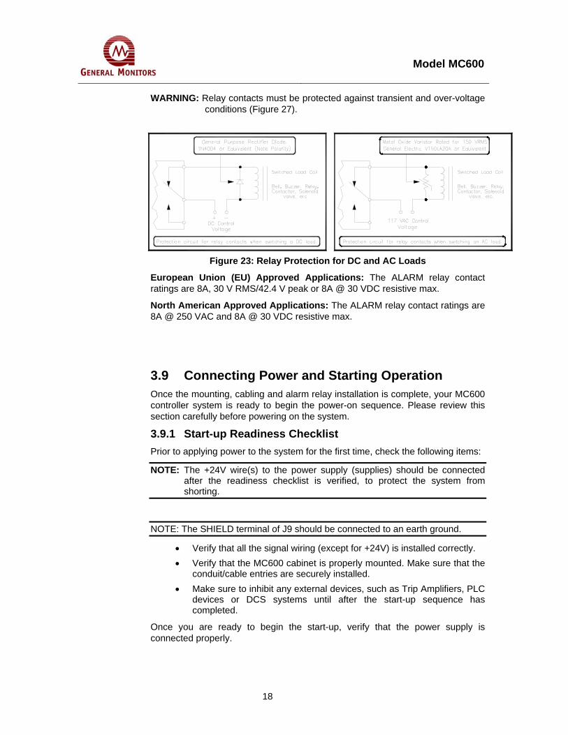
Model MC600
18
WARNING: Relay contacts must be protected against transient and over-voltage conditions (Figure 27).
Figure 23: Relay Protection for DC and AC Loads
European Union (EU) Approved Applications: The ALARM relay contact ratings are 8A, 30 V RMS/42.4 V peak or 8A @ 30 VDC resistive max.
North American Approved Applications: The ALARM relay contact ratings are 8A @ 250 VAC and 8A @ 30 VDC resistive max.
3.9 Connecting Power and Starting Operation Once the mounting, cabling and alarm relay installation is complete, your MC600 controller system is ready to begin the power-on sequence. Please review this section carefully before powering on the system.
3.9.1 Start-up Readiness Checklist Prior to applying power to the system for the first time, check the following items:
NOTE: The +24V wire(s) to the power supply (supplies) should be connected after the readiness checklist is verified, to protect the system from shorting.
NOTE: The SHIELD terminal of J9 should be connected to an earth ground.
• Verify that all the signal wiring (except for +24V) is installed correctly. • Verify that the MC600 cabinet is properly mounted. Make sure that the
conduit/cable entries are securely installed. • Make sure to inhibit any external devices, such as Trip Amplifiers, PLC
devices or DCS systems until after the start-up sequence has completed.
Once you are ready to begin the start-up, verify that the power supply is connected properly.

Model MC600
19
3.9.2 Connecting the MC600 to a Power Supply WARNING: The MC600 power supply or connected external power supply
should be left OFF and unconnected to its power source until after you have completed cabling connections.
If you have ordered a power supply pre-installed for the MC600, then the unit is shipped with cabling from the power supply to the control board pre-installed. You will only need to connect the onboard power supply to a 115/230 VAC power source.
USC
NL FG
OUTPUT: +24V 6.5A
INPUT: 110-120VAC 3.2AS-150-24 220-240VAC 1.6A
50/60HzCAUTION:
115V
Figure 24: MC600 Connections to an Onboard Power Supply
To connect the MC600 onboard power supply to a power source
Refer to Figure 24 as you follow these steps. 1. Verify that the voltage switch on the power supply is set to the appropriate
setting for your site, either 115VAC or 230VAC. 2. Connect cabling from the connector beneath the power supply to the power
supply’s external power source. Three wires will be needed to carry AC Line, AC Neutral and Frame Ground to the power source.
Voltage Switch
Frame Ground
AC Line
AC Neutral
To Power

Model MC600
20
Figure 25: Onboard Class I Division 2 Power Supply
To connect the MC600 Class I Division 2 onboard power supply to an power source:
Refer to Figure 25 when following these steps
Connect cabling from the connector beneath the power supply to the power supply’s external power source. Three wires will be needed to carry the AC line AC neutral, and frame ground to the power source.
NOTE: This is 100VAC – 240VAC/50Hz-60Hz auto-switching power supply, you do not need to select the input voltage.
To connect the MC600 to an external power supply
If the MC600 does not have an onboard power supply, then you will need to install cabling from the MC600 J9 connector to an external Primary DC power supply. See Table 26 for cable length specifications.

Model MC600
21
Figure 26: MC600 Connections to an External Power Supply
You will need to refer to your power supply manual for the location of the ground and +24VDC terminals, and connections from the external power supply to a power source.
Refer to Figure 26 as you follow these steps.
1. Connect a wire from the MC600 J9 connector COM receptacle to the power supply DC Ground connector.
2. Connect the MC600 J9 connector +24VDC receptacle to the power supply +24VDC terminal.
3. The Model MC600 operates on nominal power of +24 VDC. When you are ready to power on the MC600, connect the external power supply to a power source. Refer to your power supply manual for instructions on connecting it to a power source.
3.9.3 Startup Process for an MC600 System NOTE: Powering on and off of the MC600 is controlled from the power supply
and/or power source. If you have any problems in the start-up or testing of the detector system, please refer to Section 8.0 or contact General Monitors Technical Support (see Section 6.0).

Model MC600
22
Upon first power-up, the MC600 requires a few minutes to stabilize while the unit attains its proper operating temperature. The six MC600 Channel LEDs will go through the following process during this period:
1. The LCD segments for all six channels remain lit for several seconds. The four LEDs for READY, ALARM, FAULT and WARN also remain lit during this period.
2. Next, Channel 1 will display the part number and firmware revision for the MC600 control card, Channel 2 will display the part number and firmware revision for the LCD panel, and Channels 3 through 6 remain blank, as shown below (Rev. A is shown for reference, the actual program revision may vary):
CHANNEL 1 CHANNEL 465023-1Rev. A
CHANNEL 2 CHANNEL 565024-1Rev. A
CHANNEL 3 CHANNEL 6
3. Next, each channel that has a signal-conditioning card installed and a sensor
or instrument connected to it will go into Operation Mode, in which gas measurement data is shown. The Operation Mode display varies for different sensors and instruments, as follows: • Catalytic HC Sensor: The LCD display for a channel with a catalytic HC
sensor will go through a 50-second startup cycle countdown, followed by an Operation Mode display similar to the following (“Comb” stands for combustible):
0% LEL Comb MOS H2S Sensor: The Operation Mode display appears in the following
format, assuming that no gas is currently detected: 0 ppm H2S
• 4-20mA instrument: The Operation Mode display may appear in one of several formats, depending on the instrument that is connected to it. An example set of displays is shown in Figure 31

Model MC600
23
SETUP
ACCEPT MODE
DISPLAY
FAULT
READY
CHANNEL 3
CHANNEL 1
CHANNEL 2
ENTER
RESET
ALARM
CHANNEL 6 WARN
CHANNEL 5
CHANNEL 4
Figure 27: Sample Operation Mode Display
Once the MC600 is powered on and in Operation Mode, you will need to complete several tasks using the MC600 onboard menus. A list of these tasks follows:
NOTE: For general instructions on navigating the MC600 menu system, see Section 4.1.
1. Configure the Display Setup, as described in the following section. 2. Calibrate all connected catalytic and MOS H2S sensors (Section 4.5).
For each catalytic HC sensor connected to the MC600, General Monitors recommends that you calibrate the sensor one hour after a first time system start-up.
• For each MOS H2S sensor connected to the MC600, General Monitors recommends that you calibrate the sensor one hour after start-up and again 24 hours later.
3. Recalibrate the LCD channel display for 4-20mA signal conditioning cards (Section 4.6). 4. Configure the Alarm and Warning relay set points, as needed (Section 4.9.1). 5. Configure the relay states as needed, for energized versus de-energized, latching versus non-latching and timed (Section 4.9.3).
Catalytic HC Sensor (or HC Instruments
MOS H2S Sensor (or H2S Instruments such as S4000T)
TS420 Oxygen Instrument
Navigation Buttons
0% LEL Comb
0 ppm H2S
20.9 %vv 02
TS400 or IR7000 Carbon Monoxide Instrument
Same as Channel 1
TS4000 Chlorine Dioxide Instrument
Front Panel Setup Control
0 ppm C0
0% LEL Comb
0.0 ppmCl02

Model MC600
24
3.10 Configuring the Front Panel Setup Use the [DISPLAY SETUP] button to adjust the front panel LCD displays, LEDs and sounder (if installed). The following flowchart shows the front panel setup options that appear in the Channel 1 display. The changes you select using this menu will affect all six LCD displays, all four LEDs, etc.
Press the [MODE] button to move from one setup option to the next, and use the [ ] and [ ] buttons to change the option settings. To exit from this menu at any time press the [DISPLAY SETUP] button. Any changes made are saved automatically when this menu is exited.
LCD Adj6
DisplayTEST ?
SoundAdj0
KeyClickOn
LED Adj0
Button TEST ?
[DISPLAY SETUP]
MODE MODE MODE MODE MODE MODE
SounderVolume.0 (quietest) to9 (loudest).
oror or or or or
6 ChannelsLCD Brightness2 (darkest) to 9(lightest)
4 LEDsBrightness0 (dimmest) to9 (brightest)
Key ClickToggle.Sound is Onor Off.
Key Test.Press ENTER,then press anybutton to test.
Display Test.Press ENTER totest LCD andLED displays.
Figure 28: Display Setup Menu Sequence
LCD Brightness Adjustment. Press [ ] or [ ] to choose a value from 0 (darkest) to 9 (lightest) for the six LCD channel displays. The default value is 6.
LED Brightness Adjustment. Press [ ] or [ ] to choose a value from 0 (dimmest) to 9 (brightest) for the four LEDs: READY, ALARM, FAULT and WARN. The default is 0.
Sounder Volume. Press [ ] or [ ] to choose a value from 0 (quietest) to 9 (loudest). The default is 0.
Key Click Toggle. Press [ ] or [ ] to toggle the key click between On and Off. The default is audible or On.
Key Test. Press [ENTER] to enter the key test, and then press any front panel button to test it ([ACCEPT], [MODE], [ENTER], [RESET], [ ] or [ ]). To exit from the Key Test, you will have to exit from the display menu by pressing [DISPLAY SETUP], or wait five seconds and the unit will automatically exit from the button test.
Display Test. Press [ENTER] to start the Display Test. The sounder, the six LCD displays and the four LEDs will go through a diagnostic sequence, flashing the LEDs and sounder and counting from 0 to 9 on the LCD displays. The MC600 will return to Operation mode after completion of the test.

Model MC600
25
3.11 Maintaining the X/P Integrity The catalytic HC and MOS H2S sensor junction box housings are rated explosion-proof for use in the following hazardous locations:
CSA/FM: Class I, Division 1, Groups B, C, D and Class I, Zone 1. ATEX: Ex e d IIC, II 2 G
Anytime the cover of a sensor housing is removed, or the cover bolts are loosened and power is to be left on, it will be necessary to declassify the area. When replacing the cover, the gap between the lid and the housing should be less than .0015 inch (.038 mm).
Make sure that the flame-path is clear of dirt and debris before replacing the cover. You can verify this by tightening the cover bolts to a torque setting of 50 inch-pounds or by using a feeler gauge to ensure that the gap between the cover and the housing is less than .0015 inch (.038 mm).
There are two entry holes in each sensor housing; these holes are used to attach the sensor, as well as wiring conduits to other devices. Each hole is tapped for ¾” NPT threads. The factory installs plugs in the unused entry holes, except one. A plastic cap is placed into the remaining hole and must be removed before conduit can be attached to the housing.
When a sensor is attached to the housing, it must be screwed into the housing using five to seven turns to ensure that the explosion-proof integrity of the housing is maintained.

Model MC600
26
SETUP
ACCEPT MODE
DISPLAY
FAULT
READY
CHANNEL 3
CHANNEL 1
CHANNEL 2
ENTER
RESET
ALARM
CHANNEL 6 WARN
CHANNEL 5
CHANNEL 4
4.0 Basic Operation and Configuration The MC600 LCD displays and navigation buttons form the user interface for a set of menu options that provide you with the most flexible gas detection system possible. This chapter describes how to use the MC600 menus for operation and configuration of the MC600 system unit and connected sensors and instruments. Basic tasks you can accomplish using the menus include:
Calibrating and checking calibration for catalytic HC and MOS H2S sensors Inhibiting alarms for selected channels Configuring set points for the Alarm High, Alarm Low and Warning states Configuring the relays as Energized/De-Energized, Latching/Non-Latching or
Timed
This chapter provides instructions for these basic tasks. Section 5.0 describes several advanced configuration tasks you can accomplish using the MC600 menus
NOTE: An alternate method to accomplish many of the menu functions is to send commands to the MC600 MODBUS registers from a connected MODBUS device. Section 9.0 describes these registers in detail.
4.1 Entering and Exiting from the MC600 Menus Figure 29 shows the MC600 front panel navigation buttons and a typical menu display.
Pressing the [MODE] button displays Menu Cal in the Channel 1 LCD window; this is the first main menu option. Once the MC600 has exited from Operation mode, the other five LCD windows remain blank during most menu operations.
Figure 29: Front Panel Menu Display and Navigation Buttons
Pressing the [MODE] button a second time returns all six channels to
Menu Cal
2-Line Menu Display
Navigation Buttons

Model MC600
27
Operation mode, exiting from the menus. If you have made changes to the configuration settings using the menus, the prompt Save ? Yes appears when you press the [MODE] button a second time; you must either confirm or cancel your changes before returning to Operation mode.
4.2 Using the Front Panel Navigation Buttons The MC600 front panel includes several buttons for navigating through the menu. The menu overview flowchart shown in Section 4.4 indicates how these buttons are used to navigate through the different main menu and submenu options:
[MODE] – Toggles between entry into the menus and exit from the menus from anywhere in the menu structure.
NOTE: If you have made configuration changes using the MC600 menus, a prompt to save your changes in permanent memory will appear when you press [MODE] to exit from the menus.
[ ] (Up Arrow) – Advances through the options within a menu level. [ ] (Down Arrow) – Moves back through the options within a menu level. [ENTER] – Movement down one menu level, or initiation (start) of the
currently displayed operational task (calibration, calibration check, etc.). [RESET] (also shown as RS) – Progression up one menu level (either back to
the first option at the previous menu level or back to the most recently selected option at the previous level). [RESET] can also be used for backwards navigation through the Setup Check submenu options and to reset latched or timed alarms.
[ACCEPT] (also shown as AC) – Used for moving forward through the Setup Check menu options, to accept alarms and disable alarm devices, and to cancel fault conditions.
4.3 Menu Flowchart Legend Figure 30 shows a flowchart of the upper level of the menu structure, to help you navigate between menu options. The menu flowchart provides a roadmap for using the configuration menus and digital displays in the MC600. Several shapes indicate different characteristics of flowchart items, as follows:
Diamond shapes in the flowchart indicate decision points in the menu where you can move in several directions or choose from several parameter values. Dotted lines in the flowchart indicate Password and other prompts that only appear under particular conditions (if a password is set, if you have made configuration changes, etc.). Rectangular boxes indicate processes that take place due to a menu selection, such as zeroing or recalibrating a sensor unit. They also surround cross-references to sections in this book that describe menu functions in more detail. Display boxes indicate a status or measurement display message.

Model MC600
28
4.4 MC600 Menu Overview The following illustration shows an overview of the upper branches of the MC600 menus. Figure 30 shows a navigational flowchart for the two-line LCD menu options as they appear on the Channel 1 LCD display. Variables you must select are shown in italics, such as Chan # 1-6, etc. Connecting arrows indicate the path(s) you can travel between menu options, using the front panel navigation buttons.
NOTE: The basic menu areas described in this chapter are shown shaded.
MenuSelf Tst
Self TstCard Test
Self TstDisplay Test
See Section 5.3 On Self Tests
CalChan #1-6
See Sections 4.5 and 4.6
on Calibration
CalchckChan #1-6
InhibitChan #1-6
EnterPassword
See Section 4.7 on
Calibration Checks
RESET
RESET RESETRESETRESET
ENTER
MenuCal
ENTER
ENTER
EnterPassword
ENTER
See Section 4.8 on
Inhibiting Alarms
MODE
ENTER
MenuStupChck
RESET RESET
ENTER
MenuSetup
MenuInhibit
MenuCal Chck
ENTER ENTERENTER
ENTER
SetupChannels
SetupRelays
SetupZoning
SetupCardTest
SetupPassword
SetupFltRelay
SetupModbus
SetupLd Dflts
RESETRESETRESETRESETRESETRESETRESETRESET
See Section 4.9 for Basic Setup Menu Tasks, and Section 5.1 for Advanced Setup Menu Tasks
ENTER ENTER ENTER ENTER ENTER ENTER ENTER ENTER
ENTER
ENTER ENTER
Relay Setups
Channel Setups
FltRelaySetups
ENTER ENTER ENTER
See Section 5.2 on the Setup Check Menus
AC
RS
AC
RS
AC
RSCardTestSetups
AC
RS
UnitTemps
AC
RS
ENTERENTER
ModbusSetups
AC
RS
ZoneSetups
AC
RS
ENTER ENTER
Channel 1 Operation Mode
nn %LEL (%vv, ppm,dB)
Gas Type
MODEPressing [MODE] from anywhere in the menus will return the MC600 to Operation Mode. However, if you have made configuration changes in the menus, you must save them to nonvolatile memory or cancel the changes, before you can return to Operation Mode.
ENTER Save ?Yes
Save ?No
ENTER
Figure 30: MC600 Menu Overview
NOTE: Once a password is enabled, you must enter it before you can access the Setup and Inhibit submenus (Section 5.1.6).
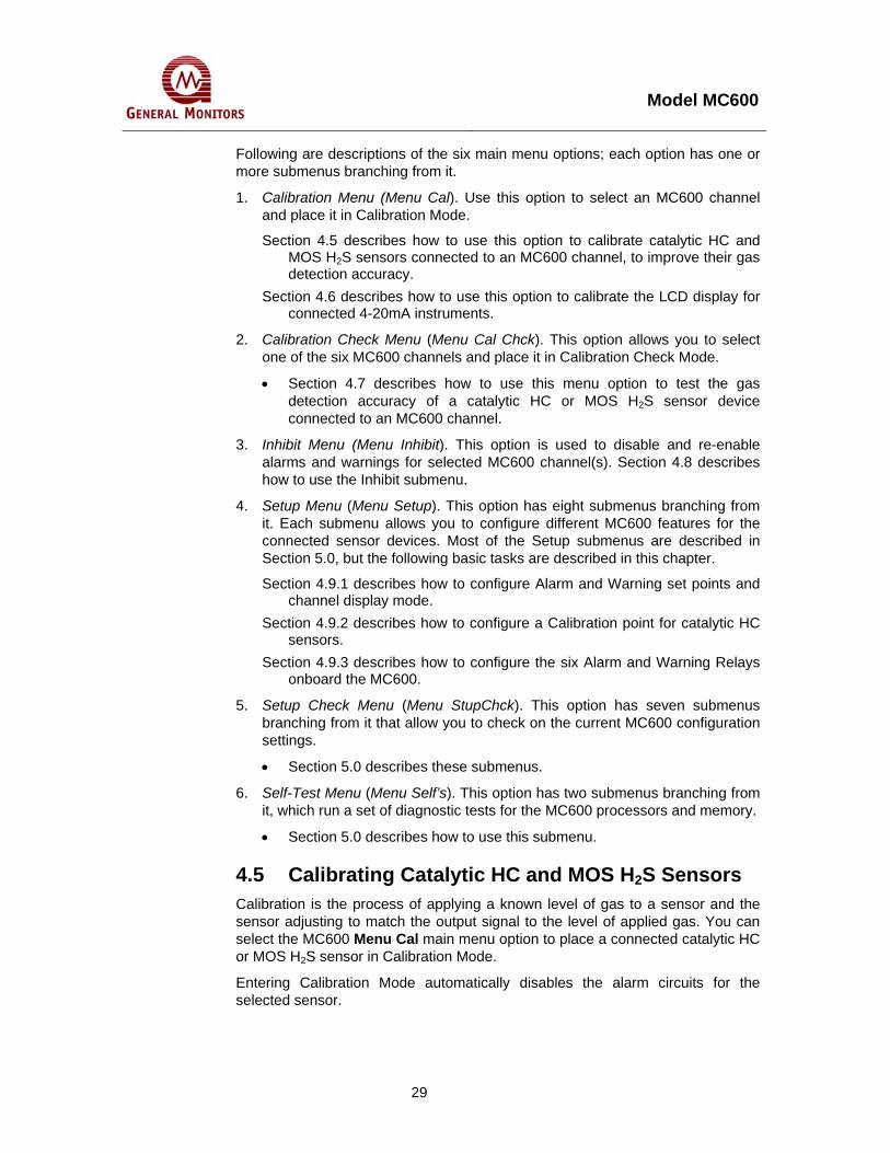
Model MC600
29
Following are descriptions of the six main menu options; each option has one or more submenus branching from it.
1. Calibration Menu (Menu Cal). Use this option to select an MC600 channel and place it in Calibration Mode.
Section 4.5 describes how to use this option to calibrate catalytic HC and MOS H2S sensors connected to an MC600 channel, to improve their gas detection accuracy.
Section 4.6 describes how to use this option to calibrate the LCD display for connected 4-20mA instruments.
2. Calibration Check Menu (Menu Cal Chck). This option allows you to select one of the six MC600 channels and place it in Calibration Check Mode.
• Section 4.7 describes how to use this menu option to test the gas detection accuracy of a catalytic HC or MOS H2S sensor device connected to an MC600 channel.
3. Inhibit Menu (Menu Inhibit). This option is used to disable and re-enable alarms and warnings for selected MC600 channel(s). Section 4.8 describes how to use the Inhibit submenu.
4. Setup Menu (Menu Setup). This option has eight submenus branching from it. Each submenu allows you to configure different MC600 features for the connected sensor devices. Most of the Setup submenus are described in Section 5.0, but the following basic tasks are described in this chapter.
Section 4.9.1 describes how to configure Alarm and Warning set points and channel display mode.
Section 4.9.2 describes how to configure a Calibration point for catalytic HC sensors.
Section 4.9.3 describes how to configure the six Alarm and Warning Relays onboard the MC600.
5. Setup Check Menu (Menu StupChck). This option has seven submenus branching from it that allow you to check on the current MC600 configuration settings.
• Section 5.0 describes these submenus.
6. Self-Test Menu (Menu Self’s). This option has two submenus branching from it, which run a set of diagnostic tests for the MC600 processors and memory.
• Section 5.0 describes how to use this submenu.
4.5 Calibrating Catalytic HC and MOS H2S Sensors Calibration is the process of applying a known level of gas to a sensor and the sensor adjusting to match the output signal to the level of applied gas. You can select the MC600 Menu Cal main menu option to place a connected catalytic HC or MOS H2S sensor in Calibration Mode.
Entering Calibration Mode automatically disables the alarm circuits for the selected sensor.
Model MC600
30
NOTE: 4-20mA instruments must be calibrated with their own control devices rather than using the MC600 menus. However, you can use the Menu Cal option to calibrate the LCD display for these instruments (see Section 4.6).
4.5.1 Calibration Schedule For catalytic HC sensors connected to the MC600, General Monitors recommends that you calibrate the sensor one hour after a first time system start-up. For MOS H2S sensors only, General Monitors recommends that you calibrate the sensor one hour after system start-up and again 24 hours later.
After the first 24 hours of operation, you only need to recalibrate the sensor(s) if a calibration check indicates that calibration is needed. You should check calibration for catalytic HC and MOS H2S sensors at least every ninety (90) days to ensure system integrity.
4.5.2 Preparing for Calibration For a catalytic HC sensor, if you suspect that background hydrocarbon gases are present, purge the sensor environment with Zero Air before beginning calibration. Zero Air is air that is hydrocarbon-free. If Zero Air is not available, cover the sensor for about thirty seconds before starting sensor calibration.
For a MOS H2S sensor, if you suspect that Hydrogen Sulfide gas is present, purge the sensor environment with clean air before you start sensor calibration.
For both catalytic and MOS H2S sensors, make sure that the equipment you will use to apply gas matches the calibration concentration configured for the sensor. The default calibration point for all catalytic HC and MOS H2S sensors is 50% of the full-scale concentration (full-scale is the maximum displayed value).
NOTE: You can use the Cal Pnt menu option to change the calibration point for catalytic HC sensors only, in the range from 25% to 95% (Section 4.9.2).
4.5.3 Sensor Calibration Equipment The more commonly used calibration devices are the portable purge calibrators for catalytic HC sensors, and breaker bottles (field calibrators) with glass ampoules for MOS H2S sensors.

Model MC600
31
4.5.3.1 Equipment for Catalytic HC Sensors The recommended calibration equipment for GM catalytic HC sensors is a GM portable purge calibrator (Figure 34).
Figure 31: Portable Purge Calibration Equipment
Before beginning sensor calibration, you should place the calibration cup over the sensor; the cylinder valve and the ON/OFF valve are used to control the flow of gas.
NOTE: Section 7.2.1 describes the TGA-1 (Test Gas Applicator) remote calibration device and the 3-liter chamber for calibrating with solvent or volatile liquids. Section 11.0 provides ordering information for all GM calibration equipment.
4.5.3.2 Equipment for MOS H2S Sensors The most common method of reliably introducing toxic calibration gas to the MOS H2S sensors is to use a General Monitors’ field calibrator (breaker bottle) with glass ampoules of H2S gas (Figure 35)

Model MC600
32
Figure 32: Field Calibrator (Breaker Bottle) with H2S Gas Ampoule
The glass ampoules contain an H2S gas concentration that is 50% of full-scale for the sensor that will be calibrated; ampoules containing several different concentrations of H2S gas are available for different sensor models.
To apply the gas, place the ampoule inside the breaker bottle in the breaker slot, and place the breaker bottle over the sensor. Once you are prompted to apply gas to the sensor, you turn the breaker thumbscrew to break the ampoule and release the gas.
NOTE: Section 7.2.1.3 describes the H2S Portable Purge Calibrator, an alternate method for introducing calibration or test gas to MOS H2S sensors that may be advisable for high humidity environments. Section 11.0 provides ordering information for all GM calibration equipment.
4.5.4 Calibration Procedure for Catalytic HC and MOS H2S Sensors
The following step-by-step procedure describes how to use the MC600 menus to start calibration for a connected catalytic HC or MOS H2S sensor. You can also send MODBUS commands to begin calibration. The LCD status messages that appear during calibration (beginning with step 2) would be similar.
To Calibrate a Catalytic HC or MOS H2S Sensor:
1. Press the [MODE] button to exit from Operation Mode and enter the MC600 menus. The Menu Cal main menu option appears on Channel 1.
2. Press [ENTER] to move to the Cal Chan # 1 prompt. Press the [ ] and [ ] arrow buttons to select which channel you will be calibrating, from 1 to 6.
3. Press [ENTER] to start calibration. The LCD display for the selected channel then displays the message Sensor Life nnn %, indicating that the sensor is zeroing. The sensor should be exposed to clean air during this interval.
This message indicates the approximate percent of expected usage left for the sensor. A new sensor device should read 100%.
If you have just installed a new sensor, and the sensor life is less than 100%, press [RESET] to reset the number back to 100%.

Model MC600
33
4. When the message Apply Gas appears on the LCD display, you should apply gas to the sensor. You have six minutes to apply gas and complete the calibration process.
First make sure that the device supplying gas for calibration is fastened in place over the sensor; this can be the cup from a portable purge calibrator, a field calibrator with a glass ampoule in it, etc.
Apply gas to the sensor. For the portable purge calibrator, this means opening the valve on the calibration cylinder and the ON/OFF valve. For the field calibrator, this means twisting the knob clockwise to break the ampoule and release the gas.
5. Once the sensor has begun detecting gas, the message Cal in Progress appears on the LCD display for a few minutes. The time required for calibration may be longer if the TGA-1 remote
calibration device, a Dust Guard, Splash Guard or other sensor accessories are present.
6. Once calibration is complete, the LCD will show the message Remove Gas. You should then disconnect whichever calibration device you have decided to use with the sensor.
7. Once you remove the gas from the sensor, the display may indicate a few percent full-scale, soon dropping to a “0” value. The unit is now calibrated, and the new SPAN value is stored in non-volatile
memory.
NOTE: If the unit cannot store the new calibration values in EEPROM, the sensor will display a Cal Fault message, and the unit will use the stored calibration values. You should attempt to recalibrate the sensor.
4.5.5 Stopping Sensor Calibration You can exit from Calibration Mode before gas is applied and before a Cal Fault error message appears, (such as when the Apply Gas prompt is shown) by pressing the [RESET] button. The message Cal Aborted will appear briefly, and the unit will then return to normal operation with the previous calibration values unchanged.
However, once gas is applied to a sensor, it is not possible to stop calibration. Also, if the MC600 is placed in Calibration Mode and no gas is applied for several minutes after the Apply Gas prompt appears, the unit will revert to a Cal Fault condition. You must calibrate the unit to clear the Cal Fault error message.

Model MC600
34
4.6 Calibrating the LCD Display for 4-20mA Instruments
NOTE: You cannot calibrate a 4-20mA instrument using the MC600 menus or MODBUS commands; you must calibrate and apply gas using the instrument’s onboard controller, following the directions in the Instruction Manual for the instrument.
The MC600 displays a value that is proportional to the current value that it receives from connected 4-20mA instruments. The function of the Options Adjust option for a 4-20mA instrument channel is to calibrate the LCD display to make sure that it shows 0% LEL (or 0% v/v or 0 ppm) when it receives 4mA input, and 50% when it receives 12mA input.
You should select the Options Adjust option for a 4-20mA instrument when you first power on your MC600 system, to calibrate the display. You would only select this option again if you suspect the LCD display for the instrument is not accurate, such as when the MC600 measurement display does not match the instrument’s own measurement display.
NOTE: Calibrating a TS420 instrument that measures oxygen adjusts the LCD display for 17.38mA (20.9% v/v) and 3.50mA (fault). Calibrating a TS4000/H instrument configured to measure oxygen adjusts the LCD display for 17.38mA (20.9% v/v) only.
To Calibrate the Channel Display for a 4-20mA Instrument 1. Press the [MODE] button to exit from Operation Mode and enter the MC600
menus. The first main menu option Menu Cal appears. 2. Press the [ ] or [ ] arrow buttons to Menu Setup and press [Enter] to
select. Press [Enter] at the Setup Channels menu, and using the [ ] or [ ] arrow buttons, select a channel and press [Enter]. Options Model appears on the display. Press [ ] or [ ] arrow buttons to Option Adjust.
3. Press [ENTER] to start Calibration. The LCD messages for the selected channel will vary depending on what type of instrument is connected.
4. The messages for all instruments (except oxygen detection) appear as follows: 4-20 Crd Zeroing: A 4mA current input is calibrated to display as 0% of full-
scale. 4-20 Crd Span ?: Pressing [ENTER] will allow the LCD channel calibration to
proceed; pressing [RESET] will stop the calibration process. Apply 12mA: It is up to the customer to apply 12mA current to the MC600. 4-20 Crd Spanning: A 12mA current input is calibrated to display as 50% of
full-scale. Remove Span: It is up to the customer to remove the 12mA current, to
return to normal operation.

Model MC600
35
5. The messages for oxygen detection instruments such as the TS420 are different, since an oxygen sensor outputs 17.38mA by default. They appear as follows: 4-20 Crd Spanning: A 17.38mA current input is calibrated to display as
20.9%. Remove Cell: You will need to remove the sensor cell from the TS420
instrument to cause the current to go to 3.50mA.
• 4-20 Crd Zeroing: Once the cell is removed, a 3.50mA current input is used to adjust the display zero.
• Replace Cell: You will need to replace the cell that was removed, to return to normal operation.
6. The messages for a TS4000/H instrument configured to measure oxygen are as follows:
4-20 Crd Spanning: A 17.38mA current input is calibrated to display as 20.9%.
• 4-20 Crd Zeroing: A value corresponding to a 4mA current input is adjusted to display as 0%.
4.7 Checking Calibration for Sensors NOTE: There is no reason to select this menu option for a 4-20mA instrument,
since you cannot check calibration for a 4-20mA instrument using the MC600 menus or MODBUS commands. You must use the instrument’s onboard controller to check calibration, following the directions in the instrument’s Instruction Manual.
A Calibration Check tests whether a catalytic HC or MOS H2S sensor is detecting a known concentration of gas (such as 50% of full-scale) applied to the sensor from calibration equipment. If the detection is not accurate, then the sensor must be recalibrated. After initial system startup and calibration, you should check calibration for the catalytic and MOS H2S sensors at least every ninety (90) days to ensure system integrity.
You can check catalytic HC and MOS H2S sensor response without activating external alarms by placing the MC600 in Calibration Check Mode. Entering Calibration Check Mode automatically disables the alarm circuits. For information on General Monitors’ calibration equipment used to apply gas during a calibration check, see Sensor Calibration Equipment in Section 4.5.3.
A step-by-step procedure follows for completing a Calibration Check, and recalibrating if necessary, using the MC600 Menu Cal Check main menu option. You can also send MODBUS commands to begin a calibration check; the LCD status messages that appear during calibration (described starting with Sensor Life nnn % in Step 3) are the same for both methods.

Model MC600
36
To Run a Calibration Check for a Catalytic HC or MOS H2S Sensor: 1. Press the [MODE] button to exit from Operation Mode and enter the MC600
menus. The main menu option Menu Cal appears. 2. Press [ ] to move to the Menu Cal Chck option. Press [ENTER] to move to
the Calchck Chan # 1 prompt. Press the [ ] and [ ] arrow buttons to select which channel device you will be checking, from 1 to 6.
3. Press [ENTER] to enter Calibration Check mode. The LCD display for the selected channel then displays the message Sensor Life nnn %, indicating the sensor is zeroing. The sensor should be exposed to clean air during this interval. This message indicates the approximate percent of expected usage left for
the sensor. A new sensor device should read 100%. If you have just installed a new sensor, and the sensor life is less than 100%,
press [RESET] to reset the number back to 100%. 4. Once the message cc flashes at the right of the LCD display along with the
message nn % LEL (or nn % v/v or n.n ppm), this indicates that it is time to apply gas to the sensor. Make sure that the device supplying the test gas is fastened in place over the
sensor; this can be the cup from a portable purge calibrator, a Field Calibrator with a glass H2S ampoule in it, a remote TGA-1 calibration unit, etc.
Apply the gas to the sensor. For the portable purge calibrator, this means opening the valve on the calibration cylinder and the ON/OFF valve. For the H2S Field Calibrator, this means turning the knob clockwise on the ampoule holder until the ampoule breaks, releasing the gas.
5. Once you have applied gas to the sensor, monitor the LCD display. If the sensor does not see gas and the reading remains at 0% LEL, 0% v/v
or 0.0 ppm, the unit will return to normal operating mode after a few minutes.
If the sensor does see the gas, the gas reading will begin to go up. The LCD reading will continue to flash while the unit remains in Calibration Check mode.
NOTE: The test gas concentration must be at least 10% full-scale before the unit will complete the calibration check sequence. If the channel is placed in the Cal Check Mode and no gas is applied for six minutes, the unit will revert to normal operation.
6. Compare the Calibration Check reading shown on the LCD display with the gas concentration applied, and determine if it is necessary to calibrate the sensor. Then take one of the following actions: If the reading is within an acceptable accuracy range, remove the gas and
allow the sensor to see clean air, then press [RESET] to exit. The procedure is finished.
If the reading is not acceptable, but the current gas concentration can be used for calibration, press [ENTER] to begin calibration and go to Step 8.
If the reading is not acceptable and the current gas concentration cannot be used for calibration, remove the gas and allow the sensor to see clean

Model MC600
37
air, and then press [RESET] to exit. Go to Section 4.5 for calibration instructions.
NOTE: The default gas concentration level for calibrating all GM sensors is 50% of full-scale. You can change this default for catalytic HC sensors only via the Cal Pnt menu option.
7. Once you have pressed [ENTER] to begin calibration, the message Cal in Progress flashes on the LCD display. Make sure that gas is still applied to the sensor.
8. When the message Remove Gas appears, stop applying gas and remove the calibration cup from the sensor. The reading will return to normal Operation Mode.
4.8 Inhibiting Alarms for Selected Channels The Inhibit main menu option allows you to inhibit alarm relays from being triggered for the selected channel(s); the inhibition can be reset once the need for it is finished. This option is provided to inhibit the alarms for a channel connected to a 4-20mA instrument, before gas is applied to the instrument during a calibration or calibration check.
You can also use this menu option to complete a manual calibration check for connected catalytic HC and MOS H2S sensors, without entering Calibration Check Mode.
To Inhibit an Alarm for a Selected Channel:
1. Press the [MODE] button to exit from Operation Mode and enter the MC600 menus. The main menu option Menu Cal appears.
2. Press [ ] to move to the Menu Inhibit option. Press [ENTER] to move to the Inhibit Chan #1 prompt.
NOTE: If a password is currently enabled, you will be prompted to enter it before you can access the Inhibit menu. Press the [ ] and [ ] arrow buttons to scroll through the alphanumeric characters for each digit in the password, and press the [ACCEPT] and [RESET] buttons to move between password digits.
3. Press the [ ] and [ ] arrow buttons to select which channel device you will be inhibiting, from 1 to 6.
4. Once you have selected a channel, press [ENTER] to move to the Chn1 Inh Set prompt.
5. To finish inhibiting the alarm, press [ENTER] again. The Inhibit Chan #1 prompt will reappear.
6. Press the [MODE] button to return to Operation mode. The inhibited channel will display a flashing “I” in the lower right corner.

Model MC600
38
To Restore an Inhibited Alarm:
1. Press the [MODE] button to exit from Operation Mode and enter the MC600 menus. The first main menu option Menu Cal appears.
2. Press [ ] to move to the option Menu Inhibit. Press [ENTER] to move to the Inhibit Chan #1 prompt.
3. Press the [ ] and [ ] arrow buttons to select which channel device you will be restoring, from 1 to 6.
4. Once you have selected a channel, press [ENTER] to move to the Chnn Inh Set prompt.
5. Press the [ ] button once to move to Chnn Inh Reset, and then press [ENTER] again. The Inhibit Chan #n prompt will reappear.
6. Press the [MODE] button to return to Operation mode. The flashing “I” in the lower right corner will not appear any longer.
4.9 Using the Basic Setup Menu Options The Menu Setup main menu option is the gateway to eight Setup submenus for configuring different portions of your MC600 system. You will need to use only two of these submenus directly after you start up your MC600 system:
Setup Channels. Step-by-step instructions are provided in this chapter for configuring Alarm and Warning set points, and a calibration point for catalytic HC sensors only.
Setup Relays. Step-by-step instructions are provided in this chapter for configuring Alarm and Warning relay options, such as Energized vs. De-Energized, Latching vs. Non-Latching or Timed from 1-120 minutes.
The remaining six Setup submenus are used more rarely, and are considered advanced options; they are Setup Zoning, Setup Card Test, Setup Password, Setup Fault Relay, Setup MODBUS, and Setup Load Defaults. They are described in detail in Section 5.0.
NOTE: The Options Model portion of this submenu is needed only if you are upgrading your system with additional signal conditioning cards; it is described in Section 5.0.
Upon enter the Menu Setup, the Fault LED indicator will be flashing

Model MC600
39
MenuSetup
ENTER
ENTER
EnterPassword
SetupChannels
ENTER
Channel#1
Channel#6
Channel#3
Channel#4
Channel#2
ENTER
Channel#5
Options Alarms
AlarmsAlarm Hi
Alarm Hi60 % Full Scale
default
AlarmsWarn
AlarmsAlarm Lo
Alarm Lo45 % Full Scale
default
Warn30 % Full Scale
default
RESET
Options Cal Pnt
Cal Pnt25 - 95 %LEL
ENTER or RESET
RESET
ENTER
RESET
RESET
RESET
ENTERENTER
ENTER
ENTER or RESET
ENTER or RESET
ENTER or RESET
RESETENTER
RESET
RESET
RESET
RESET RESET
ENTER
ENTER
ENTER
ENTER
Options Adjust
See Section 4.6 for
Adjusting Channel
Options Mode
See Section 5 for a
description of Options Mode
submenu
Options Delays See Figure
37b for Alarm delay setting
Figure 33: Setup Channels Submenu
Note: For Gassonic Products, the default setting for Alarm Hi, Alarm Lo and Warning is 79dB

Model MC600
40
Figure 34: Alarm Delay Setup
4.9.1 Configuring Alarm and Warning Set points The following rules must also be followed, regarding the boundaries between the Alarm High, Alarm Low, and Warning set points.
The Alarm High set point must be greater than or equal to the Alarm Low set point. Table 5 lists the Alarm High set point maximum for each General Monitors MC600-compatible sensor and instrument. The maximum set point value for catalytic HC sensors and HC instruments can not exceed 60% LEL (or v/v). The maximum set point varies for MOS H2S sensors and non-HC instruments.

Model MC600
41
The default setting for the Alarm High set point is always 60% of the full-scale (maximum display) value, as calculated in %LEL, %v/v or ppm units.
The Alarm Low set point for all sensors and instruments must be less than or equal to the Alarm High set point, and greater than or equal to the Warning set point.
The default setting for the Alarm Low set point is always 45% of the full-scale (maximum display) value, as calculated in %LEL, %v/v or ppm units.
The Warning set point for all sensors and instruments must be less than or equal to the Alarm Low set point. The minimum Warning set point for catalytic HC sensors and HC instruments must be at least 5% of full-scale. The minimum set point varies for different MOS H2S sensors and non-HC instruments, as listed in Table 5.
The default setting for the Warning set point is always 30% of the full-scale (maximum display) value, as calculated in %LEL, %v/v or ppm units.
Gassonic Products, the Warning set point, Alarm Low and Alarm high are always the same level and the default set point is 79dB. If user changes any above set point, MC600 will automatically update the rest of the set points to the new set point.
Table 5 lists alarm and warning set point information for each sensor and instrument that is compatible with the MC600.
Sensor / Instrument Model Display Value Full
Range
Display Increment
Warning Min. Set
point
Alarm High Max. Set point
Set point Increment
Catalytic HC sensors (all) 0-100% LEL 1% LEL 5% LEL 60% LEL 5% LEL
MOS H2S sensors, 20 ppm 0-20 ppm 1 ppm 1 ppm 19 ppm 1 ppm
MOS H2S sensors, 50 ppm 0-50 ppm 1 ppm 5 ppm 45 ppm 1 ppm
MOS H2S sensors, 100 ppm 0-100 ppm 1 ppm 5 ppm 95 ppm 5 ppm
TS400, CLO2 (Chlorine Dioxide) 0-3 ppm .1 ppm .2 ppm 2.9 ppm .1 ppm
TS400, CL2 (Chlorine) 0-10 ppm .1 ppm .5 ppm 9.5 ppm .1 ppm
TS400, CO, 100 (Caarbon Monoxide) 0-100 ppm 1 ppm 5 ppm 95 ppm 1 ppm
TS400, CO, 500 (Carbon Monoxide) 0-500 ppm 1 ppm 25 ppm 475 ppm 5 ppm
TS400, HCL (Hydrogen Chloride) 0-20 ppm .1 ppm 1 ppm 19 ppm .1 ppm
TS400, NO (Nitric Oxide) 0-100 ppm 1 ppm 5 ppm 95 ppm 1 ppm
TS400, NO2 (Nitrogen Dioxide) 0-20 ppm .1 ppm 1 ppm 19 ppm .1 ppm
TS400, SO2 (Sulfur Dioxide) 0-20 ppm .1 ppm 1 ppm 19 ppm .1 ppm

Model MC600
42
Sensor / Instrument Model Display Value Full
Range
Display Increment
Warning Min. Set
point
Alarm High Max. Set point
Set point Increment
TS400, H2S, 20 0-20 ppm 0.1 ppm 1 ppm 19 ppm 0.1 ppm
TS400, H2S, 50 0-50 ppm 0.5 ppm 10 ppm 45 ppm 0.5 ppm
TS400, H2S, 100 0-100 ppm 1 ppm 5 ppm 95 ppm 1 ppm
TS420 (Oxygen) 0-25% v/v +.1% v/v 1.3% v/v 20% v/v 0.1% v/v
TS4000/H, CLO2 (Chlorine Dioxide) 0-3 ppm .01 ppm 0.15 ppm 2.85 ppm .03 ppm
TS4000/H, CL2, 10 (Chlorine) 0-10 ppm 0.1 ppm 0.5 ppm 9.5 ppm 0.1 ppm
TS4000/H, CL2, 20 (Chlorine) 0-20 ppm 0.1 ppm 1 ppm 19 ppm 0.2 ppm
TS4000/H, CO, 100 (Carbon Monoxide) 0-100 ppm 1 ppm 5 ppm 95 ppm 1 ppm
TS4000/H, CO, 500 (Carbon Monoxide) 0-500 ppm 1 ppm 25 ppm 475 ppm 5 ppm
TS4000/H, HCL (Hydrogen Chloride) 0-20 ppm 0.1 ppm 1 ppm 19 ppm 0.2 ppm
TS4000/H, NO (Nitric Oxide) 0-100 ppm 1 ppm 5 ppm 95 ppm 1 ppm
TS4000/H, NO2 (Nitrogen Dioxide) 0-20 ppm 0.1 ppm 1 ppm 19 ppm 0.2 ppm
TS4000/H, SO2 , 20 (Sulfur Dioxide) 0-20 ppm 0.1 ppm 1 ppm 19 ppm 0.2 ppm
TS4000/H, SO2, 100 0-100 ppm 1 ppm 5 ppm 95 ppm 1 ppm
TS4000/H, 03 (Ozone) 0-1 ppm .01 ppm .05 ppm .95 ppm .01 ppm
TS4000/H, O2 (Oxygen) 0-25% v/v +.1% v/v 1.5% v/v 20% v/v .25% v/v
TS4000/H, H2S, 20 0-20 ppm 0.1 ppm 1ppm 19 ppm 0.2 ppm
TS4000/H, H2S, 50 0-50 ppm 0.1 ppm 2.5 ppm 47.5 ppm 0.5 ppm
TS4000/H, H2S, 100 0-100 ppm 1 ppm 5 ppm 95 ppm 1 ppm
IR2100 (Infrared HC) 0-100% LEL 1% LEL 5% LEL 60% LEL 5% LEL
IR400 (Infrared HC) 0-100% LEL 1% LEL 5% LEL 60% LEL 5% LEL
Sensor / Instrument Model Display Value Full
Range
Display Increment
Warning Min. Set
point
Alarm High Max. Set point
Set point Increment
IR2100 (Infrared HC) 0-100% v/v 1% v/v 5% v/v 60% v/v 5% v/v
IR400 (Infrared HC) 0-100% v/v 1% v/v 5% v/v 60% v/v 5% v/v

Model MC600
43
IR5000 (Infrared HC) Methane 0-5000 ppm 100 ppm 1500 ppm 4500 ppm 100 ppm
IR5000 (Infrared HC) Methane 0-5% LEL 0.1% LEL 0.5% LEL 4.5% LEL 0.1% LEL
IR5000 (Infrared HC) Propane 0-2000 ppm 100 ppm 600 ppm 1800 ppm 100 ppm
IR5000 (Infrared HC) Propane 0-1% LEL 0.1 %LEL 0.1% LEL 0.8% LEL 0.1% LEL
IR7000 (CO2) 0-5000 ppm 50 ppm 250 ppm 4750 ppm 250 ppm
IR700 (CO2) 0-5000ppm 50 ppm 250 ppm 4750 ppm 250 ppm
S4000C/H (Catalytic HC) 0-100% LEL 1% LEL 5% LEL 60% LEL 5% LEL
S4000T/H -20 (MOS H2S) 0-20 ppm 1 ppm 1 ppm 19 ppm 1 ppm
S4000T/H -50 (MOS H2S) 0-50 ppm 1 ppm 5 ppm 45 ppm 1 ppm
S4000T/H -100 (MOS H2S) 0-100 ppm 1 ppm 5 ppm 95 ppm 5 ppm
S4100C (Catalytic HC) 0-100% LEL 1% LEL 5% LEL 60% LEL 5% LEL
S4100T-20 (MOS H2S) 0-20 ppm 1 ppm 1 ppm 19 ppm 1 ppm
S4100T-50 (MOS H2S) 0-50 ppm 1 ppm 5 ppm 45 ppm 1 ppm
S4100T-100 (MOS H2S) 0-100 ppm 1 ppm 5 ppm 95 ppm 5 ppm
S104 (Catalytic HC) 0-100% LEL 1% LEL 5% LEL 60% LEL 5% LEL
S106A (Catalytic HC) 0-100% LEL 1% LEL 5% LEL 60% LEL 5% LEL
S214-20 (MOS H2S) 0-20 ppm 1 ppm 1 ppm 19 ppm 1 ppm
S214-50 (MOS H2S) 0-50 ppm 1 ppm 5 ppm 45 ppm 1 ppm
S214-100 (MOS H2S) 0-100 ppm 1 ppm 5 ppm 95 ppm 5 ppm
S216A-20 (MOS H2S) 0-20 ppm 1 ppm 1 ppm 19 ppm 1 ppm
S216A-50 (H2S) 0-50 ppm 1 ppm 5 ppm 45 ppm 1 ppm
S216A-100 (H2S) 0-100 ppm 1 ppm 5 ppm 95 ppm 5 ppm
GASSONIC – OBSERVER/OBSERVER-H 58- 104 dB 1 dB 64dB 99 dB 5 dB
GASSONIC - SURVEYOR 44- 104 dB 1 dB 54 dB 99 dB 5 dB
TS4000H, H2, 500 (Hydrogen) 0-500 ppm 1 ppm 25 ppm 475 ppm 5 ppm
IR5500 (Infrared HC) Methane 0-5000 ppm 100 ppm 1500 ppm 4500 ppm 100 ppm
IR5500 (Infrared HC) Methane 0-5% LEL 0.1% LEL 0.5% LEL 4.5% LEL 0.1% LEL
IR5500 (Infrared HC) Propane 0-2000 ppm 100 ppm 600 ppm 1800 ppm 100 ppm
IR5500 (Infrared HC) Propane 0-1% LEL 0.1 %LEL 0.1% LEL 0.8% LEL 0.1% LEL
Table 5: MC600 Device Measurement Ranges, Minimum and Maximum Set

Model MC600
44
Points and Increments

Model MC600
45
To Set the Alarm and Warning Set points for Each Channel:
1. Press the [MODE] button to exit from Operation Mode and enter the MC600 menus. The main menu option Menu Cal appears first.
2. Press [ ] to move to the Menu Setup option. Press [ENTER] to move to the Setup Channels prompt.
NOTE: If a password is currently enabled, you will be prompted to enter it before you can access the Setup menu. Press the [ ] and [ ] arrow buttons to scroll through the alphanumeric characters for each digit in the password, and press the [ACCEPT] and [RESET] buttons to move between password digits.
3. Once the Setup Channels prompt appear, press [ENTER] to display Channel #1. Press the [ ] and [ ] arrow buttons to select a channel, from 1 to 6.
4. Once you have selected a channel, press [ENTER] to move to the Options Model prompt, then press [ ] once to move to the Options Alarms prompt.
5. Press [ENTER] again to move to the Alarm Hi prompt, then press [ENTER] to view the current (default) set point value.
6. To change the set point value, press the [ ] and [ ] arrow buttons to cycle through the allowable values. Once the set point value you wish to select appears, press [ENTER] to select it and return to the Alarm Hi prompt.
Table 5 lists the maximum and minimum allowable alarm and warning set points for each sensor device and instrument that is compatible with the MC600.
If the full range listed in Table 5 does not appear when you are scrolling through the set point values, this is because the other two set points restrict your selection (the Alarm Hi, Alarm Lo and Warning set points may not overlap).
7. Once the Alarm Hi prompt reappears, you can press the [ ] and [ ] arrow buttons to select Alarm Lo or Warning, then press [ENTER] to view the current set point value, and modify it as described in Step 6.
8. To exit from the menus and save your changes, press [MODE]. The prompt Save? Yes will appear before you can return to Operation Mode.
Press [ENTER] to save your changes in permanent memory and return to Operation Mode.
To cancel your changes and return to Operation Mode, press [ ] to display Save? No, then press [ENTER].
4.9.2 Configuring alarm delay time (Gassonic products only) When sound level is equal or above the Warn/Alarm set point, the MC600 will flash the WARN LED. When the time delay is expired, the MC600 will then flash
the ALARM LED, activate the relays and flash on the channel LCD. There are four choices of selecting the time delay: 10, 15, 20 and 25 seconds. See figure 37b for setting up the alarm delay time

Model MC600
46
4.9.3 Configuring a Calibration Point for Catalytic HC Sensors The default setting for MC600 calibration is 50% LEL for catalytic HC sensors. Many hydrocarbon gases are calibrated at 50% LEL. However, in case the catalytic HC sensor will be used to detect a gas that requires a different calibration point, the Cal Pnt menu option allows you to adjust the calibration point between 25% LEL and 95% LEL.
To Configure a Calibration Point for Catalytic HC Sensors:
1. Press the [MODE] button to exit from Operation Mode and enter the MC600 menus; the main menu option Menu Cal appears first.
2. Press [ ] to move to the Menu Setup option. Press [ENTER] to move to the Setup Channels prompt.
NOTE: If a password is currently enabled, you will be prompted to enter it before you can access the Setup menu. Press the [ ] and [ ] arrow buttons to scroll through the alphanumeric characters for each digit in the password, and press the [ACCEPT] and [RESET] buttons to move between password digits.
3. Once the Setup Channels prompt appears, press [ENTER] again to display Channel #1. Press the [ ] and [ ] arrow buttons to select a channel, from 1 to 6.
4. Once you have selected a channel, press [ENTER] then press [ ] to move to the Options Cal Pnt prompt.
5. Press [ENTER] again to move to the default setting, Cal Pnt 50 %LEL.
6. Press the [ ] and [ ] arrow buttons to select a different calibration point, and then press [ENTER] to select that value.
7. To exit from the menus and save your changes, press [MODE]. The prompt Save? Yes will appear before you can return to Operation Mode.
Press [ENTER] to save your changes in permanent memory and return to Operation Mode.
To cancel your changes and return to Operation Mode, press [ ] to display Save? No, then press [ENTER].
4.9.4 Configuring the MC600 Relays The MC600 Setup Relays submenu provides options to configure several settings for the six MC600 Alarm and Warning relays: Latching or Non-Latching, as well as Timed, Energized or De-Energized. In addition, you can configure the minimum time duration for an activated relay (in minutes). The default setting for all of the relays is Non-Latching, De-Energized. The minimum time interval to leave a timed relay activated is one minute.
The allocation of relays to channels is determined by the zoning configuration for the MC600. We assume, in this section, that you are using the default factory configuration for zoning, which is shown in Table 6. See Section 5.0 for instructions on changing the zoning configuration for the MC600.

Model MC600
47
Number of Zones
Alarm State Channels Relays
Alarm High 1-6 1 and 2
Alarm Low 1-6 3 and 4
1
Warning 1-6 5 and 6
Table 6: Default Allocation of Relays to Channels and Alarms
SetupRelays
SetupChannels
Relay#1
RESET
EnterPassword
ENTER
MenuSetup
ENTER
ENTER
Relay#3
Relay#2
Relay#4
Relay#5
Relay#6
The configuration path for Relays #2-6 is exactly the same as for Relay #1.
OptionsState
OptionsMode
ENTER
StateDeEnrgzd State
Enrgzd
ENTER orRESET
ENTER orRESET
ModeNLatched
ModeLatched
ENTER orRESET
ENTER orRESET
ModeTimed
ENTER
Timed4 min.
ENTER ENTER ENTER ENTER ENTER ENTER
ENTER orRESET
Figure 35: Setup Relays Submenu
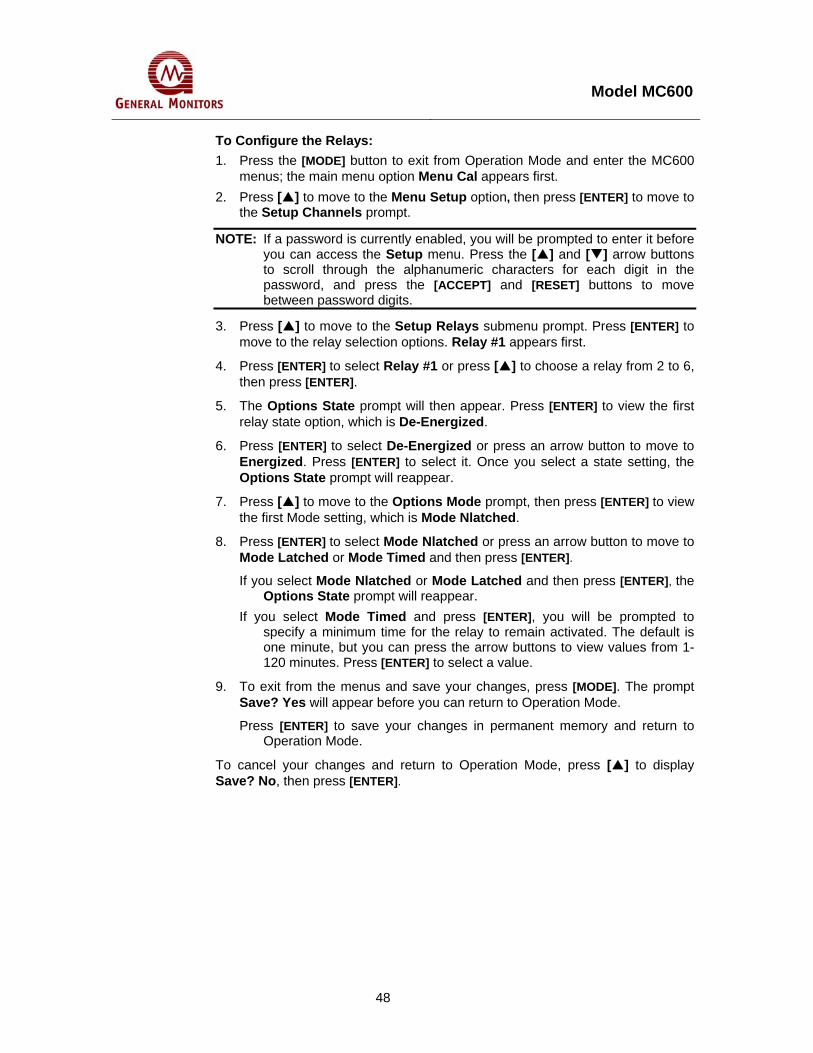
Model MC600
48
To Configure the Relays: 1. Press the [MODE] button to exit from Operation Mode and enter the MC600
menus; the main menu option Menu Cal appears first. 2. Press [ ] to move to the Menu Setup option, then press [ENTER] to move to
the Setup Channels prompt.
NOTE: If a password is currently enabled, you will be prompted to enter it before you can access the Setup menu. Press the [ ] and [ ] arrow buttons to scroll through the alphanumeric characters for each digit in the password, and press the [ACCEPT] and [RESET] buttons to move between password digits.
3. Press [ ] to move to the Setup Relays submenu prompt. Press [ENTER] to move to the relay selection options. Relay #1 appears first.
4. Press [ENTER] to select Relay #1 or press [ ] to choose a relay from 2 to 6, then press [ENTER].
5. The Options State prompt will then appear. Press [ENTER] to view the first relay state option, which is De-Energized.
6. Press [ENTER] to select De-Energized or press an arrow button to move to Energized. Press [ENTER] to select it. Once you select a state setting, the Options State prompt will reappear.
7. Press [ ] to move to the Options Mode prompt, then press [ENTER] to view the first Mode setting, which is Mode Nlatched.
8. Press [ENTER] to select Mode Nlatched or press an arrow button to move to Mode Latched or Mode Timed and then press [ENTER].
If you select Mode Nlatched or Mode Latched and then press [ENTER], the Options State prompt will reappear.
If you select Mode Timed and press [ENTER], you will be prompted to specify a minimum time for the relay to remain activated. The default is one minute, but you can press the arrow buttons to view values from 1-120 minutes. Press [ENTER] to select a value.
9. To exit from the menus and save your changes, press [MODE]. The prompt Save? Yes will appear before you can return to Operation Mode.
Press [ENTER] to save your changes in permanent memory and return to Operation Mode.
To cancel your changes and return to Operation Mode, press [ ] to display Save? No, then press [ENTER].

Model MC600
49
5.0 Advanced Configuration This chapter describes the MC600 configuration options for secondary tasks that are needed less often than the basic tasks, such as:
Selecting the Model for a channel after you have added a new card and/or device. Selecting the channel mode for the alarm and warning indicators. Setting up zoning groups for the connected sensors and instruments, in order to
allocate and configure the MC600 alarm relays.
Changing the default MODBUS communication parameters and setting passwords.
MenuSelf Tst
Self TstCard Test
Self TstDisplay Test
See Section 5.3 On Self Tests
CalChan #1-6
See Sections4.5 and 4.6
onCalibration
CalchckChan #1-6
InhibitChan #1-6
EnterPassword
See Section4.7 on
CalibrationChecks
RESET
RESET RESETRESETRESET
ENTER
MenuCal
ENTER
ENTER
EnterPassword
ENTER
See Section4.8 on
InhibitingAlarms
MODE
ENTER
MenuStupChck
RESET RESET
ENTER
MenuSetup
MenuInhibit
MenuCal Chck
ENTER ENTERENTER
ENTER
SetupChannels
SetupRelays
SetupZoning
SetupCardTest
SetupPassword
SetupFltRelay
SetupModbus
SetupLd Dflts
RESETRESETRESETRESETRESETRESETRESETRESET
See Section 4.9 for Basic Setup Menu Tasks, and Section 5.1 for Advanced Setup Menu Tasks
ENTER ENTER ENTER ENTER ENTER ENTER ENTER ENTER
ENTER
ENTER ENTER
RelaySetups
ChannelSetups
FltRelaySetups
ENTER ENTER ENTER
See Section 5.2 on the Setup Check Menus
AC
RS
AC
RS
AC
RS
CardTestSetups
AC
RS
ENTER
ModbusSetups
AC
RS
ZoneSetups
AC
RS
ENTER ENTER
UnitTemps
AC
RS
ENTER
Channel 1Operation Mode
nn %LEL(or %vv, ppm)
Gas Type
MODE Pressing [MODE] from anywhere in the menus will return theMC600 to Operation Mode.However, if you have made configuration changes in themenus, you must save them to nonvolatile memory or cancelthe changes, before you can return to Operation Mode.
ENTER Save ?Yes
Save ?No
ENTER
Figure 36: MC600 Advanced Menu Options

Model MC600
50
NOTE: The Advanced menu areas described in Figure 39 are shown shaded.
5.1 Using the Advanced Setup Menu Options The Menu Setup main menu option is the gateway to eight submenus for configuring different portions of your MC600 system. Most of these submenus are used relatively rarely and they are described in this section.
NOTE: If a password is enabled, you must enter it before you can access the Inhibit or Setup submenus. Press the [ ] and [ ] arrow buttons to scroll through the alphanumeric characters for each digit in the password, and press the [ACCEPT] and [RESET] buttons to move between password digits. The default setting is password disabled.
Setup Channels, Options Model: Step-by-step instructions are provided in this section for selecting a device model for each channel, after you upgrade the MC600 system. (Information on the basic portions of the Setup Channels submenu is provided in Section 4.0.)
Setup Channels, Options Mode: Includes options for configuring the channel Warning and Alarm indicators as Latching or Non-Latching.
Setup Zoning: Includes options for configuring zoning and voting for multiple channel-based alarms.
Setup Card Test: Includes options for signal-conditioning card diagnostics. Setup Password: Includes options for configuring passwords to restrict access to the
Setup and Inhibit submenus. Setup Fault Relay: Includes options for configuring the Fault Relays. Setup MODBUS: Includes options for configuring communications settings for
MC600 MODBUS communications, such as the data format and baud rate. Setup Load Defaults: Reloads a default MC600 configuration.
5.1.1 Selecting a Model Option Your MC600 system is already set up at the factory for you by General Monitors, based on the Models of catalytic HC sensors, MOS H2S sensors and 4-20mA instruments that you have ordered. A label directly above the signal conditioning cards indicates which device is installed in each channel.
However, if you install a field upgrade, such as installing additional signal conditioning cards or connecting different devices to your existing 4-20mA signal conditioning cards, you will need to use the Options Model submenu to reconfigure the channel(s).
Once you select a channel within the Setup Channels submenu, the Options Model submenu will display only the model options for the installed signal-conditioning card.
Figure 41 shows the large number of Model options you may select for channels with 4-20mA signal-conditioning cards installed.

Model MC600
51
MenuSetup
ENTER
ENTER
EnterPassword
ENTER
Channel#1
Channel#6
Channel#3
Channel#4
Channel#2
Channel#5
OptionsModel
ENTER RESET RESETRESETRESET RESET
ENTER ENTER ENTER ENTER
If Channel has 4-20mA Signal Board,see Model Options in Figure 31 (next page)
If Channel has HCSignal Board
If Channel hasMOS Signal Board
ModelHC Snsr
ModelMOS Snsr
ENTER ENTER
HC Snsr100 %LEL
MOS Snsr50 PPM
MOS Snsr100 PPM
RESET
MOS Snsr20 PPM
ENTER
RESET
RESET
ENTER
RESETRESET
ENTERENTER
RESET
ENTER
SetupChannels
ENTER
Figure 37: Setup Channels, Options Model Submenu
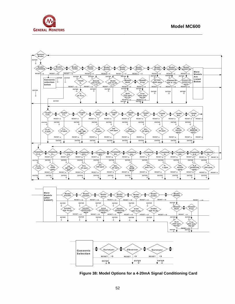
Model MC600
52
TS42002
IR400100 % LEL
/ vv
IR2100100 % LEL
/ vv
OptionsM odel
ENTER ENTEREN TERENTER
RESETR ESETRESETR ESETRESETRESET
M odelTS4000/H
S4000C/H 100 % LEL
ModelS4000T/H
S4000T/H 20/50/100
ppm
ENTER
ENTER
ENTER
ENTER
M ore M odels Are Listed Below
ENTER ENTERENTERENTER
R ESETR ESETR ESETRESETR ESET RESET
M odelS4000C/H
M odelIR 7000
IR 7000 5000 ppm
M odelIR2100
M odelTS400
0225 % vv
CLO 23 ppm
C1210 ppm
SO 220 ppm
O 320 ppm
CO100 / 500
ppm
HCL10 ppm
NO100 ppm
NO 2100 ppm
NH 350/100
ppm
TS400C102
TS400C12
TS400SO 2
TS400O 3
TS400C0
TS400HCL
TS400NO
TS400NO 2
TS400NH 3
ENTER
S4100T 20/50/100
ppm
S4100C 100 % LEL
S21420/50/100
ppm
S106A100 % LEL
S104100 % LEL
S216A20/50/100
ppm
M ore M odels (after S4000T)
M odelS214
M odelS4100T
M odelS106A
M odelS104
M odelS216A
M odelS4100C
NO100 ppmCLO 2
3 ppmCL2
10/20 ppm
SO 220/100 ppm
0O 225% V/VCO
100 / 500 ppm
HCL 20 ppm
NO 220 ppm
NH350/100 ppm
O 3 1 ppm
TS4000/HCL02
TS4000/HCL2
TS4000/HCO
TS4000/HHCL
TS4000/HNO
TS4000/HN02
TS4000/HS02
TS4000/H02
TS4000/HO 3
TS4000/HNH 3
ModelIR5000
IR5000M eth
IR5000Prop
M eth5000 ppm
5% LEL
Prop2000 ppm
1% LELRESETRESET
ENTERENTER
RESETRESET
R ESET RESET R ESET RESETR ESETRESETRESET
RESET RESET RESET RESET RESETRESET
EN TERENTER ENTERENTER ENTER
ENTER
ENTER ENTEREN TERENTER
ENTER
ENTER
ENTER
ENTER
ENTER
ENTER
TS4000/HH 2S
H 2S20/50/100
ppm
ENTER ENTER ENTER ENTER EN TER EN TER ENTER ENTER EN TER ENTER ENTER
ENTER EN TER ENTER ENTER EN TER ENTER ENTER ENTER ENTER ENTER ENTER
R ESET
RESET RESETRESETRESETRESETRESETR ESETRESET
RESETR ESET RESETRESETR ESETR ESET
RESETRESET
RESETRESETR ESET R ESET
R ESET
TS400H 2S
H 2S20/50/100
ppm
M odelTS420
ENTER ENTERENTEREN TERENTERENTERENTEREN TEREN TERENTER
RESET RESET RESET R ESETR ESETRESETRESETRESETRESETR ESET
RESETR ESETR ESETRESETRESET R ESETR ESETRESETRESET R ESET
EN TER ENTEREN TERENTERENTERENTERENTERENTER ENTER
G assonic selection below
M odelIR400
EN TER
RESET
M odelG assonic
RESET R ESET
EN TER
ENTER
TS4000/HH 2
ModelIR5500
IR5500M eth
IR 5500Prop
M eth5000 ppm
5% LEL
Prop2000 ppm
1% LELR ESET
ENTERENTER
R ESET
ENTER
RESET
ENTER
ENTER
H 2500 ppm
EN TER
RESET
RESET
EN TER
G asso n icS e lectio n
S u rveyo rO b serverS u rveyo r
R E S E TR E S E TR E S E T
E N T E RE N T E R E N T E R
Figure 38: Model Options for a 4-20mA Signal Conditioning Card

Model MC600
53
To Select a Model Option:
1. Press the [MODE] button to exit from Operation Mode and enter the MC600 menus. The first main menu option Menu Cal appears.
2. Press [ ] to move to the option Menu Setup. Press [ENTER] to move to the Setup Channels prompt.
3. At the Setup Channels prompt, press [ENTER] to display Channel #1. Press the [ ] and [ ] arrow buttons to select a channel, from 1 to 6.
4. Once you have selected a channel, press [ENTER] to move to the Options Model prompt. Press [ENTER] again to view the beginning of the list of Models.
5. Navigate through the Model options using the [ ] and [ ] buttons, then press [ENTER] to select a Model. Press [ENTER] again to complete your selection and redisplay the Options Model prompt.
6. To exit from the menus and save your changes, press [MODE]. The prompt Save? Yes will appear before you can return to Operation Mode.
Press [ENTER] to save your changes in permanent memory and return to Operation Mode.
To cancel your changes and return to Operation Mode, press [ ] to display Save? No, then press [ENTER].
NOTE: When an IR5000/IR5500 Instrument is selected, it should have the following settings for analog output values:
Fault - 0mA
Beam Block – 2mA
Analog output 1 during test gas – 1.5mA
Analog output 2 during test gas – 1.5mA
This will allow the MC600 to detect fault, beam block, and off-line conditions.
5.1.2 Selecting the Channel Mode for the Alarm and Warning Indicators
The MC600 features individual indicators for the Warning, Alarm Low and Alarm High on each of the six channel’s displays.
The MC600 allows the user to select the operating mode of the channel display. Similar to the Latching/Non-Latching option available for the Relays, this option allows the user to set the channel Warning and Alarm indictors to latch after the gas being monitored has exceeded the Warning and Alarm set points. In order to clear a latched Warning or Alarm from a channel’s display, it must first be accepted and then reset. After an alarm has been accepted, the corresponding indicator will stop flashing. A Warning or Alarm indicator can only be cleared if the gas level has moved below the corresponding set point for the channel.
Figure 39 shows the Option Mode submenu of the Setup Channels menu.

Model MC600
54
5.1.3 Configuring Zoning (for Relay Allocation) The Setup Zoning submenu provides several options for creating zones and assigning relays to MC600 channels. The default configuration is for one zone. If you select a configuration of “0 Zones” a set of menu options lets you assign each of the six MC600 relays to the Alarm High, Alarm Low or Warning state of a particular MC600 channel. With zero zoning selected, all relays default to unassigned.
You may also create two or three zones in order to share the six relays among several channels. This changes the allocation of relays to channels according to a set arrangement shown in the following table. With zoning implemented, you can configure single or dual voting for each zone; voting determines how many channels must be in an alarm or warning state to activate the relay. The default number of votes is single.

Model MC600
55
MenuSetup
ENTER
ENTER
EnterPassword
SetupChannels
Channel#1
Channel#2
Channel#3
Channel#4
Channel#5
Channel#6
RESET RESET RESET RESET RESET RESET
ENTER ENTER ENTER ENTER ENTER
ENTER
OptionsMode
OptionsMode
RESET
Ch ModeLatched
Ch ModeUnlatched
ENTER
ENTERorRESET
ENTERorRESET
Figure 39: Option Mode Submenu

Model MC600
56
Number of Zones
Zone Alarm State Channels Relays
0 N/A User-defined User-defined User-defined
1 High 1-6 1 and 2
1 Low 1-6 3 and 4
1 (default)
1 Warning 1-6 5 and 6
1 High 1-6 1 and 2
1 Low 1-6 3 and 4
1 Warning 1-6 5
1 Horn
1 Horn 1-6 6
1 High 1-3 1
1 Low 1-3 2
1 Warning 1-3 3
2 High 4-6 4
2 Low 4-6 5
2
2 Warning 4-6 6
1 High 1-2 1
1 Low 1-2 N/C
1 Warning 1-2 2
2 High 3-4 3
2 Low 3-4 N/C
2 Warning 3-4 4
3 High 5-6 5
3 Low 5-6 N/C
3
3 Warning 5-6 6
Table 7: Zoning Options and Relay Assignments

Model MC600
57
3 ZonesZone 2
3 ZonesZone 3
3 ZonesZone 1
ENTER ENTER
See Relay Assignment Options for 0 Zones in Figure 45
Zone 2Single
Zone 2Dual
Zone 3Single
Zone 3Dual
ENTER
Zone 1Single
Zone 1Dual
ENTER
Zone 1Single
Zone 1Dual
Zone 2Single
Zone 2Dual1 Zone
Single1 ZoneDual
ENTER
ENTER
ENTER
All Rlys Disabled
Zoning3 Zones
Zoning 2 Zones
Zoning1 Zone
ENTER
Zoning 0 Zones
RESET
ENTER
MenuSetup
Enter Password
ENTER
ENTER or RESET
RESET
RESET
RESET
RESET
RESET
RESET
RESET
RESET
RESET
RESET
ENTER or RESET
ENTER
2 ZonesZone 1
2 ZonesZone 2
RESET
RESET
RESET
ENTER
RESET
ENTER
ENTER
ENTER
ENTER
ENTER
ENTER
ENTER
ENTER
RESET
SetupChannels
SetupZoning
ENTER
RESET
RESET
RESET
RESET
1 ZoneSgl Horn
1 ZoneDl Horn
ENTER or RESET
ENTER or RESET
Figure 40: Zoning Submenu

Model MC600
58
SetupZoning
ENTER
Zoning0 Zones
All RlysDisabled
0 ZonesRelay # 1
0 ZonesRelay # 2
0 ZonesRelay # 3
0 ZonesRelay # 4
0 ZonesRelay # 5
0 ZonesRelay # 6
Relays #2-6 are the same as Relay #1, shown below
ENTER ENTER ENTER ENTER ENTERENTER
RESET
RESETENTER
ENTER
RESET
RESET
RelayChan #1
RelayChan #2
RelayChan #3
RelayChan #6
RelayChan #5
RelayChan #4
Channels #2-6 are configured the same as Channel #1, shown to the left
ENTERENTERENTER
RESET RESET
ChannelAlarm Hi
ChannelAlarm Lo
ChannelWarn
RESET
ENTER ENTER ENTER ENTERENTERENTER
MenuSetup
ENTER
ENTER
EnterPassword
SetupChannels
Figure 41: Relay Assignment Options with No Zoning

Model MC600
59
5.1.4 Configuring Horn Relay If “1 zone” option is selected, the horn relay can be configured and is assigned to relay 6. If any of the channels generate a warning or low or high alarm, the horn will activate. Pressing the ACCEPT button will silence the horn.
To select the horn option, enter “1 zone” submenu of setup zoning menu and select “1 zone sgl horn” for single vote or “1 zone dl horn” for dual vote. Figure 42 shows zoning submenu options.
5.1.5 Configuring Card Tests The Setup Card Test submenu allows you to configure the relays as Active or Not Active during a Card Test. In addition, you can configure the Ramp Time, which determines how quickly the signals increase from zero to full-scale during the Card Test. If you make changes to the Relays or Ramp Time parameters, you will be prompted to save your changes once you press [MODE] to exit from the menu system.
MenuSetup
ENTER
ENTER
EnterPassword
SetupChannels
SetupCardTest
ENTER
Card TestRelays
RelaysActive
RelaysInActive
ENTER
RESET
RESET
Card TestRampTime
ENTER
Ramptime
10 sec
RampTime1 Sec
RampTime3 Sec
RESET
ENTERorRESET
ENTERorRESET
ENTERorRESET
ENTERorRESET
ENTERorRESET
Figure 42: Setup Card Test Submenu

Model MC600
60
5.1.6 Configuring Setup and Inhibit Passwords By default, the MC600 password is disabled. The Setup Password submenu includes options for leaving the system password disabled (the default), enabling a default password (“FACT”) or defining a new password string.
Once a password is enabled, you will be prompted to enter a password when you attempt to gain access to the Setup and Inhibit menus.
If you make changes to the password settings, you will be prompted to save your changes once you press [MODE] to exit from the menu system.
SetupChannels
MenuSetup
ENTER
ENTER
EnterPassword
PasswordXXXX
RESET
SetupPassword
ENTER
PasswordDisable
PasswordSet
Password0000
ENTER
RESET
ENTER
PasswordXXXX
PasswordXXXX
PasswordXXXX
ENTER ENTER ENTER ENTER
ACCEPT
RESET
ACCEPT
RESET
ACCEPT
RESET
RESET
Figure 43: Setup Password Submenu

Model MC600
61
To Define a Password:
1. Press the [MODE] button to exit from Operation Mode and enter the MC600 menus. The first main menu option Menu Cal appears.
2. Press [ ] to move to the Menu Setup main menu option. Press [ENTER] to move to the Setup Channels prompt.
NOTE: If a password is currently enabled, you will be prompted to enter it before you can access the Setup menu. Press the [ ] and [ ] arrow buttons to scroll through the alphanumeric characters for each digit in the password, and press the [ACCEPT] and [RESET] buttons to move between password digits.
3. Once the Setup Channels prompt appears, press the [ ] and [ ] arrow buttons to move to the Setup Password submenu.
4. Press [ENTER] to view the first option, Password Disable. Either press [ENTER] to disable use of passwords, or press the [ ] button move to the Password Set option, then press [ENTER].
5. The default system password is “FACT”. Either press [ENTER] to use the default, or define a new 4-digit password string. Press the [ ] and [ ] arrow buttons to scroll through the alphanumeric
characters for each digit in the password, Press the [ACCEPT] and [RESET] buttons to move between password digits.
6. Press [ENTER] to complete your password definition. To exit from the menus and save your changes to the password, press [MODE]. The prompt Save? Yes will appear before you can return to Operation Mode. Press [ENTER] to save your changes in permanent memory and return to
Operation Mode. To cancel your changes and return to Operation Mode, press [ ] to display
Save? No, then press [ENTER].
NOTE: Password information is retained in nonvolatile memory. Care must be exercised in setting and enabling a password. If the password is lost or forgotten, it cannot be reset by cycling power.

Model MC600
62
5.1.7 Configuring the Fault Relays This Setup Flt Relay submenu includes options for configuring the Fault Relays so that a Fault LED will light and the Fault Relay will change state when the MC600 is in Calibration or Calibration Check Mode, or upon entering the Setup menus.
The default setting for the Fault Relay is ON during Calibration and Setup. If you make changes to the Fault Relay settings, you will be prompted to save your changes once you press [MODE] to exit from the menu system.
Drng StupInActive
MenuSetup
ENTER
ENTER
EnterPassword
SetupChannels
ENTER ENTER
Flt RelayDrng CAL
SetupFltRelay
ENTER
Drng CalActive
RESET
ENTERorRESET
ENTERorRESET
Drng StupActive
Drng CalInActive
ENTERorRESET
ENTERorRESET
Flt RelayDrngStup
Figure 44: Setup Fault Relays Submenu

Model MC600
63
5.1.8 Configuring MODBUS Parameters The Setup MODBUS submenu includes options for configuring communications parameters for the two MC600 MODBUS channels, such as the Address, Data Format and Baud Rate. The default settings are:
The default Address setting is 1 for MODBUS Channel 1, and the default address setting is 2 for MODBUS Channel 2. The range of allowable addresses is 1-247 (decimal).
The selectable Baud Rates are 19,200, 9600, 4800, or 2400 bits per second. The default setting for both channels is 19,200.
• The default Data Format setting for both channels is 8 data bits, no parity, and 1 stop bit. The data formats you can select are shown in Figure 45.
If you make changes to the default settings, you will be prompted to save your changes once you press [MODE] to exit from the menu system.
MenuSetup
ENTER
ENTER
EnterPassword
SetupChannels
SetupModbus
RESET
ModbusMOD1
ModbusMOD2
ENTER
ENTER
RESET
Format8E1, 8N1,8N2, 8O1
OptionsAddress
AddressN (1-247)
ENTERorRESET
ENTERorRESET
ENTER
RESET
OptionsFormat
RESET
ENTER
Baud2.4K, 4.8K,9.6K, 19.2K
OptionsBaud
ENTER
ENTERorRESET
RESET
Figure 45: Setup MODBUS Submenu

Model MC600
64
5.1.9 Loading Default Settings The Setup Load Defaults submenu includes options to reload a simplified set of defaults for the MC600, consisting of the following settings:
All channels are set to empty. If there are signal-conditioning cards installed in the six channel slots, they will all be flashing the message Set-Up Channel.
Relays are set for a single zone with one vote, Non-Latching and De-Energized.
MODBUS channel settings are as follows: - Addresses set to 1 for Channel 1, and 2 for Channel 2 - Baud Rate set to 19200 bps - Data Format set to 8 data bits, no parity, and 1 stop bit
Fault Relay is ON during calibration and setup Card Test settings are for Relays Active and Ramp Time = 10 seconds Setup and Inhibit menu password disabled, and set to “FACT” by default • Maximum and minimum temperatures cleared.
MenuSetup
ENTER
ENTER
EnterPassword
SetupChannels
SetupLd Dflts
RESET
Ld DfltsYes
Ld DfltsNo
ENTER
ENTER
Loading
RESET orENTER
!
NOTE: Loading defaults will delete all six-channel definitions, and you will have to reconfigure them
Figure 46: Setup Load Defaults Submenu

Model MC600
65
5.2 Using the Setup Check Menu The Menu StupChck submenu provides a read-only summary of the current configuration settings for the MC600 channels. Data is shown in the LCD windows for each channel populated with a signal card, rather than just in Channel 1. The following flowchart shows how to navigate among the different groups of settings.
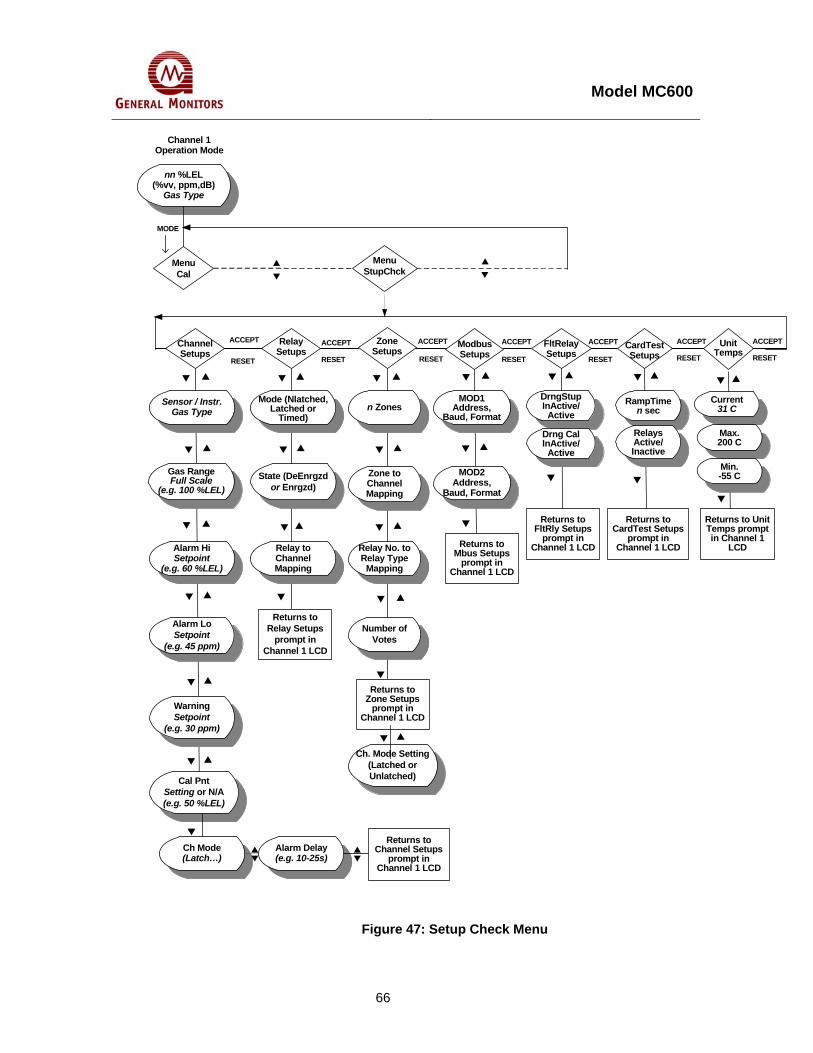
Model MC600
66
Channel 1 Operation Mode
Relay Setups
Channel Setups
ZoneSetups
ACCEPT
RESET
ModbusSetups
FltRelaySetups
CardTestSetups
ACCEPT
RESET
ACCEPT
RESET
ACCEPT
RESET
ACCEPT
RESET
ACCEPT
RESET
Sensor / Instr. Gas Type
Gas RangeFull Scale
(e.g. 100 %LEL)
Alarm HiSetpoint
(e.g. 60 %LEL)
Alarm LoSetpoint
(e.g. 45 ppm)
WarningSetpoint
(e.g. 30 ppm)
Cal PntSetting or N/A(e.g. 50 %LEL)
MenuStupChck
Mode (Nlatched, Latched or
Timed)
State (DeEnrgzd or Enrgzd)
Relay to Channel Mapping
n Zones
Zone to Channel Mapping
Relay No. to Relay Type
Mapping
Number of Votes
MOD1 Address,
Baud, Format
MOD2 Address,
Baud, Format
DrngStupInActive/
Active
Drng Cal InActive/
Active
RampTime n sec
Relays Active/Inactive
Returns to Channel Setups
prompt in Channel 1 LCD
Returns to Relay Setups
prompt in Channel 1 LCD
Returns to Zone Setups
prompt in Channel 1 LCD
Returns to Mbus Setups
prompt in Channel 1 LCD
Returns to FltRly Setups
prompt in Channel 1 LCD
Returns to CardTest Setups
prompt in Channel 1 LCD
nn %LEL(%vv, ppm,dB)
Gas Type
MenuCal
MODE
Unit Temps
ACCEPT
RESET
Current31 C
Max.200 C
Min.-55 C
Returns to Unit Temps prompt in Channel 1
LCD
Ch. Mode Setting(Latched or Unlatched)
Ch Mode(Latch…)
Alarm Delay(e.g. 10-25s)
Figure 47: Setup Check Menu

Model MC600
67
5.3 Using the Self Test Menu The Menu Self Tst submenu provides two types of tests:
Card Test. The Card Test ramps the signal from zero to full-scale for all channels that have card test set in this menu. Once you select channels to test, you can press [MODE] to start the test. For example, if Channels One, Two and Three all have card test set, then the signals for those channels will all ramp up once you press [MODE]. You will need to select the channels again in order to rerun the test
The Card Test Setup menu (see Configuring Card Tests) in Section 5.1.5) determines how fast the signal will be ramped during the test (Ramp Time), and whether the Alarm and Warning relays will be active during the test. If the relays are Active during the test, then the Warning and Alarm signals will be triggered as the signal to the channel exceeds the relay set points.
• Display Test. The Display Test darkens all segments of the six LCD channel displays. If they are not all darkened, this indicates an LCD malfunction. In addition, this test turns the READY, FAULT, ALARM and WARN LEDs on.
Channel 1Operation Mode
nn %LEL(%vv, ppm)Gas Type
MenuCal
MODE
MenuSelf Tst
Self TstDsplyTst
Self TstCardTest
CardTestChan #N
(1-6)
ChanN CT Set
ENTER
ENTER
ENTER
ENTER
Pressing the [MODE] button after one ormore Channel(s) are set starts the Card Test.
MODE
RESET
RESETRESET
Pressing [ENTER] startsthe Display Test.
ENTER
Figure 48: Self-Test Menu

Model MC600
68
6.0 Customer Support 6.1 GENERAL MONITORS’ OFFICES
Area Phone / Fax / Email UNITED STATES Corporate Office: 26776 Simpatica Circle Lake Forest, CA 92630
Phone: +1-949-581-4464. 800-446-4872 Fax: +1-949-581-1151 Email: [email protected]
9776 Whithorn Drive Houston, TX 77095
Phone: +1-281-855-6000 Fax: +1-281-855-3290 Email: [email protected]
UNITED KINGDOM Heather Close Lyme Green Business Park Macclesfield, Cheshire, United Kingdom, SK11 0LR
Phone: +44-1625-619-583 Fax: +44-1625-619-098 Email: [email protected]
IRELAND Ballybrit Business Park Galway Republic of Ireland
Phone: +353-91-751175 Fax: +353-91-751317 Email: [email protected]
SINGAPORE No. 2 Kallang Pudding Rd. #09-16 Mactech Building Singapore 349307
Phone: +65-6-748-3488 Fax: +65-6-748-1911 Email: [email protected]
MIDDLE EAST LOB12, #G20 P.O. Box 61209 Jebel Ali, Dubai United Arab Emirates
Phone: +971-4-8815751 Fax: +971-4-8817927 Email: [email protected]
Model MC600
69
7.0 Maintenance Maintenance activities for the MC600 include periodic calibration and calibration checks for connected catalytic HC and MOS H2S sensors, cleaning and lubrication, as needed. Maintenance for connected 4-20mA instruments is described in the instruction manuals for those instruments
NOTE: The system’s full two-year warranty will be voided if customer personnel or third parties damage the system during repair attempts or maintenance activities.
WARNING: Disconnect or inhibit external devices, such as, Trip Amplifiers, PLC or DCS systems before performing any maintenance.
CAUTION: Each MOS H2S Sensor is shipped with a red plastic cap fitted over the sensor head. Inside the cap is a desiccant. DO NOT remove this cap until you have applied power to the sensors. SAVE the cap and RE-CAP the sensor anytime the system power is off for more than one hour.
7.1 Developing a Maintenance Schedule Maintenance requirements will vary with each installation; General Monitors recommends that a schedule for periodic maintenance be established and followed and that a maintenance logbook be kept for each MC600 unit and sensor in operation. Specific recommendations for scheduling calibration and calibration checks are provided in the following section.
7.2 Calibration and Calibration Checks General Monitors recommends that you calibrate each catalytic HC sensor one hour after the MC600 system start-up. MOS H2S sensors should be calibrated an hour after start-up, then again after 24 hours of operation. During ongoing operation, the calibration for both catalytic and MOS H2S sensors should be checked at least every ninety (90) days to ensure system integrity. Frequent calibration checks ensure the integrity of the life-protecting equipment.
More frequent cleaning and calibration checks are recommended if the equipment is impacted by unusual environmental conditions such as mud collecting on the sensor head, sensors accidentally being painted over, etc.
7.2.1 Alternate Calibration Equipment Section 4.5.3, Sensor Calibration Equipment, describes how to calibrate sensors using the most common equipment, the portable purge calibrator for catalytic HC sensors and breaker bottles (Field Calibrators) with gas ampoules for H2S sensors. There are several alternate types of calibration equipment you can use, which are briefly described here. Ordering information for all of the calibration equipment is provided in Section 11.0.
7.2.1.1 Remote TGA-1 for Hydrocarbon Calibration The General Monitors remote test gas applicator, TGA-1, is designed to be permanently installed on a combustible gas sensor. The TGA-1 provides

Model MC600
70
protection from outside elements and it allows the user to apply a test gas to the sensor from a remote source.
Figure 49: Remote Test Gas Applicator (TGA-1)
7.2.1.2 Three-Liter Chamber for Hydrocarbon Calibration The 3-Liter Portable Calibration Chamber is used as an alternate to the more typical portable purge calibrator when the sensor is calibrated with solvent vapors. It is a practical and safe instrument for the field calibration of combustible gas monitoring systems. Sensors can be calibrated in place with a known liquid/air mixture, reducing the possibility of calibration error.
The Portable Calibration Chamber is a 3-liter sample chamber with an intrinsically safe battery-powered mixing fan. For catalytic bead sensors, a porthole allows the chamber to be placed on the sensor for calibration.
Figure 50: Three-Liter Chamber for Liquid and Solvent Vapors
Before using the 3-Liter Chamber, make sure the following is present:
3-Liter Chamber

Model MC600
71
Dish 250 micro liter syringe Correct volume of solvent/liquid for calibration and calibration checks.
7.2.1.3 H2S Portable Purge Calibrator General Monitors recommends using breaker bottles and glass ampoules for calibrating H2S gas detection instruments. However, the H2S Portable Purge Calibrator is available for applications where a calibration method of flowing H2S gas to the sensor might provide a better calibration source (e.g. high humidity environments).
The H2S Portable Purge Calibrator is a compact, practical, accurate and safe system for field calibration of H2S sensors. The cylinder is filled with an H2S in air mixture in one of seven separate parts per million (ppm) levels of concentration (10, 20, 25, 35, 50, 70 or 100). Using a known air/gas mixture reduces the possibility of error in field calibration.
NOTE: Do not store the cylinder with the regulator fully engaged in the cylinder valve.
Figure 51: H2S Portable Purge Calibrator
The Portable Purge Calibrators are lightweight assemblies that are easy to carry. However, an optional carrying case is available for those desiring to carry more than one assembly at a time. The case can hold up to two complete assemblies and facilitates transporting them in the field.

Model MC600
72
7.3 Cleaning the MC600 You can remove particulate matter from the MC600 and sensor accessories using an appropriate halogen-free solvent, such as water or ethanol. Accessories should be thoroughly dried with compressed air, if necessary, before refitting them to the detector. When cleaning with conductive liquids, all power should be removed from the equipment.
7.4 Lubrication European Union (EU) Approved Applications: The following grease compound is recommended for use: PBC Polybutylcuprysil, (or equivalent), which has BASEEFA Health & Safety Executive component approval No. 1051U for use as a jointing compound on flameproof electrical enclosures. This is available from General Monitors.
The neoprene rubber gasket, if it is found dry, should also be lubricated with Type P80 lubricant, available from General Monitors (P/N 610-010).
7.5 Storage The Model MC600 cabinet should be stored in a clean, dry area, that is within the temperature and humidity ranges quoted in Environmental Specifications in Section 10.3 You should insert dust caps into any vacant cable entry holes during storage.

Model MC600
73
8.0 Troubleshooting CAUTION: Component level repair must be undertaken either by General
Monitors’ personnel, or by an authorized service facility. SMT PCB repair shall be performed only at a General Monitors facility. Failure to comply with this requirement will invalidate the warranty.
NOTE: The system’s full two-year warranty will be voided if customer personnel or third parties damage the system during repair attempts or maintenance activities.
Be sure to inhibit or disconnect external alarm wiring before making any check that might send the unit into alarm, if an alarm condition will cause a problem.
8.1 MC600 Controller Error Codes and Remedies The MC600 controller has self-diagnostics incorporated into the microprocessor’s program. If a Fault is detected, the Fault relay will de-energize, the Fault LED will light and a fault message will appear on the MC600 LCD display for Channel 1.
8.1.1 CON FAIL/COMM Indicates failure in communication between the microprocessor and LCD display.
ACTION – Check cable #65011 for damage or loose connection. Then cycle power. If fault message reappears, the unit must be returned to the factory for repair
8.1.2 CON FAIL / EEPROM Indicates failure to recall nonvolatile user configuration.
ACTION – The unit must be returned to the factory for repair.
8.1.3 CON FAIL / LOW LINE Indicates inadequate input power.
ACTION – Check power supply and verify 20VDC minimum.
8.1.4 CON FAIL / PROGRAM Indicates failure of program checksum.
ACTION – The unit must be returned to the factory for repair.
8.1.5 CON FAIL / RAM Indicates failure of microprocessor RAM.
ACTION – The unit must be returned to the factory for repair.
8.1.6 CON FAIL / DATA RAM Indicates failure of microprocessor RAM.
ACTION – The unit must be returned to the factory for repair.

Model MC600
74
8.2 Channel Error Codes and Remedies The individual MC600 channels may show several different error codes that are related to the functioning of the signal conditioning card and/or sensor or instrument that is connected to each channel. Some of the following codes apply only to particular card types.
8.2.1 Setup Channel (Sensors and Instruments) Appears routinely after a new signal-conditioning card has been inserted, to indicate that the channel needs to be configured for model options, etc., using the MC600 menus or MODBUS commands.
ACTION – See Section 5.1.
8.2.2 Cal Channel (Sensors and Instruments) Indicates that calibration is required. Appears routinely after a new signal-conditioning card has been inserted and the channel has been configured.
ACTION – Calibrate channel per instructions in the section on Calibrating Catalytic HC and MOS H2S Sensors in Section 4.5, or Calibrating the LCD Display for 4-20mA Instruments in Section 4.6.
8.2.3 Cal Fault (Sensors and Instruments) Indicates that channel calibration failed due to conditions, such as, gas not being applied to the sensor, current not being applied to a 4-20mA card for LCD calibration, etc.
ACTION – Calibrate channel per instructions in the section on Calibrating Catalytic HC and MOS H2S Sensors in Section 4.5, or Calibrating the LCD Display for 4-20mA Instruments in Section 4.6.
8.2.4 Card Removed (Sensors and Instruments) Indicates that a signal-conditioning card has just been removed from a channel slot.
ACTION – Press [ACCEPT] to acknowledge removal of the card and leave the channel display blank or replace the card in the MC600 slot and reconfigure the channel (it will have to be set up once it is reinserted).
8.2.5 Fld Dev Fault (Instruments Only) This may indicate a problem with the wiring from the signal-conditioning card to the field device, with the signal-conditioning card fuses or with the field instrument.
NOTE: For some 4-20mA instruments, the MC600 message Fld Dev Fault will appear while the instrument is in start-up mode. Refer to the instrument documentation for information on the start-up process.
ACTION – Check and verify that the signal wiring to the sensor is correct. Also, one or both of the fuses on the signal-conditioning card may need to be replaced.
If it is not a fuse or cabling problem, this error is signal-level related and depends on instrument type. For example, the TS400 shows a fault when current is less than 3.5mA, the S4000 shows a fault when current is less than 1.5mA, etc. Refer

Model MC600
75
to the instruction manual for the respective instrument; for a list of instrument documentation, see the list of Related Documents on page vi.
8.2.6 Invalid Card (Sensors and Instruments) Indicates that an unrecognizable signal card is in the slot.
ACTION – Remove signal card and return to the factory for service.
8.2.7 Sensor Fault (Sensors Only) For catalytic HC and MOS H2S sensors only, this message indicates that the sensor is not functioning properly. The fuse on the signal conditioning card may need to be replaced if a Sensor Fault error appears during power-on.
ACTION – Check and verify that the signal wiring to the sensor is correct. If it is a MOS H2S sensor, try replacing the fuse on the MOS H2S signal-conditioning card. If adjusting the cabling and replacing the fuse does not remedy the problem, you should then attempt to calibrate the sensor per instructions in the section Calibrating Catalytic HC and MOS H2S Sensors in Section 4.5. If all of these actions are unsuccessful, return the sensor to the factory for service.
8.2.8 Field Device Offline: Whenever the channel indicates Field Device Offline that means the unit is in calibration mode, set up mode or self test mode. Please refer to device instruction manual for more detail

Model MC600
76
9.0 MC600 MODBUS Interface MODBUS is a widely used serial communication protocol for the RS-485 IEEE standard. A MODBUS program on a remote PC or other host can be used to control MC600 operation remotely. You can send MODBUS Read and Write commands to the MC600 registers to perform functions such as initiating gas check tests, zeroing and calibration of connected detectors, configuring communication channels between the controller and connected units, and monitoring status information for connected devices.
Section 9.1 provides general background information regarding the MODBUS interface, which applies for the MC600 devices. Later sections describe the MC600 MODBUS registers in detail.
9.1 General MODBUS Information 9.1.1 Serial Communication Settings The unit can be configured for different communication speeds and data formats
9.1.1.1 Baud Rate The baud rate is selectable via the MODBUS communications interface. The selectable baud rates are 19,200, 9600, 4800, or 2400 bits per second; the default setting is 19,200 for the MC600. .
9.1.1.2 Data Format The data format is selectable via the MODBUS communications interface. The default setting is 8 data bits, no parity, and 1 stop bit. The selectable data formats are as follows:
Data Bits Parity Stop Bit Format Register Code
8 None 1 8-N-1 0 8 None 2 8-N-2 1 8 Even 1 8-E-1 2 8 Odd 1 8-0-1 3
Table 8: Serial Data Formats
9.1.2 Function Codes Supported Function Code 03 (Read Holding Registers) is used to read status from the
slave unit. Function Code 06 (Preset Single Register) is used to write to the slave unit.

Model MC600
77
9.1.3 MODBUS Read Protocol (Query/Response) The MODBUS Read command query and response message formats are shown in the following two tables.
Byte
MODBUS Range
1st
2nd
3rd
4th
5th
6th
7th
8th
Slave Address Function Code Register Address High** Register Address Low** Number of Registers High Number of Registers Low CRC*** Low CRC*** High
1-247* (Decimal) 03 00 00-FFh 00 01 00-FFh
00-FFh
NOTES: *Address 0 is reserved for broadcast mode and is not supported. **Register Address can be a maximum of 160 Locations (0000-009Fh). ***CRC = Cyclic Redundancy Check
Table 9: MODBUS Read Query Message
Byte
MODBUS
Range
1st
2nd
3rd
4th
5th
6th
7th
Slave Address Function Code Byte Count Data High Data Low CRC** Low CRC** High
1-247* (Decimal) 03 02-FFh 00-FFh 00-FFh 00-FFh 00-FFh
NOTES: *Address 0 is reserved for broadcast mode and is not supported. **CRC = Cyclic Redundancy Check
Table 10: MODBUS Read Response Message

Model MC600
78
9.1.4 MODBUS Write Command Protocol (Query/Response) The MODBUS Write command Query and Response message formats are shown in the following two tables.
Byte
MODBUS
Range
1st
2nd
3rd
4th
5th
6th
7th
8th
Slave Address Function Code Register Address High** Register Address Low** Preset Data High Preset Data Low CRC*** Low CRC*** High
1-247* (Decimal) 06 00 00-FFh 00-FFh 00-FFh 00-FFh 00-FFh
NOTES: *Address 0 is reserved for broadcast mode and is not supported. **Register Address can be a maximum of 160 Locations (0000-009Fh). ***CRC = Cyclic Redundancy Check
Table 11: MODBUS Write Query Message
Byte
MODBUS
Range
1st
2nd
3rd
4th
5th
6th
7th
8th
Slave Address Function Code Register Address High** Register Address Low** Preset Data High Preset Data Low CRC Low Byte*** CRC High Byte***
1-247* (Decimal) 06 00 00-FFh 00-FFh 00-FFh 00-FFh 00-FFh
NOTES: *Address 0 is reserved for broadcast mode and is not supported. **Register Address can be a maximum of 160 Locations (0000-009Fh). ***CRC = Cyclic Redundancy Check
Table 12: MODBUS Write Response Message

Model MC600
79
9.1.5 Exception Response Messages and Codes In a normal communications query and response, the master device sends a query to the MC600 and the MC600 receives the query without a communications error. The MC600 then handles the query normally within the master device’s allowable timeout and returns a normal response to the master. An abnormal communications query produces one of several possible events:
1. If the MC600 does not receive the query due to a communications error, then no response is returned from the MC600 and the master device will eventually process a timeout condition for the query.
2. If the MC600 receives the query, but detects a communication error (CRC, etc.), then no response is returned from the MC600 and the master device will eventually process a timeout condition for the query.
3. If the MC600 receives the query without a communications error, but cannot process the response to the master within the master’s timeout setting, then no response is returned from the MC600. The master device will eventually process a timeout condition for the query. To prevent this condition from occurring, the master’s timeout setting should be set to 200 milliseconds or greater, since 200 milliseconds is the maximum response time for the MC600.
4. If the MC600 receives the query without a communications error but cannot process it due to an error in the query, then the MC600 will return an exception response message informing the master of the error. The following table shows the structure of the exception response message. A different Exception Code indicates each type of query error.
Byte MODBUS Range 1st
2nd
3rd 4th
5th
Slave Address Function Code Exception Code (See Error! Reference source not found.) CRC Low** CRC High**
1-247* (Decimal) 83h or 86h 01 – 06 00-FFh 00-FFh
Table 13: MODBUS Exception Response Message
NOTES: *Address 0 is reserved for broadcast mode and is not supported. **CRC = Cyclic Redundancy Check
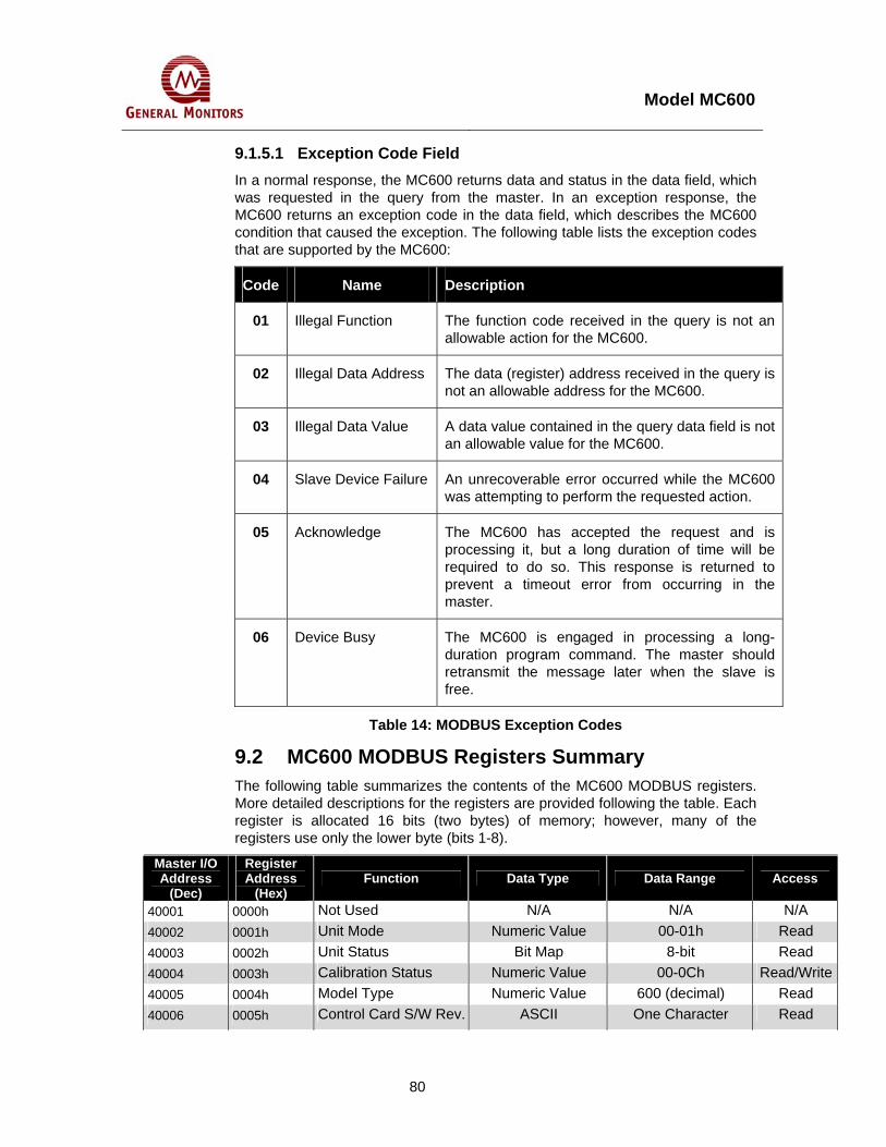
Model MC600
80
9.1.5.1 Exception Code Field In a normal response, the MC600 returns data and status in the data field, which was requested in the query from the master. In an exception response, the MC600 returns an exception code in the data field, which describes the MC600 condition that caused the exception. The following table lists the exception codes that are supported by the MC600:
Code Name Description
01 Illegal Function The function code received in the query is not an allowable action for the MC600.
02 Illegal Data Address The data (register) address received in the query is not an allowable address for the MC600.
03 Illegal Data Value A data value contained in the query data field is not an allowable value for the MC600.
04 Slave Device Failure An unrecoverable error occurred while the MC600 was attempting to perform the requested action.
05 Acknowledge The MC600 has accepted the request and is processing it, but a long duration of time will be required to do so. This response is returned to prevent a timeout error from occurring in the master.
06 Device Busy The MC600 is engaged in processing a long-duration program command. The master should retransmit the message later when the slave is free.
Table 14: MODBUS Exception Codes
9.2 MC600 MODBUS Registers Summary The following table summarizes the contents of the MC600 MODBUS registers. More detailed descriptions for the registers are provided following the table. Each register is allocated 16 bits (two bytes) of memory; however, many of the registers use only the lower byte (bits 1-8).
Master I/O Address
(Dec)
Register Address
(Hex) Function Data Type Data Range Access
40001 0000h Not Used N/A N/A N/A 40002 0001h Unit Mode Numeric Value 00-01h Read 40003 0002h Unit Status Bit Map 8-bit Read 40004 0003h Calibration Status Numeric Value 00-0Ch Read/Write40005 0004h Model Type Numeric Value 600 (decimal) Read 40006 0005h Control Card S/W Rev. ASCII One Character Read

Model MC600
81
Master I/O Address
(Dec)
Register Address
(Hex) Function Data Type Data Range Access
40007 0006h LCD S/W Revision ASCII One Character Read 40008 0007h Temperature Numeric Value 8-bit, 00-FFh Read 40009 0008h Maximum
Temperature Numeric Value 8-bit, 00-FFh Read
40010 0009h Minimum Temperature Numeric Value 8-bit, 00-FFh Read
40011 000Ah Accept/Reset Numeric Value 1 or 2 Write
40012 0008h Not Used N/A N/A N/A
40015 000Eh Not Used N/A N/A N/A
40016 000Fh Mod1 Address Numeric Value 1-247 (1-F7h) Read/Write
40017 0010h Mod1 Baud Rate Numeric Value 24, 48, 96, 192 (18h, 30h, 60h, C0h)
Read/Write
40018 0011h Mod1 Format Numeric Value 0, 1, 2 or 3 Read/Write40019 0012h Mod2 Address Numeric Value 1-247 (decimal) Read/Write40020 0013h Mod2 Baud Rate Numeric Value 24, 48, 96, 192
(18h, 30h, 0h, C0h) Read/Write
40021 0014h Mod2 Format Numeric Value 0, 1, 2 or 3 Read/Write40022-40032 0015h-0019h Not Used N/A N/A N/A 40033 0020h Mod1 Total Rcv Errors Numeric Value 8-bit, 00-FFh Read
40034 0021h Mod1 MODBUS Address Errors
Numeric Value 8-bit, 00-FFh Read
40035 0022h Mod1 Function Code Errors
Numeric Value 8-bit, 00-FFh Read
40036 0023h Mod1 Starting Address Errors
Numeric Value 8-bit, 00-FFh Read
40037 0024h Mod1 No. Reg. Errors Numeric Value 8-bit, 00-FFh Read 40038 0025h Mod1 RXD CRC
Errors Numeric Value 8-bit, 00-FFh Read
40039 0026h Mod1 Timing Numeric Value 8-bit, 00-FFh Read 40040 0027h Mod1 Framing Errors Numeric Value 8-bit, 00-FFh Read 40041 0028h Mod1 Parity Errors Numeric Value 8-bit, 00-FFh Read 40042 0029h Mod1 Noise Errors Numeric Value 8-bit, 00-FFh Read 40043 002Ah Mod1 SCI Interrupt
Errors Numeric Value 8-bit, 00-FFh Read
40044 002Bh Mod1 Clear Mod Errors
Numeric Value 1-bit Write
40045-40048 002Ch-002Fh
Not Used N/A N/A N/A
40049 0030h Mod2 Total Rcv Errors Numeric Value 8-bit, 00-FFh Read 40050 0031h Mod2 MODBUS
Address Errors Numeric Value 8-bit, 00-FFh Read
40051 0032h Mod2 Function Code Errors
Numeric Value 8-bit, 00-FFh Read

Model MC600
82
Master I/O Address
(Dec)
Register Address
(Hex) Function Data Type Data Range Access
40052 0033h Mod2 Starting Address Errors
Numeric Value 8-bit, 00-FFh Read
40053 0034h Mod2 No. Reg. Errors Numeric Value 8-bit, 00-FFh Read 40054 0035h Mod2 RXD CRC
Errors Numeric Value 8-bit, 00-FFh Read
40055 0036h Mod2 Timing Numeric Value 8-bit, 00-FFh Read 40056 0037h Mod2 Framing Errors Numeric Value 8-bit, 00-FFh Read 40057 0038h Mod2 Parity Errors Numeric Value 8-bit, 00-FFh Read 40058 0039h Mod2 Noise Errors Numeric Value 8-bit, 00-FFh Read 40059 003Ah Mod2 SCI Interrupt
Errors Numeric Value 8-bit, 00-FFh Read
40060 003Bh Mod2 Clear Comm Errors
Numeric Value 1-bit Write
40061-40064 003Ch-003Fh
Not Used N/A
40065 0040h CH1 Channel Mode Numeric Value 8-bit, 00-0Fh Read/Write40066 0041h CH1 Sensor Type Numeric Value 8-bit, 00-22h Read/Write40067 0042h CH1 Sensor Full-scale Numeric (Scaled) 16-bit Read 40068 0043h CH1 Sensor Value Numeric (Scaled) 16-bit Read 40069 0044h CH1 High Alarm
Setting Numeric (Scaled) 16-bit Read/Write
40070 0045h CH1 Low Alarm Setting
Numeric (Scaled) 16-bit Read/Write
40071 0046h CH1 Warn Setting Numeric (Scaled) 16-bit Read/Write40072 0047h CH1 Alarm State Bit Map 8-bit Read 40073 0048h CH1 Sensor Life Numeric Value 0-100% (00h-64h) Read/Write40074 0049h CH1 Cal Point Numeric Value 25-95% full-scale
(19h-5Fh) Read/Write
40075 004Ah CH1 Alarm Mode Numeric Value 8-bit Read/Write40076 004Bh CH1 Alarm Delay Time Numeric Value 8-bit Read/Write40077-40080 400Ch-
004Fh CH1 Not Used N/A N/A N/A
40081 0050h CH2 Channel Mode Numeric Value 8-bit, 00-0Fh Read/Write
40082 0051h CH2 Sensor Type Numeric Value 8-bit, 00-22h Read/Write
40083 0052h CH2 Sensor Full-scale Numeric (Scaled) 16-bit Read
40084 0053h CH2 Sensor Value Numeric (Scaled) 16-bit Read
40085 0054h CH2 High Alarm Setting
Numeric (Scaled) 16-bit Read/Write
40086 0055h CH2 Low Alarm Setting
Numeric (Scaled) 16-bit Read/Write
40087 0056h CH2 Warn Setting Numeric (Scaled) 16-bit Read/Write
40088 0057h CH2 Alarm State Bit Map 8-bit Read
40089 0058h CH2 Sensor Life Numeric Value 0-100% (00h-64h) Read/Write

Model MC600
83
Master I/O Address
(Dec)
Register Address
(Hex) Function Data Type Data Range Access
40090 0059h CH2 Cal Point Numeric Value 25-95% full-scale (19h-5Fh)
Read/Write
40091 005Ah Ch2 Alarm Mode Numeric Value 8-bit Read/Write
40092 005Bh CH2 Alarm Delay Time Numeric Value 8-bit Read/Write
40093-40096
005Ch-005Fh
Not Used N/A N/A N/A
40097 0060h CH3 Channel Mode Numeric Value 8-bit, 00-0Fh Read/Write
40098 0061h CH3 Sensor Type Numeric Value 8-bit, 00-22h Read/Write
40099 0062h CH3 Sensor Full-scale Numeric (Scaled) 16-bit Read
40100 0063h CH3 Sensor Value Numeric (Scaled) 16-bit Read
40101 0064h CH3 High Alarm Setting
Numeric (Scaled) 16-bit Read/Write
40102 0065h CH3 Low Alarm Setting
Numeric (Scaled) 16-bit Read/Write
40103 0066h CH3 Warn Setting Numeric (Scaled) 16-bit Read/Write
40104 0067h CH3 Alarm State Bit Map 8-bit Read
40105 0068h CH3 Sensor Life Numeric Value 0-100% (00h-64h) Read/Write
40106 0069h CH3 Cal Point Numeric Value 25-95% full-scale (19h-5Fh)
Read/Write
40107 006Ah Ch3 Alarm Mode Numeric Value 8-bit Read/Write
40108 006Bh Ch3 Alarm Delay Time Numeric Value 8-bit Read/Write
40109-40112
006Ch-006Fh
Not Used N/A N/A N/A
40113 0070h CH4 Channel Mode Numeric Value 8-bit, 00-0Fh Read/Write
40114 0071h CH4 Sensor Type Numeric Value 8-bit, 00-22h Read/Write
40115 0072h CH4 Sensor Full-scale Numeric (Scaled) 16-bit Read
40116 0073h CH4 Sensor Value Numeric (Scaled) 16-bit Read
40117 0074h CH4 High Alarm Setting
Numeric (Scaled) 16-bit Read/Write
40118 0075h CH4 Low Alarm Setting
Numeric (Scaled) 16-bit Read/Write
40119 0076h CH4 Warning Setting Numeric (Scaled) 16-bit Read/Write
40120 0077h CH4 Alarm State Bit Map 8-bit Read
40121 0078h CH4 Sensor Life Numeric Value 0-100% (00h-64h) Read/Write
40122 0079h CH4 Cal Point Numeric Value 25-95% full-scale (19h-5Fh)
Read/Write
40123 007Ah CH4 Alarm Mode Numeric Value 8-bit Read/Write
40124 007Bh CH4 Alarm Delay Time Numeric Value 8-bit Read/Write
40125-40128
007Ch-007Fh
CH4 Not Used N/A N/A N/A
40129 0080h CH5 Channel Mode Numeric Value 8-bit, 00-0Fh Read/Write

Model MC600
84
Master I/O Address
(Dec)
Register Address
(Hex) Function Data Type Data Range Access
40130 0081h CH5 Sensor Type Numeric Value 8-bit, 00-22h Read/Write
40131 0082h CH5 Sensor Full-scale Numeric (Scaled) 16-bit Read
40132 0083h CH5 Sensor Value Numeric (Scaled) 16-bit Read
40133 0084h CH5 High Alarm Setting
Numeric (Scaled) 16-bit Read/Write
40134 0085h CH5 Low Alarm Setting
Numeric (Scaled) 16-bit Read/Write
40135 0086h CH5 Warn Setting Numeric (Scaled) 16-bit Read/Write
40136 0087h CH5 Alarm State Bit Map 8-bit Read
40137 0088h CH5 Sensor Life Numeric Value 0-100% (00h-64h) Read/Write
40138 0089h CH5 Cal Point Numeric Value 25-95% full-scale (19h-5Fh)
Read/Write
40139 008Ah CH5 Alarm Mode Numeric Value 8-bit Read/Write
40140 008Bh CH5 Alarm Delay Time Numeric Value 8-bit Read/Write
40141-40144
008Bh-008Fh
CH5 Not Used N/A N/A N/A
40145 0090h CH6 Channel Mode Numeric Value 8-bit, 00-0Fh Read/Write
40146 0091h CH6 Sensor Type Numeric Value 8-bit, 00-22h Read/Write
40147 0092h CH6 Sensor Full-scale Numeric (Scaled) 16-bit Read
40148 0093h CH6 Sensor Value Numeric (Scaled) 16-bit Read
40149 0094h CH6 High Alarm Setting
Numeric (Scaled) 16-bit Read/Write
40150 0095h CH6 Low Alarm Setting
Numeric (Scaled) 16-bit Read/Write
40151 0096h CH6 Warn Setting Numeric (Scaled) 16-bit Read/Write
40152 0097h CH6 Alarm State Bit Map 8-bit Read
40153 0098h CH6 Sensor Life Numeric Value 0-100% (00h-64h) Read/Write
40154 0099h CH6 Cal Point Numeric Value 25-95% full-scale (19h-5Fh)
Read/Write
40155 009Ah CH6 Alarm Mode Numeric Value 8-bit Read/Write
40156 009Bh CH6 Alarm Delay Time Numeric Value 8-bit Read/Write
40157-40160
009Ch-009Fh
CH6 Not Used N/A N/A N/A
Table 15: MC600 MODBUS Register Summary

Model MC600
85
9.3 MC600 MODBUS Register Details 9.3.1 MC600 Mode (0001h, Read-Only) A Read returns the current MC600 unit mode. The value returned is 0 or 1 and indicates that the unit is starting up; 1 indicates that the unit is operating normally (includes fault conditions).
9.3.2 Unit Error Status (0002h, Read-Only) This register reports on several types of status errors. A Read command to this register returns the present status, represented by the active bit(s). The following table shows the status that is determined by the first five bits in this register. With multiple error status bits set, the maximum value for the register can range from 0-0x1F. A value of 0 indicates that there is no current status error.
Bit 8 7 6 5 4 3 2 1
Error Status N/A N/A N/A Low Line
Fault RAM Fault Program
Checksum Fault
EEPROM Checksum
Fault
LCD Communicatio
n Fault
Bit Value 80 hex 128 dec
40 hex 64 dec
20 hex 32 dec
10 hex 16 dec
8 hex 8 dec
4 hex 4 dec
2 hex 2 dec
1 hex 1 dec
Access Read-Only Read Read Read Read Read Read Read Read
Table 16: Bitmap for Unit Error Status (Lower Byte Only)
9.3.3 Calibration and Calibration Check Mode Status (0003h, Read/Write)
This register returns the status of the channel that is in Calibration mode, as indicated by the value of the lower byte in the register, from 1 to 12 decimal. The statuses indicated by the register values vary, depending on what type of sensor or 4-20mA instrument (and associated signal conditioning card) is in Calibration mode. Only the lower byte is used.
Only three of the register values are writeable, as indicated by an asterisk (*) in the table that follows; Most statuses are Read-Only. LCD messages associated with statuses are shown in the following table. Status information that does not actually appear on the channel LCD is shown in parentheses.
NOTE: Only one MC600 channel can be in Calibration mode at a particular time; a register value of 0 indicates that none of the channels is in Calibration mode.
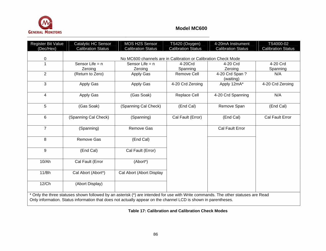
Model MC600
86
Register Bit Value (Dec/Hex)
Catalytic HC Sensor Calibration Status
MOS H2S Sensor Calibration Status
TS420 (Oxygen) Calibration Status
4-20mA Instrument Calibration Status
TS4000-02 Calibration Status
0
No MC600 channels are in Calibration or Calibration Check Mode
1 Sensor Life = n Zeroing
Sensor Life = n Zeroing
4-20Crd Spanning
4-20 Crd Zeroing
4-20 Crd Spanning
2 (Return to Zero) Apply Gas Remove Cell 4-20 Crd Span ? (waiting)
N/A
3 Apply Gas Apply Gas 4-20 Crd Zeroing Apply 12mA* 4-20 Crd Zeroing
4 Apply Gas (Gas Soak) Replace Cell 4-20 Crd Spanning N/A
5 (Gas Soak) (Spanning Cal Check) (End Cal) Remove Span (End Cal)
6 (Spanning Cal Check) (Spanning) Cal Fault (Error) (End Cal) Cal Fault Error
7 (Spanning) Remove Gas Cal Fault Error
8 Remove Gas (End Cal)
9 (End Cal) Cal Fault (Error)
10/Ah Cal Fault (Error (Abort*)
11/Bh Cal Abort (Abort*) Cal Abort (Abort Display
12/Ch (Abort Display)
* Only the three statuses shown followed by an asterisk (*) are intended for use with Write commands. The other statuses are Read Only information. Status information that does not actually appear on the channel LCD is shown in parentheses.
Table 17: Calibration and Calibration Check Modes

Model MC600
87
9.3.4 Model Type (0004h, Read-Only) This register returns the model type for the MC600 as 258h, which is 600 in decimal notation. Only the lower byte of the register is used.
9.3.5 Control Card Firmware Revision (0005h, Read-Only) This register returns the ASCII character for the control card firmware revision, such as 41h for revision A. Only the lower byte of the register is used.
9.3.6 LCD Card Firmware Revision (0006h, Read-Only) This register returns the ASCII character for the LCD card firmware revision, such as 41h for revision A. Only the lower byte of the register is used.
9.3.7 Temperature (0007h, Read-Only) This register returns a number that yields the current MC600 temperature in degrees Centigrade offset by 55o C (decimal). For example, if 50h (80 decimal) is returned, this indicates a temperature of 25o C (80 o C - 55 o C = 25o C).
9.3.8 Maximum Temperature (0008h, Read-Only) This register returns a number that yields the maximum MC600 temperature in degrees Centigrade offset by 55o C (decimal). For example, if 60h (96 decimal) is returned, this indicates a temperature of 41o C (96o C - 55 o C = 41o C).
9.3.9 Minimum Temperature (0009h, Read-Only) This register returns a number that yields the current MC600 temperature in degrees Centigrade offset by 55o C (decimal). For example, if 30h (48 decimal) is returned, this indicates a temperature of -7o C (48o C – 55o C = -7o C).
9.3.10 Accept/Reset (000Ah, Write-Only) This register duplicates the functions of the front panel, Accept/Reset buttons. Entering a value of 1 performs an Accept function. Entering a value of 2 performs a Reset function.
9.3.11 MODBUS Channel 1 Address (000Fh, Read/Write) This register returns and can also set the address for the MC600 MODBUS Channel 1. The default setting is 1, and the range of allowable addresses is 1-247 (decimal) or 01-FBh.
NOTE: If the same port on a MODBUS device is connected to both MC600 MODBUS channels, then the addresses for MODBUS Channel 1 and MODBUS Channel 2 must be unique. If a separate port is connected to each channel, then the unit addresses for Channel 1 and Channel 2 can be the same.

Model MC600
88
9.3.12 MODBUS Channel 1 Baud Rate (0010h, Read/Write) This register returns and can also set the baud rate for the MC600 MODBUS Channel 1. The default setting is 19,200 baud. The list of all possible settings is:
Baud Rate Register Value (Hex and Decimal)
2400 baud 18h (24 decimal)
4800 baud 30h (48 decimal)
9600 baud 60h (96 decimal)
19200 baud C0h (192 decimal)
Table 18: Baud Rates for MODBUS Channel 1
9.3.13 MODBUS Channel 1 Data Format (0011h, Read/Write) This register returns and can also set the data format for the MC600 MODBUS Channel 1. The default setting is 8 data bits, no parity, 1 stop bit. The list of all possible settings is:
Data Format (Data Bits – Parity – Stop Bits)
Register Value
8-N-1 0
8-N-2 1
8-E-1 2
8-0-1 3
Table 19: Data Formats for MODBUS Channel 1
9.3.14 MODBUS Channel 2 Address (0012h, Read/Write) This register returns and can also set the address for the MC600 MODBUS Channel 2. The default setting is 2, and the range of allowable addresses is 1-247 (decimal) or 01-FBh.
MODBUS Channel 2 Baud Rate (0013h, Read/Write)
This register returns and can also set the baud rate for the MC600 MODBUS Channel 2. The default setting is 19,200 baud. The list of all possible settings is:
Baud Rate Register Value (Hex and Decimal)
2400 baud 18h (24 decimal)
4800 baud 30h (48 decimal)
9600 baud 60h (96 decimal)
19200 baud C0h (192 decimal)

Model MC600
89
Table 20: Baud Rates for MODBUS Channel 2
9.3.15 MODBUS Channel 2 Data Format (0014h, Read/Write) This register returns and can also set the data format for the MC600 MODBUS Channel 2. The default setting is 8 data bits, no parity, 1 stop bit. The list of settings is:
Data Format (Data Bits – Parity – Stop Bits)
Register Value
8-N-1 0
8-N-2 1
8-E-1 2
8-0-1 3
Table 21: Data Formats for MODBUS Channel 2
9.3.16 MODBUS Channel 1 Total Receive Errors (0020h, Read-Only)
This register returns the sum total of all receive errors for MODBUS channel 1; this combines all types of communication errors shown individually in registers 0021h to 002Ah. The maximum number of errors is 255 (FFh); after 255, the counter restarts.
You can also reset the counters for this register and all Channel 1 communication errors by writing to register 002Bh (see Section 9.3.28)
9.3.17 MODBUS Channel 1 Address Errors (0021h, Read-Only) This register returns the number of valid messages received by Mod1 that specify an invalid unit address (not matching the MC600 MODBUS channel 1 unit address). The maximum number of errors is 255 (FFh); after 255, the counter restarts.
NOTE: If the same port on a MODBUS device is connected to both MC600 MODBUS channels, then duplicate address errors can occur for Channel 1 and Channel 2
9.3.18 MODBUS Channel 1 Function Code Errors (0022h, Read-Only)
This register returns the number of valid messages received by Mod1 that include an unsupported function code (not equal to 03h or 06h). The maximum number of errors is 255 (FFh); after 255, the counter restarts.
9.3.19 MODBUS Channel 1 Starting Address Errors (0023h, Read-Only)
This register returns the number of valid messages received by Mod1 that specify invalid register addresses. The maximum number of errors is 255 (FFh); after 255, the counter restarts.

Model MC600
90
9.3.20 MODBUS Channel 1 No. of Register Errors (0024h, Read-Only)
This register returns the number of valid Read Query messages received by Mod1 that specify an invalid number of registers. The maximum number of errors is 255 (FFh); after 255, the counter restarts.
9.3.21 MODBUS Channel 1 RXD CRC Errors (0025h, Read-Only) This register returns the number of valid messages received by Mod1 containing an invalid CRC (either High or Low). The maximum number of errors is 255 (FFh); after 255, the counter restarts.
9.3.22 MODBUS Channel 1 Byte Timing Errors (0026h, Read-Only)
This register returns the number of messages received by Mod1 that have an improper inter-byte delay, which is greater than 1½ times the character time. The maximum number of errors is 255 (FFh); after 255, the counter restarts.
9.3.23 MODBUS Channel 1 Framing Errors (0027h, Read-Only) This register returns the number of messages received by Mod1 that have improper composition. The maximum number of errors is 255 (FFh); after 255, the counter restarts.
9.3.24 MODBUS Channel 1 Parity Errors (0028h, Read-Only) This register returns the number of messages received by Mod1 that have incorrect message parity. The maximum number of errors is 255 (FFh); after 255, the counter restarts.
9.3.25 MODBUS Channel 1 Noise Errors (0029h, Read-Only) This register returns the number of messages received by Mod1 with noise errors. The maximum number of errors is 255 (FFh); after 255, the counter restarts.
9.3.26 MODBUS Channel 1 SCI Interrupt Errors (002Ah, Read-Only)
This register returns the number of messages received by Mod1 with interrupt errors due to serial overrun conditions. The maximum number of errors is 255 (FFh); after 255, the counter restarts.
9.3.27 MODBUS Channel 1 Clear MODBUS Errors (002Bh, Write-Only)
A Write command to this register will reset all of the counters for MODBUS Channel 1 communication errors and statistics to 0.
9.3.28 MODBUS Channel 2 Total Receive Errors (0030h, Read-Only)
This register returns the sum total of all receive errors for MODBUS channel 2; this combines all types of communication errors shown individually in registers 0031h to 003Ah. The maximum number of errors is 255 (FFh); after 255, the counter restarts.

Model MC600
91
You can also reset the counters for this register and all Channel 2 communication errors by writing to register 003Bh (see Section 9.3.40).
9.3.29 MODBUS Channel 2 Address Errors (0031h, Read-Only) This register returns the number of valid messages received by Mod2 that specify an invalid unit address (not matching the MC600 MODBUS channel 2 unit address). The maximum number of errors is 255 (FFh); after 255, the counter restarts.
NOTE: If the same port on a MODBUS device is connected to both MC600 MODBUS channels, then duplicate address errors can occur for Channel 1 and Channel 2
9.3.30 MODBUS Channel 2 Function Code Errors (0032h, Read-Only)
This register returns the number of valid messages received by Mod2 that include an unsupported function code (not equal to 03h or 06h). The maximum number of errors is 255 (FFh); after 255, the counter restarts.
9.3.31 MODBUS Channel 2 Starting Address Errors (0033h, Read-Only)
This register returns the number of valid messages received by Mod2 that specify invalid register addresses. The maximum number of errors is 255 (FFh); after 255, the counter restarts.
9.3.32 MODBUS Channel 2 Number of Register Errors (0034h, Read-Only)
This register returns the number of valid Read Query messages received by Mod2 that specify an invalid number of registers. The maximum number of errors is 255 (FFh); after 255, the counter restarts.
9.3.33 MODBUS Channel 2 RXD CRC Errors (0035h, Read-Only) This register returns the number of valid messages received by Mod2 containing an invalid CRC (either High or Low). The maximum number of errors is 255 (FFh); after 255, the counter restarts.
9.3.34 MODBUS Channel 2 Byte Timing Errors (0036h, Read-Only)
This register returns the number of messages received by Mod2 that have an improper inter-byte delay, which is greater than 1½ times the character time. The maximum number of errors is 255 (FFh); after 255, the counter restarts.
9.3.35 MODBUS Channel 2 Framing Errors (0037h, Read-Only) This register returns the number of messages received by Mod2 that have improper composition. The maximum number of errors is 255 (FFh); after 255, the counter restarts.
Model MC600
92
9.3.36 MODBUS Channel 2 Parity Errors (0038h, Read-Only) This register returns the number of messages received by Mod2 that have incorrect message parity. The maximum number of errors is 255 (FFh); after 255, the counter restarts.
9.3.37 MODBUS Channel 2 Noise Errors (0039h, Read-Only) This register returns the number of messages received by Mod2 with noise errors. The maximum number of errors is 255 (FFh); after 255, the counter restarts.
9.3.38 MODBUS Channel 2 SCI Interrupt Errors (003Ah, Read-Only)
This register returns the number of messages received by Mod2 with interrupt errors due to serial overrun conditions. The maximum number of errors is 255 (FFh); after 255, the counter restarts.
9.3.39 MODBUS Channel 2 Clear MODBUS Errors (003Bh, Write-Only)
A Write command to this register will reset all of the counters for Mod2 communication errors and statistics to 0.
9.3.40 Channel Mode (0040h for Channel 1, 0050h for Channel 2, etc.)
These six registers indicate the current mode for the six MC600 channels. You can also control the channel mode by sending Write commands to the channel registers.
A Read command to the register returns a value from 00-0Fh; each value is associated with a particular mode or error condition.
A Write command that writes the value 02h, 05h or 06h to one of the Channel Mode registers will cause the channel to enter Operating mode, Calibration mode or Calibration Check mode, respectively.
NOTE: Before issuing a Write command to start Calibration or Calibration Check mode, review the instructions in the sections Calibrating Catalytic HC and MOS H2S Sensors in Section 4.5 and Checking Calibration for Sensors in Section 4.7 carefully.
The following table provides a summary of the numeric values for this register with descriptions of the meanings when the value is returned by Read commands and sent in Write commands.

Model MC600
93
Value Read Value Description Write Value Result
00h HC Startup (catalytic HC sensors only)
01h HC Startup in Progress (catalytic HC sensors only)
N/A
02h Normal Operation (sensors and 4-20mA instruments) Returns to Operation mode, can be used to stop calibration before gas is applied.
03h Not Operational (empty channel)
04h Instrument State (4-20mA instruments). Shows when input current is under 4mA or above 20mA due to instrument-controlled operations, such as during instrument-controlled calibration.
N/A
05h Calibration Check Mode (sensors only). MC600-controlled calibration check. For more detailed MC600 status information, see page 85.
Starts Calibration Check mode
06h Calibration Mode (sensors and 4-20mA instruments). MC600-controlled calibration. For 4-20mA instruments, this calibrates only the LCD display. For more detailed MC600 status information, see page 85
Starts Calibration mode
07h Sensor Error (sensors only)
08h Field Device Error (4-20mA instruments only). This error is signal-level related and depends on instrument type. For example, the TS400 indicates a fault when output current is less than 3.5mA, the S4000 indicates a fault when output current is less than 1.5mA, etc.
09h Reset Channel Faults (sensors and 4-20mA instruments). Internal state used to reset faults occurring on a specific channel.
0Ah Invalid Card (sensors and 4-20mA instruments). Card is in slot, however it is not recognized as one of the three valid card types.
0Bh New Card (sensors and 4-20mA instruments). Card is in slot and identified, but channel is not set up.
0Ch Card Removed (sensors and 4-20mA instruments). No card in slot, but channel is set up.
N/A

Model MC600
94
Value Read Value Description Write Value Result
0Dh Calibration Required (sensors only).
0Eh Calibration Error (sensors and 4-20mA instruments).
0Fh Channel Empty (sensors and 4-20mA instruments). Card is not in slot and channel is not set up.
Table 22: Channel Mode Descriptions
9.3.41 Device Type (0041h for Channel 1, 0051h for Channel 2, etc.)
These registers are Read/Write. Sending a Read command to the Sensor Type register for a selected channel returns the current sensor type that is configured for the channel. Sending a Write command to the Sensor Type register for a selected channel will configure the selected channel for a newly installed signal conditioning card and/or a new sensor device.
Once the Write command is sent, the alarm set points for the channel will be the default settings for the specified sensor (30%, 45%, and 60% of the sensor’s Full-scale value for the Warning, Alarm Low, and Alarm High set points, respectively). Table 23 lists the Sensor Type register values for the four catalytic HC and MOS H2S sensor types. Table 24 lists the register values for compatible 4-20mA instruments.
Register Value
MOS H2S Sensor Type (MOS H2S Card)
Catalytic HC Sensor Type (Catalytic HC Card)
00h HC 0-100% LEL
01h 20 ppm
02h 50 ppm
03h 100 ppm
Table 23: Sensor Types (Catalytic HC and MOS H2S)

Model MC600
95
Register Value
4-20mA Instrument
Register Value
4-20mA Instrument
Register Value
4-20mA Instrument
04h TS400 – CLO2, 3 ppm 1Dh S214, 20 ppm 34h IR5000 – Propane, 2000 ppm
05h TS400 – CL2, 10 ppm 1Eh S214, 50 ppm 35h IR5000 – Propane, 1% LEL
06h TS400 – CO, 100 ppm 1Fh S214, 100 ppm 36h TS4000/H H2S, 100 ppm
07h TS400 – CO, 500 ppm 20h S216A, 20 ppm 37h TS400 H2S, 100 ppm
08h TS400 – HCL, 20 ppm 21h S216A, 50 ppm 38h TS4000/H, H2S, 20ppm
09h TS400 – NO, 100 ppm 22h S216A, 100 ppm 39h TS4000/H, H2S, 50ppm
0Ah TS400 – NO2, 20 ppm 23h Reserved 3Ah TS4000/H, SO2, 100ppm
0Bh TS400 – SO2, 20 ppm 24h Reserved 3Bh TS400 H2S, 20ppm
0Ch TS400 – O3, 1 ppm 25h Reserved 3Ch TS400 H2S, 50ppm
0Dh TS420 – O2, 25% v/v 26h Reserved 3Dh GASSONIC OBSERVER
0Eh IR2100, 0-100% LEL 27h TS4000/H–CO 100 ppm 3Eh GASSONIC SURVEYOR
0Fh IR2100, 0-100% v/v 28h TS4000/H–CO 500 ppm 3Fh Reserved for GASSONIC
12h IR7000, 0-5000 ppm 29h TS4000/H– CL2, 10 ppm 40h IR400, 0 - 100% LEL
13h S4000C/H,0-100% LEL 2Ah TS4000/H– CL2, 20 ppm 41h IR400, 0 – 100% V/V
14h S4000T/H, 20 ppm 2Bh TS4000/H–CLO2, 3 ppm 42h TS4000H – H2, 500 ppm
15h S4000T/H, 50 ppm 2Ch TS4000/H–HCL, 20 ppm 43h IR5500 – Methane, 5000ppm
16h S4000T/H, 100 ppm 2Dh TS4000/H–NO,100 ppm 44h IR5500 – Methane, 5 LEL
17h S4100C, 0-100% LEL 2Eh TS4000/H–NO2 ,20 ppm 45h IR5500 – Propane, 2000ppm
18h S4100T, 20 ppm 2Fh TS4000/H – O2, 25% v/v 46h IR5500 – Methane, 1 LEL
19h S4100T, 50 ppm 30h TS4000/H – O3, 1 ppm
1Ah S4100T, 100 ppm 31h TS4000/H–SO2, 20 ppm
1Bh S104, 0-100% LEL 32h IR5000 – Methane,
1Ch S106A, 0-100% LEL 33h IR5000 – Methane, 5%
Table 24: Instrument Types (4-20mA Instruments)

Model MC600
96
9.3.42 Sensor Full-scale (Read-Only, 0042h for Chan 1, 0052h for Chan 2, etc.)
These registers are Read-Only. Sending a Read command to one of the channel registers will return a scaled 16-bit value (from 0000h-FFFFh) that you must convert into the actual full-scale value for the installed sensor type using the following formula:
Actual Value = [(Returned Scaled Value converted to decimal – 12500)] / 10 (for example, a returned value of 32C8h indicates a full-scale value of 50.0)
NOTE: The units for the full-scale value depend on the type of sensor or instrument installed in the channel; ppm for MOS H2S sensors or toxic instruments, %LEL for catalytic HC sensors and instruments, or %v/v for oxygen and some HC instruments.
9.3.43 Sensor Value (Read-Only, 0043h for Chan 1, 0053h for Chan 2, etc.)
These registers are Read-Only. Sending a Read command to one of the channel registers will return a scaled 16-bit value (from 0000h-FFFFh) that you must convert into the actual sensor value using the following formula:
Actual Value = [(Returned Scaled Value converted to decimal – 12500)] / 10 (for example, a returned value of 32C8h indicates a full-scale value of 50.0)
NOTE: The units for the sensor value depend on the type of sensor or instrument installed in the channel; ppm for MOS H2S sensors or toxic instruments, %LEL for catalytic HC sensors and instruments, or %v/v for oxygen and some HC instruments.

Model MC600
97
9.3.44 Alarm High Set point (Read/Write, 0044h for Chan 1, 0054h for Chan 2, etc.)
These registers are Read/Write. Sending a Read command to one of the channel registers will return a scaled 16-bit value (from 0000h-FFFFh) that must be converted into the actual Alarm High set point value using the following formula:
Actual Value = [(Returned Scaled Value converted to decimal – 12500)] / 10 (for example, a returned value of 32C8h indicates a full-scale value of 50.0)
NOTE: The units for the set point value depend on the type of sensor or instrument installed in the channel; ppm for MOS H2S sensors or toxic instruments, %LEL for catalytic HC sensors and instruments or %v/v for oxygen and some HC instruments.
You can send a Write command to change the Alarm High set point. To determine a scaled value to include in the Write command, take the desired set point value in decimal and convert it to a scaled Hex value for the Write command using the following formula:
[(Actual Decimal Value n.n) x 10 + 12500] Hex Notation = Scaled Write Value
For example, to select a set point value of 25.0 you would include the hex value 31CEh in the Write command to this register.
9.3.45 Alarm Low Set point (Read/Write, 0045h for Chan 1, 0055h for Chan 2, etc.)
These registers are Read/Write. Sending a Read command to one of the channel registers will return a scaled 16-bit value (from 0000h-FFFFh) that you must convert into the actual Alarm Low set point value using the following formula:
Actual Value = [(Returned Scaled Value converted to decimal – 12500)] / 10 (for example, a returned value of 32C8h indicates a full-scale value of 50.0)
A Write command can be sent to change the Alarm Low set point. To determine a scaled value to include in the Write command, take the desired set point value in decimal and convert it to a scaled Hex value for the Write command using the following formula:
[(Actual Decimal Value n.n) x 10 + 12500] Hex Notation = Scaled Write Value
For example, to select a set point value of 25.0 you would include the hex value 31CEh in the Write command to this register.

Model MC600
98
9.3.46 Warning Set point (Read/Write, 0046h for Chan. 1, 0056h for Chan. 2, etc.)
These registers are Read/Write. Sending a Read command to one of the channel registers will return a scaled 16-bit value (from 0000h-FFFFh) that you must convert into the actual Warning set point value using the following formula:
Actual Value = [(Returned Scaled Value converted to decimal – 12500)] / 10 (for example, a returned value of 32C8h indicates a full-scale value of 50.0)
A Write command can be sent to change the Warning set point. To determine a scaled value to include in the Write command, take the desired set point value in decimal and convert it to a scaled Hex value for the Write command using the following formula:
[(Actual Decimal Value n.n) x 10 + 12500] Hex Notation = Scaled Write Value
For example, to select a set point value of 25.0 you would include the hex value 31CEh in the Write command to this register.
For Gassonic Observer and Gassonic Surveyor, Alarm high set point equal Alarm low set point and also equal Warning set point. Whenever user change one of the above set point, the MC600 will automatically update the rest of the set points to the new set point
9.3.47 Alarm State (0047h for Chan 1, 0057h for Chan 2, etc.) These registers are Read-Only. The lower byte of these registers returns a bit-map value that indicates the alarm state for the selected channel. The bit values are:
Enabled Bit Numeric Value Alarm Level
N/A 0 None
0 1 Warning
1 2 Alarm Low
2 4 Alarm High
3 8 Warning Accepted
4 16 Alarm Low Accepted
5 32 Alarm High Accepted
Table 25: Alarm States (Bit Map)

Model MC600
99
9.3.48 Sensor Life (0048h for Chan 1, 0058h for Chan 2, etc.) These registers are Read/Write. The lower byte returns a numeric value that indicates the current Sensor Life value for the selected channel, from 0-100% shown in hexadecimal (00h to 64h). You can also write a value to this register; usually this is done to reset the sensor life to 100% when a new sensor is installed.
9.3.49 Calibration Point (0049h for Chan 1, 0059h for Chan 2, etc.) These registers are Read/Write. They are only used with channels that have catalytic HC signal conditioning cards. For a catalytic HC-configured channel, the registers return the percentage of full-scale value that is used as a calibration point.
You can also send a Write command to a register for a catalytic-configured channel, to select a calibration point from 25-95% (19h to 5Fh) of full-scale for some hydrocarbon gases other than Methane.
9.3.50 Alarm Mode (004Ah for Chan 1, 005Ah for Chan 2, etc.) These registers are Read/Write. Entering a zero to these registers sets the corresponding channel in Non-latched Alarm Mode. Entering a 1 to these registers sets the corresponding channel in Latched Alarm Mode.
9.3.51 Alarm Delay Time (004Bh for Chan 1, 005Bh for Chan 2, etc.)
These registers are Read/Write. Enter a 10, 15, 20 and 25 corresponding to 10, 15, 20 and 25 seconds delay. Time delays only apply for Gassonic Products

Model MC600
100
10.0 MC600 Specifications 10.1 System Specifications 10.1.1 MC600 System Unit Sensor Compatibility: Compatible with all GM catalytic HC and MOS H2S
sensors, all GM combustible & H2S intelligent sensor instruments, IR2100, IR400, IR700 IR5000, IR5500, IR7000, TS4000/H, TS400 (all gases), TS420, Gassonic Observer, Observer-H and Surveyor, S4000CH/TH instruments. See detailed specifications for sensors in the following subsections.
Display Range: 0-100% LEL, 0-5000 ppm, 0-25% v/v, 0-100% v/v
For Gassonic Products: 44dB – 104dB
Area Classification: General use in non-hazardous and Class I Division 2 environments.
Channel Configuration: One to six channels with any combination of catalytic HC, MOS H2S or 4-20mA signal conditioning cards. The standard configuration is six analog input cards.
Front Panel Interface: Six individual channel LCDs, each with 2-line, 8-character backlit display area.
Six Navigation Buttons ([ACCEPT], [MODE], [ ], [ ], [ENTER], and [RESET]) for use with onboard menu system. One [DISPLAY SETUP] button to configure the display.
Four daylight-readable Ready, Alarm, Warn & Fault.
LED indicators with adjustable brightness.
Optional 95db Sounder with adjustable volume.
Optional Remote Front Panel Keypad that connects to the LCD switches.
Alarms: Alarm High, Alarm Low and Warning, per channel.

Model MC600
101
10.1.2 MC600 System Unit Continued Relay Settings: For each Relay, the state is Energized or De-
Energized, and the mode is Latching, Non-Latching, or Timed from 1-120 minutes.
Zoning and Voting: Programmable zoning, from 0 to 3 zones. Single or dual voting for 1-3 zones, programmable relays for 0 zones.
Tests: Display and card tests. Regulatory Compliance: CSA: Class I, Division 2 Groups A, B, C, D Type 4X
EMC: EN 50270, EN 61000-6-4 Warranty: Two years
10.1.3 4-20mA GM Instrument Specifications Following is a list of the compatible General Monitors 4-20mA instruments. Complete specifications are provided in the GM Instruction Manual for each instrument. For a list of part numbers and titles see Related Documentation on page vi.
S4000C/H/S104/S106A/S4100C – catalytic HC sensor-based instruments S4000T/H /S214/S216A/S4100T – MOS H2S sensor-based instruments IR2100 – Infrared HC point detector instrument IR400 – Infrared HC point detector instrument IR5000 – Infrared Open Path detector for HC gas IR5500 – Infrared Open Path detector for HC gas IR7000 – Carbon Dioxide IR700 – Carbon Dioxide TS400 – Multiple Toxic Gases TS420 – Oxygen TS4000/H – Multiple Toxic Gases GASSONIC OBSERVER, OBSERVER-H and SURVEYOR
10.2 Mechanical Specifications The MC600 is housed in a glass-filled polyester, Type 4X, UV stable enclosure. It has stainless steel hinges and lockable latches.
Height: 15.5 inches (395.25 mm) Width: 13.3 inches (339.15 mm) Depth: 6.70 inches (170.85 mm) Weight: 12.75 lb. standard, 14.7 lb. w/ power
supply Mounting Holes: Four .32-inch enclosure mounting holes Conduit Entry Holes:
Four ¾” conduit entries (standard configuration has four holes, drilled and plugged with caps)

Model MC600
102
MODEL MC600
CAUTION:READ AND UNDERSTAND THE INSTRUCTION MANUAL BEFORE OPERATING OR SERVICING.
P/N 65000 -
GALWAY, IRELAND
RATED 24VDC, " " 185 W MAX., (STANDARD)
CONTACT RATINGS: 8A @ 30VDC RESISTIVE MAX
115/230 VAC 50 TO 60 Hz, 185 W MAX., (OPTIONAL)
TEMP. (-20°C To +60°C), (STANDARD)TEMP. (-10°C To +60°C), (OPTIONAL POWER SUPPLY)
GENERAL MONITORS, INC.LAKE FOREST, CALIFORNIA, USA
MULTI-CHANNEL CONTROLLER
8A @ 250-VAC
CONFIGURATION
MANUAL DATE
SERIAL #
65079-1
Figure 52: Outline and Dimensional Drawing (Cabinet Dimensions and Mounting Holes)

Model MC600
103
Figure 53: Outline and Dimension Drawing, Cabinet Door and Bottom

Model MC600
104
10.3 Environmental Specifications
MC600 Operating Temperature
Without power supply option or with Division 2 approved power supply option: -4°F to 140°F (-20°C to + 60°C). With power supply for ordinary location option: -14°F to 140°F (-10°C to + 60°C).
MC600 Storage Temperature
Without power supply option or with Division 2 approved power supply option:: -40°F to +158°F (-40°C to +70°C)
With non Division 2 power supply option: -4°F to +158°F (-20°C to +70°C)
MC600 Operating Humidity
Without power supply: 0-95% RH, non-condensing. With power supply option: 20-90% RH, non-condensing.
MC600 Vibration Specs Meets the vibration requirements described in CSA standard C22.2, No. 152, Combustible Gas Detection Instruments
MC600 Enclosure Rating
Type 4X
10.4 Electrical Specifications
Power Supply Requirements:
24 VDC nominal, 20-36 VDC (standard). 115/230 VAC C, 50-60 Hz (optional onboard power supply).
When connecting Gassonic products to MC600, the
Supply Voltage must not be greater than 28VDC Cable Requirements: 3 wire shielded cable. Maximum distance between
MC600 and power source @ 24 VDC nominal (5 Ohm loop):

Model MC600
105
AWG FEET METERS 14 750 225 16 475 145 18 375 115 20 250 75
Table 26: VDC Cable Lengths
Maximum distance between the MC600 and catalytic HC sensor, with one-way resistance of 20 Ohms (40-Ohm loop):
AWG FEET METERS
14 7600 2320 16 4800 1460 18 3000 910 20 1900 580
Table 27: Catalytic HC Sensor Cable Lengths
Maximum distance between the MC600 and MOS H2S sensor, with one-way resistance of 10 Ohms (20-Ohm loop):
AWG FEET METERS
14 3700 112516 2400 730 18 1500 460 20 1000 300
Table 28: MOS H2S Sensor Cable Lengths
10.4.1 Relay Ratings One SPDT Fault relay. Six SPDT Auxiliary relays. Contact rating for all relays is: 8A @ 120/230 VAC, or 8A @ 30 VDC resistive maximum.
10.4.2 RS-485 Output Dual Redundant MODBUS RTU, suitable for linking up to 128 units, or up to 247 units with repeaters. Baud Rates are selectable as 2400, 4800, 9600, or 19200 bps.
10.5 Approvals CSA, CE Marking Approved.

Model MC600
106
11.0 Sensors and Accessories This chapter provides a description of the catalytic HC sensors, MOS H2S sensors, sensor accessories, upgrade modules and spare parts that can be used with the Model MC600.
11.1 Catalytic Bead Hydrocarbon (HC) Sensors General Monitors uses a low temperature catalytic bead to detect the presence of combustible gases and vapors. These gases and vapors are found in many applications. The catalytic bead converts the combustible gases and vapors to heat. This change in heat results in a change in the electrical resistance of the bead.
By taking a matched pair of catalytic beads and coating one, so that it does not respond to the presence of combustible gases and vapors, we can compare the change in resistance between the two beads. The bead that is coated is called the reference bead and the other bead is the active bead (see Figure 58).
FFigure 54: Catalytic Bead, Combustible Gas Sensor
Environmental factors can also influence the temperature of the catalytic beads. Because the beads are matched pairs, they will respond to changes in ambient temperature, humidity and pressure equally.
By connecting one end of each catalytic bead together, a series circuit is formed. This circuit is supplied with a constant current. The voltage drop across each bead will be identical in the absence of combustible gases and vapors. As combustible material is converted to heat, the resistance across the active bead increases, causing the voltage drop across each bead to be different. This difference is proportional to the amount of combustible gas or vapor that is present at the sensing elements (catalytic beads).
Reference Bead
Platinum Wire
Teflon Thermal
Mounting Base Active Bead
Mechanical Support Post

Model MC600
107
11.2 Catalytic HC Sensor Spare Parts and Accessories
To order spare parts and/or accessories, please contact your nearest General Monitors Representative, or General Monitors directly and give the following information:
Part Number of Spare Part or Accessory Description of Spare Part or Accessory Quantity of Spare Part or Accessory
11.2.1 Catalytic HC Sensor Part Numbers General Monitors offers a variety of catalytic HC sensors with sensor bodies and flame arrestors:
10001-1 General purpose, aluminum body, CSA, FM 10001-1R General-purpose, poison-resistant, aluminum body, CSA, FM 10014-1 General purpose, high temperature to 400°F (200°C), aluminum
body, CSA 10014-1R General purpose, poison resistant, high temperature to 400°F
(200°C), aluminum body 10015-1 Aluminum, high temperature (max. 120°C) CSA approved 10022-1 Aluminum CSA approved, sintered, Group A 10058-1 General-purpose, stainless steel body, CSA, FM 10058-1R General-purpose, poison resistant, stainless steel body, CSA, FM 10164-1 Hydrogen-specific, aluminum body, CSA 10387-4 Super poison-resistant, aluminum body 10391-1 High temperature, industrial hydrocarbons, stainless steel 11159-1 Stainless steel, CSA, ATEX, GOST approved, 120°C max., Group
A 11159-2 Stainless steel, CSA, ATEX, GOST approved, 180°C max., Group
A 11159-1L Standard industrial hydrocarbon (w/lugs), stainless steel, ATEX,
Group A 11159-2L 11159-3 11159-3L
High temperature hydrocarbon (w/lugs), stainless steel, ATEX, Group A Super poison-resistant, sensor assembly, ATEX, Group A Super poison-resistant, sensor housing (w/lugs), ATEX, Group A
11.2.2 Sensor Housing (Junction Box) 10252 CSA, FM-approved explosion-proof housing B13-020 B14-020
ATEX-approved, polyester housing ATEX approved, detector head assembly universal sensor

Model MC600
108
11.2.3 Sensor Accessories 10460-2 TGA-1 Remote Test Gas Applicator 10041-1 Duct Mounting Plate 10044-1 Dust Guard Kit - 1 Guard, 12 Replaceable Screens 10042-1 Replaceable Screens, Box of 12 10395-1 Splash Guard Assembly 50060-1 H2S Guard Filter 50061-1 Purafil Insert Assembly 10110-1 Dust Guard Assembly 1800822 Dust Guard, Sintered SST 10066 Flow Block
11.2.4 Calibration Equipment 10543-1 3-Liter Calibration Chamber with 250μL Syringe 928-700 Dish for the 3-Liter Chamber 928-715 250μL micro liter syringe 1400150-M Portable Purge Calibrator, Methane @ 50% LEL 1400150-H Portable Purge Calibrator, Hydrogen @ 50% LEL 1400150-BD Portable Purge Calibrator, Butadiene @ 50% LEL 1400150-B Portable Purge Calibrator, Butane @ 50% LEL 1400150-E Portable Purge Calibrator, Ethane @ 50% LEL 1400150-PR Portable Purge Calibrator, Propane @ 50% LEL 1400150-4X Portable Purge Calibrator, Hexane @ 50% LEL 1400155-M Replacement Cylinder, Methane @ 50% LEL 1400155-H Replacement Cylinder, Hydrogen @ 50% LEL 1400155-BD Replacement Cylinder, Butadiene @ 50% LEL 1400155-B Replacement Cylinder, Butane @ 50% LEL 1400155-E Replacement Cylinder, Ethane @ 50% LEL 1400155-PR Replacement Cylinder, Propane @ 50% LEL 1400155-4X Replacement Cylinder, Hexane @ 50% LEL 922-009 Pressure Regulator Gauge 1400152-1 Small Calibration Cup 1400154 Large Calibration Cup 925-026 Tubing
Cylinder refills are available for Methane and Hydrogen only. Replacement cylinders must be ordered for the other gases.

Model MC600
109
11.3 Metal Oxide Semiconductor (MOS H2S) Sensors General Monitors uses a proprietary Metal Oxide Semiconductor (MOS H2S) film on the sensor for detecting the presence of H2S gas. The MOS H2S film is deposited onto a substrate between two electrodes (see Figure 59).
Figure 55: MOS H2S Gas Sensor
With no gas present, the electrical resistance between these two electrodes is very high (in mega-ohms). As H2S adsorbs onto the film, the resistance between the electrodes decreases (to kilo-ohms). This decrease in resistance is logarithmically proportional to the concentration of H2S that is present.
The process of H2S adsorbing onto the MOS H2S film is most effective at an elevated temperature. On the outer edge of the substrate is a heater ring. The temperature of this heater ring is measured with a thermistor and kept constant by a circuit located inside the body of the sensor.
As H2S adsorbs onto the MOS H2S film, electrons move more freely from one electrode to the other. This is represented by a decrease in resistance. The process of H2S adsorbing onto the MOS H2S film is completely reversible. As the concentration of H2S decreases (as H2S desorbs), the resistance between the electrodes will increase.
Film
Substrate
Heater
Electrode Thermistor

Model MC600
110
Figure 56: Movement of Electrons on MOS H2S Film
11.4 MOS H2S Sensor Spare Parts and Accessories To order spare parts and/or accessories, please contact your nearest General Monitors Representative, or General Monitors directly, and give the following information:
Part Number of Spare Part or Accessory Description of Spare Part or Accessory Quantity of Spare Part or Accessory
11.4.1 Sensors 50445-1 0-100 ppm, aluminum body, wire screen arrestor, CSA, FM
50445-5 0-50 ppm, aluminum body, wire screen arrestor, CSA, FM
50445-9 0-20 ppm, aluminum body, wire screen arrestor, CSA, FM
50448-1 0-100 ppm, stainless steel body, wire screen arrestor, CSA, FM
50448-5 0-50 ppm, stainless steel body, wire screen arrestor, CSA, FM
50448-9 0-20 ppm, stainless steel body, wire screen arrestor, CSA, FM
51457-1 0-100 ppm, sintered screen, stainless steel body, ATEX, CSA, GOST
51457-5 0-50 ppm, sintered screen, stainless steel body, ATEX, CSA, GOST
51457-9 0-20 ppm, sintered screen, stainless steel body, ATEX, CSA, GOST
11.4.2 Sensor Housing (Junction Box) 10252 Universal Housing
e - e - e - e -e - e - e - e -
O2 O2 O2 O2
e - e - e - e - e - e - e - e - e - e - e - e - e - e - e - e -
H2S O2 H2S O2
Substrate
HeaterElectrode
Film
Thermistor

Model MC600
111
11.4.3 Sensor Accessories 10041-1 Duct Mounting Plate 10044-1 Dust Guard Kit - 1 Guard, 12 Replaceable Screens 10042-1 Replaceable Screens, Box of 12 10395-1 Splash Guard Assembly 10110-1 Dust Guard Assembly 1800822 Dust Guard, Sintered SST
11.4.4 Calibration Equipment 50000 Breaker Bottle, Single 50020 Breaker Bottle, Double 50004-3 Individual Ampoules, 10 ppm (12 minimum) 50004-21 Individual Ampoules, 25 ppm (12 minimum) 50004-13 Individual Ampoules, 50 ppm (12 minimum) 50008-9 12 Ampoules at 50 ppm (0-100ppm scale) 50008-16 12 Ampoules at 25 ppm (0-50ppm scale) 50008-10 12 Ampoules at 10 ppm (0-20ppm scale) 50009-9 12 Ampoules at 50 ppm, includes breaker bottle (0-100ppm
scale) 50009-16 12 Ampoules at 25 ppm, includes breaker bottle (0-50ppm
scale) 50009-10 12 Ampoules at 10 ppm, includes breaker bottle (0-20ppm
scale) 914-135.1 Case for Portable Purge Assembly 922-016 Replacement Regulator (0.2 L/min) 925-430.1 Replacement Hose 960-345 Hose Clamp, 5/16” 960-346 Hose Clamp, ¼” 1400250-1 10 ppm H2S Portable Purge Calibration Assembly 1400250-3 25 ppm H2S Portable Purge Calibration Assembly 1400250-5 50 ppm H2S Portable Purge Calibration Assembly 1400255-1 10 ppm H2S Replacement Cylinder 1400255-3 25 ppm H2S Replacement Cylinder 1400255-5 50 ppm H2S Replacement Cylinder 1400152-1 Calibration Cup

Model MC600
112
11.5 MC600 System Upgrades and Accessories Following are upgrade kits for expanding your MC600 system and some accessories for use with the MC600.
11.5.1 MC600 Upgrade Modules 65003-2 Power Supply Upgrade Assembly with Mounting Hardware 65003-3 Class I Division 2 Power Supply Upgrade Assembly with
Mounting Hardware 65074-1 Sounder Upgrade Assembly 65101-1 4-20mA Signal Conditioning Card Upgrade Assembly 65111-1 Catalytic Signal Conditioning Card Upgrade Assembly 65121-1 MOS H2S Signal Conditioning Card Upgrade Assembly
11.5.2 MC600 Accessories 65088-1 Type 4X Cable Entry Plugs
65087-1 Type 4X Type Sounder Plug Assembly

Model MC600
113
12.0 Installing Upgrades There are three types of upgrades you can add to your MC600 system:
Power supply for the MC600 cabinet MOS H2S, catalytic HC, or 4-20mA signal conditioning card Sounder for the MC600 cabinet door
Instructions for installing each type of upgrade are included in this chapter.
Please review the following warning and caution before proceeding to install upgrade modules and related cabling. For information on non-hazardous location cabling to the MC600 cabinet, see NEC article 504. For information on Class I location seals for sensors mounted in hazardous areas, see NEC articles 501-5 and 500-3d.
WARNING: Under NO circumstances should equipment be connected or disconnected when under power. This is contrary to hazardous area regulations and may also lead to serious damage to the equipment. Equipment damaged in this manner is not covered under warranty.
CAUTION: The MC600 Multi-Channel Controller System and field-mounted sensor devices contain components that can be damaged by static electricity. Special care must be taken when wiring the system to ensure that only the connection points are touched.
NOTE: For additional cautions, warnings and standards, see Section 3.6.1
12.1 Adding a Signal-Conditioning Card The part numbers for the signal-conditioning cards are:
65101-1 4-20mA Signal-Conditioning Card Upgrade Assembly 65111-1 Catalytic Signal-Conditioning Card Upgrade Assembly 65121-1 MOS H2S Signal-Conditioning Card Upgrade Assembly
To Add a Signal-Conditioning Card to the MC600:
1. Remove system power and then push up the locks on the left and right side of the card slot.
2. Slide the signal-conditioning card into the slot, making sure that the connector is seated in the connector slot on the MC600 backplane.
3. Once the card is seated in the slot, push down the locks on each side of the slot to lock the card in place.
4. Connect a sensor or instrument to the signal-conditioning card, following the instructions in Section 3.6
5. Once you are ready to power on the system again, you will need to set up the channel where the card is installed by selecting a model option for the attached sensor or instrument. For instructions, see Section 5.1.1.
6. After selecting a model option, you may also need to calibrate the connected device. For instructions, see Calibrating Catalytic HC and MOS H2S

Model MC600
114
Sensors in Section 4.5 or Calibrating the LCD Display for 4-20mA Instruments in Section 4.6.
12.2 Adding a Power Supply to the MC600 Chassis The Power Supply Upgrade Assembly (Part Number 65003-2) includes five screws in a bag attached to the power supply. Only four screws are needed, the fifth is a spare for your convenience. You will need to provide cabling to connect the power supply to an AC power source.
To Install the Power Supply:
1. Carefully cut the cable tie that holds the hardware bag on the front right side of the power supply, and remove the hardware from the bag.
2. Place the power supply on the mounting plate inside of the enclosure as shown. Secure the unit in place using four of the screws provided in the bag.
Figure 57: Power Supply
Voltage Select Switch
( 4X )

Model MC600
115
3. Verify the voltage select switch is selected to the proper input voltage used for the assembly.
4. Seat the Power Supply connector in the MC600 control board J9 mating connector, and tighten the two setscrews.
NL FG
Figure 58: Power Supply Connector
5. With power removed, connect cabling to AC input to the connector provided on the Power Supply assembly board.
6. To power on the MC600, follow the guidelines in Section 3.9.
12.3 Adding a Class 1 Division 2 Power Supply to MC600 Chassis
The Power Supply Upgrade Assembly (Part Number 65003-3) includes six screws. Only four screws are needed, the extra two may be considered spares. You will need to provide cabling to connect the power supply to an AC power source.
J9 CONNECTOR SET SCREWS
AC INPUT CONNECTOR

Model MC600
116
Figure 59: MC600 Class I Division 2 Power Supply
To install the power supply:
1. Carefully cut the cable tie that holds the hardware bag in the front right side of the power supply and remove the hardware from the bag.
2. Place the power supply on the mounting plate inside of the enclosure. Secure the unit in place, using four of the screws provided in the bag.
3. Seat the power supply connector in the MC600 control board J9 mating connector and tighten the two setscrews.
4. With power removed, connect cabling to AC input to the connector provided on the power supply assembly board.
5. To power on the MC600, follow the guidelines in Section 3 9.
12.4 Adding a Sounder You can install a Sounder Upgrade Assembly (Part Number 65074-1) in the MC600 cabinet front door to add an audible indicator.
To Add a Sounder Unit:
1. Remove the plug from the sounder opening.
2. Unscrew the two halves of the sounder unit.

Model MC600
117
3. Place the sounder unit with the wiring inside the cabinet door; making sure that a rubber gasket is in place at the top of the threading.
Figure 60: Sounder Unit
4. Fasten the unit in place by placing the sounder’s guard cap on the outside of the cabinet door, then fastening the guard to the sounder to anchor the unit in place.
5. Plug the connector at the end of the sounder cabling into the connector socket at the bottom of the LCD board inside of the MC600 cabinet front door.
2
1
3 6
5
CHANNEL ALLOCATION4
Figure 61: LCD Board
Sounder Cable Connector
LCD Board Inside the MC600 Cabinet Door

Model MC600
118
Index [ACCEPT]
MC600 navigation button, 29 [ENTER]
MC600 navigation button, 29 [MODE] button
for entering and exiting menus, 29 [RESET]
MC600 navigation button, 29 3-liter chamber
ordering information, 114 4-20mA instrument model options, 54 4-20mA signal card upgrade
ordering information, 118 advanced menu options
descriptions, 51 Alarm Hi set point range, 42 Alarm Lo set point range, 43 ampoules of gas
ordering information, 117 ATEX
rating for explosion-proof junction box, 26 basic menu options, 30 basic Setup menu options, 41 breaker bottle
for MOS sensor calibration, 35 ordering information, 117
brightness adjustment, 25 buttons for navigating the MC600 menus, 29 Cal Channel
error message, 77 Cal Fault
error message, 77 calibration
equipment for Catalytic sensors, 34 equipment for MOS sensors, 35 for 4-20mA channel displays, 37 for oxygen detection instruments, 37 messages for 4-20mA instruments, 37 messages for Catalytic and MOS sensors, 36 of 4-20mA instruments, 32 of connected sensors, 32 preparing for, 33 procedure, 35 required directly after startup, 25 stopping, 36
calibration check LCD messages, 39
Calibration Check procedure, 39
Calibration Check Mode prevents alarm relay activation, 38
calibration checking, 38 calibration equipment
3-liter chamber, 72 portable purge calibrator for H2S, 73
calibration for maintenance, 71 calibration point configuration
procedure, 47 Card Removed
error message, 77 Card Test
portion of self test, 68 Card Test setup submenu, 60 catalytic hydrocarbon sensors
principle of operation, 112 catalytic sensor
ordering information, 113 Catalytic sensor
model options, 52 spare parts and accessories, 113
Catalytic sensor cable length specifications, 110
Catalytic sensors operation mode display, 23 setpoint ranges, 43
Catalytic signal card upgrade ordering information, 118
channels preconfigured per customer order, 51
checking calibration, 38 cleaning the MC600, 74 CON FAIL / COMM
error message, 76 CON FAIL / EEPROM
error message, 76 CON FAIL / LOW LINE
error message, 76 CON FAIL / PROGRAM
error message, 76 CON FAIL RAM
error message, 76 configuration
preset for channels, 51 CSA, 110 CSA Class I ratings
for junction box housing, 26 CSA/FM, 26 De-energized relay setting, 49

Model MC600
119
default settings for Setup Load Defaults menu option, 65
Display O Setup menu, 25 display range
specifications, 103 Display Test
portion of self test, 68 documentation for GM products, vi duct mounting plate
ordering information, 114, 117 dust guard assembly
ordering information, 114 dust guard kit
ordering information, 114, 117 Energized relay setting, 49 error messages
Cal Channel, 77 Cal Fault, 77 Card Removed, 77 CON FAIL / COMM, 76 CON FAIL / EEPROM, 76 CON FAIL / LOW LINE, 76 CON FAIL / PROGRAM, 76 CON FAIL RAM, 76 Field Device Fault, 77 Invalid Card, 78 Sensor Error, 78 Setup Channel, 77
EU approved applications for alarm relays, 19
Exception codes for MODBUS, 83 Exception Response MODBUS message structure, 82 explosion-proof sensor housings, 26 factory configuration
channels setup for customer, 51 fault relay configuration, 63 fault relays
active / inactive during calibration & setup, 63 Field Device Fault
error message, 78 field upgrades
configuring channels, 51 front panel diagnostics, 26 glycol, 9 GM product documentation, vi grease compounds for lubricating the MC600, 74 H2S, ii H2S sensor cap warning, 71 halides, 9 heavy metals, 9 Hydrogen Sulfide
Catalytic sensor poison, 9 hydrogen sulfide portable calibrator, 73 Inhibit submenu
password, 61 inhibiting alarms, 40
procedure, 40 installation
connecting alarm relay devices, 18 connecting the MC600 to a power source, 20 power-up readiness steps, 20 startup operation and configuration tasks, 24 using appropriate cable termination, 13
Invalid Card error message, 78
IR2100 setpoint ranges, 44
IR7000 setpoint ranges, 44
junction box ordering information, 113, 116
Latched relay setting, 49 LCD brightness adjustment, 25 LED brightness adjustment, 25 legend for MC600 menus, 29 lubricants for the MC600, 74 main menu overview, 31 maintenance activities
calibration checks, 71 cleaning recommendations, 74 storage recommendations, 75
maintenance activities lubrication recommendations, 74
maintenance schedules, 71 MC600
maintenance schedules, 71 MC600
menu legend, 29 menu overview, 30 power-on start-up process, 23 power-up readiness checklist, 20
MC600 outline and dimensional drawing, 107 mechanical specifications
for MC600, 106 menu options advanced, 50 menu overview, 30 messages during calibration, 36 MODBUS channel setup
address, 64 baud rate, 64 data format, 64
MODBUS overview, 79

Model MC600
120
baud rate settings, 79 serial data format settings, 79 supported function codes, 79
MODBUS registers alarm states, 101 baud rates for MODBUS Channels, 91 Catalytic and MOS sensor types, 98 channel mode descriptions, 96 data formats for MODBUS Channels, 91 Mode bitmap for MC600 operations, 88 unit error status bitmap, 88
Mode MODBUS register for MC600 operation, 88
model selection procedure, 54
MOS sensor model options, 52 ordering information, 116 spare parts and accessories, 116
MOS sensor cable length specifications, 110
MOS sensors operation mode display, 23 principle of operation, 115 setpoint ranges, 43
MOS signal card upgrade ordering information, 118
navigation buttons for MC600 menus, 29
NEMA 4X cable entry plugs ordering information, 118
NEMA 4X sounder plug assembly ordering information, 118
Not Latched relay setting, 49 operating humidity specifications, 109 operating temperature for Catalytic sensors, 109 operating temperature for MOS sensors, 109 operating temperature specifications, 109 operation mode displays, 23 ordering information
Catalytic sensor parts and accessories, 113 catalytic sensors, 113 MOS sensor parts and accessories, 116 MOS sensors, 116 or MC600 upgrade kits and accessories, 118
outline and dimensional drawing for MC600, 107
password configuration, 61 procedure to define, 62 procedure to disable, 62
portable purge calibration equipment ordering information, 117
portable purge calibrator for Catalytic sensors, 34, 35 ordering information, 114
power supply upgrade ordering information, 118
power-on start-up process, 23 power-up readiness checklist, 20 Preset Single Register MODBUS code, 79 principle of operation
catalytic hydrocarbon sensors, 112 MOS sensors, 115
ramp time for card test, 60
Read Holding Registers MODBUS code, 79 Read Query MODBUS message structure, 80 Read Response MODBUS message structure, 80 readiness checklist
before power-on startup, 20 relay activation timing, 49 relay assignments to channels
default setting, 48 relay assignments with no zoning, 59 relay configuration, 47
procedure, 49 relay for faults
setting up, 63 relay ratings specifications, 110 relay sharing
sing zoning, 55 replacement gas cylinders
ordering information, 114 restoring an inhibited alarm
procedure steps, 41 RS-485 specifications, 110 S104
setpoint ranges, 45 S106A
setpoint ranges, 45 S214
setpoint ranges, 45 S216A
setpoint ranges, 45 S4000C
setpoint ranges, 44 S4000T
setpoint ranges, 44 S4100C
setpoint ranges, 45 S4100T

Model MC600
121
setpoint ranges, 45 Self Test submenu, 68
card test, 68 Sensing Elements, 115 sensor compatibility
specifications, 103 Sensor Error
error message, 78 Sensor Life nnn %
LCD message, 39 message during calibration, 35
set point configuration for alarms and warnings procedure, 46
set points or Alarm Hi, Alarm Lo and Warning, 42
Setup Card Test submenu, 60 Setup Channel
error message, 77 Setup Channels submenu, 42
Model Options for Catalytic and MOS Sensors, 52 Setup Channels submenu Model Options for 4-20mA
Instruments, 54 setup Fault Relays submenu, 63 Setup Load Defaults submenu, 65 Setup menu
basic options, 41 password, 61
Setup menus advanced menu options, 51
Setup MODBUS submenu, 64 Setup Password submenu, 61 Setup Relays menu option, 41 Setup Relays submenu, 48 Setup Zoning submenu, 55, 58 silicones, 9 solvents for cleaning the MC600, 74 sounder upgrade assembly
ordering information, 118 sounder volume adjustment, 26 specifications
sensor compatibility, 103 specifications
agency approvals, 110
Catalytic sensor cable lengths, 110 Catalytic sensor operating temperature, 109 display range, 103 MC600 operating humidity, 109 MC600 operating temperature, 109 MC600 relay ratings, 110 MC600 storage temperature, 109 mechanical, 106 MOS sensor cable lengths, 110 MOS sensor operating temperature, 109 RS-485 output, 110
splash guard assembly ordering information, 114, 117
startup operation and configuration tasks, 24 storage recommendations for the MC600, 75 storage temperature specifications, 109 test gas applicator, 72 TGA-1, 72
ordering information, 114 TS400
setpoint ranges, 43, 44 TS420
setpoint range, 44 upgrade installation
procedures to add a power supply upgrade, 120 to add a signal card upgrade, 119 to add a sounder unit upgrade, 122
upgrades in field require channel setup, 51
VDC cable length specifications, 110
volume adjustment, 26 Warning set point range, 43 warranty information, ii warranty requirements, 76 Write Query MODBUS message structure, 81 Write Response MODBUS message structure, 81 X/P Integrity, 26 zoneless relay assignment, 59 zoning and relay assignments summary, 57 zoning configuration, 55 zoning submenu, 58

Model MC600
122
This product may contain hazardous and/or toxic substances.
EU Member states shall dispose according to WEEE regulations. For further General Monitors’ product WEEE disposal information please visit:
www.generalmonitors.com/customer_support/faq_general.html
All other countries or states: please dispose of in accordance with existing federal, state and local environmental control regulations.
ADDENDUM Product Disposal Considerations
Related Documents