HA20 2-Channel Controller Technical Manual A1 A2 A3/Fault Channel 1 A1 A2 A3/Fault Magnetic Keypad (Keypad buttons behind door) HA20 Display & Alarm Controller Two Channel Edit Alarm Reset Next 219995 Classified to CSA C22.2 NO. 152 for combustibles detection. Class I, DIV.2, Groups A,B,C,D READ & UNDERSTAND MANUAL! S/N 90- or 10-30 VDC @ 3 WATTS Power = 100-240 V~, 50/60 Hz, .45 A Channel 2 Cal

Welcome message from author
This document is posted to help you gain knowledge. Please leave a comment to let me know what you think about it! Share it to your friends and learn new things together.
Transcript

HA20 2-Channel Controller
Technical Manual
A1
A2
A3/Fault
Channel 1
A1
A2
A3/Fault
MagneticKeypad
(Keypad buttonsbehind door)
HA20 Display & Alarm ControllerTwo Channel
Edit AlarmResetNext
219995Classified to CSA C22.2 NO. 152 for combustiblesdetection. Class I, DIV.2, Groups A,B,C,DREAD & UNDERSTAND MANUAL!
S/N 90-or 10-30 VDC @ 3 WATTSPower = 100-240 V~, 50/60 Hz, .45 A
Channel 2
Cal
HA20 2-Channel Controller
HA20 Technical Manual i
Safety
WARNINGRead and understand contents of this manual prior to operation. Failure to do so could result in serious injury or death.
IMPORTANT SAFETY
The following terms and symbols are used in this manual to alert the operator of important instrument operating issues:
This symbol is intended to alert the user to the presence of important operating and maintenance (servicing) instructions.This symbol is intended to alert the user to the presence of dangerous voltage within the instrument enclosure that may be of sufficient magnitude to constitute a risk of electric shock.
This symbol signifies the system’s ground terminal
DC refers to direct current voltages.VAC refers to alternating voltages.
WARNINGS• Shock Hazard - Disconnect or turn off power before servicing
this instrument.
• NEMA 4X wall mount models should be fitted with a locking mechanism after installation to prevent access to high voltages by unauthorized personnel (see Figure 4-1).
• Only the combustible monitor portions of this instrument have been assessed by CSA for 122.2 No. 152 performance requirements (for
combustibles using mA input.
• This equipment is suitable for use in Class I, Division 2, Groups A,B,C and D or non-hazardous locations only.
• EXPLOSION HAZARD- SUBSTITUTION OF COMPONENTS MAY IMPAIR SUITABILITY FOR CLASS I, DIVISION 2.
• EXPLOSION HAZARD- DO NOT REPLACE FUSE UNLESS POWER HAS BEEN SWITCHED OFF OR THE AREA IS KNOWN TO BE NON-HAZARDOUS.
• EXPLOSION HAZARD- DO NOT DISCONNECT EQUIPMENT UNLESS POWER HAS BEEN SWITCHED OFF OR THE AREA IS KNOWN TO BE NON-HAZARDOUS.
CAUTIONS• Use a properly rated CERTIFIED AC power (mains) cable
installed as per local or national codes.
• For DC powered units, DC power must be from a SELV rated source.
• A certified AC power (mains) disconnect or circuit breaker should be mounted near the controller and installed according applicable local and national codes. If a switch is used instead of a circuit breaker, a properly rated CERTIFIED fuse or current limiter is required to be installed as per local or national codes. Markings for positions of the switch or breaker should state (I) for on and (O) for off.
• Clean using only a damp cloth with no solvents.
• Equipment not used as prescribed within this manual may impair overall safety
HA20 2-Channel Controller
HA20 Technical Manual ii
Table of ContentsSafety�����������������������������������������������������������������������������������������������������������������������������������������������������������������������������������������i
1�General�Description1�General�Description�����������������������������������������������������������������������������������������������������������������������������������������������������������1-2
1�1�Data�Display�Screens�����������������������������������������������������������������������������������������������������������������������������������������������1-31.1.1 Main Data Screen .............................................................................................................................................1-31.1.2 Trend Screen .....................................................................................................................................................1-31.1.3 Blind Mode Screen ............................................................................................................................................1-3
1�3�Specifications�����������������������������������������������������������������������������������������������������������������������������������������������������������1-31.3.1 Power Supply Requirements .............................................................................................................................1-3
Warning ..............................................................................................................................................................1-41.3.2 Relays ...............................................................................................................................................................1-41.3.3 Ambient Temperature Range ...........................................................................................................................1-41.3.4 Humidity Range ................................................................................................................................................1-41.3.5 Altitude ..............................................................................................................................................................1-41.3.6 Housings / Installation Categories ....................................................................................................................1-51.3.7 Approvals ..........................................................................................................................................................1-5
2�Operation2�Operation����������������������������������������������������������������������������������������������������������������������������������������������������������������������������2-2
2�1�Setup�Menu�Configuration���������������������������������������������������������������������������������������������������������������������������������������2-22�2�Changing�Menu�Variables�Using�The�Keypad���������������������������������������������������������������������������������������������������������2-3
2.2.1 Setup Configuration Menus ..............................................................................................................................2-32.2.2 Channel Setup Entry Menu ...............................................................................................................................2-32.2.3 Alarm 1 / Alarm 2 / Alarm 3 Set-Up Menus .......................................................................................................2-32.2.4 Using the Configure Menu to Define Channel ..................................................................................................2-4
Name / Eunits ASCII Data Fields .........................................................................................................................2-4
HA20 2-Channel Controller
HA20 Technical Manual iii
Input Measurement Range...................................................................................................................................2-5Decimal Point Resolution .....................................................................................................................................2-5Turning Off Unused Channels ..............................................................................................................................2-52.2.5 CAL Setup Menu .........................................................................................................................................2-5
2.2.6 Calibrate Input Menu .........................................................................................................................................2-62�3�System�Configuration�Menus����������������������������������������������������������������������������������������������������������������������������������2-7
2.3.1 Relay 1 / Relay 2 Menus ...................................................................................................................................2-72.3.2 Horn / Piezo Menu ............................................................................................................................................2-82.3.3 Comm Port Menu ..............................................................................................................................................2-82.3.4 Clock / Delays Menu .........................................................................................................................................2-92.3.5 Diagnostics Menu .............................................................................................................................................2-9
2�4�System�Security�Menu�������������������������������������������������������������������������������������������������������������������������������������������2-103�Motherboard�Interface�PCB
3�Motherboard�Interface�PCB����������������������������������������������������������������������������������������������������������������������������������������������3-23�1�Input�/�Output�Optional�PCB’s���������������������������������������������������������������������������������������������������������������������������������3-3
3.1.1 Optional Analog Input PCB ...............................................................................................................................3-33.1.2 Optional Discrete Relay PCB’s..........................................................................................................................3-43.1.3 Optional 4-20mA Analog Output Board ............................................................................................................3-5
3�2�Modbus�RS-232�/�RS-485�Interface�Option�������������������������������������������������������������������������������������������������������������3-63.2.1 Modbus Register And Function Code Summary ...............................................................................................3-7
4�Enclosures4�Enclosures�������������������������������������������������������������������������������������������������������������������������������������������������������������������������4-2
4�1�HA20PCS/HA20SS�NEMA�Steel�Enclosures�����������������������������������������������������������������������������������������������������������4-24�2�HA20PY�NEMA�Polycarbonate�Enclosure��������������������������������������������������������������������������������������������������������������4-24�3�HA20XP�NEMA�7�Explosion-Proof�Wall�Mount�Enclosure������������������������������������������������������������������������������������4-3
5�Parts�List5�Parts�List����������������������������������������������������������������������������������������������������������������������������������������������������������������������������5-2
6�Specifications
HA20 2-Channel Controller
HA20 Technical Manual iv
5�Specifications��������������������������������������������������������������������������������������������������������������������������������������������������������������������6-27�Warranty
Honeywell�Analytics�Warranty�Statement���������������������������������������������������������������������������������������������������������������������������7-2

HA20 2-Channel Controller
HA20 Technical Manual v
HA20 2-Channel Controller
HA20 Technical Manual 1-1
1 General Description
HA20 2-Channel Controller
HA20 Technical Manual 1-2
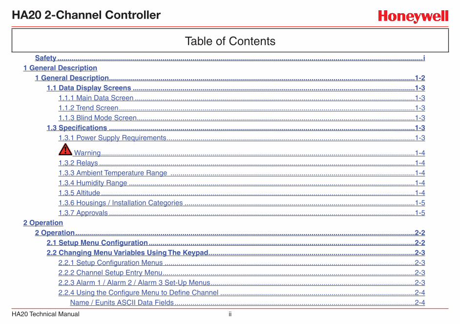
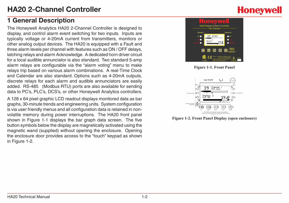
1 General DescriptionThe Honeywell Analytics HA20 2-Channel Controller is designed to display, and control alarm event switching for two inputs. Inputs are typically voltage or 4-20mA current from transmitters, monitors or other analog output devices. The HA20 is equipped with a Fault and three alarm levels per channel with features such as ON / OFF delays, latching relays and alarm Acknowledge. A dedicated horn driver circuit for a local audible annunciator is also standard. Two standard 5-amp alarm relays are configurable via the “alarm voting” menu to make relays trip based on various alarm combinations. A real-Time Clock and Calendar are also standard. Options such as 4-20mA outputs, discrete relays for each alarm and audible annunciators are easily added. RS-485 (Modbus RTU) ports are also available for sending data to PC’s, PLC’s, DCS’s, or other Honeywell Analytics controllers.
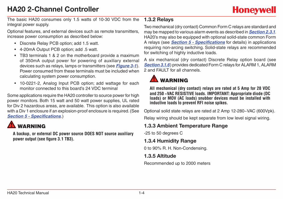
A 128 x 64 pixel graphic LCD readout displays monitored data as bar graphs, 30-minute trends and engineering units. System configuration is via user friendly menus and all configuration data is retained in non-volatile memory during power interruptions. The HA20 front panel shown in Figure 1-1 displays the bar graph data screen. The five button symbols below the display are magnetically activated using the magnetic wand (supplied) without opening the enclosure. Opening the enclosure door provides access to the “touch” keypad as shown in Figure 1-2.
A1
A2
A3/Fault
Channel 1
A1
A2
A3/Fault
MagneticKeypad
(Keypad buttonsbehind door)
HA20 Display & Alarm ControllerTwo Channel
Edit AlarmResetNext
219995Classified to CSA C22.2 NO. 152 for combustiblesdetection. Class I, DIV.2, Groups A,B,C,DREAD & UNDERSTAND MANUAL!
S/N 90-or 10-30 VDC @ 3 WATTSPower = 100-240 V~, 50/60 Hz, .45 A
Channel 2
Cal
Figure 1-1. Front Panel
SW1-SW5 are the magnetic keypad allowing operatorinterface w/o opening the enclosure. Touch key access requires
opening the enclosure.
Ch1 Alarm LEDs
LCD readout contrastadjustment
UP DOWN NEXT EDIT RESET
Ch2 Alarm LEDs
Piezo
Figure 1-2. Front Panel Display (open enclosure)

HA20 2-Channel Controller
HA20 Technical Manual 1-3
1.1 Data Display ScreensThe HA20 Controller offers three modes for displaying monitored data, as shown in Figure 1-3.
Figure 1-3. Data Display Screens
1.1.1 Main Data ScreenThe HA20 Main Data screen shown in Figure 1-3 allows each channel to be viewed simultaneously. Engineering unit values and bar graph values are both displayed in real time. Arrows below the bars indicate alarm trip point values, making it easy to identify channels at or near alarm level. The direction the horizontal 45º side arrow points indicates either a HIGH or LOW trip point. In Figure 1-1 where Ch 1 points right indicating high trip levels and Ch 2 points left indicating low trip levels. Left and Right hand arrows located at the ends of each bar graph point towards Channel Alarm LED’s on the front panel associated with this reading. The 10-digit ASCII fields for identifying engineering units and Channel ID for each channel are also shown on the Main Data screen.
1.1.2 Trend ScreenIn addition to the Main Data screen described above, the HA20 also provides 30-minute trend screens for each channel as shown in Figure 1-3. Use the Next key to scroll between data screens.
1.1.3 Blind Mode ScreenThe HA20 Blind Mode screen (Figure 1-3) does not allow viewing of channel engineering unit values. It only indicates the system’s alarm status and time / date. Some applications require only alarm status be displayed and prefer monitored values not be shown. A SECURITY menu (see Section 2.4) allows locking all configuration parameters and having only the Blind Mode screen available for viewing.
1.3 Specifications1.3.1 Power Supply RequirementsThe HA20 is equipped with an integral 15 watt (or 50 watt, depending on the configuration) universal AC input / 24 VDC output switching power supply. Standard HA20 AC power requirements are 100-240 VAC 50/60 Hz @ .45 amp max (including inrush) and 20 watts steady state, applied to TB5 on the motherboard. If AC power is not available, the HA20 may also be powered with 24 VDC applied to TB1 on the motherboard. A primary DC source or back-up DC source capability should be determined by the total system power budget calculation with guard-band included. A back-up DC power source may also be connected to TB1 for automatic switchover if the AC power source fails. See Figures 3-1 & 3-2 for wiring information.
WARNINGA back-up or external DC power source DOES NOT source aux power output (TB3 - see Figure 3.1)
HA20 2-Channel Controller
HA20 Technical Manual 1-4
The basic HA20 consumes only 1.5 watts of 10-30 VDC from the integral power supply.
Optional features, and external devices such as remote transmitters, increase power consumption as described below:
• Discrete Relay PCB option; add 1.5 watt.• 4-20mA Output PCB option; add .5 watt.• TB3 terminals 1 & 2 on the motherboard provide a maximum
of 350mA output power for powering of auxiliary external devices such as relays, lamps or transmitters (see Figure 3-1). Power consumed from these terminals must be included when calculating system power consumption.
• 10-0221-2, Analog Input PCB option; add wattage for each monitor connected to this board’s 24 VDC terminal
Some applications require the HA20 controller to source power for high power monitors. Both 15 watt and 50 watt power supplies, UL rated for Div 2 hazardous areas, are available. This option is also available with a Div 1 enclosure if an explosion-proof enclosure is required. (See Section 5 - Specifications.)
WARNINGA backup, or external DC power source DOES NOT source auxiliary power output (see figure 3.1 TB3).
1.3.2 RelaysTwo mechanical (dry contact) Common Form C relays are standard and may be mapped to various alarm events as described in Section 2.3.1. HA20’s may also be equipped with optional solid-state common Form A relays (see Section 5 - Specifications for details) in applications requiring non-arcing switching. Solid-state relays are recommended for switching of highly inductive loads.
A six mechanical (dry contact) Discrete Relay option board (see Section 3.1.6) provides dedicated Form C relays for ALARM 1, ALARM 2 and FAULT for all channels.
WARNINGAll mechanical (dry contact) relays are rated at 5 Amp for 28 VDC and 250 ~VAC RESISTIVE loads. IMPORTANT: Appropriate diode (DC loads) or MOV (AC loads) snubber devices must be installed with inductive loads to prevent RFI noise spikes.
Optional solid state relays are rated at 2 Amp 12-280~VAC (600Vpk).
Relay wiring should be kept separate from low level signal wiring.
1.3.3 Ambient Temperature Range -25 to 50 degrees C
1.3.4 Humidity Range0 to 90% R. H. Non-Condensing.
1.3.5 AltitudeRecommended up to 2000 meters
HA20 2-Channel Controller
HA20 Technical Manual 1-5
1.3.6 Housings / Installation Categories• *NEMA 4X wall mount. DIV 2 Groups A,B,C,D; Category II and
pollution degree 3; NEMA 4X; IP66
• *NEMA 4 painted carbon steel
• SS316 NEMA4X
• Polycarbonate NEMA4X
• *NEMA 7 wall mount for DIV 1 & 2 Groups B,C,D; includes O-ring in door to satisfy NEMA 4 rating.
*Includes standard non-intrusive magnetic keypad.
1.3.7 Approvals• CSA C22.2 No 1010.1 and ISA S82.02
• CSA C22.2 No 152 for combustibles (mA input only)
• UL 1604 / C22.2 No 213 (Div 2 Groups A,B,C,D)
• EN55011 & EN61000 (CE Mark). CSA File # = 219995 and may be seen at: www.CSA-International.org.
HA20 2-Channel Controller
HA20 Technical Manual 2-1
2 Operation
HA20 2-Channel Controller
HA20 Technical Manual 2-2
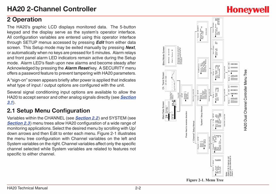
2 OperationThe HA20’s graphic LCD displays monitored data. The 5-button keypad and the display serve as the system’s operator interface. All configuration variables are entered using this operator interface through SETUP menus accessed by pressing Edit from either data screen. This Setup mode may be exited manually by pressing Next, or automatically when no keys are pressed for 5 minutes. Alarm relays and front panel alarm LED indicators remain active during the Setup mode. Alarm LED’s flash upon new alarms and become steady after Acknowledged by pressing the Alarm Reset key. A SECURITY menu offers a password feature to prevent tampering with HA20 parameters.
A “sign-on” screen appears briefly after power is applied that indicates what type of input / output options are configured with the unit.
Several signal conditioning input options are available to allow the HA20 to accept sensor and other analog signals directly (see Section 3.1).
2.1 Setup Menu ConfigurationVariables within the CHANNEL (see Section 2.2) and SYSTEM (see Section 2.3) menu trees allow HA20 configuration of a wide range of monitoring applications. Select the desired menu by scrolling with Up/down arrows and then Edit to enter each menu. Figure 2-1 illustrates the menu tree configuration with Channel variables on the left and System variables on the right. Channel variables affect only the specific channel selected while System variables are related to features not specific to either channel.
HA
20 D
ual C
hann
el C
ontro
ller M
enu
Tree
Figure 2-1. Menu Tree
HA20 2-Channel Controller
HA20 Technical Manual 2-3
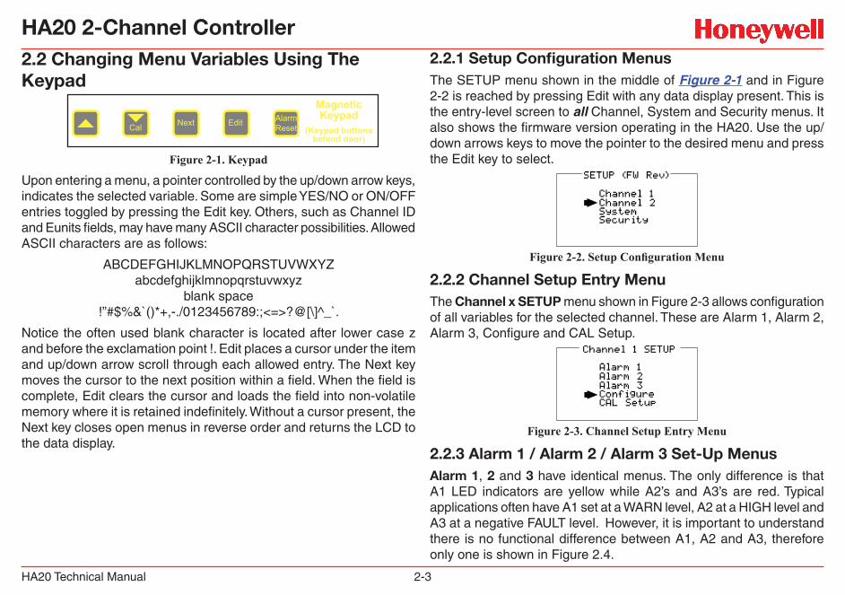
2.2 Changing Menu Variables Using The Keypad
Figure 2-1. Keypad
Upon entering a menu, a pointer controlled by the up/down arrow keys, indicates the selected variable. Some are simple YES/NO or ON/OFF entries toggled by pressing the Edit key. Others, such as Channel ID and Eunits fields, may have many ASCII character possibilities. Allowed ASCII characters are as follows:
ABCDEFGHIJKLMNOPQRSTUVWXYZabcdefghijklmnopqrstuvwxyz
blank space!”#$%&`()*+,-./0123456789:;<=>?@[\]^_`.
Notice the often used blank character is located after lower case z and before the exclamation point !. Edit places a cursor under the item and up/down arrow scroll through each allowed entry. The Next key moves the cursor to the next position within a field. When the field is complete, Edit clears the cursor and loads the field into non-volatile memory where it is retained indefinitely. Without a cursor present, the Next key closes open menus in reverse order and returns the LCD to the data display.
2.2.1 Setup Configuration MenusThe SETUP menu shown in the middle of Figure 2-1 and in Figure 2-2 is reached by pressing Edit with any data display present. This is the entry-level screen to all Channel, System and Security menus. It also shows the firmware version operating in the HA20. Use the up/down arrows keys to move the pointer to the desired menu and press the Edit key to select.
Figure 2-2. Setup Configuration Menu
2.2.2 Channel Setup Entry MenuThe Channel x SETUP menu shown in Figure 2-3 allows configuration of all variables for the selected channel. These are Alarm 1, Alarm 2, Alarm 3, Configure and CAL Setup.
Figure 2-3. Channel Setup Entry Menu
2.2.3 Alarm 1 / Alarm 2 / Alarm 3 Set-Up MenusAlarm 1, 2 and 3 have identical menus. The only difference is that A1 LED indicators are yellow while A2’s and A3’s are red. Typical applications often have A1 set at a WARN level, A2 at a HIGH level and A3 at a negative FAULT level. However, it is important to understand there is no functional difference between A1, A2 and A3, therefore only one is shown in Figure 2.4.
MagneticKeypad
(Keypad buttonsbehind door)
Edit AlarmResetNextCal

HA20 2-Channel Controller
HA20 Technical Manual 2-4
Figure 2-4. Alarm Setup Menu
• Set Point is entered in engineering units and determines the value at which the alarm trips. For example, if a channel monitors 0-50 ppm H2S and the desired alarm level is 10 ppm, the correct entry is 10.00. A one percent deadband prevents alarm chatter. This means after tripping an alarm the input must move at least 1% of full scale back through the setpoint for the alarm to auto reset.
• The ON Delay / OFF Delay entries allow ON and OFF time delays affecting how long the trip-point must be surpassed before an alarm event transition occurs. ON delays are limited to 10 seconds while OFF delays may be as long as 120 minutes. Delays are useful in many applications to prevent nuisance alarms and unwanted cycling into and out of alarm conditions.
• Low Trip is set to NO to increase alarms or YES to decrease alarms, which determines if the alarm activates upon exceeding or falling below the set-point.
• Latching determines either manual or automatic alarm reset operation. YES requires a manual Alarm Reset to unlatch the alarm even though an alarm condition no longer exists. YES also causes this alarm’s common relay, front panel LED, and optional discrete relay to latch. NO allows all outputs for this alarm to automatically reset after the alarm condition clears.
Discrete LED indicators on the front panel indicate the status of each
alarm. Any new alarm event causes the associated LED to flash until an Alarm Reset occurs causing an acknowledged steady on condition. Operators should recognize new alarms by a flashing LED. Alarm Reset also acknowledges, or deactivates, audible devices driven by the AUDIBLE ALARM option connector J2 (see Figure 3.2)
2.2.4 Using the Configure Menu to Define ChannelThe next menu option, after the Alarm Setup option, is Configure. It allows setting Name and EUNIT fields, defining the measurement range (Zero and Span), how many decimal points of resolution the reading will have and whether the channel is active (Figure 2.5).
Figure 2-5. Configure Menu - Define Channel
Name / Eunits ASCII Data FieldsThe first two items in this menu, Name and EUNIT, are for entering the 10 character channel Name and engineering unit ASCII fields. Name should describe the channel’s data in user terminology such as tag # or other description. Eunits should define the units of measure for what this channel is to display. Several standard Eunits fields are available by pressing Edit but if these are inappropriate, a CUSTOM field allows editing of each character. Section 2.2 describes how to modify these fields using the keypad.
HA20 2-Channel Controller
HA20 Technical Manual 2-5
Input Measurement RangeThe ZERO / SPAN menu options allow configuration of the measurement range displayed by this channel. Measurement Range defines the range of the input signal’s engineering units. For example, if a channel’s input is 4-20mA from a transmitter monitoring 0 to 10ppm chlorine, then the Zero value should equal 0.000 and the Span value equal 10.00. Four digits must be entered so trailing 0’s may appear here that are not displayed on other data screens.
Decimal Point ResolutionResolution of the displayed channel value is configured in the Decimal Pts. menu by setting the number of digits trailing the decimal point. Displayed readings are limited to a maximum of four digits with a polarity sign. Auto-ranging displays the highest resolution allowed by this menu’s decimal point entry. For example, a range of 0 to 100ppm and two decimal points reads 0.00 at 0ppm and 100.0 at 100ppm. This may be undesirable due to the high resolution at zero unless the sensor’s output is extremely stable. If decimal points are limited to one, the 0ppm reading becomes 0.0 and the 100ppm reading remains 100.0.
Resolution may be limited further by setting decimal points to 0 where in the above example, 0ppm reads 0 and 100ppm reads 100.
Turning Off Unused ChannelsThe Channel Active menu entry asks if this channel is to be utilized. OFF causes the controller to never process inputs applied to this channel and no alarms are tripped or data displayed. Inactive channels have a line drawn through them on the Setup screen to indicate they are turned off.
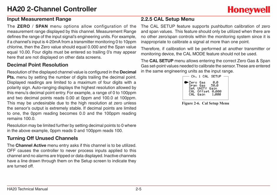
2.2.5 CAL Setup MenuThe CAL SETUP feature supports pushbutton calibration of zero and span values. This feature should only be utilized when there are no other zero/span controls within the monitoring system since it is inappropriate to calibrate a signal at more than one point.
Therefore, if calibration will be performed at another transmitter or monitoring device, the CAL MODE feature should not be used.
The CAL SETUP menu allows entering the correct Zero Gas & Span Gas set-point values needed to calibrate the sensor. These are entered in the same engineering units as the input range.
Figure 2-6. Cal Setup Menu
HA20 2-Channel Controller
HA20 Technical Manual 2-6
2.2.6 Calibrate Input MenuCalibration is the most important function for ensuring correct operation of HA20s equipped with sensor inputs. The CAL MODE (flow chart shown in Figure 2-7) is designed to make calibration quick, easy and error free. A successful ZERO and SPAN calibration requires only five keystrokes. Optional 4-20mA outputs (if equipped) transmit 1.5mA during CAL MODE and 4mA during the subsequent CAL PURGE delay to prevent external alarms during calibration. Local HA20 alarm relays are inhibited during CAL MODE. Unintentional calibrations may be reset using the Set UNITY menu item. Set UNITY resets CAL OFFSET to 0 & CAL GAIN to 1 which is useful for returning the calibration to a known starting place. Sensor aging may be monitored by recording zero and span readings at Unity Gain when the sensor is new, and again later when degradation may have occurred. CAL MODE automatically exits if no keystroke is detected after 5 minutes.
Follow these sensor calibration guidelines:
• Calibration accuracy is only as good as the calibration standard accuracy. Honeywell Analytics recommends calibration standards with NIST (National Institute of Standards and Technology) traceable accuracy to increase the validity of the calibration.
• Do not use a gas cylinder beyond its expiration date.• Calibrate a new sensor before use.• Allow the sensor to stabilize before starting calibration. (Consult
the appropriate sensor manual for warm-up times.)• Calibrate on a regular schedule. (Consult the appropriate sensor
manual for calibration intervals or depending on use and sensor exposure to poisons and contaminants.)
• Calibrate only in a clean atmosphere free of background gas.
Use the following step-by-step procedure to perform ZERO and SPAN calibrations.
1. To enter the CAL MODE from any data display, press the dual purpose down arrow/CAL key and press the Edit key within 5 seconds then select channel.
2. Using the Cal-Cup and following the instructions on the screen, apply a clean ZERO gas or be sure there is no background target gas in the monitored area. After the reading is stable, (approximately 1 minute) press the Edit key to perform a ZERO calibration.
3. If the ZERO calibration is successful, CAL MODE automatically proceeds to the SPAN check.
4. Apply the correct SPAN calibration standard. After the reading is stable, press the Edit key to perform a SPAN calibration.
WARNINGThe SPAN gas used must match the value specified since this is what the HA20 will indicate after a successful SPAN calibration. The Span Gas value may be edited if it becomes necessary to apply a different gas concentration (see Figure 2.6 [Span Gas] in Section 2.2.5).
5. If the SPAN calibration is successful, the display flashes “REMOVE CAL GAS” and starts the CAL PURGE delay.
6. CAL MODE will be complete after the end of the CAL PURGE delay.
HA20 2-Channel Controller
HA20 Technical Manual 2-7
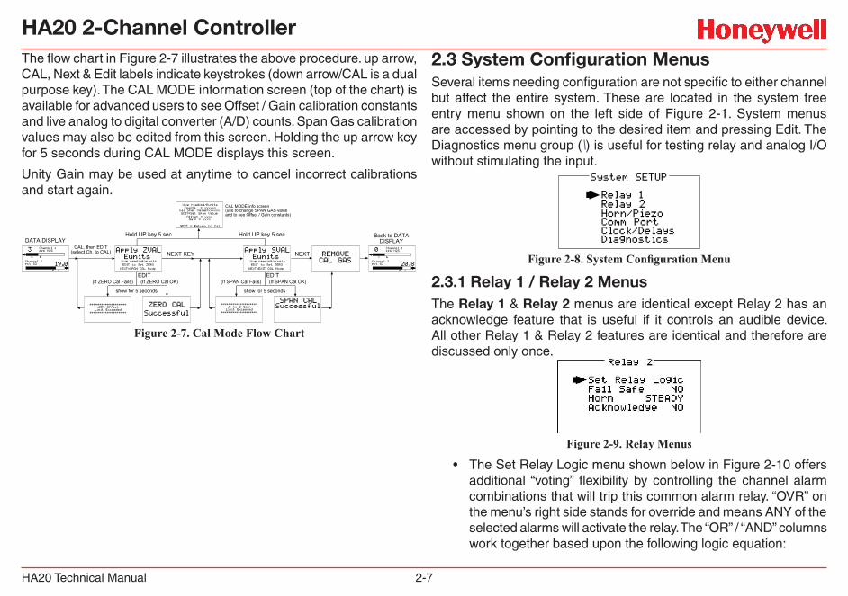
The flow chart in Figure 2-7 illustrates the above procedure. up arrow, CAL, Next & Edit labels indicate keystrokes (down arrow/CAL is a dual purpose key). The CAL MODE information screen (top of the chart) is available for advanced users to see Offset / Gain calibration constants and live analog to digital converter (A/D) counts. Span Gas calibration values may also be edited from this screen. Holding the up arrow key for 5 seconds during CAL MODE displays this screen.
Unity Gain may be used at anytime to cancel incorrect calibrations and start again.
Figure 2-7. Cal Mode Flow Chart
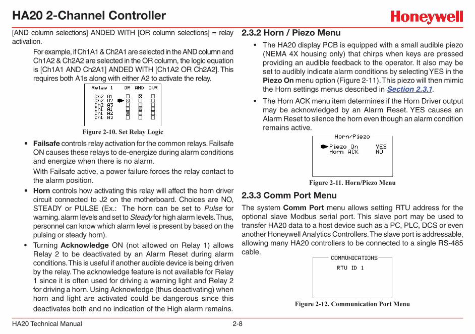
2.3 System Configuration MenusSeveral items needing configuration are not specific to either channel but affect the entire system. These are located in the system tree entry menu shown on the left side of Figure 2-1. System menus are accessed by pointing to the desired item and pressing Edit. The Diagnostics menu group (\) is useful for testing relay and analog I/O without stimulating the input.
Figure 2-8. System Configuration Menu
2.3.1 Relay 1 / Relay 2 MenusThe Relay 1 & Relay 2 menus are identical except Relay 2 has an acknowledge feature that is useful if it controls an audible device. All other Relay 1 & Relay 2 features are identical and therefore are discussed only once.
Figure 2-9. Relay Menus
• The Set Relay Logic menu shown below in Figure 2-10 offers additional “voting” flexibility by controlling the channel alarm combinations that will trip this common alarm relay. “OVR” on the menu’s right side stands for override and means ANY of the selected alarms will activate the relay. The “OR” / “AND” columns work together based upon the following logic equation:
HA20 2-Channel Controller
HA20 Technical Manual 2-8
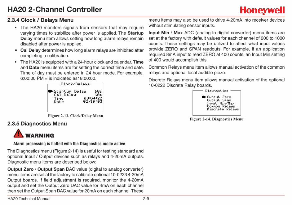
[AND column selections] ANDED WITH [OR column selections] = relay activation.
For example, if Ch1A1 & Ch2A1 are selected in the AND column and Ch1A2 & Ch2A2 are selected in the OR column, the logic equation is [Ch1A1 AND Ch2A1] ANDED WITH [Ch1A2 OR Ch2A2]. This requires both A1s along with either A2 to activate the relay.
Figure 2-10. Set Relay Logic
• Failsafe controls relay activation for the common relays. Failsafe ON causes these relays to de-energize during alarm conditions and energize when there is no alarm.With Failsafe active, a power failure forces the relay contact to the alarm position.
• Horn controls how activating this relay will affect the horn driver circuit connected to J2 on the motherboard. Choices are NO, STEADY or PULSE (Ex.: The horn can be set to Pulse for warning. alarm levels and set to Steady for high alarm levels. Thus, personnel can know which alarm level is present by based on the pulsing or steady horn).
• Turning Acknowledge ON (not allowed on Relay 1) allows Relay 2 to be deactivated by an Alarm Reset during alarm conditions. This is useful if another audible device is being driven by the relay. The acknowledge feature is not available for Relay 1 since it is often used for driving a warning light and Relay 2 for driving a horn. Using Acknowledge (thus deactivating) when horn and light are activated could be dangerous since this deactivates both and no indication of the High alarm remains.
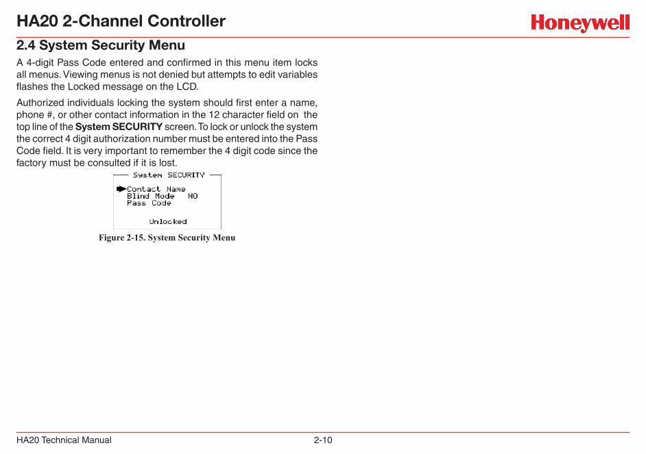
2.3.2 Horn / Piezo Menu• The HA20 display PCB is equipped with a small audible piezo
(NEMA 4X housing only) that chirps when keys are pressed providing an audible feedback to the operator. It also may be set to audibly indicate alarm conditions by selecting YES in the Piezo On menu option (Figure 2-11). This piezo will then mimic the Horn settings menus described in Section 2.3.1.
• The Horn ACK menu item determines if the Horn Driver output may be acknowledged by an Alarm Reset. YES causes an Alarm Reset to silence the horn even though an alarm condition remains active.
Figure 2-11. Horn/Piezo Menu
2.3.3 Comm Port MenuThe system Comm Port menu allows setting RTU address for the optional slave Modbus serial port. This slave port may be used to transfer HA20 data to a host device such as a PC, PLC, DCS or even another Honeywell Analytics Controllers. The slave port is addressable, allowing many HA20 controllers to be connected to a single RS-485 cable.
Figure 2-12. Communication Port Menu
HA20 2-Channel Controller
HA20 Technical Manual 2-9
2.3.4 Clock / Delays Menu• The HA20 monitors signals from sensors that may require
varying times to stabilize after power is applied. The Startup Delay menu item allows setting how long alarm relays remain disabled after power is applied.
• Cal Delay determines how long alarm relays are inhibited after completing a calibration.
• The HA20 is equipped with a 24-hour clock and calendar. Time and Date menu items are for setting the correct time and date. Time of day must be entered in 24 hour mode. For example, 6:00:00 PM = is indicated as18:00:00.
Figure 2-13. Clock/Delay Menu
2.3.5 Diagnostics Menu
WARNINGAlarm processing is halted with the Diagnostics mode active.
The Diagnostics menu (Figure 2-14) is useful for testing standard and optional Input / Output devices such as relays and 4-20mA outputs. Diagnostic menu items are described below:
Output Zero / Output Span DAC value (digital to analog converter) menu items are set at the factory to calibrate optional 10-0223 4-20mA Output boards. If field adjustment is required, monitor the 4-20mA output and set the Output Zero DAC value for 4mA on each channel then set the Output Span DAC value for 20mA on each channel. These
menu items may also be used to drive 4-20mA into receiver devices without stimulating sensor inputs.
Input Min / Max ADC (analog to digital converter) menu items are set at the factory with default values for each channel of 200 to 1000 counts. These settings may be utilized to affect what input values provide ZERO and SPAN readouts. For example, if an application required 8mA input to read ZERO at 400 counts, an Input Min setting of 400 would accomplish this.
Common Relays menu item allows manual activation of the common relays and optional local audible piezo.
Discrete Relays menu item allows manual activation of the optional 10-0222 Discrete Relay boards.
Figure 2-14. Diagnostics Menu
HA20 2-Channel Controller
HA20 Technical Manual 2-10
2.4 System Security MenuA 4-digit Pass Code entered and confirmed in this menu item locks all menus. Viewing menus is not denied but attempts to edit variables flashes the Locked message on the LCD.
Authorized individuals locking the system should first enter a name, phone #, or other contact information in the 12 character field on the top line of the System SECURITY screen. To lock or unlock the system the correct 4 digit authorization number must be entered into the Pass Code field. It is very important to remember the 4 digit code since the factory must be consulted if it is lost.
Figure 2-15. System Security Menu
HA20 2-Channel Controller
HA20 Technical Manual 3-1
3 Motherboard Interface PCB
HA20 2-Channel Controller
HA20 Technical Manual 3-2
3 Motherboard Interface PCB(P/N 10-0215)
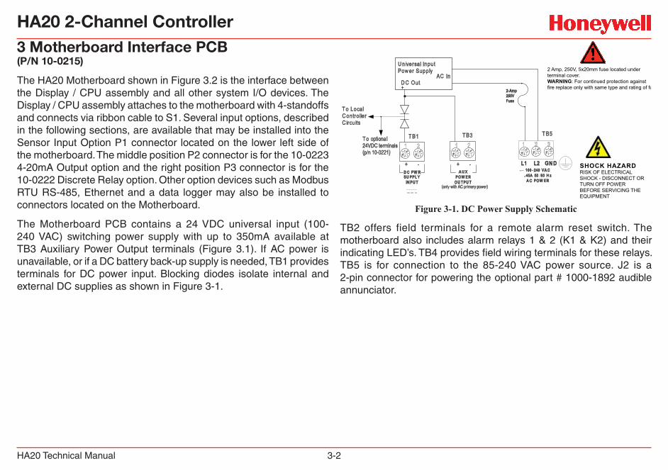
The HA20 Motherboard shown in Figure 3.2 is the interface between the Display / CPU assembly and all other system I/O devices. The Display / CPU assembly attaches to the motherboard with 4-standoffs and connects via ribbon cable to S1. Several input options, described in the following sections, are available that may be installed into the Sensor Input Option P1 connector located on the lower left side of the motherboard. The middle position P2 connector is for the 10-0223 4-20mA Output option and the right position P3 connector is for the 10-0222 Discrete Relay option. Other option devices such as Modbus RTU RS-485, Ethernet and a data logger may also be installed to connectors located on the Motherboard.
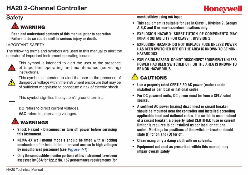
The Motherboard PCB contains a 24 VDC universal input (100-240 VAC) switching power supply with up to 350mA available at TB3 Auxiliary Power Output terminals (Figure 3.1). If AC power is unavailable, or if a DC battery back-up supply is needed, TB1 provides terminals for DC power input. Blocking diodes isolate internal and external DC supplies as shown in Figure 3-1.
2 Amp, 250V, 5x20mm fuse located underterminal cover.WARNING: For continued protection againstfire replace only with same type and rating of fuse.
U niversal Input Pow er Supply
AC InD C Out+
T o Local C ontro ller C ircu its
+ - + - L1 L2 GN D
T B1 T B3 T B5
D C PW RSU PPL Y
IN PU T
A U XPOW ER
OU T PU T
100 -240 VA C. 45A 50 60 H z
A C POW ER
SHOCK HAZARDRISK OF ELECTRICALSHOCK - DISCONNECT ORTURN OFF POWERBEFORE SERVICING THEEQUIPMENT
2-Amp250VFuse
T o optional 24VDC terminals(p/n 10-0221)
(only with AC primary power)
Figure 3-1. DC Power Supply Schematic
TB2 offers field terminals for a remote alarm reset switch. The motherboard also includes alarm relays 1 & 2 (K1 & K2) and their indicating LED’s. TB4 provides field wiring terminals for these relays. TB5 is for connection to the 85-240 VAC power source. J2 is a 2-pin connector for powering the optional part # 1000-1892 audible annunciator.
HA20 2-Channel Controller
HA20 Technical Manual 3-3
U2
J1
S1TP1
S2
PS1
U3
CR5
2-AMP FUSE(5 x 20mm)
U5
K2K1
P3
J2 3BT2BT1BT
P1 P2
D2
D1
N/CN/OCRELAY 1
N/CN/OCRELAY 2
+ALARM
-RESET
DC PWR+SUPPLY
-
INPUT
+
OUTPUT
-POWER
AUX
-
Common(0-volts)
0010-1167 Rev C2-Channel ControllerMotherBoard
1
RS-R85 / ETHERNET OPTION
1
Assy.10-0215
DATA-LOGGER PORT
DRY CONTACTS
DISCRETE RELAY OPTION(See dwg. 10-0222)Note: If installed, this optionblocks access to the fuse andmust be removed to replace fuse.
ALARM OPTION
1AUDIBLE+ -
*SENSOR INPUT OPTION 4-20mA OUTPUT OPTION(See dwg. 10-0223)
1 2 3 4 5 61 21 21 2
Combination Cat-bead/Toxic = 10-0216Dual Toxic = 10-0220Dual 4-20mA = 10-0221
*Each Input option listed may also be configured for 4-20mA Inputs. See drawings for details on each.
RELAY 1 Indicator
RELAY 2 Indicator
Universal Switching Power Supply
Ribbon Cable to 10-0214 Display Assembly
TB4
J2+Terminal = 24 VDC- Terminal is opencollector 100mA driverfor use with optional 100decibel piezoannunciator.
TB324 VDC power outputfor remote devices suchas transmitters, lights,relays etc. 350mA MAX(see Figure 3.0)
TB45 amp resistive SPDT(form C) dry contact relayoutputs. Use appropriatediode / snubber deviceswhen switching inductiveloads.
TB5Universal 100-240VACprimary power sourceterminals.Important: GND terminal3 must be tied to earthfor correct shielding ofincoming signals.
TB2
Dry contact input for usewith optional remoteAlarm Reset switch.Wires must be shorterthan 10 feet & shieldedif longer than 2 feet.
TB1
Available for 24 VDCprimary power input.May also be used asbattery back-up to ACprimary power source.TIE TB5 GND to EARTH
J3
SHOCK HAZARDRISK OF ELECTRICALSHOCK-DISCONNECT ORTURN OFF POWERBEFORE SERVICING THEEQUIPMENT
WARNING: For continued protection againstfire replace only with same type and ratingof fuse. (Part # = Littelfuse 217002)
AC POWER
L1 GNDL2100-240 VAC
321
TB5
3 Watts MAX
~.45A 50/60 Hz
Connections to J1 & J3 are not covered by CSA
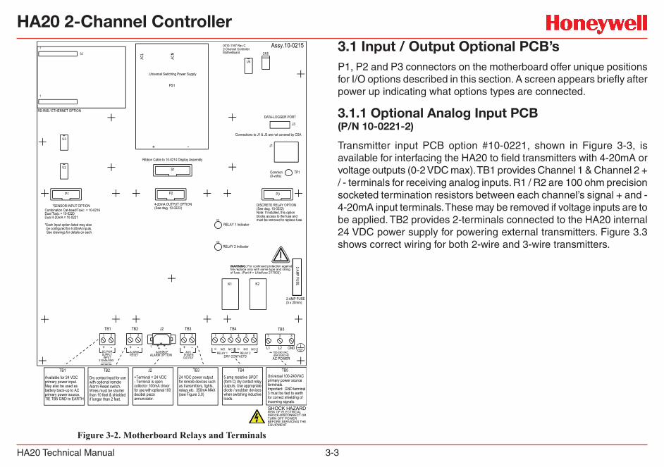
Figure 3-2. Motherboard Relays and Terminals
3.1 Input / Output Optional PCB’sP1, P2 and P3 connectors on the motherboard offer unique positions for I/O options described in this section. A screen appears briefly after power up indicating what options types are connected.
3.1.1 Optional Analog Input PCB(P/N 10-0221-2)
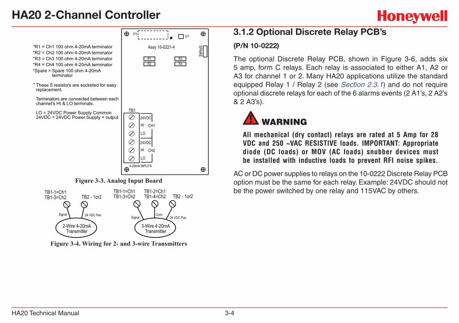
Transmitter input PCB option #10-0221, shown in Figure 3-3, is available for interfacing the HA20 to field transmitters with 4-20mA or voltage outputs (0-2 VDC max). TB1 provides Channel 1 & Channel 2 + / - terminals for receiving analog inputs. R1 / R2 are 100 ohm precision socketed termination resistors between each channel’s signal + and - 4-20mA input terminals. These may be removed if voltage inputs are to be applied. TB2 provides 2-terminals connected to the HA20 internal 24 VDC power supply for powering external transmitters. Figure 3.3 shows correct wiring for both 2-wire and 3-wire transmitters.
HA20 2-Channel Controller
HA20 Technical Manual 3-4
R3
U1
R1
P1
TB2
R4R2
TB124VDC
HI
LO
CH3
24VDC
HI
LO
CH4
24VDC
HI CH1
LO
24VDC
HI CH2
LO
4-20mA INPUTS
Assy 10-0221-4*R1 = Ch1 100 ohm 4-20mA terminator*R2 = Ch2 100 ohm 4-20mA terminator*R3 = Ch3 100 ohm 4-20mA terminator*R4 = Ch4 100 ohm 4-20mA terminator*Spare = Spare 100 ohm 4-20mA terminator
* These 5 resistors are socketed for easyreplacement.
Terminators are connected between eachchannel's HI & LO terminals.
LO = 24VDC Power Supply Common24VDC = 24VDC Power Supply + output
Figure 3-3. Analog Input Board
3-Wire 4-20mATransmitter
24 VDC Pwr.Signal
TB2 - 1or2TB1-1=Ch1TB1-3=Ch2
Com
TB1-2=Ch1TB1-4=Ch2
2-Wire 4-20mATransmitter
24 VDC Pwr.Signal
TB2 - 1or2TB1-1=Ch1TB1-3=Ch2
Figure 3-4. Wiring for 2- and 3-wire Transmitters
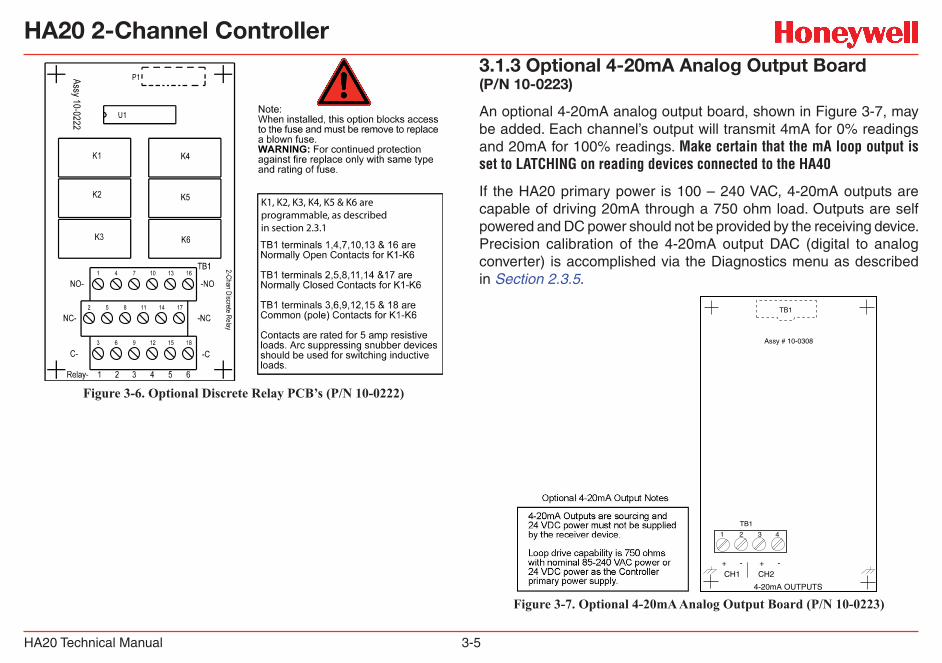
3.1.2 Optional Discrete Relay PCB’s(P/N 10-0222)
The optional Discrete Relay PCB, shown in Figure 3-6, adds six 5 amp, form C relays. Each relay is associated to either A1, A2 or A3 for channel 1 or 2. Many HA20 applications utilize the standard equipped Relay 1 / Relay 2 (see Section 2.3.1) and do not require optional discrete relays for each of the 6 alarms events (2 A1’s, 2 A2’s & 2 A3’s).
WARNINGAll mechanical (dry contact) relays are rated at 5 Amp for 28 VDC and 250 ~VAC RESISTIVE loads. IMPORTANT: Appropriate diode (DC loads) or MOV (AC loads) snubber devices must be installed with inductive loads to prevent RFI noise spikes.
AC or DC power supplies to relays on the 10-0222 Discrete Relay PCB option must be the same for each relay. Example: 24VDC should not be the power switched by one relay and 115VAC by others.
HA20 2-Channel Controller
HA20 Technical Manual 3-5
K1, K2, K3, K4, K5 & K6 are programmable, as described in section 2.3.1
Figure 3-6. Optional Discrete Relay PCB’s (P/N 10-0222)
3.1.3 Optional 4-20mA Analog Output Board(P/N 10-0223)
An optional 4-20mA analog output board, shown in Figure 3-7, may be added. Each channel’s output will transmit 4mA for 0% readings and 20mA for 100% readings. Make certain that the mA loop output is set to LATCHING on reading devices connected to the HA40
If the HA20 primary power is 100 – 240 VAC, 4-20mA outputs are capable of driving 20mA through a 750 ohm load. Outputs are self powered and DC power should not be provided by the receiving device. Precision calibration of the 4-20mA output DAC (digital to analog converter) is accomplished via the Diagnostics menu as described in Section 2.3.5.
1 2 3 4
4-20mA OUTPUTS
CH1 CH2+ - + -
TB1
TB1
Assy # 10-0308
Figure 3-7. Optional 4-20mA Analog Output Board (P/N 10-0223)
HA20 2-Channel Controller
HA20 Technical Manual 3-6
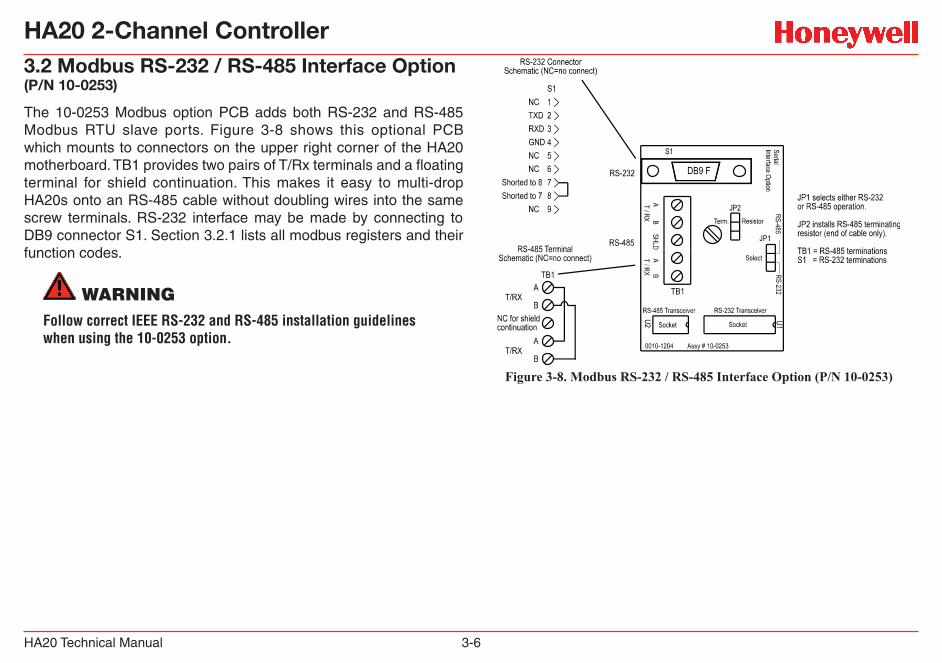
3.2 Modbus RS-232 / RS-485 Interface Option(P/N 10-0253)
The 10-0253 Modbus option PCB adds both RS-232 and RS-485 Modbus RTU slave ports. Figure 3-8 shows this optional PCB which mounts to connectors on the upper right corner of the HA20 motherboard. TB1 provides two pairs of T/Rx terminals and a floating terminal for shield continuation. This makes it easy to multi-drop HA20s onto an RS-485 cable without doubling wires into the same screw terminals. RS-232 interface may be made by connecting to DB9 connector S1. Section 3.2.1 lists all modbus registers and their function codes.
WARNINGFollow correct IEEE RS-232 and RS-485 installation guidelines when using the 10-0253 option.
Figure 3-8. Modbus RS-232 / RS-485 Interface Option (P/N 10-0253)
HA20 2-Channel Controller
HA20 Technical Manual 3-7
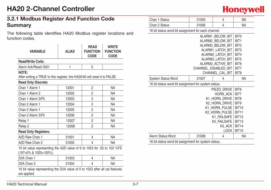
3.2.1 Modbus Register And Function Code SummaryThe following table identifies HA20 Modbus register locations and function codes.
VARIABLE ALIAS READ
FUNCTION CODE
WRITE FUNCTION
CODE Read/Write Coils: Alarm Ack/Reset 2001 1 5 NOTE:After writing a TRUE to this register, the HA20/40 will reset it to FALSE.Read Only Discrete:Chan 1 Alarm 1 12001 2 NAChan 1 Alarm 2 12002 2 NAChan 1 Alarm 3/Flt 12003 2 NAChan 2 Alarm 1 12004 2 NAChan 2 Alarm 1 12005 2 NAChan 2 Alarm 3/Flt 12006 2 NARelay 1 12007 2 NARelay 2 12008 2 NA Read Only Registers: A2D Raw Chan 1 31001 4 NAA2D Raw Chan 2 31002 4 NA10 bit value representing the A2D value of 0 to 1023 for -25 to 103 %FS (197=0% & 1003=100%). D2A Chan 1 31003 4 NAD2A Chan 2 31004 4 NA10 bit value representing the D2A value of 0 to 1023 after all cal features are applied.
Chan 1 Status 31005 4 NAChan 2 Status 31006 4 NA16 bit status word bit assignment for each channel.
ALARM1_BELOW_BIT ALARM2_BELOW_BIT ALARM3_BELOW_BIT ALARM1_LATCH_BIT ALARM2_LATCH_BIT ALARM3_LATCH_BIT
ALARM3_ACTIVE_BIT CHANNEL_DISABLED_BIT
CHANNEL_CAL_BIT
BIT0BIT1BIT2BIT3BIT4BIT5BIT6BIT7BIT8
System Status Word 31007 4 NA16 bit status word bit assignment for system status.
PIEZO_DRIVEHORN_ACK
K1_HORN_DRIVE K2_HORN_DRIVE K1_HORN_PULSE K2_HORN_PULSE
K1_FAILSAFE K2_FAILSAFE
K2_ACK LOCK
BIT6BIT7BIT8BIT9BIT10BIT11BIT12BIT13BIT14BIT15
Alarm Status Word 31008 4 NA16 bit status word bit assignment for system status.
HA20 2-Channel Controller
HA20 Technical Manual 3-8
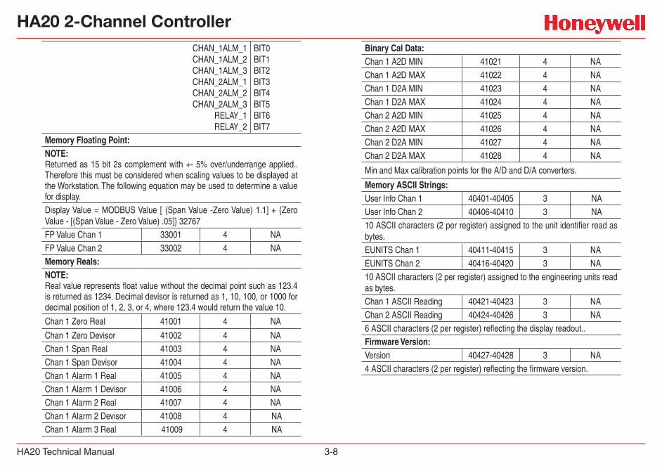
CHAN_1ALM_1CHAN_1ALM_2CHAN_1ALM_3CHAN_2ALM_1CHAN_2ALM_2CHAN_2ALM_3
RELAY_1RELAY_2
BIT0BIT1BIT2BIT3BIT4BIT5BIT6BIT7
Memory Floating Point: NOTE:Returned as 15 bit 2s complement with +- 5% over/underrange applied.. Therefore this must be considered when scaling values to be displayed at the Workstation. The following equation may be used to determine a value for display. Display Value = MODBUS Value [ (Span Value -Zero Value) 1.1] + {Zero Value - [(Span Value - Zero Value) .05]} 32767FP Value Chan 1 33001 4 NAFP Value Chan 2 33002 4 NAMemory Reals:NOTE: Real value represents float value without the decimal point such as 123.4 is returned as 1234. Decimal devisor is returned as 1, 10, 100, or 1000 for decimal position of 1, 2, 3, or 4, where 123.4 would return the value 10.
Chan 1 Zero Real 41001 4 NA
Chan 1 Zero Devisor 41002 4 NAChan 1 Span Real 41003 4 NAChan 1 Span Devisor 41004 4 NAChan 1 Alarm 1 Real 41005 4 NAChan 1 Alarm 1 Devisor 41006 4 NAChan 1 Alarm 2 Real 41007 4 NAChan 1 Alarm 2 Devisor 41008 4 NA Chan 1 Alarm 3 Real 41009 4 NA
Binary Cal Data:Chan 1 A2D MIN 41021 4 NAChan 1 A2D MAX 41022 4 NAChan 1 D2A MIN 41023 4 NAChan 1 D2A MAX 41024 4 NAChan 2 A2D MIN 41025 4 NAChan 2 A2D MAX 41026 4 NAChan 2 D2A MIN 41027 4 NAChan 2 D2A MAX 41028 4 NA
Min and Max calibration points for the A/D and D/A converters.
Memory ASCII Strings: User Info Chan 1 40401-40405 3 NA User Info Chan 2 40406-40410 3 NA 10 ASCII characters (2 per register) assigned to the unit identifier read as bytes. EUNITS Chan 1 40411-40415 3 NAEUNITS Chan 2 40416-40420 3 NA10 ASCII characters (2 per register) assigned to the engineering units read as bytes. Chan 1 ASCII Reading 40421-40423 3 NAChan 2 ASCII Reading 40424-40426 3 NA6 ASCII characters (2 per register) reflecting the display readout.. Firmware Version: Version 40427-40428 3 NA4 ASCII characters (2 per register) reflecting the firmware version.
HA20 2-Channel Controller
HA20 Technical Manual 3-9
HA20 2-Channel Controller
HA20 Technical Manual 3-10
HA20 2-Channel Controller
HA20 Technical Manual 4-1
4 Enclosures

HA20 2-Channel Controller
HA20 Technical Manual 4-2
4 EnclosuresThe HA20 controller enclosures are shown in Figures 4-1, 4-2, and 4-3. Non-metallic enclosures are not grounded by metal conduit. For internal ground points to be grounded to earth, the TB5 – GND terminal must have a proper earth ground connection (see Figure 3-2).
4.1 HA20PCS NEMA 4X/HA20SS NEMA 4 Steel EnclosuresThe HA20PCS (painted carbon steel) and HA20SS (stainless steel) enclosures are shown in Figure 4.1.
0.0 2.40 4.12 5.84 7.56
2.70
6.20
11.81 12.90 13.65
CL2.568.849.84
1/2 in. NPTConduit Fittings(Typical 4 places)
Single 1/4 Turn Latch
InstrumentViewing Window
Notes:
Part#1000-2377 316 Stainless Steel Part#1000-2378 Painted Carbon Steel
Side View
Front View
Bottom View
Material
Figure 4-1. NEMA Painted Carbon Steel or Stainless Steel Enclosure
4.2 HA20PY NEMA 4X Polycarbonate Enclosure
CAUTIONNonmetallic enclosures do not provide grounding between conduit connections. Use grounding type bushings and jumper wires. All field wiring must have insulation suitable for at least 250V.
The HA20PY polycarbonate enclosure is shown in Figure 4.2.
Figure 4-2. NEMA Polycarbonate Enclosure
HA20 2-Channel Controller
HA20 Technical Manual 4-3
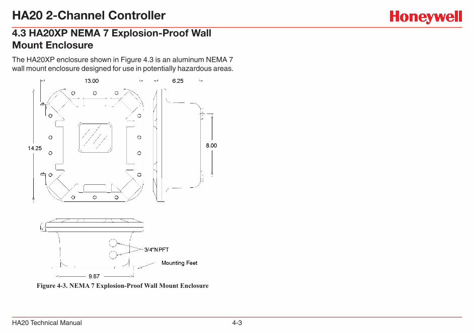
4.3 HA20XP NEMA 7 Explosion-Proof Wall Mount EnclosureThe HA20XP enclosure shown in Figure 4.3 is an aluminum NEMA 7 wall mount enclosure designed for use in potentially hazardous areas.
Figure 4-3. NEMA 7 Explosion-Proof Wall Mount Enclosure

HA40 4-Channel Controller
HA40 Technical Manual 5-1
5 Parts List
HA40 4-Channel Controller
HA40 Technical Manual 5-2
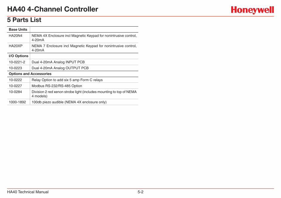
5 Parts ListBase Units
HA20N4 NEMA 4X Enclosure incl Magnetic Keypad for nonintrusive control, 4-20mA
HA20XP NEMA 7 Enclosure incl Magnetic Keypad for nonintrusive control, 4-20mA
I/O Options
10-0221-2 Dual 4-20mA Analog INPUT PCB
10-0223 Dual 4-20mA Analog OUTPUT PCB
Options and Accessories
10-0222 Relay Option to add six 5 amp Form C relays
10-0227 Modbus RS-232/RS-485 Option
10-0284 Division 2 red xenon strobe light (includes mounting to top of NEMA 4 models)
1000-1892 100db piezo audible (NEMA 4X enclosure only)
HA20 2-Channel Controller
HA20 Technical Manual 6-1
6 Specifications
HA20 2-Channel Controller
HA20 Technical Manual 6-2
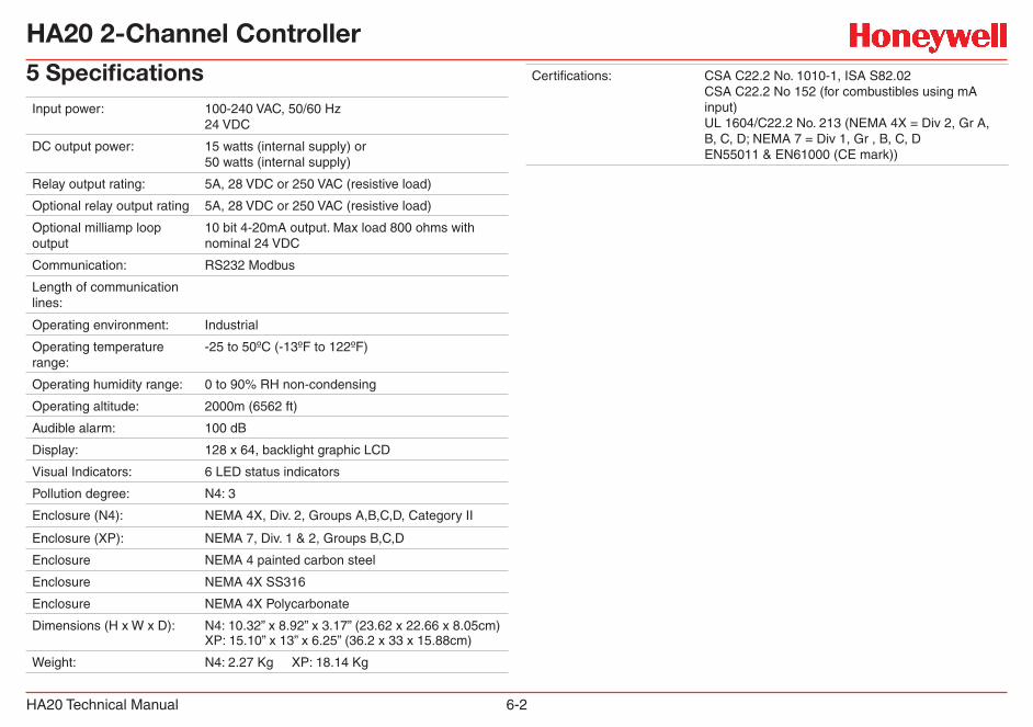
5 SpecificationsInput power: 100-240 VAC, 50/60 Hz
24 VDC
DC output power: 15 watts (internal supply) or 50 watts (internal supply)
Relay output rating: 5A, 28 VDC or 250 VAC (resistive load)
Optional relay output rating 5A, 28 VDC or 250 VAC (resistive load)
Optional milliamp loop output
10 bit 4-20mA output. Max load 800 ohms with nominal 24 VDC
Communication: RS232 Modbus
Length of communication lines:
Operating environment: Industrial
Operating temperature range:
-25 to 50ºC (-13ºF to 122ºF)
Operating humidity range: 0 to 90% RH non-condensing
Operating altitude: 2000m (6562 ft)
Audible alarm: 100 dB
Display: 128 x 64, backlight graphic LCD
Visual Indicators: 6 LED status indicators
Pollution degree: N4: 3
Enclosure (N4): NEMA 4X, Div. 2, Groups A,B,C,D, Category II
Enclosure (XP): NEMA 7, Div. 1 & 2, Groups B,C,D
Enclosure NEMA 4 painted carbon steel
Enclosure NEMA 4X SS316
Enclosure NEMA 4X Polycarbonate
Dimensions (H x W x D): N4: 10.32” x 8.92” x 3.17” (23.62 x 22.66 x 8.05cm)XP: 15.10” x 13” x 6.25” (36.2 x 33 x 15.88cm)
Weight: N4: 2.27 Kg XP: 18.14 Kg
Certifications: CSA C22.2 No. 1010-1, ISA S82.02 CSA C22.2 No 152 (for combustibles using mA input) UL 1604/C22.2 No. 213 (NEMA 4X = Div 2, Gr A, B, C, D; NEMA 7 = Div 1, Gr , B, C, D EN55011 & EN61000 (CE mark))
HA20 2-Channel Controller
HA20 Technical Manual 7-1
7 Warranty
HA20 2-Channel Controller
HA20 Technical Manual 7-2
Honeywell Analytics Warranty StatementAll products are designed and manufactured to the latest internationally recognized standards by Honeywell Analytics under a Quality Management System that is certified to ISO 9001.
As such, this instrument is warranted under proper use, to the original end-user purchaser, against any defects in materials or workmanship related failures for a period of 12 months from the date of first turn-on or 18 months from delivery from Honeywell Analytics to the customer, whichever is less. During this period, Honeywell Analytics will repair or replace defective parts on an exchange basis, F.O.B. to approved service centers on a global basis.
This warranty does not cover damage caused by accident, abuse, abnormal operating conditions or extreme poisoning of the sensor cartridge.
Defective equipment must be returned to Honeywell Analytics for repair. Before returning materials for repair or replacement, the Customer must obtain a Service Event Number (SE#) by contacting Honeywell Analytics Service in advance; include a detailed report stating the nature of the defect and ship the equipment prepaid to Honeywell Analytics’ factory. If no detail report is included, Honeywell Analytics reserves the right to charge an investigative fee (prices available upon request) before any repair or replacement is performed. Returned goods must detail the Service Event Number (SE#) clearly on the package.
Service in the field or at the customer’s premises is not covered under these warranty terms. Time and travel expenses for on-site warranty services will be charged at Honeywell Analytics’ normal billing rates. Contact your Honeywell Analytics representative for information on available Service Contracts.
Honeywell Analytics shall not be liable for any loss or damage whatsoever or howsoever occasioned which may be a direct or indirect result of the use or operation of the Contract Goods by the Buyer or any Party.
This warranty covers the controller and parts sold to the Buyer only by authorized distributors, dealers and representatives as appointed by Honeywell Analytics. This warranty does not cover defects attributable to improper installation, repair by an unauthorized person or the use of unauthorized accessories/parts on the product. A warranty claim will only be accepted if a proof of purchase is submitted and all conditions obtained within this Warranty are met.
Honeywell Analytics reserves the right to validate any warranty claim prior to processing. Upon acceptance of a warranty claim, Honeywell Analytics will repair or replace the defective product free of charge. The initial warranty period is not extended by virtue of any works carried out there after.
Instruments which have been repaired or replaced during the warranty period are warranted for the remainder of the unexpired portion of the original warranty period. Honeywell Analytics is released from all obligations under its warranty in the event repairs or modifications are made by persons other than its own authorized personnel, unless such work is authorized in writing by Honeywell Analytics.
Honeywell Analytics reserves the right to change this policy at any time. Contact Honeywell Analytics for the most current warranty information.

1998M0730 Rev 2
February 2011
© 2011 Honeywell Analytics
Find out morewww.honeywellanalytics.com
Customer business centerAmericasHoneywell Analytics404 Barclay BoulevardLincolnshire, IL 60069Tel: +1 847 955 8200Toll free: +1 800 538 0363Fax: +1 847 955 [email protected]
Europe, Middle Easst and Africa Life Safety Distribution AGWilstrasse 11-U11CH-8610 UsterSwitzerlandTel: +41 (0)1 943 4300Fax: +41 (0)1 943 [email protected]
Europe, Middle Easst and Africa [email protected]
www.honeywell.com
Asia PacificHoneywell Analytics#508, Kolon Science Valley (l)187-10 Guro-Dong, Guro-GuSeoul, 152-050 KoreaTel: +82 2 2025 0300Fax: +82 2 2025 029
Please Note:While every effort has been made to ensure accuracy in thispublication, no responsibility can be accepted for errors oromissions.Data may change, as well as legislation, and you are stronglyadvised to obtain copies of the most recently issued regulations,standards and guidelines.This publication is not intended to form the basis of a contract.
Related Documents