Materials Issues Associated with EGR Systems Michael J. Lance, C. Scott Sluder, Matt K. Ferber, John M.E. Storey and Hassina Bilheux Oak Ridge National Laboratory May 14 th , 2013 PM009 This presentation does not contain any proprietary, confidential, or otherwise restricted information

Welcome message from author
This document is posted to help you gain knowledge. Please leave a comment to let me know what you think about it! Share it to your friends and learn new things together.
Transcript
1 Managed by UT-Battelle for the U.S. Department of Energy
Materials Issues Associated with EGR Systems
Michael J. Lance, C. Scott Sluder, Matt K. Ferber, John M.E. Storey and Hassina
Bilheux Oak Ridge National Laboratory
May 14th, 2013 PM009
This presentation does not contain any proprietary, confidential, or otherwise restricted information

2 Managed by UT-Battelle for the U.S. Department of Energy
Overview Timeline
• Start: February 2009
• End: September 2014
• 74% complete
Budget
• Total Project Funding – DOE-$1960 K
• Funding received: – FY11: $360K – FY12: $360K – FY13: $100K
Barrier (Vehicle Technologies Program:
Multi-Year Program Plan 2011 – 2015)
• Page 2.3-4: Meeting EPA standards for oxides of nitrogen and particulate matter emissions with little or no fuel economy penalty will be a key factor for market entry of advanced combustion engines.
• Page 2.3-6: Engine control systems R&D will focus on developing engine controls that are precise and flexible for enabling improved efficiency and emission reduction in advanced combustion engines. These control system technologies will facilitate adjustments to parameters such as … exhaust gas recirculation (EGR) to allow advanced combustion regimes to operate over a wider range of engine speed/load conditions.
Partners • Caterpillar, Cummins, DAF Trucks, Detroit Diesel,
Ford, GM, John Deere, Modine, Navistar, PACCAR and Volvo/Mack, University of Michigan, US Army.

3 Managed by UT-Battelle for the U.S. Department of Energy
Exhaust Gas Recirculation Cooler Fouling Causes 1 to 2% Loss of Engine Efficiency
3 mm
• Deposits reduce cooler effectiveness, and increase the pumping work.
• Low-density, low-K, powdery deposit. • May be mitigated by changes in cooler
geometry or engine operation.
• Deposits form plugs strong enough to occlude gas passages.
• Usually evidence of large hydrocarbon influence.
• Lacquer-like or tar-like consistency.
Stabilized Effectiveness Loss Loss of Flow (Plugging)
3 mm
Flow
4 Managed by UT-Battelle for the U.S. Department of Energy
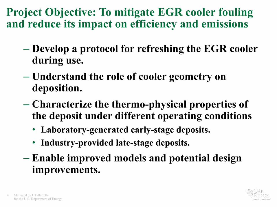
Project Objective: To mitigate EGR cooler fouling and reduce its impact on efficiency and emissions
– Develop a protocol for refreshing the EGR cooler during use.
– Understand the role of cooler geometry on deposition.
– Characterize the thermo-physical properties of the deposit under different operating conditions • Laboratory-generated early-stage deposits. • Industry-provided late-stage deposits.
– Enable improved models and potential design improvements.

5 Managed by UT-Battelle for the U.S. Department of Energy
Milestones
• Project Start – Milestone: Assembled EGR Advisory Team from industrial experts at nine
diesel engine manufacturers.
– Go/No-Go Decision: EGR Fouling chosen as project focus.
• FY2012 – Oct-11 Milestone: Received seven additional coolers from industry
(received 11 in 1st round).
– Nov-11 Milestone: Aged model deposits using bench tube reactor.
• FY2013 – Completed analysis of industry-provided coolers.
– Commenced testing of geometry effects on deposit formation and removal.

6 Managed by UT-Battelle for the U.S. Department of Energy
Approach
• Experimental Equipment for Deposit Formation and Aging – Ford 6.4-L engine to form deposits on model cooler tubes.
– Bench-top tube reactor for deposit aging in simulated diesel exhaust.
• Obtain Industry-Provided Coolers representing specific applications – Two rounds have been completed.
• Passive Control: Investigate the role of cooler geometry on deposit removal.
• Active Control: Explore Potential Refreshment Strategies – Low-temperature water condensation.
– High-temperature spallation.

7 Managed by UT-Battelle for the U.S. Department of Energy
Controlled Formation and Aging of EGR cooler Deposits Ford 6.4-L V-8 used as exhaust generator
• Exhaust passed through surrogate EGR cooler tubes.
• Thermal effectiveness of tubes is measured during exposure.
Heat Exchanger
Furnace
Water Pump
• Samples generated with our engine can then be aged in a tube reactor that simulates diesel exhaust.
• Inlet and coolant temperature, gas flow rate and water content are controlled.
• Temperatures at the inlet and outlet of the tube and the coolant temperature are monitored and used to calculate effectiveness.
Bench-top Tube Reactor
8 Managed by UT-Battelle for the U.S. Department of Energy
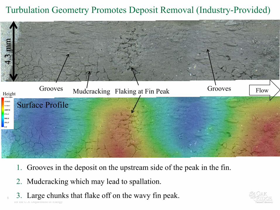
1. Grooves in the deposit on the upstream side of the peak in the fin.
2. Mudcracking which may lead to spallation.
3. Large chunks that flake off on the wavy fin peak.
4.3
mm
Turbulation Geometry Promotes Deposit Removal (Industry-Provided)
Grooves Flaking at Fin Peak Flow
Surface Profile Height
Grooves Mudcracking

9 Managed by UT-Battelle for the U.S. Department of Energy
Deposit Removal through Geometry may be a Route for Passive EGR Cooler Refreshment
• Deposit could be removed from flat tubes but only at unacceptably high flow rates. • Geometry (turbulation) was introduced by harvesting individual spiral tubes from an
industry-provided EGR cooler.
After air flow at 53 m/s for 30 min. Three Approaches for Tube Manufacturing
Additive Manufacturing
Plasma Spraying
Ensa Cooler Tube
PAPER C. Scott Sluder, John M.E. Storey and Michael J. Lance, “Removal of EGR Cooler Deposit Material by Flow-Induced Shear,” SAE 2013-01-1292.
Deposit Removal on Flat Tube

10 Managed by UT-Battelle for the U.S. Department of Energy
Deposit Formed on Spiral Tubes was far Rougher than Non-Turbulated Tube
• Deposit removal occurred both at the spiral groove but also in the flat region away from the groove.
• This points to a substantial turbulation effect on deposit removal.
• Future work will focus on introducing dimples on to square tubes and modeling the flow and shear forces with computational fluid dynamics (CFD).
Feature on Flat Portion of Spiral Tube Suggestive of Deposit Removal Deposit Removal
Flow
325
C Inlet; 90
C Coolant; FSN=1.5; HC=50 ppm; 30 SLPM
Spiral
Flat Tube

11 Managed by UT-Battelle for the U.S. Department of Energy
Water Condensation as an Active Control for Fouling
• Operating at very low coolant temperatures will collapse the soot nanostructure and/or flush the deposit out of the tube but achieving these temperatures is infeasible in practice.
• More subtle microstructural changes may occur at coolant temperatures closer to the dew point of water (40-50°C) which are achievable in diesel engines.
Nascent Deposit Following Condensation (10°
C Coolant)

12 Managed by UT-Battelle for the U.S. Department of Energy
Observing changes in Particulate Matter (PM) using an SEM
• Devolatilization in the SEM shrunk this particle ~20%. – SEM heating is time-consuming and doesn’t simulate diesel-exhaust
conditions.
• SEM imaging of PM before and after controlled hydrothermal aging and aging in diesel exhaust is being pursued.
• Motivation: To promote collapse of the PM nanostructure through a “refreshment protocol”.
Before Heating in the SEM to 1000
C (50°
C/min) After
10-9 atm 50X speed

13 Managed by UT-Battelle for the U.S. Department of Energy
Active Control: High Temperature “Decarburization”
• High inlet temperatures reduce deposit thickness on finned surfaces (Industry-Provided Coolers).
• Temperature of secondary heat transfer surface (fins) is substantially higher than the coolant.
• Operating for brief periods at full-load may be a refreshment strategy for EGR coolers.
High Inlet Gas Temperature Low Inlet Gas Temperature Metal Temp. (°C
)
Prim
ary
Prim
ary

14 Managed by UT-Battelle for the U.S. Department of Energy
Deposit removal is observed only at the inlet with high inlet gas temperatures and high flow rates
• Spallation occurs during operation. – Two spalled regions in the figure on the left were ~40 and ~70 µm deep.
• The shape of the spalled regions is faceted and angular.
• The high flow rate will also generate more shear forces promoting spallation.
High Inlet Temperature; High Smoke High Inlet Temperature; Low Smoke

15 Managed by UT-Battelle for the U.S. Department of Energy
The metal is coated with a hydrocarbon layer at low inlet gas temperatures but not at high inlet gas temperatures
• X-ray photoelectron spectroscopy (XPS) revealed the presence of an HC layer that has condensed from the exhaust stream onto the cold metal wall under low inlet gas temperatures.
• This HC layer is mostly absent with high inlet gas temperatures.
• Without an HC layer, the metal surface influences the adherence of the deposit.
• This removal phenomenon represents a heretofore unreported refreshment strategy for EGR coolers with deposit spallation possible at high engine loads.
XPS Chemical Composition
PAPER Michael J. Lance, Brad R. Watkins, Michele Kaiser, Ayyappan Ponnaiyan, John M.E. Storey, and C. Scott Sluder, “Microstructural Analysis of Deposits on Heavy-Duty EGR Coolers,” SAE 2013-01-1288.
16 Managed by UT-Battelle for the U.S. Department of Energy
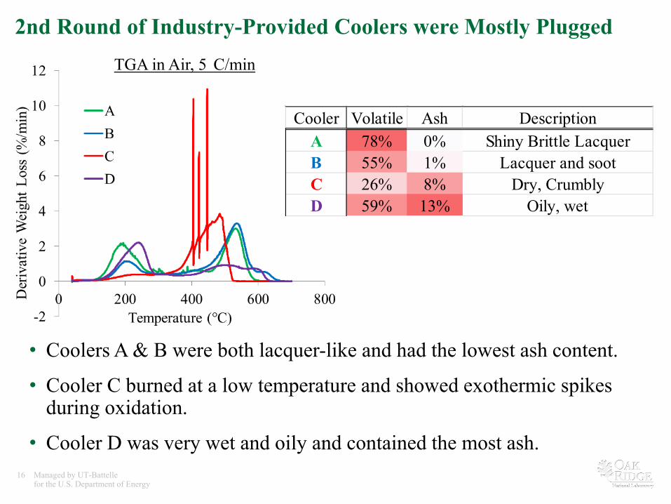
2nd Round of Industry-Provided Coolers were Mostly Plugged
• Coolers A & B were both lacquer-like and had the lowest ash content.
• Cooler C burned at a low temperature and showed exothermic spikes during oxidation.
• Cooler D was very wet and oily and contained the most ash.
TGA in Air, 5
C/min
Cooler Volatile Ash DescriptionA 78% 0% Shiny Brittle LacquerB 55% 1% Lacquer and sootC 26% 8% Dry, CrumblyD 59% 13% Oily, wet

17 Managed by UT-Battelle for the U.S. Department of Energy
Neutron Tomography was used to Image the Deposit*
• Neutron tomography allows one to non-destructively observe the deposit location in the EGR cooler.
• Deposit flowed and bubbled during use.
Three Orthogonal Projections of Lacquer Deposit
2.4
cm
* Funded in part by US Army
Cooler A

18 Managed by UT-Battelle for the U.S. Department of Energy
Lacquer is composed of polycyclic aromatic hydrocarbons (PAHs) cross-linked through contact with fomaldehyde
•! Gas chromatogram-mass spectrometry (GC-MS) was used to identify chemistry of deposit.
•! Density = 1.2 g/cm3 –! More similar to a polymer than fuel or oil.
•! Thermal Conductivity = 0.21 W/mK –! ~5 times higher than PM deposit
•! EGR walls must be held at temperatures above HC dew points to avoid condensation during rich operation.

19 Managed by UT-Battelle for the U.S. Department of Energy
Cooler C Deposit Contained Oxygenated Species
• An infrared camera revealed local heterogeneous oxidation likely caused by oxygenated PAHs feeding the combustion.
• Contained similar HC species to coolers A and B but at far lower concentrations and more dispersed by soot.
• Soot may be hindering the gas-liquid phase reaction that produces lacquer.
IR Imaging from 500 to 700°
C in Air
6.6 mm

20 Managed by UT-Battelle for the U.S. Department of Energy
Collaborations: EGR Materials Advisory Team • An advisory team consisting of chief engineers
responsible for EGR systems from nine members of the diesel crosscut team was assembled.
• EGR team companies included light-duty, heavy-duty and off-road diesel truck manufacturers:

21 Managed by UT-Battelle for the U.S. Department of Energy
Future Work
1. Passive Control: Investigate the role of geometry on deposit removal. – Controlled dimpling of square tubes. – Computational fluid dynamics (CFD) simulation.
2. Active Control: Characterize the changes in PM morphology following aging in controlled environments.
3. Active Control: Explore high temperature refreshment strategy using bench-top tube reactor. – How hot does the EGR cooler need to get to promote deposit removal?
4. Request third round of industry-provided coolers for late-stage deposit characterization.
22 Managed by UT-Battelle for the U.S. Department of Energy
Summary Relevance
EGR fouling results in 1-2% loss in engine efficiency.
Approach
Passive Control: Cooler Geometry
Active Control: (1) Low-temperature and (2) High-temperature
Real-World: Industry-Provided Samples
Technical Accomplishments and Progress
• Proof-of-Principle: Turbulation promotes deposit removal.
• Proof-of-Principle: Less deposit with high-temperature exposure.
• Forensic analysis of cooler deposits may allow one to infer deposit formation and removal mechanisms.
Collaboration with entire diesel engine community.
Proposed Future Work
Use tube sampler and reactor to better understand refreshment strategies while continuing to characterize late-stage deposits.
Related Documents