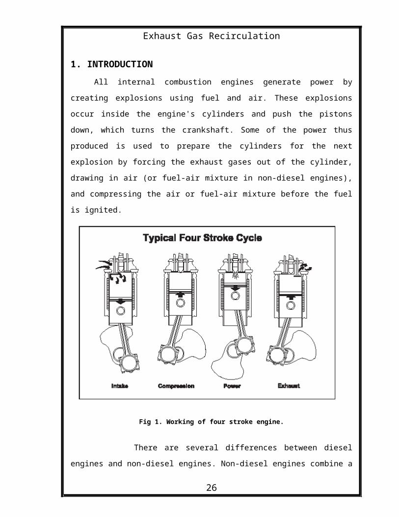
Exhaust Gas Recirculation 1. INTRODUCTION All internal combustion engines generate power by creating explosions using fuel and air. These explosions occur inside the engine's cylinders and push the pistons down, which turns the crankshaft. Some of the power thus produced is used to prepare the cylinders for the next explosion by forcing the exhaust gases out of the cylinder, drawing in air (or fuel-air mixture in non-diesel engines), and compressing the air or fuel-air mixture before the fuel is ignited. Fig 1. Working of four stroke engine. There are several differences between diesel engines and non-diesel engines. Non-diesel engines combine a 26

Welcome message from author
This document is posted to help you gain knowledge. Please leave a comment to let me know what you think about it! Share it to your friends and learn new things together.
Transcript
Exhaust Gas Recirculation
1. INTRODUCTIONAll internal combustion engines generate power by
creating explosions using fuel and air. These explosions
occur inside the engine's cylinders and push the pistons
down, which turns the crankshaft. Some of the power thus
produced is used to prepare the cylinders for the next
explosion by forcing the exhaust gases out of the cylinder,
drawing in air (or fuel-air mixture in non-diesel engines),
and compressing the air or fuel-air mixture before the fuel
is ignited.
Fig 1. Working of four stroke engine.
There are several differences between diesel
engines and non-diesel engines. Non-diesel engines combine a
26
Exhaust Gas Recirculationfuel mist with air before the mixture is taken into the
cylinder, while diesel engines inject fuel into the cylinder
after the air is taken in and compressed. Non-diesel engines
use a spark plug to ignite the fuel-air mixture, while
diesel engines use the heat created by compressing the air
in the cylinder to ignite the fuel, which is injected into
the hot air after compression. In order to create the high
temperatures needed to ignite diesel fuel, diesel engines
have much higher compression ratios than
gasoline engines. Because diesel fuel is made of larger
molecules than gasoline, burning diesel fuel produces more
energy than burning the same volume of gasoline. The higher
compression ratio in a diesel engine and the higher energy
content of diesel fuel allow diesel engines to be more
efficient than gasoline engines.
1.1. Formation of Nitrogen Oxides (NOx)
The same factors that cause diesel engines to run more
efficiently than gasoline engines also cause them to run at
a higher temperature. This leads to a pollution problem, the
creation of nitrogen oxides (NOx). You see, fuel in any
engine is burned with extra air, which helps eliminate
unburned fuel from the exhaust. This air is approximately
79% nitrogen and 21% oxygen.
When air is compressed inside the cylinder of the
diesel engine, the temperature of the air is increased
26
Exhaust Gas Recirculationenough to ignite diesel fuel after it is ignited in the
cylinder. When the diesel fuel ignites, the temperature of
the air increases to more than 1500F and the air expands
pushing the piston down and rotating the crankshaft.
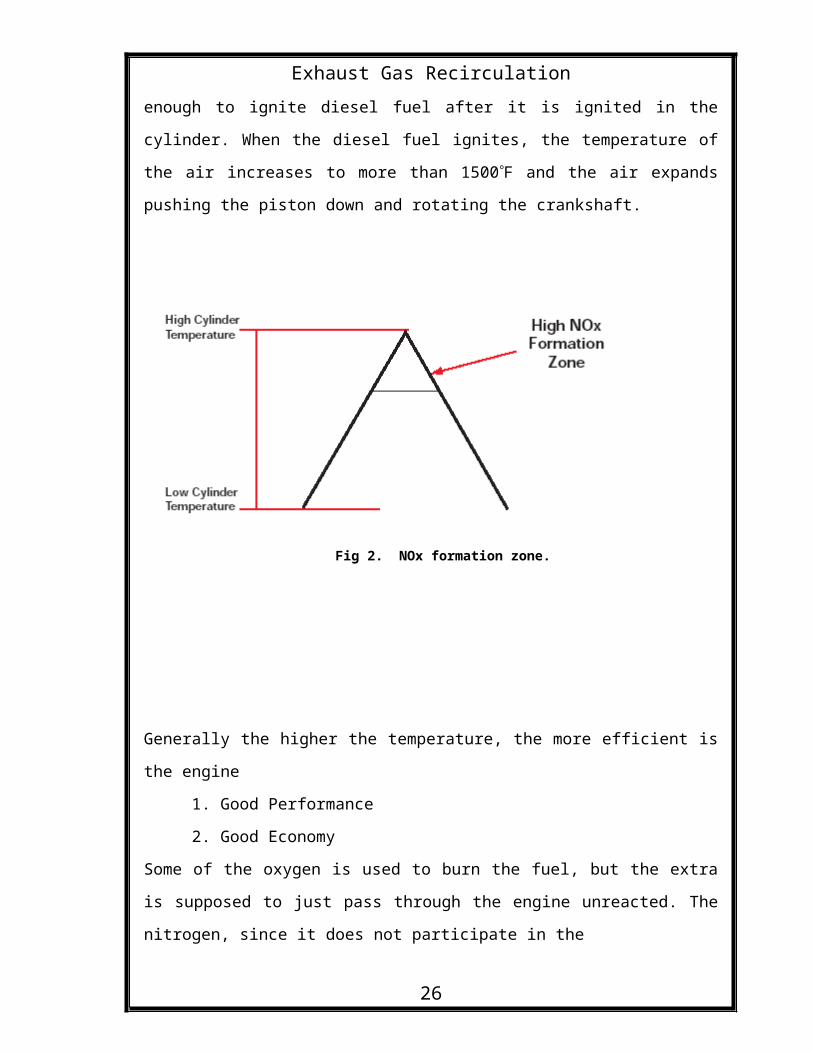
Fig 2. NOx formation zone.
Generally the higher the temperature, the more efficient is
the engine
1. Good Performance
2. Good Economy
Some of the oxygen is used to burn the fuel, but the extra
is supposed to just pass through the engine unreacted. The
nitrogen, since it does not participate in the
26
Exhaust Gas Recirculation
combustion reaction, also passes unchanged through the
engine. When the peak temperatures are high enough for long
periods of time, the nitrogen and oxygen in the air combines
to form new compounds, primarily NO and NO2. These are
normally collectively referred to as “NOx”.
1.2. Problems of NOx
Nitrogen oxides are one of the main pollutants
emitted by vehicle engines. Once they enter into the
atmosphere, they are spread over a large area by the wind.
When it rains, water then combines with the nitrogen oxides
to form acid rain. This has been known to damage buildings
and have an adverse effect on ecological systems.
Too much NOx in the atmosphere also contributes to the
production of SMOG. When the sunrays hit these pollutants
SMOG is formed. NOx also causes breathing illness to the
human lungs.
1.3. EPA Emission Standards
Since 1977, NOx emissions from diesel engines
have been regulated by the EPA
(Environmental Protection Agency). In October 2002, new NOx
standards required the
diesel engine industry to introduce additional technology to
meet the new standards
26
Exhaust Gas Recirculation
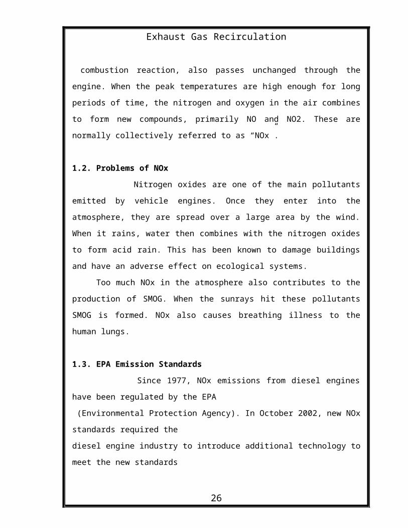
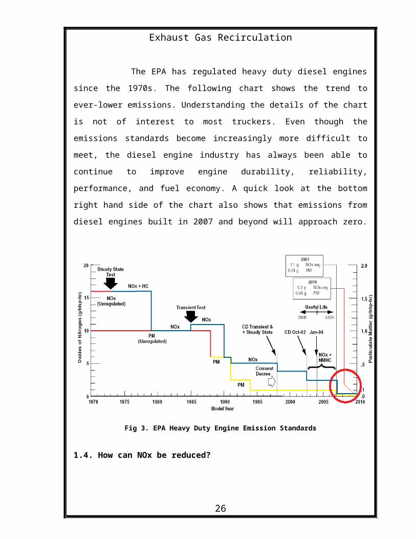
The EPA has regulated heavy duty diesel engines
since the 1970s. The following chart shows the trend to
ever-lower emissions. Understanding the details of the chart
is not of interest to most truckers. Even though the
emissions standards become increasingly more difficult to
meet, the diesel engine industry has always been able to
continue to improve engine durability, reliability,
performance, and fuel economy. A quick look at the bottom
right hand side of the chart also shows that emissions from
diesel engines built in 2007 and beyond will approach zero.
Fig 3. EPA Heavy Duty Engine Emission Standards
1.4. How can NOx be reduced?
26
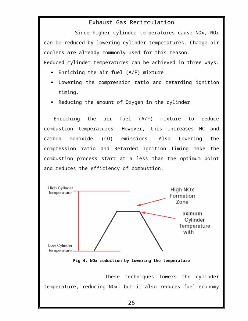
Exhaust Gas Recirculation Since higher cylinder temperatures cause NOx, NOx
can be reduced by lowering cylinder temperatures. Charge air
coolers are already commonly used for this reason.
Reduced cylinder temperatures can be achieved in three ways.
Enriching the air fuel (A/F) mixture.
Lowering the compression ratio and retarding ignition
timing.
Reducing the amount of Oxygen in the cylinder
Enriching the air fuel (A/F) mixture to reduce
combustion temperatures. However, this increases HC and
carbon monoxide (CO) emissions. Also Lowering the
compression ratio and Retarded Ignition Timing make the
combustion process start at a less than the optimum point
and reduces the efficiency of combustion.
Fig 4. NOx reduction by lowering the temperature
These techniques lowers the cylinder
temperature, reducing NOx, but it also reduces fuel economy
26
Exhaust Gas Recirculationand performance, and creates excess soot, which results in
more frequent oil changes. So, the best way is to limit the
amount of Oxygen in the cylinder. Reduced oxygen results in
lower cylinder temperatures. This is done by circulating
some exhaust gas and mixing it into the engine inlet air.
This process is known as Exhaust Gas Recirculation.
2. EXHAUST GAS RECIRCULATION Exhaust Gas Recirculation is an efficient method
to reduce NOx emissions from the engine. It works by
recirculating a quantity of exhaust gas back to the engine
cylinders. Intermixing the recirculated gas with incoming
air reduces the amount of available O2 to the combustion and
lowers the peak temperature of combustion. Recirculation is
usually achieved by piping a route from the exhaust manifold
to the intake manifold. A control valve within the circuit
regulates and times the gas flow.
2.1. Uses of Exhaust Gas Recirculation
First, exhaust gas recirculation reduces the
concentration of oxygen in the fuel-air mixture. By
replacing some of the oxygen-rich inlet air with relatively
oxygen-poor exhaust gas, there is less oxygen available for
the combustion reaction to proceed. Since the rate of a
reaction is always dependent to some degree on the
concentration of its reactants in the pre- reaction mix, the
26
Exhaust Gas RecirculationNOx-producing reactions proceed more slowly, which means
that less NOx is formed.
In addition, since there is less oxygen available,
the engine must be adjusted to inject less fuel before each
power stroke. Since we are now burning less fuel, there is
less heat available to heat the fluids taking place in the
reaction. The combustion reaction therefore occurs at lower
temperature. Since the temperature is lower, and since the
rate of the NOx-forming reaction is lower at lower
temperatures, less NOx is formed.
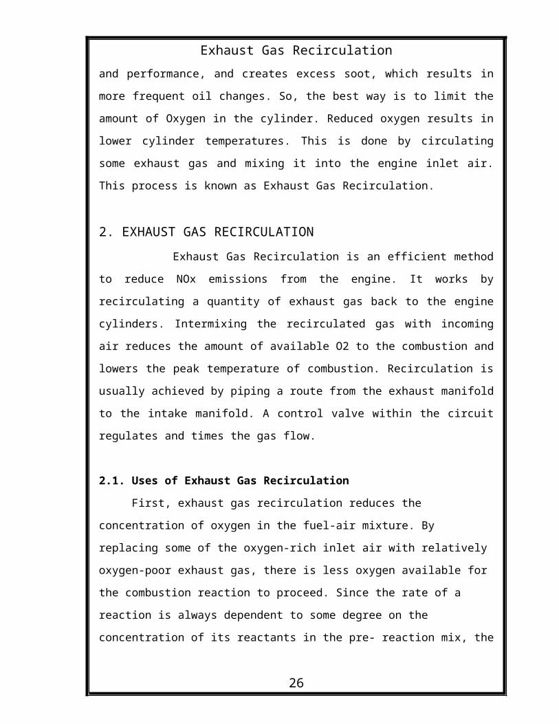
2.2. Basic Parts Of EGR
There are 3 basic parts of EGR
EGR Valve
EGR Cooler
EGR Transfer Pipe
Typical Four Stroke Diesel Engine with Basic Parts of EGR
26
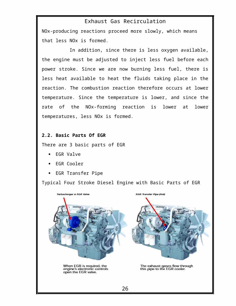
Exhaust Gas RecirculationFigure 5
When EGR is required engine electronic controls open the
EGR valve. The exhaust gas then flows through the pipe to
the cooler. The exhaust gases are cooled by water from the
truck cooling system. The cooled exhaust gas then flow
through the EGR transfer pipe to the intake manifold.
Figure 6
2.3. EGR Operating Conditions
There are three operating conditions. The EGR flow should
match the conditions
1. High EGR flow is necessary during cruising and midrange
acceleration
2. Low EGR flow is needed during low speed and light load.
26
Exhaust Gas Recirculation 3. No EGR flow should occur during conditions when
EGR flow could adversely affect the engine operating
efficiency or vehicle drivability. ie, during engine warm
up, idle, wide open throttle, etc.
2.4. EGR Impact on ECS
The ECM (Electronic Control Machine) considers the
EGR system as an integral part of the entire ECS. Therefore
the ECM is capable of neutralizing the negative aspects of
EGR by programming additional spark advance and decreased
fuel injection duration during periods of high EGR flow. By
integrating the fuel and spark control with the EGR metering
system, engine performance and the fuel economy can actually
be enhanced when the EGR system is functioning as designed.
26
Exhaust Gas Recirculation
2.5. EGR Theory of Operation
The purpose of the EGR system is to precisely regulate
the flow under different operating conditions. The precise
amount of exhaust gas must be metered into the intake
manifold and it varies significantly as the engine load
changes. By integrating the fuel and spark control with the
EGR metering system, engine performance and the fuel economy
can be enhanced. For this an ECM (Electronic Control
Machine) is used to regulate the EGR flow. When EGR is
required ECM opens the EGR valve.The ECM is capable of neutralizing the negative aspects of EGR by programming
additional spark advance and decreased fuel injection
duration during periods EGR flowThe exhaust gas then flows
through the pipe to the cooler. The exhaust gases are cooled
by water from the vehicle’s cooling system. The cooled
exhaust gas then flow through the EGR transfer pipe to the
intake manifold.
26
Exhaust Gas Recirculation
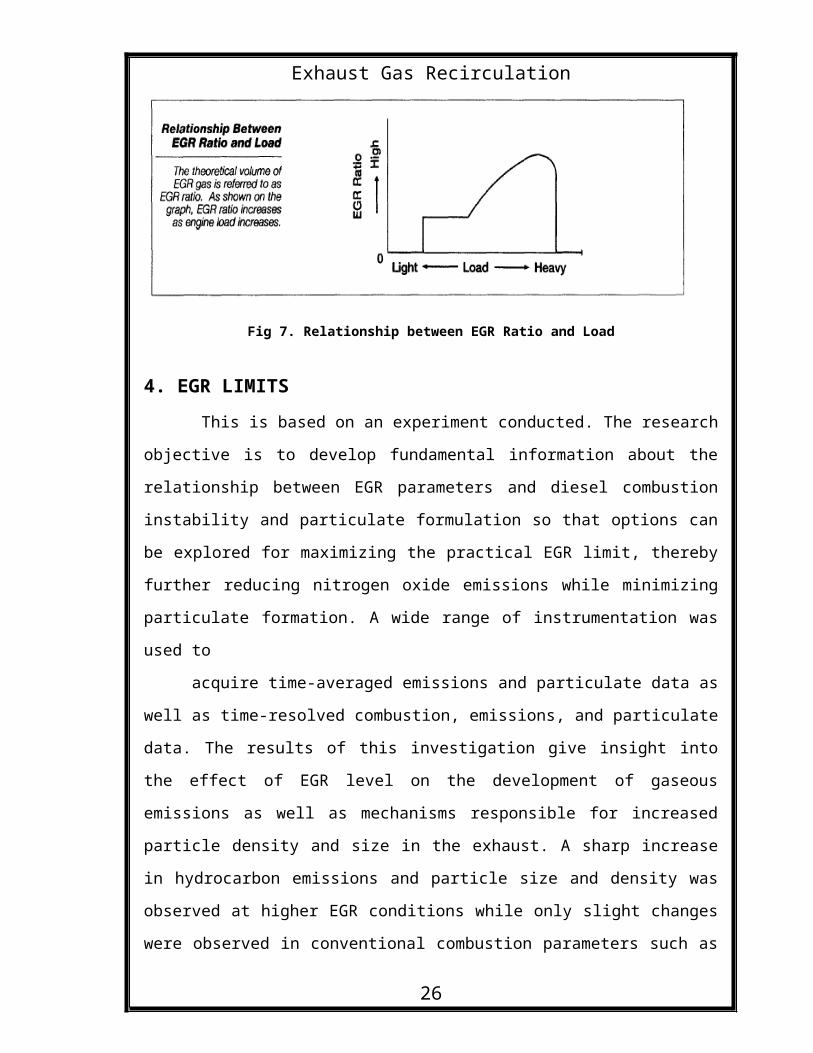
Fig 7. Relationship between EGR Ratio and Load
4. EGR LIMITS This is based on an experiment conducted. The research
objective is to develop fundamental information about the
relationship between EGR parameters and diesel combustion
instability and particulate formulation so that options can
be explored for maximizing the practical EGR limit, thereby
further reducing nitrogen oxide emissions while minimizing
particulate formation. A wide range of instrumentation was
used to
acquire time-averaged emissions and particulate data as
well as time-resolved combustion, emissions, and particulate
data. The results of this investigation give insight into
the effect of EGR level on the development of gaseous
emissions as well as mechanisms responsible for increased
particle density and size in the exhaust. A sharp increase
in hydrocarbon emissions and particle size and density was
observed at higher EGR conditions while only slight changes
were observed in conventional combustion parameters such as
26
Exhaust Gas Recirculationheat release and work. Analysis of the time-resolved data is
ongoing.
The objective of this work is to characterize the
effect of EGR on the development of combustion instability
and particulate formation so that options can be explored
for maximizing the practical EGR limit. We are specifically
interested in the dynamic details of the combustion
transition with EGR and how the transition might be altered
by appropriate high-speed adjustments to the engine. In the
long run, we conjecture that it may be possible to alter the
effective EGR limit (and thus NOx performance) by using
advanced engine control strategies.
Experiments were performed on a 1.9 liter, four-
cylinder Volkswagen turbo-charged direct injection engine
under steady state, low load conditions. Engine speed was
maintained constant at 1200 rpm using an absorbing
dynamometer and fuel flow was set to obtain 30% full load at
the 0% EGR condition. A system was devised to vary EGR by
manually deflecting the EGR diverter valve. The precise EGR
level was monitored by comparing NOx concentrations in the
exhaust and intake. NOx concentrations were used because of
the high accuracy of the analyzers at low concentrations
found in the intake over a wide range of EGR levels.
26
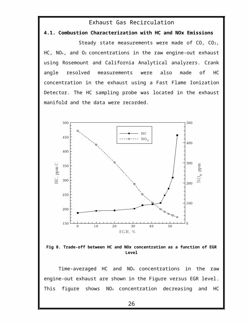
Exhaust Gas Recirculation4.1. Combustion Characterization with HC and NOx Emissions
Steady state measurements were made of CO, CO2,
HC, NOx, and O2 concentrations in the raw engine-out exhaust
using Rosemount and California Analytical analyzers. Crank
angle resolved measurements were also made of HC
concentration in the exhaust using a Fast Flame Ionization
Detector. The HC sampling probe was located in the exhaust
manifold and the data were recorded.
Fig 8. Trade-off between HC and NOx concentration as a function of EGRLevel
Time-averaged HC and NOx concentrations in the raw
engine-out exhaust are shown in the Figure versus EGR level.
This figure shows NOx concentration decreasing and HC
26
Exhaust Gas Recirculationincreasing with increasing EGR as would be expected. Note
the sudden increase in HC and leveling-off in NOx at
approximately 45% EGR, where there appears to be a
significant shift in combustion chemistry. This major
transition is in sharp contrast to the slight changes
observed in the integrated pressure parameters, HR and IMEP.
Because of the suddenness of the emissions change at 45%
EGR, it is clear that dynamic engine behavior at or above
this operating point will be highly nonlinear. Thus it is
imperative that any control strategies being considered
should be able accommodate such behavior.
4.2. Combustion Characterization with PM
Our measurements have identified significant
changes in PM emissions with EGR level as was expected.
Similar to the gaseous emissions (e.g., HC and NOx), there
was a sharp increase in PM at a critical EGR level. This
critical level corresponding to a sharp increase in PM was
observed in mass concentration, particle size, and particle
density.
a) Mass Concentration
A Tapered Element Oscillating Microbalance (TEOM)
was used to measure particulate mass concentration and total
mass accumulation as a function of time. A sample of diluted
exhaust is pulled through a 12 mm filter to the end of a
tapered quartz element. The frequency of the element changes
26
Exhaust Gas Recirculationwith mass accumulation. The instrument has approximately 3
sec resolution on mass concentration.
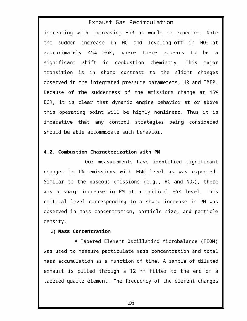
Particle mass concentration and total mass
accumulation were measured on dilute exhaust using the TEOM.
Mass accumulation rates were calculated based on over 100
mass data points and are shown in the figure as a function
of EGR level. Mass accumulation rates begin to increase
significantly at 30% EGR and continue to increase rapidly
until the maximum EGR level. The intersection of the
particulate mass and NOx curves represents a region where
the engine out particulate mass and NOx concentration are
minimized for this engine condition.
Fig 9. Relation of PM Accumulation Rate and NOx emission with EGR.
26
Exhaust Gas Recirculation
b) Particle Size
A Scanning Mobility Particle Sizer (SMPS) was used
to measure the steady state size distribution of the
particulates in the exhaust stream. The particles are
neutralized and then sorted based on their electrical
mobility diameter. The range of the SMPS was set at 11 nm –
505 nm.
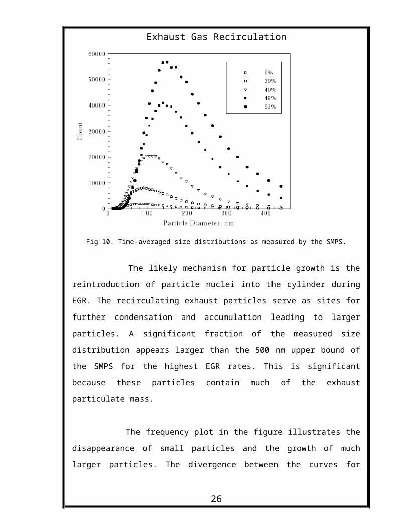
Particle sizing was performed on dilute exhaust
using the SMPS. Number concentration vs. particle diameter
is shown in the figure for several EGR levels. Two aspects
of the data stand out. The first is the increasing number
concentration with level of EGR. The second is the
increasing particle size. Note that the particle size at the
peak concentration increases by a factor of approximately
two between 30% and 53% EGR.
26
Exhaust Gas Recirculation
Fig 10. Time-averaged size distributions as measured by the SMPS.
The likely mechanism for particle growth is the
reintroduction of particle nuclei into the cylinder during
EGR. The recirculating exhaust particles serve as sites for
further condensation and accumulation leading to larger
particles. A significant fraction of the measured size
distribution appears larger than the 500 nm upper bound of
the SMPS for the highest EGR rates. This is significant
because these particles contain much of the exhaust
particulate mass.
The frequency plot in the figure illustrates the
disappearance of small particles and the growth of much
larger particles. The divergence between the curves for
26
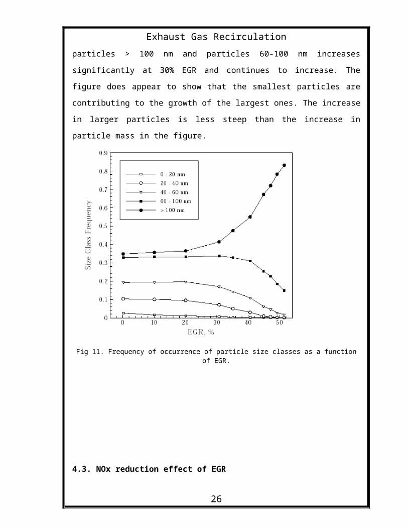
Exhaust Gas Recirculationparticles > 100 nm and particles 60-100 nm increases
significantly at 30% EGR and continues to increase. The
figure does appear to show that the smallest particles are
contributing to the growth of the largest ones. The increase
in larger particles is less steep than the increase in
particle mass in the figure.
Fig 11. Frequency of occurrence of particle size classes as a functionof EGR.
4.3. NOx reduction effect of EGR
26
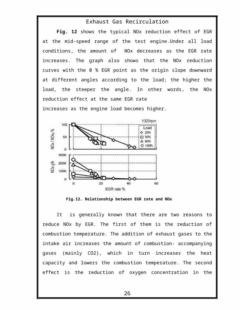
Exhaust Gas RecirculationFig. 12 shows the typical NOx reduction effect of EGR
at the mid-speed range of the test engine.Under all load
conditions, the amount of NOx decreases as the EGR rate
increases. The graph also shows that the NOx reduction
curves with the 0 % EGR point as the origin slope downward
at different angles according to the load; the higher the
load, the steeper the angle. In other words, the NOx
reduction effect at the same EGR rate
increases as the engine load becomes higher.
Fig.12. Relationship between EGR rate and NOx
It is generally known that there are two reasons to
reduce NOx by EGR. The first of them is the reduction of
combustion temperature. The addition of exhaust gases to the
intake air increases the amount of combustion- accompanying
gases (mainly CO2), which in turn increases the heat
capacity and lowers the combustion temperature. The second
effect is the reduction of oxygen concentration in the
26
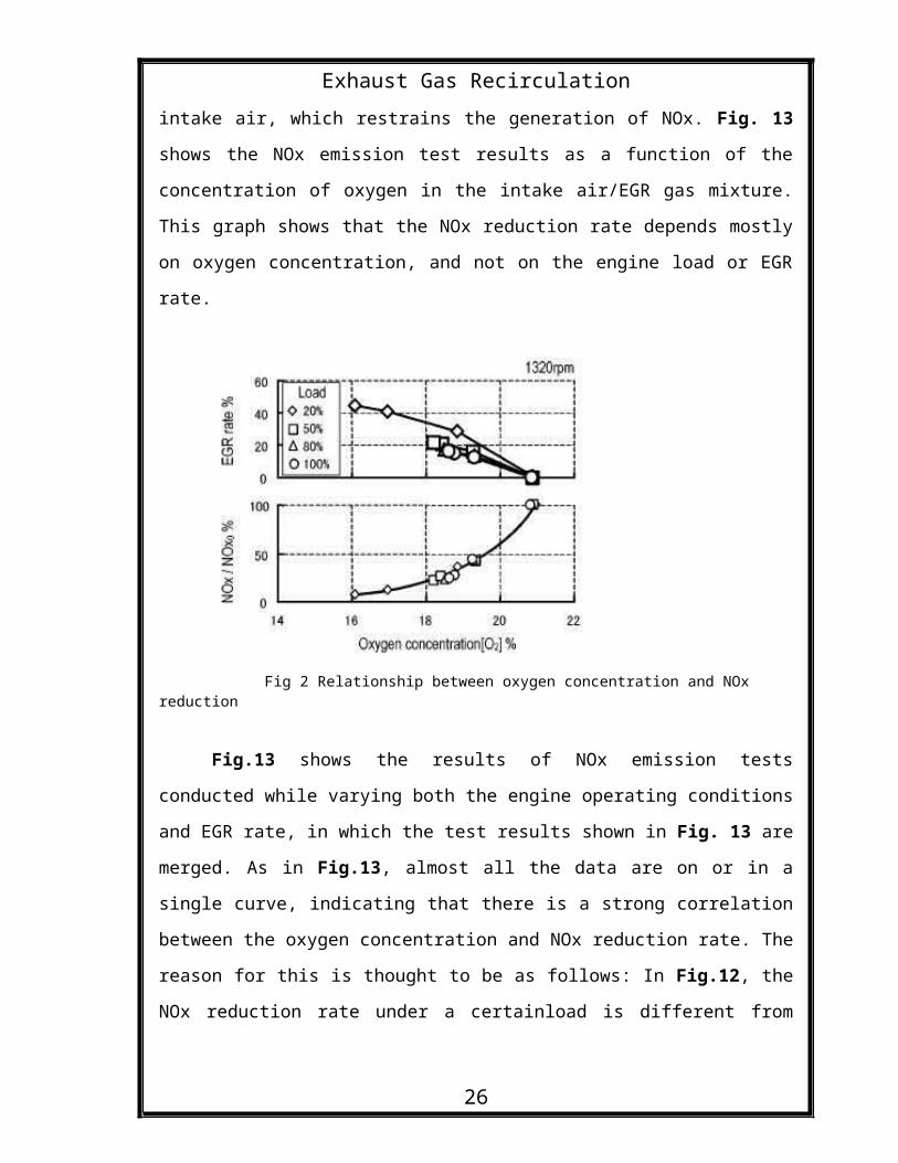
Exhaust Gas Recirculationintake air, which restrains the generation of NOx. Fig. 13
shows the NOx emission test results as a function of the
concentration of oxygen in the intake air/EGR gas mixture.
This graph shows that the NOx reduction rate depends mostly
on oxygen concentration, and not on the engine load or EGR
rate.
Fig 2 Relationship between oxygen concentration and NOx reduction
Fig.13 shows the results of NOx emission tests
conducted while varying both the engine operating conditions
and EGR rate, in which the test results shown in Fig. 13 are
merged. As in Fig.13, almost all the data are on or in a
single curve, indicating that there is a strong correlation
between the oxygen concentration and NOx reduction rate. The
reason for this is thought to be as follows: In Fig.12, the
NOx reduction rate under a certainload is different from
26
Exhaust Gas Recirculationthat under another load even when the EGR rate remains the
same because the difference in load causes a difference in
the amount of combustion-accompanying gases and oxygen
concentration in EGR gas, which in turn changes the oxygen
concentration in the intake gas (mixture of intake air andEGR gas).
5. INTERNAL EGR
When a fraction of the combustion products is
still present in the cylinder at the moment that the exhaust
valves close, the mixture at the beginning of the next
engine cycle will consist of air and fuel, as well as
combustion products. These products are called internal EGR
(in contrast to external EGR, which means that exhaust gases
are recycled to the intake system, after which they mix with
the air and fuel.) The fraction of internal EGR that is
present in the cylinder at the beginning of the compression
stroke is mainly dependent on the timing of the intake and
exhaust valves.
The valve timing of traditional engines, such as
the Diesel and Otto engines, is such that the fraction of
exhaust gases (or residuals) at the start of the cycle is as
small as possible. Traditional engines have Residual Gas
Fractions (RGF) in the range 5-15 mass%.
6. TECHNICAL ISSUES
26
Exhaust Gas Recirculation
6.1. Combustion Contamination
Exhaust gas from any combustion process may have
certain contaminants, including acid forming compounds,
unburned and partially burned hydrocarbons, air pollutants,
and liquid water. These contaminants can be successfully
reintroduced into the combustion chamber but may lead, over
time, to serious combustion degradation and instability, and
shorter component life. Such effects need to be fully
understood and documented, and appropriate improvements made
to the combustion process to protect the customer’s
investment and maintain true long-term emissions compliance.
This activity would be a key element of any major engine
manufacturer’s development process.
6.2. Control System Stability
Control systems for modern engines have been
developed over two decades and involve integrated strategies
to adjust air/fuel ratio, ignition timing, and air flow
rates to maintain emissions control at varying loads,
speeds, and fuel conditions. These systems are at the heart
of successful engine operation today and are vital to
satisfactory long term operation. Adding EGR into the
combustion process introduces further complexity that must
be carefully integrated into the entire engine control
system approach for successful operation over a wide range
26
Exhaust Gas Recirculationof conditions. For instance, if fuel quality changes over
time, the air/fuel ratio, ignition timing, air system rates,
and the EGR rate must be adjusted accordingly to keep the
combustion system stable and emissions in compliance. On the
other hand, if the engine’s load changes rapidly from part
load to full load and back to part load, the EGR system
dynamics must be included in the overall control strategy
response to make sure the engine operates smoothly during
this transition.
6.3. Materials and Durability
EGR systems may decrease long-term life of the
components affected, including the EGR coolers and control
valves, the pistons and cylinder heads, exhaust manifolds
and sensors, as well as the post engine catalyst. Operating
a few hundred hours per year may not lead to any significant
materials degradation in the overall lifespan of an engine.
However, continuous duty applications at 8500 hours per year
may cause near term emissions noncompliance and longer term
materials breakdown, shorter component life, and even
unexpected, catastrophic engine failures. To minimize or
eliminate the potentially negative impacts of EGR on engine
components, compatible components and designs must be used
that often require thousands of hours of lab and field test
operation for validation. Although both expensive and time
consuming, such efforts are a necessary part of proving any
26
Exhaust Gas Recirculationnew combustion design including EGR systems. Therefore,
major engine manufacturers worldwide need to plan for and
execute these tests in order to develop the materials needed
for successful EGR applications.
6.4. Liquid Dropout
During exhaust gas recirculation, the gasses must
be cooled with an external cooler before being reintroduced
into the cool inlet manifold of an engine. The cooling
process for the EGR may result in liquids being formed in
the return lines, depending on temperatures and local
humidity, much as liquids are formed in the tailpipe of an
automobile at certain conditions. This liquid dropout could
be a continuous stream that needs to be carefully understood
and managed with the needs of the local environment in mind.
While there may be ways to reintroduce this liquid into the
combustion process, doing so may create further problems
with combustion and lead to other emissions complications
and instability. As such, managing liquid dropout needs
careful study and development in an integrated development
program.
26
Exhaust Gas Recirculation
7. CONCLUSION
Thus, as seen that using Exhaust Gas Recirculation
Technique in engines, the emissions are vary much controlled
due to lesser amounts of NOx entering the atmosphere. Thus
the emission levels to be maintained are attained by the
engines. As seen, Exhaust Gas Recirculation is a very simple
method. It has proven to be very useful and it is being
modified further to attain better standards. This method is
very reliable in terms of fuel consumption and highly
reliable. Thus EGR is the most effective method for reducing
the nitrous oxide emissions from the engine exhaust. Many of
the four wheeler manufacturers used this technique like Ford
Company, Benz Motors etc to improve the engine performance
and reduce the amount of pollutants in the exhaust of the
engine.
26
Related Documents