T1000 MARINE CONTROLLER User Manual 11th September 2000 120-415-377 Issue 4

Welcome message from author
This document is posted to help you gain knowledge. Please leave a comment to let me know what you think about it! Share it to your friends and learn new things together.
Transcript
T1000
MARINE
CONTROLLER
User Manual
11th September 2000
120-415-377 Issue 4
120-415-377 Issue 4 i
T1000 MARINE FIRE DETECTION CONTROLLER
1. INTRODUCTION 1
1.1 SCOPE OF THE MANUAL 11.2 OVERVIEW 1
2. INDICATIONS AND CONTROLS 2
2.1 DISPLAY 22.1.1 CONDITION AREA 22.1.2 ZONE AREA 22.1.3 OUTPUT 22.1.4 LED INDICATORS 32.2 STANDARD CONTROLS 42.2.1 DISPLAY SCREEN FORMATS AND ASSOCIATED FUNCTION
PUSHBUTTONS 4
2.3 OTHER PUSHBUTTON FUNCTIONS 7
3. OPERATION 8
3.1 QUIESCENT (NORMAL) CONDITION 83.2 CONTROLLER SECURITY ACCESS LEVELS 83.3 CONTROLLER SOUNDER OPERATION 83.4 ZONE PRIORITIES 93.5 FIRE ALARM 93.6 MANUAL ALARM EVACUATE 93.7 TECHNICAL ALARMS 103.8 LAMP TEST 103.9 FIRE ALARM/FAULT DIAGNOSIS FLOWCHART 113.9.1 ZONE FAULTS 113.9.2 OUTPUT FAULTS 133.9.3 SYSTEM FAULTS 143.9.4 FAULT AREA TABLE 153.9.5 ERROR CODE TABLE 153.10 ACCESS LEVEL-3 FUNCTIONS 183.10.1 CURRENT TIME AND DATE 183.10.2 USER TEXT MESSAGES 19
4. SITE INFORMATION 21
4.1 NT CONTROLLER SITE DETAILS 214.2 NT CONTROLLER SITE AND VISIT DETAILS 224.3 CAUSE AND EFFECT DEFAULT CONFIGURATION 234.4 CUSTOMISED C AND E CONFIGURATION DETAILS - RECORD 254.5 USER TEXT CONFIGURATION DETAILS 27
ii 120-415-377 Issue 4
T1000 MARINE FIRE DETECTION CONTROLLER
5. ROUTINE MAINTENANCE AND TESTING 28
5.1 USER MAINTENANCE 285.1.1 GENERAL 285.1.2 CLEANING 285.2 ROUTINE TESTING 285.2.1 DAILY 285.2.2 WEEKLY 285.3 SERVICE MAINTENANCE 285.3.1 QUARTERLY 285.3.2 ANNUALLY 295.3.3 EVERY 4 YEARS 29
6. FIRE CONTROLLER AREA DESCRIPTOR TABLE 30
ANNEX A - REPEATER OPERATION
1. INTRODUCTION 31
2. FAULT REPORTING 32
2.1 ZONE FAULTS 322.2 OUTPUT FAULTS 322.3 SYSTEM FAULTS 322.4 COMMUNICATION FAULTS 322.4.1 REPEATER FAILS TO RECEIVE AN ACKNOWLEDGEMENT FROM
THE MASTER PANEL 32
2.4.2 MASTER FAILS TO RECEIVE AN ACKNOWLEDGEMENT FROM A REPEATER PANEL 32
120-415-377 Issue 4 1 of 41
T1000 MARINE FIRE DETECTION CONTROLLER
1. INTRODUCTION
1.1 SCOPE OF THE MANUAL
This manual contains the necessary information to enable trained personnel to use and maintain the T1000Marine Fire Detection Controller.
1.2 OVERVIEW
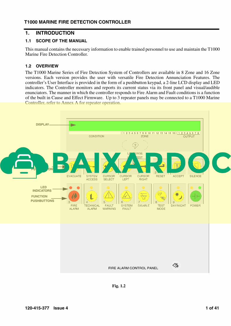
The T1000 Marine Series of Fire Detection System of Controllers are available in 8 Zone and 16 Zoneversions. Each version provides the user with versatile Fire Detection Annunciation Features. Thecontroller’s User Interface is provided in the form of a pushbutton keypad, a 2-line LCD display and LEDindicators. The Controller monitors and reports its current status via its front panel and visual/audibleenunciators. The manner in which the controller responds to Fire Alarm and Fault conditions is a functionof the built in Cause and Effect Firmware. Up to 3 repeater panels may be connected to a T1000 MarineController, refer to Annex A for repeater operation.
Fig. 1.2
DISPLAY
FUNCTION
PUSHBUTTONS
LED
INDICATORS
FUNCTION
PUSHBUTTONS
2 of 41 120-415-377 Issue 4
T1000 MARINE FIRE DETECTION CONTROLLER
2. INDICATIONS AND CONTROLS
2.1 DISPLAY
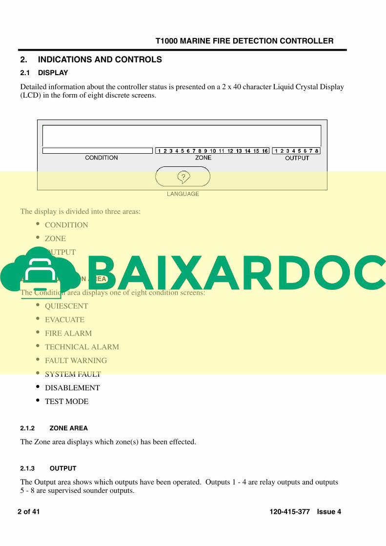
Detailed information about the controller status is presented on a 2 x 40 character Liquid Crystal Display(LCD) in the form of eight discrete screens.
The display is divided into three areas:
• CONDITION
• ZONE
• OUTPUT
2.1.1 CONDITION AREA
The Condition area displays one of eight condition screens:
• QUIESCENT
• EVACUATE
• FIRE ALARM
• TECHNICAL ALARM
• FAULT WARNING
• SYSTEM FAULT
• DISABLEMENT
• TEST MODE
2.1.2 ZONE AREA
The Zone area displays which zone(s) has been effected.
2.1.3 OUTPUT
The Output area shows which outputs have been operated. Outputs 1 - 4 are relay outputs and outputs 5 - 8 are supervised sounder outputs.
120-415-377 Issue 4 3 of 41
T1000 MARINE FIRE DETECTION CONTROLLER
2.1.4 LED INDICATORS
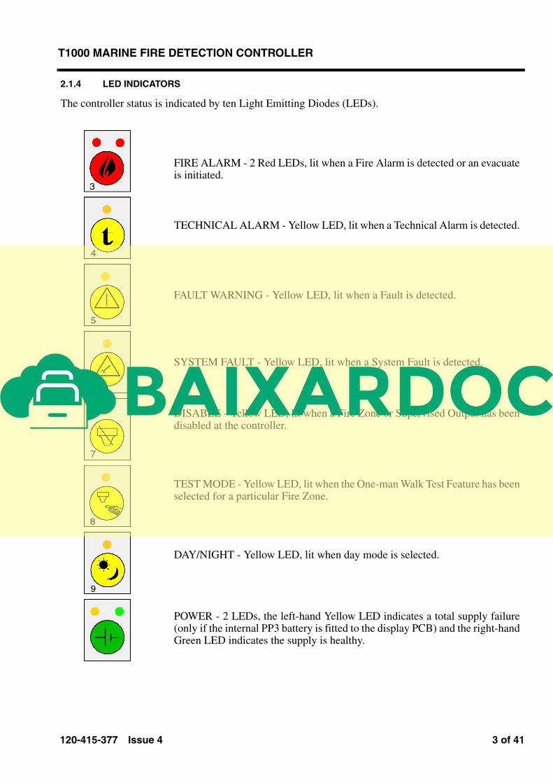
The controller status is indicated by ten Light Emitting Diodes (LEDs).
FIRE ALARM - 2 Red LEDs, lit when a Fire Alarm is detected or an evacuateis initiated.
TECHNICAL ALARM - Yellow LED, lit when a Technical Alarm is detected.
FAULT WARNING - Yellow LED, lit when a Fault is detected.
SYSTEM FAULT - Yellow LED, lit when a System Fault is detected.
DISABLE - Yellow LED, lit when a Fire Zone or Supervised Output has beendisabled at the controller.
TEST MODE - Yellow LED, lit when the One-man Walk Test Feature has beenselected for a particular Fire Zone.
DAY/NIGHT - Yellow LED, lit when day mode is selected.
POWER - 2 LEDs, the left-hand Yellow LED indicates a total supply failure(only if the internal PP3 battery is fitted to the display PCB) and the right-handGreen LED indicates the supply is healthy.
4 of 41 120-415-377 Issue 4
T1000 MARINE FIRE DETECTION CONTROLLER
2.2 STANDARD CONTROLS
The T1000 Marine controller provides a pushbutton keypad to access the various control functions andsettings of the controller. The pushbuttons are multi-functional and there use is dependent upon theselected function as detailed in the following sub-sections.
2.2.1 DISPLAY SCREEN FORMATS AND ASSOCIATED FUNCTION PUSHBUTTONS
Due to display screen limitations only the highest priority information is displayed at any one instanceunless a user overrides the priority system by operation of the front panel pushbuttons. The priority is asfollows:
1) Access level-1 display priority:
a) Operator control requests - The T1000 Marine Controller obeys instructions and the frontpanel displays the requested information; the information is displayed permanently as longas no higher priority information currently exists, or for 20 seconds if higher priorityinformation exists, or momentarily if a monitored event occurs.
b) Unacknowledged (not Accepted) fire alarms.
c) Unacknowledged (not Accepted) technical alarms.
d) Unacknowledged (not Accepted) fault warnings.
e) Unacknowledged (not Accepted) system faults.
f) Acknowledged (Accepted) fire alarms.
g) Acknowledged (Accepted) technical alarms.
h) Acknowledged (Accepted) fault warnings.
i) Acknowledged (Accepted) system faults.
j) Disablement information.
k) Test mode information.
2) At access level-2 the display obeys operator instructions and only reverts to level 1 20seconds after the last pushbutton operation irrespective of any other events.
Note: It is recommended that the operator requests a return to level 1 by operating the“SYSTEM ACCESS” pushbutton twice rather than leaving the system at access level-2.
120-415-377 Issue 4 5 of 41
T1000 MARINE FIRE DETECTION CONTROLLER
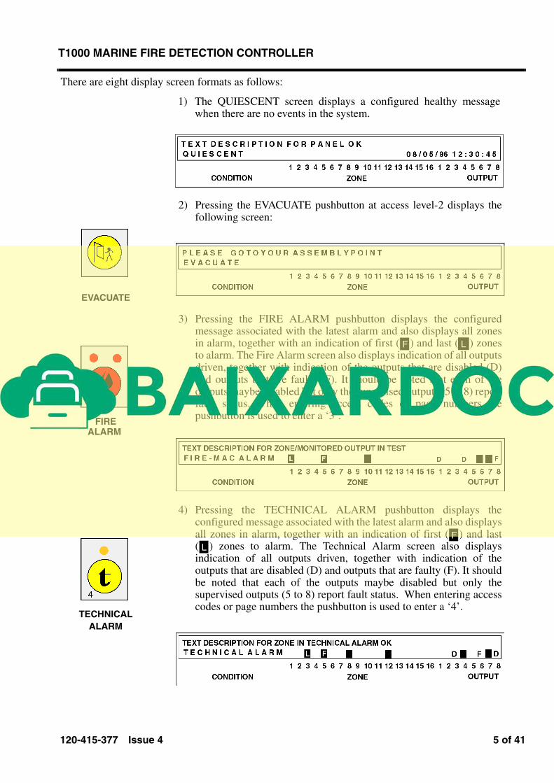
There are eight display screen formats as follows:
1) The QUIESCENT screen displays a configured healthy messagewhen there are no events in the system.
EVACUATE
FIRE
ALARM
TECHNICAL
ALARM
2) Pressing the EVACUATE pushbutton at access level-2 displays thefollowing screen:
3) Pressing the FIRE ALARM pushbutton displays the configuredmessage associated with the latest alarm and also displays all zonesin alarm, together with an indication of first ( ) and last ( ) zonesto alarm. The Fire Alarm screen also displays indication of all outputsdriven, together with indication of the outputs that are disabled (D)and outputs that are faulty (F). It should be noted that each of theoutputs maybe disabled but only the supervised outputs (5 to 8) reportfault status. When entering access codes or page numbers thepushbutton is used to enter a ‘3’.
4) Pressing the TECHNICAL ALARM pushbutton displays theconfigured message associated with the latest alarm and also displaysall zones in alarm, together with an indication of first ( ) and last( ) zones to alarm. The Technical Alarm screen also displaysindication of all outputs driven, together with indication of theoutputs that are disabled (D) and outputs that are faulty (F). It shouldbe noted that each of the outputs maybe disabled but only thesupervised outputs (5 to 8) report fault status. When entering accesscodes or page numbers the pushbutton is used to enter a ‘4’.
F L
F
L
6 of 41 120-415-377 Issue 4
T1000 MARINE FIRE DETECTION CONTROLLER
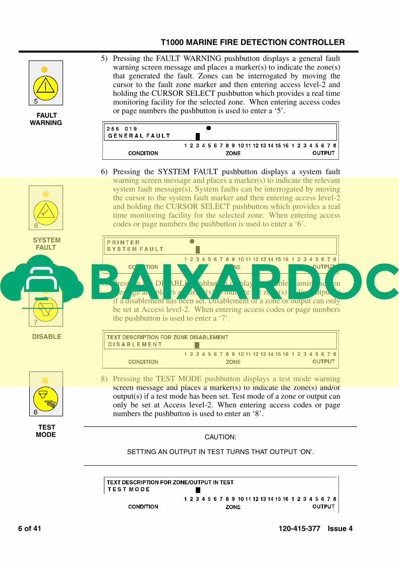
5) Pressing the FAULT WARNING pushbutton displays a general faultwarning screen message and places a marker(s) to indicate the zone(s)that generated the fault. Zones can be interrogated by moving thecursor to the fault zone marker and then entering access level-2 andholding the CURSOR SELECT pushbutton which provides a real timemonitoring facility for the selected zone. When entering access codesor page numbers the pushbutton is used to enter a ‘5’.
6) Pressing the SYSTEM FAULT pushbutton displays a system faultwarning screen message and places a marker(s) to indicate the relevantsystem fault message(s). System faults can be interrogated by movingthe cursor to the system fault marker and then entering access level-2and holding the CURSOR SELECT pushbutton which provides a realtime monitoring facility for the selected zone. When entering accesscodes or page numbers the pushbutton is used to enter a ‘6’.
7) Pressing the DISABLE pushbutton displays a disable warning screenmessage and places a marker(s) to indicate the zone(s) and/or output(s)if a disablement has been set. Disablement of a zone or output can onlybe set at Access level-2. When entering access codes or page numbersthe pushbutton is used to enter a ‘7’.
8) Pressing the TEST MODE pushbutton displays a test mode warningscreen message and places a marker(s) to indicate the zone(s) and/oroutput(s) if a test mode has been set. Test mode of a zone or output canonly be set at Access level-2. When entering access codes or pagenumbers the pushbutton is used to enter an ‘8’.
CAUTION:
SETTING AN OUTPUT IN TEST TURNS THAT OUTPUT ‘ON’.
FAULT
WARNING
SYSTEM
FAULT
DISABLE
TEST
MODE
120-415-377 Issue 4 7 of 41
T1000 MARINE FIRE DETECTION CONTROLLER
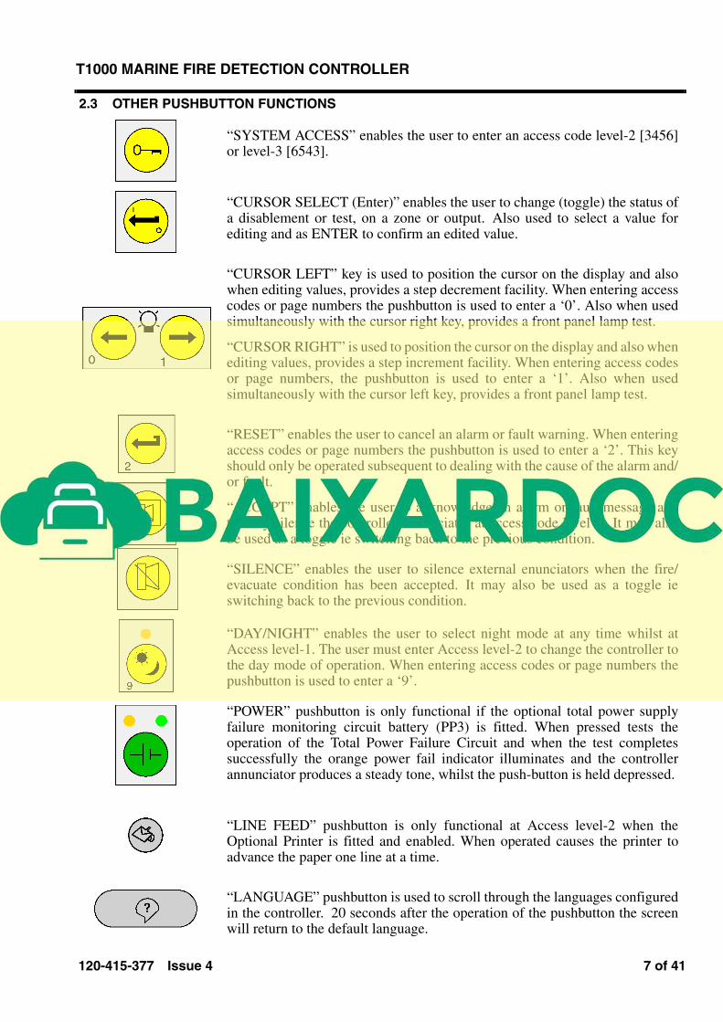
2.3 OTHER PUSHBUTTON FUNCTIONS
“SYSTEM ACCESS” enables the user to enter an access code level-2 [3456]or level-3 [6543].
“CURSOR SELECT (Enter)” enables the user to change (toggle) the status ofa disablement or test, on a zone or output. Also used to select a value forediting and as ENTER to confirm an edited value.
“CURSOR LEFT” key is used to position the cursor on the display and alsowhen editing values, provides a step decrement facility. When entering accesscodes or page numbers the pushbutton is used to enter a ‘0’. Also when usedsimultaneously with the cursor right key, provides a front panel lamp test.
“CURSOR RIGHT” is used to position the cursor on the display and also whenediting values, provides a step increment facility. When entering access codesor page numbers, the pushbutton is used to enter a ‘1’. Also when usedsimultaneously with the cursor left key, provides a front panel lamp test.
“RESET” enables the user to cancel an alarm or fault warning. When enteringaccess codes or page numbers the pushbutton is used to enter a ‘2’. This keyshould only be operated subsequent to dealing with the cause of the alarm and/or fault.
“ACCEPT” enables the user to acknowledge an alarm or fault message andthereby silence the controller annunciator at access code level 2. It may alsobe used as a toggle ie switching back to the previous condition.
“SILENCE” enables the user to silence external enunciators when the fire/evacuate condition has been accepted. It may also be used as a toggle ieswitching back to the previous condition.
“DAY/NIGHT” enables the user to select night mode at any time whilst atAccess level-1. The user must enter Access level-2 to change the controller tothe day mode of operation. When entering access codes or page numbers thepushbutton is used to enter a ‘9’.
“POWER” pushbutton is only functional if the optional total power supplyfailure monitoring circuit battery (PP3) is fitted. When pressed tests theoperation of the Total Power Failure Circuit and when the test completessuccessfully the orange power fail indicator illuminates and the controllerannunciator produces a steady tone, whilst the push-button is held depressed.
“LINE FEED” pushbutton is only functional at Access level-2 when theOptional Printer is fitted and enabled. When operated causes the printer toadvance the paper one line at a time.
“LANGUAGE” pushbutton is used to scroll through the languages configuredin the controller. 20 seconds after the operation of the pushbutton the screenwill return to the default language.
Related Documents