Copyright by FEM Section IX Available in German (D), English (E) and French (F) For references see end of document FEDERATION EUROPEENNE DE LA MANUTENTION Section IX SERIES LIFTING EQUIPMENT Rail dependent storage and retrieval systems – Interfaces FEM 9.841 /10.2.10 22 July 2010 Whole Group Index Page 1 Introduction and Aims ........................................................................... 2 2 Scope ........... Error! Bookmark not defined.Fehler! Textmarke nicht definiert. Error! Bookmark not defined. 3 Definitions .... Error! Bookmark not defined.Fehler! Textmarke nicht definiert. Error! Bookmark not defined. 4 Factors of Influence .............................................................................. 5 4.1 xxx ............... Error! Bookmark not defined.Fehler! Textmarke nicht definiert. Error! Bookmark not defined. 4.1.1 xxxError! Bookmark not defined.Fehler! Textmarke nic ht definiert. Error! Bookmark not defined. Annex ................................................................................................................... 4 Continued page ... to … Fédération Européenne de la Manutention (Section IX) Doc. no. N 072

Welcome message from author
This document is posted to help you gain knowledge. Please leave a comment to let me know what you think about it! Share it to your friends and learn new things together.
Transcript

Copyright by FEM Section IX Available in German (D), English (E) and French (F) For references see end of document
FEDERATION EUROPEENNE DE LA MANUTENTION Section IX
SERIES LIFTING EQUIPMENT
Rail dependent storage and retrieval systems – Interfaces
FEM 9.841 /10.2.10
22 July 2010
Whole Group
Index Page
1 Introduction and Aims ........................................................................... 2 2 Scope ........... Error! Bookmark not defined.Fehler! Textmarke nicht definiert.Error! Bookmark not defined. 3 Definitions .... Error! Bookmark not defined.Fehler! Textmarke nicht definiert.Error! Bookmark not defined. 4 Factors of Influence .............................................................................. 5 4.1 xxx ............... Error! Bookmark not defined.Fehler! Textmarke nicht definiert.Error! Bookmark not defined. 4.1.1 xxxError! Bookmark not defined.Fehler! Textmarke nicht definiert.Error! Bookmark not defined. Annex ................................................................................................................... 4
Continued page ... to …
Fédération Européenne de la Manutention (Section IX)
Doc. no. N 072
Page 2 FEM 9.841 / FEM 10.2.10 (07/2010)
1 Introduction and Aims
This document shall be a guideline for all persons which are involved in the system (e.g. customer, planner, construction, logistics). It informs about general properties, interfaces, behaviour under stress and time that may be relevant for the planning of material handling systems but it does not claim to be exhaustive. The persons or companies responsible for the total design of a warehouse has to consider a multiplic-ity of possibilities, limitations and requirements of the various combinations of elements. Each potential component has its specific behaviour, advantages / limitations and inter-component interfaces. It is important to know which end conditions and data to be specified are relevant. The intention is that the final system should: - be within budget ; - be within the time schedule agreed; - comply with rules and legislation; - show a logistic performance as originally intended. This is a complex process in which contractual responsibility for the building, building services and storage system may be split between a number of parties. It is an interactive process where end-user, designer of the warehouse and the designer of the storage system (system designer) are interfacing (see Flow Chart). The design of the storage system needs to consider the properties of the unit loads relevant for trans-port, conveying, storage and retrieval. This along with fire safety, special environmental conditions, specification of the warehouse-building, required capacity, throughput etc. will determine the choice of warehouse management system (WMS), conveyer, S/R machine and storage equipment. Once completed there will be test runs to demonstrate compliance. This code is intended to provide sufficient information on the issues involved in the design of the stor-age system so that timely decisions can be taken, thereby reducing the risk of conflicts during the process of realisation. The overall intention of this code is to help in removing uncertainties between the contracting parties and to add more detailed information to FEM 9.223. This FEM Code of Practice is prepared by a joint Working Group of the FEM Product Group Intralogis-tic Systems (IS) and the FEM Product Group Racking and Shelving (R&S).

Page 3 FEM 9.841 / FEM 10.2.10 (07/2010)
INFORMATION FLOW CHART DESIGN LOGISTIC WAREHOUSE (It shows a typical example, but responsibilities can change / be spread and it does not give contractual
relationships )
Wording has to be according to existing wording in other FEM documents or EN norms (e.g. FEM 9.831, EN 528)
End User / Client
Delete All FEM Doc
FEM 9.223
Page 4 FEM 9.841 / FEM 10.2.10 (07/2010)
2 Scope
This Code of Practice gives guidelines and background information about the specification of inter-faces between sub-systems of rail dependent storage & retrieval systems and is relevant for the func-tionality and safe operation of the system. For interfaces with regard to “tolerances, deformations and clearances” refer to EN 15620 / FEM 9.831 – Part 1 and FEM 9.832.
This Code of Practice specifies the position, obligations and responsibilities of parties in-volved.
3 Definitions
For terms and definitions of steel static storage systems in general: see EN 15878. Some which are important for this Code are repeated. Accidental action (EN 1990) action, usually of short duration but of significant magnitude, that is un likely to occur on a given struc-ture during the design working life. NOTE: In practical terms, a load case with an accidental action is analysed with a load factor of 1.0 and with the
possibility of residual deformations after unloading.
Accidental design situation (EN 1990) design situation involving exceptional conditions of the structure or its exposure, including fire, explo-sion, impact on local failure or an earth quake Accidental load is an example of an accidental action. Dynamic action (EN 1990) action that causes significant acceleration of the structure or structural members Load cycle / Loading event (EN 1993 -1-9) a defined loading sequence applied to the structure and giving rise to a stress history, which is nor-mally repeated a defined number of times in the life of the structure. Movement joint a structural joint in a concrete slab which allows the slab to shrink between two adjacent joints. Pick up and deposit (P&D) station structure in an operating aisle used as an interface between different types of mechanical handling equipment. Safety back stop component used to prevent unintentional unit load movement or accidental collision of a moving object with other unit loads or equipment when the unit load is placed or removed from its storage location. Serviceability limit state (SLS) state that correspond to conditions beyond which specified service requirements for a structure or structural member, such as beam deflection or horizontal sway deformation, are no longer met. Storage and retrieval machine (S/R Machine) machines, restricted to the rails on which they travel, handling unit loads for the storage and retrieval in rack systems.
Page 5 FEM 9.841 / FEM 10.2.10 (07/2010)
Planner (FEM 9.223) / System designer (SD) the person or institution responsible for the overall design and functionality of the system, this can be the logistic consultant or the general contractor or the client himself and shall be defined on a project by project basis. NOTE: For more information and responsibilities see FEM 9.223.
Quasi – rigid not fully rigid, but allowed to be considered as fully rigid Quasi - static action equivalent static action (force) in a static model, where inertia effects due to e.g. accelerating or turn-ing, effects caused by imperfections like tolerances and / or deformations of the running surface and such are accounted for by a multiplication factor βdyn NOTE: This definition differs from EN 1990. Ultimate limit state (ULS) state that is associated with collapse or with other similar forms of structural failure Unit load Individual item which can be placed or retrieved in one operation to or from its storage location , e.g. a pallet or a container with goods, tray or individual box, in a racking or shelving, system
4. Documents referred to
The following referenced documents are indispensible for the application of this document. For dated references only the edition cited applies. For undated references, the latest edition of the referenced document (including any amendments) applies.
EN 528 Rail dependent storage and retrieval equipment – Safety requirements. EN 1990 Eurocode – Basis of structural design EN 1090-2 Execution of steel structures and aluminium structures – Part 2: Technical
requirements for steel structures EN 1993-1-9 Design of steel structures – Fatigue strength of steel structures EN 15512 Steel static storage systems – Adjustable pallet racking – Principles for struc-
tural design. EN 15620 Steel static storage systems – Adjustable pallet racking – Tolerances, defor-
mations and clearances. EN 15635 Steel static storage systems – The application and maintenance of storage
equipment EN 15878 Steel static storage systems – Terms and definitions ETAG No 001 Guideline for European Technical Approval of Metal Anchors for Use in Con-
crete
Page 6 FEM 9.841 / FEM 10.2.10 (07/2010)
FEM 9.223 Basic data and criteria for the construction of automated high bay warehouses with distribution systems
FEM 9.831-1 Basis of calculations for storage and retrieval machines – Tolerances, deformations and clearances in the storage system – Part.1: General, Single
and Double deep pallet racking
FEM 9.832 Basis of calculations for storage and retrieval machines – Tolerances, defor-mation and clearances in automatic small parts warehouses (not silo design)
FEM 10.2.08 Recommendations for the design of static steel pallet racks under seismic
conditions 5. Concrete floor slab 5.1 General (1) The foundation on which the S/R machines are supported and which has to carry the concentrated loads from the storage equipment (racking), shall be sufficiently stiff and strong to ensure operational safety and structural safety of all components of the storage system. The foundation consists of:
- a subsoil, with improved load bearing properties as necessary ;
- piling, when necessary ;concrete floor slab. NOTE: In general a non-concrete floor structure will not be sufficiently stiff and strong.
(2) The structural behaviour of a concrete floor slab under load depends upon a number of factors:
- the support conditions ;
- the loading conditions (e.g. magnitude; uniformly distributed or concentrated; pattern loading; load duration);
- the reinforcement ;
- the possible presence of movement joints. (3) The floor slab may be considered to be quasi-rigid and the floor slab deflections may be neglected if it satisfies the requirements of FEM 9.831 Part 1 or FEM 9.832 (as appropriate). If the floor slab is not quasi-rigid then slab deflections must be taken into account as given in 5.3.6. NOTE 1: The deflection requirements specified in EN15620/FEM 9.831 Part 1 and FEM 9.832 are demanding.
Accurate prediction of the behaviour (deflection) of the concrete slab and of the supporting soil is difficult and inexact and the client should expect that higher cost will ensue if contractual guarantees are de-manded.
NOTE 2: It is important that a sufficient site/soil investigation is carried out in the planning stage of the project,
particularly if a high variation in soil properties might be expected.
5.2 Support conditions
(1) The support condition affects the deformation of the floor slab under load. The following two principle alternatives can be distinguished: a. Ground bearing: a floor slab directly supported by the sub soil.

Page 7 FEM 9.841 / FEM 10.2.10 (07/2010)
b. Suspended floor: a floor slab not directly and not continuously supported by the subsoil but supported by structural elements such as piles, beams, columns. (2) For type (a) slabs the geotechnical engineer and slab designer shall at least consider the following: - Uneven settlements due to possible inhomogeneous subsoil properties over the floor slab area. - The difference in settlements of the soil that is not loaded compared to the soil beneath the slab that is loaded (see Figure 1). - Spreading effect of concentrated rack loads due to the relative stiffness of the slab to sub soil. - The non-linear relationship of settlements with time.
Figure 1: Example of the deformation of a ground bearing floor slab, due to stiffening effects of the surrounding sub soil. (3) For type (b) slabs the geotechnical engineer and floor slab designer shall at least consider the follow-ing: - Uneven settlements of the piling or columns due to possible inhomogeneous sub soil properties over the pile positions. - Bending of the beams supporting the slab, if any. - Bending of the floor slab itself (see Figure 2).
Figure 2: In case of a suspended floor slab, the floor deformations might not be negligible. 5.3 Loading conditions
5.3.1 Rack loads, in house structure (1) The supplier of the rack structure shall specify to the system designer the rack loads on the floor slab in the serviceability limit state (SLS) as well as in the ultimate limit state (ULS) (at factored loads) ac-cording to EN 15512. The rack supplier shall indicate when these loads are still not final.
Page 8 FEM 9.841 / FEM 10.2.10 (07/2010)
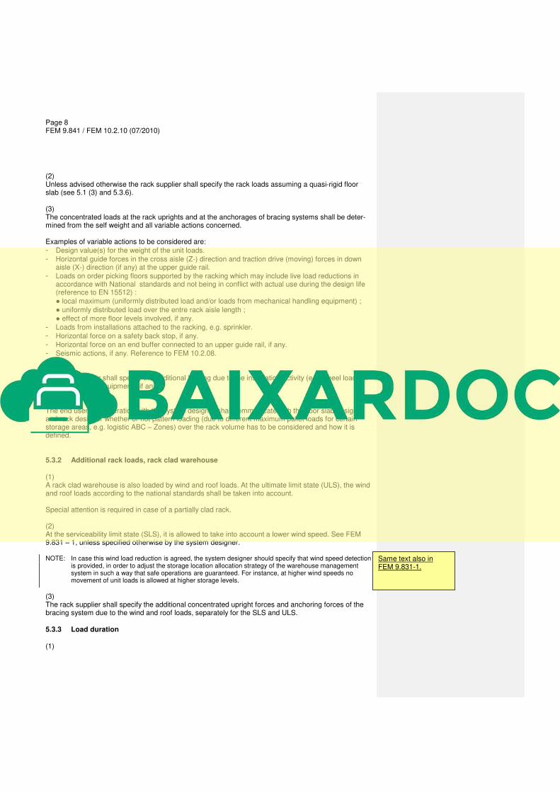
(2) Unless advised otherwise the rack supplier shall specify the rack loads assuming a quasi-rigid floor slab (see 5.1 (3) and 5.3.6). (3) The concentrated loads at the rack uprights and at the anchorages of bracing systems shall be deter-mined from the self weight and all variable actions concerned. Examples of variable actions to be considered are:
- Design value(s) for the weight of the unit loads.
- Horizontal guide forces in the cross aisle (Z-) direction and traction drive (moving) forces in down aisle (X-) direction (if any) at the upper guide rail.
- Loads on order picking floors supported by the racking which may include live load reductions in accordance with National standards and not being in conflict with actual use during the design life (reference to EN 15512) :
● local maximum (uniformly distributed load and/or loads from mechanical handling equipment) ;
● uniformly distributed load over the entre rack aisle length ;
● effect of more floor levels involved, if any.
- Loads from installations attached to the racking, e.g. sprinkler.
- Horizontal force on a safety back stop, if any.
- Horizontal force on an end buffer connected to an upper guide rail, if any.
- Seismic actions, if any. Reference to FEM 10.2.08. (4) The rack supplier shall specify the additional loading due to the installation activity (e.g. wheel loads of lorries or special equipment), if any. (5) The end user in cooperation with the system designer shall communicate with the floor slab designer and rack designer whether or not pattern loading (due to different maximum pallet loads for certain storage areas, e.g. logistic ABC – Zones) over the rack volume has to be considered and how it is defined. 5.3.2 Additional rack loads, rack clad warehouse (1) A rack clad warehouse is also loaded by wind and roof loads. At the ultimate limit state (ULS), the wind and roof loads according to the national standards shall be taken into account. Special attention is required in case of a partially clad rack. (2) At the serviceability limit state (SLS), it is allowed to take into account a lower wind speed. See FEM 9.831 – 1, unless specified otherwise by the system designer. NOTE: In case this wind load reduction is agreed, the system designer should specify that wind speed detection
is provided, in order to adjust the storage location allocation strategy of the warehouse management system in such a way that safe operations are guaranteed. For instance, at higher wind speeds no movement of unit loads is allowed at higher storage levels.
(3) The rack supplier shall specify the additional concentrated upright forces and anchoring forces of the bracing system due to the wind and roof loads, separately for the SLS and ULS. 5.3.3 Load duration (1)
Same text also in FEM 9.831-1.

Page 9 FEM 9.841 / FEM 10.2.10 (07/2010)
The deformations of the floor slab will increase with time, due to concrete creep and time related sub-soil and piling settlements. (2) If the floor slab does not satisfy the quasi-rigid criteria (see also 5.3.6), a differentiation in duration of the different loadings and possible pattern load cases might result in a more economical design. One might differentiate for instance between:
- short term loading (approximately 1 week to 1 month);
- medium term loading (approximately 1 month to 1 year);
- long term loading (longer than approximately 1 year). The end user in cooperation with the system designer shall communicate possible differentiations with the floor slab designer. Examples of short term loading: end buffer force, wind loads. Examples of medium term loading: certain pattern loading over the rack volume; maximum local load-ing on a rack supported floor in case not caused by stored goods but for instance by mechanical han-dling equipment (see 5.3.1); the SLS load case with reduced wind load. 5.3.4 Filling procedure of the rack
Depending on the specified pattern loading possibilities, it might be possible to limit the deformations especially of floor slabs of type (b), see 5.2, by specifying a filling procedure which takes into account the benefits of the bending behaviour of a continuous floor slab with multiple supports. In that case a specific agreement must be reached relating primarily to behaviour of the floor slab in the unloaded state and under increasing load conditions during the filling of the store (see 5.3.1 (4)). 5.3.5 Ground water pressure
Deflection due to ground water pressure shall be taken into account in the floor slab design. In case of an upward ground water pressure this pressure will in general not be constant with time. Design situations shall be specified with a possible differentiation with regard to short, medium and long term loading (see also 5.3.3), which is the responsibility of the geotechnical engineer. 5.3.6 Criteria for a quasi-rigid floor slab
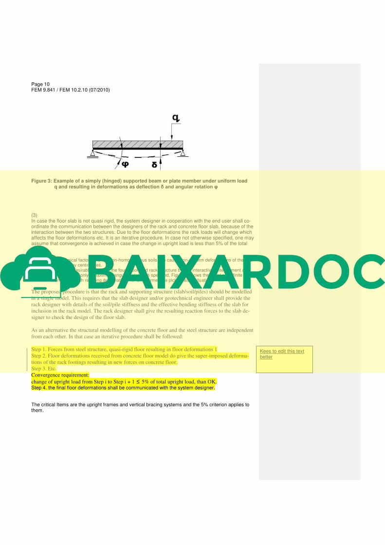
(1) The floor slab should be quasi- rigid (see FEM 9.831-1). In the exceptional case that the floor slab is not quasi- rigid, the floor slab designer shall give a “map” of lines with constant altitude or alternatively the thickness and stiffness of the concrete floor slab and the stiffness of the supporting medium. NOTE: Quasi-rigid criterion according to FEM 9.831 – Part 1 and FEM 9.832: φ ≤ 1 / 2000 and 1 / 3000 respectively (see Figure 3).
(2) Deformation of the floor slab under load (deflection, angular rotation. see Figures 1 to 3) will result in additional rack deformations (see Figure 2), and additional steel stresses in the rack. The deformations affect the clearances needed, to guarantee safe operations (see EN 15620 / FEM 9.831-Part 1 and FEM 9.832) and the additional stresses affect structural safety. Therefore the effects of floor deforma-tions shall be considered carefully by all parties involved.
Page 10 FEM 9.841 / FEM 10.2.10 (07/2010)
Figure 3: Example of a simply (hinged) supported beam or plate member under uniform load q and resulting in deformations as deflection δ and angular rotation φ (3) In case the floor slab is not quasi rigid, the system designer in cooperation with the end user shall co-ordinate the communication between the designers of the rack and concrete floor slab, because of the interaction between the two structures. Due to the floor deformations the rack loads will change which affects the floor deformations etc. It is an iterative procedure. In case not otherwise specified, one may assume that convergence is achieved in case the change in upright load is less than 5% of the total value. NOTE 1: Geotechnical factors and / or non-homogeneous soils can cause non-uniform deformations of the floor
slab of many centimetres. NOTE 2: It might be desirable to model the foundation and rack structure by one interactive finite element ap-
proach. When only a maximum angular rotation is specified, Figure 4 shows the worst case finite ele-ment model with resulting deformations for an intermediate picking aisle situation.
The proposed procedure is that the rack and supporting structure (slab/soil/piles) should be modelled
in a single model. This requires that the slab designer and/or geotechnical engineer shall provide the
rack designer with details of the soil/pile stiffness and the effective bending stiffness of the slab for
inclusion in the rack model. The rack designer shall give the resulting reaction forces to the slab de-
signer to check the design of the floor slab.
As an alternative the structural modelling of the concrete floor and the steel structure are independent
from each other. In that case an iterative procedure shall be followed:
Step 1. Forces from steel structure, quasi-rigid floor resulting in floor deformations 1
Step 2. Floor deformations received from concrete floor model do give the super-imposed deforma-
tions of the rack footings resulting in new forces on concrete floor.
Step 3. Etc.
Convergence requirement:
change of upright load from Step i to Step i + 1 ≤ 5% of total upright load, than OK. Step 4. the final floor deformations shall be communicated with the system designer. The critical Items are the upright frames and vertical bracing systems and the 5% criterion applies to them.
Kees to edit this text better
Related Documents