EXPERIMENT NO.1 OBJECT :-To study various types of kinematics links, pairs, chains & Mechanisms. APPARATUS USED: - Kinematics links, pairs, chains & Mechanisms. THEORY: – KINEMATIC LINK: – A mechanism is made of a number of resistant bodies out of which some may have motions relative to the others. A resistant body or a group of resistant bodies with rigid connections preventing their relative movement is known as a link. A link also known as kinematic link or element. Examples :- A slider-crank mechanism consists of four links: frame and guides, crank connecting rod and slider, the crank link may have crankshaft and flywheel also, forming one link having no relative motion of these. CLASSIFICATIONS OF LINKS:- 1. Rigid link- In this type of link there is no deformation while transmitting the motion. Motion between the piston and crank can be considered as a rigid link. 2. Flexible link- In this type of link there is partial deformation while transmitting the motion. Belt drive is an example of flexible link. 3. Fluid link- In this type of link the motion is transmitted with the help of fluid pressure. Hydraulic brake is an example of fluid link. Kinematic links are in form of :- 1. Singular 3. Ternary 2. Binary 4. Quaternary 1

Kom Lab Manuals Final(1)
Oct 31, 2015
Welcome message from author
This document is posted to help you gain knowledge. Please leave a comment to let me know what you think about it! Share it to your friends and learn new things together.
Transcript
E X P E R I M E N T N O . 1
OBJECT :-To study various types of kinematics links, pairs, chains & Mechanisms.
APPARATUS USED: - Kinematics links, pairs, chains & Mechanisms.
THEORY: –
KINEMATIC LINK: – A mechanism is made of a number of resistant bodies out of which some may have motions relative to the others. A resistant body or a group of resistant bodies with rigid connections preventing their relative movement is known as a link. A link also known as kinematic link or element.
Examples :- A slider-crank mechanism consists of four links: frame and guides, crank connecting rod and slider, the crank link may have crankshaft and flywheel also, forming one link having no relative motion of these.
CLASSIFICATIONS OF LINKS:-
1. Rigid link- In this type of link there is no deformation while transmitting the motion. Motion between the piston and crank can be considered as a rigid link.
2. Flexible link- In this type of link there is partial deformation while transmitting the motion. Belt drive is an example of flexible link.
3. Fluid link- In this type of link the motion is transmitted with the help of fluid pressure. Hydraulic brake is an example of fluid link.
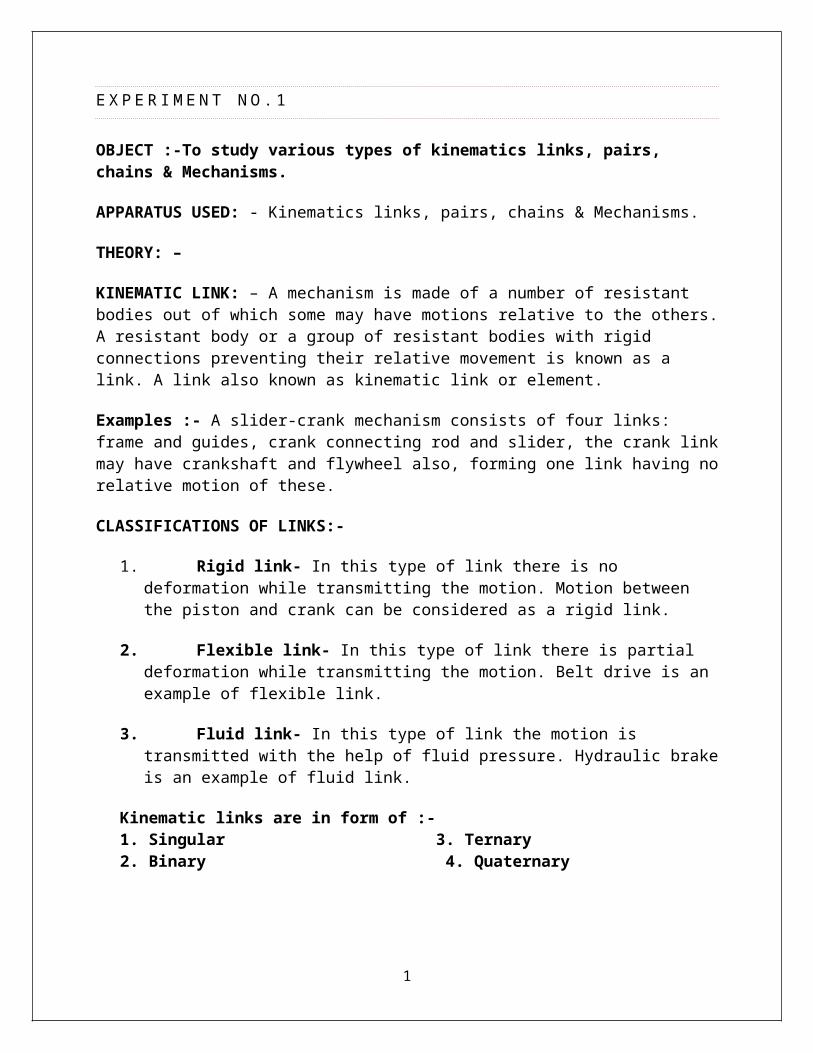
Kinematic links are in form of :-1. Singular 3. Ternary2. Binary 4. Quaternary
1
KINEMATIC PAIR: - A kinematic pair or simply a pair is a joint of two links having relative motion between them.
CLASSIFICATIONS OF PAIRS:
1-Kinematics pairs according to nature of contact:-
(i) Lower pair (links having surface or area contact)
Examples- Nut turning on a screw, shaft rotating in a bearing, universal joint etc.
(ii) Higher pair (Point or line contact between the links)
Examples:- when rolling on a surface, cam and follower pair, tooth gears, ball and roller bearings etc.
2- Kinematics pairs according to nature of Mechanical Constraint:-
(a) Closed pair (when the elements of a pair are held together mechanically)
Examples :- all the lower pairs and some of the higher pair
(b) Unclosed pair (when two links of a pair are in contact either due to force of gravity or some spring action), Example :- cam and follower pair.
3-Kinematics pairs according to nature of relative motion:-
(i) Sliding pair :- When the two elements of a pair are connected in such a way that one can only slide relative to the other , the pair is known as sliding pair.
(ii) Turning pair :-When the two elements of a pair are connected in such a way that one can only turn or revolve about a fixed axis of another link , the pair is known as turning pair.
(iii) Rolling Pair :-When the two elements of a pair are connected in such a way that one can only rolls over another fixed link , the pair is known as rolling pair.
(iv) Screw pair (Helical pair) :- When the two elements of a pair are connected in such a way that one can only turn about the other by screw threads , the pair is known as screw pair.
(v) Spherical pair :-When the two elements of a pair are connected in such a way that one can only turns or swivels about the fixed element , the pair is known as spherical pair.
KINEMATIC CHAIN :-A kinematic chain is an assembly of links in which the relative motions of the links is possible and the motion of each relative to the others is definite. If indefinite motions of other links , it is a non-kinematic chain.
2
Types of kinematics chains :-
(i) Four bar chain or quadric cycle chain :- It consists four link , each of them following a turning pair.
(ii) Single slider crank chain :- It’s the modification of simple four bar chain. It consist of one sliding pair and three turning pairs.
(iii) Double slider crank chain :- It consist of two sliding and two turning pairs.
Four bar chain or quadric chain Single slider crank chain
Double slider crank chain
MECHANISM:-A linkage is obtained if one of the links of a kinematics chain is fixed to the ground. If motion of each link results in definite motions of the others, the linkage is known as a mechanism. If one of the links of a redundant chain is fixed, it is known as a structure. The
3
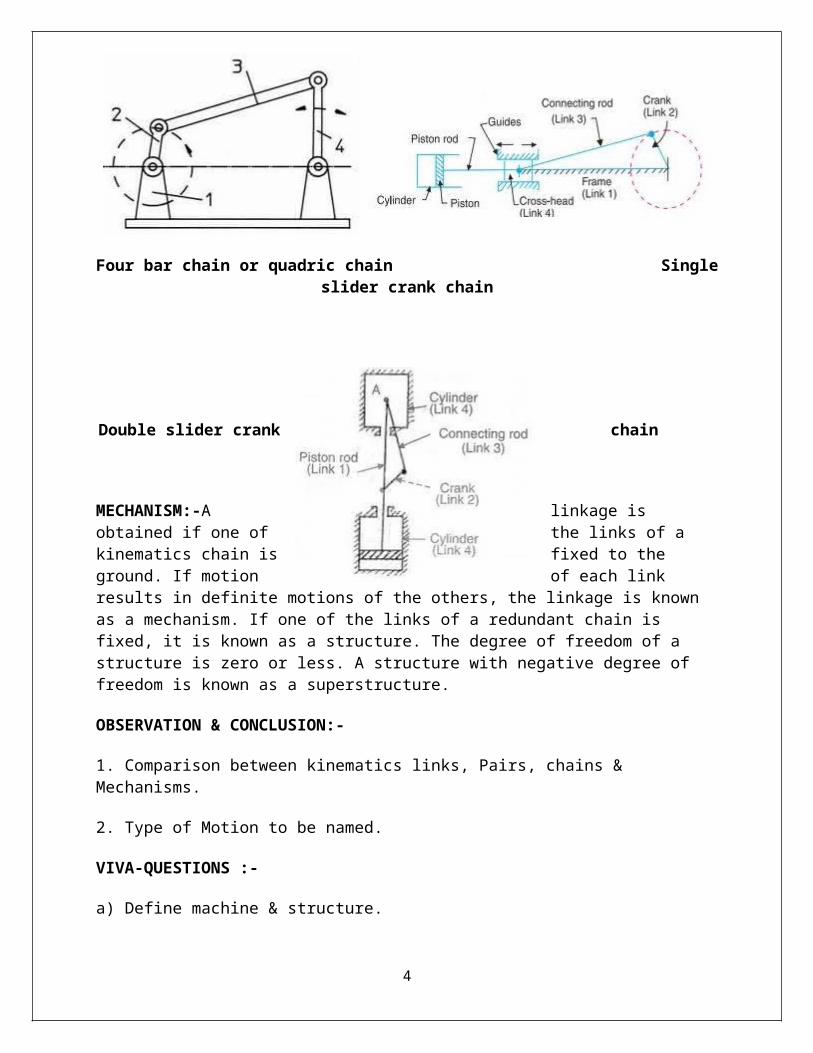
degree of freedom of a structure is zero or less. A structure with negative degree of freedom is known as a superstructure.
OBSERVATION & CONCLUSION:-
1. Comparison between kinematics links, Pairs, chains & Mechanisms.
2. Type of Motion to be named.
VIVA-QUESTIONS :-
a) Define machine & structure.
b) Concept of kinematics links, pairs, chains & mechanism.
c) Classification & examples of all the kinematics links, pairs, chains & mechanism.
d) Grashof’s criterion.
e) Types & examples of constrained motion.
4

E X P E R I M E N T N O . 2
OBJECT :-To study inversions of 4 Bar Mechanisms, Single & double slider crank mechanisms.
APPARATUS USED : – Models of 4 Bar Mechanisms, Single & double slider Crank mechanisms
THEORY: –
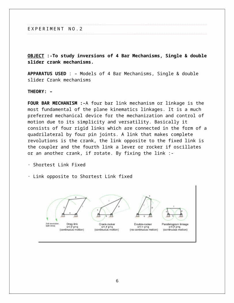
FOUR BAR MECHANISM :-A four bar link mechanism or linkage is the most fundamental of the plane kinematics linkages. It is a much preferred mechanical device for the mechanization and control of motion due to its simplicity and versatility. Basically it consists of four rigid links which are connected in the form of a quadrilateral by four pin joints. A link that makes complete revolutions is the crank, the link opposite to the fixed link is the coupler and the fourth link a lever or rocker if oscillates or an another crank, if rotate. By fixing the link :-
· Shortest Link Fixed
· Link opposite to Shortest Link fixed
5
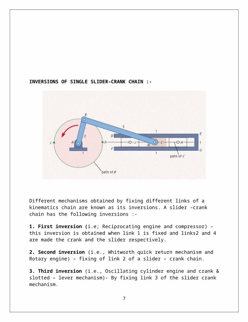
INVERSIONS OF SINGLE SLIDER–CRANK CHAIN :-
Different mechanisms obtained by fixing different links of a kinematics chain are known as its inversions. A slider –crank chain has the following inversions :-
1. First inversion (i.e; Reciprocating engine and compressor) – this inversion is obtained when link 1 is fixed and links2 and 4 are made the crank and the slider respectively.
2. Second inversion (i.e., Whitworth quick return mechanism and Rotary engine) – fixing of link 2 of a slider – crank chain.
3. Third inversion (i.e., Oscillating cylinder engine and crank & slotted – lever mechanism)- By fixing link 3 of the slider crank mechanism.
4. Fourth inversion (Hand pump) – if link 4 of the slider crank mechanism is fixed, the fourth inversion is obtained.
DOUBLE-SLIDER CRANK-CHAIN:
A four-bar chain having two turning and two sliding pairs such that two pairs of the same kind are adjacent is known as a double-slider-crank chain. The following are its inversions:
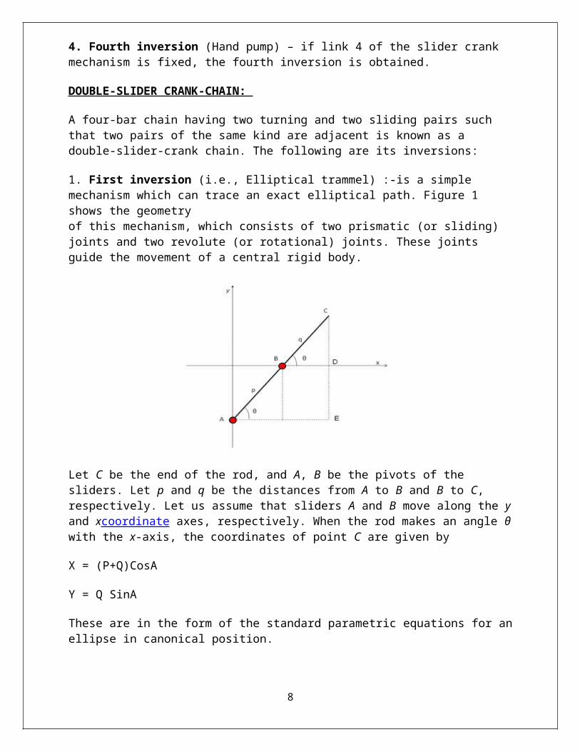
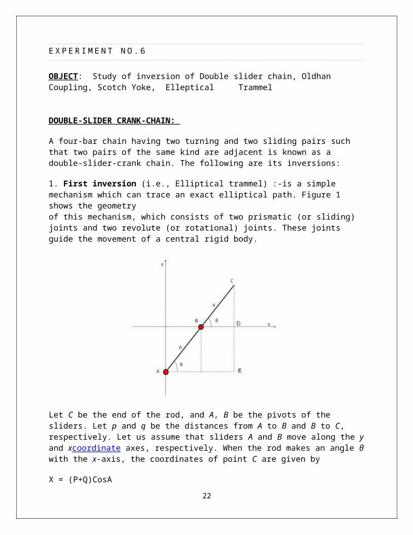
1. First inversion (i.e., Elliptical trammel) :-is a simple mechanism which can trace an exact elliptical path. Figure 1 shows the geometryof this mechanism, which consists of two prismatic (or sliding) joints and two revolute (or rotational) joints. These joints guide the movement of a central rigid body.
6
Let C be the end of the rod, and A, B be the pivots of the sliders. Let p and q be the distances from A to B and B to C, respectively. Let us assume that sliders A and B move along the y and xcoordinate axes, respectively. When the rod makes an angle θ with the x-axis, the coordinates of point C are given by
X = (P+Q)CosA
Y = Q SinA
These are in the form of the standard parametric equations for an ellipse in canonical position.
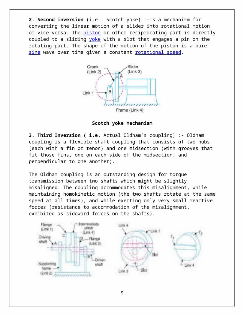
2. Second inversion (i.e., Scotch yoke) :-is a mechanism for converting the linear motion of a slider into rotational motion or vice-versa. The piston or other reciprocating part is directly coupled to a sliding yoke with a slot that engages a pin on the rotating part. The shape of the motion of the piston is a pure sine wave over time given a constant rotational speed.
Scotch yoke mechanism
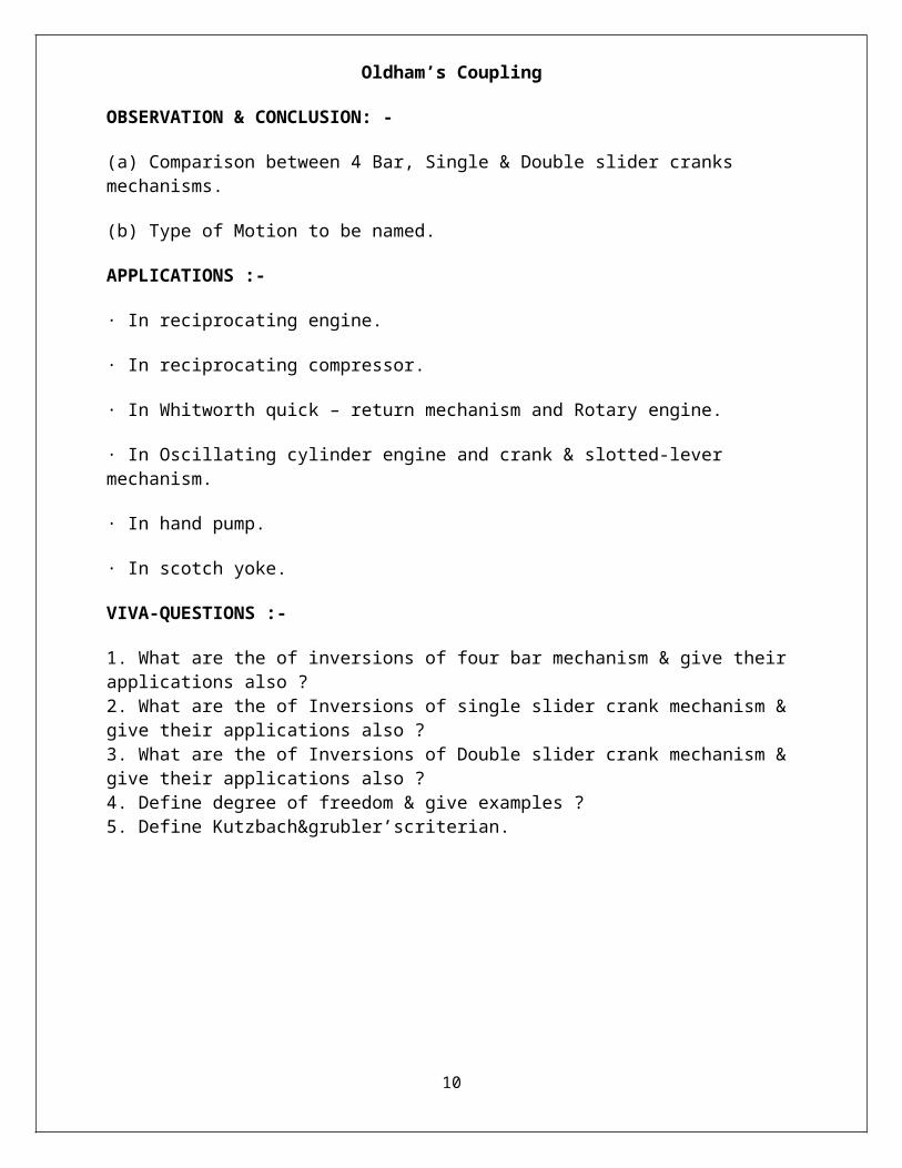
3. Third Inversion ( i.e. Actual Oldham’s coupling) :- Oldham coupling is a flexible shaft coupling that consists of two hubs (each with a fin or tenon) and one midsection (with grooves that fit those fins, one on each side of the midsection, and perpendicular to one another).
The Oldham coupling is an outstanding design for torque transmission between two shafts which might be slightly misaligned. The coupling accommodates this misalignment, while maintaining
7
homokinetic motion (the two shafts rotate at the same speed at all times), and while exerting only very small reactive forces (resistance to accommodation of the misalignment, exhibited as sideward forces on the shafts).
Oldham’s Coupling
OBSERVATION & CONCLUSION: -
(a) Comparison between 4 Bar, Single & Double slider cranks mechanisms.
(b) Type of Motion to be named.
APPLICATIONS :-
· In reciprocating engine.
· In reciprocating compressor.
· In Whitworth quick – return mechanism and Rotary engine.
· In Oscillating cylinder engine and crank & slotted-lever mechanism.
· In hand pump.
· In scotch yoke.
VIVA-QUESTIONS :-
1. What are the of inversions of four bar mechanism & give their applications also ?2. What are the of Inversions of single slider crank mechanism & give their applications also ?3. What are the of Inversions of Double slider crank mechanism & give their applications also ?4. Define degree of freedom & give examples ?5. Define Kutzbach&grubler’scriterian.
8
E X P E R I M E N T N O . 3
OBJECT : - To study various types of steering mechanisms.
APPARATUS USED: -. Steering Mechanism Apparatus.
THEORY: - 1. Definition of. Steering mechanisms2. Classification of steering mechanisms3. Diagrams of different types of steering mechanisms4. Working & Construction of different types of steering . . .mechanisms.5. Advantages & Disadvantages of steering mechanisms6. Applications of steering mechanisms.7. Examples of steering mechanisms
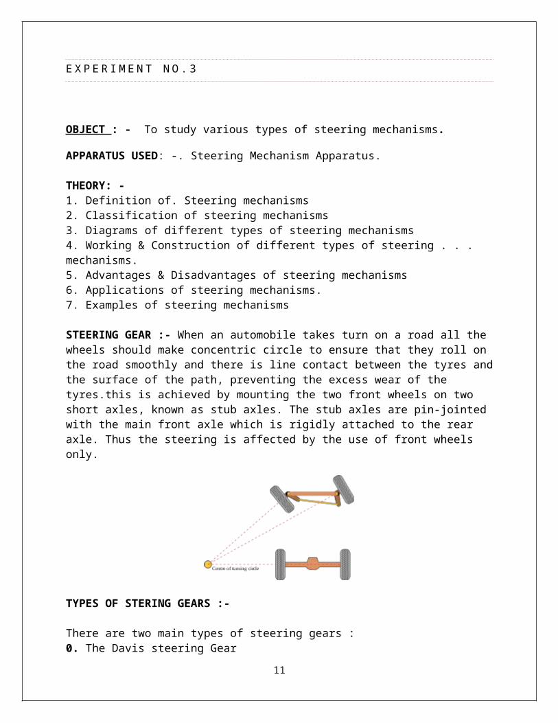
STEERING GEAR :- When an automobile takes turn on a road all the wheels should make concentric circle to ensure that they roll on the road smoothly and there is line contact between the tyres and the surface of the path, preventing the excess wear of the tyres.this is achieved by mounting the two front wheels on two short axles, known as stub axles. The stub axles are pin-jointed with the main front axle which is rigidly attached to the rear axle. Thus the steering is affected by the use of front wheels only.
TYPES OF STERING GEARS :-
There are two main types of steering gears :0. The Davis steering Gear0. The Ackermann steering gear
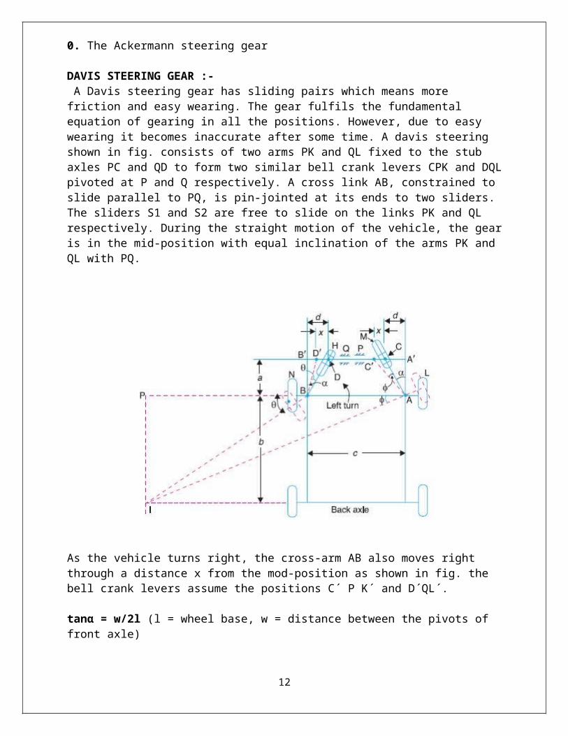
DAVIS STEERING GEAR :- A Davis steering gear has sliding pairs which means more friction and easy wearing. The gear fulfils the fundamental equation of gearing in all the positions. However, due to easy wearing it becomes inaccurate after some time. A davis steering shown in fig. consists of two arms PK and QL fixed to the stub axles PC and QD to form two similar bell crank levers CPK and DQL pivoted at P and Q respectively. A cross link AB, constrained to slide parallel to PQ, is pin-
9
jointed at its ends to two sliders. The sliders S1 and S2 are free to slide on the links PK and QL respectively. During the straight motion of the vehicle, the gear is in the mid-position with equal inclination of the arms PK and QL with PQ.
As the vehicle turns right, the cross-arm AB also moves right through a distance x from the mod-position as shown in fig. the bell crank levers assume the positions C´ P K´ and D´QL´.
tanα = w/2l (l = wheel base, w = distance between the pivots of front axle)usual value of w/l is between 0.4 to 0.5 and that of α from 11 to 14 degrees.
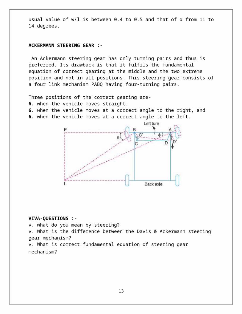
ACKERMANN STEERING GEAR :-
An Ackermann steering gear has only turning pairs and thus is preferred. Its drawback is that it fulfils the fundamental equation of correct gearing at the middle and the two extreme position and not in all positions. This steering gear consists of a four link mechanism PABQ having four-turning pairs.
Three positions of the correct gearing are-6. when the vehicle moves straight.6. when the vehicle moves at a correct angle to the right, and6. when the vehicle moves at a correct angle to the left.
10
VIVA-QUESTIONS :-v. what do you mean by steering?v. What is the difference between the Davis & Ackermann steering gear mechanism?v. What is correct fundamental equation of steering gear mechanism?
11
E X P E R I M E N T N O . 4
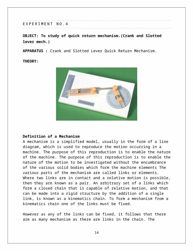
OBJECT: To study of quick return mechanism.(Crank and Slotted lever mech.)
APPARATUS : Crank and Slotted Lever Quick Return Mechanism.
THEORY:
Definition of a MechanismA mechanism is a simplified model, usually in the form of a line diagram, which is used to reproduce the motion occurring in a machine. The purpose of this reproduction is to enable the nature of the machine. The purpose of this reproduction is to enable the nature of the motion to be investigated without the encumbrance of the various solid bodies which form the machine elements The various parts of the mechanism are called links or elements. Where two links are in contact and a relative motion is possible, then they are known as a pair. An arbitrary set of a links which form a closed chain that is capable of relative motion, and that can be made into a rigid structure by the addition of a single link, is known as a kinematics chain. To form a mechanism from a kinematics chain one of the links must be fixed.
However as any of the links can be fixed, it follows that there are as many mechanism as there are links in the chain. The technique obtaining different mechanism by fixing the various links in turn is known as inversion.
Kinematics PairsThe relative motion between two links of a pair can take different form. Three types of a pairs are known as lower pairs and these are the frequently occurring ones:
Sliding : such as occurs between a piston and a cylinder
12
Turning : such as occurs with a wheel on an axleScrew motion : such as occurs between a nut and a boltAll other cases are considered to be combinations of sliding and rolling are called higher pairs. Strictly screw motion is a higher pair as it combines turning and sliding.
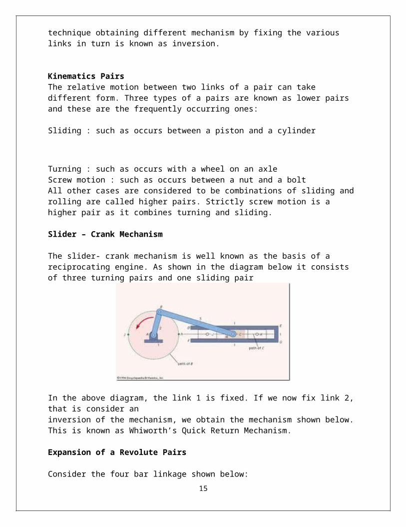
Slider – Crank Mechanism
The slider- crank mechanism is well known as the basis of a reciprocating engine. As shown in the diagram below it consists of three turning pairs and one sliding pair
In the above diagram, the link 1 is fixed. If we now fix link 2, that is consider aninversion of the mechanism, we obtain the mechanism shown below. This is known as Whiworth’s Quick Return Mechanism.
Expansion of a Revolute Pairs
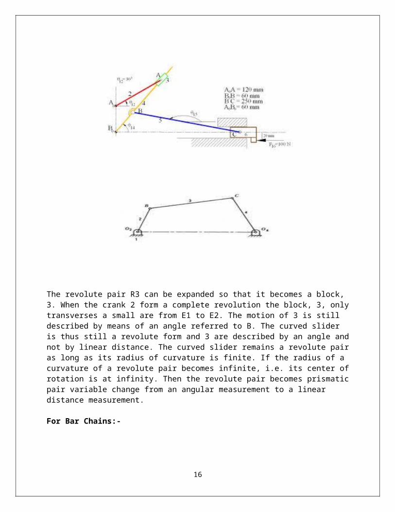
Consider the four bar linkage shown below:
13
The revolute pair R3 can be expanded so that it becomes a block, 3. When the crank 2 form a complete revolution the block, 3, only transverses a small are from E1 to E2. The motion of 3 is still described by means of an angle referred to B. The curved slider is thus still a revolute form and 3 are described by an angle and not by linear distance. The curved slider remains a revolute pair as long as its radius of curvature is finite. If the radius of a curvature of a revolute pair becomes infinite, i.e. its center of rotation is at infinity. Then the revolute pair becomes prismatic pair variable change from an angular measurement to a linear distance measurement.
For Bar Chains:-
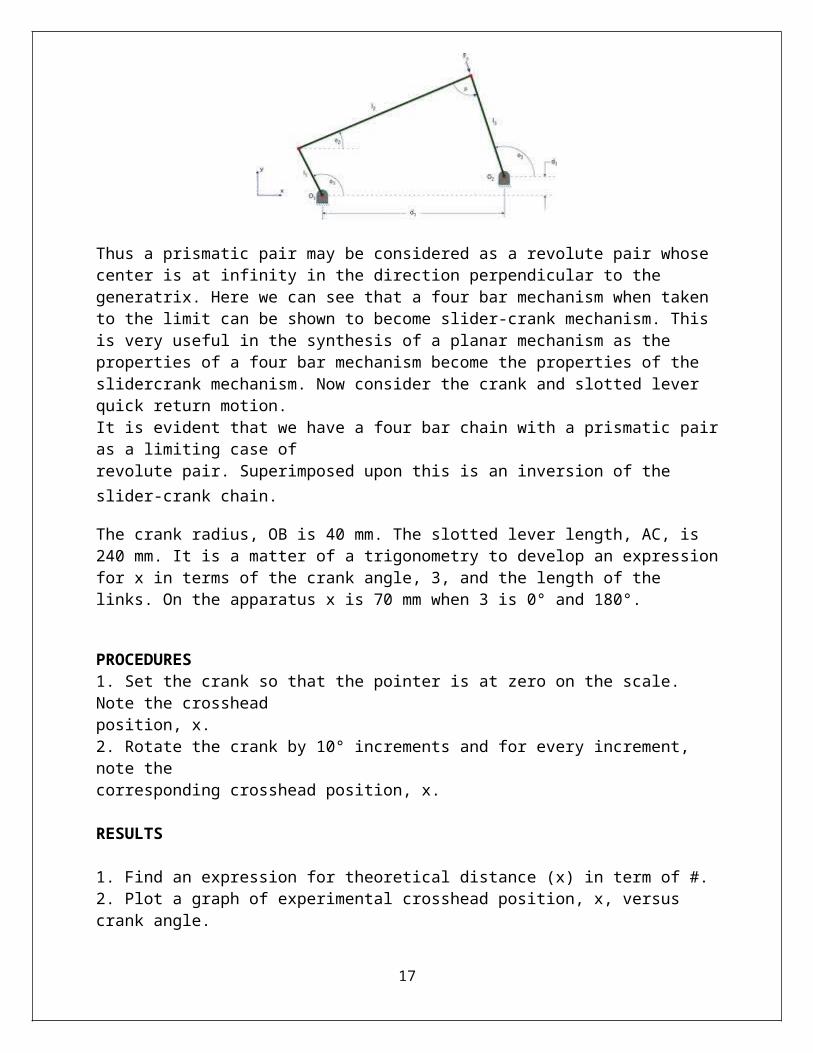
Thus a prismatic pair may be considered as a revolute pair whose center is at infinity in the direction perpendicular to the generatrix. Here we can see that a four bar mechanism when taken to the limit can be shown to become slider-crank mechanism. This is very useful in the synthesis of a planar mechanism as the properties of a four bar mechanism become the properties of the slidercrank mechanism. Now consider the crank and slotted lever quick return motion.It is evident that we have a four bar chain with a prismatic pair as a limiting case of revolute pair. Superimposed upon this is an inversion of the slider-crank chain.
The crank radius, OB is 40 mm. The slotted lever length, AC, is 240 mm. It is a matter of a trigonometry to develop an expression for x in terms of the crank angle, 3, and the length of the links. On the apparatus x is 70 mm when 3 is 0° and 180°.
PROCEDURES1. Set the crank so that the pointer is at zero on the scale. Note the crosshead
14
position, x.2. Rotate the crank by 10° increments and for every increment, note thecorresponding crosshead position, x.
RESULTS
1. Find an expression for theoretical distance (x) in term of #.2. Plot a graph of experimental crosshead position, x, versus crank angle.3. Plot on the same graph, a graph of theoretical crosshead position versus crankangle.4. On both graphs, show the return and cutting stroke.5. Plot a graph of crosshead velocity versus crank angle. On the graph, show thereturn and cutting stroke.
DISCUSSION1. How well does the experimental result agree with the predictions from the theory?2. What rotation angle is required for the cutting and return strokes?3. Discuss the motion of the slider and verify that it is indeed a quick returnmechanism.4. What is the increase in efficiency (in term of the time required for each stroke inone revolution of crank) obtainable in the mechanism?
15
E X P E R I M E N T N O . 5
AIM: - To plot slider displacement, velocity & acceleration against crank rotation for Single slider crank Mechanisms.
APPARATUS USED:- Single slider crank mechanism.
THEORY:-
1. Definition of Single slider cranks mechanism.2. Working of Single slider crank mechanism.
A slider crank mechanism converts the reciprocating motion of a slider into a roatary motion of crank or vice-versa.Velocity :- Fig. shows a slider –crank mechanism in which OA is the crank moving with uniform angular velocity in the clockwise direction. At point B, a slider moves on the fixed guide G. AB is the coupler joining A and B. it is required to find the velocity of the slider at B.Velocity vector equation :Velocity of B rel. to O = Vel. of B rel. to A + Vel. of A rel. to OVbo = Vba + Vao Vbg = Vao + Vba gb = oa + abAccelration :- Acc. Of B rel. to O = Acc. Of B rel. to A + Acc. Of A rel. to Og1b1 = o1a1 + a1ba + bab1
PROCEDURE:-
a) Bring the wheel & the slider to the respective reference marks.b) For a given angle of rotation of the crank, note down the displacement of the slides. c) Plot a graph between slider displacement & the crank rotation.d) Assume that the crank is rotating with a uniform angular speed of one rad/sec.e) Convert the crank rotation angle into time & plot the slider displacement versus time. f) By graphical differentiation, determine the velocity time graph .g) By graphical differentiation twice, determine the acceleration time graph. h) Calculate the values of velocity & acceleration.
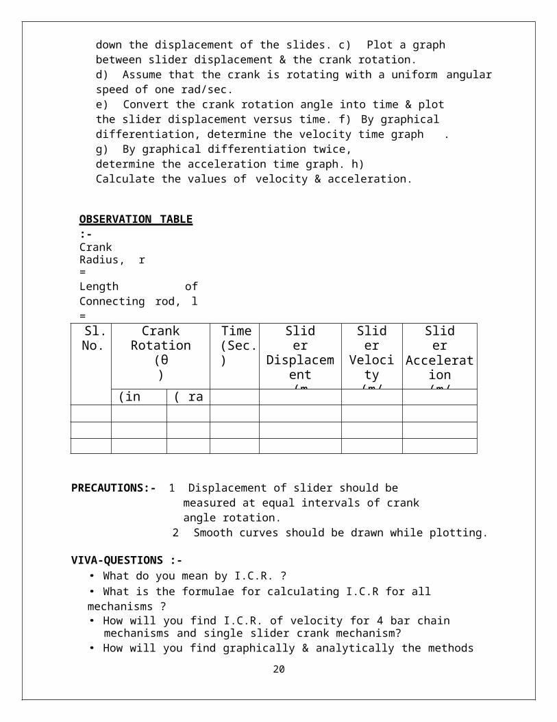
OBSERVATION TABLE :-Crank Radius,
16
r =Length of Connecting rod, l =Sl.No.
Crank Rotation(θ)
Time(Sec.)
SliderDisplacement
(m)
SliderVelocity(m/ Sec.)
SliderAcceleration
(m/ Sec2.)
(in deg.) ( rad )
PRECAUTIONS:- 1 Displacement of slider should be measured at equal intervals of crank angle rotation.
2 Smooth curves should be drawn while plotting.
VIVA-QUESTIONS :-• What do you mean by I.C.R. ?• What is the formulae for calculating I.C.R for all mechanisms ?• How will you find I.C.R. of velocity for 4 bar chain mechanisms and single slider
crank mechanism?• How will you find graphically & analytically the methods of velocity & acc. Analysis of
4-bar chain mechanism and single slider crank mechanism. ?
17
E X P E R I M E N T N O . 6
OBJECT: Study of inversion of Double slider chain, Oldhan Coupling, Scotch Yoke, Elleptical Trammel
DOUBLE-SLIDER CRANK-CHAIN:
A four-bar chain having two turning and two sliding pairs such that two pairs of the same kind are adjacent is known as a double-slider-crank chain. The following are its inversions:
1. First inversion (i.e., Elliptical trammel) :-is a simple mechanism which can trace an exact elliptical path. Figure 1 shows the geometryof this mechanism, which consists of two prismatic (or sliding) joints and two revolute (or rotational) joints. These joints guide the movement of a central rigid body.
Let C be the end of the rod, and A, B be the pivots of the sliders. Let p and q be the distances from A to B and B to C, respectively. Let us assume that sliders A and B move along the y and xcoordinate axes, respectively. When the rod makes an angle θ with the x-axis, the coordinates of point C are given by
X = (P+Q)CosA
Y = Q SinA
These are in the form of the standard parametric equations for an ellipse in canonical position.
2. Second inversion (i.e., Scotch yoke) :-is a mechanism for converting the linear motion of a slider into rotational motion or vice-versa. The piston or other reciprocating part is directly
18
coupled to a sliding yoke with a slot that engages a pin on the rotating part. The shape of the motion of the piston is a pure sine wave over time given a constant rotational speed.
Scotch yoke mechanism
3. Third Inversion ( i.e. Actual Oldham’s coupling) :- Oldham coupling is a flexible shaft coupling that consists of two hubs (each with a fin or tenon) and one midsection (with grooves that fit those fins, one on each side of the midsection, and perpendicular to one another).
The Oldham coupling is an outstanding design for torque transmission between two shafts which might be slightly misaligned. The coupling accommodates this misalignment, while maintaining homokinetic motion (the two shafts rotate at the same speed at all times), and while exerting only very small reactive forces (resistance to accommodation of the misalignment, exhibited as sideward forces on the shafts).
Oldham’s Coupling
OBSERVATION & CONCLUSION: -
(a) Comparison between 4 Bar, Single & Double slider cranks mechanisms.
(b) Type of Motion to be named.
APPLICATIONS :-
19
· In reciprocating engine.
· In reciprocating compressor.
· In Whitworth quick – return mechanism and Rotary engine.
· In Oscillating cylinder engine and crank & slotted-lever mechanism.
· In hand pump.
· In scotch yoke.
VIVA-QUESTIONS :-
1. What are the of inversions of four bar mechanism & give their applications also ?2. What are the of Inversions of single slider crank mechanism & give their applications also ?3. What are the of Inversions of Double slider crank mechanism & give their applications also ?4. Define degree of freedom & give examples ?5. Define Kutzbach&grubler’scriterian.
20

E X P E R I M E N T N O . 7
OBJECT: To plot displacement v/s θ curve for various cams
Theory:
Motion of cam follower
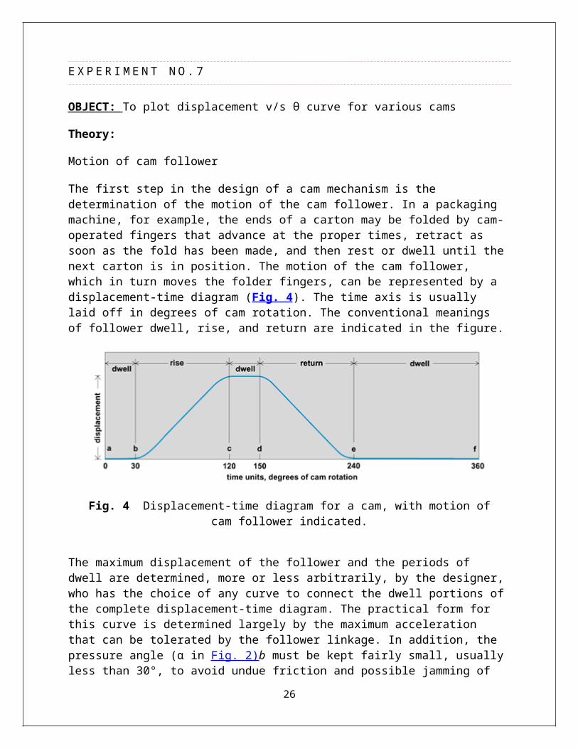
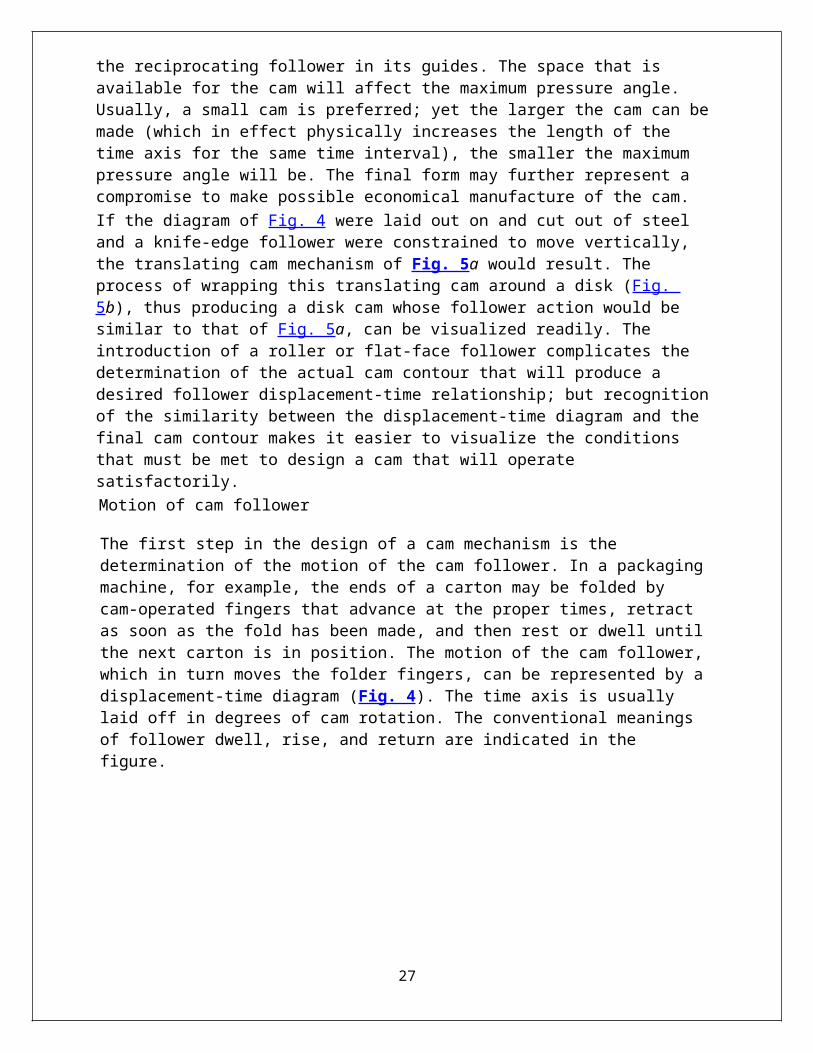
The first step in the design of a cam mechanism is the determination of the motion of the cam follower. In a packaging machine, for example, the ends of a carton may be folded by cam-operated fingers that advance at the proper times, retract as soon as the fold has been made, and then rest or dwell until the next carton is in position. The motion of the cam follower, which in turn moves the folder fingers, can be represented by a displacement-time diagram (Fig. 4). The time axis is usually laid off in degrees of cam rotation. The conventional meanings of follower dwell, rise, and return are indicated in the figure.
Fig. 4 Displacement-time diagram for a cam, with motion of cam follower indicated.
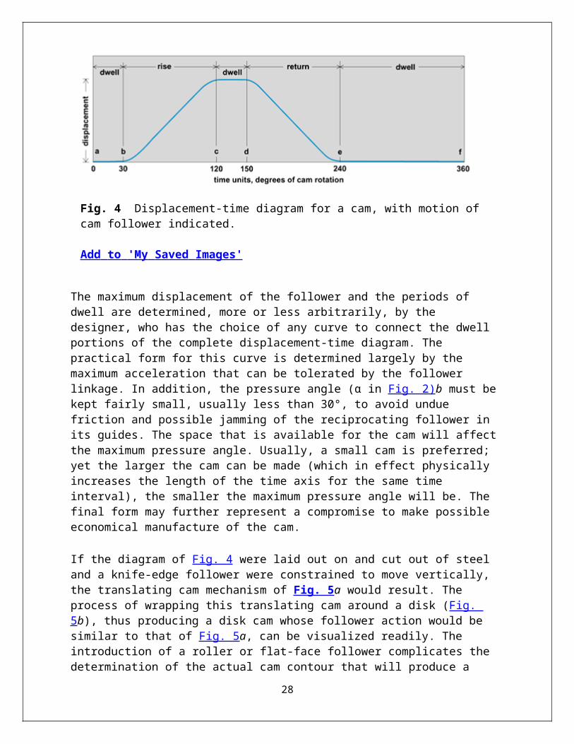
The maximum displacement of the follower and the periods of dwell are determined, more or less arbitrarily, by the designer, who has the choice of any curve to connect the dwell portions of the complete displacement-time diagram. The practical form for this curve is determined largely by the maximum acceleration that can be tolerated by the follower linkage. In addition, the pressure angle (α in Fig. 2)b must be kept fairly small, usually less than 30°, to avoid undue friction and possible jamming of the reciprocating follower in its guides. The space that is available for the cam will affect the maximum pressure angle. Usually, a small cam is preferred; yet the larger the cam can be made (which in effect physically increases the length of the time axis for the same time interval), the smaller the maximum pressure angle will be. The final form may further represent a compromise to make possible economical manufacture of the cam.If the diagram of Fig. 4 were laid out on and cut out of steel and a knife-edge follower were constrained to move vertically, the translating cam mechanism of Fig. 5a would result. The process of wrapping this translating cam around a disk (Fig. 5b), thus producing a disk cam whose follower action would be similar to that of Fig. 5a, can be visualized readily. The introduction of a roller or flat-face follower complicates the determination of the actual cam contour that will produce a desired follower displacement-time relationship; but recognition of
21
the similarity between the displacement-time diagram and the final cam contour makes it easier to visualize the conditions that must be met to design a cam that will operate satisfactorily.Motion of cam follower
The first step in the design of a cam mechanism is the determination of the motion of the cam follower. In a packaging machine, for example, the ends of a carton may be folded by cam-operated fingers that advance at the proper times, retract as soon as the fold has been made, and then rest or dwell until the next carton is in position. The motion of the cam follower, which in turn moves the folder fingers, can be represented by a displacement-time diagram (Fig. 4). The time axis is usually laid off in degrees of cam rotation. The conventional meanings of follower dwell, rise, and return are indicated in the figure.
Fig. 4 Displacement-time diagram for a cam, with motion of cam follower indicated.
Add to 'My Saved Images'
The maximum displacement of the follower and the periods of dwell are determined, more or less arbitrarily, by the designer, who has the choice of any curve to connect the dwell portions of the complete displacement-time diagram. The practical form for this curve is determined largely by the maximum acceleration that can be tolerated by the follower linkage. In addition, the pressure angle (α in Fig. 2)b must be kept fairly small, usually less than 30°, to avoid undue friction and possible jamming of the reciprocating follower in its guides. The space that is available for the cam will affect the maximum pressure angle. Usually, a small cam is preferred; yet the larger the cam can be made (which in effect physically increases the length of the time axis for the same time interval), the smaller the maximum pressure angle will be. The final form may further represent a compromise to make possible economical manufacture of the cam.If the diagram of Fig. 4 were laid out on and cut out of steel and a knife-edge follower were constrained to move vertically, the translating cam mechanism of Fig. 5a would result. The process of wrapping this translating cam around a disk (Fig. 5b), thus producing a disk cam whose follower action would be similar to that of Fig. 5a, can be visualized readily. The introduction of a roller or flat-face follower complicates the determination of the actual cam contour that will produce a desired follower displacement-time relationship; but recognition of the similarity between the displacement-time diagram and the final cam contour makes it easier to visualize the conditions that must be met to design a cam that will operate satisfactorily.
22
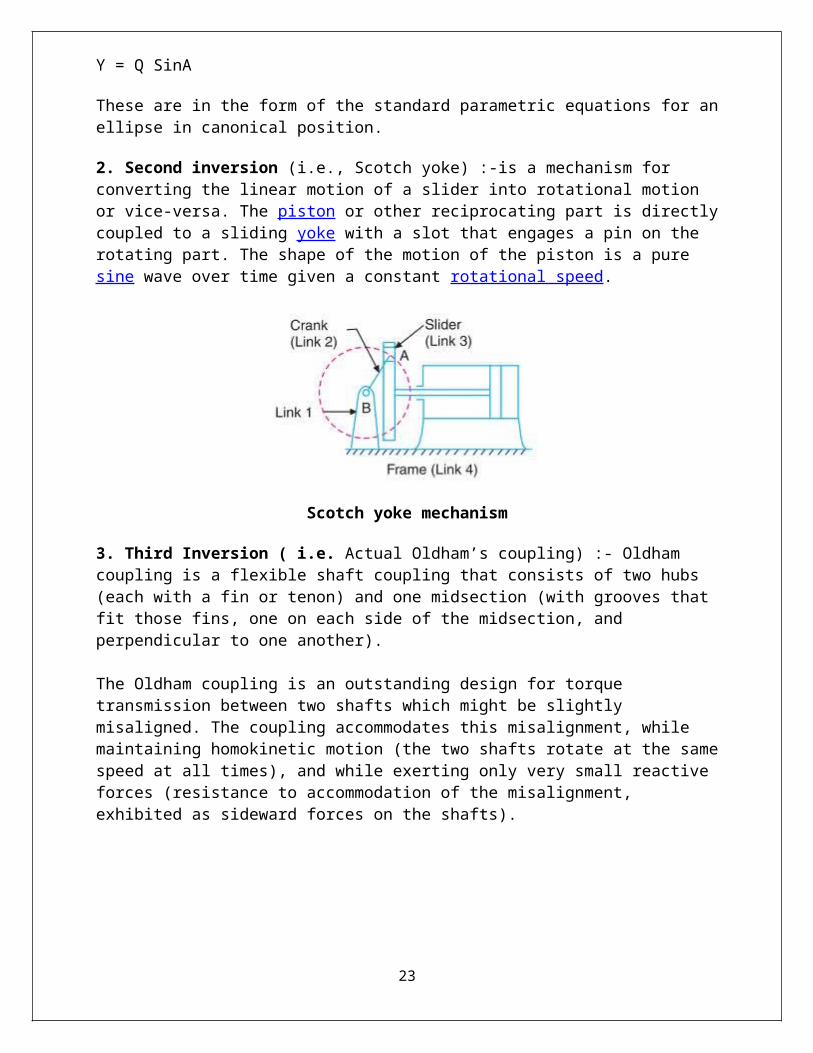
Fig. 5 Converting (a) translating cam to (b) disk cam.
Add to 'My Saved Images'
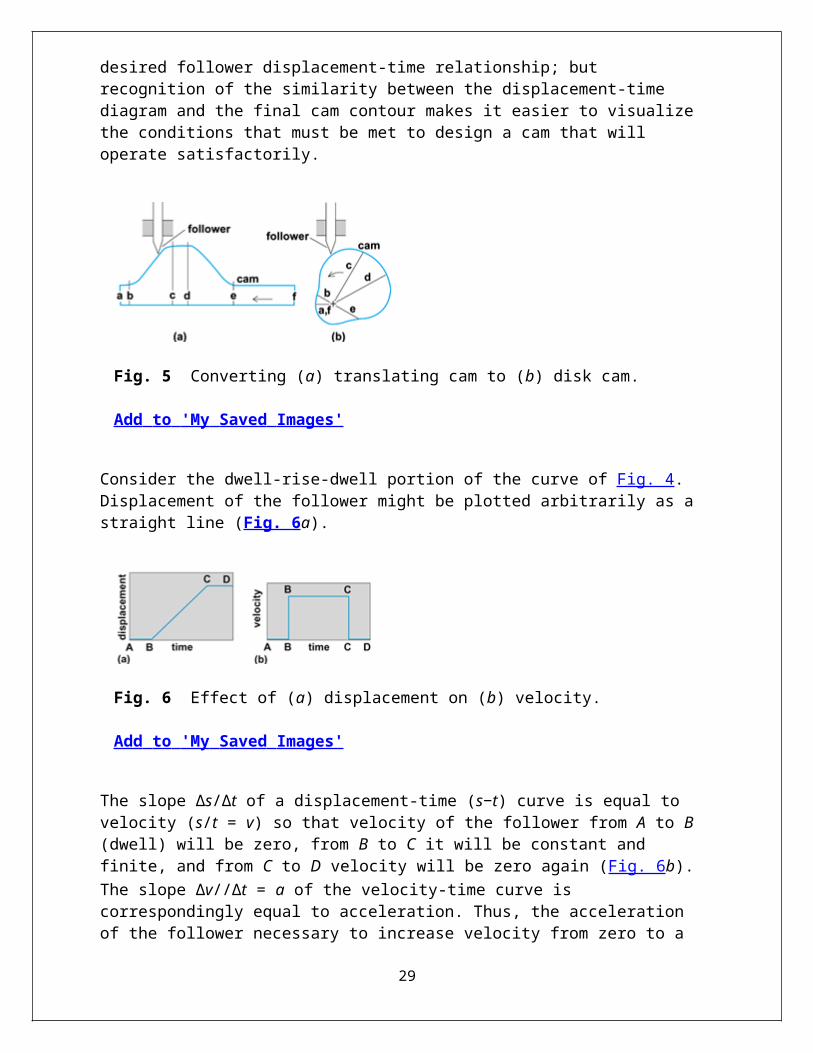
Consider the dwell-rise-dwell portion of the curve of Fig. 4. Displacement of the follower might be plotted arbitrarily as a straight line (Fig. 6a).
Fig. 6 Effect of (a) displacement on (b) velocity.
Add to 'My Saved Images'
The slope Δs/Δt of a displacement-time (s−t) curve is equal to velocity (s/t = v) so that velocity of the follower from A to B (dwell) will be zero, from B to C it will be constant and finite, and from C to D velocity will be zero again (Fig. 6b).The slope Δv//Δt = a of the velocity-time curve is correspondingly equal to acceleration. Thus, the acceleration of the follower necessary to increase velocity from zero to a finite value in zero time (B to B in Fig. 6b) is infinite. Likewise, the deceleration that occurs at C must also be infinite. The acceleration along the constant velocity line, from B to C, would be zero. Thus the curve chosen in Fig. 6a for displacement is unrealistic because of the high inertial forces that would result from abrupt changes of velocity.
Choice of acceleration curve
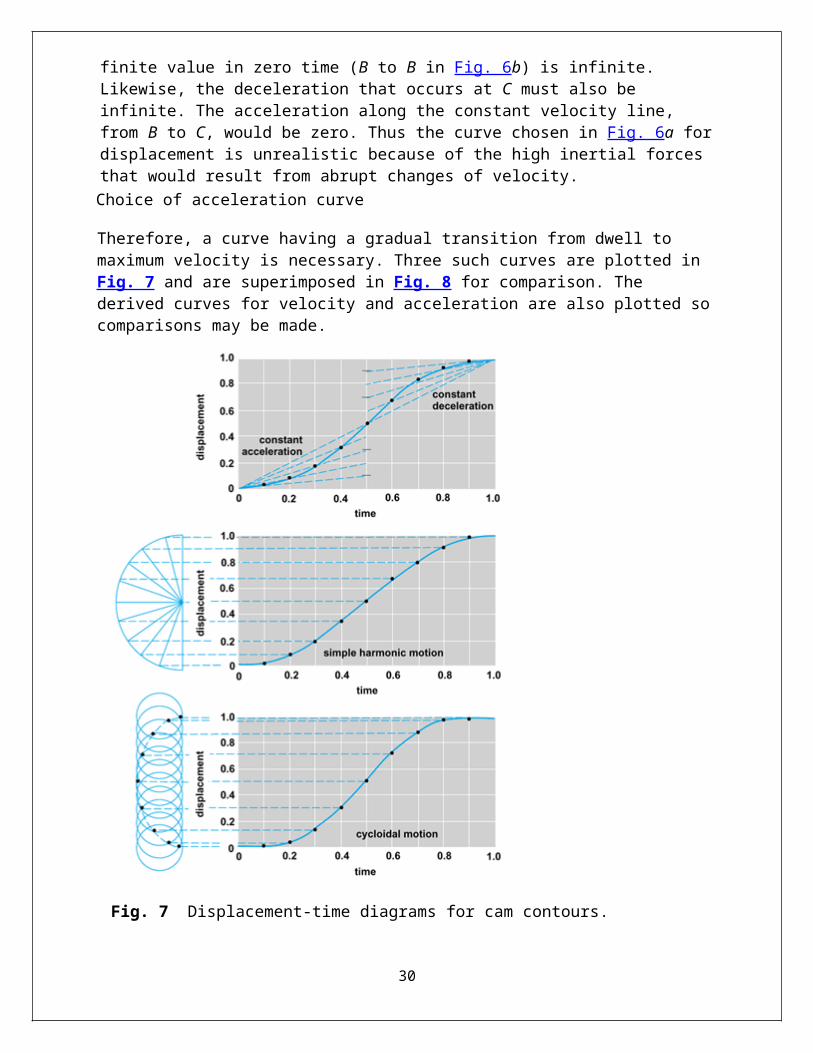
Therefore, a curve having a gradual transition from dwell to maximum velocity is necessary. Three such curves are plotted in Fig. 7 and are superimposed in Fig. 8 for comparison. The derived curves for velocity and acceleration are also plotted so comparisons may be made.
23
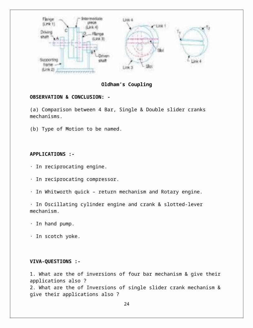
Fig. 7 Displacement-time diagrams for cam contours.
Add to 'My Saved Images'
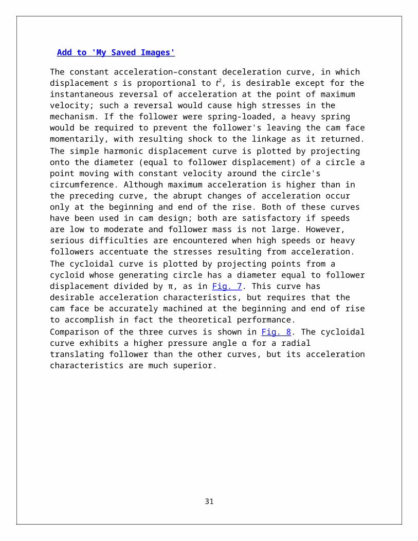
The constant acceleration–constant deceleration curve, in which displacement s is proportional to t2, is desirable except for the instantaneous reversal of acceleration at the point of maximum velocity; such a reversal would cause high stresses in the mechanism. If the follower were spring-loaded, a heavy spring would be required to prevent the follower's leaving the cam face momentarily, with resulting shock to the linkage as it returned.
The simple harmonic displacement curve is plotted by projecting onto the diameter (equal to follower displacement) of a circle a point moving with constant velocity around the circle's circumference. Although maximum acceleration is higher than in the preceding curve, the abrupt changes of acceleration occur only at the beginning and end of the rise. Both of these curves have been used in cam design; both are satisfactory if speeds are low to moderate and follower mass is not large. However, serious difficulties are encountered when high speeds or heavy followers accentuate the stresses resulting from acceleration.
24

The cycloidal curve is plotted by projecting points from a cycloid whose generating circle has a diameter equal to follower displacement divided by π, as in Fig. 7. This curve has desirable acceleration characteristics, but requires that the cam face be accurately machined at the beginning and end of rise to accomplish in fact the theoretical performance.
Comparison of the three curves is shown in Fig. 8. The cycloidal curve exhibits a higher pressure angle α for a radial translating follower than the other curves, but its acceleration characteristics are much superior.
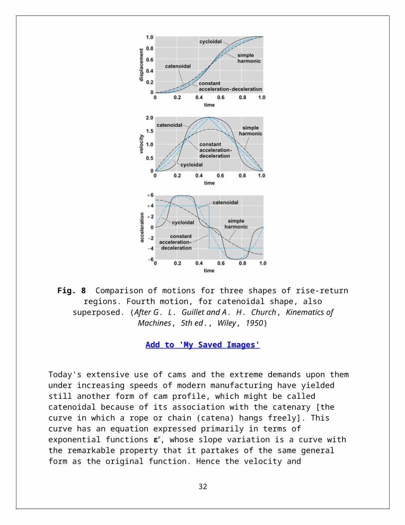
Fig. 8 Comparison of motions for three shapes of rise-return regions. Fourth motion, for catenoidal shape, also superposed. (After G. L. Guillet and A. H. Church, Kinematics of
Machines, 5th ed., Wiley, 1950)
Add to 'My Saved Images'
Today's extensive use of cams and the extreme demands upon them under increasing speeds of modern manufacturing have yielded still another form of cam profile, which might be called catenoidal because of its association with the catenary [the curve in which a rope or chain (catena) hangs freely]. This curve has an equation expressed primarily in terms of exponential
25
functions εx, whose slope variation is a curve with the remarkable property that it partakes of the same general form as the original function. Hence the velocity and acceleration curves show patterns similar to that of displacement rather than being so different, as was markedly so with the constant acceleration-deceleration profile, and less so with others. This curve (catenoidal) also is shown in the figures; it is alleged to give even smoother performance and less vibration than the cycloidal type. Its slope (jerk) will be zero four times in each cycle.The manufacture of cam and follower from a master model is dwindling in favor of manufacture using a computer tape, which accurately directs the cutting of the surface. This procedure avoids the expensive manufacture of master cams.In certain high-speed cam mechanisms, for example, an automotive engine valve gear, the elasticity and vibration characteristics of the follower linkage must be taken into account if faulty operation is to be avoided. The polydyne method derives its name from use of a polynomial displacement curve that suits the dynamic characteristics of the follower linkage.
VIVA-QUESTIONS:-
1. Define about Cams and Followers?2. Classification of Cam and Follower, advantages and disadvantages , application also?3. Define Disc Cam Nomenclature?4. Define the cut-off set position of follower motion?
26
E X P E R I M E N T N O . 8
OBJECT:- To study various types of cams and Followers arrangements.
APPARATUS USED:- Cams and Followers arrangements.
THEORY:- A cam and follower system is system/mechanism that uses a cam and follower to create a specific motion. The cam is in most cases merely a flat piece of metal that has had an unusual shape or profile machined onto it. This cam is attached to a shaft which enable it to be turned by applying a turning action to the shaft. As the cam rotates it is the profile or shape of the cam that causes the follower to move in a particular way. The movement of the follower is then transmitted to another mechanism or another part of the mechanism.
CLASSIFICATION OF CAMS AND FOLLOWERS:-
A) According to its motion:
1. The Radial - Translating Follower: In this the follower translates along a line passing through the axis of rotation of the cam.
2. The Offset – Translating Follower: In this the direction of translation of the follower is offset from the axis of rotation of the cam in the desired direction, depending on the direction of rotation of the cam.
3. The Oscillating Follower: In this the follower oscillates about a hinge point as the cam rotates.
B) According to the nature of contact:
1. The Knife-Edge follower: When contacting end of the follower has a sharp knife edge, it is called a knife edge follower. This cam follower mechanism is rarely used because of excessive wear due to small area of contact. In this follower a considerable thrust exists between the follower and guide.
2. The Flat-Face follower: When contacting end of the follower is perfectly flat faced, it is called a flat faced follower. The thrust at the bearing exerted is less as compared to other followers. The thrust can be further reduced by properly offsetting the follower from the axis of rotation of cam. These are commonly used in automobiles.
3. The Roller follower: When contacting end of the follower is a roller, it is called a roller follower. Wear rate is greatly reduced because of rolling motion between contacting surfaces. Roller followers are commonly used in large stationary gas or oil engines and aircraft engines.
27
4. The Spherical-Faced follower: When contacting end of the follower is of spherical shape, it is called a spherical faced follower. In flat faced followers high surface stress are produced to minimize these stresses the follower is machined to spherical shape.
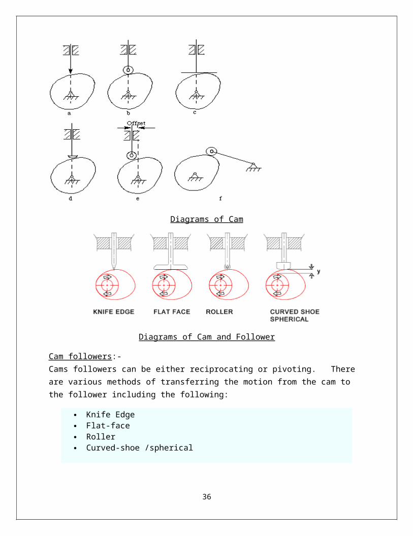
DIAGRAMS OF CAM AND FOLLOWER:-
Diagrams of Cam
Diagrams of Cam and Follower
Cam followers:- Cams followers can be either reciprocating or pivoting. There are various methods of transferring the motion from the cam to the follower including the following:
Knife Edge Flat-face Roller Curved-shoe /spherical
28
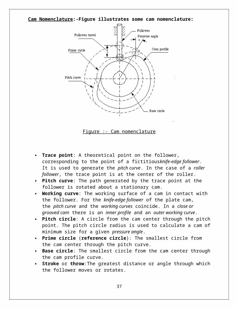
Cam Nomenclature:-Figure illustrates some cam nomenclature:
Figure :- Cam nomenclature
Trace point: A theoretical point on the follower, corresponding to the point of a fictitiousknife-edge follower. It is used to generate the pitch curve. In the case of a roller follower, the trace point is at the center of the roller.
Pitch curve: The path generated by the trace point at the follower is rotated about a stationary cam.
Working curve: The working surface of a cam in contact with the follower. For the knife-edge follower of the plate cam, the pitch curve and the working curves coincide. In a close or grooved cam there is an inner profile and an outer working curve.
Pitch circle: A circle from the cam center through the pitch point. The pitch circle radius is used to calculate a cam of minimum size for a given pressure angle.
Prime circle (reference circle): The smallest circle from the cam center through the pitch curve.
Base circle: The smallest circle from the cam center through the cam profile curve. Stroke or throw:The greatest distance or angle through which the follower moves or
rotates. Follower displacement: The position of the follower from a specific zero or rest position
(usually its the position when the f ollower contacts with the base circle of the cam) in relation to time or the rotary angle of the cam.
Pressure angle: The angle at any point between the normal to the pitch curve and the instantaneous direction of the follower motion. This angle is important in cam design because it represents the steepness of the cam profile.
WORKING AND CONSTRUCTION OF CAM AND FOLLOWER:-
29
Cam Mechanisms and Construction Principle :-
The transformation of one of the simple motions, such as rotation, into any other motions is often conveniently accomplished by means of a cam mechanism A cam mechanism usually consists of two moving elements, the cam and the follower, mounted on a fixed frame. Cam devices are versatile, and almost any arbitrarily-specified motion can be obtained. In some instances, they offer the simplest and most compact way to transform motions.
A cam may be defined as a machine element having a curved outline or a curved groove, which, by its oscillation or rotation motion, gives a predetermined specified motion to another element called the follower. The cam has a very important function in the operation of many classes of machines, especially those of the automatic type, such as printing presses, shoe machinery, textile machinery, gear-cutting machines, and screw machines. In any class of machinery in which automatic control and accurate timing are paramount, the cam is an indispensable part of mechanism. The possible applications of cams are unlimited, and their shapes occur in great variety. Some of the most common forms will be considered in this chapter.
CONSTRUCTION of CAMS:-
Design of Cam Systems :
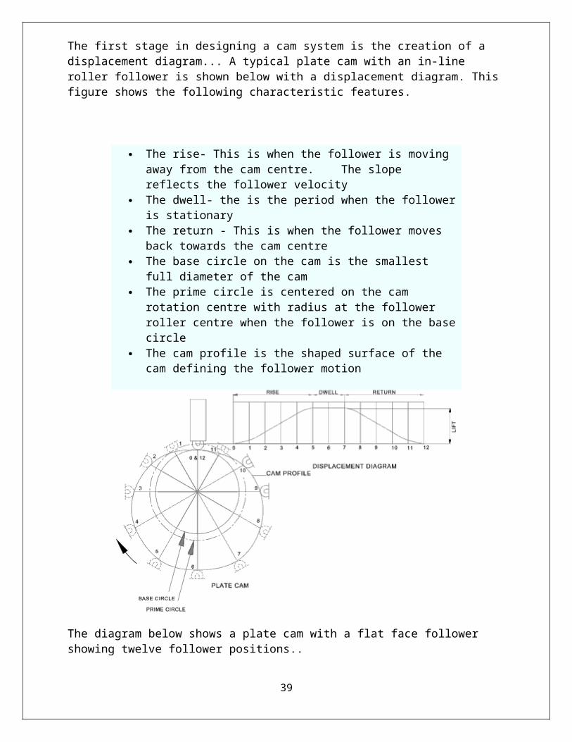
The first stage in designing a cam system is the creation of a displacement diagram... A typical plate cam with an in-line roller follower is shown below with a displacement diagram. This figure shows the following characteristic features.
30
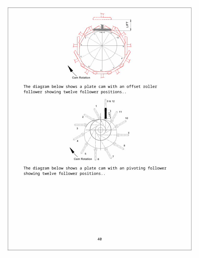
The diagram below shows a plate cam with a flat face follower showing twelve follower positions..
31
The rise- This is when the follower is moving away from the cam centre. The slope reflects the follower velocity
The dwell- the is the period when the follower is stationary The return - This is when the follower moves back towards the cam
centre The base circle on the cam is the smallest full diameter of the cam The prime circle is centered on the cam rotation centre with radius at
the follower roller centre when the follower is on the base circle The cam profile is the shaped surface of the cam defining the
follower motion
The diagram below shows a plate cam with an offset roller follower showing twelve follower positions..
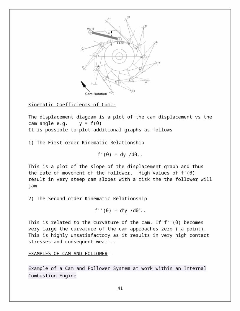
The diagram below shows a plate cam with an pivoting follower showing twelve follower positions..
Kinematic Coefficients of Cam :-
The displacement diagram is a plot of the cam displacement vs the cam angle e.g. y = f(θ)It is possible to plot additional graphs as follows
1) The First order Kinematic Relationship
f'(θ) = dy /dθ..
This is a plot of the slope of the displacement graph and thus the rate of movement of the follower. High values of f'(θ) result in very steep cam slopes with a risk the the follower will jam
32
2) The Second order Kinematic Relationship
f''(θ) = d2y /dθ2..
This is related to the curvature of the cam. If f''(θ) becomes very large the curvature of the cam approaches zero ( a point). This is highly unsatisfactory as it results in very high contact stresses and consequent wear...
EXAMPLES OF CAM AND FOLLOWER:-
Example of a Cam and Follower System at work within an Internal Combustion EngineHow the cam and follower system in an internal combustion engine work is shown in the animation of the four stroke cycle below.Animation of the Four Stroke CycleAnother Common Use of a Cam and Follower SystemAnother common use of a Cam and Follower system is within a pump, such as an oil pump. In such pumps the cam and follower system is used to suck oil in through one non-return valve and push it out through on other non-return valve. The suck action is achieved by the system because the follower is cylindrically shaped and moves within a tight fitting cylinder so oil is sucked in and pushed out as the follower moves up and down. This is similar to the gaseous mixtures being sucked into and forced out of the engine cylinder as the piston moved up and down in the previous example
OBSERVATION AND CONCLUSION:-
1.Comparison between Cams and Follower.
2.Types of motion to be named.
APPLICATIONS OF CAM AND FOLLOWER:-
RBC Roller Cam Followero RBC
o RBY Cam Followers
o S - Slotted Heado S--L - Slotted Head and Sealed
33
o S--LW - Hexlube - relubricatable hex head Crowned Cam Followers Standard Stud Series
o CS--L - Slotted Head and Sealedo CS--LW - Hexlube - relubricatable hex head
Cam-Centric Adjustable Cam Followerso S--LWX - Cylindrical Hexlube - relubricatable hex heado CS--LWX - Crowned Hexlube - relubricatable hex head
Cam Followers - Heavy Studo H - Slotted Heado H--L - Slotted Head and Sealedo H--LW - Hexlube - relubricatable hex head
Crowned Cam Followers - Heavy Studo CH--L - Slotted Head and Sealedo CH--LW - Hexlube - relubricatable hex head
Yoke Rollers - Cylindrical and Crowned O.D.o Y - Without Sealso Y--L - With Sealso CY--L - Sealed and Crowned O.D.
Pitchlign Caged Roller Followerso SRF - Without Sealso SRF--SS - With Seals
Precision Ground Inner Ringso IRo IR--Co IR--D
Mast Guide and Carriage Rollers Chain Sheaves Toothless Sprockets Airframe Needle Roller Bearings
o NBCo NBEo NBK
Airframe Track Rollerso NBFo NBL
VIVA-QUESTIONS:-
5. Define about Cams and Followers?6. Classification of Cam and Follower, advantages and disadvantages , application also?7. Define Disc Cam Nomenclature?8. Define the cut-off set position of follower motion?
34
35
E X P E R I M E N T N O . 9
Object :- To find coefficient of friction between belt and
pulley.
APPARATUS USED:- Belt & Pulley System.
THEORY:- 1. Definition of belt and pulley.2. Diagram of belt and pulley system.3. To prove the relation of belt tension for flat belt i.e.
T1/ T2 = ℮ µ θ
BELT :-
Power is transmitted from one to another by means of belts.• Belts are used where the distance between the shafts is large.• Belts are flexible type of connectors.• The flexibility of belts and ropes is due to the property of their materials.• Belts transmit power due to friction between them and the pulleys. If the
power transmitted exceeds the force of friction, the belt slips over the pulley.
• Belts are strained during motion as tensions are developed in them.• Owing to slipping and straining action, belts are not positive type of drives.
Types of belts :-
1. Flat belt2. V-belt
Material for belts :- Usual materials are leather, canvas, cotton and rubber.
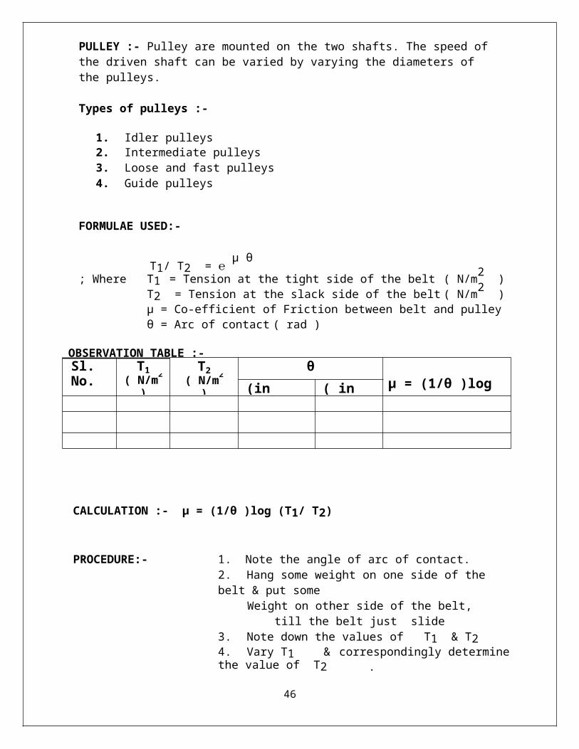
PULLEY :- Pulley are mounted on the two shafts. The speed of the driven shaft can be varied by varying the diameters of the pulleys.
Types of pulleys :-
1. Idler pulleys2. Intermediate pulleys3. Loose and fast pulleys4. Guide pulleys
FORMULAE USED:-
36
Sl. No. T1( N/m2 )
T2( N/m2 )
θµ = (1/θ )log (T1/ T2)(in degree) ( in rad. )
T1/ T2 = ℮ µ θ
; Where T1 = Tension at the tight side of the belt ( N/m2 )T2 = Tension at the slack side of the belt ( N/m2 )µ = Co-efficient of Friction between belt and pulleyθ = Arc of contact ( rad )
OBSERVATION TABLE :-
CALCULATION :- µ = (1/θ )log (T1/ T2)
PROCEDURE:- 1. Note the angle of arc of contact.2. Hang some weight on one side of the belt & put some
Weight on other side of the belt, till the belt just slide3. Note down the values of T1 & T24. Vary T1 & correspondingly determine the value of T2 .5. Now calculate the value of µ
PRECAUTION:- 1. Tapping of pulley should be done after increasing the weight.
2. Weight should be increased in small step.3. Add weights slowly without jerks.
RESULT:- µ (Co-efficient of Friction between belt and pulley ) =
VIVA-QUESTIONS :-
a. Define Belt, Classification of belt, advantage & disadvantage, Applications. b. What do you meant by slip & creep in belt drive ?c. What do you meant by crowning of pulley ?d. What do you meant by initial tension & centrifugal tension ?e. What is the formulae for the ratio of belt tensions in case of flat & V-belt drive
37
E X P E R I M E N T N O . 1 0
AIM:- To study various types of Dynamometers, Brakes and Clutches.
APPARATUS:- Brakes, Dynamometers, clutches.
THEORY:-
BRAKE:-A brake is a mechanical device which inhibits motion. Its opposite component is
a clutch. The rest of this article is dedicated to various types of vehicular brakes.
Most commonly brakes use friction to convert kinetic energy into heat, though other methods of
energy conversion may be employed. For example regenerative braking converts much of the
energy to electrical energy, which may be stored for later use. Other methods convert kinetic
energy intopotential energy in such stored forms as pressurized air or pressurized oil. Eddy
current brakes use magnetic fields to convert kinetic energy into electric current in the brake
disc, fin, or rail, which is converted into heat. Still other braking methods even transform kinetic
energy into different forms, for example by transferring the energy to a rotating flywheel. Brakes
are generally applied to rotating axles or wheels, but may also take other forms such as the
surface of a moving fluid (flaps deployed into water or air). Some vehicles use a combination of
braking mechanisms, such as drag racing cars with both wheel brakes and a parachute, or
airplanes with both wheel brakes and drag flaps raised into the air during landing.Since kinetic
energy increases quadratically with velocity ( ), an object moving at 10 m/s has
100 times as much energy as one of the same mass moving at 1 m/s, and consequently the
theoretical braking distance, when braking at the traction limit, is 100 times as long. In practice,
fast vehicles usually have significant air drag, and energy lost to air drag rises quickly with
speed.
DYNAMOMETERS:-
A dynamometer or "dyno" for short, is a device for
measuring force, moment of force (torque), or power. For example, the power produced by
an engine,motor or other rotating prime mover can be calculated by simultaneously
measuring torque and rotational speed (RPM).
A dynamometer can also be used to determine the torque and power required to operate a driven
machine such as a pump. In that case, a motoring or drivingdynamometer is used. A
dynamometer that is designed to be driven is called an absorption or passive dynamometer. A
dynamometer that can either drive or absorb is called a universal or active dynamometer.
38
In addition to being used to determine the torque or power characteristics of a machine under test
(MUT), dynamometers are employed in a number of other roles. In standard emissions testing
cycles such as those defined by the United States Environmental Protection Agency (US EPA),
dynamometers are used to provide simulated road loading of either the engine (using an engine
dynamometer) or full powertrain (using a chassis dynamometer). In fact, beyond simple power
and torque measurements, dynamometers can be used as part of a testbed for a variety of engine
development activities such as the calibration of engine management controllers, detailed
investigations into combustion behavior and tribology.
In the medical terminology, hand-held dynamometers are used for routine screening of grip
and hand strength and initial and ongoing evaluation of patients with hand trauma or
dysfunction. They are also used to measure grip strength in patients where compromise of the
cervical nerve roots or peripheral nerves is suspected.
CLUTCHES:-
A clutch is a mechanical device that provides for the transmission of power (and
therefore usually motion) from one component (the driving member) to another (the driven
member). The opposite component of the clutch is the brake.
Clutches are used whenever the ability to limit the transmission of power or motion needs to be
controlled either in amount or over time (e.g., electric screwdrivers limit how much torque is
transmitted through use of a clutch; clutches control whether automobiles transmit engine power
to the wheels).
In the simplest application, clutches are employed in devices which have two rotating shafts
(drive shaft or line shaft). In these devices, one shaft is typically attached to a motor or other
power unit (the driving member) while the other shaft (the driven member) provides output
power for work to be done.
In a drill for instance, one shaft is driven by a motor and the other drives a drill chuck. The clutch
connects the two shafts so that they may be locked together and spin at the same speed
(engaged), locked together but spinning at different speeds (slipping), or unlocked and spinning
at different speeds (disengaged).
CLASSIFICATION OF BRAKES:-
Types:
Brakes may be broadly described as using friction, pumping, or electromagnetics. One brake
may use several principles: for example, a pump may pass fluid through an orifice to create
friction:
39
Frictional brakes are most common and can be divided broadly into "shoe" or "pad" brakes,
using an explicit wear surface, and hydrodynamic brakes, such as parachutes, which use
friction in a working fluid and do not explicitly wear.Typically the term "friction brake" is
used to mean pad/shoe brakes and excludes hydrodynamic brakes, even though
hydrodynamic brakes use friction.
Friction (pad/shoe) brakes are often rotating devices with a stationary pad and a rotating
wear surface. Common configurations include shoes that contract to rub on the outside of a
rotating drum, such as a band brake; a rotating drum with shoes that expand to rub the inside
of a drum, commonly called a "drum brake", although other drum configurations are
possible; and pads that pinch a rotating disc, commonly called a "disc brake". Other brake
configurations are used, but less often. For example, PCC trolley brakes include a flat shoe
which is clamped to the rail with an electromagnet; the Murphy brake pinches a rotating
drum, and the Ausco Lambert disc brake uses a hollow disc (two parallel discs with a
structural bridge) with shoes that sit between the disc surfaces and expand laterally.
Pumping brakes are often used where a pump is already part of the machinery. For
example, an internal-combustion piston motor can have the fuel supply stopped, and then
internal pumping losses of the engine create some braking. Some engines use a valve
override called a Jake brake to greatly increase pumping losses. Pumping brakes can dump
energy as heat, or can be regenerative brakes that recharge a pressure reservoir called
a hydraulic accumulator.
Electromagnetic brakes are likewise often used where an electric motor is already part of
the machinery. For example, many hybrid gasoline/electric vehicles use the electric motor as
a generator to charge electric batteries and also as a regenerative brake. Some diesel/electric
railroad locomotives use the electric motors to generate electricity which is then sent to a
resistor bank and dumped as heat. Some vehicles, such as some transit buses, do not already
have an electric motor but use a secondary "retarder" brake that is effectively a generator
with an internal short-circuit. Related types of such a brake are eddy current brakes,
and electro-mechanical brakes (which actually are magnetically driven friction brakes, but
nowadays are often just called “electromagnetic brakes” as well).
CLASSIFICATION OF DYNAMOMETERS:- Types of dynamometers
In addition to classification as Absorption, Motoring or Universal as described above,
dynamometers can be classified in other ways.
A dyno that is coupled directly to an engine is known as an engine dyno.
40
A dyno that can measure torque and power delivered by the power train of a vehicle directly
from the drive wheel or wheels (without removing the engine from the frame of the vehicle), is
known as achassis dyno.
Dynamometers can also be classified by the type of absorption unit or absorber/driver that they
use. Some units that are capable of absorption only can be combined with a motor to construct an
absorber/driver or universal dynamometer. The following types of absorption/driver units have
been used:
Types of absorption/driver units
Eddy current or electromagnetic brake (absorption only)
Magnetic Powder brake (absorption only)
Hysteresis brake (absorption only)
Electric motor /generator (absorb or drive)
Fan brake (absorption only)
Hydraulic brake (absorption only)
Mechanical friction brake or Prony brake (absorption only)
Water brake (absorption only)
Compound dyno (usually an absorption dyno in tandem dyno)electric/motoring
with an Eddy current type absorber
EC dynamometers are currently the most common absorbers used in modern chassis dynos. The
EC absorbers provide the quick load change rate for rapid load settling. Most are air cooled, but
some are designed to require external water cooling systems.
Eddy current dynamometers require an electrically conductive core, shaft or disc, moving across
a magnetic field to produce resistance to movement. Iron is a common material, but copper,
aluminum and other conductive materials are usable.
In current (2009) applications, most EC brakes use cast iron discs, similar to vehicle disc brake
rotors, and use variable electromagnets to change the magnetic field strength to control the
amount of braking.
The electromagnet voltage is usually controlled by a computer, using changes in the magnetic
field to match the power output being applied.
Sophisticated EC systems allow steady state and controlled acceleration rate operation.
Powder dynamometer:-
41
A powder dynamometer is similar to an eddy current dynamometer, but a fine magnetic powder
is placed in the air gap between the rotor and the coil. The resulting flux lines create "chains" of
metal particulate that are constantly built and broken apart during rotation creating great torque.
Powder dynamometers are typically limited to lower RPM due to heat dissipation issues.
Hysteresis dynamometers:-
Hysteresis dynamometers, use a steel rotor that is moved through flux lines generated between
magnetic pole pieces. This design, as in the usual "disc type" eddy current absorbers, allows for
full torque to be produced at zero speed, as well as at full speed. Heat dissipation is assisted by
forced air. Hysteresis and "disc type" EC dynamometers are one of the most efficient
technologies in small (200 hp (150 kW) and less) dynamometers. A hysteresis brake is an eddy
current absorber that, unlike most "disc type" eddy current absorbers, puts the electromagnet
coils inside a vented and ribbed cylinder and rotates the cylinder, instead of rotating a disc
between electromagnets. The potential benefit for the hysteresis absorber is that the diameter can
be decreased and operating RPM of the absorber may be increased.
Electric motor/generator dynamometer:-
Electric motor/generator dynamometers are a specialized type of adjustable-speed drives. The
absorption/driver unit can be either an alternating current (AC) motor or a direct current (DC)
motor. Either an AC motor or a DC motor can operate as a generator that is driven by the unit
under test or a motor that drives the unit under test. When equipped with appropriate control
units, electric motor/generator dynamometers can be configured as universal dynamometers. The
control unit for an AC motor is a variable-frequency drive and the control unit for a DC motor is
a DC drive. In both cases, regenerative control units can transfer power from the unit under test
to the electric utility. Where permitted, the operator of the dynamometer can receive payment (or
credit) from the utility for the returned power via net metering.
In engine testing, universal dynamometers can not only absorb the power of the engine, but also
drive the engine for measuring friction, pumping losses and other factors.
Electric motor/generator dynamometers are generally more costly and complex than other types
of dynamometers.
Fan brake:-
A fan is used to blow air to provide engine load. The torque absorbed by a fan brake may be
adjusted by changing the gearing or the fan itself, or by restricting the airflow through the fan. It
should be noted that, due to the low viscosity of air, this variety of dynamometer is inherently
limited in the amount of torque that it can absorb.
42
Hydraulic brake:-
The hydraulic brake system consists of a hydraulic pump (usually a gear type pump), a fluid
reservoir and piping between the two parts. Inserted in the piping is an adjustable valve and
between the pump and the valve is a gauge or other means of measuring hydraulic pressure. In
simplest terms, the engine is brought up to the desired RPM and the valve is incrementally
closed and as the pump's outlet is restricted, the load increases and the throttle is simply opened
until at the desired throttle opening. Unlike most other systems, power is calculated by factoring
flow volume (calculated from pump design specs), hydraulic pressure and RPM. Brake HP,
whether figured with pressure, volume and RPM or with a different load cell type brake dyno,
should produce essentially identical power figures. Hydraulic dynos are renowned for having the
absolute quickest load change ability, just slightly surpassing the eddy current absorbers. The
downside is that they require large quantities of hot oil under high pressure and the requirement
for an oil reservoir.
Water brake type absorber:-
The water brake absorber is sometimes mistakenly called a "hydraulic dynamometer". Water
brake absorbers are relatively common, having been manufactured for many years and noted for
their high power capability, small package, light weight, and relatively low manufacturing cost
as compared to other, quicker reacting "power absorber" types.
Their drawbacks are that they can take a relatively long period of time to "stabilize" their load
amount and the fact that they require a constant supply of water to the "water brake housing" for
cooling. In many parts of the country, environmental regulations now prohibit "flow through"
water and large water tanks must be installed to prevent contaminated water from entering the
environment.
The schematic shows the most common type of water brake, the variable level type. Water is
added until the engine is held at a steady RPM against the load. Water is then kept at that level
and replaced by constant draining and refilling, which is needed to carry away the heat created
by absorbing the horsepower. The housing attempts to rotate in response to the torque produced
but is restrained by the scale or torque metering cell that measures the torque.
43

This schematic shows a water brake, which is actually a fluid coupling with a housing restrained
from rotating-similar to a water pump with no outlet.
Compound Dynamometers:-
In most cases, motoring dynamometers are symmetrical; a 300 kW AC dynamometer can absorb
300 kW as well as motor at 300 kW. This is an uncommon requirement in engine testing and
development. Sometimes, a more cost-effective solution is to attach a larger absorption
dynamometer with a smaller motoring dynamometer; alternatively, a larger absorption
dynamometer and a simple AC or DC motor may be used in a similar manner with the electric
motor only providing motoring power when required and no absorption. The (cheaper)
absorption dynamometer is sized for the maximum required absorption, whereas the motoring
dynamometer is sized for motoring. A typical size ratio for common emission test cycles and
most engine development is approximately 3:1. Torque measurement is somewhat complicated
since there are two machines in tandem; an inline torque transducer is the preferred method of
torque measurement in this case. An eddy-current or waterbrake dynamometer with electronic
control combined with a variable frequency drive and AC induction motor is a commonly used
configuration of this type. Disadvantages include requiring a second set of test cell services
(electrical power and cooling), and a slightly more complicated control system. Attention must
be paid to the transition between motoring and braking in terms of control stability.
CLASSIFICATION OF CLUTCHES:-
FRICTION CLUTCHES:- Friction clutches are by far the most well-known type of
clutches.MaterialsVarious materials have been used for the disc friction facings, including
asbestos in the past. Modern clutches typically use a compound organic resin with copper wire
facing or a ceramic material. A typical coefficient of friction used on a friction disc surface is
44
0.35 for organic and 0.25 for ceramic. Ceramic materials are typically used in heavy applications
such as trucks carrying large loads or racing, though the harder ceramic materials
increase flywheel and pressure plate wear.
Multiple plate clutch:-
This type of clutch has several driving members interleaved or "stacked" with several driven
members. It is used in race cars including F1, IndyCar, World Rally and even most club
racing, motorcycles,automatic transmissions and in some diesel locomotives with mechanical
transmissions. It is also used in some electronically controlled all-wheel drive systems.
Wet vs. dry:-
A wet clutch is immersed in a cooling lubricating fluid which also keeps the surfaces clean and
gives smoother performance and longer life. Wet clutches, however, tend to lose some energy to
the liquid. Since the surfaces of a wet clutch can be slippery (as with a motorcycle clutch bathed
in engine oil), stacking multiple clutch discs can compensate for the lower coefficient of
friction and so eliminate slippage under power when fully engaged.
The Hele-Shaw clutch was a wet clutch that relied entirely on viscous effects, rather than on
friction.
A dry clutch, as the name implies, is not bathed in fluid and should be, literally, dry.
Centrifugal clutch:-
A centrifugal clutch is used in some vehicles (e.g., Mopeds) and also in other applications where
the speed of the engine defines the state of the clutch, for example, in a chainsaw. This clutch
system employs centrifugal force to automatically engage the clutch when the engine rpm rises
above a threshold and to automatically disengage the clutch when the engine rpm falls low
enough. The system involves a clutch shoe or shoes attached to the driven shaft, rotating inside a
clutch bell attached to the output shaft. The shoe(s) are held inwards by springs
until centrifugal force overcomes the spring tension and the shoe(s) make contact with the bell,
driving the output. In the case of a chainsaw this allows the chain to remain stationary whilst the
engine is idling; once the throttle is pressed and the engine speed rises, the centrifugal clutch
engages and the cutting chain moves. See Saxomat and Variomatic.
Cone clutch:-
Distinguished by conical friction surfaces. The cone's taper means that a given amount of
movement of the actuator makes the surfaces approach (or recede) much more slowly than in a
disc clutch. As well, a given amount of actuating force created more pressure on the mating
surfaces. the advantage of cone clutch is that the normal force acting on contact surface is larger
than the axial force.
45
Torque limiter:-
Also known as a slip clutch or safety clutch, this device allows a rotating shaft to slip when
higher than normal resistance is encountered on a machine. An example of a safety clutch is the
one mounted on the driving shaft of a large grass mower. The clutch will yield if the blades hit a
rock, stump, or other immobile object. Motor-driven mechanical calculators had these between
the drive motor and gear train, to limit damage when the mechanism jammed, as motors used in
such calculators had high stall torque and were capable of causing damage to the mechanism if
torque wasn't limited.
BRAKE SHOE:-
A brake shoe is the part of a braking system which carries the brake lining in the drum brakes used on automobiles, or the brake block in train brakes andbicycle brakes.
DRUM BRAKE:-
A drum brake is a brake in which the friction is caused by a set of shoes or pads that press
against a rotating drum-shaped part called a brake drum.
The term "drum brake" usually means a brake in which shoes press on the inner surface of the
drum. When shoes press on the outside of the drum, it is usually called a clasp brake. Where the
drum is pinched between two shoes, similar to a conventional disk brake, it is sometimes called a
"pinch drum brake", although such brakes are relatively rare. A related type of brake uses a
flexible belt or "band" wrapping around the outside of a drum, called a band brakebrake.
46
CONSTRUCTION OF DRUM BRAKE:- Drum brake designs
Drum brakes are typically described as either leading/trailing or twin leading. Rear drum brakes
are typically of a leading/trailing design (for non-servo systems), or [Primary/Secondary] (for
duo servo systems) the shoes being moved by a single double-acting hydraulic cylinder and
hinged at the same point. In this design, one of the brake shoes will always experience the self-
applying effect, irrespective of whether the vehicle is moving forwards or backwards. This is
particularly useful on the rear brakes, where the parking brake (handbrake or footbrake) must
exert enough force to stop the vehicle from travelling backwards and hold it on a slope. Provided
the contact area of the brake shoes is large enough, which isn't always the case, the self-applying
effect can securely hold a vehicle when the weight is transferred to the rear brakes due to the
incline of a slope or the reverse direction of motion. A further advantage of using a single
hydraulic cylinder on the rear is that the opposite pivot may be made in the form of a double-
47
lobed cam that is rotated by the action of the parking brake system.Front drum brakes may be of
either design in practice, but the twin leading design is more effective This design uses two
actuating cylinders arranged so that both shoes will utilize the self-applying characteristic when
the vehicle is moving forwards. The brake shoes pivot at opposite points to each other The brake
drum itself is frequently made of cast iron, although some vehicles have used aluminum drums,
particularly for front-wheel applications. Aluminum conducts heat better than cast iron, which
improves heat dissipation and reduces fade. Aluminum drums are also lighter than iron drums,
which reduces unsprung weight. Because aluminum wears more easily than iron, aluminum
drums will frequently have an iron or steel liner on the inner surface of the drum, bonded or
riveted to the aluminum outer shell.
48
Related Documents