Page 1 Corp. 0801-L1 KGA, KGB SERIES Service Literature 2 to 7-1/2 ton 7 to 26 kW Revised 05-2016 KGA/KGB024 through 090 The KGA/KGB packaged gas units are available in stan- dard cooling efficiency (024, 030, 036, 048 060, 072, 074 and 090). Cooling capacities range from 2 to 7-1/2 tons (7 to 26kW). KGA/KGB024, 030, 036, 048, 060, 072, 074 units are available in 65,000 BTUH heat capacity. KGA/KGB036, 048, 060, 072, 074 and 090 units are available in 108,000 BTUH (105,000 BTUH in earlier built units ) heat capacity. KGA/KGB048, 060, 072, 074 and 090 units are available in 150,000 BTUH (44 kW) heat sizes. Two stage heat is available in units with 108,000 (105,000 in earlier built units) and 150,000 BTUH capac- ities. Gas heat sections are designed with aluminized steel tube heat exchangers. Information contained in this manual is intended for use by qualified service technicians only. All specifications are subject to change. Procedures outlined in this manual are presented as a recommendation only and do not super- sede or replace local or state codes. If the unit must be lifted for service, rig unit by attaching four cables to the holes located in the unit base rail (two holes at each corner). Refer to the installation instructions for the proper rigging technique. WARNING Improper installation, adjustment, alteration, service or maintenance can cause property damage, person- al injury or loss of life. Installation and service must be performed by a licensed professional installer (or equivalent), service agency or the gas supplier. WARNING Electric shock hazard. Can cause injury or death. Before attempting to perform any service or maintenance, turn the electrical power to unit OFF at discon- nect switch(es). Unit may have multiple power supplies. CAUTION As with any mechanical equipment, contact with sharp sheet metal edges can result in personal in- jury. Take care while handling this equipment and wear gloves and protective clothing. CAUTION Electrostatic discharge can affect electronic components. Take precautions during unit instal- lation and service to protect the unit's electronic controls. Precautions will help to avoid control exposure to electrostatic discharge by putting the furnace, the control and the technician at the same electrostatic potential. Neutralize electro- static charge by touching hand and all tools on an unpainted unit surface, such as the gas valve or blower deck, before performing any service pro- cedure. ELECTROSTATIC DISCHARGE (ESD) Precautions and Procedures Table of Contents Options Page 2 ....................... Specifications Page 7 .................. Spec. Gas Heat / High Altitude Page 13 ... Blower Data Page 14 ................... Electrical Data Page 30 ................. I Unit Components Page 39 ............. II Placement and Installation Page 49 ..... III Start Up Operation Page 49 ........... IV Charging Page 51 ................... V System Service Checks Page 56 ....... VI Maintenance Page 58 ................ VII Accessories Page 61 ................ VIII Diagrams Page 67 ..................

Welcome message from author
This document is posted to help you gain knowledge. Please leave a comment to let me know what you think about it! Share it to your friends and learn new things together.
Transcript
Page 1
Corp. 0801-L1
KGA, KGB SERIESService Literature
2 to 7-1/2 ton7 to 26 kWRevised 05-2016
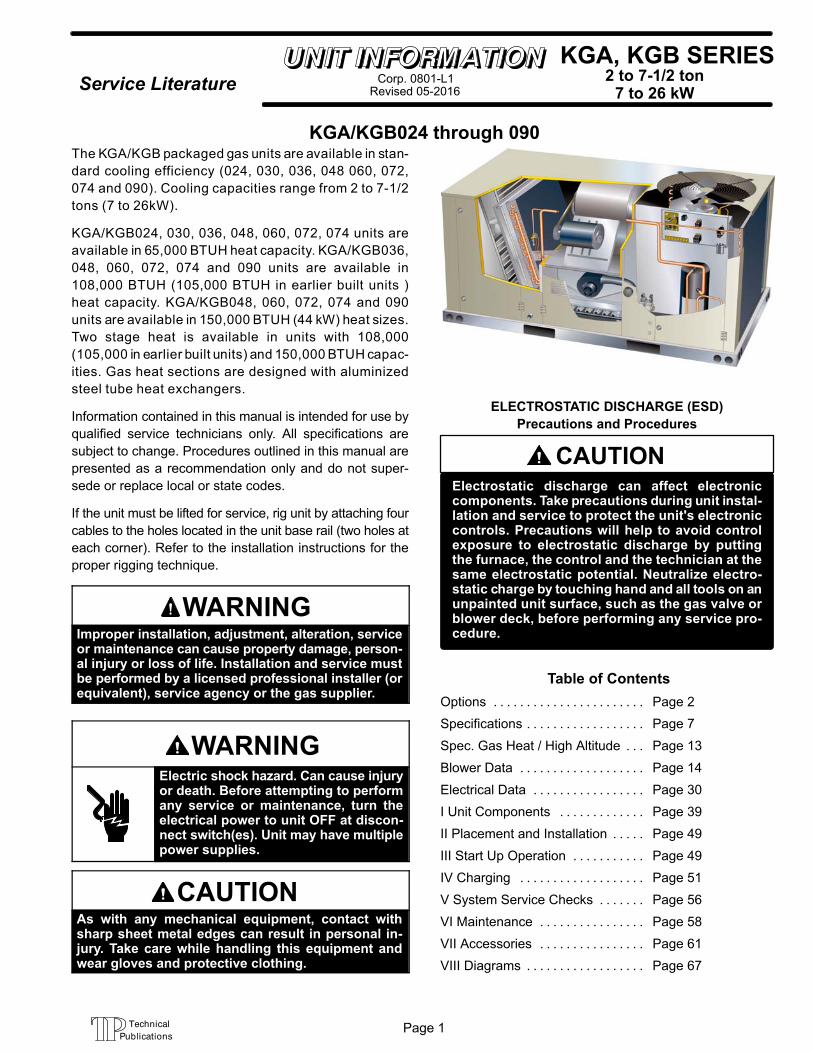
KGA/KGB024 through 090The KGA/KGB packaged gas units are available in stan
dard cooling efficiency (024, 030, 036, 048 060, 072,
074 and 090). Cooling capacities range from 2 to 7-1/2
tons (7 to 26kW).
KGA/KGB024, 030, 036, 048, 060, 072, 074 units are
available in 65,000 BTUH heat capacity. KGA/KGB036,
048, 060, 072, 074 and 090 units are available in
108,000 BTUH (105,000 BTUH in earlier built units )
heat capacity. KGA/KGB048, 060, 072, 074 and 090
units are available in 150,000 BTUH (44 kW) heat sizes.
Two stage heat is available in units with 108,000
(105,000 in earlier built units) and 150,000 BTUH capac
ities. Gas heat sections are designed with aluminized
steel tube heat exchangers.
Information contained in this manual is intended for use by
qualified service technicians only. All specifications are
subject to change. Procedures outlined in this manual are
presented as a recommendation only and do not super
sede or replace local or state codes.
If the unit must be lifted for service, rig unit by attaching four
cables to the holes located in the unit base rail (two holes at
each corner). Refer to the installation instructions for the
proper rigging technique.
WARNINGImproper installation, adjustment, alteration, serviceor maintenance can cause property damage, personal injury or loss of life. Installation and service mustbe performed by a licensed professional installer (orequivalent), service agency or the gas supplier.
WARNINGElectric shock hazard. Can cause injuryor death. Before attempting to performany service or maintenance, turn theelectrical power to unit OFF at disconnect switch(es). Unit may have multiplepower supplies.
CAUTIONAs with any mechanical equipment, contact withsharp sheet metal edges can result in personal injury. Take care while handling this equipment andwear gloves and protective clothing.
CAUTIONElectrostatic discharge can affect electroniccomponents. Take precautions during unit installation and service to protect the unit's electroniccontrols. Precautions will help to avoid controlexposure to electrostatic discharge by puttingthe furnace, the control and the technician at thesame electrostatic potential. Neutralize electrostatic charge by touching hand and all tools on anunpainted unit surface, such as the gas valve orblower deck, before performing any service procedure.
ELECTROSTATIC DISCHARGE (ESD)
Precautions and Procedures
Table of Contents
Options Page 2. . . . . . . . . . . . . . . . . . . . . . .
Specifications Page 7. . . . . . . . . . . . . . . . . .
Spec. Gas Heat / High Altitude Page 13. . .
Blower Data Page 14. . . . . . . . . . . . . . . . . . .
Electrical Data Page 30. . . . . . . . . . . . . . . . .
I Unit Components Page 39. . . . . . . . . . . . .
II Placement and Installation Page 49. . . . .
III Start Up Operation Page 49. . . . . . . . . . .
IV Charging Page 51. . . . . . . . . . . . . . . . . . .
V System Service Checks Page 56. . . . . . .
VI Maintenance Page 58. . . . . . . . . . . . . . . .
VII Accessories Page 61. . . . . . . . . . . . . . . .
VIII Diagrams Page 67. . . . . . . . . . . . . . . . . .
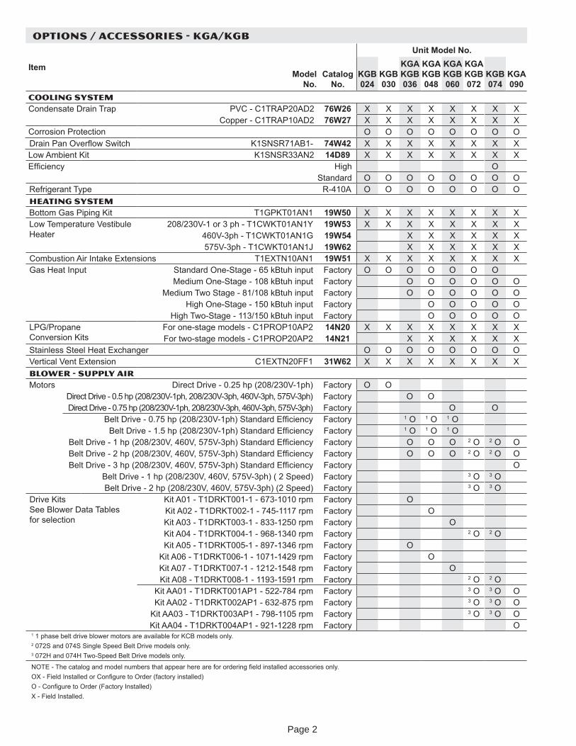
OPTIONS / ACCESSORIES - KGA/KGB
ItemModel
No.Catalog
No.
Unit Model No.
KGB 024
KGB 030
KGA KGB 036
KGA KGB 048
KGA KGB 060
KGA KGB 072
KGB 074
KGA 090
COOLING SYSTEM Condensate Drain Trap PVC - C1TRAP20AD2 76W26 X X X X X X X X
Copper - C1TRAP10AD2 76W27 X X X X X X X XCorrosion Protection O O O O O O O ODrain Pan O er o itc K1SNSR71AB1- 74W42 X X X X X X X XLow Ambient Kit K1SNSR33AN2 14D89 X X X X X X X X
cienc High OStandard O O O O O O O O
Re rigerant T pe R-410A O O O O O O O OHEATING SYSTEMBottom Gas Piping Kit T1GPKT01AN1 19W50 X X X X X X X XLow Temperature Vestibule Heater
208/230V-1 or 3 ph - T1CWKT01AN1Y 19W53 X X X X X X X X460V-3ph - T1CWKT01AN1G 19W54 X X X X X X575V-3ph - T1CWKT01AN1J 19W62 X X X X X X
Combustion Air Intake Extensions T1EXTN10AN1 19W51 X X X X X X X XGas Heat Input Standard One-Stage - 65 kBtuh input actor O O O O O O O
Medium One-Stage - 108 kBtuh input actor O O O O O OMedium Two Stage - 81/108 kBtuh input actor O O O O O O
High One-Stage - 150 kBtuh input actor O O O O OHigh Two-Stage - 113/150 kBtuh input actor O O O O O
LPG/Propane Conversion Kits
For one-stage models - C1PROP10AP2 14N20 X X X X X X X XFor two-stage models - C1PROP20AP2 14N21 X X X X X X
Stainless Steel Heat Exchanger O O O O O O O OVertical Vent Extension C1EXTN20FF1 31W62 X X X X X X X XBLOWER - SUPPLY AIRMotors Direct Drive - 0.25 hp (208/230V-1ph) Factor O O
Direct Drive - 0.5 hp (208/230V-1ph, 208/230V-3ph, 460V-3ph, 575V-3ph) Factor O ODirect Drive - 0.75 hp (208/230V-1ph, 208/230V-3ph, 460V-3ph, 575V-3ph) Factor O O
Belt Drive - 0.75 hp (208/230V-1ph) Standard E cienc Factor 1 O 1 O 1 OBelt Drive - 1.5 hp (208/230V-1ph) Standard E cienc Factor 1 O 1 O 1 O
Belt Drive - 1 hp (208/230V, 460V, 575V-3ph) Standard E cienc Factor O O O 2 O 2 O OBelt Drive - 2 hp (208/230V, 460V, 575V-3ph) Standard E cienc Factor O O O 2 O 2 O OBelt Drive - 3 hp (208/230V, 460V, 575V-3ph) Standard E cienc Factor O
Belt Drive - 1 hp (208/230V, 460V, 575V-3ph) ( 2 Speed) Factor 3 O 3 OBelt Drive - 2 hp (208/230V, 460V, 575V-3ph) (2 Speed) Factor 3 O 3 O
Drive Kits See Blower Data Tables for selection
Kit A01 - T1DRKT001-1 - 673-1010 rpm Factor OKit A02 - T1DRKT002-1 - 745-1117 rpm Factor OKit A03 - T1DRKT003-1 - 833-1250 rpm Factor OKit A04 - T1DRKT004-1 - 968-1340 rpm Factor 2 O 2 OKit A05 - T1DRKT005-1 - 897-1346 rpm Factor O
Kit A06 - T1DRKT006-1 - 1071-1429 rpm Factor OKit A07 - T1DRKT007-1 - 1212-1548 rpm Factor OKit A08 - T1DRKT008-1 - 1193-1591 rpm Factor 2 O 2 O
Kit AA01 - T1DRKT001AP1 - 522-784 rpm Factor 3 O 3 O OKit AA02 - T1DRKT002AP1 - 632-875 rpm Factor 3 O 3 O O
Kit AA03 - T1DRKT003AP1 - 798-1105 rpm Factor 3 O 3 O OKit AA04 - T1DRKT004AP1 - 921-1228 rpm Factor O
1 1 phase belt drive blower motors are available for KCB models onl .2 072S and 074S Single Speed Belt Drive models onl .3 072H and 074H Two-Speed Belt Drive models onl .
NOTE - The catalog and model numbers that appear here are for ordering eld installed accessories onl .OX - Field Installed or Con gure to Order (factor installed)O - Con gure to Order (Factor Installed)X - Field Installed.
Page 2
OPTIONS / ACCESSORIES - KGA/KGB
ItemModel
No.Catalog
No.
Unit Model No.
KGB 024
KGB 030
KGA KGB 036
KGA KGB 048
KGA KGB 060
KGA KGB 072
KGB 074
KGA 090
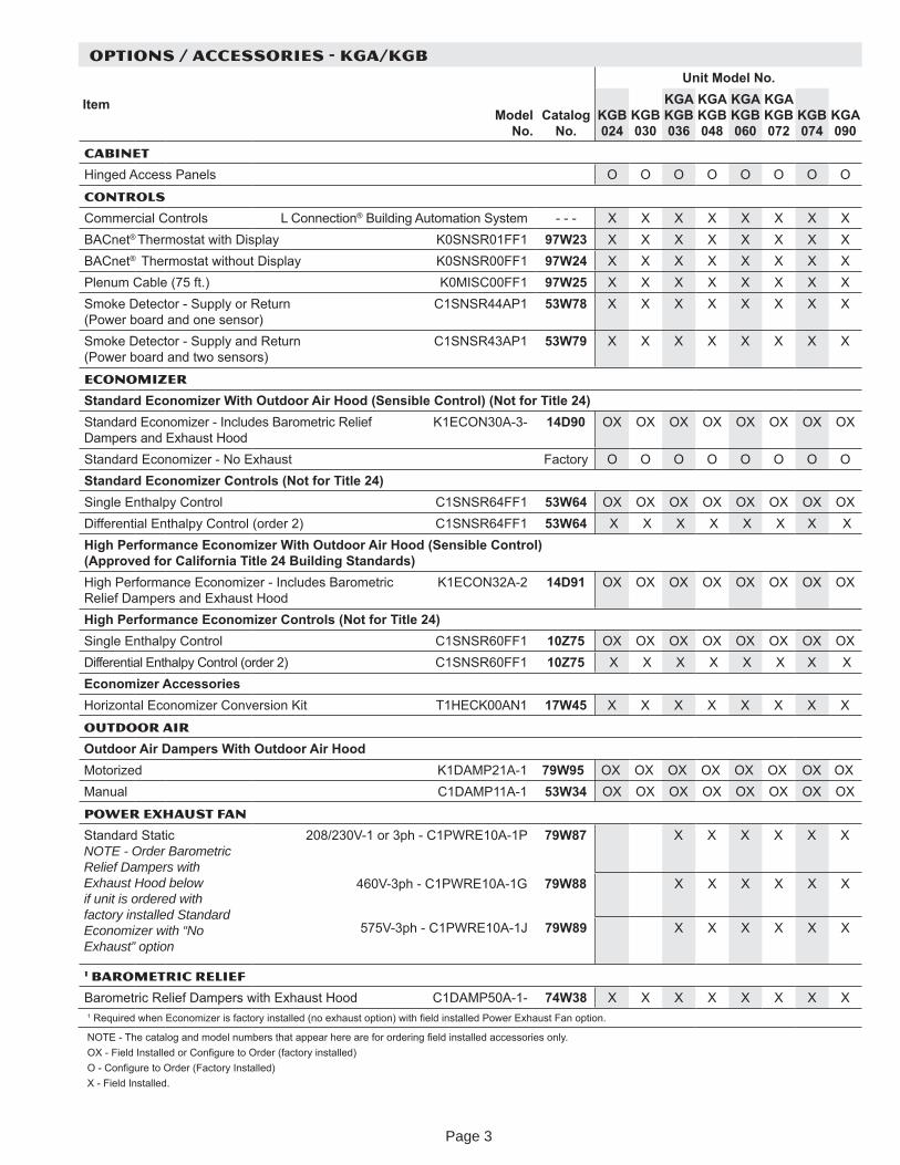
CABINET
Hinged Access Panels O O O O O O O O
CONTROLS
Commercial Controls L Connection® Building Automation S stem - - - X X X X X X X XBACnet® Thermostat with Displa K0SNSR01FF1 97W23 X X X X X X X XBACnet® Thermostat without Displa K0SNSR00FF1 97W24 X X X X X X X XPlenum Cable (75 ft.) K0MISC00FF1 97W25 X X X X X X X XSmoke Detector - Suppl or Return (Power board and one sensor)
C1SNSR44AP1 53W78 X X X X X X X X
Smoke Detector - Suppl and Return (Power board and two sensors)
C1SNSR43AP1 53W79 X X X X X X X X
ECONOMIZER
tanda d onomi e Wit tdoo Ai ood en i le Cont ol Not o itle 24Standard Economi er - Includes Barometric Relief Dampers and Exhaust Hood
K1ECON30A-3- 14D90 OX OX OX OX OX OX OX OX
Standard Economi er - No Exhaust Factor O O O O O O O Otanda d onomi e Cont ol Not o itle 24
Single Enthalp Control C1SNSR64FF1 53W64 OX OX OX OX OX OX OX OXDifferential Enthalp Control (order 2) C1SNSR64FF1 53W64 X X X X X X X X
ig e o man e onomi e Wit tdoo Ai ood en i le Cont ol (Approved for California Title 24 Building Standards)High Performance Economi er - Includes Barometric Relief Dampers and Exhaust Hood
K1ECON32A-2 14D91 OX OX OX OX OX OX OX OX
ig erforman e onomi er Controls (Not for Title 24)Single Enthalp Control C1SNSR60FF1 10Z75 OX OX OX OX OX OX OX OXDifferential Enthalp Control (order 2) C1SNSR60FF1 10Z75 X X X X X X X X
onomi er A essoriesHori ontal Economi er Conversion Kit T1HECK00AN1 17W45 X X X X X X X X
OUTDOOR AIR
Outdoor Air Dampers With Outdoor Air HoodMotori ed K1DAMP21A-1 79W95 OX OX OX OX OX OX OX OXManual C1DAMP11A-1 53W34 OX OX OX OX OX OX OX OX
Power EXhaust FAN
Standard Static NOTE - Order Barometric Relief Dampers with Exhaust Hood below if unit is ordered with factory installed Standard Economizer with “No Exhaust” option
208/230V-1 or 3ph - C1PWRE10A-1P 79W87 X X X X X X
460V-3ph - C1PWRE10A-1G 79W88 X X X X X X
575V-3ph - C1PWRE10A-1J 79W89 X X X X X X
1 BAROMETRIC RELIEF
Barometric Relief Dampers with Exhaust Hood C1DAMP50A-1- 74W38 X X X X X X X X1 Re uired when Economi er is factor installed (no exhaust option) with eld installed Power Exhaust Fan option.
NOTE - The catalog and model numbers that appear here are for ordering eld installed accessories onl .OX - Field Installed or Con gure to Order (factor installed)O - Con gure to Order (Factor Installed)X - Field Installed.
Page 3
OPTIONS / ACCESSORIES - KGA/KGB
ItemModel
No.Catalog
No.
Unit Model No.
KGB 024
KGB 030
KGA KGB 036
KGA KGB 048
KGA KGB 060
KGA KGB 072
KGB 074
KGA 090
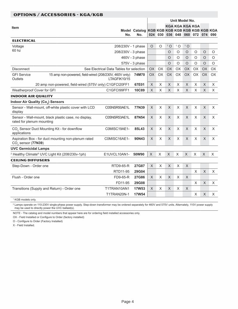
ELECTRICAL
Voltage 60 h
208/230V - 1 phase O O 1 O 1 O 1 O208/230V - 3 phase O O O O O O
460V - 3 phase O O O O O O575V - 3 phase O O O O O O
Disconnect See Electrical Data Tables for selection OX OX OX OX OX OX OX OXGFI Service Outlets
15 amp non-powered, eld-wired (208/230V, 460V onl ) LTAGFIK10/15
74M70 OX OX OX OX OX OX OX OX
20 amp non-powered, eld-wired (575V onl ) C1GFCI20FF1 67E01 X X X X X X X XWeatherproof Cover for GFI C1GFCI99FF1 10C89 X X X X X X X X
Indoor Air Quality
Indoor Air Quality (Co2) SensorsSensor - Wall-mount, off-white plastic cover with LCD displa
C0SNSR50AE1L 77N39 X X X X X X X X
Sensor - Wall-mount, black plastic case, no displa , rated for plenum mounting
C0SNSR53AE1L 87N54 X X X X X X X X
CO2 Sensor Duct Mounting Kit - for down ow applications
C0MISC19AE1- 85L43 X X X X X X X X
Aspiration Box - for duct mounting non-plenum rated CO2 sensor (77N39)
C0MISC16AE1- 90N43 X X X X X X X X
UVC Germicidal Lamps2 Health Climate® UVC Light Kit (208/230v-1ph) E1UVCL10AN1- 50W90 X X X X X X X X
CEILING DIFFUSERS
Step-Down - Order one RTD9-65-R 27G87 X X X X XRTD11-95 29G04 X X X
Flush - Order one FD9-65-R 27G86 X X X X XFD11-95 29G08 X X X
Transitions (Suppl and Return) - Order one T1TRAN10AN1 17W53 X X X X XT1TRAN20N-1 17W54 X X X
1 KGB models onl .2 Lamps operate on 110-230V single-phase power suppl . Step-down transformer ma be ordered separatel for 460V and 575V units. Alternatel , 110V power suppl
ma be used to directl power the UVC ballast(s).
NOTE - The catalog and model numbers that appear here are for ordering eld installed accessories onl .OX - Field Installed or Con gure to Order (factor installed)O - Con gure to Order (Factor Installed)X - Field Installed.
Page 4
OPTIONS / ACCESSORIES - KGA/KGB
ItemModel
No.Catalog
No.
Unit Model No.
KGB 024
KGB 030
KGA KGB 036
KGA KGB 048
KGA KGB 060
KGA KGB 072
KGB 074
KGA 090
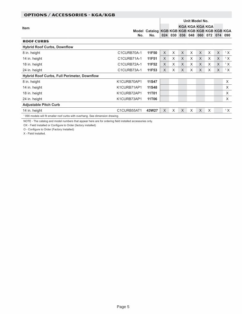
ROOF CURBS
Hy rid oof Cur s Do n o8 in. height C1CURB70A-1 11F50 X X X X X X X 1 X14 in. height C1CURB71A-1 11F51 X X X X X X X 1 X18 in. height C1CURB72A-1 11F52 X X X X X X X 1 X24 in. height C1CURB73A-1 11F53 X X X X X X X 1 XHy rid oof Cur s Full erimeter Do n o8 in. height K1CURB70AP1 11S47 X14 in. height K1CURB71AP1 11S48 X18 in. height K1CURB72AP1 11T01 X24 in. height K1CURB73AP1 11T06 XAdjustable Pitch Curb14 in. height C1CURB55AT1 43W27 X X X X X X 1 X1 090 models will t smaller roof curbs with overhang. See dimension drawing.
NOTE - The catalog and model numbers that appear here are for ordering eld installed accessories onl .OX - Field Installed or Con gure to Order (factor installed)O - Con gure to Order (Factor Installed)X - Field Installed.
Page 5
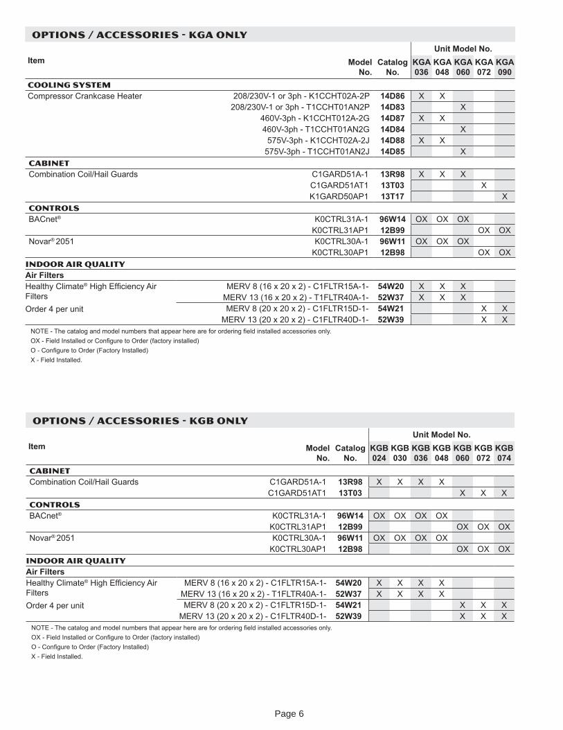
OPTIONS / ACCESSORIES - KGA ONLY
Item Model No.
Catalog No.
Unit Model No.KGA 036
KGA 048
KGA 060
KGA 072
KGA 090
COOLING SYSTEM Compressor Crankcase Heater 208/230V-1 or 3ph - K1CCHT02A-2P 14D86 X X
208/230V-1 or 3ph - T1CCHT01AN2P 14D83 X460V-3ph - K1CCHT012A-2G 14D87 X X460V-3ph - T1CCHT01AN2G 14D84 X
575V-3ph - K1CCHT02A-2J 14D88 X X575V-3ph - T1CCHT01AN2J 14D85 X
CABINETCombination Coil/Hail Guards C1GARD51A-1 13R98 X X X
C1GARD51AT1 13T03 XK1GARD50AP1 13T17 X
CONTROLSBACnet® K0CTRL31A-1 96W14 OX OX OX
K0CTRL31AP1 12B99 OX OXNovar® 2051 K0CTRL30A-1 96W11 OX OX OX
K0CTRL30AP1 12B98 OX OXINDOOR AIR QUALITYAir FiltersHealth Climate® High Ef cienc Air FiltersOrder 4 per unit
MERV 8 (16 x 20 x 2) - C1FLTR15A-1- 54W20 X X XMERV 13 (16 x 20 x 2) - T1FLTR40A-1- 52W37 X X XMERV 8 (20 x 20 x 2) - C1FLTR15D-1- 54W21 X X
MERV 13 (20 x 20 x 2) - C1FLTR40D-1- 52W39 X XNOTE - The catalog and model numbers that appear here are for ordering eld installed accessories onl .OX - Field Installed or Con gure to Order (factor installed)O - Con gure to Order (Factor Installed)X - Field Installed.
OPTIONS / ACCESSORIES - KGB ONLY
Item Model No.
Catalog No.
Unit Model No.KGB 024
KGB 030
KGB 036
KGB 048
KGB 060
KGB 072
KGB 074
CABINETCombination Coil/Hail Guards C1GARD51A-1 13R98 X X X X
C1GARD51AT1 13T03 X X XCONTROLSBACnet® K0CTRL31A-1 96W14 OX OX OX OX
K0CTRL31AP1 12B99 OX OX OXNovar® 2051 K0CTRL30A-1 96W11 OX OX OX OX
K0CTRL30AP1 12B98 OX OX OXINDOOR AIR QUALITYAir FiltersHealth Climate® High Ef cienc Air FiltersOrder 4 per unit
MERV 8 (16 x 20 x 2) - C1FLTR15A-1- 54W20 X X X XMERV 13 (16 x 20 x 2) - T1FLTR40A-1- 52W37 X X X XMERV 8 (20 x 20 x 2) - C1FLTR15D-1- 54W21 X X X
MERV 13 (20 x 20 x 2) - C1FLTR40D-1- 52W39 X X XNOTE - The catalog and model numbers that appear here are for ordering eld installed accessories onl .OX - Field Installed or Con gure to Order (factor installed)O - Con gure to Order (Factor Installed)X - Field Installed.
Page 6
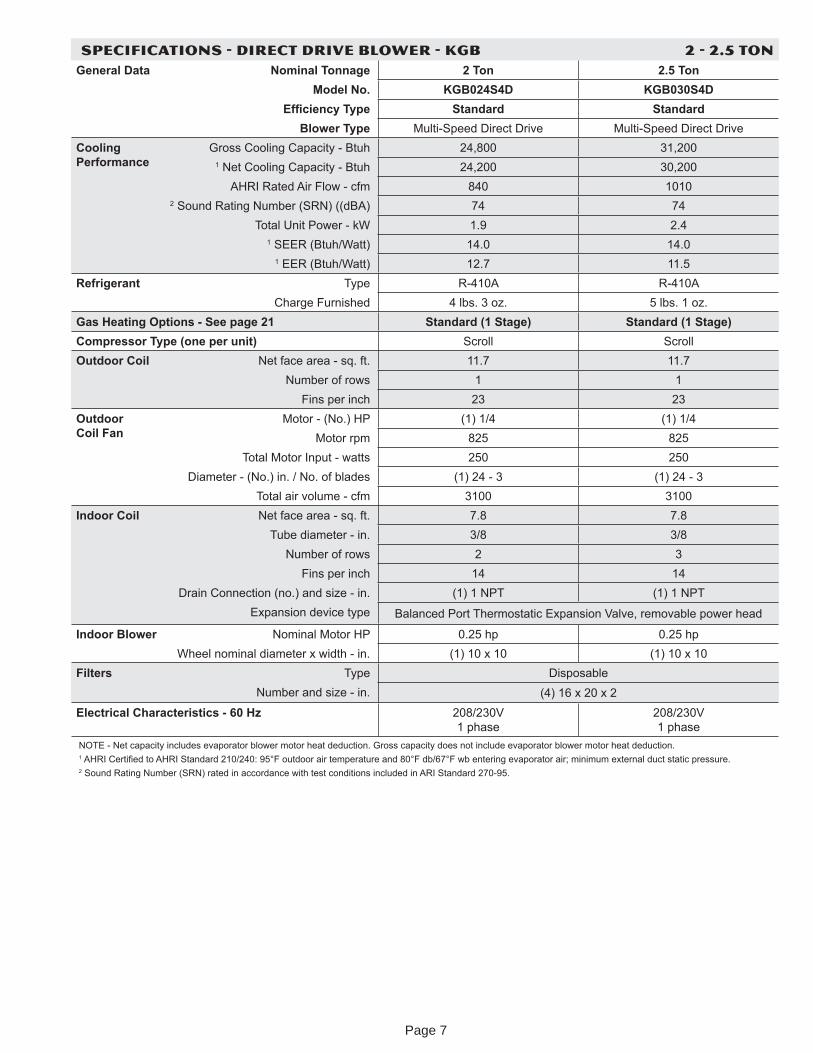
SPECIFICATIONS - DIRECT DRIVE BLOWER - KGB 2 - 2.5 TONGeneral Data Nominal Tonnage 2 Ton 2.5 Ton
Model No. KGB024S4D KGB030S4DEf ciency Type Standard Standard
Blower Type Multi-Speed Direct Drive Multi-Speed Direct DriveCooling Performance
Gross Cooling Capacit - Btuh 24,800 31,2001 Net Cooling Capacit - Btuh 24,200 30,200
AHRI Rated Air Flow - cfm 840 10102 Sound Rating Number (SRN) ((dBA) 74 74
Total Unit Power - kW 1.9 2.41 SEER (Btuh/Watt) 14.0 14.0
1 EER (Btuh/Watt) 12.7 11.5Refrigerant T pe R-410A R-410A
Charge Furnished 4 lbs. 3 o . 5 lbs. 1 o .Gas Heating Options - See page 21 Standard (1 Stage) Standard (1 Stage)Compressor Type (one per unit) Scroll ScrollOutdoor Coil Net face area - sq. ft. 11.7 11.7
Number of rows 1 1Fins per inch 23 23
Outdoor Coil Fan
Motor - (No.) HP (1) 1/4 (1) 1/4Motor rpm 825 825
Total Motor Input - watts 250 250Diameter - (No.) in. / No. of blades (1) 24 - 3 (1) 24 - 3
Total air volume - cfm 3100 3100Indoor Coil Net face area - sq. ft. 7.8 7.8
Tube diameter - in. 3/8 3/8Number of rows 2 3
Fins per inch 14 14Drain Connection (no.) and si e - in. (1) 1 NPT (1) 1 NPT
Expansion device t pe Balanced Port Thermostatic Expansion Valve, removable power head
Indoor Blower Nominal Motor HP 0.25 hp 0.25 hpWheel nominal diameter x width - in. (1) 10 x 10 (1) 10 x 10
Filters T pe DisposableNumber and si e - in. (4) 16 x 20 x 2
Electrical Characteristics - 60 H 208/230V 1 phase
208/230V 1 phase
NOTE - Net capacit includes evaporator blower motor heat deduction. Gross capacit does not include evaporator blower motor heat deduction.1 AHRI Certi ed to AHRI Standard 210/240 95 F outdoor air temperature and 80 F db/67 F wb entering evaporator air minimum external duct static pressure.2 Sound Rating Number (SRN) rated in accordance with test conditions included in ARI Standard 270-95.
Page 7
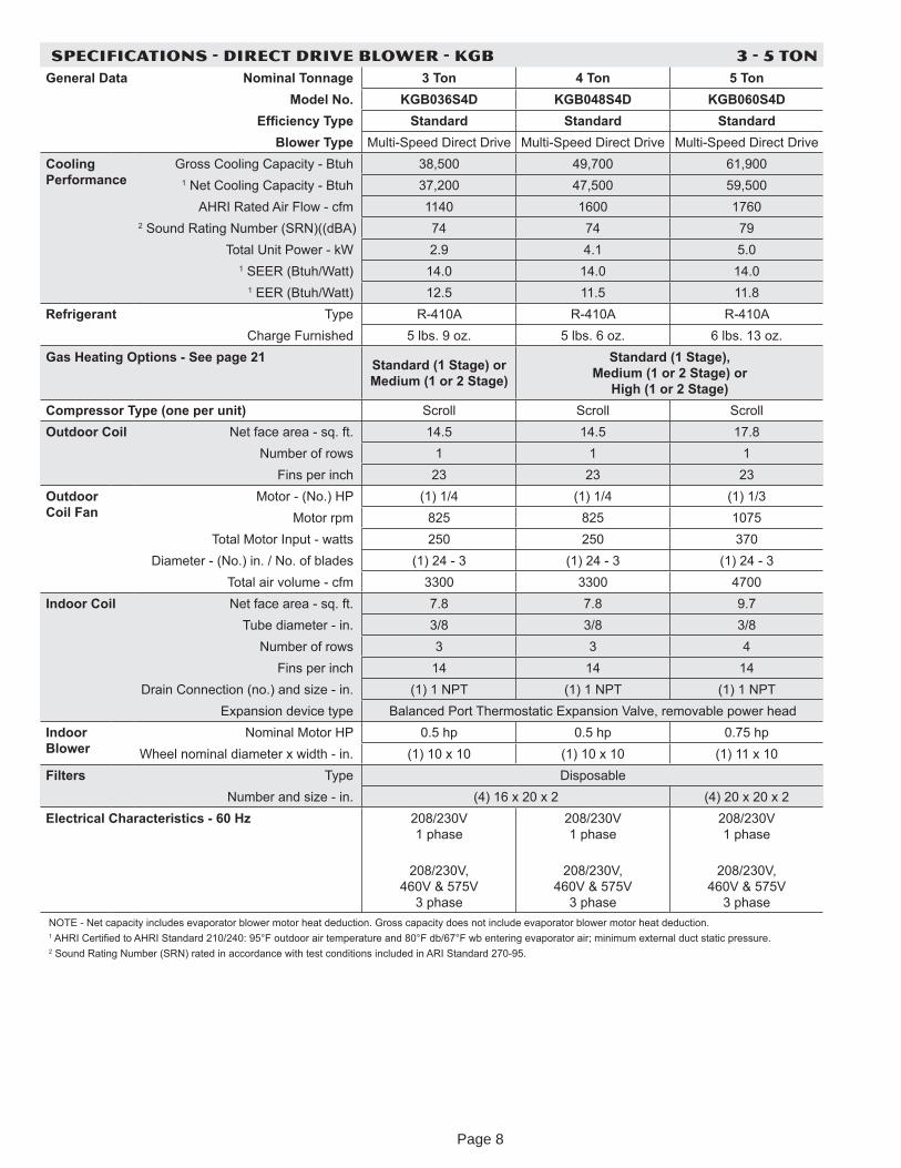
SPECIFICATIONS - DIRECT DRIVE BLOWER - KGB 3 - 5 TONGeneral Data Nominal Tonnage 3 Ton 4 Ton 5 Ton
Model No. KGB036S4D KGB048S4D KGB060S4DEf ciency Type Standard Standard Standard
Blower Type Multi-Speed Direct Drive Multi-Speed Direct Drive Multi-Speed Direct DriveCooling Performance
Gross Cooling Capacit - Btuh 38,500 49,700 61,9001 Net Cooling Capacit - Btuh 37,200 47,500 59,500
AHRI Rated Air Flow - cfm 1140 1600 17602 Sound Rating Number (SRN)((dBA) 74 74 79
Total Unit Power - kW 2.9 4.1 5.01 SEER (Btuh/Watt) 14.0 14.0 14.0
1 EER (Btuh/Watt) 12.5 11.5 11.8Refrigerant T pe R-410A R-410A R-410A
Charge Furnished 5 lbs. 9 o . 5 lbs. 6 o . 6 lbs. 13 o .Gas Heating Options - See page 21 Standard (1 Stage) or
Medium (1 or 2 Stage)
Standard (1 Stage), Medium (1 or 2 Stage) or
High (1 or 2 Stage)Compressor Type (one per unit) Scroll Scroll ScrollOutdoor Coil Net face area - sq. ft. 14.5 14.5 17.8
Number of rows 1 1 1Fins per inch 23 23 23
Outdoor Coil Fan
Motor - (No.) HP (1) 1/4 (1) 1/4 (1) 1/3Motor rpm 825 825 1075
Total Motor Input - watts 250 250 370Diameter - (No.) in. / No. of blades (1) 24 - 3 (1) 24 - 3 (1) 24 - 3
Total air volume - cfm 3300 3300 4700Indoor Coil Net face area - sq. ft. 7.8 7.8 9.7
Tube diameter - in. 3/8 3/8 3/8Number of rows 3 3 4
Fins per inch 14 14 14Drain Connection (no.) and si e - in. (1) 1 NPT (1) 1 NPT (1) 1 NPT
Expansion device t pe Balanced Port Thermostatic Expansion Valve, removable power headIndoor Blower
Nominal Motor HP 0.5 hp 0.5 hp 0.75 hpWheel nominal diameter x width - in. (1) 10 x 10 (1) 10 x 10 (1) 11 x 10
Filters T pe DisposableNumber and si e - in. (4) 16 x 20 x 2 (4) 20 x 20 x 2
Electrical Characteristics - 60 H 208/230V 1 phase
208/230V,
460V & 575V 3 phase
208/230V 1 phase
208/230V,
460V & 575V 3 phase
208/230V 1 phase
208/230V,
460V & 575V 3 phase
NOTE - Net capacit includes evaporator blower motor heat deduction. Gross capacit does not include evaporator blower motor heat deduction.1 AHRI Certi ed to AHRI Standard 210/240 95 F outdoor air temperature and 80 F db/67 F wb entering evaporator air minimum external duct static pressure.2 Sound Rating Number (SRN) rated in accordance with test conditions included in ARI Standard 270-95.
Page 8
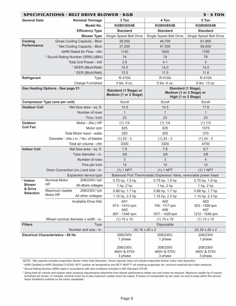
SPECIFICATIONS - BELT DRIVE BLOWER - KGB 3 - 5 TONGeneral Data Nominal Tonnage 3 Ton 4 Ton 5 Ton
Model No. KGB036S4B KGB048S4B KGB060S4BEf ciency Type Standard Standard Standard
Blower Type Single Speed Belt Drive Single Speed Belt Drive Single Speed Belt DriveCooling Performance
Gross Cooling Capacit - Btuh 38,500 49,700 61,9001 Net Cooling Capacit - Btuh 37,200 47,500 59,500
AHRI Rated Air Flow - cfm 1140 1600 17602 Sound Rating Number (SRN) (dBA) 74 74 79
Total Unit Power - kW 2.9 4.1 51 SEER (Btuh/Watt) 14.0 14.0 14.0
1 EER (Btuh/Watt) 12.5 11.5 11.8Refrigerant T pe R-410A R-410A R-410A
Charge Furnished 5 lbs. 9 o . 5 lbs. 6 o . 6 lbs. 13 o .Gas Heating Options - See page 21 Standard (1 Stage) or
Medium (1 or 2 Stage)
Standard (1 Stage), Medium (1 or 2 Stage) or
High (1 or 2 Stage)Compressor Type (one per unit) Scroll Scroll ScrollOutdoor Coil Net face area - sq. ft. 14.5 14.5 17.8
Number of rows 1 1 1Fins / inch 23 23 23
Outdoor Coil Fan
Motor - (No.) HP (1) 1/4 (1) 1/4 (1) 1/3Motor rpm 825 825 1075
Total Motor Input - watts 250 250 370Diameter - (No.) in. / No. of blades (1) 24 - 3 (1) 24 - 3 (1) 24 - 3
Total air volume - cfm 3300 3300 4700Indoor Coil Net face area - sq. ft. 7.8 7.8 9.7
Tube diameter - in. 3/8 3/8 3/8Number of rows 3 3 4
Fins per inch 14 14 14Drain Connection (no.) and si e - in. (1) 1 NPT (1) 1 NPT (1) 1 NPT
Expansion device t pe Balanced Port Thermostatic Expansion Valve, removable power head3 Indoor
Blower & Drive Selection
Nominal Motor HP
208/230V-1ph 0.75 hp, 1.5 hp 0.75 hp, 1.5 hp 0.75 hp, 1.5 hpAll others voltages 1 hp, 2 hp 1 hp, 2 hp 1 hp, 2 hp
Maximum Usable Motor HP
208/230V-1ph 0.86 hp, 1.7 hp 0.86 hp, 1.7 hp 0.86 hp, 1.7 hpAll other voltages 1.15 hp, 2.3 hp 1.15 hp, 2.3 hp 1.15 hp, 2.3 hp
Available Drive Kits A01 673 - 1010 rpm
A05 897 - 1346 rpm
A02 745 - 1117 rpm
A06 1071 - 1429 rpm
A03 833 - 1250 rpm
A07 1212 - 1548 rpm
Wheel nominal diameter x width - in. (1) 10 x 10 (1) 10 x 10 (1) 10 x 10Filters T pe Disposable
Number and si e - in. (4) 16 x 20 x 2 (4) 20 x 20 x 2Electrical Characteristics - 60 H 208/230V
1 phase
208/230V, 460V & 575V
3 phase
208/230V, 1 phase
208/230V
460V & 575V 3 phase
208/230V 1 phase
208/230V
460V & 575V 3 phase
NOTE - Net capacit includes evaporator blower motor heat deduction. Gross capacit does not include evaporator blower motor heat deduction.1 AHRI Certi ed to AHRI Standard 210/240 95 F outdoor air temperature and 80 F db/67 F wb entering evaporator air minimum external duct static pressure.2 Sound Rating Number (SRN) rated in accordance with test conditions included in ARI Standard 270-95.3 Using total air volume and s stem static pressure requirements determine from blower performance tables rpm and motor hp required. Maximum usable hp of motors
furnished are shown. In Canada, nominal motor hp is also maximum usable motor hp output. If motors of comparable hp are used, be sure to keep within the service factor limitations outlined on the motor nameplate.
Page 9
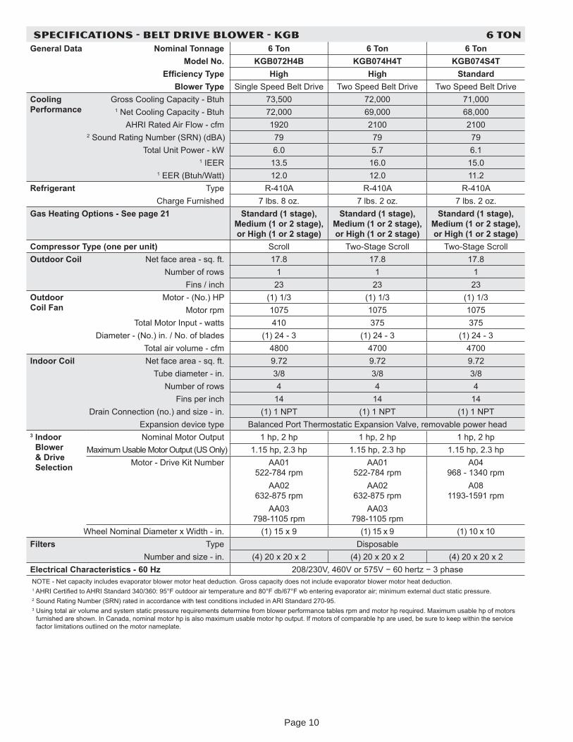
SPECIFICATIONS - BELT DRIVE BLOWER - KGB 6 TONGeneral Data Nominal Tonnage 6 Ton 6 Ton 6 Ton
Model No. KGB072H4B KGB074H4T KGB074S4TEf ciency Type High High Standard
Blower Type Single Speed Belt Drive Two Speed Belt Drive Two Speed Belt DriveCooling Performance
Gross Cooling Capacit - Btuh 73,500 72,000 71,0001 Net Cooling Capacit - Btuh 72,000 69,000 68,000
AHRI Rated Air Flow - cfm 1920 2100 21002 Sound Rating Number (SRN) (dBA) 79 79 79
Total Unit Power - kW 6.0 5.7 6.11 IEER 13.5 16.0 15.0
1 EER (Btuh/Watt) 12.0 12.0 11.2Refrigerant T pe R-410A R-410A R-410A
Charge Furnished 7 lbs. 8 o . 7 lbs. 2 o . 7 lbs. 2 o .Gas Heating Options - See page 21 Standard (1 stage),
Medium (1 or 2 stage), or High (1 or 2 stage)
Standard (1 stage), Medium (1 or 2 stage), or High (1 or 2 stage)
Standard (1 stage), Medium (1 or 2 stage), or High (1 or 2 stage)
Compressor Type (one per unit) Scroll Two-Stage Scroll Two-Stage ScrollOutdoor Coil Net face area - sq. ft. 17.8 17.8 17.8
Number of rows 1 1 1Fins / inch 23 23 23
Outdoor Coil Fan
Motor - (No.) HP (1) 1/3 (1) 1/3 (1) 1/3Motor rpm 1075 1075 1075
Total Motor Input - watts 410 375 375Diameter - (No.) in. / No. of blades (1) 24 - 3 (1) 24 - 3 (1) 24 - 3
Total air volume - cfm 4800 4700 4700Indoor Coil Net face area - sq. ft. 9.72 9.72 9.72
Tube diameter - in. 3/8 3/8 3/8Number of rows 4 4 4
Fins per inch 14 14 14Drain Connection (no.) and si e - in. (1) 1 NPT (1) 1 NPT (1) 1 NPT
Expansion device t pe Balanced Port Thermostatic Expansion Valve, removable power head3 Indoor
Blower & Drive Selection
Nominal Motor Output 1 hp, 2 hp 1 hp, 2 hp 1 hp, 2 hpMaximum Usable Motor Output (US Onl ) 1.15 hp, 2.3 hp 1.15 hp, 2.3 hp 1.15 hp, 2.3 hp
Motor - Drive Kit Number AA01 522-784 rpm
AA02 632-875 rpm
AA03 798-1105 rpm
AA01 522-784 rpm
AA02 632-875 rpm
AA03 798-1105 rpm
A04 968 - 1340 rpm
A08 1193-1591 rpm
Wheel Nominal Diameter x Width - in. (1) 15 x 9 (1) 15 x 9 (1) 10 x 10Filters T pe Disposable
Number and si e - in. (4) 20 x 20 x 2 (4) 20 x 20 x 2 (4) 20 x 20 x 2Electrical Characteristics - 60 H 208/230V, 460V or 575V 60 hert 3 phaseNOTE - Net capacit includes evaporator blower motor heat deduction. Gross capacit does not include evaporator blower motor heat deduction.1 AHRI Certi ed to AHRI Standard 340/360 95 F outdoor air temperature and 80 F db/67 F wb entering evaporator air minimum external duct static pressure.2 Sound Rating Number (SRN) rated in accordance with test conditions included in ARI Standard 270-95.3 Using total air volume and s stem static pressure requirements determine from blower performance tables rpm and motor hp required. Maximum usable hp of motors
furnished are shown. In Canada, nominal motor hp is also maximum usable motor hp output. If motors of comparable hp are used, be sure to keep within the service factor limitations outlined on the motor nameplate.
Page 10
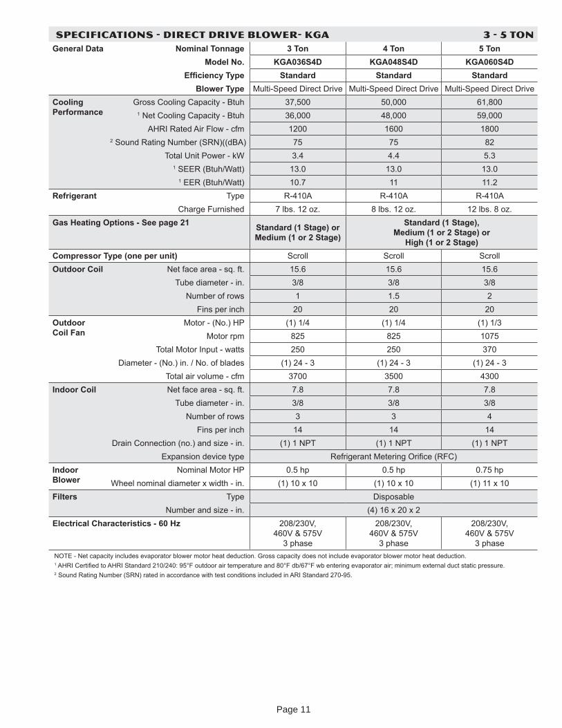
SPECIFICATIONS - DIRECT DRIVE BLOWER- KGA 3 - 5 TONGeneral Data Nominal Tonnage 3 Ton 4 Ton 5 Ton
Model No. KGA036S4D KGA048S4D KGA060S4DEf ciency Type Standard Standard Standard
Blower Type Multi-Speed Direct Drive Multi-Speed Direct Drive Multi-Speed Direct DriveCooling Performance
Gross Cooling Capacit - Btuh 37,500 50,000 61,8001 Net Cooling Capacit - Btuh 36,000 48,000 59,000
AHRI Rated Air Flow - cfm 1200 1600 18002 Sound Rating Number (SRN)((dBA) 75 75 82
Total Unit Power - kW 3.4 4.4 5.31 SEER (Btuh/Watt) 13.0 13.0 13.0
1 EER (Btuh/Watt) 10.7 11 11.2Refrigerant T pe R-410A R-410A R-410A
Charge Furnished 7 lbs. 12 o . 8 lbs. 12 o . 12 lbs. 8 o .Gas Heating Options - See page 21 Standard (1 Stage) or
Medium (1 or 2 Stage)
Standard (1 Stage), Medium (1 or 2 Stage) or
High (1 or 2 Stage)Compressor Type (one per unit) Scroll Scroll ScrollOutdoor Coil Net face area - sq. ft. 15.6 15.6 15.6
Tube diameter - in. 3/8 3/8 3/8Number of rows 1 1.5 2
Fins per inch 20 20 20Outdoor Coil Fan
Motor - (No.) HP (1) 1/4 (1) 1/4 (1) 1/3Motor rpm 825 825 1075
Total Motor Input - watts 250 250 370Diameter - (No.) in. / No. of blades (1) 24 - 3 (1) 24 - 3 (1) 24 - 3
Total air volume - cfm 3700 3500 4300Indoor Coil Net face area - sq. ft. 7.8 7.8 7.8
Tube diameter - in. 3/8 3/8 3/8Number of rows 3 3 4
Fins per inch 14 14 14Drain Connection (no.) and si e - in. (1) 1 NPT (1) 1 NPT (1) 1 NPT
Expansion device t pe Refrigerant Metering Ori ce (RFC)Indoor Blower
Nominal Motor HP 0.5 hp 0.5 hp 0.75 hpWheel nominal diameter x width - in. (1) 10 x 10 (1) 10 x 10 (1) 11 x 10
Filters T pe DisposableNumber and si e - in. (4) 16 x 20 x 2
Electrical Characteristics - 60 H 208/230V, 460V & 575V
3 phase
208/230V, 460V & 575V
3 phase
208/230V, 460V & 575V
3 phaseNOTE - Net capacit includes evaporator blower motor heat deduction. Gross capacit does not include evaporator blower motor heat deduction.1 AHRI Certi ed to AHRI Standard 210/240 95 F outdoor air temperature and 80 F db/67 F wb entering evaporator air minimum external duct static pressure.2 Sound Rating Number (SRN) rated in accordance with test conditions included in ARI Standard 270-95.
Page 11
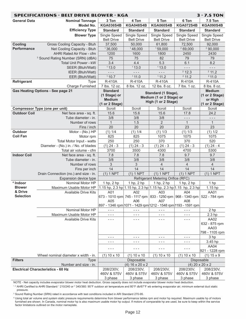
SPECIFICATIONS - BELT DRIVE BLOWER - KGA 3 - 7.5 TONGeneral Data Nominal Tonnage 3 Ton 4 Ton 5 Ton 6 Ton 7.5 Ton
Model No. KGA036S4B KGA048S4B KGA060S4B KGA072S4B KGA090S4BEf ciency Type Standard Standard Standard Standard Standard
Blower Type Single Speed Belt Drive
Single Speed Belt Drive
Single Speed Belt Drive
Single Speed Belt Drive
Single Speed Belt Drive
Cooling Performance
Gross Cooling Capacit - Btuh 37,500 50,000 61,800 72,500 92,000Net Cooling Capacit - Btuh 1 36,000 1 48,000 1 59,000 2 69,000 2 90,000
AHRI Rated Air Flow - cfm 1200 1600 1800 2450 24303 Sound Rating Number (SRN) (dBA) 75 75 82 79 79
Total Unit Power - kW 3.4 4.4 5.3 6.1 8.2SEER (Btuh/Watt) 1 13.0 1 13.0 1 13.0 - - - - - -IEER (Btuh/Watt) - - - - - - - - - 2 12.3 2 11.2EER (Btuh/Watt) 1 10.7 1 11.0 1 11.2 2 11.2 2 11.0
Refrigerant T pe R-410A R-410A R-410A R-410A R-410ACharge Furnished 7 lbs. 12 o . 8 lbs. 12 o . 12 lbs. 8 o . 7 lbs. 1 o . 8 lbs. 8 o .
Gas Heating Options - See page 21 Standard (1 Stage) or
Medium (1 or 2 Stage)
Standard (1 Stage), Medium (1 or 2 Stage) or
High (1 or 2 Stage)
Medium (1 or 2 Stage)
or High (1 or 2 Stage)
Compressor Type (one per unit) Scroll Scroll Scroll Scroll ScrollOutdoor Coil Net face area - sq. ft. 15.6 15.6 15.6 17.8 24.2
Tube diameter - in. 3/8 3/8 3/8 - - - - - -Number of rows 1 1.5 2 1 1
Fins / inch 20 20 20 23 23Outdoor Coil Fan
Motor - (No.) HP (1) 1/4 (1) 1/4 (1) 1/3 (1) 1/3 (1) 1/2Motor rpm 825 825 1075 1075 1075
Total Motor Input - watts 250 250 370 370 520Diameter - (No.) in. / No. of blades (1) 24 - 3 (1) 24 - 3 (1) 24 - 3 (1) 24 - 3 (1) 24 - 4
Total air volume - cfm 3700 3500 4300 4700 5300Indoor Coil Net face area - sq. ft. 7.8 7.8 7.8 9.7 9.7
Tube diameter - in. 3/8 3/8 3/8 3/8 3/8Number of rows 3 3 4 4 4
Fins per inch 14 14 14 14 14Drain Connection (no.) and si e - in. (1) 1 NPT (1) 1 NPT (1) 1 NPT (1) 1 NPT (1) 1 NPT
Expansion device t pe Refrigerant Metering Ori ce (RFC)4 Indoor
Blower & Drive Selection
Nominal Motor HP 1 hp, 2 hp 1 hp, 2 hp 1 hp, 2 hp 1 hp, 2 hp 1 hpMaximum Usable Motor HP 1.15 hp, 2.3 hp 1.15 hp, 2.3 hp 1.15 hp, 2.3 hp 1.15 hp, 2.3 hp 1.15 hp
Available Drive Kits A01 673 - 1010 rpm
A05 897 - 1346 rpm
A02 745 - 1117 rpm
A06 1071 - 1429 rpm
A03 833 - 1250 rpm
A07 1212 - 1548 rpm
A04 968 - 1340 rpm
A08 1193 - 1591 rpm
AA01 522 - 784 rpm
Nominal Motor HP - - - - - - - - - - - - 2 hpMaximum Usable Motor HP - - - - - - - - - - - - 2.3 hp
Available Drive Kits - - - - - - - - - - - - AA02 632 - 875 rpm
AA03 798 - 1105 rpm
- - - - - - - - - - - - 3 hp- - - - - - - - - - - - 3.45 hp
- - - - - - - - - - - - AA04 921 - 1228 rpm
Wheel nominal diameter x width - in. (1) 10 x 10 (1) 10 x 10 (1) 10 x 10 (1) 10 x 10 (1) 15 x 9Filters T pe Disposable Disposable
Number and si e - in. (4) 16 x 20 x 2 (4) 20 x 20 x 2Electrical Characteristics - 60 H 208/230V,
460V & 575V 3 phase
208/230V, 460V & 575V
3 phase
208/230V, 460V & 575V
3 phase
208/230V, 460V & 575V
3 phase
208/230V, 460V & 575V
3 phaseNOTE - Net capacit includes evaporator blower motor heat deduction. Gross capacit does not include evaporator blower motor heat deduction.1, 2 AHRI Certi ed to AHRI Standard 1 210/240 or 2 340/360 95 F outdoor air temperature and 80 F db/67 F wb entering evaporator air minimum external duct static
pressure.3 Sound Rating Number (SRN) rated in accordance with test conditions included in ARI Standard 270-95.4 Using total air volume and s stem static pressure requirements determine from blower performance tables rpm and motor hp required. Maximum usable hp of motors
furnished are shown. In Canada, nominal motor hp is also maximum usable motor hp output. If motors of comparable hp are used, be sure to keep within the service factor limitations outlined on the motor nameplate.
Page 12
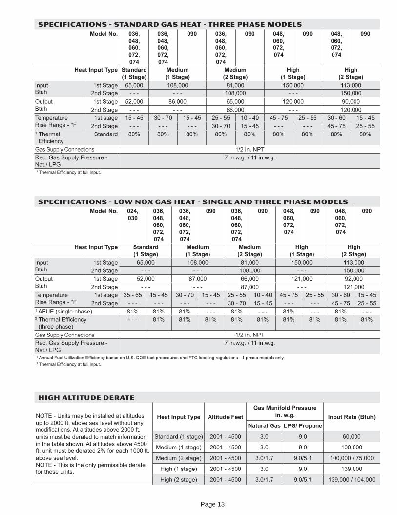
SPECIFICATIONS - LOW NOX GAS HEAT - SINGLE AND THREE PHASE MODELSModel No. 024,
030036, 048, 060, 072, 074
036, 048, 060, 072, 074
090 036, 048, 060, 072, 074
090 048, 060, 072, 074
090 048, 060, 072, 074
090
Heat Input Type Standard (1 Stage)
Medium (1 Stage)
Medium (2 Stage)
High (1 Stage)
High (2 Stage)
Input Btuh
1st Stage 65,000 108,000 81,000 150,000 113,0002nd Stage - - - - - - 108,000 - - - 150,000
Output Btuh
1st Stage 52,000 87,000 66,000 121,000 92,0002nd Stage - - - - - - 87,000 - - - 121,000
Temperature Rise Range - °F
1st stage 35 - 65 15 - 45 30 - 70 15 - 45 25 - 55 10 - 40 45 - 75 25 - 55 30 - 60 15 - 452nd Stage - - - - - - - - - - - - 30 - 70 15 - 45 - - - - - - 45 - 75 25 - 55
1 AFUE (single phase) 81% 81% 81% - - - 81% - - - 81% - - - 81% - - -2 Thermal Ef cienc
(three phase)- - - 81% 81% 81% 81% 81% 81% 81% 81% 81%
Gas Suppl Connections 1/2 in. NPTRec. Gas Suppl Pressure - Nat./ LPG
7 in.w.g. / 11 in.w.g.
1 Annual Fuel Utili ation Ef cienc based on U.S. DOE test procedures and FTC labeling regulations - 1 phase models onl .2 Thermal Ef cienc at full input.
HIGH ALTITUDE DERATE
NOTE - Units ma be installed at altitudes up to 2000 ft. above sea level without an modi cations. At altitudes above 2000 ft. units must be derated to match information in the table shown. At altitudes above 4500 ft. unit must be derated 2% for each 1000 ft. above sea level. NOTE - This is the onl permissible derate for these units.
Heat Input Type Altitude Feet Gas Manifold Pressure
in. w.g. Input Rate (Btuh) Natural Gas LPG/ Propane
Standard (1 stage) 2001 - 4500 3.0 9.0 60,000
Medium (1 stage) 2001 - 4500 3.0 9.0 100,000
Medium (2 stage) 2001 - 4500 3.0/1.7 9.0/5.1 100,000 / 75,000
High (1 stage) 2001 - 4500 3.0 9.0 139,000
High (2 stage) 2001 - 4500 3.0/1.7 9.0/5.1 139,000 / 104,000
SPECIFICATIONS - STANDARD GAS HEAT - THREE PHASE MODELSModel No. 036,
048, 060, 072, 074
036, 048, 060, 072, 074
090 036, 048, 060, 072, 074
090 048, 060, 072, 074
090 048, 060, 072, 074
090
Heat Input Type Standard (1 Stage)
Medium (1 Stage)
Medium (2 Stage)
High (1 Stage)
High (2 Stage)
Input Btuh
1st Stage 65,000 108,000 81,000 150,000 113,0002nd Stage - - - - - - 108,000 - - - 150,000
Output Btuh
1st Stage 52,000 86,000 65,000 120,000 90,0002nd Stage - - - - - - 86,000 - - - 120,000
Temperature Rise Range - °F
1st stage 15 - 45 30 - 70 15 - 45 25 - 55 10 - 40 45 - 75 25 - 55 30 - 60 15 - 452nd Stage - - - - - - - - - 30 - 70 15 - 45 - - - - - - 45 - 75 25 - 55
1 Thermal Ef cienc
Standard 80% 80% 80% 80% 80% 80% 80% 80% 80%
Gas Suppl Connections 1/2 in. NPTRec. Gas Suppl Pressure - Nat./ LPG
7 in.w.g. / 11 in.w.g.
1 Thermal Ef cienc at full input.
Page 13
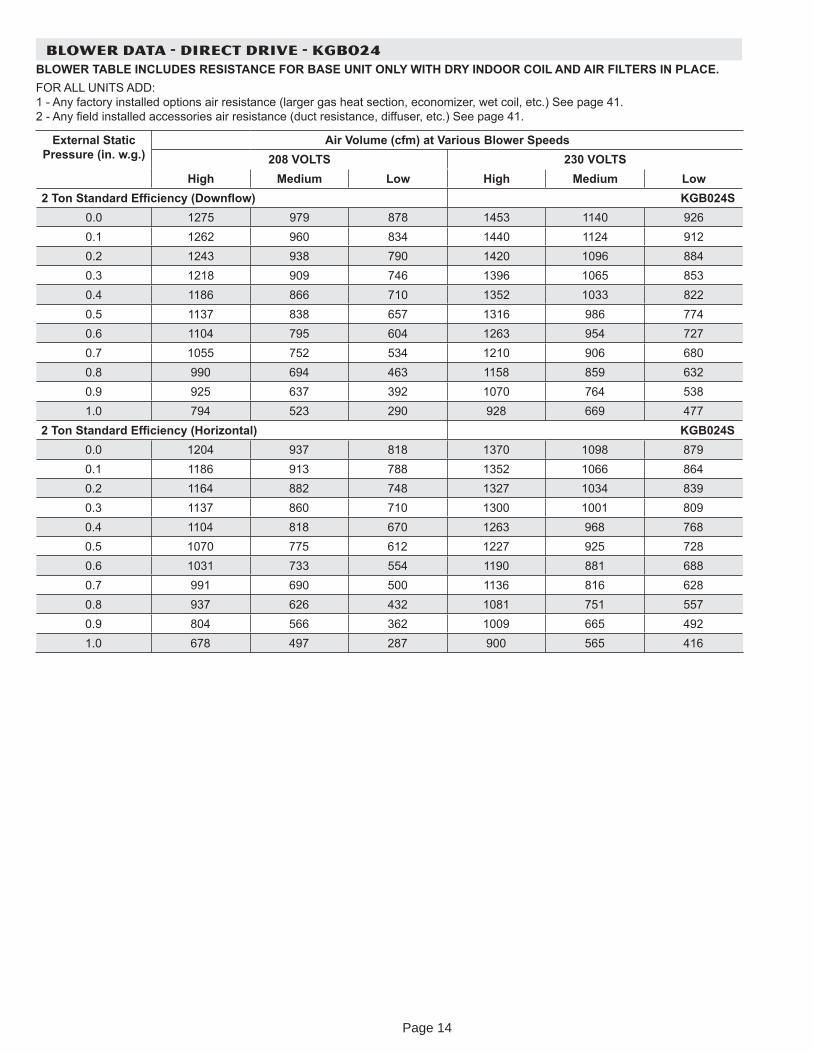
BLOWER DATA - DIRECT DRIVE - KGB024BLOWER TABLE INCLUDES RESISTANCE FOR BASE UNIT ONLY WITH DRY INDOOR COIL AND AIR FILTERS IN PLACE.FOR ALL UNITS ADD: 1 - An factor installed options air resistance (larger gas heat section, economi er, wet coil, etc.) See page 41. 2 - An eld installed accessories air resistance (duct resistance, diffuser, etc.) See page 41.
External Static Pressure (in. w.g.)
Air Volume (cfm) at Various Blower Speeds208 VOLTS 230 VOLTS
High Medium Low High Medium Low2 Ton Standard Ef ciency (Down ow) KGB024S
0.0 1275 979 878 1453 1140 9260.1 1262 960 834 1440 1124 9120.2 1243 938 790 1420 1096 8840.3 1218 909 746 1396 1065 8530.4 1186 866 710 1352 1033 8220.5 1137 838 657 1316 986 7740.6 1104 795 604 1263 954 7270.7 1055 752 534 1210 906 6800.8 990 694 463 1158 859 6320.9 925 637 392 1070 764 5381.0 794 523 290 928 669 477
2 Ton Standard Ef ciency (Hori ontal) KGB024S0.0 1204 937 818 1370 1098 8790.1 1186 913 788 1352 1066 8640.2 1164 882 748 1327 1034 8390.3 1137 860 710 1300 1001 8090.4 1104 818 670 1263 968 7680.5 1070 775 612 1227 925 7280.6 1031 733 554 1190 881 6880.7 991 690 500 1136 816 6280.8 937 626 432 1081 751 5570.9 804 566 362 1009 665 4921.0 678 497 287 900 565 416
Page 14
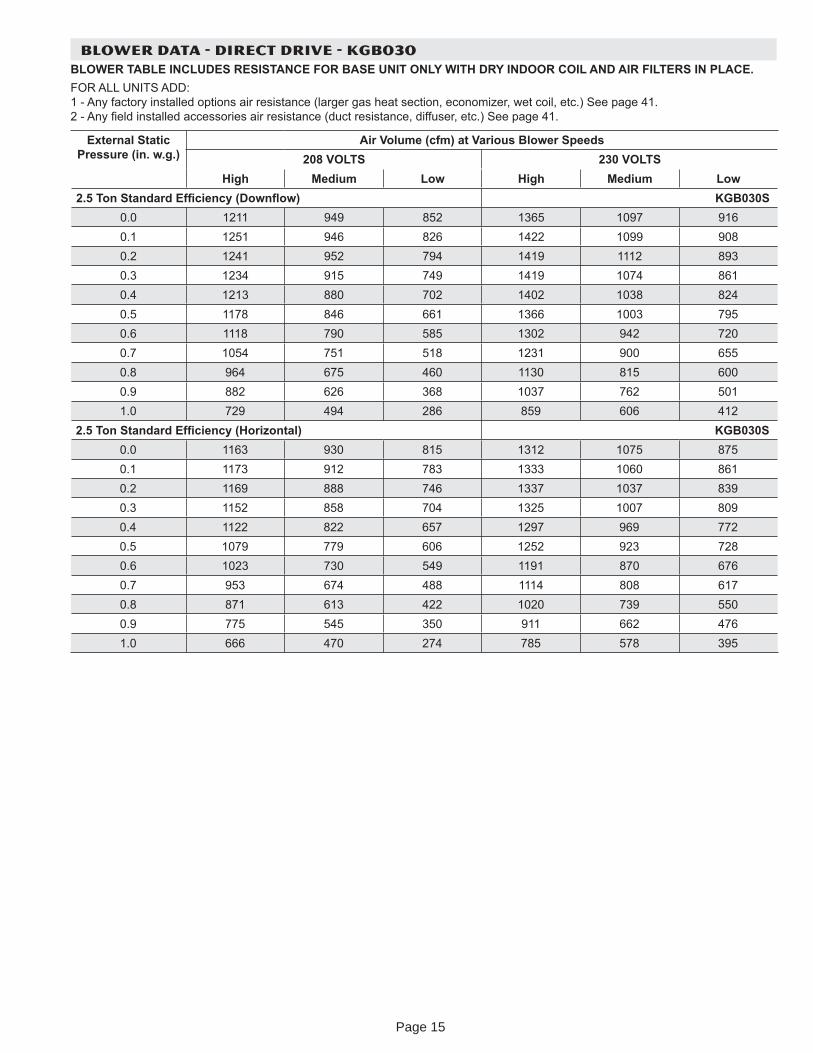
BLOWER DATA - DIRECT DRIVE - KGB030BLOWER TABLE INCLUDES RESISTANCE FOR BASE UNIT ONLY WITH DRY INDOOR COIL AND AIR FILTERS IN PLACE.FOR ALL UNITS ADD: 1 - An factor installed options air resistance (larger gas heat section, economi er, wet coil, etc.) See page 41. 2 - An eld installed accessories air resistance (duct resistance, diffuser, etc.) See page 41.
External Static Pressure (in. w.g.)
Air Volume (cfm) at Various Blower Speeds208 VOLTS 230 VOLTS
High Medium Low High Medium Low2.5 Ton Standard Ef ciency (Down ow) KGB030S
0.0 1211 949 852 1365 1097 9160.1 1251 946 826 1422 1099 9080.2 1241 952 794 1419 1112 8930.3 1234 915 749 1419 1074 8610.4 1213 880 702 1402 1038 8240.5 1178 846 661 1366 1003 7950.6 1118 790 585 1302 942 7200.7 1054 751 518 1231 900 6550.8 964 675 460 1130 815 6000.9 882 626 368 1037 762 5011.0 729 494 286 859 606 412
2.5 Ton Standard Ef ciency (Hori ontal) KGB030S0.0 1163 930 815 1312 1075 8750.1 1173 912 783 1333 1060 8610.2 1169 888 746 1337 1037 8390.3 1152 858 704 1325 1007 8090.4 1122 822 657 1297 969 7720.5 1079 779 606 1252 923 7280.6 1023 730 549 1191 870 6760.7 953 674 488 1114 808 6170.8 871 613 422 1020 739 5500.9 775 545 350 911 662 4761.0 666 470 274 785 578 395
Page 15
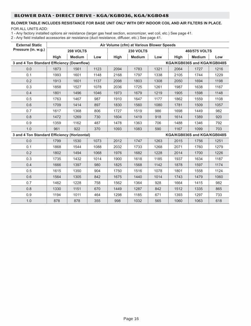
BLOWER DATA - DIRECT DRIVE - KGA/KGB036, KGA/KGB048
BLOWER TABLE INCLUDES RESISTANCE FOR BASE UNIT ONLY WITH DRY INDOOR COIL AND AIR FILTERS IN PLACE.FOR ALL UNITS ADD: 1 - An factor installed options air resistance (larger gas heat section, economi er, wet coil, etc.) See page 41. 2 - An eld installed accessories air resistance (duct resistance, diffuser, etc.) See page 41.
External Static Pressure (in. w.g.)
Air Volume (cfm) at Various Blower Speeds208 VOLTS 230 VOLTS 460/575 VOLTS
High Medium Low High Medium Low High Medium Low3 and 4 Ton Standard Ef ciency (Down ow) KGA/KGB036S and KGA/KGB048S
0.0 1873 1561 1123 2094 1783 1321 2064 1727 12160.1 1993 1601 1148 2168 1797 1338 2105 1744 12290.2 1913 1601 1137 2098 1803 1308 2050 1694 11980.3 1858 1527 1078 2036 1725 1261 1987 1638 11670.4 1801 1496 1046 1973 1679 1219 1905 1598 11480.5 1763 1467 987 1910 1647 1177 1862 1559 11080.6 1709 1414 897 1830 1560 1080 1781 1509 10570.7 1617 1368 806 1727 1519 986 1698 1449 9820.8 1472 1269 730 1604 1419 918 1614 1389 9200.9 1359 1162 487 1478 1363 706 1488 1346 7921.0 961 922 370 1093 1083 590 1167 1099 703
3 and 4 Ton Standard Ef ciency (Hori ontal) KGA/KGB036S and KGA/KGB048S0.0 1799 1530 1073 2012 1747 1263 2015 1756 12510.1 1868 1544 1088 2032 1733 1268 2071 1760 12790.2 1802 1494 1068 1976 1682 1228 2014 1700 12260.3 1735 1432 1014 1900 1618 1185 1937 1634 11870.4 1666 1397 980 1825 1568 1142 1878 1597 11740.5 1615 1350 904 1750 1516 1078 1801 1558 11240.6 1564 1305 842 1675 1440 1014 1743 1479 10600.7 1462 1228 758 1562 1364 928 1664 1415 9820.8 1330 1151 670 1449 1287 842 1512 1335 8650.9 1194 1011 464 1298 1185 671 1393 1297 7331.0 878 878 355 998 1032 565 1060 1063 618
Page 16
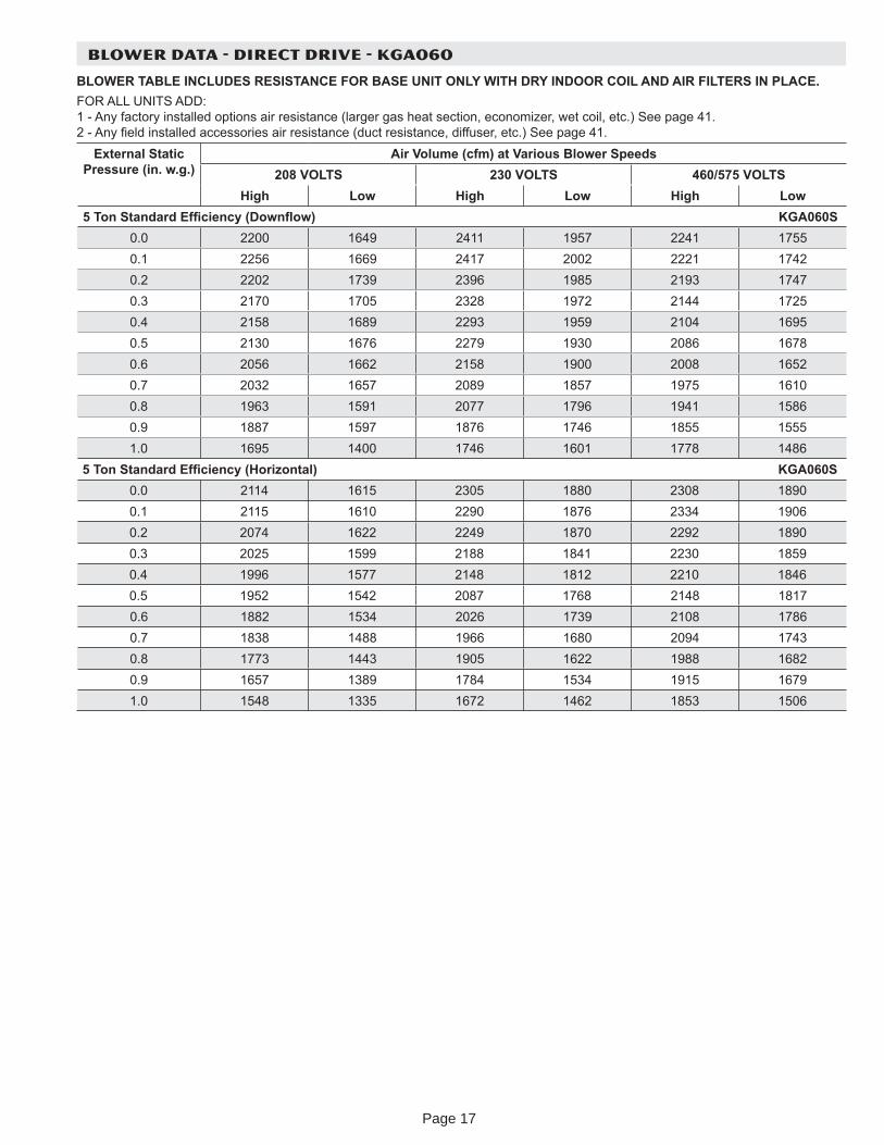
BLOWER DATA - DIRECT DRIVE - KGA060
BLOWER TABLE INCLUDES RESISTANCE FOR BASE UNIT ONLY WITH DRY INDOOR COIL AND AIR FILTERS IN PLACE.FOR ALL UNITS ADD: 1 - An factor installed options air resistance (larger gas heat section, economi er, wet coil, etc.) See page 41. 2 - An eld installed accessories air resistance (duct resistance, diffuser, etc.) See page 41.
External Static Pressure (in. w.g.)
Air Volume (cfm) at Various Blower Speeds208 VOLTS 230 VOLTS 460/575 VOLTS
High Low High Low High Low5 Ton Standard Ef ciency (Down ow) KGA060S
0.0 2200 1649 2411 1957 2241 17550.1 2256 1669 2417 2002 2221 17420.2 2202 1739 2396 1985 2193 17470.3 2170 1705 2328 1972 2144 17250.4 2158 1689 2293 1959 2104 16950.5 2130 1676 2279 1930 2086 16780.6 2056 1662 2158 1900 2008 16520.7 2032 1657 2089 1857 1975 16100.8 1963 1591 2077 1796 1941 15860.9 1887 1597 1876 1746 1855 15551.0 1695 1400 1746 1601 1778 1486
5 Ton Standard Ef ciency (Hori ontal) KGA060S0.0 2114 1615 2305 1880 2308 18900.1 2115 1610 2290 1876 2334 19060.2 2074 1622 2249 1870 2292 18900.3 2025 1599 2188 1841 2230 18590.4 1996 1577 2148 1812 2210 18460.5 1952 1542 2087 1768 2148 18170.6 1882 1534 2026 1739 2108 17860.7 1838 1488 1966 1680 2094 17430.8 1773 1443 1905 1622 1988 16820.9 1657 1389 1784 1534 1915 16791.0 1548 1335 1672 1462 1853 1506
Page 17
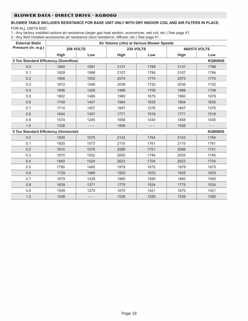
BLOWER DATA - DIRECT DRIVE - KGB060
BLOWER TABLE INCLUDES RESISTANCE FOR BASE UNIT ONLY WITH DRY INDOOR COIL AND AIR FILTERS IN PLACE.FOR ALL UNITS ADD: 1 - An factor installed options air resistance (larger gas heat section, economi er, wet coil, etc.) See page 41. 2 - An eld installed accessories air resistance (duct resistance, diffuser, etc.) See page 41.
External Static Pressure (in. w.g.)
Air Volume (cfm) at Various Blower Speeds208 VOLTS 230 VOLTS 460/575 VOLTS
High Low High Low High Low5 Ton Standard Ef ciency (Down ow) KGB060S
0.0 1940 1581 2131 1788 2131 17880.1 1929 1566 2107 1784 2107 17840.2 1906 1552 2074 1774 2074 17740.3 1872 1546 2036 1752 2036 17520.4 1836 1526 1998 1708 1998 17080.5 1802 1486 1960 1679 1960 16790.6 1749 1447 1904 1635 1904 16350.7 1714 1407 1847 1576 1847 15760.8 1644 1347 1771 1518 1771 15180.9 1574 1245 1658 1430 1658 14301.0 1338 - - - 1506 - - - 1506 - - -
5 Ton Standard Ef ciency (Hori ontal) KGB060S0.0 1930 1575 2143 1764 2143 17640.1 1920 1573 2115 1761 2115 17610.2 1910 1576 2088 1751 2088 17510.3 1870 1552 2055 1746 2055 17460.4 1840 1524 2023 1704 2023 17040.5 1790 1495 1979 1675 1979 16750.6 1739 1466 1925 1633 1925 16330.7 1679 1428 1860 1590 1860 15900.8 1639 1371 1775 1534 1775 15340.9 1559 1270 1670 1421 1670 14211.0 1438 - - - 1539 1285 1539 1285
Page 18
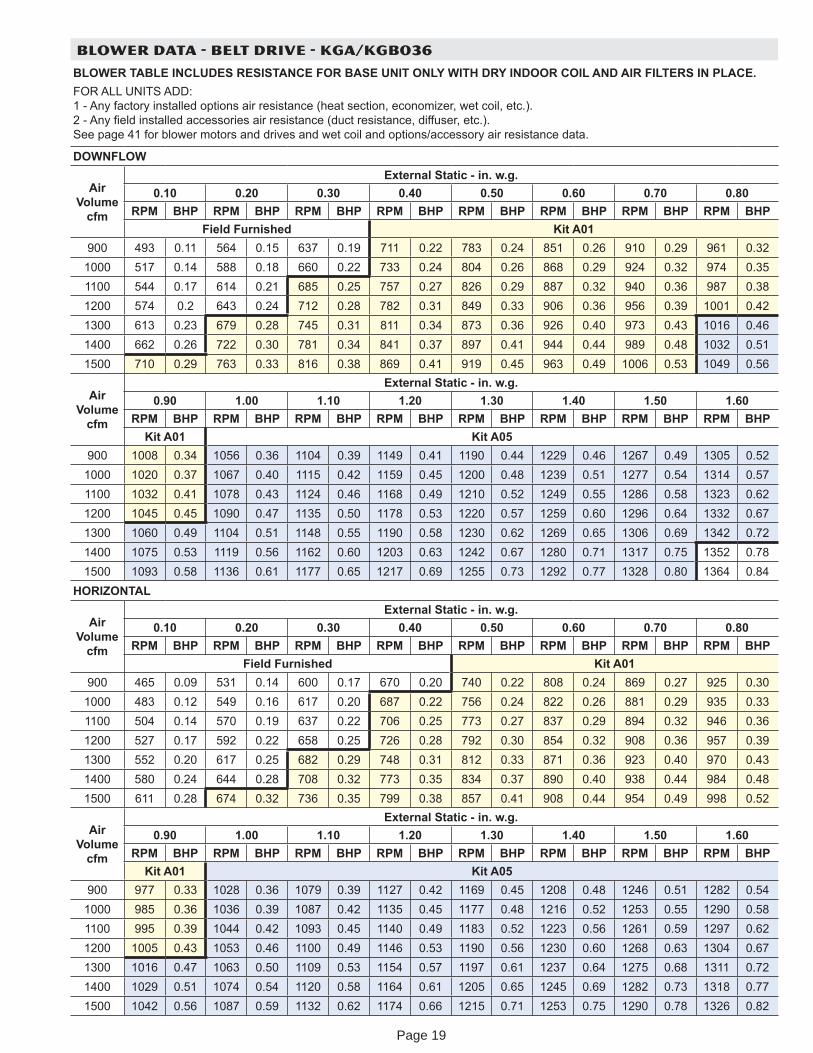
BLOWER DATA - BELT DRIVE - KGA/KGB036
BLOWER TABLE INCLUDES RESISTANCE FOR BASE UNIT ONLY WITH DRY INDOOR COIL AND AIR FILTERS IN PLACE.FOR ALL UNITS ADD: 1 - An factor installed options air resistance (heat section, economi er, wet coil, etc.). 2 - An eld installed accessories air resistance (duct resistance, diffuser, etc.). See page 41 for blower motors and drives and wet coil and options/accessor air resistance data.
DOWNFLOW
Air Volume
cfm
External Static - in. w.g.0.10 0.20 0.30 0.40 0.50 0.60 0.70 0.80
RPM BHP RPM BHP RPM BHP RPM BHP RPM BHP RPM BHP RPM BHP RPM BHPField Furnished Kit A01
900 493 0.11 564 0.15 637 0.19 711 0.22 783 0.24 851 0.26 910 0.29 961 0.321000 517 0.14 588 0.18 660 0.22 733 0.24 804 0.26 868 0.29 924 0.32 974 0.351100 544 0.17 614 0.21 685 0.25 757 0.27 826 0.29 887 0.32 940 0.36 987 0.381200 574 0.2 643 0.24 712 0.28 782 0.31 849 0.33 906 0.36 956 0.39 1001 0.421300 613 0.23 679 0.28 745 0.31 811 0.34 873 0.36 926 0.40 973 0.43 1016 0.461400 662 0.26 722 0.30 781 0.34 841 0.37 897 0.41 944 0.44 989 0.48 1032 0.511500 710 0.29 763 0.33 816 0.38 869 0.41 919 0.45 963 0.49 1006 0.53 1049 0.56
Air Volume
cfm
External Static - in. w.g.0.90 1.00 1.10 1.20 1.30 1.40 1.50 1.60
RPM BHP RPM BHP RPM BHP RPM BHP RPM BHP RPM BHP RPM BHP RPM BHPKit A01 Kit A05
900 1008 0.34 1056 0.36 1104 0.39 1149 0.41 1190 0.44 1229 0.46 1267 0.49 1305 0.521000 1020 0.37 1067 0.40 1115 0.42 1159 0.45 1200 0.48 1239 0.51 1277 0.54 1314 0.571100 1032 0.41 1078 0.43 1124 0.46 1168 0.49 1210 0.52 1249 0.55 1286 0.58 1323 0.621200 1045 0.45 1090 0.47 1135 0.50 1178 0.53 1220 0.57 1259 0.60 1296 0.64 1332 0.671300 1060 0.49 1104 0.51 1148 0.55 1190 0.58 1230 0.62 1269 0.65 1306 0.69 1342 0.721400 1075 0.53 1119 0.56 1162 0.60 1203 0.63 1242 0.67 1280 0.71 1317 0.75 1352 0.781500 1093 0.58 1136 0.61 1177 0.65 1217 0.69 1255 0.73 1292 0.77 1328 0.80 1364 0.84
HORIZONTAL
Air Volume
cfm
External Static - in. w.g.0.10 0.20 0.30 0.40 0.50 0.60 0.70 0.80
RPM BHP RPM BHP RPM BHP RPM BHP RPM BHP RPM BHP RPM BHP RPM BHPField Furnished Kit A01
900 465 0.09 531 0.14 600 0.17 670 0.20 740 0.22 808 0.24 869 0.27 925 0.301000 483 0.12 549 0.16 617 0.20 687 0.22 756 0.24 822 0.26 881 0.29 935 0.331100 504 0.14 570 0.19 637 0.22 706 0.25 773 0.27 837 0.29 894 0.32 946 0.361200 527 0.17 592 0.22 658 0.25 726 0.28 792 0.30 854 0.32 908 0.36 957 0.391300 552 0.20 617 0.25 682 0.29 748 0.31 812 0.33 871 0.36 923 0.40 970 0.431400 580 0.24 644 0.28 708 0.32 773 0.35 834 0.37 890 0.40 938 0.44 984 0.481500 611 0.28 674 0.32 736 0.35 799 0.38 857 0.41 908 0.44 954 0.49 998 0.52
Air Volume
cfm
External Static - in. w.g.0.90 1.00 1.10 1.20 1.30 1.40 1.50 1.60
RPM BHP RPM BHP RPM BHP RPM BHP RPM BHP RPM BHP RPM BHP RPM BHPKit A01 Kit A05
900 977 0.33 1028 0.36 1079 0.39 1127 0.42 1169 0.45 1208 0.48 1246 0.51 1282 0.541000 985 0.36 1036 0.39 1087 0.42 1135 0.45 1177 0.48 1216 0.52 1253 0.55 1290 0.581100 995 0.39 1044 0.42 1093 0.45 1140 0.49 1183 0.52 1223 0.56 1261 0.59 1297 0.621200 1005 0.43 1053 0.46 1100 0.49 1146 0.53 1190 0.56 1230 0.60 1268 0.63 1304 0.671300 1016 0.47 1063 0.50 1109 0.53 1154 0.57 1197 0.61 1237 0.64 1275 0.68 1311 0.721400 1029 0.51 1074 0.54 1120 0.58 1164 0.61 1205 0.65 1245 0.69 1282 0.73 1318 0.771500 1042 0.56 1087 0.59 1132 0.62 1174 0.66 1215 0.71 1253 0.75 1290 0.78 1326 0.82
Page 19
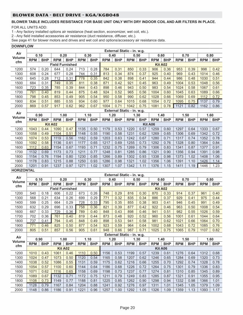
BLOWER DATA - BELT DRIVE - KGA/KGB048
BLOWER TABLE INCLUDES RESISTANCE FOR BASE UNIT ONLY WITH DRY INDOOR COIL AND AIR FILTERS IN PLACE.FOR ALL UNITS ADD: 1 - An factor installed options air resistance (heat section, economi er, wet coil, etc.). 2 - An eld installed accessories air resistance (duct resistance, diffuser, etc.). See page 41 for blower motors and drives and wet coil and options/accessor air resistance data.
DOWNFLOW
Air Volume
cfm
External Static - in. w.g.0.10 0.20 0.30 0.40 0.50 0.60 0.70 0.80
RPM BHP RPM BHP RPM BHP RPM BHP RPM BHP RPM BHP RPM BHP RPM BHPField Furnished Kit A02
1200 574 0.20 644 0.24 713 0.28 784 0.31 850 0.33 906 0.36 953 0.39 998 0.421300 608 0.24 677 0.28 744 0.31 813 0.34 874 0.37 925 0.40 969 0.43 1014 0.461400 645 0.28 712 0.31 778 0.35 842 0.38 898 0.41 944 0.44 986 0.48 1030 0.511500 684 0.31 749 0.35 811 0.38 871 0.42 921 0.45 963 0.49 1004 0.53 1048 0.561600 723 0.35 785 0.39 844 0.43 898 0.46 943 0.50 983 0.54 1024 0.58 1067 0.611700 761 0.40 819 0.44 875 0.48 924 0.52 965 0.56 1004 0.60 1045 0.63 1089 0.661800 798 0.45 853 0.49 905 0.54 950 0.58 990 0.62 1028 0.66 1069 0.69 1112 0.721900 834 0.51 885 0.55 934 0.60 977 0.64 1015 0.68 1054 0.72 1095 0.75 1137 0.792000 869 0.57 917 0.62 962 0.67 1004 0.71 1042 0.75 1081 0.78 1121 0.82 1162 0.86
Air Volume
cfm
External Static - in. w.g.0.90 1.00 1.10 1.20 1.30 1.40 1.50 1.60
RPM BHP RPM BHP RPM BHP RPM BHP RPM BHP RPM BHP RPM BHP RPM BHPKit A02 Kit A06
1200 1043 0.44 1090 0.47 1135 0.50 1179 0.53 1220 0.57 1259 0.60 1297 0.64 1333 0.671300 1058 0.49 1104 0.51 1148 0.55 1190 0.58 1231 0.62 1269 0.65 1306 0.69 1342 0.721400 1074 0.53 1119 0.56 1162 0.59 1203 0.63 1242 0.67 1280 0.71 1317 0.74 1352 0.781500 1092 0.58 1136 0.61 1177 0.65 1217 0.69 1255 0.73 1292 0.76 1328 0.80 1364 0.841600 1112 0.63 1154 0.67 1193 0.71 1232 0.75 1269 0.79 1306 0.83 1341 0.87 1377 0.911700 1132 0.69 1173 0.73 1211 0.77 1248 0.81 1285 0.86 1321 0.90 1356 0.94 1391 0.981800 1154 0.76 1194 0.80 1230 0.85 1266 0.89 1302 0.93 1338 0.98 1373 1.02 1408 1.061900 1178 0.83 1215 0.88 1250 0.93 1286 0.98 1321 1.02 1356 1.06 1391 1.10 1426 1.142000 1201 0.91 1237 0.97 1271 1.02 1307 1.07 1342 1.11 1376 1.15 1411 1.19 1446 1.23
HORIZONTAL
Air Volume
cfm
External Static - in. w.g.0.10 0.20 0.30 0.40 0.50 0.60 0.70 0.80
RPM BHP RPM BHP RPM BHP RPM BHP RPM BHP RPM BHP RPM BHP RPM BHPField Furnished Kit A02
1200 540 0.18 606 0.22 673 0.26 748 0.29 816 0.30 870 0.33 914 0.37 961 0.401300 568 0.21 634 0.26 699 0.29 771 0.32 835 0.34 886 0.37 929 0.41 975 0.441400 599 0.25 664 0.29 728 0.33 795 0.35 855 0.38 903 0.41 946 0.45 991 0.491500 632 0.29 696 0.33 758 0.36 821 0.39 877 0.42 922 0.46 963 0.50 1008 0.541600 667 0.33 729 0.36 789 0.40 848 0.43 898 0.46 941 0.51 982 0.55 1026 0.591700 702 0.36 761 0.40 819 0.44 873 0.48 920 0.52 960 0.56 1001 0.61 1044 0.641800 737 0.41 794 0.45 848 0.49 898 0.53 941 0.58 981 0.62 1021 0.66 1064 0.701900 771 0.46 825 0.50 877 0.54 923 0.59 964 0.64 1002 0.68 1043 0.72 1085 0.762000 805 0.51 857 0.56 905 0.61 948 0.66 987 0.71 1025 0.75 1065 0.79 1107 0.82
Air Volume
cfm
External Static - in. w.g.0.90 1.00 1.10 1.20 1.30 1.40 1.50 1.60
RPM BHP RPM BHP RPM BHP RPM BHP RPM BHP RPM BHP RPM BHP RPM BHPKit A02 Kit A06
1200 1010 0.43 1061 0.46 1110 0.50 1156 0.53 1199 0.57 1239 0.61 1276 0.64 1312 0.681300 1024 0.47 1073 0.50 1120 0.54 1165 0.58 1207 0.62 1246 0.65 1284 0.69 1320 0.731400 1038 0.52 1086 0.55 1131 0.59 1175 0.62 1216 0.66 1255 0.70 1292 0.74 1328 0.781500 1054 0.57 1100 0.60 1144 0.64 1186 0.68 1226 0.72 1264 0.75 1301 0.79 1336 0.831600 1071 0.62 1116 0.65 1158 0.69 1198 0.73 1237 0.77 1274 0.81 1310 0.85 1345 0.891700 1089 0.67 1132 0.71 1172 0.75 1211 0.79 1249 0.83 1285 0.87 1321 0.91 1355 0.951800 1108 0.73 1149 0.77 1188 0.81 1225 0.85 1262 0.90 1298 0.94 1332 0.98 1366 1.011900 1128 0.79 1167 0.84 1204 0.88 1241 0.92 1276 0.97 1311 1.01 1345 1.05 1379 1.092000 1148 0.86 1186 0.91 1221 0.96 1257 1.00 1292 1.05 1326 1.09 1359 1.13 1393 1.17
Page 20
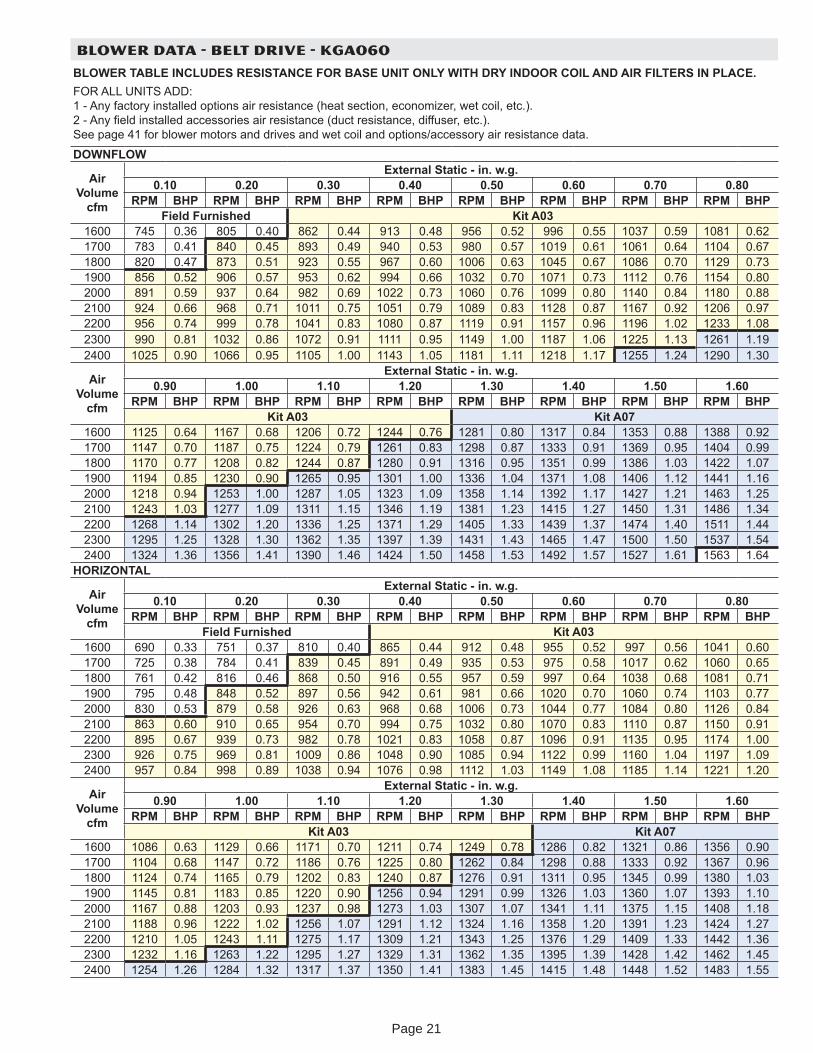
BLOWER DATA - BELT DRIVE - KGA060
BLOWER TABLE INCLUDES RESISTANCE FOR BASE UNIT ONLY WITH DRY INDOOR COIL AND AIR FILTERS IN PLACE.FOR ALL UNITS ADD: 1 - An factor installed options air resistance (heat section, economi er, wet coil, etc.). 2 - An eld installed accessories air resistance (duct resistance, diffuser, etc.). See page 41 for blower motors and drives and wet coil and options/accessor air resistance data.
DOWNFLOW
Air Volume
cfm
External Static - in. w.g.0.10 0.20 0.30 0.40 0.50 0.60 0.70 0.80
RPM BHP RPM BHP RPM BHP RPM BHP RPM BHP RPM BHP RPM BHP RPM BHPField Furnished Kit A03
1600 745 0.36 805 0.40 862 0.44 913 0.48 956 0.52 996 0.55 1037 0.59 1081 0.621700 783 0.41 840 0.45 893 0.49 940 0.53 980 0.57 1019 0.61 1061 0.64 1104 0.671800 820 0.47 873 0.51 923 0.55 967 0.60 1006 0.63 1045 0.67 1086 0.70 1129 0.731900 856 0.52 906 0.57 953 0.62 994 0.66 1032 0.70 1071 0.73 1112 0.76 1154 0.802000 891 0.59 937 0.64 982 0.69 1022 0.73 1060 0.76 1099 0.80 1140 0.84 1180 0.882100 924 0.66 968 0.71 1011 0.75 1051 0.79 1089 0.83 1128 0.87 1167 0.92 1206 0.972200 956 0.74 999 0.78 1041 0.83 1080 0.87 1119 0.91 1157 0.96 1196 1.02 1233 1.082300 990 0.81 1032 0.86 1072 0.91 1111 0.95 1149 1.00 1187 1.06 1225 1.13 1261 1.192400 1025 0.90 1066 0.95 1105 1.00 1143 1.05 1181 1.11 1218 1.17 1255 1.24 1290 1.30
Air Volume
cfm
External Static - in. w.g.0.90 1.00 1.10 1.20 1.30 1.40 1.50 1.60
RPM BHP RPM BHP RPM BHP RPM BHP RPM BHP RPM BHP RPM BHP RPM BHPKit A03 Kit A07
1600 1125 0.64 1167 0.68 1206 0.72 1244 0.76 1281 0.80 1317 0.84 1353 0.88 1388 0.921700 1147 0.70 1187 0.75 1224 0.79 1261 0.83 1298 0.87 1333 0.91 1369 0.95 1404 0.991800 1170 0.77 1208 0.82 1244 0.87 1280 0.91 1316 0.95 1351 0.99 1386 1.03 1422 1.071900 1194 0.85 1230 0.90 1265 0.95 1301 1.00 1336 1.04 1371 1.08 1406 1.12 1441 1.162000 1218 0.94 1253 1.00 1287 1.05 1323 1.09 1358 1.14 1392 1.17 1427 1.21 1463 1.252100 1243 1.03 1277 1.09 1311 1.15 1346 1.19 1381 1.23 1415 1.27 1450 1.31 1486 1.342200 1268 1.14 1302 1.20 1336 1.25 1371 1.29 1405 1.33 1439 1.37 1474 1.40 1511 1.442300 1295 1.25 1328 1.30 1362 1.35 1397 1.39 1431 1.43 1465 1.47 1500 1.50 1537 1.542400 1324 1.36 1356 1.41 1390 1.46 1424 1.50 1458 1.53 1492 1.57 1527 1.61 1563 1.64
HORIZONTAL
Air Volume
cfm
External Static - in. w.g.0.10 0.20 0.30 0.40 0.50 0.60 0.70 0.80
RPM BHP RPM BHP RPM BHP RPM BHP RPM BHP RPM BHP RPM BHP RPM BHPField Furnished Kit A03
1600 690 0.33 751 0.37 810 0.40 865 0.44 912 0.48 955 0.52 997 0.56 1041 0.601700 725 0.38 784 0.41 839 0.45 891 0.49 935 0.53 975 0.58 1017 0.62 1060 0.651800 761 0.42 816 0.46 868 0.50 916 0.55 957 0.59 997 0.64 1038 0.68 1081 0.711900 795 0.48 848 0.52 897 0.56 942 0.61 981 0.66 1020 0.70 1060 0.74 1103 0.772000 830 0.53 879 0.58 926 0.63 968 0.68 1006 0.73 1044 0.77 1084 0.80 1126 0.842100 863 0.60 910 0.65 954 0.70 994 0.75 1032 0.80 1070 0.83 1110 0.87 1150 0.912200 895 0.67 939 0.73 982 0.78 1021 0.83 1058 0.87 1096 0.91 1135 0.95 1174 1.002300 926 0.75 969 0.81 1009 0.86 1048 0.90 1085 0.94 1122 0.99 1160 1.04 1197 1.092400 957 0.84 998 0.89 1038 0.94 1076 0.98 1112 1.03 1149 1.08 1185 1.14 1221 1.20
Air Volume
cfm
External Static - in. w.g.0.90 1.00 1.10 1.20 1.30 1.40 1.50 1.60
RPM BHP RPM BHP RPM BHP RPM BHP RPM BHP RPM BHP RPM BHP RPM BHPKit A03 Kit A07
1600 1086 0.63 1129 0.66 1171 0.70 1211 0.74 1249 0.78 1286 0.82 1321 0.86 1356 0.901700 1104 0.68 1147 0.72 1186 0.76 1225 0.80 1262 0.84 1298 0.88 1333 0.92 1367 0.961800 1124 0.74 1165 0.79 1202 0.83 1240 0.87 1276 0.91 1311 0.95 1345 0.99 1380 1.031900 1145 0.81 1183 0.85 1220 0.90 1256 0.94 1291 0.99 1326 1.03 1360 1.07 1393 1.102000 1167 0.88 1203 0.93 1237 0.98 1273 1.03 1307 1.07 1341 1.11 1375 1.15 1408 1.182100 1188 0.96 1222 1.02 1256 1.07 1291 1.12 1324 1.16 1358 1.20 1391 1.23 1424 1.272200 1210 1.05 1243 1.11 1275 1.17 1309 1.21 1343 1.25 1376 1.29 1409 1.33 1442 1.362300 1232 1.16 1263 1.22 1295 1.27 1329 1.31 1362 1.35 1395 1.39 1428 1.42 1462 1.452400 1254 1.26 1284 1.32 1317 1.37 1350 1.41 1383 1.45 1415 1.48 1448 1.52 1483 1.55
Page 21
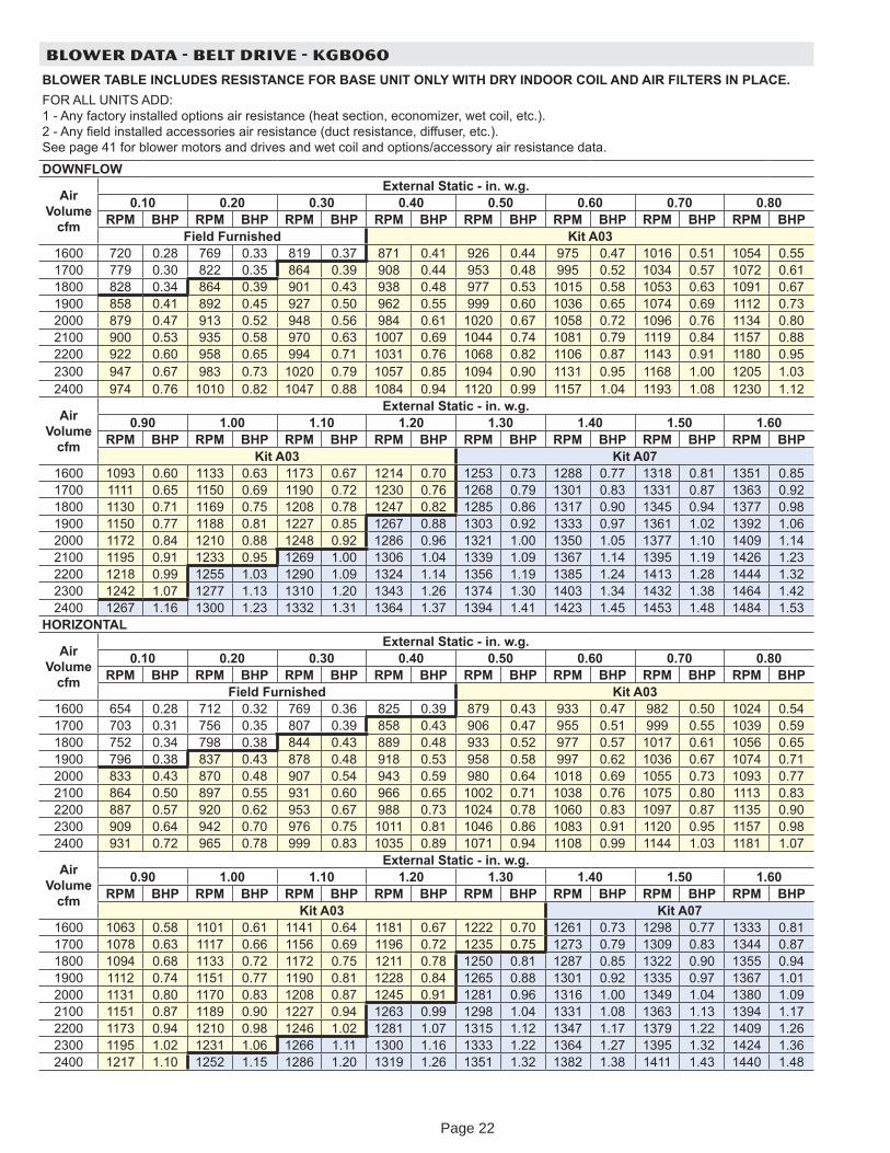
BLOWER DATA - BELT DRIVE - KGB060
BLOWER TABLE INCLUDES RESISTANCE FOR BASE UNIT ONLY WITH DRY INDOOR COIL AND AIR FILTERS IN PLACE.FOR ALL UNITS ADD: 1 - An factor installed options air resistance (heat section, economi er, wet coil, etc.). 2 - An eld installed accessories air resistance (duct resistance, diffuser, etc.). See page 41 for blower motors and drives and wet coil and options/accessor air resistance data.
DOWNFLOW
Air Volume
cfm
External Static - in. w.g.0.10 0.20 0.30 0.40 0.50 0.60 0.70 0.80
RPM BHP RPM BHP RPM BHP RPM BHP RPM BHP RPM BHP RPM BHP RPM BHPField Furnished Kit A03
1600 720 0.28 769 0.33 819 0.37 871 0.41 926 0.44 975 0.47 1016 0.51 1054 0.551700 779 0.30 822 0.35 864 0.39 908 0.44 953 0.48 995 0.52 1034 0.57 1072 0.611800 828 0.34 864 0.39 901 0.43 938 0.48 977 0.53 1015 0.58 1053 0.63 1091 0.671900 858 0.41 892 0.45 927 0.50 962 0.55 999 0.60 1036 0.65 1074 0.69 1112 0.732000 879 0.47 913 0.52 948 0.56 984 0.61 1020 0.67 1058 0.72 1096 0.76 1134 0.802100 900 0.53 935 0.58 970 0.63 1007 0.69 1044 0.74 1081 0.79 1119 0.84 1157 0.882200 922 0.60 958 0.65 994 0.71 1031 0.76 1068 0.82 1106 0.87 1143 0.91 1180 0.952300 947 0.67 983 0.73 1020 0.79 1057 0.85 1094 0.90 1131 0.95 1168 1.00 1205 1.032400 974 0.76 1010 0.82 1047 0.88 1084 0.94 1120 0.99 1157 1.04 1193 1.08 1230 1.12
Air Volume
cfm
External Static - in. w.g.0.90 1.00 1.10 1.20 1.30 1.40 1.50 1.60
RPM BHP RPM BHP RPM BHP RPM BHP RPM BHP RPM BHP RPM BHP RPM BHPKit A03 Kit A07
1600 1093 0.60 1133 0.63 1173 0.67 1214 0.70 1253 0.73 1288 0.77 1318 0.81 1351 0.851700 1111 0.65 1150 0.69 1190 0.72 1230 0.76 1268 0.79 1301 0.83 1331 0.87 1363 0.921800 1130 0.71 1169 0.75 1208 0.78 1247 0.82 1285 0.86 1317 0.90 1345 0.94 1377 0.981900 1150 0.77 1188 0.81 1227 0.85 1267 0.88 1303 0.92 1333 0.97 1361 1.02 1392 1.062000 1172 0.84 1210 0.88 1248 0.92 1286 0.96 1321 1.00 1350 1.05 1377 1.10 1409 1.142100 1195 0.91 1233 0.95 1269 1.00 1306 1.04 1339 1.09 1367 1.14 1395 1.19 1426 1.232200 1218 0.99 1255 1.03 1290 1.09 1324 1.14 1356 1.19 1385 1.24 1413 1.28 1444 1.322300 1242 1.07 1277 1.13 1310 1.20 1343 1.26 1374 1.30 1403 1.34 1432 1.38 1464 1.422400 1267 1.16 1300 1.23 1332 1.31 1364 1.37 1394 1.41 1423 1.45 1453 1.48 1484 1.53
HORIZONTAL
Air Volume
cfm
External Static - in. w.g.0.10 0.20 0.30 0.40 0.50 0.60 0.70 0.80
RPM BHP RPM BHP RPM BHP RPM BHP RPM BHP RPM BHP RPM BHP RPM BHPField Furnished Kit A03
1600 654 0.28 712 0.32 769 0.36 825 0.39 879 0.43 933 0.47 982 0.50 1024 0.541700 703 0.31 756 0.35 807 0.39 858 0.43 906 0.47 955 0.51 999 0.55 1039 0.591800 752 0.34 798 0.38 844 0.43 889 0.48 933 0.52 977 0.57 1017 0.61 1056 0.651900 796 0.38 837 0.43 878 0.48 918 0.53 958 0.58 997 0.62 1036 0.67 1074 0.712000 833 0.43 870 0.48 907 0.54 943 0.59 980 0.64 1018 0.69 1055 0.73 1093 0.772100 864 0.50 897 0.55 931 0.60 966 0.65 1002 0.71 1038 0.76 1075 0.80 1113 0.832200 887 0.57 920 0.62 953 0.67 988 0.73 1024 0.78 1060 0.83 1097 0.87 1135 0.902300 909 0.64 942 0.70 976 0.75 1011 0.81 1046 0.86 1083 0.91 1120 0.95 1157 0.982400 931 0.72 965 0.78 999 0.83 1035 0.89 1071 0.94 1108 0.99 1144 1.03 1181 1.07
Air Volume
cfm
External Static - in. w.g.0.90 1.00 1.10 1.20 1.30 1.40 1.50 1.60
RPM BHP RPM BHP RPM BHP RPM BHP RPM BHP RPM BHP RPM BHP RPM BHPKit A03 Kit A07
1600 1063 0.58 1101 0.61 1141 0.64 1181 0.67 1222 0.70 1261 0.73 1298 0.77 1333 0.811700 1078 0.63 1117 0.66 1156 0.69 1196 0.72 1235 0.75 1273 0.79 1309 0.83 1344 0.871800 1094 0.68 1133 0.72 1172 0.75 1211 0.78 1250 0.81 1287 0.85 1322 0.90 1355 0.941900 1112 0.74 1151 0.77 1190 0.81 1228 0.84 1265 0.88 1301 0.92 1335 0.97 1367 1.012000 1131 0.80 1170 0.83 1208 0.87 1245 0.91 1281 0.96 1316 1.00 1349 1.04 1380 1.092100 1151 0.87 1189 0.90 1227 0.94 1263 0.99 1298 1.04 1331 1.08 1363 1.13 1394 1.172200 1173 0.94 1210 0.98 1246 1.02 1281 1.07 1315 1.12 1347 1.17 1379 1.22 1409 1.262300 1195 1.02 1231 1.06 1266 1.11 1300 1.16 1333 1.22 1364 1.27 1395 1.32 1424 1.362400 1217 1.10 1252 1.15 1286 1.20 1319 1.26 1351 1.32 1382 1.38 1411 1.43 1440 1.48
Page 22
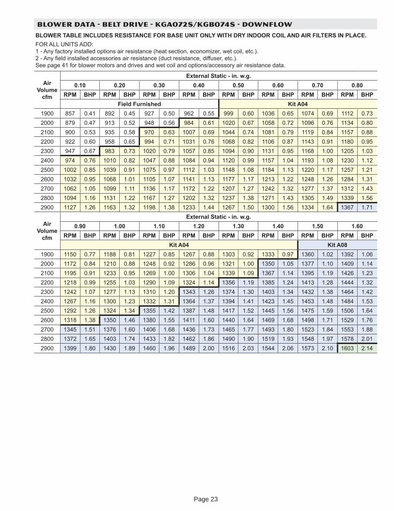
BLOWER DATA - BELT DRIVE - KGA072S/KGB074S - DOWNFLOW
BLOWER TABLE INCLUDES RESISTANCE FOR BASE UNIT ONLY WITH DRY INDOOR COIL AND AIR FILTERS IN PLACE.FOR ALL UNITS ADD: 1 - An factor installed options air resistance (heat section, economi er, wet coil, etc.). 2 - An eld installed accessories air resistance (duct resistance, diffuser, etc.). See page 41 for blower motors and drives and wet coil and options/accessor air resistance data.
Air Volume
cfm
External Static - in. w.g.0.10 0.20 0.30 0.40 0.50 0.60 0.70 0.80
RPM BHP RPM BHP RPM BHP RPM BHP RPM BHP RPM BHP RPM BHP RPM BHPField Furnished Kit A04
1900 857 0.41 892 0.45 927 0.50 962 0.55 999 0.60 1036 0.65 1074 0.69 1112 0.732000 879 0.47 913 0.52 948 0.56 984 0.61 1020 0.67 1058 0.72 1096 0.76 1134 0.802100 900 0.53 935 0.58 970 0.63 1007 0.69 1044 0.74 1081 0.79 1119 0.84 1157 0.882200 922 0.60 958 0.65 994 0.71 1031 0.76 1068 0.82 1106 0.87 1143 0.91 1180 0.952300 947 0.67 983 0.73 1020 0.79 1057 0.85 1094 0.90 1131 0.95 1168 1.00 1205 1.032400 974 0.76 1010 0.82 1047 0.88 1084 0.94 1120 0.99 1157 1.04 1193 1.08 1230 1.122500 1002 0.85 1039 0.91 1075 0.97 1112 1.03 1148 1.08 1184 1.13 1220 1.17 1257 1.212600 1032 0.95 1068 1.01 1105 1.07 1141 1.13 1177 1.17 1213 1.22 1248 1.26 1284 1.312700 1062 1.05 1099 1.11 1136 1.17 1172 1.22 1207 1.27 1242 1.32 1277 1.37 1312 1.432800 1094 1.16 1131 1.22 1167 1.27 1202 1.32 1237 1.38 1271 1.43 1305 1.49 1339 1.562900 1127 1.26 1163 1.32 1198 1.38 1233 1.44 1267 1.50 1300 1.56 1334 1.64 1367 1.71
Air Volume
cfm
External Static - in. w.g.0.90 1.00 1.10 1.20 1.30 1.40 1.50 1.60
RPM BHP RPM BHP RPM BHP RPM BHP RPM BHP RPM BHP RPM BHP RPM BHPKit A04 Kit A08
1900 1150 0.77 1188 0.81 1227 0.85 1267 0.88 1303 0.92 1333 0.97 1360 1.02 1392 1.062000 1172 0.84 1210 0.88 1248 0.92 1286 0.96 1321 1.00 1350 1.05 1377 1.10 1409 1.142100 1195 0.91 1233 0.95 1269 1.00 1306 1.04 1339 1.09 1367 1.14 1395 1.19 1426 1.232200 1218 0.99 1255 1.03 1290 1.09 1324 1.14 1356 1.19 1385 1.24 1413 1.28 1444 1.322300 1242 1.07 1277 1.13 1310 1.20 1343 1.26 1374 1.30 1403 1.34 1432 1.38 1464 1.422400 1267 1.16 1300 1.23 1332 1.31 1364 1.37 1394 1.41 1423 1.45 1453 1.48 1484 1.532500 1292 1.26 1324 1.34 1355 1.42 1387 1.48 1417 1.52 1445 1.56 1475 1.59 1506 1.642600 1318 1.38 1350 1.46 1380 1.55 1411 1.60 1440 1.64 1469 1.68 1498 1.71 1529 1.762700 1345 1.51 1376 1.60 1406 1.68 1436 1.73 1465 1.77 1493 1.80 1523 1.84 1553 1.882800 1372 1.65 1403 1.74 1433 1.82 1462 1.86 1490 1.90 1519 1.93 1548 1.97 1578 2.012900 1399 1.80 1430 1.89 1460 1.96 1489 2.00 1516 2.03 1544 2.06 1573 2.10 1603 2.14
Page 23
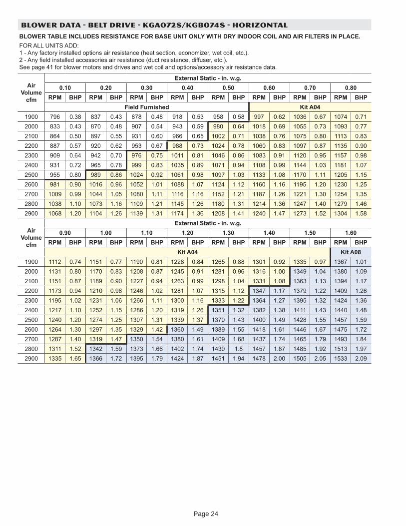
BLOWER DATA - BELT DRIVE - KGA072S/KGB074S - HORIZONTAL
BLOWER TABLE INCLUDES RESISTANCE FOR BASE UNIT ONLY WITH DRY INDOOR COIL AND AIR FILTERS IN PLACE.FOR ALL UNITS ADD: 1 - An factor installed options air resistance (heat section, economi er, wet coil, etc.). 2 - An eld installed accessories air resistance (duct resistance, diffuser, etc.). See page 41 for blower motors and drives and wet coil and options/accessor air resistance data.
Air Volume
cfm
External Static - in. w.g.0.10 0.20 0.30 0.40 0.50 0.60 0.70 0.80
RPM BHP RPM BHP RPM BHP RPM BHP RPM BHP RPM BHP RPM BHP RPM BHPField Furnished Kit A04
1900 796 0.38 837 0.43 878 0.48 918 0.53 958 0.58 997 0.62 1036 0.67 1074 0.712000 833 0.43 870 0.48 907 0.54 943 0.59 980 0.64 1018 0.69 1055 0.73 1093 0.772100 864 0.50 897 0.55 931 0.60 966 0.65 1002 0.71 1038 0.76 1075 0.80 1113 0.832200 887 0.57 920 0.62 953 0.67 988 0.73 1024 0.78 1060 0.83 1097 0.87 1135 0.902300 909 0.64 942 0.70 976 0.75 1011 0.81 1046 0.86 1083 0.91 1120 0.95 1157 0.982400 931 0.72 965 0.78 999 0.83 1035 0.89 1071 0.94 1108 0.99 1144 1.03 1181 1.072500 955 0.80 989 0.86 1024 0.92 1061 0.98 1097 1.03 1133 1.08 1170 1.11 1205 1.152600 981 0.90 1016 0.96 1052 1.01 1088 1.07 1124 1.12 1160 1.16 1195 1.20 1230 1.252700 1009 0.99 1044 1.05 1080 1.11 1116 1.16 1152 1.21 1187 1.26 1221 1.30 1254 1.352800 1038 1.10 1073 1.16 1109 1.21 1145 1.26 1180 1.31 1214 1.36 1247 1.40 1279 1.462900 1068 1.20 1104 1.26 1139 1.31 1174 1.36 1208 1.41 1240 1.47 1273 1.52 1304 1.58
Air Volume
cfm
External Static - in. w.g.0.90 1.00 1.10 1.20 1.30 1.40 1.50 1.60
RPM BHP RPM BHP RPM BHP RPM BHP RPM BHP RPM BHP RPM BHP RPM BHPKit A04 Kit A08
1900 1112 0.74 1151 0.77 1190 0.81 1228 0.84 1265 0.88 1301 0.92 1335 0.97 1367 1.012000 1131 0.80 1170 0.83 1208 0.87 1245 0.91 1281 0.96 1316 1.00 1349 1.04 1380 1.092100 1151 0.87 1189 0.90 1227 0.94 1263 0.99 1298 1.04 1331 1.08 1363 1.13 1394 1.172200 1173 0.94 1210 0.98 1246 1.02 1281 1.07 1315 1.12 1347 1.17 1379 1.22 1409 1.262300 1195 1.02 1231 1.06 1266 1.11 1300 1.16 1333 1.22 1364 1.27 1395 1.32 1424 1.362400 1217 1.10 1252 1.15 1286 1.20 1319 1.26 1351 1.32 1382 1.38 1411 1.43 1440 1.482500 1240 1.20 1274 1.25 1307 1.31 1339 1.37 1370 1.43 1400 1.49 1428 1.55 1457 1.592600 1264 1.30 1297 1.35 1329 1.42 1360 1.49 1389 1.55 1418 1.61 1446 1.67 1475 1.722700 1287 1.40 1319 1.47 1350 1.54 1380 1.61 1409 1.68 1437 1.74 1465 1.79 1493 1.842800 1311 1.52 1342 1.59 1373 1.66 1402 1.74 1430 1.8 1457 1.87 1485 1.92 1513 1.972900 1335 1.65 1366 1.72 1395 1.79 1424 1.87 1451 1.94 1478 2.00 1505 2.05 1533 2.09
Page 24
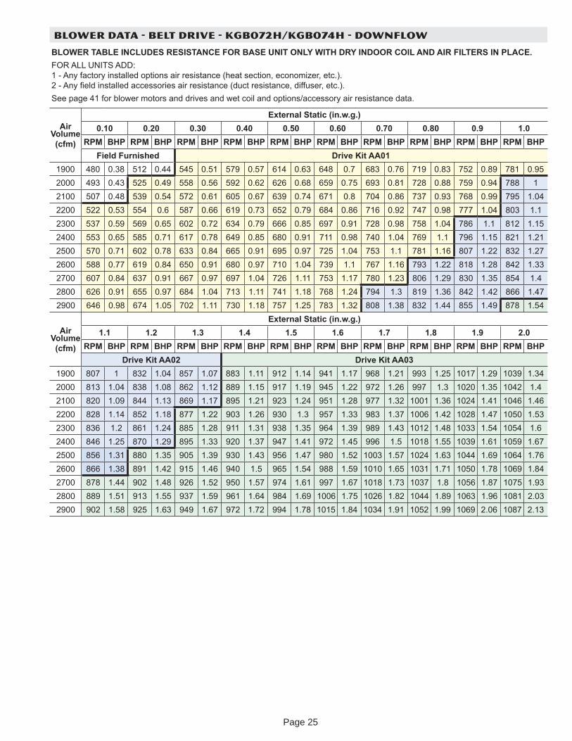
BLOWER DATA - BELT DRIVE - KGB072H/KGB074H - DOWNFLOW
BLOWER TABLE INCLUDES RESISTANCE FOR BASE UNIT ONLY WITH DRY INDOOR COIL AND AIR FILTERS IN PLACE.FOR ALL UNITS ADD: 1 - An factor installed options air resistance (heat section, economi er, etc.). 2 - An eld installed accessories air resistance (duct resistance, diffuser, etc.).See page 41 for blower motors and drives and wet coil and options/accessor air resistance data.
Air Volume (cfm)
External Static (in.w.g.)0.10 0.20 0.30 0.40 0.50 0.60 0.70 0.80 0.9 1.0
RPM BHP RPM BHP RPM BHP RPM BHP RPM BHP RPM BHP RPM BHP RPM BHP RPM BHP RPM BHPField Furnished Drive Kit AA01
1900 480 0.38 512 0.44 545 0.51 579 0.57 614 0.63 648 0.7 683 0.76 719 0.83 752 0.89 781 0.952000 493 0.43 525 0.49 558 0.56 592 0.62 626 0.68 659 0.75 693 0.81 728 0.88 759 0.94 788 12100 507 0.48 539 0.54 572 0.61 605 0.67 639 0.74 671 0.8 704 0.86 737 0.93 768 0.99 795 1.042200 522 0.53 554 0.6 587 0.66 619 0.73 652 0.79 684 0.86 716 0.92 747 0.98 777 1.04 803 1.12300 537 0.59 569 0.65 602 0.72 634 0.79 666 0.85 697 0.91 728 0.98 758 1.04 786 1.1 812 1.152400 553 0.65 585 0.71 617 0.78 649 0.85 680 0.91 711 0.98 740 1.04 769 1.1 796 1.15 821 1.212500 570 0.71 602 0.78 633 0.84 665 0.91 695 0.97 725 1.04 753 1.1 781 1.16 807 1.22 832 1.272600 588 0.77 619 0.84 650 0.91 680 0.97 710 1.04 739 1.1 767 1.16 793 1.22 818 1.28 842 1.332700 607 0.84 637 0.91 667 0.97 697 1.04 726 1.11 753 1.17 780 1.23 806 1.29 830 1.35 854 1.42800 626 0.91 655 0.97 684 1.04 713 1.11 741 1.18 768 1.24 794 1.3 819 1.36 842 1.42 866 1.472900 646 0.98 674 1.05 702 1.11 730 1.18 757 1.25 783 1.32 808 1.38 832 1.44 855 1.49 878 1.54
Air Volume (cfm)
External Static (in.w.g.)1.1 1.2 1.3 1.4 1.5 1.6 1.7 1.8 1.9 2.0
RPM BHP RPM BHP RPM BHP RPM BHP RPM BHP RPM BHP RPM BHP RPM BHP RPM BHP RPM BHPDrive Kit AA02 Drive Kit AA03
1900 807 1 832 1.04 857 1.07 883 1.11 912 1.14 941 1.17 968 1.21 993 1.25 1017 1.29 1039 1.342000 813 1.04 838 1.08 862 1.12 889 1.15 917 1.19 945 1.22 972 1.26 997 1.3 1020 1.35 1042 1.42100 820 1.09 844 1.13 869 1.17 895 1.21 923 1.24 951 1.28 977 1.32 1001 1.36 1024 1.41 1046 1.462200 828 1.14 852 1.18 877 1.22 903 1.26 930 1.3 957 1.33 983 1.37 1006 1.42 1028 1.47 1050 1.532300 836 1.2 861 1.24 885 1.28 911 1.31 938 1.35 964 1.39 989 1.43 1012 1.48 1033 1.54 1054 1.62400 846 1.25 870 1.29 895 1.33 920 1.37 947 1.41 972 1.45 996 1.5 1018 1.55 1039 1.61 1059 1.672500 856 1.31 880 1.35 905 1.39 930 1.43 956 1.47 980 1.52 1003 1.57 1024 1.63 1044 1.69 1064 1.762600 866 1.38 891 1.42 915 1.46 940 1.5 965 1.54 988 1.59 1010 1.65 1031 1.71 1050 1.78 1069 1.842700 878 1.44 902 1.48 926 1.52 950 1.57 974 1.61 997 1.67 1018 1.73 1037 1.8 1056 1.87 1075 1.932800 889 1.51 913 1.55 937 1.59 961 1.64 984 1.69 1006 1.75 1026 1.82 1044 1.89 1063 1.96 1081 2.032900 902 1.58 925 1.63 949 1.67 972 1.72 994 1.78 1015 1.84 1034 1.91 1052 1.99 1069 2.06 1087 2.13
Page 25
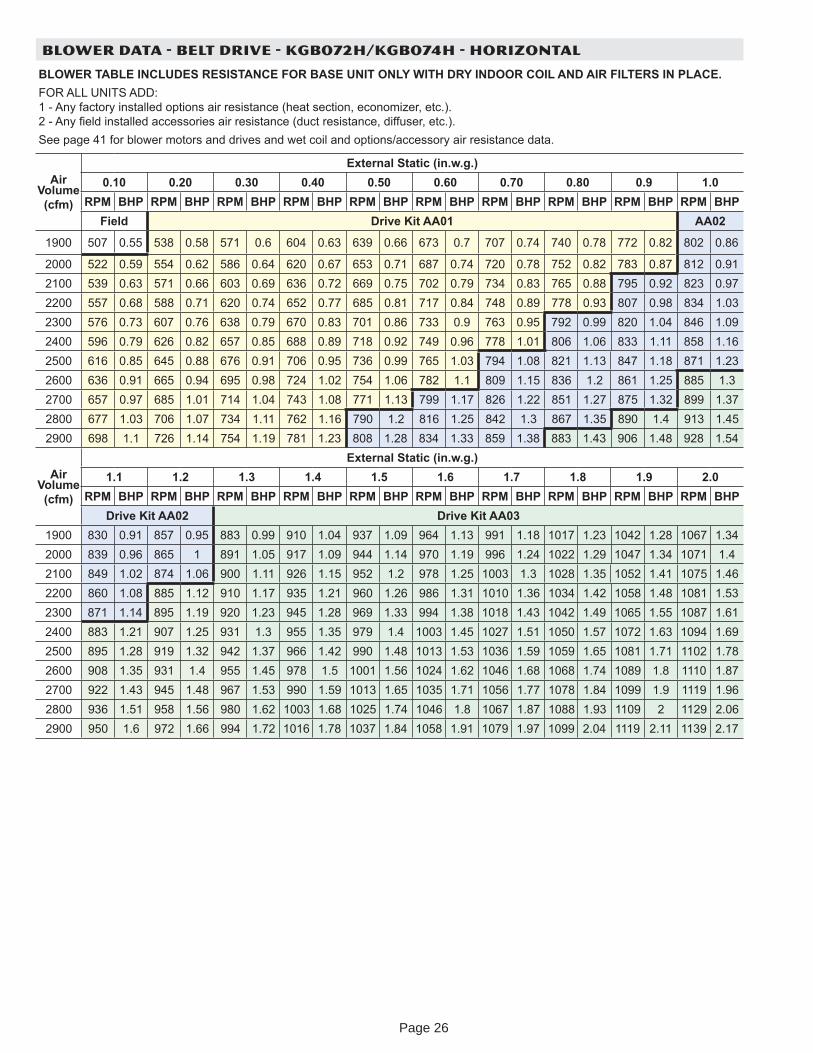
BLOWER DATA - BELT DRIVE - KGB072H/KGB074H - HORIZONTAL
BLOWER TABLE INCLUDES RESISTANCE FOR BASE UNIT ONLY WITH DRY INDOOR COIL AND AIR FILTERS IN PLACE.FOR ALL UNITS ADD: 1 - An factor installed options air resistance (heat section, economi er, etc.). 2 - An eld installed accessories air resistance (duct resistance, diffuser, etc.).See page 41 for blower motors and drives and wet coil and options/accessor air resistance data.
Air Volume (cfm)
External Static (in.w.g.)0.10 0.20 0.30 0.40 0.50 0.60 0.70 0.80 0.9 1.0
RPM BHP RPM BHP RPM BHP RPM BHP RPM BHP RPM BHP RPM BHP RPM BHP RPM BHP RPM BHPField Drive Kit AA01 AA02
1900 507 0.55 538 0.58 571 0.6 604 0.63 639 0.66 673 0.7 707 0.74 740 0.78 772 0.82 802 0.86
2000 522 0.59 554 0.62 586 0.64 620 0.67 653 0.71 687 0.74 720 0.78 752 0.82 783 0.87 812 0.912100 539 0.63 571 0.66 603 0.69 636 0.72 669 0.75 702 0.79 734 0.83 765 0.88 795 0.92 823 0.972200 557 0.68 588 0.71 620 0.74 652 0.77 685 0.81 717 0.84 748 0.89 778 0.93 807 0.98 834 1.032300 576 0.73 607 0.76 638 0.79 670 0.83 701 0.86 733 0.9 763 0.95 792 0.99 820 1.04 846 1.092400 596 0.79 626 0.82 657 0.85 688 0.89 718 0.92 749 0.96 778 1.01 806 1.06 833 1.11 858 1.162500 616 0.85 645 0.88 676 0.91 706 0.95 736 0.99 765 1.03 794 1.08 821 1.13 847 1.18 871 1.232600 636 0.91 665 0.94 695 0.98 724 1.02 754 1.06 782 1.1 809 1.15 836 1.2 861 1.25 885 1.32700 657 0.97 685 1.01 714 1.04 743 1.08 771 1.13 799 1.17 826 1.22 851 1.27 875 1.32 899 1.372800 677 1.03 706 1.07 734 1.11 762 1.16 790 1.2 816 1.25 842 1.3 867 1.35 890 1.4 913 1.452900 698 1.1 726 1.14 754 1.19 781 1.23 808 1.28 834 1.33 859 1.38 883 1.43 906 1.48 928 1.54
Air Volume (cfm)
External Static (in.w.g.)1.1 1.2 1.3 1.4 1.5 1.6 1.7 1.8 1.9 2.0
RPM BHP RPM BHP RPM BHP RPM BHP RPM BHP RPM BHP RPM BHP RPM BHP RPM BHP RPM BHPDrive Kit AA02 Drive Kit AA03
1900 830 0.91 857 0.95 883 0.99 910 1.04 937 1.09 964 1.13 991 1.18 1017 1.23 1042 1.28 1067 1.342000 839 0.96 865 1 891 1.05 917 1.09 944 1.14 970 1.19 996 1.24 1022 1.29 1047 1.34 1071 1.42100 849 1.02 874 1.06 900 1.11 926 1.15 952 1.2 978 1.25 1003 1.3 1028 1.35 1052 1.41 1075 1.462200 860 1.08 885 1.12 910 1.17 935 1.21 960 1.26 986 1.31 1010 1.36 1034 1.42 1058 1.48 1081 1.532300 871 1.14 895 1.19 920 1.23 945 1.28 969 1.33 994 1.38 1018 1.43 1042 1.49 1065 1.55 1087 1.612400 883 1.21 907 1.25 931 1.3 955 1.35 979 1.4 1003 1.45 1027 1.51 1050 1.57 1072 1.63 1094 1.692500 895 1.28 919 1.32 942 1.37 966 1.42 990 1.48 1013 1.53 1036 1.59 1059 1.65 1081 1.71 1102 1.782600 908 1.35 931 1.4 955 1.45 978 1.5 1001 1.56 1024 1.62 1046 1.68 1068 1.74 1089 1.8 1110 1.872700 922 1.43 945 1.48 967 1.53 990 1.59 1013 1.65 1035 1.71 1056 1.77 1078 1.84 1099 1.9 1119 1.962800 936 1.51 958 1.56 980 1.62 1003 1.68 1025 1.74 1046 1.8 1067 1.87 1088 1.93 1109 2 1129 2.062900 950 1.6 972 1.66 994 1.72 1016 1.78 1037 1.84 1058 1.91 1079 1.97 1099 2.04 1119 2.11 1139 2.17
Page 26
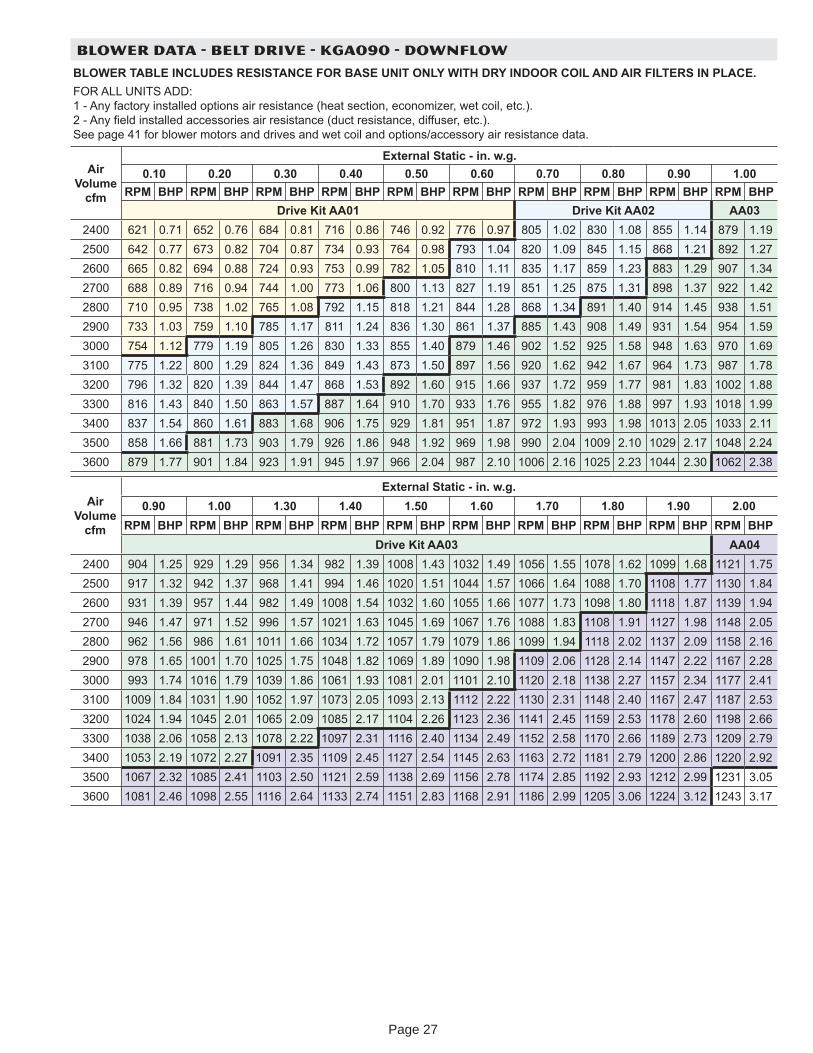
BLOWER DATA - BELT DRIVE - KGA090 - DOWNFLOW
BLOWER TABLE INCLUDES RESISTANCE FOR BASE UNIT ONLY WITH DRY INDOOR COIL AND AIR FILTERS IN PLACE.FOR ALL UNITS ADD: 1 - An factor installed options air resistance (heat section, economi er, wet coil, etc.). 2 - An eld installed accessories air resistance (duct resistance, diffuser, etc.). See page 41 for blower motors and drives and wet coil and options/accessor air resistance data.
Air Volume
cfm
External Static - in. w.g.0.10 0.20 0.30 0.40 0.50 0.60 0.70 0.80 0.90 1.00
RPM BHP RPM BHP RPM BHP RPM BHP RPM BHP RPM BHP RPM BHP RPM BHP RPM BHP RPM BHPDrive Kit AA01 Drive Kit AA02 AA03
2400 621 0.71 652 0.76 684 0.81 716 0.86 746 0.92 776 0.97 805 1.02 830 1.08 855 1.14 879 1.192500 642 0.77 673 0.82 704 0.87 734 0.93 764 0.98 793 1.04 820 1.09 845 1.15 868 1.21 892 1.272600 665 0.82 694 0.88 724 0.93 753 0.99 782 1.05 810 1.11 835 1.17 859 1.23 883 1.29 907 1.342700 688 0.89 716 0.94 744 1.00 773 1.06 800 1.13 827 1.19 851 1.25 875 1.31 898 1.37 922 1.422800 710 0.95 738 1.02 765 1.08 792 1.15 818 1.21 844 1.28 868 1.34 891 1.40 914 1.45 938 1.512900 733 1.03 759 1.10 785 1.17 811 1.24 836 1.30 861 1.37 885 1.43 908 1.49 931 1.54 954 1.593000 754 1.12 779 1.19 805 1.26 830 1.33 855 1.40 879 1.46 902 1.52 925 1.58 948 1.63 970 1.693100 775 1.22 800 1.29 824 1.36 849 1.43 873 1.50 897 1.56 920 1.62 942 1.67 964 1.73 987 1.783200 796 1.32 820 1.39 844 1.47 868 1.53 892 1.60 915 1.66 937 1.72 959 1.77 981 1.83 1002 1.883300 816 1.43 840 1.50 863 1.57 887 1.64 910 1.70 933 1.76 955 1.82 976 1.88 997 1.93 1018 1.993400 837 1.54 860 1.61 883 1.68 906 1.75 929 1.81 951 1.87 972 1.93 993 1.98 1013 2.05 1033 2.113500 858 1.66 881 1.73 903 1.79 926 1.86 948 1.92 969 1.98 990 2.04 1009 2.10 1029 2.17 1048 2.243600 879 1.77 901 1.84 923 1.91 945 1.97 966 2.04 987 2.10 1006 2.16 1025 2.23 1044 2.30 1062 2.38
Air Volume
cfm
External Static - in. w.g.0.90 1.00 1.30 1.40 1.50 1.60 1.70 1.80 1.90 2.00
RPM BHP RPM BHP RPM BHP RPM BHP RPM BHP RPM BHP RPM BHP RPM BHP RPM BHP RPM BHPDrive Kit AA03 AA04
2400 904 1.25 929 1.29 956 1.34 982 1.39 1008 1.43 1032 1.49 1056 1.55 1078 1.62 1099 1.68 1121 1.752500 917 1.32 942 1.37 968 1.41 994 1.46 1020 1.51 1044 1.57 1066 1.64 1088 1.70 1108 1.77 1130 1.842600 931 1.39 957 1.44 982 1.49 1008 1.54 1032 1.60 1055 1.66 1077 1.73 1098 1.80 1118 1.87 1139 1.942700 946 1.47 971 1.52 996 1.57 1021 1.63 1045 1.69 1067 1.76 1088 1.83 1108 1.91 1127 1.98 1148 2.052800 962 1.56 986 1.61 1011 1.66 1034 1.72 1057 1.79 1079 1.86 1099 1.94 1118 2.02 1137 2.09 1158 2.162900 978 1.65 1001 1.70 1025 1.75 1048 1.82 1069 1.89 1090 1.98 1109 2.06 1128 2.14 1147 2.22 1167 2.283000 993 1.74 1016 1.79 1039 1.86 1061 1.93 1081 2.01 1101 2.10 1120 2.18 1138 2.27 1157 2.34 1177 2.413100 1009 1.84 1031 1.90 1052 1.97 1073 2.05 1093 2.13 1112 2.22 1130 2.31 1148 2.40 1167 2.47 1187 2.533200 1024 1.94 1045 2.01 1065 2.09 1085 2.17 1104 2.26 1123 2.36 1141 2.45 1159 2.53 1178 2.60 1198 2.663300 1038 2.06 1058 2.13 1078 2.22 1097 2.31 1116 2.40 1134 2.49 1152 2.58 1170 2.66 1189 2.73 1209 2.793400 1053 2.19 1072 2.27 1091 2.35 1109 2.45 1127 2.54 1145 2.63 1163 2.72 1181 2.79 1200 2.86 1220 2.923500 1067 2.32 1085 2.41 1103 2.50 1121 2.59 1138 2.69 1156 2.78 1174 2.85 1192 2.93 1212 2.99 1231 3.053600 1081 2.46 1098 2.55 1116 2.64 1133 2.74 1151 2.83 1168 2.91 1186 2.99 1205 3.06 1224 3.12 1243 3.17
Page 27
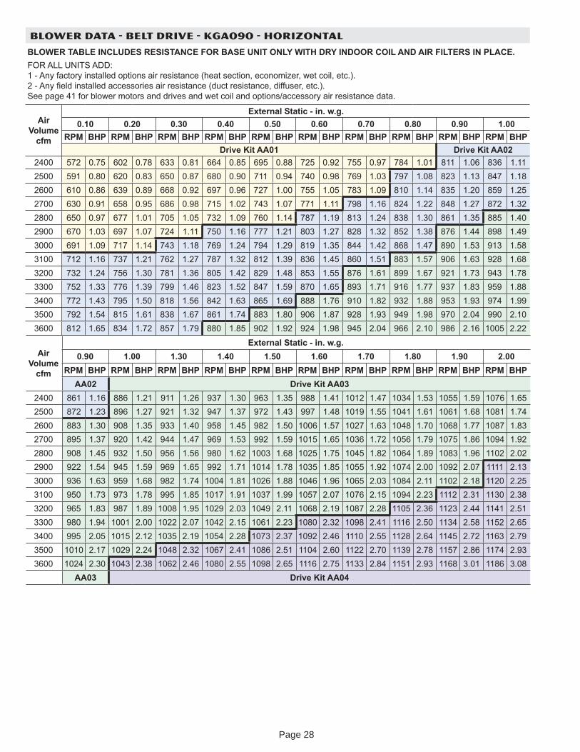
BLOWER DATA - BELT DRIVE - KGA090 - HORIZONTAL
BLOWER TABLE INCLUDES RESISTANCE FOR BASE UNIT ONLY WITH DRY INDOOR COIL AND AIR FILTERS IN PLACE.FOR ALL UNITS ADD: 1 - An factor installed options air resistance (heat section, economi er, wet coil, etc.). 2 - An eld installed accessories air resistance (duct resistance, diffuser, etc.). See page 41 for blower motors and drives and wet coil and options/accessor air resistance data.
Air Volume
cfm
External Static - in. w.g.0.10 0.20 0.30 0.40 0.50 0.60 0.70 0.80 0.90 1.00
RPM BHP RPM BHP RPM BHP RPM BHP RPM BHP RPM BHP RPM BHP RPM BHP RPM BHP RPM BHPDrive Kit AA01 Drive Kit AA02
2400 572 0.75 602 0.78 633 0.81 664 0.85 695 0.88 725 0.92 755 0.97 784 1.01 811 1.06 836 1.112500 591 0.80 620 0.83 650 0.87 680 0.90 711 0.94 740 0.98 769 1.03 797 1.08 823 1.13 847 1.182600 610 0.86 639 0.89 668 0.92 697 0.96 727 1.00 755 1.05 783 1.09 810 1.14 835 1.20 859 1.252700 630 0.91 658 0.95 686 0.98 715 1.02 743 1.07 771 1.11 798 1.16 824 1.22 848 1.27 872 1.322800 650 0.97 677 1.01 705 1.05 732 1.09 760 1.14 787 1.19 813 1.24 838 1.30 861 1.35 885 1.402900 670 1.03 697 1.07 724 1.11 750 1.16 777 1.21 803 1.27 828 1.32 852 1.38 876 1.44 898 1.493000 691 1.09 717 1.14 743 1.18 769 1.24 794 1.29 819 1.35 844 1.42 868 1.47 890 1.53 913 1.583100 712 1.16 737 1.21 762 1.27 787 1.32 812 1.39 836 1.45 860 1.51 883 1.57 906 1.63 928 1.683200 732 1.24 756 1.30 781 1.36 805 1.42 829 1.48 853 1.55 876 1.61 899 1.67 921 1.73 943 1.783300 752 1.33 776 1.39 799 1.46 823 1.52 847 1.59 870 1.65 893 1.71 916 1.77 937 1.83 959 1.883400 772 1.43 795 1.50 818 1.56 842 1.63 865 1.69 888 1.76 910 1.82 932 1.88 953 1.93 974 1.993500 792 1.54 815 1.61 838 1.67 861 1.74 883 1.80 906 1.87 928 1.93 949 1.98 970 2.04 990 2.103600 812 1.65 834 1.72 857 1.79 880 1.85 902 1.92 924 1.98 945 2.04 966 2.10 986 2.16 1005 2.22
Air Volume
cfm
External Static - in. w.g.0.90 1.00 1.30 1.40 1.50 1.60 1.70 1.80 1.90 2.00
RPM BHP RPM BHP RPM BHP RPM BHP RPM BHP RPM BHP RPM BHP RPM BHP RPM BHP RPM BHPAA02 Drive Kit AA03
2400 861 1.16 886 1.21 911 1.26 937 1.30 963 1.35 988 1.41 1012 1.47 1034 1.53 1055 1.59 1076 1.652500 872 1.23 896 1.27 921 1.32 947 1.37 972 1.43 997 1.48 1019 1.55 1041 1.61 1061 1.68 1081 1.742600 883 1.30 908 1.35 933 1.40 958 1.45 982 1.50 1006 1.57 1027 1.63 1048 1.70 1068 1.77 1087 1.832700 895 1.37 920 1.42 944 1.47 969 1.53 992 1.59 1015 1.65 1036 1.72 1056 1.79 1075 1.86 1094 1.922800 908 1.45 932 1.50 956 1.56 980 1.62 1003 1.68 1025 1.75 1045 1.82 1064 1.89 1083 1.96 1102 2.022900 922 1.54 945 1.59 969 1.65 992 1.71 1014 1.78 1035 1.85 1055 1.92 1074 2.00 1092 2.07 1111 2.133000 936 1.63 959 1.68 982 1.74 1004 1.81 1026 1.88 1046 1.96 1065 2.03 1084 2.11 1102 2.18 1120 2.253100 950 1.73 973 1.78 995 1.85 1017 1.91 1037 1.99 1057 2.07 1076 2.15 1094 2.23 1112 2.31 1130 2.383200 965 1.83 987 1.89 1008 1.95 1029 2.03 1049 2.11 1068 2.19 1087 2.28 1105 2.36 1123 2.44 1141 2.513300 980 1.94 1001 2.00 1022 2.07 1042 2.15 1061 2.23 1080 2.32 1098 2.41 1116 2.50 1134 2.58 1152 2.653400 995 2.05 1015 2.12 1035 2.19 1054 2.28 1073 2.37 1092 2.46 1110 2.55 1128 2.64 1145 2.72 1163 2.793500 1010 2.17 1029 2.24 1048 2.32 1067 2.41 1086 2.51 1104 2.60 1122 2.70 1139 2.78 1157 2.86 1174 2.933600 1024 2.30 1043 2.38 1062 2.46 1080 2.55 1098 2.65 1116 2.75 1133 2.84 1151 2.93 1168 3.01 1186 3.08
AA03 Drive Kit AA04
Page 28
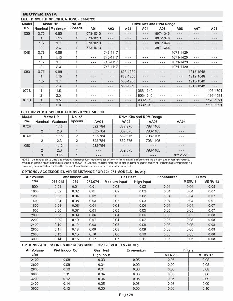
BLOWER DATABELT DRIVE KIT SPECIFICATIONS - 036-072SModel
No.Motor HP No. of
SpeedsDrive Kits and RPM Range
Nominal Maximum A01 A02 A03 A04 A05 A06 A07 A08036 0.75 0.86 1 673-1010 - - - - - - - - - 897-1346 - - - - - - - - -
1 1.15 1 673-1010 - - - - - - - - - 897-1346 - - - - - - - - -1.5 1.7 1 673-1010 - - - - - - - - - 897-1346 - - - - - - - - -2 2.3 1 673-1010 - - - - - - - - - 897-1346 - - - - - - - - -
048 0.75 0.86 1 - - - 745-1117 - - - - - - - - - 1071-1429 - - - - - -1 1.15 1 - - - 745-1117 - - - - - - - - - 1071-1429 - - - - - -
1.5 1.7 1 - - - 745-1117 - - - - - - - - - 1071-1429 - - - - - -2 2.3 1 - - - 745-1117 - - - - - - - - - 1071-1429 - - - - - -
060 0.75 0.86 1 - - - - - - 833-1250 - - - - - - - - - 1212-1548 - - -1 1.15 1 - - - - - - 833-1250 - - - - - - - - - 1212-1548 - - -
1.5 1.7 1 - - - - - - 833-1250 - - - - - - - - - 1212-1548 - - -2 2.3 1 - - - - - - 833-1250 - - - - - - - - - 1212-1548 - - -
072S 1 1.5 1 - - - - - - - - - 968-1340 - - - - - - - - - 1193-15912 2.3 1 - - - - - - - - - 968-1340 - - - - - - - - - 1193-1591
074S 1 1.5 2 - - - - - - - - - 968-1340 - - - - - - - - - 1193-15912 2.3 2 - - - - - - - - - 968-1340 - - - - - - - - - 1193-1591
OPTIONS / ACCESSORIES AIR RESISTANCE FOR 024-074 MODELS - in. w.g. Air Volume
cfmWet Indoor Coil Gas Heat Economi er Filters
036-048 060 072/074 Medium Input High Input MERV 8 MERV 13800 0.01 0.01 0.01 0.02 0.02 0.04 0.04 0.05
1000 0.02 0.02 0.01 0.02 0.02 0.04 0.04 0.071200 0.03 0.04 0.02 0.02 0.02 0.04 0.04 0.071400 0.04 0.05 0.03 0.02 0.03 0.04 0.04 0.071600 0.05 0.06 0.04 0.03 0.04 0.04 0.04 0.071800 0.06 0.07 0.05 0.03 0.05 0.05 0.05 0.072000 0.08 0.09 0.06 0.04 0.06 0.05 0.05 0.082200 0.09 0.10 0.07 0.04 0.07 0.05 0.05 0.082400 0.10 0.12 0.08 0.05 0.08 0.05 0.05 0.082600 0.11 0.13 0.09 0.05 0.09 0.06 0.05 0.082800 0.13 0.15 0.10 0.06 0.10 0.06 0.05 0.083000 0.14 0.16 0.12 0.07 0.11 0.06 0.05 0.08
OPTIONS / ACCESSORIES AIR RESISTANCE FOR 090 MODELS - in. w.g. Air Volume
cfmWet Indoor Coil Gas Heat Economi er Filters
High Input MERV 8 MERV 132400 0.08 0.03 0.05 0.05 0.082600 0.09 0.04 0.06 0.05 0.082800 0.10 0.04 0.06 0.05 0.083000 0.11 0.04 0.06 0.05 0.083200 0.12 0.04 0.06 0.06 0.093400 0.14 0.05 0.06 0.06 0.093600 0.15 0.05 0.06 0.06 0.10
BELT DRIVE KIT SPECIFICATIONS - 072H/074H/090Model
No.Motor HP No. of
SpeedsDrive Kits and RPM Range
Nominal Maximum AA01 AA02 AA03 AA04072H 1 1.15 1 522-784 632-875 798-1105 - - -
2 2.3 1 522-784 632-875 798-1105 - - -074H 1 1.15 2 522-784 632-875 798-1105 - - -
2 2.3 2 522-784 632-875 798-1105 - - -090 1 1.15 1 522-784 - - - - - - - - -
2 2.3 1 - - - 632-875 798-1105 - - -3 3.45 1 - - - - - - - - - 921-1228
NOTE - Using total air volume and s stem static pressure requirements determine from blower performance tables rpm and motor hp required. Maximum usable hp of motors furnished are shown. In Canada, nominal motor hp is also maximum usable motor hp. If motors of comparable hp are used, be sure to keep within the service factor limitations outlined on the motor nameplate.
Page 29
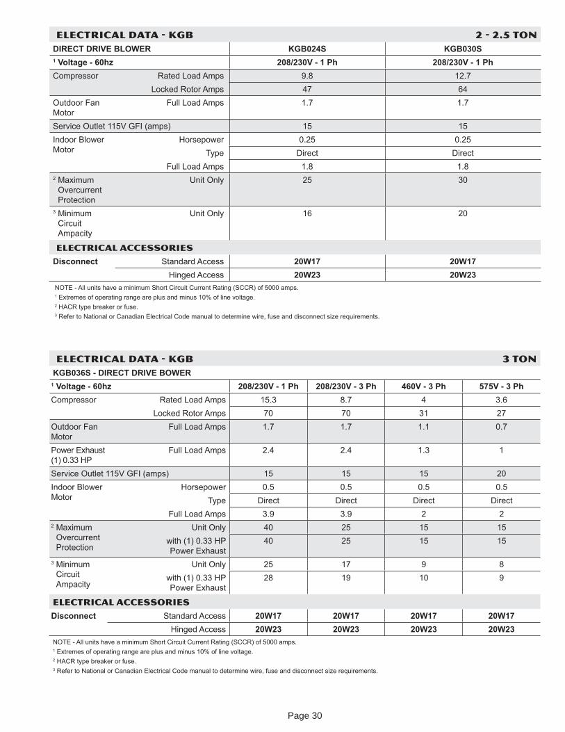
ELECTRICAL DATA - KGB 2 - 2.5 TONDIRECT DRIVE BLOWER KGB024S KGB030S1 Voltage - 60h 208/230V - 1 Ph 208/230V - 1 PhCompressor Rated Load Amps 9.8 12.7
Locked Rotor Amps 47 64Outdoor Fan Motor
Full Load Amps 1.7 1.7
Service Outlet 115V GFI (amps) 15 15Indoor Blower Motor
Horsepower 0.25 0.25T pe Direct Direct
Full Load Amps 1.8 1.82 Maximum
Overcurrent Protection
Unit Onl 25 30
3 Minimum Circuit Ampacit
Unit Onl 16 20
ELECTRICAL ACCESSORIES
Disconnect Standard Access 20W17 20W17Hinged Access 20W23 20W23
NOTE - All units have a minimum Short Circuit Current Rating (SCCR) of 5000 amps. 1 Extremes of operating range are plus and minus 10% of line voltage.2 HACR t pe breaker or fuse.3 Refer to National or Canadian Electrical Code manual to determine wire, fuse and disconnect si e requirements.
ELECTRICAL DATA - KGB 3 TONKGB036S - DIRECT DRIVE BOWER
1 Voltage - 60h 208/230V - 1 Ph 208/230V - 3 Ph 460V - 3 Ph 575V - 3 PhCompressor Rated Load Amps 15.3 8.7 4 3.6
Locked Rotor Amps 70 70 31 27Outdoor Fan Motor
Full Load Amps 1.7 1.7 1.1 0.7
Power Exhaust (1) 0.33 HP
Full Load Amps 2.4 2.4 1.3 1
Service Outlet 115V GFI (amps) 15 15 15 20Indoor Blower Motor
Horsepower 0.5 0.5 0.5 0.5T pe Direct Direct Direct Direct
Full Load Amps 3.9 3.9 2 22 Maximum
Overcurrent Protection
Unit Onl 40 25 15 15with (1) 0.33 HP Power Exhaust
40 25 15 15
3 Minimum Circuit Ampacit
Unit Onl 25 17 9 8with (1) 0.33 HP Power Exhaust
28 19 10 9
ELECTRICAL ACCESSORIES
Disconnect Standard Access 20W17 20W17 20W17 20W17Hinged Access 20W23 20W23 20W23 20W23
NOTE - All units have a minimum Short Circuit Current Rating (SCCR) of 5000 amps. 1 Extremes of operating range are plus and minus 10% of line voltage.2 HACR t pe breaker or fuse.3 Refer to National or Canadian Electrical Code manual to determine wire, fuse and disconnect si e requirements.
Page 30
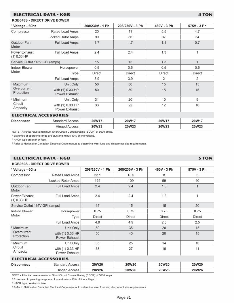
ELECTRICAL DATA - KGB 4 TONKGB048S - DIRECT DRIVE BOWER
1 Voltage - 60h 208/230V - 1 Ph 208/230V - 3 Ph 460V - 3 Ph 575V - 3 PhCompressor Rated Load Amps 20 11 5.5 4.7
Locked Rotor Amps 99 86 37 34Outdoor Fan Motor
Full Load Amps 1.7 1.7 1.1 0.7
Power Exhaust (1) 0.33 HP
Full Load Amps 2.4 2.4 1.3 1
Service Outlet 115V GFI (amps) 15 15 1.3 1Indoor Blower Motor
Horsepower 0.5 0.5 0.5 0.5T pe Direct Direct Direct Direct
Full Load Amps 3.9 3.9 2 22 Maximum
Overcurrent Protection
Unit Onl 50 30 15 15with (1) 0.33 HP Power Exhaust
50 30 15 15
3 Minimum Circuit Ampacit
Unit Onl 31 20 10 9with (1) 0.33 HP Power Exhaust
33 22 12 10
ELECTRICAL ACCESSORIES
Disconnect Standard Access 20W17 20W17 20W17 20W17Hinged Access 20W23 20W23 20W23 20W23
NOTE - All units have a minimum Short Circuit Current Rating (SCCR) of 5000 amps. 1 Extremes of operating range are plus and minus 10% of line voltage.2 HACR t pe breaker or fuse.3 Refer to National or Canadian Electrical Code manual to determine wire, fuse and disconnect si e requirements.
ELECTRICAL DATA - KGB 5 TONKGB060S - DIRECT DRIVE BOWER
1 Voltage - 60h 208/230V - 1 Ph 208/230V - 3 Ph 460V - 3 Ph 575V - 3 PhCompressor Rated Load Amps 22.1 13.5 8 5
Locked Rotor Amps 125 109 59 40Outdoor Fan Motor
Full Load Amps 2.4 2.4 1.3 1
Power Exhaust (1) 0.33 HP
Full Load Amps 2.4 2.4 1.3 1
Service Outlet 115V GFI (amps) 15 15 15 20Indoor Blower Motor
Horsepower 0.75 0.75 0.75 0.75T pe Direct Direct Direct Direct
Full Load Amps 4.9 4.9 2.5 2.52 Maximum
Overcurrent Protection
Unit Onl 50 35 20 15with (1) 0.33 HP Power Exhaust
50 40 20 15
3 Minimum Circuit Ampacit
Unit Onl 35 25 14 10with (1) 0.33 HP Power Exhaust
38 27 16 11
ELECTRICAL ACCESSORIES
Disconnect Standard Access 20W20 20W20 20W20 20W20Hinged Access 20W26 20W26 20W26 20W26
NOTE - All units have a minimum Short Circuit Current Rating (SCCR) of 5000 amps. 1 Extremes of operating range are plus and minus 10% of line voltage.2 HACR t pe breaker or fuse.3 Refer to National or Canadian Electrical Code manual to determine wire, fuse and disconnect si e requirements.
Page 31
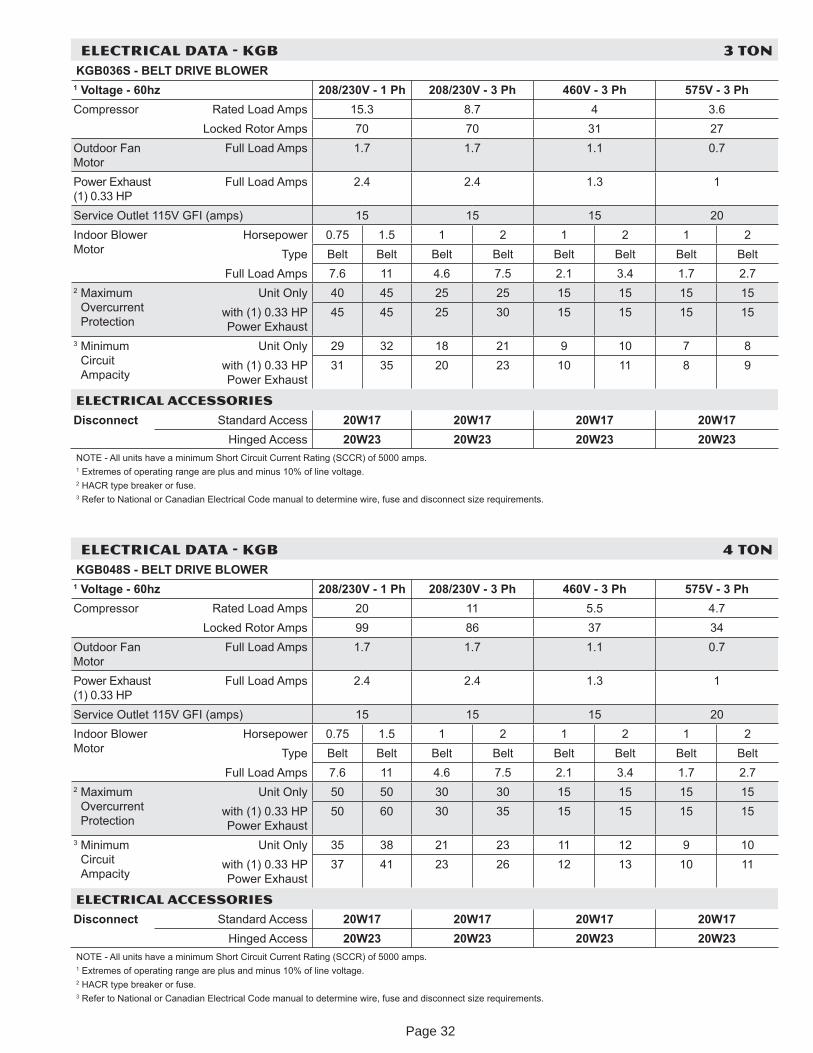
ELECTRICAL DATA - KGB 3 TONKGB036S - BELT DRIVE BLOWER
1 Voltage - 60h 208/230V - 1 Ph 208/230V - 3 Ph 460V - 3 Ph 575V - 3 PhCompressor Rated Load Amps 15.3 8.7 4 3.6
Locked Rotor Amps 70 70 31 27Outdoor Fan Motor
Full Load Amps 1.7 1.7 1.1 0.7
Power Exhaust (1) 0.33 HP
Full Load Amps 2.4 2.4 1.3 1
Service Outlet 115V GFI (amps) 15 15 15 20Indoor Blower Motor
Horsepower 0.75 1.5 1 2 1 2 1 2T pe Belt Belt Belt Belt Belt Belt Belt Belt
Full Load Amps 7.6 11 4.6 7.5 2.1 3.4 1.7 2.72 Maximum
Overcurrent Protection
Unit Onl 40 45 25 25 15 15 15 15with (1) 0.33 HP Power Exhaust
45 45 25 30 15 15 15 15
3 Minimum Circuit Ampacit
Unit Onl 29 32 18 21 9 10 7 8with (1) 0.33 HP Power Exhaust
31 35 20 23 10 11 8 9
ELECTRICAL ACCESSORIES
Disconnect Standard Access 20W17 20W17 20W17 20W17Hinged Access 20W23 20W23 20W23 20W23
NOTE - All units have a minimum Short Circuit Current Rating (SCCR) of 5000 amps. 1 Extremes of operating range are plus and minus 10% of line voltage.2 HACR t pe breaker or fuse.3 Refer to National or Canadian Electrical Code manual to determine wire, fuse and disconnect si e requirements.
ELECTRICAL DATA - KGB 4 TONKGB048S - BELT DRIVE BLOWER
1 Voltage - 60h 208/230V - 1 Ph 208/230V - 3 Ph 460V - 3 Ph 575V - 3 PhCompressor Rated Load Amps 20 11 5.5 4.7
Locked Rotor Amps 99 86 37 34Outdoor Fan Motor
Full Load Amps 1.7 1.7 1.1 0.7
Power Exhaust (1) 0.33 HP
Full Load Amps 2.4 2.4 1.3 1
Service Outlet 115V GFI (amps) 15 15 15 20Indoor Blower Motor
Horsepower 0.75 1.5 1 2 1 2 1 2T pe Belt Belt Belt Belt Belt Belt Belt Belt
Full Load Amps 7.6 11 4.6 7.5 2.1 3.4 1.7 2.72 Maximum
Overcurrent Protection
Unit Onl 50 50 30 30 15 15 15 15with (1) 0.33 HP Power Exhaust
50 60 30 35 15 15 15 15
3 Minimum Circuit Ampacit
Unit Onl 35 38 21 23 11 12 9 10with (1) 0.33 HP Power Exhaust
37 41 23 26 12 13 10 11
ELECTRICAL ACCESSORIES
Disconnect Standard Access 20W17 20W17 20W17 20W17Hinged Access 20W23 20W23 20W23 20W23
NOTE - All units have a minimum Short Circuit Current Rating (SCCR) of 5000 amps. 1 Extremes of operating range are plus and minus 10% of line voltage.2 HACR t pe breaker or fuse.3 Refer to National or Canadian Electrical Code manual to determine wire, fuse and disconnect si e requirements.
Page 32
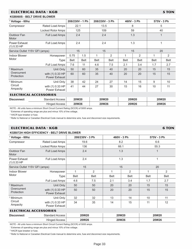
ELECTRICAL DATA - KGB 5 TONKGB060S - BELT DRIVE BLOWER
1 Voltage - 60h 208/230V - 1 Ph 208/230V - 3 Ph 460V - 3 Ph 575V - 3 PhCompressor Rated Load Amps 22.1 13.5 8 5
Locked Rotor Amps 125 109 59 40Outdoor Fan Motor
Full Load Amps 2.4 2.4 1.3 1
Power Exhaust (1) 0.33 HP
Full Load Amps 2.4 2.4 1.3 1
Service Outlet 115V GFI (amps) 15 15 15 20Indoor Blower Motor
Horsepower 0.75 1.5 1 2 1 2 1 2T pe Belt Belt Belt Belt Belt Belt Belt Belt
Full Load Amps 7.6 11 4.6 7.5 2.1 3.4 1.7 2.72 Maximum
Overcurrent Protection
Unit Onl 50 60 35 40 20 20 15 15with (1) 0.33 HP Power Exhaust
60 60 35 40 20 20 15 15
3 Minimum Circuit Ampacit
Unit Onl 38 42 24 27 14 15 9 10with (1) 0.33 HP Power Exhaust
41 44 27 30 15 16 10 11
ELECTRICAL ACCESSORIES
Disconnect Standard Access 20W20 20W20 20W20 20W20Hinged Access 20W26 20W26 20W26 20W26
NOTE - All units have a minimum Short Circuit Current Rating (SCCR) of 5000 amps. 1 Extremes of operating range are plus and minus 10% of line voltage.2 HACR t pe breaker or fuse.3 Refer to National or Canadian Electrical Code manual to determine wire, fuse and disconnect si e requirements.
ELECTRICAL DATA - KGB 6 TONKGB072H HIGH EFFICIENCY - BELT DRIVE BLOWER
1 Voltage - 60h 208/230V - 3 Ph 460V - 3 Ph 575V - 3 PhCompressor Rated Load Amps 19.6 8.2 6.6
Locked Rotor Amps 136 66.1 55.3Outdoor Fan Motor
Full Load Amps 2.4 1.3 1
Power Exhaust (1) 0.33 HP
Full Load Amps 2.4 1.3 1
Service Outlet 115V GFI (amps) 15 15 20Indoor Blower Motor
Horsepower 1 2 1 2 1 2T pe Belt Belt Belt Belt Belt Belt
Full Load Amps 4.6 7.5 2.1 3.4 1.7 2.72 Maximum
Overcurrent Protection
Unit Onl 50 50 20 20 15 15with (1) 0.33 HP Power Exhaust
50 50 20 20 15 15
3 Minimum Circuit Ampacit
Unit Onl 32 32 13 14 10 11with (1) 0.33 HP Power Exhaust
34 35 14 15 11 12
ELECTRICAL ACCESSORIES
Disconnect Standard Access 20W20 20W20 20W20Hinged Access 20W26 20W26 20W26
NOTE - All units have a minimum Short Circuit Current Rating (SCCR) of 5000 amps. 1 Extremes of operating range are plus and minus 10% of line voltage.2 HACR t pe breaker or fuse.3 Refer to National or Canadian Electrical Code manual to determine wire, fuse and disconnect si e requirements.
Page 33
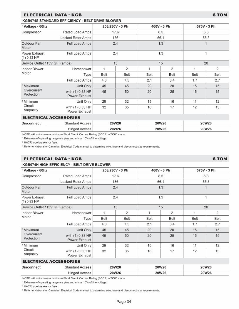
ELECTRICAL DATA - KGB 6 TONKGB074H HIGH EFFICIENCY - BELT DRIVE BLOWER
1 Voltage - 60h 208/230V - 3 Ph 460V - 3 Ph 575V - 3 PhCompressor Rated Load Amps 17.6 8.5 6.3
Locked Rotor Amps 136 66.1 55.3Outdoor Fan Motor
Full Load Amps 2.4 1.3 1
Power Exhaust (1) 0.33 HP
Full Load Amps 2.4 1.3 1
Service Outlet 115V GFI (amps) 15 15 20Indoor Blower Motor
Horsepower 1 2 1 2 1 2T pe Belt Belt Belt Belt Belt Belt
Full Load Amps 4.6 7.5 2.1 3.4 1.7 2.72 Maximum
Overcurrent Protection
Unit Onl 45 45 20 20 15 15with (1) 0.33 HP Power Exhaust
45 50 20 25 15 15
3 Minimum Circuit Ampacit
Unit Onl 29 32 15 16 11 12with (1) 0.33 HP Power Exhaust
32 35 16 17 12 13
ELECTRICAL ACCESSORIES
Disconnect Standard Access 20W20 20W20 20W20Hinged Access 20W26 20W26 20W26
NOTE - All units have a minimum Short Circuit Current Rating (SCCR) of 5000 amps. 1 Extremes of operating range are plus and minus 10% of line voltage.2 HACR t pe breaker or fuse.3 Refer to National or Canadian Electrical Code manual to determine wire, fuse and disconnect si e requirements.
ELECTRICAL DATA - KGB 6 TONKGB074S STANDARD EFFICIENCY - BELT DRIVE BLOWER
1 Voltage - 60h 208/230V - 3 Ph 460V - 3 Ph 575V - 3 PhCompressor Rated Load Amps 17.6 8.5 6.3
Locked Rotor Amps 136 66.1 55.3Outdoor Fan Motor
Full Load Amps 2.4 1.3 1
Power Exhaust (1) 0.33 HP
Full Load Amps 2.4 1.3 1
Service Outlet 115V GFI (amps) 15 15 20Indoor Blower Motor
Horsepower 1 2 1 2 1 2T pe Belt Belt Belt Belt Belt Belt
Full Load Amps 4.6 7.5 2.1 3.4 1.7 2.72 Maximum
Overcurrent Protection
Unit Onl 45 45 20 20 15 15with (1) 0.33 HP Power Exhaust
45 50 20 25 15 15
3 Minimum Circuit Ampacit
Unit Onl 29 32 15 16 11 12with (1) 0.33 HP Power Exhaust
32 35 16 17 12 13
ELECTRICAL ACCESSORIES
Disconnect Standard Access 20W20 20W20 20W20Hinged Access 20W26 20W26 20W26
NOTE - All units have a minimum Short Circuit Current Rating (SCCR) of 5000 amps. 1 Extremes of operating range are plus and minus 10% of line voltage.2 HACR t pe breaker or fuse.3 Refer to National or Canadian Electrical Code manual to determine wire, fuse and disconnect si e requirements.
Page 34
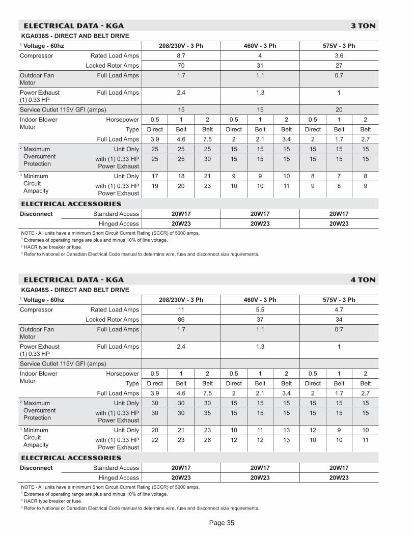
ELECTRICAL DATA - KGA 3 TONKGA036S - DIRECT AND BELT DRIVE
1 Voltage - 60h 208/230V - 3 Ph 460V - 3 Ph 575V - 3 PhCompressor Rated Load Amps 8.7 4 3.6
Locked Rotor Amps 70 31 27Outdoor Fan Motor
Full Load Amps 1.7 1.1 0.7
Power Exhaust (1) 0.33 HP
Full Load Amps 2.4 1.3 1
Service Outlet 115V GFI (amps) 15 15 20Indoor Blower Motor
Horsepower 0.5 1 2 0.5 1 2 0.5 1 2T pe Direct Belt Belt Direct Belt Belt Direct Belt Belt
Full Load Amps 3.9 4.6 7.5 2 2.1 3.4 2 1.7 2.72 Maximum
Overcurrent Protection
Unit Onl 25 25 25 15 15 15 15 15 15with (1) 0.33 HP Power Exhaust
25 25 30 15 15 15 15 15 15
3 Minimum Circuit Ampacit
Unit Onl 17 18 21 9 9 10 8 7 8with (1) 0.33 HP Power Exhaust
19 20 23 10 10 11 9 8 9
ELECTRICAL ACCESSORIES
Disconnect Standard Access 20W17 20W17 20W17Hinged Access 20W23 20W23 20W23
NOTE - All units have a minimum Short Circuit Current Rating (SCCR) of 5000 amps. 1 Extremes of operating range are plus and minus 10% of line voltage.2 HACR t pe breaker or fuse.3 Refer to National or Canadian Electrical Code manual to determine wire, fuse and disconnect si e requirements.
ELECTRICAL DATA - KGA 4 TONKGA048S - DIRECT AND BELT DRIVE
1 Voltage - 60h 208/230V - 3 Ph 460V - 3 Ph 575V - 3 PhCompressor Rated Load Amps 11 5.5 4.7
Locked Rotor Amps 86 37 34Outdoor Fan Motor
Full Load Amps 1.7 1.1 0.7
Power Exhaust (1) 0.33 HP
Full Load Amps 2.4 1.3 1
Service Outlet 115V GFI (amps)Indoor Blower Motor
Horsepower 0.5 1 2 0.5 1 2 0.5 1 2T pe Direct Belt Belt Direct Belt Belt Direct Belt Belt
Full Load Amps 3.9 4.6 7.5 2 2.1 3.4 2 1.7 2.72 Maximum
Overcurrent Protection
Unit Onl 30 30 30 15 15 15 15 15 15with (1) 0.33 HP Power Exhaust
30 30 35 15 15 15 15 15 15
3 Minimum Circuit Ampacit
Unit Onl 20 21 23 10 11 13 12 9 10with (1) 0.33 HP Power Exhaust
22 23 26 12 12 13 10 10 11
ELECTRICAL ACCESSORIES
Disconnect Standard Access 20W17 20W17 20W17Hinged Access 20W23 20W23 20W23
NOTE - All units have a minimum Short Circuit Current Rating (SCCR) of 5000 amps. 1 Extremes of operating range are plus and minus 10% of line voltage.2 HACR t pe breaker or fuse.3 Refer to National or Canadian Electrical Code manual to determine wire, fuse and disconnect si e requirements.
Page 35
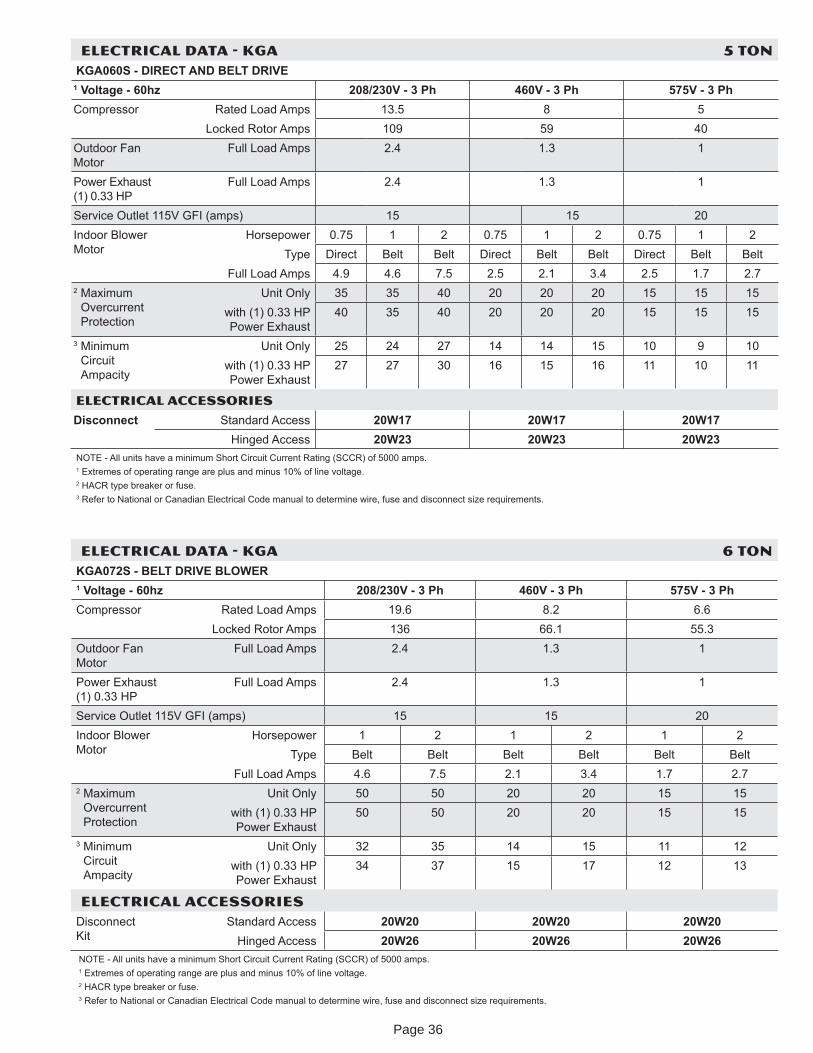
ELECTRICAL DATA - KGA 5 TONKGA060S - DIRECT AND BELT DRIVE
1 Voltage - 60h 208/230V - 3 Ph 460V - 3 Ph 575V - 3 PhCompressor Rated Load Amps 13.5 8 5
Locked Rotor Amps 109 59 40Outdoor Fan Motor
Full Load Amps 2.4 1.3 1
Power Exhaust (1) 0.33 HP
Full Load Amps 2.4 1.3 1
Service Outlet 115V GFI (amps) 15 15 20Indoor Blower Motor
Horsepower 0.75 1 2 0.75 1 2 0.75 1 2T pe Direct Belt Belt Direct Belt Belt Direct Belt Belt
Full Load Amps 4.9 4.6 7.5 2.5 2.1 3.4 2.5 1.7 2.72 Maximum
Overcurrent Protection
Unit Onl 35 35 40 20 20 20 15 15 15with (1) 0.33 HP Power Exhaust
40 35 40 20 20 20 15 15 15
3 Minimum Circuit Ampacit
Unit Onl 25 24 27 14 14 15 10 9 10with (1) 0.33 HP Power Exhaust
27 27 30 16 15 16 11 10 11
ELECTRICAL ACCESSORIES
Disconnect Standard Access 20W17 20W17 20W17Hinged Access 20W23 20W23 20W23
NOTE - All units have a minimum Short Circuit Current Rating (SCCR) of 5000 amps. 1 Extremes of operating range are plus and minus 10% of line voltage.2 HACR t pe breaker or fuse.3 Refer to National or Canadian Electrical Code manual to determine wire, fuse and disconnect si e requirements.
ELECTRICAL DATA - KGA 6 TONKGA072S - BELT DRIVE BLOWER1 Voltage - 60h 208/230V - 3 Ph 460V - 3 Ph 575V - 3 PhCompressor Rated Load Amps 19.6 8.2 6.6
Locked Rotor Amps 136 66.1 55.3Outdoor Fan Motor
Full Load Amps 2.4 1.3 1
Power Exhaust (1) 0.33 HP
Full Load Amps 2.4 1.3 1
Service Outlet 115V GFI (amps) 15 15 20Indoor Blower Motor
Horsepower 1 2 1 2 1 2T pe Belt Belt Belt Belt Belt Belt
Full Load Amps 4.6 7.5 2.1 3.4 1.7 2.72 Maximum
Overcurrent Protection
Unit Onl 50 50 20 20 15 15with (1) 0.33 HP Power Exhaust
50 50 20 20 15 15
3 Minimum Circuit Ampacit
Unit Onl 32 35 14 15 11 12with (1) 0.33 HP Power Exhaust
34 37 15 17 12 13
ELECTRICAL ACCESSORIESDisconnect Kit
Standard Access 20W20 20W20 20W20Hinged Access 20W26 20W26 20W26
NOTE - All units have a minimum Short Circuit Current Rating (SCCR) of 5000 amps. 1 Extremes of operating range are plus and minus 10% of line voltage.2 HACR t pe breaker or fuse.3 Refer to National or Canadian Electrical Code manual to determine wire, fuse and disconnect si e requirements.
Page 36
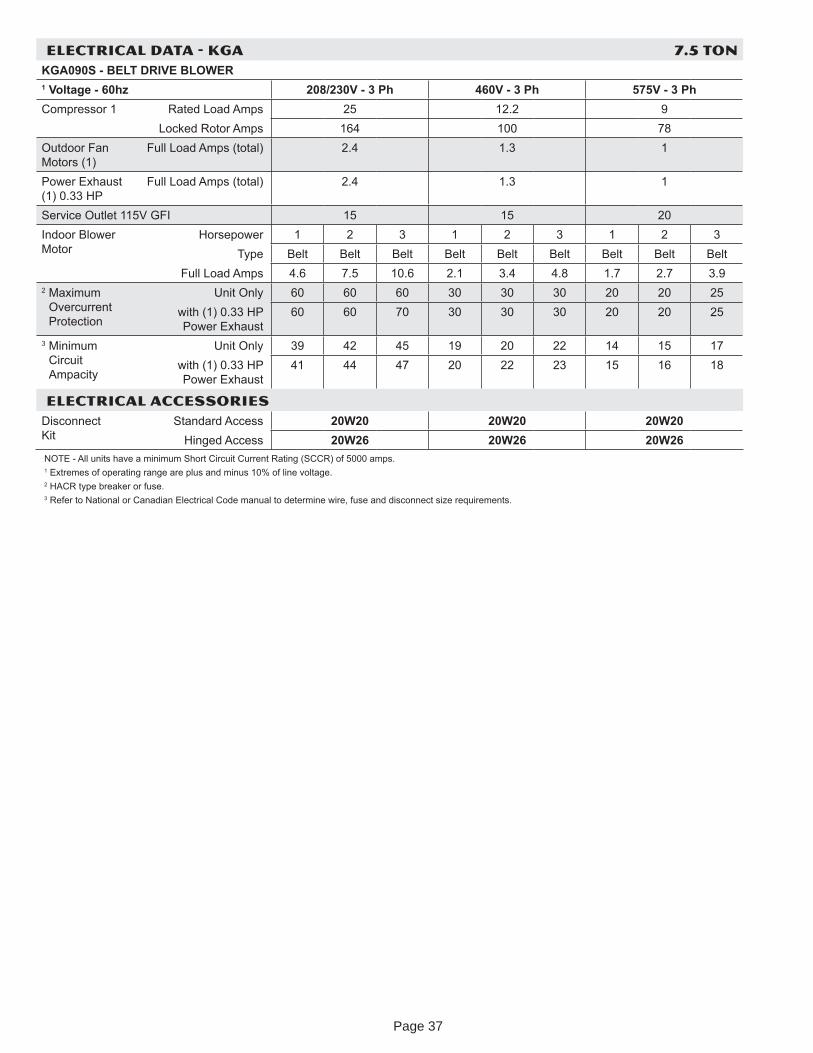
ELECTRICAL DATA - KGA 7.5 TONKGA090S - BELT DRIVE BLOWER1 Voltage - 60h 208/230V - 3 Ph 460V - 3 Ph 575V - 3 PhCompressor 1 Rated Load Amps 25 12.2 9
Locked Rotor Amps 164 100 78Outdoor Fan Motors (1)
Full Load Amps (total) 2.4 1.3 1
Power Exhaust (1) 0.33 HP
Full Load Amps (total) 2.4 1.3 1
Service Outlet 115V GFI 15 15 20Indoor Blower Motor
Horsepower 1 2 3 1 2 3 1 2 3T pe Belt Belt Belt Belt Belt Belt Belt Belt Belt
Full Load Amps 4.6 7.5 10.6 2.1 3.4 4.8 1.7 2.7 3.92 Maximum
Overcurrent Protection
Unit Onl 60 60 60 30 30 30 20 20 25with (1) 0.33 HP Power Exhaust
60 60 70 30 30 30 20 20 25
3 Minimum Circuit Ampacit
Unit Onl 39 42 45 19 20 22 14 15 17with (1) 0.33 HP Power Exhaust
41 44 47 20 22 23 15 16 18
ELECTRICAL ACCESSORIESDisconnect Kit
Standard Access 20W20 20W20 20W20Hinged Access 20W26 20W26 20W26
NOTE - All units have a minimum Short Circuit Current Rating (SCCR) of 5000 amps. 1 Extremes of operating range are plus and minus 10% of line voltage.2 HACR t pe breaker or fuse.3 Refer to National or Canadian Electrical Code manual to determine wire, fuse and disconnect si e requirements.
Page 37
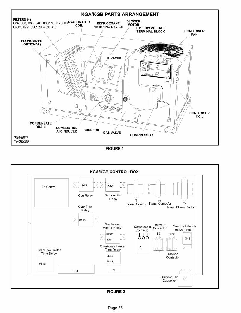
Page 38
KGA/KGB PARTS ARRANGEMENT
FIGURE 1
EVAPORATORCOIL
CONDENSERFAN
CONDENSERCOIL
COMPRESSOR
CONDENSATEDRAIN
FILTERS (4)
024, 030, 036, 048, 060*:16 X 20 X 2”060**, 072, 090: 20 X 20 X 2”
ECONOMIZER(OPTIONAL)
GAS VALVEBURNERS
COMBUSTIONAIR INDUCER
BLOWER
BLOWERMOTOR
TB1 LOW VOLTAGETERMINAL BLOCK
REFRIGERANTMETERING DEVICE
*KGA060**KGB060
FIGURE 2
C1
N
K3
K1
TB1
T1
K10
T3T4
DL46
K220
K250/
K191
DL50/
DL48
S42
K10K72A3 Control
Over FlowRelay
Over Flow SwitchTime Delay
CrankcaseHeater Relay
Crankcase HeaterTime Delay
CompressorContactor
BlowerContactor
Overload SwitchBlower Motor
Outdoor FanCapacitor
Trans. Control Trans. Comb Air
Trans. Blower Motor
Gas Relay Outdoor FanRelay
K37
BlowerContactor
KGA/KGB CONTROL BOX
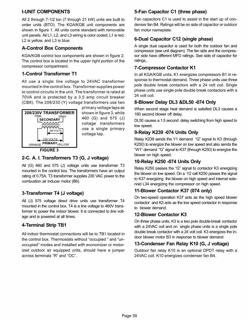
Page 39
I-UNIT COMPONENTS
All 2 through 7-1/2 ton (7 through 21 kW) units are built to
order units (BTO). The KGA/KGB unit components are
shown in figure 1. All units come standard with removable
unit panels. All L1, L2, and L3 wiring is color coded; L1 is red,
L2 is yellow, and L3 is blue.
A-Control Box Components
KGA/KGB control box components are shown in figure 2.
The control box is located in the upper right portion of the
compressor compartment.
1-Control Transformer T1
All use a single line voltage to 24VAC transformer
mounted in the control box. Transformer supplies power
to control circuits in the unit. The transformer is rated at
70VA and is protected by a 3.5 amp circuit breaker
(CB8). The 208/230 (Y) voltage transformers use two
primary voltage taps as
shown in figure 3, while
460 (G) and 575 (J)
voltage transformers
use a single primary
voltage tap.
2-C. A. I. Transformers T3 (G, J voltage)
All (G) 460 and 575 (J) voltage units use transformer T3
mounted in the control box. The transformers have an output
rating of 0.75A. T3 transformer supplies 230 VAC power to the
combustion air inducer motor (B6).
3-Transformer T4 (J voltage)
All (J) 575 voltage direct drive units use transformer T4
mounted in the control box. T4 is a line voltage to 460V trans
former to power the indoor blower. It is connected to line volt
age and is powered at all times.
4-Terminal Strip TB1
All indoor thermostat connections will be to TB1 located in
the control box. Thermostats without “occupied “ and “un
occupied” modes and installed with economizer or motor
ized outdoor air equipped units, should have a jumper
across terminals “R“ and “OC”.
5-Fan Capacitor C1 (three phase)
Fan capacitors C1 is used to assist in the start up of con
denser fan B4. Ratings will be on side of capacitor or outdoor
fan motor nameplate.
6-Dual Capacitor C12 (single phase)
A single dual capacitor is used for both the outdoor fan and
compressor (see unit diagram). The fan side and the compres
sor side have different MFD ratings. See side of capacitor for
ratings,.
7-Compressor Contactor K1
In all KGA/KGB units, K1 energizes compressors B1 in re
sponse to thermostat demand. Three phase units use three
pole double break contactors with a 24 volt coil. Single
phase units use single pole double break contactors with a
24 volt coil.
8-Blower Delay DL3 &DL50 -074 Only
When second stage heat demand is satisfied DL3 causes a
180 second blower off delay.
DL50 causes a 1.5 second delay switching from high speed to
low speed.
9-Relay K239 -074 Units Only
Relay K239 sends the Y1 demand “G” signal to K3 (through
K250) to energize the blower on low speed and also sends the
“W1” demand “G” signal to K37 (through K250) to energize the
blower on high speed.
10-Relay K250 -074 Units Only
Relay K250 passes the “G” signal to contactor K3 energizing
the blower on low speed. On a Y2 call K250 passes the signal
to K37 energizing the blower on high speed and internal sole
noid L34 energizing the compressor on high speed.
11-Blower Contactor K37 (074 only)
On two-speed operation K37 acts as the high speed blower
contactor and K3 acts as the low speed contactor in response
to blower demand.
12-Blower Contactor K3
On three phase units, K3 is a two pole double‐break contactor
with a 24VAC coil and on single phase units is a single pole
double break contactor with a 24 volt coil. K3 energizes the in
door blower motor B3 in response to blower demand.
13-Condenser Fan Relay K10 (G, J voltage)
Outdoor fan relay K10 is an optional DPDT relay with a
24VAC coil. K10 energizes condenser fan B4.
FIGURE 3
PINK GRAY
ORANGE YELLOW
230 VOLTS
208 VOLTS
PRIMARY
SECONDARY
208/230V TRANSFORMER
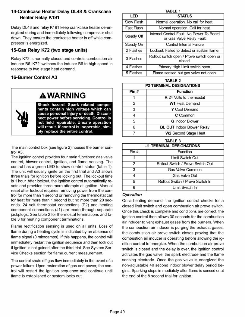
Page 40
14-Crankcase Heater Delay DL48 & Crankcase
Heater Relay K191
Delay DL48 and relay K191 keep crankcase heater de-en
ergized during and immediately following compressor shut
down. They ensure the crankcase heater is off while com
pressor is energized.
15-Gas Relay K72 (two stage units)
Relay K72 is normally closed and controls combustion air
inducer B6. K72 switches the inducer B6 to high speed in
response to two stage heat demand.
16-Burner Control A3
WARNINGShock hazard. Spark related components contain high voltage which cancause personal injury or death. Disconnect power before servicing. Control isnot field repairable. Unsafe operationwill result. If control is inoperable, simply replace the entire control.
The main control box (see figure 2) houses the burner con
trol A3.
The ignition control provides four main functions: gas valve
control, blower control, ignition, and flame sensing. The
control has a green LED to show control status (table 1).
The unit will usually ignite on the first trial and A3 allows
three trials for ignition before locking out. The lockout time
is 1 hour. After lockout, the ignition control automatically re
sets and provides three more attempts at ignition. Manual
reset after lockout requires removing power from the con
trol for more than 1 second or removing the thermostat call
for heat for more than 1 second but no more than 20 sec
onds. 24 volt thermostat connections (P2) and heating
component connections (J1) are made through separate
jackplugs. See table 2 for thermostat terminations and ta
ble 3 for heating component terminations.
Flame rectification sensing is used on all units. Loss of
flame during a heating cycle is indicated by an absence of
flame signal (0 microamps). If this happens, the control will
immediately restart the ignition sequence and then lock out
if ignition is not gained after the third trial. See System Ser
vice Checks section for flame current measurement.
The control shuts off gas flow immediately in the event of a
power failure. Upon restoration of gas and power, the con
trol will restart the ignition sequence and continue until
flame is established or system locks out.
TABLE 1
LED STATUS
Slow Flash Normal operation. No call for heat.
Fast Flash Normal operation. Call for heat.
Steady OffInternal Control Fault, No Power To Board
or Gas Valve Relay Fault
Steady On Control Internal Failure.
2 Flashes Lockout. Failed to detect or sustain flame.
3 FlashesRollout switch open / Prove switch open or
closed.
4 Flashes Primary High Limit switch open.
5 Flashes Flame sensed but gas valve not open.
TABLE 2
P2 TERMINAL DESIGNATIONS
Pin # Function
1 R 24 Volts to thermostat
2 W1 Heat Demand
3 Y Cool Demand
4 C Common
5 G Indoor Blower
6 BL OUT Indoor Blower Relay
7 W2 Second Stage Heat
TABLE 3
J1 TERMINAL DESIGNATIONS
Pin # Function
1 Limit Switch Out
2 Rollout Switch / Prove Switch Out
3 Gas Valve Common
4 Gas Valve Out
5 Rollout Switch / Prove Switch In
6 Limit Switch In
Operation
On a heating demand, the ignition control checks for a
closed limit switch and open combustion air prove switch.
Once this check is complete and conditions are correct, the
ignition control then allows 30 seconds for the combustion
air inducer to vent exhaust gases from the burners. When
the combustion air inducer is purging the exhaust gases,
the combustion air prove switch closes proving that the
combustion air inducer is operating before allowing the ig
nition control to energize. When the combustion air prove
switch is closed and the delay is over, the ignition control
activates the gas valve, the spark electrode and the flame
sensing electrode. Once the gas valve is energized the
non-adjustable 40 second indoor blower delay period be
gins. Sparking stops immediately after flame is sensed or at
the end of the 8 second trial for ignition.
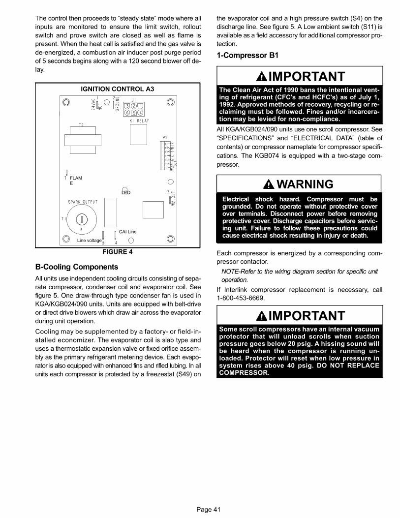
Page 41
The control then proceeds to “steady state” mode where all
inputs are monitored to ensure the limit switch, rollout
switch and prove switch are closed as well as flame is
present. When the heat call is satisfied and the gas valve is
de-energized, a combustion air inducer post purge period
of 5 seconds begins along with a 120 second blower off de
lay.
FIGURE 4
FLAME
CAI Line
Line voltage
LED
IGNITION CONTROL A3
B-Cooling Components
All units use independent cooling circuits consisting of sepa
rate compressor, condenser coil and evaporator coil. See
figure 5. One draw-through type condenser fan is used in
KGA/KGB024/090 units. Units are equipped with belt‐drive
or direct drive blowers which draw air across the evaporator
during unit operation.
Cooling may be supplemented by a factory‐ or field‐in
stalled economizer. The evaporator coil is slab type and
uses a thermostatic expansion valve or fixed orifice assem
bly as the primary refrigerant metering device. Each evapo
rator is also equipped with enhanced fins and rifled tubing. In all
units each compressor is protected by a freezestat (S49) on
the evaporator coil and a high pressure switch (S4) on the
discharge line. See figure 5. A Low ambient switch (S11) is
available as a field accessory for additional compressor pro
tection.
1-Compressor B1
IMPORTANTThe Clean Air Act of 1990 bans the intentional venting of refrigerant (CFC's and HCFC's) as of July 1,1992. Approved methods of recovery, recycling or reclaiming must be followed. Fines and/or incarceration may be levied for non-compliance.
All KGA/KGB024/090 units use one scroll compressor. See
“SPECIFICATIONS” and “ELECTRICAL DATA” (table of
contents) or compressor nameplate for compressor specifi
cations. The KGB074 is equipped with a two-stage com
pressor.
WARNINGElectrical shock hazard. Compressor must begrounded. Do not operate without protective coverover terminals. Disconnect power before removingprotective cover. Discharge capacitors before servicing unit. Failure to follow these precautions couldcause electrical shock resulting in injury or death.
Each compressor is energized by a corresponding com
pressor contactor.
NOTE-Refer to the wiring diagram section for specific unit
operation.
If Interlink compressor replacement is necessary, call
1-800-453-6669.
IMPORTANTSome scroll compressors have an internal vacuumprotector that will unload scrolls when suctionpressure goes below 20 psig. A hissing sound willbe heard when the compressor is running unloaded. Protector will reset when low pressure insystem rises above 40 psig. DO NOT REPLACECOMPRESSOR.
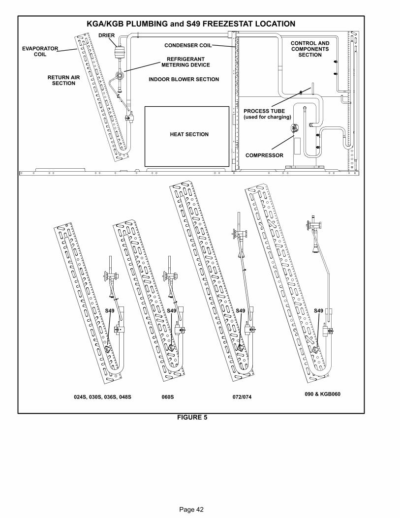
Page 42
KGA/KGB PLUMBING and S49 FREEZESTAT LOCATION
FIGURE 5
EVAPORATORCOIL
CONDENSER COIL
DRIER
COMPRESSOR
INDOOR BLOWER SECTION
HEAT SECTION
CONTROL ANDCOMPONENTS
SECTION
PROCESS TUBE(used for charging)
RETURN AIRSECTION
024S, 030S, 036S, 048S 060S
S49 S49 S49 S49
REFRIGERANTMETERING DEVICE
072/074090 & KGB060
Page 43
2-Freezestat S49
Each unit is equipped with a low temperature switch
(freezestat) located on a return bend of each evaporator
coil.
The freezestat is wired in series with the compressor con
tactor K1. The freezestat is a SPST N.C. auto-reset
switch which opens at 29°F + 3°F (‐1.7°C + 1.7°C) on a
temperature drop and closes at 58°F + 4°F (14.4°C +
2.2°C) on a temperature rise. To prevent coil icing,
freezestats open during compressor operation to tempo
rarily disable the respective compressor until the coil
temperature rises.
If the freezestats are tripping frequently due to coil icing,
check the airflow / filters , economizer position and unit
charge before allowing unit back in operation. Make
sure to eliminate conditions which might promote evap
orator ice buildup.
3-High Pressure Switch S4
The high pressure switch is an auto reset SPST N.C. switch
which opens on a pressure rise.
S4 is located in the compressor discharge line and wired in se
ries with the compressor contactor coil.
When discharge pressure rises to 640 ± 20 psig (4412 ±
138 kPa) (indicating a problem in the system) the switch
opens and the respective compressor is de-energized
(the economizer can continue to operate). When dis
charge pressure drops to 475 ± 30 psig (3275 ± 206 kPa),
the switch closes.
4-Low Ambient Switches S11 (optional)
The low ambient switch is an auto‐reset SPST N.O. pres
sure switch which allows for mechanical cooling opera
tion at low outdoor temperatures. In all models the
switch is located in each liquid line prior to the indoor coil
section and is wired in series with outdoor fan B4. When
S11 opens B4 is de-energized.
In G, J and M voltage units, S11 is wired in series with out
door fan relay K10 coil and when opened breaks 24 volts to
the coil, de-energizing outdoor fan B4.
When liquid pressure rises to 450 ± 10 psig (3102 ± 69
kPa), the switch closes and the condenser fan is ener
gized. When discharge pressure in drops to 240 ± 10 psig
(1655 ± 69 kPa), the switch opens and the condenser fan is
de-energized. This intermittent fan operation results in
higher evaporating temperature allowing the system to op
erate without icing the evaporator coil and losing capacity.
5-Low Temperature Switch S3 (optional)
(compressor monitor)
S3 is a SPST bimetal thermostat which opens on tempera
ture drop. It is wired in line with the 24VAC compressor con
tactor. When outdoor temperature drops below 40° F (4.5°
C) the switch opens and de-energizes the compressor.
When the compressor is de-energized the cooling demand
is handled by the economizer. The switch automatically re
sets when outdoor temperature rises to 50° F (10° C).
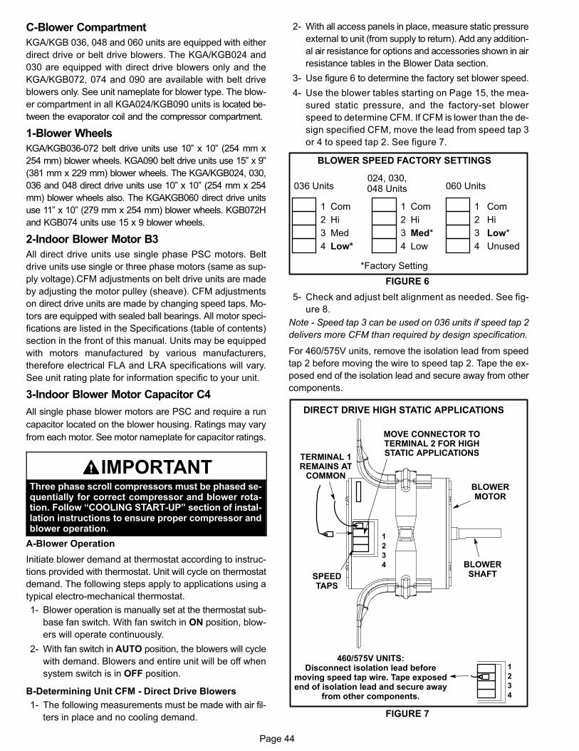
Page 44
C-Blower Compartment
KGA/KGB 036, 048 and 060 units are equipped with either
direct drive or belt drive blowers. The KGA/KGB024 and
030 are equipped with direct drive blowers only and the
KGA/KGB072, 074 and 090 are available with belt drive
blowers only. See unit nameplate for blower type. The blow
er compartment in all KGA024/KGB090 units is located be
tween the evaporator coil and the compressor compartment.
1-Blower Wheels
KGA/KGB036-072 belt drive units use 10” x 10” (254 mm x
254 mm) blower wheels. KGA090 belt drive units use 15” x 9”
(381 mm x 229 mm) blower wheels. The KGA/KGB024, 030,
036 and 048 direct drive units use 10” x 10” (254 mm x 254
mm) blower wheels also. The KGAKGB060 direct drive units
use 11” x 10” (279 mm x 254 mm) blower wheels. KGB072H
and KGB074 units use 15 x 9 blower wheels.
2-Indoor Blower Motor B3
All direct drive units use single phase PSC motors. Belt
drive units use single or three phase motors (same as sup
ply voltage).CFM adjustments on belt drive units are made
by adjusting the motor pulley (sheave). CFM adjustments
on direct drive units are made by changing speed taps. Mo
tors are equipped with sealed ball bearings. All motor speci
fications are listed in the Specifications (table of contents)
section in the front of this manual. Units may be equipped
with motors manufactured by various manufacturers,
therefore electrical FLA and LRA specifications will vary.
See unit rating plate for information specific to your unit.
3-Indoor Blower Motor Capacitor C4
All single phase blower motors are PSC and require a run
capacitor located on the blower housing. Ratings may vary
from each motor. See motor nameplate for capacitor ratings.
IMPORTANTThree phase scroll compressors must be phased sequentially for correct compressor and blower rotation. Follow “COOLING START-UP” section of installation instructions to ensure proper compressor andblower operation.
A-Blower Operation
Initiate blower demand at thermostat according to instruc
tions provided with thermostat. Unit will cycle on thermostat
demand. The following steps apply to applications using a
typical electro-mechanical thermostat.
1- Blower operation is manually set at the thermostat sub
base fan switch. With fan switch in ON position, blow
ers will operate continuously.
2- With fan switch in AUTO position, the blowers will cycle
with demand. Blowers and entire unit will be off when
system switch is in OFF position.
B-Determining Unit CFM - Direct Drive Blowers
1- The following measurements must be made with air fil
ters in place and no cooling demand.
2- With all access panels in place, measure static pressure
external to unit (from supply to return). Add any addition
al air resistance for options and accessories shown in air
resistance tables in the Blower Data section.
3- Use figure 6 to determine the factory set blower speed.
4- Use the blower tables starting on Page 15, the mea
sured static pressure, and the factory-set blower
speed to determine CFM. If CFM is lower than the de
sign specified CFM, move the lead from speed tap 3
or 4 to speed tap 2. See figure 7.
BLOWER SPEED FACTORY SETTINGS
FIGURE 6
1
2
3
4
Com
Hi
Med
Low*
1
2
3
4
Com
Hi
Med*
Low
1
2
3
4
Com
Hi
Low*
Unused
*Factory Setting
036 Units024, 030,048 Units 060 Units
5- Check and adjust belt alignment as needed. See fig
ure 8.
Note - Speed tap 3 can be used on 036 units if speed tap 2
delivers more CFM than required by design specification.
For 460/575V units, remove the isolation lead from speed
tap 2 before moving the wire to speed tap 2. Tape the ex
posed end of the isolation lead and secure away from other
components.
FIGURE 7
MOVE CONNECTOR TOTERMINAL 2 FOR HIGHSTATIC APPLICATIONS
1
2
3
4
BLOWERMOTOR
SPEEDTAPS
BLOWERSHAFT
DIRECT DRIVE HIGH STATIC APPLICATIONS
TERMINAL 1REMAINS AT
COMMON
1
2
3
4
460/575V UNITS:Disconnect isolation lead before
moving speed tap wire. Tape exposedend of isolation lead and secure away
from other components.
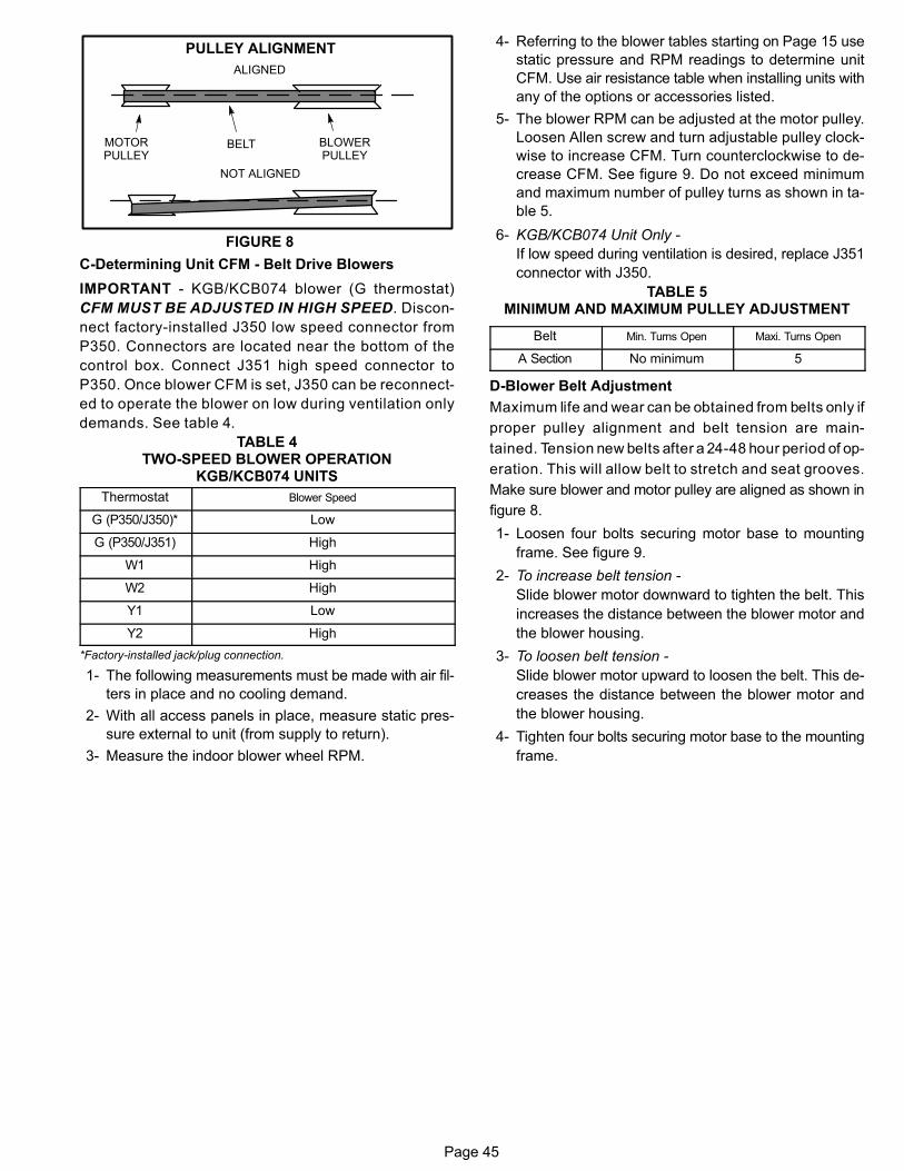
Page 45
FIGURE 8
PULLEY ALIGNMENT
BELT BLOWERPULLEY
MOTORPULLEY
NOT ALIGNED
ALIGNED
C-Determining Unit CFM - Belt Drive Blowers
IMPORTANT - KGB/KCB074 blower (G thermostat)
CFM MUST BE ADJUSTED IN HIGH SPEED. Discon
nect factory-installed J350 low speed connector from
P350. Connectors are located near the bottom of the
control box. Connect J351 high speed connector to
P350. Once blower CFM is set, J350 can be reconnect
ed to operate the blower on low during ventilation only
demands. See table 4.
TABLE 4TWO-SPEED BLOWER OPERATION
KGB/KCB074 UNITS
Thermostat Blower Speed
G (P350/J350)* Low
G (P350/J351) High
W1 High
W2 High
Y1 Low
Y2 High
*Factory-installed jack/plug connection.
1- The following measurements must be made with air fil
ters in place and no cooling demand.
2- With all access panels in place, measure static pres
sure external to unit (from supply to return).
3- Measure the indoor blower wheel RPM.
4- Referring to the blower tables starting on Page 15 use
static pressure and RPM readings to determine unit
CFM. Use air resistance table when installing units with
any of the options or accessories listed.
5- The blower RPM can be adjusted at the motor pulley.
Loosen Allen screw and turn adjustable pulley clock
wise to increase CFM. Turn counterclockwise to de
crease CFM. See figure 9. Do not exceed minimum
and maximum number of pulley turns as shown in ta
ble 5.
6- KGB/KCB074 Unit Only -
If low speed during ventilation is desired, replace J351
connector with J350.
TABLE 5MINIMUM AND MAXIMUM PULLEY ADJUSTMENT
Belt Min. Turns Open Maxi. Turns Open
A Section No minimum 5
D-Blower Belt Adjustment
Maximum life and wear can be obtained from belts only if
proper pulley alignment and belt tension are main
tained. Tension new belts after a 24-48 hour period of op
eration. This will allow belt to stretch and seat grooves.
Make sure blower and motor pulley are aligned as shown in
figure 8.
1- Loosen four bolts securing motor base to mounting
frame. See figure 9.
2- To increase belt tension -
Slide blower motor downward to tighten the belt. This
increases the distance between the blower motor and
the blower housing.
3- To loosen belt tension -
Slide blower motor upward to loosen the belt. This de
creases the distance between the blower motor and
the blower housing.
4- Tighten four bolts securing motor base to the mounting
frame.
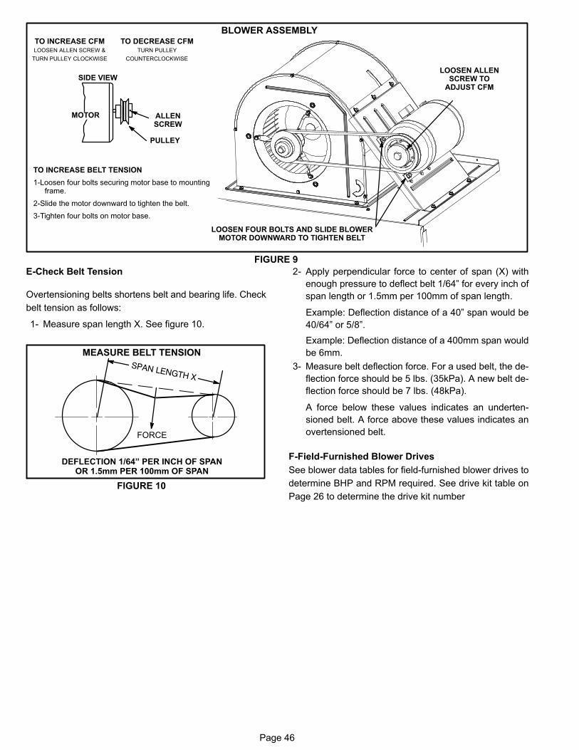
Page 46
BLOWER ASSEMBLY
TO INCREASE BELT TENSION
1-Loosen four bolts securing motor base to mountingframe.
2-Slide the motor downward to tighten the belt.
3-Tighten four bolts on motor base.
TO INCREASE CFMLOOSEN ALLEN SCREW &
TURN PULLEY CLOCKWISE
TO DECREASE CFMTURN PULLEY
COUNTERCLOCKWISE
FIGURE 9
PULLEY
MOTOR
SIDE VIEW
ALLENSCREW
LOOSEN FOUR BOLTS AND SLIDE BLOWERMOTOR DOWNWARD TO TIGHTEN BELT
LOOSEN ALLENSCREW TO
ADJUST CFM
E-Check Belt Tension
Overtensioning belts shortens belt and bearing life. Check
belt tension as follows:
1- Measure span length X. See figure 10.
MEASURE BELT TENSION
FIGURE 10
DEFLECTION 1/64” PER INCH OF SPANOR 1.5mm PER 100mm OF SPAN
FORCE
2- Apply perpendicular force to center of span (X) with
enough pressure to deflect belt 1/64” for every inch of
span length or 1.5mm per 100mm of span length.
Example: Deflection distance of a 40” span would be
40/64” or 5/8”.
Example: Deflection distance of a 400mm span would
be 6mm.
3- Measure belt deflection force. For a used belt, the de
flection force should be 5 lbs. (35kPa). A new belt de
flection force should be 7 lbs. (48kPa).
A force below these values indicates an underten
sioned belt. A force above these values indicates an
overtensioned belt.
F-Field-Furnished Blower Drives
See blower data tables for field-furnished blower drives to
determine BHP and RPM required. See drive kit table on
Page 26 to determine the drive kit number
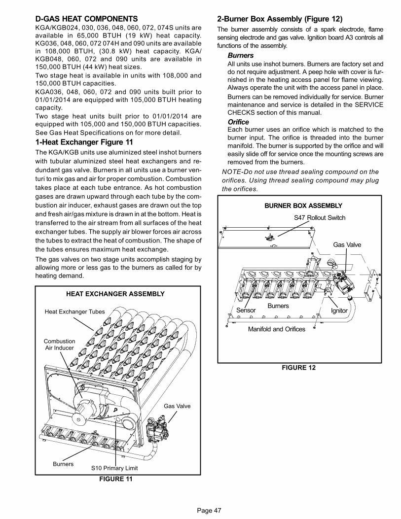
Page 47
D-GAS HEAT COMPONENTSKGA/KGB024, 030, 036, 048, 060, 072, 074S units are
available in 65,000 BTUH (19 kW) heat capacity.
KG036, 048, 060, 072 074H and 090 units are available
in 108,000 BTUH, (30.8 kW) heat capacity. KGA/
KGB048, 060, 072 and 090 units are available in
150,000 BTUH (44 kW) heat sizes.
Two stage heat is available in units with 108,000 and
150,000 BTUH capacities.
KGA036, 048, 060, 072 and 090 units built prior to
01/01/2014 are equipped with 105,000 BTUH heating
capacity.
Two stage heat units built prior to 01/01/2014 are
equipped with 105,000 and 150,000 BTUH capacities.
See Gas Heat Specifications on for more detail.
1-Heat Exchanger Figure 11
The KGA/KGB units use aluminized steel inshot burners
with tubular aluminized steel heat exchangers and re
dundant gas valve. Burners in all units use a burner ven
turi to mix gas and air for proper combustion. Combustion
takes place at each tube entrance. As hot combustion
gases are drawn upward through each tube by the com
bustion air inducer, exhaust gases are drawn out the top
and fresh air/gas mixture is drawn in at the bottom. Heat is
transferred to the air stream from all surfaces of the heat
exchanger tubes. The supply air blower forces air across
the tubes to extract the heat of combustion. The shape of
the tubes ensures maximum heat exchange.
The gas valves on two stage units accomplish staging by
allowing more or less gas to the burners as called for by
heating demand.
HEAT EXCHANGER ASSEMBLY
FIGURE 11
Heat Exchanger Tubes
CombustionAir Inducer
Gas Valve
BurnersS10 Primary Limit
2-Burner Box Assembly (Figure 12)
The burner assembly consists of a spark electrode, flame
sensing electrode and gas valve. Ignition board A3 controls all
functions of the assembly.
BurnersAll units use inshot burners. Burners are factory set and
do not require adjustment. A peep hole with cover is fur
nished in the heating access panel for flame viewing.
Always operate the unit with the access panel in place.
Burners can be removed individually for service. Burner
maintenance and service is detailed in the SERVICE
CHECKS section of this manual.
OrificeEach burner uses an orifice which is matched to the
burner input. The orifice is threaded into the burner
manifold. The burner is supported by the orifice and will
easily slide off for service once the mounting screws are
removed from the burners.
NOTE-Do not use thread sealing compound on the
orifices. Using thread sealing compound may plug
the orifices.
FIGURE 12
BURNER BOX ASSEMBLY
S47 Rollout Switch
Gas Valve
Manifold and Orifices
BurnersIgnitorSensor
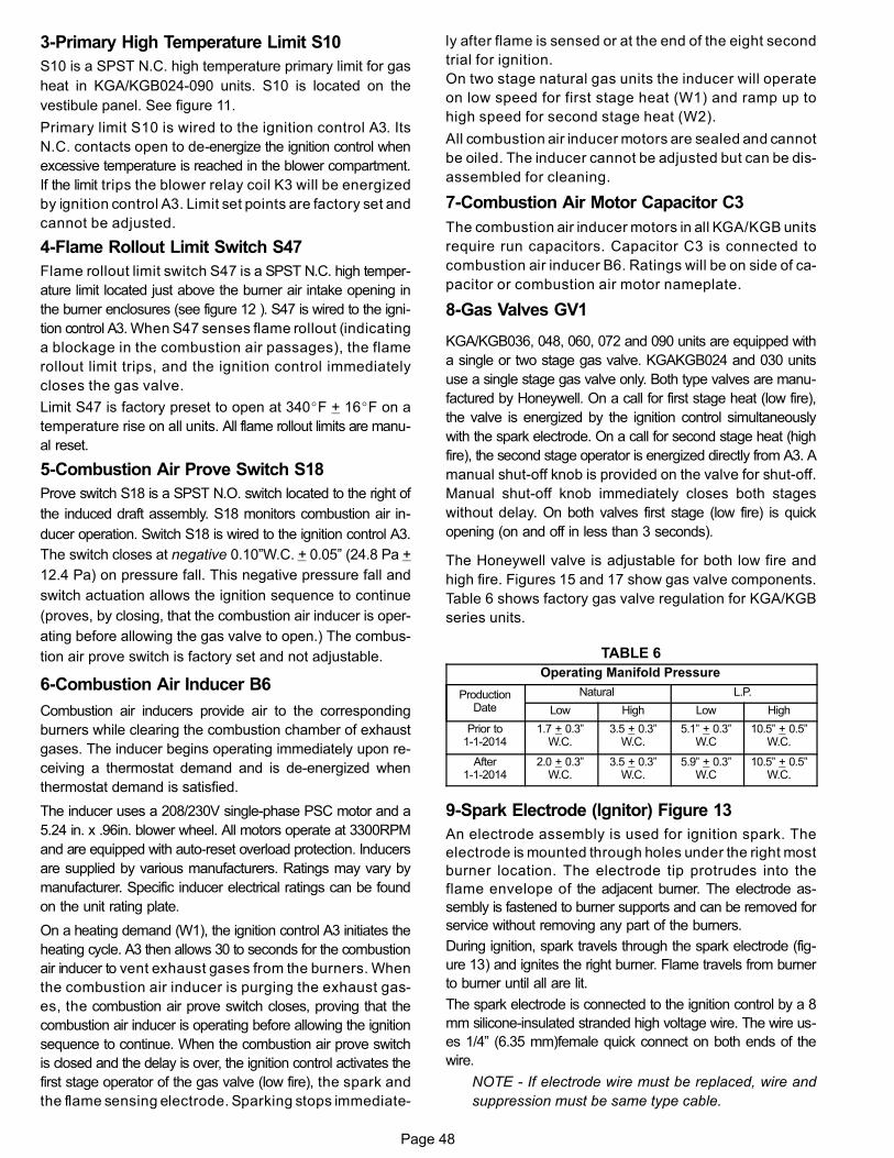
Page 48
3-Primary High Temperature Limit S10
S10 is a SPST N.C. high temperature primary limit for gas
heat in KGA/KGB024-090 units. S10 is located on the
vestibule panel. See figure 11.
Primary limit S10 is wired to the ignition control A3. Its
N.C. contacts open to de-energize the ignition control when
excessive temperature is reached in the blower compartment.
If the limit trips the blower relay coil K3 will be energized
by ignition control A3. Limit set points are factory set and
cannot be adjusted.
4-Flame Rollout Limit Switch S47
Flame rollout limit switch S47 is a SPST N.C. high temper
ature limit located just above the burner air intake opening in
the burner enclosures (see figure 12 ). S47 is wired to the igni
tion control A3. When S47 senses flame rollout (indicating
a blockage in the combustion air passages), the flame
rollout limit trips, and the ignition control immediately
closes the gas valve.
Limit S47 is factory preset to open at 340�F + 16�F on a
temperature rise on all units. All flame rollout limits are manu
al reset.
5-Combustion Air Prove Switch S18
Prove switch S18 is a SPST N.O. switch located to the right of
the induced draft assembly. S18 monitors combustion air in
ducer operation. Switch S18 is wired to the ignition control A3.
The switch closes at negative 0.10”W.C. + 0.05” (24.8 Pa +
12.4 Pa) on pressure fall. This negative pressure fall and
switch actuation allows the ignition sequence to continue
(proves, by closing, that the combustion air inducer is oper
ating before allowing the gas valve to open.) The combus
tion air prove switch is factory set and not adjustable.
6-Combustion Air Inducer B6
Combustion air inducers provide air to the corresponding
burners while clearing the combustion chamber of exhaust
gases. The inducer begins operating immediately upon re
ceiving a thermostat demand and is de-energized when
thermostat demand is satisfied.
The inducer uses a 208/230V single‐phase PSC motor and a
5.24 in. x .96in. blower wheel. All motors operate at 3300RPM
and are equipped with auto‐reset overload protection. Inducers
are supplied by various manufacturers. Ratings may vary by
manufacturer. Specific inducer electrical ratings can be found
on the unit rating plate.
On a heating demand (W1), the ignition control A3 initiates the
heating cycle. A3 then allows 30 to seconds for the combustion
air inducer to vent exhaust gases from the burners. When
the combustion air inducer is purging the exhaust gas
es, the combustion air prove switch closes, proving that the
combustion air inducer is operating before allowing the ignition
sequence to continue. When the combustion air prove switch
is closed and the delay is over, the ignition control activates the
first stage operator of the gas valve (low fire), the spark and
the flame sensing electrode. Sparking stops immediate
ly after flame is sensed or at the end of the eight second
trial for ignition.
On two stage natural gas units the inducer will operate
on low speed for first stage heat (W1) and ramp up to
high speed for second stage heat (W2).
All combustion air inducer motors are sealed and cannot
be oiled. The inducer cannot be adjusted but can be dis
assembled for cleaning.
7-Combustion Air Motor Capacitor C3
The combustion air inducer motors in all KGA/KGB units
require run capacitors. Capacitor C3 is connected to
combustion air inducer B6. Ratings will be on side of ca
pacitor or combustion air motor nameplate.
8-Gas Valves GV1
KGA/KGB036, 048, 060, 072 and 090 units are equipped with
a single or two stage gas valve. KGAKGB024 and 030 units
use a single stage gas valve only. Both type valves are manu
factured by Honeywell. On a call for first stage heat (low fire),
the valve is energized by the ignition control simultaneously
with the spark electrode. On a call for second stage heat (high
fire), the second stage operator is energized directly from A3. A
manual shut-off knob is provided on the valve for shut-off.
Manual shut‐off knob immediately closes both stages
without delay. On both valves first stage (low fire) is quick
opening (on and off in less than 3 seconds).
The Honeywell valve is adjustable for both low fire and
high fire. Figures 15 and 17 show gas valve components.
Table 6 shows factory gas valve regulation for KGA/KGB
series units.
TABLE 6
Operating Manifold Pressure
ProductionDate
Natural L.P.
Low High Low High
Prior to1-1-2014
1.7 + 0.3”W.C.
3.5 + 0.3”W.C.
5.1” + 0.3”W.C
10.5” + 0.5”W.C.
After1-1-2014
2.0 + 0.3”W.C.
3.5 + 0.3”W.C.
5.9” + 0.3”W.C
10.5” + 0.5”W.C.
9-Spark Electrode (Ignitor) Figure 13
An electrode assembly is used for ignition spark. The
electrode is mounted through holes under the right most
burner location. The electrode tip protrudes into the
flame envelope of the adjacent burner. The electrode as
sembly is fastened to burner supports and can be removed for
service without removing any part of the burners.
During ignition, spark travels through the spark electrode (fig
ure 13) and ignites the right burner. Flame travels from burner
to burner until all are lit.
The spark electrode is connected to the ignition control by a 8
mm silicone‐insulated stranded high voltage wire. The wire us
es 1/4” (6.35 mm)female quick connect on both ends of the
wire.
NOTE - If electrode wire must be replaced, wire and
suppression must be same type cable.
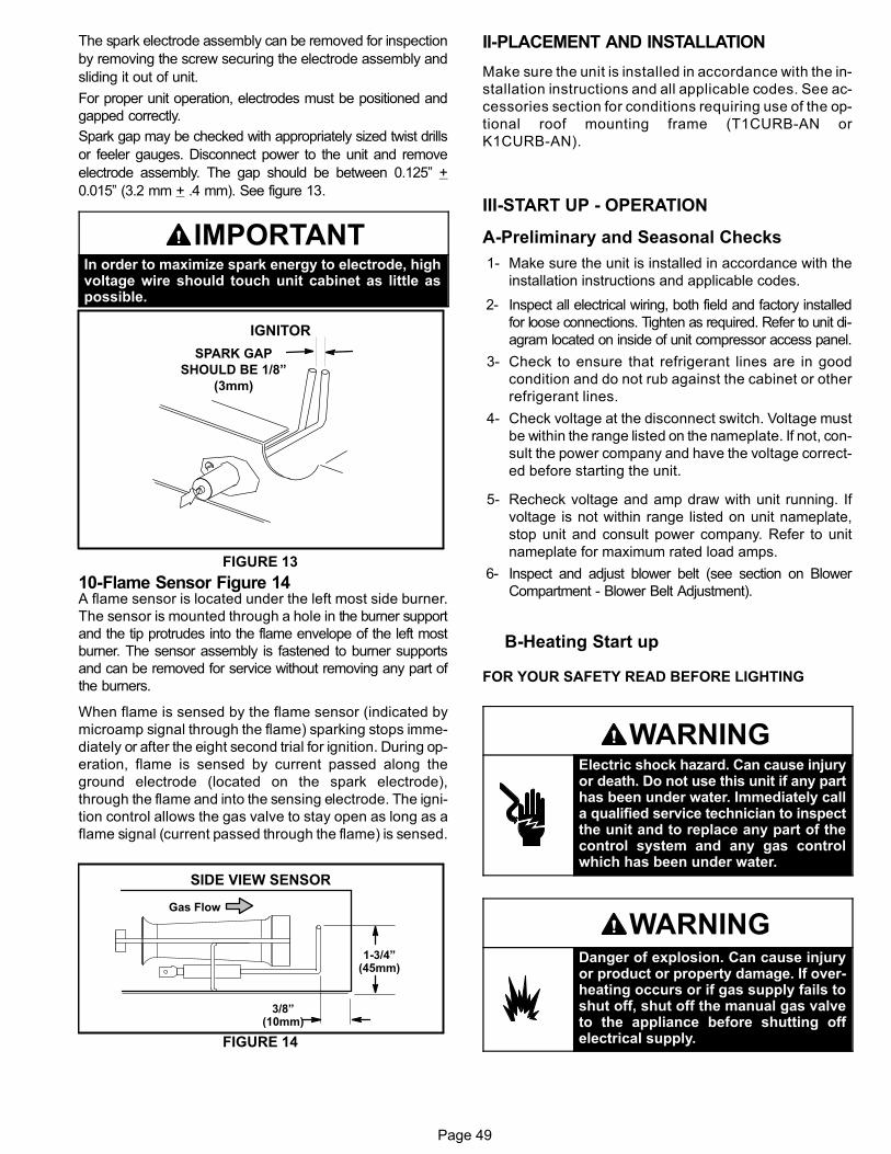
Page 49
The spark electrode assembly can be removed for inspection
by removing the screw securing the electrode assembly and
sliding it out of unit.
For proper unit operation, electrodes must be positioned and
gapped correctly.
Spark gap may be checked with appropriately sized twist drills
or feeler gauges. Disconnect power to the unit and remove
electrode assembly. The gap should be between 0.125” +
0.015” (3.2 mm + .4 mm). See figure 13.
IMPORTANTIn order to maximize spark energy to electrode, highvoltage wire should touch unit cabinet as little aspossible.
FIGURE 13
IGNITOR
SPARK GAP
SHOULD BE 1/8”
(3mm)
10-Flame Sensor Figure 14A flame sensor is located under the left most side burner.
The sensor is mounted through a hole in the burner support
and the tip protrudes into the flame envelope of the left most
burner. The sensor assembly is fastened to burner supports
and can be removed for service without removing any part of
the burners.
When flame is sensed by the flame sensor (indicated by
microamp signal through the flame) sparking stops imme
diately or after the eight second trial for ignition. During op
eration, flame is sensed by current passed along the
ground electrode (located on the spark electrode),
through the flame and into the sensing electrode. The igni
tion control allows the gas valve to stay open as long as a
flame signal (current passed through the flame) is sensed.
FIGURE 14
SIDE VIEW SENSOR
1-3/4”(45mm)
3/8”(10mm)
Gas Flow
II-PLACEMENT AND INSTALLATION
Make sure the unit is installed in accordance with the in
stallation instructions and all applicable codes. See ac
cessories section for conditions requiring use of the op
tional roof mounting frame (T1CURB-AN or
K1CURB-AN).
III-START UP - OPERATION
A-Preliminary and Seasonal Checks
1- Make sure the unit is installed in accordance with the
installation instructions and applicable codes.
2- Inspect all electrical wiring, both field and factory installed
for loose connections. Tighten as required. Refer to unit di
agram located on inside of unit compressor access panel.
3- Check to ensure that refrigerant lines are in good
condition and do not rub against the cabinet or other
refrigerant lines.
4- Check voltage at the disconnect switch. Voltage must
be within the range listed on the nameplate. If not, con
sult the power company and have the voltage correct
ed before starting the unit.
5- Recheck voltage and amp draw with unit running. If
voltage is not within range listed on unit nameplate,
stop unit and consult power company. Refer to unit
nameplate for maximum rated load amps.
6- Inspect and adjust blower belt (see section on Blower
Compartment - Blower Belt Adjustment).
B-Heating Start up
FOR YOUR SAFETY READ BEFORE LIGHTING
WARNINGElectric shock hazard. Can cause injuryor death. Do not use this unit if any parthas been under water. Immediately calla qualified service technician to inspectthe unit and to replace any part of thecontrol system and any gas controlwhich has been under water.
WARNINGDanger of explosion. Can cause injuryor product or property damage. If overheating occurs or if gas supply fails toshut off, shut off the manual gas valveto the appliance before shutting offelectrical supply.
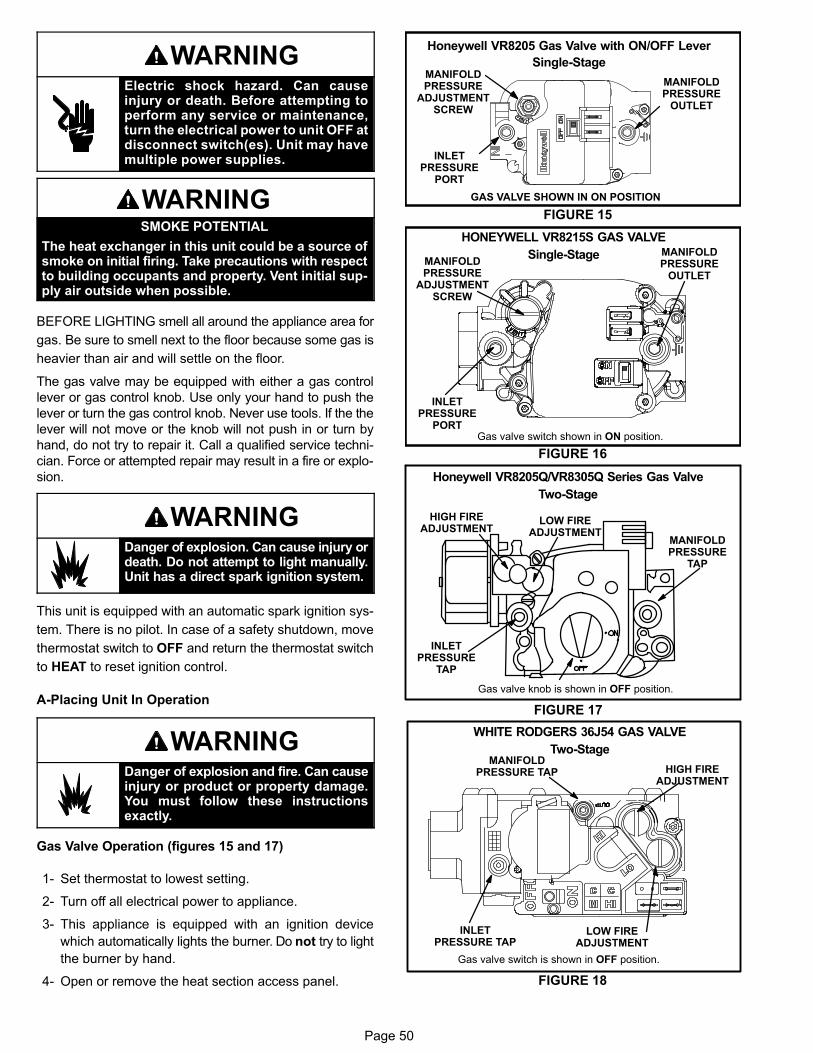
Page 50
WARNINGElectric shock hazard. Can causeinjury or death. Before attempting toperform any service or maintenance,turn the electrical power to unit OFF atdisconnect switch(es). Unit may havemultiple power supplies.
WARNINGSMOKE POTENTIAL
The heat exchanger in this unit could be a source ofsmoke on initial firing. Take precautions with respectto building occupants and property. Vent initial supply air outside when possible.
BEFORE LIGHTING smell all around the appliance area for
gas. Be sure to smell next to the floor because some gas is
heavier than air and will settle on the floor.
The gas valve may be equipped with either a gas control
lever or gas control knob. Use only your hand to push the
lever or turn the gas control knob. Never use tools. If the the
lever will not move or the knob will not push in or turn by
hand, do not try to repair it. Call a qualified service techni
cian. Force or attempted repair may result in a fire or explo
sion.
WARNINGDanger of explosion. Can cause injury ordeath. Do not attempt to light manually.Unit has a direct spark ignition system.
This unit is equipped with an automatic spark ignition sys
tem. There is no pilot. In case of a safety shutdown, move
thermostat switch to OFF and return the thermostat switch
to HEAT to reset ignition control.
A-Placing Unit In Operation
WARNINGDanger of explosion and fire. Can causeinjury or product or property damage.You must follow these instructionsexactly.
Gas Valve Operation (figures 15 and 17)
1- Set thermostat to lowest setting.
2- Turn off all electrical power to appliance.
3- This appliance is equipped with an ignition device
which automatically lights the burner. Do not try to light
the burner by hand.
4- Open or remove the heat section access panel.
GAS VALVE SHOWN IN ON POSITION
Honeywell VR8205 Gas Valve with ON/OFF Lever
Single-Stage
MANIFOLDPRESSURE
OUTLET
INLETPRESSURE
PORT
MANIFOLDPRESSURE
ADJUSTMENTSCREW
FIGURE 15
MANIFOLDPRESSURE
OUTLET
Gas valve switch shown in ON position.
INLETPRESSURE
PORT
MANIFOLDPRESSURE
ADJUSTMENTSCREW
FIGURE 16
HONEYWELL VR8215S GAS VALVE
Single-Stage
Honeywell VR8205Q/VR8305Q Series Gas Valve
Two-Stage
Gas valve knob is shown in OFF position.
FIGURE 17
LOW FIREADJUSTMENT
HIGH FIREADJUSTMENT
INLETPRESSURE
TAP
MANIFOLDPRESSURE
TAP
WHITE RODGERS 36J54 GAS VALVE
Two-Stage
Gas valve switch is shown in OFF position.
FIGURE 18
LOW FIREADJUSTMENT
HIGH FIREADJUSTMENT
INLETPRESSURE TAP
MANIFOLDPRESSURE TAP
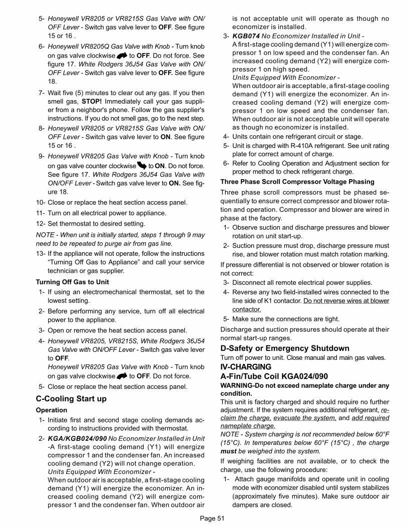
Page 51
5- Honeywell VR8205 or VR8215S Gas Valve with ON/
OFF Lever - Switch gas valve lever to OFF. See figure
15 or 16 .
6- Honeywell VR8205Q Gas Valve with Knob - Turn knob
on gas valve clockwise to OFF. Do not force. See
figure 17. White Rodgers 36J54 Gas Valve with ON/
OFF Lever - Switch gas valve lever to OFF. See figure
18.
7- Wait five (5) minutes to clear out any gas. If you then
smell gas, STOP! Immediately call your gas suppli
er from a neighbor's phone. Follow the gas supplier's
instructions. If you do not smell gas, go to the next step.
8- Honeywell VR8205 or VR8215S Gas Valve with ON/
OFF Lever - Switch gas valve lever to ON. See figure
15 or 16 .
9- Honeywell VR8205 Gas Valve with Knob - Turn knob
on gas valve counter clockwise to ON. Do not force.
See figure 17. White Rodgers 36J54 Gas Valve with
ON/OFF Lever - Switch gas valve lever to ON. See fig
ure 18.
10- Close or replace the heat section access panel.
11- Turn on all electrical power to appliance.
12- Set thermostat to desired setting.
NOTE - When unit is initially started, steps 1 through 9 may
need to be repeated to purge air from gas line.
13- If the appliance will not operate, follow the instructions
“Turning Off Gas to Appliance” and call your service
technician or gas supplier.
Turning Off Gas to Unit
1- If using an electromechanical thermostat, set to the
lowest setting.
2- Before performing any service, turn off all electrical
power to the appliance.
3- Open or remove the heat section access panel.
4- Honeywell VR8205, VR8215S, White Rodgers 36J54
Gas Valve with ON/OFF Lever - Switch gas valve lever
to OFF.
Honeywell VR8205 Gas Valve with Knob - Turn knob
on gas valve clockwise to OFF. Do not force.
5- Close or replace the heat section access panel.
C-Cooling Start up
Operation
1- Initiate first and second stage cooling demands ac
cording to instructions provided with thermostat.
2- KGA/KGB024/090 No Economizer Installed in Unit
-A first-stage cooling demand (Y1) will energize
compressor 1 and the condenser fan. An increased
cooling demand (Y2) will not change operation.
Units Equipped With Economizer -
When outdoor air is acceptable, a first-stage cooling
demand (Y1) will energize the economizer. An in
creased cooling demand (Y2) will energize com
pressor 1 and the condenser fan. When outdoor air
is not acceptable unit will operate as though no
economizer is installed.
3- KGB074 No Economizer Installed in Unit -
A first-stage cooling demand (Y1) will energize com
pressor 1 on low speed and the condenser fan. An
increased cooling demand (Y2) will energize com
pressor 1 on high speed.
Units Equipped With Economizer -
When outdoor air is acceptable, a first-stage cooling
demand (Y1) will energize the economizer. An in
creased cooling demand (Y2) will energize com
pressor 1 on low speed and the condenser fan.
When outdoor air is not acceptable unit will operate
as though no economizer is installed.
4- Units contain one refrigerant circuit or stage.
5- Unit is charged with R-410A refrigerant. See unit rating
plate for correct amount of charge.
6- Refer to Cooling Operation and Adjustment section for
proper method to check refrigerant charge.
Three Phase Scroll Compressor Voltage Phasing
Three phase scroll compressors must be phased se
quentially to ensure correct compressor and blower rota
tion and operation. Compressor and blower are wired in
phase at the factory.
1- Observe suction and discharge pressures and blower
rotation on unit start-up.
2- Suction pressure must drop, discharge pressure must
rise, and blower rotation must match rotation marking.
If pressure differential is not observed or blower rotation is
not correct:
3- Disconnect all remote electrical power supplies.
4- Reverse any two field-installed wires connected to the
line side of K1 contactor. Do not reverse wires at blower
contactor.
5- Make sure the connections are tight.
Discharge and suction pressures should operate at their
normal start‐up ranges.
D-Safety or Emergency ShutdownTurn off power to unit. Close manual and main gas valves.
IV-CHARGING
A-Fin/Tube Coil KGA024/090WARNING-Do not exceed nameplate charge under any
condition.
This unit is factory charged and should require no further
adjustment. If the system requires additional refrigerant, re
claim the charge, evacuate the system, and add required
nameplate charge.
NOTE - System charging is not recommended below 60°F
(15°C). In temperatures below 60°F (15°C) , the charge
must be weighed into the system.
If weighing facilities are not available, or to check the
charge, use the following procedure:
1- Attach gauge manifolds and operate unit in cooling
mode with economizer disabled until system stabilizes
(approximately five minutes). Make sure outdoor air
dampers are closed.
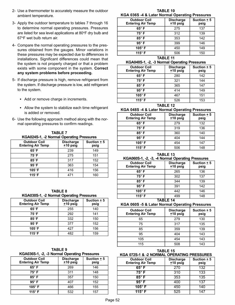
Page 52
2- Use a thermometer to accurately measure the outdoor
ambient temperature.
3- Apply the outdoor temperature to tables 7 through 16
to determine normal operating pressures. Pressures
are listed for sea level applications at 80�F dry bulb and
67�F wet bulb return air.
4- Compare the normal operating pressures to the pres
sures obtained from the gauges. Minor variations in
these pressures may be expected due to differences in
installations. Significant differences could mean that
the system is not properly charged or that a problem
exists with some component in the system. Correct
any system problems before proceeding.
5- If discharge pressure is high, remove refrigerant from
the system. If discharge pressure is low, add refrigerant
to the system.
� Add or remove charge in increments.
� Allow the system to stabilize each time refrigerant
is added or removed.
6- Use the following approach method along with the nor
mal operating pressures to confirm readings.
TABLE 7KGA024S-1, -2 Normal Operating Pressures
Outdoor CoilEntering Air Temp
Discharge+10 psig
Suction + 5psig
65�F 239 149
75�F 275 151
85�F 317 152
95�F 363 154
105�F 416 156
115�F 471 160
TABLE 8KGA030S-1, -2 Normal Operating Pressures
Outdoor CoilEntering Air Temp
Discharge+10 psig
Suction + 5psig
65�F 255 140
75�F 292 141
85�F 332 150
95�F 377 152
105�F 427 156
115�F 482 159
TABLE 9KGA036S-1, -2, -3 Normal Operating Pressures
Outdoor CoilEntering Air Temp
Discharge+10 psig
Suction + 5psig
65� F 269 146
75� F 311 148
85� F 357 150
95� F 407 152
105� F 466 155
115� F 532 157
TABLE 10KGA 036S -4 & Later Normal Operating Pressures
Outdoor CoilEntering Air Temp
Discharge+10 psig
Suction + 5psig
65� F 275 137
75� F 312 139
85� F 353 142
95� F 399 146
105� F 450 149
115� F 506 150
TABLE 11KGA048S-1, -2, -3 Normal Operating Pressures
Outdoor CoilEntering Air Temp
Discharge+10 psig
Suction + 5psig
65� F 280 142
75� F 321 144
85� F 365 147
95� F 414 149
105� F 467 151
115� F 526 153
TABLE 12KGA 048S -4 & Later Normal Operating Pressures
Outdoor CoilEntering Air Temp
Discharge+10 psig
Suction + 5psig
65� F 279 132
75� F 319 136
85� F 360 140
95� F 404 144
105� F 454 147
115� F 506 148
TABLE 13KGA060S-1, -2, -3, -4 Normal Operating Pressures
Outdoor CoilEntering Air Temp
Discharge+10 psig
Suction + 5psig
65� F 265 136
75� F 302 137
85� F 344 139
95� F 391 142
105� F 442 146
115� F 499 148
TABLE 14KGA 060S -5 & Later Normal Operating Pressures
Outdoor CoilEntering Air Temp
Discharge+10 psig
Suction + 5psig
65 279 130
75 317 135
85 359 139
95 404 143
105 454 143
115 508 143
TABLE 15KGA 072S-1 & -2 NORMAL OPERATING PRESSURES
Outdoor CoilEntering Air Temp
Discharge+10 psig
Suction + 5psig
65� F 270 132
75� F 310 133
85� F 353 135
95� F 400 137
105� F 450 140
115� F 525 147
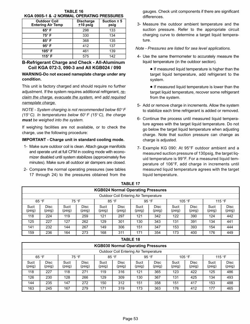
Page 53
TABLE 16KGA 090S-1 & -2 NORMAL OPERATING PRESSURES
Outdoor CoilEntering Air Temp
Discharge+10 psig
Suction + 5psig
65� F 298 133
75� F 330 134
85� F 368 135
95� F 412 137
105� F 461 139
115� F 575 142
B-Refrigerant Charge and Check - All-AluminumCoil KGA 072-3, 090-3 and All KGB024 / 090
WARNING-Do not exceed nameplate charge under any
condition.
This unit is factory charged and should require no further
adjustment. If the system requires additional refrigerant, re
claim the charge, evacuate the system, and add required
nameplate charge.
NOTE - System charging is not recommended below 60�F
(15�C). In temperatures below 60�F (15�C), the charge
must be weighed into the system.
If weighing facilities are not available, or to check the
charge, use the following procedure:
IMPORTANT - Charge unit in standard cooling mode.
1- Make sure outdoor coil is clean. Attach gauge manifolds
and operate unit at full CFM in cooling mode with econo
mizer disabled until system stabilizes (approximately five
minutes). Make sure all outdoor air dampers are closed.
2- Compare the normal operating pressures (see tables
17 through 24) to the pressures obtained from the
gauges. Check unit components if there are significant
differences.
3- Measure the outdoor ambient temperature and the
suction pressure. Refer to the appropriate circuit
charging curve to determine a target liquid tempera
ture.
Note - Pressures are listed for sea level applications.
4- Use the same thermometer to accurately measure the
liquid temperature (in the outdoor section).
� If measured liquid temperature is higher than the
target liquid temperature, add refrigerant to the
system.
� If measured liquid temperature is lower than the
target liquid temperature, recover some refrigerant
from the system.
5- Add or remove charge in increments. Allow the system
to stabilize each time refrigerant is added or removed.
6- Continue the process until measured liquid tempera
ture agrees with the target liquid temperature. Do not
go below the target liquid temperature when adjusting
charge. Note that suction pressure can change as
charge is adjusted.
7- Example KG 090: At 95°F outdoor ambient and a
measured suction pressure of 130psig, the target liq
uid temperature is 99°F. For a measured liquid tem
perature of 106°F, add charge in increments until
measured liquid temperature agrees with the target
liquid temperature.
TABLE 17
KGB024 Normal Operating Pressures
Outdoor Coil Entering Air Temperature
65 °F 75 °F 85 °F 95 °F 105 °F 115 °FSuct(psig)
Disc(psig)
Suct(psig)
Disc(psig)
Suct(psig)
Disc(psig)
Suct(psig)
Disc(psig)
Suct(psig)
Disc(psig)
Suct(psig)
Disc(psig)
118 224 119 259 121 297 121 342 122 390 124 442
125 227 127 262 129 301 130 343 131 391 134 441
141 232 144 267 149 306 151 347 153 393 154 444
159 236 164 273 168 311 171 354 173 400 176 449
TABLE 18
KGB030 Normal Operating Pressures
Outdoor Coil Entering Air Temperature
65 °F 75 °F 85 °F 95 °F 105 °F 115 °FSuct(psig)
Disc(psig)
Suct(psig)
Disc(psig)
Suct(psig)
Disc(psig)
Suct(psig)
Disc(psig)
Suct(psig)
Disc(psig)
Suct(psig)
Disc(psig)
118 227 118 271 119 316 121 365 123 422 125 486
126 230 128 266 129 309 130 367 131 425 134 493
144 235 147 272 150 312 151 358 151 417 153 488
163 245 167 279 171 319 173 363 176 412 177 465
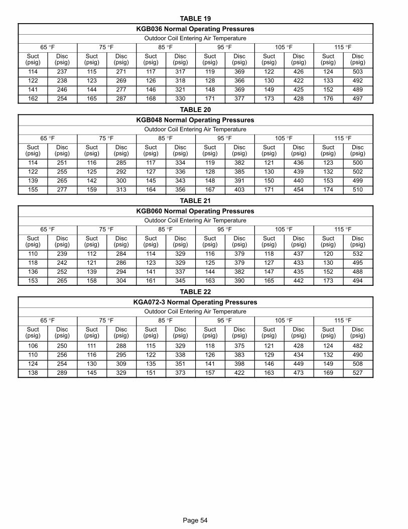
Page 54
TABLE 19
KGB036 Normal Operating Pressures
Outdoor Coil Entering Air Temperature
65 °F 75 °F 85 °F 95 °F 105 °F 115 °FSuct(psig)
Disc(psig)
Suct(psig)
Disc(psig)
Suct(psig)
Disc(psig)
Suct(psig)
Disc(psig)
Suct(psig)
Disc(psig)
Suct(psig)
Disc(psig)
114 237 115 271 117 317 119 369 122 426 124 503
122 238 123 269 126 318 128 366 130 422 133 492
141 246 144 277 146 321 148 369 149 425 152 489
162 254 165 287 168 330 171 377 173 428 176 497
TABLE 20
KGB048 Normal Operating Pressures
Outdoor Coil Entering Air Temperature
65 °F 75 °F 85 °F 95 °F 105 °F 115 °FSuct(psig)
Disc(psig)
Suct(psig)
Disc(psig)
Suct(psig)
Disc(psig)
Suct(psig)
Disc(psig)
Suct(psig)
Disc(psig)
Suct(psig)
Disc(psig)
114 251 116 285 117 334 119 382 121 436 123 500
122 255 125 292 127 336 128 385 130 439 132 502
139 265 142 300 145 343 148 391 150 440 153 499
155 277 159 313 164 356 167 403 171 454 174 510
TABLE 21
KGB060 Normal Operating Pressures
Outdoor Coil Entering Air Temperature
65 °F 75 °F 85 °F 95 °F 105 °F 115 °FSuct(psig)
Disc(psig)
Suct(psig)
Disc(psig)
Suct(psig)
Disc(psig)
Suct(psig)
Disc(psig)
Suct(psig)
Disc(psig)
Suct(psig)
Disc(psig)
110 239 112 284 114 329 116 379 118 437 120 532
118 242 121 286 123 329 125 379 127 433 130 495
136 252 139 294 141 337 144 382 147 435 152 488
153 265 158 304 161 345 163 390 165 442 173 494
TABLE 22
KGA072-3 Normal Operating Pressures
Outdoor Coil Entering Air Temperature
65 °F 75 °F 85 °F 95 °F 105 °F 115 °FSuct(psig)
Disc(psig)
Suct(psig)
Disc(psig)
Suct(psig)
Disc(psig)
Suct(psig)
Disc(psig)
Suct(psig)
Disc(psig)
Suct(psig)
Disc(psig)
106 250 111 288 115 329 118 375 121 428 124 482
110 256 116 295 122 338 126 383 129 434 132 490
124 254 130 309 135 351 141 398 146 449 149 508
138 289 145 329 151 373 157 422 163 473 169 527
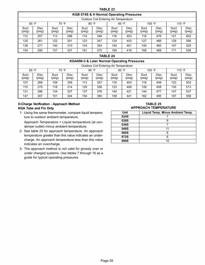
Page 55
TABLE 23
KGB 074S & H Normal Operating Pressures
Outdoor Coil Entering Air Temperature
65 °F 75 °F 85 °F 95 °F 105 °F 115 °FSuct(psig)
Disc(psig)
Suct(psig)
Disc(psig)
Suct(psig)
Disc(psig)
Suct(psig)
Disc(psig)
Suct(psig)
Disc(psig)
Suct(psig)
Disc(psig)
112 257 113 298 114 348 116 403 118 476 121 602
120 261 122 301 123 347 124 403 127 466 129 556
136 271 140 310 143 354 145 401 145 460 147 525
154 290 157 327 161 370 165 416 168 468 171 526
TABLE 24
KGA090-3 & Later Normal Operating Pressures
Outdoor Coil Entering Air Temperature
65 °F 75 °F 85 °F 95 °F 105 °F 115 °FSuct(psig)
Disc(psig)
Suct(psig)
Disc(psig)
Suct(psig)
Disc(psig)
Suct(psig)
Disc(psig)
Suct(psig)
Disc(psig)
Suct(psig)
Disc(psig)
107 268 109 309 113 357 116 403 118 449 123 503
115 275 118 314 120 358 123 406 126 458 130 513
131 286 134 327 137 376 140 421 144 477 147 537
147 307 151 344 154 390 158 441 162 495 167 558
D-Charge Verification - Approach Method
KGA Tube and Fin Only
1- Using the same thermometer, compare liquid tempera
ture to outdoor ambient temperature.
Approach Temperature = Liquid temperature (at con
denser outlet) minus ambient temperature.
2- See table 25 for approach temperature. An approach
temperature greater than this value indicates an under
charge. An approach temperature less than this value
indicates an overcharge.
3- The approach method is not valid for grossly over or
under charged systems. Use tables 7 through 16 as a
guide for typical operating pressures.
TABLE 25APPROACH TEMPERATURE
Unit Liquid Temp. Minus Ambient Temp.
024S 7
030S 9
036S 7
048S 11
060S 6
072S 6
090S 10
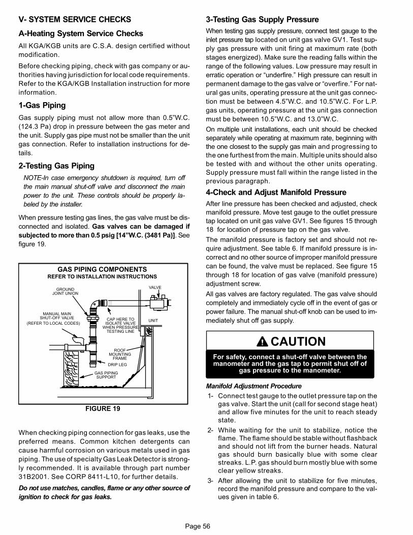
Page 56
V- SYSTEM SERVICE CHECKS
A-Heating System Service Checks
All KGA/KGB units are C.S.A. design certified without
modification.
Before checking piping, check with gas company or au
thorities having jurisdiction for local code requirements.
Refer to the KGA/KGB Installation instruction for more
information.
1-Gas Piping
Gas supply piping must not allow more than 0.5”W.C.
(124.3 Pa) drop in pressure between the gas meter and
the unit. Supply gas pipe must not be smaller than the unit
gas connection. Refer to installation instructions for de
tails.
2-Testing Gas Piping
NOTE-In case emergency shutdown is required, turn off
the main manual shut‐off valve and disconnect the main
power to the unit. These controls should be properly la
beled by the installer.
When pressure testing gas lines, the gas valve must be dis
connected and isolated. Gas valves can be damaged if
subjected to more than 0.5 psig [14”W.C. (3481 Pa)]. See
figure 19.
UNIT
GROUNDJOINT UNION
MANUAL MAINSHUT-OFF VALVE
(REFER TO LOCAL CODES)
GAS PIPINGSUPPORT
DRIP LEG
ROOFMOUNTING
FRAME
GAS PIPING COMPONENTSREFER TO INSTALLATION INSTRUCTIONS
VALVE
CAP HERE TOISOLATE VALVE
WHEN PRESSURETESTING LINE
FIGURE 19
When checking piping connection for gas leaks, use the
preferred means. Common kitchen detergents can
cause harmful corrosion on various metals used in gas
piping. The use of specialty Gas Leak Detector is strong
ly recommended. It is available through part number
31B2001. See CORP 8411-L10, for further details.
Do not use matches, candles, flame or any other source of
ignition to check for gas leaks.
3-Testing Gas Supply Pressure
When testing gas supply pressure, connect test gauge to the
inlet pressure tap located on unit gas valve GV1. Test sup
ply gas pressure with unit firing at maximum rate (both
stages energized). Make sure the reading falls within the
range of the following values. Low pressure may result in
erratic operation or “underfire.” High pressure can result in
permanent damage to the gas valve or “overfire.” For nat
ural gas units, operating pressure at the unit gas connec
tion must be between 4.5”W.C. and 10.5”W.C. For L.P.
gas units, operating pressure at the unit gas connection
must be between 10.5”W.C. and 13.0”W.C.
On multiple unit installations, each unit should be checked
separately while operating at maximum rate, beginning with
the one closest to the supply gas main and progressing to
the one furthest from the main. Multiple units should also
be tested with and without the other units operating.
Supply pressure must fall within the range listed in the
previous paragraph.
4-Check and Adjust Manifold Pressure
After line pressure has been checked and adjusted, check
manifold pressure. Move test gauge to the outlet pressure
tap located on unit gas valve GV1. See figures 15 through
18 for location of pressure tap on the gas valve.
The manifold pressure is factory set and should not re
quire adjustment. See table 6. If manifold pressure is in
correct and no other source of improper manifold pressure
can be found, the valve must be replaced. See figure 15
through 18 for location of gas valve (manifold pressure)
adjustment screw.
All gas valves are factory regulated. The gas valve should
completely and immediately cycle off in the event of gas or
power failure. The manual shut‐off knob can be used to im
mediately shut off gas supply.
CAUTIONFor safety, connect a shut‐off valve between themanometer and the gas tap to permit shut off of
gas pressure to the manometer.
Manifold Adjustment Procedure
1- Connect test gauge to the outlet pressure tap on the
gas valve. Start the unit (call for second stage heat)
and allow five minutes for the unit to reach steady
state.
2- While waiting for the unit to stabilize, notice the
flame. The flame should be stable without flashback
and should not lift from the burner heads. Natural
gas should burn basically blue with some clear
streaks. L.P. gas should burn mostly blue with some
clear yellow streaks.
3- After allowing the unit to stabilize for five minutes,
record the manifold pressure and compare to the val
ues given in table 6.
Page 57
5-Proper Gas Flow
Furnace should operate at least 5 minutes before checking
gas flow. Determine time in seconds for two revolutions of
gas through the meter. (Two revolutions assures a more ac
curate time.) Divide by two and compare to time in table 26.
Seconds in table 26 are based on a 1 cu.ft. dial and gas val
ue of 1000 btu/ft3 for natural and 2500 btu/ft3' for LP. Adjust
manifold pressure on gas valve to match time needed.
NOTE - To obtain accurate reading, shut off all other gas
appliances connected to meter.
TABLE 26
Unit Input RateSeconds for
NaturalSeconds for
Propane
65,000 55 138
105,000 34 86
108,000 33 83
150,000 24 60
IMPORTANTDisconnect heating demand as soon as an
accurate reading has been obtained.
6-Heat Exchanger
To Access or Remove Heat Exchanger From Unit:
1- Turn off gas and electric power.
2- Remove access panel(s) and unit center mullion.
3- Remove gas valve, manifold assembly and burn
ers.
4- Remove combustion air inducer. Pay careful attention
to the order in which gaskets and orifice are removed.
5- Support heat exchanger (to prevent it from falling
when final screws are removed.)
6- Remove screws supporting heat exchanger.
7- To install heat exchanger, reverse procedure. Be sure
to secure all wires and check plumbing and burner
plate for airtight seal. Screws must be torqued to 35
in.‐lbs. to ensure proper operation.
7-Flame Sensing
Flame current is an electrical current which passes from the
ignition control through the sensor electrode during unit op
eration. The current passes from the sensor through the
flame to the ground electrode (located on the flame elec
trode) to complete a safety circuit. The electrodes should be
located so the tips are at least 1/2” (12.7 mm) inside the
flame envelope. Do not bend electrodes. To measure flame
current, follow the procedure on the following page:
NOTE-Electrodes are not field adjustable. Any alter
ations to the electrode may create a hazardous con
dition that can cause property or personal injury.
1- Disconnect power to unit.
2- Remove lead from sensing electrode and install a
0-50DC microamp meter in series between the sens
ing electrode and the sensing lead.
3- Reconnect power and adjust thermostat for
heating demand.
4- When flame is established, microamp reading should
be 0.5 to 1.0. Do not bend electrodes.
Drop out signal is .09 or less.
5- Disconnect power to unit before disconnecting meter.
Make sure sensor wire is securely reconnected
before reconnecting power to unit.
NOTE-If the meter scale reads 0, the leads are re
versed. Disconnect power and reconnect leads for
proper polarity.
B-Cooling System Service Checks
KGA/KGB units are factory charged and require no further ad
justment; however, charge should be checked periodically us
ing the approach method. The approach method compares
actual liquid temperature with the outdoor ambient tempera
ture. See section IV- CHARGING.
NOTE-When unit is properly charged discharge line
pressures should approximate those in tables 7
through 16.
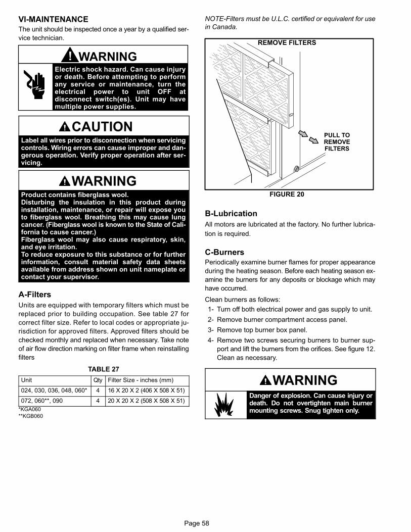
Page 58
VI-MAINTENANCE The unit should be inspected once a year by a qualified ser
vice technician.
Electric shock hazard. Can cause injuryor death. Before attempting to performany service or maintenance, turn theelectrical power to unit OFF atdisconnect switch(es). Unit may havemultiple power supplies.
WARNING!
CAUTIONLabel all wires prior to disconnection when servicingcontrols. Wiring errors can cause improper and dangerous operation. Verify proper operation after servicing.
WARNINGProduct contains fiberglass wool.Disturbing the insulation in this product duringinstallation, maintenance, or repair will expose youto fiberglass wool. Breathing this may cause lungcancer. (Fiberglass wool is known to the State of California to cause cancer.)Fiberglass wool may also cause respiratory, skin,and eye irritation.To reduce exposure to this substance or for furtherinformation, consult material safety data sheetsavailable from address shown on unit nameplate orcontact your supervisor.
A-Filters
Units are equipped with temporary filters which must be
replaced prior to building occupation. See table 27 for
correct filter size. Refer to local codes or appropriate ju
risdiction for approved filters. Approved filters should be
checked monthly and replaced when necessary. Take note
of air flow direction marking on filter frame when reinstalling
filters
TABLE 27
Unit Qty Filter Size - inches (mm)
024, 030, 036, 048, 060* 4 16 X 20 X 2 (406 X 508 X 51)
072, 060**, 090 4 20 X 20 X 2 (508 X 508 X 51)
*KGA060
**KGB060
NOTE-Filters must be U.L.C. certified or equivalent for use
in Canada.
FIGURE 20
REMOVE FILTERS
PULL TOREMOVEFILTERS
B-Lubrication
All motors are lubricated at the factory. No further lubrica
tion is required.
C-Burners
Periodically examine burner flames for proper appearance
during the heating season. Before each heating season ex
amine the burners for any deposits or blockage which may
have occurred.
Clean burners as follows:
1- Turn off both electrical power and gas supply to unit.
2- Remove burner compartment access panel.
3- Remove top burner box panel.
4- Remove two screws securing burners to burner sup
port and lift the burners from the orifices. See figure 12.
Clean as necessary.
WARNINGDanger of explosion. Can cause injury ordeath. Do not overtighten main burnermounting screws. Snug tighten only.
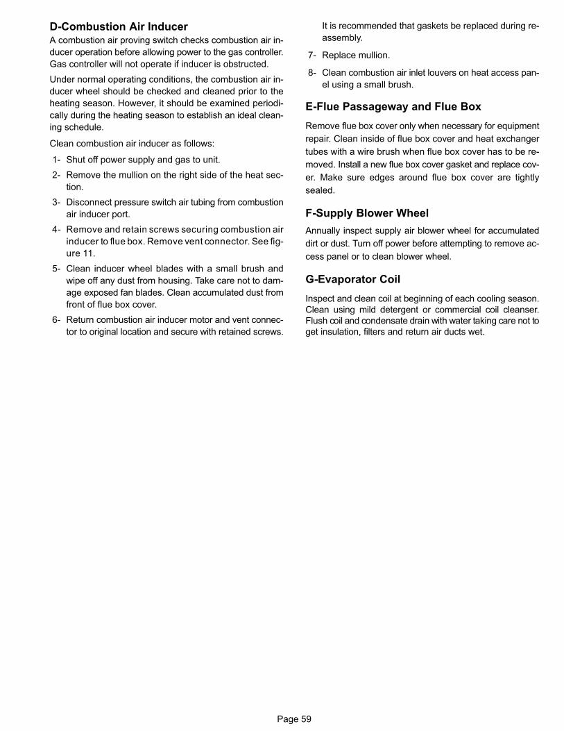
Page 59
D-Combustion Air InducerA combustion air proving switch checks combustion air in
ducer operation before allowing power to the gas controller.
Gas controller will not operate if inducer is obstructed.
Under normal operating conditions, the combustion air in
ducer wheel should be checked and cleaned prior to the
heating season. However, it should be examined periodi
cally during the heating season to establish an ideal clean
ing schedule.
Clean combustion air inducer as follows:
1- Shut off power supply and gas to unit.
2- Remove the mullion on the right side of the heat sec
tion.
3- Disconnect pressure switch air tubing from combustion
air inducer port.
4- Remove and retain screws securing combustion air
inducer to flue box. Remove vent connector. See fig
ure 11.
5- Clean inducer wheel blades with a small brush and
wipe off any dust from housing. Take care not to dam
age exposed fan blades. Clean accumulated dust from
front of flue box cover.
6- Return combustion air inducer motor and vent connec
tor to original location and secure with retained screws.
It is recommended that gaskets be replaced during re
assembly.
7- Replace mullion.
8- Clean combustion air inlet louvers on heat access pan
el using a small brush.
E-Flue Passageway and Flue Box
Remove flue box cover only when necessary for equipment
repair. Clean inside of flue box cover and heat exchanger
tubes with a wire brush when flue box cover has to be re
moved. Install a new flue box cover gasket and replace cov
er. Make sure edges around flue box cover are tightly
sealed.
F-Supply Blower Wheel
Annually inspect supply air blower wheel for accumulated
dirt or dust. Turn off power before attempting to remove ac
cess panel or to clean blower wheel.
G-Evaporator Coil
Inspect and clean coil at beginning of each cooling season.
Clean using mild detergent or commercial coil cleanser.
Flush coil and condensate drain with water taking care not to
get insulation, filters and return air ducts wet.
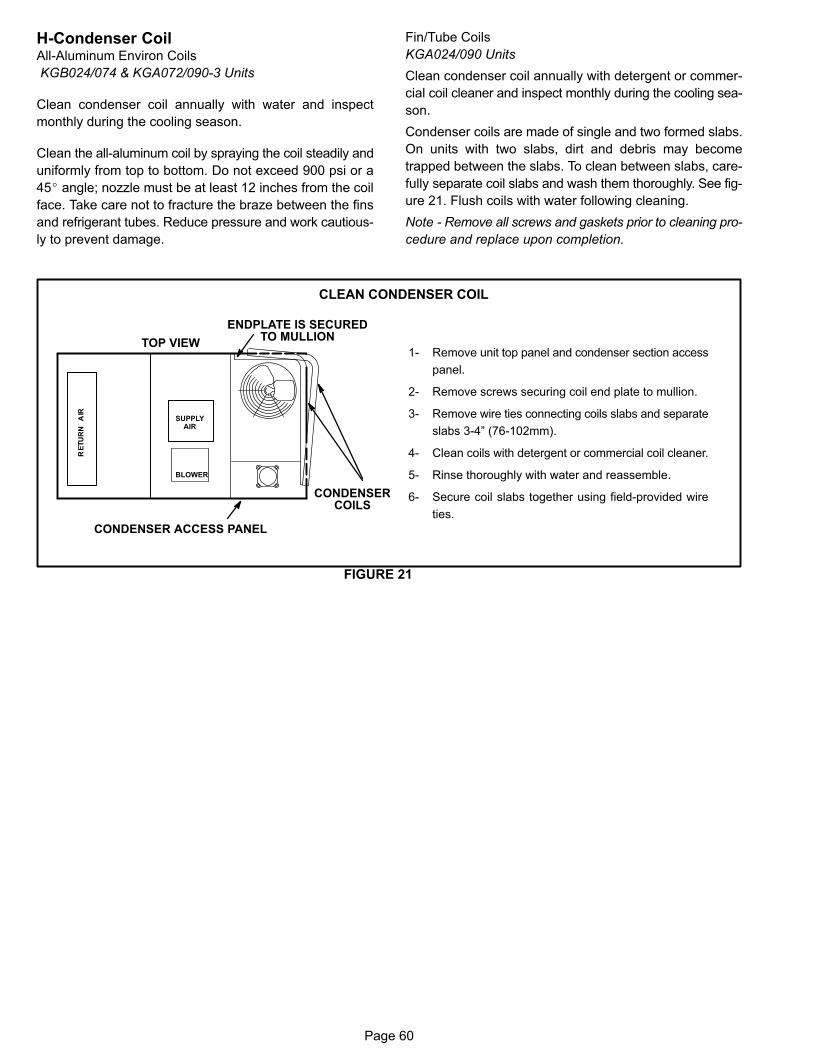
Page 60
H-Condenser CoilAll-Aluminum Environ Coils
KGB024/074 & KGA072/090-3 Units
Clean condenser coil annually with water and inspect
monthly during the cooling season.
Clean the all-aluminum coil by spraying the coil steadily and
uniformly from top to bottom. Do not exceed 900 psi or a
45� angle; nozzle must be at least 12 inches from the coil
face. Take care not to fracture the braze between the fins
and refrigerant tubes. Reduce pressure and work cautious
ly to prevent damage.
Fin/Tube Coils
KGA024/090 Units
Clean condenser coil annually with detergent or commer
cial coil cleaner and inspect monthly during the cooling sea
son.
Condenser coils are made of single and two formed slabs.
On units with two slabs, dirt and debris may become
trapped between the slabs. To clean between slabs, care
fully separate coil slabs and wash them thoroughly. See fig
ure 21. Flush coils with water following cleaning.
Note - Remove all screws and gaskets prior to cleaning pro
cedure and replace upon completion.
FIGURE 21
1- Remove unit top panel and condenser section access
panel.
2- Remove screws securing coil end plate to mullion.
3- Remove wire ties connecting coils slabs and separate
slabs 3-4” (76-102mm).
4- Clean coils with detergent or commercial coil cleaner.
5- Rinse thoroughly with water and reassemble.
6- Secure coil slabs together using field-provided wire
ties.
CLEAN CONDENSER COIL
TOP VIEW
CONDENSERCOILS
BLOWER
CONDENSER ACCESS PANEL
ENDPLATE IS SECUREDTO MULLION
SUPPLYAIR
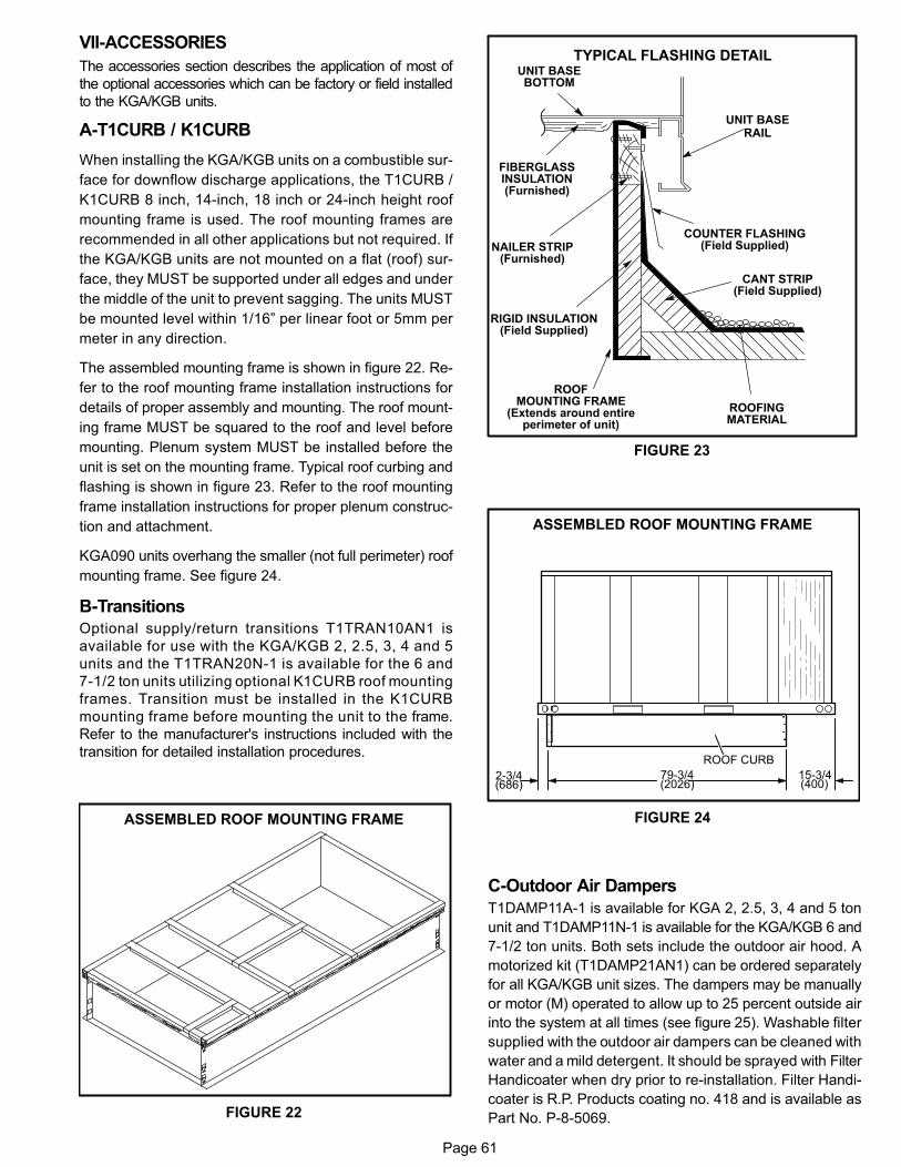
Page 61
VII-ACCESSORIES
The accessories section describes the application of most of
the optional accessories which can be factory or field installed
to the KGA/KGB units.
A-T1CURB / K1CURB
When installing the KGA/KGB units on a combustible sur
face for downflow discharge applications, the T1CURB /
K1CURB 8 inch, 14‐inch, 18 inch or 24‐inch height roof
mounting frame is used. The roof mounting frames are
recommended in all other applications but not required. If
the KGA/KGB units are not mounted on a flat (roof) sur
face, they MUST be supported under all edges and under
the middle of the unit to prevent sagging. The units MUST
be mounted level within 1/16” per linear foot or 5mm per
meter in any direction.
The assembled mounting frame is shown in figure 22. Re
fer to the roof mounting frame installation instructions for
details of proper assembly and mounting. The roof mount
ing frame MUST be squared to the roof and level before
mounting. Plenum system MUST be installed before the
unit is set on the mounting frame. Typical roof curbing and
flashing is shown in figure 23. Refer to the roof mounting
frame installation instructions for proper plenum construc
tion and attachment.
KGA090 units overhang the smaller (not full perimeter) roof
mounting frame. See figure 24.
B-Transitions
Optional supply/return transitions T1TRAN10AN1 is
available for use with the KGA/KGB 2, 2.5, 3, 4 and 5
units and the T1TRAN20N-1 is available for the 6 and
7-1/2 ton units utilizing optional K1CURB roof mounting
frames. Transition must be installed in the K1CURB
mounting frame before mounting the unit to the frame.
Refer to the manufacturer's instructions included with the
transition for detailed installation procedures.
FIGURE 22
ASSEMBLED ROOF MOUNTING FRAME
FIGURE 23
ROOFMOUNTING FRAME
(Extends around entireperimeter of unit)
FIBERGLASSINSULATION(Furnished)
COUNTER FLASHING(Field Supplied)
UNIT BASEBOTTOM
RIGID INSULATION(Field Supplied)
ROOFINGMATERIAL
CANT STRIP(Field Supplied)
NAILER STRIP(Furnished)
UNIT BASERAIL
TYPICAL FLASHING DETAIL
FIGURE 24
ASSEMBLED ROOF MOUNTING FRAME
79-3/4(2026)
15-3/4(400)
2-3/4(686)
ROOF CURB
C-Outdoor Air Dampers
T1DAMP11A-1 is available for KGA 2, 2.5, 3, 4 and 5 ton
unit and T1DAMP11N-1 is available for the KGA/KGB 6 and
7-1/2 ton units. Both sets include the outdoor air hood. A
motorized kit (T1DAMP21AN1) can be ordered separately
for all KGA/KGB unit sizes. The dampers may be manually
or motor (M) operated to allow up to 25 percent outside air
into the system at all times (see figure 25). Washable filter
supplied with the outdoor air dampers can be cleaned with
water and a mild detergent. It should be sprayed with Filter
Handicoater when dry prior to re-installation. Filter Handi
coater is R.P. Products coating no. 418 and is available as
Part No. P-8-5069.
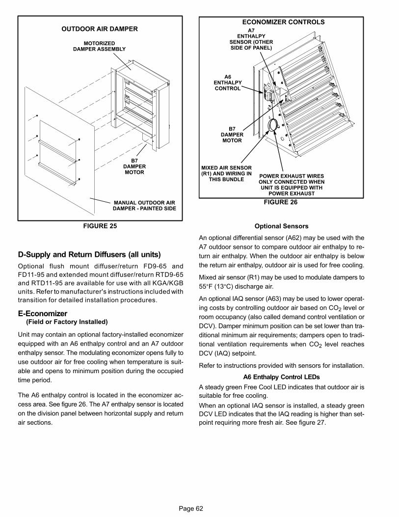
Page 62
FIGURE 25
MOTORIZEDDAMPER ASSEMBLY
MANUAL OUTDOOR AIRDAMPER - PAINTED SIDE
B7DAMPERMOTOR
OUTDOOR AIR DAMPER
D-Supply and Return Diffusers (all units)
Optional flush mount diffuser/return FD9-65 and
FD11-95 and extended mount diffuser/return RTD9-65
and RTD11-95 are available for use with all KGA/KGB
units. Refer to manufacturer's instructions included with
transition for detailed installation procedures.
E-Economizer(Field or Factory Installed)
Unit may contain an optional factory-installed economizer
equipped with an A6 enthalpy control and an A7 outdoor
enthalpy sensor. The modulating economizer opens fully to
use outdoor air for free cooling when temperature is suit
able and opens to minimum position during the occupied
time period.
The A6 enthalpy control is located in the economizer ac
cess area. See figure 26. The A7 enthalpy sensor is located
on the division panel between horizontal supply and return
air sections.
FIGURE 26
ECONOMIZER CONTROLS
A6ENTHALPYCONTROL
B7DAMPERMOTOR
A7ENTHALPY
SENSOR (OTHERSIDE OF PANEL)
POWER EXHAUST WIRESONLY CONNECTED WHENUNIT IS EQUIPPED WITH
POWER EXHAUST
MIXED AIR SENSOR(R1) AND WIRING IN
THIS BUNDLE
Optional Sensors
An optional differential sensor (A62) may be used with the
A7 outdoor sensor to compare outdoor air enthalpy to re
turn air enthalpy. When the outdoor air enthalpy is below
the return air enthalpy, outdoor air is used for free cooling.
Mixed air sensor (R1) may be used to modulate dampers to
55°F (13°C) discharge air.
An optional IAQ sensor (A63) may be used to lower operat
ing costs by controlling outdoor air based on CO2 level or
room occupancy (also called demand control ventilation or
DCV). Damper minimum position can be set lower than tra
ditional minimum air requirements; dampers open to tradi
tional ventilation requirements when CO2 level reaches
DCV (IAQ) setpoint.
Refer to instructions provided with sensors for installation.
A6 Enthalpy Control LEDs
A steady green Free Cool LED indicates that outdoor air is
suitable for free cooling.
When an optional IAQ sensor is installed, a steady green
DCV LED indicates that the IAQ reading is higher than set
point requiring more fresh air. See figure 27.
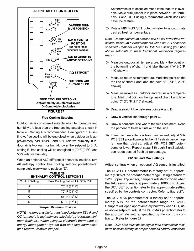
Page 63
FIGURE 27
A6 ENTHALPY CONTROLLER
A
B C
D
Open
MinPos
FREE COOLING SETPOINT;
A=Completely counterclockwise
D=Completely clockwise
OUTDOOR AIRSUITABLE LED
FreeCool
DCV
EXH
EXHSet
2V 10V
DCVMax
2V 10V
DCVSet
2V 10V
IAQ SETPOINT
IAQ READING ISABOVE SETPOINT
DAMPER MINIMUM POSITION
IAQ MAXIMUMPOSITION
(set higher than
minimum position)
Free Cooling Setpoint
Outdoor air is considered suitable when temperature and
humidity are less than the free cooling setpoints shown in
table 28. Setting A is recommended. See figure 27. At set
ting A, free cooling will be energized when outdoor air is ap
proximately 73°F (23°C) and 50% relative humidity. If in
door air is too warm or humid, lower the setpoint to B. At
setting B, free cooling will be energized at 70°F (21°C) and
50% relative humidity.
When an optional A62 differential sensor is installed, turn
A6 enthalpy control free cooling setpoint potentiometer
completely clockwise to position “D”.
TABLE 28ENTHALPY CONTROL SETPOINTS
Control Setting Free Cooling Setpoint At 50% RH
A 73° F (23° C)
B 70° F (21° C)
C 67° F (19° C)
D 63° F (17° C)
Damper Minimum Position
NOTE - A jumper is factory-installed between TB1 R and
OC terminals to maintain occupied status (allowing mini
mum fresh air). When using an electronic thermostat or
energy management system with an occupied/unoccu
pied feature, remove jumper.
1- Set thermostat to occupied mode if the feature is avail
able. Make sure jumper is in place between TB1 termi
nals R and OC if using a thermostat which does not
have the feature.
2- Rotate MIN POS SET potentiometer to approximate
desired fresh air percentage.
Note - Damper minimum position can be set lower than tra
ditional minimum air requirements when an IAQ sensor is
specified. Dampers will open to DCV MAX setting (if CO2 is
above setpoint) to meet traditional ventilation require
ments.
3- Measure outdoor air temperature. Mark the point on
the bottom line of chart 1 and label the point “A” (40�F,
4�C shown).
4- Measure return air temperature. Mark that point on the
top line of chart 1 and label the point “B” (74�F, 23�C
shown).
5- Measure mixed air (outdoor and return air) tempera
ture. Mark that point on the top line of chart 1 and label
point “C” (70�F, 21�C shown).
6- Draw a straight line between points A and B.
7- Draw a vertical line through point C.
8- Draw a horizontal line where the two lines meet. Read
the percent of fresh air intake on the side.
9- If fresh air percentage is less than desired, adjust MIN
POS SET potentiometer higher. If fresh air percentage
is more than desired, adjust MIN POS SET poten
tiometer lower. Repeat steps 3 through 8 until calcula
tion reads desired fresh air percentage.
DCV Set and Max Settings
Adjust settings when an optional IAQ sensor is installed.
The DCV SET potentiometer is factory-set at approxi
mately 50% of the potentiometer range. Using a standard
1-2000ppm CO2 sensor, dampers will start to open when
the IAQ sensor reads approximately 1000ppm. Adjust
the DCV SET potentiometer to the approximate setting
specified by the controls contractor. Refer to figure 27.
The DCV MAX potentiometer is factory-set at approxi
mately 50% of the potentiometer range or 6VDC.
Dampers will open approximately half way when CO2 ris
es above setpoint. Adjust the DCV MAX potentiometer to
the approximate setting specified by the controls con
tractor. Refer to figure 27.
Note - DCV Max must be set higher than economizer mini
mum position setting for proper demand control ventilation.
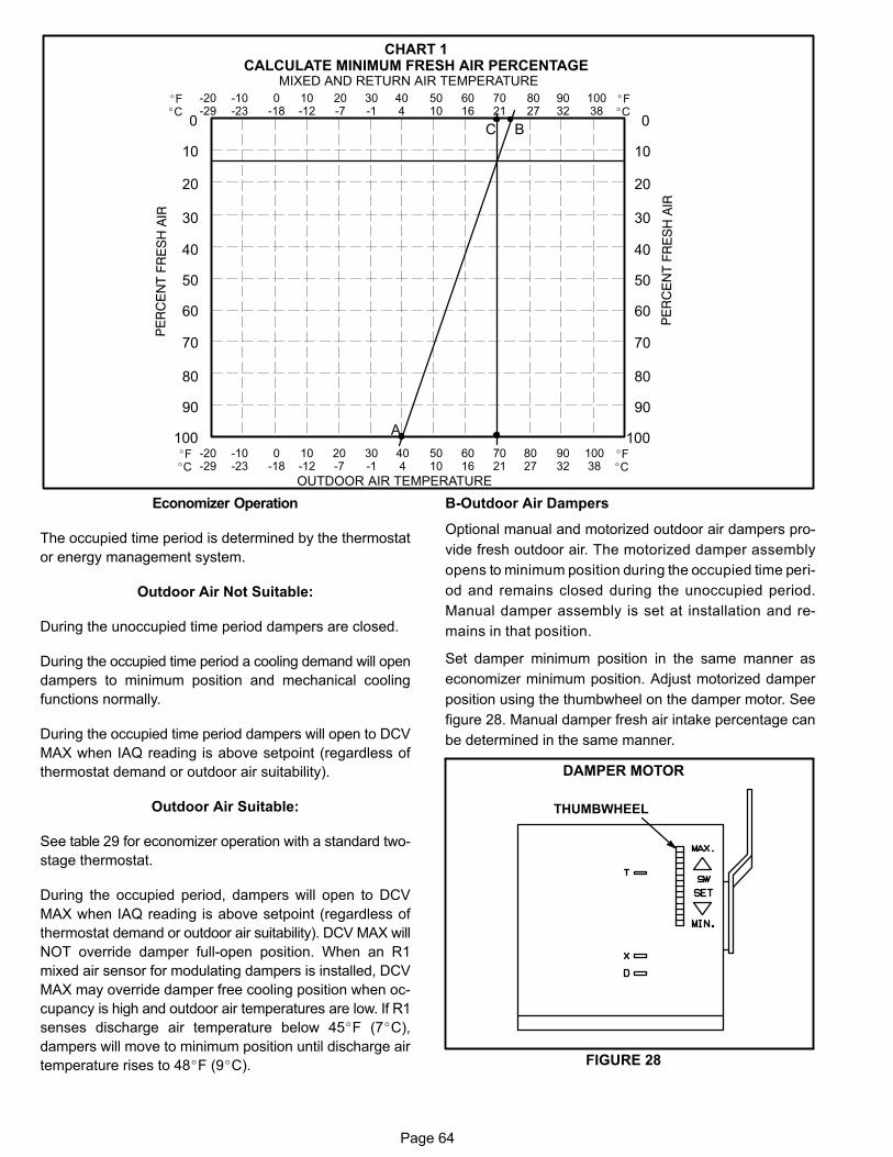
Page 64
-20-29
-10-23
0-18
10-12
20-7
30-1
404
5010
6016
7021
8027
9032
10038
0
10
30
40
50
60
70
80
90
100
20
OUTDOOR AIR TEMPERATURE
0
10
30
40
50
60
70
80
90
100
20
MIXED AND RETURN AIR TEMPERATURE
CHART 1CALCULATE MINIMUM FRESH AIR PERCENTAGE
A
BC
�F�C
�F�C
-20-29
-10-23
0-18
10-12
20-7
30-1
404
5010
6016
7021
8027
9032
10038
�F�C
�F�C
Economizer Operation
The occupied time period is determined by the thermostat
or energy management system.
Outdoor Air Not Suitable:
During the unoccupied time period dampers are closed.
During the occupied time period a cooling demand will open
dampers to minimum position and mechanical cooling
functions normally.
During the occupied time period dampers will open to DCV
MAX when IAQ reading is above setpoint (regardless of
thermostat demand or outdoor air suitability).
Outdoor Air Suitable:
See table 29 for economizer operation with a standard two-
stage thermostat.
During the occupied period, dampers will open to DCV
MAX when IAQ reading is above setpoint (regardless of
thermostat demand or outdoor air suitability). DCV MAX will
NOT override damper full-open position. When an R1
mixed air sensor for modulating dampers is installed, DCV
MAX may override damper free cooling position when oc
cupancy is high and outdoor air temperatures are low. If R1
senses discharge air temperature below 45�F (7�C),
dampers will move to minimum position until discharge air
temperature rises to 48�F (9�C).
B-Outdoor Air Dampers
Optional manual and motorized outdoor air dampers pro
vide fresh outdoor air. The motorized damper assembly
opens to minimum position during the occupied time peri
od and remains closed during the unoccupied period.
Manual damper assembly is set at installation and re
mains in that position.
Set damper minimum position in the same manner as
economizer minimum position. Adjust motorized damper
position using the thumbwheel on the damper motor. See
figure 28. Manual damper fresh air intake percentage can
be determined in the same manner.
FIGURE 28
DAMPER MOTOR
THUMBWHEEL
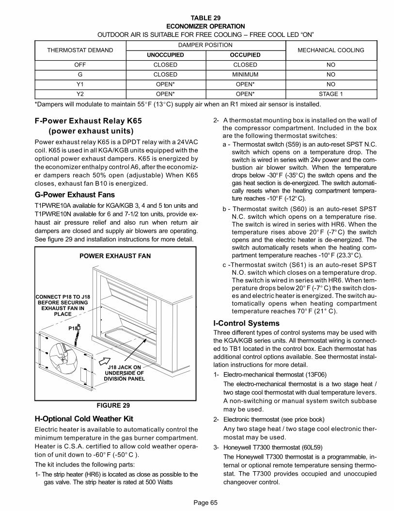
Page 65
TABLE 29
ECONOMIZER OPERATION
OUTDOOR AIR IS SUITABLE FOR FREE COOLING -- FREE COOL LED “ON”
ÁÁÁÁÁÁÁÁÁÁÁÁÁÁÁÁÁÁÁÁÁÁÁÁÁÁÁÁÁÁ
THERMOSTAT DEMANDÁÁÁÁÁÁÁÁÁÁÁÁÁÁÁÁÁÁÁÁÁÁÁÁÁÁÁÁÁÁÁÁÁÁ
DAMPER POSITION ÁÁÁÁÁÁÁÁÁÁÁÁÁÁÁÁÁÁÁÁÁÁÁÁÁÁÁÁÁÁÁÁÁ
MECHANICAL COOLING
ÁÁÁÁÁÁÁÁÁÁÁÁÁÁÁÁÁÁ
UNOCCUPIED ÁÁÁÁÁÁÁÁÁÁÁÁÁÁÁÁÁÁ
OCCUPIED
ÁÁÁÁÁÁÁÁÁÁÁÁÁÁÁÁÁÁÁÁ
OFF ÁÁÁÁÁÁÁÁÁÁÁÁÁÁÁÁÁÁ
CLOSED ÁÁÁÁÁÁÁÁÁÁÁÁÁÁÁÁÁÁ
CLOSED ÁÁÁÁÁÁÁÁÁÁÁÁÁÁÁÁÁÁÁÁÁÁ
NO
ÁÁÁÁÁÁÁÁÁÁÁÁÁÁÁÁÁÁÁÁ
G ÁÁÁÁÁÁÁÁÁÁÁÁÁÁÁÁÁÁ
CLOSED ÁÁÁÁÁÁÁÁÁÁÁÁÁÁÁÁÁÁ
MINIMUM ÁÁÁÁÁÁÁÁÁÁÁÁÁÁÁÁÁÁÁÁÁÁ
NO
ÁÁÁÁÁÁÁÁÁÁÁÁÁÁÁÁÁÁÁÁ
Y1 ÁÁÁÁÁÁÁÁÁÁÁÁÁÁÁÁÁÁ
OPEN* ÁÁÁÁÁÁÁÁÁÁÁÁÁÁÁÁÁÁ
OPEN* ÁÁÁÁÁÁÁÁÁÁÁÁÁÁÁÁÁÁÁÁÁÁ
NO
ÁÁÁÁÁÁÁÁÁÁÁÁÁÁÁÁÁÁÁÁ
Y2 ÁÁÁÁÁÁÁÁÁÁÁÁÁÁÁÁÁÁ
OPEN* ÁÁÁÁÁÁÁÁÁÁÁÁÁÁÁÁÁÁ
OPEN* ÁÁÁÁÁÁÁÁÁÁÁÁÁÁÁÁÁÁÁÁÁÁ
STAGE 1
*Dampers will modulate to maintain 55�F (13�C) supply air when an R1 mixed air sensor is installed.
F-Power Exhaust Relay K65
(power exhaust units)
Power exhaust relay K65 is a DPDT relay with a 24VAC
coil. K65 is used in all KGA/KGB units equipped with the
optional power exhaust dampers. K65 is energized by
the economizer enthalpy control A6, after the economiz
er dampers reach 50% open (adjustable) When K65
closes, exhaust fan B10 is energized.
G-Power Exhaust Fans
T1PWRE10A available for KGA/KGB 3, 4 and 5 ton units and
T1PWRE10N available for 6 and 7-1/2 ton units, provide ex
haust air pressure relief and also run when return air
dampers are closed and supply air blowers are operating.
See figure 29 and installation instructions for more detail.
FIGURE 29
P18
POWER EXHAUST FAN
J18 JACK ONUNDERSIDE OFDIVISION PANEL
CONNECT P18 TO J18BEFORE SECURING
EXHAUST FAN INPLACE
H-Optional Cold Weather Kit
Electric heater is available to automatically control the
minimum temperature in the gas burner compartment.
Heater is C.S.A. certified to allow cold weather opera
tion of unit down to ‐60° F (‐50° C ).
The kit includes the following parts:
1- The strip heater (HR6) is located as close as possible to the
gas valve. The strip heater is rated at 500 Watts
2- A thermostat mounting box is installed on the wall of
the compressor compartment. Included in the box
are the following thermostat switches:
a - Thermostat switch (S59) is an auto‐reset SPST N.C.
switch which opens on a temperature drop. The
switch is wired in series with 24v power and the com
bustion air blower switch. When the temperature
drops below ‐30°F (-35°C) the switch opens and the
gas heat section is de‐energized. The switch automati
cally resets when the heating compartment tempera
ture reaches -10°F (-12°C).
b - Thermostat switch (S60) is an auto‐reset SPST
N.C. switch which opens on a temperature rise.
The switch is wired in series with HR6. When the
temperature rises above 20° F (‐7°C) the switch
opens and the electric heater is de‐energized. The
switch automatically resets when the heating com
partment temperature reaches ‐10°F (23.3°C).
c -Thermostat switch (S61) is an auto‐reset SPST
N.O. switch which closes on a temperature drop.
The switch is wired in series with HR6. When tem
perature drops below 20° F (‐7° C) the switch clos
es and electric heater is energized. The switch au
tomatically opens when heating compartment
temperature reaches 70° F (21° C).
I-Control SystemsThree different types of control systems may be used with
the KGA/KGB series units. All thermostat wiring is connect
ed to TB1 located in the control box. Each thermostat has
additional control options available. See thermostat instal
lation instructions for more detail.
1- Electro‐mechanical thermostat (13F06)
The electro‐mechanical thermostat is a two stage heat /
two stage cool thermostat with dual temperature levers.
A non‐switching or manual system switch subbase
may be used.
2- Electronic thermostat (see price book)
Any two stage heat / two stage cool electronic ther
mostat may be used.
3- Honeywell T7300 thermostat (60L59)
The Honeywell T7300 thermostat is a programmable, in
ternal or optional remote temperature sensing thermo
stat. The T7300 provides occupied and unoccupied
changeover control.
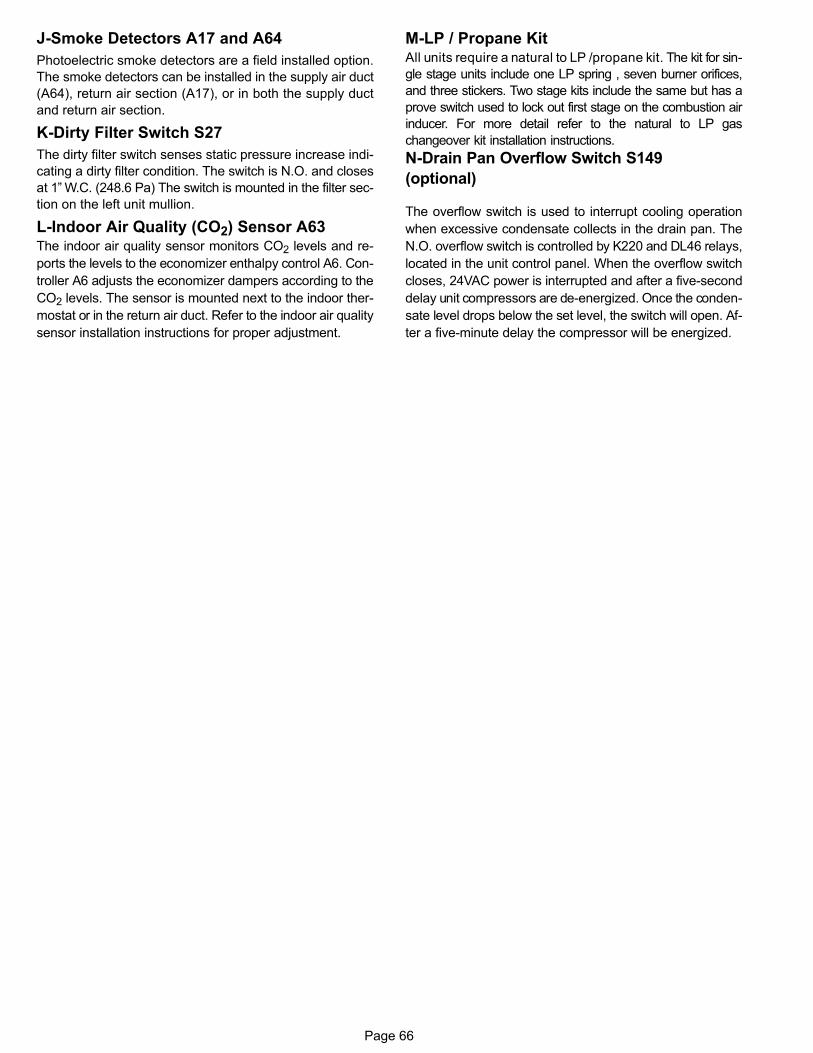
Page 66
J-Smoke Detectors A17 and A64
Photoelectric smoke detectors are a field installed option.
The smoke detectors can be installed in the supply air duct
(A64), return air section (A17), or in both the supply duct
and return air section.
K-Dirty Filter Switch S27
The dirty filter switch senses static pressure increase indi
cating a dirty filter condition. The switch is N.O. and closes
at 1” W.C. (248.6 Pa) The switch is mounted in the filter sec
tion on the left unit mullion.
L-Indoor Air Quality (CO2) Sensor A63The indoor air quality sensor monitors CO2 levels and re
ports the levels to the economizer enthalpy control A6. Con
troller A6 adjusts the economizer dampers according to the
CO2 levels. The sensor is mounted next to the indoor ther
mostat or in the return air duct. Refer to the indoor air quality
sensor installation instructions for proper adjustment.
M-LP / Propane KitAll units require a natural to LP /propane kit. The kit for sin
gle stage units include one LP spring , seven burner orifices,
and three stickers. Two stage kits include the same but has a
prove switch used to lock out first stage on the combustion air
inducer. For more detail refer to the natural to LP gas
changeover kit installation instructions.
N-Drain Pan Overflow Switch S149
(optional)
The overflow switch is used to interrupt cooling operation
when excessive condensate collects in the drain pan. The
N.O. overflow switch is controlled by K220 and DL46 relays,
located in the unit control panel. When the overflow switch
closes, 24VAC power is interrupted and after a five-second
delay unit compressors are de-energized. Once the conden
sate level drops below the set level, the switch will open. Af
ter a five-minute delay the compressor will be energized.
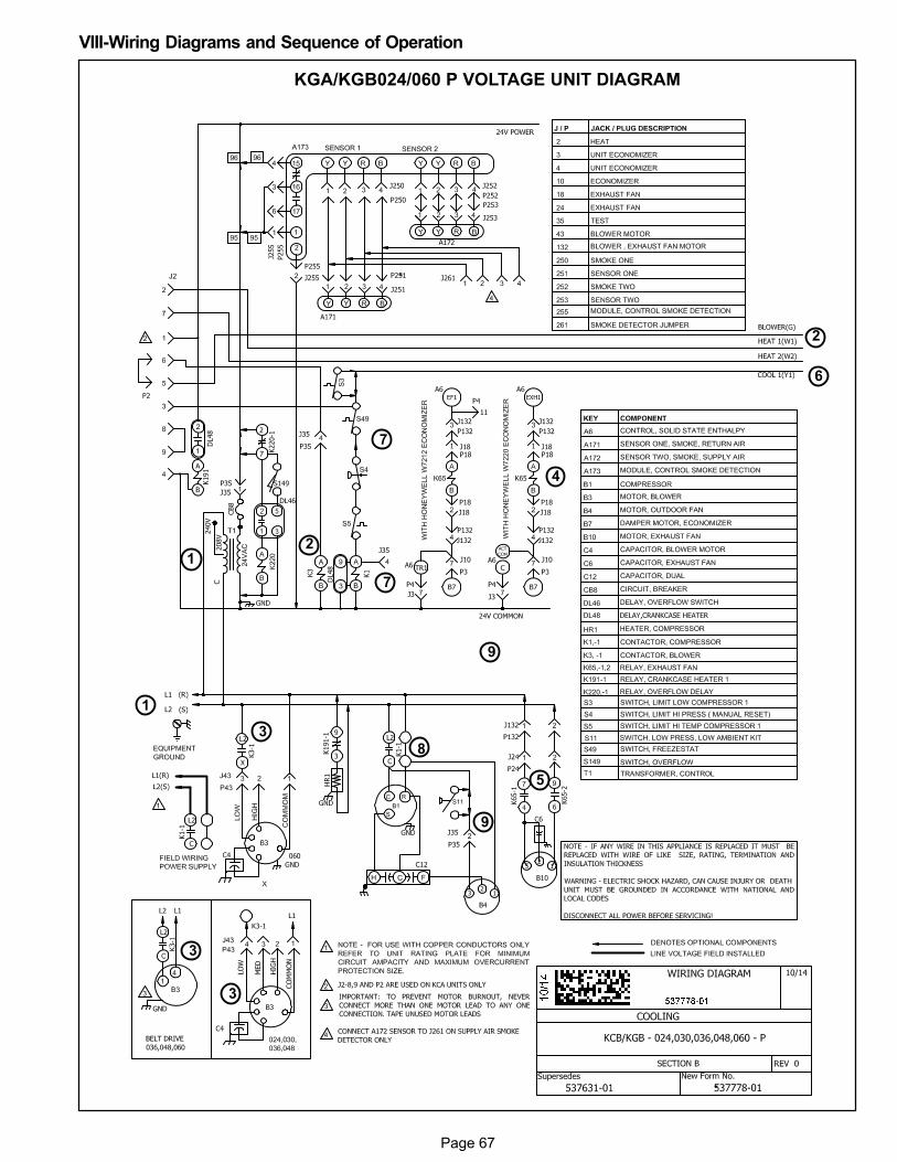
Page 67
VIII-Wiring Diagrams and Sequence of Operation
KGA/KGB024/060 P VOLTAGE UNIT DIAGRAM
1
2
3
4
5
7
8
9
2
3
3
6
7
9
1
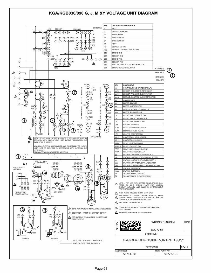
Page 68
KGA/KGB036/090 G, J, M &Y VOLTAGE UNIT DIAGRAM
1
2
3
4
5
7
8
9
6
3
7
3
1 2
9
Page 69
KGA/KGB024/090 P, Y, G, J & M Voltage Sequence of Operation
Power:
1. Line voltage from unit disconnect energizes transformer T1. T1 provides 24VAC power to
terminal strip TB1. TB1 provides 24VAC to the unit cooling, heating and blower controls.
Blower Operation:
2. Indoor thermostat terminal G energizes blower contactor K3 with 24VAC.
3. N.O. K3 closes, energizing blower B3.
Economizer Operation:
4. The economizer control module receives a demand and energizes exhaust fan relay K65 with
24VAC at 50% outside air damper open (adjustable).
5. N.O. K65-1 and N.O. K65-2 both close, energizing exhaust fan motor B10.
Cooling Demand
6. First stage cooling demand Y1 and G is energized by the thermostat. G energizes blower.
7. 24VAC is routed through TB1 to N.C. freezestat S49, and optional N.C. high pressure switch
S4. Compressor contactor K1 is energized.
8. N.O. K1-1 close energizing compressor B1.
9. Single Phase P Voltage Units
Optional N.O. low ambient switch S11 closes to energize condenser fan B4.
Three Phase Y Voltage Units
Optional N.O. low ambient switch S11 closes to energize condenser fan B4.
Three Phase G, J & M Voltage Units
Optional N.O. low ambient switch S11 closes to energize condenser fan relay K10.
N.O. contacts K10-1 close energizing condenser fan B4 .
KGB-074 Two-Stage Units
10. First-stage cooling demand Y1 and G is energized by the thermostat. G energizes blower.
11. Following from step 7 K1 energizes compressor, condenser fan and blower B1 on low speed.
12. Second-stage cooling demand Y2 energizes compressor B1, condenser fan and blower B1 on
high speed.
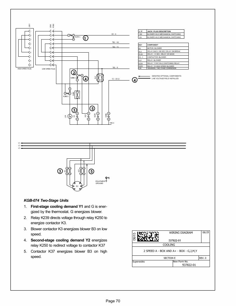
Page 70
KGB-074 Two-Stage Units
1. First-stage cooling demand Y1 and G is ener
gized by the thermostat. G energizes blower.
2. Relay K239 directs voltage through relay K250 to
energize contactor K3.
3. Blower contactor K3 energizes blower B3 on low
speed.
4. Second-stage cooling demand Y2 energizes
relay K250 to redirect voltage to contactor K37
5. Contactor K37 energizes blower B3 on high
speed.
1
2
3
4
5
3
4
5
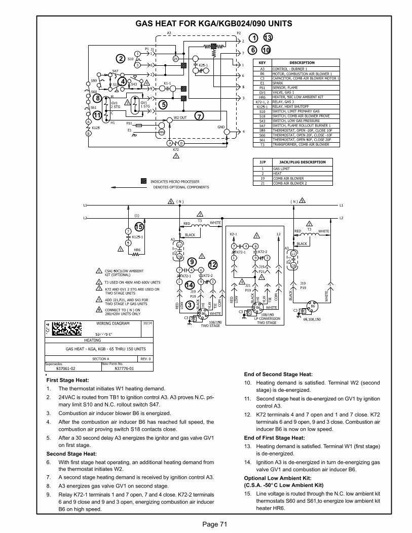
Page 71
GAS HEAT FOR KGA/KGB024/090 UNITS
2
7
85
4
First Stage Heat:
1. The thermostat initiates W1 heating demand.
2. 24VAC is routed from TB1 to ignition control A3. A3 proves N.C. pri
mary limit S10 and N.C. rollout switch S47.
3. Combustion air inducer blower B6 is energized.
4. After the combustion air inducer B6 has reached full speed, the
combustion air proving switch S18 contacts close.
5. After a 30 second delay A3 energizes the ignitor and gas valve GV1
on first stage.
Second Stage Heat:
6. With first stage heat operating, an additional heating demand from
the thermostat initiates W2.
7. A second stage heating demand is received by ignition control A3.
8. A3 energizes gas valve GV1 on second stage.
9. Relay K72-1 terminals 1 and 7 open, 7 and 4 close. K72-2 terminals
6 and 9 close and 9 and 3 open, energizing combustion air inducer
B6 on high speed.
End of Second Stage Heat:
10. Heating demand is satisfied. Terminal W2 (second
stage) is de-energized.
11. Second stage heat is de-energized on GV1 by ignition
control A3.
12. K72 terminals 4 and 7 open and 1 and 7 close. K72
terminals 6 and 9 open, 9 and 3 close. Combustion air
inducer B6 is now on low speed.
End of First Stage Heat:
13. Heating demand is satisfied. Terminal W1 (first stage)
is de-energized.
14. Ignition A3 is de-energized in turn de-energizing gas
valve GV1 and combustion air inducer B6.
Optional Low Ambient Kit:
(C.S.A. -50°C Low Ambient Kit)
15. Line voltage is routed through the N.C. low ambient kit
thermostats S60 and S61,to energize low ambient kit
heater HR6.
1
3
6
9
10
11
12
13
14
15
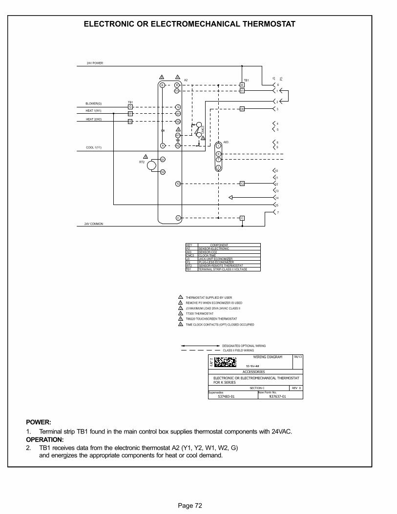
Page 72
ELECTRONIC OR ELECTROMECHANICAL THERMOSTAT
POWER:
1. Terminal strip TB1 found in the main control box supplies thermostat components with 24VAC.
OPERATION:
2. TB1 receives data from the electronic thermostat A2 (Y1, Y2, W1, W2, G)and energizes the appropriate components for heat or cool demand.
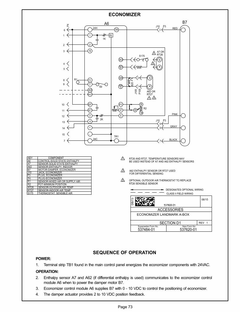
Page 73
ECONOMIZER
SEQUENCE OF OPERATION
POWER:
1. Terminal strip TB1 found in the main control panel energizes the economizer components with 24VAC.
OPERATION:
2. Enthalpy sensor A7 and A62 (if differential enthalpy is used) communicates to the economizer control
module A6 when to power the damper motor B7.
3. Economizer control module A6 supplies B7 with 0 - 10 VDC to control the positioning of economizer.
4. The damper actuator provides 2 to 10 VDC position feedback.
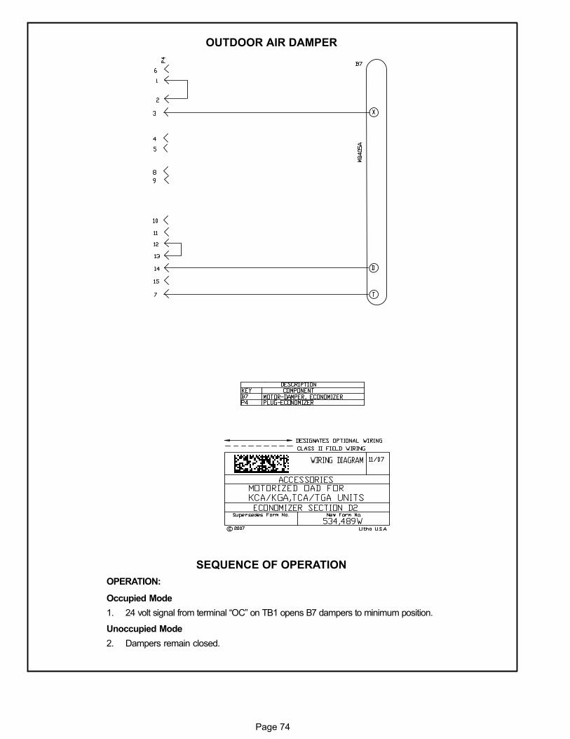
Page 74
OUTDOOR AIR DAMPER
SEQUENCE OF OPERATION
OPERATION:
Occupied Mode
1. 24 volt signal from terminal “OC” on TB1 opens B7 dampers to minimum position.
Unoccupied Mode
2. Dampers remain closed.
Related Documents