PDVSA N° TITLE REV. DATE DESCRIPTION PAG. REV. APPD. APPD. APPD.BY DATE DATE VOLUME 9–II E PDVSA, 1983 K–360 PROGRAMMABLE LOGIC CONTROLLERS FOR APPROVAL Eliecr Jiménez Alejandro Newski AUG. 94 AUG. 94 ENGINEERING SPECIFICATION AUG. 94 L.T. 0 30 E.J. A.N. ENGINEERING DESIGN MANUAL ESPECIALISTAS APPD.BY PDVSA

Welcome message from author
This document is posted to help you gain knowledge. Please leave a comment to let me know what you think about it! Share it to your friends and learn new things together.
Transcript

PDVSA N° TITLE
REV. DATE DESCRIPTION PAG. REV. APPD. APPD.
APPD.BY DATEDATE
VOLUME 9–II
� PDVSA, 1983
K–360 PROGRAMMABLE LOGIC CONTROLLERS
FOR APPROVAL
Eliecr Jiménez Alejandro NewskiAUG. 94 AUG. 94
ENGINEERING SPECIFICATION
AUG. 94 L.T.0 30 E.J. A.N.
ENGINEERING DESIGN MANUAL
ESPECIALISTAS
APPD.BY
�����
REVISION DATE
ENGINEERING SPECIFICATION
PROGRAMMABLE LOGIC CONTROLLERS
Page 1
AUG.940
PDVSA K–360
�����
Menú Principal Indice manual Indice volumen Indice norma
Index
Page
1 SCOPE 4. . . . . . . . . . . . . . . . . . . . . . . . . . . . . . . . . . . . . . . . . . . . . . . . . . .
2 CODES, STANDARDS AND PRACTICES 4. . . . . . . . . . . . . . . . . . . .
3 DEFINITIONS 5. . . . . . . . . . . . . . . . . . . . . . . . . . . . . . . . . . . . . . . . . . . . . .
4 GENERAL REQUIREMENTS 5. . . . . . . . . . . . . . . . . . . . . . . . . . . . . . . . 4.1 System 5. . . . . . . . . . . . . . . . . . . . . . . . . . . . . . . . . . . . . . . . . . . . . . . . . . . . . . . . 4.2 Design 6. . . . . . . . . . . . . . . . . . . . . . . . . . . . . . . . . . . . . . . . . . . . . . . . . . . . . . . . . 4.3 Modification Capability 6. . . . . . . . . . . . . . . . . . . . . . . . . . . . . . . . . . . . . . . . . . . 4.4 Availability 6. . . . . . . . . . . . . . . . . . . . . . . . . . . . . . . . . . . . . . . . . . . . . . . . . . . . . . 4.5 Communications 7. . . . . . . . . . . . . . . . . . . . . . . . . . . . . . . . . . . . . . . . . . . . . . . . 4.6 System Capacity 7. . . . . . . . . . . . . . . . . . . . . . . . . . . . . . . . . . . . . . . . . . . . . . . . 4.7 Port Connections 7. . . . . . . . . . . . . . . . . . . . . . . . . . . . . . . . . . . . . . . . . . . . . . . . 4.8 Protection 7. . . . . . . . . . . . . . . . . . . . . . . . . . . . . . . . . . . . . . . . . . . . . . . . . . . . . . 4.9 Assembly 7. . . . . . . . . . . . . . . . . . . . . . . . . . . . . . . . . . . . . . . . . . . . . . . . . . . . . . 4.10 ESD System 8. . . . . . . . . . . . . . . . . . . . . . . . . . . . . . . . . . . . . . . . . . . . . . . . . . . .
5 HARDWARE 8. . . . . . . . . . . . . . . . . . . . . . . . . . . . . . . . . . . . . . . . . . . . . . 5.1 General 8. . . . . . . . . . . . . . . . . . . . . . . . . . . . . . . . . . . . . . . . . . . . . . . . . . . . . . . . 5.2 Cabinets 12. . . . . . . . . . . . . . . . . . . . . . . . . . . . . . . . . . . . . . . . . . . . . . . . . . . . . . . 5.3 Redundancy 13. . . . . . . . . . . . . . . . . . . . . . . . . . . . . . . . . . . . . . . . . . . . . . . . . . . . 5.4 Power Supply 14. . . . . . . . . . . . . . . . . . . . . . . . . . . . . . . . . . . . . . . . . . . . . . . . . . . 5.5 Grounding System 14. . . . . . . . . . . . . . . . . . . . . . . . . . . . . . . . . . . . . . . . . . . . . . 5.6 Radio Frequency Interference (RFI) 14. . . . . . . . . . . . . . . . . . . . . . . . . . . . . . . 5.7 System Hardware Testing shall Cover the Following Areas 14. . . . . . . . . . . .
6 SOFTWARE 15. . . . . . . . . . . . . . . . . . . . . . . . . . . . . . . . . . . . . . . . . . . . . . . 6.1 Control Strategy Integrity 15. . . . . . . . . . . . . . . . . . . . . . . . . . . . . . . . . . . . . . . . . 6.2 Controllers 15. . . . . . . . . . . . . . . . . . . . . . . . . . . . . . . . . . . . . . . . . . . . . . . . . . . . . 6.3 Programmable Devices 19. . . . . . . . . . . . . . . . . . . . . . . . . . . . . . . . . . . . . . . . . . 6.4 System Software Test 19. . . . . . . . . . . . . . . . . . . . . . . . . . . . . . . . . . . . . . . . . . . .
7 CONFIGURATION MAN – MACHINE INTERFACE 21. . . . . . . . . . . . . 7.2 Data Base 21. . . . . . . . . . . . . . . . . . . . . . . . . . . . . . . . . . . . . . . . . . . . . . . . . . . . . . 7.3 Configuration Recovery 21. . . . . . . . . . . . . . . . . . . . . . . . . . . . . . . . . . . . . . . . . . 7.4 Utilities 22. . . . . . . . . . . . . . . . . . . . . . . . . . . . . . . . . . . . . . . . . . . . . . . . . . . . . . . . . 7.5 System Documentation Tool 22. . . . . . . . . . . . . . . . . . . . . . . . . . . . . . . . . . . . . . 7.6 Documentation 22. . . . . . . . . . . . . . . . . . . . . . . . . . . . . . . . . . . . . . . . . . . . . . . . . . 7.7 Self Testing 22. . . . . . . . . . . . . . . . . . . . . . . . . . . . . . . . . . . . . . . . . . . . . . . . . . . . .
REVISION DATE
ENGINEERING SPECIFICATION
PROGRAMMABLE LOGIC CONTROLLERS
Page 2
AUG.940
PDVSA K–360
�����
Menú Principal Indice manual Indice volumen Indice norma
Index (cont.)
Page
8 NETWORKS 23. . . . . . . . . . . . . . . . . . . . . . . . . . . . . . . . . . . . . . . . . . . . . . . 8.1 Functional Requirements 23. . . . . . . . . . . . . . . . . . . . . . . . . . . . . . . . . . . . . . . . . 8.2 Communications 24. . . . . . . . . . . . . . . . . . . . . . . . . . . . . . . . . . . . . . . . . . . . . . . . 8.3 Security Network Requirements 24. . . . . . . . . . . . . . . . . . . . . . . . . . . . . . . . . . . 8.4 Time Synchronization 24. . . . . . . . . . . . . . . . . . . . . . . . . . . . . . . . . . . . . . . . . . . . 8.5 Node Software 25. . . . . . . . . . . . . . . . . . . . . . . . . . . . . . . . . . . . . . . . . . . . . . . . . . 8.6 Remote Networks Integration 25. . . . . . . . . . . . . . . . . . . . . . . . . . . . . . . . . . . . . 8.7 Security Access 25. . . . . . . . . . . . . . . . . . . . . . . . . . . . . . . . . . . . . . . . . . . . . . . . .
9 SYSTEM TUNING 25. . . . . . . . . . . . . . . . . . . . . . . . . . . . . . . . . . . . . . . . . . 9.1 Proportional Control Loops 25. . . . . . . . . . . . . . . . . . . . . . . . . . . . . . . . . . . . . . . 9.2 Discrete On–Off Control Loops 30. . . . . . . . . . . . . . . . . . . . . . . . . . . . . . . . . . . .
10 SPECIFICATION FORM 30. . . . . . . . . . . . . . . . . . . . . . . . . . . . . . . . . . . . .
11 INSTALLATION AND COMMISSIONING 30. . . . . . . . . . . . . . . . . . . . . .
12 Q.A. / Q.C. 30. . . . . . . . . . . . . . . . . . . . . . . . . . . . . . . . . . . . . . . . . . . . . . . .

REVISION DATE
ENGINEERING SPECIFICATION
PROGRAMMABLE LOGIC CONTROLLERS
Page 3
AUG.940
PDVSA K–360
�����
Menú Principal Indice manual Indice volumen Indice norma
FOREWORD
This document is the result of several years’ work by engineers in the petroleum industryof Venezuela (PDVSA).
The recommendations presented in this publication are not intended to supersedeapplicable laws and regulations.
Users of this recommended practice are reminded that no publication of this type can becomplete, nor, can any written document, be substituted for qualifed engineering analysis.
Suggested revisions are invited and should be submitted to:
The manager
PDVSA Engineering Standards,
C/O INTEVEP – TENA División,
Apartado 76343
Caracas – 1070A
Venezuela

REVISION DATE
ENGINEERING SPECIFICATION
PROGRAMMABLE LOGIC CONTROLLERS
Page 4
AUG.940
PDVSA K–360
�����
Menú Principal Indice manual Indice volumen Indice norma
1 SCOPEThis section covers PDVSA requirements for the design, specification, installationand commissioning of programmable logic controller (PLC’S) systems. Allguidelines of the introduction Specification K–300 shall also be explicitly followed.
2 CODES, STANDARDS AND PRACTICESANSI/NFPA 70 National Electric CodeANSI C37.90–1978 Surge WithstandA.P.I. RP–550.
IEC 65A (Secretariat 123) Functional Safety of Programmable ElectronicSystems: Generic Aspects.
IEC 65A (Secretariat 122) Software for computers in the Application of IndustrialSafety Systems.
IEC – 68–2–6 Sinusoidal vibrationIEC – 68–2–27 ShockIEC – 68–2–34 Random vibration wide bandIEC 529
IEC 801–X Electromagnetic Compatibility for Industrial ProcessMeasurement and Control Equipment.
IEC 801–1 General IntroductionIEC 801–2, Level 3 (8KV) Electrostatic Discharge RequirementsIEC 801–3 Level 3 Radiated Electromagnetic Field RequirementsIEC 801–4 Class 3 Electrical Fast Transient/Burst Requirements
IEC TC77B Magnetic Field (Radiated Susceptibility)(Secretariat) 72
IEEE 472–1974
IEEE 1100 GroundingISA SP50.1–82 “Compatibility of analog signals for Electronic
Industrial Process Instruments”ISA SP84–x “Programmable Electronic System (PES) for use in
Safety Applications” – when availableISO 9001 Quality Management and Quality Assurance
StandardsMIL–HDBK–217 E
MIL – STD – 461C Part 4
MIL – STD – 462

REVISION DATE
ENGINEERING SPECIFICATION
PROGRAMMABLE LOGIC CONTROLLERS
Page 5
AUG.940
PDVSA K–360
�����
Menú Principal Indice manual Indice volumen Indice norma
MIL – HDBK – 472 Maintainability predictionNEMA
NFPA 75 Protection of Electronic EquipmentTUV Rheinland Class 5 Safety Equipment Certification as it relates to:DIN VDE 0110
DIN VDE 0113
DIN VDE 0116/10.89 Electrical Equipment of FurnacesDIN VDE 0160/04.89 Electronic Equipment to be used in Electrical Power
Installations and their assembly into Electrical PowerInstallations
DIN VDE 0165DIN VDE 0170DIN VDE 0470DIN VDE 0801/01.90 Principles for Computers in Safety Related SystemsDIN VDE 0804
DIN VDE 19250/01.89 Fundamental Safety Aspects to be Considered forMeasurement and Control Protective Equipment
ISBN3–88585–315–9 Microcomputers in Safety Techniques(TUV–Handbook). An aid to orientation for developerand manufacturer.
3 DEFINITIONSAll definitions are listed in Specification K–300.
4 GENERAL REQUIREMENTS
4.1 SystemThe PLC system shall consist of a central termination unit which gathers all thevarious inputs from the process plant, a central processor system consisting of oneor more microprocessors which give output signals whenever any of the inputsreaches a pre–determined unsafe level and via displays aid the plant operatorsupervise all process operations linked to the system.
REVISION DATE
ENGINEERING SPECIFICATION
PROGRAMMABLE LOGIC CONTROLLERS
Page 6
AUG.940
PDVSA K–360
�����
Menú Principal Indice manual Indice volumen Indice norma
This specification details the generic requirements of a PLC system. The actualprocess plant details supervised by the PLC system are given in an annexcontaining:
� Process control diagrams
� Details of measurement and control functions� Loop diagrams� Instrument schedule� Block diagram of system� Power supply� Grounding systemAll systems that utilise only one microprocessor is subject to PDVSA approval.
4.2 DesignThe design shall be modular, with latest field proven hardware and software,process input/output devices, microprocessors, signal conditioning equipmentand engineering/maintenance facilities in order to perform on–line reconfigurationand to test all system components with on–line diagnostics.
The system software and hardware shall be updatable with new equipment.
4.3 Modification CapabilityThe PLC shall allow the inclusion and/or removal of additional control units ordevices or printed circuit boards (PCB) without causing process upset and/orremoval equipment shutdown. The control loops, displays, sequences, etc., shallbe easily modifiable, save the rewiring necessary to accept additional processinputs/outputs. These capabilities shall be achievable with the PLC on–line.
4.4 AvailabilityThe PLC shall possess high integrity and fault tolerance so that no single failureof any component or device shall cause the loss of operability of more than oneloop.
Any system failure shall be to a fail–safe state. This includes all module removaland cable faults.
REVISION DATE
ENGINEERING SPECIFICATION
PROGRAMMABLE LOGIC CONTROLLERS
Page 7
AUG.940
PDVSA K–360
�����
Menú Principal Indice manual Indice volumen Indice norma
The PLC shall be designed for maximum availability, safety, and integrity of 99%in both fail–safe and fail danger modes where availibility is defined as:
Availability % �Mean Time to Failure (MTTF)
MTTF � Mean Time To Repair (MTTR)� (100)
This availability shall be based on MARKOV configuration diagrams and those ofMTBF and MTTR of the equipments. Data for failure rates shall be derived fromMIL HDBK 217E wherever possible. Calculations shall be based on the ISA SP84committee recommendations, when they become available.
4.5 CommunicationsCommunications between the PLC and other equipment shall be via a digitalcommunication link system. The communications system shall have automaticselfchecking facilities and include a fully redundant second link, that isautomatically switched into service on failure of the primary operating link. Resetback to primary operation link shall be manual via key switch or password entry.
4.6 System CapacityThe PLC shall cover the project requirement and have minimum 30 percent sparerack space, 30 percent on installed I/O, conversion, controller and multiplexercapacity, and 30 percent on area space in the Equipment room.
4.7 Port ConnectionsThe PLC shall have port connections to link with stand–alone controllers,supervisory and optimization computers and interface with protocols like MAP,Ethernet, MODBUS, Allen Bradley, Data Hiway, Tiway, Genus, etc. This shallinclude the simultaneous transmition and reception of information from theseequipments.
4.8 ProtectionThe system shall be protected against errors and hardware damage resulting fromelectrical transients on power or signal wiring generated by switching largeelectrical loads, by power line faults, lightning strikes and lightning induced surgeson power or signal cables in accordance with IEEE 472–1974.
All components of the PLC shall be immune to Electromagnetic Radiation andRadio Frequency Interference such as generated by hand held walkie–talkie setsin accordance with IEC 801–1 to 3.
4.9 AssemblyThe system shall be factory assembled and wired, complete with all necessarydevices ready for on–site installation, the latter consisting of placing the
REVISION DATE
ENGINEERING SPECIFICATION
PROGRAMMABLE LOGIC CONTROLLERS
Page 8
AUG.940
PDVSA K–360
�����
Menú Principal Indice manual Indice volumen Indice norma
equipments in position, connection of power supply/inputs/outputs wiring andcommunication cables.
4.10 ESD SystemThe PLC system for emergency shut down (ESD) system shall be in accordancewith PDVSA Specification K–336.
5 HARDWARE
5.1 GeneralThe process input/output equipment shall be designed to ensure data acquisition,regulatory control and sequential control functions are performed in an integratedmanner utilizing common equipment such that a process signal is terminated nomore than one time regardless of its numerous uses within the PLC.Input and output signals identified as critical in annex shall have 100% backupfrom the input termination assemblies, through all I/O processing (including allinternal busses), the controller and back to the output assembly.Separate processors are required for process network communications,communication with process I/O modules and for control processing. In addition,each process I/O module shall have its own microprocessor and shall performfunctions such as alarming, signal characterization, engineering unit conversionand output read–back checking.Control processing shall occur at a guaranteed interval and shall be decoupledfrom fetching of process I/O data and peer–to–peer communications.Each controller shall be configurable to allow an optimum mix of point types for aparticular application. This mix not only applies to I/O signal processing, but to thecontroller’s configuration of regulatory control, regulatory PV, logic, digitalcomposite and process module points. Memory management within the controllershall be automatic. If memory is required, the controller shall allocate and manageit.Process input/output cabinets shall accept dual 24 VDC input power sources. D–Cpower supplies within the cabinets shall be redundant and faulty power supply unitreplaceable on–line. D–C power supplies shall have an LED indicator and an alarmcontact for each of the following conditions:� Loss of D–C power� Improper charging to battery backup� Ground fault
Digital Communication Transmitter Interface
The process I/O subsystem shall have a fully tested interface to communicate withmicro–processor based transmitters. This interface shall utilize an all–digital
REVISION DATE
ENGINEERING SPECIFICATION
PROGRAMMABLE LOGIC CONTROLLERS
Page 9
AUG.940
PDVSA K–360
�����
Menú Principal Indice manual Indice volumen Indice norma
protocol to obtain maximum accuracy from signal source to PLC and shall, fromthe operators console, be able to configure, rerange, determine transmiter statusand load the transmitter date base. The interface shall also determine if thetransmitter data base has been changed from a source other than the operator andwarn the operator.
MODULESThe system shall provide continuous monitoring of analog and digital (contact)inputs signals at a fast scan and processing speeds. The following commonfunctions shall be performed:
� Signal isolation� Signal conditioning� Surge protection (IEEE 472–1974)
ProcessorsEach processor module shall consist of a microprocessor, memory, mathco–processor, and necessary communication processors. The processor shall bemechanically and electrically isolated.
They shall retain memory in the event of a power failure or internal malfunction fora minimum of six months. Battery backed up RAM shall be capable of retainingthe application program in memory for a minimum of 6 months after power loss.The memory shall be sufficient for the initial configuration plus 100% excess forfuture expansion.
A real time clock with a 10 msec resolution shall be available for time dependentfunctions such as rate calculations.
The PLC shall be capable of scanning and updating the I/O and executinguser–defined logic a minimum of 4 times per second.
I/O generalEach module type shall have unique mechanical and electronic keying. Keyingshall prevent physical insertion and on–line activation of a module in a wronglocation. The module type identifier shall be automatically recognized by theoperating system and fault diagnostics required in Paragraph 6.4. Input/Outputshall also have individual load/fuse status indication.
Thermocouple inputs shall have built in automatic cold junction compensation andlinearization. A single module shall accommodate all types of thermocouples.
All inputs and outputs shall meet the following minimal requirements on conversionaccuracies:
• Analog to digital conversion • Digital to analog conversion
– Resolution 14 bits – Resolution 12 bits
REVISION DATE
ENGINEERING SPECIFICATION
PROGRAMMABLE LOGIC CONTROLLERS
Page 10
AUG.940
PDVSA K–360
�����
Menú Principal Indice manual Indice volumen Indice norma
– Linearity + 1 bit (LSB) – Linearity + 1 bit (LSB)
– Repeatability + 1/2 bit (LSB) – Repeatability + 1/2 bit (LSB)
– Accuracy + 0.1% full scale – Accuracy + 0.25% full scale
Input modules
The system shall accept following input signals directly from field:
� Digital: Dry contact rated for 24 volts DC with any interposing relay mounted ina separate cabinet.
� Analog: 4–20mA, 1–5 VDC or 0–100 mVDC signals from 2 wire transmitters
� Automatic self calibration
� Normal mode rejection ratio of 15 db or better at 60 Hz
� Common mode rejection ratio of 80 db or better, from 0 to 100 KHz
� Sampling rate 1–5 milliseconds maximum per channel
� Thermocouples, ANSI standard types J, K, E, T, B, S, R, RTD (3 wire) 10 ohmCopper, 100 ohm Platinum, 120 ohm Nickel.
� RTD inputs shall have 12 bit minimum analog to digital conversion.
� Pulse Inputs at rates up to 20 kHz. Each input shall be filtered, converted toengineering units and the data validity checked. These inputs shall be opticallyisolated and current limited to protect against inadvertent damage. They shallbe configurable as status, latched inputs or accumulator inputs.
The functions performed on the respectively configured inputs shall include:
Status Input
� Direct or reverse sense
� Alarming of off–normal state
� Alarm delay (must be exceeded before re–alarming)
Latches input
� Direct or reverse sense
� Change of status reporting
� Hold of off–to–on transition for 1.5 seconds

REVISION DATE
ENGINEERING SPECIFICATION
PROGRAMMABLE LOGIC CONTROLLERS
Page 11
AUG.940
PDVSA K–360
�����
Menú Principal Indice manual Indice volumen Indice norma
Accumulator Input
� Direct or reverse sense� 16 bit accumulator, up to 25 PPS� Up or Down direction counting.
Where inputs have 2 independent sensors for 100% back–up or 3 independentsensors for 2 out of 3 voting as defined by the logic diagrams, the diagnostics shallbe included in the application program.
Digital input signals shall be conditioned by a low–pass filter up to 15 ms. Eachindividual input signal path on the input module shall be automatically tested forproper operation at least every 10 minutes.
Output modules
The system shall provide output signals to transducers, solenoid valves, alarmannunciators and DCS interface I/O.
Analog: 4–20 mA signals Output characteristics:
� Direct or reverse operation
� D/A per output� Power regulator per output� Software calibration� Loopback output� 5 segment output characterization� Default options upon failure� Hold� Got to zero occurrence.
Each digital (contact) output shall have the following characteristics:
� Mechanical relay dry contact rated for 24 volts DC, 2A with any interposing relaymounted in a separate cabinet
� Individual fuse with blown fuse indication� Individual contact suppression
Configurable as: Momentary (10 ms – 1 min.) Latched Pulse–width modulated(1 s to 120 s on time)
� Individually definable default state� Output readback verification
Output modules shall fail to the safe state upon microprocessor failure. Digitaloutputs shall be current rated for an inductive load with a minimum of 1 A per pointat 60°C. Modules shall be rated for full load at maximum specific conditions.

REVISION DATE
ENGINEERING SPECIFICATION
PROGRAMMABLE LOGIC CONTROLLERS
Page 12
AUG.940
PDVSA K–360
�����
Menú Principal Indice manual Indice volumen Indice norma
Digital output modules shall operate properly with a � 10% voltage variation.
The module shall detect and alarm open or shorted field circuits as well as powermonitoring. If any energize to trip signals are specified in annex, load monitoringshall be required.
5.2 Cabinets
� All equipment shall be mounted in standard cabinets suitable for a safeenvironment, with a minimum IEC 529 – IP 51 certification. The cabinet interiorfinish shall be white and fitted with a fluorescent light inside.
� Any part of the PLC equipment located outside air conditioned rooms shall meetIEC standards to comply with the area classification and any specified corrosiveatmospheres (marine, ammonia, chlorine, hydrogen sulphide, etc...) completewith inert gas purge.
� Cabinets shall be free–standing, completed assembled, wired in accordancewith PDVSA Specification K–330 and designed to operate between 0–60°C and5 to 95% non–condensing ambient conditions.
� Cabinets shall be fully enclosed with doors in front and rear as required.
� Adequate ventilation shall be provided to keep the temperatures within designspecifications and an over temperature alarm shall trip when the temperatureis greater than 45°C.
� The equipments, electronic circuitry and wiring shall be arranged to facilitategood access and perform maintenance safely.
� Engraved nameplates shall be provided for each cabinet, peripherals, and,subsystems such as controllers, multiplexers, communication devices, etc.Legends shall be approved by PDVSA.
� The system wiring shall meet the MIL–STD–461C Part 4 per MIL–STD–462:For conducted susceptibility
� Method CS01, power leads
� Method CS02, power leads
� Method CS06, power leads, spikes
For radiated susceptibility
� Method RS01, magnetic field
� Method RS02, induced magnetic field
� Method RS03, electric field.
� Termination assemblies shall be mounted within the cabinets. Allinterconnecting cables shall be tagged at both ends using shrink sleeve typemarkers or equivalent.
REVISION DATE
ENGINEERING SPECIFICATION
PROGRAMMABLE LOGIC CONTROLLERS
Page 13
AUG.940
PDVSA K–360
�����
Menú Principal Indice manual Indice volumen Indice norma
Wiring
All wiring and terminals shall be segregated according to type of signal as follows:
Analog – Standard, 24 volts D.C.
– Intrinsically safe
Digital – Standard, 24 volts D.C.
– Intrinsically safe
Thermocouple
Frequency – Standard, 24 volts D.C.
– Intrinsically safe
Terminal blocks for input and output signals shall be non–hygroscopic. Terminalsshall be tinned and clearly identified. The size of terminal block shall be consistentwith the wire size, viz # 18 AWG.
Analog wiring shall be shielded cable of twisted pairs. All wiring shall be strandedcopper except for themocouple where it should match the T/C type. The terminalsfor T/C shall match the specified thermocouple wire.
Color coding for wiring shall be as follows:
110 VAC
Hot – Black
Neutral – White
Ground – Green
24 VDC
Positive – Red
Negative – Black
Ground – Green
5.3 RedundancyEquipment to be backed up shall be as follows:
� Back–up of power supply cards to CPU’s and I/O cards (1:1 back–up).
� Back–up of internal–bus between CPU and Input/Output (1:1 back–up).

REVISION DATE
ENGINEERING SPECIFICATION
PROGRAMMABLE LOGIC CONTROLLERS
Page 14
AUG.940
PDVSA K–360
�����
Menú Principal Indice manual Indice volumen Indice norma
5.4 Power Supply
All equipment shall comply with the latest IEC, IEEE, EIA, NEMA, ISA, NEC, UL,FM, CSA or COVENIN standards.
The equipment shall operate on 24 volts. D.C. All flourescent lights and socketoutlets shall operate on 110 volts, 60 Hz., A.C.
� Each power user (consoles, controllers, I/O devices, etc.) shall have a separatecircuit breaker with its own fuse.
� The PLC shall supply 24 VDC power to electronic transmitters or other externaldevices requiring electrical power. Each process I/O device shall be providedwith self regulatory capability to assure proper power levels.
� Independent redundant power supplies shall be used for controllers, processI/O subsystems and communication devices (including interfaces), such thatany individual power supply unit failure does not have any effect on theoperation of the installed PLC equipment and also without the need to switchto battery back up facility.
5.5 Grounding SystemThe grounding system for metallic enclosures and electronic circuits shall beseparate and designed for connection to the main grounding System of the plant.The grounding system shall have a maximum resistance of I OHM. See PDVSASpecification N–201 and IEEE 1100.
5.6 Radio Frequency Interference (RFI)� Equipment shall have RFI protection against hardware damage and system
error. Error caused by RFI shall not exceed 0.1 percent of span for exposureto a field strength of 10 volts/meter over the frequency range of 10–1000 MHz.
� Minimum clearances and shielding shall be maintained between datacommunication link and power cabling, transformers, motors, etc. The designshall maintain minimum separation distance between process interfaceequipment, process, controllers, remote multiplexers and electrical substationequipment to protect the PLC from power system noise.
� The plant radio transmitter/receiver station shall be installed in a separatecabinet, remote from the PLC equipment.
5.7 System Hardware Testing shall Cover the Following Areas
� Continuity check of cross–board and interconnecting cables
� AC and DC power checks
� Proper operation of backup devices
� Diagnostic checks of all devices� Proper operation of communication network
REVISION DATE
ENGINEERING SPECIFICATION
PROGRAMMABLE LOGIC CONTROLLERS
Page 15
AUG.940
PDVSA K–360
�����
Menú Principal Indice manual Indice volumen Indice norma
6 SOFTWARE
6.1 Control Strategy IntegrityThe security of the PLC shall be ensured by providing the internal security andfailure protection circuitry such that any single component or subsystem failureshall not cause interruption or loss of more than one control or sequence output.
The PLC shall include extensive internal self checks and status indicators so thatno external diagnostics are required to determine operational status. The systemshall function with minimum maintenance and designed so that servicing can beperformed with process units on–line with no control degradation.
6.2 ControllersThe control device shall be micro–processor based with multiple processorarchitecture providing continuous control for analog loops, sequencing, andlogical operations for discrete signals.
The algorithms shall be contained in functional control built–in block, which shallbe configurable and connectable to implement the desired control strategies.
All cascaded or inter–connected loops shall reside in the same controller. Nointer–wiring between controllers is allowed.
Controller Communications
Controllers shall be capable of peer–to–peer communications with othercontrollers across nodes to accomodate interactive control strategies without thenecessity of hardwiring. The data types (discrete, integer, floating point, etc.) thatcan be communicated between control devices shall not be restricted.
All process connected devices shall interface with process signals via signalconditioning (including filtering), linearization and scaling as needed.
Redundancy (only for PLC’s with more than one micro–processor)
The control system architecture shall provide continuous uninterrupted control inthe event of any single failure in the controller, including:
� Control and communication CPU’s
� Memory� I/O and Network communications� Power� Peer–to–peer communications between controllers.
The fault detection and exclusion of the faulty processor shall be automatic andprovide for continuation of full automatic and bumpless control without operatorintervention.

REVISION DATE
ENGINEERING SPECIFICATION
PROGRAMMABLE LOGIC CONTROLLERS
Page 16
AUG.940
PDVSA K–360
�����
Menú Principal Indice manual Indice volumen Indice norma
The back–up scheme shall ensure that only error free memory transfer are madeto the back–up controller and that they accurately reflect the state of the failedcontroller prior to occurrence of the failure
The back–up scheme shall cover both configurable and programmable controlfunctions without the need of using special configuration or programming step.
6.2.1 Algorithms
� Control algorithms shall be cyclically executable, at least, twice per second.Lower or higher scan execution rates shall be available to suit specific processapplication needs. Algorithms shall allow bumpless transfer from manual toautomatic, cascade or programmable control and viceversa. Algorithms shallbe non–saturating to prevent reset wind–up.
� Control algorithms shall allow on–line changing of its tuning constants andparameters, set–points, outputs and operation modes through the availablecontrol language for the control device in order to allow advanced control.
� Algorithms shall include but not be limited to:
– Flow compensation– Alarming– Accumulation– Logic– Lead/Lag– Dead time– Switch – double pole, double throw– Signal selector (Hi, Low, Medium, Avg.)– Characterizer– Ramp and Soak– Timer– Free format calculation or program (up to 40 character expression)The controller device shall maintain a current data base image for each primarycontroller by receiving data base changes every 500 msec at least.
The controller configuration shall be downloaded or uploaded from the shareddatabase through the communication link via an external device.
REVISION DATE
ENGINEERING SPECIFICATION
PROGRAMMABLE LOGIC CONTROLLERS
Page 17
AUG.940
PDVSA K–360
�����
Menú Principal Indice manual Indice volumen Indice norma
6.2.2 Regulatory control
Regulatory control points shall be configured via pre–defined and user–definedalgorithms to execute the required control strategies.The algorithms selectable to manipulate regulatory control points shall be:
� PID
� PID with feedforward
� PID with external reset feedback
� Position Proportion
� Ratio Control Fixed, Auto Ratio, Auto Bias
� ramp Soak
� auto/Manual Station
� Switch
� Override Selector
� Non–linear gain
� Adaptive control
� Self–tuningFunctions supported automatically for regulatory points shall be:
� PV source selection
� Mode Manual, Auto Cascade, Backup Cascade
� Mode Attribute Operator, Program
� Remote Cascade
� Remote Request
� Remote Shed
� Reset windup Protection
� Override Propagation� Target Value Processing
6.2.3 Sequential control
Sequential control points shall be configurable via CRT templates to execute therequired sequential control functions thourgh a versatile mix of algorithmsavailable for use in logic points. The logic points shall have the following capability:
� Up to twelve (12) input connections
� Up to twelve (12) Output connections
� Up to sixteen (16) logic blocks
REVISION DATE
ENGINEERING SPECIFICATION
PROGRAMMABLE LOGIC CONTROLLERS
Page 18
AUG.940
PDVSA K–360
�����
Menú Principal Indice manual Indice volumen Indice norma
Each logic block shall have access to and be capable of executing the followingalgorithms:
� Logic (AND, OR, NOT, NAND, NOR, XOR)
� Compare Real (EQUAL, NOT EQUAL, GREATER THAN, GREATER THAN OREQUAL TO, LESS THAN, LESS THAN OR EQUAL TO)
� Delay, on Delay, off Delay
� Pulse (Fixed, Max time, Min Time)
� Watchdog timer
� Flip–Flop
� Check for bad input
� Switch
Logic points shall have the capability to link parameters without outputdestinations, e.g., calculated PV value, to parameters without input sources, e.g.,controller gain.
The sequential control functions shall also accommodate two types of interlocks,permissive and overrides. The permissive shall provide an “allow” function to theoperator or program to command a specific output state. The override shall “force”a specific output state without operator or program intervention.
6.2.4 Ladder Logic Control
e. Logic control using familiar ladder logic
f. Off–line or on–line ladder development and emulation
g. On–line viewing of ladder diagrams and the ability to perform dynamicdebugging
h. Ability to manually set sensor variables for ladder diagram checkout
i. Ability to provide hard–copy documentation of all ladder diagrams
j. The ability to suppress the operation of a ladder diagram if any processvariable within the ladder diagram is tagged or placed off–line.
The types of operations allowed in ladder diagrams shall include:
a. Derived points, i.e., software generated inputs
b. Contacts that may represent either digital or analog values
c. Ability to treat analog values as digital through the use of dead–bands
d. And or logic functions

REVISION DATE
ENGINEERING SPECIFICATION
PROGRAMMABLE LOGIC CONTROLLERS
Page 19
AUG.940
PDVSA K–360
�����
Menú Principal Indice manual Indice volumen Indice norma
e. Change an up down level status transitional digital value.
f. Arithmetic functions (add, subtract, multiply, and divide)
g. Time delay relays, i.e., timers that become true when expired
h. Up and down counters, and
i. Go to function (to bypass portions of ladder diagrams).
6.2.5 Configuration of controller and sequences
The configuration of the PLC with the required functions shall be done using aninteractive technique.
All configurations shall be kept in memory or in suitable magnetic or optical storagein the event of power failure.
It shall be possible to load a previously configured control or sequence schemeover the communication link from a host computer.
It shall have facilities to update or modify loop configuration in complex controlalgorithms without disturbing the normal operation of other loops in the controller.
The network configuration shall be modifiable with the entire system on–line to adda node or add new software to an existing node, etc.
6.3 Programmable Devices
6.3.1 Free programmable computing devices, working on engineering language, (e.g.C, Basic, Fortran) or high–level Manufacturer languages, shall be available on thePLC.
6.3.2 The main–machine interface described in paragraph 7 shall create, develop andedit the program.
6.4 System Software Test
The PLC shall include automatic on–line diagnostic facilities to test all hardwareand software system components such that all permanent and transient faults areidentified, alarmed and reported.

REVISION DATE
ENGINEERING SPECIFICATION
PROGRAMMABLE LOGIC CONTROLLERS
Page 20
AUG.940
PDVSA K–360
�����
Menú Principal Indice manual Indice volumen Indice norma
All testing described shall be performed automatically on–line and withoutdisturbing the process or reducing the reliability of the PLC system. Thediagnostics described above shall be built into the operating system of the PLChardware. These diagnostic routines shall be validated by a third party agencysuch as TUV Rheinland. Diagnostics shall be capable of identifying, locating andreporting the following faults as a minimum:
� Scan failure of main or I/O processors
� Memory Faults, both PROM and SRAM
� Microprocessor faults
� Communications faults
� I/O interface or addressing faults
� Application program and hardware layout consistency
� I/O module faults
� Voted signal discrepancy on inputs and outputs
� Voted discrepancy on calculated values within application program
� Load power or fuse faults on field circuits
� Power supply faults including battery back–up monitoring and output voltageverification
� Over temperature conditions.
I/O module diagnostics shall be able to detect and alarm I/O point faults of thefollowing types:
� “stuck–on” – short circuited failure of a discrete input or output
� “stuck–off – open circuit failure of a discrete output.
Status indicators shall be provided to indicate normal operation or fault conditionson each replaceable module. In addition, each fault shall initiate an internal faultflag and hard alarm contact for communication to Central Control Room. Faultinformation shall be available and displayed for the maintenance staff in a mannerthat enables fault diagnosis to a module level.
� Device Failures: The system shall continuously monitor the status of all systemdevices, components and communications (both main and backup) for failure.Upon failure it shall initiate a class 1 alarm at the operator station to allow theoperator to easily identify the failed device.
� Data Transmission Errors: The system shall continuously monitor for errors indigital data transmission between any two system devices. The system shall logand notify the operator when an error is detected.

REVISION DATE
ENGINEERING SPECIFICATION
PROGRAMMABLE LOGIC CONTROLLERS
Page 21
AUG.940
PDVSA K–360
�����
Menú Principal Indice manual Indice volumen Indice norma
7 CONFIGURATION MAN – MACHINE INTERFACEThe PLC shall be designed ergonomically to enable the operator supervise allplant operations and make the decisions to ensure safe operating conditions.
It shall contain auxiliaries such as man–machine terminal interface or portableprogrammer for on–line system test, maintenance and modification facilities.
The station shall normally be on view–only mode, but it shall be capable ofperforming control and operational tasks, as required by normal plant operation viaspecial keylock or password function.
The displays and auxiliaries shall form part of the PLC system itself or could be partof any Distributed control/scada system installed in the process plant. The numberof CRT’S/printers/hand held programmers shall be subject to PDVSA approval.
PLC ConfigurationThe system configuration as detailed in paragraph 6.2.5 shall be done by fill in theblank type fields.
7.1 Load Media
� Each disk system shall store the entire PLC configuration through optical discs,cartridges or similar devices. Additional disc drivers shall be provided asrequired for historical trend recording or other functions.
� Disk systems, shall be fast loading tape cartridges or optical disks, high density,high speed device, not required for use during normal operation.
Once the initial system software is loaded into the system, it shall not be necessaryto use cartridge discs to restore a failed node. A copy of the nodes files shall beloadable from on–line bulk memory.
7.2 Data BaseData Points
The man – machine interface shall be able to remove or add new data points,modify existing data points and install the points in any applicable node, withoutremoving that node from service or affecting any existing points in the system. Thesystem shall determine and advise if a proposed new point ID is already in use inthe system.Multiple Load
The system shall load/install multiple data points from the load media to anyapplicable node on line, without affecting that node.
7.3 Configuration RecoveryThe system shall permit to recover the configuration of a node, its data base andstore it in mass storage or the removable media (optical disc or cartridge) for laterreloading.

REVISION DATE
ENGINEERING SPECIFICATION
PROGRAMMABLE LOGIC CONTROLLERS
Page 22
AUG.940
PDVSA K–360
�����
Menú Principal Indice manual Indice volumen Indice norma
7.4 UtilitiesThe system shall include the utilities, files and management tools necessary toformat the load media, copy floppies (or cartridges), copy files from one source toanother, delete files, list the directories of files, and view or print the data within afile. The system shall also include text edit features similar to a word processor.
7.5 System Documentation ToolThe system documentation tools shall effectively manage changes in the PLCenvironment. This function can query the entire operating database for entitiesand selected parameter values on–line. These queries shall be saved and theresult output to the screen, a file on a bulk storage device or to a printer.A data file utility shall be provided that can create, display and manipulate filesconsisting of named fields of data. The following functions shall be provided:
– Set up tabular text files composed of records of named fields– Create and update documentation files. These files include fields that can be
updated on command by the system and can contain location information,parameter values and programs using specific tagname.
– Sort and filter files by field– Output results to a file or printer
7.6 DocumentationThe system shall be complete with all documentation necessary to configure,install, startup, operate and maintain the system. All maintenance documentationshall be oriented to facilitate expedient repair with minimum downtime.
7.7 Self TestingEach PLC system shall contain following test levels to ensure that the module isperforming correctly prior to being placed in operation and to monitor itsperformance while in operation.a. The first level shall be the Startup Tests. These tests shall reside in ROM and
shall be automatically executed following power–on or restart of the module.They shall verify the correct operation of the basic logic on each PCB in themodule. Failures shall be indicated by means of LED(s) on each PCB and onthe display.
b. The second level shall be the Quality Logic Tests. These tests shall beautomatically loaded and executed after the startup test a. These tests shallverify the correct operation of the module hardware and qualify it for loadingits on–process software. Failure shall be indicated on the display.
c. The third level of testing shall be On–Process Tests. These tests shall be partsof the on–process software of each module and shall be executed periodicallywhether a module is primary or backup. A recoverable error shall be error
REVISION DATE
ENGINEERING SPECIFICATION
PROGRAMMABLE LOGIC CONTROLLERS
Page 23
AUG.940
PDVSA K–360
�����
Menú Principal Indice manual Indice volumen Indice norma
message report for analysis by maintenance personnel. A non–recoverableerror shall cause the module to be shut–down, recorded in the system errormessage and indicated to the operator. A printed error history shall beavailable to be returned to factory with the failed PCB/module.
d. The fourth and most extensive level of testing shall be the Off–Process Tests.These tests shall be loaded by maintenance personnel when automatic tests(levels a, b, c) cannot resolve a problem. These tests shall have the followingfunctions:
� Display the system error event record� Display the hardware and software revision status of all modules on the network� Display a snapshot of the system status, including all nodes, modules, boxes,
etc.� Display the contents of memory of any node, module, box, etc.� link the system to supplier’s technical assistance center.e. Node IsolationThe man – machine interface shall be able to isolate the node from the system andperform detailed off–line diagnostics to test the nodes, microprocessor(s),memory, and communications.
8 NETWORKS
8.1 Functional RequirementsThe communications network shall support a variable length message protocolallowing any node in the network to have continuous access to other devices witha common interface link to all of them.
The communications subsystem shall support on–line expandability throughmodularized components.
It shall be capable of providing extended communications up to 300 metres withoutthe use of repeaters.
It shall have access to data from any and all controllers, DCS’s and I/O devicesconnected to the communications link.
Communications throughput shall be sufficient to ensure that operator consolesare updated, at least, once every 4 secs. to reflect process parameters and statuschanges from the field devices.
All components of the communications cable system shall be lead–sheathed andarmoured, suitable for direct burial.
Communications to the system network shall be high speed, secure, redundantand based on the International Standard Organization seven–layer Open SystemInterconnect model. While this model is not fully defined at present, process

REVISION DATE
ENGINEERING SPECIFICATION
PROGRAMMABLE LOGIC CONTROLLERS
Page 24
AUG.940
PDVSA K–360
�����
Menú Principal Indice manual Indice volumen Indice norma
input/output system shall currently be compatible with Real Time–MAP as definedby ISA committee SP–72, which incorporates three layers. This communicationschannel shall be reported, and, if required, the cables will be switched. Operationof the process shall not be affected by this switching.
8.2 Communications
The system shall include a fully tested high–speed network to control allcommunications between consoles, nodes, etc. It shall:
a. be redundantly cabled
b. be equipped with independent transmitter and receivers for each cable
c. have twisted pair or coax or fiber optic options
d. switch periodically between the primary and backup link/cable withoutdisrupting operations, to ensure that each link is healthy.
e. notify the operator of any failure and remain on the good link
f. contain no mechanical relays at any point.
8.3 Security Network Requirements� incorporate logical addressing to allow efficient transmission to redundant
nodes, with both the primary and backup modules database updatedsimultaneously
� include a 16 bit polynominal Cyclic Redundancy Check (CRC) checksumverification on every frame
� include message length checks� employ anti–jabber circuitry� expect no more than one undetected error in 1000 years of operation.� Automatic re–transmission in the event of error.� Continuous checking of redundant link.� Switchover to alternate link or cable on failure shall be automatic without
disrupting the system operation.� The system shall allow connection and disconnection of devices to/from the link
without disrupting any other connected, devices or peripherals.� Built–in cable fault isolation.� System level fault diagnosis.� Lightning protection.
8.4 Time SynchronizationTime Synchronization shall ensure strict coordination between modules. A clocksynchronization pulse shall be transmitted to all network modules at least every
REVISION DATE
ENGINEERING SPECIFICATION
PROGRAMMABLE LOGIC CONTROLLERS
Page 25
AUG.940
PDVSA K–360
�����
Menú Principal Indice manual Indice volumen Indice norma
one hundred (100) milliseconds. In addition, actual real time data shall betransmitted to each module at least every fifty (50) milliseconds. Drifting of actualreal time shall be no more than three (3) seconds (.0035%) per day (24 hourperiod).
8.5 Node SoftwareNode Software shall be layered and modular.
The “Software environment” layer shall provide the application software with a setof software services common to all modules/nodes and a uniform interface,regardless of the type of module/node. Each module/node shall contain the samereal time operating system which schedules all tasks and communications.
The “base applications” software layer shall define and execute the basic functionsof a particular “personality” for a module/node.
8.6 Remote Networks IntegrationThe system network shall communicate through a Plant Network with remotesystem networks without duplication of the point database. The following functionsshall be supported:
� Any node of the system network can read/write any point parameter in remotesystem network data.
� The remote tagnames can be included in the system or in computingenvironments
� The system can transfer files from and to remote network� Cascade Control between the PLC and the remote system can be achieved.
8.7 Security AccessEach system network shall be configured with the security access permitted toremote system networks. Every point parameter information and file transferrequest shall be checked for proper authorization per security configuration.
� Read only access
� Read and Write access and� No access
9 SYSTEM TUNING
9.1 Proportional Control LoopsThe system shall include facilities for tuning of linear control loops based onuniversal methods developed by GREG SHINSKEY et al and for non–linear loopsas detailed below.
REVISION DATE
ENGINEERING SPECIFICATION
PROGRAMMABLE LOGIC CONTROLLERS
Page 26
AUG.940
PDVSA K–360
�����
Menú Principal Indice manual Indice volumen Indice norma
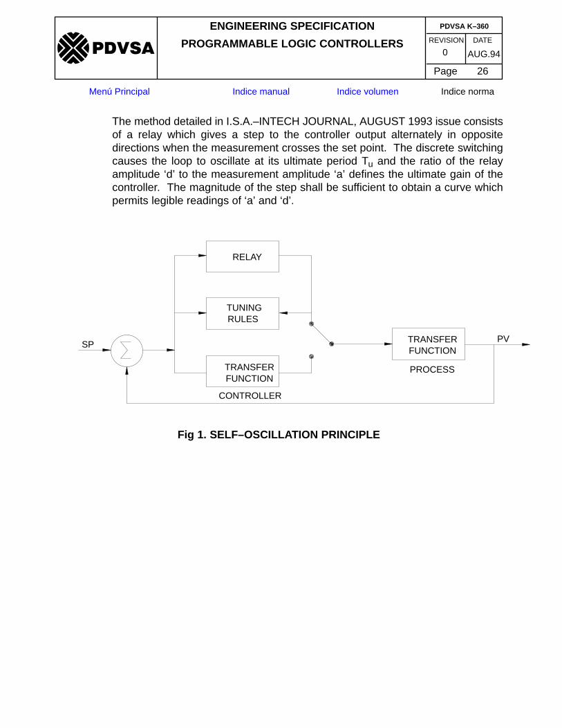
The method detailed in I.S.A.–INTECH JOURNAL, AUGUST 1993 issue consistsof a relay which gives a step to the controller output alternately in oppositedirections when the measurement crosses the set point. The discrete switchingcauses the loop to oscillate at its ultimate period Tu and the ratio of the relayamplitude ‘d’ to the measurement amplitude ‘a’ defines the ultimate gain of thecontroller. The magnitude of the step shall be sufficient to obtain a curve whichpermits legible readings of ‘a’ and ‘d’.
FUNCTIONTRANSFER
FUNCTIONTRANSFER
PVSP
CONTROLLER
RULESTUNING
RELAY
PROCESS
Fig 1. SELF–OSCILLATION PRINCIPLE

REVISION DATE
ENGINEERING SPECIFICATION
PROGRAMMABLE LOGIC CONTROLLERS
Page 27
AUG.940
PDVSA K–360
�����
Menú Principal Indice manual Indice volumen Indice norma
MEASUREMENT
a
CONTR. OUTPUT
TUNING PERIOD
TIME
UT
INITIALIZATION
d
RELAY OUTPUT
Fig 2. PLOT OF RELAY OUTPUT AND PROCESS OUTPUT DURING TUNING.
REVISION DATE
ENGINEERING SPECIFICATION
PROGRAMMABLE LOGIC CONTROLLERS
Page 28
AUG.940
PDVSA K–360
�����
Menú Principal Indice manual Indice volumen Indice norma
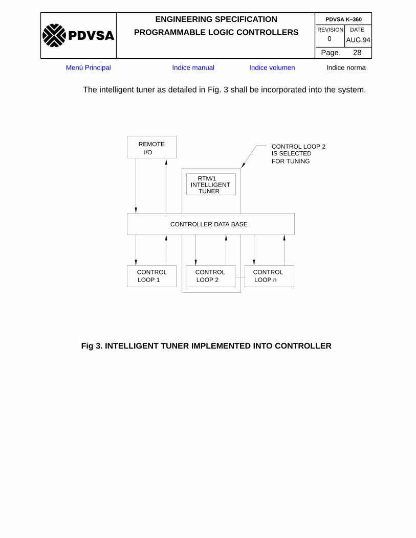
The intelligent tuner as detailed in Fig. 3 shall be incorporated into the system.
FOR TUNINGIS SELECTEDCONTROL LOOP 2
TUNER
LOOP nCONTROL
LOOP 2CONTROL
LOOP 1CONTROL
I/OREMOTE
CONTROLLER DATA BASE
INTELLIGENTRTM/1
Fig 3. INTELLIGENT TUNER IMPLEMENTED INTO CONTROLLER

REVISION DATE
ENGINEERING SPECIFICATION
PROGRAMMABLE LOGIC CONTROLLERS
Page 29
AUG.940
PDVSA K–360
�����
Menú Principal Indice manual Indice volumen Indice norma
The processor rejecting values of ‘a’ and Tu not measurable and automaticallyincreasing controller output in steps of 1% upto a maximum of 10%. See Fig. 4.
& STARTSETUPCONFIRM
ACTIVE TUNING COMPLETE
OR MODIFYREDESIGN
REJECT
REJECTREJECT
REJECTACCEPT OR
COMPLETEDCOMPUTATION
IS CORRECTACCESS TO LOOP
1. LOOP IDENTIFICATION
3. INITIATE TUNING4. COMPUTATION
2. SETUP5. ENG. APPROVAL
Fig 4. DIAGRAM OF MODEL PROGRAM.
REVISION DATE
ENGINEERING SPECIFICATION
PROGRAMMABLE LOGIC CONTROLLERS
Page 30
AUG.940
PDVSA K–360
�����
Menú Principal Indice manual Indice volumen Indice norma
9.2 Discrete On–Off Control LoopsThe discrete action output signal shall ensure that the speed of the action of thevalve is adequate to ensure that there are no sudden “surges” or“depressurization” effects in the process.
In the event a number of valves are opened or closed simultaneously the order inwhich the valves operate shall be carefully evaluated in order to ensure acontrolled “shutdown” or start–up of the plant or equipment.
10 SPECIFICATION FORM
FORM No. TITLE
20.2x Programmable logic controllers
The form is included at the end of this specification.
11 INSTALLATION AND COMMISSIONINGAll installation and commissioning shall be in accordance with project drawingsand specifications.
12 Q.A. / Q.C.All items shall conform with with procedures detailed in Specification K–369.
Related Documents