Interfacial Adhesion Studies for Step and Flash Imprint Lithography Michael W. Lin 1 , Daniel J. Hellebusch 1 , Kai Wu 1 , Eui Kyoon Kim 1 , Kuan Lu 2 , Li Tao 3 , Kenneth M. Liechti 4 , John G. Ekerdt 1 , Paul S. Ho 2 , Walter Hu 3 , C. Grant Willson 1 1 Dept of Chemical Engineering, The University of Texas at Austin, Austin, TX 78712 2 Dept of Mechanical Engineering, The University of Texas at Austin, Austin, TX 78712 3 Dept of Electrical Engineering, The University of Texas at Dallas, Richardson, TX 75080 4 Dept of Aerospace Engineering and Engineering Mechanics, The University of Texas at Austin, Austin, TX 78712 ABSTRACT The step and flash imprint lithography (SFIL) process requires the clean separation of a quartz template from a polymer imprint, and the force required to create this separation must be minimized to prevent the generation of defects. According to fracture mechanics principles, decreasing both the imprint polymer modulus and the interfacial fracture energy are beneficial for reducing the separation force. Adjusting the crosslinker concentration in the imprint formulation decreases the modulus but does not significantly impact the facture energy. On the other hand, fluorinated surfactant additives to the imprint fluid lower the modulus of the imprint polymer and decrease the fracture energy. The fracture energy is further decreased by using a nonreactive, liquid surfactant versus a surfactant that reacts with the polymer matrix. Angle-resolved X-ray photoelectron spectroscopy (XPS) results indicate that surfactant migration is more effective with a fluorinated surface treatment compared to an untreated quartz surface. This result shows that the use of fluorinated surfactants must be accompanied by a surface treatment that produces a similar energy or polarity to induce migration and lower the adhesive strength. Keywords: adhesion, SFIL, fracture, surfactant, imprint lithography 1. INTRODUCTION The step and flash imprint lithography (SFIL) process was developed in 1999 at The University of Texas at Austin as a high resolution, cost-effective alternative to photolithography for nanoscale patterning. Unlike current projection steppers, which are resolution limited by diffraction phenomena, the resolution of SFIL tools are only limited by the template and patterning capability down to 20 nm has been demonstrated. 1 The combination of high resolution and low cost of ownership make SFIL a strong candidate for future semiconductor IC manufacturing. SFIL is a contact lithographic process in which a pattern is transferred from a rigid quartz template to a liquid resist through mechanical molding techniques. The imprint fluid, also known as the etch barrier, is dispensed onto a substrate, and the template is then brought into contact with the liquid, such that the recesses in the quartz are filled through capillary force. Once the etch barrier has completely filled the features on the mold, UV radiation is projected through the backside of the template to polymerize the material. The template is then removed to leave a polymer imprint that is a replica of the template. Subsequent dry etch processes are used to transfer the pattern into the underlying substrate. A successful imprint is dependent on perfect adhesive failure at the quartz-polymer interface when the template is removed from the imprint. Removal involves applying tensile forces on the template to propagate a crack along the often-complex topography of the quartz mold. If excessive force is required, cohesive failure of the polymer can occur and thereby generate defects on the polymer and quartz surfaces resulting in poor imprints and fouling of the template as shown in Figure 1. Emerging Lithographic Technologies XII, edited by Frank M. Schellenberg Proc. of SPIE Vol. 6921, 69210E, (2008) · 0277-786X/08/$18 · doi: 10.1117/12.772797 Proc. of SPIE Vol. 6921 69210E-1 2008 SPIE Digital Library -- Subscriber Archive Copy

Welcome message from author
This document is posted to help you gain knowledge. Please leave a comment to let me know what you think about it! Share it to your friends and learn new things together.
Transcript

Interfacial Adhesion Studies for Step and Flash Imprint Lithography
Michael W. Lin1, Daniel J. Hellebusch1, Kai Wu1, Eui Kyoon Kim1, Kuan Lu2, Li Tao3, Kenneth M. Liechti4, John G. Ekerdt1, Paul S. Ho2, Walter Hu3, C. Grant Willson1
1Dept of Chemical Engineering, The University of Texas at Austin, Austin, TX 78712
2Dept of Mechanical Engineering, The University of Texas at Austin, Austin, TX 78712 3Dept of Electrical Engineering, The University of Texas at Dallas, Richardson, TX 75080
4Dept of Aerospace Engineering and Engineering Mechanics, The University of Texas at Austin, Austin, TX 78712
ABSTRACT The step and flash imprint lithography (SFIL) process requires the clean separation of a quartz template from a polymer imprint, and the force required to create this separation must be minimized to prevent the generation of defects. According to fracture mechanics principles, decreasing both the imprint polymer modulus and the interfacial fracture energy are beneficial for reducing the separation force. Adjusting the crosslinker concentration in the imprint formulation decreases the modulus but does not significantly impact the facture energy. On the other hand, fluorinated surfactant additives to the imprint fluid lower the modulus of the imprint polymer and decrease the fracture energy. The fracture energy is further decreased by using a nonreactive, liquid surfactant versus a surfactant that reacts with the polymer matrix. Angle-resolved X-ray photoelectron spectroscopy (XPS) results indicate that surfactant migration is more effective with a fluorinated surface treatment compared to an untreated quartz surface. This result shows that the use of fluorinated surfactants must be accompanied by a surface treatment that produces a similar energy or polarity to induce migration and lower the adhesive strength. Keywords: adhesion, SFIL, fracture, surfactant, imprint lithography
1. INTRODUCTION
The step and flash imprint lithography (SFIL) process was developed in 1999 at The University of Texas at Austin as a high resolution, cost-effective alternative to photolithography for nanoscale patterning. Unlike current projection steppers, which are resolution limited by diffraction phenomena, the resolution of SFIL tools are only limited by the template and patterning capability down to 20 nm has been demonstrated.1 The combination of high resolution and low cost of ownership make SFIL a strong candidate for future semiconductor IC manufacturing. SFIL is a contact lithographic process in which a pattern is transferred from a rigid quartz template to a liquid resist through mechanical molding techniques. The imprint fluid, also known as the etch barrier, is dispensed onto a substrate, and the template is then brought into contact with the liquid, such that the recesses in the quartz are filled through capillary force. Once the etch barrier has completely filled the features on the mold, UV radiation is projected through the backside of the template to polymerize the material. The template is then removed to leave a polymer imprint that is a replica of the template. Subsequent dry etch processes are used to transfer the pattern into the underlying substrate.
A successful imprint is dependent on perfect adhesive failure at the quartz-polymer interface when the template
is removed from the imprint. Removal involves applying tensile forces on the template to propagate a crack along the often-complex topography of the quartz mold. If excessive force is required, cohesive failure of the polymer can occur and thereby generate defects on the polymer and quartz surfaces resulting in poor imprints and fouling of the template as shown in Figure 1.
Emerging Lithographic Technologies XII, edited by Frank M. Schellenberg Proc. of SPIE Vol. 6921, 69210E, (2008) · 0277-786X/08/$18 · doi: 10.1117/12.772797
Proc. of SPIE Vol. 6921 69210E-12008 SPIE Digital Library -- Subscriber Archive Copy

Figure 1. Cohesive failure of an acrylate-based imprint material.
The problem is exacerbated if a silicon-containing resist is used. Cleaning the template without damaging the
fine features can prove to be an expensive and time-consuming task since any reagent or process that attacks the silicon polymer will also attack the quartz template. A large separation force can also cause local stresses and deflections in the silicon substrate since a vacuum system is used to hold the wafer in place. For multilayer film stacks, these stresses can propagate through each layer increasing the risk of delamination at the various interfaces.
Therefore, it is desirable to design imprint materials and template surface treatments to achieve preferential separation at the quartz-polymer interface and to minimize the force required to separate the two surfaces. In this study, basic fracture mechanics principles were considered to determine the ideal properties for SFIL separation. The effects of crosslinker and surfactant concentrations for various imprint materials on separation were quantified through experimentation. More specifically, tensile and 4-point bend fracture experiments were conducted to measure the effects on modulus and interfacial fracture energy, respectively. Angle-resolved x-ray photoelectron spectroscopy (XPS) was then used to observe the migration of surfactants to various interfaces and the effect of various surface treatments on the migration of the surfactants.
2. THEORETICAL
To develop a better understanding of the film properties that affect the propagation of cracks, it is useful to examine the mechanics of the SFIL separation process. The concepts of fracture mechanics were originally developed to study cohesive failure within homogenous materials; however, there exist enough similarities between the ideas of cohesion and adhesion to extend fracture mechanics to describe how failure occurs in adhesive bonds.2
Figure 2. A comparison of cohesive and adhesive failure.
For a reversible case, the work required to induce cohesive or adhesive failure is defined in equations (1) and (2)
1c 2W γ= , (1)
1221a 2W γ−γ+γ= , (2) where Wc is the work of cohesion, Wa is the work of adhesion, γi is the surface energy of surface i, and γ12 is the interfacial energy of surfaces 1 and 2. These equations allow calculations of the theoretical strength of materials and interfaces. In the real process, however, the energy required to separate surfaces is typically 2 to 3 orders of magnitude greater than Wa.3 In 1920, Griffith4 used energy arguments to describe the behavior of crack propagation in brittle materials. He showed that the creation of surface energy from a growing crack is balanced by the loss of strain energy
Proc. of SPIE Vol. 6921 69210E-2

accompanying the relaxation of local stresses; the well-known Griffith criterion for cohesive fracture in a large plate containing a central crack is shown in equation (3)
aEWc
c π=σ
. (3) where σc is the global stress, E is Young’s modulus, and a is ½ the crack length. If the stress exceeds σc, a crack is able to propagate. However, this analysis did not account for irreversible factors in the separation process, such as plastic deformation. To extend the analysis to include non-brittle materials, such as polymers, Orowan5 and Irwin6 modified Griffith’s equation as shown in equations (4) and (5)
aEGc
c π=σ
, (4)
pcc WWG +=, (5)
where Gc is the cohesive fracture energy and Wp is the plastic work. Williams2 applied the above relations to adhesive fracture as described in (6) and (7)
aGE a12
a π=σ
, (6)
paa WWG +=, (7)
where σa is the adhesive fracture stress, Ga is the adhesive fracture energy, and E12 is a composite modulus given by equation (8)
1221
2112 EE
EEEϕ+ϕ
=, (8)
where Ei is the modulus of surface i and φi is the fractional length of surface i. Thus, the real adhesive strength is a function of the material properties, the loading conditions, and the presence and size of defects. For the SFIL process, quartz (surface 1) is in contact with a polymer (surface 2), which allows the following assumptions: 1) E1 >> E2, 2) Wp >> Wa for most polymers, 3) φ1 = φ2 =½
aWE2 p2
a π≅σ . (9)
Therefore, in the SFIL process, the modulus and irreversible behavior of the polymer and the crack tip length at the template-polymer interface are the key parameters that control crack propagation.
The modulus is a measure of the stiffness of a material and can be tuned by adjusting the amount of crosslinker in the mixture. For the SFIL process, ethylene glycol diacrylate (EGDA) serves as the crosslinker in the standard etch barrier formulation and typically accounts for 20% of the monomer mixture. Surfactants added to the imprint materials can also decrease the modulus by acting as plasticizers in the bulk polymer. Moreover, fluorinated surfactant compounds selectively migrate to specific interfaces based on the free energy of the system, and this phenomena has been documented in the nanoimprint process both theoretically7, 8 and experimentally8-10. The formation of a thin fluorocarbon layer between the template and polymer imprint is favorable for separation: this layer provides ideal separation properties such as low surface energy and low modulus. On the other hand, the effects on interfacial fracture energy by crosslinker and surfactant concentration are not well understood, and solid mechanics experiments are required to evaluate these effects.
2. EXPERIMENTAL 2.1 Materials
A standard acrylate-based etch barrier (MM) was formulated with isobornyl acrylate (IBA), n-butyl acrylate (nBA), and ethylene glycol diacrylate all purchased from Aldrich. The photoinitiator was Darocur 1173 received from
Proc. of SPIE Vol. 6921 69210E-3
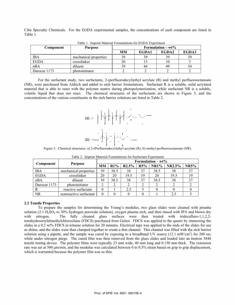
Ciba Specialty Chemicals. For the EGDA experimental samples, the concentrations of each component are listed in Table 1.
Table 1. Imprint Material Formulations for EGDA Experiment
Formulation – wt% Component Purpose MM EGDA1 EGDA2 EGDA3
IBA mechanical properties 39 39 39 39 EGDA crosslinker 20 15 10 5 nBA diluent 39 44 49 54 Darocur 1173 photoinitiator 2 2 2 2
For the surfactant study, two surfactants, 2-(perfluorodecyl)ethyl acrylate (R) and methyl perfluorooctanoate
(NR), were purchased from Aldrich and added to etch barrier formulations. Surfactant R is a soluble, solid acrylated material that is able to react with the polymer matrix during photopolymerization, while surfactant NR is a soluble, volatile liquid that does not react. The chemical structures of the surfactants are shown in Figure 3, and the concentrations of the various constituents in the etch barrier solutions are listed in Table 2.
Figure 3. Chemical structures: a) 2-(Perfluorodecyl)ethyl acrylate (R), b) methyl perfluorooctanoate (NR).
Table 2. Imprint Material Formulations for Surfactant Experiment
Formulation – wt% Component Purpose MM R1% R2.5% R5% NR1% NR2.5% NR5% IBA mechanical properties 39 38.5 38 37 38.5 38 37 EGDA crosslinker 20 20 19.5 19 20 19.5 19 nBA diluent 39 38.5 38 37 38.5 38 37 Darocur 1173 photoinitiator 2 2 2 2 2 2 2 R reactive surfactant 0 1 2.5 5 0 0 0 NR nonreactive surfactant 0 0 0 0 1 2.5 5
2.2 Tensile Properties
To prepare the samples for determining the Young’s modulus, two glass slides were cleaned with piranha solution (2:1 H2SO4 to 30% hydrogen peroxide solution), oxygen plasma etch, and then rinsed with IPA and blown dry with nitrogen. The fully cleaned glass surfaces were then treated with tridecafluro-1,1,2,2-tetrahydrooctyldimethylchlorosilane (FDCS) purchased from Gelest. FDCS was applied to the quartz by immersing the slides in a 0.2 wt% FDCS in toluene solution for 20 minutes. Electrical tape was applied to the ends of the slides for use as shims, and the slides were then clamped together to create a thin channel. This channel was filled with the etch barrier solution using a pipette, and the sample was cured by exposing to a broadband UV source (12.1 mW/cm2) for 200 sec while under nitrogen purge. The cured film was then removed from the glass slides and loaded into an Instron 5848 tensile testing device. The polymer films were typically 23 mm wide, 40 mm long and 0.150 mm thick. The extension rate was set at 500 µm/min, and the modulus was calculated between 0 to 0.5% strain based on grip to grip displacement, which is warranted because the polymer film was so thin.
Proc. of SPIE Vol. 6921 69210E-4

2.3 Fracture Properties To prepare the samples for 4-point bend fracture experiments, quartz and silicon wafers were cut into 6 x 65
mm strips using a Disco 321 wafer dicing saw. The strips were then cleaned with piranha solution, oxygen plasma etch, and then rinsed with IPA and blown dry with nitrogen, prior to chemical treatment. The silicon strips were treated with AP-410 adhesion promoter (Silicon Resources, Inc.) by spincoating at 3000 rpm and baking for 60 sec at 95°C. The quartz strips were then treated with FDCS using the same procedure as described for the glass slides. To fabricate the actual sandwich structures, two 700 nL drops of imprint fluid were dispensed onto the silicon sample, and a quartz strip was placed on top of the silicon to spread the fluid between the two surfaces. The sample was then exposed to a broadband UV source (12.1 mW/cm2) for 200 sec while under nitrogen purge. Finally, the dicing saw was used to cut a notch approximately halfway through the silicon substrate.
Figure 4. 4-point bend sample preparation process.
The 4-point bend fracture experiments were conducted using an Instron 5848 loading device with 4-point bend attachments at an extension rate of 1 µm/s. 2.3 Surface Analysis
The hydrophobicity of quartz and polymer surfaces was assessed by measuring DI water contact angles using a Ramé-Hart m100 goniometer. 1 µL of liquid was dispensed at several locations on the surface to be studied using a micropipette, and the angle measurements were averaged. Surfactant migration was tracked through angle resolved XPS using a Kratos Axis Ultra DLD at takeoff angles of 15° and 75°. These angles correspond to depth profiles of approximately 2 and 7 nm, respectively.
3. RESULTS AND DISCUSSION 3.1 EGDA Tensile and Fracture Experiments
Figure 5 shows the results of the tensile experiments for the EGDA samples.
Proc. of SPIE Vol. 6921 69210E-5

Modulus as a Function of Crosslinker Concentration
10000
1000
100
10
= 05001 e°3775
p2 = 09948
.______0 5 10 15 20 25
EDGA wt %
Figure 5 Tensile experimental results showing modulus as a function of EGDA concentration.
The modulus is strongly affected by the crosslinker concentration; the exponential relationship shows that the etch barrier modulus can be easily tuned by adjusting the amount of EGDA in the formulation. On the other hand, at very low crosslinker concentrations, the film becomes too soft and the imprinted patterns do not maintain their shape. To determine the minimum EGDA concentration for the etch barrier formulations, imprints of the different formulations were generated using a repeating brick pattern template with 200 nm tall features. The sidewall angles of the patterns were then measured from SEM images.
Figure 6. SEM images of imprints using MM, EGDA1, EGDA2, EGDA3 formulations.
Proc. of SPIE Vol. 6921 69210E-6

Fracture Energy as a Function of Crosslinker Concentration
10% 15%
EGDAConcentration
Ea30Cw
F
5% 20% 25%
Sidewall Angle as a Function of Crosslinker Concentration
90
85
18075
70
65
60
___ t
0 5 10 15 20 25
EDGA vvi%
Figure 7. Sidewall angle of imprints as a function of EGDA weight percent.
All of the formulations produced satisfactory imprints without generating any adhesion-related defects. However, the imprints from EGDA3, which contained the lowest crosslinker concentration, produced sidewall angles much less than 90 degrees; this can be attributed to the lower modulus in the film, which caused relaxation in the polymer structure. It was therefore concluded that 10% was the minimum crosslinker concentration. The results of the EGDA 4-point bend experiments are shown in Figure 8.
Figure 8. 4-point bend results showing fracture energy as a function of EGDA concentration.
Adjusting the EGDA concentration has no significant impact on the fracture energy. In order to minimize the overall separation force, it is ideal to decrease both modulus and interfacial fracture energy. Therefore, adjusting the crosslinker
Proc. of SPIE Vol. 6921 69210E-7
1400
1200
1000
800
600
400
200
000% 1.0% 2.0% 3.0%
Surfactant Concentration
40% 50% 60%
E
0C 20w
LI-
0.0
0.0% 1.0% 2.0% 3.0% 4.0% 5.0% 6.0%
Surfactant Concentration
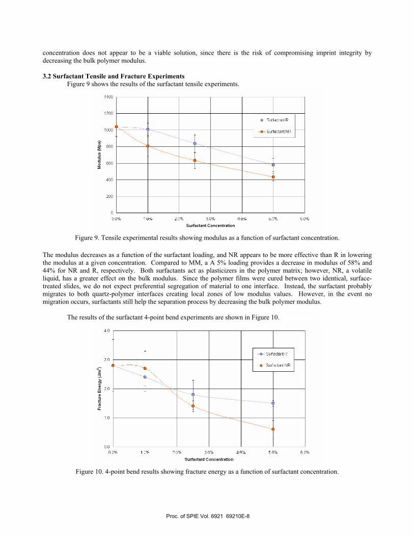
concentration does not appear to be a viable solution, since there is the risk of compromising imprint integrity by decreasing the bulk polymer modulus. 3.2 Surfactant Tensile and Fracture Experiments
Figure 9 shows the results of the surfactant tensile experiments.
Figure 9. Tensile experimental results showing modulus as a function of surfactant concentration.
The modulus decreases as a function of the surfactant loading, and NR appears to be more effective than R in lowering the modulus at a given concentration. Compared to MM, a A 5% loading provides a decrease in modulus of 58% and 44% for NR and R, respectively. Both surfactants act as plasticizers in the polymer matrix; however, NR, a volatile liquid, has a greater effect on the bulk modulus. Since the polymer films were cured between two identical, surface-treated slides, we do not expect preferential segregation of material to one interface. Instead, the surfactant probably migrates to both quartz-polymer interfaces creating local zones of low modulus values. However, in the event no migration occurs, surfactants still help the separation process by decreasing the bulk polymer modulus.
The results of the surfactant 4-point bend experiments are shown in Figure 10.
Figure 10. 4-point bend results showing fracture energy as a function of surfactant concentration.
Proc. of SPIE Vol. 6921 69210E-8

100
95
090
0C
85C00
80
0
75
7000% 1.0% 2.0% 3.0%
Surfactant Concentration
40% 50% 60%
Fracture energy decreases as the surfactant concentration increases for both surfactants used. However, at higher concentrations, surfactant NR is more effective than surfactant R in decreasing the fracture energy; at 5% loading, a 79% and 46% reduction in the fracture energy is observed for NR and R, respectively. Fracture at a solid-liquid interface (NR) should be easier than from a solid-solid interface (R), and this is accurately captured in the experimental results. 3.3 Surfactant Migration Experiments
Water contact angles were measured on the cured polymer surfaces after the 4-point bend experiments as shown in Figure 11.
Figure 11. Water contact angles for R and NR formulations.
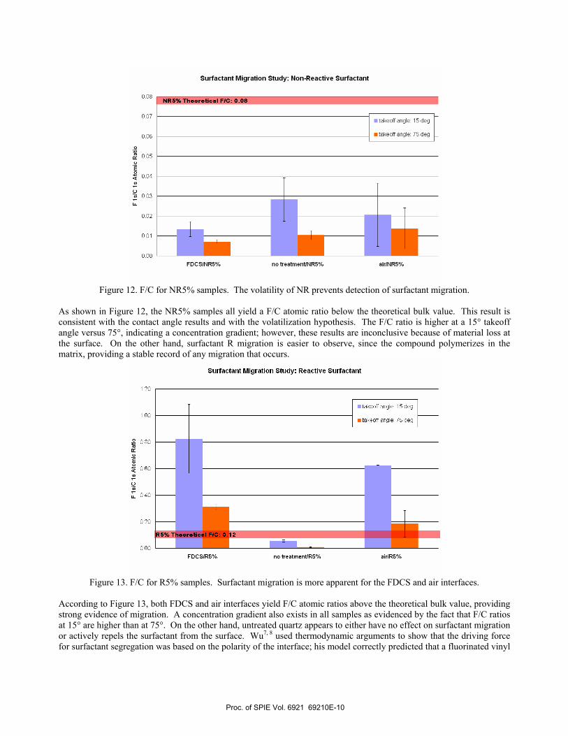
Adding R increases the contact angle up to 98° for 5 wt% loading, and this trend appears to approach an asymptotic value. The correlation between contact angle and surfactant concentration supports the results depicted in Figure 10, which shows that the fracture energy decreases as more surfactant is added. On the other hand, the surface hydrophobicity is not affected by adding NR – the NR5% result is essentially the same as MM. At first glance, this observation appears to indicate that NR does not migrate to the surface. Even if NR was evenly dispersed in the etch barrier, we would expect some increase in the surface hydrophobicity compared to MM. We theorize that either the NR, which is a volatile liquid, does migrate to the surface, but evaporates before contact angle measurements can be taken, or it migrates away from the air-polymer interface and into the bulk. It is difficult to rationalize migration away from the air-polymer interface, so the evaporation hypothesis is favored. In this case, we would expect the same water contact angles, regardless of the NR concentration. To observe the migration process, angle-resolved XPS was used to analyze the NR5% and R5% formulations polymerized in contact with 3 different interfaces: FDCS treated quartz, untreated quartz, and air. The fluorine to carbon atomic ratio was measured at takeoff angles of 15° and 75° and plotted against the theoretical F/C values, which were calculated by assuming the surfactants were homogenously dispersed in the polymer matrix.
Proc. of SPIE Vol. 6921 69210E-9
Suifactant Migration Study: Non-Reactive Surfactant
0.08
0.07
0.06
00.05
E0.04
00.03
LI-
0.02
0.01
000
5% Theoretical FIG: 0.08
• takeoff angIe: 15 deg
• takeoff angIe: 75 deg
FDCSiNRS% no treatmentiNR5% airiNRS%
Surfactant Migration Study: Reactive Surfactant
1 .20
1 .00
080
E0.60
0
: 0.40
0.20
000FDCSiRS% no treatmentlRS% airiRS%
Figure 12. F/C for NR5% samples. The volatility of NR prevents detection of surfactant migration.
As shown in Figure 12, the NR5% samples all yield a F/C atomic ratio below the theoretical bulk value. This result is consistent with the contact angle results and with the volatilization hypothesis. The F/C ratio is higher at a 15° takeoff angle versus 75°, indicating a concentration gradient; however, these results are inconclusive because of material loss at the surface. On the other hand, surfactant R migration is easier to observe, since the compound polymerizes in the matrix, providing a stable record of any migration that occurs.
Figure 13. F/C for R5% samples. Surfactant migration is more apparent for the FDCS and air interfaces.
According to Figure 13, both FDCS and air interfaces yield F/C atomic ratios above the theoretical bulk value, providing strong evidence of migration. A concentration gradient also exists in all samples as evidenced by the fact that F/C ratios at 15° are higher than at 75°. On the other hand, untreated quartz appears to either have no effect on surfactant migration or actively repels the surfactant from the surface. Wu7, 8 used thermodynamic arguments to show that the driving force for surfactant segregation was based on the polarity of the interface; his model correctly predicted that a fluorinated vinyl
Proc. of SPIE Vol. 6921 69210E-10

ether surfactant would exhibit a higher degree of migration towards a fluorinated surface than to an organic surface like polyethylene. Based on these results and our observations, we conclude that the use of fluorinated surfactants must be accompanied by a low energy surface to induce migration. If no treatment or an organic surface treatment is used, the surfactant will simply act as a plasticizer for the bulk polymer.
4. CONCLUSIONS Defect control requires a clean separation of the quartz template from the imprinted polymer in SFIL. There is
a need to design new materials and surface treatments that minimize the separation force, especially when dealing with multilayer film stacks. Basic fracture mechanics showed that decreasing the polymer modulus and the interfacial fracture energy are crucial for minimizing the separation force. Tensile and 4-point bend fracture experiments were used to evaluate the impact of crosslinker and surfactant concentration on the modulus and fracture energy. Decreasing the EGDA concentration had a significant effect on the modulus, however, due to imprint integrity concerns, the minimum crosslinker concentration was determined to be approximately 10%. On the other hand, 4-point bend fracture experiments clearly showed that EGDA does not affect the interfacial fracture energy. The effects of two fluorinated surfactants, a reactive solid (R) and a nonreactive liquid (NR), were then investigated using fracture mechanics and surface analysis experiments. The tensile experiments showed that both surfactants act as plasticizers and decrease the modulus of the polymer. Four-point bend fracture experiments indicated that adding surfactants can lower the fracture energy and that NR was more effective than R in decreasing the degree of adhesion. Since NR is a volatile liquid, the extent of migration was difficult to quantify. Therefore, R, which reacts with the polymer matrix, was used to observe the migration of fluorinated chains to specific interfaces. XPS results confirmed migration to the FDCS and air surfaces, while the untreated quartz surface appeared to repel the surfactant from the template-polymer interface. Therefore, the use of surfactants must be accompanied by a template surface treatment of similar energy and polarity to induce migration. We conclude that reducing adhesion with fluorinated surfactants, especially the NR formulation, is a better option than tuning the EGDA concentration because the ideal properties – low modulus and fracture energy – are localized at the template-polymer interface, while the bulk properties of the etch barrier that are critical for pattern integrity are not affected.
5. ACKNOWLEDGEMENTS
The authors gratefully acknowledge support from NSF, and Michael Lin gratefully acknowledges support from
the Applied Materials Graduate Fellowship. The authors would also like to acknowledge Dr. Yangming Sun and Jie Sheng of the Texas Materials Institute at The University of Texas at Austin for the XPS analysis and Mike Ronalter from the Department of Chemistry at The University of Texas at Austin for machining work on quartz. We would also like to thank Scott Smith from The University of Texas at Austin for helpful discussions on fracture mechanics principles and experiments.
6. REFERENCES [1] Colburn, M., et al., "Step and flash imprint lithography: a new approach to high-resolution patterning,"
Proceedings of SPIE-The International Society for Optical Engineering, 3676(Pt. 1, Emerging Lithographic Technologies III), 379-389 (1999).
[2] Williams, M. L., "The continuum interpretation for fracture and adhesion," Journal of Applied Polymer Science, 13(1), 29-40 (1969).
[3] Swadner, J. G. and Liechti, K. M., "Asymmetric shielding mechanisms in the mixed-mode fracture of a glass/epoxy interface," Journal of Applied Mechanics, 65, 25-29 (1998).
[4] Griffith, A. A., "The phenomena of rupture and flow in solids," Philosophical Transactions of the Royal Society of London A, 221, 163-198 (1920).
[5] Orowan, E., "Fracture and strength of solids," Reports on progress in physics, 12, 185-232 (1948). [6] Irwin, G. R., "Fracture dynamics," Fracturing of Metals, 147-166 (1948). [7] Wu, K., "Interface study for template release in step and flash imprint lithography," Ph.D. dissertation, The
University of Texas at Austin (2006). [8] Wu, K., et al., "Experimental and theoretical investigation on surfactant segregation in imprint lithography,"
Langmuir, 23(3), 1166-1170 (2007).
Proc. of SPIE Vol. 6921 69210E-11

[9] Su, Z., et al., "Surface activity of perfluorodecanoyl end-capped poly(ethylene oxide) and associated adsorption behavior to the air-water interface," Polymer, 39(19), 4655-4664 (1998).
[10] Bender, M., et al., "Multiple imprinting in UV-based nanoimprint lithography: related material issues," Microelectronic Engineering, 61-62, 407-413 (2002).
Proc. of SPIE Vol. 6921 69210E-12
Related Documents