INFLUENCE OF PROCESSING PARAMETERS IN THE MECHANICAL PROPERTIES ENHANCEMENT OF FORSTERITE CERAMIC TAN YOKE MENG FACULTY OF ENGINEERING UNIVERSITY OF MALAYA KUALA LUMPUR 2017

Welcome message from author
This document is posted to help you gain knowledge. Please leave a comment to let me know what you think about it! Share it to your friends and learn new things together.
Transcript
INFLUENCE OF PROCESSING PARAMETERS IN THE MECHANICAL PROPERTIES ENHANCEMENT OF
FORSTERITE CERAMIC
TAN YOKE MENG
FACULTY OF ENGINEERING
UNIVERSITY OF MALAYA KUALA LUMPUR
2017
INFLUENCE OF PROCESSING PARAMETERS IN
THE MECHANICAL PROPERTIES
ENHANCEMENT OF FORSTERITE CERAMIC
TAN YOKE MENG
THESIS SUBMITTED IN FULFILMENT OF THE
REQUIREMENTS FOR THE DEGREE OF DOCTOR OF
PHILOSOPHY
FACULTY OF ENGINEERING
UNIVERSITY OF MALAYA
KUALA LUMPUR
2017
ii
UNIVERSITY OF MALAYA
ORIGINAL LITERARY WORK DECLARATION
Name of Candidate: Tan Yoke Meng (I.C/Passport No: 890210-04-5643)
Registration/Matric No: KHA120109
Name of Degree: Doctor of Philosophy
Title of Project Paper/Research Report/Dissertation/Thesis (“this Work”): Influence
of processing parameters in the mechanical properties enhancement of forsterite
ceramic
Field of Study: Manufacturing Processes
I do solemnly and sincerely declare that:
(1) I am the sole author/writer of this Work;
(2) This Work is original;
(3) Any use of any work in which copyright exists was done by way of fair
dealing and for permitted purposes and any excerpt or extract from, or
reference to or reproduction of any copyright work has been disclosed
expressly and sufficiently and the title of the Work and its authorship have
been acknowledged in this Work;
(4) I do not have any actual knowledge nor do I ought reasonably to know
that the making of this work constitutes an infringement of any copyright
work;
(5) I hereby assign all and every rights in the copyright to this Work to the
University of Malaya (“UM”), who henceforth shall be owner of the
copyright in this Work and that any reproduction or use in any form or by any
means whatsoever is prohibited without the written consent of UM having
been first had and obtained;
(6) I am fully aware that if in the course of making this Work I have
infringed any copyright whether intentionally or otherwise, I may be subject
to legal action or any other action as may be determined by UM.
Candidate’s Signature Date:
Subscribed and solemnly declared before,
Witness’s Signature Date:
Name:
Designation:
iii
ABSTRACT
Phase pure forsterite was synthesized by mechanochemical method owing to its
simplicity and low cost process. Different milling methods, i.e. ball milling and attrition
milling, were investigated over sintering temperature ranging from 1200 oC to 1500
oC.
Upon comparison and selection for the best method based on relative density, Vickers
hardness and fracture toughness, the effect of ZnO addition ranging from 0.1-3.0 wt%
on the sinterability of forsterite when sintered at 1200 oC to 1500
oC was evaluated.
Subsequently, microwave sintering was conducted on both undoped and doped
forsterite bulk at temperature ranging from 1100 oC to 1250
oC.
In the present study, phase pure forsterite was successfully synthesized upon
sintering at 1200 oC and 1300
oC for attrition-milled and ball-milled samples,
respectively. It was revealed that attrition milling provides higher grinding energy and
particle refinement on the mixtures thus producing powder with significantly smaller
particle size as compared to ball-milled powder. The optimum sintering temperature
obtained was 1400 oC for both samples having the highest fracture toughness value of
4.3 MPa m1/2
and 3.52 MPa m1/2
for attritor-milled and ball-milled samples,
respectively. No decomposition of forsterite was observed throughout the sintering
regime. This study had also revealed that the incorporation of 1.0 wt% ZnO into
forsterite had enhanced the overall mechanical properties of forsterite with a maximum
of 4.51 MPa m1/2
fracture toughness value obtained upon sintering at 1400 oC. In
general, all doped samples showed better mechanical properties than the undoped
sample at all sintering temperatures studied. In addition, microwave sintering was
proven to be beneficial towards the mechanical properties enhancement at a lower
sintering temperature with very short sintering duration. Fracture toughness of 4.25
MPa m1/2
was successfully obtained at sintering temperature of 1250 oC for 1.0 wt%
iv
ZnO doped sample. The fracture toughness value obtained was 36% higher as compared
to the conventional sintered sample under equal sintering temperature. This promising
result had shown the potential of microwave sintering in further enhancing forsterite
ceramic without sacrificing the phase stability of the material. This research had
highlighted the advantageous of using attrition milling in synthesizing phase pure
forsterite, the economical production of ZnO doped forsterite having enhanced
mechanical properties and the significant reduction in sintering process with acceptable
mechanical properties for clinical application via microwave sintering.
v
ABSTRAK
Fasa forsterite tulen telah disintesis melalui kaedah mechanochemical kerana
kesederhanaan dan proses kos rendah. kaedah pengilangan yang berbeza, iaitu bola
pengilangan dan pergeseran pengilangan, telah disiasat atas suhu pensinteran dalam
julat 1200 oC sehingga 1500
oC. Setelah perbandingan dan pemilihan kaedah terbaik
berdasarkan ketumpatan relatif, kekerasan Vickers dan keliatan patah, kesan dop ZnO
sebanyak 0.1-3.0% berat pada forsterite apabila disinter pada 1200 oC 1500
oC disiasat.
Selepas itu, pensinteran melalui gelombang mikro telah dijalankan ke atas kedua-dua
pukal forsterite tanpa dop dan didopkan pada suhu antara 1100 oC hingga 1250
oC.
Dalam kajian ini, fasa forsterite tulen telah berjaya disintesis atas pensinteran pada
1200 oC dan 1300
oC untuk pergeseran gilingan dan bola gilingan sampel, masing-
masing. Ia telah mendedahkan bahawa pergeseran pengilangan menyediakan lebih
tinggi tenaga pengisaran dan kehalusan zarah pada campuran itu menghasilkan serbuk
dengan saiz zarah lebih kecil berbanding dengan serbuk bola gilingan. Suhu pensinteran
optimum yang diperolehi ialah 1400 oC untuk kedua-dua sampel yang mempunyai nilai
keliatan patah tertinggi sebanyak 4.3 MPa m1/2
dan 3.52 MPa m1/2
untuk attritor gilingan
dan bola gilingan sampel, masing-masing. Tiada penguraian forsterite diperhatikan di
seluruh rejim pensinteran. Kajian ini juga telah mendedahkan bahawa penggabungan
1.0% berat ZnO ke forsterite telah meningkatkan sifat-sifat mekanikal keseluruhan
forsterite dengan maksimum 4.51 MPa m1/2
nilai keliatan apabila disinter pada 1400 oC.
Secara umum, semua sampel yang telah dop menunjukkan sifat-sifat mekanikal yang
lebih baik daripada sampel undoped di semua pensinteran suhu dikaji. Di samping itu,
pensinteran melalui gelombang mikro telah terbukti memberi manfaat dalam
peningkatan sifat mekanikal pada suhu pensinteran yang lebih rendah dengan tempoh
pensinteran yang singkat. Patah keliatan 4.25 MPa m1/2
telah berjaya diperolehi pada
pensinteran suhu 1250 oC bagi sampel yang didop sebanyak 1.0% berat ZnO. Nilai
vi
keliatan patah yang diperolehi ialah 36% lebih tinggi berbanding dengan sampel yang
disinter secara konvensional di bawah suhu pembakaran yang sama. Hasil
memberangsangkan ini telah menunjukkan potensi pensinteran ketuhar gelombang
mikro di meningkatkan lagi forsterite seramik tanpa mengorbankan kestabilan fasa
bahan. Kajian ini telah menekankan berfaedah menggunakan pergeseran pengilangan
dalam mensintesis fasa forsterite tulen, pengeluaran ekonomi ZnO forsterite didopkan
telah dipertingkatkan ciri-ciri mekanikal dan pengurangan yang ketara dalam proses
pensinteran dengan sifat-sifat mekanikal yang boleh diterima untuk aplikasi klinikal
melalui gelombang pensinteran mikro.
vii
ACKNOWLEDGEMENTS
First and foremost, I would like to express my sincerest gratitude to my honorific
supervisors, Assoc. Prof. Dr. Tan Chou Yong and Prof. Ramesh Singh for their
countless advice, guidance, and patience have significantly encouraged my journey in
research. I am very grateful to my advisor, Prof Dinesh Agrawal at Pennsylvania State
University, University Park, United States for his incredible and valuable advice and
important support in the advancement of this research.
I would like to wish and express my warmest and sincere thanks to all lecturers,
administrative and technical staffs in the Faculty of Engineering, UM for continuous
assistance to achieve the goal of this research. My special thanks to the staffs in Faculty
of Geology and Physics for their excellent expertise in guiding me throughout the
research.
Special thanks are also given to my lab mates, Teh Yee Ching, Dr. Ali Asghar Niakan
and Dr Kelvin Chew Wai Jin for their extensive and helpful guide throughout my
graduate study in University of Malaya especially during the early semesters.
Lastly, I would like to show my countless appreciation and endless encouragement from
my family and friends in completing my PhD project. It has been a wonderful
experience, going through obstalces throughout the study and the satisfaction in
unraveling them, together with my family, collegeaus and friends.
viii
TABLE OF CONTENTS
Abstract ............................................................................................................................ iii
Abstrak .............................................................................................................................. v
Acknowledgements ......................................................................................................... vii
Table of Contents ........................................................................................................... viii
List of Figures ................................................................................................................. xii
List of Tables.................................................................................................................. xix
List of Symbols and Abbreviations ................................................................................ xxi
List of Appendices ....................................................................................................... xxiii
CHAPTER 1: INTRODUCTION .................................................................................. 1
1.1 Background of the Study ......................................................................................... 1
1.2 Scope of Research.................................................................................................... 6
1.3 Research Objectives................................................................................................. 6
1.4 Structure of the Thesis ............................................................................................. 7
CHAPTER 2: POWDER PROCESSING METHOD OF FORSTERITE ................ 9
2.1 Introduction to biomaterials ..................................................................................... 9
2.1.1 Types of biomaterials ............................................................................... 10
2.1.2 Classification and requirement of bioceramics ........................................ 11
2.1.2.1 Bioactive .................................................................................... 12
2.1.2.2 Bioresorbable ............................................................................ 12
2.1.2.3 Bioinert ...................................................................................... 13
2.2 Biocompatibility study of forsterite ceramic ......................................................... 15
2.3 Powder processing method of forsterite ceramic................................................... 17
2.3.1 Solid-state reaction via mechanical activation ......................................... 19
ix
2.3.2 Sol-gel method ......................................................................................... 25
2.3.3 Other methods .......................................................................................... 28
CHAPTER 3: SINTERABILITY OF FORSTERITE CERAMIC .......................... 31
3.1 Introduction............................................................................................................ 31
3.2 Conventional method ............................................................................................. 32
3.2.1 Heat treatment temperature and Mg/Si ratio ............................................ 32
3.2.2 Sintering temperature and dwell time ...................................................... 39
3.3 Non-conventional method ..................................................................................... 44
3.3.1 Two-step sintering .................................................................................... 44
3.3.2 Microwave sintering ................................................................................. 48
3.3.2.1 Introduction ............................................................................... 48
3.3.2.2 Microwave sintering on bioceramics ........................................ 50
3.4 Sintering additives on bioceramics ........................................................................ 57
3.4.1 Introduction .............................................................................................. 57
3.4.2 Types of sintering additives...................................................................... 58
3.4.3 Amount of sintering additives .................................................................. 60
3.4.4 Zinc oxide as sintering additive ................................................................ 63
3.4.5 Application of sintering additives on forsterite ........................................ 68
CHAPTER 4: METHODOLOGY ............................................................................... 69
4.1 Introduction............................................................................................................ 69
4.2 Powder synthesis ................................................................................................... 69
4.2.1 Starting powder preparation ..................................................................... 69
4.2.2 Forsterite preparation with different milling durations ............................ 70
4.2.3 Forsterite preparation with attrition milling ............................................. 71
4.2.4 Zinc oxide (ZnO) – doped forsterite powder preparation ........................ 71
x
4.3 Consolidation of green body .................................................................................. 72
4.3.1 Conventional sintering ............................................................................. 72
4.3.2 Microwave sintering ................................................................................. 73
4.4 Sample characterization ......................................................................................... 74
4.4.1 Phase composition analysis ...................................................................... 74
4.4.2 Brunaeur-Emmett-Teller (BET) surface area ........................................... 75
4.4.3 Differential thermal (DT) and thermogravimetric (TG) analysis ............. 76
4.4.4 Bulk density measurement ....................................................................... 76
4.4.5 Vickers hardness and fracture toughness ................................................. 77
4.4.6 Grain size measurement ........................................................................... 80
4.4.7 Morphology and Elemental Examination ................................................. 81
4.4.7.1 Scanning Electron Microscope (SEM) ...................................... 81
4.4.7.2 Field-emission Scanning Electron Microscope (FESEM) ........ 82
4.4.7.3 Transmission Electron Microscopy (TEM) ............................... 82
4.4.7.4 Cell morphology ........................................................................ 82
CHAPTER 5: RESULTS AND DISCUSSION .......................................................... 85
5.1 Part 1: Comparison between types of milling and milling duration in synthesizing
forsterite ceramic ................................................................................................... 85
5.1.1 Phase analysis of starting powder ............................................................ 86
5.1.2 Phase and particle size analysis of forsterite powder and bulk ................ 87
5.1.3 Mechanical properties and cell morphology of forsterite......................... 95
5.2 Part 2: Comparison between ZnO doped forsterite and pure forsterite ............... 106
5.2.1 Phase and elemental analysis of forsterite bulk ...................................... 108
5.2.2 Sinterability of forsterite bulk ................................................................ 111
5.3 Part 3: Effect of microwave sintering on the sinterability of forsterite ............... 119
5.3.1 Phase analysis of forsterite bulk ............................................................. 119
xi
5.3.2 Mechanical properties evaluation of forsterite bulk ............................... 120
5.3.3 Comparison between conventional sintering (CS) and microwave
sintering (MS) ......................................................................................... 130
5.3.3.1 Pure (undoped) forsterite ......................................................... 130
5.3.3.2 ZnO doped forsterite ............................................................... 132
CHAPTER 6: CONCLUSIONS................................................................................. 135
6.1 Conclusions ......................................................................................................... 135
6.2 Future directions .................................................................................................. 141
REFERENCES ......................................................................................................... 143
List of Publications and Papers Presented .................................................................... 154
Appendix A ................................................................................................................... 156
Appendix B ................................................................................................................... 158
Appendix C ................................................................................................................... 174
xii
LIST OF FIGURES
Figure 2.1: Phase-contrast microscopic images of rat calvaria osteoblasts cultured on
forsterite discs for 4 h (a) and 24 h (b) after seeding (Ni et al., 2007). ........................... 16
Figure 2.2: Proliferation of osteoblast cultivated on forsterite ceramics for 1, 3 and 7
days in comparison with the control (Ni et al., 2007). .................................................... 16
Figure 2.3: Phase purity of analysis of forsterite prepared using MgO and talc upon
milling at various duration and heat treated at 1000 oC for 1 hour (Tavangarian &
Emadi, 2010b). ................................................................................................................ 21
Figure 2.4: Phase purity of MgO-SiO2 mixtures milled at various duration and heated at
850 oC for 3 hours (Cheng et al., 2012). ......................................................................... 23
Figure 2.5: Average particle size as a function of milling duration (Cheng et al., 2012).
......................................................................................................................................... 23
Figure 2.6: Types of motion in a ball mill: (A) cascading, (B) falling or cataracting, (C)
centrifugal. (Bernotat & Schonert, 1998). ....................................................................... 24
Figure 2.7: Phase purity result of forsterite powder heated at various temperatures for 3
hours in air (Hassanzadeh-Tabrizi et al., 2016). ............................................................. 27
Figure 2.8: Phase purity of S1, S2, S3 and S4 samples. Weak peak represented by the
asterisk defined the peak for MgO phase (45-0946) (Sun et al., 2009). ......................... 28
Figure 2.9: Phase stability results of the spray-dried precursors heated at various
temperatures to form forsterite powder (Douy, 2002). ................................................... 30
Figure 2.10: Phase stability results of the evaporated precursors heated at various
temperatures to form forsterite powder (Douy, 2002). ................................................... 30
Figure 3.1: Phase purity result of forsterite powder milled at various durations and
subsequently heated at 1000 oC for 1 hour (Tavangarian & Emadi, 2009). ................... 33
Figure 3.2: Phase purity result of forsterite powder milled at various durations and
subsequently heated at 1200 oC for 1 hour (Tavangarian & Emadi, 2009). ................... 34
Figure 3.3: Phase purity of powder milled for 5 hours and annealed for 10 minutes at
corresponding temperatures (Tavangarian et al., 2010). ................................................. 35
Figure 3.4: Phase purity of powder milled for 10 hours and annealed for 10 minutes at
corresponding temperatures (Tavangarian et al., 2010). ................................................. 36
Figure 3.5: Phase purity of MgO-SiO2 mixtures milled for 30 hours and heated at
various temperatures for 3 hours (Cheng, et al., 2012). .................................................. 37
xiii
Figure 3.6: Phase purity of forsterite powders heated at various temperatures for 3 hours
in air with Mg/Si ratio of 2 (Shi et al., 2012). ................................................................. 38
Figure 3.7: Phase purity result of forsterite powders heated at 1350 oC for 3 hours in air
with various ratio of Mg/Si (Shi et al., 2012). ................................................................ 38
Figure 3.8: Phase purity result of forsterite bulk sintered at 1450 oC and 1550
oC for 8
hours (Ni et al., 2007). .................................................................................................... 39
Figure 3.9: SEM micrograph of forsterite bulk sintered at 1450 oC for 8 hours (Ni et al.,
2007). .............................................................................................................................. 40
Figure 3.10: SEM of the fracture surface of forsterite upon sintering at a) 1450 oC and
b) 1550 oC (Ni et al., 2007). ............................................................................................ 41
Figure 3.11: Mechanical properties evaluation of heat treated (solid lines) and non-heat
treated (dash lines) forsterite bulked sintered at different temperatures for 2 hours
(Ramesh, et al., 2013). .................................................................................................... 43
Figure 3.12: Phase stability result heat treated forsterite sintered in bulk form at
different temperatures for 2 hours (Ramesh et al., 2013). .............................................. 44
Figure 3.13: Example of a typical two-step sintering profile. ........................................ 45
Figure 3.14: Relative density of forsterite bulk in a function of the first stage (T1) of
two-step sintering temperature (Fathi & Kharaziha, 2009). ........................................... 46
Figure 3.15: Average grain size versus relative density of forsterite bulk under TSS1
(T1 = 1300 oC and T2 = 750
oC) and TSS2 (T1 = 1300
oC and T2 = 850
oC) profiles
with 15 hours holding for second step sintering (Fathi & Kharaziha, 2009). ................. 46
Figure 3.16: (a) Vickers hardness and (b) fracture toughness of forsterite as a function
of relative density sintered at 1300 oC for first step sintering (Fathi & Kharaziha, 2009).
......................................................................................................................................... 47
Figure 3.17: Phase purity of mixtures of initial precursors milled for 40 hours and
heated at different temperatures via microwave heating (Bafrooei et al., 2014). ........... 51
Figure 3.18: Relative density of forsterite ceramic sintered using conventional and
microwave sintering (Bafrooei et al., 2014).................................................................... 52
Figure 3.19: XRD traces of pure HA microwave sintered at 900, 1000, 1100 and 1200 oC (Veljovic et al., 2010)................................................................................................. 53
Figure 3.20: XRD traces of pure HA microwave sintered at 900, 1000, 1100 and 1200 oC (Veljovic et al., 2010)................................................................................................. 53
xiv
Figure 3.21: The relationship between grain size and sintering temperature of HA and
HA/TCP .......................................................................................................................... 54
Figure 3.22: Effect of conventional and microwave sintering temperature on the relative
density of zirconia (Borrell et al., 2012). ........................................................................ 56
Figure 3.23: Effect of conventional and microwave sintering temperature on the grain
size of zirconia (Borrell et al., 2012)............................................................................... 56
Figure 3.24: Effect of conventional and microwave sintering temperature on the fracture
toughness of zirconia (Borrell et al., 2012). .................................................................... 57
Figure 3.25: SEM micrograph of the grain size of (a) undoped TCP, (b) TCP-MgO/SrO,
(c) TCP-SrO/SiO2 and (d) TCP-MgO/SrO/SiO2 sintered at 1250 oC for 2 hours (Bose et
al., 2011). ........................................................................................................................ 59
Figure 3.26: Relative density variation sintered at different sintering temperature
(Ramesh et al., 2007). ..................................................................................................... 61
Figure 3.27: SEM micrograph of HA sintered at 1300 oC (Ramesh et al., 2007)........... 61
Figure 3.28: Effect of sintering temperature and Mn addition on the Vickers hardness of
HA (Ramesh et al., 2007). ............................................................................................... 61
Figure 3.29: Effect of Nb2O5 content on the Vickers hardness of alumina composites
sintered at 1650 oC (Hassan et al., 2014). ....................................................................... 63
Figure 3.30: Effect of Nb2O5 content on the fracture toughness of alumina composites
sintered at 1650 oC (Hassan et al., 2014). ....................................................................... 63
Figure 3.31: Densification of TCP and HA sintered at 1250 oC under different
composition of ZnO addition (Bandhopadhyay et al., 2007). ......................................... 65
Figure 3.32: Density for green and sintered of pure and doped nano-HAp sintered at
1250 oC for 6 hours (Kalita & Bhatt, 2007) .................................................................... 66
Figure 3.33: Vickers hardness and fracture toughness of PMNT/ZnO ceramics
(Promsawat et al., 2012).................................................................................................. 67
Figure 4.1: Sintering profile for the firing of green bulk samples via conventional
sintering. .......................................................................................................................... 73
Figure 4.2: Schematic diagram of a pyramidal indenter used in Vickers hardness test
(D1, D2 = diagonal length of indentation; L1, L2, L3, L4 = length of fracture). ........... 78
Figure 4.3: Flow chart of project research ...................................................................... 84
xv
Figure 5.1: XRD traces of magnesium carbonate powder. ............................................. 86
Figure 5.2: XRD traces of talc powder. .......................................................................... 86
Figure 5.3: XRD traces of proto forsterite powder upon attrition milling for 5 hours. .. 87
Figure 5.4: XRD of conventional milled forsterite bulk for 3 hours and sintered at 1200 oC for 2 hours at ramp rate of 10
oC/min. ....................................................................... 88
Figure 5.5: XRD of conventional milled forsterite bulk for 5 hours and sintered at 1200 oC for 2 hours at ramp rate of 10
oC/min. ....................................................................... 88
Figure 5.6: XRD of conventional milled forsterite bulk for 3 hours and sintered at 1300 oC for 2 hours at ramp rate of 10
oC/min. ....................................................................... 89
Figure 5.7: XRD of conventional milled forsterite bulk for 5 hours and sintered at 1300 oC for 2 hours at ramp rate of 10
oC/min. ....................................................................... 90
Figure 5.8: XRD of conventional ball milled forsterite bulk for 3 hours and sintered at
1400 and 1500 oC for 2 hours at ramp rate of 10
oC/min. ............................................... 91
Figure 5.9: XRD of conventional ball milled forsterite bulk for 5 hours and sintered at
1400 and 1500 oC for 2 hours at ramp rate of 10
oC/min. ............................................... 92
Figure 5.10: XRD of attritor milled forsterite bulk for 5 hours and sintered at 1200,
1300, 1400 and 1500 oC for 2 hours at ramp rate of 10
oC/min. ..................................... 93
Figure 5.11: SEM image of forsterite powder upon attrition milling revealing the
presence of loosely packed powders with both small and large size particles. .............. 94
Figure 5.12: TEM images of powders upon (a) ball milled for 3 hours, (b) ball milled
for 5 hours and (c) attritor milled for 5 hours. ................................................................ 95
Figure 5.13: Relative density comparison between conventional ball mill (BM) and
attritor mill (AM) for 5 hours of forsterite bulk as a function of sintering temperature. 96
Figure 5.14: Morphology of AM sample sintered at (a) 1200 oC, (b) 1300
oC, (c) 1400
oC and (d) 1500
oC for 2 hours at 10
oC/min. Large pores were entrapped between small
and large grains when sintered at 1500 oC. ..................................................................... 97
Figure 5.15: Vickers hardness of ball and attritor milled forsterite as a function of
sintering temperature. ...................................................................................................... 98
Figure 5.16: Variation of hardness with density of sintered BM samples ...................... 99
Figure 5.17: Morphology of BM sample sintered at a) 1200 oC and b) 1300
oC for 2
hours at 10 oC/min. ........................................................................................................ 100
xvi
Figure 5.18: Fracture toughness of ball and attritor milled of forsterite as a function of
sintering temperature. .................................................................................................... 102
Figure 5.19: Morphology of BM sample sintered at 1400 oC. Arrows showed the
formation of elongated grain structure in forsterite. ..................................................... 103
Figure 5.20: Morphology of BM sample sintered at 1500 oC. High ratio of large to small
grain was observed and pores were still detected. ........................................................ 103
Figure 5.21: Cell morphology upon culturing for 4 hours on AM sample (sintered at
1400 oC). The white arrows indicate the adhered cell with filopodial extensions. ....... 104
Figure 5.22: SEM image of cells proliferation of MC3T3-E1 on AM sample: (a) 1 day
culture and (b) 3 days culture. ....................................................................................... 105
Figure 5.23: TG and DTA curves of attritor-milled powder heat treated up to 1000 oC.
....................................................................................................................................... 107
Figure 5.24: XRD of heat treated forsterite powder at 1000 oC for 2 hours with ramping
rate of 10 oC/min. .......................................................................................................... 108
Figure 5.25: XRD traces of pure (undoped) forsterite sintered at (a) 1200 oC, (b) 1250
oC and (c) 1500
oC......................................................................................................... 109
Figure 5.26: XRD traces of 0.5 wt% ZnO doped forsterite sintered at (a) 1200 oC, (b)
1250 oC and (c) 1500
oC. .............................................................................................. 109
Figure 5.27: XRD traces of 1.0 wt% ZnO doped forsterite sintered at (a) 1200 oC, (b)
1250 oC and (c) 1500
oC. .............................................................................................. 110
Figure 5.28: XRD traces of 3.0 wt% ZnO doped forsterite sintered at (a) 1200 oC, (b)
1250 oC and (c) 1500
oC. .............................................................................................. 110
Figure 5.29: Elemental analysis of (a) 3.0 wt% and (b) 1.0 wt% of ZnO content sintered
at 1500 oC ...................................................................................................................... 111
Figure 5.30: Relative density variation as a function of sintering temperatures for
forsterite. ....................................................................................................................... 112
Figure 5.31: Vickers hardness variation as a function of sintering temperature for
forsterite. ....................................................................................................................... 113
Figure 5.32: Morphology of (a) undoped, (b) 0.5 wt%, (c) 1.0 wt% and (d) 3.0 wt%
ZnO-doped forsterite sintered at 1200 oC. .................................................................... 114
Figure 5.33: Fracture toughness variation as a function of sintering temperature for
forsterite. ....................................................................................................................... 115
xvii
Figure 5.34: Fracture toughness variation in terms of Vickers hardness for pure
forsterite samples. ......................................................................................................... 115
Figure 5.35: Grain size of pure and doped forsterite bulk under various sintering
temperatures. ................................................................................................................. 116
Figure 5.36: Morphology of (a) undoped, (b) 0.5 wt% and (c) 1.0 wt% ZnO doped
forsterite bulk sintered at 1400 oC. ................................................................................ 117
Figure 5.37: Fracture toughness dependence on the grain size of forsterite. ................ 117
Figure 5.38: XRD traces of (a) undoped, (b) 0.5 wt%, (c) 1.0 wt% and (d) 3.0 wt%
doped ZnO forsterite microwave sintered at 1100 oC. .................................................. 119
Figure 5.39: XRD traces of (a) undoped, (b) 0.5 wt%, (c) 1.0 wt% and (d) 3.0 wt%
doped ZnO forsterite microwave sintered at 1250 oC. .................................................. 120
Figure 5.40: Relative density variation of forsterite with different ZnO composition as a
function of sintering temperature. ................................................................................. 121
Figure 5.41: SEM morphology of 3.0 wt% ZnO sample sintered at 1200 oC. ............. 121
Figure 5.42: Morphology of (a) pure (undoped) and (b) 0.5 wt% ZnO doped forsterite
samples microwave-sintered at 1100 oC. ...................................................................... 122
Figure 5.43: Vickers hardness variation as a function of sintering temperature of
forsterite bulk. ............................................................................................................... 122
Figure 5.44: Vickers hardness variation in terms of relative density. ........................... 123
Figure 5.45: Fracture toughness variation as a function of sintering temperature of
forsterite bulk. ............................................................................................................... 124
Figure 5.46: SEM morphology of a) undoped and b) 1.0 wt% ZnO doped samples
microwave sintered at 1250 oC. Red circles indicating the clustering of ZnO particles.
....................................................................................................................................... 125
Figure 5.47: Fracture toughness variation as a function of Vickers hardness. ............. 126
Figure 5.48: Morphology of 1.0 wt% ZnO doped sample microwave sintered at 1250 oC. .................................................................................................................................. 128
Figure 5.49: Morphology of 3.0 wt% ZnO doped forsterite sample microwave sintered
at 1150 oC. White circle signify the spot for EDX. ....................................................... 128
Figure 5.50: Morphology of 3.0 wt% ZnO doped forsterite sample microwave sintered
at 1250 oC ...................................................................................................................... 129

xviii
Figure 5.51: SEM image of pure forsterite sintered at 1250 oC via a) microwave
sintering and b) conventional sintering ......................................................................... 131
Figure 5.52: SEM images of 1.0 wt% ZnO doped forsterite sintered at 1250 oC via a)
microwave sintering and b) conventional sintering ...................................................... 133
xix
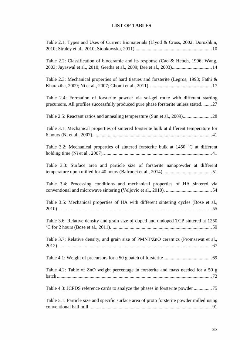
LIST OF TABLES
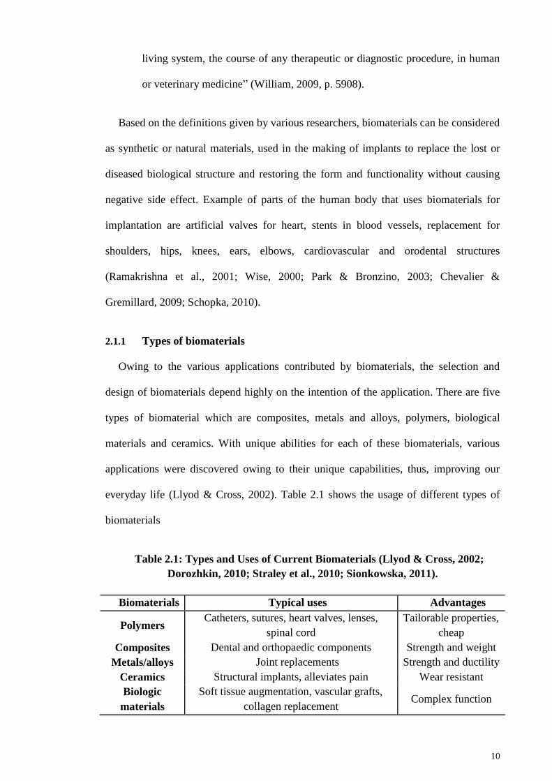
Table 2.1: Types and Uses of Current Biomaterials (Llyod & Cross, 2002; Dorozhkin,
2010; Straley et al., 2010; Sionkowska, 2011)................................................................ 10
Table 2.2: Classification of bioceramic and its response (Cao & Hench, 1996; Wang,
2003; Jayaswal et al., 2010; Geetha et al., 2009; Dee et al., 2003)................................. 14
Table 2.3: Mechanical properties of hard tissues and forsterite (Legros, 1993; Fathi &
Kharaziha, 2009; Ni et al., 2007; Ghomi et al., 2011). ................................................... 17
Table 2.4: Formation of forsterite powder via sol-gel route with different starting
precursors. All profiles successfully produced pure phase forsterite unless stated. ....... 27
Table 2.5: Reactant ratios and annealing temperature (Sun et al., 2009)........................ 28
Table 3.1: Mechanical properties of sintered forsterite bulk at different temperature for
6 hours (Ni et al., 2007). ................................................................................................. 41
Table 3.2: Mechanical properties of sintered forsterite bulk at 1450 oC at different
holding time (Ni et al., 2007). ......................................................................................... 41
Table 3.3: Surface area and particle size of forsterite nanopowder at different
temperature upon milled for 40 hours (Bafrooei et al., 2014). ....................................... 51
Table 3.4: Processing conditions and mechanical properties of HA sintered via
conventional and microwave sintering (Veljovic et al., 2010). ...................................... 54
Table 3.5: Mechanical properties of HA with different sintering cycles (Bose et al.,
2010). .............................................................................................................................. 55
Table 3.6: Relative density and grain size of doped and undoped TCP sintered at 1250 oC for 2 hours (Bose et al., 2011). ................................................................................... 59
Table 3.7: Relative density, and grain size of PMNT/ZnO ceramics (Promsawat et al.,
2012). .............................................................................................................................. 67
Table 4.1: Weight of precursors for a 50 g batch of forsterite ........................................ 69
Table 4.2: Table of ZnO weight percentage in forsterite and mass needed for a 50 g
batch ................................................................................................................................ 72
Table 4.3: JCPDS reference cards to analyze the phases in forsterite powder ............... 75
Table 5.1: Particle size and specific surface area of proto forsterite powder milled using
conventional ball mill. ..................................................................................................... 91

xx
Table 5.2: Particle size and specific surface area of proto forsterite powder milled using
conventional ball mill and attritor mill............................................................................ 93
Table 5.3: EDX result on 3.0 wt% ZnO doped forsterite sample microwave sintered at
1150 oC. ......................................................................................................................... 129
Table 5.4: Mechanical properties of pure forsterite sintered via conventional and
microwave sintering ...................................................................................................... 132
Table 5.5: Mechanical properties of 1.0 wt% ZnO doped forsterite sintered via
conventional and microwave sintering.......................................................................... 134
xxi
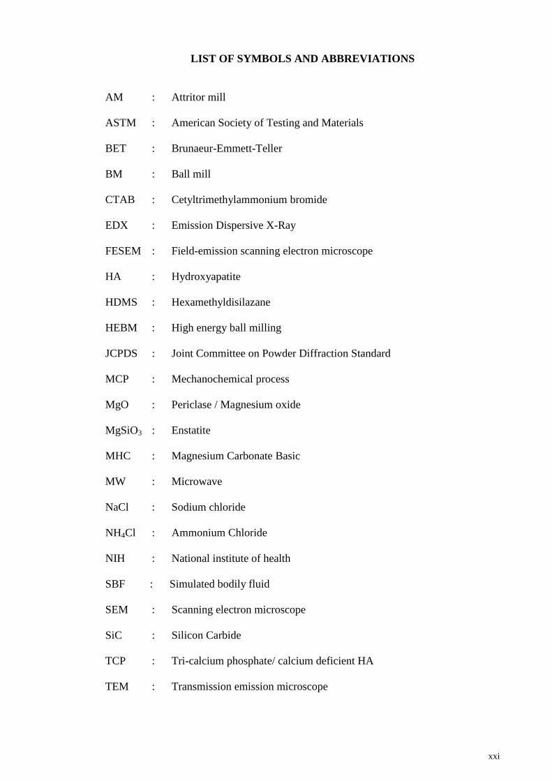
LIST OF SYMBOLS AND ABBREVIATIONS
AM : Attritor mill
ASTM : American Society of Testing and Materials
BET : Brunaeur-Emmett-Teller
BM : Ball mill
CTAB : Cetyltrimethylammonium bromide
EDX : Emission Dispersive X-Ray
FESEM : Field-emission scanning electron microscope
HA : Hydroxyapatite
HDMS : Hexamethyldisilazane
HEBM : High energy ball milling
JCPDS : Joint Committee on Powder Diffraction Standard
MCP : Mechanochemical process
MgO : Periclase / Magnesium oxide
MgSiO3 : Enstatite
MHC : Magnesium Carbonate Basic
MW : Microwave
NaCl : Sodium chloride
NH4Cl : Ammonium Chloride
NIH : National institute of health
SBF : Simulated bodily fluid
SEM : Scanning electron microscope
SiC : Silicon Carbide
TCP : Tri-calcium phosphate/ calcium deficient HA
TEM : Transmission emission microscope

xxii
TEOS : Tetra ethyl ortho-silicate
XRD : X-ray diffraction
ZnO : Zinc Oxide

xxiii
LIST OF APPENDICES
Appendix A: Calculation of raw materials preparation …………………………… 156
Appendix B: X-ray diffraction reference cards……………………………………. 158
Appendix C: Materials and Equipments…………………………………………… 174
1
CHAPTER 1: INTRODUCTION
1.1 Background of the Study
Researchers had undergone a huge revolution in bone treatment that shifted from
painkilling treatment of contagious diseases of bone to an interventional treatment of
continuous age-related issues (Hench, 2000). The discovery of antibiotics to control
infections has brought about to a new anesthetic for safer surgeries that involved a
stable fixation devices and development of joint prostheses (artificial joint). However at
present, the reconstruction of bone defects is still a challenge to many researchers in the
field of medic and dental. Bone graft has been used extensively in treating bone diseases
that affects the daily quality life of victim especially aged patients (Kokubo et al.,
2003). These implants were defined as “manufactured devices that have been designed
and developed to fulfill particular functions when implanted into the living body, and
usually for specific indications” (Wang et al., 2011). It was well established by Hench
(2000) and Kloss and Glassner (2006) that bone strength deteriorates significantly faster
as the age of victims reaches about 50-60 years (Hench, 2000; Kloss & Glassner, 2006).
Disease and injury from accidents also cause damage and degeneration of tissues and
bones in human body, which emphasize more on the need for bone grafting. Bone
grafting can be divided into three main categories. Autograft tissue involved the
transplantation of bones from one site to another from the same host. The applicability
of autograft has been restricted by the expensive cost, painful, second site morbidity and
limited supply since it involved the same host. Allograft or homograft was introduced to
solve the limited supply issue from autograft method. Bones were transplant from a
different host to the victim but it may cause the infection or disease to spread from the
donor to the patient. Also, the patient’s immune system may reject the tissue thus
causing complication upon transplantation (Hench, 2000; Brien, 2011; Naderi et al.,
2011). The third method is heterograft or xenograft in which the tissue/graft transplant
2
involved both living and non-living of different species. However, the difference in
genetics made this method controversial and hardly being used at present (Hench,
2000). Therefore, artificial bone substitute materials were introduced and have attracted
the attention of many researchers for clinical applications.
The most common material used for artificial bone substitution is bioceramic.
Bioceramics was first introduced and implemented into surgery for humans in 1980s
whereby hydroxyapatite (HA) was used as a coating for implants. HA was chosen due
to the excellent biocompatibility, bone bonding ability and chemical similarity to natural
bone (Dorozhkin & Epple, 2002; Dorozhkin, 2009; Juhasz & Best, 2012). Then in 1985
to 2001, zirconia was widely used as a hip joint femoral heads implant owing to its good
mechanical properties (Jayaswal et al, 2010). Bioceramic materials were also chosen for
bone tissue replacement because of the simplicity in fabrication and low production cost
(Tomoaia et al., 2013).
Generally, bioceramics are divided into several types depending on its properties and
functionality. For example, HA has good biocompatibility which gives rise to its usage
as dental fillers and coating of implants whereas zirconia has very good mechanical
properties that makes it useful for load-bearing applications (Amir et al., 2012). Before
zirconia was introduced, alumina was widely used as joint prostheses and wear plates in
knees (Jayaswal et al., 2010; Binyamin et al., 2006). Then, an attempt was made to
counter the low fracture toughness of alumina by introducing zirconia into the network
and producing a biphasic structure. However, due to ageing of zirconia the structure
became unstable (Deville et al., 2006). Many other methods and materials were
introduced throughout the years to enhance the mechanical properties and
biocompatibility of bioceramics with the aim of having both good biocompatibility and
optimal mechanical properties for bone implantation.
3
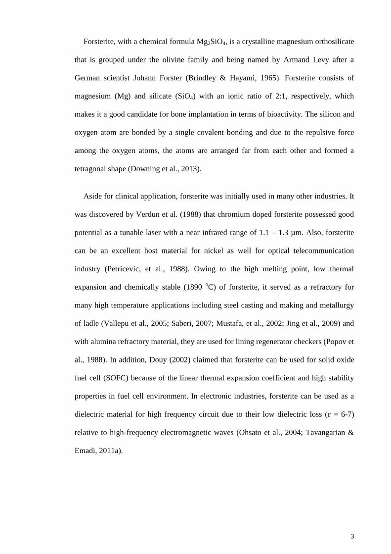
Forsterite, with a chemical formula Mg2SiO4, is a crystalline magnesium orthosilicate
that is grouped under the olivine family and being named by Armand Levy after a
German scientist Johann Forster (Brindley & Hayami, 1965). Forsterite consists of
magnesium (Mg) and silicate (SiO4) with an ionic ratio of 2:1, respectively, which
makes it a good candidate for bone implantation in terms of bioactivity. The silicon and
oxygen atom are bonded by a single covalent bonding and due to the repulsive force
among the oxygen atoms, the atoms are arranged far from each other and formed a
tetragonal shape (Downing et al., 2013).
Aside for clinical application, forsterite was initially used in many other industries. It
was discovered by Verdun et al. (1988) that chromium doped forsterite possessed good
potential as a tunable laser with a near infrared range of 1.1 – 1.3 µm. Also, forsterite
can be an excellent host material for nickel as well for optical telecommunication
industry (Petricevic, et al., 1988). Owing to the high melting point, low thermal
expansion and chemically stable (1890 oC) of forsterite, it served as a refractory for
many high temperature applications including steel casting and making and metallurgy
of ladle (Vallepu et al., 2005; Saberi, 2007; Mustafa, et al., 2002; Jing et al., 2009) and
with alumina refractory material, they are used for lining regenerator checkers (Popov et
al., 1988). In addition, Douy (2002) claimed that forsterite can be used for solid oxide
fuel cell (SOFC) because of the linear thermal expansion coefficient and high stability
properties in fuel cell environment. In electronic industries, forsterite can be used as a
dielectric material for high frequency circuit due to their low dielectric loss (ɛ = 6-7)
relative to high-frequency electromagnetic waves (Ohsato et al., 2004; Tavangarian &
Emadi, 2011a).
4
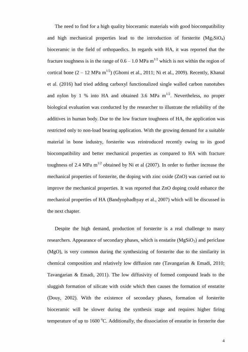
The need to find for a high quality bioceramic materials with good biocompatibility
and high mechanical properties lead to the introduction of forsterite (Mg2SiO4)
bioceramic in the field of orthopaedics. In regards with HA, it was reported that the
fracture toughness is in the range of 0.6 – 1.0 MPa m1/2
which is not within the region of
cortical bone (2 – 12 MPa m1/2
) (Ghomi et al., 2011; Ni et al., 2009). Recently, Khanal
et al. (2016) had tried adding carboxyl functionalized single walled carbon nanotubes
and nylon by 1 % into HA and obtained 3.6 MPa m1/2
. Nevertheless, no proper
biological evaluation was conducted by the researcher to illustrate the reliability of the
additives in human body. Due to the low fracture toughness of HA, the application was
restricted only to non-load bearing application. With the growing demand for a suitable
material in bone industry, forsterite was reintroduced recently owing to its good
biocompatibility and better mechanical properties as compared to HA with fracture
toughness of 2.4 MPa m1/2
obtained by Ni et al (2007). In order to further increase the
mechanical properties of forsterite, the doping with zinc oxide (ZnO) was carried out to
improve the mechanical properties. It was reported that ZnO doping could enhance the
mechanical properties of HA (Bandyophadhyay et al., 2007) which will be discussed in
the next chapter.
Despite the high demand, production of forsterite is a real challenge to many
researchers. Appearance of secondary phases, which is enstatite (MgSiO3) and periclase
(MgO), is very common during the synthesizing of forsterite due to the similarity in
chemical composition and relatively low diffusion rate (Tavangarian & Emadi, 2010;
Tavangarian & Emadi, 2011). The low diffusivity of formed compound leads to the
sluggish formation of silicate with oxide which then causes the formation of enstatite
(Douy, 2002). With the existence of secondary phases, formation of forsterite
bioceramic will be slower during the synthesis stage and requires higher firing
temperature of up to 1600 oC. Additionally, the dissociation of enstatite in forsterite due
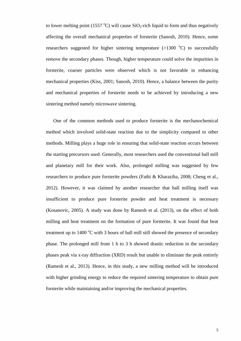
5
to lower melting point (1557 oC) will cause SiO2-rich liquid to form and thus negatively
affecting the overall mechanical properties of forsterite (Sanosh, 2010). Hence, some
researchers suggested for higher sintering temperature (>1300 oC) to successfully
remove the secondary phases. Though, higher temperature could solve the impurities in
forsterite, coarser particles were observed which is not favorable in enhancing
mechanical properties (Kiss, 2001; Sanosh, 2010). Hence, a balance between the purity
and mechanical properties of forsterite needs to be achieved by introducing a new
sintering method namely microwave sintering.
One of the common methods used to produce forsterite is the mechanochemical
method which involved solid-state reaction due to the simplicity compared to other
methods. Milling plays a huge role in ensuring that solid-state reaction occurs between
the starting precursors used. Generally, most researchers used the conventional ball mill
and planetary mill for their work. Also, prolonged milling was suggested by few
researchers to produce pure forsterite powders (Fathi & Kharaziha, 2008; Cheng et al.,
2012). However, it was claimed by another researcher that ball milling itself was
insufficient to produce pure forsterite powder and heat treatment is necessary
(Kosanovic, 2005). A study was done by Ramesh et al. (2013), on the effect of both
milling and heat treatment on the formation of pure forsterite. It was found that heat
treatment up to 1400 oC with 3 hours of ball mill still showed the presence of secondary
phase. The prolonged mill from 1 h to 3 h showed drastic reduction in the secondary
phases peak via x-ray diffraction (XRD) result but unable to eliminate the peak entirely
(Ramesh et al., 2013). Hence, in this study, a new milling method will be introduced
with higher grinding energy to reduce the required sintering temperature to obtain pure
forsterite while maintaining and/or improving the mechanical properties.
6
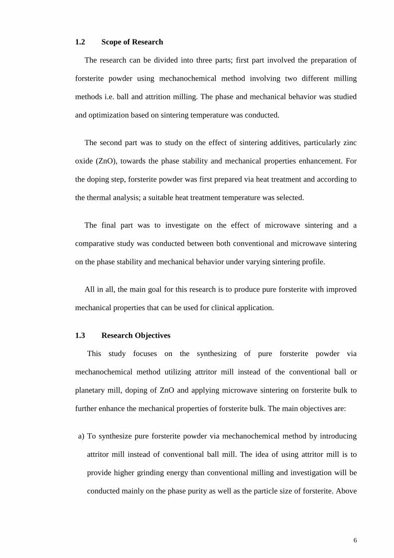
1.2 Scope of Research
The research can be divided into three parts; first part involved the preparation of
forsterite powder using mechanochemical method involving two different milling
methods i.e. ball and attrition milling. The phase and mechanical behavior was studied
and optimization based on sintering temperature was conducted.
The second part was to study on the effect of sintering additives, particularly zinc
oxide (ZnO), towards the phase stability and mechanical properties enhancement. For
the doping step, forsterite powder was first prepared via heat treatment and according to
the thermal analysis; a suitable heat treatment temperature was selected.
The final part was to investigate on the effect of microwave sintering and a
comparative study was conducted between both conventional and microwave sintering
on the phase stability and mechanical behavior under varying sintering profile.
All in all, the main goal for this research is to produce pure forsterite with improved
mechanical properties that can be used for clinical application.
1.3 Research Objectives
This study focuses on the synthesizing of pure forsterite powder via
mechanochemical method utilizing attritor mill instead of the conventional ball or
planetary mill, doping of ZnO and applying microwave sintering on forsterite bulk to
further enhance the mechanical properties of forsterite bulk. The main objectives are:
a) To synthesize pure forsterite powder via mechanochemical method by introducing
attritor mill instead of conventional ball mill. The idea of using attritor mill is to
provide higher grinding energy than conventional milling and investigation will be
conducted mainly on the phase purity as well as the particle size of forsterite. Above
7
that, mechanical properties and morphology of the synthesized forsterite bulk will
be evaluated as well.
b) To investigate the effect of doping ZnO into forsterite powder on the mechanical
properties that includes densification, microhardness and fracture toughness as well
as the morphology of forsterite bioceramic. Sintering will be conducted on the bulk
samples ranging from 1200 – 1500 oC with a ramping rate of 10
oC/min for 2 h.
c) To compare the phase stability, mechanical properties and morphology of
conventional and microwave sintered bulk forsterite samples. A short and
preliminary study will be conducted on the effect of microwave sintering on the
forsterite samples with sintering temperature of 1100 – 1250 oC and a ramping rate
of 50 oC/min for 30 min. The as-compared results will be used as the benchmark of
the upcoming future work in the application of microwave sintering on forsterite.
1.4 Structure of the Thesis
In Chapter 2, a brief overview on the effects of different powder processing methods
on the properties of forsterite powder is presented. Parameters including types of
starting precursors, duration of milling and heat treatment profiles are discussed and
compared based on the phase stability and powder particle size.
Chapter 3 will discuss on the sinterability of forsterite ceramic under various
sintering methods such as conventional sintering, two step sintering and microwave
sintering. These discussions will involve a comparative study between different
sintering methods with regards to the mechanical properties of forsterite as well as
particle size. Also, the effect of sintering additives on bioceramics was presented to
highlight the important parameters that require attention with regards to doping on
forsterite.
8
The description on the synthesis method used in manufacturing the forsterite powders
as well as the sintering methods are presented in Chapter 4. The characterization
methods are also discussed in this chapter.
Results and discussions are presented in Chapter 5. A thorough discussion on the
effects of different milling methods and duration are laid out in this chapter, i.e.
forsterite powder prepared via ball and attrition milling are compared in terms of phase
stability, particle size and specific surface area. Based on the results obtained, further
work is carried out by selecting for the best milling methods employed based on the
sintering behavior and mechanical properties upon sintering. The effect of ZnO as
sintering additives on the properties of forsterite upon sintering at 1200 oC to 1500
oC
are presented and based on the results, microwave sintering is employed as well on the
undoped and doped samples to do a comparative study between these two sintering
methods.
Lastly, Chapter 6 will conclude the entire work based on the findings obtained and
provide suggestions for future work. The appendices contain various experimental
details and machinery specifications as well as research publications.
9
CHAPTER 2: POWDER PROCESSING METHOD OF FORSTERITE
2.1 Introduction to biomaterials
Since half a century ago, biomaterial was extensively studied under medicine,
biology, tissue engineering, materials science and chemistry field (Amogh et al., 2010).
A biomaterial is essentially a material that is used and adapted for medical applications
such as surgery and drug delivery and generally, biomaterial can be defined as (Cao &
Hench, 1996):
i. Performance of implant material that is equivalent with the host tissue.
ii. The tissue at the interface should be equivalent to the normal host tissue and
the response of the material to physical stimuli should be like that of the
tissue it replaces.
Also, according to United States National Institute of Health (NIH), a biomaterial is
defined as:
“any substance (other than a drug) or a combination or substances, synthetic or
natural in origin, which can be used for any period of time, as a whole or a part
of a system which treats, augments, or replaces any tissue, organ, or function of
the body” (National Institute of Health, 1982, p. 1).
Another researcher defined biomaterials as “a non-drug substance suitable for
inclusion in system which augment or replace the function of bodily tissue or organ”
(Jayaswal et al., 2010). Recently, a more sophisticated definition of biomaterial was
defined by William, 2009. The researcher defined it as:
“a substance that has been engineered to take a form which, alone or as part of a
complex system, is used to direct, by control of interactions with components of
10
living system, the course of any therapeutic or diagnostic procedure, in human
or veterinary medicine” (William, 2009, p. 5908).
Based on the definitions given by various researchers, biomaterials can be considered
as synthetic or natural materials, used in the making of implants to replace the lost or
diseased biological structure and restoring the form and functionality without causing
negative side effect. Example of parts of the human body that uses biomaterials for
implantation are artificial valves for heart, stents in blood vessels, replacement for
shoulders, hips, knees, ears, elbows, cardiovascular and orodental structures
(Ramakrishna et al., 2001; Wise, 2000; Park & Bronzino, 2003; Chevalier &
Gremillard, 2009; Schopka, 2010).
2.1.1 Types of biomaterials
Owing to the various applications contributed by biomaterials, the selection and
design of biomaterials depend highly on the intention of the application. There are five
types of biomaterial which are composites, metals and alloys, polymers, biological
materials and ceramics. With unique abilities for each of these biomaterials, various
applications were discovered owing to their unique capabilities, thus, improving our
everyday life (Llyod & Cross, 2002). Table 2.1 shows the usage of different types of
biomaterials
Table 2.1: Types and Uses of Current Biomaterials (Llyod & Cross, 2002;
Dorozhkin, 2010; Straley et al., 2010; Sionkowska, 2011).
Biomaterials Typical uses Advantages
Polymers Catheters, sutures, heart valves, lenses,
spinal cord
Tailorable properties,
cheap
Composites Dental and orthopaedic components Strength and weight
Metals/alloys Joint replacements Strength and ductility
Ceramics Structural implants, alleviates pain Wear resistant
Biologic
materials
Soft tissue augmentation, vascular grafts,
collagen replacement Complex function
11
2.1.2 Classification and requirement of bioceramics
Two of the most important requirements of a bioceramic for bone reconstruction are
the mechanical properties and biocompatibility (Geetha, et al., 2009; O’Brien, 2011).
Depending on the application such as hip transplant and dental implant, the type of
material used will be different and it is determined based on the mechanical properties.
Hardness, fracture toughness, elongation, tensile strength and modulus are few of the
important properties of the material that will determine the reliability of the implants
(Geetha et al., 2009). For example, owing to a very high hardness and density, zirconia
was chosen for hip joint femoral heads implant instead of other bioceramics (Jayaswal
et al, 2010). However, if zirconia bioceramic was implanted on a bone that requires
minimal stiffness, the stress will be diverted from the adjacent bone causing bone
resorption surrounding the implant and led to implant loosening. On the other hand, if
the fracture toughness of the implant is lower than the requirement, cracking will occur
and can be referred as biomechanical incompatibility. The term stress shielding effect
was introduced when the biomechanical incompatibility causes fatality on the bone cells
(Geetha et al., 2009; Monaco et al., 2013). During the production of scaffolds, the
mechanical properties need to be consistent with the implantation site to ensure proper
surgical handling during the implantation. However, certain amount of porosity was
also needed to allow cell penetration and vascularization (O’Brien, 2011). It was
generally known that porosity will cause deterioration in the mechanical properties of
the material. Thus, a balance between the mechanical properties and the porosities are
required to ensure the successfulness of the implant.
Biocompatibility can be defined as “the ability of a material to perform with an
appropriate response in a specific application” (Lemons, 1996). So, the materials are
expected to not cause inflammatory or allergic reactions and must be non-toxic to the
12
human body. Upon implantation, the cells must be able to adhere, operate as usual and
move onto the surface of the implant and proliferate on the surface to form new matrix
(O’Brien, 2011). The successfulness of an implant is controlled by the reaction of the
human body’s response. The degradation and host response due to the material in
human body are the two main criteria that influence the biocompatibility of a material
which give rise to the three major classifications of bioceramics which are bioactive,
bioresorbable and bioinert (Geetha et al., 2009; Jayaswal et al., 2010 Best et al., 2008).
2.1.2.1 Bioactive
According to Cao & Hench (1996), bioactive material was defined as “a biological
material that elicits a specific biological response at the interface of the material which
results in the formation of a bond between the tissues and the material”. Mineral layers
of biological apatite between the material and bone produced from the dissolution of
bioactive material would enhance the natural bonding between the implant and the bone
to create an environmentally compatible bonding with osteogenesis (bone growth) and
provide good stabilization (Cao & Hench, 1996; Dorozhkin, 2010). Although HA and
bioglass are both bioactive material, the bonding mechanism between these materials
differ (Cao & Hench, 1996).
2.1.2.2 Bioresorbable
Bioresorbable material has the ability to dissolve in human body environment to
allow new tissues to form and grow on any surface abnormalities but may not be
interfacing directly with the material (Dorozhkin, 2010). Generally, this type of material
degrades over time and will be replaced by endogenous tissue which then becomes a
normal, functional bone (Binyamin et al., 2006). Scaffolds will usually use
bioresorbable materials as a mean to fill spaces and allowing the tissues to infiltrate and
substitute with the scaffold itself thus repairing the irregularities of the body part
13
(Dorozhkin, 2010). Few examples of bioresorbable bioceramics are hydroxyapatite
(when sintered at low temperature), calcium phosphate and calcium sulfate dihydrate
(Binyamin et al., 2006; Dee et al., 2003).
Similarly to calcium phosphate, HA is also more stable than calcium phosphate
especially when the surrounding pH dropped to 5.5 whereby in the case of calcium
phosphate, dissolution will occur and reprecipitate (Jayaswal et al., 2010). Further, Ruys
et al. (1995) and Katti (2004) reported that HA has good osteogenesis ability by
controlling its stability in terms of chemical composition under in vivo condition and
also calcium phosphate was undesirable owing to its low mechanical strength,
particularly fracture toughness.
2.1.2.3 Bioinert
Best (2009), defined bioinert material as a material with “a minimal level of response
from the host tissue in which the implant becomes covered in a thin fibrous layer which
is non-adherent”. This material possesses biocompatibility while maintaining the
mechanical and physical properties upon implantation. Instead of reacting with the host
tissue, bioinert material lack biological response but it is nontoxic. Hence, bioinert
materials are commonly used for supporting role in orthopaedics field owing to its
decent wear properties and useful slithering functions (Binyamin, et al., 2006).
Alumina was categorized as bioinert materials that has good wear properties and was
widely used for joint replacement implant (Jayaswal et al., 2010; Katti, 2004). Alumina
can be easily produced with high surface finish which is beneficial to its surface
properties (Jayaswal et al., 2010; Binyamin et al., 2006). Nevertheless, the application
of alumina as hip implant was negated due to the loosening of joint between the implant
and the hip joint which eventually leads to irritation to the patient (Suchanek &
Yoshimura, 1998). One of the drawback of alumina as an implant falls on its high
14
rigidity which is not compatible for hip joint replacement as Bizot & Sedel (2001)
claimed that the shock absorbance of alumina was reduced especially during a sudden
fall by the patient.
Zirconia, another material that has bioinert properties is widely used in ball heads for
total hip implantation (Katti, 2004). Comparing with alumina, partially stabilized
zirconia has better flexural strength, fracture toughness and low Young’s modulus and
owing to its high scratch and corrosion resistance compared to metal, zirconia ceramic
was commonly used for orthopaedics implant (Clarke et al., 2003; Aboushelib et al.,
2008; Jayaswal et al., 2010). Also, zirconia was widely used in dental implant owing to
the mechanical properties and the aesthetic color similar to tooth (Piconi & Maccauro,
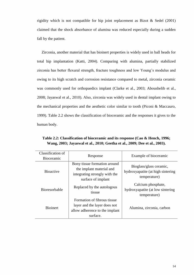
1999). Table 2.2 shows the classification of bioceramic and the responses it gives to the
human body.
Table 2.2: Classification of bioceramic and its response (Cao & Hench, 1996;
Wang, 2003; Jayaswal et al., 2010; Geetha et al., 2009; Dee et al., 2003).
Classification of
Bioceramic Response Example of bioceramic
Bioactive
Bony tissue formation around
the implant material and
integrating strongly with the
surface of implant
Bioglass/glass ceramic,
hydroxyapatite (at high sintering
temperature)
Bioresorbable Replaced by the autologous
tissue
Calcium phosphate,
hydroxyapatite (at low sintering
temperature)
Bioinert
Formation of fibrous tissue
layer and the layer does not
allow adherence to the implant
surface.
Alumina, zirconia, carbon
15
2.2 Biocompatibility study of forsterite ceramic
Silicon plays an important role in bone and osteoblast growth as well as during early
bone calcification (Carlisle, 1988). Schwarz (1972) demonstrated that silicon deficient
rats experienced skeletal deformations and when the amount of silicon increased, the
growth rate of the rats improved. In general, magnesium is important to human
metabolism and it can be found in bone tissues (Vorman, 2003; Wolf and Cittadini,
2003). Additionally, magnesium also contributes in bone mineralization and indirectly
affecting the mineral metabolism positively (LeGeros, 1991; Althoff et al., 1982; Chou
et al., 2014). Magnesium also affects the insulin secretion to regulate the bone growth
(Pietak et al., 2007; Liu et al., 1988). Thus, owing to the chemical composition of
forsterite, researchers had recently begun investigating on the mechanical capability of
forsterite to substitute HA in future.
In the field of biomedical, forsterite was introduced as early as the 1990’s as many
researchers were still investigating for a new potential biomaterial in orthopaedics. With
recent studies done on forsterite for biomedical application, forsterite has gained many
interests from researchers i.e. from synthesizing of forsterite to enhancing the
mechanical properties and towards the fabrication of scaffolds using forsterite. In the
2000’s, Ni et al. (2007) had successfully proven that forsterite possessed good
biocompatibility and better mechanical properties than HA which then caught the
attention of other researchers on the potential of forsterite as the next candidate for
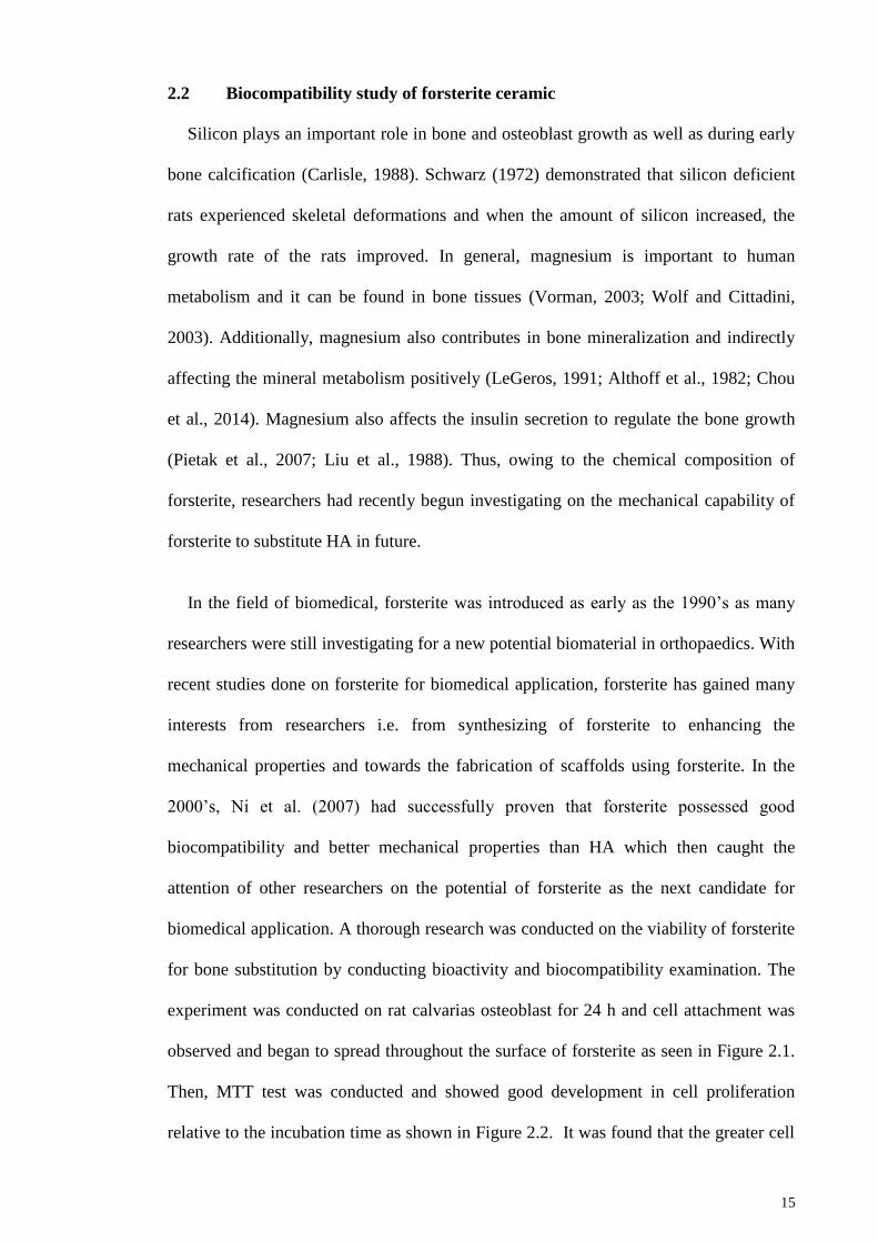
biomedical application. A thorough research was conducted on the viability of forsterite
for bone substitution by conducting bioactivity and biocompatibility examination. The
experiment was conducted on rat calvarias osteoblast for 24 h and cell attachment was
observed and began to spread throughout the surface of forsterite as seen in Figure 2.1.
Then, MTT test was conducted and showed good development in cell proliferation
relative to the incubation time as shown in Figure 2.2. It was found that the greater cell
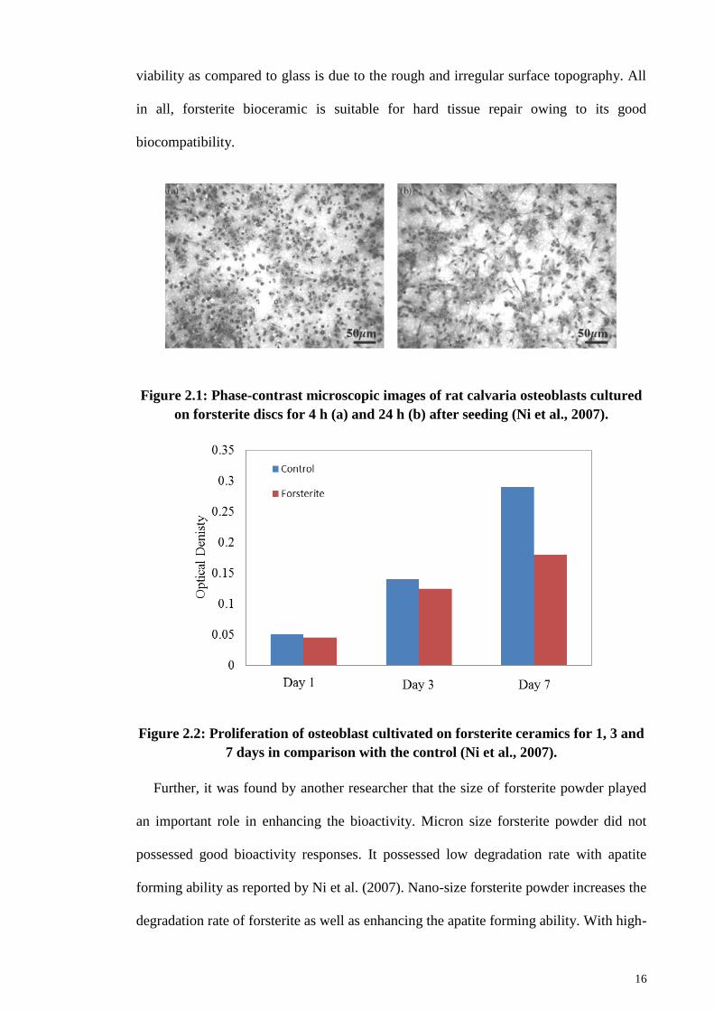
16
viability as compared to glass is due to the rough and irregular surface topography. All
in all, forsterite bioceramic is suitable for hard tissue repair owing to its good
biocompatibility.
Figure 2.1: Phase-contrast microscopic images of rat calvaria osteoblasts cultured
on forsterite discs for 4 h (a) and 24 h (b) after seeding (Ni et al., 2007).
Figure 2.2: Proliferation of osteoblast cultivated on forsterite ceramics for 1, 3 and
7 days in comparison with the control (Ni et al., 2007).
Further, it was found by another researcher that the size of forsterite powder played
an important role in enhancing the bioactivity. Micron size forsterite powder did not
possessed good bioactivity responses. It possessed low degradation rate with apatite
forming ability as reported by Ni et al. (2007). Nano-size forsterite powder increases the
degradation rate of forsterite as well as enhancing the apatite forming ability. With high-
17
volume fraction of grain boundaries owing to the nanostructured forsterite powder, the
osteoblast adhesion, proliferation and mineralization of forsterite were significantly
improved (Catledge et al., 2002; Webster et al., 2001; Kharaziha & Fathi, 2010).
Additionally, with the nanostructured technology of forsterite, researchers have the
luxury and flexibility to design the surface and mechanical properties and grain size
distribution of forsterite to match it with human bone (Gutwein & Webster, 2002).
Hence, enhanced mechanical properties of forsterite were obtainable for nanostructured
forsterite instead of micron size (Cottom & Mayo, 1996; Kharaziha & Fathi, 2010). The
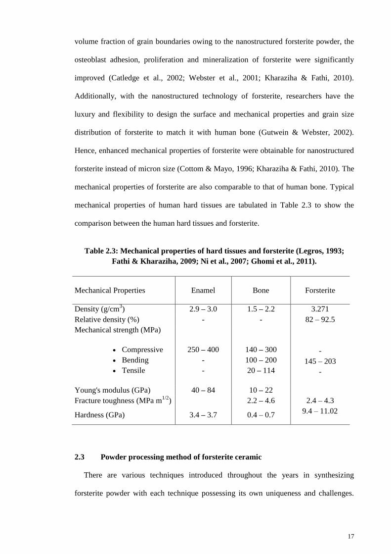
mechanical properties of forsterite are also comparable to that of human bone. Typical
mechanical properties of human hard tissues are tabulated in Table 2.3 to show the
comparison between the human hard tissues and forsterite.
Table 2.3: Mechanical properties of hard tissues and forsterite (Legros, 1993;
Fathi & Kharaziha, 2009; Ni et al., 2007; Ghomi et al., 2011).
Mechanical Properties Enamel Bone Forsterite
Density (g/cm3) 2.9 – 3.0 1.5 – 2.2 3.271
Relative density (%) - - 82 – 92.5
Mechanical strength (MPa)
Compressive
Bending
Tensile
250 – 400
-
-
140 – 300
100 – 200
20 – 114
-
145 – 203
-
Young's modulus (GPa) 40 – 84 10 – 22
Fracture toughness (MPa m1/2
) 2.2 – 4.6 2.4 – 4.3
Hardness (GPa) 3.4 – 3.7 0.4 – 0.7 9.4 – 11.02
2.3 Powder processing method of forsterite ceramic
There are various techniques introduced throughout the years in synthesizing
forsterite powder with each technique possessing its own uniqueness and challenges.
18
The two most commonly used methods are solid-state reaction via mechanical
activation with heat treatment and sol-gel route.
One of the main drawbacks of forsterite ceramic occurred during the synthesis stage
in which forming pure forsterite powder is challenging. Secondary phases tend to
appear during the synthesis of forsterite when the parameter for heat treatment profile,
milling profile and amount of starting precursors are not optimized. Enstatite (MgSiO3)
and periclase (MgO) are the two commonly found secondary phases in the phase
stability of forsterite upon synthesis (Hiraga, et al., 2010). Owing to its chemical
similarities to forsterite, the synthesis stage requires high accuracy and sensitivity to
ensure for a proper formation of forsterite which will be discussed further in later
section.
Appearance of secondary phases led to many complications in the mechanical
properties of forsterite. Due to the appearance of enstatite, it will dissociate in forsterite
and formed SiO2-rich liquid upon heated at 1557 oC which causes reduction in the
mechanical properties of forsterite (Tavangarian et al., 2010; Tavangarian & Emadi,
2011). In regards with optical industry, huge size of impurities in forsterite cause
significant light scattering and loss of visual clarity (Sun et al., 2009). Generally,
formation of secondary phases is not preferred by majority of researchers although a
few of them claimed that having enstatite in forsterite will enhance the crushing strength
and density due to the formation of glassy matrix at 1500 oC (Mustafa et al., 2002).
However, the formation of glassy phase will be detrimental to the fracture toughness of
forsterite. Thus, depending on the types of mechanical properties needed to enhance, the
formation of enstatite is subjective.
19
2.3.1 Solid-state reaction via mechanical activation
This method is also known as mechanochemical process (MCP) and was first
demonstrated by McCormick (1995). This process involved the use of mechanical
energy such as milling to activate the chemical reactions between the precursors and
also causes structural changes such as particle refinement (McCormick, 1995). During
milling process, balls will collide with powders thus deforming the particles and
introducing fracture and refinement on the grain and particle size. Prolonged milling
duration will induce more energy to the mixtures of powder causing dislocation on the
structure and forming random nanostructure grains but if not controlled, contamination
can occur from the milling ball. Generally, a short milling will only involve
homogenizing the mixing between precursors whereas prolonging the duration of
milling eventually leads to minor chemical reactions. Aside from the regular type of
milling, high energy ball milling (HEBM) or attrition milling was introduced and gain
major acceptance in the industrial work owing to its high energy shearing and collision
of milling balls and precursors. The ability of HEBM to produce grain size in the order
of 103-10
4 as well as particle refinement has definitely attracted researchers to
implement this type of milling in hope to obtain nano-size particles and grains.
Although HEBM could cause contamination on the precursors due to the shearing
between milling balls, the high yield and simplistic procedure has gain the acceptance
by researchers (Mukhopadhyay, & Basu, 2007).
Few of the parameters that are important during milling are the size, density,
hardness and composition of ball mills or also known as milling media. Size of balls
used is usually bigger than the pieces of material to be milled to obtain a finer size of
the material. A denser ball should be used to ensure that the ball does not float on the
top of the material. Also, a more durable ball is required to disallow wear of the tumbler
and the ball itself during milling. Lastly, the composition of the ball should be
20
controlled to safeguard the final product from contamination by the milling media
(Suryanarayana, 2009).
There are many combinations of starting precursors used by researchers to obtain
pure forsterite. One of the well-known researchers in the field of forsterite bioceramic
had tried several combinations of precursors including MgO or MgCO3 mixed with
SiO2 or talc (Tavangarian & Emadi, 2009, 2010 & 2010a). A study was done on
prolonged milling on the formation of single phase forsterite ceramic. Based on a study
by Tavangarian & Emadi (2009), duration of 5 min until 100 hours were selected with a
controlled heat treatment temperature of 1000 oC and held for 1 h. During the initial
stage, milling at 5 min, 1 and 5 hours showed the presence of periclase. Upon milling
for 10 hours, single phase forsterite was successfully obtained. No significant changes
were observed on the phase purity and structural composition of samples upon milling
up to 100 hours. Only the intensity of sample decreased as the milling duration
increases with crystallite size ranging from 28-40 nm (Tavangarian & Emadi, 2009). It
was also suggested by the researcher that the formation of forsterite via solid-state
reaction was governed by the following reactions (Equations 2.1 and 2.2):
5MgCO3 → 5MgO + 5CO2 (2.1)
Mg3Si4O10(OH)2 + MgO → 4MgSiO3 + H2O (2.2)
Upon reaching 1000 o
C of heat treatment, another reaction occurred between the
products of the initial reaction and can be shown in equation 2.3:
4MgO + 4MgSiO3 → 4Mg2SiO4 (2.3)
It was proposed by Brindley & Hayami (1965) that during the initial stage of
reaction, MgO reacted with the surface of SiO2 and form enstatite. With the formation
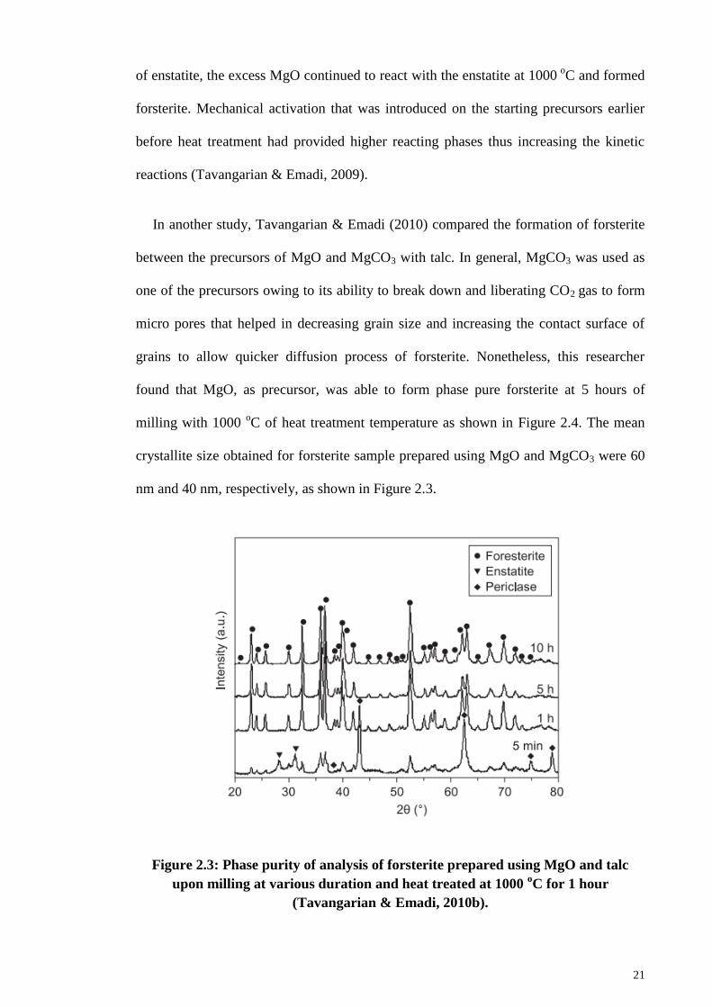
21
of enstatite, the excess MgO continued to react with the enstatite at 1000 o
C and formed
forsterite. Mechanical activation that was introduced on the starting precursors earlier
before heat treatment had provided higher reacting phases thus increasing the kinetic
reactions (Tavangarian & Emadi, 2009).
In another study, Tavangarian & Emadi (2010) compared the formation of forsterite
between the precursors of MgO and MgCO3 with talc. In general, MgCO3 was used as
one of the precursors owing to its ability to break down and liberating CO2 gas to form
micro pores that helped in decreasing grain size and increasing the contact surface of
grains to allow quicker diffusion process of forsterite. Nonetheless, this researcher
found that MgO, as precursor, was able to form phase pure forsterite at 5 hours of
milling with 1000 oC of heat treatment temperature as shown in Figure 2.4. The mean
crystallite size obtained for forsterite sample prepared using MgO and MgCO3 were 60
nm and 40 nm, respectively, as shown in Figure 2.3.
Figure 2.3: Phase purity of analysis of forsterite prepared using MgO and talc
upon milling at various duration and heat treated at 1000 oC for 1 hour
(Tavangarian & Emadi, 2010b).
22
All the works done by Tavangarian & Emadi (2009; 2010; 2010a; 2010b) were based
on the use of planetary milling. The name of planetary milling comes from its planet-
like movement of the vial. The vial and rotating disc rotates in opposite directions thus
causing the milling balls to experience ‘friction effect’ (Suryanarayana, 2001). It
operates under two relative motions which are planetary motion around the vial axis and
rotary motion surrounding the mill axis (Balaz, 2008).
Cheng et al. (2012) had introduced another high energy ball milling process to
produce forsterite using MgO and silica (SiO2). Based on the study, 5 to 30 hours of
milling was conducted followed by heat treatment at 850 oC for 3 hours. The phase
purity result was represented in Figure 2.4. Forsterite peak was observed for the entire
milling duration. Nonetheless, both SiO2 and MgO peaks were observed as well for
mixtures milled from 5 to 20 hours. The author proved that the milling duration played
an important role in ensuring the formation of phase pure forsterite. The result obtained
was supported by the particle size results obtained under various milling durations as
shown in Figure 2.5. Increasing milling duration had led to the reduction in particle size
thus producing phase pure forsterite powder (Cheng et al., 2012).
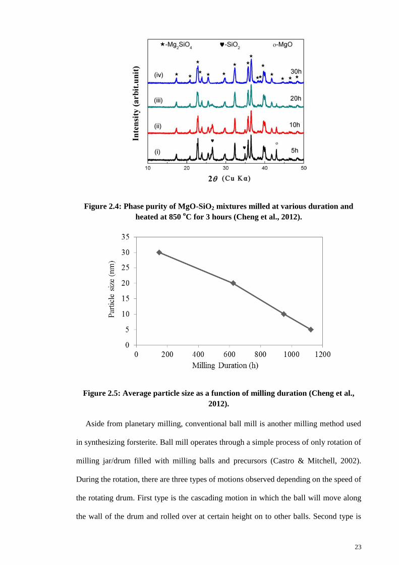
23
Figure 2.4: Phase purity of MgO-SiO2 mixtures milled at various duration and
heated at 850 oC for 3 hours (Cheng et al., 2012).
Figure 2.5: Average particle size as a function of milling duration (Cheng et al.,
2012).
Aside from planetary milling, conventional ball mill is another milling method used
in synthesizing forsterite. Ball mill operates through a simple process of only rotation of
milling jar/drum filled with milling balls and precursors (Castro & Mitchell, 2002).
During the rotation, there are three types of motions observed depending on the speed of
the rotating drum. First type is the cascading motion in which the ball will move along
the wall of the drum and rolled over at certain height on to other balls. Second type is
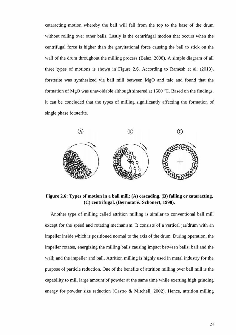
24
cataracting motion whereby the ball will fall from the top to the base of the drum
without rolling over other balls. Lastly is the centrifugal motion that occurs when the
centrifugal force is higher than the gravitational force causing the ball to stick on the
wall of the drum throughout the milling process (Balaz, 2008). A simple diagram of all
three types of motions is shown in Figure 2.6. According to Ramesh et al. (2013),
forsterite was synthesized via ball mill between MgO and talc and found that the
formation of MgO was unavoidable although sintered at 1500 oC. Based on the findings,
it can be concluded that the types of milling significantly affecting the formation of
single phase forsterite.
Figure 2.6: Types of motion in a ball mill: (A) cascading, (B) falling or cataracting,
(C) centrifugal. (Bernotat & Schonert, 1998).
Another type of milling called attrition milling is similar to conventional ball mill
except for the speed and rotating mechanism. It consists of a vertical jar/drum with an
impeller inside which is positioned normal to the axis of the drum. During operation, the
impeller rotates, energizing the milling balls causing impact between balls; ball and the
wall; and the impeller and ball. Attrition milling is highly used in metal industry for the
purpose of particle reduction. One of the benefits of attrition milling over ball mill is the
capability to mill large amount of powder at the same time while exerting high grinding
energy for powder size reduction (Castro & Mitchell, 2002). Hence, attrition milling
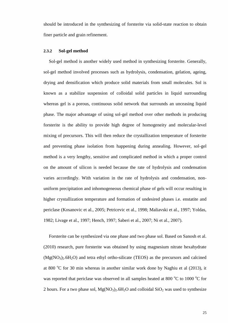
25
should be introduced in the synthesizing of forsterite via solid-state reaction to obtain
finer particle and grain refinement.
2.3.2 Sol-gel method
Sol-gel method is another widely used method in synthesizing forsterite. Generally,
sol-gel method involved processes such as hydrolysis, condensation, gelation, ageing,
drying and densification which produce solid materials from small molecules. Sol is
known as a stabilize suspension of colloidal solid particles in liquid surrounding
whereas gel is a porous, continuous solid network that surrounds an unceasing liquid
phase. The major advantage of using sol-gel method over other methods in producing
forsterite is the ability to provide high degree of homogeneity and molecular-level
mixing of precursors. This will then reduce the crystallization temperature of forsterite
and preventing phase isolation from happening during annealing. However, sol-gel
method is a very lengthy, sensitive and complicated method in which a proper control
on the amount of silicon is needed because the rate of hydrolysis and condensation
varies accordingly. With variation in the rate of hydrolysis and condensation, non-
uniform precipitation and inhomogeneous chemical phase of gels will occur resulting in
higher crystallization temperature and formation of undesired phases i.e. enstatite and
periclase (Kosanovic et al., 2005; Petricevic et al., 1998; Maliavski et al., 1997; Yoldas,
1982; Livage et al., 1997; Hench, 1997; Saberi et al., 2007; Ni et al., 2007).
Forsterite can be synthesized via one phase and two phase sol. Based on Sanosh et al.
(2010) research, pure forsterite was obtained by using magnesium nitrate hexahydrate
(Mg(NO3)2.6H2O) and tetra ethyl ortho-silicate (TEOS) as the precursors and calcined
at 800 oC for 30 min whereas in another similar work done by Naghiu et al (2013), it
was reported that periclase was observed in all samples heated at 800 oC to 1000
oC for
2 hours. For a two phase sol, Mg(NO3)2.6H2O and colloidal SiO2 was used to synthesize
26
forsterite (Afonina et al., 2005). Saberi et al. (2009) has produced forsterite via polymer
matrix and citrate nitrate methods by using Mg(NO3)2.6H2O, citric acid, ammonia
solution and SiO2. Upon calcination at 860 oC for 1 hour, single phase forsterite was
obtained. The collective results of some researchers using sol-gel method to produce
pure forsterite are tabulated in Table 2.4.
Surfactant-assisted sol-gel route was introduced by Hassanzadeh-Tabrizi et al. (2016)
via addition of cetyltrimethylammonium bromide (CTAB) as surfactant into the starting
precursors of TEOS and Mg(NO3)2.6H2O. The gel was heated at 400 oC to 900
oC for 3
hours in air with two different amounts of CTAB added (3 and 6 g). From Figure 2.7,
phase pure forsterite was obtained upon heating at 700 oC with no significant effect by
CTAB on forsterite phase formation. Nevertheless, the required temperature to formed
phase pure forsterite powder is lower than that of solid-state method. This is due to the
finer crystallite size of powder and molecular mixing of starting precursors. Further
increasing the heating temperature would only decrease the broadening of the peaks but
with higher peak intensities (Hassanzadeh-Tabrizi et al., 2016).
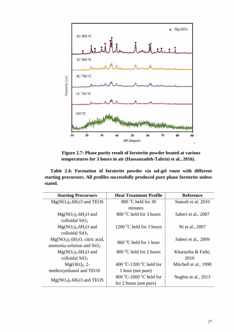
27
Figure 2.7: Phase purity result of forsterite powder heated at various
temperatures for 3 hours in air (Hassanzadeh-Tabrizi et al., 2016).
Table 2.4: Formation of forsterite powder via sol-gel route with different
starting precursors. All profiles successfully produced pure phase forsterite unless
stated.
Starting Precursors Heat Treatment Profile Reference
Mg(NO3)2.6H2O and TEOS 800 oC held for 30
minutes
Sanosh et al. 2010
Mg(NO3)2.6H2O and
colloidal SiO2
800 oC held for 3 hours Saberi et al., 2007
Mg(NO3)2.6H2O and
colloidal SiO2
1200 oC held for 3 hours Ni et al., 2007
Mg(NO3)2.6H2O, citric acid,
ammonia solution and SiO2 860
oC held for 1 hour
Saberi et al., 2009
Mg(NO3)2.6H2O and
colloidal SiO2
800 oC held for 2 hours Kharaziha & Fathi,
2010
Mg(OEt)2, 2-
methoxyethanol and TEOS
400 oC-1200
oC held for
1 hour (not pure)
Mitchell et al., 1998
Mg(NO3)2.6H2O and TEOS 800
oC-1000
oC held for
for 2 hours (not pure)
Naghiu et al., 2013
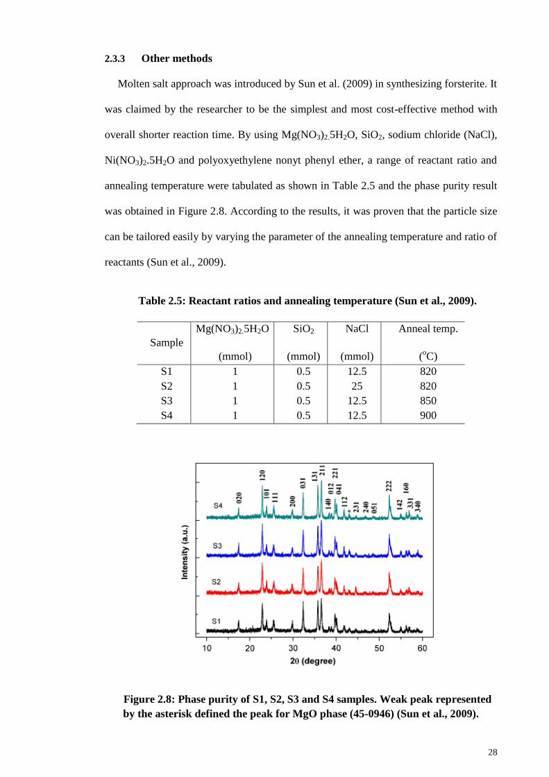
28
2.3.3 Other methods
Molten salt approach was introduced by Sun et al. (2009) in synthesizing forsterite. It
was claimed by the researcher to be the simplest and most cost-effective method with
overall shorter reaction time. By using Mg(NO3)2.5H2O, SiO2, sodium chloride (NaCl),
Ni(NO3)2.5H2O and polyoxyethylene nonyt phenyl ether, a range of reactant ratio and
annealing temperature were tabulated as shown in Table 2.5 and the phase purity result
was obtained in Figure 2.8. According to the results, it was proven that the particle size
can be tailored easily by varying the parameter of the annealing temperature and ratio of
reactants (Sun et al., 2009).
Table 2.5: Reactant ratios and annealing temperature (Sun et al., 2009).
Sample
Mg(NO3)2.5H2O
(mmol)
SiO2
(mmol)
NaCl
(mmol)
Anneal temp.
(oC)
S1 1 0.5 12.5 820
S2 1 0.5 25 820
S3 1 0.5 12.5 850
S4 1 0.5 12.5 900
Figure 2.8: Phase purity of S1, S2, S3 and S4 samples. Weak peak represented
by the asterisk defined the peak for MgO phase (45-0946) (Sun et al., 2009).
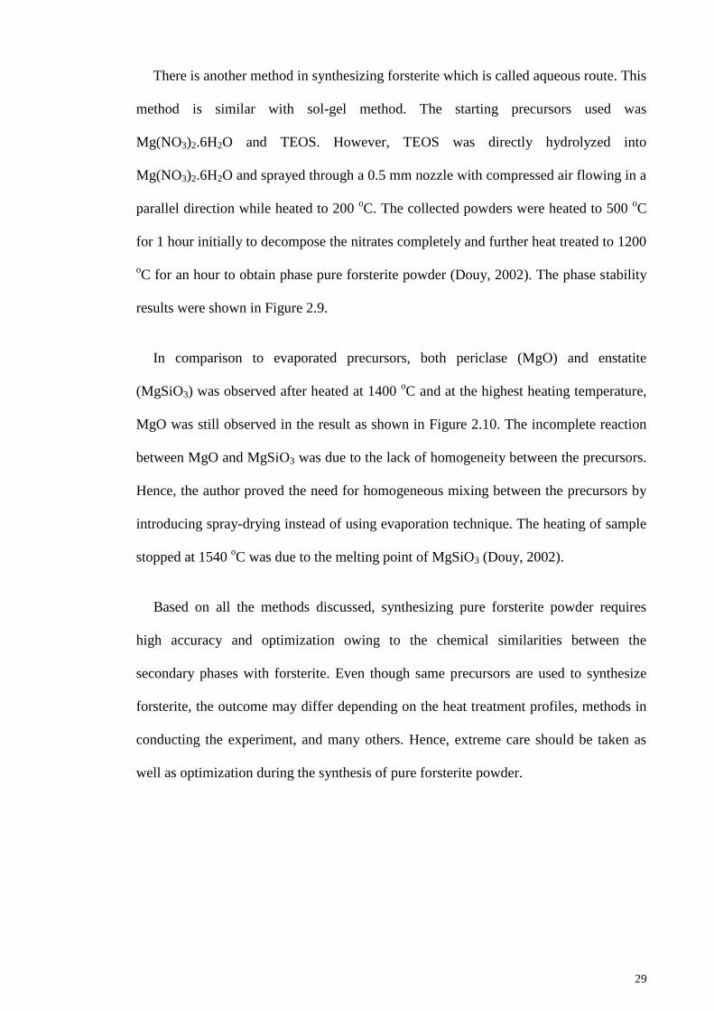
29
There is another method in synthesizing forsterite which is called aqueous route. This
method is similar with sol-gel method. The starting precursors used was
Mg(NO3)2.6H2O and TEOS. However, TEOS was directly hydrolyzed into
Mg(NO3)2.6H2O and sprayed through a 0.5 mm nozzle with compressed air flowing in a
parallel direction while heated to 200 oC. The collected powders were heated to 500
oC
for 1 hour initially to decompose the nitrates completely and further heat treated to 1200
oC for an hour to obtain phase pure forsterite powder (Douy, 2002). The phase stability
results were shown in Figure 2.9.
In comparison to evaporated precursors, both periclase (MgO) and enstatite
(MgSiO3) was observed after heated at 1400 oC and at the highest heating temperature,
MgO was still observed in the result as shown in Figure 2.10. The incomplete reaction
between MgO and MgSiO3 was due to the lack of homogeneity between the precursors.
Hence, the author proved the need for homogeneous mixing between the precursors by
introducing spray-drying instead of using evaporation technique. The heating of sample
stopped at 1540 oC was due to the melting point of MgSiO3 (Douy, 2002).
Based on all the methods discussed, synthesizing pure forsterite powder requires
high accuracy and optimization owing to the chemical similarities between the
secondary phases with forsterite. Even though same precursors are used to synthesize
forsterite, the outcome may differ depending on the heat treatment profiles, methods in
conducting the experiment, and many others. Hence, extreme care should be taken as
well as optimization during the synthesis of pure forsterite powder.
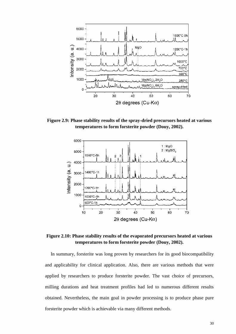
30
Figure 2.9: Phase stability results of the spray-dried precursors heated at various
temperatures to form forsterite powder (Douy, 2002).
Figure 2.10: Phase stability results of the evaporated precursors heated at various
temperatures to form forsterite powder (Douy, 2002).
In summary, forsterite was long proven by researchers for its good biocompatibility
and applicability for clinical application. Also, there are various methods that were
applied by researchers to produce forsterite powder. The vast choice of precursors,
milling durations and heat treatment profiles had led to numerous different results
obtained. Nevertheless, the main goal in powder processing is to produce phase pure
forsterite powder which is achievable via many different methods.
31
CHAPTER 3: SINTERABILITY OF FORSTERITE CERAMIC
3.1 Introduction
Sintering is one of the most important processes in enhancing the mechanical
properties of ceramics. It involved the densification of the solid via firing process
typically to a temperature of 0.5 – 0.9 of the melting point. The driving force for
sintering lies on the elimination of internal surface area namely pore and consequently
increasing the density of solid. Typically, sintering can be divided into three different
stages. Initial stage begins the moment when atomic mobility is obtained and through
observation, necking is found between individual particles but with a low densification
rate. Then, intermediate stage comes with higher curvatures of the initial stage.
Densification rate is the highest at this point and usually only ~5 – 10% porosity is left.
At the final stage, grain coarsening begins by breaking the channel-like pores into
isolated and closed voids. Many obstacles were faced by researchers in removing the
leftover pores from intermediate stage due to the excessive growth of grain entrapping
the pores forming transgranular pores (Rahaman, 2003).
In order to obtain phase pure forsterite powder, heat is needed to transform the initial
reactant into the final product upon preparation. Energy, in the form of heat, will be
transferred to the reactant to react chemically into the required product according to
equation 2.1 – 2.3 in subsection 2.3.1. There are many sintering methods introduced for
past 20 years in enhancing the mechanical properties of ceramics. In the case of
forsterite ceramic, only three types of sintering (conventional sintering, two step
sintering and microwave sintering) were implemented for research. Up until now, there
are no studies done using pressure-assisted sintering as well as thorough study of
microwave sintering on forsterite. Hence, discussion on sinterability of forsterite will be
grouped into conventional and non-conventional methods.
32
3.2 Conventional method
In conventional method, forsterite will be heated and/or sintered under atmospheric
pressure with preset heating profile to provide energy either for chemical and/or
mechanical purposes.
3.2.1 Heat treatment temperature and Mg/Si ratio
For forsterite, heat treatment was deemed necessary by Kosanovic et al (2005) as it
provides energy to complete the reaction between the precursors. This claimed was
supported by another researcher that produced forsterite via solid-state reaction method
by using MgCO3 and talc as the starting precursors. The researcher milled the mixture
using planetary mill from 5 minutes to 100 hours without heat treatment to observe on
the possibility for the formation of forsterite. It was found that upon milling up to 5
hours, the mixture transformed into an amorphous state with no sign of formation of
forsterite observed (Tavangarian & Emadi, 2009).
Hence, the mixtures were then annealed at 1000 oC and 1200
oC for 1 hour to
investigate on the formation of forsterite phase. The XRD traces are shown in Figure 3.1
and 3.2. Samples milled from 10 hours onward and annealed at 1000 oC showed pure
forsterite phase. Prolonged milling did not show any significant effect on the structure
and phase purity of forsterite. Further, for samples annealed at 1200 oC, pure forsterite
was successfully obtained upon milling for 5 hours (Tavangarian & Emadi, 2009 &
2010a). The reappearance of MgSiO3 was observed for samples milled at 80 and 100
hours. Since the enstatite phase at 1200 oC is meta-stable, forsterite was formed instead
owing to its more negative free energy change than enstatite. Nonetheless, as the milling
increases, faster kinetic was experienced by the mixture thus reforming the enstatite
phase which was known to be stable up to 1600 oC (Tavangarian & Emadi, 2009;
Kazakos, et al., 1990). It can be deduced that higher heat treatment temperature can
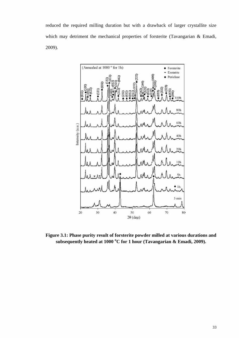
33
reduced the required milling duration but with a drawback of larger crystallite size
which may detriment the mechanical properties of forsterite (Tavangarian & Emadi,
2009).
Figure 3.1: Phase purity result of forsterite powder milled at various durations and
subsequently heated at 1000 oC for 1 hour (Tavangarian & Emadi, 2009).
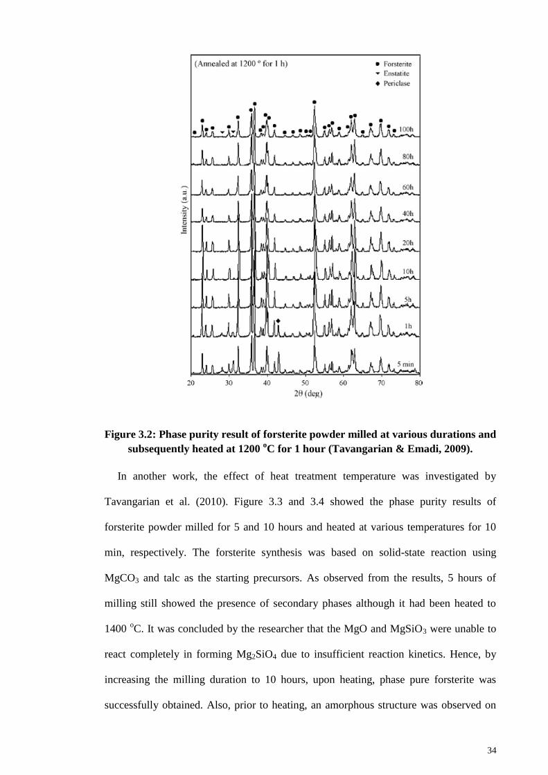
34
Figure 3.2: Phase purity result of forsterite powder milled at various durations and
subsequently heated at 1200 oC for 1 hour (Tavangarian & Emadi, 2009).
In another work, the effect of heat treatment temperature was investigated by
Tavangarian et al. (2010). Figure 3.3 and 3.4 showed the phase purity results of
forsterite powder milled for 5 and 10 hours and heated at various temperatures for 10
min, respectively. The forsterite synthesis was based on solid-state reaction using
MgCO3 and talc as the starting precursors. As observed from the results, 5 hours of
milling still showed the presence of secondary phases although it had been heated to
1400 oC. It was concluded by the researcher that the MgO and MgSiO3 were unable to
react completely in forming Mg2SiO4 due to insufficient reaction kinetics. Hence, by
increasing the milling duration to 10 hours, upon heating, phase pure forsterite was
successfully obtained. Also, prior to heating, an amorphous structure was observed on
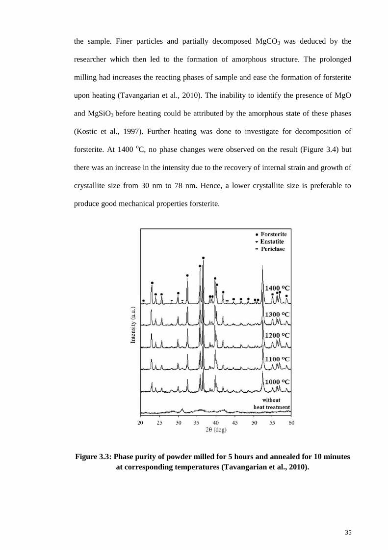
35
the sample. Finer particles and partially decomposed MgCO3 was deduced by the
researcher which then led to the formation of amorphous structure. The prolonged
milling had increases the reacting phases of sample and ease the formation of forsterite
upon heating (Tavangarian et al., 2010). The inability to identify the presence of MgO
and MgSiO3 before heating could be attributed by the amorphous state of these phases
(Kostic et al., 1997). Further heating was done to investigate for decomposition of
forsterite. At 1400 oC, no phase changes were observed on the result (Figure 3.4) but
there was an increase in the intensity due to the recovery of internal strain and growth of
crystallite size from 30 nm to 78 nm. Hence, a lower crystallite size is preferable to
produce good mechanical properties forsterite.
Figure 3.3: Phase purity of powder milled for 5 hours and annealed for 10 minutes
at corresponding temperatures (Tavangarian et al., 2010).
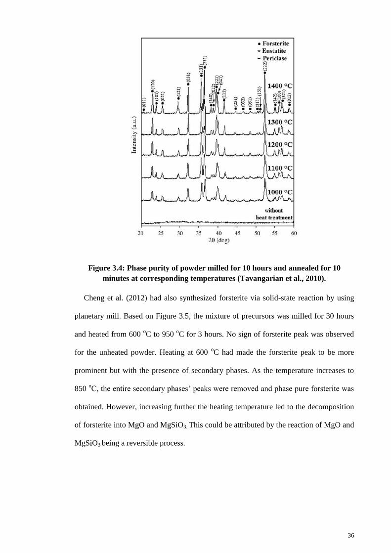
36
Figure 3.4: Phase purity of powder milled for 10 hours and annealed for 10
minutes at corresponding temperatures (Tavangarian et al., 2010).
Cheng et al. (2012) had also synthesized forsterite via solid-state reaction by using
planetary mill. Based on Figure 3.5, the mixture of precursors was milled for 30 hours
and heated from 600 oC to 950
oC for 3 hours. No sign of forsterite peak was observed
for the unheated powder. Heating at 600 oC had made the forsterite peak to be more
prominent but with the presence of secondary phases. As the temperature increases to
850 oC, the entire secondary phases’ peaks were removed and phase pure forsterite was
obtained. However, increasing further the heating temperature led to the decomposition
of forsterite into MgO and MgSiO3. This could be attributed by the reaction of MgO and
MgSiO3 being a reversible process.
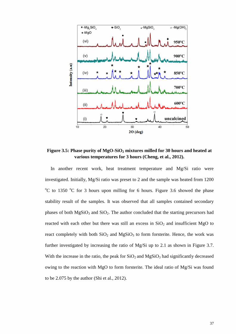
37
Figure 3.5: Phase purity of MgO-SiO2 mixtures milled for 30 hours and heated at
various temperatures for 3 hours (Cheng, et al., 2012).
In another recent work, heat treatment temperature and Mg/Si ratio were
investigated. Initially, Mg/Si ratio was preset to 2 and the sample was heated from 1200
oC to 1350
oC for 3 hours upon milling for 6 hours. Figure 3.6 showed the phase
stability result of the samples. It was observed that all samples contained secondary
phases of both MgSiO3 and SiO2. The author concluded that the starting precursors had
reacted with each other but there was still an excess in SiO2 and insufficient MgO to
react completely with both SiO2 and MgSiO3 to form forsterite. Hence, the work was
further investigated by increasing the ratio of Mg/Si up to 2.1 as shown in Figure 3.7.
With the increase in the ratio, the peak for SiO2 and MgSiO3 had significantly decreased
owing to the reaction with MgO to form forsterite. The ideal ratio of Mg/Si was found
to be 2.075 by the author (Shi et al., 2012).
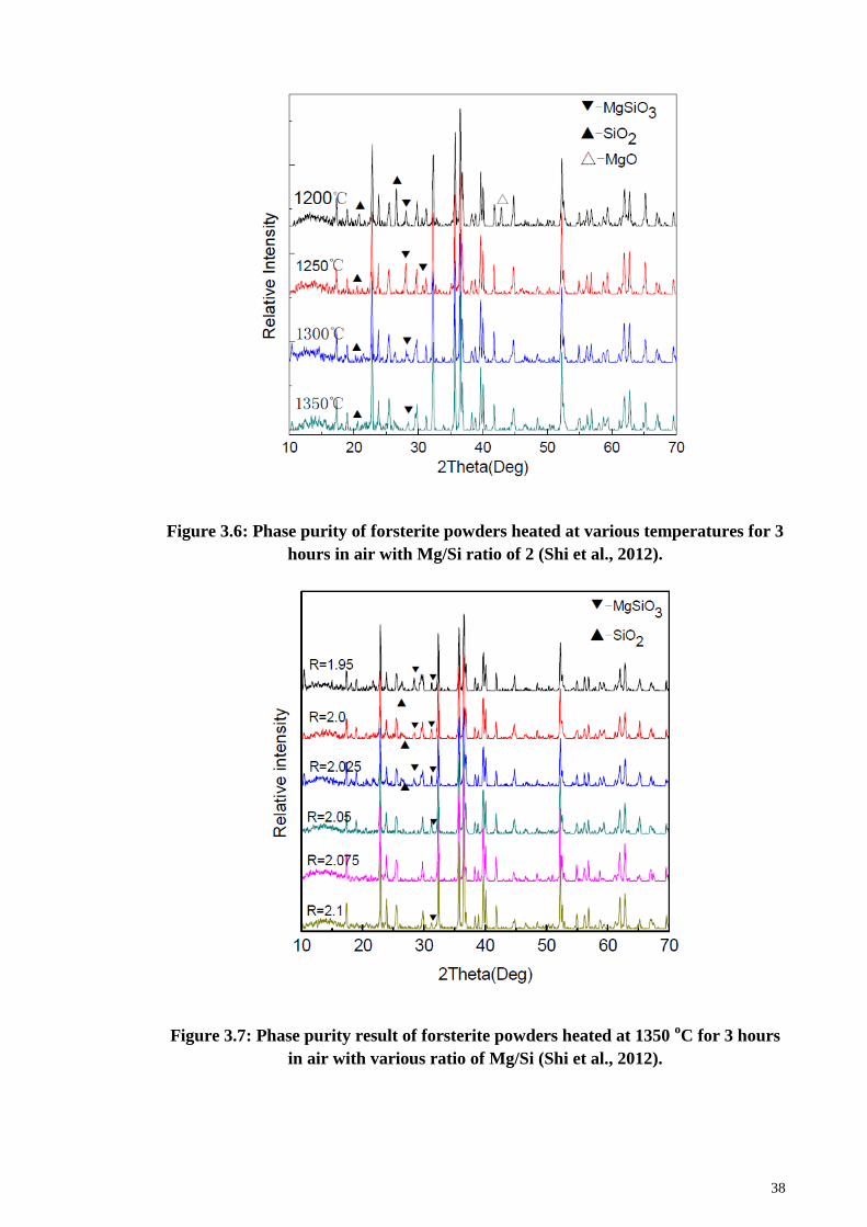
38
Figure 3.6: Phase purity of forsterite powders heated at various temperatures for 3
hours in air with Mg/Si ratio of 2 (Shi et al., 2012).
Figure 3.7: Phase purity result of forsterite powders heated at 1350 oC for 3 hours
in air with various ratio of Mg/Si (Shi et al., 2012).
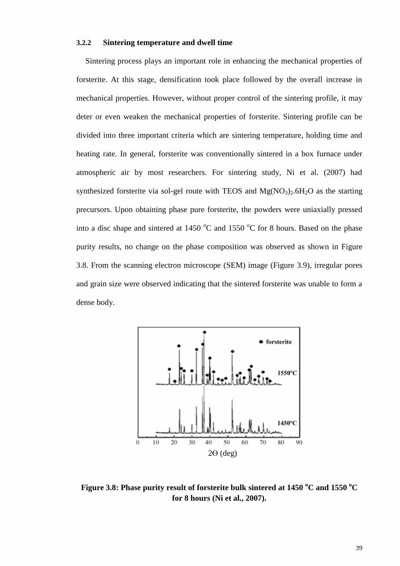
39
3.2.2 Sintering temperature and dwell time
Sintering process plays an important role in enhancing the mechanical properties of
forsterite. At this stage, densification took place followed by the overall increase in
mechanical properties. However, without proper control of the sintering profile, it may
deter or even weaken the mechanical properties of forsterite. Sintering profile can be
divided into three important criteria which are sintering temperature, holding time and
heating rate. In general, forsterite was conventionally sintered in a box furnace under
atmospheric air by most researchers. For sintering study, Ni et al. (2007) had
synthesized forsterite via sol-gel route with TEOS and Mg(NO3)2.6H2O as the starting
precursors. Upon obtaining phase pure forsterite, the powders were uniaxially pressed
into a disc shape and sintered at 1450 oC and 1550
oC for 8 hours. Based on the phase
purity results, no change on the phase composition was observed as shown in Figure
3.8. From the scanning electron microscope (SEM) image (Figure 3.9), irregular pores
and grain size were observed indicating that the sintered forsterite was unable to form a
dense body.
Figure 3.8: Phase purity result of forsterite bulk sintered at 1450 oC and 1550
oC
for 8 hours (Ni et al., 2007).
2ϴ (deg)
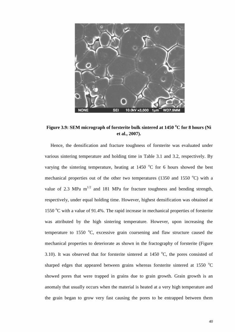
40
Figure 3.9: SEM micrograph of forsterite bulk sintered at 1450 oC for 8 hours (Ni
et al., 2007).
Hence, the densification and fracture toughness of forsterite was evaluated under
various sintering temperature and holding time in Table 3.1 and 3.2, respectively. By
varying the sintering temperature, heating at 1450 oC for 6 hours showed the best
mechanical properties out of the other two temperatures (1350 and 1550 oC) with a
value of 2.3 MPa m1/2
and 181 MPa for fracture toughness and bending strength,
respectively, under equal holding time. However, highest densification was obtained at
1550 oC with a value of 91.4%. The rapid increase in mechanical properties of forsterite
was attributed by the high sintering temperature. However, upon increasing the
temperature to 1550 oC, excessive grain coarsening and flaw structure caused the
mechanical properties to deteriorate as shown in the fractography of forsterite (Figure
3.10). It was observed that for forsterite sintered at 1450 oC, the pores consisted of
sharped edges that appeared between grains whereas forsterite sintered at 1550 oC
showed pores that were trapped in grains due to grain growth. Grain growth is an
anomaly that usually occurs when the material is heated at a very high temperature and
the grain began to grow very fast causing the pores to be entrapped between them
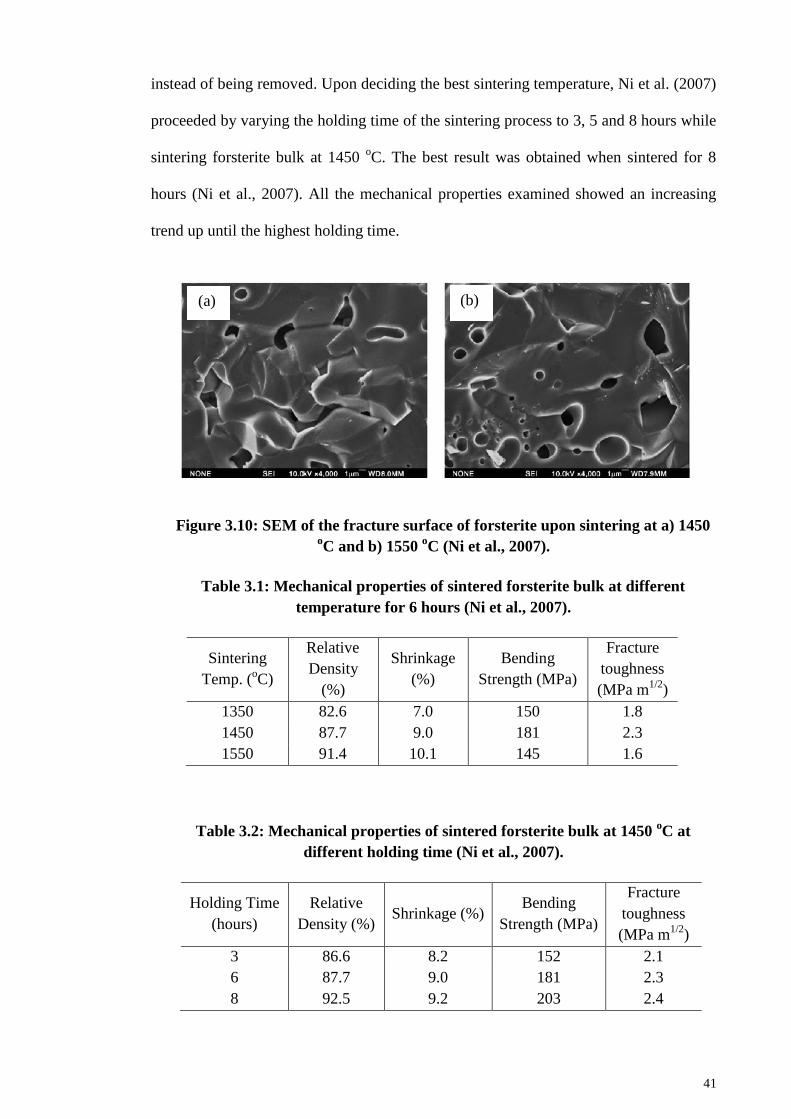
41
instead of being removed. Upon deciding the best sintering temperature, Ni et al. (2007)
proceeded by varying the holding time of the sintering process to 3, 5 and 8 hours while
sintering forsterite bulk at 1450 oC. The best result was obtained when sintered for 8
hours (Ni et al., 2007). All the mechanical properties examined showed an increasing
trend up until the highest holding time.
Figure 3.10: SEM of the fracture surface of forsterite upon sintering at a) 1450 oC and b) 1550
oC (Ni et al., 2007).
Table 3.1: Mechanical properties of sintered forsterite bulk at different
temperature for 6 hours (Ni et al., 2007).
Sintering
Temp. (oC)
Relative
Density
(%)
Shrinkage
(%)
Bending
Strength (MPa)
Fracture
toughness
(MPa m1/2
)
1350 82.6 7.0 150 1.8
1450 87.7 9.0 181 2.3
1550 91.4 10.1 145 1.6
Table 3.2: Mechanical properties of sintered forsterite bulk at 1450 oC at
different holding time (Ni et al., 2007).
Holding Time
(hours)
Relative
Density (%) Shrinkage (%)
Bending
Strength (MPa)
Fracture
toughness
(MPa m1/2
)
3 86.6 8.2 152 2.1
6 87.7 9.0 181 2.3
8 92.5 9.2 203 2.4
(a) (b)
42
In another work, Ramesh et al. (2013) had produced forsterite bulk via solid-state
reaction using MgO and talc as the starting precursors. Sintering temperature ranging
from 1200 oC until 1500
oC, held for 2 hours with ramping rate of 10
oC/min was
investigated and comparisons were done between the heat treated and non-heat treated
forsterite powders.
Figure 3.11 and 3.12 showed and the evaluation of mechanical properties of forsterite
and the phase stability result of forsterite sintered at various temperatures, respectively.
The non-heat treated samples showed superior densification compared to heat treated
samples with a maximum value of 74.4% and 90.7%, respectively. In general, all
mechanical properties of forsterite samples were enhanced as the sintering temperature
increased. However, considering the decomposition of forsterite at high temperature,
higher sintering temperature than 1500 oC was not advisable as enstatite has melting
point of 1557 oC. The author had reported that owing to the migration of MgO to the
surface of forsterite from the heat treatment, grain growth was suppressed but
densification was thwarted. Thus, non-heat treated samples experienced a drastic
increase in grain size upon heated at 1500 oC with high hardness and fracture toughness
due to the high relative density and low concentration of MgO (Ramesh et al., 2013).
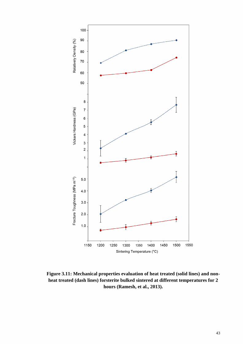
43
Figure 3.11: Mechanical properties evaluation of heat treated (solid lines) and non-
heat treated (dash lines) forsterite bulked sintered at different temperatures for 2
hours (Ramesh, et al., 2013).
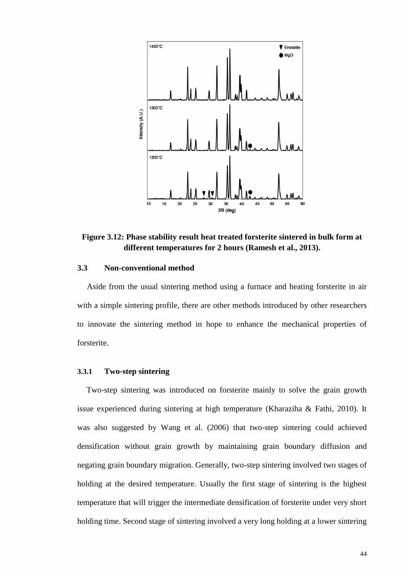
44
Figure 3.12: Phase stability result heat treated forsterite sintered in bulk form at
different temperatures for 2 hours (Ramesh et al., 2013).
3.3 Non-conventional method
Aside from the usual sintering method using a furnace and heating forsterite in air
with a simple sintering profile, there are other methods introduced by other researchers
to innovate the sintering method in hope to enhance the mechanical properties of
forsterite.
3.3.1 Two-step sintering
Two-step sintering was introduced on forsterite mainly to solve the grain growth
issue experienced during sintering at high temperature (Kharaziha & Fathi, 2010). It
was also suggested by Wang et al. (2006) that two-step sintering could achieved
densification without grain growth by maintaining grain boundary diffusion and
negating grain boundary migration. Generally, two-step sintering involved two stages of
holding at the desired temperature. Usually the first stage of sintering is the highest
temperature that will trigger the intermediate densification of forsterite under very short
holding time. Second stage of sintering involved a very long holding at a lower sintering
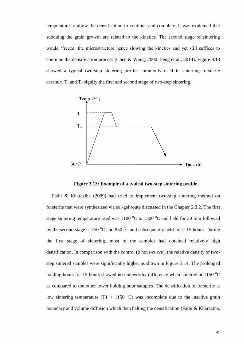
45
temperature to allow the densification to continue and complete. It was explained that
subduing the grain growth are related to the kinetics. The second stage of sintering
would ‘freeze’ the microstructure hence slowing the kinetics and yet still suffices to
continue the densification process (Chen & Wang, 2000; Feng et al., 2014). Figure 3.13
showed a typical two-step sintering profile commonly used in sintering forsterite
ceramic. T1 and T2 signify the first and second stage of two-step sintering.
Figure 3.13: Example of a typical two-step sintering profile.
Fathi & Kharaziha (2009) had tried to implement two-step sintering method on
forsterite that were synthesized via sol-gel route discussed in the Chapter 2.3.2. The first
stage sintering temperature used was 1100 oC to 1300
oC and held for 30 min followed
by the second stage at 750 oC and 850
oC and subsequently held for 2-15 hours. During
the first stage of sintering, most of the samples had obtained relatively high
densification. In comparison with the control (0 hour-curve), the relative density of two-
step sintered samples were significantly higher as shown in Figure 3.14. The prolonged
holding hours for 15 hours showed no noteworthy difference when sintered at 1150 oC
as compared to the other lower holding hour samples. The densification of forsterite at
low sintering temperature (T1 < 1150 oC) was incomplete due to the inactive grain
boundary and volume diffusion which then halting the densification (Fathi & Kharaziha,
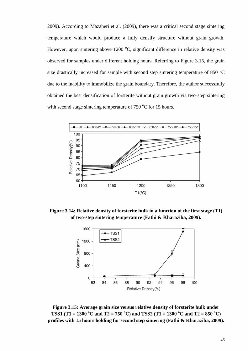
46
2009). According to Mazaheri et al. (2009), there was a critical second stage sintering
temperature which would produce a fully densify structure without grain growth.
However, upon sintering above 1200 oC, significant difference in relative density was
observed for samples under different holding hours. Referring to Figure 3.15, the grain
size drastically increased for sample with second step sintering temperature of 850 oC
due to the inability to immobilize the grain boundary. Therefore, the author successfully
obtained the best densification of forsterite without grain growth via two-step sintering
with second stage sintering temperature of 750 oC for 15 hours.
Figure 3.14: Relative density of forsterite bulk in a function of the first stage (T1)
of two-step sintering temperature (Fathi & Kharaziha, 2009).
Figure 3.15: Average grain size versus relative density of forsterite bulk under
TSS1 (T1 = 1300 oC and T2 = 750
oC) and TSS2 (T1 = 1300
oC and T2 = 850
oC)
profiles with 15 hours holding for second step sintering (Fathi & Kharaziha, 2009).
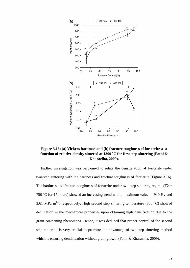
47
Figure 3.16: (a) Vickers hardness and (b) fracture toughness of forsterite as a
function of relative density sintered at 1300 oC for first step sintering (Fathi &
Kharaziha, 2009).
Further investigation was performed to relate the densification of forsterite under
two-step sintering with the hardness and fracture toughness of forsterite (Figure 3.16).
The hardness and fracture toughness of forsterite under two-step sintering regime (T2 =
750 oC for 15 hours) showed an increasing trend with a maximum value of 940 Hv and
3.61 MPa m1/2
, respectively. High second step sintering temperature (850 oC) showed
declination in the mechanical properties upon obtaining high densification due to the
grain coarsening phenomena. Hence, it was deduced that proper control of the second
step sintering is very crucial to promote the advantage of two-step sintering method
which is ensuring densification without grain growth (Fathi & Kharaziha, 2009).
48
3.3.2 Microwave sintering
3.3.2.1 Introduction
In the past years, microwave has been used extensively as an essential appliance in
kitchens. However, the usage of microwave in material processing is still a new
advancement. Microwave is widely used in the field of telecommunication via
microwave frequencies, food processing, printing materials and biomedical fields but
restricted to temperature below 500 oC. Utilizing microwave at high temperature has yet
to mature when scaling-up for industries usage. Mostly, high temperature application
uses conventional heating as it is well-established long before microwave was first
introduced (Agrawal, 2006; Thostenson and Chou, 1999). Conventional thermal
sintering involved heat transfer via conduction, convection and radiation to the surface
of material whereas microwave heating involved the change of electromagnetic to
thermal energy. With the introduction of microwave, volumetric heating and high
heating rates was found to be beneficial as it eliminates the need for a slow heating rates
to avoid thermal shock (reduce in production time) from conventional heating thus
enhancing the overall quality of material (Agrawal, 2006; Thostenson & Chou, 1999;
Yadoji et al., 2003; Zuo et al., 2013; Zuo et al., 2014). Also, selective sintering can be
accomplished using microwave by taking into account the different dielectric properties
of material. When materials in contact possess various dielectric properties, microwave
will selectively choose the higher loss material and this phenomena can be widely used
in joining of ceramics or polymer (Siores and DoRego, 1995). The notable advantage of
microwave makes it an interesting method for new discoveries in the field of ceramic
especially in sintering regime.
Microwave sintering for ceramics is a rather new to industry as it can hardly
accommodate large amount of production. However, researchers have begun venturing
into this field in hope to produce nanostructured ceramic which is known to exhibit

49
superior mechanical properties compared to standard materials (Agrawal, 2006; Bian et
al., 2013). As discussed in the previous sections, many researchers had experienced
grain coarsening and grain growth due to elevated sintering temperature above certain
limit. Hence, Fathi & Kharaziha (2009) had introduced two-step sintering onto forsterite
to solve the issue. However, the drawback of two-step sintering is the lengthy duration
required to complete the sintering (> 15 hours). Thus, microwave is the alternate option
used to produce nanostructured forsterite with minimal grain growth. Owing to the high
heating rates as well as volumetric heating of microwave sintering, dense ceramics can
be produced while maintaining its nanostructured morphology (Thuault et al., 2014).
Further, the innovation of sintering method are focused on the improvement of
mechanical properties of ceramic via modification of densification as well as reduction
of fabrication time of materials (Presenda et al., 2015; Clark et al., 2004; Rybakov et al,
2013; Oghbaei & Mirzaee, 2010; Das et al., 2009).
Several important parameters are of concern during microwave sintering process.
One of the parameters is the ability for the material to couple with microwave which is
controlled by its dielectric properties. For example, zirconia has a very poor coupling
with microwave below 400 oC and moderate coupling ability above the temperature.
Hence, an early heating up to 400 oC is needed to allow the zirconia to couple with the
microwave and it was suggested that a hybrid microwave sintering is required (Monaco
et al., 2015). Silicon carbide susceptors was introduced into the hybrid microwave
sintering to provide the initial heating via conduction until the material reached its
critical temperature and began absorbing the microwave more effectively. Silicon
carbide is well-known to absorb microwave easily at room temperature thus making it a
suitable material for such purposes (Wang et al., 2006; Thostenson & Chou, 1999;
Monaco et al., 2015).
50
The next important parameter is the methods to control the temperature. Two
common methods used for controlling the temperature in the microwave furnace are
pulsating powering of the magnetron at a fixed output power (operates under time
controlled manner) and continuous powering of the magnetron under varying power
output (power-control method) (Monaco et al., 2015). First method is usually used in
the domestic oven in which a high output power was programmed on the magnetron
prematurely whereas second method is commonly found for industrial usage whereby
continuous adjustment on the output power was done to ensure the temperature
maintained, increased or decreased according to the profile. Generally, both methods
did not affect the grain growth or the densification of sample. The only difference is
second method has higher accuracy in controlling the temperature than the first method
(Yasuoka et al., 2006).
3.3.2.2 Microwave sintering on bioceramics
Recently, microwave sintering was introduced on forsterite by Bafrooei et al. (2014)
using solid-state reaction method. The initial mixtures were prepared by mixing both
silica gel and magnesium hydroxide (Mg(OH)2) using planetary milling for 40 hours.
Upon heating the mixtures under microwave irradiation, the phase purity of the powders
were examined under various temperatures. Based on Figure 3.17, the lowest tested
temperature (500 oC) showed signs of formation of forsterite peak and upon heating at
900 oC, pure phase forsterite was obtained. Any further heating of the powder would
lead to peak the increase in peak intensity as well as enhancement of crystallite size.
The surface area and particle size were measured accordingly and tabulated in Table
3.3. The increased in surface area until 900 oC was due to rapid decomposition and
appearance of stresses which then led to particle decomposition. Nonetheless, further
heating after 900 oC showed the decrease in surface area which can be simply due to
grain growth (Bafrooei et al., 2014).
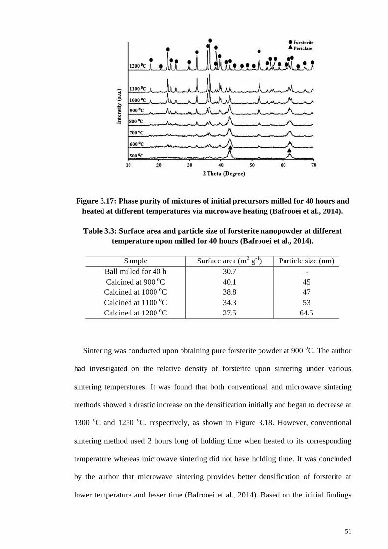
51
Figure 3.17: Phase purity of mixtures of initial precursors milled for 40 hours and
heated at different temperatures via microwave heating (Bafrooei et al., 2014).
Table 3.3: Surface area and particle size of forsterite nanopowder at different
temperature upon milled for 40 hours (Bafrooei et al., 2014).
Sample Surface area (m2 g
-1) Particle size (nm)
Ball milled for 40 h 30.7 -
Calcined at 900 oC 40.1 45
Calcined at 1000 oC 38.8 47
Calcined at 1100 oC 34.3 53
Calcined at 1200 oC 27.5 64.5
Sintering was conducted upon obtaining pure forsterite powder at 900 oC. The author
had investigated on the relative density of forsterite upon sintering under various
sintering temperatures. It was found that both conventional and microwave sintering
methods showed a drastic increase on the densification initially and began to decrease at
1300 oC and 1250
oC, respectively, as shown in Figure 3.18. However, conventional
sintering method used 2 hours long of holding time when heated to its corresponding
temperature whereas microwave sintering did not have holding time. It was concluded
by the author that microwave sintering provides better densification of forsterite at
lower temperature and lesser time (Bafrooei et al., 2014). Based on the initial findings
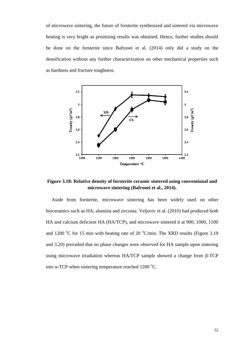
52
of microwave sintering, the future of forsterite synthesized and sintered via microwave
heating is very bright as promising results was obtained. Hence, further studies should
be done on the forsterite since Bafrooei et al. (2014) only did a study on the
densification without any further characterization on other mechanical properties such
as hardness and fracture toughness.
Figure 3.18: Relative density of forsterite ceramic sintered using conventional and
microwave sintering (Bafrooei et al., 2014).
Aside from forsterite, microwave sintering has been widely used on other
bioceramics such as HA, alumina and zirconia. Veljovic et al. (2010) had produced both
HA and calcium deficient HA (HA/TCP), and microwave sintered it at 900, 1000, 1100
and 1200 oC for 15 min with heating rate of 20
oC/min. The XRD results (Figure 3.19
and 3.20) prevailed that no phase changes were observed for HA sample upon sintering
using microwave irradiation whereas HA/TCP sample showed a change from β-TCP
into α-TCP when sintering temperature reached 1200 oC.
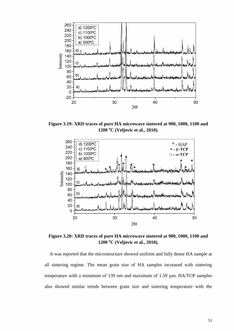
53
Figure 3.19: XRD traces of pure HA microwave sintered at 900, 1000, 1100 and
1200 oC (Veljovic et al., 2010).
Figure 3.20: XRD traces of pure HA microwave sintered at 900, 1000, 1100 and
1200 oC (Veljovic et al., 2010).
It was reported that the microstructure showed uniform and fully dense HA sample at
all sintering regime. The mean grain size of HA samples increased with sintering
temperature with a minimum of 139 nm and maximum of 1.59 µm. HA/TCP samples
also showed similar trends between grain size and sintering temperature with the
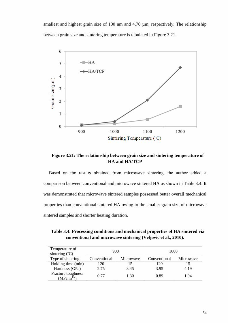
54
smallest and highest grain size of 100 nm and 4.70 µm, respectively. The relationship
between grain size and sintering temperature is tabulated in Figure 3.21.
Figure 3.21: The relationship between grain size and sintering temperature of
HA and HA/TCP
Based on the results obtained from microwave sintering, the author added a
comparison between conventional and microwave sintered HA as shown in Table 3.4. It
was demonstrated that microwave sintered samples possessed better overall mechanical
properties than conventional sintered HA owing to the smaller grain size of microwave
sintered samples and shorter heating duration.
Table 3.4: Processing conditions and mechanical properties of HA sintered via
conventional and microwave sintering (Veljovic et al., 2010).
Temperature of
sintering (oC)
900 1000
Type of sintering Conventional Microwave Conventional Microwave
Holding time (min) 120 15 120 15
Hardness (GPa) 2.75 3.45 3.95 4.19
Fracture toughness
(MPa m1/2
) 0.77 1.30 0.89 1.04
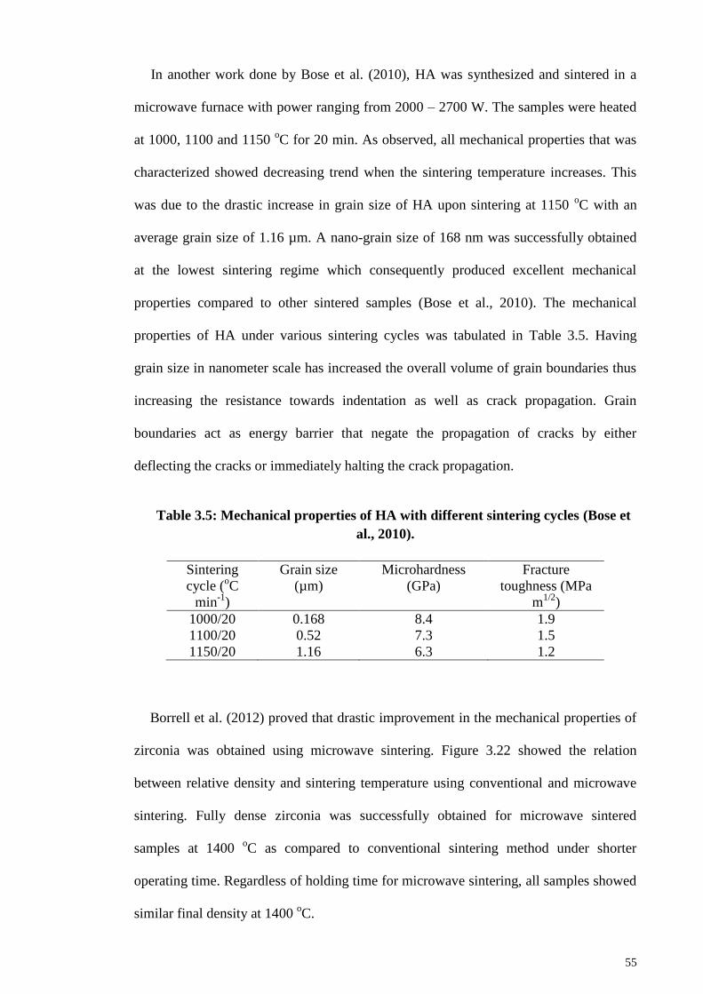
55
In another work done by Bose et al. (2010), HA was synthesized and sintered in a
microwave furnace with power ranging from 2000 – 2700 W. The samples were heated
at 1000, 1100 and 1150 oC for 20 min. As observed, all mechanical properties that was
characterized showed decreasing trend when the sintering temperature increases. This
was due to the drastic increase in grain size of HA upon sintering at 1150 oC with an
average grain size of 1.16 µm. A nano-grain size of 168 nm was successfully obtained
at the lowest sintering regime which consequently produced excellent mechanical
properties compared to other sintered samples (Bose et al., 2010). The mechanical
properties of HA under various sintering cycles was tabulated in Table 3.5. Having
grain size in nanometer scale has increased the overall volume of grain boundaries thus
increasing the resistance towards indentation as well as crack propagation. Grain
boundaries act as energy barrier that negate the propagation of cracks by either
deflecting the cracks or immediately halting the crack propagation.
Table 3.5: Mechanical properties of HA with different sintering cycles (Bose et
al., 2010).
Sintering
cycle (oC
min-1
)
Grain size
(µm)
Microhardness
(GPa)
Fracture
toughness (MPa
m1/2
)
1000/20 0.168 8.4 1.9
1100/20 0.52 7.3 1.5
1150/20 1.16 6.3 1.2
Borrell et al. (2012) proved that drastic improvement in the mechanical properties of
zirconia was obtained using microwave sintering. Figure 3.22 showed the relation
between relative density and sintering temperature using conventional and microwave
sintering. Fully dense zirconia was successfully obtained for microwave sintered
samples at 1400 oC as compared to conventional sintering method under shorter
operating time. Regardless of holding time for microwave sintering, all samples showed
similar final density at 1400 oC.
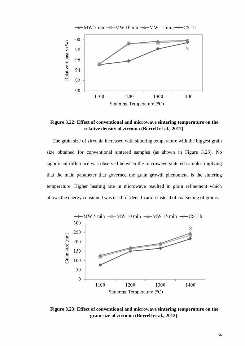
56
Figure 3.22: Effect of conventional and microwave sintering temperature on the
relative density of zirconia (Borrell et al., 2012).
The grain size of zirconia increased with sintering temperature with the biggest grain
size obtained for conventional sintered samples (as shown in Figure 3.23). No
significant difference was observed between the microwave sintered samples implying
that the main parameter that governed the grain growth phenomena is the sintering
temperature. Higher heating rate in microwave resulted in grain refinement which
allows the energy consumed was used for densification instead of coarsening of grains.
Figure 3.23: Effect of conventional and microwave sintering temperature on the
grain size of zirconia (Borrell et al., 2012).

57
The fracture toughness result obtained was not dependent on the grain size of
zirconia. Both conventional and microwave for 5 min samples showed same highest
value of fracture toughness (4.48 MPa m1/2
) at 1400 oC as seen in Figure 3.24. It was
claimed by the author that it is possible to have similar fracture toughness values
although the grain sizes of conventional and microwave sintered samples were the same
(Borrell et al., 2012).
Figure 3.24: Effect of conventional and microwave sintering temperature on the
fracture toughness of zirconia (Borrell et al., 2012).
3.4 Sintering additives on bioceramics
3.4.1 Introduction
Aside from sintering method, another technique that could contribute in improving
the mechanical properties of ceramic is by addition of sintering additives. Doping
additional chemical substance into bioceramic was widely used to improve chemical
and mechanical properties. It was found that dopant could restrict grain growth up to an
extent that nanocrystalline grains are obtained (Mukhopadhyay & Basu, 2007). Further,
it is a cost-efficient method unlike other expensive and sophisticated routes such as hot
isostatic pressing. It is important to optimize the profiling during the addition of
additives which can be divided into two major parameters i.e. types and amounts of
58
sintering additives. Nevertheless, owing that forsterite is a new emerging bioceramic,
the study on adding sintering additives to forsterite is very scarce.
3.4.2 Types of sintering additives
From literature, there are several choices of additives that were tested to further
improve sinterability without decomposition or/and decreasing bioactivity (Suchanek et
al., 1997). Each of these sintering additives will bring different effects towards the
overall properties of bioceramic. An extensive research on these additives is necessary
to optimize the profile as reported by Suchanek et al. (1997). According to the research,
K2CO3, Na2CO3, H3BO3, KF, CaCl2, KCl, KH2PO4, (KPO3)n, Na2Si2O5, Na4P2O7,
Na3PO4, (NaPO3)n, Na5P3O10 and β-NaCaPO4 were selected as the sintering additives
for HA and based on the results, it was justified that H3BO3, CaCl2, KCl, KH2PO4,
(KPO3)n, and Na2Si2O5 did not enhance the densification of HA which implied that not
every sintering additives produce positive effects (Suchanek et al., 1997).
Another research was done regarding the effect of dopant towards bioceramic by
Bose et al. (2011). An evaluation was done on the influence of MgO, SrO and SiO2 to
the bioactivity and mechanical properties of β-tricalcium phosphate (β-TCP). During the
phase analysis of these samples, a very weak sign of α-TCP was observed for samples
containing SrO/SiO2 whereas samples containing MgO showed only β-TCP (Bose et al.,
2011). It was claimed by Bose et al. (2011) that the major phases of TCP remains
unchanged although there was addition of sintering additives. Also, the combinations of
various dopants were done and the densification of TCP showed significant different
between samples which are tabulated in Table 3.6.
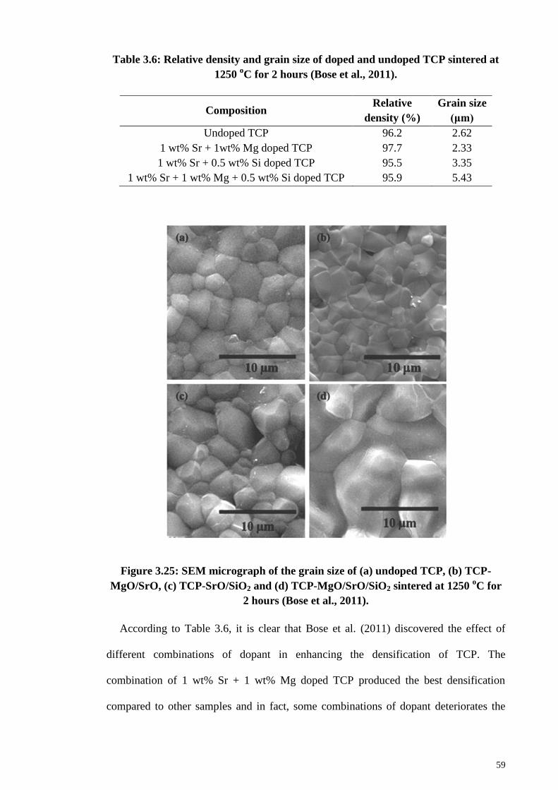
59
Table 3.6: Relative density and grain size of doped and undoped TCP sintered at
1250 oC for 2 hours (Bose et al., 2011).
Composition Relative
density (%)
Grain size
(μm)
Undoped TCP 96.2 2.62
1 wt% Sr + 1wt% Mg doped TCP 97.7 2.33
1 wt% Sr + 0.5 wt% Si doped TCP 95.5 3.35
1 wt% Sr + 1 wt% Mg + 0.5 wt% Si doped TCP 95.9 5.43
Figure 3.25: SEM micrograph of the grain size of (a) undoped TCP, (b) TCP-
MgO/SrO, (c) TCP-SrO/SiO2 and (d) TCP-MgO/SrO/SiO2 sintered at 1250 oC for
2 hours (Bose et al., 2011).
According to Table 3.6, it is clear that Bose et al. (2011) discovered the effect of
different combinations of dopant in enhancing the densification of TCP. The
combination of 1 wt% Sr + 1 wt% Mg doped TCP produced the best densification
compared to other samples and in fact, some combinations of dopant deteriorates the
60
density as compared to the undoped TCP. The justification of such result was
hypothesized that the absence of α-TCP would increase the densification. Based on the
SEM image shown in Figure 3.25, the grain size of TCP doped with 1 wt% Sr and 1
wt% Mg possessed the smallest grain size among other samples (Bose et al., 2011).
3.4.3 Amount of sintering additives
In a study done by Ramesh et al. (2007), investigation was conducted on the addition
of manganese on HA. A range of 0.05 wt% until 1 wt% of manganese (Mn) was
selected with sintering profile of 950 – 1450 oC for 2 hours at a ramping rate of 10
oC/min. The densification for all samples showed similar trends as sintering temperature
increases (Figure 3.26). Upon sintering above 1000 oC, all samples showed very high
relative density (~98%). Nonetheless, all doped samples showed 99% densification
when sintered at 1100-1250 oC whereas pure HA samples only achieved a maximum of
98.9% at 1150 oC. No further densification was inspected as intergranular pores were
observed upon further sintering as shown in Figure 3.27. In regards to hardness, it was
found that 0.05 wt% of Mn possessed the highest hardness at 1000 oC as compared to
the pure and other compositions HA. All doped HA showed reduction in hardness
(Figure 3.28) as sintering temperature increases whereas pure HA showed drastic
increase in hardness to a maximum of 7.21 GPa at 1050 oC and thereafter decreased
with increasing temperature (Ramesh et al., 2007). Based on this findings, it can be
concluded that the addition of Mn indeed enhanced the mechanical properties of HA but
only at certain compositions.
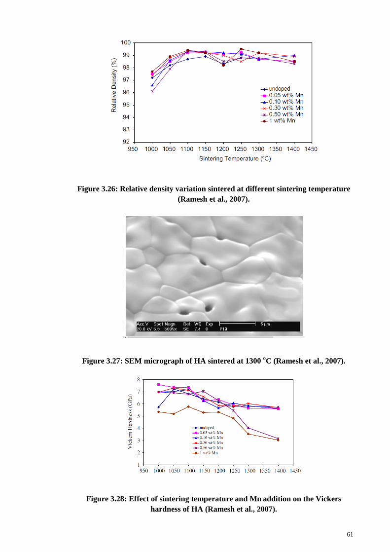
61
Figure 3.26: Relative density variation sintered at different sintering temperature
(Ramesh et al., 2007).
Figure 3.27: SEM micrograph of HA sintered at 1300 oC (Ramesh et al., 2007).
Figure 3.28: Effect of sintering temperature and Mn addition on the Vickers
hardness of HA (Ramesh et al., 2007).
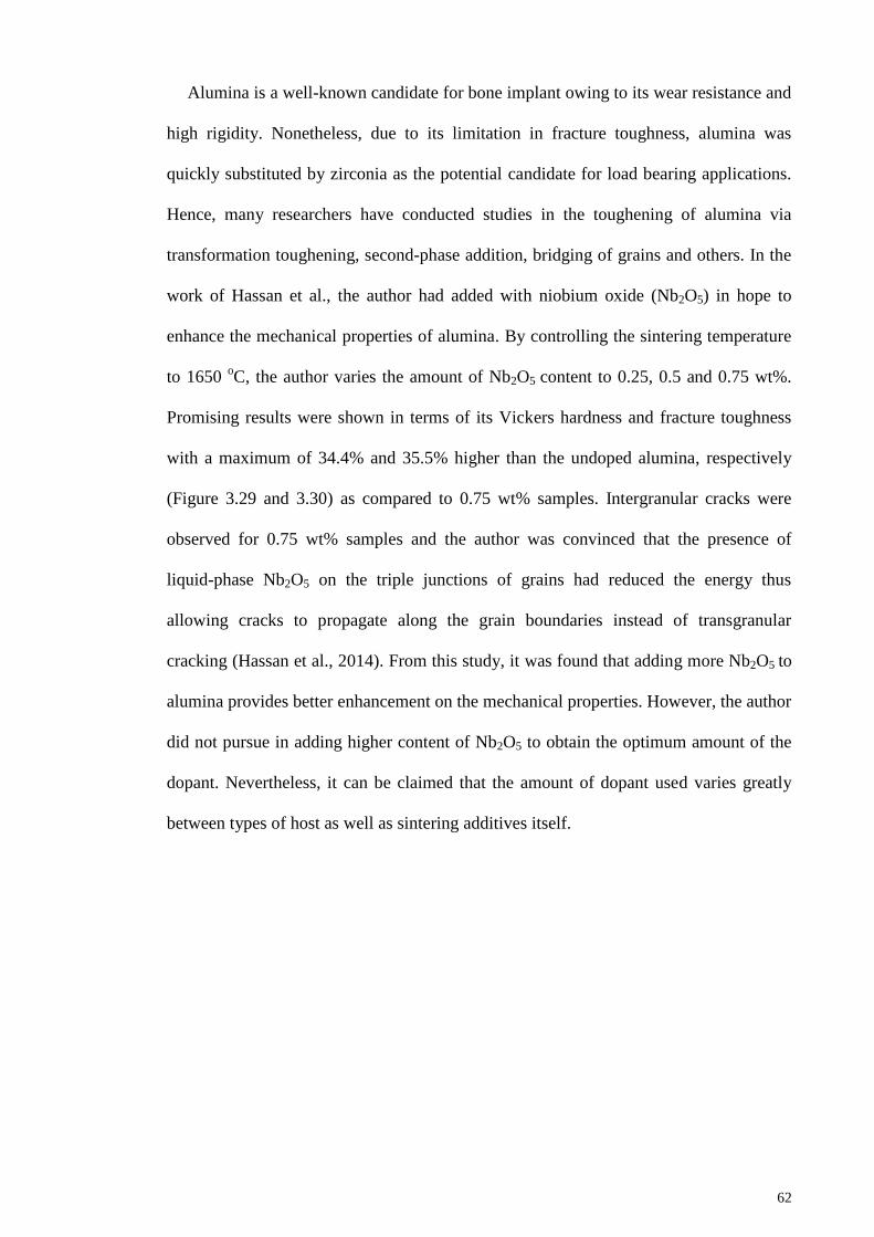
62
Alumina is a well-known candidate for bone implant owing to its wear resistance and
high rigidity. Nonetheless, due to its limitation in fracture toughness, alumina was
quickly substituted by zirconia as the potential candidate for load bearing applications.
Hence, many researchers have conducted studies in the toughening of alumina via
transformation toughening, second-phase addition, bridging of grains and others. In the
work of Hassan et al., the author had added with niobium oxide (Nb2O5) in hope to
enhance the mechanical properties of alumina. By controlling the sintering temperature
to 1650 oC, the author varies the amount of Nb2O5 content to 0.25, 0.5 and 0.75 wt%.
Promising results were shown in terms of its Vickers hardness and fracture toughness
with a maximum of 34.4% and 35.5% higher than the undoped alumina, respectively
(Figure 3.29 and 3.30) as compared to 0.75 wt% samples. Intergranular cracks were
observed for 0.75 wt% samples and the author was convinced that the presence of
liquid-phase Nb2O5 on the triple junctions of grains had reduced the energy thus
allowing cracks to propagate along the grain boundaries instead of transgranular
cracking (Hassan et al., 2014). From this study, it was found that adding more Nb2O5 to
alumina provides better enhancement on the mechanical properties. However, the author
did not pursue in adding higher content of Nb2O5 to obtain the optimum amount of the
dopant. Nevertheless, it can be claimed that the amount of dopant used varies greatly
between types of host as well as sintering additives itself.
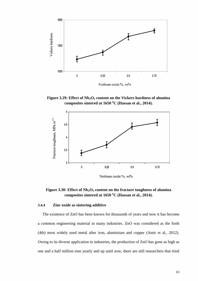
63
Figure 3.29: Effect of Nb2O5 content on the Vickers hardness of alumina
composites sintered at 1650 oC (Hassan et al., 2014).
Figure 3.30: Effect of Nb2O5 content on the fracture toughness of alumina
composites sintered at 1650 oC (Hassan et al., 2014).
3.4.4 Zinc oxide as sintering additive
The existence of ZnO has been known for thousands of years and now it has become
a common engineering material in many industries. ZnO was considered as the forth
(4th) most widely used metal after iron, aluminium and copper (Amir et al., 2012).
Owing to its diverse application in industries, the production of ZnO has gone as high as
one and a half million tons yearly and up until now, there are still researchers that tried
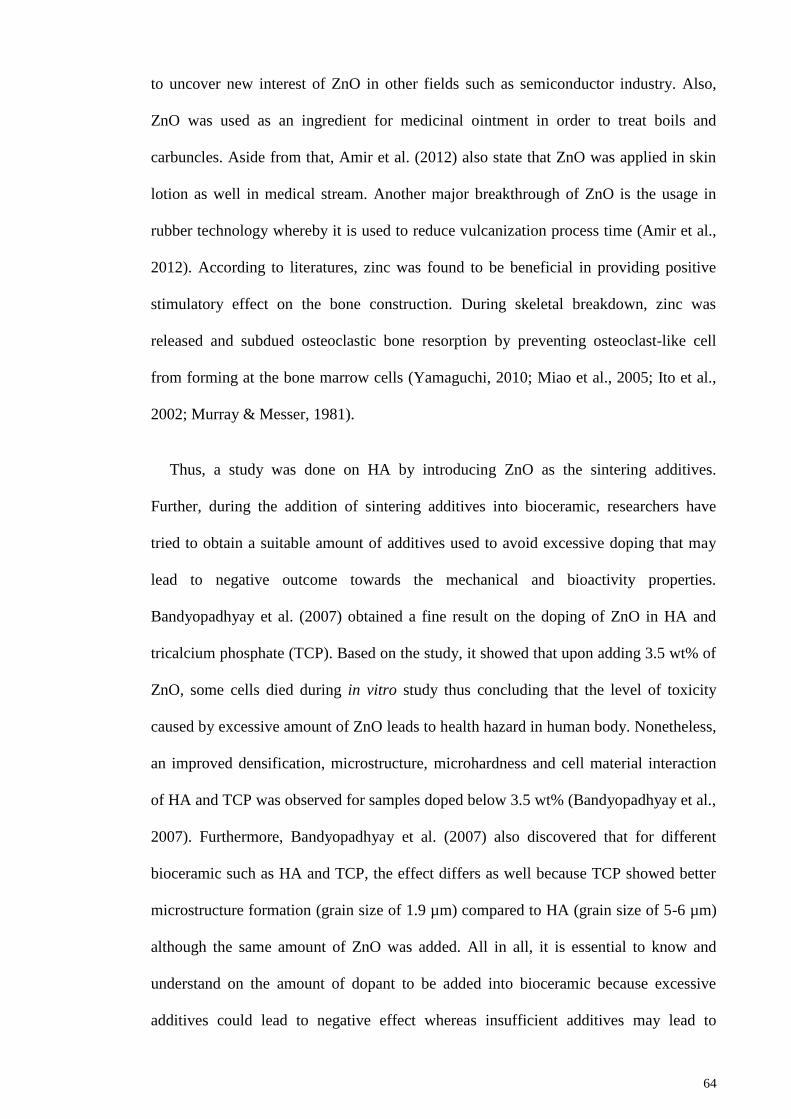
64
to uncover new interest of ZnO in other fields such as semiconductor industry. Also,
ZnO was used as an ingredient for medicinal ointment in order to treat boils and
carbuncles. Aside from that, Amir et al. (2012) also state that ZnO was applied in skin
lotion as well in medical stream. Another major breakthrough of ZnO is the usage in
rubber technology whereby it is used to reduce vulcanization process time (Amir et al.,
2012). According to literatures, zinc was found to be beneficial in providing positive
stimulatory effect on the bone construction. During skeletal breakdown, zinc was
released and subdued osteoclastic bone resorption by preventing osteoclast-like cell
from forming at the bone marrow cells (Yamaguchi, 2010; Miao et al., 2005; Ito et al.,
2002; Murray & Messer, 1981).
Thus, a study was done on HA by introducing ZnO as the sintering additives.
Further, during the addition of sintering additives into bioceramic, researchers have
tried to obtain a suitable amount of additives used to avoid excessive doping that may
lead to negative outcome towards the mechanical and bioactivity properties.
Bandyopadhyay et al. (2007) obtained a fine result on the doping of ZnO in HA and
tricalcium phosphate (TCP). Based on the study, it showed that upon adding 3.5 wt% of
ZnO, some cells died during in vitro study thus concluding that the level of toxicity
caused by excessive amount of ZnO leads to health hazard in human body. Nonetheless,
an improved densification, microstructure, microhardness and cell material interaction
of HA and TCP was observed for samples doped below 3.5 wt% (Bandyopadhyay et al.,
2007). Furthermore, Bandyopadhyay et al. (2007) also discovered that for different
bioceramic such as HA and TCP, the effect differs as well because TCP showed better
microstructure formation (grain size of 1.9 µm) compared to HA (grain size of 5-6 µm)
although the same amount of ZnO was added. All in all, it is essential to know and
understand on the amount of dopant to be added into bioceramic because excessive
additives could lead to negative effect whereas insufficient additives may lead to
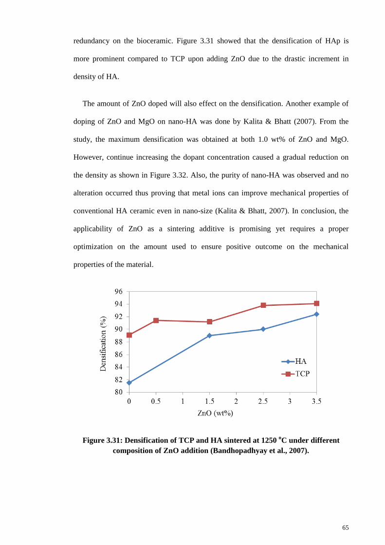
65
redundancy on the bioceramic. Figure 3.31 showed that the densification of HAp is
more prominent compared to TCP upon adding ZnO due to the drastic increment in
density of HA.
The amount of ZnO doped will also effect on the densification. Another example of
doping of ZnO and MgO on nano-HA was done by Kalita & Bhatt (2007). From the
study, the maximum densification was obtained at both 1.0 wt% of ZnO and MgO.
However, continue increasing the dopant concentration caused a gradual reduction on
the density as shown in Figure 3.32. Also, the purity of nano-HA was observed and no
alteration occurred thus proving that metal ions can improve mechanical properties of
conventional HA ceramic even in nano-size (Kalita & Bhatt, 2007). In conclusion, the
applicability of ZnO as a sintering additive is promising yet requires a proper
optimization on the amount used to ensure positive outcome on the mechanical
properties of the material.
Figure 3.31: Densification of TCP and HA sintered at 1250 oC under different
composition of ZnO addition (Bandhopadhyay et al., 2007).
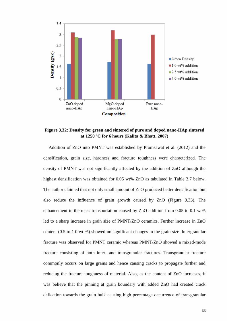
66
Figure 3.32: Density for green and sintered of pure and doped nano-HAp sintered
at 1250 oC for 6 hours (Kalita & Bhatt, 2007)
Addition of ZnO into PMNT was established by Promsawat et al. (2012) and the
densification, grain size, hardness and fracture toughness were characterized. The
density of PMNT was not significantly affected by the addition of ZnO although the
highest densification was obtained for 0.05 wt% ZnO as tabulated in Table 3.7 below.
The author claimed that not only small amount of ZnO produced better densification but
also reduce the influence of grain growth caused by ZnO (Figure 3.33). The
enhancement in the mass transportation caused by ZnO addition from 0.05 to 0.1 wt%
led to a sharp increase in grain size of PMNT/ZnO ceramics. Further increase in ZnO
content (0.5 to 1.0 wt %) showed no significant changes in the grain size. Intergranular
fracture was observed for PMNT ceramic whereas PMNT/ZnO showed a mixed-mode
fracture consisting of both inter- and transgranular fractures. Transgranular fracture
commonly occurs on large grains and hence causing cracks to propagate further and
reducing the fracture toughness of material. Also, as the content of ZnO increases, it
was believe that the pinning at grain boundary with added ZnO had created crack
deflection towards the grain bulk causing high percentage occurrence of transgranular
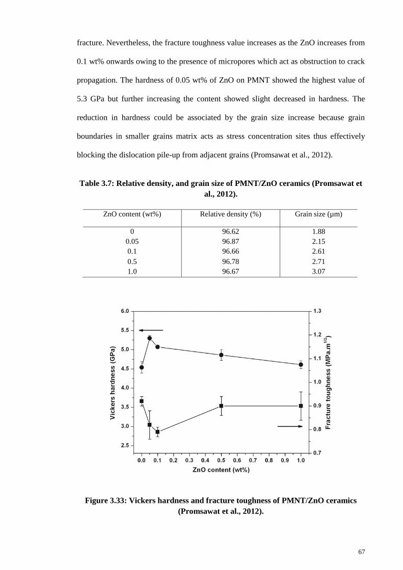
67
fracture. Nevertheless, the fracture toughness value increases as the ZnO increases from
0.1 wt% onwards owing to the presence of micropores which act as obstruction to crack
propagation. The hardness of 0.05 wt% of ZnO on PMNT showed the highest value of
5.3 GPa but further increasing the content showed slight decreased in hardness. The
reduction in hardness could be associated by the grain size increase because grain
boundaries in smaller grains matrix acts as stress concentration sites thus effectively
blocking the dislocation pile-up from adjacent grains (Promsawat et al., 2012).
Table 3.7: Relative density, and grain size of PMNT/ZnO ceramics (Promsawat et
al., 2012).
ZnO content (wt%) Relative density (%) Grain size (µm)
0 96.62 1.88
0.05 96.87 2.15
0.1 96.66 2.61
0.5 96.78 2.71
1.0 96.67 3.07
Figure 3.33: Vickers hardness and fracture toughness of PMNT/ZnO ceramics
(Promsawat et al., 2012).
68
3.4.5 Application of sintering additives on forsterite
Up to date, forsterite was commonly doped with chromium especially in the field of
optical. The development of laser materials for tunable near-IR fiber lasers and
ultrabroadband fiber-optic amplifier has gained much interest from many researchers.
As early as 1988, Petricevic et al. (1988) had explored into this field and incorporate
chromium into forsterite resulting in the success of producing one of the most widely
tunable solid-state lasers in the spectral region. However, insufficient study was
conducted to investigate on the effect of different dopant concentration to fully optimize
this groundbreaking result. Thus, Aseev et al. (2015) had continued the study by varying
the chromium concentration as well as heat treatment temperature to investigate on how
it affects the spectral luminescence properties and concluding that addition of chromium
provides small difference in terms of quantum luminescence yield.
In summary, this chapter has presented the importance of heat treatment in the
formation of phase pure forsterite. Sufficient temperature needs to be applied on
forsterite to allow a complete reaction between the precursors. The mechanical
properties of forsterite is highly dependent on the profiling and types of sintering
methods used. Many studies have been conducted on the sinterability of forsterite using
conventional method which includes regular sintering under atmospheric air with a
simple heating to the desired temperature and cooling it back to room temperature.
Two-step sintering was introduced on forsterite to elucidate the grain growth
phenomena that was experienced in all conventional sintering but undesirable in
industry due to long processing duration. Hence, microwave sintering was suggested as
the next potential sintering method that could significantly reduce the sintering hours.
Sintering additive was also introduced to forsterite as it allows enhancement in
mechanical properties of forsterite with low cost and simplicity. Attrition milling was
introduced as a new milling method to produce forsterite (solid state reaction)
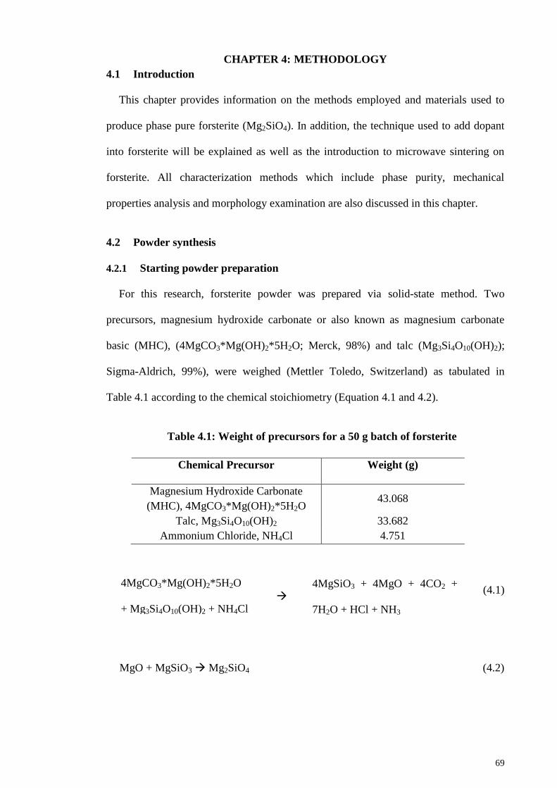
69
CHAPTER 4: METHODOLOGY
4.1 Introduction
This chapter provides information on the methods employed and materials used to
produce phase pure forsterite (Mg2SiO4). In addition, the technique used to add dopant
into forsterite will be explained as well as the introduction to microwave sintering on
forsterite. All characterization methods which include phase purity, mechanical
properties analysis and morphology examination are also discussed in this chapter.
4.2 Powder synthesis
4.2.1 Starting powder preparation
For this research, forsterite powder was prepared via solid-state method. Two
precursors, magnesium hydroxide carbonate or also known as magnesium carbonate
basic (MHC), (4MgCO3*Mg(OH)2*5H2O; Merck, 98%) and talc (Mg3Si4O10(OH)2);
Sigma-Aldrich, 99%), were weighed (Mettler Toledo, Switzerland) as tabulated in
Table 4.1 according to the chemical stoichiometry (Equation 4.1 and 4.2).
Table 4.1: Weight of precursors for a 50 g batch of forsterite
Chemical Precursor Weight (g)
Magnesium Hydroxide Carbonate
(MHC), 4MgCO3*Mg(OH)2*5H2O 43.068
Talc, Mg3Si4O10(OH)2 33.682
Ammonium Chloride, NH4Cl 4.751
(4.1)
MgO + MgSiO3 Mg2SiO4 (4.2)
4MgCO3*Mg(OH)2*5H2O
+ Mg3Si4O10(OH)2 + NH4Cl
4MgSiO3 + 4MgO + 4CO2 +
7H2O + HCl + NH3
70
A 500 ml beaker filled with 150 ml of 95% denatured, ethanol (Hamburg, Germany)
was prepared and the as-weighed MHC powder was added into the beaker before
subjecting ultrasonic pulse with 70 amps for 5 min (10s on, 1s off) with ultrasonic
vibrator (Sonics & Materials, USA). This step was taken to ensure homogeneous
mixing between the precursors by eliminating agglomeration of powder particle.
Subsequently, talc was added into the same beaker (containing ultrasonicated-MHC +
ethanol) to form mixtures of both precursors and underwent high frequency pulse again
using similar parameters for 30 min.
4.2.2 Forsterite preparation with different milling durations
The effect of milling duration on the formation of forsterite was investigated. A
conventional ball mill was used to blend the ultrasonicated powder at 350 rpm for 3 and
5 hours. The mixture was transferred into a 500 ml polypropylene bottle that served as
milling jar. Upon filling up the milling jar with the mixture, zirconia ball (Retsch) with
3 mm diameter was added into the jar as the milling media. A ball to powder weigh
ratio of 30:1 was used throughout the milling process. Ammonium chloride (NH4Cl,
Merck) was added into the milling jar at the final 10 min of the milling acting as a
catalyst. Upon completion of milling process, the mixture in the milling jar was emptied
by transferring it into a drying bowl through a sieve to separate the slurry (milled
powder) from the zirconia balls. Lab wash bottle filled with ethanol was used to flush
the residues in the milling jar and clean the zirconia balls from the slurry upon sieving
to reduce wastage of precursors. The slurry was dried in a standard box oven under
atmospheric air (Memmert, Germany) at 60 oC for 24 hours. The dried slurry was then
grounded using mortar and pestle and sieved using a metal mesh with aperture size of
212 µm to obtain it in powder form.
71
4.2.3 Forsterite preparation with attrition milling
Attritor mill (Union Process, USA) was used to grind and mix the precursors under
high grinding energy. 500 rpm was used during the milling process with 5 hours
duration. The ultrasonicated mixture was transferred into the milling jar of the attritor
mill with the aid of a funnel to ease the transferring process. Zirconia balls of 3 mm
were used as milling media with ball to powder ratio of 30:1. Similarly, at the final 10
min of milling, NH4Cl was added into the milling jar. The mixture was then dried,
grounded and sieved using a metal mesh with aperture size of 212 µm.
4.2.4 Zinc oxide (ZnO) – doped forsterite powder preparation
Upon comparing the difference between ball and attritor mill in phase stability and
mechanical properties under various sintering temperature, attritor mill was selected.
For the doping process, the powder obtained after sieving was heat treated in powder
form using a box furnace (LT Furnace, Malaysia) to form pure forsterite powder. Firing
temperature of 900 and 1000 oC with heating and cooling ramp rate of 10
oC/min and
held for 2 hours was investigated. The chemical change upon heat treatment process
was presented in equation 3.2 above. With the forsterite powder obtained through heat
treatment, ZnO powder (Systerm, Malaysia) was mixed with forsterite powder via
milling process. Three powder compositions, i.e. 0.5, 1.0 and 3.0 wt% ZnO-doped
forsterite were prepared and Table 4.2 shows the weight percentage of ZnO added to
forsterite.
For each different batches, both forsterite and ZnO powders were mixed in a 500 ml
beaker filled with 150 ml of ethanol and undergone ultrasonic pulse for 30 min (10 s
pulse on, 1 s pulse off) to ensure homogeneous mixing between the powders prior to
milling. The mixture was transferred into the milling jar containing zirconia balls of 3
mm as the milling media (ball to powder ratio of 30:1). The attritor mill was set to 500
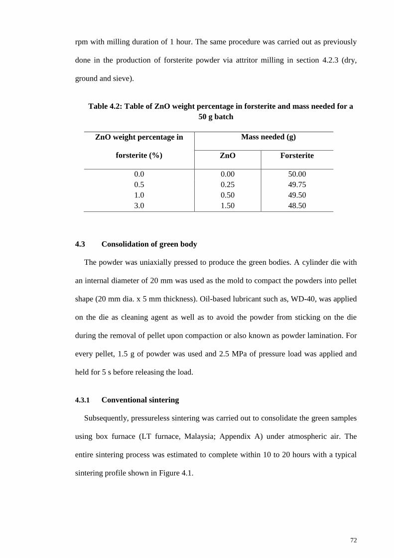
72
rpm with milling duration of 1 hour. The same procedure was carried out as previously
done in the production of forsterite powder via attritor milling in section 4.2.3 (dry,
ground and sieve).
Table 4.2: Table of ZnO weight percentage in forsterite and mass needed for a
50 g batch
ZnO weight percentage in
forsterite (%)
Mass needed (g)
ZnO Forsterite
0.0 0.00 50.00
0.5 0.25 49.75
1.0 0.50 49.50
3.0 1.50 48.50
4.3 Consolidation of green body
The powder was uniaxially pressed to produce the green bodies. A cylinder die with
an internal diameter of 20 mm was used as the mold to compact the powders into pellet
shape (20 mm dia. x 5 mm thickness). Oil-based lubricant such as, WD-40, was applied
on the die as cleaning agent as well as to avoid the powder from sticking on the die
during the removal of pellet upon compaction or also known as powder lamination. For
every pellet, 1.5 g of powder was used and 2.5 MPa of pressure load was applied and
held for 5 s before releasing the load.
4.3.1 Conventional sintering
Subsequently, pressureless sintering was carried out to consolidate the green samples
using box furnace (LT furnace, Malaysia; Appendix A) under atmospheric air. The
entire sintering process was estimated to complete within 10 to 20 hours with a typical
sintering profile shown in Figure 4.1.
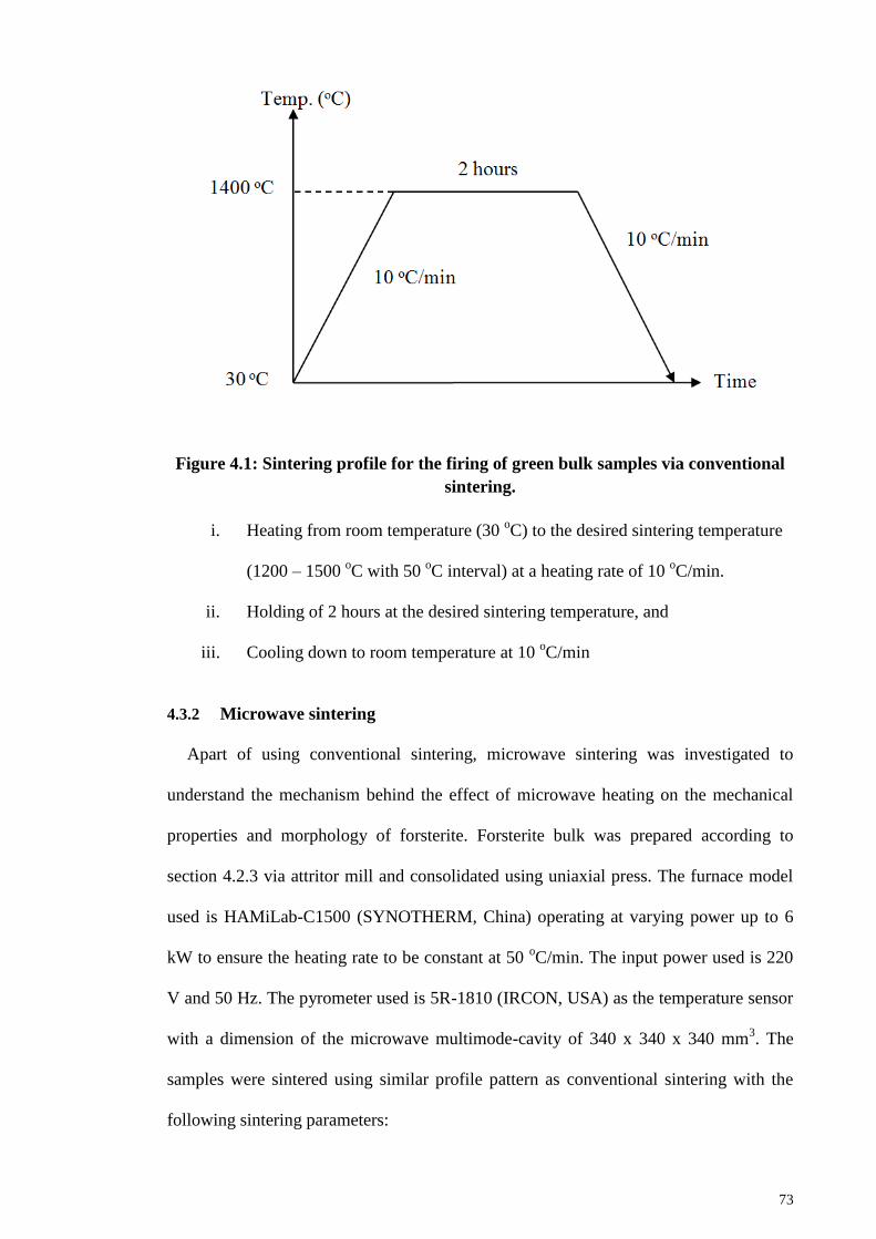
73
Figure 4.1: Sintering profile for the firing of green bulk samples via conventional
sintering.
i. Heating from room temperature (30 oC) to the desired sintering temperature
(1200 – 1500 oC with 50
oC interval) at a heating rate of 10
oC/min.
ii. Holding of 2 hours at the desired sintering temperature, and
iii. Cooling down to room temperature at 10 oC/min
4.3.2 Microwave sintering
Apart of using conventional sintering, microwave sintering was investigated to
understand the mechanism behind the effect of microwave heating on the mechanical
properties and morphology of forsterite. Forsterite bulk was prepared according to
section 4.2.3 via attritor mill and consolidated using uniaxial press. The furnace model
used is HAMiLab-C1500 (SYNOTHERM, China) operating at varying power up to 6
kW to ensure the heating rate to be constant at 50 oC/min. The input power used is 220
V and 50 Hz. The pyrometer used is 5R-1810 (IRCON, USA) as the temperature sensor
with a dimension of the microwave multimode-cavity of 340 x 340 x 340 mm3. The
samples were sintered using similar profile pattern as conventional sintering with the
following sintering parameters:
74
i. Heating from room temperature (30 oC) to the desired sintering temperature
(1100 – 1250 oC with 50
oC interval) at a heating rate of 50
oC/min.
ii. Holding of 30 min at the desired sintering temperature, and
iii. Cooling down to room temperature at 50 oC/min
Phase stability, relative density, Vickers hardness, fracture toughness and
morphology of microwave sintered samples were investigated.
4.4 Sample characterization
The characterizations of powder sample include the phase stability analysis
(including crystallite size) with X-ray Diffraction, Brunaeur-Emmett-Teller surface area
measurement, differential thermal and thermogravimetric analysis, powder morphology
using scanning electron microscopy (SEM) and particle shape and size calculation via
transmission electron microscopy (TEM).
The phase analysis and mechanical properties characterization were conducted on
forsterite bulk samples which include X-ray Diffraction, relative density, Vickers
hardness, fracture toughness and morphology examination via SEM and field-emission
scanning electron microscope (FESEM) to observe the grain patterns.
4.4.1 Phase composition analysis
Phase analysis was performed through X-ray Diffraction (XRD) analysis (Empyrean,
PANalytical, Netherlands) with parameters of 45 kV and 40 mA using Cu-Kα radiation
source. The scanning speed and step size used was 0.5 o/min and 0.02
o, respectively. By
referring to Joint Committee on Powder Diffraction Standards – International Center for
Diffraction Data (JCPDS-ICCD) reference card, each XRD traces obtained was
compared to the respective cards listed in Table 4.3 below.
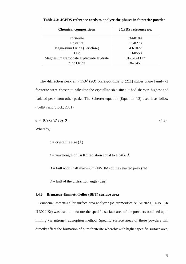
75
Table 4.3: JCPDS reference cards to analyze the phases in forsterite powder
Chemical compositions JCPDS reference no.
Forsterite 34-0189
Enstatite 11-0273
Magnesium Oxide (Periclase) 43-1022
Talc 13-0558
Magnesium Carbonate Hydroxide Hydrate 01-070-1177
Zinc Oxide 36-1451
The diffraction peak at ~ 35.6o
(2ϴ) corresponding to (211) miller plane family of
forsterite were chosen to calculate the crystallite size since it had sharper, highest and
isolated peak from other peaks. The Scherrer equation (Equation 4.3) used is as follow
(Cullity and Stock, 2001):
d = (4.3)
Whereby,
d = crystallite size (Å)
λ = wavelength of Cu Kα radiation equal to 1.5406 Å
B = Full width half maximum (FWHM) of the selected peak (rad)
ϴ = half of the diffraction angle (deg)
4.4.2 Brunaeur-Emmett-Teller (BET) surface area
Brunaeur-Emmett-Teller surface area analyzer (Micromeritics ASAP2020, TRISTAR
II 3020 Kr) was used to measure the specific surface area of the powders obtained upon
milling via nitrogen adsorption method. Specific surface areas of these powders will
directly affect the formation of pure forsterite whereby with higher specific surface area,
76
a lower sintering temperature is required to obtain pure forsterite. The powders were
degassed at 90 oC for 1 hour followed by 300
oC for 4 hours prior to analysis.
4.4.3 Differential thermal (DT) and thermogravimetric (TG) analysis
Differential thermal and thermogravimetric (Perkin Elmer, Pyris Diamond) analysis
were conducted to provide information on the weight reduction of samples upon heating
as well as to evaluate on the possible crystallization process of forsterite in obtaining a
phase-pure powder. The process was conducted under air atmosphere beginning from
70 oC until 1000
oC with heating rate of 10
oC/min. The data obtained will be plotted
into graph form to examine for any peaks that corresponded to weight lost and change
of energy occurring throughout the firing process.
4.4.4 Bulk density measurement
The methods implemented to determine the bulk density is highly accurate, non-
destructive and easy to perform. For the measurement of bulk density, Archimedes
principle was applied into the water immersion technique by using a Mettler Toledo
Balance AG204 Densi-meter (Appendix A). According to the principle, a body that is
completely submerged or partially submerged in a fluid has a buoyancy force or
resultant force acting upward with magnitude equal to the weight of water displaced by
the body. Thus, weight of sample was measured in air and when submerged in water as
well as after submerging into the water to calculate the density of sample. For non-
porous samples, the density can be measured using Equation 4.4. For porous samples
(density less than 80%) another additional equation will be used, which is shown in
Equation 4.5 and 4.6. Based on Equation 4.5 and 4.6, the inclusion on actual weight of
sample in water is due to the existence of porosity in the sample which will be
consumed by the water upon soaking it thus increasing the total weigh of sample.
Regardless of porosity, these two equations (Equation 4.5 and 4.6) can be applied for
77
non-porous samples since the values obtained differ only by a very small percentage
(~0.1%). In this research, distilled water was used as the immersion medium.
For non-porous sample,
Bulk Density, ρa = ρw * Wa / (Wa – Ww) (3.4)
Whereby,
ρa = bulk density of sample
ρw = density of distilled water used with respect to temperature (refer to
appendix A)
Wa = weight of sample in air
Ww = weight of sample in water
For porous sample,
Bulk Density, ρa = ρw * Wa / (Wa – Ww,actual) (3.5)
Ww, actual = (3.6)
Whereby,
Wa+w = weight of sample in air after soaking in water
4.4.5 Vickers hardness and fracture toughness
Prior to Vickers hardness test, both grinding and polishing of the samples were done
by using a grinder (Imtech Grinder-Polisher, Germany ; Appendix A) with silicon
carbide (SiC) paper (600, 800 and 1200 grit) as a ground to remove the roughness and
flatten the surface of the sintered sample thus refining the entire surface prior to
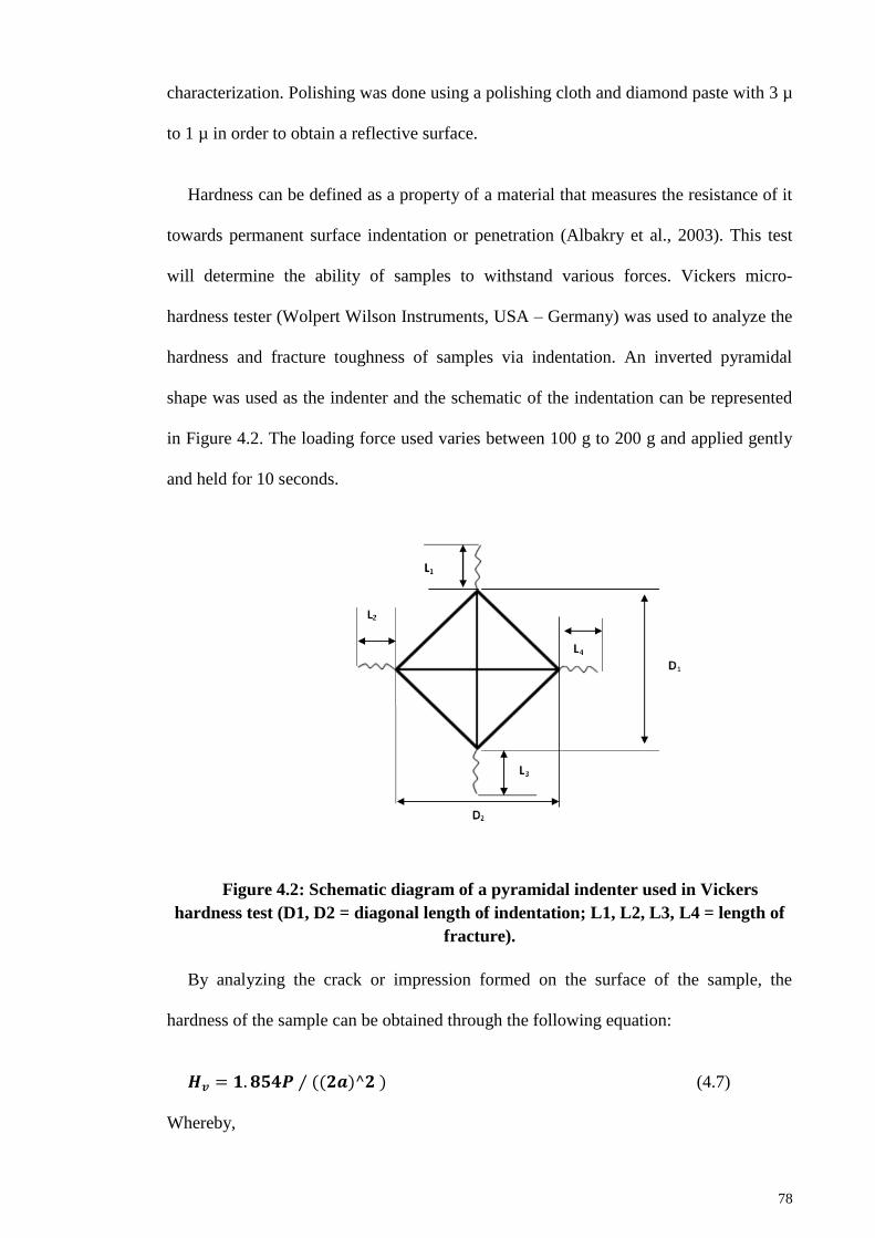
78
characterization. Polishing was done using a polishing cloth and diamond paste with 3 µ
to 1 µ in order to obtain a reflective surface.
Hardness can be defined as a property of a material that measures the resistance of it
towards permanent surface indentation or penetration (Albakry et al., 2003). This test
will determine the ability of samples to withstand various forces. Vickers micro-
hardness tester (Wolpert Wilson Instruments, USA – Germany) was used to analyze the
hardness and fracture toughness of samples via indentation. An inverted pyramidal
shape was used as the indenter and the schematic of the indentation can be represented
in Figure 4.2. The loading force used varies between 100 g to 200 g and applied gently
and held for 10 seconds.
Figure 4.2: Schematic diagram of a pyramidal indenter used in Vickers
hardness test (D1, D2 = diagonal length of indentation; L1, L2, L3, L4 = length of
fracture).
By analyzing the crack or impression formed on the surface of the sample, the
hardness of the sample can be obtained through the following equation:
(4.7)
Whereby,
79
Hv = Vickers hardness value
P = applied load
2a = average diagonal lengths =
Vickers hardness value (Hv) can be obtained through the physical size of the
indentation and based on the following ASTM E384-10e2 standard test method for
Knoop and Vickers hardness of materials. In order to increase the accuracy of the
measurement, three different points of indentations were made and the mean value was
calculated.
Fracture toughness (KIc) of forsterite samples were measured using an equation
formulated by Niihara (1985) (Equation 4.8). It is favorable to select Niihara’s method
because it is a non-destructive test which allowed the same sample to be used in
obtaining three different locations for indentations. It has been verified in the literature
that forsterite experienced Median or half-penny cracks instead of Palmqvist cracks
(Kharaziha and Fathi, 2010).
(4.8)
Whereby,
KIc = fracture toughness
c = characteristic crack length (i.e. L + a, whereby L = average of L1, L2, L3,
and L4 as depicted in Figure 4.2)
Hv = Vickers hardness value
a = half of the average diagonal length (
)
80
4.4.6 Grain size measurement
The grain size of forsterite bulk was measured on thermally etched samples via line
intercept method on the SEM images. Polished surface was required for the
measurement. In general, a test line was drawn on an A4 size SEM micrograph and the
interception of the line and grain boundaries are calculated. At least 50 grains need to be
covered by the test line and several lines are drawn before taking the average value. The
average grain size was measured based on the equation suggested by Mendelson (1969)
shown in Equation 4.9 and 4.10:
(4.9)
Whereby,
D = average grain size
L = measured average interception length over grains which was intercepted by
the line drawn (equation 3.11)
(4.10)
Whereby,
C = total length of the test line
M = magnification of the SEM micrograph
N = number of intercepts
The method used to calculate the number of intersections was according to the
Standard Test Method for Determining Average Grain Size (ASTM E112 – 10). The
calculation of the number of intercept can be interpreted as follow:
81
At the end point, if the line intercept with the grain boundary, it will be
considered as 0.5 intersection. If the line does not intersect with grain boundary,
no point will be given.
Any tangential intersection with a grain boundary is considered as 1 intersection.
Any line intersecting with triple-junction grain boundary is considered as 1.5
intersection.
This technique is restricted to certain limitations such as (Wurst and Nelson, 1972):
1. It can only be used on polycrystalline ceramics that formed a fully dense single-
phase ceramic.
2. It requires a correction factor during the grain size calculation if two-phase
microstructures were employed.
3. Huge amount of porosity and/or second phase (> 10 vol%) will greatly affect the
accuracy of the measurement.
4.4.7 Morphology and Elemental Examination
4.4.7.1 Scanning Electron Microscope (SEM)
Scanning electron microscope (ProX, Phenom) and energy dispersive x-ray
spectroscopy (EDX) were used to investigate on the morphology and elemental
composition of bulk samples. It is important to analyze the grain structure as most
mechanical behavior of ceramics is dependent to the grains. Elemental analysis was
conducted to investigate the elements found on the selected spots on the grain
structures.
Prior to SEM and EDX, the samples were grinded and polished to a mirror like
surface finished. Upon polishing, samples were thermally etched at temperature 50 oC
lower than its respective sintering temperature with holding time of 30 min and ramp
rate of 10 oC/min for heating and cooling to delineate the grain boundaries.
82
4.4.7.2 Field-emission Scanning Electron Microscope (FESEM)
Similarly to SEM, field-emission scanning electron microscope was also used to
investigate on the morphology of the bulk samples. The difference between SEM and
FESEM is FESEM produced higher resolution images for a more detailed observation.
Prior to FESEM observation, the sample was etched (according to 3.3.8) and coated
with platinum (~5 nm thickness) using JFC-1600 Auto Fine Coater, JEOL, to avoid
from charging effect by increasing the conduction on sample during FESEM operation.
4.4.7.3 Transmission Electron Microscopy (TEM)
Transmission electron microscopy (TEM, JEOL, JEM-2100F, Japan) is another
method to observe the morphology of samples with significantly higher resolution than
SEM. This method was used to examine forsterite powder’s size and shape. TEM
operates similarly as a standard microscope but operating using electrons instead of
light. With electrons acting as the source, it will travel through vacuum, concentrated
into a thin beam using electromagnetic lenses, directed to the specimen (very thin and
small area) and displayed at the viewing screen. The information of the imaging can be
extracted by understanding that darker regions in the image imply more absorption of
electrons by specimen and vice versa (Williams and Carter, 1996).
Prior to examination, the powder was suspended in ethanol and placed in an
ultrasonic bath for 30 min to disperse the powder. The suspension was dripped on a
copper grid which contained a holey carbon film and left to dry for 5 days in a dry
cabinet. The flow chart of the project is shown in Figure 4.3.
4.4.7.4 Cell morphology
In this study, MC3T3-E1 osteoblast-like cell was used for cell morphology study.
The cell attachment ability and morphology on the samples were evaluated by loading
83
the cells on the sample and incubated for 4 hours, 1 day and 3 days. The samples were
rinsed gently under phosphate buffer saline and fixed with glutaraldehyde (Sigma-
Aldrich, 3%) in sodium phosphate buffer at 4 oC for 2 hours. Then, graded series of
ethanol solutions (50%, 60%, 70%, 80%, 90% and 100%) were used to dehydrate the
samples with cell for 30 min at 4 oC. The samples were then dried in
hexamethyldisilazane (HDMS, Wako, Japan). Fixation for 30 min was done on the cell
area after adding 500 µl of HDMS. This step was repeated for three times in order to
flush away the ethanol content completely. Upon evaporation of HDMS, the samples
were gold-sputtered prior to SEM.
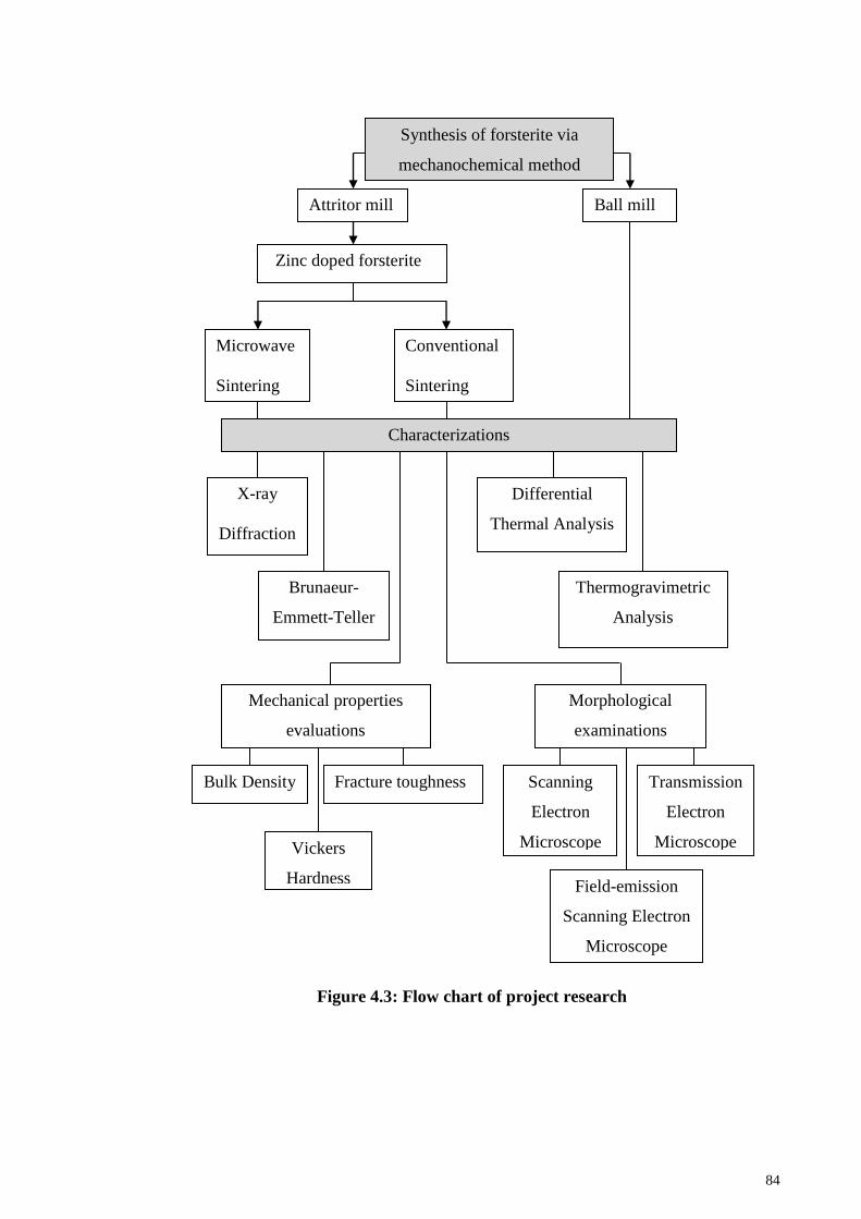
84
Figure 4.3: Flow chart of project research
Attritor mill Ball mill
Zinc doped forsterite
Microwave
Sintering
Conventional
Sintering
Synthesis of forsterite via
mechanochemical method
Characterizations
X-ray
Diffraction
Brunaeur-
Emmett-Teller
Differential
Thermal Analysis
Thermogravimetric
Analysis
Mechanical properties
evaluations
Bulk Density
Vickers
Hardness
Fracture toughness
Morphological
examinations
Scanning
Electron
Microscope
Field-emission
Scanning Electron
Microscope
Transmission
Electron
Microscope
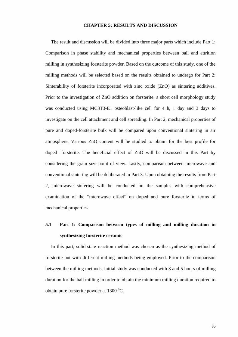
85
CHAPTER 5: RESULTS AND DISCUSSION
The result and discussion will be divided into three major parts which include Part 1:
Comparison in phase stability and mechanical properties between ball and attrition
milling in synthesizing forsterite powder. Based on the outcome of this study, one of the
milling methods will be selected based on the results obtained to undergo for Part 2:
Sinterability of forsterite incorporated with zinc oxide (ZnO) as sintering additives.
Prior to the investigation of ZnO addition on forsterite, a short cell morphology study
was conducted using MC3T3-E1 osteoblast-like cell for 4 h, 1 day and 3 days to
investigate on the cell attachment and cell spreading. In Part 2, mechanical properties of
pure and doped-forsterite bulk will be compared upon conventional sintering in air
atmosphere. Various ZnO content will be studied to obtain for the best profile for
doped- forsterite. The beneficial effect of ZnO will be discussed in this Part by
considering the grain size point of view. Lastly, comparison between microwave and
conventional sintering will be deliberated in Part 3. Upon obtaining the results from Part
2, microwave sintering will be conducted on the samples with comprehensive
examination of the “microwave effect” on doped and pure forsterite in terms of
mechanical properties.
5.1 Part 1: Comparison between types of milling and milling duration in
synthesizing forsterite ceramic
In this part, solid-state reaction method was chosen as the synthesizing method of
forsterite but with different milling methods being employed. Prior to the comparison
between the milling methods, initial study was conducted with 3 and 5 hours of milling
duration for the ball milling in order to obtain the minimum milling duration required to
obtain pure forsterite powder at 1300 oC.
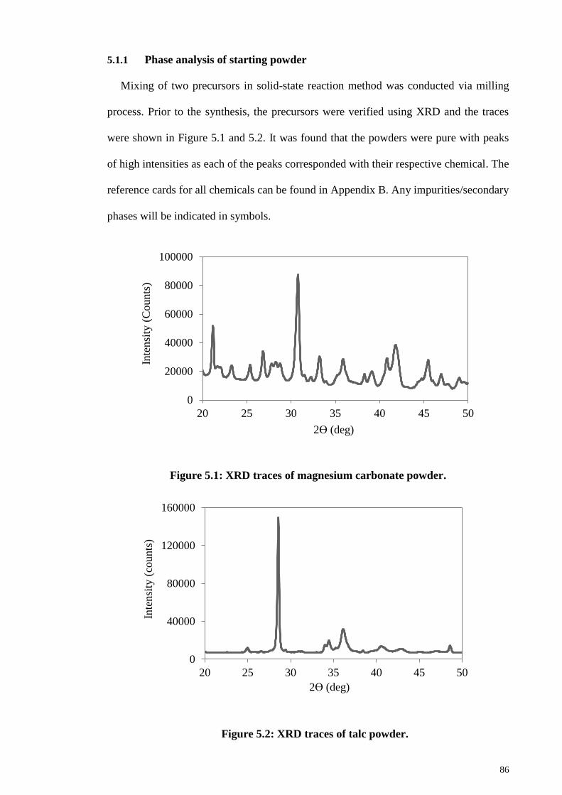
86
5.1.1 Phase analysis of starting powder
Mixing of two precursors in solid-state reaction method was conducted via milling
process. Prior to the synthesis, the precursors were verified using XRD and the traces
were shown in Figure 5.1 and 5.2. It was found that the powders were pure with peaks
of high intensities as each of the peaks corresponded with their respective chemical. The
reference cards for all chemicals can be found in Appendix B. Any impurities/secondary
phases will be indicated in symbols.
Figure 5.1: XRD traces of magnesium carbonate powder.
Figure 5.2: XRD traces of talc powder.
0
20000
40000
60000
80000
100000
20 25 30 35 40 45 50
Inte
nsi
ty (
Counts
)
2ϴ (deg)
0
40000
80000
120000
160000
20 25 30 35 40 45 50
Inte
nsi
ty (
counts
)
2ϴ (deg)
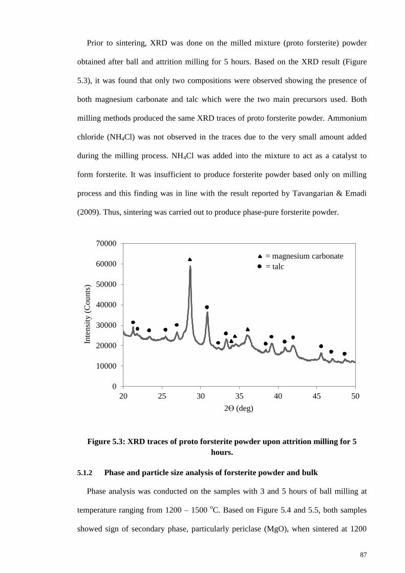
87
Prior to sintering, XRD was done on the milled mixture (proto forsterite) powder
obtained after ball and attrition milling for 5 hours. Based on the XRD result (Figure
5.3), it was found that only two compositions were observed showing the presence of
both magnesium carbonate and talc which were the two main precursors used. Both
milling methods produced the same XRD traces of proto forsterite powder. Ammonium
chloride (NH4Cl) was not observed in the traces due to the very small amount added
during the milling process. NH4Cl was added into the mixture to act as a catalyst to
form forsterite. It was insufficient to produce forsterite powder based only on milling
process and this finding was in line with the result reported by Tavangarian & Emadi
(2009). Thus, sintering was carried out to produce phase-pure forsterite powder.
Figure 5.3: XRD traces of proto forsterite powder upon attrition milling for 5
hours.
5.1.2 Phase and particle size analysis of forsterite powder and bulk
Phase analysis was conducted on the samples with 3 and 5 hours of ball milling at
temperature ranging from 1200 – 1500 oC. Based on Figure 5.4 and 5.5, both samples
showed sign of secondary phase, particularly periclase (MgO), when sintered at 1200
0
10000
20000
30000
40000
50000
60000
70000
20 25 30 35 40 45 50
Inte
nsi
ty (
Counts
)
2ϴ (deg)
= magnesium carbonate
= talc
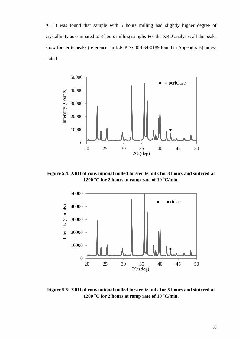
88
oC. It was found that sample with 5 hours milling had slightly higher degree of
crystallinity as compared to 3 hours milling sample. For the XRD analysis, all the peaks
show forsterite peaks (reference card: JCPDS 00-034-0189 found in Appendix B) unless
stated.
Figure 5.4: XRD of conventional milled forsterite bulk for 3 hours and sintered at
1200 oC for 2 hours at ramp rate of 10
oC/min.
Figure 5.5: XRD of conventional milled forsterite bulk for 5 hours and sintered at
1200 oC for 2 hours at ramp rate of 10
oC/min.
0
10000
20000
30000
40000
50000
20 25 30 35 40 45 50
Inte
nsi
ty (
Counts
)
2ϴ (deg)
= periclase
0
10000
20000
30000
40000
50000
20 25 30 35 40 45 50
Inte
nsi
ty (
Counts
)
2ϴ (deg)
= periclase
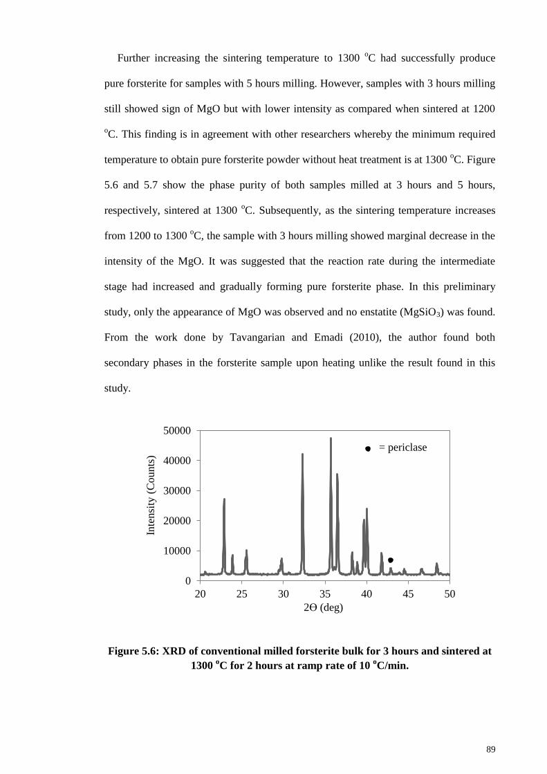
89
Further increasing the sintering temperature to 1300 oC had successfully produce
pure forsterite for samples with 5 hours milling. However, samples with 3 hours milling
still showed sign of MgO but with lower intensity as compared when sintered at 1200
oC. This finding is in agreement with other researchers whereby the minimum required
temperature to obtain pure forsterite powder without heat treatment is at 1300 oC. Figure
5.6 and 5.7 show the phase purity of both samples milled at 3 hours and 5 hours,
respectively, sintered at 1300 oC. Subsequently, as the sintering temperature increases
from 1200 to 1300 oC, the sample with 3 hours milling showed marginal decrease in the
intensity of the MgO. It was suggested that the reaction rate during the intermediate
stage had increased and gradually forming pure forsterite phase. In this preliminary
study, only the appearance of MgO was observed and no enstatite (MgSiO3) was found.
From the work done by Tavangarian and Emadi (2010), the author found both
secondary phases in the forsterite sample upon heating unlike the result found in this
study.
Figure 5.6: XRD of conventional milled forsterite bulk for 3 hours and sintered at
1300 oC for 2 hours at ramp rate of 10
oC/min.
0
10000
20000
30000
40000
50000
20 25 30 35 40 45 50
Inte
nsi
ty (
Counts
)
2ϴ (deg)
= periclase
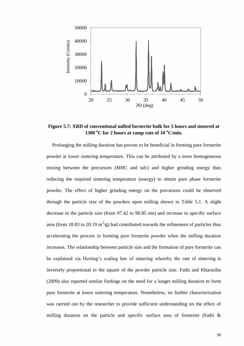
90
Figure 5.7: XRD of conventional milled forsterite bulk for 5 hours and sintered at
1300 oC for 2 hours at ramp rate of 10
oC/min.
Prolonging the milling duration has proven to be beneficial in forming pure forsterite
powder at lower sintering temperature. This can be attributed by a more homogeneous
mixing between the precursors (MHC and talc) and higher grinding energy thus
reducing the required sintering temperature (energy) to obtain pure phase forsterite
powder. The effect of higher grinding energy on the precursors could be observed
through the particle size of the powders upon milling shown in Table 5.1. A slight
decrease in the particle size (from 97.42 to 90.85 nm) and increase in specific surface
area (from 18.83 to 20.19 m2/g) had contributed towards the refinement of particles thus
accelerating the process in forming pure forsterite powder when the milling duration
increases. The relationship between particle size and the formation of pure forsterite can
be explained via Herring’s scaling law of sintering whereby the rate of sintering is
inversely proportional to the square of the powder particle size. Fathi and Kharaziha
(2009) also reported similar findings on the need for a longer milling duration to form
pure forsterite at lower sintering temperature. Nonetheless, no further characterization
was carried out by the researcher to provide sufficient understanding on the effect of
milling duration on the particle and specific surface area of forsterite (Fathi &
0
10000
20000
30000
40000
50000
20 25 30 35 40 45 50
Inte
nsi
ty (
Co
un
ts)
2ϴ (deg)
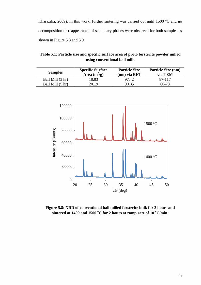
91
Kharaziha, 2009). In this work, further sintering was carried out until 1500 oC and no
decomposition or reappearance of secondary phases were observed for both samples as
shown in Figure 5.8 and 5.9.
Table 5.1: Particle size and specific surface area of proto forsterite powder milled
using conventional ball mill.
Samples Specific Surface
Area (m2/g)
Particle Size
(nm) via BET
Particle Size (nm)
via TEM
Ball Mill (3 hr) 18.83 97.42 87-117
Ball Mill (5 hr) 20.19 90.85 60-73
Figure 5.8: XRD of conventional ball milled forsterite bulk for 3 hours and
sintered at 1400 and 1500 oC for 2 hours at ramp rate of 10
oC/min.
0
20000
40000
60000
80000
100000
120000
20 25 30 35 40 45 50
Inte
nsi
ty (
Counts
)
2ϴ (deg)
1400 oC
1500 oC
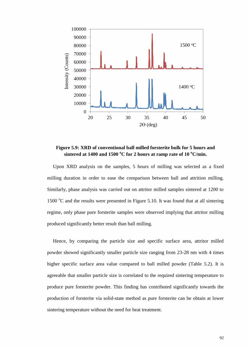
92
Figure 5.9: XRD of conventional ball milled forsterite bulk for 5 hours and
sintered at 1400 and 1500 oC for 2 hours at ramp rate of 10
oC/min.
Upon XRD analysis on the samples, 5 hours of milling was selected as a fixed
milling duration in order to ease the comparison between ball and attrition milling.
Similarly, phase analysis was carried out on attritor milled samples sintered at 1200 to
1500 oC and the results were presented in Figure 5.10. It was found that at all sintering
regime, only phase pure forsterite samples were observed implying that attritor milling
produced significantly better result than ball milling.
Hence, by comparing the particle size and specific surface area, attritor milled
powder showed significantly smaller particle size ranging from 23-28 nm with 4 times
higher specific surface area value compared to ball milled powder (Table 5.2). It is
agreeable that smaller particle size is correlated to the required sintering temperature to
produce pure forsterite powder. This finding has contributed significantly towards the
production of forsterite via solid-state method as pure forsterite can be obtain at lower
sintering temperature without the need for heat treatment.
0
10000
20000
30000
40000
50000
60000
70000
80000
90000
100000
20 25 30 35 40 45 50
Inte
nsi
ty (
Counts
)
2ϴ (deg)
1400 oC
1500 oC
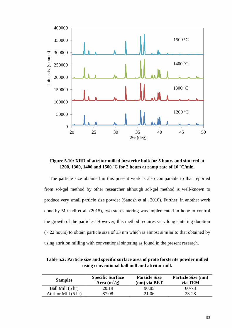
93
Figure 5.10: XRD of attritor milled forsterite bulk for 5 hours and sintered at
1200, 1300, 1400 and 1500 oC for 2 hours at ramp rate of 10
oC/min.
The particle size obtained in this present work is also comparable to that reported
from sol-gel method by other researcher although sol-gel method is well-known to
produce very small particle size powder (Sanosh et al., 2010). Further, in another work
done by Mirhadi et al. (2015), two-step sintering was implemented in hope to control
the growth of the particles. However, this method requires very long sintering duration
(~ 22 hours) to obtain particle size of 33 nm which is almost similar to that obtained by
using attrition milling with conventional sintering as found in the present research.
Table 5.2: Particle size and specific surface area of proto forsterite powder milled
using conventional ball mill and attritor mill.
Samples Specific Surface
Area (m2/g)
Particle Size
(nm) via BET
Particle Size (nm)
via TEM
Ball Mill (5 hr) 20.19 90.85 60-73
Attritor Mill (5 hr) 87.08 21.06 23-28
0
50000
100000
150000
200000
250000
300000
350000
400000
20 25 30 35 40 45 50
Inte
nsi
ty (
Counts
)
2ϴ (deg)
1200 oC
1300 oC
1400 oC
1500 oC
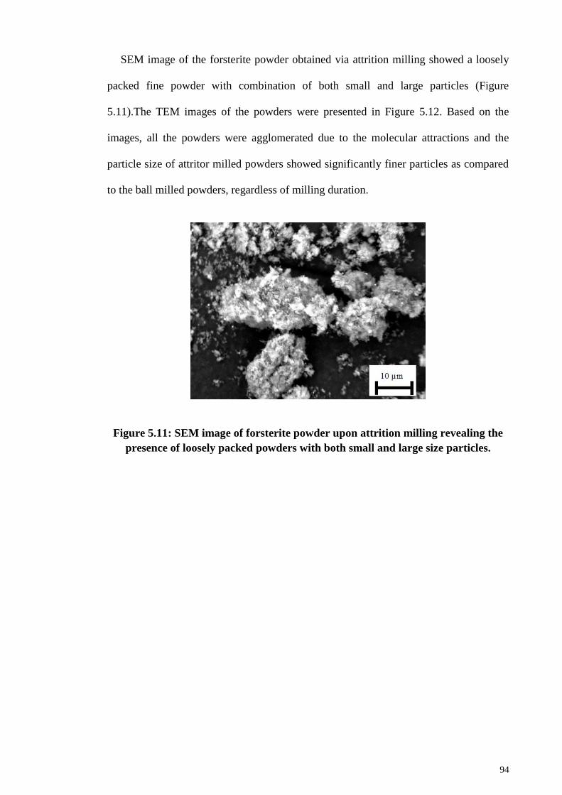
94
SEM image of the forsterite powder obtained via attrition milling showed a loosely
packed fine powder with combination of both small and large particles (Figure
5.11).The TEM images of the powders were presented in Figure 5.12. Based on the
images, all the powders were agglomerated due to the molecular attractions and the
particle size of attritor milled powders showed significantly finer particles as compared
to the ball milled powders, regardless of milling duration.
Figure 5.11: SEM image of forsterite powder upon attrition milling revealing the
presence of loosely packed powders with both small and large size particles.
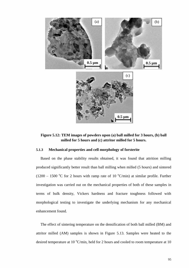
95
Figure 5.12: TEM images of powders upon (a) ball milled for 3 hours, (b) ball
milled for 5 hours and (c) attritor milled for 5 hours.
5.1.3 Mechanical properties and cell morphology of forsterite
Based on the phase stability results obtained, it was found that attrition milling
produced significantly better result than ball milling when milled (5 hours) and sintered
(1200 – 1500 oC for 2 hours with ramp rate of 10
oC/min) at similar profile. Further
investigation was carried out on the mechanical properties of both of these samples in
terms of bulk density, Vickers hardness and fracture toughness followed with
morphological testing to investigate the underlying mechanism for any mechanical
enhancement found.
The effect of sintering temperature on the densification of both ball milled (BM) and
attritor milled (AM) samples is shown in Figure 5.13. Samples were heated to the
desired temperature at 10 oC/min, held for 2 hours and cooled to room temperature at 10
0.5 µm 0.5 µm
0.5 µm
(a) (b)
(c)
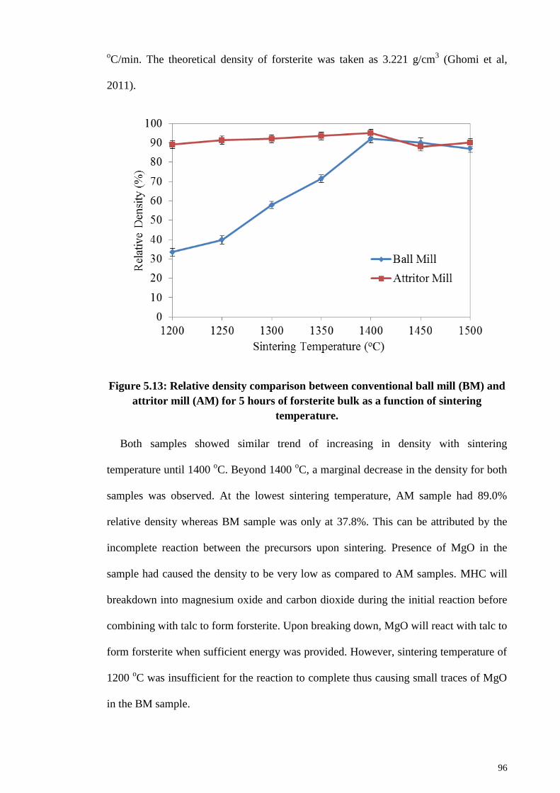
96
oC/min. The theoretical density of forsterite was taken as 3.221 g/cm
3 (Ghomi et al,
2011).
Figure 5.13: Relative density comparison between conventional ball mill (BM) and
attritor mill (AM) for 5 hours of forsterite bulk as a function of sintering
temperature.
Both samples showed similar trend of increasing in density with sintering
temperature until 1400 oC. Beyond 1400
oC, a marginal decrease in the density for both
samples was observed. At the lowest sintering temperature, AM sample had 89.0%
relative density whereas BM sample was only at 37.8%. This can be attributed by the
incomplete reaction between the precursors upon sintering. Presence of MgO in the
sample had caused the density to be very low as compared to AM samples. MHC will
breakdown into magnesium oxide and carbon dioxide during the initial reaction before
combining with talc to form forsterite. Upon breaking down, MgO will react with talc to
form forsterite when sufficient energy was provided. However, sintering temperature of
1200 oC was insufficient for the reaction to complete thus causing small traces of MgO
in the BM sample.
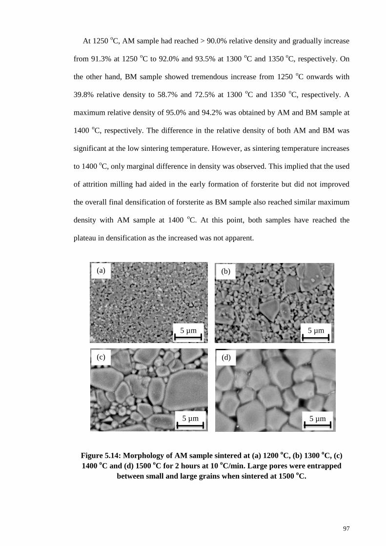
97
At 1250 oC, AM sample had reached > 90.0% relative density and gradually increase
from 91.3% at 1250 oC to 92.0% and 93.5% at 1300
oC and 1350
oC, respectively. On
the other hand, BM sample showed tremendous increase from 1250 oC onwards with
39.8% relative density to 58.7% and 72.5% at 1300 oC and 1350
oC, respectively. A
maximum relative density of 95.0% and 94.2% was obtained by AM and BM sample at
1400 oC, respectively. The difference in the relative density of both AM and BM was
significant at the low sintering temperature. However, as sintering temperature increases
to 1400 oC, only marginal difference in density was observed. This implied that the used
of attrition milling had aided in the early formation of forsterite but did not improved
the overall final densification of forsterite as BM sample also reached similar maximum
density with AM sample at 1400 oC. At this point, both samples have reached the
plateau in densification as the increased was not apparent.
Figure 5.14: Morphology of AM sample sintered at (a) 1200 oC, (b) 1300
oC, (c)
1400 oC and (d) 1500
oC for 2 hours at 10
oC/min. Large pores were entrapped
between small and large grains when sintered at 1500 oC.
5 µm
(a) (b)
5 µm
(c)
5 µm
(d)
5 µm
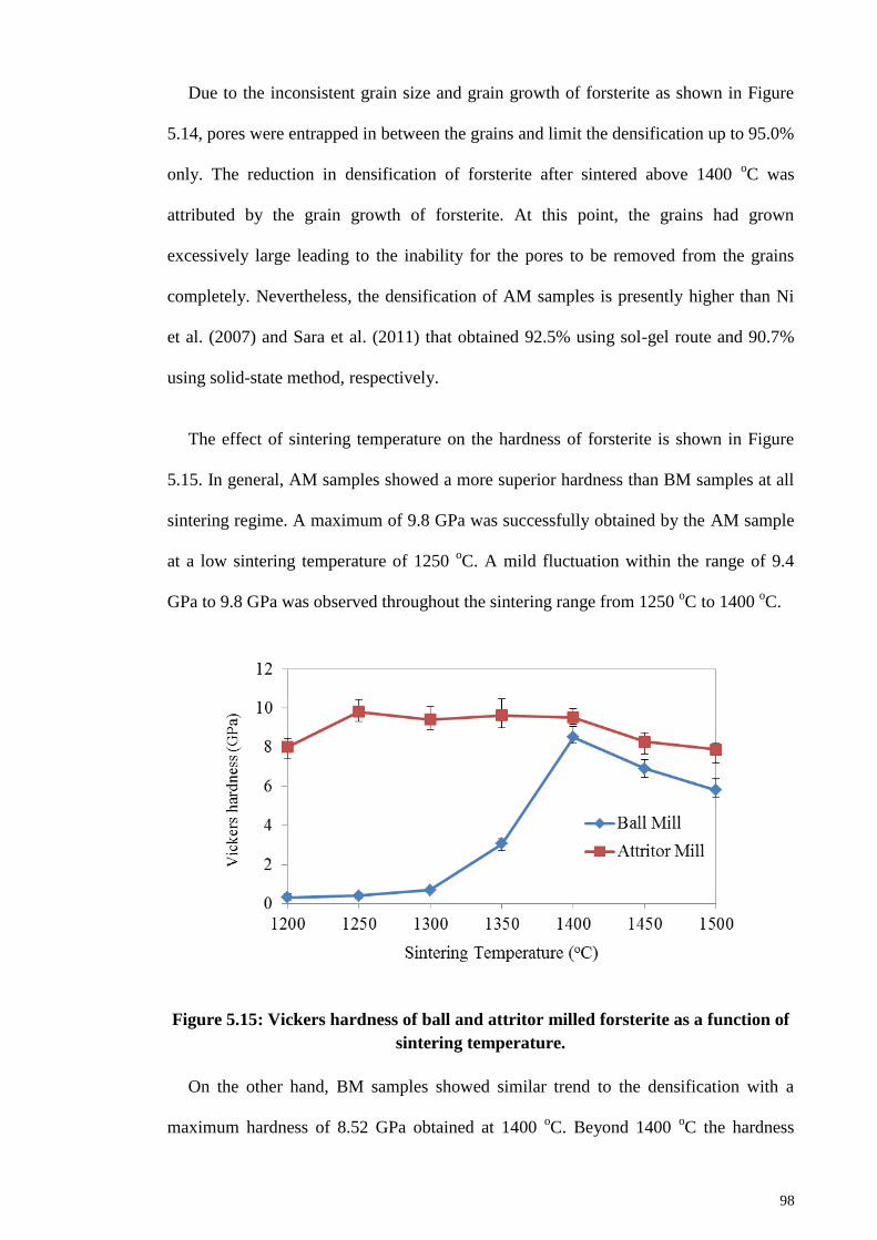
98
Due to the inconsistent grain size and grain growth of forsterite as shown in Figure
5.14, pores were entrapped in between the grains and limit the densification up to 95.0%
only. The reduction in densification of forsterite after sintered above 1400 oC was
attributed by the grain growth of forsterite. At this point, the grains had grown
excessively large leading to the inability for the pores to be removed from the grains
completely. Nevertheless, the densification of AM samples is presently higher than Ni
et al. (2007) and Sara et al. (2011) that obtained 92.5% using sol-gel route and 90.7%
using solid-state method, respectively.
The effect of sintering temperature on the hardness of forsterite is shown in Figure
5.15. In general, AM samples showed a more superior hardness than BM samples at all
sintering regime. A maximum of 9.8 GPa was successfully obtained by the AM sample
at a low sintering temperature of 1250 oC. A mild fluctuation within the range of 9.4
GPa to 9.8 GPa was observed throughout the sintering range from 1250 oC to 1400
oC.
Figure 5.15: Vickers hardness of ball and attritor milled forsterite as a function of
sintering temperature.
On the other hand, BM samples showed similar trend to the densification with a
maximum hardness of 8.52 GPa obtained at 1400 oC. Beyond 1400
oC the hardness
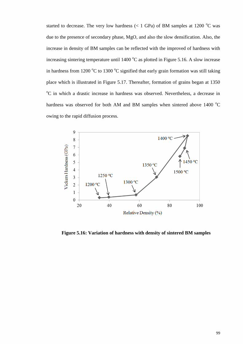
99
started to decrease. The very low hardness (< 1 GPa) of BM samples at 1200 oC was
due to the presence of secondary phase, MgO, and also the slow densification. Also, the
increase in density of BM samples can be reflected with the improved of hardness with
increasing sintering temperature until 1400 oC as plotted in Figure 5.16. A slow increase
in hardness from 1200 oC to 1300
oC signified that early grain formation was still taking
place which is illustrated in Figure 5.17. Thereafter, formation of grains began at 1350
oC in which a drastic increase in hardness was observed. Nevertheless, a decrease in
hardness was observed for both AM and BM samples when sintered above 1400 oC
owing to the rapid diffusion process.
Figure 5.16: Variation of hardness with density of sintered BM samples
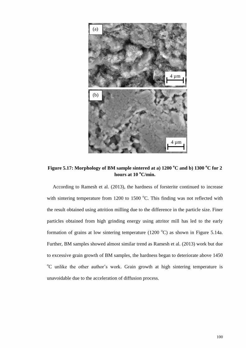
100
Figure 5.17: Morphology of BM sample sintered at a) 1200 oC and b) 1300
oC for 2
hours at 10 oC/min.
According to Ramesh et al. (2013), the hardness of forsterite continued to increase
with sintering temperature from 1200 to 1500 oC. This finding was not reflected with
the result obtained using attrition milling due to the difference in the particle size. Finer
particles obtained from high grinding energy using attritor mill has led to the early
formation of grains at low sintering temperature (1200 oC) as shown in Figure 5.14a.
Further, BM samples showed almost similar trend as Ramesh et al. (2013) work but due
to excessive grain growth of BM samples, the hardness began to deteriorate above 1450
oC unlike the other author’s work. Grain growth at high sintering temperature is
unavoidable due to the acceleration of diffusion process.
4 µm
(a)
4 µm
(b)
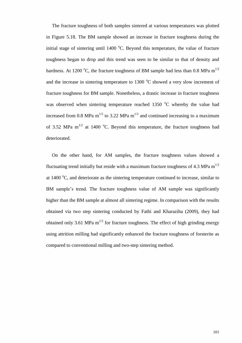
101
The fracture toughness of both samples sintered at various temperatures was plotted
in Figure 5.18. The BM sample showed an increase in fracture toughness during the
initial stage of sintering until 1400 oC. Beyond this temperature, the value of fracture
toughness began to drop and this trend was seen to be similar to that of density and
hardness. At 1200 oC, the fracture toughness of BM sample had less than 0.8 MPa m
1/2
and the increase in sintering temperature to 1300 oC showed a very slow increment of
fracture toughness for BM sample. Nonetheless, a drastic increase in fracture toughness
was observed when sintering temperature reached 1350 oC whereby the value had
increased from 0.8 MPa m1/2
to 3.22 MPa m1/2
and continued increasing to a maximum
of 3.52 MPa m1/2
at 1400 oC. Beyond this temperature, the fracture toughness had
deteriorated.
On the other hand, for AM samples, the fracture toughness values showed a
fluctuating trend initially but reside with a maximum fracture toughness of 4.3 MPa m1/2
at 1400 oC, and deteriorate as the sintering temperature continued to increase, similar to
BM sample’s trend. The fracture toughness value of AM sample was significantly
higher than the BM sample at almost all sintering regime. In comparison with the results
obtained via two step sintering conducted by Fathi and Kharaziha (2009), they had
obtained only 3.61 MPa m1/2
for fracture toughness. The effect of high grinding energy
using attrition milling had significantly enhanced the fracture toughness of forsterite as
compared to conventional milling and two-step sintering method.
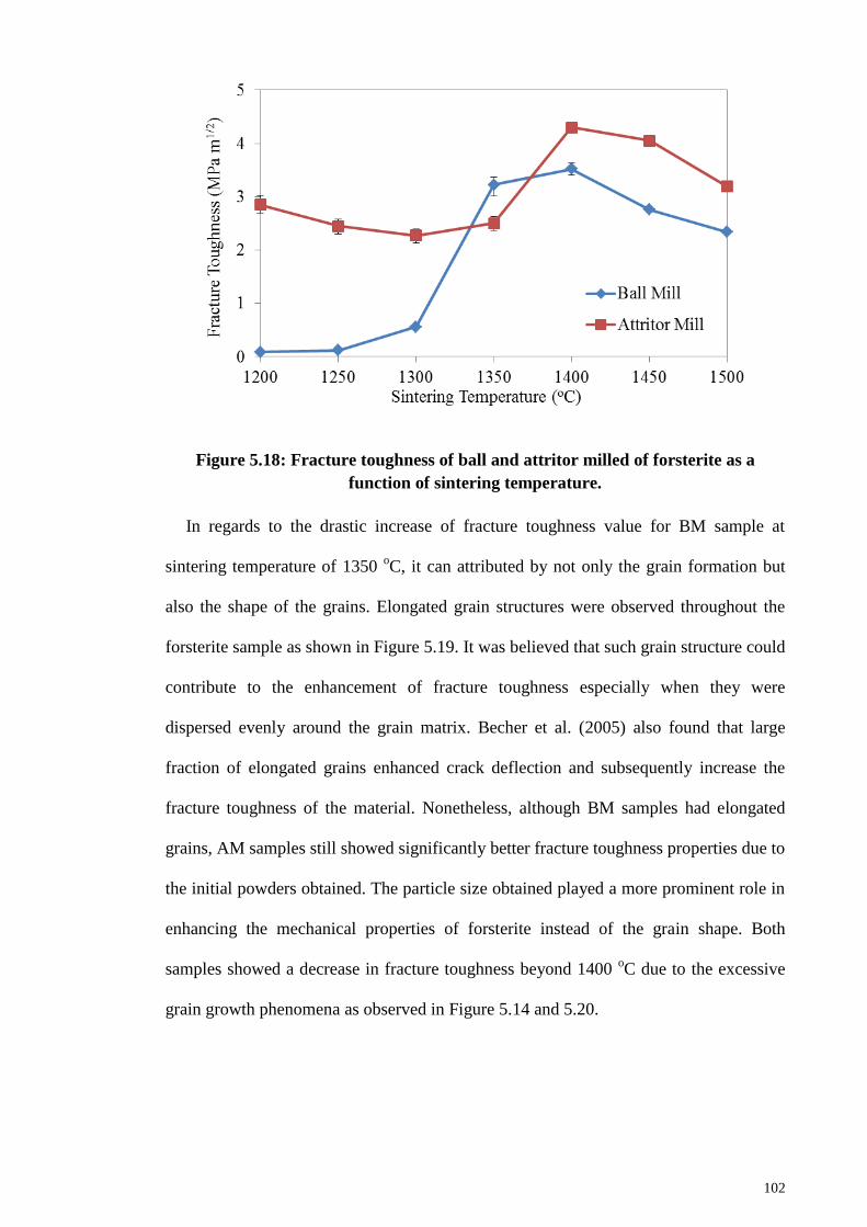
102
Figure 5.18: Fracture toughness of ball and attritor milled of forsterite as a
function of sintering temperature.
In regards to the drastic increase of fracture toughness value for BM sample at
sintering temperature of 1350 oC, it can attributed by not only the grain formation but
also the shape of the grains. Elongated grain structures were observed throughout the
forsterite sample as shown in Figure 5.19. It was believed that such grain structure could
contribute to the enhancement of fracture toughness especially when they were
dispersed evenly around the grain matrix. Becher et al. (2005) also found that large
fraction of elongated grains enhanced crack deflection and subsequently increase the
fracture toughness of the material. Nonetheless, although BM samples had elongated
grains, AM samples still showed significantly better fracture toughness properties due to
the initial powders obtained. The particle size obtained played a more prominent role in
enhancing the mechanical properties of forsterite instead of the grain shape. Both
samples showed a decrease in fracture toughness beyond 1400 oC due to the excessive
grain growth phenomena as observed in Figure 5.14 and 5.20.
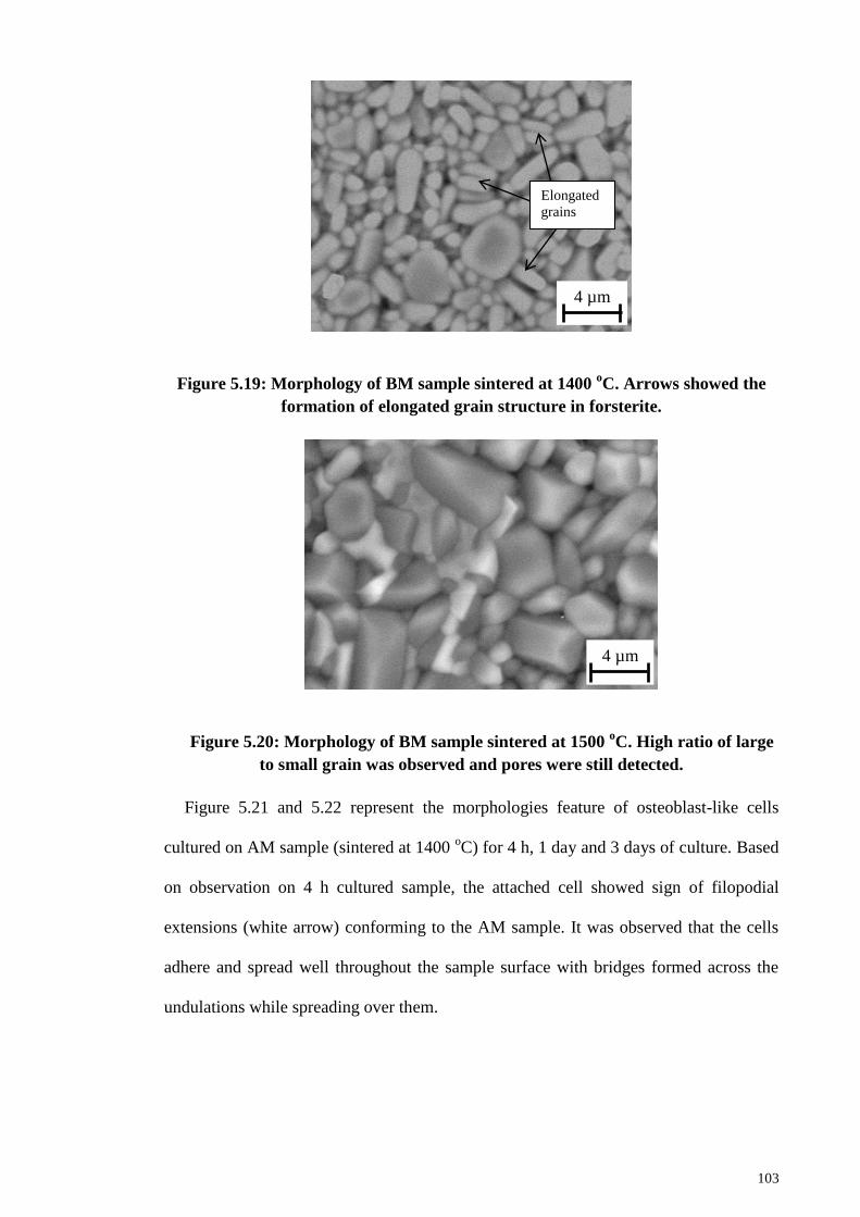
103
Figure 5.19: Morphology of BM sample sintered at 1400 oC. Arrows showed the
formation of elongated grain structure in forsterite.
Figure 5.20: Morphology of BM sample sintered at 1500 oC. High ratio of large
to small grain was observed and pores were still detected.
Figure 5.21 and 5.22 represent the morphologies feature of osteoblast-like cells
cultured on AM sample (sintered at 1400 oC) for 4 h, 1 day and 3 days of culture. Based
on observation on 4 h cultured sample, the attached cell showed sign of filopodial
extensions (white arrow) conforming to the AM sample. It was observed that the cells
adhere and spread well throughout the sample surface with bridges formed across the
undulations while spreading over them.
4 µm
Elongated
grains
4 µm
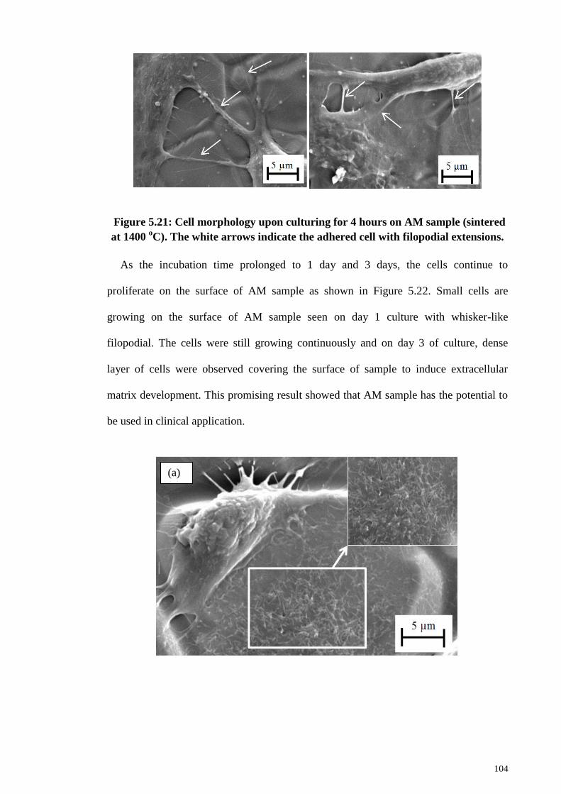
104
Figure 5.21: Cell morphology upon culturing for 4 hours on AM sample (sintered
at 1400 oC). The white arrows indicate the adhered cell with filopodial extensions.
As the incubation time prolonged to 1 day and 3 days, the cells continue to
proliferate on the surface of AM sample as shown in Figure 5.22. Small cells are
growing on the surface of AM sample seen on day 1 culture with whisker-like
filopodial. The cells were still growing continuously and on day 3 of culture, dense
layer of cells were observed covering the surface of sample to induce extracellular
matrix development. This promising result showed that AM sample has the potential to
be used in clinical application.
(a)
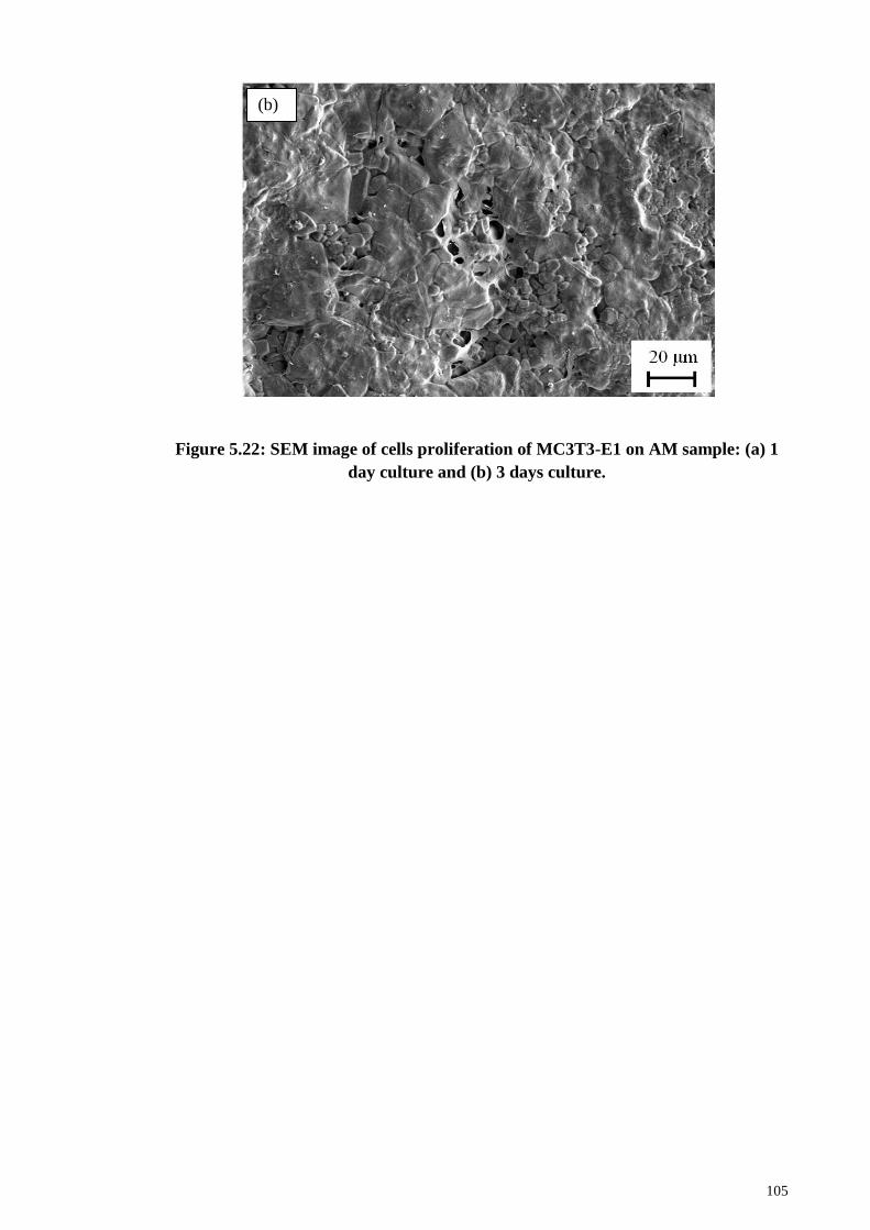
105
Figure 5.22: SEM image of cells proliferation of MC3T3-E1 on AM sample: (a) 1
day culture and (b) 3 days culture.
(b)
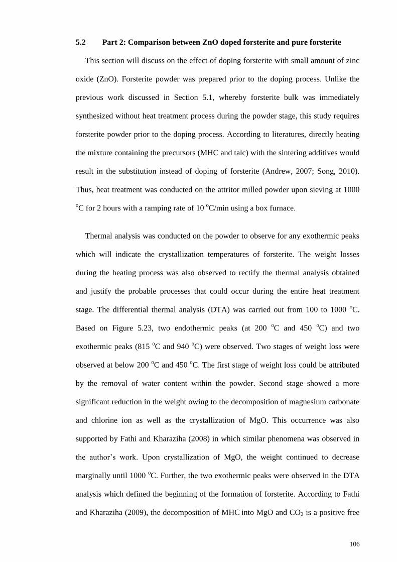
106
5.2 Part 2: Comparison between ZnO doped forsterite and pure forsterite
This section will discuss on the effect of doping forsterite with small amount of zinc
oxide (ZnO). Forsterite powder was prepared prior to the doping process. Unlike the
previous work discussed in Section 5.1, whereby forsterite bulk was immediately
synthesized without heat treatment process during the powder stage, this study requires
forsterite powder prior to the doping process. According to literatures, directly heating
the mixture containing the precursors (MHC and talc) with the sintering additives would
result in the substitution instead of doping of forsterite (Andrew, 2007; Song, 2010).
Thus, heat treatment was conducted on the attritor milled powder upon sieving at 1000
oC for 2 hours with a ramping rate of 10
oC/min using a box furnace.
Thermal analysis was conducted on the powder to observe for any exothermic peaks
which will indicate the crystallization temperatures of forsterite. The weight losses
during the heating process was also observed to rectify the thermal analysis obtained
and justify the probable processes that could occur during the entire heat treatment
stage. The differential thermal analysis (DTA) was carried out from 100 to 1000 oC.
Based on Figure 5.23, two endothermic peaks (at 200 oC and 450
oC) and two
exothermic peaks (815 oC and 940
oC) were observed. Two stages of weight loss were
observed at below 200 oC and 450
oC. The first stage of weight loss could be attributed
by the removal of water content within the powder. Second stage showed a more
significant reduction in the weight owing to the decomposition of magnesium carbonate
and chlorine ion as well as the crystallization of MgO. This occurrence was also
supported by Fathi and Kharaziha (2008) in which similar phenomena was observed in
the author’s work. Upon crystallization of MgO, the weight continued to decrease
marginally until 1000 oC. Further, the two exothermic peaks were observed in the DTA
analysis which defined the beginning of the formation of forsterite. According to Fathi
and Kharaziha (2009), the decomposition of MHC into MgO and CO2 is a positive free
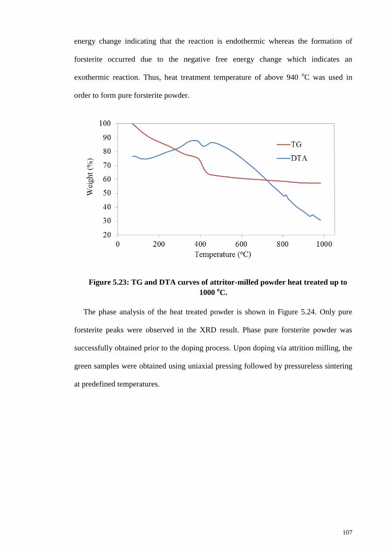
107
energy change indicating that the reaction is endothermic whereas the formation of
forsterite occurred due to the negative free energy change which indicates an
exothermic reaction. Thus, heat treatment temperature of above 940 oC was used in
order to form pure forsterite powder.
Figure 5.23: TG and DTA curves of attritor-milled powder heat treated up to
1000 oC.
The phase analysis of the heat treated powder is shown in Figure 5.24. Only pure
forsterite peaks were observed in the XRD result. Phase pure forsterite powder was
successfully obtained prior to the doping process. Upon doping via attrition milling, the
green samples were obtained using uniaxial pressing followed by pressureless sintering
at predefined temperatures.
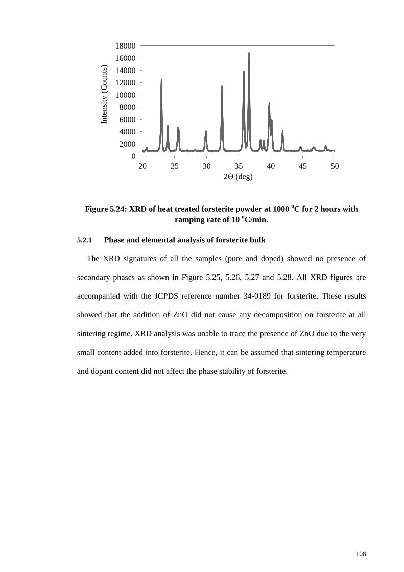
108
Figure 5.24: XRD of heat treated forsterite powder at 1000 oC for 2 hours with
ramping rate of 10 oC/min.
5.2.1 Phase and elemental analysis of forsterite bulk
The XRD signatures of all the samples (pure and doped) showed no presence of
secondary phases as shown in Figure 5.25, 5.26, 5.27 and 5.28. All XRD figures are
accompanied with the JCPDS reference number 34-0189 for forsterite. These results
showed that the addition of ZnO did not cause any decomposition on forsterite at all
sintering regime. XRD analysis was unable to trace the presence of ZnO due to the very
small content added into forsterite. Hence, it can be assumed that sintering temperature
and dopant content did not affect the phase stability of forsterite.
0
2000
4000
6000
8000
10000
12000
14000
16000
18000
20 25 30 35 40 45 50
Inte
nsi
ty (
Counts
)
2ϴ (deg)
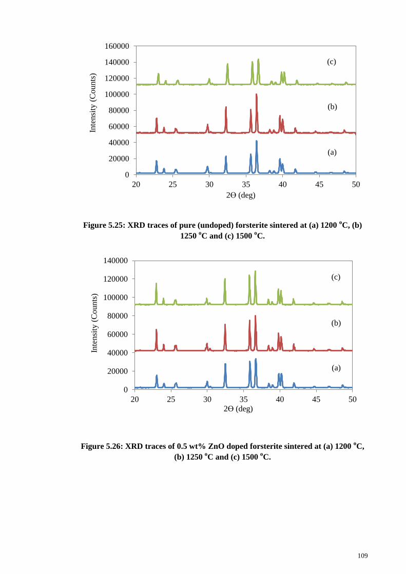
109
Figure 5.25: XRD traces of pure (undoped) forsterite sintered at (a) 1200 oC, (b)
1250 oC and (c) 1500
oC.
Figure 5.26: XRD traces of 0.5 wt% ZnO doped forsterite sintered at (a) 1200 oC,
(b) 1250 oC and (c) 1500
oC.
0
20000
40000
60000
80000
100000
120000
140000
160000
20 25 30 35 40 45 50
Inte
nsi
ty (
Co
un
ts)
2ϴ (deg)
(b)
(c)
(a)
0
20000
40000
60000
80000
100000
120000
140000
20 25 30 35 40 45 50
Inte
nsi
ty (
Counts
)
2ϴ (deg)
(a)
(b)
(c)
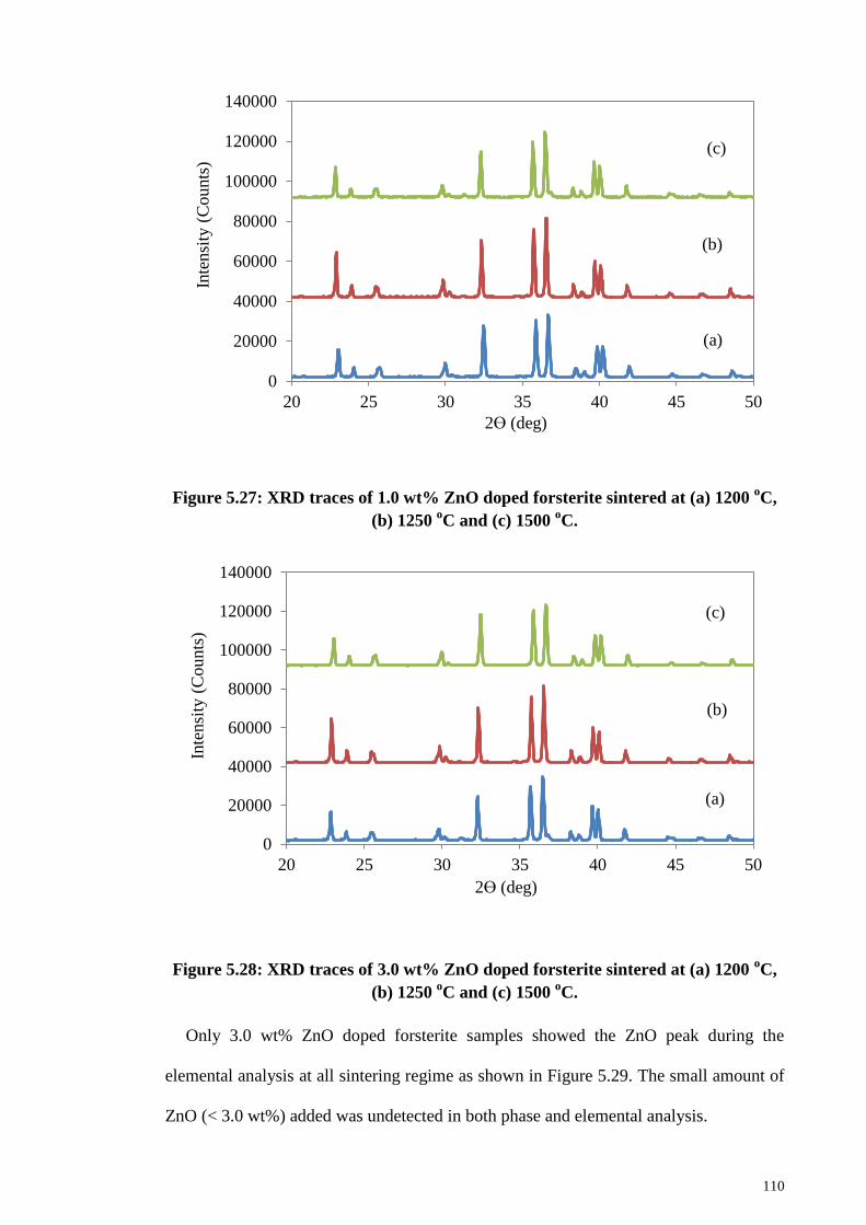
110
Figure 5.27: XRD traces of 1.0 wt% ZnO doped forsterite sintered at (a) 1200 oC,
(b) 1250 oC and (c) 1500
oC.
Figure 5.28: XRD traces of 3.0 wt% ZnO doped forsterite sintered at (a) 1200 oC,
(b) 1250 oC and (c) 1500
oC.
Only 3.0 wt% ZnO doped forsterite samples showed the ZnO peak during the
elemental analysis at all sintering regime as shown in Figure 5.29. The small amount of
ZnO (< 3.0 wt%) added was undetected in both phase and elemental analysis.
0
20000
40000
60000
80000
100000
120000
140000
20 25 30 35 40 45 50
Inte
nsi
ty (
Counts
)
2ϴ (deg)
(a)
(b)
(c)
0
20000
40000
60000
80000
100000
120000
140000
20 25 30 35 40 45 50
Inte
nsi
ty (
Co
un
ts)
2ϴ (deg)
(a)
(b)
(c)
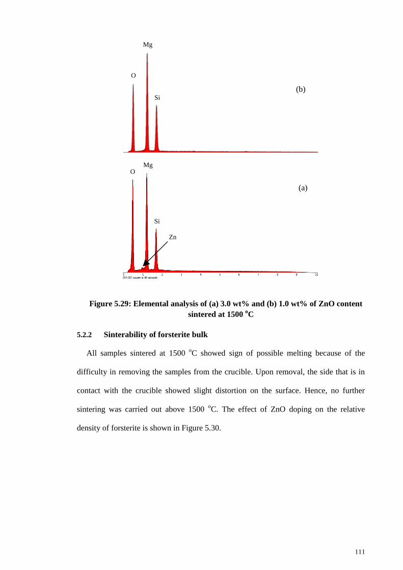
111
Figure 5.29: Elemental analysis of (a) 3.0 wt% and (b) 1.0 wt% of ZnO content
sintered at 1500 oC
5.2.2 Sinterability of forsterite bulk
All samples sintered at 1500 oC showed sign of possible melting because of the
difficulty in removing the samples from the crucible. Upon removal, the side that is in
contact with the crucible showed slight distortion on the surface. Hence, no further
sintering was carried out above 1500 oC. The effect of ZnO doping on the relative
density of forsterite is shown in Figure 5.30.
(a)
(b)
O
Mg
O Mg
Si
Si
Zn
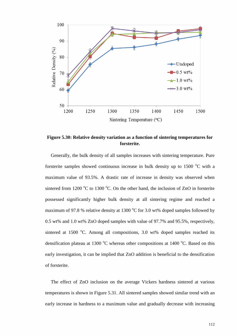
112
Figure 5.30: Relative density variation as a function of sintering temperatures for
forsterite.
Generally, the bulk density of all samples increases with sintering temperature. Pure
forsterite samples showed continuous increase in bulk density up to 1500 oC with a
maximum value of 93.5%. A drastic rate of increase in density was observed when
sintered from 1200 oC to 1300
oC. On the other hand, the inclusion of ZnO in forsterite
possessed significantly higher bulk density at all sintering regime and reached a
maximum of 97.8 % relative density at 1300 oC for 3.0 wt% doped samples followed by
0.5 wt% and 1.0 wt% ZnO doped samples with value of 97.7% and 95.5%, respectively,
sintered at 1500 oC. Among all compositions, 3.0 wt% doped samples reached its
densification plateau at 1300 oC whereas other compositions at 1400
oC. Based on this
early investigation, it can be implied that ZnO addition is beneficial to the densification
of forsterite.
The effect of ZnO inclusion on the average Vickers hardness sintered at various
temperatures is shown in Figure 5.31. All sintered samples showed similar trend with an
early increase in hardness to a maximum value and gradually decrease with increasing
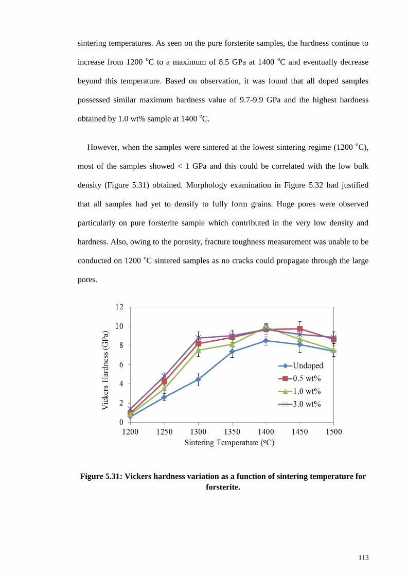
113
sintering temperatures. As seen on the pure forsterite samples, the hardness continue to
increase from 1200 oC to a maximum of 8.5 GPa at 1400
oC and eventually decrease
beyond this temperature. Based on observation, it was found that all doped samples
possessed similar maximum hardness value of 9.7-9.9 GPa and the highest hardness
obtained by 1.0 wt% sample at 1400 oC.
However, when the samples were sintered at the lowest sintering regime (1200 oC),
most of the samples showed < 1 GPa and this could be correlated with the low bulk
density (Figure 5.31) obtained. Morphology examination in Figure 5.32 had justified
that all samples had yet to densify to fully form grains. Huge pores were observed
particularly on pure forsterite sample which contributed in the very low density and
hardness. Also, owing to the porosity, fracture toughness measurement was unable to be
conducted on 1200 oC sintered samples as no cracks could propagate through the large
pores.
Figure 5.31: Vickers hardness variation as a function of sintering temperature for
forsterite.
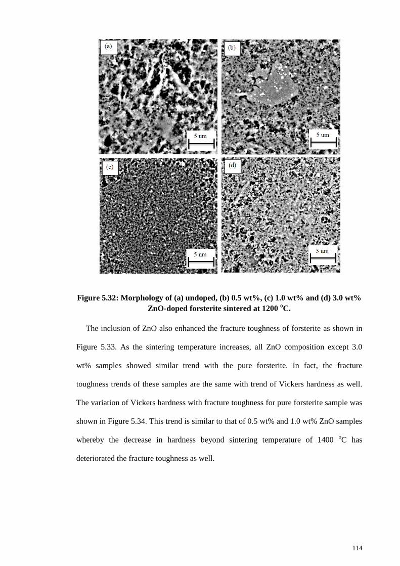
114
Figure 5.32: Morphology of (a) undoped, (b) 0.5 wt%, (c) 1.0 wt% and (d) 3.0 wt%
ZnO-doped forsterite sintered at 1200 oC.
The inclusion of ZnO also enhanced the fracture toughness of forsterite as shown in
Figure 5.33. As the sintering temperature increases, all ZnO composition except 3.0
wt% samples showed similar trend with the pure forsterite. In fact, the fracture
toughness trends of these samples are the same with trend of Vickers hardness as well.
The variation of Vickers hardness with fracture toughness for pure forsterite sample was
shown in Figure 5.34. This trend is similar to that of 0.5 wt% and 1.0 wt% ZnO samples
whereby the decrease in hardness beyond sintering temperature of 1400 oC has
deteriorated the fracture toughness as well.
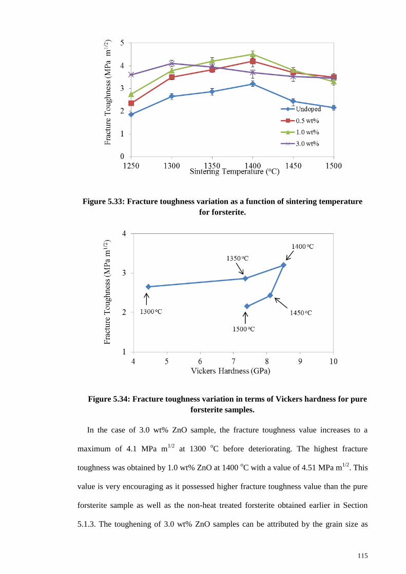
115
Figure 5.33: Fracture toughness variation as a function of sintering temperature
for forsterite.
Figure 5.34: Fracture toughness variation in terms of Vickers hardness for pure
forsterite samples.
In the case of 3.0 wt% ZnO sample, the fracture toughness value increases to a
maximum of 4.1 MPa m1/2
at 1300 oC before deteriorating. The highest fracture
toughness was obtained by 1.0 wt% ZnO at 1400 oC with a value of 4.51 MPa m
1/2. This
value is very encouraging as it possessed higher fracture toughness value than the pure
forsterite sample as well as the non-heat treated forsterite obtained earlier in Section
5.1.3. The toughening of 3.0 wt% ZnO samples can be attributed by the grain size as
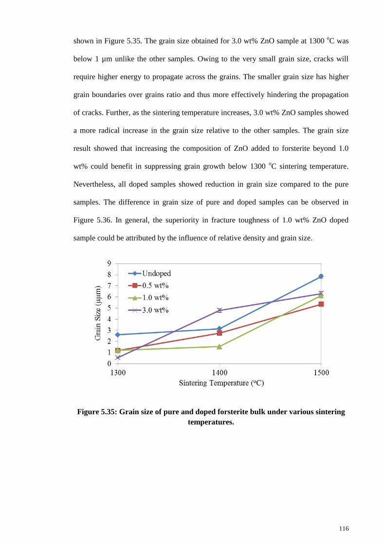
116
shown in Figure 5.35. The grain size obtained for 3.0 wt% ZnO sample at 1300 oC was
below 1 µm unlike the other samples. Owing to the very small grain size, cracks will
require higher energy to propagate across the grains. The smaller grain size has higher
grain boundaries over grains ratio and thus more effectively hindering the propagation
of cracks. Further, as the sintering temperature increases, 3.0 wt% ZnO samples showed
a more radical increase in the grain size relative to the other samples. The grain size
result showed that increasing the composition of ZnO added to forsterite beyond 1.0
wt% could benefit in suppressing grain growth below 1300 oC sintering temperature.
Nevertheless, all doped samples showed reduction in grain size compared to the pure
samples. The difference in grain size of pure and doped samples can be observed in
Figure 5.36. In general, the superiority in fracture toughness of 1.0 wt% ZnO doped
sample could be attributed by the influence of relative density and grain size.
Figure 5.35: Grain size of pure and doped forsterite bulk under various sintering
temperatures.
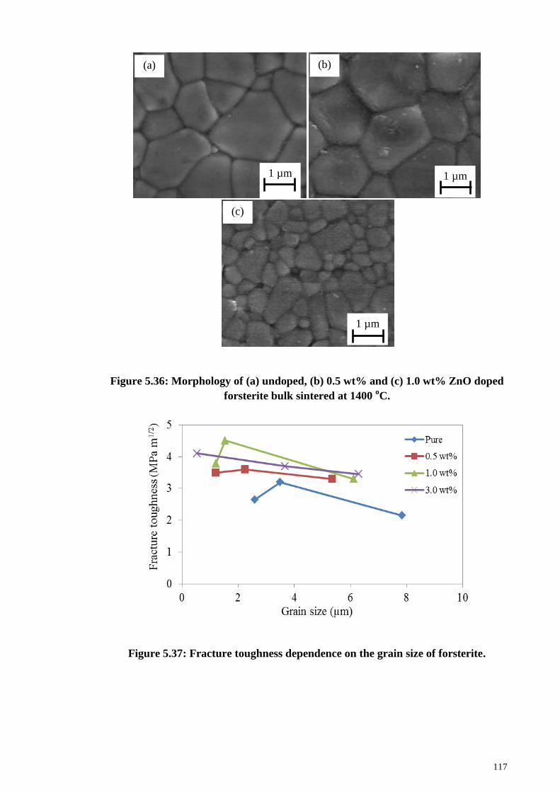
117
Figure 5.36: Morphology of (a) undoped, (b) 0.5 wt% and (c) 1.0 wt% ZnO doped
forsterite bulk sintered at 1400 oC.
Figure 5.37: Fracture toughness dependence on the grain size of forsterite.
1 µm
(a)
1 µm
(b)
1 µm
(c)
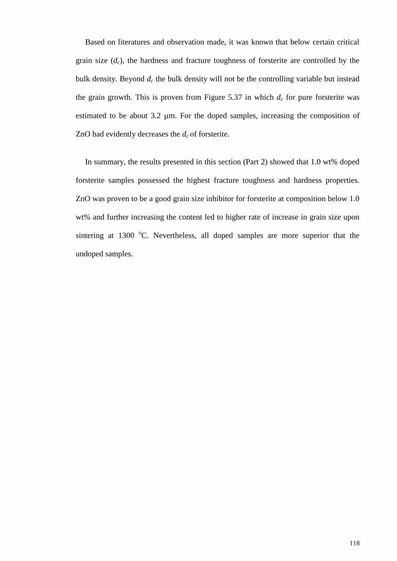
118
Based on literatures and observation made, it was known that below certain critical
grain size (dc), the hardness and fracture toughness of forsterite are controlled by the
bulk density. Beyond dc the bulk density will not be the controlling variable but instead
the grain growth. This is proven from Figure 5.37 in which dc for pure forsterite was
estimated to be about 3.2 µm. For the doped samples, increasing the composition of
ZnO had evidently decreases the dc of forsterite.
In summary, the results presented in this section (Part 2) showed that 1.0 wt% doped
forsterite samples possessed the highest fracture toughness and hardness properties.
ZnO was proven to be a good grain size inhibitor for forsterite at composition below 1.0
wt% and further increasing the content led to higher rate of increase in grain size upon
sintering at 1300 oC. Nevertheless, all doped samples are more superior that the
undoped samples.
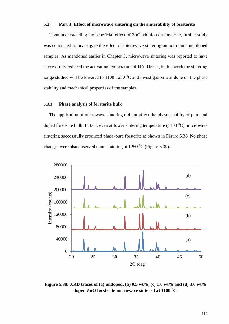
119
5.3 Part 3: Effect of microwave sintering on the sinterability of forsterite
Upon understanding the beneficial effect of ZnO addition on forsterite, further study
was conducted to investigate the effect of microwave sintering on both pure and doped
samples. As mentioned earlier in Chapter 3, microwave sintering was reported to have
successfully reduced the activation temperature of HA. Hence, in this work the sintering
range studied will be lowered to 1100-1250 oC and investigation was done on the phase
stability and mechanical properties of the samples.
5.3.1 Phase analysis of forsterite bulk
The application of microwave sintering did not affect the phase stability of pure and
doped forsterite bulk. In fact, even at lower sintering temperature (1100 oC), microwave
sintering successfully produced phase-pure forsterite as shown in Figure 5.38. No phase
changes were also observed upon sintering at 1250 oC (Figure 5.39).
Figure 5.38: XRD traces of (a) undoped, (b) 0.5 wt%, (c) 1.0 wt% and (d) 3.0 wt%
doped ZnO forsterite microwave sintered at 1100 oC.
0
40000
80000
120000
160000
200000
240000
280000
20 25 30 35 40 45 50
Inte
nsi
ty (
counts
)
2ϴ (deg)
(a)
(b)
(c)
(d)
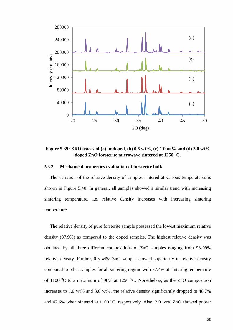
120
Figure 5.39: XRD traces of (a) undoped, (b) 0.5 wt%, (c) 1.0 wt% and (d) 3.0 wt%
doped ZnO forsterite microwave sintered at 1250 oC.
5.3.2 Mechanical properties evaluation of forsterite bulk
The variation of the relative density of samples sintered at various temperatures is
shown in Figure 5.40. In general, all samples showed a similar trend with increasing
sintering temperature, i.e. relative density increases with increasing sintering
temperature.
The relative density of pure forsterite sample possessed the lowest maximum relative
density (87.9%) as compared to the doped samples. The highest relative density was
obtained by all three different compositions of ZnO samples ranging from 98-99%
relative density. Further, 0.5 wt% ZnO sample showed superiority in relative density
compared to other samples for all sintering regime with 57.4% at sintering temperature
of 1100 oC to a maximum of 98% at 1250
oC. Nonetheless, as the ZnO composition
increases to 1.0 wt% and 3.0 wt%, the relative density significantly dropped to 48.7%
and 42.6% when sintered at 1100 oC, respectively. Also, 3.0 wt% ZnO showed poorer
0
40000
80000
120000
160000
200000
240000
280000
20 25 30 35 40 45 50
Inte
nsi
ty (
cou
nts
)
2ϴ (deg)
(a)
(b)
(c)
(d)
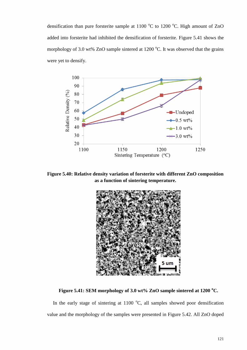
121
densification than pure forsterite sample at 1100 oC to 1200
oC. High amount of ZnO
added into forsterite had inhibited the densification of forsterite. Figure 5.41 shows the
morphology of 3.0 wt% ZnO sample sintered at 1200 oC. It was observed that the grains
were yet to densify.
Figure 5.40: Relative density variation of forsterite with different ZnO composition
as a function of sintering temperature.
Figure 5.41: SEM morphology of 3.0 wt% ZnO sample sintered at 1200 oC.
In the early stage of sintering at 1100 oC, all samples showed poor densification
value and the morphology of the samples were presented in Figure 5.42. All ZnO doped
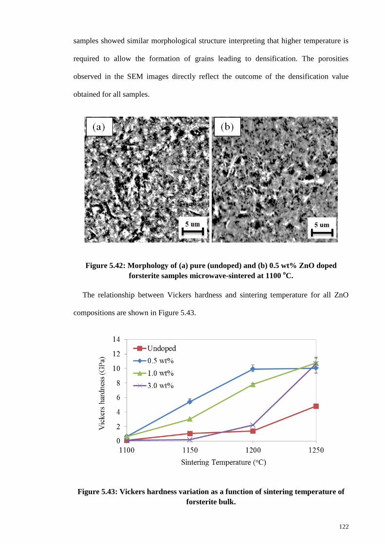
122
samples showed similar morphological structure interpreting that higher temperature is
required to allow the formation of grains leading to densification. The porosities
observed in the SEM images directly reflect the outcome of the densification value
obtained for all samples.
Figure 5.42: Morphology of (a) pure (undoped) and (b) 0.5 wt% ZnO doped
forsterite samples microwave-sintered at 1100 oC.
The relationship between Vickers hardness and sintering temperature for all ZnO
compositions are shown in Figure 5.43.
Figure 5.43: Vickers hardness variation as a function of sintering temperature of
forsterite bulk.
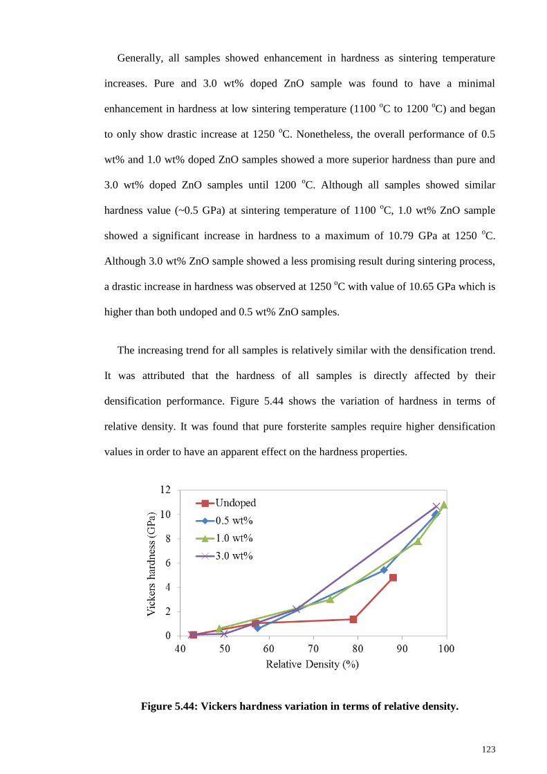
123
Generally, all samples showed enhancement in hardness as sintering temperature
increases. Pure and 3.0 wt% doped ZnO sample was found to have a minimal
enhancement in hardness at low sintering temperature (1100 oC to 1200
oC) and began
to only show drastic increase at 1250 oC. Nonetheless, the overall performance of 0.5
wt% and 1.0 wt% doped ZnO samples showed a more superior hardness than pure and
3.0 wt% doped ZnO samples until 1200 oC. Although all samples showed similar
hardness value (~0.5 GPa) at sintering temperature of 1100 oC, 1.0 wt% ZnO sample
showed a significant increase in hardness to a maximum of 10.79 GPa at 1250 oC.
Although 3.0 wt% ZnO sample showed a less promising result during sintering process,
a drastic increase in hardness was observed at 1250 oC with value of 10.65 GPa which is
higher than both undoped and 0.5 wt% ZnO samples.
The increasing trend for all samples is relatively similar with the densification trend.
It was attributed that the hardness of all samples is directly affected by their
densification performance. Figure 5.44 shows the variation of hardness in terms of
relative density. It was found that pure forsterite samples require higher densification
values in order to have an apparent effect on the hardness properties.
Figure 5.44: Vickers hardness variation in terms of relative density.
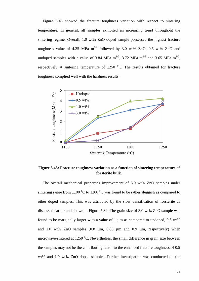
124
Figure 5.45 showed the fracture toughness variation with respect to sintering
temperature. In general, all samples exhibited an increasing trend throughout the
sintering regime. Overall, 1.0 wt% ZnO doped sample possessed the highest fracture
toughness value of 4.25 MPa m1/2
followed by 3.0 wt% ZnO, 0.5 wt% ZnO and
undoped samples with a value of 3.84 MPa m1/2
, 3.72 MPa m1/2
and 3.65 MPa m1/2
,
respectively at sintering temperature of 1250 oC. The results obtained for fracture
toughness complied well with the hardness results.
Figure 5.45: Fracture toughness variation as a function of sintering temperature of
forsterite bulk.
The overall mechanical properties improvement of 3.0 wt% ZnO samples under
sintering range from 1100 oC to 1200
oC was found to be rather sluggish as compared to
other doped samples. This was attributed by the slow densification of forsterite as
discussed earlier and shown in Figure 5.39. The grain size of 3.0 wt% ZnO sample was
found to be marginally larger with a value of 1 µm as compared to undoped, 0.5 wt%
and 1.0 wt% ZnO samples (0.8 µm, 0.85 µm and 0.9 µm, respectively) when
microwave-sintered at 1250 oC. Nevertheless, the small difference in grain size between
the samples may not be the contributing factor to the enhanced fracture toughness of 0.5
wt% and 1.0 wt% ZnO doped samples. Further investigation was conducted on the
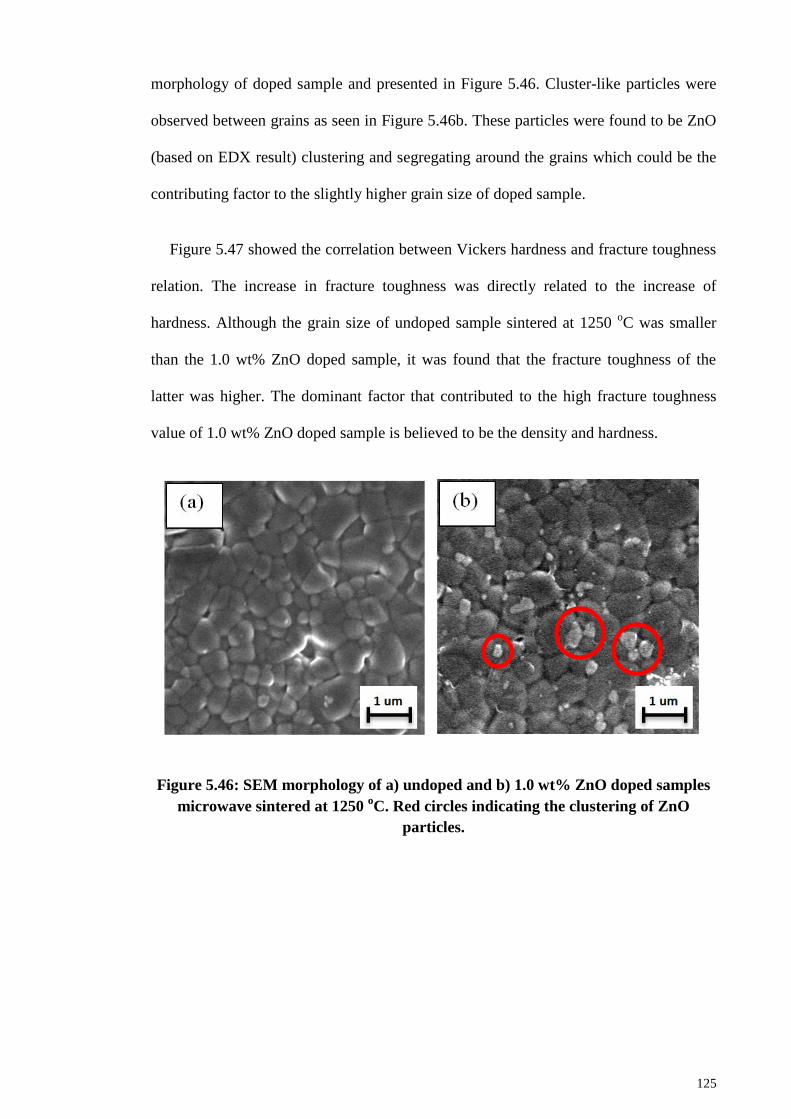
125
morphology of doped sample and presented in Figure 5.46. Cluster-like particles were
observed between grains as seen in Figure 5.46b. These particles were found to be ZnO
(based on EDX result) clustering and segregating around the grains which could be the
contributing factor to the slightly higher grain size of doped sample.
Figure 5.47 showed the correlation between Vickers hardness and fracture toughness
relation. The increase in fracture toughness was directly related to the increase of
hardness. Although the grain size of undoped sample sintered at 1250 oC was smaller
than the 1.0 wt% ZnO doped sample, it was found that the fracture toughness of the
latter was higher. The dominant factor that contributed to the high fracture toughness
value of 1.0 wt% ZnO doped sample is believed to be the density and hardness.
Figure 5.46: SEM morphology of a) undoped and b) 1.0 wt% ZnO doped samples
microwave sintered at 1250 oC. Red circles indicating the clustering of ZnO
particles.
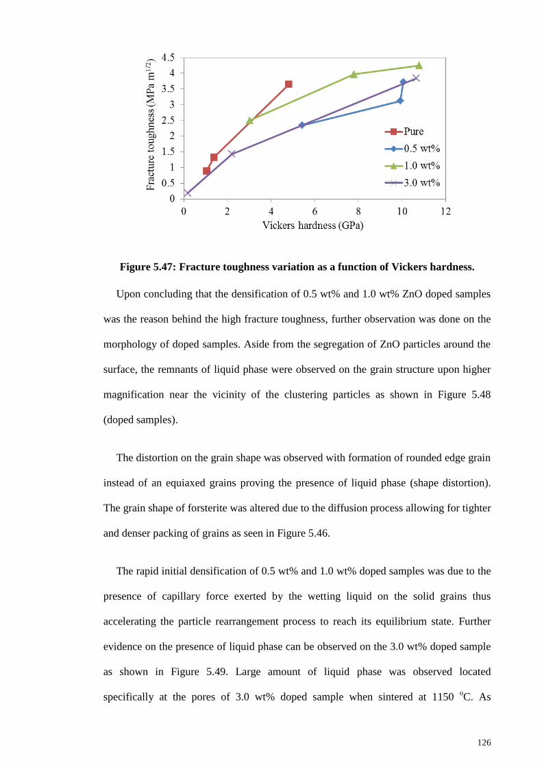
126
Figure 5.47: Fracture toughness variation as a function of Vickers hardness.
Upon concluding that the densification of 0.5 wt% and 1.0 wt% ZnO doped samples
was the reason behind the high fracture toughness, further observation was done on the
morphology of doped samples. Aside from the segregation of ZnO particles around the
surface, the remnants of liquid phase were observed on the grain structure upon higher
magnification near the vicinity of the clustering particles as shown in Figure 5.48
(doped samples).
The distortion on the grain shape was observed with formation of rounded edge grain
instead of an equiaxed grains proving the presence of liquid phase (shape distortion).
The grain shape of forsterite was altered due to the diffusion process allowing for tighter
and denser packing of grains as seen in Figure 5.46.
The rapid initial densification of 0.5 wt% and 1.0 wt% doped samples was due to the
presence of capillary force exerted by the wetting liquid on the solid grains thus
accelerating the particle rearrangement process to reach its equilibrium state. Further
evidence on the presence of liquid phase can be observed on the 3.0 wt% doped sample
as shown in Figure 5.49. Large amount of liquid phase was observed located
specifically at the pores of 3.0 wt% doped sample when sintered at 1150 oC. As
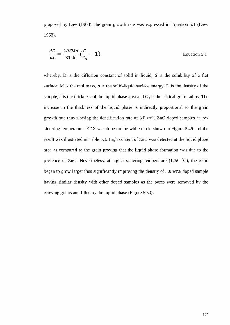
127
proposed by Law (1968), the grain growth rate was expressed in Equation 5.1 (Law,
1968).
Equation 5.1
whereby, D is the diffusion constant of solid in liquid, S is the solubility of a flat
surface, M is the mol mass, σ is the solid-liquid surface energy. D is the density of the
sample, δ is the thickness of the liquid phase area and Go is the critical grain radius. The
increase in the thickness of the liquid phase is indirectly proportional to the grain
growth rate thus slowing the densification rate of 3.0 wt% ZnO doped samples at low
sintering temperature. EDX was done on the white circle shown in Figure 5.49 and the
result was illustrated in Table 5.3. High content of ZnO was detected at the liquid phase
area as compared to the grain proving that the liquid phase formation was due to the
presence of ZnO. Nevertheless, at higher sintering temperature (1250 oC), the grain
began to grow larger thus significantly improving the density of 3.0 wt% doped sample
having similar density with other doped samples as the pores were removed by the
growing grains and filled by the liquid phase (Figure 5.50).
128
Figure 5.48: Morphology of 1.0 wt% ZnO doped sample microwave sintered at
1250 oC.
Figure 5.49: Morphology of 3.0 wt% ZnO doped forsterite sample microwave
sintered at 1150 oC. White circle signify the spot for EDX.
1 µm
0.5 µm
1
2
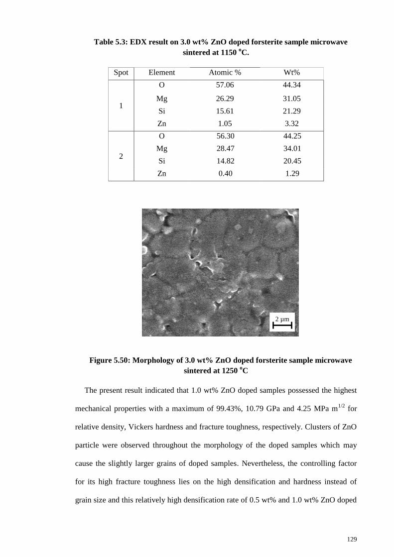
129
Table 5.3: EDX result on 3.0 wt% ZnO doped forsterite sample microwave
sintered at 1150 oC.
Spot Element Atomic % Wt%
1
O 57.06 44.34
Mg 26.29 31.05
Si 15.61 21.29
Zn 1.05 3.32
2
O 56.30 44.25
Mg 28.47 34.01
Si 14.82 20.45
Zn 0.40 1.29
Figure 5.50: Morphology of 3.0 wt% ZnO doped forsterite sample microwave
sintered at 1250 oC
The present result indicated that 1.0 wt% ZnO doped samples possessed the highest
mechanical properties with a maximum of 99.43%, 10.79 GPa and 4.25 MPa m1/2
for
relative density, Vickers hardness and fracture toughness, respectively. Clusters of ZnO
particle were observed throughout the morphology of the doped samples which may
cause the slightly larger grains of doped samples. Nevertheless, the controlling factor
for its high fracture toughness lies on the high densification and hardness instead of
grain size and this relatively high densification rate of 0.5 wt% and 1.0 wt% ZnO doped
2 µm
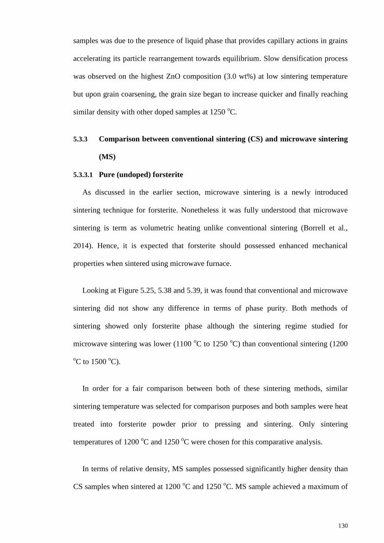
130
samples was due to the presence of liquid phase that provides capillary actions in grains
accelerating its particle rearrangement towards equilibrium. Slow densification process
was observed on the highest ZnO composition (3.0 wt%) at low sintering temperature
but upon grain coarsening, the grain size began to increase quicker and finally reaching
similar density with other doped samples at 1250 oC.
5.3.3 Comparison between conventional sintering (CS) and microwave sintering
(MS)
5.3.3.1 Pure (undoped) forsterite
As discussed in the earlier section, microwave sintering is a newly introduced
sintering technique for forsterite. Nonetheless it was fully understood that microwave
sintering is term as volumetric heating unlike conventional sintering (Borrell et al.,
2014). Hence, it is expected that forsterite should possessed enhanced mechanical
properties when sintered using microwave furnace.
Looking at Figure 5.25, 5.38 and 5.39, it was found that conventional and microwave
sintering did not show any difference in terms of phase purity. Both methods of
sintering showed only forsterite phase although the sintering regime studied for
microwave sintering was lower (1100 oC to 1250
oC) than conventional sintering (1200
oC to 1500
oC).
In order for a fair comparison between both of these sintering methods, similar
sintering temperature was selected for comparison purposes and both samples were heat
treated into forsterite powder prior to pressing and sintering. Only sintering
temperatures of 1200 oC and 1250
oC were chosen for this comparative analysis.
In terms of relative density, MS samples possessed significantly higher density than
CS samples when sintered at 1200 oC and 1250
oC. MS sample achieved a maximum of
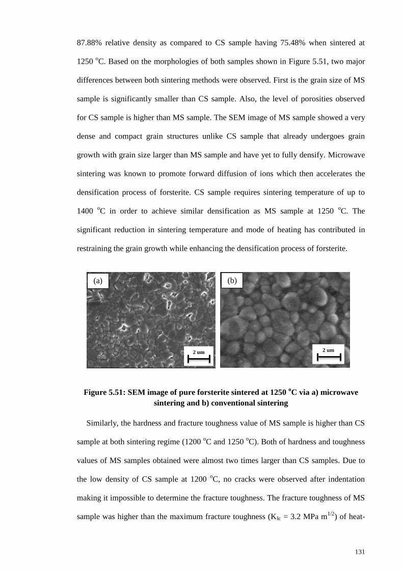
131
87.88% relative density as compared to CS sample having 75.48% when sintered at
1250 oC. Based on the morphologies of both samples shown in Figure 5.51, two major
differences between both sintering methods were observed. First is the grain size of MS
sample is significantly smaller than CS sample. Also, the level of porosities observed
for CS sample is higher than MS sample. The SEM image of MS sample showed a very
dense and compact grain structures unlike CS sample that already undergoes grain
growth with grain size larger than MS sample and have yet to fully densify. Microwave
sintering was known to promote forward diffusion of ions which then accelerates the
densification process of forsterite. CS sample requires sintering temperature of up to
1400 oC in order to achieve similar densification as MS sample at 1250
oC. The
significant reduction in sintering temperature and mode of heating has contributed in
restraining the grain growth while enhancing the densification process of forsterite.
Figure 5.51: SEM image of pure forsterite sintered at 1250 oC via a) microwave
sintering and b) conventional sintering
Similarly, the hardness and fracture toughness value of MS sample is higher than CS
sample at both sintering regime (1200 oC and 1250
oC). Both of hardness and toughness
values of MS samples obtained were almost two times larger than CS samples. Due to
the low density of CS sample at 1200 oC, no cracks were observed after indentation
making it impossible to determine the fracture toughness. The fracture toughness of MS
sample was higher than the maximum fracture toughness (KIc = 3.2 MPa m1/2
) of heat-
2 um
(a)
2 um
(b)
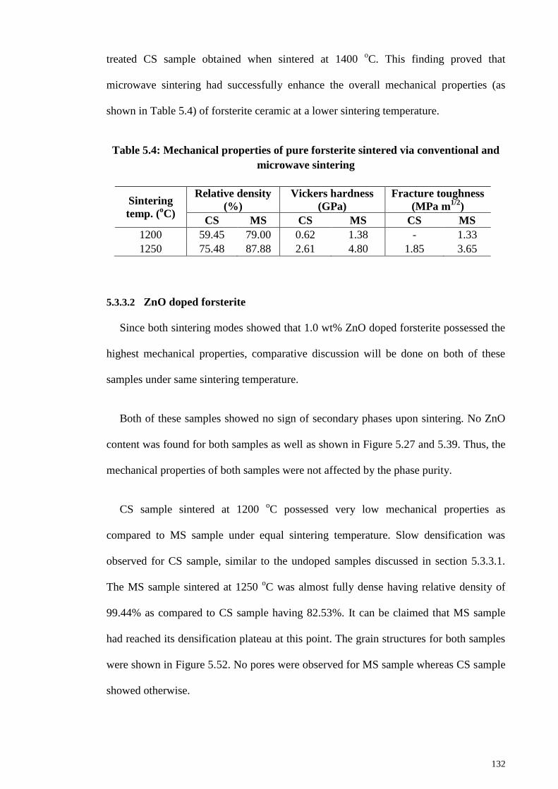
132
treated CS sample obtained when sintered at 1400 oC. This finding proved that
microwave sintering had successfully enhance the overall mechanical properties (as
shown in Table 5.4) of forsterite ceramic at a lower sintering temperature.
Table 5.4: Mechanical properties of pure forsterite sintered via conventional and
microwave sintering
Sintering
temp. (oC)
Relative density
(%)
Vickers hardness
(GPa)
Fracture toughness
(MPa m1/2
)
CS MS CS MS CS MS
1200 59.45 79.00 0.62 1.38 - 1.33
1250 75.48 87.88 2.61 4.80 1.85 3.65
5.3.3.2 ZnO doped forsterite
Since both sintering modes showed that 1.0 wt% ZnO doped forsterite possessed the
highest mechanical properties, comparative discussion will be done on both of these
samples under same sintering temperature.
Both of these samples showed no sign of secondary phases upon sintering. No ZnO
content was found for both samples as well as shown in Figure 5.27 and 5.39. Thus, the
mechanical properties of both samples were not affected by the phase purity.
CS sample sintered at 1200 oC possessed very low mechanical properties as
compared to MS sample under equal sintering temperature. Slow densification was
observed for CS sample, similar to the undoped samples discussed in section 5.3.3.1.
The MS sample sintered at 1250 oC was almost fully dense having relative density of
99.44% as compared to CS sample having 82.53%. It can be claimed that MS sample
had reached its densification plateau at this point. The grain structures for both samples
were shown in Figure 5.52. No pores were observed for MS sample whereas CS sample
showed otherwise.
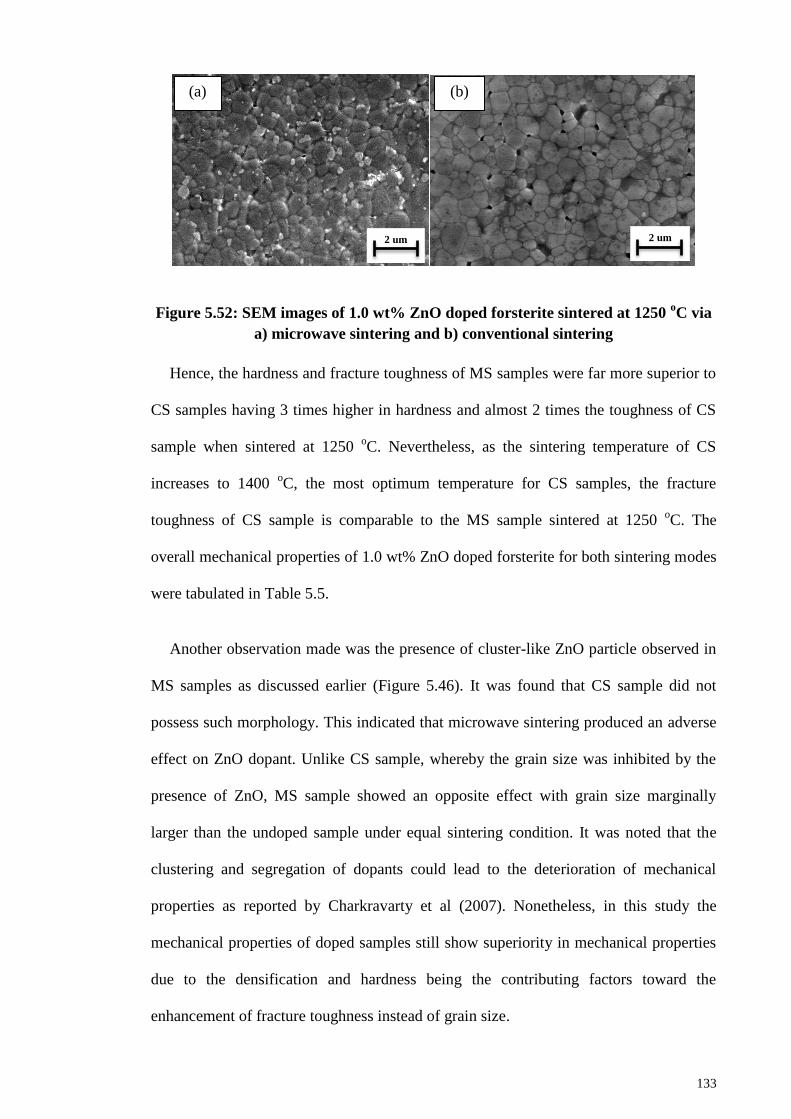
133
Figure 5.52: SEM images of 1.0 wt% ZnO doped forsterite sintered at 1250 oC via
a) microwave sintering and b) conventional sintering
Hence, the hardness and fracture toughness of MS samples were far more superior to
CS samples having 3 times higher in hardness and almost 2 times the toughness of CS
sample when sintered at 1250 oC. Nevertheless, as the sintering temperature of CS
increases to 1400 oC, the most optimum temperature for CS samples, the fracture
toughness of CS sample is comparable to the MS sample sintered at 1250 oC. The
overall mechanical properties of 1.0 wt% ZnO doped forsterite for both sintering modes
were tabulated in Table 5.5.
Another observation made was the presence of cluster-like ZnO particle observed in
MS samples as discussed earlier (Figure 5.46). It was found that CS sample did not
possess such morphology. This indicated that microwave sintering produced an adverse
effect on ZnO dopant. Unlike CS sample, whereby the grain size was inhibited by the
presence of ZnO, MS sample showed an opposite effect with grain size marginally
larger than the undoped sample under equal sintering condition. It was noted that the
clustering and segregation of dopants could lead to the deterioration of mechanical
properties as reported by Charkravarty et al (2007). Nonetheless, in this study the
mechanical properties of doped samples still show superiority in mechanical properties
due to the densification and hardness being the contributing factors toward the
enhancement of fracture toughness instead of grain size.
2 um
(a)
2 um
(b)
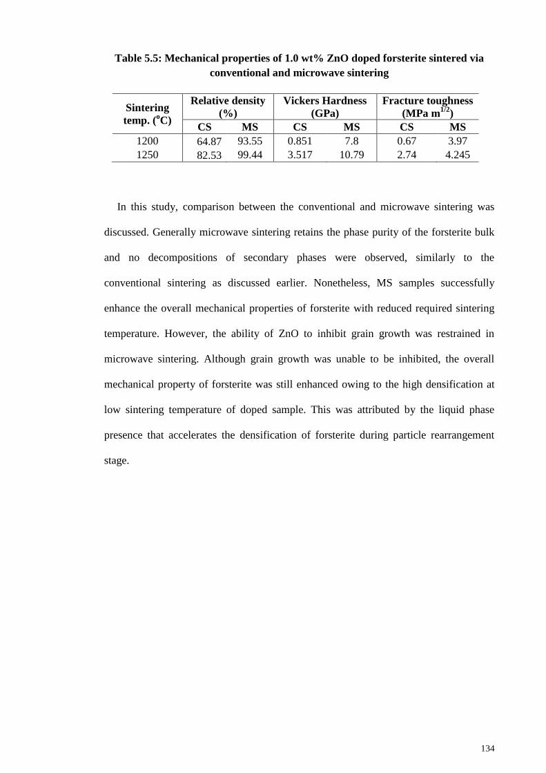
134
Table 5.5: Mechanical properties of 1.0 wt% ZnO doped forsterite sintered via
conventional and microwave sintering
Sintering
temp. (oC)
Relative density
(%)
Vickers Hardness
(GPa)
Fracture toughness
(MPa m1/2
)
CS MS CS MS CS MS
1200 64.87 93.55 0.851 7.8 0.67 3.97
1250 82.53 99.44 3.517 10.79 2.74 4.245
In this study, comparison between the conventional and microwave sintering was
discussed. Generally microwave sintering retains the phase purity of the forsterite bulk
and no decompositions of secondary phases were observed, similarly to the
conventional sintering as discussed earlier. Nonetheless, MS samples successfully
enhance the overall mechanical properties of forsterite with reduced required sintering
temperature. However, the ability of ZnO to inhibit grain growth was restrained in
microwave sintering. Although grain growth was unable to be inhibited, the overall
mechanical property of forsterite was still enhanced owing to the high densification at
low sintering temperature of doped sample. This was attributed by the liquid phase
presence that accelerates the densification of forsterite during particle rearrangement
stage.
135
CHAPTER 6: CONCLUSIONS
6.1 Conclusions
In this study, attrition milling was introduced into the mechanochemical method or
also known as solid-state reaction method to synthesize forsterite powder. The
sinterability of forsterite produced by using attrition milling was compared with the
commonly used ball milling in terms of its mechanical properties. The effect of adding
ZnO on the sinterability of forsterite, especially fracture toughness, was investigated. A
thorough comparison was also conducted between conventional sintering and
microwave sintering to investigate the beneficial effect of microwave sintering on the
sinterability of forsterite ceramic.
The following conclusions were successfully drawn from this research:
1. The application of heat treatment and/or sintering is necessary in producing
forsterite powder/bulk as milling alone showed the presence of incomplete
reaction between talc and magnesium carbonate.
2. Longer milling duration (3 hours vs 5 hours) was found to reduce the required
sintering temperature to produce phase-pure forsterite bulk.
3. High purity single-phase forsterite bulk was successfully synthesized using
attrition milling upon sintering from 1200 oC to 1500
oC. Ball milling requires
higher sintering temperature (1300 oC) in order to obtain phase-pure forsterite
bulk.
4. Smaller powder particle size (23-28 nm) of attrition-milled (AM) powder was
obtained as compared to ball-milled (BM) powder (60-73 nm) upon milling for 5
hours in both cases. Owing to the smaller particle size and high specific surface
area of the former, pure forsterite was successfully obtained at a low sintering
temperature followed by an early densification of forsterite.
136
5. The synthesized forsterite via attrition milling achieved a high relative density of
89-95% when sintered at 1200 oC – 1500
oC whereas ball milled samples require
sintering temperature of at least 1400 oC to produce similar density.
6. AM samples were unable to further increase its density due to the presence of
both large and small grains that causes micropores to be entrapped between them
as the grain grows.
7. The hardness of AM samples exhibited higher hardness value than BM samples
regardless of sintering temperature. A maximum of 9.8 GPa was successfully
obtained at sintering temperature of 1250 oC for AM sample.
8. The slow increase in hardness of BM samples was due to the late densification
of the sample and only began to densify after sintering above 1300 oC.
‘Necking’ process was observed on the morphology of BM sample when
sintered at 1300 oC. The difference between both AM and BM samples in terms
of hardness and density was attributed by the particle size of the powder prior to
sintering process.
9. Fracture toughness of BM sample showed similar trend with its density and
hardness. The optimum temperature having the highest fracture toughness of
BM sample was at 1400 oC, similar to that of density and hardness. AM sample
obtained the highest fracture toughness of 4.3 MPa m1/2
at 1400 oC. The drastic
increase in fracture toughness of BM sample at sintering temperature above
1300 oC was due to the formation of elongated grains which was found to be
beneficial in enhancing fracture toughness.
10. Cell morphology studies using MC3T3-E1 osteoblast-like cell have shown
promising result on AM sample for clinical application. Day 1 observation
showed continuous growth of the cell by forming small whisker-like filopodial
137
on the surface of sample and a very dense cell forming a thin layer on the
surface of the sample on the third day.
11. According to the thermal analysis, the endothermic peaks observed were related
to the removal of water content from the powder and the decomposition of
magnesium carbonate to recrystallize MgO. The exothermic peaks were
indicating the beginning of the formation of forsterite and it was concluded that
940 oC is the required heat treatment temperature to form forsterite powder.
12. Phase-pure forsterite powder was successfully obtained upon heat treatment at
1000 oC.
13. Both undoped and ZnO doped forsterite at all compositions showed only
forsterite peak in the XRD analysis. The highest amount of ZnO composition
(3.0 wt%) did not show signs of ZnO peak. Nevertheless, elemental analysis
using EDX was able to detect the presence of ZnO for only 3.0 wt% ZnO doped
samples.
14. All samples showed an increase in relative density with increasing sintering
temperature. Doped samples possessed a more superior density than undoped
samples at all sintering regime. The highest relative density was 97.8% obtained
by 3.0 wt% ZnO doped sample sintered at 1300 oC followed by 97.7% and
95.5% from 0.5 wt% and 1.0 wt% ZnO doped samples, respectively, when
sintered at 1500 oC.
15. 3.0 wt% ZnO doped samples had reached its densification plateau earlier at 1300
oC sintering temperature than other samples (1400
oC). This could be attributed
by the beneficial effect of ZnO on the densification rate of forsterite ceramic.
16. The undoped sample achieved a maximum of 8.5 GPa when sintered at 1400 oC
whereas all doped samples possessed similar maximum hardness within the
range of 9.7-9.9 GPa. The low hardness value obtained at 1200 oC was attributed
138
by the low densification of the respective samples. The morphology of the
samples showed that grains were yet to form at this stage.
17. ZnO inclusion in forsterite was found to enhance the fracture toughness of
forsterite. The highest fracture toughness obtained was 4.51 MPa m1/2
by 1.0
wt% ZnO doped sample sintered at 1400 oC.
18. In terms of grain size, the fracture toughness of 3.0 wt% ZnO doped sample
showed a more superior value at 1300 oC but began to show deterioration in
fracture toughness as sintering continues to a higher temperature. This was
attributed by the smaller grain size of the sample as compared to other samples
but due to the drastic increase in the grain size, the fracture toughness was also
affected.
19. Further increasing the amount of ZnO in forsterite has led to the inability of ZnO
to inhibit grain growth as sintering temperature increases. The increase of ZnO
had also significantly reduces the dc of forsterite thus causing deterioration of
fracture toughness at smaller grain size.
20. 1.0 wt% ZnO doped sample showed the best mechanical properties compared to
other samples and ZnO was proven to serve as a good grain size inhibitor at
composition of 1.0 wt% and below.
21. Microwave sintering was found to not cause any disruption on the phase purity
of forsterite bulk, similar to conventional sintering.
22. Undoped forsterite sample obtained 87.9% relative density when sintered at
1250 oC. Doped samples were found to possess a more superior relative density
with value ranging from 98-99% for all three compositions when sintered at the
same temperature.
139
23. The highest amount of ZnO composition (3.0 wt%) did not possessed similar
trend as the other compositions when sintered from 1100 oC to 1200
oC as the
density of this sample began to densify beyond 1200 oC.
24. Highest hardness was obtained by 1.0 wt% ZnO doped sample with value of
10.65 GPa via microwave sintering at temperature of 1250 oC. The increase in
hardness of all samples was attributed by its respective densification.
Nonetheless, the doped samples showed a more superior densification and
hardness than the undoped sample.
25. The fracture toughness of microwave-sintered 1.0 wt% ZnO doped sample was
found to the best with a value of 4.25 MPa m1/2
followed by 3.0 wt% ZnO, 0.5
wt% ZnO and undoped samples ranging from 3.65 MPa m1/2
to 3.85 MPa m1/2
.
The trend of fracture toughness complied well with the hardness and relative
density result.
26. The increase amount of ZnO composition was found to marginally increase the
grain size of forsterite. Conducting microwave sintering on ZnO doped forsterite
has shown an adverse effect on the grain size of forsterite with 1 µm grain size
from 0.85 µm and 0.9 µm for 0.5 wt% ZnO and 1.0 wt% ZnO doped samples,
respectively.
27. Cluster-like particles were observed throughout the grain morphology of doped
samples which reduces the effectiveness of ZnO as grain growth inhibitor.
Nonetheless, the dominant factor that affects the overall mechanical properties
of forsterite is density and hardness instead of grain size.
28. Microwave of ZnO doped samples clearly showed the presence of liquid phase
due to the ZnO addition which increases the rate of densification of forsterite
thus improving the mechanical properties of forsterite, particularly fracture
toughness, even at low sintering temperature (1150 oC).
140
29. Doping of ZnO up to 3.0 wt% resulted in an opposite side-effect as compared to
0.5 wt% and 1.0 wt% ZnO doped samples. Instead of increasing the
densification rate at low sintering temperature (1150 oC), 3.0 wt% doped sample
showed a very slow densification rate owing to the high thickness of liquid
phase found in the grain vicinity. It was found that high thickness of liquid phase
slowed the grain growth rate of sample thus inhibiting the densification of
forsterite at low sintering temperature (<1200 oC).
30. Microwave sintering had significantly reduced the required sintering
temperature to achieve similar densification of forsterite. 87.88% relative
density was successfully obtained using microwave sintering at temperature of
1250 oC whereas conventional sintering requires 1400
oC to obtain similar
densification.
31. In regards to fracture toughness, microwave sintering allowed forsterite to obtain
fracture toughness of 3.65 MPa m1/2
at temperature of 1250 oC unlike
conventional sintering that only obtained 1.85 MPa m1/2
and 3.2 MPa m1/2
at
temperature of 1250 oC and 1400
oC, respectively, on heat-treated forsterite.
32. In comparison between 1.0 wt% ZnO doped samples sintered via microwave and
conventional method, MS samples had reached its densification plateau at 1250
oC with value of 99.44% whereas CS sample still showed many porosities
throughout the grain structures.
33. Comparable fracture toughness was obtained between MS and CS when sintered
at 1250 oC and 1400
oC, respectively. With reduction in the required sintering
temperature for the optimum mechanical properties, microwave sintering had
proven to be beneficial in reducing the temperature needed as well as improving
the mechanical properties while retaining the phase purity of forsterite.
141
6.2 Future directions
Based on current study, many findings were made and there are many other possible
improvements that can be taken. There are uncertainties occurring throughout the
research which requires further investigation that could enhance the sinterability of
forsterite especially the fracture toughness.
As discussed earlier in this work, ZnO was found to be beneficial to forsterite in
inhibiting the grain growth phenomena. Reduction in grain size has indeed enhances the
fracture toughness of forsterite but it would be clearer to go further in detail on the
function of ZnO towards the grain boundaries and its distribution throughout the grain
morphology. Microwave sintering is a new field to venture for forsterite. A more
detailed study can be conducted to obtain the optimum profile with the best mechanical
properties for forsterite and probing the underlying mechanism. Also, it was found that
conventional and microwave sintering produce some exciting results on ZnO doped
samples as CS samples showed inhibition on grain growth whereas MS samples showed
otherwise. With the following suggestions for future directions, it will be great to clarify
these phenomena.
1. The composition and distribution upon sintering process of grain boundaries
phases can be enlighten, particularly on doped samples, by running an in depth
investigation using X-ray Photoelectron Spectroscopy (XPS) analysis.
2. Although literatures have shown that ZnO addition on HA was found to be non-
toxic but biocompatibility test should be conducted in depth with studies on the
cell attachment, adhesion, proliferation and cytotoxicity test as well as simulated
bodily fluid (SBF) study on the ZnO doped forsterite to ensure that it is viable
for clinical usage.
142
3. A more detail profiling of microwave sintering on forsterite can be conducted to
fully understand the mechanical properties trend with varying sintering
temperature, sintering ramp rate and sintering time. Knowing that the grain size
obtained was still 1.0 µm and below when sintered at 1250 oC, further sintering
can be conducted to observe on the grain growth of forsterite under microwave
sintering and probably improvement on mechanical properties.
4. Addition of other sintering additives (manganese oxide, zirconia) can be
conducted on forsterite to investigate the probable beneficial effect. Microwave
sintering can be cooperated with these sintering additives to venture on other
interesting possibilities of microwave effect on doped forsterite.
5. Cold isostatic pressing (CIP) was known to provide additional reinforcement
towards the enhancement in mechanical properties of other ceramic such as
hydroxyapatite. This reinforcement could further increase the mechanical
properties of forsterite.
143
REFERENCES
Aboushelib, M. N., Kleverlaan, C. J., & Feilzer, A. J. (2008). Evaluation of a high
fracture toughness composite ceramic for dental application. Journal of
Prosthodontics, 17(7), 538-544.
Afonina, G. A., Leonov, V. G., & Popova, O. N. (2005). Production of forsterite
powder using sol gel technology. Glass and Ceramics, 62, 248-252.
Agrawal, D. (2006). Microwave sintering of ceramics, composites and metallic
materials and meting of glasses. Transactions of the Indian Ceramic Society,
65(3), 129-144.
Althoff, J., Quint, P., Krefting, E. R., & Hohling, H. J. (1982). Morphological studies on
the epiphyseal growth plate combined with biochemical and X-ray microprobe
analyses. Histochemistry, 74(4), 541-552.
Amir, M., McDonagh, A. M. & Cortie, M. B. (2012). Zinc oxide particles: Synthesis,
properties and applications. Chemical Engineering Journal, 185-186, 1-22.
Amogh, T., Mangesh, G., & Anna, P. N. (2010). A Brief Review: Biomaterials and
Their Application. International Journal of Pharmacy and Pharmaceutical
Sciences, 2(4), 19-23.
Andrew J. Berry, Andrew M. Walker, Jorg Hermann, Hugh St. C. O'Neill, Garry J.
Foran, & Gale, J. D. (2007). Titanium substitution mechanisms in forsterite.
Chemical Geology, 242, 176-186.
Aseev, V. A., Zhukov, S. N., Kuleshsov, N. V., Kuril'chik, S. V., Mudryi, A. V.,
Nikonorov, N. V., Rokhmin, A. S., & Yasyukevich, A. S. (2015). Spectral
luminescence characteristics of forsterite nano glass ceramics doped with
chromium ions. Optics and Spectroscopy, 118(1), 146-150.
Baláž, P. (2008). High-Energy Milling Mechanochemistry in Nanoscience and Minerals
Engineering (pp. 103-132): Springer Berlin Heidelberg.
Bandyopadhyay, A., Withey, E.A., Moore, J. & Bose, S. (2007). Influence of ZnO
doping in calcium phosphate ceramics. Materials Science and Engineering, 27,
14-17.
Becher, P. F., Sun, E. Y., Plucknett, K. P., Alexander, K. B., Hsueh, C.-H., Lin, H.-T.,
Waters, S. B., Westmoreland, C. G., Kang, E.-S., Hirao, K., & Brito, M. E.
(2005). Microstructural Design of Silicon Nitride with Improved Fracture
Toughness: I, Effects of Grain Shape and Size. Journal of the American Ceramic
Society, 81(11), 2821-2830.
Bernotat, S. & Schonert, K. (1998). Size reduction. In: Ullmann’s Encyclopedia of
Industrial Chemistry. VCH Verlagsgesellschaft, Weinheim, B2, 5.1–5.39.
Best, S. M., Porter, A. E., Thian, E. S., & Huang, J. (2008). Bioceramics: Past, present
and for the future. Journal of the European Ceramic Society, 28(7), 1319-1327.
144
Bian, H.-m., Yang, Y., Wang, Y., Tian, W., Jiang, H.-f., Hu, Z.-j., & Yu, W.-m. (2012).
Alumina–titania ceramics prepared by microwave sintering and conventional
pressure-less sintering. Journal of Alloys and Compounds, 525, 63-67.
Binyamin, G., Shafi, B.M. & Mery, C.M. (2006). Biomaterials: A primer for surgeons.
Seminars in Pediatric Surgery, 15, 276-283.
Bizot P. & Sedel L. (2001). Alumina bearings in hip replacement: theoretical and
practical aspects. Operative Techniques in Orthopaedics., 4, 263-269.
Borrell, A., Salvador, M. D., Peñaranda-Foix, F. L., & Cátala-Civera, J. M. (2013).
Microwave Sintering of Zirconia Materials: Mechanical and Microstructural
Properties. International Journal of Applied Ceramic Technology, 10(2), 313-
320.
Borrell, A., Salvador, M. D., Miranda, M., Penaranda-Foix, F. L., & Catala-Civera, J.
M. (2014). Microwave technique: A powerful tool for sintering ceramic
materials. Current Nanoscience, 10, 32-35.
Bose, S., Dasgupta, S., Tarafder, S., & Bandyopadhyay, A. (2010). Microwave-
processed nanocrystalline hydroxyapatite: simultaneous enhancement of
mechanical and biological properties. Acta Biomater, 6(9), 3782-3790.
Bose, S., Tarafder, S., Baneree, S. S., Davies, N. M., & Bandyopadhyay, A. (2011).
Understanding in vivo response and mechanical property variation in MgO, SrO
and SiO2 doped b-tTCP. Bone, 48(6), 1282-1290.
Briend, F.J. (2011). Biomaterials & scaffolds for tissue engineering. Materials Today,
14(3), 88-95.
Brindley, G. W., & Hayami, R. (1965). Mechanism of formation of forsterite and
enstatite from serpentine. Materials Research Laboratory, 12, 505.
Cao, W. & Hench, L. L. (1996). Bioactive materials. Ceramics International, 22, 493-
507.
Carlisle, E. M. (1988). Silicon as a trace nutrient. The Science of the Total Environment,
73, 95-106.
Castro, C. L. D., & Mitchell, B. S. (2002). Nanoparticles for mechanical attrition. In M.
I. Baraton (Ed.), Synthesis, Functionalization and Surface Treatment of
Nanoparticles (pp. 1-15): American Scientific Publishers.
Catledge, S. A., Fries, M. D., Vohra, Y. K., Lacefield, W. R., Lemons, J. E., Woodard,
S., & Venugopalan, R. (2002). Nanostructured ceramcs for biomedical implants.
Journal of nanoscience and nanotechnoogy, 2(3-4), 293-312.
Chakravarty, D., Bysakh, S., Muraleedharan, K., Rao, T. N., & Sundaresan, R. (2007).
Spark Plasma Sintering of Magnesia-Doped Alumina with High Hardness and
Fracture Toughness. Journal of the American Ceramic Society, 91(1), 203-208.
145
Chen, I. W., & Wang, X. H. (2000). Sintering dense nanocrystalline ceramics without
final-stage grain growth. Nature, 404, 168-171.
Cheng, L., Liu, P., Chen, X., Niu, W., Yao, G., Liu, C., . . . Zhang, H. (2012).
Fabrication of nanopowders by high energy ball milling and low temperature
sintering of Mg2SiO4 microwave dielectrics. Journal of Alloys and Compounds,
513, 373-377.
Chesters, J. H. (1983). Refractories: Production and properties. London: IOM
Communications Ltd.
Chevalier, J., & Gremillard, L. (2009). Ceramics for the medical applications: a picture
for the next 20 years. Journal of European Ceramic Society, 29, 1245-1255.
Chou, J., Valenzuela, S. M., Santos, J., Bishop, D., Milthorpe, B., Green, D. W., Ben-
Nissan, B. (2014). Strontium- and magnesium-enriched biomimetic beta-TCP
macrospheres with potential for bone tissue morphogenesis. J Tissue Eng Regen
Med, 8(10), 771-778
Clark, D. E., Folz, D. C. & Mahmoud, M. M. (Eds.). (2004). Microwave solution for
ceramic engineers. Westerville: American Ceramic Society.
Clarke, I. C., Manaka, M., Green, D. D., Williams, P., Pezzotti, G., Kim, Y. H., . . .
Gustafson, G. A. (2003). Current status of zirconia used in total hip implants.
Journal of Bone and Joint Surgery, 85(4), 73-84.
Coadou, C. L., Karst, N., Emieux, F., Sicardy, O., Montani, A., Bernard-Granger, G., . .
. Simonato, P. (2015). Assessment of ultrathin yttria-stabilized zirconia foils for
biomedical applications. Journal of Materials Science, 50, 6197-6207.
Cottom, B. A., & Mayo, M. J. (1996). Fracture toughness of nanocrystalline ZrO2-
3mol-percent Y2O3 determined by vickers indentation. Scripta materialia,
34(5), 809-814.
Cullity, B. D. & Stock, S. R. (2001) Elements of X-Ray Diffraction. 3rd Edition,
Prentice-Hall, Inc., New York.
Das, S., Mukhopadhyay, A. K., Datta, S., & Basu, D. (2009). Prospects of microwave
processing: an overview. Bulletin of Materials Science, 32, 1-13.
Dee, K. C., Puleo, D. A. & Bizios, R. (2003). An introduction to tissue biomaterial
interactions. Wiley-Liss, Inc.
Deville S., Chevalier, J. and Gremillard, L. (2006). Influence of surface finish and
residual stresses on the ageing sensitivity of biomedical grade zirconia.
Biomaterials, 27, 2186-92.
Dorozhkin, S.V. (2009). Calcium orthophosphate-based biocomposites and hybrid
biomaterials. Journal of Materials Science, 44(9), 2343-2387.
Dorozhkin, S. V. (2010). Bioceramics of calcium orthophosphates. Biomaterials, 31(7),
1465-1485.
146
Dorozhkin, S.V. & Best, S. (2002). Biological and Medical Significance of Calcium
Phosphates, Angewandte Chemie International Edition, 41(17), 3130-3146.
Douy, A. (2002). Aqueous Syntheses of Forsterite (Mg2SiO4) and Enstatite (MgSiO3).
Journal of Sol-Gel Science and Technology, 24(3), 221-228
Fathi. M.H. & Kharaziha, M. (2008). Mechanically activated crystallization of phase
pure nanocrystalline forsterite powders. Materials Letters, 62(27), 4306-4309.
Fathi, M. H., & Kharaziha, M. (2009). Two-step sintering of dense, nanostructural
forsterite. Materials Letters, 63(17), 1455-1458
Feng, P., Niu, M., Gao, C., Peng, S., & Shuai, C. (2014). A novel two-step sintering for
nano-hydroxyapatite scaffolds for bone tissue engineering. Scientific Reports, 4,
5599.
Geetha M., Singh, A. K., Asokamani, R. & Gogia, A. K. (2009). Ti based biomaterials,
the ultimate choice for orthopaedic implants – A review. Progress in Materials
Science, 54, 397-425.
Ghomi, H., Jaberzadeh, M. & Fathi, M.H. (2011). Novel fabrication of forsterite
scaffold with improved mechanical properties. Journal of Alloys and
Compounds, 509, 63-68.
Gutwein, L. G., & Webster, T. J. (2002). Osteoblast and chrondrocyte proliferation in
the presence of alumina and titania nanoparticles. Journal of Nanoparticle
Research, 4, 231-238.
Hassan, A. M., Awaad, M., Bondioli, F., & Naga, S. M. (2014). Densification Behavior
and Mechanical Properties of Niobium-Oxide-Doped Alumina Ceramics.
Journal of Ceramic Science and Technology, 5(1), 51-56.
Hassanzadeh-Tabrizi, S. A., Bigham, A., & Rafienia, M. (2016). Surfactant-assisted sol-
gel synthesis of forsterite nanoparticles as a novel drug delivery system. Mater
Sci Eng C Mater Biol Appl, 58, 737-741.
Hench, L. L. (1998). Bioceramics. Journal of American Ceramic Society, 81(7), 1705-
1728.
Hench, L.L. (2000). The challenge of orthopaedic materials. Current Orthopaedics, 14,
7-15.
Hiraga, T., Tachibana, C., Ohashi, N., & Sano, S. (2010). Grain growth systematics for
forsterite enstatite aggregrates: Effect of lithology on grain size in the upper
mantle. Earth and Planetary Science Letters, 291(1-4), 10-20.
Ito, A., Kawamura, H., Otsuka, M., Ikeuchi, M., Ohgushi, H., Ishikawa, K., . . .
Ichinose, N. (2002). Zinc-releasing calcium phosphate for stimulating bone
formation. Materials Science and Engineering: C, 22(1), 21-25.
Jayaswal, G. P., Dange, S. P., & Khalikar, A. N. (2010). Bioceramic in dental implants:
A review. Journal of Indian Prosthodontic Society, 10(1), 8-12.
147
Jing, L. I., Qi, W., Jihui, L., & Peng, L. (2009). Synthesis process of forsterite refractory
by iron ore tailings. Journal of Environmental Sciences Supplement, 92-95.
Juhasz, J. & Best, S. (2012). Bioactive ceramics: processing, structures and properties.
Journal of Materials Science, 47(2), 610-624.
Katti, K.S. (2004). Biomaterials in total joint replacement. Colloids and Surfaces B:
Biointerfaces, 39, 133-142.
Kazakos, A., Komarneni, S., & Roy, R. (1990). Preparation and densification of
forsterite (Mg2SiO4) by nanocomposite sol-gel processing. Materials Letters,
9(10), 405-409.
Khanal, S. P., Mahfuz, H., Rondinone, A. J., & Leventouri, T. (2016). Improvement of
the fracture toughness of hydroxyapatite by incorporation of carboxyl
functionalized single walled nanotubes (CfSWCNTs) and nylon. Materials
Science and Engineering: C, 60, 204-210.
Kharaziha, M., & Fathi, M. H. (2010). Improvement of mechanical properties and
biocompatibility of forsterite bioceramic addressed to bone tissue engineering
materials. J Mech Behav Biomed Mater, 3(7), 530-537.
Kosanović, C., Stubičar, N., Tomašić, N., Bermanec, V., & Stubičar, M. (2005).
Synthesis of a forsterite powder by combined ball milling and thermal treatment.
Journal of Alloys and Compounds, 389(1-2), 306-309.
Kiss, S.J., Kostic, E., Djurovic, D. & Boskovic, S. (2001). Influence of mechanical
activation and fluorine ion on forsterite formation. Powder Technology, 114, 84-
88.
Kloss, F.R. & Gassner, R. (2006). Bone and aging: Effects on the maxillofacial
skeleton. Experimental Gerontology, 41, 123-129.
Kokubo, T., Kim, H.M. & Kawashita, M. (2003). Novel bioactive materials with
different mechanical properties. Biomaterials, 24, 2161-2175.
Kosanovic, C., Stubicar, N., Tomasic, N., Bermanec, V. & Stubicar, M. (2005),
Synthesis of a forsterite powder by combined ball milling and thermal treatment.
Journal of Alloys and Compounds, 389(1), 306-309.
Kostic, E., Kiss, S., & Boskovic, S. (1997). Decrease of the MgAl2O4 formation
temperature. Powder Technology, 92, 271-274.
Law, K.W. (1968). Grain growth in UO2-Al2O3 in the presence of a liquid phase.
General Electric Research and Development Center, Schenectady, New York,
12301.
Lawson, S. (1995). Environmental degradation of zirconia ceramics. Journal of the
European Ceramic Society, 15, 485-502.
148
Lee, S. K. Y., Tan, C. Y., Lai, S. K. L., Tolouei, R., Amiriyan, M., Yap, B. K., &
Ramesh, S. (2011). Sintering behaviour of forsterite bioceramics. Paper
presented at the 2011 Natl. Postgrad. Conf.
LeGeros, R. Z. (1991). Calcium phosphate in oral biology and medicine. Monographs
in Oral Science, 15, 1-201.
LeGeros, R. Z. and LeGeros, J. P. (1993). Dense hydroxyapatite. In An Introduction to
Bioceramics. Ed. by Hench, L. L. and Wilson, J. (World Scientific, Singapore)
Chapter 9, 139.
Liu, C. C., Yeh, J. K., & Aloia, J. F. (1988). Magnesium directly stimulates osteoblast
proliferation. Journal of Bone and Mineral Research, 3, 104.
Livage, J., Babonneau, F., Chatry, M., & Coury, L. (1997). Sol-gel synthesis and NMR
characterization of ceramics. Ceramics International, 23, 13-18.
Llyod, S.N. & Cross, W. (2002). The current use of biomaterials in urology. European
Urology Supplements, 1, 2-6.
Maliavski, N. I., Dushkin, O. V., Tchekounova, E. V., Markina, J. V., & Scarinci, G.
(1997). An organic-inorganic silica precursor suitable for the sol-gel synthesis in
aqueous media. Journal of Sol-Gel Science and Technology, 8, 571-575.
McCormick, P. G. (1995). Application of mechanical alloying to chemical refining
(overview). Materials Transactions, 36(2), 161-169.
Mendelson, M. I. (1969). Average Grain Size in Polycrystalline Ceramics. Journal of
American Ceramic Society, 52, 443-446.
Miao, S., Weng, W., Cheng, K., Du, P., Shen, G., Han, G., & Zhang, S. (2005). Sol-gel
preparation of Zn-doped fluoridated hydroxyapatite films. Surface & Coatings
Technology, 198, 223-226.
Mitchell, M. B. D., Jackson, D., & James, P. F. (1998). Preparation and characterization
of forsterite (Mg2SiO4) aerogels. Journal of Non-Crystalline Solids, 225, 359-
364.
Mohamed, N.R. (2007). Sintering of Ceramics. CRC Press.
Monaco, C., Tucci, A., Esposito, L., & Scotti, R. (2013). Microstructural changes
produced by abrading Y-TZP in presintered and sintered conditions. Journal of
Dentistry, 41(2), 121-126.
Monaco, C., Prete, F., Leonelli, C., Esposito, L., & Tucci, A. (2015). Microstructural
study of microwave sintered zirconia for dental applications. Ceramics
International, 41(1), 1255-1261.
Mukhopadhyay, A., & Basu, B. (2007). Consolidation-microstructure-property
relationships in bulk nanoceramics and ceramic nanocomposites: a review.
Structural ceramic nanomaterials, 52(5), 257-288.
149
Murray, E. J., & Messer, H. H. (1981). Turnover of bone zinc during normal and
accelerated bone loss in rats. Journal of Nutrition, 111, 1641-1647.
Mustafa, E., Khalil, N., & Gamal, A. (2002). Sintering and microstructure of spinel–
forsterite bodies. Ceramic International, 28, 663-667.
Naderi, H., Matin, M. M., & Barhrami, A. R. (2011). Critical issues in tissue
engineering: biomaterials, cell sources, angiogenesis and drug delivery systems.
Journal of biomaterials applications, 1-17.
Naghiu, M. A., Gorea, M., Mutch, E., Kristaly, F., & Tomoaia-Cotisel, M. (2013).
Forsterite Nanopowder: Structural Characterization and Biocompatibility
Evaluation. Journal of Materials Science & Technology, 29(7), 628-632.
National Institutes of Health (NIH). (1982). Clinical applications of biomaterials. NIH
Consensus Statement, 4(5), 1-19.
Ni, S., Chou, L., & Chang, J. (2007). Preparation and characterization of forsterite
(Mg2SiO4) bioceramics. Ceramics International, 33(1), 83-88.
O’Brien, F. J. Biomaterials & scaffolds for tissue engineering. Materials Today, 14(3),
88-95.
Ohsato, H., Tsunooka, T., Sugiyama, T., Kakimoto, K.-i., & Ogawa, H. (2006).
Forsterite ceramics for millimeterwave dielectrics. Journal of Electroceramics,
17(2-4), 445-450.
Oghbaei, M., & Mirzaee, O. (2010). Microwave versus conventional sintering: a review
of fundamentals, advantages and applications. Journal of Alloys and
Compounds, 494, 175-189.
Park J. B. & Bronzino, J. D. (Eds.). (2003). Biomaterials: principles and applications.
Boca Rator: CRC Press.
Petricevic, V., Gayen, S. K., Alfano, R. R., Yamagishi, K., Anzai, H., & Yamaguchi, Y.
(1988). Laser action in chromium-doped forsterite. Applied Physics Letters,
52(13), 1040-1042.
Piconi, C., & Maccauro, G. (1999). Zirconia as a ceramic biomaterials. Biomaterials,
20(1), 1-25.
Pietak, A. M., Reid, J. W., Stott, M. J., & Sayer, M. (2007). Silicon substitution in the
calcium phosphate bioceramics. Biomaterials, 28, 4023-4032.
Popov, O. N., Frolova, V. P., Orlova, V. N., Shatova, N. P., & Izosenkova, A. V.
(1988). Contact interaction of aluminosilicate and basic refractories.
Refractories For The Consumer, 29(3), 259-262.
Presenda, A., Salvador, M. D., Penaranda-Foix, F. L., Moreno, R., & Borrell, A. (2015).
Effect of microwave sintering on microstructure and mechanical properties in Y-
TZP materials used for dental applications. Ceramic International, 41, 7125-
7132.
150
Promsawat, M., Watcharapasom, A., & Jiansirisomboon, S. (2012). Effects of ZnO
nanoparticulate addition on the properties of PMNT ceramics. Nanoscale
Research Letters, 7(1), 65.
Ramakrishna, S., Mayer, J., Wintermantel, E. & Leong, K.W. (2001). Biomedical
applications of polymer-composite materials: A review. Composites Science and
Technology, 61(9), 1189-1224.
Ramesh, S., Yaghoubi, A., Lee, K. Y., Chin, K. M., Purbolaksono, J., Hamdi, M., &
Hassan, M. A. (2013). Nanocrystalline forsterite for biomedical applications:
synthesis, microstructure and mechanical properties. Journal of Mechanical
Behavior of Biomedical Materials, 25, 63-69.
Ramesh, S., Tan, C. Y., Peralta, C. L., & Teng, W. D. (2007). The effect of manganese
oxide on the sinterability of hydroxyapatite. Science and Technology of
Advanced Materials, 8(4), 257-263.
Rybakov, K. I., Olevsky, E. A., & Krikun, E. V. (2013). Microwave sintering:
fundamentals and modeling. Journal of American Ceramic Society, 96, 1003-
1020.
Saberi, A., Alinejad, B., Negahdari, Z., Kazemi, F., & Almasi, A. (2007). A novel
method to low temperature synthesis of nanocrystalline forsterite. Materials
Research Bulletin, 42(4), 666-673.
Saberi, A., Negahdari, Z., Alinejad, B., & Golestani-Fard, F. (2009). Synthesis and
characterization of nanocrystalline forsterite through citrate–nitrate route.
Ceramics International, 35(4), 1705-1708.
Sanosh, K.P., Balakrishnan, A., Francis, L. & Kim, T.N. (2010). Sol–gel synthesis of
forsterite nanopowders with narrow particle size distribution. Journal of Alloys
and Compounds, 495(1), 113-115.
Schoppka, S., Schmid, T., Schmid, C., & Lehle, K. (2010). Curent strategies in
cardiovascular biomaterial functionalization. Materials, 3(1), 638-655.
Shi, F., Du, P. C., Liu, J. X., Wu, J. W., & Luo, C. Y. (2012). Preparation of Forsterite
by Solid State Synthesis Process and its Dielectric Properties. Advanced
Materials Research, 534, 110-113.
Sionkowska, A. (2011). Current research on the blends of natural and synthetic
polymers as new biomaterials: Review. Progress in Polymer Science, 36(9),
1254-1276.
Siores, E. and DoRego, D. (1995). Microwave applications in materials joining. Journal
of Materials Processing Technology. 48(12), 619-625.
Song Kai Xin, Xu Jun Ming, Hu Xiao Ping, Zheng Liang, Ying Zhi Hua, & Bin, Q. H.
(2010). Microwave dielectric properties of Al-substituted forsterite ceramics.
Paper presented at the International Conference on Electrical and Control
Engineering.
151
Straley, K. S., Foo, C. W. P., & Heilshorn, S. C. (2010). Biomaterial design strategies
for the treatment of spinal cord injuries. Journal of Neurotrauma, 27, 1-19.
Suchanek, W., Yashima, M., Kakihana, M., & Yoshimura, M. (1997). Hydroxyapatite
ceramics with selected sintering additives. Biomaterials, 80, 2805-2813.
Suchanek, W. & Yoshimura, M. (1998). Processing and properties of hydroxyapatite
ceramics with selected sintering additives. Biomaterials, 13, 94-117.
Sun, H.-T., Fujii, M., Nitta, N., Mizuhata, M., Yasuda, H., Deki, S., & Hayashi, S.
(2009). Molten-Salt Synthesis and Characterization of Nickel-Doped Forsterite
Nanocrystals. Journal of the American Ceramic Society, 92(4), 962-966.
Suryanarayana, C. (2001). Mechanical alloying and milling. Progress in Materials
Science, 46, 1-184.
Tavangarian, F., & Emadi, R. (2009). Mechanical activation assisted synthesis of pure
nanocrystalline forsterite powder. Journal of Alloys and Compounds, 485(1-2),
648-652.
Tavangarian, F., Emadi, R., & Shafyei, A. (2010). Influence of mechanical activation
and thermal treatment time on nanoparticle forsterite formation mechanism.
Powder Technology, 198(3), 412-416.
Tavangarian, F., & Emadi, R. (2010a). Synthesis of nanocrystalline forsterite
(Mg2SiO4) powder by combined mechanical activation and thermal treatment.
Materials Research Bulletin, 45(4), 388-391.
Tavangarian, F., & Emadi, R. (2010b). Synthesis of pure nanocrystalline magnesium
silicate powder. Ceramics Silikaty, 54(2), 122-127.
Tavangarian, F., & Emadi, R. (2011). Improving degradation rate and apatite formation
ability of nanostructure forsterite. Ceramics International, 37(7), 2275-2280.
Thostenson, E.T. & Chou, T.W. (1999). Microwave processing: fundamentals and
applications. Composite: Part A, 30, 1055-1071.
Thuault, A., Savary, E., Hornez, J. C., Moreau, G., Descamps, M., Marinel, S., &
Leriche, A. (2014). Improvement of the hydroxyapatite mechanical properties by
direct microwave sintering in single mode cavity. Journal of European Ceramic
Society, 34, 1865-1871.
Tomoaia, G.H., Soritau, O., Cotisel, M.T., Pop, L.B., Pop, Mocanu, A., Horovitz, O. &
Bobos, L.D. (2013). Scaffolds made of nanostructured phosphates, collagen and
chitosan for cell culture, Powder Technology, 238, 99-107.
Vallepu, R., Nakamura, Y., Komatsu, R., & Ikeda, K. (2995). Preparation of forsterite
by the geopolymer technique-gel compositions as a function of pH and
crystalline phases. Journal of Sol-Gel Science and Technology, 35, 107-114.
152
Veljović, D., Zalite, I., Palcevskis, E., Smiciklas, I., Petrović, R., & Janaćković, D.
(2010). Microwave sintering of fine grained HAP and HAP/TCP bioceramics.
Ceramics International, 36(2), 595-603.
Verdun, H. R., Thomas, L. M., Andrauskas, D. M., McCollum, T., & Pinto, A. (1988).
Chromium-doped forsterite laser pumped with 1.06 μm radiation. Applied
Physics Letters, 53(26), 2593.
Vorman, J. (2003). Magnesium: Nutrition and metabolism. Mol Aspects Med., 24, 27-
37.
Wang, J., Binner, J., & Vaidhyanathan, N. (2006). Evidence for the microwave effect
during hybrid sintering. Journal of American Ceramic Society, 89(6), 1977-
1984.
Wang, M. (2003). Developing bioactive composite materials for tissue replacement.
Biomaterials, 24, 2133-2151.
Wang, X. H., Chen, P. L., & Chen, I. W. (2006). Two-step sintering of ceramics with
constant grain-size I. Y2O3. Journal of American Ceramic Society, 89, 431-437.
Wang, W., Ouyang, Y., & Poh, C. K. (2011). Orthopaedic implant technology:
Biomaterials from past to future. Biomaterials in Orthopaedic Implant
Technology, 40(5), 237-244.
Webster, T. J., Ergun, C., Doremus, R. H., Siegel, R. W., & Bizios, R. (2001).
Enhanced osteoclast-like cell functions on nanophase ceramics. Biomaterials,
22(11), 1327-1333.
Williams, D. B. & Carter, C. B. (1996). The transmission electron microscope. Springer
US.
Williams, D. F. (2009). On the nature of biomaterials. Biomaterials, 30(30), 5897-5909.
Wise, D. L. (2000). Biomaterials Engineering and Devices. Humana Press; Berlín,
Germany, 205-319.
Wolf, F. I. and Cittadini, A. (2003). Chemistry and biochemistry of magnesium. Mol
Aspects Med., 24, 3-9.
Wurst, J. C. & Nelson, J. A. (1972). Lineal Intercept Technique for Measuring Grain
Size in Two-phase Polycrystalline Ceramics. Journal of American Ceramic
Society, 5, 109.
Yadoji, P., Peelamedu, R., Agrawal, D. & Roy, R. (2003). Microwave sintering of Ni-
Zn ferrites: comparison with conventional sintering. Materials Science and
Engineering: Part B, 98, 269-278.
Yamaguchi, M. (2010). Role of nutritional zinc in the prevention of osteoporosis.
Molecular and Cellular Biochemistry, 338, 241-254.
153
Yasuoka, M., Nishimura, Y., Nagaoka, T., & Watari, K. (2006). Influence of different
methods of controlling microwave sintering. Journal of Thermal Analysis and
Calorimetry, 83(2), 407-410.
Yoldas, B. E. (1982). Introduction and effect of structural variations in inorganic
polymers and glass networks. Journal of Non-Crystalline Solids, 51, 105-121.
Zuo, F., Carry, C., Saunier, S., Marinel, S., & Goeuriot, D. (2013). Comparison of the
microwave and conventional sintering of alumina: effect of MgO doping and
particle size. Journal of American Ceramic Society, 96, 1732-1737.
Zuo, F., Badev, A., Saunier, S., Goeuriot, D., Heuguet, R., & Marinel, S. (2014).
Microwave versus conventional sintering: Estimate of the appraten activation
energy for densification of alpha-alumina and zinc oxide. Journal of the
European Ceramic Society, 34, 3103-3110.
154
LIST OF PUBLICATIONS AND PAPERS PRESENTED
Published works as well as papers presented at conferences, seminars, symposiums etc
pertaining to the research topic of the research report/ dissertation/ thesis are suggested
be included in this section. The first page of the article may also be appended as
reference.
Publications
1. Sinterability of forsterite prepared via solid-state reaction, (2015)
International Journal of Applied Ceramic Technology, Vol. 12, 437-442.
2. Study on the effects of milling time and sintering temperature on the
sinterability of forsterite (Mg2SiO4), (2015) Journal of the Ceramic Society of
Japan, Vol. 123, 1032-1037.
3. Effect of Attritor Milling on Synthesis and Sintering of Forsterite Ceramics,
(2016) International Journal of Applied Ceramic Technology, Vol. 13, 726-735.
4. The effects of calcium-to-phosphorus ratio on the densification and
mechanical properties of hydroxyapatite ceramic, (2015) International
Journal of Applied Ceramic Technology, Vol. 12, 223-227.
5. The effect of sintering ramp rate on the sinterability of forsterite ceramics
(2014) Materials Research Innovations, Vol. 18, 61-64.
6. Effect of calcination on the sintering behavior of hydroxyapatite, (2014)
Ceramics Silikaty, Vol. 58, 320-325.
Conferences
1. Effect of ball milling in synthesizing pure forsterite, (2014) AUN/SEED-NET
Regional Conference on Materials Engineering (RCME).
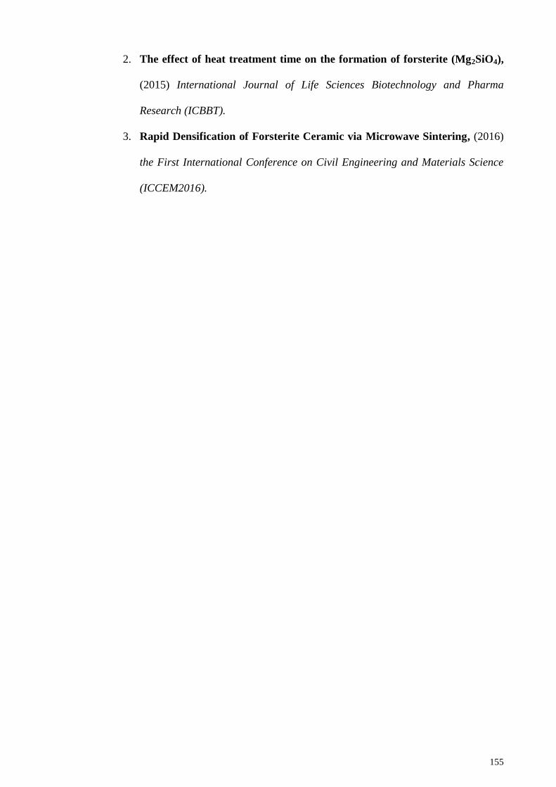
155
2. The effect of heat treatment time on the formation of forsterite (Mg2SiO4),
(2015) International Journal of Life Sciences Biotechnology and Pharma
Research (ICBBT).
3. Rapid Densification of Forsterite Ceramic via Microwave Sintering, (2016)
the First International Conference on Civil Engineering and Materials Science
(ICCEM2016).
156
APPENDIX A
Calculation of raw materials preparation
The reaction between the precursors occurred in two stages. First and second stages
were governed by the following equation:
A-1
MgO + MgSiO3 Mg2SiO4 A-2
The reaction to produce forsterite based on equation A-2 was based on MgO and
MgSiO3 knowing the 4MgCO3*Mg(OH)2*5H2O will decompose into MgO and CO2
gas. Ammonium chloride (NH4Cl) was not directly involved in the reaction and acted
only as a catalyst. Table A-1 showed the molecular weight of the precursors and
forsterite.
Table A-1: Molecular weight of various compositions
Compositions Molecular weight (g/mol)
4MgCO3*Mg(OH)2*5H2O 485
Mg3Si4O10(OH)2 379.3
Mg2SiO4 140.7
NH4Cl 53.5
50 g of 4Mg2SiO4 =
= 0.0888 mol
4MgCO3*Mg(OH)2*5H2O +
Mg3Si4O10(OH)2 + NH4Cl
4MgSiO3 + 4MgO + 4CO2 +
7H2O + HCl + NH3
157
Based on the equation, 1 mol of MgO with 1 mol of talc will produce 1 mol of
forsterite. Hence, 0.0888 mol of forsterite can be produced by using 0.0888 mol for both
MgCO3 and talc.
Amount of 4MgCO3*Mg(OH)2*5H2O = (0.0888 mol) x (485 g/mol)
= 43.068 g
Amount of talc = (0.0888 mol) x (379.3 g/mol)
= 33.682 g
Amount of NH4Cl = (0.0888 mol) x (53.5 g/mol)
= 4.751 g
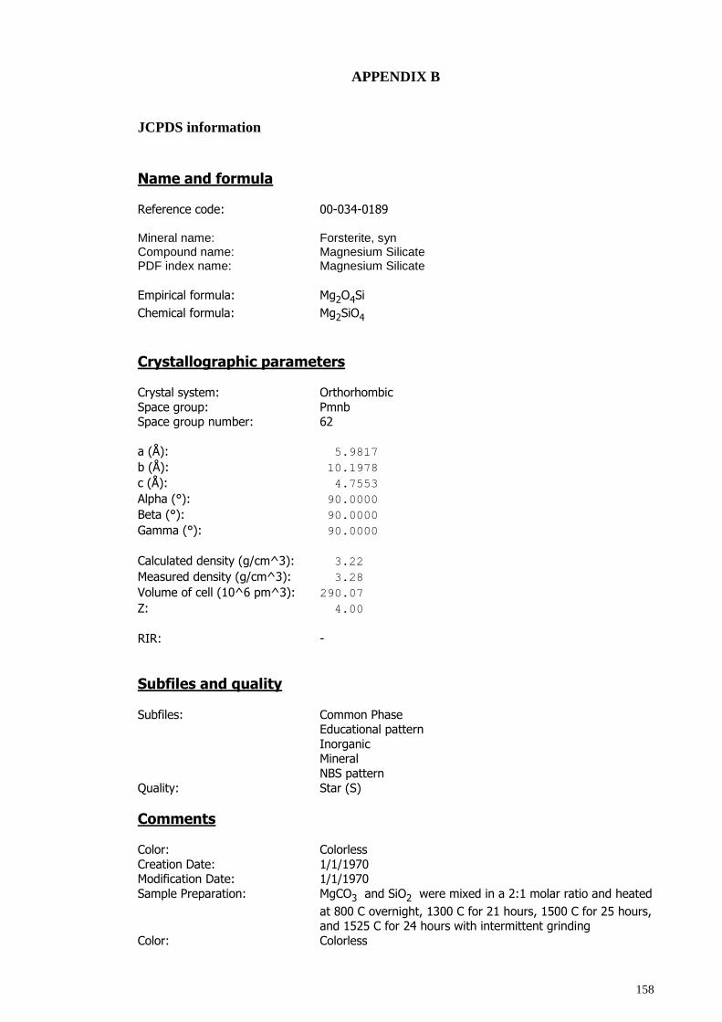
158
APPENDIX B
JCPDS information
Name and formula
Reference code: 00-034-0189
Mineral name: Forsterite, syn Compound name: Magnesium Silicate PDF index name: Magnesium Silicate
Empirical formula: Mg2O4Si
Chemical formula: Mg2SiO4
Crystallographic parameters
Crystal system: Orthorhombic
Space group: Pmnb Space group number: 62
a (Å): 5.9817
b (Å): 10.1978
c (Å): 4.7553
Alpha (°): 90.0000
Beta (°): 90.0000
Gamma (°): 90.0000
Calculated density (g/cm^3): 3.22
Measured density (g/cm^3): 3.28
Volume of cell (10^6 pm^3): 290.07
Z: 4.00
RIR: -
Subfiles and quality
Subfiles: Common Phase Educational pattern
Inorganic Mineral
NBS pattern
Quality: Star (S)
Comments
Color: Colorless
Creation Date: 1/1/1970 Modification Date: 1/1/1970
Sample Preparation: MgCO3 and SiO2 were mixed in a 2:1 molar ratio and heated
at 800 C overnight, 1300 C for 21 hours, 1500 C for 25 hours, and 1525 C for 24 hours with intermittent grinding
Color: Colorless
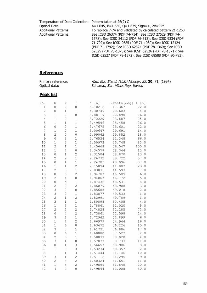
159
Temperature of Data Collection: Pattern taken at 26(2) C
Optical Data: A=1.645, B=1.660, Q=1.679, Sign=+, 2V=92°
Additional Patterns: To replace 7-74 and validated by calculated pattern 21-1260 Additional Patterns: See ICSD 26374 (PDF 74-714); See ICSD 27529 (PDF 74-
1678); See ICSD 34112 (PDF 76-513); See ICSD 9334 (PDF 71-792); See ICSD 9685 (PDF 71-1080); See ICSD 12124
(PDF 71-1792); See ICSD 62524 (PDF 78-1369); See ICSD
62525 (PDF 78-1370); See ICSD 62526 (PDF 78-1371); See ICSD 62527 (PDF 78-1372); See ICSD 68588 (PDF 80-783).
References
Primary reference: Natl. Bur. Stand. (U.S.) Monogr. 25, 20, 71, (1984) Optical data: Sahama., Bur. Mines Rep. Invest.
Peak list No. h k l d [A] 2Theta[deg] I [%]
1 0 2 0 5.10212 17.367 22.0
2 0 1 1 4.30749 20.603 4.0
3 1 2 0 3.88119 22.895 76.0
4 1 0 1 3.72220 23.887 25.0
5 1 1 1 3.49596 25.458 26.0
6 0 2 1 3.47675 25.601 22.0
7 1 2 1 3.00647 29.691 14.0
8 2 0 0 2.99062 29.852 18.0
9 0 3 1 2.76534 32.348 66.0
10 1 3 1 2.50973 35.748 83.0
11 2 1 1 2.45668 36.547 100.0
12 1 4 0 2.34558 38.344 13.0
13 0 1 2 2.31504 38.870 13.0
14 2 2 1 2.26732 39.722 57.0
15 0 4 1 2.24703 40.096 37.0
16 1 1 2 2.15894 41.807 23.0
17 2 3 1 2.03031 44.593 7.0
18 0 3 2 1.94787 46.589 6.0
19 2 4 0 1.94067 46.772 5.0
20 0 5 1 1.87436 48.531 8.0
21 2 0 2 1.86079 48.908 3.0
22 3 2 0 1.85688 49.018 2.0
23 3 0 1 1.83877 49.533 1.0
24 2 1 2 1.82991 49.789 1.0
25 3 1 1 1.80898 50.405 4.0
26 1 5 1 1.78861 51.020 5.0
27 2 2 2 1.74828 52.285 73.0
28 0 4 2 1.73861 52.598 24.0
29 3 2 1 1.72942 52.899 6.0
30 1 4 2 1.66979 54.944 16.0
31 1 6 0 1.63472 56.226 15.0
32 3 3 1 1.61731 56.886 17.0
33 0 6 1 1.60080 57.527 2.0
34 2 5 1 1.58837 58.020 4.0
35 3 4 0 1.57077 58.733 11.0
36 0 1 3 1.56657 58.906 8.0
37 1 0 3 1.53234 60.357 2.0
38 1 1 3 1.51444 61.146 10.0
39 3 1 2 1.51112 61.295 9.0
40 2 4 2 1.50324 61.651 11.0
41 1 5 2 1.49899 61.845 20.0
42 4 0 0 1.49544 62.008 30.0
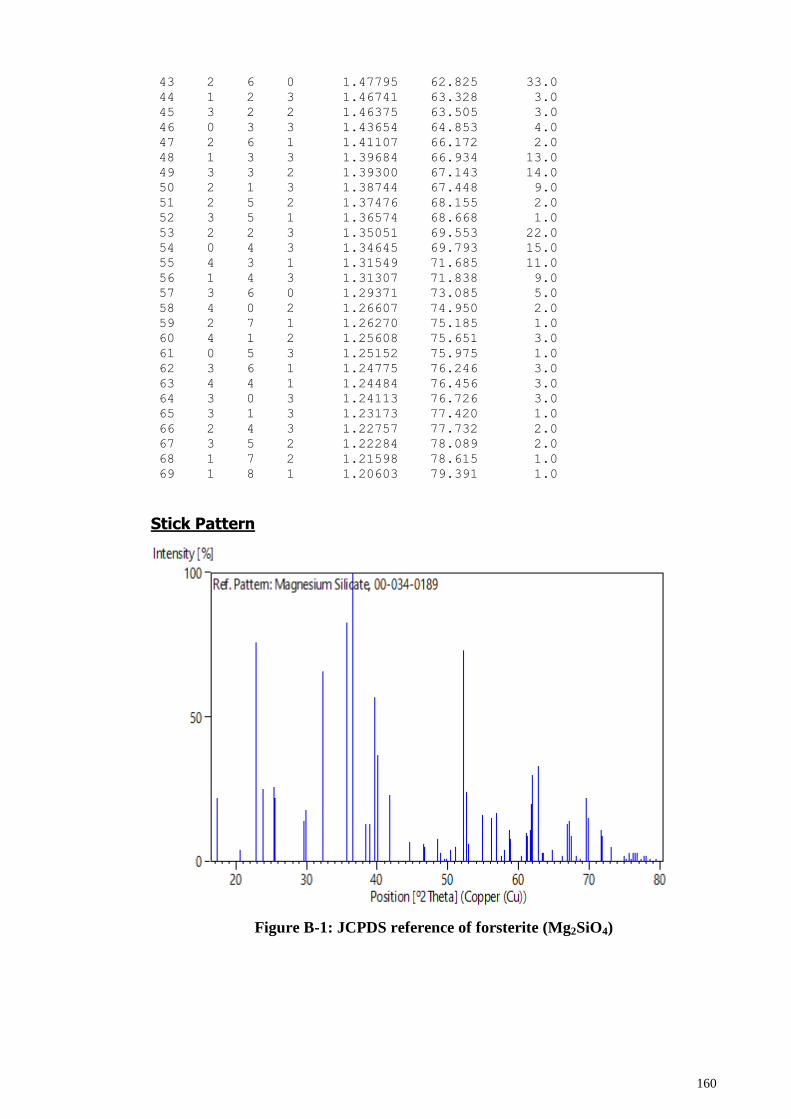
160
43 2 6 0 1.47795 62.825 33.0
44 1 2 3 1.46741 63.328 3.0
45 3 2 2 1.46375 63.505 3.0
46 0 3 3 1.43654 64.853 4.0
47 2 6 1 1.41107 66.172 2.0
48 1 3 3 1.39684 66.934 13.0
49 3 3 2 1.39300 67.143 14.0
50 2 1 3 1.38744 67.448 9.0
51 2 5 2 1.37476 68.155 2.0
52 3 5 1 1.36574 68.668 1.0
53 2 2 3 1.35051 69.553 22.0
54 0 4 3 1.34645 69.793 15.0
55 4 3 1 1.31549 71.685 11.0
56 1 4 3 1.31307 71.838 9.0
57 3 6 0 1.29371 73.085 5.0
58 4 0 2 1.26607 74.950 2.0
59 2 7 1 1.26270 75.185 1.0
60 4 1 2 1.25608 75.651 3.0
61 0 5 3 1.25152 75.975 1.0
62 3 6 1 1.24775 76.246 3.0
63 4 4 1 1.24484 76.456 3.0
64 3 0 3 1.24113 76.726 3.0
65 3 1 3 1.23173 77.420 1.0
66 2 4 3 1.22757 77.732 2.0
67 3 5 2 1.22284 78.089 2.0
68 1 7 2 1.21598 78.615 1.0
69 1 8 1 1.20603 79.391 1.0
Stick Pattern
Figure B-1: JCPDS reference of forsterite (Mg2SiO4)
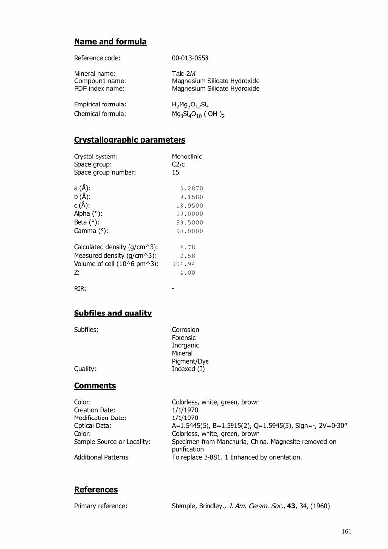
161
Name and formula
Reference code: 00-013-0558 Mineral name: Talc-2M Compound name: Magnesium Silicate Hydroxide PDF index name: Magnesium Silicate Hydroxide
Empirical formula: H2Mg3O12Si4
Chemical formula: Mg3Si4O10 ( OH )2
Crystallographic parameters
Crystal system: Monoclinic Space group: C2/c
Space group number: 15
a (Å): 5.2870
b (Å): 9.1580
c (Å): 18.9500
Alpha (°): 90.0000
Beta (°): 99.5000
Gamma (°): 90.0000
Calculated density (g/cm^3): 2.78
Measured density (g/cm^3): 2.58
Volume of cell (10^6 pm^3): 904.94
Z: 4.00
RIR: -
Subfiles and quality Subfiles: Corrosion
Forensic Inorganic
Mineral
Pigment/Dye Quality: Indexed (I)
Comments
Color: Colorless, white, green, brown Creation Date: 1/1/1970
Modification Date: 1/1/1970 Optical Data: A=1.5445(5), B=1.5915(2), Q=1.5945(5), Sign=-, 2V=0-30°
Color: Colorless, white, green, brown
Sample Source or Locality: Specimen from Manchuria, China. Magnesite removed on purification
Additional Patterns: To replace 3-881. 1 Enhanced by orientation.
References Primary reference: Stemple, Brindley., J. Am. Ceram. Soc., 43, 34, (1960)
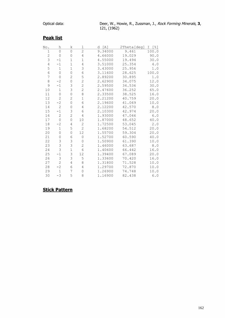
162
Optical data: Deer, W., Howie, R., Zussman, J., Rock Forming Minerals, 3,
121, (1962)
Peak list No. h k l d [A] 2Theta[deg] I [%]
1 0 0 2 9.34000 9.461 100.0
2 0 0 4 4.66000 19.029 90.0
3 -1 1 1 4.55000 19.494 30.0
4 -1 1 4 3.51000 25.354 4.0
5 1 1 3 3.43000 25.956 1.0
6 0 0 6 3.11600 28.625 100.0
7 0 2 5 2.89200 30.895 1.0
8 -2 0 2 2.62900 34.075 12.0
9 -1 3 2 2.59500 34.536 30.0
10 1 3 2 2.47600 36.252 65.0
11 0 0 8 2.33500 38.525 16.0
12 2 2 1 2.21200 40.759 20.0
13 -2 0 6 2.19600 41.069 10.0
14 2 0 4 2.12200 42.570 8.0
15 -1 3 6 2.10300 42.974 20.0
16 2 2 4 1.93000 47.046 6.0
17 0 0 10 1.87000 48.652 40.0
18 -2 4 2 1.72500 53.045 2.0
19 1 5 2 1.68200 54.512 20.0
20 0 0 12 1.55700 59.304 20.0
21 0 6 0 1.52700 60.590 40.0
22 3 3 0 1.50900 61.390 10.0
23 3 3 2 1.46000 63.687 8.0
24 3 1 6 1.40600 66.442 16.0
25 -1 3 12 1.39400 67.089 20.0
26 3 3 5 1.33600 70.420 16.0
27 2 4 8 1.31800 71.528 10.0
28 -2 6 4 1.29700 72.870 10.0
29 1 7 0 1.26900 74.748 10.0
30 -3 5 8 1.16900 82.438 6.0
Stick Pattern
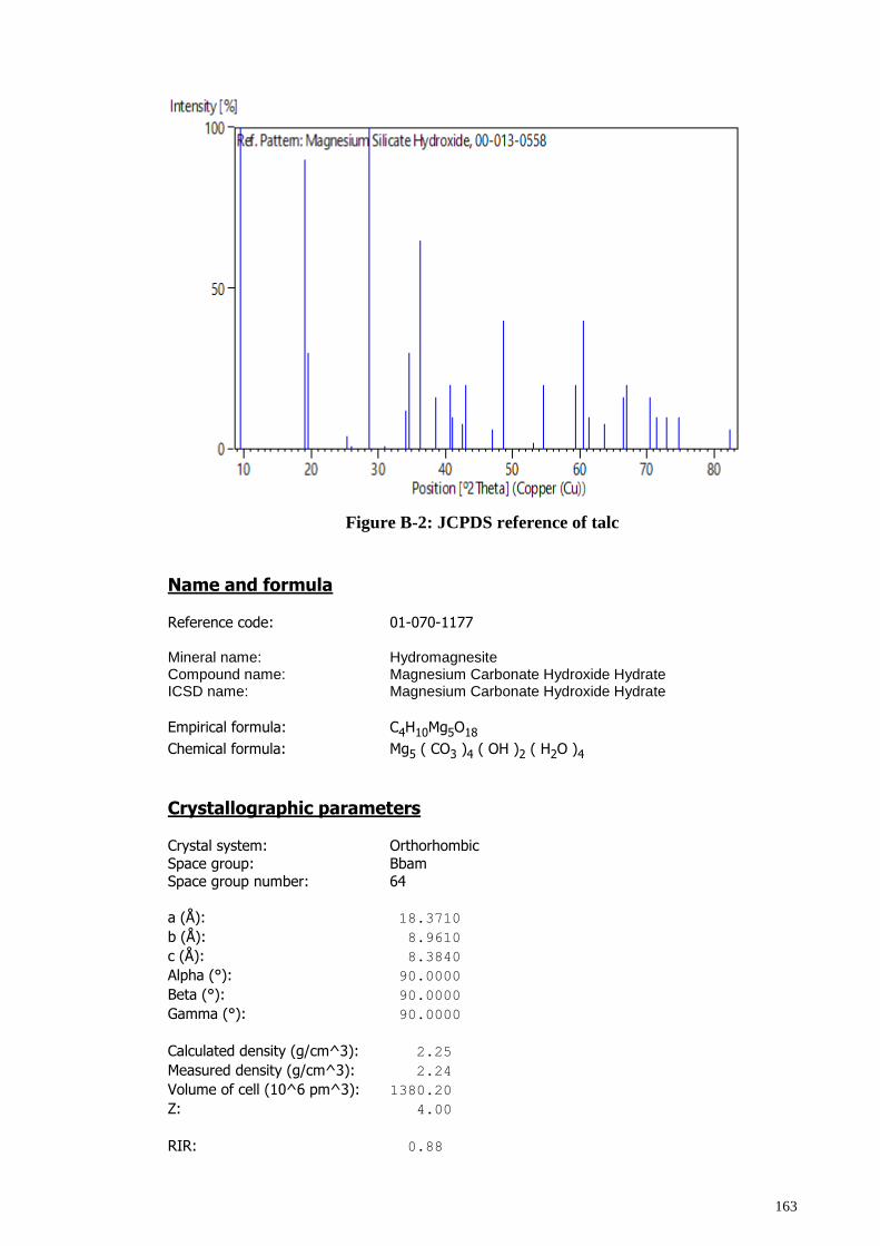
163
Figure B-2: JCPDS reference of talc
Name and formula
Reference code: 01-070-1177
Mineral name: Hydromagnesite Compound name: Magnesium Carbonate Hydroxide Hydrate ICSD name: Magnesium Carbonate Hydroxide Hydrate
Empirical formula: C4H10Mg5O18
Chemical formula: Mg5 ( CO3 )4 ( OH )2 ( H2O )4
Crystallographic parameters
Crystal system: Orthorhombic
Space group: Bbam Space group number: 64
a (Å): 18.3710
b (Å): 8.9610
c (Å): 8.3840
Alpha (°): 90.0000
Beta (°): 90.0000
Gamma (°): 90.0000
Calculated density (g/cm^3): 2.25
Measured density (g/cm^3): 2.24
Volume of cell (10^6 pm^3): 1380.20
Z: 4.00
RIR: 0.88
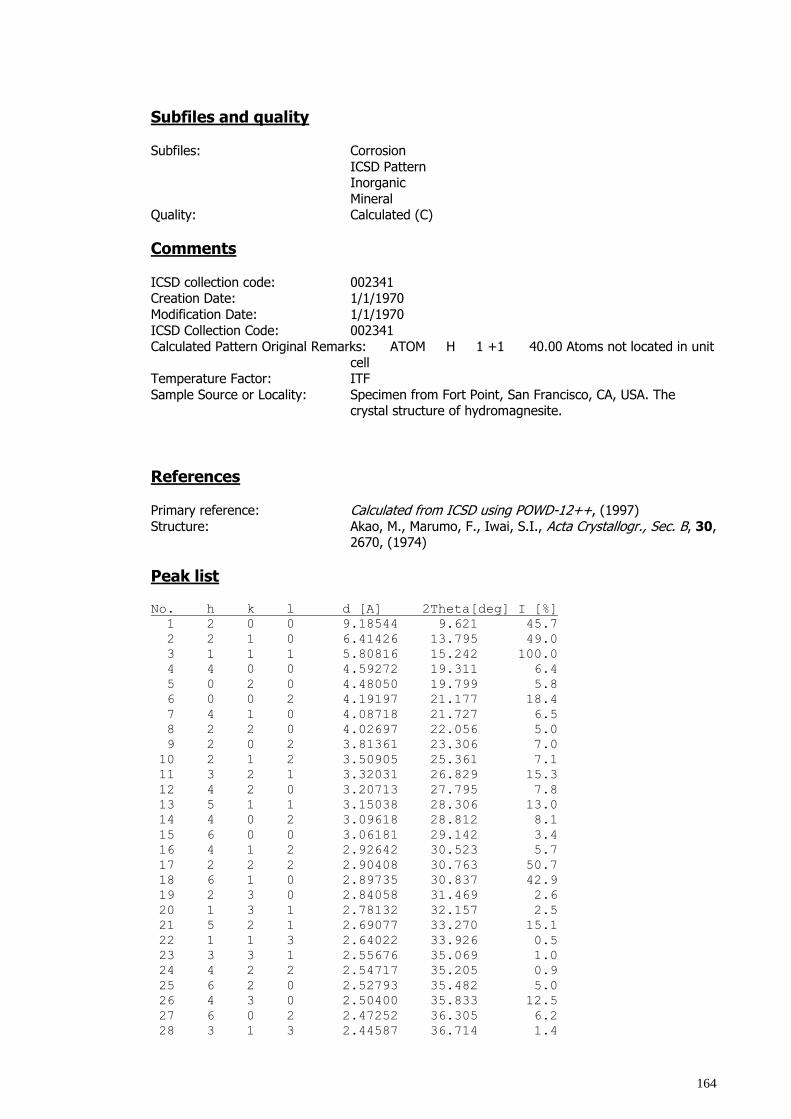
164
Subfiles and quality
Subfiles: Corrosion
ICSD Pattern Inorganic
Mineral Quality: Calculated (C)
Comments
ICSD collection code: 002341 Creation Date: 1/1/1970
Modification Date: 1/1/1970
ICSD Collection Code: 002341 Calculated Pattern Original Remarks: ATOM H 1 +1 40.00 Atoms not located in unit
cell Temperature Factor: ITF
Sample Source or Locality: Specimen from Fort Point, San Francisco, CA, USA. The crystal structure of hydromagnesite.
References
Primary reference: Calculated from ICSD using POWD-12++, (1997)
Structure: Akao, M., Marumo, F., Iwai, S.I., Acta Crystallogr., Sec. B, 30, 2670, (1974)
Peak list No. h k l d [A] 2Theta[deg] I [%]
1 2 0 0 9.18544 9.621 45.7
2 2 1 0 6.41426 13.795 49.0
3 1 1 1 5.80816 15.242 100.0
4 4 0 0 4.59272 19.311 6.4
5 0 2 0 4.48050 19.799 5.8
6 0 0 2 4.19197 21.177 18.4
7 4 1 0 4.08718 21.727 6.5
8 2 2 0 4.02697 22.056 5.0
9 2 0 2 3.81361 23.306 7.0
10 2 1 2 3.50905 25.361 7.1
11 3 2 1 3.32031 26.829 15.3
12 4 2 0 3.20713 27.795 7.8
13 5 1 1 3.15038 28.306 13.0
14 4 0 2 3.09618 28.812 8.1
15 6 0 0 3.06181 29.142 3.4
16 4 1 2 2.92642 30.523 5.7
17 2 2 2 2.90408 30.763 50.7
18 6 1 0 2.89735 30.837 42.9
19 2 3 0 2.84058 31.469 2.6
20 1 3 1 2.78132 32.157 2.5
21 5 2 1 2.69077 33.270 15.1
22 1 1 3 2.64022 33.926 0.5
23 3 3 1 2.55676 35.069 1.0
24 4 2 2 2.54717 35.205 0.9
25 6 2 0 2.52793 35.482 5.0
26 4 3 0 2.50400 35.833 12.5
27 6 0 2 2.47252 36.305 6.2
28 3 1 3 2.44587 36.714 1.4
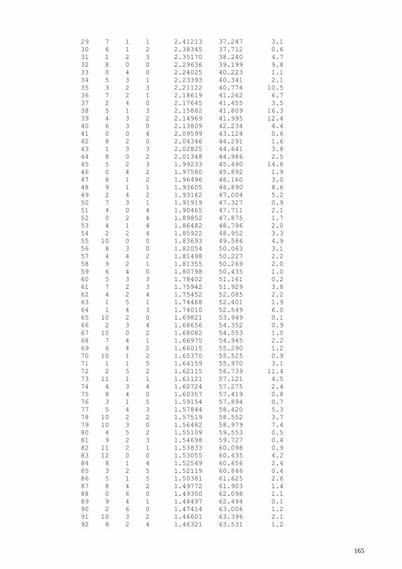
165
29 7 1 1 2.41213 37.247 3.1
30 6 1 2 2.38345 37.712 0.6
31 1 2 3 2.35170 38.240 4.7
32 8 0 0 2.29636 39.199 9.8
33 0 4 0 2.24025 40.223 1.1
34 5 3 1 2.23393 40.341 2.1
35 3 2 3 2.21122 40.774 10.5
36 7 2 1 2.18619 41.262 6.7
37 2 4 0 2.17645 41.455 3.5
38 5 1 3 2.15882 41.809 16.3
39 4 3 2 2.14969 41.995 12.4
40 6 3 0 2.13809 42.234 4.4
41 0 0 4 2.09599 43.124 0.6
42 8 2 0 2.04346 44.291 1.6
43 1 3 3 2.02825 44.641 3.8
44 8 0 2 2.01348 44.986 2.5
45 5 2 3 1.99233 45.490 14.8
46 0 4 2 1.97580 45.892 1.9
47 8 1 2 1.96496 46.160 3.0
48 9 1 1 1.93605 46.890 8.6
49 2 4 2 1.93162 47.004 5.2
50 7 3 1 1.91919 47.327 0.9
51 4 0 4 1.90465 47.711 2.1
52 0 2 4 1.89852 47.875 1.7
53 4 1 4 1.86482 48.796 2.0
54 2 2 4 1.85922 48.952 3.3
55 10 0 0 1.83693 49.586 4.9
56 8 3 0 1.82054 50.063 3.1
57 4 4 2 1.81498 50.227 2.2
58 9 2 1 1.81355 50.269 2.0
59 6 4 0 1.80798 50.435 1.0
60 5 3 3 1.78402 51.161 0.2
61 7 2 3 1.75942 51.929 3.8
62 4 2 4 1.75452 52.085 2.2
63 1 5 1 1.74468 52.401 1.9
64 1 4 3 1.74010 52.549 6.0
65 10 2 0 1.69821 53.949 0.1
66 2 3 4 1.68656 54.352 0.9
67 10 0 2 1.68082 54.553 1.0
68 7 4 1 1.66975 54.945 2.2
69 6 4 2 1.66015 55.290 1.2
70 10 1 2 1.65370 55.525 0.9
71 1 1 5 1.64159 55.970 3.1
72 2 5 2 1.62115 56.739 11.4
73 11 1 1 1.61121 57.121 4.5
74 4 3 4 1.60724 57.275 2.4
75 8 4 0 1.60357 57.419 0.8
76 3 1 5 1.59154 57.894 0.7
77 5 4 3 1.57844 58.420 5.3
78 10 2 2 1.57519 58.552 3.7
79 10 3 0 1.56482 58.979 7.4
80 4 5 2 1.55109 59.553 0.5
81 9 2 3 1.54698 59.727 0.4
82 11 2 1 1.53833 60.098 0.9
83 12 0 0 1.53055 60.435 4.2
84 8 1 4 1.52549 60.656 2.4
85 3 2 5 1.52119 60.846 0.4
86 5 1 5 1.50381 61.625 2.6
87 8 4 2 1.49772 61.903 1.4
88 0 6 0 1.49350 62.098 1.1
89 9 4 1 1.48497 62.494 0.1
90 2 6 0 1.47414 63.006 1.2
91 10 3 2 1.46601 63.396 2.1
92 8 2 4 1.46321 63.531 1.2
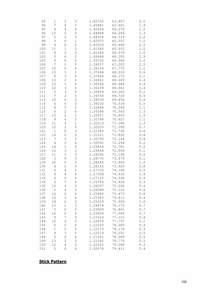
166
93 1 3 5 1.45755 63.807 0.5
94 7 4 3 1.45481 63.941 1.9
95 4 4 4 1.45204 64.078 1.2
96 12 2 0 1.44868 64.244 1.3
97 5 2 5 1.44318 64.519 2.2
98 3 6 1 1.42972 65.201 1.0
99 4 6 0 1.42029 65.688 2.2
100 11 1 3 1.41560 65.933 2.0
101 8 5 0 1.41284 66.079 1.2
102 0 6 2 1.40688 66.395 2.9
103 0 0 6 1.39732 66.908 3.0
104 7 1 5 1.39557 67.003 2.5
105 10 0 4 1.38154 67.775 1.1
106 13 1 1 1.37694 68.033 0.6
107 8 3 4 1.37446 68.172 0.1
108 12 2 2 1.36922 68.469 0.4
109 10 1 4 1.36540 68.688 0.9
110 12 3 0 1.36239 68.861 0.4
111 5 3 5 1.35854 69.083 0.1
112 7 2 5 1.34758 69.726 0.5
113 10 4 2 1.34539 69.856 0.8
114 6 6 0 1.34232 70.039 0.5
115 8 5 2 1.33884 70.248 1.1
116 0 2 6 1.33396 70.543 1.3
117 13 2 1 1.32971 70.803 1.9
118 9 4 3 1.32768 70.927 1.1
119 11 4 1 1.32219 71.266 1.3
120 10 2 4 1.32020 71.390 0.7
121 1 6 3 1.31383 71.790 0.6
122 14 0 0 1.31221 71.892 0.8
123 7 5 3 1.30793 72.164 0.4
124 4 5 4 1.30591 72.294 0.2
125 14 1 0 1.29836 72.781 0.2
126 12 3 2 1.29568 72.956 0.1
127 11 3 3 1.29245 73.168 0.2
128 3 6 3 1.28775 73.479 0.1
129 10 5 0 1.28285 73.806 1.0
130 4 2 6 1.28102 73.929 0.8
131 6 6 2 1.27730 74.180 0.5
132 8 4 4 1.27358 74.433 1.4
133 6 0 6 1.27120 74.596 0.9
134 2 7 0 1.26789 74.824 0.3
135 12 4 0 1.26397 75.096 0.4
136 5 4 5 1.26089 75.312 0.6
137 14 2 0 1.25860 75.473 0.8
138 10 3 4 1.25383 75.811 0.4
139 14 0 2 1.25229 75.920 1.0
140 13 1 3 1.24878 76.172 0.7
141 5 6 3 1.23929 76.861 0.7
142 12 0 4 1.23626 77.084 0.7
143 4 7 0 1.23314 77.315 0.4
144 10 5 2 1.22670 77.797 0.1
145 6 2 6 1.22293 78.083 0.4
146 1 5 5 1.22173 78.174 0.3
147 4 3 6 1.22019 78.291 0.5
148 0 6 4 1.21631 78.589 0.5
149 13 2 3 1.21392 78.774 0.5
150 12 4 2 1.21015 79.068 0.3
151 2 6 4 1.20578 79.411 0.4
Stick Pattern
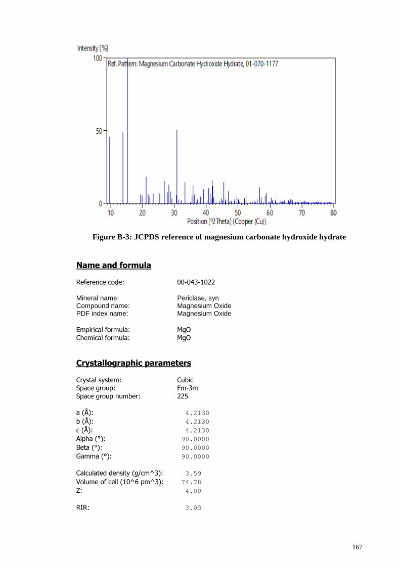
167
Figure B-3: JCPDS reference of magnesium carbonate hydroxide hydrate
Name and formula
Reference code: 00-043-1022
Mineral name: Periclase, syn Compound name: Magnesium Oxide PDF index name: Magnesium Oxide
Empirical formula: MgO
Chemical formula: MgO
Crystallographic parameters
Crystal system: Cubic Space group: Fm-3m
Space group number: 225
a (Å): 4.2130
b (Å): 4.2130
c (Å): 4.2130
Alpha (°): 90.0000
Beta (°): 90.0000
Gamma (°): 90.0000
Calculated density (g/cm^3): 3.59
Volume of cell (10^6 pm^3): 74.78
Z: 4.00
RIR: 3.03
168
Status, subfiles and quality Status: Marked as deleted by ICDD
Subfiles: Alloy, metal or intermetalic
Corrosion Inorganic
Mineral Pharmaceutical
Quality: Calculated (C)
Comments Creation Date: 1/1/1970
Modification Date: 1/1/1970
Calculation of diffractometer peak intensities done with MICRO-POWD v. 2.2 (D. Smith and K. Smith) using default instrument broadening function (NBS
Table), diffracted beam monochromator polarization correction, and atomic scattering factors corrected for
anomalous dispersion. Cell parameters from Sasaki, S. et al., \ITProc. Jpn. Acad.\RG, \BF55\RG 43-48 (1979). Atomic
positions from same source: Mg in 2a, O in 1b
Isotropic thermal parameters also from same source: Mg, B=.312; O, B=.362 Deleted Or Rejected By: Deleted by 45-946, experimental pattern; minerals
subcommittee 6/94.
References Primary reference: Grier, D., McCarthy, G., North Dakota State University, Fargo,
North Dakota, USA., ICDD Grant-in-Aid, (1991)
Peak list No. h k l d [A] 2Theta[deg] I [%]
1 1 1 1 2.43200 36.931 11.0
2 2 0 0 2.10600 42.909 100.0
3 2 2 0 1.48950 62.283 51.0
4 3 1 1 1.27030 74.658 6.0
5 2 2 2 1.21620 78.598 15.0
6 4 0 0 1.05320 94.006 6.0
7 3 3 1 0.96650 105.689 3.0
8 4 2 0 0.94210 109.699 18.0
Stick Pattern
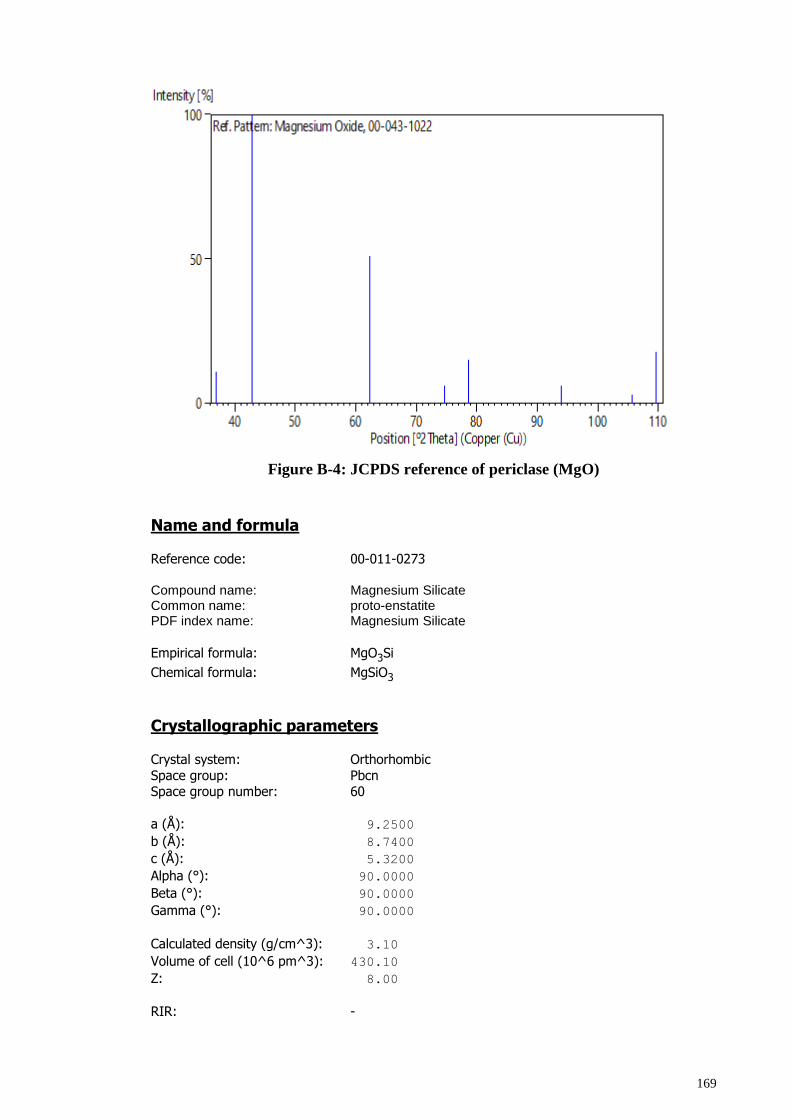
169
Figure B-4: JCPDS reference of periclase (MgO)
Name and formula
Reference code: 00-011-0273
Compound name: Magnesium Silicate Common name: proto-enstatite PDF index name: Magnesium Silicate
Empirical formula: MgO3Si
Chemical formula: MgSiO3
Crystallographic parameters
Crystal system: Orthorhombic
Space group: Pbcn Space group number: 60
a (Å): 9.2500
b (Å): 8.7400
c (Å): 5.3200
Alpha (°): 90.0000
Beta (°): 90.0000
Gamma (°): 90.0000
Calculated density (g/cm^3): 3.10
Volume of cell (10^6 pm^3): 430.10
Z: 8.00
RIR: -
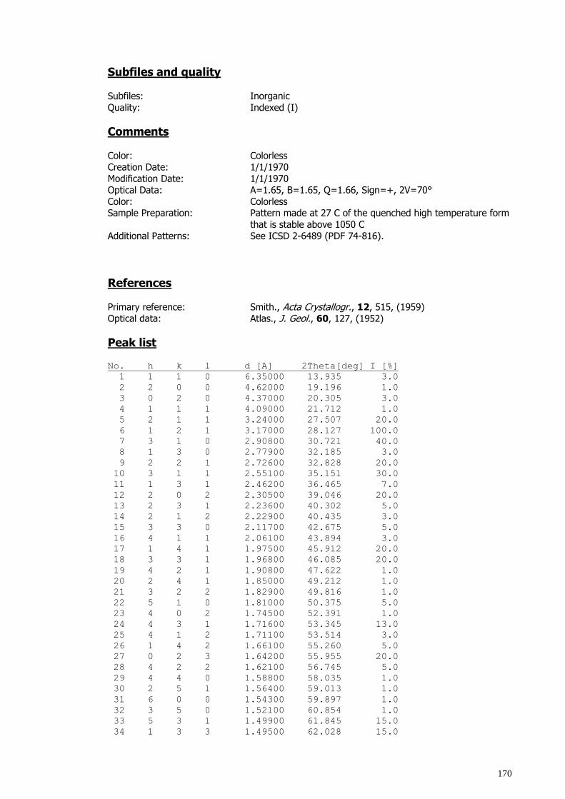
170
Subfiles and quality Subfiles: Inorganic
Quality: Indexed (I)
Comments Color: Colorless
Creation Date: 1/1/1970
Modification Date: 1/1/1970 Optical Data: A=1.65, B=1.65, Q=1.66, Sign=+, 2V=70°
Color: Colorless Sample Preparation: Pattern made at 27 C of the quenched high temperature form
that is stable above 1050 C
Additional Patterns: See ICSD 2-6489 (PDF 74-816).
References Primary reference: Smith., Acta Crystallogr., 12, 515, (1959)
Optical data: Atlas., J. Geol., 60, 127, (1952)
Peak list No. h k l d [A] 2Theta[deg] I [%]
1 1 1 0 6.35000 13.935 3.0
2 2 0 0 4.62000 19.196 1.0
3 0 2 0 4.37000 20.305 3.0
4 1 1 1 4.09000 21.712 1.0
5 2 1 1 3.24000 27.507 20.0
6 1 2 1 3.17000 28.127 100.0
7 3 1 0 2.90800 30.721 40.0
8 1 3 0 2.77900 32.185 3.0
9 2 2 1 2.72600 32.828 20.0
10 3 1 1 2.55100 35.151 30.0
11 1 3 1 2.46200 36.465 7.0
12 2 0 2 2.30500 39.046 20.0
13 2 3 1 2.23600 40.302 5.0
14 2 1 2 2.22900 40.435 3.0
15 3 3 0 2.11700 42.675 5.0
16 4 1 1 2.06100 43.894 3.0
17 1 4 1 1.97500 45.912 20.0
18 3 3 1 1.96800 46.085 20.0
19 4 2 1 1.90800 47.622 1.0
20 2 4 1 1.85000 49.212 1.0
21 3 2 2 1.82900 49.816 1.0
22 5 1 0 1.81000 50.375 5.0
23 4 0 2 1.74500 52.391 1.0
24 4 3 1 1.71600 53.345 13.0
25 4 1 2 1.71100 53.514 3.0
26 1 4 2 1.66100 55.260 5.0
27 0 2 3 1.64200 55.955 20.0
28 4 2 2 1.62100 56.745 5.0
29 4 4 0 1.58800 58.035 1.0
30 2 5 1 1.56400 59.013 1.0
31 6 0 0 1.54300 59.897 1.0
32 3 5 0 1.52100 60.854 1.0
33 5 3 1 1.49900 61.845 15.0
34 1 3 3 1.49500 62.028 15.0
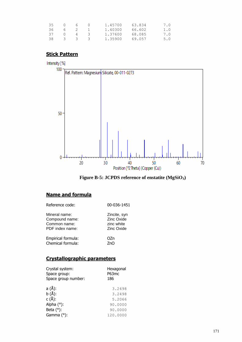
171
35 0 6 0 1.45700 63.834 7.0
36 6 2 1 1.40300 66.602 1.0
37 0 4 3 1.37600 68.085 7.0
38 3 3 3 1.35900 69.057 5.0
Stick Pattern
Figure B-5: JCPDS reference of enstatite (MgSiO3)
Name and formula Reference code: 00-036-1451
Mineral name: Zincite, syn Compound name: Zinc Oxide Common name: zinc white PDF index name: Zinc Oxide
Empirical formula: OZn
Chemical formula: ZnO
Crystallographic parameters Crystal system: Hexagonal
Space group: P63mc Space group number: 186
a (Å): 3.2498
b (Å): 3.2498
c (Å): 5.2066
Alpha (°): 90.0000
Beta (°): 90.0000
Gamma (°): 120.0000
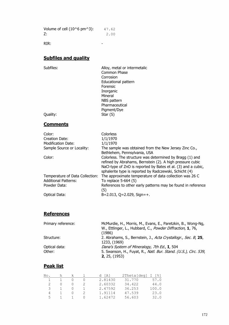
172
Volume of cell (10^6 pm^3): 47.62
Z: 2.00
RIR: -
Subfiles and quality
Subfiles: Alloy, metal or intermetalic Common Phase
Corrosion Educational pattern
Forensic Inorganic
Mineral
NBS pattern Pharmaceutical
Pigment/Dye Quality: Star (S)
Comments
Color: Colorless Creation Date: 1/1/1970
Modification Date: 1/1/1970
Sample Source or Locality: The sample was obtained from the New Jersey Zinc Co., Bethlehem, Pennsylvania, USA
Color: Colorless. The structure was determined by Bragg (1) and refined by Abrahams, Bernstein (2). A high pressure cubic
NaCl-type of ZnO is reported by Bates et al. (3) and a cubic,
sphalerite type is reported by Radczewski, Schicht (4) Temperature of Data Collection: The approximate temperature of data collection was 26 C
Additional Patterns: To replace 5-664 (5) Powder Data: References to other early patterns may be found in reference
(5) Optical Data: B=2.013, Q=2.029, Sign=+.
References
Primary reference: McMurdie, H., Morris, M., Evans, E., Paretzkin, B., Wong-Ng,
W., Ettlinger, L., Hubbard, C., Powder Diffraction, 1, 76, (1986)
Structure: 2. Abrahams, S., Bernstein, J., Acta Crystallogr., Sec. B, 25, 1233, (1969)
Optical data: Dana's System of Mineralogy, 7th Ed., I, 504
Other: 5. Swanson, H., Fuyat, R., Natl. Bur. Stand. (U.S.), Circ. 539, 2, 25, (1953)
Peak list No. h k l d [A] 2Theta[deg] I [%]
1 1 0 0 2.81430 31.770 57.0
2 0 0 2 2.60332 34.422 44.0
3 1 0 1 2.47592 36.253 100.0
4 1 0 2 1.91114 47.539 23.0
5 1 1 0 1.62472 56.603 32.0
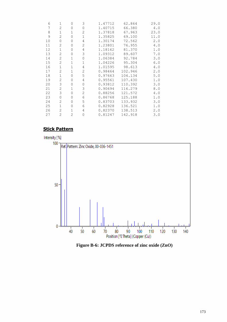
173
6 1 0 3 1.47712 62.864 29.0
7 2 0 0 1.40715 66.380 4.0
8 1 1 2 1.37818 67.963 23.0
9 2 0 1 1.35825 69.100 11.0
10 0 0 4 1.30174 72.562 2.0
11 2 0 2 1.23801 76.955 4.0
12 1 0 4 1.18162 81.370 1.0
13 2 0 3 1.09312 89.607 7.0
14 2 1 0 1.06384 92.784 3.0
15 2 1 1 1.04226 95.304 6.0
16 1 1 4 1.01595 98.613 4.0
17 2 1 2 0.98464 102.946 2.0
18 1 0 5 0.97663 104.134 5.0
19 2 0 4 0.95561 107.430 1.0
20 3 0 0 0.93812 110.392 3.0
21 2 1 3 0.90694 116.279 8.0
22 3 0 2 0.88256 121.572 4.0
23 0 0 6 0.86768 125.188 1.0
24 2 0 5 0.83703 133.932 3.0
25 1 0 6 0.82928 136.521 1.0
26 2 1 4 0.82370 138.513 2.0
27 2 2 0 0.81247 142.918 3.0
Stick Pattern
Figure B-6: JCPDS reference of zinc oxide (ZnO)
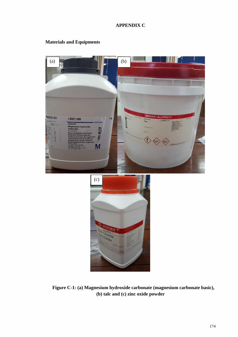
174
APPENDIX C
Materials and Equipments
Figure C-1: (a) Magnesium hydroxide carbonate (magnesium carbonate basic),
(b) talc and (c) zinc oxide powder
(a) (b)
(c)
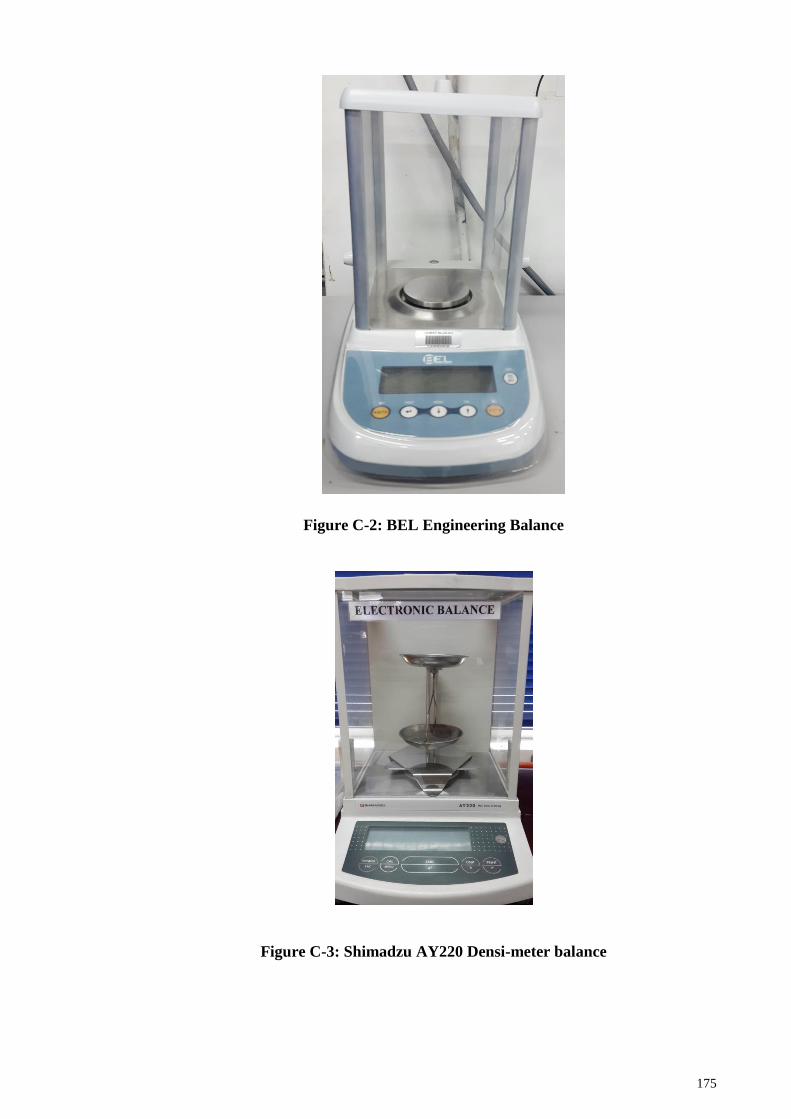
175
Figure C-2: BEL Engineering Balance
Figure C-3: Shimadzu AY220 Densi-meter balance
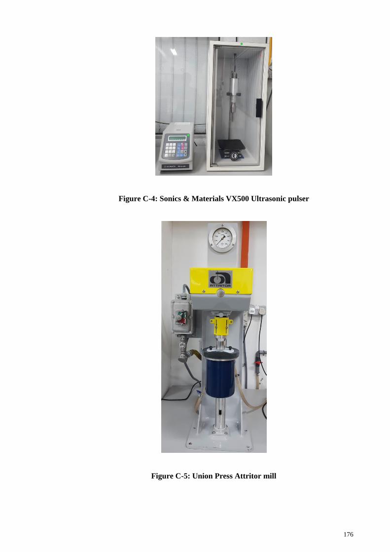
176
Figure C-4: Sonics & Materials VX500 Ultrasonic pulser
Figure C-5: Union Press Attritor mill
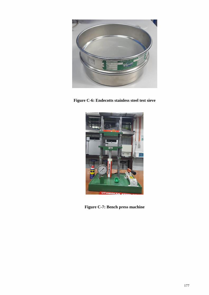
177
Figure C-6: Endecotts stainless steel test sieve
Figure C-7: Bench press machine
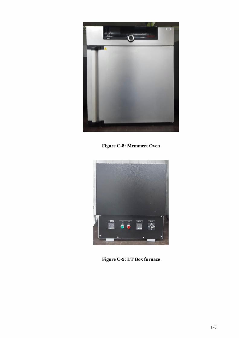
178
Figure C-8: Memmert Oven
Figure C-9: LT Box furnace
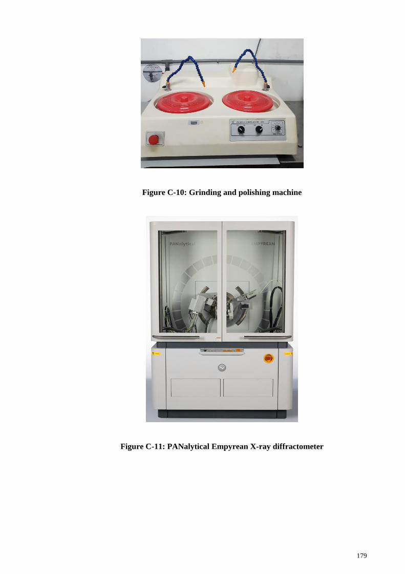
179
Figure C-10: Grinding and polishing machine
Figure C-11: PANalytical Empyrean X-ray diffractometer
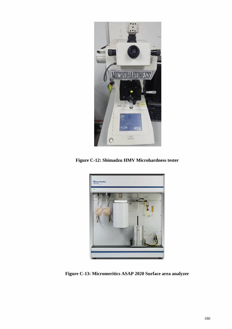
180
Figure C-12: Shimadzu HMV Microhardness tester
Figure C-13: Micromeritics ASAP 2020 Surface area analyzer
181
Figure C-14: Perkin Elmer Pyris Diamond Differential scanning calorimeter
Figure C-15: Phenom Pro-X Scanning electron microscope
182
Figure C-16: JEOL Field-emission Scanning electron microscope
Figure C-17: JEOL Transmission electron microscope
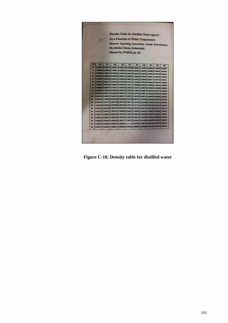
183
Figure C-18: Density table for distilled water
Related Documents