Installation # 7059 1 Cognito Motorsports, Inc. 4”-6” Front Lift System for 2011-present GM IFS 2 and 4WD 8 Lug Truck Requirements - Maximum wheel backspacing is 5” - Do not use a tire that is more than 4 1/2” wider than the rim width on a 4 3/4” or more backspaced wheel. - Factory 20” wheels will fit with this lift kit, factory 17” and 18” wheels will NOT fit. - Set at 4 to 5”, suggested tire size is 33” tall and up to 12.5” wide on an 8 to 9” wide rim with 4.25 to 5.0” back spacing. Set at 5 to 6”, suggested tire size is 34.5” tall and up to 12.4” wide on an 8 to 8.5” wide rim with 5.0” to 5.5” back spacing. Call Cognito Motorsports with wheel and tire suggestions if necessary. Trimming of inner fender well and bottom rear of steel fender may be required. - Follow alignment specs at the end of this instruction set. Introduction - Installation requires a qualified mechanic. - Prior to installation on used vehicles, carefully inspect the vehicle’s steering and driveline systems, paying close attention to the tie rod ends, pitman and idler arms, ball joints, and wheel bearings. Also check steering to frame attaching points for stress cracks. The overall vehicle must be in excellent working condition: repair or replace all worn parts. - Read instructions carefully and study the pictures (if included) before attempting installation. - Check the parts and hardware packages against the parts list to assure that your kit is complete. - Secure and properly rack the vehicle on a hoist prior to beginning installation. - Always wear safety glasses when using power tools. - Use extreme caution when cutting is required under the vehicle: the factory undercoating may be flammable. Be careful of all fuel lines, fuel tanks, brake lines, and electrical harnesses. - Front-end alignment will be necessary after completion. - Exhaust modification may be necessary. - Drive line(s) modification may be necessary.

Welcome message from author
This document is posted to help you gain knowledge. Please leave a comment to let me know what you think about it! Share it to your friends and learn new things together.
Transcript
Installation # 7059
1
Cognito Motorsports, Inc. 4”-6” Front Lift System for 2011-present GM IFS 2 and 4WD 8 Lug Truck
Requirements - Maximum wheel backspacing is 5” - Do not use a tire that is more than 4 1/2” wider than the rim width on a 4 3/4” or more
backspaced wheel. - Factory 20” wheels will fit with this lift kit, factory 17” and 18” wheels will NOT fit. - Set at 4 to 5”, suggested tire size is 33” tall and up to 12.5” wide on an 8 to 9” wide rim with
4.25 to 5.0” back spacing. Set at 5 to 6”, suggested tire size is 34.5” tall and up to 12.4” wide on an 8 to 8.5” wide rim with 5.0” to 5.5” back spacing. Call Cognito Motorsports with wheel and tire suggestions if necessary. Trimming of inner fender well and bottom rear of steel fender may be required.
- Follow alignment specs at the end of this instruction set. Introduction - Installation requires a qualified mechanic. - Prior to installation on used vehicles, carefully inspect the vehicle’s steering and driveline
systems, paying close attention to the tie rod ends, pitman and idler arms, ball joints, and wheel bearings. Also check steering to frame attaching points for stress cracks. The overall vehicle must be in excellent working condition: repair or replace all worn parts.
- Read instructions carefully and study the pictures (if included) before attempting installation. - Check the parts and hardware packages against the parts list to assure that your kit is
complete. - Secure and properly rack the vehicle on a hoist prior to beginning installation. - Always wear safety glasses when using power tools. - Use extreme caution when cutting is required under the vehicle: the factory undercoating
may be flammable. Be careful of all fuel lines, fuel tanks, brake lines, and electrical harnesses.
- Front-end alignment will be necessary after completion. - Exhaust modification may be necessary. - Drive line(s) modification may be necessary.
Installation # 7059
2
Parts List - BOX100430
- 8259, Front Cross member
- 8260, Rear Cross member
- 1545, clip nut plate
- BOX100431
- 8265, Driver side spindle
- 8266, Passenger side spindle
- BOX100432
- PISK3008, pitman/idler arm support kit
- HP9117, sub frame hardware pack
- HP9118, non torsion drop brackets hardware pack
- 1527, Skid Plate
- 8263, driver non torsion bracket
- 8264, passenger non torsion drop bracket
- 8261, driver bump stop bracket
- 8262, passenger bump stop bracket
- (2) 5501, NTD bracket mandrel
- SBELKHD-1004, sway bar end link kit
- BOX100433, 4WD ONLY
- 1534, Driver-side Differential Mount (needed on 4WD only)
- 1535, Passenger-side Differential Mount (needed on 4WD only)
- (2) 5483, Front axle spacer (needed on 4WD only)
- HP9120, 4WD hardware
Front End Disassembly
1) Always work on a properly supported vehicle. With the vehicle on a car hoist, lift the vehicle off of the ground and remove the front wheels.
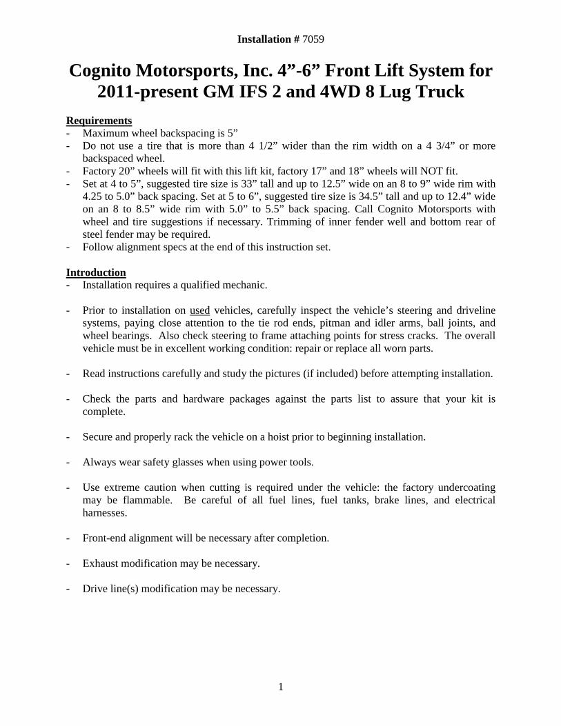
2) Remove torsion bar adjusting screw, Figure 1.
Installation # 7059
3
Figure 1: remove torsion bar adjusting bolt
3) Slide torsion bar forward into lower control arm, This will allow the torsion bar adjuster
keyway to fall out. Repeat this to the other side.
4) remove the factory sway bar end links, which connect the sway bar to the lower control arms, from the truck and discard.
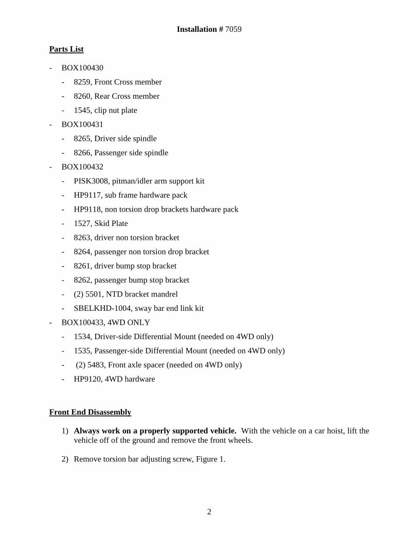
5) Skip this step for 2WD vehicle. then remove the hub cover and the axle nut and washer using a 1.5/16" socket as seen in Figure 2. unbolt inner cv axle flange from differential then remove cv axles from truck.
Figure 2
6) unbolt factory front shocks from truck and retain the lower mounting hardware.
Installation # 7059
4
7) Extended brake lines are not needed; the rubber brake line can be pulled through the steel
bracket for better fitment. If you are retaining the factory brake lines, skip now to the next step. You can purchase extended brake lines if desired. If installing new brake lines Then remove the front rubber brake line by taking the clip off of the top of the line and unscrewing the fitting. Next, unscrew the bolt on the banjo fitting of the caliper and discard the brake line. Repeat on the other side. Re-assemble the new lines in the opposite manner, being sure that copper crush washers are used on both sides of the banjo fitting on the caliper.
8) Unbolt the brake line bracket from the spindle and unfasten the ABS sensor line from the
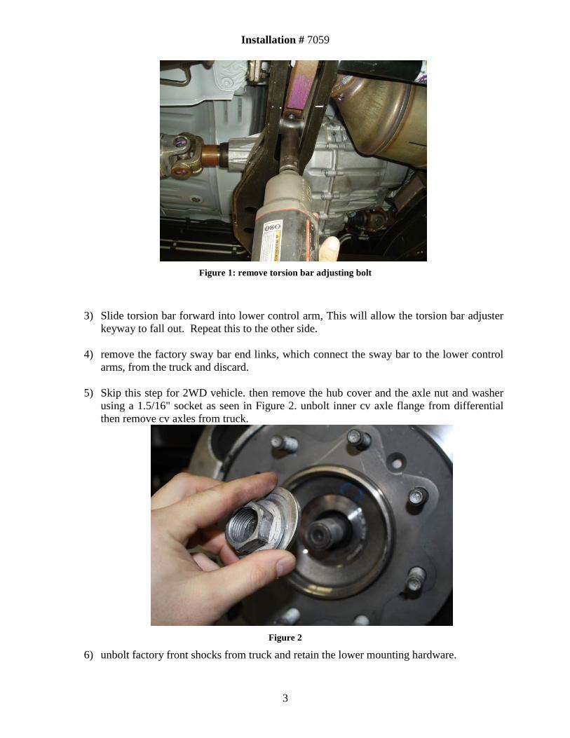
brake line bracket. Remove the brake calipers by removing the 2 bolts fastening the caliper to the spindle; it is easiest to hang the caliper from the front bumper bracket with a bungee cord or something of the like. Now remove the clips from the wheel studs and discard, and then remove the brake rotors by first removing the flat head torx screw. At this time, remove the clips from ALL 4 corners of the vehicle, as aftermarket wheels will not fit with these clips in place, see Figure 3.
Figure 3 Remove clips from all 4 corners of vehicle. MUST DO for aftermarket wheels.
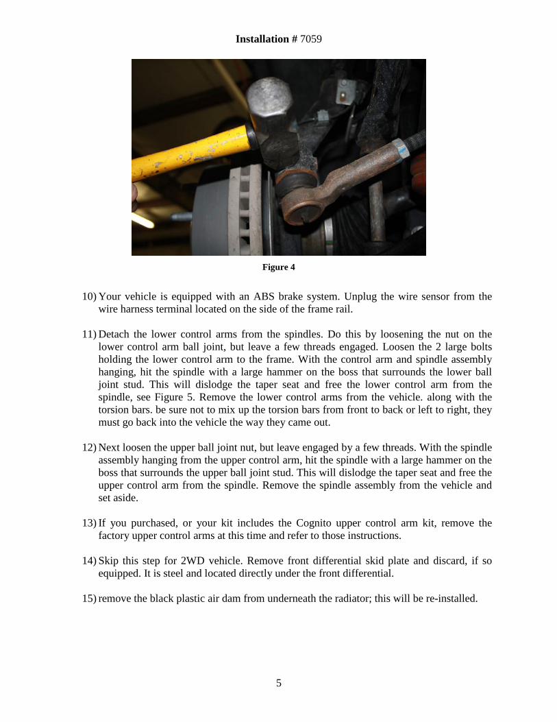
9) Remove the tie rod end nuts on the spindle. Using a pickle fork, or hammer, dislodge tie
rod from spindle. Pull down on the tie rod and hit the spindle casting with a hammer to dislodge the taper seat as shown in Figure 4.
Installation # 7059
5
Figure 4
10) Your vehicle is equipped with an ABS brake system. Unplug the wire sensor from the
wire harness terminal located on the side of the frame rail.
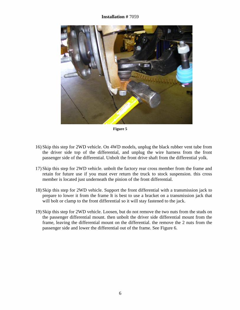
11) Detach the lower control arms from the spindles. Do this by loosening the nut on the lower control arm ball joint, but leave a few threads engaged. Loosen the 2 large bolts holding the lower control arm to the frame. With the control arm and spindle assembly hanging, hit the spindle with a large hammer on the boss that surrounds the lower ball joint stud. This will dislodge the taper seat and free the lower control arm from the spindle, see Figure 5. Remove the lower control arms from the vehicle. along with the torsion bars. be sure not to mix up the torsion bars from front to back or left to right, they must go back into the vehicle the way they came out.
12) Next loosen the upper ball joint nut, but leave engaged by a few threads. With the spindle assembly hanging from the upper control arm, hit the spindle with a large hammer on the boss that surrounds the upper ball joint stud. This will dislodge the taper seat and free the upper control arm from the spindle. Remove the spindle assembly from the vehicle and set aside.
13) If you purchased, or your kit includes the Cognito upper control arm kit, remove the
factory upper control arms at this time and refer to those instructions.
14) Skip this step for 2WD vehicle. Remove front differential skid plate and discard, if so equipped. It is steel and located directly under the front differential.
15) remove the black plastic air dam from underneath the radiator; this will be re-installed.
Installation # 7059
6
Figure 5
16) Skip this step for 2WD vehicle. On 4WD models, unplug the black rubber vent tube from the driver side top of the differential, and unplug the wire harness from the front passenger side of the differential. Unbolt the front drive shaft from the differential yolk.
17) Skip this step for 2WD vehicle. unbolt the factory rear cross member from the frame and
retain for future use if you must ever return the truck to stock suspension. this cross member is located just underneath the pinion of the front differential.
18) Skip this step for 2WD vehicle. Support the front differential with a transmission jack to
prepare to lower it from the frame It is best to use a bracket on a transmission jack that will bolt or clamp to the front differential so it will stay fastened to the jack.
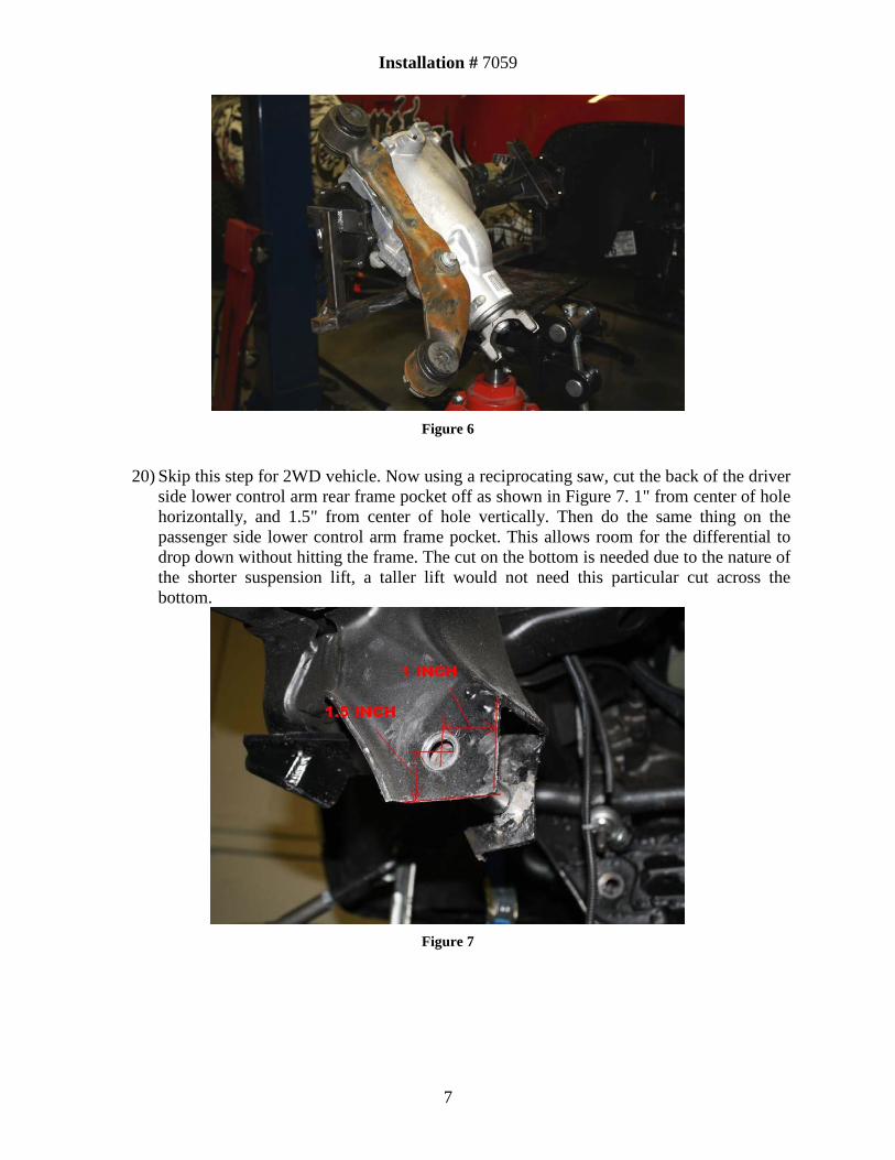
19) Skip this step for 2WD vehicle. Loosen, but do not remove the two nuts from the studs on the passenger differential mount. then unbolt the driver side differential mount from the frame, leaving the differential mount on the differential. the remove the 2 nuts from the passenger side and lower the differential out of the frame. See Figure 6.
Installation # 7059
7
Figure 6
20) Skip this step for 2WD vehicle. Now using a reciprocating saw, cut the back of the driver
side lower control arm rear frame pocket off as shown in Figure 7. 1" from center of hole horizontally, and 1.5" from center of hole vertically. Then do the same thing on the passenger side lower control arm frame pocket. This allows room for the differential to drop down without hitting the frame. The cut on the bottom is needed due to the nature of the shorter suspension lift, a taller lift would not need this particular cut across the bottom.
Figure 7
Installation # 7059
8
Lift Kit Installation and Front End Re-assembly
21) This step will begin the installation process. Do not tighten any fasteners until instructed to. Unless otherwise specified, flat washers will always be used under the heads of bolts and under nuts. Therefore, one bolt with one nut will require 2 flat washers.
22) Install the Cognito Motorsports Pitman and Idler arm support kit at this time that is
included with your lift system and has installation instructions attached to it, although at the end do not re-install the steel skid plate under the differential if it is 4WD, since it is not used on the 4" suspension lift. Re-install the previously removed plastic air dam/skid plate that belongs under the radiator area.
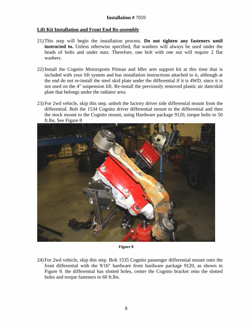
23) For 2wd vehicle, skip this step. unbolt the factory driver side differential mount from the differential. Bolt the 1534 Cognito driver differential mount to the differential and then the stock mount to the Cognito mount, using Hardware package 9120, torque bolts to 50 ft.lbs. See Figure 8
Figure 8
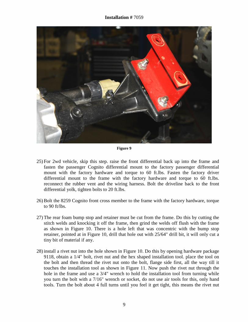
24) For 2wd vehicle, skip this step. Bolt 1535 Cognito passenger differential mount onto the
front differential with the 9/16" hardware from hardware package 9120, as shown in Figure 9. the differential has slotted holes, center the Cognito bracket onto the slotted holes and torque fasteners to 60 ft.lbs.
Installation # 7059
9
Figure 9
25) For 2wd vehicle, skip this step. raise the front differential back up into the frame and
fasten the passenger Cognito differential mount to the factory passenger differential mount with the factory hardware and torque to 60 ft.lbs. Fasten the factory driver differential mount to the frame with the factory hardware and torque to 60 ft.lbs. reconnect the rubber vent and the wiring harness. Bolt the driveline back to the front differential yolk, tighten bolts to 20 ft.lbs.
26) Bolt the 8259 Cognito front cross member to the frame with the factory hardware, torque
to 90 ft/lbs.
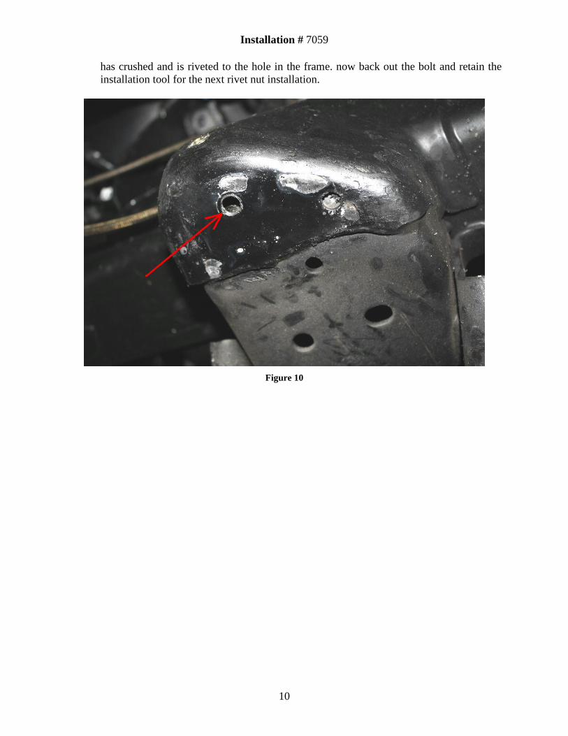
27) The rear foam bump stop and retainer must be cut from the frame. Do this by cutting the stitch welds and knocking it off the frame, then grind the welds off flush with the frame as shown in Figure 10. There is a hole left that was concentric with the bump stop retainer, pointed at in Figure 10, drill that hole out with 25/64" drill bit, it will only cut a tiny bit of material if any.
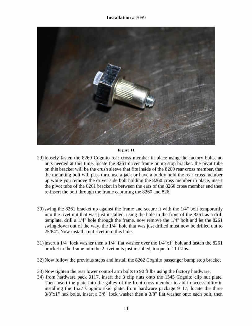
28) install a rivet nut into the hole shown in Figure 10. Do this by opening hardware package
9118, obtain a 1/4" bolt, rivet nut and the hex shaped installation tool. place the tool on the bolt and then thread the rivet nut onto the bolt, flange side first, all the way till it touches the installation tool as shown in Figure 11. Now push the rivet nut through the hole in the frame and use a 3/4" wrench to hold the installation tool from turning while you turn the bolt with a 7/16" wrench or socket, do not use air tools for this, only hand tools. Turn the bolt about 4 full turns until you feel it get tight, this means the rivet nut
Installation # 7059
10
has crushed and is riveted to the hole in the frame. now back out the bolt and retain the installation tool for the next rivet nut installation.
Figure 10
Installation # 7059
11
Figure 11
29) loosely fasten the 8260 Cognito rear cross member in place using the factory bolts, no nuts needed at this time. locate the 8261 driver frame bump stop bracket. the pivot tube on this bracket will be the crush sleeve that fits inside of the 8260 rear cross member, that the mounting bolt will pass thru. use a jack or have a buddy hold the rear cross member up while you remove the driver side bolt holding the 8260 cross member in place, insert the pivot tube of the 8261 bracket in between the ears of the 8260 cross member and then re-insert the bolt through the frame capturing the 8260 and 826.
30) swing the 8261 bracket up against the frame and secure it with the 1/4" bolt temporarily into the rivet nut that was just installed. using the hole in the front of the 8261 as a drill template, drill a 1/4" hole through the frame. now remove the 1/4" bolt and let the 8261 swing down out of the way. the 1/4" hole that was just drilled must now be drilled out to 25/64". Now install a nut rivet into this hole.
31) insert a 1/4" lock washer then a 1/4" flat washer over the 1/4"x1" bolt and fasten the 8261
bracket to the frame into the 2 rivet nuts just installed, torque to 11 ft.lbs.
32) Now follow the previous steps and install the 8262 Cognito passenger bump stop bracket
33) Now tighten the rear lower control arm bolts to 90 ft.lbs using the factory hardware. 34) from hardware pack 9117, insert the 3 clip nuts onto the 1545 Cognito clip nut plate.
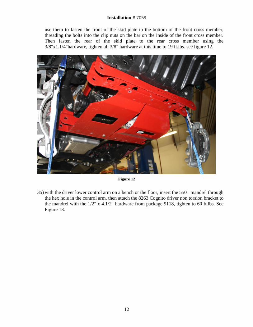
Then insert the plate into the galley of the front cross member to aid in accessibility in installing the 1527 Cognito skid plate. from hardware package 9117, locate the three 3/8"x1" hex bolts, insert a 3/8" lock washer then a 3/8" flat washer onto each bolt, then
Installation # 7059
12
use them to fasten the front of the skid plate to the bottom of the front cross member, threading the bolts into the clip nuts on the bar on the inside of the front cross member. Then fasten the rear of the skid plate to the rear cross member using the 3/8"x1.1/4"hardware, tighten all 3/8" hardware at this time to 19 ft.lbs. see figure 12.
Figure 12
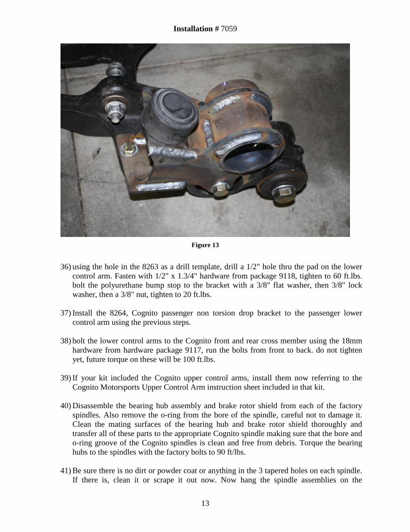
35) with the driver lower control arm on a bench or the floor, insert the 5501 mandrel through
the hex hole in the control arm. then attach the 8263 Cognito driver non torsion bracket to the mandrel with the 1/2" x 4.1/2" hardware from package 9118, tighten to 60 ft.lbs. See Figure 13.
Installation # 7059
13
Figure 13
36) using the hole in the 8263 as a drill template, drill a 1/2" hole thru the pad on the lower
control arm. Fasten with 1/2" x 1.3/4" hardware from package 9118, tighten to 60 ft.lbs. bolt the polyurethane bump stop to the bracket with a 3/8" flat washer, then 3/8" lock washer, then a 3/8" nut, tighten to 20 ft.lbs.
37) Install the 8264, Cognito passenger non torsion drop bracket to the passenger lower
control arm using the previous steps.
38) bolt the lower control arms to the Cognito front and rear cross member using the 18mm hardware from hardware package 9117, run the bolts from front to back. do not tighten yet, future torque on these will be 100 ft.lbs.
39) If your kit included the Cognito upper control arms, install them now referring to the
Cognito Motorsports Upper Control Arm instruction sheet included in that kit.
40) Disassemble the bearing hub assembly and brake rotor shield from each of the factory spindles. Also remove the o-ring from the bore of the spindle, careful not to damage it. Clean the mating surfaces of the bearing hub and brake rotor shield thoroughly and transfer all of these parts to the appropriate Cognito spindle making sure that the bore and o-ring groove of the Cognito spindles is clean and free from debris. Torque the bearing hubs to the spindles with the factory bolts to 90 ft/lbs.
41) Be sure there is no dirt or powder coat or anything in the 3 tapered holes on each spindle.
If there is, clean it or scrape it out now. Now hang the spindle assemblies on the
Installation # 7059
14
appropriate sides of the vehicle from the ball joint of the upper control arm. Then attach the lower control arm ball joint to the Cognito spindle. Tighten all ball joints to the Cognito spindles, 100 ft/lbs for the lower, and very tight with a boxed end wrench on the upper approx. 50 ft/lb.
42) All hardware installed up to this point may now be tightened.
43) Install the brake rotors and calipers on to the appropriate side Cognito spindle. Install
Cognito brake line kit if purchased with suspension kit, tightening fittings to factory specifications.
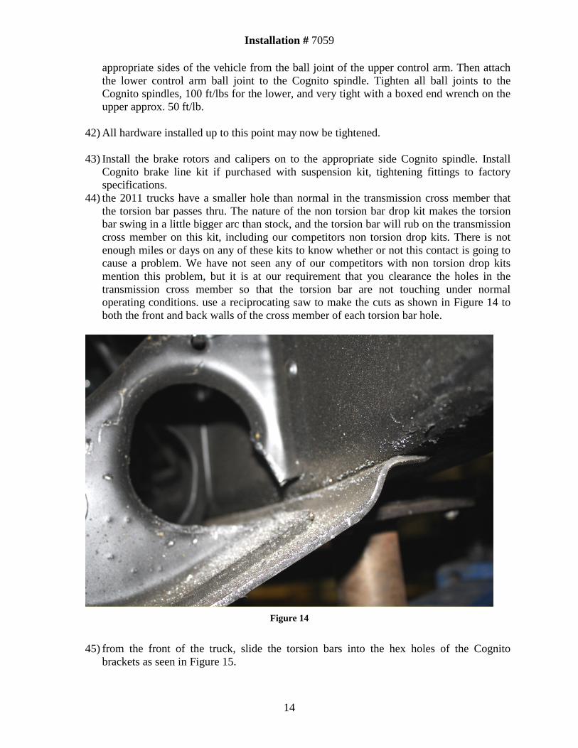
44) the 2011 trucks have a smaller hole than normal in the transmission cross member that the torsion bar passes thru. The nature of the non torsion bar drop kit makes the torsion bar swing in a little bigger arc than stock, and the torsion bar will rub on the transmission cross member on this kit, including our competitors non torsion drop kits. There is not enough miles or days on any of these kits to know whether or not this contact is going to cause a problem. We have not seen any of our competitors with non torsion drop kits mention this problem, but it is at our requirement that you clearance the holes in the transmission cross member so that the torsion bar are not touching under normal operating conditions. use a reciprocating saw to make the cuts as shown in Figure 14 to both the front and back walls of the cross member of each torsion bar hole.
Figure 14
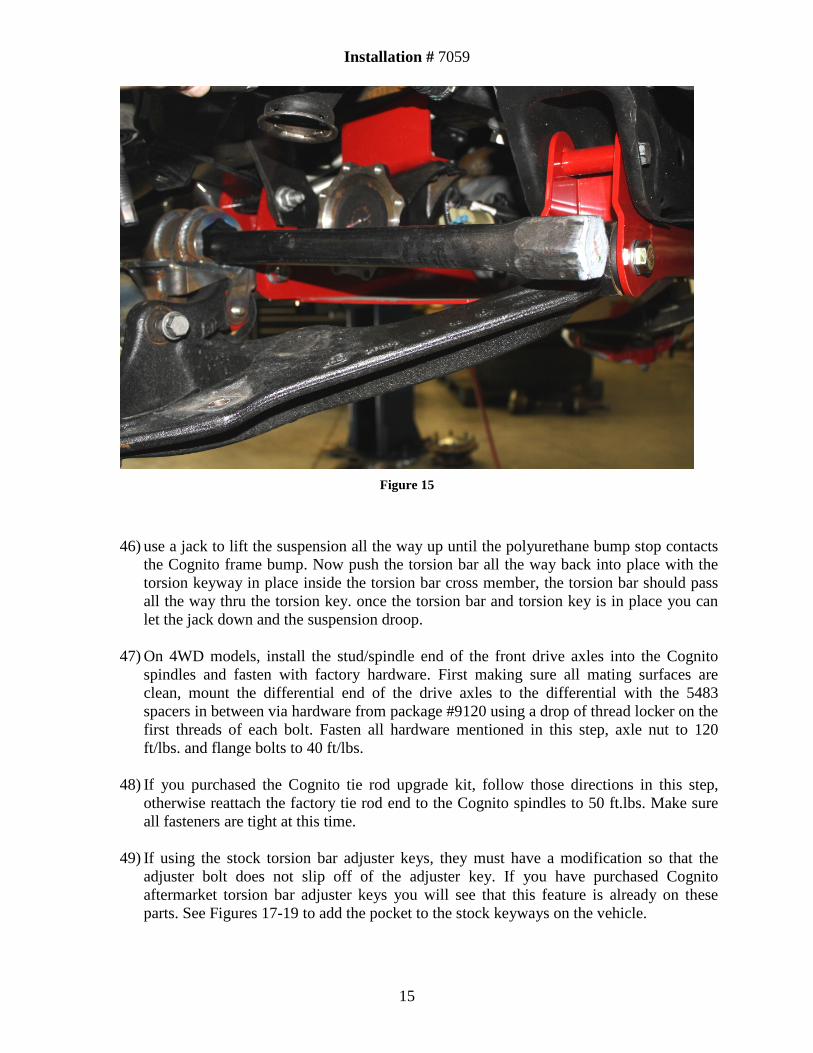
45) from the front of the truck, slide the torsion bars into the hex holes of the Cognito
brackets as seen in Figure 15.
Installation # 7059
15
Figure 15
46) use a jack to lift the suspension all the way up until the polyurethane bump stop contacts the Cognito frame bump. Now push the torsion bar all the way back into place with the torsion keyway in place inside the torsion bar cross member, the torsion bar should pass all the way thru the torsion key. once the torsion bar and torsion key is in place you can let the jack down and the suspension droop.
47) On 4WD models, install the stud/spindle end of the front drive axles into the Cognito
spindles and fasten with factory hardware. First making sure all mating surfaces are clean, mount the differential end of the drive axles to the differential with the 5483 spacers in between via hardware from package #9120 using a drop of thread locker on the first threads of each bolt. Fasten all hardware mentioned in this step, axle nut to 120 ft/lbs. and flange bolts to 40 ft/lbs.
48) If you purchased the Cognito tie rod upgrade kit, follow those directions in this step,
otherwise reattach the factory tie rod end to the Cognito spindles to 50 ft.lbs. Make sure all fasteners are tight at this time.
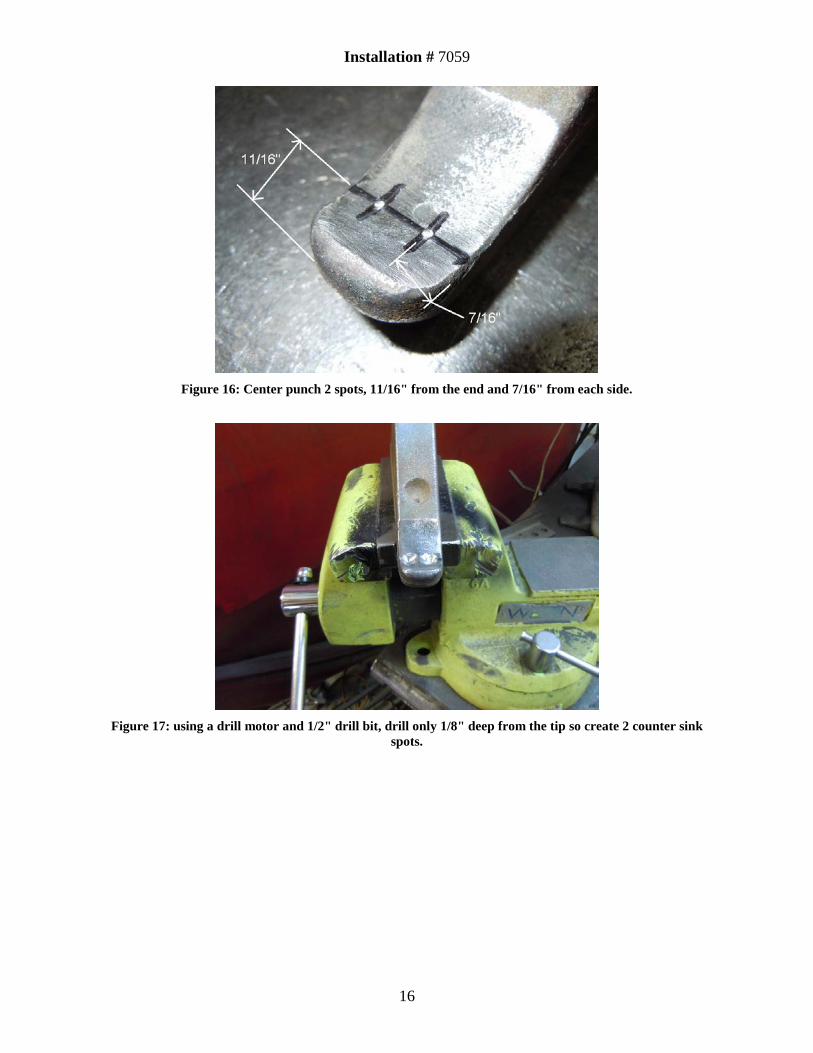
49) If using the stock torsion bar adjuster keys, they must have a modification so that the adjuster bolt does not slip off of the adjuster key. If you have purchased Cognito aftermarket torsion bar adjuster keys you will see that this feature is already on these parts. See Figures 17-19 to add the pocket to the stock keyways on the vehicle.
Installation # 7059
16
Figure 16: Center punch 2 spots, 11/16" from the end and 7/16" from each side.
Figure 17: using a drill motor and 1/2" drill bit, drill only 1/8" deep from the tip so create 2 counter sink
spots.
Installation # 7059
17
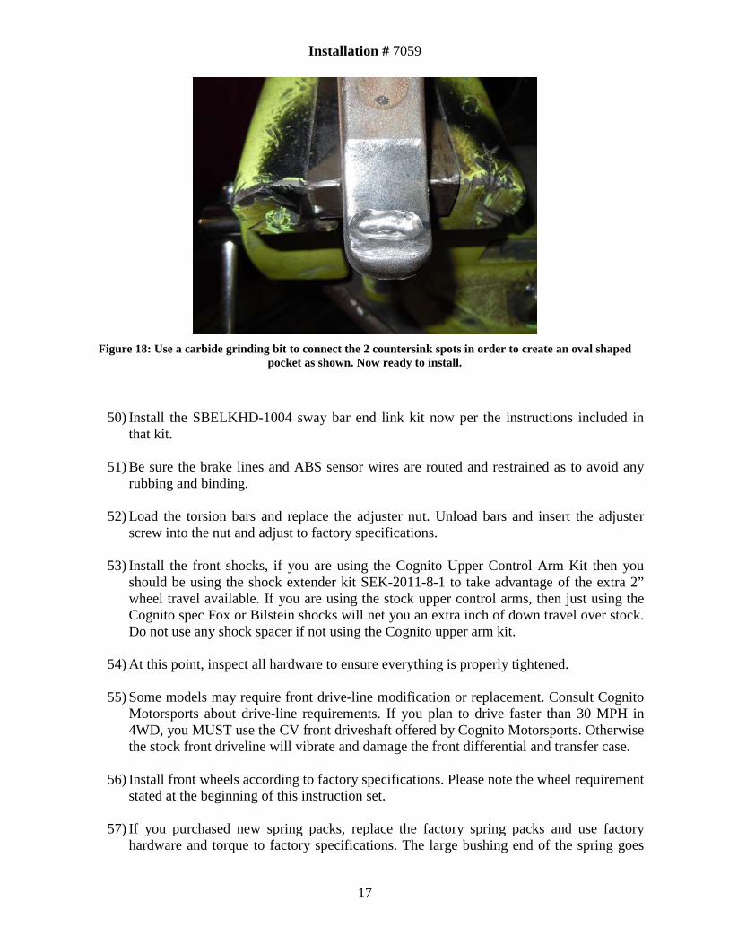
Figure 18: Use a carbide grinding bit to connect the 2 countersink spots in order to create an oval shaped
pocket as shown. Now ready to install.
50) Install the SBELKHD-1004 sway bar end link kit now per the instructions included in that kit.
51) Be sure the brake lines and ABS sensor wires are routed and restrained as to avoid any
rubbing and binding.
52) Load the torsion bars and replace the adjuster nut. Unload bars and insert the adjuster screw into the nut and adjust to factory specifications.
53) Install the front shocks, if you are using the Cognito Upper Control Arm Kit then you
should be using the shock extender kit SEK-2011-8-1 to take advantage of the extra 2” wheel travel available. If you are using the stock upper control arms, then just using the Cognito spec Fox or Bilstein shocks will net you an extra inch of down travel over stock. Do not use any shock spacer if not using the Cognito upper arm kit.
54) At this point, inspect all hardware to ensure everything is properly tightened.
55) Some models may require front drive-line modification or replacement. Consult Cognito
Motorsports about drive-line requirements. If you plan to drive faster than 30 MPH in 4WD, you MUST use the CV front driveshaft offered by Cognito Motorsports. Otherwise the stock front driveline will vibrate and damage the front differential and transfer case.
56) Install front wheels according to factory specifications. Please note the wheel requirement
stated at the beginning of this instruction set.
57) If you purchased new spring packs, replace the factory spring packs and use factory hardware and torque to factory specifications. The large bushing end of the spring goes
Installation # 7059
18
toward the front of the vehicle. Use appropriate length u-bolts and torque them to 110 ft-lbs if they are 3/4”. Then install rear wheels and shocks.
58) Adjust the torsion bars so that the front ride height is appropriate, and so that the truck is
even left to right side. Do not over crank the torsion bars to try and gain too much height. Always lift the front of the truck so the wheels droop down before turning the torsion adjuster bolt tighter. Then drive the truck briefly to settle the height before measuring.
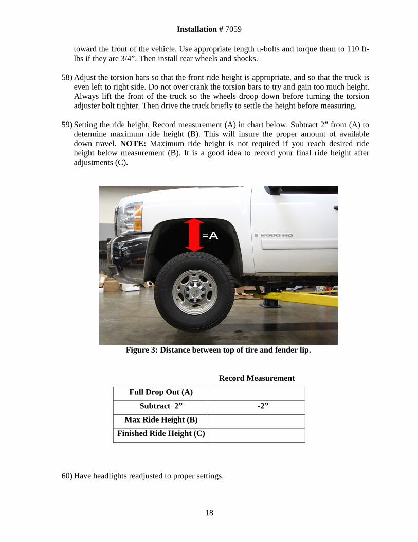
59) Setting the ride height, Record measurement (A) in chart below. Subtract 2” from (A) to determine maximum ride height (B). This will insure the proper amount of available down travel. NOTE: Maximum ride height is not required if you reach desired ride height below measurement (B). It is a good idea to record your final ride height after adjustments (C).
Figure 3: Distance between top of tire and fender lip.
Record Measurement
Full Drop Out (A)
Subtract 2” -2”
Max Ride Height (B)
Finished Ride Height (C)
60) Have headlights readjusted to proper settings.

Installation # 7059
19
61) Have the vehicle professionally aligned to the following specifications: Caster, +2.0 to +4.5 degrees with a caster split .9 degrees higher on the passenger side. Camber, 0 to + .2 degrees. Toe settings, .1 degree toe in on each side.
Installation # 7059
20
Cognito Motorsports Limited Lifetime Warranty Cognito Motorsports warrants, to the original retail purchaser, that its suspension products are free from defects in workmanship and material for as long as the purchaser owns the vehicle on which the product was originally installed. Cognito Motorsports does not warrant the product for finish, alterations, modifications, and/or original installation contrary to specifications of Cognito Motorsports. Cognito Motorsports suspension products are not designed nor intended to be installed on vehicles used in race applications or for racing purposes or for similar activities involving abnormal abuse other than the vehicle was originally designed to handle or endure. (A “RACE” is defined as any contest between two or more vehicles, and/or contest of one or more vehicle against the clock, whether or not such contest is for a prize.)
This warranty is for a one-time replacement of each Cognito Motorsports product and does not cover any part that Cognito Motorsports has previously replaced under this warranty. This warranty does not include coverage for police or taxi vehicles, race vehicles, or vehicles used for government or commercial purposes. Also excluded from this warrant are sales outside of the United States of America. Alterations to the finish of the parts including but not limited to painting, powder coating, plating, and/or welding will void all warranties. Cognito Motorsports obligation under this warranty is limited to the repair or replacement, at Cognito Motorsports option of the defective product. Any and all costs of removal, installation or re-installation, freight charges, incidental or consequential damages are expressly excluded from this warranty.
This warranty excludes the following items: bushings, bumpstops, tie-rod ends, limiting straps, and hiem joints. These parts are subject to wear and are not considered defective when worn. They are warranted for 60 days of purchase for defects in workmanship. Cognito Motorsports suspension components must be installed as a complete system. Any substitutions or exemptions of required components will immediately void the warranty. Some finish damage may happen to parts during shipping and is not covered under warranty. This warranty shall not apply to any product that had been subject to accident, negligence, alteration, abuse, or misuse. Cognito Motorsports does not warrant products not manufactured by Cognito Motorsports. Cognito Motorsports reserves the right to supersede, discontinue, or change the design, finish, part number and/or application of parts when deemed necessary by Cognito Motorsports without written notice, and in the sole and absolute discretion of Cognito Motorsports. Warranty Claims All warranty claims must be submitted through the original company of purchase. All claims must be shipped back to the original company of purchase with an approved RMA number listed as a reference on the shipping label and clearly printed on two opposing sides of the package(s); product in question must be inspected by Cognito Motorsports before replacement parts are shipped out. Return Policy Cognito Motorsports has a no refund return policy. Under special circumstances, returns might be accepted with prior written approval. All returned product will be shipped freight prepaid. Product returned is subject to a 25% restocking fee. No returns will be accepted after 30 days upon receipt of product. Product Consumer Safety and Warning The installation of this kit will modify the suspension of your vehicle and may cause it to handle significantly different than a factory equipped vehicle. Installing larger tires with modified suspension and increased ground clearance will significantly alter the handling characteristics of the vehicle, and may result in increased braking distances as well as changes in vehicle maneuverability and handling compared to the factory equipped vehicle. As with any vehicle, extreme caution and care must be used to prevent loss of control or roll-over during sharp turns or abrupt maneuvers. Always wear seat belts and drive safely, recognizing the reduced speeds and specialized driving techniques is required.
This suspension system will not strengthen nor reinforce the stock frame of the vehicle, nor will it increase rollover protection. It is necessary to periodically inspect all suspension and drive train components for tightness of fit or any damage. Installation of these parts will modify the height of the vehicle and will raise the center of gravity. Altered height modifications and off-road operation may increase your vehicle’s susceptibility to roll over conditions and may cause serious injury or death. Many states regulate the height modification to each vehicle. Check the laws in your state for exact specifications. Height modifications may affect the reaction, ride, handling, and wear factor of your vehicle’s components.
Failure to drive this vehicle safely may result in injury or death! Do not drive this vehicle unless you are familiar with its unique handling characteristics and are confident of your ability to maintain control under all driving conditions. Some modifications and combinations of modifications are not recommended, unsafe, and may not be permitted in your state. Consult your vehicle owner’s manual, the instructions accompanying this product, and your state laws before undertaking these modifications. The owner of the modified vehicle and the qualified mechanic required to install this product are responsible for the legality and safety of the vehicle being modified.
Related Documents