www.lightpointe.com Freedom Flexibility Fast Hybrid Free Space Optical / Microwave Communication Networks: A Unique Solution For Ultra High-Speed Local Loop Connectivity Gerald Clark, Heinz Willebrand, Maha Achour LightPointe Communications, Inc. 10140 Barnes Canyon Road San Diego, CA 92121 Phone: (858) 657 0000 Fax: (858) 657 0028 © 2001 LightPointe Communications, Inc. All rights reserved.

Welcome message from author
This document is posted to help you gain knowledge. Please leave a comment to let me know what you think about it! Share it to your friends and learn new things together.
Transcript
www. l ightpo inte.com Freedom Flexibility Fast
Hybrid Free Space Optical / MicrowaveCommunication Networks:
A Unique Solution For UltraHigh-Speed Local Loop Connectivity
Gerald Clark, Heinz Willebrand, Maha Achour
LightPointe Communications, Inc.10140 Barnes Canyon Road
San Diego, CA 92121Phone: (858) 657 0000Fax: (858) 657 0028
© 2001 LightPointe Communications, Inc.All rights reserved.
www. l ightpo inte.com Freedom Flexibility Fast
Table of Contents
Abstract ......................................................................................................................................................... 1
Introduction................................................................................................................................................... 1
Atmospheric Impact...................................................................................................................................... 2Infrared Laser Systems ........................................................................................................................... 2Microwave Systems ............................................................................................................................... 3
Link Budget Analysis ................................................................................................................................... 4Channel Bandwidth ................................................................................................................................ 5Atmospheric Attenuation ....................................................................................................................... 5Optical BER ........................................................................................................................................... 6Electrical BER........................................................................................................................................ 6
Hybrid Microwave/Laser Communication System....................................................................................... 7
Hybrid Microwave/Laser Network ............................................................................................................. 10
Summary and Conclusion ........................................................................................................................... 12
References................................................................................................................................................... 13
www. l ightpo inte.com Freedom Flexibility Fast
1
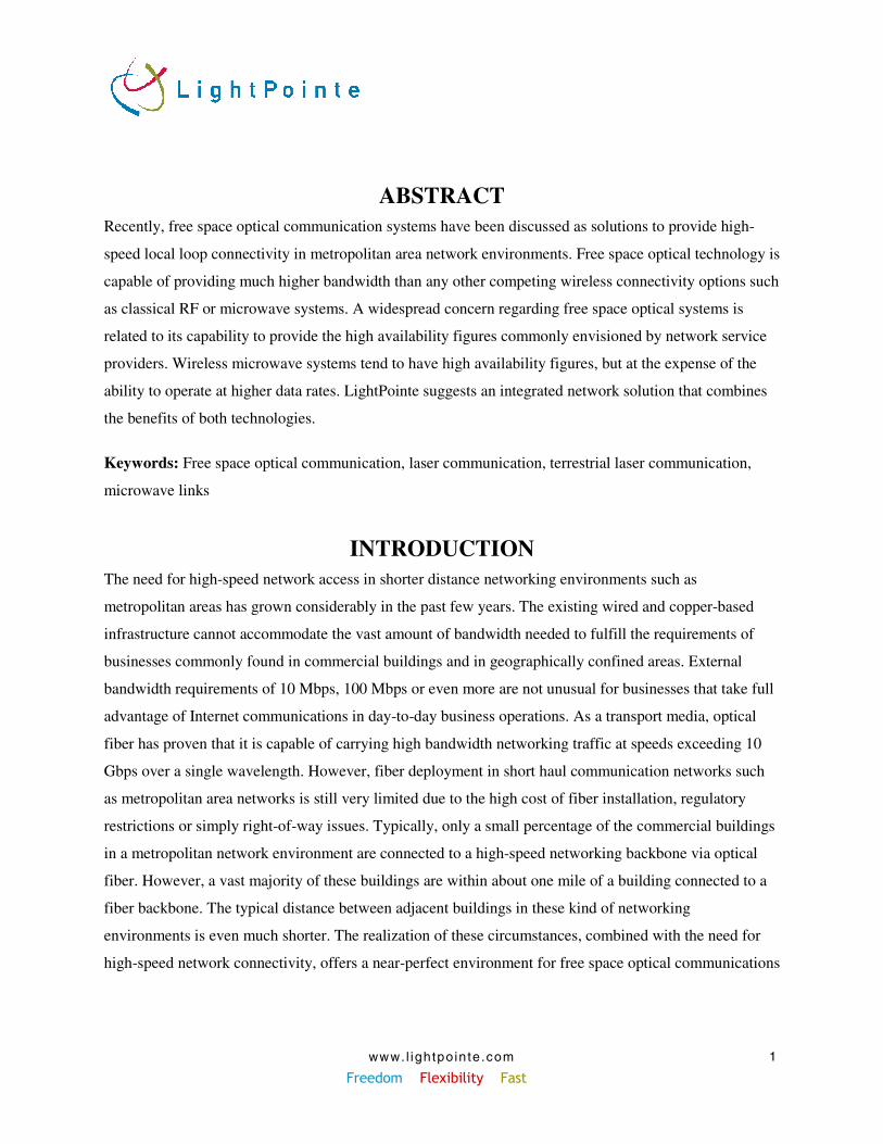
ABSTRACTRecently, free space optical communication systems have been discussed as solutions to provide high-
speed local loop connectivity in metropolitan area network environments. Free space optical technology is
capable of providing much higher bandwidth than any other competing wireless connectivity options such
as classical RF or microwave systems. A widespread concern regarding free space optical systems is
related to its capability to provide the high availability figures commonly envisioned by network service
providers. Wireless microwave systems tend to have high availability figures, but at the expense of the
ability to operate at higher data rates. LightPointe suggests an integrated network solution that combines
the benefits of both technologies.
Keywords: Free space optical communication, laser communication, terrestrial laser communication,
microwave links
INTRODUCTIONThe need for high-speed network access in shorter distance networking environments such as
metropolitan areas has grown considerably in the past few years. The existing wired and copper-based
infrastructure cannot accommodate the vast amount of bandwidth needed to fulfill the requirements of
businesses commonly found in commercial buildings and in geographically confined areas. External
bandwidth requirements of 10 Mbps, 100 Mbps or even more are not unusual for businesses that take full
advantage of Internet communications in day-to-day business operations. As a transport media, optical
fiber has proven that it is capable of carrying high bandwidth networking traffic at speeds exceeding 10
Gbps over a single wavelength. However, fiber deployment in short haul communication networks such
as metropolitan area networks is still very limited due to the high cost of fiber installation, regulatory
restrictions or simply right-of-way issues. Typically, only a small percentage of the commercial buildings
in a metropolitan network environment are connected to a high-speed networking backbone via optical
fiber. However, a vast majority of these buildings are within about one mile of a building connected to a
fiber backbone. The typical distance between adjacent buildings in these kind of networking
environments is even much shorter. The realization of these circumstances, combined with the need for
high-speed network connectivity, offers a near-perfect environment for free space optical communications
www. l ightpo inte.com Freedom Flexibility Fast
2
technology. Adverse weather conditions such as dense fog or steam are still challenging this technology
relative to carrier-like availability figures.
LightPointe Communications proposes a hybrid optical/microwave system architecture to counteract
concerns over availability. With respect to the weather impact, optical and microwave technologies are
complementary. While the optical communication path suffers signal degradation and attenuation from
small size particles such as fog, RF/microwave systems are far less impacted by these kinds of weather
conditions. This is especially true for microwave frequencies below 10 GHz.
This paper provides some background information to motivate the hybrid approach and discusses
potential network architectures. We also show a commercially available system that is used as hot-
standby link for an optical Ethernet based communication system.
ATMOSPHERIC IMPACT
Infrared Laser SystemsInfrared laser communication systems operate in a frequency range around 200 THz. These frequencies
correspond to wavelengths on the order of 1 micrometer. A laser beam in this frequency range or
wavelength band is attenuated as it propagates through the atmosphere [1]. In addition, the laser beam is
often broadened, defocused, and may even be deflected from its initial propagation direction. The
attenuation and amount of beam alteration depend on the wavelength, output power, makeup of the
atmosphere, and the day-to-day atmospheric condition. When the output power is low, the effects are
linear in behavior. That is, doubling the initial beam intensity results in a doubled intensity at every point
along the beam path. Absorption, scattering, and atmospheric turbulence are examples of linear effects.
On the other hand, when the power is sufficiently high, new effects are observed that are characterized by
nonlinear relationships.
Beer’s law describes attenuation of laser radiation in the atmosphere:
R -e P
P(R) γ=,
where, the ratio P(R)/P is the transmittance, γ is the attenuation coefficient, and R is the length of the
transmission path. Four individual processes determine the attenuation coefficient: molecular absorption,
molecular scattering, aerosol absorption, and aerosol scattering.
www. l ightpo inte.com Freedom Flexibility Fast
3
• Atmospheric Absorption: By far, the most important absorbing molecules are H2O and C2O.
Depending on the weather conditions, altitude, and geographical location, the concentrations
of those molecules vary. Therefore, depending on the absorption band of those molecules, the
transmittance reaches zero for some wavelengths. The wavelength intervals where the
transmittance is relatively high are called atmospheric windows. Obviously, for efficient
energy transmission the laser wavelength should fall well within one of these windows. The
wavelength under consideration in this paper is 850 nm.
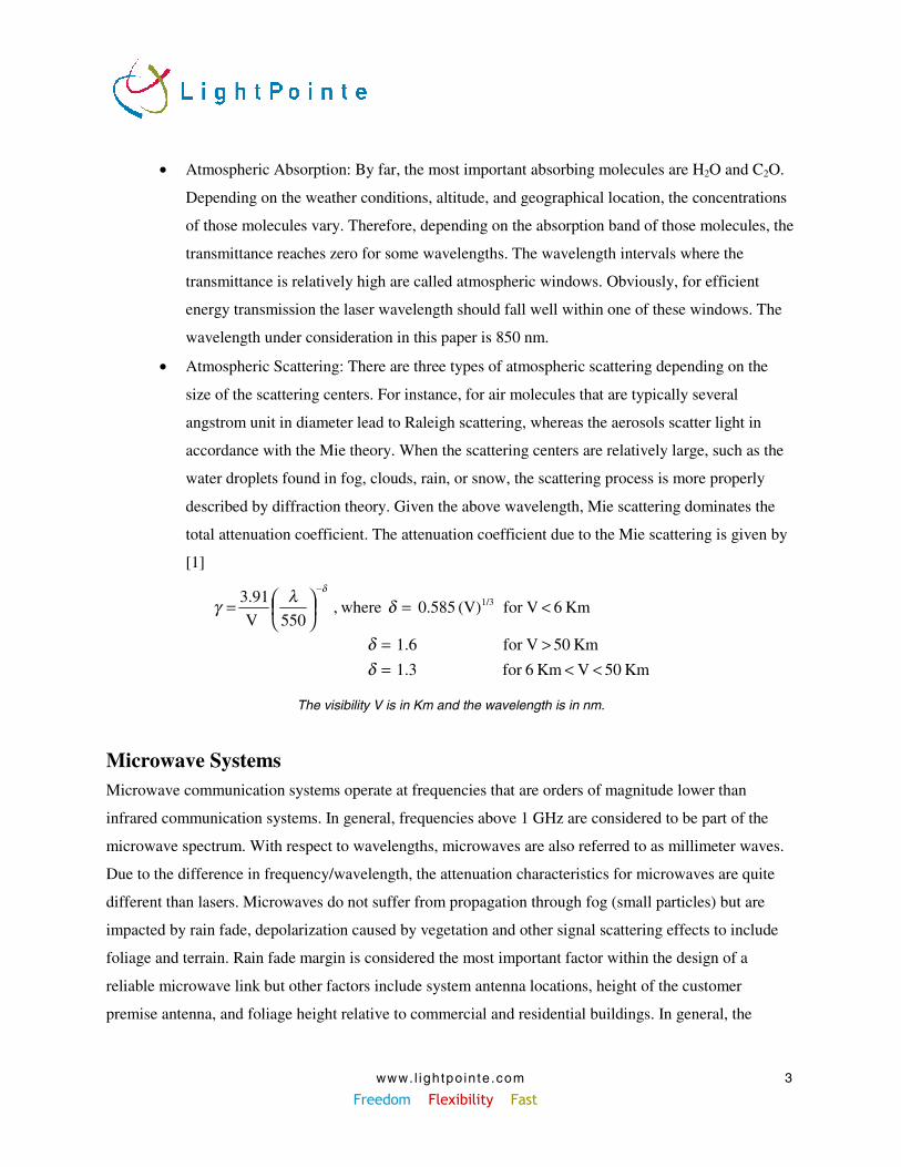
• Atmospheric Scattering: There are three types of atmospheric scattering depending on the
size of the scattering centers. For instance, for air molecules that are typically several
angstrom unit in diameter lead to Raleigh scattering, whereas the aerosols scatter light in
accordance with the Mie theory. When the scattering centers are relatively large, such as the
water droplets found in fog, clouds, rain, or snow, the scattering process is more properly
described by diffraction theory. Given the above wavelength, Mie scattering dominates the
total attenuation coefficient. The attenuation coefficient due to the Mie scattering is given by
[1]
Km 50 V Km 6for 1.3
Km 50 Vfor 1.6
Km 6 Vfor (V) 0.585 where, 550
V
3.91 1/3
<<=>=
<=
=
−
δδ
δλγδ
The visibility V is in Km and the wavelength is in nm.
Microwave SystemsMicrowave communication systems operate at frequencies that are orders of magnitude lower than
infrared communication systems. In general, frequencies above 1 GHz are considered to be part of the
microwave spectrum. With respect to wavelengths, microwaves are also referred to as millimeter waves.
Due to the difference in frequency/wavelength, the attenuation characteristics for microwaves are quite
different than lasers. Microwaves do not suffer from propagation through fog (small particles) but are
impacted by rain fade, depolarization caused by vegetation and other signal scattering effects to include
foliage and terrain. Rain fade margin is considered the most important factor within the design of a
reliable microwave link but other factors include system antenna locations, height of the customer
premise antenna, and foliage height relative to commercial and residential buildings. In general, the
www. l ightpo inte.com Freedom Flexibility Fast
4
geographical area of interest for a microwave deployment is characterized to fall into a certain rain zone.
These rain zones have been defined by long-term measurements of rainfall. The microwave system
designer incorporates the rain characteristics of a specific zone into the link budget analysis to calculate
the statistical availability figure. For voice/data applications, the design goal is to reach 99.999%
statistical availability, and as for infrared systems, the statistical availability is a function of the distance
between two communication locations. Other parameters that impact the availability characteristics are
microwave launch power levels, antenna types and sizes, the receiver sensitivity and the actual
transmission frequency. In general, higher frequency microwaves are much more impacted by rain than
the lower frequency band. For microwave systems operating below 10 GHz, the rain impact can be nearly
neglected as far as distances below a few miles are concerned. Detailed information on how to perform a
link budget analysis and calculate statistical availability figure can be found in [2].
The government strictly regulates the use of the microwave spectrum for communication purposes.
Parts of the spectrum between roughly 1 GHz and 50 GHz sections are available for commercial
applications and the government grants the right to use a specific microwave band with a limited channel
bandwidth through a licensing process. Higher frequency microwave bands are widely used by
applications such as MMDS or LMDS. A few years ago two limited spectral bands around 2.4 GHz and
5.8 GHz were released by the government for unlicensed public and commercial use. These bands are
commonly referred to as ISM (Industrial-Scientific-Medical) bands. Three more unlicensed spectral bands
of 100 MHz channel bandwidth are available in the 5.2, 5.3 and 5.7 GHz range. These three bands are
commonly referred to as UNII (Universal National Information Infrastructure) bands.
In this paper we concentrate mainly on the unlicensed microwave bands below 10 GHz because they
fit well within the license free nature of infrared systems. For the anticipated geographical distances in
our hybrid network design, a 99.999% statistical availability figure of the microwave path can be easily
achieved with standard microwave component technology.
In the following paragraph we provide a simple link budget analysis for the infrared path.
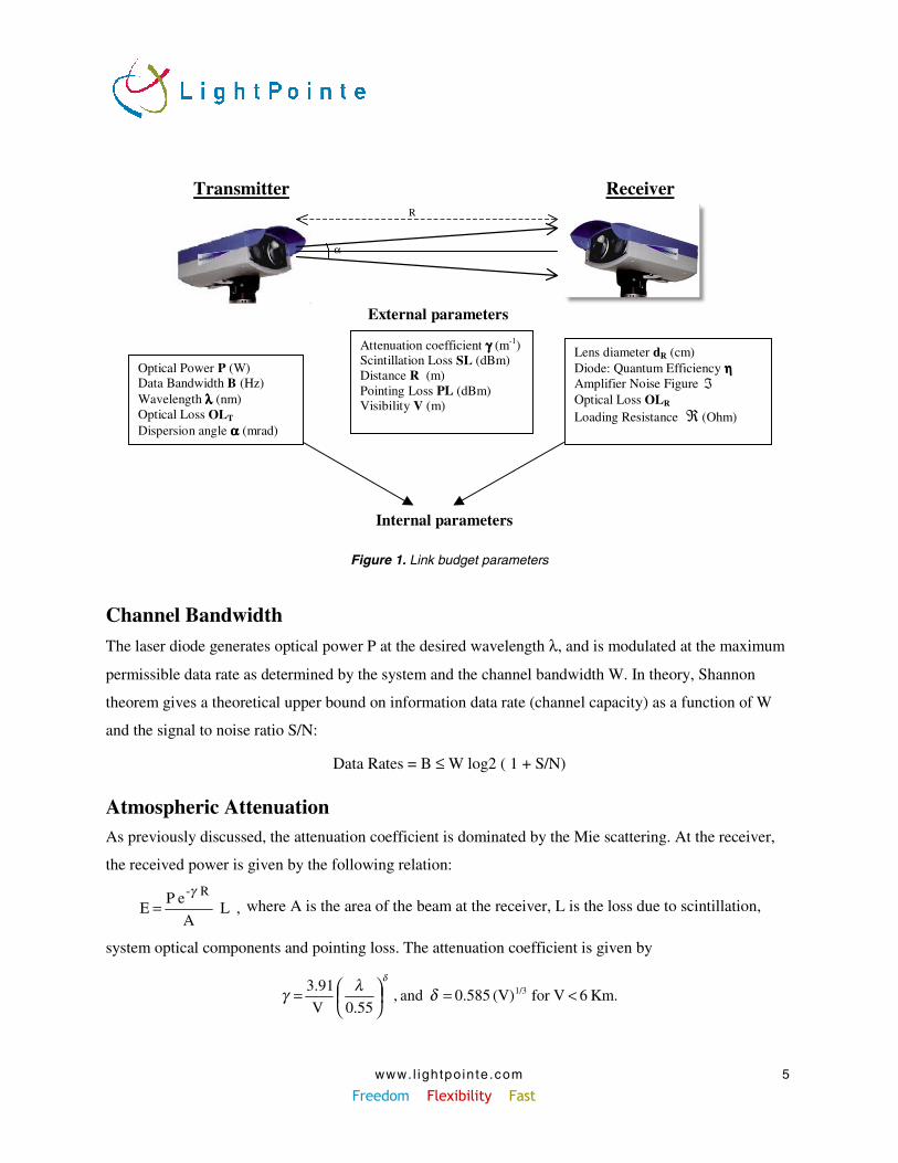
LINK BUDGET ANALYSISTo perform a link budget analysis it is important to know the physical characteristics of the transmission
equipment (internal parameters) as well as the physical properties of the transmission path (external
parameters). These parameters are listed in Figure 1. The following section discusses some of these
parameters in more detail.
www. l ightpo inte.com Freedom Flexibility Fast
5
α
R
Optical Power P (W)Data Bandwidth B (Hz)Wavelength λλλλ (nm)Optical Loss OLT
Dispersion angle αααα (mrad)
Transmitter
Lens diameter dR (cm)Diode: Quantum Efficiency ηηηηAmplifier Noise Figure ℑOptical Loss OLR
Loading Resistance ℜ (Ohm)
Attenuation coefficient γγγγ (m-1)Scintillation Loss SL (dBm)Distance R (m)Pointing Loss PL (dBm)Visibility V (m)
Receiver
Internal parameters
External parameters
Figure 1. Link budget parameters
Channel BandwidthThe laser diode generates optical power P at the desired wavelength λ, and is modulated at the maximum
permissible data rate as determined by the system and the channel bandwidth W. In theory, Shannon
theorem gives a theoretical upper bound on information data rate (channel capacity) as a function of W
and the signal to noise ratio S/N:
Data Rates = B ≤ W log2 ( 1 + S/N)
Atmospheric AttenuationAs previously discussed, the attenuation coefficient is dominated by the Mie scattering. At the receiver,
the received power is given by the following relation:
, L A
e P E
R -γ= where A is the area of the beam at the receiver, L is the loss due to scintillation,
system optical components and pointing loss. The attenuation coefficient is given by
Km. 6 Vfor (V) 0.585 and , 0.55
V
3.91 1/3 <=
= δλγ
δ
www. l ightpo inte.com Freedom Flexibility Fast
6
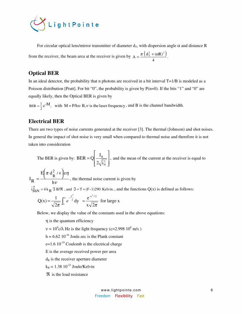
For circular optical lens/mirror transmitter of diameter dT, with dispersion angle α and distance R
from the receiver, the beam area at the receiver is given by ( )4
R)( d A
22T απ +
= .
Optical BERIn an ideal detector, the probability that n photons are received in a bit interval T=1/B is modeled as a
Poisson distribution [Pratt]. For bit “0”, the probability is given by P(n=0). If the bits “1” and “0” are
equally likely, then the Optical BER is given by
frequencylaser theis B,P/h M with ,M-e 2
1 BER νυ== , and B is the channel bandwidth.
Electrical BERThere are two types of noise currents generated at the receiver [3]. The thermal (Johnson) and shot noises.
In general the impact of shot noise is very small when compared to thermal noise and therefore it is not
taken into consideration
The BER is given by: , i2
IQ BER
2N
R
= and the mean of the current at the receiver is equal to
ν
ηπ
h
e d E
RI4/2
R
= , the thermal noise current is given by
Kelvin. 1)290-(FT and , B/ Bk 4 2ShNi +=ℑℜℑ= , and the functions Q(x) is defined as follows:
xlargefor 2x
e dy
2
1 Q(x)
2/-x
x
2
y 22
ππ≈= ∫
∞ −e
Below, we display the value of the constants used in the above equations:
η is the quantum efficiency
ν = 109c/λ Hz is the light frequency (c=2.998 108 m/s )
h = 6.62 10-34 Joule.sec is the Plank constant
e=1.6 10-19 Coulomb is the electrical charge
E is the average received power per area
dR is the receiver aperture diameter
kB = 1.38 10-23 Joule/Kelvin
ℜ is the load resistance
www. l ightpo inte.com Freedom Flexibility Fast
7
B is the channel bandwidth
ℑ is the amplifier noise figure
T is the temperature set equal to 290 K by convention
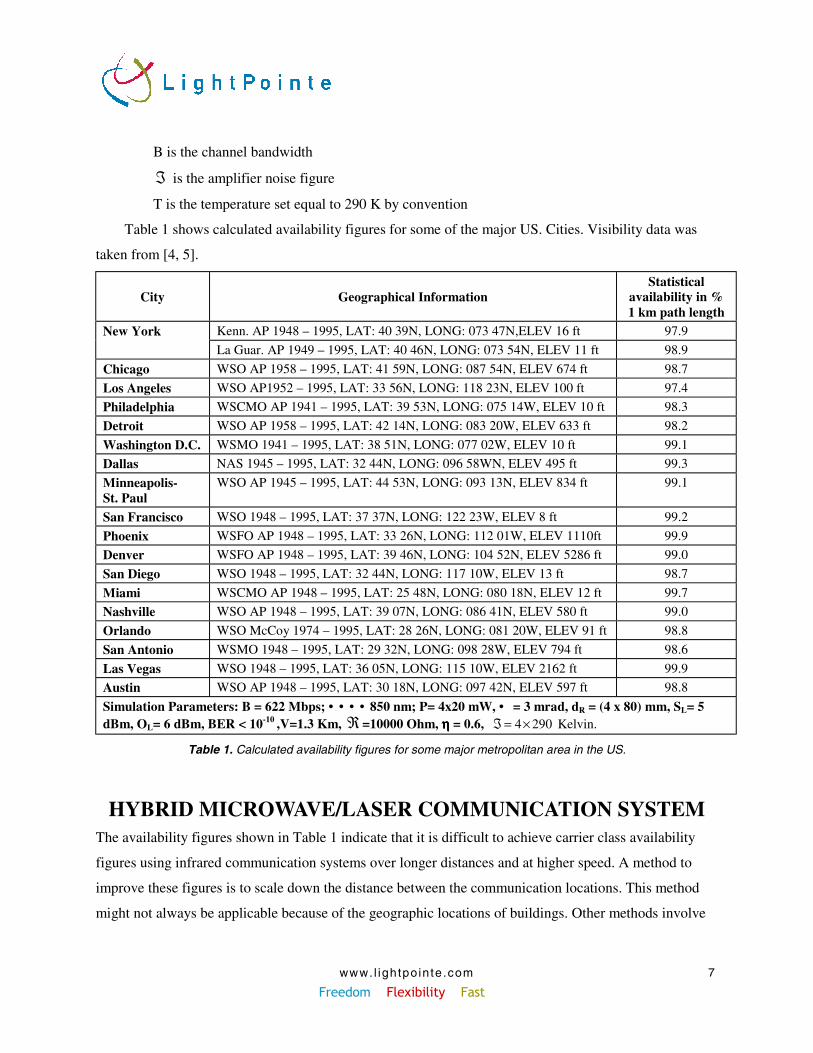
Table 1 shows calculated availability figures for some of the major US. Cities. Visibility data was
taken from [4, 5].
City Geographical InformationStatistical
availability in %1 km path length
Kenn. AP 1948 – 1995, LAT: 40 39N, LONG: 073 47N,ELEV 16 ft 97.9New YorkLa Guar. AP 1949 – 1995, LAT: 40 46N, LONG: 073 54N, ELEV 11 ft 98.9
Chicago WSO AP 1958 – 1995, LAT: 41 59N, LONG: 087 54N, ELEV 674 ft 98.7
Los Angeles WSO AP1952 – 1995, LAT: 33 56N, LONG: 118 23N, ELEV 100 ft 97.4
Philadelphia WSCMO AP 1941 – 1995, LAT: 39 53N, LONG: 075 14W, ELEV 10 ft 98.3
Detroit WSO AP 1958 – 1995, LAT: 42 14N, LONG: 083 20W, ELEV 633 ft 98.2
Washington D.C. WSMO 1941 – 1995, LAT: 38 51N, LONG: 077 02W, ELEV 10 ft 99.1
Dallas NAS 1945 – 1995, LAT: 32 44N, LONG: 096 58WN, ELEV 495 ft 99.3
Minneapolis-St. Paul
WSO AP 1945 – 1995, LAT: 44 53N, LONG: 093 13N, ELEV 834 ft 99.1
San Francisco WSO 1948 – 1995, LAT: 37 37N, LONG: 122 23W, ELEV 8 ft 99.2
Phoenix WSFO AP 1948 – 1995, LAT: 33 26N, LONG: 112 01W, ELEV 1110ft 99.9
Denver WSFO AP 1948 – 1995, LAT: 39 46N, LONG: 104 52N, ELEV 5286 ft 99.0
San Diego WSO 1948 – 1995, LAT: 32 44N, LONG: 117 10W, ELEV 13 ft 98.7
Miami WSCMO AP 1948 – 1995, LAT: 25 48N, LONG: 080 18N, ELEV 12 ft 99.7
Nashville WSO AP 1948 – 1995, LAT: 39 07N, LONG: 086 41N, ELEV 580 ft 99.0
Orlando WSO McCoy 1974 – 1995, LAT: 28 26N, LONG: 081 20W, ELEV 91 ft 98.8
San Antonio WSMO 1948 – 1995, LAT: 29 32N, LONG: 098 28W, ELEV 794 ft 98.6
Las Vegas WSO 1948 – 1995, LAT: 36 05N, LONG: 115 10W, ELEV 2162 ft 99.9
Austin WSO AP 1948 – 1995, LAT: 30 18N, LONG: 097 42N, ELEV 597 ft 98.8
Simulation Parameters: B = 622 Mbps; • • • • 850 nm; P= 4x20 mW, • = 3 mrad, dR = (4 x 80) mm, SL= 5dBm, OL= 6 dBm, BER < 10-10 ,V=1.3 Km, ℜ =10000 Ohm, ηηηη = 0.6, Kelvin. 2904 ×=ℑ
Table 1. Calculated availability figures for some major metropolitan area in the US.
HYBRID MICROWAVE/LASER COMMUNICATION SYSTEMThe availability figures shown in Table 1 indicate that it is difficult to achieve carrier class availability
figures using infrared communication systems over longer distances and at higher speed. A method to
improve these figures is to scale down the distance between the communication locations. This method
might not always be applicable because of the geographic locations of buildings. Other methods involve
www. l ightpo inte.com Freedom Flexibility Fast
8
increasing the launch power, increasing the receiver optics diameter or use the more preferable
wavelength range around 1500 instead of 850 nm. This approach is certainly feasible but in many cases is
not economical. Launching very high power levels in the infrared spectral range around 850 nm can also
violate eye safety standards and cause a potential health risk.
LightPointe suggests using an infrared system in conjunction with a slower speed microwave backup
link to improve the statistical availability of free space laser systems. The basic assumption behind this
approach is that losing a connection completely is certainly much worse than communicating at slower
speed for a short period of time. Due to the lower bandwidth of microwave systems, this approach is
certainly not applicable to any kind of transmission scenario. However, for commercial applications
involving networking speeds on the order of 100-155 Mbps, this approach might very well be a viable
solution to boost the availability figure to 99.999%.
With respect to the networking protocol, the focus of this development was related to 100 Mbps IP-
data networks. The current hybrid network architecture provides a high-speed full duplex 100 Mbps
Ethernet primary connection. The backup system is an 11 Mbps wireless Ethernet bridge operating in the
unlicensed 2.4 GHz ISM band. This specific approach was taken to ensure the license-free operation for
both parts of the overall system. However, the system architecture is not limited with respect to using this
specific frequency band. The modular design allows the use of other microwave systems that operate in a
different frequency range. The hybrid network architecture provides an automatic switchover facility in
the event of an IR-link malfunction. Switching is performed automatically without user intervention and
within a timeframe on the order of 100 milliseconds. The system automatically resumes its regular high-
speed operation when the failure disappears. Due to the hot-standby design of the overall architecture,
maintenance of the infrared system can be performed without taking the network down. Another benefit
of the hybrid approach is that infrared link status information from the SNMP based network management
and control system can be retrieved by the network system administrator, should an IR-system
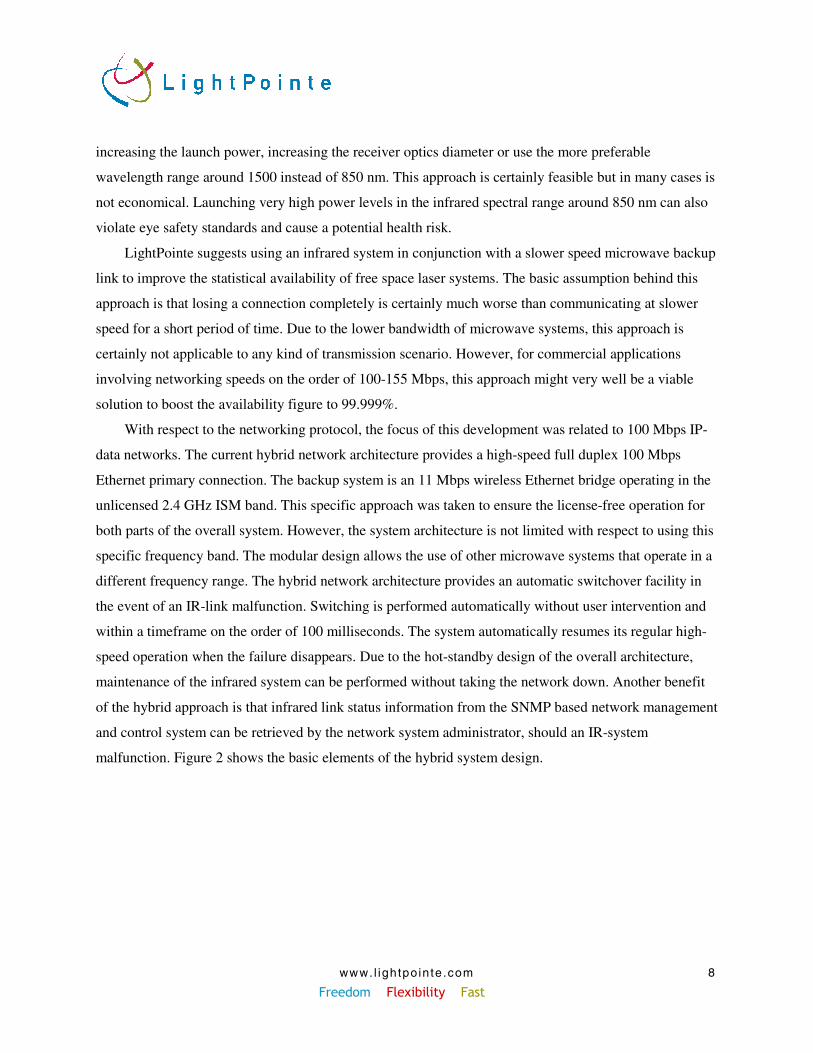
malfunction. Figure 2 shows the basic elements of the hybrid system design.
www. l ightpo inte.com Freedom Flexibility Fast
9
OpticalTransceiver
MicrowaveTransceiver
Network InterfaceMultiplexer &Switching facility
Figure 2. Basic elements of the hybrid system design
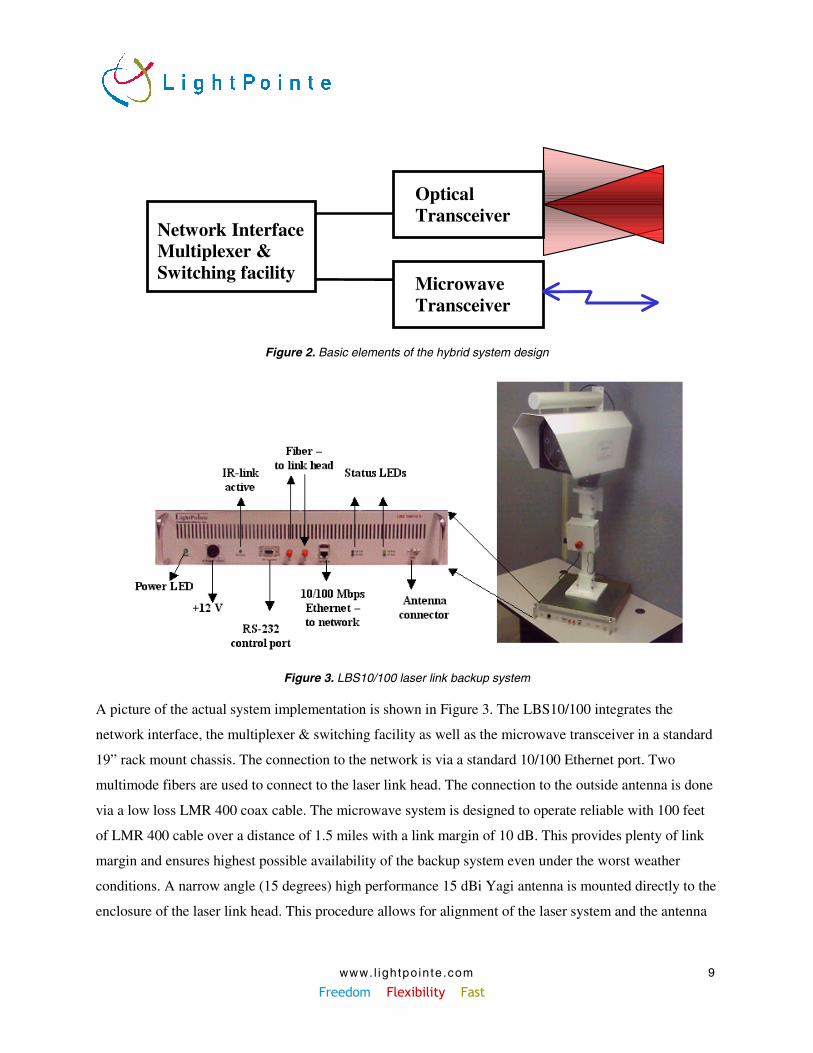
Figure 3. LBS10/100 laser link backup system
A picture of the actual system implementation is shown in Figure 3. The LBS10/100 integrates the
network interface, the multiplexer & switching facility as well as the microwave transceiver in a standard
19” rack mount chassis. The connection to the network is via a standard 10/100 Ethernet port. Two
multimode fibers are used to connect to the laser link head. The connection to the outside antenna is done
via a low loss LMR 400 coax cable. The microwave system is designed to operate reliable with 100 feet
of LMR 400 cable over a distance of 1.5 miles with a link margin of 10 dB. This provides plenty of link
margin and ensures highest possible availability of the backup system even under the worst weather
conditions. A narrow angle (15 degrees) high performance 15 dBi Yagi antenna is mounted directly to the
enclosure of the laser link head. This procedure allows for alignment of the laser system and the antenna
www. l ightpo inte.com Freedom Flexibility Fast
10
in a single installation step by using the built-in telescope and the advanced l power meter features
incorporated into the back panel of the laser link head.
HYBRID MICROWAVE/LASER NETWORK
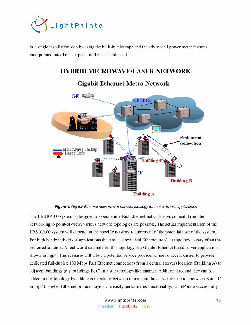
Figure 4. Gigabit Ethernet network star network topology for metro access applications
The LBS10/100 system is designed to operate in a Fast Ethernet network environment. From the
networking to point-of-view, various network topologies are possible. The actual implementation of the
LBS10/100 system will depend on the specific network requirement of the potential user of the system.
For high bandwidth driven applications the classical switched Ethernet tree/star topology is very often the
preferred solution. A real world example for this topology is a Gigabit Ethernet based server application
shown in Fig.4. This scenario will allow a potential service provider or metro access carrier to provide
dedicated full-duplex 100 Mbps Fast Ethernet connections from a central (server) location (Building A) to
adjacent buildings (e.g. buildings B, C) in a star topology-like manner. Additional redundancy can be
added to this topology by adding connections between remote buildings (see connection between B and C
in Fig.4). Higher Ethernet protocol layers can easily perform this functionality. LightPointe successfully
www. l ightpo inte.com Freedom Flexibility Fast
11
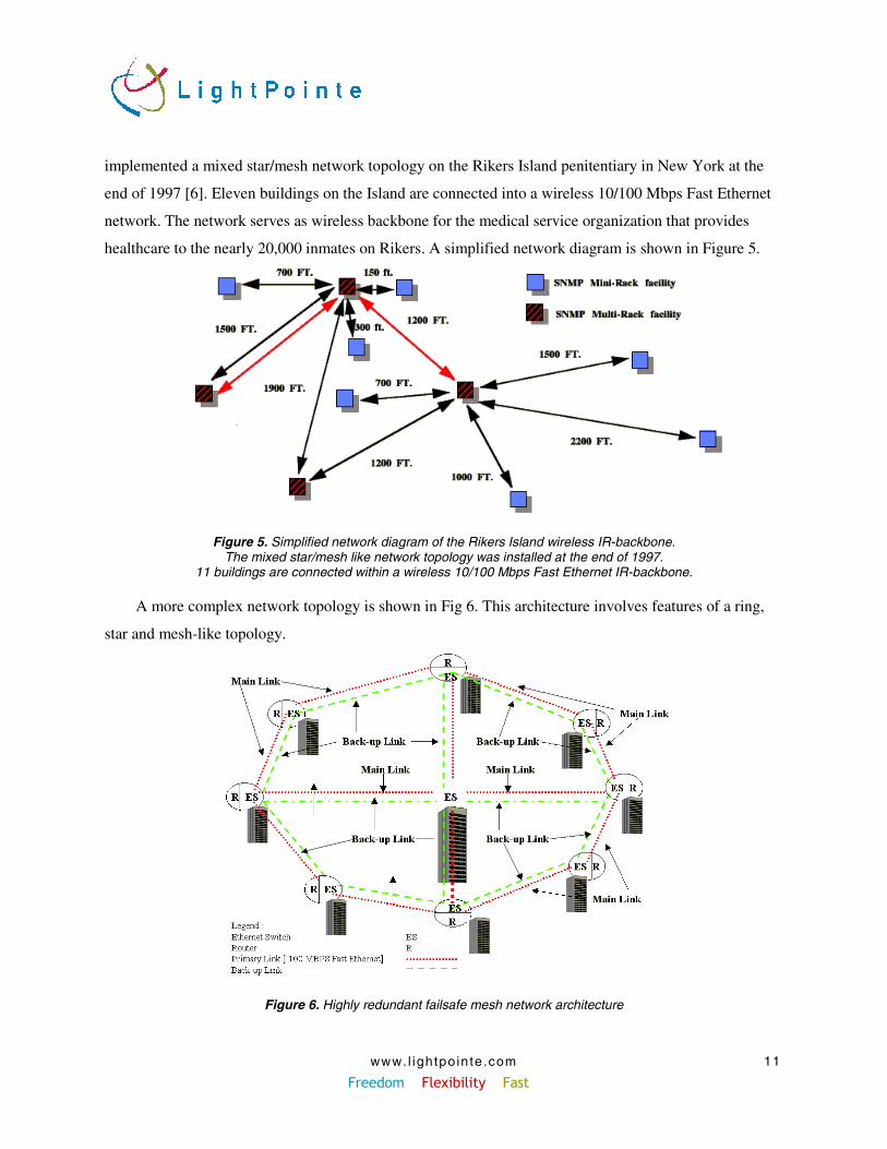
implemented a mixed star/mesh network topology on the Rikers Island penitentiary in New York at the
end of 1997 [6]. Eleven buildings on the Island are connected into a wireless 10/100 Mbps Fast Ethernet
network. The network serves as wireless backbone for the medical service organization that provides
healthcare to the nearly 20,000 inmates on Rikers. A simplified network diagram is shown in Figure 5.
Figure 5. Simplified network diagram of the Rikers Island wireless IR-backbone.The mixed star/mesh like network topology was installed at the end of 1997.
11 buildings are connected within a wireless 10/100 Mbps Fast Ethernet IR-backbone.
A more complex network topology is shown in Fig 6. This architecture involves features of a ring,
star and mesh-like topology.
Figure 6. Highly redundant failsafe mesh network architecture
www. l ightpo inte.com Freedom Flexibility Fast
12
This highly redundant network architecture includes the redundant microwave backup as well as
topology features that allow the routing of information though different network paths that are controlled
by higher protocol layers. This architecture allows the network to operate flawlessly when multiple
connections within the network fail at the same time.
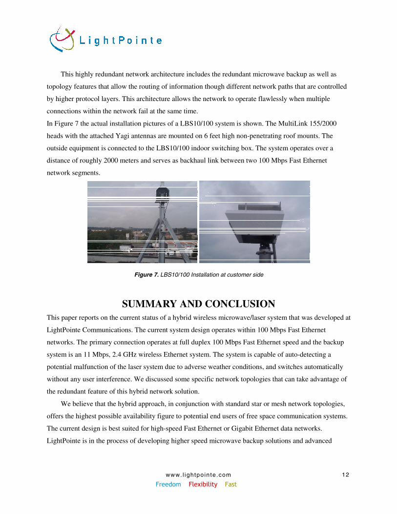
In Figure 7 the actual installation pictures of a LBS10/100 system is shown. The MultiLink 155/2000
heads with the attached Yagi antennas are mounted on 6 feet high non-penetrating roof mounts. The
outside equipment is connected to the LBS10/100 indoor switching box. The system operates over a
distance of roughly 2000 meters and serves as backhaul link between two 100 Mbps Fast Ethernet
network segments.
Figure 7. LBS10/100 Installation at customer side
SUMMARY AND CONCLUSIONThis paper reports on the current status of a hybrid wireless microwave/laser system that was developed at
LightPointe Communications. The current system design operates within 100 Mbps Fast Ethernet
networks. The primary connection operates at full duplex 100 Mbps Fast Ethernet speed and the backup
system is an 11 Mbps, 2.4 GHz wireless Ethernet system. The system is capable of auto-detecting a
potential malfunction of the laser system due to adverse weather conditions, and switches automatically
without any user interference. We discussed some specific network topologies that can take advantage of
the redundant feature of this hybrid network solution.
We believe that the hybrid approach, in conjunction with standard star or mesh network topologies,
offers the highest possible availability figure to potential end users of free space communication systems.
The current design is best suited for high-speed Fast Ethernet or Gigabit Ethernet data networks.
LightPointe is in the process of developing higher speed microwave backup solutions and advanced
www. l ightpo inte.com Freedom Flexibility Fast
13
networking infrastructures. This patent pending hybrid FORCE™ technology will ensure availability for
data/voice applications and enable various networking topologies for metro access carriers.
REFERENCES1. “Laser Beam Propagation in the Atmosphere”, Hugo Weichel, 1990.
2. [“Radio system design for Telecommunications”, Roger L. Freeman, Wiley Series in telecommunications andSignal Processing, 1997
3. “Optical Electronics in Modern Comunication”, A. Yariv, 1996.
4. “International Station Meteorological Climate Summary”, CD-ROM, Ver. 4.0, Federal Climate ComplexAsheville, Dept. of the Navy, Commerce and Air Force, September 1996.
5. Web Site: http://www.ncdc.noaa.gov/cgi-bin/res40.pl?page=climvisgsod.html
6. “Wireless Behind Bars – Infrared Network Cracks Through Medical Case”, Frontline Report, Wireless
Integration Magazine, July, August 1998
Related Documents