Efficient microwave to optical photon conversion: an electro-optical realization ALFREDO RUEDA, 1,2,3,† FLORIAN SEDLMEIR, 1,2,3,9,† MICHELE C. COLLODO, 1,2,4,5 ULRICH VOGL, 1,2 BIRGIT STILLER, 1,2,6 GERHARD SCHUNK, 1,2,3 DMITRY V. STREKALOV , 1 CHRISTOPH MARQUARDT , 1,2 JOHANNES M. FINK, 4,7 OSKAR PAINTER, 4 GERD LEUCHS, 1,2 AND HARALD G. L. SCHWEFEL 8, * 1 Max Planck Institute for the Science of Light, Günther-Scharowsky-Straße 1/Building 24, 90158 Erlangen, Germany 2 Institute for Optics, Information and Photonics, University Erlangen-Nürnberg, Staudtstr. 7/B2, 91058 Erlangen, Germany 3 SAOT, School in Advanced Optical Technologies, Paul-Gordan-Str. 6, 91052 Erlangen, Germany 4 Institute for Quantum Information and Matter and Thomas J. Watson, Sr., Laboratory of Applied Physics, California Institute of Technology, Pasadena, California 91125, USA 5 Currently at: Department of Physics, ETH Zürich, CH-8093 Zürich, Switzerland 6 Currently at: Centre for Ultrahigh Bandwidth Devices for Optical Systems (CUDOS), School of Physics, University of Sydney, New South Wales 2006, Australia 7 Currently at: Institute of Science and Technology Austria, 3400 Klosterneuburg, Austria 8 Department of Physics, University of Otago, Dunedin, New Zealand 9 e-mail: Florian. [email protected] *Corresponding author: Harald. [email protected] Received 17 February 2016; revised 5 May 2016; accepted 13 May 2016 (Doc. ID 259508); published 6 June 2016 Linking classical microwave electrical circuits to the optical telecommunication band is at the core of modern com- munication. Future quantum information networks will require coherent microwave-to-optical conversion to link electronic quantum processors and memories via low-loss optical telecommunication networks. Efficient conversion can be achieved with electro-optical modulators operating at the single microwave photon level. In the standard electro-optic modulation scheme, this is impossible because both up- and down-converted sidebands are necessarily present. Here, we demonstrate true single-sideband up- or down-conversion in a triply resonant whispering gallery mode resonator by explicitly addressing modes with asymmetric free spectral range. Compared to previous experiments, we show a 3 orders of magnitude improvement of the electro-optical conversion efficiency, reaching 0.1% photon number conversion for a 10 GHz microwave tone at 0.42 mW of optical pump power. The presented scheme is fully compatible with existing superconducting 3D circuit quantum electrodynamics technology and can be used for nonclassical state conversion and communication. Our conversion bandwidth is larger than 1 MHz and is not fundamentally limited. © 2016 Optical Society of America OCIS codes: (190.4223) Nonlinear wave mixing; (230.2090) Electro-optical devices; (190.7220) Upconversion. http://dx.doi.org/10.1364/OPTICA.3.000597 1. INTRODUCTION Efficient conversion of signals between the microwave and the optical domain is a key feature required in classical and quantum communication networks. In classical communication technol- ogy, the information is processed electronically at microwave frequencies of several gigahertz. Due to high ohmic losses at such frequencies, the distribution of the computational output over long distances is usually performed at optical frequencies in glass fibers. The emerging quantum information technology has devel- oped similar requirements with additional layers of complexity, concerned with preventing loss, decoherence, and dephasing. Superconducting qubits operating at gigahertz frequencies are promising candidates for scalable quantum processors [1–3], while the optical domain offers access to a large set of very well developed quantum optical tools, such as highly efficient single-photon detectors and long-lived quantum memories [4]. Optical communication channels allow for low transmission losses and are, in contrast to electronic ones, not thermally occu- pied at room temperature due to the high photon energies com- pared to k B T . To be useful for quantum information, a noiseless conversion channel with unity conversion probability has to be developed. For the required coupling between the vastly different wave- lengths, different experimental platforms have been proposed, e.g., cold atoms [5,6], spin ensembles coupled to superconducting circuits [7,8], and trapped ions [9,10]. The highest conversion efficiency so far was reached via electro-optomechanical coupling, where a high-quality mechanical membrane [11,12] or a piezo- electric photonic crystal [13] provide the link between an electronic LC circuit and laser light. Nearly 10% photon number 2334-2536/16/060597-08 Journal © 2016 Optical Society of America Research Article Vol. 3, No. 6 / June 2016 / Optica 597

Welcome message from author
This document is posted to help you gain knowledge. Please leave a comment to let me know what you think about it! Share it to your friends and learn new things together.
Transcript
Efficient microwave to optical photon conversion:an electro-optical realizationALFREDO RUEDA,1,2,3,† FLORIAN SEDLMEIR,1,2,3,9,† MICHELE C. COLLODO,1,2,4,5 ULRICH VOGL,1,2 BIRGIT STILLER,1,2,6
GERHARD SCHUNK,1,2,3 DMITRY V. STREKALOV,1 CHRISTOPH MARQUARDT,1,2 JOHANNES M. FINK,4,7
OSKAR PAINTER,4 GERD LEUCHS,1,2 AND HARALD G. L. SCHWEFEL8,*1Max Planck Institute for the Science of Light, Günther-Scharowsky-Straße 1/Building 24, 90158 Erlangen, Germany2Institute for Optics, Information and Photonics, University Erlangen-Nürnberg, Staudtstr. 7/B2, 91058 Erlangen, Germany3SAOT, School in Advanced Optical Technologies, Paul-Gordan-Str. 6, 91052 Erlangen, Germany4Institute for Quantum Information and Matter and Thomas J. Watson, Sr., Laboratory of Applied Physics, California Institute of Technology,Pasadena, California 91125, USA5Currently at: Department of Physics, ETH Zürich, CH-8093 Zürich, Switzerland6Currently at: Centre for Ultrahigh Bandwidth Devices for Optical Systems (CUDOS), School of Physics, University of Sydney,New South Wales 2006, Australia7Currently at: Institute of Science and Technology Austria, 3400 Klosterneuburg, Austria8Department of Physics, University of Otago, Dunedin, New Zealand9e-mail: Florian. [email protected]*Corresponding author: Harald. [email protected]
Received 17 February 2016; revised 5 May 2016; accepted 13 May 2016 (Doc. ID 259508); published 6 June 2016
Linking classical microwave electrical circuits to the optical telecommunication band is at the core of modern com-munication. Future quantum information networks will require coherent microwave-to-optical conversion to linkelectronic quantum processors and memories via low-loss optical telecommunication networks. Efficient conversioncan be achieved with electro-optical modulators operating at the single microwave photon level. In the standardelectro-optic modulation scheme, this is impossible because both up- and down-converted sidebands are necessarilypresent. Here, we demonstrate true single-sideband up- or down-conversion in a triply resonant whisperinggallery mode resonator by explicitly addressing modes with asymmetric free spectral range. Compared to previousexperiments, we show a 3 orders of magnitude improvement of the electro-optical conversion efficiency, reaching0.1% photon number conversion for a 10 GHz microwave tone at 0.42 mW of optical pump power. The presentedscheme is fully compatible with existing superconducting 3D circuit quantum electrodynamics technology and can beused for nonclassical state conversion and communication. Our conversion bandwidth is larger than 1 MHz and is notfundamentally limited. © 2016 Optical Society of America
OCIS codes: (190.4223) Nonlinear wave mixing; (230.2090) Electro-optical devices; (190.7220) Upconversion.
http://dx.doi.org/10.1364/OPTICA.3.000597
1. INTRODUCTION
Efficient conversion of signals between the microwave and theoptical domain is a key feature required in classical and quantumcommunication networks. In classical communication technol-ogy, the information is processed electronically at microwavefrequencies of several gigahertz. Due to high ohmic losses at suchfrequencies, the distribution of the computational output overlong distances is usually performed at optical frequencies in glassfibers. The emerging quantum information technology has devel-oped similar requirements with additional layers of complexity,concerned with preventing loss, decoherence, and dephasing.Superconducting qubits operating at gigahertz frequencies arepromising candidates for scalable quantum processors [1–3],while the optical domain offers access to a large set of very welldeveloped quantum optical tools, such as highly efficient
single-photon detectors and long-lived quantum memories [4].Optical communication channels allow for low transmissionlosses and are, in contrast to electronic ones, not thermally occu-pied at room temperature due to the high photon energies com-pared to kBT .
To be useful for quantum information, a noiseless conversionchannel with unity conversion probability has to be developed.For the required coupling between the vastly different wave-lengths, different experimental platforms have been proposed,e.g., cold atoms [5,6], spin ensembles coupled to superconductingcircuits [7,8], and trapped ions [9,10]. The highest conversionefficiency so far was reached via electro-optomechanical coupling,where a high-quality mechanical membrane [11,12] or a piezo-electric photonic crystal [13] provide the link between anelectronic LC circuit and laser light. Nearly 10% photon number
2334-2536/16/060597-08 Journal © 2016 Optical Society of America
Research Article Vol. 3, No. 6 / June 2016 / Optica 597
conversion from 7 GHz microwaves into the optical domain wasdemonstrated in a cryogenic environment [12]. Efficient directelectro-optic modulation as demonstrated, for example, in inte-grated microstructures [14,15] has been discussed by Tsang[16,17] as an alternative approach. The resulting phase modula-tion creates sidebands symmetrically around the optical pumpfrequency, which can be described by sum frequency generation(SFG) and difference frequency generation (DFG). The processof SFG combines a microwave and an optical photon and creates ablueshifted photon (anti-Stokes). This process is fundamentallynoiseless and hence does not lead to decoherence if the photonconversion efficiency approaches unity.
In the process of DFG, the microwave signal photon canstimulate an optical pump photon to decay into a red-shiftedoptical (Stokes) and an additional microwave photon. Suchmicrowave parametric amplification adds a minimum amountof noise as the process can also occur spontaneously (spontaneousparametric down-conversion) without the presence of a micro-wave signal [18]. This spontaneous process can be used to gen-erate entangled pairs of microwave and optical photons [17].Above threshold, the spontaneous process can stimulate paramet-ric oscillations generating coherent microwave radiation [19].
Significant improvements of electro-optic modulation weremade in the recent years through the development of resonantmodulators with high quality (Q) factors consisting of a lithiumniobate whispering gallery mode (WGM) resonator coupled to amicrowave resonator [20,21]. The best reported photon conver-sion efficiency so far was of the order of 0.0001% per mW opticalpump power [21,22]. These implementations could not individu-ally address either SFG or DFG, and therefore always includeadditional noise from the spontaneous process.
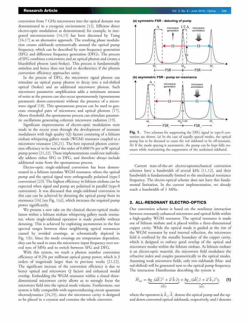
Electro-optic single-sideband conversion has been demon-strated in a lithium tantalate WGM resonator, where the opticalpump and the optical signal were orthogonally polarized (type-Iconversion) [23]. The highest efficiency in lithium niobate can beexpected when signal and pump are polarized in parallel (type-0conversion). It was discussed that single-sideband conversion inthis case can be achieved by detuning the optical pump from itsresonance [16] [see Fig. 1(a)], which increases the required pumppower significantly.
We present a new take on the classical electro-optical modu-lation within a lithium niobate whispering gallery mode resona-tor, where single-sideband operation is made possible withoutdetuning. This is achieved by exploiting asymmetries in the freespectral ranges between three neighboring optical resonancescaused by avoided crossings, as schematically depicted inFig. 1(b). Since the mode crossings are temperature dependent,they can be used to tune the microwave input frequency over sev-eral tens of MHz and to switch between SFG and DFG.
With this system, we reach a photon number conversionefficiency of 0.2% per milliwatt optical pump power, which is 3orders of magnitude larger than in previous works [21,22].The significant increase of the conversion efficiency is due tobetter optical and microwave Q factors and enhanced modaloverlap. Embedding the WGM resonator within a closed three-dimensional microwave cavity allows us to strongly focus themicrowave field into the optical mode volume. Furthermore, oursystem is fully compatible with superconducting circuit quantumelectrodynamics [24,25], since the microwave cavity is designedto be placed in a cryostat and contains the whole converter.
Current state-of-the-art electro-optomechanical conversionschemes have a bandwidth of several kHz [11,12], and theirbandwidth is fundamentally limited to the mechanical resonancefrequency. The electro-optical scheme does not have this funda-mental limitation. In the current implementation, we alreadyreach a bandwidth of 1 MHz.
2. ALL-RESONANT ELECTRO-OPTICS
Our conversion scheme is based on the nonlinear interactionbetween resonantly enhanced microwave and optical fields withina high-quality WGM resonator. The optical resonator is madeout of lithium niobate and is placed within a three-dimensionalcopper cavity. While the optical mode is guided at the rim ofthe WGM resonator by total internal reflection, the microwavefield is confined by the metallic boundary of the copper cavity,which is designed to enforce good overlap of the optical andmicrowave modes within the lithium niobate. As lithium niobateis an electro-optic material, the microwave field modulates therefractive index and couples parametrically to the optical modes.Assuming weak microwave fields, only two sidebands (blue- andred-shifted) will be generated next to the optical pump frequency.The interaction Hamiltonian describing the system is
H int � ℏg−�ab†−c† � a†b−c�|fflfflfflfflfflfflfflfflfflfflfflfflfflfflffl{zfflfflfflfflfflfflfflfflfflfflfflfflfflfflffl}DFG
� ℏg��ab†� c � a†b� c†�|fflfflfflfflfflfflfflfflfflfflfflfflfflfflfflffl{zfflfflfflfflfflfflfflfflfflfflfflfflfflfflfflffl}SFG
; (1)
where the operators a; b�; b− denote the optical pump and the up-and down-converted optical sidebands, respectively, and c denotes
Fig. 1. Two schemes for suppressing the DFG signal in type-0 con-version are shown. (a) In the case of equally spaced modes, the opticalpump has to be detuned to cause the red sideband to be off-resonant.(b) If the mode spacing is asymmetric, the pump can be kept fully res-onant while maintaining the suppression of the undesired sideband.
Research Article Vol. 3, No. 6 / June 2016 / Optica 598

the microwave mode. The nonlinear coupling rates g� are givenby (compare e.g., [21])
g� � npn�nΩ
r
ffiffiffiffiffiffiffiffiffiffiffiffiffiffiffiffiffiffiffiffiffiffiffiffiffiffiℏωpω�Ω0
8ϵ0V pV �V Ω
s×Z
dVΨpΨΩΨ�; (2)
where np, n�, and nΩ are the refractive indices of the pump, side-bands, and the microwave tone and ωp, ω�, and Ω0 are the re-spective resonance frequencies. The normalization volumes V p,V �, and V Ω are given by the integral
RdVΨΨ� over the respec-
tive spatial field distributions Ψp, Ψ�, and ΨΩ. The nonlinearcoupling is mediated by the electro-optic coefficient r. The inte-gral in Eq. (2) is nonzero only if phase-matching is fulfilled. In thecase of whispering gallery modes, this means that the azimuthalmode numbers m (number of wavelengths around the rim of theresonator) have to obey the relation m� � mp � mΩ. In our ex-periment, the optical pump Pp and the microwave signal PΩ areboth undepleted (i.e., the nonlinear conversion efficiency dependslinearly on the pump and signal intensities). From Eq. (1) we findthe output power of the sidebands P� and the photon numberconversion efficiency η� to be
P� � 8g2
ℏΩγ2γΩ
jΓpj2jΓ�j2jΓΩj2|fflfflfflfflfflfflfflfflfflfflfflfflfflfflffl{zfflfflfflfflfflfflfflfflfflfflfflfflfflfflffl}ζ�
PpPΩ and η� � Ωω�
ζ�Pp; (3)
where
Γp � −i�ω − ωp� � γ � γ 0; (4a)
ΓΩ � −i�Ω − Ω0� � γΩ � γ 0Ω; (4b)
Γ� � −i�ω�Ω − ω�� � γ � γ 0: (4c)
The expressions in Eq. (4) describe the detuning of the opticalpump ω, the microwave Ω, and the generated sidebands ω�Ωfrom their respective resonance frequencies. Since the opticalmodes have the same polarization and are close in frequency, wecan assume the same coupling and loss rates γ and γ 0 for all ofthem. For the nonlinear coupling rates, we assumed g � g− �g� following the same argument. Coupling and loss rate for themicrowave mode are denoted as γΩ and γ 0Ω.
In case of zero detunings for all modes, the common figure ofmerit, the electro-optic cooperativity [17], can be expressed interms of the given metrics as
G0 �jαgj2Γ�ΓΩ
≈Γ�ΓΩ
4γ�γΩη�; (5)
where jαj2 corresponds to the number of pump photons inthe resonator. The approximation on the right-hand side is validfor the linear regime of small conversion efficiencies as assumedfor Eq. (3). The cooperativity can therefore be directly calculatedfrom the cavity parameters and the measured photon conver-sion rate.
If the optical modes are spectrally equidistant, the suppressionof one of the sidebands can be achieved by detuning the pumpfrom its resonance frequency as schematically depicted inFig. 1(a). However, detuning decreases the coupling of the pumpto the cavity and therefore increases the required pump powersignificantly (see below). We propose an alternative scheme de-picted in Fig. 1(b): the spectral distance, or free spectral range(FSR), can be asymmetric for the up- and down-converted modes.This would allow detuning of, for example, the down-converted
light by Δ− � ω − Ω − ω− while the pump and the up-convertedlight remain fully resonant. We will show that such dispersionengineering is possible by exploiting avoided crossings. Bothschemes in Fig. 1 lead to a power suppression factor S betweenthe sidebands of
S � P�P−
� Δ2−
�γ � γ 0�2 � 1: (6)
As the suppression depends only on the detuning of the down-converted sideband from its resonance, the two schemes can becompared in terms of the required pump power using Eq. (3).One can show with the help of Eqs. (3) and (6) that the detuningscheme requires �S − 1�∕4� 1 times more pump power to pro-duce the same suppression S. For example, 30 dB suppressionwould require about 250 times more pump power.
3. EXPERIMENTAL REALIZATION
The challenge in this experiment is to bring two resonant systemshaving largely different frequencies to interact. The design has toprovide a good spatial overlap between microwave and opticalmodes, while the involved modes have to fulfill phase-matchingand energy conservation. This requires careful tailoring of the sys-tem based on numerical simulations. Our starting point was torealize a suitable geometry where the optical FSR is approximatelyequal to the frequency of the resonant microwave mode (mΩ � 1)to fulfill energy conservation (see Fig. 1).
For the experiment, we fabricated a lithium niobate WGMresonator with a radius of R � 2.4 mm and thickness d �0.4 mm by single-point diamond turning and subsequent polish-ing [26]. The resonator has a z-cut configuration, where the opticaxis is aligned parallel to the symmetry axis. The disk is placed in a3D microwave copper cavity as depicted in Figs. 2(a)–2(c), whereit is clamped by two metallic rings that are designed to maximizethe field overlap between the microwave and optical modes. Asilicon prism is placed within the cavity, touching the WGM res-onator for optical coupling. To enable critical coupling, the cou-pling plane of the prism is coated with a thermally grown siliconoxide layer serving as a spacer. As an optical pump, we use a nar-row-band tunable laser (λ ≈ 1550 nm) which can either be sweptover or locked to a resonance via the Pound–Drever–Hall tech-nique. Two holes in the copper cavity allow the optical pumplight to enter and the light reflected and emitted from the WGMresonator to leave the cavity. This light is collected and analyzedby a photodiode and an optical spectrum analyzer (OSA). Themicrowave signal is coupled via a coaxial pin coupler mountedclose to the WGM resonator into the cavity and analyzed witha vector network analyzer (VNA) in reflection. A metallic tuningscrew is used to perturb the microwave field for fine adjustment ofits resonance frequency. The whole setup is thermally stabilized atroom temperature with mK precision by a proportional–integral–derivative controller and a thermoelectric element attached on theouter side of the closed copper cavity.
All fields are primarily polarized along the optic axis of theWGM resonator (TE type modes) as we aim for type-0 conver-sion. This allows us to address the largest electro-optic tensorelement of lithium niobate (r33 ≈ 31 pm∕V [27]).
Figure 2(d) shows the tuning over a typical optical mode de-tected in reflection. We find coupling efficiencies of about 60%.Although the modes are critically coupled (γ � γ 0), 40% of thelight is reflected from the cavity due to imperfect spatial mode
Research Article Vol. 3, No. 6 / June 2016 / Optica 599

matching. Typically the loaded Q is larger than 1 × 10⁸, corre-sponding to linewidths less than 2 MHz. The optical free spectralranges, which were measured with sideband spectroscopy [28],are around 8.95 GHz.
The phase and amplitude of the microwave signal back-reflected from the cavity was measured with the VNA.Figure 2(e) shows that the tuning screw allows us to change themicrowave resonance frequency from Ω0 � 2π × 8.90 GHz to2π × 9.07 GHz. We find a loaded Q � 246 for the undisturbedmode, which decreases to Q � 174 for maximum perturbationby the tuning screw. Measurements of the phase response indicatethat the microwave mode is undercoupled (γΩ < γ 0Ω), resulting ina nonideal coupling efficiency around 60%–75%, depending onthe position of the tuning screw.
Note that the pin coupler in our current setup excites a propa-gating (mΩ � 1) and a counterpropagating (mΩ � −1) micro-wave mode and only the part propagating in the direction ofthe excited optical modes is converted. Considering these geom-etries and the analytic knowledge of the optical modes [29], wecan rewrite Eq. (2) as g� � n2pωpr33EΩ∕2, where the singlephoton electric field EΩ is determined from the simulated micro-wave field distribution in the region of the optical mode [compareFig. 2(b)]. From this, we estimate the single-photon couplingrate for the m � 1 mode to be g ≈ 2π × 28 Hz.
A. Asymmetric FSR around Avoided Crossings
The key feature required for the single-sideband conversion in aWGM resonator with type-0 phase-matching without detuningthe pump is an asymmetric spectral distance between the pumpand the two signal modes (compare Fig. 1). In a mm-size reso-nator, adjacent free spectral ranges differ only by a couple of kHzdue to the combined effect of material and geometric dispersion.Hence, both sidebands are generated in the case of zero pumpdetuning. However, in WGM resonators, different modes can
couple to each other linearly if they are close to degeneracy[30,31]. Because of different thermal dispersion of differentWGM families, such modes can be brought into resonance bychanging the resonator temperature. This feature allows themto exchange energy and leads to avoided crossings. Such crossingsappear as a mode splitting around the unperturbed resonance fre-quency, where the minimal spectral separation is proportional tothe coupling rate between the two modes and can reach manylinewidths. Essentially, the modes shift away from their unper-turbed resonance position, leading to a change of the effectivedispersion.
Such a crossing is shown in Fig. 3, where the frequency of aTE-polarized mode within a sweeping window of 100 MHz isplotted against a temperature change of the resonator. From thefit in Fig. 3 we extract a coupling rate of κ � 2π × 5.27 MHzand the asymptotes, yielding the temperature dependence of the
Fig. 3. On the left, the resonance position of a TE mode experiencingan avoided crossing with a TM mode is shown for different temperaturesettings. On the right, the WGM spectrum around the avoided crossingis plotted for different temperatures.
Fig. 2. (a) Photograph of the bottom part of the microwave cavity with silicon coupling prism and the WGM resonator. (b) Simulation of the micro-wave field distribution in the cavity. Only the z component (TE) of the field is shown. (c) Schematic of the cavity. An optical pump beam (red dashed)couples through a prism into the WGM, and part of the light is directly reflected. The sideband is given in blue. In the side view, the metallic tuning screwto perturb the microwave mode and the coaxial pin coupler are shown. The pin coupler is defined as the input port of the converter and the output port isthe optical outcoupling spot inside of the prism (solid lines). (d) Reflection spectrum of the optical mode used for sum frequency conversion (compareFig. 5). Also shown are the linewidth and the corresponding Q factors. (e) Microwave spectrum in reflection from the coaxial pin coupler. The mΩ � �1mode is shown for tuning screw position inside (red) and outside (black) the cavity.
Research Article Vol. 3, No. 6 / June 2016 / Optica 600

two interacting modes. The ratio of their slopes is approximately1.8, which corresponds to the ratio between the temperaturesensitivities of TE and TM polarized modes in a lithium niobateWGM resonator of that size [32]. Such polarization coupling hasbeen previously observed in ring resonators [33] and in largermagnesium fluoride resonators [34].
To demonstrate the effect of the splitting on the spectraldistance between two adjacent modes of the same family, weshow a spectrum of the m − 1, m and m� 1 modes in Fig. 4(a).The corresponding spectral distances FSR� � νm�1 − νm andFSR− � νm − νm−1 are presented in Fig. 4(b). The free spectralranges are strongly temperature-dependent close to the avoidedcrossings, and the difference jΔ� − Δ−j can be several tens ofMHz, exceeding the linewidth of the modes significantly. Wewill use this temperature-dependent asymmetry of the FSR toswitch between sum and difference frequency generation in thefollowing sections.
B. Single-Sideband Conversion
For conversion of a microwave signal to a single optical sideband,we use the mode triplet shown in Figs. 4(a) and 4(b). The opticalpump laser was locked to the central mode denoted with m (blackcurve), while the temperature of the cavity was stabilized around27.88°C. The free spectral ranges at that working point aremarked by the dashed line in Fig. 4(b). The microwave cavityresonance was set to Ω0 � 2π × 8.960 GHz and the microwavesignal sent to the cavity was swept from 8.925 to 8.975 GHz insteps of 200 kHz. For each step, the optical signal was measuredwith an optical spectrum analyzer (YOKOGAWA AQ6370C)(see inset in Fig. 5). The obtained magnitude of the generatedsidebands is shown in Fig. 4(c) as a function of the microwavedetuning from its resonance, which is indicated by the blackdashed line.
The up- and down-converted signals can be addressed sepa-rately as they appear at different microwave frequencies due to
the different FSRs of the respective modes. The Lorentzian givenby Eq. (3) agrees well with the measured data. The asymmetry ofthe peaks and their intensity difference can be attributed to thedetuning from the microwave resonance position. The centralfrequencies of the peaks are separated by 18.1 MHz, which cor-responds to the difference between FSR� and FSR−. The extinc-tion ratio for the suppressed sideband is determined by the FSRasymmetry and the linewidth of the microwave and opticalmodes. From the fit, we find a suppression of the down-convertedsignal at maximum up-conversion of 23 dB. This suppressioncould be further increased by a stronger mode splitting and nar-rower bandwidths of both the microwave and optical modes.
4. CONVERSION EFFICIENCY
The photon number conversion efficiency can be found by meas-uring the microwave power at the input and the optical signalpower at the output of the converter. From Eq. (3), we find
η� � Ωω�
P�PΩ
: (7)
As input power of the microwave, we take the power arriving atthe coaxial pin coupler. Cable losses were calibrated out by meas-uring them separately prior to the experiment. As optical signalpower, we consider the power leaving the WGM resonator insidethe silicon prism [see Fig. 2(c)]. For this, we measured the reflec-tion losses on the prism surface. This is justified for estimating theperformance of the system because the prism can be coated toprevent reflection loss. The power of the sideband is obtainedby measuring its relative strength compared with the reflectedpump power on the optical spectrum analyzer. This allows usto calculate the sideband power leaving the resonator from thecoupling efficiency of the pump and the absolute pump powersent to the resonator.
Fig. 4. (a) Resonance frequencies of three TE modes that are separated by one azimuthal mode number m corresponding to the free spectral rangeFSR� ≈ 9 GHz. Each mode experiences avoided crossings of different strength for some temperatures. (b) Frequency difference of the m� 1 and m − 1mode from the m mode. One can see that FSR� and FSR− are functions of the temperature and differ by up to 50 MHz. This allows selective up- anddown-conversion as depicted in (c): The temperature was set to 27.88°C, indicated by the dashed line in (a) and (b), where FSR� − FSR− � 18.1 MHz.The optical pump is locked to the m mode. A microwave signal sweeping over the microwave resonance is indicated by the gray Lorentzian, while thegenerated sidebands are measured with an optical spectrum analyzer (see Fig. 5). The shown sidebands are separated by 18.1 MHz and the suppression ofthe down-conversion at the maximum of the up-conversion is about 23 dB.
Research Article Vol. 3, No. 6 / June 2016 / Optica 601

For demonstration of the absolute conversion efficiency, wechoose the optical mode depicted in Fig. 2(d) and pump it onresonance. The working temperature is set such that the avoidedcrossing occurs on the red detuned side of the mode. This ensuresthat we can obtain a single sum-frequency-generated sidebandwhich is not disturbed by the linear mode coupling causingthe avoided crossing. We measure FSR� � 8.941 GHz and ad-just the microwave resonance frequency Ω0 to that value with thetuning screw. In this configuration, we find γΩ � 2π × 3.6 MHzand γ 0Ω � 2π × 16.2 MHz for the undercoupled microwavemode and γ � γ 0 � 2π × 346 kHz for the critically coupled op-tical mode. The laser is locked to the resonator, and 1 mW opticalpower is sent into the cavity. Considering the imperfect couplingand the resulting reflection from the prism [see Fig. 2(d)],0.42 mW are actually coupled into the WGM resonator. Themicrowave signal frequency is set on resonance and the poweris increased from −54 dBm to −22 dBm in steps of 1 dBm.
The results are presented in Fig. 5. The inset shows a typicalOSA spectrum, where the single up-converted optical sideband ishighlighted in blue. The plot shows the optical signal power leav-ing the resonator as a function of the input microwave signalpower. In the undepleted pump regime, the optical signal scaleslinearly with the input microwave power according to Eq. (3). Atapproximately 1 μWmicrowave power, the pump starts to depleteand the up-converted signal saturates. From fitting the linear re-gime, we find a power conversion efficiency of P�∕PΩ �23.68� 0.46, which transforms into an absolute photonnumber conversion efficiency of η� � �1.09� 0.02� × 10−3 usingEq. (7). Inserting the cavity parameters into Eq. (3), we find thesingle-photon coupling rate to be g eff � 2π × �7.43� 0.02� Hz.In order to compare this value with the theoretically derived one,we have to multiply it by
ffiffiffi2
psince the theory does not take into
account that we experimentally excite propagating and counterpro-pagating modes at the same time.
This effective coupling rate is about three times smaller thanthe expected one from numerical simulations, corresponding toalmost ten times decreased conversion efficiency. This is likelycaused by air gaps between the WGM resonator and the metallicrings clamping the resonator. Due to the high dielectric constantof lithium niobate in the microwave regime, even very small airgaps lead to a significant field drop in air. Our simulations showthat an air gap of 20 μm caused by imperfect machining of thecavity and polishing of the upper and lower side of the WGMresonator lowers g already by a factor of 2.
5. DISCUSSION AND CONCLUSION
The three main findings of this paper are set forth in this section.The first is a 3 order of magnitude improvement of resonantelectro-optic conversion of microwave photons into the opticalregime compared to the so far best reported values [21,35]. Thesecond is a highly efficient suppression of either the up- or down-converted sideband by engineering the dispersion of the resona-tor. The third is a MHz bandwidth for the conversion. All threefindings are important steps towards coherent and bidirectionalmicrowave photon conversion based on direct electro-opticmodulation. For quantum operations, the conversion efficiencywill have to be pushed toward unity, which is possible with someengineering improvements.
For high nonlinear coupling rates, the microwave mode startsto deplete in the case of SFG and the photon number conversionbecomes [17]
η� � 4γγΩ�γ � γ 0��γΩ � γ 0Ω�
G0
�1� G0�2: (8)
It becomes apparent that G0 � 1, γ ≫ γ 0, and γΩ ≫ γ 0Ω arerequired to approach unity photon number conversion. Forour current system, which is critically coupled in the optical re-gime and undercoupled in the microwave regime, we find thatG0 ≈ 4 × 10⁻³. Therefore, the cooperativity has to be enhancedby more than 3 orders of magnitude.
The pump power can be increased only slightly since photo-and thermo-refractive effects in lithium niobate cause the systemto become unstable. While the optical Q factors are already closeto the material limitation [36], it was shown recently that the in-trinsic microwave absorption in lithium niobate at millikelvintemperatures allows for QΩ ≈ 105 [37]. This alone would in-crease our G0 by 3 orders of magnitude in the current couplingregime. Furthermore, our simulations show that g scales inverselywith the resonator thickness. Assuming a realistic resonator thick-ness of 50 μm, together with the closing of any air gaps deterio-rating g , can improve the cooperativity additionally by 2 to 3orders of magnitude. Recently, theoretical studies showed addi-tional ways to increase g [38,39]. Putting these optimizations to-gether, G0 ≈ 1 within an overcoupled regime can be achieved in arealistic scenario, ready to realize quantum state transfer [40].Although optical cooling of the microwave mode will be possibleto a certain extent, for quantum operation, the converter has to beoperated in a cryostat to avoid up-conversion of thermal micro-wave photons. This is required anyway since it will increase themicrowave Q factor due to superconducting boundaries and de-crease of the dielectric loss in lithium niobate. Of course, thiscomes with additional challenges. Temperature tuning, for exam-ple, would have to be replaced by voltage tuning or pressure
Fig. 5. Power of the up-converted sideband as a function of themicrowave power sent to the cavity. With increasing microwave power,the optical pump mode depletes and the conversion efficiency decreases.A linear fit in the undepleted regime (gray) yields a slope ofP�∕PΩ � 23.68� 0.46, corresponding to a photon number conversionefficiency of η� � �1.09� 0.02� × 10−3. The inset shows an OSAspectrum (resolution 2.5 GHz) of the reflected pump power and the gen-erated up-converted sideband.
Research Article Vol. 3, No. 6 / June 2016 / Optica 602

tuning, and different thermal expansion of LN and the metal cav-ity have to be considered.
Electro-optomechanical schemes work in the resolved side-band regime where two pump tones, an optical and a microwaveone, are detuned from their respective resonance frequencies bythe mechanical resonance frequency. The consequence is that thebandwidth of the process is ultimately limited to the resonancefrequency of the mechanical resonator, which is typically below1 MHz. In practice, only tens of kilohertz have so far beenachieved in efficient conversion experiments [12]. Coupling suchsystems to on-demand single-microwave photon sources [41] ischallenging, as the temporal signature of these photons is inthe order of megahertz [42]. Furthermore, the achievable suppres-sion of the red-detuned sideband is limited as the pump detuningis also determined by the mechanical resonance frequency.Depending on the system parameters, this can lead to contami-nation of the converted signal with spontaneous emission.
Our system does not have these restrictions, as the mediatorbetween the two regimes is the nonresonant, nonlinear polariz-ability of lithium niobate. Hence, the bandwidth of the electro-optic scheme is solely determined by intrinsic losses and thenonlinear as well as external coupling rates. Furthermore, thedescribed dispersion management of the optical modes allowsus to choose the degree of suppression freely, without detuningthe optical pump.
These advantages justify the further investigation and optimi-zation of the electro-optical approach, even though the electro-optomechanical approach presently has the efficiency advantage.As we have discussed, the single-photon regime is within reachprovided an optimized system. This would not only allow forthe interfacing of microwave qubits with the optical domain,but also electro-optic cooling of the microwave mode. With evenlesser requirements, the generation of entangled pairs of micro-wave and optical photons utilizing parametric down-conversionis possible, which has recently been shown in the optical domainin a WGM-based system [43].
Funding. Alexander von Humboldt Foundation;Studienstiftung des Deutschen Volkes.
Acknowledgment. We would like to acknowledge ourstimulating discussions with Konrad Lehnert and AlessandroPitanti.
†These authors contributed equally to this work.
REFERENCES
1. R. J. Schoelkopf and S. M. Girvin, “Wiring up quantum systems,” Nature451, 664–669 (2008).
2. M. H. Devoret and R. J. Schoelkopf, “Superconducting circuits forquantum information: an outlook,” Science 339, 1169–1174 (2013).
3. D. Ristè, S. Poletto, M.-Z. Huang, A. Bruno, V. Vesterinen, O.-P. Saira,and L. DiCarlo, “Detecting bit-flip errors in a logical qubit using stabilizermeasurements,” Nat. Commun. 6, 6983 (2015).
4. A. I. Lvovsky, B. C. Sanders, and W. Tittel, “Optical quantum memory,”Nat. Photonics 3, 706–714 (2009).
5. M. Hafezi, Z. Kim, S. L. Rolston, L. A. Orozco, B. L. Lev, and J. M. Taylor,“Atomic interface between microwave and optical photons,” Phys. Rev. A85, 020302 (2012).
6. J. Verdú, H. Zoubi, C. Koller, J. Majer, H. Ritsch, and J. Schmiedmayer,“Strong magnetic coupling of an ultracold gas to a superconductingwaveguide cavity,” Phys. Rev. Lett. 103, 043603 (2009).
7. A. Imamoğlu, “Cavity QED based on collective magnetic dipole coupling:spin ensembles as hybrid two-level systems,” Phys. Rev. Lett. 102,083602 (2009).
8. D. Marcos, M. Wubs, J. M. Taylor, R. Aguado, M. D. Lukin, and A. S.Sørensen, “Coupling nitrogen-vacancy centers in diamond to supercon-ducting flux qubits,” Phys. Rev. Lett. 105, 210501 (2010).
9. L. A. Williamson, Y.-H. Chen, and J. J. Longdell, “Magneto-optic modu-lator with unit quantum efficiency,” Phys. Rev. Lett. 113, 203601 (2014).
10. X. Fernandez-Gonzalvo, Y.-H. Chen, C. Yin, S. Rogge, and J. J.Longdell, “Coherent frequency up-conversion of microwaves to theoptical telecommunications band in an Er:YSO crystal,” Phys. Rev. A92, 062313 (2015).
11. T. Bagci, A. Simonsen, S. Schmid, L. G. Villanueva, E. Zeuthen, J. Appel,J. M. Taylor, A. Sørensen, K. Usami, A. Schliesser, and E. S. Polzik,“Optical detection of radio waves through a nanomechanical transducer,”Nature 507, 81–85 (2014).
12. R. W. Andrews, R. W. Peterson, T. P. Purdy, K. Cicak, R. W. Simmonds,C. A. Regal, and K. W. Lehnert, “Bidirectional and efficient conversionbetween microwave and optical light,” Nat. Phys. 10, 321–326 (2014).
13. J. Bochmann, A. Vainsencher, D. D. Awschalom, and A. N. Cleland,“Nanomechanical coupling between microwave and optical photons,”Nat. Phys. 9, 712–716 (2013).
14. C. Xiong, W. H. P. Pernice, and H. X. Tang, “Low-loss, silicon integrated,aluminum nitride photonic circuits and their use for electro-optic signalprocessing,” Nano Lett. 12, 3562–3568 (2012).
15. L. Chen, Q. Xu, M. G. Wood, and R. M. Reano, “Hybrid silicon and lithiumniobate electro-optical ring modulator,” Optica 1, 112–118 (2014).
16. M. Tsang, “Cavity quantum electro-optics,” Phys. Rev. A 81, 063837(2010).
17. M. Tsang, “Cavity quantum electro-optics. II. Input-output relationsbetween traveling optical and microwave fields,” Phys. Rev. A 84,043845 (2011).
18. C. M. Caves, “Quantum limits on noise in linear amplifiers,” Phys. Rev. D26, 1817–1839 (1982).
19. A. A. Savchenkov, A. B. Matsko, M. Mohageg, D. V. Strekalov, and L.Maleki, “Parametric oscillations in a whispering gallery resonator,” Opt.Lett. 32, 157–159 (2007).
20. D. Cohen, M. Hossein-Zadeh, and A. Levi, “Microphotonic modulator formicrowave receiver,” Electron. Lett. 37, 300–301 (2001).
21. V. S. Ilchenko, A. A. Savchenkov, A. B. Matsko, and L. Maleki,“Whispering-gallery-mode electro-optic modulator and photonic micro-wave receiver,” J. Opt. Soc. Am. B 20, 333–342 (2003).
22. D. V. Strekalov, A. A. Savchenkov, A. B. Matsko, and N. Yu, “Efficientupconversion of subterahertz radiation in a high-Q whispering galleryresonator,” Opt. Lett. 34, 713–715 (2009).
23. A. A. Savchenkov, W. Liang, A. B. Matsko, V. S. Ilchenko, D. Seidel, andL. Maleki, “Tunable optical single-sideband modulator with completesideband suppression,” Opt. Lett. 34, 1300–1302 (2009).
24. C. Rigetti, J. M. Gambetta, S. Poletto, B. L. T. Plourde, J. M. Chow, A. D.Córcoles, J. A. Smolin, S. T. Merkel, J. R. Rozen, G. A. Keefe, M. B.Rothwell, M. B. Ketchen, and M. Steffen, “Superconducting qubit in awaveguide cavity with a coherence time approaching 0.1 ms,” Phys.Rev. B 86, 100506 (2012).
25. H. Paik, D. I. Schuster, L. S. Bishop, G. Kirchmair, G. Catelani, A. P.Sears, B. R. Johnson, M. J. Reagor, L. Frunzio, L. I. Glazman, S. M.Girvin, M. H. Devoret, and R. J. Schoelkopf, “Observation of high coher-ence in Josephson junction qubits measured in a three-dimensionalcircuit QED architecture,” Phys. Rev. Lett. 107, 240501 (2011).
26. I. S. Grudinin, A. B. Matsko, A. A. Savchenkov, D. Strekalov, V. S.Ilchenko, and L. Maleki, “Ultra high Q crystalline microcavities,” Opt.Commun. 265, 33–38 (2006).
27. K. Wong, Properties of Lithium Niobate, EMIS Datareviews Series(INSPEC/Institution of Electrical Engineers, 2002).
28. J. Li, H. Lee, K. Y. Yang, and K. J. Vahala, “Sideband spectroscopyand dispersion measurement in microcavities,” Opt. Express 20,26337–26344 (2012).
29. I. Breunig, B. Sturman, F. Sedlmeir, H. G. L. Schwefel, and K. Buse,“Whispering gallery modes at the rim of an axisymmetric opticalresonator: analytical versus numerical description and comparisonwith experiment,” Opt. Express 21, 30683–30692 (2013).
30. T. Carmon, H. G. L. Schwefel, L. Yang, M. Oxborrow, A. D. Stone,and K. J. Vahala, “Static envelope patterns in composite resonances
Research Article Vol. 3, No. 6 / June 2016 / Optica 603

generated by level crossing in optical toroidal microcavities,” Phys.Rev. Lett. 100, 103905 (2008).
31. J.Wiersig, “Formation of long-lived, scarlikemodes near avoided resonancecrossings in optical microcavities,” Phys. Rev. Lett. 97, 253901 (2006).
32. U. Schlarb and K. Betzler, “Influence of the defect structure on the re-fractive indices of undoped and mg-doped lithium niobate,” Phys.Rev. B 50, 751–757 (1994).
33. S. Ramelow, A. Farsi, S. Clemmen, J. S. Levy, A. R. Johnson, Y.Okawachi, M. R. E. Lamont, M. Lipson, and A. L. Gaeta, “Strong polariza-tion mode coupling in microresonators,” Opt. Lett. 39, 5134–5137 (2014).
34. W. Weng and A. N. Luiten, “Mode-interactions and polarization conver-sion in a crystalline microresonator,” Opt. Lett. 40, 5431–5434 (2015).
35. D. V. Strekalov, H. G. L. Schwefel, A. A. Savchenkov, A. B. Matsko, L. J.Wang, and N. Yu, “Microwave whispering-gallery resonator for efficientoptical up-conversion,” Phys. Rev. A. 80, 033810 (2009).
36. M. Leidinger, S. Fieberg, N. Waasem, F. Kühnemann, K. Buse, and I.Breunig, “Comparative study on three highly sensitive absorptionmeasurement techniques characterizing lithium niobate over its entiretransparent spectral range,” Opt. Express 23, 21690–21705 (2015).
37. M. Goryachev, N. Kostylev, and M. E. Tobar, “Single-photon level studyof microwave properties of lithium niobate at millikelvin temperatures,”Phys. Rev. B 92, 060406 (2015).
38. N. G. Pavlov, N. M. Kondratyev, and M. L. Gorodetsky, “Modeling thewhispering gallery microresonator-based optical modulator,” Appl.Opt. 54, 10460–10466 (2015).
39. C. Javerzac-Galy, K. Plekhanov, N. Bernier, L. D. Toth, A. K. Feofanov,and T. J. Kippenberg, “On-chip microwave-to-optical quantum coherentconverter based on a superconducting resonator coupled to an electro-optic microresonator,” arXiv:1512.06442 (2015).
40. S. Huang, “Quantum state transfer in cavity electro-optic modulators,”Phys. Rev. A 92, 043845 (2015).
41. D. Bozyigit, C. Lang, L. Steffen, J. M. Fink, C. Eichler, M. Baur, R.Bianchetti, P. J. Leek, S. Filipp, M. P. da Silva, A. Blais, and A.Wallraff, “Antibunching of microwave-frequency photons observed incorrelation measurements using linear detectors,” Nat. Phys. 7, 154–158 (2011).
42. R. W. Andrews, A. P. Reed, K. Cicak, J. D. Teufel, and K. W. Lehnert,“Quantum-enabled temporal and spectral mode conversion of micro-wave signals,” Nat. Commun. 6, 10021 (2015).
43. G. Schunk, U. Vogl, D. V. Strekalov, M. Förtsch, F. Sedlmeir, H. G. L.Schwefel, M. Göbelt, S. Christiansen, G. Leuchs, and C. Marquardt,“Interfacing transitions of different alkali atoms and telecom bands usingone narrowband photon pair source,” Optica 2, 773–778 (2015).
Research Article Vol. 3, No. 6 / June 2016 / Optica 604
Related Documents


