IPN Progress Report 42-172 February 15, 2008 High-Power Upgrade of the Three-Frequency (7.2-/8.4-/32-Gigahertz) Deep Space Network Feed: Design Phase B. Khayatian 1 and D. Hoppe 1 Modifications to the existing three-frequency (7.2-/8.4-/32-GHz) feed that would increase its 7.2-GHz uplink capability from 20 kW to 100 kW are described. The new design produces a transmit band (7.2-GHz) match covering more bandwidth than the current configuration. The impact of the modifications on the downlink noise temperature and radiation patterns at 8.4 and 32 GHz are estimated using commercial modeling tools. Plans for the next phase of the project, testing of a prototype feed, are also discussed. I. Introduction Currently the highest effective isotropic radiated power (EIRP) uplink command capability in the Deep Space Network (DSN) is the 20-kW uplink system on the 70-m antennas. No backup for this capability exists. Development of an equivalent uplink capability on the 34-m beam-waveguide antennas is highly desirable. 2 In order to compensate for the lost antenna directivity, the 34-m system must transmit 80 to 100 kW. The 34-m beam-waveguide antennas are configured with a three-frequency feed and are capable of uplink at 7.2 GHz and downlink at 8.4 and 32 GHz, all simultaneously [1]. Unfortunately, the existing feed design is limited to approximately 20 kW of uplink power due to a combination of high electric- field strength in the uplink junction region and cooling/power dissipation issues. Although other options exist, 3 the simplest way to increase the uplink capability of the 34-m antennas is to modify the existing feed for 80- to 100-kW uplink operation. The design of the modified feed is the subject of this article. We begin with a review of the geometry of the existing feed and a summary of the proposed modifi- cations. This is followed by a short discussion of the modeling approaches considered. The next sections describe the overall model and the most critical part of the design, the matching of the new uplink junc- tion at 7.2 GHz. Next, the effect of the new junction on the noise temperature of the feed at 8.4 and 1 Communications Ground Systems Section. 2 As described in “High Effective Isotropic Radiated Power (EIRP) Uplink Study,” http://eis.jpl.nasa.gov/dsnse/mega/ (JPL internal Website), Jet Propulsion Laboratory, Pasadena, California, September 2007. 3 Ibid. The research described in this publication was carried out by the Jet Propulsion Laboratory, California Institute of Technology, under a contract with the National Aeronautics and Space Administration. 1

Welcome message from author
This document is posted to help you gain knowledge. Please leave a comment to let me know what you think about it! Share it to your friends and learn new things together.
Transcript

IPN Progress Report 42-172 February 15, 2008
High-Power Upgrade of the Three-Frequency(7.2-/8.4-/32-Gigahertz) Deep Space
Network Feed: Design PhaseB. Khayatian1 and D. Hoppe1
Modifications to the existing three-frequency (7.2-/8.4-/32-GHz) feed that wouldincrease its 7.2-GHz uplink capability from 20 kW to 100 kW are described. Thenew design produces a transmit band (7.2-GHz) match covering more bandwidththan the current configuration. The impact of the modifications on the downlinknoise temperature and radiation patterns at 8.4 and 32 GHz are estimated usingcommercial modeling tools. Plans for the next phase of the project, testing of aprototype feed, are also discussed.
I. Introduction
Currently the highest effective isotropic radiated power (EIRP) uplink command capability in the DeepSpace Network (DSN) is the 20-kW uplink system on the 70-m antennas. No backup for this capabilityexists. Development of an equivalent uplink capability on the 34-m beam-waveguide antennas is highlydesirable.2 In order to compensate for the lost antenna directivity, the 34-m system must transmit 80 to100 kW.
The 34-m beam-waveguide antennas are configured with a three-frequency feed and are capable ofuplink at 7.2 GHz and downlink at 8.4 and 32 GHz, all simultaneously [1]. Unfortunately, the existingfeed design is limited to approximately 20 kW of uplink power due to a combination of high electric-field strength in the uplink junction region and cooling/power dissipation issues. Although other optionsexist,3 the simplest way to increase the uplink capability of the 34-m antennas is to modify the existingfeed for 80- to 100-kW uplink operation. The design of the modified feed is the subject of this article.
We begin with a review of the geometry of the existing feed and a summary of the proposed modifi-cations. This is followed by a short discussion of the modeling approaches considered. The next sectionsdescribe the overall model and the most critical part of the design, the matching of the new uplink junc-tion at 7.2 GHz. Next, the effect of the new junction on the noise temperature of the feed at 8.4 and
1 Communications Ground Systems Section.
2 As described in “High Effective Isotropic Radiated Power (EIRP) Uplink Study,” http://eis.jpl.nasa.gov/dsnse/mega/(JPL internal Website), Jet Propulsion Laboratory, Pasadena, California, September 2007.
3 Ibid.
The research described in this publication was carried out by the Jet Propulsion Laboratory, California Institute ofTechnology, under a contract with the National Aeronautics and Space Administration.
1

32 GHz is estimated. Matching at these two bands is then considered, followed with a calculation of thenew radiation patterns for the feed in all three bands. Finally, plans for a follow-on effort, fabrication,and testing of a prototype feed are described.
II. Existing Feed Design and Proposed Modifications
Figures 1 and 2 depict the existing feed before placement in the cryogenic dewar or connection of thehigh-power transmit components. Additional horn segments are also added prior to installation in thebeam-waveguide antenna. Two turnstile junctions are visible. The leftmost of these is the uplink transmitjunction for the feed covering the band from 7.145 to 7.19 GHz, and the second, smaller junction is theportion of the feed where the downlink 8.4-GHz signals are extracted over a bandwidth covering 8.4 to8.585 GHz. Next we can see the 32-GHz monopulse coupler, which provides both tracking informationthrough the coupler arms and the sum signal that is extracted through the fin polarizer shown at thevery right-hand edge of Fig. 1 over the 31.8- to 32.3-GHz band. In Fig. 2, we see a detailed view of the7.2-GHz and 8.4-GHz turnstile junctions. Also visible is the thermal barrier between the two junctions.Components below (to the right of) this barrier reside inside the cryogenic dewar at a physical temperatureof 4 K. The transmit junction is at ambient temperature. Injection of 20 kW at 7.2 GHz and extractionof extremely low-level downlink signals take place within a few inches. This is possible since the horndimensions are chosen such that the 7.2-GHz uplink signals experience cut-off between the two turnstilejunctions, and thus a high level of isolation is maintained.
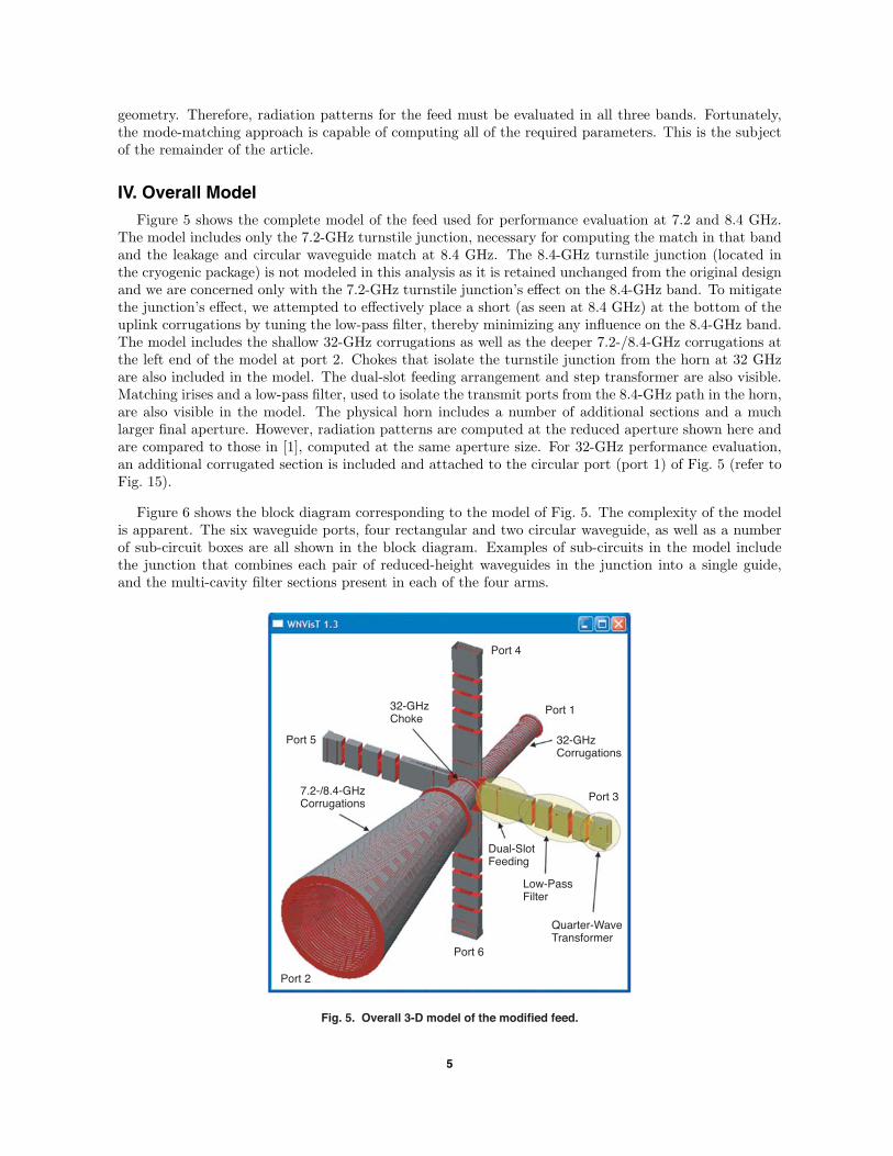
Figure 3 shows cut-away views of the feed and details of the uplink and downlink turnstile junctions.The uplink band is injected through four apertures and the downlink band is injected through eightapertures, both of which are symmetrically located at the bottom of the feed corrugations (see Fig. 3).Proper phasing of the four signals can provide either right-hand circular polarization (RHCP) or left-handcircular polarization (LHCP). As shown in the figure, in the current design the transmit signal is injectedthrough four apertures by means of a single corrugation, while the downlink signal is extracted througheight apertures by means of a pair of corrugations (see Fig. 3). While use of a single corrugation waschosen for the uplink because it allows for a simpler cooling design, the raw mismatch at the junction isvery poor in this case, with approximately 1 dB of return loss. In order to obtain suitable performancein the transmit band, a complex, high-Q matching network is required. Because of the high-Q, thismatching structure is sensitive to thermal variations. In addition, the single-slot design limits the totalarea available for injecting the power into the feed.
Fig. 1. Photo of the existing 20-kW feed without a dewar.
2
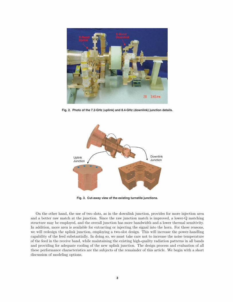
Fig. 2. Photo of the 7.2-GHz (uplink) and 8.4-GHz (downlink) junction details.
X-BandUplink
X-BandDownlink
Fig. 3. Cut-away view of the existing turnstile junctions.
UplinkJunction
DownlinkJunction
On the other hand, the use of two slots, as in the downlink junction, provides for more injection areaand a better raw match at the junction. Since the raw junction match is improved, a lower-Q matchingstructure may be employed, and the overall junction has more bandwidth and a lower thermal sensitivity.In addition, more area is available for extracting or injecting the signal into the horn. For these reasons,we will redesign the uplink junction, employing a two-slot design. This will increase the power-handlingcapability of the feed substantially. In doing so, we must take care not to increase the noise temperatureof the feed in the receive band, while maintaining the existing high-quality radiation patterns in all bandsand providing for adequate cooling of the new uplink junction. The design process and evaluation of allthese performance characteristics are the subjects of the remainder of this article. We begin with a shortdiscussion of modeling options.
3

III. Design and Modeling Approach
During the development of the original feed, models were created for the circular corrugated horn andthe waveguide-matching network, but the turnstile junction was optimized through prototype develop-ment and measurements. This was done primarily because of limitations in the electromagnetic modelingtools at the time. For this upgrade, our intent was to model the entire feed system and if possible tooptimize various components using the electromagnetic modeling tools.
Two commercially available modeling tools were considered for this task, HFSS [2], a finite-elementmodeler, and WASPNET [3], a mode-matching tool. Figure 4 illustrates the difference between the twoapproaches. In the left panel, we see the turnstile junction and its associated mesh as modeled by HFSS.HFSS has the advantage of being able to handle totally arbitrary geometries, but the finite-elementmethod typically requires a large amount of computational resources, primarily memory. Because of therequirement to mesh the geometry, optimization of individual component dimensions is challenging, butpossible, using this method. In the right panel of Fig. 4, we see the WASPNET model for the junction.In the mode-matching approach, the complex junction is constructed from a set of fundamental buildingblocks. The building blocks are typically simple devices such as circular waveguide steps, circular-to-rectangular waveguide steps, rectangular boxes with up to six ports, etc. The multimode scatteringmatrix for each of these components is easily found using the semi-analytical mode-matching approach.The scattering matrix of the entire, complex device is found by cascading the scattering matrices of theindividual components. The fundamental building blocks and their interconnections are described by thesimple block diagram in Fig. 4. The mode-matching method is particularly well-suited to incorporatingoptimization since a single dimension affects only one of the building blocks and a change demands therecalculation of a single scattering matrix. Memory requirements for the mode-matching method arealso typically less than those for the finite-element method. Fortunately, the entire three-frequency feed,including the proposed modifications, can be represented using simple building blocks. Thus, for thisdesign effort, we have chosen the mode-matching approach.
In order to verify the new junction design for the feed, a number of parameters must be evaluated.The primary requirement for the junction’s four rectangular waveguide ports is that they must be well-matched throughout the transmit band near 7.2 GHz. In addition, the circular ports of the junctionmust be well-matched in the 8.4- and 32-GHz bands. Leakage of the 8.4- and 32-GHz signals from thefeed into the rectangular transmit ports must be minimized since the transmit ports are at a physicaltemperature near 300 K and any leakage path will increase the receive system noise temperature. Finally,signals in all three bands traverse the uplink junction and are subject to being disturbed by the junction
Fig. 4. Depiction of a turnstile junction: HFSS geometry (left two figures) versus its equivalent WASPNET model (right figure).
4
geometry. Therefore, radiation patterns for the feed must be evaluated in all three bands. Fortunately,the mode-matching approach is capable of computing all of the required parameters. This is the subjectof the remainder of the article.
IV. Overall Model
Figure 5 shows the complete model of the feed used for performance evaluation at 7.2 and 8.4 GHz.The model includes only the 7.2-GHz turnstile junction, necessary for computing the match in that bandand the leakage and circular waveguide match at 8.4 GHz. The 8.4-GHz turnstile junction (located inthe cryogenic package) is not modeled in this analysis as it is retained unchanged from the original designand we are concerned only with the 7.2-GHz turnstile junction’s effect on the 8.4-GHz band. To mitigatethe junction’s effect, we attempted to effectively place a short (as seen at 8.4 GHz) at the bottom of theuplink corrugations by tuning the low-pass filter, thereby minimizing any influence on the 8.4-GHz band.The model includes the shallow 32-GHz corrugations as well as the deeper 7.2-/8.4-GHz corrugations atthe left end of the model at port 2. Chokes that isolate the turnstile junction from the horn at 32 GHzare also included in the model. The dual-slot feeding arrangement and step transformer are also visible.Matching irises and a low-pass filter, used to isolate the transmit ports from the 8.4-GHz path in the horn,are also visible in the model. The physical horn includes a number of additional sections and a muchlarger final aperture. However, radiation patterns are computed at the reduced aperture shown here andare compared to those in [1], computed at the same aperture size. For 32-GHz performance evaluation,an additional corrugated section is included and attached to the circular port (port 1) of Fig. 5 (refer toFig. 15).
Figure 6 shows the block diagram corresponding to the model of Fig. 5. The complexity of the modelis apparent. The six waveguide ports, four rectangular and two circular waveguide, as well as a numberof sub-circuit boxes are all shown in the block diagram. Examples of sub-circuits in the model includethe junction that combines each pair of reduced-height waveguides in the junction into a single guide,and the multi-cavity filter sections present in each of the four arms.
Fig. 5. Overall 3-D model of the modified feed.
Port 2
Port 5
Port 4
Port 6
Port 3
32-GHzCorrugations
7.2-/8.4-GHzCorrugations
Dual-SlotFeeding
Low-PassFilter
Quarter-WaveTransformer
Port 132-GHzChoke
5

Fig. 6. Overall block diagram of the modified feed.
V. Junction Optimization and Return Loss
In this section, we describe the most critical part of the design, optimization of the junction matchin the transmit band covering 7.145 to 7.190 GHz. For this portion of the modeling, we do not considerthe filters but concentrate on the junction itself, as depicted in Fig. 7. Here we see the dual-slot feedingarrangement clearly. Two of the corrugations are replaced by square-waveguide sections, and each of thesesections is fed by four reduced-height rectangular waveguide sections. In each of the four quadrants, thepair of reduced-height guides is brought together in a combining junction. Although other arrangementswere evaluated, we have chosen not to inject the signals into two consecutive slots, but rather to skip onecorrugation. This allows for sufficient space between the two feeding waveguides to incorporate cooling,a very important requirement for 100-kW operation. It should be noted that there is reduction in thewaveguide width at the connection to the square segment as well as a single iris placed in each of the tworeduced-height waveguides. As we shall see, these dimensions are the free parameters used to match thejunction.
In order to maximize the bandwidth of the overall match, we optimize the junction and the three-portcombiner/splitter separately. We begin by optimizing the relative heights and lengths of the sectionsmaking up the splitter/combiner. Figure 8 shows the final match for the device when looking into thecombined port, S33, as well as the coupling between the reduced-height ports, S21, and a match on oneof these ports, S11. Here we have optimized the value of S33, achieving a 35-dB return loss over the 7- to
6
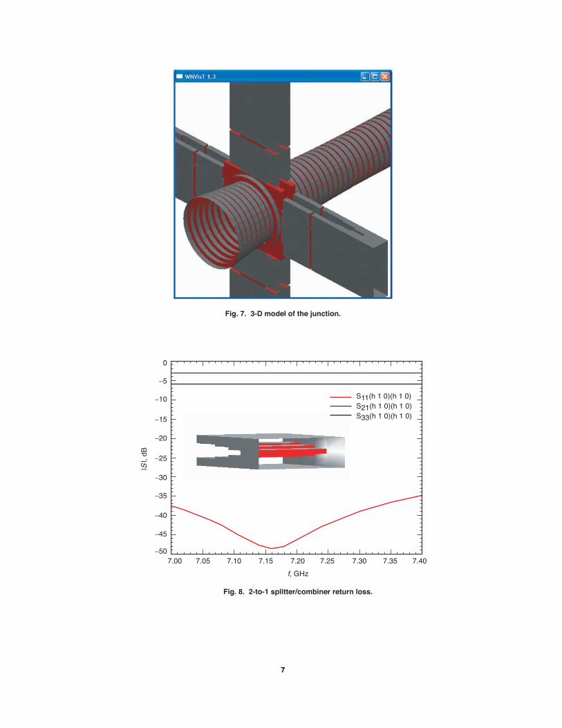
Fig. 7. 3-D model of the junction.
Fig. 8. 2-to-1 splitter/combiner return loss.
0
−10
−5
−15
−20
−25
−30
−35
−40
−45
−50
|S |,
dB
f, GHz
7.00 7.05 7.10 7.15 7.257.20 7.30 7.407.35
S11(h 1 0)(h 1 0)S21(h 1 0)(h 1 0)S33(h 1 0)(h 1 0)
7

7.4-GHz band. Next, this component is inserted into the model, and the reduction in the waveguide widthat the connection to the square segment as well as the dimensions of the matching iris are optimized forthe best return loss over the 7.2-GHz band.
The results are shown in Fig. 9. Here S55 is the important parameter, and a 20-dB return loss isachieved over a band covering 7.1 to 7.35 GHz. This is a large increase in bandwidth over the existing,single-slot design, and it is very desirable since the broadband translates into low temperature sensitivity.The coupling between the circular waveguide port to the right of the figure and the 7.2-GHz rectangularwaveguide input ports is also shown in the figure as S51. Here we see the very low value of couplingin the 7- to 7.3-GHz band due to the cut-off waveguide circular-waveguide dimensions in this frequencyrange. Also of interest is the coupling between these ports in the 8.4-GHz receive band. As mentionedearlier, we require a low value of coupling in this band in order to minimize any impact on the noisetemperature. We observe a maximum coupling value of approximately −13 dB in this band (see S51 inFig. 9). Since the transmit ports are at a physical temperature near 300 K, this coupling translates intoa noise-temperature contribution of approximately 15 K. This noise temperature is unacceptable in thislow-noise system, which otherwise resides at a physical temperature of 4 K. Thus, a low-pass filter isrequired in each of the four transmit arms in order to provide more isolation. The optimization of thisfilter is the subject of the next section.
VI. Filter Optimization
In order to reduce the noise-temperature contribution to a negligible amount, at least 30 dB of isolation(corresponding to a noise-temperature contribution of 0.3 K) is required. Additional margin over thislevel is, of course, desirable. Figure 10 depicts two realizations of a low-pass filter that can provide therequired isolation. On the left side of the figure, we have a two-section corrugated filter. This is thetype of filter that is implemented in the existing feed. On the right-hand side of the figure, we have athree-stage inductive iris filter. Both filters have been investigated, and suitable designs have been foundin either case.
Fig. 9. Overall junction return loss.
f, GHz
S51(h 1 0)(h 1 1 c)
S55(h 1 0)(h 1 0)
0
−10
−5
−15
−20
−25
−30
−35
−40
|S |,
dB
7.0 7.2 7.4 7.6 8.07.8 8.2 8.68.4
8

Fig. 10. Low-pass filter options.
It has been established that the dual-stage corrugated filter is the highest loss region in the operationalfeed. Recent upgrades to the feed’s cooling system have focused on this region and have reduced theoperational temperature of this area significantly. In addition, some of the highest peak fields in thetransmit path are located in this region. Concerns about this filter led to consideration of alternativedesigns. Upon completion of both the corrugated and iris-loaded designs, HFSS was used to evaluate thepeak field strengths in each device. It was found that for the same operating power the inductive irisfilter has slightly lower peak fields than the corrugated filter, and furthermore the high field area exists ina region that is easier to cool. For these reasons, we intend to prototype and install the iris-loaded filterin the next phase of the effort. We have an additional advantage in that the filter is now implementedin a waveguide with a height equal to three groove widths plus two fin widths in the corrugated horn,whereas the original filter was in a waveguide with height equal to one groove width. This increase inheight reduces both field strength and loss, minimizing the chances of breakdown and reducing thermalissues. In addition, we have chosen to use thick irises, allowing for excellent cooling throughout all regionsin the filter.
The mode-matching code was used to optimize the filter’s response, resulting in the characteristicsshown in Fig. 11. A return loss of better than 20 dB from 7.0 to 7.3 GHz and an isolation of 25 dB inthe 8.4-GHz band were realized. This isolation, when cascaded with the raw junction isolation, shouldresult in an overall isolation near 40 dB.
Fig. 11. Filter isolation and return loss.
S11(h 1 0)(h 1 0)
S21(h 1 0)(h 1 0)
S22(h 1 0)(h 1 0)
6.8 7.0 7.2 7.4 7.6 7.8 8.0 8.2 8.4 8.6 8.8
0
−10
−5
−15
−20
−25
−30
−35
−40
|S |,
dB
f, GHz
9
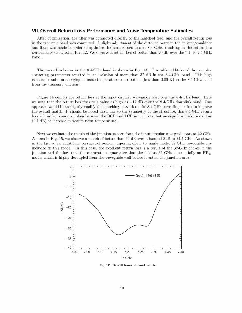
VII. Overall Return Loss Performance and Noise Temperature Estimates
After optimization, the filter was connected directly to the matched feed, and the overall return lossin the transmit band was computed. A slight adjustment of the distance between the splitter/combinerand filter was made in order to optimize the horn return loss at 8.4 GHz, resulting in the return-lossperformance depicted in Fig. 12. We observe a return loss of better than 20 dB over the 7.1- to 7.3-GHzband.
The overall isolation in the 8.4-GHz band is shown in Fig. 13. Favorable addition of the complexscattering parameters resulted in an isolation of more than 37 dB in the 8.4-GHz band. This highisolation results in a negligible noise-temperature contribution (less than 0.06 K) in the 8.4-GHz bandfrom the transmit junction.
Figure 14 depicts the return loss at the input circular waveguide port over the 8.4-GHz band. Herewe note that the return loss rises to a value as high as −17 dB over the 8.4-GHz downlink band. Oneapproach would be to slightly modify the matching network on the 8.4-GHz turnstile junction to improvethe overall match. It should be noted that, due to the symmetry of the structure, this 8.4-GHz returnloss will in fact cause coupling between the RCP and LCP input ports, but no significant additional loss(0.1 dB) or increase in system noise temperature.
Next we evaluate the match of the junction as seen from the input circular-waveguide port at 32 GHz.As seen in Fig. 15, we observe a match of better than 30 dB over a band of 31.5 to 32.5 GHz. As shownin the figure, an additional corrugated section, tapering down to single-mode, 32-GHz waveguide wasincluded in this model. In this case, the excellent return loss is a result of the 32-GHz chokes in thejunction and the fact that the corrugations guarantee that the field at 32 GHz is essentially an HE11
mode, which is highly decoupled from the waveguide wall before it enters the junction area.
S55(h 1 0)(h 1 0)
Fig. 12. Overall transmit band match.
7.00 7.05 7.10 7.15 7.257.20 7.30 7.407.35
0
−10
−5
−15
−20
−25
−30
−35
−40
|S |,
dB
f, GHz
10

S21(h 1 1 c)(h 1 1 c)
S51(h 1 0)(h 1 1 c)
S52(h 1 0)(h 1 1 c)
Fig. 13. Overall isolation in the 8.4-GHz band.
8.30 8.35 8.40 8.45 8.558.50 8.60 8.65
0
−10
−5
−15
−20
−25
−30
−35
−40
|S |,
dB
f, GHz
S11(h 1 1 c)(h 1 1 c)
Fig. 14. Input circular waveguide return loss at 8.4 GHz.
8.30 8.35 8.40 8.45 8.558.50 8.60 8.65
0
−10
−5
−15
−20
−25
−30
−35
−40
|S |,
dB
f, GHz
The most difficult performance evaluation for the feed was the noise-temperature contribution of thejunction in the 32-GHz receive band. In this case, all of the rectangular waveguides in the junction armssupport many modes, making convergence of the coupling values problematic. The results of Fig. 15 (aswell as the radiation pattern results of the next section) would indicate that the junction is relativelyinvisible at 32 GHz, leading to a negligible noise-temperature contribution. A very preliminary calculationgives an upper bound to the noise-temperature contribution at 32 GHz or 0.07 K. While this value isextremely low, confidence in the value is also low due to the size of the model used in the computation.Prototype testing in the next phase of the project will measure the contribution directly.
11

S11(h 1 1 c)(h 1 1 c)
Fig. 15. Input circular waveguide return loss at 32 GHz.
31.5 31.6 31.7 31.8 31.9 32.0 32.1 32.2 32.3 32.4 32.5
0
−10
−5
−15
−20
−25
−30
−35
−40
−45
−50
−55
−60
|S |,
dB
f, GHz
VIII. Radiation Pattern Computation
The final parameter of importance for the feed is the radiation pattern in each of the three bands. Thecomputed patterns at 7.2, 8.4, and 32 GHz are shown in Figs. 16 through 18. In the case of the 7.2-GHzpattern, the junction plays no role since the circular waveguide at the point of injection supports only asingle mode. As can be seen in Fig. 16, we observe excellent pattern symmetry and beam widths identicalto those reported for the existing feed [1].
The radiation pattern at 8.4 GHz was computed by exciting the feed through the circular waveguideport, giving the results shown in Fig. 17. In this case, the junction effects are taken into account, asshown in the model. Once again, excellent pattern symmetry is observed. This implies that the microwaveenergy passes the junction essentially undisturbed in the 8.4-GHz band.
Finally, we observe excellent pattern symmetry in the 32-GHz band, as shown in Fig. 18. As describedearlier, this is a result of the 32-GHz chokes present in the junction and the fact that the HE11 modeis highly decoupled from the waveguide walls. As seen in Fig. 18, the horn is further truncated, so thecomputations become manageable on a PC.
Note that the computed patterns in Figs. 16 through 18 have assumed a radial symmetry in the horn.This assumption is made to reduce the problem set so that it can be managed within the computingresources available on hand (software and hardware limitations). We separately verified (through pro-cessing S21 parameters) that the total accountable energy with and without the radial symmetry werenearly identical.
IX. Prototype Fabrication and Test Plan
In the next phase of the project, we intend to fabricate a prototype junction, matching arms, andfilters. These will be integrated with existing feed components to form a fully operational feed. Themost important test of the new feed will be a demonstration of its uplink power capability. This test is
12

E-Plane
H-Plane
Fig. 16. Radiation patterns at 7.2 GHz.
0
−10
−20
−30
−40
−50
−60
−70
RE
LAT
IVE
GA
IN, d
B
θ, deg
−80 −60 −40 −20 200 40 8060
E-Plane
H-Plane
Fig. 17. Radiation patterns at 8.4 GHz.
0
−10
−20
−30
−40
−50
−60
RE
LAT
IVE
GIN
, dB
θ, deg
−80 −60 −40 −20 200 40 8060
13

E-Plane
H-Plane
Fig. 18. Radiation patterns at 32 GHz.
0
−10
−5
−15
−20
−25
−30
−35
−40
−45
−50
RE
LAT
IVE
GA
IN, d
B
θ, deg
−40 −30 −20 −10 100 20 4030
problematic since an 80- to 100-kW transmitter is not likely to be available. We will likely be limitedto the use of two coherent 20-kW transmitters, maximum. In this case, it will be possible to deliver20 kW to two opposing arms, operating the feed at 40 kW, linearly polarized. This will test the armsat an equivalent circularly polarized power of 80 kW. Since we expect the filters and matching irises inthe arms to be the power-limiting components, both in terms of field strength and thermal stress, the40-kW test is nearly sufficient. We have experience with horns having a circular waveguide dimensionsimilar to those present in the junction area of this feed operating at approximately 500 kW (X-band) inthe Goldstone Solar System Radar (GSSR).
In order to test the filters and junction arms individually, without the need for the feed itself, we havedevised the test depicted in Fig. 19. For this test we design a “junction equivalent” set of irises to beplaced between the two pairs of junction arms. These irises will simulate the junction mismatch. Whenplaced between the arms, a realistic and well-matched two-port network will result. This simple two-portwaveguide assembly then can be easily tested at a power level of 20 kW, and at power levels up to 40 kW,assuming two transmitters are available. This will test the junction arms, matching irises, and filtersbeyond the 25-kW maximum operating power level for a single arm.
X. Summary and Conclusions
A new uplink junction design for the three-frequency (7.2-/8.4-/32-GHz) DSN feed has been presented.The new design injects the uplink power through two non-consecutive corrugations in the feed. The de-sign and optimization were completed using commercially available mode-matching software. The newconfiguration gives increased power-handling capability, better bandwidth, and better thermal character-istics relative to the existing design. A new filter structure for isolating the 8.4-GHz receive band fromthe 300-K uplink system also was developed. Simulations of all of the important parameters of the feedhave been presented. These include input matches and radiation patterns in all three bands and noisetemperature estimates in the two receive bands. Finally, a plan for testing the prototype feed, to beconstructed in the next phase of the project, has been presented.
14

Fig. 19. Back-to-back arm test 3-D drawing.
Matching Arms
20 kW
Load
JunctionEquivalent
Acknowledgment
We would like to thank Mr. John Sosnowski for his input. His comments werevaluable in our design when considering cooling capabilities of the two-slot junction.
References
[1] P. H. Stanton, D. J. Hoppe, and H. Reilly, “Development of a 7.2-, 8.4-, and32-Gigahertz (X-/X-/Ka-Band) Three-Frequency Feed for the Deep Space Net-work,” The Telecommunications and Mission Operations Progress Report 42-145,January–March 2001, Jet Propulsion Laboratory, Pasadena, California, pp. 1–20,May 15, 2001. http://ipnpr/progress report/42-145/145D.pdf
[2] “Ansoft,” http://www.ansoft.com/products/hf/hfss/, September 2007.
[3] “MiG Microwave Innovation Group,” http://www.mig-germany.com/, Septem-ber 2007.
15
Related Documents