Figure HP BUTTERFLY VALVES HIGH PERFORMANCE BUTTERFLY VALVE www.fnw.com Features: • Bi-directional Bubble-tight Shutoff • Suitable for Saturated Steam Service to 150 PSI • Double Off-Set Configuration with Conical Angled Disc • Available in Wafer (3” to 12”) or Lug (3” to 24”) • Stocked in Carbon by Stainless and All Stainless Steel Configurations • Dead-end Service Rated to Full 285 PSI Pressure Differential in the Preferred Flow Direction * • Vacuum rated to 29.91”Hg (0.3750 Torr) + • Easy access reverse packing gland (up to 12”) • ISO Top-works for Manual or Direct Mount Actuation (up to 12”) • Low Maintenance • Manufactured in ISO 9001 Facility Standards: • Design: API 609 • Mounting Pad: ISO 5211 • End Flange: ASME B16.5 • Wall Thickness: ASME B16.34 • Face to Face: API 609 • Pressure/Temp Rating: ANSI B16.34 • Material Rating: ANSI B16.34 • Shell/Seat Test: API 598 ○ Body: CS - 3.2 MPa (464 PSI) SS - 3.0 MPa (435 PSI) ○ Seat Hydro: 2.3 MPa (333 PSI) ○ Seat Air: 0.6 MPa (87 PSI) Options FNW offers many options and modifications for valves. These include, but are not limited to: Actuation including chain wheels, square drive nuts, worm-gear operators, and pneumatic and electric operators. Also available are various control accessories, stem extensions, and custom mounting hardware. Contact FNW with your specific application needs. * Preferred Flow Direction is defined as having the seat retainer ring facing upstream. For non-preferred flow direction (seat retainer ring facing downstream), a downstream flange is required on 10 inch and larger valves for full 285 PSI differential. Without a downstream flange, dead-end service in the non-preferred flow direction is limited to 230 PSI for 10 and 12 inch valves, 150 PSI for 14 inch and larger valves. Pressures listed are for non-shock ambient temperatures. + Vacuum measurements are often made in inches of mercury below atmospheric pressure. The values calculated here assume standard atmospheric pressure of 29.92 inches of mercury.

Welcome message from author
This document is posted to help you gain knowledge. Please leave a comment to let me know what you think about it! Share it to your friends and learn new things together.
Transcript
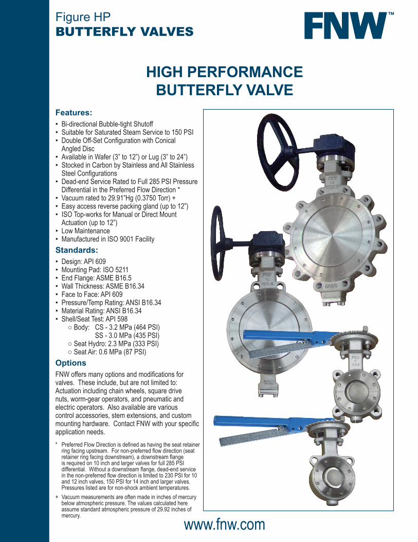
Figure HPBUTTERFLY VALVES
HIGH PERFORMANCEBUTTERFLY VALVE
www.fnw.com
Features: • Bi-directional Bubble-tight Shutoff • Suitable for Saturated Steam Service to 150 PSI • Double Off-Set Confi guration with Conical
Angled Disc • Available in Wafer (3” to 12”) or Lug (3” to 24”) • Stocked in Carbon by Stainless and All Stainless
Steel Confi gurations • Dead-end Service Rated to Full 285 PSI Pressure
Differential in the Preferred Flow Direction * • Vacuum rated to 29.91”Hg (0.3750 Torr) + • Easy access reverse packing gland (up to 12”) • ISO Top-works for Manual or Direct Mount
Actuation (up to 12”) • Low Maintenance • Manufactured in ISO 9001 Facility
Standards: • Design: API 609 • Mounting Pad: ISO 5211 • End Flange: ASME B16.5 • Wall Thickness: ASME B16.34 • Face to Face: API 609 • Pressure/Temp Rating: ANSI B16.34 • Material Rating: ANSI B16.34 • Shell/Seat Test: API 598
○ Body: CS - 3.2 MPa (464 PSI) SS - 3.0 MPa (435 PSI) ○ Seat Hydro: 2.3 MPa (333 PSI) ○ Seat Air: 0.6 MPa (87 PSI)
OptionsFNW offers many options and modifi cations for valves. These include, but are not limited to: Actuation including chain wheels, square drive nuts, worm-gear operators, and pneumatic and electric operators. Also available are various control accessories, stem extensions, and custom mounting hardware. Contact FNW with your specifi c application needs.* Preferred Flow Direction is defi ned as having the seat retainer
ring facing upstream. For non-preferred fl ow direction (seat retainer ring facing downstream), a downstream fl ange is required on 10 inch and larger valves for full 285 PSI differential. Without a downstream fl ange, dead-end service in the non-preferred fl ow direction is limited to 230 PSI for 10 and 12 inch valves, 150 PSI for 14 inch and larger valves. Pressures listed are for non-shock ambient temperatures.
+ Vacuum measurements are often made in inches of mercury below atmospheric pressure. The values calculated here assume standard atmospheric pressure of 29.92 inches of mercury.
Cv (Flow Coefficients)
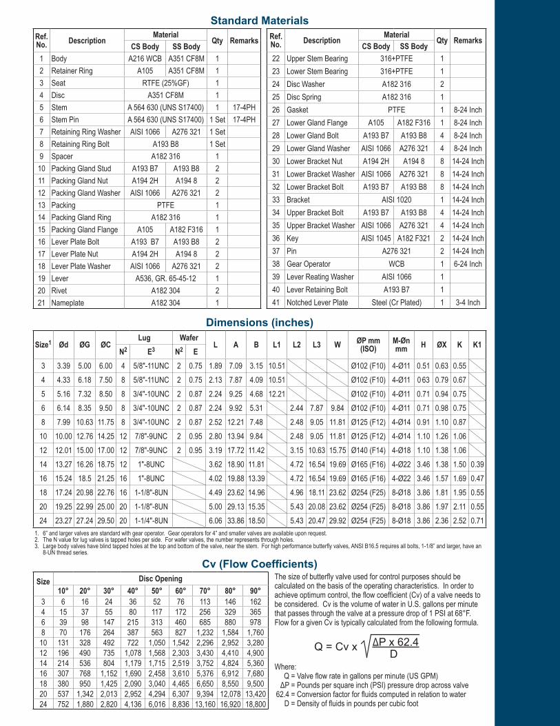
Dimensions (inches)
Size1 Ød ØG ØCLug Wafer
L A B L1 L2 L3 W ØP mm (ISO)
M-Øn mm H ØX K K1
N2 E3 N2 E3 3.39 5.00 6.00 4 5/8"-11UNC 2 0.75 1.89 7.09 3.15 10.51 Ø102 (F10) 4-Ø11 0.51 0.63 0.554 4.33 6.18 7.50 8 5/8"-11UNC 2 0.75 2.13 7.87 4.09 10.51 Ø102 (F10) 4-Ø11 0.63 0.79 0.675 5.16 7.32 8.50 8 3/4"-10UNC 2 0.87 2.24 9.25 4.68 12.21 Ø102 (F10) 4-Ø11 0.71 0.94 0.756 6.14 8.35 9.50 8 3/4"-10UNC 2 0.87 2.24 9.92 5.31 2.44 7.87 9.84 Ø102 (F10) 4-Ø11 0.71 0.98 0.758 7.99 10.63 11.75 8 3/4"-10UNC 2 0.87 2.52 12.21 7.48 2.48 9.05 11.81 Ø125 (F12) 4-Ø14 0.91 1.10 0.8710 10.00 12.76 14.25 12 7/8"-9UNC 2 0.95 2.80 13.94 9.84 2.48 9.05 11.81 Ø125 (F12) 4-Ø14 1.10 1.26 1.0612 12.01 15.00 17.00 12 7/8"-9UNC 2 0.95 3.19 17.72 11.42 3.15 10.63 15.75 Ø140 (F14) 4-Ø18 1.10 1.38 1.0614 13.27 16.26 18.75 12 1"-8UNC 3.62 18.90 11.81 4.72 16.54 19.69 Ø165 (F16) 4-Ø22 3.46 1.38 1.50 0.3916 15.24 18.5 21.25 16 1"-8UNC 4.02 19.88 13.39 4.72 16.54 19.69 Ø165 (F16) 4-Ø22 3.46 1.57 1.69 0.4718 17.24 20.98 22.76 16 1-1/8"-8UN 4.49 23.62 14.96 4.96 18.11 23.62 Ø254 (F25) 8-Ø18 3.86 1.81 1.95 0.5520 19.25 22.99 25.00 20 1-1/8"-8UN 5.00 29.13 15.35 5.43 20.08 23.62 Ø254 (F25) 8-Ø18 3.86 1.97 2.11 0.5524 23.27 27.24 29.50 20 1-1/4"-8UN 6.06 33.86 18.50 5.43 20.47 29.92 Ø254 (F25) 8-Ø18 3.86 2.36 2.52 0.71
1. 6” and larger valves are standard with gear operator. Gear operators for 4” and smaller valves are available upon request.2. The N value for lug valves is tapped holes per side. For wafer valves, the number represents through holes.3. Large body valves have blind tapped holes at the top and bottom of the valve, near the stem. For high performance butterfly valves, ANSI B16.5 requires all bolts, 1-1/8” and larger, have an
8-UN thread series.
Standard MaterialsRef. No. Description
MaterialQty Remarks
CS Body SS Body1 Body A216 WCB A351 CF8M 12 Retainer Ring A105 A351 CF8M 13 Seat RTFE (25%GF) 14 Disc A351 CF8M 15 Stem A 564 630 (UNS S17400) 1 17-4PH6 Stem Pin A 564 630 (UNS S17400) 1 Set 17-4PH7 Retaining Ring Washer AISI 1066 A276 321 1 Set8 Retaining Ring Bolt A193 B8 1 Set9 Spacer A182 316 1
10 Packing Gland Stud A193 B7 A193 B8 211 Packing Gland Nut A194 2H A194 8 212 Packing Gland Washer AISI 1066 A276 321 213 Packing PTFE 114 Packing Gland Ring A182 316 115 Packing Gland Flange A105 A182 F316 116 Lever Plate Bolt A193 B7 A193 B8 217 Lever Plate Nut A194 2H A194 8 218 Lever Plate Washer AISI 1066 A276 321 219 Lever A536, GR. 65-45-12 120 Rivet A182 304 221 Nameplate A182 304 1
Ref. No. Description Material Qty Remarks
CS Body SS Body22 Upper Stem Bearing 316+PTFE 123 Lower Stem Bearing 316+PTFE 124 Disc Washer A182 316 225 Disc Spring A182 316 126 Gasket PTFE 1 8-24 Inch27 Lower Gland Flange A105 A182 F316 1 8-24 Inch28 Lower Gland Bolt A193 B7 A193 B8 4 8-24 Inch29 Lower Gland Washer AISI 1066 A276 321 4 8-24 Inch30 Lower Bracket Nut A194 2H A194 8 8 14-24 Inch31 Lower Bracket Washer AISI 1066 A276 321 8 14-24 Inch32 Lower Bracket Bolt A193 B7 A193 B8 8 14-24 Inch33 Bracket AISI 1020 1 14-24 Inch34 Upper Bracket Bolt A193 B7 A193 B8 4 14-24 Inch35 Upper Bracket Washer AISI 1066 A276 321 4 14-24 Inch36 Key AISI 1045 A182 F321 2 14-24 Inch37 Pin A276 321 2 14-24 Inch38 Gear Operator WCB 1 6-24 Inch39 Lever Reating Washer AISI 1066 140 Lever Retaining Bolt A193 B7 141 Notched Lever Plate Steel (Cr Plated) 1 3-4 Inch
Size Disc Opening10° 20° 30° 40° 50° 60° 70° 80° 90°
3 6 16 24 36 52 76 113 146 1624 15 37 55 80 117 172 256 329 3656 39 98 147 215 313 460 685 880 9788 70 176 264 387 563 827 1,232 1,584 1,76010 131 328 492 722 1,050 1,542 2,296 2,952 3,28012 196 490 735 1,078 1,568 2,303 3,430 4,410 4,90014 214 536 804 1,179 1,715 2,519 3,752 4,824 5,36016 307 768 1,152 1,690 2,458 3,610 5,376 6,912 7,68018 380 950 1,425 2,090 3,040 4,465 6,650 8,550 9,50020 537 1,342 2,013 2,952 4,294 6,307 9,394 12,078 13,42024 752 1,880 2,820 4,136 6,016 8,836 13,160 16,920 18,800
The size of butterfly valve used for control purposes should be calculated on the basis of the operating characteristics. In order to achieve optimum control, the flow coefficient (Cv) of a valve needs to be considered. Cv is the volume of water in U.S. gallons per minute that passes through the valve at a pressure drop of 1 PSI at 68°F. Flow for a given Cv is typically calculated from the following formula.
Where: Q = Valve flow rate in gallons per minute (US GPM) ΔP = Pounds per square inch (PSI) pressure drop across valve 62.4 = Conversion factor for fluids computed in relation to water D = Density of fluids in pounds per cubic foot
Q = Cv x ΔP x 62.4 D


Figure HPBUTTERFLY VALVES
DOC: FNWHP09 Ver. 8/2014 21872© 2014 - FNW. All rights reserved.The FNW logo is a trademark of Ferguson Enterprises, Inc., PL Sourcing, PO Box 2778, Newport News, VA 23609
The contents of this publication are presented for information purposes only, and while effort has been made to ensure their accuracy, they are not to be construed as warranties or guarantees, expressed or implied, regarding the products or services described herein or their use or applicability. All sales are governed by our terms and conditions, which are available on request. We reserve the right to modify or improve the designs or specifications of our products at any time without notice. Always verify that you have the most recent product specifications or other documentation prior to the installation of these products.
Size Wafer Lug3 18 224 24 295 35 406 59 708 79 9510 110 13012 148 18914 29116 38318 49820 66124 991
Weight (Lbs)Pressure/TemperatureSize Differential Pressure*
150 PSI 285 PSI3 270 3384 436 5785 657 8586 962 1,2928 1,726 2,359
10 2,616 3,68312 3,878 5,56714 5,555 7,94216 7,415 10,70818 9,494 13,96520 13,868 20,10824 21,522 31,919
* Torques shown are for the preferred flow direction (valve retaining ring facing upstream pressure).
Torque (in-lbs)
The valve is designed with two offsets. The first offset is between the seat sealing surface and the centerline of the valve stem, putting the stem behind the sealing surface. Since the stem does not penetrate the sealing surface, there is a complete, uninterrupted, 360° seat seal. The second offset is between the centerline of the valve stem and the centerline of the valve port. This double-offset creates an eccentric seating action that reduces seat wear and torque. The disc cams into the seat for a bubble tight shut-off. The cam action is improved by the conical angle of the valve disc.
Double Off-Set Design CAM ACTION
The disc pulls away from the seat, reducing wear and torque.
CONICAL ANGLED DISCThe disc edges are angled as if cut from a cone. This angle improves the cam action of the valve.
DOUBLE OFF-SETCenterline of seal
OFF-SET #2
OFF-SET #1
Centerline of stemCenterline of valve port Centerline of stem
F N W HP 1 L S T G X
CLASS CONNECTION BODY MATERIAL SEAT OPERATOR SIZE CODES1 = 150# W
L==
WAFERLUG
CS
==
WCB - CARBON STEELCF8M - STAINLESS STEEL
T = RTFE LG
==
LEVER (STANDARD TO 4”)GEAR (STANDARD ON 6” TO 24”)
34568
10
======
MPSUX10
121416182024
======
121416182024
Figure Number Matrix
Related Documents